VS - Hussmann · supply necessary claim forms. Concealed Loss or Damage When loss or damage is not...
24
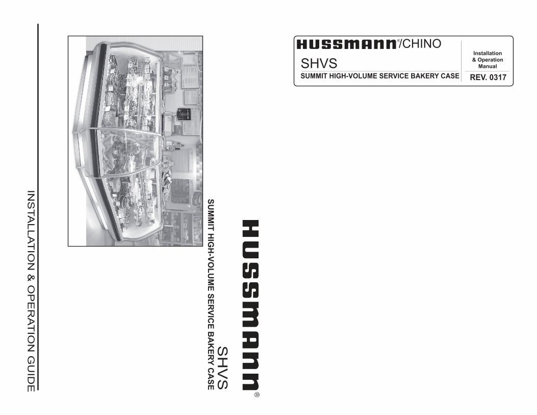
SHVS SUMMIT HIGH-VOLUME SERVICE BAKERY CASE INSTALLATION & OPERATION GUIDE /CHINO SHVS SUMMIT HIGH-VOLUME SERVICE BAKERY CASE REV. 0317 Installation & Operation Manual
Transcript of VS - Hussmann · supply necessary claim forms. Concealed Loss or Damage When loss or damage is not...
SH
VS
S
UM
MIT
HIG
H-V
OL
UM
E S
ER
VIC
E B
AK
ER
Y C
AS
E
INS
TA
LLA
TIO
N &
OP
ER
AT
ION
GU
IDE
/CHINO
SHVSSUMMIT HIGH-VOLUME SERVICE BAKERY CASE REV. 0317
Installation
& Operation
Manual

2
/CHINOA publication of HUSSMANN® Chino
13770 Ramona Avenue � Chino, California 91710
(909) 628-8942 FAX
(909) 590-4910
(800) 395-9229
Keep this booklet with the case at all times for future reference.
General Instructions
Table of Contents
General Instructions.....................................................2
Important Information ..................................................3
Cut and Plan Views ......................................................3
Installation .....................................................................3Location ..................................................................................... 3
Bumper Installation Instructions................................................. 4
Shipping Braces ...........................................................7Leveling ..................................................................................... 7
Joining ...........................................................................7
Exterior Loading ...........................................................7
Plumbing .......................................................................8Waste Outlet and Water Seal .................................................... 8
Installing Drip Piping .................................................................. 8
Refrigeration .................................................................9Refrigerant Type ........................................................................ 9
Refrigeration Piping ................................................................... 9
Refrigeration Data ...................................................................... 9
Defrost Data ............................................................................... 9
Physical Data ............................................................................. 9
Glycol Requirements ................................................................. 9
Controls and Adjustments .........................................10
User Information ......................................................... 11Stocking ................................................................................... 11
Care and Cleaning ................................................................... 11
Important Steps ....................................................................... 11
Case Cleaning ......................................................................... 11
Stainless Steel Cleaning and Care .......................................... 12
Electrical......................................................................13Wiring Color Code ................................................................... 13
Rear Close-off Panel ............................................................... 13
Electrical .................................................................................. 13
Electrical Wiring Diagrams ........................................13
Wiring Diagrams .........................................................14
Speci� cation Sheet ....................................................19
Appendices .................................................................20Appendix A. - Temperature Guidelines .................................... 20
Appendix B. - Application Recommendations .......................... 20
Appendix C. - Field Recommendations ................................... 20
Appendix D. - Recommendations to User ............................... 21
This Booklet Contains Information on the:
Merchandisers listed below. All models are available in
either 48", 57 1/2" or 75 1/2" lengths:
SHVS-N - Non-refrigerated Summit High-Volume Bakery
Case with 4 levels (3 shelves) and lift front glass.
SHVS-R - Refrigerated Summit High-Volume Bakery Case
with 4 levels (3 shelves) and lift front glass. Remote unit
requires separate condenser unit connection.
SHVS-S/C - Self-contained Refrigerated Summit
High-Volume Bakery Case with 4 levels (3 shelves) and
lift front glass.
Shipping Damage
All equipment should be thoroughly examined for shipping
damage before and during unloading.
This equipment has been carefully inspected at our factory
and the carrier has assumed responsibility for safe arrival.
If damaged, either apparent or concealed, claim must be
made to the carrier.
Apparent Loss or Damage
If there is an obvious loss or damage, it must be noted on
the freight bill or express receipt and signed by the carrier�s
agent; otherwise, carrier may refuse claim. The carrier will
supply necessary claim forms.
Concealed Loss or Damage
When loss or damage is not apparent until after equipment
is uncrated, a claim for concealed damage is made. Make
request in writing to carrier for inspection within 15 days,
and retain all packaging. The carrier will supply inspection
report and required claim forms.
Shortages
Check your shipment for any possible shortages of
material. If a shortage should exist and is found to be the
responsibility of Hussmann Chino, notify Hussmann Chino.
If such a shortage involves the carrier, notify the carrier
immediately, and request an inspection. Hussmann Chino
will acknowledge shortages within ten days from receipt
of equipment.
Hussmann Chino Product Control
The serial number and shipping date of all equipment
has been recorded in Hussmann�s ! les for warranty and
replacement part purposes. All correspondence pertaining
to warranty or parts ordering must include the serial number
of each piece of equipment involved, in order to provide
the customer with the correct parts.
It is the contractor’s responsibility to install
case(s) according to local construction and
health codes
3
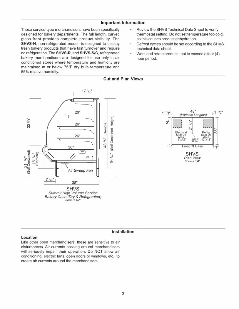
Cut and Plan Views
SHVSSummit High Volume Service
Air Sweep Fan
Bakery Case (Dry & Refrigerated)Scale = 1/2"
17 1/2"
20"
26"
26"
30"
7 3/4"
32
3/ 4
"21
1/ 2
"( S
el f
Co
nt a
i ne
d)
48
3/ 4
"( R
em
ote
)
15
3/ 4
"( R
em
ote
)
38"
54
1/ 4
"(S
el f
Co
nt a
i ne
dH
eig
ht )
2"
1"
1 1/2"
WasteOutlet
Refrig.Stub Up
Area12"x12"
Front Of Case 1"
38
"
1 1/2"48"(Variable Lengths)
SHVSPlan ViewScale = 1/4"
ElectricalStub Up
Area12"x12"
21
3/4
"
These service-type merchandisers have been speci! cally
designed for bakery departments. The full length, curved
glass front provides complete product visibility. The
SHVS-N, non-refrigerated model, is designed to display
fresh bakery products that have fast turnover and require
no refrigeration. The SHVS-R, and SHVS-S/C, refrigerated
bakery merchandisers are designed for use only in air
conditioned stores where temperature and humidity are
maintained at or below 75°F dry bulb temperature and
55% relative humidity.
� Review the SHVS Technical Data Sheet to verify
thermostat setting. Do not set temperature too cold,
as this causes product dehydration.
� Defrost cycles should be set according to the SHVS
technical data sheet.
� Work and rotate product - not to exceed a four (4)
hour period.
Installation
Location
Like other open merchandisers, these are sensitive to air
disturbances. Air currents passing around merchandisers
will seriously impair their operation. Do NOT allow air
conditioning, electric fans, open doors or windows, etc., to
create air currents around the merchandisers.
Important Information
4
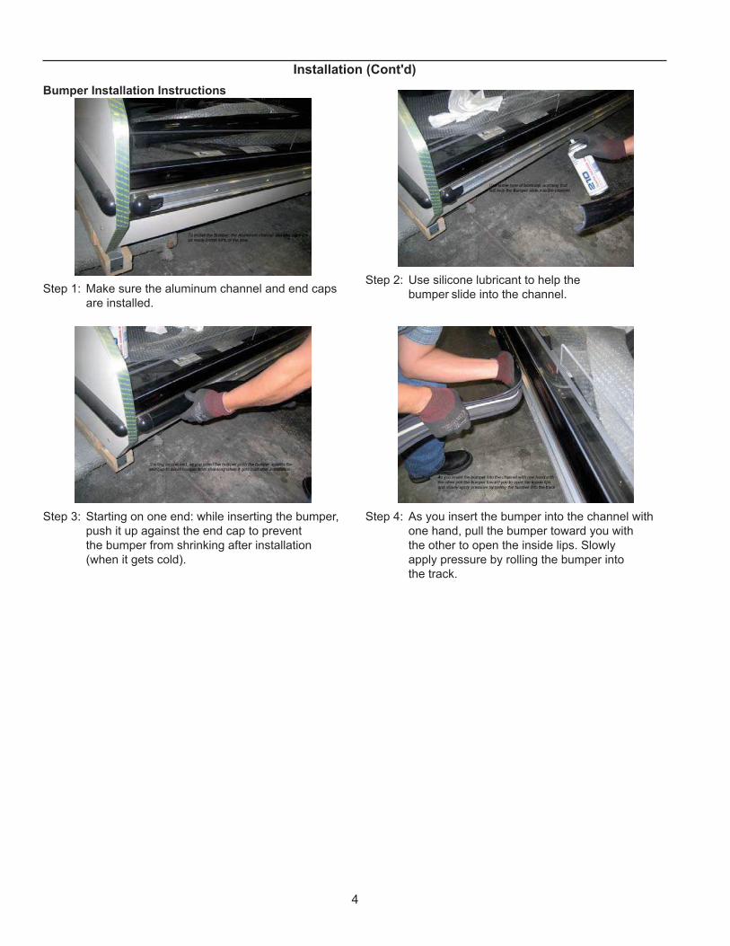
Bumper Installation Instructions
Step 1: Make sure the aluminum channel and end caps
are installed.
Step 2: Use silicone lubricant to help the
bumper slide into the channel.
Step 3: Starting on one end: while inserting the bumper,
push it up against the end cap to prevent
the bumper from shrinking after installation
(when it gets cold).
Step 4: As you insert the bumper into the channel with
one hand, pull the bumper toward you with
the other to open the inside lips. Slowly
apply pressure by rolling the bumper into
the track.
Installation (Cont'd)
5
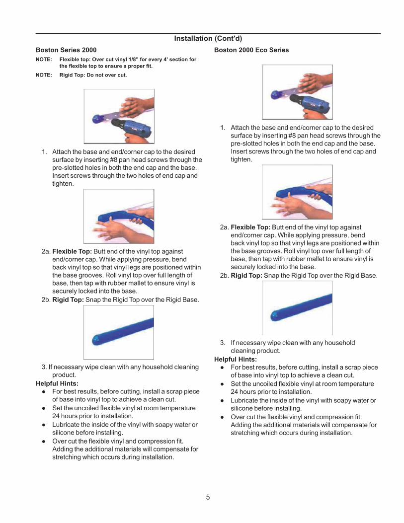
Boston Series 2000
NOTE: Flexible top: Over cut vinyl 1/8" for every 4' section for
the � exible top to ensure a proper � t.
NOTE: Rigid Top: Do not over cut.
1. Attach the base and end/corner cap to the desired
surface by inserting #8 pan head screws through the
pre-slotted holes in both the end cap and the base.
Insert screws through the two holes of end cap and
tighten.
2a. Flexible Top: Butt end of the vinyl top against
end/corner cap. While applying pressure, bend
back vinyl top so that vinyl legs are positioned within
the base grooves. Roll vinyl top over full length of
base, then tap with rubber mallet to ensure vinyl is
securely locked into the base.
2b. Rigid Top: Snap the Rigid Top over the Rigid Base.
3. If necessary wipe clean with any household cleaning
product.
Helpful Hints:
! For best results, before cutting, install a scrap piece
of base into vinyl top to achieve a clean cut.
! Set the uncoiled flexible vinyl at room temperature
24 hours prior to installation.
! Lubricate the inside of the vinyl with soapy water or
silicone before installing.
! Over cut the flexible vinyl and compression fit.
Adding the additional materials will compensate for
stretching which occurs during installation.
Installation (Cont'd)
Boston 2000 Eco Series
1. Attach the base and end/corner cap to the desired
surface by inserting #8 pan head screws through the
pre-slotted holes in both the end cap and the base.
Insert screws through the two holes of end cap and
tighten.
2a. Flexible Top: Butt end of the vinyl top against
end/corner cap. While applying pressure, bend
back vinyl top so that vinyl legs are positioned within
the base grooves. Roll vinyl top over full length of
base, then tap with rubber mallet to ensure vinyl is
securely locked into the base.
2b. Rigid Top: Snap the Rigid Top over the Rigid Base.
3. If necessary wipe clean with any household
cleaning product.
Helpful Hints:
! For best results, before cutting, install a scrap piece
of base into vinyl top to achieve a clean cut.
! Set the uncoiled flexible vinyl at room temperature
24 hours prior to installation.
! Lubricate the inside of the vinyl with soapy water or
silicone before installing.
! Over cut the flexible vinyl and compression fit.
Adding the additional materials will compensate for
stretching which occurs during installation.

6
Installation (Cont'd)
Boston 1000 Series
NOTE: Flexible top: Over cut vinyl 1/8" for every 4' section for
the � exible top to ensure a proper � t.
NOTE: Rigid Top: Do not over cut.
Installation
1. Attach the base and end/corner cap to the desired
surface by inserting #8 pan head screws through the
pre-slotted holes in both the end cap and the base.
Insert screws through the two holes of end cap and
tighten.
2a. Flexible Top: Butt end of the vinyl top against
end/corner cap. While applying pressure, bend
back vinyl top so that vinyl legs are positioned within
the base grooves. Roll vinyl top over full length of
base, then tap with rubber mallet to ensure vinyl is
securely locked into the base.
2b. Rigid Top: Snap the Rigid Top over the Rigid Base.
3. If necessary wipe clean with any household
cleaning product.
Helpful Hints:
! For best results, before cutting, install a scrap piece
of base into vinyl top to achieve a clean cut.
! Set the uncoiled flexible vinyl at room temperature
24 hours prior to installation.
! Lubricate the inside of the vinyl with soapy water or
silicone before installing.
! Over cut the flexible vinyl and compression fit.
Adding the additional materials will compensate for
stretching which occurs during installation.
7
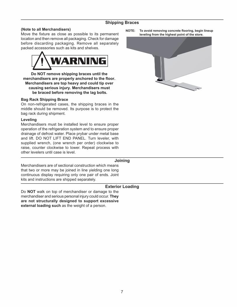
Shipping Braces
(Note to all Merchandisers)
Move the ! xture as close as possible to its permanent
location and then remove all packaging. Check for damage
before discarding packaging. Remove all separately
packed accessories such as kits and shelves.
Do NOT remove shipping braces until the
merchandisers are properly anchored to the floor.
Merchandisers are top heavy and could tip over
causing serious injury. Merchandisers must
be braced before removing the lag bolts.
Bag Rack Shipping Brace
On non-refrigerated cases, the shipping braces in the
middle should be removed. Its purpose is to protect the
bag rack during shipment.
Leveling
Merchandisers must be installed level to ensure proper
operation of the refrigeration system and to ensure proper
drainage of defrost water. Place prybar under metal base
and lift. DO NOT LIFT END PANEL. Turn leveler, with
supplied wrench, (one wrench per order) clockwise to
raise, counter clockwise to lower. Repeat process with
other levelers until case is level.
NOTE: To avoid removing concrete ! ooring, begin lineup
leveling from the highest point of the store.
JoiningMerchandisers are of sectional construction which means
that two or more may be joined in line yielding one long
continuous display requiring only one pair of ends. Joint
kits and instructions are shipped separately.
Exterior LoadingDo NOT walk on top of merchandiser or damage to the
merchandiser and serious personal injury could occur. They
are not structurally designed to support excessive
external loading such as the weight of a person.
8
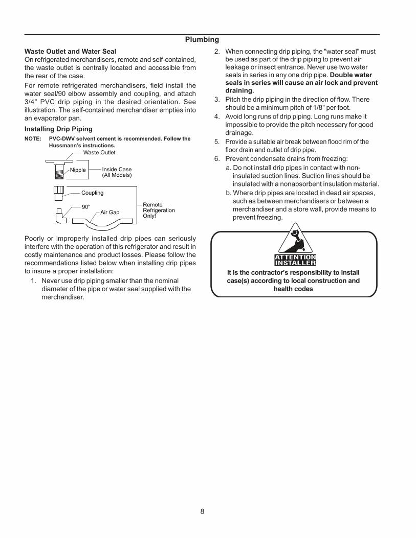
Plumbing
Waste Outlet and Water Seal
On refrigerated merchandisers, remote and self-contained,
the waste outlet is centrally located and accessible from
the rear of the case.
For remote refrigerated merchandisers, ! eld install the
water seal/90 elbow assembly and coupling, and attach
3/4" PVC drip piping in the desired orientation. See
illustration. The self-contained merchandiser empties into
an evaporator pan.
Installing Drip Piping
NOTE: PVC-DWV solvent cement is recommended. Follow the
Hussmann�s instructions.
Waste Outlet
Nipple Inside Case(All Models)
Coupling
90°Air Gap
RemoteRefrigerationOnly!
Poorly or improperly installed drip pipes can seriously
interfere with the operation of this refrigerator and result in
costly maintenance and product losses. Please follow the
recommendations listed below when installing drip pipes
to insure a proper installation:
1. Never use drip piping smaller than the nominal
diameter of the pipe or water seal supplied with the
merchandiser.
2. When connecting drip piping, the "water seal" must be used as part of the drip piping to prevent air leakage or insect entrance. Never use two water seals in series in any one drip pipe. Double water seals in series will cause an air lock and prevent draining.
3. Pitch the drip piping in the direction of # ow. There
should be a minimum pitch of 1/8" per foot.
4. Avoid long runs of drip piping. Long runs make it
impossible to provide the pitch necessary for good
drainage.
5. Provide a suitable air break between # ood rim of the
# oor drain and outlet of drip pipe.
6. Prevent condensate drains from freezing:
a. Do not install drip pipes in contact with non-
insulated suction lines. Suction lines should be
insulated with a nonabsorbent insulation material.
b. Where drip pipes are located in dead air spaces,
such as between merchandisers or between a
merchandiser and a store wall, provide means to
prevent freezing.
It is the contractor’s responsibility to install
case(s) according to local construction and
health codes

9
Refrigeration
Refrigerant Type
Unless otherwise speci! ed on the factory order, remote and
self-contained merchandisers are equipped for operation
on R22 refrigerant. The correct type of refrigerant will be
stamped on each merchandiser�s serial plate located inside
the merchandiser.
Refrigeration Piping
Liquid Suction
3/8" O.D. 5/8" O.D.
The refrigerant line connections are behind the rear
close-off panel, underneath the drain tub, on the left hand
end of the merchandiser as viewed from the rear. After
connections have been made, seal this outlet thoroughly.
Seal both inside and the outside. We recommend using an
aerosol dispensed urethane type of insulation. See SHVS
technical data sheet for proper duration and frequency.
Self contained cases have individual defrost time clocks.
When power has been applied, set the time clock to the
proper duration and frequency.
The time clock is located behind the front panel under the
case. Turn the clock dial counterclockwise until the pointer
is directed to the current time of day.
Multiplexing - Piping of merchandisers operating on the
same refrigeration system may be run from merchandiser
to merchandiser through the end frame saddles provided
for this purpose. DO NOT RUN REFRIGERANT LINES
THROUGH MERCHANDISERS THAT ARE NOT THE
SAME REFRIGERATION SYSTEM as this may result in
poor refrigeration control and compressor failure.
Line Sizing - Refrigerant lines should be sized as shown
on the refrigeration legend that is furnished for the store
(not furnished by Hussmann). If a legend has not been
furnished, refer to the Hussmann Application Engineering
Manual for guidance.
Oil Traps - P-TRAPS (oil traps) must be installed at the
base of all suction line vertical risers.
Pressure Drop - Pressure drop can rob the system of
capacity. To keep the pressure drop to a minimum, keep the
refrigerant line run as short as possible using a minimum
number of elbows. Where elbows are required, use long
radius elbows only.
Insulation - The suction and liquid lines should be clamped
or taped together and insulated for a minimum of 30� from
the merchandiser. Additional insulation is recommended
wherever condensation drippage is objectionable.
Refrigeration Data
Note: This data is based on store temperature and humidity
that does not exceed 75F and 55% R.H.
Note: Not recommended to control temp by regulating coil
temp allow T-STAT to cycle and control temp.
Btu/hr/ft*
See Spec Sheets
*For all refrigeration equipment other than Hussmann, use
conventional Btu values.
ELECTRIC or GAS Not Recommended
Physical Data
Merchandiser Drip Pipe (in.) 1½
Merchandiser Liquid Line (in.) 3/8*
Merchandiser Suction Line (in.) 5/8*
Estimated Charge (lb)***
4ft 1.2
5ft 1.5
6ft 1.8
*Dependent on case length and refrigerant type.
*** This is an average for all refrigerants types. Actual
refrigerant charge may vary by approximately half a
pound.
Glycol Requirements
GPM PSI
4ft 0.8 2.3
5ft 1.0 3.3
6ft 1.2 5.2

10
Controls and Adjustments
The objective of the controls and settings listed in this
section is to maximize product shelf life. Not complying with
these instructions will increase spoilage rate due to drying
of the product and could cause sweating on the front glass
if operated too cold.
Allow bakery products to reach store ambient conditions
after preparation just prior to display. This is essential to
maximize the shelf life of perishables.

11
User Information
Stocking
In order to maximize product life, maintain a constant and
proper product temperature from the time the product is
received through storage, preparation and display.
Products should not be placed in merchandisers until
all refrigeration controls have been adjusted and
merchandisers are at proper operating temperature. Care
should be taken to place the bakery trays all the way to the
front of the shelf. This avoids blocking the rear refrigerated
air discharge. The load limit decals are af! xed to the interior
of the merchandiser. Again, air discharge and return
air ! ow must be unobstructed at all times to provide
proper refrigeration.
There is also a row of vents located at the base of the
front glass, just above the front rub rail. These vents allow
a gentle air " ow across the front glass from the ambient
fans that prevents any condensation on the glass. Do Not
place any signs or other restrictive objects on the front
of the merchandiser that will block these vents.
Care and Cleaning
Long life and satisfactory performance of any equipment
is dependent upon the care it receives. To ensure long
life, proper sanitation and minimum maintenance costs,
merchandisers should be thoroughly cleaned, all debris
removed and the interiors washed down, weekly.
Do Not use HOT water on COLD glass surfaces.
This can cause the glass to shatter and could
result in personal injury. Allow glass
fronts, ends and service doors to warm
before applying hot water.
Exterior Surfaces -The exterior surfaces must be
cleaned with a mild detergent and warm water to protect
and maintain their attractive ! nish. Never use abrasive
cleansers or scouring pads.
Front Glass - DO NOT use the front glass as a
support during cleaning. Removal of the glass is NOT
recommended.
Interior Surfaces -The lower display decks are removable
by sliding open rear drawer and lifting them up and out.
The interior surfaces may be cleaned with most domestic
detergents, ammonia based cleaners and sanitizing
solutions with no harm to the surface.
Shut off fan during cleaning
Important Steps
1. For temperature settings, please see the SHVS
technical data sheet.
2. Temperature control should be my means of a
T-STAT and Suction Solenoid or equivalent for each
case.
3. Product should be worked and rotated on a regular
basis, not to exceed a 4-hour period.
4. At night, turn off case lights and cover the product
with a damp (not wet) cloth similar to cheese cloth
(etc.). This should be washed out in the morning and
kept in a walk-in box during the day so that it is cool
and moist when covering the product.
5. Discharge air temperature should be approximately
26°F, with between 150-200 FPM air velocity. Do not
display product directly within the air discharge.
6. Clean Humidity system a minimum of every 90 days
for proper system operation.
Case Cleaning
CLEANING PRECAUTIONS When cleaning:
• Do not use high pressure water hoses
• Do not introduce water faster then waste outlet can drain
• NEVER INTRODUCE WATER ON SELF CONTAINED UNIT WITH AN EVPORATOR PAN
• NEVER USE A CLEANING OR SANITIZING SOLUTION THAT HAS AN OIL BASE (these will dissolve the butyl sealants) or an AMMONA BASE (this will corrode the copper components of the case)
• TO PRESERVE THE ATTRACTIVE FINISH:
• DO USE WATER AND A MILD DETERGENT FOR THE EXTERIOR ONLY
• DO NOT USE A CHLORANITED CLAENER ON ANY SURFACE
• DO NOT USE ABRASIVES OR STEEL WOOL SCOURING PADS (these will mar the finish)
CAUTION
Do Not Use:
� Mineral oil based solutions, as these will dissolve
the butyl sealants used in the construction of the
merchandisers.
� Abrasive cleansers and scouring pads, as these will
mar the ! nish.
Do:
� Remove the product and all loose debris to avoid
clogging the waste outlet.
� Thoroughly clean all surfaces with soap and hot
water. Do NOT use steam or high water pressure
hoses to wash the interior. These will destroy the
merchandisers� sealing causing leaks and poor
performance.
� Rinse with hot water, but do NOT " ood. Never
introduce water faster than the waste outlet can
remove it.

12
NOTE: Self-contained Models
The evaporator pan must be monitored
for over! ow conditions. Provide drainage if
necessary. After cleaning and rinsing, purge the pan
of any standing water.
� Care should be taken to minimize direct contact
between fan motors and cleaning or rinse water.
� Allow the merchandisers to dry before resuming
operation.
� When cleaning lighted shelves, wipe down with a
damp sponge or cloth so that water does not enter
the light channel. Do NOT use a hose or submerge
shelves in water.
User Information (Cont'd)
Stainless Steel Cleaning and Care
There are three basic things, which can break down your
stainless steel�s passivity layer and allow corrosion.
1. Mechanical Abrasion
Mechanical Abrasion means those things that
will scratch the steels surface. Steel Pads, wire
Brushes, and Scrapers are prime examples.
2. Water
Water comes out of our tap in varying degrees of
hardness. Depending on what part of the country
you live in, you may have hard or soft water. Hard
water may leave spots. Also, when heated, hard
water leaves deposits behind that if left to sit, will
break down the passive layer and rust your stainless
steel. Other deposits from food preparation and
service must be properly removed.
3. Chlorides
Chlorides are found nearly everywhere. They
are in water, food and table salt. One of the worst
perpetrators of chlorides can come from household
and industrial cleaners.
Don�t Despair! Here are a few steps that can help prevent
stainless steel rust.
1. Use the Proper Tools
When cleaning your stainless steel products, take
care to use non-abrasive tools. Soft Clothes and
plastic scouring pads will NOT harm the steel�s
passive layer. Stainless steel pads can also be
used but the scrubbing motion must be in the same
direction of the manufacturer�s polishing marks.
2. Clean With the Polish Lines
Some stainless steels come with visible polishing
lines or �grain�. When visible lines are present, you
should ALWAYS scrub in a motion that is parallel to
them. When the grain cannot be seen, play it safe
and use a soft cloth or plastic scouring pad.
3. Use Alkaline, Alkaline Chlorinated or
Non-chloride Containing Cleaners
While many traditional cleaners are loaded
with chlorides, the industry is providing an ever
increasing choice of non-chloride cleaners. If you
are not sure of your cleaner�s chloride content
contact your cleaner supplier. If they tell you that
your present cleaner contains chlorides, ask for
an alternative. Also, avoid cleaners containing
quaternary salts as they also can attack stainless
steel & cause pitting and rusting.
4. Treat your Water
Though this is not always practical, softening hard
water can do much to reduce deposits. There
are certain " lters that can be installed to remove
distasteful and corrosive elements. Salts in a
properly maintained water softener are your friends.
If you are not sure of the proper water treatment, call
a treatment specialist.
5. Keep your Food Equipment Clean
Use alkaline, alkaline chlorinated or non-chlorinated
cleaners at recommended strength. Clean
frequently to avoid build-up of hard, stubborn stains.
If you boil water in your stainless steel equipment,
remember the single most likely cause of damage is
chlorides in the water. Heating cleaners that contain
chlorides has a similar effect.
6. RINSE, RINSE, RINSE
If chlorinated cleaners are used you must rinse,
rinse, rinse and wipe dry immediately. The sooner
you wipe off standing water, especially when sit
contains cleaning agents, the better. After wiping the
equipment down, allow it to air dry for the oxygen
helps maintain the stainless steel�s passivity " lm.
7. Never Use Hydrochloric Acid (Muriatic Acid) on
Stainless Steel
8. Regularly Restore/Passivate Stainless Steel
13
Electrical
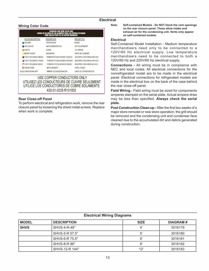
Wiring Color Code
Rear Close-off Panel
To perform electrical and refrigeration work, remove the rear
closure panel by loosening the sheet metal screws. Replace
when work is complete.
Note: Self-contained Models - Do NOT block the vent openings
on the rear closure panel. These allow intake and
exhaust air for the condensing unit. Vents only appear
on self-contained models.
Electrical
Self-Contained Model Installation - Medium temperature
merchandisers need only to be connected to a
120V/60 Hz electrical supply. Low temperature
merchandisers need to be connected to both a
120V/60 Hz and 220V/60 Hz electrical supply.
Connections - All wiring must be in compliance with
NEC and local codes. All electrical connections for the
nonrefrigerated model are to be made in the electrical
panel. Electrical connections for refrigerated models are
made in the electrical box on the back of the case behind
the rear close-off panel.
Field Wiring - Field wiring must be sized for components
amperes stamped on the serial plate. Actual ampere draw
may be less than speci! ed. Always check the serial
plate.
Post Construction Clean-up - After the ! rst two weeks of a
major store remodel or new store operation, the grill should
be removed and the condensing unit and condenser face
cleaned due to the accumulated dirt and debris generated
during construction.
Electrical Wiring Diagrams
MODEL DESCRIPTION SIZE DIAGRAM #
SHVS SHVS-4-R-48" 4' 3016179
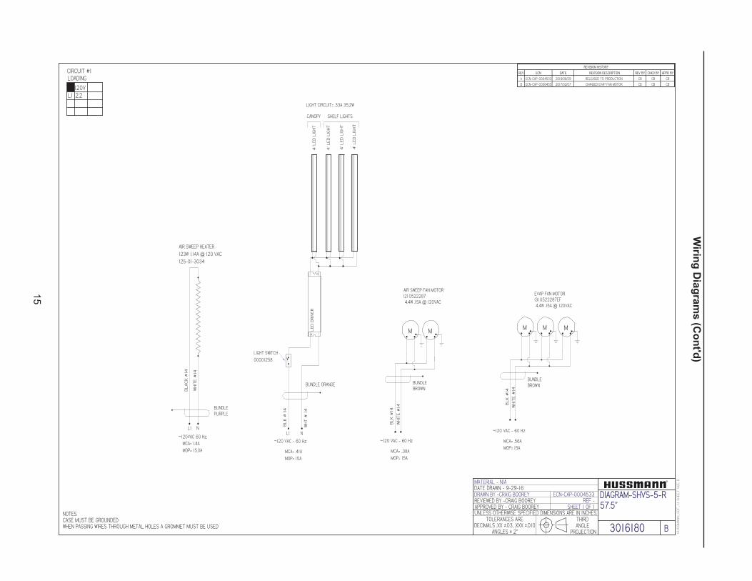
SHVS-5-R 57.5" 5' 3016180
SHVS-6-R 75.5" 6' 3016181
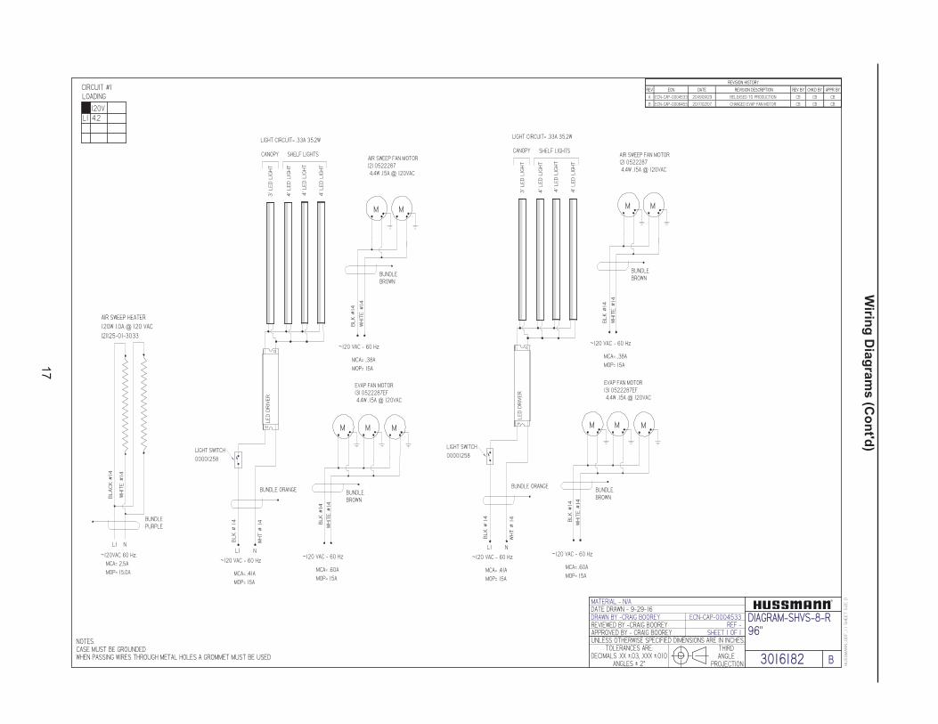
SHVS-8-R 96" 8' 3016182
SHVS-12-R 144" 12' 3016183

14
Wirin
g D
iag
ram
s
HUSSMANN_GDF_1.1SHEETSIZEDMATERIAL - N/A
THIRDANGLE
PROJECTION
UNLESS OTHERWISE SPECIFIED DIMENSIONS ARE IN INCHES.
DRAWN BY -CRAIG BOOREY
APPROVED BY - CRAIG BOOREY
TOLERANCES ARE:DECIMALS .XX u.03, .XXX u.010
ANGLES u 2v
DATE DRAWN - 9-29-16ECN-CAP-0004533
REVIEWED BY -CRAIG BOOREY REF -
3016179
DIAGRAM-SHVS-4-R48"
REV ECN DATE REVISION DESCRIPTION REV BY CHKD BY APPR BY
A ECN-CAP-0004533 2016/09/29 RELEASED TO PRODUCTION CB CB CB
B ECN-CAP-0006455 2017/02/07 CHANGED EVAP FAN MOTOR CB CB CB
REVISION HISTORY
NOTES:CASE MUST BE GROUNDEDWHEN PASSING WIRES THROUGH METAL HOLES A GROMMET MUST BE USED B
SHEET 1 OF 1
CIRCUIT #1
L1
LOADING
2.2120V
BUNDLEBROWN
M M
BLK#14
WHITE#14
LIGHT SWITCH00001258
AIR SWEEP FAN MOTOR(2) 05222874.4W .15A @ 120VAC
M
BUNDLEBROWN
M M
BLK#14
WHITE#14
EVAP FAN MOTOR(3) 0522287EF4.4W .15A @ 120VAC
BUNDLE ORANGE
~120 VAC - 60 Hz
BLK#14
L1 N
MCA= .41AMOP= 15A
WHT#14
CANOPY
LIGHT CIRCUIT= .33A 35.2W
3'LEDLIGHT
LEDDRIVER
~120 VAC - 60 Hz
MCA= ..38AMOP= 15A
~120 VAC - 60 Hz
MCA= .56AMOP= 15A
SHELF LIGHTS
AIR SWEEP HEATER120W 1.11A @ 120 VAC125-01-3033
BUNDLEPURPLE
BLACK#14
WHITE#14
L1 N
~120VAC 60 Hz.MCA= 1.39AMOP= 15.0A
4'LEDLIGHT
4'LEDLIGHT
4'LEDLIGHT
15
HUSSMANN_GDF_1.1SHEETSIZEDMATERIAL - N/A
THIRDANGLE
PROJECTION
UNLESS OTHERWISE SPECIFIED DIMENSIONS ARE IN INCHES.
DRAWN BY -CRAIG BOOREY
APPROVED BY - CRAIG BOOREY
TOLERANCES ARE:DECIMALS .XX u.03, .XXX u.010
ANGLES u 2v
DATE DRAWN - 9-29-16ECN-CAP-0004533
REVIEWED BY -CRAIG BOOREY REF -
3016180
DIAGRAM-SHVS-5-R57.5"
REV ECN DATE REVISION DESCRIPTION REV BY CHKD BY APPR BY
A ECN-CAP-0004533 2016/09/29 RELEASED TO PRODUCTION CB CB CB
B ECN-CAP-0006455 2017/02/07 CHANGED EVAP FAN MOTOR CB CB CB
REVISION HISTORY
NOTES:CASE MUST BE GROUNDEDWHEN PASSING WIRES THROUGH METAL HOLES A GROMMET MUST BE USED B
SHEET 1 OF 1
CIRCUIT #1
L1
LOADING
2.2120V
BUNDLEBROWN
M M
BLK#14
WHITE#14
LIGHT SWITCH00001258
AIR SWEEP FAN MOTOR(2) 05222874.4W .15A @ 120VAC
M
BUNDLEBROWN
M M
BLK#14
WHITE#14
EVAP FAN MOTOR(3) 0522287EF4.4W .15A @ 120VAC
BUNDLE ORANGE
~120 VAC - 60 Hz
BLK#14
L1 N
MCA= .41AMOP= 15A
WHT#14
CANOPY
LIGHT CIRCUIT= .33A 35.2W
4'LEDLIGHT
LEDDRIVER
~120 VAC - 60 Hz
MCA= ..38AMOP= 15A
~120 VAC - 60 Hz
MCA= .56AMOP= 15A
SHELF LIGHTS
AIR SWEEP HEATER123W 1.14A @ 120 VAC125-01-3034
BUNDLEPURPLE
BLACK#14
WHITE#14
L1 N
~120VAC 60 Hz.MCA= 1.4AMOP= 15.0A
4'LEDLIGHT
4'LEDLIGHT
4'LEDLIGHT
Wirin
g D
iag
ram
s (C
on
t'd)

16
Wirin
g D
iag
ram
s (C
on
t'd)
HUSSMANN_GDF_1.1SHEETSIZEDMATERIAL - N/A
THIRDANGLE
PROJECTION
UNLESS OTHERWISE SPECIFIED DIMENSIONS ARE IN INCHES.
DRAWN BY -CRAIG BOOREY
APPROVED BY - CRAIG BOOREY
TOLERANCES ARE:DECIMALS .XX u.03, .XXX u.010
ANGLES u 2v
DATE DRAWN - 9-29-16ECN-CAP-0004533
REVIEWED BY -CRAIG BOOREY REF -
3016181
DIAGRAM-SHVS-6-R75.5"
REV ECN DATE REVISION DESCRIPTION REV BY CHKD BY APPR BY
A ECN-CAP-0004533 2016/09/29 RELEASED TO PRODUCTION CB CB CB
B ECN-CAP-0006455 2017/02/07 CHANGED EVAP FAN MOTOR CB CB CB
REVISION HISTORY
NOTES:CASE MUST BE GROUNDEDWHEN PASSING WIRES THROUGH METAL HOLES A GROMMET MUST BE USED B
SHEET 1 OF 1
CIRCUIT #1
L1
LOADING
2.8120V
BUNDLEBROWN
M M
BLK#14
WHITE#14
LIGHT SWITCH00001258
AIR SWEEP FAN MOTOR(2) 05222874.4W .15A @ 120VAC
M
BUNDLEBROWN
M M
BLK#14
WHITE#14
EVAP FAN MOTOR(4) 0522287EF4.4W .15A @ 120VAC
BUNDLE ORANGE
~120 VAC - 60 Hz
BLK#14
L1 N
MCA= .60AMOP= 15A
WHT#14
CANOPY
LIGHT CIRCUIT= .48A 52W
5'LEDLIGHT
LEDDRIVER
~120 VAC - 60 Hz
MCA= ..38AMOP= 15A
~120 VAC - 60 Hz
MCA= .75AMOP= 15A
SHELF LIGHTS
AIR SWEEP HEATER165W 1.38A @ 120 VAC0000819
BUNDLEPURPLE
BLACK#14
WHITE#14
L1 N
~120VAC 60 Hz.MCA= 1.7AMOP= 15.0A
M
6'LEDLIGHT
6'LEDLIGHT
6'LEDLIGHT
17
Wirin
g D
iag
ram
s (C
on
t'd)
HUSSMANN_GDF_1.1SHEETSIZEDMATERIAL - N/A
THIRDANGLE
PROJECTION
UNLESS OTHERWISE SPECIFIED DIMENSIONS ARE IN INCHES.
DRAWN BY -CRAIG BOOREY
APPROVED BY - CRAIG BOOREY
TOLERANCES ARE:DECIMALS .XX u.03, .XXX u.010
ANGLES u 2v
DATE DRAWN - 9-29-16ECN-CAP-0004533
REVIEWED BY -CRAIG BOOREY REF -
3016182
DIAGRAM-SHVS-8-R96"
REV ECN DATE REVISION DESCRIPTION REV BY CHKD BY APPR BY
A ECN-CAP-0004533 2016/09/29 RELEASED TO PRODUCTION CB CB CB
B ECN-CAP-0006455 2017/02/07 CHANGED EVAP FAN MOTOR CB CB CB
REVISION HISTORY
NOTES:CASE MUST BE GROUNDEDWHEN PASSING WIRES THROUGH METAL HOLES A GROMMET MUST BE USED B
SHEET 1 OF 1
CIRCUIT #1
L1
LOADING
4.2120V
BUNDLEBROWN
M M
BLK#14
WHITE#14
LIGHT SWITCH00001258
AIR SWEEP FAN MOTOR(2) 05222874.4W .15A @ 120VAC
M
BUNDLEBROWN
M M
BLK#14
WHITE#14
EVAP FAN MOTOR(3) 0522287EF4.4W .15A @ 120VAC
BUNDLE ORANGE
~120 VAC - 60 Hz
BLK#14
L1 N
MCA= .41AMOP= 15A
WHT#14
CANOPY
LIGHT CIRCUIT= .33A 35.2W
3'LEDLIGHT
LEDDRIVER
~120 VAC - 60 Hz
MCA= ..38AMOP= 15A
~120 VAC - 60 Hz
MCA= .60AMOP= 15A
4'LEDLIGHT
4'LEDLIGHT
4'LEDLIGHT
SHELF LIGHTS
BUNDLEBROWN
M M
BLK#14
WHITE#14
LIGHT SWITCH00001258
AIR SWEEP FAN MOTOR(2) 05222874.4W .15A @ 120VAC
M
BUNDLEBROWN
M M
BLK#14
WHITE#14
EVAP FAN MOTOR(3) 0522287EF4.4W .15A @ 120VAC
BUNDLE ORANGE
~120 VAC - 60 Hz
BLK#14
L1 N
MCA= .41AMOP= 15A
WHT#14
CANOPY
LIGHT CIRCUIT= .33A 35.2W
3'LEDLIGHT
LEDDRIVER
~120 VAC - 60 Hz
MCA= ..38AMOP= 15A
~120 VAC - 60 Hz
MCA= .60AMOP= 15A
4'LEDLIGHT
4'LEDLIGHT
4'LEDLIGHT
SHELF LIGHTS
AIR SWEEP HEATER120W 1.0A @ 120 VAC(2)125-01-3033
BUNDLEPURPLE
BLACK#14
WHITE#14
L1 N
~120VAC 60 Hz.MCA= 2.5AMOP= 15.0A

18
Wirin
g D
iag
ram
s (C
on
t'd)
HUSSMANN_GDF_1.1SHEETSIZEDMATERIAL - N/A
THIRDANGLE
PROJECTION
UNLESS OTHERWISE SPECIFIED DIMENSIONS ARE IN INCHES.
DRAWN BY -CRAIG BOOREY
APPROVED BY - CRAIG BOOREY
TOLERANCES ARE:DECIMALS .XX u.03, .XXX u.010
ANGLES u 2v
DATE DRAWN - 9-29-16ECN-CAP-0004533
REVIEWED BY -CRAIG BOOREY REF -
3016183
DIAGRAM-SHVS-12-R144"
REV ECN DATE REVISION DESCRIPTION REV BY CHKD BY APPR BY
A ECN-CAP-0004533 2016/09/29 RELEASED TO PRODUCTION CB CB CB
B ECN-CAP-0006455 2017/02/07 CHANGED EVAP FAN MOTOR CB CB CB
REVISION HISTORY
NOTES:CASE MUST BE GROUNDEDWHEN PASSING WIRES THROUGH METAL HOLES A GROMMET MUST BE USED B
SHEET 1 OF 1
CIRCUIT #1
L1
LOADING
6.1120V
BUNDLEBROWN
M M
BLK#14
WHITE#14
LIGHT SWITCH00001258
AIR SWEEP FAN MOTOR(2) 05222874.4W .15A @ 120VAC
M
BUNDLEBROWN
M M
BLK#14
WHITE#14
AIR SWEEP HEATER360W 3.13A @ 120 VAC125-01-3030
BLACK#14
WHITE#14
BUNDLEPURPLE
EVAP FAN MOTOR(3) 0522287EF4.4W .15A @ 120VAC
BUNDLE ORANGE
~120 VAC - 60 Hz
BLK#14
L1 N
MCA= .41AMOP= 15A
WHT#14
CANOPY
LIGHT CIRCUIT= .33A 35.2W
3'LEDLIGHT
LEDDRIVER
~120 VAC - 60 HzMCA= 3.9AMOP= 15A
~120 VAC - 60 Hz
MCA= ..38AMOP= 15A
~120 VAC - 60 Hz
MCA= .60AMOP= 15A
4'LEDLIGHT
4'LEDLIGHT
4'LEDLIGHT
SHELF LIGHTS
BUNDLEBROWN
M M
BLK#14
WHITE#14
LIGHT SWITCH00001258
AIR SWEEP FAN MOTOR(2) 05222874.4W .15A @ 120VAC
M
BUNDLEBROWN
M M
BLK#14
WHITE#14
EVAP FAN MOTOR(3) 0522287EF4.4W .15A @ 120VAC
BUNDLE ORANGE
~120 VAC - 60 Hz
BLK#14
L1 N
MCA= .41AMOP= 15A
WHT#14
CANOPY
LIGHT CIRCUIT= .33A 35.2W
3'LEDLIGHT
LEDDRIVER
~120 VAC - 60 Hz
MCA= ..38AMOP= 15A
~120 VAC - 60 Hz
MCA= .60AMOP= 15A
4'LEDLIGHT
4'LEDLIGHT
4'LEDLIGHT
SHELF LIGHTS

19
Specification Sheet

2020
Appendices
Appendix A. - Temperature Guidelines
The refrigerators should be operated according to the
manufacturer�s published engineering specifications
for entering air temperatures for specific equipment
applications. Table 1 shows the typical temperature of
the air entering the food zone one hour before the start of
defrost and one hour after defrost for various categories
of refrigerators. Refer to Appendix C for Field Evaluation
Guidelines.
Table 1
Type of RefrigeratorTypical Entering
Air Temperature
I. OPEN DISPLAY
A. Non frozen:
1) Meat 28°F
2) Dairy/Deli 32°F
3) Produce
a. Processed 36°F
b. Unprocessed 45°F
B. Frozen 0°F
C. Ice Cream -5°F
II. CLOSED DISPLAY
A. Non frozen:
1) Meat 34°F
2) Dairy/Deli 34°F
3) Produce
a. Processed 36°F
b. Unprocessed 45°F
B. Frozen 0°F
C. Ice Cream -5°F
Single Deck Multi Deck Service Case Reach-In
I. Open Display Styles II. Closed Display Styles
Appendix B. - Application Recommendations
1.0 Temperature performance is critical for controlling
bacteria growth. Therefore, the following
recommendations are included in the standard.
They are based on con! rmed ! eld experience
over many years.
1.1 The installer is responsible for following the
installation instructions and recommendations
provided by Hussmann for the installation
of each individual type refrigerator.
1.2 Refrigeration piping should be sized according to
the equipment manufacturer�s recommendations
and installed in accordance with normal
refrigeration practices. Refrigeration piping
should be insulated according to Hussmann�s
recommendations.
1.3 A clogged waste outlet blocks refrigeration. The
installer is responsible for the proper installation
of the system which dispenses condensate waste
through an air gap into the building indirect waste
system.
1.4 The installer should perform a complete start-up
evaluation prior to the loading of food into the
refrigerator, which includes such items as:
a) Initial temperature performance, Coils should
be properly fed with a refrigerant according to
manufacturer�s recommendations.
b) Observation of outside in" uences such
as drafts, radiant heating from the ceiling
and from lamps. Such in" uence should be
properly corrected or compensated for.
c) At the same time, checks should be made of
the store dry-bulb and wet-bulb temperatures
to ascertain that they are within the limits
prescribed by Hussmann.
d) Complete start-up procedures should include
checking through a defrost to make certain
of its adequate frequency and length without
substantially exceeding the actual needs.
This should include checking the electrical
or refrigerant circuits to make sure that
defrosts are correctly programmed for all the
refrigerators connected to each refrigeration
system.
e) Recording instruments should be used to
check performance.
Appendix C. - Field Recommendations
Recommendations for � eld evaluating the
performance of retail food refrigerators and hot
cases
1.0 The most consistent indicator of display
refrigerator performance is temperature of the air
entering the product zone (see Appendix A). In
practical use, the precise determination of return
air temperature is extremely dif! cult. Readings of
return air temperatures will be variable and results
will be inconsistent. The product temperature
alone is not an indicator of refrigerator
performance.
NOTE: Public Health will use the temperature of the product in
determining if the refrigerator will be allowed to display
potentially hazardous food. For the purpose of this
evaluation, product temperature above the FDA Food
Code 1993 temperature for potentially hazardous food
will be the � rst indication that an evaluation should
be performed. It is expected that all refrigerators will
keep food at the FDA Food Code 1993 temperature for
potentially hazardous food.
2121
Appendices (Cont'd)
1.1 The following recommendations are made
for the purpose of arriving at easily taken and
understood data which, coupled with other
observations, may be used to determine whether
a display refrigerator is working as intended:
a) INSTRUMENT - A stainless steel stem-type
thermometer is recommended and it should
have a dial a minimum of 1 inch internal
diameter. A test thermometer scaled only
in Celsius or dually scaled in Celsius and
Fahrenheit shall be accurate to 1°C (1.8°F).
Temperature measuring devices that are
scaled only in Fahrenheit shall be accurate to
2°F. The thermometer should be checked for
proper calibration. (It should read 32°F when
the stem is immersed in an ice water bath).
b) LOCATION - The probe or sensing element
of the thermometer should be located in
the airstream where the air ! rst enters the
display or storage area, and not more than
1 inch away from the surface and in the
center of the discharge opening.
c) READING - It should ! rst be determined
that the refrigerator is refrigerating and has
operated at least one hour since the end
of the last defrost period. The thermometer
reading should be made only after it has
been allowed to stabilize, i.e., maintain a
constant reading.
d) OTHER OBSERVATIONS - Other
observations should be made which may
indicate operating problems, such as
unsatisfactory product, feel/appearance.
e) CONCLUSIONS - In the absence of any
apparent undesirable conditions, the
refrigerator should be judged to be operating
properly. If it is determined that such
condition is undesirable, i.e., the product is
above proper temperature, checks should be
made for the following:
1. Has the refrigerator been loaded with
warm product?
2. Is the product loaded beyond the �Safe
Load Line� markers?
3. Are the return air ducts blocked?
4. Are the entering air ducts blocked?
5. Is a dumped display causing turbulent air
" ow and mixing with room air?
6. Are spotlights or other high intensity
lighting directed onto the product?
7. Are there unusual draft conditions (from
heating/air-conditioning ducts, open
doors, etc.)?
8. Is there exposure to direct sunlight?
9. Are the coils of the refrigerator iced up?
10. Is the store ambient over 75°F, 55% RH
as set forth in ASHRAE Standard 72 and
ASHRAE Standard 117?
11. Are the shelf positions, number, and size
other than recommended by Hussmann?
12. Is there an improper application or control
system?
13. Is the evaporator fan motor/blade
inoperative?
14. Is the defrost time excessive?
15. Is the defrost termination, thermostat (if
used) set too high?
16. Are the refrigerant controls incorrectly
adjusted?
17. Is the air entering the condenser above
design conditions? Are the condenser ! ns
clear of dirt, dust, etc.?
18. Is there a shortage of refrigerant?
19. Has the equipment been modi! ed to use
replacements for CFC-12,
CFC-502 or other refrigerant? If so,
have the modi! cations been made in
accordance with the recommendations
of the Hussmann equipment? Is the
refrigerator charged with the proper
refrigerant and lubricant? Does the system
use the recommended compressor?
Appendix D. - Recommendations to User
1.0 Hussmann Corporation provides instructions
and recommendations for proper periodic
cleaning. The user will be responsible for
such cleaning, including the cleaning of low
temperature equipment within the compartment
and the cooling coil area(s). Cleaning practices,
particularly with respect to proper refrigerator
unloading and warm-up, must be in accordance
with applicable recommendations.
2222
For further technical information, please log on to http://www.hussmann.com/products/SHVS.htm
Appendices (Cont'd)
1.1 Cleaning of non frozen food equipment
should include a weekly cleaning of the food
compartment as a minimum to prevent bacteria
growth from accumulating. Actual use and
products may dictate more frequent cleaning.
Circumstances of use and equipment design
must also dictate the frequency of cleaning the
display areas. Weekly washing down of the
storage compartment is also recommended,
especially for equipment subject to drippage
of milk or other liquids, or the collection of
vegetable, meat, crumbs, etc. or other debris
or litter. Daily cleaning of the external areas
surrounding the storage or display compartments
with detergent and water will keep the equipment
presentable and prevent grime buildup.
1.2 Load levels as de! ned by the manufacturer must
be observed.
1.3 The best preservation is achieved by following
these rules:
a) Buy quality products.
b) Receive perishables from transit equipment
at the ideal temperature for the particular
product.
c) Expedite perishables to the store�s storage
equipment to avoid unnecessary warm-up
and prolonged temperature recovery. Food
store refrigerators are not food chillers nor
can they reclaim quality lost through previous
mishandling.
d) Care must be taken when cross
merchandising products to ensure that
potentially hazardous vegetable products are
not placed in non refrigerated areas.
e) Display and storage equipment doors should
be kept closed during periods of inactivity.
f) Minimize the transfer time of perishables
from storage to display.
g) Keep meat under refrigeration in meat cutting
and processing area except for the few
moments it is being handled in processing.
When a cut or tray of meat is not to be
worked on immediately, the procedure should
call for returning it to refrigeration.
h) Keep tools clean and sanitized. Since
mechanical equipment is used for fresh
meat processing, all such equipment should
be cleaned at least daily and each time
a different kind of meat product comes in
contact with the tool or equipment.
i) Make sure that all refrigeration equipment is
installed and adjusted in strict accordance
with the manufacturer�s recommendations.
j) See that all storage and refrigeration
equipment is kept in proper working order by
routine maintenance.

This warning does not mean that Hussmann products
will cause cancer or reproductive harm, or is in
violation of any product-safety standards or
requirements. As clarified by the California State
government, Proposition 65 can be considered more of
a ‘right to know’ law than a pure product safety law.
When used as designed, Hussmann believes that our
products are not harmful. We provide the Proposition
65 warning to stay in compliance with California State
law. It is your responsibility to provide accurate
Proposition 65 warning labels to your customers when
necessary. For more information on Proposition 65,
please visit the California State government website.
August 31, 2018
23
2323
The MODEL NAME and SERIAL NUMBER is required in order to
provide you with the correct parts and information for your particular
unit.
They can be found on a small metal plate on the unit.
Please note them below for future reference.
MODEL:
SERIAL NUMBER:
/ChinoAdditional copies of this publication may be obtained by contacting:
Hussmann® Chino
13770 Ramona Avenue � Chino, California 91710
(909) 628-8942 FAX
(909) 590-4910
(800) 395-9229
Service Record
Last service date: By:
_______________ __________________________________________________________________________________________________
_______________ __________________________________________________________________________________________________
_______________ __________________________________________________________________________________________________
_______________ __________________________________________________________________________________________________
_______________ __________________________________________________________________________________________________
_______________ __________________________________________________________________________________________________
_______________ __________________________________________________________________________________________________
24


![Damage & Return Claim Form REVISED[1] · Con˜dential Page 1 Revised 7/07/2014 Claims Department DAMAGE & RETURN CLAIM FORM 2100 E Grand Ave., Suite 600 El Segundo, CA 90245](https://static.fdocuments.us/doc/165x107/5b5d812e7f8b9aa1428e4c07/damage-return-claim-form-revised1-condential-page-1-revised-7072014.jpg)