VRV Xpress UsersManual Tcm135-168625
96
E2S n.v. Technologiepark, 5 B9051 Zwijnaarde Belgium www.e2s.be VRV_Xpress User’s Manual V7.0.3 VRV_ VRV_ Xpress Xpress User’s Manual User’s Manual V7.0.3 V7.0.3
-
Upload
etc-confort -
Category
Documents
-
view
64 -
download
10
description
vrv
Transcript of VRV Xpress UsersManual Tcm135-168625

E2S n.v. Technologiepark, 5 B9051 Zwijnaarde Belgium www.e2s.be
VRV_Xpress
User’s Manual
V7.0.3
VRV_VRV_XpressXpress
User’s ManualUser’s Manual
V7.0.3V7.0.3
Table of Contents
28 July, 2015 VRV_Xpress User's Manual Page i
Table of Contents
1 Understanding the Basics of VRV_Xpress.......................................................................... 1
1.1 Air Conditioning Systems............................................................................................... 1
1.1.1 Outdoor Unit ............................................................................................................... 2
1.1.2 Indoor unit ................................................................................................................... 3
1.1.3 Refnet Piping Connections (Joint / Header) ............................................................... 3
1.1.4 BS-Boxes..................................................................................................................... 3
1.1.5 Other Devices.............................................................................................................. 4
1.2 Selecting a System........................................................................................................... 4
1.3 Using Databases .............................................................................................................. 5
2 Initial Setup ............................................................................................................................ 7
2.1 Language Selection Window .......................................................................................... 7
2.2 Disclaimer and Welcome Windows ................................................................................ 8
2.3 The Main Window........................................................................................................... 9
3 Making a Selection............................................................................................................... 10
3.1 Selecting the Indoor Units............................................................................................. 10
3.2 Selecting the Outdoor Unit............................................................................................ 13
3.3 Completing the Piping Diagram ................................................................................... 19
3.4 Making the Piping Consistent with the Floor Plan ....................................................... 23
3.5 Piping Limits ................................................................................................................. 26
3.6 Revisiting the Outdoor Unit Tab ................................................................................... 27
3.7 Saving the Results ......................................................................................................... 29
4 Refining the Selection.......................................................................................................... 30
4.1 Indoor Unit Selection Revisited .................................................................................... 30
4.1.1 Defining Rooms ........................................................................................................ 30
4.1.2 Indoor Unit Options .................................................................................................. 32
4.1.3 Editing and Moving Indoor Units............................................................................. 32
4.1.4 Exporting and Importing Indoor Units ..................................................................... 33
4.2 Selecting Other Devices ................................................................................................ 34
4.2.1 VAM Devices ............................................................................................................ 35
4.2.2 Ventilation Devices ................................................................................................... 35
4.2.3 Hydro Boxes.............................................................................................................. 36
4.3 Outdoor Unit Tab Revisited .......................................................................................... 37
4.3.1 Disconnecting Indoor Units ...................................................................................... 37
4.3.2 Moving Outdoor Units.............................................................................................. 38
4.3.3 Heat Recovery Outdoor Units................................................................................... 38
4.3.4 Residential Application Indoor Units........................................................................ 42
4.3.5 Using REFNET Headers........................................................................................... 44
4.3.6 Simplified Piping....................................................................................................... 45
5 Wiring Diagrams ................................................................................................................. 47
5.1 Wiring Diagram............................................................................................................. 47
5.2 Centralized Controller Wiring....................................................................................... 49
6 The Preferences Window .................................................................................................... 53
6.1 The Command ToolBar................................................................................................. 53
6.2 The Preferences Command ........................................................................................... 54
6.2.1 Units Tab ................................................................................................................... 54
6.2.2 Diagrams Tab ............................................................................................................ 56
6.2.3 Data Input Tab........................................................................................................... 56
6.2.4 Prices Tab .................................................................................................................. 57
6.2.5 Reports Tab................................................................................................................ 57
Table of Contents
28 July, 2015 VRV_Xpress User's Manual Page ii
7 Reporting .............................................................................................................................. 59
8 Special Systems .................................................................................................................... 62
8.1 Outdoor for Indoor ........................................................................................................ 62
8.2 Air Handling Units (AHU)............................................................................................ 63
8.2.1 AHU with DX-kit...................................................................................................... 65
8.2.2 Plug and Play AHU................................................................................................... 67
9 Advanced Selections ............................................................................................................ 69
9.1 Manual Selections ......................................................................................................... 69
9.1.1 Setting the Manual Selections................................................................................... 69
9.1.2 Manually Selected Indoor Units ............................................................................... 70
9.1.3 Manually Selected VKM Devices ............................................................................ 71
9.1.4 Manually Selected Outdoor Air Processing Units (FXMQ-MF) ............................. 72
9.1.5 Manually Selected Biddle Air Curtains .................................................................... 73
9.1.6 Manually Selected AHU Devices ............................................................................. 73
9.1.7 Manually Selected Hydro Boxes .............................................................................. 74
9.2 Discharge Temperature Values...................................................................................... 74
9.3 Tolerances and Safety Factors....................................................................................... 76
9.4 Finding Alternative Outdoor Units ............................................................................... 79
9.5 Changing the Operational Load .................................................................................... 81
9.6 Changing the Connection Ratio .................................................................................... 83
9.7 Selecting Indoor Units on Sensible Cooling................................................................. 84
10 Getting a New Version..................................................................................................... 88
List of Figures
Figure 1: A building equipped with an outdoor unit, several indoor units and a ventilation unit... 1
Figure 2: A heat pump system shown in a piping diagram ............................................................. 1
Figure 3: A heat recovery system shown in a piping diagram......................................................... 2
Figure 4: Outdoor units.................................................................................................................... 2
Figure 5: Indoor units....................................................................................................................... 3
Figure 6: Joint and header piping connections ................................................................................ 3
Figure 7: A BS-box and its piping ................................................................................................... 4
Figure 8: Other devices, which connect to outdoor units................................................................ 4
Figure 9: The device database in VRV_Xpress............................................................................... 5
Figure 10: Selecting the country and the language.......................................................................... 7
Figure 11: The disclaimer window .................................................................................................. 8
Figure 12: The welcome window .................................................................................................... 8
Figure 13: The VRV_Xpress start up window ................................................................................ 9
Figure 14: Selecting indoor units................................................................................................... 10
Figure 15: Selecting the indoor unit family................................................................................... 10
Figure 16: Entering a sensible capacity without total capacity ..................................................... 11
Figure 17: Adding a few indoor units ............................................................................................ 12
Figure 18: Getting information from Internet or Extranet............................................................. 13
Figure 19: The outdoor units tab.................................................................................................... 13
Figure 20: The outdoor edit window ............................................................................................. 14
Figure 21: Connecting the indoor units ......................................................................................... 15
Figure 22: Overview of the selected outdoor unit data ................................................................. 16
Figure 23: Defining a water cooled outdoor unit .......................................................................... 17
Figure 24: Important requirements for water-cooled systems....................................................... 18
Figure 25: Overview of the selected water cooled outdoor unit data............................................ 18
Figure 26: The initial piping diagram............................................................................................ 19
Figure 27: Moving the mouse in a piping diagram and entering a piping length......................... 20
Table of Contents
28 July, 2015 VRV_Xpress User's Manual Page iii
Figure 28: The diagram with the completed piping ...................................................................... 21
Figure 29: Explaining the selection of a device............................................................................. 21
Figure 30: Floor plans and their corresponding piping diagrams ................................................. 23
Figure 31: Editing the piping diagram........................................................................................... 24
Figure 32: Swapping two sub groups ............................................................................................ 25
Figure 33: Extending piping limits through sizing up pipe diameters .......................................... 26
Figure 34: Example of absolute piping limits................................................................................ 27
Figure 35: Editing an outdoor unit................................................................................................. 27
Figure 36: Defining the height difference between outdoor unit and indoor units ....................... 28
Figure 37: Constraining the outdoor unit modules........................................................................ 28
Figure 38: Saving the project......................................................................................................... 29
Figure 39: Placing two indoor units in a single room.................................................................... 30
Figure 40: Selecting options .......................................................................................................... 32
Figure 41: Moving and (multiple) selecting indoor units.............................................................. 33
Figure 42: A multiple select edit window...................................................................................... 33
Figure 43: Exporting indoor units to open them in Excel ............................................................. 34
Figure 44: Selecting other devices................................................................................................. 35
Figure 45: Selecting a VAM device............................................................................................... 35
Figure 46: Selecting other ventilation devices............................................................................... 36
Figure 47: Selecting high temperature hydro boxes...................................................................... 36
Figure 48: Selecting low temperature hydro boxes....................................................................... 37
Figure 49: Several ways to disconnect indoor units...................................................................... 37
Figure 50: Moving outdoor units in the outdoor unit tab .............................................................. 38
Figure 51: Removing the indoor units and change the outdoor family......................................... 38
Figure 52: Adding the BS-boxes and indoor units ........................................................................ 39
Figure 53: The initial piping diagram and the completed one....................................................... 39
Figure 54: Adding a HT hydro box to a heat recovery system...................................................... 40
Figure 55: Intelligent copy of a heat pump system into a heat recovery system .......................... 40
Figure 56: Deleting the heat pump outdoor unit............................................................................ 41
Figure 57: A recovery system using a multiple BS-box................................................................ 41
Figure 58: Connecting more than one indoor unit to a BS-box .................................................... 42
Figure 59: Defining RA indoor units ............................................................................................. 43
Figure 60: Connecting RA indoor units to an outdoor unit........................................................... 43
Figure 61: The completed piping diagram for a RA system ......................................................... 44
Figure 62: Defining an outdoor unit with REFNET headers ........................................................ 44
Figure 63: Using automatic piping lengths.................................................................................... 45
Figure 64: The piping with worst case diameter size up ............................................................... 46
Figure 65: The wiring diagram for the system with 6 indoor units............................................... 47
Figure 66: Adapted options in the wiring diagram........................................................................ 48
Figure 67: Sharing a remote controller between two consecutive indoor units............................ 48
Figure 68: Sharing a remote controller between any indoor units ................................................ 49
Figure 69: Initial window to define centralized controllers .......................................................... 49
Figure 70: Defining control groups by dragging the outdoor units............................................... 50
Figure 71: Some centralized controllers are incompatible............................................................ 50
Figure 72: Completing the control groups..................................................................................... 51
Figure 73: The wiring diagram for control group 1....................................................................... 51
Figure 74: Overruling the default wiring diagram (making other clusters) .................................. 52
Figure 75: The command toolbar................................................................................................... 53
Figure 76: Importing an incomplete project .................................................................................. 53
Figure 77: Confirm exiting without saving ................................................................................... 54
Figure 78: Outdoor unit groups ..................................................................................................... 54
Figure 79: Changing the dimension of an unit .............................................................................. 55
Figure 80: A psychrometric diagram with the measurements of a single condition..................... 55
Table of Contents
28 July, 2015 VRV_Xpress User's Manual Page iv
Figure 81: Defining colors and line styles for diagrams ............................................................... 56
Figure 82: Defining the device prefixes ........................................................................................ 56
Figure 83: Loading a price file....................................................................................................... 57
Figure 84: Defining extra data in the reports................................................................................. 57
Figure 85: Defining distributor data and the corresponding header and footer in the report ....... 58
Figure 86: The report tab showing the different reporting sections .............................................. 59
Figure 87: An example page from the MSWord report................................................................. 60
Figure 88: The results of executing a material list XML export command .................................. 61
Figure 89: The conceptual scheme of an outdoor for indoor system............................................ 62
Figure 90: An outdoor for indoor system with its piping and wiring diagrams............................ 63
Figure 91: Air handling unit configurations .................................................................................. 63
Figure 92: Schematic overview of an air handling unit and the control boxes (X, Y and Z) ...... 64
Figure 93: Selecting an EKEXV device ........................................................................................ 65
Figure 94: A pair single configuration ........................................................................................... 66
Figure 95: Adapted capacity index of EKEXV devices ................................................................ 66
Figure 96: Defining a pair multi configuration.............................................................................. 67
Figure 97: The outdoor units in a pair multi configuration ........................................................... 67
Figure 98: Selection of a plug and play air handling unit ............................................................. 68
Figure 99: The outdoor unit selection in a plug and play pair multi configuration ...................... 68
Figure 100: Possibility to save the advanced options as defaults.................................................. 69
Figure 101: Allowing the manual selections ................................................................................. 70
Figure 102: Manually selecting an indoor unit.............................................................................. 71
Figure 103: Selecting a VKM device ............................................................................................ 72
Figure 104: Selecting an outdoor air processing unit. ................................................................... 72
Figure 105: Selecting a Biddle air curtain ..................................................................................... 73
Figure 106: Manually selected AHU device with DX-kit............................................................. 74
Figure 107: Manual selection of hydro boxes ............................................................................... 74
Figure 108: Setting the discharge temperature calculation ........................................................... 75
Figure 109: The indoor units overview and report with discharge temperature results................ 76
Figure 110: Defining addresses, technical cooling, tolerances and safety factors ........................ 77
Figure 111: Restrictions on technical cooling................................................................................ 77
Figure 112: Smaller indoor units due to tolerance on cooling ...................................................... 78
Figure 113: Larger indoor unit due to safety factor on cooling..................................................... 78
Figure 114: Settings to enable alternative outdoor units ............................................................... 79
Figure 115: The selected outdoor unit and its alternative(s) ......................................................... 80
Figure 116: Alternative solutions with larger and smaller outdoor units ...................................... 80
Figure 117: Allowing changing the operational load of outdoor units.......................................... 81
Figure 118: Manually selecting an outdoor unit through operational load changes ..................... 82
Figure 119: Caution when reducing operational loads.................................................................. 82
Figure 120: Limiting the maximum connection ratio ................................................................... 83
Figure 121: Reducing the connection ratio.................................................................................... 84
Figure 122: Capacity tables for a few indoor units ....................................................................... 84
Figure 123: Graphical representation of the bypass factor............................................................ 85
Figure 124: Indicating a room condition on a psychrometrics diagram ....................................... 86
Figure 125: The about box with upgrade command button .......................................................... 88
Figure 126: The version upgrade screen........................................................................................ 89
Figure 127: Upgrading to a newer version .................................................................................... 90
Figure 128: Notice about collecting statistics data ........................................................................ 90
Figure 129: Trying to download the same version ........................................................................ 91
Understanding the Basics of VRV_Xpress
28 July, 2015 VRV_Xpress User's Manual Page 1
1 Understanding the Basics of VRV_Xpress This chapter describes general selection principles used in VRV_Xpress and the devices you can
select with VRV_Xpress. Several terms used in the sub sections of this chapter will also be
explained again in the next chapters, but in terms of how to perform a selection.
1.1 Air Conditioning Systems
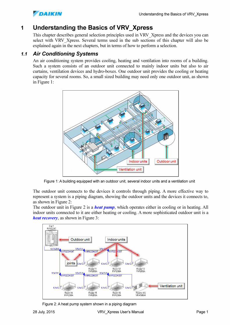
An air conditioning system provides cooling, heating and ventilation into rooms of a building.
Such a system consists of an outdoor unit connected to mainly indoor units but also to air
curtains, ventilation devices and hydro-boxes. One outdoor unit provides the cooling or heating
capacity for several rooms. So, a small sized building may need only one outdoor unit, as shown
in Figure 1:
The outdoor unit connects to the devices it controls through piping. A more effective way to
represent a system is a piping diagram, showing the outdoor units and the devices it connects to,
as shown in Figure 2:
The outdoor unit in Figure 2 is a heat pump, which operates either in cooling or in heating. All
indoor units connected to it are either heating or cooling. A more sophisticated outdoor unit is a
heat recovery, as shown in Figure 3:
Figure 1: A building equipped with an outdoor unit, several indoor units and a ventilation unit
Figure 2: A heat pump system shown in a piping diagram
Understanding the Basics of VRV_Xpress
28 July, 2015 VRV_Xpress User's Manual Page 2
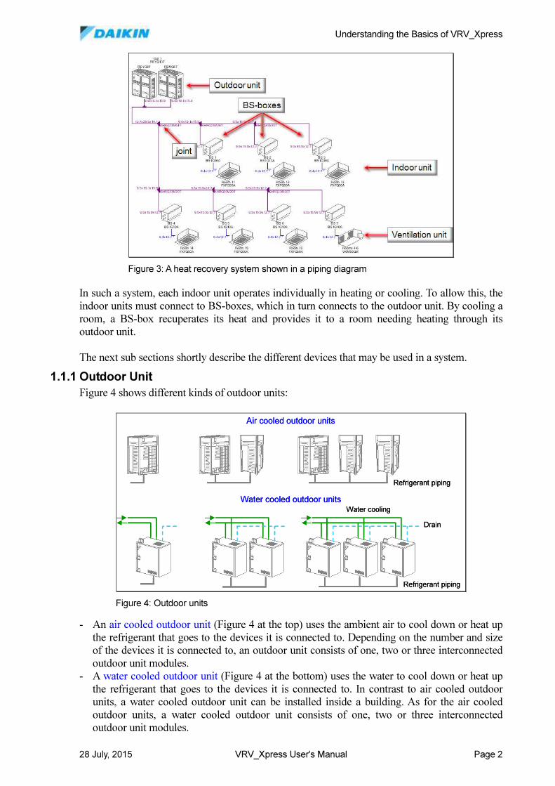
In such a system, each indoor unit operates individually in heating or cooling. To allow this, the
indoor units must connect to BS-boxes, which in turn connects to the outdoor unit. By cooling a
room, a BS-box recuperates its heat and provides it to a room needing heating through its
outdoor unit.
The next sub sections shortly describe the different devices that may be used in a system.
1.1.1 Outdoor Unit
Figure 4 shows different kinds of outdoor units:
- An air cooled outdoor unit (Figure 4 at the top) uses the ambient air to cool down or heat up
the refrigerant that goes to the devices it is connected to. Depending on the number and size
of the devices it is connected to, an outdoor unit consists of one, two or three interconnected
outdoor unit modules.
- A water cooled outdoor unit (Figure 4 at the bottom) uses the water to cool down or heat up
the refrigerant that goes to the devices it is connected to. In contrast to air cooled outdoor
units, a water cooled outdoor unit can be installed inside a building. As for the air cooled
outdoor units, a water cooled outdoor unit consists of one, two or three interconnected
outdoor unit modules.
Figure 3: A heat recovery system shown in a piping diagram
Water cooled outdoor units
Air cooled outdoor units
Drain
Water cooling
Refrigerant piping
Refrigerant piping
Water cooled outdoor units
Air cooled outdoor units
Drain
Water cooling
Refrigerant piping
Refrigerant piping
Figure 4: Outdoor units
Understanding the Basics of VRV_Xpress
28 July, 2015 VRV_Xpress User's Manual Page 3
1.1.2 Indoor unit
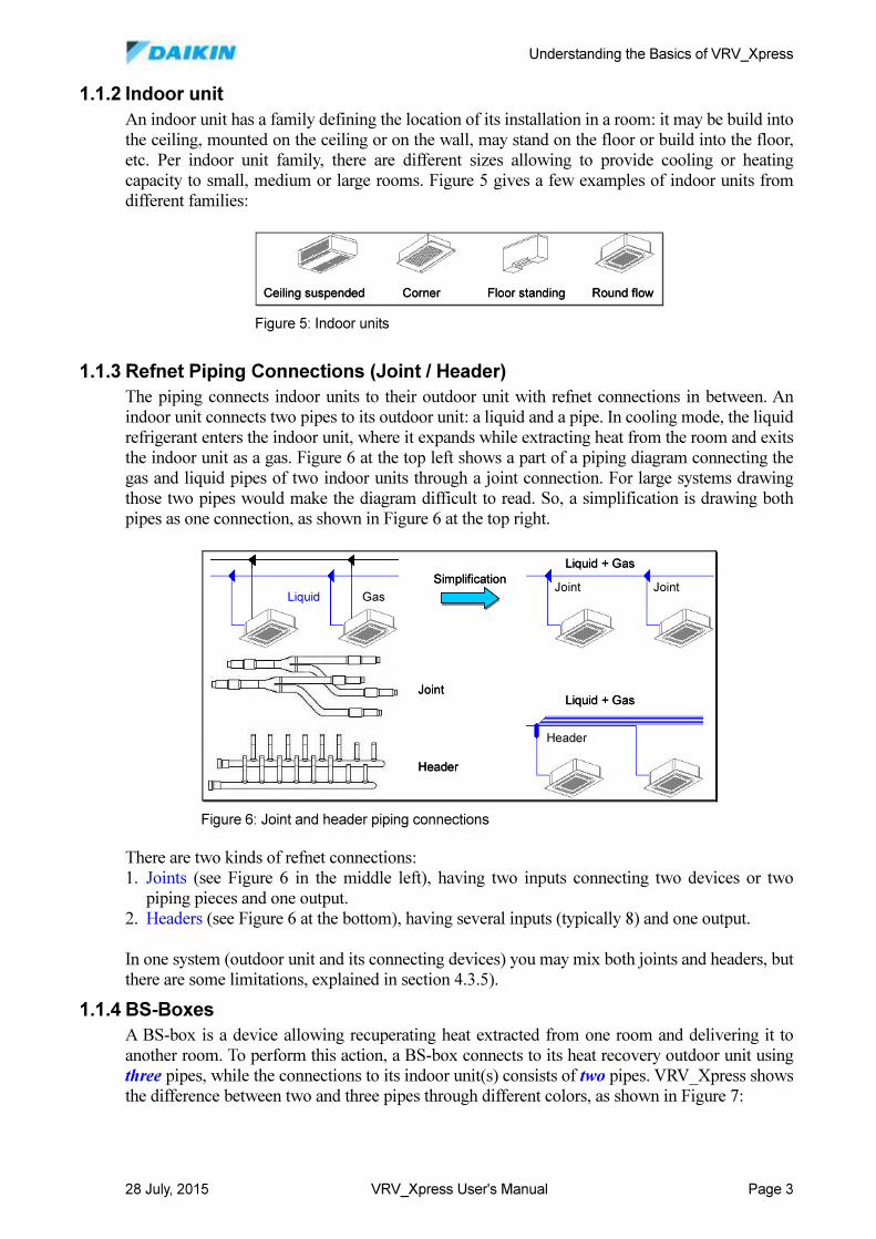
An indoor unit has a family defining the location of its installation in a room: it may be build into
the ceiling, mounted on the ceiling or on the wall, may stand on the floor or build into the floor,
etc. Per indoor unit family, there are different sizes allowing to provide cooling or heating
capacity to small, medium or large rooms. Figure 5 gives a few examples of indoor units from
different families:
1.1.3 Refnet Piping Connections (Joint / Header)
The piping connects indoor units to their outdoor unit with refnet connections in between. An
indoor unit connects two pipes to its outdoor unit: a liquid and a pipe. In cooling mode, the liquid
refrigerant enters the indoor unit, where it expands while extracting heat from the room and exits
the indoor unit as a gas. Figure 6 at the top left shows a part of a piping diagram connecting the
gas and liquid pipes of two indoor units through a joint connection. For large systems drawing
those two pipes would make the diagram difficult to read. So, a simplification is drawing both
pipes as one connection, as shown in Figure 6 at the top right.
There are two kinds of refnet connections:
1. Joints (see Figure 6 in the middle left), having two inputs connecting two devices or two
piping pieces and one output.
2. Headers (see Figure 6 at the bottom), having several inputs (typically 8) and one output.
In one system (outdoor unit and its connecting devices) you may mix both joints and headers, but
there are some limitations, explained in section 4.3.5).
1.1.4 BS-Boxes
A BS-box is a device allowing recuperating heat extracted from one room and delivering it to
another room. To perform this action, a BS-box connects to its heat recovery outdoor unit using
three pipes, while the connections to its indoor unit(s) consists of two pipes. VRV_Xpress shows
the difference between two and three pipes through different colors, as shown in Figure 7:
Ceiling suspended Corner Floor standing Round flowCeiling suspended Corner Floor standing Round flow
Figure 5: Indoor units
GasLiquid
Simplification
Liquid + Gas
Joint
Header
Liquid + Gas
Joint Joint
Header
GasLiquid
Simplification
Liquid + Gas
Joint
Header
Liquid + Gas
Joint Joint
Header
Figure 6: Joint and header piping connections
Understanding the Basics of VRV_Xpress
28 July, 2015 VRV_Xpress User's Manual Page 4
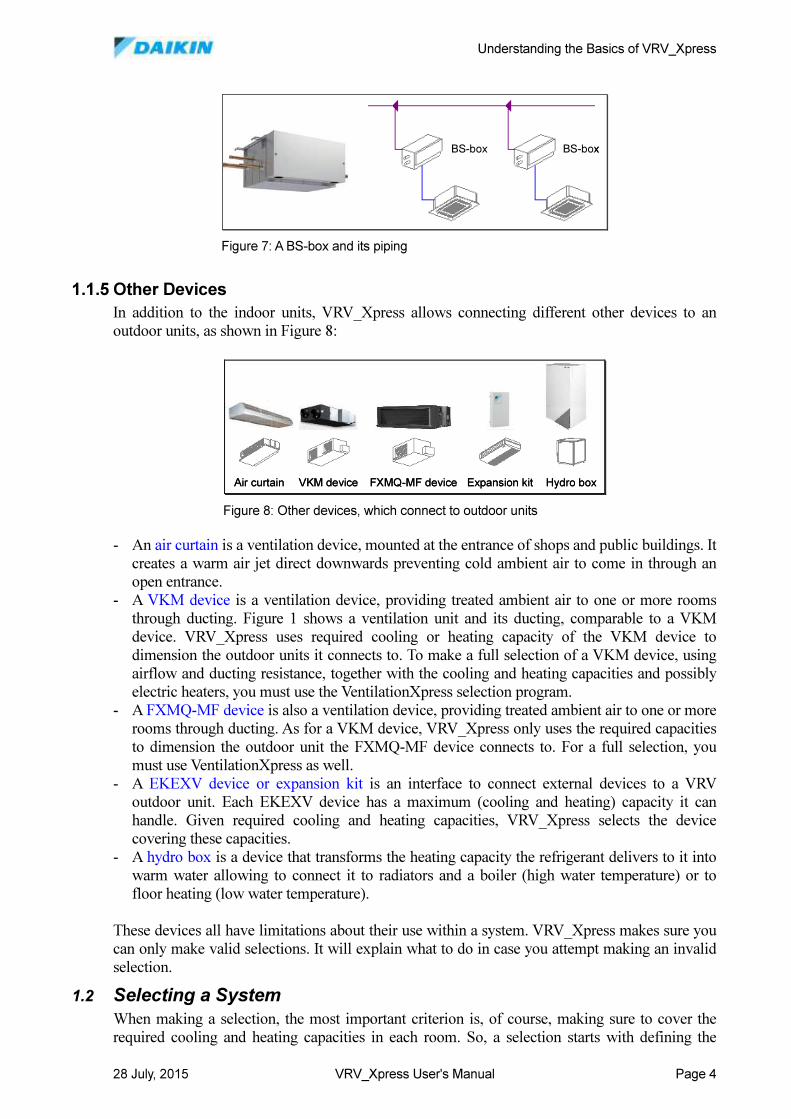
1.1.5 Other Devices
In addition to the indoor units, VRV_Xpress allows connecting different other devices to an
outdoor units, as shown in Figure 8:
- An air curtain is a ventilation device, mounted at the entrance of shops and public buildings. It
creates a warm air jet direct downwards preventing cold ambient air to come in through an
open entrance.
- A VKM device is a ventilation device, providing treated ambient air to one or more rooms
through ducting. Figure 1 shows a ventilation unit and its ducting, comparable to a VKM
device. VRV_Xpress uses required cooling or heating capacity of the VKM device to
dimension the outdoor units it connects to. To make a full selection of a VKM device, using
airflow and ducting resistance, together with the cooling and heating capacities and possibly
electric heaters, you must use the VentilationXpress selection program.
- A FXMQ-MF device is also a ventilation device, providing treated ambient air to one or more
rooms through ducting. As for a VKM device, VRV_Xpress only uses the required capacities
to dimension the outdoor unit the FXMQ-MF device connects to. For a full selection, you
must use VentilationXpress as well.
- A EKEXV device or expansion kit is an interface to connect external devices to a VRV
outdoor unit. Each EKEXV device has a maximum (cooling and heating) capacity it can
handle. Given required cooling and heating capacities, VRV_Xpress selects the device
covering these capacities.
- A hydro box is a device that transforms the heating capacity the refrigerant delivers to it into
warm water allowing to connect it to radiators and a boiler (high water temperature) or to
floor heating (low water temperature).
These devices all have limitations about their use within a system. VRV_Xpress makes sure you
can only make valid selections. It will explain what to do in case you attempt making an invalid
selection.
1.2 Selecting a System
When making a selection, the most important criterion is, of course, making sure to cover the
required cooling and heating capacities in each room. So, a selection starts with defining the
BS-box BS-boxBS-box BS-box
Figure 7: A BS-box and its piping
VKM device FXMQ-MF device Expansion kit Hydro boxAir curtain VKM device FXMQ-MF device Expansion kit Hydro boxAir curtain
Figure 8: Other devices, which connect to outdoor units
Understanding the Basics of VRV_Xpress
28 July, 2015 VRV_Xpress User's Manual Page 5
indoor units in the rooms. You may need some other devices as well, for example a few
ventilation devices or a hydro box to provide warm water.
The next step is deciding what kind of outdoor unit you will use: an air-cooled or a water-cooled
outdoor unit, a heat pump or a heat recovery system. In case you select a heat recovery system,
you must add BS-boxes (see section 4.3.2). The selected outdoor unit compensates for capacity
losses due to piping length or heat losses in pipes or extra capacity needed for defrost.
To connect indoor units and other devices, you only have to drag them to the required outdoor
unit or BS-box. VRV_Xpress will automatically use joints to interconnect the piping. It also
automatically dimensions the different indoor units, BS-boxes and outdoor unit to make sure the
indoor units cover their required cooling and heating capacities. VRV_Xpress also calculates an
initial wiring diagram showing the control wiring between the indoor units, possibly the BS-
boxes and the outdoor unit. This completes an initial selection.
However, you may want to enter more detailed information about the selected system:
- You can enter the piping length of each piping piece and define the number of bends in these
pieces. VRV_Xpress then applies all piping rules to dimension the required pipe diameters
and to correct refnet joints or headers. If necessary, VRV_Xpress also performs a size up of
some diameters to comply with piping rule limitations.
- You can define extra wiring options, such as connecting two indoor units to a single remote
controller allowing their concurrent operation.
- You can define a complete central control diagram allowing the management of several
systems by a central control system. This is useful in hotels, where rooms are managed from
the reception desk, or in large buildings, where a building management system controls the
systems remotely from a central location.
- In addition, you may also fine tune the selection itself, by downsizing an indoor unit, although
the smaller model does not cover the required capacities, but it comes close enough. This may
lead to a smaller or more competing system.
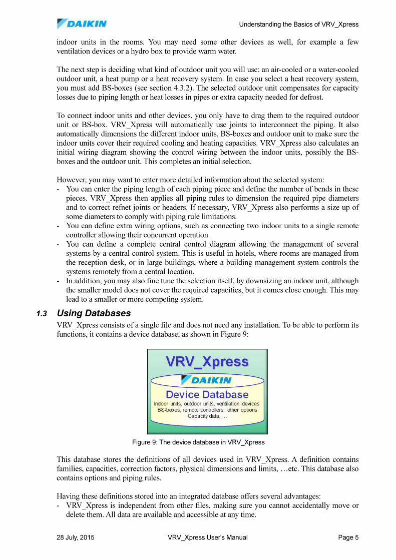
1.3 Using Databases
VRV_Xpress consists of a single file and does not need any installation. To be able to perform its
functions, it contains a device database, as shown in Figure 9:
This database stores the definitions of all devices used in VRV_Xpress. A definition contains
families, capacities, correction factors, physical dimensions and limits, …etc. This database also
contains options and piping rules.
Having these definitions stored into an integrated database offers several advantages:
- VRV_Xpress is independent from other files, making sure you cannot accidentally move or
delete them. All data are available and accessible at any time.
Figure 9: The device database in VRV_Xpress
Understanding the Basics of VRV_Xpress
28 July, 2015 VRV_Xpress User's Manual Page 6
- The device database has an expiration date, as Daikin may decide to launch new devices,
abolish existing ones or offer extra options. When the device database becomes outdated, so is
VRV_Xpress. A newer VRV_Xpress version automatically contains an updated device
database.
- The device database data are read-only, making sure you get the same results, even across
different projects.
- It is possible to have a VRV_Xpress version, which is specific for a given region, making sure
you only create projects using devices that are available in your region.
Initial Setup
28 July, 2015 VRV_Xpress User's Manual Page 7
2 Initial Setup
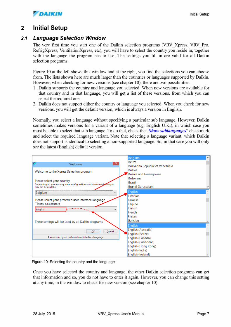
2.1 Language Selection Window
The very first time you start one of the Daikin selection programs (VRV_Xpress, VRV_Pro,
RefrigXpress, VentilationXpress, etc), you will have to select the country you reside in, together
with the language the program has to use. The settings you fill in are valid for all Daikin
selection programs.
Figure 10 at the left shows this window and at the right, you find the selections you can choose
from. The lists shown here are much larger than the countries or languages supported by Daikin.
However, when checking for new versions (see chapter 10), there are two possibilities:
1. Daikin supports the country and language you selected. When new versions are available for
that country and in that language, you will get a list of these versions, from which you can
select the required one.
2. Daikin does not support either the country or language you selected. When you check for new
versions, you will get the default version, which is always a version in English.
Normally, you select a language without specifying a particular sub language. However, Daikin
sometimes makes versions for a variant of a language (e.g. English U.K.), in which case you
must be able to select that sub language. To do that, check the “Show sublanguages” checkmark
and select the required language variant. Note that selecting a language variant, which Daikin
does not support is identical to selecting a non-supported language. So, in that case you will only
see the latest (English) default version.
Once you have selected the country and language, the other Daikin selection programs can get
that information and so, you do not have to enter it again. However, you can change this setting
at any time, in the window to check for new version (see chapter 10).
Figure 10: Selecting the country and the language
Initial Setup
28 July, 2015 VRV_Xpress User's Manual Page 8
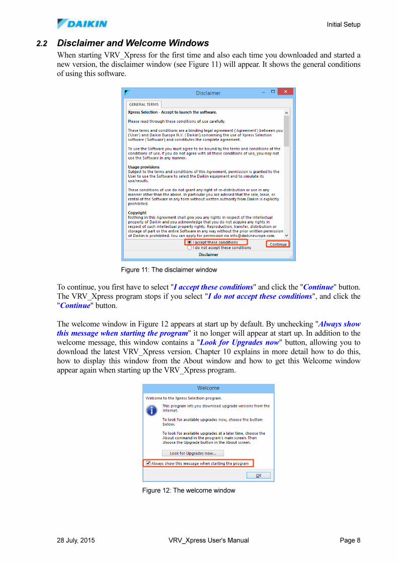
2.2 Disclaimer and Welcome Windows
When starting VRV_Xpress for the first time and also each time you downloaded and started a
new version, the disclaimer window (see Figure 11) will appear. It shows the general conditions
of using this software.
To continue, you first have to select "I accept these conditions" and click the "Continue" button.
The VRV_Xpress program stops if you select "I do not accept these conditions", and click the
"Continue" button.
The welcome window in Figure 12 appears at start up by default. By unchecking "Always show this message when starting the program" it no longer will appear at start up. In addition to the
welcome message, this window contains a "Look for Upgrades now" button, allowing you to
download the latest VRV_Xpress version. Chapter 10 explains in more detail how to do this,
how to display this window from the About window and how to get this Welcome window
appear again when starting up the VRV_Xpress program.
Figure 11: The disclaimer window
Figure 12: The welcome window
Initial Setup
28 July, 2015 VRV_Xpress User's Manual Page 9
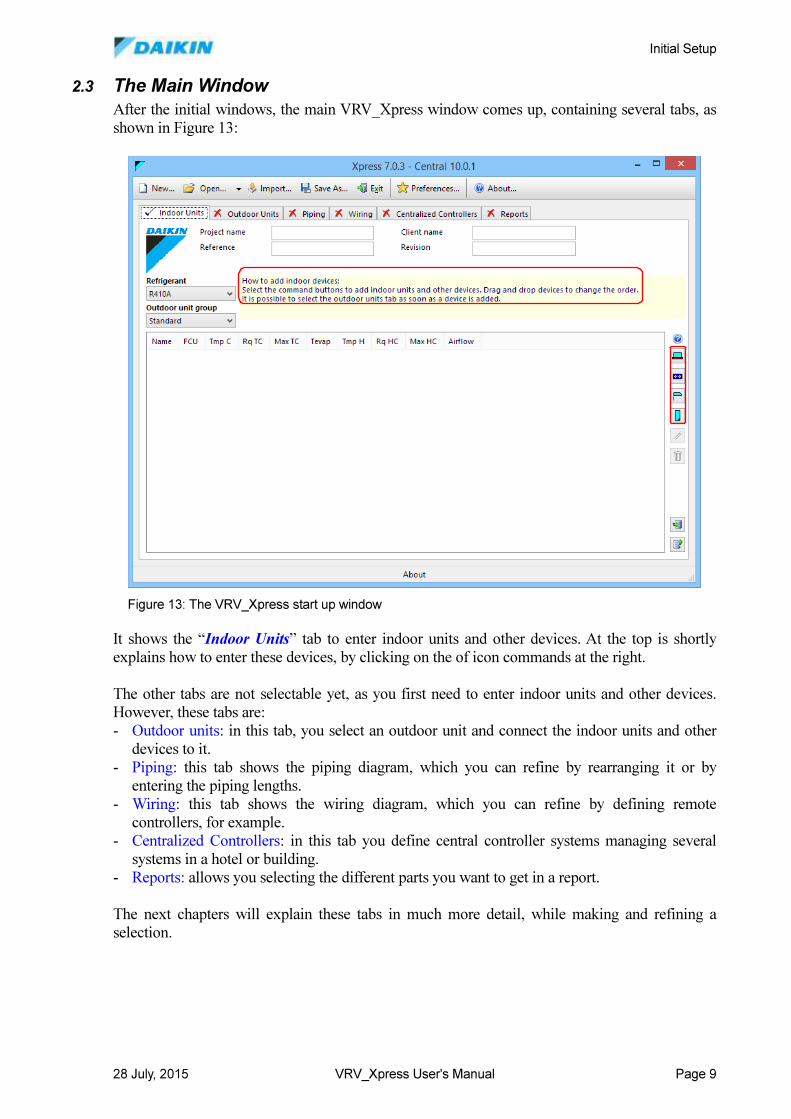
2.3 The Main Window
After the initial windows, the main VRV_Xpress window comes up, containing several tabs, as
shown in Figure 13:
It shows the “Indoor Units” tab to enter indoor units and other devices. At the top is shortly
explains how to enter these devices, by clicking on the of icon commands at the right.
The other tabs are not selectable yet, as you first need to enter indoor units and other devices.
However, these tabs are:
- Outdoor units: in this tab, you select an outdoor unit and connect the indoor units and other
devices to it.
- Piping: this tab shows the piping diagram, which you can refine by rearranging it or by
entering the piping lengths.
- Wiring: this tab shows the wiring diagram, which you can refine by defining remote
controllers, for example.
- Centralized Controllers: in this tab you define central controller systems managing several
systems in a hotel or building.
- Reports: allows you selecting the different parts you want to get in a report.
The next chapters will explain these tabs in much more detail, while making and refining a
selection.
Figure 13: The VRV_Xpress start up window
Making a Selection
28 July, 2015 VRV_Xpress User's Manual Page 10
3 Making a Selection This chapter explains the different steps to follow to make a first and simple selection, which
only uses indoor units and an outdoor unit. Next chapters refine this selection and combine other
devices as well.
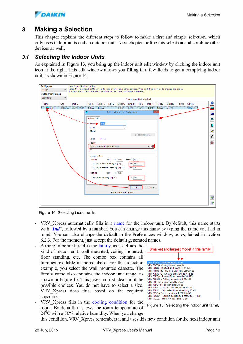
3.1 Selecting the Indoor Units
As explained in Figure 13, you bring up the indoor unit edit window by clicking the indoor unit
icon at the right. This edit window allows you filling in a few fields to get a complying indoor
unit, as shown in Figure 14:
- VRV_Xpress automatically fills in a name for the indoor unit. By default, this name starts
with “Ind”, followed by a number. You can change this name by typing the name you had in
mind. You can also change the default in the Preferences window, as explained in section
6.2.3. For the moment, just accept the default generated names.
- A more important field is the family, as it defines the
kind of indoor unit: wall mounted, ceiling mounted,
floor standing, etc. The combo box contains all
families available in the database. For this selection
example, you select the wall mounted cassette. The
family name also contains the indoor unit range, as
shown in Figure 15. This gives an first idea about the
possible choices. You do not have to select a size.
VRV_Xpress does this, based on the required
capacities.
- VRV_Xpress fills in the cooling condition for the
room. By default, it shows the room temperature of
240C with a 50% relative humidity. When you change
this condition, VRV_Xpress remembers it and uses this new condition for the next indoor unit
Figure 14: Selecting indoor units
Smallest and largest model in this familySmallest and largest model in this family
Figure 15: Selecting the indoor unit family
Making a Selection
28 July, 2015 VRV_Xpress User's Manual Page 11
selections.
- VRV_Xpress uses the required total capacity you enter to look up all indoor unit sizes for the
selected family and selects the one that covers the closest the required total capacity. If you
leave this field zero, VRV_Xpress does not consider it for the indoor unit selection.
- You can also enter the required sensible capacity to add an extra criterion that VRV_Xpress
must cover. If you leave this field zero, VRV_Xpress does not consider it for the indoor unit
selection.
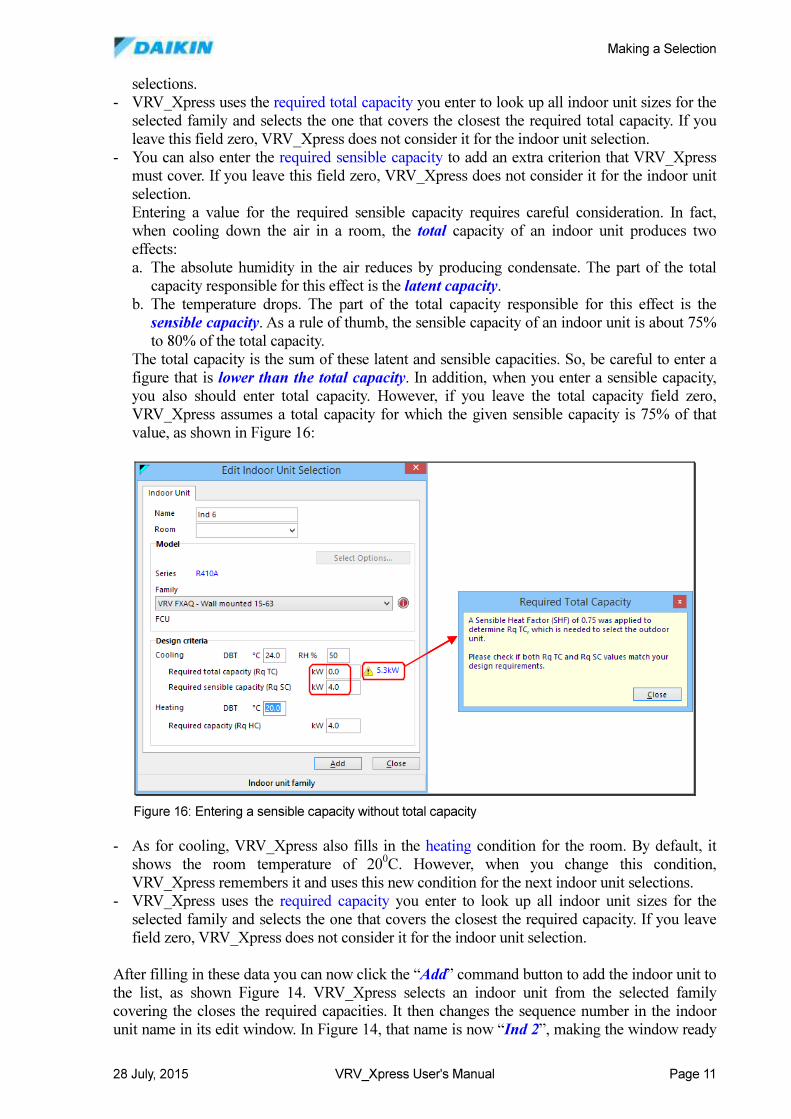
Entering a value for the required sensible capacity requires careful consideration. In fact,
when cooling down the air in a room, the total capacity of an indoor unit produces two
effects:
a. The absolute humidity in the air reduces by producing condensate. The part of the total
capacity responsible for this effect is the latent capacity.
b. The temperature drops. The part of the total capacity responsible for this effect is the
sensible capacity. As a rule of thumb, the sensible capacity of an indoor unit is about 75%
to 80% of the total capacity.
The total capacity is the sum of these latent and sensible capacities. So, be careful to enter a
figure that is lower than the total capacity. In addition, when you enter a sensible capacity,
you also should enter total capacity. However, if you leave the total capacity field zero,
VRV_Xpress assumes a total capacity for which the given sensible capacity is 75% of that
value, as shown in Figure 16:
- As for cooling, VRV_Xpress also fills in the heating condition for the room. By default, it
shows the room temperature of 200C. However, when you change this condition,
VRV_Xpress remembers it and uses this new condition for the next indoor unit selections.
- VRV_Xpress uses the required capacity you enter to look up all indoor unit sizes for the
selected family and selects the one that covers the closest the required capacity. If you leave
field zero, VRV_Xpress does not consider it for the indoor unit selection.
After filling in these data you can now click the “Add” command button to add the indoor unit to
the list, as shown Figure 14. VRV_Xpress selects an indoor unit from the selected family
covering the closes the required capacities. It then changes the sequence number in the indoor
unit name in its edit window. In Figure 14, that name is now “Ind 2”, making the window ready
Figure 16: Entering a sensible capacity without total capacity
Making a Selection
28 July, 2015 VRV_Xpress User's Manual Page 12
for the next indoor unit. If the next room in the building has the same requirements, all fields can
remain the same. Just click the “Add” command button again to add the next indoor unit.
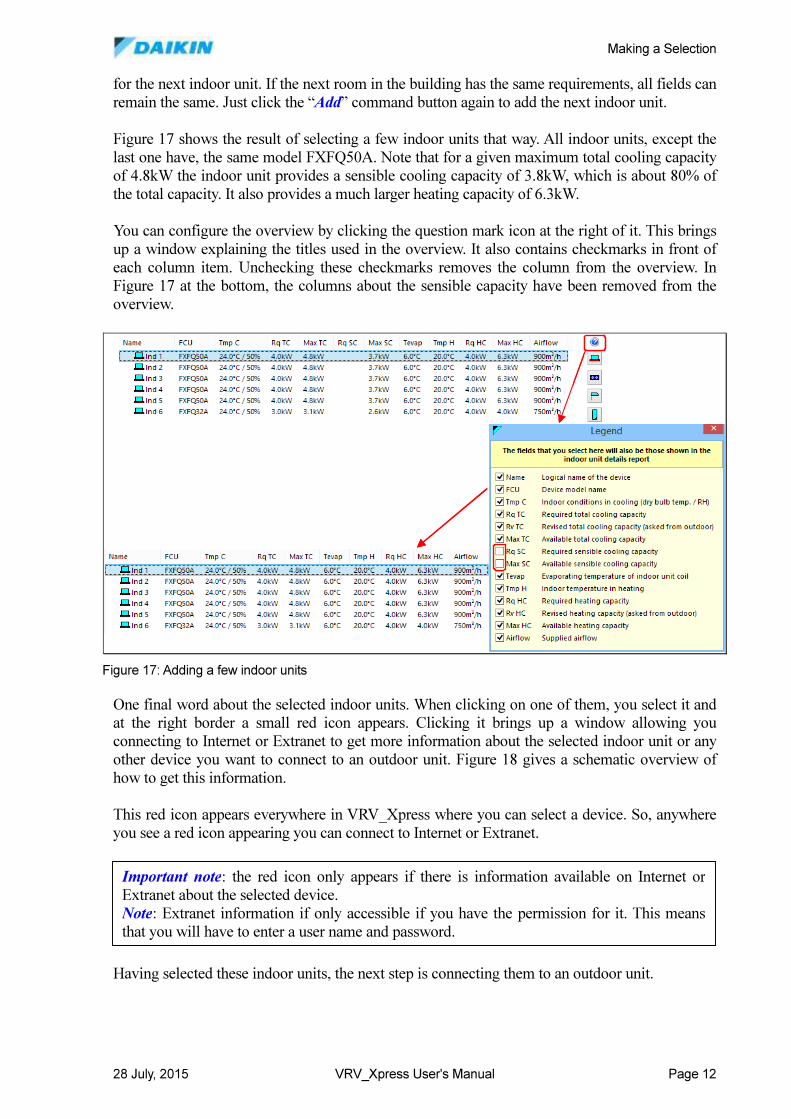
Figure 17 shows the result of selecting a few indoor units that way. All indoor units, except the
last one have, the same model FXFQ50A. Note that for a given maximum total cooling capacity
of 4.8kW the indoor unit provides a sensible cooling capacity of 3.8kW, which is about 80% of
the total capacity. It also provides a much larger heating capacity of 6.3kW.
You can configure the overview by clicking the question mark icon at the right of it. This brings
up a window explaining the titles used in the overview. It also contains checkmarks in front of
each column item. Unchecking these checkmarks removes the column from the overview. In
Figure 17 at the bottom, the columns about the sensible capacity have been removed from the
overview.
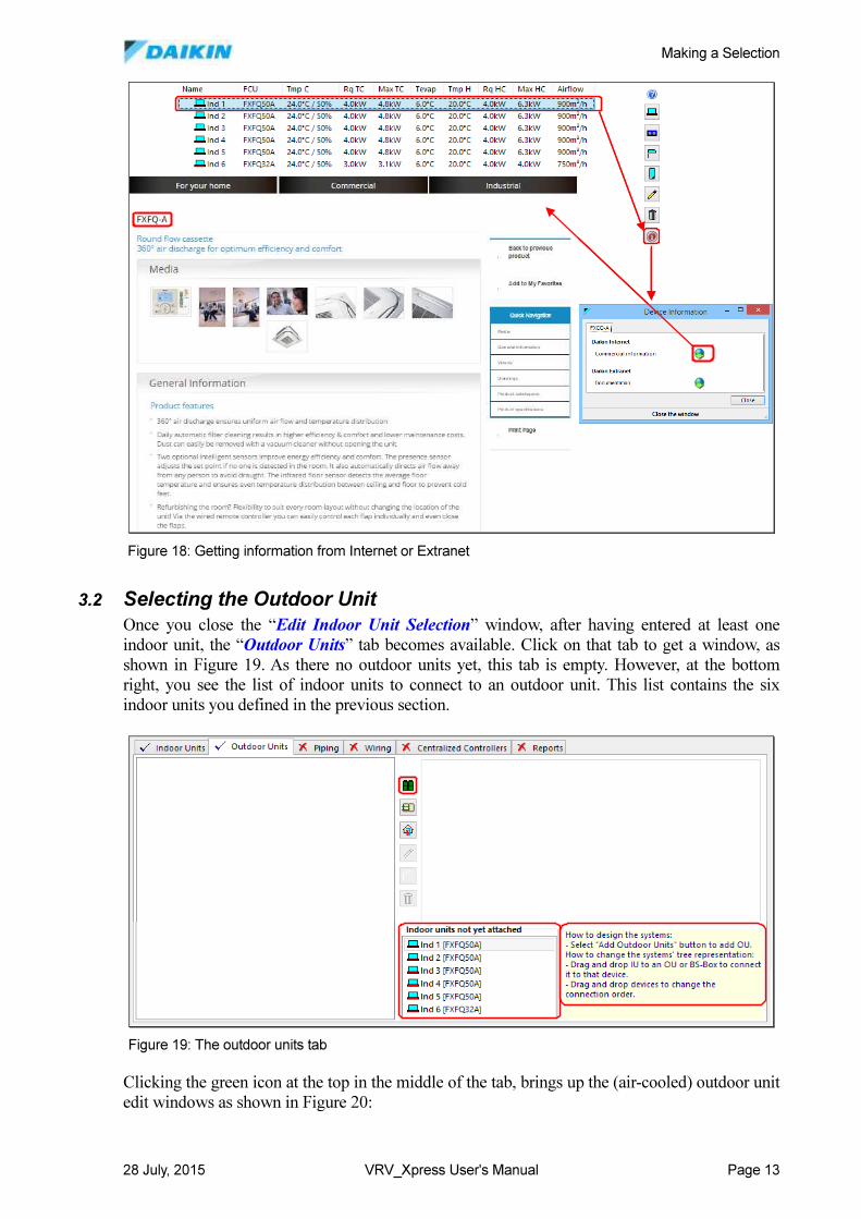
One final word about the selected indoor units. When clicking on one of them, you select it and
at the right border a small red icon appears. Clicking it brings up a window allowing you
connecting to Internet or Extranet to get more information about the selected indoor unit or any
other device you want to connect to an outdoor unit. Figure 18 gives a schematic overview of
how to get this information.
This red icon appears everywhere in VRV_Xpress where you can select a device. So, anywhere
you see a red icon appearing you can connect to Internet or Extranet.
Having selected these indoor units, the next step is connecting them to an outdoor unit.
Figure 17: Adding a few indoor units
Important note: the red icon only appears if there is information available on Internet or
Extranet about the selected device.
Note: Extranet information if only accessible if you have the permission for it. This means
that you will have to enter a user name and password.
Making a Selection
28 July, 2015 VRV_Xpress User's Manual Page 13
3.2 Selecting the Outdoor Unit
Once you close the “Edit Indoor Unit Selection” window, after having entered at least one
indoor unit, the “Outdoor Units” tab becomes available. Click on that tab to get a window, as
shown in Figure 19. As there no outdoor units yet, this tab is empty. However, at the bottom
right, you see the list of indoor units to connect to an outdoor unit. This list contains the six
indoor units you defined in the previous section.
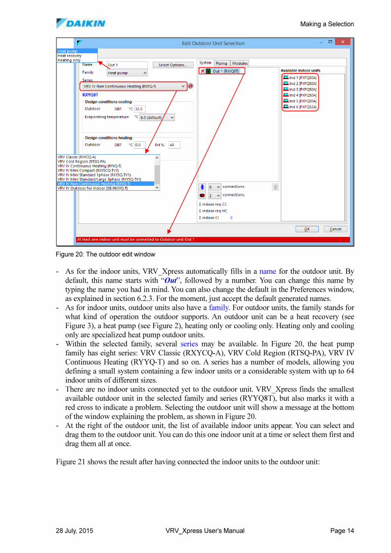
Clicking the green icon at the top in the middle of the tab, brings up the (air-cooled) outdoor unit
edit windows as shown in Figure 20:
Figure 18: Getting information from Internet or Extranet
Figure 19: The outdoor units tab
Making a Selection
28 July, 2015 VRV_Xpress User's Manual Page 14
- As for the indoor units, VRV_Xpress automatically fills in a name for the outdoor unit. By
default, this name starts with “Out”, followed by a number. You can change this name by
typing the name you had in mind. You can also change the default in the Preferences window,
as explained in section 6.2.3. For the moment, just accept the default generated names.
- As for indoor units, outdoor units also have a family. For outdoor units, the family stands for
what kind of operation the outdoor supports. An outdoor unit can be a heat recovery (see
Figure 3), a heat pump (see Figure 2), heating only or cooling only. Heating only and cooling
only are specialized heat pump outdoor units.
- Within the selected family, several series may be available. In Figure 20, the heat pump
family has eight series: VRV Classic (RXYCQ-A), VRV Cold Region (RTSQ-PA), VRV IV
Continuous Heating (RYYQ-T) and so on. A series has a number of models, allowing you
defining a small system containing a few indoor units or a considerable system with up to 64
indoor units of different sizes.
- There are no indoor units connected yet to the outdoor unit. VRV_Xpress finds the smallest
available outdoor unit in the selected family and series (RYYQ8T), but also marks it with a
red cross to indicate a problem. Selecting the outdoor unit will show a message at the bottom
of the window explaining the problem, as shown in Figure 20.
- At the right of the outdoor unit, the list of available indoor units appear. You can select and
drag them to the outdoor unit. You can do this one indoor unit at a time or select them first and
drag them all at once.
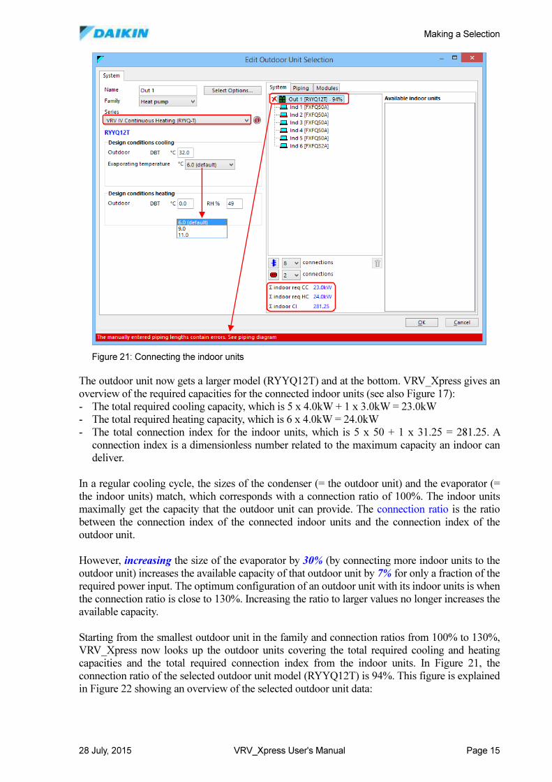
Figure 21 shows the result after having connected the indoor units to the outdoor unit:
Figure 20: The outdoor edit window
Making a Selection
28 July, 2015 VRV_Xpress User's Manual Page 15
The outdoor unit now gets a larger model (RYYQ12T) and at the bottom. VRV_Xpress gives an
overview of the required capacities for the connected indoor units (see also Figure 17):
- The total required cooling capacity, which is 5 x 4.0kW + 1 x 3.0kW = 23.0kW
- The total required heating capacity, which is 6 x 4.0kW = 24.0kW
- The total connection index for the indoor units, which is 5 x 50 + 1 x 31.25 = 281.25. A
connection index is a dimensionless number related to the maximum capacity an indoor can
deliver.
In a regular cooling cycle, the sizes of the condenser (= the outdoor unit) and the evaporator (=
the indoor units) match, which corresponds with a connection ratio of 100%. The indoor units
maximally get the capacity that the outdoor unit can provide. The connection ratio is the ratio
between the connection index of the connected indoor units and the connection index of the
outdoor unit.
However, increasing the size of the evaporator by 30% (by connecting more indoor units to the
outdoor unit) increases the available capacity of that outdoor unit by 7% for only a fraction of the
required power input. The optimum configuration of an outdoor unit with its indoor units is when
the connection ratio is close to 130%. Increasing the ratio to larger values no longer increases the
available capacity.
Starting from the smallest outdoor unit in the family and connection ratios from 100% to 130%,
VRV_Xpress now looks up the outdoor units covering the total required cooling and heating
capacities and the total required connection index from the indoor units. In Figure 21, the
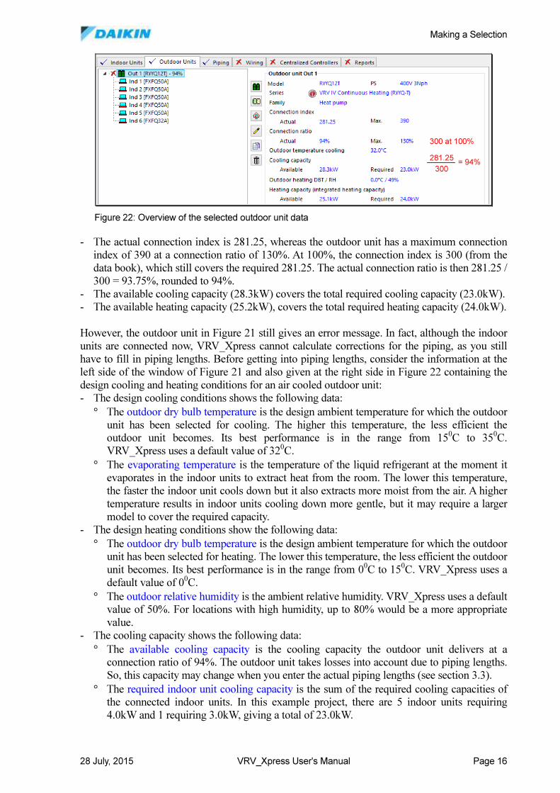
connection ratio of the selected outdoor unit model (RYYQ12T) is 94%. This figure is explained
in Figure 22 showing an overview of the selected outdoor unit data:
Figure 21: Connecting the indoor units
Making a Selection
28 July, 2015 VRV_Xpress User's Manual Page 16
- The actual connection index is 281.25, whereas the outdoor unit has a maximum connection
index of 390 at a connection ratio of 130%. At 100%, the connection index is 300 (from the
data book), which still covers the required 281.25. The actual connection ratio is then 281.25 /
300 = 93.75%, rounded to 94%.
- The available cooling capacity (28.3kW) covers the total required cooling capacity (23.0kW).
- The available heating capacity (25.2kW), covers the total required heating capacity (24.0kW).
However, the outdoor unit in Figure 21 still gives an error message. In fact, although the indoor
units are connected now, VRV_Xpress cannot calculate corrections for the piping, as you still
have to fill in piping lengths. Before getting into piping lengths, consider the information at the
left side of the window of Figure 21 and also given at the right side in Figure 22 containing the
design cooling and heating conditions for an air cooled outdoor unit:
- The design cooling conditions shows the following data:
° The outdoor dry bulb temperature is the design ambient temperature for which the outdoor
unit has been selected for cooling. The higher this temperature, the less efficient the
outdoor unit becomes. Its best performance is in the range from 150C to 35
0C.
VRV_Xpress uses a default value of 320C.
° The evaporating temperature is the temperature of the liquid refrigerant at the moment it
evaporates in the indoor units to extract heat from the room. The lower this temperature,
the faster the indoor unit cools down but it also extracts more moist from the air. A higher
temperature results in indoor units cooling down more gentle, but it may require a larger
model to cover the required capacity.
- The design heating conditions show the following data:
° The outdoor dry bulb temperature is the design ambient temperature for which the outdoor
unit has been selected for heating. The lower this temperature, the less efficient the outdoor
unit becomes. Its best performance is in the range from 00C to 15
0C. VRV_Xpress uses a
default value of 00C.
° The outdoor relative humidity is the ambient relative humidity. VRV_Xpress uses a default
value of 50%. For locations with high humidity, up to 80% would be a more appropriate
value.
- The cooling capacity shows the following data:
° The available cooling capacity is the cooling capacity the outdoor unit delivers at a
connection ratio of 94%. The outdoor unit takes losses into account due to piping lengths.
So, this capacity may change when you enter the actual piping lengths (see section 3.3).
° The required indoor unit cooling capacity is the sum of the required cooling capacities of
the connected indoor units. In this example project, there are 5 indoor units requiring
4.0kW and 1 requiring 3.0kW, giving a total of 23.0kW.
300 at 100%
281.25
300= 94%
300 at 100%
281.25
300= 94%
Figure 22: Overview of the selected outdoor unit data
Making a Selection
28 July, 2015 VRV_Xpress User's Manual Page 17
- The heating capacity shows the following data:
° The available integrated heating capacity is the heating capacity the outdoor unit delivers
at a connection ratio of 94%, but which is less than the published heating capacity. Indeed,
integrated heating capacity is the published capacity minus the capacity the outdoor unit
uses for ice defrosting. As the outdoor unit takes the losses into account due to the piping
lengths, this capacity may change when you enter the actual piping lengths.
° The required indoor unit heating capacity and the operational load have the same meaning
as for cooling.
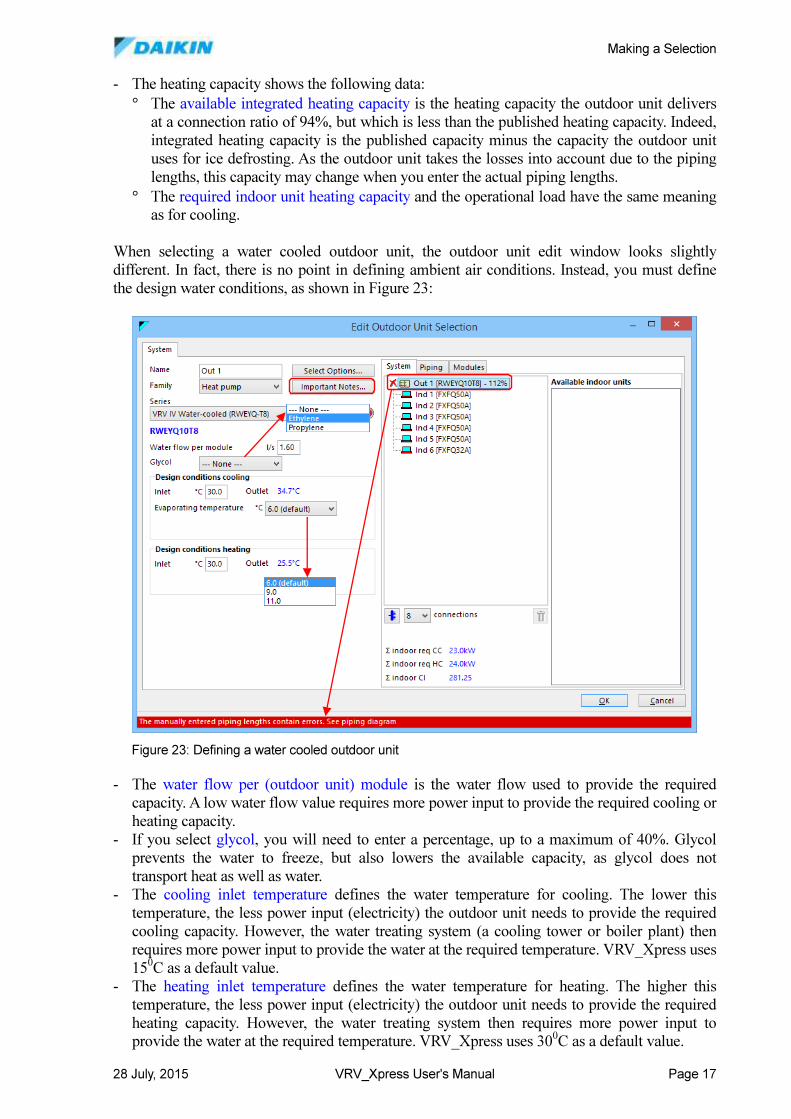
When selecting a water cooled outdoor unit, the outdoor unit edit window looks slightly
different. In fact, there is no point in defining ambient air conditions. Instead, you must define
the design water conditions, as shown in Figure 23:
- The water flow per (outdoor unit) module is the water flow used to provide the required
capacity. A low water flow value requires more power input to provide the required cooling or
heating capacity.
- If you select glycol, you will need to enter a percentage, up to a maximum of 40%. Glycol
prevents the water to freeze, but also lowers the available capacity, as glycol does not
transport heat as well as water.
- The cooling inlet temperature defines the water temperature for cooling. The lower this
temperature, the less power input (electricity) the outdoor unit needs to provide the required
cooling capacity. However, the water treating system (a cooling tower or boiler plant) then
requires more power input to provide the water at the required temperature. VRV_Xpress uses
150C as a default value.
- The heating inlet temperature defines the water temperature for heating. The higher this
temperature, the less power input (electricity) the outdoor unit needs to provide the required
heating capacity. However, the water treating system then requires more power input to
provide the water at the required temperature. VRV_Xpress uses 300C as a default value.
Figure 23: Defining a water cooled outdoor unit
Making a Selection
28 July, 2015 VRV_Xpress User's Manual Page 18
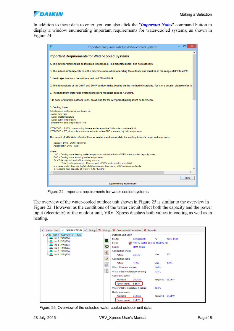
In addition to these data to enter, you can also click the "Important Notes" command button to
display a window enumerating important requirements for water-cooled systems, as shown in
Figure 24:
The overview of the water-cooled outdoor unit shown in Figure 25 is similar to the overview in
Figure 22. However, as the conditions of the water circuit affect both the capacity and the power
input (electricity) of the outdoor unit, VRV_Xpress displays both values in cooling as well as in
heating.
Figure 24: Important requirements for water-cooled systems
Figure 25: Overview of the selected water cooled outdoor unit data
Making a Selection
28 July, 2015 VRV_Xpress User's Manual Page 19
Before explaining the settings in the piping and modules tab in the previous figures, the next
sections describe the functions of the piping diagram. Section 3.6 explains these piping and
modules tabs. Closing the outdoor unit edit window will show the outdoor unit in the upper left
part of the outdoor units tab (see Figure 25, but also Figure 22).
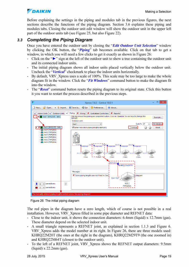
3.3 Completing the Piping Diagram
Once you have entered the outdoor unit by closing the “Edit Outdoor Unit Selection” window
by clicking the OK button, the “Piping” tab becomes available. Click on that tab to get a
window, in which you will need a few clicks to get it exactly as shown in Figure 26:
- Click on the “►” sign at the left of the outdoor unit to show a tree containing the outdoor unit
and its connected indoor units.
- The initial piping diagram shows all indoor units placed vertically below the outdoor unit.
Uncheck the “Vertical” checkmark to place the indoor units horizontally.
- By default, VRV_Xpress uses a scale of 100%. This scale may be too large to make the whole
diagram fit in the window. Click the “Fit Windows” command button to make the diagram fit
into the window.
- The “Reset” command button resets the piping diagram to its original state. Click this button
it you want to restart the process described in the previous steps.
The red pipes in the diagram have a zero length, which of course is not possible in a real
installation. However, VRV_Xpress filled in some pipe diameter and REFNET data:
- Close to the indoor unit, it shows the connection diameters: 6.4mm (liquid) x 12.7mm (gas).
These diameter depend on the selected indoor unit.
- A small triangle represents a REFNET joint, as explained in section 1.1.3 and Figure 6.
VRV_Xpress adds the model number at its right. In Figure 26, there are three models used:
KHRQ22M20T (the ones at the right in the diagram), KHRQ22M29T9 (the one zoomed in)
and KHRQ22M64T (closest to the outdoor unit).
- To the left of a REFNET joint, VRV_Xpress shows the REFNET output diameters: 9.5mm
(liquid) x 22.2mm (gas).
Figure 26: The initial piping diagram
Making a Selection
28 July, 2015 VRV_Xpress User's Manual Page 20
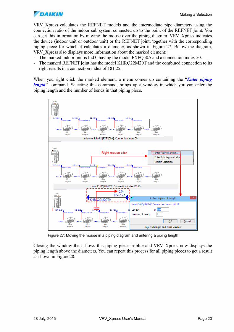
VRV_Xpress calculates the REFNET models and the intermediate pipe diameters using the
connection ratio of the indoor sub system connected up to the point of the REFNET joint. You
can get this information by moving the mouse over the piping diagram. VRV_Xpress indicates
the device (indoor unit or outdoor unit) or the REFNET joint, together with the corresponding
piping piece for which it calculates a diameter, as shown in Figure 27. Below the diagram,
VRV_Xpress also displays more information about the marked element:
- The marked indoor unit is Ind3, having the model FXFQ50A and a connection index 50.
- The marked REFNET joint has the model KHRQ22M20T and the combined connection to its
right results in a connection index of 181.25.
When you right click the marked element, a menu comes up containing the “Enter piping
length” command. Selecting this command, brings up a window in which you can enter the
piping length and the number of bends in that piping piece.
Closing the window then shows this piping piece in blue and VRV_Xpress now displays the
piping length above the diameters. You can repeat this process for all piping pieces to get a result
as shown in Figure 28:
Right mouse clickRight mouse click
Figure 27: Moving the mouse in a piping diagram and entering a piping length
Making a Selection
28 July, 2015 VRV_Xpress User's Manual Page 21
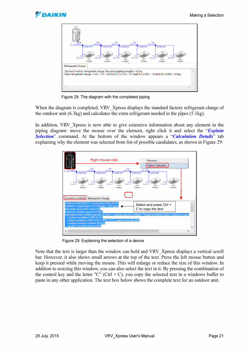
When the diagram is completed, VRV_Xpress displays the standard factory refrigerant charge of
the outdoor unit (6.3kg) and calculates the extra refrigerant needed in the pipes (5.1kg).
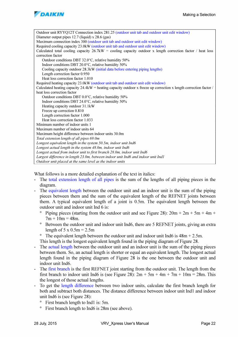
In addition, VRV_Xpress is now able to give extensive information about any element in the
piping diagram: move the mouse over the element, right click it and select the “Explain
Selection” command. At the bottom of the window appears a “Calculation Details” tab
explaining why the element was selected from list of possible candidates, as shown in Figure 29:
Note that the text is larger than the window can hold and VRV_Xpress displays a vertical scroll
bar. However, it also shows small arrows at the top of the text. Press the left mouse button and
keep it pressed while moving the mouse. This will enlarge or reduce the size of this window. In
addition to resizing this window, you can also select the text in it. By pressing the combination of
the control key and the letter "C" (Ctrl + C), you copy the selected text in a windows buffer to
paste in any other application. The text box below shows the complete text for an outdoor unit.
Figure 28: The diagram with the completed piping
Right mouse click
Select and press Ctrl +
C to copy the text
Right mouse click
Select and press Ctrl +
C to copy the text
Figure 29: Explaining the selection of a device
Making a Selection
28 July, 2015 VRV_Xpress User's Manual Page 22
What follows is a more detailed explanation of the text in italics:
- The total extension length of all pipes is the sum of the lengths of all piping pieces in the
diagram.
- The equivalent length between the outdoor unit and an indoor unit is the sum of the piping
pieces between them and the sum of the equivalent length of the REFNET joints between
them. A typical equivalent length of a joint is 0.5m. The equivalent length between the
outdoor unit and indoor unit Ind 6 is:
° Piping pieces (starting from the outdoor unit and see Figure 28): 20m + 2m + 5m + 4m +
7m + 10m = 48m.
° Between the outdoor unit and indoor unit Ind6, there are 5 REFNET joints, giving an extra
length of 5 x 0.5m = 2.5m
° The equivalent length between the outdoor unit and indoor unit Ind6 is 48m + 2.5m.
This length is the longest equivalent length found in the piping diagram of Figure 28.
- The actual length between the outdoor unit and an indoor unit is the sum of the piping pieces
between them. So, an actual length is shorter or equal an equivalent length. The longest actual
length found in the piping diagram of Figure 28 is the one between the outdoor unit and
indoor unit Ind6.
- The first branch is the first REFNET joint starting from the outdoor unit. The length from the
first branch to indoor unit Ind6 is (see Figure 28): 2m + 5m + 4m + 7m + 10m = 28m. This
the longest of those actual lengths.
- To get the length difference between two indoor units, calculate the first branch length for
both and subtract both distances. The distance difference between indoor unit Ind1 and indoor
unit Ind6 is (see Figure 28):
° First branch length to Ind1 is: 5m.
° First branch length to Ind6 is 28m (see above).
Outdoor unit RYYQ12T Connection index 281.25 (outdoor unit tab and outdoor unit edit window)
Diameter output pipes 12.7 (liquid) x 28.6 (gas)
Maximum connection index 300 (outdoor unit tab and outdoor unit edit window)
Required cooling capacity 23.0kW (outdoor unit tab and outdoor unit edit window)
Calculated total cooling capacity 26.7kW = cooling capacity outdoor x length correction factor / heat loss
correction factor
Outdoor conditions DBT 32.0°C, relative humidity 50%
Indoor conditions DBT 20.0°C, relative humidity 50%
Cooling capacity outdoor 28.3kW (initial data before entering piping lengths)
Length correction factor 0.950
Heat loss correction factor 1.010
Required heating capacity 23.0kW (outdoor unit tab and outdoor unit edit window)
Calculated heating capacity 24.4kW = heating capacity outdoor x freeze up correction x length correction factor /
heat loss correction factor
Outdoor conditions DBT 0.0°C, relative humidity 50%
Indoor conditions DBT 24.0°C, relative humidity 50%
Heating capacity outdoor 31.1kW
Freeze up correction 0.810
Length correction factor 1.000
Heat loss correction factor 1.033
Minimum number of indoor units 1
Maximum number of indoor units 64
Maximum height difference between indoor units 30.0m
Total extension length of all pipes 69.0m
Longest equivalent length in the system 50.5m, indoor unit Ind6
Longest actual length in the system 48.0m, indoor unit Ind6
Longest actual from indoor unit to first branch 28.0m, indoor unit Ind6
Largest difference in length 23.0m, between indoor unit Ind6 and indoor unit Ind1
Outdoor unit placed at the same level as the indoor units
Making a Selection
28 July, 2015 VRV_Xpress User's Manual Page 23
° Length difference between Ind6 and Ind1 is 28m – 5m.
- If both the outdoor and its indoor units are on the same floor, there is no height difference
between them. However, when installing indoor units on a different floor, the outdoor unit
may be placed below its indoor units (on the ground) or above them (on the roof). In both
cases, there is a vertical pipe connecting the floors. This pipe contributes to the piping length
(see section 3.6).
VRV_Xpress displays these piping length data, as there are several limits that you must respect.
For some of these limits, the solution to circumvent them is upsizing the pipe diameters. Other
limits are absolute and the piping has to stay within these limits to have a valid system selection.
Before getting deeper into the piping rules, you may have to refine the piping diagram to make it
consistent with the actual piping on a floor plan.
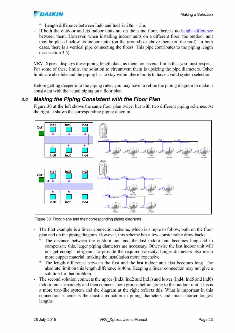
3.4 Making the Piping Consistent with the Floor Plan
Figure 30 at the left shows the same floor plan twice, but with two different piping schemes. At
the right, it shows the corresponding piping diagram.
- The first example is a linear connection scheme, which is simple to follow, both on the floor
plan and on the piping diagram. However, this scheme has a few considerable draw-backs:
° The distance between the outdoor unit and the last indoor unit becomes long and to
compensate this, larger piping diameters are necessary. Otherwise the last indoor unit will
not get enough refrigerant to provide the required capacity. Larger diameters also mean
more cupper material, making the installation more expensive.
° The length difference between the first and the last indoor unit also becomes long. The
absolute limit on this length difference is 40m. Keeping a linear connection may not give a
solution for that problem.
- The second solution connects the upper (Ind3, Ind2 and Ind1) and lower (Ind4, Ind5 and Ind6)
indoor units separately and then connects both groups before going to the outdoor unit. This is
a more tree-like system and the diagram at the right reflects this. What is important in this
connection scheme is the drastic reduction in piping diameters and much shorter longest
lengths.
Ind1 Ind2 Ind3
Ind6 Ind5 Ind4
Ind1 Ind2 Ind3
Ind6 Ind5 Ind4
Out1
Out1
Ind1 Ind2 Ind3
Ind6 Ind5 Ind4
Ind1 Ind2 Ind3
Ind6 Ind5 Ind4
Out1
Out1
Figure 30: Floor plans and their corresponding piping diagrams
Making a Selection
28 July, 2015 VRV_Xpress User's Manual Page 24
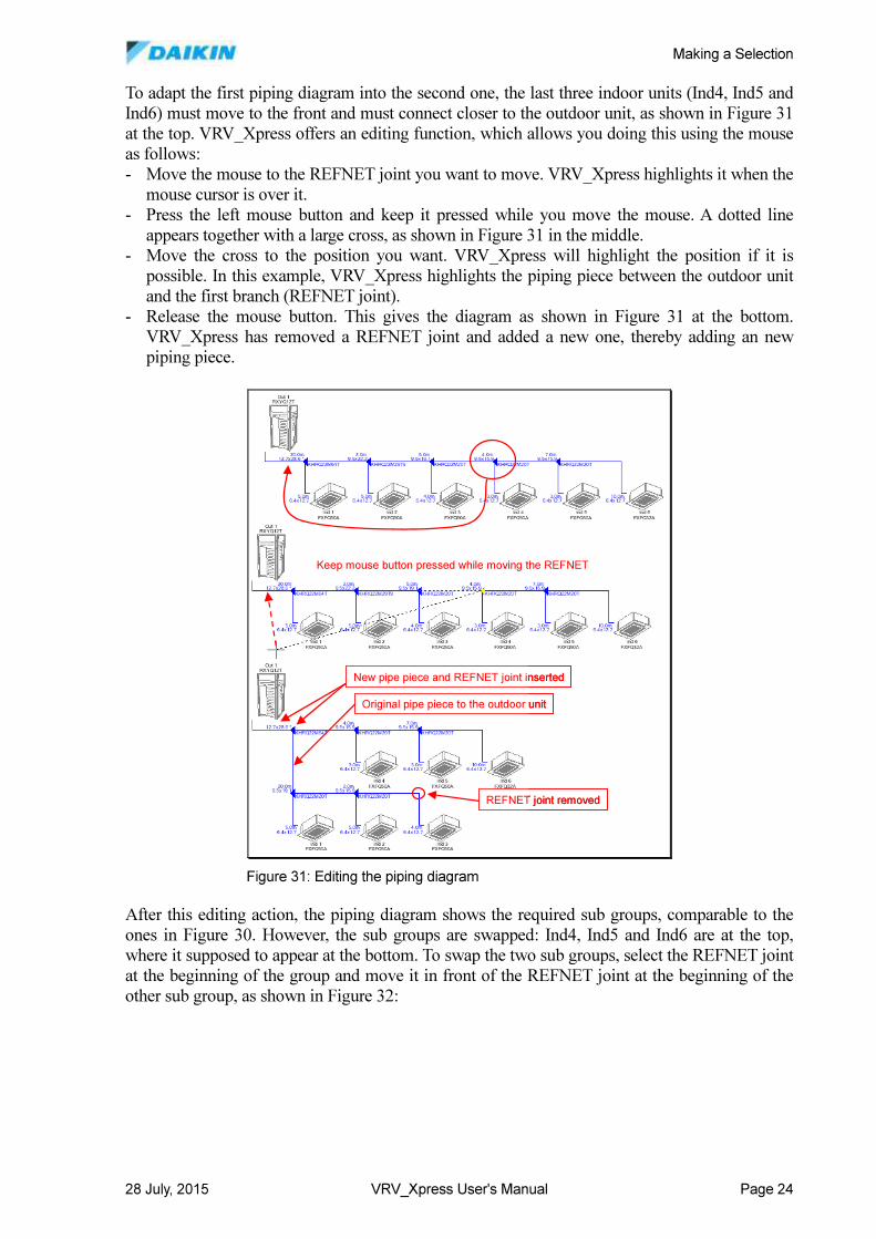
To adapt the first piping diagram into the second one, the last three indoor units (Ind4, Ind5 and
Ind6) must move to the front and must connect closer to the outdoor unit, as shown in Figure 31
at the top. VRV_Xpress offers an editing function, which allows you doing this using the mouse
as follows:
- Move the mouse to the REFNET joint you want to move. VRV_Xpress highlights it when the
mouse cursor is over it.
- Press the left mouse button and keep it pressed while you move the mouse. A dotted line
appears together with a large cross, as shown in Figure 31 in the middle.
- Move the cross to the position you want. VRV_Xpress will highlight the position if it is
possible. In this example, VRV_Xpress highlights the piping piece between the outdoor unit
and the first branch (REFNET joint).
- Release the mouse button. This gives the diagram as shown in Figure 31 at the bottom.
VRV_Xpress has removed a REFNET joint and added a new one, thereby adding an new
piping piece.
After this editing action, the piping diagram shows the required sub groups, comparable to the
ones in Figure 30. However, the sub groups are swapped: Ind4, Ind5 and Ind6 are at the top,
where it supposed to appear at the bottom. To swap the two sub groups, select the REFNET joint
at the beginning of the group and move it in front of the REFNET joint at the beginning of the
other sub group, as shown in Figure 32:
Keep mouse button pressed while moving the REFNET
Original pipe piece to the outdoor unit
New pipe piece and REFNET joint inserted
REFNET joint removed
Keep mouse button pressed while moving the REFNET
Original pipe piece to the outdoor unit
New pipe piece and REFNET joint inserted
REFNET joint removed
Figure 31: Editing the piping diagram
Making a Selection
28 July, 2015 VRV_Xpress User's Manual Page 25
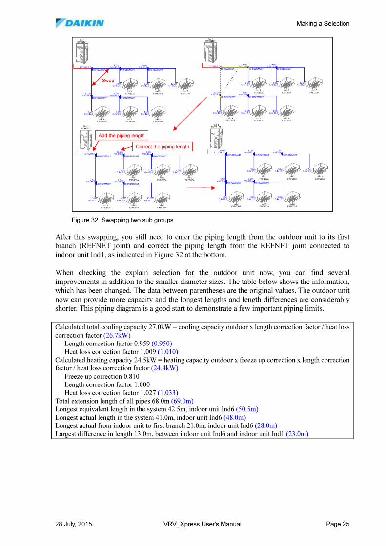
After this swapping, you still need to enter the piping length from the outdoor unit to its first
branch (REFNET joint) and correct the piping length from the REFNET joint connected to
indoor unit Ind1, as indicated in Figure 32 at the bottom.
When checking the explain selection for the outdoor unit now, you can find several
improvements in addition to the smaller diameter sizes. The table below shows the information,
which has been changed. The data between parentheses are the original values. The outdoor unit
now can provide more capacity and the longest lengths and length differences are considerably
shorter. This piping diagram is a good start to demonstrate a few important piping limits.
Calculated total cooling capacity 27.0kW = cooling capacity outdoor x length correction factor / heat loss
correction factor (26.7kW)
Length correction factor 0.959 (0.950)
Heat loss correction factor 1.009 (1.010)
Calculated heating capacity 24.5kW = heating capacity outdoor x freeze up correction x length correction
factor / heat loss correction factor (24.4kW)
Freeze up correction 0.810
Length correction factor 1.000
Heat loss correction factor 1.027 (1.033)
Total extension length of all pipes 68.0m (69.0m)
Longest equivalent length in the system 42.5m, indoor unit Ind6 (50.5m)
Longest actual length in the system 41.0m, indoor unit Ind6 (48.0m)
Longest actual from indoor unit to first branch 21.0m, indoor unit Ind6 (28.0m)
Largest difference in length 13.0m, between indoor unit Ind6 and indoor unit Ind1 (23.0m)
Swap
Add the piping length
Correct the piping length
Swap
Add the piping length
Correct the piping length
Figure 32: Swapping two sub groups
Making a Selection
28 July, 2015 VRV_Xpress User's Manual Page 26
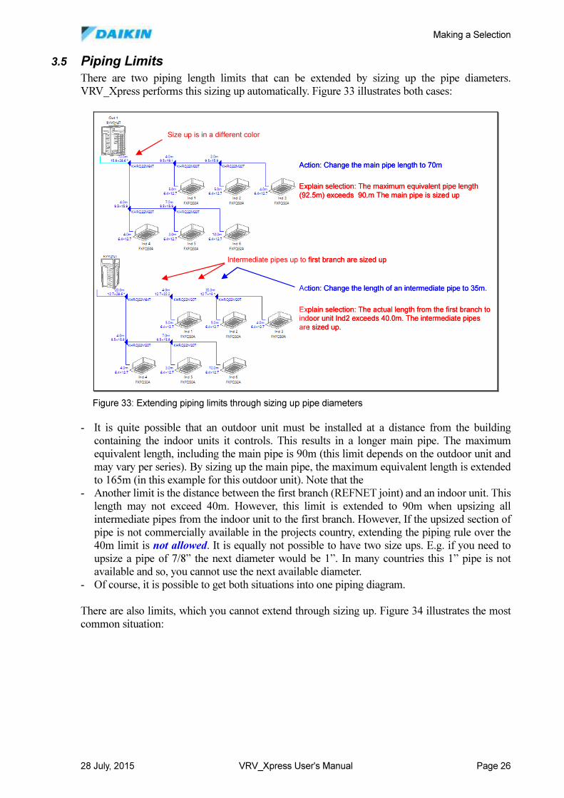
3.5 Piping Limits
There are two piping length limits that can be extended by sizing up the pipe diameters.
VRV_Xpress performs this sizing up automatically. Figure 33 illustrates both cases:
- It is quite possible that an outdoor unit must be installed at a distance from the building
containing the indoor units it controls. This results in a longer main pipe. The maximum
equivalent length, including the main pipe is 90m (this limit depends on the outdoor unit and
may vary per series). By sizing up the main pipe, the maximum equivalent length is extended
to 165m (in this example for this outdoor unit). Note that the
- Another limit is the distance between the first branch (REFNET joint) and an indoor unit. This
length may not exceed 40m. However, this limit is extended to 90m when upsizing all
intermediate pipes from the indoor unit to the first branch. However, If the upsized section of
pipe is not commercially available in the projects country, extending the piping rule over the
40m limit is not allowed. It is equally not possible to have two size ups. E.g. if you need to
upsize a pipe of 7/8” the next diameter would be 1”. In many countries this 1” pipe is not
available and so, you cannot use the next available diameter.
- Of course, it is possible to get both situations into one piping diagram.
There are also limits, which you cannot extend through sizing up. Figure 34 illustrates the most
common situation:
Explain selection: The maximum equivalent pipe length
(92.5m) exceeds 90.m The main pipe is sized up
Action: Change the main pipe length to 70m
Size up is in a different color
Explain selection: The actual length from the first branch to indoor unit Ind2 exceeds 40.0m. The intermediate pipes
are sized up.
Action: Change the length of an intermediate pipe to 35m.
Intermediate pipes up to first branch are sized up
Figure 33: Extending piping limits through sizing up pipe diameters
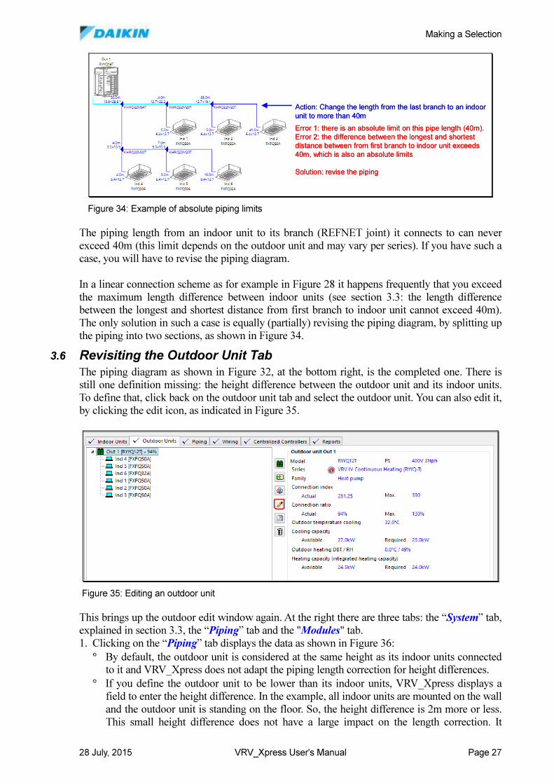
Making a Selection
28 July, 2015 VRV_Xpress User's Manual Page 27
The piping length from an indoor unit to its branch (REFNET joint) it connects to can never
exceed 40m (this limit depends on the outdoor unit and may vary per series). If you have such a
case, you will have to revise the piping diagram.
In a linear connection scheme as for example in Figure 28 it happens frequently that you exceed
the maximum length difference between indoor units (see section 3.3: the length difference
between the longest and shortest distance from first branch to indoor unit cannot exceed 40m).
The only solution in such a case is equally (partially) revising the piping diagram, by splitting up
the piping into two sections, as shown in Figure 34.
3.6 Revisiting the Outdoor Unit Tab
The piping diagram as shown in Figure 32, at the bottom right, is the completed one. There is
still one definition missing: the height difference between the outdoor unit and its indoor units.
To define that, click back on the outdoor unit tab and select the outdoor unit. You can also edit it,
by clicking the edit icon, as indicated in Figure 35.
This brings up the outdoor edit window again. At the right there are three tabs: the “System” tab,
explained in section 3.3, the “Piping” tab and the "Modules" tab.
1. Clicking on the “Piping” tab displays the data as shown in Figure 36:
° By default, the outdoor unit is considered at the same height as its indoor units connected
to it and VRV_Xpress does not adapt the piping length correction for height differences.
° If you define the outdoor unit to be lower than its indoor units, VRV_Xpress displays a
field to enter the height difference. In the example, all indoor units are mounted on the wall
and the outdoor unit is standing on the floor. So, the height difference is 2m more or less.
This small height difference does not have a large impact on the length correction. It
Error 1: there is an absolute limit on this pipe length (40m).
Error 2: the difference between the longest and shortest
distance between from first branch to indoor unit exceeds
40m, which is also an absolute limits
Solution: revise the piping
Action: Change the length from the last branch to an indoor
unit to more than 40m
Figure 34: Example of absolute piping limits
Figure 35: Editing an outdoor unit
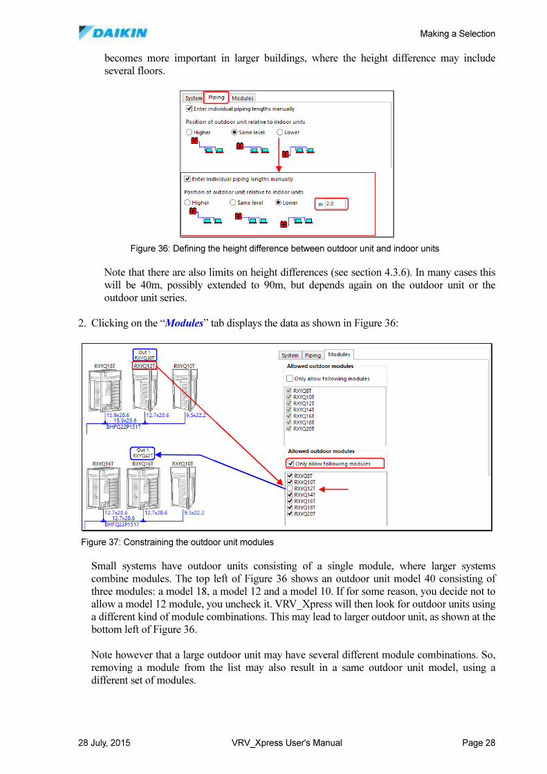
Making a Selection
28 July, 2015 VRV_Xpress User's Manual Page 28
becomes more important in larger buildings, where the height difference may include
several floors.
Note that there are also limits on height differences (see section 4.3.6). In many cases this
will be 40m, possibly extended to 90m, but depends again on the outdoor unit or the
outdoor unit series.
2. Clicking on the “Modules” tab displays the data as shown in Figure 36:
Small systems have outdoor units consisting of a single module, where larger systems
combine modules. The top left of Figure 36 shows an outdoor unit model 40 consisting of
three modules: a model 18, a model 12 and a model 10. If for some reason, you decide not to
allow a model 12 module, you uncheck it. VRV_Xpress will then look for outdoor units using
a different kind of module combinations. This may lead to larger outdoor unit, as shown at the
bottom left of Figure 36.
Note however that a large outdoor unit may have several different module combinations. So,
removing a module from the list may also result in a same outdoor unit model, using a
different set of modules.
Figure 36: Defining the height difference between outdoor unit and indoor units
Figure 37: Constraining the outdoor unit modules
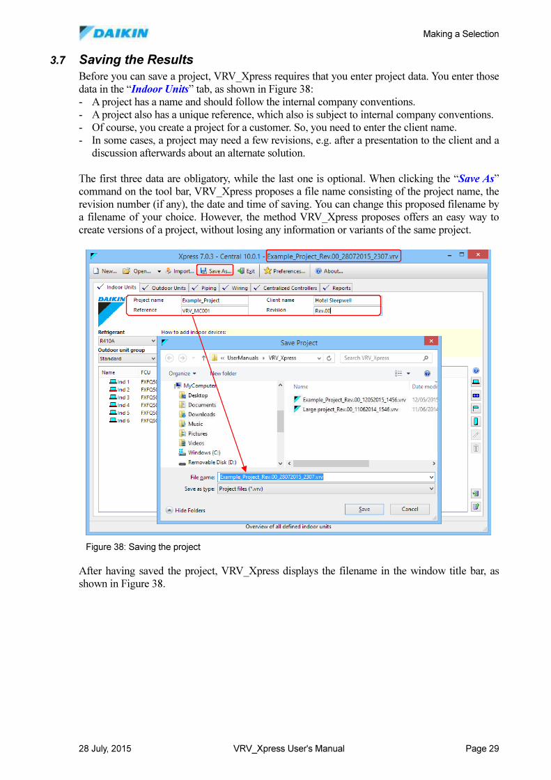
Making a Selection
28 July, 2015 VRV_Xpress User's Manual Page 29
3.7 Saving the Results
Before you can save a project, VRV_Xpress requires that you enter project data. You enter those
data in the “Indoor Units” tab, as shown in Figure 38:
- A project has a name and should follow the internal company conventions.
- A project also has a unique reference, which also is subject to internal company conventions.
- Of course, you create a project for a customer. So, you need to enter the client name.
- In some cases, a project may need a few revisions, e.g. after a presentation to the client and a
discussion afterwards about an alternate solution.
The first three data are obligatory, while the last one is optional. When clicking the “Save As”
command on the tool bar, VRV_Xpress proposes a file name consisting of the project name, the
revision number (if any), the date and time of saving. You can change this proposed filename by
a filename of your choice. However, the method VRV_Xpress proposes offers an easy way to
create versions of a project, without losing any information or variants of the same project.
After having saved the project, VRV_Xpress displays the filename in the window title bar, as
shown in Figure 38.
Figure 38: Saving the project
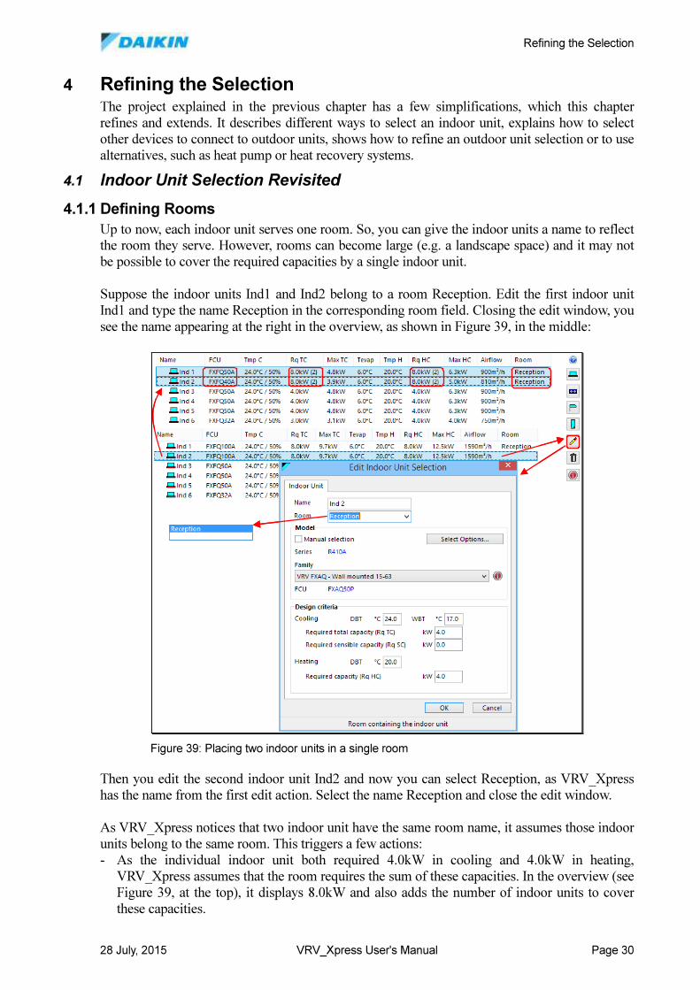
Refining the Selection
28 July, 2015 VRV_Xpress User's Manual Page 30
4 Refining the Selection The project explained in the previous chapter has a few simplifications, which this chapter
refines and extends. It describes different ways to select an indoor unit, explains how to select
other devices to connect to outdoor units, shows how to refine an outdoor unit selection or to use
alternatives, such as heat pump or heat recovery systems.
4.1 Indoor Unit Selection Revisited
4.1.1 Defining Rooms
Up to now, each indoor unit serves one room. So, you can give the indoor units a name to reflect
the room they serve. However, rooms can become large (e.g. a landscape space) and it may not
be possible to cover the required capacities by a single indoor unit.
Suppose the indoor units Ind1 and Ind2 belong to a room Reception. Edit the first indoor unit
Ind1 and type the name Reception in the corresponding room field. Closing the edit window, you
see the name appearing at the right in the overview, as shown in Figure 39, in the middle:
Then you edit the second indoor unit Ind2 and now you can select Reception, as VRV_Xpress
has the name from the first edit action. Select the name Reception and close the edit window.
As VRV_Xpress notices that two indoor unit have the same room name, it assumes those indoor
units belong to the same room. This triggers a few actions:
- As the individual indoor unit both required 4.0kW in cooling and 4.0kW in heating,
VRV_Xpress assumes that the room requires the sum of these capacities. In the overview (see
Figure 39, at the top), it displays 8.0kW and also adds the number of indoor units to cover
these capacities.
Figure 39: Placing two indoor units in a single room
Refining the Selection
28 July, 2015 VRV_Xpress User's Manual Page 31
- To select the indoor units, VRV_Xpress now uses a few steps:
° Divide the required capacities of the room by the number of indoor units in the room. So,
each indoor unit still has 4.0kW as a required cooling and heating capacity.
° Select the first indoor unit Ind1 that covers these divided capacity values. The resulting
indoor unit is still a model FXFQ50A.
° The required capacities of the room are now reduced by the capacities covered by this first
indoor unit Ind1 and divided by the number of indoor units less 1 in the room. Indoor unit
Ind2 now has to cover 8.0kW – 4.8kW = 3.2kW for cooling and 8.0kW – 6.3kW = 1.5kW
for heating. The result is that indoor unit Ind2 now has a model FXFQ40A.
° The process now repeats for the next indoor unit, until all indoor units in the room have
been selected. This results in a selection of indoor units that covers the required capacities
in a closest possible way.
The situation becomes a bit more complicated if a room contains indoor units served by different
outdoor units. Suppose the two indoor units in room reception are connected to two different
outdoor units. VRV_Xpress then uses slightly different steps:
- Divide the required capacities of the room by the number of indoor units in the room. So,
each indoor unit still has 4.0kW as a required cooling and heating capacity.
- Create two groups of indoor units: the group connected to the first outdoor unit and another
group connected to the second.
- Treat each group as a room and select the indoor units in these rooms as described as above.
- Note that the extra capacities that would be available in the first group have no influence on
the selection in the second group and vice versa. In the example, each group contains one
indoor unit. So, the selection results in a model FXFQ50A for both indoor units Ind1 and
Ind2. This is the same result as when having individual indoor units.
Note:
When using groups of indoor units in a room and connected to different outdoor units,
you will need to make sure that all indoor units operate in the same mode (cooling or
heating) or at least make sure the indoor units do not operate in different modes (a group
in cooling and another in heating). You can do this using a centralized control system,
explained in section 5.2.
Note:
When selecting indoor units on total and sensible capacities, this method may lead to a
non-selection of the last indoor unit. In fact,. after the selection (total and sensible) of the
first indoor unit, the next indoor units must provide the capacities (total and sensible) for
the remaining capacities. If the difference between the provided total and sensible
capacities of this first indoor unit is large, the remaining indoor units must provide more
sensible capacity. The last indoor unit may then indeed have to cope with a large sensible
load, possible as large as the total load, resulting in a non-selection. Currently, there is no
solution for that situation.
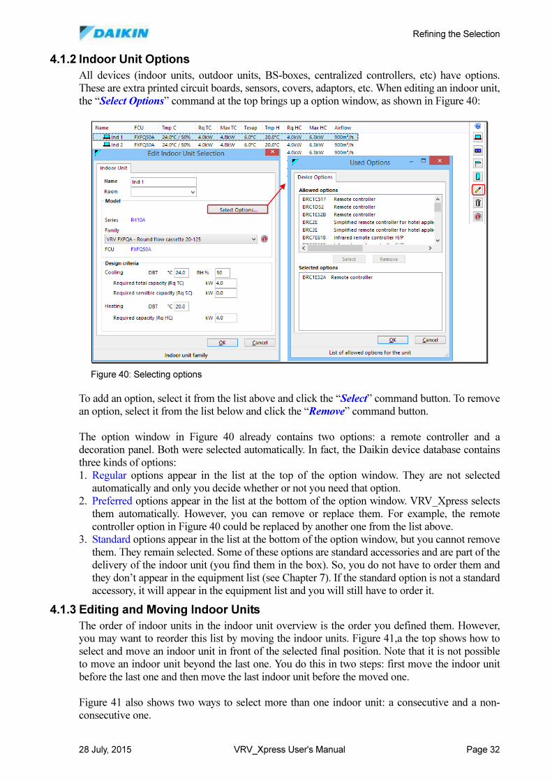
Refining the Selection
28 July, 2015 VRV_Xpress User's Manual Page 32
4.1.2 Indoor Unit Options
All devices (indoor units, outdoor units, BS-boxes, centralized controllers, etc) have options.
These are extra printed circuit boards, sensors, covers, adaptors, etc. When editing an indoor unit,
the “Select Options” command at the top brings up a option window, as shown in Figure 40:
To add an option, select it from the list above and click the “Select” command button. To remove
an option, select it from the list below and click the “Remove” command button.
The option window in Figure 40 already contains two options: a remote controller and a
decoration panel. Both were selected automatically. In fact, the Daikin device database contains
three kinds of options:
1. Regular options appear in the list at the top of the option window. They are not selected
automatically and only you decide whether or not you need that option.
2. Preferred options appear in the list at the bottom of the option window. VRV_Xpress selects
them automatically. However, you can remove or replace them. For example, the remote
controller option in Figure 40 could be replaced by another one from the list above.
3. Standard options appear in the list at the bottom of the option window, but you cannot remove
them. They remain selected. Some of these options are standard accessories and are part of the
delivery of the indoor unit (you find them in the box). So, you do not have to order them and
they don’t appear in the equipment list (see Chapter 7). If the standard option is not a standard
accessory, it will appear in the equipment list and you will still have to order it.
4.1.3 Editing and Moving Indoor Units
The order of indoor units in the indoor unit overview is the order you defined them. However,
you may want to reorder this list by moving the indoor units. Figure 41,a the top shows how to
select and move an indoor unit in front of the selected final position. Note that it is not possible
to move an indoor unit beyond the last one. You do this in two steps: first move the indoor unit
before the last one and then move the last indoor unit before the moved one.
Figure 41 also shows two ways to select more than one indoor unit: a consecutive and a non-
consecutive one.
Figure 40: Selecting options
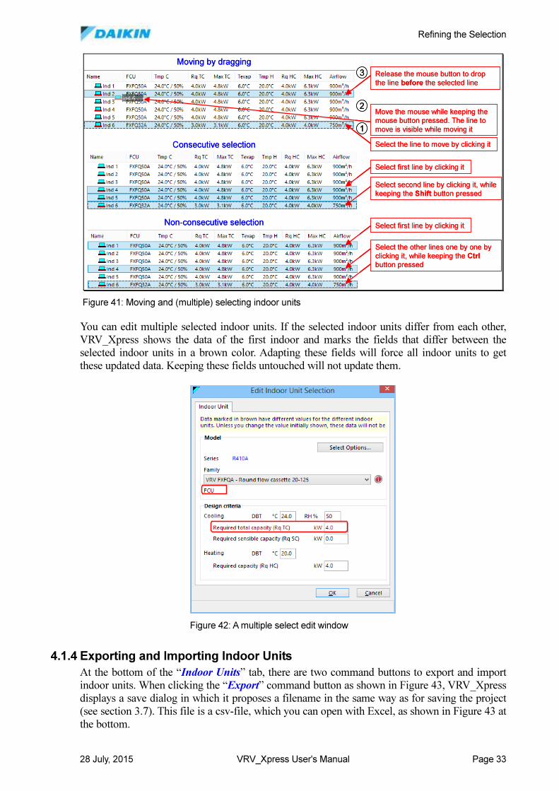
Refining the Selection
28 July, 2015 VRV_Xpress User's Manual Page 33
You can edit multiple selected indoor units. If the selected indoor units differ from each other,
VRV_Xpress shows the data of the first indoor and marks the fields that differ between the
selected indoor units in a brown color. Adapting these fields will force all indoor units to get
these updated data. Keeping these fields untouched will not update them.
4.1.4 Exporting and Importing Indoor Units
At the bottom of the “Indoor Units” tab, there are two command buttons to export and import
indoor units. When clicking the “Export” command button as shown in Figure 43, VRV_Xpress
displays a save dialog in which it proposes a filename in the same way as for saving the project
(see section 3.7). This file is a csv-file, which you can open with Excel, as shown in Figure 43 at
the bottom.
Select first line by clicking it
Select second line by clicking it, while
keeping the Shift button pressed
Consecutive selection
Non-consecutive selection Select first line by clicking it
Select the other lines one by one by
clicking it, while keeping the Ctrl
button pressed
Moving by dragging
Select the line to move by clicking it
Move the mouse while keeping the
mouse button pressed. The line to
move is visible while moving it
Release the mouse button to drop
the line before the selected line
1
2
3
Figure 41: Moving and (multiple) selecting indoor units
Figure 42: A multiple select edit window
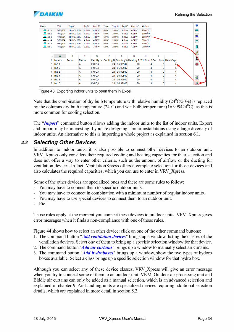
Refining the Selection
28 July, 2015 VRV_Xpress User's Manual Page 34
Note that the combination of dry bulb temperature with relative humidity (240C/50%) is replaced
by the columns dry bulb temperature (240C) and wet bulb temperature (16.999424
0C), as this is
more common for cooling selection.
The “Import” command button allows adding the indoor units to the list of indoor units. Export
and import may be interesting if you are designing similar installations using a large diversity of
indoor units. An alternative to this is importing a whole project as explained in section 6.1.
4.2 Selecting Other Devices
In addition to indoor units, it is also possible to connect other devices to an outdoor unit.
VRV_Xpress only considers their required cooling and heating capacities for their selection and
does not offer a way to enter other criteria, such as the amount of airflow or the ducting for
ventilation devices. In fact, VentilationXpress offers a complete selection for those devices and
also calculates the required capacities, which you can use to enter in VRV_Xpress.
Some of the other devices are specialized ones and there are some rules to follow:
- You may have to connect them to specific outdoor units.
- You may have to connect in combination with a minimum number of regular indoor units.
- You may have to use special devices to connect them to an outdoor unit.
- Etc
Those rules apply at the moment you connect these devices to outdoor units. VRV_Xpress gives
error messages when it finds a non-compliance with one of those rules.
Figure 44 shows how to select an other device: click on one of the other command buttons:
1. The command button "Add ventilation devices" brings up a window, listing the classes of the
ventilation devices. Select one of them to bring up a specific selection window for that device.
2. The command button "Add air curtains" brings up a window to manually select air curtains.
3. The command button "Add hydroboxes" brings up a window, show the two types of hydoro
boxes available. Select a class brings up a specific selection window for that hydro box.
Although you can select any of these device classes, VRV_Xpress will give an error message
when you try to connect some of them to an outdoor unit: VKM, Outdoor air processing unit and
Biddle air curtains can only be added as a manual selection, which is an advanced selection and
explained in chapter 9. Air handling units are specialized devices requiring additional selection
details, which are explained in more detail in section 8.2.
Figure 43: Exporting indoor units to open them in Excel
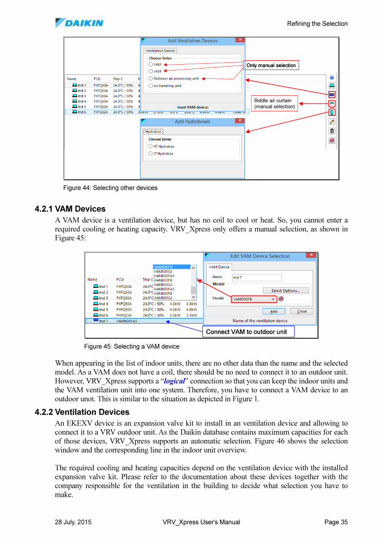
Refining the Selection
28 July, 2015 VRV_Xpress User's Manual Page 35
4.2.1 VAM Devices
A VAM device is a ventilation device, but has no coil to cool or heat. So, you cannot enter a
required cooling or heating capacity. VRV_Xpress only offers a manual selection, as shown in
Figure 45:
When appearing in the list of indoor units, there are no other data than the name and the selected
model. As a VAM does not have a coil, there should be no need to connect it to an outdoor unit.
However, VRV_Xpress supports a “logical” connection so that you can keep the indoor units and
the VAM ventilation unit into one system. Therefore, you have to connect a VAM device to an
outdoor unot. This is similar to the situation as depicted in Figure 1.
4.2.2 Ventilation Devices
An EKEXV device is an expansion valve kit to install in an ventilation device and allowing to
connect it to a VRV outdoor unit. As the Daikin database contains maximum capacities for each
of those devices, VRV_Xpress supports an automatic selection. Figure 46 shows the selection
window and the corresponding line in the indoor unit overview.
The required cooling and heating capacities depend on the ventilation device with the installed
expansion valve kit. Please refer to the documentation about these devices together with the
company responsible for the ventilation in the building to decide what selection you have to
make.
Only manual selection
Biddle air curtain(manual selection)
Only manual selection
Biddle air curtain(manual selection)
Figure 44: Selecting other devices
Connect VAM to outdoor unitConnect VAM to outdoor unit
Figure 45: Selecting a VAM device
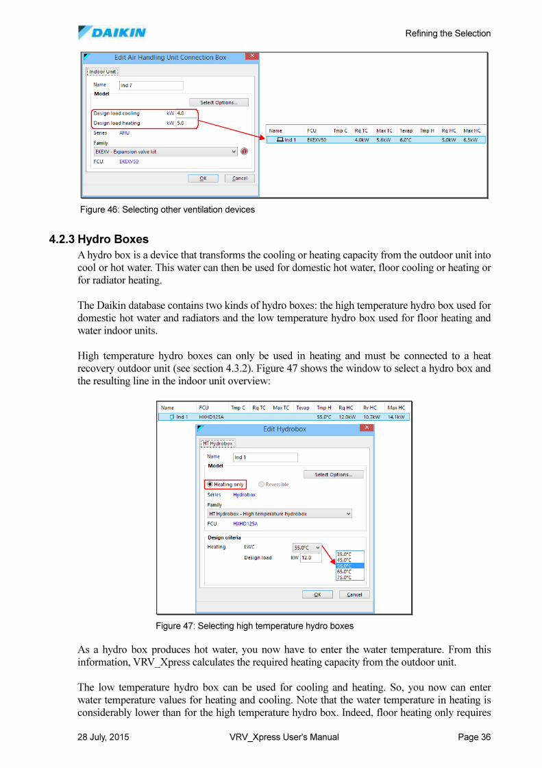
Refining the Selection
28 July, 2015 VRV_Xpress User's Manual Page 36
4.2.3 Hydro Boxes
A hydro box is a device that transforms the cooling or heating capacity from the outdoor unit into
cool or hot water. This water can then be used for domestic hot water, floor cooling or heating or
for radiator heating.
The Daikin database contains two kinds of hydro boxes: the high temperature hydro box used for
domestic hot water and radiators and the low temperature hydro box used for floor heating and
water indoor units.
High temperature hydro boxes can only be used in heating and must be connected to a heat
recovery outdoor unit (see section 4.3.2). Figure 47 shows the window to select a hydro box and
the resulting line in the indoor unit overview:
As a hydro box produces hot water, you now have to enter the water temperature. From this
information, VRV_Xpress calculates the required heating capacity from the outdoor unit.
The low temperature hydro box can be used for cooling and heating. So, you now can enter
water temperature values for heating and cooling. Note that the water temperature in heating is
considerably lower than for the high temperature hydro box. Indeed, floor heating only requires
Figure 46: Selecting other ventilation devices
Figure 47: Selecting high temperature hydro boxes
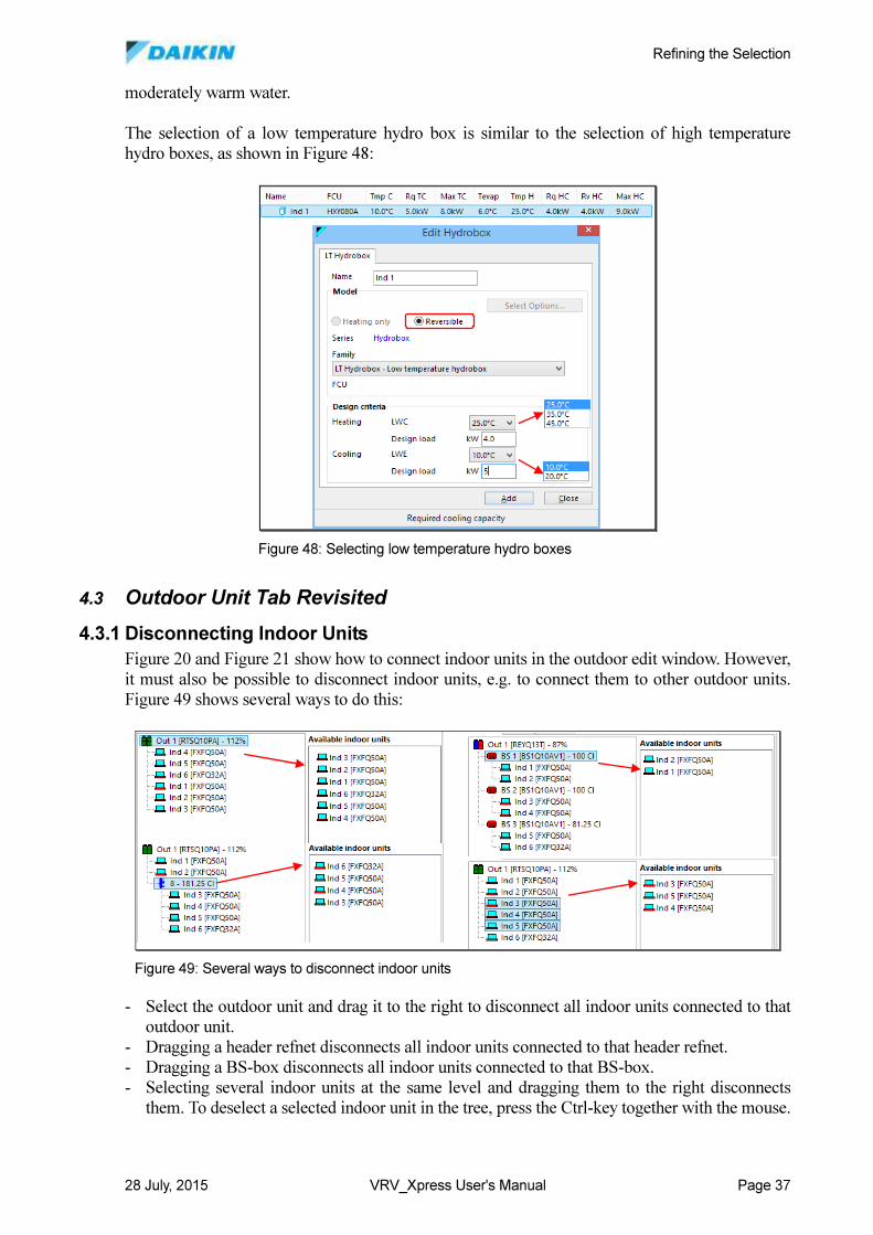
Refining the Selection
28 July, 2015 VRV_Xpress User's Manual Page 37
moderately warm water.
The selection of a low temperature hydro box is similar to the selection of high temperature
hydro boxes, as shown in Figure 48:
4.3 Outdoor Unit Tab Revisited
4.3.1 Disconnecting Indoor Units
Figure 20 and Figure 21 show how to connect indoor units in the outdoor edit window. However,
it must also be possible to disconnect indoor units, e.g. to connect them to other outdoor units.
Figure 49 shows several ways to do this:
- Select the outdoor unit and drag it to the right to disconnect all indoor units connected to that
outdoor unit.
- Dragging a header refnet disconnects all indoor units connected to that header refnet.
- Dragging a BS-box disconnects all indoor units connected to that BS-box.
- Selecting several indoor units at the same level and dragging them to the right disconnects
them. To deselect a selected indoor unit in the tree, press the Ctrl-key together with the mouse.
Figure 48: Selecting low temperature hydro boxes
Figure 49: Several ways to disconnect indoor units
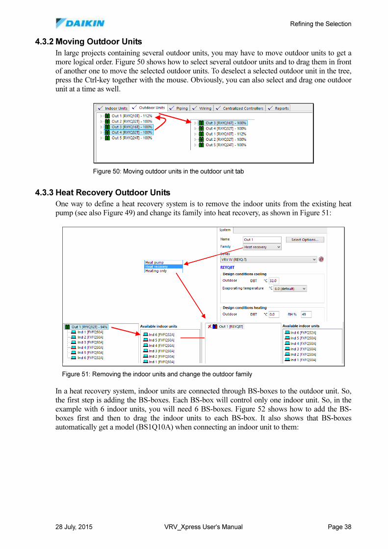
Refining the Selection
28 July, 2015 VRV_Xpress User's Manual Page 38
4.3.2 Moving Outdoor Units
In large projects containing several outdoor units, you may have to move outdoor units to get a
more logical order. Figure 50 shows how to select several outdoor units and to drag them in front
of another one to move the selected outdoor units. To deselect a selected outdoor unit in the tree,
press the Ctrl-key together with the mouse. Obviously, you can also select and drag one outdoor
unit at a time as well.
4.3.3 Heat Recovery Outdoor Units
One way to define a heat recovery system is to remove the indoor units from the existing heat
pump (see also Figure 49) and change its family into heat recovery, as shown in Figure 51:
In a heat recovery system, indoor units are connected through BS-boxes to the outdoor unit. So,
the first step is adding the BS-boxes. Each BS-box will control only one indoor unit. So, in the
example with 6 indoor units, you will need 6 BS-boxes. Figure 52 shows how to add the BS-
boxes first and then to drag the indoor units to each BS-box. It also shows that BS-boxes
automatically get a model (BS1Q10A) when connecting an indoor unit to them:
Figure 50: Moving outdoor units in the outdoor unit tab
Figure 51: Removing the indoor units and change the outdoor family
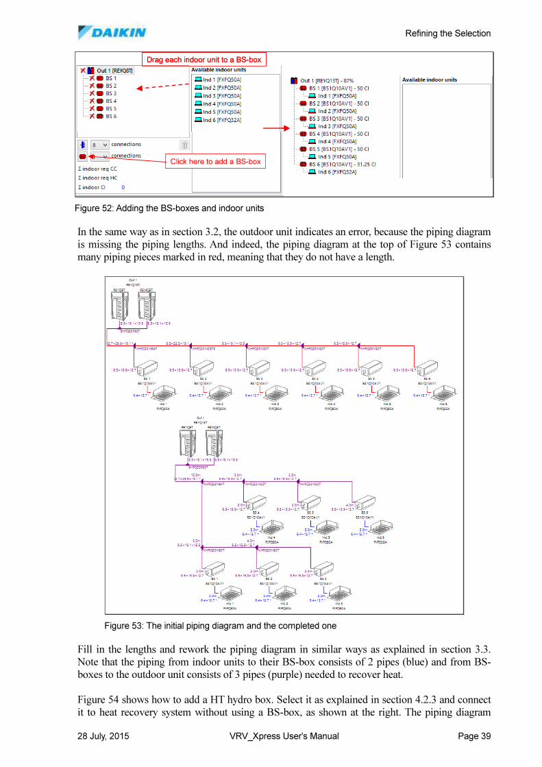
Refining the Selection
28 July, 2015 VRV_Xpress User's Manual Page 39
In the same way as in section 3.2, the outdoor unit indicates an error, because the piping diagram
is missing the piping lengths. And indeed, the piping diagram at the top of Figure 53 contains
many piping pieces marked in red, meaning that they do not have a length.
Fill in the lengths and rework the piping diagram in similar ways as explained in section 3.3.
Note that the piping from indoor units to their BS-box consists of 2 pipes (blue) and from BS-
boxes to the outdoor unit consists of 3 pipes (purple) needed to recover heat.
Figure 54 shows how to add a HT hydro box. Select it as explained in section 4.2.3 and connect
it to heat recovery system without using a BS-box, as shown at the right. The piping diagram
Click here to add a BS-box
Drag each indoor unit to a BS-box
Click here to add a BS-box
Drag each indoor unit to a BS-box
Figure 52: Adding the BS-boxes and indoor units
Figure 53: The initial piping diagram and the completed one
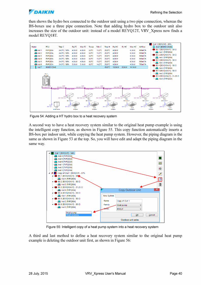
Refining the Selection
28 July, 2015 VRV_Xpress User's Manual Page 40
then shows the hydro box connected to the outdoor unit using a two pipe connection, whereas the
BS-boxes use a three pipe connection. Note that adding hydro box to the outdoor unit also
increases the size of the outdoor unit: instead of a model REYQ12T, VRV_Xpress now finds a
model REYQ18T.
A second way to have a heat recovery system similar to the original heat pump example is using
the intelligent copy function, as shown in Figure 55. This copy function automatically inserts a
BS-box per indoor unit, while copying the heat pump system. However, the piping diagram is the
same as shown in Figure 53 at the top. So, you will have edit and adapt the piping diagram in the
same way.
A third and last method to define a heat recovery system similar to the original heat pump
example is deleting the outdoor unit first, as shown in Figure 56:
Figure 54: Adding a HT hydro box to a heat recovery system
Figure 55: Intelligent copy of a heat pump system into a heat recovery system
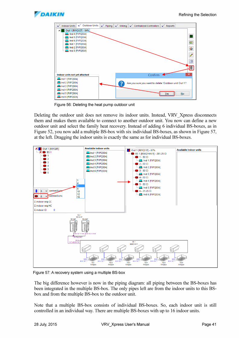
Refining the Selection
28 July, 2015 VRV_Xpress User's Manual Page 41
Deleting the outdoor unit does not remove its indoor units. Instead, VRV_Xpress disconnects
them and makes them available to connect to another outdoor unit. You now can define a new
outdoor unit and select the family heat recovery. Instead of adding 6 individual BS-boxes, as in
Figure 52, you now add a multiple BS-box with six individual BS-boxes, as shown in Figure 57,
at the left. Dragging the indoor units is exactly the same as for individual BS-boxes.
The big difference however is now in the piping diagram: all piping between the BS-boxes has
been integrated in the multiple BS-box. The only pipes left are from the indoor units to this BS-
box and from the multiple BS-box to the outdoor unit.
Note that a multiple BS-box consists of individual BS-boxes. So, each indoor unit is still
controlled in an individual way. There are multiple BS-boxes with up to 16 indoor units.
Figure 56: Deleting the heat pump outdoor unit
Figure 57: A recovery system using a multiple BS-box
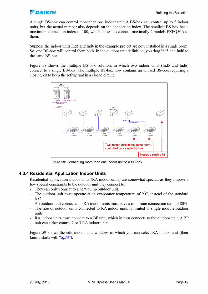
Refining the Selection
28 July, 2015 VRV_Xpress User's Manual Page 42
A single BS-box can control more than one indoor unit. A BS-box can control up to 5 indoor
units, but the actual number also depends on the connection index. The smallest BS-box has a
maximum connection index of 100, which allows to connect maximally 2 models FXFQ50A to
them.
Suppose the indoor units Ind5 and Ind6 in the example project are now installed in a single room.
So, one BS-box will control them both. In the outdoor unit definition, you drag Ind5 and Ind6 to
the same BS-box.
Figure 58 shows the multiple BS-box solution, in which two indoor units (Ind5 and Ind6)
connect to a single BS-box. The multiple BS-box now contains an unused BS-box requiring a
closing kit to keep the refrigerant in a closed circuit.
4.3.4 Residential Application Indoor Units
Residential application indoor units (RA indoor units) are somewhat special, as they impose a
few special constraints to the outdoor unit they connect to:
- They can only connect to a heat pump outdoor unit.
- The outdoor unit must operate at an evaporator temperature of 90C, instead of the standard
60C.
- An outdoor unit connected to RA indoor units must have a minimum connection ratio of 80%.
- The size of outdoor units connected to RA indoor units is limited to single module outdoor
units.
- RA indoor units must connect to a BP unit, which in turn connects to the outdoor unit. A BP
unit can either control 2 or 3 RA indoor units.
Figure 59 shows the edit indoor unit window, in which you can select RA indoor unit (their
family starts with “Split”).
Needs a closing kit
Two indoor units in the same room,
controlled by a single BS-box
Needs a closing kit
Two indoor units in the same room,
controlled by a single BS-box
Figure 58: Connecting more than one indoor unit to a BS-box
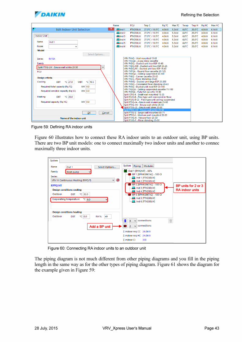
Refining the Selection
28 July, 2015 VRV_Xpress User's Manual Page 43
Figure 60 illustrates how to connect these RA indoor units to an outdoor unit, using BP units.
There are two BP unit models: one to connect maximally two indoor units and another to connec
maximally three indoor units.
The piping diagram is not much different from other piping diagrams and you fill in the piping
length in the same way as for the other types of piping diagram. Figure 61 shows the diagram for
the example given in Figure 59:
Figure 59: Defining RA indoor units
Add a BP unit
BP units for 2 or 3
RA indoor units
Add a BP unit
BP units for 2 or 3
RA indoor units
Figure 60: Connecting RA indoor units to an outdoor unit
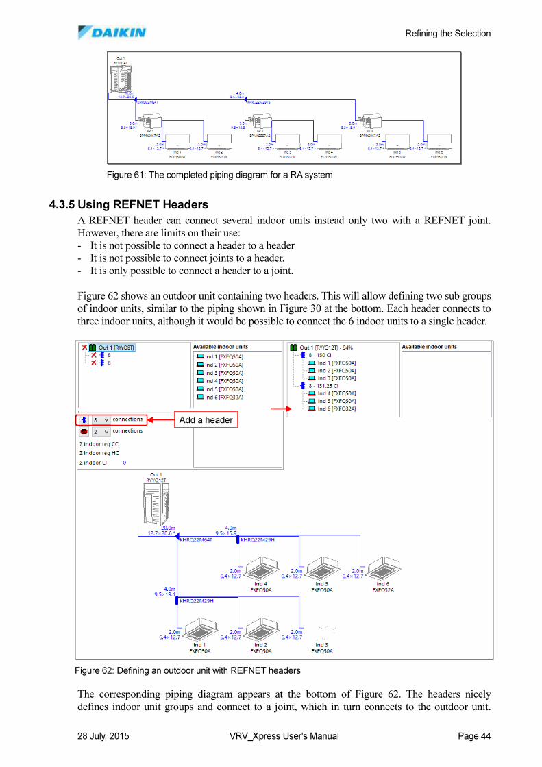
Refining the Selection
28 July, 2015 VRV_Xpress User's Manual Page 44
4.3.5 Using REFNET Headers
A REFNET header can connect several indoor units instead only two with a REFNET joint.
However, there are limits on their use:
- It is not possible to connect a header to a header
- It is not possible to connect joints to a header.
- It is only possible to connect a header to a joint.
Figure 62 shows an outdoor unit containing two headers. This will allow defining two sub groups
of indoor units, similar to the piping shown in Figure 30 at the bottom. Each header connects to
three indoor units, although it would be possible to connect the 6 indoor units to a single header.
The corresponding piping diagram appears at the bottom of Figure 62. The headers nicely
defines indoor unit groups and connect to a joint, which in turn connects to the outdoor unit.
Figure 61: The completed piping diagram for a RA system
Add a headerAdd a header
Figure 62: Defining an outdoor unit with REFNET headers
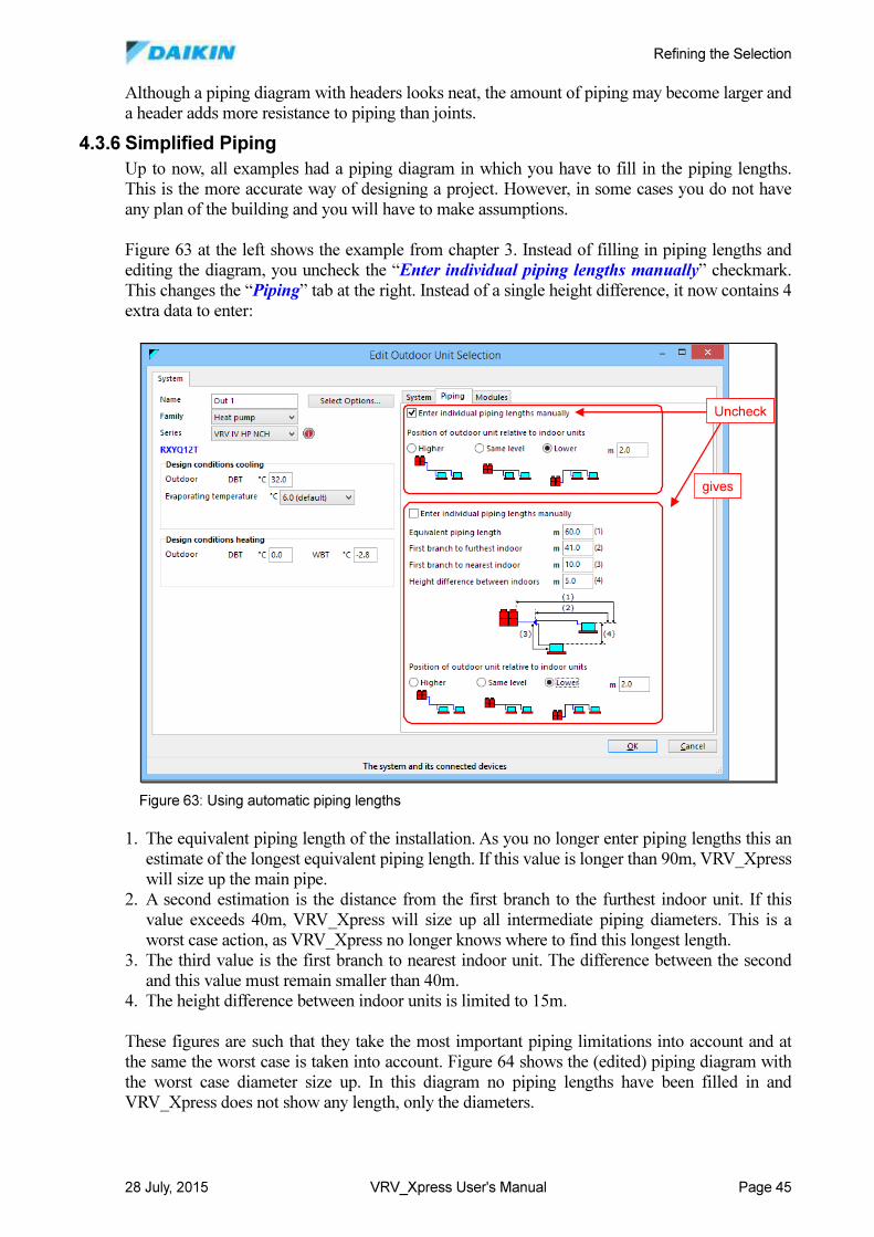
Refining the Selection
28 July, 2015 VRV_Xpress User's Manual Page 45
Although a piping diagram with headers looks neat, the amount of piping may become larger and
a header adds more resistance to piping than joints.
4.3.6 Simplified Piping
Up to now, all examples had a piping diagram in which you have to fill in the piping lengths.
This is the more accurate way of designing a project. However, in some cases you do not have
any plan of the building and you will have to make assumptions.
Figure 63 at the left shows the example from chapter 3. Instead of filling in piping lengths and
editing the diagram, you uncheck the “Enter individual piping lengths manually” checkmark.
This changes the “Piping” tab at the right. Instead of a single height difference, it now contains 4
extra data to enter:
1. The equivalent piping length of the installation. As you no longer enter piping lengths this an
estimate of the longest equivalent piping length. If this value is longer than 90m, VRV_Xpress
will size up the main pipe.
2. A second estimation is the distance from the first branch to the furthest indoor unit. If this
value exceeds 40m, VRV_Xpress will size up all intermediate piping diameters. This is a
worst case action, as VRV_Xpress no longer knows where to find this longest length.
3. The third value is the first branch to nearest indoor unit. The difference between the second
and this value must remain smaller than 40m.
4. The height difference between indoor units is limited to 15m.
These figures are such that they take the most important piping limitations into account and at
the same the worst case is taken into account. Figure 64 shows the (edited) piping diagram with
the worst case diameter size up. In this diagram no piping lengths have been filled in and
VRV_Xpress does not show any length, only the diameters.
Uncheck
gives
Uncheck
gives
Figure 63: Using automatic piping lengths
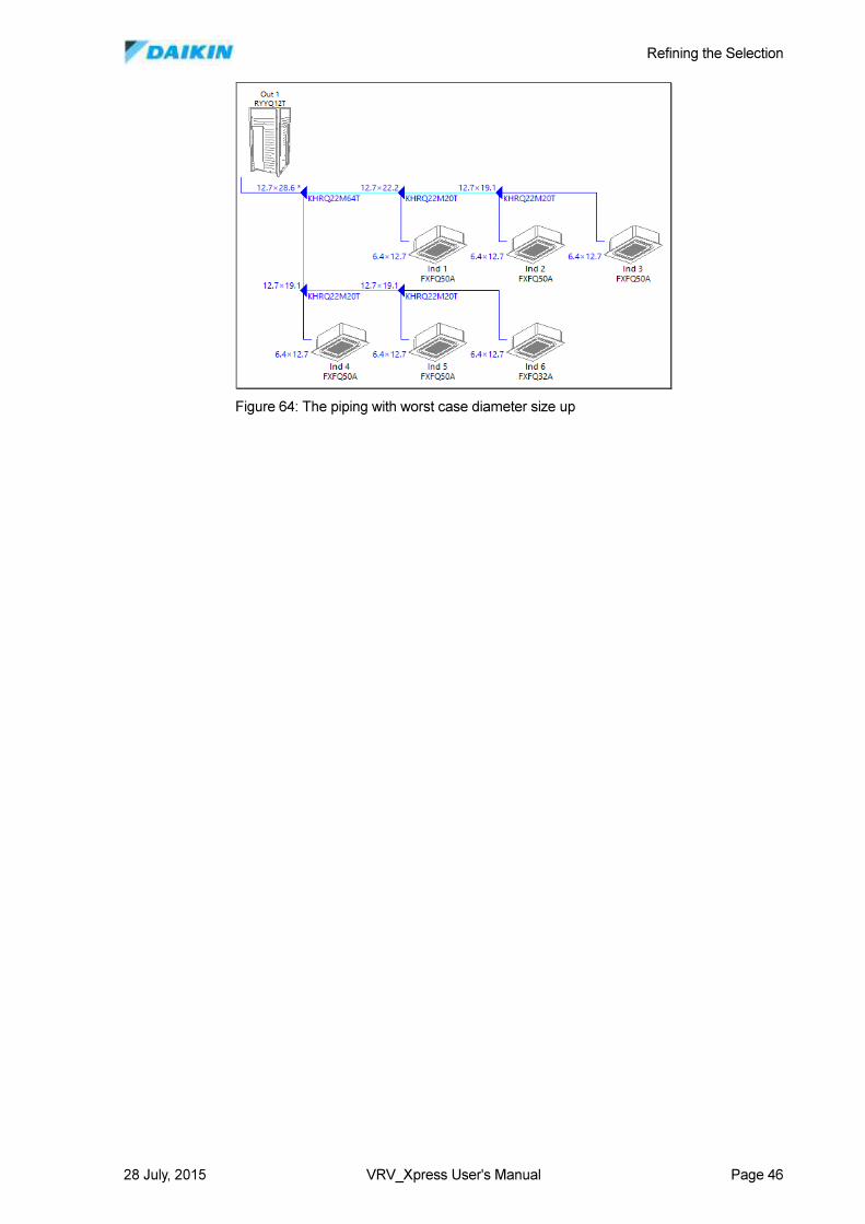
Refining the Selection
28 July, 2015 VRV_Xpress User's Manual Page 46
Figure 64: The piping with worst case diameter size up
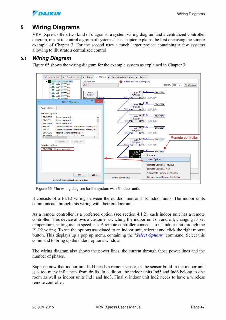
Wiring Diagrams
28 July, 2015 VRV_Xpress User's Manual Page 47
5 Wiring Diagrams VRV_Xpress offers two kind of diagrams: a system wiring diagram and a centralized controller
diagram, meant to control a group of systems. This chapter explains the first one using the simple
example of Chapter 3. For the second uses a much larger project containing a few systems
allowing to illustrate a centralized control.
5.1 Wiring Diagram
Figure 65 shows the wiring diagram for the example system as explained in Chapter 3:
It consists of a F1/F2 wiring between the outdoor unit and its indoor units. The indoor units
communicate through this wiring with their outdoor unit.
As a remote controller is a preferred option (see section 4.1.2), each indoor unit has a remote
controller. This device allows a customer switching the indoor unit on and off, changing its set
temperature, setting its fan speed, etc. A remote controller connects to its indoor unit through the
P1,P2 wiring. To see the options associated to an indoor unit, select it and click the right mouse
button. This displays up a pop up menu, containing the "Select Options" command. Select this
command to bring up the indoor options window.
The wiring diagram also shows the power lines, the current through those power lines and the
number of phases.
Suppose now that indoor unit Ind4 needs a remote sensor, as the sensor build in the indoor unit
gets too many influences from drafts. In addition, the indoor units Ind5 and Ind6 belong to one
room as well as indoor units Ind1 and Ind3. Finally, indoor unit Ind2 needs to have a wireless
remote controller.
Remote controllerRemote controller
Figure 65: The wiring diagram for the system with 6 indoor units
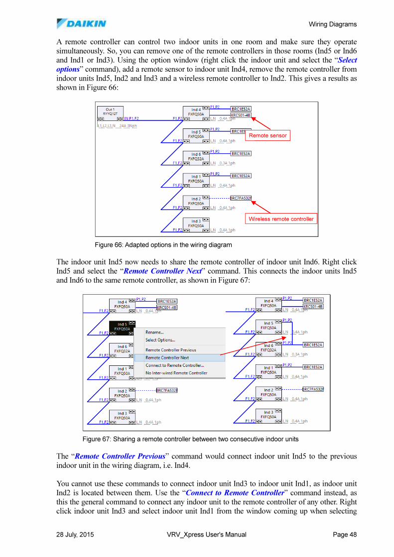
Wiring Diagrams
28 July, 2015 VRV_Xpress User's Manual Page 48
A remote controller can control two indoor units in one room and make sure they operate
simultaneously. So, you can remove one of the remote controllers in those rooms (Ind5 or Ind6
and Ind1 or Ind3). Using the option window (right click the indoor unit and select the “Select
options” command), add a remote sensor to indoor unit Ind4, remove the remote controller from
indoor units Ind5, Ind2 and Ind3 and a wireless remote controller to Ind2. This gives a results as
shown in Figure 66:
The indoor unit Ind5 now needs to share the remote controller of indoor unit Ind6. Right click
Ind5 and select the “Remote Controller Next” command. This connects the indoor units Ind5
and Ind6 to the same remote controller, as shown in Figure 67:
The “Remote Controller Previous” command would connect indoor unit Ind5 to the previous
indoor unit in the wiring diagram, i.e. Ind4.
You cannot use these commands to connect indoor unit Ind3 to indoor unit Ind1, as indoor unit
Ind2 is located between them. Use the “Connect to Remote Controller” command instead, as
this the general command to connect any indoor unit to the remote controller of any other. Right
click indoor unit Ind3 and select indoor unit Ind1 from the window coming up when selecting
Remote sensor
Wireless remote controller
Remote sensor
Wireless remote controller
Figure 66: Adapted options in the wiring diagram
Figure 67: Sharing a remote controller between two consecutive indoor units
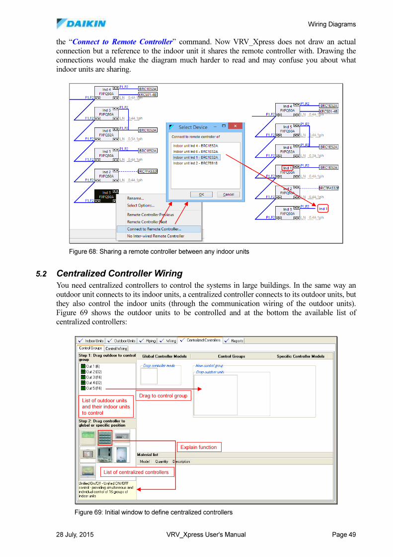
Wiring Diagrams
28 July, 2015 VRV_Xpress User's Manual Page 49
the “Connect to Remote Controller” command. Now VRV_Xpress does not draw an actual
connection but a reference to the indoor unit it shares the remote controller with. Drawing the
connections would make the diagram much harder to read and may confuse you about what
indoor units are sharing.
5.2 Centralized Controller Wiring
You need centralized controllers to control the systems in large buildings. In the same way an
outdoor unit connects to its indoor units, a centralized controller connects to its outdoor units, but
they also control the indoor units (through the communication wiring of the outdoor units).
Figure 69 shows the outdoor units to be controlled and at the bottom the available list of
centralized controllers:
Figure 68: Sharing a remote controller between any indoor units
List of outdoor units and their indoor units
to control
List of centralized controllers
Drag to control group
Explain function
List of outdoor units and their indoor units
to control
List of centralized controllers
Drag to control group
Explain function
Figure 69: Initial window to define centralized controllers
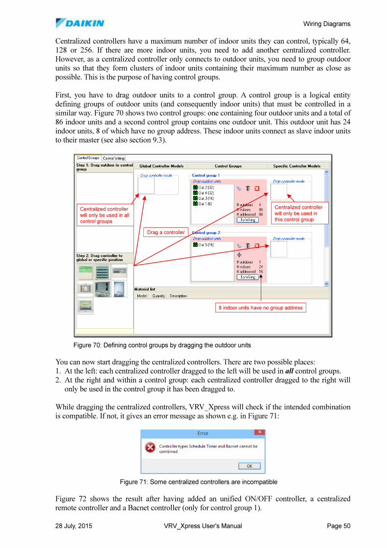
Wiring Diagrams
28 July, 2015 VRV_Xpress User's Manual Page 50
Centralized controllers have a maximum number of indoor units they can control, typically 64,
128 or 256. If there are more indoor units, you need to add another centralized controller.
However, as a centralized controller only connects to outdoor units, you need to group outdoor
units so that they form clusters of indoor units containing their maximum number as close as
possible. This is the purpose of having control groups.
First, you have to drag outdoor units to a control group. A control group is a logical entity
defining groups of outdoor units (and consequently indoor units) that must be controlled in a
similar way. Figure 70 shows two control groups: one containing four outdoor units and a total of
86 indoor units and a second control group contains one outdoor unit. This outdoor unit has 24
indoor units, 8 of which have no group address. These indoor units connect as slave indoor units
to their master (see also section 9.3).
You can now start dragging the centralized controllers. There are two possible places:
1. At the left: each centralized controller dragged to the left will be used in all control groups.
2. At the right and within a control group: each centralized controller dragged to the right will
only be used in the control group it has been dragged to.
While dragging the centralized controllers, VRV_Xpress will check if the intended combination
is compatible. If not, it gives an error message as shown e.g. in Figure 71:
Figure 72 shows the result after having added an unified ON/OFF controller, a centralized
remote controller and a Bacnet controller (only for control group 1).
8 indoor units have no group address
Centralized controller
will only be used in this control group
Drag a controller
Centralized controller will only be used in all
control groups
8 indoor units have no group address
Centralized controller
will only be used in this control group
Drag a controller
Centralized controller will only be used in all
control groups
Figure 70: Defining control groups by dragging the outdoor units
Figure 71: Some centralized controllers are incompatible
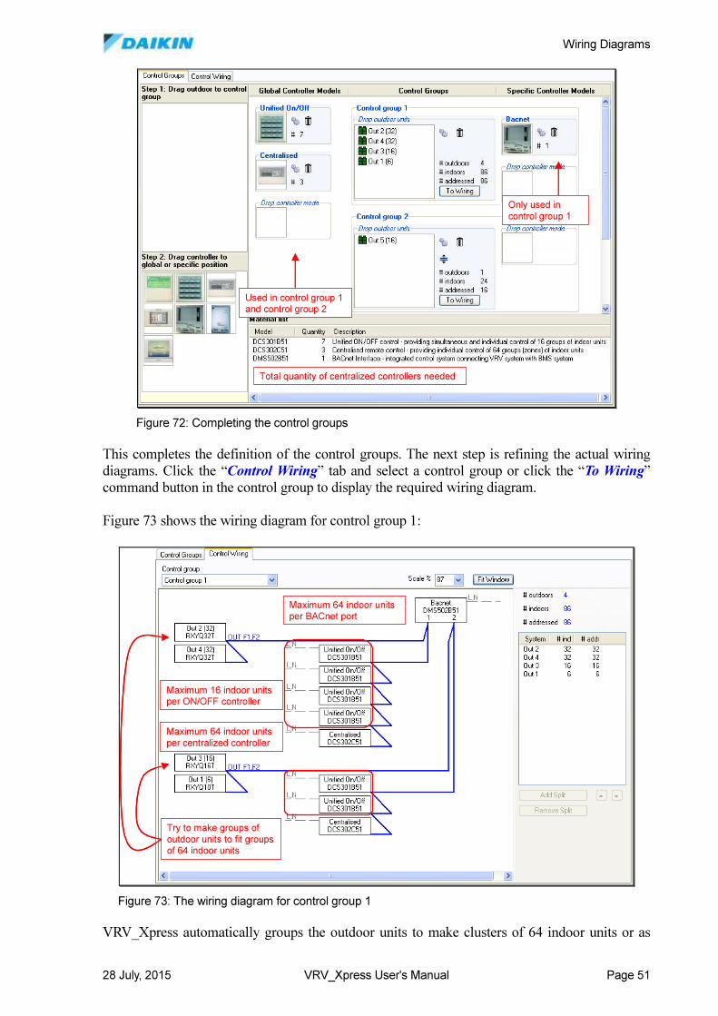
Wiring Diagrams
28 July, 2015 VRV_Xpress User's Manual Page 51
This completes the definition of the control groups. The next step is refining the actual wiring
diagrams. Click the “Control Wiring” tab and select a control group or click the “To Wiring”
command button in the control group to display the required wiring diagram.
Figure 73 shows the wiring diagram for control group 1:
VRV_Xpress automatically groups the outdoor units to make clusters of 64 indoor units or as
Used in control group 1 and control group 2
Only used in
control group 1
Total quantity of centralized controllers needed
Used in control group 1 and control group 2
Only used in
control group 1
Total quantity of centralized controllers needed
Figure 72: Completing the control groups
Maximum 16 indoor units per ON/OFF controller
Maximum 64 indoor units
per centralized controller
Maximum 64 indoor units per BACnet port
Try to make groups of
outdoor units to fit groups of 64 indoor units
Maximum 16 indoor units per ON/OFF controller
Maximum 64 indoor units
per centralized controller
Maximum 64 indoor units per BACnet port
Try to make groups of
outdoor units to fit groups of 64 indoor units
Figure 73: The wiring diagram for control group 1
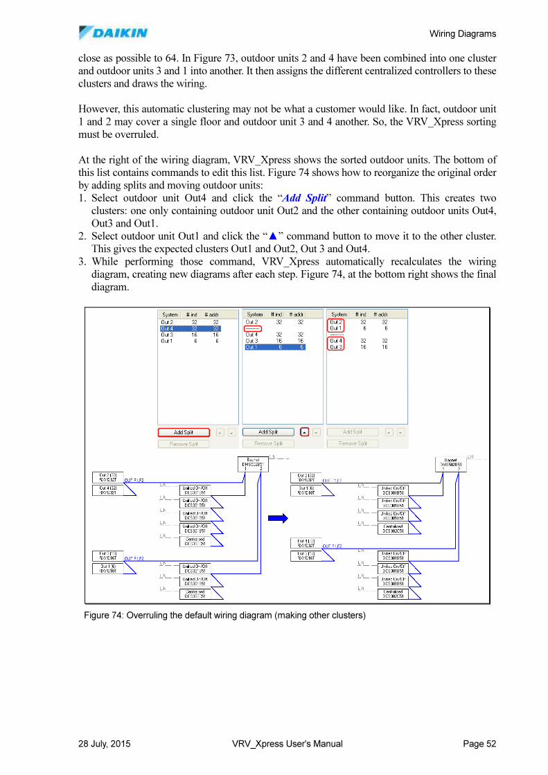
Wiring Diagrams
28 July, 2015 VRV_Xpress User's Manual Page 52
close as possible to 64. In Figure 73, outdoor units 2 and 4 have been combined into one cluster
and outdoor units 3 and 1 into another. It then assigns the different centralized controllers to these
clusters and draws the wiring.
However, this automatic clustering may not be what a customer would like. In fact, outdoor unit
1 and 2 may cover a single floor and outdoor unit 3 and 4 another. So, the VRV_Xpress sorting
must be overruled.
At the right of the wiring diagram, VRV_Xpress shows the sorted outdoor units. The bottom of
this list contains commands to edit this list. Figure 74 shows how to reorganize the original order
by adding splits and moving outdoor units:
1. Select outdoor unit Out4 and click the “Add Split” command button. This creates two
clusters: one only containing outdoor unit Out2 and the other containing outdoor units Out4,
Out3 and Out1.
2. Select outdoor unit Out1 and click the “▲” command button to move it to the other cluster.
This gives the expected clusters Out1 and Out2, Out 3 and Out4.
3. While performing those command, VRV_Xpress automatically recalculates the wiring
diagram, creating new diagrams after each step. Figure 74, at the bottom right shows the final
diagram.
Figure 74: Overruling the default wiring diagram (making other clusters)
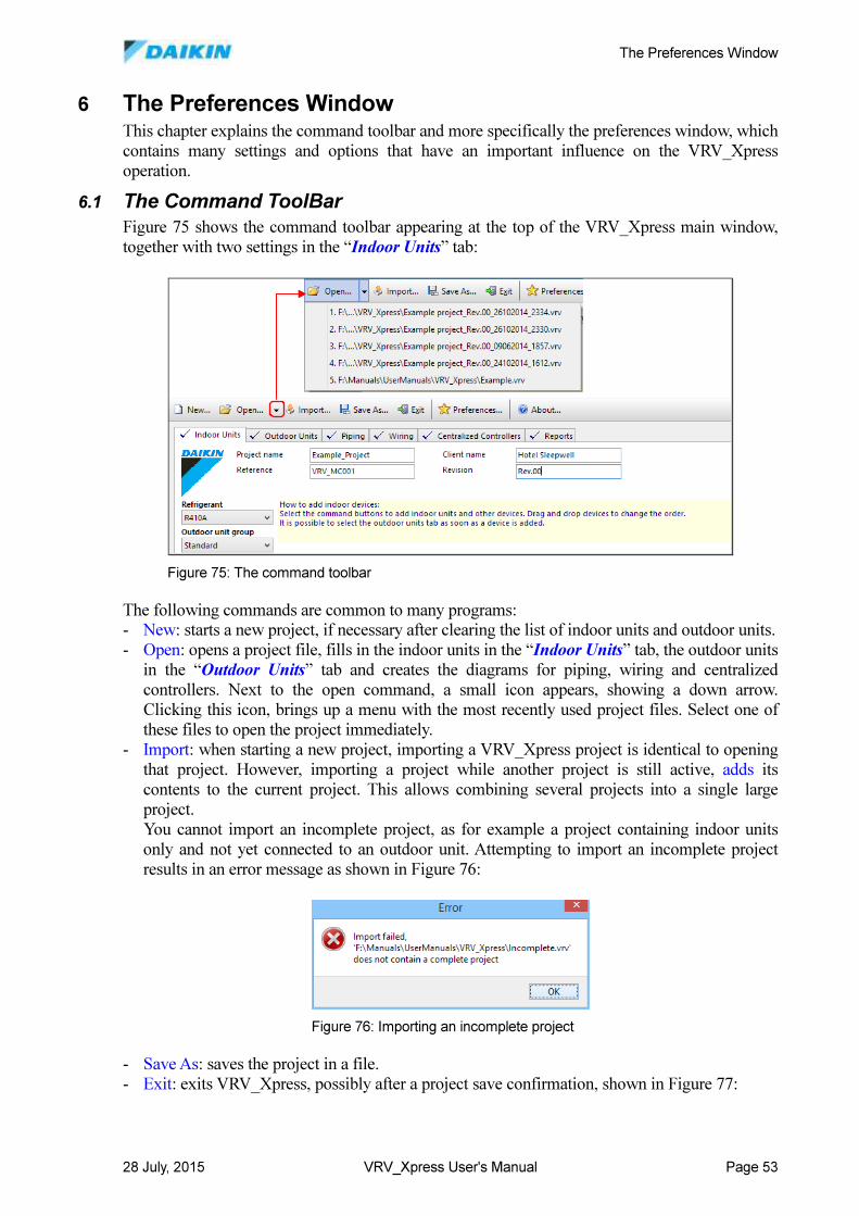
The Preferences Window
28 July, 2015 VRV_Xpress User's Manual Page 53
6 The Preferences Window This chapter explains the command toolbar and more specifically the preferences window, which
contains many settings and options that have an important influence on the VRV_Xpress
operation.
6.1 The Command ToolBar
Figure 75 shows the command toolbar appearing at the top of the VRV_Xpress main window,
together with two settings in the “Indoor Units” tab:
The following commands are common to many programs:
- New: starts a new project, if necessary after clearing the list of indoor units and outdoor units.
- Open: opens a project file, fills in the indoor units in the “Indoor Units” tab, the outdoor units
in the “Outdoor Units” tab and creates the diagrams for piping, wiring and centralized
controllers. Next to the open command, a small icon appears, showing a down arrow.
Clicking this icon, brings up a menu with the most recently used project files. Select one of
these files to open the project immediately.
- Import: when starting a new project, importing a VRV_Xpress project is identical to opening
that project. However, importing a project while another project is still active, adds its
contents to the current project. This allows combining several projects into a single large
project.
You cannot import an incomplete project, as for example a project containing indoor units
only and not yet connected to an outdoor unit. Attempting to import an incomplete project
results in an error message as shown in Figure 76:
- Save As: saves the project in a file.
- Exit: exits VRV_Xpress, possibly after a project save confirmation, shown in Figure 77:
Figure 75: The command toolbar
Figure 76: Importing an incomplete project
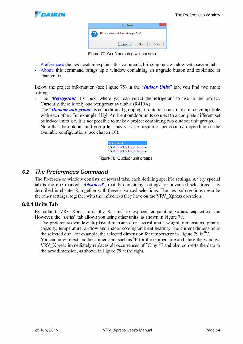
The Preferences Window
28 July, 2015 VRV_Xpress User's Manual Page 54
- Preferences: the next section explains this command, bringing up a window with several tabs.
- About: this command brings up a window containing an upgrade button and explained in
chapter 10.
Below the project information (see Figure 75) in the “Indoor Units” tab, you find two more
settings:
- The “Refrigerant” list box, where you can select the refrigerant to use in the project.
Currently, there is only one refrigerant available (R410A).
- The “Outdoor unit group” is an additional grouping of outdoor units, that are not compatible
with each other. For example, High Ambient outdoor units connect to a complete different set
of indoor units. So, it is not possible to make a project combining two outdoor unit groups.
Note that the outdoor unit group list may vary per region or per country, depending on the
available configurations (see chapter 10).
6.2 The Preferences Command
The Preferences window consists of several tabs, each defining specific settings. A very special
tab is the one marked "Advanced", mainly containing settings for advanced selections. It is
described in chapter 8, together with these advanced selections. The next sub sections describe
the other settings, together with the influences they have on the VRV_Xpress operation.
6.2.1 Units Tab
By default, VRV_Xpress uses the SI units to express temperature values, capacities, etc.
However, the “Units” tab allows you using other units, as shown in Figure 79.
- The preferences window displays dimensions for several units: weight, dimensions, piping,
capacity, temperature, airflow and indoor cooling/ambient heating. The current dimension is
the selected one. For example, the selected dimension for temperature in Figure 79 is 0C.
- You can now select another dimension, such as 0F for the temperature and close the window.
VRV_Xpress immediately replaces all occurrences of 0C by
0F and also converts the data to
the new dimension, as shown in Figure 79 at the right.
Figure 77: Confirm exiting without saving
Figure 78: Outdoor unit groups
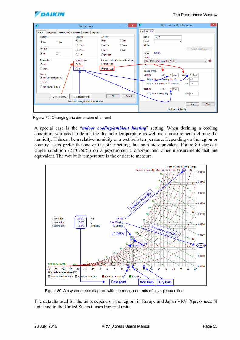
The Preferences Window
28 July, 2015 VRV_Xpress User's Manual Page 55
A special case is the “indoor cooling/ambient heating” setting. When defining a cooling
condition, you need to define the dry bulb temperature as well as a measurement defining the
humidity. This can be a relative humidity or a wet bulb temperature. Depending on the region or
country, users prefer the one or the other setting, but both are equivalent. Figure 80 shows a
single condition (250C/50%) on a psychrometric diagram and other measurements that are
equivalent. The wet bulb temperature is the easiest to measure.
The defaults used for the units depend on the region: in Europe and Japan VRV_Xpress uses SI
units and in the United States it uses Imperial units.
Unit in effect Available unitUnit in effect Available unit
Figure 79: Changing the dimension of an unit
Wet bulb Dry bulbDew point
Absolute humidity
Relativ
e hum
idity
Enthalpy
Wet bulb Dry bulbDew point
Absolute humidity
Relativ
e hum
idity
Enthalpy
Figure 80: A psychrometric diagram with the measurements of a single condition
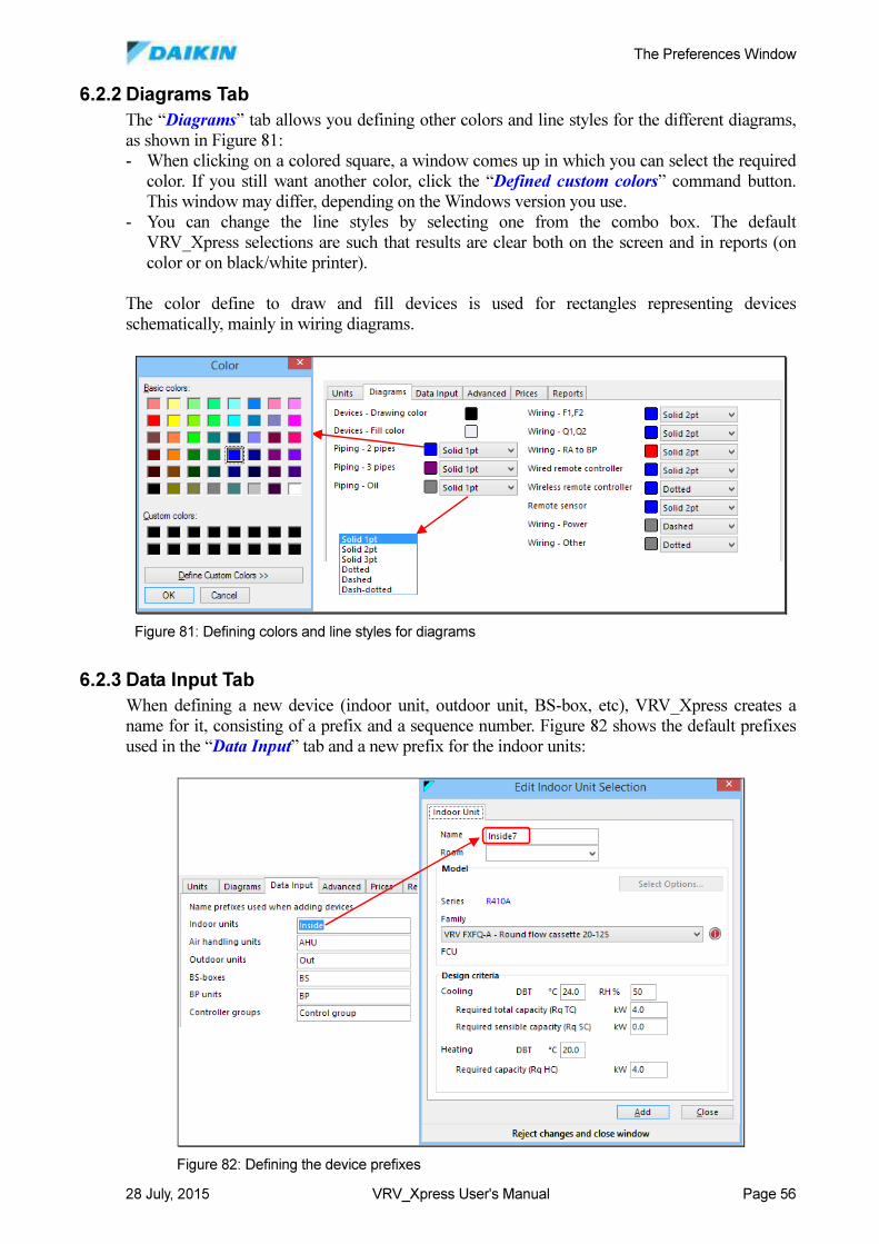
The Preferences Window
28 July, 2015 VRV_Xpress User's Manual Page 56
6.2.2 Diagrams Tab
The “Diagrams” tab allows you defining other colors and line styles for the different diagrams,
as shown in Figure 81:
- When clicking on a colored square, a window comes up in which you can select the required
color. If you still want another color, click the “Defined custom colors” command button.
This window may differ, depending on the Windows version you use.
- You can change the line styles by selecting one from the combo box. The default
VRV_Xpress selections are such that results are clear both on the screen and in reports (on
color or on black/white printer).
The color define to draw and fill devices is used for rectangles representing devices
schematically, mainly in wiring diagrams.
6.2.3 Data Input Tab
When defining a new device (indoor unit, outdoor unit, BS-box, etc), VRV_Xpress creates a
name for it, consisting of a prefix and a sequence number. Figure 82 shows the default prefixes
used in the “Data Input” tab and a new prefix for the indoor units:
Figure 81: Defining colors and line styles for diagrams
Figure 82: Defining the device prefixes
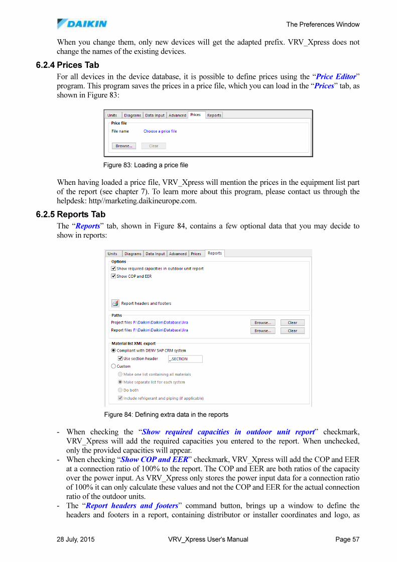
The Preferences Window
28 July, 2015 VRV_Xpress User's Manual Page 57
When you change them, only new devices will get the adapted prefix. VRV_Xpress does not
change the names of the existing devices.
6.2.4 Prices Tab
For all devices in the device database, it is possible to define prices using the “Price Editor”
program. This program saves the prices in a price file, which you can load in the “Prices” tab, as
shown in Figure 83:
When having loaded a price file, VRV_Xpress will mention the prices in the equipment list part
of the report (see chapter 7). To learn more about this program, please contact us through the
helpdesk: http//marketing.daikineurope.com.
6.2.5 Reports Tab
The “Reports” tab, shown in Figure 84, contains a few optional data that you may decide to
show in reports:
- When checking the “Show required capacities in outdoor unit report” checkmark,
VRV_Xpress will add the required capacities you entered to the report. When unchecked,
only the provided capacities will appear.
- When checking “Show COP and EER” checkmark, VRV_Xpress will add the COP and EER
at a connection ratio of 100% to the report. The COP and EER are both ratios of the capacity
over the power input. As VRV_Xpress only stores the power input data for a connection ratio
of 100% it can only calculate these values and not the COP and EER for the actual connection
ratio of the outdoor units.
- The “Report headers and footers” command button, brings up a window to define the
headers and footers in a report, containing distributor or installer coordinates and logo, as
Figure 83: Loading a price file
Figure 84: Defining extra data in the reports
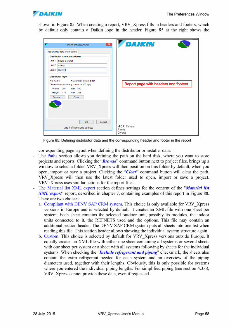
The Preferences Window
28 July, 2015 VRV_Xpress User's Manual Page 58
shown in Figure 85. When creating a report, VRV_Xpress fills in headers and footers, which
by default only contain a Daikin logo in the header. Figure 85 at the right shows the
corresponding page layout when defining the distributor or installer data.
- The Paths section allows you defining the path on the hard disk, where you want to store
projects and reports. Clicking the “Browse” command button next to project files, brings up a
window to select a folder. VRV_Xpress will then position on this folder by default, when you
open, import or save a project. Clicking the “Clear” command button will clear the path.
VRV_Xpress will then use the latest folder used to open, import or save a project.
VRV_Xpress uses similar actions for the report files.
- The Material list XML export section defines settings for the content of the "Material list
XML export" report, described in chapter 7, containing examples of this report in Figure 88.
There are two choices:
a. Compliant with DENV SAP CRM system. This choice is only available for VRV_Xpress
versions in Europe and is selected by default. It creates an XML file with one sheet per
system. Each sheet contains the selected outdoor unit, possibly its modules, the indoor
units connected to it, the REFNETS used and the options. This file may contain an
additional section header. The DENV SAP CRM system puts all sheets into one list when
reading this file. This section header allows showing the individual system structure again.
b. Custom. This choice is selected by default for VRV_Xpress versions outside Europe. It
equally creates an XML file with either one sheet containing all systems or several sheets
with one sheet per system or a sheet with all systems following by sheets for the individual
systems. When checking the "Include refrigerant and piping" checkmark, the sheets also
contain the extra refrigerant needed for each system and an overview of the piping
diameters used, together with their lengths. Obviously, this is only possible for systems
where you entered the individual piping lengths. For simplified piping (see section 4.3.6),
VRV_Xpress cannot provide these data, even if requested.
Report page with headers and footersReport page with headers and footers
Figure 85: Defining distributor data and the corresponding header and footer in the report
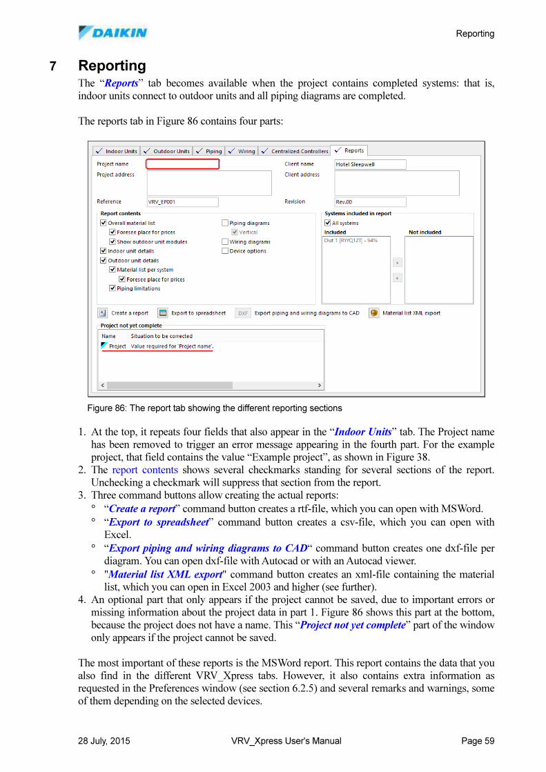
Reporting
28 July, 2015 VRV_Xpress User's Manual Page 59
7 Reporting The “Reports” tab becomes available when the project contains completed systems: that is,
indoor units connect to outdoor units and all piping diagrams are completed.
The reports tab in Figure 86 contains four parts:
1. At the top, it repeats four fields that also appear in the “Indoor Units” tab. The Project name
has been removed to trigger an error message appearing in the fourth part. For the example
project, that field contains the value “Example project”, as shown in Figure 38.
2. The report contents shows several checkmarks standing for several sections of the report.
Unchecking a checkmark will suppress that section from the report.
3. Three command buttons allow creating the actual reports:
° “Create a report” command button creates a rtf-file, which you can open with MSWord.
° “Export to spreadsheet” command button creates a csv-file, which you can open with
Excel.
° “Export piping and wiring diagrams to CAD“ command button creates one dxf-file per
diagram. You can open dxf-file with Autocad or with an Autocad viewer.
° "Material list XML export" command button creates an xml-file containing the material
list, which you can open in Excel 2003 and higher (see further).
4. An optional part that only appears if the project cannot be saved, due to important errors or
missing information about the project data in part 1. Figure 86 shows this part at the bottom,
because the project does not have a name. This “Project not yet complete” part of the window
only appears if the project cannot be saved.
The most important of these reports is the MSWord report. This report contains the data that you
also find in the different VRV_Xpress tabs. However, it also contains extra information as
requested in the Preferences window (see section 6.2.5) and several remarks and warnings, some
of them depending on the selected devices.
Figure 86: The report tab showing the different reporting sections
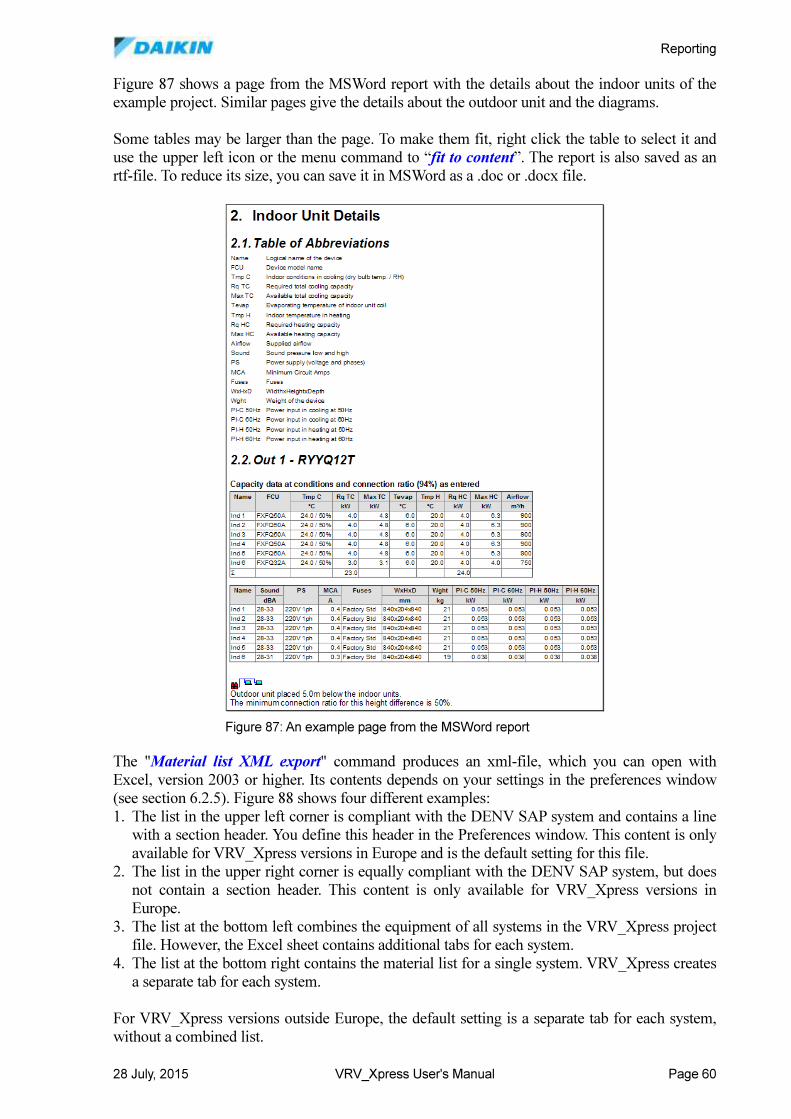
Reporting
28 July, 2015 VRV_Xpress User's Manual Page 60
Figure 87 shows a page from the MSWord report with the details about the indoor units of the
example project. Similar pages give the details about the outdoor unit and the diagrams.
Some tables may be larger than the page. To make them fit, right click the table to select it and
use the upper left icon or the menu command to “fit to content”. The report is also saved as an
rtf-file. To reduce its size, you can save it in MSWord as a .doc or .docx file.
The "Material list XML export" command produces an xml-file, which you can open with
Excel, version 2003 or higher. Its contents depends on your settings in the preferences window
(see section 6.2.5). Figure 88 shows four different examples:
1. The list in the upper left corner is compliant with the DENV SAP system and contains a line
with a section header. You define this header in the Preferences window. This content is only
available for VRV_Xpress versions in Europe and is the default setting for this file.
2. The list in the upper right corner is equally compliant with the DENV SAP system, but does
not contain a section header. This content is only available for VRV_Xpress versions in
Europe.
3. The list at the bottom left combines the equipment of all systems in the VRV_Xpress project
file. However, the Excel sheet contains additional tabs for each system.
4. The list at the bottom right contains the material list for a single system. VRV_Xpress creates
a separate tab for each system.
For VRV_Xpress versions outside Europe, the default setting is a separate tab for each system,
without a combined list.
Figure 87: An example page from the MSWord report
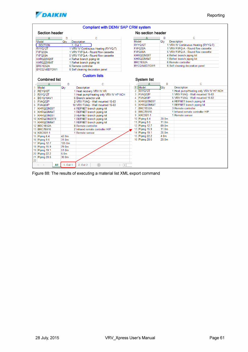
Reporting
28 July, 2015 VRV_Xpress User's Manual Page 61
Compliant with DENV SAP CRM system
Section header No section header
Custom listsCombined list System list
Compliant with DENV SAP CRM system
Section header No section header
Custom listsCombined list System list
Figure 88: The results of executing a material list XML export command
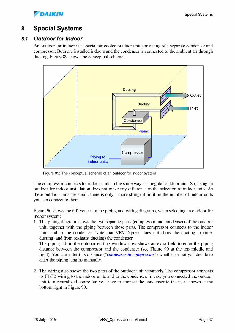
Special Systems
28 July, 2015 VRV_Xpress User's Manual Page 62
8 Special Systems
8.1 Outdoor for Indoor
An outdoor for indoor is a special air-cooled outdoor unit consisting of a separate condenser and
compressor. Both are installed indoors and the condenser is connected to the ambient air through
ducting. Figure 89 shows the conceptual scheme.
The compressor connects to indoor units in the same way as a regular outdoor unit. So, using an
outdoor for indoor installation does not make any difference in the selection of indoor units. As
these outdoor units are small, there is only a more stringent limit on the number of indoor units
you can connect to them.
Figure 90 shows the differences in the piping and wiring diagrams, when selecting an outdoor for
indoor system:
1. The piping diagram shows the two separate parts (compressor and condenser) of the outdoor
unit, together with the piping between those parts. The compressor connects to the indoor
units and to the condenser. Note that VRV_Xpress does not show the ducting to (inlet
ducting) and from (exhaust ducting) the condenser.
The piping tab in the outdoor editing window now shows an extra field to enter the piping
distance between the compressor and the condenser (see Figure 90 at the top middle and
right). You can enter this distance ("condenser to compressor") whether or not you decide to
enter the piping lengths manually.
2. The wiring also shows the two parts of the outdoor unit separately. The compressor connects
its F1/F2 wiring to the indoor units and to the condenser. In case you connected the outdoor
unit to a centralized controller, you have to connect the condenser to the it, as shown at the
bottom right in Figure 90.
Piping to
indoor units
Compressor
Condenser
Ducting
Inlet
Outlet
Ducting
Piping
Piping to
indoor units
Compressor
Condenser
Ducting
Inlet
Outlet
Ducting
Piping
Figure 89: The conceptual scheme of an outdoor for indoor system
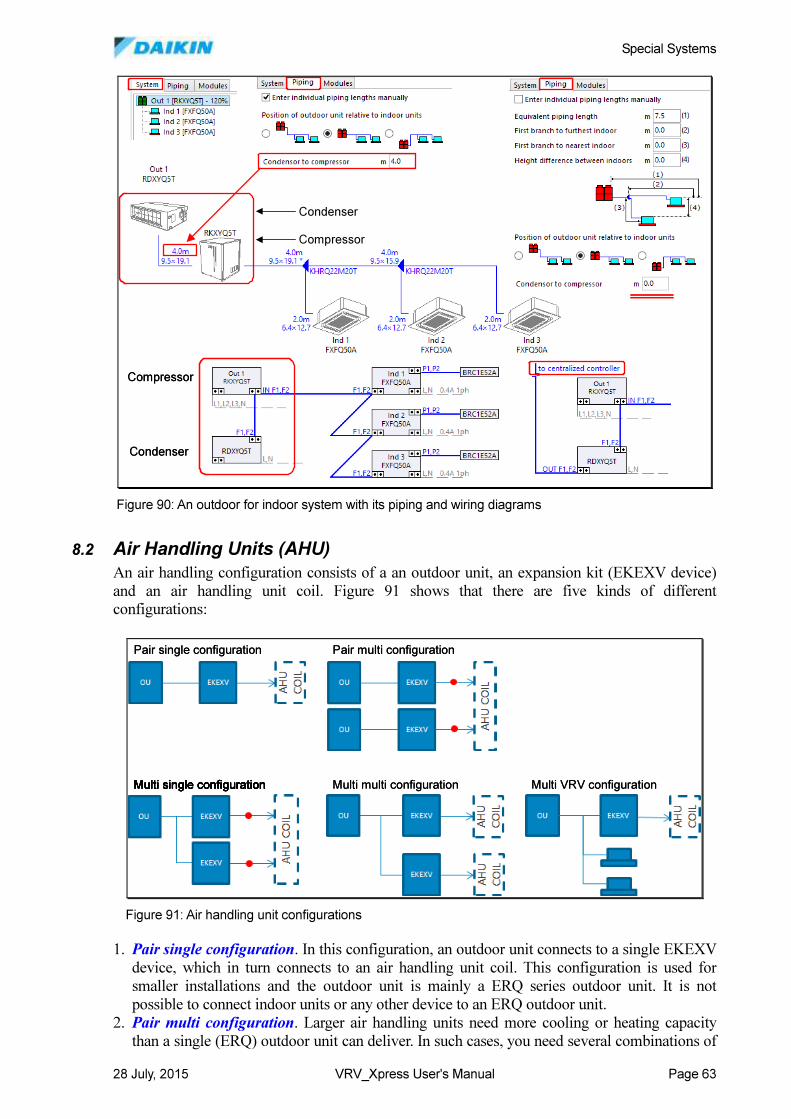
Special Systems
28 July, 2015 VRV_Xpress User's Manual Page 63
8.2 Air Handling Units (AHU)
An air handling configuration consists of a an outdoor unit, an expansion kit (EKEXV device)
and an air handling unit coil. Figure 91 shows that there are five kinds of different
configurations:
1. Pair single configuration. In this configuration, an outdoor unit connects to a single EKEXV
device, which in turn connects to an air handling unit coil. This configuration is used for
smaller installations and the outdoor unit is mainly a ERQ series outdoor unit. It is not
possible to connect indoor units or any other device to an ERQ outdoor unit.
2. Pair multi configuration. Larger air handling units need more cooling or heating capacity
than a single (ERQ) outdoor unit can deliver. In such cases, you need several combinations of
Condenser
Compressor
Condenser
Compressor
Condenser
Compressor
Condenser
Compressor
Figure 90: An outdoor for indoor system with its piping and wiring diagrams
Pair single configuration
Multi single configurationMulti single configurationMulti single configuration
Pair multi configuration
Multi multi configuration Multi VRV configuration
Pair single configuration
Multi single configurationMulti single configurationMulti single configuration
Pair multi configuration
Multi multi configuration Multi VRV configuration
Figure 91: Air handling unit configurations
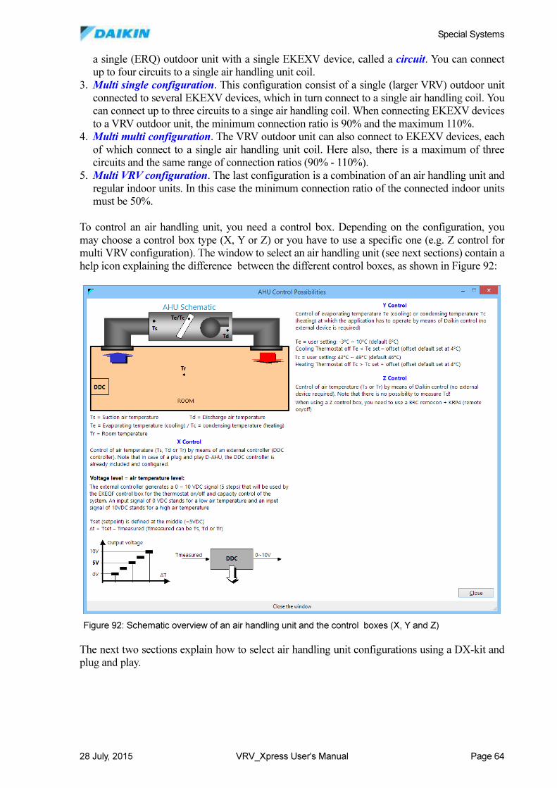
Special Systems
28 July, 2015 VRV_Xpress User's Manual Page 64
a single (ERQ) outdoor unit with a single EKEXV device, called a circuit. You can connect
up to four circuits to a single air handling unit coil.
3. Multi single configuration. This configuration consist of a single (larger VRV) outdoor unit
connected to several EKEXV devices, which in turn connect to a single air handling coil. You
can connect up to three circuits to a singe air handling coil. When connecting EKEXV devices
to a VRV outdoor unit, the minimum connection ratio is 90% and the maximum 110%.
4. Multi multi configuration. The VRV outdoor unit can also connect to EKEXV devices, each
of which connect to a single air handling unit coil. Here also, there is a maximum of three
circuits and the same range of connection ratios (90% - 110%).
5. Multi VRV configuration. The last configuration is a combination of an air handling unit and
regular indoor units. In this case the minimum connection ratio of the connected indoor units
must be 50%.
To control an air handling unit, you need a control box. Depending on the configuration, you
may choose a control box type (X, Y or Z) or you have to use a specific one (e.g. Z control for
multi VRV configuration). The window to select an air handling unit (see next sections) contain a
help icon explaining the difference between the different control boxes, as shown in Figure 92:
The next two sections explain how to select air handling unit configurations using a DX-kit and
plug and play.
Figure 92: Schematic overview of an air handling unit and the control boxes (X, Y and Z)
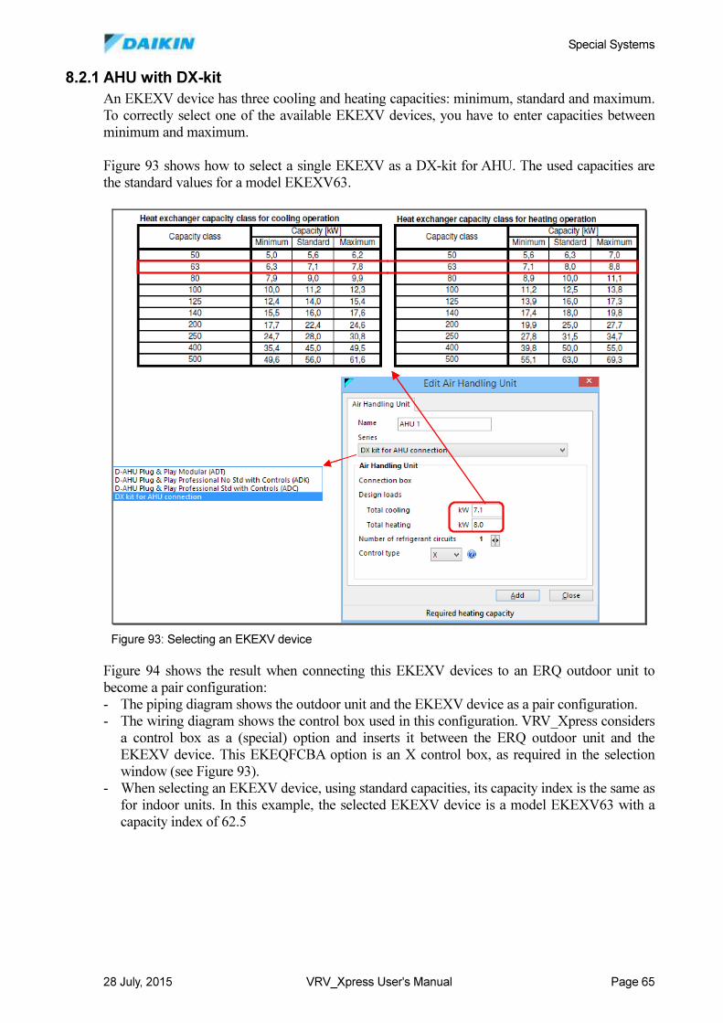
Special Systems
28 July, 2015 VRV_Xpress User's Manual Page 65
8.2.1 AHU with DX-kit
An EKEXV device has three cooling and heating capacities: minimum, standard and maximum.
To correctly select one of the available EKEXV devices, you have to enter capacities between
minimum and maximum.
Figure 93 shows how to select a single EKEXV as a DX-kit for AHU. The used capacities are
the standard values for a model EKEXV63.
Figure 94 shows the result when connecting this EKEXV devices to an ERQ outdoor unit to
become a pair configuration:
- The piping diagram shows the outdoor unit and the EKEXV device as a pair configuration.
- The wiring diagram shows the control box used in this configuration. VRV_Xpress considers
a control box as a (special) option and inserts it between the ERQ outdoor unit and the
EKEXV device. This EKEQFCBA option is an X control box, as required in the selection
window (see Figure 93).
- When selecting an EKEXV device, using standard capacities, its capacity index is the same as
for indoor units. In this example, the selected EKEXV device is a model EKEXV63 with a
capacity index of 62.5
Figure 93: Selecting an EKEXV device
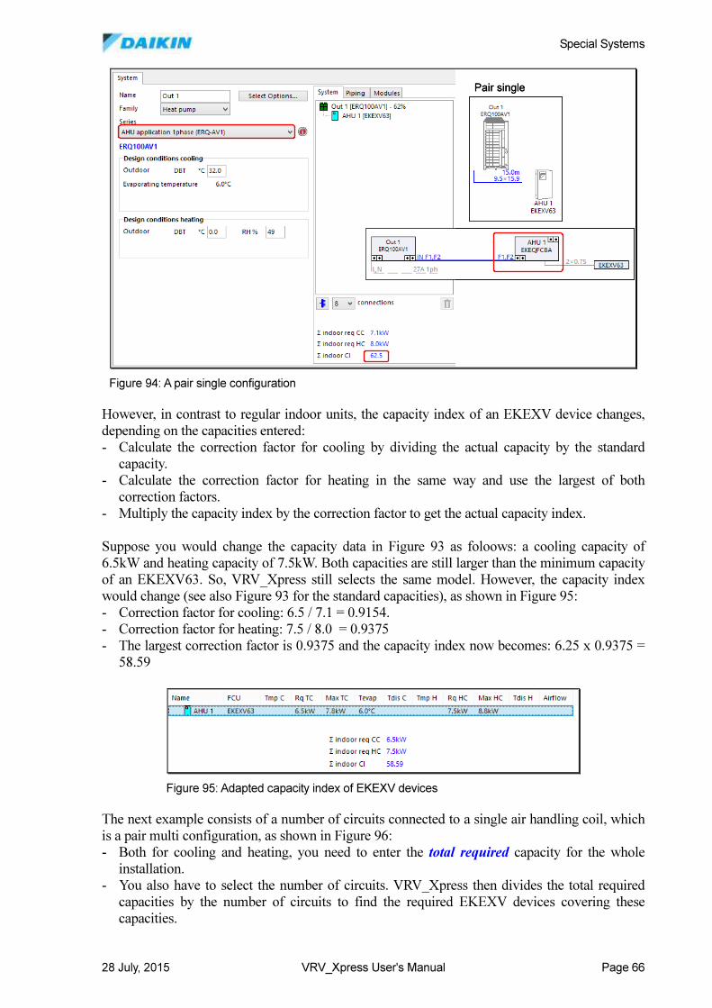
Special Systems
28 July, 2015 VRV_Xpress User's Manual Page 66
However, in contrast to regular indoor units, the capacity index of an EKEXV device changes,
depending on the capacities entered:
- Calculate the correction factor for cooling by dividing the actual capacity by the standard
capacity.
- Calculate the correction factor for heating in the same way and use the largest of both
correction factors.
- Multiply the capacity index by the correction factor to get the actual capacity index.
Suppose you would change the capacity data in Figure 93 as foloows: a cooling capacity of
6.5kW and heating capacity of 7.5kW. Both capacities are still larger than the minimum capacity
of an EKEXV63. So, VRV_Xpress still selects the same model. However, the capacity index
would change (see also Figure 93 for the standard capacities), as shown in Figure 95:
- Correction factor for cooling: 6.5 / 7.1 = 0.9154.
- Correction factor for heating: 7.5 / 8.0 = 0.9375
- The largest correction factor is 0.9375 and the capacity index now becomes: 6.25 x 0.9375 =
58.59
The next example consists of a number of circuits connected to a single air handling coil, which
is a pair multi configuration, as shown in Figure 96:
- Both for cooling and heating, you need to enter the total required capacity for the whole
installation.
- You also have to select the number of circuits. VRV_Xpress then divides the total required
capacities by the number of circuits to find the required EKEXV devices covering these
capacities.
Pair singlePair single
Figure 94: A pair single configuration
Figure 95: Adapted capacity index of EKEXV devices
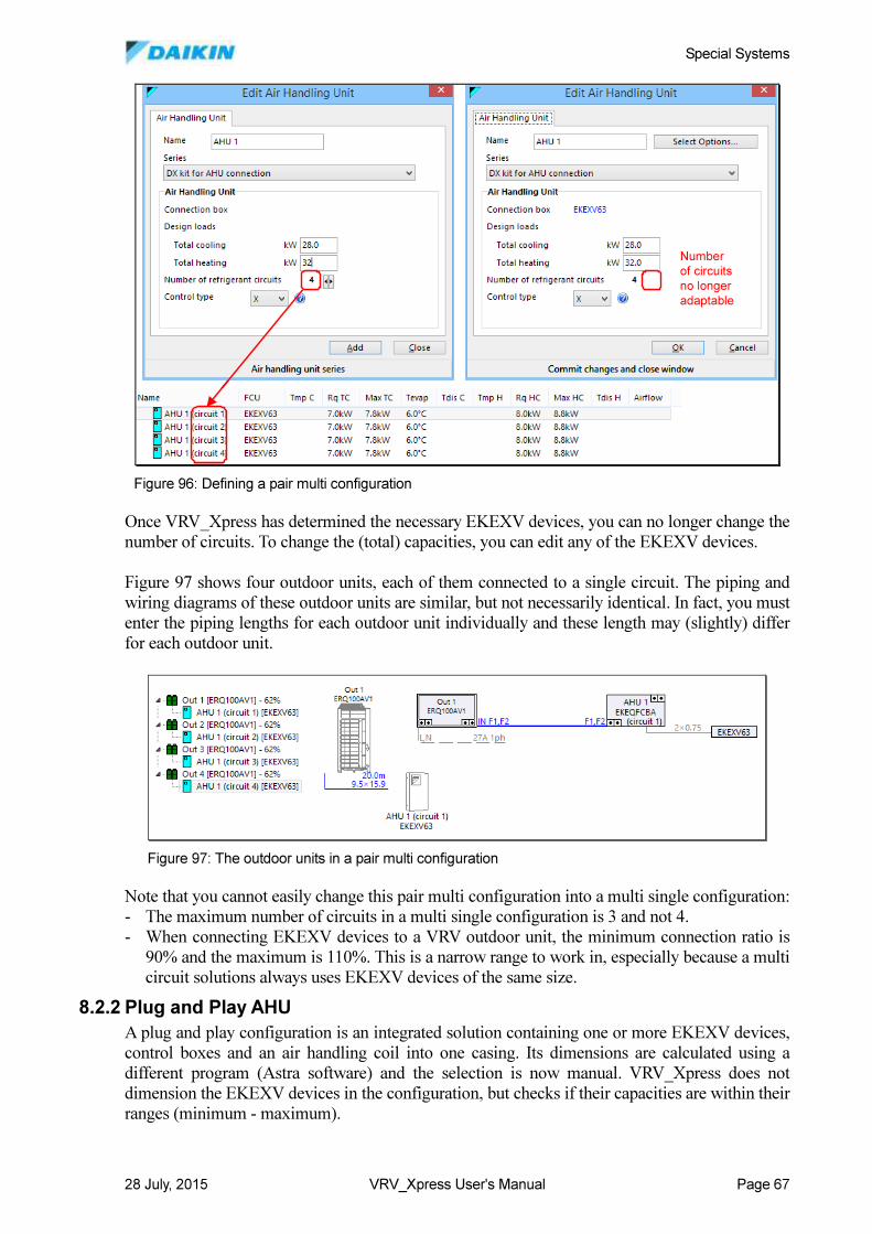
Special Systems
28 July, 2015 VRV_Xpress User's Manual Page 67
Once VRV_Xpress has determined the necessary EKEXV devices, you can no longer change the
number of circuits. To change the (total) capacities, you can edit any of the EKEXV devices.
Figure 97 shows four outdoor units, each of them connected to a single circuit. The piping and
wiring diagrams of these outdoor units are similar, but not necessarily identical. In fact, you must
enter the piping lengths for each outdoor unit individually and these length may (slightly) differ
for each outdoor unit.
Note that you cannot easily change this pair multi configuration into a multi single configuration:
- The maximum number of circuits in a multi single configuration is 3 and not 4.
- When connecting EKEXV devices to a VRV outdoor unit, the minimum connection ratio is
90% and the maximum is 110%. This is a narrow range to work in, especially because a multi
circuit solutions always uses EKEXV devices of the same size.
8.2.2 Plug and Play AHU
A plug and play configuration is an integrated solution containing one or more EKEXV devices,
control boxes and an air handling coil into one casing. Its dimensions are calculated using a
different program (Astra software) and the selection is now manual. VRV_Xpress does not
dimension the EKEXV devices in the configuration, but checks if their capacities are within their
ranges (minimum - maximum).
Number
of circuits
no longer
adaptable
Number
of circuits
no longer
adaptable
Figure 96: Defining a pair multi configuration
Figure 97: The outdoor units in a pair multi configuration
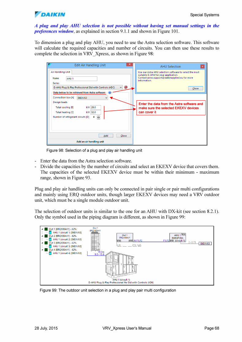
Special Systems
28 July, 2015 VRV_Xpress User's Manual Page 68
A plug and play AHU selection is not possible without having set manual settings in the preferences window, as explained in section 9.1.1 and shown in Figure 101.
To dimension a plug and play AHU, you need to use the Astra selection software. This software
will calculate the required capacities and number of circuits. You can then use these results to
complete the selection in VRV_Xpress, as shown in Figure 98:
- Enter the data from the Astra selection software.
- Divide the capacities by the number of circuits and select an EKEXV device that covers them.
The capacities of the selected EKEXV device must be within their minimum - maximum
range, shown in Figure 93.
Plug and play air handling units can only be connected in pair single or pair multi configurations
and mainly using ERQ outdoor units, though larger EKEXV devices may need a VRV outdoor
unit, which must be a single module outdoor unit.
The selection of outdoor units is similar to the one for an AHU with DX-kit (see section 8.2.1).
Only the symbol used in the piping diagram is different, as shown in Figure 99:
Enter the data from the Astra software and
make sure the selected EKEXV devices
can cover it
Enter the data from the Astra software and
make sure the selected EKEXV devices
can cover it
Figure 98: Selection of a plug and play air handling unit
Figure 99: The outdoor unit selection in a plug and play pair multi configuration
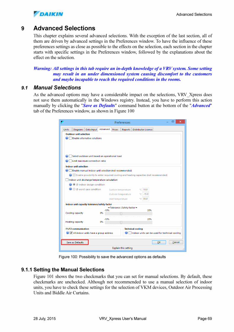
Advanced Selections
28 July, 2015 VRV_Xpress User's Manual Page 69
9 Advanced Selections This chapter explains several advanced selections. With the exception of the last section, all of
them are driven by advanced settings in the Preferences window. To have the influence of these
preferences settings as close as possible to the effects on the selection, each section in the chapter
starts with specific settings in the Preferences window, followed by the explanations about the
effect on the selection.
Warning: All settings in this tab require an in-depth knowledge of a VRV system. Some setting
may result in an under dimensioned system causing discomfort to the customers
and maybe incapable to reach the required conditions in the rooms.
9.1 Manual Selections
As the advanced options may have a considerable impact on the selections, VRV_Xpress does
not save them automatically in the Windows registry. Instead, you have to perform this action
manually by clicking the "Save as Defaults" command button at the bottom of the "Advanced"
tab of the Preferences window, as shown in Figure 100
9.1.1 Setting the Manual Selections
Figure 101 shows the two checkmarks that you can set for manual selections. By default, these
checkmarks are unchecked. Although not recommended to use a manual selection of indoor
units, you have to check these settings for the selection of VKM devices, Outdoor Air Processing
Units and Biddle Air Curtains.
Figure 100: Possibility to save the advanced options as defaults
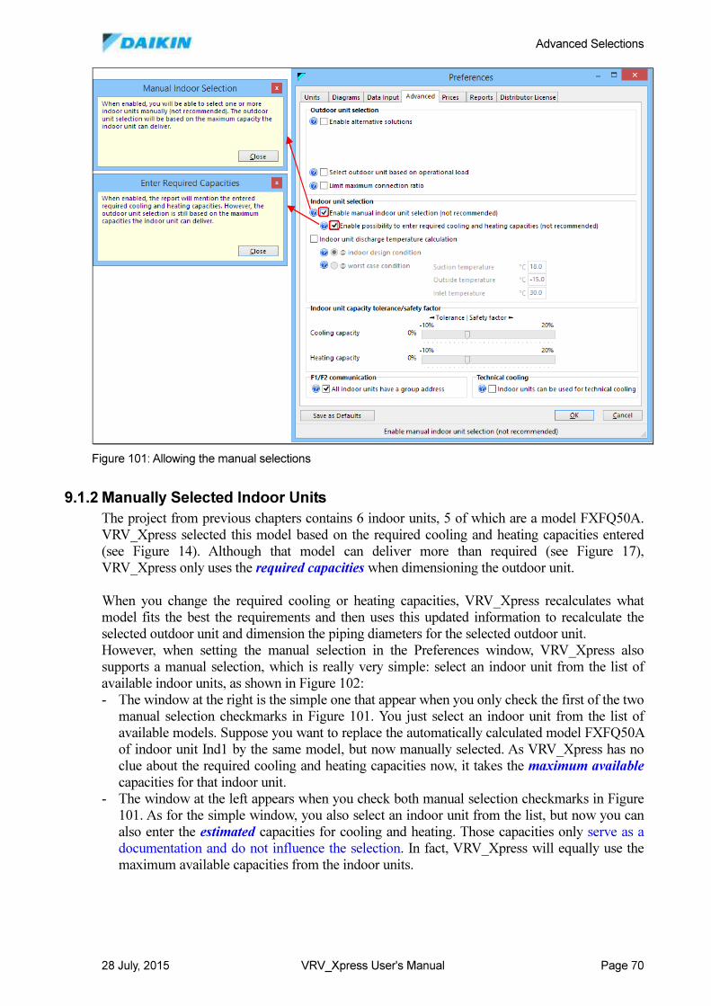
Advanced Selections
28 July, 2015 VRV_Xpress User's Manual Page 70
9.1.2 Manually Selected Indoor Units
The project from previous chapters contains 6 indoor units, 5 of which are a model FXFQ50A.
VRV_Xpress selected this model based on the required cooling and heating capacities entered
(see Figure 14). Although that model can deliver more than required (see Figure 17),
VRV_Xpress only uses the required capacities when dimensioning the outdoor unit.
When you change the required cooling or heating capacities, VRV_Xpress recalculates what
model fits the best the requirements and then uses this updated information to recalculate the
selected outdoor unit and dimension the piping diameters for the selected outdoor unit.
However, when setting the manual selection in the Preferences window, VRV_Xpress also
supports a manual selection, which is really very simple: select an indoor unit from the list of
available indoor units, as shown in Figure 102:
- The window at the right is the simple one that appear when you only check the first of the two
manual selection checkmarks in Figure 101. You just select an indoor unit from the list of
available models. Suppose you want to replace the automatically calculated model FXFQ50A
of indoor unit Ind1 by the same model, but now manually selected. As VRV_Xpress has no
clue about the required cooling and heating capacities now, it takes the maximum available
capacities for that indoor unit.
- The window at the left appears when you check both manual selection checkmarks in Figure
101. As for the simple window, you also select an indoor unit from the list, but now you can
also enter the estimated capacities for cooling and heating. Those capacities only serve as a
documentation and do not influence the selection. In fact, VRV_Xpress will equally use the
maximum available capacities from the indoor units.
Figure 101: Allowing the manual selections
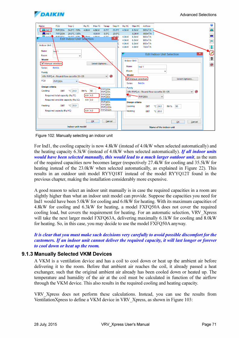
Advanced Selections
28 July, 2015 VRV_Xpress User's Manual Page 71
For Ind1, the cooling capacity is now 4.8kW (instead of 4.0kW when selected automatically) and
the heating capacity 6.3kW (instead of 4.0kW when selected automatically). If all indoor units
would have been selected manually, this would lead to a much larger outdoor unit, as the sum
of the required capacities now becomes larger (respectively 27.4kW for cooling and 35.5kW for
heating instead of the 23.0kW when selected automatically, as explained in Figure 22). This
results in an outdoor unit model RYYQ18T instead of the model RYYQ12T found in the
previous chapter, making the installation considerably more expensive.
A good reason to select an indoor unit manually is in case the required capacities in a room are
slightly higher than what an indoor unit model can provide. Suppose the capacities you need for
Ind1 would have been 5.0kW for cooling and 6.0kW for heating. With its maximum capacities of
4.8kW for cooling and 6.3kW for heating, a model FXFQ50A does not cover the required
cooling load, but covers the requirement for heating. For an automatic selection, VRV_Xpress
will take the next larger model FXFQ63A, delivering maximally 6.1kW for cooling and 8.0kW
for heating. So, in this case, you may decide to use the model FXFQ50A anyway.
It is clear that you must make such decisions very carefully to avoid possible discomfort for the
customers. If an indoor unit cannot deliver the required capacity, it will last longer or forever
to cool down or heat up the room.
9.1.3 Manually Selected VKM Devices
A VKM is a ventilation device and has a coil to cool down or heat up the ambient air before
delivering it to the room. Before that ambient air reaches the coil, it already passed a heat
exchanger, such that the original ambient air already has been cooled down or heated up. The
temperature and humidity of the air at the coil must be calculated in function of the airflow
through the VKM device. This also results in the required cooling and heating capacity.
VRV_Xpress does not perform these calculations. Instead, you can use the results from
VentilationXpress to define a VKM device in VRV_Xpress, as shown in Figure 103:
Figure 102: Manually selecting an indoor unit
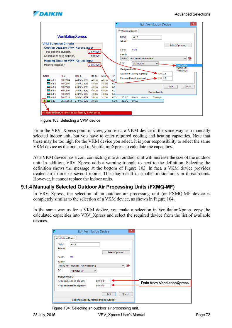
Advanced Selections
28 July, 2015 VRV_Xpress User's Manual Page 72
From the VRV_Xpress point of view, you select a VKM device in the same way as a manually
selected indoor unit, but you have to enter required cooling and heating capacities. Note that
these may be too high for the VKM device you select. It is your responsibility to select the same
VKM device as the one used in VentilationXpress to calculate the capacities.
As a VKM device has a coil, connecting it to an outdoor unit will increase the size of the outdoor
unit. In addition, VRV_Xpress adds a warning triangle to next to the definition. Selecting the
definition shows the message at the bottom of Figure 103. In fact, a VKM device provides
treated air to one or several rooms. This may result in smaller indoor units in those rooms.
However, it cannot replace the indoor units.
9.1.4 Manually Selected Outdoor Air Processing Units (FXMQ-MF)
In VRV_Xpress, the selection of an outdoor air processing unit (or FXMQ-MF device is
completely similar to the selection of a VKM device, as shown in Figure 104.
In the same way as for a VKM device, you make a selection in VentilationXpress, copy the
calculated capacities into VRV_Xpress and select the required device from the list of available
devices.
VentilationXpressVentilationXpress
Figure 103: Selecting a VKM device
Data from VentilationXpressData from VentilationXpress
Figure 104: Selecting an outdoor air processing unit.
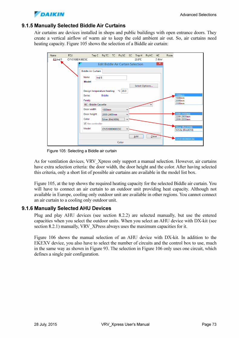
Advanced Selections
28 July, 2015 VRV_Xpress User's Manual Page 73
9.1.5 Manually Selected Biddle Air Curtains
Air curtains are devices installed in shops and public buildings with open entrance doors. They
create a vertical airflow of warm air to keep the cold ambient air out. So, air curtains need
heating capacity. Figure 105 shows the selection of a Biddle air curtain:
As for ventilation devices, VRV_Xpress only support a manual selection. However, air curtains
have extra selection criteria: the door width, the door height and the color. After having selected
this criteria, only a short list of possible air curtains are available in the model list box.
Figure 105, at the top shows the required heating capacity for the selected Biddle air curtain. You
will have to connect an air curtain to an outdoor unit providing heat capacity. Although not
available in Europe, cooling only outdoor unit are available in other regions. You cannot connect
an air curtain to a cooling only outdoor unit.
9.1.6 Manually Selected AHU Devices
Plug and play AHU devices (see section 8.2.2) are selected manually, but use the entered
capacities when you select the outdoor units. When you select an AHU device with DX-kit (see
section 8.2.1) manually, VRV_XPress always uses the maximum capacities for it.
Figure 106 shows the manual selection of an AHU device with DX-kit. In addition to the
EKEXV device, you also have to select the number of circuits and the control box to use, much
in the same way as shown in Figure 93. The selection in Figure 106 only uses one circuit, which
defines a single pair configuration.
Figure 105: Selecting a Biddle air curtain
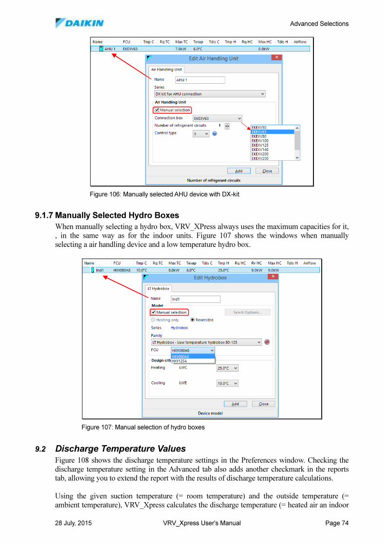
Advanced Selections
28 July, 2015 VRV_Xpress User's Manual Page 74
9.1.7 Manually Selected Hydro Boxes
When manually selecting a hydro box, VRV_XPress always uses the maximum capacities for it,
, in the same way as for the indoor units. Figure 107 shows the windows when manually
selecting a air handling device and a low temperature hydro box.
9.2 Discharge Temperature Values
Figure 108 shows the discharge temperature settings in the Preferences window. Checking the
discharge temperature setting in the Advanced tab also adds another checkmark in the reports
tab, allowing you to extend the report with the results of discharge temperature calculations.
Using the given suction temperature (= room temperature) and the outside temperature (=
ambient temperature), VRV_Xpress calculates the discharge temperature (= heated air an indoor
Figure 106: Manually selected AHU device with DX-kit
Figure 107: Manual selection of hydro boxes
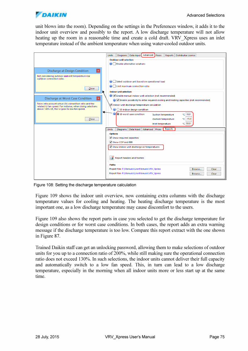
Advanced Selections
28 July, 2015 VRV_Xpress User's Manual Page 75
unit blows into the room). Depending on the settings in the Preferences window, it adds it to the
indoor unit overview and possibly to the report. A low discharge temperature will not allow
heating up the room in a reasonable time and create a cold draft. VRV_Xpress uses an inlet
temperature instead of the ambient temperature when using water-cooled outdoor units.
Figure 109 shows the indoor unit overview, now containing extra columns with the discharge
temperature values for cooling and heating. The heating discharge temperature is the most
important one, as a low discharge temperature may cause discomfort to the users.
Figure 109 also shows the report parts in case you selected to get the discharge temperature for
design conditions or for worst case conditions. In both cases, the report adds an extra warning
message if the discharge temperature is too low. Compare this report extract with the one shown
in Figure 87.
Trained Daikin staff can get an unlocking password, allowing them to make selections of outdoor
units for you up to a connection ratio of 200%, while still making sure the operational connection
ratio does not exceed 130%. In such selections, the indoor units cannot deliver their full capacity
and automatically switch to a low fan speed. This, in turn can lead to a low discharge
temperature, especially in the morning when all indoor units more or less start up at the same
time.
Figure 108: Setting the discharge temperature calculation
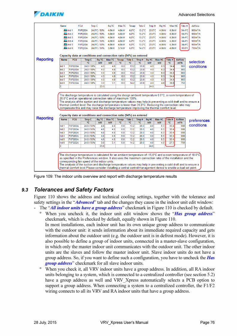
Advanced Selections
28 July, 2015 VRV_Xpress User's Manual Page 76
9.3 Tolerances and Safety Factors
Figure 110 shows the address and technical cooling settings, together with the tolerance and
safety settings in the “Advanced” tab and the changes they cause in the indoor unit edit window:
- The “All indoor units have a group address” checkmark in Figure 110 is checked by default.
° When you uncheck it, the indoor unit edit window shows the “Has group address”
checkmark, which is checked by default, equally shown in Figure 110.
In most installations, each indoor unit has its own unique group address to communicate
with the outdoor unit: it sends information about its immediate required capacity and gets
information about the outdoor unit (e.g. the outdoor unit is in defrost mode). However, it is
also possible to define a group of indoor units, connected in a master-slave configuration,
in which only the master indoor unit communicates with the outdoor unit. The other indoor
units are the slaves and follow the master indoor unit. Slave indoor units do not have a
group address. So, if you want to define such a configuration, you have to uncheck the Has
group address” checkmark for all slave indoor units.
° When you check it, all VRV indoor units have a group address. In addition, all RA indoor
units belonging to a system, which is connected to a centralized controller (see section 5.2)
have a group address as well and VRV_Xpress automatically selects a PCB option to
support a group address. When connecting a system to a centralized controller, the F1/F2
wiring connects to all its VRV and RA indoor units that have a group address.
preferences
conditions
selection
conditions
Reporting
Reportingpreferences
conditions
selection
conditions
Reporting
Reporting
Figure 109: The indoor units overview and report with discharge temperature results
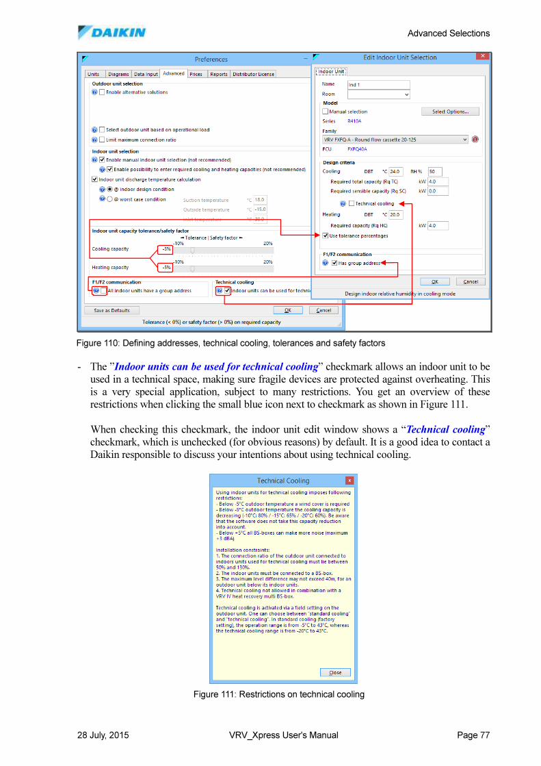
Advanced Selections
28 July, 2015 VRV_Xpress User's Manual Page 77
- The ”Indoor units can be used for technical cooling” checkmark allows an indoor unit to be
used in a technical space, making sure fragile devices are protected against overheating. This
is a very special application, subject to many restrictions. You get an overview of these
restrictions when clicking the small blue icon next to checkmark as shown in Figure 111.
When checking this checkmark, the indoor unit edit window shows a “Technical cooling”
checkmark, which is unchecked (for obvious reasons) by default. It is a good idea to contact a
Daikin responsible to discuss your intentions about using technical cooling.
Figure 110: Defining addresses, technical cooling, tolerances and safety factors
Figure 111: Restrictions on technical cooling
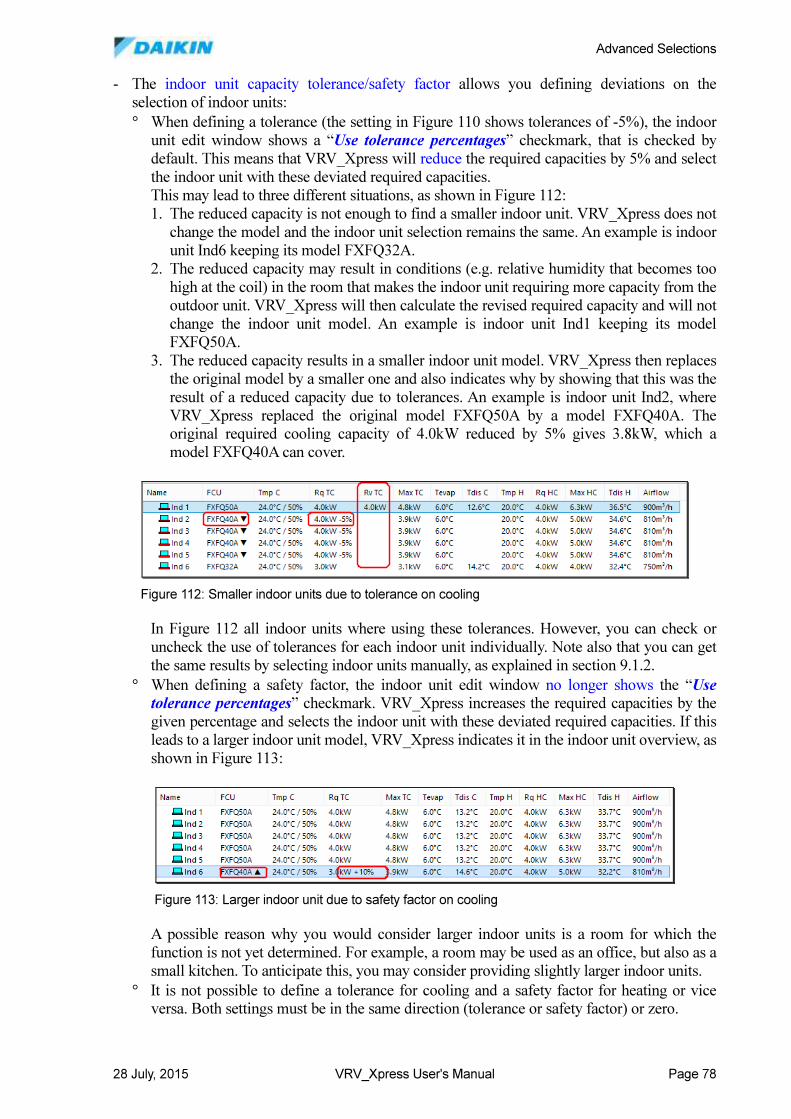
Advanced Selections
28 July, 2015 VRV_Xpress User's Manual Page 78
- The indoor unit capacity tolerance/safety factor allows you defining deviations on the
selection of indoor units:
° When defining a tolerance (the setting in Figure 110 shows tolerances of -5%), the indoor
unit edit window shows a “Use tolerance percentages” checkmark, that is checked by
default. This means that VRV_Xpress will reduce the required capacities by 5% and select
the indoor unit with these deviated required capacities.
This may lead to three different situations, as shown in Figure 112:
1. The reduced capacity is not enough to find a smaller indoor unit. VRV_Xpress does not
change the model and the indoor unit selection remains the same. An example is indoor
unit Ind6 keeping its model FXFQ32A.
2. The reduced capacity may result in conditions (e.g. relative humidity that becomes too
high at the coil) in the room that makes the indoor unit requiring more capacity from the
outdoor unit. VRV_Xpress will then calculate the revised required capacity and will not
change the indoor unit model. An example is indoor unit Ind1 keeping its model
FXFQ50A.
3. The reduced capacity results in a smaller indoor unit model. VRV_Xpress then replaces
the original model by a smaller one and also indicates why by showing that this was the
result of a reduced capacity due to tolerances. An example is indoor unit Ind2, where
VRV_Xpress replaced the original model FXFQ50A by a model FXFQ40A. The
original required cooling capacity of 4.0kW reduced by 5% gives 3.8kW, which a
model FXFQ40A can cover.
In Figure 112 all indoor units where using these tolerances. However, you can check or
uncheck the use of tolerances for each indoor unit individually. Note also that you can get
the same results by selecting indoor units manually, as explained in section 9.1.2.
° When defining a safety factor, the indoor unit edit window no longer shows the “Use tolerance percentages” checkmark. VRV_Xpress increases the required capacities by the
given percentage and selects the indoor unit with these deviated required capacities. If this
leads to a larger indoor unit model, VRV_Xpress indicates it in the indoor unit overview, as
shown in Figure 113:
A possible reason why you would consider larger indoor units is a room for which the
function is not yet determined. For example, a room may be used as an office, but also as a
small kitchen. To anticipate this, you may consider providing slightly larger indoor units.
° It is not possible to define a tolerance for cooling and a safety factor for heating or vice
versa. Both settings must be in the same direction (tolerance or safety factor) or zero.
Figure 112: Smaller indoor units due to tolerance on cooling
Figure 113: Larger indoor unit due to safety factor on cooling
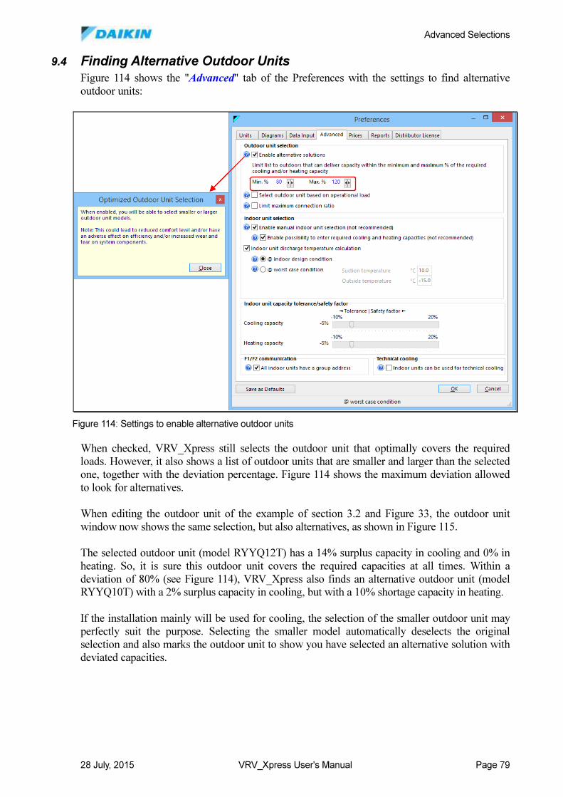
Advanced Selections
28 July, 2015 VRV_Xpress User's Manual Page 79
9.4 Finding Alternative Outdoor Units
Figure 114 shows the "Advanced" tab of the Preferences with the settings to find alternative
outdoor units:
When checked, VRV_Xpress still selects the outdoor unit that optimally covers the required
loads. However, it also shows a list of outdoor units that are smaller and larger than the selected
one, together with the deviation percentage. Figure 114 shows the maximum deviation allowed
to look for alternatives.
When editing the outdoor unit of the example of section 3.2 and Figure 33, the outdoor unit
window now shows the same selection, but also alternatives, as shown in Figure 115.
The selected outdoor unit (model RYYQ12T) has a 14% surplus capacity in cooling and 0% in
heating. So, it is sure this outdoor unit covers the required capacities at all times. Within a
deviation of 80% (see Figure 114), VRV_Xpress also finds an alternative outdoor unit (model
RYYQ10T) with a 2% surplus capacity in cooling, but with a 10% shortage capacity in heating.
If the installation mainly will be used for cooling, the selection of the smaller outdoor unit may
perfectly suit the purpose. Selecting the smaller model automatically deselects the original
selection and also marks the outdoor unit to show you have selected an alternative solution with
deviated capacities.
Figure 114: Settings to enable alternative outdoor units
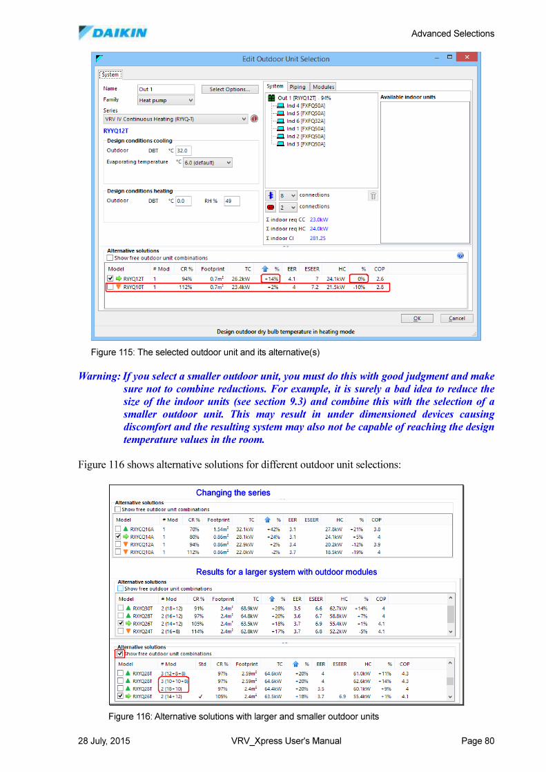
Advanced Selections
28 July, 2015 VRV_Xpress User's Manual Page 80
Warning: If you select a smaller outdoor unit, you must do this with good judgment and make
sure not to combine reductions. For example, it is surely a bad idea to reduce the
size of the indoor units (see section 9.3) and combine this with the selection of a
smaller outdoor unit. This may result in under dimensioned devices causing
discomfort and the resulting system may also not be capable of reaching the design
temperature values in the room.
Figure 116 shows alternative solutions for different outdoor unit selections:
Figure 115: The selected outdoor unit and its alternative(s)
Changing the series
Results for a larger system with outdoor modules
Changing the series
Results for a larger system with outdoor modules
Figure 116: Alternative solutions with larger and smaller outdoor units
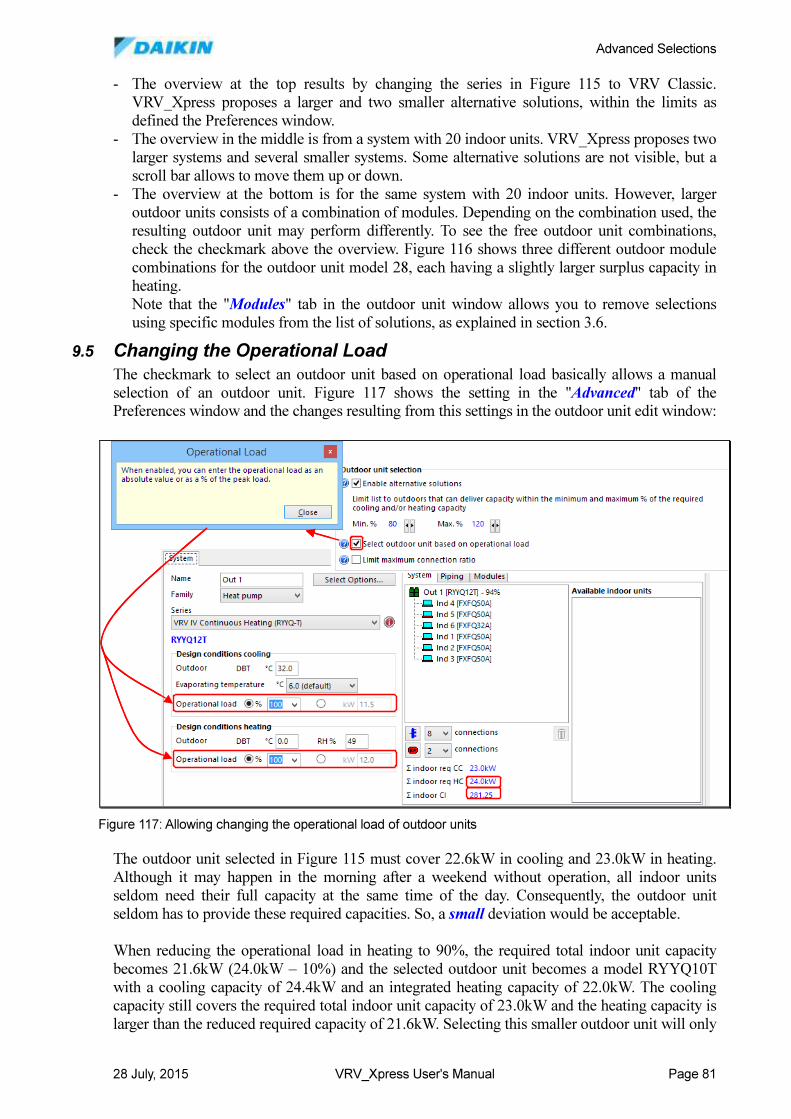
Advanced Selections
28 July, 2015 VRV_Xpress User's Manual Page 81
- The overview at the top results by changing the series in Figure 115 to VRV Classic.
VRV_Xpress proposes a larger and two smaller alternative solutions, within the limits as
defined the Preferences window.
- The overview in the middle is from a system with 20 indoor units. VRV_Xpress proposes two
larger systems and several smaller systems. Some alternative solutions are not visible, but a
scroll bar allows to move them up or down.
- The overview at the bottom is for the same system with 20 indoor units. However, larger
outdoor units consists of a combination of modules. Depending on the combination used, the
resulting outdoor unit may perform differently. To see the free outdoor unit combinations,
check the checkmark above the overview. Figure 116 shows three different outdoor module
combinations for the outdoor unit model 28, each having a slightly larger surplus capacity in
heating.
Note that the "Modules" tab in the outdoor unit window allows you to remove selections
using specific modules from the list of solutions, as explained in section 3.6.
9.5 Changing the Operational Load
The checkmark to select an outdoor unit based on operational load basically allows a manual
selection of an outdoor unit. Figure 117 shows the setting in the "Advanced" tab of the
Preferences window and the changes resulting from this settings in the outdoor unit edit window:
The outdoor unit selected in Figure 115 must cover 22.6kW in cooling and 23.0kW in heating.
Although it may happen in the morning after a weekend without operation, all indoor units
seldom need their full capacity at the same time of the day. Consequently, the outdoor unit
seldom has to provide these required capacities. So, a small deviation would be acceptable.
When reducing the operational load in heating to 90%, the required total indoor unit capacity
becomes 21.6kW (24.0kW – 10%) and the selected outdoor unit becomes a model RYYQ10T
with a cooling capacity of 24.4kW and an integrated heating capacity of 22.0kW. The cooling
capacity still covers the required total indoor unit capacity of 23.0kW and the heating capacity is
larger than the reduced required capacity of 21.6kW. Selecting this smaller outdoor unit will only
Figure 117: Allowing changing the operational load of outdoor units
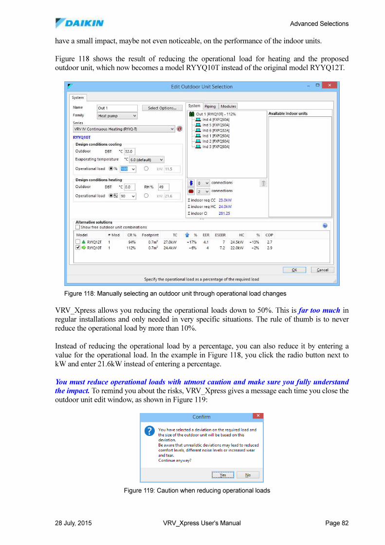
Advanced Selections
28 July, 2015 VRV_Xpress User's Manual Page 82
have a small impact, maybe not even noticeable, on the performance of the indoor units.
Figure 118 shows the result of reducing the operational load for heating and the proposed
outdoor unit, which now becomes a model RYYQ10T instead of the original model RYYQ12T.
VRV_Xpress allows you reducing the operational loads down to 50%. This is far too much in
regular installations and only needed in very specific situations. The rule of thumb is to never
reduce the operational load by more than 10%.
Instead of reducing the operational load by a percentage, you can also reduce it by entering a
value for the operational load. In the example in Figure 118, you click the radio button next to
kW and enter 21.6kW instead of entering a percentage.
You must reduce operational loads with utmost caution and make sure you fully understand the impact. To remind you about the risks, VRV_Xpress gives a message each time you close the
outdoor unit edit window, as shown in Figure 119:
Figure 118: Manually selecting an outdoor unit through operational load changes
Figure 119: Caution when reducing operational loads
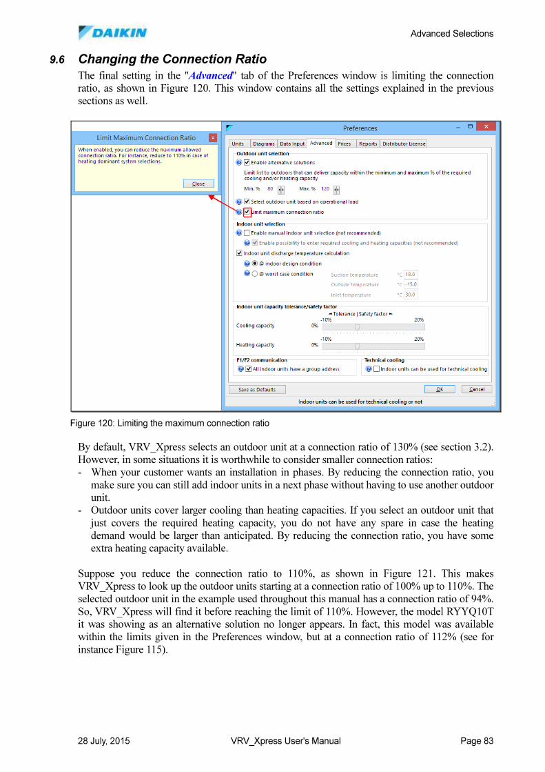
Advanced Selections
28 July, 2015 VRV_Xpress User's Manual Page 83
9.6 Changing the Connection Ratio
The final setting in the "Advanced" tab of the Preferences window is limiting the connection
ratio, as shown in Figure 120. This window contains all the settings explained in the previous
sections as well.
By default, VRV_Xpress selects an outdoor unit at a connection ratio of 130% (see section 3.2).
However, in some situations it is worthwhile to consider smaller connection ratios:
- When your customer wants an installation in phases. By reducing the connection ratio, you
make sure you can still add indoor units in a next phase without having to use another outdoor
unit.
- Outdoor units cover larger cooling than heating capacities. If you select an outdoor unit that
just covers the required heating capacity, you do not have any spare in case the heating
demand would be larger than anticipated. By reducing the connection ratio, you have some
extra heating capacity available.
Suppose you reduce the connection ratio to 110%, as shown in Figure 121. This makes
VRV_Xpress to look up the outdoor units starting at a connection ratio of 100% up to 110%. The
selected outdoor unit in the example used throughout this manual has a connection ratio of 94%.
So, VRV_Xpress will find it before reaching the limit of 110%. However, the model RYYQ10T
it was showing as an alternative solution no longer appears. In fact, this model was available
within the limits given in the Preferences window, but at a connection ratio of 112% (see for
instance Figure 115).
Figure 120: Limiting the maximum connection ratio
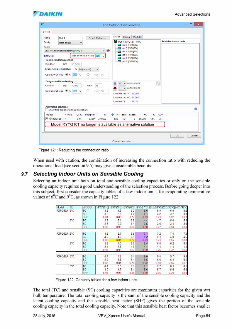
Advanced Selections
28 July, 2015 VRV_Xpress User's Manual Page 84
When used with caution, the combination of increasing the connection ratio with reducing the
operational load (see section 9.5) may give considerable benefits.
9.7 Selecting Indoor Units on Sensible Cooling
Selecting an indoor unit both on total and sensible cooling capacities or only on the sensible
cooling capacity requires a good understanding of the selection process. Before going deeper into
this subject, first consider the capacity tables of a few indoor units, for evaporating temperature
values of 60C and 9
0C, as shown in Figure 122:
The total (TC) and sensible (SC) cooling capacities are maximum capacities for the given wet
bulb temperature. The total cooling capacity is the sum of the sensible cooling capacity and the
latent cooling capacity and the sensible heat factor (SHF) gives the portion of the sensible
cooling capacity in the total cooling capacity. Note that this sensible heat factor becomes smaller
Model RYYQ10T no longer is available as alternative solutionModel RYYQ10T no longer is available as alternative solution
Figure 121: Reducing the connection ratio
Figure 122: Capacity tables for a few indoor units
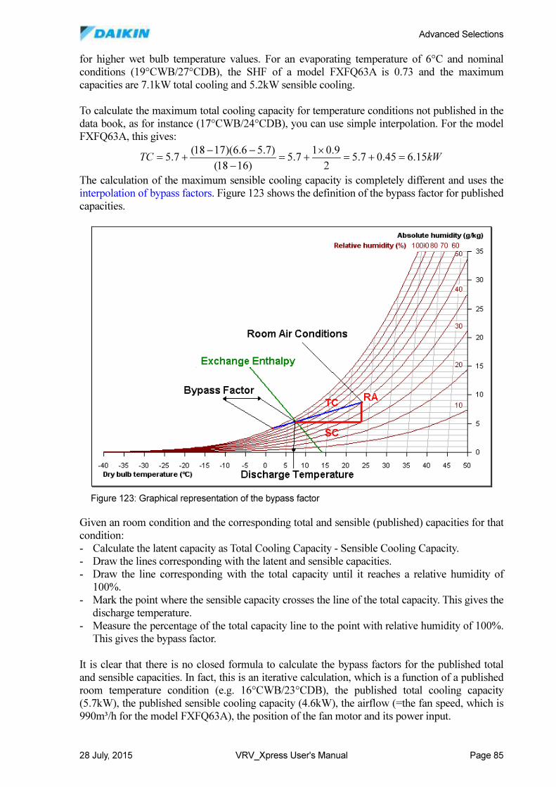
Advanced Selections
28 July, 2015 VRV_Xpress User's Manual Page 85
for higher wet bulb temperature values. For an evaporating temperature of 6°C and nominal
conditions (19°CWB/27°CDB), the SHF of a model FXFQ63A is 0.73 and the maximum
capacities are 7.1kW total cooling and 5.2kW sensible cooling.
To calculate the maximum total cooling capacity for temperature conditions not published in the
data book, as for instance (17°CWB/24°CDB), you can use simple interpolation. For the model
FXFQ63A, this gives:
kWTC 15.645.07.52
9.017.5
)1618(
)7.56.6)(1718(7.5 =+=
×+=
−
−−+=
The calculation of the maximum sensible cooling capacity is completely different and uses the
interpolation of bypass factors. Figure 123 shows the definition of the bypass factor for published
capacities.
Given an room condition and the corresponding total and sensible (published) capacities for that
condition:
- Calculate the latent capacity as Total Cooling Capacity - Sensible Cooling Capacity.
- Draw the lines corresponding with the latent and sensible capacities.
- Draw the line corresponding with the total capacity until it reaches a relative humidity of
100%.
- Mark the point where the sensible capacity crosses the line of the total capacity. This gives the
discharge temperature.
- Measure the percentage of the total capacity line to the point with relative humidity of 100%.
This gives the bypass factor.
It is clear that there is no closed formula to calculate the bypass factors for the published total
and sensible capacities. In fact, this is an iterative calculation, which is a function of a published
room temperature condition (e.g. 16°CWB/23°CDB), the published total cooling capacity
(5.7kW), the published sensible cooling capacity (4.6kW), the airflow (=the fan speed, which is
990m³/h for the model FXFQ63A), the position of the fan motor and its power input.
SC
TC
SC
TC
Figure 123: Graphical representation of the bypass factor
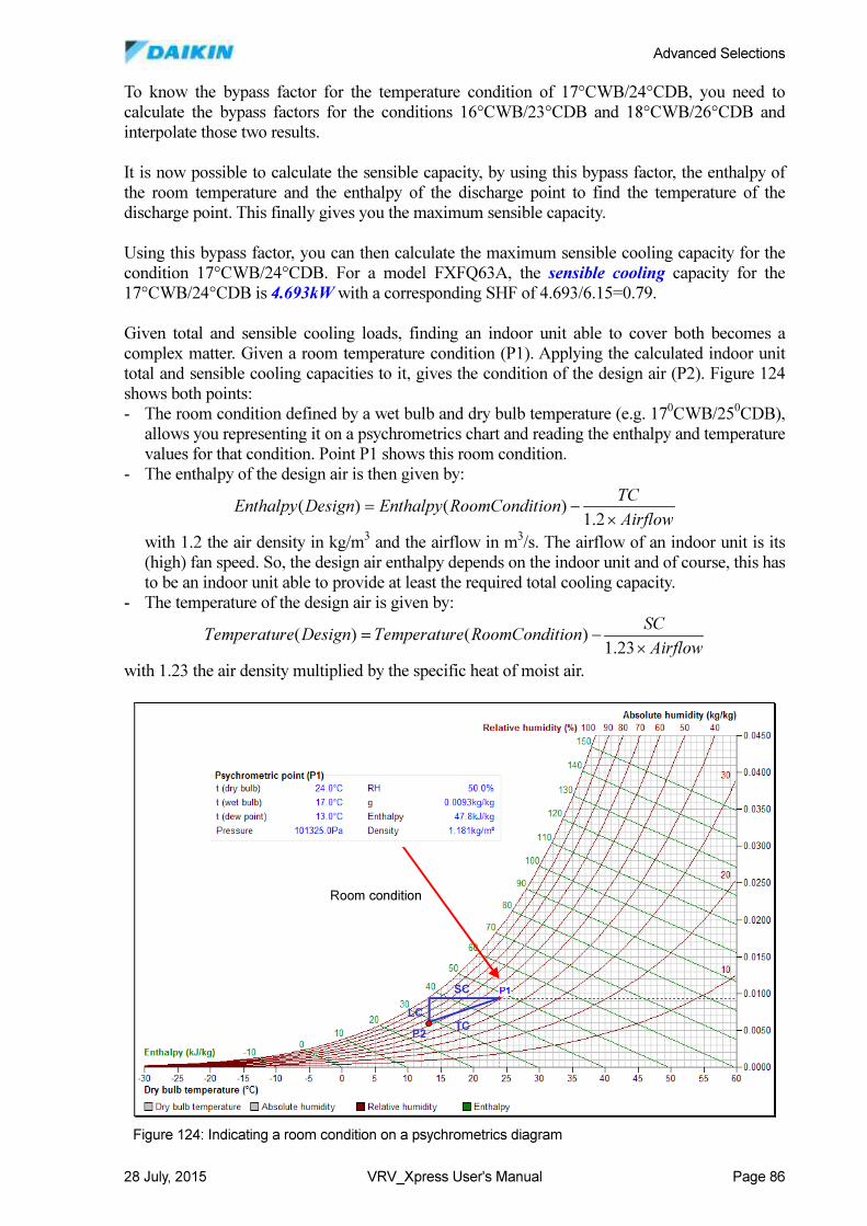
Advanced Selections
28 July, 2015 VRV_Xpress User's Manual Page 86
To know the bypass factor for the temperature condition of 17°CWB/24°CDB, you need to
calculate the bypass factors for the conditions 16°CWB/23°CDB and 18°CWB/26°CDB and
interpolate those two results.
It is now possible to calculate the sensible capacity, by using this bypass factor, the enthalpy of
the room temperature and the enthalpy of the discharge point to find the temperature of the
discharge point. This finally gives you the maximum sensible capacity.
Using this bypass factor, you can then calculate the maximum sensible cooling capacity for the
condition 17°CWB/24°CDB. For a model FXFQ63A, the sensible cooling capacity for the
17°CWB/24°CDB is 4.693kW with a corresponding SHF of 4.693/6.15=0.79.
Given total and sensible cooling loads, finding an indoor unit able to cover both becomes a
complex matter. Given a room temperature condition (P1). Applying the calculated indoor unit
total and sensible cooling capacities to it, gives the condition of the design air (P2). Figure 124
shows both points:
- The room condition defined by a wet bulb and dry bulb temperature (e.g. 170CWB/25
0CDB),
allows you representing it on a psychrometrics chart and reading the enthalpy and temperature
values for that condition. Point P1 shows this room condition.
- The enthalpy of the design air is then given by:
Airflow
TCionRoomConditEnthalpyDesignEnthalpy
×
−=
2.1)()(
with 1.2 the air density in kg/m3 and the airflow in m
3/s. The airflow of an indoor unit is its
(high) fan speed. So, the design air enthalpy depends on the indoor unit and of course, this has
to be an indoor unit able to provide at least the required total cooling capacity.
- The temperature of the design air is given by:
Airflow
SCionRoomConditeTemperaturDesigneTemperatur
×
−=
23.1)()(
with 1.23 the air density multiplied by the specific heat of moist air.
SC
TC
LC
Room condition
P2
SC
TC
LC
Room condition
P2
Figure 124: Indicating a room condition on a psychrometrics diagram
Advanced Selections
28 July, 2015 VRV_Xpress User's Manual Page 87
The resulting point P2 must comply with two important conditions:
1. The relative humidity must be less than 100%.
2. Using the (published or calculated) maximum sensible capacity of the indoor unit, you can
also calculate the temperature that the indoor unit would provide:
T (incoming air) - maximum sensible cooling capacity / (1.23 x airflow).
If this temperature is higher than the temperature of the design air (P2), the indoor unit is not
capable of producing the required sensible cooling capacity.
Given a total and a sensible cooling load, the selection of an indoor unit now proceeds as
follows:
- Find an indoor unit covering the required total cooling load, using the given room conditions.
- Calculate the maximum sensible capacity of the indoor unit for the given room conditions, its
maximum total capacity, its airflow and its bypass factor. As explained above, this is an
iterative calculation.
- Calculate the sensible capacity of the indoor unit and corresponding with the required total
cooling load, using the given room conditions, its airflow and its bypass factor.
- Find the position of point P2 for the required total capacity and the corresponding calculated
sensible capacity of the indoor unit.
- Check the conditions 1 and 2 above for this point. If the indoor unit complies, VRV_Xpress
selects it. If not, VRV_Xpress takes the next larger model from the indoor unit family.
The resulting indoor unit may be much larger than you expect, especially when the ratio of
SC/TC gives a value that is (much) higher than the SHF of the indoor unit. In fact, if the required
sensible cooling load is almost equal to the required total cooling load, you should consider using
a selection with a higher evaporating temperature. For example at an evaporating temperature of
90C, the SHF is more than 0.9 for many room conditions (see Figure 122).
Selecting indoor unit for a total and sensible capacity requires careful considerations. And of
course, you cannot renounce selecting indoor units on total and sensible cooling loads because
this may lead to larger models. In fact, for some projects may have strict requirements for
sensible capacities and you must be able to cope with these requirements.
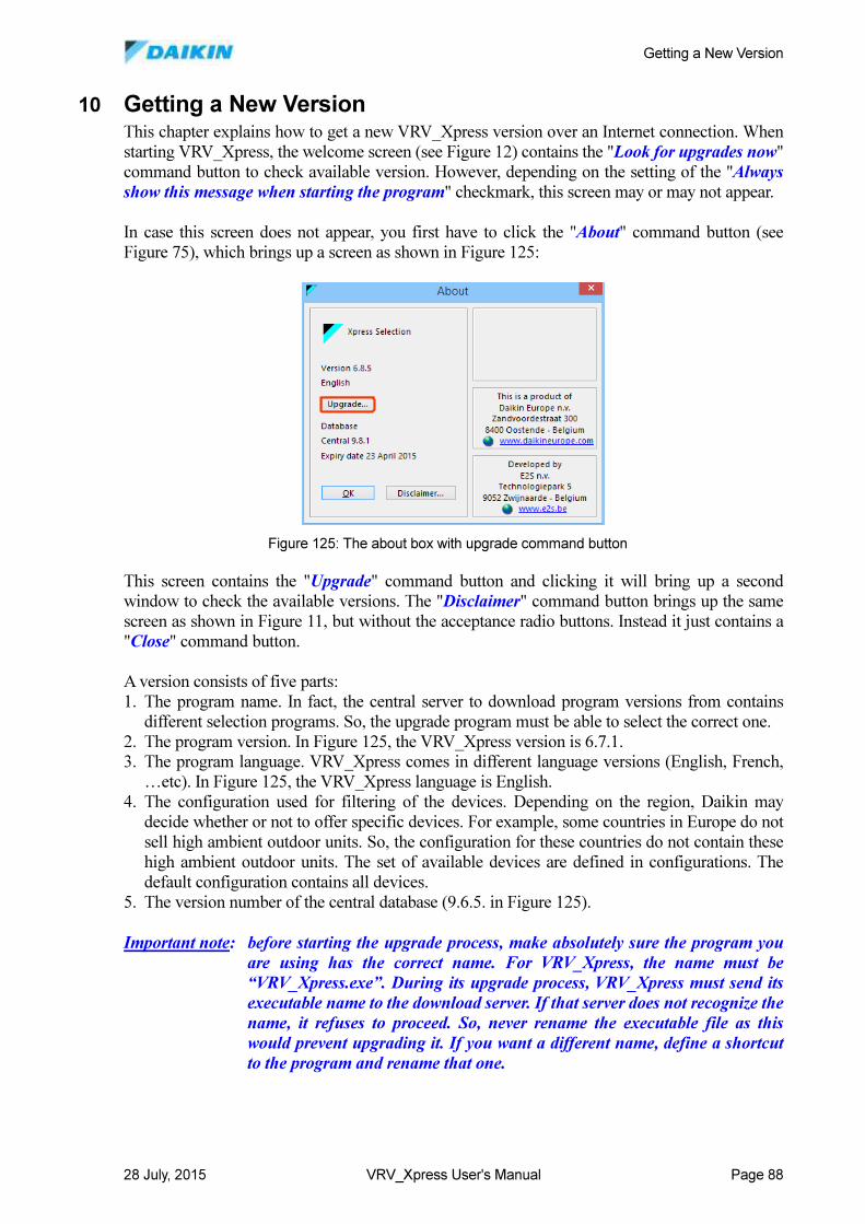
Getting a New Version
28 July, 2015 VRV_Xpress User's Manual Page 88
10 Getting a New Version This chapter explains how to get a new VRV_Xpress version over an Internet connection. When
starting VRV_Xpress, the welcome screen (see Figure 12) contains the "Look for upgrades now"
command button to check available version. However, depending on the setting of the "Always
show this message when starting the program" checkmark, this screen may or may not appear.
In case this screen does not appear, you first have to click the "About" command button (see
Figure 75), which brings up a screen as shown in Figure 125:
This screen contains the "Upgrade" command button and clicking it will bring up a second
window to check the available versions. The "Disclaimer" command button brings up the same
screen as shown in Figure 11, but without the acceptance radio buttons. Instead it just contains a
"Close" command button.
A version consists of five parts:
1. The program name. In fact, the central server to download program versions from contains
different selection programs. So, the upgrade program must be able to select the correct one.
2. The program version. In Figure 125, the VRV_Xpress version is 6.7.1.
3. The program language. VRV_Xpress comes in different language versions (English, French,
…etc). In Figure 125, the VRV_Xpress language is English.
4. The configuration used for filtering of the devices. Depending on the region, Daikin may
decide whether or not to offer specific devices. For example, some countries in Europe do not
sell high ambient outdoor units. So, the configuration for these countries do not contain these
high ambient outdoor units. The set of available devices are defined in configurations. The
default configuration contains all devices.
5. The version number of the central database (9.6.5. in Figure 125).
Important note: before starting the upgrade process, make absolutely sure the program you
are using has the correct name. For VRV_Xpress, the name must be
“VRV_Xpress.exe”. During its upgrade process, VRV_Xpress must send its
executable name to the download server. If that server does not recognize the
name, it refuses to proceed. So, never rename the executable file as this
would prevent upgrading it. If you want a different name, define a shortcut
to the program and rename that one.
Figure 125: The about box with upgrade command button
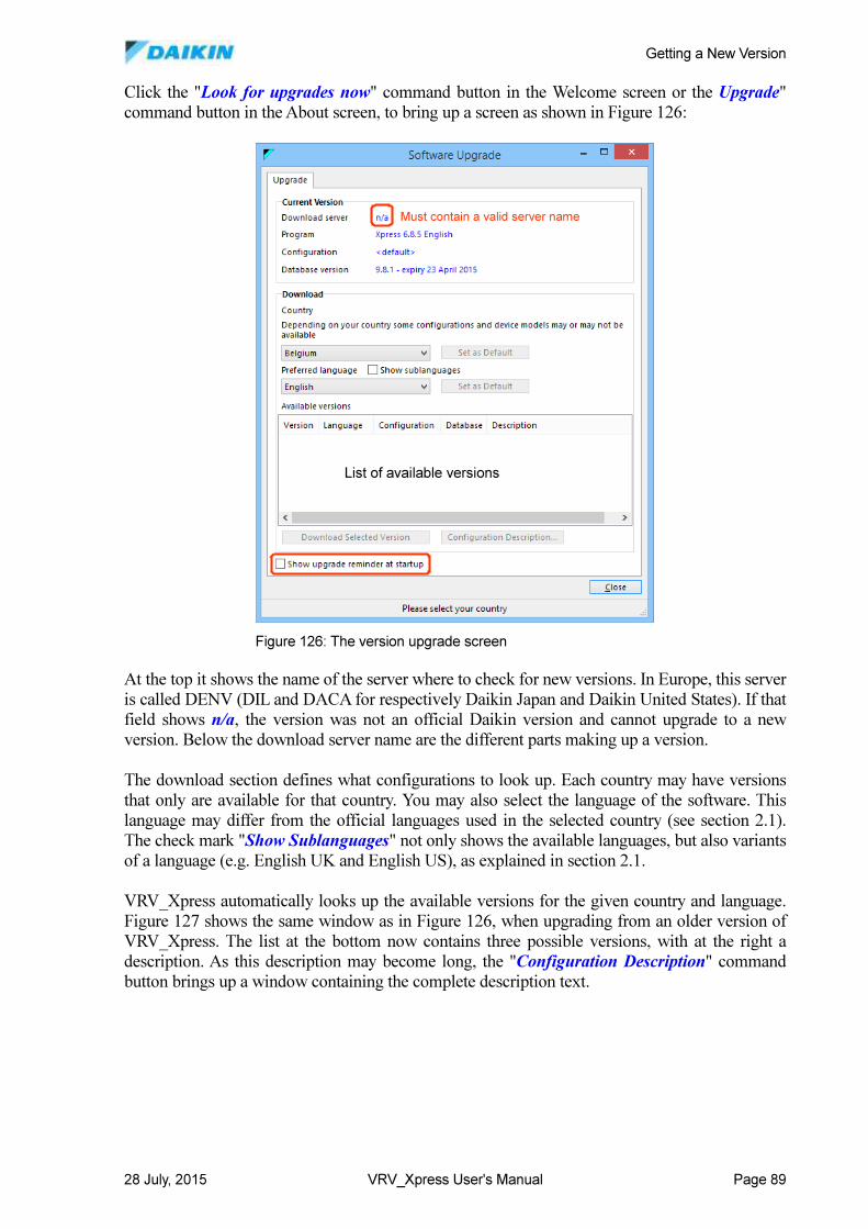
Getting a New Version
28 July, 2015 VRV_Xpress User's Manual Page 89
Click the "Look for upgrades now" command button in the Welcome screen or the Upgrade"
command button in the About screen, to bring up a screen as shown in Figure 126:
At the top it shows the name of the server where to check for new versions. In Europe, this server
is called DENV (DIL and DACA for respectively Daikin Japan and Daikin United States). If that
field shows n/a, the version was not an official Daikin version and cannot upgrade to a new
version. Below the download server name are the different parts making up a version.
The download section defines what configurations to look up. Each country may have versions
that only are available for that country. You may also select the language of the software. This
language may differ from the official languages used in the selected country (see section 2.1).
The check mark "Show Sublanguages" not only shows the available languages, but also variants
of a language (e.g. English UK and English US), as explained in section 2.1.
VRV_Xpress automatically looks up the available versions for the given country and language.
Figure 127 shows the same window as in Figure 126, when upgrading from an older version of
VRV_Xpress. The list at the bottom now contains three possible versions, with at the right a
description. As this description may become long, the "Configuration Description" command
button brings up a window containing the complete description text.
List of available versions
Must contain a valid server name
List of available versions
Must contain a valid server name
Figure 126: The version upgrade screen
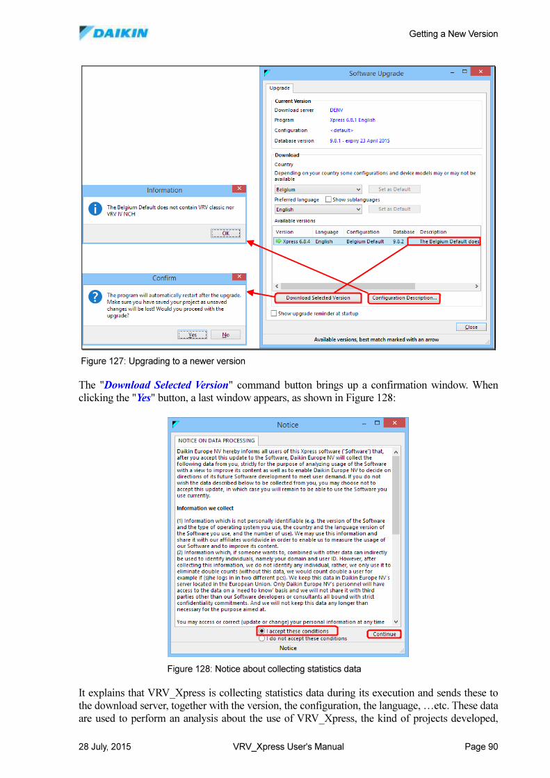
Getting a New Version
28 July, 2015 VRV_Xpress User's Manual Page 90
The "Download Selected Version" command button brings up a confirmation window. When
clicking the "Yes" button, a last window appears, as shown in Figure 128:
It explains that VRV_Xpress is collecting statistics data during its execution and sends these to
the download server, together with the version, the configuration, the language, …etc. These data
are used to perform an analysis about the use of VRV_Xpress, the kind of projects developed,
Figure 127: Upgrading to a newer version
Figure 128: Notice about collecting statistics data
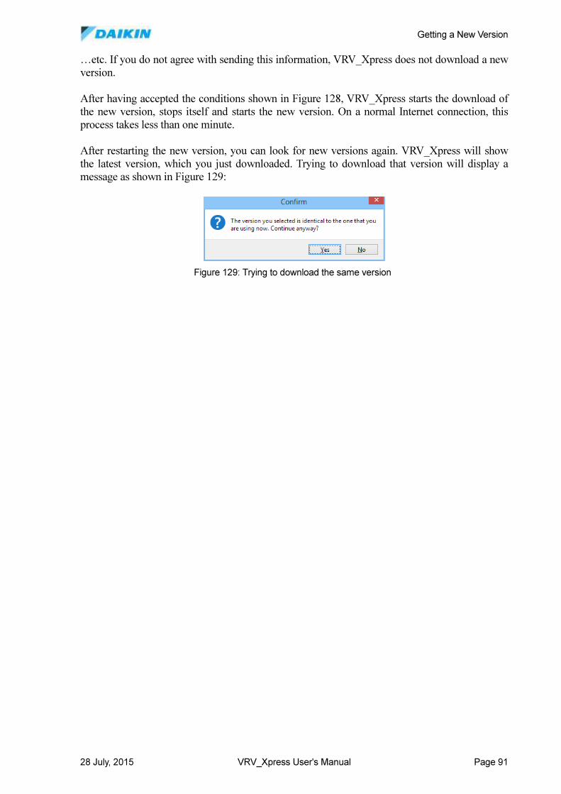
Getting a New Version
28 July, 2015 VRV_Xpress User's Manual Page 91
…etc. If you do not agree with sending this information, VRV_Xpress does not download a new
version.
After having accepted the conditions shown in Figure 128, VRV_Xpress starts the download of
the new version, stops itself and starts the new version. On a normal Internet connection, this
process takes less than one minute.
After restarting the new version, you can look for new versions again. VRV_Xpress will show
the latest version, which you just downloaded. Trying to download that version will display a
message as shown in Figure 129:
Figure 129: Trying to download the same version