VRV IV heat recovery - Tenways · 2018-05-01 · › Incorporates VRV IV standards & technologies:...
8
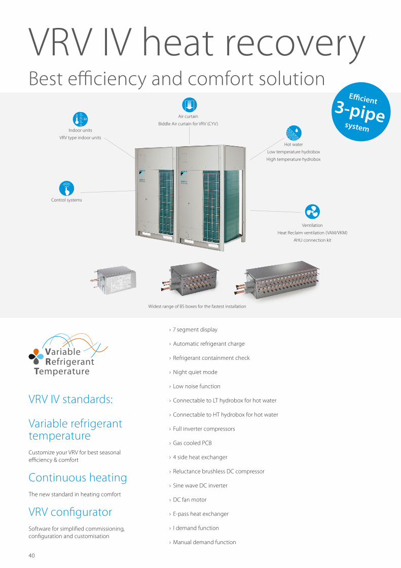
40 Air curtain Biddle Air curtain for VRV (CYV) Hot water Low temperature hydrobox High temperature hydrobox 22 Indoor units VRV type indoor units Ventilation Heat Reclaim ventilation (VAM/VKM) AHU connection kit Control systems VRV IV heat recovery Best efficiency and comfort solution VRV IV standards: Variable refrigerant temperature Customize your VRV for best seasonal efficiency & comfort Continuous heating The new standard in heating comfort VRV configurator Software for simplified commissioning, configuration and customisation › 7 segment display › Automatic refrigerant charge › Refrigerant containment check › Night quiet mode › Low noise function › Connectable to LT hydrobox for hot water › Connectable to HT hydrobox for hot water › Full inverter compressors › Gas cooled PCB › 4 side heat exchanger › Reluctance brushless DC compressor › Sine wave DC inverter › DC fan motor › E-pass heat exchanger › I demand function › Manual demand function Widest range of BS boxes for the fastest installation Efficient 3-pipe system
Transcript of VRV IV heat recovery - Tenways · 2018-05-01 · › Incorporates VRV IV standards & technologies:...
40
Air curtain
Biddle Air curtain for VRV (CYV)
Hot water
Low temperature hydrobox
High temperature hydrobox
22
Indoor units
VRV type indoor units
Ventilation
Heat Reclaim ventilation (VAMVKM)
AHU connection kit
Control systems
VRV IV heat recovery Best efficiency and comfort solution
VRV IV standards
Variable refrigerant temperatureCustomize your VRV for best seasonal efficiency amp comfort
Continuous heatingThe new standard in heating comfort
VRV configuratorSoftware for simplified commissioning configuration and customisation
rsaquo 7 segment display
rsaquo Automatic refrigerant charge
rsaquo Refrigerant containment check
rsaquo Night quiet mode
rsaquo Low noise function
rsaquo Connectable to LT hydrobox for hot water
rsaquo Connectable to HT hydrobox for hot water
rsaquo Full inverter compressors
rsaquo Gas cooled PCB
rsaquo 4 side heat exchanger
rsaquo Reluctance brushless DC compressor
rsaquo Sine wave DC inverter
rsaquo DC fan motor
rsaquo E-pass heat exchanger
rsaquo I demand function
rsaquo Manual demand function
Widest range of BS boxes for the fastest installation
Efficient3-pipesystem
41
-25 -20
-20-25 25 4543-15 -10 -5
-15
-25 -20 -15
0
-20-25 25 4543-15 -10 -5 0
-20-25 4543-15 -10 -5 0
-20 -15 -10 -5 150
-25 -20
-20-25 25 4543-15 -10 -5
-15
-25 -20 -15
0
-20-25 25 4543-15 -10 -5 0
-20-25 4543-15 -10 -5 0
-20 -15 -10 -5 150
ldquoFreerdquo heat and hot water productionUntil now most commercial buildings have relied on separate systems for cooling heating hot water and so on which results in a lot of wasted energy
An integrated heat recovery system reuses heat from offices server rooms to warm other areas or create hot water
Maximum comfortA VRV heat-recovery system allows simultaneous cooling and heating
rsaquo For hotel owners this means a perfect environment for guests as they can freely choose between cooling or heating
rsaquo For offices it means a perfect working indoor climate for both north and south-facing offices
Cooling
Heating
Hot water
Extracted heat delivers
free hot water and heating
+
Improved efficiencyIn heat-recovery operation the VRV IV is up to 15 more efficient compared to VRV III In single mode operation the seasonal efficiency of the system can be even as much as 28 higher - thanks to the variable refrigerant temperature technology - compared to a conventional VRF system
Cooling load
Heating load
Ambient
temperature
Improved mix
mode control
Optimised Partition of Heat Exchanger for highest seasonal efficiency in heat recovery modeVertically divided heat exchanger with an optimized ratio for mix mode operation This improves heat recovery efficiency by reducing radiation losses
30
70
During heating the bottom of the heat exchanger stays hot
which minimises frost accumulation and defrost periods
Wide heating operation rangeVRV IV heat recovery has a standard operation range down to -20degCWB in heating It can also provide cooling down to -20degCDB for technical server rooms (field setting)
-20degCWB
-20degCDB
Technical Cooling
Heating
Cooling
-5degCDB 43degCDB-25degCDB
155degCWB
North
South
Efficient3-pipesystem
42
Fully redesigned
BS boxesAdvantages of 3-pipe technology
Lower pressure drop means more efficiency rsaquo Smooth refrigerant flow in 3-pipe system thanks to 2 smaller gas pipes results in higher energy efficiency
rsaquo Disturbed refrigerant flow in large gas pipe on 2-pipe system results in bigger pressure drop
More ldquofreerdquo heatDaikin 3-pipe technology needs less energy to recover heat meaning significantly higher efficiency during heat recovery mode Our system can recover heat at a low condensing temperature because it has dedicated gas liquid and discharge pipes
In a 2-pipe system gas and liquid travel as a mixture so the condensing temperature needs to be higher in order to separate the mixed gas and liquid refrigerant The higher condensing temperature means more energy is used to recover heat resulting in lower efficiency
3-pipe VRV HR
2-pipe system
Pressure
Pipe length
Pressure
Enthalpy
Power input Daikin
Power input 2-pipe system
Condensing 55 degC
Condensing 45 degC
Freely combine outdoor unitsCombine outdoor units flexibly to reduce your carbon footprint optimise your system for continuous heating and achieve the highest efficiency
Total piping length 1000m
Longest length actual (Equivalent) 165m (190m)
Longest length after first branch 90m1
Level difference between indoor and outdoor units 90m1
Level difference between indoor units 30m
Flexible piping design
1 Outdoor unit in highest position Consult your local sales representative for restrictions on piping lengths
165m
Act
ual p
ipin
g le
ngth
90m
1 Lev
el d
iffer
ence
bet
wee
n in
door
and
out
door
uni
ts
30m
Lev
el d
iffer
ence
bet
wee
n in
door
uni
ts
90m
max
imum
Save on refrigerant rsaquo Smaller diameter pipes and 3-pipe system results in up to 36 less refrigerant charge compared to 2-pipe systems saving on refrigerant cost and reducing environmental impact
5 to 15 more efficient in heat recovery mode compared to 2-pipe system
Up to 5 more cooling capacity available at longer piping lengths compared to 2-pipe system
43
Fully redesigned
BS boxes
BS1Q 10 16 25 A
BS 6 8 Q14 AV1
BS 10 12 Q14 AV1 BS 16 Q14 AV1
Single port
rsaquo Unique to the market rsaquo Compact and light to install rsaquo No drain piping needed rsaquo Ideal for remote rooms rsaquo Technical cooling function rsaquo Connect up to 250 class unit (28 kW) rsaquo Allows multi-tenant applications
Multi port 4 ndash 6 ndash 8 ndash 10 ndash 12 ndash 16
rsaquo Up to 55 smaller and 41 lighter than previous range
rsaquo Faster installation thanks to a reduced number of brazing points and wiring
rsaquo All indoor units connectable to one BS box rsaquo Fewer inspection ports needed rsaquo Up to 16 kW capacity available per port rsaquo Connect up to 250 class unit (28kW) by combining 2 ports
rsaquo No limit on unused ports permitting phased installation
rsaquo Allows multi-tenant applications
Maximum design flexibility and installation speed
rsaquo Quickly and flexibly design your system with a unique range of single and multi BS boxes
rsaquo A wide variety of compact and lightweight multi BS boxes greatly reduces installation time
rsaquo Free combination of single and multi BS boxes
Maximum comfort at all times
With the VRV BS box any indoor unit not being used to switch between heating and cooling maintains the constant desired temperature This is because our heat recovery system does not need to equalise pressure over the entire system after a change-over
Off
Faster installation thanks to open connection
rsaquo No need to cut the pipe before brazing ndash for indoor units smaller or equal to 56 kW (50 class)
rsaquo Cut and braze the pipe ndash for indoor units bigger or equal to 71 kW (63 class)
BS box
BS 4 Q14 AV1
44
rsaquo Incorporates VRV IV standards amp technologies Variable Refrigerant Temperature continuous heating VRV configurator 7 segment display and full inverter compressors 4-side heat exchanger refrigerant cooled PCB new DC fan motor
rsaquo Free combination of outdoor units to meet installation space or efficiency requirements
rsaquo Possibility to extend the operation range in cooling down to -20degC for technical cooling operation such as server rooms
rsaquo Contains all standard VRV features
VRV IV heat recovery
Best efficiency amp comfort solution
rsaquo Fully integrated solution with heat recovery for maximum efficiency with COPs of up to 8
rsaquo Covers all thermal needs of a building via a single point of contact accurate temperature control ventilation hot water air handling units and Biddle air curtains
rsaquo bdquoFreeldquo heating and hot water production provided by transferring heat from areas requiring cooling to areas requiring heating or hot water
rsaquo The perfect personal comfort for gueststenants via simultaneous cooling and heating
Outdoor system REYQ 10T 13T 16T 18T 20T 22T 24T 26T 28T 30T 32TSystem Outdoor unit module 1 REMQ5T REYQ8T REYQ10T REYQ8T REYQ12T REYQ16T
Outdoor unit module 2 REMQ5T REYQ8T REYQ10T REYQ12T REYQ16T REYQ14T REYQ16T REYQ18T REYQ16TCapacity range HP 10 13 16 18 20 22 24 26 28 30 32Cooling capacity Nom 35degCDB kW 280 (1) 364 (1) 448 (1) 504 (1) 559 (1) 615 (1) 674 (1) 735 (1) 785 (1) 839 (1) 900 (1)Heating capacity Nom 6degCWB kW 280 (2) 364 (2) 448 (2) 504 (2) 559 (2) 615 (2) 674 (2) 735 (2) 785 (2) 839 (2) 900 (2)
Max 6degCWB kW 320 (2) 410 (2) 500 (2) 565 (2) 625 (2) 690 (2) 750 (2) 825 (2) 875 (2) 940 (2) 1000 (2)Power input - 50Hz Cooling Nom 35degCDB kW 634 848 1062 1246 1454 1638 1811 1993 2203 2443 256
Heating Nom 6degCWB kW 542 746 950 1104 1280 1434 1595 1765 1925 2035 224Max 6degCWB kW 650 876 1102 1289 1494 1681 1841 2073 2233 2373 258
EER at nom capacity 35degCDB kWkW 442 429 422 404 384 375 372 369 356 343 352COP at nom capacity 6degCWB kWkW 517 488 472 457 437 429 423 416 408 412 402COP at max capacity 6degCWB kWkW 492 468 454 438 418 410 407 398 392 396 388ESEER - Automatic 777 754 741 738 706 707 687 695 672 648 663ESEER - Standard 655 636 625 598 568 554 546 541 523 503 514Maximum number of connectable indoor units 64 (3)Indoor index connection
Min 125 1625 200 225 250 275 300 325 350 375 400Nom 250 3250 400 450 500 550 600 650 700 750 800Max 325 4225 520 585 650 715 780 845 910 975 1040
Piping connections Liquid OD mm 952 127 159 191Gas OD mm 222 286 349Total piping length System Actual m 500 1000Discharge gas OD mm 191 222 286
Current - 50Hz Maximum fuse amps (MFA) A 40 50 63 80Continuous heating v
Outdoor system REYQ 8T 10T 12T 14T 16T 18T 20TCapacity range HP 8 10 12 14 16 18 20Cooling capacity Nom 35degCDB kW 224 (1) 280 (1) 335 (1) 400 (1) 450 (1) 504 (1) 560 (1)Heating capacity Nom 6degCWB kW 224 (2) 280 (2) 335 (2) 400 (2) 450 (2) 504 (2) 560 (2)
Max 6degCWB kW 250 (2) 315 (2) 375 (2) 450 (2) 500 (2) 565 (2) 630 (2)Power input - 50Hz Cooling Nom 35degCDB kW 531 (1) 715 (1) 923 (1) 107 (1) 128 (1) 152 186
Heating Nom 6degCWB kW 475 (2) 629 (2) 805 (2) 960 (2) 112 (2) 123 149Max 6degCWB kW 551 (2) 738 (2) 943 (2) 113 (2) 129 (2) 143 175
EER at nom capacity 35degCDB kWkW 422 (1) 392 (1) 363 (1) 374 (1) 352 (1) 332 301COP at nom capacity 6degCWB kWkW 472 (2) 445 (2) 416 (2) 417 (2) 402 (2) 410 376COP at max capacity 6degCWB kWkW 454 (2) 427 (2) 398 (2) 388 (2) 395 360ESEER - Automatic 741 737 684 705 663 626 568Maximum number of connectable indoor units 64 (3)Indoor index connection
Min 100 125 150 175 200 225 250Nom 200 250 300 350 400 450 500Max 260 325 390 455 520 585 650
Dimensions Unit HeightxWidthxDepth mm 1685x930x765 1685x1240x765Weight Unit kg 210 218 304 305 337Fan Air flow rate Cooling Nom msup3min 162 175 185 223 260 251 261Sound power level Cooling Nom dBA 78 79 81 86 88Sound pressure level Cooling Nom dBA 58 61 64 65 66Operation range Cooling Min~Max degCDB -50~430
Heating Min~Max degCWB -20~155Refrigerant Type R-410A
GWP 20875Charge TCO₂eq 202 205 207 246
kg 97 98 99 118Piping connections Liquid OD mm 952 127 159
Gas OD mm 191 222 286Total piping length System Actual m 1000Discharge gas OD mm 159 191 222 286
Power supply PhaseFrequencyVoltage HzV 3N~50380-415Current - 50Hz Maximum fuse amps (MFA) A 20 25 32 40 50
REYQ-T
Up to 30m indoor unit height difference
45
+
25degC - 35degC
45degC - 75degC
25degC - 75degC
45degC - 75degC
REYQ-T
Outdoor system REYQ 34T 36T 38T 40T 42T 44T 46T 48T 50T 52T 54TSystem Outdoor unit module 1 REYQ16T REYQ8T REYQ10T REYQ12T REYQ14T REYQ16T REYQ18T
Outdoor unit module 2 REYQ18T REYQ20T REYQ12T REYQ16T REYQ18TOutdoor unit module 3 - REYQ18T REYQ16T REYQ18T
Capacity range HP 34 36 38 40 42 44 46 48 50 52 54Cooling capacity Nom 35degCDB kW 954 (1) 1010 (1) 1063 (1) 1119 (1) 1180 (1) 1235 (1) 1300 (1) 1350 (1) 1404 (1) 1458 (1) 1512 (1)Heating capacity Nom 6degCWB kW 954 (2) 1010 (2) 1063 (2) 1119 (2) 1180 (2) 1235 (2) 1300 (2) 1350 (2) 1404 (2) 1458 (2) 1512 (2)
Max 6degCWB kW 1065 (2) 1130 (2) 1190 (2) 1255 (2) 1315 (2) 1375 (2) 1450 (2) 1500 (2) 1565 (2) 1630 (2) 1695 (2)Power input - 50Hz Cooling Nom 35degCDB kW 280 314 2974 3158 3275 3483 363 384 408 432 456
Heating Nom 6degCWB kW 235 261 2510 2664 2869 3045 3200 336 347 358 369Max 6degCWB kW 272 304 2924 3111 3318 3523 371 387 401 415 429
EER at nom capacity 35degCDB kWkW 341 322 357 354 360 355 358 352 344 338 332COP at nom capacity 6degCWB kWkW 406 387 424 420 411 406 402 405 407 410COP at max capacity 6degCWB kWkW 392 372 407 403 396 390 391 388 390 393 395ESEER - Automatic 643 606 666 668 679 668 675 663 649 637 626Maximum number of connectable indoor units 64 (3)Indoor index connection
Min 425 450 475 500 525 550 575 600 625 650 675Nom 850 900 950 1000 1050 1100 1150 1200 1250 1300 1350Max 1105 1170 1235 1300 1365 1430 1495 1560 1625 1690 1755
Piping connections Liquid OD mm 191Gas OD mm 349 413Total piping length System Actual m 1000Discharge gas OD mm 286 349
Current - 50Hz Maximum fuse amps (MFA) A 80 100 125Continuous heating v
Outdoor unit module REMQ 5TDimensions Unit HeightWidthDepth mm 1685930765Weight Unit kg 210Fan Air flow rate Cooling Nom msup3min 162
External static pressure Max Pa 78Discharge direction VerticalType Propeller fan
Sound power level Cooling Nom dBA 77Sound pressure level Cooling Nom dBA 56Operation range Cooling Min~Max degCDB -50~430
Heating Min~Max degCWB -20~155Refrigerant Type R-410A
GWP 20875Charge TCO₂eq 202
kg 97Power supply PhaseFrequencyVoltage HzV 3N~50380-415Current - 50Hz Maximum fuse amps (MFA) A 20
(1) Nominal cooling capacities are based on indoor temperature 27degCDB 19degCWB outdoor temperature 35degCDB equivalent refrigerant piping 5m level difference 0m Data for standard efficiency series (2) Nominal heating capacities are based on indoor temperature 20degCDB outdoor temperature 7degCDB 6degCWB equivalent refrigerant piping 5m level difference 0m Data for standard efficiency series (3) Actual number of connectable indoor units depends on the indoor unit type (VRV indoor Hydrobox RA indoor etc) and the connection ratio restriction for the system (50 lt= CR lt= 130) | REMQ5 unit cannot be used as standalone unit | Technical cooling setting refer to the installation manual for more information
Cooling
Heating
Hot water
Extracted heat delivers
free hot water and heating
VRV heat recovery (REYQ8-54T)
BS-Box
BS-Box Heating only hydrobox for VRV
Domestic hot water tank
Daikin solar panel
Domestic hot water
Low temp radiator
Air handling unit
Under floor heating
VRV indoor unitsLiquid pipe
F1 F2 communication
Gas pipe
Hot water
Discharge gas pipe
46
Detailed technical drawings
REMQ5T REYQ8-12T
4
67
5
9
4-15x225mm -
10
8
21
11
97
272
328
373
1240
107
C
13117
9259
276
122
1685
76
137
765
76
515
729
1076
134
393
107
112
125
70
106
71
192
AB
310
100
160
AA
3
ABAA
RYMQ18-20T RXYQQ18-20TRYMQ14-16T RXYQQ14-16T REYQ14-20T 205240
240 210
Notes
1 Detail middotAmiddot and detail middotBmiddot indicate the dimensions after fixing the attached piping
3 Gas pipe
Oslash middot286middot brazing connection
Oslash middot127middot brazing connection
Oslash middot222middot brazing connection
Liquid pipe
RYYQ14-20T RYMQ14-20T RXYQ14-20T RXYQQ14-20T
Equalising pipe
High pressurelow pressure gas pipe
2 Items middot4 - 10 Knockout hole
RYYQ14-16T RYMQ14-16T RXYQ14-16T RXYQQ14-16T REYQ14-20T
RYMQ14-16T
RYMQ18-20T
REYQ14-20T Oslash middot222middot brazing connectionOslash middot254middot brazing connectionREYQ14-20T
678910
12
3
45
Oslash65Oslash27Oslash65Oslash80Oslash65
No
11
Part name Remark
Grounding terminal
Pipe routing hole (bottom)
Pipe routing hole (front)
Power cord routing hole (side)
Power cord routing hole (front)
Power cord routing hole (front)
Power cord routing hole (front)
Equalising pipe connection port
Gas pipe connection port
Liquid pipe connection port
See note middot3middot
See note middot3middot
See note middot3middot
Inside of the switch box (middotM8middot)
Power cord routing hole (bottom)
Model
Pitch of foundation bolt holes
Pitc
h of
foun
datio
n bo
lt ho
les
Foundation bolt holeOblong hole
Oslash middot159middot brazing connectionRYYQ18-20T RYMQ18-20T RXYQ18-20T RXYQQ18-20T
Oslash middot286middot brazing connection
Detail middotAmiddot Detail middotBmiddot
DETAIL B DETAIL A
View middotCmiddot
High pressurelow pressure gas pipe
REYQ14-20T
2D079533B
4
515
76
765
76
67
5
9
272
328
373
930
97 107
13117
9259
276
122
766
729
4-15x225mm
134
353
107
112
125
70
10
8
100
160
AA
339
AB
66
106
C
AC
240208
AB
195
248AA
REMQ5T RYMQ10-12T REYQ8-12TRYMQ8TRYYQ10-12T RXYQ10-12T RXYQQ10-12TRYYQ8T RXYQ8T RXYQQ8T
--195248 240208
--
137
21
3
11
1685
678910
12
3
45
Oslash65Oslash27Oslash65Oslash80Oslash65
No
11
Part name Remark
Grounding terminal
Pipe routing hole (bottom)
Pipe routing hole (front)
Power cord routing hole (side)
Power cord routing hole (front)
Power cord routing hole (front)
Power cord routing hole (front)
Equalising pipe connection port
Gas pipe connection portLiquid pipe connection port
See note middot3middot
See note middot3middot
See note middot3middot
Notes
Detail middotAmiddot and detail middotBmiddot indicate the dimensions after fixing the attached piping
Gas pipeOslash middot191middot brazing connectionOslash middot222middot brazing connection
Oslash middot286middot brazing connection
Oslash middot95middot brazing connection
Oslash middot127middot brazing connection
Oslash middot191middot brazing connectionOslash middot222middot brazing connection
Liquid pipe
Pitch of foundation bolt holes
Pitc
h of
foun
datio
n bo
lt ho
les
Foundation bolt holeOblong hole
AC
RYYQ8T RYMQ8T RXYQ8T RXYQQ8T
RYYQ12T RYMQ12T RXYQ12T RXYQQ12T
RYYQ8-10T RYMQ8-10T RXYQ8-10T RXYQQ8-10T REMQ5T REYQ8-12T
RYYQ10T RYMQ10T RXYQ10T RXYQQ10T
Model
Equalising pipe
High pressurelow pressure gas pipe
Items middot4 - 10 Knockout hole
RYYQ12T RYMQ12T RXYQ12T RXYQQ12T
RYMQ8-10TRYMQ12T
REMQ5T REYQ8-12T Oslash middot191middot brazing connection
Oslash middot254middot brazing connectionREMQ5T REYQ8-12T
12
3
Inside of the switch box (middotM8middot)
Power cord routing hole (bottom)
Detail middotAmiddot Detail middotBmiddot
DETAIL ADETAIL B
View middotCmiddot
High pressurelow pressure gas pipe
REMQ5TREYQ8-12T
2D079532B
REYQ14-20T
VIEW ALL REYQ-T TECHNICAL DRAWINGS ON MYDAIKINEU
47
Detailed technical drawings
REYQ-T
3D079542
REYQ-TFor single unit installationltPattern1gt
ltPattern2gt
ltPattern3gt
ltPattern1gt
ltPattern2gt
ltPattern3gt
ltPattern1gt
ltUnit mmgt
Wall height unrestricted
Wall height unrestricted
10 or more
300 or more
500 or moreltFrontgt
ltFrontgt
ltFrontgt ltFrontgt
ltFro
ntgt
ltSuc
tion s
idegt
500 or more50 or more
300 or more
300 or more300 or more
10 or more 20 or more 20 or more
200 or more200 or more
100 or more
400 or more
100 or more
100 or more
For installation in rows For centralized group layout
NOTES
10 or more ltFrontgt500 or more
10 or more
50 or more 50 or more 50 or more ltFrontgt500 or more
100 or more
10 or more
400 or more
300 or more
300 or more
10 or more
10 or more 10 or more
ltFrontgt600 or more
20 or more
20 or moreltFrontgt500 or more
ltPattern2gt
100 or more
50 or more
50 or more
ltFrontgt500 or more
500 or moreltFrontgt
100 or more
100 or more
50 or more
50 or more
10 or more
10 or more 20 or more
20 or moreltFrontgt500 or more
300 or more
10 or more
10 or more
ltFrontgt500 or more
100 or more
50 or more
100 or more
50 or more 100 or more 50 or more
100 or more 50 or more
ltFrontgt
ltFrontgt
10 or more
10 or more 10 or more
10 or more
500 or more
900 or more20 or more
500 or more
50 or more
50 or more 50 or more
50 or more
20 or moreltFrontgt 500 or more
100 or more 600 or more
ltFrontgt500 or more
100 or more
1 Heights of walls in case of patterns 1 and 2 Front 1500mm Suction side 500mm Side Height unrestricted Installation space as shown on this drawing is based on the cooling operation at 35 degrees outdoor air temperature When the design outdoor air temperature exceeds 35 degrees or the load exceeds maximum ability of much generation load of heat in all outdoor unit take the suction side space more broadly than the space as shown on this drawing
2 If the above wall heights are exceeded then h22 and h12 should be added to the front and suction side service spaces respectively as shown in the figure on the right 3 When installing the units most appropriate pattern should be selected from those shown above in order to obtain the best fit in the space available always bearing in mind the need to leave enough space for a person to pass between units and wall and for the air to circulate freely (If more units are to be installed than are catered for in the above patterns your layout should take account of the possibility of short circuits) 4 The units should be installed to leave sufficient space at the front for the on site refrigerant piping work to be carried out comfortably
lt Suc
tion s
ide gt
lt Fron
t gt
VIEW ALL REYQ-T TECHNICAL DRAWINGS ON MYDAIKINEU
- intro
-
- Page 4319
- Page 4520
- Page 4721
- Page 4922
-
- vrv iv
-
- Page 4319
- Page 4520
- Page 4721
- Page 4922
-
- benefits
-
- Page 4319
- Page 4520
- Page 4721
- Page 4922
-
- outdoor
-
- Page 4319
- Page 4520
- Page 4721
- Page 4922
-
- indoor
-
- Page 4319
- Page 4520
- Page 4721
- Page 4922
-
- hot water
-
- Page 4319
- Page 4520
- Page 4721
- Page 4922
-
- biddle air curtain
-
- Page 4319
- Page 4520
- Page 4721
- Page 4922
-
- ventilation
-
- Page 4319
- Page 4520
- Page 4721
- Page 4922
-
- controls
-
- Page 4319
- Page 4520
- Page 4721
- Page 4922
-
- options
-
- Page 4319
- Page 4520
- Page 4721
- Page 4922
-
- tools
-
- Page 4319
- Page 4520
- Page 4721
- Page 4922
-
- previous
-
- Page 4319
- Page 4520
- Page 4721
- Page 4922

45
+
25degC - 35degC
45degC - 75degC
25degC - 75degC
45degC - 75degC
REYQ-T
Outdoor system REYQ 34T 36T 38T 40T 42T 44T 46T 48T 50T 52T 54TSystem Outdoor unit module 1 REYQ16T REYQ8T REYQ10T REYQ12T REYQ14T REYQ16T REYQ18T
Outdoor unit module 2 REYQ18T REYQ20T REYQ12T REYQ16T REYQ18TOutdoor unit module 3 - REYQ18T REYQ16T REYQ18T
Capacity range HP 34 36 38 40 42 44 46 48 50 52 54Cooling capacity Nom 35degCDB kW 954 (1) 1010 (1) 1063 (1) 1119 (1) 1180 (1) 1235 (1) 1300 (1) 1350 (1) 1404 (1) 1458 (1) 1512 (1)Heating capacity Nom 6degCWB kW 954 (2) 1010 (2) 1063 (2) 1119 (2) 1180 (2) 1235 (2) 1300 (2) 1350 (2) 1404 (2) 1458 (2) 1512 (2)
Max 6degCWB kW 1065 (2) 1130 (2) 1190 (2) 1255 (2) 1315 (2) 1375 (2) 1450 (2) 1500 (2) 1565 (2) 1630 (2) 1695 (2)Power input - 50Hz Cooling Nom 35degCDB kW 280 314 2974 3158 3275 3483 363 384 408 432 456
Heating Nom 6degCWB kW 235 261 2510 2664 2869 3045 3200 336 347 358 369Max 6degCWB kW 272 304 2924 3111 3318 3523 371 387 401 415 429
EER at nom capacity 35degCDB kWkW 341 322 357 354 360 355 358 352 344 338 332COP at nom capacity 6degCWB kWkW 406 387 424 420 411 406 402 405 407 410COP at max capacity 6degCWB kWkW 392 372 407 403 396 390 391 388 390 393 395ESEER - Automatic 643 606 666 668 679 668 675 663 649 637 626Maximum number of connectable indoor units 64 (3)Indoor index connection
Min 425 450 475 500 525 550 575 600 625 650 675Nom 850 900 950 1000 1050 1100 1150 1200 1250 1300 1350Max 1105 1170 1235 1300 1365 1430 1495 1560 1625 1690 1755
Piping connections Liquid OD mm 191Gas OD mm 349 413Total piping length System Actual m 1000Discharge gas OD mm 286 349
Current - 50Hz Maximum fuse amps (MFA) A 80 100 125Continuous heating v
Outdoor unit module REMQ 5TDimensions Unit HeightWidthDepth mm 1685930765Weight Unit kg 210Fan Air flow rate Cooling Nom msup3min 162
External static pressure Max Pa 78Discharge direction VerticalType Propeller fan
Sound power level Cooling Nom dBA 77Sound pressure level Cooling Nom dBA 56Operation range Cooling Min~Max degCDB -50~430
Heating Min~Max degCWB -20~155Refrigerant Type R-410A
GWP 20875Charge TCO₂eq 202
kg 97Power supply PhaseFrequencyVoltage HzV 3N~50380-415Current - 50Hz Maximum fuse amps (MFA) A 20
(1) Nominal cooling capacities are based on indoor temperature 27degCDB 19degCWB outdoor temperature 35degCDB equivalent refrigerant piping 5m level difference 0m Data for standard efficiency series (2) Nominal heating capacities are based on indoor temperature 20degCDB outdoor temperature 7degCDB 6degCWB equivalent refrigerant piping 5m level difference 0m Data for standard efficiency series (3) Actual number of connectable indoor units depends on the indoor unit type (VRV indoor Hydrobox RA indoor etc) and the connection ratio restriction for the system (50 lt= CR lt= 130) | REMQ5 unit cannot be used as standalone unit | Technical cooling setting refer to the installation manual for more information
Cooling
Heating
Hot water
Extracted heat delivers
free hot water and heating
VRV heat recovery (REYQ8-54T)
BS-Box
BS-Box Heating only hydrobox for VRV
Domestic hot water tank
Daikin solar panel
Domestic hot water
Low temp radiator
Air handling unit
Under floor heating
VRV indoor unitsLiquid pipe
F1 F2 communication
Gas pipe
Hot water
Discharge gas pipe
46
Detailed technical drawings
REMQ5T REYQ8-12T
4
67
5
9
4-15x225mm -
10
8
21
11
97
272
328
373
1240
107
C
13117
9259
276
122
1685
76
137
765
76
515
729
1076
134
393
107
112
125
70
106
71
192
AB
310
100
160
AA
3
ABAA
RYMQ18-20T RXYQQ18-20TRYMQ14-16T RXYQQ14-16T REYQ14-20T 205240
240 210
Notes
1 Detail middotAmiddot and detail middotBmiddot indicate the dimensions after fixing the attached piping
3 Gas pipe
Oslash middot286middot brazing connection
Oslash middot127middot brazing connection
Oslash middot222middot brazing connection
Liquid pipe
RYYQ14-20T RYMQ14-20T RXYQ14-20T RXYQQ14-20T
Equalising pipe
High pressurelow pressure gas pipe
2 Items middot4 - 10 Knockout hole
RYYQ14-16T RYMQ14-16T RXYQ14-16T RXYQQ14-16T REYQ14-20T
RYMQ14-16T
RYMQ18-20T
REYQ14-20T Oslash middot222middot brazing connectionOslash middot254middot brazing connectionREYQ14-20T
678910
12
3
45
Oslash65Oslash27Oslash65Oslash80Oslash65
No
11
Part name Remark
Grounding terminal
Pipe routing hole (bottom)
Pipe routing hole (front)
Power cord routing hole (side)
Power cord routing hole (front)
Power cord routing hole (front)
Power cord routing hole (front)
Equalising pipe connection port
Gas pipe connection port
Liquid pipe connection port
See note middot3middot
See note middot3middot
See note middot3middot
Inside of the switch box (middotM8middot)
Power cord routing hole (bottom)
Model
Pitch of foundation bolt holes
Pitc
h of
foun
datio
n bo
lt ho
les
Foundation bolt holeOblong hole
Oslash middot159middot brazing connectionRYYQ18-20T RYMQ18-20T RXYQ18-20T RXYQQ18-20T
Oslash middot286middot brazing connection
Detail middotAmiddot Detail middotBmiddot
DETAIL B DETAIL A
View middotCmiddot
High pressurelow pressure gas pipe
REYQ14-20T
2D079533B
4
515
76
765
76
67
5
9
272
328
373
930
97 107
13117
9259
276
122
766
729
4-15x225mm
134
353
107
112
125
70
10
8
100
160
AA
339
AB
66
106
C
AC
240208
AB
195
248AA
REMQ5T RYMQ10-12T REYQ8-12TRYMQ8TRYYQ10-12T RXYQ10-12T RXYQQ10-12TRYYQ8T RXYQ8T RXYQQ8T
--195248 240208
--
137
21
3
11
1685
678910
12
3
45
Oslash65Oslash27Oslash65Oslash80Oslash65
No
11
Part name Remark
Grounding terminal
Pipe routing hole (bottom)
Pipe routing hole (front)
Power cord routing hole (side)
Power cord routing hole (front)
Power cord routing hole (front)
Power cord routing hole (front)
Equalising pipe connection port
Gas pipe connection portLiquid pipe connection port
See note middot3middot
See note middot3middot
See note middot3middot
Notes
Detail middotAmiddot and detail middotBmiddot indicate the dimensions after fixing the attached piping
Gas pipeOslash middot191middot brazing connectionOslash middot222middot brazing connection
Oslash middot286middot brazing connection
Oslash middot95middot brazing connection
Oslash middot127middot brazing connection
Oslash middot191middot brazing connectionOslash middot222middot brazing connection
Liquid pipe
Pitch of foundation bolt holes
Pitc
h of
foun
datio
n bo
lt ho
les
Foundation bolt holeOblong hole
AC
RYYQ8T RYMQ8T RXYQ8T RXYQQ8T
RYYQ12T RYMQ12T RXYQ12T RXYQQ12T
RYYQ8-10T RYMQ8-10T RXYQ8-10T RXYQQ8-10T REMQ5T REYQ8-12T
RYYQ10T RYMQ10T RXYQ10T RXYQQ10T
Model
Equalising pipe
High pressurelow pressure gas pipe
Items middot4 - 10 Knockout hole
RYYQ12T RYMQ12T RXYQ12T RXYQQ12T
RYMQ8-10TRYMQ12T
REMQ5T REYQ8-12T Oslash middot191middot brazing connection
Oslash middot254middot brazing connectionREMQ5T REYQ8-12T
12
3
Inside of the switch box (middotM8middot)
Power cord routing hole (bottom)
Detail middotAmiddot Detail middotBmiddot
DETAIL ADETAIL B
View middotCmiddot
High pressurelow pressure gas pipe
REMQ5TREYQ8-12T
2D079532B
REYQ14-20T
VIEW ALL REYQ-T TECHNICAL DRAWINGS ON MYDAIKINEU
47
Detailed technical drawings
REYQ-T
3D079542
REYQ-TFor single unit installationltPattern1gt
ltPattern2gt
ltPattern3gt
ltPattern1gt
ltPattern2gt
ltPattern3gt
ltPattern1gt
ltUnit mmgt
Wall height unrestricted
Wall height unrestricted
10 or more
300 or more
500 or moreltFrontgt
ltFrontgt
ltFrontgt ltFrontgt
ltFro
ntgt
ltSuc
tion s
idegt
500 or more50 or more
300 or more
300 or more300 or more
10 or more 20 or more 20 or more
200 or more200 or more
100 or more
400 or more
100 or more
100 or more
For installation in rows For centralized group layout
NOTES
10 or more ltFrontgt500 or more
10 or more
50 or more 50 or more 50 or more ltFrontgt500 or more
100 or more
10 or more
400 or more
300 or more
300 or more
10 or more
10 or more 10 or more
ltFrontgt600 or more
20 or more
20 or moreltFrontgt500 or more
ltPattern2gt
100 or more
50 or more
50 or more
ltFrontgt500 or more
500 or moreltFrontgt
100 or more
100 or more
50 or more
50 or more
10 or more
10 or more 20 or more
20 or moreltFrontgt500 or more
300 or more
10 or more
10 or more
ltFrontgt500 or more
100 or more
50 or more
100 or more
50 or more 100 or more 50 or more
100 or more 50 or more
ltFrontgt
ltFrontgt
10 or more
10 or more 10 or more
10 or more
500 or more
900 or more20 or more
500 or more
50 or more
50 or more 50 or more
50 or more
20 or moreltFrontgt 500 or more
100 or more 600 or more
ltFrontgt500 or more
100 or more
1 Heights of walls in case of patterns 1 and 2 Front 1500mm Suction side 500mm Side Height unrestricted Installation space as shown on this drawing is based on the cooling operation at 35 degrees outdoor air temperature When the design outdoor air temperature exceeds 35 degrees or the load exceeds maximum ability of much generation load of heat in all outdoor unit take the suction side space more broadly than the space as shown on this drawing
2 If the above wall heights are exceeded then h22 and h12 should be added to the front and suction side service spaces respectively as shown in the figure on the right 3 When installing the units most appropriate pattern should be selected from those shown above in order to obtain the best fit in the space available always bearing in mind the need to leave enough space for a person to pass between units and wall and for the air to circulate freely (If more units are to be installed than are catered for in the above patterns your layout should take account of the possibility of short circuits) 4 The units should be installed to leave sufficient space at the front for the on site refrigerant piping work to be carried out comfortably
lt Suc
tion s
ide gt
lt Fron
t gt
VIEW ALL REYQ-T TECHNICAL DRAWINGS ON MYDAIKINEU
- intro
-
- Page 4319
- Page 4520
- Page 4721
- Page 4922
-
- vrv iv
-
- Page 4319
- Page 4520
- Page 4721
- Page 4922
-
- benefits
-
- Page 4319
- Page 4520
- Page 4721
- Page 4922
-
- outdoor
-
- Page 4319
- Page 4520
- Page 4721
- Page 4922
-
- indoor
-
- Page 4319
- Page 4520
- Page 4721
- Page 4922
-
- hot water
-
- Page 4319
- Page 4520
- Page 4721
- Page 4922
-
- biddle air curtain
-
- Page 4319
- Page 4520
- Page 4721
- Page 4922
-
- ventilation
-
- Page 4319
- Page 4520
- Page 4721
- Page 4922
-
- controls
-
- Page 4319
- Page 4520
- Page 4721
- Page 4922
-
- options
-
- Page 4319
- Page 4520
- Page 4721
- Page 4922
-
- tools
-
- Page 4319
- Page 4520
- Page 4721
- Page 4922
-
- previous
-
- Page 4319
- Page 4520
- Page 4721
- Page 4922