Vrctitle - The Plymouth Colony Pages
140
VRC2000 Installation and Operations Manual
Transcript of Vrctitle - The Plymouth Colony Pages

VRC2000
Installation andOperations Manual

© Copyright 1997 Gentner Communications Corporation. All rights reserved. No part of this manual may bereproduced in any form or by any means without written permission from Gentner Communications Corporation.Printed in the United States of America. Original version, 11/89. Gentner Communications Corporation reservesspecification privileges. Information in this manual is subject to change without notice.
VRC2000 Installation and Operations ManualGentner Part No. 800-072-200 (Rev. 2.00)April 1997
Manual Development: Bill Kilpack
Artwork and IIlustrations: Jim Wright, Bill Kilpack
Gentner Communications Corporation is committed to protecting the environmentand preserving our natural resources.
This manual has been printed entirely on recycled paper.
CopyrightInformation

Contents
VRC2000 Installation and Operations Manual Page iii
Introduction 1Warranty Registration 1
Unpacking 2
Features and Benefits 2
Product Description 2Front-Panel Controls 4Back-Panel Connectors 4Remote/Local Modes 5
Before You Install 6Power Requirements 6Software Requirements 6Telephone Line Requirements 6Equipment Placement 6Telephone Option 6
Initialization 6Step 1 — Operating Voltage 6Step 2 — Internal Lithium Battery 7Step 3 — Surge Protection Option 7Step 4 — Back-Panel Connections 7Step 5 — Power Up 8
Operational Modes 9Local vs. Remote Modes 9Setup Modes 9User Modes 9Operator Mode 9Automatic Mode 9Tutorial 9
VRC2000 Setup 10VRC2000 Word List 10VRC2000 Setup and User Modes 11Security 11Changing Access Codes 12Internal Battery/Access Code Check 14Turning the VRC2000 Voice On/Off 15Toggling Between User and Setup Modes 16Changing the System Identifier 16Setting the Clock 18Clock Setting Exercise 19Telephone Interface 20Telephone Interface Setting Exercise 20Setting Up Outbound Telephone Numbers 21Telephone Number Programming Exercise 24Alarms 26Programming VRC2000 Alarm Delays and Channels 27Setting Up Status Channels 27Status Channel Programming Exercise 31Metering Channels 36Calibration Constant and Tolerance Limits 38
Technical or Setup AssistanceTelephone: 800.945.7730 (USA) or 801.975.7200 (worldwide) • Worldwide Web @ http://ww w.gentne r.com

Page iv VRC2000 Installation and Operations Manual
Technical or Setup AssistanceTelephone: 800.945.7730 (USA) or 801.975.7200 (worldwide) • Worldwide Web @ http://ww w.gentne r.com
Setting Up Metering Channels 39Metering Channel Programming Exercise 43Setting Up Command Channels 50Command Channel Programming Exercise 52Setting Time-Of-Day Functions 54Entering Time/Date On Time-Of-Day Functions 55Time-Of-Day Function Programming Exercise 56Setting Up Mute Functions 59Mute Function Programming Exercise 60Setting Up Sequence Output Programs 62Sequence Output Programming Exercise 62Setting Up Auto-Logging Functions 64Auto-Logging Programming Exercise 65Clearing All Programming 67
VRC2000 Installation 68Step 1 — Determine Metering Channel Input Type 68Step 2 — Metering Connections 69Step 3 — Determine Status-Channel Input Range 69Step 4 — Status Connections 70Step 5 — Command Connections 70Step 6 — Telephone Interface Connection 72Step 7 — Four-Wire Connections (Dedicated Circuits) 72Step 8 — Two-Way Radio Connection 73
Operation 74Accessing User Mode 74Taking Readings From Status and Metering Channels 74Single/Multiple Responses From Status/Metering Channels 75Issuing Commands 76Remembering VRC2000 Codes 78Alarms 78Checking Current Date and Time 80Using Sequence Output Programs 80Using the Sound Sensor 81Turning the Data Interface ON/OFF 81Auto-Logging 82
Maintenance and Service 83General Treatment 83Troubleshooting 83
Frequently Asked Questions 87
Specifications 90
Firmware License 91
Warranty 92
FCC Part 15 Compliance 92
FCC Part 68 Compliance 93
U.S. Patent Information 93
Contents continued

VRC2000 Installation and Operations Manual Page v
Technical or Setup AssistanceTelephone: 800.945.7730 (USA) or 801.975.7200 (worldwide) • Worldwide Web @ http://ww w.gentne r.com
Appendix A: Glossary 94
Appendix B: Connector Pinouts 98
Appendix C: Accessories 100Software 100Hardware 101
Appendix D: Theory of Operation 102Microcontroller Theory 103Telephone Logic and Interface 104Unbalanced Audio Output 105Status Channel Inputs 105Metering Channel Inputs 105Command Channel Outputs 106Real-Time Clock 106DTMF Encoder/Decoder 106Digital Voice Synthesizer 107Power Supply 107
Appendix E: Technical Description 108VRC2000 Unit 108Real-Time Clock and Memory 108Inputs 108
Appendix F: Remote/Local Tutorial 110Local Mode 110Remote Mode 113
Appendix G: Time-Of-Day Function Tutorial 114Exercise 1 114Exercise 2 116Exercise 3 116
Appendix H: Setup Worksheets 117Worksheet 1: Auto-Logging 117Worksheet 2: Real-Time Clock/Calendar 117Worksheet 3: Telephone Interface Options Setup 117Worksheet 4: System Identifier Setup 118Worksheet 5: Access Codes Setup 118Worksheet 6: Outbound Telephone Numbers 119Worksheet 7: Sequence-Output Programs 119Worksheet 8: Time-Of-Day Functions Setup 120Worksheet 9: Mute Assignments 121Worksheet 10: Command Channel Setup 122Worksheet 11: Metering Channel Setup 123Worksheet 12: Status Channel Setup 124
Appendix I: Word List 125
Appendix J: Schematics 129

Table 1. System Identifier Word List 17Table 2. Clock/Calendar Setting Exercise 19Table 3. Telephone Interface Setting Exercise 21Table 4. Telephone Number Programming Exercise 24Table 5. Pager Number Programming Exercise 26Table 6. Outbound Telephone Number Command Codes 26Table 7. Status Channel Access Codes 31Table 8. Metering Channel Access Codes 42Table 9. Command Channel Access Codes 52Table 10. Time-Of-Day Function Access Codes 55Table 11. Mute Function Access Codes 60Table 12. Sequence Output Programming Exercise 63Table 13. Sequence-Output Program Access Codes 63Table 14. Sequence Output Access Codes 81Table 15. Command 1–8 Pinout 98Table 16. Command 9–16 Pinout 99Table 17. Metering Pinout 99Table 18. Status Pinout 100Table 19. VRC2000 Chip-Enable Logic 103Table 20. Hardware Interrupt Prioritization 104
List of Tables
Page vi VRC2000 Installation and Operations Manual
Technical or Setup AssistanceTelephone: 800.945.7730 (USA) or 801.975.7200 (worldwide) • Worldwide Web @ http://ww w.gentne r.com
List of FiguresFigure 1. Equipment diagram 2Figure 2. Typical VRC2000 configuration 3Figure 3. VRC2000 front-panel controls 4Figure 4. VRC2000 back-panel connectors 4Figure 5. VRC2000 transformer wiring diagram 7Figure 6. VRC2000 lithium battery jumper diagram 7Figure 7. VRC2000 back-panel connectors 7Figure 7a. VRC2000 back-panel connectors 8Figure 8. Power-up configuration 8Figure 9. VRC2000 front-panel controls 9Figure 10. Operational Modes 9Figure 11. VRC2000 front-panel controls 12Figure 11a.VRC2000 front-panel controls 14Figure 12. Telephone configuration quick reference 25Figure 13. VRC2000 metering-channel input conversion 68Figure 14. VRC2000 back-panel connectors 69Figure 15. VRC2000 metering-channel input schematic 69Figure 16. VRC2000 status-channel input, series diode inserted 69Figure 17. Status-channel surge protection 69Figure 18. VRC2000 back-panel connectors 70Figure 19. VRC2000 status-channel input schematic 70Figure 20 VRC2000 command-channel input schematic 71Figure 21. VRC2000-to-Command Relay Unit schematic 71Figure 22. VRC2000 back-panel connectors 72Figure 23. DTMF keypad 78Figure 24. Receive amplifier schematic 84Figure 25. RFI filter. 85Figure 26. Microphone amplifier schematic 86Figure 27. VRC2000 block diagram 102Figure 28. VRC2000 front-panel controls 110

VRC2000 Installation and Operations Manual Page 1
Technical or Setup AssistanceTelephone: 800.945.7730 (USA) or 801.975.7200 (worldwide) • Worldwide Web @ http://www.gentner.com
Congratulations on purchasing the VRC2000 Voice Remote Control. TheVRC2000 is a very flexible remote control system. It can be set up to efficientlyand effectively monitor a wide variety of remote equipment, includingbroadcast transmitters.
The VRC2000’s built-in voice synthesizer allows the unit to talk over anystandard dial-up telephone line in plain English, providing complete controlover your remote location from anywhere there is a telephone. The VRC2000responds to commands sent by any standard touch-tone telephone. Other typesof control interfaces are optionally available, including a two-way radiointerface and modem connections for PCs.
The VRC2000 system allows you to define the characteristics of each monitor/control channel. You program the voice synthesizer to give you the informationyou need; you may also program the VRC2000 to act on its own when certainconditions are met, including calling you to report alarm conditions.
This manual explains how to install, set up and operate the VRC2000 in a step-by-step format. It also supplies instructions on how to resolve technicalproblems, should any arise.
If you need any additional information on how to install, set up or operate yoursystem, please contact us at Gentner Communications at the location notedbelow. We welcome and encourage your comments so we can continue toimprove our products and serve your needs.
Gentner Communications Corporation1825 Research Way
Salt Lake City, UT 84119
TEL: Worldwide 801.975.7200 In U.S.A. 800.945.7730
FAX: Worldwide 801.977.0087 In U.S.A. 800.933.5107
FAX-On-Demand 24-Hour Information Service 800.695.8110
FAX-On-Demand International Line 801.974.3661
Worldwide Web Page @ http:\\www.gentner.com
Warranty Registration
Please register your VRC2000 by completing the self-addressed, postageprepaid warranty registration card and return it to GentnerCommunications by mail. You may also FAX it to the above listed faxnumber or call Gentner Communications. When your product is properlyregistered, Gentner Communications will be able to serve you better shouldyou require technical assistance or desire to receive upgrades, new productinformation, etc.
Introduction

Page 2 VRC2000 Installation and Operations Manual
Technical or Setup AssistanceTelephone: 800.945.7730 (USA) or 801.975.7200 (worldwide) • Worldwide Web @ http://ww w.gentne r.com
Ensure that the following items (See Figure 1, below.) were received with yourshipment:
SHIPPING NOTE:Gentner Communications is not responsible for product damage incurred duringshipment. You must make claims directly with the carrier. Inspect your shipmentcarefully for obvious signs of damage. If the shipment appears to be damaged,retain the original boxes and packing material for inspection by the carrier.Contact your carrier immediately.
Direct access to all monitoring and control functions from any DTMF telephoneor PC
Multilevel security to prevent unauthorized access to your system
Precise meter readings for 16 parameters of your remote site (each channelconfigurable for up to four tolerance limits)
Monitor the On/Off status of up to 16 remote-site parameters
Remote control of up to 16 command channels (each with two switches),programmable to latching or momentary
Automatic reporting of alarm conditions
Automatic control of critical functions, activated by status or metering channelalarm condition or regularly scheduled time
Customizable synthesized voice reporting (vocabulary of almost 800 words)
VRC2000 control unit required only at the remote location
The VRC2000’s flexible systemic architecture allows it to efficiently andeffectively monitor a wide variety of remote equipment (i.e. broadcasttransmitters). The VRC2000’s built-in voice synthesizer provides completecontrol over your remote location from anywhere there is a telephone.
The VRC2000 responds to commands that you send with any standard DTMFtelephone. Other types of control interfaces are optionally available (Appendix C:Accessories, Page 100).
The VRC2000 system allows you to define the operational characteristics of eachmonitoring and control channel. You program the voice synthesizer to give youonly the information you need from every important monitoring channel. Youmay also program the VRC2000 to act on its own when certain conditions are
Unpacking
Figure 1. Equipment diagram
Features andBenefits
ProductDescription
VRC2000 Installation and Operations Manual Page 3
Technical or Setup AssistanceTelephone: 800.945.7730 (USA) or 801.975.7200 (worldwide) • Worldwide Web @ http://ww w.gentne r.com
met, such as having the VRC2000 call your telephone number to report alarmconditions.
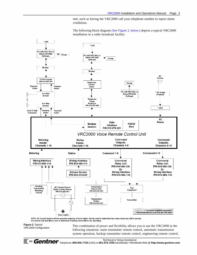
The following block diagram (See Figure 2, below.) depicts a typical VRC2000installation in a radio broadcast facility:
This combination of power and flexibility allows you to use the VRC2000 in thefollowing situations: main transmitter remote control, automatic transmissionsystem operation, backup transmitter remote control, engineering remote control,
Figure 2 . TypicalVRC2000 configuration

Page 4 VRC2000 Installation and Operations Manual
Technical or Setup AssistanceTelephone: 800.945.7730 (USA) or 801.975.7200 (worldwide) • Worldwide Web @ http://ww w.gentne r.com
microwave remote supervision, machine remote control, land mobile repeaterremote control, paging transmitter remote control, low-power TV (LPTV) remotecontrol.
Front-Panel Controls
The VRC2000 unit was designed for ease in operation and physical hookup.Manual operation consists of a single button and two LEDs (Figure 3,below). The front-panel controls perform the following functions:
1. Condenser Microphone. From this opening, dial-up callers can audiblymonitor the surrounding area of the installed VRC2000 unit.
2. On Line. This LED indicates if the VRC2000 is coupled to the telephoneline in use that is plugged into the back of the unit.
3. Local/Remote. This button toggles the VRC2000 between local controland remote operation via dial-up telephone line or using the VRC-Winsoftware (Windows®) or Setup VRC2000 software (DOS).
4. Power. This LED indicates if power is being supplied to the VRC2000.
Back-Panel Connectors
Following are descriptions of each of the VRC2000’s connectors (Figure 4,below). For pinouts, see Appendix B: Connector Pinouts (Page 98).
1. Power. The VRC2000 will operate with the AC input-voltage setting of117Vac or 234Vac.
POWER NOTE:You must verify that your VRC2000 is set to operate from the correct AC linevoltage before plugging it in. See Initialization, Page 6.
2. 0.5 Amp. This fuse module is where the half-amp fuse is located.
3. Batt. This connector is for connection of an optional battery backup.Gentner Communications recommends purchasing an Uninterruptible PowerSupply (UPS).
4. Gnd. This ground lug is for connection of all equipment requiringgrounding (such as the Gentner telephone surge protector).
5. Line. This RJ11C jack serves as the communication link between theVRC2000 and a standard dial-up telephone line.
6. Set. This RJ11C jack allows a telephone set to be connected to theVRC2000 to monitor incoming calls, place outbound calls or provide local
Product DescriptionContinued
Figure 3. VRC2000 front-panelcontrols
Figure 4. VRC2000 back-panelconnectors

VRC2000 Installation and Operations Manual Page 5
Technical or Setup AssistanceTelephone: 800.945.7730 (USA) or 801.975.7200 (worldwide) • Worldwide Web @ http://ww w.gentne r.com
control (such as during setup; see VRC2000 Setup, Page 10).
7. Metering. This DB37 connector serves as the metering communicationlink between the VRC2000 and the site equipment.
8. COM Port. This DB9 connector serves as the serial link between theVRC2000 and a PC.
9. Status. This DB37 connector serves as the status communication linkbetween the VRC2000 and the site equipment.
10. Command 1–8. This DB37 connector serves as the command link (forthe first eight command channels) between the VRC2000 and the siteequipment.
11. Audio In/Out. These standard BNC connectors provide unbalanced, four-wire interconnection, such as for two-wire radio.
12. Command 9–16. This DB37 connector serves as the command link (forthe second eight command channels) between the VRC2000 and the siteequipment.
Remote/Local Modes
The standard mode of operation for the VRC2000 is remote mode. Thisallows users connected via dial-up telephone line to remotely control theVRC2000 and issue commands.
However, suppose that the site engineer needs to perform maintenance on siteequipment. To do so, he must press the REMOTE/LOCAL button [3] (SeeFigure 3, previous page.) on the VRC2000’s front panel (the button will lightred, indicating that the VRC2000 is in local mode). In this mode, theVRC2000 is suspended from issuing command outputs, unless issued by theDTMF telephone connected to the VRC2000’s SET jack [6] (Figure 4,previous page). When in the local position, the VRC2000 provides directcurrent to the telephone set through the SET jack, allowing use of the DTMFpad to key in programming tones to set up the VRC2000. In other words, inlocal mode, the VRC2000 can be programmed or operated directly, withoutconnecting through a dial-up telephone line. However, metering and statusinformation is still available, as before.
REMOTE/LOCAL NOTE:Switching the VRC2000 to local mode during maintenance of site equipment iscritical. If the engineer was working on site equipment and the remote locationevoked a command channel connected to the site equipment, the engineer couldpossibly be injured.

Page 6 VRC2000 Installation and Operations Manual
Technical or Setup AssistanceTelephone: 800.945.7730 (USA) or 801.975.7200 (worldwide) • Worldwide Web @ http://ww w.gentne r.com
Power Requirements
The VRC2000 will accommodate an AC-voltage input of 117Vac or 234Vac(manual switching required), 50–60Hz, 15W nominal.
POWER NOTE:You must verify that your VRC2000 is set to operate from the correct AC linevoltage before plugging it in. See Installation, below.
Software Requirements
Refer to your Setup VRC2000 Installation and Operations Manual or VRC-Win Installation and Operations Manual.
Telephone Line Requirements
For normal operation, the VRC2000 works on standard analog telephonelines and connects to the telephone system with a standard RJ11C modularjack. If you do not have an RJ11C jack where you want to install yourVRC2000, call your telephone company for installation.
Equipment Placement
The VRC2000 is designed for standard 19-inch rack-cabinet mounting.
Telephone Option
A DTMF telephone set can be used for local-mode control and programmingof your VRC2000.
Before connecting the VRC2000 to your site equipment, it is necessary toinitialize the unit to verify it is properly configured.
Step 1 — Operating Voltage
OPERATING VOLTAGE NOTE:You must verify that your VRC2000 is set to operate from the correct AC linevoltage before plugging it in.
Your VRC2000 may operate on either 117Vac or 234Vac. You must verifywhich operating voltage your VRC2000 is set for by looking at the wiringharness of the VRC2000’s internal line transformer.
Unless marked otherwise, the VRC2000 is shipped with the harnessjumpered for 117Vac. However, you should follow the procedure listed belowto insure that your particular unit is properly set up before applying ACpower to the system.
To change the VRC2000’s operating voltage:
Step 1Carefully remove the VRC2000’s top cover by loosening the four mountingscrews on the sides of the unit.
Step 2Disconnect the four conductor Molex connections between the transformer
Before YouInstall
Initialization

VRC2000 Installation and Operations Manual Page 7
Technical or Setup AssistanceTelephone: 800.945.7730 (USA) or 801.975.7200 (worldwide) • Worldwide Web @ http://ww w.gentne r.com
inputs and the power-cord connector.
Step 3Insert the white Molex connector for 117Vac operation. Use the red Molexconnector for 234Vac operation. (See Figure 5, left.)
Step 2 — Internal Lithium Battery
Properly connect the internal lithium battery to the system RAM and clockcircuitry before applying power to your new VRC2000.
The internal lithium battery provides power to back up the system RAM andreal-time clock. In order to extend the life of the battery, it is not connectedat the factory. You must properly position a Berg shorting jumper (SeeFigure 6, left, below.) in order to connect the internal lithium battery.
BATTERY CONNECTION NOTE:If you do not properly connect the internal lithium battery, all VRC2000 defaultprogramming will be restored in the event of an AC power failure or power bump.All custom programming will be lost.
Do not apply AC power until you have properly positioned the internallithium battery jumper and checked the AC voltage set up for your VRC2000.
Step 3 — Surge Protection Option
The VRC2000 is a sensitive electronic device. In order to avoid damage toyour unit, Gentner Communications strongly recommends that you alwaysproperly protect your VRC2000 from voltage surges over telephone lines andAC power lines connected to your VRC2000.
The VRC2000 is equipped with a highly reliable Telephone Surge Protector(See Appendix C: Accessories, Page 100.) on the telephone line input.Gentner Communications does not guarantee that this Telephone SurgeProtector will protect your VRC2000 from damage caused by all voltagesurges; however, the Telephone Surge Protector will help limit such damage.
VOLTAGE SURGE NOTE:Never disconnect or bypass surge protection for your VRC2000. Damage to yourVRC2000 system caused by voltage surges is not covered under the terms of theGentner warranty agreement (Page 92).
Step 4 — Back-Panel Connections
Telephone SetConnect a standard DTMF telephone set to the SET jack [6] (See Figure 7,below.) on the back panel of the VRC2000 with a standard modular cable.
Telephone LineUse the supplied modular telephone connector to connect the LINE jack [5]to the telephone line coming into your building.
Figure 5 . VRC2000 transformer wiringdiagram
Figure 6. VRC2000 lithium batteryjumper diagram
Figure 7. VRC2000 back-panelconnectors

Page 8 VRC2000 Installation and Operations Manual
Technical or Setup AssistanceTelephone: 800.945.7730 (USA) or 801.975.7200 (worldwide) • Worldwide Web @ http://ww w.gentne r.com
Audio AmplifierIf possible, attach an audio amplifier and speaker to the BNC connectormarked AUDIO OUT [11] (Figure 7a, above).
Step 5 — Power Up
Connect the supplied AC power cord to the power module [1], and apply ACpower to the VRC2000.
MANUAL NOTE:In instances where the VRC2000 responds verbally, the VRC2000’s verbiage willbe set off by a bullet (•) and printed in SMALL CAPS. Numbers and phrases youshould send back to the VRC2000 with your DTMF keypad will be offset with ablock (☎) and quotation marks (“ ”).
With Audio AmplifierIf you have an audio amplifier and speaker attached to the VRC2000 (SeeFigure 8, below.), the unit should respond with the spoken phrase:
• DATA ERASED. CLOCK ERASED.
Now remove AC power from the VRC2000, and plug the unit back in. TheVRC2000 should respond with the phrase
• DATA OK. CLOCK OK.
However, if the VRC2000 also responds
• DATA ERASED. CLOCK ERASED.
the internal lithium battery has not been properly connected. PerformStep 2 — Internal Lithium Battery (See Page 7.) again.
Without Audio AmplifierIf you do not use an audio amplifier to confirm that your VRC2000 is readyfor operation, follow these directions:
1) Apply AC power to the VRC2000.
2) Pick up the telephone handset and listen.
InitializationContinued
Figure 7a. VRC2000 back-panelconnectors
Figure 8. Power-up configuration
VRC2000 Installation and Operations Manual Page 9
Technical or Setup AssistanceTelephone: 800.945.7730 (USA) or 801.975.7200 (worldwide) • Worldwide Web @ http://ww w.gentne r.com
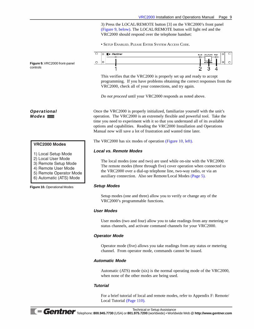
3) Press the LOCAL/REMOTE button [3] on the VRC2000’s front panel(Figure 9, below). The LOCAL/REMOTE button will light red and theVRC2000 should respond over the telephone handset:
• SETUP ENABLED. PLEASE ENTER SYSTEM ACCESS CODE.
This verifies that the VRC2000 is properly set up and ready to acceptprogramming. If you have problems obtaining the correct responses from theVRC2000, check all of your connections, and try again.
Do not proceed until your VRC2000 responds as noted above.
Once the VRC2000 is properly initialized, familiarize yourself with the unit’soperation. The VRC2000 is an extremely flexible and powerful tool. Take thetime you need to experiment with it so that you understand all of its availableoptions and capabilities. Reading the VRC2000 Installation and OperationsManual now will save a lot of frustration and wasted time later.
The VRC2000 has six modes of operation (Figure 10, left).
Local vs. Remote Modes
The local modes (one and two) are used while on-site with the VRC2000.The remote modes (three through five) cover operation when connected tothe VRC2000 over a dial-up telephone line, two-way radio, or via anauxiliary connection. Also see Remote/Local Modes (Page 5).
Setup Modes
Setup modes (one and three) allow you to verify or change any of theVRC2000’s programmable functions.
User Modes
User modes (two and four) allow you to take readings from any metering orstatus channels, and activate command channels for your VRC2000.
Operator Mode
Operator mode (five) allows you take readings from any status or meteringchannel. From operator mode, commands cannot be issued.
Automatic Mode
Automatic (ATS) mode (six) is the normal operating mode of the VRC2000,when none of the other modes are being used.
Tutorial
For a brief tutorial of local and remote modes, refer to Appendix F: Remote/Local Tutorial (Page 110).
Figure 10. Operational Modes
OperationalModes
Figure 9. VRC2000 front-panelcontrols

Page 10 VRC2000 Installation and Operations Manual
Technical or Setup AssistanceTelephone: 800.945.7730 (USA) or 801.975.7200 (worldwide) • Worldwide Web @ http://ww w.gentne r.com
The VRC2000 is controlled and set up with DTMF tones. You can use anystandard DTMF telephone in either the local or remote modes to set up andprogram the VRC2000.
If you are unfamiliar with the VRC2000’s operation and set-up procedures, readthis section of the manual thoroughly. Experienced VRC2000 users may wish torefer to the setup worksheets in Appendix H: Setup Worksheets (Page 117).
The set-up process is fast and easy if you use the Setup VRC2000 software orVRC-Win software now available from Gentner Communications. Thesesoftware packages will run on any 100-percent IBM-compatible PC that isequipped with a 100-percent Hayes-compatible modem. The Setup VRC2000software is a menu-driven DOS-based program that greatly simplifies and speedsup this process. The VRC-Win software is Windows®-based, simplifying thingsfurther through the point-and-click user interface. These software are especiallyuseful for owners who have never set up a VRC2000 before. Refer to AppendixC: Accessories (Page 100) for more information about the Setup VRC2000software and VRC-Win software.
The set-up procedure will take substantial time if you plan to use a standardDTMF telephone. It is very important that you thoroughly understand theoperation of the VRC2000 as well as the electrical parameters of the equipmentyou plan to control with the VRC2000 before you begin the set-up process. Thebetter you understand the system and the more you plan ahead, the easier theset-up process will be.
Planning is vital to successful and error-free programming of the VRC2000. Youcan always change the parameters for any VRC2000 channel after you have setup the channel, but a little planning will help you make more efficient use of theset-up process.
Refer to the worksheets in Appendix H: Setup Worksheets (Page 117).Programming is straightforward if you use these worksheets, and have them infront of you while setting up your VRC2000.
MANUAL NOTE:In instances where the VRC2000 responds verbally, the VRC2000’s verbiage willbe set off by a bullet (•) and printed in SMALL CAPS. Numbers and phrases youshould send back to the VRC2000 with your DTMF keypad will be offset with atelephone icon (☎) and quotation marks (“ ”).
VRC2000 Word List
The VRC2000’s special electronic speech package allows the system to talkin plain English to you over any dial-up telephone line. This speech packagehas a vocabulary of almost 800 words. The VRC2000 will say whatever isdesired in response to commands, sign-ons, sign-offs, metering requests, etc.
For example
• HELLO. THIS IS THE AM TRANSMITTER. PLEASE ENTER ACCESS CODE.
Or the VRC2000 can respond to a particular command with
• COMMAND CHANNEL TWO. MAIN POWER, RAISE.
VRC2000Setup

VRC2000 Installation and Operations Manual Page 11
Technical or Setup AssistanceTelephone: 800.945.7730 (USA) or 801.975.7200 (worldwide) • Worldwide Web @ http://ww w.gentne r.com
Or the VRC2000 can respond to a metering request with
• METERING CHANNEL ONE. FILAMENT VOLTAGE, 6.123 VOLTS.
These phrases are only examples. The VRC2000 is very flexible and, withinthe limits of the system’s vocabulary, can be set up to say anything desired.
A complete listing of the VRC2000’s vocabulary is included in Appendix I:Word List (Page 125).
VRC2000 Setup and User Modes
The VRC2000 has two major modes of operation: setup and user. The setupmode allows programming all functions of any metering, status or commandchannel, setting alarm parameters, specifying words and sentences for theVRC2000 to use, and several other functions. The user mode allowsmetering channel or status channel reports to be requested, and commands tobe issued to change the operating parameters of the equipment connected tothe unit. The VRC2000 can be accessed and operated in either the setup orthe user mode from either a local or remote location.
The VRC2000 is designed for easy setup. With only the basic VRC2000 unitand a standard DTMF telephone, the functions of any metering, status orcommand channel can be programmed, as well as the unit’s responses to anymetering or status request, or command.
To set up the VRC2000 so all functions correspond with specific needs andapplications, enter DTMF tones from a telephone pad to program anyVRC2000 function. When a valid code is entered, the unit will respond withthe current parameters programmed for that function; the VRC2000 willthen allow you to edit/change them.
One important item to make the setup process easier is to time DTMF entriescorrectly. Experiment with the set-up procedures a few times to understandthe way the VRC2000 responds to entries; practice initiating and completinga set-up event.
Use local mode the first time the VRC2000 is set up. The set-up process willbe easier if you connect an amplifier and speaker is connected to the AUDIOOUT BNC connector on the VRC2000’s rear panel. After, apply AC powerto the unit.
Security
The VRC2000 provides three security levels: operator, user and system.
OperatorOperator access allows metering and status-channel readings to be taken.Commands cannot be issued to the VRC2000, and alarms cannot be cleared.
UserUser access allows metering and status-channel readings to be taken, theVRC2000’s command-channel switches can be activated, and alarms can becleared.

Page 12 VRC2000 Installation and Operations Manual
Technical or Setup AssistanceTelephone: 800.945.7730 (USA) or 801.975.7200 (worldwide) • Worldwide Web @ http://ww w.gentne r.com
SystemSystem access allows any metering, status or command channel to be set up,and any VRC2000 programming to be changed. System access also allowsany access codes for any of the three security levels to be changed.Command-channel outputs cannot be triggered, readings from the meteringand status channels cannot be taken, and alarms cannot be cleared.
Changing Access Codes
To change access codes for any security level, follow these step-by-stepinstructions:
Step 1Press the LOCAL/REMOTE button [3] (See Figure 11, below.) on theVRC2000’s front panel.
The unit will respond:
• SETUP ENABLED. PLEASE ENTER SYSTEM ACCESS CODE.
The VRC2000 will allow 10 seconds to completely enter the default system-access code (below) on the DTMF telephone pad:
☎ “1 2 3 4 5 6 7”
If the correct sequence of numbers were entered, the VRC2000 will respond:
• THANK YOU. PLEASE SELECT FUNCTION FOR PROGRAMMING.
If the unit does not respond, either
1) the connections between telephone and the VRC2000 are incorrect2) the wrong sequence of numbers was entered3) the sequence of numbers was not entered quickly enough4) the telephone being used has poor DTMF tone quality
Check the connections and try again until the indicated response from theVRC2000 is received.
If invalid number sequences or symbols are entered, the VRC2000 will say
• ERROR.
This indicates an entry the VRC2000 cannot accept for the currentparameter. If the ERROR message comes, begin the programming sequencefor the parameter again.
DEFAULT PARAMETER NOTE:Default parameters are enclosed in {braces}. Change parameters enclosed in{braces} when programming the VRC2000.
VRC2000 SetupContinued
Figure 11. VRC2000 front-panelcontrols

VRC2000 Installation and Operations Manual Page 13
Technical or Setup AssistanceTelephone: 800.945.7730 (USA) or 801.975.7200 (worldwide) • Worldwide Web @ http://ww w.gentne r.com
Step 2In order to change the access codes for all three security levels, enter
☎ “0 9 0”
The VRC2000 will respond:
• OPERATOR ACCESS CODE IS {0, 1, 2, 3, 4} ... [BEEP]• USER ACCESS CODE IS {1, 2, 3, 4, 5} ... [BEEP]• SYSTEM ACCESS CODE IS {1, 2, 3, 4, 5, 6, 7} ... [BEEP]
The VRC2000 is reporting, in order of priority, the access codes for all threesecurity levels. The pause between the end of an access code and the [BEEP]is four seconds long. New access codes should be entered during that four-second pause.
To change the access codes, enter
☎ “0 9 0”
The VRC2000 will respond as before. Immediately after, the VRC2000 says
• OPERATOR ACCESS CODE IS 0, 1, 2, 3, 4
Promptly enter the following sequence of numbers:
☎ “1 1 1 1 1”
After the last number in the above sequence in entered, the VRC2000 willrespond with a double [BEEP]. The double [BEEP] indicates that a newoperator access code has been entered.
ACCESS CODE NOTE:When entering individual access codes (operator, user or system), any five digitscan be used.
The VRC2000 will say
• USER ACCESS CODE IS 1, 2, 3, 4, 5
As soon as the VRC2000 completes this statement, enter the followingsequence of numbers:
☎ “2 2 2 2 2”
The VRC2000 will double [BEEP] again, then say
• SYSTEM ACCESS CODE IS 1, 2, 3, 4, 5, 6, 7
Promptly enter the following sequence:
☎ “3 3 3 3 3 3 3”
The VRC2000 will double [BEEP] again to confirm that a new system accesscode had been entered.

Page 14 VRC2000 Installation and Operations Manual
Technical or Setup AssistanceTelephone: 800.945.7730 (USA) or 801.975.7200 (worldwide) • Worldwide Web @ http://ww w.gentne r.com
Step 3Verify the newly entered access codes by entering
☎ “0 9 0”
The VRC2000 should respond:
• OPERATOR ACCESS CODE IS 1, 1, 1, 1, 1 ... [BEEP]• USER ACCESS CODE IS 2, 2, 2, 2, 2 ... [BEEP]• SYSTEM ACCESS CODE IS 3, 3, 3, 3, 3, 3, 3 ... [BEEP]
If the VRC2000 does not respond as indicated above, an error entering thenew access codes may have been made. Go through the process (See Step 2,previous page.) again until the new access codes have been correctly entered.
Internal Battery/Access Code Check
Verify that the VRC2000’s internal lithium battery is properly connected,and that the new access codes have been properly entered and stored.Following these step-by-step instructions:
Step 1Press the LOCAL/REMOTE button [3] (See Figure 11a, below.) on theVRC2000’s front panel to exit setup mode. The button light will extinguish,and the VRC2000 will say
• SETUP DISABLED. GOOD-BYE.
Step 2Unplug the VRC2000’s AC power cord, wait 25–30 seconds, and plug itback in. The VRC2000 should respond:
• DATA OK. CLOCK OK.
However, the VRC2000 may also say
• DATA ERASED. CLOCK ERASED.
If this occurs, the VRC2000’s internal-lithium battery is not properlyenabled.
Step 3Press the LOCAL/REMOTE button [3] on the VRC2000’s front panel. Thebutton will light red and the VRC2000 will say
• SETUP ENABLED. PLEASE ENTER SYSTEM ACCESS CODE.
With the DTMF pad, enter the new system access code programmed inChanging Access Codes (Page 12).
☎ “3 3 3 3 3 3 3”
VRC2000 SetupContinued
Figure 11a. VRC2000 front-panelcontrols

VRC2000 Installation and Operations Manual Page 15
Technical or Setup AssistanceTelephone: 800.945.7730 (USA) or 801.975.7200 (worldwide) • Worldwide Web @ http://ww w.gentne r.com
ACCESS CODE NOTE:If a different access code was programmed from the one in the exercise, enter theaccess code programmed.
The VRC2000 should respond:
• THANK YOU. PLEASE SELECT FUNCTION FOR PROGRAMMING.
If the VRC2000 does not respond with this message, there was an errorentering the new system access code, the unit was not properly programmedwith the new system access code or the internal lithium battery was notplaced correctly.
ACCESS ERROR NOTE:If unable to obtain access to the VRC2000’s programming functions with the newsystem access code, remove AC power from the VRC2000, remove all status andmetering channel inputs from the unit, then remove the Berg jumpers on theinternal lithium battery. Replace the battery jumper, reconnect all status andmetering channel inputs, and return AC power to the VRC2000.
If not done so previously, program your own set of access codes for all threesecurity levels. Write these access codes into the provided spreadsheet(Appendix H: Setup Worksheets, Page 117).
ACCESS CODE NOTE:When determining access codes, use the letters on the DTMF pad to spell outmeaningful words. This will make the codes easier to remember.
Do not forget or lose your written record of the access codes. Do notprogram the access codes carelessly. If the access codes are lost or forgotten,the only way to gain access to the VRC2000 is to remove the jumper on theinternal lithium battery and unplug the VRC2000. This will erase allprogrammed functions and all parameters and functions will have to bereprogrammed.
Turning the VRC2000 Voice On/Off
Disabling the VRC2000’s voice functions in setup mode will allow longstrings of numbers with the DTMF pad without waiting for the voice torespond. Doing so will speed up programming. To disable the VRC2000’svoice functions, follow these step-by-step instructions:
Step 1Enter setup mode (either local or remote).
Step 2Enter
☎ “9 3 0”
The VRC2000 will respond:
• VOICE OFF.
To reactivate the voice function, enter
☎ “9 4 0”

Page 16 VRC2000 Installation and Operations Manual
Technical or Setup AssistanceTelephone: 800.945.7730 (USA) or 801.975.7200 (worldwide) • Worldwide Web @ http://ww w.gentne r.com
The VRC2000 will respond:
• VOICE ON.
The VRC2000 will accept very long strings of numbers when the voicefunction is disabled, although you can only enter one programming sequenceat a time. If an invalid code number is entered with the voice function off,the VRC2000 will respond with an ERROR message.
VOICE FUNCTION NOTE:The voice function will automatically be turned back on after a validprogramming sequence is entered. You will hear an ERROR message after thevoice function is turned off if you enter an invalid programming sequence; beginthe programming sequence for the parameter again if an ERROR message isreceived.
Toggling Between User and Setup Modes
Toggling between the user and setup modes can be done at any time. Whenin local setup mode, toggle to the local user mode by entering
☎ “9 2 0”
The VRC2000 will respond:
• USER ENABLED.
Toggle back to local setup mode by entering the same “9 2 0” sequence.
When in the remote user mode, toggle to remote setup mode by entering
☎ “9 1 0”
The VRC2000 will say
• SETUP ENABLED. PLEASE ENTER SYSTEM ACCESS CODE.
Now enter the correct seven-digit system access code in order to proceed withany set-up function.
Toggle back to remote user mode by entering the same “9 1 0” sequence.
SETUP MODE NOTE:The setup mode cannot be entered from the operator security level. Attemptingto do so will result in an ERROR message.
Changing the System Identifier
The system identifier is the greeting the VRC2000 gives when a user signson to the system; it can be customized, as long as it is composed of exactly20 words.
The default system identifier states
• HELLO. THIS IS THE VRC2000 WITH VOICE, MODEM OR RADIO ACCESS.PLEASE ENTER ACCESS CODE.
VRC2000 SetupContinued

VRC2000 Installation and Operations Manual Page 17
Technical or Setup AssistanceTelephone: 800.945.7730 (USA) or 801.975.7200 (worldwide) • Worldwide Web @ http://ww w.gentne r.com
This statement can be altered to include the station call letters or other wordsrelevant to the facility.
To change the system identifier, first sign on to the VRC2000 in the setupmode and enter the system access code. Then enter
☎ “0 8 0”
The VRC2000 will respond with the same message stated on the previouspage.
Now enter the following sequence of DTMF tones (Table 1, below):
The VRC2000’s system identifier is now programmed. Verify that the newsystem identifier was correctly programmed by entering the “0 8 0” sequenceon the DTMF pad.
The VRC2000 can be programmed with almost any desired statement; theonly limit is the VRC2000’s vocabulary of almost 800 words. Refer to theAppendix I: Word List (See Page 125.) for a complete listing of theVRC2000’s vocabulary.
Gentner Communications recommends that the system identifier alwaysbegin with the words
• HELLO. THIS IS THE ....
Also always use the words
• PLEASE ENTER ACCESS CODE
at the end of the system identifier. This will remind users that they have toenter an access code to operate a VRC2000.
Table 1. System Identifier Word List
DTMF Code Word Definition☎ “4 6 4” • HELLO
☎ “7 2 6” • THIS
☎ “4 9 7” • IS☎ “7 2 2” • THE
☎ “1 0 0” • A☎ “1 0 1” • B☎ “1 0 2” • C☎ “1 0 3” • D☎ “7 3 9” • TRANSMITTER
☎ “6 8 5” • SITE
☎ “0 5 6” • (5 MILLISECONDS SILENCE)☎ “0 5 6” • (5 MILLISECONDS SILENCE)☎ “0 5 6” • (5 MILLISECONDS SILENCE)☎ “0 5 6” • (5 MILLISECONDS SILENCE)☎ “0 5 6” • (5 MILLISECONDS SILENCE)☎ “0 5 6” • (5 MILLISECONDS SILENCE)☎ “6 1 0” • PLEASE
☎ “4 0 0” • ENTER
☎ “2 0 4” • ACCESS
☎ “3 1 0” • CODE

Page 18 VRC2000 Installation and Operations Manual
Technical or Setup AssistanceTelephone: 800.945.7730 (USA) or 801.975.7200 (worldwide) • Worldwide Web @ http://ww w.gentne r.com
SYSTEM IDENTIFIER NOTE:For maximum security, programming the system identifier solely with silencesmay be desirable.
The use of silences in the system identifier will help make the VRC2000’sstatements more understandable.
Sixty DTMF tones, entered correctly, are required to program theVRC2000’s system identifier. Once the first DTMF tone in theprogramming sequence is entered, the VRC2000 will wait until all 60 tonesare entered.
If not completed previously, now program the VRC2000 with your ownsystem identifier. First, decide what the unit will say (Appendix I: WordList, Page 125). Make notes on the tones to be programmed into theVRC2000. Remember to include exactly 20 words (60 DTMF tones) in thesystem identifier.
VOICE OFF NOTE:Using the VOICE OFF command “9 3 0” when programming the systemidentifier will save time. Although it is not mandatory, always remember to turnthe voice function back on with the VOICE ON command “9 4 0” when finished.
Setting the Clock
The VRC2000 has a real-time clock and calendar used to tag alarms. Settingthis clock accurately is important. The VRC2000’s clock can also be set upto automatically change to and from daylight savings time.
To set the VRC2000 clock, enter setup mode with the system access code.Next, enter
☎ “0 6 0”
The VRC2000 will respond:
• TIME OF DAY HOURS ARE ... {TWELVE} ... [BEEP]• TIME OF DAY MINUTES ARE ... {ZERO} ... [BEEP]• TIME OF DAY SECONDS ARE ... {ZERO} ... [BEEP]• TIME OF DAY IS ... {AM} ... [BEEP]• DAYLIGHT SAVINGS TIME IS ... {DISABLED} ... [BEEP]• DAY OF WEEK IS ... {WEDNESDAY} ... [BEEP]• DATE IS ... {DECEMBER SIXTEEN, NINETEEN EIGHTY-EIGHT} ... [BEEP]
In the pauses before each [BEEP], enter new numbers that will reset eachportion of the clock/calendar.
TIME/CLOCK NOTE:The time actually spoken by the VRC2000 may vary from the information statedabove, depending on the length of time which has elapsed since power wasapplied to the unit. However, the format will be the same as indicated above.
The clock is not updated until the last number is entered for each individualtime/date function. This means the time can be set to accurate time bases(i.e. studio clock or WWV).
VRC2000 SetupContinued
VRC2000 Installation and Operations Manual Page 19
Technical or Setup AssistanceTelephone: 800.945.7730 (USA) or 801.975.7200 (worldwide) • Worldwide Web @ http://ww w.gentne r.com
When the daylight savings time function is enabled, the VRC2000 willautomatically advance its clock forward one hour at 2 a.m. on the firstSunday in April. It will also move the clock back one hour at 2 a.m. on thelast Sunday in October.
DAYLIGHT SAVINGS TIME NOTE:The daylight savings time function adjusts the clock only. No programmed time-of-day operations are affected.
Clock Setting Exercise
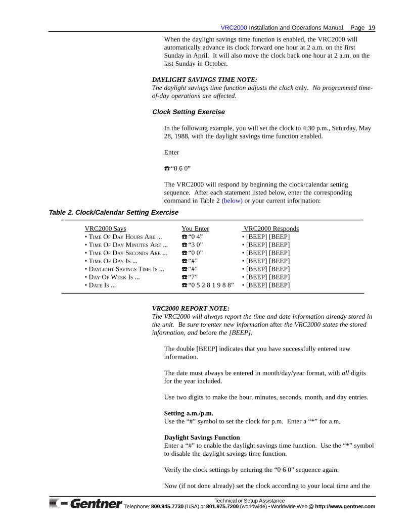
In the following example, you will set the clock to 4:30 p.m., Saturday, May28, 1988, with the daylight savings time function enabled.
Enter
☎ “0 6 0”
The VRC2000 will respond by beginning the clock/calendar settingsequence. After each statement listed below, enter the correspondingcommand in Table 2 (below) or your current information:
VRC2000 REPORT NOTE:The VRC2000 will always report the time and date information already stored inthe unit. Be sure to enter new information after the VRC2000 states the storedinformation, and before the [BEEP].
The double [BEEP] indicates that you have successfully entered newinformation.
The date must always be entered in month/day/year format, with all digitsfor the year included.
Use two digits to make the hour, minutes, seconds, month, and day entries.
Setting a.m./p.m.Use the “#” symbol to set the clock for p.m. Enter a “*” for a.m.
Daylight Savings FunctionEnter a “#” to enable the daylight savings time function. Use the “*” symbolto disable the daylight savings time function.
Verify the clock settings by entering the “0 6 0” sequence again.
Now (if not done already) set the clock according to your local time and the
Table 2. Clock/Calendar Setting Exercise
VRC2000 Says You Enter VRC2000 Responds• TIME OF DAY HOURS ARE ... ☎ “0 4” • [BEEP] [BEEP]• TIME OF DAY MINUTES ARE ... ☎ “3 0” • [BEEP] [BEEP]• TIME OF DAY SECONDS ARE ... ☎ “0 0” • [BEEP] [BEEP]• TIME OF DAY IS ... ☎ “#” • [BEEP] [BEEP]• DAYLIGHT SAVINGS TIME IS ... ☎ “#” • [BEEP] [BEEP]• DAY OF WEEK IS ... ☎ “7” • [BEEP] [BEEP]• DATE IS ... ☎ “0 5 2 8 1 9 8 8” • [BEEP] [BEEP]

Page 20 VRC2000 Installation and Operations Manual
Technical or Setup AssistanceTelephone: 800.945.7730 (USA) or 801.975.7200 (worldwide) • Worldwide Web @ http://ww w.gentne r.com
current date. Refer to Appendix I: Word List (See Page 125.) for thecommand numbers for each part of the clock/calendar functions. Write outthe planned numbers to be entered before beginning. Use the worksheets inAppendix H: Setup Worksheets (See Page 117.) to plan and recordprogramming to be entered into the VRC2000.
Telephone Interface
Several options make the VRC2000 work correctly with particular telephonesystems: pulse/tone selection, ring count, inactivity timer and precision dial-tone waiting.
Pulse/Tone SelectionThis option allows selection of DTMF or pulse dialing for VRC2000outbound calling.
Ring CountThis option allows the VRC2000 to be programmed to answer incomingcalls after a certain number of rings. For example, if the ring count is set to0, the unit is constantly online, allowing use of the VRC2000 with adedicated four-wire connection. (Such a dedicated four-wire connection willprovide 24-hour access to the site.) Unless using such a dedicated four-wiresystem, program the unit to answer on the first or second ring.
Inactivity TimerThis option allows an inactivity timer to be switched ON or OFF. When theinactivity timer is ON, the VRC2000 must receive at least one valid DTMFcommand every five minutes, or it will automatically exit the setup, user and/or operator modes. If the inactivity timer is OFF, the unit will exit the setup,user and/or operator mode after one hour if it has not received any validDTMF commands; it will exit the user mode only when the you properlysign off or hang up the telephone line.
Unless using the VRC2000 on a dedicated telephone line (for constant accessto commands), Gentner Communications recommends leaving the inactivitytimer ON.
Dial-Tone WaitThis allows the VRC2000 to be programmed to wait for a precision dial tonebefore beginning to dial an outbound number. Some older telephonesystems, or some systems with poor quality lines, do not have reliableprecision dial tone. In such cases, the VRC2000 can be programmed to waitsix seconds before beginning to dial an outbound number.
Unless you are in an area with a very old telephone system, or an area withvery poor quality lines, Gentner Communications recommends programmingthe VRC2000 to wait for a precision dial tone before dialing.
Telephone Interface Setting Exercise
In the following exercise, program the VRC2000 to make outbound callswith pulse dialing, answer automatically after two rings, enable the inactivitytimer and enable dial-tone wait function.
VRC2000 SetupContinued

VRC2000 Installation and Operations Manual Page 21
Technical or Setup AssistanceTelephone: 800.945.7730 (USA) or 801.975.7200 (worldwide) • Worldwide Web @ http://ww w.gentne r.com
VRC2000 REPORT NOTE:The VRC2000 will report the information already stored in the unit. Be sure toenter new information after the VRC2000 states the stored information, andbefore you hear a [BEEP].
The double [BEEP] indicates successfully entered new information.
This series of DTMF entries has programmed the VRC2000 to use pulsedialing for all outbound dialing and answer after two rings. The inactivitytimer has also been switched ON, and the dial-tone wait function has beenenabled.
Pulse/DTMF DialingWhen programming the VRC2000, enter a “#” symbol to enable DTMFoutbound dialing; use “*” for outbound pulse dialing.
Inactive Disconnect FunctionEnter a “#” symbol to enable the inactive time disconnect function. Use the“*” to disable the inactive time disconnect function.
Dial-Tone Wait FunctionEnter a “#” to enable the dial-tone wait function. Use “*” to disable the dialtone wait function.
This set of commands should allow the VRC2000 to function properly inmost circumstances. To change any of the parameters of the telephoneinterface options, refer to Appendix I: Word List (See Page 125.) for acomplete listing of optional command codes.
After programming the telephone interface options, record the setup on theworksheet provided for this purpose in Appendix H: Setup Worksheets (Page117).
Setting Up Outbound Telephone Numbers
The VRC2000 can be programmed to automatically dial certain telephonenumbers and report alarm conditions; thus, all parameters of the equipmentconnected to the VRC2000 no longer need to be constantly monitored.Critical parameters can be set to trigger an alarm if certain conditions aremet. When this happens, the VRC2000 will then automatically call theprogrammed outbound telephone numbers and report the alarm.
Table 3. Telephone Interface Setting Exercise
VRC2000 Says You Enter VRC2000 Responds• DIALING IS {DTMF} ... ☎ “*” • [BEEP] [BEEP]• NUMBER OF RINGS BEFORE ANSWERING IS {TWO} ... ☎ “2” • [BEEP] [BEEP]• INACTIVE TIME DISCONNECT IS {ENABLED} ... ☎ “#” • [BEEP] [BEEP]• DIAL TONE WAIT IS {ENABLED} ... ☎ “#” • [BEEP] [BEEP]
First, enter
☎ “0 7 0”
The VRC2000 will respond by beginning the telephone interface optionsequence. After each statement listed in Table 3 (See below.), enter thecommand listed:

Page 22 VRC2000 Installation and Operations Manual
Technical or Setup AssistanceTelephone: 800.945.7730 (USA) or 801.975.7200 (worldwide) • Worldwide Web @ http://ww w.gentne r.com
The VRC2000 can be programmed to dial up to five different telephonenumbers. The unit can be set up to call only certain numbers for certainalarm conditions, or call each of the numbers in sequence.
Data Interface OptionIf the VRC2000 is installed with a Data Interface (See Appendix C:Accessories, Page 100.), the VRC2000 can be programmed to automaticallyactivate the Data Interface and report alarms in an electronic data formatwith a dedicated PC and modem at the studio site.
For each outbound telephone number, select whether it will report alarmsusing voice or the Data Interface’s modem selection. Each outboundtelephone number can also be programmed to either use a telephone line totransmit this information, or to use a two-way radio set.
If using the Setup VRC2000 software or VRC-Win software to performauto-logging functions, the VRC2000 will use the first outbound telephonenumber programmed for modem access to transmit auto-logging data.
See the Data Interface Installation and Operations Manual for informationabout how to install and use the Data Interface. Refer to the Setup VRC2000Installation and Operations Manual for instructions on how to use it toprogram the VRC2000’s outbound telephone numbers and auto-loggingfunctions. See the VRC-Win Installation and Operations Manual for fulldescription of its operational parameters.
Outbound Telephone NumbersThere are four output configurations available for each of the five outboundtelephone numbers: telephone modem, telephone voice, radio modem andradio voice.
Telephone Modem. This output configuration causes the VRC2000 to dialthe selected outbound telephone number, turn on the Data Interface andtransmit pending alarm information in an electronic data format.
TELEPHONE MODEM NOTE:The VRC2000 must be equipped with the Data Interface in order to use thetelephone modem output configuration.
Telephone Voice. This output configuration allows the VRC2000 to dial theselected outbound telephone number and use its electronic voice to transmitinformation about the pending alarm.
Radio Modem. This output configuration causes the VRC2000 to activatethe push-to-talk output on the VRC2000, turn on the Data Interface, andtransmit information about the pending alarm in an electronic data format.
RADIO MODEM NOTE:The VRC2000 must be equipped with the Data Interface in order to use the radiomodem output configuration.
Radio Voice. This output configuration causes the VRC2000 to activate thepush-to-talk output on the VRC2000, and use its electronic voice to transmitinformation about a pending alarm.
VRC2000 SetupContinued

VRC2000 Installation and Operations Manual Page 23
Technical or Setup AssistanceTelephone: 800.945.7730 (USA) or 801.975.7200 (worldwide) • Worldwide Web @ http://ww w.gentne r.com
Message Only FunctionIn either the phone voice or radio voice output configuration, the message-only function for the outbound telephone number can be enabled. Themessage-only function will allow the VRC2000 to call a number and onlyleave a message to return the call. With the message-only function enabled,the VRC2000 will wait until a call is answered (or until the 20-secondtimeout period), state the programmed system identifier, and say
• PLEASE RETURN CALL .
This allows the VRC2000 to call you directly and request a call back, or theVRC2000 can call and leave this message on your answering machine. Ineither case, the VRC2000 will only leave a message; you cannot gain accessto the system without returning the call and properly entering the appropriateaccess code. The message-only function is ideal for engineers who depend ona telephone pager for alarm notifications.
If the message-only function is disabled, the call does not need to bereturned; the VRC2000 will call the outbound telephone number andimmediately allow an access code to be entered and commands to be issued.
Outbound Call SequenceWhen an alarm condition is present, the VRC2000 will keep dialingoutbound telephone numbers until corrective action is taken. The VRC2000will dial each of the enabled outbound telephone numbers stored in memoryuntil the alarm(s) is cleared.
The unit will pause for one minute between each outbound call in thesequence, allowing time to make an incoming call to the VRC2000. The unitwill also pause for 10 minutes after the last call in the sequence beforebeginning the sequence over again.
OUTBOUND CALL SEQUENCE NOTE:If an alarm is programmed to call one specific number, and that alarm is theoldest alarm that has been recognized by the VRC2000, the unit will call that onespecific number once every minute until that alarm has been cleared. It will notpause for 10 minutes at any time.
Number DisablingEach of the programmed outbound telephone numbers can be enabled/disabled. This allows all five numbers to be programmed but, if someonegoes on vacation, that particular outbound telephone number can be disableduntil that person returns.
However, be cautious when disabling outbound telephone numbers. If theVRC2000 is programmed to dial a particular number when an alarmcondition is present, if the number is disabled, verify that the VRC2000 canalways call at least one enabled outbound telephone number on each alarmset up.
Auto-Logging and Alarm LoggingTo use the VRC2000 for auto-logging and alarm logging functions, at leastone outbound telephone number should be programmed for phone modem orradio modem output. Gentner Communications recommends that outboundtelephone number 1 be set for modem output. This will ensure that alarmsare logged before they are cleared.
Page 24 VRC2000 Installation and Operations Manual
Technical or Setup AssistanceTelephone: 800.945.7730 (USA) or 801.975.7200 (worldwide) • Worldwide Web @ http://ww w.gentne r.com
Telephone Number Programming Exercise
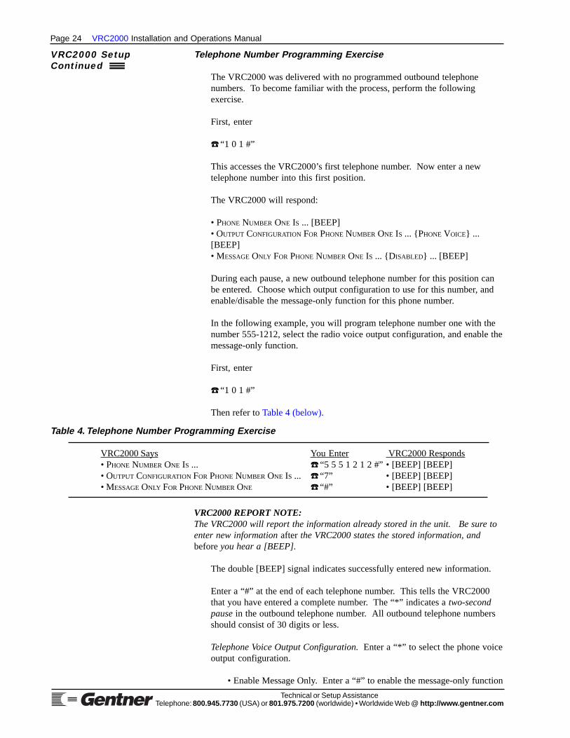
The VRC2000 was delivered with no programmed outbound telephonenumbers. To become familiar with the process, perform the followingexercise.
First, enter
☎ “1 0 1 #”
This accesses the VRC2000’s first telephone number. Now enter a newtelephone number into this first position.
The VRC2000 will respond:
• PHONE NUMBER ONE IS ... [BEEP]• OUTPUT CONFIGURATION FOR PHONE NUMBER ONE IS ... {PHONE VOICE} ...[BEEP]• MESSAGE ONLY FOR PHONE NUMBER ONE IS ... {DISABLED} ... [BEEP]
During each pause, a new outbound telephone number for this position canbe entered. Choose which output configuration to use for this number, andenable/disable the message-only function for this phone number.
In the following example, you will program telephone number one with thenumber 555-1212, select the radio voice output configuration, and enable themessage-only function.
First, enter
☎ “1 0 1 #”
Then refer to Table 4 (below).
VRC2000 REPORT NOTE:The VRC2000 will report the information already stored in the unit. Be sure toenter new information after the VRC2000 states the stored information, andbefore you hear a [BEEP].
The double [BEEP] signal indicates successfully entered new information.
Enter a “#” at the end of each telephone number. This tells the VRC2000that you have entered a complete number. The “*” indicates a two-secondpause in the outbound telephone number. All outbound telephone numbersshould consist of 30 digits or less.
Telephone Voice Output Configuration. Enter a “*” to select the phone voiceoutput configuration.
• Enable Message Only. Enter a “#” to enable the message-only function
Table 4. Telephone Number Programming Exercise
VRC2000 Says You Enter VRC2000 Responds• PHONE NUMBER ONE IS ... ☎ “5 5 5 1 2 1 2 #” • [BEEP] [BEEP]• OUTPUT CONFIGURATION FOR PHONE NUMBER ONE IS ... ☎ “7” • [BEEP] [BEEP]• MESSAGE ONLY FOR PHONE NUMBER ONE ☎ “#” • [BEEP] [BEEP]
VRC2000 SetupContinued

VRC2000 Installation and Operations Manual Page 25
Technical or Setup AssistanceTelephone: 800.945.7730 (USA) or 801.975.7200 (worldwide) • Worldwide Web @ http://ww w.gentne r.com
for an outbound telephone number.
• Disable Message Only. Enter a “*” to disable the message-onlyfunction for an outbound telephone number.
Telephone Modem Output Configuration. Enter a “#” to select the phonemodem output configuration.
Radio Voice Output Configuration. Enter a “7” to select the radio voiceoutput configuration.
• Enable Message Only. Enter a “#” to enable the message-onlyfunction for an outbound telephone number.
• Disable Message Only. Enter a “*” to disable the message-onlyfunction for an outbound telephone number.
Radio Modem Output Configuration. Enter a “9” to select the radio modemoutput configuration.
See Figure 12 (left) for telephone configuration quick reference.
RADIO/PHONE MODEM NOTE:The VRC2000 must be equipped with the Data Interface to use radio modem orphone modem output configuration. Also, if the outbound telephone number isprogrammed to use either the phone modem or radio modem outputconfiguration, the VRC2000 will not ask you to enable (#”) or disable (“*”) themessage-only function.
To verify that the new telephone number was properly programmed, enter
☎ “1 0 1”
The VRC2000 should respond:
• PHONE NUMBER ONE IS ... 5 5 5 1 2 1 2 ... [BEEP]• OUTPUT CONFIGURATION FOR PHONE NUMBER ONE IS ... RADIO VOICE ... [BEEP]• MESSAGE ONLY FOR PHONE NUMBER ONE IS ... ENABLED ... [BEEP]
Now try disabling phone number l. First, enter
☎ “1 0 1 *”
The VRC2000 will respond:
• PHONE NUMBER ONE IS DISABLED.
To enable phone number l, enter
☎ “1 0 1 #”
The VRC2000 will respond with the number entered into this position andmessage-only mode status.
Notice that pressing “#” at the end of the “l 0 1” entry enables that outboundtelephone number and allows the parameters of that outbound telephone
Figure 12 . Telephone configuration quickreference

Page 26 VRC2000 Installation and Operations Manual
Technical or Setup AssistanceTelephone: 800.945.7730 (USA) or 801.975.7200 (worldwide) • Worldwide Web @ http://ww w.gentne r.com
VRC2000 SetupContinued
Remember to enter a “#” at the end of each of the numbers entered. Thistells the VRC2000 that a complete telephone number had been entered.
OUTBOUND TELEPHONE NUMBER NOTE:Two-second pauses can be programmed into any phone number by entering a“*”. This pause can be useful for dialing over some long-distance services (i.e.MCI or Sprint) that require special access codes to be entered. Remember, alloutbound telephone numbers must consist of 30 digits or less, including pausesymbols.
Alarms
The VRC2000 uses alarms to trigger certain actions. Both the alarm and theaction to be taken when the alarm is triggered are user-programmable. It isimportant to understand the concept of alarms, and how the VRC2000 canbe programmed to take action based on alarms.
Table 6. Outbound Telephone Number Command Codes
Command Code Outbound Telephone Number
☎ “1 0 1 #” Phone Number 1☎ “1 0 2 #” Phone Number 2☎ “1 0 3 #” Phone Number 3☎ “1 0 4 #” Phone Number 4☎ “1 0 5 #” Phone Number 5
PAGER PAUSE NOTE:Different pagers will require differing lengths of pauses before entering the call-back phone number. Consult your pager user documentation to determine thelength of the pause.
Now enter five of your own telephone numbers into the VRC2000. Eachphone number position on the unit does not have to be filled, and the samenumber can be entered in more than one position.
Refer to Appendix H: Setup Worksheets (See Page 117.) for a worksheetdesigned for recording the numbers entered into each VRC2000 phonenumber position.
The five outbound telephone number positions are accessed by entering thefollowing codes (Table 6, below):
number to be programmed. Pressing “*” after the entry disables thattelephone number. This applies to all five outbound telephone numbers.
Pager Number Programming ExampleOften, it is desirable for the VRC2000 to call a pager to report alarms.When programming the VRC2000 to call a pager, the “*” (two-secondpause) is critical. See Table 5 (below).
Table 5. Pager Number Programming Exercise
VRC2000 Says You Enter VRC2000 Responds• PHONE NUMBER ONE IS ... ☎ “5 5 5 1 2 1 2 * * * * #” • [BEEP] [BEEP]• OUTPUT CONFIGURATION FOR PHONE NUMBER ONE IS ... ☎ “*” • [BEEP] [BEEP]• MESSAGE ONLY FOR PHONE NUMBER ONE ☎ “#” • [BEEP] [BEEP]

VRC2000 Installation and Operations Manual Page 27
Technical or Setup AssistanceTelephone: 800.945.7730 (USA) or 801.975.7200 (worldwide) • Worldwide Web @ http://ww w.gentne r.com
Alarm StorageThe most recent 32 alarms are stored by the VRC2000 until they are cleared.If more than 32 alarms are activated, only the most recent 32 alarms aresaved in the unit.
Reporting AlarmsThe VRC2000 can be programmed to call when an alarm is activated andreport the alarm condition; or the unit can also be programmed toautomatically issue a command to change the site equipment’s operatingparameter(s) when an alarm is activated. The VRC2000 can also beprogrammed to perform both tasks, or to take no action at all.
Status ChannelsThe VRC2000 has 16 status channels; the VRC2000 can be programmed toactivate an alarm when any one of the status channels changes its state. Formore information, see Setting Up Status Channels (below).
Metering ChannelsThe VRC2000 has 16 metering channels. For each metering channel, alarmscan be programmed for any of the four tolerance limits (two limits abovenominal operating condition, two limits below nominal operating condition).For more information, see Metering Channels (Page 36).
Programming VRC2000 Alarm Delays and Channels
When programming the VRC2000, there are several constants, be itprogramming an alarm delay, a status channel, command channel ormetering channel. One of utmost importance is that you use two digits whenreferring to channels (command, metering or status).
Alarm Delay Examples“0 9” would program this status channel’s alarm delay for nine seconds
“5 6” would sets this metering channel’s alarm delay for 56 seconds
Channel Examples“0 6” will associate command channel 6 with a status channel
“0 3” will assign command channel 3 to a status-channel parameter
“1 4” would program command channel 14 as the default command channelfor the selected metering channel
“1 1” would program command channel 11 as the automatic commandchannel for the metering channel’s second low tolerance limit
Setting Up Status Channels
The VRC2000 has 16 status channels, each of which can either be high(open state) or low (closed state). The VRC2000 can be programmed toprovide specified information when a status channel is queried. Any statuschannel can be set to set off an alarm (see Alarms, previous page).
Status channels allow monitoring of site parameters that have only twostates, such as checking if the exterior building lights are on or off. If thelights are supposed to be on, but they are malfunctioning, the VRC2000 can

Page 28 VRC2000 Installation and Operations Manual
Technical or Setup AssistanceTelephone: 800.945.7730 (USA) or 801.975.7200 (worldwide) • Worldwide Web @ http://ww w.gentne r.com
be programmed to cause an alarm condition. The VRC2000 can also beprogrammed to turn on a set of auxiliary lights if the main set failed.
CHANNEL OVERLOAD NOTE:Be very careful not to overload status channels with excessive voltage or current.Overloads can seriously damage the VRC2000. For status-channel electricalspecifications, see Specifications (Page 90).
Alarm DelayThere is an alarm delay built into each status channel. The amount of timethat will pass between when a status channel changes states (from high tolow, or vice versa) and when an alarm condition is activated is user-programmable. The alarm delay can be anywhere from one to 99 seconds.Always use two digits when programming this parameter.
Preparation for ProgrammingBecause each status channel has many functions and options, setting upstatus channels will take some time. To speed up the process, it is importantto plot out the site parameters to be monitored with the status channelsbefore beginning to program the VRC2000. When doing this, be sure todecide if the parameter being monitored should cause an alarm, and if theVRC2000 should automatically take some action when the a status-channelstate changes.
Status Channel ProgrammingThe VRC2000 can access set-up information about a particular statuschannel. When this is done, the unit will list functions available for thestatus channel.
For each parameter of the 10 status-channel parameters, the VRC2000 willrespond with a preprogrammed message, followed by the default parameter,followed by a [BEEP].
To begin, enter
☎ “7 0 1”
The VRC2000 will respond with the following 10 phrases:
• CHANNEL IDENTIFIER FOR STATUS CHANNEL ONE IS ... {5 MILLISECONDS SILENCE,5 MILLISECONDS SILENCE} ... [BEEP]
STATUS CHANNEL IDENTIFIER NOTE:Two words from the VRC2000 word list (See Appendix I: Word List, Page 125.)for the unit to use as a status-channel identifier. The default setting for eachstatus channel is two five-millisecond silences. Silences do count as words.
• DEFAULT COMMAND CHANNEL FOR STATUS CHANNEL ONE IS ... {DISABLED} ...[BEEP]
STATUS-COMMAND CHANNEL ASSOCIATION NOTE:A status channel can be associated with a command channel. This will allowcontrol of the selected command channel directly after requesting informationabout a status channel. The default setting {Disabled} indicates that this statuschannel is not associated with any command channel.
VRC2000 SetupContinued

VRC2000 Installation and Operations Manual Page 29
Technical or Setup AssistanceTelephone: 800.945.7730 (USA) or 801.975.7200 (worldwide) • Worldwide Web @ http://ww w.gentne r.com
For example, a command channel that controls the ON/OFF conditions of ablower can be associated with a status channel that indicates the ON/OFFcondition of the same blower. When the status channel is accessed todetermine the blower’s status, the associated command channel can beimmediately accessed to turn the blower ON or OFF without having to enterthe access code for that command channel.
To disable a default command channel assignment for a status channel,program the unit with the digits “0 0” when setting up this parameter. The “00” command-channel assignment tells the VRC2000 that no status channelwill be associated with this command channel.
• ALARM DELAY FOR STATUS CHANNEL ONE IS ... {ONE} ... [BEEP]
The delay between the time an alarm is generated and the time automaticcommands are issued can be programmed for anywhere from one to 99seconds. Alarm delays are handy in smoothing transients and time-basedautomatic functions. Once the alarm delay time passes, the VRC2000 willissue automatic commands until the status channel’s condition changes.Thus, an alarm is not actually issued if the condition that triggered the alarmis cleared up before the alarm delay time has passed. Always use two digitsto enter this parameter.
• LOW INPUT IDENTIFIER FOR STATUS CHANNEL ONE IS ... {INPUT CLOSED} ...[BEEP]
Any two words from Appendix I: Word List (See Page 125.) can beprogrammed as a an identifier, such as [ON AIR] [HIGH CHARGE][SYSTEM OK].
• ALARM ON LOW INPUT OF STATUS CHANNEL ONE IS ... {DISABLED} ... [BEEP]
The low state of any status channel can either be enabled or disabled. Thedefault setting for the low state of any status channel is disabled. Whenprogramming the VRC2000, enter “#” to enable the alarm for this parameter;a “*” will disable the alarm for this parameter.
• COMMAND CHANNEL NUMBER FOR LOW INPUT OF STATUS CHANNEL ONE IS ...{D ISABLED} ... [BEEP]
Any command channel can be programmed to be automatically activated by alow state on a status channel. This is called an automatic command. Thedefault setting, {Disabled}, indicates that there is no command channel tiedto the status channel’s low state.
To disable an automatic command-channel assignment, program theVRC2000 with the digits “0 0” when setting up this parameter. The “0 0”command-channel assignment tells the VRC2000 that automatic commandsshould not be sent when this status-channel’s input goes low. Always use twodigits when programming this parameter.
Each command channel has two switches. If the VRC2000 is programmedto activate a command channel when a status channel is low, the VRC2000will ask you to select the switch to be activated for that command channel.Enter “#” to automatically activate the B switch; enter “*” to automaticallyactivate the A switch.

Page 30 VRC2000 Installation and Operations Manual
Technical or Setup AssistanceTelephone: 800.945.7730 (USA) or 801.975.7200 (worldwide) • Worldwide Web @ http://ww w.gentne r.com
• HIGH INPUT IDENTIFIER FOR STATUS CHANNEL ONE IS {I NPUT OPEN} ... [BEEP]
Any two words from Appendix I: Word List (See Page 125.) can beprogrammed to replace {Input Open}.
• ALARM ON HIGH INPUT OF STATUS CHANNEL ONE IS {DISABLED} ... [BEEP]
An alarm for the high state of any status channel can either be enabled ordisabled. That is, with the alarm enabled, the VRC2000 will generate analarm if the status channel goes high. When programming the VRC2000,enter “#” to enable the alarm for this parameter; enter “*” to disable thealarm for this parameter.
• COMMAND CHANNEL NUMBER FOR HIGH INPUT OF STATUS CHANNEL ONE IS ...{D ISABLED} ... [BEEP]
Any command channel can be programmed to be automatically activated bya high state on a status channel. The default setting, {Disabled}, indicatesthat there is no command channel tied to the status channel’s high state. Todisable an automatic command-channel assignment, program the unit withthe digits “0 0” when setting up this parameter. The “0 0” command-channel assignment tells the VRC2000 not to automatically activate anycommands when this status channel’s input goes high.
Each command channel has two switches. If the VRC2000 is programmedto activate a command channel when a status channel is high, the VRC2000will also ask you to select the switch to be activated for that commandchannel. Enter a “#” to automatically activate the B switch; enter “*” toautomatically activate the A switch.
• PHONE NUMBER FOR STATUS ALARM ONE IS ... {DIAL ALL} ... [BEEP]
Program the VRC2000 to dial any or all of the telephone numbers enteredinto the unit’s memory when the VRC2000 senses an alarm on statuschannel l. The default setting, {Dial All}, indicates that the VRC2000 willdial, in sequence, all numbers entered into the unit’s memory when it sensesan alarm on this status channel. The VRC2000 can also be programmed todial only one number in memory.
To set up the VRC2000 to dial all telephone numbers in sequence, programthis parameter with a “0”. To set up the VRC2000 to dial outboundtelephone number 1 only, program the parameter with a “1”. To set up theunit to dial outbound telephone number 2 only, program this parameter witha “2”, and so on.
There are 16 status channels on your VRC2000. Each can be programmedwith all the parameters listed above. Status channels are accessed with thefollowing codes (Table 7, next page, top):
VRC2000 SetupContinued

VRC2000 Installation and Operations Manual Page 31
Technical or Setup AssistanceTelephone: 800.945.7730 (USA) or 801.975.7200 (worldwide) • Worldwide Web @ http://ww w.gentne r.com
Table 7. Status Channel Access Codes
To AccessYou Enter: Status Channel:
☎ “7 0 1” 1☎ “7 0 2” 2☎ “7 0 3” 3☎ “7 0 4” 4☎ “7 0 5” 5☎ “7 0 6” 6☎ “7 0 7” 7☎ “7 0 8” 8☎ “7 0 9” 9☎ “7 1 0” 10☎ “7 1 1” 11☎ “7 1 2” 12☎ “7 1 3” 13☎ “7 1 4” 14☎ “7 1 5” 15☎ “7 1 6” 16
STATUS CHANNEL NOTE:Notice that the “7” on your DTMF pad corresponds with the letter S. This isintended to help you remember that a code starting with a “7” will programstatus channels.
To program status channels, first enter the appropriate code for the channelyou would like to program. Immediately after, the VRC2000 states itsmessage, the desired set-up information. All codes must be entered beforethe [BEEP].
SINGLE BEEP NOTE:The VRC2000 will emit a single [BEEP] after a set-up parameter if you do notmake a new entry. If you do make a new entry after a set-up parameter is statedby the VRC2000, the unit will [BEEP] twice.
This process will proceed more quickly if the exact codes to be programmedare well planned. For this purpose, this manual includes worksheets inAppendix H: Setup Worksheets (Page 117).
Status Channel Programming Exercise
The following exercise will illustrate more fully how to program statuschannels.
Enter
☎ “7 0 1”
The VRC2000 will respond:
• CHANNEL IDENTIFIER FOR STATUS CHANNEL ONE IS ... {5 MILLISECONDS SILENCE, 5MILLISECONDS SILENCE}

Page 32 VRC2000 Installation and Operations Manual
Technical or Setup AssistanceTelephone: 800.945.7730 (USA) or 801.975.7200 (worldwide) • Worldwide Web @ http://ww w.gentne r.com
Enter
☎ “7 3 2 5 1 3”
The VRC2000 responds with a double [BEEP].
The VRC2000 has now been programmed to state [TOWER LIGHTS] wheninformation is requested about status channel l. Or, if desired, any other twowords from the VRC2000’s word list can be programmed (Appendix I: WordList, Page 125).
The VRC2000 will say
• DEFAULT COMMAND CHANNEL FOR STATUS CHANNEL ONE IS ... {DISABLED}
You enter
☎ “0 7”
The VRC2000 responds with a double [BEEP].
The unit has now been programmed to allow direct access to commandchannel 7 when status channel l is queried.
When the VRC2000 has been accessed with the user access code, enter “*”to activate the A switch of command channel 7 when reading status channell. Enter “#” to activate command channel 7’s B switch when reading statuschannel l.
To disable the default command channel for this status channel, program theunit with the digits “0 0” when you setting up this parameter. The “0 0”command channel assignment tells the VRC2000 that no command channelswill be associated with this status channel.
This function makes it easier and quicker to control selected parameters ofremote equipment immediately after taking a rending for those parameters.
The VRC2000 will say
• ALARM DELAY FOR STATUS CHANNEL ONE IS ...{ONE}
You enter
☎ “2 5”
The VRC2000 will respond with a double [BEEP].
The alarm delay for status channel 1 is now set at 25 seconds. The unit willwait for 25 seconds after an alarm is generated before taking any action. Ifthe condition which caused the alarm is cleared before the alarm delay timehas expired, the VRC2000 will automatically clear the alarm and take noaction.
The VRC2000 will state
• LOW INPUT IDENTIFIER FOR STATUS CHANNEL ONE IS {I NPUT CLOSED}
VRC2000 SetupContinued

VRC2000 Installation and Operations Manual Page 33
Technical or Setup AssistanceTelephone: 800.945.7730 (USA) or 801.975.7200 (worldwide) • Worldwide Web @ http://ww w.gentne r.com
You enter
☎ “5 1 3 5 7 0”
The VRC2000 will respond with a double [BEEP].
The VRC2000 is now programmed to say [LIGHTS OFF] when informationis requested about status channel l, and status channel 1 is closed.
The VRC2000 will say
• ALARM ON LOW INPUT OF STATUS CHANNEL ONE IS ... {DISABLED}
You enter
☎ “#”
The VRC2000 will respond with a double [BEEP].
The alarm for status channel 1’s low input has not been enabled. TheVRC2000 will activate an alarm condition when the state of status channel 1switches closed.
ENABLING ALARMS NOTE:When programming the VRC2000, enter a “#” symbol to enable the alarm forany parameter. Enter a “*” to disable the parameter’s alarm.
The VRC2000 will say
• COMMAND CHANNEL NUMBER FOR LOW INPUT OF STATUS CHANNEL ONE IS ...{D ISABLED}
You enter
☎ “0 3”
The VRC2000 will respond with a double [BEEP].
Command channel 3 has now been tied to status channel 1’s low state. Thismeans that the VRC2000 will automatically activate a command channel 3switch when status channel 1 goes low. The unit will wait for the alarmdelay period to pass before it activates command channel 3.
The command channel can now be programmed to be automatically activatewith a low state on a status channel. The default setting of {Disabled}indicates that there is no command channel tied to the low state of this statuschannel.
To disable an automatic command channel assignment, program the unitwith the digits “0 0” when setting up this parameter. The “0 0” command-channel assignment tells the VRC2000 that you do not wish to automaticallyactivate any commands when the input of this status channel goes low.
When tying a command channel to a status channel (as in this example), theVRC2000 will respond:
• ACTIVE COMMAND CHANNEL SWITCH FOR LOW INPUT OF STATUS CHANNEL ONE

Page 34 VRC2000 Installation and Operations Manual
Technical or Setup AssistanceTelephone: 800.945.7730 (USA) or 801.975.7200 (worldwide) • Worldwide Web @ http://ww w.gentne r.com
IS ...{A}
Now enter a code that will tell the VRC2000 which switch on commandchannel 3 to automatically activate when status channel 1 goes low.
You enter
☎ “#”
The VRC2000 will respond with the double [BEEP].
The VRC2000 is now programmed to automatically fire command channel3’s B switch when status channel 1 goes low.
Enter “#” to program switch B for the selected command channel; enter “*”to program switch A of the selected command channel.
The VRC2000 will say
• HIGH INPUT IDENTIFIER FOR STATUS CHANNEL ONE IS ... {INPUT OPEN}
You enter
☎ “5 1 3 5 7 5”
The VRC2000 will respond with a double [BEEP].
The unit will now answer [LIGHTS ON] when information about statuschannel 1 is requested, and it is in the open state.
The VRC2000 will say
• ALARM ON HIGH INPUT OF STATUS CHANNEL ONE IS ... {DISABLED}
You enter
☎ “*”
The VRC2000 will respond with a double [BEEP].
The alarm for status channel 1’s high input is now disabled. The VRC2000will not activate an alarm condition when the state of status channel 1switches open.
When programming the VRC2000, enter a “#” symbol to enable the alarmfor this parameter. Enter “*” to disable the alarm.
The VRC2000 will say
• COMMAND CHANNEL NUMBER FOR HIGH INPUT OF STATUS CHANNEL ONE IS ...{D ISABLED}
You enter
☎ “0 4”
VRC2000 SetupContinued

VRC2000 Installation and Operations Manual Page 35
Technical or Setup AssistanceTelephone: 800.945.7730 (USA) or 801.975.7200 (worldwide) • Worldwide Web @ http://ww w.gentne r.com
The VRC2000 will respond with a double [BEEP].
Command channel 4 has now been tied to the high state of status channel l.This means that the VRC2000 will automatically activate a commandchannel 4 switch when status channel 1 goes high. The unit will wait for thealarm delay period to pass before it activates command channel 4.
Any command channel can be programmed to automatically activate with ahigh state on a status channel. The default setting, {Disabled}, indicates thatthere is no command channel tied to this status channel’s high state.
To disable an automatic command-channel assignment, program the unitwith the digits “0 0” when setting up this parameter. The “0 0” command-channel assignment tells the VRC2000 that no commands will beautomatically activated when the input of this status channel switches high.
When tying a command channel to a status channel (as in this example), theVRC2000 will continue with the following:
• ACTIVE COMMAND CHANNEL SWITCH FOR HIGH INPUT OF STATUS CHANNEL ONE
IS ... {B}
Now enter a code that will tell the VRC2000 which switch on commandchannel 4 to automatically activate when status channel 1 goes high.
You enter
☎ “#”
The VRC2000 will respond with a double [BEEP].
The VRC2000 has now been programmed to automatically fire commandchannel 4’s B switch when status channel 1 goes high.
Enter “#” to program switch B for the selected command channel; enter “*”to program switch A of the selected command channel.
The VRC2000 will say
• PHONE NUMBER FOR STATUS ALARM ONE IS ... {DIAL ALL}
You enter
☎ “3”
The VRC2000 will respond with a double [BEEP].
The VRC2000 will now dial only outbound telephone number 3 when analarm condition is generated by status channel l. When an alarm isgenerated, the unit will wait for the programmed alarm-delay period, thendial the number entered in position three of the outbound telephone numbermemory.
OUTBOUND TELEPHONE NUMBER NOTE:The VRC2000 does not check to see whether outbound telephone number 3 isenabled/disabled during this part of the programming procedure. See Setting UpOutbound Telephone Numbers (Page 21) for details.

Page 36 VRC2000 Installation and Operations Manual
Technical or Setup AssistanceTelephone: 800.945.7730 (USA) or 801.975.7200 (worldwide) • Worldwide Web @ http://ww w.gentne r.com
Remember that the VRC2000 can store up to 32 alarms in memory. Theoldest alarm in the system’s memory determines which outbound telephonenumbers will be dialed.
Enter a “0” to program the VRC2000 to dial all five numbers entered in theoutbound telephone number memory when it senses an alarm condition on astatus channel. The default setting is {Dial All}. If the programmedoutbound telephone number is disabled, the VRC2000 will automaticallyreset this status channel to {Dial All} when an alarm is generated.
When you are ready to begin the final status-channel setup, use theworksheets in Appendix H (Page 117) to plan the exact codes to beprogrammed. Make copies of the worksheets as necessary. Planning willmake this process much faster and easier. Also, use the same worksheets tokeep a permanent written record of your programming for each statuschannel.
Metering Channels
The VRC2000 has 16 metering channels (analog inputs). Metering channelsoperate somewhat like status channels, and are programmed similarly.However, each metering channel accepts an analog input. What theVRC2000 says when a metering channel is queried is user-programmable.The user also programs what calibration constants are used to derivereported values, time delays before alarms, and up to four tolerance levels foreach metering channel; each metering channel can, in turn, generate alarmsand activate automatic commands.
Metering channels act like direct current (DC) voltmeters or ammeters.They measure electromotive force over a 10V range, or direct current up to10mA. This voltage scale can be programmed to read from 0–10Vdc, orfrom -5–5Vdc (sometimes referred to as the A–D range), or from 0–10mA,or from -5–5mA, all with respect to VRC2000 chassis ground.
Enter a “*” on the DTMF pad to program this metering channel to read arange from -5–5Vdc; enter a “#” to program it to read a range from 0–10Vdc.
Each metering channel’s default parameters make it act like a unity gainamplifier; that is, the calibration constant for each metering channel isdefaulted to 1.000. The default settings can be used to take accurate readingsof voltage or current samples.
Metering Channel SettingsThe VRC2000’s metering channels can be set up for linear, indirect or powerreadings.
Linear Input. A metering channel defined as a linear input multiplies thesample voltage by the calibration constant. The VRC2000 will say [L] toindicate a linear configuration. Linear values are obtained by multiplying theinput voltage (or current) values by the calibration constant.
Linear value = (sample) * (calibration constant)
Indirect Input. A metering channel defined as an indirect input multipliesthe two previous consecutive metering-channel readings together. Indirect
VRC2000 SetupContinued

VRC2000 Installation and Operations Manual Page 37
Technical or Setup AssistanceTelephone: 800.945.7730 (USA) or 801.975.7200 (worldwide) • Worldwide Web @ http://ww w.gentne r.com
inputs are primarily used to calculate power readings (Power = Current *Voltage). The VRC2000 will say [I] to indicate an indirect configuration.Indirect values are obtained by multiplying the values of the two previousconsecutive metering channels readings together. See the examples below.
Example 1
Indirect value for metering channel 3 =
(sample for metering channel 1) * (calibration constant for meteringchannel 1)
*
(sample for metering channel 2) * (calibration constant for meteringchannel 2)
*
calibration constant for metering channel 3
Example 2
Indirect value for metering channel 1 =
(sample for metering channel 16) * (calibration constant for meteringchannel 16)
*
(sample for metering channel 15) * (calibration constant for meteringchannel 15)
*
calibration constant for metering channel 1
CHANNELS 1 AND 2 NOTE:As shown in Example 2, denoting an indirect value for metering channels 1 and2 will result in calling up values from metering channels 15 and/or 16 (the twoprevious channels).
Power Readings. Metering channels defined as power readingsmathematically square the input to the metering channel, then multiply theresult by the calibration constant. The VRC2000 will say [P] to indicate apower configuration. Power readings automatically square the value of ametering channel’s input sample.
Power values = [(sample) * (sample)] * (calibration constant)
METER CHANNEL OVERLOAD NOTE:Be very careful not to overload any of the metering channels with excessivevoltage or current. Overloads can seriously damage your VRC2000.
Page 38 VRC2000 Installation and Operations Manual
Technical or Setup AssistanceTelephone: 800.945.7730 (USA) or 801.975.7200 (worldwide) • Worldwide Web @ http://ww w.gentne r.com
Calibration Constant and Tolerance Limits
Any mathematical value between -9,999 and 9,999 can be programmed intoany metering channel as the calibration constant. This value must containfour digits, plus the decimal point.
SPOKEN NUMBER NOTE:The VRC2000 can only say numbers ranging from -9,999 to 9,999. Use unitidentifiers and calibration constants to convert the voltage or current readingson any metering channel into this range.
Use the calibration constant to obtain actual voltage or current readingsbased on a sample.
ExampleIf the voltage sample is 5V, which represents an actual value of 5,000V,program a calibration constant of 1,000. Or program a calibration constantof 1, and change the units identifier to KILO VOLTS. Since the largestnumber that the VRC2000 can say is 9,999, use the best combination of thecalibration constant and the units identifier; this will result in informationbeing reported clearly. Use “*” as the decimal point in positive numbers.Use “#” for the decimal point in negative numbers.
POSITIVE/NEGATIVE CONSTANT NOTE:The VRC2000 obeys mathematical rules. A negative sample multiplied by anegative calibration constant results in a positive value. A positive samplemultiplied by a negative calibration constant results in a negative value.
Tolerance LimitsUp to four tolerance limits for each metering channel can be programmed.Two of these limits must always be below the nominal value set for eachmetering channel; the other two must be above the nominal value. Thesecond low limit refers to the lowest tolerance limit the metering channelwill monitor; the second upper limit refers to the highest tolerance limit.
These tolerance limits can be programmed to automatically activate selectedcommand channels, or to automatically call the outbound telephone numbersselected under the previous parameter, or both.
All tolerance limits must be set according to the result of the voltage orcurrent sample for each metering channel and the associated calibrationconstant.
Just as with the calibration constant, program any number between -9,999and 9,999 into any metering channel as a tolerance limit. Obviously, settingthe second low tolerance limit for a metering channel at 9,999 will cause theVRC2000 to always generate an alarm if the alarm function for thistolerance limit is enabled. To disable the second low tolerance limit, set it atthe lowest extreme number available (-9,999). On the other hand, if the firsthigh tolerance limit for a metering channel is set at -9999, the VRC2000will always generate an alarm if the alarm function for this tolerance limit isenabled. To disable the first high tolerance limit, set it at the highest numberavailable (9,999).
Remember to use “*” as the decimal point in positive numbers (i.e.“5*125”=5.125), “#” for negative numbers (i.e. “7#85”=-7.85”). This valuemust contain four digits, plus the decimal point.
VRC2000 SetupContinued

VRC2000 Installation and Operations Manual Page 39
Technical or Setup AssistanceTelephone: 800.945.7730 (USA) or 801.975.7200 (worldwide) • Worldwide Web @ http://ww w.gentne r.com
Setting Up Metering Channels
The programming steps for metering channels are necessarily morecomplicated than those of status channels. There are many more parametersto be programmed for each metering channel than for any status channel.Gentner Communications strongly recommends taking time to read thissection and experiment with setting up several metering channels beforedeciding on the VRC2000’s final programming parameters.
Use the VRC2000 to access a specific metering channel’s set-up information.The VRC2000 begin list all available metering-channel functions. For eachparameter, the VRC2000 will respond with a preprogrammed message,followed by the default parameter, followed by a [BEEP].
You enter
☎ “6 0 1”
The VRC2000 will respond:
• CHANNEL IDENTIFIER FOR METERING CHANNEL ONE IS ... {5 MILLISECONDS
SILENCE, 5 MILLISECONDS SILENCE} ... [BEEP]
Two words from Appendix I: Word List (See Page 125.) can be programmedas the metering-channel identifier. The default setting for each meteringChannel is two silences (which count as words).
• UNITS IDENTIFIER FOR METERING CHANNEL ONE IS ... {5 MILLISECONDS SILENCE,VOLTS} ... [BEEP]
Any metering channel can be programmed to identify its value in acombination of two words from Appendix I: Word List (Page 125). Forexample, the words [KILO VOLTS] or [MILLI AMPS] can be programmedas values.
• CONFIGURATION FOR METERING CHANNEL ONE IS ... {L} ... [BEEP]
Enter a “5” on the DTMF pad to configure this metering channel for linearreadings. Enter a “4” on the DTMF pad to configure this metering channelfor indirect readings. Enter a “7” for power readings.
The VRC2000 will say
• RANGE FOR METERING CHANNEL ONE IS ... {ZERO TO PLUS TEN} ... [BEEP]
Enter a “*” on the DTMF pad to program this metering channel to read arange from -5–5Vdc; enter a “#” to program it to read a range from 0–10Vdc.
• CALIBRATION CONSTANT FOR METERING CHANNEL ONE IS ... {ONE, POINT, ZERO,ZERO, ZERO} ... [BEEP]
When setting the tolerance limits for each metering channel, set themaccording the result of the calibration constant multiplied by the voltage orcurrent sample.

Page 40 VRC2000 Installation and Operations Manual
Technical or Setup AssistanceTelephone: 800.945.7730 (USA) or 801.975.7200 (worldwide) • Worldwide Web @ http://ww w.gentne r.com
• DEFAULT COMMAND CHANNEL FOR METERING CHANNEL ONE IS ... {DISABLED} ...[BEEP]
Any command channel can be tied to any metering channel. This allowscommands to be issued directly, immediately after requesting metering-channel information.
When the VRC2000 has been accessed with the user access code, enter “*”to activate the A switch of the default command channel when you arereading metering channel 1. Enter “#” to activate the B switch of the defaultcommand channel when reading metering channel l.
When programming this parameter, enter “0 0” to disable the defaultcommand channel for the selected metering channel. Always use two digitsto program this parameter.
• ALARM DELAY FOR METERING CHANNEL ONE IS .... {ONE} ... [BEEP]
The time delay before alarms are generated and automatic commands areissued is user-programmable (from one second to 99 seconds). Alarm delaysare handy in smoothing transients and time-based automatic functions. Oncethe alarm delay time passes, the unit will issue automatic commands untilthe metering channel’s input condition returns to a nominal (non-alarm)level. Always use two digits to program this parameter.
• PHONE NUMBER FOR METERING ALARM ONE IS ... {DIAL ALL} ... [BEEP]
The VRC2000 can be programmed to dial any single outbound telephonenumber or all of the outbound telephone numbers entered into the unit’smemory when an alarm on a metering channel is sensed. The default settingis {Dial All}, which indicates that the VRC2000 will dial, in sequence, allnumbers presently entered into the unit’s outbound telephone numbermemory.
To set up the VRC2000 to dial all of the telephone numbers in sequence,program this parameter with a “0”. To program this parameter to dial asingle outbound telephone number, enter the single-digit number whichcorresponds to the number you want the VRC2000 to dial. For example, toprogram the VRC2000 to dial outbound telephone number 1 when an alarmis generated by this metering channel, enter “1”.
• SECOND LOW LIMIT OF METERING CHANNEL ONE IS ... {MINUS, NINE THOUSAND,NINE HUNDRED, NINETY-NINE} ... [BEEP]
When setting tolerance limits for each metering channel, set them accordingthe result of the calibration constant multiplied by the voltage or currentsample.
• COMMAND CHANNEL NUMBER FOR SECOND LOW LIMIT OF METERING CHANNEL
ONE IS ... {DISABLED} ... [BEEP]
This parameter allows a specific command channel to be selected in order toautomatically activate if the second low tolerance limit on a meteringchannel is passed (i.e. an automatic command). Also select the switch to befired for that command channel. Enter “#” to automatically activate the B
VRC2000 SetupContinued

VRC2000 Installation and Operations Manual Page 41
Technical or Setup AssistanceTelephone: 800.945.7730 (USA) or 801.975.7200 (worldwide) • Worldwide Web @ http://ww w.gentne r.com
switch; enter “*” to automatically activate the A switch.
When programming this parameter, enter “0 0” to disable the automaticcommand channel assignment for the metering channel’s second lowtolerance limit. Always use two digits to program this parameter.
• ALARM FOR SECOND LOW LIMIT OF METERING CHANNEL ONE IS ... {DISABLED}... [BEEP]
The VRC2000 can be programmed to declare an alarm condition when thesecond low tolerance limit is passed on a metering channel. Whenprogramming the VRC2000, enter “#” to enable the alarm for this parameter;enter “*” to disable the alarm for this parameter.
• FIRST LOW LIMIT OF METERING CHANNEL ONE IS ... {MINUS, NINE THOUSAND,NINE HUNDRED, NINETY-NINE} ... [BEEP]
This parameter acts in the same way as the second low tolerance limit. Thisis the low value closest to the nominal value selected for the meteringchannel.
• COMMAND CHANNEL NUMBER FOR FIRST LOW LIMIT OF METERING CHANNEL ONE
IS ... {DISABLED} ... [BEEP]
This parameter allows selection of the specific command channel toautomatically activate if the first low tolerance limit is passed on a meteringchannel. This parameter functions and is programmed in the same way asthe automatic command channel assignment for the second low tolerancelimit. Also select the switch to be fired for that command channel (“#” toautomatically activate the B switch; “*” to automatically activate the Aswitch).
• ALARM FOR FIRST LOW LIMIT OF METERING CHANNEL ONE IS ... {DISABLED} ...[BEEP]
The VRC2000 can be programmed to declare an alarm condition when thefirst low tolerance limit is passed on a metering channel. This parameter isprogrammed and functions just as with the alarm for the second lowtolerance limit.
• FIRST HIGH LIMI T OF METERING CHANNEL ONE IS ... {NINE THOUSAND, NINE
HUNDRED, NINETY-NINE} ... [BEEP]
To disable the first high tolerance limit, set it at the highest number available(9,999).
• COMMAND CHANNEL NUMBER FOR FIRST HIGH LIMIT OF METERING CHANNEL ONE
IS ... {DISABLED} ... [BEEP]
This parameter is programmed and functions the same as the automaticcommand channel assignments for the second and first low tolerance limits.
This parameter allows selection of the specific command channel you wouldlike to automatically activate if the first high tolerance limit is passed on ametering channel. Also select the switch to be fired for that commandchannel (“#” to automatically activate the B switch; “*” to automaticallyactivate the A switch).

Page 42 VRC2000 Installation and Operations Manual
Technical or Setup AssistanceTelephone: 800.945.7730 (USA) or 801.975.7200 (worldwide) • Worldwide Web @ http://ww w.gentne r.com
VRC2000 SetupContinued
• ALARM FOR FIRST HIGH LIMIT OF METERING CHANNEL ONE IS ... {DISABLED} ...[BEEP]
The VRC2000 can be programmed to declare an alarm condition when thefirst high tolerance limit is met on a metering channel.
• SECOND HIGH LIMIT OF METERING CHANNEL ONE IS ... {NINE THOUSAND, NINE
HUNDRED, NINETY-NINE} ... [BEEP]
This parameter acts the same as the first high tolerance limit. This is thehighest value allowed for the metering channel.
• COMMAND CHANNEL NUMBER FOR SECOND HIGH LIMIT OF METERING CHANNEL
ONE IS ... {DISABLED} ... [BEEP]
This parameter allows the specific command channel to automaticallyactivate if the second high tolerance limit is passed on a metering channel.You also select the switch to be fired for that command channel.
• ALARM FOR SECOND HIGH LIMI T OF METERING CHANNEL ONE IS ... {DISABLED}... [BEEP]
The VRC2000 can be programmed to declare an alarm condition when thesecond high tolerance limit is passed on a metering channel.
There are 16 metering channels on a VRC2000. Each can be programmedwith all the parameters outlined above. The metering channels are accessedwith the codes listed in Table 8 (below):
METERING CHANNEL NOTE:Notice that the “6” on your DTMF pad corresponds with the letter M. This isintended to help you remember that a code beginning with a “6” will programmetering channels.
Table 8. Metering Channel Access Codes
You Enter To Access Metering Channel
☎ “6 0 1” 1☎ “6 0 2” 2☎ “6 0 3” 3☎ “6 0 4” 4☎ “6 0 5” 5☎ “6 0 6” 6☎ “6 0 7” 7☎ “6 0 8” 8☎ “6 0 9” 9☎ “6 1 0” 10☎ “6 1 1” 11☎ “6 1 2” 12☎ “6 1 3” 13☎ “6 1 4” 14☎ “6 1 5” 15☎ “6 1 6” 16

VRC2000 Installation and Operations Manual Page 43
Technical or Setup AssistanceTelephone: 800.945.7730 (USA) or 801.975.7200 (worldwide) • Worldwide Web @ http://ww w.gentne r.com
To program metering channels, first enter the appropriate code for thechannel you would like to program. Immediately after the VRC2000 statesits message, enter the desired set-up information. All codes must be enteredbefore the [BEEP].
SINGLE BEEP NOTE:The VRC2000 will emit a single [BEEP] after a set-up parameter if you do notmake a new entry. If you do make a new entry after a set-up parameter is statedby the VRC2000, the unit will [BEEP] twice.
This process will proceed more quickly if the exact codes to be programmedare well planned. For this purpose, this manual includes worksheets inAppendix H: Setup Worksheets (Page 117).
Metering Channel Programming Exercise
The following exercise will illustrate more fully how to program meteringchannels.
Enter
☎ “6 0 1”
The VRC2000 will respond:
• CHANNEL IDENTIFIER FOR METERING CHANNEL ONE IS ... {5 MILLISECONDS
SILENCE, 5 MILLISECONDS SILENCE)
Enter
☎ “6 0 8 7 7 1”
The VRC2000 will respond with a double [BEEP].
The VRC2000 is now programmed to say [PLATE VOLTAGE] wheninformation about metering channel l is requested. Remember to enter theDTMF sequence before the double [BEEP] signal from the VRC2000.
The VRC2000 will say
• UNITS IDENTIFIER FOR METERING CHANNEL ONE IS ... {5 MILLISECONDS SILENCE,VOLTS}
You enter
☎ “0 4 7 7 7 2”
The VRC2000 responds with a double [BEEP].
This metering channel is now programmed to identify its units as [KILOVOLTS], although any two words from the word list can be entered as a unitsidentifier.
The VRC2000 will say
• CONFIGURATION FOR METERING CHANNEL ONE IS ... {L}

Page 44 VRC2000 Installation and Operations Manual
Technical or Setup AssistanceTelephone: 800.945.7730 (USA) or 801.975.7200 (worldwide) • Worldwide Web @ http://ww w.gentne r.com
You enter
☎ “5”
The VRC2000 will respond with a double [BEEP].
This metering channel is now programmed to read in linear values (as aresult of entering “5”). The VRC2000 will say [I] to indicate the indirectconfiguration; entering a “4” will configure this metering channel forindirect readings. The VRC2000 will say [P] to indicate the powerconfiguration; entering a “7” will configure the metering channel for powerreadings.
The VRC2000 will say
• RANGE FOR METERING CHANNEL ONE IS ... {ZERO TO PLUS TEN}
You enter
☎ “#”
The VRC2000 will respond with a double [BEEP].
This metering channel is now programmed to read in a range of 0–10Vdc.Any metering channel can be programmed to read in a range of 0–10Vdc, orfrom -5–5Vdc. Enter a “*” to program this metering channel to read from-5–5Vdc; enter a “#” to read from 0–10Vdc.
The VRC2000 will say
• CALIBRATION CONSTANT FOR METERING CHANNEL ONE IS ... {ONE POINT ZERO
ZERO ZERO}
You enter
☎ “3 * 1 4 2”
The VRC2000 will respond with a double [BEEP].
This metering channel is now configured to use the value +3.142 as thecalibration constant.
Another option is to change the units identifier to make metering readingseasier to understand. To use the calibration constant and/or units identifierto obtain actual voltage or current readings (based on a sample), refer to thefollowing example.
The VRC2000 will say
• DEFAULT COMMAND CHANNEL FOR METERING CHANNEL ONE IS ... {DISABLED}
You enter
☎ “1 0”
The VRC2000 will respond with a double [BEEP].
VRC2000 SetupContinued
VRC2000 Installation and Operations Manual Page 45
Technical or Setup AssistanceTelephone: 800.945.7730 (USA) or 801.975.7200 (worldwide) • Worldwide Web @ http://ww w.gentne r.com
The unit is now programmed to allow direct access to command channel 10when information about metering channel l is requested. When the useraccess code has been entered, the “*” will activate command channel 10’s Aswitch when accessing metering channel l. Enter the “#” symbol to activatecommand channel 10’s B switch when accessing metering channel l.
When programming this parameter, enter “0 0” to disable the defaultcommand channel for the selected metering channel. Always use two digitsto program this parameter.
The VRC2000 will say
• ALARM DELAY FOR METERING CHANNEL ONE IS ... {ONE}
You enter
☎ “1 0”
The VRC2000 will respond with a double [BEEP].
The alarm delay for this metering channel has now been set at 10 seconds.The alarm delay before alarms are generated and automatic commands areissued can be set for any value ranging from one second to 99 seconds. Oncethe alarm delay time passes, the unit will issue automatic commands until themetering channel’s input condition returns to a nominal (non-alarm) level.An entry of “0 5” would program an alarm delay of five seconds; entering “85” sets it at 85 seconds. Always use two digits to program this parameter.
The VRC2000 will say
• PHONE NUMBER FOR METERING ALARM ONE IS ... {DIAL ALL}
You enter
☎ “0”
The VRC2000 will respond with a double [BEEP].
The VRC2000 is now programmed to dial all telephone numbers, insequence, that have been entered into its memory. A metering channel canbe programmed to dial any one of the five outbound telephone numberscurrently stored in its memory, or all five of the outbound telephone numbers,when an alarm condition is generated by a metering channel. The VRC2000will not begin dialing the outbound telephone numbers until the alarm delayhas expired. The default setting for this function is {Dial All}.
To set up the VRC2000 to dial all of the telephone numbers in sequence, youprogram this parameter with a “0”. To program this parameter to dial asingle outbound telephone number, enter the single-digit number whichcorresponds to the number you want the VRC2000 to dial when it senses analarm condition (i.e. to dial outbound telephone number 3 when, enter a “3”.)
The VRC2000 will say
• SECOND LOW LIMIT OF METERING CHANNEL ONE IS ... {MINUS, NINE THOUSAND,NINE HUNDRED, NINETY-NINE}

Page 46 VRC2000 Installation and Operations Manual
Technical or Setup AssistanceTelephone: 800.945.7730 (USA) or 801.975.7200 (worldwide) • Worldwide Web @ http://ww w.gentne r.com
You enter
☎ “2 * 3 4 6”
The VRC2000 will respond with a double [BEEP].
The lowest tolerance limit has now been programmed with a value of 2.346.This is now the lowest value the metering channel will permit.
All tolerance limits must be set according to the result of the voltage orcurrent sample for each metering channel and the associated calibrationconstant.
The VRC2000 will say
• COMMAND CHANNEL NUMBER FOR SECOND LOW LIMIT OF METERING CHANNEL
ONE IS ... {DISABLED}
You enter
☎ “1 6”
The VRC2000 will respond with a double [BEEP].
Command channel 16 is now selected to automatically activate when thesecond low tolerance limit is met on this metering channel. This parameterallows the specific command channel to be automatically activated if thesecond low tolerance limit on a metering channel is passed to be selected.Also select the switch to be fired for that command channel.
When programming this parameter, enter “0 0” to disable the automaticcommand-channel assignment for the metering channel’s second lowtolerance limit. Always use two digits to program this parameter.
When tying a command channel to a status channel (as in this example), theVRC2000 will say
• ACTIVE COMMAND CHANNEL SWITCH FOR SECOND LOW LIMI T OF METERING
CHANNEL ONE IS ...
Since each command channel has two switches, now enter a code to instructthe VRC2000 whether to fire command channel 16’s A switch or the Bswitch when metering channel 1’s second low limit is passed.
You enter
☎ “#”
The VRC2000 will respond with a double [BEEP].
The VRC2000 is now programmed to automatically fire command channel16’s B switch when the second low tolerance limit for metering channel 1 ismet. Entering “#” indicates the B switch; entering “*” indicates the Aswitch.
VRC2000 SetupContinued

VRC2000 Installation and Operations Manual Page 47
Technical or Setup AssistanceTelephone: 800.945.7730 (USA) or 801.975.7200 (worldwide) • Worldwide Web @ http://ww w.gentne r.com
The VRC2000 will respond:
• ALARM FOR SECOND LOW LIMIT OF METERING CHANNEL ONE IS ... {DISABLED}
You enter
☎ “#”
The VRC2000 will respond with a double [BEEP].
The VRC2000 will now declare an alarm condition when the second lowtolerance limit is met on this metering channel. When programming theVRC2000, enter a “#” to enable the alarm for this parameter; enter a “*” todisable the alarm.
The VRC2000 will say
• FIRST LOW LIMIT OF METERING CHANNEL ONE IS ... {MINUS, NINE THOUSAND,NINE HUNDRED, NINETY-NINE}
You enter
☎ “1 * 3 4 6”
The VRC2000 will respond with a double [BEEP].
The value of the first low tolerance limit is now set at 1.346. The “*”indicates a decimal point in a positive number.
The VRC2000 will say
• COMMAND CHANNEL NUMBER FOR FIRST LOW LIMIT OF METERING CHANNEL ONE
IS ... {DISABLED}
You enter
☎ “1 5”
The VRC2000 will respond with a double [BEEP].
Command channel 15 is now set to automatically activate when thismetering channel’s first low tolerance limit is passed. When an automaticcommand channel assignment is made (as in this example), the VRC2000will continue with the following
• ACTIVE COMMAND CHANNEL SWITCH FOR FIRST LOW LIMI T OF METERING
CHANNEL ONE IS ...
Since each command channel has two switches, now enter a code to tell theVRC2000 whether to fire command channel 15’s switch A or switch B whenmetering channel 1’s first low limit is passed.
You enter
☎ “*”

Page 48 VRC2000 Installation and Operations Manual
Technical or Setup AssistanceTelephone: 800.945.7730 (USA) or 801.975.7200 (worldwide) • Worldwide Web @ http://ww w.gentne r.com
The VRC2000 will respond with a double [BEEP].
The VRC2000 is now set to automatically fire command channel 15’s Aswitch when metering channel 1’s first low tolerance limit is passed.
Entering “*” indicates A switch; “#” indicates the B switch.
The VRC2000 will say
• ALARM FOR FIRST LOW LIMIT OF METERING CHANNEL ONE IS ... {DISABLED}
You enter
☎ “*”
The VRC2000 will respond with a double [BEEP].
The alarm for the first low tolerance limit on metering channel l is nowdisabled. Entering “*” here disables the alarm for this tolerance limit; “#”enables the alarm for this tolerance limit.
The VRC2000 will say
• FIRST HIGH LIMI T OF METERING CHANNEL ONE IS ... {NINE THOUSAND, NINE
HUNDRED, NINETY-NINE}
You enter
☎ “5 * 2 5 5”
The VRC2000 will respond with a double [BEEP].
The first high tolerance limit for metering channel l is now set at 5.255. The“*” indicates a decimal point in a positive number.
The VRC2000 will say
• COMMAND CHANNEL NUMBER FOR FIRST HIGH LIMI T OF METERING CHANNEL
ONE IS ... {DISABLED}
You enter
☎ “1 3"
The VRC2000 will respond with a double [BEEP].
Command channel 13 is now selected to automatically activate when the firsthigh tolerance limit is met on this metering channel. When tying acommand channel to a metering channel (as in this example), the VRC2000will continue with the following
• ACTIVE COMMAND CHANNEL SWITCH FOR FIRST HIGH LIMIT OF METERING
CHANNEL ONE IS ...
Since each command channel has two switches, now enter a code to tell theVRC2000 which switch on command channel 13 to automatically fire whenthe first high limit for metering channel 1 is passed.
VRC2000 SetupContinued

VRC2000 Installation and Operations Manual Page 49
Technical or Setup AssistanceTelephone: 800.945.7730 (USA) or 801.975.7200 (worldwide) • Worldwide Web @ http://ww w.gentne r.com
You enter
☎ “#”
The VRC2000 will respond with a double [BEEP].
The VRC2000 is now set to automatically fire command channel 16’s Bswitch when metering channel 1’s first high tolerance limit is passed.Entering “#” indicates the B switch; “*” indicates the A switch.
The VRC2000 will say
• ALARM FOR FIRST HIGH LIMIT OF METERING CHANNEL ONE IS ... {DISABLED}
You enter
☎ “#””
The VRC2000 will respond with a double [BEEP].
The VRC2000 will now declare an alarm condition when metering channel1’s first high tolerance limit is passed.
The VRC2000 will say
• SECOND HIGH LIMI T OF METERING CHANNEL ONE IS ... {NINE THOUSAND, NINE
HUNDRED, NINETY-NINE}
You enter
☎ “7 * 1 2 3”
The VRC2000 will respond with a double [BEEP].
The second high tolerance limit is now set at 7.123. This is the highest valueallowed for this metering channel (“*” indicates a decimal point in a positivenumber; “#” indicates the decimal in a negative number).
The VRC2000 will say
• COMMAND CHANNEL NUMBER FOR SECOND HIGH LIMIT OF METERING CHANNEL
ONE IS ... {DISABLED}
You enter
☎ “0 0”
The VRC2000 will respond with a double [BEEP].
The command-channel assignment for metering channel 1’s second hightolerance limit is now disabled. As a result, no automatic commands willissue when this tolerance limit is exceeded, and the VRC2000 will notrequest selection of a command channel switch to activate.
The VRC2000 will say
• ALARM FOR SECOND HIGH LIMI T OF METERING CHANNEL ONE IS ... {DISABLED}

Page 50 VRC2000 Installation and Operations Manual
Technical or Setup AssistanceTelephone: 800.945.7730 (USA) or 801.975.7200 (worldwide) • Worldwide Web @ http://ww w.gentne r.com
You enter
☎ “#”
The VRC2000 will respond with a double [BEEP].
The VRC2000 will now declare an alarm condition when metering channel1’s second high tolerance limit is met. Entering “#” enables the alarm; “*”disables the alarm.
Now program metering channels with your own information. Use theplanning worksheets (See Appendix H: Setup Worksheets, Page 117.) to planthe exact codes to be programmed. Planning will make this process muchfaster and easier. These worksheets also function as a permanent writtenrecord of metering-channel programming.
Setting Up Command Channels
The VRC2000 has 16 command channels which can turn equipment on oroff, raise/lower power or voltage settings on site equipment, or anything elsecontrollable through the open collector output switches on the VRC2000’srear panel.
If open collectors are not adequate for site-control needs, use the CommandRelay Unit (See Appendix C: Accessories, Page 100.), which converts theopen collector outputs of up to eight command channels to relay contactclosures. Each relay in the Command Relay Unit is rated for up to 5A, at upto 240V.
Any status or metering channel can be programmed to automatically activatea particular command-channel switch. Commands can also be issued directlyto any command channel via DTMF telephone.
Each command channel has two switch outputs, labeled A and B. The switchoutputs are open collectors, which can be programmed either as momentaryor latching.
In the latching configuration, when switch A is activated, switch B willalways be deactivated, and vice versa. In other words, either switch B orcontact A will always be activate. Latching command-channel switches areoften used as toggle switches for certain types of site equipment.
Momentary switches may be set up to activate for periods of time rangingfrom one-eighth of a second to 31.875 seconds. The default setting for allopen collectors is momentary, with one-half second duration. Switches Aand B cannot be ON at the same time.
For command-channel electrical specifications, see Specifications (Page 91).
Programming command channels is similar programming status andmetering channels; however, take time to read this section and experimentwith setting up several command channels before deciding on finalprogramming.
First, access a command channel’s set-up information. The VRC2000 willlist the available functions for the command channel. For each parameter,
VRC2000 SetupContinued

VRC2000 Installation and Operations Manual Page 51
Technical or Setup AssistanceTelephone: 800.945.7730 (USA) or 801.975.7200 (worldwide) • Worldwide Web @ http://ww w.gentne r.com
the VRC2000 will respond with a preprogrammed message, followed by thedefault parameter, then a [BEEP]. Any default parameter (enclosed in braces{ }) can be changed when setting up the VRC2000.
You enter
☎ “2 0 1”
The VRC2000 will respond:
• CHANNEL IDENTIFIER FOR COMMAND CHANNEL ONE IS {5MILLISECONDS SILENCE, 5MILLISECONDS SILENCE} ... [BEEP]
Two words from the VRC2000 word list (See Appendix I.) can beprogrammed for the unit’s command-channel identifier. The default settingfor each command channel is two five-millisecond silences. The silences docount as words.
• CONFIGURATION FOR COMMAND CHANNEL ONE IS ... {M} ... [BEEP]
Each command channel to be either latching or momentary. If a commandchannel is set up to be momentary, the unit will say [M]; if set up to belatching, the VRC2000 will say [L]. If momentary, program an active delaytime (the time in which the switch is active) for that command channel; iflatching, either the A or B switch will always be energized. Use the “*”symbol to program command channel switches as momentary; the “#”symbol programs command-channel switches as latching.
• SWITCH A IDENTIFIER FOR COMMAND CHANNEL ONE IS ... {A ACTIVATED} ...[BEEP]
Each command channel has two switches (A and B). The unit can beprogrammed to identify each switch with up to two words from the VRC2000word list (Appendix H).
• SWITCH B IDENTIFIER FOR COMMAND CHANNEL ONE IS {B A CTIVATED} ...[BEEP]
• ACTIVE DELAY FOR COMMAND CHANNEL ONE IS ... {FOUR} ... [BEEP]
This parameter adjusts the length of each command channel’s momentaryclosure. The number to be programmed represents the number of one-eighthseconds to activate a momentary switch. For example, the {Four} defaultsetting indicates that the momentary closure will last one-half second.
If a command channel is programmed as latching, one switch or the otherwill always be activated. The unit will not allow programming of the activedelay parameter if the command channel is latching. Use three digits toprogram this parameter. For example, entering “0 0 8” would program anactive delay of one second.
There are 16 command channels, each with an A and a B switch, on theVRC2000. Each one can be programmed with all the parameters listedabove. The command channels are accessed with the codes listed in Table 9(next page, top).

Page 52 VRC2000 Installation and Operations Manual
Technical or Setup AssistanceTelephone: 800.945.7730 (USA) or 801.975.7200 (worldwide) • Worldwide Web @ http://ww w.gentne r.com
VRC2000 SetupContinued
COMMAND CHANNEL CODE NOTE:The “2” on the DTMF pad corresponds to the letter C. This is intended to helpyou remember that codes starting with a “2” program VRC2000 commandchannels.
To program command channels, enter the appropriate access code.Immediately after the VRC2000 responds, enter the set-up information to beprogrammed into the unit. Enter information before the [BEEP] signal fromthe VRC2000.
SINGLE BEEP NOTE:The VRC2000 will emit a single [BEEP] after a set-up parameter if you do notmake a new entry. If you do make a new entry after a set-up parameter is statedby the VRC2000, the unit will [BEEP] twice.
This process will run more quickly and smoothly if the exact codes to beprogrammed into each command channel are well planned. Worksheets inAppendix H (See Page 117.) will aid in the planning process.
Command Channel Programming Exercise
The following command-channel programming exercise will illustrate morefully how to program command channels.
Enter
☎ “2 0 1”
The VRC2000 will respond:
• CHANNEL IDENTIFIER FOR COMMAND CHANNEL ONE IS ... {5 MILLISECONDS
SILENCE, 5 MILLISECONDS SILENCE}
Table 9. Command Channel Access Codes
To AccessYou Enter Command Channel
☎ “2 0 1” 1☎ “2 0 2” 2☎ “2 0 3” 3☎ “2 0 4” 4☎ “2 0 5” 5☎ “2 0 6” 6☎ “2 0 7” 7☎ “2 0 8” 8☎ “2 0 9” 9☎ “2 1 0” 10☎ “2 1 1” 11☎ “2 1 2” 12☎ “2 1 3” 13☎ “2 1 4” 14☎ “2 1 5” 15☎ “2 1 6” 16

VRC2000 Installation and Operations Manual Page 53
Technical or Setup AssistanceTelephone: 800.945.7730 (USA) or 801.975.7200 (worldwide) • Worldwide Web @ http://ww w.gentne r.com
You enter
☎ “6 0 8 7 7 1”
The VRC2000 will respond with a double [BEEP].
The VRC2000 will now say [PLATE VOLTAGE] when a command is issuedto command channel l.
The VRC2000 will say
• CONFIGURATION FOR COMMAND CHANNEL ONE IS ... {M}
You enter
☎ “*”
The VRC2000 will respond with a double [BEEP].
The switches for command channel 1 are now set to be momentary. Use “*”to program command-channel switches as momentary, “#” latching.
The VRC2000 will say
• SWITCH A IDENTIFIER FOR COMMAND CHANNEL ONE IS ... {A ACTIVATED}
You enter
☎ “6 3 4 7 7 1”
The VRC2000 will respond with a double [BEEP].
The VRC2000 will now say [RAISE VOLTAGE] when switch A forcommand channel 1 is energized.
The VRC2000 will say
• SWITCH B IDENTIFIER FOR COMMAND CHANNEL ONE IS ... {B ACTIVATED}
You enter
☎ “5 2 9 7 7 1”
The VRC2000 will respond with a double [BEEP].
The VRC2000 will now say [LOWER VOLTAGE] when switch B forcommand channel 1 is activated.
The VRC2000 will say
• ACTIVE DELAY FOR COMMAND CHANNEL ONE IS ... {FOUR}
You enter
☎ “0 0 8”

Page 54 VRC2000 Installation and Operations Manual
Technical or Setup AssistanceTelephone: 800.945.7730 (USA) or 801.975.7200 (worldwide) • Worldwide Web @ http://ww w.gentne r.com
The VRC2000 will respond with a double [BEEP].
Both switches for command channel 1 are now programmed to close for onesecond and then release. The active-delay function applies in this examplebecause this command channel as momentary. The active-delay functioncauses the switches to energize for a programmed length of time whenactivated either manually or by automatic command.
When ready to begin final setup of command channels, use the worksheets inAppendix H (See Page 117.) to plan the exact set-up information to beentered for each parameter. Planning will make this process faster andeasier. Also, use the same worksheets to keep a permanent written record ofcommand-channel programming.
Give some thought to exactly how the command channels should interfacewith site equipment. Experiment before settling on final programming andinterface scheme. At the same time, it is easy to change VRC2000programming — setting parameters will not lock your site into a particularconfiguration.
Setting Time-Of-Day Functions
Up to 64 time-of-day functions can be programmed into the VRC2000.Time-of-day functions are based on a 24-hour clock, and can be used toautomatically activate any of the command channels’ 32 switches.
Time-of-day functions may be set to occur
• daily, at a specific time of day
• on a specific day of the year, at a specific time of day
• weekly, at a specific time of day
• every day, at a specific time of day for a particular month.
Typical uses for time-of-day functions in broadcast applications includeautomatic power-level changes at dusk and dawn, and antenna patternchanges.
All time-of-day functions are disabled when the VRC2000 is shipped fromthe factory.
The programming steps for the time-of-day functions are simple; however,read this section and experiment with setting up several time-of-dayfunctions before deciding on the final VRC2000 programming.
First, access set-up information about a particular time-of-day function for alisting of the options and functions available for each time-of-day function.For each parameter, the VRC2000 will respond with a preprogrammedmessage, followed by the default parameter (in braces { }), followed by a[BEEP]. Any default parameters can be changed when setting up theVRC2000.
VRC2000 SetupContinued

VRC2000 Installation and Operations Manual Page 55
Technical or Setup AssistanceTelephone: 800.945.7730 (USA) or 801.975.7200 (worldwide) • Worldwide Web @ http://ww w.gentne r.com
You enter
☎ “3 0 1 *”
The VRC2000 will respond:
• TIME-OF-DAY HOURS FOR ENTRY ONE ARE ... {DISABLED}
DEFAULT SETTING NOTE:As shipped from the factory, all time-of-day functions are disabled.
Enter a “#” symbol after the code to enable that time-of-day function.Entering “#” will also allow programming of the selected time-of-dayfunction. Entering a “*” symbol will disable the selected time-of-dayfunction.
There are 64 time-of-day function entries available on your VRC2000. Themetering channels are accessed with the codes listed in Table 10 (below).
To program a time-of-day function, first enter the appropriate access code,then enter a “#”. Immediately after the VRC2000 responds, enter desired set-up information. Enter your information before the VRC2000 emits a single[BEEP].
This process run more quickly and easily if exact codes to be programmedinto each time-of-day entry are well planned. Worksheets supplied inAppendix H (See Page 117.) will help in the planning process.
Entering Time/Date On Time-Of-Day Functions
The time in which a time-of-day function activates must include two digits,be it the month, hour, minute or second.
ExampleEntering “0 3” would mean the third month (March), third day,third hour,
Table 10. Time-Of-Day Function Access Codes
To AccessYou Enter Time-Of-Day Function
☎ “3 0 1” 1☎ “3 0 2” 2☎ “3 0 3” 3☎ “3 0 4” 4☎ “3 0 5” 5☎ “3 0 6” 6☎ “3 0 7” 7☎ “3 0 8” 8☎ “3 0 9” 9☎ “3 1 0” 10
(continuing through)
☎ “3 6 2” 62☎ “3 6 3” 63☎ “3 6 4” 64

Page 56 VRC2000 Installation and Operations Manual
Technical or Setup AssistanceTelephone: 800.945.7730 (USA) or 801.975.7200 (worldwide) • Worldwide Web @ http://ww w.gentne r.com
third minute or third second (depending on which parameter is beingprogrammed). Entering “1 1” would indicate the eleventh month(November), eleventh day, eleventh hour, eleventh minute or eleventhsecond.
Time-Of-Day Function Programming Exercise
The following time-of-day function programming exercise will illustratemore fully how to program time-of-day functions.
TIME-OF-D AY PROGRAMMING NOTE:The “#” symbol must be entered after the proper access code in order toprogram time-of-day functions. Entering the “*” symbol after the time-of-dayfunction access code will disable that time-of-day function.
The VRC2000 will emit only a single [BEEP] after a set-up parameter if youdo not make a new entry. If you do make a new entry, the VRC2000 will[BEEP] twice.
Enter
☎ “3 0 1 #”
The VRC2000 will respond:
• TIME-OF-DAY HOURS FOR ENTRY ONE ARE ... {TEN}
You enter
☎ “0 6”
The VRC2000 will respond with a double [BEEP].
The time-of-day function entry one is now set to activate at the sixth hour onthe clock. Two digits must be entered for all time-of-day functions, includingany leading zeros.
The VRC2000’s real-time clock expresses time in a 12-hour format. Whetherthe hour entered is for AM (before noon) or PM (after noon) must bespecified.
The VRC2000 will say
• TIME-OF-DAY MINUTES FOR ENTRY ONE ARE ... {TEN}
You enter
☎ “3 0”
The VRC2000 will respond with a double [BEEP].
Time-of-day function entry one is now set to activate at the thirtieth minuteof the selected hour.
VRC2000 SetupContinued

VRC2000 Installation and Operations Manual Page 57
Technical or Setup AssistanceTelephone: 800.945.7730 (USA) or 801.975.7200 (worldwide) • Worldwide Web @ http://ww w.gentne r.com
The VRC2000 will say
• TIME-OF-DAY SECONDS FOR ENTRY ONE ARE ... {TEN}
You enter
☎ “4 5”
The VRC2000 will respond with a double [BEEP].
Time-of-day function entry one is now set to activate at the forty-fifth secondof the selected minute and hour.
The VRC2000 will say
• TIME-OF-DAY FOR ENTRY ONE IS ... {AM}
You enter
☎ “#”
The VRC2000 will respond with a double [BEEP].
Time-of-day function entry one is now set to activate during the after noon(PM) portion of the day. In this example, the time selected is 6:30:45 p.m.Use “#” to program the time-of-day function to activate during the afternoon(PM), “*” to program the time-of-day function to activate before noon (AM).
The VRC2000 will say
• TIME-OF-DAY DATE FOR ENTRY ONE IS ... {OCTOBER}
You enter
☎ “0 9”
The VRC2000 will respond with a double [BEEP].
Time-of-day function entry one is now set to activate on a day in September.
DATE VS. MONTH NOTE:The VRC2000’s word list does not contain the word “month.” Therefore, thisparameter uses the word [DATE] to prompt and entry for what month a time-of-day function should activate.
To disable the date parameter, enter “0 0”. To activate time-of-day functionsweekly, the date parameter must be disabled.
If the date function is disabled, the VRC2000 will say
• DAY OF WEEK FOR ENTRY ONE IS ... {DISABLED}
You enter
☎ “4”

Page 58 VRC2000 Installation and Operations Manual
Technical or Setup AssistanceTelephone: 800.945.7730 (USA) or 801.975.7200 (worldwide) • Worldwide Web @ http://ww w.gentne r.com
The VRC2000 will respond with a double [BEEP].
Time-of-day function one is now set to activate on Wednesday; that is, thefourth day of the week. Use a single digit to enter the day of the week for atime-of-day function.
To disable the day-of-the-week parameter, enter a “0”. To activate a time-of-day function every day, the day-of-the-week function must be disabled.
The VRC2000 will say
• TIME-OF-DAY DAY FOR ENTRY ONE IS ... {TEN}
You enter
☎ “0 7”
The VRC2000 will respond with a double [BEEP].
Time-of-day function one is now set to activate at the seventh day of theselected month. For this example, the VRC2000’s time-of-day function entryone to is set to activate at 6:30:45 p.m. on September 7.
The VRC2000 will say
• COMMAND CHANNEL NUMBER FOR ENTRY ONE IS ... {ONE}
You enter
☎ “0 4”
The VRC2000 will respond with a double [BEEP].
When the VRC2000 executes time-of-day function entry one, it will nowtrigger command channel 4 at 6:30:45 p.m. on September 7. Always use twodigits to enter the command channel number for a time-of-day function.
The VRC2000 will say
• ACTIVE COMMAND CHANNEL SWITCH FOR ENTRY ONE IS ... {A ACTIVATED}
SWITCH IDENTIFIER NOTE:The VRC2000 will speak whatever words programmed to identify the activecommand channel switch for a time-of-day function entry.
You enter
☎ “*”
The VRC2000 will respond with a double [BEEP].
When the VRC2000 executes time-of-day function entry one, it will nowactivate command channel 4’s A switch at 6:30:45 p.m. on September 7.Enter a “*” to specify switch A for the selected command channel; enter a“#” symbol to specify switch B.
VRC2000 SetupContinued

VRC2000 Installation and Operations Manual Page 59
Technical or Setup AssistanceTelephone: 800.945.7730 (USA) or 801.975.7200 (worldwide) • Worldwide Web @ http://ww w.gentne r.com
For further practice setting up time-of-day functions, refer to Appendix G:Time-Of-Day Function Tutorial (Page 114).
When ready to begin final setup of time-of-day functions, use the worksheetsin Appendix H (See Page 117.) plan the exact codes to be entered for eachtime-of-day function parameter. Careful planning will make this processfaster and easier. Use the same worksheets to keep a permanent writtenrecord of time-of-day function programming.
Setting Up Mute Functions
The VRC2000 has 40 mute-function entries. Mute functions will disable allalarms and automatic commands associated with any status channel ormetering channel. Mute functions can activated by any status channel. Amute function will disable itself when the status channel that is programmedto control the mute function changes back to its original state.
Mute functions can be very helpful in broadcast applications wherecircumstances require changing transmitters. With the mute functions, thosealarms that do not apply to the new transmitter can be muted or disarmed.The default setting (in braces { }) for each mute function entry is disabled.
Programming mute functions is similar to setting up time-of-day functions.Please read this section and experiment with setting up several mutefunctions before deciding on final VRC2000 programming.
First, access a particular mute-function entry’s set-up information. TheVRC2000 will list the options and functions available for each parameter,giving a preprogrammed message, followed by the default parameter,followed by a [BEEP]. Any default parameters can be changesd when settingup the VRC2000.
You enter
☎ “4 0 1 *”
The VRC2000 will respond:
• STATUS CHANNEL NUMBER FOR DISARM ONE IS ... {DISABLED}
DEFAULT MUTE FUNCTION NOTE:As shipped from the factory, all VRC2000 mut functions are disabled.
Enter a “#” after the code for the selected mute function to enable that mutefunction. The “#” entry also allows the selected mute function’s parametersto be programmed. Entering a “*” symbol disables the selected mutefunction.
The 40 mute-function entries are accessed with the codes listed in Table 11(next page, top).

Page 60 VRC2000 Installation and Operations Manual
Technical or Setup AssistanceTelephone: 800.945.7730 (USA) or 801.975.7200 (worldwide) • Worldwide Web @ http://ww w.gentne r.com
To program a mute function, first enter the appropriate code for the entry tobe programmed, followed by a “#” symbol. Immediately after the VRC2000responds, enter the set-up information to be programmed. Enter theinformation before the VRC2000 emits a single [BEEP].
SINGLE BEEP NOTE:The VRC2000 will emit a single [BEEP] after a set-up parameter if you do notmake a new entry. If you do make a new entry after a set-up parameter is statedby the VRC2000, the unit will [BEEP] twice.
This process will proceed more quickly if the exact codes to be programmedinto each mute-function entry are well planned. Worksheets supplied inAppendix H (See Page 117.) will aid in the planning process.
Mute Function Programming Exercise
The following mute-function programming exercise will illustrate more fullyhow to program mute functions.
Enter
☎ “4 0 1 #”
MUTE FUNCTION PROGRAMMING NOTE:The “#” symbol must be entered after the proper access code when setting upmute functions. Entering a “*” symbol will disable the selected mute function.
The VRC2000 will respond:
• STATUS CHANNEL NUMBER FOR DISARM ONE IS ... {ONE}
VRC2000 SetupContinuedTable 11. Mute Function Access Codes
To AccessYou Enter Mute Function
☎ “4 0 1” 1☎ “4 0 2” 2☎ “4 0 3” 3☎ “4 0 4” 4☎ “4 0 5” 5☎ “4 0 6” 6☎ “4 0 7” 7☎ “4 0 8” 8☎ “4 0 9” 9☎ “4 1 0” 10
(continuing through)
☎ “4 3 8” 38☎ “4 3 9” 39☎ “4 4 0” 40

VRC2000 Installation and Operations Manual Page 61
Technical or Setup AssistanceTelephone: 800.945.7730 (USA) or 801.975.7200 (worldwide) • Worldwide Web @ http://ww w.gentne r.com
You enter
☎ “0 2”
The VRC2000 will respond with a double [BEEP].
Status channel 2 will now activate mute-function entry one. Use two digitsto program the status-channel number for a mute function.
The VRC2000 will say
• STATUS CHANNEL CONDITION FOR DISARM ONE IS ... {INPUT CLOSED}
You enter
☎ “*”
The VRC2000 will respond with a double [BEEP].
Mute-function entry one will now be activated by status channel 2 going low.The VRC2000 will use the words programmed to identify status channel 2’slow state.
Enter a “*” symbol to program the mute function for the selected statuschannel’s low state. Enter a “#” symbol to program the mute function forthestatus channel’s high state.
The VRC2000 will say
• CHANNEL FOR DISARM ONE IS ... {METERING}
You enter
☎ “#”
The VRC2000 will respond with a double [BEEP].
Mute-function entry one is now set to mute (disarm), a metering channel.The mute function will be activated by status channel 2 going low. All alarmsand automatic commands associated with the selected metering channel willbe defeated as long as the mute function is active. Enter a “#” symbol toprogram the mute function to mute (disarm) a metering channel; enter a “*”symbol to program the mute function to mute a status channel.
The VRC2000 will say
• CHANNEL NUMBER FOR DISARM ONE IS ... {ONE}
You enter
☎ “0 9”
The VRC2000 will respond with a double [BEEP].
Mute-function entry one will now be activated by status channel 2 going low;it will mute (disarm) metering channel 9. Use two digits to enter the numberof the status or metering channel to be muted (disarmed).

Page 62 VRC2000 Installation and Operations Manual
Technical or Setup AssistanceTelephone: 800.945.7730 (USA) or 801.975.7200 (worldwide) • Worldwide Web @ http://ww w.gentne r.com
VRC2000 SetupContinued
When ready to begin final setup of mute functions, use the worksheets inAppendix H (See Page 117.) to plan the exact set-up information to beentered for each parameter. Proper planning will make this process fasterand easier. Also, use the same worksheets as a permanent written record ofprogramming for each mute-channel entry.
Setting Up Sequence Output Programs
The VRC2000 allows four separate sequences (each consisting of up to 32keystrokes), to be called up with simple sets of three DTMF entries. Thismini-program, which can be replayed at any time with the proper code,works something like an automatic telephone dialer.
Gentner Communications recommends that sequence-output programs onlybe used to take readings from the status and metering channels, check thereal-time clock, and/or check for pending alarms.
Four sequence-output programs are available on the VRC2000. As shippedfrom the factory, these sequence-output programs are empty.
Programming sequence-output programs is simple. Nevertheless, read thissection and experiment with setting up a sequence-output program a fewtimes before deciding on the final VRC2000 programming.
First, access a sequence-output program’s default set-up information. Foreach parameter, the VRC2000 will respond with a preprogrammed message,followed by the default parameter (in braces { }), followed by a [BEEP]. Anydefault parameter can be changed when setting up the VRC2000.
You enter
☎ “5 0 1”
The VRC2000 will respond:
• SEQUENCE ONE IS ... {DISABLED} ... [BEEP]
To change the setup for the first sequence-output program, enter set-upmode, then enter a “5 0 1” access code, then the code numbers to beprogrammed into the sequence-output program.
Each sequence-output program allows up to 32 digits to be entered. If asequence-output program contains less than 32 digits, end it with the DTMFsequence “8 8 8”.
To disable a sequence output, enter the access code for the selected sequence-output program, followed by “8 8 8”. This erases all previous programmingfor the selected sequence-output program and enters an empty sequence.
Sequence Output Programming Exercise
The following sequence-output programming exercise will illustrate morefully how to program sequence outputs. The exercise will set up a sequence-output program to check the real-time clock, take readings on statuschannels 1, 5 and 6, and metering channels 2, 4 and 16. You must be in set-up mode to change sequence-output programs.

VRC2000 Installation and Operations Manual Page 63
Technical or Setup AssistanceTelephone: 800.945.7730 (USA) or 801.975.7200 (worldwide) • Worldwide Web @ http://ww w.gentne r.com
If the “0 0 0” code is included, all pending alarms will be read by a sequence-output program. If including this command in the sequence output, alwaysput it at the end of the complete sequence (before “8 8 8”, if required).
Sequence-output programs can check a selection of status and meteringchannels without having to enter the complete tone sequence. in this case,they can be used for routine checks on site equipment.
All four sequence-output programs available on the VRC2000 are accessedfor programming with the codes listed in Table 13 (below).
Two or more sequence-output programs can be linked together by enteringanother sequence-output program’s access code in the set-up sequence.
Any sequence-output program canbe stopped while it is functioning bypressing any DTMF digit. The VRC2000 will stop the sequence-outputprogram and wait for the next command to be entered on the DTMF pad. Youmust be in user or operator mode to activate a sequence-output program.
First, enter
☎ “5 0 1”
Then enter the commands in Table 12 (below).
Table 13. Sequence-Output Program Access Codes
To Access SequenceYou Enter Output Number
☎ “5 0 1” Sequence 1☎ “5 0 2” Sequence 2☎ “5 0 3” Sequence 3☎ “5 0 4” Sequence 4
Table 12. Sequence Output Programming Exercise
You enter Sequence Description
☎ “0 6 0” Check real-time clock
☎ “7 0 1 *” Read state of status channel 1
☎ “7 0 5 *” Read state of status channel 5
☎ “7 0 6 *” Read state of status channel 6
☎ “6 0 2 *” Check metering channel 2
☎ “6 0 4 *” Check metering channel 4
☎ “6 1 6 *” Check metering channel 16
☎ “8 8 8” This sequence-output program contains less than 32digits; thus, it ends with “8 8 8”

Page 64 VRC2000 Installation and Operations Manual
Technical or Setup AssistanceTelephone: 800.945.7730 (USA) or 801.975.7200 (worldwide) • Worldwide Web @ http://ww w.gentne r.com
When ready to begin final setup of sequence-output programs, use theworksheets in Appendix H (See Page 117.) to plan the exact codes to beentered. Planning will make this process faster and easier. Also, use the sameworksheets to keep a permanent written record of seuqnce-outputprogramming.
Setting Up Auto-Logging Functions
If your VRC2000 is equipped with a Data Interface, the system can be set upto automatically dial an outbound telephone number (or key on a two-wayradio system), turn on the Data Interface, and transmit all metering andstatus-channel readings and the current state of the command channels to anattached PC running Setup VRC2000 software in terminal mode, or VRC-Win software. The system can be programmed to auto-log at regularintervals ranging from every 15 minutes to once a day.
Refer to the Data Interface Installation and Operations Manual, SetupVRC2000 Installation and Operations Manual, and/or VRC-Win Installationand Operations Manual for more information about auto-logging.
The VRC2000 programming steps to set-up auto-logging are simple. Readthis section and experiment with setting up auto-logging a few times beforedeciding on the final VRC2000 programming.
First, access the default set-up information for the auto-logging function.For each parameter, the VRC2000 will respond with a preprogrammedmessage, followed by the default parameter (in braces { }), followed by a[BEEP]. Any default parameter can be changed when setting up theVRC2000.
You enter
☎ “0 2 0 #”
The VRC2000 will respond:
• TIME-OF-DAY HOURS FOR LOGGING START TIME ARE ... {TWELVE} ... [BEEP]• TIME-OF-DAY MINUTES FOR LOGGING START TIME ARE ... {ZERO} ... [BEEP]• TIME OF DAY FOR LOGGING START IS ... {AM} ... [BEEP]• TIME-OF-DAY HOURS FOR LOGGING STOP TIME ARE ... {TWELVE} ... [BEEP]• TIME-OF-DAY MINUTES FOR LOGGING STOP TIME ARE ... {ZERO} ... [BEEP]• TIME OF DAY FOR LOGGING STOP IS ... {AM} ... [BEEP]• LOGGING REPEAT TIME HOURS ARE ... {ZERO} ... [BEEP]• LOGGING REPEAT TIME MINUTES ARE ... {FIFTEEN} ... [BEEP]
To change the auto-logging function, you must be the set-up mode, thenenter “0 2 0 #” access code, followed by the code numbers to be programmedfor the auto-logging function. Two digits must be entered for any timeentries required for the auto-logging function. Enter the “*” symbol toindicate AM (before noon); the “#” indicates PM (after noon).
AUTO-LOGGING NOTE:The VRC2000 will auto-log only to the first outbound telephone number set up touse phone modem or radio modem output configuration. If using the auto-logging function, Gentner Communications recommends programming outboundtelephone number 1 in either phone modem or radio modem output configurationto force the VRC2000 to use this number for auto-logging. Doing so also
VRC2000 SetupContinued

VRC2000 Installation and Operations Manual Page 65
Technical or Setup AssistanceTelephone: 800.945.7730 (USA) or 801.975.7200 (worldwide) • Worldwide Web @ http://ww w.gentne r.com
ensures that alarm logs are always reported before being cleared.
Auto-Logging Programming Exercise
The following autologging programming exercise will illustrate more fullyhow to program auto-logging. The exercise entails setting the auto-loggingfunction to begin generation logs at 6:05 a.m. every day, and stop generatinglogs at 7:45 p.m. every evening; the logs will be generated every 90 minutes.
AUTO-LOGGING PROGRAMMING NOTE:You must be in the set-up mode in order to change the set up for an auto-loggingfunction.
AUTO-LOGGING TIME NOTE:The interval for auto-logging cannot cross midnight. In other words, loggingcannot run from 7:45 p.m.–6:05 a.m. (for example).
First, enter
☎ “0 2 0 #”
The VRC2000 will respond
• TIME-OF-DAY HOURS FOR LOGGING START TIME ARE ... {TWELVE}
You enter
☎ “0 6”
The VRC2000 will respond with a double [BEEP].
Auto-logging will now start at the sixth hour of the day.
TIME NOTE:Enter two digits for all time entries.
The VRC2000 will say
• TIME-OF-DAY MINUTES FOR LOGGING START TIME ARE ... {ZERO}
You enter
☎ “0 5”
The VRC2000 will respond with a double [BEEP].
Auto-logging will now start at the fifth minute of the selected hour.
The VRC2000 will say
• TIME-OF-DAY FOR LOGGING START IS ... {AM}
You enter
☎ “*”

Page 66 VRC2000 Installation and Operations Manual
Technical or Setup AssistanceTelephone: 800.945.7730 (USA) or 801.975.7200 (worldwide) • Worldwide Web @ http://ww w.gentne r.com
The VRC2000 will respond with a double [BEEP].
Auto-logging is programmed to occur before noon (AM). Use “*” to selectAM; “#” selects PM.
The VRC2000 will say
• TIME-OF-DAY HOURS FOR LOGGING STOP TIME ARE ... {TWELVE}
You enter
☎ “0 7”
The VRC2000 will respond with a double [BEEP].
Auto-logging will now stop at the seventh hour of every day.
The VRC2000 will say
• TIME-OF-DAY MINUTES FOR LOGGING STOP TIME ARE ... {FIFTY-NINE}
You enter
☎ “3 5”
The VRC2000 will respond with a double [BEEP].
Auto-logging will now stop at the 35th minute of the selected hour.
The VRC2000 will say
• TIME OF DAY FOR LOGGING STOP IS {AM}
You enter
☎ “#”
The VRC2000 will respond with a double [BEEP].
Auto-logging will now stop after noon (PM). Enter “#” to select PM; use “*”to select AM.
The VRC2000 will say
• LOGGING REPEAT TIME HOURS ARE ... {ZERO}
You enter
☎ “0 1”
The VRC2000 will respond with a double [BEEP].
The auto-logging function will now generate a new auto-log at least onceevery hour.
VRC2000 SetupContinued

VRC2000 Installation and Operations Manual Page 67
Technical or Setup AssistanceTelephone: 800.945.7730 (USA) or 801.975.7200 (worldwide) • Worldwide Web @ http://ww w.gentne r.com
The VRC2000 will say
• LOGGING REPEAT TIME MINUTES ARE ... {FIFTEEN}
You enter
☎ “3 0”
The VRC2000 will respond with a double [BEEP].
The auto-logging function will now generate a new auto-log once every 90minutes.
To disable the auto-logging function, enter
☎ “0 2 0 *”
The VRC2000 will respond
• LOGGING IS DISABLED
DATA INTERFACE NOTE:A Data Interface must be installed in the VRC2000 in order to use the auto-logging function. Refer to the Data Interface Installation and OperationsManual, Setup VRC2000 Installation and Opertaions Manual and/or VRC-WinInstallation and Operations Manual for more information about how to set up acontrol site to accept auto-logs from the VRC2000.
Clearing All Programming
Once the VRC2000 programming is planned in its entirety, you may desire toclear all practice/exercise programming from the VRC2000 and start fromscratch. To do this, remove AC power from the VRC2000, disconnect allstatus and metering-channel inputs, then disconnect and reconnect theinternal lithium battery. After you reinitializing the VRC2000, all functionswill return to their default status.
Before making final connections to site equipment, verify all VRC2000programming. Check the words programmed into status, metering, andcommand-channel identifiers by accessing each channel. Status channelsshould all report the open state, since no closures have been connected to theunit yet. Connect a calibrated DC voltage to the metering-channel inputs toverify that proper programming of calibration constants and unit identifiersfor each metering channel. Use a logic probe or voltmeter to verify thecorrect operation of each command channel.

Page 68 VRC2000 Installation and Operations Manual
Technical or Setup AssistanceTelephone: 800.945.7730 (USA) or 801.975.7200 (worldwide) • Worldwide Web @ http://ww w.gentne r.com
Before installing the VRC2000, be sure you have read and understood all sectionsof VRC2000 Setup (Pages 10–67). With proper planning, all set-up parameterscan easily be configuredn in the VRC2000 prior to physical installation of theunit with any site equipment. If the set-up process is already complete,installation is reduced to a matter of connecting the wires.
SURGE PROTECTION NOTE:The VRC2000 is a sensitive electronic device. In order to avoid damage to yourunit, always properly protect the VRC2000 from voltage surges over connectedtelephone lines and AC power lines.
The VRC2000 is equipped with a highly reliable Telephone Surge Protector onthe telephone-line input. Gentner Communications does not guarantee that thisTelephone Surge Protector will protect the VRC2000 from damage caused by allvoltage surges; however, the Telephone Surge Protector will limit such damage.Never disconnect or bypass the Telephone Surge Protector.
Step 1 — Determine Metering Channel Input Type
As shipped from the factory, the VRC2000’s metering-channel inputs areready to read voltage values with an absolute maximum range of -5–10Vdc.However, should your application require that current values be monitored,the metering-channel inputs can be easily switched to reading an absolutemaximum maximum range of -5–10mA.
If your application requires only voltage values to be monitored, skip to Step2 — Metering Connections (next page). If your application requires currentvalues to be monitored, continue with Step 1.
To change the metering-channel inputs to read current, place a Berg shortingjumper (provided) across the dual row post of the desired metering channels.
Figure 13 (See below.) will in determining the proper position for the Bergshorting jumper to change a particular metering channel from a voltageinput to a current input.
Once all metering-channel inputs requiring modification have beenjumpered, continue to Step 2.
VRC2000Installation
Figure 13. VRC2000 metering-channelinput conversion

VRC2000 Installation and Operations Manual Page 69
Technical or Setup AssistanceTelephone: 800.945.7730 (USA) or 801.975.7200 (worldwide) • Worldwide Web @ http://ww w.gentne r.com
Step 2 — Metering Connections
The VRC2000’s 16 metering-channel inputs are arranged together in theDB37 connector [7] labeled METERING on the unit’s rear panel (Figure 14,below). For electrical specifications, see Specifications (Page 90). Forpinouts, see Appendix B: Connector Pinouts (Page 98).
Figure 14. VRC2000 back-panelconnectors
Figure 15. VRC2000 metering-channelinput schematic
Each metering channel has two programmable upper tolerance limits, andtwo programmable lower tolerance limits. Each metering channel can also becalibrated in a linear numeric value proportional to input, or a power-to-linear input conversion. Metering channels can also be programmed to readindirect power (the multiplication of two consecutive channels, with theresult appearing in the third channel as a new calibrated value).
Figure 15 (See below.) represents a single VRC2000 metering-channel input.Each metering-channel input is unbalanced, and is referenced to chassisground.
Connect the VRC2000 METERING connector to desired site equipment,remembering that input levels for metering channels must not exceed -5–10Vdc (voltage reading) or -5–10mA (current reading).
Step 3 — Determine Status-Channel Input Range
When the VRC2000 takes status readings, the voltage sample is broken downinto two categories, logic 1 (open) or logic 2 (closed). How the readings isbroken down is determined by the sample itself:
0–.8Vdc = Logic 0 (closed)2–5Vdc = Logic 1 (open)
Higher DC voltage levels can be connected to a status-channel input if aseries diode is inserted to make the open range float (Figure 16, left).
To protect the status channel from power surges, connect a relay to the inputand ground (Figure 17, left). When the relay closes, input goes low.
CLOSURE-TO-GROUND NOTE:Without a closure to ground, each status-channel input will read open (logic 1).
Figure 17. Status-channel surgeprotection
Figure 16. VRC2000 status-channelinput with series diode inserted

Page 70 VRC2000 Installation and Operations Manual
Technical or Setup AssistanceTelephone: 800.945.7730 (USA) or 801.975.7200 (worldwide) • Worldwide Web @ http://ww w.gentne r.com
If your application does not require higher voltage capabilities, skip to Step 4— Status Connections (below). If your applications does require higherinput values, insert the series diode as indicated in Figure 16 (previouspage).
Step 4 — Status Connections
The VRC2000’s 16 status-channel inputs appear together in the DB37connector on the rear panel labeled STATUS [9] (Figure 18, below).For electrical specifications, see Specifications (Page 90). For Pinouts seeAppendix C: Connector Pinouts (Page 98).
The electrical diagram in Figure 19 (See below.) represents a singleVRC2000 status-channel input. Each such input is unbalanced, and isreferenced to chassis ground.
VRC2000 InstallationContinued
Figure 19. VRC2000 status-channelinput schematic
Figure 18. VRC2000 back-panelconnectors
Connect the VRC2000 STATUS connector to desired site equipment,remembering that input levels for status channels must not exceed -.2–5.2Vdc.
Step 5 — Command Connections
The VRC2000’s 32 command-channel outputs are broken out into two DB37connectors [10, 12] (See Figure 18, above.) to accommodate the 16 commandchannels, each with two output switches (A and B). The DB37 connectorsare labeled COMMAND 1–8 and COMMAND 9–16. For electricalspecifications, see Specifications (Page 90). For pinouts, see Appendix B:Connector Pinouts (Page 98).
Figure 20 (next page, top) shows a single VRC2000 command-channeloutput.
Connect the COMMAND 1–8 and COMMAND 9–16 connectors to desiredsite equipment, remembering that command channels must not exceedvoltage of 48Vdc or sinking current of 250mA.

VRC2000 Installation and Operations Manual Page 71
Technical or Setup AssistanceTelephone: 800.945.7730 (USA) or 801.975.7200 (worldwide) • Worldwide Web @ http://ww w.gentne r.com
Command Relay UnitFigure 21 (below) provides examples of how to interface command-channeloutputs to a Command Relay Unit.
Figure 2 0 VRC2000 command-channel input schematic
For information about the Command Relay Unit, see Appendix C:Accessories (Page 100).
Figure 21. VRC2000-to-Command RelayUnit electrical schematic

Page 72 VRC2000 Installation and Operations Manual
Technical or Setup AssistanceTelephone: 800.945.7730 (USA) or 801.975.7200 (worldwide) • Worldwide Web @ http://ww w.gentne r.com
Step 6 — Telephone Interface Connection
The VRC2000 was designed to be remotely operated using standard dial-uptelephone lines. To accommodate this, the rear panel of the unit containstwo modular telephone jacks (Figure 22, below).
VRC2000 InstallationContinued
Connect the LINE jack [5] to a standard dial-up telephone line. Plug anyDTMF telephone into the SET jack [6].
SURGE PROTECTION NOTE:The VRC2000 is a sensitive electronic device. In order to avoid damage to theunit, always properly protect the VRC2000 from voltage surges over thetelephone phone lines and connected AC power lines.
The VRC2000 is equipped with a highly reliable Telephone Surge Protectoron the telephone LINE input. Gentner Communications does not guaranteethat this Telephone Surge Protector will protect your unit from damagecaused by all voltage surges; however, the Telephone Surge Protector willhelp limit such damage. Never disconnect or bypass the VRC SurgeProtector.
The VRC2000 is registered with the Federal Communications Commission(FCC). Its use is governed by FCC Rules and Regulations Part 68, regardingdevices to be connected to the switched telephone network.
The FCC places the following restrictions on the use of the VRC2000:
1. The VRC2000 cannot be connected to a party line or a pay telephone.
2. You must notify your local telephone company that the VRC2000, anautomatic dialing device, is being installed. If the unit is permanentlyremoved, you must again notify your local telephone company.
3. Gentner Communications Corporation must make all necessaryrepairs to the VRC2000 needed to maintain a valid FCC registration.
Your local telephone company has the right to disconnect service if problemsdevelop on the telephone circuit in use by the VRC2000. The telephonecompany must provide proper notifications so the cause of such a problemcan be addressed. Your local telephone company also has the right to makechanges in their off-premesis wiring. If any such changes are related to theVRC2000, the telephone company must notify you in writing of the changesso steps an be taken to maintain uninterrupted service.
Step 7 — Four-Wire Connections (Dedicated Circuits)
A dedicated circuit can be connected to the VRC2000, eliminating the needfor a standard telephone line. With this four-wire connection, all VRC2000functions can be accessed (required tones required to program the unit maybe sent over the hard-wired audio circuit).
If your application does not require four-wire connection, skip to Step 8 —
Figure 22. VRC2000 back-panelconnectors

VRC2000 Installation and Operations Manual Page 73
Technical or Setup AssistanceTelephone: 800.945.7730 (USA) or 801.975.7200 (worldwide) • Worldwide Web @ http://ww w.gentne r.com
Two-Way Radio Connection (below). If your application would benefit fromfour-wire connection, follow the step-by-step instructions below.
Dedicated four-wire circuits are available through two BNC connectors onthe rear panel of the VRC2000, labeled AUDIO IN and AUDIO OUT [11].For electrical specifications, see Specifications (Page 90).
The VRC2000 can be set up to always be online by programming the ringcount to be zero. In the dedicated mode, send tones to the VRC2000 throughthe AUDIO IN port, and listen for responses through the AUDIO OUT port.The AUDIO OUT port can also be connected to an audio amplifier for easymonitoring of VRC2000 reporting.
Step 8 — Two-Way Radio Connection
A two-way radio system can be connected to the VRC2000, eliminating theneed for any standard telephone line. All VRC2000 functions can be accessedwith a two-way radio. In other words, the VRC2000 will perform the samefunctions over a two-way radio link as it will over a standard dial-uptelephone line.
If, however, your application does not require two-wire radio connection,installation is complete; continue to Operation (next page). If yourapplication does require two-wire radio connection, follow the instructionsbelow.
At your remote site, connect your two-way radio receiver to the VRC2000using the two BNC connectors on the VRC2000 rear panel, labeled AUDIOIN and AUDIO OUT [11].
Connect audio to be decoded by the VRC2000 to the AUDIO IN connector.Connect audio to be sent to the control site to the AUDIO OUT connector.For electrical specifications, see Specifications (Page 90).
A Push-To-Talk (PTT) output appears on pin 19 of both command-channeloutput connectors [10, 12] on the VRC2000’s rear panel. These outputs areactive low whenever the VRC2000 has data in its voice buffer (when the unithas information to report) or when the Data Interface is activated.
AUXILIA RY AUDIO CONNECTION NOTE:It is possible to use the auxiliary audio connections on the rear panel of theVRC2000 and the unit’s built-in telephone coupler at the same time. However,the VRC2000 cannot assign a priority to either connection. In the case of twosimultaneous incoming signals, the unit will be unable to decode the DTMF tonescoming in over either connection.
At the control site, a DTMF generator must be supplied and properlyconnected to the two-way radio transmitter. Use a standard telephoneinstrument, a modem or other type of auto-dialer.
The VRC2000 will automatically come online when it receives theengineering DTMF tones “A B”, in that sequence or “* #”.
DTMF GENERATOR NOTE:The DTMF generator you supply must be capable of producing the “A B C D”series of engineering tones in order to properly use the VRC2000 over a two-wayradio connection.
Page 74 VRC2000 Installation and Operations Manual
Technical or Setup AssistanceTelephone: 800.945.7730 (USA) or 801.975.7200 (worldwide) • Worldwide Web @ http://ww w.gentne r.com
Entering the “C” engineering DTMF tone produces the same result asentering a “*”. Entering the “D” engineering DTMF tone produces the sameresult as entering a “#”.
CONTROL LOOP NOTE:If the control loop is a two-wire circuit, use a telephone hybrid to convert thiscircuit into the required four-wire circuit. The TC100 Telephone Couplerincorporates several very useful features for such applications, including thecapability to simulate a telephone loop.
In order to operate your VRC2000 over the two-way radio link, the dial-tonewait function and inactivity-timer function must be disabled.
Installation is now complete.
DTMF tones operate the VRC2000, just as they were used to set it up. Using anyDTMF telephone, the VRC2000 can be called to request readings on status andmetering channels, issue commands to any of the command channels, check tosee if there are any pending alarms, and/or clear the alarms.
Once the VRC2000 is set up, it is simple to operate the system.
Accessing User Mode
The VRC2000 has two modes of operation: user mode and setup mode. Togain access to user mode, enter the appropriate access code. (For informationregarding access codes, see Security, Page 11.)
There are two security levels that allow access to user mode: operator anduser. Operator is the first level of security. With the operator access code,only readings from the status and metering channels can be taken. User isthe second security level. With the user access code, readings can be takenfrom status and metering channels, and commands can be issued to any ofthe command channels.
Taking Readings From Status and Metering Channels
The following steps are required to request readings from the VRC2000’sstatus and metering channels.
Step 1 — Call the VRC2000Dial the VRC2000’s telephone number. The VRC2000 will answer after theprogrammed number of rings, and give its programmed system-identifierphrase.
Step 2 — Enter Access CodeEnter the five-digit operator or user access code (as programmed into theVRC2000).
ACCESS CODE NOTE:The VRC2000 will allow you to enter the code only once. If a mistake is made,the VRC2000 will automatically hang up.
The VRC2000 will immediately report whether or not any alarms arepending. If alarms are pending, the unit will say
Operation
VRC2000 InstallationContinued

VRC2000 Installation and Operations Manual Page 75
Technical or Setup AssistanceTelephone: 800.945.7730 (USA) or 801.975.7200 (worldwide) • Worldwide Web @ http://ww w.gentne r.com
• ALARMS PENDING
If there are no alarms, it will say
• NO ALARMS PENDING
Step 3 — Request Status ReadingEnter the following code in order to request a reading from a status channel:
☎ “7 x x *”
x x NOTE:Substitute the appropriate code for the x x that corresponds with the channelnumber to be accessed (i.e. 01 is channel 1, 11 is channel 11).
The VRC2000 will respond with the phrase set up for the status channel,followed by the phrase set up for the actual current state of the statuschannel.
Step 4 — Request Meter ReadingEnter the following code in order to request information about a meteringchannel:
☎ “6 x x *”
The VRC2000 will respond with the phrase set up for the metering channel,followed by the phrase set up for the actual current reading of the meteringchannel.
Step 5 — Sign OffSign off from the VRC2000 by entering the following code:
☎ “9 9 9”
The VRC2000 will respond:
• GOOD-BYE
Then the unit will automatically hang up the telephone line.
HANG-UP NOTE:The VRC2000 will also automatically hang up if no codes are entered for aperiod of five minutes (if the inactivity timer is enabled).
Single/Multiple Responses From Status/Metering Channels
Either single or multiple responses can be requested from status andmetering channels.
Single ResponseA single response is requested by entering “*” after the status or metering-channel code. This instructs the VRC2000 to send only a single response toyour request, which will be accurate as of the exact time the “*” wasentered.
Multiple ResponseA multiple response is requested by entering “#” after the status or metering-

Page 76 VRC2000 Installation and Operations Manual
Technical or Setup AssistanceTelephone: 800.945.7730 (USA) or 801.975.7200 (worldwide) • Worldwide Web @ http://ww w.gentne r.com
channel code. This instructs the VRC2000 to give six consecutive responses(at eight-second intervals), for the metering or status channel. Eachresponse will be accurate as of the time of the response. Multiple responsesallow changes in status or metering-channel inputs to be tracked over a shortperiod of 40 seconds.
To stop a multiple response before it completes all five responses, enter thesame access code again for the particular status or metering channel,followed by “*”.
Issuing Commands
To issue commands to a command channel (as well as request readings fromthe status and/or metering channels), follow these steps:
Step 1 — Call the VRC2000Dial the VRC2000’s telephone number.
The VRC2000 will answer after the programmed number of rings, and statethe system-identifier phrase as programmed.
Step 2 — Enter Access CodeEnter the five-digit user access code programmed into the VRC2000.
ACCESS CODE NOTE:The VRC2000 will allow you to enter the code only once. If a mistake is made,the VRC2000 will automatically hang up.
The VRC2000 will immediately report whether or not any alarms arepending. If alarms are pending, the unit will say
• ALARMS PENDING
If there are no alarms, it will say
• NO ALARMS PENDING
OPERATOR ACCESS CODE NOTE:The operator access code will not allow commands to be manually issued.
Step 3 — Request Status ReadingEnter the following code in order to request a reading from a status channel:
☎ “7 x x *”
x x NOTE:Substitute the appropriate code for the x x that corresponds with the channelnumber to be accessed (i.e. 01 is channel 1, 11 is channel 11).
The VRC2000 will respond with the phrase set up for the status channel,followed by the phrase set up for the actual current state of the statuschannel.
Step 4 — Request Meter ReadingEnter the following code in order to request information about a meteringchannel:
OperationContinued

VRC2000 Installation and Operations Manual Page 77
Technical or Setup AssistanceTelephone: 800.945.7730 (USA) or 801.975.7200 (worldwide) • Worldwide Web @ http://ww w.gentne r.com
☎ “6 x x *”
The VRC2000 will respond with the phrase set up for the metering channel,followed by the phrase set up for the actual current reading of the meteringchannel.
Step 5 — Access Command ChannelAccess the command channel by entering the following code:
☎ “2 x x”
The VRC2000 will respond with the programmed identifying the commandchannel.
Step 6 — Energize Switch (A or B)Enter the following code to energize switch A:
☎ “*”
The VRC2000 will respond with the programmed phrase identifying switchA, and energize the selected command channel’s switch A.
OR
Enter the following code to energize switch B:
☎ “#”
The VRC2000 will respond with the programmed phrase identifying switchB, and energize the selected command channel’s switch B.
Each switch is activated immediately after entering “*” or “#”. Either symbolcan be enered several times in a row (if desired).
Multiple A/B Switch Example. Entering the following sequence
☎ “2 0 1 * # * #”
would first activate command channel 1’s A switch, then the B switch, thenthe A switch again, then the B switch again.
Using the default command channel feature, a command-channel switch canbe immediately activated after requesting a reading from any status ormetering channel.
Default Command Channel Example. Immediately after the VRC2000 hasreported the current reading for a particular status or metering channel, entera “*” to activate the command channel’s A switch programmed as the defaultcommand channel; enter a “#” to activate the command channel’s B switchprogrammed as the default command channel for that specific status/metering channel.
Say command channel 10 was set up to control perimeter lights at a remotesite, and status channel 8 was programmed to monitor the status of thoselights. If command channel 10 was also programmed as the manualcommand assignment for status channel 8, an additional “*” can be entered

Page 78 VRC2000 Installation and Operations Manual
Technical or Setup AssistanceTelephone: 800.945.7730 (USA) or 801.975.7200 (worldwide) • Worldwide Web @ http://ww w.gentne r.com
to activate command channel 10’s A switch (or an additional “#” can beentered to activate command channel 10’s B switch) after accessing statuschannel 8 with the “7 0 8 *”.
Step 7 — Sign OffSign off from the VRC2000 by entering the following code:
☎ “9 9 9”
The VRC2000 will respond:
• GOOD-BYE
Then the unit will automatically hang up the telephone line.
HANG-UP NOTE:The VRC2000 will also automatically hang up if no codes are entered for aperiod of five minutes (if the inactivity timer is enabled).
Remembering VRC2000 Codes
The codes for status, metering, and command channels correspond to theletters that are etched into the number keys of a standard DTMF telephone(Figure 23, left).
Thus, command corresponds with 2, metering corresponds with 6, and statuscorresponds with 7.
Alarms
The VRC2000 saves the most recent 32 alarms and reports them to you.Alarms can be cleared at any time and, of course, commands can be issuedto the VRC2000 to correct the condition which caused the alarm. There arefour types of alarms: unauthorized access, status channel, metering channeland metering-system failure.
Unauthorized AccessAn alarm condition will be activated by three attempted unauthorizedaccesses. In other words, if anyone attempts to enter an incorrect accesscode three time in a row, the VRC2000 will report that an anauthorizedperson is attempting to gain access to the site. If such an alarm occurs,Gentner Communications recommends changing access codes as a safetymeasure.
Status ChannelEach status channel can be programmed to cause an alarm condition when itchanges its state.
Metering ChannelEach metering channel can trigger an alarm from any one of four tolerancelimits.
Metering-System FailureA metering-system failure alarm will be generated if any status or metering-channel input is overloaded.
OperationContinued
Figure 23. DTMF keypad

VRC2000 Installation and Operations Manual Page 79
Technical or Setup AssistanceTelephone: 800.945.7730 (USA) or 801.975.7200 (worldwide) • Worldwide Web @ http://ww w.gentne r.com
Muting Outbound Telephone NumbersThe VRC2000 can be prevented from calling outbound telephone numbersfor a period of one hour by entering the following code:
☎ “0 3 0 *”
The VRC2000 will respond:
• PLEASE ENTER SYSTEM ACCESS CODE
Now enter the correct seven-digit system access code. After the correctsystem access code is entered, the VRC2000 will respond:
• ALARM REPORTING DISABLED
This disables alarm reporting for one hour. This is useful whenreprogramming the unit, or making changes to connected site equipment.
Sample ScenarioMaintenance needs to be performed on the transmitter. Naturally, the besttime for the transmitter to be down is around 2 a.m. Just shutting down thetransmitter will generate alarms, calling a supervisor at 2 a.m. or calling thestation engineer who is performing the maintenance (and already knows thetransmitter is down). Thus, the station engineer could shut down thetransmitter for a one-hour period to perform the maintenance and, with thealarms disabled, the system would not call the outbound telephone numbersto report them. If maintenance is finished prior to the one-hour period, thealarm reporting can be enabled manually (below).
To enable alarm reporting before the end of the one-hour period, enter
☎ “0 3 0 #”
The VRC2000 will respond:
• ALARM REPORTING ENABLED
To determine what alarms are present, enter the following code:
☎ “0 0 0”
If no alarms are present, the VRC2000 will respond:
• NO ALARMS PENDING
If alarms are present, the VRC2000 will list causes of the alarm conditions,beginning with the oldest alarm stored in the system. After each alarm isreported, they can either be cleared or the alarm-reporting routine can beimmediately exited.
ALARM NOTE:Clearing an alarm does not mean that the condition that caused the alarm hasbeen corrected.
To exit the alarm reporting routine, enter “*”.

Page 80 VRC2000 Installation and Operations Manual
Technical or Setup AssistanceTelephone: 800.945.7730 (USA) or 801.975.7200 (worldwide) • Worldwide Web @ http://ww w.gentne r.com
Once the cause of an alarm is determined, the problem can be corrected byissuing commands to the appropriate command channels.
To clear all alarms stored in the VRC2000 by entering
☎ “0 1 0”
This clears all alarms. Be careful with this command, since alarms cannotbe recalled once they have been cleared.
If a “*” is entered during alarm reporting, the VRC2000 will stop reportingalarms, return to normal operation and wait for a command.
Status-Channel AlarmsStatus-channel alarms are generated when the sample changes its state (i.e. astatus channel sample goes low or high). For example, if an alarm isgenerated and cleared, a new alarm will not be generated until the statuschannel goes high and then goes low again, even though the status channel’ssample remains in the low condition. The alarm is generated by thetransition between the high and low states.
Metering-Channel AlarmsMetering-channel alarms are generated the same way as status-channelalarms. The first high limit for a metering channel could be set to generatean alarm. If an alarm is generated and cleared, a new alarm will not begenerated until the metering-channels sample returns to the meteringchannel’s nominal range and then rises to above the first high limit. Onceagain, the alarm is generated by the transition over the tolerance limit.
Checking Current Date and Time
To check the VRC2000’s real-time clock, enter
☎ “0 6 0”
The unit will respond with the current date and time.
Using Sequence Output Programs
To use the first sequence-output program, enter the following code:
☎ “5 0 1 #”
Your VRC2000 will respond:
• SEQUENCE ONE ENABLED
The VRC2000 will continue with all information configured into thesequence-output program. There are four sequence-output programsavailable on the VRC2000. To access them, use the codes in Table 14 (nextpage, top).
OperationContinued

VRC2000 Installation and Operations Manual Page 81
Technical or Setup AssistanceTelephone: 800.945.7730 (USA) or 801.975.7200 (worldwide) • Worldwide Web @ http://ww w.gentne r.com
Table 14. Sequence Output Access Codes
To Access SequenceYou Enter Output Program
☎ “5 0 1 #” Sequence 1☎ “5 0 2 #” Sequence 2☎ “5 0 3 #” Sequence 3☎ “5 0 4 #” Sequence 4
Any sequence-output program can be halted at any time while the VRC2000provides the programmed information by entering any DTMF digit.
Using the Sound Sensor
The VRC2000 unit contains a small condenser microphone built into itsfront panel. This microphone can be activated, at any time, to listen to anysounds being generated in the vicinity of the VRC2000. This is handy tocheck for proper operation of cooling fans or other noisy equipment, or evenlistening for other people’s voices in the area of your VRC2000 (in the caseof a security alarm).
To activate the sound sensor, enter
☎ “0 5 0 #”
This will activate the sound sensor for 30 seconds.
To deactivate the sound sensor at any time prior to the end of the 30 seconds,enter
☎ “0 5 0 *”
Turning the Data Interface ON/OFF
If your VRC2000 is equipped with the Data Interface, it can be activated/deactivated while you are in operator or user mode.
To turn the Data Interface ON, enter
☎ “0 2 0 #”
The VRC2000 will emit a high-pitched electronic (modem) tone. This is thesound of the electronic data format that the Data Interface uses to transmitinformation about the VRC2000 to the PC equipped with a modem.
“0 2 0 #” CODE NOTE:Do not use the “0 2 0 #” code if your VRC2000 is not equipped with the DataInterface.
To turn the Data Interface OFF, enter
☎ “0 2 0 *”
The high-pitched electronic tone will stop, and the VRC2000 will say
• VOICE SELECTED

Page 82 VRC2000 Installation and Operations Manual
Technical or Setup AssistanceTelephone: 800.945.7730 (USA) or 801.975.7200 (worldwide) • Worldwide Web @ http://ww w.gentne r.com
DATA INTERFACE DEACTIVATION NOTE:It is not always possible to turn the Data Interface OFF with the “0 2 0 *” code.The noise created by the Data Interface will sometimes prevent the unit fromproperly decoding the command. However, the Data Interface will automaticallyturn itself OFF after 45 seconds if it has not established a modem connection.
Refer to the Data Interface Installation and Operations Manual, SetupVRC2000 Installation and Operations Manual, and/or VRC-Win Installationand Operations Manual for information on how to install and use the DataInterface.
Auto-Logging
If your VRC2000 is equipped with the Data Interface, the system can beconfigured to automatically dial an outbound telephone number (or key on atwo-way radio system’s PTT switch), turn on the Data Interface, andtransmit all metering and status-channel readings to a PC running SetupVRC2000 software in terminal mode or VRC-Win software. The system canbe programmed to auto-log at regular intervals. These intervals can be asshort as 15 minutes, or as long as 11 hours and 59 minutes.
Refer to the Data Interface Installation and Operations Manual, SetupVRC2000 Installation and Operations Manual, and/or VRC-Win Installationand Operations Manual for more information about auto-logging.
Auto-logging can only be enabled/disabled in the set-up mode.
DATA INTERFACE NOTE:A Data Interface must be installed in the VRC2000 to use auto-logging.
OperationContinued

VRC2000 Installation and Operations Manual Page 83
Technical or Setup AssistanceTelephone: 800.945.7730 (USA) or 801.975.7200 (worldwide) • Worldwide Web @ http://ww w.gentne r.com
The VRC2000 is a highly specialized device. Repair and maintenance shouldalways be done by fully qualified service technicians.
CIRCUIT NOTE:The VRC2000 contains CMOS integrated circuits. Any internal service shouldonly be attempted ine a static-free environment.
General Treatment
The VRC2000 is designed to operate in conditions typical of transmitter/remote sites. The unit should be kept clean and dry to prevent damage. Whentransporting the VRC2000, Gentner Communications recommends using astatic-free case or bag.
Troubleshooting
This section provides details in locating minor problems with a VRC2000.The following measurements can help diagnose problems. Please read thewarranty in Section Two of this manual before attempting to field service aVRC2000.
• Power SupplyTypical ReadingsJ7 Pin 1 = 10Vdc Digital Regulator InputJ7 Pin 3 = 20Vdc Positive Analog Regulator InputJ7 Pin 4 = -20Vdc Negative Analog Regulator Input
U23 Pin 40 = 4.8–5.2Vdc Digital SupplyU32 Pin 1 = 11.7–12.3Vdc Positive Analog SupplyU46 Pin 4 = -11.7–-12.3Vdc Negative Analog Supply
Battery OFF position = 3.6VdcRAM, Clock Backup
Repair Procedure (If Necessary)Power-supply problems are typically incorrectly determined to be faultyregulators. The actual cause of most power-supply problem is a badintegrated circuit, which causes the regulator(s) to dissipate an abnormalamount of power, or even shut down.
The digital supply-to-circuit ground continuity is from 200–300 Ohms.A readings lower than 200 Ohms (with the power OFF), indicates anintegrated-circuit failure.
Metering-System Failure Alarms. Metering-system failure systemalarms can be generated by dirty AC power. Verify that the AC ripple onthe analog supplies is less than 30mV if the VRC2000 reports thesealarms.
• Processor PresetTypical ReadingsU23 Pin 1 = 5Vdc
Repair Procedure (If Necessary)Check the reset circuitry. The VRC2000 automatically holds itsprocessor in reset if the AC line input drops below 72Vac RMS.
Maintenance andService

Page 84 VRC2000 Installation and Operations Manual
Technical or Setup AssistanceTelephone: 800.945.7730 (USA) or 801.975.7200 (worldwide) • Worldwide Web @ http://ww w.gentne r.com
• Processor Constantly InterruptedTypical ReadingsU23 Pin 2 Constantly clocked.
Repair Procedure (If Necessary)Interrupt problems occur only when the VRC2000 hardware is damaged.A good place to check for this damage is the microprocessor address/data bus. The resistance between each of U23 pins 21–28 and groundshould be 10kOhms. If any of these pins measures differently, itindicates that a port on the bus has broken down. Contact GentnerCommunications technical support.
• Poor or No DTMF DecodingTypical ReadingsU55 Pin 3 = 3.576–3.583MHz ClockU16 Pin 8 < 1.5V peak-to-peak when receiving DTMF tones.
Repair Procedure (If Necessary)Since DTMF receive levels vary from area to area, it may be necessary toadjust the gain in the DTMF receive amplifier. The circuit in Figure 24(below) depicts the receive amplifier.
Maintenance/ServiceContinued
The analog input of the SSI202 DTMF decoder has a 40dB window ofacceptable DTMF level. As shipped from the factory, that window iscentered at -20dBm, setting the maximum acceptable, nominal inputlevel 0dBm, and the minimum -40dBm. This nominal level (-20dBm) istypically 1.5V p-p at pin 8 of U16C. If a VRC2000 has a DTMF levelgreater than this at U16C’s output, then either of the following simplechanges can be made to adjust the receive window.
Suggestion 1: Connect the junction of R86 and FET3’s drain to groundby shorting across FET3’s drain and source leads.
Suggestion 2: Increase the value of R49.
If R49 is changed to 20kOhms, 6dB of attenuation is obtained. It may be
Figure 24. Receive amplifier schematic

VRC2000 Installation and Operations Manual Page 85
Technical or Setup AssistanceTelephone: 800.945.7730 (USA) or 801.975.7200 (worldwide) • Worldwide Web @ http://ww w.gentne r.com
necessary to raise R49 to 100kOhms if DTMF receive levels approach2V peak-to-peak. If a VRC2000 has a low DTMF receive level, thevoltage gain of U16B can be increased by decreasing the value of R49.
• RFI Interfe rence (Poor DTMF Decoding No Auto-Answer)Typical Reading/FindingU42 Pin 5 Pulses low during ring.Ringing voltage must be 30–120VRMS, 15–80Hz RFI audio on phoneline.
Repair Procedure (If Necessary)RFI problems are cured with any or a combination of the followingmethods:
Suggestion l: Correct site grounding problems.
Suggestion 2: Update the phone company’s surge protection.
Suggestion 3: Build a filter.
Suggestion 4: Buy a filter.
The VRC2000 should be grounded using common RF-protectionpractices. Avoid wiring that creates ground loops (two different paths tostation ground).
AM RFI is often generated by central office carbon-shunt surgeprotections installed from tip and ring to ground. Update this protectionto gas tubes.
AM and FM RFI can be trapped using a filter. Figure 25 (below)illustrates suggested RFI filters.
The telephone company can provide filters. VRC2000’s installed at AMsites have performed well with AT&T’s Z1OOA filter.
• Metering System Failure AlarmsTypical ReadingsJl Pins 1–16 less than 10VdcAnalog Regulator AC ripple less than 30mV peak to peak.
Repair Procedure (If Necessary)The VRC2000 can only monitor DC potentials up to 10Vdc or 10mA.The VRC2000 will report metering-system failure alarms if aninstantaneous reading is taken above these limits.
Poor power rectification can only be cleaned up by AC line conditioning.
Figure 25. RFI filter.
Component Values
Disc Caps.Rated > 100V
L Ca Cb AM 22uH 0.0022uF 1,000pF
FM 390–500uH 220pF 100pF

Page 86 VRC2000 Installation and Operations Manual
Technical or Setup AssistanceTelephone: 800.945.7730 (USA) or 801.975.7200 (worldwide) • Worldwide Web @ http://ww w.gentne r.com
• Condenser ProblemsThe VRC2000’s built-in condenser microphone is very sensitive. If theVRC2000 is to operate in a noisy environment, a gain adjustment in thecondenser-microphone circuit may be necessary.
Attenuation of 24dB in the microphone’s output can be obtained byopening R35 to make U15C a voltage follower. Further changes in themicrophone level can be made by varying R31 and R30 in the next stageof amplification, Ul5B. VRC2000 users may opt to connect other audiosources to this input.
The circuit presented in Figure 26 (below) depicts the amplifier used toboost the microphones level.
Maintenance/ServiceContinued
Figure 26. Microphone amplifier schematic

VRC2000 Installation and Operations Manual Page 87
Technical or Setup AssistanceTelephone: 800.945.7730 (USA) or 801.975.7200 (worldwide) • Worldwide Web @ http://ww w.gentne r.com
QuestionIs there any way to speed up VRC2000 setup?
AnswerYes. VRC2000 setup can be sped up in several ways:
• Use VRC-Win Software (Windows®)• Use Setup VRC2000 Software (DOS)• Use the “9 3 0” Voice Off instruction• Use a speed dialer• Force an [ERROR] after desired set-up feature has been updated• Tape record the required set-up DTMF tones required, then play them back to the unit.
QuestionCan I enter set-up mode from the remote site or take readings from local mode?
AnswerYes. The DTMF tones “9 2 0” toggle the VRC2000 from local set-up mode tolocal-user mode for taking readings. The DTMF tones “9 1 0” toggle the unitfrom remote-user mode to remote set-up mode.
QuestionWhat do I do if I forget the system-access code or accidentally change it?
AnswerThe only way to restore control is to erase all VRC2000 programming byremoving the Berg jumper from the internal-lithium battery, thenreprogramming your unit. Be sure to remove AC power from the unit, anddisconnect all metering and status-channel inputs before reconnecting theinternal-lithium battery.
QuestionWhy does my VRC2000 issue metering-system failure alarms?
AnswerTypically, this is caused by metering inputs with instantaneous voltagesgreater than 10Vdc or severe fluctuations in the AC line supplying the unit.However, damaged or faulty metering-circuit components can cause thesealarms.
QuestionWhy does my VRC2000 continually report alarms on a single metering channel?
AnswerThis typically indicates that the tolerance limits for that metering channel areimproperly set (too tight).
QuestionMy VRC2000 doesn’ t save the set-up features I program when the unit losespower. What’s happening?
AnswerEither the Berg jumper on the internal-lithium battery is in the OFF position,the battery has discharged all of its power, or the battery has been damaged.The internal-lithium battery has a life expectancy of four years.
Frequently AskedQuestions

Page 88 VRC2000 Installation and Operations Manual
Technical or Setup AssistanceTelephone: 800.945.7730 (USA) or 801.975.7200 (worldwide) • Worldwide Web @ http://ww w.gentne r.com
QuestionMy VRC2000 won’t automatically answer a ringing line. What can I do?
AnswerTry the following
• Set up the ring count for one ring.• Verify that the circuit in use has a Class B ringer equivalency.• RFI filter the telephone line.
QuestionMy VRC2000 won’t respond to DTMF commands. What can I do?
AnswerVerify that this is true with a variety of telephone instruments, and fromdifferent telephone lines, then use the following list for suggestions.
• DTMF receive levels are distorted when issued after line connection onsome telephone exchanges. Typically, lowering the VRC2000’s receivewindow cures this problem.• Your telephone line in use may have RFI problems. Use a RFI filter.
QuestionHow do I figure an accurate calibration constant if my operating level is 5,200Vand my sample voltage is 4.5Vdc?
AnswerSet up the metering channel in use with a units identifier of KILO VOLTS,then the calibration constant would be (5.2)/(4.5), which is 1.155.
Think of calibration constant in this manner:“What number must I multiply my sample by to equal my actualrepresentation?”
QuestionHow long should I keep a status channel input low to assure VRC2000 detection?
AnswerAt least one second.
QuestionI need to monitor status conditions with a logic high greater than 5.2V. What canI do?
AnswerUse a series diode to make the highs float which still allows the lows toconduct current and pull the status channel low.
QuestionWhat benefits does the Data Interface accessory provide?
AnswerThe Data Interface can provide real-time readouts of all VRC2000 inputs fordisplay on a PC running Setup VRC2000 software (DOS) or VRC-Winsoftware (Windows®). It also allows users to program time-based automaticlogs for hard-copy sotrage or digital storage on your PC.
Frequent QuestionsContinued
VRC2000 Installation and Operations Manual Page 89
Technical or Setup AssistanceTelephone: 800.945.7730 (USA) or 801.975.7200 (worldwide) • Worldwide Web @ http://ww w.gentne r.com
QuestionWhat is the cost of the Setup VRC2000 software?
AnswerIt’s free for download from the Gentner Web Site. Connect tohttp:\\ww w.gentner.com, click the TECHNICAL SUPPORT button, accessthe SITE CONTROL page, then select Setup VRC2000 software download.This DOS-based software accelerates and simplifies VRC2000 setup for boththe novice and advanced user. It also makes set-up changes extremelyefficient.
QuestionIs VRC-Win software worth the money?
AnswerYes! All from within the point-and-click Windows® environment, VRC-Winsoftware accelerates and simplifies VRC2000 setup with the power of graphicuser interface, making set-up changes extremely efficient, and onlinemonitoring intuitive. Contact your dealer for cost.
QuestionWhat do I do if my VRC2000 requires factory service?
AnswerGentner Communications must issue a return authorization (RA) number tothe user before shipment of a unit is accepted. To obtain a RA number, callGentner Communications Technical Support at one of the numbers listed atthe bottom of the page. Gentner Communications maintains a stock ofVRC2000 loaner units that are routinely provided to customers who need aremote control while their unit is away for repair.
NON-WARRANTY REPAIR NOTE:VRC2000 non-warranty repairs can be costly. Protect your unit from electricalsurges caused by lightning and other high-voltage transients. Always usetelephone/AC surge protectors. Double check the unit’s electrical specificationsbefore making any input or output connections.
Page 90 VRC2000 Installation and Operations Manual
Technical or Setup AssistanceTelephone: 800.945.7730 (USA) or 801.975.7200 (worldwide) • Worldwide Web @ http://ww w.gentne r.com
VRC2000
Dimensions19"/48.3cmW x 1.75"/4.45cmH x 10"/25.4cmD
Weight11 lbs/4.98 kg (dry) 16 lbs/7.26 kg (shipping)
ConnectorsLINE: RJ11C modular phone jack; automatic answering ring
voltage 30–120 VRMS, 15–68Hz; ring duration of 178milliseconds minimum, with interval of 500milliseconds to 10 seconds
SET: RJ11C modular phone jack
COMMAND 1–8: DB37; 32 outputs, configured in 16 channels of twocommands each; open collector outputs rated at 48Vdc,sinking current 250mA; can be set up to function aslatching or momentary
COMMAND 9–16: DB37; 32 outputs, configured in 16 channels of twocommands each; open collector outputs rated at 48Vdc,sinking current 250mA; can be set up to function aslatching or momentary
METERING: DB37; 16 metering channels with resolution of one in1,024, with four-digit accuracy of +/- 0.5%; +/- 0.25Vminimum for full scale, +/- 1V minimumrecommended; -5–5V or 0 to 10Vdc maximum(selectable); maximum voltage allowed: -5–10Vdc;maximum current allowed: -5–10mA
STATUS: DB37; 16 TTL-compatible status shannels with rangeof 0–0.8Vdc recognized as Logic 0 (closed); range of 2–5Vdc recognized as Logic l (open); maximum voltageallowed: 0.2–5.2Vdc.
AUDIO IN/OUT: Standard BNC connectors
Power Requirements
177Vac or 234Vac (manual switching required); 50–60Hz; 15W nominal
Operating Temperature
-20–70° C
Specifications are subject to change without notice.
Specifications

VRC2000 Installation and Operations Manual Page 91
Technical or Setup AssistanceTelephone: 800.945.7730 (USA) or 801.975.7200 (worldwide) • Worldwide Web @ http://ww w.gentne r.com
The VRC2000 is a microprocessor-based system. All firmware for the unit was developed by Gentner CommunicationsCorporation. Your new VRC2000 was shipped in a sealed static-protective bag with a label referring you to theconditions outlined in the firmware license agreement (below). When this seal is broken, the terms and conditions ofthis agreement become effective.
Gentner Firmware License Agreement
Gentner Communications Corporation (hereinafter referred to as Gentner) is the sole owner of the VRC2000 firmware.The VRC2000 firmware is defined as all software stored in the memory device supplied with this license. Gentnergrants to the purchaser and/or the end-user of the VRC2000 Voice Remote Control a nonexclusive license to use thefirmware under the following terms and conditions:
THIS FIRM WARE IS
A. For use on only the VRC2000 which has been purchased and properly registered by serial number with Gentner.
B. Not to be copied or duplicated in any way, and not to be transferred or delivered to any other person or entity withoutthe written consent of Gentner.
C. Protected by all applicable copyright and patent laws. The copyrights and patents assigned to Gentner for theVRC2000 remain the sole property of Gentner.
This license does not assign or transfer ownership of the firmware. Included in this license is all information containedin the instructional manuals, schematic diagrams and related materials.
This license shall remain in effect for the life of your VRC2000. You may terminate the license by returning theVRC2000 to Gentner in its original container, seal intact. This license is automatically terminated if you violate any ofthe terms and conditions of this license. Upon such termination, the VRC2000 must be returned to Gentner.
Cancellation or termination of this license agreement shall not result in the return or refund of funds if the seal on theoriginal container has been broken or is not fully intact.
This license agreement is granted solely to the original purchaser of the VRC2000. If the VRC2000, and thus thefirmware and this license, is to be passed to another person or entity in any way, the original purchaser must adviseGentner in writing of this transfer. The new holder of the VRC2000 must acknowledge in writing acceptance of theterms and conditions of this license. The license shall be deemed terminated if such written acceptance is not presentedto Gentner.
FirmwareLicense

Page 92 VRC2000 Installation and Operations Manual
Technical or Setup AssistanceTelephone: 800.945.7730 (USA) or 801.975.7200 (worldwide) • Worldwide Web @ http://ww w.gentne r.com
Gentner Communications Corporation (Manufacturer) warrants that this product is free of defects in both materials andworkmanship. Should any part of this equipment be defective, the Manufacturer agrees, at its option, to:
A. Repair or replace any defective part free of charge (except transportation charges) for a period of oneyear from the date of the original purchase, provided the owner returns the equipment to the Manufacturer at theaddress set forth below. No charge will be made for parts of labor during this period;
B. Furnish replacement for any defective parts in the equipment for a period of one year from the date of originalpurchase. Replacement parts shall be furnished without charge, except labor and transportation.
This Warranty excludes assembled products not manufactured by the Manufacturer whether or not they areincorporated in a Manufacturer product or sold under a Manufacturer part or model number.
THIS WARRANTY IS VOID IF:
A. The equipment has been damaged by negligence, accident, act of God, or mishandling, or has not been operated inaccordance with the procedures described in the operating and technical instructions; or,
B. The equipment has been altered or repaired by other than the Manufacturer or an authorized service representativeof the Manufacturer; or,
C. Adaptations or accessories other than those manufactured or provided by the Manufacturer have been made orattached to the equipment which, in the determination of the Manufacturer, shall have affected the performance, safetyor reliability of the equipment; or,
D. The equipments original serial number has been modified or removed.
NO OTHER WARRANTY, EXPRESS OR IMPLIED, INCLUDING WARRANTY OF MERCHANTABILITY ORFITNESS FOR ANY PARTICULAR USE, APPLIES TO THE EQUIPMENT, nor is any person or company authorizedto assume any warranty for the Manufacturer or any other liability in connection with the sale of the Manufacturer'sproducts.
Manufacturer does not assume any responsibility for consequential damages, expenses, or loss of revenue or property,inconvenience, or interruption in operation experienced by the customer due to a malfunction in the purchasedequipment. No warranty service performed on any product shall extend the applicable warranty period.
In case of unsatisfactory operation, the purchaser shall promptly notify the Manufacturer at the address set forth belowin writing, giving full particulars as to the defects or unsatisfactory operation. Upon receipt of such notice, theManufacturer will give instructions respecting the shipment of the equipment, or such other matters as it elects tohonor this warranty as above provided. This warranty does not cover damage to the equipment during shipping and theManufacturer assumes no responsibility for such damage. All shipping costs shall be paid by the customer.
This warranty extends only to the original purchaser and is not assignable or transferable.
Gentner Communications Corporation, 1825 Research Way, Salt Lake City, Utah 84119
This equipment has been tested and found to comply with the limits for a Class A digital device, pursuant to Part 15 ofthe FCC rules. These limits are designed to provide reasonable protection against harmful interference when theequipment is operated in a commercial environment. This equipment generates, uses, and can radiate radio frequencyenergy and, if not installed and used in accordance with the instruction manual, may cause harmful interference toradio communications. Operation of this equipment in a residential area is likely to cause harmful interference, inwhich case the user will be required to correct the interference at his/her own expense.
Changes or modifications not expressly approved by Gentner Communications Corporation could void the user’sauthority to operate the equipment.
Warranty
FCC Part 15Compliance

VRC2000 Installation and Operations Manual Page 93
Technical or Setup AssistanceTelephone: 800.945.7730 (USA) or 801.975.7200 (worldwide) • Worldwide Web @ http://ww w.gentne r.com
FCC Registration Number: FBI5FU-71578-MD-TThe Ringer Equivalence Number (REN) is 1.1B
A label containing, among other information, the FCC registration number and Ringer Equivalence Number (REN) forthis equipment is prominently posted on the top plate, near the rear of the equipment. If requested, this informationmust be provided to your telephone company.
USOC Jacks: This device uses RJ11C and RJ21X terminal jacks.
The REN is used to determine the quantity of devices which may be connected to the telephone line. Excessive RENson the telephone line may result in the devices not ringing in response to an incoming call. In most, but not all areas,the sum of the RENs should not exceed five (5). To be certain of the number of devices that may be connected to theline, as determined by the total RENs, contact the telephone company to obtain the maximum RENs for the callingarea.
If this equipment causes harm to the telephone network, the telephone company will notify you in advance thattemporary discontinuance of service may be required. If advance notice is not practical, the telephone company willnotify the customer as soon as possible. Also, you will be advised of your right to file a complaint with the FCC if youbelieve it is necessary.
The telephone company may make changes in its facilities, equipment, operations, or procedures that could affect theoperation of the equipment. If this happens, the telephone company will provide advance notice for you to make thenecessary modifications in order to maintain uninterrupted service.
If you experience problems with this equipment, contact Gentner Communications Corporation, 1825 Research Way,Salt Lake City, Utah 84119, or by phone at (801) 975-7200 for repair and warranty information. If the trouble iscausing harm to the telephone network, the telephone company may request you remove the equipment from thenetwork until the problem is resolved.
No user serviceable parts are contained in this product. If damage or malfunction occurs, contact GentnerCommunications for instructions on its repair or return.This equipment cannot be used on telephone company provided coin service. Connection to Party Line Service issubject to state tariffs.
The technology used in the VRC2000 is protected by U.S. Patent No. 4,872,195.
FCC Part 68Compliance
U.S. PatentInformation

Page 94 VRC2000 Installation and Operations Manual
Technical or Setup AssistanceTelephone: 800.945.7730 (USA) or 801.975.7200 (worldwide) • Worldwide Web @ http://ww w.gentne r.com
Throughout this manual, you may notice some unfamiliar terms, or terms that may not necessarily apply to yourapplication or industry. For purposes of simplification, broadcast industry terms will be used throughout this document.Some of these terms, and their counterpart meaning in other industries, appear below.
AC Cur rent Sensor Accessory allowing accurate measurement of current samples from AC power. SeeAppendix C: Accessories (Page 100).
Access Codes The VRC2000 provides three security levels. Enter the correct access code to usethe VRC2000 system in any of the three security levels.
Accessories Gentner Communications provides both hardware and software accessories to meetVRC2000 needs. See Appendix C: Accessories (Page 100).
Alarm The VRC2000 uses alarms to trigger certain actions. What triggers alarms andwhat happens when an alarm is triggered is determined by user programming. TheVRC2000 stores the most recent 32 alarms in memory until they are cleared.
Alarm Delay There is a user-programmable time delay before an alarm is registered on ametering or status channel. The delay can be set anywhere from 1–99 seconds.
Auto-logging If your VRC2000 is equipped with a Data Interface, the system can be configured toautomatically dial an outbound telephone number (or key on a two-way radiosystem), turn on the Data Interface, and transmit all mereting and status channelreadings to a PC running Setup VRC2000 software (DOS) in terminal mode orVRC-Win software (Windows®).
Automatic Commands Up to 64 time-of-day functions can be programmed into the VRC2000. Theseautomatic commands are based on a 24-hour clock, and can be used toautomatically activate any of the command channelss 32 switches.
Battery The Internal Lithium battery provides power to back up the system RAM and real-time clock. The battery is not connected at the factory, and must be be properlyconnected with a Berg jumper for operation.
Calibration Constant Calibration constants are one of the parameters associated with metering channels.The calibration constant is used to obtain actual voltage or current readings basedon a sample. For example, with a voltage sample of 5V (which represents an actualvalue of 5,000V), propgram the calibration constant of 1,000. Another option is toprogram a calibration constant of one, and use a unit identifier of KILO VOLTS.
Channel Identifiers Two words can be programmed into the VRC2000 to identify merering and/orstatus channels. Default is two five-millisecond silences.
Clock The VRC2000 has a real-time clock and calendar which is used to tage allVRC2000 alarms. This clock must be set accurately. The clock can also be set toautomatically accommodate daylight-savings time.
Command Channels The VRC2000 has 16 command channels which can be used to turn equipment on/off, raise/lower power or voltage settings, or anything else that can be controlledthrough open collector outputs.
Command Channel Switches Each command channel has two switch outputs (A and B). The switch outputs areopen collectors that can be programmed to be either momentary or latching.
Command Relay Unit Accessory allowing open collectors for all command-channel outputs. SeeAppendix C: Accessories (Page 100).
Appendix A:Glossary
VRC2000 Installation and Operations Manual Page 95
Technical or Setup AssistanceTelephone: 800.945.7730 (USA) or 801.975.7200 (worldwide) • Worldwide Web @ http://ww w.gentne r.com
Current Samples To change the metering-channel inputs to read current (rather than voltage),properly place a Berg shorting jumper across the desired metering channel’s dual-row post.
Data Interface This accessory includes a 2,400bps internal modem plus a RS232 serial COM port.See Appendix C: Accessories (Page 100).
Default Command Channels Any command channel can be tied to any metering channel. This allowscommands to be issued immediately after requesting information about a meteringchannel.
Dial-Tone Wait Some older telephone systems or systems with poor quality lines do not havereliable prevision dial tone. In such cases, the VRC2000 can be programmed towait six seconds before beginning to dial an outbound telephone number.
Disarm Functions See Mute Functions.
DTMF Dual-tone multi-frequency (touch-tones by AT&T) for dialing on the phone system.
FCC Registration Number The VRC2000 us registrered with the FCC, and is governed by FCC Rules andRegulations Part 68 regarding devices to be connected to the switched telephonenetwork. The FCC registration number and ringer equivalency numbers appear ona printed label attached to the VRC2000 chassis.
First Low Limit The first low limit is the low value closest to the nominal value set for eachmetering channel. See also Tolerance Limits.
First High Limit The first high limit is the high value closest to the nominal value set for eachmetering channel. See also Tolerance Limits.
Four-Wire Connections Using a four-wire connection, all VRC2000 functions can be accessed with adedicated line. The DTMF tones required for VRC2000 operation will be sent overthis hard-wired circuit via two BNC connectors on the back panel.
Inactivity Timer When the inactivity timer is active, the VRC2000 must receive at least one validDTMF command every five minutes or it will automatically exit set-up/user/operator mode. If the inactivity timer is inactive, the unit will exit set-up/operator mode after one hour if it has received no DTMF commands; user modewill only be exited when the line is properly hung up or the user has properlysigned off.
Indi rect Meter Readings A metering channel defined as an indirect output multiplies the readings of the twoprevious consecutive metering channels together. Indirect inputs are usedprimarily to calculate power readings.
Internal Lithium Battery See Battery.
Latching A control signal (in this case, a command-channel output) that remains in a fixedstate until you release it. This is opposed to a momentary control which is a pulsedsignal.
LED Light Emiting Diode. A semiconductor diode used in an electronic display thatemits a light when subjected to an applied voltage.
Linear Metering Readings A metering channel defined as a linear input multiplies the sample voltage by amathematical constant. See also Calibration Constant.
Local User Mode Local modes are used when you are on-site with your VRC2000. User modes allowreadings to be taken from metering/status channels, and commands to be issued via

Page 96 VRC2000 Installation and Operations Manual
Technical or Setup AssistanceTelephone: 800.945.7730 (USA) or 801.975.7200 (worldwide) • Worldwide Web @ http://ww w.gentne r.com
command-channel outputs.
Message-Only Function The message-only function will allow the VRC2000 to call a number and only leavea message to return the call.
Metering Channel The VRC2000 has 16 analog inputs called metering channels. What the VRC2000says when reporting metering-channel readings is user programmable.
Momentary A control signal (in this case, a command-channel output) that pulses at aprogrammed rate. The number to be programmed represents the number of one-eighth seconds to activate a momentary switch. This is opposed to a momentarycontrol which is a fixed signal.
Multiple-Response Reports The VRC2000 can be programmed to provide six consecutive responses, each ateight-second intervals, for metering and status channels. Each response is accurateas of the the time of the response. See also Single-Response Reports.
Mute Functions A mute function will disable all alarms and automatic commands associated withany status or metering channel.
Operator Access Code This code allows metering and status-channel readings to be taken. Commandscannot be issued and alarms cannot be cleared.
Outbound Telephone Number The VRC2000 can be programmed to automatically call certain telephone numbersto report alarm conditions.
Output Configurations For each outbound telephone number, you can select whether it will report an alarmusing the VRC2000’s electronic voice or using the modem section of the DataInterface. Whether a telephone line or two-way radio is used to transmit thisinformation can also be selected.
Pinouts Configuration of signal-carrying lines on a connector.
Power Meter Readings Metering channels defined as power samples mathematically square the input to themetering channel, then multiply the result by the Calibration Constant. See alsoCalibration Constant.
Precision Dial Tone See Dial-Tone Wait.
PTT See Push-To-Talk Outputs.
Push-To-Talk Outputs A PTT output appears on pin 19 of both of the VRC2000’s back-panel command-channel output connectors. These outputs are pulled low whenever the VRC2000has data in its voice buffer, indicating that it has alarms to report.
Radio-Mode Operation A two-way radio can be connected to a VRC2000 system, eliminating the need forany standard telephone line. All VRC2000 functions can be accessed via thisconnection.
Real-Time Clock See Clock.
Reports See Single-Response Reports. See Multiple-Response Reports.
Ring Count The VRC2000 can be programmed to answer incoming calls after a certain numberof rings: a “ring count.”
Ringer Equivalency See FCC Registration Number.
Appendix A:Continued
VRC2000 Installation and Operations Manual Page 97
Technical or Setup AssistanceTelephone: 800.945.7730 (USA) or 801.975.7200 (worldwide) • Worldwide Web @ http://ww w.gentne r.com
Second High Limit This is the highest tolerance limit the metering channel will monitor. See alsoTolerance Limits.
Second Low Limit This is the lowest tolerance limit the metering channel will monitor. See alsoTolerance Limits.
Security Levels The VRC2000 provides three security levels: operator, user and system. Operatoraccess allows metering and status-channel readings to be taken. User access allowsmetering and status-channel readings to be taken; commands can be issued, andalarms can be cleared. System access allows setup of any metering/status/commandchannel, changing of VRC2000 programming and access codes; commands cannotbe issued, and readings from status and metering-channel inputs cannot be taken.
Sequence-Output Programs The VRC2000 allows up to four separate sequences of up to 32 keystrokes (DTMFcommands) to be programmed. These mini programs are stored in the unit and canbe triggered with DTMF commands.
Setup VRC2000 Software This software is an easy-to-use DOS software package. See Appendix C:Accessories (Page 100).
Silence Sensor Absolute carrier control is required by the FCC when the VRC2000 is used as theprimary remote control system for a transmitter and is accessed via telephone line.The Silence Sensor provides absolute carrier control. See Appendix C: Accessories(Page 100).
Single-Response Reports A single-response report is where the VRC2000 sends only a single response toreport the readings coming from a status or metering channel. See also Multiple-Response Reports.
Sound Sensor The VRC2000 comes with a built-in condenser microphone built into its frontpanel. This microphone can be activated at any time to listen to sounds beinggenerated in the vicinity of the VRC2000.
Status Channels The VRC2000 has 16 status-channel inputs, each of which can be high (open) orlow (closed). The VRC2000 can be programmed with desired words to describe theinformation gathered from a status channel.
System Access Code The system access code allows setup of any metering/status/command channel,changing of VRC2000 programming and access codes; commands cannot be issued,and readings from status and metering-channel inputs cannot be taken.
System Identifier The 20-word statement a VRC2000 makes when a user signs onto the system can becustomized to suit application needs.
Telephone Interface Several options are available to make the VRC2000 function with your particulartelephone system. Options include selection of pulse/DTMF dialing, ring count,inactivity timer and dial-tone wait. See also Ring Count, Inactivity Timer, Dial-Tone Wait.
Telephone Surge Protector This accessory comes as part of the VRC2000 system, although additional aresuggested for replacement of others damaged by lightning strikes, etc. SeeAppendix C: Accessories (Page 100).
Temperature Probe Up to four temperature probes can be connected to the Temperature Sensoraccessory. See Appendix C: Accessories (Page 100).
Temperature Sensor Unit See Temperature Probe.
Time-Of-Day Functions See Automatic Commands.

Page 98 VRC2000 Installation and Operations Manual
Technical or Setup AssistanceTelephone: 800.945.7730 (USA) or 801.975.7200 (worldwide) • Worldwide Web @ http://ww w.gentne r.com
Tolerance Limits Up to four tolerance limits for each metering channel can be programmed. Two ofthese limits must always be below the nominal value set for each metering channel;two of these values must always be above the nominal value.
Two-Way Radio Connections See Four-Wire Connections.
User Access Code The user access code allows tering and status-channel readings to be taken;commands can be issued, and alarms can be cleared.
Voice Mode The VRC2000’s voice mode can be turned ON/OFF to help speed VRC2000programming.
VRC-Win Software This software is an intuititive point-and-click Windows® software package. SeeAppendix C: Accessories (Page 100).
Wiring Interface This accessory provides an alternative to the standard DB37 connectors on theVRC2000’s back panel. See Appendix C: Accesories (Page 100).
Word List The VRC2000 incorporates a special electronic-speech package that allows thesystem to talk over any telephone line. This speech package has a vocabulary ofalmost 800 words. See Appendix I: Word List (Page 125).
Table 15. Command 1–8 Pinout
Pin Description1 Command 1A2 Command 1B3 Command 2A4 Command 2B5 Command 3A6 Command 3B7 Command 4A8 Command 4B9 Command 5A10 Command 5B11 Command 6A12 Command 6B13 Command 7A14 Command 7B15 Command 8A16 Command 8B17 +5Vdc through internal 220ohm resistor18 +5Vdc through internal 220ohm resistor19 PTT20–37 Ground
Appendix A:Continued
Appendix B: ConnectorPinouts

VRC2000 Installation and Operations Manual Page 99
Technical or Setup AssistanceTelephone: 800.945.7730 (USA) or 801.975.7200 (worldwide) • Worldwide Web @ http://ww w.gentne r.com
Table 16. Command 9–16 Pinout
Pin Description1 Command 9A2 Command 9B3 Command 10A4 Command 10B5 Command 11A6 Command 11B7 Command 12A8 Command 12B9 Command 13A10 Command 13B11 Command 14A12 Command 14B13 Command 15A14 Command 15B15 Command 16A16 Command 16B17 +5Vdc through internal 220ohm resistor18 +5Vdc through internal 220ohm resistor19 PTT20–37 Ground
Table 17. Metering Pinout
Pin Description1 Metering 12 Metering 23 Metering 34 Metering 45 Metering 56 Metering 67 Metering 78 Metering 89 Metering 910 Metering 1011 Metering 1112 Metering 1213 Metering 1314 Metering 1415 Metering 1516 Metering 1617–19 +5Vdc (220ohm current limited)20–37 Ground (+/- volt reference)

Page 100 VRC2000 Installation and Operations Manual
Technical or Setup AssistanceTelephone: 800.945.7730 (USA) or 801.975.7200 (worldwide) • Worldwide Web @ http://ww w.gentne r.com
Table 18. Status Pinout
Pin Description1 Status 12 Status 23 Status 34 Status 45 Status 56 Status 67 Status 78 Status 89 Status 910 Status 1011 Status 1112 Status 1213 Status 1314 Status 1415 Status 1516 Status 1617–37 Ground (+/- volt reference)
Appendix B:Continued
A complete line of accessories is available from Gentner Communications toallow you to customize your VRC2000 system to most effectively and efficientlymeet your needs.
The VRC2000 is supported by a complete line of accessories and options. Formore information, contact Gentner Communcations.
Software
VRC-WinVRC-Win is designed to work with any 386 (with a math coprocessor),486DX or better computer system. The Windows®-compatible VRC-Winsoftware supplements the VRC2000 and allows all information to be enteredvia computer and displayed on a monitor in the intuitive point-and-clickWindows® environment. Gentner Part Number: 910-084-100
Setup VRC2000This easy to use, menu-driven DOS software package will run on 100percent IBM-compatible computers. With it, you can quickly program orreprogram your VRC2000 without using a DTMF telephone. SetupVRC2000 also includes a terminal emulation program which you can use todirectly monitor and control the VRC2000 in conjunction with the DataInterface accessory.
The Setup VRC2000 DOS software package is free for download from theGentner Web Site. Connect to http:\\ww w.gentner.com, click theTECHNICAL SUPPORT button, access the SITE CONTROL page, thenselect Setup VRC2000 software download. Or contact Technical Support atone of the numbers listed at the bottom of the page and request it by partnumber. Gentner Part Number: 910-084-200
Appendix C:Accessories

VRC2000 Installation and Operations Manual Page 101
Technical or Setup AssistanceTelephone: 800.945.7730 (USA) or 801.975.7200 (worldwide) • Worldwide Web @ http://ww w.gentne r.com
Hardware
AC Cur rent SensorThis accessory allows you to accurately measure current samples from ACpower lines. Use the AC Current Sensor to check the status of tower lights,incoming AC power or the power output of your standby power generator.The AC Current Sensor provides an analog output which you can connect toa VRC2000 metering-channel input. Gentner Part Number: 910-093-001
Command Relay UnitThe standard VRC2000 remote control unit provides open collectors for allcommand channel outputs. This accessory converts the open collectors torelay contact closures with Phoenix® connectors. Each relay is rated at 5A,up to 240V, noninductive. One Command Relay Unit will interface witheight VRC2000 command channels. Gentner Part Number: 910-085-120
Data InterfaceThe Data Interface includes a 2,400 bits per second (bps) internal modemplus a 2,400 bps RS232 serial communications port. This accessory allowsyou to communicate directly with the VRC2000 through a PC running SetupVRC2000 software (in the terminal mode) or VRC-Win software. You canmake this connection directly using the RS232 port or over standardtelephone lines through a modem. Gentner Part Number: 910-076-201
Silence SensorAbsolute carrier control is required by the FCC when the VRC2000 is usedas the primary remote control system for a transmitter and is accessed via thetelephone network. The Silence Sensor gives you absolute carrier control bymonitoring the program audio feed to the transmitter.Gentner Part Number: 910-074-001
Telephone Surge ProtectorThe VRC2000 comes equipped with the VRC2000 Telephone SurgeProtector. You may want to order a spare Telephone Surge Protector in casethe original unit is damaged by a lightning strike or other voltage surges.Gentner Part Number: 910-072-050; 900-072-050 (Parts Kit)
Temperature SensorThe Temperature Sensor can be directly interfaced with the VRC2000 toallow you to monitor the internal environment of your transmitter building,the outside temperature, the temperature inside your equipment rack, or eventhe temperature at the top of the tower. Use it to automatically turn onde-icing equipment or sound an alarm due to overheating. The TemperatureSensor accurately measures up to four temperatures simultaneously over arange of -50–250° F. The unit is available in either Fahrenheit or Celsiusversions. The Temperature Sensor Unit comes equipped with TemperatureProbe with a 12-foot cable. Gentner Part Number: 910-091-001(Temperature Sensor plus one Fahrenheit probe); 910-091-003 (TemperatureSensor plus one Celsius probe)
Temperature ProbeYou can connect up to four Temperature Probes to the Temperature SensorUnit. Each Temperature Sensor Unit comes equipped with one TemperatureProbe. Gentner Part Number: 910-091-001 (Fahrenheit probe);910-093-001 (Celsius probe)

Page 102 VRC2000 Installation and Operations Manual
Technical or Setup AssistanceTelephone: 800.945.7730 (USA) or 801.975.7200 (worldwide) • Worldwide Web @ http://ww w.gentne r.com
Wiring InterfaceThis accessory provides an alternative to standard DB37 connectors to theVRC2000. It brings connection points to all VRC2000 status/meter/command channels via Phioenix® connectors.Gentner Part Number: 910-085-110
The VRC2000 is designed to provide accurate, dependable, and inexpensiveremote supervision and control of many types of equipment and facilities. Theunit uses CMOS integrated circuits to provide for low power consumption andminimal generation of internal heat. The VRC2000 consists of the followingmajor building blocks:
• MC146805 Microcontroller• Firmware (Operating System)• Digital Voice Synthesizer• Command Channel Outputs• Metering Channel Inputs• Status Channel Inputs• Real-Time Clock• DTMF Generator/Detector• Telephone Interface
Figure 27 (below) is a block diagram of the VRC2000 system.
Appendix C:Continued
Appendix D: Theoryof Operation
All circuitry is contained on a single four-layer printed circuit board (PCB).Layers one and four (top and bottom) contain traces that convey signal-levelinformation. Three power-supply traces are on the third layer from the top. Thesecond PCB layer is exclusively the ground plane. Along with ferrite beads andseries inducters on all inputs and outputs, this design provides excellent RFIprotection.
Figure 27. VRC2000 block diagram

VRC2000 Installation and Operations Manual Page 103
Technical or Setup AssistanceTelephone: 800.945.7730 (USA) or 801.975.7200 (worldwide) • Worldwide Web @ http://ww w.gentne r.com
Each of the building blocks will be discussed in the following text. During thisdiscussion, refer to the electrical diagrams in Appendix J: Schematics (Page 129).
Microcontroller Theory
The VRC2000’s central processing unit (CPU) is a MC146805E2 controller.It has external and timer interrupts, and it consumes very little power. TheMC146805 accesses 8K of memory but, by address decoding, the unit is ablesupport additional ROM/RAM to allow for addressing the digital voicesynthesizer’s word library.
The chip-enable logic used in the VRC2000 is outlined in Table 19 (below).
The SPCCMDWR* enables the MM54104 digital voice synthesizer whenactive, and the SPCADRWR* controls the address selection of which wordROM the digital voice synthesizer is accessing. The ADCMDWR* enablesthe demultiplexer used on the metering channel inputs while theADDTHRD* and the ADDTLRD* lines control which data byte is accessed.
The four CMDxxxxx* enable lines each control eight command-channelswitches configured in four channels of two switches each. CMDDTAWR*controls command channels 1–4’s switch functions (*, #); CMDDTBWR*controls command channels 5–8’s switch functions, and so on. The statuschannel enable lines STSDTARD* and STSDTBRD* each control half of the16 status-channel inputs.
The microprocessor master clock runs at 4MHz. The 256Hz pulses that U25(a MC146818 clock) generates are critical to the interrupt service routines.
U29 (a 74HC541 tristate input port) decodes the VRC2000’s eight hardwareinterrupts. These interrupts are prioritized as outlined in Table 20 (next page,top).
Table 19. VRC2000 Chip-Enable Logic
Identity Function Destination
IOEN* Modem Data InterfaceSPCCMDWR* Speech Command Write U6 74HC574 ClockSPCADRWR* Speech Address Write U5 74HC574 ClockADCMDWR* A/D Command Write U38 74HC574 ClockCMDDTDWR* Command Data D Write U53 74HC574 ClockCMDDTCWR* Command Data C Write U51 74HC574 ClockCMDDTBWR* Command Data B Write U49 74HC574 ClockCMDDTAWR* Command Data A Write U47 74HC574 ClockADDTHRD* A/D Data High Byte Read U37 AD573 HBE*ADDTLRD* A/D Data Low Byte Read U37 AD573 LBE*STSDTARD* Status Data A Read U39 74HCT541 G1*, G2*STSDTBRD* Status Data B Read U40 74HCT541 G1*, G2*
* Denotes Active Low Input
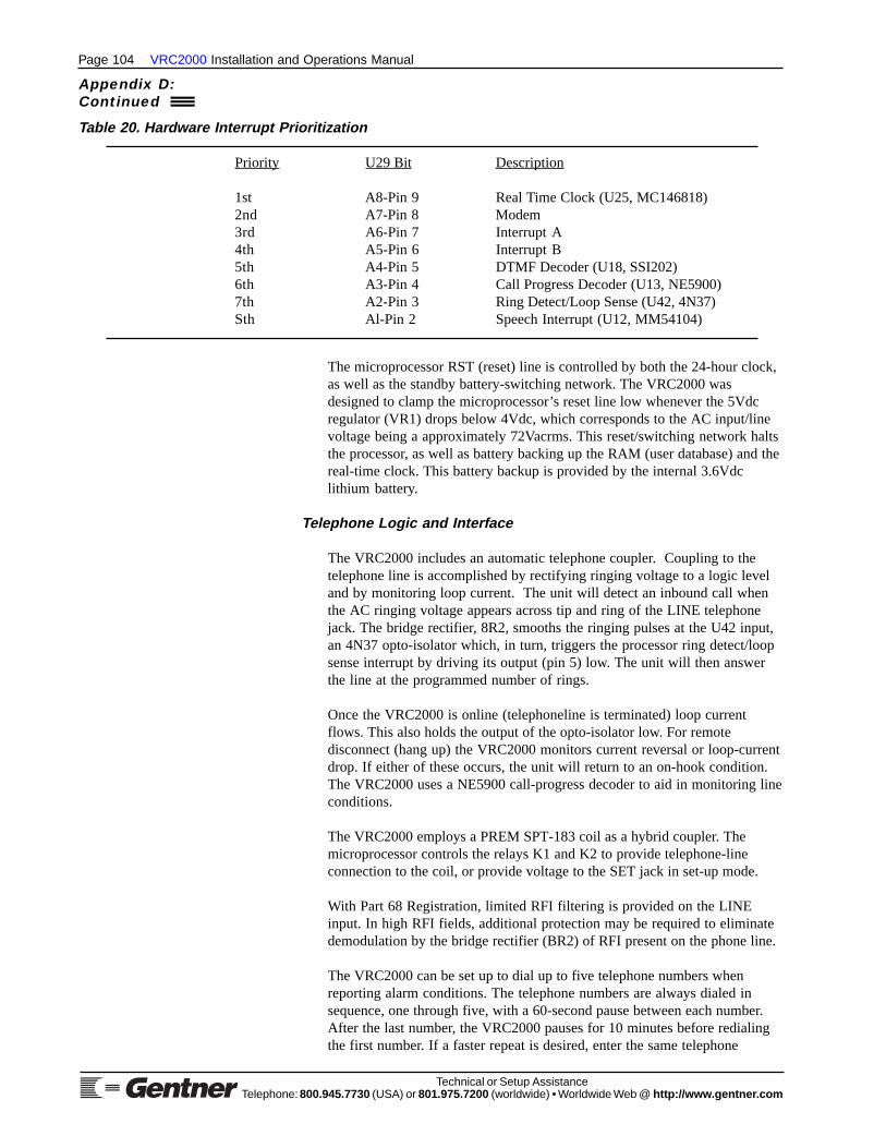
Page 104 VRC2000 Installation and Operations Manual
Technical or Setup AssistanceTelephone: 800.945.7730 (USA) or 801.975.7200 (worldwide) • Worldwide Web @ http://ww w.gentne r.com
The microprocessor RST (reset) line is controlled by both the 24-hour clock,as well as the standby battery-switching network. The VRC2000 wasdesigned to clamp the microprocessor’s reset line low whenever the 5Vdcregulator (VR1) drops below 4Vdc, which corresponds to the AC input/linevoltage being a approximately 72Vacrms. This reset/switching network haltsthe processor, as well as battery backing up the RAM (user database) and thereal-time clock. This battery backup is provided by the internal 3.6Vdclithium battery.
Telephone Logic and Interface
The VRC2000 includes an automatic telephone coupler. Coupling to thetelephone line is accomplished by rectifying ringing voltage to a logic leveland by monitoring loop current. The unit will detect an inbound call whenthe AC ringing voltage appears across tip and ring of the LINE telephonejack. The bridge rectifier, 8R2, smooths the ringing pulses at the U42 input,an 4N37 opto-isolator which, in turn, triggers the processor ring detect/loopsense interrupt by driving its output (pin 5) low. The unit will then answerthe line at the programmed number of rings.
Once the VRC2000 is online (telephoneline is terminated) loop currentflows. This also holds the output of the opto-isolator low. For remotedisconnect (hang up) the VRC2000 monitors current reversal or loop-currentdrop. If either of these occurs, the unit will return to an on-hook condition.The VRC2000 uses a NE5900 call-progress decoder to aid in monitoring lineconditions.
The VRC2000 employs a PREM SPT-183 coil as a hybrid coupler. Themicroprocessor controls the relays K1 and K2 to provide telephone-lineconnection to the coil, or provide voltage to the SET jack in set-up mode.
With Part 68 Registration, limited RFI filtering is provided on the LINEinput. In high RFI fields, additional protection may be required to eliminatedemodulation by the bridge rectifier (BR2) of RFI present on the phone line.
The VRC2000 can be set up to dial up to five telephone numbers whenreporting alarm conditions. The telephone numbers are always dialed insequence, one through five, with a 60-second pause between each number.After the last number, the VRC2000 pauses for 10 minutes before redialingthe first number. If a faster repeat is desired, enter the same telephone
Table 20. Hardware Interrupt Prioritization
Priority U29 Bit Description
1st A8-Pin 9 Real Time Clock (U25, MC146818)2nd A7-Pin 8 Modem3rd A6-Pin 7 Interrupt A4th A5-Pin 6 Interrupt B5th A4-Pin 5 DTMF Decoder (U18, SSI202)6th A3-Pin 4 Call Progress Decoder (U13, NE5900)7th A2-Pin 3 Ring Detect/Loop Sense (U42, 4N37)Sth Al-Pin 2 Speech Interrupt (U12, MM54104)
Appendix D:Continued

VRC2000 Installation and Operations Manual Page 105
Technical or Setup AssistanceTelephone: 800.945.7730 (USA) or 801.975.7200 (worldwide) • Worldwide Web @ http://ww w.gentne r.com
number in several locations. The user can also direct alarms occurring onspecific channels to report to a specific telephone number in the outboundtelephone number stack.
Unbalanced Audio Output
The VRC2000’s BNC connectors located on the unit’s rear panel provideauxiliary audio connections. The connector labeled AUDIO IN is paralleledwith the telephone-receive audio. The BNC marked AUDIO OUT containsthe send audio. For electrical specifications, see Specifications (Page 90).
Status Channel Inputs
There are 16 status-channel inputs on the VRC2000. These inputs aredesigned to accept either a TTL level or a dry contact closure. The status-channel input is labeled STATUS on the VRC2000 rear panel. Thisconnector is a DB37M.
U39 and U40, 74HCT541 octal-line drivers, are used to output the status-channel data onto the address/data bus. U39 monitors the condition of statuschannels 1–8, and U40 is tied to status channels 9–16.
The operating input levels of the 74HCT541 are 0–0.8Vdc for logic 0 and 2–5Vdc as logic 1. The absolute maximum input range of this chip is -0.2–5.2Vdc. Since the VRC2000 reads status-channel inputs once every second, itis recommended that a logic transition last at least one second to ensurecorrect detection.
A section of the VRC2000’s memory map is dedicated to storing thecondition of each status-channel input. This table is recalled when statuschannels are accessed via the appropriate DTMF tones.
Metering Channel Inputs
There are 16 metering-channel inputs on the VRC2000. Each meteringchannel is programmable to measure -5–5Vdc or 0–10Vdc. Each metering-channel input can also be internally jumpered to read -5–5mA or 0–10mAfor full scale. The input to the unit’s metering system is labeled METERING.
Each metering-channel input can measure linear, power-to-linear or calculateindirect power. When measuring a linear potential, the result of the A/Dconversion is given. With power-to-linear conversion, a metering channel’sinput voltage will undergo a numeric conversion from that of an exponentialfactor of a power meter to a linear presentation.
Indirect power conversion takes the two previous consecutive meteringchannels and multiplies them together to produce a numeric presentation.For instance, an indirect power conversion could be used to calculate thepower output of a piece of equipment by multiplying voltage by current.
U32 (an AD7506 multiplexer) is used as a switching network at themetering-channel inputs. The AD7506 output contains the analogrepresentation of the input selected via the four address lines, A0–A3 ormetering channels 1–16. U37 (an AD573) is a successive approximationanalog-to-digital converter. Analog-to-digital conversion is done on a binaryweighted scale. Each of the 10 binary bits (1024) is compared with the input

Page 106 VRC2000 Installation and Operations Manual
Technical or Setup AssistanceTelephone: 800.945.7730 (USA) or 801.975.7200 (worldwide) • Worldwide Web @ http://ww w.gentne r.com
until the closest value is found. The AD573 has a high-byte enable (HBE)and a low-byte enable (LBE), which allows the processor to read 10 bits ofdata for each metering channel, rather than the normal eight bits.
Just like the status channels, the VRC2000 stores the data of all metering-channel inputs in memory for quick processing and easy access.
Command Channel Outputs
The VRC2000 has 32 outputs configured into 16 command channels withtwo commands each. Each of these outputs are open collector drivers ratedto 48Vdc at 250mA (noninductive). Each switch can be programmed aslatching or momentary. When a command channel is programmed to bemomentary, the output can be enabled for .125–32 seconds via userprogramming.
U48, U50, U52 and U54 (all ULN2BO3A Darlington pair drivers) aredevices providing the 32 command-channel switches.
Real-Time Clock
The MC146818 time-of-day clock (U25) pulses the microprocessor at thecritical 256Hz rate to allow time-of-day functions, and report the operatorthe time and date an alarm was detected. Y3 (a 32.768KHz crystal) controlsthe clock’s accuracy. By adjusting C46 (a trimmer capacitor) this clock isset at the factory to 32.768KHz +/- .3Hz. No further adjustment should everbe needed. This keeps the time of day accurate to within two seconds permonth.
DTMF Encoder/Decoder
To make the VRC2000 operate on the toll grade dial-up telephone networkwith the capability of both sending and receiving data using DTMF tones, aSSI202 DTMF decoder and a MK5089 DTMF generator are used. TheSSI202 (U18) and MK5089 (U35) are both clocked by the 3.58MHz crystal(Y2).
The SSI202 decoder has a receive-level window of 40dB, centered at-20dBm. This allows for both local and long-distance access. Typical localloop signals arrive at the SSI202’s analog input at -4–-6dBm. Long-distancecalls typically have a level of -l5dBm.
The MK5089 is used in conjunction with U13 (a NE5900) to generate andmonitor outbound alarm reporting telephone calls and for auto-loggingfunctions. The MK5089 DTMF generator initiates the call while theNE5900 is a call-progress decoder.
The NE5900 is a narrow bandpass filter which monitors the power in thetelephone band to detect the following conditions:
• Ringing• Reorder• Fast Busy• Slow Busy• Dial Tone
Appendix D:Continued

VRC2000 Installation and Operations Manual Page 107
Technical or Setup AssistanceTelephone: 800.945.7730 (USA) or 801.975.7200 (worldwide) • Worldwide Web @ http://ww w.gentne r.com
These conditions inform the VRC2000 whether outbound calls have beenterminated (answered) or not.
Digital Voice Synthesizer
The VRC2000’s synthesized voice reporting is done by NationalSemiconductor’s Mozer MM54104 digital voice synthesizer. This integratedcircuit is a Vocorder (energy from an actual human voice recording is brokendown into bits, synthesized to recreate an addressable vocabulary word byword).
Refer to Appenidix J: Schematics (Page 129) for digital voice synthesizercircuitry. U12 is the MM54104 and its associated memory (U1, U3, U8 andU10). These memory devices are 27C256 EPROMs, which contain almost800 words (library/vocabulary) accessible to the unit.
Power Supply
The VRC2000 was designed to operate on an AC line of either 117Vac or234Vac. Selection of line voltage is accomplished by selecting the properMolex connector, which ties the line cord to the VRC2000’s transformer.
The AC line transformer produces two output levels at its secondarywindings. One is 31Vrms, which is rectified and input to the linearregulators; the other, 17Vrms, powers the digital regulator.
The digital circuitry on the VRC2000’S PCB is powered by VR1, a 7,805K5Vdc regulator. VR2 and VR3 provide +/-12Vdc (7812T and 7912T) for thelinear chips. The digital voice synthesizer operates at a VDD of 9Vdc, so a1N5223, 2.7V Zener diode is in series with its supply line.
The MC146818 clock and the RAM (U27, a HM6264) are both powered bythe 3.6Vdc internal-lithium battery when the AC line drops below 72Vrms.

Page 108 VRC2000 Installation and Operations Manual
Technical or Setup AssistanceTelephone: 800.945.7730 (USA) or 801.975.7200 (worldwide) • Worldwide Web @ http://ww w.gentne r.com
VRC2000 Unit
The VRC2000 is a microprocessor-based system (MC146805E2) whichpermits conventional remote control of broadcast transmitters and otherequipment as well as automatic transmission systems (ATS) operation. Thesystem’s internal Central Processing Unit (CPU) and memory circuitry allowthe VRC2000 to be set up by the user to make decisions and take actionsbased on predetermined criteria, provide telemetry to the user, or to respondto commands directly.
DTMF Cont rolThe VRC2000 is primarily controlled by standard telephone DTMF signals.When receiving instructions, the VRC2000 responds in plain English withits internal digital-voice synthesizer. The VRC2000 has a vocabulary ofalmost 800 words, numbers, prefixes, and suffixes. (See Appendix I,Page 125.) You may program the VRC2000’s voice responses during theset-up operation (VRC2000 Setup, Page 10).
An automatic telephone coupler is built into the VRC2000. This devicesenses telephone company ringing and disconnect signals, providingautomatic connection to and disconnection from the dial-up telephone line.The VRC2000 can also dial out to a preprogrammed telephone number witheither DTMF or pulse signals. The VRC2000 comes standard withadditional four-wire connections to allow use with almost any bidirectionalaudio link.
The VRC2000 may be programmed to automatically dial to up to fivetelephone numbers upon the presence of an alarm condition, using eitherpulse dialing or DTMF. The system will also automatically answer incomingtelephone calls based on a programmed number of rings.
Real-Time Clock and Memory
The VRC2000 incorporates a highly accurate real-time clock and calendar.Internal lithium battery maintains real-time clock and user memory(non-volatile CMOS RAM). These allow the VRC2000 to tag registeredalarms with the time of day and date, and to perform automatic functionsaccording to the time of day, day of week or date.
Inputs
The VRC2000 contains a number of different types of inputs: metering,status and command. These inputs (channels) can be connected to yourtransmitter and/or other equipment to provide a complete and accuratepicture of how attached equipment is operating.
Metering ChannelsThe VRC2000 has 16 metering-channel inputs. These inputs accept ananalog voltage or current sample; the VRC2000’s internal circuitry convertsthese samples into four-digit numbers, which the system can then report overthe telephone line. Each metering channel can be set up with four tolerance(threshold) limits, two upper and two lower. You can also program thesystem to issue an automatic command from any of these tolerance limits.You may also set up the VRC2000 to recognize any tolerance limit as analarm condition.
Appendix E: TechnicalDescription

VRC2000 Installation and Operations Manual Page 109
Technical or Setup AssistanceTelephone: 800.945.7730 (USA) or 801.975.7200 (worldwide) • Worldwide Web @ http://ww w.gentne r.com
Each metering channel can be calibrated in a linear numeric valueproportional to input or a power-to-linear conversion of input. Eachmetering channel may also be programmed to read indirect power — themultiplication of two consecutive channels, with the resultant appearing inthe third channel as a new calibrated value. Input impedance on eachmetering channel is 100kOhms.
Status ChannelsThe VRC2000 also contains 16 status-channel inputs. Each of these inputshas two conditions: the status-channel inputs are either high or low. Eitherstate may be declared an alarm condition, and any status channel can beprogrammed to mute any metering or status channel.
Mute Capability. Any status channel can be programmed to override (defeat)the alarm limits set on any metering or status channel (any automaticcommand associated with such a tolerance limit will also be defeated). Atotal of 40 mute functions are available.
Command ChannelsSixteen command channels (with two switches each) are standard in theVRC2000. This configuration provides you with a total of 32 possiblecommands. These command channels allow commands to be sent totransmitter or other equipment over the telephone lines with a standardDTMF telephone. The command channel outputs on the VRC2000 areopen-collector drivers, and each command channel may be programmed to beeither latching or momentary. Momentary commands can be set up to lastfrom .125 to 31.875 seconds in increments of of one-eighth (.125) of asecond.
Commands can be activated manually in real time over the telephone, or theycan be set up to activate automatically based on the condition of selectedmetering or status channel. Commands can also be triggered by the built-inreal time clock as time-of-day events.
Automatic Commands. Automatic commands may be initiated by any ofthree sources: status-channel conditions (activated or deactivated), exceededtolerance limits on any metering channel, or by up to 64 preprogrammedtime-of-day functions.

Page 110 VRC2000 Installation and Operations Manual
Technical or Setup AssistanceTelephone: 800.945.7730 (USA) or 801.975.7200 (worldwide) • Worldwide Web @ http://ww w.gentne r.com
The following exercises will help you understand how the VRC2000 operates inthe local and remote modes. See Also Remote/Local Modes (Page 5).
Local Mode
The following examples will help you understand how the VRC2000operates in the local user mode. A dial-up telephone line is not required forthe local user mode, although the Initialization procedure should already becomplete (Page 6).
With a standard DTMF telephone connected, power up the VRC2000. Pickup the telephone handset and listen, then push in the LOCAL/REMOTEbutton [3] (See Figure 28, below.) on the VRC2000’s front panel. The buttonwill light red.
Appendix F: Remote/Local Tutorial
LOCAL/REMOTE NOTE:This button must remain ON as long as you require local control of theVRC2000.
You will hear the VRC2000 say
• SETUP ENABLED. PLEASE ENTER SYSTEM ACCESS CODE.
Immediately following this message, use the telephone’s DTMF pad to enterthe following sequence of numbers:
☎ “1 2 3 4 5 6 7”
If you entered this sequence correctly, the VRC2000 will respond:
• THANK YOU. PLEASE SELECT FUNCTION FOR PROGRAMMING.
ACCESS CODE NOTE:If the access code was entered incorrectly, the VRC2000 will stop supplyingpower to your telephone handset. The VRC2000 will allow you only one attemptto enter the proper access code. To re-enter the access code, press the LOCAL/REMOTE button [3] to return to remote mode, then press the button again toattempt local connection again.
Once you have properly entered the access code and gained access to theVRC2000, you are in the Local Setup mode. Local Setup allows you toprogram various functions into your VRC2000. For now, switchimmediately into the Local User mode to avoid entering unwantedprogramming information into the VRC2000.
To enter the Local User mode, enter the following sequence on your DTMFphone:
☎ “9 2 0”
The VRC2000 will respond:
• USER ENABLED.
Figure 28. VRC2000 front-panelcontrols

VRC2000 Installation and Operations Manual Page 111
Technical or Setup AssistanceTelephone: 800.945.7730 (USA) or 801.975.7200 (worldwide) • Worldwide Web @ http://ww w.gentne r.com
Now you can enter commands using the telephone DTMF pad that will causethe VRC2000 to take readings, report pending alarms or activate command-channel outputs.
To check on pending alarms, enter the following sequence on your DTMFpad:
☎ “0 0 0”
The VRC2000 will respond:
• NO ALARMS PENDING.
ALARMS PENDING NOTE:No alarms are pending since the VRC2000 has not yet been set up for alarmreporting. Instructions for setting up alarms are covered in VRC2000 Setup(Page 10). If the VRC2000 reports an alarm at this point, make a note of exactlywhat the unit says.
Now enter the following sequence on your DTMF pad:
☎ “1 1 1”
The VRC2000 will respond:
• ERROR.
The sequence just entered is not a valid instruction. Whenever you hear anERROR message, wait a second and then re-enter a valid sequence.
Now enter
☎ “6 0 1 *”
The VRC2000 will respond:
• METERING CHANNEL ONE ... POINT ZERO, ZERO, ZERO, ZERO, VOLTS.
The VRC2000 is reporting the current input condition of metering channel l.Since the VRC2000 has not been fully set up yet, no further message will beheard. After the unit is set up, the VRC2000 will tell you the exact electricalcondition of metering channel 1.
Now enter
☎ “6 1 6 *”
The VRC2000 will respond:
• METERING CHANNEL SIXTEEN ... POINT ZERO, ZERO, ZERO, ZERO, VOLTS.
Now enter
☎ “7 0 1 *”
The VRC2000 will respond with the current condition of status channel l.
Page 112 VRC2000 Installation and Operations Manual
Technical or Setup AssistanceTelephone: 800.945.7730 (USA) or 801.975.7200 (worldwide) • Worldwide Web @ http://ww w.gentne r.com
Now enter
☎ “7 0 8 *”
The VRC2000 will report the current condition of status channel 8.
Now enter
☎ “2 0 1 *”
The VRC2000 will respond:
• COMMAND CHANNEL ONE. A ACTIVATED.
The VRC2000 is reporting that command channel 1’s A switch is energized.
Now enter
☎ “2 0 2 * # *”
The VRC2000 will respond:
• COMMAND CHANNEL TWO. A ACTIVATED. B ACTIVATED. A ACTIVATED.
The sequence instructed the VRC2000 to activate command channel 2’s Aswitch and B switch, and then to activate the A switch again.
VOICE RESPONSE NOTE:Although the voice report from the VRC2000 took several seconds, the commandchannel switches are activated immediately after you press the “*” or “#”buttons on your telephone.
Now enter a longer sequence:
☎ “6 1 0 * 6 1 1 * 7 1 2 *”
Listen to the response.
This demonstrates the VRC2000’s capability to accept long sequences ofcommands. As long as valid instructions are sent, the VRC2000 willcontinue to process the commands and respond to the user. All validcommands are executed immediately, even though the voice output of theunit may take some time.
If you enter an invalid command, the VRC2000 will respond with theERROR message.
VOICE BUFFER NOTE:The VRC2000’s electronic voice buffer can hold only 128 words. If the voicebuffer is filled beyond this capacity, some of the words will not be reported. Allcommands, however, will be executed.
Now enter
☎ “0 6 0”
Appendix F:Continued

VRC2000 Installation and Operations Manual Page 113
Technical or Setup AssistanceTelephone: 800.945.7730 (USA) or 801.975.7200 (worldwide) • Worldwide Web @ http://ww w.gentne r.com
The VRC2000 will respond with the system date and time. Since the real-time clock has not yet been set, the date and time reported will be based onthe unit’s default parameters.
Now press the LOCAL/REMOTE button on the VRC2000’s front panel (itwill dim). The VRC2000 will respond:
• SETUP DISABLED. GOOD-BYE.
By returning to remote mode, you are signing off from the local mode.
Remote Mode
With the VRC2000, you can control all functions from any DTMF telephoneover a standard dial-up telephone line (one connected to the VRC2000, theother connected to a separate DTMF telephone — not the one connected tothe VRC2000 back panel). Initialization should be complete before thispoint (Page 6).
From the second telephone, call your VRC2000. After the second ring, theVRC2000 will automatically answer your call and say:
• HELLO. THIS IS THE VRC2000 WITH VOICE, MODEM OR RADIO ACCESS. PLEASE
ENTER ACCESS CODE.
Now use your telephone s DTMF pad to enter the default user access code:
☎ “1 2 3 4 5”
ACCESS CODE NOTE:Notice that this is a different code than you used in the Local Mode tutorial(Page 110).
The VRC2000 will respond:
• THANK YOU. NO ALARMS PENDING.
This indicates that you have successfully accessed the VRC2000 from aremote location over the telephone. The user access code indicated above isthe factory-set default code. If you are unable to access the VRC2000 withthe default user access code, try powering down the VRC2000 andreconnecting the internal lithium battery (Step 2, Page 7).
The VRC2000 responds to the same commands in the remote mode as it doesin the local mode. Try some of the commands now that you tried earlier inthe local mode.
When you are done experimenting with commands in the remote mode, enterthe remote user sign-off code:
☎ “9 9 9”
The VRC2000 will respond:
• GOOD-BYE.

Page 114 VRC2000 Installation and Operations Manual
Technical or Setup AssistanceTelephone: 800.945.7730 (USA) or 801.975.7200 (worldwide) • Worldwide Web @ http://ww w.gentne r.com
This indicates that you have successfully signed off from VRC2000 remoteuser mode.
The following exercises will familiarize you with programming time-of-dayfunctions.
Exercise 1
In the following exercise, program time-of-day function three to activate theA switch for command channel 8 every day for the month of November at11:59:01 p.m.
TIME-OF-D AY PROGRAMMING NOTE:Enter the #” symbol after the proper access code to program time-of-dayfunctions. Entering the “*” symbol will disable that time-of-day function.
The VRC2000 will report only a single [BEEP] after a set-up parameter ifyou do not make a new entry. If you do make a new entry, the VRC2000 will[BEEP] twice.
Enter
☎ “3 0 3 #”
The VRC2000 will respond:
• TIME-OF-DAY HOURS FOR ENTRY THREE ARE ... {TEN}
You enter
☎ “1 1”
The VRC2000 will respond with a double [BEEP].
Time-of-day function entry three will now activate at the eleventh hour.
The VRC2000 will say
• TIME-OF-DAY MINUTES FOR ENTRY THREE ARE ... {TEN}
You enter
☎ “5 9”
The VRC2000 will respond with a double [BEEP].
Time-of-day function entry three will now activate at the fifty-ninth minuteof the selected hour.
The VRC2000 will say
• TIME-OF-DAY SECONDS FOR ENTRY THREE ARE ... {TEN}
You enter
☎ “0 1"
Appendix F:Continued
Appendix G: Time-Of-DayFunction Tutorial

VRC2000 Installation and Operations Manual Page 115
Technical or Setup AssistanceTelephone: 800.945.7730 (USA) or 801.975.7200 (worldwide) • Worldwide Web @ http://ww w.gentne r.com
The VRC2000 will respond with a double [BEEP].
Time-of-day function entry three will now activate at the first second of theselected minute and hour.
The VRC2000 will say
• TIME OF DAY FOR ENTRY THREE IS ... {AM}
You enter
☎ “#”
The VRC2000 will respond with a double [BEEP].
Time-of-day function entry three will now activate during the afternoon(PM). In this example, time selected is 11:59:01 p.m.
Use the “#” symbol to program the time-of-day function to activate duringthe afternoon (PM); the “*” selected AM (before noon) portion of the day.
The VRC2000 will say
• TIME-OF-DAY DATE FOR ENTRY ONE IS ... {OCTOBER}
You enter
☎ “1 1”
The VRC2000 will respond with a double [BEEP].
Time-of-day function entry three will now activate in November.
The VRC2000 will say
• TIME-OF-DAY DAY FOR ENTRY ONE IS ... {TEN}.
You enter
☎ “0 0”
The VRC2000 will respond with a double [BEEP].
Time-of-day function three will now activate every day during the month ofNovember at 11:59:01 p.m.
The “0 0” entry for this parameter programs the VRC2000 to activate theselected command-channel switch every day for the programmed month atthe programmed time.
The VRC2000 will say
• COMMAND CHANNEL NUMBER FOR ENTRY ONE IS ... {ONE}
You enter
☎ “0 8”

Page 116 VRC2000 Installation and Operations Manual
Technical or Setup AssistanceTelephone: 800.945.7730 (USA) or 801.975.7200 (worldwide) • Worldwide Web @ http://ww w.gentne r.com
The VRC2000 will respond with a double [BEEP].
Time-of-day function three will now trigger command channel 8 at 11:59:01p.m. every day during the month of November.
The VRC2000 will say
• ACTIVE COMMAND CHANNEL SWITCH FOR ENTRY ONE IS ... {A ACTIVATED}
You enter
☎ “*”
The VRC2000 will respond with a double [BEEP].
Time-of-day function three will now trigger command channel 8’s A switchat 11:59:01 p.m. every day for the month of November.
Exercise 2
Repeat the same steps listed above, only use the disable code (“0 0”) for thetime-of-day date function. Then set-up this entry to activate weekly onWednesday (“0 4”).
Exercise 3
Repeating the same steps listed above, but use the disable code “0” for theday-of-the-week function. This will cause this time-of-day function toactivate daily.
Appendix G:Continued
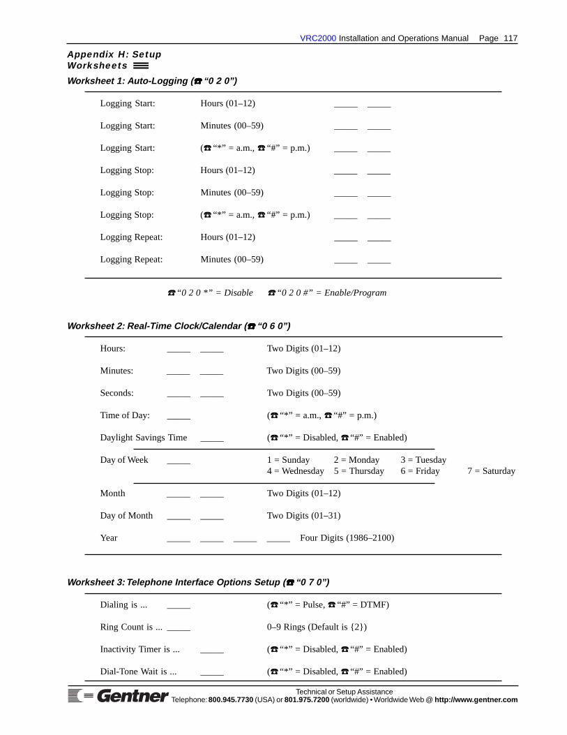
VRC2000 Installation and Operations Manual Page 117
Technical or Setup AssistanceTelephone: 800.945.7730 (USA) or 801.975.7200 (worldwide) • Worldwide Web @ http://ww w.gentne r.com
Appendix H: SetupWorksheets
Worksheet 1: Auto-Logging ( ☎ ☎ ☎ ☎ ☎ “0 2 0”)
Logging Start: Hours (01–12) _____ _____
Logging Start: Minutes (00–59) _____ _____
Logging Start: (☎ “*” = a.m., ☎ “#” = p.m.) _____ _____
Logging Stop: Hours (01–12) _____ _____
Logging Stop: Minutes (00–59) _____ _____
Logging Stop: (☎ “*” = a.m., ☎ “#” = p.m.) _____ _____
Logging Repeat: Hours (01–12) _____ _____
Logging Repeat: Minutes (00–59) _____ _____
☎ “0 2 0 *” = Disable ☎ “0 2 0 #” = Enable/Program
Worksheet 2: Real-Time Clock/Calendar ( ☎ ☎ ☎ ☎ ☎ “0 6 0”)
Hours: _____ _____ Two Digits (01–12)
Minutes: _____ _____ Two Digits (00–59)
Seconds: _____ _____ Two Digits (00–59)
Time of Day: _____ (☎ “*” = a.m., ☎ “#” = p.m.)
Daylight Savings Time _____ (☎ “*” = Disabled, ☎ “#” = Enabled)
Day of Week _____ 1 = Sunday 2 = Monday 3 = Tuesday4 = Wednesday 5 = Thursday 6 = Friday 7 = Saturday
Month _____ _____ Two Digits (01–12)
Day of Month _____ _____ Two Digits (01–31)
Year _____ _____ _____ _____ Four Digits (1986–2100)
Worksheet 3: Telephone Interface Options Setup ( ☎ ☎ ☎ ☎ ☎ “0 7 0”)
Dialing is ... _____ (☎ “*” = Pulse, ☎ “#” = DTMF)
Ring Count is ... _____ 0–9 Rings (Default is {2})
Inactivity Timer is ... _____ (☎ “*” = Disabled, ☎ “#” = Enabled)
Dial-Tone Wait is ... _____ (☎ “*” = Disabled, ☎ “#” = Enabled)

Page 118 VRC2000 Installation and Operations Manual
Technical or Setup AssistanceTelephone: 800.945.7730 (USA) or 801.975.7200 (worldwide) • Worldwide Web @ http://ww w.gentne r.com
Worksheet 4: System Identifier Setup ( ☎ ☎ ☎ ☎ ☎ “0 8 0”)
Word Code # Word Suggestion
Word # 1 ( ) ____________________ • HELLO
Word # 2 ( ) ____________________ • THIS
Word # 3 ( ) ____________________ • IS
Word # 4 ( ) ____________________
Word # 5 ( ) ____________________
Word # 6 ( ) ____________________
Word # 7 ( ) ____________________
Word # 8 ( ) ____________________
Word # 9 ( ) ____________________
Word # 10 ( ) ____________________
Word # 11 ( ) ____________________
Word # 12 ( ) ____________________
Word # 13 ( ) ____________________
Word # 14 ( ) ____________________
Word # 15 ( ) ____________________
Word # 16 ( ) ____________________
Word # 17 ( ) ____________________ • PLEASE
Word # 18 ( ) ____________________ • ENTER
Word # 19 ( ) ____________________ • ACCESS
Word # 20 ( ) ____________________ • CODE
Worksheet 5: Access Codes Setup ( ☎ ☎ ☎ ☎ ☎ “0 9 0”)
Operator Access Default {0 1 2 3 4} _____ _____ _____ _____ _____
User Access Default {1 2 3 4 5} _____ _____ _____ _____ _____
System Access Default {1 2 3 4 5 6 7} _____ _____ _____ _____ _____ _____ _____
Appendix H:Continued

VRC2000 Installation and Operations Manual Page 119
Technical or Setup AssistanceTelephone: 800.945.7730 (USA) or 801.975.7200 (worldwide) • Worldwide Web @ http://ww w.gentne r.com
Worksheet 6: Outbound Telephone Numbers ( ☎ ☎ ☎ ☎ ☎ “1 0 1” through ☎ ☎ ☎ ☎ ☎ “1 0 5”)
Output ConfigurationTelephone Number (☎ “*” = Phone Voice)
Outbound (30 digits maximum) (☎ “#” = Phone Modem) Message-Only ModeTelephone (End entry with #) (☎ “7” = Radio Voice) (☎ “#” = Enabled)Numbers (* = two-second pause) (☎ “9” = Radio Modem) (☎ “*” = Disabled)
☎ “1 0 1 x” ______________________ _____ _____
☎ “1 0 1 x” ______________________ _____ _____
☎ “1 0 1 x” ______________________ _____ _____
☎ “1 0 1 x” ______________________ _____ _____
☎ “1 0 1 x” ______________________ _____ _____
x = Suffix (* = Disable, # = Enable)
Worksheet 7: Sequence-Output Programs ( ☎ ☎ ☎ ☎ ☎ “5 0 1” through ☎ ☎ ☎ ☎ ☎ “5 0 4”)
SequenceOutputProgram Digits 1 2 3 4 5 6 7 8 9 10 11 12 13 14 15 16 17 18 19 20 21 22 23 24 25 26 27 28 29 30 31 32
☎ “5 0 1” _ _ _ _ _ _ _ _ _ _ _ _ _ _ _ _ _ _ _ _ _ _ _ _ _ _ _ _ _ _ _ _
☎ “5 0 2” _ _ _ _ _ _ _ _ _ _ _ _ _ _ _ _ _ _ _ _ _ _ _ _ _ _ _ _ _ _ _ _
☎ “5 0 3” _ _ _ _ _ _ _ _ _ _ _ _ _ _ _ _ _ _ _ _ _ _ _ _ _ _ _ _ _ _ _ _
☎ “5 0 4” _ _ _ _ _ _ _ _ _ _ _ _ _ _ _ _ _ _ _ _ _ _ _ _ _ _ _ _ _ _ _ _

Page 120 VRC2000 Installation and Operations Manual
Technical or Setup AssistanceTelephone: 800.945.7730 (USA) or 801.975.7200 (worldwide) • Worldwide Web @ http://ww w.gentne r.com
Worksheet 8: Time-Of-Day Functions Setup ( ☎ ☎ ☎ ☎ ☎ “3 0 1” through ☎ ☎ ☎ ☎ ☎ “3 6 4”)
Time Day Of Command CommandOf Time Time Time * = a.m. Month Day Week Channel * = Switch ADay Hours Minutes Seconds# = p.m.(00–12) (00–31) (0–7) (01–16) # = Switch B
3xxy 08 30 00 * 01 01 0 1 #
_____ _____ _____ _____ _____ _____ _____ _____ _____ _____
_____ _____ _____ _____ _____ _____ _____ _____ _____ _____
_____ _____ _____ _____ _____ _____ _____ _____ _____ _____
_____ _____ _____ _____ _____ _____ _____ _____ _____ _____
_____ _____ _____ _____ _____ _____ _____ _____ _____ _____
_____ _____ _____ _____ _____ _____ _____ _____ _____ _____
_____ _____ _____ _____ _____ _____ _____ _____ _____ _____
_____ _____ _____ _____ _____ _____ _____ _____ _____ _____
_____ _____ _____ _____ _____ _____ _____ _____ _____ _____
_____ _____ _____ _____ _____ _____ _____ _____ _____ _____
_____ _____ _____ _____ _____ _____ _____ _____ _____ _____
_____ _____ _____ _____ _____ _____ _____ _____ _____ _____
_____ _____ _____ _____ _____ _____ _____ _____ _____ _____
_____ _____ _____ _____ _____ _____ _____ _____ _____ _____
_____ _____ _____ _____ _____ _____ _____ _____ _____ _____
_____ _____ _____ _____ _____ _____ _____ _____ _____ _____
_____ _____ _____ _____ _____ _____ _____ _____ _____ _____
_____ _____ _____ _____ _____ _____ _____ _____ _____ _____
_____ _____ _____ _____ _____ _____ _____ _____ _____ _____
_____ _____ _____ _____ _____ _____ _____ _____ _____ _____
_____ _____ _____ _____ _____ _____ _____ _____ _____ _____
_____ _____ _____ _____ _____ _____ _____ _____ _____ _____
xx = function number (01–64); y = suffix (* = Disable, # = Enable)Make copies as necessary.
Appendix H:Continued

VRC2000 Installation and Operations Manual Page 121
Technical or Setup AssistanceTelephone: 800.945.7730 (USA) or 801.975.7200 (worldwide) • Worldwide Web @ http://ww w.gentne r.com
Worksheet 9: Mute Assignments ( ☎☎☎☎☎ “4 0 1” through ☎☎☎☎☎ “4 4 0”)
Status Status Condition Metering or ChannelChannel Causing Mute Status to be
Mute Causing Mute (* = Low Input) (# = Metering) MutedFunction (01–16) (# = High Input) (* = Status) (01–16)
4xxy 02 * # 09
_____ _____ _____ _____ _____
_____ _____ _____ _____ _____
_____ _____ _____ _____ _____
_____ _____ _____ _____ _____
_____ _____ _____ _____ _____
_____ _____ _____ _____ _____
_____ _____ _____ _____ _____
_____ _____ _____ _____ _____
_____ _____ _____ _____ _____
_____ _____ _____ _____ _____
_____ _____ _____ _____ _____
_____ _____ _____ _____ _____
_____ _____ _____ _____ _____
_____ _____ _____ _____ _____
_____ _____ _____ _____ _____
_____ _____ _____ _____ _____
_____ _____ _____ _____ _____
_____ _____ _____ _____ _____
_____ _____ _____ _____ _____
_____ _____ _____ _____ _____
_____ _____ _____ _____ _____
_____ _____ _____ _____ _____
xx = function number (01–64); y = suffix (* = Disable, # = Enable)Make copies as necessary.

Page 122 VRC2000 Installation and Operations Manual
Technical or Setup AssistanceTelephone: 800.945.7730 (USA) or 801.975.7200 (worldwide) • Worldwide Web @ http://ww w.gentne r.com
Appendix H:Continued
W
orks
heet
10:
Com
man
d C
hann
el S
etup
(
☎ ☎☎ ☎ ☎ “2
0 1
” throu
gh ☎ ☎☎ ☎ ☎
“2 1
6”)
xx =
co
mm
an
d c
ha
nn
el (
01
–1
6)
Ma
ke c
op
ies
as
ne
cess
ary
.

VRC2000 Installation and Operations Manual Page 123
Technical or Setup AssistanceTelephone: 800.945.7730 (USA) or 801.975.7200 (worldwide) • Worldwide Web @ http://ww w.gentne r.com
W
orks
heet
11:
Met
erin
g C
hann
el S
etup
(
☎ ☎☎ ☎ ☎ “6
0 1
” t
h
rough
☎ ☎☎ ☎ ☎ “6
1
6”)
xx =
me
terin
g c
ha
nn
el (
01
–1
6)
Ma
ke c
op
ies
as
ne
cess
ary
.

Page 124 VRC2000 Installation and Operations Manual
Technical or Setup AssistanceTelephone: 800.945.7730 (USA) or 801.975.7200 (worldwide) • Worldwide Web @ http://ww w.gentne r.com
W
orks
heet
12:
Sta
tus
Cha
nnel
Set
up (
☎ ☎☎ ☎ ☎ “7
0 1
” throu
gh ☎ ☎☎ ☎ ☎
“7 1
6”)
xx =
sta
tus
cha
nn
el (
01
–1
6)
Ma
ke c
op
ies
as
ne
cess
ary
.
Appendix H:Continued

VRC2000 Installation and Operations Manual Page 125
Technical or Setup AssistanceTelephone: 800.945.7730 (USA) or 801.975.7200 (worldwide) • Worldwide Web @ http://ww w.gentne r.com
Appendix I: WordList
Code Word Code Word Code Word Code Word000 zero 049 Sunday 100 A 149 in- (rising)001 one 050 Monday 101 B 150 per-002 two 051 Tuesday 102 C 151 re- (“restore”)003 three 052 Wednesday 103 D 152 re- (“replace”)004 four 053 Thursday 104 E 153 re- (“reset”)005 five 054 Friday 105 F 154 re- (“receiver”)006 six 055 Saturday 106 G 155 sub-007 seven 056 5 ms silence 107 H 156 un- (“unlock”)008 eight 057 10 ms silence 108 I 157 un- (“untrue”)009 nine 058 20 ms silence 109 J 158 200 Hz 500 ms010 minus 059 40 ms silence 110 K 159 200 Hz 50 ms011 plus 060 80 ms silence 111 L 160 400 Hz 500 ms012 point 061 160 ms silence 112 M 161 400 Hz 50 ms013 hundred 062 320 ms silence 113 N 162 800 Hz 500 ms014 thousand 063 640 ms silence 114 O 163 800 Hz 50 ms015 million 064 960 ms silence 115 P 164 1000 Hz 500 ms016 ten 065 January 116 Q 165 1000 Hz 50 ms017 eleven 066 February 117 R 166 2000 Hz 500 ms018 twelve 067 March 118 S 167 2000 Hz 50 ms019 thirteen 068 April 119 T 168 5000 Hz 500 ms020 fourteen 069 May 120 U 169 5000 Hz 100 ms021 fifteen 070 June 121 V 170 -022 sixteen 071 July 122 W 171 -023 seventeen 072 August 123 X 172 -024 eighteen 073 September 124 Y 173 -025 nineteen 074 October 125 Z 174 -026 AM 075 November 126 -ed (“id”) 175 -027 PM 076 December 127 -ed (short-”id”) 176 -028 AC 077 1.3 sec silence 128 -ed (“d”) 177 -029 dB 078 2 sec silence 129 -ed (“t”) 178 -030 DC 079 5 sec silence 130 -er (“dollar”) 179 -031 VA 080 amber 131 -er (“after”) 180 -032 zero 081 black 132 -er (“lower”) 181 -033 ten 082 blue 133 -er (“customer”) 182 -034 twenty 083 brown 134 -er (“lesser”) 183 -035 thirty 084 gold 135 -ing (“budgeting”) 184 -036 forty 085 gray 136 -ing (“missing”) 185 -037 fifty 086 green 137 -ing (“activating”) 186 -038 sixty 087 orange 138 -ly 187 -039 seventy 088 pink 139 -s (“s”) 188 -040 eighty 089 purple 140 -s (“ez”) 189 -041 ninety 090 red 141 -th 190 -042 pico- 091 silver 142 -uth 191 -043 nano- 092 turquoise 143 a- (“a”) 192 -044 micro- 093 violet 144 a- (short-”uh”) 193 -045 milli- 094 white 145 a- (“uh”) 194 -046 centi- 095 yellow 146 de- 195 -047 kilo- 096 - 147 dis- 196 -048 mega- 097 STL 148 in- (short) 197 -

Page 126 VRC2000 Installation and Operations Manual
Technical or Setup AssistanceTelephone: 800.945.7730 (USA) or 801.975.7200 (worldwide) • Worldwide Web @ http://ww w.gentne r.com
Code Word Code Word Code Word Code Word200 able 250 authorized 300 change 350 degrees201 abort 251 auto 301 channel 351 delay202 aborted 252 automatic 302 check 352 delete203 above 253 auxiliary 303 checkpoint 353 delta204 access 254 available 304 choice 354 department205 acknowledge 255 average 305 circuit 355 depth206 activate 256 back 306 clear 356 descend207 activated 257 bad 307 clock 357 detect208 activating 258 bail-out 308 close 358 detected209 active 259 bang 309 closed 359 detector210 additional 260 bars 310 code 360 devise211 adjust 261 barometric 311 coil 361 dial212 advise 262 base 312 cold 362 dialed213 advisory 263 base-current 313 combiner 363 dialing214 affirm 264 bath 314 command 364 did215 after 265 battery 315 common 365 diesel216 afternoon 266 baud 316 communication 366 dip217 again 267 be 317 complete 367 direct218 ahead 268 bearing 318 composition 368 direction219 air 269 before 319 compressor 369 diisable220 aircraft 270 behind 320 computer 370 disabled221 adjust 271 bell 321 condition 371 disarm222 alarm 272 below 322 conductivity 372 discharge223 alert 273 blank 323 conference 373 disconnect224 all 274 blocking 324 configuration 374 disengage225 allied 275 booster 325 confirmed 375 display226 alternate 276 box 326 connect 376 divide227 altitude 277 brake 327 constant 377 division228 am 278 bright 328 consumption 378 do229 Amps 279 building 329 contact 379 door230 Amperes 280 burst 330 control 380 double231 an 281 busy 331 converter 381 down232 and 282 button 332 cool 382 drive233 angle 283 buzzer 333 coolant 383 dumb234 announcement 284 by 334 coordinates 384 dummy235 answer 285 calibrate 335 correct 385 duplex236 antenna 286 calibration 336 count 386 earth237 approaching 287 call 337 crash 387 east238 are 288 calling 338 cross 388 echo239 area 289 cancel 339 cubic 389 efficiency240 armed 290 cap 340 current 390 elapsed241 arrival 291 capacitance 341 damage 391 electric242 as 292 capacitor 342 danger 392 electricity243 ascend 293 car 343 dark 393 emergency244 ask 294 carrier 344 data 394 empty245 assign 295 case 345 date 395 enable246 at 296 caution 346 day 396 enabled247 attack 297 Celsius 347 decimal 397 end248 attention 298 center 348 decrease 398 energy249 audio 299 centigrade 349 default 399 engage
Appendix I:Continued

VRC2000 Installation and Operations Manual Page 127
Technical or Setup AssistanceTelephone: 800.945.7730 (USA) or 801.975.7200 (worldwide) • Worldwide Web @ http://ww w.gentne r.com
Code Word Code Word Code Word Code Word400 enter 450 good 500 key 550 mono401 entry 451 good-bye 501 kill 551 more402 equal 452 grams 502 knots 552 morning403 equipment 453 great 503 large 553 motor404 erase 454 greater 504 last 554 move405 erased 455 greater-than 505 leak 555 music406 error 456 ground 506 leakage 556 near407 escape 457 group 507 leave 557 negate408 evening 458 half 508 left 558 neutral409 exit 459 hard 509 less 559 next410 exterior 460 has 510 less-than 560 night411 external 461 have 511 level 561 no412 extreme 462 head-end 512 li ght 562 none413 fade 463 heading 513 lights 563 normal414 Fahrenheit 464 hello 514 limit 564 north415 failed 465 help 515 line 565 not416 failure 466 here 516 line-feed 566 notice417 fan 467 Hertz 517 link 567 now418 Farads 468 high 518 listen 568 number419 fast 469 higher 519 load 569 of420 faster 470 hold 520 local 570 off421 fault 471 home 521 lock 571 oh422 feet 472 hook 522 locked 572 Ohms423 field 473 horizontal 523 logging 573 okay424 filament 474 hot 524 long 574 old425 fire 475 hours 525 loop 575 on426 fire (excited) 476 house 526 loop-current 576 only427 first 477 identification 527 looped 577 open428 flash 478 identifier 528 low 578 operator429 flooded 479 idle 529 lower 579 optical430 floor 480 if 530 main 580 or431 flow 481 immediate 531 maintain 581 order432 for 482 in 532 mark 582 originate433 forward 483 input 533 marker 583 other434 forwarded 484 inactive 534 match 584 out435 free 485 inbound 535 may-day 585 output436 freeze 486 inches 536 medium 586 outside437 freezer 487 incorrect 537 message 587 over438 frequency 488 increase 538 meter 588 over-range439 from 489 inductor 539 meters 589 page440 front 490 insert 540 metering 590 pair441 fuel 491 instruction 541 micro 591 pan442 function 492 interface 542 microphone 592 panic443 furnace 493 interrupt 543 microwave 593 parallel444 fuse 494 intruder 544 mike 594 pass445 fused 495 intrusion 545 miles 595 passed446 gallons 496 invalid 546 minutes 596 peak447 gas 497 is 547 modem 597 pending448 generator 498 isolation 548 module 598 per449 go 499 junction 549 monitor 599 percent

Page 128 VRC2000 Installation and Operations Manual
Technical or Setup AssistanceTelephone: 800.945.7730 (USA) or 801.975.7200 (worldwide) • Worldwide Web @ http://ww w.gentne r.com
Code Word Code Word Code Word Code Word600 period 650 repeat 700 station 750 unbalanced601 phase 651 report 701 status 751 understood602 phase-angle 652 request 702 stereo 752 unit603 phone 653 reset 703 stop 753 unknown604 pick 654 resistance 704 storage 754 unlock605 pickup 655 resistor 705 strobe 755 unlocked606 place 656 response 706 studio 756 untrue607 plant 657 restore 707 subscriber 757 up608 plate 658 restored 708 supervisory 758 use609 play 659 resuming 709 supply 759 user610 please 660 return 710 surface 760 used611 police 661 reverse 711 switch 761 utility612 port 662 right 712 switched 762 vaccum613 position 663 ring 713 system 763 valve614 post 664 room 714 tank 764 vehicle615 pounds 665 running 715 tape 765 vertical616 power 666 save 716 taping 766 very617 present 667 screen 717 temperature 767 video618 pressure 668 search 718 terminate 768 visual619 priority 669 second 719 terminated 769 voice620 proceed 670 seconds 720 test 770 volt621 program 671 secure 721 thank-you 771 voltage622 pull 672 security 722 the 772 volts623 pulse 673 select 723 thee 773 wait624 pulses 674 send 724 therms 774 warm625 pump 675 sensor 725 thermal 775 warning626 push 676 sequence 726 this 776 was627 put 677 serial 727 time 777 water628 quarter 678 service 728 today 778 Watts629 question 679 set 729 told 779 wave630 radar 680 short 730 tone 780 way631 radial 681 shut 731 total 781 week632 radio 682 side 732 tower 782 welcome633 rain 683 signal 733 track 783 well634 raise 684 single 734 tracking 784 west635 range 685 site 735 traffic 785 why636 rate 686 slow 736 transfer 786 wind (noun)637 reading 687 slower 737 transferred 787 wind (verb)638 ready 688 small 738 transformer 788 window639 received 689 smoke 739 transmitter 789 wish640 receiver 690 sorry 740 trip 790 with641 reconnect 691 sound 741 tripped 791 within642 record 692 south 742 true 792 word643 recorded 693 space 743 trunk 793 working644 reflected 694 spare 744 turn 794 wrong645 release 695 speed 745 turned 795 yes646 relief 696 square 746 type 796 you647 remote 697 standby 747 unable 797 your648 removed 698 start 748 unattended 798 yours649 repair 699 state 749 unbalance 799 zone
Appendix I:Continued

VRC2000 Installation and Operations Manual Page 129
Technical or Setup AssistanceTelephone: 800.945.7730 (USA) or 801.975.7200 (worldwide) • Worldwide Web @ http://ww w.gentne r.com
Appendix J:Schematics

Page 130 VRC2000 Installation and Operations Manual
Technical or Setup AssistanceTelephone: 800.945.7730 (USA) or 801.975.7200 (worldwide) • Worldwide Web @ http://ww w.gentne r.com
Appendix J:Continued

VRC2000 Installation and Operations Manual Page 131
Technical or Setup AssistanceTelephone: 800.945.7730 (USA) or 801.975.7200 (worldwide) • Worldwide Web @ http://ww w.gentne r.com

Page 132 VRC2000 Installation and Operations Manual
Technical or Setup AssistanceTelephone: 800.945.7730 (USA) or 801.975.7200 (worldwide) • Worldwide Web @ http://ww w.gentne r.com
Appendix J:Continued

VRC2000 Installation and Operations Manual Page 133
Technical or Setup AssistanceTelephone: 800.945.7730 (USA) or 801.975.7200 (worldwide) • Worldwide Web @ http://ww w.gentne r.com

Page 134 VRC2000 Installation and Operations Manual
Technical or Setup AssistanceTelephone: 800.945.7730 (USA) or 801.975.7200 (worldwide) • Worldwide Web @ http://ww w.gentne r.com
VRC2000 Notes