VPN Client Full Manual
212
202-10061-01 202-10061-01 October 2004 NETGEAR, Inc. 4500 Great America Parkway Santa Clara, CA 95054 USA Reference Manual for the NETGEAR ProSafe VPN Client
description
nii
Transcript of VPN Client Full Manual

Reference Manual for the NETGEAR ProSafe VPN Client
202-10061-01
202-10061-01 October 2004
NETGEAR, Inc.4500 Great America Parkway Santa Clara, CA 95054 USA
© 2004 by NETGEAR, Inc. All rights reserved. FullManual.
Trademarks
NETGEAR and Auto Uplink are trademarks or registered trademarks of NETGEAR, Inc..
Microsoft, Windows, and Windows NT are registered trademarks of Microsoft Corporation.
Other brand and product names are registered trademarks or trademarks of their respective holders. Portions of this document are copyright Intoto, Inc.
October 2004
Statement of Conditions
In the interest of improving internal design, operational function, and/or reliability, NETGEAR reserves the right to make changes to the products described in this document without notice.
NETGEAR does not assume any liability that may occur due to the use or application of the product(s) or circuit layout(s) described herein.
Export Restrictions
The NETGEAR VPN Client (the “software”) is subject to United States Export Controls. The software may not be exported or transmitted 1) into (or to a national or resident of) Cuba, Iran, Iraq, Libya, North Korea, Syria, Sudan or any other country to which the United States has embargoed goods; or 2) to anyone on the United States Treasury Department's list of Specially Designated Nationals or the U.S. Commerce Department's Table of Deny Orders. By using this software, you agree to abide by the laws, rules and regulations - including, but not limited to the Export Administration Act and the Arms Export Control Act - applicable to such use and not to transfer, by electronic transmission or otherwise, the software to either a foreign national or a foreign destination in violation of any such laws.
ii
202-10061-01
Contents
Chapter 1 About This Manual
Audience, Versions, Conventions ...................................................................................1-1
How to Use this Manual ..................................................................................................1-2
How to Print this Manual .................................................................................................1-3
Chapter 2 Introduction
What's Included? ............................................................................................................2-1
What’s in the Box? ..........................................................................................................2-2
NETGEAR Related Products ..........................................................................................2-2
Chapter 3 Installation
What You Need Before You Begin ..................................................................................3-1
System Requirements ..............................................................................................3-1
Installing .........................................................................................................................3-2
Upgrading .......................................................................................................................3-2
Getting Started ................................................................................................................3-3
VPN Client Connection Indicators ..................................................................................3-3
Uninstalling the NETGEAR ProSafe VPN Client ............................................................3-4
Keyboard Shortcuts ........................................................................................................3-5
Chapter 4 Configuring L2TP Connections
Basic Steps .....................................................................................................................4-1
How to Configure an L2TP Dial-Up Network Connection ...............................................4-1
For Windows 95/98/Me ............................................................................................4-1
For Windows NT 4.0 ................................................................................................4-2
For Windows 2000 ...................................................................................................4-3
For Windows XP ......................................................................................................4-4
How to Configure a Security Policy ................................................................................4-4
Contents iii
202-10061-01
When Using a Modem to Establish the L2TP Connection ..............................................4-5
Chapter 5 Using the Security Policy Editor
What is the Security Policy Editor? .................................................................................5-1
Basic Steps to Configure a Security Policy .....................................................................5-1
How to Secure All Connections ......................................................................................5-2
How to Configure Global Policy Settings ........................................................................5-3
How to Configure Other Connections .............................................................................5-4
How to Add and Configure a Connection .......................................................................5-6
How to Enter a Preshared Key .......................................................................................5-8
How to Configure a Gateway ..........................................................................................5-9
Configure My Identity ....................................................................................................5-10
Configure Security Policy Connection Options ............................................................. 5-11
Configure Authentication (Phase 1) ..............................................................................5-12
Configure Key Exchange (Phase 2) .............................................................................5-14
Sample Secure Gateway Configuration .......................................................................5-15
Edit a Distinguished Name ...........................................................................................5-16
Configure and Manage Connections ............................................................................5-17
Add and Configure a Connection ...........................................................................5-18
Copy a Connection .................................................................................................5-20
Move a Connection ................................................................................................5-20
Rename a Connection ...........................................................................................5-20
Delete a Connection ...............................................................................................5-21
Manage Proposals ........................................................................................................5-21
Add a Proposal .......................................................................................................5-21
Copy a Proposal .....................................................................................................5-21
Move a Proposal ....................................................................................................5-22
Delete a Proposal ...................................................................................................5-22
Manage Redundant Gateways .....................................................................................5-23
Add a Redundant Gateway ....................................................................................5-24
Copy a Redundant Gateway ..................................................................................5-24
Move a Redundant Gateway ..................................................................................5-25
Rename a Redundant Gateway .............................................................................5-25
Delete a Redundant Gateway ................................................................................5-25
Disable Redundant Gateways ................................................................................5-26
202-10061-01
iv Contents
Manage the Security Policy ..........................................................................................5-26
Export a Security Policy .........................................................................................5-26
Edit a Security Policy .............................................................................................5-27
Import a Security Policy .........................................................................................5-27
Reload the Security Policy .....................................................................................5-28
Deactivate the Security Policy ................................................................................5-28
Reactivate the Security Policy ................................................................................5-29
Configure Where to Retrieve a New Policy ............................................................5-29
Retrieve a New Policy Manually .............................................................................5-30
Chapter 6 Using the Certificate Manager
What is the Certificate Manager? ...................................................................................6-1
Getting Started with the Certificate Manager ...........................................................6-1
What are Certificates? ..............................................................................................6-2
CA Enrollment Methods and Procedures .................................................................6-3
Preshared Keys ........................................................................................................6-4
Obtain Certificates ..........................................................................................................6-4
With Online (SCEP) Enrollment ...............................................................................6-4
With Manual (File-Based) Enrollment .................................................................... 6-11
Obtain Certificates Through Internet Explorer ........................................................6-17
Manage Certificates ......................................................................................................6-17
Verify a Certificate ..................................................................................................6-18
Export a CA Certificate ...........................................................................................6-19
Delete a Certificate .................................................................................................6-19
RA Certificates .......................................................................................................6-20
Personal Certificates ..............................................................................................6-21
Manage Certificate Revocation Lists (CRLs) ................................................................6-25
Configuring Automatic CRL Retrieval ....................................................................6-25
Import a CRL ..........................................................................................................6-26
Update all CRLs Manually ......................................................................................6-27
View a CRL ............................................................................................................6-27
Delete a CRL ..........................................................................................................6-27
Manage the Trust Policy ...............................................................................................6-27
Set the Trust Policy ................................................................................................6-28
Set the Trust Policy and View Trusted Root CA Certificates ..................................6-29
Contents v
202-10061-01
Chapter 7 Using Sessions
Authenticate Yourself ......................................................................................................7-1
Automatically Start and End Secure Sessions ...............................................................7-1
Start and End a Secure Session Manually .....................................................................7-2
Chapter 8 Distributing Customized Profiles
Create a Customized Installation Containing a Security Policy ......................................8-1
Create a Customized Installation Containing a Security Policy and a CA Certificate .....8-2
Create a Customized Installation Containing a Security Policy, CA Certificate, and Personal Certificate .......................................................................................................................8-2
Chapter 9 Troubleshooting
System Tray Icons ..........................................................................................................9-1
Remove the Client Icon from the System Tray ........................................................9-2
Restore the Client Icon to the System Tray .............................................................9-2
View Policy Management Information ......................................................................9-2
Log Viewer ......................................................................................................................9-3
Freeze the Log Viewer .............................................................................................9-3
Unfreeze the Log Viewer ..........................................................................................9-4
Clear Log Viewer Messages ....................................................................................9-4
Save the Log Viewer Messages ...............................................................................9-4
Print the messages in the Log Viewer ......................................................................9-4
Configure Global Policy Settings ....................................................................................9-4
Network Address Translation (NAT) ...............................................................................9-6
Connection Monitor ........................................................................................................9-7
Manual keys ...................................................................................................................9-9
Enable Manual Keys ..............................................................................................9-10
Enter Inbound and Outbound Manual Keys ........................................................... 9-11
Start a Secure Connection with Manual Keys ........................................................9-12
Disable Manual Keys .............................................................................................9-13
Appendix A Networks, Routing, and Firewall Basics
Related Publications ...................................................................................................... A-1
Basic Router Concepts .................................................................................................. A-1
What is a Router? ................................................................................................... A-1
202-10061-01
vi Contents
Routing Information Protocol ................................................................................... A-2
IP Addresses and the Internet ................................................................................. A-2
Netmask .................................................................................................................. A-4
Subnet Addressing .................................................................................................. A-5
Private IP Addresses ............................................................................................... A-7
Single IP Address Operation Using NAT ................................................................. A-8
MAC Addresses and Address Resolution Protocol ................................................. A-9
Related Documents ................................................................................................. A-9
Domain Name Server .............................................................................................. A-9
IP Configuration by DHCP .................................................................................... A-10
Internet Security and Firewalls .................................................................................... A-10
What is a Firewall? .................................................................................................A-11
Stateful Packet Inspection ......................................................................................A-11
Denial of Service Attack .........................................................................................A-11
Appendix B Virtual Private Networking
What is a VPN? ............................................................................................................. B-1
What Is IPSec and How Does It Work? ......................................................................... B-2
IPSec Security Features ......................................................................................... B-2
IPSec Components ................................................................................................. B-2
Encapsulating Security Payload (ESP) ................................................................... B-3
Authentication Header (AH) .................................................................................... B-4
IKE Security Association ......................................................................................... B-4
Key Management .................................................................................................... B-6
Understand the Process Before You Begin ................................................................... B-6
VPN Process Overview ................................................................................................. B-7
Network Interfaces and Addresses ......................................................................... B-7
Setting Up a VPN Tunnel Between Gateways ........................................................ B-8
VPNC IKE Security Parameters .................................................................................. B-10
VPNC IKE Phase I Parameters ............................................................................. B-10
VPNC IKE Phase II Parameters .............................................................................B-11
Testing and Troubleshooting .........................................................................................B-11
Additional Reading .......................................................................................................B-11
Contents vii
202-10061-01
Appendix C VPN Tunnel: NETGEAR ProSafe VPN Client to NETGEAR FVS318 VPN Router
Configuration Summary (Road Warrior Example) ......................................................... C-1
The Use of a Fully Qualified Domain Name (FQDN) .............................................. C-2
The VPN Wizard and VPNC Defaults ..................................................................... C-3
Setting Up the Client-to-Gateway VPN Configuration (Road Warrior Example) ............ C-3
Step 1: Configuring the Client-to-Gateway VPN Tunnel on the VPN Router at the Employer’s Main Office ........................................................................................... C-4
Step 2: Configuring the NETGEAR ProSafe VPN Client on the Road Warrior’s Remote PC C-7
Monitoring the VPN Tunnel (Road Warrior Example) .................................................. C-14
Viewing the PC Client’s Connection Monitor and Log Viewer ............................... C-14
Viewing the VPN Router’s VPN Status and Log Information ................................ C-16
Configuration Summary (Telecommuter Example) ...................................................... C-20
Setting Up the Client-to-Gateway VPN Configuration (Telecommuter Example) ........ C-21
Step 1: Configuring the Client-to-Gateway VPN Tunnel on the VPN Router at the Employer’s Main Office ......................................................................................... C-21
Step 2: Configuring the NETGEAR ProSafe VPN Client on the Remote PC at the Telecommuter’s Home Office ................................................................................ C-25
Monitoring the VPN Tunnel (Telecommuter Example) ................................................. C-32
Viewing the PC Client’s Connection Monitor and Log Viewer ............................... C-32
Viewing the VPN Router’s VPN Status and Log Information ................................ C-34
Appendix D VPN Tunnel: NETGEAR ProSafe VPN Client to NETGEAR FVL328 or FVS328 VPN Routers
Configuration Summary (Road Warrior Example) ......................................................... D-1
The VPN Wizard and VPNC Defaults ..................................................................... D-2
Setting Up the Client-to-Gateway VPN Configuration (Road Warrior Example) ............ D-3
Step 1: Configuring the Client-to-Gateway VPN Tunnel on the VPN Router at the Employer’s Main Office ........................................................................................... D-3
Step 2: Configuring the NETGEAR ProSafe VPN Client on the Road Warrior’s Remote PC D-6
Monitoring the VPN Tunnel (Road Warrior Example) .................................................. D-13
Viewing the PC Client’s Connection Monitor and Log Viewer ............................... D-13
Viewing the VPN Router’s VPN Status and Log Information ................................ D-15
202-10061-01
viii Contents
Appendix E VPN Tunnel: NETGEAR ProSafe VPN Client to NETGEAR FWG114P VPN Router
Configuration Summary (Road Warrior Example) ......................................................... E-1
The Use of a Fully Qualified Domain Name (FQDN) .............................................. E-2
The VPN Wizard and VPNC Defaults ..................................................................... E-3
Setting Up the Client-to-Gateway VPN Configuration (Road Warrior Example) ............ E-3
Step 1: Configuring the Client-to-Gateway VPN Tunnel on the VPN Router at the Employer’s Main Office ........................................................................................... E-4
Step 2: Configuring the NETGEAR ProSafe VPN Client on the Road Warrior’s Remote PC E-6
Monitoring the VPN Tunnel (Road Warrior Example) .................................................. E-14
Viewing the PC Client’s Connection Monitor and Log Viewer ............................... E-14
Viewing the VPN Router’s VPN Status and Log Information ................................ E-16
Glossary
Numeric .........................................................................................................................G-1
A ....................................................................................................................................G-1
C ....................................................................................................................................G-2
D ....................................................................................................................................G-2
E ....................................................................................................................................G-3
F ....................................................................................................................................G-4
G ....................................................................................................................................G-4
I ......................................................................................................................................G-4
L .....................................................................................................................................G-6
M ....................................................................................................................................G-6
N ....................................................................................................................................G-7
P ....................................................................................................................................G-7
Q ....................................................................................................................................G-9
R ....................................................................................................................................G-9
S ....................................................................................................................................G-9
T ..................................................................................................................................G-10
V ..................................................................................................................................G-10
W .................................................................................................................................G-10
Contents ix
202-10061-01

202-10061-01
x Contents
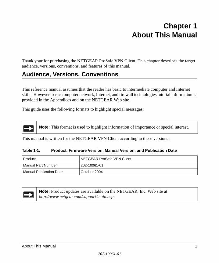
Chapter 1 About This Manual
Thank your for purchasing the NETGEAR ProSafe VPN Client. This chapter describes the target audience, versions, conventions, and features of this manual.
Audience, Versions, Conventions
This reference manual assumes that the reader has basic to intermediate computer and Internet skills. However, basic computer network, Internet, and firewall technologies tutorial information is provided in the Appendices and on the NETGEAR Web site.
This guide uses the following formats to highlight special messages:
This manual is written for the NETGEAR VPN Client according to these versions:
Note: This format is used to highlight information of importance or special interest.
Table 1-1. Product, Firmware Version, Manual Version, and Publication Date
Product NETGEAR ProSafe VPN Client
Manual Part Number 202-10061-01
Manual Publication Date October 2004
Note: Product updates are available on the NETGEAR, Inc. Web site at http://www.netgear.com/support/main.asp.
About This Manual 1
202-10061-01
Reference Manual for the NETGEAR ProSafe VPN Client
How to Use this Manual
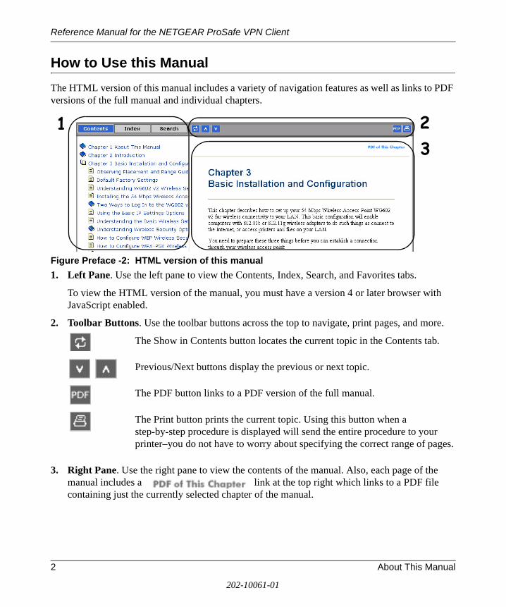
The HTML version of this manual includes a variety of navigation features as well as links to PDF versions of the full manual and individual chapters.
Figure Preface -2: HTML version of this manual
1. Left Pane. Use the left pane to view the Contents, Index, Search, and Favorites tabs.
To view the HTML version of the manual, you must have a version 4 or later browser with JavaScript enabled.
2. Toolbar Buttons. Use the toolbar buttons across the top to navigate, print pages, and more.
The Show in Contents button locates the current topic in the Contents tab.
Previous/Next buttons display the previous or next topic.
The PDF button links to a PDF version of the full manual.
The Print button prints the current topic. Using this button when a step-by-step procedure is displayed will send the entire procedure to your printer–you do not have to worry about specifying the correct range of pages.
3. Right Pane. Use the right pane to view the contents of the manual. Also, each page of the manual includes a link at the top right which links to a PDF file containing just the currently selected chapter of the manual.
1 23
2 About This Manual
202-10061-01
Reference Manual for the NETGEAR ProSafe VPN Client
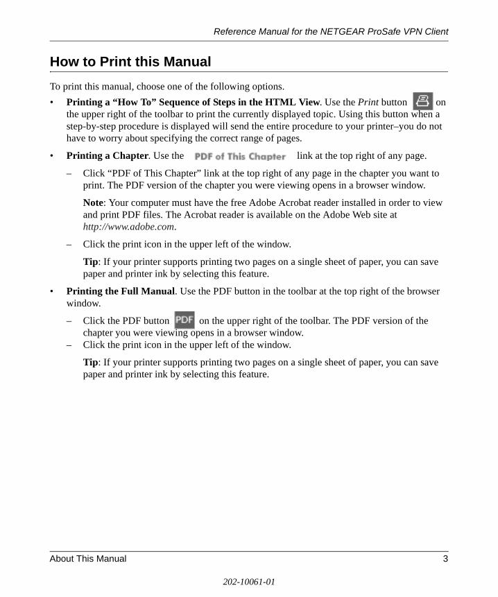
How to Print this Manual
To print this manual, choose one of the following options.
• Printing a “How To” Sequence of Steps in the HTML View. Use the Print button on the upper right of the toolbar to print the currently displayed topic. Using this button when a step-by-step procedure is displayed will send the entire procedure to your printer–you do not have to worry about specifying the correct range of pages.
• Printing a Chapter. Use the link at the top right of any page.
– Click “PDF of This Chapter” link at the top right of any page in the chapter you want to print. The PDF version of the chapter you were viewing opens in a browser window.
Note: Your computer must have the free Adobe Acrobat reader installed in order to view and print PDF files. The Acrobat reader is available on the Adobe Web site at http://www.adobe.com.
– Click the print icon in the upper left of the window.
Tip: If your printer supports printing two pages on a single sheet of paper, you can save paper and printer ink by selecting this feature.
• Printing the Full Manual. Use the PDF button in the toolbar at the top right of the browser window.
– Click the PDF button on the upper right of the toolbar. The PDF version of the chapter you were viewing opens in a browser window.
– Click the print icon in the upper left of the window.
Tip: If your printer supports printing two pages on a single sheet of paper, you can save paper and printer ink by selecting this feature.
About This Manual 3
202-10061-01

Reference Manual for the NETGEAR ProSafe VPN Client
4 About This Manual
202-10061-01

Reference Manual for the NETGEAR ProSafe VPN Client
Chapter 2 Introduction
This chapter describes the features of the NETGEAR ProSafe VPN Client.
The NETGEAR ProSafe VPN Client is a remote access and end-point security product that secures communications over the Internet and other public networks to create a virtual private network (VPN) between users. The NETGEAR ProSafe VPN Client secures data communications sent from a desktop or portable computer across a public or private TCP/IP network. The client protects the office computer user and the home and mobile workforce.
The NETGEAR VPN Client supports secure client-to-gateway or client-to-client communications. For example, employees can telecommute from their homes to the office through the Internet or dial-in connections for secure client-to-gateway communications. Organizations that require a low-cost solution for secure communications among their employees or members across a private LAN, WAN, or individual dial-up connections can use the NETGEAR VPN Client for secure client-to-client communications.
The NETGEAR VPN Client starts automatically when the user’s computer starts, and runs transparently at all times behind other software programs. Through a system tray icon, the user can determine the client's communications status, open its components, and perform several other actions.
What's Included?
The NETGEAR ProSafe VPN Client contains two primary components:
• Security Policy Editor is where users create, import, and manage connections and their associated proposals that make up their security policy.
• Certificate Manager allows users to request and retrieve, import, and store the certificates users receive from certificate authorities (CAs), and to also set the trust policy.
There are also two diagnostic tools:
• Log Viewer lists the IKE negotiations that occur during Authentication (Phase 1).
• Connection Monitor displays statistical and diagnostic information for each active connection.
Introduction 2-1
202-10061-01
Reference Manual for the NETGEAR ProSafe VPN Client
What’s in the Box?
The product package should contain the following items:
• ProSafe VPN Client Software CD in one-user (VPN01L) or five-user (VPN05L) license packs
• Installation guide (on disk)
• ProSafe VPN Easy Configuration Files
• Support information and warranty card
NETGEAR Related Products
NETGEAR products related to the NETGEAR ProSafe VPN Client are as follows:
• FR114P 4 Port Cable/DSL ProSafe Firewall/Print Server
• FVL328 Cable/DSL ProSafe High-Speed VPN Firewall Router
• FVS318 Cable/DSL ProSafe VPN Firewall with 8-port switch
• FVS328 ProSafe VPN Firewall with Dial Back-up
• FWAG114 Dual Band VPN Firewall
• FWG114P ProSafe 802.11g Wireless Firewall with USB Print Server
2-2 Introduction
202-10061-01

Reference Manual for the NETGEAR ProSafe VPN Client
Chapter 3 Installation
This chapter describes how to install your NETGEAR ProSafe VPN Client.
What You Need Before You Begin
You need to verify that your computer meets the minimum system requirements.
System Requirements
Before installing the NETGEAR ProSafe VPN Client, please make sure that these minimum requirements have been met:
• IBM-compatible computer with Pentium processor or equivalent (not Alpha platforms)
• Compatible operating systems with minimum RAM:
Some versions of Windows may ask for the original Windows operating system installation files to complete the installation of the VPN Client driver software
• 35 MB hard disk space
• Native Microsoft TCP/IP communications protocol
• For dial-up connections:
– Non-encrypting modem
– Native Microsoft PPP dialer
Operating system Minimum RAM
Microsoft® Windows® 95 and 98 16 MB
Windows NT® Workstation 4.0 32 MB
Windows Me and 2000 Professional 64 MB
Windows XP Home and Professional 64 MB; 128 MB recommended
Installation 3-1
202-10061-01
Reference Manual for the NETGEAR ProSafe VPN Client
• For network connections, Ethernet card and connection
• Microsoft Internet Explorer 4.0 or later
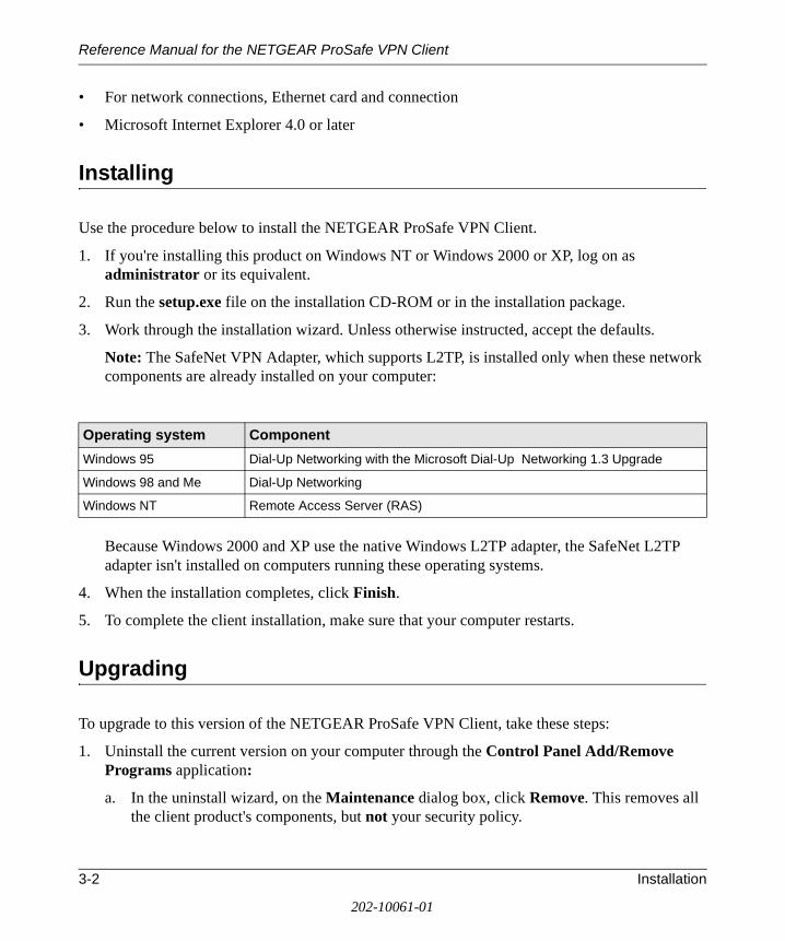
Installing
Use the procedure below to install the NETGEAR ProSafe VPN Client.
1. If you're installing this product on Windows NT or Windows 2000 or XP, log on as administrator or its equivalent.
2. Run the setup.exe file on the installation CD-ROM or in the installation package.
3. Work through the installation wizard. Unless otherwise instructed, accept the defaults.
Note: The SafeNet VPN Adapter, which supports L2TP, is installed only when these network components are already installed on your computer:
Because Windows 2000 and XP use the native Windows L2TP adapter, the SafeNet L2TP adapter isn't installed on computers running these operating systems.
4. When the installation completes, click Finish.
5. To complete the client installation, make sure that your computer restarts.
Upgrading
To upgrade to this version of the NETGEAR ProSafe VPN Client, take these steps:
1. Uninstall the current version on your computer through the Control Panel Add/Remove Programs application:
a. In the uninstall wizard, on the Maintenance dialog box, click Remove. This removes all the client product's components, but not your security policy.
Operating system Component
Windows 95 Dial-Up Networking with the Microsoft Dial-Up Networking 1.3 Upgrade
Windows 98 and Me Dial-Up Networking
Windows NT Remote Access Server (RAS)
3-2 Installation
202-10061-01
Reference Manual for the NETGEAR ProSafe VPN Client
b. The Uninstall Security Policy dialog box prompts you to delete your IPSec security policy, which includes any certificates and private keys:
– To keep it, click No. You can import this security policy after you install the new version of the NETGEAR ProSafe VPN Client.
– To delete it, click Yes.
c. When the Maintenance Complete dialog box opens, click Finish.
d. To complete the uninstall, make sure that your computer restarts.
2. Install this new version of the NETGEAR ProSafe VPN Client.
Getting Started
The NETGEAR ProSafe VPN Client contains two primary modules:
• Security Policy Editor to configure and maintain the security policy
• Certificate Manager to request, store, and administer certificates
To learn how to use NETGEAR VPN Client, go to Start>Programs>NETGEAR ProSafe VPN Client>NETGEAR ProSafe VPN Client Help.
VPN Client Connection Indicators
The NETGEAR ProSafe VPN Client provides the following indicators to give you feedback on the status of your wireless connection:
The System Tray (SysTray) resides on one end of the taskbar in the Microsoft Windows desktop.
Installation 3-3
202-10061-01
Reference Manual for the NETGEAR ProSafe VPN Client
Uninstalling the NETGEAR ProSafe VPN Client
When you remove the NETGEAR ProSafe VPN Client and its components, you have the option to keep your security policy, certificates, and private keys to use when you upgrade or reinstall the client.
Note: Before you upgrade the client, read the readme file and Release Notes provided with the new version.
1. Open the Control Panel Add/Remove Programs application.
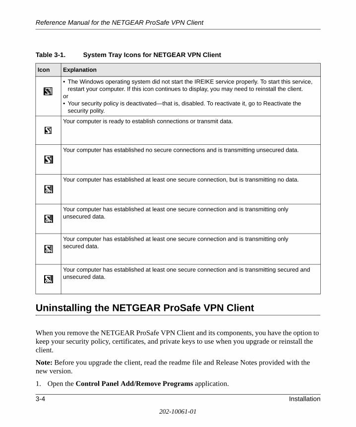
Table 3-1. System Tray Icons for NETGEAR VPN Client
Icon Explanation
• The Windows operating system did not start the IREIKE service properly. To start this service, restart your computer. If this icon continues to display, you may need to reinstall the client.
or• Your security policy is deactivated—that is, disabled. To reactivate it, go to Reactivate the
security polity.
Your computer is ready to establish connections or transmit data.
Your computer has established no secure connections and is transmitting unsecured data.
Your computer has established at least one secure connection, but is transmitting no data.
Your computer has established at least one secure connection and is transmitting only unsecured data.
Your computer has established at least one secure connection and is transmitting only secured data.
Your computer has established at least one secure connection and is transmitting secured and unsecured data.
3-4 Installation
202-10061-01
Reference Manual for the NETGEAR ProSafe VPN Client
2. Remove NETGEAR ProSafe VPN Client. The details depend on the version of Windows on your computer.
3. Work through the uninstall wizard:
a. When the Maintenance dialog box opens, click Remove.
b. When prompted to remove all installed components, click Yes.
Note: This does not remove the IPSec security policy, certificates, or private keys.
c. When prompted to remove the IPSec security policy, which includes certificates and private keys, in most cases, click No. You can import this policy after you reinstall this client version or upgrade to a newer client version; this can save a lot of time.
d. When the maintenance complete message opens, click Finish.
4. Make sure that the computer restarts; this is required to complete the uninstall.
Keyboard Shortcuts
The client supports standard Windows keyboard shortcuts for accessibility. For a complete list of Windows keyboard shortcuts, refer to the keyboard shortcuts help topics in Windows.
Installation 3-5
202-10061-01

Reference Manual for the NETGEAR ProSafe VPN Client
3-6 Installation
202-10061-01
Reference Manual for the NETGEAR ProSafe VPN Client
Chapter 4 Configuring L2TP Connections
This chapter describes how to use configure VPN tunnels using the NETGEAR ProSafe VPN Client.
Basic Steps
The client supports Layer 2 Tunneling Protocol (L2TP) connections through a virtual adapter: the SafeNet VPN Adapter. The specific steps required vary with the Windows operating system installed on your computer.
To create and secure an L2TP connection, perform these tasks in the sequence that your network security administrator recommends:
• Configure a network connection to the remote party’s L2TP network server.
• Configure the security policy for L2TP.
• If you are establishing the L2TP or virtual adapter connection over a physical dial-up connection—that is, a modem—add another dial-up connection adapter.
How to Configure an L2TP Dial-Up Network Connection
Configuring a dial-up network connection for L2TP requires you to use the Dial-Up Networking (DUN) features of the Windows operating system. The steps vary by operating system.
For Windows 95/98/Me
1. Create the connection to the other party's L2TP network server:
a. On the desktop, double-click My Computer.
b. Double-click Dial-Up Networking. The Dial-Up Networking dialog box opens.
c. Double-click Make New Connection. The Make New Connection wizard opens.
Configuring L2TP Connections 4-1
202-10061-01
Reference Manual for the NETGEAR ProSafe VPN Client
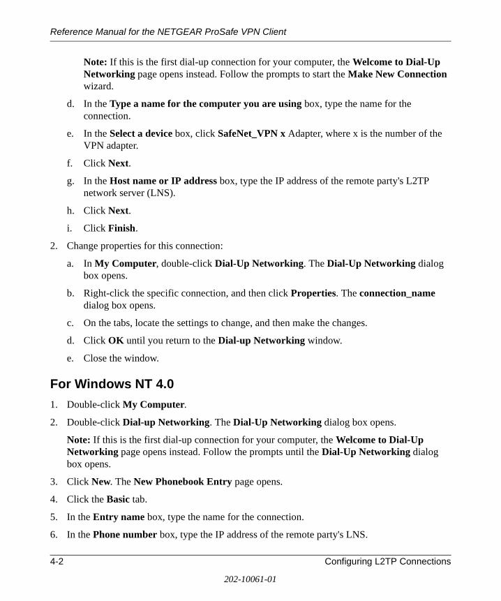
Note: If this is the first dial-up connection for your computer, the Welcome to Dial-Up Networking page opens instead. Follow the prompts to start the Make New Connection wizard.
d. In the Type a name for the computer you are using box, type the name for the connection.
e. In the Select a device box, click SafeNet_VPN x Adapter, where x is the number of the VPN adapter.
f. Click Next.
g. In the Host name or IP address box, type the IP address of the remote party's L2TP network server (LNS).
h. Click Next.
i. Click Finish.
2. Change properties for this connection:
a. In My Computer, double-click Dial-Up Networking. The Dial-Up Networking dialog box opens.
b. Right-click the specific connection, and then click Properties. The connection_name dialog box opens.
c. On the tabs, locate the settings to change, and then make the changes.
d. Click OK until you return to the Dial-up Networking window.
e. Close the window.
For Windows NT 4.0
1. Double-click My Computer.
2. Double-click Dial-up Networking. The Dial-Up Networking dialog box opens.
Note: If this is the first dial-up connection for your computer, the Welcome to Dial-Up Networking page opens instead. Follow the prompts until the Dial-Up Networking dialog box opens.
3. Click New. The New Phonebook Entry page opens.
4. Click the Basic tab.
5. In the Entry name box, type the name for the connection.
6. In the Phone number box, type the IP address of the remote party's LNS.
4-2 Configuring L2TP Connections
202-10061-01
Reference Manual for the NETGEAR ProSafe VPN Client
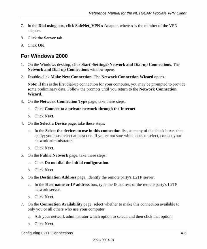
7. In the Dial using box, click SafeNet_VPN x Adapter, where x is the number of the VPN adapter.
8. Click the Server tab.
9. Click OK.
For Windows 2000
1. On the Windows desktop, click Start>Settings>Network and Dial-up Connections. The Network and Dial-up Connections window opens.
2. Double-click Make New Connection. The Network Connection Wizard opens.
Note: If this is the first dial-up connection for your computer, you may be prompted to provide some preliminary data. Follow the prompts until you return to the Network Connection Wizard.
3. On the Network Connection Type page, take these steps:
a. Click Connect to a private network through the Internet.
b. Click Next.
4. On the Select a Device page, take these steps:
a. In the Select the devices to use in this connection list, as many of the check boxes that apply; you must select at least one. If you're not sure which ones to select, contact your network administrator.
b. Click Next.
5. On the Public Network page, take these steps:
a. Click Do not dial the initial configuration.
b. Click Next.
6. On the Destination Address page, identify the remote party's L2TP server:
a. In the Host name or IP address box, type the IP address of the remote party's L2TP network server.
b. Click Next.
7. On the Connection Availability page, select whether to make this connection available to only you or all others who use your computer:
a. Ask your network administrator which option to select, and then click that option.
b. Click Next.
Configuring L2TP Connections 4-3
202-10061-01
Reference Manual for the NETGEAR ProSafe VPN Client
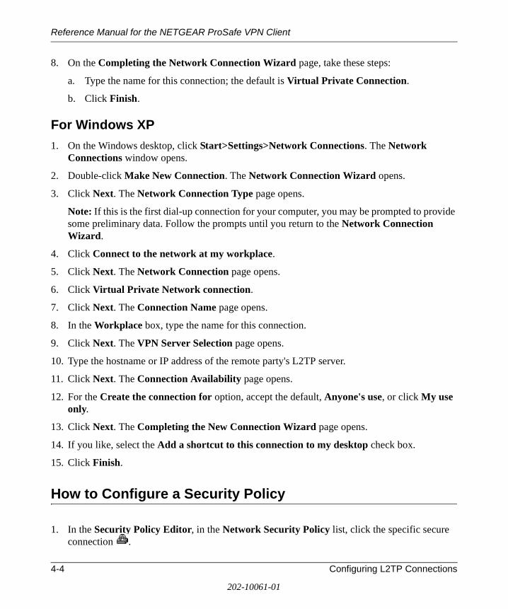
8. On the Completing the Network Connection Wizard page, take these steps:
a. Type the name for this connection; the default is Virtual Private Connection.
b. Click Finish.
For Windows XP
1. On the Windows desktop, click Start>Settings>Network Connections. The Network Connections window opens.
2. Double-click Make New Connection. The Network Connection Wizard opens.
3. Click Next. The Network Connection Type page opens.
Note: If this is the first dial-up connection for your computer, you may be prompted to provide some preliminary data. Follow the prompts until you return to the Network Connection Wizard.
4. Click Connect to the network at my workplace.
5. Click Next. The Network Connection page opens.
6. Click Virtual Private Network connection.
7. Click Next. The Connection Name page opens.
8. In the Workplace box, type the name for this connection.
9. Click Next. The VPN Server Selection page opens.
10. Type the hostname or IP address of the remote party's L2TP server.
11. Click Next. The Connection Availability page opens.
12. For the Create the connection for option, accept the default, Anyone's use, or click My use only.
13. Click Next. The Completing the New Connection Wizard page opens.
14. If you like, select the Add a shortcut to this connection to my desktop check box.
15. Click Finish.
How to Configure a Security Policy
1. In the Security Policy Editor, in the Network Security Policy list, click the specific secure connection .
4-4 Configuring L2TP Connections
202-10061-01
Reference Manual for the NETGEAR ProSafe VPN Client
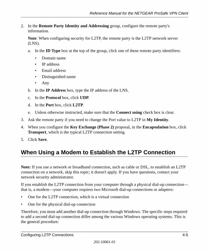
2. In the Remote Party Identity and Addressing group, configure the remote party's information.
Note: When configuring security for L2TP, the remote party is the L2TP network server (LNS).
a. In the ID Type box at the top of the group, click one of these remote party identifiers:
• Domain name
• IP address
• Email address
• Distinguished name
• Any
b. In the IP Address box, type the IP address of the LNS.
c. In the Protocol box, click UDP.
d. In the Port box, click L2TP.
e. Unless otherwise instructed, make sure that the Connect using check box is clear.
3. Ask the remote party if you need to change the Port value to L2TP in My Identity.
4. When you configure the Key Exchange (Phase 2) proposal, in the Encapsulation box, click Transport, which is the typical L2TP connection setting.
5. Click Save.
When Using a Modem to Establish the L2TP Connection
Note: If you use a network or broadband connection, such as cable or DSL, to establish an L2TP connection on a network, skip this topic; it doesn't apply. If you have questions, contact your network security administrator.
If you establish the L2TP connection from your computer through a physical dial-up connection—that is, a modem—your computer requires two Microsoft dial-up connections or adapters:
• One for the L2TP connection, which is a virtual connection
• One for the physical dial-up connection
Therefore, you must add another dial-up connection through Windows. The specific steps required to add a second dial-up connection differ among the various Windows operating systems. This is the general procedure:
Configuring L2TP Connections 4-5
202-10061-01
Reference Manual for the NETGEAR ProSafe VPN Client
1. On your computer, in Windows help, look up network adapters, network connections, or add a connection.
2. In Control Panel, open the Network or Network and Dial-up Connections application.
3. Follow the instructions in the help to add another dial-up connection or adapter.
Note: In Windows 95 and 98, dial-up adapters may be labeled Dial-Up Adapter and Dial-Up Adapter#2 (VPN Support).
If you need additional help, contact your network security administrator or IT staff.
4-6 Configuring L2TP Connections
202-10061-01
Reference Manual for the NETGEAR ProSafe VPN Client
Chapter 5 Using the Security Policy Editor
This chapter describes how to use the Security Policy Editor of the NETGEAR VPN Client.
What is the Security Policy Editor?
The Security Policy Editor is the client module in which you (or your network security administrator) create, import, and export security policies. Only one security policy is in effect at any time.
The policy contains connections and proposals that define the address of the remote (or other) party, the security level for the connection, how you identify yourself to the other party, and other attributes concerning the proposals and connections.
The sequence of the connections in the Network Security Policy list in the Security Policy Editor determines the order in which the client tests for a match between an incoming transmission and the proposed policies, and, in turn, defines the connection's security policy.
There are two ways to open the Security Policy Editor:
• On the Windows desktop, click Start>Programs>ProSafe VPN Client>Security Policy Editor.
• In the Windows system tray, right-click the client icon, and then click Security Policy Editor.
Basic Steps to Configure a Security Policy
Caution: Before attempting to configure the security policy, check with your network security administrator: your security policy may have been configured when the client was installed.
Using the Security Policy Editor 5-1
202-10061-01
Reference Manual for the NETGEAR ProSafe VPN Client
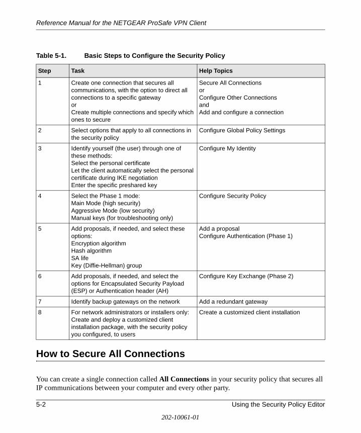
How to Secure All Connections
You can create a single connection called All Connections in your security policy that secures all IP communications between your computer and every other party.
Table 5-1. Basic Steps to Configure the Security Policy
Step Task Help Topics
1 Create one connection that secures all communications, with the option to direct all connections to a specific gatewayorCreate multiple connections and specify which ones to secure
Secure All ConnectionsorConfigure Other ConnectionsandAdd and configure a connection
2 Select options that apply to all connections in the security policy
Configure Global Policy Settings
3 Identify yourself (the user) through one of these methods:Select the personal certificateLet the client automatically select the personal certificate during IKE negotiationEnter the specific preshared key
Configure My Identity
4 Select the Phase 1 mode:Main Mode (high security)Aggressive Mode (low security)Manual keys (for troubleshooting only)
Configure Security Policy
5 Add proposals, if needed, and select these options:Encryption algorithmHash algorithmSA lifeKey (Diffie-Hellman) group
Add a proposalConfigure Authentication (Phase 1)
6 Add proposals, if needed, and select the options for Encapsulated Security Payload (ESP) or Authentication header (AH)
Configure Key Exchange (Phase 2)
7 Identify backup gateways on the network Add a redundant gateway
8 For network administrators or installers only: Create and deploy a customized client installation package, with the security policy you configured, to users
Create a customized client installation
5-2 Using the Security Policy Editor
202-10061-01
Reference Manual for the NETGEAR ProSafe VPN Client
1. In the Security Policy Editor, click Options>Secure>All Connections. A secure connection called All Connections is added to the Network Security Policy list.
2. To route all secure communications from your computer through a specific, secure, IPSec-compliant network gateway, such as a firewall or router, see “How to Configure a Gateway” on page 5-9.
3. Click Save.
4. Configure My Identity for this connection.
5. Exit the Security Policy Editor.
How to Configure Global Policy Settings
Global policy settings are program preferences that apply to all secure IP communications. You can change these at any time to match to your security policy.
1. In the Security Policy Editor, click Options, and then click Global Policy Settings. The Global Policy Settings dialog box opens.
2. In the Retransmit Interval box, type the length of time, in seconds, that the client waits before resending an IKE protocol packet that has not been responded to. The default is 8 seconds.
Note: If the client selects a redundant gateway when you know that the primary one is available, try entering a higher number for Retransmit Interval.
3. In the Number of retries box, type the number of times your computer resends an IKE protocol packet before abandoning the exchange. The default is 3 tries.
4. Status notifications are messages that inform communicating parties what the time-out periods are and whether their security proposals have been accepted or rejected.
To send these messages, select the Send status notifications to peer host check box.
5. An internal network IP address is a virtual IP address assigned to the client user. Remote users can appear as internal users on a private network to, for example, access a WINS server or browse the network.
To enable remote users to appear as internal users on a private network, select the Allow to Specify Internal Network Address check box.
Note: If you select this check box, you must enter a private internal network IP address when configuring My Identity.
Using the Security Policy Editor 5-3
202-10061-01
Reference Manual for the NETGEAR ProSafe VPN Client
6. To enable logging the Log Viewer's IKE negotiation messages to the isakmp.log file in the client's installation directory, select the Enable logging to a file check box. This can facilitate remote troubleshooting by allowing a user to send a file with these messages instead of repeatedly freezing and printing the Log Viewer.
Notes:
• The maximum size for the isakmp.log file is 100 KB. When the client's computer, the client, and the IKE service restart and the isakmp.log file size exceeds 100 KB, this isakmp.log file is deleted and a new one created.
• On computers running Windows 95 and 98, when the isakmp.log file size exceeds 64 KB, Notepad prompts the user to try WordPad instead because of the file's size. When the user tries WordPad, however, WordPad prompts the user that it can't open the file because it is in use by another program (the IKE service).
In this case, to view the file, try one of these options:
— Rename it, and then open it in WordPad.
— Open a read-only version of the file in Microsoft Word.
— Clear the Enable logging to a file check box, and then open the file.
7. If you don't use a smart card and reader or similar device to authenticate your identity, skip this step.
If you do use a smart card and reader or similar device, the client can, when it detects that the smart card or reader is removed, delete active keys and end these communications sessions. This provides extra security. Only connections that use the keys on your smart card are affected.
To enable this feature, select the Smart card removal clears keys check box.
8. Click OK.
9. Click Save.
How to Configure Other Connections
The security policy includes a connection called Other Connections. This connection, non-secure by default, is designed to allow all non-encrypted IP traffic through and let you to access the Internet and other public networks unsecured or “in the clear.”
5-4 Using the Security Policy Editor
202-10061-01
Reference Manual for the NETGEAR ProSafe VPN Client
The client processes connections in the order in which they display in the Network Security Policy list. Because Other Connections is the catchall or default rule for communications that don't conform to the proposals for individual connections, it is always last in the connections list.
1. In the Security Policy Editor, click Options, point to Secure, and then click Specified Connections.
2. In the Network Security Policy list, click Other Connections.
3. In the Connection Security group, click a security level:
• Secure secures communications for this connection.
• Non-secure , the default, allows communications for this connection to pass through unsecured, or not encrypted.
• Block prohibits all communications for this connection from passing through.
4. If you selected Non-secure or Block in the Connection Security group, the Internet Interface group is available:
a. In the Name list, click the interface for your computer to use to connect to a network. The default, Any, lets your computer select any available interface.
For devices with associated IP addresses, the IP Addr box shows the IP address.
b. In the Port box, click the protocol port through which your computer connects to the remote party. The default, All, secures all protocol ports.
The port's standard numeric designation shows next to the Port box.
5. Click Save.
6. If you selected Secure in the Connection Security group, is your network protected by a secure IPSec-compliant gateway, such as a firewall or router?
• If it is, see “How to Configure a Gateway” on page 5-9.
• If it is not, continue with the next step.
7. The Connection Security setting determines your next step:
• If you selected Secure, configure My Identity for this connection.
• If you selected Non-secure or Block, you can add and configure connections.
Using the Security Policy Editor 5-5
202-10061-01
Reference Manual for the NETGEAR ProSafe VPN Client
How to Add and Configure a Connection
You can create and configure multiple connections for your security policy.
Before you can configure a connection, make sure that you have identification information for the remote party, such as network IP address, domain name, or email address. If the remote party (user or network) is protected by a secure IPSec-compliant gateway device, obtain that gateway's IP address, too.
1. In the Security Policy Editor, configure Other Connections.
2. In the Network Security Policy list, if the My Connections folder does not appear, click Options, point to Secure, and then click Specified Connections.
3. Click (or Edit>Add Connection). A highlighted New Connection entry displays in the Network Security Policy list.
4. Rename the new connection.
5. In the Connection Security group, take these steps:
a. Click the security level:
• Secure secures communications for this connection. This is the default.
• Non-secure allows communications for this connection to pass through unsecured, or not encrypted.
• Block prohibits all communications for this connection from passing through.
b. When the Secure security level is selected, the Only Connect Manually check box appears. By default, the check box is clear; this means that the client establishes and terminates connections automatically as needed. You can, however, initiate and end secure sessions manually.
To require the user to manually establish and terminate all secure sessions using this connection (with the Connect and Disconnect options on the client icon's shortcut menu), select the Only Connect Manually check box.
If a connection for which the Only Connect Manually check box is selected isn't manually connected, traffic that would otherwise go over this connection is bypassed, as though there were no connection configured for this traffic. Traffic that would go over that connection if it were active is instead compared against the remaining connections in the Network Security Policy box to determine how to handle it.
5-6 Using the Security Policy Editor
202-10061-01
Reference Manual for the NETGEAR ProSafe VPN Client
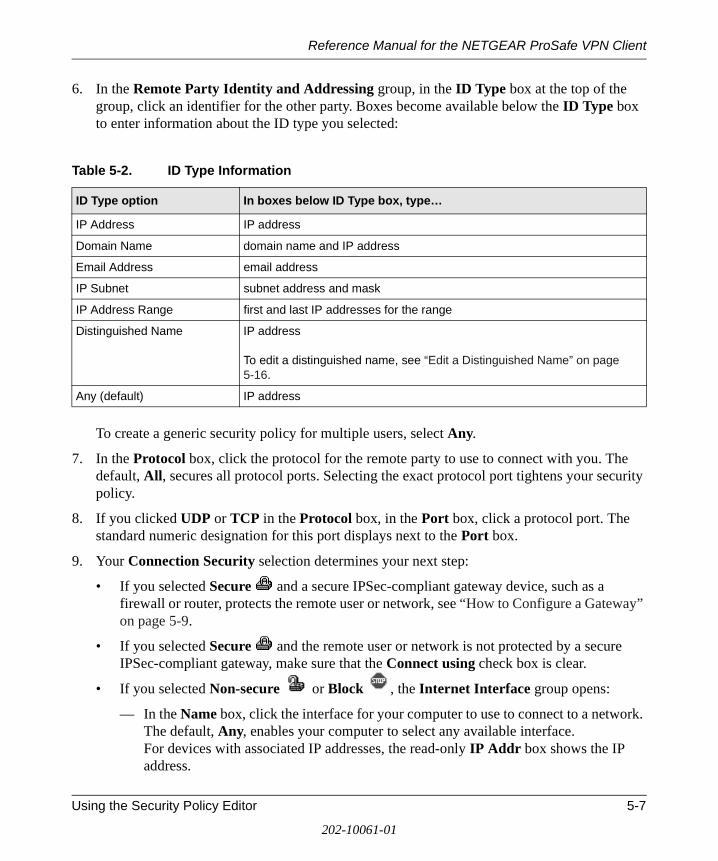
6. In the Remote Party Identity and Addressing group, in the ID Type box at the top of the group, click an identifier for the other party. Boxes become available below the ID Type box to enter information about the ID type you selected:
To create a generic security policy for multiple users, select Any.
7. In the Protocol box, click the protocol for the remote party to use to connect with you. The default, All, secures all protocol ports. Selecting the exact protocol port tightens your security policy.
8. If you clicked UDP or TCP in the Protocol box, in the Port box, click a protocol port. The standard numeric designation for this port displays next to the Port box.
9. Your Connection Security selection determines your next step:
• If you selected Secure and a secure IPSec-compliant gateway device, such as a firewall or router, protects the remote user or network, see “How to Configure a Gateway” on page 5-9.
• If you selected Secure and the remote user or network is not protected by a secure IPSec-compliant gateway, make sure that the Connect using check box is clear.
• If you selected Non-secure or Block , the Internet Interface group opens:
— In the Name box, click the interface for your computer to use to connect to a network. The default, Any, enables your computer to select any available interface. For devices with associated IP addresses, the read-only IP Addr box shows the IP address.
Table 5-2. ID Type Information
ID Type option In boxes below ID Type box, type…
IP Address IP address
Domain Name domain name and IP address
Email Address email address
IP Subnet subnet address and mask
IP Address Range first and last IP addresses for the range
Distinguished Name IP address To edit a distinguished name, see “Edit a Distinguished Name” on page 5-16.
Any (default) IP address
Using the Security Policy Editor 5-7
202-10061-01
Reference Manual for the NETGEAR ProSafe VPN Client
— In the Port box, click the protocol port for your computer to connect to the remote party through. The default, All, secures all protocol ports. The number displayed next to the Port box is the port's standard designation.
10. Click Save.
11. Configure My Identity for this connection.
How to Enter a Preshared Key
A preshared key is an alphanumeric character string that can be used instead of certificates to authenticate the identity of communicating parties during Phase 1 IKE negotiations. This character string, which can contain from 8 through 255 characters, is called preshared because the remote party needs it before you can communicate with it. Both parties must enter this preshared key in their IPSec-compliant devices, such as a firewall, gateway encryptor, router, or software client. Preshared keys can be included with the security policy when it is exported or included in a customized client installation.
When you use preshared keys, you don't have to deal with CAs and certificates. Preshared key, however, do not provide the same level of security as certificates. Use preshared keys only for testing, troubleshooting, or one-to-one communications that do not require a corporate security policy.
Before you begin to configure the security policy, decide whether to use certificates or preshared keys.
To use preshared keys instead of certificates for authentication, enter the preshared key when you configure My Identity for a selected connection.
Note: Preshared keys are not global policy settings; therefore, you must assign the key to each applicable connection individually.
1. In the Security Policy Editor, in the Network Security Policy list, expand the specific secure connection .
2. In this connection, click My Identity.
3. In the Select Certificate box, click None.
4. Click Pre-Shared Key. The Pre-shared Key dialog box opens.
5. Click Enter Key.
6. Type the key.
7. Click OK.
5-8 Using the Security Policy Editor
202-10061-01
Reference Manual for the NETGEAR ProSafe VPN Client
8. Click Save.
9. Complete configuring My Identity.
How to Configure a Gateway
When configuring a secure connection—Other Connections, All Connections, or a specific connection—in the Security Policy Editor, and your network or, for specific connections only, the remote party's network routes secure IP communications through a gateway device, such as a firewall or router, you must identify the gateway and its addressing.
1. In the Security Policy Editor, in the Network Security Policy list, click the particular secure connection .
2. In the right pane, select the Connect using check box. When configuring a specific connection, this is in the Remote Party Identity and Addressing group.
3. In the adjoining box, click the gateway to use.
4. In the ID Type box immediately below the Connect using check box, click an identifier for this gateway.
Note: To create a generic security policy for multiple users, select Any (the default).
5. Complete the boxes that become available, based on the gateway identifier you specified in ID Type:
• If you clicked IP Address, you can edit the gateway's IP address in a box below the ID Type box.
• If you clicked Domain Name:
— You can edit the gateway's IP address in a box below the ID Type box.
— In the box adjacent to the ID Type box, select how to specify the gateway: click Gateway IP Address or Gateway Hostname (DNS name).
— In the box below the Gateway IP Address/Hostname box, type the value for the selected gateway option.
• If you clicked Distinguished Name or Any:
— In the box adjacent to the ID Type box, select how to specify the gateway: click Gateway IP Address or Gateway Hostname (DNS name).
— In the box below the Gateway IP Address/Hostname box, type the value for the selected gateway option.
Using the Security Policy Editor 5-9
202-10061-01
Reference Manual for the NETGEAR ProSafe VPN Client
To change the distinguished name, see “Edit a Distinguished Name” on page 5-16.
6. Click Save.
Configure My Identity
The remote party that you want to communicate securely with uses the information in My Identity to verify that you really are who you indicate that you are. This is done with either a preshared key that you and the remote party have or a certificate This information also distinguishes you from the remote party during the key exchange process.
The ID types available for identifying yourself in My Identity come from the subject information fields of the personal certificate request that you completed when you requested a personal certificate from a CA.
1. In the Security Policy Editor, in the Network Security Policy list, expand the specific secure connection .
2. Click My Identity.
3. If you are using preshared keys, see “How to Enter a Preshared Key” on page 5-8.
4. If you are using certificates:
a. In the Select Certificate box, you can specify a personal certificate or let the client select one:
• To select a particular personal certificate, click that certificate.
• For the client to select a personal certificate automatically, click Select automatically during IKE negotiation, the default for new security policies. This option facilitates creating a policy.
b. In the ID Type box, click the information and format that identifies you to remote parties.
A box opens below the ID Type box with the particular subject information, in the ID type you clicked, from the personal certificate that you selected in the Select Certificate box.
If you selected Select automatically during IKE negotiation in the Select Certificate box, the default ID type is Distinguished Name; each personal certificate contains this.
Caution: The ID type is a search criterion that the client uses when automatically selecting a certificate. This means that if it doesn't find a personal certificate with the ID type selected, the connection attempt fails.
5-10 Using the Security Policy Editor
202-10061-01
Reference Manual for the NETGEAR ProSafe VPN Client
5. If the Port box is enabled, click the protocol port through which your computer will connect to the other party. The default, All, secures all protocol ports. Selecting the exact protocol port tightens your security policy.
The port's standard numeric designation shows next to the Port box.
6. In the Virtual Adapter box, you can configure the client to use a virtual adapter to handle private IP addressing. If certain programs that work with the client are “IP address-aware,” your computer is assigned a private Windows Internet Naming Service (WINS) server address, or both, you may need to do this.
In the Virtual Adapter box, click an option:
• Disabled—No virtual adapter is used. This is the default.
• Required—When the client tries to launch the connection with the virtual adapter, IP address-aware programs know the assigned address for the virtual adapter and use it as the source IP address. If the launch fails, the connection attempt fails.
• Preferred—Uses the same procedure as Required with one exception: if the connection launch using the virtual adapter IP address fails, the client uses address substitution to dynamically change the server IP address throughout the session.
7. If you selected the Allow to Specify Internal Network Address check box when you configured Global Policy Settings, and the Internal Network IP Address box opens, type an IP address in it.
8. In the Internet Interface group, in the Name box, click the interface for your computer to use to connect to a network. The default, Any, enables your computer to select any available interface.
For devices with associated IP addresses, the IP Addr box shows the IP address.
Caution: If the Name box contains an entry other than Any, do not change it. This was configured by your network security administrator. The only instance in which you may need to change this entry is to assist your network security administrator in troubleshooting connection problems.
9. Click Save.
10. Configure Security Policy.
Configure Security Policy Connection Options
Before you configure the options for Security Policy in a connection, take these steps:
Using the Security Policy Editor 5-11
202-10061-01

Reference Manual for the NETGEAR ProSafe VPN Client
• Make sure that the connection is secure: In the Connection Security group, click Secure .
• Configure My Identity for this connection.
The Phase 1 negotiation mode selected for Security Policy determines how the security association (SA) is established for each connection through IKE negotiations.
1. In the Security Policy Editor, in the Network Security Policy list, expand the specific secure connection .
2. Expand Security Policy.
3. In the Select Phase 1 Negotiation Mode group, click an option:
• Main Mode ensures the highest level of security when the communicating parties are negotiating authentication (Phase 1).
• Aggressive Mode is quicker than Main Mode, because it eliminates several steps when the communicating parties are negotiating authentication (Phase 1).
• Use Manual Keys requires no negotiations; ProSafe recommends using this for troubleshooting only.
4. To activate the perfect forward secrecy (PFS) feature, which requires exchanging independent keying material each time Key Exchange keys are generated, select the Enable Perfect Forward Secrecy (PFS) check box.
5. If you selected the Enable Perfect Forward Secrecy (PFS) check box, in the PFS Key Group list, click a Diffie-Hellman Group 1, 2, or 5.
6. To set a counter that determines if a packet is unique, select the Enable Replay Detection check box.
7. Click Save.
The Phase 1 Negotiation Mode you selected determines your next step:
• If you selected Main Mode or Aggressive Mode, configure Authentication (Phase 1).
• If you selected Use Manual Keys, configure Key Exchange (Phase 2).
Configure Authentication (Phase 1)
After you configure Security Policy for a secure connection, the next step is to configure authentication proposals for this policy, one connection at a time.
5-12 Using the Security Policy Editor
202-10061-01
Reference Manual for the NETGEAR ProSafe VPN Client
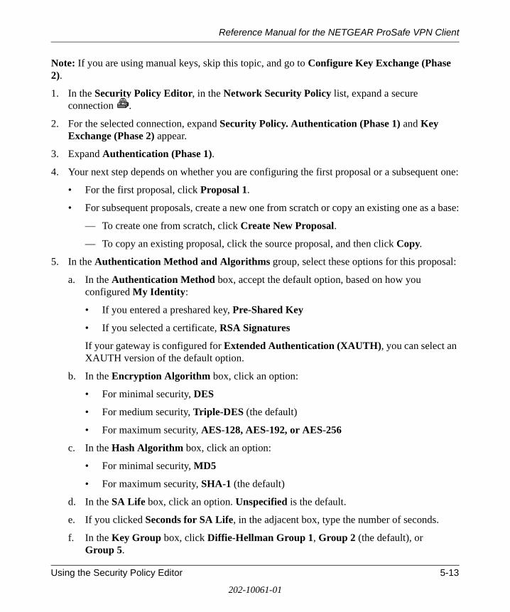
Note: If you are using manual keys, skip this topic, and go to Configure Key Exchange (Phase 2).
1. In the Security Policy Editor, in the Network Security Policy list, expand a secure connection .
2. For the selected connection, expand Security Policy. Authentication (Phase 1) and Key Exchange (Phase 2) appear.
3. Expand Authentication (Phase 1).
4. Your next step depends on whether you are configuring the first proposal or a subsequent one:
• For the first proposal, click Proposal 1.
• For subsequent proposals, create a new one from scratch or copy an existing one as a base:
— To create one from scratch, click Create New Proposal.
— To copy an existing proposal, click the source proposal, and then click Copy.
5. In the Authentication Method and Algorithms group, select these options for this proposal:
a. In the Authentication Method box, accept the default option, based on how you configured My Identity:
• If you entered a preshared key, Pre-Shared Key
• If you selected a certificate, RSA Signatures
If your gateway is configured for Extended Authentication (XAUTH), you can select an XAUTH version of the default option.
b. In the Encryption Algorithm box, click an option:
• For minimal security, DES
• For medium security, Triple-DES (the default)
• For maximum security, AES-128, AES-192, or AES-256
c. In the Hash Algorithm box, click an option:
• For minimal security, MD5
• For maximum security, SHA-1 (the default)
d. In the SA Life box, click an option. Unspecified is the default.
e. If you clicked Seconds for SA Life, in the adjacent box, type the number of seconds.
f. In the Key Group box, click Diffie-Hellman Group 1, Group 2 (the default), or Group 5.
Using the Security Policy Editor 5-13
202-10061-01
Reference Manual for the NETGEAR ProSafe VPN Client
6. Click Save.
7. Configure Key Exchange (Phase 2).
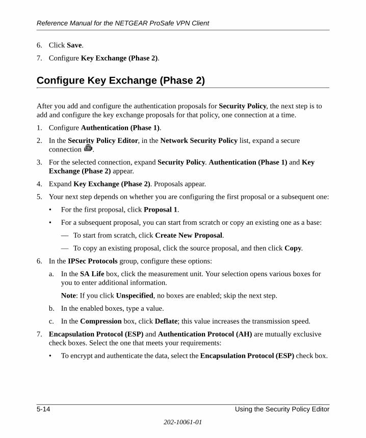
Configure Key Exchange (Phase 2)
After you add and configure the authentication proposals for Security Policy, the next step is to add and configure the key exchange proposals for that policy, one connection at a time.
1. Configure Authentication (Phase 1).
2. In the Security Policy Editor, in the Network Security Policy list, expand a secure connection .
3. For the selected connection, expand Security Policy. Authentication (Phase 1) and Key Exchange (Phase 2) appear.
4. Expand Key Exchange (Phase 2). Proposals appear.
5. Your next step depends on whether you are configuring the first proposal or a subsequent one:
• For the first proposal, click Proposal 1.
• For a subsequent proposal, you can start from scratch or copy an existing one as a base:
— To start from scratch, click Create New Proposal.
— To copy an existing proposal, click the source proposal, and then click Copy.
6. In the IPSec Protocols group, configure these options:
a. In the SA Life box, click the measurement unit. Your selection opens various boxes for you to enter additional information.
Note: If you click Unspecified, no boxes are enabled; skip the next step.
b. In the enabled boxes, type a value.
c. In the Compression box, click Deflate; this value increases the transmission speed.
7. Encapsulation Protocol (ESP) and Authentication Protocol (AH) are mutually exclusive check boxes. Select the one that meets your requirements:
• To encrypt and authenticate the data, select the Encapsulation Protocol (ESP) check box.
5-14 Using the Security Policy Editor
202-10061-01
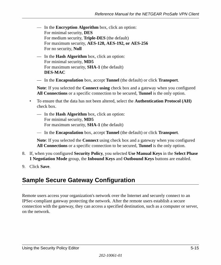
Reference Manual for the NETGEAR ProSafe VPN Client
— In the Encryption Algorithm box, click an option: For minimal security, DES For medium security, Triple-DES (the default) For maximum security, AES-128, AES-192, or AES-256 For no security, Null
— In the Hash Algorithm box, click an option: For minimal security, MD5 For maximum security, SHA-1 (the default) DES-MAC
— In the Encapsulation box, accept Tunnel (the default) or click Transport.
Note: If you selected the Connect using check box and a gateway when you configured All Connections or a specific connection to be secured, Tunnel is the only option.
• To ensure that the data has not been altered, select the Authentication Protocol (AH) check box.
— In the Hash Algorithm box, click an option: For minimal security, MD5 For maximum security, SHA-1 (the default)
— In the Encapsulation box, accept Tunnel (the default) or click Transport.
Note: If you selected the Connect using check box and a gateway when you configured All Connections or a specific connection to be secured, Tunnel is the only option.
8. If, when you configured Security Policy, you selected Use Manual Keys in the Select Phase 1 Negotiation Mode group, the Inbound Keys and Outbound Keys buttons are enabled.
9. Click Save.
Sample Secure Gateway Configuration
Remote users access your organization's network over the Internet and securely connect to an IPSec-compliant gateway protecting the network. After the remote users establish a secure connection with the gateway, they can access a specified destination, such as a computer or server, on the network.
Using the Security Policy Editor 5-15
202-10061-01
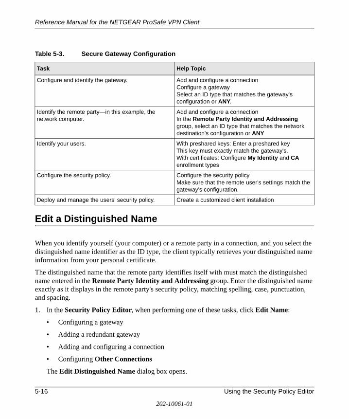
Reference Manual for the NETGEAR ProSafe VPN Client
Edit a Distinguished Name
When you identify yourself (your computer) or a remote party in a connection, and you select the distinguished name identifier as the ID type, the client typically retrieves your distinguished name information from your personal certificate.
The distinguished name that the remote party identifies itself with must match the distinguished name entered in the Remote Party Identity and Addressing group. Enter the distinguished name exactly as it displays in the remote party's security policy, matching spelling, case, punctuation, and spacing.
1. In the Security Policy Editor, when performing one of these tasks, click Edit Name:
• Configuring a gateway
• Adding a redundant gateway
• Adding and configuring a connection
• Configuring Other Connections
The Edit Distinguished Name dialog box opens.
Table 5-3. Secure Gateway Configuration
Task Help Topic
Configure and identify the gateway. Add and configure a connection Configure a gatewaySelect an ID type that matches the gateway's configuration or ANY.
Identify the remote party—in this example, the network computer.
Add and configure a connectionIn the Remote Party Identity and Addressing group, select an ID type that matches the network destination's configuration or ANY
Identify your users. With preshared keys: Enter a preshared keyThis key must exactly match the gateway's.With certificates: Configure My Identity and CA enrollment types
Configure the security policy. Configure the security policyMake sure that the remote user's settings match the gateway's configuration.
Deploy and manage the users' security policy. Create a customized client installation
5-16 Using the Security Policy Editor
202-10061-01
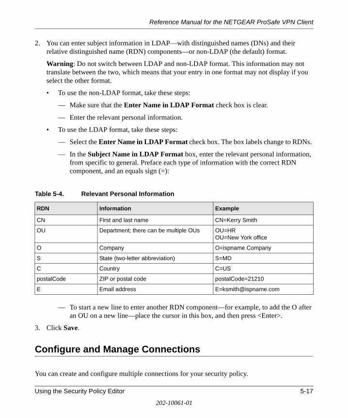
Reference Manual for the NETGEAR ProSafe VPN Client
2. You can enter subject information in LDAP—with distinguished names (DNs) and their relative distinguished name (RDN) components—or non-LDAP (the default) format.
Warning: Do not switch between LDAP and non-LDAP format. This information may not translate between the two, which means that your entry in one format may not display if you select the other format.
• To use the non-LDAP format, take these steps:
— Make sure that the Enter Name in LDAP Format check box is clear.
— Enter the relevant personal information.
• To use the LDAP format, take these steps:
— Select the Enter Name in LDAP Format check box. The box labels change to RDNs.
— In the Subject Name in LDAP Format box, enter the relevant personal information, from specific to general. Preface each type of information with the correct RDN component, and an equals sign (=):
— To start a new line to enter another RDN component—for example, to add the O after an OU on a new line—place the cursor in this box, and then press <Enter>.
3. Click Save.
Configure and Manage Connections
You can create and configure multiple connections for your security policy.
Table 5-4. Relevant Personal Information
RDN Information Example
CN First and last name CN=Kerry Smith
OU Department; there can be multiple OUs OU=HR OU=New York office
O Company O=ispname Company
S State (two-letter abbreviation) S=MD
C Country C=US
postalCode ZIP or postal code postalCode=21210
E Email address [email protected]
Using the Security Policy Editor 5-17
202-10061-01
Reference Manual for the NETGEAR ProSafe VPN Client
Before you can configure a connection, make sure that you have identification information for the remote party, such as network IP address, domain name, or email address. If the remote party (user or network) is protected by a secure IPSec-compliant gateway device, obtain that gateway's IP address, too.
Add and Configure a Connection
1. In the Security Policy Editor, configure Other Connections.
2. In the Network Security Policy list, if the My Connections folder does not appear, click Options, point to Secure, and then click Specified Connections.
3. Click (or Edit>Add Connection). A highlighted New Connection entry displays in the Network Security Policy list.
4. Rename the new connection.
5. In the Connection Security group, take these steps:
a. Click the security level:
• Secure secures communications for this connection. This is the default.
• Non-secure allows communications for this connection to pass through unsecured, or not encrypted.
• Block prohibits all communications for this connection from passing through.
b. When the Secure security level is selected, the Only Connect Manually check box appears. By default, the check box is clear; this means that the client establishes and terminates connections automatically as needed. You can, however, initiate and end secure sessions manually.
To require the user to manually establish and terminate all secure sessions using this connection (with the Connect and Disconnect options on the client icon's shortcut menu), select the Only Connect Manually check box.
If a connection for which the Only Connect Manually check box is selected isn't manually connected, traffic that would otherwise go over this connection is bypassed, as though there were no connection configured for this traffic. Traffic that would go over that connection if it were active is instead compared against the remaining connections in the Network Security Policy box to determine how to handle it.
6. In the Remote Party Identity and Addressing group, in the ID Type box at the top of the group, click an identifier for the other party. Boxes become available below the ID Type box to enter information about the ID type you selected:
5-18 Using the Security Policy Editor
202-10061-01
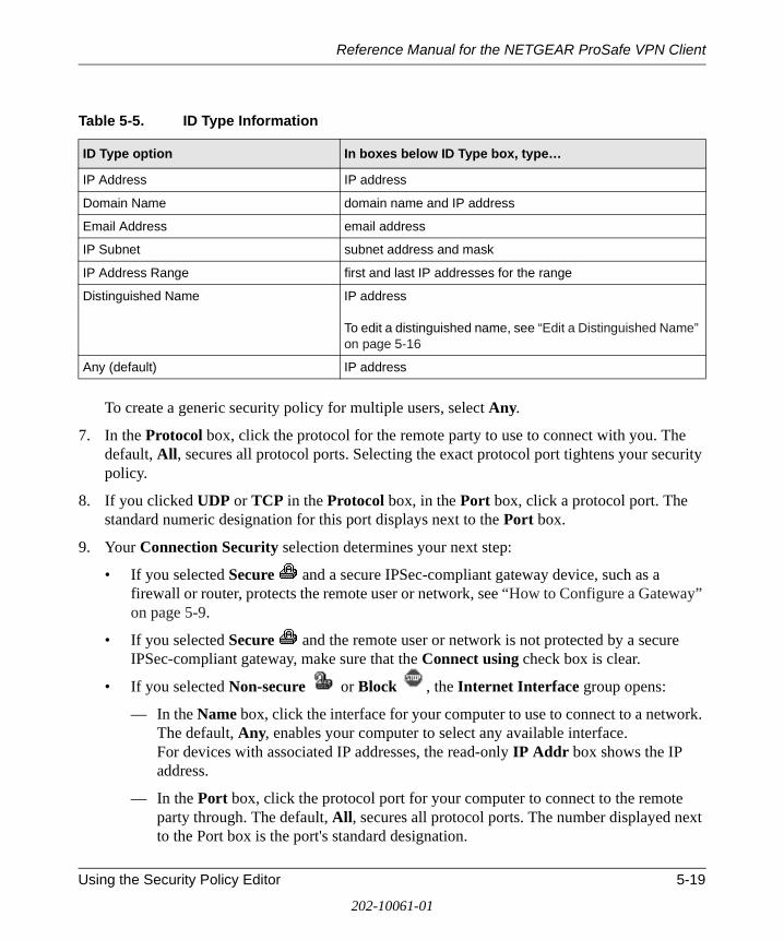
Reference Manual for the NETGEAR ProSafe VPN Client
To create a generic security policy for multiple users, select Any.
7. In the Protocol box, click the protocol for the remote party to use to connect with you. The default, All, secures all protocol ports. Selecting the exact protocol port tightens your security policy.
8. If you clicked UDP or TCP in the Protocol box, in the Port box, click a protocol port. The standard numeric designation for this port displays next to the Port box.
9. Your Connection Security selection determines your next step:
• If you selected Secure and a secure IPSec-compliant gateway device, such as a firewall or router, protects the remote user or network, see “How to Configure a Gateway” on page 5-9.
• If you selected Secure and the remote user or network is not protected by a secure IPSec-compliant gateway, make sure that the Connect using check box is clear.
• If you selected Non-secure or Block , the Internet Interface group opens:
— In the Name box, click the interface for your computer to use to connect to a network. The default, Any, enables your computer to select any available interface. For devices with associated IP addresses, the read-only IP Addr box shows the IP address.
— In the Port box, click the protocol port for your computer to connect to the remote party through. The default, All, secures all protocol ports. The number displayed next to the Port box is the port's standard designation.
Table 5-5. ID Type Information
ID Type option In boxes below ID Type box, type…
IP Address IP address
Domain Name domain name and IP address
Email Address email address
IP Subnet subnet address and mask
IP Address Range first and last IP addresses for the range
Distinguished Name IP address To edit a distinguished name, see “Edit a Distinguished Name” on page 5-16
Any (default) IP address
Using the Security Policy Editor 5-19
202-10061-01

Reference Manual for the NETGEAR ProSafe VPN Client
10. Click Save.
11. Configure My Identity for this connection.
Copy a Connection
1. In the Security Policy Editor, in the Network Security Policy list, click the connection to copy.
2. Click . A new connection named Copy of connection name displays in the Network Security Policy list.
3. Rename the copied connection.
4. Press Enter.
5. Click Save.
Move a Connection
The client attempts connections and their proposals in the sequence they appear in the Network Security Policy list in the Security Policy Editor. To change this selection order, you can move a connection up or down in this list.
Note: Other Connections is always the last connection attempted; its place at the bottom of the Network Security Policy list is fixed.
1. In the Security Policy Editor, in the Network Security Policy list, click the connection to move.
2. Click to move the connection up or to move it down.
3. Click Save.
Rename a Connection
1. In the Security Policy Editor, in the Network Security Policy list, right-click the connection to rename, and then click Rename.
2. Type a new name, with a maximum of 80 alphanumeric characters, for this connection.
3. Press Enter.
4. Click Save.
5-20 Using the Security Policy Editor
202-10061-01
Reference Manual for the NETGEAR ProSafe VPN Client
Delete a Connection
1. In the Security Policy Editor, in the Network Security Policy list, click the connection to delete.
2. Click .
3. When a confirmation message opens, click Yes.
4. Click Save.
Manage Proposals
When you add a connection and configure its Security Policy, the Security Policy Editor provides one proposal (Proposal 1) for Authentication (Phase 1) and Key Exchange (Phase 2). If you need additional proposals, copy one or add one.
Add a Proposal
1. In the Security Policy Editor, in the Network Security Policy list, expand a secure connection .
2. Expand Security Policy for the secure connection. Authentication (Phase 1) and Key Exchange (Phase 2) appear.
3. Click the type of proposal to add:
• Authentication (Phase 1)
• Key Exchange (Phase 2)
4. Click Create New Proposal.
5. Click Save.
Copy a Proposal
You can copy proposals for Authentication (Phase 1) or Key Exchange (Phase 2) in the selected connection only. You cannot copy proposals to another phase or connection.
1. In the Security Policy Editor, in the Network Security Policy list, expand a secure connection .
2. Expand Security Policy for the secure connection. Authentication (Phase 1) and Key Exchange (Phase 2) appear.
Using the Security Policy Editor 5-21
202-10061-01
Reference Manual for the NETGEAR ProSafe VPN Client
3. Depending on the type of proposal you want to copy, click a proposal for Authentication (Phase 1) or Key Exchange (Phase 2) that you want to copy.
4. Click . The new proposal appears below the copied proposal; its number is the copied proposal incremented by one. Each proposal's number below the new one is incremented by one from before the copy operation. Proposal labels are fixed; you can't change them.
Example: There are four proposals for a connection. You copied Proposal 2; the new proposal is Proposal 3. Proposals 3 and 4 are now Proposals 4 and 5.
5. Click Save.
Move a Proposal
The client attempts proposals in the order they are listed, in the particular phase for a connection, in the Network Security Policy list. To change the selection order, you can move a proposal up or down.
When you change a proposal's position in the list, the client renumbers the proposals to maintain sequential numbering. Each time you move one, make sure that the proposals are in the order you want them tried in.
1. In the Security Policy Editor, in the Network Security Policy list, expand the specific secure connection .
2. For this secure connection, expand Security Policy.
3. Depending on the location of the proposal to move, expand Authentication (Phase 1) or Key Exchange (Phase 2).
4. Click the proposal to move.
5. Click to move the proposal up or to move it down.
6. Repeat steps 4 and 5 as necessary.
7. Click Save.
Delete a Proposal
In the Network Security Policy list in the Security Policy Editor, there must be at least one proposal each for Authentication (Phase 1) and Key Exchange (Phase 2).
1. In the Security Policy Editor, in the Network Security Policy list, expand a secure connection .
5-22 Using the Security Policy Editor
202-10061-01
Reference Manual for the NETGEAR ProSafe VPN Client
2. Expand Security Policy for the secure connection. Authentication (Phase 1) and Key Exchange (Phase 2) display.
3. Depending on the location of the proposal you want to delete, expand Authentication (Phase 1) or Key Exchange (Phase 2). The proposals for the phase display.
4. Click the proposal to delete.
5. Click .
6. When a confirmation message box opens, click Yes.
7. Click Save.
Manage Redundant Gateways
A redundant gateway is an alternate network access gateway to establish a connection with the client when the primary gateway is busy, offline, or otherwise not available.
Before you can add redundant gateways for a secure connection, you must configure the primary gateway in the Security Policy Editor.
In most cases, use the same security policy information to configure all redundant gateways for a single connection. However, these exceptions must be unique to each device:
• Distinguished name
• IP address
• Preshared key
Each secure connection can have a maximum of 10 redundant gateways, plus the primary. The original secure connection is always the primary gateway.
The client selects the alternates in the sequence in which they are listed for the particular connection in the Network Security Policy list. The client “rolls over” to a redundant gateway only when the primary gateway does not respond. If the client receives a response from the primary gateway, it continues trying to establish a connection.
When the security association (SA) times out, the client tries to connect with the primary gateway. If the primary gateway is busy, it returns to the last active redundant gateway.
Using the Security Policy Editor 5-23
202-10061-01
Reference Manual for the NETGEAR ProSafe VPN Client
Add a Redundant Gateway
1. In the Security Policy Editor, in the Network Security Policy list, click the specific secure connection that has a gateway configured—that is, the Connect using check box and a gateway are selected.
2. On the toolbar, click Edit, point to Add, and then click Redundant Gateway. The New Name for RGW X dialog box, where X is a sequence number from 1 through 10, opens.
3. Type a name for this redundant gateway, and then click OK. The new gateway displays below Security Policy for this connection in the Network Security Policy list.
4. In the Redundant Gateway Identity and Addressing group, in the ID Type box, click an identifier for this gateway. Boxes become available, based on the identifier you select.
Note: To create a generic security policy for multiple users, for ID Type, click Any.
5. Complete the gateway identity-related boxes; for details, see “How to Configure a Gateway” on page 5-9.
6. Your next step depends on how My Identity is configured for this connection:
• If you selected a certificate—in the My Identity group, for Select Certificate, a certificate name appears—go to the next step.
• If you entered a preshared key—in the My Identity group, for Select Certificate, None appears—take these steps:
— Click Pre-Shared Key. The Pre-shared Key dialog box opens.
— Click Enter Key.
— Enter the key that matches the preshared key in the gateway's configuration.
— Click OK.
7. Click Save.
Copy a Redundant Gateway
A quick way to add redundant gateways to a connection is to copy another redundant gateway in the same connection. You can copy redundant gateway within a connection only, not between connections.
1. In the Security Policy Editor, in the Network Security Policy list, expand a secure connection .
2. Right-click a redundant gateway , and then click Copy. The New Name for RGW X dialog box, where X is the sequence number, 1 through 10, opens.
5-24 Using the Security Policy Editor
202-10061-01
Reference Manual for the NETGEAR ProSafe VPN Client
3. Type a name for this new connection.
4. Click OK.
5. Click Save.
Move a Redundant Gateway
When the primary gateway is not available, the client tries redundant gateways in the order in which they appear for a connection in the Network Security Policy list. You can change the selection order by moving a gateway up or down in a connection's list. Redundant gateways can be moved only in their connection.
1. In the Security Policy Editor, in the Network Security Policy list, expand the specific secure connection .
2. Select a redundant gateway .
3. Click to move the gateway up or to it down.
4. Repeat steps 2 and 3 as necessary.
5. Click Save.
Rename a Redundant Gateway
1. In the Security Policy Editor, in the Network Security Policy list, expand the specific secure connection .
2. Right-click a redundant gateway , and then click Rename. The New Name for RGW X dialog box, where X is the sequence number 1 through 10, opens.
3. Type the new name.
4. Click OK.
5. Click Save.
Delete a Redundant Gateway
1. In the Security Policy Editor, in the Network Security Policy list, expand a secure connection .
2. Click the redundant gateway to delete.
3. Click .
4. When a confirmation dialog box opens, click Yes.
Using the Security Policy Editor 5-25
202-10061-01
Reference Manual for the NETGEAR ProSafe VPN Client
5. Click Save.
Disable Redundant Gateways
You can disable all redundant gateways for a selected secure connection without deleting them. You can also enable them again later.
1. In the Security Policy Editor, in the Network Security Policy list, select the specific secure connection .
2. In the Remote Party Addressing and Identity group, clear the Connect using check box.
3. Click Save.
Manage the Security Policy
Export a Security Policy
When you export a security policy, the client creates an .spd file that contains all the connections, proposals, global policy settings, and My Identity information from the security policy. You can include this security policy file in a customized client installation; make it available to users on a website, CD-ROM, or other location or medium; or save it as a backup of your security policy.
1. In the Security Policy Editor, click File>Export Security Policy. The Export Policy To dialog box opens.
2. In the Save As dialog box, navigate to the directory to save this file to and enter the filename. The default location and name is C:\policy.spd.
Note: If you are creating a customized installation, rename this file IPSecPolicy.spd.
3. To password-protect this policy file during the export/import process only, take these steps:
a. Select the Protect Exported Policy check box.
b. In the Password box, enter a password that contains at least eight alphanumeric characters.
c. In the Confirm box, retype the password.
4. To limit or prevent users who import this policy or install it from changing it, lock it when you export it:
• To allow users to edit the entire security policy, accept the default, Policy is unlocked.
• To allow users to change only their My Identity settings, click Policy is partially locked.
5-26 Using the Security Policy Editor
202-10061-01
Reference Manual for the NETGEAR ProSafe VPN Client
• To prohibit users from changing anything in the security policy, but let them view it, click Policy is completely locked.
• Click OK.
5. Click Save.
Edit a Security Policy
After you add and configure connections for a security policy, you can change the options.
1. In the Security Policy Editor, in the Network Security Policy list, click a connection; expand secure connections to open the components of the policy to edit.
2. In the right pane, change the particular settings. For details, refer to the help topic on configuring the specific entity you're editing.
3. Click Save.
Note: If secure connections are active, the client prompts you to reset active connections:
• To reset active connections, which drops and disconnects all active connections and applies the new policy immediately, click Yes.
• To store the changes, but delay saving them until the active connections end, click No. Then, when you're ready to put the new policy into effect, reload the security policy.
Note: If you don't explicitly reload the policy, it goes into effect the next time you log on to Windows or restart your computer.
Import a Security Policy
Caution: When you import a security policy, it overwrites the existing policy on your computer.
1. Obtain the name and location of the policy file to import (an .spd file).
2. In the Security Policy Editor, click File>Import Security Policy. The Import Policy From dialog box opens.
3. Navigate to the .spd file to import; when its file name displays in the File name box, click Open.
4. A policy file can be password-protected and encrypted when it is exported from the client. To import it, you must enter the password used when the policy file was exported.
If the Policy Protection Password dialog box opens, this policy file is password-protected. Unless you enter the password, you can't import the file and policy.
a. Obtain the password.
Using the Security Policy Editor 5-27
202-10061-01
Reference Manual for the NETGEAR ProSafe VPN Client
b. In the Password box, type the password.
c. Click OK. The Policy Import dialog box opens.
— If the New policy resets existing connections check box on the Policy Management dialog box in Security Policy Editor is selected, the Reset existing connections check box on the Policy Import dialog box is also selected. This means that the client will reset, or drop, all active connections. If the New policy resets existing connections check box on the Policy Management dialog box is clear, the Reset existing connections check box is also clear. Based on your preference, select or clear the Reset existing connections check box; this does not change the New policy resets existing connections check box on the Policy Management dialog box.
— When an import confirmation message box opens, click OK. Note: After the policy is imported, it is no longer encrypted.
Reload the Security Policy
Importing a security policy or editing the existing one makes a new policy available to replace the current one. If you do not reset existing connections, which the client prompts you to do, the new policy does not go into effect (and active connections are not dropped).
When the client doesn't appear to be working properly, try performing this task. It disconnects all connections and loads the current security policy from scratch.
When you're ready to put the new policy into service, which will overwrite the current policy and drop (terminate) any existing connections, take this step:
• Right-click the client icon, and then click Reload Security Policy or, if there are any active secure communications sessions, Disconnect All. All sessions end, and either the current security policy or a new security policy is loaded.
Note: If you don't explicitly reload the policy or reset existing connections, the edited policy or imported policy takes effect the next time you log on to Windows or restart your computer.
Deactivate the Security Policy
To allow all communications to transmit unsecured or not encrypted, you can override or deactivate your security policy. The client continues to run in the background, but secures no communications.
When you deactivate your security policy, you can't communicate with other parties on secure connections unless they also disable their security policy.
5-28 Using the Security Policy Editor
202-10061-01
Reference Manual for the NETGEAR ProSafe VPN Client
You can deactivate the security policy in one of two ways:
• In the Security Policy Editor, take these steps:
— Click Options>Secure>None. The Network Security Policy list and the connections are read-only, but are not deleted.
— Click Save.
— Exit the Security Policy Editor.
• In the Windows system tray, right-click the icon, and then click Deactivate Security Policy.
In both cases, in a few seconds, the client icon's Deactivate Security Policy menu option becomes Activate Security Policy, and the icon changes to .
Reactivate the Security Policy
Right-click the client icon , and then click Activate Security Policy; this option changes to Deactivate Security Policy, and the icon changes to .
Configure Where to Retrieve a New Policy
The client can be managed by enterprise VPN policy management applications. These products typically serve as the initial and ongoing distribution point (policy server) for the client's security policies.
For the client to check for and retrieve a new security policy from a policy management product's policy server, the location and polling frequency of the LDAP policy server and that there is a policy server must be configured on the Security Policy Editor's Policy Management dialog box.
Obtain the specifics from your network security administrator; your entries must exactly match those expected by the policy management product's LDAP server. Your client may be preconfigured with this information.
Then, if the policy management application requires this step, the client must enroll or register with the management product. This registration may occur automatically when the CA is SCEP-compliant and the client submits a personal certificate request.
Therefore, perform this task only if your network security administrator instructs you to do so.
1. In the Security Policy Editor, click File>Register Client. The VPN Policy Server Registration dialog box opens.
2. In the Name box (the only one that you must complete), type your name (CN is the RDN).
Using the Security Policy Editor 5-29
202-10061-01
Reference Manual for the NETGEAR ProSafe VPN Client
3. In the Department box, type your department's name (OU is the RDN).
4. In the Company box, type your company's name (O is the RDN).
5. In the State box, type your company's name (S is the RDN).
6. Click OK.
7. When a registration confirmation message box opens, click OK.
Retrieve a New Policy Manually
When the client is configured to automatically check for and retrieve new security policies from a policy management product or a policy server on a web site, you can manually check this source for a new or updated policy.
• In the Security Policy Editor, click File>Retrieve Policy.
The client checks the web address or LDAP server configured on the Policy Management dialog box.
A message box opens confirming the success or failure of the retrieval attempt.
5-30 Using the Security Policy Editor
202-10061-01
Reference Manual for the NETGEAR ProSafe VPN Client
Chapter 6 Using the Certificate Manager
This chapter describes how to configure the advanced features of your NETGEAR ProSafe VPN Client.
What is the Certificate Manager?
The Certificate Manager is the client module where you obtain and manage the certificates you receive from certificate authorities (CAs), set the trust policy, and view certificate revocation lists (CRLs).To learn how to perform all the various certificate-related tasks, refer to the topics in the Certificate Manager book in the help.
The Certificate Manager includes these tabs for you to perform the tasks listed above:
• My Certificates
• Root CA Certificates
• Trust Policy
• CA Certificates
• RA Certificates
• CRLs
• Requests
There are three ways to open the Certificate Manager:
• On the Windows desktop, click Start>Programs>ProSafe VPN Client>Certificate Manager.
• Right-click the client icon, and then click Certificate Manager.
• In the Security Policy Editor, click Options>Certificate Manager.
Getting Started with the Certificate Manager
If you are using preshared keys for authentication in your VPN, or secure connection, to the other party, you don't have to open the Certificate Manager; skip all the topics in the Certificate Manager book in the help.
Using the Certificate Manager 6-1
202-10061-01
Reference Manual for the NETGEAR ProSafe VPN Client
If you are using certificates for authentication with the remote party to your VPN, and don't already have a CA and personal certificate, you need to obtain these. However, depending on your network and installed applications and hardware at any particular site, specific tasks may not apply; additional tasks may be required. For details on the tasks to perform, contact your network security administrator.
These are the typical tasks to perform to obtain and manage certificates:
1. Select a CA.
2. Determine its enrollment method (see “CA Enrollment Methods and Procedures” on page 6-3).
3. Obtain a CA and personal certificate. There are three methods for doing this:
• Online enrollment
• File-based enrollment
• Through Internet Explorer
The help contains topics on these methods; go to the Obtain certificates book in the Certificate Manager book.
4. Manage the various certificates obtained. In the help, go to the Manage certificates book in the Certificate Manager book.
5. Work with certificate revocation lists (CRLs).
6. Set the trust policy.
What are Certificates?
To set up a VPN, or secure connection, between the client installed on your computer and a remote party, both parties must identify themselves, and then verify that each is really who it indicates it is. One way to do this is with a preshared key that both parties know in advance.
A more secure way to identify the two parties is through certificates. A certificate is an electronic document that contains a public key and is digitally signed by the third-party entity that issued it, called a certificate authority (CA) or certification authority. Because it validates the identities of the two VPN parties, it must be trusted. Set the trust policy in the Certificate Manager.
There are two types of CA certificates:
• A root CA certificate is signed by and issued to itself—that is, the issuer and subject are the same.
• A subordinate or intermediate CA certificate is issued by a CA other than itself. A subordinate certificate can be issued by a root CA or another subordinate CA.
6-2 Using the Certificate Manager
202-10061-01

Reference Manual for the NETGEAR ProSafe VPN Client
Also required for the client user is a personal certificate, which contains information about the user (client) that uniquely identifies it. This is requested by the client, and issued by a subordinate CA.
CAs that support SCEP may also employ a registration authority (RA), which is a network authority that collects and verifies certificate request information for the CA, and then signs responses on behalf of the CA. The CA, however, actually issues the certificates. These CAs may include RA certificates with CA certificates.
CA Enrollment Methods and Procedures
To communicate securely with certificates, you need three certificates issued by a CA:
1. Root CA certificate
2. Subordinate CA certificate
Note: CAs that support Simple Certificate Enrollment Protocol (SCEP) may employ a registration authority (RA). The CA may include one or more RA certificates with the CA certificate.
3. Personal certificate (and keys)
To obtain certificates, you must enroll with a CA. There are two ways to enroll through the client:
• Online enrollment, which uses SCEP. Use the following method:
a. Obtain the CA's certificate server DNS name or IP address to make this request. Follow the instructions for the particular CA.
You can also obtain personal and CA certificates for IPSec through Microsoft Internet Explorer or an email program.
Note: To access the Microsoft CSP, Internet Explorer 5.01 or later must be installed on your computer.
b. Retrieve a CA certificate online.
c. Request a personal certificate online.
d. Retrieve the personal certificate.
• Manual (file-based) enrollment, which requires cutting and pasting text from a text editor. CAs handle this method in various ways; all start with a certificate request file. Follow the instructions provided by the CA.
These are the typical steps:
a. Obtain a CA certificate manually.
Using the Certificate Manager 6-3
202-10061-01
Reference Manual for the NETGEAR ProSafe VPN Client
b. Import a CA certificate.
c. Create a certificate request file for a personal certificate.
The Certificate Manager automatically generates the public/private key pair you need. The public key goes with your request; the private key resides on the hard drive of your computer.
d. Prepare the personal certificate file to import.
e. Import the personal certificate file.
Preshared Keys
A preshared key is an alphanumeric character string that can be used instead of certificates to authenticate the identity of communicating parties during Phase 1 IKE negotiations. This character string, which can contain from 8 through 255 characters, is called preshared because the remote party needs it before you can communicate with it. Both parties must enter this preshared key in their IPSec-compliant devices, such as a firewall, gateway encryptor, router, or software client. Preshared keys can be included with the security policy when it is exported or included in a customized client installation.
When you use preshared keys, you don't have to deal with CAs and certificates. Preshared key, however, do not provide the same level of security as certificates. Use preshared keys only for testing, troubleshooting, or one-to-one communications that do not require a corporate security policy.
Before you begin to configure the security policy, decide whether to use certificates or preshared keys.
Obtain Certificates
With Online (SCEP) Enrollment
CAs that Support SCEP
Simple Certificate Enrollment Protocol (SCEP) allows clients and servers certificates to obtain certificates from CAs online. The listed CAs support SCEP.
6-4 Using the Certificate Manager
202-10061-01

Reference Manual for the NETGEAR ProSafe VPN Client
Retrieve a CA Certificate Online
Before you can request a personal certificate online, you must retrieve a CA certificate—root or subordinate—online. For a list of the CAs that offer online retrieval, go to CAs that support SCEP.
When you retrieve a CA certificate online, the CA may also include registration authority (RA) certificates, which you can view or verify in the Certificate Manager.
Note: If you access the Internet through a firewall, make sure that the Use HTTP proxy server for online certificate requests and CRL updates check box is selected on the Certificate Settings dialog box in the Security Policy Editor.
1. In the Certificate Manager, click the tab for the CA certificate type to retrieve:
• For a root CA certificate, Root CA Certificates
• For a subordinate CA certificate, CA Certificates
2. Click Retrieve CA Certificate. The Retrieve CA Certificate Online dialog box opens.
3. In the CA Domain box, type the CA's domain name, such as abc123.com.
4. In the Online Certificate Server box, type the complete URL, including the schema, such as http://, of the CA's certificate server.
5. Unless your network security administrator instructs you otherwise, leave the Place certificate in local machine store check box selected (the default). This adds the certificate to the store for all users who log on to this computer (local machine).
Caution: In Windows NT and Windows 2000 and XP, you must be logged on as administrator or its equivalent to add this certificate to the local machine store.
6. Click OK. In a few seconds, the Root or CA Certificate Store dialog box opens and prompts you to add the CA certificate to the client's root or CA store, according to the type of CA certificate you retrieved.
Table 6-1. Certificate Authorities Supporting SCEP
Certificate Authority Website
Entrust Technologies, Inc www.entrust.com
Sun www.sun.com
Microsoft Corporation www.microsoft.com
RSA Security (Keon) www.rsasecurity.com
VeriSign, Inc. www.verisign.com
Using the Certificate Manager 6-5
202-10061-01
Reference Manual for the NETGEAR ProSafe VPN Client
7. Click Yes. The certificate displays on the appropriate tab, Root CA Certificates or CA Certificates, in the Certificate Manager. If the retrieved CA certificate included RA certificates, these display on the RA Certificates tab.
Configure a CA Certificate
If you did not request your CA certificate online, but the CA you requested it from supports SCEP, before you can request a personal certificate online—that is, through SCEP enrollment—you must change this CA certificate's parameters to make it appear as if you requested it online. When the client is managed by a policy management application, the CA certificate may need to be configured, too.
For root CA certificates, you can also specify whether the certificate is trusted for IP security (IPSec).
1. In Certificate Manager, click the tab for the specific certificate type:
• For a root CA certificate, Root CA Certificates
• For a subordinate CA certificate, CA Certificates
2. On this tab, click the certificate to configure.
3. Click Configure. The Configuration Parameters dialog box opens.
4. In the CA Domain box, type the CA's domain name, such as alphabeta.com.
5. In the Online Certificate Server box, type the complete URL, including the schema, such as http://, of the CA's certificate server.
6. For Root CA certificates only: To specify that this certificate is trusted for IPSec communications, select the Trust this certificate for IP security check box.
The next time you view or verify this certificate, for Enh KeyUsage, IP security end system appears as the value.
7. Click OK.
Use an HTTP Proxy Server for Online Certificate Requests and CRL Updates
These blocks of IP addresses are reserved for private or non-routable VPN use by the Internet Assigned Numbers Authority (IANA):
• 10.0.0.0 through 10.255.255.255
• 172.16.0.0 through 172.31.255.255
• 192.168.0.0 through 192.168.255.255
6-6 Using the Certificate Manager
202-10061-01
Reference Manual for the NETGEAR ProSafe VPN Client
If your network uses an HTTP proxy server to translate private IP addresses to routable IP addresses, you must configure this option and enter the HTTP proxy server's DNS or IP address.
Note: When your computer accesses the Internet through a firewall, before you request and retrieve a CA certificate online, make sure that the Use HTTP proxy server for online certificate requests and CRL updates option is selected.
1. In the Security Policy Editor, click Options>Certificate Settings. The Certificate Settings dialog box opens.
2. Select the Use HTTP proxy server for online certificate requests and CRL updates check box.
3. In the Proxy DNS name or IP address box, type the DNS or IP address.
4. Click OK.
5. Click Save.
Import a CA Certificate
In these two situations, you must import a CA certificate into the Certificate Manager:
• As part of obtaining a CA certificate manually, you downloaded a CA certificate to your computer from the CA's web site
• To obtain a CA certificate file that was exported from the Certificate Manager or a policy management application
1. In the Certificate Manager, click the tab for the certificate type to import:
• For a root CA certificate, the Root CA Certificates tab
• For a CA certificate, the CA Certificates tab
If the CA certificate you import has RA certificates associated with it, these are imported with the CA certificate.
2. Click Import Certificate. The Import CA Certificate dialog box opens.
3. Navigate to the certificate file; make sure that its name displays in the File name box.
4. Unless your network security administrator instructs you to change it, leave the Import certificate to local machine store check box selected (the default).
Caution: In Windows NT and Windows 2000 and XP, you must be logged on as administrator or its equivalent to add this certificate to the local machine store (for all users who log on to this computer).
5. Click Import.
Using the Certificate Manager 6-7
202-10061-01
Reference Manual for the NETGEAR ProSafe VPN Client
6. When a confirmation message box opens, click Yes.
Select a CSP
You can select a cryptographic service provider (CSP) when requesting a personal certificate, regardless of the method. You can also designate a default CSP to use for all personal certificate requests.
1. In the Security Policy Editor, click Options>Certificate Settings. The Online or File-based Certificate Request dialog box opens.
2. Click Advanced. The Advanced Certificate Enrollment Settings dialog box opens.
3. Click the specific CSP in the list.
4. If the Key Size box is enabled, click the key size to use.
5. To designate the settings on this dialog box as the default for all personal certificate requests, select the Save as default CSP settings check box.
6. By default, the Place certificate and keys in local machine store check box is clear, which places the imported certificate in your—the logged-on user's—personal certificate store. Unless your network security administrator instructs you to change it, accept the default.
Caution: In Windows NT and Windows 2000 and XP, you must be logged on as administrator or its equivalent to add this certificate to the local machine store.
7. Click OK.
Request a Personal Certificate
After you retrieve or import a CA certificate, you must request a personal certificate from this CA. If your client was installed with a CA certificate, the Online Certificate Request or File-based Certificate Request dialog box opens automatically the first time your computer restarts after client installation.
When the CA supports SCEP, submit the request online. For CAs that don't support SCEP, create a certificate request to submit to the CA manually.
Note: If you requested your CA certificate manually from CA that supports SCEP, and want to request a personal certificate online, configure the CA certificate before requesting the personal certificate.
1. In the Certificate Manager, click the My Certificates tab.
2. Click Request Certificate. The Online Certificate Request or File-based Certificate Request dialog box opens.
6-8 Using the Certificate Manager
202-10061-01

Reference Manual for the NETGEAR ProSafe VPN Client
3. For online certificate requests only: In the Enrollment method group, make sure that Online is selected.
4. In the Subject Name group, complete the personal information boxes, as required by the CA.
Note: To use LDAP format when completing these boxes, select the Enter Subject Name in LDAP format check box, and then go to Edit a distinguished name.
5. If this CA requires it, complete at least one box in the Subject Alternate Name group, according to the CA's instructions. These boxes may be completed automatically.
6. For online certificate requests only: In the Online Request Information group, take these steps:
a. In the Challenge Phrase box, type an alphanumeric character string for the CA to confirm your identity with if you ask to revoke your certificate. The CA makes sure that you are the person the certificate says you are before rescinding your certificate. Record this phrase.
b. In the Confirm Challenge box, retype the challenge phrase.
c. In the Issuing CA list, click the CA you are requesting the certificate from.
7. Caution: Make this selection carefully; you can't reverse your decision later.
In the Key Generation Options group, specify whether the private key associated with the personal certificate you're requesting can be exported to, for example, transfer it to another computer or make a backup copy. By default, the private key cannot be exported; the Generate exportable key check box is clear. To make the key exportable, select the Generate exportable key check box.
8. To select the CSP or assign the default CSP, click Advanced.
9. Click OK.
• For online certificate requests only: This submits your request. The Key Generation message box opens while the client generates a public/private key pair, and then closes. The Online Certificate Request message box opens when the client submits your request.
When the CA receives (accepts) your request, a confirmation message may open; click OK.
It may take some time for the CA to approve your request. The client checks the CA at a defined interval for approved personal certificates to retrieve (you can change this polling interval if you wish—see “Define How Often to Check for and Retrieve New Personal Certificates” on page 6-10).
Using the Certificate Manager 6-9
202-10061-01
Reference Manual for the NETGEAR ProSafe VPN Client
• For file-based certificate requests only: When a message box opens confirming that the certificate request file was created, click OK.
To find out how to send the certificate request file to the CA and receive the certificate file when the CA returns it; this process varies with each CA, contact the specific CA.
Define How Often to Check for and Retrieve New Personal Certificates
For CAs that support SCEP, the client periodically checks for, or polls, the CA's certificate server to look for and retrieve any new personal certificates approved in response to online certificate requests, which display on the Requests tab in the Certificate Manager. You can set the time period between these automatic pools.
1. In the Security Policy Editor, click Options>Certificate Settings. The Certificate Settings dialog box opens.
2. In the Online certificate request polling interval (minutes) box, specify how often the client checks the CA's certificate server for approved personal certificates requests; type the number of minutes, from 1 through 999999, between polls. The default is 15 minutes.
3. Click OK.
4. Click Save.
Retrieve a Personal Certificate Manually
After you submit your online request for a personal certificate, the CA must receive the request, and then approve it. Some time may elapse between these two events. The approval creates the personal certificate. The client automatically checks this CA for the approved certificate at the interval defined on the Certificates Setting dialog box in the Certificate Manager, and then retrieves and displays it on the My Certificates tab in the Certificate Manager.
You can check for and retrieve your approved personal certificate manually, too, if you don't want to wait for the client.
1. In the Certificate Manager, click the Requests tab.
2. Click Retrieve.
Note: If the CA hasn't approved your request yet, a message alerts you of this. Try again later or wait for the client to retrieve it.
3. If the CA has approved your request, the client prompted you to add this personal certificate; click Yes. The request is removed from the Requests tab, and the retrieved certificate displays on the My Certificates tab.
6-10 Using the Certificate Manager
202-10061-01
Reference Manual for the NETGEAR ProSafe VPN Client
Manage Certificate Requests
View a certificate request. You can view the information about a pending request for a CA or personal certificate until you or the client you retrieve a valid certificate, you import one, or you delete the certificate request.
1. In the Certificate Manager, click the Requests tab.
2. Click the certificate request to view.
3. Click View. A dialog box opens with information about the selected certificate request.
4. To close the certificate request, click anywhere in the dialog box.
Delete a certificate request. You can delete a pending certificate request that displays on the Requests tab in the Certificate Manager. When you retrieve or import a valid certificate, the Certificate Manager automatically removes this certificate request.
1. In the Certificate Manager, click the Requests tab.
2. Click the specific certificate request.
3. Click Delete.
4. When a confirmation message opens, click Yes.
5. If prompted to delete the key container, click Yes.
With Manual (File-Based) Enrollment
The procedure for obtaining a CA certificate manually varies with each CA. These are the typical steps.
1. On the CA's website, complete the registration process.
2. Download the CA certificate from the CA's website to your computer through the Internet Explorer certificate management. For details, refer to Windows or Internet Explorer help.
3. In the Certificate Manager, on the Root CA Certificates or CA Certificates tab (depending on the certificate you're importing), import the CA certificate.
4. To complete the process, follow the instructions from the specific CA.
Note: Before you can request a personal certificate online from this CA, you must configure the CA certificate.
Import a CA Certificate
In these two situations, you must import a CA certificate into the Certificate Manager:
Using the Certificate Manager 6-11
202-10061-01
Reference Manual for the NETGEAR ProSafe VPN Client
• As part of obtaining a CA certificate manually, you downloaded a CA certificate to your computer from the CA's web site
• To obtain a CA certificate file that was exported from the Certificate Manager or a policy management application
1. In the Certificate Manager, click the tab for the certificate type to import:
• For a root CA certificate, the Root CA Certificates tab
• For a CA certificate, the CA Certificates tab
If the CA certificate you import has RA certificates associated with it, these are imported with the CA certificate.
2. Click Import Certificate. The Import CA Certificate dialog box opens.
3. Navigate to the certificate file; make sure that its name displays in the File name box.
4. Unless your network security administrator instructs you to change it, leave the Import certificate to local machine store check box selected (the default).
Caution: In Windows NT and Windows 2000 and XP, you must be logged on as administrator or its equivalent to add this certificate to the local machine store (for all users who log on to this computer).
5. Click Import.
6. When a confirmation message box opens, click Yes.
Request a Personal Certificate
After you retrieve or import a CA certificate, you must request a personal certificate from this CA. If your client was installed with a CA certificate, the Online Certificate Request or File-based Certificate Request dialog box opens automatically the first time your computer restarts after client installation.
When the CA supports SCEP, submit the request online. For CAs that don't support SCEP, create a certificate request to submit to the CA manually.
Note: If you requested your CA certificate manually from CA that supports SCEP, and want to request a personal certificate online, configure the CA certificate before requesting the personal certificate.
1. In the Certificate Manager, click the My Certificates tab.
2. Click Request Certificate. The Online Certificate Request or File-based Certificate Request dialog box opens.
6-12 Using the Certificate Manager
202-10061-01
Reference Manual for the NETGEAR ProSafe VPN Client
3. For online certificate requests only: In the Enrollment method group, make sure that Online is selected.
4. In the Subject Name group, complete the personal information boxes, as required by the CA.
Note: To use LDAP format when completing these boxes, select the Enter Subject Name in LDAP format check box, and then go to Edit a distinguished name.
5. If this CA requires it, complete at least one box in the Subject Alternate Name group, according to the CA's instructions. These boxes may be completed automatically.
6. For online certificate requests only: In the Online Request Information group, take these steps:
a. In the Challenge Phrase box, type an alphanumeric character string for the CA to confirm your identity with if you ask to revoke your certificate. The CA makes sure that you are the person the certificate says you are before rescinding your certificate. Record this phrase.
b. In the Confirm Challenge box, retype the challenge phrase.
c. In the Issuing CA list, click the CA you are requesting the certificate from.
Caution: Make this selection carefully; you can't reverse your decision later.
7. In the Key Generation Options group, specify whether the private key associated with the personal certificate you're requesting can be exported to, for example, transfer it to another computer or make a backup copy. By default, the private key cannot be exported; the Generate exportable key check box is clear. To make the key exportable, select the Generate exportable key check box.
8. To select the CSP or assign the default CSP, click Advanced.
9. Click OK.
• For online certificate requests only: This submits your request. The Key Generation message box opens while the client generates a public/private key pair, and then closes. The Online Certificate Request message box opens when the client submits your request.
When the CA receives (accepts) your request, a confirmation message may open; click OK.
It may take some time for the CA to approve your request. The client checks the CA at a defined interval for approved personal certificates to retrieve. To change this polling interval, see “Define How Often to Check for and Retrieve New Personal Certificates” on page 6-10.
Using the Certificate Manager 6-13
202-10061-01
Reference Manual for the NETGEAR ProSafe VPN Client
• For file-based certificate requests only: When a message box opens confirming that the certificate request file was created, click OK.
To find out how to send the certificate request file to the CA and receive the certificate file when the CA returns it; this process varies with each CA, contact the specific CA.
Create a Personal Certificate File to Import
After you create and manually submit a personal certificate request file to a CA, and the CA approves the request, this CA returns a certificate to you in an email. You must create a certificate file from the email so that you can import the personal certificate to the Certificate Manager.
The certificate request approval process varies with each CA. This is an example of the typical process:
1. Submit the personal certificate request file you created, CertReq.req, to the CA, according to the instructions the CA or your network security administrator provides.
When the CA approves your certificate request, it sends you an email that contains the certificate.
This is a sample email returned by the CA:
Dear Applicant, Your Administrator has approved your request for an IPSec certificate. If you have any questions or problems, please contact your Administrator by replying to this email message. THE COMMON NAME OF THIS CERTIFICATE: Kerry Smith -----BEGIN CERTIFICATE----- MIICzCCAmigAwIBAgIQRFfr0rQ4W2xUCfmYzDKCqDANBgkqhkiG9w0BAQQFADCB zjEXMBUGA1UEChMOVmVyaVNpZ24sIEluYy4xRzBFBgNVBAsTPkZvciBWZXJpU2ln biBhdXRob3JpemVkIHRlc3Rpbmcgb25seS4gTm8gYXNzdXJhbmNlcyAoQykgVlMx OTk4MUcwRQYDVQQLEz53d3cudmVyaXNpZ24uY29tL3JlcG9zaXRvcnkvVGVzdENQ MA0GCSqGSIb3DQEBBAUAA4GBACBA6T+yqr8xoJfBv2T0P1AcLxG9tjOMuUPELvV mg4jNB2Jj9oD+iIpEp4yf4NhKq6N3p8vcdXXz2FMxhNMHGAqY8mwKhRAPQrJKnVi /o9Adoh7SQ3Aoh4ds8CfRcgcrHdQeQBdgszwzRJMTNKP3zj/qvRevIZ/h72MbfWl gnvK -----END CERTIFICATE-----
6-14 Using the Certificate Manager
202-10061-01
Reference Manual for the NETGEAR ProSafe VPN Client
2. Copy the entire certificate, from -----BEGIN CERTIFICATE----- through -----END CERTIFICATE-----, inclusive.
Note: When working with Microsoft Certificate Server, copy only the data between -----BEGIN CERTIFICATE----- and -----END CERTIFICATE-----, not inclusive, and insert a carriage return at the end.
3. Paste the certificate into a text editor, such as Notepad, name it CertReq.der, and save it to the same drive and directory that the certificate request file, CertReq.req, resides in.
4. Import the personal certificate to the Certificate Manager.
Import a Personal Certificate
In these two situations, you must import a personal certificate to the Certificate Manager:
• If you created a personal certificate file from the email that the CA when you manually requested a personal certificate
• To bring a personal certificate file exported from the Certificate Manager (not necessarily in your client) to your client's Certificate Manager
Note: Make sure that you have the password entered to protect the private key when this personal certificate was exported.
1. In the Certificate Manager, click the My Certificates tab.
2. Click Import Certificate. The Import Certificate dialog box opens.
3. In the Import Type group, select the certificate and private key type to import:
• For online certificate enrollment, click PKCS12 Personal Certificate.
• For older certificate and key types, click Certificate and Private Key File.
• For a manual certificate request, click Certificate Request Response File.
4. By default, the Import certificate to local machine store check box is clear, which places the imported certificate in your—the logged-on user's—personal certificate store. Unless your network security administrator instructs you to change it, accept the default.
Caution: In Windows NT and Windows 2000 and XP, you must be logged on as administrator or its equivalent to add this certificate to the local machine store (for all users who log on to this computer).
5. The import type you selected determines the boxes available for you to complete:
Using the Certificate Manager 6-15
202-10061-01
Reference Manual for the NETGEAR ProSafe VPN Client
• In the Certificate File box, type the drive, directory, and file name/file type of the personal certificate or certificate request response file to import or click Browse to locate it.
The default certificate request response filename is C:\temp_directory_for_OS\Cert.p7r.
• In the Key File box, type the drive, directory, and file name of the private key file to import or click Browse to locate it.
• In the Password box, type the password used when the file was exported.
6. Unless your network security administrator advises you to change it, leave the Import certificate to local machine store check box selected (the default).
7. Click Import.
8. When the key import confirmation message opens, click OK.
Note: If the import fails, try selecting a different import type.
9. When prompted to add this personal certificate, click Yes.
Select a CSP
You can select a cryptographic service provider (CSP) when requesting a personal certificate, regardless of the method. You can also designate a default CSP to use for all personal certificate requests.
1. In the Security Policy Editor, click Options>Certificate Settings. The Online or File-based Certificate Request dialog box opens.
2. Click Advanced. The Advanced Certificate Enrollment Settings dialog box opens.
3. Click the specific CSP in the list.
4. If the Key Size box is enabled, click the key size to use.
5. To designate the settings on this dialog box as the default for all personal certificate requests, select the Save as default CSP settings check box.
6. By default, the Place certificate and keys in local machine store check box is clear, which places the imported certificate in your—the logged-on user's—personal certificate store. Unless your network security administrator instructs you to change it, accept the default.
Caution: In Windows NT and Windows 2000 and XP, you must be logged on as administrator or its equivalent to add this certificate to the local machine store.
7. Click OK.
6-16 Using the Certificate Manager
202-10061-01
Reference Manual for the NETGEAR ProSafe VPN Client
View and Delete Certificate Requests
You can view the information about a pending request for a CA or personal certificate until you or the client you retrieve a valid certificate, you import one, or you delete the certificate request.
1. In the Certificate Manager, click the Requests tab.
2. Click the certificate request to view.
3. Click View. A dialog box opens with information about the selected certificate request.
4. To close the certificate request, click anywhere in the dialog box.
You can delete a pending certificate request that displays on the Requests tab in the Certificate Manager. When you retrieve or import a valid certificate, the Certificate Manager automatically removes this certificate request.
1. In the Certificate Manager, click the Requests tab.
2. Click the specific certificate request.
3. Click Delete.
4. When a confirmation message opens, click Yes.
5. If prompted to delete the key container, click Yes.
Obtain Certificates Through Internet Explorer
You can use CA and personal certificates obtained outside the client—for example, through Microsoft Internet Explorer or your email program—with the client. (In some email programs, personal certificates may be called digital IDs.)
To obtain certificates through Internet Explorer, go to the web page the CA or your network security administrator directs you to, and then follow the directions provided. You don't need to go through the client's Certificate Manager to request certificates.
Note: To access the Microsoft CSP, make sure that Internet Explorer 5.01 or later is installed on your computer.
Manage Certificates
When you view a certificate, a new window opens with various certificate attributes, such as its name, serial number, key size, and validity dates.
1. In the Certificate Manager, click the tab for the type of certificate to view:
Using the Certificate Manager 6-17
202-10061-01
Reference Manual for the NETGEAR ProSafe VPN Client
• For a personal certificate, My Certificates
By default (the All option is selected), the tab lists all personal certificates issued to you and your computer (Users and This machine).
— For a list of the personal certificates issued to you, the logged-on user, click Users.
— For a list of the personal certificates issued to your computer (the local machine), click This machine.
• For a root CA certificate, Root CA Certificates
— Clear the Show only trusted roots check box; this lists all root CA certificates on the computer.
• For a subordinate CA certificate, CA Certificates
• For an RA certificate, RA Certificates
2. Click the specific certificate to view.
3. Click View. A box opens with information about the selected certificate.
4. To close the certificate, click anywhere in this certificate box.
Verify a Certificate
After you import or retrieve a certificate, you can check whether it is valid or verified.
1. In the Certificate Manager, take the steps for the specific certificate type:
• For a personal certificate:
— Click the My Certificates tab.
— If the certificate you want to verify isn't listed on the tab, in Show certificates for, click All. This displays every personal certificate on the computer on the tab.
• For a root CA certificate:
— Click the Root CA Certificates tab.
— If the certificate you want to verify isn't listed on the tab, clear the Show only trusted roots check box. Every root CA certificate on the computer displays on the tab.
• For a subordinate CA certificate, click the CA Certificates tab.
• For an RA certificate, click the RA Certificates tab.
2. Click the certificate to verify.
6-18 Using the Certificate Manager
202-10061-01

Reference Manual for the NETGEAR ProSafe VPN Client
3. Click Verify. The client checks the validity dates and attempts to check the certificate against its revocation list. A dialog box opens with this information:
• Current status of the certificate: valid/verified or invalid/not verified, depending on the certificate type
• If the certificate is invalid or not verified, a brief explanation of why
• The certificate's contents and attributes, such as its name, serial number, and key size
4. To close this dialog box, click OK.
Export a CA Certificate
Exporting a CA certificate copies it to a file to, for example, transfer it to another computer, create a backup copy, or include it in a customized client installation.
When a CA certificate has associated RA certificates, the CA certificate export file also contains these RA certificates.
1. In the Certificate Manager, click the tab for the certificate type to export:
• For a root CA certificate, the Root CA Certificates tab
• For a subordinate CA certificate, the CA Certificates tab
2. Click the certificate to export.
3. Click Export. The Export CA Certificate dialog box opens.
4. Navigate to the destination drive and directory for the file.
5. In the File name box, enter the filename of the certificate you are exporting. The default filename is C:\temp_directory_path_for_OS\CaCert.cser.
Note: If you're creating a customized client installation, accept the default filename.
6. Click Save.
Delete a Certificate
Note: When you delete a CA certificate, the client also deletes any associated RA certificates.
1. In the Certificate Manager, take the steps for the specific certificate type:
• For a personal certificate:
— Click the My Certificates tab.
Using the Certificate Manager 6-19
202-10061-01
Reference Manual for the NETGEAR ProSafe VPN Client
— If the certificate to delete isn't listed on the tab, in the Show certificates for group, click All. All personal certificates on the computer display on the tab.
• For a root CA certificate:
— Click the Root CA Certificates tab.
— Clear the Show only trusted roots check box. All root CA certificates on the computer display on the tab.
• For a subordinate CA certificate, click the CA Certificates tab.
• For an expired RA certificate, the only RA certificates you can directly delete, click the RA certificates tab.
2. Click the certificate to delete.
3. Click Delete.
4. When a delete confirmation message box opens, click OK.
RA Certificates
When you view a certificate, a new window opens with various certificate attributes, such as its name, serial number, key size, and validity dates.
1. In the Certificate Manager, click the tab for the type of certificate to view:
• For a personal certificate, My Certificates
By default (the All option is selected), the tab lists all personal certificates issued to you and your computer (Users and This machine).
— For a list of the personal certificates issued to you, the logged-on user, click Users.
— For a list of the personal certificates issued to your computer (the local machine), click This machine.
• For a root CA certificate, Root CA Certificates
Clear the Show only trusted roots check box; this lists all root CA certificates on the computer.
• For a subordinate CA certificate, CA Certificates
• For an RA certificate, RA Certificates
2. Click the specific certificate to view.
3. Click View. A box opens with information about the selected certificate.
6-20 Using the Certificate Manager
202-10061-01
Reference Manual for the NETGEAR ProSafe VPN Client
4. To close the certificate, click anywhere in this certificate box.
After you import or retrieve a certificate, you can check whether it is valid or verified.
1. In the Certificate Manager, take the steps for the specific certificate type:
• For a personal certificate:
— Click the My Certificates tab.
— If the certificate you want to verify isn't listed on the tab, in Show certificates for, click All. This displays every personal certificate on the computer on the tab.
• For a root CA certificate:
— Click the Root CA Certificates tab.
— If the certificate you want to verify isn't listed on the tab, clear the Show only trusted roots check box. Every root CA certificate on the computer displays on the tab.
• For a subordinate CA certificate, click the CA Certificates tab.
• For an RA certificate, click the RA Certificates tab.
2. Click the certificate to verify.
3. Click Verify. The client checks the validity dates and attempts to check the certificate against its revocation list. A dialog box opens with this information:
• Current status of the certificate: valid/verified or invalid/not verified, depending on the certificate type
• If the certificate is invalid or not verified, a brief explanation of why
• The certificate's contents and attributes, such as its name, serial number, and key size
4. To close this dialog box, click OK.
Personal Certificates
Importing a Personal Certificate
In these two situations, you must import a personal certificate to the Certificate Manager:
• If you created a personal certificate file from the email that the CA when you manually requested a personal certificate
• To bring a personal certificate file exported from the Certificate Manager (not necessarily in your client) to your client's Certificate Manager
Using the Certificate Manager 6-21
202-10061-01
Reference Manual for the NETGEAR ProSafe VPN Client
Note: Make sure that you have the password entered to protect the private key when this personal certificate was exported.
1. In the Certificate Manager, click the My Certificates tab.
2. Click Import Certificate. The Import Certificate dialog box opens.
3. In the Import Type group, select the certificate and private key type to import:
• For online certificate enrollment, click PKCS12 Personal Certificate.
• For older certificate and key types, click Certificate and Private Key File.
• For a manual certificate request, click Certificate Request Response File.
4. By default, the Import certificate to local machine store check box is clear, which places the imported certificate in your—the logged-on user's—personal certificate store. Unless your network security administrator instructs you to change it, accept the default.
Caution: In Windows NT and Windows 2000 and XP, you must be logged on as administrator or its equivalent to add this certificate to the local machine store (for all users who log on to this computer).
5. The import type you selected determines the boxes available for you to complete:
• In the Certificate File box, type the drive, directory, and file name/file type of the personal certificate or certificate request response file to import or click Browse to locate it.
The default certificate request response filename is C:\temp_directory_for_OS\Cert.p7r.
• In the Key File box, type the drive, directory, and file name of the private key file to import or click Browse to locate it.
• In the Password box, type the password used when the file was exported.
6. Unless your network security administrator advises you to change it, leave the Import certificate to local machine store check box selected (the default).
7. Click Import.
8. When the key import confirmation message opens, click OK.
Note: If the import fails, try selecting a different import type.
9. When prompted to add this personal certificate, click Yes.
6-22 Using the Certificate Manager
202-10061-01
Reference Manual for the NETGEAR ProSafe VPN Client
Viewing a Personal Certificate
When you view a certificate, a new window opens with various certificate attributes, such as its name, serial number, key size, and validity dates.
1. In the Certificate Manager, click the tab for the type of certificate to view:
• For a personal certificate, My Certificates
By default (the All option is selected), the tab lists all personal certificates issued to you and your computer (Users and This machine).
— For a list of the personal certificates issued to you, the logged-on user, click Users.
— For a list of the personal certificates issued to your computer (the local machine), click This machine.
• For a root CA certificate, Root CA Certificates
— Clear the Show only trusted roots check box; this lists all root CA certificates on the computer.
• For a subordinate CA certificate, CA Certificates
• For an RA certificate, RA Certificates
2. Click the specific certificate to view.
3. Click View. A box opens with information about the selected certificate.
4. To close the certificate, click anywhere in this certificate box.
Verifying a Personal Certificate
After you import or retrieve a certificate, you can check whether it is valid or verified.
1. In the Certificate Manager, take the steps for the specific certificate type:
• For a personal certificate:
— Click the My Certificates tab.
— If the certificate you want to verify isn't listed on the tab, in Show certificates for, click All. This displays every personal certificate on the computer on the tab.
• For a root CA certificate:
— Click the Root CA Certificates tab.
— If the certificate you want to verify isn't listed on the tab, clear the Show only trusted roots check box. Every root CA certificate on the computer displays on the tab.
Using the Certificate Manager 6-23
202-10061-01
Reference Manual for the NETGEAR ProSafe VPN Client
• For a subordinate CA certificate, click the CA Certificates tab.
• For an RA certificate, click the RA Certificates tab.
2. Click the certificate to verify.
3. Click Verify. The client checks the validity dates and attempts to check the certificate against its revocation list. A dialog box opens with this information:
• Current status of the certificate: valid/verified or invalid/not verified, depending on the certificate type
• If the certificate is invalid or not verified, a brief explanation of why
• The certificate's contents and attributes, such as its name, serial number, and key size
4. To close this dialog box, click OK.
Exporting a Personal Certificate
Exporting a personal certificate copies it to a file so that you can, for example, transfer it to another computer or create a backup copy.
Caution: The private key is exported with the personal certificate only if, when the personal certificate was requested, the Generate exportable key check box was selected. If this check box was not selected then, you can't export the private key.
1. In the Certificate Manager, click the My Certificates tab.
2. Click the personal certificate to export.
3. Click Export. The Export Certificate and Private Key dialog box opens.
4. In the File name box, enter the drive, directory, and filename for the personal certificate file. The default filename is C:\temp_directory_path_for_OS\Cert.p12.
5. In the Password box, type an alphanumeric password.
6. In the Confirm Password box, retype the password. Record it, too; whoever imports this file will need it.
7. Click Export.
Deleting a Personal CertificateNote: When you delete a CA certificate, the client also deletes any associated RA certificates.
1. In the Certificate Manager, take the steps for the specific certificate type:
• For a personal certificate:
6-24 Using the Certificate Manager
202-10061-01
Reference Manual for the NETGEAR ProSafe VPN Client
— Click the My Certificates tab.
— If the certificate to delete isn't listed on the tab, in the Show certificates for group, click All. All personal certificates on the computer display on the tab.
• For a root CA certificate:
— Click the Root CA Certificates tab.
— Clear the Show only trusted roots check box. All root CA certificates on the computer display on the tab.
• For a subordinate CA certificate, click the CA Certificates tab.
• For an expired RA certificate, the only RA certificates you can directly delete, click the RA certificates tab.
2. Click the certificate to delete.
3. Click Delete.
4. When a delete confirmation message box opens, click OK.
Manage Certificate Revocation Lists (CRLs)
Configuring Automatic CRL Retrieval
A certificate revocation list (CRL) is a list of certificates that the issuing CA rescinded before their expiration dates. This may occur when, for example, a user's name or address changes or the user leaves the company. When you retrieve or import a certificate from a CA, it typically contains a CRL. If it doesn't, you can import one. You can view a CRL on the CRLs tab in the Certificate Manager.
The client can periodically poll, or check for, CA CRL distribution sites and then retrieve the latest CRLs. You must define the site and polling interval.
1. In the Certificate Manager, view a personal certificate.
2. On the certificate, if the CRL Dist. Point entry contains an URL, jot down what precedes the :// in the URL: http, file, or ldap.
3. In the Security Policy Editor, click Options>Certificate Settings. The Certificate Settings dialog box opens.
4. The CRL Dist. Point entry on the personal certificate you just viewed determines your next step:
Using the Certificate Manager 6-25
202-10061-01
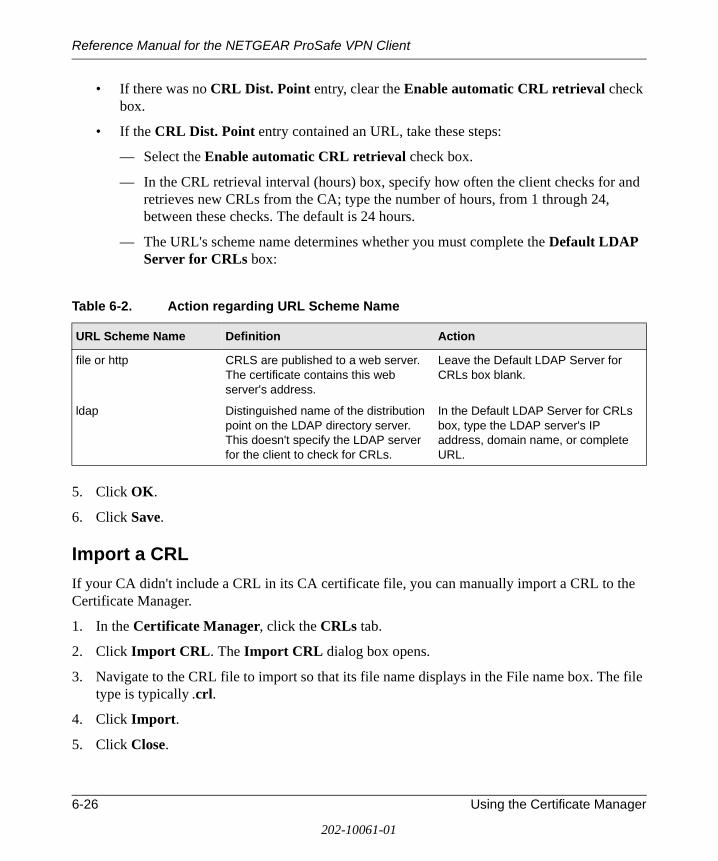
Reference Manual for the NETGEAR ProSafe VPN Client
• If there was no CRL Dist. Point entry, clear the Enable automatic CRL retrieval check box.
• If the CRL Dist. Point entry contained an URL, take these steps:
— Select the Enable automatic CRL retrieval check box.
— In the CRL retrieval interval (hours) box, specify how often the client checks for and retrieves new CRLs from the CA; type the number of hours, from 1 through 24, between these checks. The default is 24 hours.
— The URL's scheme name determines whether you must complete the Default LDAP Server for CRLs box:
5. Click OK.
6. Click Save.
Import a CRL
If your CA didn't include a CRL in its CA certificate file, you can manually import a CRL to the Certificate Manager.
1. In the Certificate Manager, click the CRLs tab.
2. Click Import CRL. The Import CRL dialog box opens.
3. Navigate to the CRL file to import so that its file name displays in the File name box. The file type is typically .crl.
4. Click Import.
5. Click Close.
Table 6-2. Action regarding URL Scheme Name
URL Scheme Name Definition Action
file or http CRLS are published to a web server. The certificate contains this web server's address.
Leave the Default LDAP Server for CRLs box blank.
ldap Distinguished name of the distribution point on the LDAP directory server. This doesn't specify the LDAP server for the client to check for CRLs.
In the Default LDAP Server for CRLs box, type the LDAP server's IP address, domain name, or complete URL.
6-26 Using the Certificate Manager
202-10061-01

Reference Manual for the NETGEAR ProSafe VPN Client
Update all CRLs Manually
Instead of waiting for the client to check for and retrieve new CRLs automatically at defined intervals, you can manually update all the CRLs.
1. In the Certificate Manager, click the CRLs tab.
2. Click Update All CRLs.
3. Click Close.
View a CRL
1. In the Certificate Manager, click the CRLs tab.
2. Click the CRL to view.
3. Click View. A dialog box with information about the selected CRL opens.
4. To close this dialog box, click OK.
Delete a CRL
If you no longer need the CRL for a particular CA, you can delete it from the Certificate Manager.
1. In the Certificate Manager, click the CRLs tab.
2. Click the CRL to delete.
3. Click Delete.
4. When a confirmation message box opens, click OK.
5. Click Close.
Manage the Trust Policy
In the Certificate Manager, when you trust a root CA certificate, the client considers this CA, its subordinate CAs, and the certificates issued by these CAs as valid for IPSec communications, Conversely, when a root CA certificate is not trusted for IPSec sessions, neither are the certificates issued by it or its subordinate CAs.
The trust policy specifies the trusted root CAs:
• Root CAs specifically configured for IPSec communications (the default)
Using the Certificate Manager 6-27
202-10061-01
Reference Manual for the NETGEAR ProSafe VPN Client
The client selects this option when it imports a root CA or reinstalls it after you upgrade the client, if you saved your certificates.
There are two ways to identify a trusted root CA certificate in the Certificate Manager:
• On the Configuration Parameters dialog box, the Trust this certificate for IP security check box is selected.
• When you view or verify the certificates, for Enh KeyUsage, the option IP security end system appears.
• Root CAs that have issued a personal certificate to any of the computer's users
• All root CAs installed on your computer (the local machine)
The trust policy also applies to personal certificates issued by a CA in the trust hierarchy for remote parties that your security policy allows you to communicate with.
Set the Trust Policy
The trust policy for certificates specifies which root CA certificates the client considers valid for IPSec communications. When you set the trust policy on the Trust Policy tab in the Certificate Manager, the trust policy selected on the Root CA Certificates and Root CA Certificates tabs changes to reflect the Trust Policy tab setting.
1. In the Certificate Manager, click the Trust Policy tab.
2. In the Specify which root certificate authorities (CAs) to trust group, select the trust policy:
• To trust only those root CA certificates configured to be trusted for IPSec sessions, click Trust specific root CAs.
• To trust only root CA certificates that issued a personal certificate to any of the computer's users, click Trust CAs that have issued a local personal certificate.
• To trust all the root CAs installed on your computer, click Trust all root CAs installed on this computer
Caution: Depending on the operating system and Internet Explorer version installed on your computer, there may be at least 100 root CA certificates on your computer. Before you select this option, carefully consider the security ramifications.
The trust policy you select takes effect immediately.
6-28 Using the Certificate Manager
202-10061-01
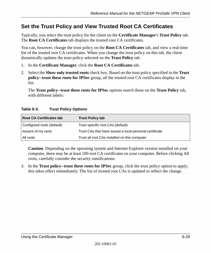
Reference Manual for the NETGEAR ProSafe VPN Client
Set the Trust Policy and View Trusted Root CA Certificates
Typically, you select the trust policy for the client on the Certificate Manager's Trust Policy tab. The Root CA Certificates tab displays the trusted root CA certificates.
You can, however, change the trust policy on the Root CA Certificates tab, and view a real-time list of the trusted root CA certificates. When you change the trust policy on this tab, the client dynamically updates the trust policy selected on the Trust Policy tab.
1. In the Certificate Manager, click the Root CA Certificates tab.
2. Select the Show only trusted roots check box. Based on the trust policy specified in the Trust policy--trust these roots for IPSec group, all the trusted root CA certificates display in the list.
The Trust policy--trust these roots for IPSec options match those on the Trust Policy tab, with different labels:
Caution: Depending on the operating system and Internet Explorer version installed on your computer, there may be at least 100 root CA certificates on your computer. Before clicking All roots, carefully consider the security ramifications.
3. In the Trust policy--trust these roots for IPSec group, click the trust policy option to apply; this takes effect immediately. The list of trusted root CAs is updated to reflect the change.
Table 6-3. Trust Policy Options
Root CA Certificates tab Trust Policy tab
Configured roots (default) Trust specific root CAs (default)
Issuers of my certs Trust CAs that have issued a local personal certificate
All roots Trust all root CAs installed on this computer
Using the Certificate Manager 6-29
202-10061-01

Reference Manual for the NETGEAR ProSafe VPN Client
6-30 Using the Certificate Manager
202-10061-01

Reference Manual for the NETGEAR ProSafe VPN Client
Chapter 7 Using Sessions
This chapter describes how to perform network management tasks with your NETGEAR ProSafe VPN Client.
Authenticate Yourself
You may be prompted to enter your username and password when you attempt to establish a VPN; enter this information on the dialog box that opens. This is to authenticate who you, the user, are to the network, before the connection is initiated.
Automatically Start and End Secure Sessions
By default, the client automatically establishes and terminates connections, based on the remote party's identity, when needed.
For example, suppose that you want to check your office email from home. The security policy in the client installed on your home computer contains a VPN to access the office network's mail server. When you start your email program at home, and select the proper profile, the client initiates the secure connection behind the scenes. The remote party's identity determines which connection the client selects. All that you'll probably see is a connection logon dialog box, if it's required. After the client connects to the network mail server, you can access your office email.
The connection remains “up” or active until one of these occurs:
• It's dropped by the network, the Internet, or your ISP.
• You turn your computer off.
• When importing or reloading the security policy, you select the Reset existing connections option.
• You terminate it manually with the Disconnect or Disconnect All option on the client icon's shortcut menu.
Note: You may be required to start and end secure sessions manually or choose to work with secure connections that way.
Using Sessions 7-1
202-10061-01
Reference Manual for the NETGEAR ProSafe VPN Client
Start and End a Secure Session Manually
By default, the client automatically establishes and terminates secure connections—VPNs—based on the remote party's identity. You can, however, directly connect to a specific destination with the Connect option on the client icon's shortcut (right-click) menu. Starting the secure connection by selecting this option is analogous to picking up the handset of a telephone and selecting a speed dial number or entering the other party's number to initiate a phone call.
For example, when you're in the office, you connect directly to your corporate network; to access this network remotely, from home or on the road, you must use a VPN connection. With the manual connection feature, you can select the specific connection to use.
If the Only Connect Manually check box check box is selected for a specific connection, the client doesn't automatically initiate or end secure sessions for this connection; you must manually connect and disconnect such sessions.
1. In the Windows system tray, right-click the client icon, point to Connect, and then click the connection name.
2. To terminate the secure communications session, right-click the client icon, click Disconnect, and then click the connection name to end.
7-2 Using Sessions
202-10061-01
Reference Manual for the NETGEAR ProSafe VPN Client
Chapter 8 Distributing Customized Profiles
A customized installation is the standard client installation package modified to include a security policy, a CA certificate, and perhaps a personal certificate. If preshared keys are to be employed, you can include these instead of CA and personal certificates. Because personal certificates are unique to each individual, a single personal certificate cannot be distributed to multiple users.
Adding these entities to the basic client installation package can facilitate managing corporate security policies for multiple users. You can create multiple customized installations for users with different security needs.
These are the customized installation package options:
Create a Customized Installation Containing a Security Policy
1. Configure the security policy for the users.
Note: If you want users to employ preshared keys instead of certificates, configure one in My Identity for the security policy.
2. Export the security policy; name the file IPSecPolicy.spd.
3. Add the IPSecPolicy.spd file to the client's installation directory.
4. Deploy this customized installation to users on a network drive, website, CD-ROM, or other location or medium, such as a directory or .zip or .exe file.
5. Make sure that the users have installation instructions and the specific information they need to either use preshared keys or obtain a CA certificate and personal certificate. Help topics describe these tasks.
Distributing Customized Profiles 8-1
202-10061-01
Reference Manual for the NETGEAR ProSafe VPN Client
Create a Customized Installation Containing a Security Policy and a CA Certificate
1. Obtain a CA certificate.
2. Export this CA certificate; name the file CaCert.cser.
3. Configure a security policy.
4. Export the security policy; name the file IPSecPolicy.spd.
5. Add the CaCert.cser and the IPSecPolicy.spd files to the same directory that the setup.exe file is located in on the NETGEAR ProSafe VPN Client installation media.
6. Deploy this customized installation to users on a network drive, web page, CD-ROM, or other location/medium as a directory or .zip or .exe file.
7. Tell users how to install the product and perform these tasks:
a. Add the CA certificate to the Root Store, when prompted.
b. Complete the online personal certificate request form that opens automatically. They need their domain name and IP address and, if they are allowed to transfer their personal certificate to another computer, they must select the Generate exportable key option.
Create a Customized Installation Containing a Security Policy, CA Certificate, and Personal Certificate
Note: Because personal certificates are unique to each individual, a single personal certificate cannot be distributed to multiple users.
1. Obtain a CA certificate.
2. Export the CA certificate; name the file CaCert.cser.
3. Request a personal certificate for each user to receive this customized installation.
Note: When you create the certificate request, click Generate exportable key.
4. Export the personal certificate, which includes the private key; name the file IPSecCerts.p12.
5. Configure a security policy.
6. Export the security policy; name the file IPSecPolicy.spd.
8-2 Distributing Customized Profiles
202-10061-01
Reference Manual for the NETGEAR ProSafe VPN Client
7. Add the CaCert.cser, IPSecCerts.p12, and the IPSecPolicy.spd files to the same directory that the setup.exe file is located in on the NETGEAR ProSafe VPN Client installation media.
8. Deploy this customized installation to users on a network drive, web page, CD-ROM, or other location/medium as a directory or .zip or .exe file.
9. Make sure that users have installation instructions and the password entered when you exported the personal certificates.
Distributing Customized Profiles 8-3
202-10061-01
Reference Manual for the NETGEAR ProSafe VPN Client
8-4 Distributing Customized Profiles
202-10061-01
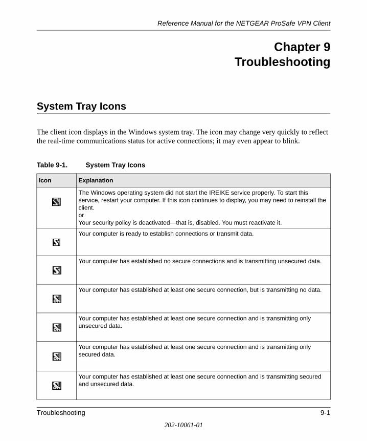
Reference Manual for the NETGEAR ProSafe VPN Client
Chapter 9 Troubleshooting
System Tray Icons
The client icon displays in the Windows system tray. The icon may change very quickly to reflect the real-time communications status for active connections; it may even appear to blink.
Table 9-1. System Tray Icons
Icon Explanation
The Windows operating system did not start the IREIKE service properly. To start this service, restart your computer. If this icon continues to display, you may need to reinstall the client.orYour security policy is deactivated—that is, disabled. You must reactivate it.
Your computer is ready to establish connections or transmit data.
Your computer has established no secure connections and is transmitting unsecured data.
Your computer has established at least one secure connection, but is transmitting no data.
Your computer has established at least one secure connection and is transmitting only unsecured data.
Your computer has established at least one secure connection and is transmitting only secured data.
Your computer has established at least one secure connection and is transmitting secured and unsecured data.
Troubleshooting 9-1
202-10061-01
Reference Manual for the NETGEAR ProSafe VPN Client
Remove the Client Icon from the System Tray
Although it is not recommended, the client icon can be removed from the system tray. Typically, this occurs inadvertently. This has no affect on the communications status of active connections.
• In the Windows system tray, right-click the client icon, and then click Remove Icon.
Restore the Client Icon to the System Tray
If you remove the client icon from the system tray, you can put it back.
1. In Windows Explorer, locate this file on your computer, mostly likely on the C: drive:
NETGEAR VPN Client installation directory/Program Files/NETGEAR ProSafe VPN Client/Safecfg.exe.
2. Double-click the file Safecfg.exe. The client icon reappears in the system tray.
3. Exit Windows Explorer.
View Policy Management Information
When you contact customer support or your IT or network administrator and the client is managed by an enterprise VPN policy management application—that is, on the Policy Management dialog box, the Use Policy Server check box is selected—you may be asked to provide specific policy management information to assist in the troubleshooting process.
1. In the Windows system tray, right-click the client icon, and then click Policy Management. The Policy Management Information dialog box opens and shows this data:
• Whether the client is registered with the policy server
• Policy server name
• Policy subtree
• Distinguished name (DN) of the policy server's CA
• Policy server's relative distinguished name (RDN)
2. Relay this information to the support staff.
3. Close this dialog box; click OK.
9-2 Troubleshooting
202-10061-01
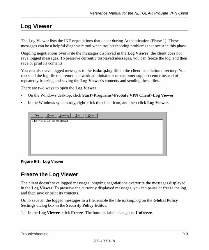
Reference Manual for the NETGEAR ProSafe VPN Client
Log Viewer
The Log Viewer lists the IKE negotiations that occur during Authentication (Phase 1). These messages can be a helpful diagnostic tool when troubleshooting problems that occur in this phase.
Ongoing negotiations overwrite the messages displayed in the Log Viewer; the client does not save logged messages. To preserve currently displayed messages, you can freeze the log, and then save or print its contents.
You can also save logged messages to the isakmp.log file in the client installation directory. You can send the log file to a remote network administrator or customer support center instead of repeatedly freezing and saving the Log Viewer's contents and sending these files.
There are two ways to open the Log Viewer:
• On the Windows desktop, click Start>Programs>ProSafe VPN Client>Log Viewer.
• In the Windows system tray, right-click the client icon, and then click Log Viewer.
Figure 9-1: Log Viewer
Freeze the Log Viewer
The client doesn't save logged messages; ongoing negotiations overwrite the messages displayed in the Log Viewer. To preserve the currently displayed messages, you can pause or freeze the log, and then save or print its contents.
Or, to save all the logged messages to a file, enable the file isakmp.log on the Global Policy Settings dialog box in the Security Policy Editor.
1. In the Log Viewer, click Freeze. The button's label changes to Unfreeze.
Troubleshooting 9-3
202-10061-01
Reference Manual for the NETGEAR ProSafe VPN Client
Unfreeze the Log Viewer
When the Log Viewer is frozen or halted, you must unfreeze it to restart the logging and scrolling of IKE negotiation messages in the Log Viewer.
1. In the Log Viewer, click Unfreeze. The button's label changes to Freeze.
Clear Log Viewer Messages
You can't recover the messages that you clear manually from the Log Viewer.
1. In the Log Viewer, click Clear.
Save the Log Viewer Messages
1. In the Log Viewer, click Freeze.
2. Click Save Log.
3. In the Save As dialog box, follow the standard Windows Save As procedure. By default, the file is named IKEx.log, where x is an incremental number.
Print the messages in the Log Viewer
1. In the Log Viewer, click Freeze.
2. Click Print.
3. In the Print dialog box, follow the standard Windows Print procedure.
Configure Global Policy Settings
Global policy settings are program preferences that apply to all secure IP communications. You can change these at any time to match to your security policy.
1. In the Security Policy Editor, click Options, and then click Global Policy Settings. The Global Policy Settings dialog box opens.
2. In the Retransmit Interval box, type the length of time, in seconds, that the client waits before resending an IKE protocol packet that has not been responded to. The default is 8 seconds.
Note: If the client selects a redundant gateway when you know that the primary one is available, try entering a higher number for Retransmit Interval.
9-4 Troubleshooting
202-10061-01
Reference Manual for the NETGEAR ProSafe VPN Client
3. In the Number of retries box, type the number of times your computer resends an IKE protocol packet before abandoning the exchange. The default is 3 tries.
4. Status notifications are messages that inform communicating parties what the time-out periods are and whether their security proposals have been accepted or rejected.
To send these messages, select the Send status notifications to peer host check box.
5. An internal network IP address is a virtual IP address assigned to the client user. Remote users can appear as internal users on a private network to, for example, access a WINS server or browse the network.
To enable remote users to appear as internal users on a private network, select the Allow to Specify Internal Network Address check box.
Note: If you select this check box, you must enter a private internal network IP address when configuring My Identity.
6. To enable logging the Log Viewer's IKE negotiation messages to the isakmp.log file in the client's installation directory, select the Enable logging to a file check box. This can facilitate remote troubleshooting by allowing a user to send a file with these messages instead of repeatedly freezing and printing the Log Viewer.
Notes:
• The maximum size for the isakmp.log file is 100 KB. When the client's computer, the client, and the IKE service restart and the isakmp.log file size exceeds 100 KB, this isakmp.log file is deleted and a new one created.
• On computers running Windows 95 and 98, when the isakmp.log file size exceeds 64 KB, Notepad prompts the user to try WordPad instead because of the file's size. When the user tries WordPad, however, WordPad prompts the user that it can't open the file because it is in use by another program (the IKE service).
In this case, to view the file, try one of these options:
— Rename it, and then open it in WordPad.
— Open a read-only version of the file in Microsoft Word.
— Clear the Enable logging to a file check box, and then open the file.
7. If you don't use a smart card and reader or similar device to authenticate your identity, skip this step.
Troubleshooting 9-5
202-10061-01
Reference Manual for the NETGEAR ProSafe VPN Client
If you do use a smart card and reader or similar device, the client can, when it detects that the smart card or reader is removed, delete active keys and end these communications sessions. This provides extra security. Only connections that use the keys on your smart card are affected.
To enable this feature, select the Smart card removal clears keys check box.
8. Click OK.
9. Click Save.
Network Address Translation (NAT)
Network Address Translation (NAT) devices are widely deployed to enable local area networks (LANs) to use a single set of external IP addresses for an entire network.
Remote users commonly encounter NAT devices in home networks, broadband modems (cable and DSL), and hotels. Although an IPSec VPN connection can coexist with NAT devices, IPSec-NAT incompatibilities may occur. To prevent these incompatibilities, the client employs the latest of the emerging standards for NAT-Traversal (NAT-T).
When connecting to a peer (remote) device that implements the same NAT-T standard (there are several), the client automatically detects the presence of the NAT device; you don't have to configure anything. Then, the client and the peer device encapsulate the IPSec packets inside UDP packets; this allows the VPN connection to traverse the NAT device without requiring any changes in the NAT device.
When the client connects to a peer device and detects a NAT device, Log Viewer messages indicate this detection. Here is a sample of these logged messages:
9-6 Troubleshooting
202-10061-01
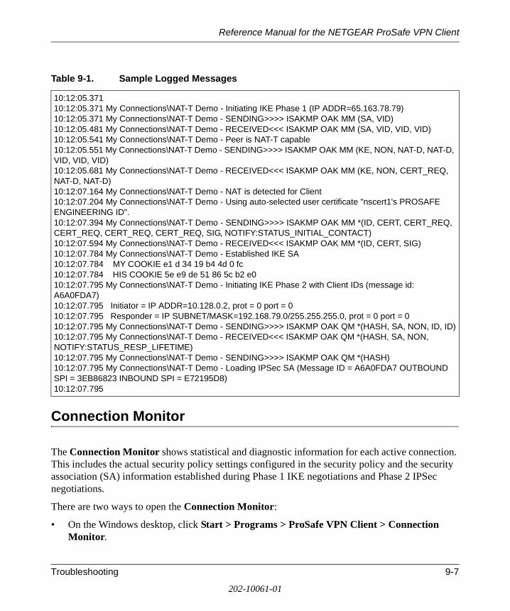
Reference Manual for the NETGEAR ProSafe VPN Client
Connection Monitor
The Connection Monitor shows statistical and diagnostic information for each active connection. This includes the actual security policy settings configured in the security policy and the security association (SA) information established during Phase 1 IKE negotiations and Phase 2 IPSec negotiations.
There are two ways to open the Connection Monitor:
• On the Windows desktop, click Start > Programs > ProSafe VPN Client > Connection Monitor.
Table 9-1. Sample Logged Messages
10:12:05.371 10:12:05.371 My Connections\NAT-T Demo - Initiating IKE Phase 1 (IP ADDR=65.163.78.79)10:12:05.371 My Connections\NAT-T Demo - SENDING>>>> ISAKMP OAK MM (SA, VID)10:12:05.481 My Connections\NAT-T Demo - RECEIVED<<< ISAKMP OAK MM (SA, VID, VID, VID)10:12:05.541 My Connections\NAT-T Demo - Peer is NAT-T capable10:12:05.551 My Connections\NAT-T Demo - SENDING>>>> ISAKMP OAK MM (KE, NON, NAT-D, NAT-D, VID, VID, VID)10:12:05.681 My Connections\NAT-T Demo - RECEIVED<<< ISAKMP OAK MM (KE, NON, CERT_REQ, NAT-D, NAT-D)10:12:07.164 My Connections\NAT-T Demo - NAT is detected for Client10:12:07.204 My Connections\NAT-T Demo - Using auto-selected user certificate "nscert1's PROSAFE ENGINEERING ID".10:12:07.394 My Connections\NAT-T Demo - SENDING>>>> ISAKMP OAK MM *(ID, CERT, CERT_REQ, CERT_REQ, CERT_REQ, CERT_REQ, SIG, NOTIFY:STATUS_INITIAL_CONTACT)10:12:07.594 My Connections\NAT-T Demo - RECEIVED<<< ISAKMP OAK MM *(ID, CERT, SIG)10:12:07.784 My Connections\NAT-T Demo - Established IKE SA10:12:07.784 MY COOKIE e1 d 34 19 b4 4d 0 fc10:12:07.784 HIS COOKIE 5e e9 de 51 86 5c b2 e010:12:07.795 My Connections\NAT-T Demo - Initiating IKE Phase 2 with Client IDs (message id: A6A0FDA7)10:12:07.795 Initiator = IP ADDR=10.128.0.2, prot = 0 port = 010:12:07.795 Responder = IP SUBNET/MASK=192.168.79.0/255.255.255.0, prot = 0 port = 010:12:07.795 My Connections\NAT-T Demo - SENDING>>>> ISAKMP OAK QM *(HASH, SA, NON, ID, ID)10:12:07.795 My Connections\NAT-T Demo - RECEIVED<<< ISAKMP OAK QM *(HASH, SA, NON, NOTIFY:STATUS_RESP_LIFETIME)10:12:07.795 My Connections\NAT-T Demo - SENDING>>>> ISAKMP OAK QM *(HASH)10:12:07.795 My Connections\NAT-T Demo - Loading IPSec SA (Message ID = A6A0FDA7 OUTBOUND SPI = 3EB86823 INBOUND SPI = E72195D8)10:12:07.795
Troubleshooting 9-7
202-10061-01
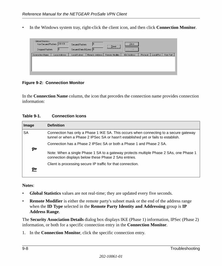
Reference Manual for the NETGEAR ProSafe VPN Client
• In the Windows system tray, right-click the client icon, and then click Connection Monitor.
Figure 9-2: Connection Monitor
In the Connection Name column, the icon that precedes the connection name provides connection information:
Notes:
• Global Statistics values are not real-time; they are updated every five seconds.
• Remote Modifier is either the remote party's subnet mask or the end of the address range when the ID Type selected in the Remote Party Identity and Addressing group is IP Address Range.
The Security Association Details dialog box displays IKE (Phase 1) information, IPSec (Phase 2) information, or both for a specific connection entry in the Connection Monitor.
1. In the Connection Monitor, click the specific connection entry.
Table 9-1. Connection Icons
Image Definition
SA Connection has only a Phase 1 IKE SA. This occurs when connecting to a secure gateway tunnel or when a Phase 2 IPSec SA or hasn't established yet or fails to establish.
Connection has a Phase 2 IPSec SA or both a Phase 1 and Phase 2 SA. Note: When a single Phase 1 SA to a gateway protects multiple Phase 2 SAs, one Phase 1 connection displays below these Phase 2 SAs entries.
Client is processing secure IP traffic for that connection.
9-8 Troubleshooting
202-10061-01
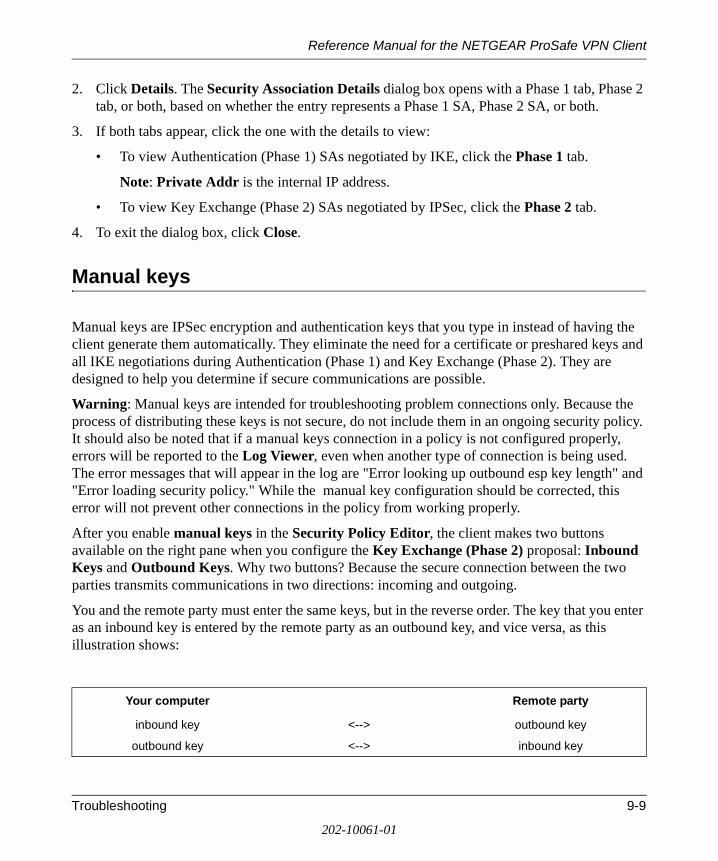
Reference Manual for the NETGEAR ProSafe VPN Client
2. Click Details. The Security Association Details dialog box opens with a Phase 1 tab, Phase 2 tab, or both, based on whether the entry represents a Phase 1 SA, Phase 2 SA, or both.
3. If both tabs appear, click the one with the details to view:
• To view Authentication (Phase 1) SAs negotiated by IKE, click the Phase 1 tab.
Note: Private Addr is the internal IP address.
• To view Key Exchange (Phase 2) SAs negotiated by IPSec, click the Phase 2 tab.
4. To exit the dialog box, click Close.
Manual keys
Manual keys are IPSec encryption and authentication keys that you type in instead of having the client generate them automatically. They eliminate the need for a certificate or preshared keys and all IKE negotiations during Authentication (Phase 1) and Key Exchange (Phase 2). They are designed to help you determine if secure communications are possible.
Warning: Manual keys are intended for troubleshooting problem connections only. Because the process of distributing these keys is not secure, do not include them in an ongoing security policy. It should also be noted that if a manual keys connection in a policy is not configured properly, errors will be reported to the Log Viewer, even when another type of connection is being used. The error messages that will appear in the log are "Error looking up outbound esp key length" and "Error loading security policy." While the manual key configuration should be corrected, this error will not prevent other connections in the policy from working properly.
After you enable manual keys in the Security Policy Editor, the client makes two buttons available on the right pane when you configure the Key Exchange (Phase 2) proposal: Inbound Keys and Outbound Keys. Why two buttons? Because the secure connection between the two parties transmits communications in two directions: incoming and outgoing.
You and the remote party must enter the same keys, but in the reverse order. The key that you enter as an inbound key is entered by the remote party as an outbound key, and vice versa, as this illustration shows:
Your computer Remote party
inbound key <--> outbound key
outbound key <--> inbound key
Troubleshooting 9-9
202-10061-01
Reference Manual for the NETGEAR ProSafe VPN Client
Each direction requires a separate key. The encryption or hash algorithm that you selected when enabling manual keys determines the exact key length. For a list of these key lengths, go to Enter manual keys.
Enable Manual Keys
1. In the Security Policy Editor, in the Network Security Policy list, expand the specific secure connection .
2. For this connection, click My Identity.
3. In the Select Certificate box, in the My Identity group, click None.
4. For the selected connection, expand Security Policy.
5. In the right pane, in the Select Phase 1 Negotiation Mode group, click Use Manual Keys.
6. In the Network Security Policy list, expand Key Exchange (Phase 2).
7. Click the specific proposal.
8. In the IPSec Protocols group, Encapsulation Protocol (ESP) and Authentication Protocol (AH) are mutually exclusive check boxes:
• To encrypt and authenticate the data, select the Encapsulation Protocol (ESP) check box.
— In the Encryption Algorithm box, click an option: For minimal security, DES For medium security, Triple-DES (the default) For maximum security, AES-128, AES-192, or AES-256 For no security, Null Record your selection; you need it to determine the length of the key for the ESP Encryption Key box when entering inbound and outbound keys.
— In the Hash Algorithm box, click an option: For minimal security, MD5 For maximum security, SHA-1 (the default) DES-MAC Record your selection; you need it to determine the length of the key for the ESP Authentication Key box when entering inbound and outbound keys.
— In the Encapsulation box, accept Tunnel (the default) or click Transport. Note: If you selected the Connect using check box and a gateway when you configured All Connections or a specific connection to be secured, Tunnel is the only option.
9-10 Troubleshooting
202-10061-01
Reference Manual for the NETGEAR ProSafe VPN Client
• To ensure that the data has not been altered, select the Authentication Protocol (AH) check box.
— In the Hash Algorithm box, click an option: MD5 for minimal security SHA-1 for maximum security (the default) Record your selection; you need it to determine the length of the key for the AH Authentication Key box when entering inbound and outbound keys.
— In the Encapsulation box, accept Tunnel (the default) or click Transport. Note: If you selected the Connect using check box and a gateway when you configured All Connections or a specific connection to be secured, Tunnel is the only option.
9. Make sure that the remote party configures the same options in its VPN software.
10. Enter inbound and outbound manual keys.
11. Click Save.
Enter Inbound and Outbound Manual Keys
Before you perform this task, make sure that the particular connection is enabled for manual keys.
1. In the Security Policy Editor, in the Network Security Policy list, expand the secure connection .
2. Expand Security Policy.
3. Expand Key Exchange (Phase 2).
4. Click the proposal to enter manuals keys for.
5. In the right pane, click one key type: Inbound Keys or Outbound Keys. The Inbound or Outbound Keying Material dialog box opens.
6. In the Security Parameters Index box, type the same value, a number with a maximum of 8 digits, the remote party sets for this parameter. The default is 100.
7. Click Enter Key. Specific boxes in the Keys group become available, based on the check box selected in the IPSec Protocols group when manual keys were enabled:
Troubleshooting 9-11
202-10061-01
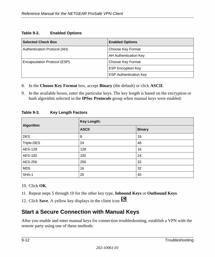
Reference Manual for the NETGEAR ProSafe VPN Client
8. In the Choose Key Format box, accept Binary (the default) or click ASCII.
9. In the available boxes, enter the particular keys. The key length is based on the encryption or hash algorithm selected in the IPSec Protocols group when manual keys were enabled:
10. Click OK.
11. Repeat steps 5 through 10 for the other key type, Inbound Keys or Outbound Keys.
12. Click Save. A yellow key displays in the client icon .
Start a Secure Connection with Manual Keys
After you enable and enter manual keys for connection troubleshooting, establish a VPN with the remote party using one of these methods:
Table 9-2. Enabled Options
Selected Check Box Enabled Options
Authentication Protocol (AH) Choose Key Format
AH Authentication Key
Encapsulation Protocol (ESP) Choose Key Format
ESP Encryption Key
ESP Authentication Key
Table 9-3. Key Length Factors
AlgorithmKey Length:
ASCII Binary
DES 8 16
Triple-DES 24 48
AES-128 128 16
AES-192 192 24
AES-256 256 32
MD5 16 32
SHA-1 20 40
9-12 Troubleshooting
202-10061-01
Reference Manual for the NETGEAR ProSafe VPN Client
• From a command prompt, ping the other computer.
• In Windows Explorer, map a drive on the other computer.
Note: Because IKE is not used with manual keys, the client logs no IKE negotiation messages in the Log Viewer.
Disable Manual Keys
When you complete using manual keys for troubleshooting, you can return to the original settings.
1. In the Security Policy Editor, in the Network Security Policy list, expand the secure connection you were troubleshooting with manual keys.
2. Are you using certificates or preshared keys?
• If you're using certificates:
— Click My Identity.
— In the Select Certificate box, click a personal certificate. Your original settings are restored.
• If you're using preshared keys:
— Click Security Policy.
— In the Select Phase 1 Negotiation Mode group, click Main Mode or Aggressive Mode. Your original settings are restored.
3. Click Save.
Troubleshooting 9-13
202-10061-01
Reference Manual for the NETGEAR ProSafe VPN Client
9-14 Troubleshooting
202-10061-01
Reference Manual for the NETGEAR ProSafe VPN Client
Appendix ANetworks, Routing, and Firewall Basics
This chapter provides an overview of IP networks, routing, and firewalls.
Related Publications
As you read this document, you may be directed to various RFC documents for further information. An RFC is a Request For Comment (RFC) published by the Internet Engineering Task Force (IETF), an open organization that defines the architecture and operation of the Internet. The RFC documents outline and define the standard protocols and procedures for the Internet. The documents are listed on the World Wide Web at www.ietf.org and are mirrored and indexed at many other sites worldwide.
Basic Router Concepts
Large amounts of bandwidth can be provided easily and relatively inexpensively in a local area network (LAN). However, providing high bandwidth between a local network and the Internet can be very expensive. Because of this expense, Internet access is usually provided by a slower-speed wide-area network (WAN) link such as a cable or DSL modem. In order to make the best use of the slower WAN link, a mechanism must be in place for selecting and transmitting only the data traffic meant for the Internet. The function of selecting and forwarding this data is performed by a router.
What is a Router?
A router is a device that forwards traffic between networks based on network layer information in the data and on routing tables maintained by the router. In these routing tables, a router builds up a logical picture of the overall network by gathering and exchanging information with other routers in the network. Using this information, the router chooses the best path for forwarding network traffic.
Networks, Routing, and Firewall Basics A-1
202-10061-01
Reference Manual for the NETGEAR ProSafe VPN Client
Routers vary in performance and scale, number of routing protocols supported, and types of physical WAN connection they support. The NETGEAR ProSafe VPN Client is a small office router that routes the IP protocol over a single-user broadband connection.
Routing Information Protocol
One of the protocols used by a router to build and maintain a picture of the network is the Routing Information Protocol (RIP). Using RIP, routers periodically update one another and check for changes to add to the routing table.
The NETGEAR VPN Client supports both the older RIP-1 and the newer RIP-2 protocols. Among other improvements, RIP-2 supports subnet and multicast protocols. RIP is not required for most home applications.
IP Addresses and the Internet
Because TCP/IP networks are interconnected across the world, every machine on the Internet must have a unique address to make sure that transmitted data reaches the correct destination. Blocks of addresses are assigned to organizations by the Internet Assigned Numbers Authority (IANA). Individual users and small organizations may obtain their addresses either from the IANA or from an Internet service provider (ISP). You can contact IANA at www.iana.org.
The Internet Protocol (IP) uses a 32-bit address structure. The address is usually written in dot notation (also called dotted-decimal notation), in which each group of eight bits is written in decimal form, separated by decimal points.
For example, the following binary address:
11000011 00100010 00001100 00000111
is normally written as:
195.34.12.7
The latter version is easier to remember and easier to enter into your computer.
In addition, the 32 bits of the address are subdivided into two parts. The first part of the address identifies the network, and the second part identifies the host node or station on the network. The dividing point may vary depending on the address range and the application.
A-2 Networks, Routing, and Firewall Basics
202-10061-01
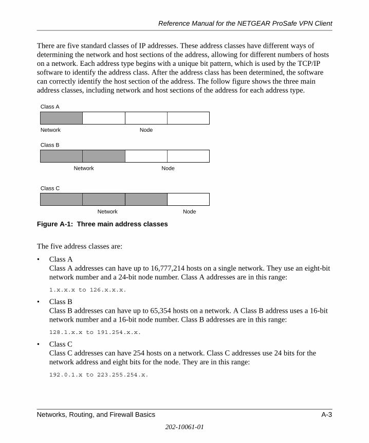
Reference Manual for the NETGEAR ProSafe VPN Client
There are five standard classes of IP addresses. These address classes have different ways of determining the network and host sections of the address, allowing for different numbers of hosts on a network. Each address type begins with a unique bit pattern, which is used by the TCP/IP software to identify the address class. After the address class has been determined, the software can correctly identify the host section of the address. The follow figure shows the three main address classes, including network and host sections of the address for each address type.
Figure A-1: Three main address classes
The five address classes are:
• Class A Class A addresses can have up to 16,777,214 hosts on a single network. They use an eight-bit network number and a 24-bit node number. Class A addresses are in this range:
1.x.x.x to 126.x.x.x.
• Class B Class B addresses can have up to 65,354 hosts on a network. A Class B address uses a 16-bit network number and a 16-bit node number. Class B addresses are in this range:
128.1.x.x to 191.254.x.x.
• Class C Class C addresses can have 254 hosts on a network. Class C addresses use 24 bits for the network address and eight bits for the node. They are in this range:
192.0.1.x to 223.255.254.x.
7261
Class A
Network Node
Class B
Class C
Network Node
Network Node
Networks, Routing, and Firewall Basics A-3
202-10061-01
Reference Manual for the NETGEAR ProSafe VPN Client
• Class D Class D addresses are used for multicasts (messages sent to many hosts). Class D addresses are in this range:
224.0.0.0 to 239.255.255.255.
• Class E Class E addresses are for experimental use.
This addressing structure allows IP addresses to uniquely identify each physical network and each node on each physical network.
For each unique value of the network portion of the address, the base address of the range (host address of all zeros) is known as the network address and is not usually assigned to a host. Also, the top address of the range (host address of all ones) is not assigned, but is used as the broadcast address for simultaneously sending a packet to all hosts with the same network address.
Netmask
In each of the address classes previously described, the size of the two parts (network address and host address) is implied by the class. This partitioning scheme can also be expressed by a netmask associated with the IP address. A netmask is a 32-bit quantity that, when logically combined (using an AND operator) with an IP address, yields the network address. For instance, the netmasks for Class A, B, and C addresses are 255.0.0.0, 255.255.0.0, and 255.255.255.0, respectively.
For example, the address 192.168.170.237 is a Class C IP address whose network portion is the upper 24 bits. When combined (using an AND operator) with the Class C netmask, as shown here, only the network portion of the address remains:
11000000 10101000 10101010 11101101 (192.168.170.237)
combined with:
11111111 11111111 11111111 00000000 (255.255.255.0)
Equals:
11000000 10101000 10101010 00000000 (192.168.170.0)
As a shorter alternative to dotted-decimal notation, the netmask may also be expressed in terms of the number of ones from the left. This number is appended to the IP address, following a backward slash (/), as “/n.” In the example, the address could be written as 192.168.170.237/24, indicating that the netmask is 24 ones followed by 8 zeros.
A-4 Networks, Routing, and Firewall Basics
202-10061-01
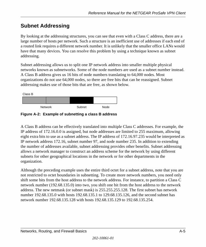
Reference Manual for the NETGEAR ProSafe VPN Client
Subnet Addressing
By looking at the addressing structures, you can see that even with a Class C address, there are a large number of hosts per network. Such a structure is an inefficient use of addresses if each end of a routed link requires a different network number. It is unlikely that the smaller office LANs would have that many devices. You can resolve this problem by using a technique known as subnet addressing.
Subnet addressing allows us to split one IP network address into smaller multiple physical networks known as subnetworks. Some of the node numbers are used as a subnet number instead. A Class B address gives us 16 bits of node numbers translating to 64,000 nodes. Most organizations do not use 64,000 nodes, so there are free bits that can be reassigned. Subnet addressing makes use of those bits that are free, as shown below.
Figure A-2: Example of subnetting a class B address
A Class B address can be effectively translated into multiple Class C addresses. For example, the IP address of 172.16.0.0 is assigned, but node addresses are limited to 255 maximum, allowing eight extra bits to use as a subnet address. The IP address of 172.16.97.235 would be interpreted as IP network address 172.16, subnet number 97, and node number 235. In addition to extending the number of addresses available, subnet addressing provides other benefits. Subnet addressing allows a network manager to construct an address scheme for the network by using different subnets for other geographical locations in the network or for other departments in the organization.
Although the preceding example uses the entire third octet for a subnet address, note that you are not restricted to octet boundaries in subnetting. To create more network numbers, you need only shift some bits from the host address to the network address. For instance, to partition a Class C network number (192.68.135.0) into two, you shift one bit from the host address to the network address. The new netmask (or subnet mask) is 255.255.255.128. The first subnet has network number 192.68.135.0 with hosts 192.68.135.1 to 129.68.135.126, and the second subnet has network number 192.68.135.128 with hosts 192.68.135.129 to 192.68.135.254.
7262
Class B
Network Subnet Node
Networks, Routing, and Firewall Basics A-5
202-10061-01
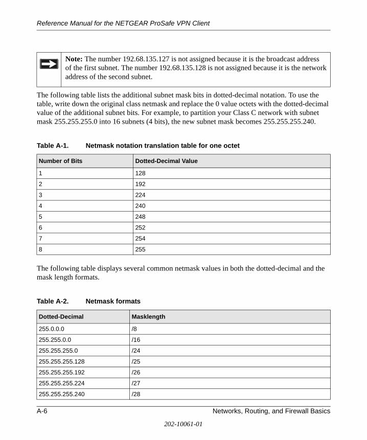
Reference Manual for the NETGEAR ProSafe VPN Client
The following table lists the additional subnet mask bits in dotted-decimal notation. To use the table, write down the original class netmask and replace the 0 value octets with the dotted-decimal value of the additional subnet bits. For example, to partition your Class C network with subnet mask 255.255.255.0 into 16 subnets (4 bits), the new subnet mask becomes 255.255.255.240.
The following table displays several common netmask values in both the dotted-decimal and the mask length formats.
Note: The number 192.68.135.127 is not assigned because it is the broadcast address of the first subnet. The number 192.68.135.128 is not assigned because it is the network address of the second subnet.
Table A-1. Netmask notation translation table for one octet
Number of Bits Dotted-Decimal Value
1 128
2 192
3 224
4 240
5 248
6 252
7 254
8 255
Table A-2. Netmask formats
Dotted-Decimal Masklength
255.0.0.0 /8
255.255.0.0 /16
255.255.255.0 /24
255.255.255.128 /25
255.255.255.192 /26
255.255.255.224 /27
255.255.255.240 /28
A-6 Networks, Routing, and Firewall Basics
202-10061-01
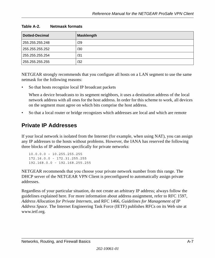
Reference Manual for the NETGEAR ProSafe VPN Client
NETGEAR strongly recommends that you configure all hosts on a LAN segment to use the same netmask for the following reasons:
• So that hosts recognize local IP broadcast packets
When a device broadcasts to its segment neighbors, it uses a destination address of the local network address with all ones for the host address. In order for this scheme to work, all devices on the segment must agree on which bits comprise the host address.
• So that a local router or bridge recognizes which addresses are local and which are remote
Private IP Addresses
If your local network is isolated from the Internet (for example, when using NAT), you can assign any IP addresses to the hosts without problems. However, the IANA has reserved the following three blocks of IP addresses specifically for private networks:
10.0.0.0 - 10.255.255.255172.16.0.0 - 172.31.255.255192.168.0.0 - 192.168.255.255
NETGEAR recommends that you choose your private network number from this range. The DHCP server of the NETGEAR VPN Client is preconfigured to automatically assign private addresses.
Regardless of your particular situation, do not create an arbitrary IP address; always follow the guidelines explained here. For more information about address assignment, refer to RFC 1597, Address Allocation for Private Internets, and RFC 1466, Guidelines for Management of IP Address Space. The Internet Engineering Task Force (IETF) publishes RFCs on its Web site at www.ietf.org.
255.255.255.248 /29
255.255.255.252 /30
255.255.255.254 /31
255.255.255.255 /32
Table A-2. Netmask formats
Dotted-Decimal Masklength
Networks, Routing, and Firewall Basics A-7
202-10061-01

Reference Manual for the NETGEAR ProSafe VPN Client
Single IP Address Operation Using NAT
In the past, if multiple PCs on a LAN needed to access the Internet simultaneously, you had to obtain a range of IP addresses from the ISP. This type of Internet account is more costly than a single-address account typically used by a single user with a modem, rather than a router. The NETGEAR VPN Client employs an address-sharing method called Network Address Translation (NAT). This method allows several networked PCs to share an Internet account using only a single IP address, which may be statically or dynamically assigned by your ISP.
The router accomplishes this address sharing by translating the internal LAN IP addresses to a single address that is globally unique on the Internet. The internal LAN IP addresses can be either private addresses or registered addresses. For more information about IP address translation, refer to RFC 1631, The IP Network Address Translator (NAT).
The following figure illustrates a single IP address operation.
Figure A-3: Single IP address operation using NAT
This scheme offers the additional benefit of firewall-like protection because the internal LAN addresses are not available to the Internet through the translated connection. All incoming inquiries are filtered out by the router. This filtering can prevent intruders from probing your system. However, using port forwarding, you can allow one PC (for example, a Web server) on your local network to be accessible to outside users.
192.168.0.2
192.168.0.3
192.168.0.4
192.168.0.5
192.168.0.1 172.21.15.105
Private IP addressesassigned by user
Internet
IP addressesassigned by ISP
A-8 Networks, Routing, and Firewall Basics
202-10061-01
Reference Manual for the NETGEAR ProSafe VPN Client
MAC Addresses and Address Resolution Protocol
An IP address alone cannot be used to deliver data from one LAN device to another. To send data between LAN devices, you must convert the IP address of the destination device to its media access control (MAC) address. Each device on an Ethernet network has a unique MAC address, which is a 48-bit number assigned to each device by the manufacturer. The technique that associates the IP address with a MAC address is known as address resolution. Internet Protocol uses the Address Resolution Protocol (ARP) to resolve MAC addresses.
If a device sends data to another station on the network and the destination MAC address is not yet recorded, ARP is used. An ARP request is broadcast onto the network. All stations on the network receive and read the request. The destination IP address for the chosen station is included as part of the message so that only the station with this IP address responds to the ARP request. All other stations discard the request.
Related Documents
The station with the correct IP address responds with its own MAC address directly to the sending device. The receiving station provides the transmitting station with the required destination MAC address. The IP address data and MAC address data for each station are held in an ARP table. The next time data is sent, the address can be obtained from the address information in the table.
For more information about address assignment, refer to the IETF documents RFC 1597, Address Allocation for Private Internets, and RFC 1466, Guidelines for Management of IP Address Space.
For more information about IP address translation, refer to RFC 1631, The IP Network Address Translator (NAT).
Domain Name Server
Many of the resources on the Internet can be addressed by simple descriptive names such as www.NETGEAR.com. This addressing is very helpful at the application level, but the descriptive name must be translated to an IP address in order for a user to actually contact the resource. Just as a telephone directory maps names to phone numbers, or as an ARP table maps IP addresses to MAC addresses, a domain name system (DNS) server maps descriptive names of network resources to IP addresses.
Networks, Routing, and Firewall Basics A-9
202-10061-01
Reference Manual for the NETGEAR ProSafe VPN Client
When a PC accesses a resource by its descriptive name, it first contacts a DNS server to obtain the IP address of the resource. The PC sends the desired message using the IP address. Many large organizations, such as ISPs, maintain their own DNS servers and allow their customers to use the servers to look up addresses.
IP Configuration by DHCP
When an IP-based local area network is installed, each PC must be configured with an IP address. If the PCs need to access the Internet, they should also be configured with a gateway address and one or more DNS server addresses. As an alternative to manual configuration, there is a method by which each PC on the network can automatically obtain this configuration information. A device on the network may act as a Dynamic Host Configuration Protocol (DHCP) server. The DHCP server stores a list or pool of IP addresses, along with other information (such as gateway and DNS addresses) that it may assign to the other devices on the network. The NETGEAR VPN Client has the capacity to act as a DHCP server.
The NETGEAR VPN Client also functions as a DHCP client when connecting to the ISP. The firewall can automatically obtain an IP address, subnet mask, DNS server addresses, and a gateway address if the ISP provides this information by DHCP.
Internet Security and Firewalls
When your LAN connects to the Internet through a router, an opportunity is created for outsiders to access or disrupt your network. A NAT router provides some protection because by the very nature of the Network Address Translation (NAT) process, the network behind the NAT router is shielded from access by outsiders on the Internet. However, there are methods by which a determined hacker can possibly obtain information about your network or at the least can disrupt your Internet access. A greater degree of protection is provided by a firewall router.
A-10 Networks, Routing, and Firewall Basics
202-10061-01
Reference Manual for the NETGEAR ProSafe VPN Client
What is a Firewall?
A firewall is a device that protects one network from another, while allowing communication between the two. A firewall incorporates the functions of the NAT router, while adding features for dealing with a hacker intrusion or attack. Several known types of intrusion or attack can be recognized when they occur. When an incident is detected, the firewall can log details of the attempt, and can optionally send email to an administrator notifying them of the incident. Using information from the log, the administrator can take action with the ISP of the hacker. In some types of intrusions, the firewall can fend off the hacker by discarding all further packets from the hacker’s IP address for a period of time.
Stateful Packet Inspection
Unlike simple Internet sharing routers, a firewall uses a process called stateful packet inspection to ensure secure firewall filtering to protect your network from attacks and intrusions. Since user-level applications such as FTP and Web browsers can create complex patterns of network traffic, it is necessary for the firewall to analyze groups of network connection states. Using Stateful Packet Inspection, an incoming packet is intercepted at the network layer and then analyzed for state-related information associated with all network connections. A central cache within the firewall keeps track of the state information associated with all network connections. All traffic passing through the firewall is analyzed against the state of these connections in order to determine whether or not it will be allowed to pass through or rejected.
Denial of Service Attack
A hacker may be able to prevent your network from operating or communicating by launching a Denial of Service (DoS) attack. The method used for such an attack can be as simple as merely flooding your site with more requests than it can handle. A more sophisticated attack may attempt to exploit some weakness in the operating system used by your router or gateway. Some operating systems can be disrupted by simply sending a packet with incorrect length information.
Networks, Routing, and Firewall Basics A-11
202-10061-01
Reference Manual for the NETGEAR ProSafe VPN Client
A-12 Networks, Routing, and Firewall Basics
202-10061-01
Reference Manual for the NETGEAR ProSafe VPN Client
Appendix BVirtual Private Networking
There have been many improvements in the Internet including Quality of Service, network performance, and inexpensive technologies, such as DSL. But one of the most important advances has been in Virtual Private Networking (VPN) Internet Protocol security (IPSec). IPSec is one of the most complete, secure, and commercially available, standards-based protocols developed for transporting data.
What is a VPN?
A VPN is a shared network where private data is segmented from other traffic so that only the intended recipient has access. The term VPN was originally used to describe a secure connection over the Internet. Today, however, VPN is also used to describe private networks, such as Frame Relay, Asynchronous Transfer Mode (ATM), and Multiprotocol Label Switching (MPLS).
A key aspect of data security is that the data flowing across the network is protected by encryption technologies. Private networks lack data security, which allows data attackers to tap directly into the network and read the data. IPSec-based VPNs use encryption to provide data security, which increases the network’s resistance to data tampering or theft.
IPSec-based VPNs can be created over any type of IP network, including the Internet, Frame Relay, ATM, and MPLS, but only the Internet is ubiquitous and inexpensive.
VPNs are traditionally used for:
• Intranets: Intranets connect an organization’s locations. These locations range from the headquarters offices, to branch offices, to a remote employee’s home. Often this connectivity is used for e-mail and for sharing applications and files. While Frame Relay, ATM, and MPLS accomplish these tasks, the shortcomings of each limits connectivity. The cost of connecting home users is also very expensive compared to Internet-access technologies, such as DSL or cable. Because of this, organizations are moving their networks to the Internet, which is inexpensive, and using IPSec to create these networks.
Virtual Private Networking B-1
202-10061-01
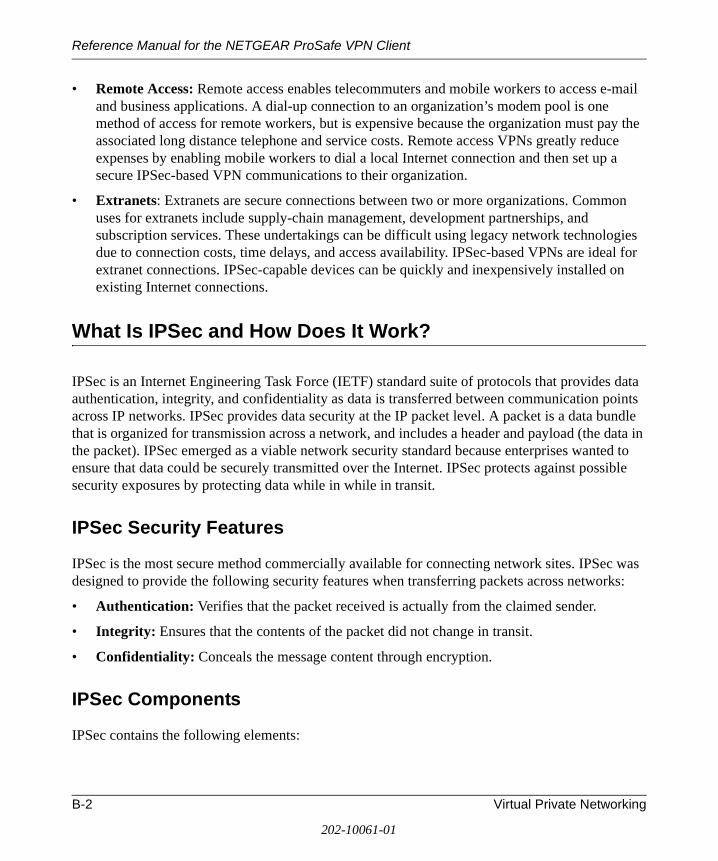
Reference Manual for the NETGEAR ProSafe VPN Client
• Remote Access: Remote access enables telecommuters and mobile workers to access e-mail and business applications. A dial-up connection to an organization’s modem pool is one method of access for remote workers, but is expensive because the organization must pay the associated long distance telephone and service costs. Remote access VPNs greatly reduce expenses by enabling mobile workers to dial a local Internet connection and then set up a secure IPSec-based VPN communications to their organization.
• Extranets: Extranets are secure connections between two or more organizations. Common uses for extranets include supply-chain management, development partnerships, and subscription services. These undertakings can be difficult using legacy network technologies due to connection costs, time delays, and access availability. IPSec-based VPNs are ideal for extranet connections. IPSec-capable devices can be quickly and inexpensively installed on existing Internet connections.
What Is IPSec and How Does It Work?
IPSec is an Internet Engineering Task Force (IETF) standard suite of protocols that provides data authentication, integrity, and confidentiality as data is transferred between communication points across IP networks. IPSec provides data security at the IP packet level. A packet is a data bundle that is organized for transmission across a network, and includes a header and payload (the data in the packet). IPSec emerged as a viable network security standard because enterprises wanted to ensure that data could be securely transmitted over the Internet. IPSec protects against possible security exposures by protecting data while in while in transit.
IPSec Security Features
IPSec is the most secure method commercially available for connecting network sites. IPSec was designed to provide the following security features when transferring packets across networks:
• Authentication: Verifies that the packet received is actually from the claimed sender.
• Integrity: Ensures that the contents of the packet did not change in transit.
• Confidentiality: Conceals the message content through encryption.
IPSec Components
IPSec contains the following elements:
B-2 Virtual Private Networking
202-10061-01
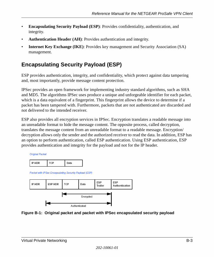
Reference Manual for the NETGEAR ProSafe VPN Client
• Encapsulating Security Payload (ESP): Provides confidentiality, authentication, and integrity.
• Authentication Header (AH): Provides authentication and integrity.
• Internet Key Exchange (IKE): Provides key management and Security Association (SA) management.
Encapsulating Security Payload (ESP)
ESP provides authentication, integrity, and confidentiality, which protect against data tampering and, most importantly, provide message content protection.
IPSec provides an open framework for implementing industry standard algorithms, such as SHA and MD5. The algorithms IPSec uses produce a unique and unforgeable identifier for each packet, which is a data equivalent of a fingerprint. This fingerprint allows the device to determine if a packet has been tampered with. Furthermore, packets that are not authenticated are discarded and not delivered to the intended receiver.
ESP also provides all encryption services in IPSec. Encryption translates a readable message into an unreadable format to hide the message content. The opposite process, called decryption, translates the message content from an unreadable format to a readable message. Encryption/decryption allows only the sender and the authorized receiver to read the data. In addition, ESP has an option to perform authentication, called ESP authentication. Using ESP authentication, ESP provides authentication and integrity for the payload and not for the IP header.
Figure B-1: Original packet and packet with IPSec encapsulated security payload
Virtual Private Networking B-3
202-10061-01
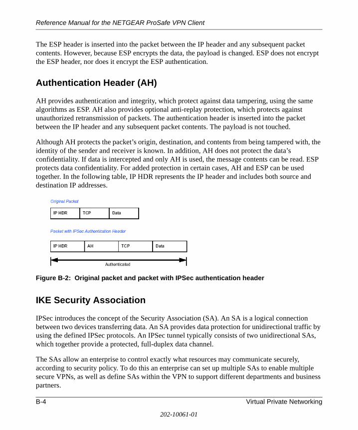
Reference Manual for the NETGEAR ProSafe VPN Client
The ESP header is inserted into the packet between the IP header and any subsequent packet contents. However, because ESP encrypts the data, the payload is changed. ESP does not encrypt the ESP header, nor does it encrypt the ESP authentication.
Authentication Header (AH)
AH provides authentication and integrity, which protect against data tampering, using the same algorithms as ESP. AH also provides optional anti-replay protection, which protects against unauthorized retransmission of packets. The authentication header is inserted into the packet between the IP header and any subsequent packet contents. The payload is not touched.
Although AH protects the packet’s origin, destination, and contents from being tampered with, the identity of the sender and receiver is known. In addition, AH does not protect the data’s confidentiality. If data is intercepted and only AH is used, the message contents can be read. ESP protects data confidentiality. For added protection in certain cases, AH and ESP can be used together. In the following table, IP HDR represents the IP header and includes both source and destination IP addresses.
Figure B-2: Original packet and packet with IPSec authentication header
IKE Security Association
IPSec introduces the concept of the Security Association (SA). An SA is a logical connection between two devices transferring data. An SA provides data protection for unidirectional traffic by using the defined IPSec protocols. An IPSec tunnel typically consists of two unidirectional SAs, which together provide a protected, full-duplex data channel.
The SAs allow an enterprise to control exactly what resources may communicate securely, according to security policy. To do this an enterprise can set up multiple SAs to enable multiple secure VPNs, as well as define SAs within the VPN to support different departments and business partners.
B-4 Virtual Private Networking
202-10061-01
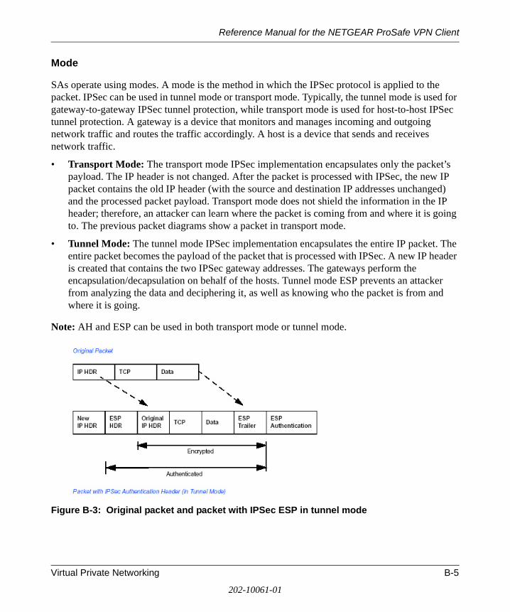
Reference Manual for the NETGEAR ProSafe VPN Client
Mode
SAs operate using modes. A mode is the method in which the IPSec protocol is applied to the packet. IPSec can be used in tunnel mode or transport mode. Typically, the tunnel mode is used for gateway-to-gateway IPSec tunnel protection, while transport mode is used for host-to-host IPSec tunnel protection. A gateway is a device that monitors and manages incoming and outgoing network traffic and routes the traffic accordingly. A host is a device that sends and receives network traffic.
• Transport Mode: The transport mode IPSec implementation encapsulates only the packet’s payload. The IP header is not changed. After the packet is processed with IPSec, the new IP packet contains the old IP header (with the source and destination IP addresses unchanged) and the processed packet payload. Transport mode does not shield the information in the IP header; therefore, an attacker can learn where the packet is coming from and where it is going to. The previous packet diagrams show a packet in transport mode.
• Tunnel Mode: The tunnel mode IPSec implementation encapsulates the entire IP packet. The entire packet becomes the payload of the packet that is processed with IPSec. A new IP header is created that contains the two IPSec gateway addresses. The gateways perform the encapsulation/decapsulation on behalf of the hosts. Tunnel mode ESP prevents an attacker from analyzing the data and deciphering it, as well as knowing who the packet is from and where it is going.
Note: AH and ESP can be used in both transport mode or tunnel mode.
Figure B-3: Original packet and packet with IPSec ESP in tunnel mode
Virtual Private Networking B-5
202-10061-01
Reference Manual for the NETGEAR ProSafe VPN Client
Key Management
IPSec uses the Internet Key Exchange (IKE) protocol to facilitate and automate the SA setup and the exchange of keys between parties transferring data. Using keys ensures that only the sender and receiver of a message can access it.
IPSec requires that keys be re-created, or refreshed, frequently so that the parties can communicate securely with each other. IKE manages the process of refreshing keys; however, a user can control the key strength and the refresh frequency. Refreshing keys on a regular basis ensures data confidentiality between sender and receiver.
Understand the Process Before You Begin
It is a good idea to gather all the necessary information required to establish a VPN before you begin the configuration process. You should understand whether the firmware is up to date, all of the addresses that will be necessary, and all of the parameters that need to be set on both sides. Try to understand any incompatibilities before you begin, so that you minimize any potential complications which may arise from normal firewall or WAN processes.
NETGEAR is a member of the VPN Consortium, a group formed to facilitate IPSec VPN vendor interoperability. The VPN Consortium has developed specific scenarios to aid system administrators in the often confusing process of connecting two different vendor implementations of the IPSec standard. Additional information regarding inter-vendor interoperability may be found at http://www.vpnc.org/interop.html.
If you are not a full-time system administrator, it is a good idea to familiarize yourself with the mechanics of a VPN. The brief description in this document will help. Other good sources include:
• The NETGEAR VPN Tutorial – http://www.netgear.com/planetvpn/pvpn_2.html
• The VPN Consortium – http://www.vpnc.org/
• The VPN bibliography in “Additional Reading“ on page B-11.
B-6 Virtual Private Networking
202-10061-01
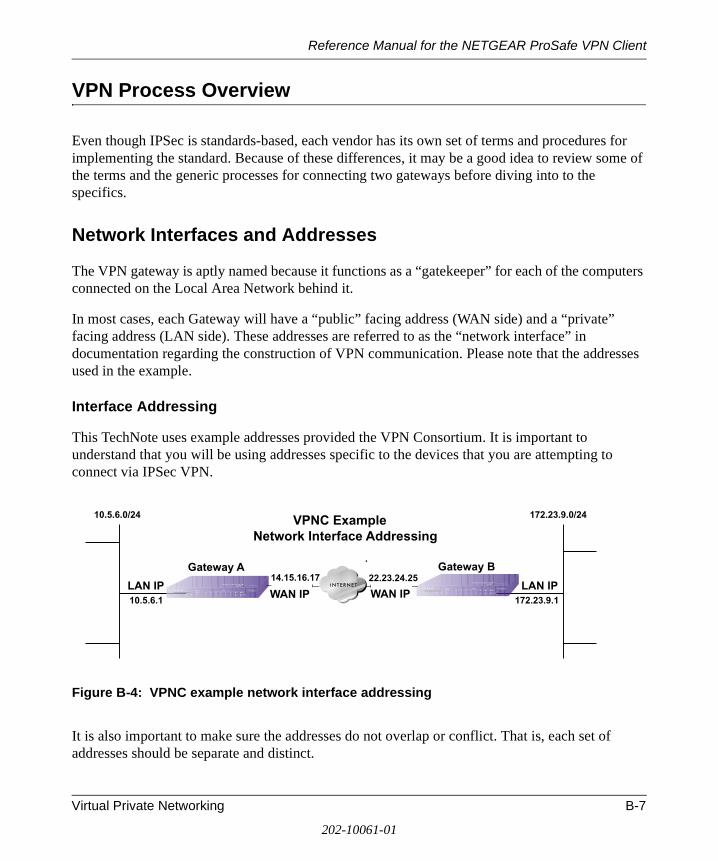
Reference Manual for the NETGEAR ProSafe VPN Client
VPN Process Overview
Even though IPSec is standards-based, each vendor has its own set of terms and procedures for implementing the standard. Because of these differences, it may be a good idea to review some of the terms and the generic processes for connecting two gateways before diving into to the specifics.
Network Interfaces and Addresses
The VPN gateway is aptly named because it functions as a “gatekeeper” for each of the computers connected on the Local Area Network behind it.
In most cases, each Gateway will have a “public” facing address (WAN side) and a “private” facing address (LAN side). These addresses are referred to as the “network interface” in documentation regarding the construction of VPN communication. Please note that the addresses used in the example.
Interface Addressing
This TechNote uses example addresses provided the VPN Consortium. It is important to understand that you will be using addresses specific to the devices that you are attempting to connect via IPSec VPN.
Figure B-4: VPNC example network interface addressing
It is also important to make sure the addresses do not overlap or conflict. That is, each set of addresses should be separate and distinct.
Gateway A22.23.24.2514.15.16.17
10.5.6.0/24 172.23.9.0/24
172.23.9.110.5.6.1WAN IP WAN IP
LAN IPLAN IP
Gateway B
VPNC ExampleNetwork Interface Addressing
Virtual Private Networking B-7
202-10061-01
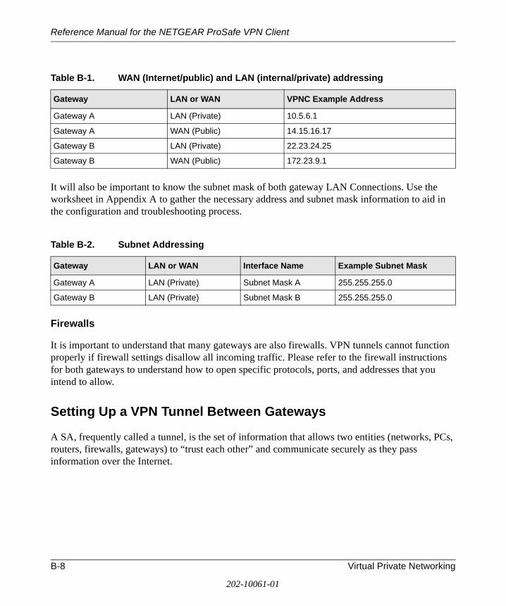
Reference Manual for the NETGEAR ProSafe VPN Client
It will also be important to know the subnet mask of both gateway LAN Connections. Use the worksheet in Appendix A to gather the necessary address and subnet mask information to aid in the configuration and troubleshooting process.
Firewalls
It is important to understand that many gateways are also firewalls. VPN tunnels cannot function properly if firewall settings disallow all incoming traffic. Please refer to the firewall instructions for both gateways to understand how to open specific protocols, ports, and addresses that you intend to allow.
Setting Up a VPN Tunnel Between Gateways
A SA, frequently called a tunnel, is the set of information that allows two entities (networks, PCs, routers, firewalls, gateways) to “trust each other” and communicate securely as they pass information over the Internet.
Table B-1. WAN (Internet/public) and LAN (internal/private) addressing
Gateway LAN or WAN VPNC Example Address
Gateway A LAN (Private) 10.5.6.1
Gateway A WAN (Public) 14.15.16.17
Gateway B LAN (Private) 22.23.24.25
Gateway B WAN (Public) 172.23.9.1
Table B-2. Subnet Addressing
Gateway LAN or WAN Interface Name Example Subnet Mask
Gateway A LAN (Private) Subnet Mask A 255.255.255.0
Gateway B LAN (Private) Subnet Mask B 255.255.255.0
B-8 Virtual Private Networking
202-10061-01

Reference Manual for the NETGEAR ProSafe VPN Client
Figure B-5: VPN tunnel SA
The SA contains all the information necessary for gateway A to negotiate a secure and encrypted communication stream with gateway B. This communication is often referred to as a “tunnel.” The gateways contain this information so that it does not have to be loaded onto every computer connected to the gateways.
Each gateway must negotiate its Security Association with another gateway using the parameters and processes established by IPSec. As illustrated below, the most common method of accomplishing this process is via the Internet Key Exchange (IKE) protocol which automates some of the negotiation procedures. Alternatively, you can configure your gateways using manual key exchange, which involves manually configuring each paramter on both gateways.
Figure B-6: IPSec SA negotiation
The IPSec software on Host A initiates the IPSec process in an attempt to communicate with Host B. The two computers then begin the Internet Key Exchange (IKE) process.
Gateway A Gateway B
192.168.3.1 192.168.0.1
VPN Tunnel
24.0.0.1 10.0.0.1
PCsPCs
VPN GatewayVPN Gateway
1) Communicationrequest sent to VPN Gateway
2) IKE Phase I authentication
3) IKE Phase II negotiation
4) Secure data transfer
5) IPSec tunnel termination
IPSec Security Association IKEVPN Tunnel Negotiation Steps
Virtual Private Networking B-9
202-10061-01
Reference Manual for the NETGEAR ProSafe VPN Client
IKE Phase I.
a. The two parties negotiate the encryption and authentication algorithms to use in the IKE SAs.
b. The two parties authenticate each other using a predetermined mechanism, such as preshared keys or digital certificates.
c. A shared master key is generated by the Diffie-Hellman Public key algorithm within the IKE framework for the two parties. The master key is also used in the second phase to derive IPSec keys for the SAs.
IKE Phase II.
a. The two parties negotiate the encryption and authentication algorithms to use in the IPSec SAs.
b. The master key is used to derive the IPSec keys for the SAs. Once the SA keys are created and exchanged, the IPSec SAs are ready to protect user data between the two VPN gateways.
Data transfer. Data is transferred between IPSec peers based on the IPSec parameters and keys stored in the SA database.
IPSec tunnel termination. IPSec SAs terminate through deletion or by timing out.
VPNC IKE Security Parameters
It is important to remember that both gateways must have the identical parameters set for the process to work correctly. The settings in these TechNote examples follow the examples given for Scenario 1 of the VPN Consortium.
VPNC IKE Phase I Parameters
The IKE Phase 1 parameters used:
• Main mode
• TripleDES
• SHA-1
• MODP group 1
• pre-shared secret of "hr5xb84l6aa9r6"
B-10 Virtual Private Networking
202-10061-01
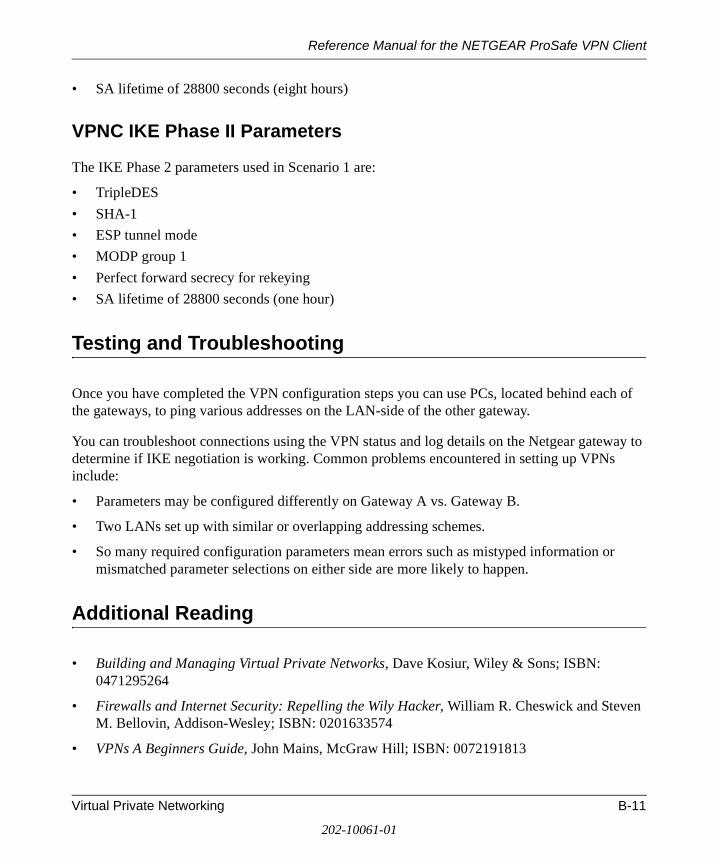
Reference Manual for the NETGEAR ProSafe VPN Client
• SA lifetime of 28800 seconds (eight hours)
VPNC IKE Phase II Parameters
The IKE Phase 2 parameters used in Scenario 1 are:
• TripleDES
• SHA-1
• ESP tunnel mode
• MODP group 1
• Perfect forward secrecy for rekeying
• SA lifetime of 28800 seconds (one hour)
Testing and Troubleshooting
Once you have completed the VPN configuration steps you can use PCs, located behind each of the gateways, to ping various addresses on the LAN-side of the other gateway.
You can troubleshoot connections using the VPN status and log details on the Netgear gateway to determine if IKE negotiation is working. Common problems encountered in setting up VPNs include:
• Parameters may be configured differently on Gateway A vs. Gateway B.
• Two LANs set up with similar or overlapping addressing schemes.
• So many required configuration parameters mean errors such as mistyped information or mismatched parameter selections on either side are more likely to happen.
Additional Reading
• Building and Managing Virtual Private Networks, Dave Kosiur, Wiley & Sons; ISBN: 0471295264
• Firewalls and Internet Security: Repelling the Wily Hacker, William R. Cheswick and Steven M. Bellovin, Addison-Wesley; ISBN: 0201633574
• VPNs A Beginners Guide, John Mains, McGraw Hill; ISBN: 0072191813
Virtual Private Networking B-11
202-10061-01
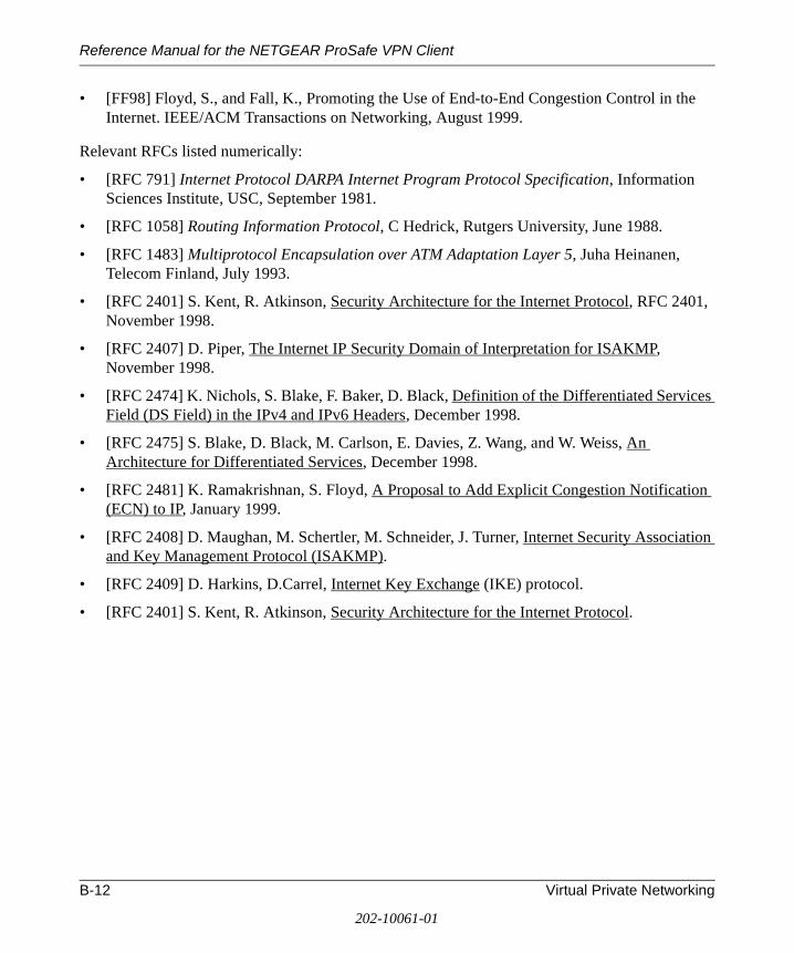
Reference Manual for the NETGEAR ProSafe VPN Client
• [FF98] Floyd, S., and Fall, K., Promoting the Use of End-to-End Congestion Control in the Internet. IEEE/ACM Transactions on Networking, August 1999.
Relevant RFCs listed numerically:
• [RFC 791] Internet Protocol DARPA Internet Program Protocol Specification, Information Sciences Institute, USC, September 1981.
• [RFC 1058] Routing Information Protocol, C Hedrick, Rutgers University, June 1988.
• [RFC 1483] Multiprotocol Encapsulation over ATM Adaptation Layer 5, Juha Heinanen, Telecom Finland, July 1993.
• [RFC 2401] S. Kent, R. Atkinson, Security Architecture for the Internet Protocol, RFC 2401, November 1998.
• [RFC 2407] D. Piper, The Internet IP Security Domain of Interpretation for ISAKMP, November 1998.
• [RFC 2474] K. Nichols, S. Blake, F. Baker, D. Black, Definition of the Differentiated Services Field (DS Field) in the IPv4 and IPv6 Headers, December 1998.
• [RFC 2475] S. Blake, D. Black, M. Carlson, E. Davies, Z. Wang, and W. Weiss, An Architecture for Differentiated Services, December 1998.
• [RFC 2481] K. Ramakrishnan, S. Floyd, A Proposal to Add Explicit Congestion Notification (ECN) to IP, January 1999.
• [RFC 2408] D. Maughan, M. Schertler, M. Schneider, J. Turner, Internet Security Association and Key Management Protocol (ISAKMP).
• [RFC 2409] D. Harkins, D.Carrel, Internet Key Exchange (IKE) protocol.
• [RFC 2401] S. Kent, R. Atkinson, Security Architecture for the Internet Protocol.
B-12 Virtual Private Networking
202-10061-01
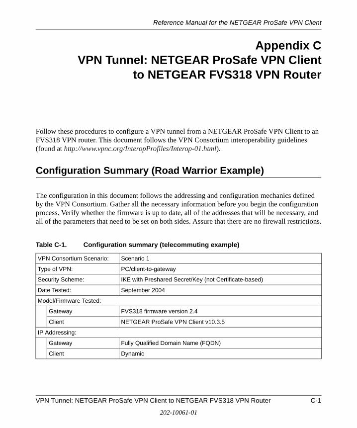
Reference Manual for the NETGEAR ProSafe VPN Client
Appendix CVPN Tunnel: NETGEAR ProSafe VPN Client
to NETGEAR FVS318 VPN Router
Follow these procedures to configure a VPN tunnel from a NETGEAR ProSafe VPN Client to an FVS318 VPN router. This document follows the VPN Consortium interoperability guidelines (found at http://www.vpnc.org/InteropProfiles/Interop-01.html).
Configuration Summary (Road Warrior Example)
The configuration in this document follows the addressing and configuration mechanics defined by the VPN Consortium. Gather all the necessary information before you begin the configuration process. Verify whether the firmware is up to date, all of the addresses that will be necessary, and all of the parameters that need to be set on both sides. Assure that there are no firewall restrictions.
Table C-1. Configuration summary (telecommuting example)
VPN Consortium Scenario: Scenario 1
Type of VPN: PC/client-to-gateway
Security Scheme: IKE with Preshared Secret/Key (not Certificate-based)
Date Tested: September 2004
Model/Firmware Tested:
Gateway FVS318 firmware version 2.4
Client NETGEAR ProSafe VPN Client v10.3.5
IP Addressing:
Gateway Fully Qualified Domain Name (FQDN)
Client Dynamic
VPN Tunnel: NETGEAR ProSafe VPN Client to NETGEAR FVS318 VPN Router C-1
202-10061-01

Reference Manual for the NETGEAR ProSafe VPN Client
Figure C-1: Addressing and subnet used for road warrior example
The Use of a Fully Qualified Domain Name (FQDN)
Many ISPs provide connectivity to their customers using dynamic instead of static IP addressing. This means that a user’s IP address does not remain constant over time which presents a challenge for gateways attempting to establish VPN connectivity.
A Dynamic DNS (DDNS) service allows a user whose public IP address is dynamically assigned to be located by a host name or domain name. It provides a central public database where information (such as e-mail addresses, host names and IP addresses) can be stored and retrieved. Now, a gateway can be configured to use a third party service in lieu of a permanent and unchanging IP address to establish bi-directional VPN connectivity.
To use DDNS, you must register with a DDNS service provider. Example DDNS Service Providers include:
• DynDNS: http://www.dyndns.org
• TZO.com: http://netgear.tzo.com
• ngDDNS: http://ngddns.iego.net
Note: Product updates are available on the NETGEAR, Inc. web site at http://kbserver.netgear.com/main.asp.
Gateway A
bzrouter.dyndns.org
10.5.6.0/24
10.5.6.1
WAN IP WAN IPLAN IP
Client B
FQDN 0.0.0.0
Router(at employer'smain office)
Road Warrior Example
PC(running NETGEARProSafe VPN Client)
C-2 VPN Tunnel: NETGEAR ProSafe VPN Client to NETGEAR FVS318 VPN Router
202-10061-01
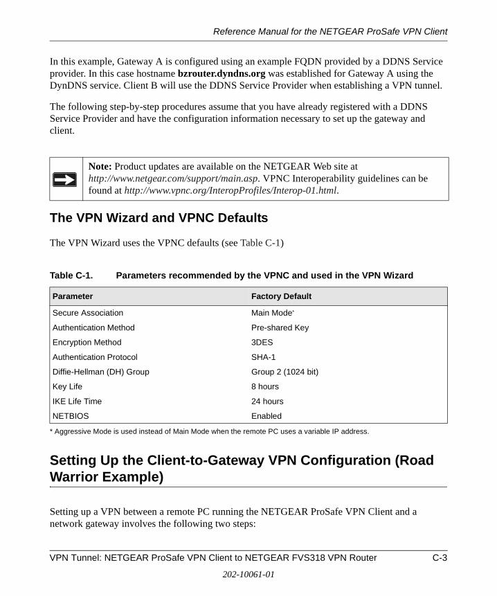
Reference Manual for the NETGEAR ProSafe VPN Client
In this example, Gateway A is configured using an example FQDN provided by a DDNS Service provider. In this case hostname bzrouter.dyndns.org was established for Gateway A using the DynDNS service. Client B will use the DDNS Service Provider when establishing a VPN tunnel.
The following step-by-step procedures assume that you have already registered with a DDNS Service Provider and have the configuration information necessary to set up the gateway and client.
The VPN Wizard and VPNC Defaults
The VPN Wizard uses the VPNC defaults (see Table C-1)
Setting Up the Client-to-Gateway VPN Configuration (Road Warrior Example)
Setting up a VPN between a remote PC running the NETGEAR ProSafe VPN Client and a network gateway involves the following two steps:
Note: Product updates are available on the NETGEAR Web site at http://www.netgear.com/support/main.asp. VPNC Interoperability guidelines can be found at http://www.vpnc.org/InteropProfiles/Interop-01.html.
Table C-1. Parameters recommended by the VPNC and used in the VPN Wizard
Parameter Factory Default
Secure Association Main Mode*
* Aggressive Mode is used instead of Main Mode when the remote PC uses a variable IP address.
Authentication Method Pre-shared Key
Encryption Method 3DES
Authentication Protocol SHA-1
Diffie-Hellman (DH) Group Group 2 (1024 bit)
Key Life 8 hours
IKE Life Time 24 hours
NETBIOS Enabled
VPN Tunnel: NETGEAR ProSafe VPN Client to NETGEAR FVS318 VPN Router C-3
202-10061-01

Reference Manual for the NETGEAR ProSafe VPN Client
• Step 1: Configuring the Client-to-Gateway VPN Tunnel on the VPN Router at the Employer’s Main Office uses the VPN Wizard to configure the VPN tunnel between the remote PC and network gateway.
• Step 2: Configuring the NETGEAR ProSafe VPN Client on the Road Warrior’s Remote PC configures the NETGEAR ProSafe VPN Client endpoint.
Step 1: Configuring the Client-to-Gateway VPN Tunnel on the VPN Router at the Employer’s Main Office
Follow this procedure to configure a client-to-gateway VPN tunnel using the VPN Wizard.
1. Log in to the VPN router at its LAN address of http://192.168.3.1 with its default user name of admin and password of password. Click the VPN Wizard link in the main menu to display this screen. Click Next to proceed.
Figure C-2: VPN Wizard start screen
2. Fill in the Connection Name and the pre-shared key, select the type of target end point, and click Next to proceed.
Note: The Connection Name is arbitrary and not relevant to how the configuration functions.
C-4 VPN Tunnel: NETGEAR ProSafe VPN Client to NETGEAR FVS318 VPN Router
202-10061-01
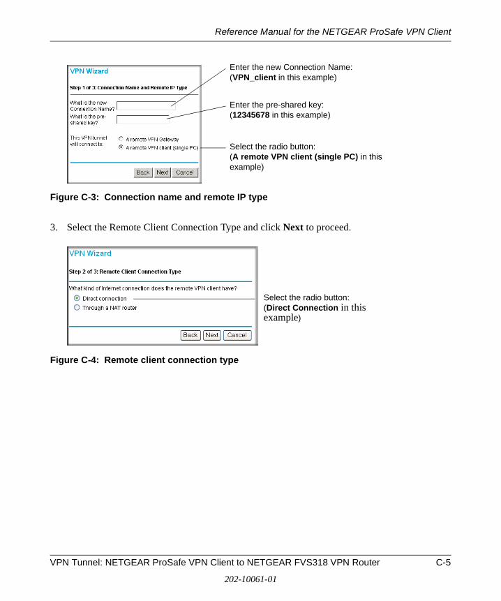
Reference Manual for the NETGEAR ProSafe VPN Client
Figure C-3: Connection name and remote IP type
3. Select the Remote Client Connection Type and click Next to proceed.
Figure C-4: Remote client connection type
Enter the new Connection Name: (VPN_client in this example)
Enter the pre-shared key: (12345678 in this example)
Select the radio button: (A remote VPN client (single PC) in this example)
Select the radio button: (Direct Connection in this example)
VPN Tunnel: NETGEAR ProSafe VPN Client to NETGEAR FVS318 VPN Router C-5
202-10061-01

Reference Manual for the NETGEAR ProSafe VPN Client
The Summary screen below displays.
Figure C-5: VPN Wizard summary
4. Click Done on the Summary screen (see Figure C-5) to complete the configuration procedure. The VPN Settings menu below displays showing that the new tunnel is enabled.
Figure C-6: VPN settings
C-6 VPN Tunnel: NETGEAR ProSafe VPN Client to NETGEAR FVS318 VPN Router
202-10061-01
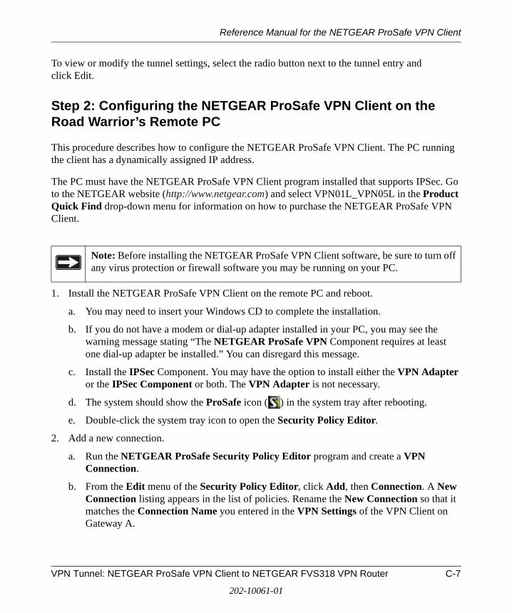
Reference Manual for the NETGEAR ProSafe VPN Client
To view or modify the tunnel settings, select the radio button next to the tunnel entry and click Edit.
Step 2: Configuring the NETGEAR ProSafe VPN Client on the Road Warrior’s Remote PC
This procedure describes how to configure the NETGEAR ProSafe VPN Client. The PC running the client has a dynamically assigned IP address.
The PC must have the NETGEAR ProSafe VPN Client program installed that supports IPSec. Go to the NETGEAR website (http://www.netgear.com) and select VPN01L_VPN05L in the Product Quick Find drop-down menu for information on how to purchase the NETGEAR ProSafe VPN Client.
1. Install the NETGEAR ProSafe VPN Client on the remote PC and reboot.
a. You may need to insert your Windows CD to complete the installation.
b. If you do not have a modem or dial-up adapter installed in your PC, you may see the warning message stating “The NETGEAR ProSafe VPN Component requires at least one dial-up adapter be installed.” You can disregard this message.
c. Install the IPSec Component. You may have the option to install either the VPN Adapter or the IPSec Component or both. The VPN Adapter is not necessary.
d. The system should show the ProSafe icon ( ) in the system tray after rebooting.
e. Double-click the system tray icon to open the Security Policy Editor.
2. Add a new connection.
a. Run the NETGEAR ProSafe Security Policy Editor program and create a VPN Connection.
b. From the Edit menu of the Security Policy Editor, click Add, then Connection. A New Connection listing appears in the list of policies. Rename the New Connection so that it matches the Connection Name you entered in the VPN Settings of the VPN Client on Gateway A.
Note: Before installing the NETGEAR ProSafe VPN Client software, be sure to turn off any virus protection or firewall software you may be running on your PC.
VPN Tunnel: NETGEAR ProSafe VPN Client to NETGEAR FVS318 VPN Router C-7
202-10061-01
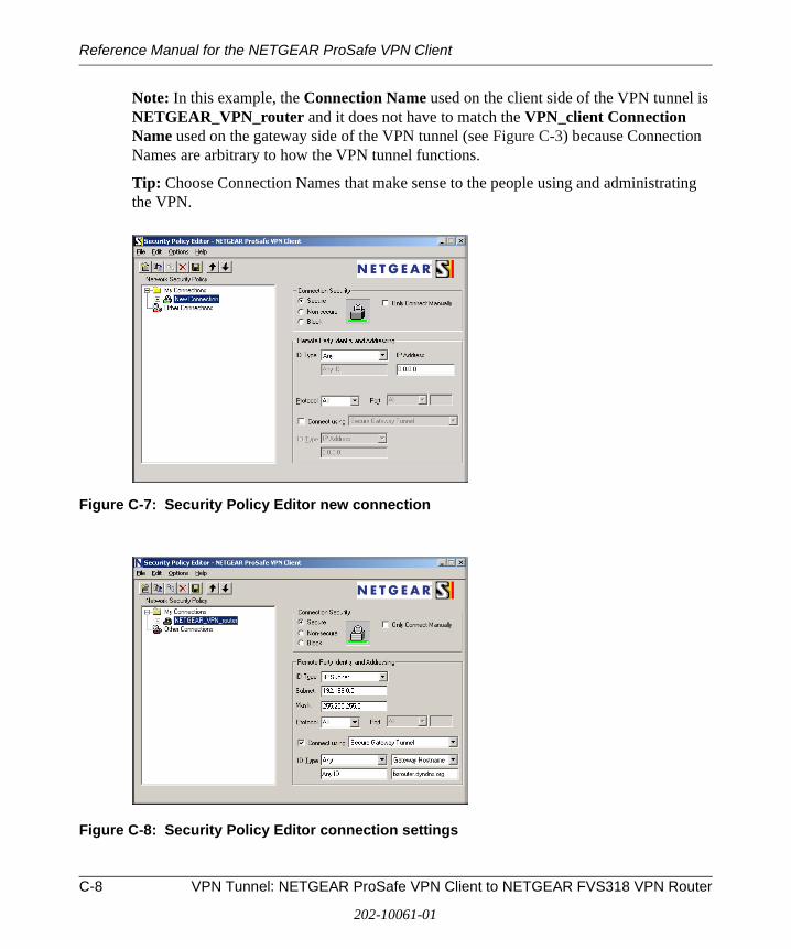
Reference Manual for the NETGEAR ProSafe VPN Client
Note: In this example, the Connection Name used on the client side of the VPN tunnel is NETGEAR_VPN_router and it does not have to match the VPN_client Connection Name used on the gateway side of the VPN tunnel (see Figure C-3) because Connection Names are arbitrary to how the VPN tunnel functions.
Tip: Choose Connection Names that make sense to the people using and administrating the VPN.
Figure C-7: Security Policy Editor new connection
Figure C-8: Security Policy Editor connection settings
C-8 VPN Tunnel: NETGEAR ProSafe VPN Client to NETGEAR FVS318 VPN Router
202-10061-01

Reference Manual for the NETGEAR ProSafe VPN Client
c. Select Secure in the Connection Security check box.
d. Select IP Subnet in the ID Type menu.
e. In this example, type 192.168.0.0 in the Subnet field as the network address of the VPN Client.
f. Enter 255.255.0.0 in the Mask field as the LAN Subnet Mask of the VPN Client.
g. Select All in the Protocol menu to allow all traffic through the VPN tunnel.
h. Select the Connect using Secure Gateway Tunnel check box.
i. Select Domain Name in the ID Type menu below the check box.
j. Select Gateway Hostname and enter bzrouter.dyndns.org (in this example).
k. The resulting Connection Settings are shown in Figure C-8.
3. Configure the Security Policy in the NETGEAR ProSafe VPN Client software.
a. In the Network Security Policy list, expand the new connection by double clicking its name or clicking on the “+” symbol. My Identity and Security Policy subheadings appear below the connection name.
b. Click on the Security Policy subheading to show the Security Policy menu.
Figure C-9: Security Policy Editor security policy
c. Select the Main Mode in the Select Phase 1 Negotiation Mode check box.
VPN Tunnel: NETGEAR ProSafe VPN Client to NETGEAR FVS318 VPN Router C-9
202-10061-01
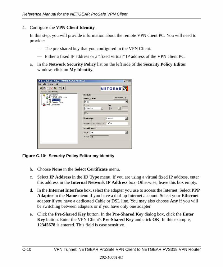
Reference Manual for the NETGEAR ProSafe VPN Client
4. Configure the VPN Client Identity.
In this step, you will provide information about the remote VPN client PC. You will need to provide:
— The pre-shared key that you configured in the VPN Client.
— Either a fixed IP address or a “fixed virtual” IP address of the VPN client PC.
a. In the Network Security Policy list on the left side of the Security Policy Editor window, click on My Identity.
Figure C-10: Security Policy Editor my identity
b. Choose None in the Select Certificate menu.
c. Select IP Address in the ID Type menu. If you are using a virtual fixed IP address, enter this address in the Internal Network IP Address box. Otherwise, leave this box empty.
d. In the Internet Interface box, select the adapter you use to access the Internet. Select PPP Adapter in the Name menu if you have a dial-up Internet account. Select your Ethernet adapter if you have a dedicated Cable or DSL line. You may also choose Any if you will be switching between adapters or if you have only one adapter.
e. Click the Pre-Shared Key button. In the Pre-Shared Key dialog box, click the Enter Key button. Enter the VPN Client's Pre-Shared Key and click OK. In this example, 12345678 is entered. This field is case sensitive.
C-10 VPN Tunnel: NETGEAR ProSafe VPN Client to NETGEAR FVS318 VPN Router
202-10061-01
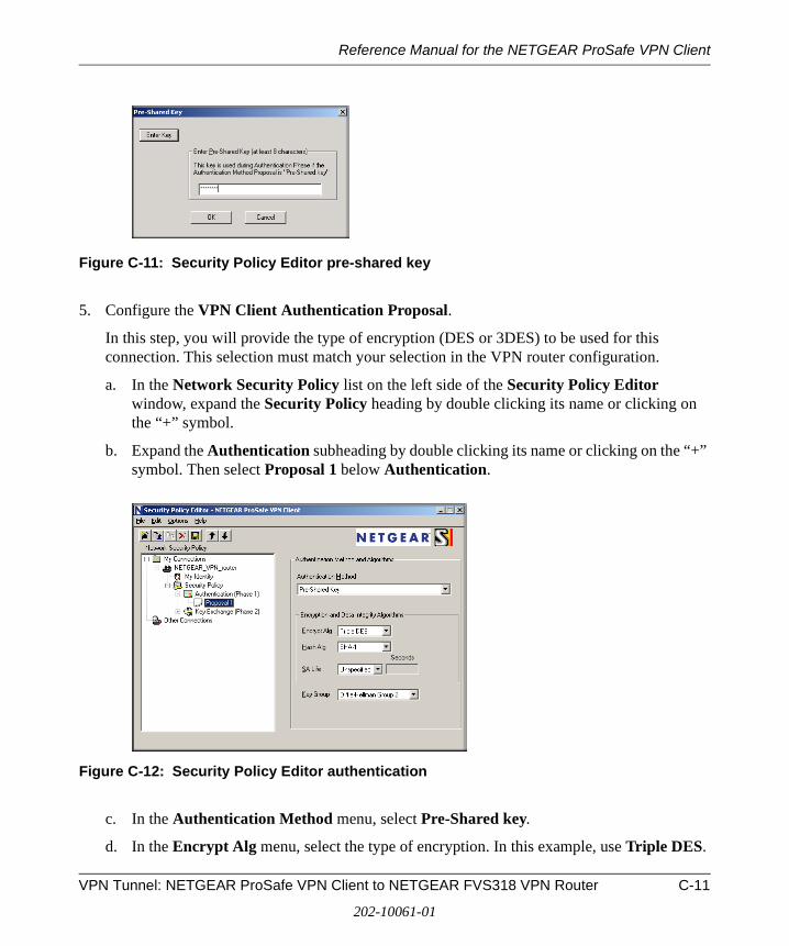
Reference Manual for the NETGEAR ProSafe VPN Client
Figure C-11: Security Policy Editor pre-shared key
5. Configure the VPN Client Authentication Proposal.
In this step, you will provide the type of encryption (DES or 3DES) to be used for this connection. This selection must match your selection in the VPN router configuration.
a. In the Network Security Policy list on the left side of the Security Policy Editor window, expand the Security Policy heading by double clicking its name or clicking on the “+” symbol.
b. Expand the Authentication subheading by double clicking its name or clicking on the “+” symbol. Then select Proposal 1 below Authentication.
Figure C-12: Security Policy Editor authentication
c. In the Authentication Method menu, select Pre-Shared key.
d. In the Encrypt Alg menu, select the type of encryption. In this example, use Triple DES.
VPN Tunnel: NETGEAR ProSafe VPN Client to NETGEAR FVS318 VPN Router C-11
202-10061-01

Reference Manual for the NETGEAR ProSafe VPN Client
e. In the Hash Alg menu, select SHA-1.
f. In the SA Life menu, select Unspecified.
g. In the Key Group menu, select Diffie-Hellman Group 2.
6. Configure the VPN Client Key Exchange Proposal.
In this step, you will provide the type of encryption (DES or 3DES) to be used for this connection. This selection must match your selection in the VPN router configuration.
a. Expand the Key Exchange subheading by double clicking its name or clicking on the “+” symbol. Then select Proposal 1 below Key Exchange.
Figure C-13: Security Policy Editor key exchange
b. In the SA Life menu, select Unspecified.
c. In the Compression menu, select None.
d. Check the Encapsulation Protocol (ESP) checkbox.
e. In the Encrypt Alg menu, select the type of encryption. In this example, use Triple DES.
f. In the Hash Alg menu, select SHA-1.
g. In the Encapsulation menu, select Tunnel.
h. Leave the Authentication Protocol (AH) checkbox unchecked.
7. Save the VPN Client settings.
From the File menu at the top of the Security Policy Editor window, select Save.
C-12 VPN Tunnel: NETGEAR ProSafe VPN Client to NETGEAR FVS318 VPN Router
202-10061-01

Reference Manual for the NETGEAR ProSafe VPN Client
After you have configured and saved the VPN client information, your PC will automatically open the VPN connection when you attempt to access any IP addresses in the range of the remote VPN router’s LAN.
8. Check the VPN Connection.
To check the VPN Connection, you can initiate a request from the remote PC to the VPN router’s network by using the Connect option in the NETGEAR VPN Client menu bar (see Figure C-14). Since the remote PC has a dynamically assigned WAN IP address, it must initiate the request.
a. Open the popup menu by right-clicking on the system tray icon.
b. Select Connect to open the My Connections list.
c. Choose NETGEAR_VPN_router.
The NETGEAR ProSafe VPN Client will report the results of the attempt to connect. Once the connection is established, you can access resources of the network connected to the VPN router.
Figure C-14: Connecting the PC the FVS318 over the VPN tunnel
To perform a ping test using our example, start from the remote PC:
a. Establish an Internet connection from the PC.
b. On the Windows taskbar, click the Start button, and then click Run.
c. Type ping -t 192.168.0.1, and then click OK.
Right-mouse-click on the system tray icon to open the popup menu.
VPN Tunnel: NETGEAR ProSafe VPN Client to NETGEAR FVS318 VPN Router C-13
202-10061-01
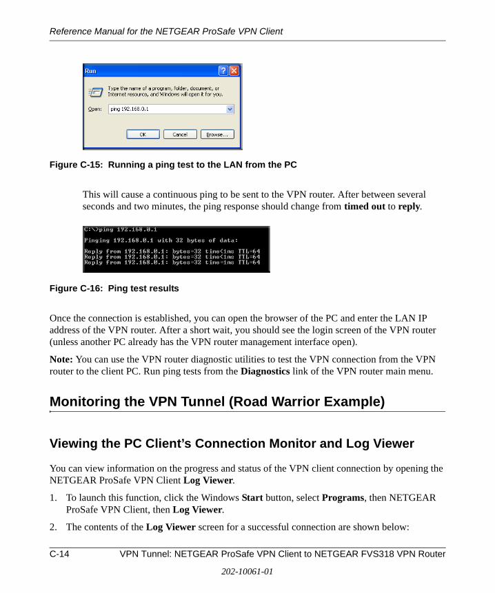
Reference Manual for the NETGEAR ProSafe VPN Client
Figure C-15: Running a ping test to the LAN from the PC
This will cause a continuous ping to be sent to the VPN router. After between several seconds and two minutes, the ping response should change from timed out to reply.
Figure C-16: Ping test results
Once the connection is established, you can open the browser of the PC and enter the LAN IP address of the VPN router. After a short wait, you should see the login screen of the VPN router (unless another PC already has the VPN router management interface open).
Note: You can use the VPN router diagnostic utilities to test the VPN connection from the VPN router to the client PC. Run ping tests from the Diagnostics link of the VPN router main menu.
Monitoring the VPN Tunnel (Road Warrior Example)
Viewing the PC Client’s Connection Monitor and Log Viewer
You can view information on the progress and status of the VPN client connection by opening the NETGEAR ProSafe VPN Client Log Viewer.
1. To launch this function, click the Windows Start button, select Programs, then NETGEAR ProSafe VPN Client, then Log Viewer.
2. The contents of the Log Viewer screen for a successful connection are shown below:
C-14 VPN Tunnel: NETGEAR ProSafe VPN Client to NETGEAR FVS318 VPN Router
202-10061-01
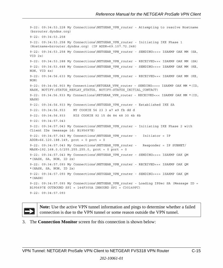
Reference Manual for the NETGEAR ProSafe VPN Client
9-22: 09:34:53.228 My Connections\NETGEAR_VPN_router - Attempting to resolve Hostname (bzrouter.dyndns.org)
9-22: 09:34:53.258
9-22: 09:34:53.258 My Connections\NETGEAR_VPN_router - Initiating IKE Phase 1 (Hostname=bzrouter.dyndns.org) (IP ADDR=69.107.72.248)
9-22: 09:34:53.258 My Connections\NETGEAR_VPN_router - SENDING>>>> ISAKMP OAK MM (SA, VID 2x)
9-22: 09:34:53.288 My Connections\NETGEAR_VPN_router - RECEIVED<<< ISAKMP OAK MM (SA)
9-22: 09:34:53.648 My Connections\NETGEAR_VPN_router - SENDING>>>> ISAKMP OAK MM (KE, NON, VID 4x)
9-22: 09:34:56.633 My Connections\NETGEAR_VPN_router - RECEIVED<<< ISAKMP OAK MM (KE, NON)
9-22: 09:34:56.903 My Connections\NETGEAR_VPN_router - SENDING>>>> ISAKMP OAK MM *(ID, HASH, NOTIFY:STATUS_REPLAY_STATUS, NOTIFY:STATUS_INITIAL_CONTACT)
9-22: 09:34:56.933 My Connections\NETGEAR_VPN_router - RECEIVED<<< ISAKMP OAK MM *(ID, HASH)
9-22: 09:34:56.933 My Connections\NETGEAR_VPN_router - Established IKE SA
9-22: 09:34:56.933 MY COOKIE 56 23 3 a7 e9 fb dd d
9-22: 09:34:56.933 HIS COOKIE 92 15 d4 84 48 30 4b 8b
9-22: 09:34:57.043
9-22: 09:34:57.043 My Connections\NETGEAR_VPN_router - Initiating IKE Phase 2 with Client IDs (message id: B195697E)
9-22: 09:34:57.043 My Connections\NETGEAR_VPN_router - Initiator = IP ADDR=66.120.188.149, prot = 0 port = 0
9-22: 09:34:57.043 My Connections\NETGEAR_VPN_router - Responder = IP SUBNET/MASK=192.168.0.0/255.255.255.0, prot = 0 port = 0
9-22: 09:34:57.043 My Connections\NETGEAR_VPN_router - SENDING>>>> ISAKMP OAK QM *(HASH, SA, NON, ID 2x)
9-22: 09:34:57.093 My Connections\NETGEAR_VPN_router - RECEIVED<<< ISAKMP OAK QM *(HASH, SA, NON, ID 2x)
9-22: 09:34:57.093 My Connections\NETGEAR_VPN_router - SENDING>>>> ISAKMP OAK QM *(HASH)
9-22: 09:34:57.093 My Connections\NETGEAR_VPN_router - Loading IPSec SA (Message ID = B195697E OUTBOUND SPI = 144F305A INBOUND SPI = C30149FC)
9-22: 09:34:57.093
3. The Connection Monitor screen for this connection is shown below:
Note: Use the active VPN tunnel information and pings to determine whether a failed connection is due to the VPN tunnel or some reason outside the VPN tunnel.
VPN Tunnel: NETGEAR ProSafe VPN Client to NETGEAR FVS318 VPN Router C-15
202-10061-01
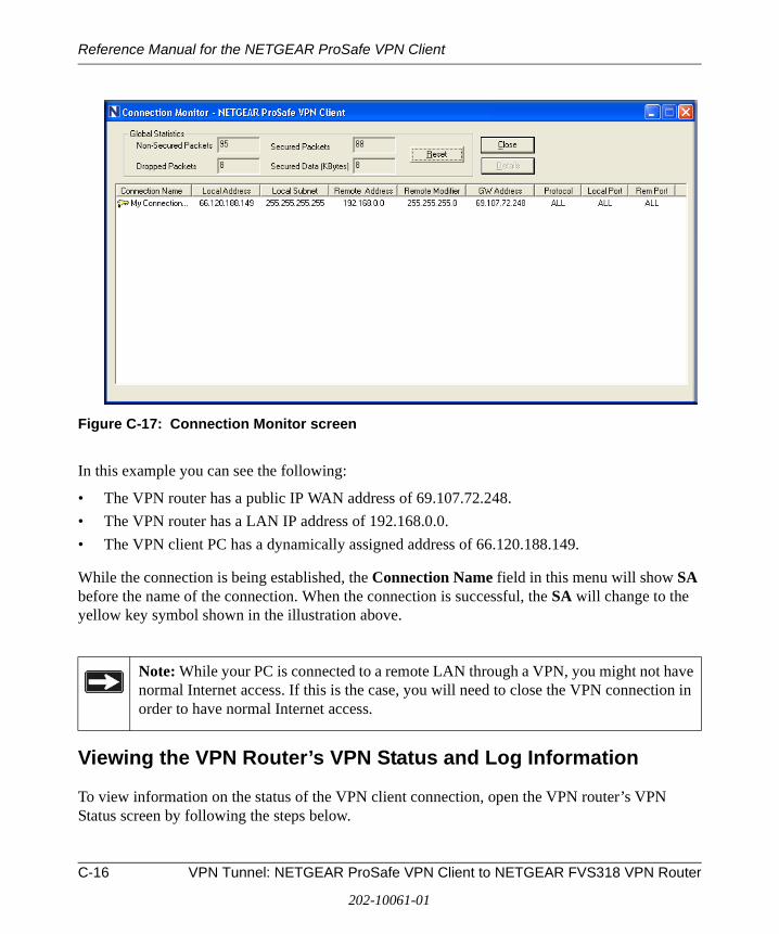
Reference Manual for the NETGEAR ProSafe VPN Client
Figure C-17: Connection Monitor screen
In this example you can see the following:
• The VPN router has a public IP WAN address of 69.107.72.248.
• The VPN router has a LAN IP address of 192.168.0.0.
• The VPN client PC has a dynamically assigned address of 66.120.188.149.
While the connection is being established, the Connection Name field in this menu will show SA before the name of the connection. When the connection is successful, the SA will change to the yellow key symbol shown in the illustration above.
Viewing the VPN Router’s VPN Status and Log Information
To view information on the status of the VPN client connection, open the VPN router’s VPN Status screen by following the steps below.
Note: While your PC is connected to a remote LAN through a VPN, you might not have normal Internet access. If this is the case, you will need to close the VPN connection in order to have normal Internet access.
C-16 VPN Tunnel: NETGEAR ProSafe VPN Client to NETGEAR FVS318 VPN Router
202-10061-01
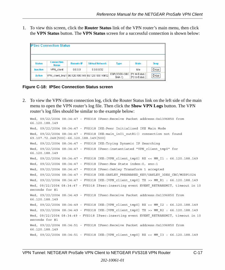
Reference Manual for the NETGEAR ProSafe VPN Client
1. To view this screen, click the Router Status link of the VPN router’s main menu, then click the VPN Status button. The VPN Status screen for a successful connection is shown below:
Figure C-18: IPSec Connection Status screen
2. To view the VPN client connection log, click the Router Status link on the left side of the main menu to open the VPN router’s log file. Then click the Show VPN Logs button. The VPN router’s log files should be similar to the example below:
Wed, 09/22/2004 08:34:47 - FVS318 IPsec:Receive Packet address:0x1396850 from 66.120.188.149
Wed, 09/22/2004 08:34:47 - FVS318 IKE:Peer Initialized IKE Main Mode
Wed, 09/22/2004 08:34:47 - FVS318 IKE:main_inI1_outR1() connection not found 69.107.72.248[500]-66.120.188.149[500]
Wed, 09/22/2004 08:34:47 - FVS318 IKE:Trying Dynamic IP Searching
Wed, 09/22/2004 08:34:47 - FVS318 IPsec:instantiated "VPN_client_tmp0" for 66.120.188.149
Wed, 09/22/2004 08:34:47 - FVS318 IKE:[VPN_client_tmp0] RX << MM_I1 : 66.120.188.149
Wed, 09/22/2004 08:34:47 - FVS318 IPsec:New State index:0, sno:1
Wed, 09/22/2004 08:34:47 - FVS318 IPsec:Oakley Transform 1 accepted
Wed, 09/22/2004 08:34:47 - FVS318 IKE:OAKLEY_PRESHARED_KEY/OAKLEY_3DES_CBC/MODP1024
Wed, 09/22/2004 08:34:47 - FVS318 IKE:[VPN_client_tmp0] TX >> MM_R1 : 66.120.188.149
Wed, 09/22/2004 08:34:47 - FVS318 IPsec:inserting event EVENT_RETRANSMIT, timeout in 10 seconds for #1
Wed, 09/22/2004 08:34:49 - FVS318 IPsec:Receive Packet address:0x1396850 from 66.120.188.149
Wed, 09/22/2004 08:34:49 - FVS318 IKE:[VPN_client_tmp0] RX << MM_I2 : 66.120.188.149
Wed, 09/22/2004 08:34:49 - FVS318 IKE:[VPN_client_tmp0] TX >> MM_R2 : 66.120.188.149
Wed, 09/22/2004 08:34:49 - FVS318 IPsec:inserting event EVENT_RETRANSMIT, timeout in 10 seconds for #1
Wed, 09/22/2004 08:34:51 - FVS318 IPsec:Receive Packet address:0x1396850 from 66.120.188.149
Wed, 09/22/2004 08:34:51 - FVS318 IKE:[VPN_client_tmp0] RX << MM_I3 : 66.120.188.149
VPN Tunnel: NETGEAR ProSafe VPN Client to NETGEAR FVS318 VPN Router C-17
202-10061-01
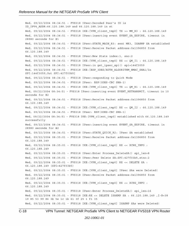
Reference Manual for the NETGEAR ProSafe VPN Client
Wed, 09/22/2004 08:34:51 - FVS318 IPsec:Decoded Peer's ID is ID_IPV4_ADDR:66.120.188.149 and 66.120.188.149 in st
Wed, 09/22/2004 08:34:51 - FVS318 IKE:[VPN_client_tmp0] TX >> MM_R3 : 66.120.188.149
Wed, 09/22/2004 08:34:51 - FVS318 IPsec:inserting event EVENT_SA_EXPIRE, timeout in 28980 seconds for #1
Wed, 09/22/2004 08:34:51 - FVS318 IPsec:STATE_MAIN_R3: sent MR3, ISAKMP SA established
Wed, 09/22/2004 08:34:51 - FVS318 IPsec:Receive Packet address:0x1396850 from 66.120.188.149
Wed, 09/22/2004 08:34:51 - FVS318 IPsec:New State index:1, sno:2
Wed, 09/22/2004 08:34:51 - FVS318 IKE:[VPN_client_tmp0] RX << QM_I1 : 66.120.188.149
Wed, 09/22/2004 08:34:51 - FVS318 IPsec:in get_ipsec_spi() spi=144f3059
Wed, 09/22/2004 08:34:51 - FVS318 IKE:[ESP_3DES/AUTH_ALGORITHM_HMAC_SHA1/In SPI:144f3059,Out SPI:427f03b5]
Wed, 09/22/2004 08:34:51 - FVS318 IPsec:responding to Quick Mode
Wed, 09/22/2004 08:34:51 - FVS318 IPsec: ESP(3DES-CBC SHA-1)
Wed, 09/22/2004 08:34:51 - FVS318 IKE:[VPN_client_tmp0] TX >> QM_R1 : 66.120.188.149
Wed, 09/22/2004 08:34:51 - FVS318 IPsec:inserting event EVENT_RETRANSMIT, timeout in 10 seconds for #2
Wed, 09/22/2004 08:34:51 - FVS318 IPsec:Receive Packet address:0x1396850 from 66.120.188.149
Wed, 09/22/2004 08:34:51 - FVS318 IKE:[VPN_client_tmp0] RX << QM_I2 : 66.120.188.149
Wed, 09/22/2004 08:34:51 - FVS318 IPsec: ESP(3DES-CBC SHA-1)
Wed, 09/22/2004 08:34:51 - FVS318 IKE:[VPN_client_tmp0] established with 66.120.188.149 successfully
Wed, 09/22/2004 08:34:51 - FVS318 IPsec:inserting event EVENT_SA_EXPIRE, timeout in 28980 seconds for #2
Wed, 09/22/2004 08:34:51 - FVS318 IPsec:STATE_QUICK_R2: IPsec SA established
Wed, 09/22/2004 08:35:01 - FVS318 IPsec:Receive Packet address:0x1396850 from 66.120.188.149
Wed, 09/22/2004 08:35:01 - FVS318 IKE:[VPN_client_tmp0] RX << XCHG_INFO : 66.120.188.149
Wed, 09/22/2004 08:35:01 - FVS318 IPsec:Enter Process_DeleteSA() spi_len=8
Wed, 09/22/2004 08:35:01 - FVS318 IPsec:Peer Delete SA:SPI:427f03b5,stno:2
Wed, 09/22/2004 08:35:01 - FVS318 IKE:[VPN_client_tmp0] RX << DELETE SA : 66.120.188.149 (SPI=427f03b5)
Wed, 09/22/2004 08:35:01 - FVS318 IKE:[VPN_client_tmp0] IPsec SAs were Deleted!
Wed, 09/22/2004 08:35:01 - FVS318 IPsec:Receive Packet address:0x1396850 from 66.120.188.149
Wed, 09/22/2004 08:35:01 - FVS318 IKE:[VPN_client_tmp0] RX << XCHG_INFO : 66.120.188.149
Wed, 09/22/2004 08:35:01 - FVS318 IPsec:Enter Process_DeleteSA() spi_len=16
Wed, 09/22/2004 08:35:01 - FVS318 IKE:RX << DELETE ISAKMP SA : 66.120.188.149 ,I-R=38 19 85 53 99 86 3b 5e 1c 1b 61 3f 25 1 f1 35
Wed, 09/22/2004 08:35:01 - FVS318 IKE:[VPN_client_tmp0] ISAKMP SAs were Deleted!
C-18 VPN Tunnel: NETGEAR ProSafe VPN Client to NETGEAR FVS318 VPN Router
202-10061-01
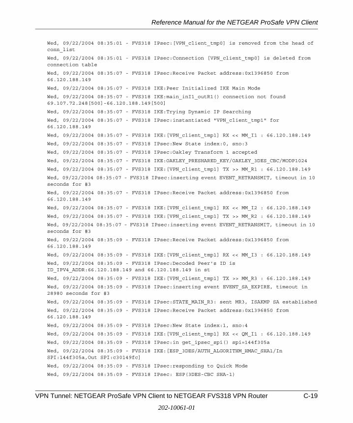
Reference Manual for the NETGEAR ProSafe VPN Client
Wed, 09/22/2004 08:35:01 - FVS318 IPsec:[VPN_client_tmp0] is removed from the head of conn_list
Wed, 09/22/2004 08:35:01 - FVS318 IPsec:Connection [VPN_client_tmp0] is deleted from connection table
Wed, 09/22/2004 08:35:07 - FVS318 IPsec:Receive Packet address:0x1396850 from 66.120.188.149
Wed, 09/22/2004 08:35:07 - FVS318 IKE:Peer Initialized IKE Main Mode
Wed, 09/22/2004 08:35:07 - FVS318 IKE:main_inI1_outR1() connection not found 69.107.72.248[500]-66.120.188.149[500]
Wed, 09/22/2004 08:35:07 - FVS318 IKE:Trying Dynamic IP Searching
Wed, 09/22/2004 08:35:07 - FVS318 IPsec:instantiated "VPN_client_tmp1" for 66.120.188.149
Wed, 09/22/2004 08:35:07 - FVS318 IKE:[VPN_client_tmp1] RX << MM_I1 : 66.120.188.149
Wed, 09/22/2004 08:35:07 - FVS318 IPsec:New State index:0, sno:3
Wed, 09/22/2004 08:35:07 - FVS318 IPsec:Oakley Transform 1 accepted
Wed, 09/22/2004 08:35:07 - FVS318 IKE:OAKLEY_PRESHARED_KEY/OAKLEY_3DES_CBC/MODP1024
Wed, 09/22/2004 08:35:07 - FVS318 IKE:[VPN_client_tmp1] TX >> MM_R1 : 66.120.188.149
Wed, 09/22/2004 08:35:07 - FVS318 IPsec:inserting event EVENT_RETRANSMIT, timeout in 10 seconds for #3
Wed, 09/22/2004 08:35:07 - FVS318 IPsec:Receive Packet address:0x1396850 from 66.120.188.149
Wed, 09/22/2004 08:35:07 - FVS318 IKE:[VPN_client_tmp1] RX << MM_I2 : 66.120.188.149
Wed, 09/22/2004 08:35:07 - FVS318 IKE:[VPN_client_tmp1] TX >> MM_R2 : 66.120.188.149
Wed, 09/22/2004 08:35:07 - FVS318 IPsec:inserting event EVENT_RETRANSMIT, timeout in 10 seconds for #3
Wed, 09/22/2004 08:35:09 - FVS318 IPsec:Receive Packet address:0x1396850 from 66.120.188.149
Wed, 09/22/2004 08:35:09 - FVS318 IKE:[VPN_client_tmp1] RX << MM_I3 : 66.120.188.149
Wed, 09/22/2004 08:35:09 - FVS318 IPsec:Decoded Peer's ID is ID_IPV4_ADDR:66.120.188.149 and 66.120.188.149 in st
Wed, 09/22/2004 08:35:09 - FVS318 IKE:[VPN_client_tmp1] TX >> MM_R3 : 66.120.188.149
Wed, 09/22/2004 08:35:09 - FVS318 IPsec:inserting event EVENT_SA_EXPIRE, timeout in 28980 seconds for #3
Wed, 09/22/2004 08:35:09 - FVS318 IPsec:STATE_MAIN_R3: sent MR3, ISAKMP SA established
Wed, 09/22/2004 08:35:09 - FVS318 IPsec:Receive Packet address:0x1396850 from 66.120.188.149
Wed, 09/22/2004 08:35:09 - FVS318 IPsec:New State index:1, sno:4
Wed, 09/22/2004 08:35:09 - FVS318 IKE:[VPN_client_tmp1] RX << QM_I1 : 66.120.188.149
Wed, 09/22/2004 08:35:09 - FVS318 IPsec:in get_ipsec_spi() spi=144f305a
Wed, 09/22/2004 08:35:09 - FVS318 IKE:[ESP_3DES/AUTH_ALGORITHM_HMAC_SHA1/In SPI:144f305a,Out SPI:c30149fc]
Wed, 09/22/2004 08:35:09 - FVS318 IPsec:responding to Quick Mode
Wed, 09/22/2004 08:35:09 - FVS318 IPsec: ESP(3DES-CBC SHA-1)
VPN Tunnel: NETGEAR ProSafe VPN Client to NETGEAR FVS318 VPN Router C-19
202-10061-01
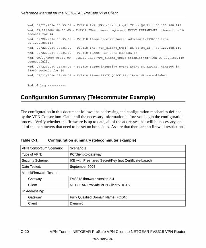
Reference Manual for the NETGEAR ProSafe VPN Client
Wed, 09/22/2004 08:35:09 - FVS318 IKE:[VPN_client_tmp1] TX >> QM_R1 : 66.120.188.149
Wed, 09/22/2004 08:35:09 - FVS318 IPsec:inserting event EVENT_RETRANSMIT, timeout in 10 seconds for #4
Wed, 09/22/2004 08:35:09 - FVS318 IPsec:Receive Packet address:0x1396850 from 66.120.188.149
Wed, 09/22/2004 08:35:09 - FVS318 IKE:[VPN_client_tmp1] RX << QM_I2 : 66.120.188.149
Wed, 09/22/2004 08:35:09 - FVS318 IPsec: ESP(3DES-CBC SHA-1)
Wed, 09/22/2004 08:35:09 - FVS318 IKE:[VPN_client_tmp1] established with 66.120.188.149 successfully
Wed, 09/22/2004 08:35:09 - FVS318 IPsec:inserting event EVENT_SA_EXPIRE, timeout in 28980 seconds for #4
Wed, 09/22/2004 08:35:09 - FVS318 IPsec:STATE_QUICK_R2: IPsec SA established
End of Log ----------
Configuration Summary (Telecommuter Example)
The configuration in this document follows the addressing and configuration mechanics defined by the VPN Consortium. Gather all the necessary information before you begin the configuration process. Verify whether the firmware is up to date, all of the addresses that will be necessary, and all of the parameters that need to be set on both sides. Assure that there are no firewall restrictions.
Table C-1. Configuration summary (telecommuter example)
VPN Consortium Scenario: Scenario 1
Type of VPN: PC/client-to-gateway
Security Scheme: IKE with Preshared Secret/Key (not Certificate-based)
Date Tested: September 2004
Model/Firmware Tested:
Gateway FVS318 firmware version 2.4
Client NETGEAR ProSafe VPN Client v10.3.5
IP Addressing:
Gateway Fully Qualified Domain Name (FQDN)
Client Dynamic
C-20 VPN Tunnel: NETGEAR ProSafe VPN Client to NETGEAR FVS318 VPN Router
202-10061-01
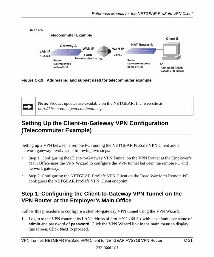
Reference Manual for the NETGEAR ProSafe VPN Client
Figure C-19: Addressing and subnet used for telecommuter example
Setting Up the Client-to-Gateway VPN Configuration (Telecommuter Example)
Setting up a VPN between a remote PC running the NETGEAR ProSafe VPN Client and a network gateway involves the following two steps:
• Step 1: Configuring the Client-to-Gateway VPN Tunnel on the VPN Router at the Employer’s Main Office uses the VPN Wizard to configure the VPN tunnel between the remote PC and network gateway.
• Step 2: Configuring the NETGEAR ProSafe VPN Client on the Road Warrior’s Remote PC configures the NETGEAR ProSafe VPN Client endpoint.
Step 1: Configuring the Client-to-Gateway VPN Tunnel on the VPN Router at the Employer’s Main Office
Follow this procedure to configure a client-to-gateway VPN tunnel using the VPN Wizard.
1. Log in to the VPN router at its LAN address of http://192.168.3.1 with its default user name of admin and password of password. Click the VPN Wizard link in the main menu to display this screen. Click Next to proceed.
Note: Product updates are available on the NETGEAR, Inc. web site at http://kbserver.netgear.com/main.asp.
Gateway A
bzrouter.dyndns.org
10.5.6.0/24
10.5.6.1
WAN IP WAN IPLAN IP
Client B
FQDN 0.0.0.0
Router(at employer'smain office)
Telecommuter Example
NAT Router B
Router(at telecommuter'shome office)
PC(running NETGEARProSafe VPN Client)
VPN Tunnel: NETGEAR ProSafe VPN Client to NETGEAR FVS318 VPN Router C-21
202-10061-01
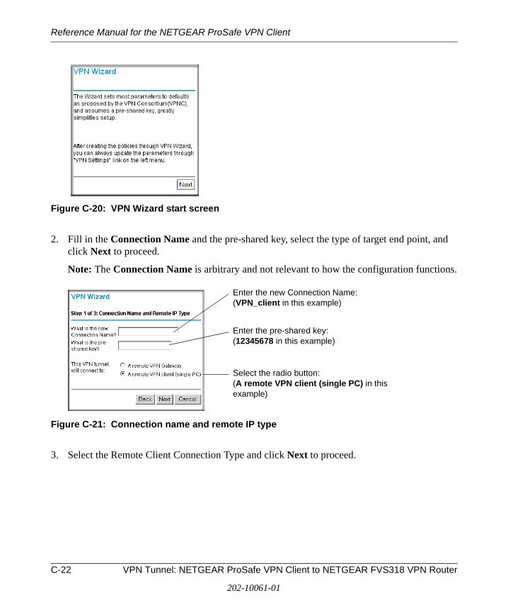
Reference Manual for the NETGEAR ProSafe VPN Client
Figure C-20: VPN Wizard start screen
2. Fill in the Connection Name and the pre-shared key, select the type of target end point, and click Next to proceed.
Note: The Connection Name is arbitrary and not relevant to how the configuration functions.
Figure C-21: Connection name and remote IP type
3. Select the Remote Client Connection Type and click Next to proceed.
Enter the new Connection Name: (VPN_client in this example)
Enter the pre-shared key: (12345678 in this example)
Select the radio button: (A remote VPN client (single PC) in this example)
C-22 VPN Tunnel: NETGEAR ProSafe VPN Client to NETGEAR FVS318 VPN Router
202-10061-01
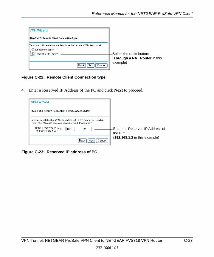
Reference Manual for the NETGEAR ProSafe VPN Client
Figure C-22: Remote Client Connection type
4. Enter a Reserved IP Address of the PC and click Next to proceed.
Figure C-23: Reserved IP address of PC
Select the radio button: (Through a NAT Router in this example)
Enter the Reserved IP Address of the PC: (192.168.1.2 in this example)
VPN Tunnel: NETGEAR ProSafe VPN Client to NETGEAR FVS318 VPN Router C-23
202-10061-01

Reference Manual for the NETGEAR ProSafe VPN Client
The Summary screen below displays.
Figure C-24: VPN Wizard summary
5. Click Done on the Summary screen (see Figure C-5) to complete the configuration procedure. The VPN Settings menu below displays showing that the new tunnel is enabled.
Figure C-25: VPN settings
C-24 VPN Tunnel: NETGEAR ProSafe VPN Client to NETGEAR FVS318 VPN Router
202-10061-01
Reference Manual for the NETGEAR ProSafe VPN Client
To view or modify the tunnel settings, select the radio button next to the tunnel entry and click Edit.
Step 2: Configuring the NETGEAR ProSafe VPN Client on the Remote PC at the Telecommuter’s Home Office
This procedure describes how to configure the NETGEAR ProSafe VPN Client. We will assume the PC running the client has a dynamically assigned IP address.
The PC must have the NETGEAR ProSafe VPN Client program installed that supports IPSec. Go to the NETGEAR website (http://www.netgear.com) and select VPN01L_VPN05L in the Product Quick Find drop-down menu for information on how to purchase the NETGEAR ProSafe VPN Client.
1. Install the NETGEAR ProSafe VPN Client on the remote PC and reboot.
a. You may need to insert your Windows CD to complete the installation.
b. If you do not have a modem or dial-up adapter installed in your PC, you may see the warning message stating “The NETGEAR ProSafe VPN Component requires at least one dial-up adapter be installed.” You can disregard this message.
c. Install the IPSec Component. You may have the option to install either the VPN Adapter or the IPSec Component or both. The VPN Adapter is not necessary.
d. The system should show the ProSafe icon ( ) in the system tray after rebooting.
e. Double-click the system tray icon to open the Security Policy Editor.
2. Add a new connection.
a. Run the NETGEAR ProSafe Security Policy Editor program and create a VPN Connection.
b. From the Edit menu of the Security Policy Editor, click Add, then Connection. A New Connection listing appears in the list of policies. Rename the New Connection so that it matches the Connection Name you entered in the VPN Settings of the VPN Client on Gateway A.
Note: Before installing the NETGEAR ProSafe VPN Client software, be sure to turn off any virus protection or firewall software you may be running on your PC.
VPN Tunnel: NETGEAR ProSafe VPN Client to NETGEAR FVS318 VPN Router C-25
202-10061-01

Reference Manual for the NETGEAR ProSafe VPN Client
Note: In this example, the Connection Name used on the client side of the VPN tunnel is NETGEAR_VPN_router and it does not have to match the VPN_client Connection Name used on the gateway side of the VPN tunnel (see Figure C-3) because Connection Names are arbitrary to how the VPN tunnel functions.
Tip: Choose Connection Names that make sense to the people using and administrating the VPN.
Figure C-26: Security Policy Editor new connection
Figure C-27: Security Policy Editor Connection settings
C-26 VPN Tunnel: NETGEAR ProSafe VPN Client to NETGEAR FVS318 VPN Router
202-10061-01
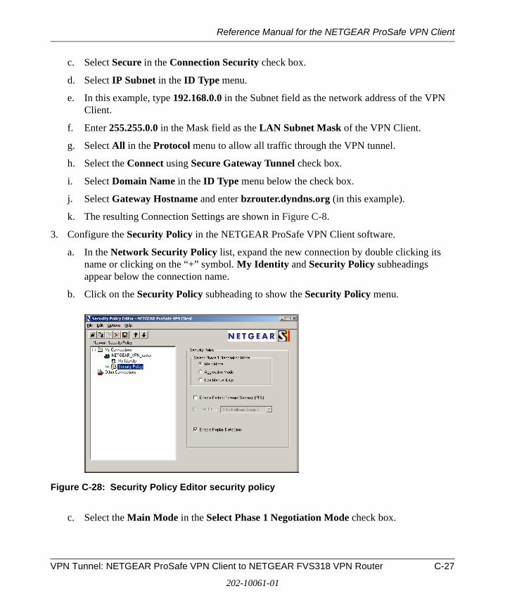
Reference Manual for the NETGEAR ProSafe VPN Client
c. Select Secure in the Connection Security check box.
d. Select IP Subnet in the ID Type menu.
e. In this example, type 192.168.0.0 in the Subnet field as the network address of the VPN Client.
f. Enter 255.255.0.0 in the Mask field as the LAN Subnet Mask of the VPN Client.
g. Select All in the Protocol menu to allow all traffic through the VPN tunnel.
h. Select the Connect using Secure Gateway Tunnel check box.
i. Select Domain Name in the ID Type menu below the check box.
j. Select Gateway Hostname and enter bzrouter.dyndns.org (in this example).
k. The resulting Connection Settings are shown in Figure C-8.
3. Configure the Security Policy in the NETGEAR ProSafe VPN Client software.
a. In the Network Security Policy list, expand the new connection by double clicking its name or clicking on the “+” symbol. My Identity and Security Policy subheadings appear below the connection name.
b. Click on the Security Policy subheading to show the Security Policy menu.
Figure C-28: Security Policy Editor security policy
c. Select the Main Mode in the Select Phase 1 Negotiation Mode check box.
VPN Tunnel: NETGEAR ProSafe VPN Client to NETGEAR FVS318 VPN Router C-27
202-10061-01
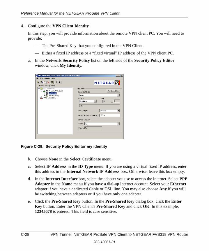
Reference Manual for the NETGEAR ProSafe VPN Client
4. Configure the VPN Client Identity.
In this step, you will provide information about the remote VPN client PC. You will need to provide:
— The Pre-Shared Key that you configured in the VPN Client.
— Either a fixed IP address or a “fixed virtual” IP address of the VPN client PC.
a. In the Network Security Policy list on the left side of the Security Policy Editor window, click My Identity.
Figure C-29: Security Policy Editor my identity
b. Choose None in the Select Certificate menu.
c. Select IP Address in the ID Type menu. If you are using a virtual fixed IP address, enter this address in the Internal Network IP Address box. Otherwise, leave this box empty.
d. In the Internet Interface box, select the adapter you use to access the Internet. Select PPP Adapter in the Name menu if you have a dial-up Internet account. Select your Ethernet adapter if you have a dedicated Cable or DSL line. You may also choose Any if you will be switching between adapters or if you have only one adapter.
e. Click the Pre-Shared Key button. In the Pre-Shared Key dialog box, click the Enter Key button. Enter the VPN Client's Pre-Shared Key and click OK. In this example, 12345678 is entered. This field is case sensitive.
C-28 VPN Tunnel: NETGEAR ProSafe VPN Client to NETGEAR FVS318 VPN Router
202-10061-01
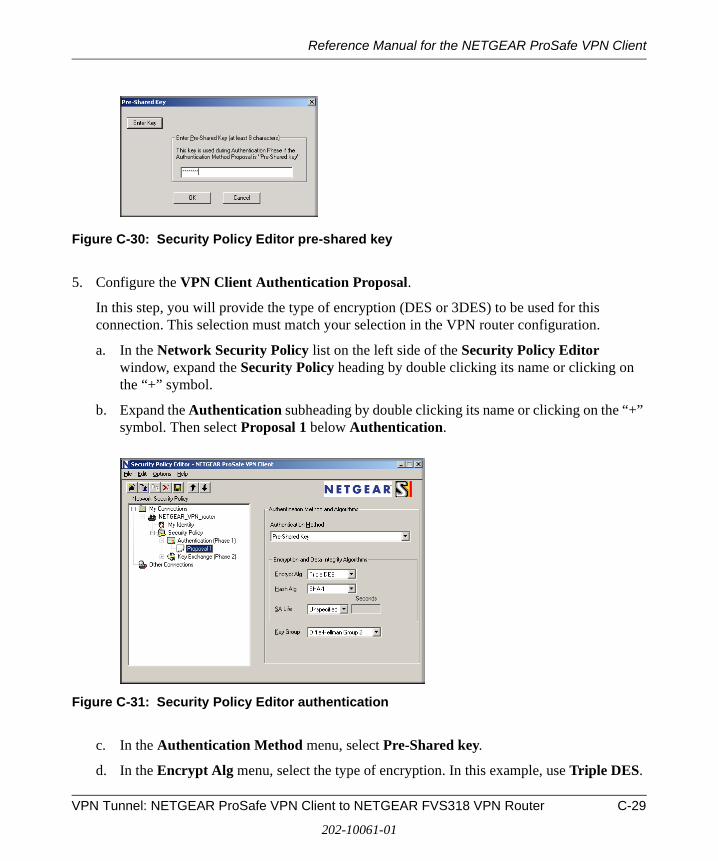
Reference Manual for the NETGEAR ProSafe VPN Client
Figure C-30: Security Policy Editor pre-shared key
5. Configure the VPN Client Authentication Proposal.
In this step, you will provide the type of encryption (DES or 3DES) to be used for this connection. This selection must match your selection in the VPN router configuration.
a. In the Network Security Policy list on the left side of the Security Policy Editor window, expand the Security Policy heading by double clicking its name or clicking on the “+” symbol.
b. Expand the Authentication subheading by double clicking its name or clicking on the “+” symbol. Then select Proposal 1 below Authentication.
Figure C-31: Security Policy Editor authentication
c. In the Authentication Method menu, select Pre-Shared key.
d. In the Encrypt Alg menu, select the type of encryption. In this example, use Triple DES.
VPN Tunnel: NETGEAR ProSafe VPN Client to NETGEAR FVS318 VPN Router C-29
202-10061-01

Reference Manual for the NETGEAR ProSafe VPN Client
e. In the Hash Alg menu, select SHA-1.
f. In the SA Life menu, select Unspecified.
g. In the Key Group menu, select Diffie-Hellman Group 2.
6. Configure the VPN Client Key Exchange Proposal.
In this step, you will provide the type of encryption (DES or 3DES) to be used for this connection. This selection must match your selection in the VPN router configuration.
a. Expand the Key Exchange subheading by double clicking its name or clicking on the “+” symbol. Then select Proposal 1 below Key Exchange.
Figure C-32: Security Policy Editor key exchange
b. In the SA Life menu, select Unspecified.
c. In the Compression menu, select None.
d. Check the Encapsulation Protocol (ESP) checkbox.
e. In the Encrypt Alg menu, select the type of encryption. In this example, use Triple DES.
f. In the Hash Alg menu, select SHA-1.
g. In the Encapsulation menu, select Tunnel.
h. Leave the Authentication Protocol (AH) checkbox unchecked.
7. Save the VPN Client settings.
From the File menu at the top of the Security Policy Editor window, select Save.
C-30 VPN Tunnel: NETGEAR ProSafe VPN Client to NETGEAR FVS318 VPN Router
202-10061-01
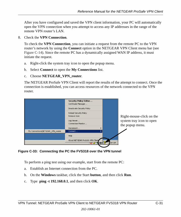
Reference Manual for the NETGEAR ProSafe VPN Client
After you have configured and saved the VPN client information, your PC will automatically open the VPN connection when you attempt to access any IP addresses in the range of the remote VPN router’s LAN.
8. Check the VPN Connection.
To check the VPN Connection, you can initiate a request from the remote PC to the VPN router’s network by using the Connect option in the NETGEAR VPN Client menu bar (see Figure C-14). Since the remote PC has a dynamically assigned WAN IP address, it must initiate the request.
a. Right-click the system tray icon to open the popup menu.
b. Select Connect to open the My Connections list.
c. Choose NETGEAR_VPN_router.
The NETGEAR ProSafe VPN Client will report the results of the attempt to connect. Once the connection is established, you can access resources of the network connected to the VPN router.
Figure C-33: Connecting the PC the FVS318 over the VPN tunnel
To perform a ping test using our example, start from the remote PC:
a. Establish an Internet connection from the PC.
b. On the Windows taskbar, click the Start button, and then click Run.
c. Type ping -t 192.168.0.1, and then click OK.
Right-mouse-click on the system tray icon to open the popup menu.
VPN Tunnel: NETGEAR ProSafe VPN Client to NETGEAR FVS318 VPN Router C-31
202-10061-01
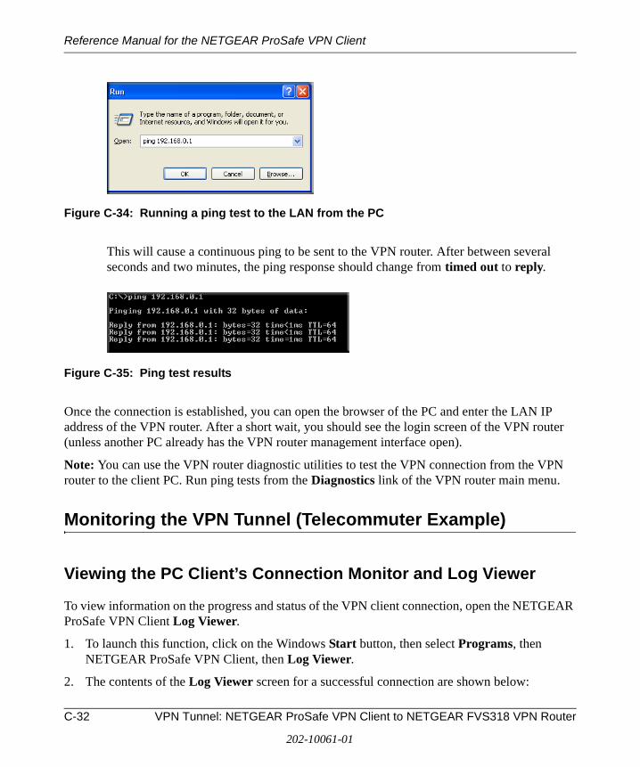
Reference Manual for the NETGEAR ProSafe VPN Client
Figure C-34: Running a ping test to the LAN from the PC
This will cause a continuous ping to be sent to the VPN router. After between several seconds and two minutes, the ping response should change from timed out to reply.
Figure C-35: Ping test results
Once the connection is established, you can open the browser of the PC and enter the LAN IP address of the VPN router. After a short wait, you should see the login screen of the VPN router (unless another PC already has the VPN router management interface open).
Note: You can use the VPN router diagnostic utilities to test the VPN connection from the VPN router to the client PC. Run ping tests from the Diagnostics link of the VPN router main menu.
Monitoring the VPN Tunnel (Telecommuter Example)
Viewing the PC Client’s Connection Monitor and Log Viewer
To view information on the progress and status of the VPN client connection, open the NETGEAR ProSafe VPN Client Log Viewer.
1. To launch this function, click on the Windows Start button, then select Programs, then NETGEAR ProSafe VPN Client, then Log Viewer.
2. The contents of the Log Viewer screen for a successful connection are shown below:
C-32 VPN Tunnel: NETGEAR ProSafe VPN Client to NETGEAR FVS318 VPN Router
202-10061-01
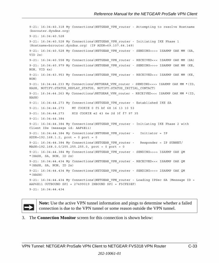
Reference Manual for the NETGEAR ProSafe VPN Client
9-21: 16:34:40.318 My Connections\NETGEAR_VPN_router - Attempting to resolve Hostname (bzrouter.dyndns.org)
9-21: 16:34:40.528
9-21: 16:34:40.528 My Connections\NETGEAR_VPN_router - Initiating IKE Phase 1 (Hostname=bzrouter.dyndns.org) (IP ADDR=69.107.64.149)
9-21: 16:34:40.528 My Connections\NETGEAR_VPN_router - SENDING>>>> ISAKMP OAK MM (SA, VID 2x)
9-21: 16:34:40.558 My Connections\NETGEAR_VPN_router - RECEIVED<<< ISAKMP OAK MM (SA)
9-21: 16:34:40.979 My Connections\NETGEAR_VPN_router - SENDING>>>> ISAKMP OAK MM (KE, NON, VID 4x)
9-21: 16:34:43.953 My Connections\NETGEAR_VPN_router - RECEIVED<<< ISAKMP OAK MM (KE, NON)
9-21: 16:34:44.233 My Connections\NETGEAR_VPN_router - SENDING>>>> ISAKMP OAK MM *(ID, HASH, NOTIFY:STATUS_REPLAY_STATUS, NOTIFY:STATUS_INITIAL_CONTACT)
9-21: 16:34:44.263 My Connections\NETGEAR_VPN_router - RECEIVED<<< ISAKMP OAK MM *(ID, HASH)
9-21: 16:34:44.273 My Connections\NETGEAR_VPN_router - Established IKE SA
9-21: 16:34:44.273 MY COOKIE 0 f5 bf 68 16 13 10 53
9-21: 16:34:44.273 HIS COOKIE e2 43 6e 2d 3f f7 97 35
9-21: 16:34:44.384
9-21: 16:34:44.384 My Connections\NETGEAR_VPN_router - Initiating IKE Phase 2 with Client IDs (message id: AAF6E11)
9-21: 16:34:44.384 My Connections\NETGEAR_VPN_router - Initiator = IP ADDR=192.168.1.2, prot = 0 port = 0
9-21: 16:34:44.384 My Connections\NETGEAR_VPN_router - Responder = IP SUBNET/MASK=192.168.0.0/255.255.255.0, prot = 0 port = 0
9-21: 16:34:44.384 My Connections\NETGEAR_VPN_router - SENDING>>>> ISAKMP OAK QM *(HASH, SA, NON, ID 2x)
9-21: 16:34:44.434 My Connections\NETGEAR_VPN_router - RECEIVED<<< ISAKMP OAK QM *(HASH, SA, NON, ID 2x)
9-21: 16:34:44.434 My Connections\NETGEAR_VPN_router - SENDING>>>> ISAKMP OAK QM *(HASH)
9-21: 16:34:44.434 My Connections\NETGEAR_VPN_router - Loading IPSec SA (Message ID = AAF6E11 OUTBOUND SPI = 27499019 INBOUND SPI = F5CFE3EF)
9-21: 16:34:44.434
3. The Connection Monitor screen for this connection is shown below:
Note: Use the active VPN tunnel information and pings to determine whether a failed connection is due to the VPN tunnel or some reason outside the VPN tunnel.
VPN Tunnel: NETGEAR ProSafe VPN Client to NETGEAR FVS318 VPN Router C-33
202-10061-01
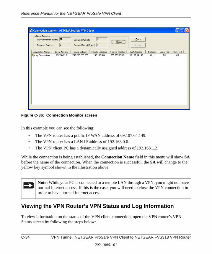
Reference Manual for the NETGEAR ProSafe VPN Client
Figure C-36: Connection Monitor screen
In this example you can see the following:
• The VPN router has a public IP WAN address of 69.107.64.149.
• The VPN router has a LAN IP address of 192.168.0.0.
• The VPN client PC has a dynamically assigned address of 192.168.1.2.
While the connection is being established, the Connection Name field in this menu will show SA before the name of the connection. When the connection is successful, the SA will change to the yellow key symbol shown in the illustration above.
Viewing the VPN Router’s VPN Status and Log Information
To view information on the status of the VPN client connection, open the VPN router’s VPN Status screen by following the steps below:
Note: While your PC is connected to a remote LAN through a VPN, you might not have normal Internet access. If this is the case, you will need to close the VPN connection in order to have normal Internet access.
C-34 VPN Tunnel: NETGEAR ProSafe VPN Client to NETGEAR FVS318 VPN Router
202-10061-01
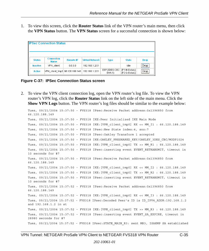
Reference Manual for the NETGEAR ProSafe VPN Client
1. To view this screen, click the Router Status link of the VPN router’s main menu, then click the VPN Status button. The VPN Status screen for a successful connection is shown below:
Figure C-37: IPSec Connection Status screen
2. To view the VPN client connection log, open the VPN router’s log file. To view the VPN router’s VPN log, click the Router Status link on the left side of the main menu. Click the Show VPN Logs button. The VPN router’s log files should be similar to the example below:
Tues, 09/21/2004 15:37:50 - FVS318 IPsec:Receive Packet address:0x1396850 from 66.120.188.149
Tues, 09/21/2004 15:37:50 - FVS318 IKE:Peer Initialized IKE Main Mode
Tues, 09/21/2004 15:37:50 - FVS318 IKE:[VPN_client_tmp0] RX << MM_I1 : 66.120.188.149
Tues, 09/21/2004 15:37:50 - FVS318 IPsec:New State index:4, sno:7
Tues, 09/21/2004 15:37:50 - FVS318 IPsec:Oakley Transform 1 accepted
Tues, 09/21/2004 15:37:50 - FVS318 IKE:OAKLEY_PRESHARED_KEY/OAKLEY_3DES_CBC/MODP1024
Tues, 09/21/2004 15:37:50 - FVS318 IKE:[VPN_client_tmp0] TX >> MM_R1 : 66.120.188.149
Tues, 09/21/2004 15:37:50 - FVS318 IPsec:inserting event EVENT_RETRANSMIT, timeout in 10 seconds for #7
Tues, 09/21/2004 15:37:50 - FVS318 IPsec:Receive Packet address:0x1396850 from 66.120.188.149
Tues, 09/21/2004 15:37:50 - FVS318 IKE:[VPN_client_tmp0] RX << MM_I2 : 66.120.188.149
Tues, 09/21/2004 15:37:50 - FVS318 IKE:[VPN_client_tmp0] TX >> MM_R2 : 66.120.188.149
Tues, 09/21/2004 15:37:50 - FVS318 IPsec:inserting event EVENT_RETRANSMIT, timeout in 10 seconds for #7
Tues, 09/21/2004 15:37:52 - FVS318 IPsec:Receive Packet address:0x1396850 from 66.120.188.149
Tues, 09/21/2004 15:37:52 - FVS318 IKE:[VPN_client_tmp0] RX << MM_I3 : 66.120.188.149
Tues, 09/21/2004 15:37:52 - FVS318 IPsec:Decoded Peer's ID is ID_IPV4_ADDR:192.168.1.2 and 192.168.1.2 in st
Tues, 09/21/2004 15:37:52 - FVS318 IKE:[VPN_client_tmp0] TX >> MM_R3 : 66.120.188.149
Tues, 09/21/2004 15:37:52 - FVS318 IPsec:inserting event EVENT_SA_EXPIRE, timeout in 28980 seconds for #7
Tues, 09/21/2004 15:37:52 - FVS318 IPsec:STATE_MAIN_R3: sent MR3, ISAKMP SA established
VPN Tunnel: NETGEAR ProSafe VPN Client to NETGEAR FVS318 VPN Router C-35
202-10061-01
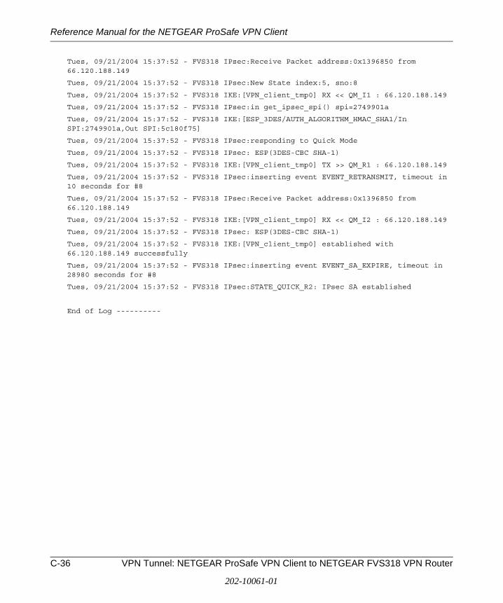
Reference Manual for the NETGEAR ProSafe VPN Client
Tues, 09/21/2004 15:37:52 - FVS318 IPsec:Receive Packet address:0x1396850 from 66.120.188.149
Tues, 09/21/2004 15:37:52 - FVS318 IPsec:New State index:5, sno:8
Tues, 09/21/2004 15:37:52 - FVS318 IKE:[VPN_client_tmp0] RX << QM_I1 : 66.120.188.149
Tues, 09/21/2004 15:37:52 - FVS318 IPsec:in get_ipsec_spi() spi=2749901a
Tues, 09/21/2004 15:37:52 - FVS318 IKE:[ESP_3DES/AUTH_ALGORITHM_HMAC_SHA1/In SPI:2749901a,Out SPI:5c180f75]
Tues, 09/21/2004 15:37:52 - FVS318 IPsec:responding to Quick Mode
Tues, 09/21/2004 15:37:52 - FVS318 IPsec: ESP(3DES-CBC SHA-1)
Tues, 09/21/2004 15:37:52 - FVS318 IKE:[VPN_client_tmp0] TX >> QM_R1 : 66.120.188.149
Tues, 09/21/2004 15:37:52 - FVS318 IPsec:inserting event EVENT_RETRANSMIT, timeout in 10 seconds for #8
Tues, 09/21/2004 15:37:52 - FVS318 IPsec:Receive Packet address:0x1396850 from 66.120.188.149
Tues, 09/21/2004 15:37:52 - FVS318 IKE:[VPN_client_tmp0] RX << QM_I2 : 66.120.188.149
Tues, 09/21/2004 15:37:52 - FVS318 IPsec: ESP(3DES-CBC SHA-1)
Tues, 09/21/2004 15:37:52 - FVS318 IKE:[VPN_client_tmp0] established with 66.120.188.149 successfully
Tues, 09/21/2004 15:37:52 - FVS318 IPsec:inserting event EVENT_SA_EXPIRE, timeout in 28980 seconds for #8
Tues, 09/21/2004 15:37:52 - FVS318 IPsec:STATE_QUICK_R2: IPsec SA established
End of Log ----------
C-36 VPN Tunnel: NETGEAR ProSafe VPN Client to NETGEAR FVS318 VPN Router
202-10061-01
Reference Manual for the NETGEAR ProSafe VPN Client
Appendix DVPN Tunnel: NETGEAR ProSafe VPN Client
to NETGEAR FVL328 or FVS328 VPN Routers
Follow these procedures to configure a VPN tunnel from a NETGEAR ProSafe VPN Client to the FVL328 or FVS328 VPN routers. This document follows the VPN Consortium interoperability guidelines (found at http://www.vpnc.org/InteropProfiles/Interop-01.html).
Configuration Summary (Road Warrior Example)
The configuration in this document follows the addressing and configuration mechanics defined by the VPN Consortium. Gather all the necessary information before you begin the configuration process. Verify whether the firmware is up to date, all of the addresses that will be necessary, and all of the parameters that need to be set on both sides. Assure that there are no firewall restrictions.
Note: Although this appendix uses the FVL328 as the example VPN router, the procedures to configure an FVS328 VPN router are similar.
VPN Tunnel: NETGEAR ProSafe VPN Client to NETGEAR FVL328 or FVS328 VPN Routers D-1
202-10061-01
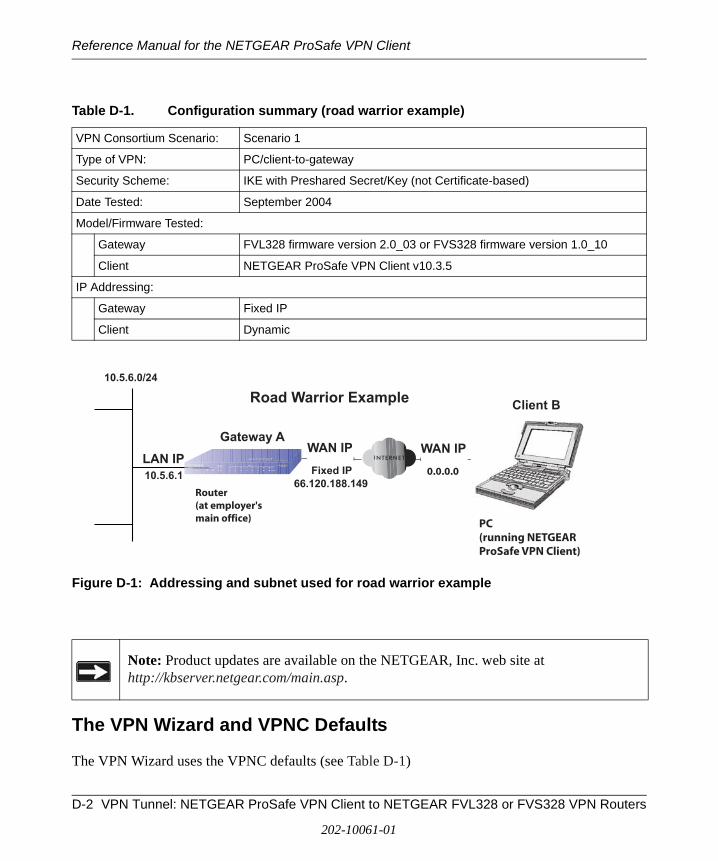
Reference Manual for the NETGEAR ProSafe VPN Client
Figure D-1: Addressing and subnet used for road warrior example
The VPN Wizard and VPNC Defaults
The VPN Wizard uses the VPNC defaults (see Table D-1)
Table D-1. Configuration summary (road warrior example)
VPN Consortium Scenario: Scenario 1
Type of VPN: PC/client-to-gateway
Security Scheme: IKE with Preshared Secret/Key (not Certificate-based)
Date Tested: September 2004
Model/Firmware Tested:
Gateway FVL328 firmware version 2.0_03 or FVS328 firmware version 1.0_10
Client NETGEAR ProSafe VPN Client v10.3.5
IP Addressing:
Gateway Fixed IP
Client Dynamic
Note: Product updates are available on the NETGEAR, Inc. web site at http://kbserver.netgear.com/main.asp.
Gateway A
66.120.188.149
10.5.6.0/24
10.5.6.1
WAN IP WAN IPLAN IP
Client B
Fixed IP 0.0.0.0
Router(at employer'smain office)
Road Warrior Example
PC(running NETGEARProSafe VPN Client)
D-2 VPN Tunnel: NETGEAR ProSafe VPN Client to NETGEAR FVL328 or FVS328 VPN Routers
202-10061-01
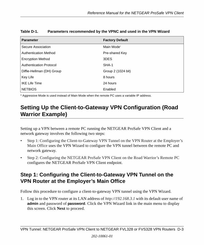
Reference Manual for the NETGEAR ProSafe VPN Client
Setting Up the Client-to-Gateway VPN Configuration (Road Warrior Example)
Setting up a VPN between a remote PC running the NETGEAR ProSafe VPN Client and a network gateway involves the following two steps:
• Step 1: Configuring the Client-to-Gateway VPN Tunnel on the VPN Router at the Employer’s Main Office uses the VPN Wizard to configure the VPN tunnel between the remote PC and network gateway.
• Step 2: Configuring the NETGEAR ProSafe VPN Client on the Road Warrior’s Remote PC configures the NETGEAR ProSafe VPN Client endpoint.
Step 1: Configuring the Client-to-Gateway VPN Tunnel on the VPN Router at the Employer’s Main Office
Follow this procedure to configure a client-to-gateway VPN tunnel using the VPN Wizard.
1. Log in to the VPN router at its LAN address of http://192.168.3.1 with its default user name of admin and password of password. Click the VPN Wizard link in the main menu to display this screen. Click Next to proceed.
Table D-1. Parameters recommended by the VPNC and used in the VPN Wizard
Parameter Factory Default
Secure Association Main Mode*
* Aggressive Mode is used instead of Main Mode when the remote PC uses a variable IP address.
Authentication Method Pre-shared Key
Encryption Method 3DES
Authentication Protocol SHA-1
Diffie-Hellman (DH) Group Group 2 (1024 bit)
Key Life 8 hours
IKE Life Time 24 hours
NETBIOS Enabled
VPN Tunnel: NETGEAR ProSafe VPN Client to NETGEAR FVL328 or FVS328 VPN Routers D-3
202-10061-01
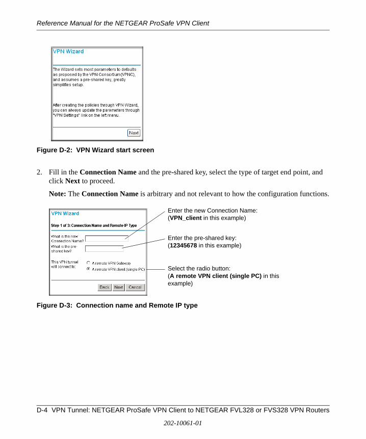
Reference Manual for the NETGEAR ProSafe VPN Client
Figure D-2: VPN Wizard start screen
2. Fill in the Connection Name and the pre-shared key, select the type of target end point, and click Next to proceed.
Note: The Connection Name is arbitrary and not relevant to how the configuration functions.
Figure D-3: Connection name and Remote IP type
Enter the new Connection Name: (VPN_client in this example)
Enter the pre-shared key: (12345678 in this example)
Select the radio button: (A remote VPN client (single PC) in this example)
D-4 VPN Tunnel: NETGEAR ProSafe VPN Client to NETGEAR FVL328 or FVS328 VPN Routers
202-10061-01
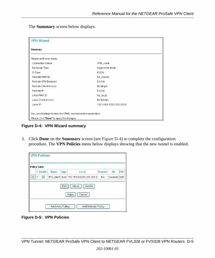
Reference Manual for the NETGEAR ProSafe VPN Client
The Summary screen below displays.
Figure D-4: VPN Wizard summary
3. Click Done on the Summary screen (see Figure D-4) to complete the configuration procedure. The VPN Policies menu below displays showing that the new tunnel is enabled.
Figure D-5: VPN Policies
fvl_local
fvl_remote
VPN Tunnel: NETGEAR ProSafe VPN Client to NETGEAR FVL328 or FVS328 VPN Routers D-5
202-10061-01

Reference Manual for the NETGEAR ProSafe VPN Client
To view or modify the tunnel settings, select the radio button next to the tunnel entry and click Edit.
Step 2: Configuring the NETGEAR ProSafe VPN Client on the Road Warrior’s Remote PC
This procedure describes how to configure the NETGEAR ProSafe VPN Client. The PC running the client has a dynamically assigned IP address.
The PC must have the NETGEAR ProSafe VPN Client program installed that supports IPSec. Go to the NETGEAR website (http://www.netgear.com) and select VPN01L_VPN05L in the Product Quick Find drop-down menu for information on how to purchase the NETGEAR ProSafe VPN Client.
1. Install the NETGEAR ProSafe VPN Client on the remote PC and reboot.
a. You may need to insert your Windows CD to complete the installation.
b. If you do not have a modem or dial-up adapter installed in your PC, you may see the warning message stating “The NETGEAR ProSafe VPN Component requires at least one dial-up adapter be installed.” You can disregard this message.
c. Install the IPSec Component. You may have the option to install either the VPN Adapter or the IPSec Component or both. The VPN Adapter is not necessary.
d. The system should show the ProSafe icon ( ) in the system tray after rebooting.
e. Double-click the system tray icon to open the Security Policy Editor.
2. Add a new connection.
a. Run the NETGEAR ProSafe Security Policy Editor program and create a VPN Connection.
b. From the Edit menu of the Security Policy Editor, click Add, then Connection. A New Connection listing appears in the list of policies. Rename the New Connection so that it matches the Connection Name you entered in the VPN Settings of the VPN Client on Gateway A.
Note: Before installing the NETGEAR ProSafe VPN Client software, be sure to turn off any virus protection or firewall software you may be running on your PC.
D-6 VPN Tunnel: NETGEAR ProSafe VPN Client to NETGEAR FVL328 or FVS328 VPN Routers
202-10061-01
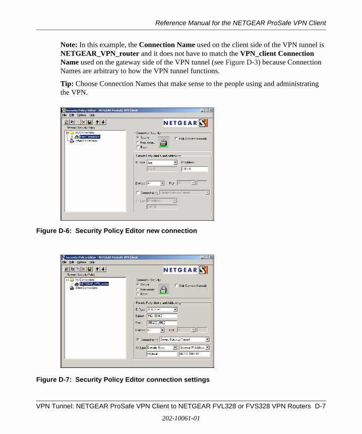
Reference Manual for the NETGEAR ProSafe VPN Client
Note: In this example, the Connection Name used on the client side of the VPN tunnel is NETGEAR_VPN_router and it does not have to match the VPN_client Connection Name used on the gateway side of the VPN tunnel (see Figure D-3) because Connection Names are arbitrary to how the VPN tunnel functions.
Tip: Choose Connection Names that make sense to the people using and administrating the VPN.
Figure D-6: Security Policy Editor new connection
Figure D-7: Security Policy Editor connection settings
VPN Tunnel: NETGEAR ProSafe VPN Client to NETGEAR FVL328 or FVS328 VPN Routers D-7
202-10061-01
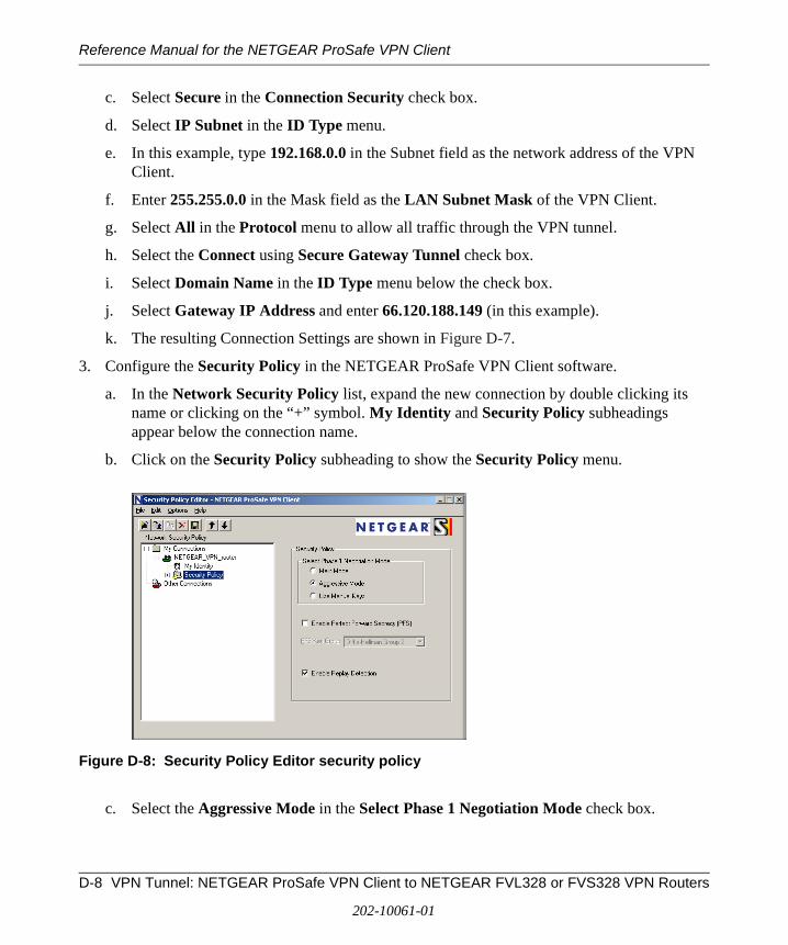
Reference Manual for the NETGEAR ProSafe VPN Client
c. Select Secure in the Connection Security check box.
d. Select IP Subnet in the ID Type menu.
e. In this example, type 192.168.0.0 in the Subnet field as the network address of the VPN Client.
f. Enter 255.255.0.0 in the Mask field as the LAN Subnet Mask of the VPN Client.
g. Select All in the Protocol menu to allow all traffic through the VPN tunnel.
h. Select the Connect using Secure Gateway Tunnel check box.
i. Select Domain Name in the ID Type menu below the check box.
j. Select Gateway IP Address and enter 66.120.188.149 (in this example).
k. The resulting Connection Settings are shown in Figure D-7.
3. Configure the Security Policy in the NETGEAR ProSafe VPN Client software.
a. In the Network Security Policy list, expand the new connection by double clicking its name or clicking on the “+” symbol. My Identity and Security Policy subheadings appear below the connection name.
b. Click on the Security Policy subheading to show the Security Policy menu.
Figure D-8: Security Policy Editor security policy
c. Select the Aggressive Mode in the Select Phase 1 Negotiation Mode check box.
D-8 VPN Tunnel: NETGEAR ProSafe VPN Client to NETGEAR FVL328 or FVS328 VPN Routers
202-10061-01
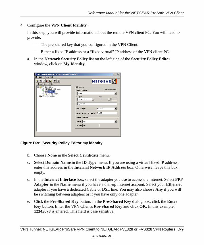
Reference Manual for the NETGEAR ProSafe VPN Client
4. Configure the VPN Client Identity.
In this step, you will provide information about the remote VPN client PC. You will need to provide:
— The pre-shared key that you configured in the VPN Client.
— Either a fixed IP address or a “fixed virtual” IP address of the VPN client PC.
a. In the Network Security Policy list on the left side of the Security Policy Editor window, click on My Identity.
Figure D-9: Security Policy Editor my identity
b. Choose None in the Select Certificate menu.
c. Select Domain Name in the ID Type menu. If you are using a virtual fixed IP address, enter this address in the Internal Network IP Address box. Otherwise, leave this box empty.
d. In the Internet Interface box, select the adapter you use to access the Internet. Select PPP Adapter in the Name menu if you have a dial-up Internet account. Select your Ethernet adapter if you have a dedicated Cable or DSL line. You may also choose Any if you will be switching between adapters or if you have only one adapter.
e. Click the Pre-Shared Key button. In the Pre-Shared Key dialog box, click the Enter Key button. Enter the VPN Client's Pre-Shared Key and click OK. In this example, 12345678 is entered. This field is case sensitive.
VPN Tunnel: NETGEAR ProSafe VPN Client to NETGEAR FVL328 or FVS328 VPN Routers D-9
202-10061-01
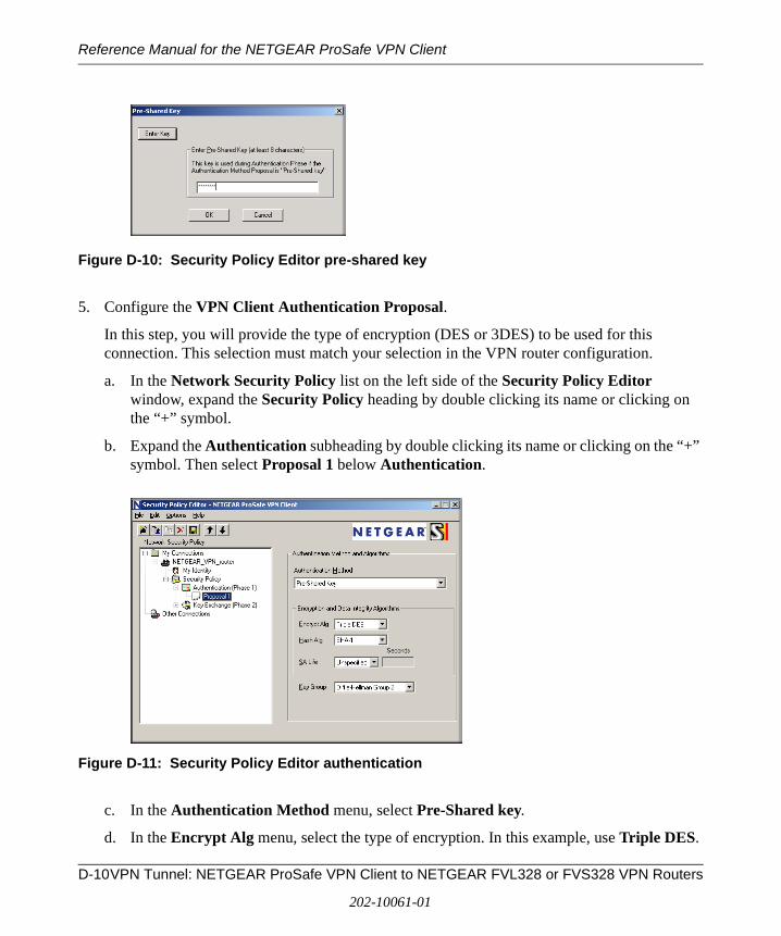
Reference Manual for the NETGEAR ProSafe VPN Client
Figure D-10: Security Policy Editor pre-shared key
5. Configure the VPN Client Authentication Proposal.
In this step, you will provide the type of encryption (DES or 3DES) to be used for this connection. This selection must match your selection in the VPN router configuration.
a. In the Network Security Policy list on the left side of the Security Policy Editor window, expand the Security Policy heading by double clicking its name or clicking on the “+” symbol.
b. Expand the Authentication subheading by double clicking its name or clicking on the “+” symbol. Then select Proposal 1 below Authentication.
Figure D-11: Security Policy Editor authentication
c. In the Authentication Method menu, select Pre-Shared key.
d. In the Encrypt Alg menu, select the type of encryption. In this example, use Triple DES.
D-10VPN Tunnel: NETGEAR ProSafe VPN Client to NETGEAR FVL328 or FVS328 VPN Routers
202-10061-01
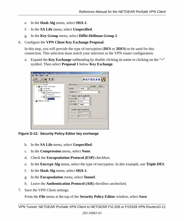
Reference Manual for the NETGEAR ProSafe VPN Client
e. In the Hash Alg menu, select SHA-1.
f. In the SA Life menu, select Unspecified.
g. In the Key Group menu, select Diffie-Hellman Group 2.
6. Configure the VPN Client Key Exchange Proposal.
In this step, you will provide the type of encryption (DES or 3DES) to be used for this connection. This selection must match your selection in the VPN router configuration.
a. Expand the Key Exchange subheading by double clicking its name or clicking on the “+” symbol. Then select Proposal 1 below Key Exchange.
Figure D-12: Security Policy Editor key exchange
b. In the SA Life menu, select Unspecified.
c. In the Compression menu, select None.
d. Check the Encapsulation Protocol (ESP) checkbox.
e. In the Encrypt Alg menu, select the type of encryption. In this example, use Triple DES.
f. In the Hash Alg menu, select SHA-1.
g. In the Encapsulation menu, select Tunnel.
h. Leave the Authentication Protocol (AH) checkbox unchecked.
7. Save the VPN Client settings.
From the File menu at the top of the Security Policy Editor window, select Save.
VPN Tunnel: NETGEAR ProSafe VPN Client to NETGEAR FVL328 or FVS328 VPN RoutersD-11
202-10061-01
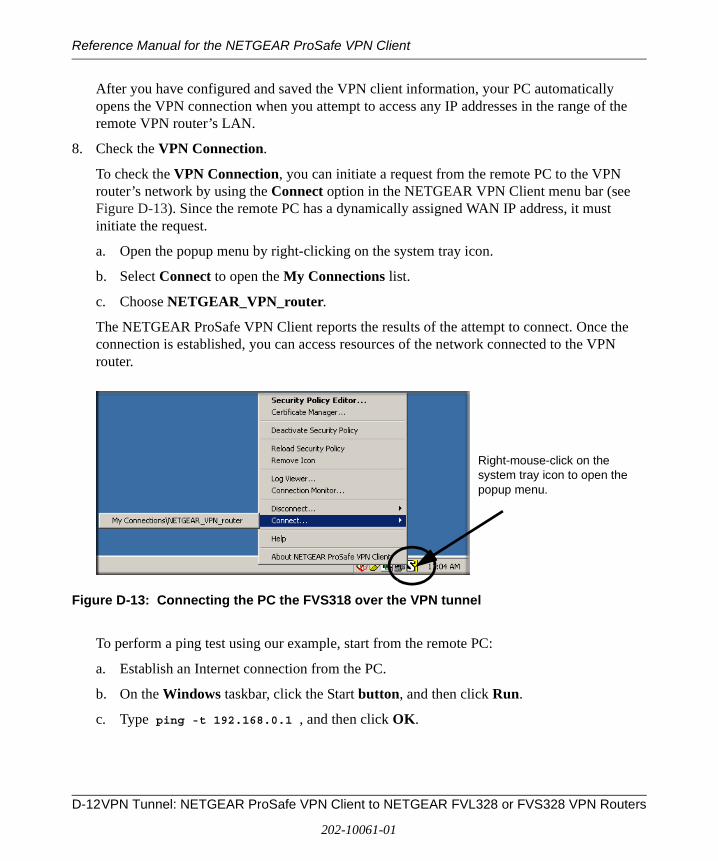
Reference Manual for the NETGEAR ProSafe VPN Client
After you have configured and saved the VPN client information, your PC automatically opens the VPN connection when you attempt to access any IP addresses in the range of the remote VPN router’s LAN.
8. Check the VPN Connection.
To check the VPN Connection, you can initiate a request from the remote PC to the VPN router’s network by using the Connect option in the NETGEAR VPN Client menu bar (see Figure D-13). Since the remote PC has a dynamically assigned WAN IP address, it must initiate the request.
a. Open the popup menu by right-clicking on the system tray icon.
b. Select Connect to open the My Connections list.
c. Choose NETGEAR_VPN_router.
The NETGEAR ProSafe VPN Client reports the results of the attempt to connect. Once the connection is established, you can access resources of the network connected to the VPN router.
Figure D-13: Connecting the PC the FVS318 over the VPN tunnel
To perform a ping test using our example, start from the remote PC:
a. Establish an Internet connection from the PC.
b. On the Windows taskbar, click the Start button, and then click Run.
c. Type ping -t 192.168.0.1 , and then click OK.
Right-mouse-click on the system tray icon to open the popup menu.
D-12VPN Tunnel: NETGEAR ProSafe VPN Client to NETGEAR FVL328 or FVS328 VPN Routers
202-10061-01

Reference Manual for the NETGEAR ProSafe VPN Client
Figure D-14: Running a ping test to the LAN from the PC
This will cause a continuous ping to be sent to the VPN router. Within two minutes, the ping response should change from timed out to reply.
Figure D-15: Ping test results
Once the connection is established, you can open the browser of the PC and enter the LAN IP address of the VPN router. After a short wait, you should see the login screen of the VPN router (unless another PC already has the VPN router management interface open).
Note: You can use the VPN router diagnostic utilities to test the VPN connection from the VPN router to the client PC. Run ping tests from the Diagnostics link of the VPN router main menu.
Monitoring the VPN Tunnel (Road Warrior Example)
Viewing the PC Client’s Connection Monitor and Log Viewer
You can view information on the progress and status of the VPN client connection by opening the NETGEAR ProSafe VPN Client Log Viewer.
1. To launch this function, click the Windows Start button, select Programs, then NETGEAR ProSafe VPN Client, then Log Viewer.
2. The contents of the Log Viewer screen for a successful connection is shown below:
VPN Tunnel: NETGEAR ProSafe VPN Client to NETGEAR FVL328 or FVS328 VPN RoutersD-13
202-10061-01
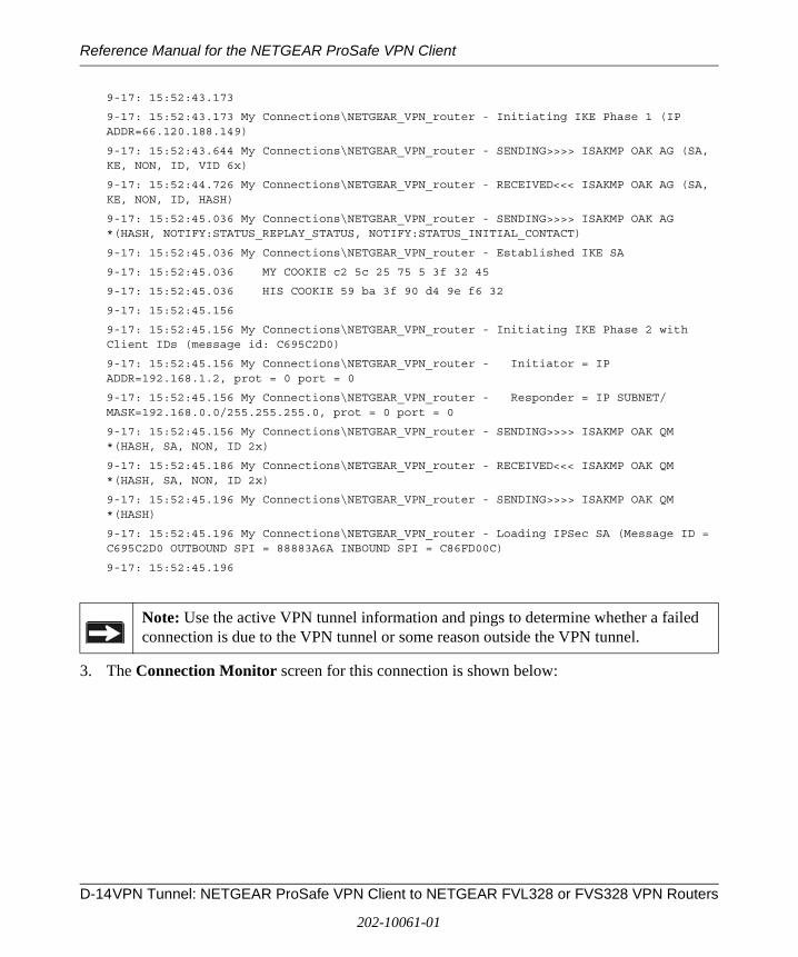
Reference Manual for the NETGEAR ProSafe VPN Client
9-17: 15:52:43.173
9-17: 15:52:43.173 My Connections\NETGEAR_VPN_router - Initiating IKE Phase 1 (IP ADDR=66.120.188.149)
9-17: 15:52:43.644 My Connections\NETGEAR_VPN_router - SENDING>>>> ISAKMP OAK AG (SA, KE, NON, ID, VID 6x)
9-17: 15:52:44.726 My Connections\NETGEAR_VPN_router - RECEIVED<<< ISAKMP OAK AG (SA, KE, NON, ID, HASH)
9-17: 15:52:45.036 My Connections\NETGEAR_VPN_router - SENDING>>>> ISAKMP OAK AG *(HASH, NOTIFY:STATUS_REPLAY_STATUS, NOTIFY:STATUS_INITIAL_CONTACT)
9-17: 15:52:45.036 My Connections\NETGEAR_VPN_router - Established IKE SA
9-17: 15:52:45.036 MY COOKIE c2 5c 25 75 5 3f 32 45
9-17: 15:52:45.036 HIS COOKIE 59 ba 3f 90 d4 9e f6 32
9-17: 15:52:45.156
9-17: 15:52:45.156 My Connections\NETGEAR_VPN_router - Initiating IKE Phase 2 with Client IDs (message id: C695C2D0)
9-17: 15:52:45.156 My Connections\NETGEAR_VPN_router - Initiator = IP ADDR=192.168.1.2, prot = 0 port = 0
9-17: 15:52:45.156 My Connections\NETGEAR_VPN_router - Responder = IP SUBNET/MASK=192.168.0.0/255.255.255.0, prot = 0 port = 0
9-17: 15:52:45.156 My Connections\NETGEAR_VPN_router - SENDING>>>> ISAKMP OAK QM *(HASH, SA, NON, ID 2x)
9-17: 15:52:45.186 My Connections\NETGEAR_VPN_router - RECEIVED<<< ISAKMP OAK QM *(HASH, SA, NON, ID 2x)
9-17: 15:52:45.196 My Connections\NETGEAR_VPN_router - SENDING>>>> ISAKMP OAK QM *(HASH)
9-17: 15:52:45.196 My Connections\NETGEAR_VPN_router - Loading IPSec SA (Message ID = C695C2D0 OUTBOUND SPI = 88883A6A INBOUND SPI = C86FD00C)
9-17: 15:52:45.196
3. The Connection Monitor screen for this connection is shown below:
Note: Use the active VPN tunnel information and pings to determine whether a failed connection is due to the VPN tunnel or some reason outside the VPN tunnel.
D-14VPN Tunnel: NETGEAR ProSafe VPN Client to NETGEAR FVL328 or FVS328 VPN Routers
202-10061-01
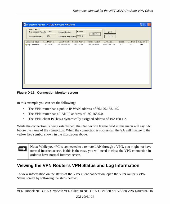
Reference Manual for the NETGEAR ProSafe VPN Client
Figure D-16: Connection Monitor screen
In this example you can see the following:
• The VPN router has a public IP WAN address of 66.120.188.149.
• The VPN router has a LAN IP address of 192.168.0.0.
• The VPN client PC has a dynamically assigned address of 192.168.1.2.
While the connection is being established, the Connection Name field in this menu will say SA before the name of the connection. When the connection is successful, the SA will change to the yellow key symbol shown in the illustration above.
Viewing the VPN Router’s VPN Status and Log Information
To view information on the status of the VPN client connection, open the VPN router’s VPN Status screen by following the steps below:
Note: While your PC is connected to a remote LAN through a VPN, you might not have normal Internet access. If this is the case, you will need to close the VPN connection in order to have normal Internet access.
VPN Tunnel: NETGEAR ProSafe VPN Client to NETGEAR FVL328 or FVS328 VPN RoutersD-15
202-10061-01
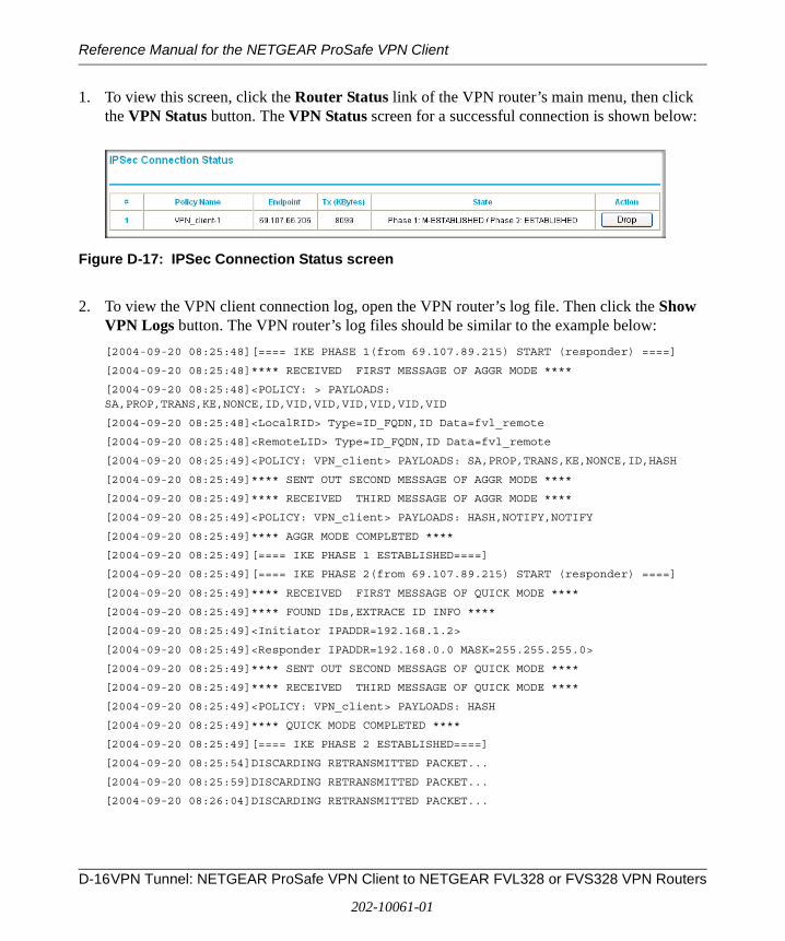
Reference Manual for the NETGEAR ProSafe VPN Client
1. To view this screen, click the Router Status link of the VPN router’s main menu, then click the VPN Status button. The VPN Status screen for a successful connection is shown below:
Figure D-17: IPSec Connection Status screen
2. To view the VPN client connection log, open the VPN router’s log file. Then click the Show VPN Logs button. The VPN router’s log files should be similar to the example below:
[2004-09-20 08:25:48][==== IKE PHASE 1(from 69.107.89.215) START (responder) ====]
[2004-09-20 08:25:48]**** RECEIVED FIRST MESSAGE OF AGGR MODE ****
[2004-09-20 08:25:48]<POLICY: > PAYLOADS: SA,PROP,TRANS,KE,NONCE,ID,VID,VID,VID,VID,VID,VID
[2004-09-20 08:25:48]<LocalRID> Type=ID_FQDN,ID Data=fvl_remote
[2004-09-20 08:25:48]<RemoteLID> Type=ID_FQDN,ID Data=fvl_remote
[2004-09-20 08:25:49]<POLICY: VPN_client> PAYLOADS: SA,PROP,TRANS,KE,NONCE,ID,HASH
[2004-09-20 08:25:49]**** SENT OUT SECOND MESSAGE OF AGGR MODE ****
[2004-09-20 08:25:49]**** RECEIVED THIRD MESSAGE OF AGGR MODE ****
[2004-09-20 08:25:49]<POLICY: VPN_client> PAYLOADS: HASH,NOTIFY,NOTIFY
[2004-09-20 08:25:49]**** AGGR MODE COMPLETED ****
[2004-09-20 08:25:49][==== IKE PHASE 1 ESTABLISHED====]
[2004-09-20 08:25:49][==== IKE PHASE 2(from 69.107.89.215) START (responder) ====]
[2004-09-20 08:25:49]**** RECEIVED FIRST MESSAGE OF QUICK MODE ****
[2004-09-20 08:25:49]**** FOUND IDs,EXTRACE ID INFO ****
[2004-09-20 08:25:49]<Initiator IPADDR=192.168.1.2>
[2004-09-20 08:25:49]<Responder IPADDR=192.168.0.0 MASK=255.255.255.0>
[2004-09-20 08:25:49]**** SENT OUT SECOND MESSAGE OF QUICK MODE ****
[2004-09-20 08:25:49]**** RECEIVED THIRD MESSAGE OF QUICK MODE ****
[2004-09-20 08:25:49]<POLICY: VPN_client> PAYLOADS: HASH
[2004-09-20 08:25:49]**** QUICK MODE COMPLETED ****
[2004-09-20 08:25:49][==== IKE PHASE 2 ESTABLISHED====]
[2004-09-20 08:25:54]DISCARDING RETRANSMITTED PACKET...
[2004-09-20 08:25:59]DISCARDING RETRANSMITTED PACKET...
[2004-09-20 08:26:04]DISCARDING RETRANSMITTED PACKET...
D-16VPN Tunnel: NETGEAR ProSafe VPN Client to NETGEAR FVL328 or FVS328 VPN Routers
202-10061-01
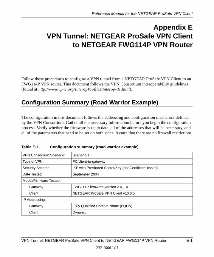
Reference Manual for the NETGEAR ProSafe VPN Client
Appendix EVPN Tunnel: NETGEAR ProSafe VPN Client
to NETGEAR FWG114P VPN Router
Follow these procedures to configure a VPN tunnel from a NETGEAR ProSafe VPN Client to an FWG114P VPN router. This document follows the VPN Consortium interoperability guidelines (found at http://www.vpnc.org/InteropProfiles/Interop-01.html).
Configuration Summary (Road Warrior Example)
The configuration in this document follows the addressing and configuration mechanics defined by the VPN Consortium. Gather all the necessary information before you begin the configuration process. Verify whether the firmware is up to date, all of the addresses that will be necessary, and all of the parameters that need to be set on both sides. Assure that there are no firewall restrictions.
Table E-1. Configuration summary (road warrior example)
VPN Consortium Scenario: Scenario 1
Type of VPN: PC/client-to-gateway
Security Scheme: IKE with Preshared Secret/Key (not Certificate-based)
Date Tested: September 2004
Model/Firmware Tested:
Gateway FWG114P firmware version 2.0_14
Client NETGEAR ProSafe VPN Client v10.3.5
IP Addressing:
Gateway Fully Qualified Domain Name (FQDN)
Client Dynamic
VPN Tunnel: NETGEAR ProSafe VPN Client to NETGEAR FWG114P VPN Router E-1
202-10061-01
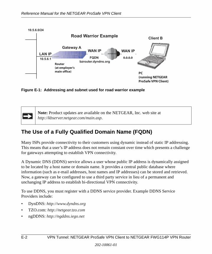
Reference Manual for the NETGEAR ProSafe VPN Client
Figure E-1: Addressing and subnet used for road warrior example
The Use of a Fully Qualified Domain Name (FQDN)
Many ISPs provide connectivity to their customers using dynamic instead of static IP addressing. This means that a user’s IP address does not remain constant over time which presents a challenge for gateways attempting to establish VPN connectivity.
A Dynamic DNS (DDNS) service allows a user whose public IP address is dynamically assigned to be located by a host name or domain name. It provides a central public database where information (such as e-mail addresses, host names and IP addresses) can be stored and retrieved. Now, a gateway can be configured to use a third party service in lieu of a permanent and unchanging IP address to establish bi-directional VPN connectivity.
To use DDNS, you must register with a DDNS service provider. Example DDNS Service Providers include:
• DynDNS: http://www.dyndns.org
• TZO.com: http://netgear.tzo.com
• ngDDNS: http://ngddns.iego.net
Note: Product updates are available on the NETGEAR, Inc. web site at http://kbserver.netgear.com/main.asp.
Gateway A
bzrouter.dyndns.org
10.5.6.0/24
10.5.6.1
WAN IP WAN IPLAN IP
Client B
FQDN 0.0.0.0
Router(at employer'smain office)
Road Warrior Example
PC(running NETGEARProSafe VPN Client)
E-2 VPN Tunnel: NETGEAR ProSafe VPN Client to NETGEAR FWG114P VPN Router
202-10061-01
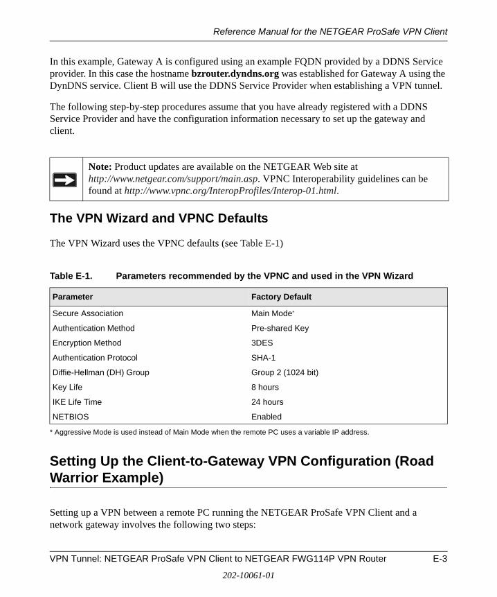
Reference Manual for the NETGEAR ProSafe VPN Client
In this example, Gateway A is configured using an example FQDN provided by a DDNS Service provider. In this case the hostname bzrouter.dyndns.org was established for Gateway A using the DynDNS service. Client B will use the DDNS Service Provider when establishing a VPN tunnel.
The following step-by-step procedures assume that you have already registered with a DDNS Service Provider and have the configuration information necessary to set up the gateway and client.
The VPN Wizard and VPNC Defaults
The VPN Wizard uses the VPNC defaults (see Table E-1)
Setting Up the Client-to-Gateway VPN Configuration (Road Warrior Example)
Setting up a VPN between a remote PC running the NETGEAR ProSafe VPN Client and a network gateway involves the following two steps:
Note: Product updates are available on the NETGEAR Web site at http://www.netgear.com/support/main.asp. VPNC Interoperability guidelines can be found at http://www.vpnc.org/InteropProfiles/Interop-01.html.
Table E-1. Parameters recommended by the VPNC and used in the VPN Wizard
Parameter Factory Default
Secure Association Main Mode*
* Aggressive Mode is used instead of Main Mode when the remote PC uses a variable IP address.
Authentication Method Pre-shared Key
Encryption Method 3DES
Authentication Protocol SHA-1
Diffie-Hellman (DH) Group Group 2 (1024 bit)
Key Life 8 hours
IKE Life Time 24 hours
NETBIOS Enabled
VPN Tunnel: NETGEAR ProSafe VPN Client to NETGEAR FWG114P VPN Router E-3
202-10061-01
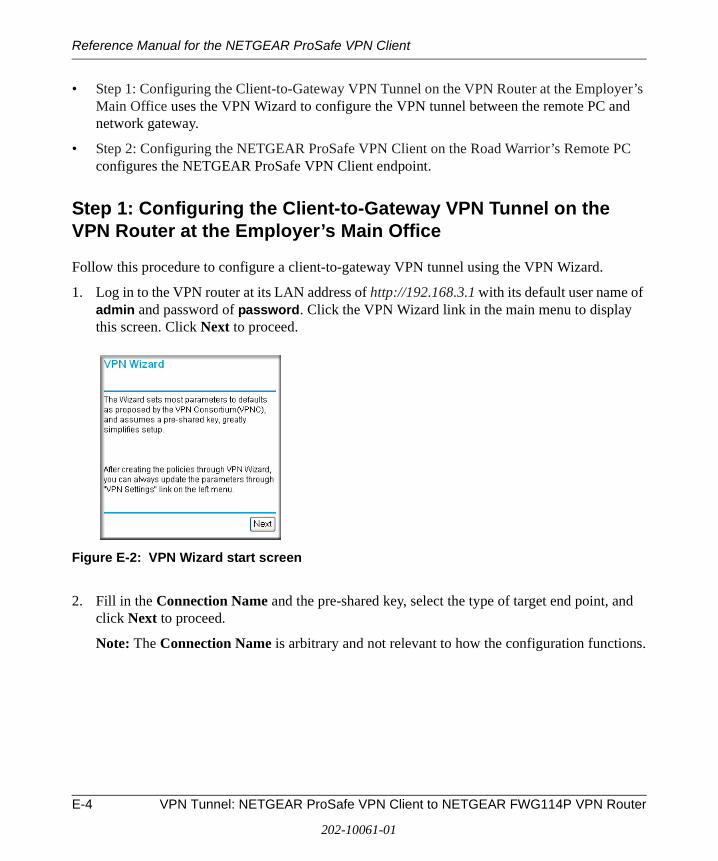
Reference Manual for the NETGEAR ProSafe VPN Client
• Step 1: Configuring the Client-to-Gateway VPN Tunnel on the VPN Router at the Employer’s Main Office uses the VPN Wizard to configure the VPN tunnel between the remote PC and network gateway.
• Step 2: Configuring the NETGEAR ProSafe VPN Client on the Road Warrior’s Remote PC configures the NETGEAR ProSafe VPN Client endpoint.
Step 1: Configuring the Client-to-Gateway VPN Tunnel on the VPN Router at the Employer’s Main Office
Follow this procedure to configure a client-to-gateway VPN tunnel using the VPN Wizard.
1. Log in to the VPN router at its LAN address of http://192.168.3.1 with its default user name of admin and password of password. Click the VPN Wizard link in the main menu to display this screen. Click Next to proceed.
Figure E-2: VPN Wizard start screen
2. Fill in the Connection Name and the pre-shared key, select the type of target end point, and click Next to proceed.
Note: The Connection Name is arbitrary and not relevant to how the configuration functions.
E-4 VPN Tunnel: NETGEAR ProSafe VPN Client to NETGEAR FWG114P VPN Router
202-10061-01
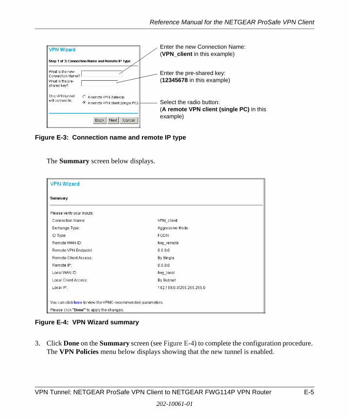
Reference Manual for the NETGEAR ProSafe VPN Client
Figure E-3: Connection name and remote IP type
The Summary screen below displays.
Figure E-4: VPN Wizard summary
3. Click Done on the Summary screen (see Figure E-4) to complete the configuration procedure. The VPN Policies menu below displays showing that the new tunnel is enabled.
Enter the new Connection Name: (VPN_client in this example)
Enter the pre-shared key: (12345678 in this example)
Select the radio button: (A remote VPN client (single PC) in this example)
VPN Tunnel: NETGEAR ProSafe VPN Client to NETGEAR FWG114P VPN Router E-5
202-10061-01
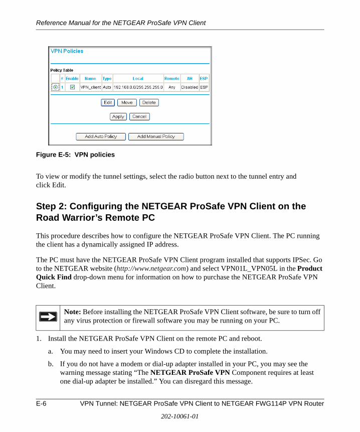
Reference Manual for the NETGEAR ProSafe VPN Client
Figure E-5: VPN policies
To view or modify the tunnel settings, select the radio button next to the tunnel entry and click Edit.
Step 2: Configuring the NETGEAR ProSafe VPN Client on the Road Warrior’s Remote PC
This procedure describes how to configure the NETGEAR ProSafe VPN Client. The PC running the client has a dynamically assigned IP address.
The PC must have the NETGEAR ProSafe VPN Client program installed that supports IPSec. Go to the NETGEAR website (http://www.netgear.com) and select VPN01L_VPN05L in the Product Quick Find drop-down menu for information on how to purchase the NETGEAR ProSafe VPN Client.
1. Install the NETGEAR ProSafe VPN Client on the remote PC and reboot.
a. You may need to insert your Windows CD to complete the installation.
b. If you do not have a modem or dial-up adapter installed in your PC, you may see the warning message stating “The NETGEAR ProSafe VPN Component requires at least one dial-up adapter be installed.” You can disregard this message.
Note: Before installing the NETGEAR ProSafe VPN Client software, be sure to turn off any virus protection or firewall software you may be running on your PC.
E-6 VPN Tunnel: NETGEAR ProSafe VPN Client to NETGEAR FWG114P VPN Router
202-10061-01
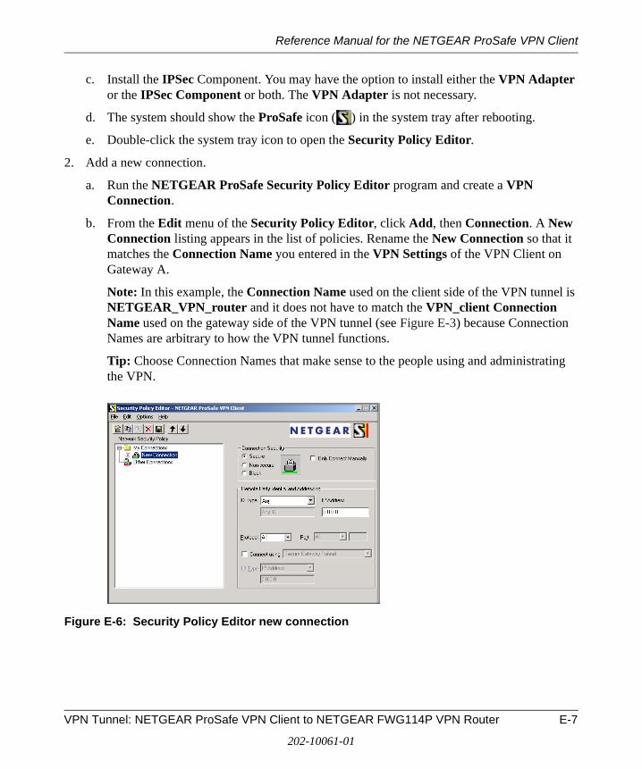
Reference Manual for the NETGEAR ProSafe VPN Client
c. Install the IPSec Component. You may have the option to install either the VPN Adapter or the IPSec Component or both. The VPN Adapter is not necessary.
d. The system should show the ProSafe icon ( ) in the system tray after rebooting.
e. Double-click the system tray icon to open the Security Policy Editor.
2. Add a new connection.
a. Run the NETGEAR ProSafe Security Policy Editor program and create a VPN Connection.
b. From the Edit menu of the Security Policy Editor, click Add, then Connection. A New Connection listing appears in the list of policies. Rename the New Connection so that it matches the Connection Name you entered in the VPN Settings of the VPN Client on Gateway A.
Note: In this example, the Connection Name used on the client side of the VPN tunnel is NETGEAR_VPN_router and it does not have to match the VPN_client Connection Name used on the gateway side of the VPN tunnel (see Figure E-3) because Connection Names are arbitrary to how the VPN tunnel functions.
Tip: Choose Connection Names that make sense to the people using and administrating the VPN.
Figure E-6: Security Policy Editor new connection
VPN Tunnel: NETGEAR ProSafe VPN Client to NETGEAR FWG114P VPN Router E-7
202-10061-01
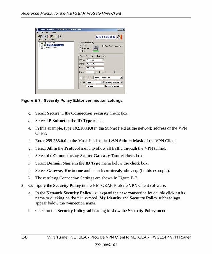
Reference Manual for the NETGEAR ProSafe VPN Client
Figure E-7: Security Policy Editor connection settings
c. Select Secure in the Connection Security check box.
d. Select IP Subnet in the ID Type menu.
e. In this example, type 192.168.0.0 in the Subnet field as the network address of the VPN Client.
f. Enter 255.255.0.0 in the Mask field as the LAN Subnet Mask of the VPN Client.
g. Select All in the Protocol menu to allow all traffic through the VPN tunnel.
h. Select the Connect using Secure Gateway Tunnel check box.
i. Select Domain Name in the ID Type menu below the check box.
j. Select Gateway Hostname and enter bzrouter.dyndns.org (in this example).
k. The resulting Connection Settings are shown in Figure E-7.
3. Configure the Security Policy in the NETGEAR ProSafe VPN Client software.
a. In the Network Security Policy list, expand the new connection by double clicking its name or clicking on the “+” symbol. My Identity and Security Policy subheadings appear below the connection name.
b. Click on the Security Policy subheading to show the Security Policy menu.
E-8 VPN Tunnel: NETGEAR ProSafe VPN Client to NETGEAR FWG114P VPN Router
202-10061-01
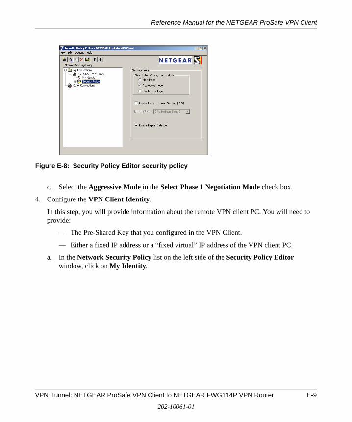
Reference Manual for the NETGEAR ProSafe VPN Client
Figure E-8: Security Policy Editor security policy
c. Select the Aggressive Mode in the Select Phase 1 Negotiation Mode check box.
4. Configure the VPN Client Identity.
In this step, you will provide information about the remote VPN client PC. You will need to provide:
— The Pre-Shared Key that you configured in the VPN Client.
— Either a fixed IP address or a “fixed virtual” IP address of the VPN client PC.
a. In the Network Security Policy list on the left side of the Security Policy Editor window, click on My Identity.
VPN Tunnel: NETGEAR ProSafe VPN Client to NETGEAR FWG114P VPN Router E-9
202-10061-01
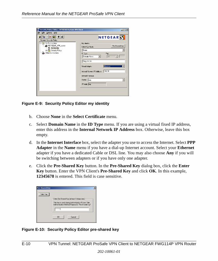
Reference Manual for the NETGEAR ProSafe VPN Client
Figure E-9: Security Policy Editor my identity
b. Choose None in the Select Certificate menu.
c. Select Domain Name in the ID Type menu. If you are using a virtual fixed IP address, enter this address in the Internal Network IP Address box. Otherwise, leave this box empty.
d. In the Internet Interface box, select the adapter you use to access the Internet. Select PPP Adapter in the Name menu if you have a dial-up Internet account. Select your Ethernet adapter if you have a dedicated Cable or DSL line. You may also choose Any if you will be switching between adapters or if you have only one adapter.
e. Click the Pre-Shared Key button. In the Pre-Shared Key dialog box, click the Enter Key button. Enter the VPN Client's Pre-Shared Key and click OK. In this example, 12345678 is entered. This field is case sensitive.
Figure E-10: Security Policy Editor pre-shared key
E-10 VPN Tunnel: NETGEAR ProSafe VPN Client to NETGEAR FWG114P VPN Router
202-10061-01
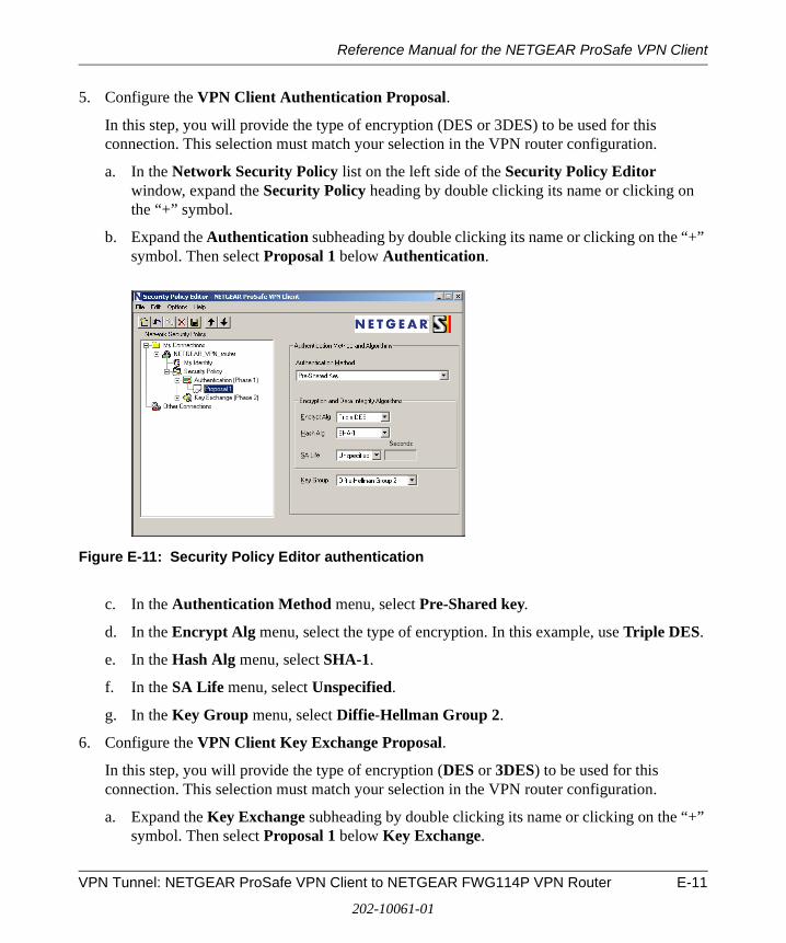
Reference Manual for the NETGEAR ProSafe VPN Client
5. Configure the VPN Client Authentication Proposal.
In this step, you will provide the type of encryption (DES or 3DES) to be used for this connection. This selection must match your selection in the VPN router configuration.
a. In the Network Security Policy list on the left side of the Security Policy Editor window, expand the Security Policy heading by double clicking its name or clicking on the “+” symbol.
b. Expand the Authentication subheading by double clicking its name or clicking on the “+” symbol. Then select Proposal 1 below Authentication.
Figure E-11: Security Policy Editor authentication
c. In the Authentication Method menu, select Pre-Shared key.
d. In the Encrypt Alg menu, select the type of encryption. In this example, use Triple DES.
e. In the Hash Alg menu, select SHA-1.
f. In the SA Life menu, select Unspecified.
g. In the Key Group menu, select Diffie-Hellman Group 2.
6. Configure the VPN Client Key Exchange Proposal.
In this step, you will provide the type of encryption (DES or 3DES) to be used for this connection. This selection must match your selection in the VPN router configuration.
a. Expand the Key Exchange subheading by double clicking its name or clicking on the “+” symbol. Then select Proposal 1 below Key Exchange.
VPN Tunnel: NETGEAR ProSafe VPN Client to NETGEAR FWG114P VPN Router E-11
202-10061-01
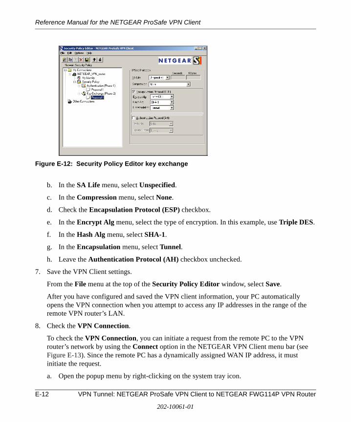
Reference Manual for the NETGEAR ProSafe VPN Client
Figure E-12: Security Policy Editor key exchange
b. In the SA Life menu, select Unspecified.
c. In the Compression menu, select None.
d. Check the Encapsulation Protocol (ESP) checkbox.
e. In the Encrypt Alg menu, select the type of encryption. In this example, use Triple DES.
f. In the Hash Alg menu, select SHA-1.
g. In the Encapsulation menu, select Tunnel.
h. Leave the Authentication Protocol (AH) checkbox unchecked.
7. Save the VPN Client settings.
From the File menu at the top of the Security Policy Editor window, select Save.
After you have configured and saved the VPN client information, your PC automatically opens the VPN connection when you attempt to access any IP addresses in the range of the remote VPN router’s LAN.
8. Check the VPN Connection.
To check the VPN Connection, you can initiate a request from the remote PC to the VPN router’s network by using the Connect option in the NETGEAR VPN Client menu bar (see Figure E-13). Since the remote PC has a dynamically assigned WAN IP address, it must initiate the request.
a. Open the popup menu by right-clicking on the system tray icon.
E-12 VPN Tunnel: NETGEAR ProSafe VPN Client to NETGEAR FWG114P VPN Router
202-10061-01
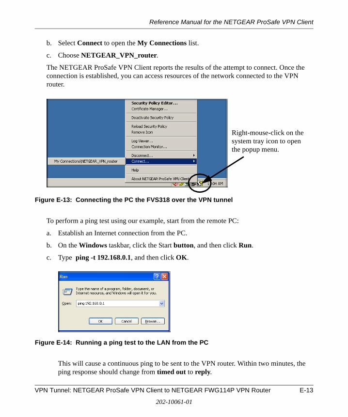
Reference Manual for the NETGEAR ProSafe VPN Client
b. Select Connect to open the My Connections list.
c. Choose NETGEAR_VPN_router.
The NETGEAR ProSafe VPN Client reports the results of the attempt to connect. Once the connection is established, you can access resources of the network connected to the VPN router.
Figure E-13: Connecting the PC the FVS318 over the VPN tunnel
To perform a ping test using our example, start from the remote PC:
a. Establish an Internet connection from the PC.
b. On the Windows taskbar, click the Start button, and then click Run.
c. Type ping -t 192.168.0.1, and then click OK.
Figure E-14: Running a ping test to the LAN from the PC
This will cause a continuous ping to be sent to the VPN router. Within two minutes, the ping response should change from timed out to reply.
Right-mouse-click on the system tray icon to open the popup menu.
VPN Tunnel: NETGEAR ProSafe VPN Client to NETGEAR FWG114P VPN Router E-13
202-10061-01
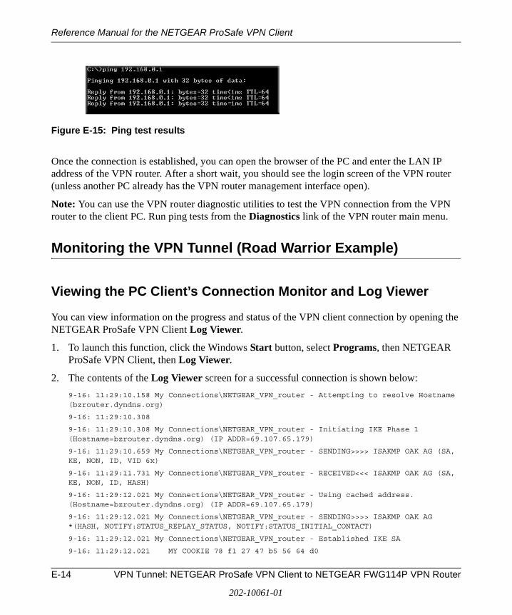
Reference Manual for the NETGEAR ProSafe VPN Client
Figure E-15: Ping test results
Once the connection is established, you can open the browser of the PC and enter the LAN IP address of the VPN router. After a short wait, you should see the login screen of the VPN router (unless another PC already has the VPN router management interface open).
Note: You can use the VPN router diagnostic utilities to test the VPN connection from the VPN router to the client PC. Run ping tests from the Diagnostics link of the VPN router main menu.
Monitoring the VPN Tunnel (Road Warrior Example)
Viewing the PC Client’s Connection Monitor and Log Viewer
You can view information on the progress and status of the VPN client connection by opening the NETGEAR ProSafe VPN Client Log Viewer.
1. To launch this function, click the Windows Start button, select Programs, then NETGEAR ProSafe VPN Client, then Log Viewer.
2. The contents of the Log Viewer screen for a successful connection is shown below:
9-16: 11:29:10.158 My Connections\NETGEAR_VPN_router - Attempting to resolve Hostname (bzrouter.dyndns.org)
9-16: 11:29:10.308
9-16: 11:29:10.308 My Connections\NETGEAR_VPN_router - Initiating IKE Phase 1 (Hostname=bzrouter.dyndns.org) (IP ADDR=69.107.65.179)
9-16: 11:29:10.659 My Connections\NETGEAR_VPN_router - SENDING>>>> ISAKMP OAK AG (SA, KE, NON, ID, VID 6x)
9-16: 11:29:11.731 My Connections\NETGEAR_VPN_router - RECEIVED<<< ISAKMP OAK AG (SA, KE, NON, ID, HASH)
9-16: 11:29:12.021 My Connections\NETGEAR_VPN_router - Using cached address. (Hostname=bzrouter.dyndns.org) (IP ADDR=69.107.65.179)
9-16: 11:29:12.021 My Connections\NETGEAR_VPN_router - SENDING>>>> ISAKMP OAK AG *(HASH, NOTIFY:STATUS_REPLAY_STATUS, NOTIFY:STATUS_INITIAL_CONTACT)
9-16: 11:29:12.021 My Connections\NETGEAR_VPN_router - Established IKE SA
9-16: 11:29:12.021 MY COOKIE 78 f1 27 47 b5 56 64 d0
E-14 VPN Tunnel: NETGEAR ProSafe VPN Client to NETGEAR FWG114P VPN Router
202-10061-01
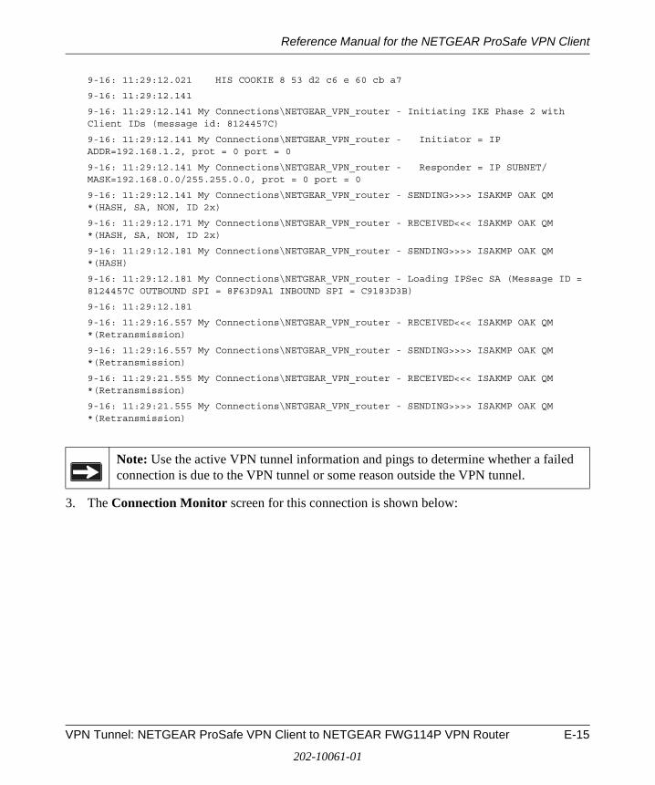
Reference Manual for the NETGEAR ProSafe VPN Client
9-16: 11:29:12.021 HIS COOKIE 8 53 d2 c6 e 60 cb a7
9-16: 11:29:12.141
9-16: 11:29:12.141 My Connections\NETGEAR_VPN_router - Initiating IKE Phase 2 with Client IDs (message id: 8124457C)
9-16: 11:29:12.141 My Connections\NETGEAR_VPN_router - Initiator = IP ADDR=192.168.1.2, prot = 0 port = 0
9-16: 11:29:12.141 My Connections\NETGEAR_VPN_router - Responder = IP SUBNET/MASK=192.168.0.0/255.255.0.0, prot = 0 port = 0
9-16: 11:29:12.141 My Connections\NETGEAR_VPN_router - SENDING>>>> ISAKMP OAK QM *(HASH, SA, NON, ID 2x)
9-16: 11:29:12.171 My Connections\NETGEAR_VPN_router - RECEIVED<<< ISAKMP OAK QM *(HASH, SA, NON, ID 2x)
9-16: 11:29:12.181 My Connections\NETGEAR_VPN_router - SENDING>>>> ISAKMP OAK QM *(HASH)
9-16: 11:29:12.181 My Connections\NETGEAR_VPN_router - Loading IPSec SA (Message ID = 8124457C OUTBOUND SPI = 8F63D9A1 INBOUND SPI = C9183D3B)
9-16: 11:29:12.181
9-16: 11:29:16.557 My Connections\NETGEAR_VPN_router - RECEIVED<<< ISAKMP OAK QM *(Retransmission)
9-16: 11:29:16.557 My Connections\NETGEAR_VPN_router - SENDING>>>> ISAKMP OAK QM *(Retransmission)
9-16: 11:29:21.555 My Connections\NETGEAR_VPN_router - RECEIVED<<< ISAKMP OAK QM *(Retransmission)
9-16: 11:29:21.555 My Connections\NETGEAR_VPN_router - SENDING>>>> ISAKMP OAK QM *(Retransmission)
3. The Connection Monitor screen for this connection is shown below:
Note: Use the active VPN tunnel information and pings to determine whether a failed connection is due to the VPN tunnel or some reason outside the VPN tunnel.
VPN Tunnel: NETGEAR ProSafe VPN Client to NETGEAR FWG114P VPN Router E-15
202-10061-01
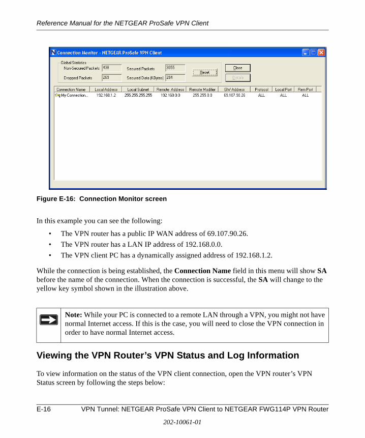
Reference Manual for the NETGEAR ProSafe VPN Client
Figure E-16: Connection Monitor screen
In this example you can see the following:
• The VPN router has a public IP WAN address of 69.107.90.26.
• The VPN router has a LAN IP address of 192.168.0.0.
• The VPN client PC has a dynamically assigned address of 192.168.1.2.
While the connection is being established, the Connection Name field in this menu will show SA before the name of the connection. When the connection is successful, the SA will change to the yellow key symbol shown in the illustration above.
Viewing the VPN Router’s VPN Status and Log Information
To view information on the status of the VPN client connection, open the VPN router’s VPN Status screen by following the steps below:
Note: While your PC is connected to a remote LAN through a VPN, you might not have normal Internet access. If this is the case, you will need to close the VPN connection in order to have normal Internet access.
E-16 VPN Tunnel: NETGEAR ProSafe VPN Client to NETGEAR FWG114P VPN Router
202-10061-01
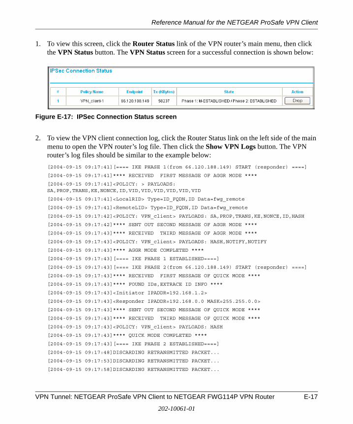
Reference Manual for the NETGEAR ProSafe VPN Client
1. To view this screen, click the Router Status link of the VPN router’s main menu, then click the VPN Status button. The VPN Status screen for a successful connection is shown below:
Figure E-17: IPSec Connection Status screen
2. To view the VPN client connection log, click the Router Status link on the left side of the main menu to open the VPN router’s log file. Then click the Show VPN Logs button. The VPN router’s log files should be similar to the example below:
[2004-09-15 09:17:41][==== IKE PHASE 1(from 66.120.188.149) START (responder) ====]
[2004-09-15 09:17:41]**** RECEIVED FIRST MESSAGE OF AGGR MODE ****
[2004-09-15 09:17:41]<POLICY: > PAYLOADS: SA,PROP,TRANS,KE,NONCE,ID,VID,VID,VID,VID,VID,VID
[2004-09-15 09:17:41]<LocalRID> Type=ID_FQDN,ID Data=fwg_remote
[2004-09-15 09:17:41]<RemoteLID> Type=ID_FQDN,ID Data=fwg_remote
[2004-09-15 09:17:42]<POLICY: VPN_client> PAYLOADS: SA,PROP,TRANS,KE,NONCE,ID,HASH
[2004-09-15 09:17:42]**** SENT OUT SECOND MESSAGE OF AGGR MODE ****
[2004-09-15 09:17:43]**** RECEIVED THIRD MESSAGE OF AGGR MODE ****
[2004-09-15 09:17:43]<POLICY: VPN_client> PAYLOADS: HASH,NOTIFY,NOTIFY
[2004-09-15 09:17:43]**** AGGR MODE COMPLETED ****
[2004-09-15 09:17:43][==== IKE PHASE 1 ESTABLISHED====]
[2004-09-15 09:17:43][==== IKE PHASE 2(from 66.120.188.149) START (responder) ====]
[2004-09-15 09:17:43]**** RECEIVED FIRST MESSAGE OF QUICK MODE ****
[2004-09-15 09:17:43]**** FOUND IDs,EXTRACE ID INFO ****
[2004-09-15 09:17:43]<Initiator IPADDR=192.168.1.2>
[2004-09-15 09:17:43]<Responder IPADDR=192.168.0.0 MASK=255.255.0.0>
[2004-09-15 09:17:43]**** SENT OUT SECOND MESSAGE OF QUICK MODE ****
[2004-09-15 09:17:43]**** RECEIVED THIRD MESSAGE OF QUICK MODE ****
[2004-09-15 09:17:43]<POLICY: VPN_client> PAYLOADS: HASH
[2004-09-15 09:17:43]**** QUICK MODE COMPLETED ****
[2004-09-15 09:17:43][==== IKE PHASE 2 ESTABLISHED====]
[2004-09-15 09:17:48]DISCARDING RETRANSMITTED PACKET...
[2004-09-15 09:17:53]DISCARDING RETRANSMITTED PACKET...
[2004-09-15 09:17:58]DISCARDING RETRANSMITTED PACKET...
VPN Tunnel: NETGEAR ProSafe VPN Client to NETGEAR FWG114P VPN Router E-17
202-10061-01
Reference Manual for the NETGEAR ProSafe VPN Client
E-18 VPN Tunnel: NETGEAR ProSafe VPN Client to NETGEAR FWG114P VPN Router
202-10061-01

Reference Manual for the NETGEAR ProSafe VPN Client
Glossary
Use the list below to find definitions for technical terms used in this manual.
Numeric
3DES
3DES (Triple DES) achieves a high level of security by encrypting the data three times using DES with three different, unrelated keys.
A
ADSLShort for asymmetric digital subscriber line, a technology that allows data to be sent over existing copper telephone lines at data rates of from 1.5 to 9 Mbps when receiving data (known as the downstream rate) and from 16 to 640 Kbps when sending data (known as the upstream rate). ADSL requires a special ADSL modem. ADSL is growing in popularity as more areas around the world gain access.
Address Resolution ProtocolAn Internet Protocol that dynamically maps Internet addresses to physical (hardware) addresses on a LAN.
AESAdvanced Encryption Standard, a symmetric 128-bit block data encryption technique. It is an iterated block cipher with a variable block length and a variable key length. The block length and the key length can be independently specified to 128, 192 or 256 bits.The U.S government adopted the algorithm as its encryption technique in October 2000, replacing the DES encryption it used. AES works at multiple network layers simultaneously.
AHAuthentication Header.
APISee “Application Programming Interface” on page 2.
Glossary Glossary-1
202-10061-01
Reference Manual for the NETGEAR ProSafe VPN Client
Application Programming InterfaceAn API is an interface used by an programmer to interface with functions provided by an application.
ARPSee “ADSL” on page 1.
Auto-negotiation A feature that allows twisted-pair ports to advertise their capabilities for speed, duplex and flow control. When connected to a port that also supports auto-negotiation, the link can automatically configure itself to the optimum setup.
C
CAA Certificate Authority is a trusted third-party organization or company that issues digital certificates used to create digital signatures and public-private key pairs.
Certificate Authority
A Certificate Authority is a trusted third-party organization or company that issues digital certificates used to create digital signatures and public-private key pairs. The role of the CA in this process is to guarantee that the individual granted the unique certificate is, in fact, who he or she claims to be. Usually, this means that the CA has an arrangement with a financial institution, such as a credit card company, which provides it with information to confirm an individual's claimed identity. CAs are a critical component in data security and electronic commerce because they guarantee that the two parties exchanging information are really who they claim to be.the two parties exchanging information are really who they claim to be.
CRLCertificate Revocation List. Each Certificate Authority (CA) maintains a revoked certificates list.
D
DES
The Data Encryption Standard (DES) processes input data that is 64 bits wide, encrypting these values using a 56 bit key. See also 3DES.
DHCPSee “Dynamic Host Configuration Protocol.” on page 3.
Glossary-2 Glossary
202-10061-01

Reference Manual for the NETGEAR ProSafe VPN Client
DNSShort for Domain Name System (or Service), an Internet service that translates domain names into IP addresses. Because domain names are alphabetic, they're easier to remember. The Internet however, is really based on IP addresses. Every time you use a domain name, therefore, a DNS service must translate the name into the corresponding IP address. For example, the domain name www.example.com might translate to 198.105.232.4. The DNS system is, in fact, its own network. If one DNS server doesn't know how to translate a particular domain name, it asks another one, and so on, until the correct IP address is returned.
Domain NameA descriptive name for an address or group of addresses on the Internet. Domain names are of the form of a registered entity name plus one of a number of predefined top level suffixes such as .com, .edu, .uk, etc. For example, in the address mail.NETGEAR.com, mail is a server name and NETGEAR.com is the domain.
DSLShort for digital subscriber line, but is commonly used in reference to the asymmetric version of this technology (ADSL) that allows data to be sent over existing copper telephone lines at data rates of from 1.5 to 9 Mbps when receiving data (known as the downstream rate) and from 16 to 640 Kbps when sending data (known as the upstream rate). ADSL requires a special ADSL modem. ADSL is growing in popularity as more areas around the world gain access.
DSLAMDSL Access Multiplexor. The piece of equipment at the telephone company central office that provides the ADSL signal.
Dynamic Host Configuration Protocol. DHCP is a protocol for assigning dynamic IP addresses to devices on a network. With dynamic addressing, a device can have a different IP address every time it connects to the network. In some systems, the device's IP address can even change while it is still connected. DHCP also supports a mix of static and dynamic IP addresses. Dynamic addressing simplifies network administration because the software tracks IP addresses rather than requiring an administrator to manage the task. A new computer can be added to a network without the hassle of manually assigning it a unique IP address.
E
ESPEncapsulating Security Payload.
Ethernet A LAN specification developed jointly by Xerox, Intel and Digital Equipment Corporation. Ethernet networks transmit packets at a rate of 10 Mbps.
Glossary Glossary-3
202-10061-01
Reference Manual for the NETGEAR ProSafe VPN Client
F
Filtering The process of screening a packet for certain characteristics, such as source address, destination address, or protocol. Filtering is used to determine whether traffic is to be forwarded, and can also prevent unauthorized access to a network or network devices.
ForwardingWhen a frame is received on an input port on a switch, the address is checked against the lookup table. If the lookup table has recorded the destination address, the frame is automatically forwarded on an output port.
Fully Qualified domain Name (FQDN)
A fully qualified domain name consists of a host and domain name, including top-level domain. For example, www.netgear.com is a fully qualified domain name. www is the host, netgear is the second-level domain, and.com is the top level domain. A FQDN always starts with a host name and continues all the way up to the top-level domain name, so www.parc.xerox.com is also a FQDN. Routers can use FQDN to uniquely identify their address on the Internet rather than an IP address.
G
GatewayA local device, usually a router, that connects hosts on a local network to other networks.
I
ICMPSee “Internet Control Message Protocol” on page 5.
IEEE Institute of Electrical and Electronics Engineers. This American organization was founded in 1963 and sets standards for computers and communications.
IETF Internet Engineering Task Force. An organization responsible for providing engineering solutions for TCP/IP networks. In the network management area, this group is responsible for the development of the SNMP protocol.
Glossary-4 Glossary
202-10061-01
Reference Manual for the NETGEAR ProSafe VPN Client
IKEInternet Key Exchange. An automated method for exchanging and managing encryption keys between two VPN devices.
Internet Control Message ProtocolICMP is an extension to the Internet Protocol (IP) that supports packets containing error, control, and informational messages. The PING command, for example, uses ICMP to test an Internet connection.
Internet ProtocolThe method or protocol by which data is sent from one computer to another on the Internet. Each computer (known as a host) on the Internet has at least one IP address that uniquely identifies it among all other computers on the Internet. When you send or receive data (for example, an e-mail note or a Web page), the message gets divided into little chunks called packets. Each of these packets contains both the sender's Internet address and the receiver's address. Any packet is sent first to a gateway computer that understands a small part of the Internet. The gateway computer reads the destination address and forwards the packet to an adjacent gateway that in turn reads the destination address and so forth across the Internet until one gateway recognizes the packet as belonging to a computer within its immediate neighborhood or domain. That gateway then forwards the packet directly to the computer whose address is specified. Because a message is divided into a number of packets, each packet can, if necessary, be sent by a different route across the Internet. Packets can arrive in a different order than they were sent. The Internet Protocol just delivers them. It's up to another protocol, the Transmission Control Protocol (TCP) to put them back in the right order. IP is a connectionless protocol, which means that there is no continuing connection between the end points that are communicating. Each packet that travels through the Internet is treated as an independent unit of data without any relation to any other unit of data. (The reason the packets do get put in the right order is because of TCP, the connection-oriented protocol that keeps track of the packet sequence in a message.) In the Open Systems Interconnection (OSI) communication model, IP is in Layer 3, the Networking Layer. The most widely used version of IP today is IP version 4 (IPv4). However, IP version 6 (IPv6) is also beginning to be supported. IPv6 provides for much longer addresses and therefore for the possibility of many more Internet users. IPv6 includes the capabilities of IPv4 and any server that can support IPv6 packets can also support IPv4 packets.
IPSee “Internet Protocol” on page 5.
IP AddressA four-byte number uniquely defining each host on the Internet, usually written in dotted-decimal notation with periods separating the bytes (for example, 134.177.244.57). Ranges of addresses are assigned by Internic, an organization formed for this purpose.
IPSecInternet Protocol Security. IPSec is a series of guidelines for securing private information transmitted over public networks. IPSec is a VPN method providing a higher level of security than PPTP.
Glossary Glossary-5
202-10061-01
Reference Manual for the NETGEAR ProSafe VPN Client
ISPInternet service provider.
L
LANSee “Local Area Network” on page 6.
LDAPSee “Lightweight Directory Access Protocol” on page 6.
Lightweight Directory Access ProtocolA set of protocols for accessing information directories. LDAP is based on the standards contained within the X.500 standard, but is significantly simpler. Unlike X.500, LDAP supports TCP/IP, which is necessary for any type of Internet access. Although not yet widely implemented, LDAP should eventually make it possible for almost any application running on virtually any computer platform to obtain directory information, such as e-mail addresses and public keys. Because LDAP is an open protocol, applications need not worry about the type of server hosting the directory.
Local Area NetworkA communications network serving users within a limited area, such as one floor of a building. A LAN typically connects multiple personal computers and shared network devices such as storage and printers. Although many technologies exist to implement a LAN, Ethernet is the most common for connecting personal computers and is limited to a distance of 1,500 feet. LANs can be connected together, but if modems and telephones connect two or more LANs, the larger network constitutes what is called a WAN or Wide Area Network.
M
MAC(1) Media Access Control. In LANs, the sublayer of the data link control layer that supports medium-dependent functions and uses the services of the physical layer to provide services to the logical link control (LLC) sublayer. The MAC sublayer includes the method of determining when a device has access to the transmission medium. (2) Message Authentication Code. In computer security, a value that is a part of a message or accompanies a message and is used to determine that the contents, origin, author, or other attributes of all or part of the message are as they appear to be. (IBM Glossary of Computing Terms)
MAC addressThe Media Access Control address is a unique 48-bit hardware address assigned to every network interface card. Usually written in the form 01:23:45:67:89:ab.
Glossary-6 Glossary
202-10061-01
Reference Manual for the NETGEAR ProSafe VPN Client
MD5MD5 creates digital signatures using a one-way hash function, meaning that it takes a message and converts it into a fixed string of digits, also called a message digest. When using a one-way hash function, one can compare a calculated message digest against the message digest that is decrypted with a public key to verify that the message hasn't been tampered with. This comparison is called a "hashcheck."
N
NATSee “Network Address Translation” on page 7.
NetBIOS
Network Basic Input Output System. An application programming interface (API) for sharing services and information on local-area networks (LANs). Provides for communication between stations of a network where each station is given a name. These names are alphanumeric names, 16 characters in length.
netmaskCombined with the IP address, the IP Subnet Mask allows a device to know which other addresses are local to it, and which must be reached through a gateway or router. A number that explains which part of an IP address comprises the network address and which part is the host address on that network. It can be expressed in dotted-decimal notation or as a number appended to the IP address. For example, a 28-bit mask starting from the MSB can be shown as 255.255.255.192 or as /28 appended to the IP address.
Network Address TranslationSometimes referred to as Transparent Proxying, IP Address Overloading, or IP Masquerading. Involves use of a device called a Network Address Translator, which assigns a contrived, or logical, IP address and port number to each node on an organization's internal network and passes packets using these assigned addresses.
P
packetA block of information sent over a network. A packet typically contains a source and destination network address, some protocol and length information, a block of data, and a checksum.
Glossary Glossary-7
202-10061-01
Reference Manual for the NETGEAR ProSafe VPN Client
Perfect Forward SecrecyPerfect Forward Secrecy (PFS) provides additional security by means of a Diffie-Hellman shared secret value. With PFS, if one key is compromised, previous and subsequent keys are secure because they are not derived from previous keys.
PKIXPKIX. The most widely used standard for defining digital certificates.
Point-to-Point ProtocolPPP. A protocol allowing a computer using TCP/IP to connect directly to the Internet.
PPPA protocol allowing a computer using TCP/IP to connect directly to the Internet.
PPPoAPPPoA. PPP over ATM is a protocol for connecting remote hosts to the Internet over an always-on connection by simulating a dial-up connection.
PPPoEPPPoE. PPP over Ethernet is a protocol for connecting remote hosts to the Internet over an always-on connection by simulating a dial-up connection.
PPP over ATMPPPoA. PPP over ATM is a protocol for connecting remote hosts to the Internet over an always-on connection by simulating a dial-up connection.
PPP over EthernetPPPoE. PPP over Ethernet is a protocol for connecting remote hosts to the Internet over an always-on connection by simulating a dial-up connection.
PPTPPoint-to-Point Tunneling Protocol. A method for establishing a virtual private network (VPN) by embedding Microsoft’s network protocol into Internet packets.
Protocol A set of rules for communication between devices on a network.
PSTNPublic Switched Telephone Network.
Public Key InfrastructurePKIX. The most widely used standard for defining digital certificates. X.509 is actually an ITU Recommendation, which means that it has not yet been officially defined or approved. As a result, companies have implemented the standard in different ways. For example, both
Glossary-8 Glossary
202-10061-01
Reference Manual for the NETGEAR ProSafe VPN Client
Netscape and Microsoft use X.509 certificates to implement SSL in their Web servers and browsers. But an X.509 Certificate generated by Netscape may not be readable by Microsoft products, and vice versa.
Q
QoSSee “Quality of Service” on page 9.
Quality of ServiceQoS is a networking term that specifies a guaranteed level of throughput. Throughput is the amount of data transferred from one device to another or processed in a specified amount of time - typically, throughputs are measured in bytes per second (Bps).
R
RFCRequest For Comment. Refers to documents published by the Internet Engineering Task Force (IETF) proposing standard protocols and procedures for the Internet. RFCs can be found at www.ietf.org.
RIPSee “Routing Information Protocol” on page 9.
routerA device that forwards data between networks. An IP router forwards data based on IP source and destination addresses.
Routing Information ProtocolRIP is the routing protocol used by the routed process on Berkeley-derived UNIX systems. Many networks use RIP; it works well for small, isolated, and topologically simple networks.
S
Subnet MaskCombined with the IP address, the IP Subnet Mask allows a device to know which other addresses are local to it, and which must be reached through a gateway or router.
Glossary Glossary-9
202-10061-01
Reference Manual for the NETGEAR ProSafe VPN Client
T
TCP/IPThe main internetworking protocols used in the Internet. The Internet Protocol (IP) used in conjunction with the Transfer Control Protocol (TCP) form TCP/IP.
V
VPNVirtual Private Network. A method for securely transporting data between two private networks by using a public network such as the Internet as a connection.
W
WANSee “Wide Area Network” on page 10.
Web Also known as World-Wide Web (WWW) or W3. An Internet client-server system to distribute information, based upon the hypertext transfer protocol (HTTP).
Wide Area NetworkA WAN is a computer network that spans a relatively large geographical area. Typically, a WAN consists of two or more local-area networks (LANs).
WINSWINS. Windows Internet Naming Service is a server process for resolving Windows-based computer names to IP addresses.
Glossary-10 Glossary
202-10061-01