Voluson® S6 Voluson® S8 Voluson® S8 Pro Basic User Manual
660
Voluson® S6 Voluson® S8 Voluson® S8 Pro Basic User Manual English (English) Revision 2 HCAT# H46952LC 5482585-100 SW 14.0.0 © by General Electric
description
The Voluson® S6 / Voluson® S8 / Voluson® S8 Pro is a professional, innovative, mostversatile real-time scanning system.It opens new sonographic possibilities with the 3D/4D VOLUME scanning technique. The vastarray of probes makes it suitable for many applications.
Transcript of Voluson® S6 Voluson® S8 Voluson® S8 Pro Basic User Manual
Voluson® S6Voluson® S8Voluson® S8 ProBasic User ManualEnglish (English)
Revision 2
HCAT# H46952LC
5482585-100
SW 14.0.0
© by General Electric
Revision History
Revision Date
Revision 1 March 2014
Revision 2 May 2014
i-iiVoluson® S6 / Voluson® S8 / Voluson® S8 Pro Basic User Manual
5482585-100 Revision 2
Table of ContentsChapter 1 – General
Contacting GE - - - - - - - - - - - - - - - - - - - - - - - - - - - - - - - - - - - - - - - - - - - - - - - - - - - - 1-2Manufacturer - - - - - - - - - - - - - - - - - - - - - - - - - - - - - - - - - - - - - - - - - - - - - - - - - - - - - 1-6About this User Manual - - - - - - - - - - - - - - - - - - - - - - - - - - - - - - - - - - - - - - - - - - - - - - 1-7
Chapter 2 – SafetyWarning labels used in the Basic User Manual - - - - - - - - - - - - - - - - - - - - - - - - - - - - - - 2-3Symbols and Labels used on the system - - - - - - - - - - - - - - - - - - - - - - - - - - - - - - - - - - 2-3Classification - - - - - - - - - - - - - - - - - - - - - - - - - - - - - - - - - - - - - - - - - - - - - - - - - - - - - 2-5Remarks for Safe Use - - - - - - - - - - - - - - - - - - - - - - - - - - - - - - - - - - - - - - - - - - - - - - - 2-6System Safety and Maintenance - - - - - - - - - - - - - - - - - - - - - - - - - - - - - - - - - - - - - - - 2-7Probe Safety and Maintenance - - - - - - - - - - - - - - - - - - - - - - - - - - - - - - - - - - - - - - - - 2-13Biopsy Safety and Maintenance - - - - - - - - - - - - - - - - - - - - - - - - - - - - - - - - - - - - - - - 2-18Battery Safety and Maintenance - - - - - - - - - - - - - - - - - - - - - - - - - - - - - - - - - - - - - - - 2-19Manufacturer Responsibility - - - - - - - - - - - - - - - - - - - - - - - - - - - - - - - - - - - - - - - - - - 2-20Service Documents - - - - - - - - - - - - - - - - - - - - - - - - - - - - - - - - - - - - - - - - - - - - - - - - 2-20Bioeffects and Safety of Ultrasound Scans - - - - - - - - - - - - - - - - - - - - - - - - - - - - - - - 2-21Disposal - - - - - - - - - - - - - - - - - - - - - - - - - - - - - - - - - - - - - - - - - - - - - - - - - - - - - - - - 2-23Network disclosure - - - - - - - - - - - - - - - - - - - - - - - - - - - - - - - - - - - - - - - - - - - - - - - - 2-24
Chapter 3 – Description of the SystemProduct Description - - - - - - - - - - - - - - - - - - - - - - - - - - - - - - - - - - - - - - - - - - - - - - - - - 3-2System Assembly - - - - - - - - - - - - - - - - - - - - - - - - - - - - - - - - - - - - - - - - - - - - - - - - - - 3-3Mechanical Adjustment - - - - - - - - - - - - - - - - - - - - - - - - - - - - - - - - - - - - - - - - - - - - - - 3-3Concept of Operation - - - - - - - - - - - - - - - - - - - - - - - - - - - - - - - - - - - - - - - - - - - - - - - 3-7Layout of Menus - - - - - - - - - - - - - - - - - - - - - - - - - - - - - - - - - - - - - - - - - - - - - - - - - - - 3-7Button description - - - - - - - - - - - - - - - - - - - - - - - - - - - - - - - - - - - - - - - - - - - - - - - - - 3-10Remove USB Devices - - - - - - - - - - - - - - - - - - - - - - - - - - - - - - - - - - - - - - - - - - - - - - 3-14Electronic User Manual (EUM) - - - - - - - - - - - - - - - - - - - - - - - - - - - - - - - - - - - - - - - - 3-14
Chapter 4 – Operating the SystemGeneral Remarks - - - - - - - - - - - - - - - - - - - - - - - - - - - - - - - - - - - - - - - - - - - - - - - - - - 4-2Safety Warnings - - - - - - - - - - - - - - - - - - - - - - - - - - - - - - - - - - - - - - - - - - - - - - - - - - - 4-2Power On / Boot Up - - - - - - - - - - - - - - - - - - - - - - - - - - - - - - - - - - - - - - - - - - - - - - - - 4-2Power Off / Shutdown - - - - - - - - - - - - - - - - - - - - - - - - - - - - - - - - - - - - - - - - - - - - - - - 4-3Transducer Connection - - - - - - - - - - - - - - - - - - - - - - - - - - - - - - - - - - - - - - - - - - - - - - 4-4Prepareing the Transducer - - - - - - - - - - - - - - - - - - - - - - - - - - - - - - - - - - - - - - - - - - - - 4-5Probe/Program Selection - - - - - - - - - - - - - - - - - - - - - - - - - - - - - - - - - - - - - - - - - - - - - 4-7Entering Patient Data - - - - - - - - - - - - - - - - - - - - - - - - - - - - - - - - - - - - - - - - - - - - - - - 4-9Image Annotation - - - - - - - - - - - - - - - - - - - - - - - - - - - - - - - - - - - - - - - - - - - - - - - - - 4-26
Chapter 5 – Probes and BiopsiesProbes - - - - - - - - - - - - - - - - - - - - - - - - - - - - - - - - - - - - - - - - - - - - - - - - - - - - - - - - - - 5-2Biopsies - - - - - - - - - - - - - - - - - - - - - - - - - - - - - - - - - - - - - - - - - - - - - - - - - - - - - - - - 5-10
Chapter 6 – 2D Mode2D Main Menu - - - - - - - - - - - - - - - - - - - - - - - - - - - - - - - - - - - - - - - - - - - - - - - - - - - - 6-22D Operation - - - - - - - - - - - - - - - - - - - - - - - - - - - - - - - - - - - - - - - - - - - - - - - - - - - - - 6-3Cine Mode - - - - - - - - - - - - - - - - - - - - - - - - - - - - - - - - - - - - - - - - - - - - - - - - - - - - - - 6-142D Sub Menu - - - - - - - - - - - - - - - - - - - - - - - - - - - - - - - - - - - - - - - - - - - - - - - - - - - - 6-18Gray Map - - - - - - - - - - - - - - - - - - - - - - - - - - - - - - - - - - - - - - - - - - - - - - - - - - - - - - - 6-20B-Flow - - - - - - - - - - - - - - - - - - - - - - - - - - - - - - - - - - - - - - - - - - - - - - - - - - - - - - - - - 6-21
Voluson® S6 / Voluson® S8 / Voluson® S8 Pro Basic User Manual5482585-100 Revision 2 i-iii
XTD-View (Extended View) - - - - - - - - - - - - - - - - - - - - - - - - - - - - - - - - - - - - - - - - - - 6-24Contrast Imaging - - - - - - - - - - - - - - - - - - - - - - - - - - - - - - - - - - - - - - - - - - - - - - - - - - 6-31
Chapter 7 – M ModeM Main Menu - - - - - - - - - - - - - - - - - - - - - - - - - - - - - - - - - - - - - - - - - - - - - - - - - - - - - 7-2M Operation - - - - - - - - - - - - - - - - - - - - - - - - - - - - - - - - - - - - - - - - - - - - - - - - - - - - - - 7-3M Sub Menu - - - - - - - - - - - - - - - - - - - - - - - - - - - - - - - - - - - - - - - - - - - - - - - - - - - - - - 7-6MCF Mode (M Color Flow Mode) - - - - - - - - - - - - - - - - - - - - - - - - - - - - - - - - - - - - - - - 7-7MTD Mode (M Tissue Doppler Mode) - - - - - - - - - - - - - - - - - - - - - - - - - - - - - - - - - - - 7-11MHDF Mode (MHD-Flow Mode) - - - - - - - - - - - - - - - - - - - - - - - - - - - - - - - - - - - - - - - 7-15STIC with M-Mode - - - - - - - - - - - - - - - - - - - - - - - - - - - - - - - - - - - - - - - - - - - - - - - - - 7-19Anatomical M-Mode (AMM) - - - - - - - - - - - - - - - - - - - - - - - - - - - - - - - - - - - - - - - - - - 7-19
Chapter 8 – Doppler ModesPulsed Wave Doppler Mode (PW Mode) - - - - - - - - - - - - - - - - - - - - - - - - - - - - - - - - - - 8-2Continuous Wave Doppler Mode (CW Mode) - - - - - - - - - - - - - - - - - - - - - - - - - - - - - - - 8-7Color Flow Mode (CFM) - - - - - - - - - - - - - - - - - - - - - - - - - - - - - - - - - - - - - - - - - - - - - 8-10Power Doppler Mode (PD Mode) - - - - - - - - - - - - - - - - - - - - - - - - - - - - - - - - - - - - - - 8-15HD-Flow Mode (Bi-directional Angio Mode) - - - - - - - - - - - - - - - - - - - - - - - - - - - - - - - 8-20Tissue Doppler Mode (TD Mode ) - - - - - - - - - - - - - - - - - - - - - - - - - - - - - - - - - - - - - - 8-25Doppler Mode Functions and Filters - - - - - - - - - - - - - - - - - - - - - - - - - - - - - - - - - - - - 8-29
Chapter 9 – Volume ModeVolume Acquisition with Volume Probes - - - - - - - - - - - - - - - - - - - - - - - - - - - - - - - - - - 9-2Volume Acquisition: Static 3D Sectional Planes - - - - - - - - - - - - - - - - - - - - - - - - - - - - 9-15Sub Menus - - - - - - - - - - - - - - - - - - - - - - - - - - - - - - - - - - - - - - - - - - - - - - - - - - - - - - 9-38Volume Acquisition: Static 3D Render - - - - - - - - - - - - - - - - - - - - - - - - - - - - - - - - - - - 9-42Real Time 4D Acquisition - - - - - - - - - - - - - - - - - - - - - - - - - - - - - - - - - - - - - - - - - - - - 9-71Sono Render Start - - - - - - - - - - - - - - - - - - - - - - - - - - - - - - - - - - - - - - - - - - - - - - - - - 9-87Volume Cine - - - - - - - - - - - - - - - - - - - - - - - - - - - - - - - - - - - - - - - - - - - - - - - - - - - - - 9-88Volume Contrast Imaging: (VCI A-Plane) - - - - - - - - - - - - - - - - - - - - - - - - - - - - - - - - - 9-91VCI-Omniview - - - - - - - - - - - - - - - - - - - - - - - - - - - - - - - - - - - - - - - - - - - - - - - - - - - - 9-93STIC (Spatio-Temporal Image Correlation) - - - - - - - - - - - - - - - - - - - - - - - - - - - - - - - 9-98Real Time 4D Biopsy - - - - - - - - - - - - - - - - - - - - - - - - - - - - - - - - - - - - - - - - - - - - - - 9-103VOCALII - - - - - - - - - - - - - - - - - - - - - - - - - - - - - - - - - - - - - - - - - - - - - - - - - - - - - - - 9-106SonoAVC Follicle - - - - - - - - - - - - - - - - - - - - - - - - - - - - - - - - - - - - - - - - - - - - - - - - 9-120VCAD Heart - Volume Computer Aided Display - - - - - - - - - - - - - - - - - - - - - - - - - - - 9-126SonoVCAD labor - - - - - - - - - - - - - - - - - - - - - - - - - - - - - - - - - - - - - - - - - - - - - - - - - 9-133HDlive - - - - - - - - - - - - - - - - - - - - - - - - - - - - - - - - - - - - - - - - - - - - - - - - - - - - - - - - 9-139
Chapter 10 – Elastography ModeGUI elements - - - - - - - - - - - - - - - - - - - - - - - - - - - - - - - - - - - - - - - - - - - - - - - - - - - - 10-2Elastography Main Menu - - - - - - - - - - - - - - - - - - - - - - - - - - - - - - - - - - - - - - - - - - - - 10-3Elastography Sub Menu - - - - - - - - - - - - - - - - - - - - - - - - - - - - - - - - - - - - - - - - - - - - - 10-5Elastography Sub Menu 2 - - - - - - - - - - - - - - - - - - - - - - - - - - - - - - - - - - - - - - - - - - - 10-6
Chapter 11 – Measurements and Patient Worksheets (Reports)Generic Measurements - - - - - - - - - - - - - - - - - - - - - - - - - - - - - - - - - - - - - - - - - - - - - 11-2Calculations and Worksheets - - - - - - - - - - - - - - - - - - - - - - - - - - - - - - - - - - - - - - - - 11-24Basic Calculation Functionality - - - - - - - - - - - - - - - - - - - - - - - - - - - - - - - - - - - - - - - 11-95Basic Patient Worksheet Functions - - - - - - - - - - - - - - - - - - - - - - - - - - - - - - - - - - - - 11-97Measure Setup - - - - - - - - - - - - - - - - - - - - - - - - - - - - - - - - - - - - - - - - - - - - - - - - - 11-104
Chapter 12 – ArchiveCurrent Patient Dialog - - - - - - - - - - - - - - - - - - - - - - - - - - - - - - - - - - - - - - - - - - - - - - 12-3
Table of Contents
i-ivVoluson® S6 / Voluson® S8 / Voluson® S8 Pro Basic User Manual
5482585-100 Revision 2
Clipboard - - - - - - - - - - - - - - - - - - - - - - - - - - - - - - - - - - - - - - - - - - - - - - - - - - - - - - - 12-6Patient Archive - - - - - - - - - - - - - - - - - - - - - - - - - - - - - - - - - - - - - - - - - - - - - - - - - - 12-11Image History - - - - - - - - - - - - - - - - - - - - - - - - - - - - - - - - - - - - - - - - - - - - - - - - - - - 12-32Exam Review - - - - - - - - - - - - - - - - - - - - - - - - - - - - - - - - - - - - - - - - - - - - - - - - - - - 12-33Selecting Exams - - - - - - - - - - - - - - - - - - - - - - - - - - - - - - - - - - - - - - - - - - - - - - - - - 12-40Settings - - - - - - - - - - - - - - - - - - - - - - - - - - - - - - - - - - - - - - - - - - - - - - - - - - - - - - - 12-41
Chapter 13 – Utilities and System SetupUtilities - - - - - - - - - - - - - - - - - - - - - - - - - - - - - - - - - - - - - - - - - - - - - - - - - - - - - - - - - 13-2System Setup - - - - - - - - - - - - - - - - - - - - - - - - - - - - - - - - - - - - - - - - - - - - - - - - - - - 13-10
Chapter 14 – Programmable KeysWhere to program the keys - - - - - - - - - - - - - - - - - - - - - - - - - - - - - - - - - - - - - - - - - - 14-2P-keys - - - - - - - - - - - - - - - - - - - - - - - - - - - - - - - - - - - - - - - - - - - - - - - - - - - - - - - - - 14-4Start Exam Button - - - - - - - - - - - - - - - - - - - - - - - - - - - - - - - - - - - - - - - - - - - - - - - - - 14-8End Exam Button - - - - - - - - - - - - - - - - - - - - - - - - - - - - - - - - - - - - - - - - - - - - - - - - - 14-9
Chapter 15 – ConnectionsHow to Connect Auxiliary Devices Safely - - - - - - - - - - - - - - - - - - - - - - - - - - - - - - - - - 15-2To Connect Internal and External Accessories - - - - - - - - - - - - - - - - - - - - - - - - - - - - - 15-3Connection between Internal I/O and External I/O - - - - - - - - - - - - - - - - - - - - - - - - - - 15-4Recorder type - - - - - - - - - - - - - - - - - - - - - - - - - - - - - - - - - - - - - - - - - - - - - - - - - - - - 15-7Connection of Peripherals - - - - - - - - - - - - - - - - - - - - - - - - - - - - - - - - - - - - - - - - - - - 15-9External Monitor - - - - - - - - - - - - - - - - - - - - - - - - - - - - - - - - - - - - - - - - - - - - - - - - - 15-11Isolating transformer Noratel IMED 300WR - - - - - - - - - - - - - - - - - - - - - - - - - - - - - - 15-12ECG Module - - - - - - - - - - - - - - - - - - - - - - - - - - - - - - - - - - - - - - - - - - - - - - - - - - - - 15-12Battery Pack - - - - - - - - - - - - - - - - - - - - - - - - - - - - - - - - - - - - - - - - - - - - - - - - - - - - 15-17
Chapter 16 – Technical Data / InformationSafety Conformance - - - - - - - - - - - - - - - - - - - - - - - - - - - - - - - - - - - - - - - - - - - - - - - 16-2Physical Attributes - - - - - - - - - - - - - - - - - - - - - - - - - - - - - - - - - - - - - - - - - - - - - - - - - 16-3System overview - - - - - - - - - - - - - - - - - - - - - - - - - - - - - - - - - - - - - - - - - - - - - - - - - - 16-5Screen Formats - - - - - - - - - - - - - - - - - - - - - - - - - - - - - - - - - - - - - - - - - - - - - - - - - - 16-6Display Modes - - - - - - - - - - - - - - - - - - - - - - - - - - - - - - - - - - - - - - - - - - - - - - - - - - - 16-7Display Annotation - - - - - - - - - - - - - - - - - - - - - - - - - - - - - - - - - - - - - - - - - - - - - - - - 16-7System Standard Features - - - - - - - - - - - - - - - - - - - - - - - - - - - - - - - - - - - - - - - - - - - 16-9System Options - - - - - - - - - - - - - - - - - - - - - - - - - - - - - - - - - - - - - - - - - - - - - - - - - - 16-10System Parameters - - - - - - - - - - - - - - - - - - - - - - - - - - - - - - - - - - - - - - - - - - - - - - - 16-12Scanning Parameters - - - - - - - - - - - - - - - - - - - - - - - - - - - - - - - - - - - - - - - - - - - - - 16-16Generic Measurements and Measurements/Calculations - - - - - - - - - - - - - - - - - - - - 16-25External Inputs and Outputs - - - - - - - - - - - - - - - - - - - - - - - - - - - - - - - - - - - - - - - - - 16-29Guidance and manufacturer´s declaration - - - - - - - - - - - - - - - - - - - - - - - - - - - - - - - 16-30
Chapter 17 – ANNEX- Abbreviations
Table of Contents
Voluson® S6 / Voluson® S8 / Voluson® S8 Pro Basic User Manual5482585-100 Revision 2 i-v

This page was intentionally left blank.
i-viVoluson® S6 / Voluson® S8 / Voluson® S8 Pro Basic User Manual
5482585-100 Revision 2
Chapter 1
General
This chapter consists of information concerning indications for use and contact information.Contacting GE - - - - - - - - - - - - - - - - - - - - - - - - - - - - - - - - - - - - - - - - - - - - - - - - 1-2Manufacturer - - - - - - - - - - - - - - - - - - - - - - - - - - - - - - - - - - - - - - - - - - - - - - - - - 1-6About this User Manual - - - - - - - - - - - - - - - - - - - - - - - - - - - - - - - - - - - - - - - - - 1-7
Voluson® S6 / Voluson® S8 / Voluson® S8 Pro Basic User Manual5482585-100 Revision 2 1-1
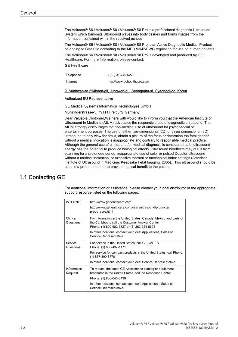
The Voluson® S6 / Voluson® S8 / Voluson® S8 Pro is a professional diagnostic UltrasoundSystem which transmits Ultrasound waves into body tissues and forms images from theinformation contained within the received echoes.The Voluson® S6 / Voluson® S8 / Voluson® S8 Pro is an Active Diagnostic Medical Productbelonging to Class IIa according to the MDD 93/42/EWG regulation for use on human patients.The Voluson® S6 / Voluson® S8 / Voluson® S8 Pro is developed and produced by GEHealthcare. For more Information, please contact:GE Healthcare
Telephone +(82) 31-740-6273
Internet http://www.gehealthcare.com
9, Sunhwan-ro 214beon-gil, Jungwon-gu, Seongnam-si, Gyeonggi-do, Korea
Authorized EU Representative
GE Medical Systems Information Technologies GmbHMunzingerstrasse-5, 79111 Freiburg, GermanyDear Valuable Customer,We here with would like to inform you that the American Institute ofUltrasound in Medicine (AIUM) advocates the responsible use of diagnostic ultrasound. TheAIUM strongly discourages the non-medical use of ultrasound for psychosocial orentertainment purposes. The use of either two-dimensional (2D) or three-dimensional (3D)ultrasound to only view the fetus, obtain a picture of the fetus or determine the fetal genderwithout a medical indication is inappropriate and contrary to responsible medical practice.Although the general use of ultrasound for medical diagnosis is considered safe, ultrasoundenergy has the potential to produce biological effects. Ultrasound bioeffects may result fromscanning for a prolonged period, inappropriate use of color or pulsed Doppler ultrasoundwithout a medical indication, or excessive thermal or mechanical index settings (AmericanInstitute of Ultrasound in Medicine: Keepsake Fetal Imaging; 2005). Thus ultrasound should beused in a prudent manner to provide medical benefit to the patient.
1.1 Contacting GE
For additional information or assistance, please contact your local distributor or the appropriatesupport resource listed on the following pages:
INTERNET http://www.gehealthcare.comhttp://www.gehealthcare.com/usen/ultrasound/products/probe_care.html
ClinicalQuestions
For information in the United States, Canada, Mexico and parts ofthe Caribbean, call the Customer Answer CenterPhone: (1) 800-682-5327 or (1) 262-524-5698In other locations, contact your local Applications, Sales orService Representative.
ServiceQuestions
For service in the United States, call GE CARESPhone: (1) 800-437-1171For service for compact products in the United States, call Phone:(1) 877-800-6776In other locations, contact your local Service Representative.
InformationRequest
To request the latest GE Accessories catalog or equipmentbrochures in the United States, call the Response CenterPhone: (1) 800-643-6439In other locations, contact your local Applications, Sales orService Representative.
General
1-2Voluson® S6 / Voluson® S8 / Voluson® S8 Pro Basic User Manual
5482585-100 Revision 2
Placing anOrder
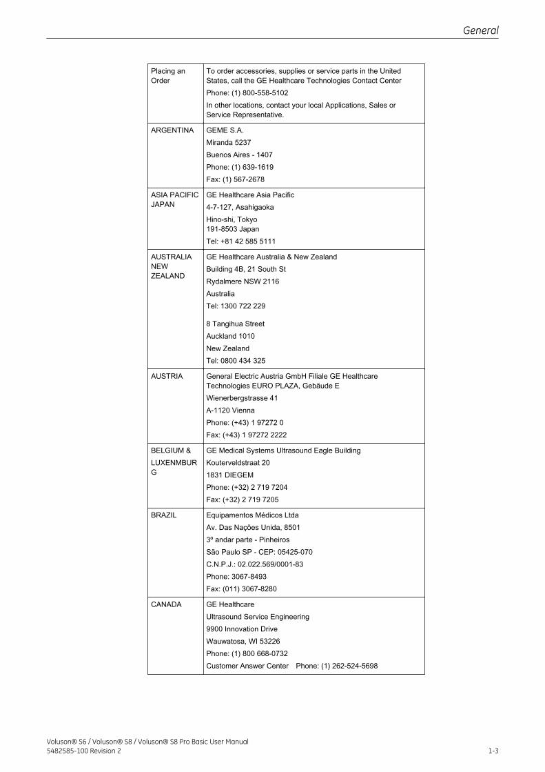
To order accessories, supplies or service parts in the UnitedStates, call the GE Healthcare Technologies Contact CenterPhone: (1) 800-558-5102In other locations, contact your local Applications, Sales orService Representative.
ARGENTINA GEME S.A.Miranda 5237Buenos Aires - 1407Phone: (1) 639-1619Fax: (1) 567-2678
ASIA PACIFICJAPAN
GE Healthcare Asia Pacific4-7-127, AsahigaokaHino-shi, Tokyo191-8503 JapanTel: +81 42 585 5111
AUSTRALIANEWZEALAND
GE Healthcare Australia & New ZealandBuilding 4B, 21 South StRydalmere NSW 2116AustraliaTel: 1300 722 229
8 Tangihua StreetAuckland 1010New ZealandTel: 0800 434 325
AUSTRIA General Electric Austria GmbH Filiale GE HealthcareTechnologies EURO PLAZA, Gebäude EWienerbergstrasse 41A-1120 ViennaPhone: (+43) 1 97272 0Fax: (+43) 1 97272 2222
BELGIUM &LUXENMBURG
GE Medical Systems Ultrasound Eagle BuildingKouterveldstraat 201831 DIEGEMPhone: (+32) 2 719 7204Fax: (+32) 2 719 7205
BRAZIL Equipamentos Médicos LtdaAv. Das Nações Unida, 85013º andar parte - PinheirosSão Paulo SP - CEP: 05425-070C.N.P.J.: 02.022.569/0001-83Phone: 3067-8493Fax: (011) 3067-8280
CANADA GE HealthcareUltrasound Service Engineering9900 Innovation DriveWauwatosa, WI 53226Phone: (1) 800 668-0732Customer Answer Center Phone: (1) 262-524-5698
General
Voluson® S6 / Voluson® S8 / Voluson® S8 Pro Basic User Manual5482585-100 Revision 2 1-3
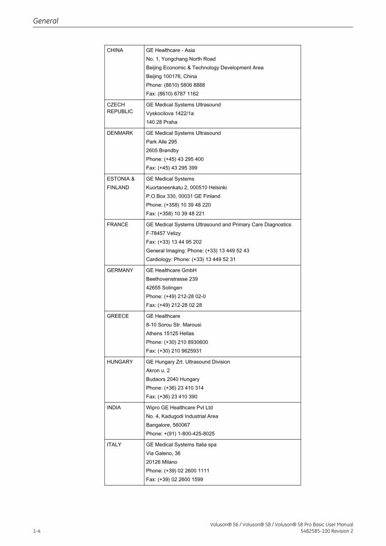
CHINA GE Healthcare - AsiaNo. 1, Yongchang North RoadBeijing Economic & Technology Development AreaBeijing 100176, ChinaPhone: (8610) 5806 8888Fax: (8610) 6787 1162
CZECHREPUBLIC
GE Medical Systems UltrasoundVyskocilova 1422/1a140 28 Praha
DENMARK GE Medical Systems UltrasoundPark Alle 2952605 BrøndbyPhone: (+45) 43 295 400Fax: (+45) 43 295 399
ESTONIA &FINLAND
GE Medical SystemsKuortaneenkatu 2, 000510 HelsinkiP.O.Box 330, 00031 GE FinlandPhone: (+358) 10 39 48 220Fax: (+358) 10 39 48 221
FRANCE GE Medical Systems Ultrasound and Primary Care DiagnosticsF-78457 VelizyFax: (+33) 13 44 95 202General Imaging: Phone: (+33) 13 449 52 43Cardiology: Phone: (+33) 13 449 52 31
GERMANY GE Healthcare GmbHBeethovenstrasse 23942655 SolingenPhone: (+49) 212-28 02-0Fax: (+49) 212-28 02 28
GREECE GE Healthcare8-10 Sorou Str. MarousiAthens 15125 HellasPhone: (+30) 210 8930600Fax: (+30) 210 9625931
HUNGARY GE Hungary Zrt. Ultrasound DivisionAkron u. 2Budaors 2040 HungaryPhone: (+36) 23 410 314Fax: (+36) 23 410 390
INDIA Wipro GE Healthcare Pvt LtdNo. 4, Kadugodi Industrial AreaBangalore, 560067Phone: +(91) 1-800-425-8025
ITALY GE Medical Systems Italia spaVia Galeno, 3620126 MilanoPhone: (+39) 02 2600 1111Fax: (+39) 02 2600 1599
General
1-4Voluson® S6 / Voluson® S8 / Voluson® S8 Pro Basic User Manual
5482585-100 Revision 2
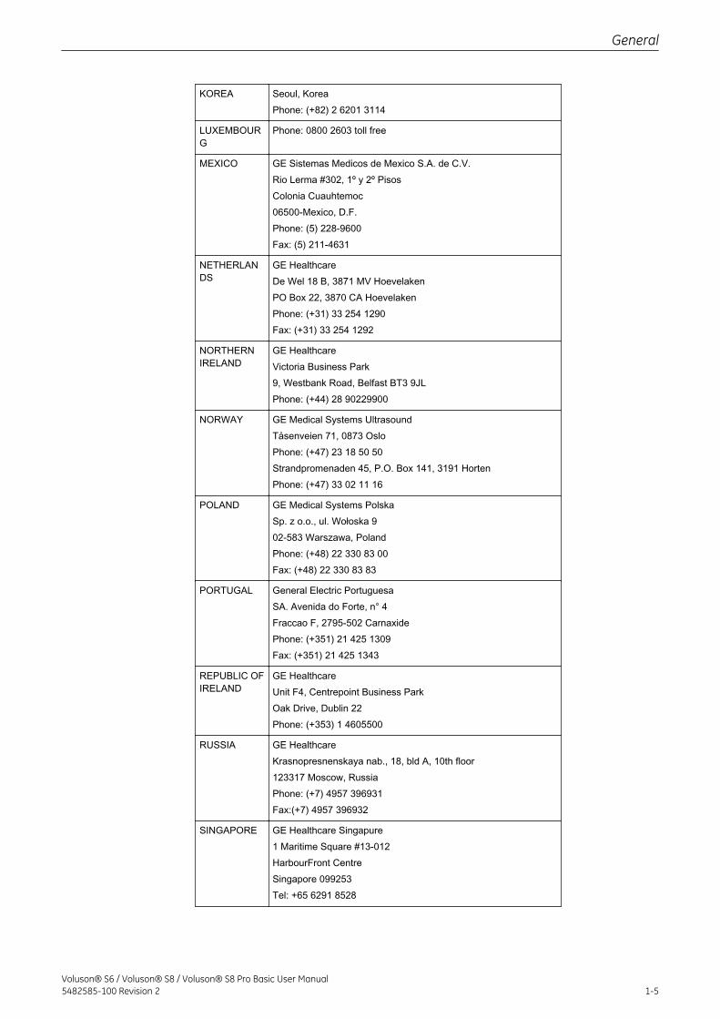
KOREA Seoul, KoreaPhone: (+82) 2 6201 3114
LUXEMBOURG
Phone: 0800 2603 toll free
MEXICO GE Sistemas Medicos de Mexico S.A. de C.V.Rio Lerma #302, 1º y 2º PisosColonia Cuauhtemoc06500-Mexico, D.F.Phone: (5) 228-9600Fax: (5) 211-4631
NETHERLANDS
GE HealthcareDe Wel 18 B, 3871 MV HoevelakenPO Box 22, 3870 CA HoevelakenPhone: (+31) 33 254 1290Fax: (+31) 33 254 1292
NORTHERNIRELAND
GE HealthcareVictoria Business Park9, Westbank Road, Belfast BT3 9JLPhone: (+44) 28 90229900
NORWAY GE Medical Systems UltrasoundTåsenveien 71, 0873 OsloPhone: (+47) 23 18 50 50Strandpromenaden 45, P.O. Box 141, 3191 HortenPhone: (+47) 33 02 11 16
POLAND GE Medical Systems PolskaSp. z o.o., ul. Wołoska 902-583 Warszawa, PolandPhone: (+48) 22 330 83 00Fax: (+48) 22 330 83 83
PORTUGAL General Electric PortuguesaSA. Avenida do Forte, n° 4Fraccao F, 2795-502 CarnaxidePhone: (+351) 21 425 1309Fax: (+351) 21 425 1343
REPUBLIC OFIRELAND
GE HealthcareUnit F4, Centrepoint Business ParkOak Drive, Dublin 22Phone: (+353) 1 4605500
RUSSIA GE HealthcareKrasnopresnenskaya nab., 18, bld A, 10th floor123317 Moscow, RussiaPhone: (+7) 4957 396931Fax:(+7) 4957 396932
SINGAPORE GE Healthcare Singapure1 Maritime Square #13-012HarbourFront CentreSingapore 099253Tel: +65 6291 8528
General
Voluson® S6 / Voluson® S8 / Voluson® S8 Pro Basic User Manual5482585-100 Revision 2 1-5
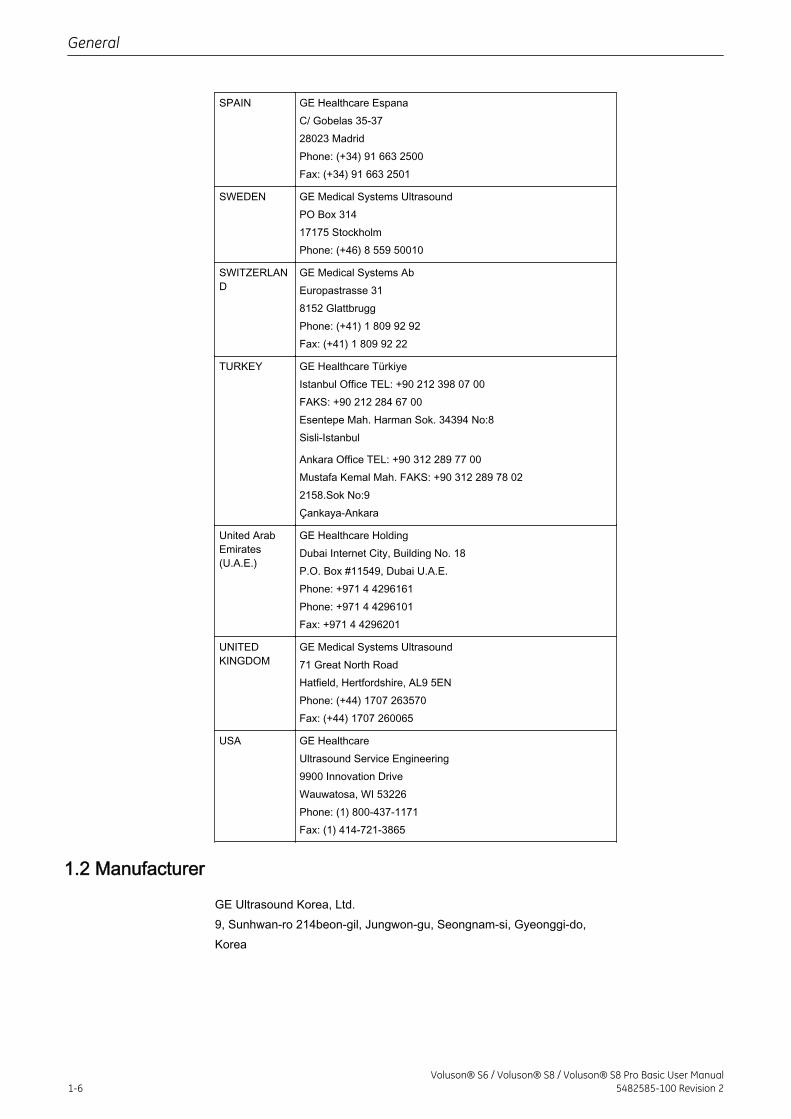
SPAIN GE Healthcare EspanaC/ Gobelas 35-3728023 MadridPhone: (+34) 91 663 2500Fax: (+34) 91 663 2501
SWEDEN GE Medical Systems UltrasoundPO Box 31417175 StockholmPhone: (+46) 8 559 50010
SWITZERLAND
GE Medical Systems AbEuropastrasse 318152 GlattbruggPhone: (+41) 1 809 92 92Fax: (+41) 1 809 92 22
TURKEY GE Healthcare TürkiyeIstanbul Office TEL: +90 212 398 07 00FAKS: +90 212 284 67 00Esentepe Mah. Harman Sok. 34394 No:8Sisli-Istanbul
Ankara Office TEL: +90 312 289 77 00Mustafa Kemal Mah. FAKS: +90 312 289 78 022158.Sok No:9Çankaya-Ankara
United ArabEmirates(U.A.E.)
GE Healthcare HoldingDubai Internet City, Building No. 18P.O. Box #11549, Dubai U.A.E.Phone: +971 4 4296161Phone: +971 4 4296101Fax: +971 4 4296201
UNITEDKINGDOM
GE Medical Systems Ultrasound71 Great North RoadHatfield, Hertfordshire, AL9 5ENPhone: (+44) 1707 263570Fax: (+44) 1707 260065
USA GE HealthcareUltrasound Service Engineering9900 Innovation DriveWauwatosa, WI 53226Phone: (1) 800-437-1171Fax: (1) 414-721-3865
1.2 Manufacturer
GE Ultrasound Korea, Ltd.9, Sunhwan-ro 214beon-gil, Jungwon-gu, Seongnam-si, Gyeonggi-do,Korea
General
1-6Voluson® S6 / Voluson® S8 / Voluson® S8 Pro Basic User Manual
5482585-100 Revision 2
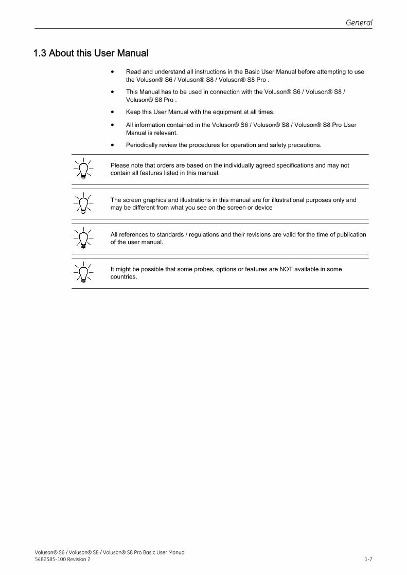
1.3 About this User Manual
• Read and understand all instructions in the Basic User Manual before attempting to usethe Voluson® S6 / Voluson® S8 / Voluson® S8 Pro .
• This Manual has to be used in connection with the Voluson® S6 / Voluson® S8 /Voluson® S8 Pro .
• Keep this User Manual with the equipment at all times.
• All information contained in the Voluson® S6 / Voluson® S8 / Voluson® S8 Pro UserManual is relevant.
• Periodically review the procedures for operation and safety precautions.
Please note that orders are based on the individually agreed specifications and may notcontain all features listed in this manual.
The screen graphics and illustrations in this manual are for illustrational purposes only andmay be different from what you see on the screen or device
All references to standards / regulations and their revisions are valid for the time of publicationof the user manual.
It might be possible that some probes, options or features are NOT available in somecountries.
General
Voluson® S6 / Voluson® S8 / Voluson® S8 Pro Basic User Manual5482585-100 Revision 2 1-7

This page was intentionally left blank.
General
1-8Voluson® S6 / Voluson® S8 / Voluson® S8 Pro Basic User Manual
5482585-100 Revision 2
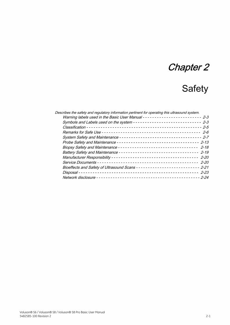
Chapter 2
Safety
Describes the safety and regulatory information pertinent for operating this ultrasound system.Warning labels used in the Basic User Manual - - - - - - - - - - - - - - - - - - - - - - - - - 2-3Symbols and Labels used on the system - - - - - - - - - - - - - - - - - - - - - - - - - - - - - 2-3Classification - - - - - - - - - - - - - - - - - - - - - - - - - - - - - - - - - - - - - - - - - - - - - - - - - 2-5Remarks for Safe Use - - - - - - - - - - - - - - - - - - - - - - - - - - - - - - - - - - - - - - - - - - 2-6System Safety and Maintenance - - - - - - - - - - - - - - - - - - - - - - - - - - - - - - - - - - - 2-7Probe Safety and Maintenance - - - - - - - - - - - - - - - - - - - - - - - - - - - - - - - - - - - 2-13Biopsy Safety and Maintenance - - - - - - - - - - - - - - - - - - - - - - - - - - - - - - - - - - 2-18Battery Safety and Maintenance - - - - - - - - - - - - - - - - - - - - - - - - - - - - - - - - - - 2-19Manufacturer Responsibility - - - - - - - - - - - - - - - - - - - - - - - - - - - - - - - - - - - - - 2-20Service Documents - - - - - - - - - - - - - - - - - - - - - - - - - - - - - - - - - - - - - - - - - - - 2-20Bioeffects and Safety of Ultrasound Scans - - - - - - - - - - - - - - - - - - - - - - - - - - - 2-21Disposal - - - - - - - - - - - - - - - - - - - - - - - - - - - - - - - - - - - - - - - - - - - - - - - - - - - 2-23Network disclosure - - - - - - - - - - - - - - - - - - - - - - - - - - - - - - - - - - - - - - - - - - - - 2-24
Voluson® S6 / Voluson® S8 / Voluson® S8 Pro Basic User Manual5482585-100 Revision 2 2-1
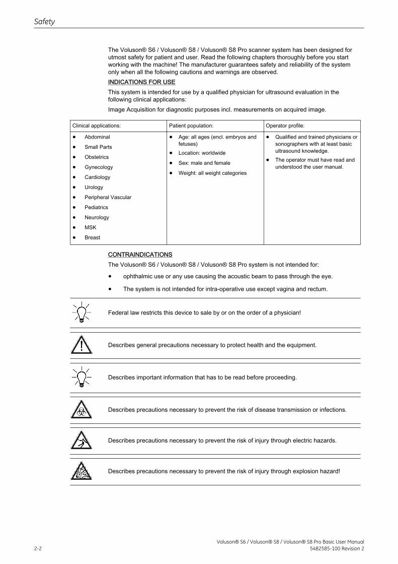
The Voluson® S6 / Voluson® S8 / Voluson® S8 Pro scanner system has been designed forutmost safety for patient and user. Read the following chapters thoroughly before you startworking with the machine! The manufacturer guarantees safety and reliability of the systemonly when all the following cautions and warnings are observed.INDICATIONS FOR USEThis system is intended for use by a qualified physician for ultrasound evaluation in thefollowing clinical applications:Image Acquisition for diagnostic purposes incl. measurements on acquired image.
Clinical applications: Patient population: Operator profile:
• Abdominal
• Small Parts
• Obstetrics
• Gynecology
• Cardiology
• Urology
• Peripheral Vascular
• Pediatrics
• Neurology
• MSK
• Breast
• Age: all ages (encl. embryos andfetuses)
• Location: worldwide
• Sex: male and female
• Weight: all weight categories
• Qualified and trained physicians orsonographers with at least basicultrasound knowledge.
• The operator must have read andunderstood the user manual.
CONTRAINDICATIONSThe Voluson® S6 / Voluson® S8 / Voluson® S8 Pro system is not intended for:
• ophthalmic use or any use causing the acoustic beam to pass through the eye.
• The system is not intended for intra-operative use except vagina and rectum.
Federal law restricts this device to sale by or on the order of a physician!
Describes general precautions necessary to protect health and the equipment.
Describes important information that has to be read before proceeding.
Describes precautions necessary to prevent the risk of disease transmission or infections.
Describes precautions necessary to prevent the risk of injury through electric hazards.
Describes precautions necessary to prevent the risk of injury through explosion hazard!
Safety
2-2Voluson® S6 / Voluson® S8 / Voluson® S8 Pro Basic User Manual
5482585-100 Revision 2
Describes precautions necessary to prevent the risk of injury through moving or tippinghazard!
Describes precautions necessary to prevent the risk of injury through mechanical hazard!
2.1 Warning labels used in the Basic User Manual
2.2 Symbols and Labels used on the system
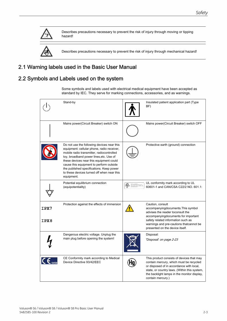
Some symbols and labels used with electrical medical equipment have been accepted asstandard by IEC. They serve for marking connections, accessories, and as warnings.
Stand-by Insulated patient application part (TypeBF)
Mains power(Circuit Breaker) switch ON Mains power(Circuit Breaker) switch OFF
Do not use the following devices near thisequipment: cellular phone, radio receiver,mobile radio transmitter, radiocontrolledtoy, broadband power lines,etc. Use ofthese devices near this equipment couldcause this equipment to perform outsidethe published specifications. Keep powerto these devices turned off when near thisequipment.
Protective earth (ground) connection
Potential equilibrium connection(equipotentiality)
UL conformity mark according to UL60601-1 and CAN/CSA C22/2 NO. 601.1:
Protection against the effects of immersion Caution, consultaccompanyingdocuments.This symboladvises the reader toconsult theaccompanyingdocuments for importantsafety related information such aswarnings and pre-cautions thatcannot bepresented on the device itself.
Dangerous electric voltage. Unplug themain plug before opening the system!
Disposal:'Disposal' on page 2-23
CE Conformity mark according to MedicalDevice Directive 93/42/EEC
This product consists of devices that maycontain mercury, which must be recycledor disposed of in accordance with local,state, or country laws. (Within this system,the backlight lamps in the monitor display,contain mercury.)
Safety
Voluson® S6 / Voluson® S8 / Voluson® S8 Pro Basic User Manual5482585-100 Revision 2 2-3
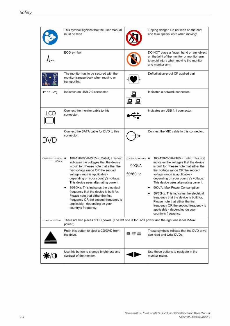
This symbol signifies that the user manualmust be read
Tipping danger. Do not lean on the cartand take special care when moving!
ECG symbol DO NOT place a finger, hand or any objecton the joint of the monitor or monitor armto avoid injury when moving the monitorand monitor arm.
The monitor has to be secured with themonitor-transportlock when moving ortransporting.
Defibrillation-proof CF applied part
Indicates an USB 2.0 connector. Indicates a network connector.
Connect the monitor cable to thisconnector.
Indicates an USB 1.1 connector.
Connect the SATA cable for DVD to thisconnector.
Connect the MIC cable to this connector.
• 100-120V/220-240V~: Outlet, This textindicates the voltages that the deviceis built for. Please note that either thefirst voltage range OR the secondvoltage range is applicable -depending on your country’s voltage.This device uses alternating current.
• 50/60Hz: This indicates the electricalfrequency that the device is built for.Please note that either the firstfrequency OR the second frequency isapplicable - depending on yourcountry’s frequency.
• 100-120V/220-240V~ : Inlet, This textindicates the voltages that the deviceis built for. Please note that either thefirst voltage range OR the secondvoltage range is applicable -depending on your country’s voltage.This device uses alternating current.
• 900VA: Max Power Consumption
• 50/60Hz: This indicates the electricalfrequency that the device is built for.Please note that either the firstfrequency OR the second frequency isapplicable - depending on yourcountry’s frequency.
There are two pieces of DC power. (The left one is for DVD power and the right one is for V-Navipower.)
Push this button to eject a CD/DVD fromthe drive.
These symbols indicate that the DVD drivecan read and write DVDs.
Use this button to change brightness andcontrast of the monitor.
Use these buttons to navigate in themonitor menu.
Safety
2-4Voluson® S6 / Voluson® S8 / Voluson® S8 Pro Basic User Manual
5482585-100 Revision 2
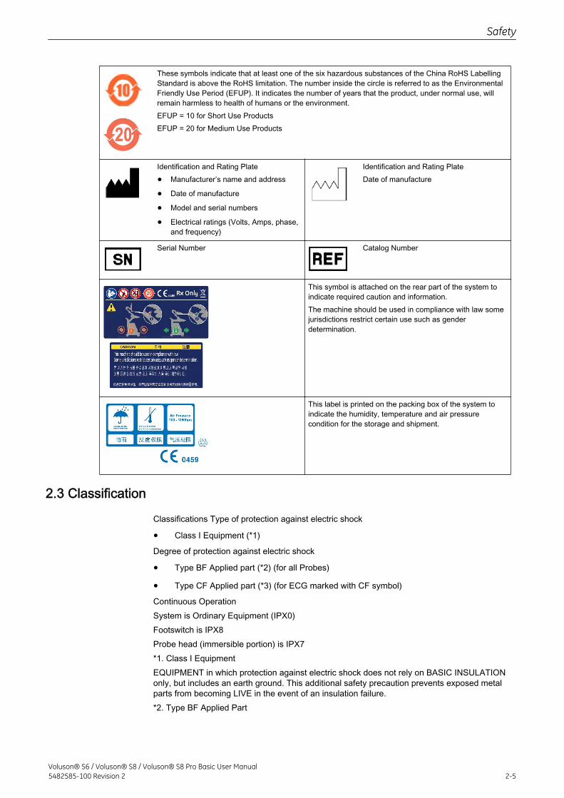
These symbols indicate that at least one of the six hazardous substances of the China RoHS LabellingStandard is above the RoHS limitation. The number inside the circle is referred to as the EnvironmentalFriendly Use Period (EFUP). It indicates the number of years that the product, under normal use, willremain harmless to health of humans or the environment.EFUP = 10 for Short Use ProductsEFUP = 20 for Medium Use Products
Identification and Rating Plate
• Manufacturer’s name and address
• Date of manufacture
• Model and serial numbers
• Electrical ratings (Volts, Amps, phase,and frequency)
Identification and Rating PlateDate of manufacture
Serial Number Catalog Number
This symbol is attached on the rear part of the system toindicate required caution and information.The machine should be used in compliance with law somejurisdictions restrict certain use such as genderdetermination.
This label is printed on the packing box of the system toindicate the humidity, temperature and air pressurecondition for the storage and shipment.
2.3 Classification
Classifications Type of protection against electric shock
• Class I Equipment (*1)
Degree of protection against electric shock
• Type BF Applied part (*2) (for all Probes)
• Type CF Applied part (*3) (for ECG marked with CF symbol)
Continuous OperationSystem is Ordinary Equipment (IPX0)Footswitch is IPX8Probe head (immersible portion) is IPX7*1. Class I EquipmentEQUIPMENT in which protection against electric shock does not rely on BASIC INSULATIONonly, but includes an earth ground. This additional safety precaution prevents exposed metalparts from becoming LIVE in the event of an insulation failure.*2. Type BF Applied Part
Safety
Voluson® S6 / Voluson® S8 / Voluson® S8 Pro Basic User Manual5482585-100 Revision 2 2-5
TYPE BF APPLIED PART providing a specified degree of protection against electric shock,with particular regard to allowable LEAKAGE CURRENT.*3. Type CF Applied PartTYPE CF APPLIED PART providing a degree of protection higher than that for Type BFApplied Part against electric shock particularly regarding allowable LEAKAGE CURRENTS.
2.4 Remarks for Safe Use
• Get acquainted with the transducers and the ultrasound system: read the user manualthoroughly!
• Misinterpretation of an Ultrasound Image can lead to false diagnosis.
• Follow all safety instructions as well as the clinically adopted precautions and measuresfor hygiene.
• Any ultrasound transducers - irrespective of system and design - are sensitive to shockand shall be treated with care. Pay attention to cracks, which may allow conductive fluidsto leak in.
• Avoid kinking, bending or twisting of probe cables and take care to guard them againstmechanical stress (e.g., wheels or heels).
• The probes must not be exposed to mechanical shock (e.g., by dropping). Any damagecaused in this will void the warranty!
• Have the scanner system and the transducers regularly checked (for faulty cables,housing, etc.) by authorized personnel!
• Damage to transducer or cable may lead to a safety hazard, therefore have themrepaired immediately!
• Before plugging in or unplugging a transducer, activate the “FREEZE” mode!
• A specialist familiar with the handling and use of the system shall perform installationand first switch-on and check-up of the system.
• For safety reason, avoid handling fluids in the vicinity of the system. Fluids leaking intothe disk drive can damage the drive.
• The user manual must always be with the scanner system. It is the user’s duty to ensurethis!
• Only ultrasound probes conforming to type BF requirements may be used with theVoluson® S6 / Voluson® S8 / Voluson® S8 Pro .
• Do not install software on the system, that has not been released by GE Healthcare, asthis may lead to erroneous data transfer and thereby decrease system performance.
• The Voluson® S6 / Voluson® S8 / Voluson® S8 Pro system has been tested for EMCand is compliant with CISPR11 group 1 class B and IEC60601-1-2. The Voluson® S6 /Voluson® S8 / Voluson® S8 Pro system is approved for use in a residential district. It isexpected that the user has medical experience and is well informed with the usermanual.
• Main power quality should be that of a typical commercial and/or hospital environment. Ifthe user requires continued operation during power main interruption, it is recommendedthat the system be powered from an uninterruptable power source (UPS).There have been reports of severe allergic reactions to medical devices containing latex(natural rubber). Operators are advised to identify latex-sensitive patients and beprepared to treat allergic reactions promptly. Refer to FDA Medical Alert MDA91-1.
Safety
2-6Voluson® S6 / Voluson® S8 / Voluson® S8 Pro Basic User Manual
5482585-100 Revision 2
2.5 System Safety and Maintenance
This machine must be used in compliance with the law. Some jurisdictions restrict certain usessuch as gender determination.
Federal law restricts this device to sale by or on the order of a physician.
2.5.1 Instructions for Use
This equipment has been tested and found to comply with the limits for medical devices in IEC60601-1-2. These limits are designed to provide reasonable protection against harmfulinterference in a typical medical installation. This equipment generates, uses and can radiateradio frequency energy and, if not installed and used in accordance with the instructions, maycause harmful interference to other devices in the vicinity. However, there is no guarantee thatinterference will not occur in a particular installation. If this equipment does cause harmfulinterference to other devices, which can be determined by turning the equipment off and on,the user is encouraged to try to correct the interference by one or more of the followingmeasures:
• Reorient or relocate the device.
• Increase the distance between equipment.
• Connect the equipment to an outlet on a circuit different from that to which the otherdevice(s) are connected.
• Consult the manufacturer or field service technician for help.
The Voluson S6/S8 does not contain any operator serviceable internal components. Ensurethat unauthorized personnel do not tamper with the unit.
Do not touch the patient and the Signal Input/Output lines (for example, USB port) at the sametime.
2.5.2 Environmental Conditions for Operation
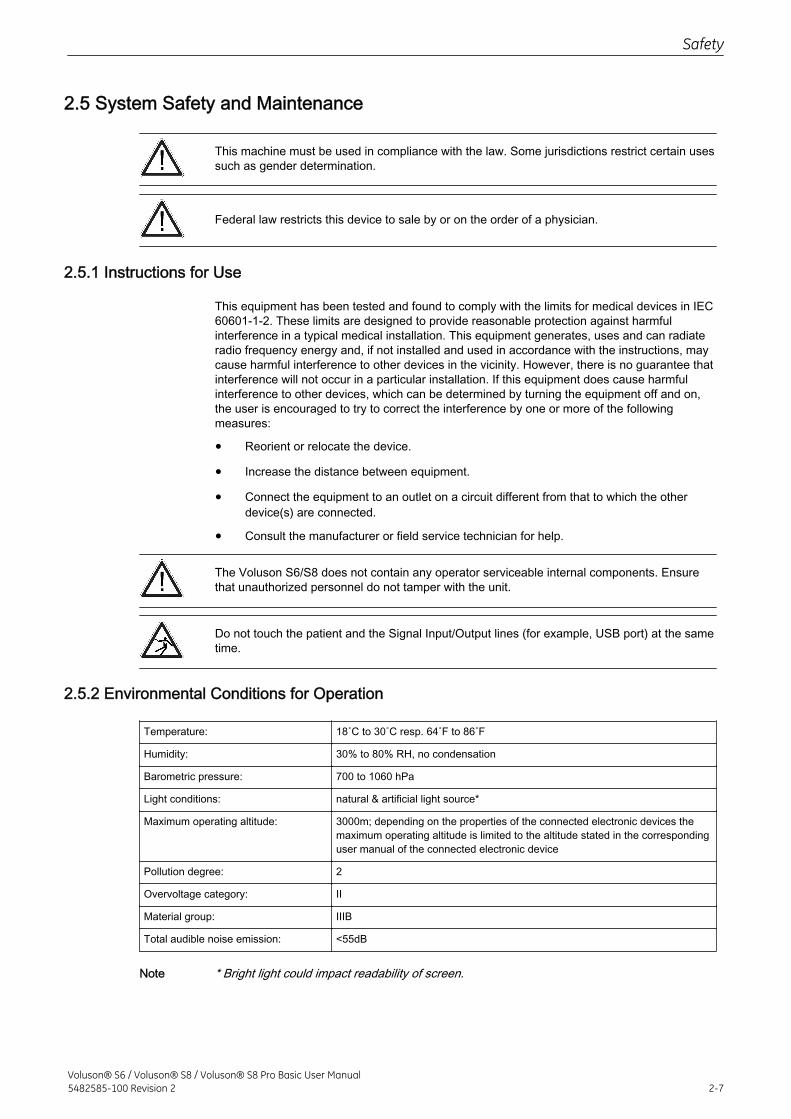
Temperature: 18˚C to 30˚C resp. 64˚F to 86˚F
Humidity: 30% to 80% RH, no condensation
Barometric pressure: 700 to 1060 hPa
Light conditions: natural & artificial light source*
Maximum operating altitude: 3000m; depending on the properties of the connected electronic devices themaximum operating altitude is limited to the altitude stated in the correspondinguser manual of the connected electronic device
Pollution degree: 2
Overvoltage category: II
Material group: IIIB
Total audible noise emission: <55dB
Note * Bright light could impact readability of screen.
Safety
Voluson® S6 / Voluson® S8 / Voluson® S8 Pro Basic User Manual5482585-100 Revision 2 2-7
Ultrasound systems are highly sensitive medical instruments that can easily be damaged byimproper handling. Use care when handling and protect from damage also when not in use.DO NOT use a damaged or defective ultrasound system. Failure to follow these precautionscan result in serious injury and equipment damage.
This equipment is not to be used during transportation (e.g. ambulance cars, aircrafts).
Thermal Safety. Maintaining a safe thermal environment for the patient has been a designpriority at GE Healthcare. Software settings limit the power dissipated for the ultrasoundtransducer as well as the motor-drive to values low enough to ensure that operatingtemperatures stay below 43˚C.
Not to be used in sterile environment.
This equipment must not be used in oxygen enriched atmosphere or in the presence ofinflammable gases (e.g. anesthetic gases).
The use of the system outside the described conditions or intended use, and disregardingsafety related information is considered as abnormal use. The manufacturer is not liable fordamage caused by abnormal use of the device!
Use for diagnostic purposes only.
Do not operate the system in the vicinity of a heat source, of strong electric or magnetic fields(close to a transformer), or near instruments generating high-frequency signals, such as HFsurgery. These can affect the ultrasound images adversely.
In the event the equipment has been brought from a cold environment (stock room, airfreight)into a warm room, allow several hours for temperature balance and passing of condensationhumidity before switching on for the first time.
Do not cover the ventilation holes of the Voluson® S6 / Voluson® S8 / Voluson® S8 Pro !
2.5.2.1 Electric InstallationThe system must be exclusively installed in medically used rooms. The equipment conformswith regulations for electrical safety (IEC 60601) and safety class IIa according to the MDD93/42/EWG regulation for use on humans patients. Probes are rated Type BF. Local safetyregulations may require an additional connection between the potential equilibrium bolt andthe building’s grounding system.
Before switching on the first time, the local main voltage and frequencies have to be checkedagainst the values indicated on the Voluson® S6 / Voluson® S8 / Voluson® S8 Pro ratingplate located on the rear panel. Only authorized personnel must perform any change to thesystem.The minimum required house installation must have 16A.
Safety
2-8Voluson® S6 / Voluson® S8 / Voluson® S8 Pro Basic User Manual
5482585-100 Revision 2
Do not detach power cord from Voluson® S6 / Voluson® S8 / Voluson® S8 Pro . To avoid riskof electric shock, Voluson® S6 / Voluson® S8 / Voluson® S8 Pro must only be connected to asupply mains with PROTECTIVE EARTH.Do not connect any unauthorized equipment between power cord plug and wall power outlet.
2.5.2.2 Moving or lifting the System
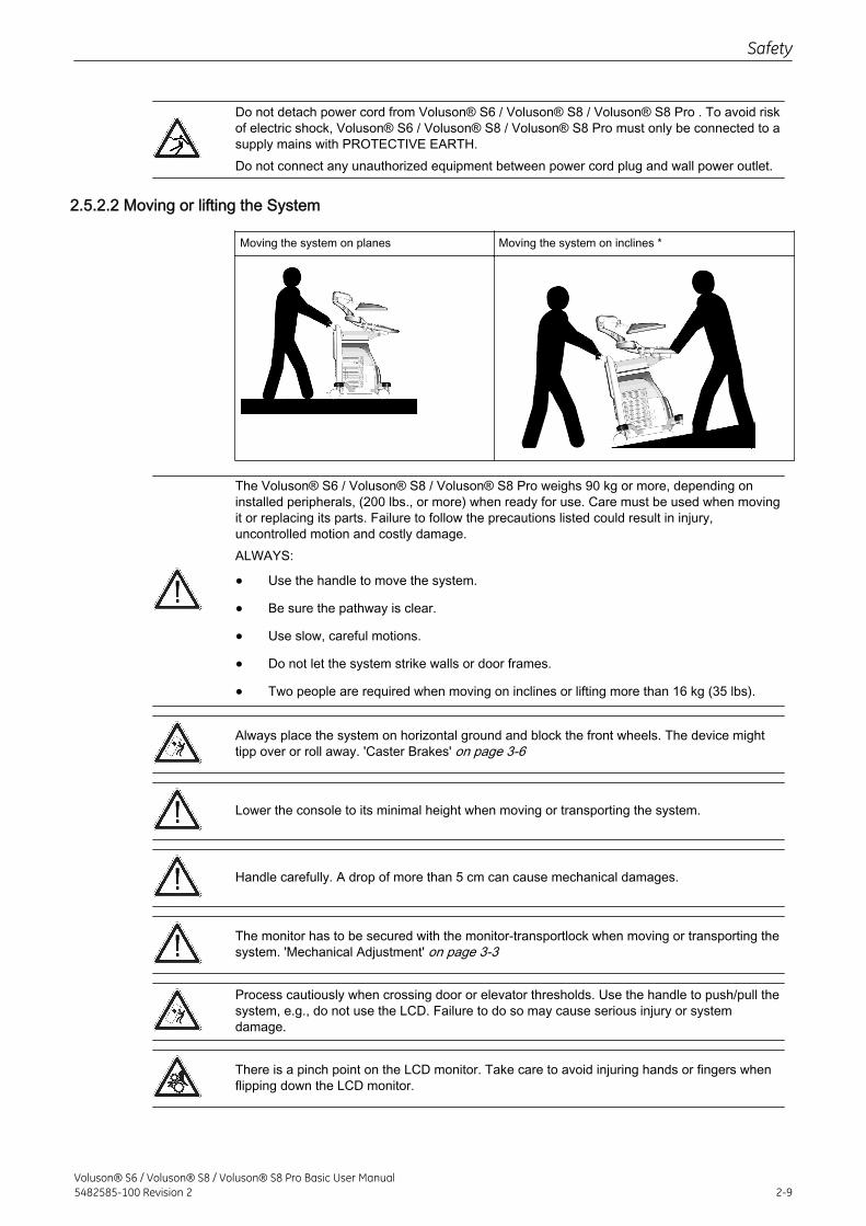
Moving the system on planes Moving the system on inclines *
The Voluson® S6 / Voluson® S8 / Voluson® S8 Pro weighs 90 kg or more, depending oninstalled peripherals, (200 lbs., or more) when ready for use. Care must be used when movingit or replacing its parts. Failure to follow the precautions listed could result in injury,uncontrolled motion and costly damage.ALWAYS:
• Use the handle to move the system.
• Be sure the pathway is clear.
• Use slow, careful motions.
• Do not let the system strike walls or door frames.
• Two people are required when moving on inclines or lifting more than 16 kg (35 lbs).
Always place the system on horizontal ground and block the front wheels. The device mighttipp over or roll away. 'Caster Brakes' on page 3-6
Lower the console to its minimal height when moving or transporting the system.
Handle carefully. A drop of more than 5 cm can cause mechanical damages.
The monitor has to be secured with the monitor-transportlock when moving or transporting thesystem. 'Mechanical Adjustment' on page 3-3
Process cautiously when crossing door or elevator thresholds. Use the handle to push/pull thesystem, e.g., do not use the LCD. Failure to do so may cause serious injury or systemdamage.
There is a pinch point on the LCD monitor. Take care to avoid injuring hands or fingers whenflipping down the LCD monitor.
Safety
Voluson® S6 / Voluson® S8 / Voluson® S8 Pro Basic User Manual5482585-100 Revision 2 2-9
2.5.3 ECG Module
The ECG module is an option of the ultrasound scanner system used to obtain an ECG signalto mark the systolic and end diastolic moments in M mode and Doppler evaluations.
• The ECG module is not intended for ECG diagnosis. It must not be used for an intra-operative application of the heart.
• Monitor: Not for use as a cardiac monitor.
• Only the patient cable supplied by GE Healthcare, and only recommended electrodesmust be used.
• Take care that neither bare parts of one of the three electrodes nor the patient comesinto contact with conductive parts (e.g., metal parts of the examination bed, trolley, orsimilar).
• If the use of a HF surgical system with simultaneously connected ECG electrodesbecomes necessary, a large distance of ECG electrodes from the surgical field and aperfect position of the neutral electrode of the HF surgical system must be observed(avoiding burning risk).
• If the use of a defibrillator becomes necessary, there must be no ECG adhesiveelectrodes and no conductive paste between the contact positions of the defibrillatorplates (avoid current bridge; the signal input of the ECG module is defibrillator-safe).
For further details and information please review: 'ECG Module' on page 15-12
2.5.4 Cleaning and Maintenance
Prior to cleaning any part of the system:
1. Turn off the system power. If possible, disconnect the power cord.To clean the system cabinet:
1. Moisten a soft, non-abrasive folded cloth with a mild,general purpose, non-abrasive soapand water solution.
2. Wipe down the top, front, back, and both sides of the system cabinet.
Do not spray any liquid directly into the unit.
To clean the monitor face:Use a soft, folded cloth. Gently wipe the monitor face. Do NOT use a glass cleaner that has ahydrocarbon base (such as Benzene, Methyl Alcohol or Methyl Ethyl Ketone) on monitors withthe filter (anti-glare shield). Hard rubbing will also damage the filter.
When cleaning the monitor, make sure not to scratch the monitor.
To clean the operator control panel:
1. Moisten a soft, non-abrasive folded cloth with a mild,general purpose, non-abrasive soapand water solution.
2. Wipe down operator control panel.
3. Use a cotton swab to clean around keys or controls. Use a toothpick to remove solidsfrom between keys and controls.
When cleaning the operator control panel, make sure not to spill or spray any liquid on thecontrols, into the system cabinet, or in the probe connection receptacle.
Safety
2-10Voluson® S6 / Voluson® S8 / Voluson® S8 Pro Basic User Manual
5482585-100 Revision 2
To clean the footswitch:
1. Moisten a soft, non-abrasive folded cloth with a mild, general purpose, non-abrasivesoap and water solution.
2. Wipe the external surfaces of the unit then dry with a soft,clean, cloth.Have the system checked and serviced in regular intervals (once per year) by authorizedservice personnel. In case of total failure first check if main voltage is present. Mentioning anyobservations or failure symptoms to the service engineers is helpful.
Before cleaning the scanner switch it off. Do not use disinfection spray nor gas disinfection.Electric parts must be protected from drip water. Dust and grime on the frame can causeirregular function! Check the main cable, transducer cables, plugs and sockets on a regularbasis.
No covers or panels must be removed from the system (high-voltage risk). Only servicepersonnel from GE Healthcare must perform service and repairs. Attempting do-it-yourselfrepairs invalidate warranty, and are an infringement to regulations and are inadmissible acc. toIEC 60601-1. Under the condition of regular maintenance by authorized service personnel alifetime of 7 years for the equipment and 5 years for the probes may be expected.
Never modify this product, including system components, software, cables, and so on. Usermodification may cause safety hazards and degradation in system performance. Allmodification must be done by a GE qualified person.
After cleaning, please inspect the system including functionality by live scan. If any defects areobserved or malfunctions occur, do not operate the equipment but inform a qualified serviceperson. Contact a Service Representative for information.
The following table provides cleaning instructions for the ultrasound device. Effective cleaningand disinfection is not possible for parts with narrow gaps and holes (e.g. keyboard,trackball,...). It is the responsibility of the user to decide which cleaning and disinfectionprocedure is necessary to ensure a safe working environment. Electrical contacts andconnectors must not be cleaned. Do not use any other cleaning agents than listed in the tablebelow. Do not spray any liquid directly on the system.
Component When How to clean Cleaning agent
Probe holder daily or after eachexamination
Wipe gently with a damp,non-abrasive cloth.
IPA solution (20% IPA, 80%water) or "Sani Cloth Active"disinfection wipes
Probes daily or after eachexamination
See Probe Care Card and 'Probe Maintenance' on page 2-14
User interface daily or after eachexamination
Wipe gently with a damp,non-abrasive cloth.
Spiritus dilutus = 70%ethanol, 30% water
Monitor display daily or after eachexamination
Wipe gently with absorbentcotton or other soft materiallike chamois.
Spiritus dilutus = 70%ethanol, 30% water
Housings daily or after eachexamination
Wipe gently with a damp,non-abrasive cloth.
IPA solution (20% IPA, 80%water) or "Sani Cloth Active"disinfection wipes
Peripherals (e.g.printers,...)
Clean according to the instructions of the peripheral manufacturer.
2.5.4.1 Safety TestScan time limits: According to respective national regulations, and according to themanufacturer recommendations for the medical-technical system.Range:
Safety
Voluson® S6 / Voluson® S8 / Voluson® S8 Pro Basic User Manual5482585-100 Revision 2 2-11
a) Visual inspection: Housing, connection, operating elements, display facilities, labels,accessories, user manual.
b) Functional test: Checking of functions (according to user manual), check also modularcombinations and common operability of system and accessories.
c) Electric test: Checking of the electric safety of system combinations according toIEC60601-1 or respective national regulations.
For safety reasons, avoid handling fluids in the vicinity of the system.
Item Safety Test Notes
Console LeakageCurrent Checks
Annually Also after corrective maintenance or as required byyour facilities QA program.
Peripheral LeakageCurrent Checks
Annually Also after corrective maintenance or as required byyour facilities QA program.
Surface Probe LeakageCurrent Checks
Annually Also after corrective maintenance or as required byyour facilities QA program.
Endocavity ProbeLeakage CurrentChecks
Annually Also after corrective maintenance or as required byyour facilities QA program.
2.5.4.2 Note for the Administration of “Full Backup” Data
All settings and patient data created since last full backup are NOT backed-up! It is highlyrecommended to create a full backup of settings and patient data regularly.
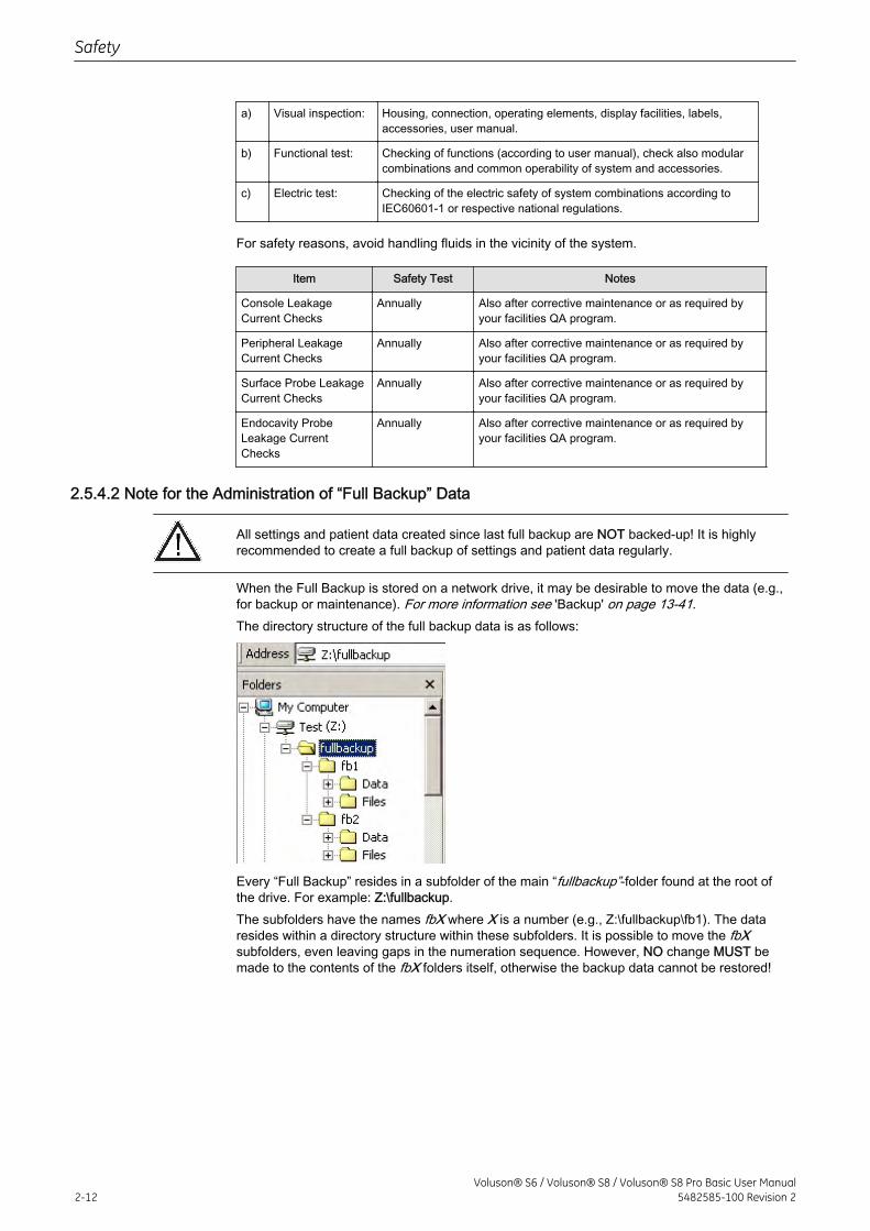
When the Full Backup is stored on a network drive, it may be desirable to move the data (e.g.,for backup or maintenance). For more information see 'Backup' on page 13-41.The directory structure of the full backup data is as follows:
Every “Full Backup” resides in a subfolder of the main “fullbackup”-folder found at the root ofthe drive. For example: Z:\fullbackup.The subfolders have the names fbX where X is a number (e.g., Z:\fullbackup\fb1). The dataresides within a directory structure within these subfolders. It is possible to move the fbXsubfolders, even leaving gaps in the numeration sequence. However, NO change MUST bemade to the contents of the fbX folders itself, otherwise the backup data cannot be restored!
Safety
2-12Voluson® S6 / Voluson® S8 / Voluson® S8 Pro Basic User Manual
5482585-100 Revision 2
2.6 Probe Safety and Maintenance
2.6.1 Handling Precautions
Ultrasound probes are highly sensitive medical instruments that can easily be damaged byimproper handling. Use care when handling and protect from damage when not in use. DONOT use a damaged or defective probe. Failure to follow these precautions can result inserious injury and equipment damage.Transducer damage can result from contact with inappropriate coupling or cleaning agents.Do not soak or saturate transducers with solutions containing alcohol, bleach, ammoniumchloride compounds, hydrogen peroxide or incompatible solutions as shown on the Care-card!Avoid contact with solutions or coupling gels containing mineral oil or lanolin.Inspect the probe prior to use for damage or degeneration to the housing, strain relief, lensand seal.
Note Sporadically, silicone grease can leak in small amounts from the probes’ cable bushing. Thisleakage is not a failure or harmful to the human body. Silicone grease does not contain anyhazardous substances and is only used to seal the cable bushing. In case of a leakage wipethe grease with a cloth.
2.6.2 Watertightness
Attention: All probes labeled “IPX7” are watertight up to a minimum of 5 cm above the probes strain relief. If the probe is not explicitly marked as IPX7, only the scan head is watertight andthe rest of the probe is IPX0 according to IEC 60601-2-37. review: 'Probe Maintenance' on page 2-14.The footswitch rated IPX8 is suitable for use in surgical rooms:
2.6.3 Electrical Shock Hazard
The probe is driven with electrical energy that can injure the patient or user if live internal partsare contacted by conductive solution:
• DO NOT immerse the probe into any liquid beyond the immersion level. 'ProbeMaintenance' on page 2-14. Never immerse the probe connector or probe adaptorsinto any liquid.
• DO NOT drop the probes or subject them to other types of mechanical shock or impact.Degraded performance or damage such as cracks or chips in the housing may result.
• Inspect the probe before and after each use for damage or degradation to the housing,strain relief, lens, and seal. A thorough inspection should be conducted during thecleaning process.
• DO NOT kink, tightly coil, or apply excessive force on the probe cable. Insulation failuremay result.
• Electrical leakage checks should be performed on a routine basis by GE Service orqualified hospital personnel. Refer to the service manual for leakage check procedures.
Safety
Voluson® S6 / Voluson® S8 / Voluson® S8 Pro Basic User Manual5482585-100 Revision 2 2-13
2.6.4 Mechanical Hazards
A defective probe or excessive force can cause patient injury or probe damage:
• Observe depth markings and do not apply excessive force when inserting ormanipulating intracavitary probes.
• Inspect probes for sharp edges or rough surfaces that could injure sensitive tissue.
• Avoid mechanical shock or impact to the transducer and do not apply excessive bendingor pulling force to the cable.
2.6.5 Cable Handling
Take the following precautions with probe cables:
• Keep free from wheels.
• Do not bend the cable acutely.
• Avoid crossing cables between probes.
2.6.6 Ergonomics
Probes have been ergonomically designed to:
• Handle and manipulate with ease.
• Connect to the system with one hand.
• Be lightweight and balanced.
• Have rounded edges and smooth surfaces.
Cables have been designed to:
• Connect to system with appropriate cable length.
• Stand up to typical wear with cleaning and using disinfectant agents, contact withapproved gel, etc.
2.6.7 Probe Maintenance
Only authorized personnel shall perform any type of repair. Never attempt to open atransducer or transducer connector. This will void the warranty!
2.6.7.1 Inspecting ProbesAfter each use, inspect the probe’s lens, cable, and casing. Look for any damage that wouldallow liquid to enter the probe. If any damage is found, the probe must not be placed into anyliquid (e.g. for disinfection) and must not be used until it has been inspected and repaired/replaced by a GE Healthcare Service Representative.
Note Keep a log of all probe maintenance, along with a picture of any probe malfunction.
2.6.7.2 Probe Handling and Infection ControlThis information is intended to increase user awareness of the risks of disease transmissionassociated with using this equipment and provide guidance in making decisions directlyaffecting the safety of the patient as well as the equipment user.Diagnostic ultrasound systems utilize ultrasound energy that must be coupled to the patient bydirect physical contact. Depending on the type of examination, this contact occurs with a
Safety
2-14Voluson® S6 / Voluson® S8 / Voluson® S8 Pro Basic User Manual
5482585-100 Revision 2
variety of tissues ranging from intact skin in a routine exam to recirculating blood in a surgicalprocedure.The level of risk of infection varies greatly with the type of contact.One of the most effective ways to prevent transmission between patients is with single use ordisposable devices. However, ultrasound transducers are complex and expensive devices thatmust be reused between patients. It is very important, therefore, to minimize the risk ofdisease transmission by using barriers and through proper processing between patients.
2.6.7.3 Probe Cleaning and Disinfecting Process
Adequate cleaning and disinfection are necessary to prevent disease transmission. It is theresponsibility of the equipment user to verify and maintain the effectiveness of the infectioncontrol procedures in use.High-level disinfection is recommended for surface probes and is required for endocavityprobes. Additional to disinfection the use of sterile, legally marketed probe sheats forintracavitary procedures is MANDATORY.Ultrasound probes can be disinfected using liquid chemical germicides. The level ofdisinfection is directly related to the duration of contact with the germicide. Increased contacttime produces a higher level of disinfection.
CREUTZFIELD-JACOB DISEASENeurological use on patients with this disease must be avoided. If a probe becomescontaminated, there is no adequate disinfecting means.
To clean and disinfect the probe after each use:
1. Remove the probe sheath, if appropriate.
2. Disconnect the probe from the ultrasound console.
3. Remove all coupling gel and other visible substances from the probe by wiping with asoft dry cloth. If necessary to remove material dried to the surface the cloth can bemoistened with lukewarm water.
4. After each use, inspect the probe’s lens, cable, and casing. Look for any damage thatwould allow liquid to enter the probe. If any damage is found, the probe must not beplaced into any liquid (e.g. for disinfection) and must not be used until it has beeninspected and repaired/replaced by a GE Healthcare Service Representative.
5. Prepare a solution of a suitable cleaning-disinfectant with the right concentrationaccording to the manufacturer’s instructions. Be sure to follow all precautions for storage,use and disposal.
Please consider our constantly updated Care-Card (which is inside the transducer boxes) fordisinfectants and gels that are compatible with the surface material of the probes!The most current version can be found on the web:To reach the care and disinfectant site listing for the latest in germicides & couplantsrecommended by GE for surface material compatibility review: http://www.gehealthcare.com/usen/ultrasound/products/probe_care.htmlThe products given in table 1 have been validated for appropriate cleaning and disinfection ofthe probes.
1. Place the probe into the solution of cleaning-disinfectant. Make sure not to immerse theprobe into the liquid beyond the immersion level given in the pictures below. Make surethat the probe is covered with the cleaning-disinfectant up to the immersion level duringthe complete disinfection time. Leave the probe in the solution for the specified timeaccording to the manufacturer’s instructions. For the recommended cleaning anddesinfection time, please see your probe-care card.!
2. Scrub the probe as needed using a soft sponge, gauze, or cloth to remove all visibleresidue from the probe surface. Prolonged soaking or scrubbing with a soft bristle brush(such as a toothbrush) may be necessary if material has dried onto the probe surface.
Safety
Voluson® S6 / Voluson® S8 / Voluson® S8 Pro Basic User Manual5482585-100 Revision 2 2-15
3. Rinse the probe with enough clean, potable water to remove all disinfectant residues.
4. Use a soft cloth to clean the cable and the user section of the probe with the cleaning-disinfectant liquid. Make sure that the surface of the probe and cable is wettedthoroughly with the cleaning-disinfectant.
5. Allow probe to air dry completely.
6. Reconnect the probe to the ultrasound console and place the probe into it’s holder.
7. Inspect the probe prior to use for damage or degeneration to the housing, strain relief,lens and seal. Do not use a damaged or defective probe until it has been inspected andrepaired/replaced by a GE Healthcare Service Representative.
8. Inspect the probe prior to use for damage or degeneration to the housing, strain relief,lens and seal. Do not use a damaged or defective probe until it has been inspected andrepaired/replaced by a GE Healthcare Service Representative.
9. Put a new sterile, legally marketed probe sheath over the probe prior to next use.
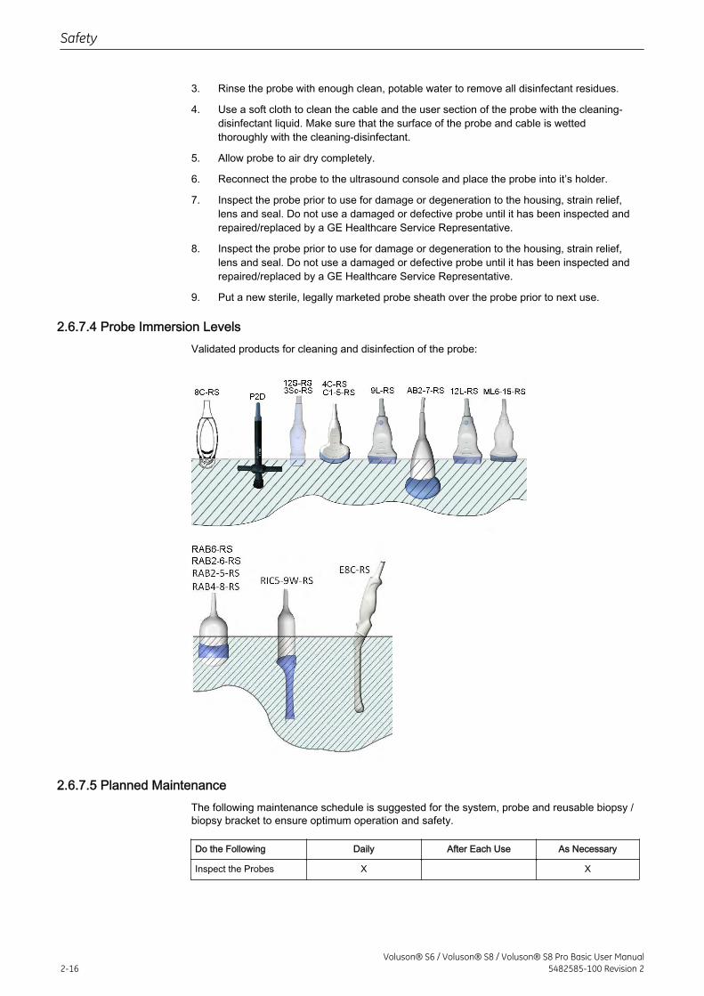
2.6.7.4 Probe Immersion LevelsValidated products for cleaning and disinfection of the probe:
2.6.7.5 Planned MaintenanceThe following maintenance schedule is suggested for the system, probe and reusable biopsy /biopsy bracket to ensure optimum operation and safety.
Do the Following Daily After Each Use As Necessary
Inspect the Probes X X
Safety
2-16Voluson® S6 / Voluson® S8 / Voluson® S8 Pro Basic User Manual
5482585-100 Revision 2
Clean the Probes X X
Disinfect Probes X X
After cleaning and disinfection, inspect the probe’s lens, cable, casing and connector. Look forany damage that would allow liquid to enter the probe. Also, inspect the probe functionality bylive scan. If any damage is found, do not use the probe until it has been inspected andrepaired/replaced by a GE service representative.
2.6.7.6 Environmental requirements for ProbesProbes must be operated, stored, or transported within the parameters outlined below.
Ensure that the probe face temperature does not exceed the normal operation temperaturerange.Avoid temperatures above 50ºC
Probe Environmental Requirements
Operational Storage Transport
Temperature +18º to +30º C +64º to+86º F
-10º to +50º C +14º to+122º F
-10º to +50º +14º to+122º F
Humidity Max. 80% non-condensing
Max. 90% non-condensing
Max. 90% non-condensing
Pressure 700 - 1060hPa 700 - 1060hPa 700 - 1060hPa
2.6.7.7 Using Protective Sheaths
Probes are not delivered sterilely! Before the first useage, it is MANDATORY to clean anddesinfect probes to avoid infections or disease transmissions!
Protective barriers may be required to minimize disease transmission. Probe sheaths areavailable for use with all clinical situations where infection is a concern. Legally marketed,sterile probe sheaths must be used for intracavitary procedures. Use of legally marketed,sterile, pyrogen free probe sheats is MANDATORY.Instructions: Custom-made sheaths are available for each probe. Each probe sheath kitconsists of a flexible sheath used to cover the probe and cable and elastic bands used tosecure the sheath.Sterile probe sheaths are supplied as part of disposable biopsy kits for those probes intendedfor use in biopsy procedures. In addition to the sheath and elastic bands, there are associatedaccessories for performing a biopsy procedure which are included in the kit. Refer to thebiopsy instructions, 'Biopsy Special Concerns' on page 2-18
Devices containing latex may cause severe allergic reaction in latex sensitive individuals.Refer to FDA’s March 29, 1991 Medical Alert on latex products.
DO NOT use pre-lubricated condoms as a sheath.In some cases, they may damage the probe. Lubricants in these condoms may not becompatible with probe construction.
DO NOT use an expired probe sheath.Before using probe sheaths, verify whether the term of validity has expired.
Safety
Voluson® S6 / Voluson® S8 / Voluson® S8 Pro Basic User Manual5482585-100 Revision 2 2-17
Probes must be cleaned and desinfected before they are replaced or disposed.
2.7 Biopsy Safety and Maintenance
2.7.1 Biopsy Special Concerns
Biopsyneedles and biopsyguides are not delivered sterilely! Before the first useage, it isMANDATORY to clean and desinfect biopsyneedles and biopsyguides to avoid infections ordisease transmissions!
There may be restrictions on performing IVF, CVS or PUBS. Please consider the local lawsand regulations!
2.7.1.1 Preparing the Patient
• Prepare the patient according to the usual procedures for the purpose.
• An ultrasound examination with this system must be performed either under supervision,or by adequately trained and qualified medical staff.
A biopsy must only be performed by physicians with adequate experience. Under allcircumstances the necessary safety precautions and sterility measures have to be respected.
It is absolutely necessary to ensure that before performing a biopsy, the selected anddisplayed biopsy line corresponds to the biopsy needle guide mounted to the transducer (left/right).
Before starting a biopsy please make sure that in case you want to save a study, all relevantpatient information is entered.
Do not use needle guide if it appears damaged.
Cleaning and Sterilization of reusable Biopsy Guides: (for disposable biopsy guides, pleaseregard enclosed manuals):After each use, remove needle guide from transducer. Remove visible contaminants fromneedle guide surface thoroughly,using a small, soft instrument brush. Take special care of allnarrow areas and tubes. Keep needle guide from drying out until complete cleaning can beaccomplished. After that, soak needle guide for minimum of five minutes in neutral pH, lowfoamingenzymatic detergent.While immersed, use instrument brush to remove trapped contaminants from Surfaces, holesand tubes. If visible contaminants cannot be easily removed, repeat soaking procedure for anadditional five minutes. Remove needle guide from cleaning solution and remove anyremaining residue with dry wipe. Follow cleaning solution manufacturer’s directions for useand recommendations for concentration.
Disposable biopsy guides: Single-use components must be disposed as infectious waste!
Safety
2-18Voluson® S6 / Voluson® S8 / Voluson® S8 Pro Basic User Manual
5482585-100 Revision 2

If a sterile package of biopsy is damaged, do not use the infectious biopsy or throw it away toavoid infections.
Reusable biopsy guides must be sterilized before they are disposed!
2.7.2 Biopsy Lines
To achieve the best possible accuracy of the display of the needle path, the biopsy lines haveto be programmed for each transducer. To program a Single Angle Biopsy Line: 'To program aSingle Angle Biopsy Line' on page 5-17 To program a Multi Angle Biopsy Line: 'To programa Multi Angle Biopsy Line' on page 5-18
• The biopsy lines must be programmed once by the service personnel or by the user. Theprocedure must be repeated if probes and/or biopsy guides are exchanged.
• Before performing a biopsy, make sure that the displayed biopsy line coincides with theneedle track (check in a bowl filled with approx. 47˚C warm water).
• The needle used for this alignment verification must not be used for the actualprocedure. Always use a straight, new and sterile needle for each biopsy procedure.
Depending on the needle stiffness/thickness and the elasticity and composition of the differenttissue-types in the path of the biopsy needle, the actual needle track can deviate from thepredicted biopsy line. The biopsy needle might bend and not follow a straight line.
2.8 Battery Safety and Maintenance
USE ONLY BATTERIES APPROVED BY GE HEALTHCARE AS SUITABLE FOR USE WITHTHE VOLUSON S6/S8 ULTRASOUND SCANNER.
THE VOLUSON S6/S8 BATTERY HAS A SAFETY DEVICE. DO NOT ATTEMPT TO DIS-ASSEMBLE OR ALTER THE BATTERY! ALWAYS OBSERVE THE FOLLOWINGPRECAUTIONS:
• DO NOT short-circuit the battery by directly connecting the negative terminals with metalobjects.
• DO NOT heat the battery or discard it in a fire.
• DO NOT expose the battery to temperatures over 50˚C. Keep the battery away from fireand other heat sources.
• DO NOT charge the battery near a heat source, such as, a fire or heater.
• DO NOT leave the battery in direct sunlight.
• DO NOT pierce the battery with a sharp object, hit it, or step on it.
• DO NOT use a damaged battery.
• DO NOT apply solder to a battery.
• DO NOT connect the battery to an electrical power outlet.
TO PREVENT THE BATTERY BURSTING, IGNITING, OR FUMES FROM THE BATTERYCAUSING EQUIPMENT DAMAGE, ALWAYS OBSERVE THE FOLLOWING PRECAUTIONS:
• DO NOT immerse the battery in water or allow it to get wet.
Safety
Voluson® S6 / Voluson® S8 / Voluson® S8 Pro Basic User Manual5482585-100 Revision 2 2-19
• DO NOT place the battery into a microwave oven or pressurized container.
• If the battery leaks or emits an odor, remove it from all possible flammable sources.
• If the battery emits an odor or heat, is deformed or discolored, or in a way appearsabnormal during use, recharging or storage, immediately remove it and stop using it.
Note The Voluson S6/S8 ultrasound scanner is supplied with a lithium ion battery in the powersupply module, as option. The lithium ion technology used in the system's battery issignificantly less hazardous to the environment than the lithium metal technology used in someother batteries (such a watch battery). Used batteries should not be placed with commonhousehold waste products. Contact local authority for the location of a chemical wastecollection program nearest you.
Note Regulations vary for different countries. Dispose of a used battery in accordance with localregulations.
2.9 Manufacturer Responsibility
The manufacturer, assembler, importer or installer considers themselfes responsible regardingsafety, reliability and performance of the instrument under the following conditions:
• when assembling the system, when adding options, when new settings or modificationsor repairs were performed by service personnel authorized by GE Healthcare.
• also that the local electric installation complies with the national regulations, and that theequipment is only used according to the User Manual.
2.10 Service Documents
The Service Manual supplies block diagrams, lists of spare parts, descriptions, adjustmentinstructions or similar information which help adequately qualified technical personnel inrepairing those parts of the instrument which have been defined repairable by themanufacturer.For additional information or assistance, please contact your local distributor or the appropriatesupport resource.
2.10.1 Service Software – Remote Access
By using the remote access feature, a GE field engineer can access the ultrasound system viaa modem connection. The field engineers are required to contact/call the affected site inadvance prior to establish a connection to the system.Disruptive Mode:If the field engineer requires unrestricted access to the ultrasound system the field engineerrequests to create a disruptive mode on the system. A message appears on the screen askingfor permission to switch to disruptive mode:GE Service is requesting permission to diagnose the system remotely. Normal systemoperations might be disturbed during this period. Click on YES to allow GE Service to continuesystem diagnostics.If disruptive mode is accepted, work on the system can be severely affected. Therefore, it isnot allowed to perform an exam or make a diagnosis using the ultrasound system while beingin disruptive mode.
Note A remote connection can affect the system’s performance (e.g., in 3D/4D or Doppler mode).Therefore, it is recommended to cease work on the system as soon as the field engineercontacts the site and announces the remote connection.
Network Security:The remote access features enables, after checkout has been performed, network serviceslike ftp or telnet on the ultrasound system. Therefore, it is advisable to restrict network access
Safety
2-20Voluson® S6 / Voluson® S8 / Voluson® S8 Pro Basic User Manual
5482585-100 Revision 2
to system for unauthorized personnel. It is strongly recommended to use a firewall to restrictnetwork access from and to an ultrasound system with the remote access feature installed.Other precautions like a secure network segment are encouraged.
2.11 Bioeffects and Safety of Ultrasound Scans
When ultrasound waves travel through tissue, there is a certain risk for damage. There hasbeen a lot of research on the impact that high frequency waves can have on different kinds oftissues under defined conditions and “There is, to date, no evidence that diagnostic ultrasoundhas produced any harm to humans – including the developing fetus.” (Guidelines for the safeuse of diagnostic ultrasound equipment, Safety Group of the British Medical UltrasoundSociety 2010).Physiological effects due to ultrasound are generally assumed to be deterministic and onlyoccur above a certain threshold in contrast to ionizing radiation, which causes effectsaccidentally. Thus ultrasound examinations can be held very safe if certain proceedings arefollowed. It is therefore recommended to read the following sections and study the citedliterature.
2.11.1 Prudent Use – ALARA Principle
In spite of the relatively low risk of ultrasound scans compared to other imaging techniques,the operator shall choose the exposure level with caution to minimize the risk of bioeffects.“A fundamental approach to the safe use of diagnostic ultrasound is to use the lowest outputpower and the shortest scan time consistent with acquiring the required diagnostic information.This is the ALARA principle (i.e. As Low As Reasonably Achievable). It is acknowledged thatin some situations it is reasonable to use higher output or longer examination times than inothers: for example, the risks of missing a fetal anomaly must be weighed against the risk ofharm from potential bioeffects. Consequently, it is essential for operators of ultrasoundscanners to be properly trained and fully informed when making decisions of this nature.”(Guidelines for the safe use of diagnostic ultrasound equipment, Safety Group of the BritishMedical Ultrasound Society 2010)Special care regarding ALARA should be taken with obstetric examinations as any potentialbioeffects are likely to be of greatest significance in the embryo or fetus.It is strongly recommended to consider ALARA when undertaking ultrasound scans.
2.11.2 Bioeffects
• Thermal effects refer to heating of soft tissue and boneThe thermal indices TIs (soft tissue), TIb (bone near focus) and TIc (bone near surface)were introduced to provide the operator a relative potential for a tissue temperature rise.It should be noted that a TI of 1 does not necessarily mean that tissues being scannedwill increase in temperature by 1˚C – almost every scanning situation departs from theassumed model conditions, such as tissue type, blood perfusion, mode of operation andactual exposure time of the scanned area. However, the thermal indices provideinformation regarding the possible increase in the risk of potential thermal bioeffects andit provides a relative magnitude that can be used to implement ALARA. In addition totissue heating due to the generated ultrasound field, the temperature of the probe headitself can also increase during the examination. The operator shall be aware, that in thetissue region near the ultrasonic transducer, there will be a superposition with theheating due to the ultrasound field, which is not considered by the TI values.
• Nonthermal effects refer to mechanical phenomena such as cavitationNonthermal bioeffects are caused by the interaction of ultrasound fields with very smallpockets of gas (stabilized gas bodies), i.e. the generation, growth, vibration and possiblecollapse of microbubbles within the tissue. This behavior is referred to as cavitation(Medical Ultrasound Safety, 2nd Edition, AIUM 2009/American Institute of Ultrasound inMedicine Consensus Report on Potential Bioeffects of Diagnostic Ultrasound, AIUM2008/Guidelines for the safe use of diagnostic ultrasound equipment, Safety Group of
Safety
Voluson® S6 / Voluson® S8 / Voluson® S8 Pro Basic User Manual5482585-100 Revision 2 2-21
the British Medical Ultrasound Society 2010). The potential of cavitation increases withthe rarefactional peak pressure but decreases with the pulse frequency. Therefore theMechanical Index MI was introduced to take account of both the pressure and thefrequency. The higher the MI the greater is the risk of nonthermal bioeffects.
2.11.3 Regulated Parameters
Relevant parameters having physiological effects (For more information see 'Bioeffects' onpage 2-21. ) are regulated according to FDA and IEC guidelines and standards. Theseparameters are
Parameter Meaning Limit Displayed
MI Mechanical Index 1.9 Yes
TIs, TIb, TIc Thermal Indices TI – one of the followingvalues can be displayed:
6 Yes
TIs: soft tissues
TIb: bone in focal region
TIc: bone at surface (e.g. cranial)
Ispta.3 Averaged intensity at spatial peak with aderating of 0.3dB/(cm MHz)
720 mW/cm2 No
T Temperature at the patient’s side of theprobe – lower limit during patient contact,higher limit for rest position
43˚C/50˚C (109.4˚F/122˚F)
No
2.11.4 Interpretation of displayed parameters MI and TI
During obstetric examinations these displayed values shall be observed very critically,because there may be conditions that are potentially hazardous even below the regulatorylimits.Some guidelines recommend that embryonic and fetal in situ temperatures of 41˚C (4˚C abovenormal temperature) should be limited in time by 5 min or less. Thus, for a reasonable safetymargin, TI values above 1 should be avoided. Additional factors, like fever of the mother, areagain reasons to keep the TI values as low as possible on the one hand, and go only as highas necessary to achieve the desired clinical results ('Prudent Use – ALARA Principle' on page2-21).The mechanical index, which indicates the risk of cavitation, becomes important at theinterface between gas and soft tissue (nonfetal lung and bowel), but also with the use of gasbody contrast agents. Often an MI value of 0.4 or less is suggested for examinations of tissuecontaining stabilized gas bodies. This value arises from operating experience and is notconfirmed.Some examples where the MI and TI, respectively, are more or less important are shown inthe following table according to Particular requirements for the basic safety and essentialperformance of ultrasonic medical diagnostic and monitoring equipment, IEC 60601-2-37.
Safety
2-22Voluson® S6 / Voluson® S8 / Voluson® S8 Pro Basic User Manual
5482585-100 Revision 2
Of greater importance Of less importance
MI –MechanicalIndex
With contrast agents In the absence of gas bodies, i.e. most tissuescanning
Cardiac scanning (lung exposure)
Abdominal scanning (bowel gas)
TI – ThermalIndices
1st trimester scanningFetal skull and spineNeonatal headPatient with feverPoorly perfused tissueScanning near ribs or bone: TIb
Well perfused tissue, i.e. liver, spleenCardiac scanningVascular scanning
Further information can be retrieved from Bioeffects & Safety of Diagnostic Ultrasound, AIUM,1993 and Evaluation of Research Reports: Ultrasound Bioeffects Literature Reviews(1992-2003).
2.11.5 Reporting Tables
Particular requirements for the basic safety and essential performance of ultrasonic medicaldiagnostic and monitoring equipment, IEC 60601-2-37 2nd Edition, 2007.Information for Manufacturers Seeking Marketing Clearance of Diagnostic Ultrasound Systemsand transducers, FDA Guidance, 2008.Ultrasonics - Field characterization - Test methods for the determination of thermal andmechanical indices related to medical diagnostic ultrasonic fields, IEC 62359 1st Edition, 2005.
2.12 Disposal
Disposal of Old Electrical & Electronic Equipment (applicable in the European Union and otherEuropean countries with separate collection systems).This symbol on the product or on itspackaging indicates that this product shall not be treated as household waste.Instead it shallbe handed over to the applicable collection point for the recycling of electrical and electronicequipment. By ensuring this product is disposed of correctly, you will help prevent potentialnegative consequences for the environment and human health, which could otherwise becaused by inappropriate waste handling of this product. The recycling of materials will help toconserve natural resources. Please follow the local law for disposal of waste products,accessories and US console. It is user responsibility to comply with regional environmentalprotection policy. For more detailed information about recycling of this product, please contactyour local city office, your household waste disposal service or the shop where you purchasedthe product.
Safety
Voluson® S6 / Voluson® S8 / Voluson® S8 Pro Basic User Manual5482585-100 Revision 2 2-23
2.13 Network disclosure
Purpose and scope
Purpose of the network connection
Network interface technical specifications
Physical and link layer interface: Ethernet IEEE 802.3 10BASE-T, 100BASE-TX and1000BASE-T
Internet Protocol Version: IPv4
IP-Addressing: static or DHCP
Enabled Host-to-Host communication protocols:
• DNS – Only used as client.
• DHCP – Only used as client.
• NetBIOS – Name, Datagram, Session services, Network file share MS network. Onlyused as client.
• Insite ExC – Device servicing by GE Remote Service.
• ACR/NEMA Digital Imaging and Communications in Medicine (DICOM®1)
○ DICOM Conformance Statement: http://www.gehealthcare.com/usen/interoperability/dicom/products/ultrasound_dicom.html
○ IHE Integration Statement: http://www.gehealthcare.com/usen/interoperability/ihe.html
Required IT network characteristics
Minimum throughput 100 Mbit/sec, recommended 1Gbit/sec for large image file transferPorts open only to secure LAN closed to Internet:
Potential hazardous situations resulting from failures of the IT network
The following general hazardous situations have been identified as potentially arising as aresult of the IT network failing to provide the required characteristics specified above:
• Delayed or impaired access to images or other exam information or patient data.
• Permanent loss of images or other exam information or patient data.
• Corruption of images or other exam information or patient data.
In addition to the hazardous situations identified above, connection of the Voluson® S6 /Voluson® S8 / Voluson® S8 Pro to a network that includes other equipment could result inother unidentified risks to patients, operators or third parties. The responsible organizationshould identify, analyze, evaluate and control these risks on an ongoing basis including afterchanges to the network such as those listed below, which could introduce new risks andrequire additional analysis.
• changes in network configuration
• connection of additional items to the network
• disconnection of items from the network
1 DICOM is the registered trademark of the National Electrical Manufacturers Association for its standards publicationsrelating to digital communications of medical information.
Safety
2-24Voluson® S6 / Voluson® S8 / Voluson® S8 Pro Basic User Manual
5482585-100 Revision 2
• update of equipment connected to the network
• upgrade of equipment connected to the network
Safety
Voluson® S6 / Voluson® S8 / Voluson® S8 Pro Basic User Manual5482585-100 Revision 2 2-25

This page was intentionally left blank.
Safety
2-26Voluson® S6 / Voluson® S8 / Voluson® S8 Pro Basic User Manual
5482585-100 Revision 2
Chapter 3
Description of the System
Describes the console overview and operator controls.Product Description - - - - - - - - - - - - - - - - - - - - - - - - - - - - - - - - - - - - - - - - - - - - 3-2System Assembly - - - - - - - - - - - - - - - - - - - - - - - - - - - - - - - - - - - - - - - - - - - - - 3-3Mechanical Adjustment - - - - - - - - - - - - - - - - - - - - - - - - - - - - - - - - - - - - - - - - - 3-3Concept of Operation - - - - - - - - - - - - - - - - - - - - - - - - - - - - - - - - - - - - - - - - - - - 3-7Layout of Menus - - - - - - - - - - - - - - - - - - - - - - - - - - - - - - - - - - - - - - - - - - - - - - 3-7Button description - - - - - - - - - - - - - - - - - - - - - - - - - - - - - - - - - - - - - - - - - - - - 3-10Remove USB Devices - - - - - - - - - - - - - - - - - - - - - - - - - - - - - - - - - - - - - - - - - 3-14Electronic User Manual (EUM) - - - - - - - - - - - - - - - - - - - - - - - - - - - - - - - - - - - 3-14
Voluson® S6 / Voluson® S8 / Voluson® S8 Pro Basic User Manual5482585-100 Revision 2 3-1
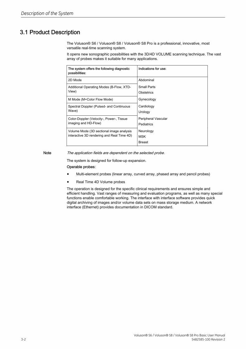
3.1 Product Description
The Voluson® S6 / Voluson® S8 / Voluson® S8 Pro is a professional, innovative, mostversatile real-time scanning system.It opens new sonographic possibilities with the 3D/4D VOLUME scanning technique. The vastarray of probes makes it suitable for many applications.
The system offers the following diagnosticpossibilities:
Indications for use:
2D Mode Abdominal
Additional Operating Modes (B-Flow, XTD-View)
Small PartsObstetrics
M Mode (M+Color Flow Mode) Gynecology
Spectral Doppler (Pulsed- and ContinuousWave)
CardiologyUrology
Color-Doppler (Velocity-, Power-, Tissueimaging and HD-Flow)
Peripheral VascularPediatrics
Volume Mode (3D sectional image analysisinteractive 3D rendering and Real Time 4D)
NeurologyMSKBreast
Note The application fields are dependent on the selected probe.
The system is designed for follow-up expansion.Operable probes:
• Multi-element probes (linear array, curved array, phased array and pencil probes)
• Real Time 4D Volume probes
The operation is designed for the specific clinical requirements and ensures simple andefficient handling. Vast ranges of measuring and evaluation programs, as well as many specialfunctions enable comfortable working. The interface with interface software provides quickdigital archiving of images and/or volume data sets on mass storage medium. A networkinterface (Ethernet) provides documentation in DICOM standard.
Description of the System
3-2Voluson® S6 / Voluson® S8 / Voluson® S8 Pro Basic User Manual
5482585-100 Revision 2
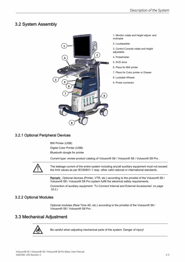
3.2 System Assembly
1. Monitor rotate and height adjust- andinclinable
2. Loudspeaker
3. Control Console rotate and heightadjustable
4. Probeholder
5. DVD drive
6. Place for BW printer
7. Place for Color printer or Drawer
8. Lockable Wheels
9. Probe connector
3.2.1 Optional Peripheral Devices
BW Printer (USB)Digital Color Printer (USB)Bluetooth dongle for printer
Current type: review product catalog of Voluson® S6 / Voluson® S8 / Voluson® S8 Pro .
The leakage current of the entire system including any/all auxiliary equipment must not exceedthe limit values as per IEC60601-1 resp. other valid national or international standards.
Remark: Optional devices (Printer, VTR, etc.) according to the pricelist of the Voluson® S6 /Voluson® S8 / Voluson® S8 Pro system fulfill the electrical safety requirements.Connection of auxiliary equipment: 'To Connect Internal and External Accessories' on page15-3 )
3.2.2 Optional Modules
Optional modules (Real Time 4D, etc.) according to the pricelist of the Voluson® S6 /Voluson® S8 / Voluson® S8 Pro .
3.3 Mechanical Adjustment
Be careful when adjusting mechanical parts of the system: Danger of injury!
Description of the System
Voluson® S6 / Voluson® S8 / Voluson® S8 Pro Basic User Manual5482585-100 Revision 2 3-3
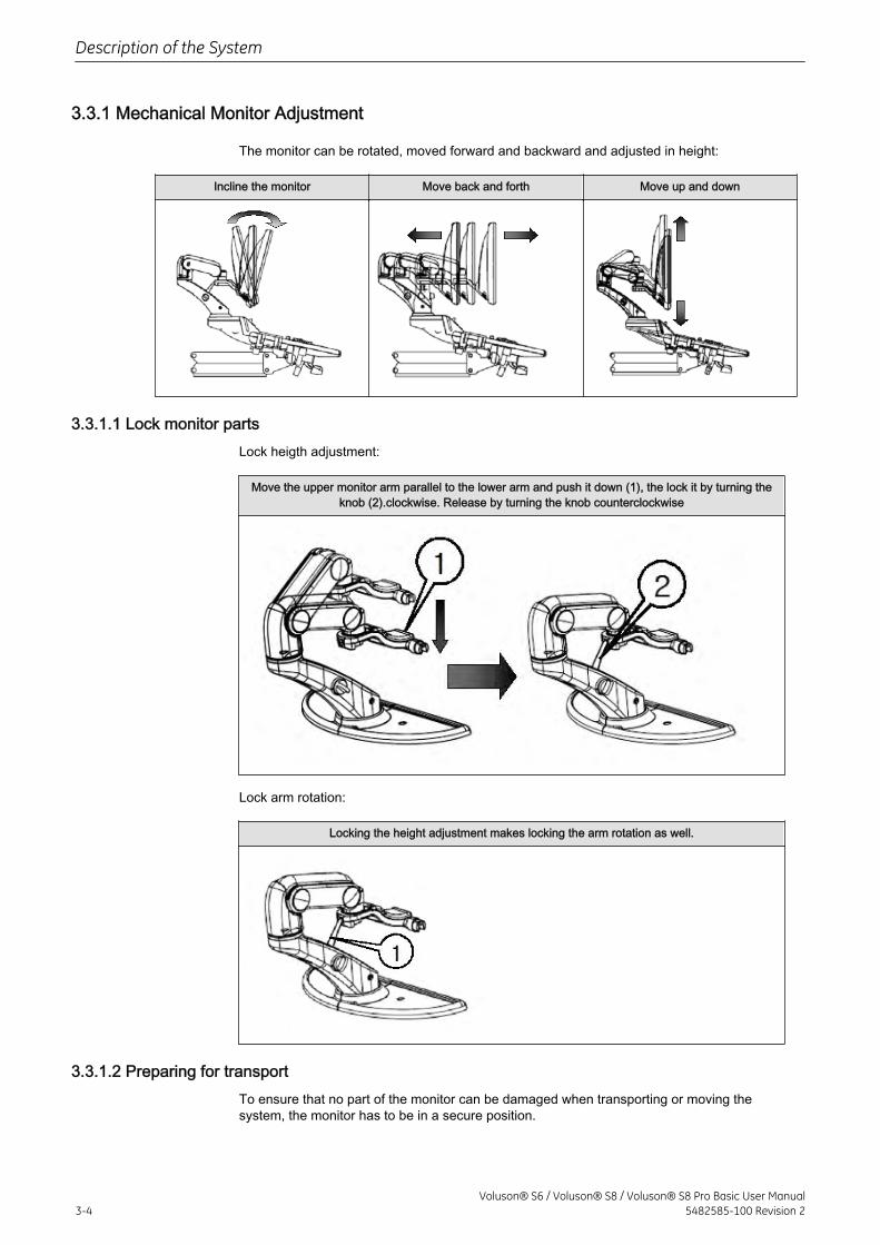
3.3.1 Mechanical Monitor Adjustment
The monitor can be rotated, moved forward and backward and adjusted in height:
Incline the monitor Move back and forth Move up and down
3.3.1.1 Lock monitor partsLock heigth adjustment:
Move the upper monitor arm parallel to the lower arm and push it down (1), the lock it by turning theknob (2).clockwise. Release by turning the knob counterclockwise
Lock arm rotation:
Locking the height adjustment makes locking the arm rotation as well.
3.3.1.2 Preparing for transportTo ensure that no part of the monitor can be damaged when transporting or moving thesystem, the monitor has to be in a secure position.
Description of the System
3-4Voluson® S6 / Voluson® S8 / Voluson® S8 Pro Basic User Manual
5482585-100 Revision 2
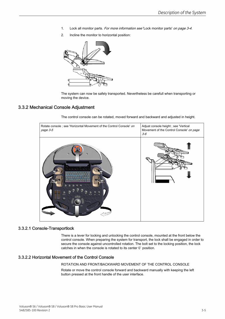
1. Lock all monitor parts. For more information see 'Lock monitor parts' on page 3-4.
2. Incline the monitor to horizontal position:
The system can now be safely transported. Nevertheless be carefull when transporting ormoving the device.
3.3.2 Mechanical Console Adjustment
The control console can be rotated, moved forward and backward and adjusted in height.
Rotate console ; see 'Horizontal Movement of the Control Console' onpage 3-5
Adjust console height ; see 'VerticalMovement of the Control Console' on page3-6
3.3.2.1 Console-TransportlockThere is a lever for locking and unlocking the control console, mounted at the front below thecontrol console. When preparing the system for transport, the lock shall be engaged in order tosecure the console against uncontrolled rotation. The bolt set to the locking position, the lockcatches in when the console is rotated to its center 0˚ position.
3.3.2.2 Horizontal Movement of the Control ConsoleROTATION AND FRONT/BACKWARD MOVEMENT OF THE CONTROL CONSOLERotate or move the control console forward and backward manually with keeping the leftbutton pressed at the front handle of the user interface.
Description of the System
Voluson® S6 / Voluson® S8 / Voluson® S8 Pro Basic User Manual5482585-100 Revision 2 3-5
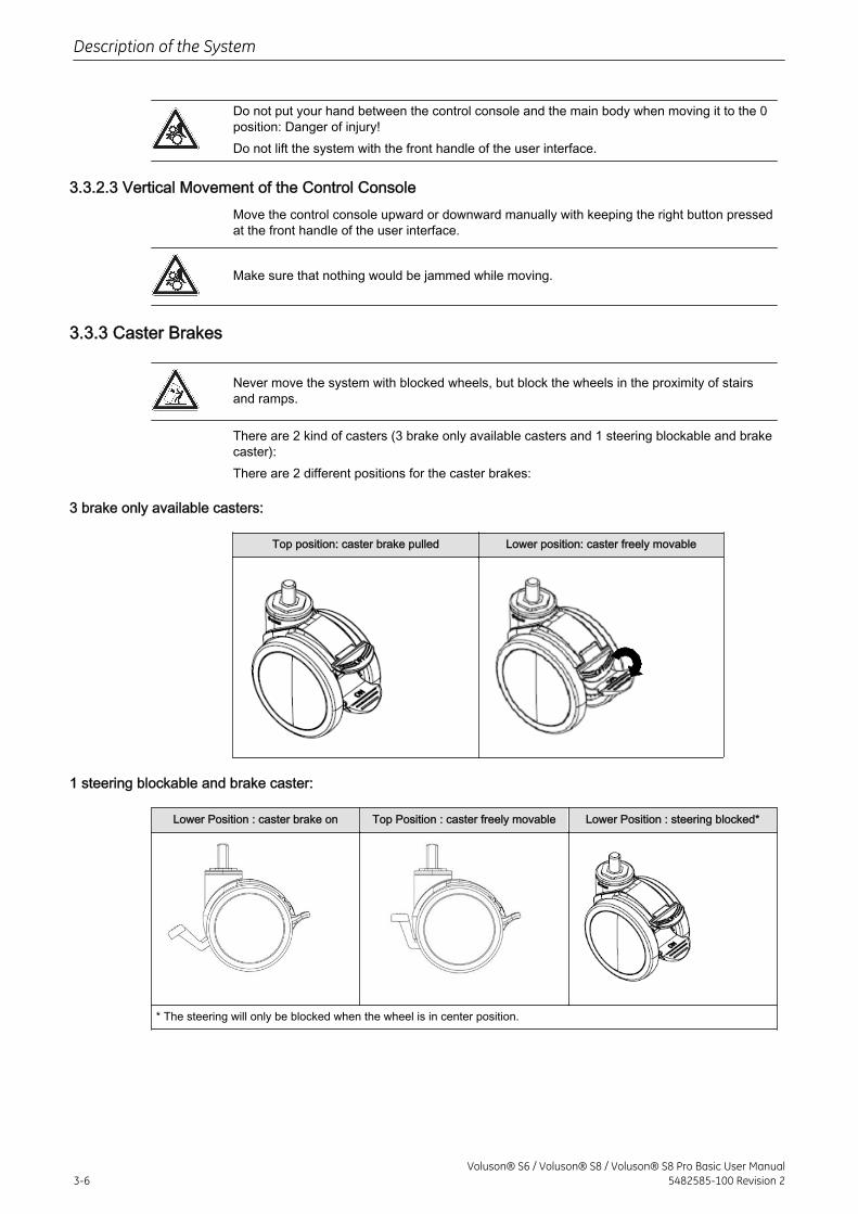
Do not put your hand between the control console and the main body when moving it to the 0position: Danger of injury!Do not lift the system with the front handle of the user interface.
3.3.2.3 Vertical Movement of the Control ConsoleMove the control console upward or downward manually with keeping the right button pressedat the front handle of the user interface.
Make sure that nothing would be jammed while moving.
3.3.3 Caster Brakes
Never move the system with blocked wheels, but block the wheels in the proximity of stairsand ramps.
There are 2 kind of casters (3 brake only available casters and 1 steering blockable and brakecaster):There are 2 different positions for the caster brakes:
3 brake only available casters:
Top position: caster brake pulled Lower position: caster freely movable
1 steering blockable and brake caster:
Lower Position : caster brake on Top Position : caster freely movable Lower Position : steering blocked*
* The steering will only be blocked when the wheel is in center position.
Description of the System
3-6Voluson® S6 / Voluson® S8 / Voluson® S8 Pro Basic User Manual
5482585-100 Revision 2
3.4 Concept of Operation
The control center of the Voluson® S6 / Voluson® S8 / Voluson® S8 Pro is the console withthe digipot controls, the hard keys and the trackball. The console controls frequently usedfunctions, e.g., Freeze/Run, change of modes, etc. Additional functions are controlled via thetrackball.
3.4.1 Digipot controls, Trackball
Activated functions are easily controlled by these controls. When rotated they deliver digitalpulses and can be selected by program call-up. They are displayed in the status area by theirlocation, their function, and their actual value of setting.
3.4.2 Keyboard-Shortcut Functions
The available menus are shown in the menu area on the left side of the screen. The currentmenu selection is highlighted.Roll with the trackball and the arrow moves to anotherselection.The corresponding keyboard shortcuts are shown to the left of the actual function.
3.5 Layout of Menus
Mainly two menu levels are used for operating the system, the main-menu level and thesubmenu level. From the main menu the most important submenus, e.g. adjusting the 2Dimage are directly accessible. Some hard keys activate a specific submenu on the menu area,e.g. the Archive key. Normally changing from one submenu to another is made via the mainmenu; direct call-up from one to another submenu is possible in some rare cases only.
3.5.1 Layout of the 2D Mode Main Menu
All B-Mode operations are started from this menu. It contains 4 main groups of operatingfunctions:
Main group 1: Main menu keys for:
• Presets
• Sub window probe dependent functions
• Image up/down
• Image left/right
• Virtual Convex mode
• FFC (Focus and Frequency Composite)
• XBeam CRI (CrossBeam Compound Resolution Imaging) CE (CodedExcitation)
• SRI (Speckle Reduction Imaging)
• Image Angle
• β-View (Beta View)
• Focal ZonesOTI (Optimized Tissue Imaging)
• Frequency
Main group 2: Sub menu keys for:adjusting the 2D image
Description of the System
Voluson® S6 / Voluson® S8 / Voluson® S8 Pro Basic User Manual5482585-100 Revision 2 3-7
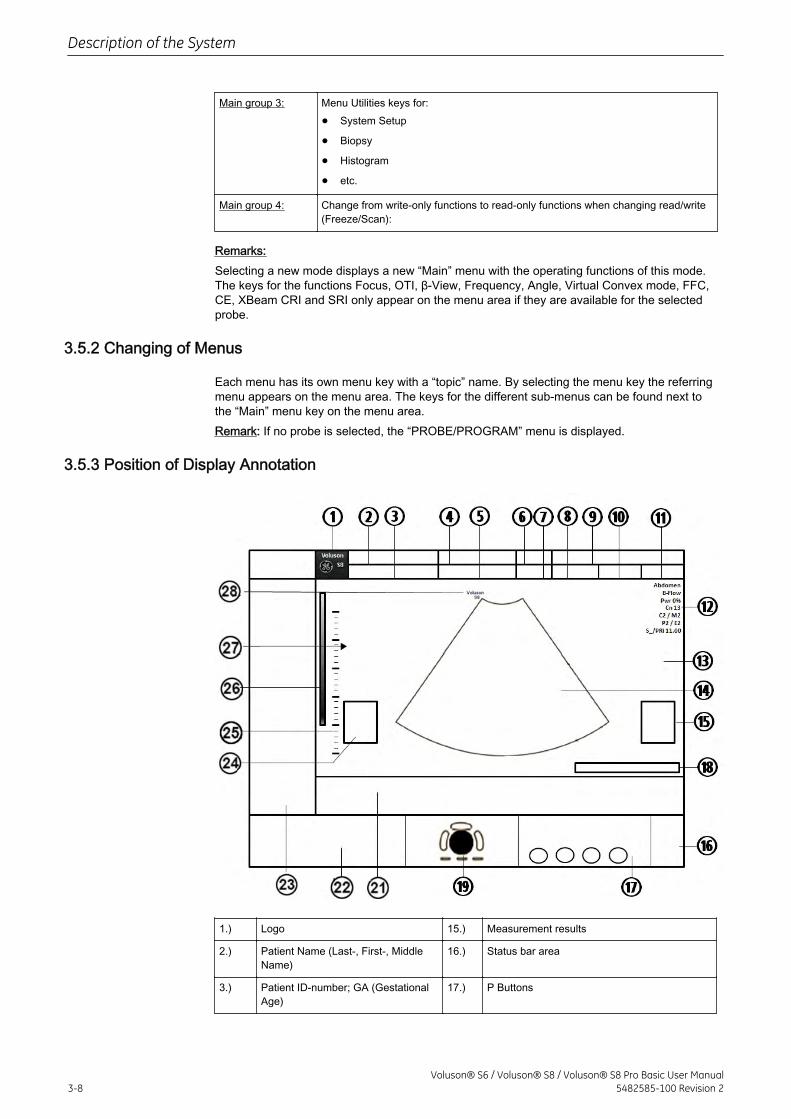
Main group 3: Menu Utilities keys for:
• System Setup
• Biopsy
• Histogram
• etc.
Main group 4: Change from write-only functions to read-only functions when changing read/write(Freeze/Scan):
Remarks:Selecting a new mode displays a new “Main” menu with the operating functions of this mode.The keys for the functions Focus, OTI, β-View, Frequency, Angle, Virtual Convex mode, FFC,CE, XBeam CRI and SRI only appear on the menu area if they are available for the selectedprobe.
3.5.2 Changing of Menus
Each menu has its own menu key with a “topic” name. By selecting the menu key the referringmenu appears on the menu area. The keys for the different sub-menus can be found next tothe “Main” menu key on the menu area.Remark: If no probe is selected, the “PROBE/PROGRAM” menu is displayed.
3.5.3 Position of Display Annotation
1.) Logo 15.) Measurement results
2.) Patient Name (Last-, First-, MiddleName)
16.) Status bar area
3.) Patient ID-number; GA (GestationalAge)
17.) P Buttons
Description of the System
3-8Voluson® S6 / Voluson® S8 / Voluson® S8 Pro Basic User Manual
5482585-100 Revision 2
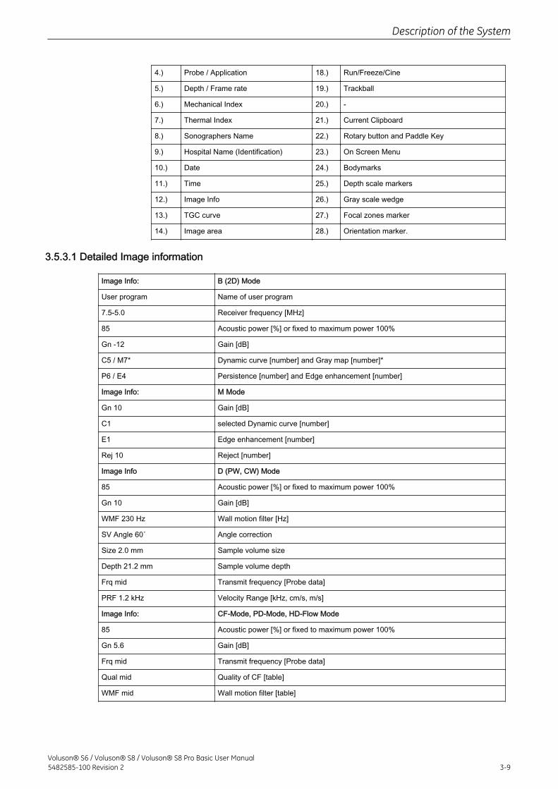
4.) Probe / Application 18.) Run/Freeze/Cine
5.) Depth / Frame rate 19.) Trackball
6.) Mechanical Index 20.) -
7.) Thermal Index 21.) Current Clipboard
8.) Sonographers Name 22.) Rotary button and Paddle Key
9.) Hospital Name (Identification) 23.) On Screen Menu
10.) Date 24.) Bodymarks
11.) Time 25.) Depth scale markers
12.) Image Info 26.) Gray scale wedge
13.) TGC curve 27.) Focal zones marker
14.) Image area 28.) Orientation marker.
3.5.3.1 Detailed Image information
Image Info: B (2D) Mode
User program Name of user program
7.5-5.0 Receiver frequency [MHz]
85 Acoustic power [%] or fixed to maximum power 100%
Gn -12 Gain [dB]
C5 / M7* Dynamic curve [number] and Gray map [number]*
P6 / E4 Persistence [number] and Edge enhancement [number]
Image Info: M Mode
Gn 10 Gain [dB]
C1 selected Dynamic curve [number]
E1 Edge enhancement [number]
Rej 10 Reject [number]
Image Info D (PW, CW) Mode
85 Acoustic power [%] or fixed to maximum power 100%
Gn 10 Gain [dB]
WMF 230 Hz Wall motion filter [Hz]
SV Angle 60˚ Angle correction
Size 2.0 mm Sample volume size
Depth 21.2 mm Sample volume depth
Frq mid Transmit frequency [Probe data]
PRF 1.2 kHz Velocity Range [kHz, cm/s, m/s]
Image Info: CF-Mode, PD-Mode, HD-Flow Mode
85 Acoustic power [%] or fixed to maximum power 100%
Gn 5.6 Gain [dB]
Frq mid Transmit frequency [Probe data]
Qual mid Quality of CF [table]
WMF mid Wall motion filter [table]
Description of the System
Voluson® S6 / Voluson® S8 / Voluson® S8 Pro Basic User Manual5482585-100 Revision 2 3-9
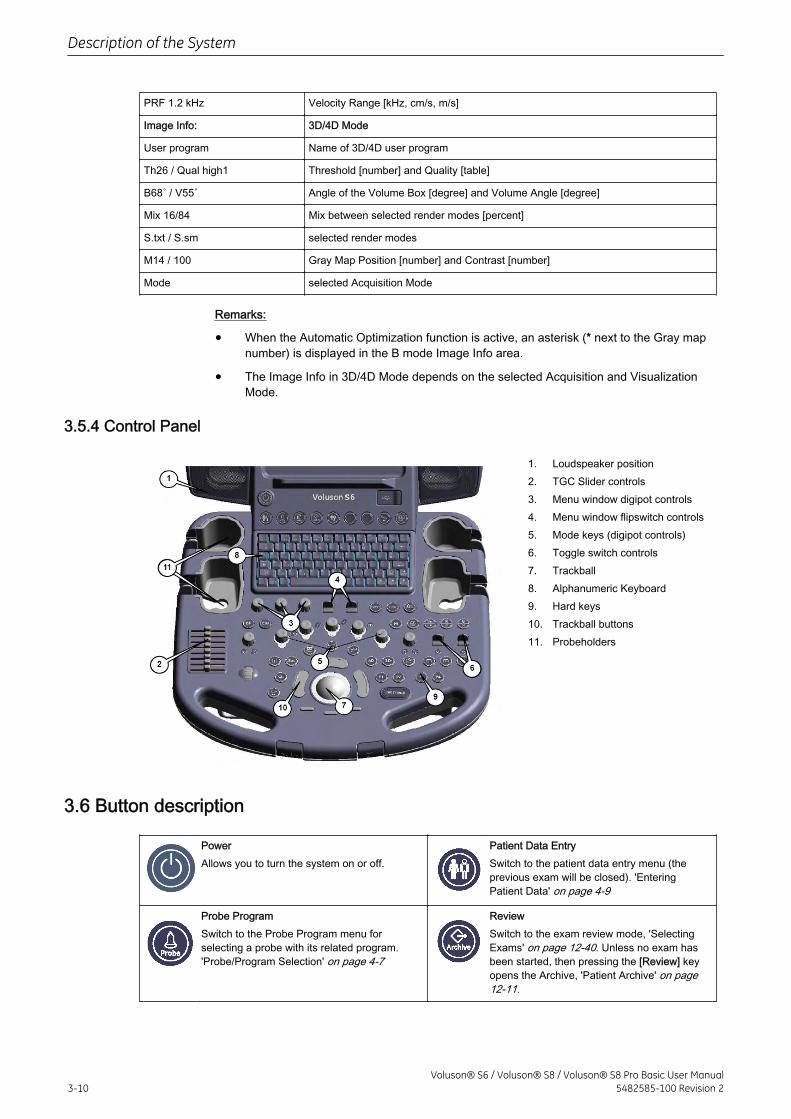
PRF 1.2 kHz Velocity Range [kHz, cm/s, m/s]
Image Info: 3D/4D Mode
User program Name of 3D/4D user program
Th26 / Qual high1 Threshold [number] and Quality [table]
B68˚ / V55˚ Angle of the Volume Box [degree] and Volume Angle [degree]
Mix 16/84 Mix between selected render modes [percent]
S.txt / S.sm selected render modes
M14 / 100 Gray Map Position [number] and Contrast [number]
Mode selected Acquisition Mode
Remarks:
• When the Automatic Optimization function is active, an asterisk (* next to the Gray mapnumber) is displayed in the B mode Image Info area.
• The Image Info in 3D/4D Mode depends on the selected Acquisition and VisualizationMode.
3.5.4 Control Panel
1. Loudspeaker position2. TGC Slider controls3. Menu window digipot controls4. Menu window flipswitch controls5. Mode keys (digipot controls)6. Toggle switch controls7. Trackball8. Alphanumeric Keyboard9. Hard keys10. Trackball buttons11. Probeholders
3.6 Button description
PowerAllows you to turn the system on or off.
Patient Data EntrySwitch to the patient data entry menu (theprevious exam will be closed). 'EnteringPatient Data' on page 4-9
Probe ProgramSwitch to the Probe Program menu forselecting a probe with its related program.'Probe/Program Selection' on page 4-7
ReviewSwitch to the exam review mode, 'SelectingExams' on page 12-40. Unless no exam hasbeen started, then pressing the [Review] keyopens the Archive, 'Patient Archive' on page12-11.
Description of the System
3-10Voluson® S6 / Voluson® S8 / Voluson® S8 Pro Basic User Manual
5482585-100 Revision 2
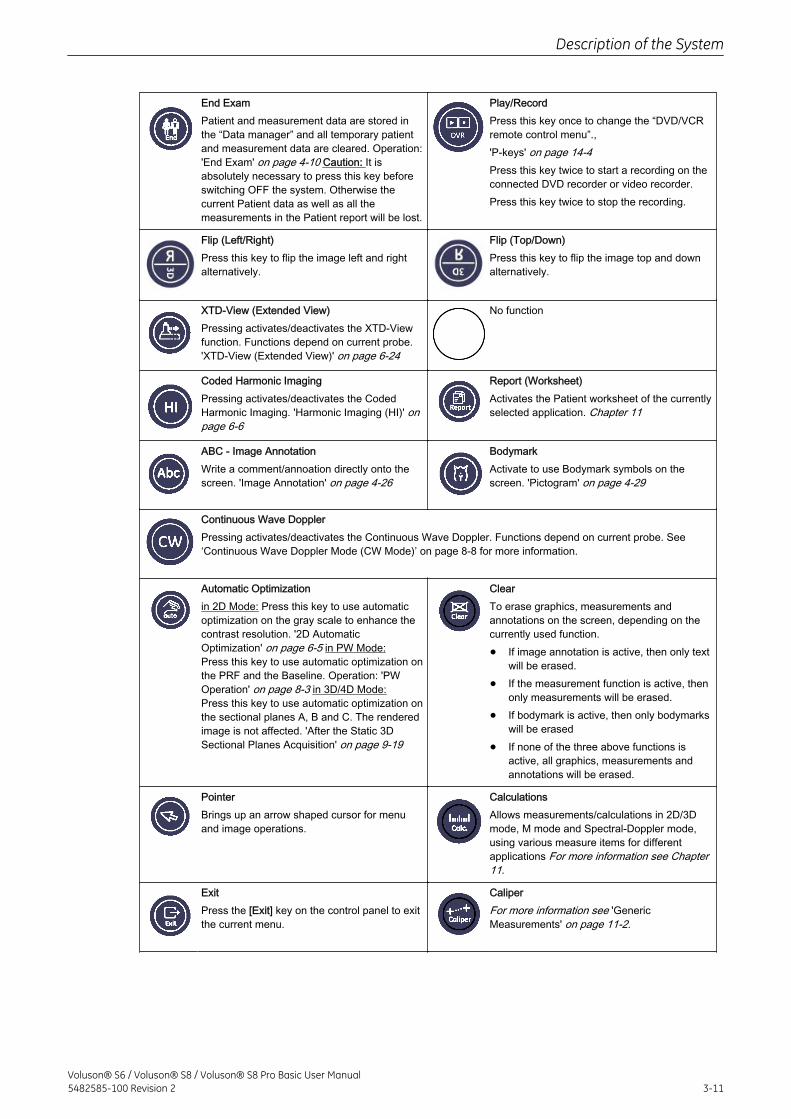
End ExamPatient and measurement data are stored inthe “Data manager” and all temporary patientand measurement data are cleared. Operation:'End Exam' on page 4-10 Caution: It isabsolutely necessary to press this key beforeswitching OFF the system. Otherwise thecurrent Patient data as well as all themeasurements in the Patient report will be lost.
Play/RecordPress this key once to change the “DVD/VCRremote control menu”.,'P-keys' on page 14-4Press this key twice to start a recording on theconnected DVD recorder or video recorder.Press this key twice to stop the recording.
Flip (Left/Right)Press this key to flip the image left and rightalternatively.
Flip (Top/Down)Press this key to flip the image top and downalternatively.
XTD-View (Extended View)Pressing activates/deactivates the XTD-Viewfunction. Functions depend on current probe.'XTD-View (Extended View)' on page 6-24
No function
Coded Harmonic ImagingPressing activates/deactivates the CodedHarmonic Imaging. 'Harmonic Imaging (HI)' onpage 6-6
Report (Worksheet)Activates the Patient worksheet of the currentlyselected application. Chapter 11
ABC - Image AnnotationWrite a comment/annoation directly onto thescreen. 'Image Annotation' on page 4-26
BodymarkActivate to use Bodymark symbols on thescreen. 'Pictogram' on page 4-29
Continuous Wave DopplerPressing activates/deactivates the Continuous Wave Doppler. Functions depend on current probe. See‘Continuous Wave Doppler Mode (CW Mode)’ on page 8‐8 for more information.
Automatic Optimizationin 2D Mode: Press this key to use automaticoptimization on the gray scale to enhance thecontrast resolution. '2D AutomaticOptimization' on page 6-5 in PW Mode:Press this key to use automatic optimization onthe PRF and the Baseline. Operation: 'PWOperation' on page 8-3 in 3D/4D Mode:Press this key to use automatic optimization onthe sectional planes A, B and C. The renderedimage is not affected. 'After the Static 3DSectional Planes Acquisition' on page 9-19
ClearTo erase graphics, measurements andannotations on the screen, depending on thecurrently used function.
• If image annotation is active, then only textwill be erased.
• If the measurement function is active, thenonly measurements will be erased.
• If bodymark is active, then only bodymarkswill be erased
• If none of the three above functions isactive, all graphics, measurements andannotations will be erased.
PointerBrings up an arrow shaped cursor for menuand image operations.
CalculationsAllows measurements/calculations in 2D/3Dmode, M mode and Spectral-Doppler mode,using various measure items for differentapplications For more information see Chapter11.
ExitPress the [Exit] key on the control panel to exitthe current menu.
CaliperFor more information see 'GenericMeasurements' on page 11-2.
Description of the System
Voluson® S6 / Voluson® S8 / Voluson® S8 Pro Basic User Manual5482585-100 Revision 2 3-11
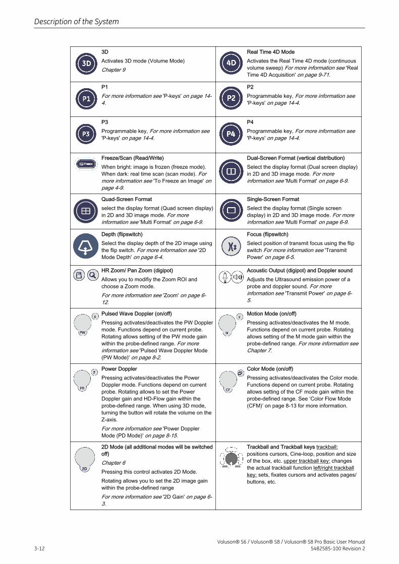
3DActivates 3D mode (Volume Mode)Chapter 9
Real Time 4D ModeActivates the Real Time 4D mode (continuousvolume sweep) For more information see 'RealTime 4D Acquisition' on page 9-71.
P1For more information see 'P-keys' on page 14-4.
P2Programmable key, For more information see'P-keys' on page 14-4.
P3Programmable key, For more information see'P-keys' on page 14-4.
P4Programmable key, For more information see'P-keys' on page 14-4.
Freeze/Scan (Read/Write)When bright: image is frozen (freeze mode).When dark: real time scan (scan mode). Formore information see 'To Freeze an Image' onpage 4-9.
Dual-Screen Format (vertical distribution)Select the display format (Dual screen display)in 2D and 3D image mode. For moreinformation see 'Multi Format' on page 6-9.
Quad-Screen Formatselect the display format (Quad screen display)in 2D and 3D image mode. For moreinformation see 'Multi Format' on page 6-9.
Single-Screen FormatSelect the display format (Single screendisplay) in 2D and 3D image mode. For moreinformation see 'Multi Format' on page 6-9.
Depth (flipswitch)Select the display depth of the 2D image usingthe flip switch. For more information see '2DMode Depth' on page 6-4.
Focus (flipswitch)Select position of transmit focus using the flipswitch For more information see 'TransmitPower' on page 6-5.
HR Zoom/ Pan Zoom (digipot)Allows you to modifiy the Zoom ROI andchoose a Zoom mode.For more information see 'Zoom' on page 6-12.
Acoustic Output (digipot) and Doppler soundAdjusts the Ultrasound emission power of aprobe and doppler sound. For moreinformation see 'Transmit Power' on page 6-5.
Pulsed Wave Doppler (on/off)Pressing activates/deactivates the PW Dopplermode. Functions depend on current probe.Rotating allows setting of the PW mode gainwithin the probe-defined range. For moreinformation see 'Pulsed Wave Doppler Mode(PW Mode)' on page 8-2.
Motion Mode (on/off)Pressing activates/deactivates the M mode.Functions depend on current probe. Rotatingallows setting of the M mode gain within theprobe-defined range. For more information seeChapter 7.
Power DopplerPressing activates/deactivates the PowerDoppler mode. Functions depend on currentprobe. Rotating allows to set the PowerDoppler gain and HD-Flow gain within theprobe-defined range. When using 3D mode,turning the button will rotate the volume on theZ-axis.For more information see 'Power DopplerMode (PD Mode)' on page 8-15.
Color Mode (on/off)Pressing activates/deactivates the Color mode.Functions depend on current probe. Rotatingallows setting of the CF mode gain within theprobe-defined range. See ‘Color Flow Mode(CFM)’ on page 8‐13 for more information.
2D Mode (all additional modes will be switchedoff)Chapter 6Pressing this control activates 2D Mode.Rotating allows you to set the 2D image gainwithin the probe-defined rangeFor more information see '2D Gain' on page 6-3.
Trackball and Trackball keys trackball:positions cursors, Cine-loop, position and sizeof the box, etc. upper trackball key: changesthe actual trackball function left/right trackballkey: sets, fixates cursors and activates pages/buttons, etc.
Description of the System
3-12Voluson® S6 / Voluson® S8 / Voluson® S8 Pro Basic User Manual
5482585-100 Revision 2
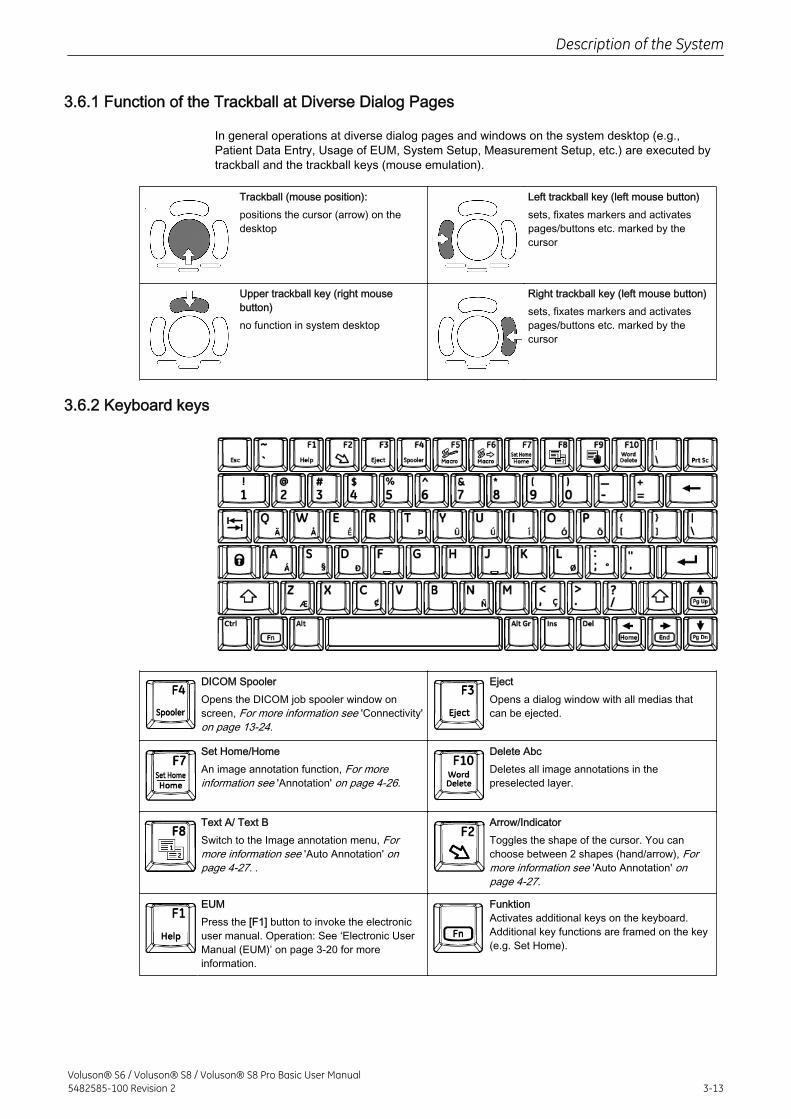
3.6.1 Function of the Trackball at Diverse Dialog Pages
In general operations at diverse dialog pages and windows on the system desktop (e.g.,Patient Data Entry, Usage of EUM, System Setup, Measurement Setup, etc.) are executed bytrackball and the trackball keys (mouse emulation).
Trackball (mouse position):positions the cursor (arrow) on thedesktop
Left trackball key (left mouse button)sets, fixates markers and activatespages/buttons etc. marked by thecursor
Upper trackball key (right mousebutton)no function in system desktop
Right trackball key (left mouse button)sets, fixates markers and activatespages/buttons etc. marked by thecursor
3.6.2 Keyboard keys
DICOM SpoolerOpens the DICOM job spooler window onscreen, For more information see 'Connectivity'on page 13-24.
EjectOpens a dialog window with all medias thatcan be ejected.
Set Home/HomeAn image annotation function, For moreinformation see 'Annotation' on page 4-26.
Delete AbcDeletes all image annotations in thepreselected layer.
Text A/ Text BSwitch to the Image annotation menu, Formore information see 'Auto Annotation' onpage 4-27. .
Arrow/IndicatorToggles the shape of the cursor. You canchoose between 2 shapes (hand/arrow), Formore information see 'Auto Annotation' onpage 4-27.
EUMPress the [F1] button to invoke the electronicuser manual. Operation: See ‘Electronic UserManual (EUM)’ on page 3‐20 for moreinformation.
FunktionActivates additional keys on the keyboard.Additional key functions are framed on the key(e.g. Set Home).
Description of the System
Voluson® S6 / Voluson® S8 / Voluson® S8 Pro Basic User Manual5482585-100 Revision 2 3-13
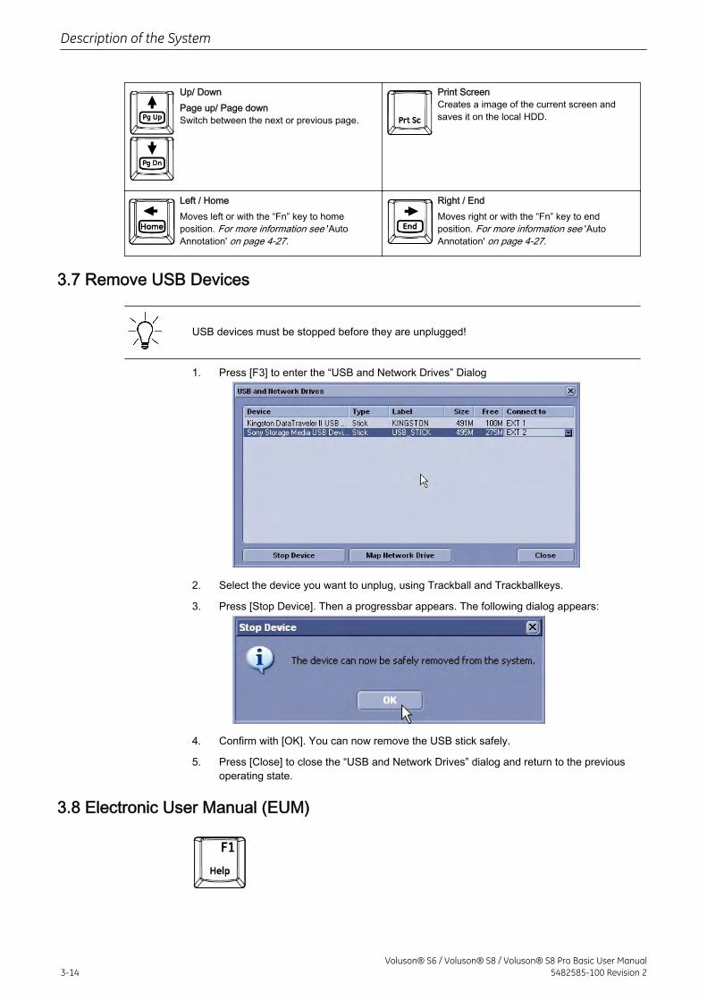
Up/ DownPage up/ Page downSwitch between the next or previous page.
Print ScreenCreates a image of the current screen andsaves it on the local HDD.
Left / HomeMoves left or with the “Fn” key to homeposition. For more information see 'AutoAnnotation' on page 4-27.
Right / EndMoves right or with the “Fn” key to endposition. For more information see 'AutoAnnotation' on page 4-27.
3.7 Remove USB Devices
USB devices must be stopped before they are unplugged!
1. Press [F3] to enter the “USB and Network Drives” Dialog
2. Select the device you want to unplug, using Trackball and Trackballkeys.
3. Press [Stop Device]. Then a progressbar appears. The following dialog appears:
4. Confirm with [OK]. You can now remove the USB stick safely.
5. Press [Close] to close the “USB and Network Drives” dialog and return to the previousoperating state.
3.8 Electronic User Manual (EUM)
Description of the System
3-14Voluson® S6 / Voluson® S8 / Voluson® S8 Pro Basic User Manual
5482585-100 Revision 2
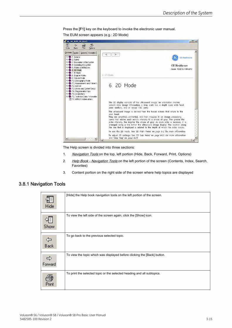
Press the [F1] key on the keyboard to invoke the electronic user manual.The EUM screen appears (e.g.: 2D Mode)
The Help screen is divided into three sections:
1. Navigation Tools on the top, left portion (Hide, Back, Forward, Print, Options)
2. Help Book - Navigation Tools on the left portion of the screen (Contents, Index, Search,Favorites)
3. Content portion on the right side of the screen where help topics are displayed
3.8.1 Navigation Tools
[Hide] the Help book navigation tools on the left portion of the screen.
To view the left side of the screen again, click the [Show] icon.
To go back to the previous selected topic.
To view the topic which was displayed before clicking the [Back] button.
To print the selected topic or the selected heading and all subtopics.
Description of the System
Voluson® S6 / Voluson® S8 / Voluson® S8 Pro Basic User Manual5482585-100 Revision 2 3-15
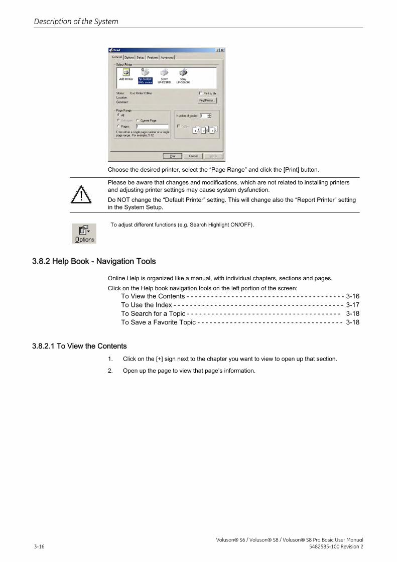
Choose the desired printer, select the “Page Range” and click the [Print] button.
Please be aware that changes and modifications, which are not related to installing printersand adjusting printer settings may cause system dysfunction.Do NOT change the “Default Printer” setting. This will change also the “Report Printer” settingin the System Setup.
To adjust different functions (e.g. Search Highlight ON/OFF).
3.8.2 Help Book - Navigation Tools
Online Help is organized like a manual, with individual chapters, sections and pages.Click on the Help book navigation tools on the left portion of the screen:
To View the Contents - - - - - - - - - - - - - - - - - - - - - - - - - - - - - - - - - - - - - - - 3-16To Use the Index - - - - - - - - - - - - - - - - - - - - - - - - - - - - - - - - - - - - - - - - - - 3-17To Search for a Topic - - - - - - - - - - - - - - - - - - - - - - - - - - - - - - - - - - - - - - 3-18To Save a Favorite Topic - - - - - - - - - - - - - - - - - - - - - - - - - - - - - - - - - - - - 3-18
3.8.2.1 To View the Contents1. Click on the [+] sign next to the chapter you want to view to open up that section.
2. Open up the page to view that page’s information.
Description of the System
3-16Voluson® S6 / Voluson® S8 / Voluson® S8 Pro Basic User Manual
5482585-100 Revision 2
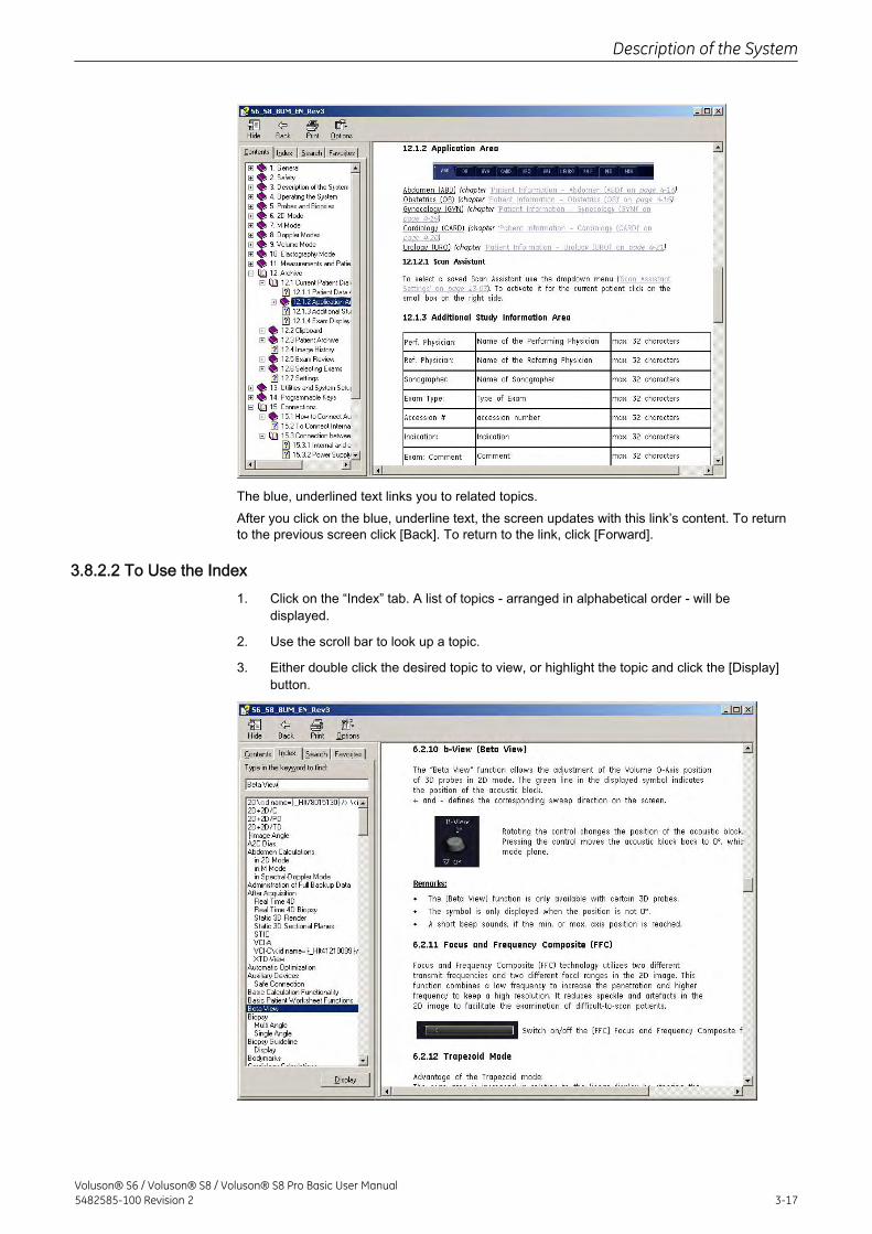
The blue, underlined text links you to related topics.After you click on the blue, underline text, the screen updates with this link’s content. To returnto the previous screen click [Back]. To return to the link, click [Forward].
3.8.2.2 To Use the Index1. Click on the “Index” tab. A list of topics - arranged in alphabetical order - will be
displayed.
2. Use the scroll bar to look up a topic.
3. Either double click the desired topic to view, or highlight the topic and click the [Display]button.
Description of the System
Voluson® S6 / Voluson® S8 / Voluson® S8 Pro Basic User Manual5482585-100 Revision 2 3-17
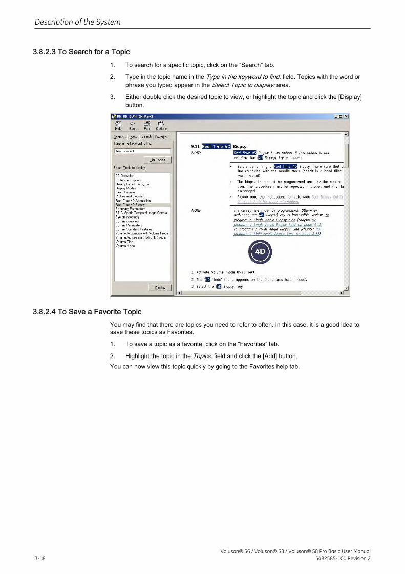
3.8.2.3 To Search for a Topic1. To search for a specific topic, click on the “Search” tab.
2. Type in the topic name in the Type in the keyword to find: field. Topics with the word orphrase you typed appear in the Select Topic to display: area.
3. Either double click the desired topic to view, or highlight the topic and click the [Display]button.
3.8.2.4 To Save a Favorite TopicYou may find that there are topics you need to refer to often. In this case, it is a good idea tosave these topics as Favorites.
1. To save a topic as a favorite, click on the “Favorites” tab.
2. Highlight the topic in the Topics: field and click the [Add] button.You can now view this topic quickly by going to the Favorites help tab.
Description of the System
3-18Voluson® S6 / Voluson® S8 / Voluson® S8 Pro Basic User Manual
5482585-100 Revision 2
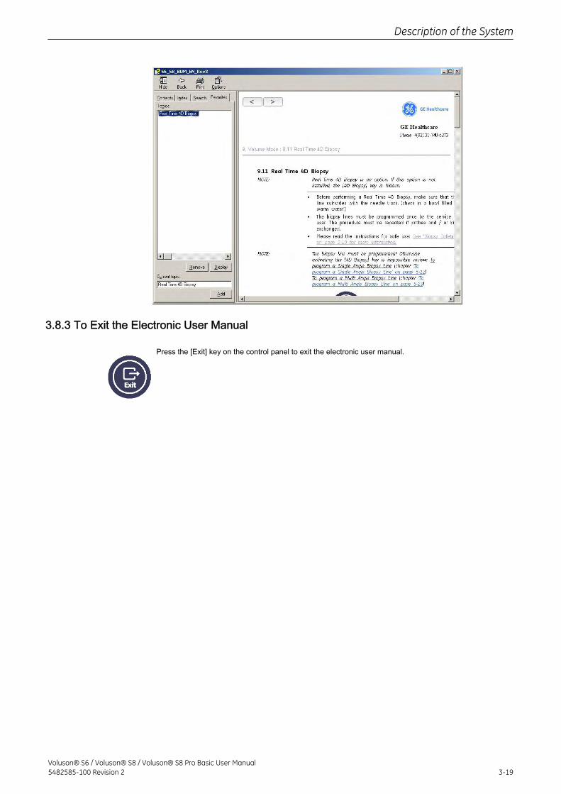
3.8.3 To Exit the Electronic User Manual
Press the [Exit] key on the control panel to exit the electronic user manual.
Description of the System
Voluson® S6 / Voluson® S8 / Voluson® S8 Pro Basic User Manual5482585-100 Revision 2 3-19

This page was intentionally left blank.
Description of the System
3-20Voluson® S6 / Voluson® S8 / Voluson® S8 Pro Basic User Manual
5482585-100 Revision 2
Chapter 4
Operating the System
Describes powering on the system, transducer connection, program selection and patient datas.General Remarks - - - - - - - - - - - - - - - - - - - - - - - - - - - - - - - - - - - - - - - - - - - - - - 4-2Safety Warnings - - - - - - - - - - - - - - - - - - - - - - - - - - - - - - - - - - - - - - - - - - - - - - 4-2Power On / Boot Up - - - - - - - - - - - - - - - - - - - - - - - - - - - - - - - - - - - - - - - - - - - - 4-2Power Off / Shutdown - - - - - - - - - - - - - - - - - - - - - - - - - - - - - - - - - - - - - - - - - - 4-3Transducer Connection - - - - - - - - - - - - - - - - - - - - - - - - - - - - - - - - - - - - - - - - - 4-4Prepareing the Transducer - - - - - - - - - - - - - - - - - - - - - - - - - - - - - - - - - - - - - - - 4-5Probe/Program Selection - - - - - - - - - - - - - - - - - - - - - - - - - - - - - - - - - - - - - - - - 4-7Entering Patient Data - - - - - - - - - - - - - - - - - - - - - - - - - - - - - - - - - - - - - - - - - - - 4-9Image Annotation - - - - - - - - - - - - - - - - - - - - - - - - - - - - - - - - - - - - - - - - - - - - - 4-26
Voluson® S6 / Voluson® S8 / Voluson® S8 Pro Basic User Manual5482585-100 Revision 2 4-1
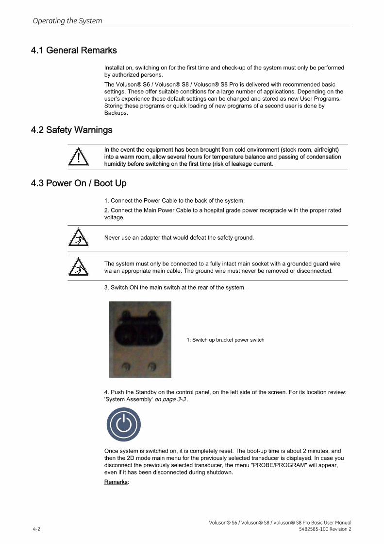
4.1 General Remarks
Installation, switching on for the first time and check-up of the system must only be performedby authorized persons.The Voluson® S6 / Voluson® S8 / Voluson® S8 Pro is delivered with recommended basicsettings. These offer suitable conditions for a large number of applications. Depending on theuser’s experience these default settings can be changed and stored as new User Programs.Storing these programs or quick loading of new programs of a second user is done byBackups.
4.2 Safety Warnings
In the event the equipment has been brought from cold environment (stock room, airfreight)into a warm room, allow several hours for temperature balance and passing of condensationhumidity before switching on the first time (risk of leakage current.
4.3 Power On / Boot Up
1. Connect the Power Cable to the back of the system.2. Connect the Main Power Cable to a hospital grade power receptacle with the proper ratedvoltage.
Never use an adapter that would defeat the safety ground.
The system must only be connected to a fully intact main socket with a grounded guard wirevia an appropriate main cable. The ground wire must never be removed or disconnected.
3. Switch ON the main switch at the rear of the system.
1: Switch up bracket power switch
4. Push the Standby on the control panel, on the left side of the screen. For its location review:'System Assembly' on page 3-3 .
Once system is switched on, it is completely reset. The boot-up time is about 2 minutes, andthen the 2D mode main menu for the previously selected transducer is displayed. In case youdisconnect the previously selected transducer, the menu "PROBE/PROGRAM" will appear,even if it has been disconnected during shutdown.Remarks:
Operating the System
4-2Voluson® S6 / Voluson® S8 / Voluson® S8 Pro Basic User Manual
5482585-100 Revision 2
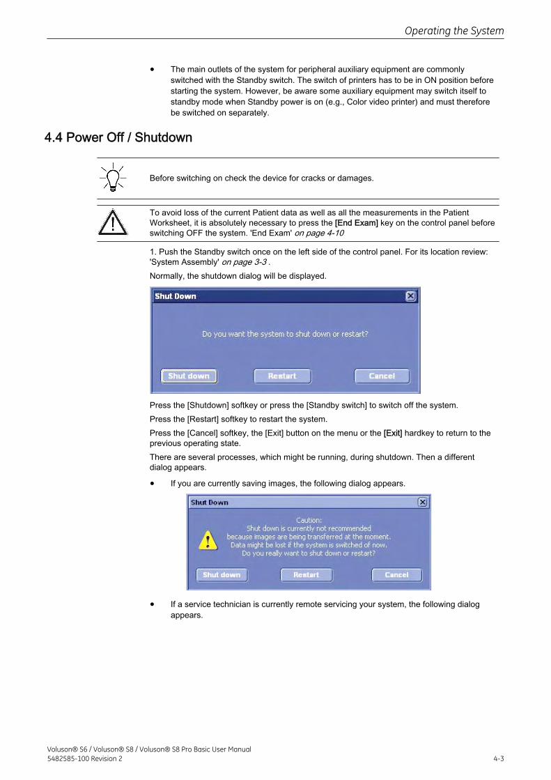
• The main outlets of the system for peripheral auxiliary equipment are commonlyswitched with the Standby switch. The switch of printers has to be in ON position beforestarting the system. However, be aware some auxiliary equipment may switch itself tostandby mode when Standby power is on (e.g., Color video printer) and must thereforebe switched on separately.
4.4 Power Off / Shutdown
Before switching on check the device for cracks or damages.
To avoid loss of the current Patient data as well as all the measurements in the PatientWorksheet, it is absolutely necessary to press the [End Exam] key on the control panel beforeswitching OFF the system. 'End Exam' on page 4-10
1. Push the Standby switch once on the left side of the control panel. For its location review:'System Assembly' on page 3-3 .Normally, the shutdown dialog will be displayed.
Press the [Shutdown] softkey or press the [Standby switch] to switch off the system.Press the [Restart] softkey to restart the system.Press the [Cancel] softkey, the [Exit] button on the menu or the [Exit] hardkey to return to theprevious operating state.There are several processes, which might be running, during shutdown. Then a differentdialog appears.
• If you are currently saving images, the following dialog appears.
• If a service technician is currently remote servicing your system, the following dialogappears.
Operating the System
Voluson® S6 / Voluson® S8 / Voluson® S8 Pro Basic User Manual5482585-100 Revision 2 4-3
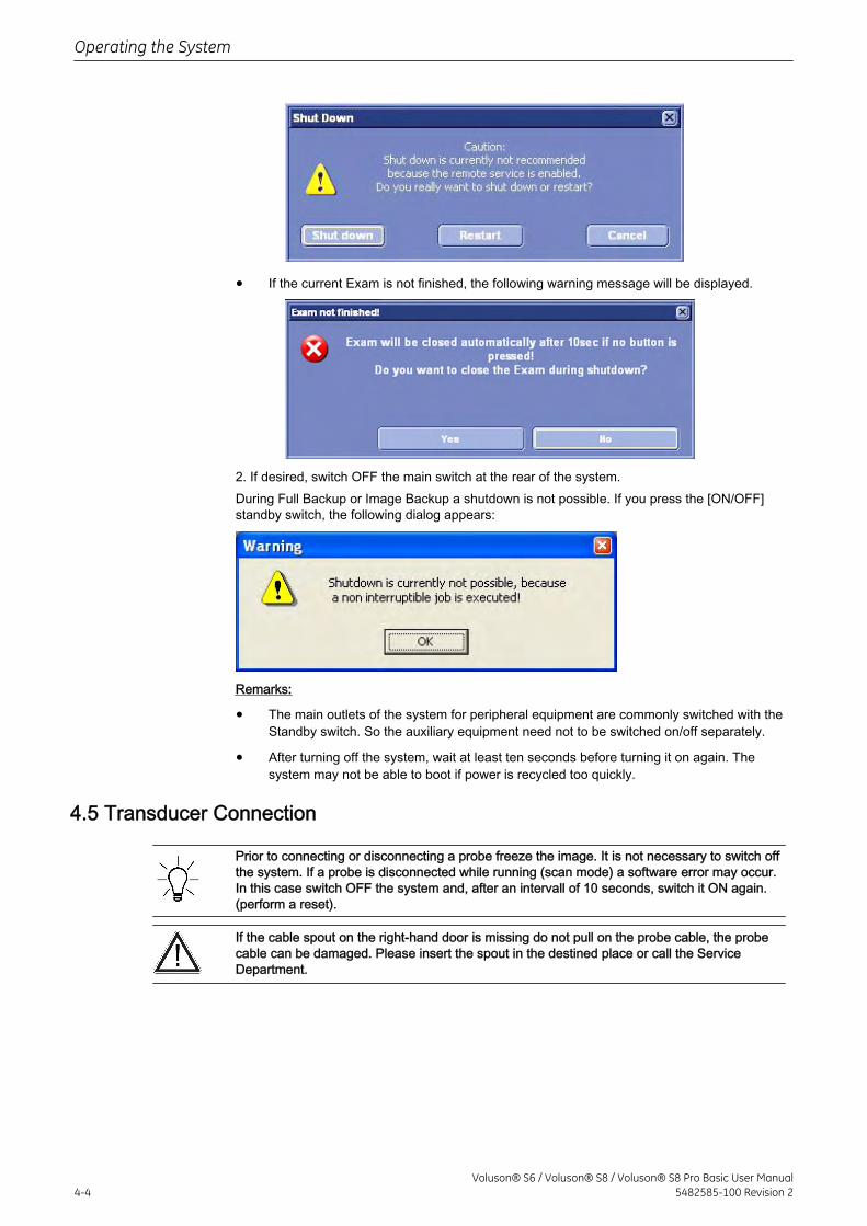
• If the current Exam is not finished, the following warning message will be displayed.
2. If desired, switch OFF the main switch at the rear of the system.During Full Backup or Image Backup a shutdown is not possible. If you press the [ON/OFF]standby switch, the following dialog appears:
Remarks:
• The main outlets of the system for peripheral equipment are commonly switched with theStandby switch. So the auxiliary equipment need not to be switched on/off separately.
• After turning off the system, wait at least ten seconds before turning it on again. Thesystem may not be able to boot if power is recycled too quickly.
4.5 Transducer Connection
Prior to connecting or disconnecting a probe freeze the image. It is not necessary to switch offthe system. If a probe is disconnected while running (scan mode) a software error may occur.In this case switch OFF the system and, after an intervall of 10 seconds, switch it ON again.(perform a reset).
If the cable spout on the right-hand door is missing do not pull on the probe cable, the probecable can be damaged. Please insert the spout in the destined place or call the ServiceDepartment.
Operating the System
4-4Voluson® S6 / Voluson® S8 / Voluson® S8 Pro Basic User Manual
5482585-100 Revision 2
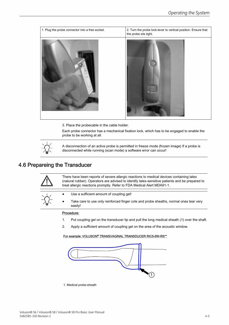
1. Plug the probe connector into a free socket. 2. Turn the probe lock-lever to vertical position. Ensure thatthe probe sits tight.
3. Place the probecable in the cable holder.Each probe connector has a mechanical fixation lock, which has to be engaged to enable theprobe to be working at all.
A disconnection of an active probe is permitted in freeze mode (frozen image) If a probe isdisconnected while running (scan mode) a software error can occur!
4.6 Prepareing the Transducer
There have been reports of severe allergic reactions to medical devices containing latex(natural rubber). Operators are advised to identify latex-sensitive patients and be prepared totreat allergic reactions promptly. Refer to FDA Medical Alert MDA91-1.
• Use a sufficient amount of coupling gel!
• Take care to use only reinforced finger cots and probe sheaths, normal ones tear veryeasily!
Procedure:
1. Put coupling gel on the transducer tip and pull the long medical sheath (1) over the shaft.
2. Apply a sufficient amount of coupling gel on the area of the acoustic window.
For example: VOLUSON® TRANSVAGINAL TRANSDUCER RIC5-9W-RS**
1. Medical probe-sheath
Operating the System
Voluson® S6 / Voluson® S8 / Voluson® S8 Pro Basic User Manual5482585-100 Revision 2 4-5
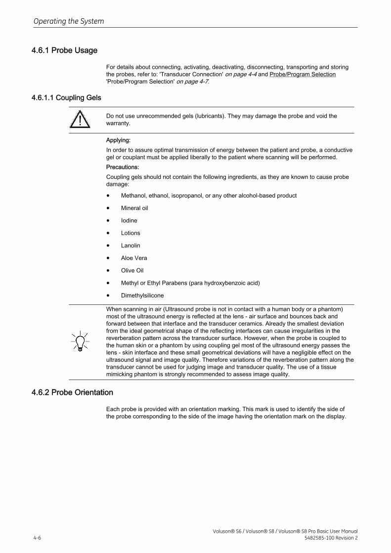
4.6.1 Probe Usage
For details about connecting, activating, deactivating, disconnecting, transporting and storingthe probes, refer to: 'Transducer Connection' on page 4-4 and Probe/Program Selection'Probe/Program Selection' on page 4-7.
4.6.1.1 Coupling Gels
Do not use unrecommended gels (lubricants). They may damage the probe and void thewarranty.
Applying:In order to assure optimal transmission of energy between the patient and probe, a conductivegel or couplant must be applied liberally to the patient where scanning will be performed.Precautions:Coupling gels should not contain the following ingredients, as they are known to cause probedamage:
• Methanol, ethanol, isopropanol, or any other alcohol-based product
• Mineral oil
• Iodine
• Lotions
• Lanolin
• Aloe Vera
• Olive Oil
• Methyl or Ethyl Parabens (para hydroxybenzoic acid)
• Dimethylsilicone
When scanning in air (Ultrasound probe is not in contact with a human body or a phantom)most of the ultrasound energy is reflected at the lens - air surface and bounces back andforward between that interface and the transducer ceramics. Already the smallest deviationfrom the ideal geometrical shape of the reflecting interfaces can cause irregularities in thereverberation pattern across the transducer surface. However, when the probe is coupled tothe human skin or a phantom by using coupling gel most of the ultrasound energy passes thelens - skin interface and these small geometrical deviations will have a negligible effect on theultrasound signal and image quality. Therefore variations of the reverberation pattern along thetransducer cannot be used for judging image and transducer quality. The use of a tissuemimicking phantom is strongly recommended to assess image quality.
4.6.2 Probe Orientation
Each probe is provided with an orientation marking. This mark is used to identify the side ofthe probe corresponding to the side of the image having the orientation mark on the display.
Operating the System
4-6Voluson® S6 / Voluson® S8 / Voluson® S8 Pro Basic User Manual
5482585-100 Revision 2
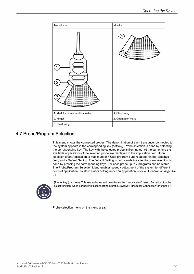
Transducer: Monitor:
1. Mark for direction of insonation 1. Shadowing
2. Finger 2. Orientation mark
3. Shadowing
4.7 Probe/Program Selection
This menu shows the connected probes. The denomination of each transducer connected tothe system appears in the corresponding key (softkey). Probe selection is done by selectingthe corresponding key. The key with the selected probe is illuminated. At the same time theavailable applications of the selected probe are displayed in the application field. Uponselection of an Application, a maximum of 7 User program buttons appear in the “Settings”field, and a Default Setting. The Default Setting is not user-defineable. Program selection isdone by pressing the corresponding keys. For each probe up to 7 programs can be stored.The Probe/Program Selection Menu enables speedy adjustment of the system for differentfields of application. To store a user setting under an application, review: 'General' on page 13-11
[Probe] key (hard key): This key activates and deactivates the “probe select” menu. Behavior of probeselect function, when connecting/disconnecting a probe, review: 'Transducer Connection' on page 4-4
Probe selection menu on the menu area:
Operating the System
Voluson® S6 / Voluson® S8 / Voluson® S8 Pro Basic User Manual5482585-100 Revision 2 4-7
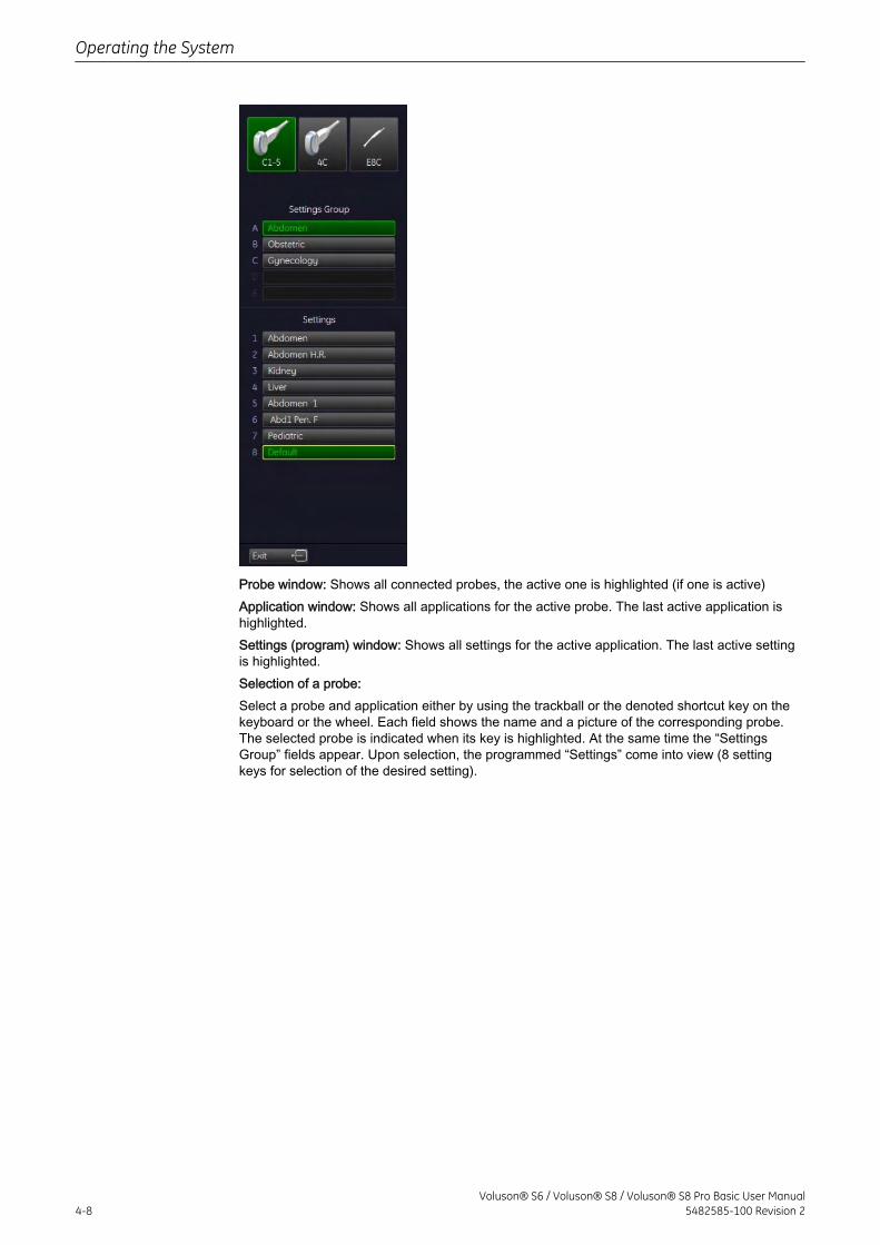
Probe window: Shows all connected probes, the active one is highlighted (if one is active)Application window: Shows all applications for the active probe. The last active application ishighlighted.Settings (program) window: Shows all settings for the active application. The last active settingis highlighted.Selection of a probe:Select a probe and application either by using the trackball or the denoted shortcut key on thekeyboard or the wheel. Each field shows the name and a picture of the corresponding probe.The selected probe is indicated when its key is highlighted. At the same time the “SettingsGroup” fields appear. Upon selection, the programmed “Settings” come into view (8 settingkeys for selection of the desired setting).
Operating the System
4-8Voluson® S6 / Voluson® S8 / Voluson® S8 Pro Basic User Manual
5482585-100 Revision 2
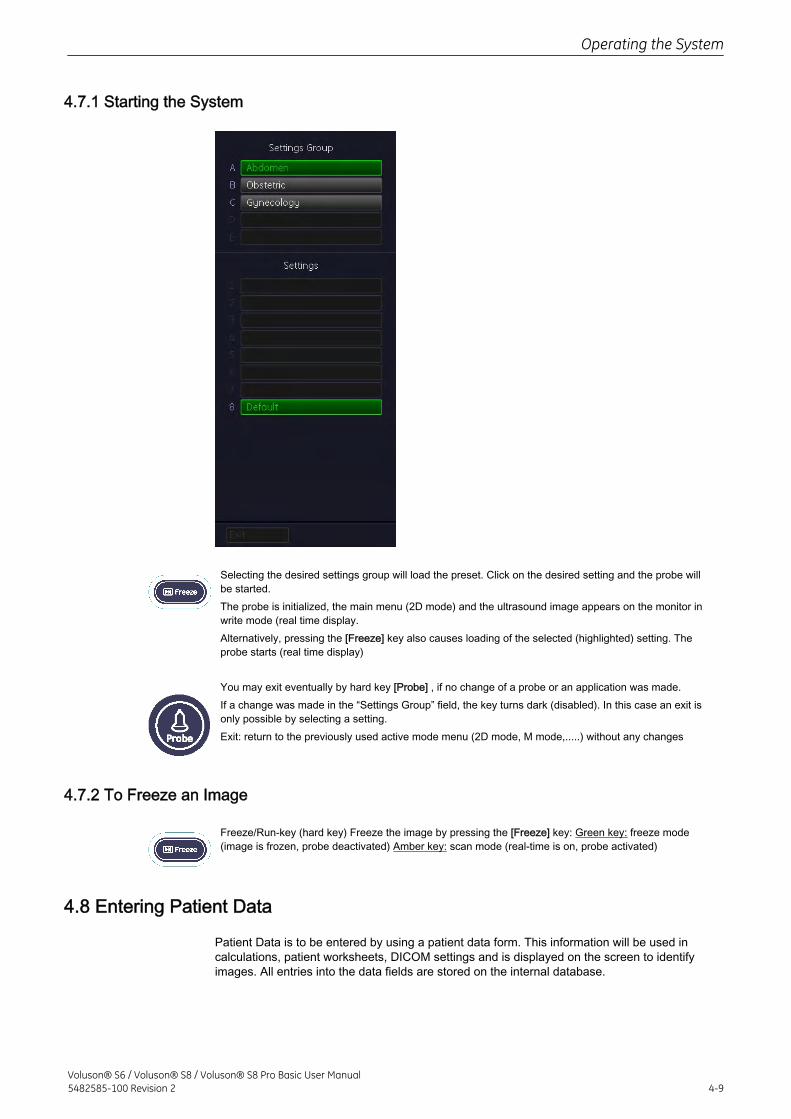
4.7.1 Starting the System
Selecting the desired settings group will load the preset. Click on the desired setting and the probe willbe started.The probe is initialized, the main menu (2D mode) and the ultrasound image appears on the monitor inwrite mode (real time display.Alternatively, pressing the [Freeze] key also causes loading of the selected (highlighted) setting. Theprobe starts (real time display)
You may exit eventually by hard key [Probe] , if no change of a probe or an application was made.If a change was made in the “Settings Group” field, the key turns dark (disabled). In this case an exit isonly possible by selecting a setting.Exit: return to the previously used active mode menu (2D mode, M mode,.....) without any changes
4.7.2 To Freeze an Image
Freeze/Run-key (hard key) Freeze the image by pressing the [Freeze] key: Green key: freeze mode(image is frozen, probe deactivated) Amber key: scan mode (real-time is on, probe activated)
4.8 Entering Patient Data
Patient Data is to be entered by using a patient data form. This information will be used incalculations, patient worksheets, DICOM settings and is displayed on the screen to identifyimages. All entries into the data fields are stored on the internal database.
Operating the System
Voluson® S6 / Voluson® S8 / Voluson® S8 Pro Basic User Manual5482585-100 Revision 2 4-9
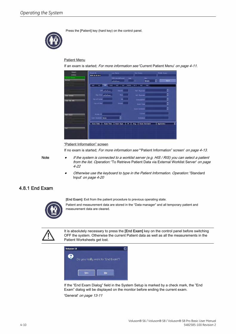
Press the [Patient] key (hard key) on the control panel.
Patient MenuIf an exam is started; For more information see 'Current Patient Menu' on page 4-11.
“Patient Information” screenIf no exam is started; For more information see '“Patient Information” screen' on page 4-13.
Note • If the system is connected to a worklist server (e.g. HIS / RIS) you can select a patientfrom the list. Operation: 'To Retrieve Patient Data via External Worklist Server' on page4-22
• Otherwise use the keyboard to type in the Patient Information. Operation: 'StandardInput' on page 4-20
4.8.1 End Exam
[End Exam]: Exit from the patient procedure to previous operating state.Patient and measurement data are stored in the “Data manager” and all temporary patient andmeasurement data are cleared.
It is absolutely necessary to press the [End Exam] key on the control panel before switchingOFF the system. Otherwise the current Patient data as well as all the measurements in thePatient Worksheets get lost.
If the “End Exam Dialog” field in the System Setup is marked by a check mark, the ”EndExam” dialog will be displayed on the monitor before ending the current exam.'General' on page 13-11
Operating the System
4-10Voluson® S6 / Voluson® S8 / Voluson® S8 Pro Basic User Manual
5482585-100 Revision 2
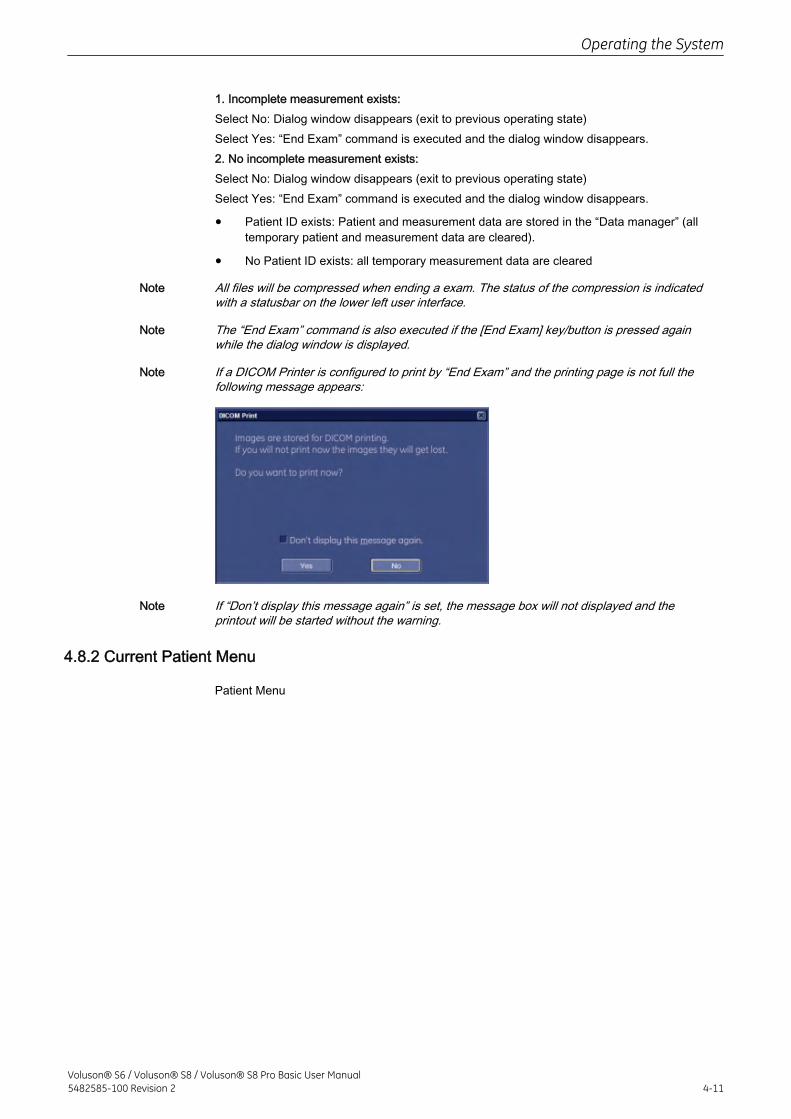
1. Incomplete measurement exists:Select No: Dialog window disappears (exit to previous operating state)Select Yes: “End Exam” command is executed and the dialog window disappears.2. No incomplete measurement exists:Select No: Dialog window disappears (exit to previous operating state)Select Yes: “End Exam” command is executed and the dialog window disappears.
• Patient ID exists: Patient and measurement data are stored in the “Data manager” (alltemporary patient and measurement data are cleared).
• No Patient ID exists: all temporary measurement data are cleared
Note All files will be compressed when ending a exam. The status of the compression is indicatedwith a statusbar on the lower left user interface.
Note The “End Exam” command is also executed if the [End Exam] key/button is pressed againwhile the dialog window is displayed.
Note If a DICOM Printer is configured to print by “End Exam” and the printing page is not full thefollowing message appears:
Note If “Don’t display this message again” is set, the message box will not displayed and theprintout will be started without the warning.
4.8.2 Current Patient Menu
Patient Menu
Operating the System
Voluson® S6 / Voluson® S8 / Voluson® S8 Pro Basic User Manual5482585-100 Revision 2 4-11
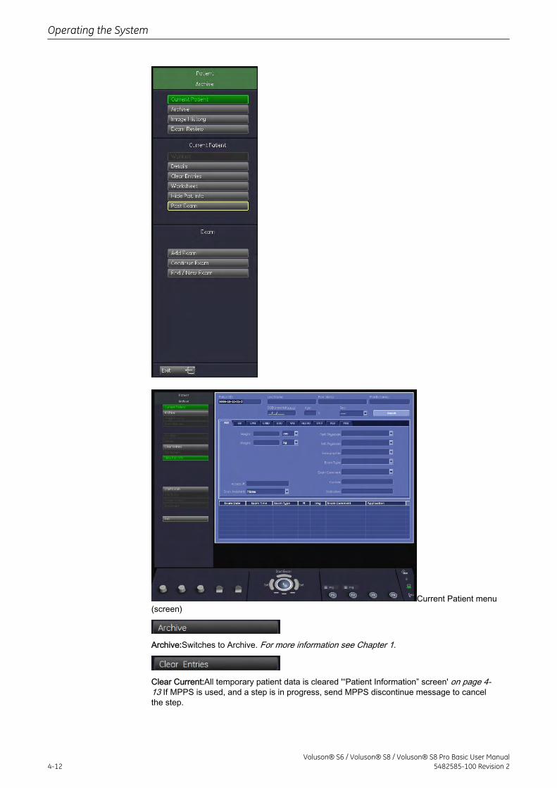
Current Patient menu(screen)
Archive:Switches to Archive. For more information see Chapter 1.
Clear Current:All temporary patient data is cleared '“Patient Information” screen' on page 4-13 If MPPS is used, and a step is in progress, send MPPS discontinue message to cancelthe step.
Operating the System
4-12Voluson® S6 / Voluson® S8 / Voluson® S8 Pro Basic User Manual
5482585-100 Revision 2
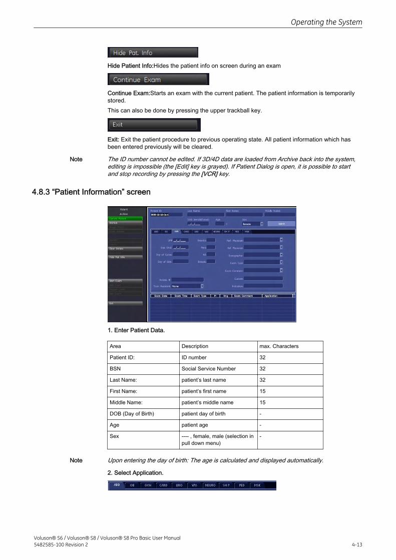
Hide Patient Info:Hides the patient info on screen during an exam
Continue Exam:Starts an exam with the current patient. The patient information is temporarilystored.This can also be done by pressing the upper trackball key.
Exit: Exit the patient procedure to previous operating state. All patient information which hasbeen entered previously will be cleared.
Note The ID number cannot be edited. If 3D/4D data are loaded from Archive back into the system,editing is impossible (the [Edit] key is grayed). If Patient Dialog is open, it is possible to startand stop recording by pressing the [VCR] key.
4.8.3 “Patient Information” screen
1. Enter Patient Data.
Area Description max. Characters
Patient ID: ID number 32
BSN Social Service Number 32
Last Name: patient’s last name 32
First Name: patient’s first name 15
Middle Name: patient’s middle name 15
DOB (Day of Birth) patient day of birth -
Age patient age -
Sex ---- , female, male (selection inpull down menu)
-
Note Upon entering the day of birth: The age is calculated and displayed automatically.
2. Select Application.
Operating the System
Voluson® S6 / Voluson® S8 / Voluson® S8 Pro Basic User Manual5482585-100 Revision 2 4-13
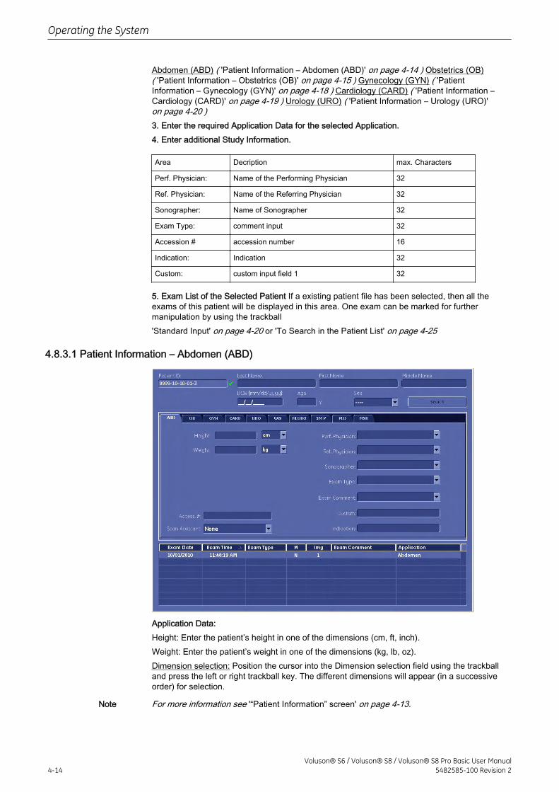
Abdomen (ABD) ( 'Patient Information – Abdomen (ABD)' on page 4-14 ) Obstetrics (OB)( 'Patient Information – Obstetrics (OB)' on page 4-15 ) Gynecology (GYN) ( 'PatientInformation – Gynecology (GYN)' on page 4-18 ) Cardiology (CARD) ( 'Patient Information –Cardiology (CARD)' on page 4-19 ) Urology (URO) ( 'Patient Information – Urology (URO)'on page 4-20 )3. Enter the required Application Data for the selected Application.4. Enter additional Study Information.
Area Decription max. Characters
Perf. Physician: Name of the Performing Physician 32
Ref. Physician: Name of the Referring Physician 32
Sonographer: Name of Sonographer 32
Exam Type: comment input 32
Accession # accession number 16
Indication: Indication 32
Custom: custom input field 1 32
5. Exam List of the Selected Patient If a existing patient file has been selected, then all theexams of this patient will be displayed in this area. One exam can be marked for furthermanipulation by using the trackball'Standard Input' on page 4-20 or 'To Search in the Patient List' on page 4-25
4.8.3.1 Patient Information – Abdomen (ABD)
Application Data:Height: Enter the patient’s height in one of the dimensions (cm, ft, inch).Weight: Enter the patient’s weight in one of the dimensions (kg, lb, oz).Dimension selection: Position the cursor into the Dimension selection field using the trackballand press the left or right trackball key. The different dimensions will appear (in a successiveorder) for selection.
Note For more information see '“Patient Information” screen' on page 4-13.
Operating the System
4-14Voluson® S6 / Voluson® S8 / Voluson® S8 Pro Basic User Manual
5482585-100 Revision 2
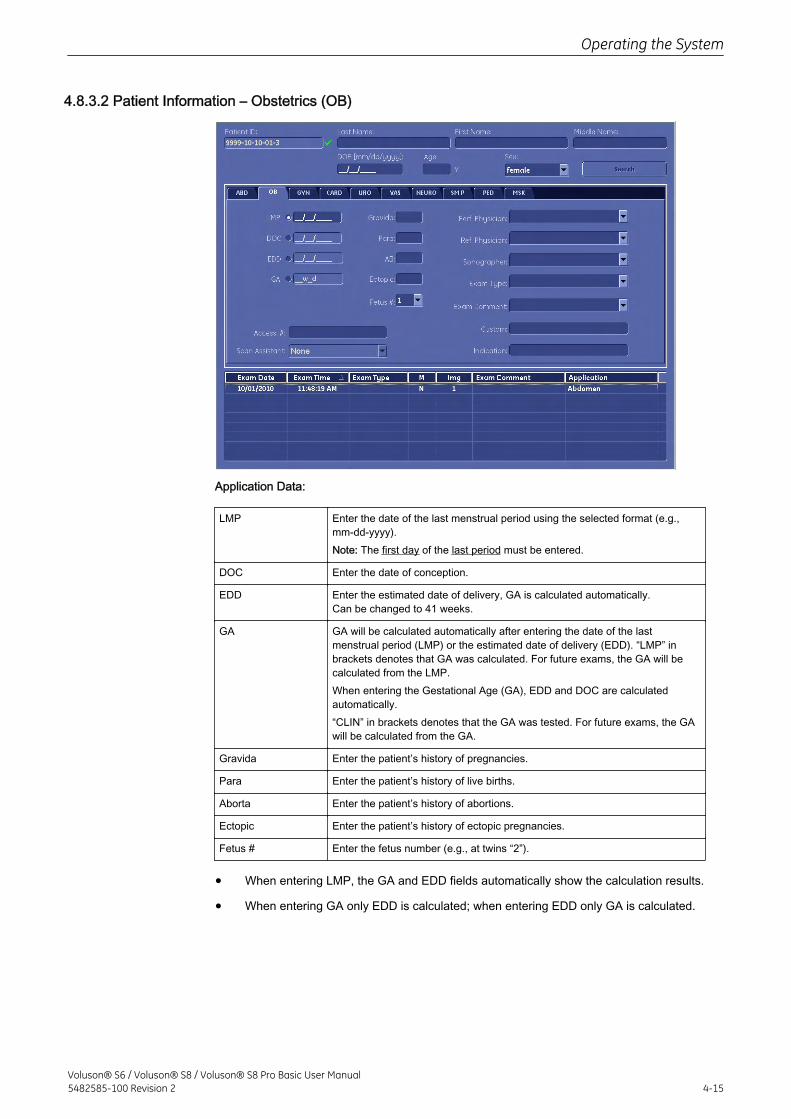
4.8.3.2 Patient Information – Obstetrics (OB)
Application Data:
LMP Enter the date of the last menstrual period using the selected format (e.g.,mm-dd-yyyy).Note: The first day of the last period must be entered.
DOC Enter the date of conception.
EDD Enter the estimated date of delivery, GA is calculated automatically.Can be changed to 41 weeks.
GA GA will be calculated automatically after entering the date of the lastmenstrual period (LMP) or the estimated date of delivery (EDD). “LMP” inbrackets denotes that GA was calculated. For future exams, the GA will becalculated from the LMP.When entering the Gestational Age (GA), EDD and DOC are calculatedautomatically.“CLIN” in brackets denotes that the GA was tested. For future exams, the GAwill be calculated from the GA.
Gravida Enter the patient’s history of pregnancies.
Para Enter the patient’s history of live births.
Aborta Enter the patient’s history of abortions.
Ectopic Enter the patient’s history of ectopic pregnancies.
Fetus # Enter the fetus number (e.g., at twins “2”).
• When entering LMP, the GA and EDD fields automatically show the calculation results.
• When entering GA only EDD is calculated; when entering EDD only GA is calculated.
Operating the System
Voluson® S6 / Voluson® S8 / Voluson® S8 Pro Basic User Manual5482585-100 Revision 2 4-15
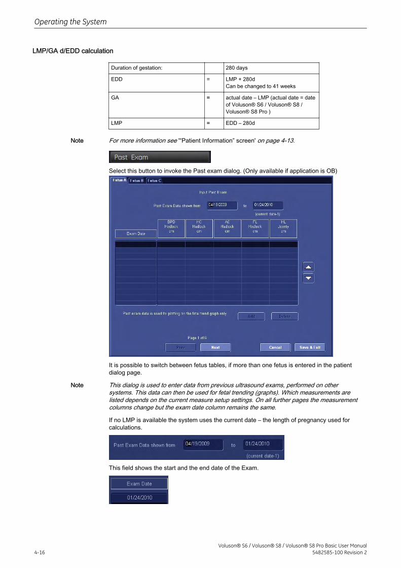
LMP/GA d/EDD calculation
Duration of gestation: 280 days
EDD = LMP + 280dCan be changed to 41 weeks
GA = actual date – LMP (actual date = dateof Voluson® S6 / Voluson® S8 /Voluson® S8 Pro )
LMP = EDD – 280d
Note For more information see '“Patient Information” screen' on page 4-13.
Select this button to invoke the Past exam dialog. (Only available if application is OB)
It is possible to switch between fetus tables, if more than one fetus is entered in the patientdialog page.
Note This dialog is used to enter data from previous ultrasound exams, performed on othersystems. This data can then be used for fetal trending (graphs). Which measurements arelisted depends on the current measure setup settings. On all further pages the measurementcolumns change but the exam date column remains the same.
If no LMP is available the system uses the current date – the length of pregnancy used forcalculations.
This field shows the start and the end date of the Exam.
Operating the System
4-16Voluson® S6 / Voluson® S8 / Voluson® S8 Pro Basic User Manual
5482585-100 Revision 2
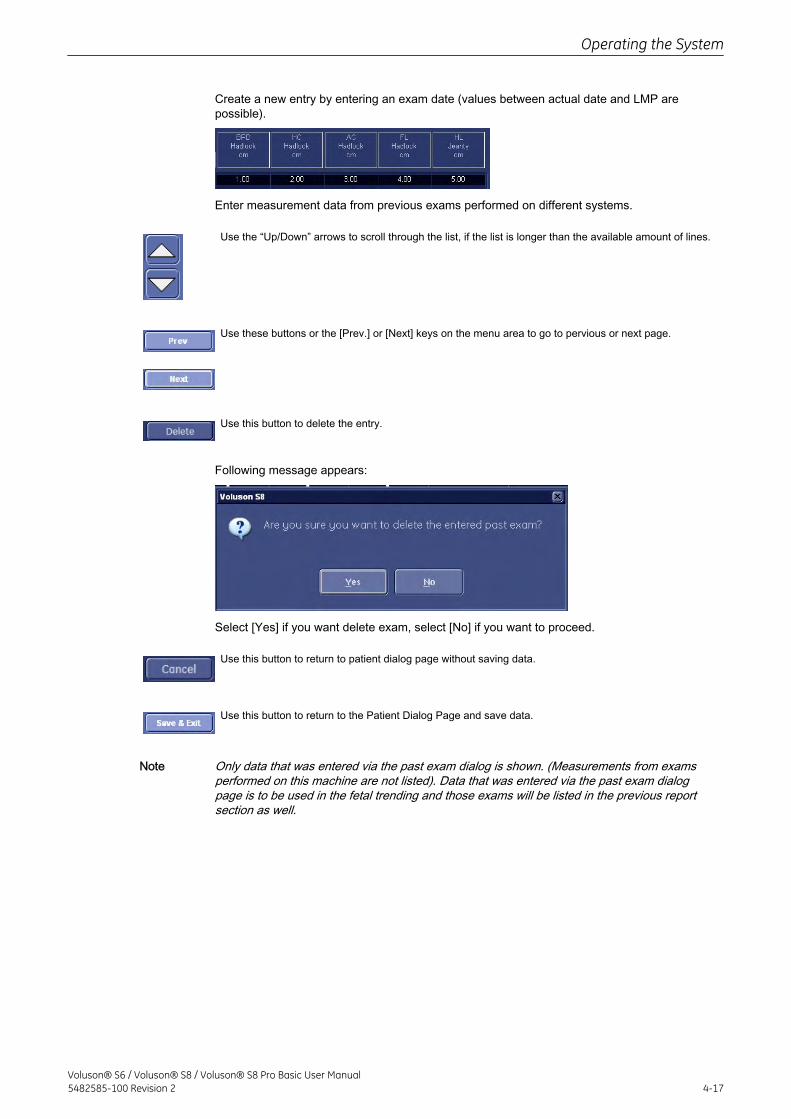
Create a new entry by entering an exam date (values between actual date and LMP arepossible).
Enter measurement data from previous exams performed on different systems.
Use the “Up/Down” arrows to scroll through the list, if the list is longer than the available amount of lines.
Use these buttons or the [Prev.] or [Next] keys on the menu area to go to pervious or next page.
Use this button to delete the entry.
Following message appears:
Select [Yes] if you want delete exam, select [No] if you want to proceed.
Use this button to return to patient dialog page without saving data.
Use this button to return to the Patient Dialog Page and save data.
Note Only data that was entered via the past exam dialog is shown. (Measurements from examsperformed on this machine are not listed). Data that was entered via the past exam dialogpage is to be used in the fetal trending and those exams will be listed in the previous reportsection as well.
Operating the System
Voluson® S6 / Voluson® S8 / Voluson® S8 Pro Basic User Manual5482585-100 Revision 2 4-17
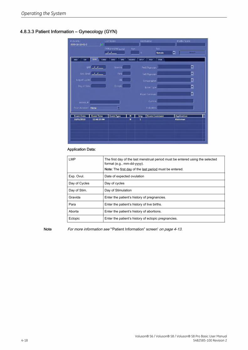
4.8.3.3 Patient Information – Gynecology (GYN)
Application Data:
LMP The first day of the last menstrual period must be entered using the selectedformat (e.g., mm-dd-yyyy).Note: The first day of the last period must be entered.
Exp. Ovul. Date of expected ovulation
Day of Cycles Day of cycles
Day of Stim. Day of Stimulation
Gravida Enter the patient’s history of pregnancies.
Para Enter the patient’s history of live births.
Aborta Enter the patient’s history of abortions.
Ectopic Enter the patient’s history of ectopic pregnancies.
Note For more information see '“Patient Information” screen' on page 4-13.
Operating the System
4-18Voluson® S6 / Voluson® S8 / Voluson® S8 Pro Basic User Manual
5482585-100 Revision 2
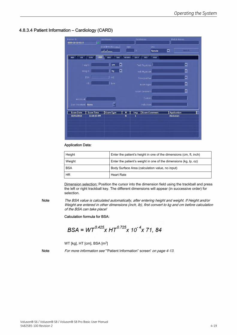
4.8.3.4 Patient Information – Cardiology (CARD)
Application Data:
Height Enter the patient’s height in one of the dimensions (cm, ft, inch)
Weight Enter the patient’s weight in one of the dimensions (kg, lp, oz)
BSA Body Surface Area (calculation value, no input)
HR Heart Rate
Dimension selection: Position the cursor into the dimension field using the trackball and pressthe left or right trackball key. The different dimensions will appear (in successive order) forselection.
Note The BSA value is calculated automatically, after entering height and weight. If Height and/orWeight are entered in other dimensions (inch, lb), first convert to kg and cm before calculationof the BSA can take place!
Calculation formula for BSA:
WT [kg], HT [cm], BSA [m2]
Note For more information see '“Patient Information” screen' on page 4-13.
Operating the System
Voluson® S6 / Voluson® S8 / Voluson® S8 Pro Basic User Manual5482585-100 Revision 2 4-19
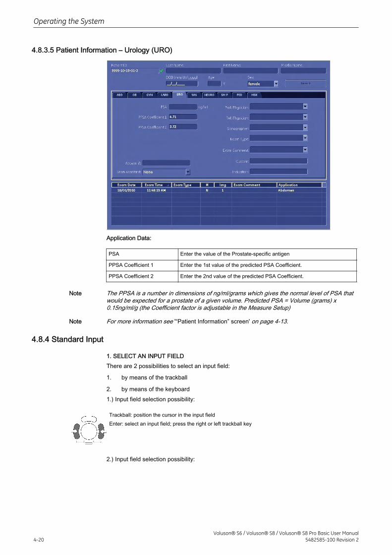
4.8.3.5 Patient Information – Urology (URO)
Application Data:
PSA Enter the value of the Prostate-specific antigen
PPSA Coefficient 1 Enter the 1st value of the predicted PSA Coefficient.
PPSA Coefficient 2 Enter the 2nd value of the predicted PSA Coefficient.
Note The PPSA is a number in dimensions of ng/ml/grams which gives the normal level of PSA thatwould be expected for a prostate of a given volume. Predicted PSA = Volume (grams) x0.15ng/ml/g (the Coefficient factor is adjustable in the Measure Setup)
Note For more information see '“Patient Information” screen' on page 4-13.
4.8.4 Standard Input
1. SELECT AN INPUT FIELDThere are 2 possibilities to select an input field:
1. by means of the trackball
2. by means of the keyboard1.) Input field selection possibility:
Trackball: position the cursor in the input fieldEnter: select an input field; press the right or left trackball key
2.) Input field selection possibility:
Operating the System
4-20Voluson® S6 / Voluson® S8 / Voluson® S8 Pro Basic User Manual
5482585-100 Revision 2
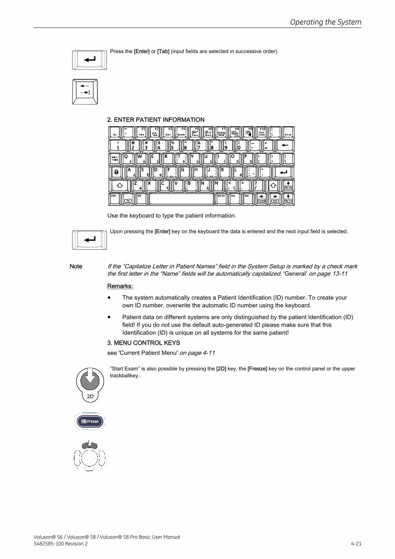
Press the [Enter] or [Tab] (input fields are selected in successive order).
2. ENTER PATIENT INFORMATION
Use the keyboard to type the patient information.
Upon pressing the [Enter] key on the keyboard the data is entered and the next input field is selected.
Note If the “Capitalize Letter in Patient Names” field in the System Setup is marked by a check markthe first letter in the “Name” fields will be automatically capitalized. 'General' on page 13-11
Remarks:
• The system automatically creates a Patient Identification (ID) number. To create yourown ID number, overwrite the automatic ID number using the keyboard.
• Patient data on different systems are only distinguished by the patient Identification (ID)field! If you do not use the default auto-generated ID please make sure that thisIdentification (ID) is unique on all systems for the same patient!
3. MENU CONTROL KEYSsee 'Current Patient Menu' on page 4-11
”Start Exam” is also possible by pressing the [2D] key, the [Freeze] key on the control panel or the uppertrackballkey..
Operating the System
Voluson® S6 / Voluson® S8 / Voluson® S8 Pro Basic User Manual5482585-100 Revision 2 4-21
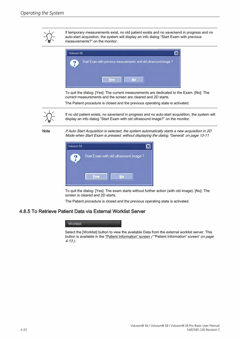
If temporary measurements exist, no old patient exists and no save/send in progress and noauto-start acquisition, the system will display an info dialog “Start Exam with previousmeasurements?” on the monitor.
To quit the dialog: [Yes]: The current measurements are dedicated to the Exam. [No]: Thecurrent measurements and the screen are cleared and 2D starts.The Patient procedure is closed and the previous operating state is activated.
If no old patient exists, no save/send in progress and no auto-start acquisition, the system willdisplay an info dialog “Start Exam with old ultrasound image?” on the monitor.
Note If Auto Start Acquisition is selected, the system automatically starts a new acquisition in 2DMode when Start Exam is pressed, without displaying the dialog. 'General' on page 13-11
To quit the dialog: [Yes]: The exam starts without further action (with old image). [No]: Thescreen is cleared and 2D starts.The Patient procedure is closed and the previous operating state is activated.
4.8.5 To Retrieve Patient Data via External Worklist Server
Select the [Worklist] button to view the available Data from the external worklist server. Thisbutton is available in the “Patient Information” screen ( '“Patient Information” screen' on page4-13 ).
Operating the System
4-22Voluson® S6 / Voluson® S8 / Voluson® S8 Pro Basic User Manual
5482585-100 Revision 2
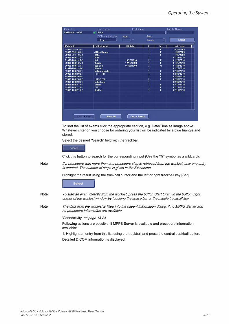
To sort the list of exams click the appropriate caption, e.g. Date/Time as image above.Whatever criterion you choose for ordering your list will be indicated by a blue triangle andstored.Select the desired “Search” field with the trackball.
Click this button to search for the corresponding input (Use the “%” symbol as a wildcard).
Note If a procedure with more than one procedure step is retrieved from the worklist, only one entryis created. The number of steps is given in the S# column.
Highlight the result using the trackball cursor and the left or right trackball key [Set].
Note To start an exam directly from the worklist, press the button Start Exam in the bottom rightcorner of the worklist window by touching the space bar or the middle trackball key.
Note The data from the worklist is filled into the patient information dialog, if no MPPS Server andno procedure information are available.
'Connectivity' on page 13-24Following actions are possible, if MPPS Server is available and procedure informationavailable:1. Highlight an entry from this list using the trackball and press the central trackball button.Detailed DICOM information is displayed:
Operating the System
Voluson® S6 / Voluson® S8 / Voluson® S8 Pro Basic User Manual5482585-100 Revision 2 4-23
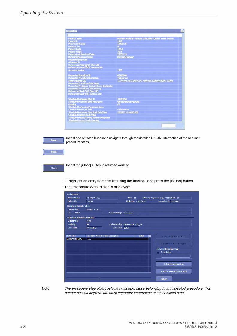
Select one of these buttons to navigate through the detailed DICOM information of the relevantprocedure steps.
Select the [Close] button to return to worklist.
2. Highlight an entry from this list using the trackball and press the [Select] button.The “Procedure Step” dialog is displayed:
Note The procedure step dialog lists all procedure steps belonging to the selected procedure. Theheader section displays the most important information of the selected step.
Operating the System
4-24Voluson® S6 / Voluson® S8 / Voluson® S8 Pro Basic User Manual
5482585-100 Revision 2
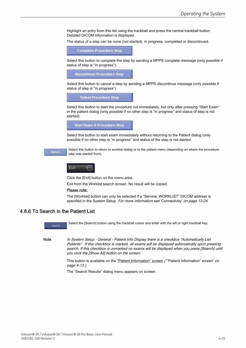
Highlight an entry from this list using the trackball and press the central trackball button.Detailed DICOM information is displayed.The status of a step can be none (not started), in progress, completed or discontinued.
Select this button to complete the step by sending a MPPS complete message (only possible ifstatus of step is “in progress”).
Select this button to cancel a step by sending a MPPS discontinue message (only possible ifstatus of step is “in progress”).
Select this button to start the procedure not immediately, but only after pressing “Start Exam”in the patient dialog (only possible if no other step is “in progress” and status of step is notstarted).
Select this button to start exam immediately without returning to the Patient dialog (onlypossible if no other step is “in progress” and status of the step is not started.
Select this button to return to worklist dialog or to the patient menu (depending on where the procedurestep was started from).
Click the [Exit] button on the menu area.Exit from the Worklist search screen. No result will be copied.Please note:The [Worklist] button can only be selected if a “Service: WORKLIST” DICOM address isspecified in the System Setup. For more information see 'Connectivity' on page 13-24.
4.8.6 To Search in the Patient List
Select the [Search] button using the trackball cursor and enter with the left or right trackball key.
Note In System Setup - General - Patient Info Display there is a checkbox “Automatically ListPatients” . If this checkbox is marked, all exams will be displayed automatically upon pressingsearch. If this checkbox is unmarked no exams will be displayed when you press [Search] untilyou click the [Show All] button on the screen.
This button is available on the “Patient Information” screen ( '“Patient Information” screen' onpage 4-13 ).The “Search Results” dialog menu appears on screen.
Operating the System
Voluson® S6 / Voluson® S8 / Voluson® S8 Pro Basic User Manual5482585-100 Revision 2 4-25
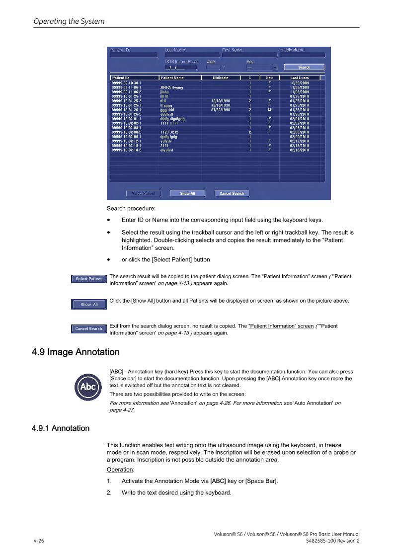
Search procedure:
• Enter ID or Name into the corresponding input field using the keyboard keys.
• Select the result using the trackball cursor and the left or right trackball key. The result ishighlighted. Double-clicking selects and copies the result immediately to the “PatientInformation” screen.
• or click the [Select Patient] button
The search result will be copied to the patient dialog screen. The “Patient Information” screen ( '“PatientInformation” screen' on page 4-13 ) appears again.
Click the [Show All] button and all Patients will be displayed on screen, as shown on the picture above.
Exit from the search dialog screen, no result is copied. The “Patient Information” screen ( '“PatientInformation” screen' on page 4-13 ) appears again.
4.9 Image Annotation
[ABC] - Annotation key (hard key) Press this key to start the documentation function. You can also press[Space bar] to start the documentation function. Upon pressing the [ABC] Annotation key once more thetext is switched off but the annotation text is not cleared.There are two possibilities provided to write on the screen:For more information see 'Annotation' on page 4-26. For more information see 'Auto Annotation' onpage 4-27.
4.9.1 Annotation
This function enables text writing onto the ultrasound image using the keyboard, in freezemode or in scan mode, respectively. The inscription will be erased upon selection of a probe ora program. Inscription is not possible outside the annotation area.Operation:
1. Activate the Annotation Mode via [ABC] key or [Space Bar].
2. Write the text desired using the keyboard.
Operating the System
4-26Voluson® S6 / Voluson® S8 / Voluson® S8 Pro Basic User Manual
5482585-100 Revision 2
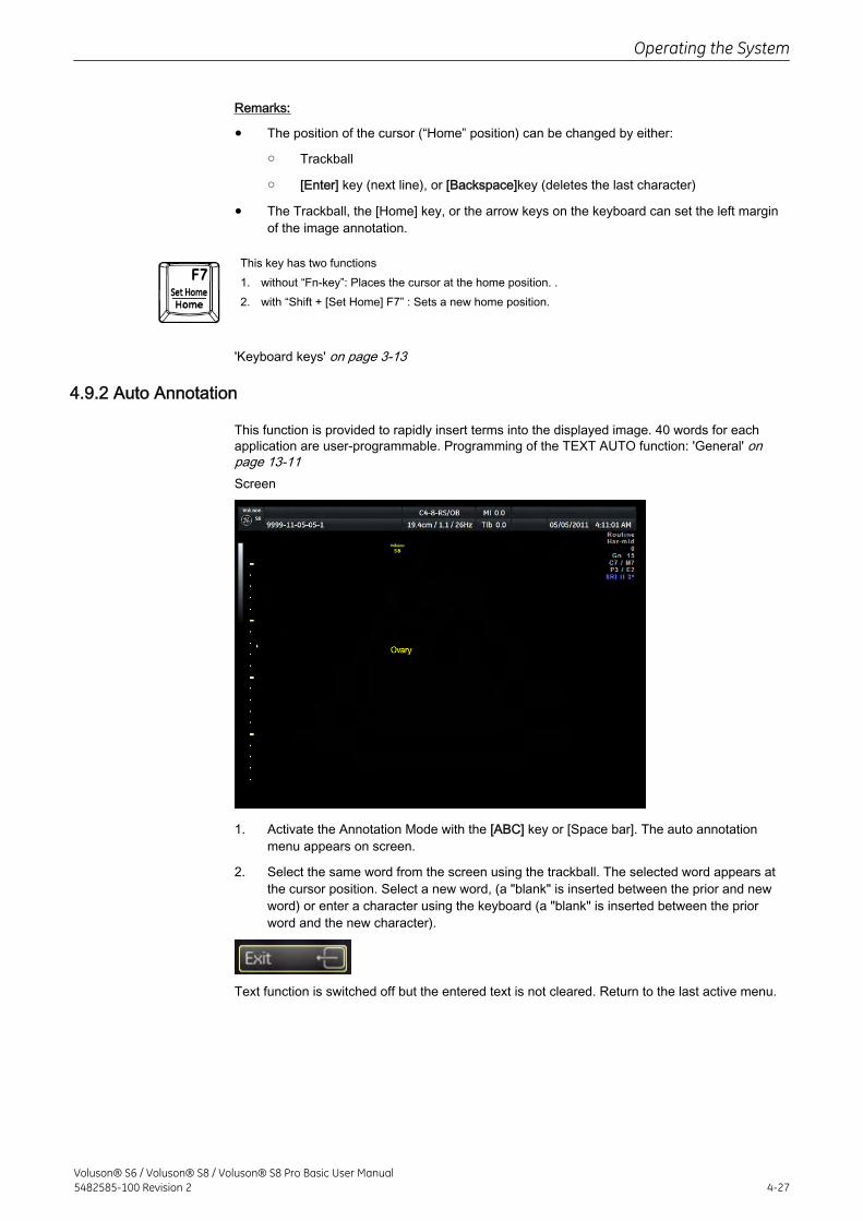
Remarks:
• The position of the cursor (“Home” position) can be changed by either:
○ Trackball
○ [Enter] key (next line), or [Backspace]key (deletes the last character)
• The Trackball, the [Home] key, or the arrow keys on the keyboard can set the left marginof the image annotation.
This key has two functions1. without “Fn-key”: Places the cursor at the home position. .2. with “Shift + [Set Home] F7” : Sets a new home position.
'Keyboard keys' on page 3-13
4.9.2 Auto Annotation
This function is provided to rapidly insert terms into the displayed image. 40 words for eachapplication are user-programmable. Programming of the TEXT AUTO function: 'General' onpage 13-11Screen
1. Activate the Annotation Mode with the [ABC] key or [Space bar]. The auto annotationmenu appears on screen.
2. Select the same word from the screen using the trackball. The selected word appears atthe cursor position. Select a new word, (a "blank" is inserted between the prior and newword) or enter a character using the keyboard (a "blank" is inserted between the priorword and the new character).
Text function is switched off but the entered text is not cleared. Return to the last active menu.
Operating the System
Voluson® S6 / Voluson® S8 / Voluson® S8 Pro Basic User Manual5482585-100 Revision 2 4-27
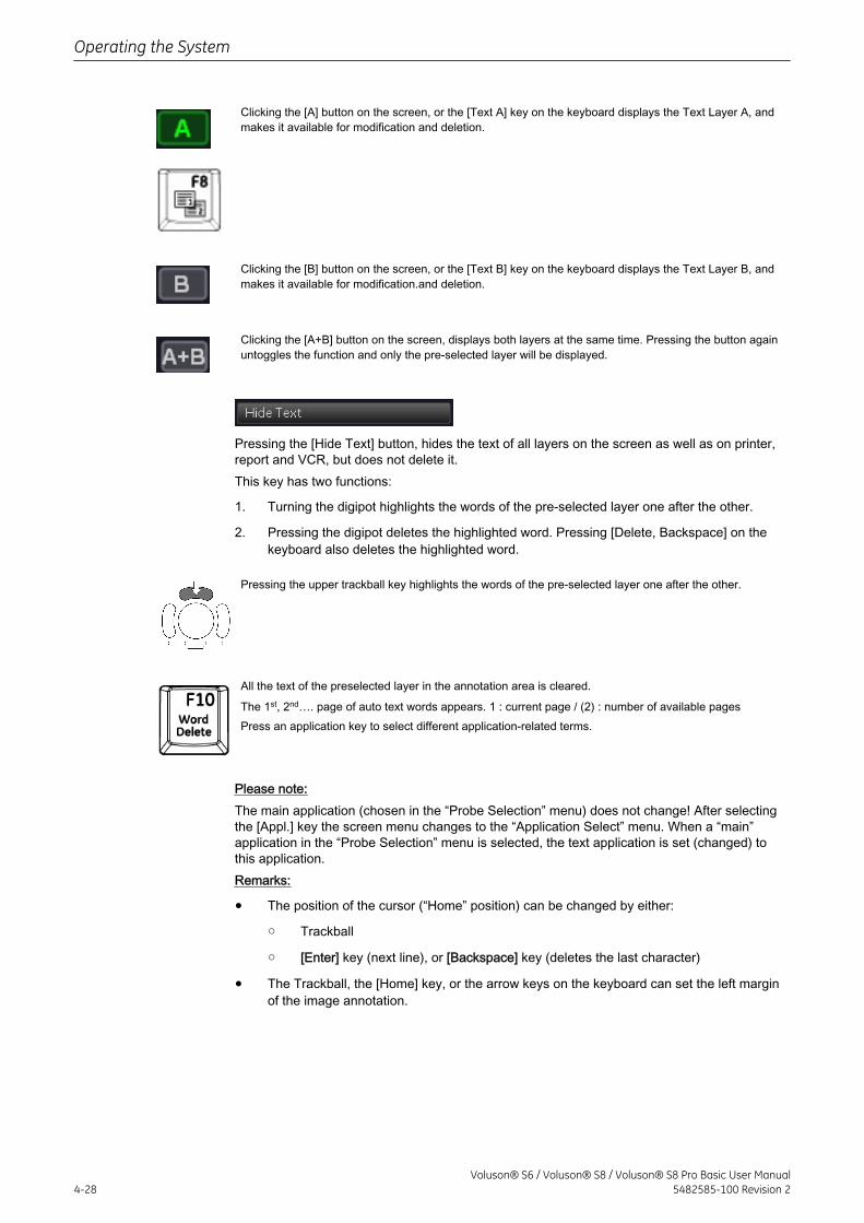
Clicking the [A] button on the screen, or the [Text A] key on the keyboard displays the Text Layer A, andmakes it available for modification and deletion.
Clicking the [B] button on the screen, or the [Text B] key on the keyboard displays the Text Layer B, andmakes it available for modification.and deletion.
Clicking the [A+B] button on the screen, displays both layers at the same time. Pressing the button againuntoggles the function and only the pre-selected layer will be displayed.
Pressing the [Hide Text] button, hides the text of all layers on the screen as well as on printer,report and VCR, but does not delete it.This key has two functions:
1. Turning the digipot highlights the words of the pre-selected layer one after the other.
2. Pressing the digipot deletes the highlighted word. Pressing [Delete, Backspace] on thekeyboard also deletes the highlighted word.
Pressing the upper trackball key highlights the words of the pre-selected layer one after the other.
All the text of the preselected layer in the annotation area is cleared.
The 1st, 2nd…. page of auto text words appears. 1 : current page / (2) : number of available pagesPress an application key to select different application-related terms.
Please note:The main application (chosen in the “Probe Selection” menu) does not change! After selectingthe [Appl.] key the screen menu changes to the “Application Select” menu. When a “main”application in the “Probe Selection” menu is selected, the text application is set (changed) tothis application.Remarks:
• The position of the cursor (“Home” position) can be changed by either:
○ Trackball
○ [Enter] key (next line), or [Backspace] key (deletes the last character)
• The Trackball, the [Home] key, or the arrow keys on the keyboard can set the left marginof the image annotation.
Operating the System
4-28Voluson® S6 / Voluson® S8 / Voluson® S8 Pro Basic User Manual
5482585-100 Revision 2
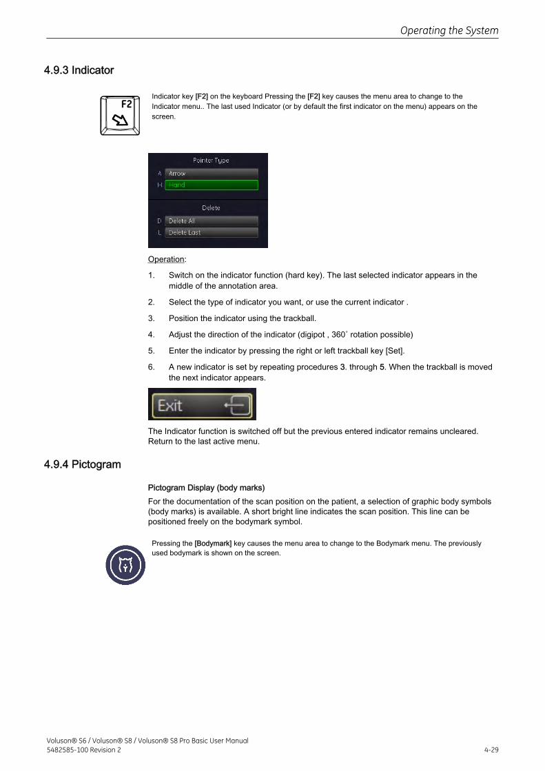
4.9.3 Indicator
Indicator key [F2] on the keyboard Pressing the [F2] key causes the menu area to change to theIndicator menu.. The last used Indicator (or by default the first indicator on the menu) appears on thescreen.
Operation:
1. Switch on the indicator function (hard key). The last selected indicator appears in themiddle of the annotation area.
2. Select the type of indicator you want, or use the current indicator .
3. Position the indicator using the trackball.
4. Adjust the direction of the indicator (digipot , 360˚ rotation possible)
5. Enter the indicator by pressing the right or left trackball key [Set].
6. A new indicator is set by repeating procedures 3. through 5. When the trackball is movedthe next indicator appears.
The Indicator function is switched off but the previous entered indicator remains uncleared.Return to the last active menu.
4.9.4 Pictogram
Pictogram Display (body marks)For the documentation of the scan position on the patient, a selection of graphic body symbols(body marks) is available. A short bright line indicates the scan position. This line can bepositioned freely on the bodymark symbol.
Pressing the [Bodymark] key causes the menu area to change to the Bodymark menu. The previouslyused bodymark is shown on the screen.
Operating the System
Voluson® S6 / Voluson® S8 / Voluson® S8 Pro Basic User Manual5482585-100 Revision 2 4-29
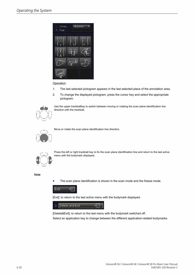
Operation:
1. The last selected pictogram appears in the last selected place of the annotation area.
2. To change the displayed pictogram, press the cursor key and select the appropriatepictogram.
Use the upper trackballkey to switch between moving or rotating the scan plane identification linedirection with the trackball.
Move or rotate the scan plane identification line direction.
Press the left or right trackball key to fix the scan plane identification line and return to the last activemenu with the bodymark displayed.
Note
• The scan plane identification is shown in the scan mode and the freeze mode.
[Exit]: to return to the last active menu with the bodymark displayed.
[Delete&Exit]: to return to the last menu with the bodymark switched off.Select an application key to change between the different application-related bodymarks.
Operating the System
4-30Voluson® S6 / Voluson® S8 / Voluson® S8 Pro Basic User Manual
5482585-100 Revision 2
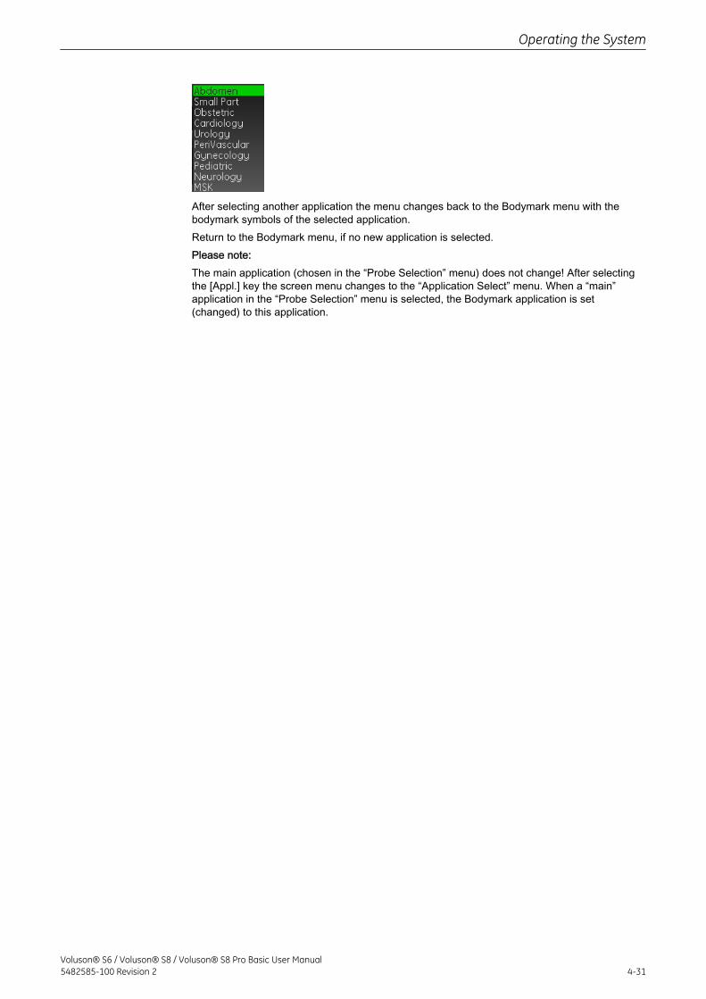
After selecting another application the menu changes back to the Bodymark menu with thebodymark symbols of the selected application.Return to the Bodymark menu, if no new application is selected.Please note:The main application (chosen in the “Probe Selection” menu) does not change! After selectingthe [Appl.] key the screen menu changes to the “Application Select” menu. When a “main”application in the “Probe Selection” menu is selected, the Bodymark application is set(changed) to this application.
Operating the System
Voluson® S6 / Voluson® S8 / Voluson® S8 Pro Basic User Manual5482585-100 Revision 2 4-31

This page was intentionally left blank.
Operating the System
4-32Voluson® S6 / Voluson® S8 / Voluson® S8 Pro Basic User Manual
5482585-100 Revision 2
Chapter 5
Probes and Biopsies
Describes probe precautions and -handling, pobe applications and features, care and maintenanceof probes and biopsies.
Probes - - - - - - - - - - - - - - - - - - - - - - - - - - - - - - - - - - - - - - - - - - - - - - - - - - - - - 5-2Biopsies - - - - - - - - - - - - - - - - - - - - - - - - - - - - - - - - - - - - - - - - - - - - - - - - - - - 5-10
Voluson® S6 / Voluson® S8 / Voluson® S8 Pro Basic User Manual5482585-100 Revision 2 5-1
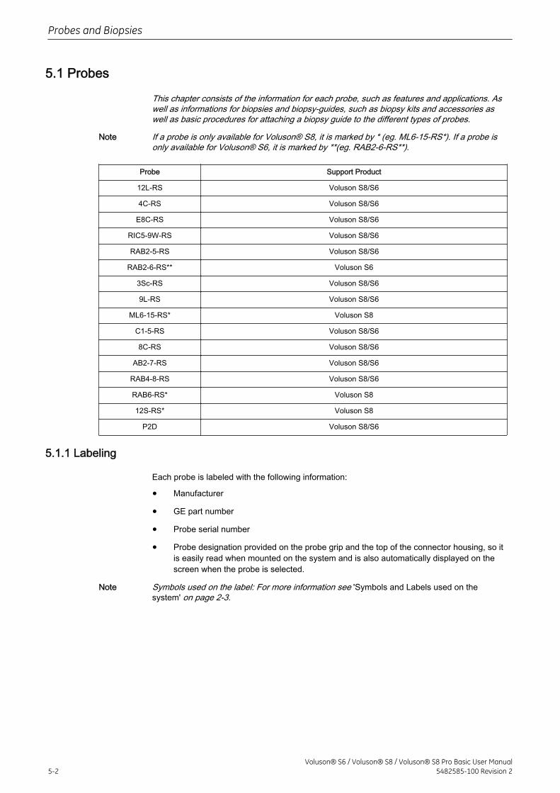
5.1 Probes
This chapter consists of the information for each probe, such as features and applications. Aswell as informations for biopsies and biopsy-guides, such as biopsy kits and accessories aswell as basic procedures for attaching a biopsy guide to the different types of probes.
Note If a probe is only available for Voluson® S8, it is marked by * (eg. ML6-15-RS*). If a probe isonly available for Voluson® S6, it is marked by **(eg. RAB2-6-RS**).
Probe Support Product
12L-RS Voluson S8/S6
4C-RS Voluson S8/S6
E8C-RS Voluson S8/S6
RIC5-9W-RS Voluson S8/S6
RAB2-5-RS Voluson S8/S6
RAB2-6-RS** Voluson S6
3Sc-RS Voluson S8/S6
9L-RS Voluson S8/S6
ML6-15-RS* Voluson S8
C1-5-RS Voluson S8/S6
8C-RS Voluson S8/S6
AB2-7-RS Voluson S8/S6
RAB4-8-RS Voluson S8/S6
RAB6-RS* Voluson S8
12S-RS* Voluson S8
P2D Voluson S8/S6
5.1.1 Labeling
Each probe is labeled with the following information:
• Manufacturer
• GE part number
• Probe serial number
• Probe designation provided on the probe grip and the top of the connector housing, so itis easily read when mounted on the system and is also automatically displayed on thescreen when the probe is selected.
Note Symbols used on the label: For more information see 'Symbols and Labels used on thesystem' on page 2-3.
Probes and Biopsies
5-2Voluson® S6 / Voluson® S8 / Voluson® S8 Pro Basic User Manual
5482585-100 Revision 2
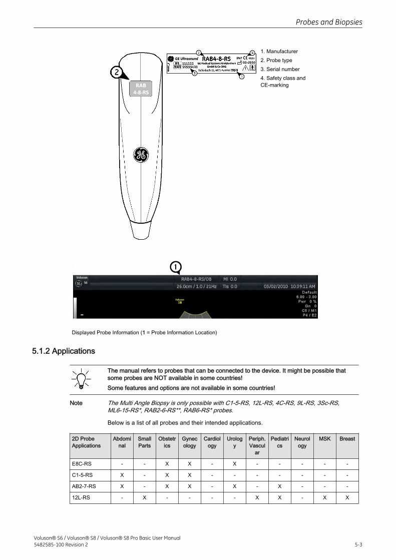
1. Manufacturer2. Probe type3. Serial number4. Safety class andCE-marking
Displayed Probe Information (1 = Probe Information Location)
5.1.2 Applications
The manual refers to probes that can be connected to the device. It might be possible thatsome probes are NOT available in some countries!Some features and options are not available in some countries!
Note The Multi Angle Biopsy is only possible with C1-5-RS, 12L-RS, 4C-RS, 9L-RS, 3Sc-RS,ML6-15-RS*, RAB2-6-RS**, RAB6-RS* probes.
Below is a list of all probes and their intended applications.
2D ProbeApplications
Abdominal
SmallParts
Obstetrics
Gynecology
Cardiology
Urology
Periph.Vascul
ar
Pediatrics
Neurology
MSK Breast
E8C-RS - - X X - X - - - - -
C1-5-RS X - X X - - - - - - -
AB2-7-RS X - X X - X - X - - -
12L-RS - X - - - - X X - X X
Probes and Biopsies
Voluson® S6 / Voluson® S8 / Voluson® S8 Pro Basic User Manual5482585-100 Revision 2 5-3
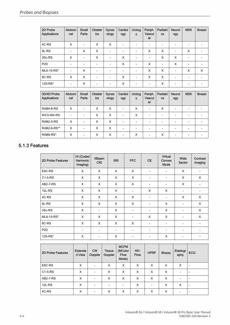
2D ProbeApplications
Abdominal
SmallParts
Obstetrics
Gynecology
Cardiology
Urology
Periph.Vascul
ar
Pediatrics
Neurology
MSK Breast
4C-RS X - X X - - - - - - -
9L-RS - X X - - - X X - X -
3Sc-RS X - X - X - - X X - -
P2D - - - - X - X - X - -
ML6-15-RS* - X - - - - X X - X X
8C-RS X X - - X - X X - - -
12S-RS* - X - - X - - X - - -
3D/4D ProbeApplications
Abdominal
SmallParts
Obstetrics
Gynecology
Cardiology
Urology
Periph.Vascul
ar
Pediatrics
Neurology
MSK Breast
RAB4-8-RS X - X X - X - X - - -
RIC5-9W-RS - - X X - X - - - - -
RAB2-5-RS X - X X - - - - - - -
RAB2-6-RS** X - X X - - - - - - -
RAB6-RS* X - X X - X - X - - -
5.1.3 Features
2D Probe FeaturesHI (CodedHarmonicImaging)
XBeamCRI SRI FFC CE
VirtualConvexMode
WideSector
ContrastImaging
E8C-RS X X X X - - X -
C1-5-RS X X X X - - X X
AB2-7-RS X X X X - - X -
12L-RS X X X - X X - -
4C-RS X X X X - - X X
9L-RS X X X X - X - X
3Sc-RS X - X - - X - X
ML6-15-RS* X X X - X X - X
8C-RS X X X X - - - -
P2D - - - - - - - -
12S-RS* X - X - - X - -
2D Probe Features Extended View
CWDoppler
TissueDoppler
MCFM(MColor
FlowMode)
HD-Flow HPRF Biopsy Elastogr
aphy ECG
E8C-RS X - X X X X X X -
C1-5-RS X - X X X X X - -
AB2-7-RS X - X X X X X - -
12L-RS X - - - X - X X -
4C-RS X - X X X X X - -
Probes and Biopsies
5-4Voluson® S6 / Voluson® S8 / Voluson® S8 Pro Basic User Manual
5482585-100 Revision 2
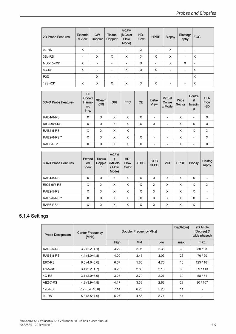
2D Probe Features Extended View
CWDoppler
TissueDoppler
MCFM(MColor
FlowMode)
HD-Flow HPRF Biopsy Elastogr
aphy ECG
9L-RS X - - - X - X - -
3Sc-RS - X X X X X X - X
ML6-15-RS* X - - - X - X X -
8C-RS X - - X X X - - X
P2D - X - - - - - - X
12S-RS* X X X X X X - - X
3D4D Probe Features
HICodedHarmo
nicImg.
XBeamCRI SRI FFC CE Beta-
View
VirtualConvex Mode
WideSector
Contrast
Imaging
HD-Flow-3D
RAB4-8-RS X X X X X - - X - X
RIC5-9W-RS X X X X X X - X X X
RAB2-5-RS X X X X - - - X X X
RAB2-6-RS** X X X X X - - X - X
RAB6-RS* X X X X X - - X - X
3D4D Probe FeaturesExtend
edView
TissueDopple
r
MCFM)
(MColor FlowMode)
HD-FlowColor
STIC STICCFPD VCI HPRF Biopsy Elastog
raphy
RAB4-8-RS X X X X X X X X X -
RIC5-9W-RS X X X X X X X X X X
RAB2-5-RS X X X X X X X X X -
RAB2-6-RS** X X X X X X X X X -
RAB6-RS* X X X X X X X X X -
5.1.4 Settings
Probe Designation Center Frequency[MHz]
Doppler Frequency[MHz]Depth[cm] 2D Angle
[Degree] (/wide phased)
High Mid Low max. max.
RAB2-5-RS 3.2 (2.2~4.1) 3.22 2.95 2.38 30 80 / 98
RAB4-8-RS 4.4 (4.0~4.8) 4.00 3.45 3.03 26 70 / 90
E8C-RS 6.5 (4.6~8.0) 6.67 5.88 4.76 16 123 / 161
C1-5-RS 3.4 (2.2~4.7) 3.23 2.86 2.13 30 69 / 113
4C-RS 3.1 (2.0~3.9) 3.23 2.70 2.27 30 58 / 81
AB2-7-RS 4.3 (3.9~4.8) 4.17 3.33 2.63 28 80 / 107
12L-RS 7.7 (5.4~10.0) 7.14 6.25 5.26 11 -
9L-RS 5.3 (3.5~7.0) 5.27 4.55 3.71 14 -
Probes and Biopsies
Voluson® S6 / Voluson® S8 / Voluson® S8 Pro Basic User Manual5482585-100 Revision 2 5-5
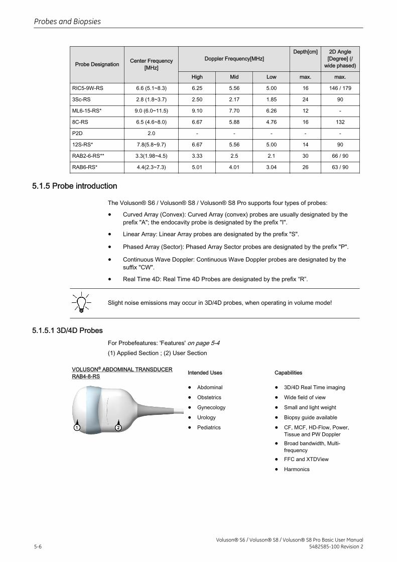
Probe Designation Center Frequency[MHz]
Doppler Frequency[MHz]Depth[cm] 2D Angle
[Degree] (/wide phased)
High Mid Low max. max.
RIC5-9W-RS 6.6 (5.1~8.3) 6.25 5.56 5.00 16 146 / 179
3Sc-RS 2.8 (1.8~3.7) 2.50 2.17 1.85 24 90
ML6-15-RS* 9.0 (6.0~11.5) 9.10 7.70 6.26 12 -
8C-RS 6.5 (4.6~8.0) 6.67 5.88 4.76 16 132
P2D 2.0 - - - - -
12S-RS* 7.8(5.8~9.7) 6.67 5.56 5.00 14 90
RAB2-6-RS** 3.3(1.98~4.5) 3.33 2.5 2.1 30 66 / 90
RAB6-RS* 4.4(2.3~7.3) 5.01 4.01 3.04 26 63 / 90
5.1.5 Probe introduction
The Voluson® S6 / Voluson® S8 / Voluson® S8 Pro supports four types of probes:
• Curved Array (Convex): Curved Array (convex) probes are usually designated by theprefix "A"; the endocavity probe is designated by the prefix "I".
• Linear Array: Linear Array probes are designated by the prefix "S".
• Phased Array (Sector): Phased Array Sector probes are designated by the prefix "P".
• Continuous Wave Doppler: Continuous Wave Doppler probes are designated by thesuffix "CW".
• Real Time 4D: Real Time 4D Probes are designated by the prefix “R”.
Slight noise emissions may occur in 3D/4D probes, when operating in volume mode!
5.1.5.1 3D/4D ProbesFor Probefeatures: 'Features' on page 5-4(1) Applied Section ; (2) User Section
VOLUSON® ABDOMINAL TRANSDUCERRAB4-8-RS Intended Uses Capabilities
• Abdominal
• Obstetrics
• Gynecology
• Urology
• Pediatrics
• 3D/4D Real Time imaging
• Wide field of view
• Small and light weight
• Biopsy guide available
• CF, MCF, HD-Flow, Power,Tissue and PW Doppler
• Broad bandwidth, Multi-frequency
• FFC and XTDView
• Harmonics
Probes and Biopsies
5-6Voluson® S6 / Voluson® S8 / Voluson® S8 Pro Basic User Manual
5482585-100 Revision 2
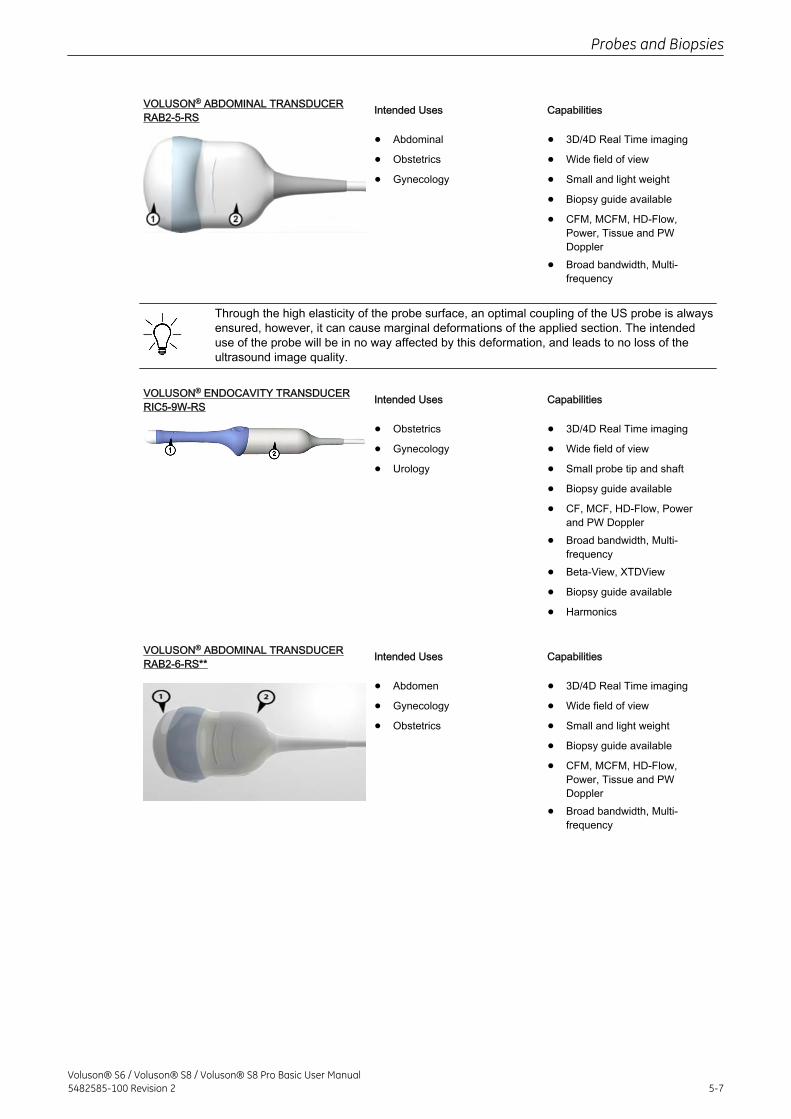
VOLUSON® ABDOMINAL TRANSDUCERRAB2-5-RS Intended Uses Capabilities
• Abdominal
• Obstetrics
• Gynecology
• 3D/4D Real Time imaging
• Wide field of view
• Small and light weight
• Biopsy guide available
• CFM, MCFM, HD-Flow,Power, Tissue and PWDoppler
• Broad bandwidth, Multi-frequency
Through the high elasticity of the probe surface, an optimal coupling of the US probe is alwaysensured, however, it can cause marginal deformations of the applied section. The intendeduse of the probe will be in no way affected by this deformation, and leads to no loss of theultrasound image quality.
VOLUSON® ENDOCAVITY TRANSDUCERRIC5-9W-RS Intended Uses Capabilities
• Obstetrics
• Gynecology
• Urology
• 3D/4D Real Time imaging
• Wide field of view
• Small probe tip and shaft
• Biopsy guide available
• CF, MCF, HD-Flow, Powerand PW Doppler
• Broad bandwidth, Multi-frequency
• Beta-View, XTDView
• Biopsy guide available
• Harmonics
VOLUSON® ABDOMINAL TRANSDUCERRAB2-6-RS** Intended Uses Capabilities
• Abdomen
• Gynecology
• Obstetrics
• 3D/4D Real Time imaging
• Wide field of view
• Small and light weight
• Biopsy guide available
• CFM, MCFM, HD-Flow,Power, Tissue and PWDoppler
• Broad bandwidth, Multi-frequency
Probes and Biopsies
Voluson® S6 / Voluson® S8 / Voluson® S8 Pro Basic User Manual5482585-100 Revision 2 5-7
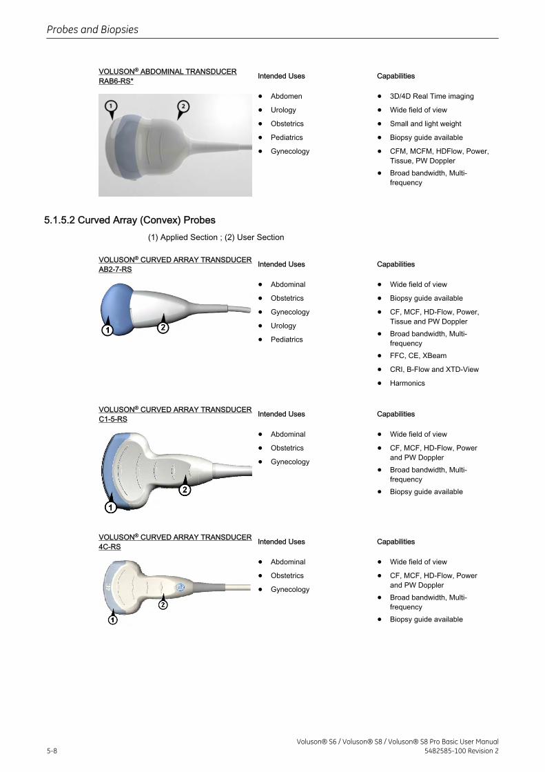
VOLUSON® ABDOMINAL TRANSDUCERRAB6-RS* Intended Uses Capabilities
• Abdomen
• Urology
• Obstetrics
• Pediatrics
• Gynecology
• 3D/4D Real Time imaging
• Wide field of view
• Small and light weight
• Biopsy guide available
• CFM, MCFM, HDFlow, Power,Tissue, PW Doppler
• Broad bandwidth, Multi-frequency
5.1.5.2 Curved Array (Convex) Probes(1) Applied Section ; (2) User Section
VOLUSON® CURVED ARRAY TRANSDUCERAB2-7-RS Intended Uses Capabilities
• Abdominal
• Obstetrics
• Gynecology
• Urology
• Pediatrics
• Wide field of view
• Biopsy guide available
• CF, MCF, HD-Flow, Power,Tissue and PW Doppler
• Broad bandwidth, Multi-frequency
• FFC, CE, XBeam
• CRI, B-Flow and XTD-View
• Harmonics
VOLUSON® CURVED ARRAY TRANSDUCERC1-5-RS Intended Uses Capabilities
• Abdominal
• Obstetrics
• Gynecology
• Wide field of view
• CF, MCF, HD-Flow, Powerand PW Doppler
• Broad bandwidth, Multi-frequency
• Biopsy guide available
VOLUSON® CURVED ARRAY TRANSDUCER4C-RS Intended Uses Capabilities
• Abdominal
• Obstetrics
• Gynecology
• Wide field of view
• CF, MCF, HD-Flow, Powerand PW Doppler
• Broad bandwidth, Multi-frequency
• Biopsy guide available
Probes and Biopsies
5-8Voluson® S6 / Voluson® S8 / Voluson® S8 Pro Basic User Manual
5482585-100 Revision 2
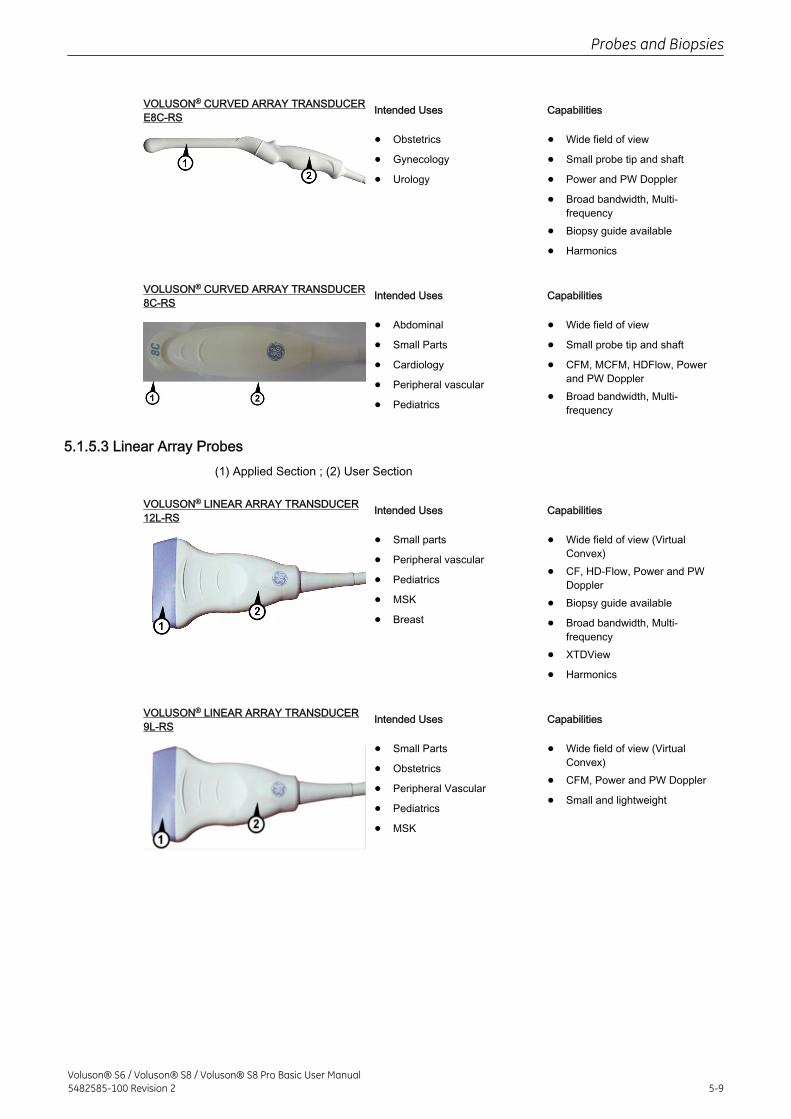
VOLUSON® CURVED ARRAY TRANSDUCERE8C-RS Intended Uses Capabilities
• Obstetrics
• Gynecology
• Urology
• Wide field of view
• Small probe tip and shaft
• Power and PW Doppler
• Broad bandwidth, Multi-frequency
• Biopsy guide available
• Harmonics
VOLUSON® CURVED ARRAY TRANSDUCER8C-RS Intended Uses Capabilities
• Abdominal
• Small Parts
• Cardiology
• Peripheral vascular
• Pediatrics
• Wide field of view
• Small probe tip and shaft
• CFM, MCFM, HDFlow, Powerand PW Doppler
• Broad bandwidth, Multi-frequency
5.1.5.3 Linear Array Probes(1) Applied Section ; (2) User Section
VOLUSON® LINEAR ARRAY TRANSDUCER12L-RS Intended Uses Capabilities
• Small parts
• Peripheral vascular
• Pediatrics
• MSK
• Breast
• Wide field of view (VirtualConvex)
• CF, HD-Flow, Power and PWDoppler
• Biopsy guide available
• Broad bandwidth, Multi-frequency
• XTDView
• Harmonics
VOLUSON® LINEAR ARRAY TRANSDUCER9L-RS Intended Uses Capabilities
• Small Parts
• Obstetrics
• Peripheral Vascular
• Pediatrics
• MSK
• Wide field of view (VirtualConvex)
• CFM, Power and PW Doppler
• Small and lightweight
Probes and Biopsies
Voluson® S6 / Voluson® S8 / Voluson® S8 Pro Basic User Manual5482585-100 Revision 2 5-9
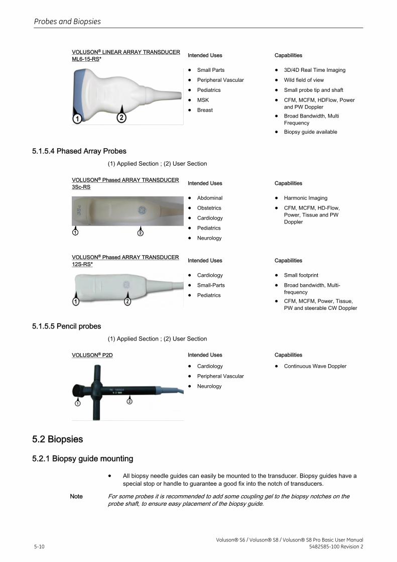
VOLUSON® LINEAR ARRAY TRANSDUCERML6-15-RS* Intended Uses Capabilities
• Small Parts
• Peripheral Vascular
• Pediatrics
• MSK
• Breast
• 3D/4D Real Time Imaging
• Wild field of view
• Small probe tip and shaft
• CFM, MCFM, HDFlow, Powerand PW Doppler
• Broad Bandwidth, MultiFrequency
• Biopsy guide available
5.1.5.4 Phased Array Probes(1) Applied Section ; (2) User Section
VOLUSON® Phased ARRAY TRANSDUCER3Sc-RS Intended Uses Capabilities
• Abdominal
• Obstetrics
• Cardiology
• Pediatrics
• Neurology
• Harmonic Imaging
• CFM, MCFM, HD-Flow,Power, Tissue and PWDoppler
VOLUSON® Phased ARRAY TRANSDUCER12S-RS* Intended Uses Capabilities
• Cardiology
• Small-Parts
• Pediatrics
• Small footprint
• Broad bandwidth, Multi-frequency
• CFM, MCFM, Power, Tissue,PW and steerable CW Doppler
5.1.5.5 Pencil probes(1) Applied Section ; (2) User Section
VOLUSON® P2D Intended Uses Capabilities
• Cardiology
• Peripheral Vascular
• Neurology
• Continuous Wave Doppler
5.2 Biopsies
5.2.1 Biopsy guide mounting
• All biopsy needle guides can easily be mounted to the transducer. Biopsy guides have aspecial stop or handle to guarantee a good fix into the notch of transducers.
Note For some probes it is recommended to add some coupling gel to the biopsy notches on theprobe shaft, to ensure easy placement of the biopsy guide.
Probes and Biopsies
5-10Voluson® S6 / Voluson® S8 / Voluson® S8 Pro Basic User Manual
5482585-100 Revision 2

Ensure the correct position and optimal fit every time before using a biopsy guide! Thestainless steel tube (and the bore inside) of the biopsy needle guide must be sterile.
Refer to the biopsy guide’s user manual for detailed information on how to mount and use thebiopsy guide.
• The cold-sterilized transducer can be kept sterile by placing a sterile sheath over theshaft (sterile coupling gel between transducer and sheath).
Technical data:The materials of all reusable biopsy needle guides are stainless steel type 304 and 303 (AISINo).Sterilization for reusable biopsy needle guides:Autoclaving (moist heat) 121ºC for 20 minutes (3 Pre-Vaccum-cycles) or 134ºC for 5 minutesRecommended minimum sterilization level SAL 10-6 .
E8333JB(Disposable) for Curved Array Transducer E8C-RS
Press the needle guide onto thetransducer shaft so that the smallswelling of the needle guide catchesin the notch at the transducer tip.
E8385MJ(Disposable) for Curved Array Transducer E8C-RS
Press the needle guide onto thetransducer shaft so that the smallswelling of the needle guide catchesin the notch at the transducer tip.
H40412LN(Reusable) for Curved Array Transducer E8C-RS
Place the needle guide onto thetransducer; push it forward until thebracket catches in the support on thehousing of the probe. Fix the biopsyguide by means of the knurled screw.
PEC 63 for Voluson® Endocavity Transducer RIC5-9W-RS
Press the needle guide onto thetransducer shaft and push it forwarduntil the small swelling of the needleguide catches in the notch at thetransducer tip.
H48681GF/H48691Z for Voluson® Endocavity Transducer RIC5-9W-RS
Press the needle guide onto thetransducer shaft and push it forwarduntil the small swelling of the needleguide catches in the notch at thetransducer tip.
Probes and Biopsies
Voluson® S6 / Voluson® S8 / Voluson® S8 Pro Basic User Manual5482585-100 Revision 2 5-11
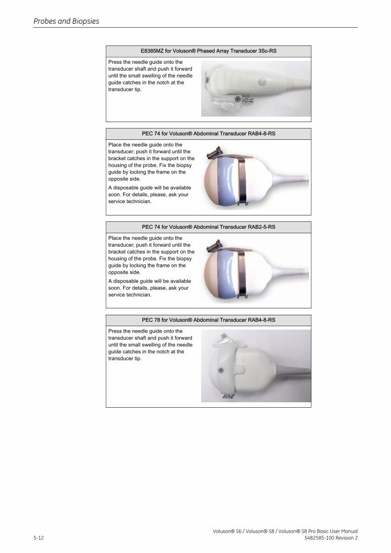
E8385MZ for Voluson® Phased Array Transducer 3Sc-RS
Press the needle guide onto thetransducer shaft and push it forwarduntil the small swelling of the needleguide catches in the notch at thetransducer tip.
PEC 74 for Voluson® Abdominal Transducer RAB4-8-RS
Place the needle guide onto thetransducer; push it forward until thebracket catches in the support on thehousing of the probe. Fix the biopsyguide by locking the frame on theopposite side.A disposable guide will be availablesoon. For details, please, ask yourservice technician.
PEC 74 for Voluson® Abdominal Transducer RAB2-5-RS
Place the needle guide onto thetransducer; push it forward until thebracket catches in the support on thehousing of the probe. Fix the biopsyguide by locking the frame on theopposite side.A disposable guide will be availablesoon. For details, please, ask yourservice technician.
PEC 78 for Voluson® Abdominal Transducer RAB4-8-RS
Press the needle guide onto thetransducer shaft and push it forwarduntil the small swelling of the needleguide catches in the notch at thetransducer tip.
Probes and Biopsies
5-12Voluson® S6 / Voluson® S8 / Voluson® S8 Pro Basic User Manual
5482585-100 Revision 2
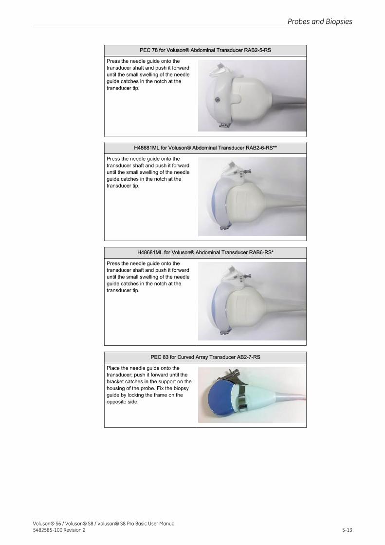
PEC 78 for Voluson® Abdominal Transducer RAB2-5-RS
Press the needle guide onto thetransducer shaft and push it forwarduntil the small swelling of the needleguide catches in the notch at thetransducer tip.
H48681ML for Voluson® Abdominal Transducer RAB2-6-RS**
Press the needle guide onto thetransducer shaft and push it forwarduntil the small swelling of the needleguide catches in the notch at thetransducer tip.
H48681ML for Voluson® Abdominal Transducer RAB6-RS*
Press the needle guide onto thetransducer shaft and push it forwarduntil the small swelling of the needleguide catches in the notch at thetransducer tip.
PEC 83 for Curved Array Transducer AB2-7-RS
Place the needle guide onto thetransducer; push it forward until thebracket catches in the support on thehousing of the probe. Fix the biopsyguide by locking the frame on theopposite side.
Probes and Biopsies
Voluson® S6 / Voluson® S8 / Voluson® S8 Pro Basic User Manual5482585-100 Revision 2 5-13
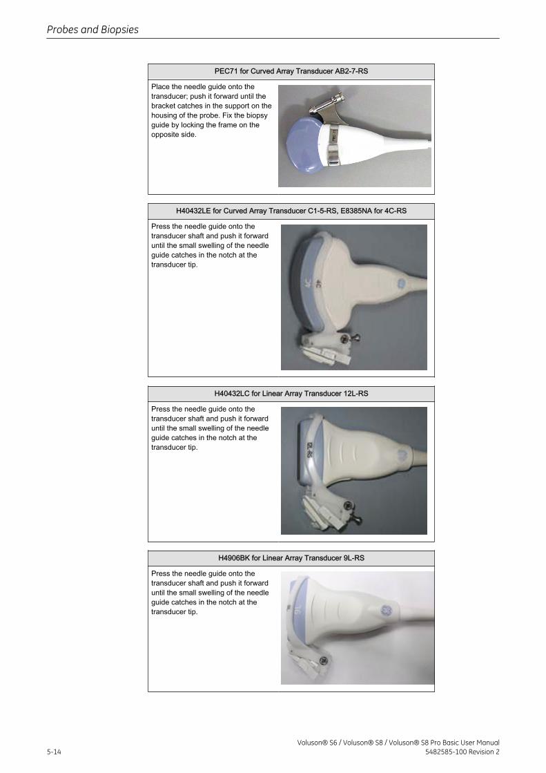
PEC71 for Curved Array Transducer AB2-7-RS
Place the needle guide onto thetransducer; push it forward until thebracket catches in the support on thehousing of the probe. Fix the biopsyguide by locking the frame on theopposite side.
H40432LE for Curved Array Transducer C1-5-RS, E8385NA for 4C-RS
Press the needle guide onto thetransducer shaft and push it forwarduntil the small swelling of the needleguide catches in the notch at thetransducer tip.
H40432LC for Linear Array Transducer 12L-RS
Press the needle guide onto thetransducer shaft and push it forwarduntil the small swelling of the needleguide catches in the notch at thetransducer tip.
H4906BK for Linear Array Transducer 9L-RS
Press the needle guide onto thetransducer shaft and push it forwarduntil the small swelling of the needleguide catches in the notch at thetransducer tip.
Probes and Biopsies
5-14Voluson® S6 / Voluson® S8 / Voluson® S8 Pro Basic User Manual
5482585-100 Revision 2
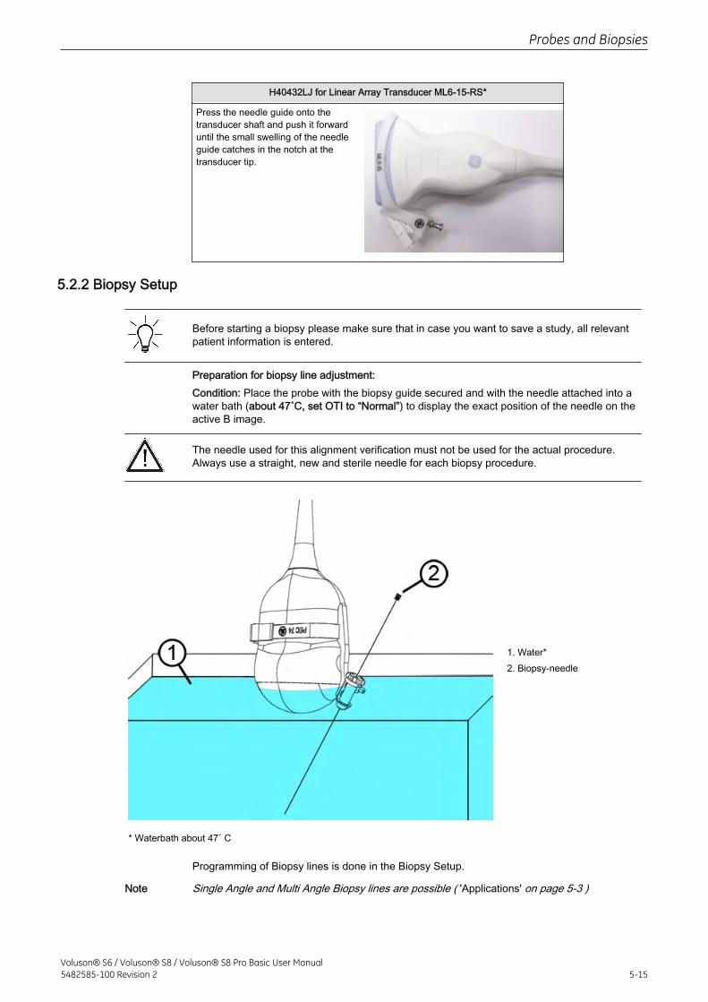
H40432LJ for Linear Array Transducer ML6-15-RS*
Press the needle guide onto thetransducer shaft and push it forwarduntil the small swelling of the needleguide catches in the notch at thetransducer tip.
5.2.2 Biopsy Setup
Before starting a biopsy please make sure that in case you want to save a study, all relevantpatient information is entered.
Preparation for biopsy line adjustment:Condition: Place the probe with the biopsy guide secured and with the needle attached into awater bath (about 47˚C, set OTI to “Normal”) to display the exact position of the needle on theactive B image.
The needle used for this alignment verification must not be used for the actual procedure.Always use a straight, new and sterile needle for each biopsy procedure.
1. Water*2. Biopsy-needle
* Waterbath about 47˚ C
Programming of Biopsy lines is done in the Biopsy Setup.
Note Single Angle and Multi Angle Biopsy lines are possible ( 'Applications' on page 5-3 )
Probes and Biopsies
Voluson® S6 / Voluson® S8 / Voluson® S8 Pro Basic User Manual5482585-100 Revision 2 5-15
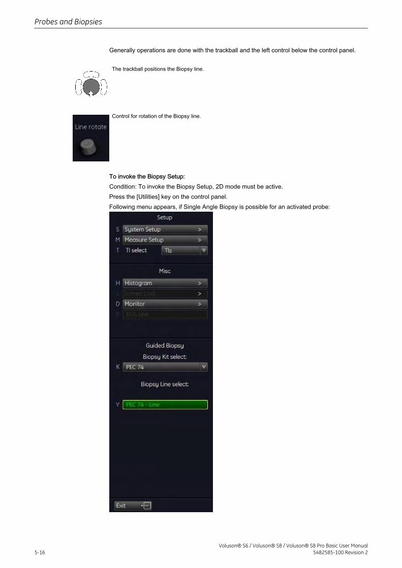
Generally operations are done with the trackball and the left control below the control panel.
The trackball positions the Biopsy line.
Control for rotation of the Biopsy line.
To invoke the Biopsy Setup:Condition: To invoke the Biopsy Setup, 2D mode must be active.Press the [Utilities] key on the control panel.Following menu appears, if Single Angle Biopsy is possible for an activated probe:
Probes and Biopsies
5-16Voluson® S6 / Voluson® S8 / Voluson® S8 Pro Basic User Manual
5482585-100 Revision 2
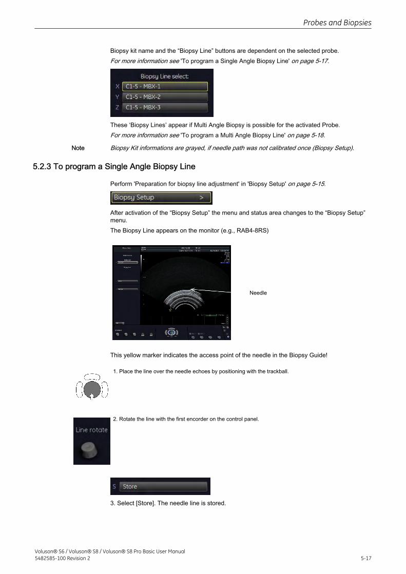
Biopsy kit name and the “Biopsy Line” buttons are dependent on the selected probe.For more information see 'To program a Single Angle Biopsy Line' on page 5-17.
These ‘Biopsy Lines’ appear if Multi Angle Biopsy is possible for the activated Probe.For more information see 'To program a Multi Angle Biopsy Line' on page 5-18.
Note Biopsy Kit informations are grayed, if needle path was not calibrated once (Biopsy Setup).
5.2.3 To program a Single Angle Biopsy Line
Perform 'Preparation for biopsy line adjustment' in 'Biopsy Setup' on page 5-15.
After activation of the “Biopsy Setup” the menu and status area changes to the “Biopsy Setup”menu.The Biopsy Line appears on the monitor (e.g., RAB4-8RS)
Needle
This yellow marker indicates the access point of the needle in the Biopsy Guide!
1. Place the line over the needle echoes by positioning with the trackball.
2. Rotate the line with the first encorder on the control panel.
3. Select [Store]. The needle line is stored.
Probes and Biopsies
Voluson® S6 / Voluson® S8 / Voluson® S8 Pro Basic User Manual5482585-100 Revision 2 5-17
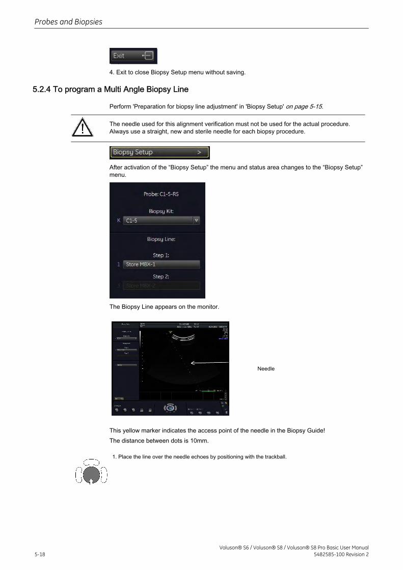
4. Exit to close Biopsy Setup menu without saving.
5.2.4 To program a Multi Angle Biopsy Line
Perform 'Preparation for biopsy line adjustment' in 'Biopsy Setup' on page 5-15.
The needle used for this alignment verification must not be used for the actual procedure.Always use a straight, new and sterile needle for each biopsy procedure.
After activation of the “Biopsy Setup” the menu and status area changes to the “Biopsy Setup”menu.
The Biopsy Line appears on the monitor.
Needle
This yellow marker indicates the access point of the needle in the Biopsy Guide!The distance between dots is 10mm.
1. Place the line over the needle echoes by positioning with the trackball.
Probes and Biopsies
5-18Voluson® S6 / Voluson® S8 / Voluson® S8 Pro Basic User Manual
5482585-100 Revision 2
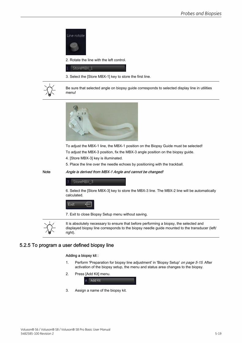
2. Rotate the line with the left control.
3. Select the [Store MBX-1] key to store the first line.
Be sure that selected angle on biopsy guide corresponds to selected display line in utilitiesmenu!
To adjust the MBX-1 line, the MBX-1 position on the Biopsy Guide must be selected!To adjust the MBX-3 position, fix the MBX-3 angle position on the biopsy guide.4. [Store MBX-3] key is illuminated.5. Place the line over the needle echoes by positioning with the trackball.
Note Angle is derived from MBX-1 Angle and cannot be changed!
6. Select the [Store MBX-3] key to store the MBX-3 line. The MBX-2 line will be automaticallycalculated.
7. Exit to close Biopsy Setup menu without saving.
It is absolutely necessary to ensure that before performing a biopsy, the selected anddisplayed biopsy line corresponds to the biopsy needle guide mounted to the transducer (left/right).
5.2.5 To program a user defined biopsy line
Adding a biopsy kit :
1. Perform 'Preparation for biopsy line adjustment' in 'Biopsy Setup' on page 5-15. Afteractivation of the biopsy setup, the menu and status area changes to the biopsy.
2. Press [Add Kit] menu.
3. Assign a name of the biopsy kit.
Probes and Biopsies
Voluson® S6 / Voluson® S8 / Voluson® S8 Pro Basic User Manual5482585-100 Revision 2 5-19
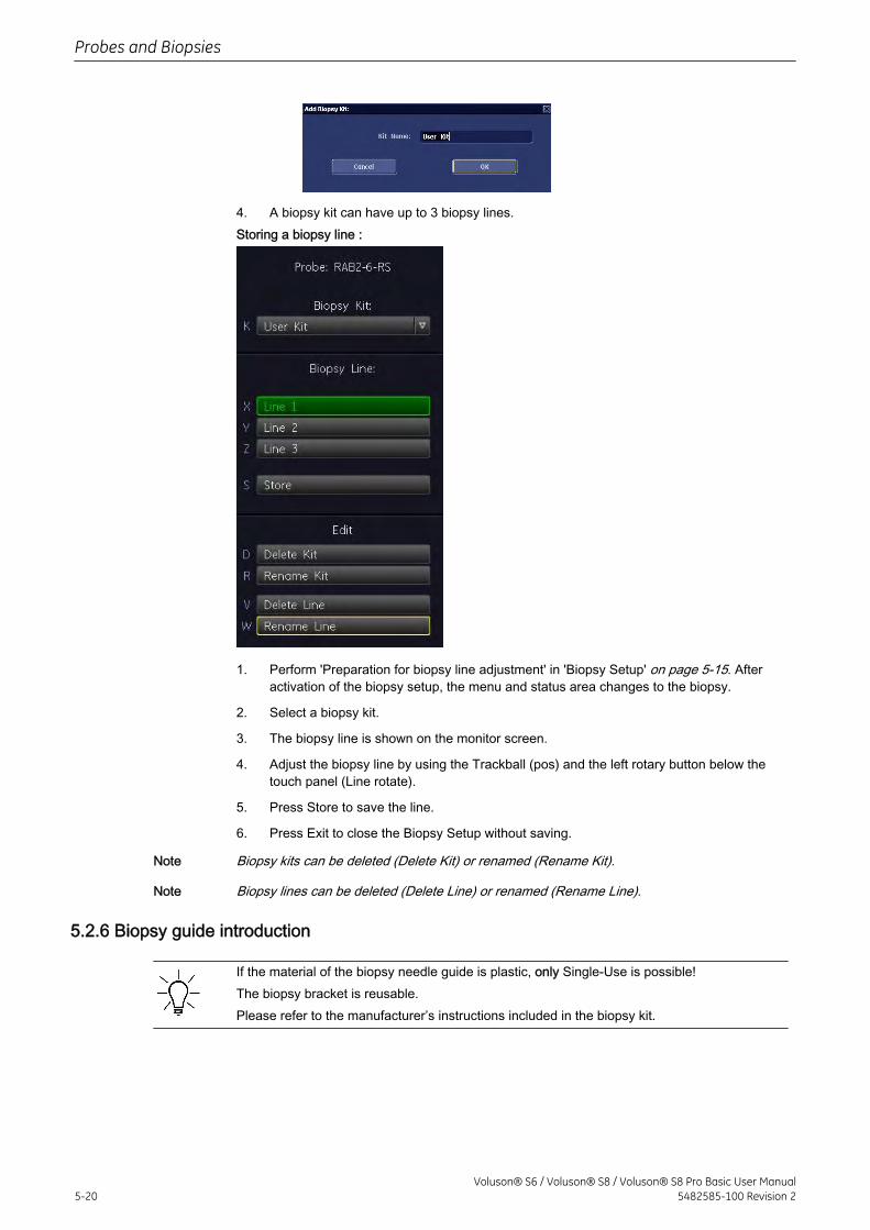
4. A biopsy kit can have up to 3 biopsy lines.Storing a biopsy line :
1. Perform 'Preparation for biopsy line adjustment' in 'Biopsy Setup' on page 5-15. Afteractivation of the biopsy setup, the menu and status area changes to the biopsy.
2. Select a biopsy kit.
3. The biopsy line is shown on the monitor screen.
4. Adjust the biopsy line by using the Trackball (pos) and the left rotary button below thetouch panel (Line rotate).
5. Press Store to save the line.
6. Press Exit to close the Biopsy Setup without saving.
Note Biopsy kits can be deleted (Delete Kit) or renamed (Rename Kit).
Note Biopsy lines can be deleted (Delete Line) or renamed (Rename Line).
5.2.6 Biopsy guide introduction
If the material of the biopsy needle guide is plastic, only Single-Use is possible!The biopsy bracket is reusable.Please refer to the manufacturer’s instructions included in the biopsy kit.
Probes and Biopsies
5-20Voluson® S6 / Voluson® S8 / Voluson® S8 Pro Basic User Manual
5482585-100 Revision 2
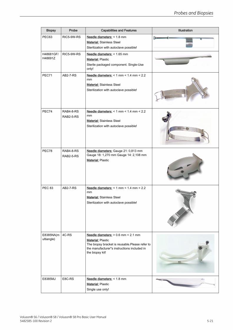
Biopsy Probe Capabilities and Features Illustration
PEC63 RIC5-9W-RS Needle diameters: < 1.8 mmMaterial: Stainless SteelSterilization with autoclave possible!
H48681GF/H48691Z
RIC5-9W-RS Needle diameters: < 1.65 mmMaterial: PlasticSterile packaged component. Single-Useonly!
PEC71 AB2-7-RS Needle diameters: < 1 mm < 1.4 mm < 2.2mmMaterial: Stainless SteelSterilization with autoclave possible!
PEC74 RAB4-8-RSRAB2-5-RS
Needle diameters: < 1 mm < 1.4 mm < 2.2mmMaterial: Stainless SteelSterilization with autoclave possible!
PEC78 RAB4-8-RSRAB2-5-RS
Needle diameters: Gauge 21: 0,813 mmGauge 18: 1,270 mm Gauge 14: 2,108 mmMaterial: Plastic
PEC 83 AB2-7-RS Needle diameters: < 1 mm < 1.4 mm < 2.2mmMaterial: Stainless SteelSterilization with autoclave possible!
E8385NA(multiangle)
4C-RS Needle diameters: > 0.6 mm < 2.1 mmMaterial: PlasticThe biopsy bracket is reusable.Please refer tothe manufacturer"s instructions included inthe biopsy kit!
E8385MJ E8C-RS Needle diameters: < 1.8 mmMaterial: PlasticSingle use only!
Probes and Biopsies
Voluson® S6 / Voluson® S8 / Voluson® S8 Pro Basic User Manual5482585-100 Revision 2 5-21
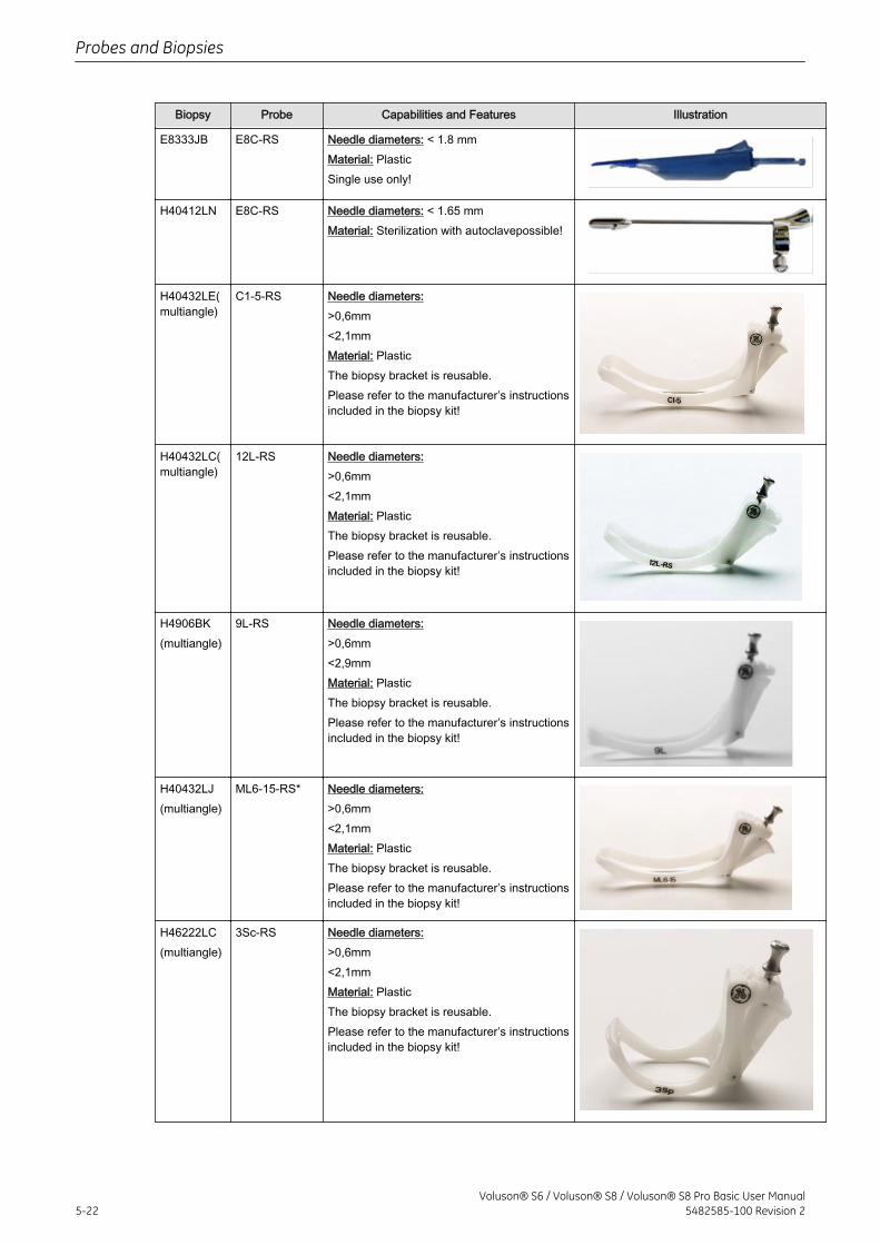
Biopsy Probe Capabilities and Features Illustration
E8333JB E8C-RS Needle diameters: < 1.8 mmMaterial: PlasticSingle use only!
H40412LN E8C-RS Needle diameters: < 1.65 mmMaterial: Sterilization with autoclavepossible!
H40432LE(multiangle)
C1-5-RS Needle diameters:>0,6mm<2,1mmMaterial: PlasticThe biopsy bracket is reusable.Please refer to the manufacturer’s instructionsincluded in the biopsy kit!
H40432LC(multiangle)
12L-RS Needle diameters:>0,6mm<2,1mmMaterial: PlasticThe biopsy bracket is reusable.Please refer to the manufacturer’s instructionsincluded in the biopsy kit!
H4906BK(multiangle)
9L-RS Needle diameters:>0,6mm<2,9mmMaterial: PlasticThe biopsy bracket is reusable.Please refer to the manufacturer’s instructionsincluded in the biopsy kit!
H40432LJ(multiangle)
ML6-15-RS* Needle diameters:>0,6mm<2,1mmMaterial: PlasticThe biopsy bracket is reusable.Please refer to the manufacturer’s instructionsincluded in the biopsy kit!
H46222LC(multiangle)
3Sc-RS Needle diameters:>0,6mm<2,1mmMaterial: PlasticThe biopsy bracket is reusable.Please refer to the manufacturer’s instructionsincluded in the biopsy kit!
Probes and Biopsies
5-22Voluson® S6 / Voluson® S8 / Voluson® S8 Pro Basic User Manual
5482585-100 Revision 2
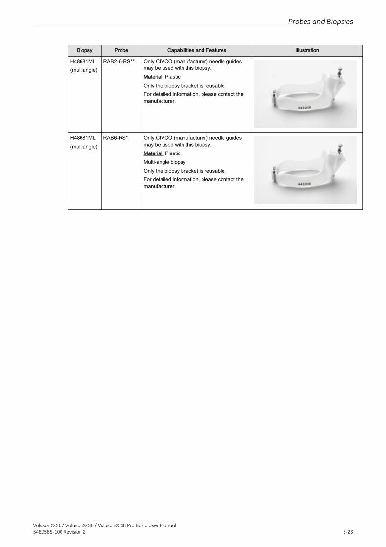
Biopsy Probe Capabilities and Features Illustration
H48681ML(multiangle)
RAB2-6-RS** Only CIVCO (manufacturer) needle guidesmay be used with this biopsy.Material: PlasticOnly the biopsy bracket is reusable.For detailed information, please contact themanufacturer.
H48681ML(multiangle)
RAB6-RS* Only CIVCO (manufacturer) needle guidesmay be used with this biopsy.Material: PlasticMulti-angle biopsyOnly the biopsy bracket is reusable.For detailed information, please contact themanufacturer.
Probes and Biopsies
Voluson® S6 / Voluson® S8 / Voluson® S8 Pro Basic User Manual5482585-100 Revision 2 5-23

This page was intentionally left blank.
Probes and Biopsies
5-24Voluson® S6 / Voluson® S8 / Voluson® S8 Pro Basic User Manual
5482585-100 Revision 2
Chapter 6
2D Mode
Describes the general functions of the 2D- Mode.Image quality is the essential performance of the system.Please read this chapter carefully.
2D Main Menu - - - - - - - - - - - - - - - - - - - - - - - - - - - - - - - - - - - - - - - - - - - - - - - - 6-22D Operation - - - - - - - - - - - - - - - - - - - - - - - - - - - - - - - - - - - - - - - - - - - - - - - - - 6-3Cine Mode - - - - - - - - - - - - - - - - - - - - - - - - - - - - - - - - - - - - - - - - - - - - - - - - - - 6-142D Sub Menu - - - - - - - - - - - - - - - - - - - - - - - - - - - - - - - - - - - - - - - - - - - - - - - 6-18Gray Map - - - - - - - - - - - - - - - - - - - - - - - - - - - - - - - - - - - - - - - - - - - - - - - - - - 6-20B-Flow - - - - - - - - - - - - - - - - - - - - - - - - - - - - - - - - - - - - - - - - - - - - - - - - - - - - 6-21XTD-View (Extended View) - - - - - - - - - - - - - - - - - - - - - - - - - - - - - - - - - - - - - - 6-24Contrast Imaging - - - - - - - - - - - - - - - - - - - - - - - - - - - - - - - - - - - - - - - - - - - - - 6-31
Voluson® S6 / Voluson® S8 / Voluson® S8 Pro Basic User Manual5482585-100 Revision 2 6-1
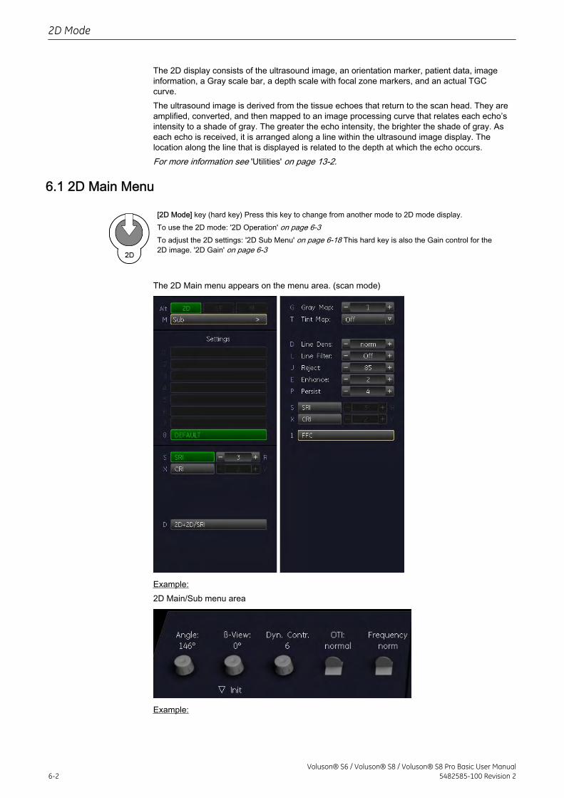
The 2D display consists of the ultrasound image, an orientation marker, patient data, imageinformation, a Gray scale bar, a depth scale with focal zone markers, and an actual TGCcurve.The ultrasound image is derived from the tissue echoes that return to the scan head. They areamplified, converted, and then mapped to an image processing curve that relates each echo’sintensity to a shade of gray. The greater the echo intensity, the brighter the shade of gray. Aseach echo is received, it is arranged along a line within the ultrasound image display. Thelocation along the line that is displayed is related to the depth at which the echo occurs.For more information see 'Utilities' on page 13-2.
6.1 2D Main Menu
[2D Mode] key (hard key) Press this key to change from another mode to 2D mode display.To use the 2D mode: '2D Operation' on page 6-3To adjust the 2D settings: '2D Sub Menu' on page 6-18 This hard key is also the Gain control for the2D image. '2D Gain' on page 6-3
The 2D Main menu appears on the menu area. (scan mode)
Example:2D Main/Sub menu area
Example:
2D Mode
6-2Voluson® S6 / Voluson® S8 / Voluson® S8 Pro Basic User Manual
5482585-100 Revision 2
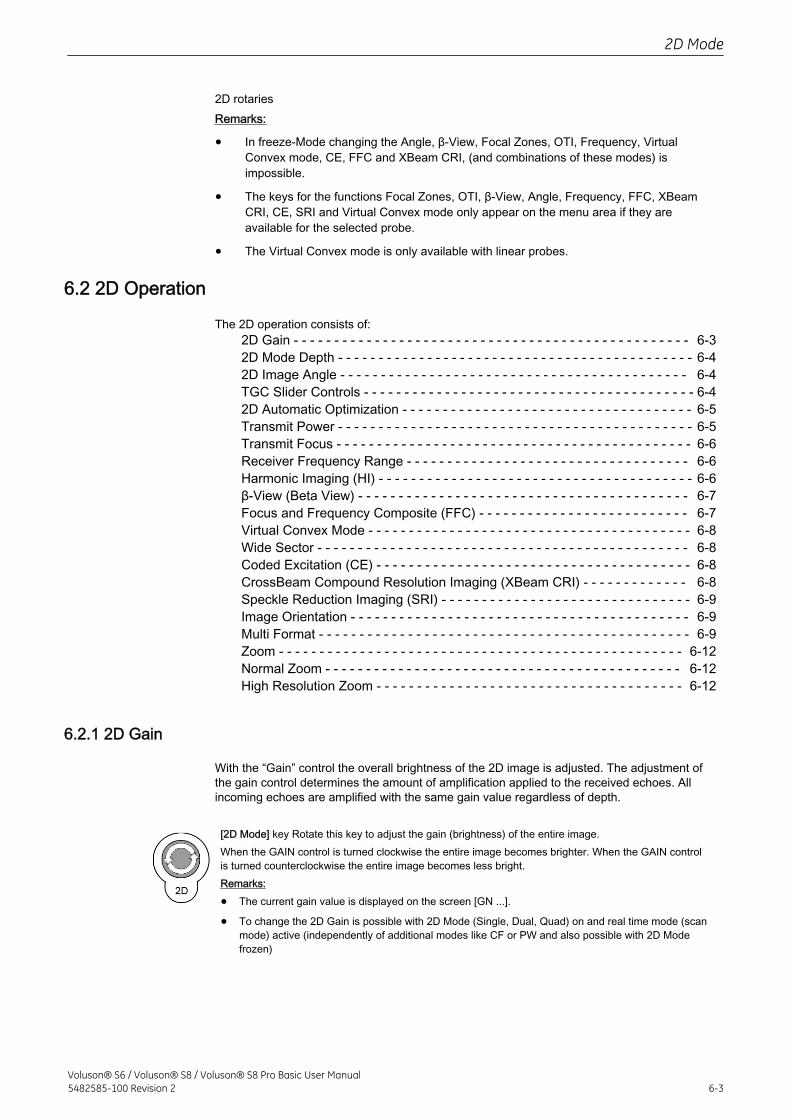
2D rotariesRemarks:
• In freeze-Mode changing the Angle, β-View, Focal Zones, OTI, Frequency, VirtualConvex mode, CE, FFC and XBeam CRI, (and combinations of these modes) isimpossible.
• The keys for the functions Focal Zones, OTI, β-View, Angle, Frequency, FFC, XBeamCRI, CE, SRI and Virtual Convex mode only appear on the menu area if they areavailable for the selected probe.
• The Virtual Convex mode is only available with linear probes.
6.2 2D Operation
The 2D operation consists of:2D Gain - - - - - - - - - - - - - - - - - - - - - - - - - - - - - - - - - - - - - - - - - - - - - - - - - 6-32D Mode Depth - - - - - - - - - - - - - - - - - - - - - - - - - - - - - - - - - - - - - - - - - - - - 6-42D Image Angle - - - - - - - - - - - - - - - - - - - - - - - - - - - - - - - - - - - - - - - - - - - 6-4TGC Slider Controls - - - - - - - - - - - - - - - - - - - - - - - - - - - - - - - - - - - - - - - - - 6-42D Automatic Optimization - - - - - - - - - - - - - - - - - - - - - - - - - - - - - - - - - - - - 6-5Transmit Power - - - - - - - - - - - - - - - - - - - - - - - - - - - - - - - - - - - - - - - - - - - - 6-5Transmit Focus - - - - - - - - - - - - - - - - - - - - - - - - - - - - - - - - - - - - - - - - - - - - 6-6Receiver Frequency Range - - - - - - - - - - - - - - - - - - - - - - - - - - - - - - - - - - - 6-6Harmonic Imaging (HI) - - - - - - - - - - - - - - - - - - - - - - - - - - - - - - - - - - - - - - - 6-6β-View (Beta View) - - - - - - - - - - - - - - - - - - - - - - - - - - - - - - - - - - - - - - - - - 6-7Focus and Frequency Composite (FFC) - - - - - - - - - - - - - - - - - - - - - - - - - - 6-7Virtual Convex Mode - - - - - - - - - - - - - - - - - - - - - - - - - - - - - - - - - - - - - - - - 6-8Wide Sector - - - - - - - - - - - - - - - - - - - - - - - - - - - - - - - - - - - - - - - - - - - - - - 6-8Coded Excitation (CE) - - - - - - - - - - - - - - - - - - - - - - - - - - - - - - - - - - - - - - - 6-8CrossBeam Compound Resolution Imaging (XBeam CRI) - - - - - - - - - - - - - 6-8Speckle Reduction Imaging (SRI) - - - - - - - - - - - - - - - - - - - - - - - - - - - - - - - 6-9Image Orientation - - - - - - - - - - - - - - - - - - - - - - - - - - - - - - - - - - - - - - - - - - 6-9Multi Format - - - - - - - - - - - - - - - - - - - - - - - - - - - - - - - - - - - - - - - - - - - - - - 6-9Zoom - - - - - - - - - - - - - - - - - - - - - - - - - - - - - - - - - - - - - - - - - - - - - - - - - - 6-12Normal Zoom - - - - - - - - - - - - - - - - - - - - - - - - - - - - - - - - - - - - - - - - - - - - 6-12High Resolution Zoom - - - - - - - - - - - - - - - - - - - - - - - - - - - - - - - - - - - - - - 6-12
6.2.1 2D Gain
With the “Gain” control the overall brightness of the 2D image is adjusted. The adjustment ofthe gain control determines the amount of amplification applied to the received echoes. Allincoming echoes are amplified with the same gain value regardless of depth.
[2D Mode] key Rotate this key to adjust the gain (brightness) of the entire image.When the GAIN control is turned clockwise the entire image becomes brighter. When the GAIN controlis turned counterclockwise the entire image becomes less bright.Remarks:
• The current gain value is displayed on the screen [GN ...].
• To change the 2D Gain is possible with 2D Mode (Single, Dual, Quad) on and real time mode (scanmode) active (independently of additional modes like CF or PW and also possible with 2D Modefrozen)
2D Mode
Voluson® S6 / Voluson® S8 / Voluson® S8 Pro Basic User Manual5482585-100 Revision 2 6-3
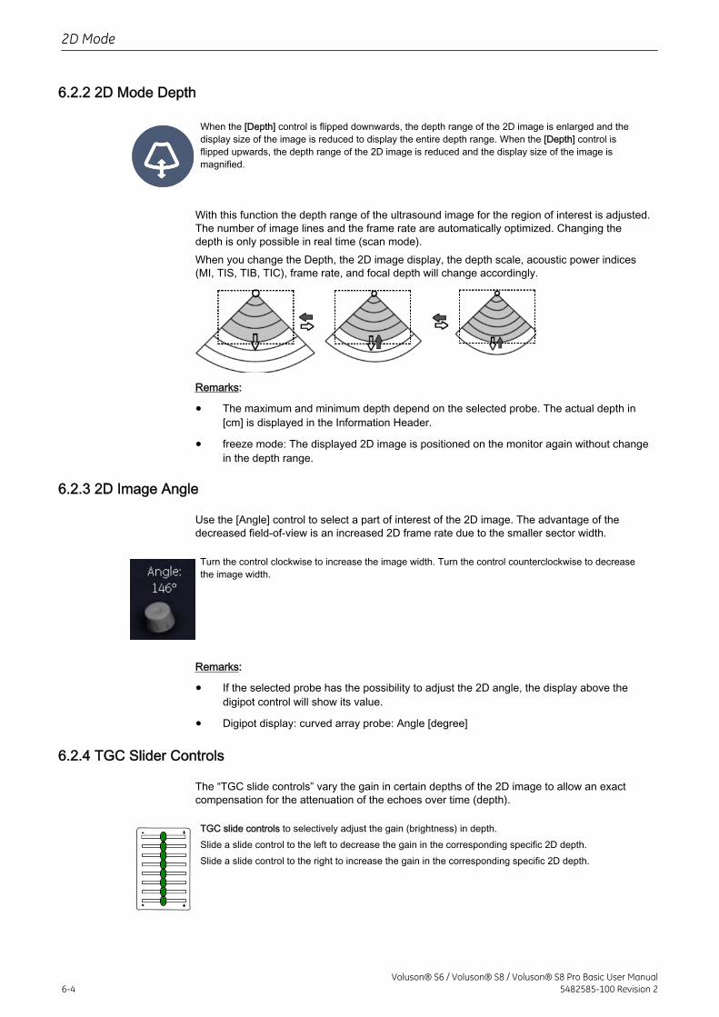
6.2.2 2D Mode Depth
When the [Depth] control is flipped downwards, the depth range of the 2D image is enlarged and thedisplay size of the image is reduced to display the entire depth range. When the [Depth] control isflipped upwards, the depth range of the 2D image is reduced and the display size of the image ismagnified.
With this function the depth range of the ultrasound image for the region of interest is adjusted.The number of image lines and the frame rate are automatically optimized. Changing thedepth is only possible in real time (scan mode).When you change the Depth, the 2D image display, the depth scale, acoustic power indices(MI, TIS, TIB, TIC), frame rate, and focal depth will change accordingly.
Remarks:
• The maximum and minimum depth depend on the selected probe. The actual depth in[cm] is displayed in the Information Header.
• freeze mode: The displayed 2D image is positioned on the monitor again without changein the depth range.
6.2.3 2D Image Angle
Use the [Angle] control to select a part of interest of the 2D image. The advantage of thedecreased field-of-view is an increased 2D frame rate due to the smaller sector width.
Turn the control clockwise to increase the image width. Τurn the control counterclockwise to decreasethe image width.
Remarks:
• If the selected probe has the possibility to adjust the 2D angle, the display above thedigipot control will show its value.
• Digipot display: curved array probe: Angle [degree]
6.2.4 TGC Slider Controls
The “TGC slide controls” vary the gain in certain depths of the 2D image to allow an exactcompensation for the attenuation of the echoes over time (depth).
TGC slide controls to selectively adjust the gain (brightness) in depth.Slide a slide control to the left to decrease the gain in the corresponding specific 2D depth.Slide a slide control to the right to increase the gain in the corresponding specific 2D depth.
2D Mode
6-4Voluson® S6 / Voluson® S8 / Voluson® S8 Pro Basic User Manual
5482585-100 Revision 2
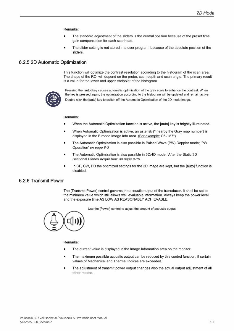
Remarks:
• The standard adjustment of the sliders is the central position because of the preset timegain compensation for each scanhead.
• The slider setting is not stored in a user program, because of the absolute position of thesliders.
6.2.5 2D Automatic Optimization
This function will optimize the contrast resolution according to the histogram of the scan area.The shape of the ROI will depend on the probe, scan depth and scan angle. The primary resultis a value for the lower and upper endpoint of the histogram.
Pressing the [auto] key causes automatic optimization of the gray scale to enhance the contrast. Whenthe key is pressed again, the optimization according to the histogram will be updated and remain active.Double-click the [auto] key to switch off the Automatic Optimization of the 2D mode image.
Remarks:
• When the Automatic Optimization function is active, the [auto] key is brightly illuminated.
• When Automatic Optimization is active, an asterisk (* nearby the Gray map number) isdisplayed in the B mode Image Info area. (For example: C5 / M7*)
• The Automatic Optimization is also possible in Pulsed Wave (PW) Doppler mode; 'PWOperation' on page 8-3
• The Automatic Optimization is also possible in 3D/4D mode; 'After the Static 3DSectional Planes Acquisition' on page 9-19
• In CF, CW, PD the optimized settings for the 2D image are kept, but the [auto] function isdisabled.
6.2.6 Transmit Power
The [Transmit Power] control governs the acoustic output of the transducer. It shall be set tothe minimum value which still allows well evaluable information. Always keep the power leveland the exposure time AS LOW AS REASONABLY ACHIEVABLE.
Use the [Power] control to adjust the amount of acoustic output.
Remarks:
• The current value is displayed in the Image Information area on the monitor.
• The maximum possible acoustic output can be reduced by this control function, if certainvalues of Mechanical and Thermal Indices are exceeded.
• The adjustment of transmit power output changes also the actual output adjustment of allother modes.
2D Mode
Voluson® S6 / Voluson® S8 / Voluson® S8 Pro Basic User Manual5482585-100 Revision 2 6-5
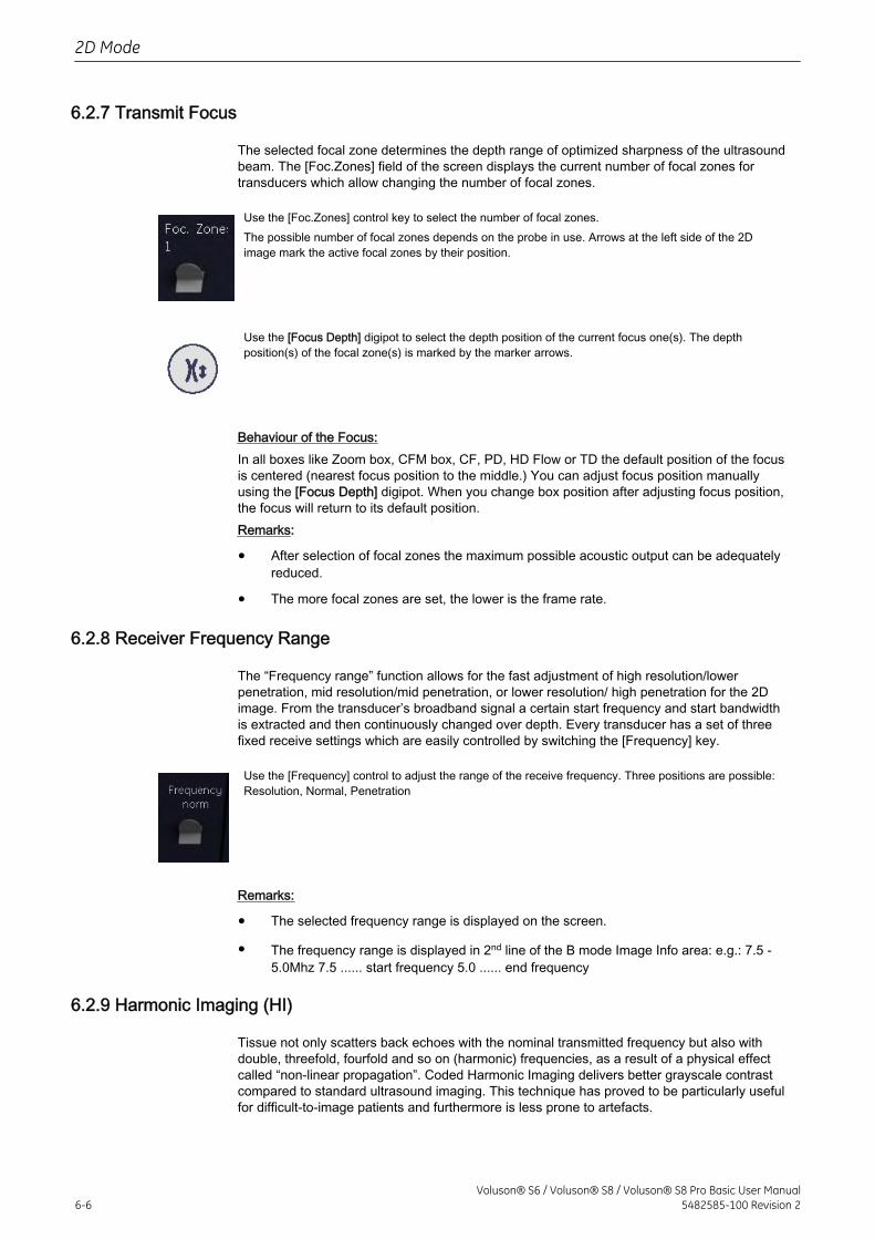
6.2.7 Transmit Focus
The selected focal zone determines the depth range of optimized sharpness of the ultrasoundbeam. The [Foc.Zones] field of the screen displays the current number of focal zones fortransducers which allow changing the number of focal zones.
Use the [Foc.Zones] control key to select the number of focal zones.The possible number of focal zones depends on the probe in use. Arrows at the left side of the 2Dimage mark the active focal zones by their position.
Use the [Focus Depth] digipot to select the depth position of the current focus one(s). The depthposition(s) of the focal zone(s) is marked by the marker arrows.
Behaviour of the Focus:In all boxes like Zoom box, CFM box, CF, PD, HD Flow or TD the default position of the focusis centered (nearest focus position to the middle.) You can adjust focus position manuallyusing the [Focus Depth] digipot. When you change box position after adjusting focus position,the focus will return to its default position.Remarks:
• After selection of focal zones the maximum possible acoustic output can be adequatelyreduced.
• The more focal zones are set, the lower is the frame rate.
6.2.8 Receiver Frequency Range
The “Frequency range” function allows for the fast adjustment of high resolution/lowerpenetration, mid resolution/mid penetration, or lower resolution/ high penetration for the 2Dimage. From the transducer’s broadband signal a certain start frequency and start bandwidthis extracted and then continuously changed over depth. Every transducer has a set of threefixed receive settings which are easily controlled by switching the [Frequency] key.
Use the [Frequency] control to adjust the range of the receive frequency. Three positions are possible:Resolution, Normal, Penetration
Remarks:
• The selected frequency range is displayed on the screen.
• The frequency range is displayed in 2nd line of the B mode Image Info area: e.g.: 7.5 -5.0Mhz 7.5 ...... start frequency 5.0 ...... end frequency
6.2.9 Harmonic Imaging (HI)
Tissue not only scatters back echoes with the nominal transmitted frequency but also withdouble, threefold, fourfold and so on (harmonic) frequencies, as a result of a physical effectcalled “non-linear propagation”. Coded Harmonic Imaging delivers better grayscale contrastcompared to standard ultrasound imaging. This technique has proved to be particularly usefulfor difficult-to-image patients and furthermore is less prone to artefacts.
2D Mode
6-6Voluson® S6 / Voluson® S8 / Voluson® S8 Pro Basic User Manual
5482585-100 Revision 2
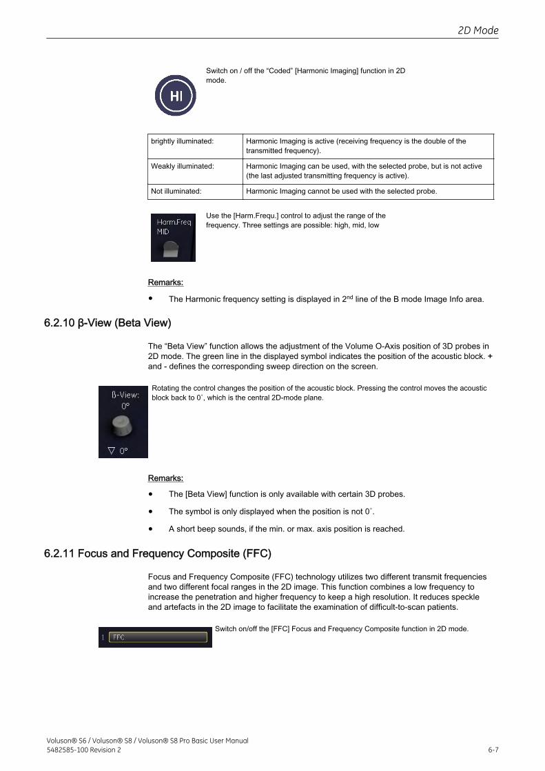
Switch on / off the “Coded” [Harmonic Imaging] function in 2Dmode.
brightly illuminated: Harmonic Imaging is active (receiving frequency is the double of thetransmitted frequency).
Weakly illuminated: Harmonic Imaging can be used, with the selected probe, but is not active(the last adjusted transmitting frequency is active).
Not illuminated: Harmonic Imaging cannot be used with the selected probe.
Use the [Harm.Frequ.] control to adjust the range of thefrequency. Three settings are possible: high, mid, low
Remarks:
• The Harmonic frequency setting is displayed in 2nd line of the B mode Image Info area.
6.2.10 β-View (Beta View)
The “Beta View” function allows the adjustment of the Volume O-Axis position of 3D probes in2D mode. The green line in the displayed symbol indicates the position of the acoustic block. +and - defines the corresponding sweep direction on the screen.
Rotating the control changes the position of the acoustic block. Pressing the control moves the acousticblock back to 0˚, which is the central 2D-mode plane.
Remarks:
• The [Beta View] function is only available with certain 3D probes.
• The symbol is only displayed when the position is not 0˚.
• A short beep sounds, if the min. or max. axis position is reached.
6.2.11 Focus and Frequency Composite (FFC)
Focus and Frequency Composite (FFC) technology utilizes two different transmit frequenciesand two different focal ranges in the 2D image. This function combines a low frequency toincrease the penetration and higher frequency to keep a high resolution. It reduces speckleand artefacts in the 2D image to facilitate the examination of difficult-to-scan patients.
Switch on/off the [FFC] Focus and Frequency Composite function in 2D mode.
2D Mode
Voluson® S6 / Voluson® S8 / Voluson® S8 Pro Basic User Manual5482585-100 Revision 2 6-7
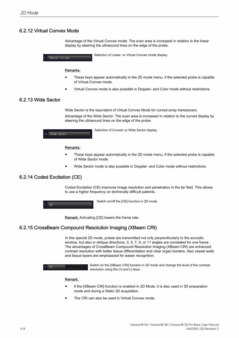
6.2.12 Virtual Convex Mode
Advantage of the Virtual Convex mode: The scan area is increased in relation to the lineardisplay by steering the ultrasound lines on the edge of the probe.
Selection of Linear- or Virtual Convex mode display.
Remarks:
• These keys appear automatically in the 2D mode menu, if the selected probe is capableof Virtual Convex mode.
• Virtual Convex mode is also possible in Doppler- and Color mode without restrictions.
6.2.13 Wide Sector
Wide Sector is the equivalent of Virtual Convex Mode for curved array transducers.Advantage of the Wide Sector: The scan area is increased in relation to the curved display bysteering the ultrasound lines on the edge of the probe.
Selection of Curved- or Wide Sector display.
Remarks:
• These keys appear automatically in the 2D mode menu, if the selected probe is capableof Wide Sector mode.
• Wide Sector mode is also possible in Doppler- and Color mode without restrictions.
6.2.14 Coded Excitation (CE)
Coded Excitation (CE) improves image resolution and penetration in the far field. This allowsto use a higher frequency on technically difficult patients.
Switch on/off the [CE] function in 2D mode.
Remark: Activating [CE] lowers the frame rate.
6.2.15 CrossBeam Compound Resolution Imaging (XBeam CRI)
In this special 2D mode, pulses are transmitted not only perpendicularly to the acousticwindow, but also in oblique directions. 3, 5, 7, 9, or 11 angles are correlated for one frame.The advantages of CrossBeam Compound Resolution Imaging (XBeam CRI) are enhancedcontrast resolution with better tissue differentiation and clear organ borders. Also vessel wallsand tissue layers are emphasized for easier recognition.
Switch on the [XBeam CRI] function in 2D mode and change the level of the contrastresolution using the [+] and [-] keys.
Remark:
• If the [XBeam CRI] function is enabled in 2D Mode, it is also used in 3D preparationmode and during a Static 3D acquisition.
• The CRI can also be used in Virtual Convex mode.
2D Mode
6-8Voluson® S6 / Voluson® S8 / Voluson® S8 Pro Basic User Manual
5482585-100 Revision 2
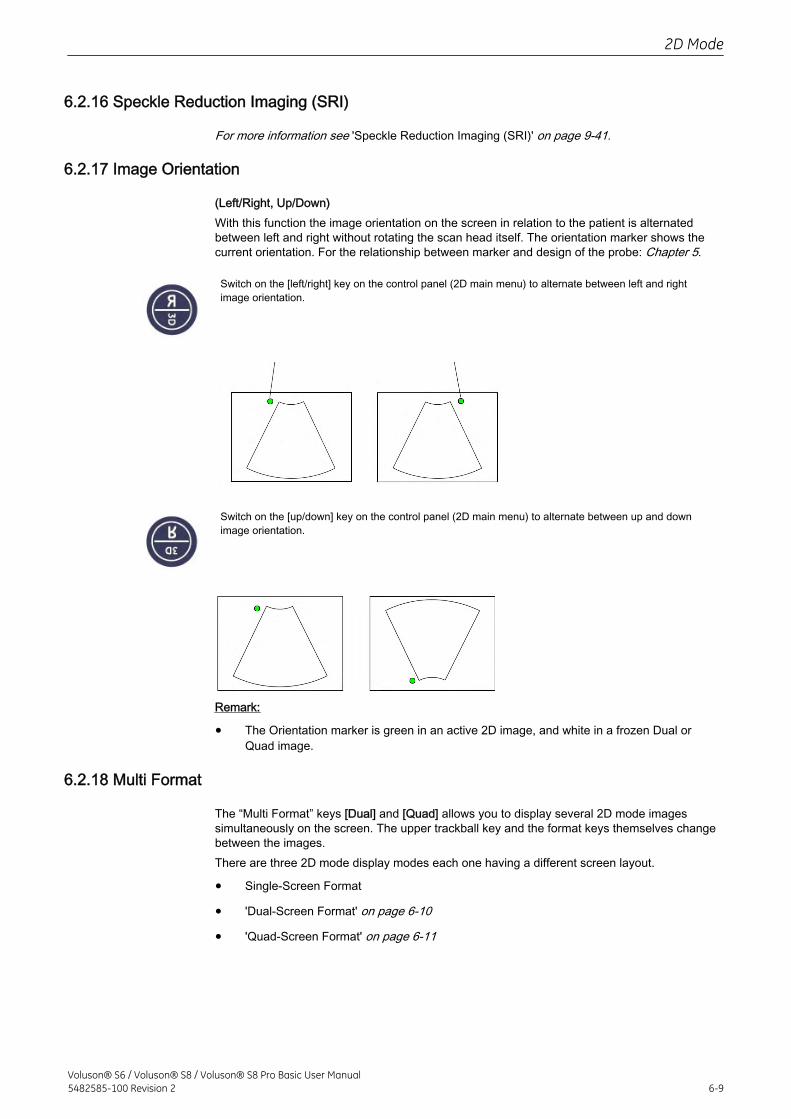
6.2.16 Speckle Reduction Imaging (SRI)
For more information see 'Speckle Reduction Imaging (SRI)' on page 9-41.
6.2.17 Image Orientation
(Left/Right, Up/Down)With this function the image orientation on the screen in relation to the patient is alternatedbetween left and right without rotating the scan head itself. The orientation marker shows thecurrent orientation. For the relationship between marker and design of the probe: Chapter 5.
Switch on the [left/right] key on the control panel (2D main menu) to alternate between left and rightimage orientation.
Switch on the [up/down] key on the control panel (2D main menu) to alternate between up and downimage orientation.
Remark:
• The Orientation marker is green in an active 2D image, and white in a frozen Dual orQuad image.
6.2.18 Multi Format
The “Multi Format” keys [Dual] and [Quad] allows you to display several 2D mode imagessimultaneously on the screen. The upper trackball key and the format keys themselves changebetween the images.There are three 2D mode display modes each one having a different screen layout.
• Single-Screen Format
• 'Dual-Screen Format' on page 6-10
• 'Quad-Screen Format' on page 6-11
2D Mode
Voluson® S6 / Voluson® S8 / Voluson® S8 Pro Basic User Manual5482585-100 Revision 2 6-9
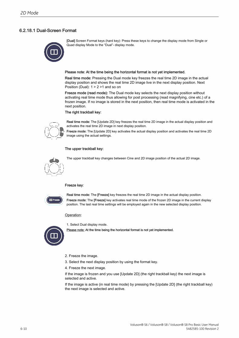
6.2.18.1 Dual-Screen Format
[Dual] Screen Format keys (hard key): Press these keys to change the display mode from Single orQuad display Mode to the “Dual”- display mode.
Please note: At the time being the horizontal format is not yet implemented.Real time mode: Pressing the Dual mode key freezes the real time 2D image in the actualdisplay position and shows the real time 2D image live in the next display position. NextPosition (Dual): 1 > 2 >1 and so onFreeze mode (read mode): The Dual mode key selects the next display position withoutactivating real time mode thus allowing for post processing (read magnifying, cine etc.) of afrozen image. If no image is stored in the next position, then real time mode is activated in thenext position.The right trackball key:
Real time mode: The [Update 2D] key freezes the real time 2D image in the actual display position andactivates the real time 2D image in next display position.Freeze mode: The [Update 2D] key activates the actual display position and activates the real time 2Dimage using the actual settings.
The upper trackball key:
The upper trackball key changes between Cine and 2D image position of the actual 2D image.
Freeze key:
Real time mode: The [Freeze] key freezes the real time 2D image in the actual display position.Freeze mode: The [Freeze] key activates real time mode of the frozen 2D image in the current displayposition. The last real time settings will be employed again in the new selected display position.
Operation:
1. Select Dual display mode.Please note: At the time being the horizontal format is not yet implemented.
2. Freeze the image.3. Select the next display position by using the format key.4. Freeze the next image.If the image is frozen and you use [Update 2D] (the right trackball key) the next image isselected and active.If the image is active (in real time mode) by pressing the [Update 2D] (the right trackball key)the next image is selected and active.
2D Mode
6-10Voluson® S6 / Voluson® S8 / Voluson® S8 Pro Basic User Manual
5482585-100 Revision 2
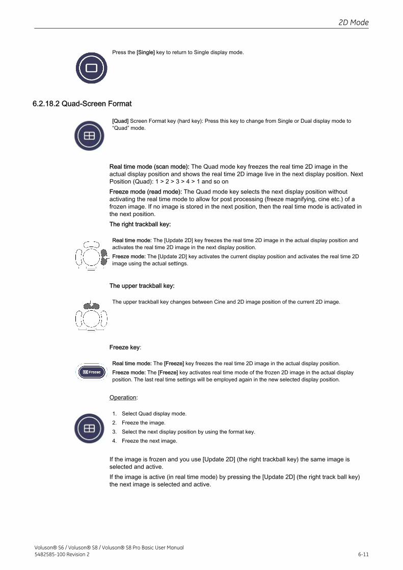
Press the [Single] key to return to Single display mode.
6.2.18.2 Quad-Screen Format
[Quad] Screen Format key (hard key): Press this key to change from Single or Dual display mode to“Quad” mode.
Real time mode (scan mode): The Quad mode key freezes the real time 2D image in theactual display position and shows the real time 2D image live in the next display position. NextPosition (Quad): 1 > 2 > 3 > 4 > 1 and so onFreeze mode (read mode): The Quad mode key selects the next display position withoutactivating the real time mode to allow for post processing (freeze magnifying, cine etc.) of afrozen image. If no image is stored in the next position, then the real time mode is activated inthe next position.The right trackball key:
Real time mode: The [Update 2D] key freezes the real time 2D image in the actual display position andactivates the real time 2D image in the next display position.Freeze mode: The [Update 2D] key activates the current display position and activates the real time 2Dimage using the actual settings.
The upper trackball key:
The upper trackball key changes between Cine and 2D image position of the current 2D image.
Freeze key:
Real time mode: The [Freeze] key freezes the real time 2D image in the actual display position.Freeze mode: The [Freeze] key activates real time mode of the frozen 2D image in the actual displayposition. The last real time settings will be employed again in the new selected display position.
Operation:
1. Select Quad display mode.2. Freeze the image.3. Select the next display position by using the format key.4. Freeze the next image.
If the image is frozen and you use [Update 2D] (the right trackball key) the same image isselected and active.If the image is active (in real time mode) by pressing the [Update 2D] (the right track ball key)the next image is selected and active.
2D Mode
Voluson® S6 / Voluson® S8 / Voluson® S8 Pro Basic User Manual5482585-100 Revision 2 6-11
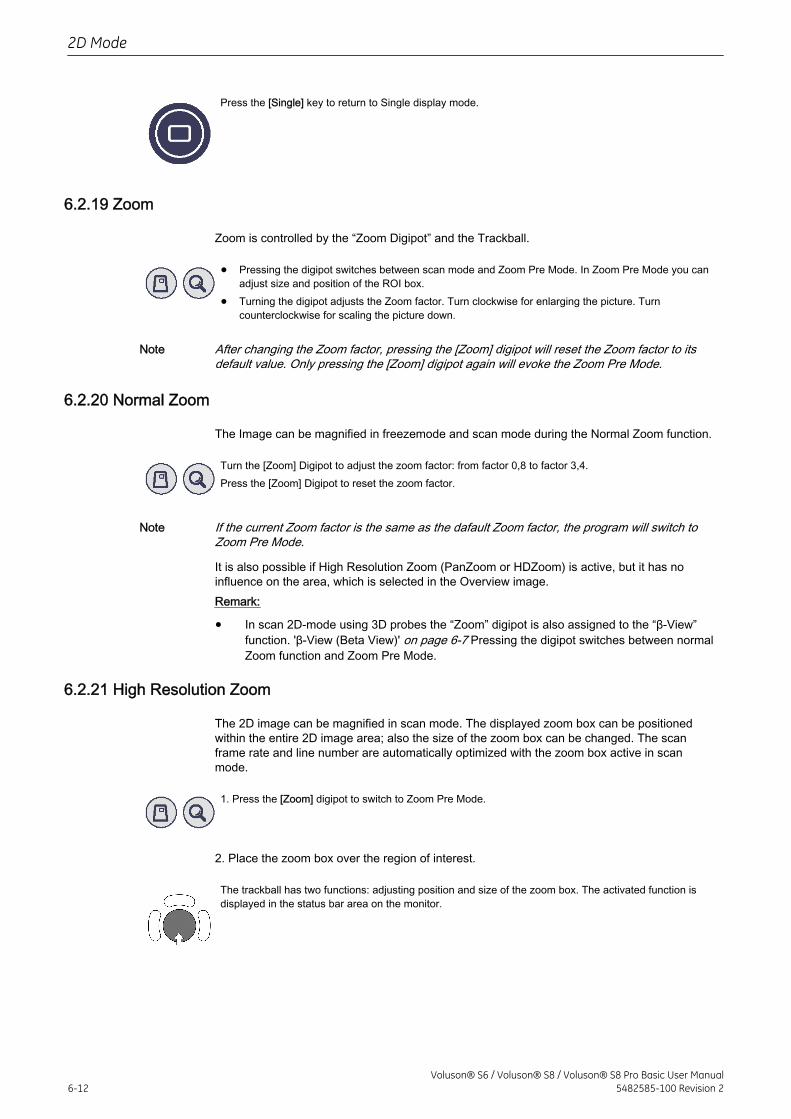
Press the [Single] key to return to Single display mode.
6.2.19 Zoom
Zoom is controlled by the “Zoom Digipot” and the Trackball.
• Pressing the digipot switches between scan mode and Zoom Pre Mode. In Zoom Pre Mode you canadjust size and position of the ROI box.
• Turning the digipot adjusts the Zoom factor. Turn clockwise for enlarging the picture. Turncounterclockwise for scaling the picture down.
Note After changing the Zoom factor, pressing the [Zoom] digipot will reset the Zoom factor to itsdefault value. Only pressing the [Zoom] digipot again will evoke the Zoom Pre Mode.
6.2.20 Normal Zoom
The Image can be magnified in freezemode and scan mode during the Normal Zoom function.
Turn the [Zoom] Digipot to adjust the zoom factor: from factor 0,8 to factor 3,4.Press the [Zoom] Digipot to reset the zoom factor.
Note If the current Zoom factor is the same as the dafault Zoom factor, the program will switch toZoom Pre Mode.
It is also possible if High Resolution Zoom (PanZoom or HDZoom) is active, but it has noinfluence on the area, which is selected in the Overview image.Remark:
• In scan 2D-mode using 3D probes the “Zoom” digipot is also assigned to the “β-View”function. 'β-View (Beta View)' on page 6-7 Pressing the digipot switches between normalZoom function and Zoom Pre Mode.
6.2.21 High Resolution Zoom
The 2D image can be magnified in scan mode. The displayed zoom box can be positionedwithin the entire 2D image area; also the size of the zoom box can be changed. The scanframe rate and line number are automatically optimized with the zoom box active in scanmode.
1. Press the [Zoom] digipot to switch to Zoom Pre Mode.
2. Place the zoom box over the region of interest.
The trackball has two functions: adjusting position and size of the zoom box. The activated function isdisplayed in the status bar area on the monitor.
2D Mode
6-12Voluson® S6 / Voluson® S8 / Voluson® S8 Pro Basic User Manual
5482585-100 Revision 2
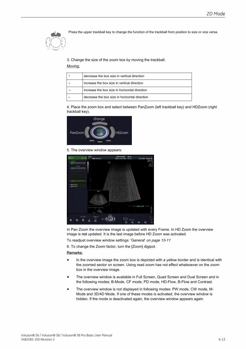
Press the upper trackball key to change the function of the trackball from position to size or vice versa.
3. Change the size of the zoom box by moving the trackball.Moving:
↑ decrease the box size in vertical direction
↓ increase the box size in vertical direction
→ increase the box size in horizontal direction
← decrease the box size in horizontal direction
4. Place the zoom box and select between PanZoom (left trackball key) and HDZoom (righttrackball key).
5. The overview window appears:
In Pan Zoom the overview image is updated with every Frame. In HD Zoom the overviewimage is not updated. It is the last image before HD Zoom was activated.To readjust overview window settings: 'General' on page 13-116. To change the Zoom factor, turn the [Zoom] digipot.Remarks:
• In the overview image the zoom box is depicted with a yellow border and is identical withthe zoomed sector on screen. Using read zoom has not effect whatsoever on the zoombox in the overview image.
• The overview window is available in Full Screen, Quad Screen and Dual Screen and inthe following modes: B-Mode, CF mode, PD mode, HD-Flow, B-Flow and Contrast.
• The overview window is not displayed in following modes: PW mode, CW mode, M-Mode and 3D/4D Mode. If one of these modes is activated, the overview window ishidden. If the mode is deactivated again, the overview window appears again.
2D Mode
Voluson® S6 / Voluson® S8 / Voluson® S8 Pro Basic User Manual5482585-100 Revision 2 6-13
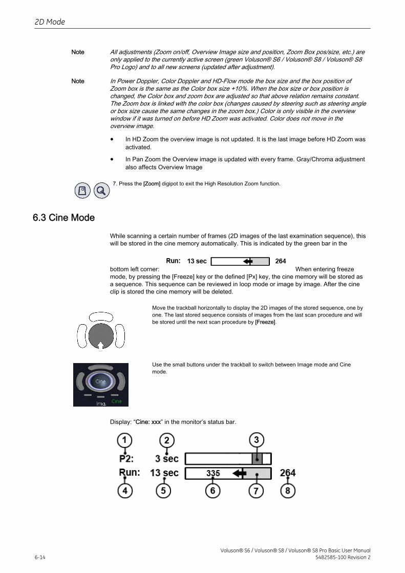
Note All adjustments (Zoom on/off, Overview Image size and position, Zoom Box pos/size, etc.) areonly applied to the currently active screen (green Voluson® S6 / Voluson® S8 / Voluson® S8Pro Logo) and to all new screens (updated after adjustment).
Note In Power Doppler, Color Doppler and HD-Flow mode the box size and the box position ofZoom box is the same as the Color box size +10%. When the box size or box position ischanged, the Color box and zoom box are adjusted so that above relation remains constant.The Zoom box is linked with the color box (changes caused by steering such as steering angleor box size cause the same changes in the zoom box.) Color is only visible in the overviewwindow if it was turned on before HD Zoom was activated. Color does not move in theoverview image.
• In HD Zoom the overview image is not updated. It is the last image before HD Zoom wasactivated.
• In Pan Zoom the Overview image is updated with every frame. Gray/Chroma adjustmentalso affects Overview Image
7. Press the [Zoom] digipot to exit the High Resolution Zoom function.
6.3 Cine Mode
While scanning a certain number of frames (2D images of the last examination sequence), thiswill be stored in the cine memory automatically. This is indicated by the green bar in the
bottom left corner: When entering freezemode, by pressing the [Freeze] key or the defined [Px] key, the cine memory will be stored asa sequence. This sequence can be reviewed in loop mode or image by image. After the cineclip is stored the cine memory will be deleted.
Move the trackball horizontally to display the 2D images of the stored sequence, one byone. The last stored sequence consists of images from the last scan procedure and willbe stored until the next scan procedure by [Freeze].
Use the small buttons under the trackball to switch between Image mode and Cinemode.
Display: “Cine: xxx” in the monitor’s status bar.
2D Mode
6-14Voluson® S6 / Voluson® S8 / Voluson® S8 Pro Basic User Manual
5482585-100 Revision 2
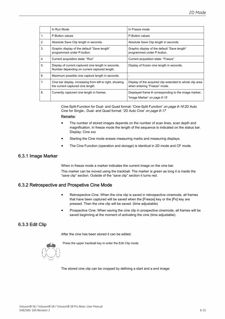
In Run Mode In Freeze mode
1. P-Button values P-Button values
2. Absolute Save Clip length in seconds. Absolute Save Clip length in seconds.
3. Graphic display of the default “Save length”programmed under P-button.
Graphic display of the default “Save length”programmed under P-button.
4. Current acquisition state: “Run” Current acquisition state: “Freeze”
5. Display of current captured cine length in seconds.Number depending on current captured length.
Display of frozen cine length in seconds.
6. Maximum possible cine capture length in seconds. -
7. Cine bar display, increasing from left to right, showingthe current captured cine length.
Display of the acquired clip extended to whole clip areawhen entering “Freeze” mode.
8. Currently captured cine length in frames. Displayed frame # corresponding to the image marker,'Image Marker' on page 6-15
Cine-Split-Function for Dual- and Quad format: 'Cine-Split Function' on page 6-16 2D AutoCine for Single-, Dual- and Quad format: '2D Auto Cine' on page 6-17Remarks:
• The number of stored images depends on the number of scan lines, scan depth andmagnification. In freeze mode the length of the sequence is indicated on the status bar.Display: Cine xxx
• Starting the Cine mode erases measuring marks and measuring displays.
• The Cine Function (operation and storage) is identical in 2D mode and CF mode.
6.3.1 Image Marker
When in freeze mode a marker indicates the current image on the cine bar.This marker can be moved using the trackball. The marker is green as long it is inside the“save clip” section. Outside of the “save clip” section it turns red.
6.3.2 Retrospective and Prospetive Cine Mode
• Retrospective Cine: When the cine clip is saved in retrospective cinemode, all framesthat have been captured will be saved when the [Freeze] key or the [Px] key arepressed. Then the cine clip will be saved. (time adjustable)
• Prospective Cine: When saving the cine clip in prospective cinemode, all frames will besaved beginning at the moment of activating the cine (time adjustable).
6.3.3 Edit Clip
After the cine has been stored it can be edited.
Press the upper trackball key to enter the Edit Clip mode.
The stored cine clip can be cropped by defining a start and a end image:
2D Mode
Voluson® S6 / Voluson® S8 / Voluson® S8 Pro Basic User Manual5482585-100 Revision 2 6-15
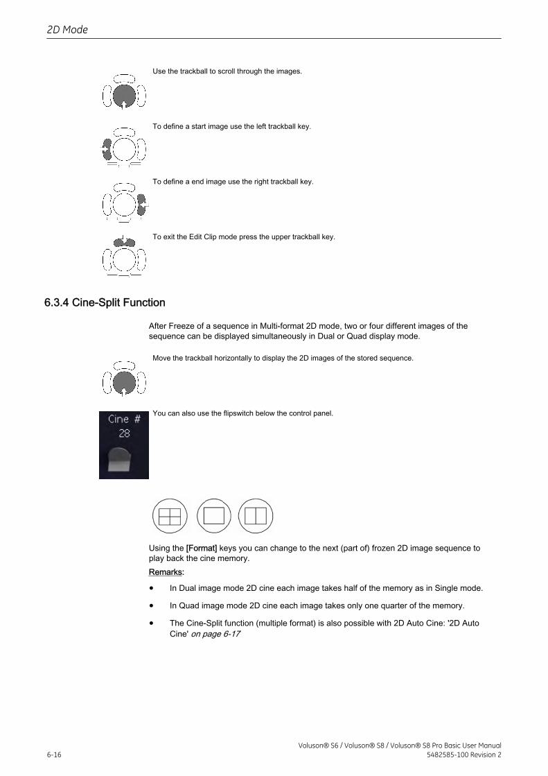
Use the trackball to scroll through the images.
To define a start image use the left trackball key.
To define a end image use the right trackball key.
To exit the Edit Clip mode press the upper trackball key.
6.3.4 Cine-Split Function
After Freeze of a sequence in Multi-format 2D mode, two or four different images of thesequence can be displayed simultaneously in Dual or Quad display mode.
Move the trackball horizontally to display the 2D images of the stored sequence.
You can also use the flipswitch below the control panel.
Using the [Format] keys you can change to the next (part of) frozen 2D image sequence toplay back the cine memory.Remarks:
• In Dual image mode 2D cine each image takes half of the memory as in Single mode.
• In Quad image mode 2D cine each image takes only one quarter of the memory.
• The Cine-Split function (multiple format) is also possible with 2D Auto Cine: '2D AutoCine' on page 6-17
2D Mode
6-16Voluson® S6 / Voluson® S8 / Voluson® S8 Pro Basic User Manual
5482585-100 Revision 2
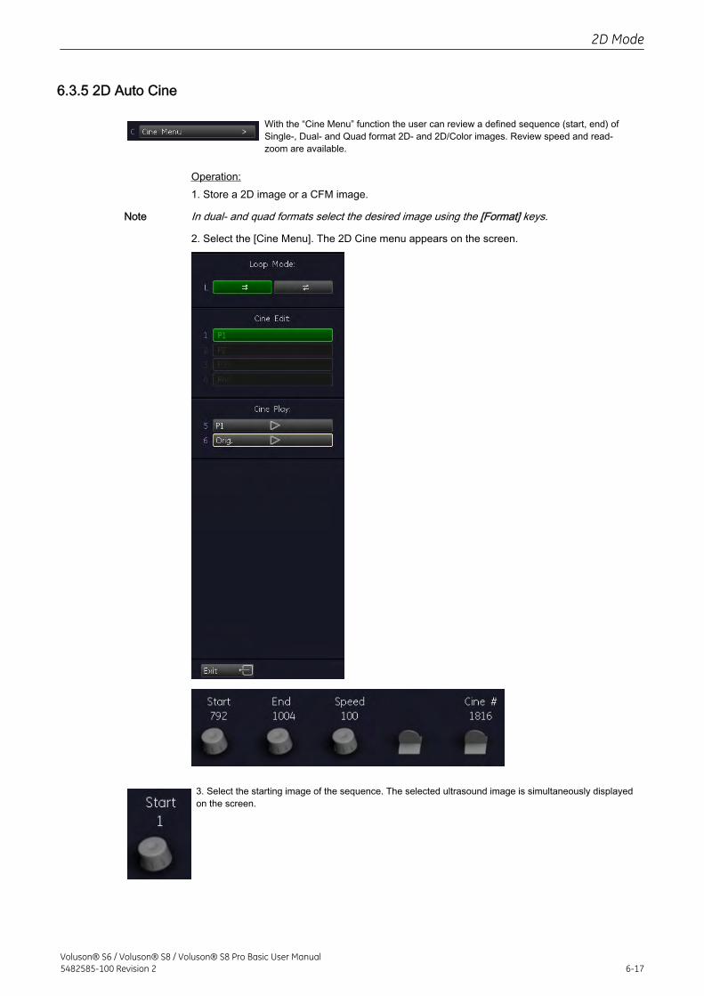
6.3.5 2D Auto Cine
With the “Cine Menu” function the user can review a defined sequence (start, end) ofSingle-, Dual- and Quad format 2D- and 2D/Color images. Review speed and read-zoom are available.
Operation:1. Store a 2D image or a CFM image.
Note In dual- and quad formats select the desired image using the [Format] keys.
2. Select the [Cine Menu]. The 2D Cine menu appears on the screen.
3. Select the starting image of the sequence. The selected ultrasound image is simultaneously displayedon the screen.
2D Mode
Voluson® S6 / Voluson® S8 / Voluson® S8 Pro Basic User Manual5482585-100 Revision 2 6-17
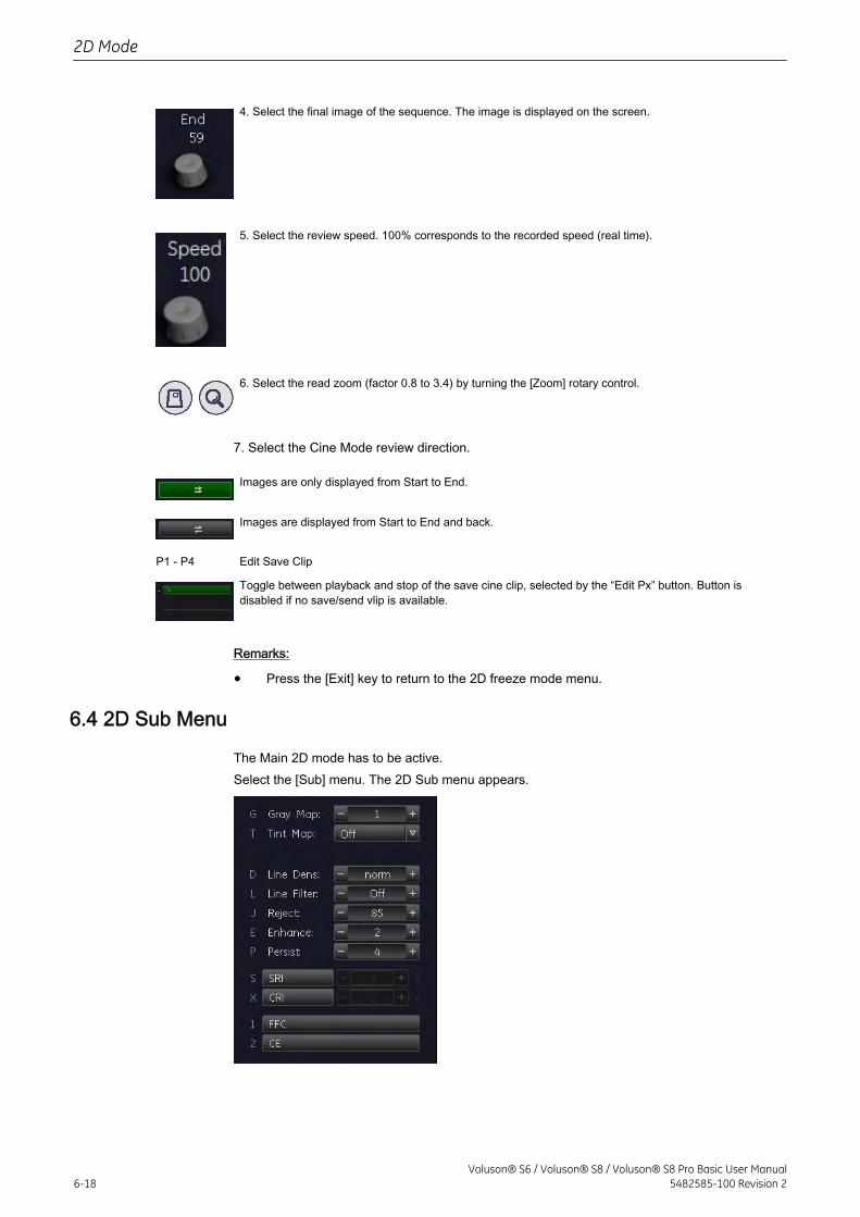
4. Select the final image of the sequence. The image is displayed on the screen.
5. Select the review speed. 100% corresponds to the recorded speed (real time).
6. Select the read zoom (factor 0.8 to 3.4) by turning the [Zoom] rotary control.
7. Select the Cine Mode review direction.
Images are only displayed from Start to End.
Images are displayed from Start to End and back.
P1 - P4 Edit Save Clip
Toggle between playback and stop of the save cine clip, selected by the “Edit Px” button. Button isdisabled if no save/send vlip is available.
Remarks:
• Press the [Exit] key to return to the 2D freeze mode menu.
6.4 2D Sub Menu
The Main 2D mode has to be active.Select the [Sub] menu. The 2D Sub menu appears.
2D Mode
6-18Voluson® S6 / Voluson® S8 / Voluson® S8 Pro Basic User Manual
5482585-100 Revision 2
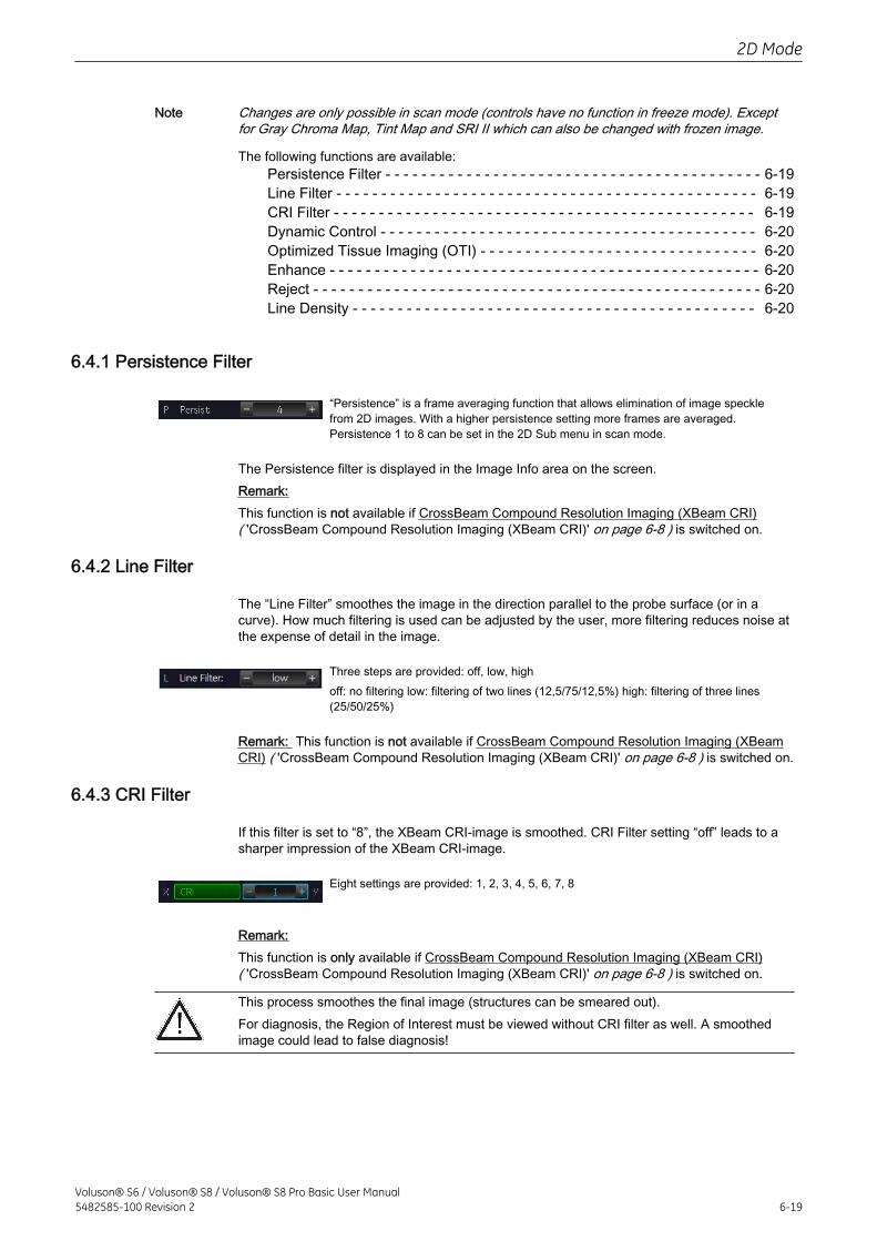
Note Changes are only possible in scan mode (controls have no function in freeze mode). Exceptfor Gray Chroma Map, Tint Map and SRI II which can also be changed with frozen image.
The following functions are available:Persistence Filter - - - - - - - - - - - - - - - - - - - - - - - - - - - - - - - - - - - - - - - - - - 6-19Line Filter - - - - - - - - - - - - - - - - - - - - - - - - - - - - - - - - - - - - - - - - - - - - - - - 6-19CRI Filter - - - - - - - - - - - - - - - - - - - - - - - - - - - - - - - - - - - - - - - - - - - - - - - 6-19Dynamic Control - - - - - - - - - - - - - - - - - - - - - - - - - - - - - - - - - - - - - - - - - - 6-20Optimized Tissue Imaging (OTI) - - - - - - - - - - - - - - - - - - - - - - - - - - - - - - - 6-20Enhance - - - - - - - - - - - - - - - - - - - - - - - - - - - - - - - - - - - - - - - - - - - - - - - - 6-20Reject - - - - - - - - - - - - - - - - - - - - - - - - - - - - - - - - - - - - - - - - - - - - - - - - - - 6-20Line Density - - - - - - - - - - - - - - - - - - - - - - - - - - - - - - - - - - - - - - - - - - - - - 6-20
6.4.1 Persistence Filter
“Persistence” is a frame averaging function that allows elimination of image specklefrom 2D images. With a higher persistence setting more frames are averaged.Persistence 1 to 8 can be set in the 2D Sub menu in scan mode.
The Persistence filter is displayed in the Image Info area on the screen.Remark:This function is not available if CrossBeam Compound Resolution Imaging (XBeam CRI)( 'CrossBeam Compound Resolution Imaging (XBeam CRI)' on page 6-8 ) is switched on.
6.4.2 Line Filter
The “Line Filter” smoothes the image in the direction parallel to the probe surface (or in acurve). How much filtering is used can be adjusted by the user, more filtering reduces noise atthe expense of detail in the image.
Three steps are provided: off, low, highoff: no filtering low: filtering of two lines (12,5/75/12,5%) high: filtering of three lines(25/50/25%)
Remark: This function is not available if CrossBeam Compound Resolution Imaging (XBeamCRI) ( 'CrossBeam Compound Resolution Imaging (XBeam CRI)' on page 6-8 ) is switched on.
6.4.3 CRI Filter
If this filter is set to “8”, the XBeam CRI-image is smoothed. CRI Filter setting “off” leads to asharper impression of the XBeam CRI-image.
Eight settings are provided: 1, 2, 3, 4, 5, 6, 7, 8
Remark:This function is only available if CrossBeam Compound Resolution Imaging (XBeam CRI)( 'CrossBeam Compound Resolution Imaging (XBeam CRI)' on page 6-8 ) is switched on.
This process smoothes the final image (structures can be smeared out).For diagnosis, the Region of Interest must be viewed without CRI filter as well. A smoothedimage could lead to false diagnosis!
2D Mode
Voluson® S6 / Voluson® S8 / Voluson® S8 Pro Basic User Manual5482585-100 Revision 2 6-19
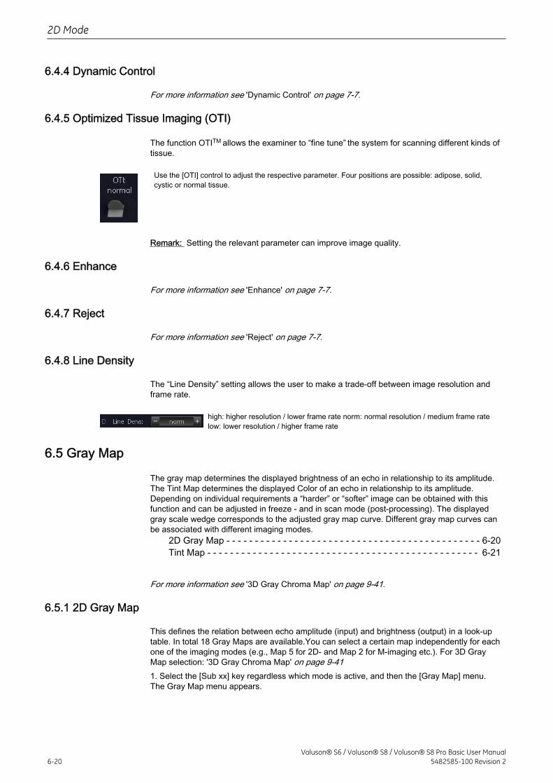
6.4.4 Dynamic Control
For more information see 'Dynamic Control' on page 7-7.
6.4.5 Optimized Tissue Imaging (OTI)
The function OTITM allows the examiner to “fine tune” the system for scanning different kinds oftissue.
Use the [OTI] control to adjust the respective parameter. Four positions are possible: adipose, solid,cystic or normal tissue.
Remark: Setting the relevant parameter can improve image quality.
6.4.6 Enhance
For more information see 'Enhance' on page 7-7.
6.4.7 Reject
For more information see 'Reject' on page 7-7.
6.4.8 Line Density
The “Line Density” setting allows the user to make a trade-off between image resolution andframe rate.
high: higher resolution / lower frame rate norm: normal resolution / medium frame ratelow: lower resolution / higher frame rate
6.5 Gray Map
The gray map determines the displayed brightness of an echo in relationship to its amplitude.The Tint Map determines the displayed Color of an echo in relationship to its amplitude.Depending on individual requirements a “harder” or “softer” image can be obtained with thisfunction and can be adjusted in freeze - and in scan mode (post-processing). The displayedgray scale wedge corresponds to the adjusted gray map curve. Different gray map curves canbe associated with different imaging modes.
2D Gray Map - - - - - - - - - - - - - - - - - - - - - - - - - - - - - - - - - - - - - - - - - - - - - 6-20Tint Map - - - - - - - - - - - - - - - - - - - - - - - - - - - - - - - - - - - - - - - - - - - - - - - - 6-21
For more information see '3D Gray Chroma Map' on page 9-41.
6.5.1 2D Gray Map
This defines the relation between echo amplitude (input) and brightness (output) in a look-uptable. In total 18 Gray Maps are available.You can select a certain map independently for eachone of the imaging modes (e.g., Map 5 for 2D- and Map 2 for M-imaging etc.). For 3D GrayMap selection: '3D Gray Chroma Map' on page 9-411. Select the [Sub xx] key regardless which mode is active, and then the [Gray Map] menu.The Gray Map menu appears.
2D Mode
6-20Voluson® S6 / Voluson® S8 / Voluson® S8 Pro Basic User Manual
5482585-100 Revision 2
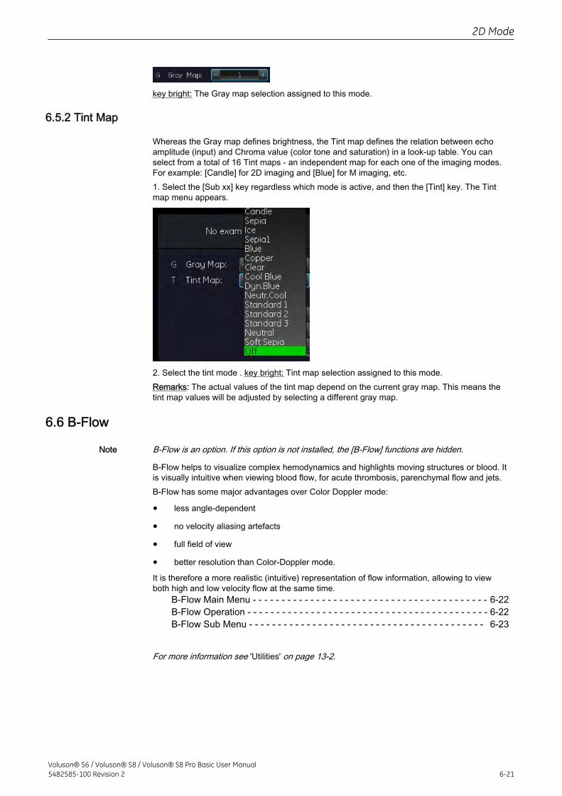
key bright: The Gray map selection assigned to this mode.
6.5.2 Tint Map
Whereas the Gray map defines brightness, the Tint map defines the relation between echoamplitude (input) and Chroma value (color tone and saturation) in a look-up table. You canselect from a total of 16 Tint maps - an independent map for each one of the imaging modes.For example: [Candle] for 2D imaging and [Blue] for M imaging, etc.1. Select the [Sub xx] key regardless which mode is active, and then the [Tint] key. The Tintmap menu appears.
2. Select the tint mode . key bright: Tint map selection assigned to this mode.Remarks: The actual values of the tint map depend on the current gray map. This means thetint map values will be adjusted by selecting a different gray map.
6.6 B-Flow
Note B-Flow is an option. If this option is not installed, the [B-Flow] functions are hidden.
B-Flow helps to visualize complex hemodynamics and highlights moving structures or blood. Itis visually intuitive when viewing blood flow, for acute thrombosis, parenchymal flow and jets.B-Flow has some major advantages over Color Doppler mode:
• less angle-dependent
• no velocity aliasing artefacts
• full field of view
• better resolution than Color-Doppler mode.
It is therefore a more realistic (intuitive) representation of flow information, allowing to viewboth high and low velocity flow at the same time.
B-Flow Main Menu - - - - - - - - - - - - - - - - - - - - - - - - - - - - - - - - - - - - - - - - - 6-22B-Flow Operation - - - - - - - - - - - - - - - - - - - - - - - - - - - - - - - - - - - - - - - - - - 6-22B-Flow Sub Menu - - - - - - - - - - - - - - - - - - - - - - - - - - - - - - - - - - - - - - - - - 6-23
For more information see 'Utilities' on page 13-2.
2D Mode
Voluson® S6 / Voluson® S8 / Voluson® S8 Pro Basic User Manual5482585-100 Revision 2 6-21
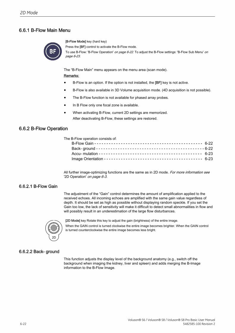
6.6.1 B-Flow Main Menu
[B-Flow Mode] key (hard key)Press the [BF] control to activate the B-Flow mode.To use B-Flow: 'B-Flow Operation' on page 6-22. To adjust the B-Flow settings: 'B-Flow Sub Menu' onpage 6-23.
The “B-Flow Main” menu appears on the menu area (scan mode).Remarks:
• B-Flow is an option. If the option is not installed, the [BF] key is not active.
• B-Flow is also available in 3D Volume acquisition mode. (4D acquisition is not possible).
• The B-Flow function is not available for phased array probes.
• In B Flow only one focal zone is available.
• When activating B-Flow, current 2D settings are memorized.After deactivating B-Flow, these settings are restored.
6.6.2 B-Flow Operation
The B-Flow operation consists of:B-Flow Gain - - - - - - - - - - - - - - - - - - - - - - - - - - - - - - - - - - - - - - - - - - - - - 6-22Back- ground - - - - - - - - - - - - - - - - - - - - - - - - - - - - - - - - - - - - - - - - - - - - - 6-22Accu- mulation - - - - - - - - - - - - - - - - - - - - - - - - - - - - - - - - - - - - - - - - - - - 6-23Image Orientation - - - - - - - - - - - - - - - - - - - - - - - - - - - - - - - - - - - - - - - - - 6-23
All further image-optimizing functions are the same as in 2D mode. For more information see'2D Operation' on page 6-3.
6.6.2.1 B-Flow GainThe adjustment of the “Gain” control determines the amount of amplification applied to thereceived echoes. All incoming echoes are amplified with the same gain value regardless ofdepth. It should be set as high as possible without displaying random speckle. If you set theGain too low, the lack of sensitivity will make it difficult to detect small abnormalities in flow andwill possibly result in an underestimation of the large flow disturbances.
[2D Mode] key Rotate this key to adjust the gain (brightness) of the entire image.When the GAIN control is turned clockwise the entire image becomes brighter. When the GAIN controlis turned counterclockwise the entire image becomes less bright.
6.6.2.2 Back- groundThis function adjusts the display level of the background anatomy (e.g., switch off thebackground when imaging the kidney, liver and spleen) and adds merging the B-Imageinformation to the B-Flow Image.
2D Mode
6-22Voluson® S6 / Voluson® S8 / Voluson® S8 Pro Basic User Manual
5482585-100 Revision 2
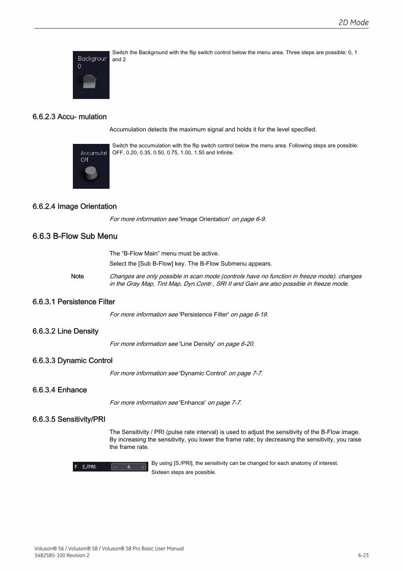
Switch the Background with the flip switch control below the menu area. Three steps are possible: 0, 1and 2
6.6.2.3 Accu- mulationAccumulation detects the maximum signal and holds it for the level specified.
Switch the accumulation with the flip switch control below the menu area. Following steps are possible:OFF, 0.20, 0.35, 0.50, 0.75, 1.00, 1.50 and Infinite.
6.6.2.4 Image OrientationFor more information see 'Image Orientation' on page 6-9.
6.6.3 B-Flow Sub Menu
The “B-Flow Main” menu must be active.Select the [Sub B-Flow] key. The B-Flow Submenu appears.
Note Changes are only possible in scan mode (controls have no function in freeze mode). changesin the Gray Map, Tint Map, Dyn.Contr., SRI II and Gain are also possible in freeze mode.
6.6.3.1 Persistence FilterFor more information see 'Persistence Filter' on page 6-19.
6.6.3.2 Line DensityFor more information see 'Line Density' on page 6-20.
6.6.3.3 Dynamic ControlFor more information see 'Dynamic Control' on page 7-7.
6.6.3.4 EnhanceFor more information see 'Enhance' on page 7-7.
6.6.3.5 Sensitivity/PRIThe Sensitivity / PRI (pulse rate interval) is used to adjust the sensitivity of the B-Flow image.By increasing the sensitivity, you lower the frame rate; by decreasing the sensitivity, you raisethe frame rate.
By using [S./PRI], the sensitivity can be changed for each anatomy of interest.Sixteen steps are possible.
2D Mode
Voluson® S6 / Voluson® S8 / Voluson® S8 Pro Basic User Manual5482585-100 Revision 2 6-23
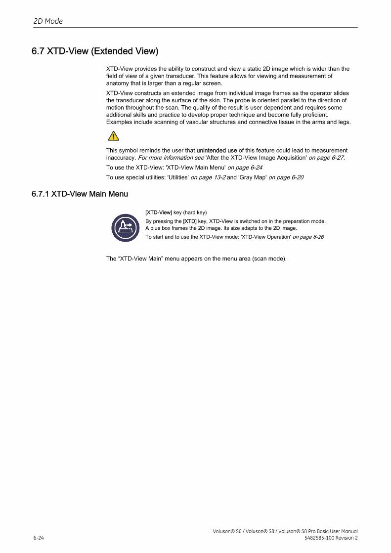
6.7 XTD-View (Extended View)
XTD-View provides the ability to construct and view a static 2D image which is wider than thefield of view of a given transducer. This feature allows for viewing and measurement ofanatomy that is larger than a regular screen.XTD-View constructs an extended image from individual image frames as the operator slidesthe transducer along the surface of the skin. The probe is oriented parallel to the direction ofmotion throughout the scan. The quality of the result is user-dependent and requires someadditional skills and practice to develop proper technique and become fully proficient.Examples include scanning of vascular structures and connective tissue in the arms and legs.
This symbol reminds the user that unintended use of this feature could lead to measurementinaccuracy. For more information see 'After the XTD-View Image Acquisition' on page 6-27.To use the XTD-View: 'XTD-View Main Menu' on page 6-24To use special utilities: 'Utilities' on page 13-2 and 'Gray Map' on page 6-20
6.7.1 XTD-View Main Menu
[XTD-View] key (hard key)By pressing the [XTD] key, XTD-View is switched on in the preparation mode.A blue box frames the 2D image. Its size adapts to the 2D image.To start and to use the XTD-View mode: 'XTD-View Operation' on page 6-26
The “XTD-View Main” menu appears on the menu area (scan mode).
2D Mode
6-24Voluson® S6 / Voluson® S8 / Voluson® S8 Pro Basic User Manual
5482585-100 Revision 2
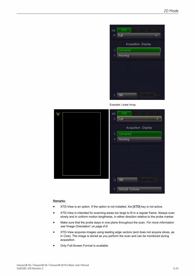
Example: Linear Array
Remarks:
• XTD-View is an option. If the option is not installed, the [XTD] key is not active.
• XTD-View is intended for scanning areas too large to fit in a regular frame. Always scanslowly and in uniform motion lengthwise, in either direction relative to the probe marker.
• Make sure that the probe stays in one plane throughout the scan. For more informationsee 'Image Orientation' on page 6-9.
• XTD-View acquires images using leading edge vectors (and does not acquire slices, asin Cine). The image is stored as you perform the scan and can be monitored duringacquisition.
• Only Full-Screen Format is available.
2D Mode
Voluson® S6 / Voluson® S8 / Voluson® S8 Pro Basic User Manual5482585-100 Revision 2 6-25
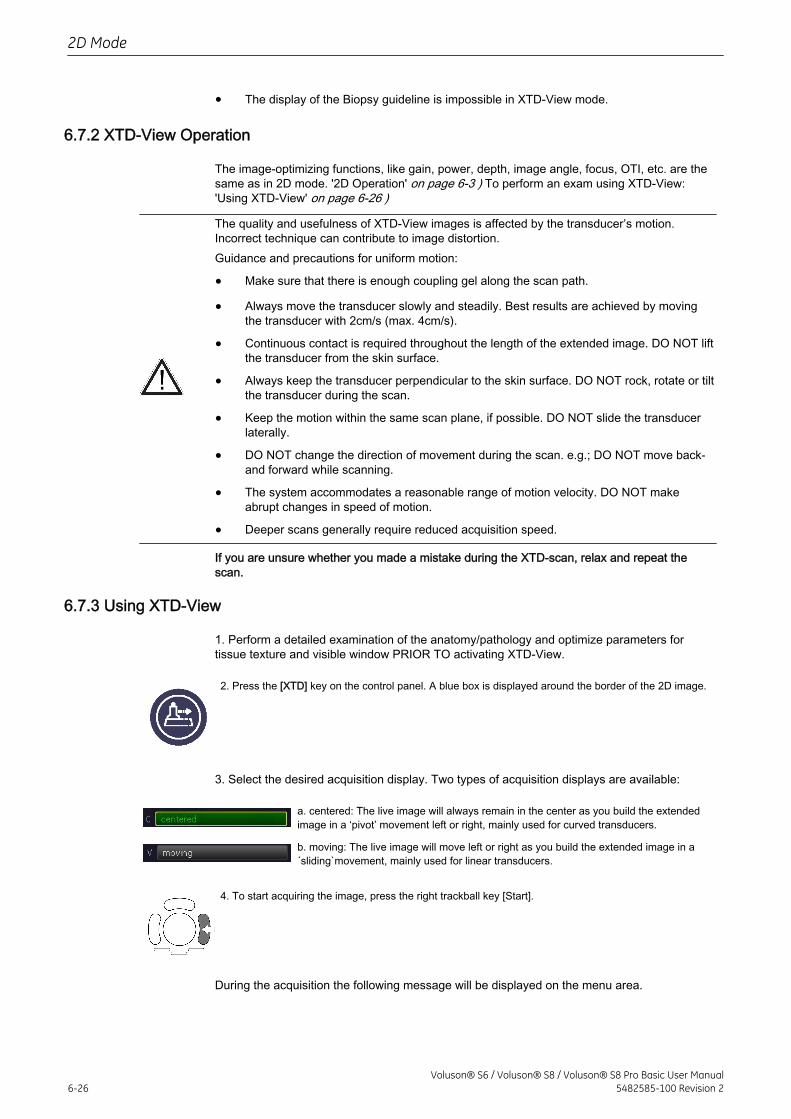
• The display of the Biopsy guideline is impossible in XTD-View mode.
6.7.2 XTD-View Operation
The image-optimizing functions, like gain, power, depth, image angle, focus, OTI, etc. are thesame as in 2D mode. '2D Operation' on page 6-3 ) To perform an exam using XTD-View:'Using XTD-View' on page 6-26 )
The quality and usefulness of XTD-View images is affected by the transducer’s motion.Incorrect technique can contribute to image distortion.Guidance and precautions for uniform motion:
• Make sure that there is enough coupling gel along the scan path.
• Always move the transducer slowly and steadily. Best results are achieved by movingthe transducer with 2cm/s (max. 4cm/s).
• Continuous contact is required throughout the length of the extended image. DO NOT liftthe transducer from the skin surface.
• Always keep the transducer perpendicular to the skin surface. DO NOT rock, rotate or tiltthe transducer during the scan.
• Keep the motion within the same scan plane, if possible. DO NOT slide the transducerlaterally.
• DO NOT change the direction of movement during the scan. e.g.; DO NOT move back-and forward while scanning.
• The system accommodates a reasonable range of motion velocity. DO NOT makeabrupt changes in speed of motion.
• Deeper scans generally require reduced acquisition speed.
If you are unsure whether you made a mistake during the XTD-scan, relax and repeat thescan.
6.7.3 Using XTD-View
1. Perform a detailed examination of the anatomy/pathology and optimize parameters fortissue texture and visible window PRIOR TO activating XTD-View.
2. Press the [XTD] key on the control panel. A blue box is displayed around the border of the 2D image.
3. Select the desired acquisition display. Two types of acquisition displays are available:
a. centered: The live image will always remain in the center as you build the extendedimage in a ‘pivot’ movement left or right, mainly used for curved transducers.
b. moving: The live image will move left or right as you build the extended image in a´sliding`movement, mainly used for linear transducers.
4. To start acquiring the image, press the right trackball key [Start].
During the acquisition the following message will be displayed on the menu area.
2D Mode
6-26Voluson® S6 / Voluson® S8 / Voluson® S8 Pro Basic User Manual
5482585-100 Revision 2
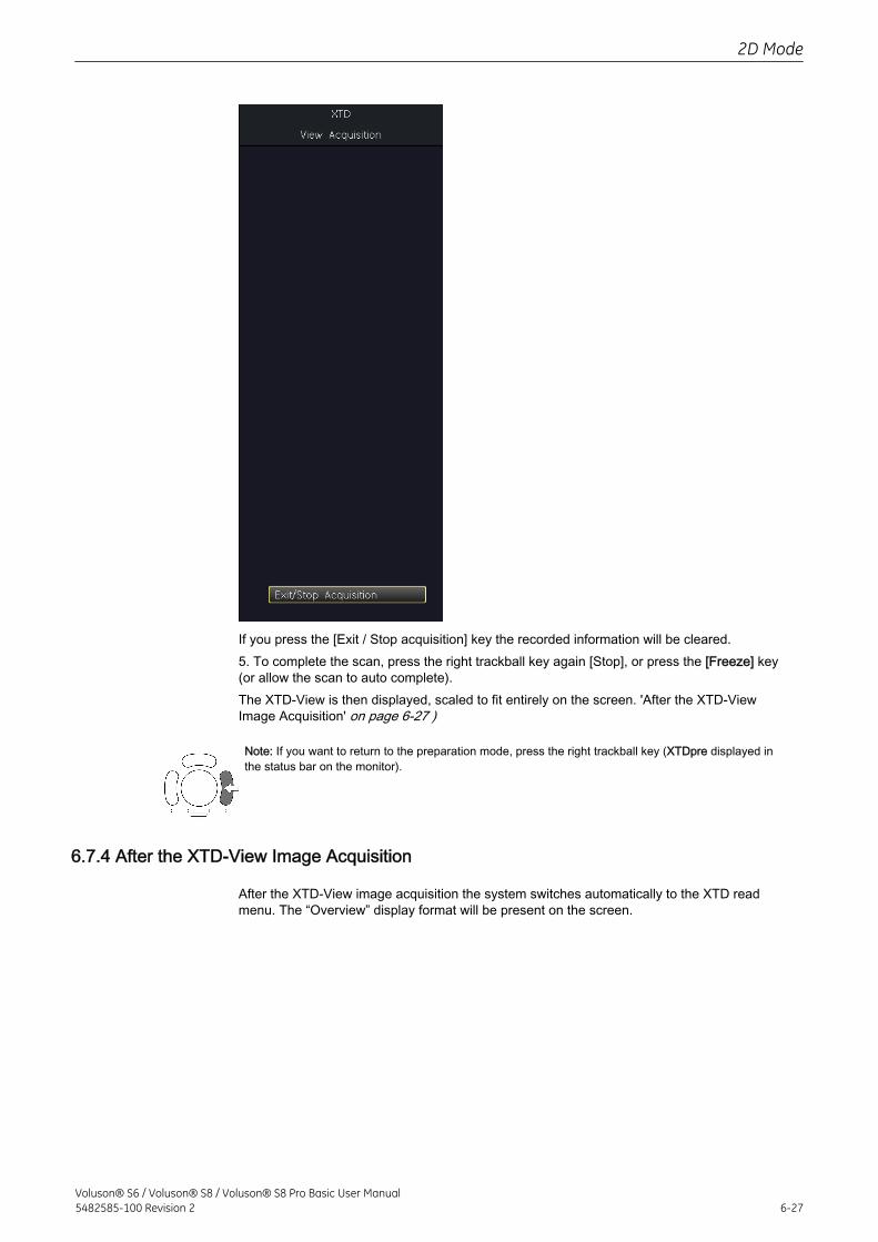
If you press the [Exit / Stop acquisition] key the recorded information will be cleared.5. To complete the scan, press the right trackball key again [Stop], or press the [Freeze] key(or allow the scan to auto complete).The XTD-View is then displayed, scaled to fit entirely on the screen. 'After the XTD-ViewImage Acquisition' on page 6-27 )
Note: If you want to return to the preparation mode, press the right trackball key (XTDpre displayed inthe status bar on the monitor).
6.7.4 After the XTD-View Image Acquisition
After the XTD-View image acquisition the system switches automatically to the XTD readmenu. The “Overview” display format will be present on the screen.
2D Mode
Voluson® S6 / Voluson® S8 / Voluson® S8 Pro Basic User Manual5482585-100 Revision 2 6-27
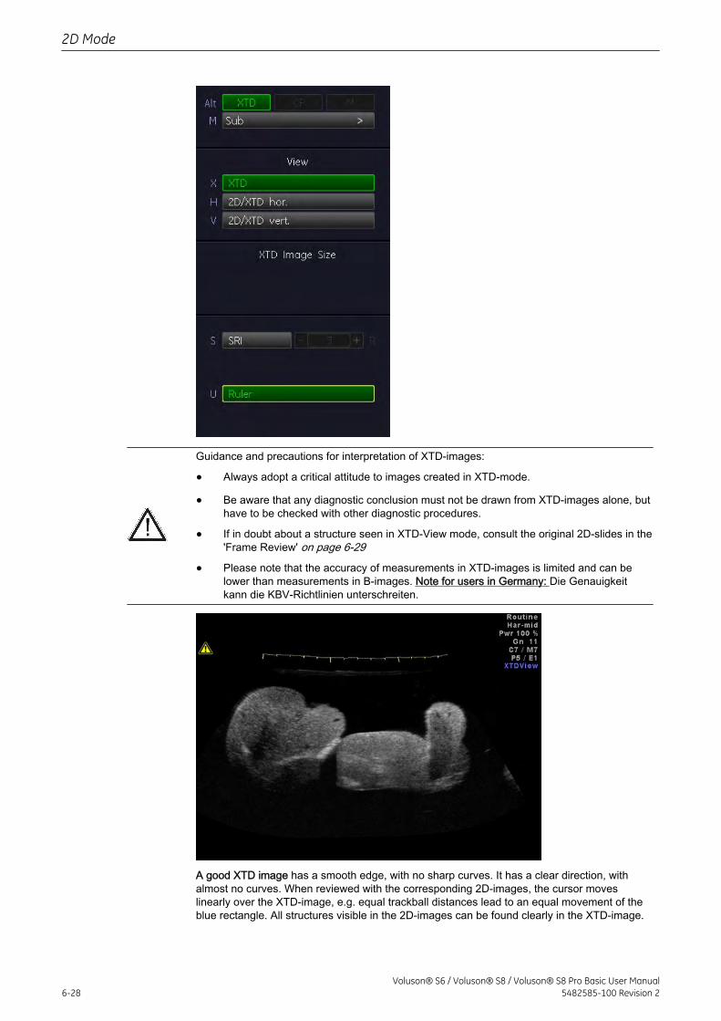
Guidance and precautions for interpretation of XTD-images:
• Always adopt a critical attitude to images created in XTD-mode.
• Be aware that any diagnostic conclusion must not be drawn from XTD-images alone, buthave to be checked with other diagnostic procedures.
• If in doubt about a structure seen in XTD-View mode, consult the original 2D-slides in the'Frame Review' on page 6-29
• Please note that the accuracy of measurements in XTD-images is limited and can belower than measurements in B-images. Note for users in Germany: Die Genauigkeitkann die KBV-Richtlinien unterschreiten.
A good XTD image has a smooth edge, with no sharp curves. It has a clear direction, withalmost no curves. When reviewed with the corresponding 2D-images, the cursor moveslinearly over the XTD-image, e.g. equal trackball distances lead to an equal movement of theblue rectangle. All structures visible in the 2D-images can be found clearly in the XTD-image.
2D Mode
6-28Voluson® S6 / Voluson® S8 / Voluson® S8 Pro Basic User Manual
5482585-100 Revision 2
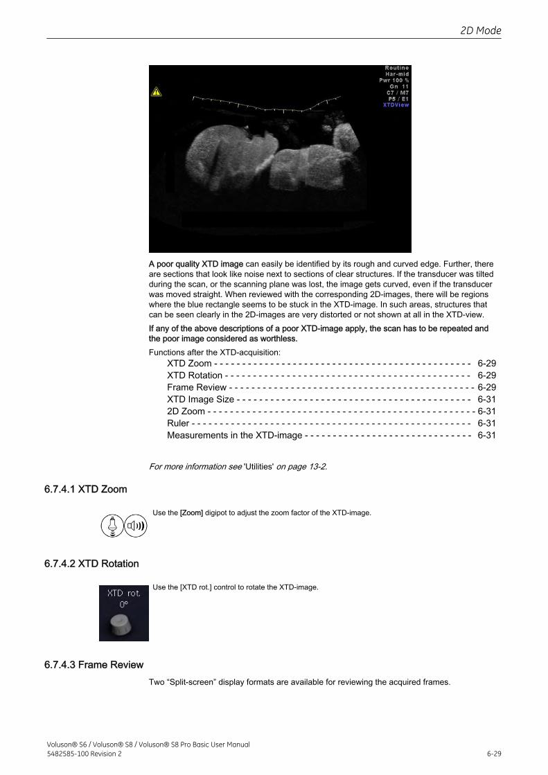
A poor quality XTD image can easily be identified by its rough and curved edge. Further, thereare sections that look like noise next to sections of clear structures. If the transducer was tiltedduring the scan, or the scanning plane was lost, the image gets curved, even if the transducerwas moved straight. When reviewed with the corresponding 2D-images, there will be regionswhere the blue rectangle seems to be stuck in the XTD-image. In such areas, structures thatcan be seen clearly in the 2D-images are very distorted or not shown at all in the XTD-view.If any of the above descriptions of a poor XTD-image apply, the scan has to be repeated andthe poor image considered as worthless.Functions after the XTD-acquisition:
XTD Zoom - - - - - - - - - - - - - - - - - - - - - - - - - - - - - - - - - - - - - - - - - - - - - - 6-29XTD Rotation - - - - - - - - - - - - - - - - - - - - - - - - - - - - - - - - - - - - - - - - - - - - 6-29Frame Review - - - - - - - - - - - - - - - - - - - - - - - - - - - - - - - - - - - - - - - - - - - - 6-29XTD Image Size - - - - - - - - - - - - - - - - - - - - - - - - - - - - - - - - - - - - - - - - - - 6-312D Zoom - - - - - - - - - - - - - - - - - - - - - - - - - - - - - - - - - - - - - - - - - - - - - - - - 6-31Ruler - - - - - - - - - - - - - - - - - - - - - - - - - - - - - - - - - - - - - - - - - - - - - - - - - - 6-31Measurements in the XTD-image - - - - - - - - - - - - - - - - - - - - - - - - - - - - - - 6-31
For more information see 'Utilities' on page 13-2.
6.7.4.1 XTD Zoom
Use the [Zoom] digipot to adjust the zoom factor of the XTD-image.
6.7.4.2 XTD Rotation
Use the [XTD rot.] control to rotate the XTD-image.
6.7.4.3 Frame ReviewTwo “Split-screen” display formats are available for reviewing the acquired frames.
2D Mode
Voluson® S6 / Voluson® S8 / Voluson® S8 Pro Basic User Manual5482585-100 Revision 2 6-29
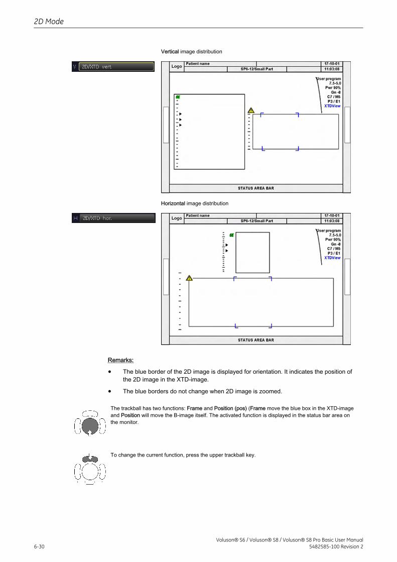
Vertical image distribution
Horizontal image distribution
Remarks:
• The blue border of the 2D image is displayed for orientation. It indicates the position ofthe 2D image in the XTD-image.
• The blue borders do not change when 2D image is zoomed.
The trackball has two functions: Frame and Position (pos) (Frame move the blue box in the XTD-imageand Position will move the B-image itself. The activated function is displayed in the status bar area onthe monitor.
To change the current function, press the upper trackball key.
2D Mode
6-30Voluson® S6 / Voluson® S8 / Voluson® S8 Pro Basic User Manual
5482585-100 Revision 2
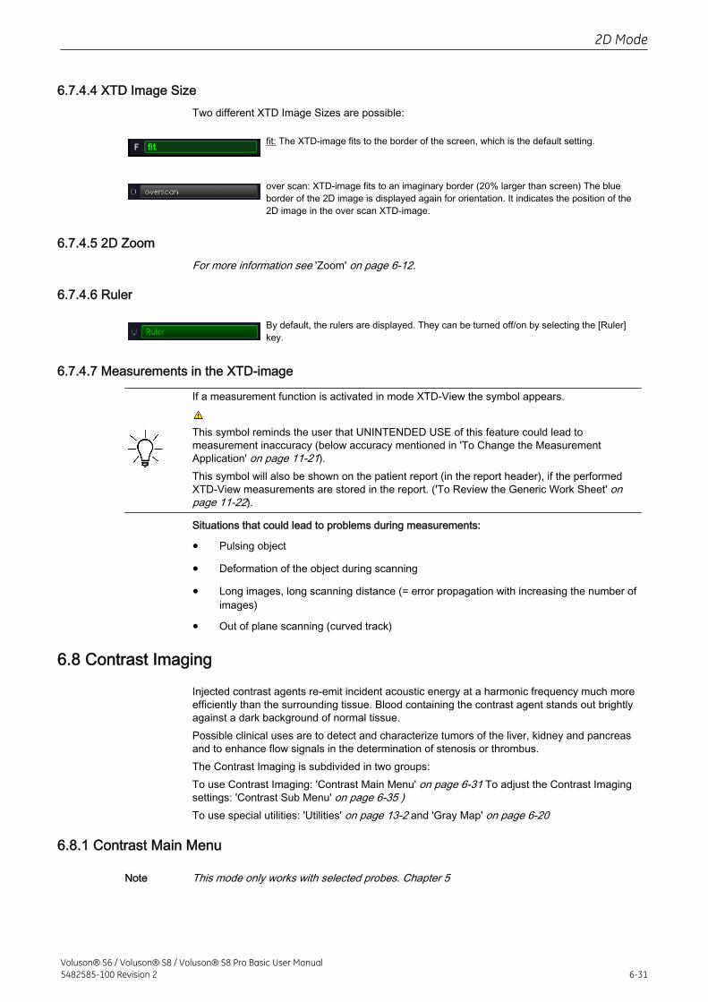
6.7.4.4 XTD Image SizeTwo different XTD Image Sizes are possible:
fit: The XTD-image fits to the border of the screen, which is the default setting.
over scan: XTD-image fits to an imaginary border (20% larger than screen) The blueborder of the 2D image is displayed again for orientation. It indicates the position of the2D image in the over scan XTD-image.
6.7.4.5 2D ZoomFor more information see 'Zoom' on page 6-12.
6.7.4.6 Ruler
By default, the rulers are displayed. They can be turned off/on by selecting the [Ruler]key.
6.7.4.7 Measurements in the XTD-image
If a measurement function is activated in mode XTD-View the symbol appears.
This symbol reminds the user that UNINTENDED USE of this feature could lead tomeasurement inaccuracy (below accuracy mentioned in 'To Change the MeasurementApplication' on page 11-21).This symbol will also be shown on the patient report (in the report header), if the performedXTD-View measurements are stored in the report. ('To Review the Generic Work Sheet' onpage 11-22).
Situations that could lead to problems during measurements:
• Pulsing object
• Deformation of the object during scanning
• Long images, long scanning distance (= error propagation with increasing the number ofimages)
• Out of plane scanning (curved track)
6.8 Contrast Imaging
Injected contrast agents re-emit incident acoustic energy at a harmonic frequency much moreefficiently than the surrounding tissue. Blood containing the contrast agent stands out brightlyagainst a dark background of normal tissue.Possible clinical uses are to detect and characterize tumors of the liver, kidney and pancreasand to enhance flow signals in the determination of stenosis or thrombus.The Contrast Imaging is subdivided in two groups:To use Contrast Imaging: 'Contrast Main Menu' on page 6-31 To adjust the Contrast Imagingsettings: 'Contrast Sub Menu' on page 6-35 )To use special utilities: 'Utilities' on page 13-2 and 'Gray Map' on page 6-20
6.8.1 Contrast Main Menu
Note This mode only works with selected probes. Chapter 5
2D Mode
Voluson® S6 / Voluson® S8 / Voluson® S8 Pro Basic User Manual5482585-100 Revision 2 6-31
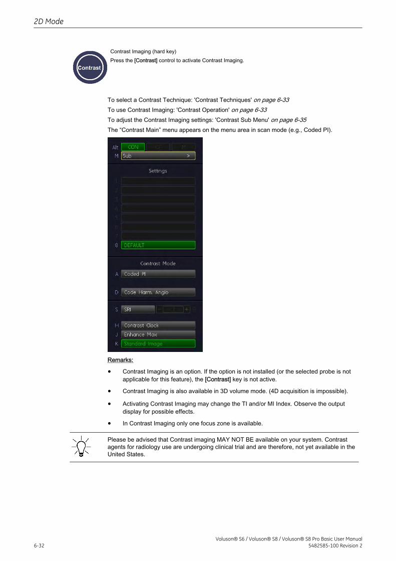
Contrast Imaging (hard key)Press the [Contrast] control to activate Contrast Imaging.
To select a Contrast Technique: 'Contrast Techniques' on page 6-33To use Contrast Imaging: 'Contrast Operation' on page 6-33To adjust the Contrast Imaging settings: 'Contrast Sub Menu' on page 6-35The “Contrast Main” menu appears on the menu area in scan mode (e.g., Coded PI).
Remarks:
• Contrast Imaging is an option. If the option is not installed (or the selected probe is notapplicable for this feature), the [Contrast] key is not active.
• Contrast Imaging is also available in 3D volume mode. (4D acquisition is impossible).
• Activating Contrast Imaging may change the TI and/or MI Index. Observe the outputdisplay for possible effects.
• In Contrast Imaging only one focus zone is available.
Please be advised that Contrast imaging MAY NOT BE available on your system. Contrastagents for radiology use are undergoing clinical trial and are therefore, not yet available in theUnited States.
2D Mode
6-32Voluson® S6 / Voluson® S8 / Voluson® S8 Pro Basic User Manual
5482585-100 Revision 2
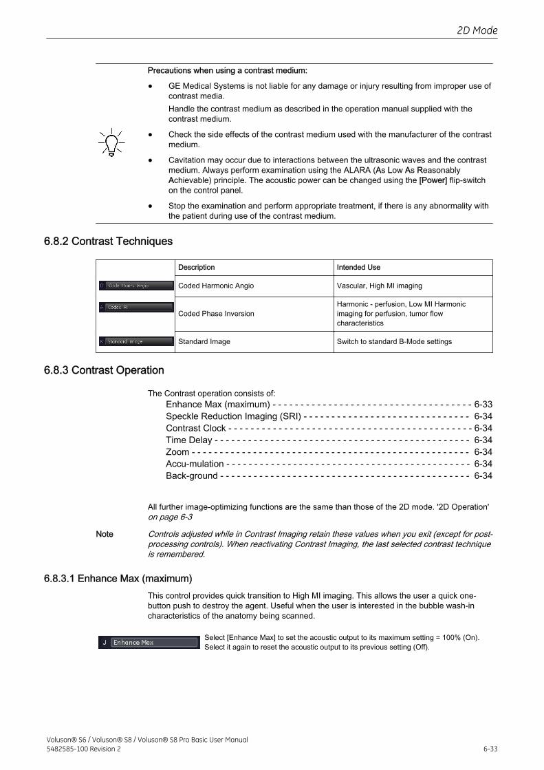
Precautions when using a contrast medium:
• GE Medical Systems is not liable for any damage or injury resulting from improper use ofcontrast media.Handle the contrast medium as described in the operation manual supplied with thecontrast medium.
• Check the side effects of the contrast medium used with the manufacturer of the contrastmedium.
• Cavitation may occur due to interactions between the ultrasonic waves and the contrastmedium. Always perform examination using the ALARA (As Low As ReasonablyAchievable) principle. The acoustic power can be changed using the [Power] flip-switchon the control panel.
• Stop the examination and perform appropriate treatment, if there is any abnormality withthe patient during use of the contrast medium.
6.8.2 Contrast Techniques
Description Intended Use
Coded Harmonic Angio Vascular, High MI imaging
Coded Phase InversionHarmonic - perfusion, Low MI Harmonicimaging for perfusion, tumor flowcharacteristics
Standard Image Switch to standard B-Mode settings
6.8.3 Contrast Operation
The Contrast operation consists of:Enhance Max (maximum) - - - - - - - - - - - - - - - - - - - - - - - - - - - - - - - - - - - - 6-33Speckle Reduction Imaging (SRI) - - - - - - - - - - - - - - - - - - - - - - - - - - - - - - 6-34Contrast Clock - - - - - - - - - - - - - - - - - - - - - - - - - - - - - - - - - - - - - - - - - - - - 6-34Time Delay - - - - - - - - - - - - - - - - - - - - - - - - - - - - - - - - - - - - - - - - - - - - - - 6-34Zoom - - - - - - - - - - - - - - - - - - - - - - - - - - - - - - - - - - - - - - - - - - - - - - - - - - 6-34Accu-mulation - - - - - - - - - - - - - - - - - - - - - - - - - - - - - - - - - - - - - - - - - - - - 6-34Back-ground - - - - - - - - - - - - - - - - - - - - - - - - - - - - - - - - - - - - - - - - - - - - - 6-34
All further image-optimizing functions are the same than those of the 2D mode. '2D Operation'on page 6-3
Note Controls adjusted while in Contrast Imaging retain these values when you exit (except for post-processing controls). When reactivating Contrast Imaging, the last selected contrast techniqueis remembered.
6.8.3.1 Enhance Max (maximum)This control provides quick transition to High MI imaging. This allows the user a quick one-button push to destroy the agent. Useful when the user is interested in the bubble wash-incharacteristics of the anatomy being scanned.
Select [Enhance Max] to set the acoustic output to its maximum setting = 100% (On).Select it again to reset the acoustic output to its previous setting (Off).
2D Mode
Voluson® S6 / Voluson® S8 / Voluson® S8 Pro Basic User Manual5482585-100 Revision 2 6-33
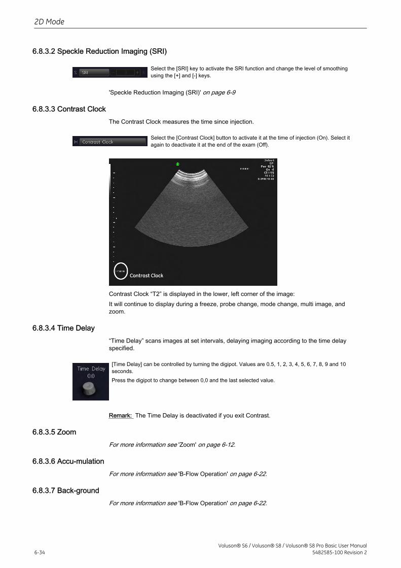
6.8.3.2 Speckle Reduction Imaging (SRI)
Select the [SRI] key to activate the SRI function and change the level of smoothingusing the [+] and [-] keys.
'Speckle Reduction Imaging (SRI)' on page 6-9
6.8.3.3 Contrast ClockThe Contrast Clock measures the time since injection.
Select the [Contrast Clock] button to activate it at the time of injection (On). Select itagain to deactivate it at the end of the exam (Off).
Contrast Clock “T2” is displayed in the lower, left corner of the image:It will continue to display during a freeze, probe change, mode change, multi image, andzoom.
6.8.3.4 Time Delay“Time Delay” scans images at set intervals, delaying imaging according to the time delayspecified.
[Time Delay] can be controlled by turning the digipot. Values are 0.5, 1, 2, 3, 4, 5, 6, 7, 8, 9 and 10seconds.Press the digipot to change between 0,0 and the last selected value.
Remark: The Time Delay is deactivated if you exit Contrast.
6.8.3.5 ZoomFor more information see 'Zoom' on page 6-12.
6.8.3.6 Accu-mulationFor more information see 'B-Flow Operation' on page 6-22.
6.8.3.7 Back-groundFor more information see 'B-Flow Operation' on page 6-22.
2D Mode
6-34Voluson® S6 / Voluson® S8 / Voluson® S8 Pro Basic User Manual
5482585-100 Revision 2
6.8.4 Contrast Sub Menu
The “Contrast Main” menu must be active.
Note Changes are only possible in scan mode (controls have no function in freeze mode). Onlychanges in the Gray Chroma Map are also possible in freeze mode.
Select the [Sub Contrast] key. The Contrast Submenu appears.
6.8.4.1 Persistence FilterFor more information see 'Persistence Filter' on page 6-19.
6.8.4.2 Line DensityFor more information see 'Line Density' on page 6-20.
6.8.4.3 Dynamic ControlFor more information see 'Dynamic Control' on page 7-7.
6.8.4.4 EnhanceFor more information see 'Enhance' on page 7-7.
6.8.4.5 Sensitivity/PRIFor more information see 'B-Flow Sub Menu' on page 6-23.
2D Mode
Voluson® S6 / Voluson® S8 / Voluson® S8 Pro Basic User Manual5482585-100 Revision 2 6-35

This page was intentionally left blank.
2D Mode
6-36Voluson® S6 / Voluson® S8 / Voluson® S8 Pro Basic User Manual
5482585-100 Revision 2
Chapter 7
M Mode
Describes the general functions of the M Mode.Image quality is the essential performance of the system.Please read this chapter carefully.
M Main Menu - - - - - - - - - - - - - - - - - - - - - - - - - - - - - - - - - - - - - - - - - - - - - - - - 7-2M Operation - - - - - - - - - - - - - - - - - - - - - - - - - - - - - - - - - - - - - - - - - - - - - - - - - 7-3M Sub Menu - - - - - - - - - - - - - - - - - - - - - - - - - - - - - - - - - - - - - - - - - - - - - - - - - 7-6MCF Mode (M Color Flow Mode) - - - - - - - - - - - - - - - - - - - - - - - - - - - - - - - - - - - 7-7MTD Mode (M Tissue Doppler Mode) - - - - - - - - - - - - - - - - - - - - - - - - - - - - - - 7-11MHDF Mode (MHD-Flow Mode) - - - - - - - - - - - - - - - - - - - - - - - - - - - - - - - - - - 7-15STIC with M-Mode - - - - - - - - - - - - - - - - - - - - - - - - - - - - - - - - - - - - - - - - - - - - 7-19Anatomical M-Mode (AMM) - - - - - - - - - - - - - - - - - - - - - - - - - - - - - - - - - - - - - - 7-19
Voluson® S6 / Voluson® S8 / Voluson® S8 Pro Basic User Manual5482585-100 Revision 2 7-1
M mode imaging provides Time and Motion echo information derived from a stationaryultrasound beam. M mode is used along with a 2D image. A straight line running through the2D image, called the M-cursor, identifies the position of the stationary ultrasound beam fromwhich the echo information is being gathered. The motion or change that occurs at thisposition over time is used by the system to generate the scrolling M mode display.M mode is primarily a cardiology mode. M mode records moving anatomical structures andproduces subtle patterns of motion. These patterns allow you to plot temporal relationshipbetween events in the cardiac cycle. Precise measurements of structures are possible with Mmode. M mode also provides textural information that permits discriminating between normaland abnormal tissue.The M mode display contains system information, a depth scale, a time scale, a TGC curve,and a gray map pattern. There are three M mode display format options; 'Display Size' onpage 7-7The continuous update of the M mode display allows you immediately to recognize changes inanatomical position relative to the M-cursor. With this instant information you can immediatelyaim the M-line to the structures of interest by adjusting the probe or the M-cursor.The description of M mode is subdivided in two groups. In these groups you will see how touse M mode and how to adjust the M settings.M mode is also possible in combination with CF mode, TD Mode and HDF Mode:
M Main Menu - - - - - - - - - - - - - - - - - - - - - - - - - - - - - - - - - - - - - - - - - - - - - 7-2M Operation - - - - - - - - - - - - - - - - - - - - - - - - - - - - - - - - - - - - - - - - - - - - - - 7-3M Sub Menu - - - - - - - - - - - - - - - - - - - - - - - - - - - - - - - - - - - - - - - - - - - - - - 7-6MCF Mode (M Color Flow Mode) - - - - - - - - - - - - - - - - - - - - - - - - - - - - - - - 7-7MTD Mode (M Tissue Doppler Mode) - - - - - - - - - - - - - - - - - - - - - - - - - - - 7-11MHDF Mode (MHD-Flow Mode) - - - - - - - - - - - - - - - - - - - - - - - - - - - - - - - 7-15STIC with M-Mode - - - - - - - - - - - - - - - - - - - - - - - - - - - - - - - - - - - - - - - - - 7-19Anatomical M-Mode (AMM) - - - - - - - - - - - - - - - - - - - - - - - - - - - - - - - - - - 7-19
To use special utilities: 'Utilities' on page 13-2 and 'Gray Map' on page 6-20
7.1 M Main Menu
[M Mode] key (hard key)By pressing the [M] control the M mode is switched on in the preparation mode, only the M-cursorappears on the active 2D image. To start and use the M mode: 'M Operation' on page 7-3To adjust the M settings: 'M Sub Menu' on page 7-6This hard key is also the Gain control for the M mode (only in scan mode). 'M Gain Control' on page 7-4
The “M Main” menu appears on the menu area. (scan mode)
M Mode
7-2Voluson® S6 / Voluson® S8 / Voluson® S8 Pro Basic User Manual
5482585-100 Revision 2
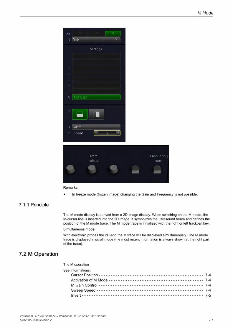
Remarks:
• In freeze mode (frozen image) changing the Gain and Frequency is not possible.
7.1.1 Principle
The M mode display is derived from a 2D image display. When switching on the M mode, theM-cursor line is inserted into the 2D image. It symbolizes the ultrasound beam and defines theposition of the M mode trace. The M mode trace is initialized with the right or left trackball key.Simultaneous mode:With electronic probes the 2D-and the M trace will be displayed simultaneously. The M modetrace is displayed in scroll mode (the most recent information is always shown at the right partof the trace).
7.2 M Operation
The M operationSee informations:
Cursor Position - - - - - - - - - - - - - - - - - - - - - - - - - - - - - - - - - - - - - - - - - - - - 7-4Activation of M Mode - - - - - - - - - - - - - - - - - - - - - - - - - - - - - - - - - - - - - - - - 7-4M Gain Control - - - - - - - - - - - - - - - - - - - - - - - - - - - - - - - - - - - - - - - - - - - - 7-4Sweep Speed - - - - - - - - - - - - - - - - - - - - - - - - - - - - - - - - - - - - - - - - - - - - - 7-4Invert - - - - - - - - - - - - - - - - - - - - - - - - - - - - - - - - - - - - - - - - - - - - - - - - - - - 7-5
M Mode
Voluson® S6 / Voluson® S8 / Voluson® S8 Pro Basic User Manual5482585-100 Revision 2 7-3
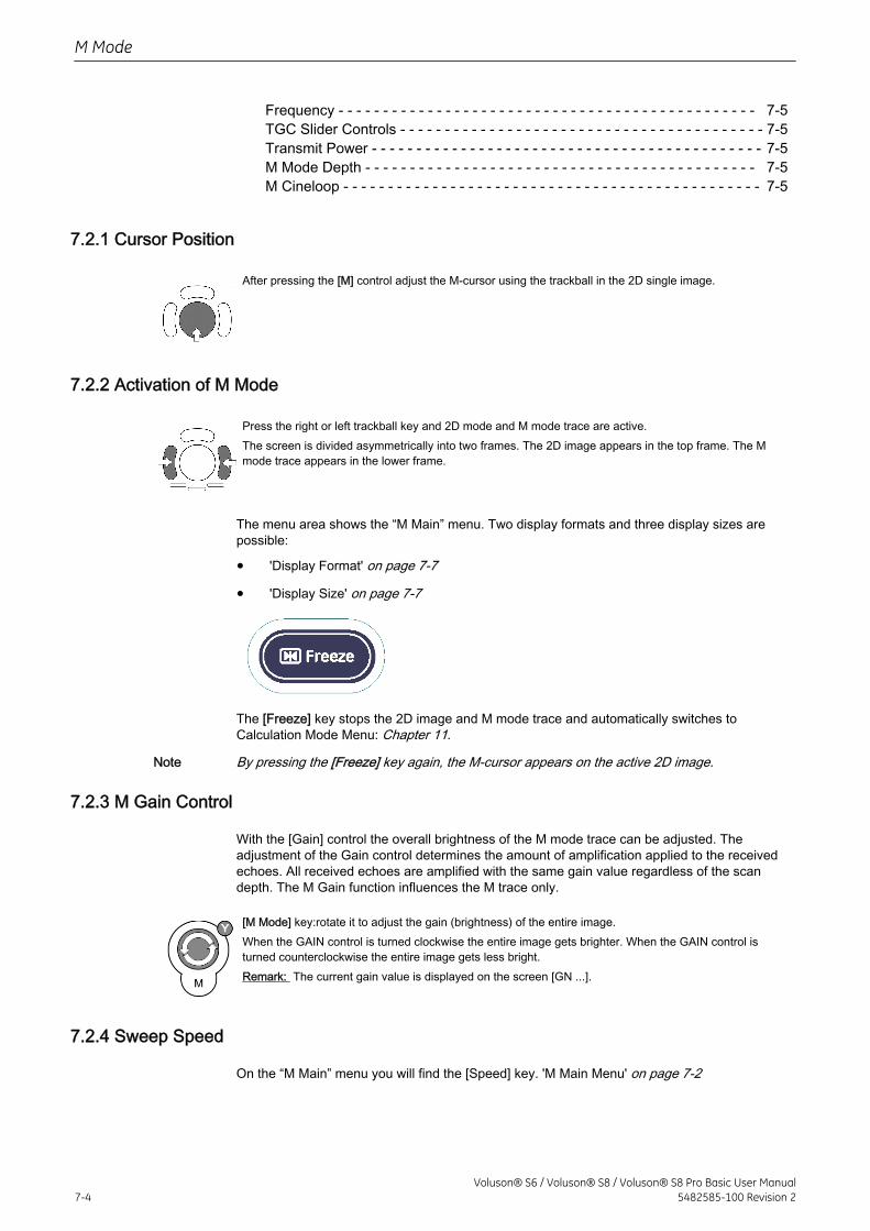
Frequency - - - - - - - - - - - - - - - - - - - - - - - - - - - - - - - - - - - - - - - - - - - - - - - 7-5TGC Slider Controls - - - - - - - - - - - - - - - - - - - - - - - - - - - - - - - - - - - - - - - - - 7-5Transmit Power - - - - - - - - - - - - - - - - - - - - - - - - - - - - - - - - - - - - - - - - - - - - 7-5M Mode Depth - - - - - - - - - - - - - - - - - - - - - - - - - - - - - - - - - - - - - - - - - - - - 7-5M Cineloop - - - - - - - - - - - - - - - - - - - - - - - - - - - - - - - - - - - - - - - - - - - - - - - 7-5
7.2.1 Cursor Position
After pressing the [M] control adjust the M-cursor using the trackball in the 2D single image.
7.2.2 Activation of M Mode
Press the right or left trackball key and 2D mode and M mode trace are active.The screen is divided asymmetrically into two frames. The 2D image appears in the top frame. The Mmode trace appears in the lower frame.
The menu area shows the “M Main” menu. Two display formats and three display sizes arepossible:
• 'Display Format' on page 7-7
• 'Display Size' on page 7-7
The [Freeze] key stops the 2D image and M mode trace and automatically switches toCalculation Mode Menu: Chapter 11.
Note By pressing the [Freeze] key again, the M-cursor appears on the active 2D image.
7.2.3 M Gain Control
With the [Gain] control the overall brightness of the M mode trace can be adjusted. Theadjustment of the Gain control determines the amount of amplification applied to the receivedechoes. All received echoes are amplified with the same gain value regardless of the scandepth. The M Gain function influences the M trace only.
[M Mode] key:rotate it to adjust the gain (brightness) of the entire image.When the GAIN control is turned clockwise the entire image gets brighter. When the GAIN control isturned counterclockwise the entire image gets less bright.Remark: The current gain value is displayed on the screen [GN ...].
7.2.4 Sweep Speed
On the “M Main” menu you will find the [Speed] key. 'M Main Menu' on page 7-2
M Mode
7-4Voluson® S6 / Voluson® S8 / Voluson® S8 Pro Basic User Manual
5482585-100 Revision 2
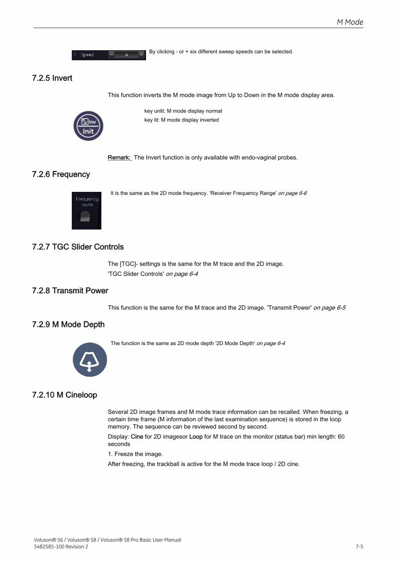
By clicking - or + six different sweep speeds can be selected.
7.2.5 Invert
This function inverts the M mode image from Up to Down in the M mode display area.
key unlit: M mode display normalkey lit: M mode display inverted
Remark: The Invert function is only available with endo-vaginal probes.
7.2.6 Frequency
It is the same as the 2D mode frequency. 'Receiver Frequency Range' on page 6-6
7.2.7 TGC Slider Controls
The [TGC]- settings is the same for the M trace and the 2D image.'TGC Slider Controls' on page 6-4
7.2.8 Transmit Power
This function is the same for the M trace and the 2D image. 'Transmit Power' on page 6-5
7.2.9 M Mode Depth
The function is the same as 2D mode depth '2D Mode Depth' on page 6-4
7.2.10 M Cineloop
Several 2D image frames and M mode trace information can be recalled. When freezing, acertain time frame (M information of the last examination sequence) is stored in the loopmemory. The sequence can be reviewed second by second.Display: Cine for 2D imagesor Loop for M trace on the monitor (status bar) min length: 60seconds1. Freeze the image.After freezing, the trackball is active for the M mode trace loop / 2D cine.
M Mode
Voluson® S6 / Voluson® S8 / Voluson® S8 Pro Basic User Manual5482585-100 Revision 2 7-5
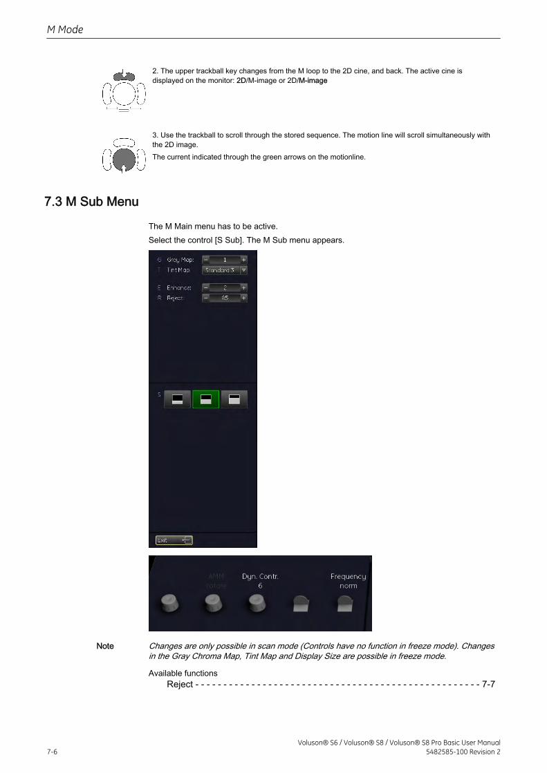
2. The upper trackball key changes from the M loop to the 2D cine, and back. The active cine isdisplayed on the monitor: 2D/M-image or 2D/M-image
3. Use the trackball to scroll through the stored sequence. The motion line will scroll simultaneously withthe 2D image.The current indicated through the green arrows on the motionline.
7.3 M Sub Menu
The M Main menu has to be active.Select the control [S Sub]. The M Sub menu appears.
Note Changes are only possible in scan mode (Controls have no function in freeze mode). Changesin the Gray Chroma Map, Tint Map and Display Size are possible in freeze mode.
Available functionsReject - - - - - - - - - - - - - - - - - - - - - - - - - - - - - - - - - - - - - - - - - - - - - - - - - - - 7-7
M Mode
7-6Voluson® S6 / Voluson® S8 / Voluson® S8 Pro Basic User Manual
5482585-100 Revision 2
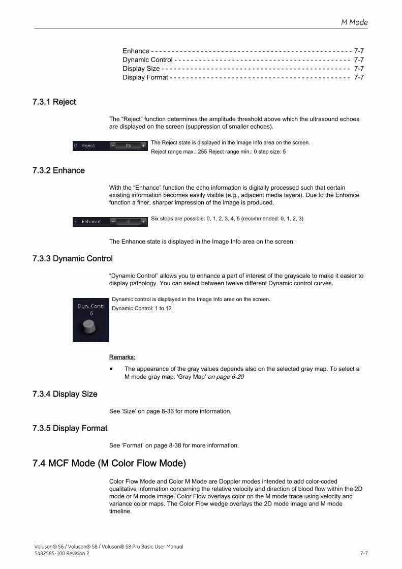
Enhance - - - - - - - - - - - - - - - - - - - - - - - - - - - - - - - - - - - - - - - - - - - - - - - - - 7-7Dynamic Control - - - - - - - - - - - - - - - - - - - - - - - - - - - - - - - - - - - - - - - - - - - 7-7Display Size - - - - - - - - - - - - - - - - - - - - - - - - - - - - - - - - - - - - - - - - - - - - - - 7-7Display Format - - - - - - - - - - - - - - - - - - - - - - - - - - - - - - - - - - - - - - - - - - - - 7-7
7.3.1 Reject
The “Reject” function determines the amplitude threshold above which the ultrasound echoesare displayed on the screen (suppression of smaller echoes).
The Reject state is displayed in the Image Info area on the screen.Reject range max.: 255 Reject range min.: 0 step size: 5
7.3.2 Enhance
With the “Enhance” function the echo information is digitally processed such that certainexisting information becomes easily visible (e.g., adjacent media layers). Due to the Enhancefunction a finer, sharper impression of the image is produced.
Six steps are possible: 0, 1, 2, 3, 4, 5 (recommended: 0, 1, 2, 3)
The Enhance state is displayed in the Image Info area on the screen.
7.3.3 Dynamic Control
“Dynamic Control” allows you to enhance a part of interest of the grayscale to make it easier todisplay pathology. You can select between twelve different Dynamic control curves.
Dynamic control is displayed in the Image Info area on the screen.Dynamic Control: 1 to 12
Remarks:
• The appearance of the gray values depends also on the selected gray map. To select aM mode gray map: 'Gray Map' on page 6-20
7.3.4 Display Size
See ‘Size’ on page 8‐36 for more information.
7.3.5 Display Format
See ‘Format’ on page 8‐38 for more information.
7.4 MCF Mode (M Color Flow Mode)
Color Flow Mode and Color M Mode are Doppler modes intended to add color-codedqualitative information concerning the relative velocity and direction of blood flow within the 2Dmode or M mode image. Color Flow overlays color on the M mode trace using velocity andvariance color maps. The Color Flow wedge overlays the 2D mode image and M modetimeline.
M Mode
Voluson® S6 / Voluson® S8 / Voluson® S8 Pro Basic User Manual5482585-100 Revision 2 7-7
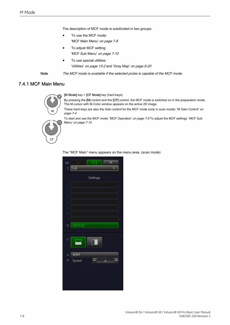
The description of MCF mode is subdivided in two groups:
• To use the MCF mode:'MCF Main Menu' on page 7-8
• To adjust MCF setting:'MCF Sub Menu' on page 7-10
• To use special utilities:'Utilities' on page 13-2 and 'Gray Map' on page 6-20
Note The MCF mode is available if the selected probe is capable of the MCF mode.
7.4.1 MCF Main Menu
[M Mode] key + [CF Mode] key (hard keys)By pressing the [M] control and the [CF] control, the MCF mode is switched on in the preparation mode.The M-cursor with M-Color window appears on the active 2D image.These hard keys are also the Gain control for the MCF mode (only in scan mode): 'M Gain Control' onpage 7-4To start and use the MCF mode: 'MCF Operation' on page 7-9 To adjust the MCF settings: 'MCF SubMenu' on page 7-10
The “MCF Main” menu appears on the menu area. (scan mode)
M Mode
7-8Voluson® S6 / Voluson® S8 / Voluson® S8 Pro Basic User Manual
5482585-100 Revision 2
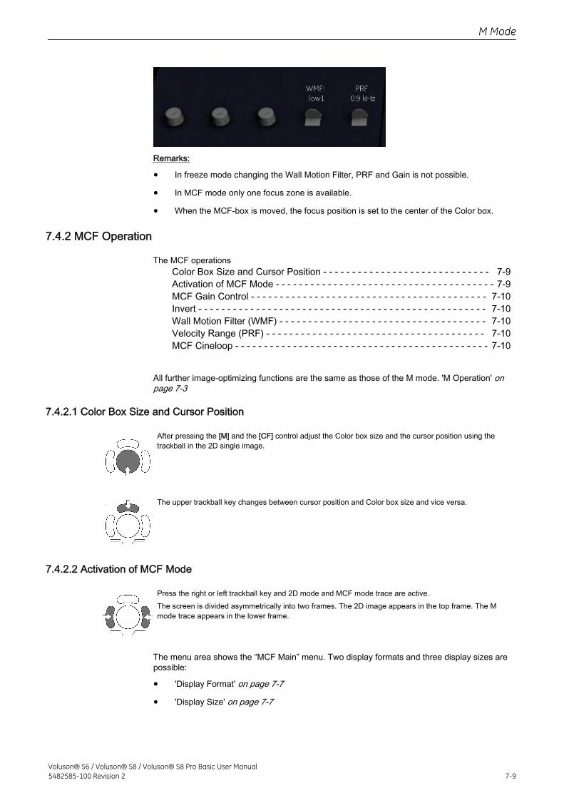
Remarks:
• In freeze mode changing the Wall Motion Filter, PRF and Gain is not possible.
• In MCF mode only one focus zone is available.
• When the MCF-box is moved, the focus position is set to the center of the Color box.
7.4.2 MCF Operation
The MCF operationsColor Box Size and Cursor Position - - - - - - - - - - - - - - - - - - - - - - - - - - - - - 7-9Activation of MCF Mode - - - - - - - - - - - - - - - - - - - - - - - - - - - - - - - - - - - - - - 7-9MCF Gain Control - - - - - - - - - - - - - - - - - - - - - - - - - - - - - - - - - - - - - - - - - 7-10Invert - - - - - - - - - - - - - - - - - - - - - - - - - - - - - - - - - - - - - - - - - - - - - - - - - - 7-10Wall Motion Filter (WMF) - - - - - - - - - - - - - - - - - - - - - - - - - - - - - - - - - - - - 7-10Velocity Range (PRF) - - - - - - - - - - - - - - - - - - - - - - - - - - - - - - - - - - - - - - 7-10MCF Cineloop - - - - - - - - - - - - - - - - - - - - - - - - - - - - - - - - - - - - - - - - - - - - 7-10
All further image-optimizing functions are the same as those of the M mode. 'M Operation' onpage 7-3
7.4.2.1 Color Box Size and Cursor Position
After pressing the [M] and the [CF] control adjust the Color box size and the cursor position using thetrackball in the 2D single image.
The upper trackball key changes between cursor position and Color box size and vice versa.
7.4.2.2 Activation of MCF Mode
Press the right or left trackball key and 2D mode and MCF mode trace are active.The screen is divided asymmetrically into two frames. The 2D image appears in the top frame. The Mmode trace appears in the lower frame.
The menu area shows the “MCF Main” menu. Two display formats and three display sizes arepossible:
• 'Display Format' on page 7-7
• 'Display Size' on page 7-7
M Mode
Voluson® S6 / Voluson® S8 / Voluson® S8 Pro Basic User Manual5482585-100 Revision 2 7-9
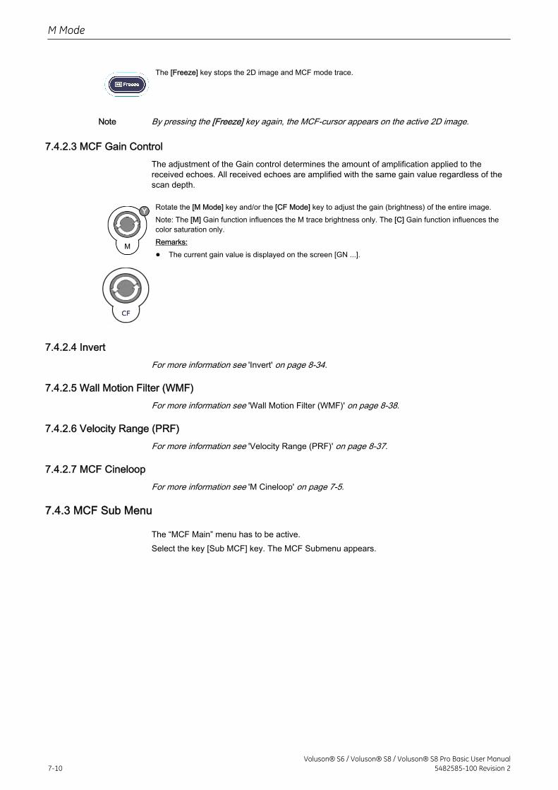
The [Freeze] key stops the 2D image and MCF mode trace.
Note By pressing the [Freeze] key again, the MCF-cursor appears on the active 2D image.
7.4.2.3 MCF Gain ControlThe adjustment of the Gain control determines the amount of amplification applied to thereceived echoes. All received echoes are amplified with the same gain value regardless of thescan depth.
Rotate the [M Mode] key and/or the [CF Mode] key to adjust the gain (brightness) of the entire image.Note: The [M] Gain function influences the M trace brightness only. The [C] Gain function influences thecolor saturation only.Remarks:
• The current gain value is displayed on the screen [GN ...].
7.4.2.4 InvertFor more information see 'Invert' on page 8-34.
7.4.2.5 Wall Motion Filter (WMF)For more information see 'Wall Motion Filter (WMF)' on page 8-38.
7.4.2.6 Velocity Range (PRF)For more information see 'Velocity Range (PRF)' on page 8-37.
7.4.2.7 MCF CineloopFor more information see 'M Cineloop' on page 7-5.
7.4.3 MCF Sub Menu
The “MCF Main” menu has to be active.Select the key [Sub MCF] key. The MCF Submenu appears.
M Mode
7-10Voluson® S6 / Voluson® S8 / Voluson® S8 Pro Basic User Manual
5482585-100 Revision 2
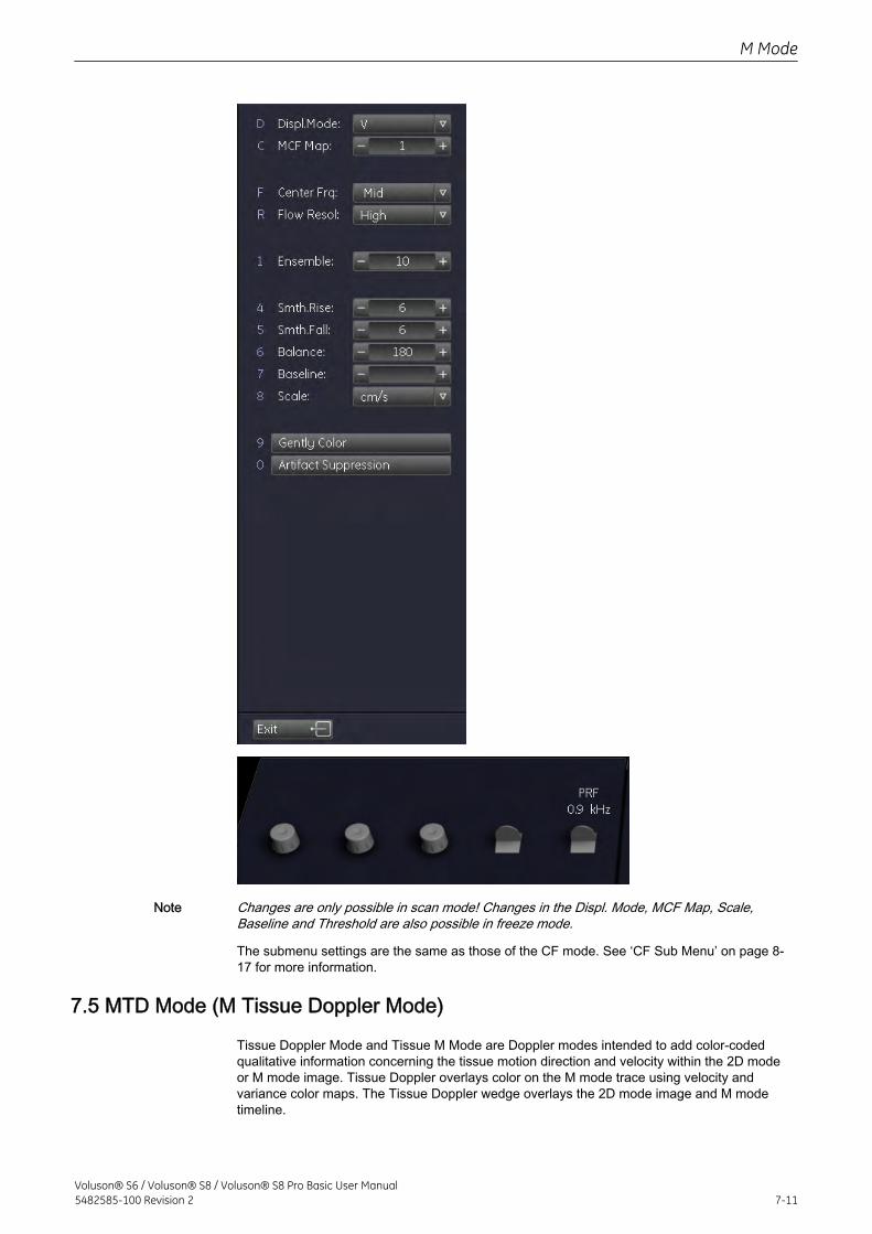
Note Changes are only possible in scan mode! Changes in the Displ. Mode, MCF Map, Scale,Baseline and Threshold are also possible in freeze mode.
The submenu settings are the same as those of the CF mode. See ‘CF Sub Menu’ on page 8‐17 for more information.
7.5 MTD Mode (M Tissue Doppler Mode)
Tissue Doppler Mode and Tissue M Mode are Doppler modes intended to add color-codedqualitative information concerning the tissue motion direction and velocity within the 2D modeor M mode image. Tissue Doppler overlays color on the M mode trace using velocity andvariance color maps. The Tissue Doppler wedge overlays the 2D mode image and M modetimeline.
M Mode
Voluson® S6 / Voluson® S8 / Voluson® S8 Pro Basic User Manual5482585-100 Revision 2 7-11
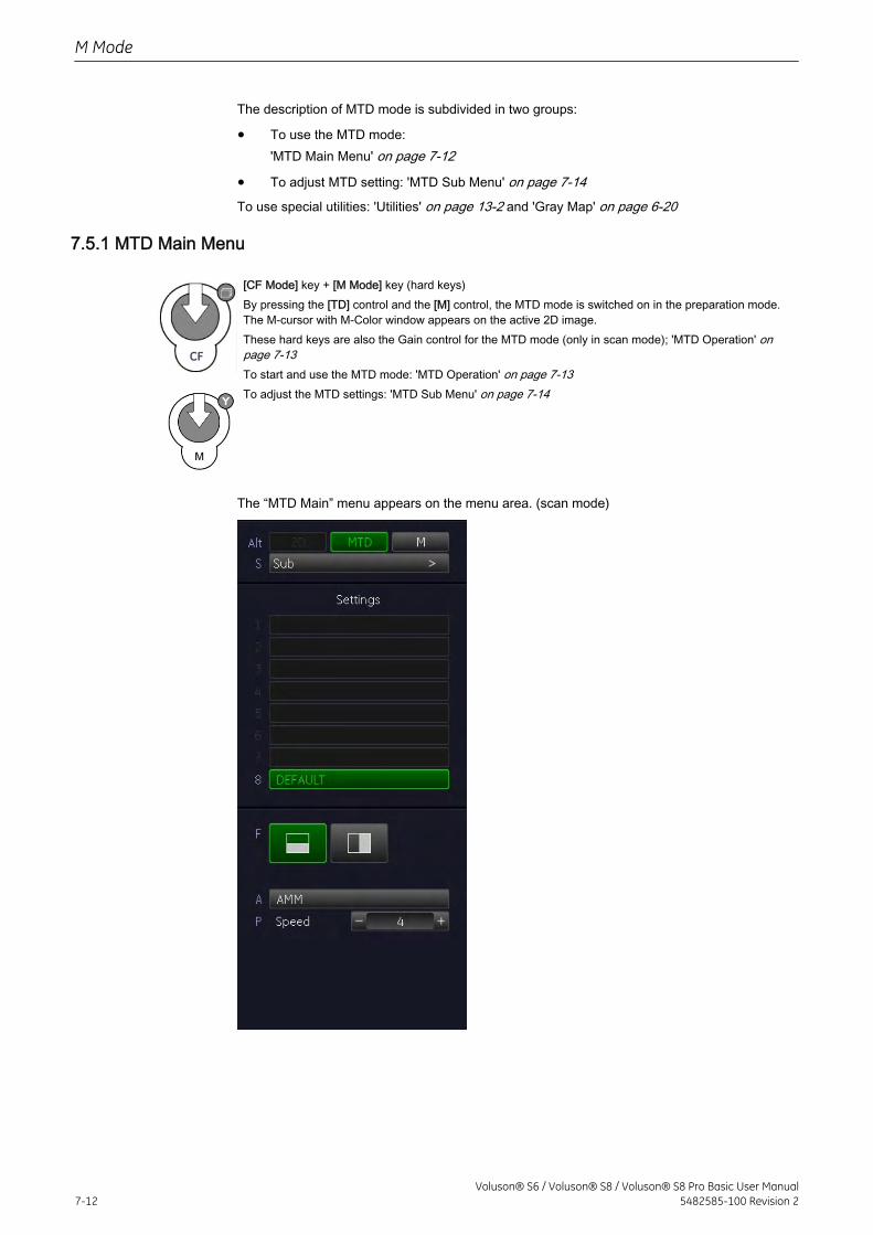
The description of MTD mode is subdivided in two groups:
• To use the MTD mode:'MTD Main Menu' on page 7-12
• To adjust MTD setting: 'MTD Sub Menu' on page 7-14To use special utilities: 'Utilities' on page 13-2 and 'Gray Map' on page 6-20
7.5.1 MTD Main Menu
[CF Mode] key + [M Mode] key (hard keys)By pressing the [TD] control and the [M] control, the MTD mode is switched on in the preparation mode.The M-cursor with M-Color window appears on the active 2D image.These hard keys are also the Gain control for the MTD mode (only in scan mode); 'MTD Operation' onpage 7-13To start and use the MTD mode: 'MTD Operation' on page 7-13To adjust the MTD settings: 'MTD Sub Menu' on page 7-14
The “MTD Main” menu appears on the menu area. (scan mode)
M Mode
7-12Voluson® S6 / Voluson® S8 / Voluson® S8 Pro Basic User Manual
5482585-100 Revision 2
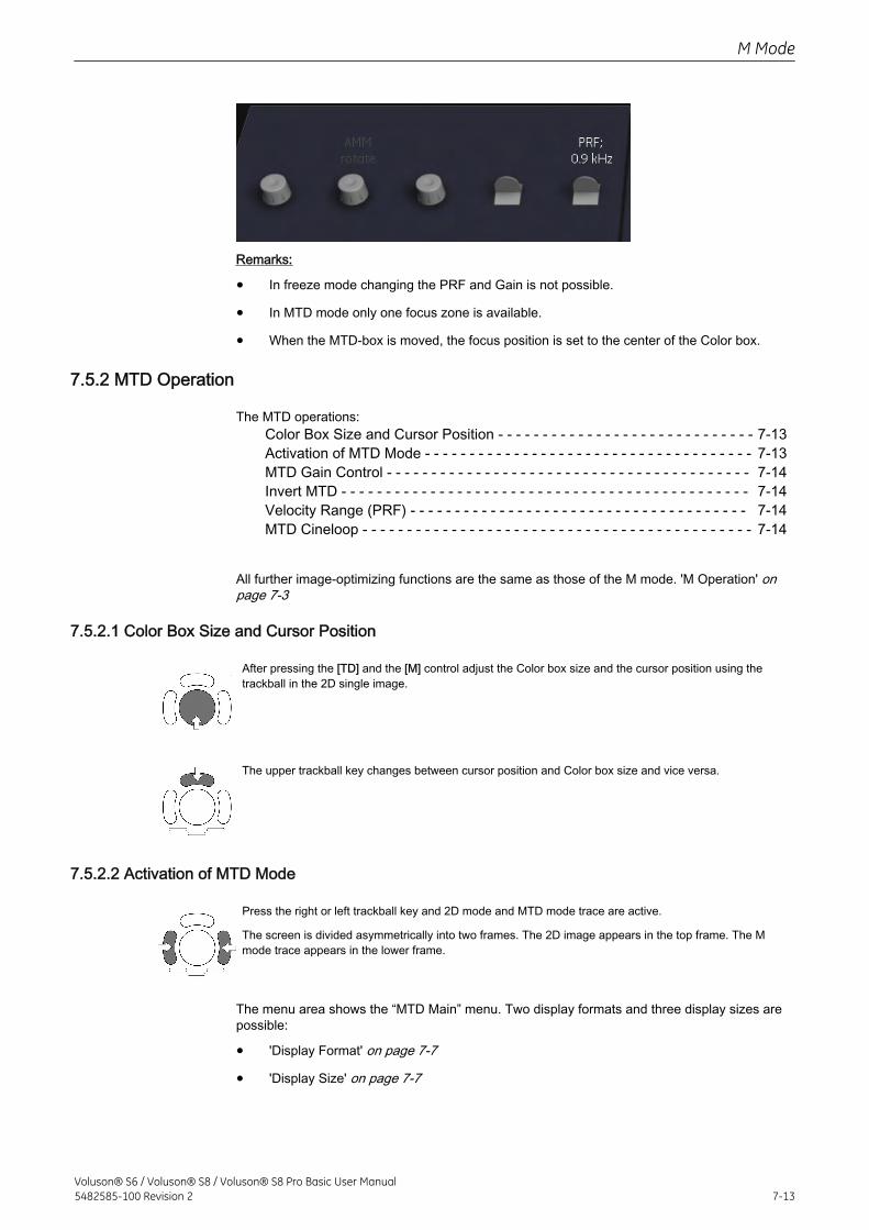
Remarks:
• In freeze mode changing the PRF and Gain is not possible.
• In MTD mode only one focus zone is available.
• When the MTD-box is moved, the focus position is set to the center of the Color box.
7.5.2 MTD Operation
The MTD operations:Color Box Size and Cursor Position - - - - - - - - - - - - - - - - - - - - - - - - - - - - - 7-13Activation of MTD Mode - - - - - - - - - - - - - - - - - - - - - - - - - - - - - - - - - - - - - 7-13MTD Gain Control - - - - - - - - - - - - - - - - - - - - - - - - - - - - - - - - - - - - - - - - - 7-14Invert MTD - - - - - - - - - - - - - - - - - - - - - - - - - - - - - - - - - - - - - - - - - - - - - - 7-14Velocity Range (PRF) - - - - - - - - - - - - - - - - - - - - - - - - - - - - - - - - - - - - - - 7-14MTD Cineloop - - - - - - - - - - - - - - - - - - - - - - - - - - - - - - - - - - - - - - - - - - - - 7-14
All further image-optimizing functions are the same as those of the M mode. 'M Operation' onpage 7-3
7.5.2.1 Color Box Size and Cursor Position
After pressing the [TD] and the [M] control adjust the Color box size and the cursor position using thetrackball in the 2D single image.
The upper trackball key changes between cursor position and Color box size and vice versa.
7.5.2.2 Activation of MTD Mode
Press the right or left trackball key and 2D mode and MTD mode trace are active.
The screen is divided asymmetrically into two frames. The 2D image appears in the top frame. The Mmode trace appears in the lower frame.
The menu area shows the “MTD Main” menu. Two display formats and three display sizes arepossible:
• 'Display Format' on page 7-7
• 'Display Size' on page 7-7
M Mode
Voluson® S6 / Voluson® S8 / Voluson® S8 Pro Basic User Manual5482585-100 Revision 2 7-13
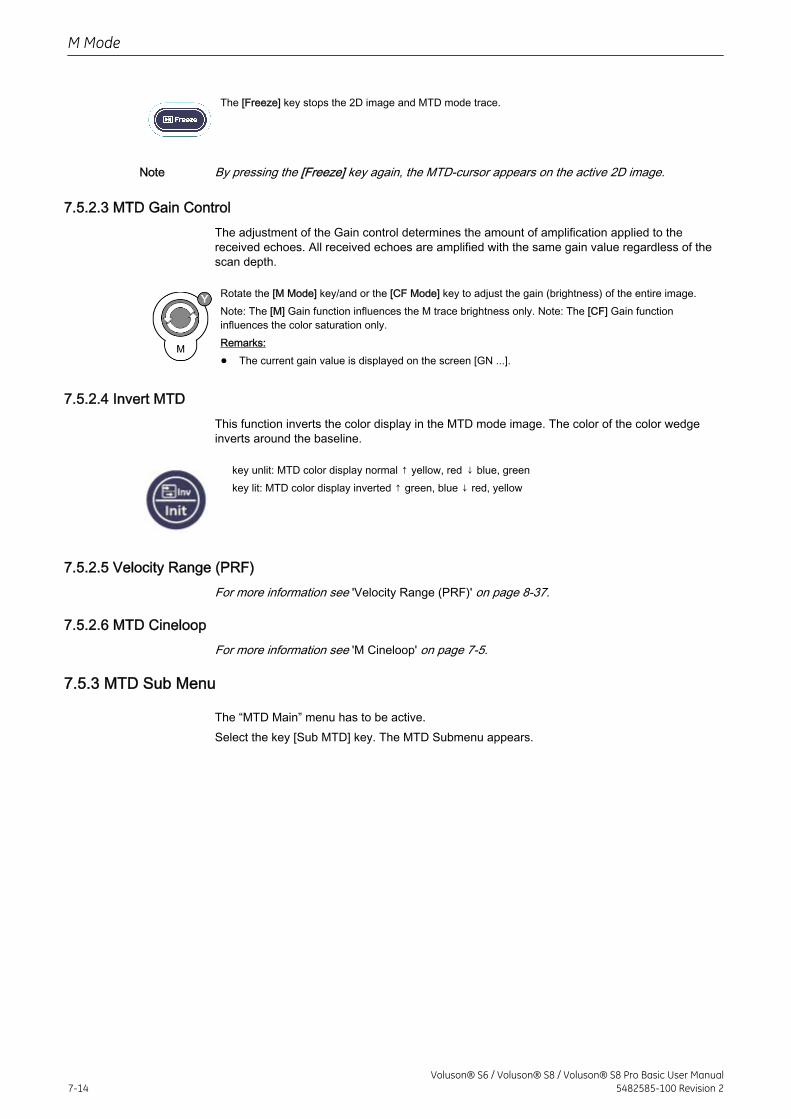
The [Freeze] key stops the 2D image and MTD mode trace.
Note By pressing the [Freeze] key again, the MTD-cursor appears on the active 2D image.
7.5.2.3 MTD Gain ControlThe adjustment of the Gain control determines the amount of amplification applied to thereceived echoes. All received echoes are amplified with the same gain value regardless of thescan depth.
Rotate the [M Mode] key/and or the [CF Mode] key to adjust the gain (brightness) of the entire image.Note: The [M] Gain function influences the M trace brightness only. Note: The [CF] Gain functioninfluences the color saturation only.Remarks:
• The current gain value is displayed on the screen [GN ...].
7.5.2.4 Invert MTDThis function inverts the color display in the MTD mode image. The color of the color wedgeinverts around the baseline.
key unlit: MTD color display normal ↑ yellow, red ↓ blue, greenkey lit: MTD color display inverted ↑ green, blue ↓ red, yellow
7.5.2.5 Velocity Range (PRF)For more information see 'Velocity Range (PRF)' on page 8-37.
7.5.2.6 MTD CineloopFor more information see 'M Cineloop' on page 7-5.
7.5.3 MTD Sub Menu
The “MTD Main” menu has to be active.Select the key [Sub MTD] key. The MTD Submenu appears.
M Mode
7-14Voluson® S6 / Voluson® S8 / Voluson® S8 Pro Basic User Manual
5482585-100 Revision 2
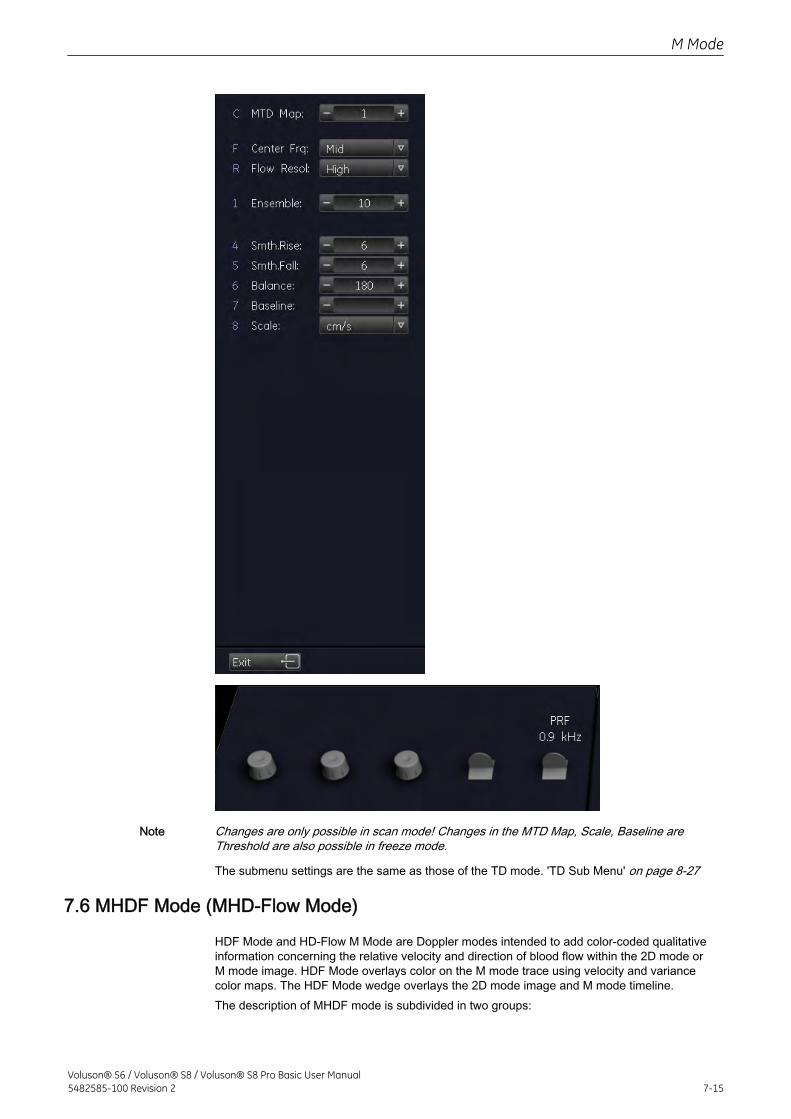
Note Changes are only possible in scan mode! Changes in the MTD Map, Scale, Baseline areThreshold are also possible in freeze mode.
The submenu settings are the same as those of the TD mode. 'TD Sub Menu' on page 8-27
7.6 MHDF Mode (MHD-Flow Mode)
HDF Mode and HD-Flow M Mode are Doppler modes intended to add color-coded qualitativeinformation concerning the relative velocity and direction of blood flow within the 2D mode orM mode image. HDF Mode overlays color on the M mode trace using velocity and variancecolor maps. The HDF Mode wedge overlays the 2D mode image and M mode timeline.The description of MHDF mode is subdivided in two groups:
M Mode
Voluson® S6 / Voluson® S8 / Voluson® S8 Pro Basic User Manual5482585-100 Revision 2 7-15
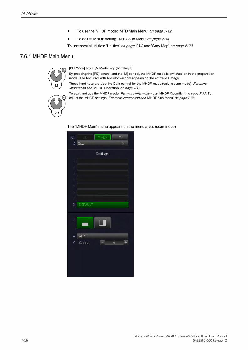
• To use the MHDF mode: 'MTD Main Menu' on page 7-12
• To adjust MHDF setting: 'MTD Sub Menu' on page 7-14To use special utilities: 'Utilities' on page 13-2 and 'Gray Map' on page 6-20
7.6.1 MHDF Main Menu
[PD Mode] key + [M Mode] key (hard keys)By pressing the [PD] control and the [M] control, the MHDF mode is switched on in the preparationmode. The M-cursor with M-Color window appears on the active 2D image.These hard keys are also the Gain control for the MHDF mode (only in scan mode); For moreinformation see 'MHDF Operation' on page 7-17.To start and use the MHDF mode: For more information see 'MHDF Operation' on page 7-17. Toadjust the MHDF settings: For more information see 'MHDF Sub Menu' on page 7-18.
The “MHDF Main” menu appears on the menu area. (scan mode)
M Mode
7-16Voluson® S6 / Voluson® S8 / Voluson® S8 Pro Basic User Manual
5482585-100 Revision 2
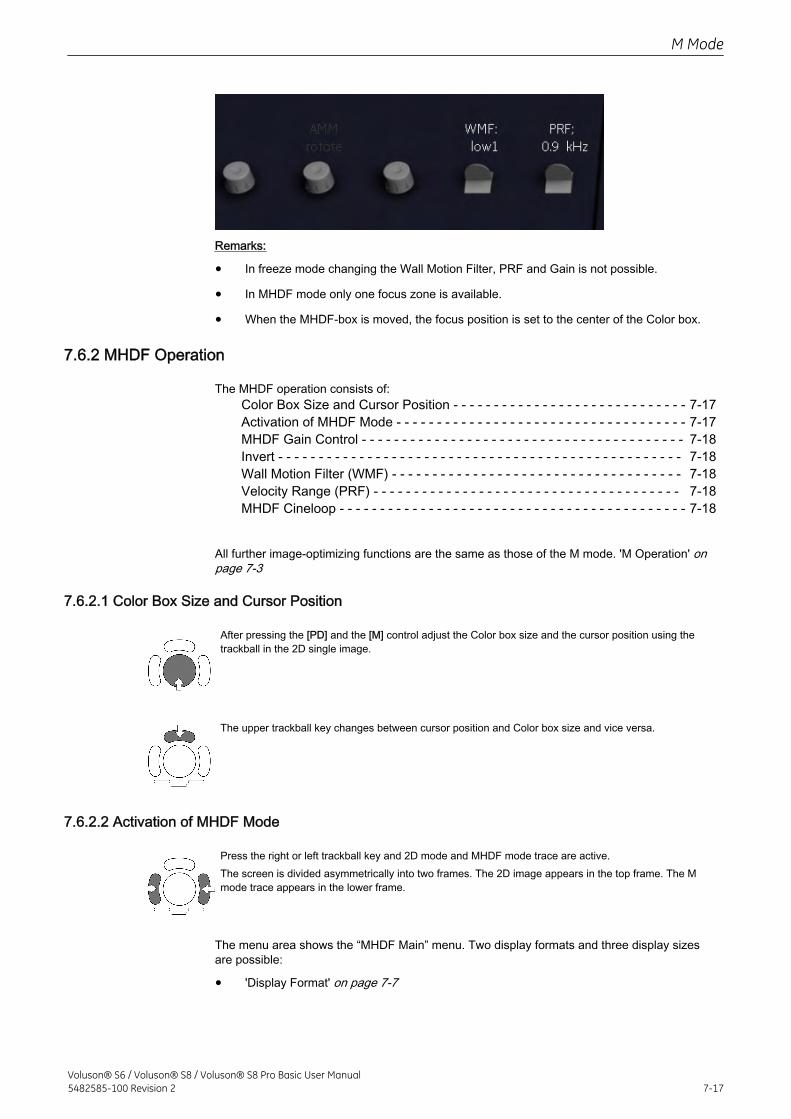
Remarks:
• In freeze mode changing the Wall Motion Filter, PRF and Gain is not possible.
• In MHDF mode only one focus zone is available.
• When the MHDF-box is moved, the focus position is set to the center of the Color box.
7.6.2 MHDF Operation
The MHDF operation consists of:Color Box Size and Cursor Position - - - - - - - - - - - - - - - - - - - - - - - - - - - - - 7-17Activation of MHDF Mode - - - - - - - - - - - - - - - - - - - - - - - - - - - - - - - - - - - - 7-17MHDF Gain Control - - - - - - - - - - - - - - - - - - - - - - - - - - - - - - - - - - - - - - - - 7-18Invert - - - - - - - - - - - - - - - - - - - - - - - - - - - - - - - - - - - - - - - - - - - - - - - - - - 7-18Wall Motion Filter (WMF) - - - - - - - - - - - - - - - - - - - - - - - - - - - - - - - - - - - - 7-18Velocity Range (PRF) - - - - - - - - - - - - - - - - - - - - - - - - - - - - - - - - - - - - - - 7-18MHDF Cineloop - - - - - - - - - - - - - - - - - - - - - - - - - - - - - - - - - - - - - - - - - - - 7-18
All further image-optimizing functions are the same as those of the M mode. 'M Operation' onpage 7-3
7.6.2.1 Color Box Size and Cursor Position
After pressing the [PD] and the [M] control adjust the Color box size and the cursor position using thetrackball in the 2D single image.
The upper trackball key changes between cursor position and Color box size and vice versa.
7.6.2.2 Activation of MHDF Mode
Press the right or left trackball key and 2D mode and MHDF mode trace are active.The screen is divided asymmetrically into two frames. The 2D image appears in the top frame. The Mmode trace appears in the lower frame.
The menu area shows the “MHDF Main” menu. Two display formats and three display sizesare possible:
• 'Display Format' on page 7-7
M Mode
Voluson® S6 / Voluson® S8 / Voluson® S8 Pro Basic User Manual5482585-100 Revision 2 7-17
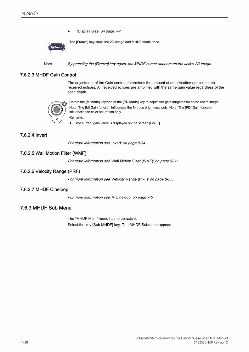
• 'Display Size' on page 7-7
The [Freeze] key stops the 2D image and MHDF mode trace.
Note By pressing the [Freeze] key again, the MHDF-cursor appears on the active 2D image.
7.6.2.3 MHDF Gain ControlThe adjustment of the Gain control determines the amount of amplification applied to thereceived echoes. All received echoes are amplified with the same gain value regardless of thescan depth.
Rotate the [M Mode] key/and or the [PD Mode] key to adjust the gain (brightness) of the entire image.Note: The [M] Gain function influences the M trace brightness only. Note: The [PD] Gain functioninfluences the color saturation only.Remarks:
• The current gain value is displayed on the screen [GN ...].
7.6.2.4 InvertFor more information see 'Invert' on page 8-34.
7.6.2.5 Wall Motion Filter (WMF)For more information see 'Wall Motion Filter (WMF)' on page 8-38.
7.6.2.6 Velocity Range (PRF)For more information see 'Velocity Range (PRF)' on page 8-37.
7.6.2.7 MHDF CineloopFor more information see 'M Cineloop' on page 7-5.
7.6.3 MHDF Sub Menu
The “MHDF Main” menu has to be active.Select the key [Sub MHDF] key. The MHDF Submenu appears.
M Mode
7-18Voluson® S6 / Voluson® S8 / Voluson® S8 Pro Basic User Manual
5482585-100 Revision 2
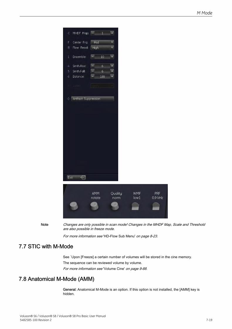
Note Changes are only possible in scan mode! Changes in the MHDF Map, Scale and Thresholdare also possible in freeze mode.
For more information see 'HD-Flow Sub Menu' on page 8-23.
7.7 STIC with M-Mode
See `Upon [Freeze] a certain number of volumes will be stored in the cine memory.The sequence can be reviewed volume by volume.For more information see 'Volume Cine' on page 9-88.
7.8 Anatomical M-Mode (AMM)
General: Anatomical M-Mode is an option. If this option is not installed, the [AMM] key ishidden.
M Mode
Voluson® S6 / Voluson® S8 / Voluson® S8 Pro Basic User Manual5482585-100 Revision 2 7-19
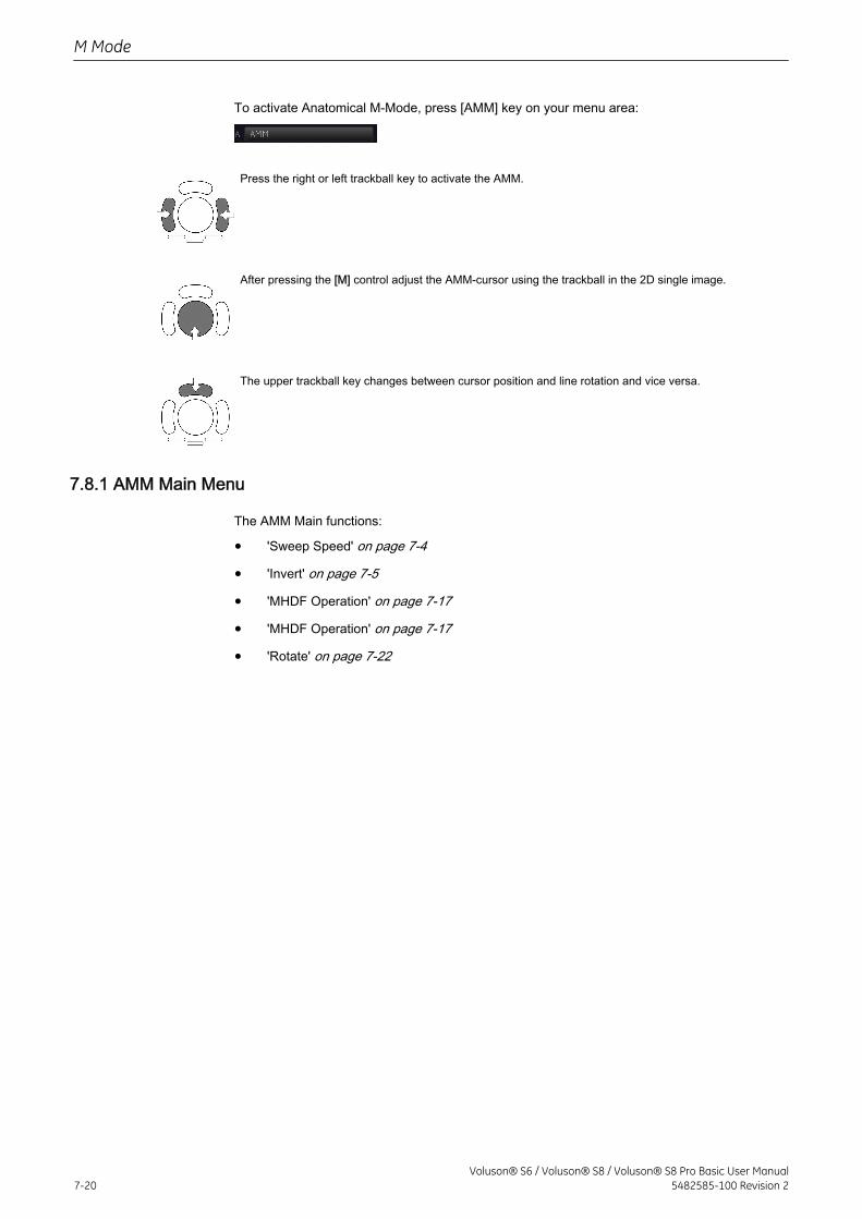
To activate Anatomical M-Mode, press [AMM] key on your menu area:
Press the right or left trackball key to activate the AMM.
After pressing the [M] control adjust the AMM-cursor using the trackball in the 2D single image.
The upper trackball key changes between cursor position and line rotation and vice versa.
7.8.1 AMM Main Menu
The AMM Main functions:
• 'Sweep Speed' on page 7-4
• 'Invert' on page 7-5
• 'MHDF Operation' on page 7-17
• 'MHDF Operation' on page 7-17
• 'Rotate' on page 7-22
M Mode
7-20Voluson® S6 / Voluson® S8 / Voluson® S8 Pro Basic User Manual
5482585-100 Revision 2
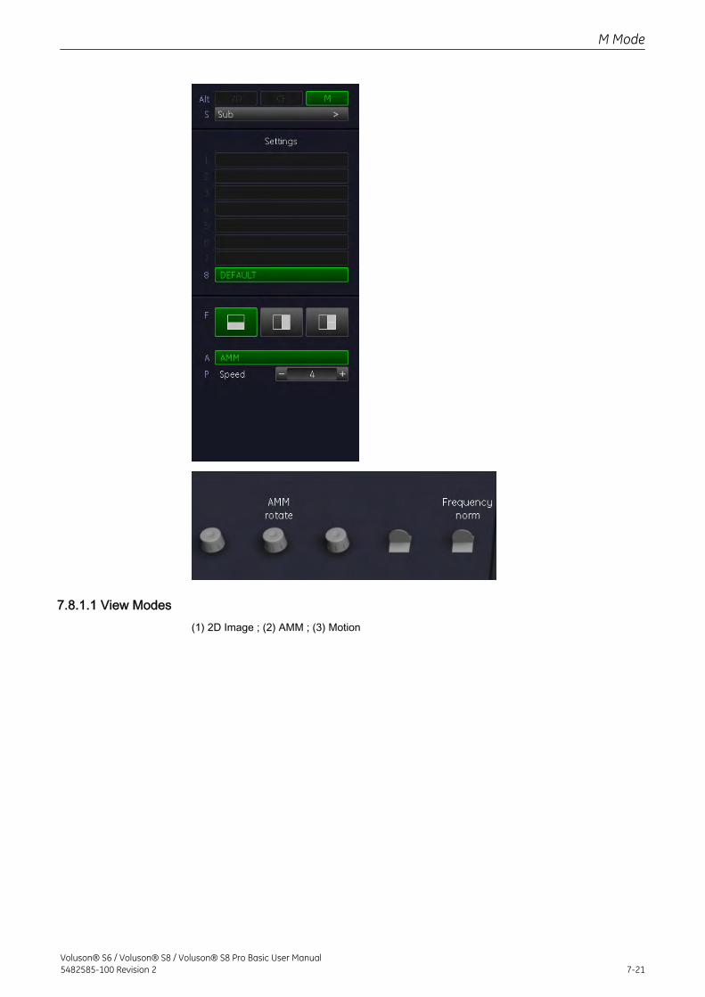
7.8.1.1 View Modes(1) 2D Image ; (2) AMM ; (3) Motion
M Mode
Voluson® S6 / Voluson® S8 / Voluson® S8 Pro Basic User Manual5482585-100 Revision 2 7-21
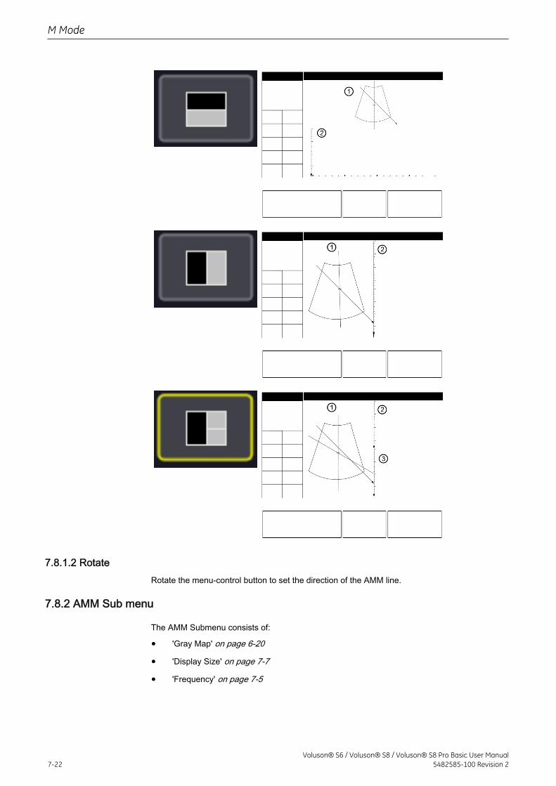
7.8.1.2 RotateRotate the menu-control button to set the direction of the AMM line.
7.8.2 AMM Sub menu
The AMM Submenu consists of:
• 'Gray Map' on page 6-20
• 'Display Size' on page 7-7
• 'Frequency' on page 7-5
M Mode
7-22Voluson® S6 / Voluson® S8 / Voluson® S8 Pro Basic User Manual
5482585-100 Revision 2
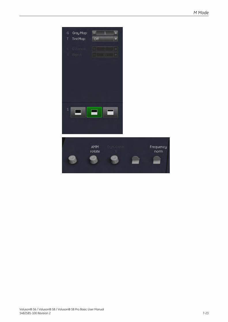
M Mode
Voluson® S6 / Voluson® S8 / Voluson® S8 Pro Basic User Manual5482585-100 Revision 2 7-23

This page was intentionally left blank.
M Mode
7-24Voluson® S6 / Voluson® S8 / Voluson® S8 Pro Basic User Manual
5482585-100 Revision 2
Chapter 8
Doppler Modes
Describes the general functions of the Spectral Doppler Mode (PW), Continuos Wave Doppler(CW), Color Flow Mode (CFM), Power Doppler (PD), High Definition Flow (HD-Flow) and TissueDoppler.Image quality is the essential performance of the system.Please read this chapter carefully.
Pulsed Wave Doppler Mode (PW Mode) - - - - - - - - - - - - - - - - - - - - - - - - - - - - - 8-2Continuous Wave Doppler Mode (CW Mode) - - - - - - - - - - - - - - - - - - - - - - - - - - 8-7Color Flow Mode (CFM) - - - - - - - - - - - - - - - - - - - - - - - - - - - - - - - - - - - - - - - - 8-10Power Doppler Mode (PD Mode) - - - - - - - - - - - - - - - - - - - - - - - - - - - - - - - - - - 8-15HD-Flow Mode (Bi-directional Angio Mode) - - - - - - - - - - - - - - - - - - - - - - - - - - 8-20Tissue Doppler Mode (TD Mode ) - - - - - - - - - - - - - - - - - - - - - - - - - - - - - - - - - 8-25Doppler Mode Functions and Filters - - - - - - - - - - - - - - - - - - - - - - - - - - - - - - - - 8-29
Voluson® S6 / Voluson® S8 / Voluson® S8 Pro Basic User Manual5482585-100 Revision 2 8-1
8.1 Pulsed Wave Doppler Mode (PW Mode)
Doppler imaging includes a spectral analysis which describes the Doppler shift signal from themoving reflectors within a sample volume. The spectral display scrolls from right to left anddepicts the spectral distribution of the components of the Doppler shift frequency over time.Frequency or velocity values appear on the vertical axis and time along the horizontal axis.Component amplitudes appear as shades of gray. The brighter the shade, the higher theamplitude.The Doppler display can be used alone, but it is normally used with a 2D image. The 2D imagecontains a Doppler cursor that defines the location of the Doppler ultrasound beam relative tothe 2D image display.The flow direction cursor can be aligned with the direction of flow within the vessel todetermine the Doppler angle. The system uses the Doppler angle to calibrate the Dopplervelocity display. When the Doppler frequency display is used, the frequency display is notcalibrated to account for the Doppler angle.The Doppler display consists of the following: the spectral analysis display of the ultrasounddata, patient data and identification, image information, a gray scale map, a velocity orfrequency scale, and a time scale.The TI and MI values on the monitor depend on the values set by the Doppler controls. Pleaserefer to Chapter 2 and Chapter 5 for a complete explanation of the acoustic output.A sample volume cursor is located on the PW cursor and it indicates where, along theultrasound beam, the spectral analysis is being performed. An angle correction cursor can beadded to the sample volume.The PW mode is subdivided in two groups. In these groups you will see how to use PW modeand how to adjust the PW settings.'Utilities' on page 13-2 and 'Gray Map' on page 6-20
8.1.1 PW Main Menu
[PW Mode] key (hard key)Press the [PW] control to activate the PW mode in the preparation mode. Firstonly the PW-cursor appears on the active 2D image.To start and use the PW mode: 'PW Operation' on page 8-3 To adjust thePW settings: 'PW Sub Menu' on page 8-6This hard key is also the Gain control for the PW mode in scan mode: 'PWOperation' on page 8-3
Doppler Modes
8-2Voluson® S6 / Voluson® S8 / Voluson® S8 Pro Basic User Manual
5482585-100 Revision 2
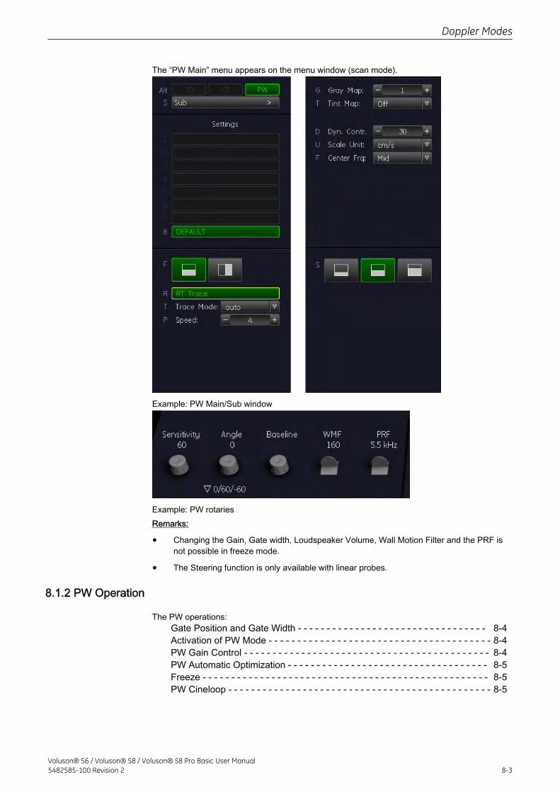
The “PW Main” menu appears on the menu window (scan mode).
Example: PW Main/Sub window
Example: PW rotariesRemarks:
• Changing the Gain, Gate width, Loudspeaker Volume, Wall Motion Filter and the PRF isnot possible in freeze mode.
• The Steering function is only available with linear probes.
8.1.2 PW Operation
The PW operations:Gate Position and Gate Width - - - - - - - - - - - - - - - - - - - - - - - - - - - - - - - - - 8-4Activation of PW Mode - - - - - - - - - - - - - - - - - - - - - - - - - - - - - - - - - - - - - - - 8-4PW Gain Control - - - - - - - - - - - - - - - - - - - - - - - - - - - - - - - - - - - - - - - - - - - 8-4PW Automatic Optimization - - - - - - - - - - - - - - - - - - - - - - - - - - - - - - - - - - - 8-5Freeze - - - - - - - - - - - - - - - - - - - - - - - - - - - - - - - - - - - - - - - - - - - - - - - - - - 8-5PW Cineloop - - - - - - - - - - - - - - - - - - - - - - - - - - - - - - - - - - - - - - - - - - - - - - 8-5
Doppler Modes
Voluson® S6 / Voluson® S8 / Voluson® S8 Pro Basic User Manual5482585-100 Revision 2 8-3
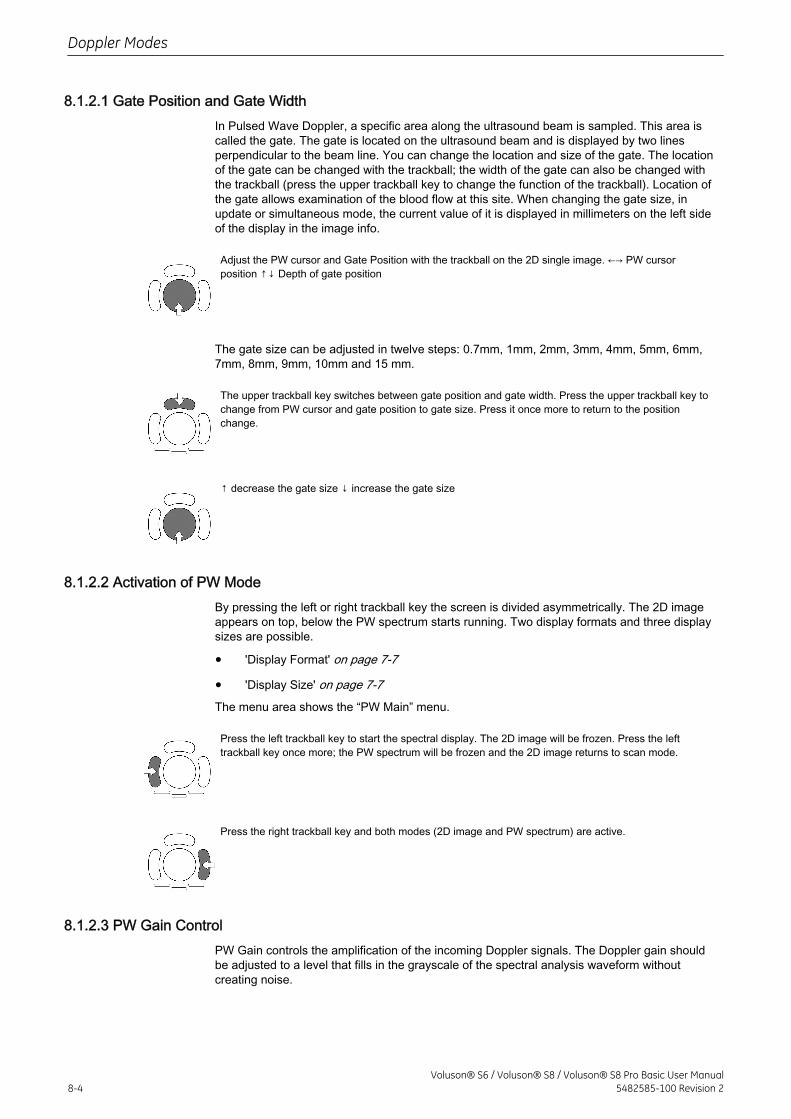
8.1.2.1 Gate Position and Gate WidthIn Pulsed Wave Doppler, a specific area along the ultrasound beam is sampled. This area iscalled the gate. The gate is located on the ultrasound beam and is displayed by two linesperpendicular to the beam line. You can change the location and size of the gate. The locationof the gate can be changed with the trackball; the width of the gate can also be changed withthe trackball (press the upper trackball key to change the function of the trackball). Location ofthe gate allows examination of the blood flow at this site. When changing the gate size, inupdate or simultaneous mode, the current value of it is displayed in millimeters on the left sideof the display in the image info.
Adjust the PW cursor and Gate Position with the trackball on the 2D single image. ←→ PW cursorposition ↑↓ Depth of gate position
The gate size can be adjusted in twelve steps: 0.7mm, 1mm, 2mm, 3mm, 4mm, 5mm, 6mm,7mm, 8mm, 9mm, 10mm and 15 mm.
The upper trackball key switches between gate position and gate width. Press the upper trackball key tochange from PW cursor and gate position to gate size. Press it once more to return to the positionchange.
↑ decrease the gate size ↓ increase the gate size
8.1.2.2 Activation of PW ModeBy pressing the left or right trackball key the screen is divided asymmetrically. The 2D imageappears on top, below the PW spectrum starts running. Two display formats and three displaysizes are possible.
• 'Display Format' on page 7-7
• 'Display Size' on page 7-7The menu area shows the “PW Main” menu.
Press the left trackball key to start the spectral display. The 2D image will be frozen. Press the lefttrackball key once more; the PW spectrum will be frozen and the 2D image returns to scan mode.
Press the right trackball key and both modes (2D image and PW spectrum) are active.
8.1.2.3 PW Gain ControlPW Gain controls the amplification of the incoming Doppler signals. The Doppler gain shouldbe adjusted to a level that fills in the grayscale of the spectral analysis waveform withoutcreating noise.
Doppler Modes
8-4Voluson® S6 / Voluson® S8 / Voluson® S8 Pro Basic User Manual
5482585-100 Revision 2
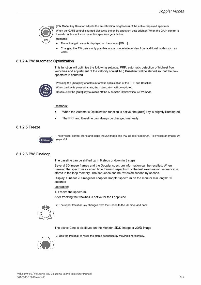
[PW Mode] key Rotation adjusts the amplification (brightness) of the entire displayed spectrum.When the GAIN control is turned clockwise the entire spectrum gets brighter. When the GAIN control isturned counterclockwise the entire spectrum gets darker.Remarks:
• The actual gain value is displayed on the screen [GN ...].
• Changing the PW gain is only possible in scan mode independent from additional modes such asColor.
8.1.2.4 PW Automatic OptimizationThis function will optimize the following settings: PRF: automatic detection of highest flowvelocities and adjustment of the velocity scale(PRF) Baseline: will be shifted so that the flowspectrum is centered
Pressing the [auto] key enables automatic optimization of the PRF and Baseline.When the key is pressed again, the optimization will be updated.Double-click the [auto] key to switch off the Automatic Optimization in PW mode.
Remarks:
• When the Automatic Optimization function is active, the [auto] key is brightly illuminated.
• The PRF and Baseline can always be changed manually!
8.1.2.5 Freeze
The [Freeze] control starts and stops the 2D image and PW Doppler spectrum. 'To Freeze an Image' onpage 4-9
8.1.2.6 PW CineloopThe baseline can be shifted up in 8 steps or down in 8 steps.Several 2D image frames and the Doppler spectrum information can be recalled. Whenfreezing the spectrum a certain time frame (D-spectrum of the last examination sequence) isstored in the loop memory. The sequence can be reviewed second by second.Display: Cine for 2D imagesor Loop for Doppler spectrum on the monitor min length: 60secondsOperation:1. Freeze the spectrum.After freezing the trackball is active for the Loop/Cine.
2. The upper trackball key changes from the D-loop to the 2D cine, and back.
The active Cine is displayed on the Monitor: 2D/D-image or 2D/D-image
3. Use the trackball to recall the stored sequence by moving it horizontally.
Doppler Modes
Voluson® S6 / Voluson® S8 / Voluson® S8 Pro Basic User Manual5482585-100 Revision 2 8-5
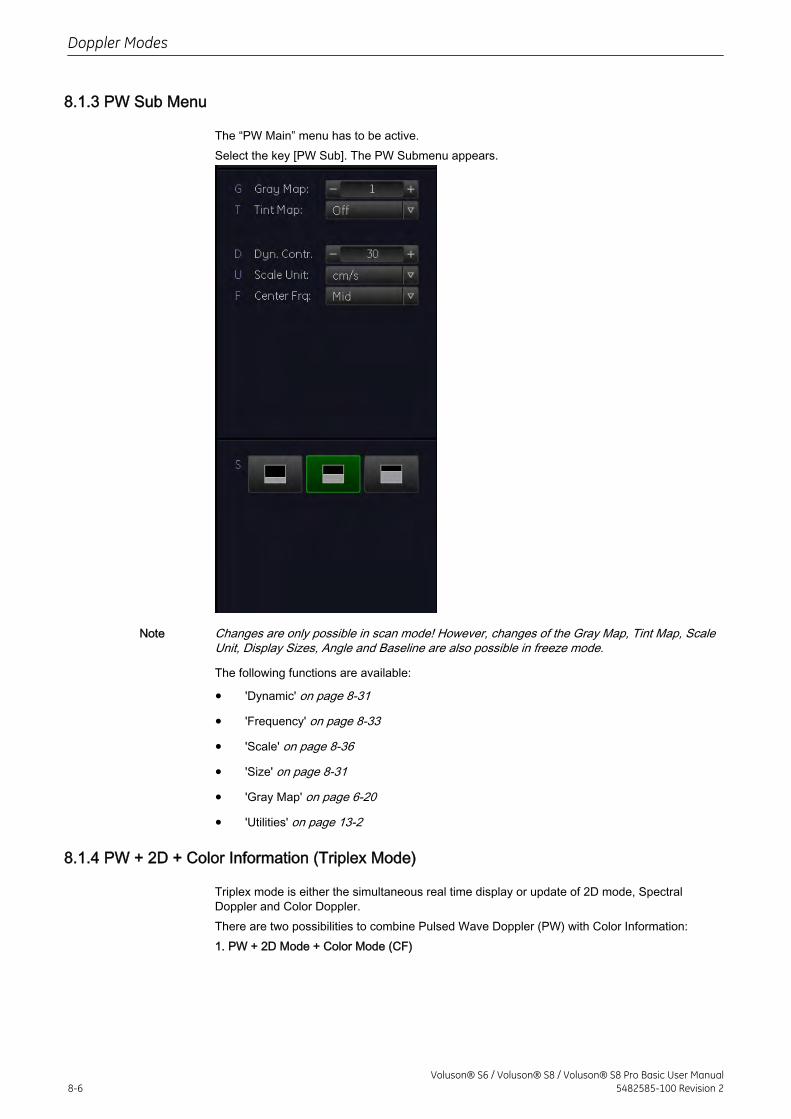
8.1.3 PW Sub Menu
The “PW Main” menu has to be active.Select the key [PW Sub]. The PW Submenu appears.
Note Changes are only possible in scan mode! However, changes of the Gray Map, Tint Map, ScaleUnit, Display Sizes, Angle and Baseline are also possible in freeze mode.
The following functions are available:
• 'Dynamic' on page 8-31
• 'Frequency' on page 8-33
• 'Scale' on page 8-36
• 'Size' on page 8-31
• 'Gray Map' on page 6-20
• 'Utilities' on page 13-2
8.1.4 PW + 2D + Color Information (Triplex Mode)
Triplex mode is either the simultaneous real time display or update of 2D mode, SpectralDoppler and Color Doppler.There are two possibilities to combine Pulsed Wave Doppler (PW) with Color Information:1. PW + 2D Mode + Color Mode (CF)
Doppler Modes
8-6Voluson® S6 / Voluson® S8 / Voluson® S8 Pro Basic User Manual
5482585-100 Revision 2
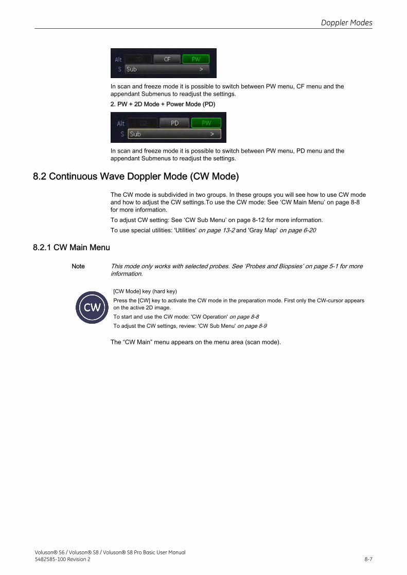
In scan and freeze mode it is possible to switch between PW menu, CF menu and theappendant Submenus to readjust the settings.2. PW + 2D Mode + Power Mode (PD)
In scan and freeze mode it is possible to switch between PW menu, PD menu and theappendant Submenus to readjust the settings.
8.2 Continuous Wave Doppler Mode (CW Mode)
The CW mode is subdivided in two groups. In these groups you will see how to use CW modeand how to adjust the CW settings.To use the CW mode: See ‘CW Main Menu’ on page 8‐8for more information.To adjust CW setting: See ‘CW Sub Menu’ on page 8‐12 for more information.To use special utilities: 'Utilities' on page 13-2 and 'Gray Map' on page 6-20
8.2.1 CW Main Menu
Note This mode only works with selected probes. See ‘Probes and Biopsies’ on page 5‐1 for moreinformation.
[CW Mode] key (hard key)Press the [CW] key to activate the CW mode in the preparation mode. First only the CW-cursor appearson the active 2D image.To start and use the CW mode: 'CW Operation' on page 8-8To adjust the CW settings, review: 'CW Sub Menu' on page 8-9
The “CW Main” menu appears on the menu area (scan mode).
Doppler Modes
Voluson® S6 / Voluson® S8 / Voluson® S8 Pro Basic User Manual5482585-100 Revision 2 8-7
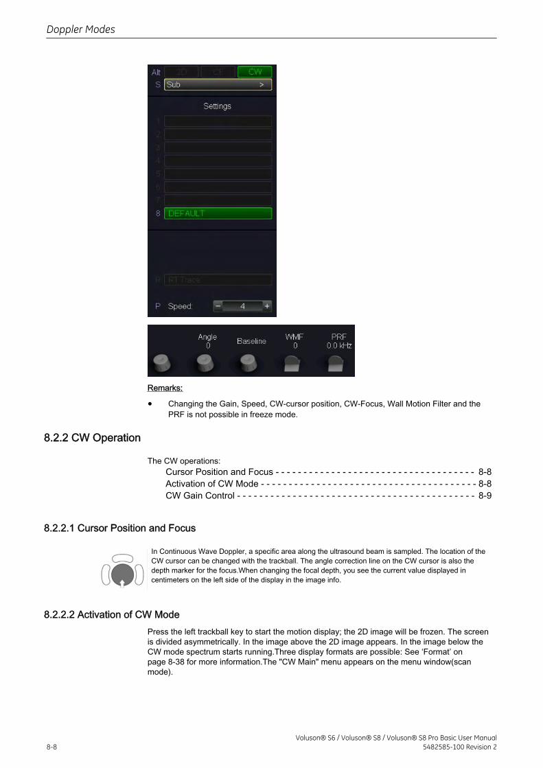
Remarks:
• Changing the Gain, Speed, CW-cursor position, CW-Focus, Wall Motion Filter and thePRF is not possible in freeze mode.
8.2.2 CW Operation
The CW operations:Cursor Position and Focus - - - - - - - - - - - - - - - - - - - - - - - - - - - - - - - - - - - - 8-8Activation of CW Mode - - - - - - - - - - - - - - - - - - - - - - - - - - - - - - - - - - - - - - - 8-8CW Gain Control - - - - - - - - - - - - - - - - - - - - - - - - - - - - - - - - - - - - - - - - - - - 8-9
8.2.2.1 Cursor Position and Focus
In Continuous Wave Doppler, a specific area along the ultrasound beam is sampled. The location of theCW cursor can be changed with the trackball. The angle correction line on the CW cursor is also thedepth marker for the focus.When changing the focal depth, you see the current value displayed incentimeters on the left side of the display in the image info.
8.2.2.2 Activation of CW ModePress the left trackball key to start the motion display; the 2D image will be frozen. The screenis divided asymmetrically. In the image above the 2D image appears. In the image below theCW mode spectrum starts running.Three display formats are possible: See ‘Format’ onpage 8‐38 for more information.The "CW Main" menu appears on the menu window(scanmode).
Doppler Modes
8-8Voluson® S6 / Voluson® S8 / Voluson® S8 Pro Basic User Manual
5482585-100 Revision 2
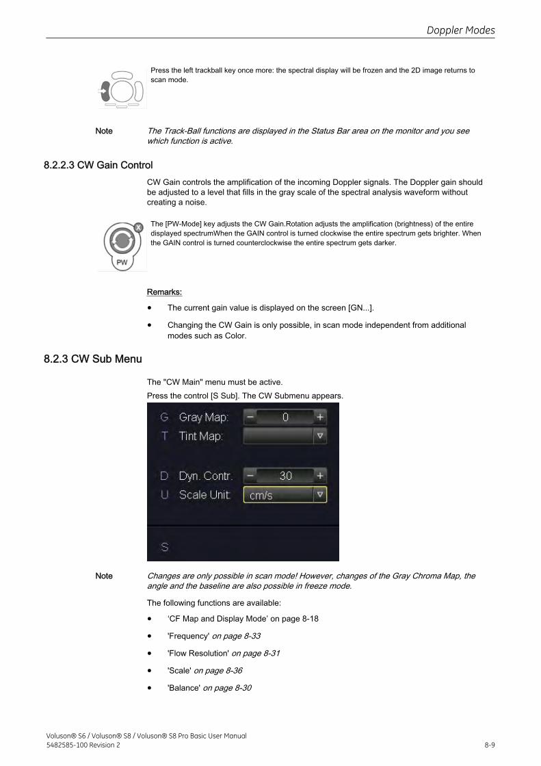
Press the left trackball key once more: the spectral display will be frozen and the 2D image returns toscan mode.
Note The Track-Ball functions are displayed in the Status Bar area on the monitor and you seewhich function is active.
8.2.2.3 CW Gain ControlCW Gain controls the amplification of the incoming Doppler signals. The Doppler gain shouldbe adjusted to a level that fills in the gray scale of the spectral analysis waveform withoutcreating a noise.
The [PW-Mode] key adjusts the CW Gain.Rotation adjusts the amplification (brightness) of the entiredisplayed spectrumWhen the GAIN control is turned clockwise the entire spectrum gets brighter. Whenthe GAIN control is turned counterclockwise the entire spectrum gets darker.
Remarks:
• The current gain value is displayed on the screen [GN...].
• Changing the CW Gain is only possible, in scan mode independent from additionalmodes such as Color.
8.2.3 CW Sub Menu
The "CW Main" menu must be active.Press the control [S Sub]. The CW Submenu appears.
Note Changes are only possible in scan mode! However, changes of the Gray Chroma Map, theangle and the baseline are also possible in freeze mode.
The following functions are available:
• ‘CF Map and Display Mode’ on page 8‐18
• 'Frequency' on page 8-33
• 'Flow Resolution' on page 8-31
• 'Scale' on page 8-36
• 'Balance' on page 8-30
Doppler Modes
Voluson® S6 / Voluson® S8 / Voluson® S8 Pro Basic User Manual5482585-100 Revision 2 8-9
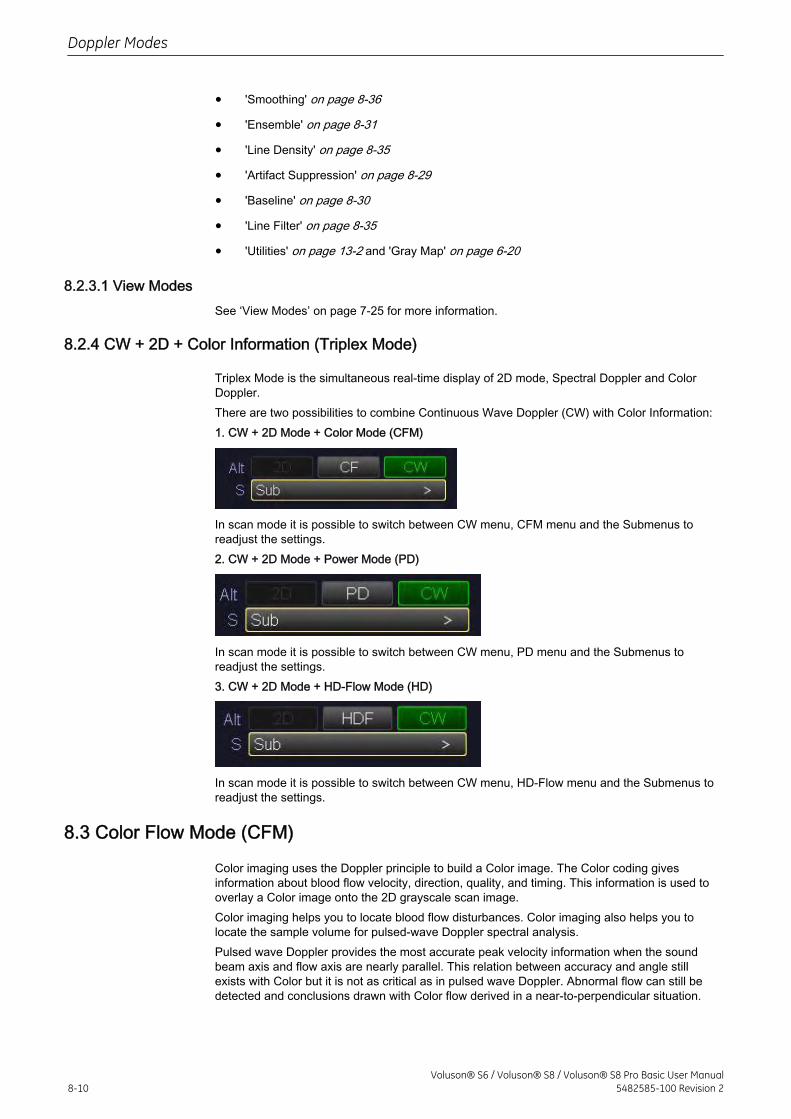
• 'Smoothing' on page 8-36
• 'Ensemble' on page 8-31
• 'Line Density' on page 8-35
• 'Artifact Suppression' on page 8-29
• 'Baseline' on page 8-30
• 'Line Filter' on page 8-35
• 'Utilities' on page 13-2 and 'Gray Map' on page 6-20
8.2.3.1 View ModesSee ‘View Modes’ on page 7‐25 for more information.
8.2.4 CW + 2D + Color Information (Triplex Mode)
Triplex Mode is the simultaneous real-time display of 2D mode, Spectral Doppler and ColorDoppler.There are two possibilities to combine Continuous Wave Doppler (CW) with Color Information:1. CW + 2D Mode + Color Mode (CFM)
In scan mode it is possible to switch between CW menu, CFM menu and the Submenus toreadjust the settings.2. CW + 2D Mode + Power Mode (PD)
In scan mode it is possible to switch between CW menu, PD menu and the Submenus toreadjust the settings.3. CW + 2D Mode + HD-Flow Mode (HD)
In scan mode it is possible to switch between CW menu, HD-Flow menu and the Submenus toreadjust the settings.
8.3 Color Flow Mode (CFM)
Color imaging uses the Doppler principle to build a Color image. The Color coding givesinformation about blood flow velocity, direction, quality, and timing. This information is used tooverlay a Color image onto the 2D grayscale scan image.Color imaging helps you to locate blood flow disturbances. Color imaging also helps you tolocate the sample volume for pulsed-wave Doppler spectral analysis.Pulsed wave Doppler provides the most accurate peak velocity information when the soundbeam axis and flow axis are nearly parallel. This relation between accuracy and angle stillexists with Color but it is not as critical as in pulsed wave Doppler. Abnormal flow can still bedetected and conclusions drawn with Color flow derived in a near-to-perpendicular situation.
Doppler Modes
8-10Voluson® S6 / Voluson® S8 / Voluson® S8 Pro Basic User Manual
5482585-100 Revision 2
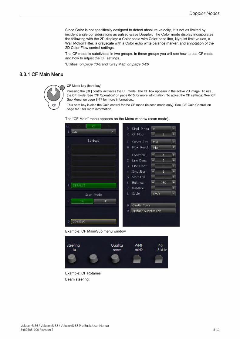
Since Color is not specifically designed to detect absolute velocity, it is not as limited byincident angle considerations as pulsed-wave Doppler. The Color mode display incorporatesthe following with the 2D-display: a Color scale with Color base line, Nyquist limit values, aWall Motion Filter, a grayscale with a Color echo write balance marker, and annotation of the2D Color Flow control settings.The CF mode is subdivided in two groups. In these groups you will see how to use CF modeand how to adjust the CF settings.'Utilities' on page 13-2 and 'Gray Map' on page 6-20
8.3.1 CF Main Menu
CF Mode key (hard key)Pressing the [CF] control activates the CF mode. The CF box appears in the active 2D image. To usethe CF mode: See ‘CF Operation’ on page 8‐15 for more information. To adjust the CF settings: See ‘CFSub Menu’ on page 8‐17 for more information.)This hard key is also the Gain control for the CF mode (in scan mode only). See ‘CF Gain Control’ onpage 8‐16 for more information.
The “CF Main” menu appears on the Menu window (scan mode).
Example: CF Main/Sub menu window
Example: CF RotariesBeam steering:
Doppler Modes
Voluson® S6 / Voluson® S8 / Voluson® S8 Pro Basic User Manual5482585-100 Revision 2 8-11
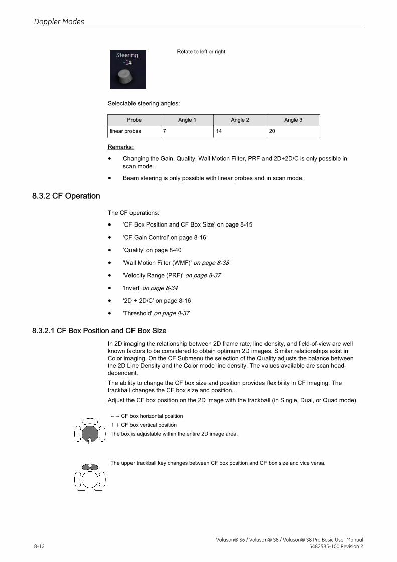
Rotate to left or right.
Selectable steering angles:
Probe Angle 1 Angle 2 Angle 3
linear probes 7 14 20
Remarks:
• Changing the Gain, Quality, Wall Motion Filter, PRF and 2D+2D/C is only possible inscan mode.
• Beam steering is only possible with linear probes and in scan mode.
8.3.2 CF Operation
The CF operations:
• ‘CF Box Position and CF Box Size’ on page 8‐15
• ‘CF Gain Control’ on page 8‐16
• ‘Quality’ on page 8‐40
• 'Wall Motion Filter (WMF)' on page 8-38
• 'Velocity Range (PRF)' on page 8-37
• 'Invert' on page 8-34
• ‘2D + 2D/C’ on page 8‐16
• 'Threshold' on page 8-37
8.3.2.1 CF Box Position and CF Box SizeIn 2D imaging the relationship between 2D frame rate, line density, and field-of-view are wellknown factors to be considered to obtain optimum 2D images. Similar relationships exist inColor imaging. On the CF Submenu the selection of the Quality adjusts the balance betweenthe 2D Line Density and the Color mode line density. The values available are scan head-dependent.The ability to change the CF box size and position provides flexibility in CF imaging. Thetrackball changes the CF box size and position.Adjust the CF box position on the 2D image with the trackball (in Single, Dual, or Quad mode).
← → CF box horizontal position↑ ↓ CF box vertical positionThe box is adjustable within the entire 2D image area.
The upper trackball key changes between CF box position and CF box size and vice versa.
Doppler Modes
8-12Voluson® S6 / Voluson® S8 / Voluson® S8 Pro Basic User Manual
5482585-100 Revision 2
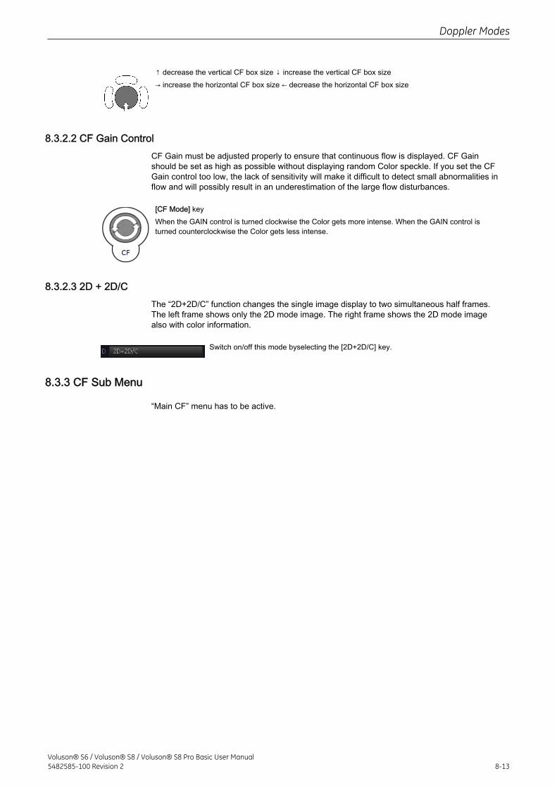
↑ decrease the vertical CF box size ↓ increase the vertical CF box size→ increase the horizontal CF box size ← decrease the horizontal CF box size
8.3.2.2 CF Gain ControlCF Gain must be adjusted properly to ensure that continuous flow is displayed. CF Gainshould be set as high as possible without displaying random Color speckle. If you set the CFGain control too low, the lack of sensitivity will make it difficult to detect small abnormalities inflow and will possibly result in an underestimation of the large flow disturbances.
[CF Mode] keyWhen the GAIN control is turned clockwise the Color gets more intense. When the GAIN control isturned counterclockwise the Color gets less intense.
8.3.2.3 2D + 2D/CThe “2D+2D/C” function changes the single image display to two simultaneous half frames.The left frame shows only the 2D mode image. The right frame shows the 2D mode imagealso with color information.
Switch on/off this mode byselecting the [2D+2D/C] key.
8.3.3 CF Sub Menu
“Main CF” menu has to be active.
Doppler Modes
Voluson® S6 / Voluson® S8 / Voluson® S8 Pro Basic User Manual5482585-100 Revision 2 8-13
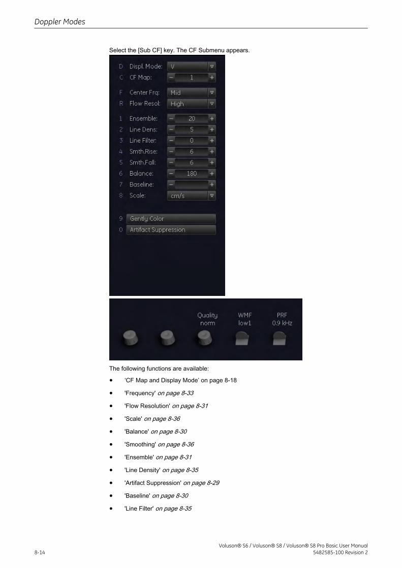
Select the [Sub CF] key. The CF Submenu appears.
The following functions are available:
• ‘CF Map and Display Mode’ on page 8‐18
• 'Frequency' on page 8-33
• 'Flow Resolution' on page 8-31
• 'Scale' on page 8-36
• 'Balance' on page 8-30
• 'Smoothing' on page 8-36
• 'Ensemble' on page 8-31
• 'Line Density' on page 8-35
• 'Artifact Suppression' on page 8-29
• 'Baseline' on page 8-30
• 'Line Filter' on page 8-35
Doppler Modes
8-14Voluson® S6 / Voluson® S8 / Voluson® S8 Pro Basic User Manual
5482585-100 Revision 2
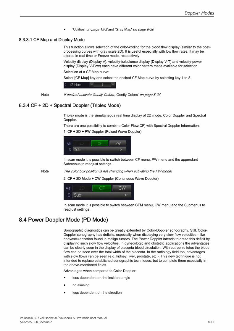
• 'Utilities' on page 13-2 and 'Gray Map' on page 6-20
8.3.3.1 CF Map and Display ModeThis function allows selection of the color-coding for the blood flow display (similar to the post-processing curves with gray scale 2D). It is useful especially with low flow rates. It may bealtered in real time or Freeze mode, respectively.Velocity display (Display V), velocity-turbulence display (Display V-T) and velocity-powerdisplay (Display V-Pow) each have different color pattern maps available for selection.Selection of a CF Map curve:Select [CF Map] key and select the desired CF Map curve by selecting key 1 to 8.
Note If desired activate Gently Colors. 'Gently Colors' on page 8-34
8.3.4 CF + 2D + Spectral Doppler (Triplex Mode)
Triplex mode is the simultaneous real time display of 2D mode, Color Doppler and SpectralDoppler.There are one possibility to combine Color Flow(CF) with Spectral Doppler Information:1. CF + 2D + PW Doppler (Pulsed Wave Doppler)
In scan mode it is possible to switch between CF menu, PW menu and the appendantSubmenus to readjust settings.
Note The color box position is not changing when activating the PW mode!
2. CF + 2D Mode + CW Doppler (Continuous Wave Doppler)
In scan mode it is possible to switch between CFM menu, CW menu and the Submenus toreadjust settings.
8.4 Power Doppler Mode (PD Mode)
Sonographic diagnostics can be greatly extended by Color-Doppler sonography. Still, Color-Doppler sonography has deficits, especially when displaying very slow flow velocities - likeneovascularization found in malign tumors. The Power Doppler intends to erase this deficit bydisplaying such slow flow velocities. In gynecologic and obstetric applications the advantagescan be clearly seen in the display of placenta blood circulation. With eutrophic fetus the bloodflow can be seen over the total width of the placenta. In the radiology field too, advantageswith slow flows can be seen (e.g. kidney, liver, prostate, etc.). This new technique is notintended to replace established sonographic techniques, but to complete them especially inthe above-mentioned fields.Advantages when compared to Color-Doppler:
• less dependent on the incident angle
• no aliasing
• less dependent on the direction
Doppler Modes
Voluson® S6 / Voluson® S8 / Voluson® S8 Pro Basic User Manual5482585-100 Revision 2 8-15
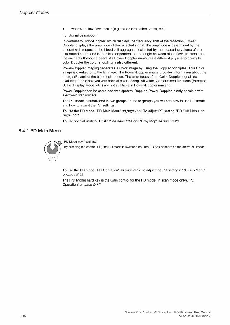
• wherever slow flows occur (e.g., blood circulation, veins, etc.)
Functional description:In contrast to Color-Doppler, which displays the frequency shift of the reflection, PowerDoppler displays the amplitude of the reflected signal.The amplitude is determined by theamount with respect to the blood cell aggregates collected by the measuring volume of theultrasound beam, and is thus less dependent on the angle between blood flow direction andthe incident ultrasound beam. As Power Doppler measures a different physical property tocolor Doppler the color encoding is also different.Power-Doppler imaging generates a Color image by using the Doppler principles. This Colorimage is overlaid onto the B-image. The Power-Doppler image provides information about theenergy (Power) of the blood cell motion. The amplitudes of the Color Doppler signal areevaluated and displayed with special color-coding. All velocity-determined functions (Baseline,Scale, Display Mode, etc.) are not available in Power-Doppler imaging.Power-Doppler can be combined with spectral Doppler. Power-Doppler is only possible withelectronic transducers.The PD mode is subdivided in two groups. In these groups you will see how to use PD modeand how to adjust the PD settings.To use the PD mode: 'PD Main Menu' on page 8-16 To adjust PD setting: 'PD Sub Menu' onpage 8-18To use special utilities: 'Utilities' on page 13-2 and 'Gray Map' on page 6-20
8.4.1 PD Main Menu
PD Mode key (hard key)By pressing the control [PD] the PD mode is switched on. The PD Box appears on the active 2D image.
To use the PD mode: 'PD Operation' on page 8-17 To adjust the PD settings: 'PD Sub Menu'on page 8-18The [PD Mode] hard key is the Gain control for the PD mode (in scan mode only). 'PDOperation' on page 8-17
Doppler Modes
8-16Voluson® S6 / Voluson® S8 / Voluson® S8 Pro Basic User Manual
5482585-100 Revision 2
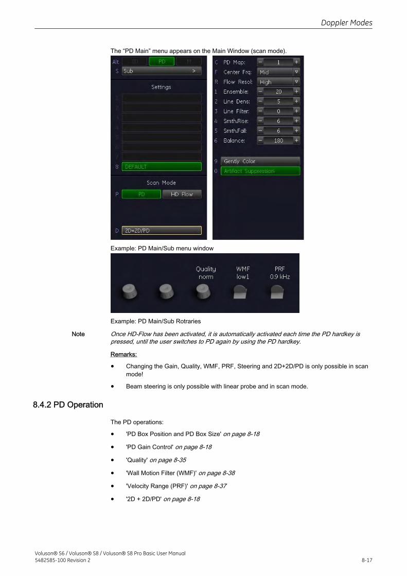
The “PD Main” menu appears on the Main Window (scan mode).
Example: PD Main/Sub menu window
Example: PD Main/Sub Rotraries
Note Once HD-Flow has been activated, it is automatically activated each time the PD hardkey ispressed, until the user switches to PD again by using the PD hardkey.
Remarks:
• Changing the Gain, Quality, WMF, PRF, Steering and 2D+2D/PD is only possible in scanmode!
• Beam steering is only possible with linear probe and in scan mode.
8.4.2 PD Operation
The PD operations:
• 'PD Box Position and PD Box Size' on page 8-18
• 'PD Gain Control' on page 8-18
• 'Quality' on page 8-35
• 'Wall Motion Filter (WMF)' on page 8-38
• 'Velocity Range (PRF)' on page 8-37
• '2D + 2D/PD' on page 8-18
Doppler Modes
Voluson® S6 / Voluson® S8 / Voluson® S8 Pro Basic User Manual5482585-100 Revision 2 8-17
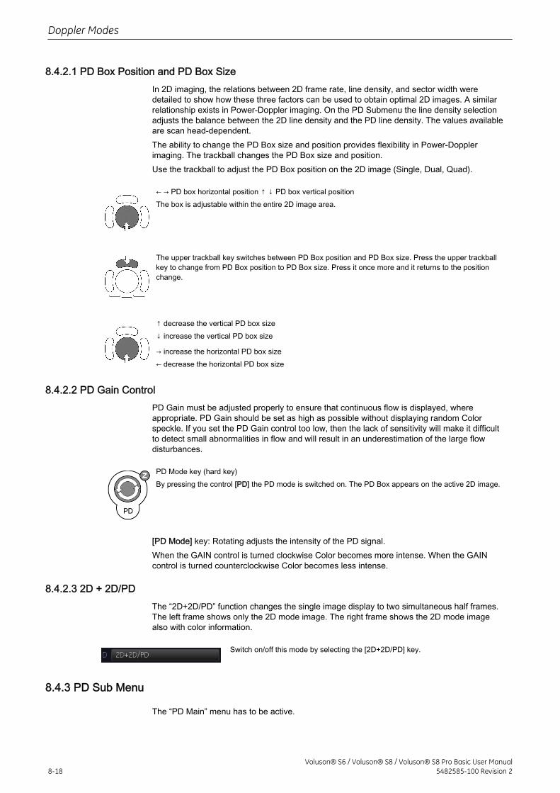
8.4.2.1 PD Box Position and PD Box SizeIn 2D imaging, the relations between 2D frame rate, line density, and sector width weredetailed to show how these three factors can be used to obtain optimal 2D images. A similarrelationship exists in Power-Doppler imaging. On the PD Submenu the line density selectionadjusts the balance between the 2D line density and the PD line density. The values availableare scan head-dependent.The ability to change the PD Box size and position provides flexibility in Power-Dopplerimaging. The trackball changes the PD Box size and position.Use the trackball to adjust the PD Box position on the 2D image (Single, Dual, Quad).
← → PD box horizontal position ↑ ↓ PD box vertical positionThe box is adjustable within the entire 2D image area.
The upper trackball key switches between PD Box position and PD Box size. Press the upper trackballkey to change from PD Box position to PD Box size. Press it once more and it returns to the positionchange.
↑ decrease the vertical PD box size↓ increase the vertical PD box size
→ increase the horizontal PD box size← decrease the horizontal PD box size
8.4.2.2 PD Gain ControlPD Gain must be adjusted properly to ensure that continuous flow is displayed, whereappropriate. PD Gain should be set as high as possible without displaying random Colorspeckle. If you set the PD Gain control too low, then the lack of sensitivity will make it difficultto detect small abnormalities in flow and will result in an underestimation of the large flowdisturbances.
PD Mode key (hard key)By pressing the control [PD] the PD mode is switched on. The PD Box appears on the active 2D image.
[PD Mode] key: Rotating adjusts the intensity of the PD signal.When the GAIN control is turned clockwise Color becomes more intense. When the GAINcontrol is turned counterclockwise Color becomes less intense.
8.4.2.3 2D + 2D/PDThe “2D+2D/PD” function changes the single image display to two simultaneous half frames.The left frame shows only the 2D mode image. The right frame shows the 2D mode imagealso with color information.
Switch on/off this mode by selecting the [2D+2D/PD] key.
8.4.3 PD Sub Menu
The “PD Main” menu has to be active.
Doppler Modes
8-18Voluson® S6 / Voluson® S8 / Voluson® S8 Pro Basic User Manual
5482585-100 Revision 2
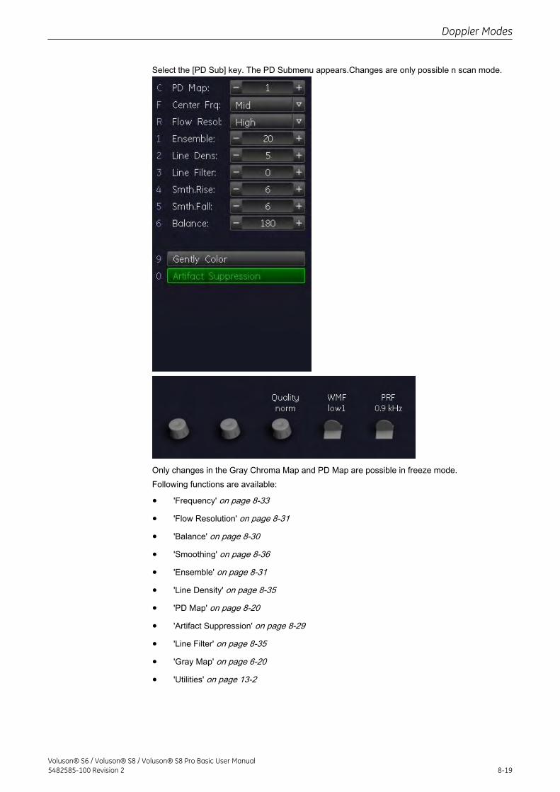
Select the [PD Sub] key. The PD Submenu appears.Changes are only possible n scan mode.
Only changes in the Gray Chroma Map and PD Map are possible in freeze mode.Following functions are available:
• 'Frequency' on page 8-33
• 'Flow Resolution' on page 8-31
• 'Balance' on page 8-30
• 'Smoothing' on page 8-36
• 'Ensemble' on page 8-31
• 'Line Density' on page 8-35
• 'PD Map' on page 8-20
• 'Artifact Suppression' on page 8-29
• 'Line Filter' on page 8-35
• 'Gray Map' on page 6-20
• 'Utilities' on page 13-2
Doppler Modes
Voluson® S6 / Voluson® S8 / Voluson® S8 Pro Basic User Manual5482585-100 Revision 2 8-19
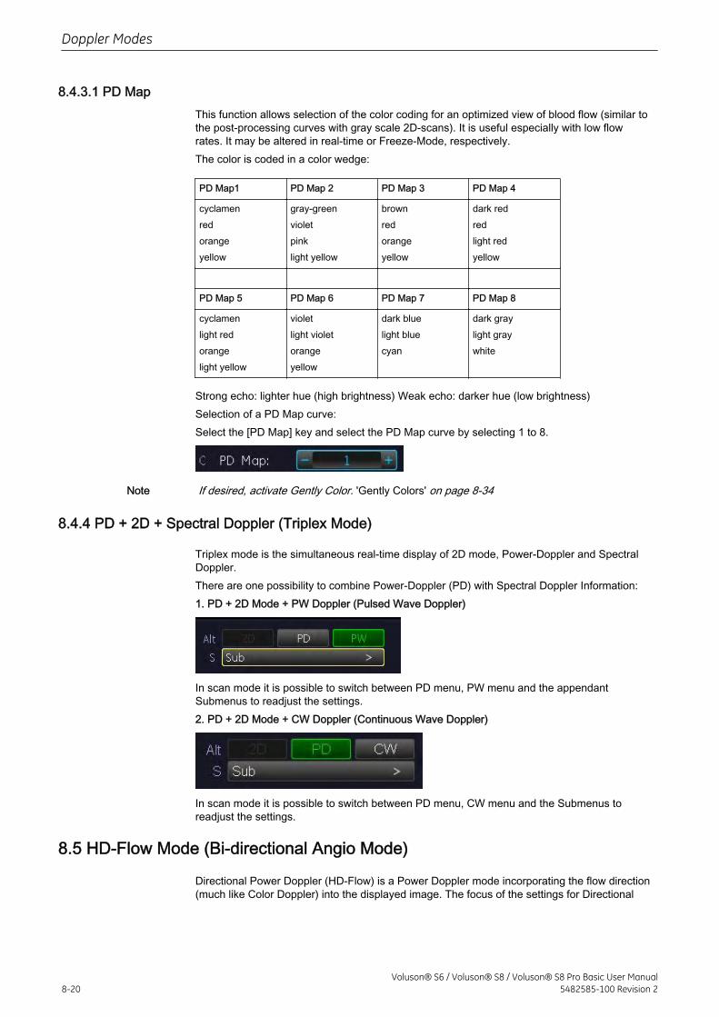
8.4.3.1 PD MapThis function allows selection of the color coding for an optimized view of blood flow (similar tothe post-processing curves with gray scale 2D-scans). It is useful especially with low flowrates. It may be altered in real-time or Freeze-Mode, respectively.The color is coded in a color wedge:
PD Map1 PD Map 2 PD Map 3 PD Map 4
cyclamenredorangeyellow
gray-greenvioletpinklight yellow
brownredorangeyellow
dark redredlight redyellow
PD Map 5 PD Map 6 PD Map 7 PD Map 8
cyclamenlight redorangelight yellow
violetlight violetorangeyellow
dark bluelight bluecyan
dark graylight graywhite
Strong echo: lighter hue (high brightness) Weak echo: darker hue (low brightness)Selection of a PD Map curve:Select the [PD Map] key and select the PD Map curve by selecting 1 to 8.
Note If desired, activate Gently Color. 'Gently Colors' on page 8-34
8.4.4 PD + 2D + Spectral Doppler (Triplex Mode)
Triplex mode is the simultaneous real-time display of 2D mode, Power-Doppler and SpectralDoppler.There are one possibility to combine Power-Doppler (PD) with Spectral Doppler Information:1. PD + 2D Mode + PW Doppler (Pulsed Wave Doppler)
In scan mode it is possible to switch between PD menu, PW menu and the appendantSubmenus to readjust the settings.2. PD + 2D Mode + CW Doppler (Continuous Wave Doppler)
In scan mode it is possible to switch between PD menu, CW menu and the Submenus toreadjust the settings.
8.5 HD-Flow Mode (Bi-directional Angio Mode)
Directional Power Doppler (HD-Flow) is a Power Doppler mode incorporating the flow direction(much like Color Doppler) into the displayed image. The focus of the settings for Directional
Doppler Modes
8-20Voluson® S6 / Voluson® S8 / Voluson® S8 Pro Basic User Manual
5482585-100 Revision 2
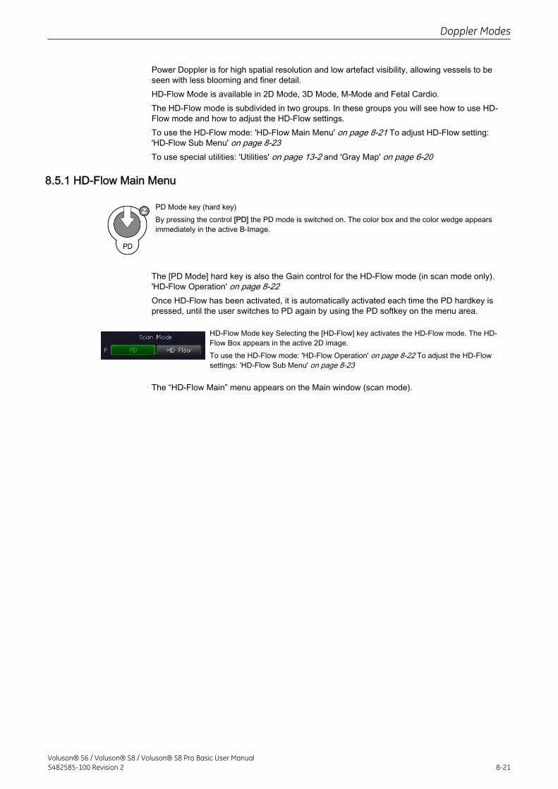
Power Doppler is for high spatial resolution and low artefact visibility, allowing vessels to beseen with less blooming and finer detail.HD-Flow Mode is available in 2D Mode, 3D Mode, M-Mode and Fetal Cardio.The HD-Flow mode is subdivided in two groups. In these groups you will see how to use HD-Flow mode and how to adjust the HD-Flow settings.To use the HD-Flow mode: 'HD-Flow Main Menu' on page 8-21 To adjust HD-Flow setting:'HD-Flow Sub Menu' on page 8-23To use special utilities: 'Utilities' on page 13-2 and 'Gray Map' on page 6-20
8.5.1 HD-Flow Main Menu
PD Mode key (hard key)By pressing the control [PD] the PD mode is switched on. The color box and the color wedge appearsimmediately in the active B-Image.
The [PD Mode] hard key is also the Gain control for the HD-Flow mode (in scan mode only).'HD-Flow Operation' on page 8-22Once HD-Flow has been activated, it is automatically activated each time the PD hardkey ispressed, until the user switches to PD again by using the PD softkey on the menu area.
HD-Flow Mode key Selecting the [HD-Flow] key activates the HD-Flow mode. The HD-Flow Box appears in the active 2D image.To use the HD-Flow mode: 'HD-Flow Operation' on page 8-22 To adjust the HD-Flowsettings: 'HD-Flow Sub Menu' on page 8-23
The “HD-Flow Main” menu appears on the Main window (scan mode).
Doppler Modes
Voluson® S6 / Voluson® S8 / Voluson® S8 Pro Basic User Manual5482585-100 Revision 2 8-21
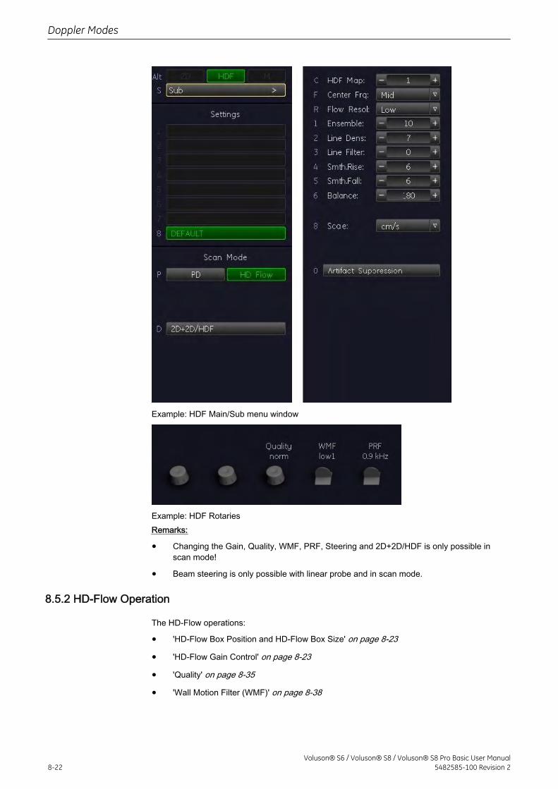
Example: HDF Main/Sub menu window
Example: HDF RotariesRemarks:
• Changing the Gain, Quality, WMF, PRF, Steering and 2D+2D/HDF is only possible inscan mode!
• Beam steering is only possible with linear probe and in scan mode.
8.5.2 HD-Flow Operation
The HD-Flow operations:
• 'HD-Flow Box Position and HD-Flow Box Size' on page 8-23
• 'HD-Flow Gain Control' on page 8-23
• 'Quality' on page 8-35
• 'Wall Motion Filter (WMF)' on page 8-38
Doppler Modes
8-22Voluson® S6 / Voluson® S8 / Voluson® S8 Pro Basic User Manual
5482585-100 Revision 2
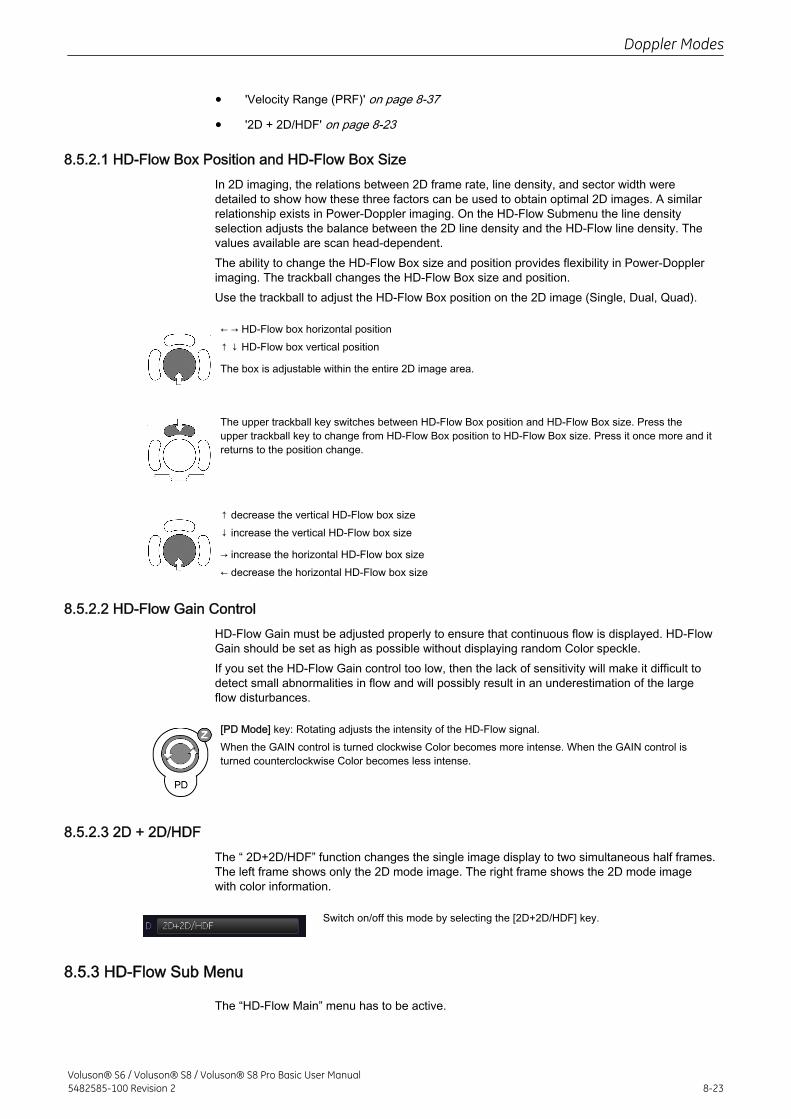
• 'Velocity Range (PRF)' on page 8-37
• '2D + 2D/HDF' on page 8-23
8.5.2.1 HD-Flow Box Position and HD-Flow Box SizeIn 2D imaging, the relations between 2D frame rate, line density, and sector width weredetailed to show how these three factors can be used to obtain optimal 2D images. A similarrelationship exists in Power-Doppler imaging. On the HD-Flow Submenu the line densityselection adjusts the balance between the 2D line density and the HD-Flow line density. Thevalues available are scan head-dependent.The ability to change the HD-Flow Box size and position provides flexibility in Power-Dopplerimaging. The trackball changes the HD-Flow Box size and position.Use the trackball to adjust the HD-Flow Box position on the 2D image (Single, Dual, Quad).
← → HD-Flow box horizontal position↑ ↓ HD-Flow box vertical position
The box is adjustable within the entire 2D image area.
The upper trackball key switches between HD-Flow Box position and HD-Flow Box size. Press theupper trackball key to change from HD-Flow Box position to HD-Flow Box size. Press it once more and itreturns to the position change.
↑ decrease the vertical HD-Flow box size↓ increase the vertical HD-Flow box size
→ increase the horizontal HD-Flow box size← decrease the horizontal HD-Flow box size
8.5.2.2 HD-Flow Gain ControlHD-Flow Gain must be adjusted properly to ensure that continuous flow is displayed. HD-FlowGain should be set as high as possible without displaying random Color speckle.If you set the HD-Flow Gain control too low, then the lack of sensitivity will make it difficult todetect small abnormalities in flow and will possibly result in an underestimation of the largeflow disturbances.
[PD Mode] key: Rotating adjusts the intensity of the HD-Flow signal.When the GAIN control is turned clockwise Color becomes more intense. When the GAIN control isturned counterclockwise Color becomes less intense.
8.5.2.3 2D + 2D/HDFThe “ 2D+2D/HDF” function changes the single image display to two simultaneous half frames.The left frame shows only the 2D mode image. The right frame shows the 2D mode imagewith color information.
Switch on/off this mode by selecting the [2D+2D/HDF] key.
8.5.3 HD-Flow Sub Menu
The “HD-Flow Main” menu has to be active.
Doppler Modes
Voluson® S6 / Voluson® S8 / Voluson® S8 Pro Basic User Manual5482585-100 Revision 2 8-23
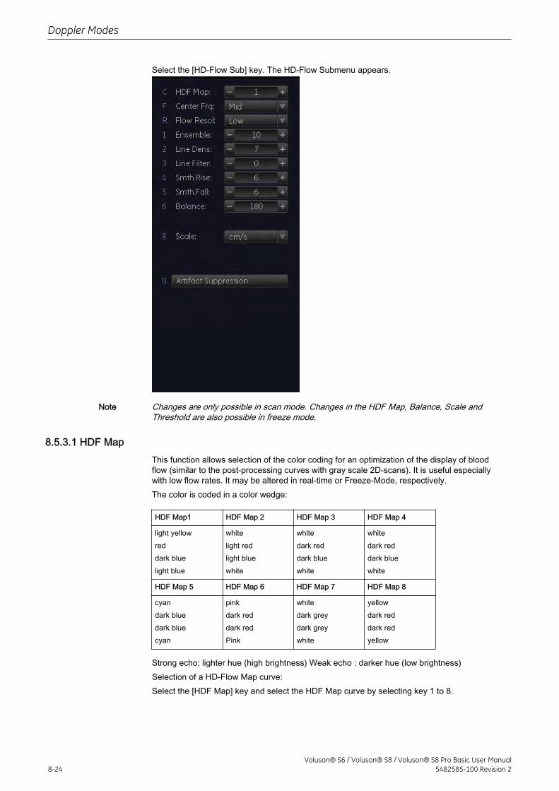
Select the [HD-Flow Sub] key. The HD-Flow Submenu appears.
Note Changes are only possible in scan mode. Changes in the HDF Map, Balance, Scale andThreshold are also possible in freeze mode.
8.5.3.1 HDF MapThis function allows selection of the color coding for an optimization of the display of bloodflow (similar to the post-processing curves with gray scale 2D-scans). It is useful especiallywith low flow rates. It may be altered in real-time or Freeze-Mode, respectively.The color is coded in a color wedge:
HDF Map1 HDF Map 2 HDF Map 3 HDF Map 4
light yellowreddark bluelight blue
whitelight redlight bluewhite
whitedark reddark bluewhite
whitedark reddark bluewhite
HDF Map 5 HDF Map 6 HDF Map 7 HDF Map 8
cyandark bluedark bluecyan
pinkdark reddark redPink
whitedark greydark greywhite
yellowdark reddark redyellow
Strong echo: lighter hue (high brightness) Weak echo : darker hue (low brightness)Selection of a HD-Flow Map curve:Select the [HDF Map] key and select the HDF Map curve by selecting key 1 to 8.
Doppler Modes
8-24Voluson® S6 / Voluson® S8 / Voluson® S8 Pro Basic User Manual
5482585-100 Revision 2
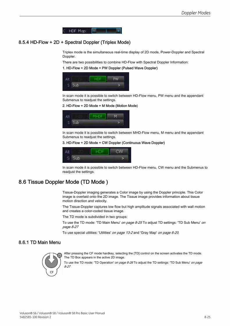
8.5.4 HD-Flow + 2D + Spectral Doppler (Triplex Mode)
Triplex mode is the simultaneous real-time display of 2D mode, Power-Doppler and SpectralDoppler.There are two possibilities to combine HD-Flow with Spectral Doppler Information:1. HD-Flow + 2D Mode + PW Doppler (Pulsed Wave Doppler)
In scan mode it is possible to switch between HD-Flow menu, PW menu and the appendantSubmenus to readjust the settings.2. HD-Flow + 2D Mode + M Mode (Motion Mode)
In scan mode it is possible to switch between MHD-Flow menu, M menu and the appendantSubmenus to readjust the settings.3. HD-Flow + 2D Mode + CW Doppler (Continuous Wave Doppler)
In scan mode it is possible to switch between HD-Flow menu, CW menu and the Submenus toreadjust the settings.
8.6 Tissue Doppler Mode (TD Mode )
Tissue-Doppler imaging generates a Color image by using the Doppler principle. This Colorimage is overlaid onto the 2D image. The Tissue image provides information about tissuemotion direction and velocity.The Tissue-Doppler captures low flow but high amplitude signals associated with wall motionand creates a color-coded tissue image.The TD mode is subdivided in two groups:To use the TD mode: 'TD Main Menu' on page 8-25 To adjust TD settings: 'TD Sub Menu' onpage 8-27To use special utilities: 'Utilities' on page 13-2 and 'Gray Map' on page 6-20.
8.6.1 TD Main Menu
After pressing the CF mode hardkey, selecting the [TD] control on the screen activates the TD mode.The TD Box appears in the active 2D image.To use the TD mode: 'TD Operation' on page 8-26 To adjust the TD settings: 'TD Sub Menu' on page8-27
Doppler Modes
Voluson® S6 / Voluson® S8 / Voluson® S8 Pro Basic User Manual5482585-100 Revision 2 8-25
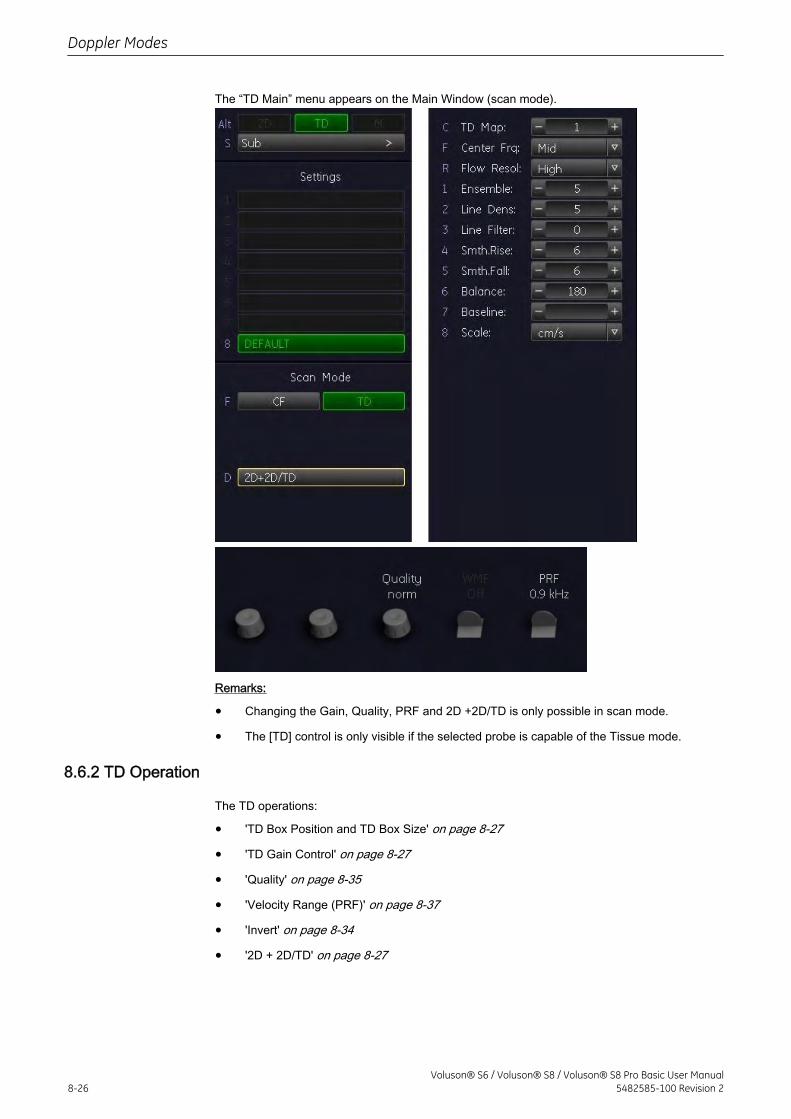
The “TD Main” menu appears on the Main Window (scan mode).
Remarks:
• Changing the Gain, Quality, PRF and 2D +2D/TD is only possible in scan mode.
• The [TD] control is only visible if the selected probe is capable of the Tissue mode.
8.6.2 TD Operation
The TD operations:
• 'TD Box Position and TD Box Size' on page 8-27
• 'TD Gain Control' on page 8-27
• 'Quality' on page 8-35
• 'Velocity Range (PRF)' on page 8-37
• 'Invert' on page 8-34
• '2D + 2D/TD' on page 8-27
Doppler Modes
8-26Voluson® S6 / Voluson® S8 / Voluson® S8 Pro Basic User Manual
5482585-100 Revision 2
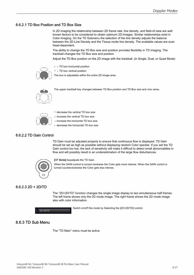
8.6.2.1 TD Box Position and TD Box SizeIn 2D imaging the relationship between 2D frame rate, line density, and field-of-view are wellknown factors to be considered to obtain optimum 2D-Images. Similar relationships exist inColor-Imaging. On the TD Submenu the selection of the line density adjusts the balancebetween the 2D-Line Density and the Tissue mode line density. The available values are scanhead-dependent.The ability to change the TD Box size and position provides flexibility in TD Imaging. Thetrackball changes the TD Box size and position.Adjust the TD Box position on the 2D image with the trackball. (in Single, Dual, or Quad Mode)
← → TD box horizontal position↑ ↓ TD box vertical positionThe box is adjustable within the entire 2D image area.
The upper trackball key changes between TD Box position and TD Box size and vice versa.
↑ decrease the vertical TD box size↓ increase the vertical TD box size→ increase the horizontal TD box size← decrease the horizontal TD box size
8.6.2.2 TD Gain ControlTD Gain must be adjusted properly to ensure that continuous flow is displayed. TD Gainshould be set as high as possible without displaying random Color speckle. If you set the TDGain control too low, the lack of sensitivity will make it difficult to detect small abnormalities inflow and will possibly result in an underestimation of the large flow disturbances.
[CF Mode] keyadjusts the TD Gain.When the GAIN control is turned clockwise the Color gets more intense. When the GAIN control isturned counterclockwise the Color gets less intense.
8.6.2.3 2D + 2D/TDThe “2D+2D/TD” function changes the single image display to two simultaneous half frames.The left frame shows only the 2D mode image. The right frame shows the 2D mode imagealso with color information.
Switch on/off this mode by Selecting the [2D+2D/TD] control.
8.6.3 TD Sub Menu
The “TD Main” menu must be active.
Doppler Modes
Voluson® S6 / Voluson® S8 / Voluson® S8 Pro Basic User Manual5482585-100 Revision 2 8-27
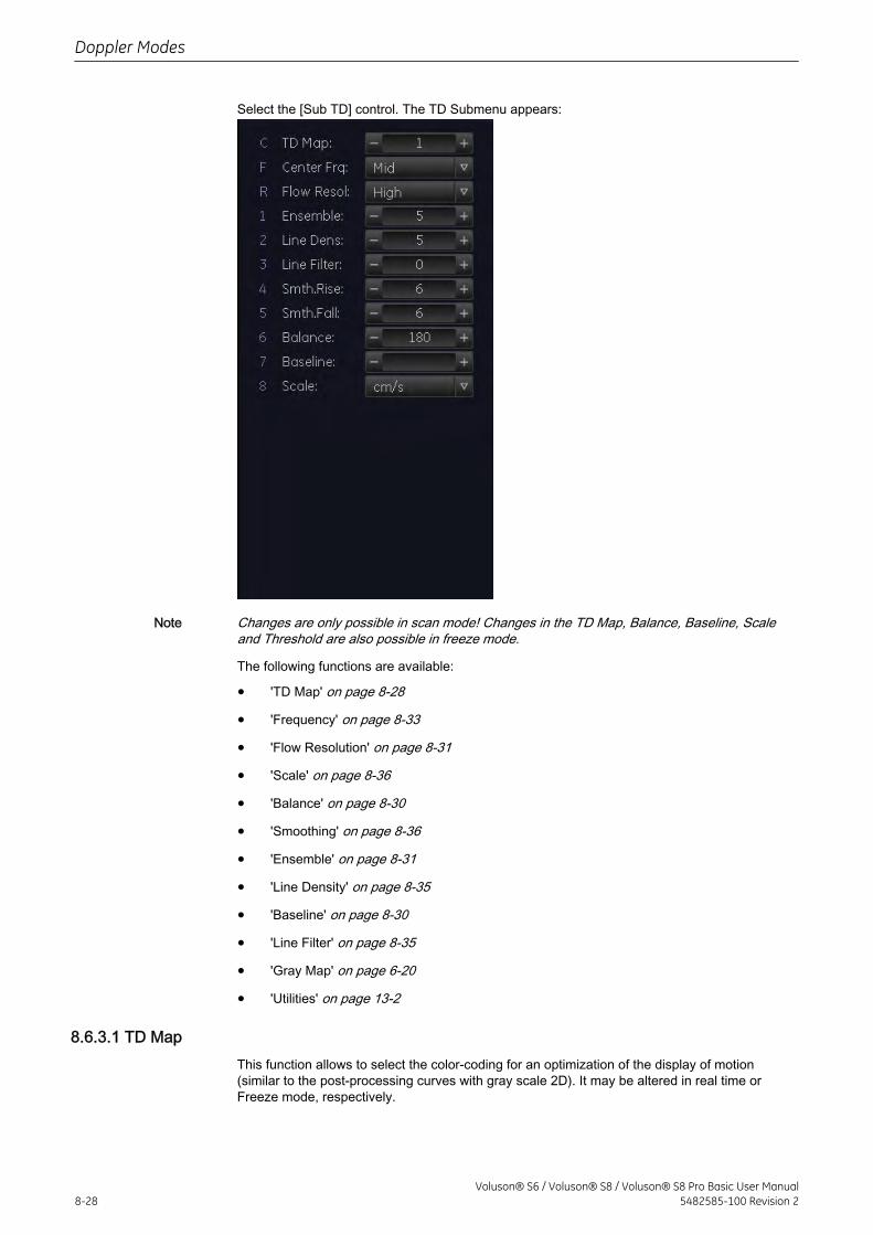
Select the [Sub TD] control. The TD Submenu appears:
Note Changes are only possible in scan mode! Changes in the TD Map, Balance, Baseline, Scaleand Threshold are also possible in freeze mode.
The following functions are available:
• 'TD Map' on page 8-28
• 'Frequency' on page 8-33
• 'Flow Resolution' on page 8-31
• 'Scale' on page 8-36
• 'Balance' on page 8-30
• 'Smoothing' on page 8-36
• 'Ensemble' on page 8-31
• 'Line Density' on page 8-35
• 'Baseline' on page 8-30
• 'Line Filter' on page 8-35
• 'Gray Map' on page 6-20
• 'Utilities' on page 13-2
8.6.3.1 TD MapThis function allows to select the color-coding for an optimization of the display of motion(similar to the post-processing curves with gray scale 2D). It may be altered in real time orFreeze mode, respectively.
Doppler Modes
8-28Voluson® S6 / Voluson® S8 / Voluson® S8 Pro Basic User Manual
5482585-100 Revision 2
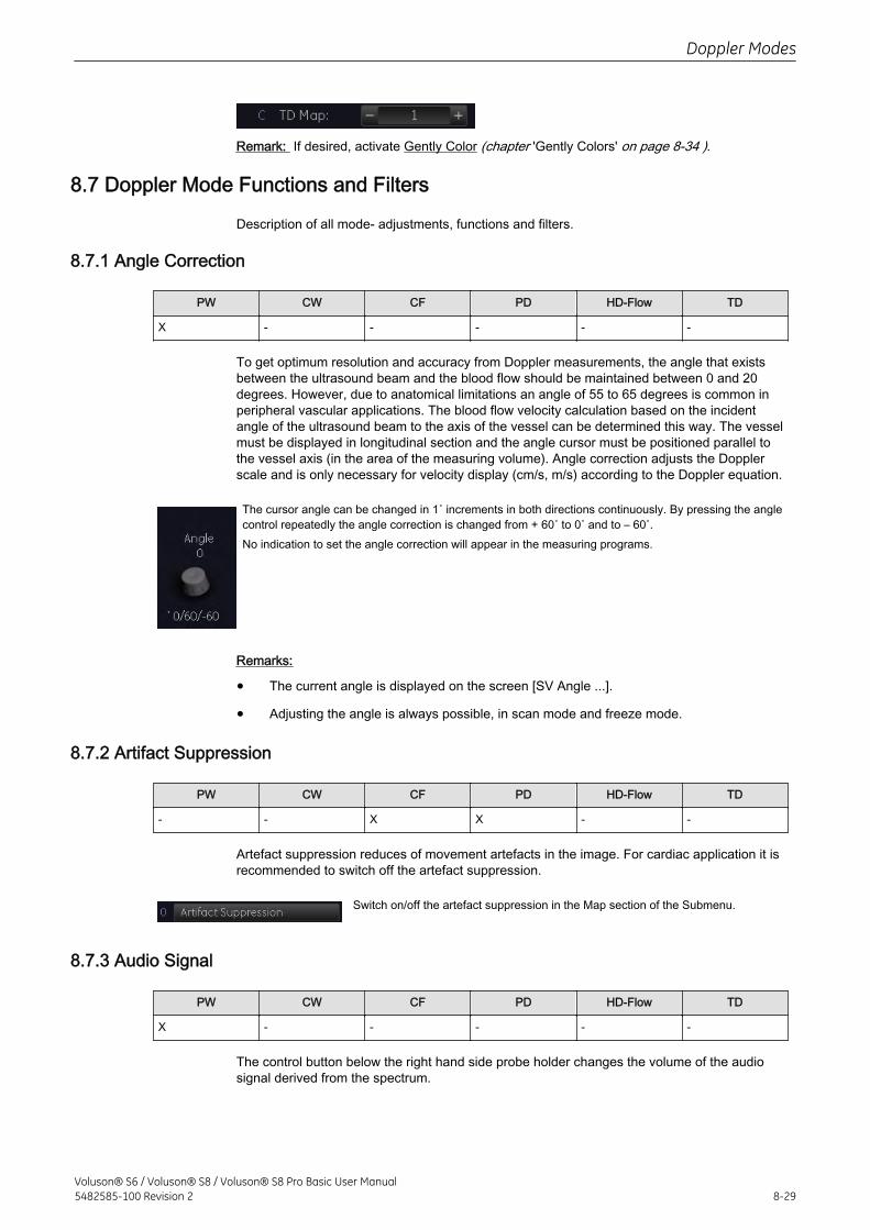
Remark: If desired, activate Gently Color (chapter 'Gently Colors' on page 8-34 ).
8.7 Doppler Mode Functions and Filters
Description of all mode- adjustments, functions and filters.
8.7.1 Angle Correction
PW CW CF PD HD-Flow TD
X - - - - -
To get optimum resolution and accuracy from Doppler measurements, the angle that existsbetween the ultrasound beam and the blood flow should be maintained between 0 and 20degrees. However, due to anatomical limitations an angle of 55 to 65 degrees is common inperipheral vascular applications. The blood flow velocity calculation based on the incidentangle of the ultrasound beam to the axis of the vessel can be determined this way. The vesselmust be displayed in longitudinal section and the angle cursor must be positioned parallel tothe vessel axis (in the area of the measuring volume). Angle correction adjusts the Dopplerscale and is only necessary for velocity display (cm/s, m/s) according to the Doppler equation.
The cursor angle can be changed in 1˚ increments in both directions continuously. By pressing the anglecontrol repeatedly the angle correction is changed from + 60˚ to 0˚ and to – 60˚.No indication to set the angle correction will appear in the measuring programs.
Remarks:
• The current angle is displayed on the screen [SV Angle ...].
• Adjusting the angle is always possible, in scan mode and freeze mode.
8.7.2 Artifact Suppression
PW CW CF PD HD-Flow TD
- - X X - -
Artefact suppression reduces of movement artefacts in the image. For cardiac application it isrecommended to switch off the artefact suppression.
Switch on/off the artefact suppression in the Map section of the Submenu.
8.7.3 Audio Signal
PW CW CF PD HD-Flow TD
X - - - - -
The control button below the right hand side probe holder changes the volume of the audiosignal derived from the spectrum.
Doppler Modes
Voluson® S6 / Voluson® S8 / Voluson® S8 Pro Basic User Manual5482585-100 Revision 2 8-29
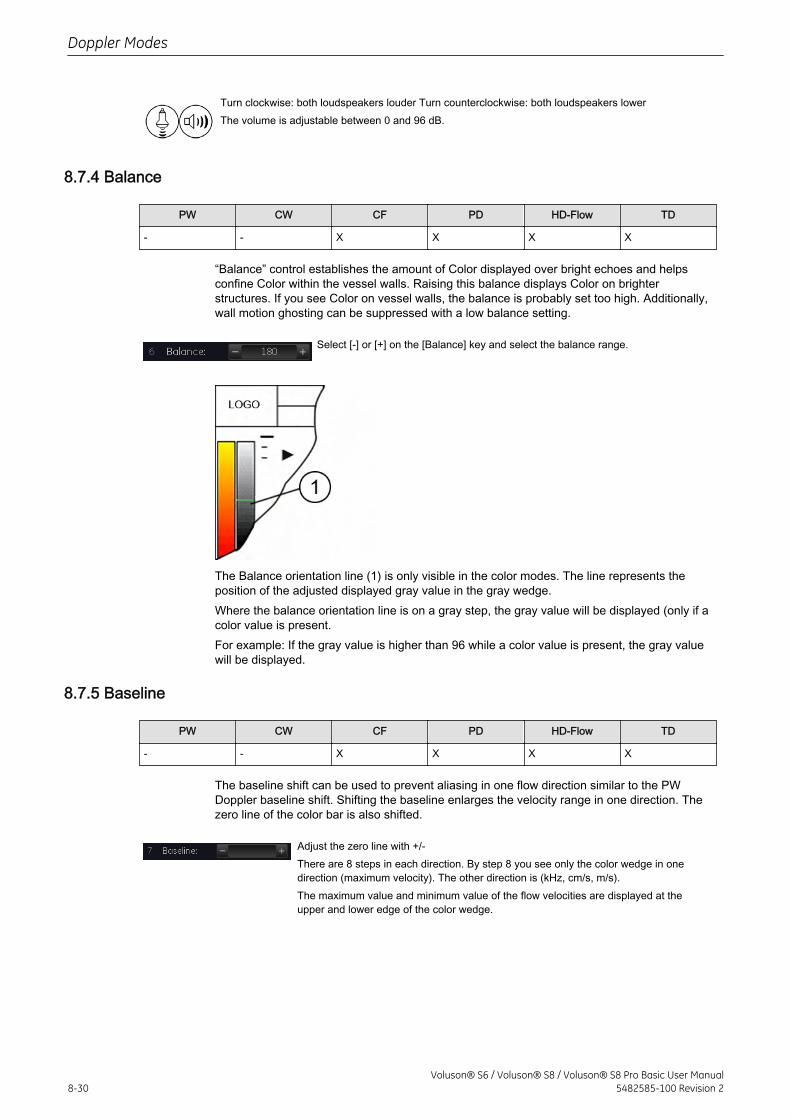
Turn clockwise: both loudspeakers louder Turn counterclockwise: both loudspeakers lowerThe volume is adjustable between 0 and 96 dB.
8.7.4 Balance
PW CW CF PD HD-Flow TD
- - X X X X
“Balance” control establishes the amount of Color displayed over bright echoes and helpsconfine Color within the vessel walls. Raising this balance displays Color on brighterstructures. If you see Color on vessel walls, the balance is probably set too high. Additionally,wall motion ghosting can be suppressed with a low balance setting.
Select [-] or [+] on the [Balance] key and select the balance range.
The Balance orientation line (1) is only visible in the color modes. The line represents theposition of the adjusted displayed gray value in the gray wedge.Where the balance orientation line is on a gray step, the gray value will be displayed (only if acolor value is present.For example: If the gray value is higher than 96 while a color value is present, the gray valuewill be displayed.
8.7.5 Baseline
PW CW CF PD HD-Flow TD
- - X X X X
The baseline shift can be used to prevent aliasing in one flow direction similar to the PWDoppler baseline shift. Shifting the baseline enlarges the velocity range in one direction. Thezero line of the color bar is also shifted.
Adjust the zero line with +/-There are 8 steps in each direction. By step 8 you see only the color wedge in onedirection (maximum velocity). The other direction is (kHz, cm/s, m/s).The maximum value and minimum value of the flow velocities are displayed at theupper and lower edge of the color wedge.
Doppler Modes
8-30Voluson® S6 / Voluson® S8 / Voluson® S8 Pro Basic User Manual
5482585-100 Revision 2
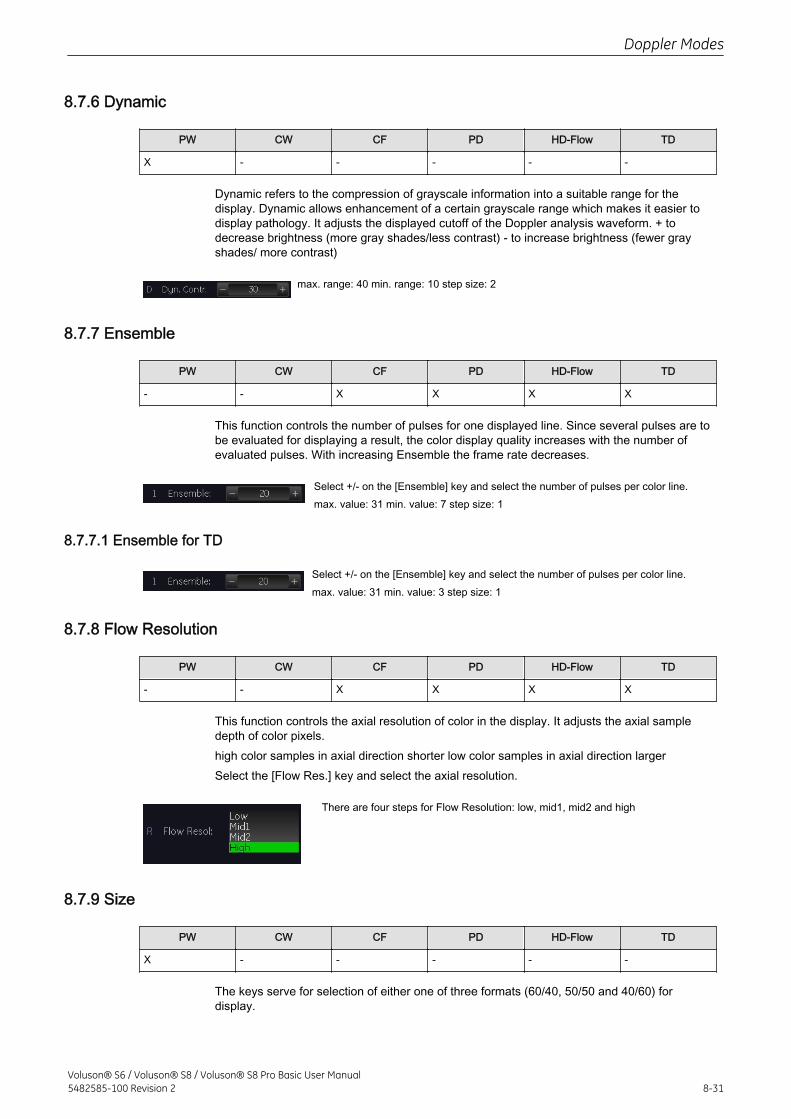
8.7.6 Dynamic
PW CW CF PD HD-Flow TD
X - - - - -
Dynamic refers to the compression of grayscale information into a suitable range for thedisplay. Dynamic allows enhancement of a certain grayscale range which makes it easier todisplay pathology. It adjusts the displayed cutoff of the Doppler analysis waveform. + todecrease brightness (more gray shades/less contrast) - to increase brightness (fewer grayshades/ more contrast)
max. range: 40 min. range: 10 step size: 2
8.7.7 Ensemble
PW CW CF PD HD-Flow TD
- - X X X X
This function controls the number of pulses for one displayed line. Since several pulses are tobe evaluated for displaying a result, the color display quality increases with the number ofevaluated pulses. With increasing Ensemble the frame rate decreases.
Select +/- on the [Ensemble] key and select the number of pulses per color line.max. value: 31 min. value: 7 step size: 1
8.7.7.1 Ensemble for TD
Select +/- on the [Ensemble] key and select the number of pulses per color line.max. value: 31 min. value: 3 step size: 1
8.7.8 Flow Resolution
PW CW CF PD HD-Flow TD
- - X X X X
This function controls the axial resolution of color in the display. It adjusts the axial sampledepth of color pixels.high color samples in axial direction shorter low color samples in axial direction largerSelect the [Flow Res.] key and select the axial resolution.
There are four steps for Flow Resolution: low, mid1, mid2 and high
8.7.9 Size
PW CW CF PD HD-Flow TD
X - - - - -
The keys serve for selection of either one of three formats (60/40, 50/50 and 40/60) fordisplay.
Doppler Modes
Voluson® S6 / Voluson® S8 / Voluson® S8 Pro Basic User Manual5482585-100 Revision 2 8-31
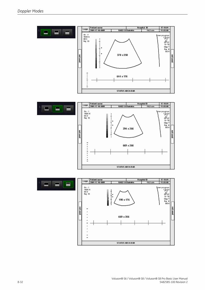
Doppler Modes
8-32Voluson® S6 / Voluson® S8 / Voluson® S8 Pro Basic User Manual
5482585-100 Revision 2
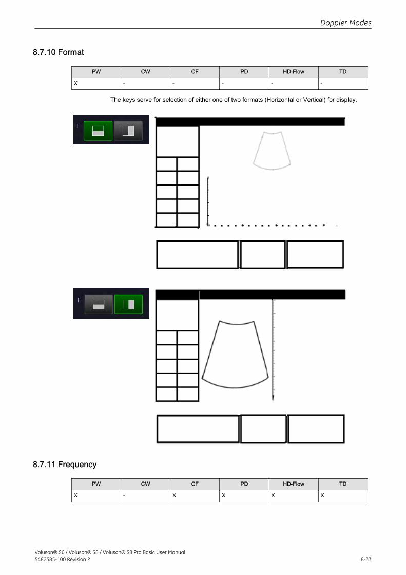
8.7.10 Format
PW CW CF PD HD-Flow TD
X - - - - -
The keys serve for selection of either one of two formats (Horizontal or Vertical) for display.
8.7.11 Frequency
PW CW CF PD HD-Flow TD
X - X X X X
Doppler Modes
Voluson® S6 / Voluson® S8 / Voluson® S8 Pro Basic User Manual5482585-100 Revision 2 8-33
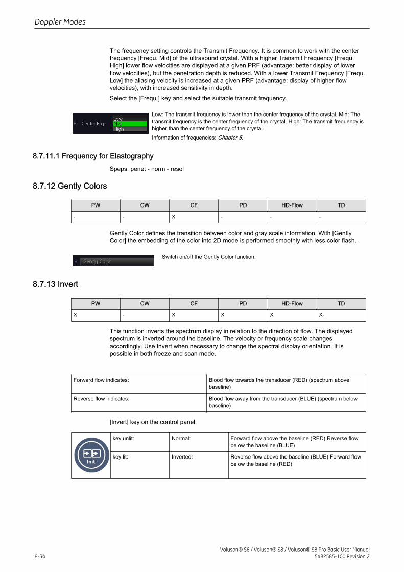
The frequency setting controls the Transmit Frequency. It is common to work with the centerfrequency [Frequ. Mid] of the ultrasound crystal. With a higher Transmit Frequency [Frequ.High] lower flow velocities are displayed at a given PRF (advantage: better display of lowerflow velocities), but the penetration depth is reduced. With a lower Transmit Frequency [Frequ.Low] the aliasing velocity is increased at a given PRF (advantage: display of higher flowvelocities), with increased sensitivity in depth.Select the [Frequ.] key and select the suitable transmit frequency.
Low: The transmit frequency is lower than the center frequency of the crystal. Mid: Thetransmit frequency is the center frequency of the crystal. High: The transmit frequency ishigher than the center frequency of the crystal.Information of frequencies: Chapter 5.
8.7.11.1 Frequency for ElastographySpeps: penet - norm - resol
8.7.12 Gently Colors
PW CW CF PD HD-Flow TD
- - X - - -
Gently Color defines the transition between color and gray scale information. With [GentlyColor] the embedding of the color into 2D mode is performed smoothly with less color flash.
Switch on/off the Gently Color function.
8.7.13 Invert
PW CW CF PD HD-Flow TD
X - X X X X-
This function inverts the spectrum display in relation to the direction of flow. The displayedspectrum is inverted around the baseline. The velocity or frequency scale changesaccordingly. Use Invert when necessary to change the spectral display orientation. It ispossible in both freeze and scan mode.
Forward flow indicates: Blood flow towards the transducer (RED) (spectrum abovebaseline)
Reverse flow indicates: Blood flow away from the transducer (BLUE) (spectrum belowbaseline)
[Invert] key on the control panel.
key unlit: Normal: Forward flow above the baseline (RED) Reverse flowbelow the baseline (BLUE)
key lit: Inverted: Reverse flow above the baseline (BLUE) Forward flowbelow the baseline (RED)
Doppler Modes
8-34Voluson® S6 / Voluson® S8 / Voluson® S8 Pro Basic User Manual
5482585-100 Revision 2
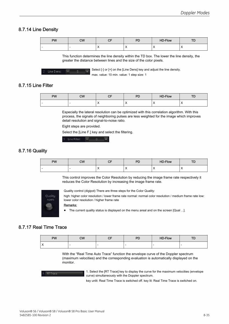
8.7.14 Line Density
PW CW CF PD HD-Flow TD
- - X X X X
This function determines the line density within the TD box. The lower the line density, thegreater the distance between lines and the size of the color pixels.
Select [-] or [+] on the [Line Dens] key and adjust the line density.max. value: 10 min. value: 1 step size: 1
8.7.15 Line Filter
PW CW CF PD HD-Flow TD
- - X X X X
Especially the lateral resolution can be optimized with this correlation algorithm. With thisprocess, the signals of neighboring pulses are less weighted for the image which improvesdetail resolution and signal-to-noise ratio.Eight steps are provided.Select the [Line F.] key and select the filtering.
8.7.16 Quality
PW CW CF PD HD-Flow TD
- - X X X X
This control improves the Color Resolution by reducing the image frame rate respectively itreduces the Color Resolution by increasing the image frame rate.
Quality control (digipot) There are three steps for the Color Quality:high: higher color resolution / lower frame rate normal: normal color resolution / medium frame rate low:lower color resolution / higher frame rateRemarks:
• The current quality status is displayed on the menu areal and on the screen [Qual ...].
8.7.17 Real Time Trace
PW CW CF PD HD-Flow TD
X - - - - -
With the “Real Time Auto Trace” function the envelope curve of the Doppler spectrum(maximum velocities) and the corresponding evaluation is automatically displayed on themonitor.
1. Select the [RT Trace] key to display the curve for the maximum velocities (envelopecurve) simultaneously with the Doppler spectrum.key unlit: Real Time Trace is switched off. key lit: Real Time Trace is switched on.
Doppler Modes
Voluson® S6 / Voluson® S8 / Voluson® S8 Pro Basic User Manual5482585-100 Revision 2 8-35
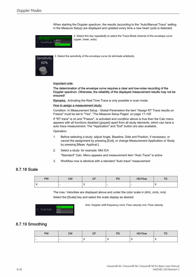
When starting the Doppler spectrum, the results (according to the “Auto/Manual Trace” settingin the Measure Setup) are displayed and updated every time a new heart cycle is detected.
2. Select this key repeatedly to select the Trace Mode channel of the envelope curve(upper, lower, auto).
3. Select the sensitivity of the envelope curve (to eliminate artefacts).
Important note:The determination of the envelope curve requires a clear and low-noise recording of theDoppler spectrum. Otherwise, the reliability of the displayed measurement results may not beensured!Remarks: Activating the Real Time Trace is only possible in scan mode.How to assign a measurement study:Condition: In Measurement Setup - Global Parameters the item "Assign RT Trace results onFreeze" must be set to "Yes", 'The Measure Setup Pages' on page 11-105If "RT trace" is on and "Freeze", is activated and condition above is true then the Calc menuappears with all functions disabled (grayed) apart from all study elements, which can have aauto trace measurement. The "Application" and "Exit" button are also available.Operation:
1. Before selecting a study: adjust Angle, Baseline, Side and Position, if necessary; orcancel the assignment by pressing [Exit], or change Measurement Application or Studyby pressing [Meas. Applicat.].
2. Select a study: for example: Mid ICA"Standard" Calc. Menu appears and measurement item "Auto Trace" is active
3. Workflow now is identical with a standard "Auto trace" measurement
8.7.18 Scale
PW CW CF PD HD-Flow TD
X - X - - X
The max. Velocities are displayed above and under the color scale in (kHz, cm/s, m/s)Select the [Scale] key and select the scale display as desired.
kHz: Doppler shift frequency cm/s: Flow velocity m/s: Flow velocity
8.7.19 Smoothing
PW CW CF PD HD-Flow TD
- - X X X X
Doppler Modes
8-36Voluson® S6 / Voluson® S8 / Voluson® S8 Pro Basic User Manual
5482585-100 Revision 2
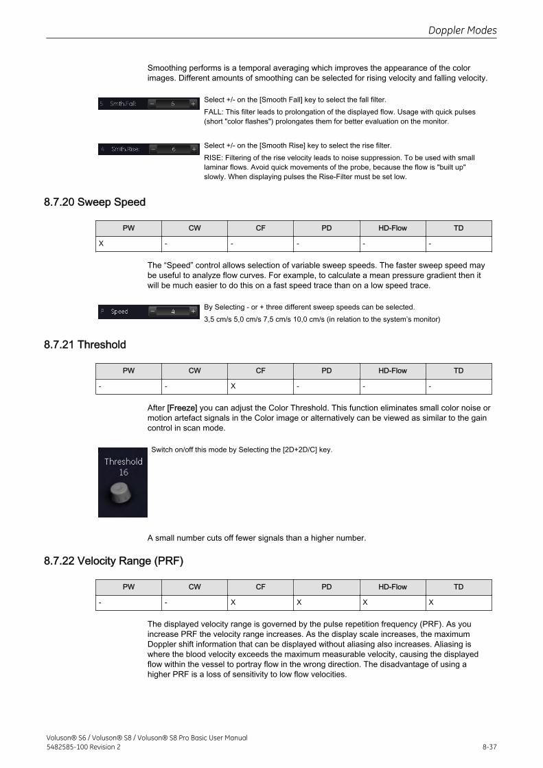
Smoothing performs is a temporal averaging which improves the appearance of the colorimages. Different amounts of smoothing can be selected for rising velocity and falling velocity.
Select +/- on the [Smooth Fall] key to select the fall filter.FALL: This filter leads to prolongation of the displayed flow. Usage with quick pulses(short "color flashes") prolongates them for better evaluation on the monitor.
Select +/- on the [Smooth Rise] key to select the rise filter.RISE: Filtering of the rise velocity leads to noise suppression. To be used with smalllaminar flows. Avoid quick movements of the probe, because the flow is "built up"slowly. When displaying pulses the Rise-Filter must be set low.
8.7.20 Sweep Speed
PW CW CF PD HD-Flow TD
X - - - - -
The “Speed” control allows selection of variable sweep speeds. The faster sweep speed maybe useful to analyze flow curves. For example, to calculate a mean pressure gradient then itwill be much easier to do this on a fast speed trace than on a low speed trace.
By Selecting - or + three different sweep speeds can be selected.3,5 cm/s 5,0 cm/s 7,5 cm/s 10,0 cm/s (in relation to the system’s monitor)
8.7.21 Threshold
PW CW CF PD HD-Flow TD
- - X - - -
After [Freeze] you can adjust the Color Threshold. This function eliminates small color noise ormotion artefact signals in the Color image or alternatively can be viewed as similar to the gaincontrol in scan mode.
Switch on/off this mode by Selecting the [2D+2D/C] key.
A small number cuts off fewer signals than a higher number.
8.7.22 Velocity Range (PRF)
PW CW CF PD HD-Flow TD
- - X X X X
The displayed velocity range is governed by the pulse repetition frequency (PRF). As youincrease PRF the velocity range increases. As the display scale increases, the maximumDoppler shift information that can be displayed without aliasing also increases. Aliasing iswhere the blood velocity exceeds the maximum measurable velocity, causing the displayedflow within the vessel to portray flow in the wrong direction. The disadvantage of using ahigher PRF is a loss of sensitivity to low flow velocities.
Doppler Modes
Voluson® S6 / Voluson® S8 / Voluson® S8 Pro Basic User Manual5482585-100 Revision 2 8-37
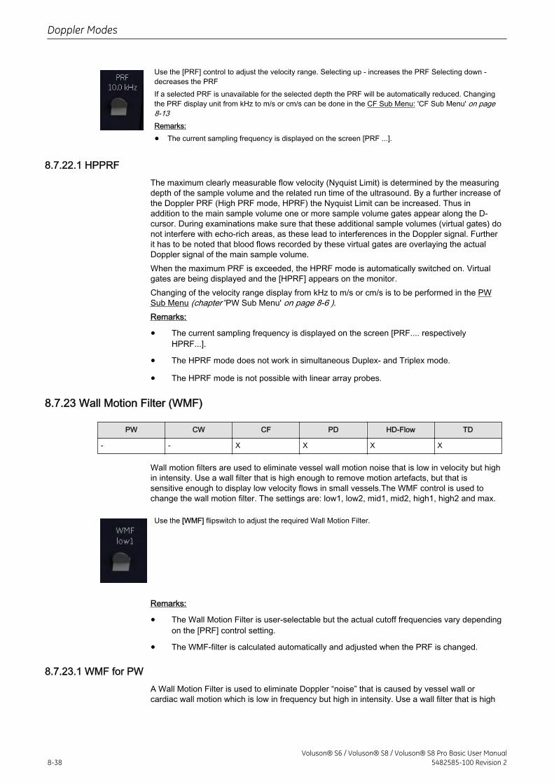
Use the [PRF] control to adjust the velocity range. Selecting up - increases the PRF Selecting down -decreases the PRFIf a selected PRF is unavailable for the selected depth the PRF will be automatically reduced. Changingthe PRF display unit from kHz to m/s or cm/s can be done in the CF Sub Menu: 'CF Sub Menu' on page8-13Remarks:
• The current sampling frequency is displayed on the screen [PRF ...].
8.7.22.1 HPPRFThe maximum clearly measurable flow velocity (Nyquist Limit) is determined by the measuringdepth of the sample volume and the related run time of the ultrasound. By a further increase ofthe Doppler PRF (High PRF mode, HPRF) the Nyquist Limit can be increased. Thus inaddition to the main sample volume one or more sample volume gates appear along the D-cursor. During examinations make sure that these additional sample volumes (virtual gates) donot interfere with echo-rich areas, as these lead to interferences in the Doppler signal. Furtherit has to be noted that blood flows recorded by these virtual gates are overlaying the actualDoppler signal of the main sample volume.When the maximum PRF is exceeded, the HPRF mode is automatically switched on. Virtualgates are being displayed and the [HPRF] appears on the monitor.Changing of the velocity range display from kHz to m/s or cm/s is to be performed in the PWSub Menu (chapter 'PW Sub Menu' on page 8-6 ).Remarks:
• The current sampling frequency is displayed on the screen [PRF.... respectivelyHPRF...].
• The HPRF mode does not work in simultaneous Duplex- and Triplex mode.
• The HPRF mode is not possible with linear array probes.
8.7.23 Wall Motion Filter (WMF)
PW CW CF PD HD-Flow TD
- - X X X X
Wall motion filters are used to eliminate vessel wall motion noise that is low in velocity but highin intensity. Use a wall filter that is high enough to remove motion artefacts, but that issensitive enough to display low velocity flows in small vessels.The WMF control is used tochange the wall motion filter. The settings are: low1, low2, mid1, mid2, high1, high2 and max.
Use the [WMF] flipswitch to adjust the required Wall Motion Filter.
Remarks:
• The Wall Motion Filter is user-selectable but the actual cutoff frequencies vary dependingon the [PRF] control setting.
• The WMF-filter is calculated automatically and adjusted when the PRF is changed.
8.7.23.1 WMF for PWA Wall Motion Filter is used to eliminate Doppler “noise” that is caused by vessel wall orcardiac wall motion which is low in frequency but high in intensity. Use a wall filter that is high
Doppler Modes
8-38Voluson® S6 / Voluson® S8 / Voluson® S8 Pro Basic User Manual
5482585-100 Revision 2
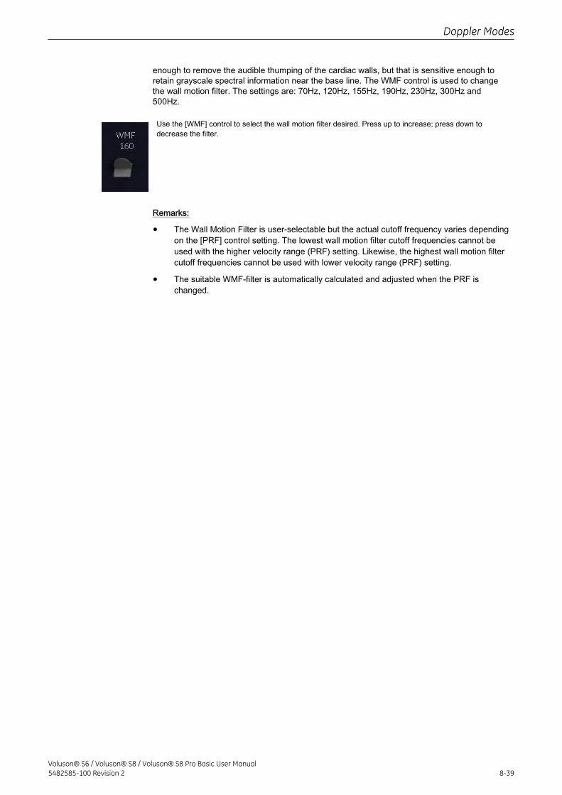
enough to remove the audible thumping of the cardiac walls, but that is sensitive enough toretain grayscale spectral information near the base line. The WMF control is used to changethe wall motion filter. The settings are: 70Hz, 120Hz, 155Hz, 190Hz, 230Hz, 300Hz and500Hz.
Use the [WMF] control to select the wall motion filter desired. Press up to increase; press down todecrease the filter.
Remarks:
• The Wall Motion Filter is user-selectable but the actual cutoff frequency varies dependingon the [PRF] control setting. The lowest wall motion filter cutoff frequencies cannot beused with the higher velocity range (PRF) setting. Likewise, the highest wall motion filtercutoff frequencies cannot be used with lower velocity range (PRF) setting.
• The suitable WMF-filter is automatically calculated and adjusted when the PRF ischanged.
Doppler Modes
Voluson® S6 / Voluson® S8 / Voluson® S8 Pro Basic User Manual5482585-100 Revision 2 8-39

This page was intentionally left blank.
Doppler Modes
8-40Voluson® S6 / Voluson® S8 / Voluson® S8 Pro Basic User Manual
5482585-100 Revision 2
Chapter 9
Volume Mode
Describes the general functions of the Volume Mode.Image quality is the essential performance of the system.Please read this chapter carefully.
Voluson® S6 / Voluson® S8 / Voluson® S8 Pro Basic User Manual5482585-100 Revision 2 9-1
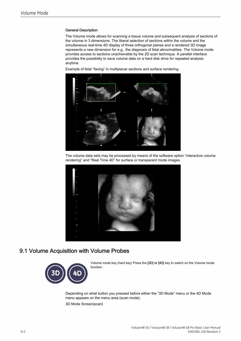
General DescriptionThe Volume mode allows for scanning a tissue volume and subsequent analysis of sections ofthe volume in 3 dimensions. The liberal selection of sections within the volume and thesimultaneous real-time 4D display of three orthogonal planes and a rendered 3D imagerepresents a new dimension for e.g., the diagnosis of fetal abnormalities. The Volume modeprovides access to sections unachievable by the 2D scan technique. A parallel interfaceprovides the possibility to save volume data on a hard disk drive for repeated analysisanytime.Example of fetal “facing” in multiplanar sections and surface rendering.
The volume data sets may be processed by means of the software option “interactive volumerendering” and “Real Time 4D” for surface or transparent mode images.
9.1 Volume Acquisition with Volume Probes
Volume mode key (hard key) Press the [3D] or [4D] key to switch on the Volume modefunction.
Depending on what button you pressed before either the “3D Mode” menu or the 4D Modemenu appears on the menu area (scan mode).3D Mode Screen(scan)
Volume Mode
9-2Voluson® S6 / Voluson® S8 / Voluson® S8 Pro Basic User Manual
5482585-100 Revision 2
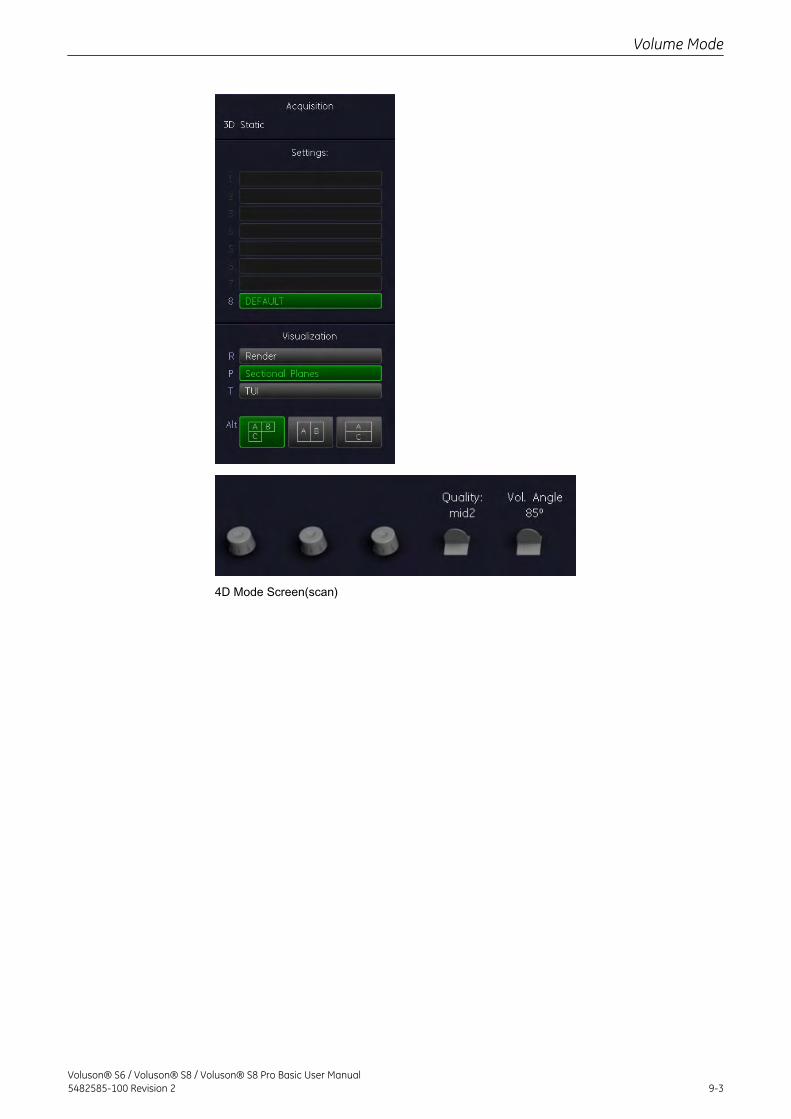
4D Mode Screen(scan)
Volume Mode
Voluson® S6 / Voluson® S8 / Voluson® S8 Pro Basic User Manual5482585-100 Revision 2 9-3
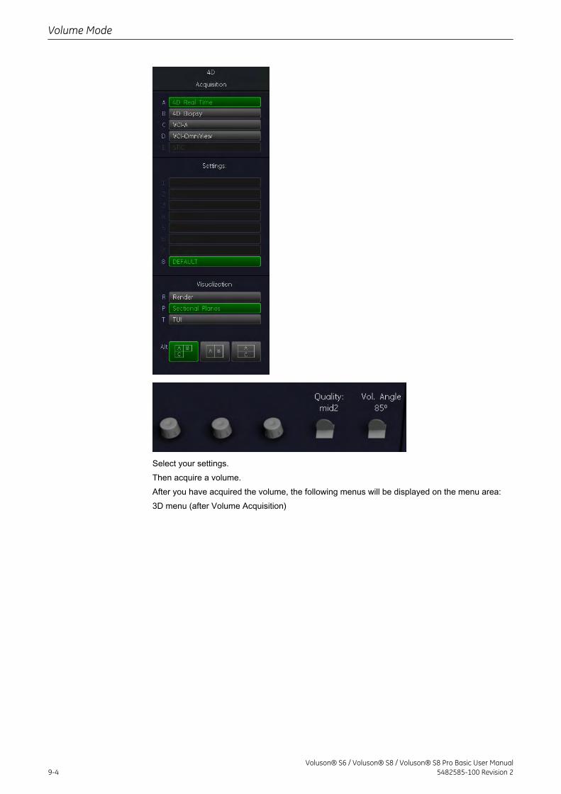
Select your settings.Then acquire a volume.After you have acquired the volume, the following menus will be displayed on the menu area:3D menu (after Volume Acquisition)
Volume Mode
9-4Voluson® S6 / Voluson® S8 / Voluson® S8 Pro Basic User Manual
5482585-100 Revision 2
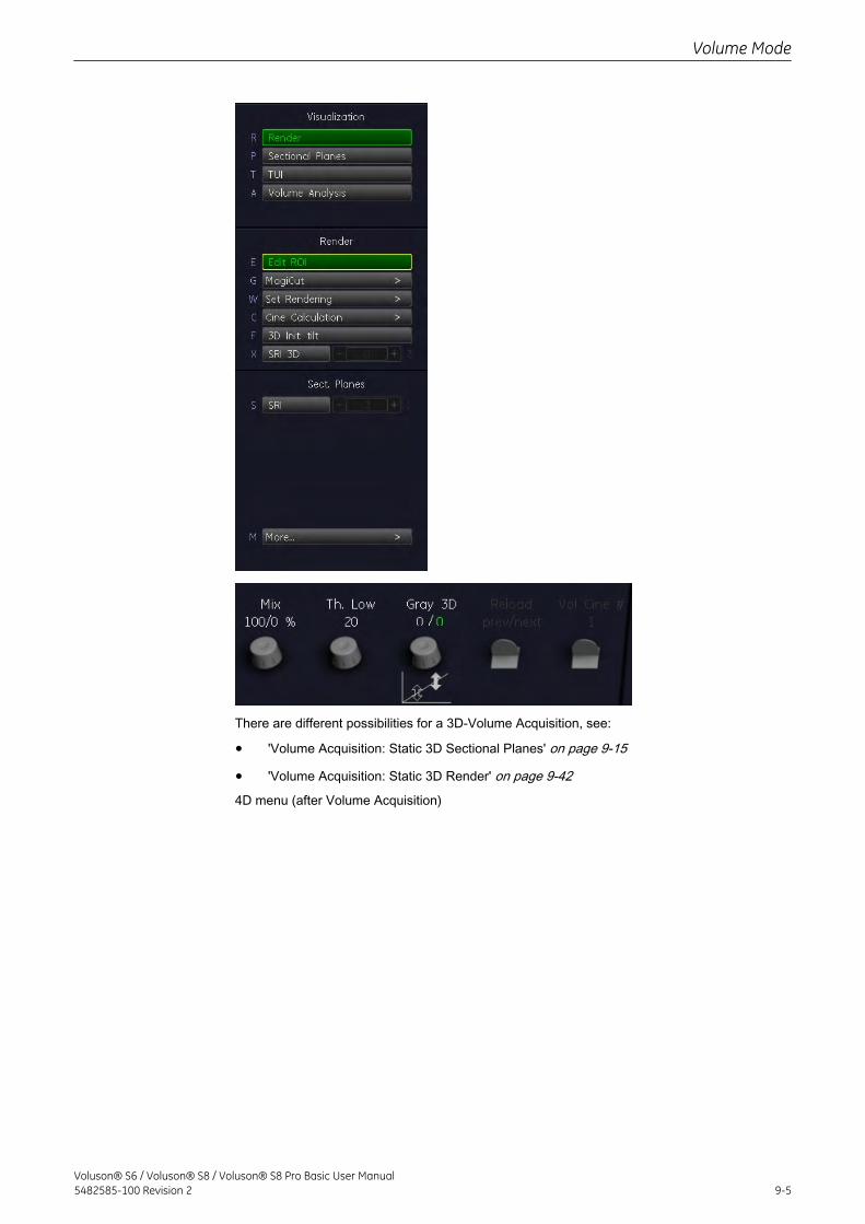
There are different possibilities for a 3D-Volume Acquisition, see:
• 'Volume Acquisition: Static 3D Sectional Planes' on page 9-15
• 'Volume Acquisition: Static 3D Render' on page 9-424D menu (after Volume Acquisition)
Volume Mode
Voluson® S6 / Voluson® S8 / Voluson® S8 Pro Basic User Manual5482585-100 Revision 2 9-5
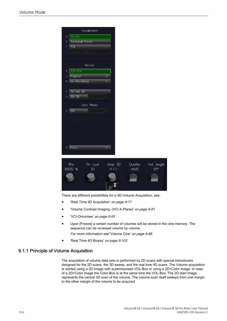
There are different possibilities for a 4D-Volume Acquisition, see:
• 'Real Time 4D Acquisition' on page 9-71
• 'Volume Contrast Imaging: (VCI A-Plane)' on page 9-91
• 'VCI-Omniview' on page 9-93
• Upon [Freeze] a certain number of volumes will be stored in the cine memory. Thesequence can be reviewed volume by volume.For more information see 'Volume Cine' on page 9-88.
• 'Real Time 4D Biopsy' on page 9-103
9.1.1 Principle of Volume Acquisition
The acquisition of volume data sets is performed by 2D scans with special transducersdesigned for the 2D scans, the 3D sweep, and the real time 4D scans. The Volume acquisitionis started using a 2D-image with superimposed VOL-Box or using a 2D+Color image. In caseof a 2D+Color image the Color-Box is at the same time the VOL-Box. The 2D start imagerepresents the central 2D scan of the volume. The volume scan itself sweeps from one marginto the other margin of the volume to be acquired.
Volume Mode
9-6Voluson® S6 / Voluson® S8 / Voluson® S8 Pro Basic User Manual
5482585-100 Revision 2
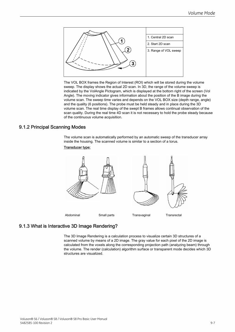
1. Central 2D scan
2. Start 2D scan
3. Range of VOL sweep
The VOL BOX frames the Region of Interest (ROI) which will be stored during the volumesweep. The display shows the actual 2D scan. In 3D, the range of the volume sweep isindicated by the VolAngle Pictogram, which is displayed at the bottom right of the screen (VolAngle). The moving indicator gives information about the position of the B image during thevolume scan. The sweep time varies and depends on the VOL BOX size (depth range, angle)and the quality (6 positions). The probe must be held steady and in place during the 3Dvolume scan. The real time display of the swept B frames allows continual observation of thescan quality. During the real time 4D scan it is not necessary to hold the probe steady becauseof the continuous volume acquisition.
9.1.2 Principal Scanning Modes
The volume scan is automatically performed by an automatic sweep of the transducer arrayinside the housing. The scanned volume is similar to a section of a torus.Transducer type:
Abdominal Small parts Transvaginal Transrectal
9.1.3 What is Interactive 3D Image Rendering?
The 3D Image Rendering is a calculation process to visualize certain 3D structures of ascanned volume by means of a 2D image. The gray value for each pixel of the 2D image iscalculated from the voxels along the corresponding projection path (analyzing beam) throughthe volume. The render (calculation) algorithm surface or transparent mode decides which 3Dstructures are visualized.
Volume Mode
Voluson® S6 / Voluson® S8 / Voluson® S8 Pro Basic User Manual5482585-100 Revision 2 9-7
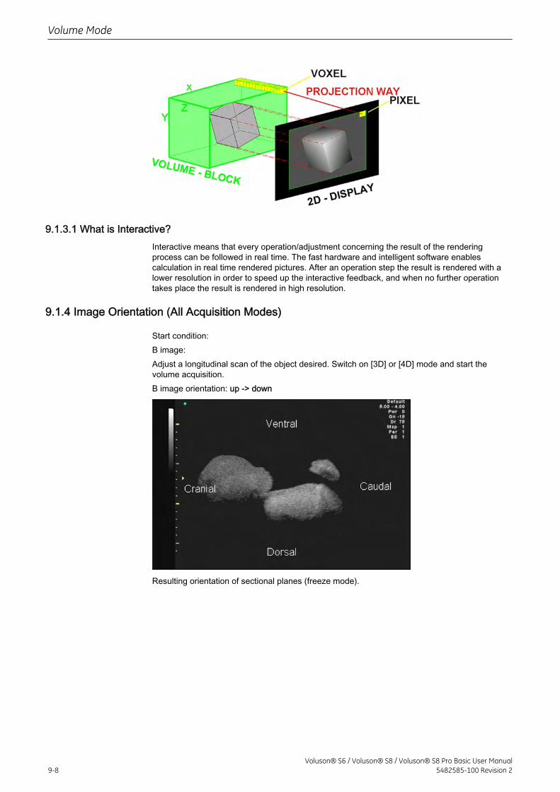
9.1.3.1 What is Interactive?Interactive means that every operation/adjustment concerning the result of the renderingprocess can be followed in real time. The fast hardware and intelligent software enablescalculation in real time rendered pictures. After an operation step the result is rendered with alower resolution in order to speed up the interactive feedback, and when no further operationtakes place the result is rendered in high resolution.
9.1.4 Image Orientation (All Acquisition Modes)
Start condition:B image:Adjust a longitudinal scan of the object desired. Switch on [3D] or [4D] mode and start thevolume acquisition.B image orientation: up -> down
Resulting orientation of sectional planes (freeze mode).
Volume Mode
9-8Voluson® S6 / Voluson® S8 / Voluson® S8 Pro Basic User Manual
5482585-100 Revision 2
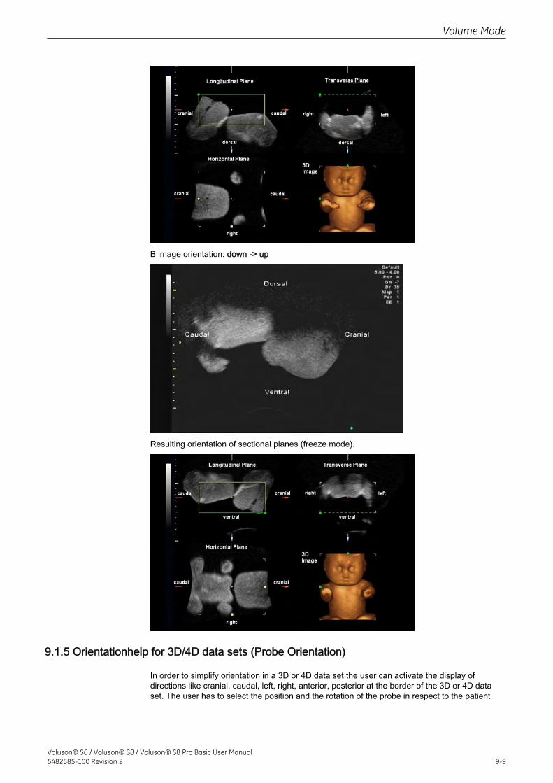
B image orientation: down -> up
Resulting orientation of sectional planes (freeze mode).
9.1.5 Orientationhelp for 3D/4D data sets (Probe Orientation)
In order to simplify orientation in a 3D or 4D data set the user can activate the display ofdirections like cranial, caudal, left, right, anterior, posterior at the border of the 3D or 4D dataset. The user has to select the position and the rotation of the probe in respect to the patient
Volume Mode
Voluson® S6 / Voluson® S8 / Voluson® S8 Pro Basic User Manual5482585-100 Revision 2 9-9
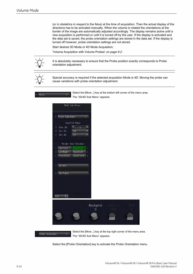
(or in obstetrics in respect to the fetus) at the time of acquisition. Then the actual display of thedirections has to be activated manually. When the volume is rotated the orientations at theborder of the image are automatically adjusted accordingly. The display remains active until anew acquisition is performed or until it is turned off by the user. If the display is activated andthe data set is saved, the probe orientation settings are stored in the data set. If the display isturned off however, probe orientation settings are not stored.Start desired 3D Mode or 4D Mode Acquisition;'Volume Acquisition with Volume Probes' on page 9-2 .
It is absolutely necessary to ensure that the Probe position exactly corresponds to Probeorientation adjustment.
Special accuracy is required if the selected acquisition Mode is 4D. Moving the probe cancause variations with probe orientation adjustment.
Select the [More...] key at the bottom left corner of the menu area.The “3D/4D Sub Menu” appears.
Select the [More...] key at the top right corner of the menu area.The “3D/4D Sub Menu” appears.
Select the [Probe Orientation] key to activate the Probe Orientation menu.
Volume Mode
9-10Voluson® S6 / Voluson® S8 / Voluson® S8 Pro Basic User Manual
5482585-100 Revision 2
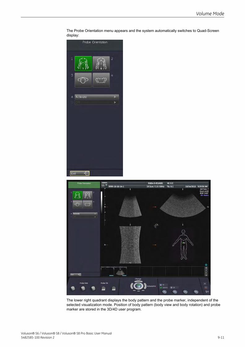
The Probe Orientation menu appears and the system automatically switches to Quad-Screendisplay:
The lower right quadrant displays the body pattern and the probe marker, independent of theselected visualization mode. Position of body pattern (body view and body rotation) and probemarker are stored in the 3D/4D user program.
Volume Mode
Voluson® S6 / Voluson® S8 / Voluson® S8 Pro Basic User Manual5482585-100 Revision 2 9-11
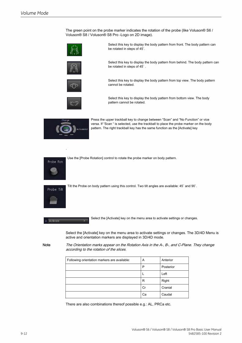
The green point on the probe marker indicates the rotation of the probe (like Voluson® S6 /Voluson® S8 / Voluson® S8 Pro -Logo on 2D image).
Select this key to display the body pattern from front. The body pattern canbe rotated in steps of 45˚.
Select this key to display the body pattern from behind. The body pattern canbe rotated in steps of 45˚ .
Select this key to display the body pattern from top view. The body patterncannot be rotated.
Select this key to display the body pattern from bottom view. The bodypattern cannot be rotated.
Press the upper trackball key to change between “Scan” and “No Function” or viceversa. If “Scan “ is selected, use the trackball to place the probe marker on the bodypattern. The right trackball key has the same function as the [Activate] key
.
Use the [Probe Rotation] control to rotate the probe marker on body pattern.
Tilt the Probe on body pattern using this control. Two tilt angles are available: 45˚ and 90˚.
Select the [Activate] key on the menu area to activate settings or changes.
Select the [Activate] key on the menu area to activate settings or changes. The 3D/4D Menu isactive and orientation markers are displayed in 3D/4D mode.
Note The Orientation marks appear on the Rotation Axis in the A-, B-, and C-Plane. They changeaccording to the rotation of the slices.
Following orientation markers are available: A Anterior
P Posterior
L Left
R Right
Cr Cranial
Ca Caudal
There are also combinations thereof possible e.g.: AL, PRCa etc.
Volume Mode
9-12Voluson® S6 / Voluson® S8 / Voluson® S8 Pro Basic User Manual
5482585-100 Revision 2
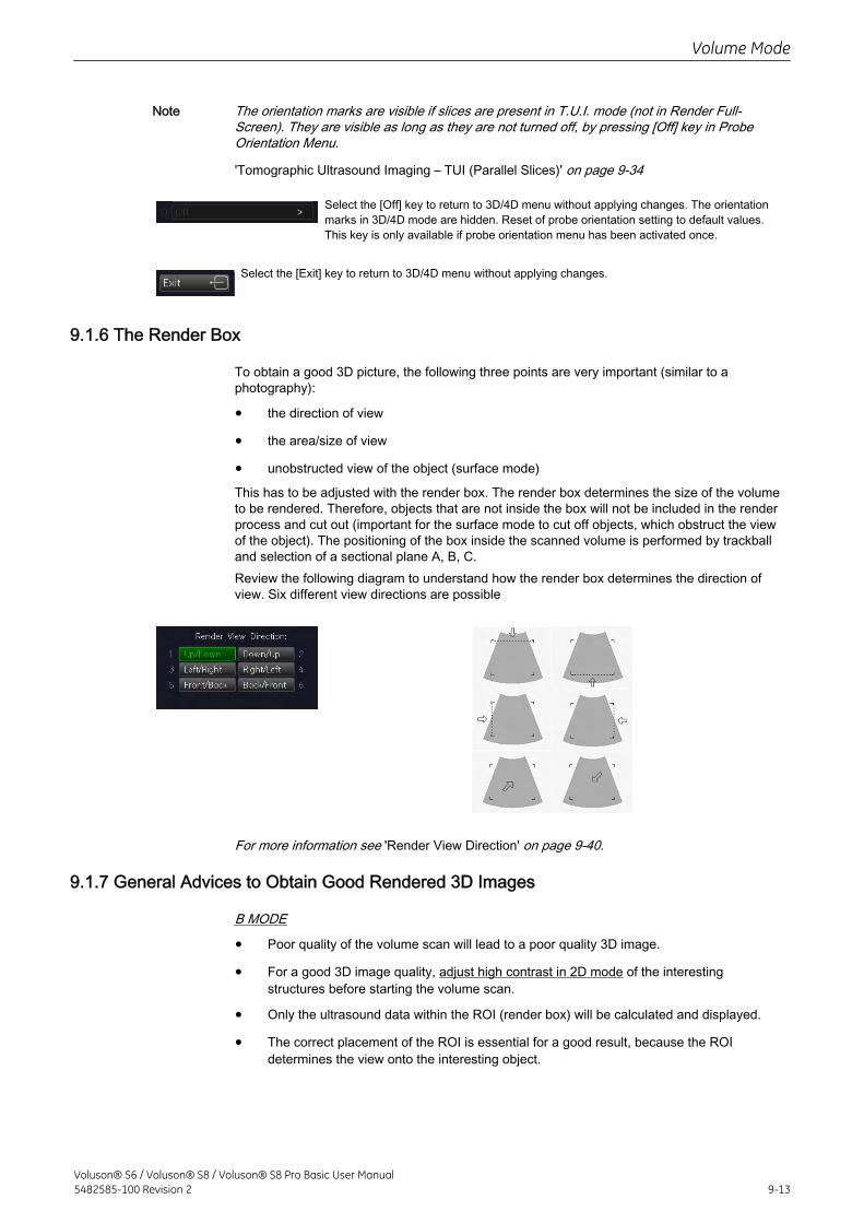
Note The orientation marks are visible if slices are present in T.U.I. mode (not in Render Full-Screen). They are visible as long as they are not turned off, by pressing [Off] key in ProbeOrientation Menu.
'Tomographic Ultrasound Imaging – TUI (Parallel Slices)' on page 9-34
Select the [Off] key to return to 3D/4D menu without applying changes. The orientationmarks in 3D/4D mode are hidden. Reset of probe orientation setting to default values.This key is only available if probe orientation menu has been activated once.
Select the [Exit] key to return to 3D/4D menu without applying changes.
9.1.6 The Render Box
To obtain a good 3D picture, the following three points are very important (similar to aphotography):
• the direction of view
• the area/size of view
• unobstructed view of the object (surface mode)
This has to be adjusted with the render box. The render box determines the size of the volumeto be rendered. Therefore, objects that are not inside the box will not be included in the renderprocess and cut out (important for the surface mode to cut off objects, which obstruct the viewof the object). The positioning of the box inside the scanned volume is performed by trackballand selection of a sectional plane A, B, C.Review the following diagram to understand how the render box determines the direction ofview. Six different view directions are possible
For more information see 'Render View Direction' on page 9-40.
9.1.7 General Advices to Obtain Good Rendered 3D Images
B MODE
• Poor quality of the volume scan will lead to a poor quality 3D image.
• For a good 3D image quality, adjust high contrast in 2D mode of the interestingstructures before starting the volume scan.
• Only the ultrasound data within the ROI (render box) will be calculated and displayed.
• The correct placement of the ROI is essential for a good result, because the ROIdetermines the view onto the interesting object.
Volume Mode
Voluson® S6 / Voluson® S8 / Voluson® S8 Pro Basic User Manual5482585-100 Revision 2 9-13
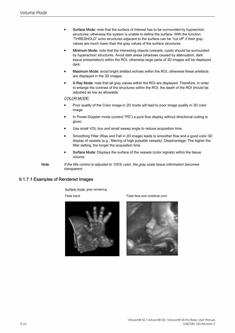
• Surface Mode: note that the surface of interest has to be surrounded by hypoechoicstructures; otherwise the system is unable to define the surface. With the function“THRESHOLD” echo structures adjacent to the surface can be "cut off" if their grayvalues are much lower than the gray values of the surface structures.
• Minimum Mode: note that the interesting objects (vessels, cysts) should be surroundedby hyperechoic structures. Avoid dark areas (shadows caused by attenuation, darktissue presentation) within the ROI, otherwise large parts of 3D images will be displayeddark.
• Maximum Mode: avoid bright artefact echoes within the ROI, otherwise these artefactsare displayed in the 3D images.
• X-Ray Mode: note that all gray values within the ROI are displayed. Therefore, in orderto enlarge the contrast of the structures within the ROI, the depth of the ROI should beadjusted as low as allowable.
COLOR MODE:
• Poor quality of the Color image in 2D mode will lead to poor image quality in 3D colorimage.
• In Power-Doppler mode (control “PD”) a pure flow display without directional coding isgiven.
• Use small VOL box and small sweep angle to reduce acquisition time.
• Smoothing Filter (Rise and Fall in 2D image) leads to smoother flow and a good color 3Ddisplay of vessels (e.g., filtering of high pulsatile vessels). Disadvantage: The higher thefilter setting, the longer the acquisition time.
• Surface Mode: Displays the surface of the vessels (color signals) within the tissuevolume.
Note If the Mix control is adjusted to 100% color, the gray scale tissue information becomestransparent.
9.1.7.1 Examples of Rendered Images
Surface mode: gray rendering
Fetal hand Fetal face and umbilical cord
Volume Mode
9-14Voluson® S6 / Voluson® S8 / Voluson® S8 Pro Basic User Manual
5482585-100 Revision 2
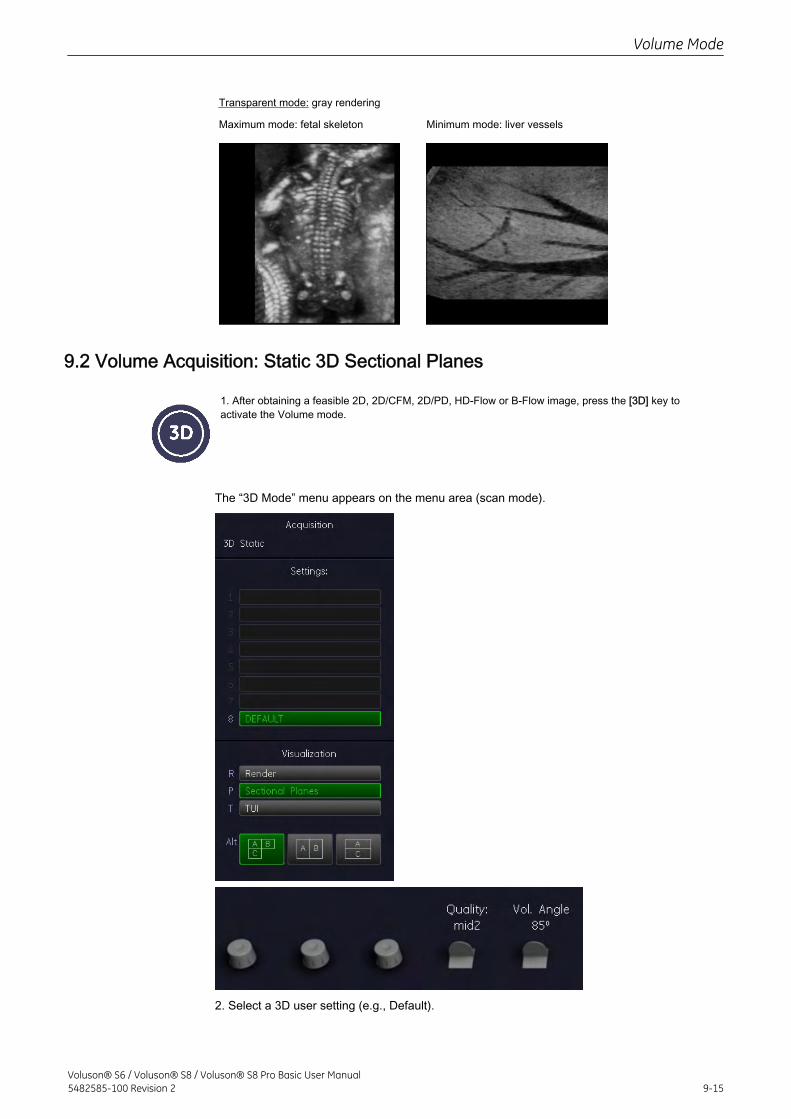
Transparent mode: gray rendering
Maximum mode: fetal skeleton Minimum mode: liver vessels
9.2 Volume Acquisition: Static 3D Sectional Planes
1. After obtaining a feasible 2D, 2D/CFM, 2D/PD, HD-Flow or B-Flow image, press the [3D] key toactivate the Volume mode.
The “3D Mode” menu appears on the menu area (scan mode).
2. Select a 3D user setting (e.g., Default).
Volume Mode
Voluson® S6 / Voluson® S8 / Voluson® S8 Pro Basic User Manual5482585-100 Revision 2 9-15
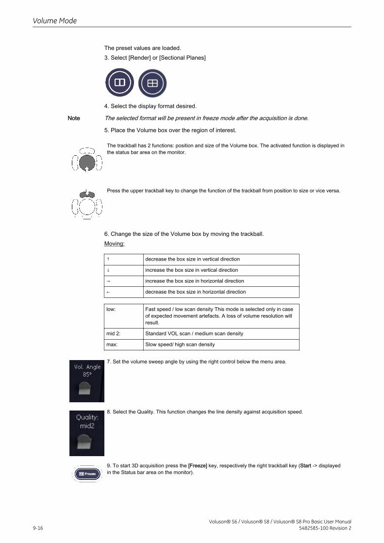
The preset values are loaded.3. Select [Render] or [Sectional Planes]
4. Select the display format desired.
Note The selected format will be present in freeze mode after the acquisition is done.
5. Place the Volume box over the region of interest.
The trackball has 2 functions: position and size of the Volume box. The activated function is displayed inthe status bar area on the monitor.
Press the upper trackball key to change the function of the trackball from position to size or vice versa.
6. Change the size of the Volume box by moving the trackball.Moving:
↑ decrease the box size in vertical direction
↓ increase the box size in vertical direction
→ increase the box size in horizontal direction
← decrease the box size in horizontal direction
low: Fast speed / low scan density This mode is selected only in caseof expected movement artefacts. A loss of volume resolution willresult.
mid 2: Standard VOL scan / medium scan density
max: Slow speed/ high scan density
7. Set the volume sweep angle by using the right control below the menu area.
8. Select the Quality. This function changes the line density against acquisition speed.
9. To start 3D acquisition press the [Freeze] key, respectively the right trackball key (Start -> displayedin the Status bar area on the monitor).
Volume Mode
9-16Voluson® S6 / Voluson® S8 / Voluson® S8 Pro Basic User Manual
5482585-100 Revision 2
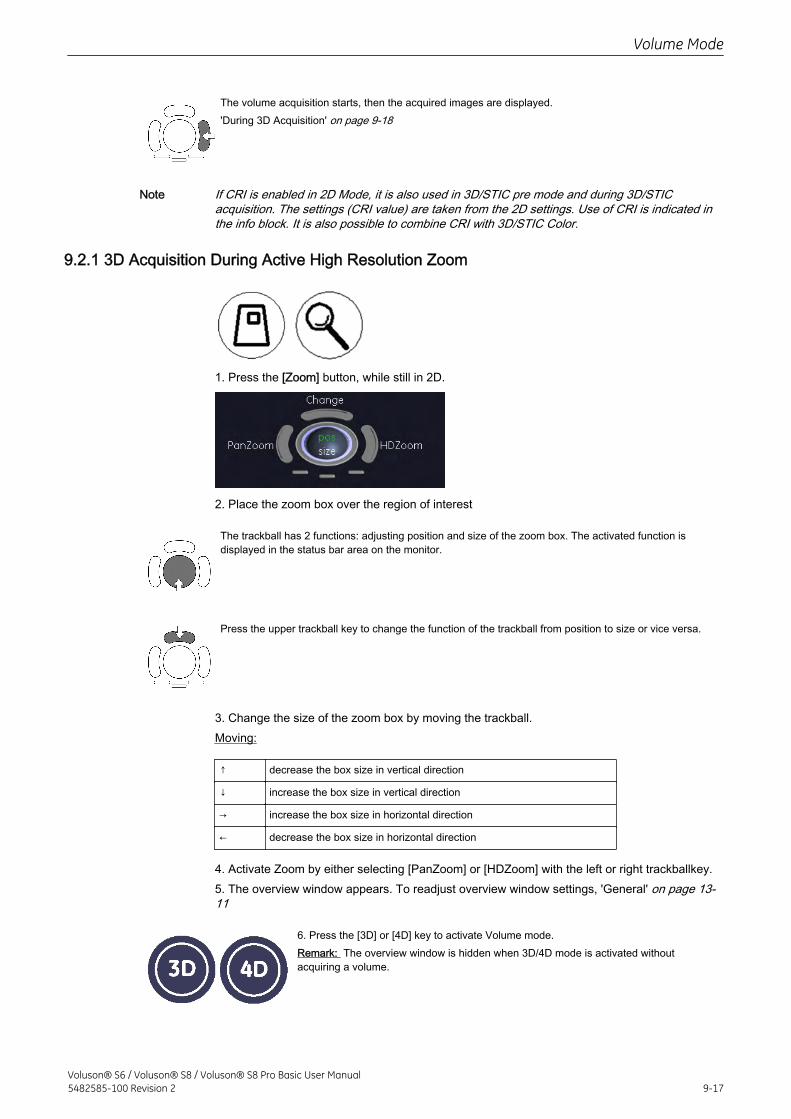
The volume acquisition starts, then the acquired images are displayed.'During 3D Acquisition' on page 9-18
Note If CRI is enabled in 2D Mode, it is also used in 3D/STIC pre mode and during 3D/STICacquisition. The settings (CRI value) are taken from the 2D settings. Use of CRI is indicated inthe info block. It is also possible to combine CRI with 3D/STIC Color.
9.2.1 3D Acquisition During Active High Resolution Zoom
1. Press the [Zoom] button, while still in 2D.
2. Place the zoom box over the region of interest
The trackball has 2 functions: adjusting position and size of the zoom box. The activated function isdisplayed in the status bar area on the monitor.
Press the upper trackball key to change the function of the trackball from position to size or vice versa.
3. Change the size of the zoom box by moving the trackball.Moving:
↑ decrease the box size in vertical direction
↓ increase the box size in vertical direction
→ increase the box size in horizontal direction
← decrease the box size in horizontal direction
4. Activate Zoom by either selecting [PanZoom] or [HDZoom] with the left or right trackballkey.5. The overview window appears. To readjust overview window settings, 'General' on page 13-11
6. Press the [3D] or [4D] key to activate Volume mode.Remark: The overview window is hidden when 3D/4D mode is activated withoutacquiring a volume.
Volume Mode
Voluson® S6 / Voluson® S8 / Voluson® S8 Pro Basic User Manual5482585-100 Revision 2 9-17
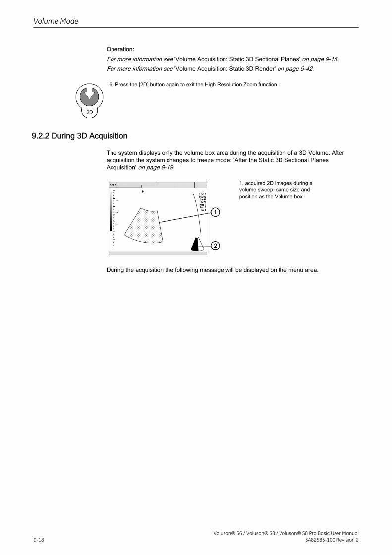
Operation:For more information see 'Volume Acquisition: Static 3D Sectional Planes' on page 9-15.For more information see 'Volume Acquisition: Static 3D Render' on page 9-42.
6. Press the [2D] button again to exit the High Resolution Zoom function.
9.2.2 During 3D Acquisition
The system displays only the volume box area during the acquisition of a 3D Volume. Afteracquisition the system changes to freeze mode: 'After the Static 3D Sectional PlanesAcquisition' on page 9-19
1. acquired 2D images during avolume sweep. same size andposition as the Volume box
During the acquisition the following message will be displayed on the menu area.
Volume Mode
9-18Voluson® S6 / Voluson® S8 / Voluson® S8 Pro Basic User Manual
5482585-100 Revision 2
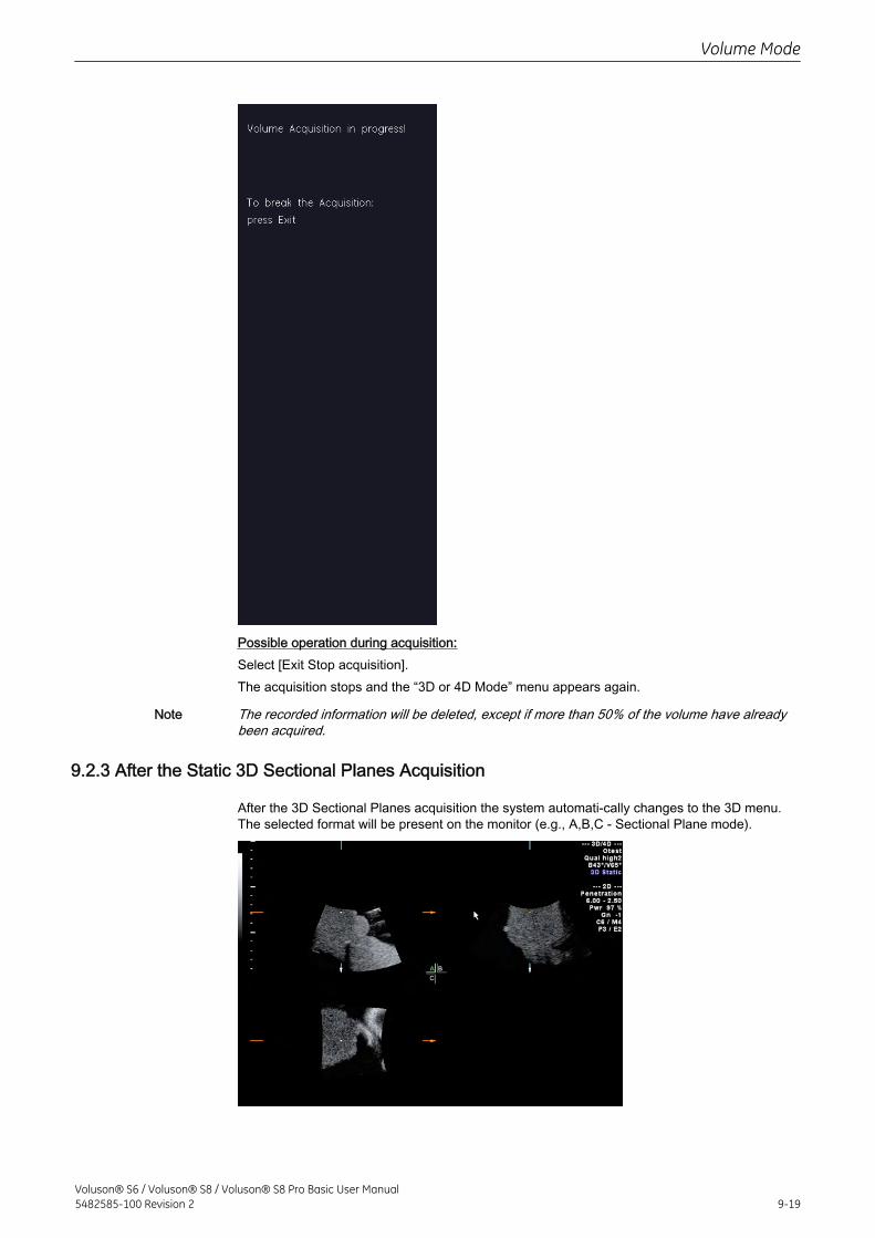
Possible operation during acquisition:Select [Exit Stop acquisition].The acquisition stops and the “3D or 4D Mode” menu appears again.
Note The recorded information will be deleted, except if more than 50% of the volume have alreadybeen acquired.
9.2.3 After the Static 3D Sectional Planes Acquisition
After the 3D Sectional Planes acquisition the system automati-cally changes to the 3D menu.The selected format will be present on the monitor (e.g., A,B,C - Sectional Plane mode).
Volume Mode
Voluson® S6 / Voluson® S8 / Voluson® S8 Pro Basic User Manual5482585-100 Revision 2 9-19
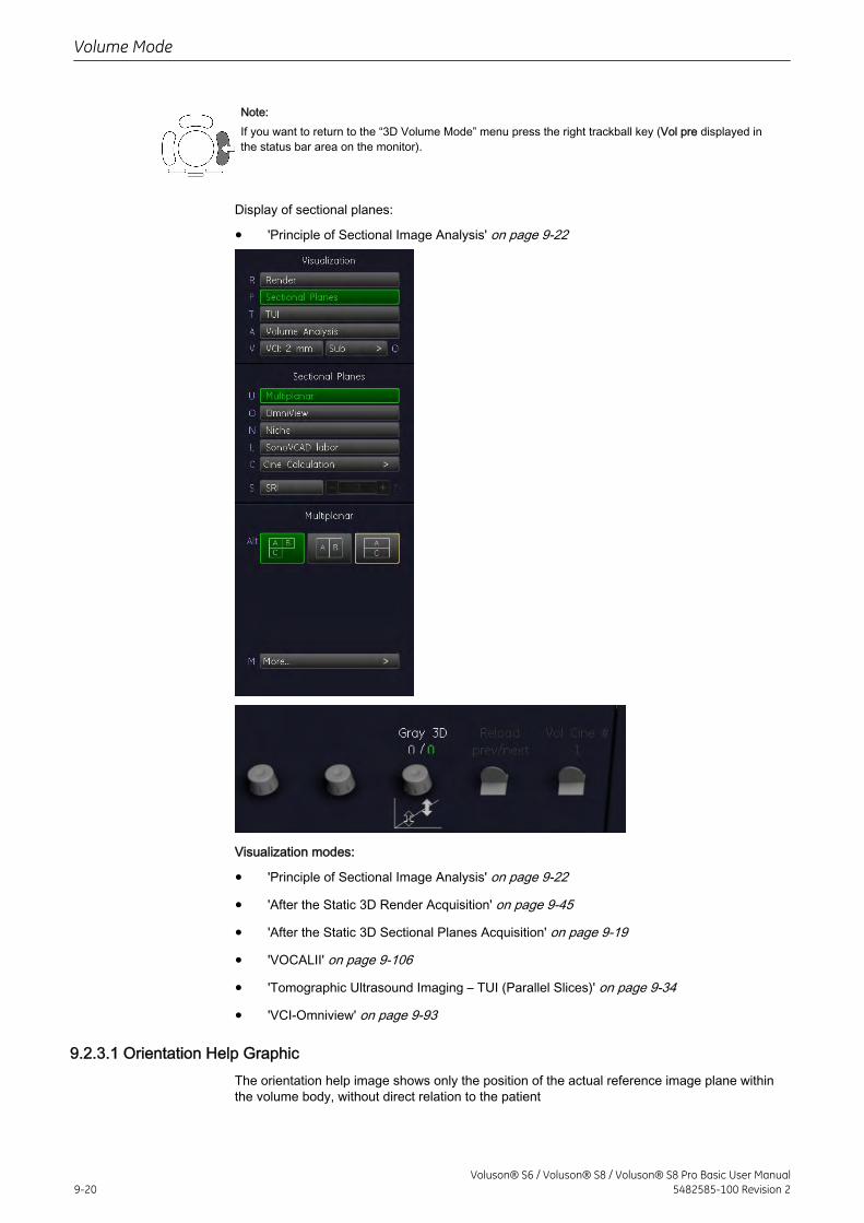
Note:If you want to return to the “3D Volume Mode” menu press the right trackball key (Vol pre displayed inthe status bar area on the monitor).
Display of sectional planes:
• 'Principle of Sectional Image Analysis' on page 9-22
Visualization modes:
• 'Principle of Sectional Image Analysis' on page 9-22
• 'After the Static 3D Render Acquisition' on page 9-45
• 'After the Static 3D Sectional Planes Acquisition' on page 9-19
• 'VOCALII' on page 9-106
• 'Tomographic Ultrasound Imaging – TUI (Parallel Slices)' on page 9-34
• 'VCI-Omniview' on page 9-93
9.2.3.1 Orientation Help GraphicThe orientation help image shows only the position of the actual reference image plane withinthe volume body, without direct relation to the patient
Volume Mode
9-20Voluson® S6 / Voluson® S8 / Voluson® S8 Pro Basic User Manual
5482585-100 Revision 2
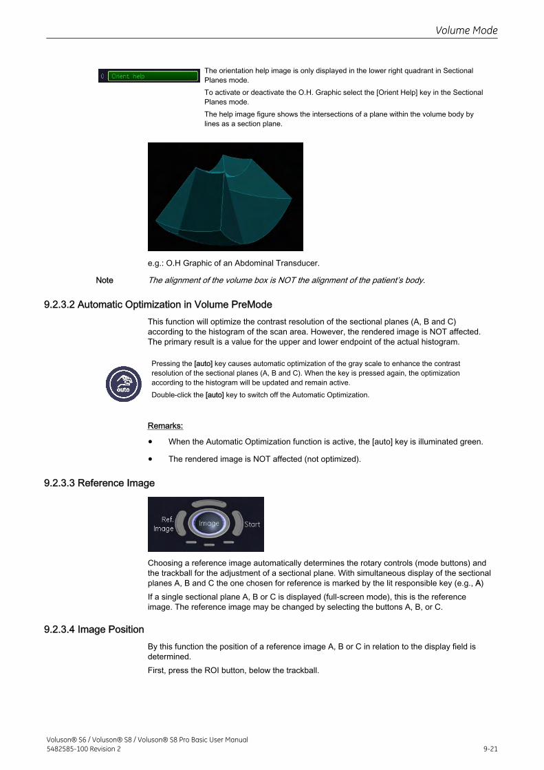
The orientation help image is only displayed in the lower right quadrant in SectionalPlanes mode.To activate or deactivate the O.H. Graphic select the [Orient Help] key in the SectionalPlanes mode.The help image figure shows the intersections of a plane within the volume body bylines as a section plane.
e.g.: O.H Graphic of an Abdominal Transducer.
Note The alignment of the volume box is NOT the alignment of the patient’s body.
9.2.3.2 Automatic Optimization in Volume PreModeThis function will optimize the contrast resolution of the sectional planes (A, B and C)according to the histogram of the scan area. However, the rendered image is NOT affected.The primary result is a value for the upper and lower endpoint of the actual histogram.
Pressing the [auto] key causes automatic optimization of the gray scale to enhance the contrastresolution of the sectional planes (A, B and C). When the key is pressed again, the optimizationaccording to the histogram will be updated and remain active.Double-click the [auto] key to switch off the Automatic Optimization.
Remarks:
• When the Automatic Optimization function is active, the [auto] key is illuminated green.
• The rendered image is NOT affected (not optimized).
9.2.3.3 Reference Image
Choosing a reference image automatically determines the rotary controls (mode buttons) andthe trackball for the adjustment of a sectional plane. With simultaneous display of the sectionalplanes A, B and C the one chosen for reference is marked by the lit responsible key (e.g., A)If a single sectional plane A, B or C is displayed (full-screen mode), this is the referenceimage. The reference image may be changed by selecting the buttons A, B, or C.
9.2.3.4 Image PositionBy this function the position of a reference image A, B or C in relation to the display field isdetermined.First, press the ROI button, below the trackball.
Volume Mode
Voluson® S6 / Voluson® S8 / Voluson® S8 Pro Basic User Manual5482585-100 Revision 2 9-21
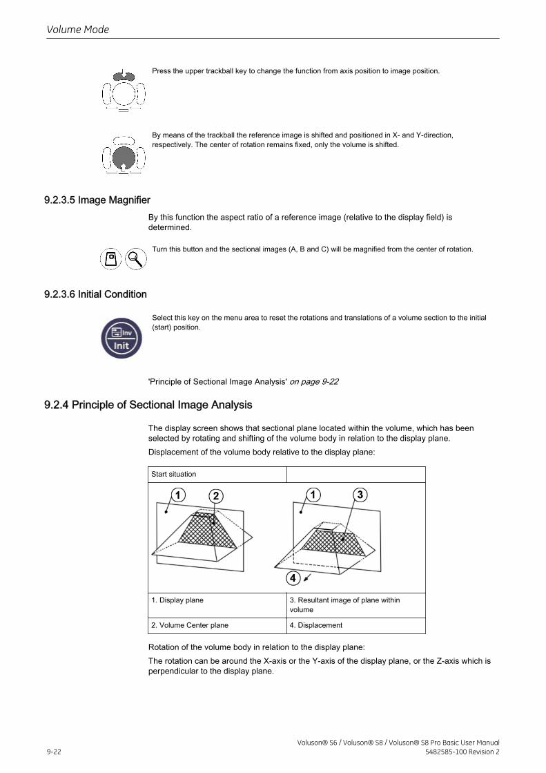
Press the upper trackball key to change the function from axis position to image position.
By means of the trackball the reference image is shifted and positioned in X- and Y-direction,respectively. The center of rotation remains fixed, only the volume is shifted.
9.2.3.5 Image MagnifierBy this function the aspect ratio of a reference image (relative to the display field) isdetermined.
Turn this button and the sectional images (A, B and C) will be magnified from the center of rotation.
9.2.3.6 Initial Condition
Select this key on the menu area to reset the rotations and translations of a volume section to the initial(start) position.
'Principle of Sectional Image Analysis' on page 9-22
9.2.4 Principle of Sectional Image Analysis
The display screen shows that sectional plane located within the volume, which has beenselected by rotating and shifting of the volume body in relation to the display plane.Displacement of the volume body relative to the display plane:
Start situation
1. Display plane 3. Resultant image of plane withinvolume
2. Volume Center plane 4. Displacement
Rotation of the volume body in relation to the display plane:The rotation can be around the X-axis or the Y-axis of the display plane, or the Z-axis which isperpendicular to the display plane.
Volume Mode
9-22Voluson® S6 / Voluson® S8 / Voluson® S8 Pro Basic User Manual
5482585-100 Revision 2
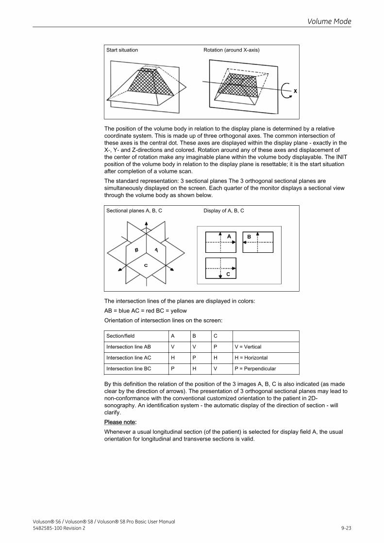
Start situation Rotation (around X-axis)
The position of the volume body in relation to the display plane is determined by a relativecoordinate system. This is made up of three orthogonal axes. The common intersection ofthese axes is the central dot. These axes are displayed within the display plane - exactly in theX-, Y- and Z-directions and colored. Rotation around any of these axes and displacement ofthe center of rotation make any imaginable plane within the volume body displayable. The INITposition of the volume body in relation to the display plane is resettable; it is the start situationafter completion of a volume scan.The standard representation: 3 sectional planes The 3 orthogonal sectional planes aresimultaneously displayed on the screen. Each quarter of the monitor displays a sectional viewthrough the volume body as shown below.
Sectional planes A, B, C Display of A, B, C
The intersection lines of the planes are displayed in colors:AB = blue AC = red BC = yellowOrientation of intersection lines on the screen:
Section/field A B C
Intersection line AB V V P V = Vertical
Intersection line AC H P H H = Horizontal
Intersection line BC P H V P = Perpendicular
By this definition the relation of the position of the 3 images A, B, C is also indicated (as madeclear by the direction of arrows). The presentation of 3 orthogonal sectional planes may lead tonon-conformance with the conventional customized orientation to the patient in 2D-sonography. An identification system - the automatic display of the direction of section - willclarify.Please note:Whenever a usual longitudinal section (of the patient) is selected for display field A, the usualorientation for longitudinal and transverse sections is valid.
Volume Mode
Voluson® S6 / Voluson® S8 / Voluson® S8 Pro Basic User Manual5482585-100 Revision 2 9-23
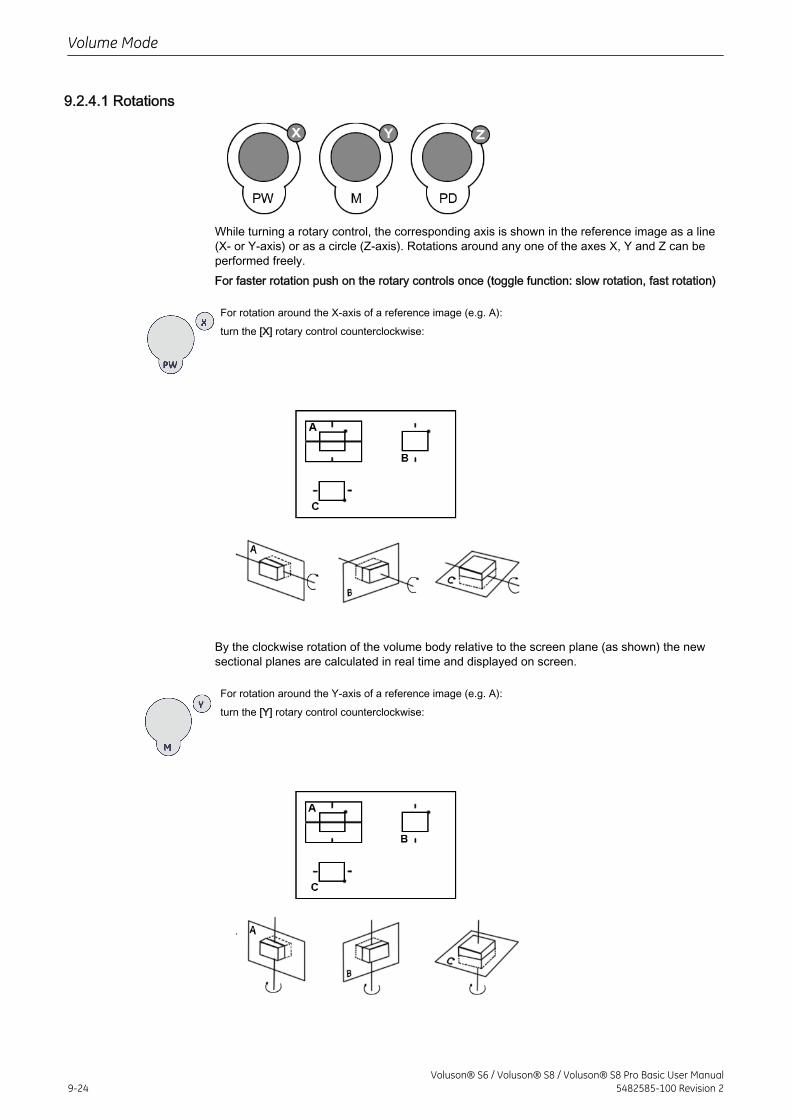
9.2.4.1 Rotations
While turning a rotary control, the corresponding axis is shown in the reference image as a line(X- or Y-axis) or as a circle (Z-axis). Rotations around any one of the axes X, Y and Z can beperformed freely.For faster rotation push on the rotary controls once (toggle function: slow rotation, fast rotation)
For rotation around the X-axis of a reference image (e.g. A):turn the [X] rotary control counterclockwise:
By the clockwise rotation of the volume body relative to the screen plane (as shown) the newsectional planes are calculated in real time and displayed on screen.
For rotation around the Y-axis of a reference image (e.g. A):turn the [Y] rotary control counterclockwise:
Volume Mode
9-24Voluson® S6 / Voluson® S8 / Voluson® S8 Pro Basic User Manual
5482585-100 Revision 2
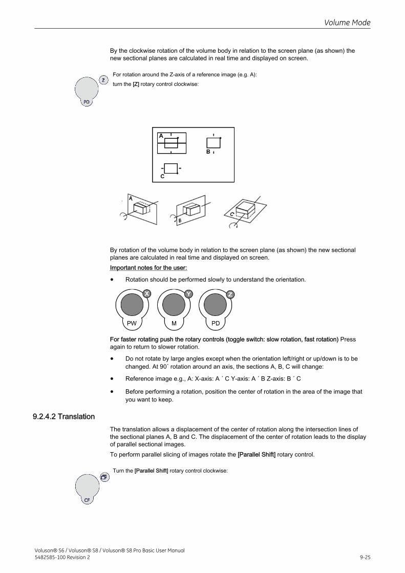
By the clockwise rotation of the volume body in relation to the screen plane (as shown) thenew sectional planes are calculated in real time and displayed on screen.
For rotation around the Z-axis of a reference image (e.g. A):turn the [Z] rotary control clockwise:
By rotation of the volume body in relation to the screen plane (as shown) the new sectionalplanes are calculated in real time and displayed on screen.Important notes for the user:
• Rotation should be performed slowly to understand the orientation.
For faster rotating push the rotary controls (toggle switch: slow rotation, fast rotation) Pressagain to return to slower rotation.
• Do not rotate by large angles except when the orientation left/right or up/down is to bechanged. At 90˚ rotation around an axis, the sections A, B, C will change:
• Reference image e.g., A: X-axis: A ´ C Y-axis: A ´ B Z-axis: B ´ C
• Before performing a rotation, position the center of rotation in the area of the image thatyou want to keep.
9.2.4.2 TranslationThe translation allows a displacement of the center of rotation along the intersection lines ofthe sectional planes A, B and C. The displacement of the center of rotation leads to the displayof parallel sectional images.To perform parallel slicing of images rotate the [Parallel Shift] rotary control.
Turn the [Parallel Shift] rotary control clockwise:
Volume Mode
Voluson® S6 / Voluson® S8 / Voluson® S8 Pro Basic User Manual5482585-100 Revision 2 9-25
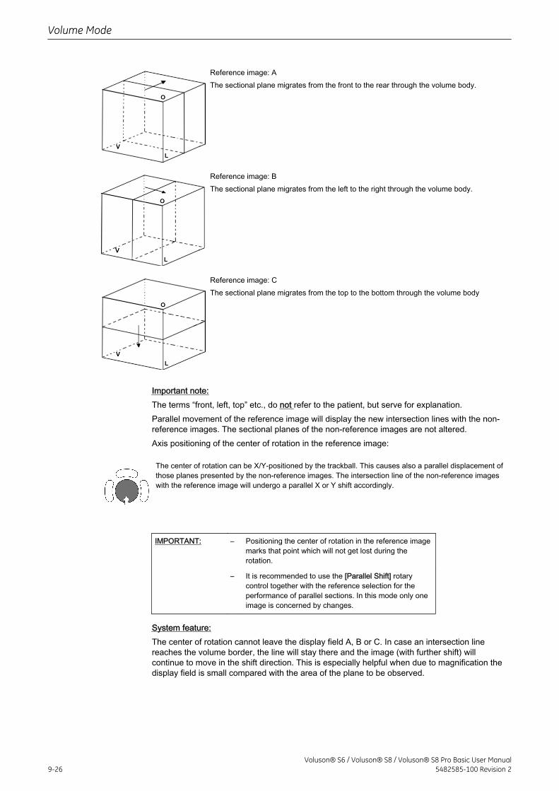
Reference image: AThe sectional plane migrates from the front to the rear through the volume body.
Reference image: BThe sectional plane migrates from the left to the right through the volume body.
Reference image: CThe sectional plane migrates from the top to the bottom through the volume body
Important note:The terms “front, left, top” etc., do not refer to the patient, but serve for explanation.Parallel movement of the reference image will display the new intersection lines with the non-reference images. The sectional planes of the non-reference images are not altered.Axis positioning of the center of rotation in the reference image:
The center of rotation can be X/Y-positioned by the trackball. This causes also a parallel displacement ofthose planes presented by the non-reference images. The intersection line of the non-reference imageswith the reference image will undergo a parallel X or Y shift accordingly.
IMPORTANT: – Positioning the center of rotation in the reference imagemarks that point which will not get lost during therotation.
– It is recommended to use the [Parallel Shift] rotarycontrol together with the reference selection for theperformance of parallel sections. In this mode only oneimage is concerned by changes.
System feature:The center of rotation cannot leave the display field A, B or C. In case an intersection linereaches the volume border, the line will stay there and the image (with further shift) willcontinue to move in the shift direction. This is especially helpful when due to magnification thedisplay field is small compared with the area of the plane to be observed.
Volume Mode
9-26Voluson® S6 / Voluson® S8 / Voluson® S8 Pro Basic User Manual
5482585-100 Revision 2
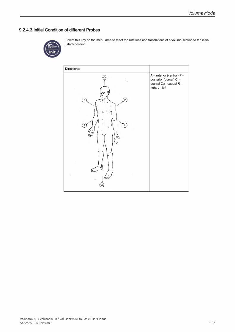
9.2.4.3 Initial Condition of different Probes
Select this key on the menu area to reset the rotations and translations of a volume section to the initial(start) position.
Directions:
A - anterior (ventral) P -posterior (dorsal) Cr -cranial Ca - caudal R -right L - left
Volume Mode
Voluson® S6 / Voluson® S8 / Voluson® S8 Pro Basic User Manual5482585-100 Revision 2 9-27
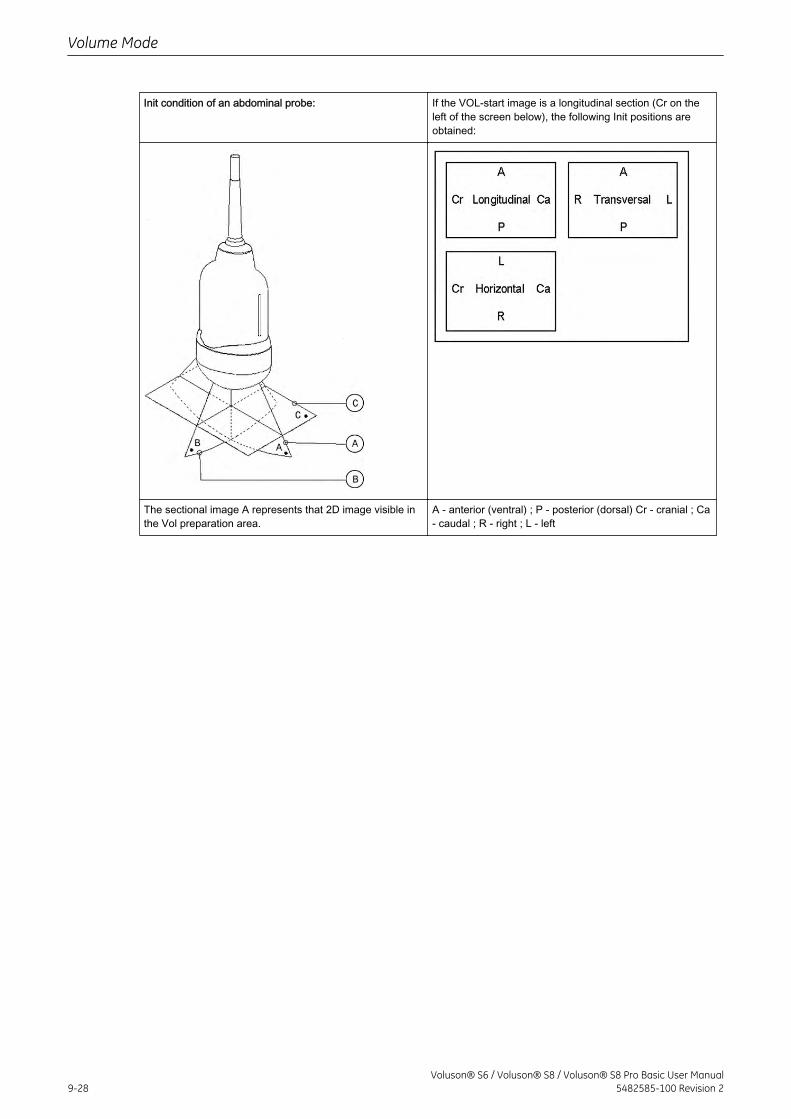
Init condition of an abdominal probe: If the VOL-start image is a longitudinal section (Cr on theleft of the screen below), the following Init positions areobtained:
The sectional image A represents that 2D image visible inthe Vol preparation area.
A - anterior (ventral) ; P - posterior (dorsal) Cr - cranial ; Ca- caudal ; R - right ; L - left
Volume Mode
9-28Voluson® S6 / Voluson® S8 / Voluson® S8 Pro Basic User Manual
5482585-100 Revision 2
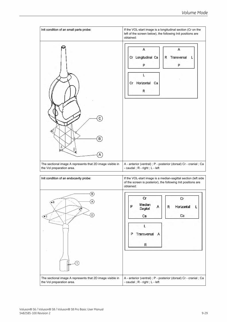
Init condition of an small parts probe: If the VOL-start image is a longitudinal section (Cr on theleft of the screen below), the following Init positions areobtained:
The sectional image A represents that 2D image visible inthe Vol preparation area.
A - anterior (ventral) ; P - posterior (dorsal) Cr - cranial ; Ca- caudal ; R - right ; L - left
Init condition of an endocavity probe: If the VOL-start image is a median-sagittal section (left sideof the screen is posterior), the following Init positions areobtained:
The sectional image A represents that 2D image visible inthe Vol preparation area.
A - anterior (ventral) ; P - posterior (dorsal) Cr - cranial ; Ca- caudal ; R - right ; L - left
Volume Mode
Voluson® S6 / Voluson® S8 / Voluson® S8 Pro Basic User Manual5482585-100 Revision 2 9-29

9.2.4.4 Initial Condition of different Probes
Select this key on the menu area to reset the rotations and translations of a volume section tothe initial (start) position.Initial condition of an endorectal probe:
A:Positioning the TransverseSection
B: Positioning theLongitudinal Section
C:Positioning the HorizontalSection
The sectional image A represents that 2D image visible in the Vol preparation area. If theVOL-start image is a transverse section of the prostate (right side of the patient is left side ofthe screen), the following Init positions are obtained:Monitor Display:
Volume Mode
9-30Voluson® S6 / Voluson® S8 / Voluson® S8 Pro Basic User Manual
5482585-100 Revision 2
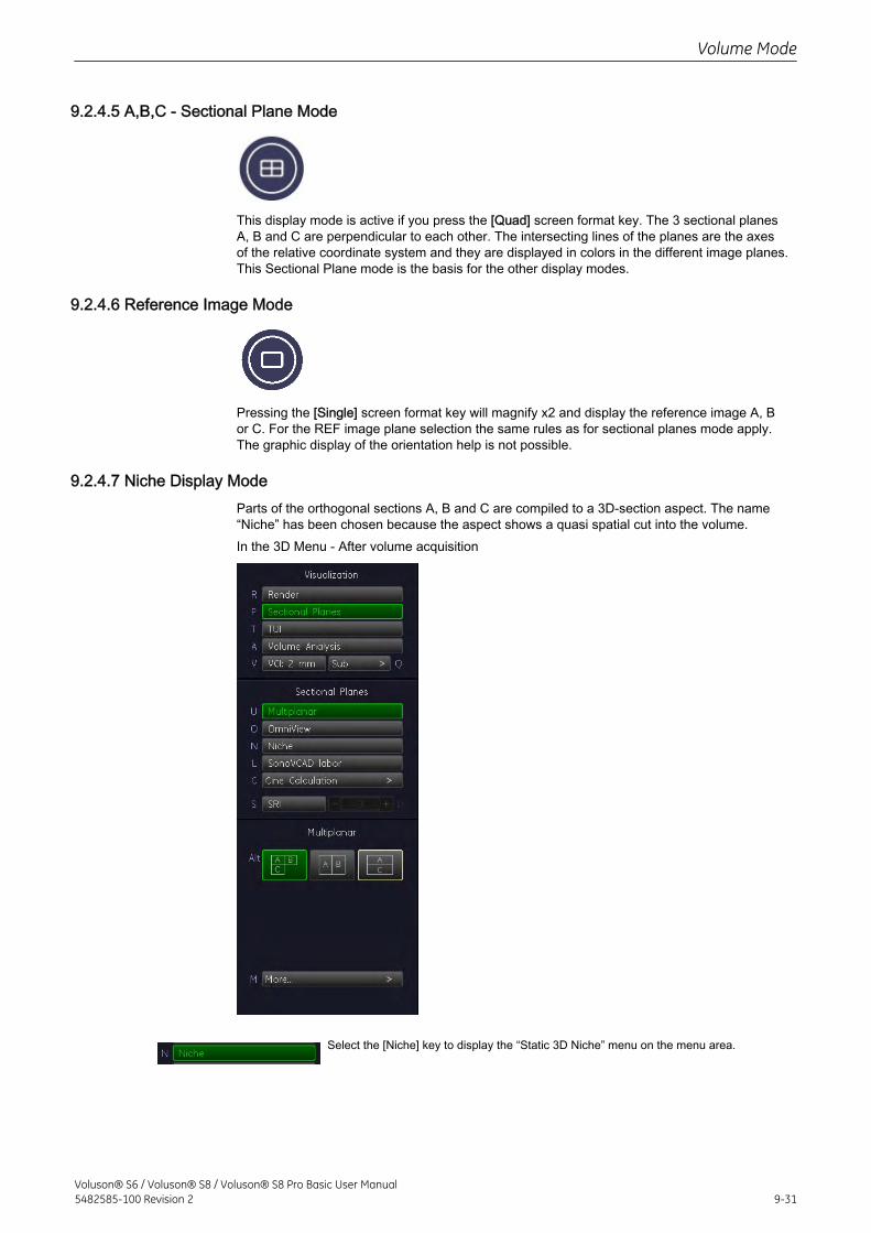
9.2.4.5 A,B,C - Sectional Plane Mode
This display mode is active if you press the [Quad] screen format key. The 3 sectional planesA, B and C are perpendicular to each other. The intersecting lines of the planes are the axesof the relative coordinate system and they are displayed in colors in the different image planes.This Sectional Plane mode is the basis for the other display modes.
9.2.4.6 Reference Image Mode
Pressing the [Single] screen format key will magnify x2 and display the reference image A, Bor C. For the REF image plane selection the same rules as for sectional planes mode apply.The graphic display of the orientation help is not possible.
9.2.4.7 Niche Display ModeParts of the orthogonal sections A, B and C are compiled to a 3D-section aspect. The name“Niche” has been chosen because the aspect shows a quasi spatial cut into the volume.In the 3D Menu - After volume acquisition
Select the [Niche] key to display the “Static 3D Niche” menu on the menu area.
Volume Mode
Voluson® S6 / Voluson® S8 / Voluson® S8 Pro Basic User Manual5482585-100 Revision 2 9-31
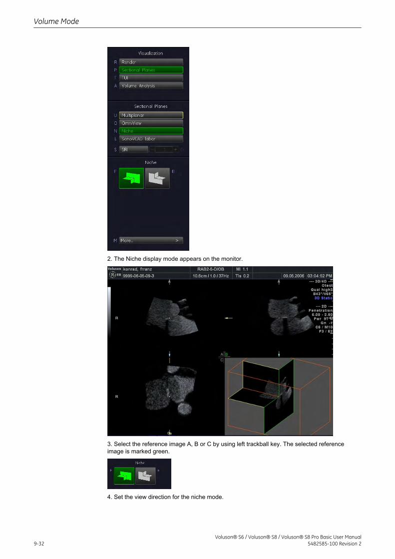
2. The Niche display mode appears on the monitor.
3. Select the reference image A, B or C by using left trackball key. The selected referenceimage is marked green.
4. Set the view direction for the niche mode.
Volume Mode
9-32Voluson® S6 / Voluson® S8 / Voluson® S8 Pro Basic User Manual
5482585-100 Revision 2
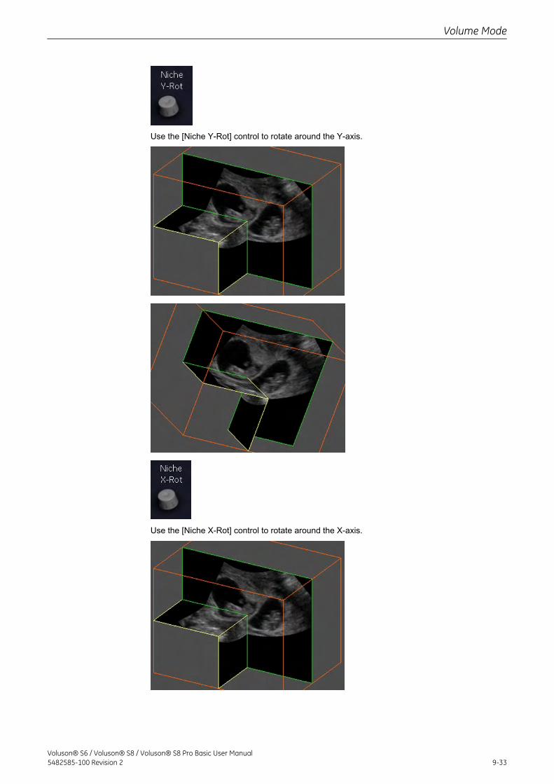
Use the [Niche Y-Rot] control to rotate around the Y-axis.
Use the [Niche X-Rot] control to rotate around the X-axis.
Volume Mode
Voluson® S6 / Voluson® S8 / Voluson® S8 Pro Basic User Manual5482585-100 Revision 2 9-33
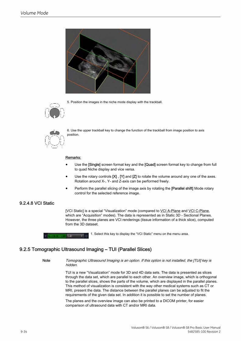
5. Position the images in the niche mode display with the trackball.
6. Use the upper trackball key to change the function of the trackball from image position to axisposition.
Remarks:
• Use the [Single] screen format key and the [Quad] screen format key to change from fullto quad Niche display and vice versa.
• Use the rotary controls [X] , [Y] and [Z] to rotate the volume around any one of the axes.Rotation around X-, Y- and Z-axis can be performed freely.
• Perform the parallel slicing of the image axis by rotating the [Parallel shift] Mode rotarycontrol for the selected reference image.
9.2.4.8 VCI Static[VCI Static] is a special “Visualization” mode (compared to VCI A-Plane and VCI C-Plane,which are “Acquisition” modes). The data is represented as in Static 3D - Sectional Planes.However, the three planes are VCI renderings (tissue information of a thick slice), computedfrom the 3D dataset.
1. Select this key to display the “VCI Static” menu on the menu area.
9.2.5 Tomographic Ultrasound Imaging – TUI (Parallel Slices)
Note Tomographic Ultrasound Imaging is an option. If this option is not installed, the [TUI] key ishidden.
TUI is a new “Visualization” mode for 3D and 4D data sets. The data is presented as slicesthrough the data set, which are parallel to each other. An overview image, which is orthogonalto the parallel slices, shows the parts of the volume, which are displayed in the parallel planes.This method of visualization is consistent with the way other medical systems such as CT orMRI, present the data. The distance between the parallel planes can be adjusted to fit therequirements of the given data set. In addition it is possible to set the number of planes.The planes and the overview image can also be printed to a DICOM printer, for easiercomparison of ultrasound data with CT and/or MRI data.
Volume Mode
9-34Voluson® S6 / Voluson® S8 / Voluson® S8 Pro Basic User Manual
5482585-100 Revision 2
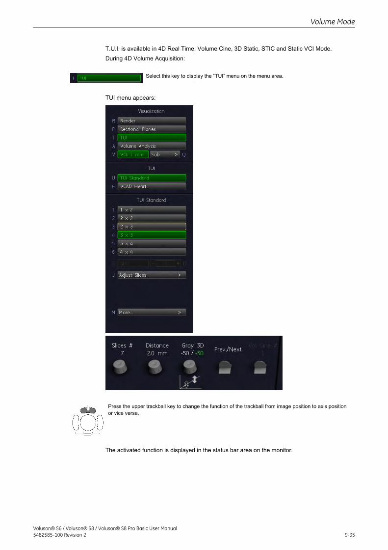
T.U.I. is available in 4D Real Time, Volume Cine, 3D Static, STIC and Static VCI Mode.During 4D Volume Acquisition:
Select this key to display the “TUI” menu on the menu area.
TUI menu appears:
Press the upper trackball key to change the function of the trackball from image position to axis positionor vice versa.
The activated function is displayed in the status bar area on the monitor.
Volume Mode
Voluson® S6 / Voluson® S8 / Voluson® S8 Pro Basic User Manual5482585-100 Revision 2 9-35
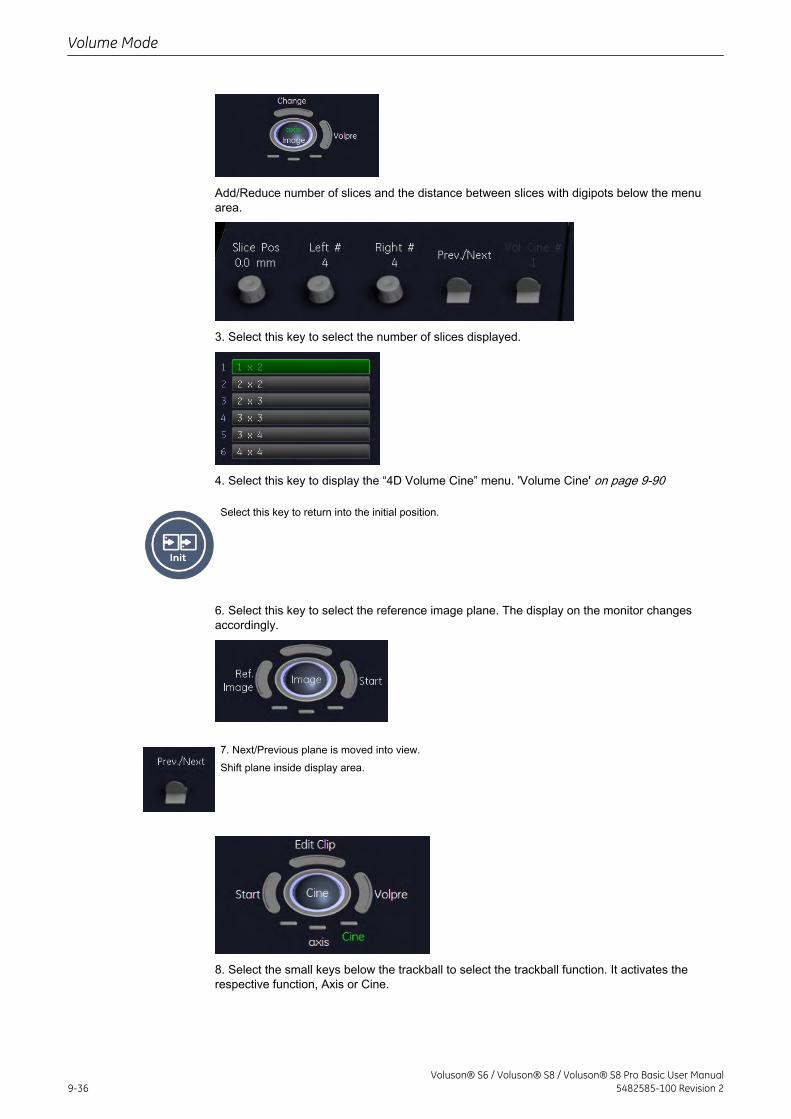
Add/Reduce number of slices and the distance between slices with digipots below the menuarea.
3. Select this key to select the number of slices displayed.
4. Select this key to display the “4D Volume Cine” menu. 'Volume Cine' on page 9-90
Select this key to return into the initial position.
6. Select this key to select the reference image plane. The display on the monitor changesaccordingly.
7. Next/Previous plane is moved into view.Shift plane inside display area.
8. Select the small keys below the trackball to select the trackball function. It activates therespective function, Axis or Cine.
Volume Mode
9-36Voluson® S6 / Voluson® S8 / Voluson® S8 Pro Basic User Manual
5482585-100 Revision 2
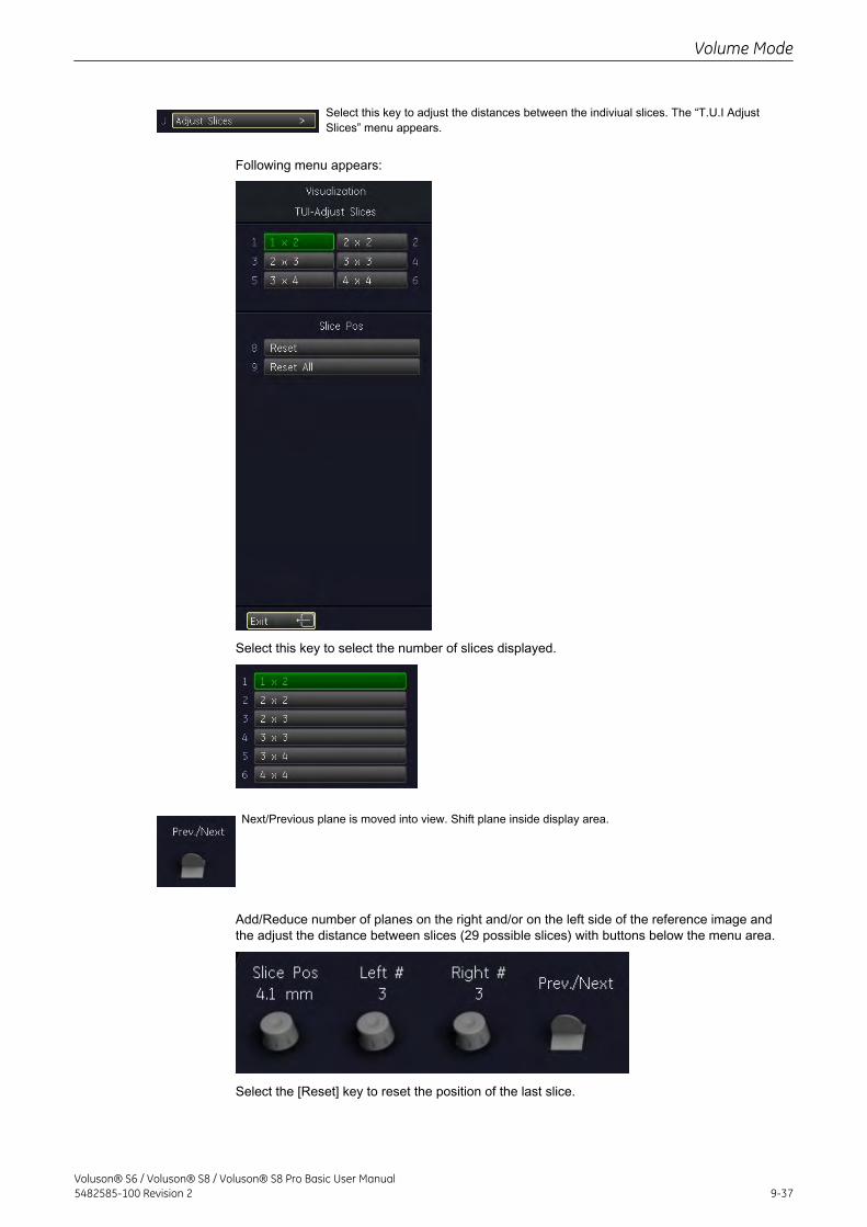
Select this key to adjust the distances between the indiviual slices. The “T.U.I AdjustSlices” menu appears.
Following menu appears:
Select this key to select the number of slices displayed.
Next/Previous plane is moved into view. Shift plane inside display area.
Add/Reduce number of planes on the right and/or on the left side of the reference image andthe adjust the distance between slices (29 possible slices) with buttons below the menu area.
Select the [Reset] key to reset the position of the last slice.
Volume Mode
Voluson® S6 / Voluson® S8 / Voluson® S8 Pro Basic User Manual5482585-100 Revision 2 9-37
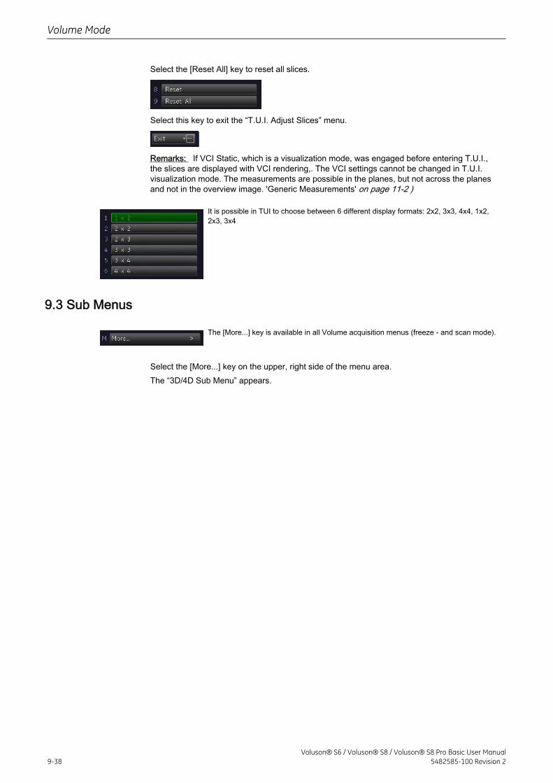
Select the [Reset All] key to reset all slices.
Select this key to exit the “T.U.I. Adjust Slices” menu.
Remarks: If VCI Static, which is a visualization mode, was engaged before entering T.U.I.,the slices are displayed with VCI rendering,. The VCI settings cannot be changed in T.U.I.visualization mode. The measurements are possible in the planes, but not across the planesand not in the overview image. 'Generic Measurements' on page 11-2 )
It is possible in TUI to choose between 6 different display formats: 2x2, 3x3, 4x4, 1x2,2x3, 3x4
9.3 Sub Menus
The [More...] key is available in all Volume acquisition menus (freeze - and scan mode).
Select the [More...] key on the upper, right side of the menu area.The “3D/4D Sub Menu” appears.
Volume Mode
9-38Voluson® S6 / Voluson® S8 / Voluson® S8 Pro Basic User Manual
5482585-100 Revision 2
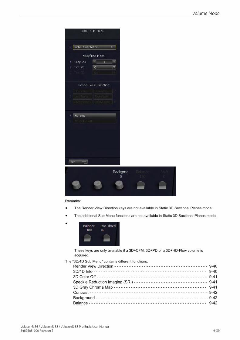
Remarks:
• The Render View Direction keys are not available in Static 3D Sectional Planes mode.
• The additional Sub Menu functions are not available in Static 3D Sectional Planes mode.
•
These keys are only available if a 3D+CFM, 3D+PD or a 3D+HD-Flow volume isacquired.
The “3D/4D Sub Menu” contains different functions:Render View Direction - - - - - - - - - - - - - - - - - - - - - - - - - - - - - - - - - - - - - - 9-403D/4D Info - - - - - - - - - - - - - - - - - - - - - - - - - - - - - - - - - - - - - - - - - - - - - - 9-403D Color Off - - - - - - - - - - - - - - - - - - - - - - - - - - - - - - - - - - - - - - - - - - - - - 9-41Speckle Reduction Imaging (SRI) - - - - - - - - - - - - - - - - - - - - - - - - - - - - - - 9-413D Gray Chroma Map - - - - - - - - - - - - - - - - - - - - - - - - - - - - - - - - - - - - - - 9-41Contrast - - - - - - - - - - - - - - - - - - - - - - - - - - - - - - - - - - - - - - - - - - - - - - - - 9-42Background - - - - - - - - - - - - - - - - - - - - - - - - - - - - - - - - - - - - - - - - - - - - - - 9-42Balance - - - - - - - - - - - - - - - - - - - - - - - - - - - - - - - - - - - - - - - - - - - - - - - - 9-42
Volume Mode
Voluson® S6 / Voluson® S8 / Voluson® S8 Pro Basic User Manual5482585-100 Revision 2 9-39
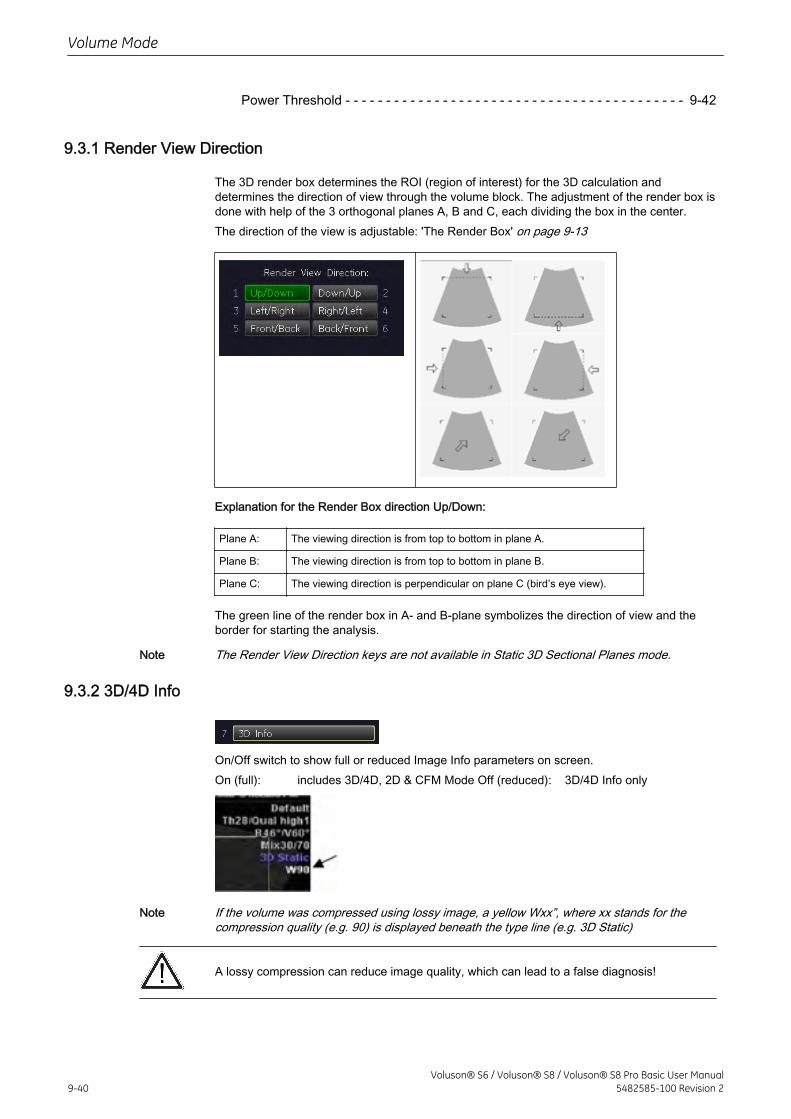
Power Threshold - - - - - - - - - - - - - - - - - - - - - - - - - - - - - - - - - - - - - - - - - - 9-42
9.3.1 Render View Direction
The 3D render box determines the ROI (region of interest) for the 3D calculation anddetermines the direction of view through the volume block. The adjustment of the render box isdone with help of the 3 orthogonal planes A, B and C, each dividing the box in the center.The direction of the view is adjustable: 'The Render Box' on page 9-13
Explanation for the Render Box direction Up/Down:
Plane A: The viewing direction is from top to bottom in plane A.
Plane B: The viewing direction is from top to bottom in plane B.
Plane C: The viewing direction is perpendicular on plane C (bird’s eye view).
The green line of the render box in A- and B-plane symbolizes the direction of view and theborder for starting the analysis.
Note The Render View Direction keys are not available in Static 3D Sectional Planes mode.
9.3.2 3D/4D Info
On/Off switch to show full or reduced Image Info parameters on screen.On (full): includes 3D/4D, 2D & CFM Mode Off (reduced): 3D/4D Info only
Note If the volume was compressed using lossy image, a yellow Wxx”, where xx stands for thecompression quality (e.g. 90) is displayed beneath the type line (e.g. 3D Static)
A lossy compression can reduce image quality, which can lead to a false diagnosis!
Volume Mode
9-40Voluson® S6 / Voluson® S8 / Voluson® S8 Pro Basic User Manual
5482585-100 Revision 2
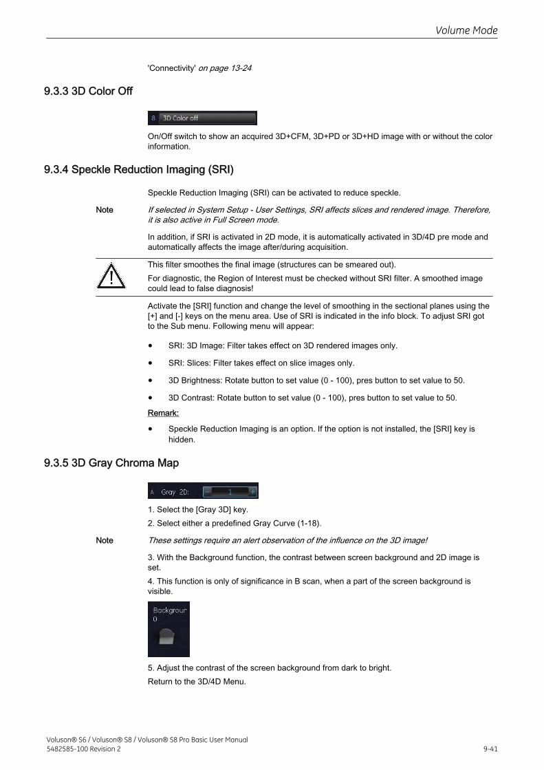
'Connectivity' on page 13-24
9.3.3 3D Color Off
On/Off switch to show an acquired 3D+CFM, 3D+PD or 3D+HD image with or without the colorinformation.
9.3.4 Speckle Reduction Imaging (SRI)
Speckle Reduction Imaging (SRI) can be activated to reduce speckle.
Note If selected in System Setup - User Settings, SRI affects slices and rendered image. Therefore,it is also active in Full Screen mode.
In addition, if SRI is activated in 2D mode, it is automatically activated in 3D/4D pre mode andautomatically affects the image after/during acquisition.
This filter smoothes the final image (structures can be smeared out).For diagnostic, the Region of Interest must be checked without SRI filter. A smoothed imagecould lead to false diagnosis!
Activate the [SRI] function and change the level of smoothing in the sectional planes using the[+] and [-] keys on the menu area. Use of SRI is indicated in the info block. To adjust SRI gotto the Sub menu. Following menu will appear:
• SRI: 3D Image: Filter takes effect on 3D rendered images only.
• SRI: Slices: Filter takes effect on slice images only.
• 3D Brightness: Rotate button to set value (0 - 100), pres button to set value to 50.
• 3D Contrast: Rotate button to set value (0 - 100), pres button to set value to 50.
Remark:
• Speckle Reduction Imaging is an option. If the option is not installed, the [SRI] key ishidden.
9.3.5 3D Gray Chroma Map
1. Select the [Gray 3D] key.2. Select either a predefined Gray Curve (1-18).
Note These settings require an alert observation of the influence on the 3D image!
3. With the Background function, the contrast between screen background and 2D image isset.4. This function is only of significance in B scan, when a part of the screen background isvisible.
5. Adjust the contrast of the screen background from dark to bright.Return to the 3D/4D Menu.
Volume Mode
Voluson® S6 / Voluson® S8 / Voluson® S8 Pro Basic User Manual5482585-100 Revision 2 9-41
9.3.6 Contrast
To adjust the contrast of the 3D/4D image: '3D Gray Chroma Map' on page 9-41
Note The settings require an alert observation of the influence on the 3D image! These keys are notavailable in Static 3D Sectional Planes mode.
9.3.7 Background
To adjust the background: '3D Gray Chroma Map' on page 9-41
Note This key is not available in Static 3D Sectional Planes mode.
9.3.8 Balance
Normally this function does not need to be adjusted.
Note This key is only available if a 3D+CFM, 3D+PD or a 3D+HD image is acquired.
9.3.9 Power Threshold
This function eliminates low color noise of motion artefact signals in the sectional slices as wellas in the rendered 3D image.
A lower number cuts off fewer signals than a higher number.
Note This key is only available if a 3D+CFM, 3D+PD or a 3D+HD image is acquired.
9.4 Volume Acquisition: Static 3D Render
1. After obtaining the ROI in 2D, 2D/CFM, 2D/PD, 2D/HD or B-Flow image, press the [3D] keyto activate the Volume mode.2. In the 3D Static Menu select a setting and an application key and adjust the settings.
Volume Mode
9-42Voluson® S6 / Voluson® S8 / Voluson® S8 Pro Basic User Manual
5482585-100 Revision 2
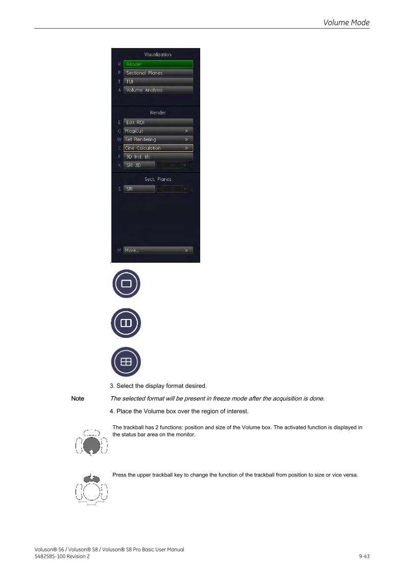
.
3. Select the display format desired.
Note The selected format will be present in freeze mode after the acquisition is done.
4. Place the Volume box over the region of interest.
The trackball has 2 functions: position and size of the Volume box. The activated function is displayed inthe status bar area on the monitor.
Press the upper trackball key to change the function of the trackball from position to size or vice versa.
Volume Mode
Voluson® S6 / Voluson® S8 / Voluson® S8 Pro Basic User Manual5482585-100 Revision 2 9-43
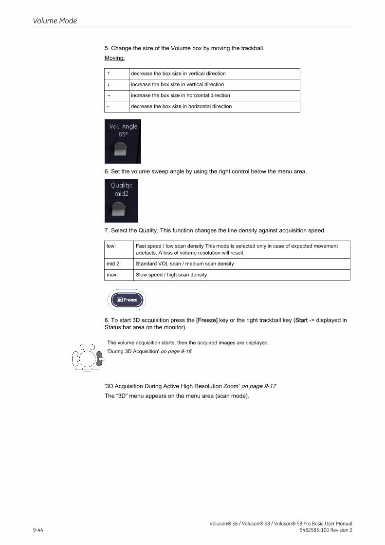
5. Change the size of the Volume box by moving the trackball.Moving:
↑ decrease the box size in vertical direction
↓ increase the box size in vertical direction
→ increase the box size in horizontal direction
← decrease the box size in horizontal direction
6. Set the volume sweep angle by using the right control below the menu area.
7. Select the Quality. This function changes the line density against acquisition speed.
low: Fast speed / low scan density This mode is selected only in case of expected movementartefacts. A loss of volume resolution will result.
mid 2: Standard VOL scan / medium scan density
max: Slow speed / high scan density
8. To start 3D acquisition press the [Freeze] key or the right trackball key (Start -> displayed inStatus bar area on the monitor).
The volume acquisition starts, then the acquired images are displayed.'During 3D Acquisition' on page 9-18
'3D Acquisition During Active High Resolution Zoom' on page 9-17The “3D” menu appears on the menu area (scan mode).
Volume Mode
9-44Voluson® S6 / Voluson® S8 / Voluson® S8 Pro Basic User Manual
5482585-100 Revision 2
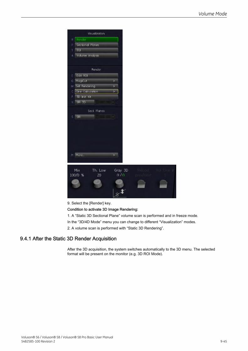
9. Select the [Render] key.Condition to activate 3D Image Rendering:1. A “Static 3D Sectional Plane” volume scan is performed and in freeze mode.In the “3D/4D Mode” menu you can change to different “Visualization” modes.2. A volume scan is performed with “Static 3D Rendering”.
9.4.1 After the Static 3D Render Acquisition
After the 3D acquisition, the system switches automatically to the 3D menu. The selectedformat will be present on the monitor (e.g. 3D ROI Mode).
Volume Mode
Voluson® S6 / Voluson® S8 / Voluson® S8 Pro Basic User Manual5482585-100 Revision 2 9-45
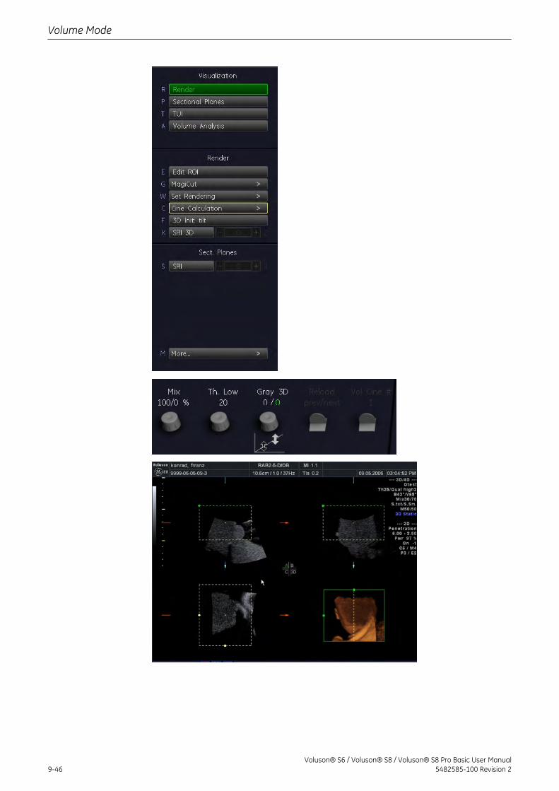
Volume Mode
9-46Voluson® S6 / Voluson® S8 / Voluson® S8 Pro Basic User Manual
5482585-100 Revision 2
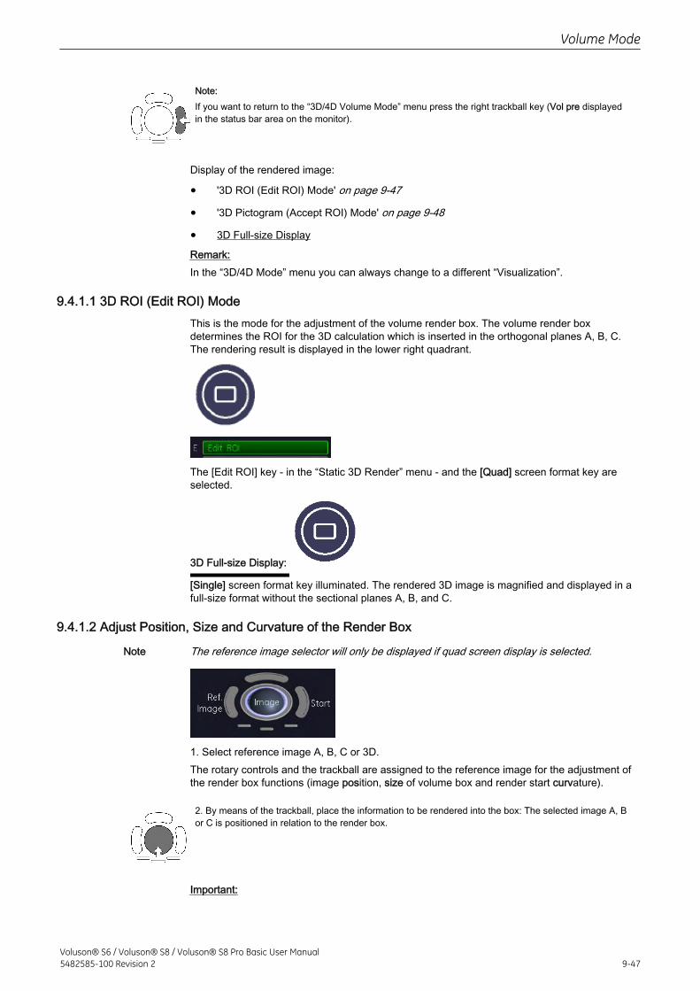
Note:If you want to return to the “3D/4D Volume Mode” menu press the right trackball key (Vol pre displayedin the status bar area on the monitor).
Display of the rendered image:
• '3D ROI (Edit ROI) Mode' on page 9-47
• '3D Pictogram (Accept ROI) Mode' on page 9-48
• 3D Full-size Display
Remark:In the “3D/4D Mode” menu you can always change to a different “Visualization”.
9.4.1.1 3D ROI (Edit ROI) ModeThis is the mode for the adjustment of the volume render box. The volume render boxdetermines the ROI for the 3D calculation which is inserted in the orthogonal planes A, B, C.The rendering result is displayed in the lower right quadrant.
The [Edit ROI] key - in the “Static 3D Render” menu - and the [Quad] screen format key areselected.
3D Full-size Display:
[Single] screen format key illuminated. The rendered 3D image is magnified and displayed in afull-size format without the sectional planes A, B, and C.
9.4.1.2 Adjust Position, Size and Curvature of the Render Box
Note The reference image selector will only be displayed if quad screen display is selected.
1. Select reference image A, B, C or 3D.The rotary controls and the trackball are assigned to the reference image for the adjustment ofthe render box functions (image position, size of volume box and render start curvature).
2. By means of the trackball, place the information to be rendered into the box: The selected image A, Bor C is positioned in relation to the render box.
Important:
Volume Mode
Voluson® S6 / Voluson® S8 / Voluson® S8 Pro Basic User Manual5482585-100 Revision 2 9-47
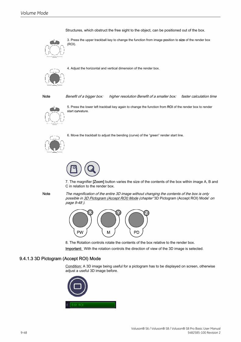
Structures, which obstruct the free sight to the object, can be positioned out of the box.
3. Press the upper trackball key to change the function from image position to size of the render box(ROI).
4. Adjust the horizontal and vertical dimension of the render box.
Note Benefit of a bigger box: higher resolution Benefit of a smaller box: faster calculation time
5. Press the lower left trackball key again to change the function from ROI of the render box to renderstart curvature.
6. Move the trackball to adjust the bending (curve) of the “green” render start line.
7. The magnifier [Zoom] button varies the size of the contents of the box within image A, B andC in relation to the render box.
Note The magnification of the entire 3D image without changing the contents of the box is onlypossible in 3D Pictogram (Accept ROI) Mode (chapter '3D Pictogram (Accept ROI) Mode' onpage 9-48 ).
8. The Rotation controls rotate the contents of the box relative to the render box.Important: With the rotation controls the direction of view of the 3D image is selected.
9.4.1.3 3D Pictogram (Accept ROI) ModeCondition: A 3D image being useful for a pictogram has to be displayed on screen, otherwiseadjust a useful 3D image before.
Volume Mode
9-48Voluson® S6 / Voluson® S8 / Voluson® S8 Pro Basic User Manual
5482585-100 Revision 2
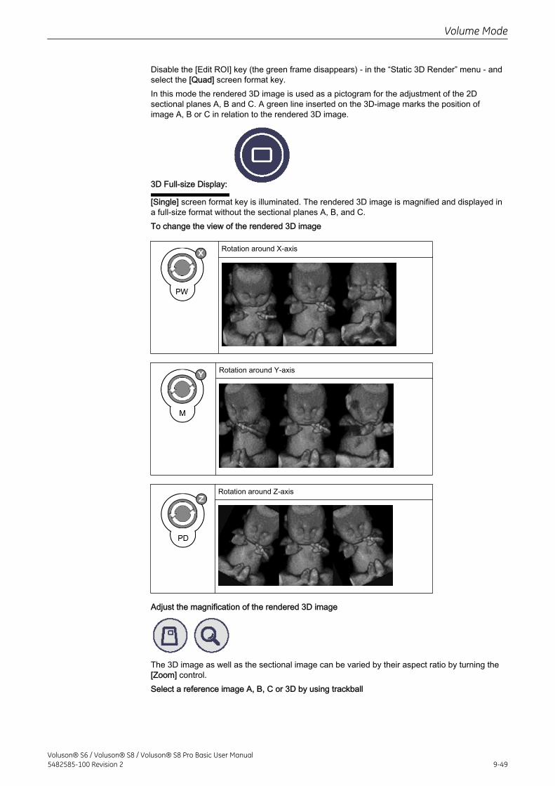
Disable the [Edit ROI] key (the green frame disappears) - in the “Static 3D Render” menu - andselect the [Quad] screen format key.In this mode the rendered 3D image is used as a pictogram for the adjustment of the 2Dsectional planes A, B and C. A green line inserted on the 3D-image marks the position ofimage A, B or C in relation to the rendered 3D image.
3D Full-size Display:
[Single] screen format key is illuminated. The rendered 3D image is magnified and displayed ina full-size format without the sectional planes A, B, and C.To change the view of the rendered 3D image
Rotation around X-axis
Rotation around Y-axis
Rotation around Z-axis
Adjust the magnification of the rendered 3D image
The 3D image as well as the sectional image can be varied by their aspect ratio by turning the[Zoom] control.Select a reference image A, B, C or 3D by using trackball
Volume Mode
Voluson® S6 / Voluson® S8 / Voluson® S8 Pro Basic User Manual5482585-100 Revision 2 9-49
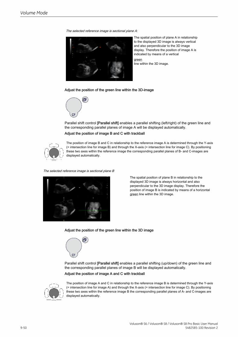
The selected reference image is sectional plane A:
The spatial position of plane A in relationshipto the displayed 3D image is always verticaland also perpendicular to the 3D imagedisplay. Therefore the position of image A isindicated by means of a verticalgreenline within the 3D image.
Adjust the position of the green line within the 3D-image
Parallel shift control [Parallel shift] enables a parallel shifting (left/right) of the green line andthe corresponding parallel planes of image A will be displayed automatically.Adjust the position of image B and C with trackball
The position of image B and C in relationship to the reference image A is determined through the Y-axis(= intersection line for image B) and through the X-axis (= intersection line for image C). By positioningthese two axes within the reference image the corresponding parallel planes of B- and C-images aredisplayed automatically.
The selected reference image is sectional plane B
The spatial position of plane B in relationship to thedisplayed 3D image is always horizontal and alsoperpendicular to the 3D image display. Therefore theposition of image B is indicated by means of a horizontalgreen line within the 3D image.
Adjust the position of the green line within the 3D image
Parallel shift control [Parallel shift] enables a parallel shifting (up/down) of the green line andthe corresponding parallel planes of image B will be displayed automatically.Adjust the position of image A and C with trackball
The position of image A and C in relationship to the reference image B is determined through the Y-axis(= intersection line for image A) and through the X-axis (= intersection line for image C). By positioningthese two axes within the reference image B the corresponding parallel planes of A- and C-images aredisplayed automatically.
Volume Mode
9-50Voluson® S6 / Voluson® S8 / Voluson® S8 Pro Basic User Manual
5482585-100 Revision 2
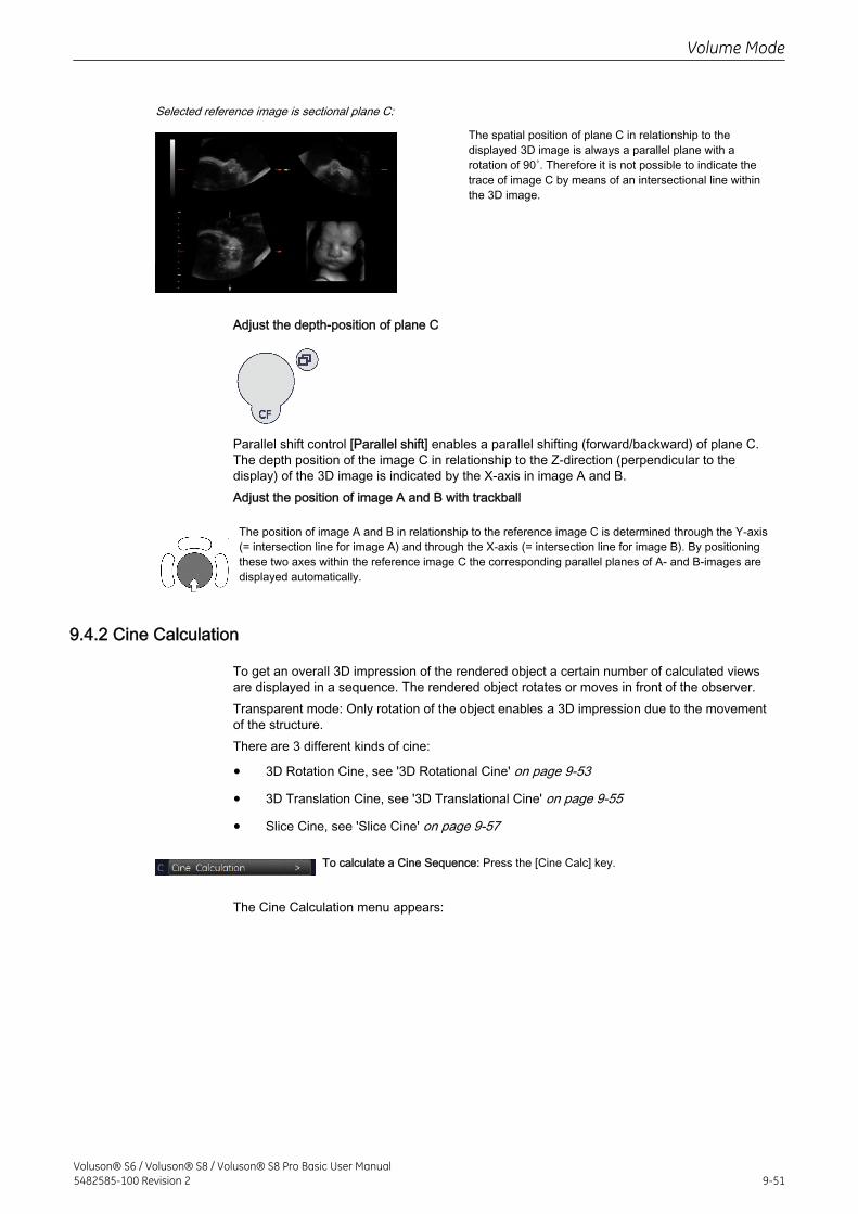
Selected reference image is sectional plane C:
The spatial position of plane C in relationship to thedisplayed 3D image is always a parallel plane with arotation of 90˚. Therefore it is not possible to indicate thetrace of image C by means of an intersectional line withinthe 3D image.
Adjust the depth-position of plane C
Parallel shift control [Parallel shift] enables a parallel shifting (forward/backward) of plane C.The depth position of the image C in relationship to the Z-direction (perpendicular to thedisplay) of the 3D image is indicated by the X-axis in image A and B.Adjust the position of image A and B with trackball
The position of image A and B in relationship to the reference image C is determined through the Y-axis(= intersection line for image A) and through the X-axis (= intersection line for image B). By positioningthese two axes within the reference image C the corresponding parallel planes of A- and B-images aredisplayed automatically.
9.4.2 Cine Calculation
To get an overall 3D impression of the rendered object a certain number of calculated viewsare displayed in a sequence. The rendered object rotates or moves in front of the observer.Transparent mode: Only rotation of the object enables a 3D impression due to the movementof the structure.There are 3 different kinds of cine:
• 3D Rotation Cine, see '3D Rotational Cine' on page 9-53
• 3D Translation Cine, see '3D Translational Cine' on page 9-55
• Slice Cine, see 'Slice Cine' on page 9-57
To calculate a Cine Sequence: Press the [Cine Calc] key.
The Cine Calculation menu appears:
Volume Mode
Voluson® S6 / Voluson® S8 / Voluson® S8 Pro Basic User Manual5482585-100 Revision 2 9-51
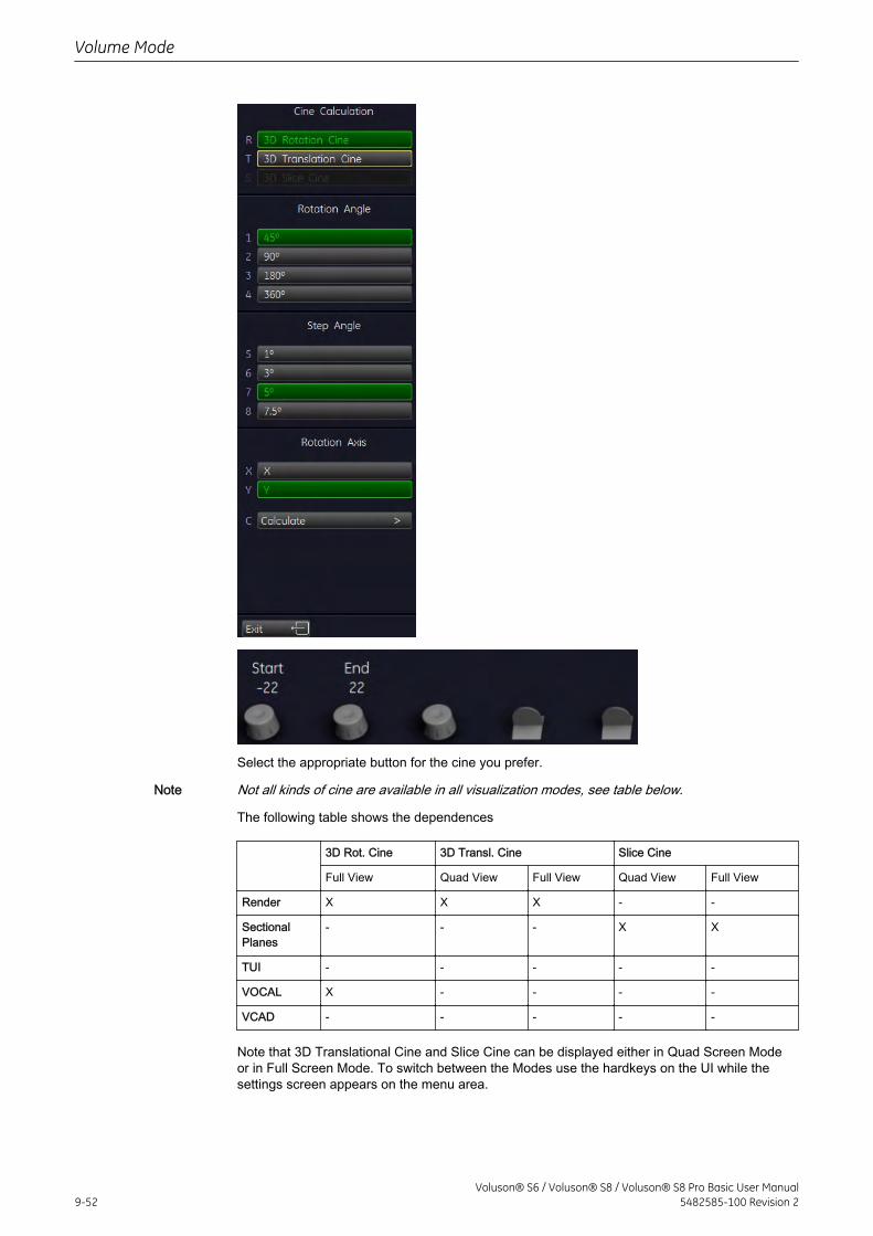
Select the appropriate button for the cine you prefer.
Note Not all kinds of cine are available in all visualization modes, see table below.
The following table shows the dependences
3D Rot. Cine 3D Transl. Cine Slice Cine
Full View Quad View Full View Quad View Full View
Render X X X - -
SectionalPlanes
- - - X X
TUI - - - - -
VOCAL X - - - -
VCAD - - - - -
Note that 3D Translational Cine and Slice Cine can be displayed either in Quad Screen Modeor in Full Screen Mode. To switch between the Modes use the hardkeys on the UI while thesettings screen appears on the menu area.
Volume Mode
9-52Voluson® S6 / Voluson® S8 / Voluson® S8 Pro Basic User Manual
5482585-100 Revision 2
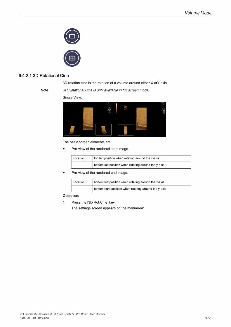
9.4.2.1 3D Rotational Cine3D rotation cine is the rotation of a volume around either X orY axis.
Note 3D Rotational Cine is only available in full screen mode.
Single View:
The basic screen elements are:
• Pre-view of the rendered start image.
Location: top left position when rotating around the x-axis
bottom left position when rotating around the y-axis
• Pre-view of the rendered end image.
Location: bottom left position when rotating around the x-axis
bottom right position when rotating around the y-axis
Operation:
1. Press the [3D Rot.Cine] keyThe settings screen appears on the menuarea:
Volume Mode
Voluson® S6 / Voluson® S8 / Voluson® S8 Pro Basic User Manual5482585-100 Revision 2 9-53
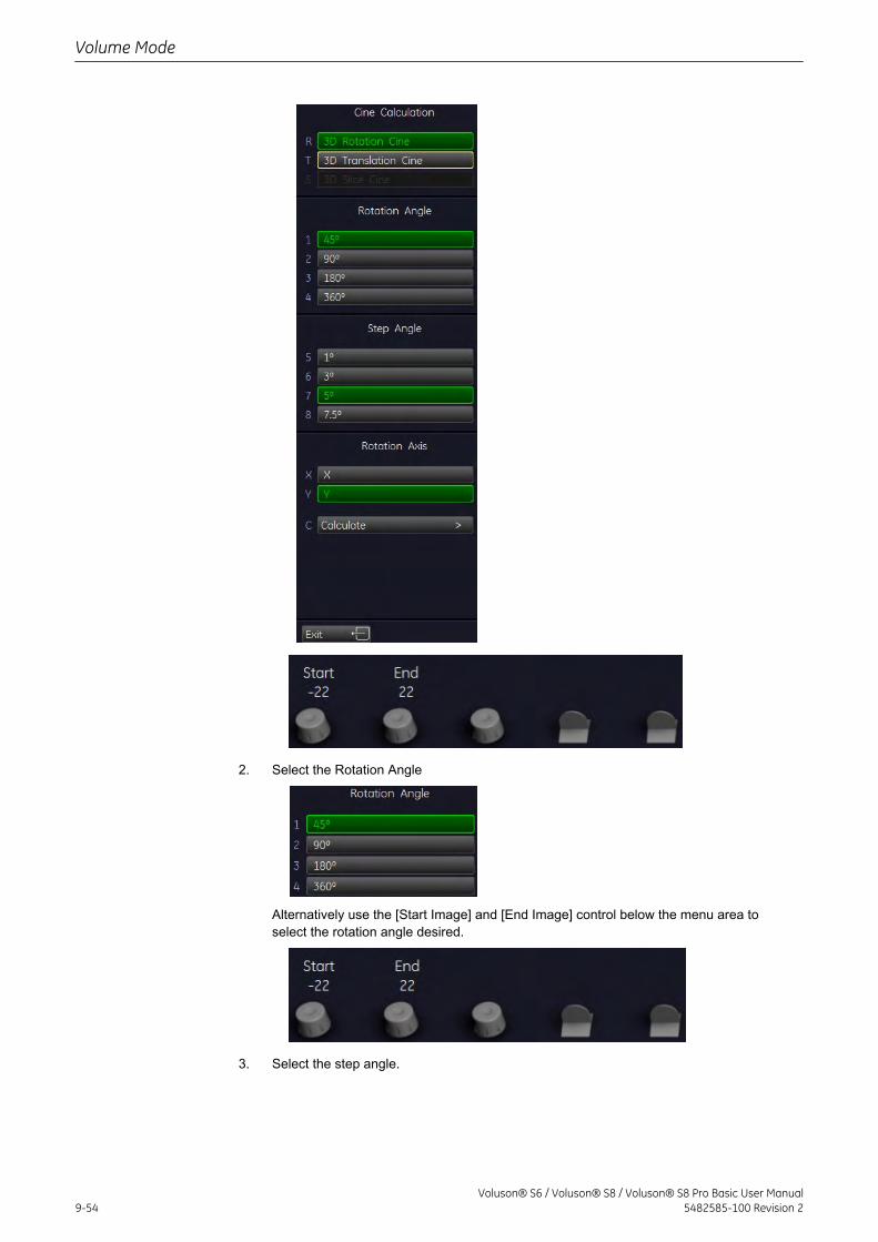
2. Select the Rotation Angle
Alternatively use the [Start Image] and [End Image] control below the menu area toselect the rotation angle desired.
3. Select the step angle.
Volume Mode
9-54Voluson® S6 / Voluson® S8 / Voluson® S8 Pro Basic User Manual
5482585-100 Revision 2
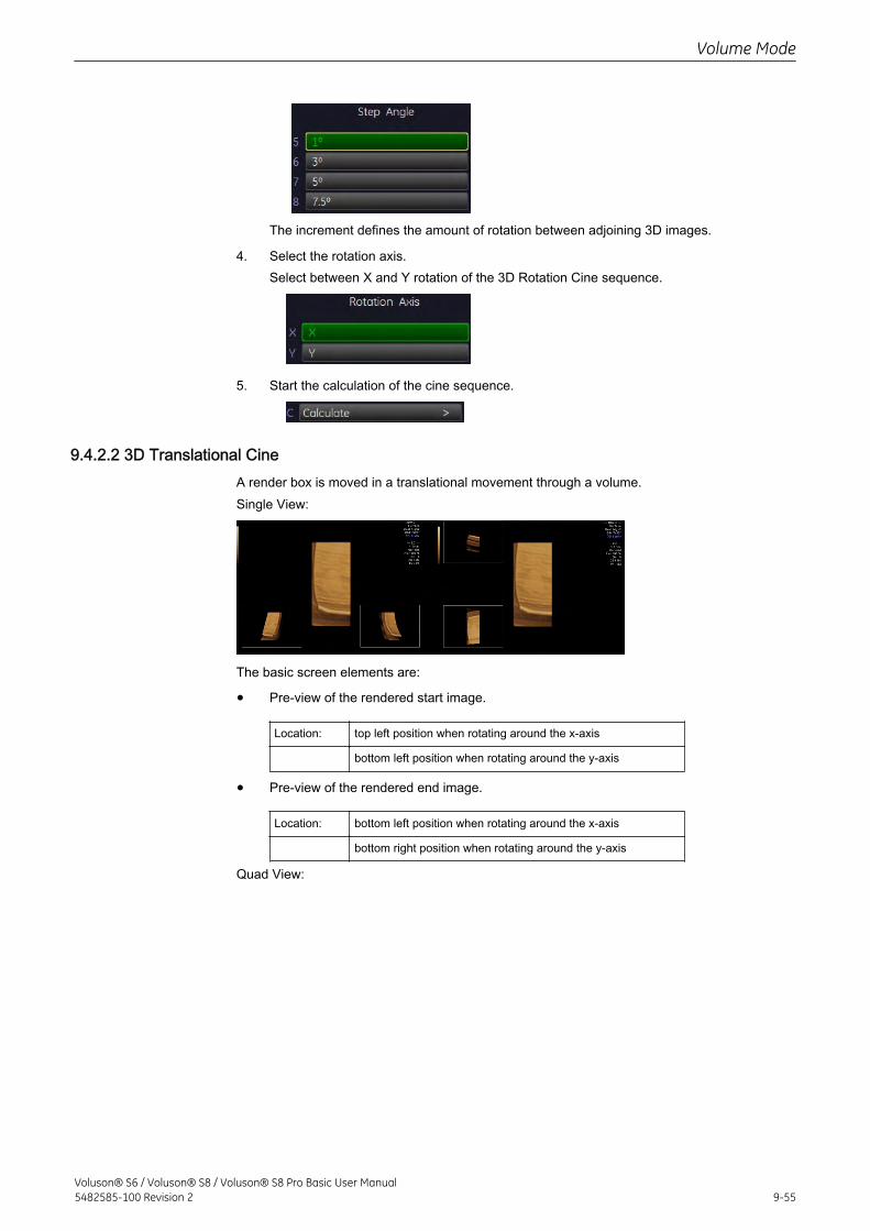
The increment defines the amount of rotation between adjoining 3D images.
4. Select the rotation axis.Select between X and Y rotation of the 3D Rotation Cine sequence.
5. Start the calculation of the cine sequence.
9.4.2.2 3D Translational CineA render box is moved in a translational movement through a volume.Single View:
The basic screen elements are:
• Pre-view of the rendered start image.
Location: top left position when rotating around the x-axis
bottom left position when rotating around the y-axis
• Pre-view of the rendered end image.
Location: bottom left position when rotating around the x-axis
bottom right position when rotating around the y-axis
Quad View:
Volume Mode
Voluson® S6 / Voluson® S8 / Voluson® S8 Pro Basic User Manual5482585-100 Revision 2 9-55
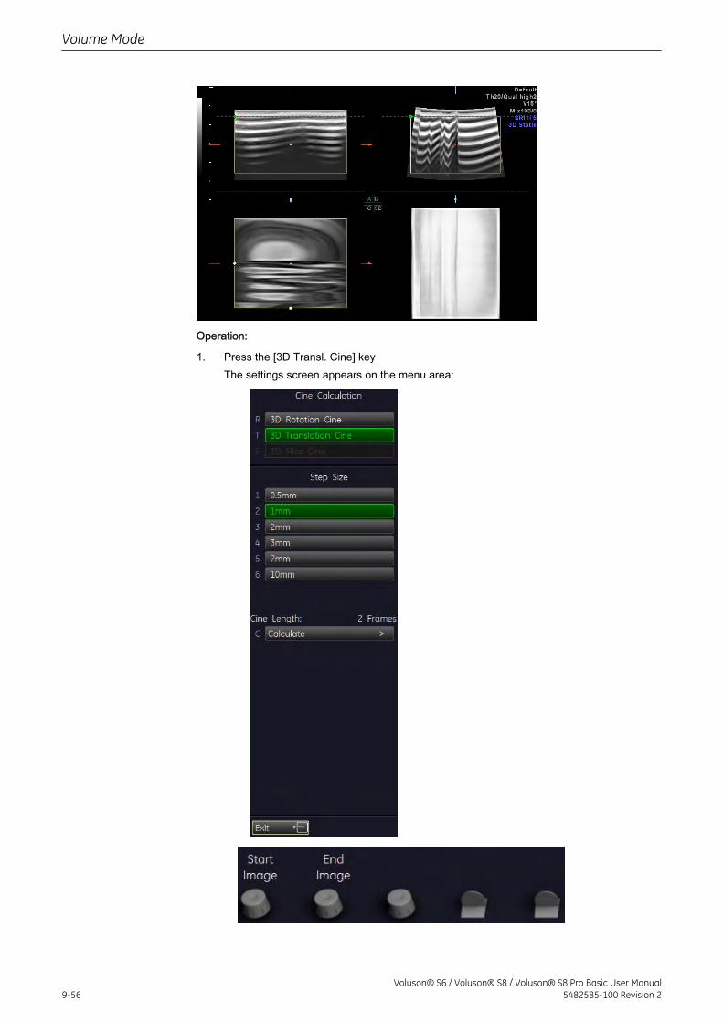
Operation:
1. Press the [3D Transl. Cine] keyThe settings screen appears on the menu area:
Volume Mode
9-56Voluson® S6 / Voluson® S8 / Voluson® S8 Pro Basic User Manual
5482585-100 Revision 2
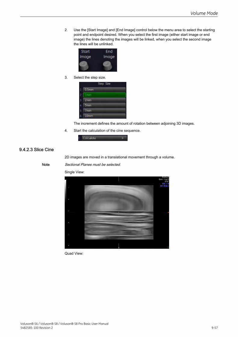
2. Use the [Start Image] and [End Image] control below the menu area to select the startingpoint and endpoint desired. When you select the first image (either start image or endimage) the lines denoting the images will be linked, when you select the second imagethe lines will be unlinked.
3. Select the step size.
The increment defines the amount of rotation between adjoining 3D images.
4. Start the calculation of the cine sequence.
9.4.2.3 Slice Cine2D images are moved in a translational movement through a volume.
Note Sectional Planes must be selected.
Single View:
Quad View:
Volume Mode
Voluson® S6 / Voluson® S8 / Voluson® S8 Pro Basic User Manual5482585-100 Revision 2 9-57
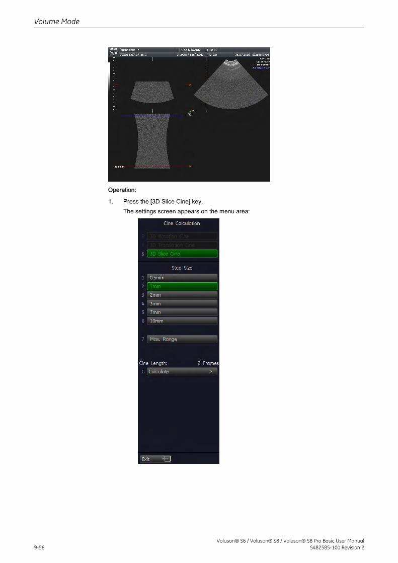
Operation:
1. Press the [3D Slice Cine] key.The settings screen appears on the menu area:
Volume Mode
9-58Voluson® S6 / Voluson® S8 / Voluson® S8 Pro Basic User Manual
5482585-100 Revision 2
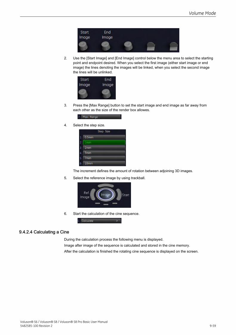
2. Use the [Start Image] and [End Image] control below the menu area to select the startingpoint and endpoint desired. When you select the first image (either start image or endimage) the lines denoting the images will be linked, when you select the second imagethe lines will be unlinked.
3. Press the [Max Range] button to set the start image and end image as far away fromeach other as the size of the render box allowes.
4. Select the step size.
The increment defines the amount of rotation between adjoining 3D images.
5. Select the reference image by using trackball.
6. Start the calculation of the cine sequence.
9.4.2.4 Calculating a CineDuring the calculation process the following menu is displayed.Image after image of the sequence is calculated and stored in the cine memory.After the calculation is finished the rotating cine sequence is displayed on the screen.
Volume Mode
Voluson® S6 / Voluson® S8 / Voluson® S8 Pro Basic User Manual5482585-100 Revision 2 9-59
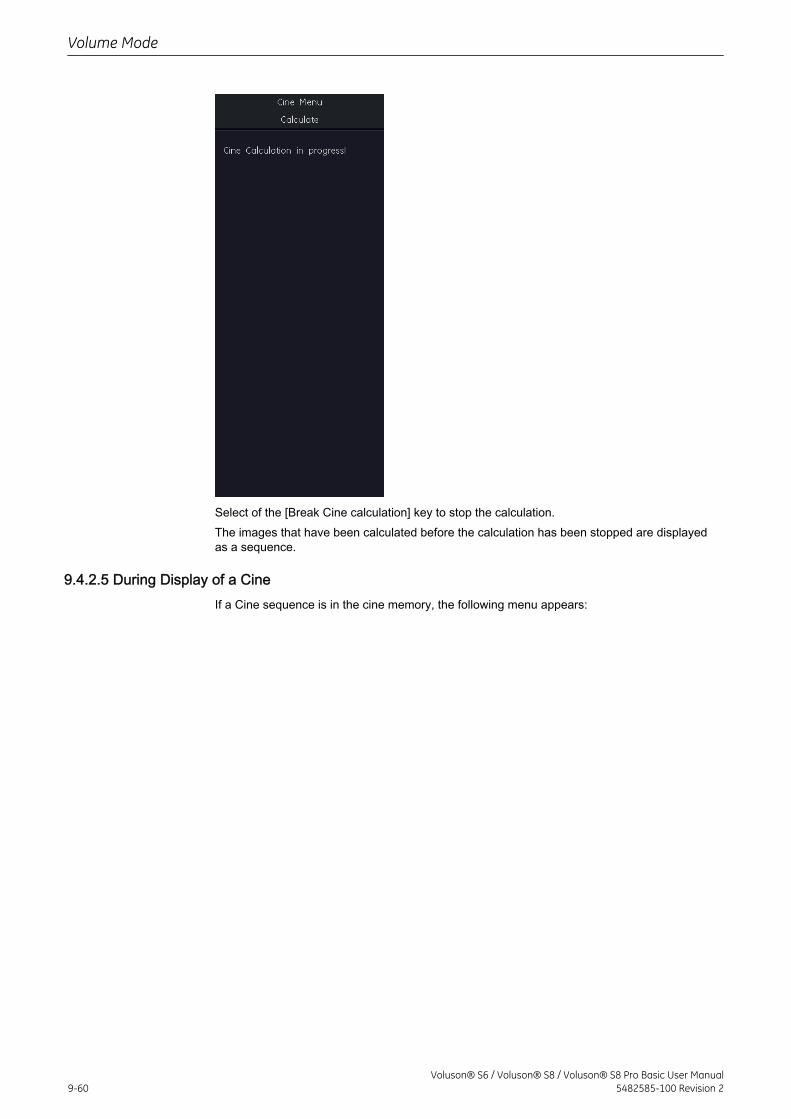
Select of the [Break Cine calculation] key to stop the calculation.The images that have been calculated before the calculation has been stopped are displayedas a sequence.
9.4.2.5 During Display of a CineIf a Cine sequence is in the cine memory, the following menu appears:
Volume Mode
9-60Voluson® S6 / Voluson® S8 / Voluson® S8 Pro Basic User Manual
5482585-100 Revision 2
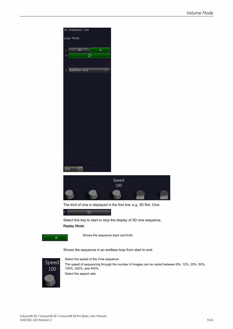
The kind of cine is displayed in the first line: e.g. 3D Rot. Cine
Select this key to start or stop the display of 3D cine sequence.Replay Mode
Shows the sequence back and forth.
Shows the sequence in an endless loop from start to end.
Select the speed of the Cine sequenceThe speed of sequencing through the number of images can be varied between 6%, 12%, 25%, 50%,100%, 200%, and 400%.Select the aspect ratio
Volume Mode
Voluson® S6 / Voluson® S8 / Voluson® S8 Pro Basic User Manual5482585-100 Revision 2 9-61
The 3D image magnification can be varied by turning the [Zoom] control.Select the render modesChoose between two render modes: Skin Surface or SmoothSelection of single images
After selecting the [Start/Stop] key move the trackball horizontally and you can select each single imagestep by step.The displayed number indicate: (2 / 10): image number of the sequence
9.4.2.6 Changing the Kind of Cine
Note When you are in the Slice Cine menu - Sectional Planes Mode, you need to change thevisualization mode to be able to change to another kind of cine.
When in Render Mode:
• Press [New Cine Sequence].
• Change the Kind of Cine.
• The following screen appears on the menu area:
• Press [Yes] and the menu changes accordingly.
When in Sectional Planes Mode:
• Press [Exit].
The menu changes to the 3D or 4D Main menu.
• Change the Visualization mode.
• Press the [Cine Calc] key.
• The following screen appears on the menu area:
• Press [Yes] and the menu changes to the Cine Calculation menu, from where youproceed as described in 'Cine Calculation' on page 9-51
Volume Mode
9-62Voluson® S6 / Voluson® S8 / Voluson® S8 Pro Basic User Manual
5482585-100 Revision 2
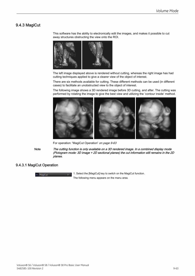
9.4.3 MagiCut
This software has the ability to electronically edit the images, and makes it possible to cutaway structures obstructing the view onto the ROI.
The left image displayed above is rendered without cutting, whereas the right image has hadcutting techniques applied to give a clearer view of the object of interest.There are six methods available for cutting. These different methods can be used (in differentcases) to facilitate an unobstructed view to the object of interest.The following image shows a 3D rendered image before 3D cutting, and after. The cutting wasperformed by rotating the image to give the best view and utilizing the ’contour inside’ method.
For operation: 'MagiCut Operation' on page 9-63
Note The cutting function is only available on a 3D rendered image. In a combined display mode(Pictogram mode: 3D image + 2D sectional planes) the cut information still remains in the 2Dplanes.
9.4.3.1 MagiCut Operation
1. Select the [MagiCut] key to switch on the MagiCut function.The following menu appears on the manu area.
Volume Mode
Voluson® S6 / Voluson® S8 / Voluson® S8 Pro Basic User Manual5482585-100 Revision 2 9-63
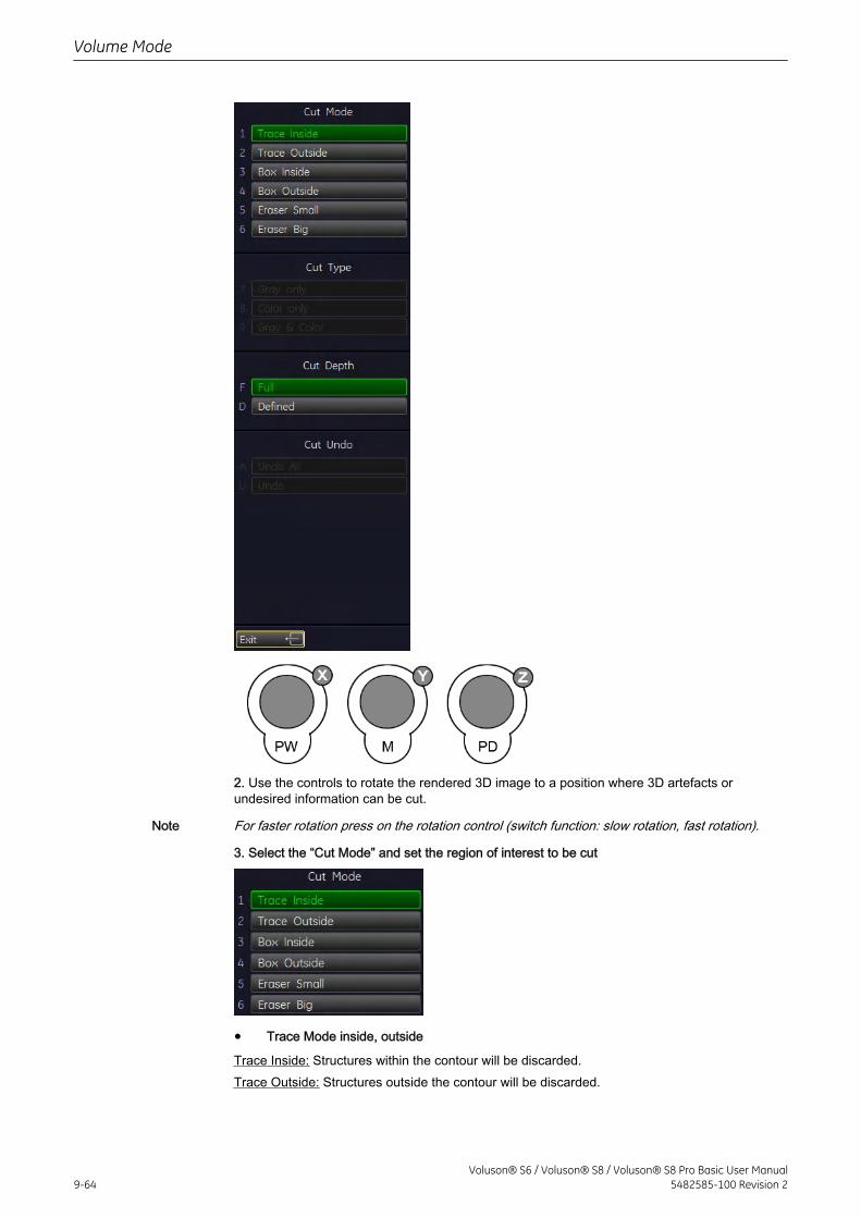
2. Use the controls to rotate the rendered 3D image to a position where 3D artefacts orundesired information can be cut.
Note For faster rotation press on the rotation control (switch function: slow rotation, fast rotation).
3. Select the “Cut Mode” and set the region of interest to be cut
• Trace Mode inside, outside
Trace Inside: Structures within the contour will be discarded.Trace Outside: Structures outside the contour will be discarded.
Volume Mode
9-64Voluson® S6 / Voluson® S8 / Voluson® S8 Pro Basic User Manual
5482585-100 Revision 2
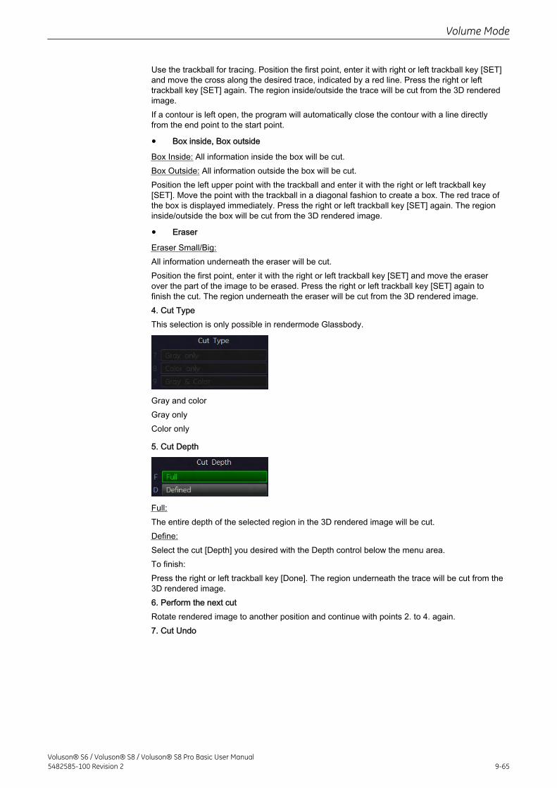
Use the trackball for tracing. Position the first point, enter it with right or left trackball key [SET]and move the cross along the desired trace, indicated by a red line. Press the right or lefttrackball key [SET] again. The region inside/outside the trace will be cut from the 3D renderedimage.If a contour is left open, the program will automatically close the contour with a line directlyfrom the end point to the start point.
• Box inside, Box outside
Box Inside: All information inside the box will be cut.Box Outside: All information outside the box will be cut.Position the left upper point with the trackball and enter it with the right or left trackball key[SET]. Move the point with the trackball in a diagonal fashion to create a box. The red trace ofthe box is displayed immediately. Press the right or left trackball key [SET] again. The regioninside/outside the box will be cut from the 3D rendered image.
• Eraser
Eraser Small/Big:All information underneath the eraser will be cut.Position the first point, enter it with the right or left trackball key [SET] and move the eraserover the part of the image to be erased. Press the right or left trackball key [SET] again tofinish the cut. The region underneath the eraser will be cut from the 3D rendered image.4. Cut TypeThis selection is only possible in rendermode Glassbody.
Gray and colorGray onlyColor only
5. Cut Depth
Full:The entire depth of the selected region in the 3D rendered image will be cut.Define:Select the cut [Depth] you desired with the Depth control below the menu area.To finish:Press the right or left trackball key [Done]. The region underneath the trace will be cut from the3D rendered image.6. Perform the next cutRotate rendered image to another position and continue with points 2. to 4. again.7. Cut Undo
Volume Mode
Voluson® S6 / Voluson® S8 / Voluson® S8 Pro Basic User Manual5482585-100 Revision 2 9-65
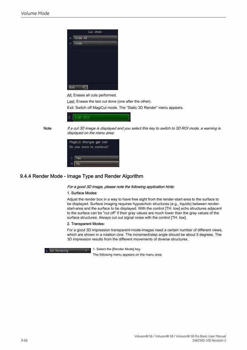
All: Erases all cuts performed.Last: Erases the last cut done (one after the other).Exit: Switch off MagiCut mode. The “Static 3D Render” menu appears.
Note If a cut 3D image is displayed and you select this key to switch to 3D ROI mode, a warning isdisplayed on the menu area:
9.4.4 Render Mode - Image Type and Render Algorithm
For a good 3D image, please note the following application hints:1. Surface Modes:Adjust the render box in a way to have free sight from the render-start-area to the surface tobe displayed. Surface imaging requires hypoechoic structures (e.g., liquids) between render-start-area and the surface to be displayed. With the control [TH. low] echo structures adjacentto the surface can be "cut off" if their gray values are much lower than the gray values of thesurface structures. Always cut out signal noise with the control [TH. low].2. Transparent Modes:For a good 3D impression transparent-mode-images need a certain number of different views,which are shown in a rotation cine. The increment/step angle should be about 5 degrees. The3D impression results from the different movements of diverse structures.
1. Select the [Render Mode] key.The following menu appears on the manu area.
Volume Mode
9-66Voluson® S6 / Voluson® S8 / Voluson® S8 Pro Basic User Manual
5482585-100 Revision 2
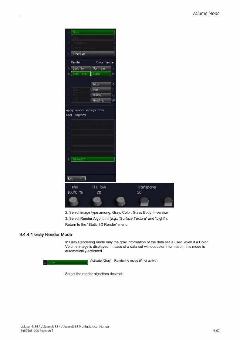
2. Select image type among: Gray, Color, Glass Body, Inversion3. Select Render Algorithm (e.g.: “Surface Texture” and “Light”).Return to the “Static 3D Render” menu.
9.4.4.1 Gray Render ModeIn Gray Rendering mode only the gray information of the data set is used, even if a ColorVolume image is displayed. In case of a data set without color information, this mode isautomatically activated.
Activate [Gray] - Rendering mode (if not active)
Select the render algorithm desired:
Volume Mode
Voluson® S6 / Voluson® S8 / Voluson® S8 Pro Basic User Manual5482585-100 Revision 2 9-67
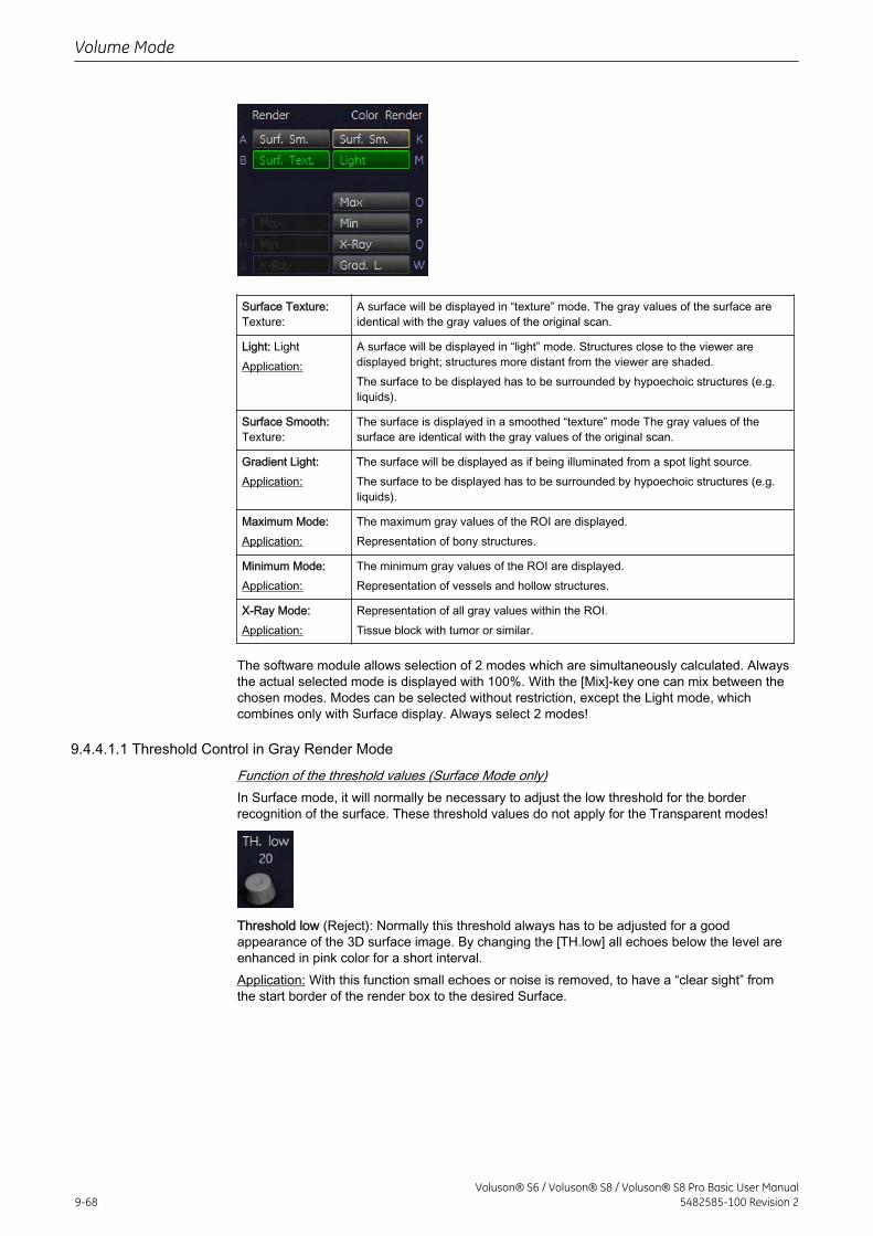
Surface Texture:Texture:
A surface will be displayed in “texture” mode. The gray values of the surface areidentical with the gray values of the original scan.
Light: LightApplication:
A surface will be displayed in “light” mode. Structures close to the viewer aredisplayed bright; structures more distant from the viewer are shaded.The surface to be displayed has to be surrounded by hypoechoic structures (e.g.liquids).
Surface Smooth:Texture:
The surface is displayed in a smoothed “texture” mode The gray values of thesurface are identical with the gray values of the original scan.
Gradient Light:Application:
The surface will be displayed as if being illuminated from a spot light source.The surface to be displayed has to be surrounded by hypoechoic structures (e.g.liquids).
Maximum Mode:Application:
The maximum gray values of the ROI are displayed.Representation of bony structures.
Minimum Mode:Application:
The minimum gray values of the ROI are displayed.Representation of vessels and hollow structures.
X-Ray Mode:Application:
Representation of all gray values within the ROI.Tissue block with tumor or similar.
The software module allows selection of 2 modes which are simultaneously calculated. Alwaysthe actual selected mode is displayed with 100%. With the [Mix]-key one can mix between thechosen modes. Modes can be selected without restriction, except the Light mode, whichcombines only with Surface display. Always select 2 modes!
9.4.4.1.1 Threshold Control in Gray Render Mode
Function of the threshold values (Surface Mode only)In Surface mode, it will normally be necessary to adjust the low threshold for the borderrecognition of the surface. These threshold values do not apply for the Transparent modes!
Threshold low (Reject): Normally this threshold always has to be adjusted for a goodappearance of the 3D surface image. By changing the [TH.low] all echoes below the level areenhanced in pink color for a short interval.Application: With this function small echoes or noise is removed, to have a “clear sight” fromthe start border of the render box to the desired Surface.
Volume Mode
9-68Voluson® S6 / Voluson® S8 / Voluson® S8 Pro Basic User Manual
5482585-100 Revision 2
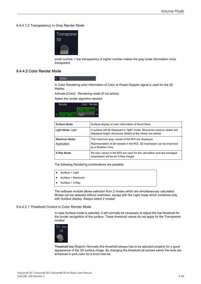
9.4.4.1.2 Transparency in Gray Render Mode
small number = low transparency A higher number makes the gray scale information moretransparent.
9.4.4.2 Color Render Mode
In Color Rendering color information of Color or Power-Doppler signal is used for the 3Ddisplay.Activate [Color] - Rendering mode (if not active).Select the render algorithm desired:
Surface Mode: Surface-display of color information of blood flows
Light Mode: Light: A surface will be displayed in “light” mode. Structures close to viewer aredisplayed bright; structures distant to the viewer are darker.
Maximum Mode:Application:
The maximum gray values of the ROI are displayed.Representation of all vessels in the ROI. 3D impression can be improvedby a Rotation Cine.
X-Ray Mode: All color values in the ROI are used for the calculation and are averaged(impression will be an X-Ray image)
The following Rendering combinations are possible:
• Surface + Light
• Surface + Maximum
• Surface + X-Ray
The software module allows selection from 2 modes which are simultaneously calculated.Modes can be selected without restriction, except with the Light mode which combines onlywith Surface display. Always select 2 modes!
9.4.4.2.1 Threshold Control in Color Render Mode
In case Surface mode is selected, it will normally be necessary to adjust the low threshold forthe border recognition of the surface. These threshold values do not apply for the Transparentmodes!
Threshold low (Reject): Normally this threshold always has to be adjusted properly for a goodappearance of the 3D surface image. By changing the threshold all echoes below the level areenhanced in pink color for a short interval.
Volume Mode
Voluson® S6 / Voluson® S8 / Voluson® S8 Pro Basic User Manual5482585-100 Revision 2 9-69
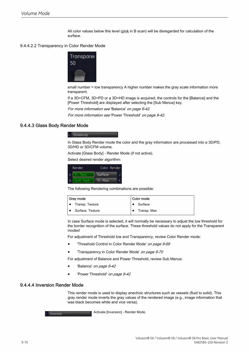
All color values below this level (pink in B scan) will be disregarded for calculation of thesurface.
9.4.4.2.2 Transparency in Color Render Mode
small number = low transparency A higher number makes the gray scale information moretransparent.If a 3D+CFM, 3D+PD or a 3D+HD image is acquired, the controls for the [Balance] and the[Power Threshold] are displayed after selecting the [Sub Menus] key.For more information see 'Balance' on page 9-42.For more information see 'Power Threshold' on page 9-42.
9.4.4.3 Glass Body Render Mode
In Glass Body Render mode the color and the gray information are processed into a 3D/PD,3D/HD or 3D/CFM volume.Activate [Glass Body] - Render Mode (if not active).Select desired render algorithm:
The following Rendering combinations are possible:
Gray mode
• Transp. Texture
• Surface. Texture
Color mode
• Surface
• Transp. Max
In case Surface mode is selected, it will normally be necessary to adjust the low threshold forthe border recognition of the surface. These threshold values do not apply for the Transparentmodes!For adjustment of Threshold low and Transparency, review Color Render mode:
• 'Threshold Control in Color Render Mode' on page 9-69
• 'Transparency in Color Render Mode' on page 9-70For adjustment of Balance and Power Threshold, review Sub Menus:
• 'Balance' on page 9-42
• 'Power Threshold' on page 9-42
9.4.4.4 Inversion Render ModeThis render mode is used to display anechoic structures such as vessels (fluid to solid). Thisgray render mode inverts the gray values of the rendered image (e.g., image information thatwas black becomes white and vice versa).
Activate [Inversion] - Render Mode.
Volume Mode
9-70Voluson® S6 / Voluson® S8 / Voluson® S8 Pro Basic User Manual
5482585-100 Revision 2
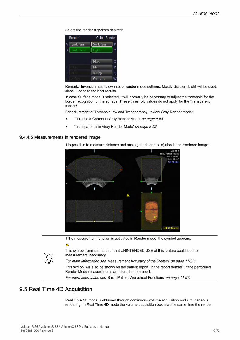
Select the render algorithm desired:
Remark: Inversion has its own set of render mode settings. Mostly Gradient Light will be used,since it leads to the best results.In case Surface mode is selected, it will normally be necessary to adjust the threshold for theborder recognition of the surface. These threshold values do not apply for the Transparentmodes!For adjustment of Threshold low and Transparency, review Gray Render mode:
• 'Threshold Control in Gray Render Mode' on page 9-68
• 'Transparency in Gray Render Mode' on page 9-69
9.4.4.5 Measurements in rendered imageIt is possible to measure distance and area (generic and calc) also in the rendered image.
If the measurement function is activated in Render mode, the symbol appears.
This symbol reminds the user that UNINTENDED USE of this feature could lead tomeasurement inaccuracy.For more information see 'Measurement Accuracy of the System' on page 11-23.This symbol will also be shown on the patient report (in the report header), if the performedRender Mode measurements are stored in the report.For more information see 'Basic Patient Worksheet Functions' on page 11-97.
9.5 Real Time 4D Acquisition
Real Time 4D mode is obtained through continuous volume acquisition and simultaneousrendering. In Real Time 4D mode the volume acquisition box is at the same time the render
Volume Mode
Voluson® S6 / Voluson® S8 / Voluson® S8 Pro Basic User Manual5482585-100 Revision 2 9-71
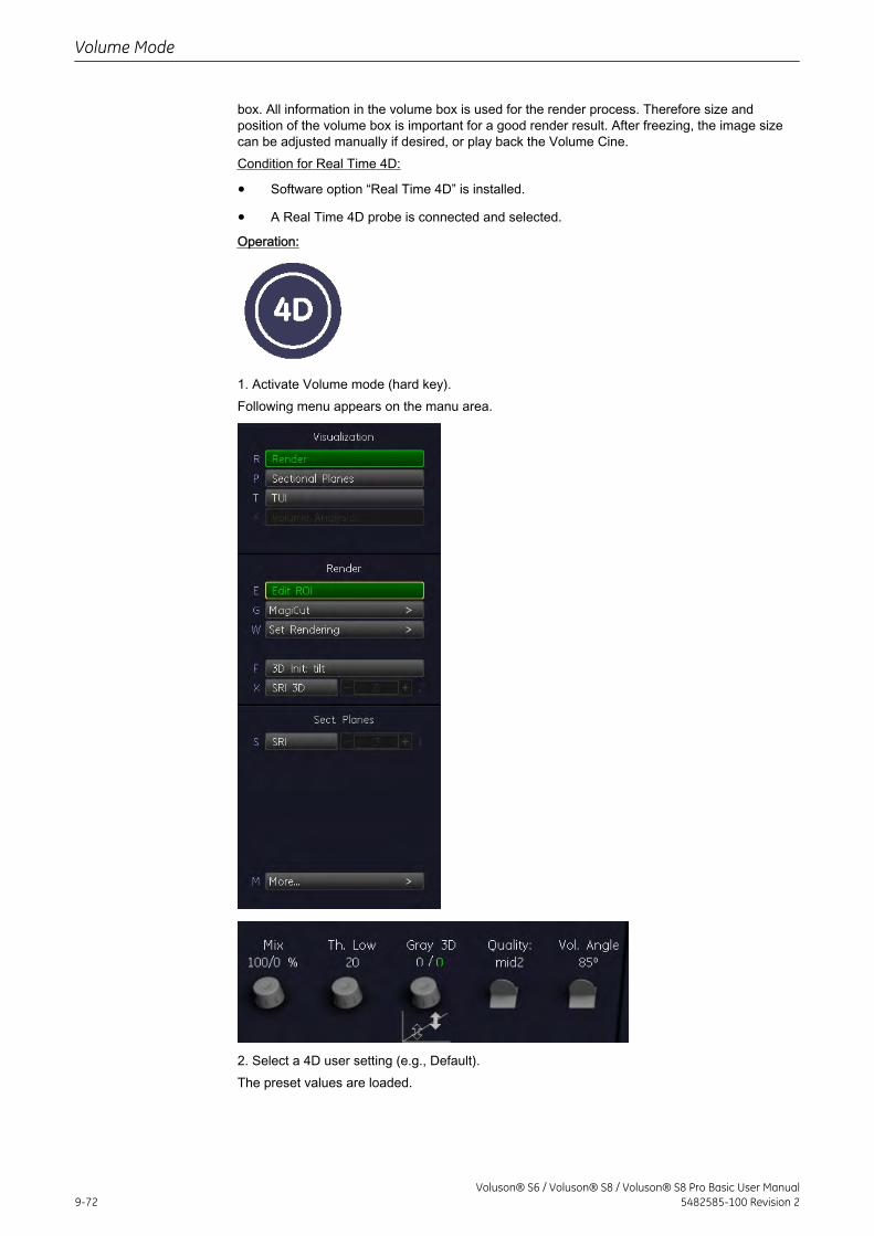
box. All information in the volume box is used for the render process. Therefore size andposition of the volume box is important for a good render result. After freezing, the image sizecan be adjusted manually if desired, or play back the Volume Cine.Condition for Real Time 4D:
• Software option “Real Time 4D” is installed.
• A Real Time 4D probe is connected and selected.
Operation:
1. Activate Volume mode (hard key).Following menu appears on the manu area.
2. Select a 4D user setting (e.g., Default).The preset values are loaded.
Volume Mode
9-72Voluson® S6 / Voluson® S8 / Voluson® S8 Pro Basic User Manual
5482585-100 Revision 2
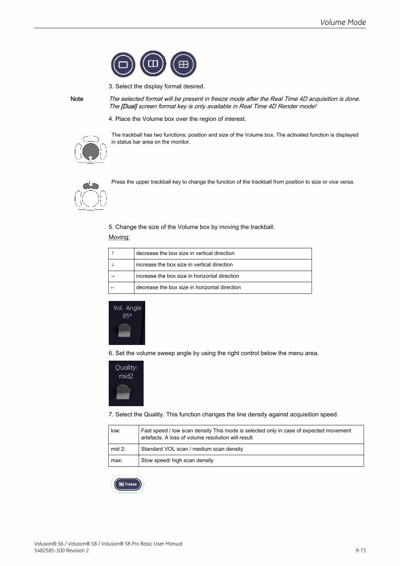
3. Select the display format desired.
Note The selected format will be present in freeze mode after the Real Time 4D acquisition is done.The [Dual] screen format key is only available in Real Time 4D Render mode!
4. Place the Volume box over the region of interest.
The trackball has two functions: position and size of the Volume box. The activated function is displayedin status bar area on the monitor.
Press the upper trackball key to change the function of the trackball from position to size or vice versa.
5. Change the size of the Volume box by moving the trackball.Moving:
↑ decrease the box size in vertical direction
↓ increase the box size in vertical direction
→ increase the box size in horizontal direction
← decrease the box size in horizontal direction
6. Set the volume sweep angle by using the right control below the menu area.
7. Select the Quality. This function changes the line density against acquisition speed.
low: Fast speed / low scan density This mode is selected only in case of expected movementartefacts. A loss of volume resolution will result
mid 2: Standard VOL scan / medium scan density
max: Slow speed/ high scan density
Volume Mode
Voluson® S6 / Voluson® S8 / Voluson® S8 Pro Basic User Manual5482585-100 Revision 2 9-73
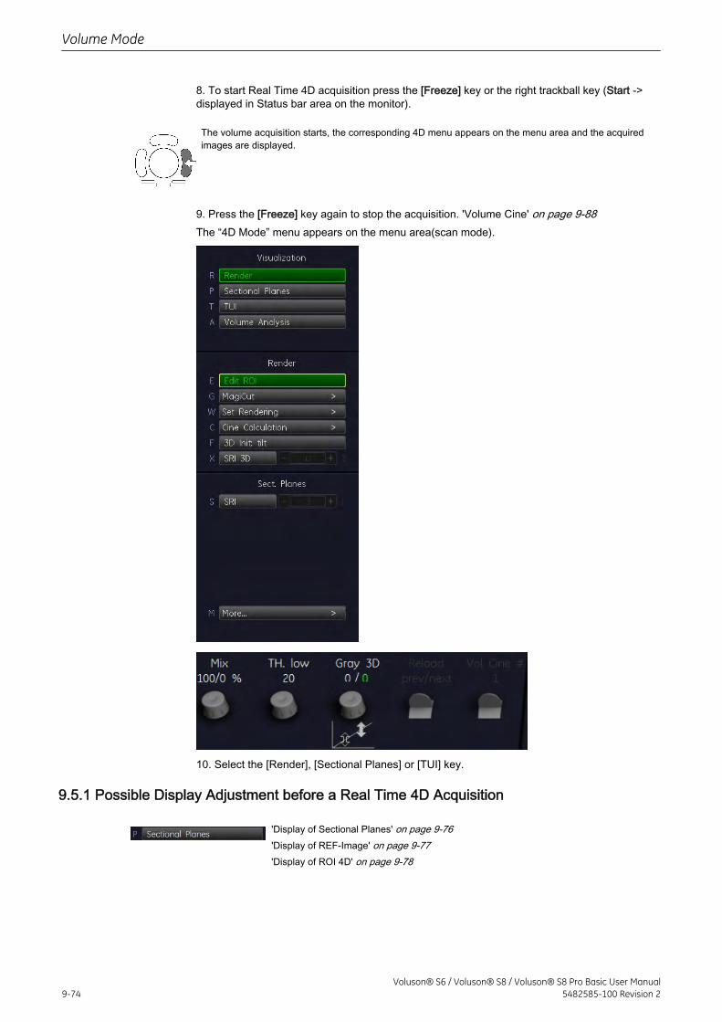
8. To start Real Time 4D acquisition press the [Freeze] key or the right trackball key (Start ->displayed in Status bar area on the monitor).
The volume acquisition starts, the corresponding 4D menu appears on the menu area and the acquiredimages are displayed.
9. Press the [Freeze] key again to stop the acquisition. 'Volume Cine' on page 9-88The “4D Mode” menu appears on the menu area(scan mode).
10. Select the [Render], [Sectional Planes] or [TUI] key.
9.5.1 Possible Display Adjustment before a Real Time 4D Acquisition
'Display of Sectional Planes' on page 9-76'Display of REF-Image' on page 9-77'Display of ROI 4D' on page 9-78
Volume Mode
9-74Voluson® S6 / Voluson® S8 / Voluson® S8 Pro Basic User Manual
5482585-100 Revision 2
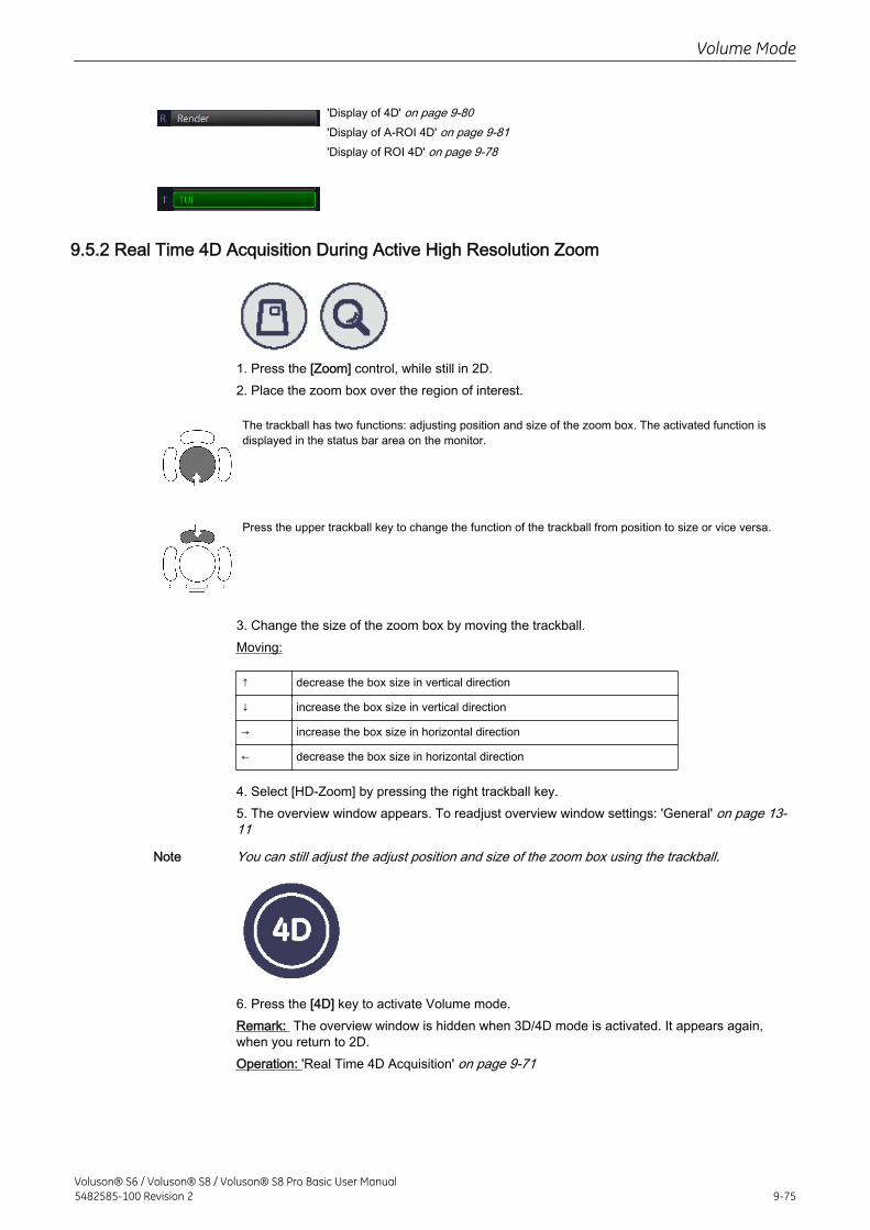
'Display of 4D' on page 9-80'Display of A-ROI 4D' on page 9-81'Display of ROI 4D' on page 9-78
9.5.2 Real Time 4D Acquisition During Active High Resolution Zoom
1. Press the [Zoom] control, while still in 2D.2. Place the zoom box over the region of interest.
The trackball has two functions: adjusting position and size of the zoom box. The activated function isdisplayed in the status bar area on the monitor.
Press the upper trackball key to change the function of the trackball from position to size or vice versa.
3. Change the size of the zoom box by moving the trackball.Moving:
↑ decrease the box size in vertical direction
↓ increase the box size in vertical direction
→ increase the box size in horizontal direction
← decrease the box size in horizontal direction
4. Select [HD-Zoom] by pressing the right trackball key.5. The overview window appears. To readjust overview window settings: 'General' on page 13-11
Note You can still adjust the adjust position and size of the zoom box using the trackball.
6. Press the [4D] key to activate Volume mode.Remark: The overview window is hidden when 3D/4D mode is activated. It appears again,when you return to 2D.Operation: 'Real Time 4D Acquisition' on page 9-71
Volume Mode
Voluson® S6 / Voluson® S8 / Voluson® S8 Pro Basic User Manual5482585-100 Revision 2 9-75
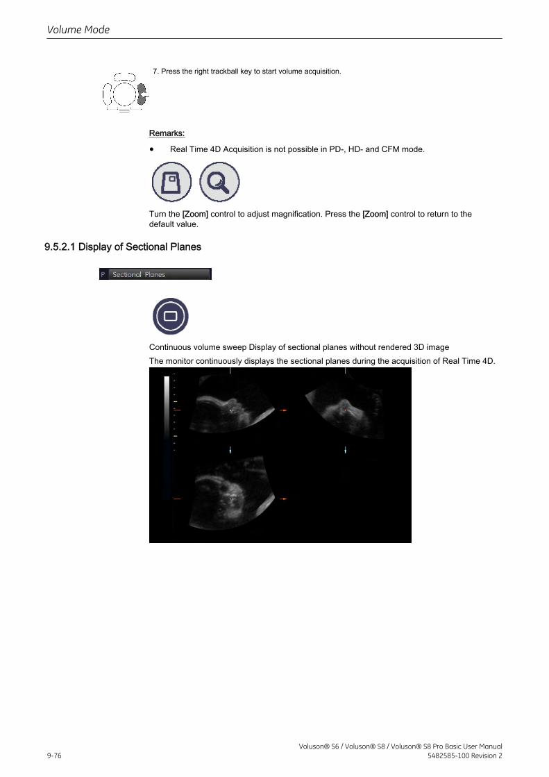
7. Press the right trackball key to start volume acquisition.
Remarks:
• Real Time 4D Acquisition is not possible in PD-, HD- and CFM mode.
Turn the [Zoom] control to adjust magnification. Press the [Zoom] control to return to thedefault value.
9.5.2.1 Display of Sectional Planes
Continuous volume sweep Display of sectional planes without rendered 3D imageThe monitor continuously displays the sectional planes during the acquisition of Real Time 4D.
Volume Mode
9-76Voluson® S6 / Voluson® S8 / Voluson® S8 Pro Basic User Manual
5482585-100 Revision 2
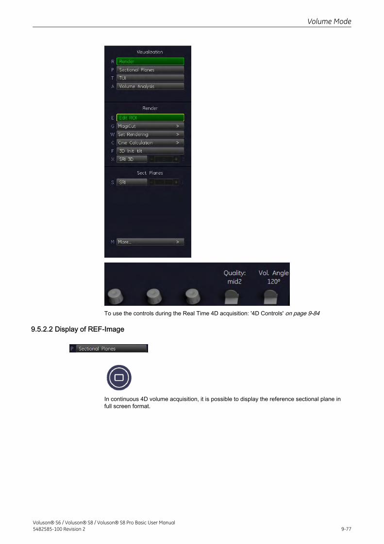
To use the controls during the Real Time 4D acquisition: '4D Controls' on page 9-84
9.5.2.2 Display of REF-Image
In continuous 4D volume acquisition, it is possible to display the reference sectional plane infull screen format.
Volume Mode
Voluson® S6 / Voluson® S8 / Voluson® S8 Pro Basic User Manual5482585-100 Revision 2 9-77
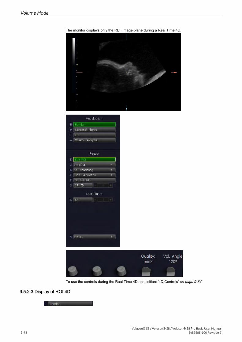
The monitor displays only the REF image plane during a Real Time 4D.
To use the controls during the Real Time 4D acquisition: '4D Controls' on page 9-84
9.5.2.3 Display of ROI 4D
Volume Mode
9-78Voluson® S6 / Voluson® S8 / Voluson® S8 Pro Basic User Manual
5482585-100 Revision 2
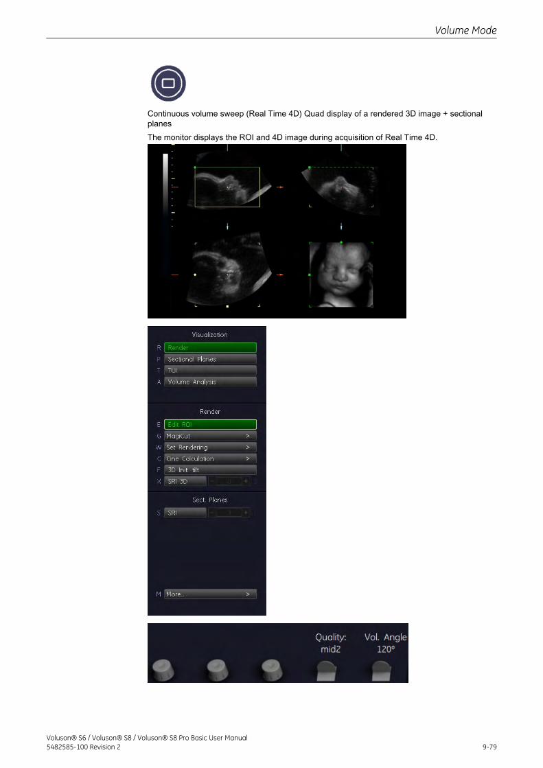
Continuous volume sweep (Real Time 4D) Quad display of a rendered 3D image + sectionalplanesThe monitor displays the ROI and 4D image during acquisition of Real Time 4D.
Volume Mode
Voluson® S6 / Voluson® S8 / Voluson® S8 Pro Basic User Manual5482585-100 Revision 2 9-79
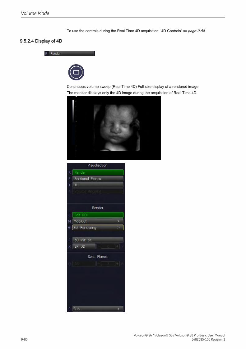
To use the controls during the Real Time 4D acquisition: '4D Controls' on page 9-84
9.5.2.4 Display of 4D
Continuous volume sweep (Real Time 4D) Full size display of a rendered imageThe monitor displays only the 4D image during the acquisition of Real Time 4D.
Volume Mode
9-80Voluson® S6 / Voluson® S8 / Voluson® S8 Pro Basic User Manual
5482585-100 Revision 2
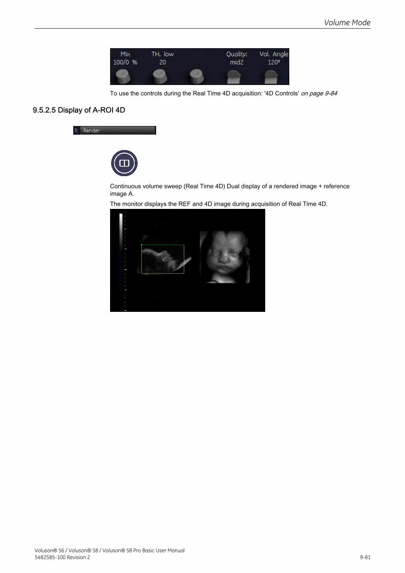
To use the controls during the Real Time 4D acquisition: '4D Controls' on page 9-84
9.5.2.5 Display of A-ROI 4D
Continuous volume sweep (Real Time 4D) Dual display of a rendered image + referenceimage A.The monitor displays the REF and 4D image during acquisition of Real Time 4D.
Volume Mode
Voluson® S6 / Voluson® S8 / Voluson® S8 Pro Basic User Manual5482585-100 Revision 2 9-81
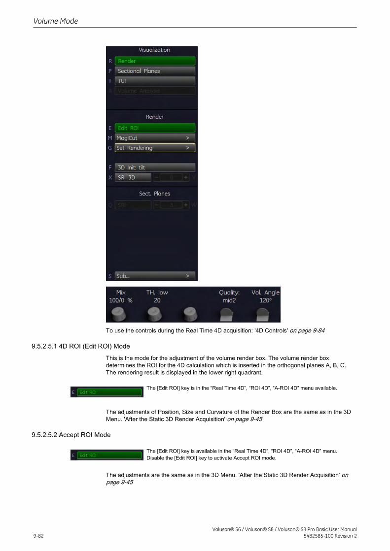
To use the controls during the Real Time 4D acquisition: '4D Controls' on page 9-84
9.5.2.5.1 4D ROI (Edit ROI) Mode
This is the mode for the adjustment of the volume render box. The volume render boxdetermines the ROI for the 4D calculation which is inserted in the orthogonal planes A, B, C.The rendering result is displayed in the lower right quadrant.
The [Edit ROI] key is in the “Real Time 4D”, “ROI 4D”, “A-ROI 4D” menu available.
The adjustments of Position, Size and Curvature of the Render Box are the same as in the 3DMenu. 'After the Static 3D Render Acquisition' on page 9-45
9.5.2.5.2 Accept ROI Mode
The [Edit ROI] key is available in the “Real Time 4D”, “ROI 4D”, “A-ROI 4D” menu.Disable the [Edit ROI] key to activate Accept ROI mode.
The adjustments are the same as in the 3D Menu. 'After the Static 3D Render Acquisition' onpage 9-45
Volume Mode
9-82Voluson® S6 / Voluson® S8 / Voluson® S8 Pro Basic User Manual
5482585-100 Revision 2
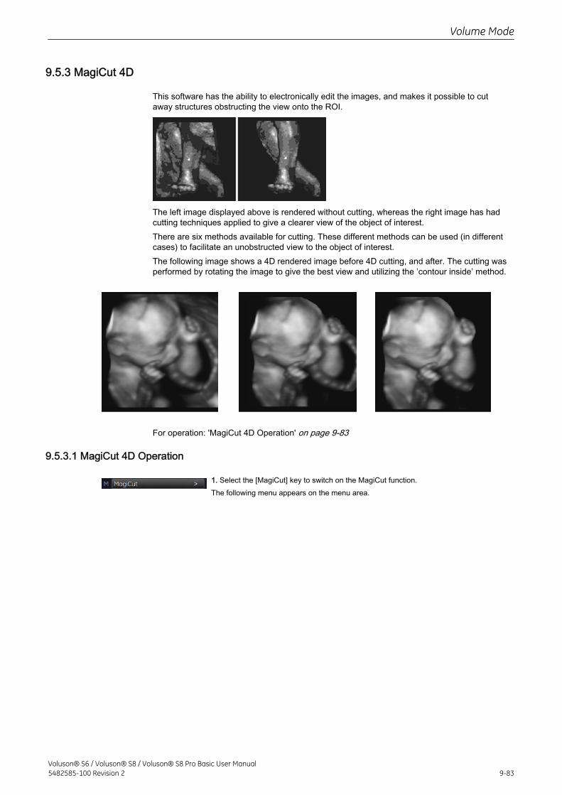
9.5.3 MagiCut 4D
This software has the ability to electronically edit the images, and makes it possible to cutaway structures obstructing the view onto the ROI.
The left image displayed above is rendered without cutting, whereas the right image has hadcutting techniques applied to give a clearer view of the object of interest.There are six methods available for cutting. These different methods can be used (in differentcases) to facilitate an unobstructed view to the object of interest.The following image shows a 4D rendered image before 4D cutting, and after. The cutting wasperformed by rotating the image to give the best view and utilizing the ’contour inside’ method.
For operation: 'MagiCut 4D Operation' on page 9-83
9.5.3.1 MagiCut 4D Operation
1. Select the [MagiCut] key to switch on the MagiCut function.The following menu appears on the menu area.
Volume Mode
Voluson® S6 / Voluson® S8 / Voluson® S8 Pro Basic User Manual5482585-100 Revision 2 9-83
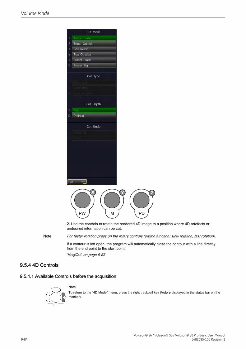
2. Use the controls to rotate the rendered 4D image to a position where 4D artefacts orundesired information can be cut.
Note For faster rotation press on the rotary controls (switch function: slow rotation, fast rotation).
If a contour is left open, the program will automatically close the contour with a line directlyfrom the end point to the start point.'MagiCut' on page 9-63
9.5.4 4D Controls
9.5.4.1 Available Controls before the acquisition
Note:To return to the “4D Mode” menu, press the right trackball key (Volpre displayed in the status bar on themonitor).
Volume Mode
9-84Voluson® S6 / Voluson® S8 / Voluson® S8 Pro Basic User Manual
5482585-100 Revision 2
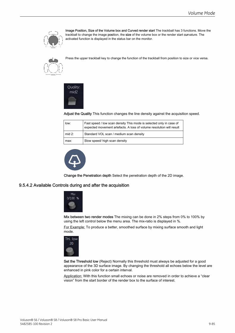
Image Position, Size of the Volume box and Curved render start The trackball has 3 functions. Move thetrackball to change the image position, the size of the volume box or the render start curvature. Theactivated function is displayed in the status bar on the monitor.
Press the upper trackball key to change the function of the trackball from position to size or vice versa.
Adjust the Quality This function changes the line density against the acquisition speed.
low: Fast speed / low scan density This mode is selected only in case ofexpected movement artefacts. A loss of volume resolution will result
mid 2: Standard VOL scan / medium scan density
max: Slow speed/ high scan density
Change the Penetration depth Select the penetration depth of the 2D image.
9.5.4.2 Available Controls during and after the acquisition
Mix between two render modes The mixing can be done in 2% steps from 0% to 100% byusing the left control below the menu area. The mix-ratio is displayed in %.For Example: To produce a better, smoothed surface by mixing surface smooth and lightmode.
Set the Threshold low (Reject) Normally this threshold must always be adjusted for a goodappearance of the 3D surface image. By changing the threshold all echoes below the level areenhanced in pink color for a certain interval.Application: With this function small echoes or noise are removed in order to achieve a “clearvision” from the start border of the render box to the surface of interest.
Volume Mode
Voluson® S6 / Voluson® S8 / Voluson® S8 Pro Basic User Manual5482585-100 Revision 2 9-85
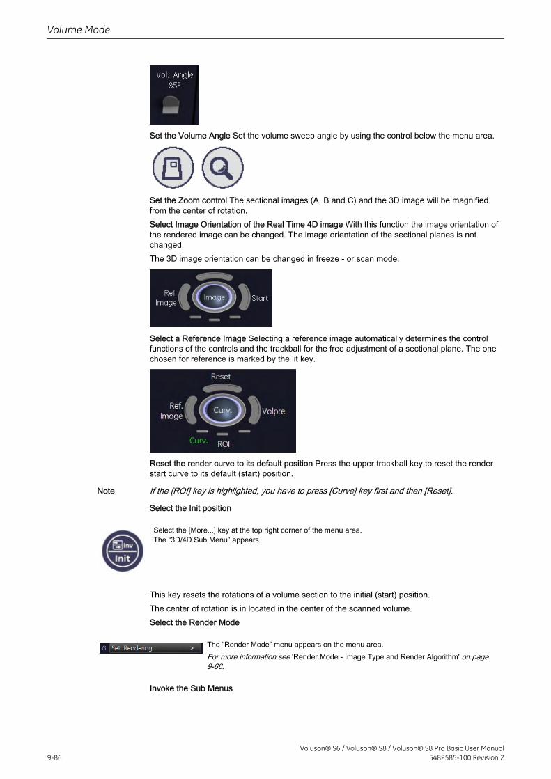
Set the Volume Angle Set the volume sweep angle by using the control below the menu area.
Set the Zoom control The sectional images (A, B and C) and the 3D image will be magnifiedfrom the center of rotation.Select Image Orientation of the Real Time 4D image With this function the image orientation ofthe rendered image can be changed. The image orientation of the sectional planes is notchanged.The 3D image orientation can be changed in freeze - or scan mode.
Select a Reference Image Selecting a reference image automatically determines the controlfunctions of the controls and the trackball for the free adjustment of a sectional plane. The onechosen for reference is marked by the lit key.
Reset the render curve to its default position Press the upper trackball key to reset the renderstart curve to its default (start) position.
Note If the [ROI] key is highlighted, you have to press [Curve] key first and then [Reset].
Select the Init position
Select the [More...] key at the top right corner of the menu area.The “3D/4D Sub Menu” appears
This key resets the rotations of a volume section to the initial (start) position.The center of rotation is in located in the center of the scanned volume.Select the Render Mode
The “Render Mode” menu appears on the menu area.For more information see 'Render Mode - Image Type and Render Algorithm' on page9-66.
Invoke the Sub Menus
Volume Mode
9-86Voluson® S6 / Voluson® S8 / Voluson® S8 Pro Basic User Manual
5482585-100 Revision 2
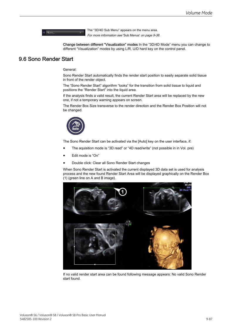
The “3D/4D Sub Menu” appears on the menu area.For more information see 'Sub Menus' on page 9-38.
Change between different “Visualization” modes In the “3D/4D Mode” menu you can change todifferent “Visualization” modes by using L/R, U/D hard key on the control panel.
9.6 Sono Render Start
General:Sono Render Start automatically finds the render start position to easily separate solid tissuein front of the render object.The “Sono Render Start” algorithm “looks” for the transition from solid tissue to liquid andpositions the “Render Start” into the liquid area.If the analysis finds a valid result, the current Render Start area will be replaced by the newone, if not a temporary warning appears on screen.The Render Box Size transverse to the render direction and the Render Box Position will notbe changed.
The Sono Render Start can be activated via the [Auto] key on the user interface, if:
• The aquisition mode is “3D read” or “4D read/write” (not possible in in Vol. pre)
• Edit mode is “On”
• Double click: Clear all Sono Render Start changes
When Sono Render Start is activated the current displayed 3D data set is used for analysisprocess and the new found Render Start Area will be displayed graphically on the Render Box(1) (green line on A and B image).
If no valid render start area can be found following message appears: No valid Sono Renderstart found.
Volume Mode
Voluson® S6 / Voluson® S8 / Voluson® S8 Pro Basic User Manual5482585-100 Revision 2 9-87
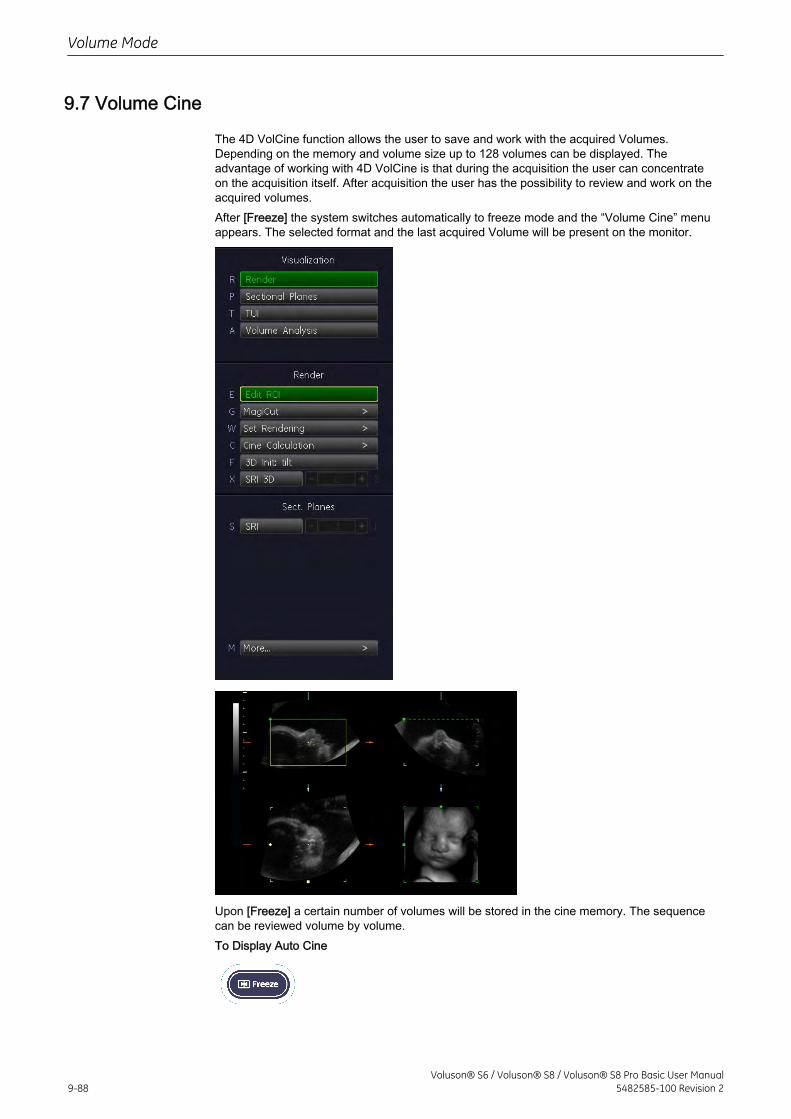
9.7 Volume Cine
The 4D VolCine function allows the user to save and work with the acquired Volumes.Depending on the memory and volume size up to 128 volumes can be displayed. Theadvantage of working with 4D VolCine is that during the acquisition the user can concentrateon the acquisition itself. After acquisition the user has the possibility to review and work on theacquired volumes.After [Freeze] the system switches automatically to freeze mode and the “Volume Cine” menuappears. The selected format and the last acquired Volume will be present on the monitor.
Upon [Freeze] a certain number of volumes will be stored in the cine memory. The sequencecan be reviewed volume by volume.To Display Auto Cine
Volume Mode
9-88Voluson® S6 / Voluson® S8 / Voluson® S8 Pro Basic User Manual
5482585-100 Revision 2
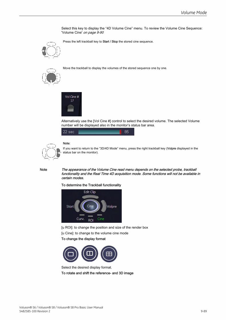
Select this key to display the “4D Volume Cine” menu. To review the Volume Cine Sequence:'Volume Cine' on page 9-90
Press the left trackball key to Start / Stop the stored cine sequence.
Move the trackball to display the volumes of the stored sequence one by one.
Alternatively use the [Vol Cine #] control to select the desired volume. The selected Volumenumber will be displayed also in the monitor’s status bar area.
Note:If you want to return to the “3D/4D Mode” menu, press the right trackball key (Volpre displayed in thestatus bar on the monitor).
Note The appearance of the Volume Cine read menu depends on the selected probe, trackballfunctionality and the Real Time 4D acquisition mode. Some functions will not be available incertain modes.
To determine the Trackball functionality
[u ROI]: to change the position and size of the render box[u Cine]: to change to the volume cine modeTo change the display format
Select the desired display format.To rotate and shift the reference- and 3D image
Volume Mode
Voluson® S6 / Voluson® S8 / Voluson® S8 Pro Basic User Manual5482585-100 Revision 2 9-89
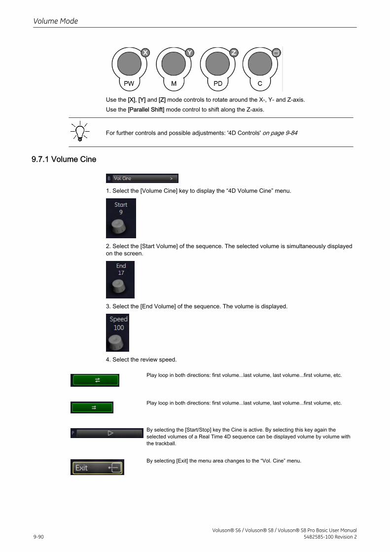
Use the [X], [Y] and [Z] mode controls to rotate around the X-, Y- and Z-axis.Use the [Parallel Shift] mode control to shift along the Z-axis.
For further controls and possible adjustments: '4D Controls' on page 9-84
9.7.1 Volume Cine
1. Select the [Volume Cine] key to display the “4D Volume Cine” menu.
2. Select the [Start Volume] of the sequence. The selected volume is simultaneously displayedon the screen.
3. Select the [End Volume] of the sequence. The volume is displayed.
4. Select the review speed.
Play loop in both directions: first volume...last volume, last volume...first volume, etc.
Play loop in both directions: first volume...last volume, last volume...first volume, etc.
By selecting the [Start/Stop] key the Cine is active. By selecting this key again theselected volumes of a Real Time 4D sequence can be displayed volume by volume withthe trackball.
By selecting [Exit] the menu area changes to the “Vol. Cine” menu.
Volume Mode
9-90Voluson® S6 / Voluson® S8 / Voluson® S8 Pro Basic User Manual
5482585-100 Revision 2
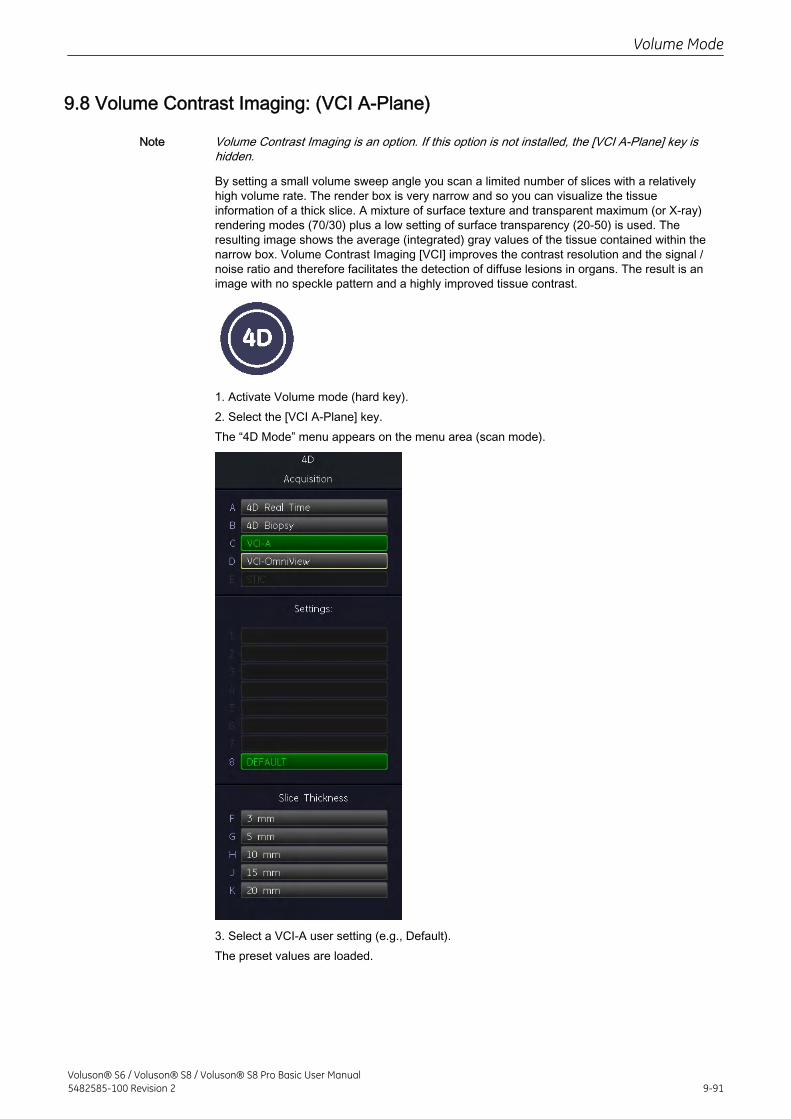
9.8 Volume Contrast Imaging: (VCI A-Plane)
Note Volume Contrast Imaging is an option. If this option is not installed, the [VCI A-Plane] key ishidden.
By setting a small volume sweep angle you scan a limited number of slices with a relativelyhigh volume rate. The render box is very narrow and so you can visualize the tissueinformation of a thick slice. A mixture of surface texture and transparent maximum (or X-ray)rendering modes (70/30) plus a low setting of surface transparency (20-50) is used. Theresulting image shows the average (integrated) gray values of the tissue contained within thenarrow box. Volume Contrast Imaging [VCI] improves the contrast resolution and the signal /noise ratio and therefore facilitates the detection of diffuse lesions in organs. The result is animage with no speckle pattern and a highly improved tissue contrast.
1. Activate Volume mode (hard key).2. Select the [VCI A-Plane] key.The “4D Mode” menu appears on the menu area (scan mode).
3. Select a VCI-A user setting (e.g., Default).The preset values are loaded.
Volume Mode
Voluson® S6 / Voluson® S8 / Voluson® S8 Pro Basic User Manual5482585-100 Revision 2 9-91
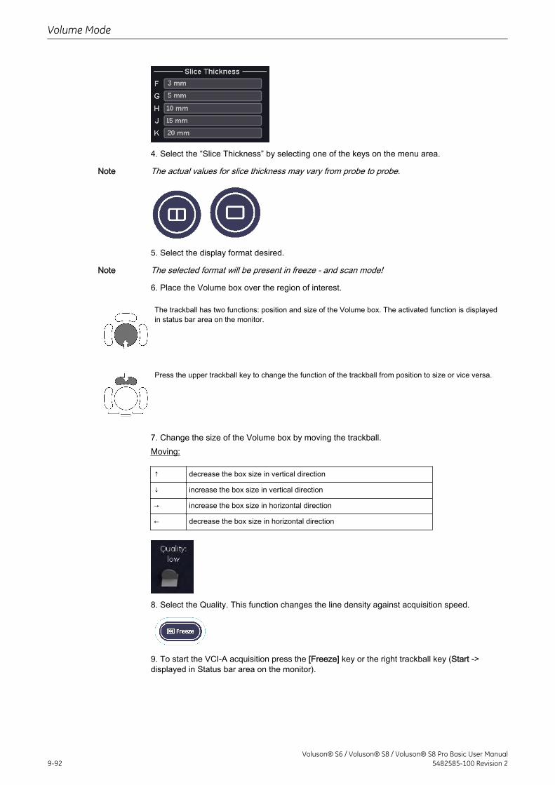
4. Select the “Slice Thickness” by selecting one of the keys on the menu area.
Note The actual values for slice thickness may vary from probe to probe.
5. Select the display format desired.
Note The selected format will be present in freeze - and scan mode!
6. Place the Volume box over the region of interest.
The trackball has two functions: position and size of the Volume box. The activated function is displayedin status bar area on the monitor.
Press the upper trackball key to change the function of the trackball from position to size or vice versa.
7. Change the size of the Volume box by moving the trackball.Moving:
↑ decrease the box size in vertical direction
↓ increase the box size in vertical direction
→ increase the box size in horizontal direction
← decrease the box size in horizontal direction
8. Select the Quality. This function changes the line density against acquisition speed.
9. To start the VCI-A acquisition press the [Freeze] key or the right trackball key (Start ->displayed in Status bar area on the monitor).
Volume Mode
9-92Voluson® S6 / Voluson® S8 / Voluson® S8 Pro Basic User Manual
5482585-100 Revision 2
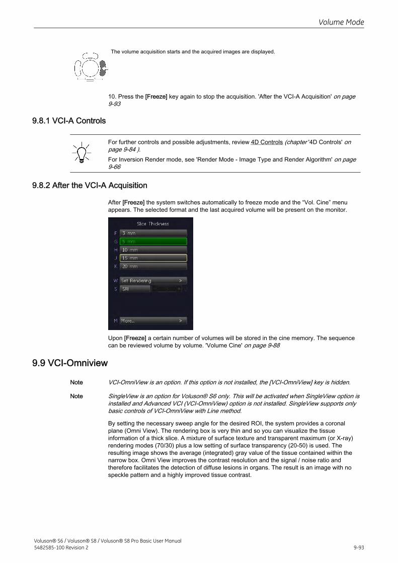
The volume acquisition starts and the acquired images are displayed.
10. Press the [Freeze] key again to stop the acquisition. 'After the VCI-A Acquisition' on page9-93
9.8.1 VCI-A Controls
For further controls and possible adjustments, review 4D Controls (chapter '4D Controls' onpage 9-84 ).For Inversion Render mode, see 'Render Mode - Image Type and Render Algorithm' on page9-66
9.8.2 After the VCI-A Acquisition
After [Freeze] the system switches automatically to freeze mode and the “Vol. Cine” menuappears. The selected format and the last acquired volume will be present on the monitor.
Upon [Freeze] a certain number of volumes will be stored in the cine memory. The sequencecan be reviewed volume by volume. 'Volume Cine' on page 9-88
9.9 VCI-Omniview
Note VCI-OmniView is an option. If this option is not installed, the [VCI-OmniView] key is hidden.
Note SingleView is an option for Voluson® S6 only. This will be activated when SingleView option isinstalled and Advanced VCI (VCI-OmniView) option is not installed. SingleView supports onlybasic controls of VCI-OmniView with Line method.
By setting the necessary sweep angle for the desired ROI, the system provides a coronalplane (Omni View). The rendering box is very thin and so you can visualize the tissueinformation of a thick slice. A mixture of surface texture and transparent maximum (or X-ray)rendering modes (70/30) plus a low setting of surface transparency (20-50) is used. Theresulting image shows the average (integrated) gray value of the tissue contained within thenarrow box. Omni View improves the contrast resolution and the signal / noise ratio andtherefore facilitates the detection of diffuse lesions in organs. The result is an image with nospeckle pattern and a highly improved tissue contrast.
Volume Mode
Voluson® S6 / Voluson® S8 / Voluson® S8 Pro Basic User Manual5482585-100 Revision 2 9-93
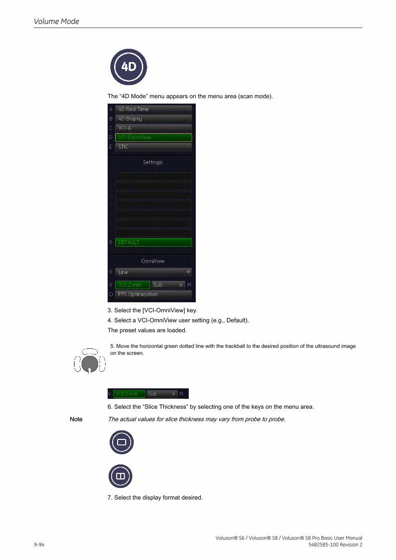
The “4D Mode” menu appears on the menu area (scan mode).
3. Select the [VCI-OmniView] key.4. Select a VCI-OmniView user setting (e.g., Default).The preset values are loaded.
5. Move the horizontal green dotted line with the trackball to the desired position of the ultrasound imageon the screen.
6. Select the “Slice Thickness” by selecting one of the keys on the menu area.
Note The actual values for slice thickness may vary from probe to probe.
7. Select the display format desired.
Volume Mode
9-94Voluson® S6 / Voluson® S8 / Voluson® S8 Pro Basic User Manual
5482585-100 Revision 2
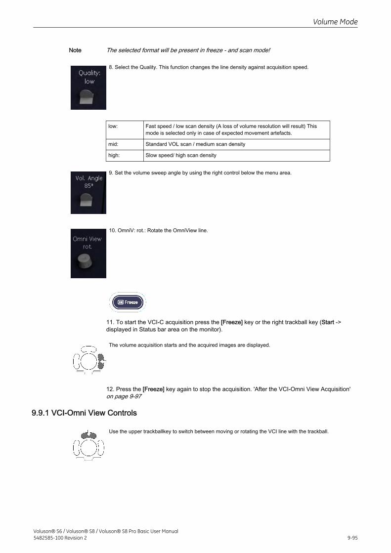
Note The selected format will be present in freeze - and scan mode!
8. Select the Quality. This function changes the line density against acquisition speed.
low: Fast speed / low scan density (A loss of volume resolution will result) Thismode is selected only in case of expected movement artefacts.
mid: Standard VOL scan / medium scan density
high: Slow speed/ high scan density
9. Set the volume sweep angle by using the right control below the menu area.
10. OmniV: rot.: Rotate the OmniView line.
11. To start the VCI-C acquisition press the [Freeze] key or the right trackball key (Start ->displayed in Status bar area on the monitor).
The volume acquisition starts and the acquired images are displayed.
12. Press the [Freeze] key again to stop the acquisition. 'After the VCI-Omni View Acquisition'on page 9-97
9.9.1 VCI-Omni View Controls
Use the upper trackballkey to switch between moving or rotating the VCI line with the trackball.
Volume Mode
Voluson® S6 / Voluson® S8 / Voluson® S8 Pro Basic User Manual5482585-100 Revision 2 9-95
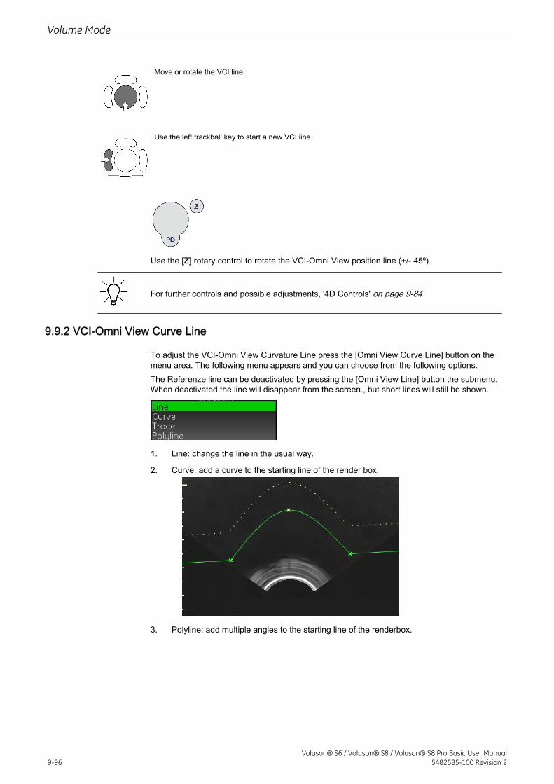
Move or rotate the VCI line.
Use the left trackball key to start a new VCI line.
Use the [Z] rotary control to rotate the VCI-Omni View position line (+/- 45º).
For further controls and possible adjustments, '4D Controls' on page 9-84
9.9.2 VCI-Omni View Curve Line
To adjust the VCI-Omni View Curvature Line press the [Omni View Curve Line] button on themenu area. The following menu appears and you can choose from the following options.The Referenze line can be deactivated by pressing the [Omni View Line] button the submenu.When deactivated the line will disappear from the screen., but short lines will still be shown.
1. Line: change the line in the usual way.
2. Curve: add a curve to the starting line of the render box.
3. Polyline: add multiple angles to the starting line of the renderbox.
Volume Mode
9-96Voluson® S6 / Voluson® S8 / Voluson® S8 Pro Basic User Manual
5482585-100 Revision 2
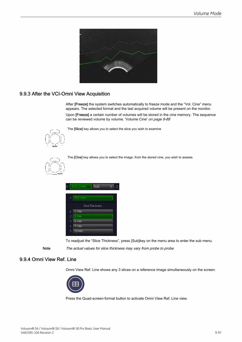
9.9.3 After the VCI-Omni View Acquisition
After [Freeze] the system switches automatically to freeze mode and the “Vol. Cine” menuappears. The selected format and the last acquired volume will be present on the monitor.Upon [Freeze] a certain number of volumes will be stored in the cine memory. The sequencecan be reviewed volume by volume. 'Volume Cine' on page 9-88
The [Slice] key allows you to select the slice you wish to examine
The [Cine] key allows you to select the image, from the stored cine, you wish to assess.
To readjust the “Slice Thickness”, press [Sub]key on the menu area to enter the sub menu.
Note The actual values for slice thickness may vary from probe to probe.
9.9.4 Omni View Ref. Line
Omni View Ref. Line shows any 3 slices on a reference image simultaneously on the screen.
Press the Quad-screen-format button to activate Omni View Ref. Line view.
Volume Mode
Voluson® S6 / Voluson® S8 / Voluson® S8 Pro Basic User Manual5482585-100 Revision 2 9-97
Press the Dual-screen-format button to activate Omni View dual view.
Press the Single-screen-format button to switch back to Omni View full format view.
9.10 STIC (Spatio-Temporal Image Correlation)
General: STIC is an option. If this option is not installed, the [STIC] key is hidden.With this acquisition method the fetal heart or an artery can be visualized in 4D. It is not a RealTime 4D technique, but a post processed 3D acquisition.
• STIC-Fetal Cardio is only available on RAB & RIC probes in the OB/GYN application
• STIC-Vascular is only available on the RSP probe in the Peripheral Vascular application
Data is acquired for a predefined period of time (7.5 – 15 sec.). The acquired images are postprocessed to calculate a 4D Volume Cine sequence representing one complete heart cycle.In order to achieve a good result, try to adjust the size of the volume box and the sweep angleto be as small as possible. The longer the acquisition time, the better the spatial resolution willbe. The user must be sure that there is minimal movement of the participating persons (e.g.,mother and fetus), and that the probe is held absolutely still throughout the acquisition period.Movement will cause a failure of the acquisition. If the user (trained operator) clearlyrecognizes a disturbance during the acquisition period, the acquisition has to be cancelled.A good STIC data set shows a regular and synchronous pumping of the fetal heart or of anartery. Please make sure that the borders of the fetal heart or the artery are smooth and thereare no sudden discontinuities.One or more of the following artefacts in the data set indicate a disturbance during acquisition:
• Sudden discontinuities in the reference image B: These are due to motion of the mother,the fetus or fetal arrhythmia during acquisition.
• Sudden discontinuities in the color display: Motion of the mother, the fetus or fetalarrhythmia affects the color flow in the same way it affects the gray image.
• Fetal heart rate far to low or far to high: After acquisition the estimated fetal heart rate isdisplayed. If the value does not correspond to the estimations based on other diagnosticmethods at all, the acquisition failed and has to be repeated.
• Asynchronous movement in different parts of the image: e.g., the left part of the image iscontracting and the right part is expanding at the same time.
• The color does not fit the structures displayed in gray mode: The color is displayedabove or below the actual vessel.
• Color “moves” through the image in a certain direction: This artefact is caused by afailure in detecting the heart rate due to low acquisition frame rate. Use higheracquisition frame rate for better result.
In all of the above cases the data set has to be discarded and the acquisition has to berepeated.
When is it not allowed to perform the STIC fetal cardio acquisition?
• severe fetal arrhythmia
Volume Mode
9-98Voluson® S6 / Voluson® S8 / Voluson® S8 Pro Basic User Manual
5482585-100 Revision 2
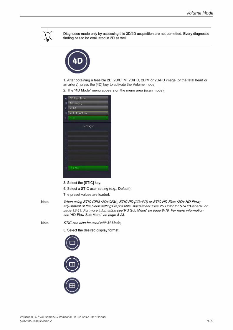
Diagnoses made only by assessing this 3D/4D acquisition are not permitted. Every diagnosticfinding has to be evaluated in 2D as well.
1. After obtaining a feasible 2D, 2D/CFM, 2D/HD, 2D/M or 2D/PD image (of the fetal heart oran artery), press the [4D] key to activate the Volume mode.2. The “4D Mode” menu appears on the menu area (scan mode).
3. Select the [STIC] key.4. Select a STIC user setting (e.g., Default).The preset values are loaded.
Note When using STIC CFM (2D+CFM), STIC PD (2D+PD) or STIC HD-Flow (2D+ HD-Flow)adjustment of the Color settings is possible. Adjustment “Use 2D Color for STIC: 'General' onpage 13-11. For more information see 'PD Sub Menu' on page 8-18. For more informationsee 'HD-Flow Sub Menu' on page 8-23.
Note STIC can also be used with M-Mode,
5. Select the desired display format .
Volume Mode
Voluson® S6 / Voluson® S8 / Voluson® S8 Pro Basic User Manual5482585-100 Revision 2 9-99
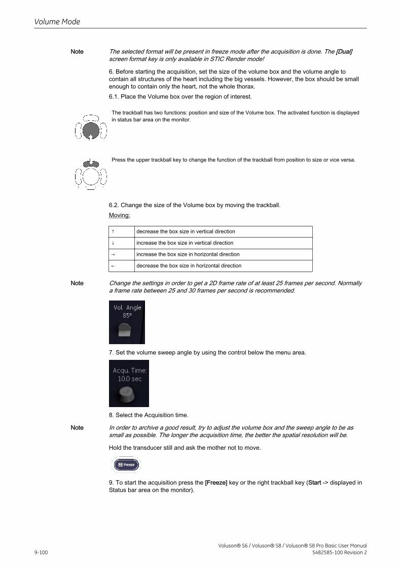
Note The selected format will be present in freeze mode after the acquisition is done. The [Dual]screen format key is only available in STIC Render mode!
6. Before starting the acquisition, set the size of the volume box and the volume angle tocontain all structures of the heart including the big vessels. However, the box should be smallenough to contain only the heart, not the whole thorax.6.1. Place the Volume box over the region of interest.
The trackball has two functions: position and size of the Volume box. The activated function is displayedin status bar area on the monitor.
Press the upper trackball key to change the function of the trackball from position to size or vice versa.
6.2. Change the size of the Volume box by moving the trackball.Moving:
↑ decrease the box size in vertical direction
↓ increase the box size in vertical direction
→ increase the box size in horizontal direction
← decrease the box size in horizontal direction
Note Change the settings in order to get a 2D frame rate of at least 25 frames per second. Normallya frame rate between 25 and 30 frames per second is recommended.
7. Set the volume sweep angle by using the control below the menu area.
8. Select the Acquisition time.
Note In order to archive a good result, try to adjust the volume box and the sweep angle to be assmall as possible. The longer the acquisition time, the better the spatial resolution will be.
Hold the transducer still and ask the mother not to move.
9. To start the acquisition press the [Freeze] key or the right trackball key (Start -> displayed inStatus bar area on the monitor).
Volume Mode
9-100Voluson® S6 / Voluson® S8 / Voluson® S8 Pro Basic User Manual
5482585-100 Revision 2
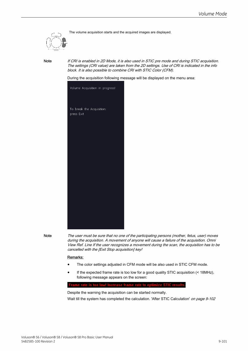
The volume acquisition starts and the acquired images are displayed.
Note If CRI is enabled in 2D Mode, it is also used in STIC pre mode and during STIC acquisition.The settings (CRI value) are taken from the 2D settings. Use of CRI is indicated in the infoblock. It is also possible to combine CRI with STIC Color (CFM).
During the acquisition following message will be displayed on the menu area:
Note The user must be sure that no one of the participating persons (mother, fetus, user) movesduring the acquisition. A movement of anyone will cause a failure of the acquisition. OmniView Ref. Line If the user recognizes a movement during the scan, the acquisition has to becancelled with the [Exit Stop acquisition] key!
Remarks:
• The color settings adjusted in CFM mode will be also used in STIC CFM mode.
• If the expected frame rate is too low for a good quality STIC acquisition (< 18MHz),following message appears on the screen:
Despite the warning the acquisition can be started normally.Wait till the system has completed the calculation. 'After STIC Calculation' on page 9-102
Volume Mode
Voluson® S6 / Voluson® S8 / Voluson® S8 Pro Basic User Manual5482585-100 Revision 2 9-101
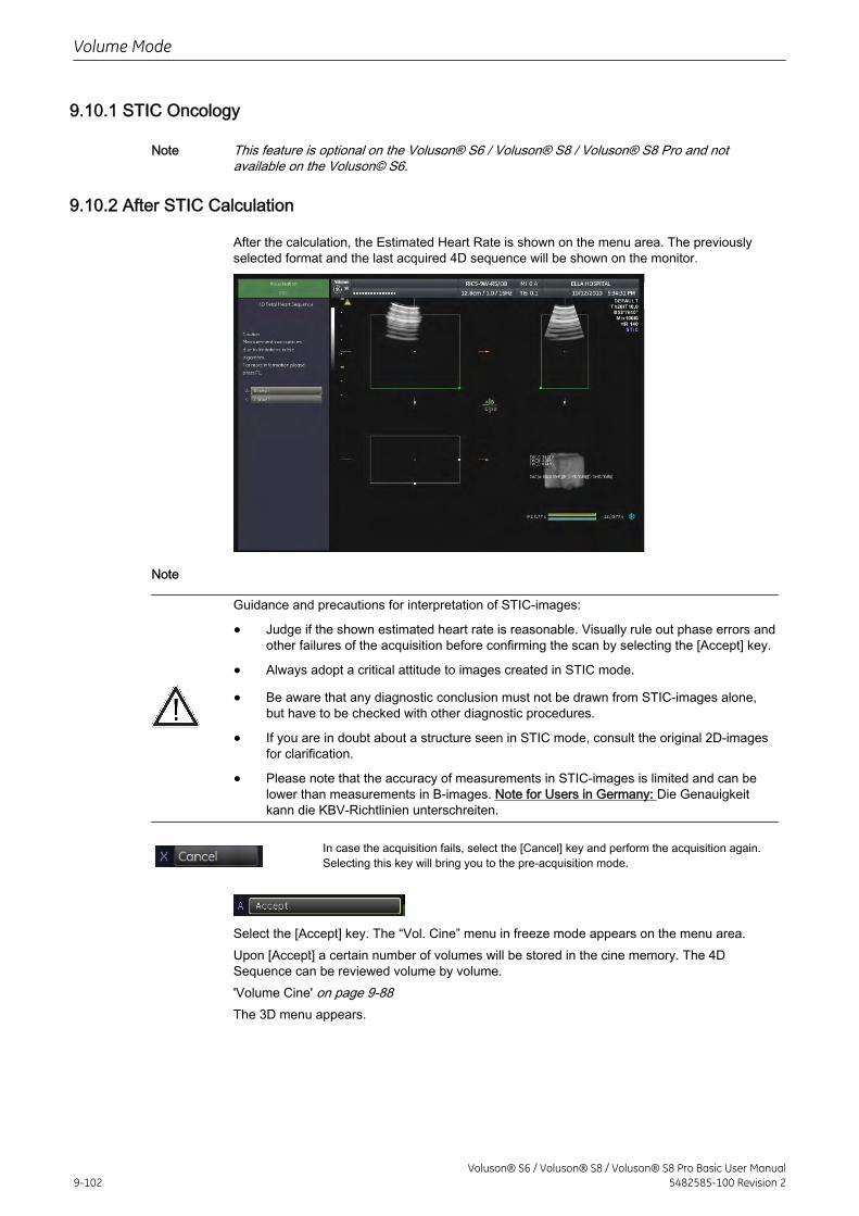
9.10.1 STIC Oncology
Note This feature is optional on the Voluson® S6 / Voluson® S8 / Voluson® S8 Pro and notavailable on the Voluson© S6.
9.10.2 After STIC Calculation
After the calculation, the Estimated Heart Rate is shown on the menu area. The previouslyselected format and the last acquired 4D sequence will be shown on the monitor.
Note
Guidance and precautions for interpretation of STIC-images:
• Judge if the shown estimated heart rate is reasonable. Visually rule out phase errors andother failures of the acquisition before confirming the scan by selecting the [Accept] key.
• Always adopt a critical attitude to images created in STIC mode.
• Be aware that any diagnostic conclusion must not be drawn from STIC-images alone,but have to be checked with other diagnostic procedures.
• If you are in doubt about a structure seen in STIC mode, consult the original 2D-imagesfor clarification.
• Please note that the accuracy of measurements in STIC-images is limited and can belower than measurements in B-images. Note for Users in Germany: Die Genauigkeitkann die KBV-Richtlinien unterschreiten.
In case the acquisition fails, select the [Cancel] key and perform the acquisition again.Selecting this key will bring you to the pre-acquisition mode.
Select the [Accept] key. The “Vol. Cine” menu in freeze mode appears on the menu area.Upon [Accept] a certain number of volumes will be stored in the cine memory. The 4DSequence can be reviewed volume by volume.'Volume Cine' on page 9-88The 3D menu appears.
Volume Mode
9-102Voluson® S6 / Voluson® S8 / Voluson® S8 Pro Basic User Manual
5482585-100 Revision 2
9.10.2.1 Measurements in the STIC-image
If the measurement function is activated in mode STIC, the symbol appears. This symbolreminds the user that UNINTENDED USE of this feature could lead to measurementinaccuracy (below accuracy mentioned in chapter 'Measurement Accuracy of the System' onpage 11-23). This symbol will also be shown on the patient report (in the report header), ifthe performed STIC measurements are stored in the report. ('Basic Patient WorksheetFunctions' on page 11-97).
9.11 Real Time 4D Biopsy
Note Real Time 4D Biopsy is an option. If this option is not installed, the [4D Biopsy] key is hidden.
• Before performing a Real Time 4D Biopsy, make sure that the displayed biopsy linecoincides with the needle track. (check in a bowl filled with approx. 47˚C warm water!)
• The biopsy lines must be programmed once by the service personnel or the user. Theprocedure must be repeated if probes and / or biopsy guides are exchanged.
• Please read the Instructions for safe use: 'Biopsy Safety and Maintenance' on page 2-18
Note The biopsy line must be programmed! Otherwise activating the [4D Biopsy] key is impossible.For more information see 'To program a Single Angle Biopsy Line' on page 5-17. For moreinformation see 'To program a Multi Angle Biopsy Line' on page 5-18.
1. Activate Volume mode (hard key).2. The “4D Mode” menu appears on the menu area (scan mode).3. Select the [4D Biopsy] key.Following menu appears on the menu area.
Volume Mode
Voluson® S6 / Voluson® S8 / Voluson® S8 Pro Basic User Manual5482585-100 Revision 2 9-103
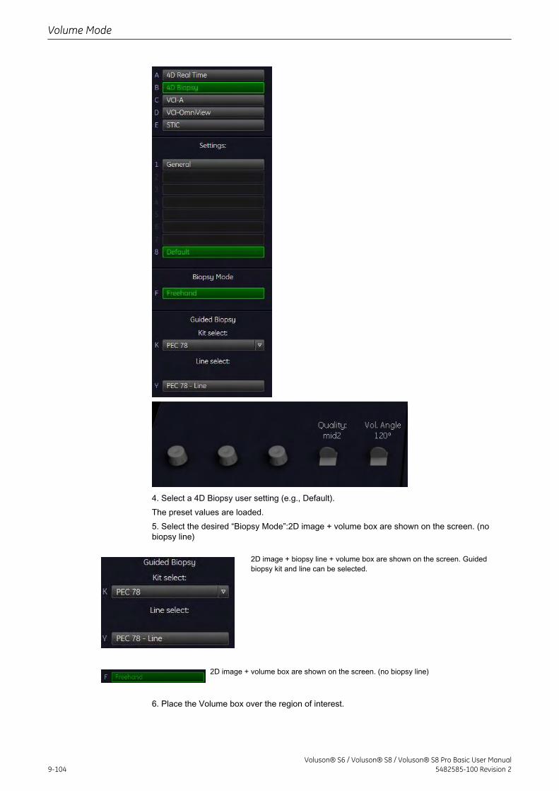
4. Select a 4D Biopsy user setting (e.g., Default).The preset values are loaded.5. Select the desired “Biopsy Mode”:2D image + volume box are shown on the screen. (nobiopsy line)
2D image + biopsy line + volume box are shown on the screen. Guidedbiopsy kit and line can be selected.
2D image + volume box are shown on the screen. (no biopsy line)
6. Place the Volume box over the region of interest.
Volume Mode
9-104Voluson® S6 / Voluson® S8 / Voluson® S8 Pro Basic User Manual
5482585-100 Revision 2
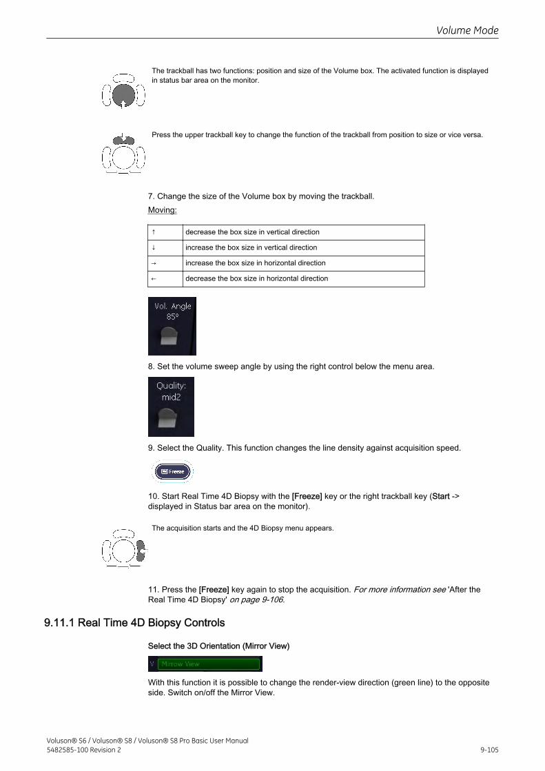
The trackball has two functions: position and size of the Volume box. The activated function is displayedin status bar area on the monitor.
Press the upper trackball key to change the function of the trackball from position to size or vice versa.
7. Change the size of the Volume box by moving the trackball.Moving:
↑ decrease the box size in vertical direction
↓ increase the box size in vertical direction
→ increase the box size in horizontal direction
← decrease the box size in horizontal direction
8. Set the volume sweep angle by using the right control below the menu area.
9. Select the Quality. This function changes the line density against acquisition speed.
10. Start Real Time 4D Biopsy with the [Freeze] key or the right trackball key (Start ->displayed in Status bar area on the monitor).
The acquisition starts and the 4D Biopsy menu appears.
11. Press the [Freeze] key again to stop the acquisition. For more information see 'After theReal Time 4D Biopsy' on page 9-106.
9.11.1 Real Time 4D Biopsy Controls
Select the 3D Orientation (Mirror View)
With this function it is possible to change the render-view direction (green line) to the oppositeside. Switch on/off the Mirror View.
Volume Mode
Voluson® S6 / Voluson® S8 / Voluson® S8 Pro Basic User Manual5482585-100 Revision 2 9-105
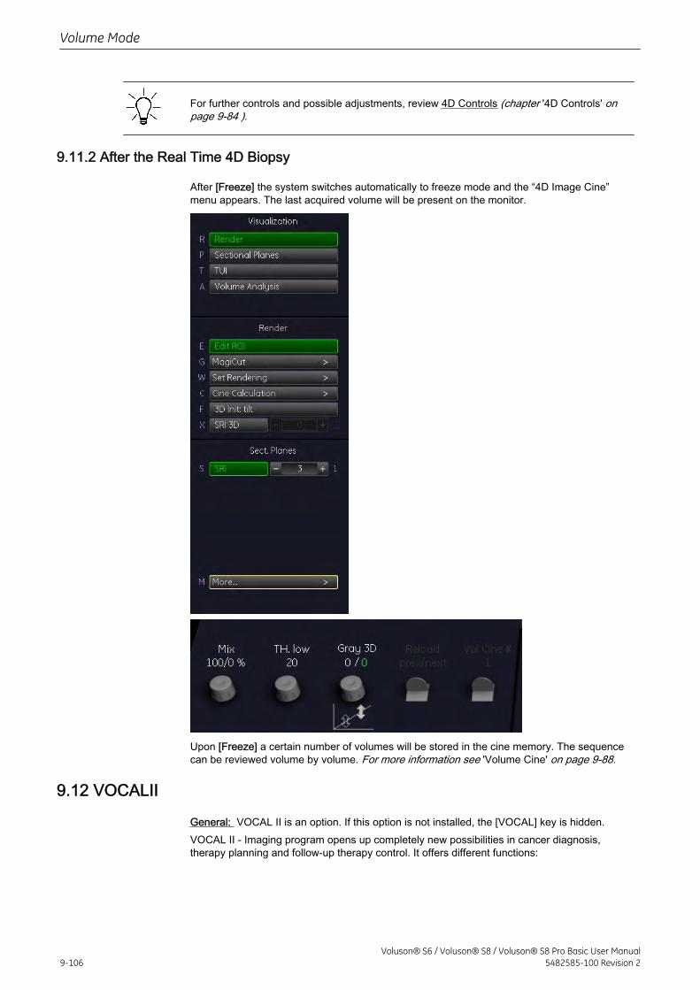
For further controls and possible adjustments, review 4D Controls (chapter '4D Controls' onpage 9-84 ).
9.11.2 After the Real Time 4D Biopsy
After [Freeze] the system switches automatically to freeze mode and the “4D Image Cine”menu appears. The last acquired volume will be present on the monitor.
Upon [Freeze] a certain number of volumes will be stored in the cine memory. The sequencecan be reviewed volume by volume. For more information see 'Volume Cine' on page 9-88.
9.12 VOCALII
General: VOCAL II is an option. If this option is not installed, the [VOCAL] key is hidden.VOCAL II - Imaging program opens up completely new possibilities in cancer diagnosis,therapy planning and follow-up therapy control. It offers different functions:
Volume Mode
9-106Voluson® S6 / Voluson® S8 / Voluson® S8 Pro Basic User Manual
5482585-100 Revision 2
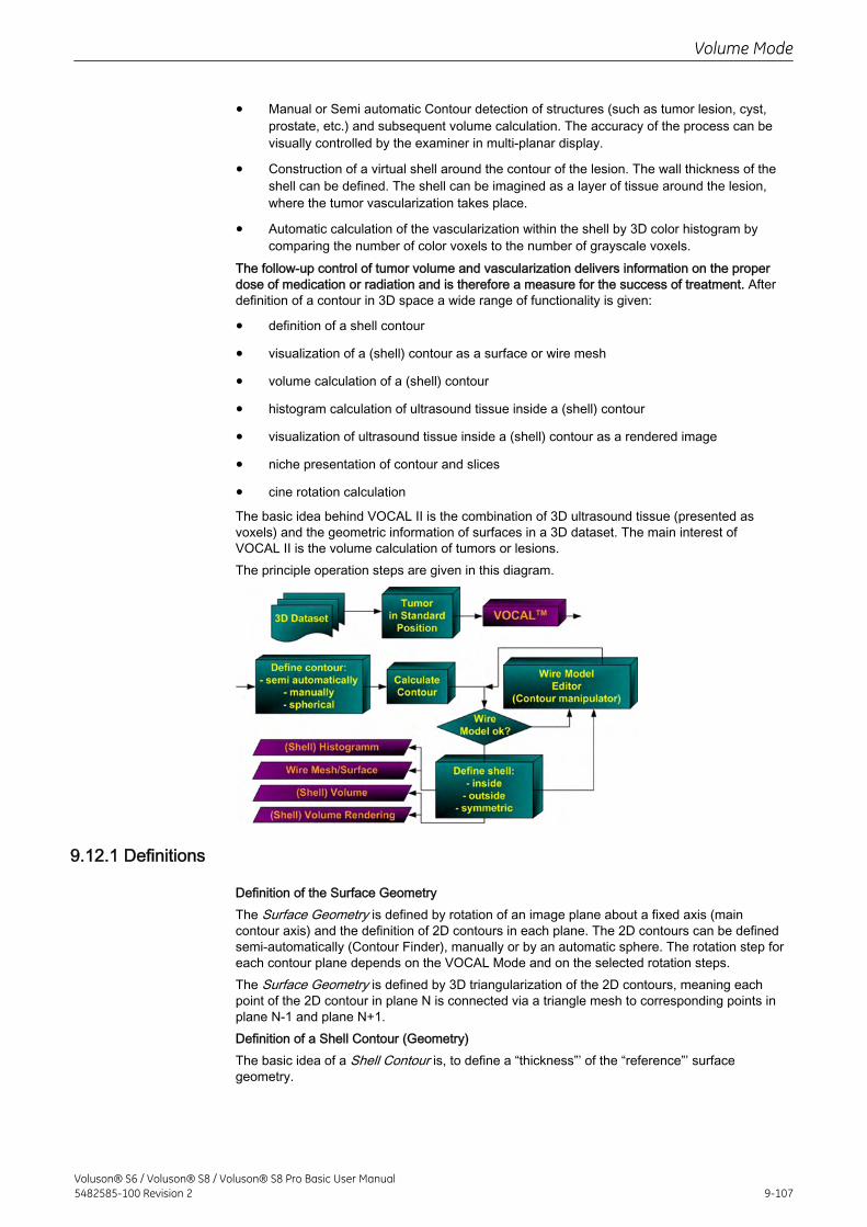
• Manual or Semi automatic Contour detection of structures (such as tumor lesion, cyst,prostate, etc.) and subsequent volume calculation. The accuracy of the process can bevisually controlled by the examiner in multi-planar display.
• Construction of a virtual shell around the contour of the lesion. The wall thickness of theshell can be defined. The shell can be imagined as a layer of tissue around the lesion,where the tumor vascularization takes place.
• Automatic calculation of the vascularization within the shell by 3D color histogram bycomparing the number of color voxels to the number of grayscale voxels.
The follow-up control of tumor volume and vascularization delivers information on the properdose of medication or radiation and is therefore a measure for the success of treatment. Afterdefinition of a contour in 3D space a wide range of functionality is given:
• definition of a shell contour
• visualization of a (shell) contour as a surface or wire mesh
• volume calculation of a (shell) contour
• histogram calculation of ultrasound tissue inside a (shell) contour
• visualization of ultrasound tissue inside a (shell) contour as a rendered image
• niche presentation of contour and slices
• cine rotation calculation
The basic idea behind VOCAL II is the combination of 3D ultrasound tissue (presented asvoxels) and the geometric information of surfaces in a 3D dataset. The main interest ofVOCAL II is the volume calculation of tumors or lesions.The principle operation steps are given in this diagram.
9.12.1 Definitions
Definition of the Surface GeometryThe Surface Geometry is defined by rotation of an image plane about a fixed axis (maincontour axis) and the definition of 2D contours in each plane. The 2D contours can be definedsemi-automatically (Contour Finder), manually or by an automatic sphere. The rotation step foreach contour plane depends on the VOCAL Mode and on the selected rotation steps.The Surface Geometry is defined by 3D triangularization of the 2D contours, meaning eachpoint of the 2D contour in plane N is connected via a triangle mesh to corresponding points inplane N-1 and plane N+1.Definition of a Shell Contour (Geometry)The basic idea of a Shell Contour is, to define a “thickness”’ of the “reference”’ surfacegeometry.
Volume Mode
Voluson® S6 / Voluson® S8 / Voluson® S8 Pro Basic User Manual5482585-100 Revision 2 9-107
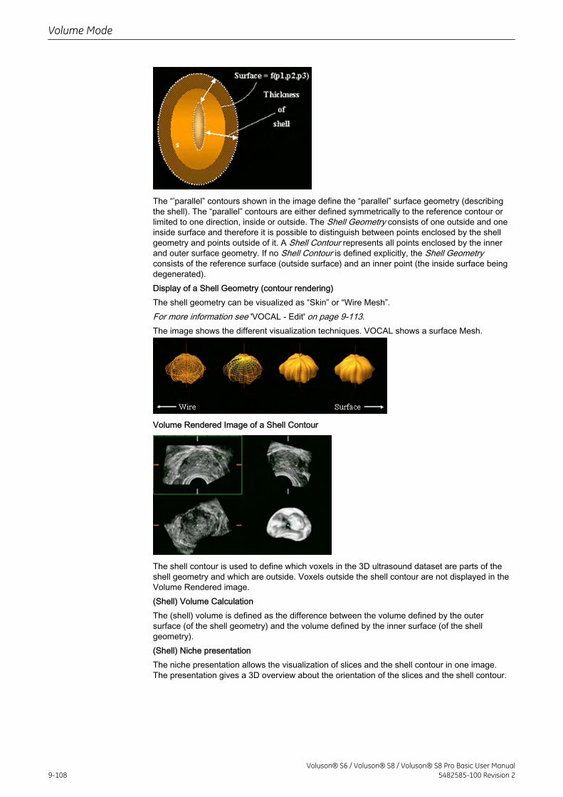
The “’parallel” contours shown in the image define the “parallel” surface geometry (describingthe shell). The “parallel” contours are either defined symmetrically to the reference contour orlimited to one direction, inside or outside. The Shell Geometry consists of one outside and oneinside surface and therefore it is possible to distinguish between points enclosed by the shellgeometry and points outside of it. A Shell Contour represents all points enclosed by the innerand outer surface geometry. If no Shell Contour is defined explicitly, the Shell Geometryconsists of the reference surface (outside surface) and an inner point (the inside surface beingdegenerated).Display of a Shell Geometry (contour rendering)The shell geometry can be visualized as “Skin” or “Wire Mesh”.For more information see 'VOCAL - Edit' on page 9-113.The image shows the different visualization techniques. VOCAL shows a surface Mesh.
Volume Rendered Image of a Shell Contour
The shell contour is used to define which voxels in the 3D ultrasound dataset are parts of theshell geometry and which are outside. Voxels outside the shell contour are not displayed in theVolume Rendered image.(Shell) Volume CalculationThe (shell) volume is defined as the difference between the volume defined by the outersurface (of the shell geometry) and the volume defined by the inner surface (of the shellgeometry).(Shell) Niche presentationThe niche presentation allows the visualization of slices and the shell contour in one image.The presentation gives a 3D overview about the orientation of the slices and the shell contour.
Volume Mode
9-108Voluson® S6 / Voluson® S8 / Voluson® S8 Pro Basic User Manual
5482585-100 Revision 2
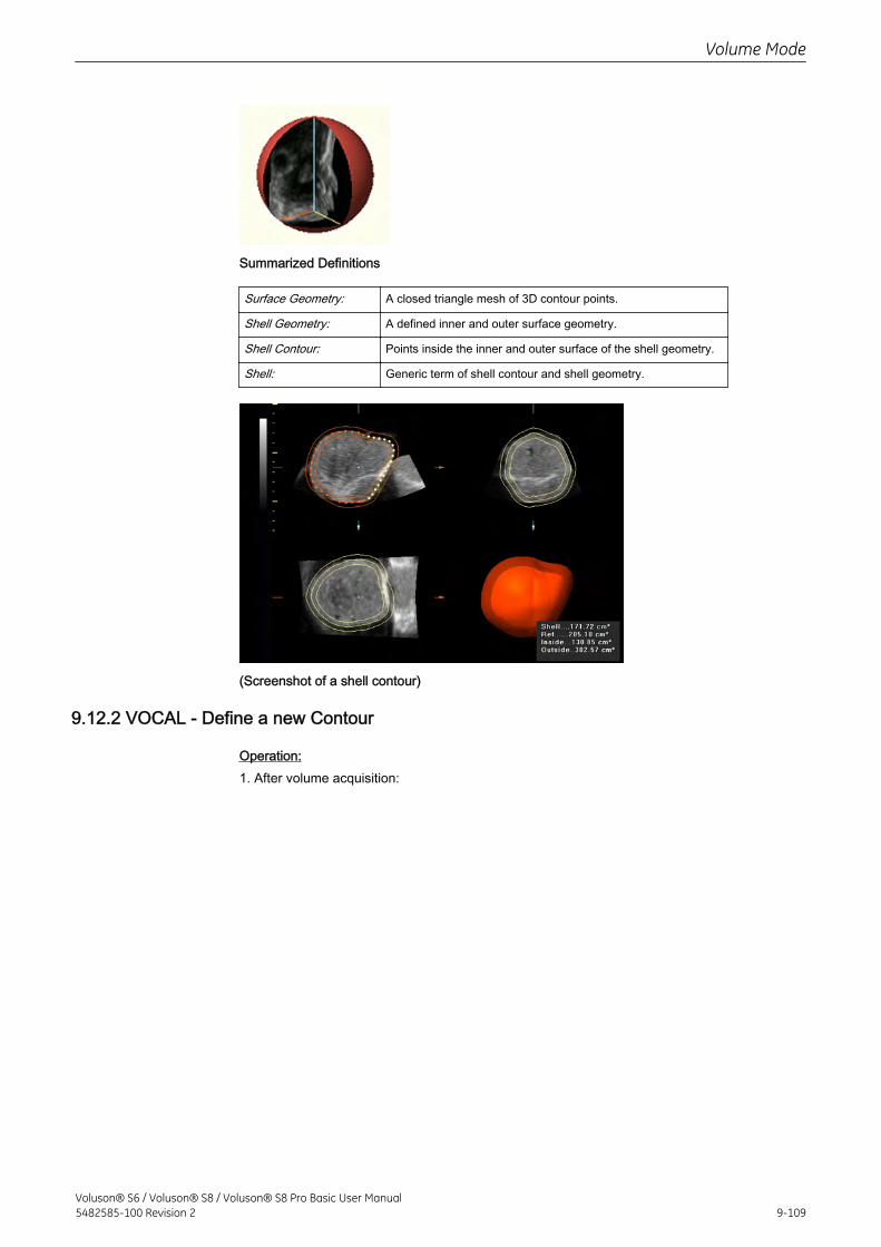
Summarized Definitions
Surface Geometry: A closed triangle mesh of 3D contour points.
Shell Geometry: A defined inner and outer surface geometry.
Shell Contour: Points inside the inner and outer surface of the shell geometry.
Shell: Generic term of shell contour and shell geometry.
(Screenshot of a shell contour)
9.12.2 VOCAL - Define a new Contour
Operation:1. After volume acquisition:
Volume Mode
Voluson® S6 / Voluson® S8 / Voluson® S8 Pro Basic User Manual5482585-100 Revision 2 9-109
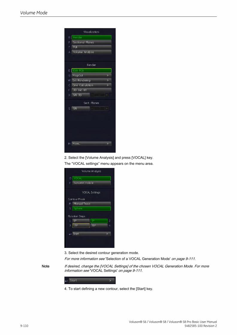
2. Select the [Volume Analysis] and press [VOCAL] key.The “VOCAL settings” menu appears on the menu area.
3. Select the desired contour generation mode.For more information see 'Selection of a VOCAL Generation Mode' on page 9-111.
Note If desired, change the [VOCAL Settings] of the chosen VOCAL Generation Mode. For moreinformation see 'VOCAL Settings' on page 9-111.
4. To start defining a new contour, select the [Start] key.
Volume Mode
9-110Voluson® S6 / Voluson® S8 / Voluson® S8 Pro Basic User Manual
5482585-100 Revision 2
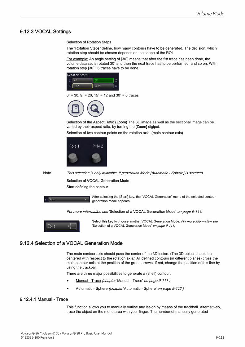
9.12.3 VOCAL Settings
Selection of Rotation StepsThe “Rotation Steps” define, how many contours have to be generated. The decision, whichrotation step should be chosen depends on the shape of the ROI.For example: An angle setting of [30˚] means that after the fist trace has been done, thevolume data set is rotated 30˚ and then the next trace has to be performed, and so on. Withrotation step [30˚], 6 traces have to be done.
6˚ = 30, 9˚ = 20, 15˚ = 12 and 30˚ = 6 traces
Selection of the Aspect Ratio (Zoom) The 3D image as well as the sectional image can bevaried by their aspect ratio, by turning the [Zoom] digipot.Selection of two contour points on the rotation axis. (main contour axis)
Note This selection is only available, if generation Mode [Automatic - Sphere] is selected.
Selection of VOCAL Generation ModeStart defining the contour
After selecting the [Start] key, the “VOCAL Generation” menu of the selected contourgeneration mode appears.
For more information see 'Selection of a VOCAL Generation Mode' on page 9-111.
Select this key to choose another VOCAL Generation Mode. For more information see'Selection of a VOCAL Generation Mode' on page 9-111.
9.12.4 Selection of a VOCAL Generation Mode
The main contour axis should pass the center of the 3D lesion. (The 3D object should becentered with respect to the rotation axis.) All defined contours (in different planes) cross themain contour axis at the position of the green arrows. If not, change the position of this line byusing the trackball.There are three major possibilities to generate a (shell) contour:
• Manual - Trace (chapter 'Manual - Trace' on page 9-111 )
• Automatic - Sphere (chapter 'Automatic - Sphere' on page 9-112 )
9.12.4.1 Manual - TraceThis function allows you to manually outline any lesion by means of the trackball. Alternatively,trace the object on the menu area with your finger. The number of manually generated
Volume Mode
Voluson® S6 / Voluson® S8 / Voluson® S8 Pro Basic User Manual5482585-100 Revision 2 9-111
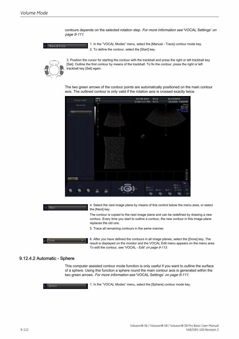
contours depends on the selected rotation step. For more information see 'VOCAL Settings' onpage 9-111.
1. In the “VOCAL Modes” menu, select the [Manual - Trace] contour mode key.2. To define the contour, select the [Start] key.
3. Position the cursor for starting the contour with the trackball and press the right or left trackball key[Set]. Outline the first contour by means of the trackball. To fix the contour, press the right or lefttrackball key [Set] again.
The two green arrows of the contour points are automatically positioned on the main contouraxis. The outlined contour is only valid if the rotation axis is crossed exactly twice.
4. Select the next image plane by means of this control below the menu area, or selectthe [Next] key.The contour is copied to the next image plane and can be redefined by drawing a newcontour. Every time you start to outline a contour, the new contour in this image planereplaces the old one.5. Trace all remaining contours in the same manner.
6. After you have defined the contours in all image planes, select the [Done] key. Theresult is displayed on the monitor and the VOCAL Edit menu appears on the menu area.To edit the contour, see 'VOCAL - Edit' on page 9-113.
9.12.4.2 Automatic - SphereThis computer assisted contour mode function is only useful if you want to outline the surfaceof a sphere. Using this function a sphere round the main contour axis is generated within thetwo green arrows. For more information see 'VOCAL Settings' on page 9-111.
1. In the “VOCAL Modes” menu, select the [Sphere] contour mode key.
Volume Mode
9-112Voluson® S6 / Voluson® S8 / Voluson® S8 Pro Basic User Manual
5482585-100 Revision 2
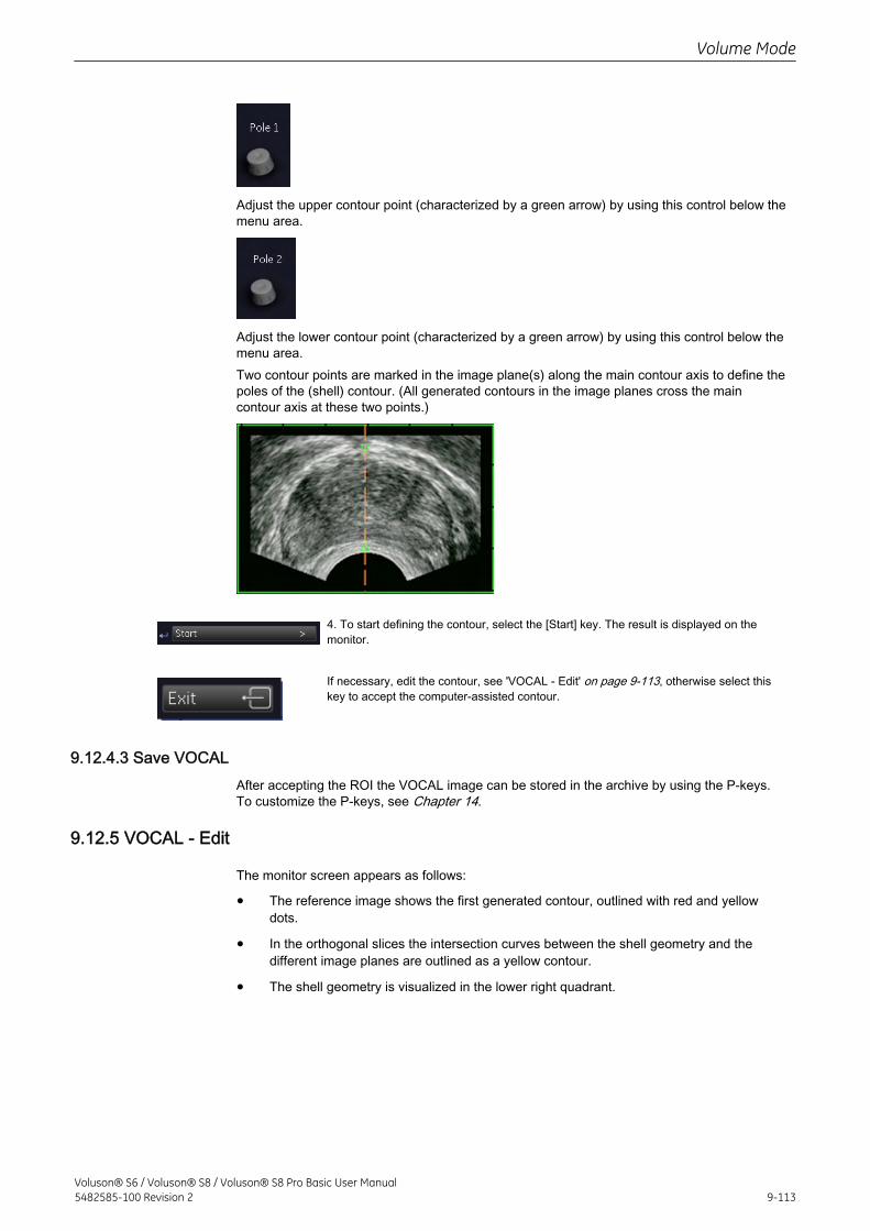
Adjust the upper contour point (characterized by a green arrow) by using this control below themenu area.
Adjust the lower contour point (characterized by a green arrow) by using this control below themenu area.Two contour points are marked in the image plane(s) along the main contour axis to define thepoles of the (shell) contour. (All generated contours in the image planes cross the maincontour axis at these two points.)
4. To start defining the contour, select the [Start] key. The result is displayed on themonitor.
If necessary, edit the contour, see 'VOCAL - Edit' on page 9-113, otherwise select thiskey to accept the computer-assisted contour.
9.12.4.3 Save VOCALAfter accepting the ROI the VOCAL image can be stored in the archive by using the P-keys.To customize the P-keys, see Chapter 14.
9.12.5 VOCAL - Edit
The monitor screen appears as follows:
• The reference image shows the first generated contour, outlined with red and yellowdots.
• In the orthogonal slices the intersection curves between the shell geometry and thedifferent image planes are outlined as a yellow contour.
• The shell geometry is visualized in the lower right quadrant.
Volume Mode
Voluson® S6 / Voluson® S8 / Voluson® S8 Pro Basic User Manual5482585-100 Revision 2 9-113
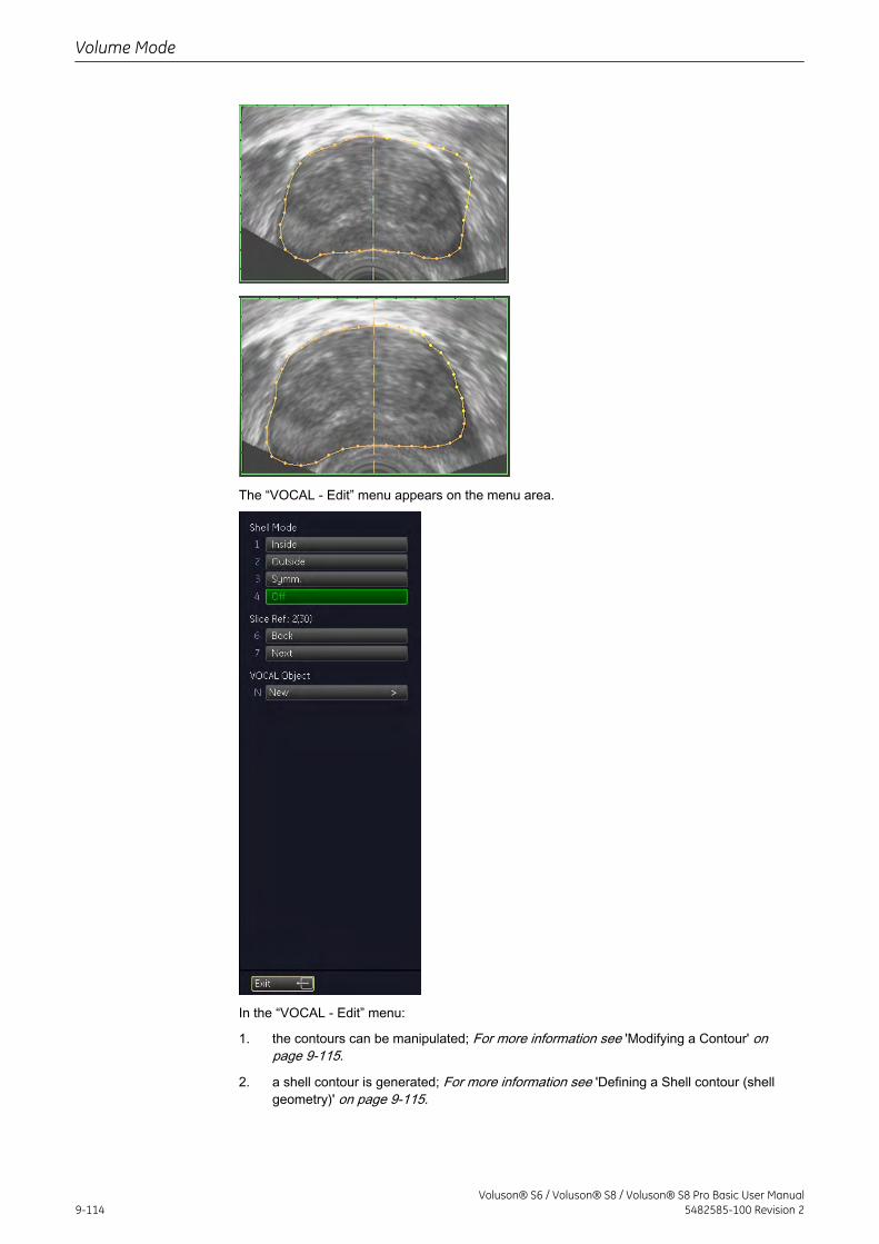
The “VOCAL - Edit” menu appears on the menu area.
In the “VOCAL - Edit” menu:
1. the contours can be manipulated; For more information see 'Modifying a Contour' onpage 9-115.
2. a shell contour is generated; For more information see 'Defining a Shell contour (shellgeometry)' on page 9-115.
Volume Mode
9-114Voluson® S6 / Voluson® S8 / Voluson® S8 Pro Basic User Manual
5482585-100 Revision 2
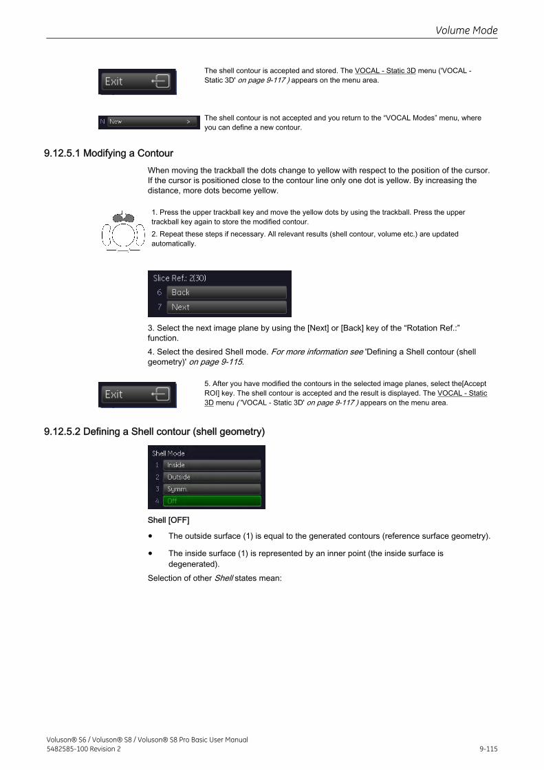
The shell contour is accepted and stored. The VOCAL - Static 3D menu ('VOCAL -Static 3D' on page 9-117 ) appears on the menu area.
The shell contour is not accepted and you return to the “VOCAL Modes” menu, whereyou can define a new contour.
9.12.5.1 Modifying a ContourWhen moving the trackball the dots change to yellow with respect to the position of the cursor.If the cursor is positioned close to the contour line only one dot is yellow. By increasing thedistance, more dots become yellow.
1. Press the upper trackball key and move the yellow dots by using the trackball. Press the uppertrackball key again to store the modified contour.2. Repeat these steps if necessary. All relevant results (shell contour, volume etc.) are updatedautomatically.
3. Select the next image plane by using the [Next] or [Back] key of the “Rotation Ref.:”function.4. Select the desired Shell mode. For more information see 'Defining a Shell contour (shellgeometry)' on page 9-115.
5. After you have modified the contours in the selected image planes, select the[AcceptROI] key. The shell contour is accepted and the result is displayed. The VOCAL - Static3D menu ( 'VOCAL - Static 3D' on page 9-117 ) appears on the menu area.
9.12.5.2 Defining a Shell contour (shell geometry)
Shell [OFF]
• The outside surface (1) is equal to the generated contours (reference surface geometry).
• The inside surface (1) is represented by an inner point (the inside surface isdegenerated).
Selection of other Shell states mean:
Volume Mode
Voluson® S6 / Voluson® S8 / Voluson® S8 Pro Basic User Manual5482585-100 Revision 2 9-115
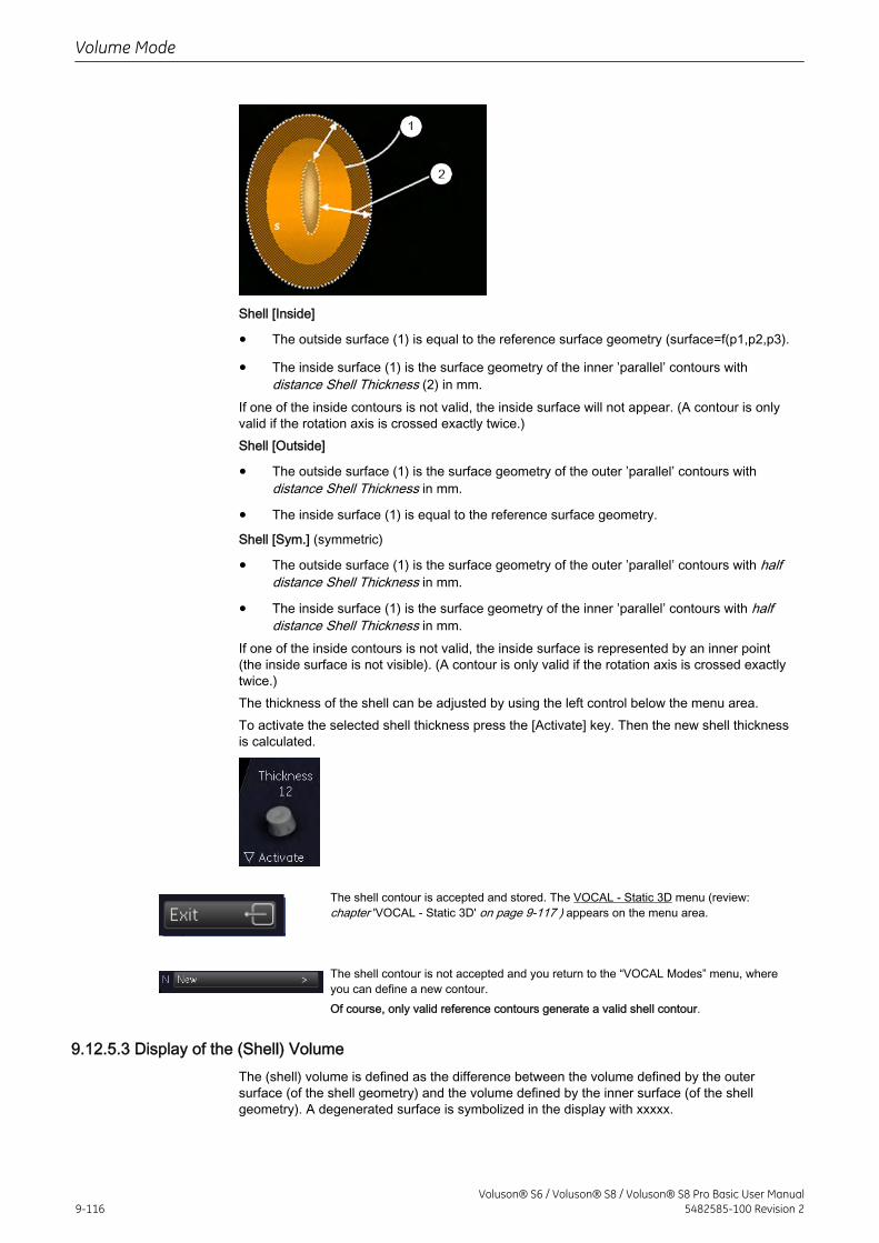
Shell [Inside]
• The outside surface (1) is equal to the reference surface geometry (surface=f(p1,p2,p3).
• The inside surface (1) is the surface geometry of the inner ’parallel’ contours withdistance Shell Thickness (2) in mm.
If one of the inside contours is not valid, the inside surface will not appear. (A contour is onlyvalid if the rotation axis is crossed exactly twice.)Shell [Outside]
• The outside surface (1) is the surface geometry of the outer ’parallel’ contours withdistance Shell Thickness in mm.
• The inside surface (1) is equal to the reference surface geometry.
Shell [Sym.] (symmetric)
• The outside surface (1) is the surface geometry of the outer ’parallel’ contours with halfdistance Shell Thickness in mm.
• The inside surface (1) is the surface geometry of the inner ’parallel’ contours with halfdistance Shell Thickness in mm.
If one of the inside contours is not valid, the inside surface is represented by an inner point(the inside surface is not visible). (A contour is only valid if the rotation axis is crossed exactlytwice.)The thickness of the shell can be adjusted by using the left control below the menu area.To activate the selected shell thickness press the [Activate] key. Then the new shell thicknessis calculated.
The shell contour is accepted and stored. The VOCAL - Static 3D menu (review:chapter 'VOCAL - Static 3D' on page 9-117 ) appears on the menu area.
The shell contour is not accepted and you return to the “VOCAL Modes” menu, whereyou can define a new contour.Of course, only valid reference contours generate a valid shell contour.
9.12.5.3 Display of the (Shell) VolumeThe (shell) volume is defined as the difference between the volume defined by the outersurface (of the shell geometry) and the volume defined by the inner surface (of the shellgeometry). A degenerated surface is symbolized in the display with xxxxx.
Volume Mode
9-116Voluson® S6 / Voluson® S8 / Voluson® S8 Pro Basic User Manual
5482585-100 Revision 2
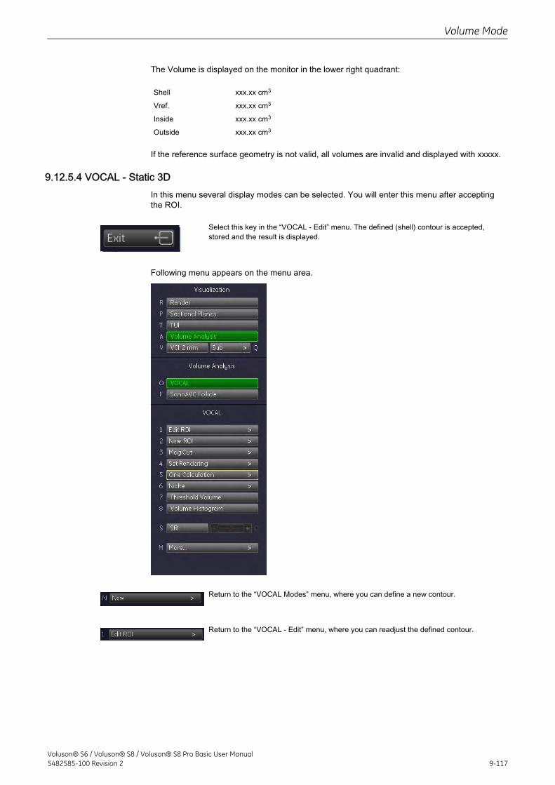
The Volume is displayed on the monitor in the lower right quadrant:
Shell
Vref.
Inside
Outside
xxx.xx cm3
xxx.xx cm3
xxx.xx cm3
xxx.xx cm3
If the reference surface geometry is not valid, all volumes are invalid and displayed with xxxxx.
9.12.5.4 VOCAL - Static 3DIn this menu several display modes can be selected. You will enter this menu after acceptingthe ROI.
Select this key in the “VOCAL - Edit” menu. The defined (shell) contour is accepted,stored and the result is displayed.
Following menu appears on the menu area.
Return to the “VOCAL Modes” menu, where you can define a new contour.
Return to the “VOCAL - Edit” menu, where you can readjust the defined contour.
Volume Mode
Voluson® S6 / Voluson® S8 / Voluson® S8 Pro Basic User Manual5482585-100 Revision 2 9-117
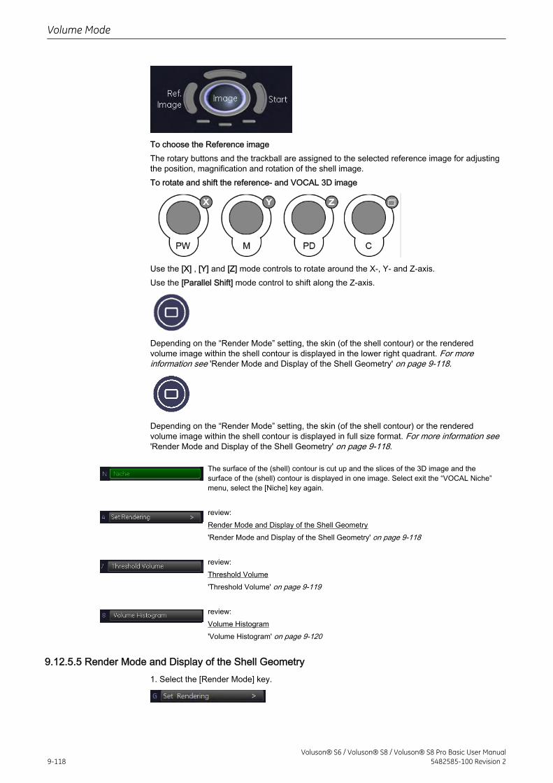
To choose the Reference imageThe rotary buttons and the trackball are assigned to the selected reference image for adjustingthe position, magnification and rotation of the shell image.To rotate and shift the reference- and VOCAL 3D image
Use the [X] , [Y] and [Z] mode controls to rotate around the X-, Y- and Z-axis.Use the [Parallel Shift] mode control to shift along the Z-axis.
Depending on the “Render Mode” setting, the skin (of the shell contour) or the renderedvolume image within the shell contour is displayed in the lower right quadrant. For moreinformation see 'Render Mode and Display of the Shell Geometry' on page 9-118.
Depending on the “Render Mode” setting, the skin (of the shell contour) or the renderedvolume image within the shell contour is displayed in full size format. For more information see'Render Mode and Display of the Shell Geometry' on page 9-118.
The surface of the (shell) contour is cut up and the slices of the 3D image and thesurface of the (shell) contour is displayed in one image. Select exit the “VOCAL Niche”menu, select the [Niche] key again.
review:Render Mode and Display of the Shell Geometry'Render Mode and Display of the Shell Geometry' on page 9-118
review:Threshold Volume'Threshold Volume' on page 9-119
review:Volume Histogram'Volume Histogram' on page 9-120
9.12.5.5 Render Mode and Display of the Shell Geometry1. Select the [Render Mode] key.
Volume Mode
9-118Voluson® S6 / Voluson® S8 / Voluson® S8 Pro Basic User Manual
5482585-100 Revision 2
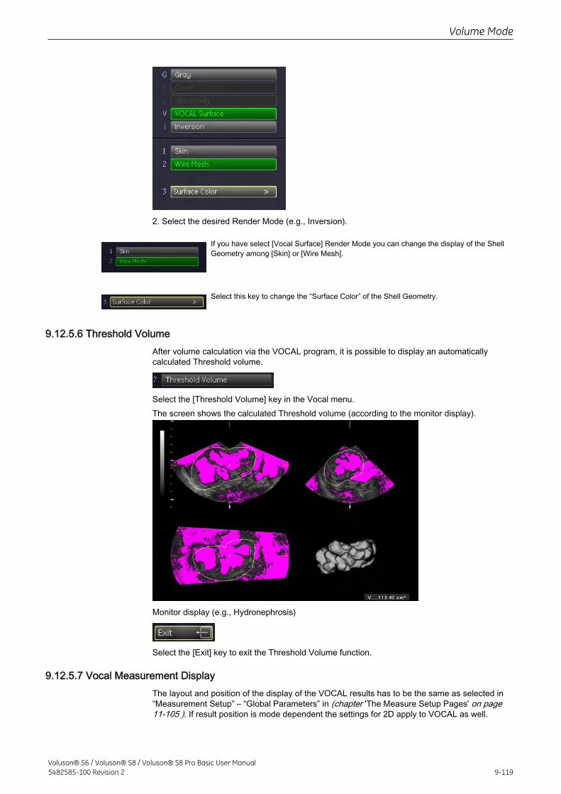
2. Select the desired Render Mode (e.g., Inversion).
If you have select [Vocal Surface] Render Mode you can change the display of the ShellGeometry among [Skin] or [Wire Mesh].
Select this key to change the “Surface Color” of the Shell Geometry.
9.12.5.6 Threshold VolumeAfter volume calculation via the VOCAL program, it is possible to display an automaticallycalculated Threshold volume.
Select the [Threshold Volume] key in the Vocal menu.The screen shows the calculated Threshold volume (according to the monitor display).
Monitor display (e.g., Hydronephrosis)
Select the [Exit] key to exit the Threshold Volume function.
9.12.5.7 Vocal Measurement DisplayThe layout and position of the display of the VOCAL results has to be the same as selected in“Measurement Setup” – “Global Parameters” in (chapter 'The Measure Setup Pages' on page11-105 ). If result position is mode dependent the settings for 2D apply to VOCAL as well.
Volume Mode
Voluson® S6 / Voluson® S8 / Voluson® S8 Pro Basic User Manual5482585-100 Revision 2 9-119
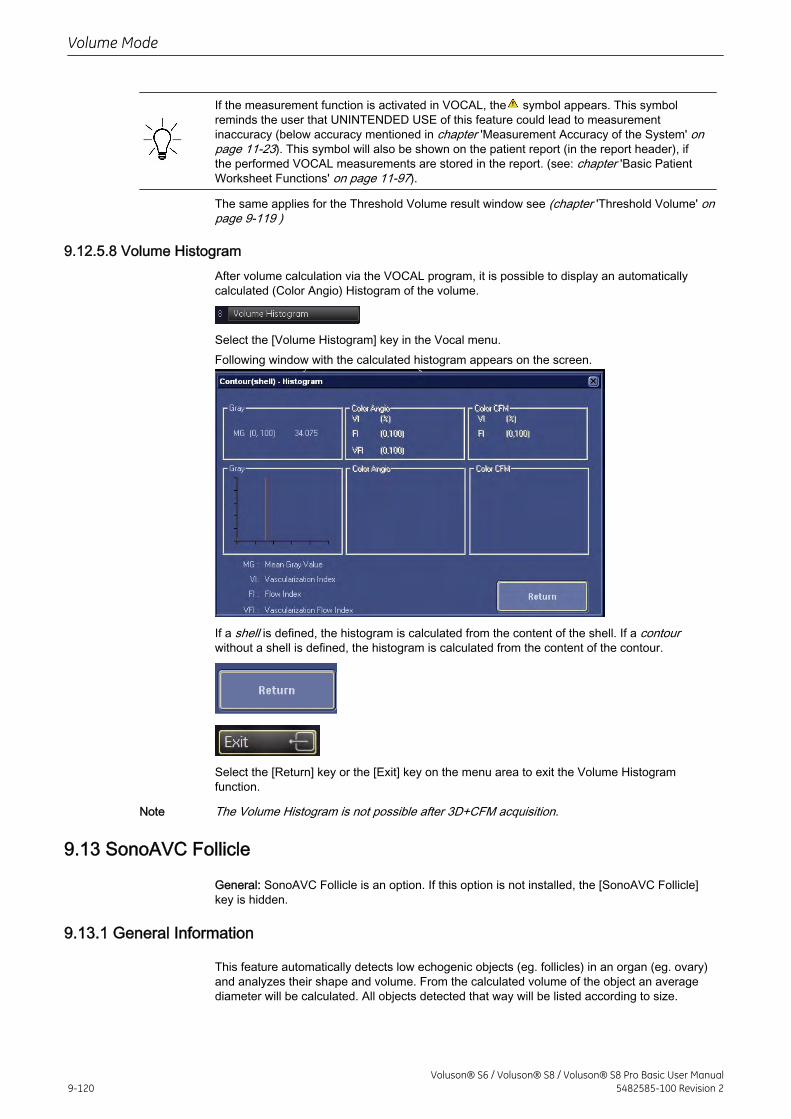
If the measurement function is activated in VOCAL, the symbol appears. This symbolreminds the user that UNINTENDED USE of this feature could lead to measurementinaccuracy (below accuracy mentioned in chapter 'Measurement Accuracy of the System' onpage 11-23). This symbol will also be shown on the patient report (in the report header), ifthe performed VOCAL measurements are stored in the report. (see: chapter 'Basic PatientWorksheet Functions' on page 11-97).
The same applies for the Threshold Volume result window see (chapter 'Threshold Volume' onpage 9-119 )
9.12.5.8 Volume HistogramAfter volume calculation via the VOCAL program, it is possible to display an automaticallycalculated (Color Angio) Histogram of the volume.
Select the [Volume Histogram] key in the Vocal menu.Following window with the calculated histogram appears on the screen.
If a shell is defined, the histogram is calculated from the content of the shell. If a contourwithout a shell is defined, the histogram is calculated from the content of the contour.
Select the [Return] key or the [Exit] key on the menu area to exit the Volume Histogramfunction.
Note The Volume Histogram is not possible after 3D+CFM acquisition.
9.13 SonoAVC Follicle
General: SonoAVC Follicle is an option. If this option is not installed, the [SonoAVC Follicle]key is hidden.
9.13.1 General Information
This feature automatically detects low echogenic objects (eg. follicles) in an organ (eg. ovary)and analyzes their shape and volume. From the calculated volume of the object an averagediameter will be calculated. All objects detected that way will be listed according to size.
Volume Mode
9-120Voluson® S6 / Voluson® S8 / Voluson® S8 Pro Basic User Manual
5482585-100 Revision 2
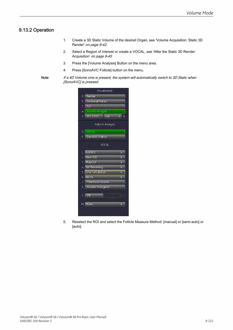
9.13.2 Operation
1. Create a 3D Static Volume of the desired Organ, see 'Volume Acquisition: Static 3DRender' on page 9-42.
2. Select a Region of Interest or create a VOCAL, see 'After the Static 3D RenderAcquisition' on page 9-45
3. Press the [Volume Analysis] Button on the menu area.
4. Press [SonoAVC Follicle] button on the menu.
Note If a 4D Volume cine is present, the system will automatically switch to 3D Static when[SonoAVC] is pressed.
5. Reselect the ROI and select the Follicle Measure Method: [manual] or [semi-auto] or[auto].
Volume Mode
Voluson® S6 / Voluson® S8 / Voluson® S8 Pro Basic User Manual5482585-100 Revision 2 9-121
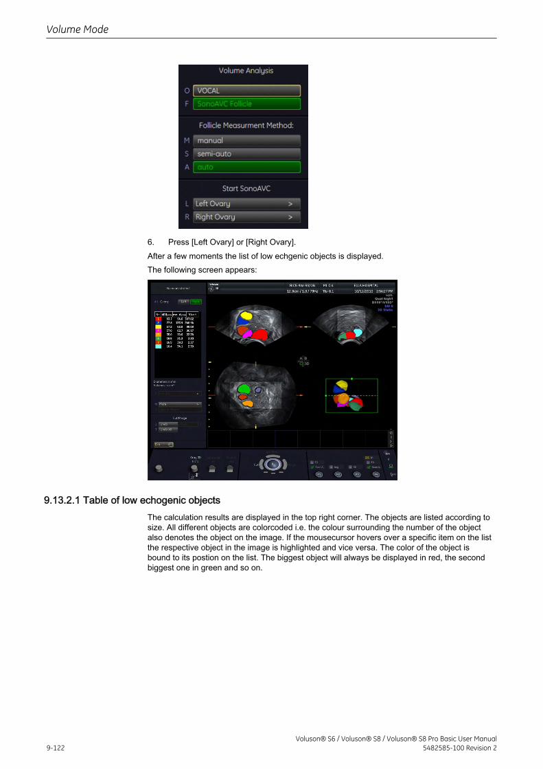
6. Press [Left Ovary] or [Right Ovary].After a few moments the list of low echgenic objects is displayed.The following screen appears:
9.13.2.1 Table of low echogenic objectsThe calculation results are displayed in the top right corner. The objects are listed according tosize. All different objects are colorcoded i.e. the colour surrounding the number of the objectalso denotes the object on the image. If the mousecursor hovers over a specific item on the listthe respective object in the image is highlighted and vice versa. The color of the object isbound to its postion on the list. The biggest object will always be displayed in red, the secondbiggest one in green and so on.
Volume Mode
9-122Voluson® S6 / Voluson® S8 / Voluson® S8 Pro Basic User Manual
5482585-100 Revision 2
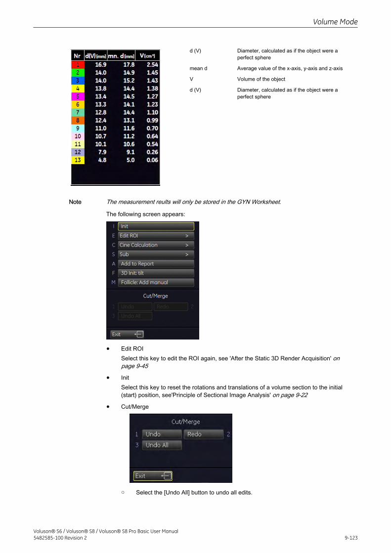
d (V) Diameter, calculated as if the object were aperfect sphere
mean d Average value of the x-axis, y-axis and z-axis
V Volume of the object
d (V) Diameter, calculated as if the object were aperfect sphere
Note The measurement reults will only be stored in the GYN Worksheet.
The following screen appears:
• Edit ROISelect this key to edit the ROI again, see 'After the Static 3D Render Acquisition' onpage 9-45
• InitSelect this key to reset the rotations and translations of a volume section to the initial(start) position, see'Principle of Sectional Image Analysis' on page 9-22
• Cut/Merge
○ Select the [Undo All] button to undo all edits.
Volume Mode
Voluson® S6 / Voluson® S8 / Voluson® S8 Pro Basic User Manual5482585-100 Revision 2 9-123
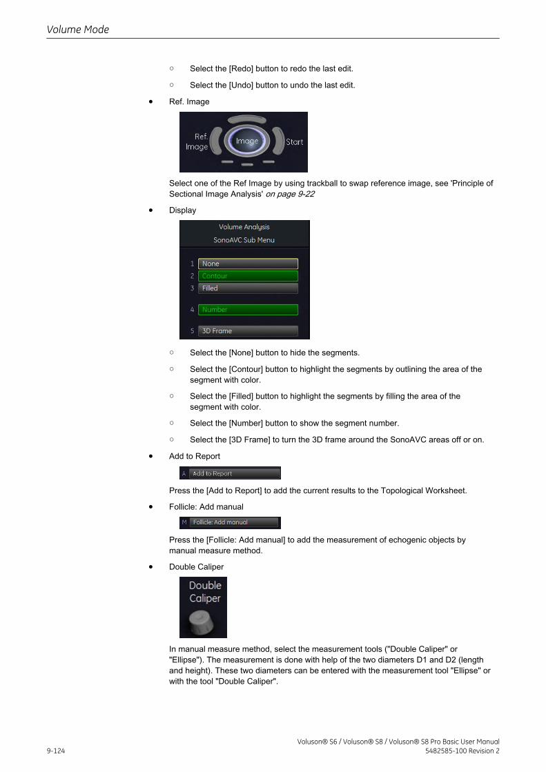
○ Select the [Redo] button to redo the last edit.
○ Select the [Undo] button to undo the last edit.
• Ref. Image
Select one of the Ref Image by using trackball to swap reference image, see 'Principle ofSectional Image Analysis' on page 9-22
• Display
○ Select the [None] button to hide the segments.
○ Select the [Contour] button to highlight the segments by outlining the area of thesegment with color.
○ Select the [Filled] button to highlight the segments by filling the area of thesegment with color.
○ Select the [Number] button to show the segment number.
○ Select the [3D Frame] to turn the 3D frame around the SonoAVC areas off or on.
• Add to Report
Press the [Add to Report] to add the current results to the Topological Worksheet.
• Follicle: Add manual
Press the [Follicle: Add manual] to add the measurement of echogenic objects bymanual measure method.
• Double Caliper
In manual measure method, select the measurement tools ("Double Caliper" or"Ellipse"). The measurement is done with help of the two diameters D1 and D2 (lengthand height). These two diameters can be entered with the measurement tool "Ellipse" orwith the tool "Double Caliper".
Volume Mode
9-124Voluson® S6 / Voluson® S8 / Voluson® S8 Pro Basic User Manual
5482585-100 Revision 2
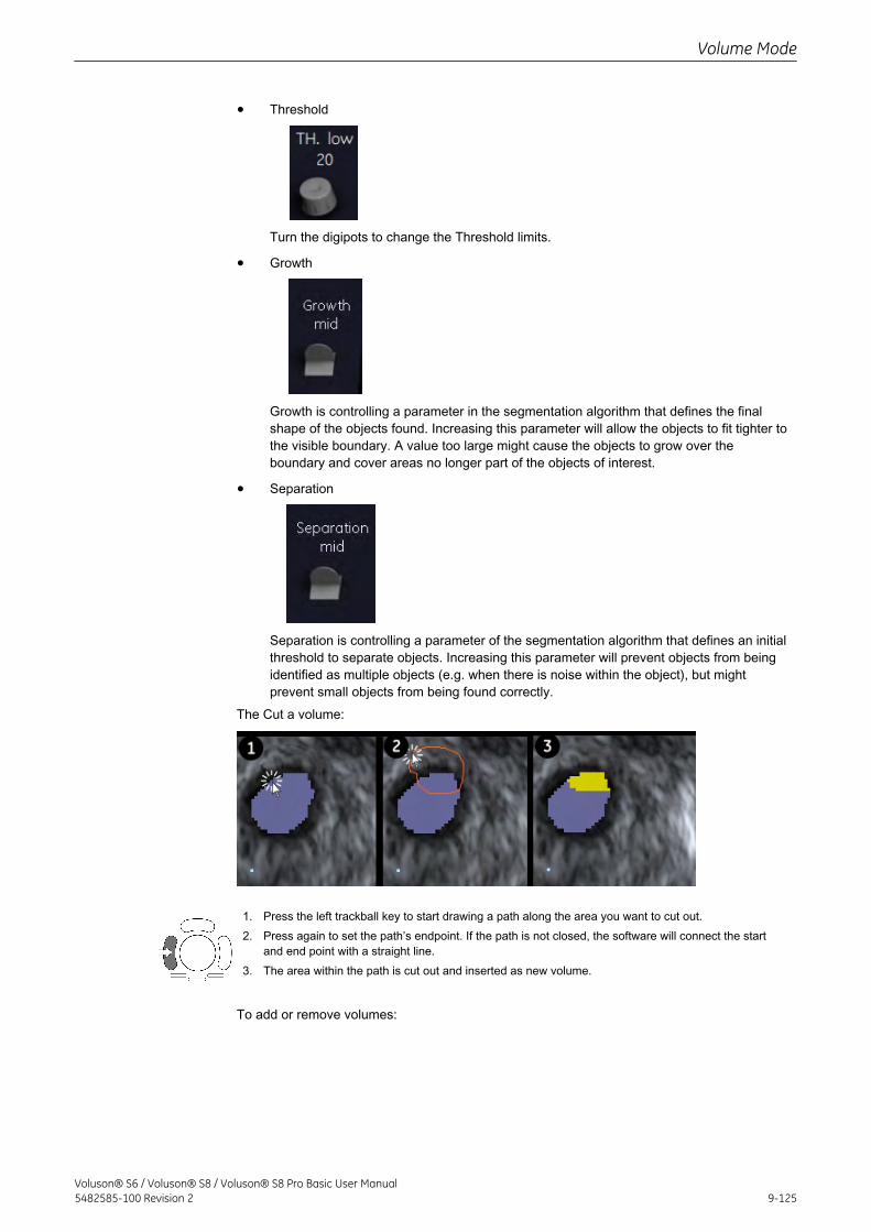
• Threshold
Turn the digipots to change the Threshold limits.
• Growth
Growth is controlling a parameter in the segmentation algorithm that defines the finalshape of the objects found. Increasing this parameter will allow the objects to fit tighter tothe visible boundary. A value too large might cause the objects to grow over theboundary and cover areas no longer part of the objects of interest.
• Separation
Separation is controlling a parameter of the segmentation algorithm that defines an initialthreshold to separate objects. Increasing this parameter will prevent objects from beingidentified as multiple objects (e.g. when there is noise within the object), but mightprevent small objects from being found correctly.
The Cut a volume:
1. Press the left trackball key to start drawing a path along the area you want to cut out.2. Press again to set the path’s endpoint. If the path is not closed, the software will connect the start
and end point with a straight line.3. The area within the path is cut out and inserted as new volume.
To add or remove volumes:
Volume Mode
Voluson® S6 / Voluson® S8 / Voluson® S8 Pro Basic User Manual5482585-100 Revision 2 9-125
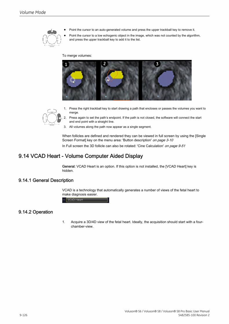
• Point the cursor to an auto-generated volume and press the upper trackball key to remove it.
• Point the cursor to a low echogenic object in the image, which was not counted by the algorithm,and press the upper trackball key to add it to the list.
To merge volumes:
1. Press the right trackball key to start drawing a path that encloses or passes the volumes you want tomerge.
2. Press again to set the path’s endpoint. If the path is not closed, the software will connect the startand end point with a straight line.
3. All volumes along the path now appear as a single segment.
When follicles are defined and rendered they can be viewed in full screen by using the [SingleScreen Format] key on the menu area: 'Button description' on page 3-10In Full screen the 3D follicle can also be rotated: 'Cine Calculation' on page 9-51
9.14 VCAD Heart - Volume Computer Aided Display
General: VCAD Heart is an option. If this option is not installed, the [VCAD Heart] key ishidden.
9.14.1 General Description
VCAD is a technology that automatically generates a number of views of the fetal heart tomake diagnosis easier.
9.14.2 Operation
1. Acquire a 3D/4D view of the fetal heart. Ideally, the acquisition should start with a four-chamber-view.
Volume Mode
9-126Voluson® S6 / Voluson® S8 / Voluson® S8 Pro Basic User Manual
5482585-100 Revision 2
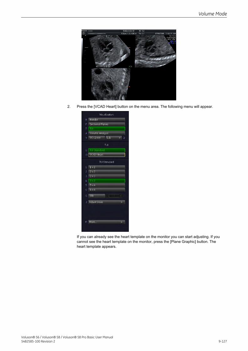
2. Press the [VCAD Heart] button on the menu area. The following menu will appear.
If you can already see the heart template on the monitor you can start adjusting. If youcannot see the heart template on the monitor, press the [Plane Graphic] button. Theheart template appears.
Volume Mode
Voluson® S6 / Voluson® S8 / Voluson® S8 Pro Basic User Manual5482585-100 Revision 2 9-127
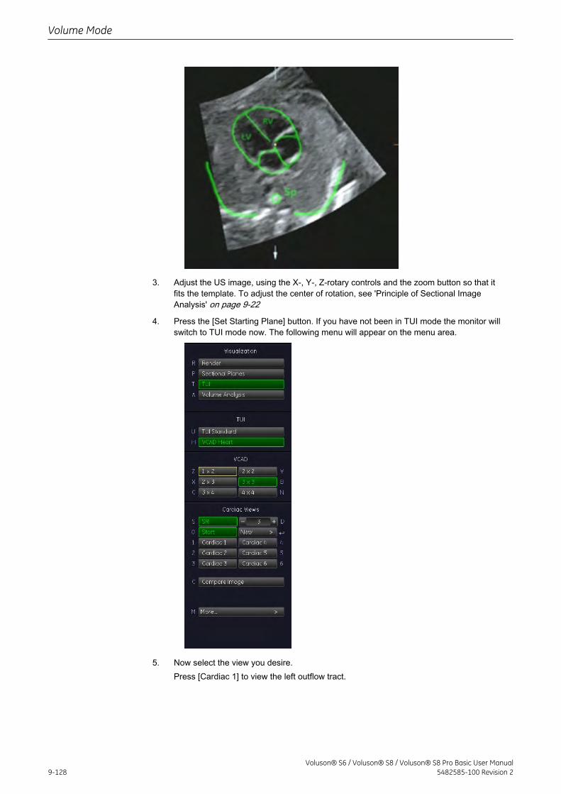
3. Adjust the US image, using the X-, Y-, Z-rotary controls and the zoom button so that itfits the template. To adjust the center of rotation, see 'Principle of Sectional ImageAnalysis' on page 9-22
4. Press the [Set Starting Plane] button. If you have not been in TUI mode the monitor willswitch to TUI mode now. The following menu will appear on the menu area.
5. Now select the view you desire.Press [Cardiac 1] to view the left outflow tract.
Volume Mode
9-128Voluson® S6 / Voluson® S8 / Voluson® S8 Pro Basic User Manual
5482585-100 Revision 2
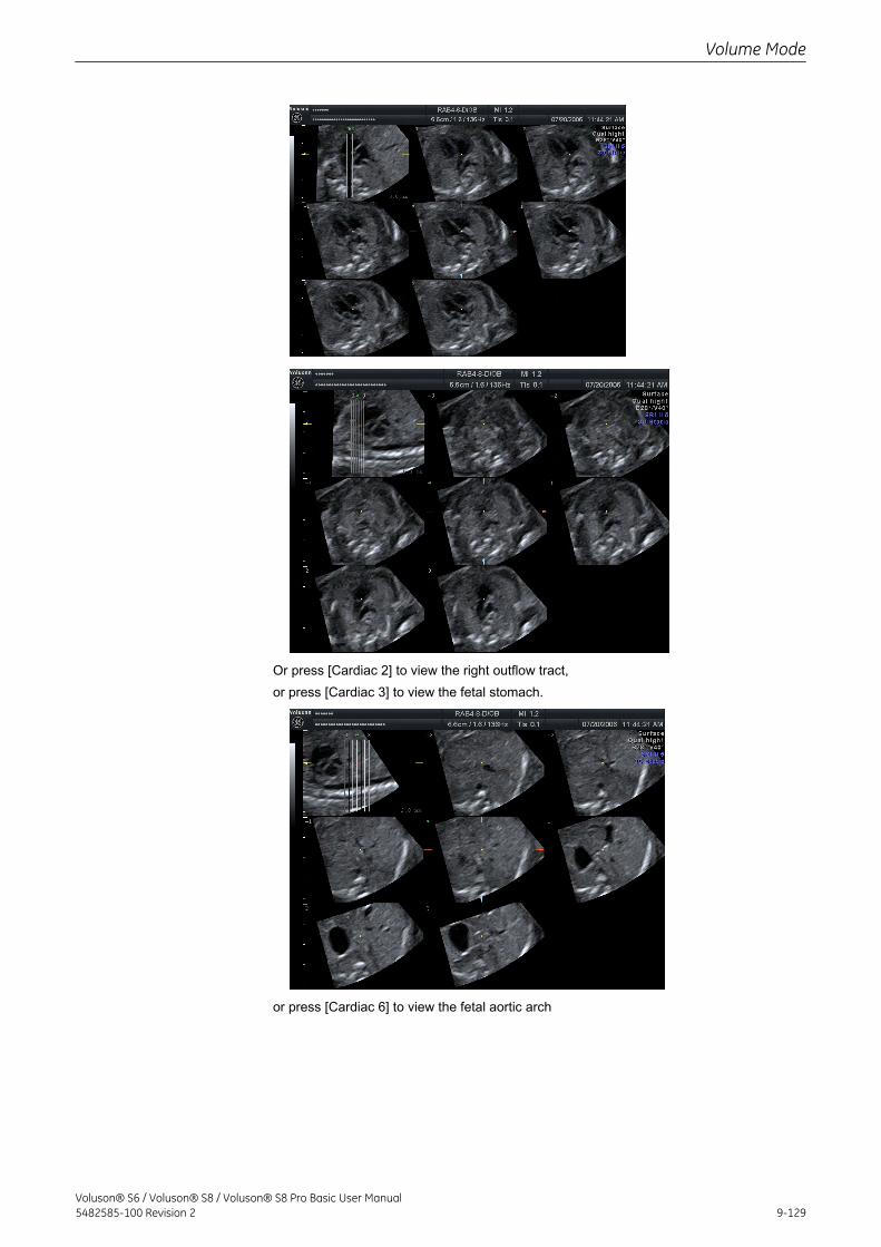
Or press [Cardiac 2] to view the right outflow tract,or press [Cardiac 3] to view the fetal stomach.
or press [Cardiac 6] to view the fetal aortic arch
Volume Mode
Voluson® S6 / Voluson® S8 / Voluson® S8 Pro Basic User Manual5482585-100 Revision 2 9-129
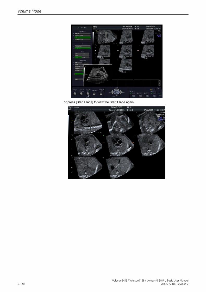
or press [Start Plane] to view the Start Plane again.
Volume Mode
9-130Voluson® S6 / Voluson® S8 / Voluson® S8 Pro Basic User Manual
5482585-100 Revision 2
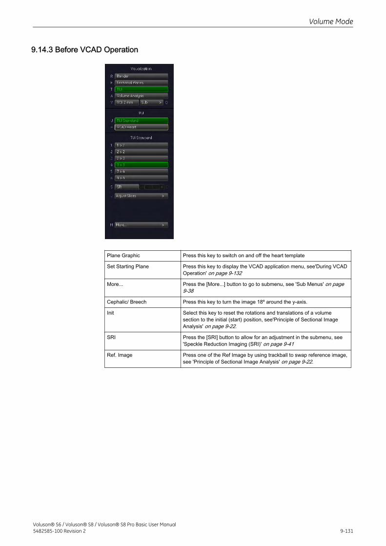
9.14.3 Before VCAD Operation
Plane Graphic Press this key to switch on and off the heart template
Set Starting Plane Press this key to display the VCAD application menu, see'During VCADOperation' on page 9-132
More... Press the [More...] button to go to submenu, see 'Sub Menus' on page9-38
Cephalic/ Breech Press this key to turn the image 18º around the y-axis.
Init Select this key to reset the rotations and translations of a volumesection to the initial (start) position, see'Principle of Sectional ImageAnalysis' on page 9-22.
SRI Press the [SRI] button to allow for an adjustment in the submenu, see'Speckle Reduction Imaging (SRI)' on page 9-41
Ref. Image Press one of the Ref Image by using trackball to swap reference image,see 'Principle of Sectional Image Analysis' on page 9-22.
Volume Mode
Voluson® S6 / Voluson® S8 / Voluson® S8 Pro Basic User Manual5482585-100 Revision 2 9-131
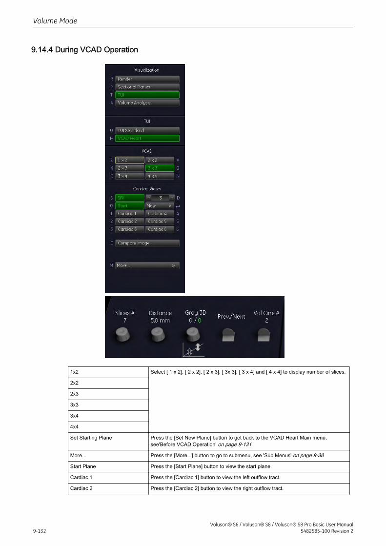
9.14.4 During VCAD Operation
1x2 Select [ 1 x 2], [ 2 x 2], [ 2 x 3], [ 3x 3], [ 3 x 4] and [ 4 x 4] to display number of slices.
2x2
2x3
3x3
3x4
4x4
Set Starting Plane Press the [Set New Plane] button to get back to the VCAD Heart Main menu,see'Before VCAD Operation' on page 9-131
More... Press the [More...] button to go to submenu, see 'Sub Menus' on page 9-38
Start Plane Press the [Start Plane] button to view the start plane.
Cardiac 1 Press the [Cardiac 1] button to view the left outflow tract.
Cardiac 2 Press the [Cardiac 2] button to view the right outflow tract.
Volume Mode
9-132Voluson® S6 / Voluson® S8 / Voluson® S8 Pro Basic User Manual
5482585-100 Revision 2
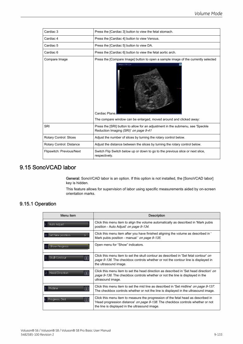
Cardiac 3 Press the [Cardiac 3] button to view the fetal stomach.
Cardiac 4 Press the [Cardiac 4] button to view Venous.
Cardiac 5 Press the [Cardiac 5] button to view DA.
Cardiac 6 Press the [Cardiac 6] button to view the fetal aortic arch.
Compare Image Press the [Compare Image] button to open a sample image of the currently selected
Cardiac Plane.
The compare window can be enlarged, moved around and clicked away:
SRI Press the [SRI] button to allow for an adjustment in the submenu, see 'SpeckleReduction Imaging (SRI)' on page 9-41
Rotary Control: Slices Adjust the number of slices by turning the rotary control below.
Rotary Control: Distance Adjust the distance between the slices by turning the rotary control below.
Flipswitch: Previous/Next Switch Flip Switch below up or down to go to the previous slice or next slice,respectively.
9.15 SonoVCAD labor
General: SonoVCAD labor is an option. If this option is not installed, the [SonoVCAD labor]key is hidden.This feature allows for supervision of labor using specific measurements aided by on-screenorientation marks.
9.15.1 Operation
Menu item Description
Click this menu item to align the volume automatically as described in 'Mark pubisposition - Auto Adjust' on page 9-134.
Click this menu item after you have finished aligning the volume as described in 'Mark pubis position - manual ' on page 9-135.
Open menu for “Show” indicators.
Click this menu item to set the skull contour as described in 'Set fetal contour' onpage 9-136. The checkbox controls whether or not the contour line is displayed inthe ultrasound image.
Click this menu item to set the head direction as described in 'Set head direction' onpage 9-136. The checkbox controls whether or not the line is displayed in theultrasound image.
Click this menu item to set the mid line as described in 'Set midline' on page 9-137.The checkbox controls whether or not the line is displayed in the ultrasound image.
Click this menu item to measure the progression of the fetal head as described in'Head progression distance' on page 9-138. The checkbox controls whether or notthe line is displayed in the ultrasound image.
Volume Mode
Voluson® S6 / Voluson® S8 / Voluson® S8 Pro Basic User Manual5482585-100 Revision 2 9-133
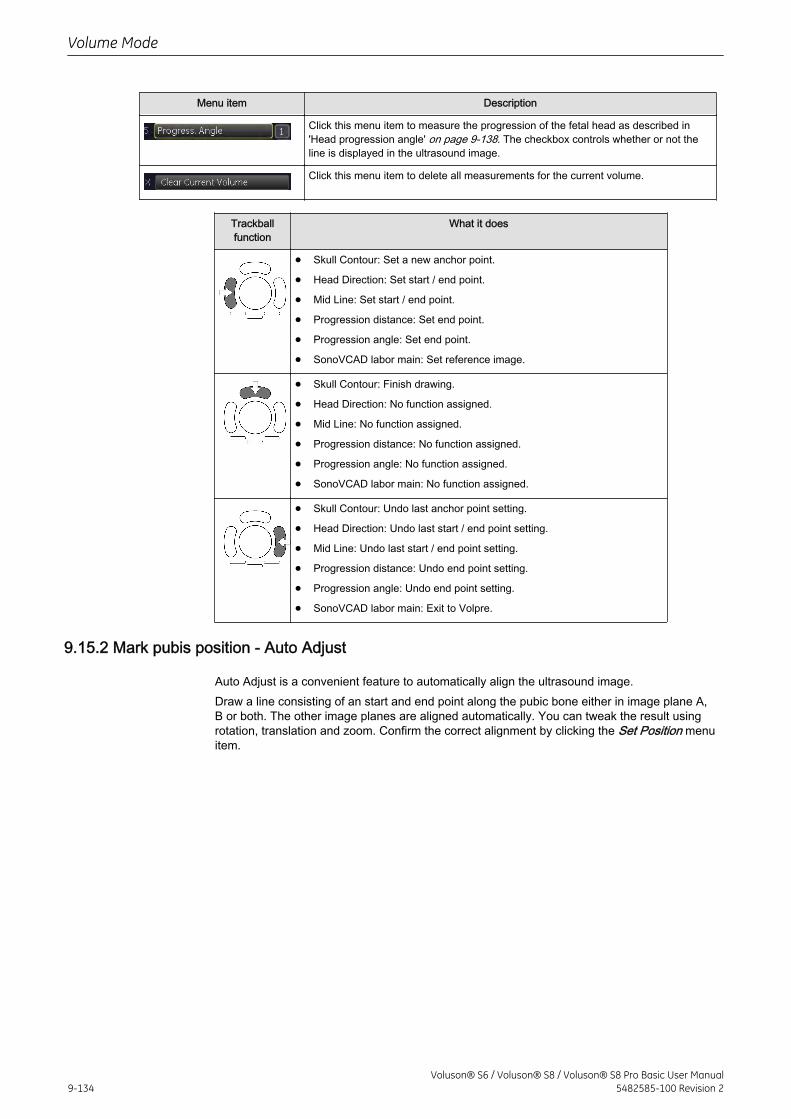
Menu item Description
Click this menu item to measure the progression of the fetal head as described in'Head progression angle' on page 9-138. The checkbox controls whether or not theline is displayed in the ultrasound image.
Click this menu item to delete all measurements for the current volume.
Trackballfunction
What it does
• Skull Contour: Set a new anchor point.
• Head Direction: Set start / end point.
• Mid Line: Set start / end point.
• Progression distance: Set end point.
• Progression angle: Set end point.
• SonoVCAD labor main: Set reference image.
• Skull Contour: Finish drawing.
• Head Direction: No function assigned.
• Mid Line: No function assigned.
• Progression distance: No function assigned.
• Progression angle: No function assigned.
• SonoVCAD labor main: No function assigned.
• Skull Contour: Undo last anchor point setting.
• Head Direction: Undo last start / end point setting.
• Mid Line: Undo last start / end point setting.
• Progression distance: Undo end point setting.
• Progression angle: Undo end point setting.
• SonoVCAD labor main: Exit to Volpre.
9.15.2 Mark pubis position - Auto Adjust
Auto Adjust is a convenient feature to automatically align the ultrasound image.Draw a line consisting of an start and end point along the pubic bone either in image plane A,B or both. The other image planes are aligned automatically. You can tweak the result usingrotation, translation and zoom. Confirm the correct alignment by clicking the Set Position menuitem.
Volume Mode
9-134Voluson® S6 / Voluson® S8 / Voluson® S8 Pro Basic User Manual
5482585-100 Revision 2
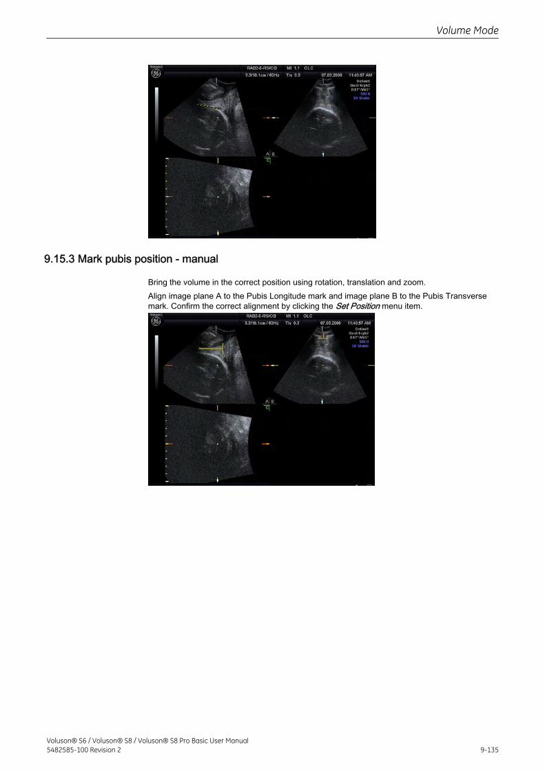
9.15.3 Mark pubis position - manual
Bring the volume in the correct position using rotation, translation and zoom.Align image plane A to the Pubis Longitude mark and image plane B to the Pubis Transversemark. Confirm the correct alignment by clicking the Set Position menu item.
Volume Mode
Voluson® S6 / Voluson® S8 / Voluson® S8 Pro Basic User Manual5482585-100 Revision 2 9-135
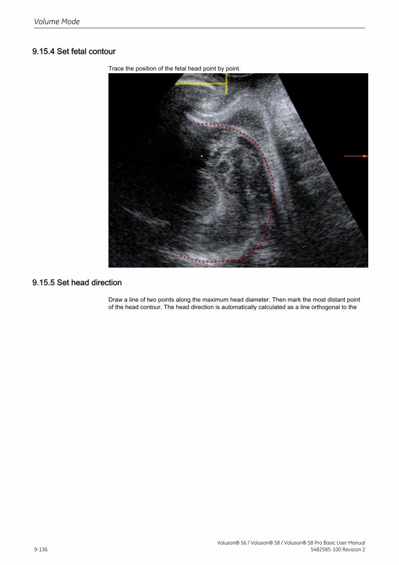
9.15.4 Set fetal contour
Trace the position of the fetal head point by point.
9.15.5 Set head direction
Draw a line of two points along the maximum head diameter. Then mark the most distant pointof the head contour. The head direction is automatically calculated as a line orthogonal to the
Volume Mode
9-136Voluson® S6 / Voluson® S8 / Voluson® S8 Pro Basic User Manual
5482585-100 Revision 2
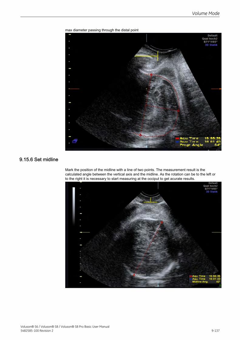
max diameter passing through the distal point
9.15.6 Set midline
Mark the position of the midline with a line of two points. The measurement result is thecalculated angle between the vertical axis and the midline. As the rotation can be to the left orto the right it is necessary to start measuring at the occiput to get acurate results.
Volume Mode
Voluson® S6 / Voluson® S8 / Voluson® S8 Pro Basic User Manual5482585-100 Revision 2 9-137
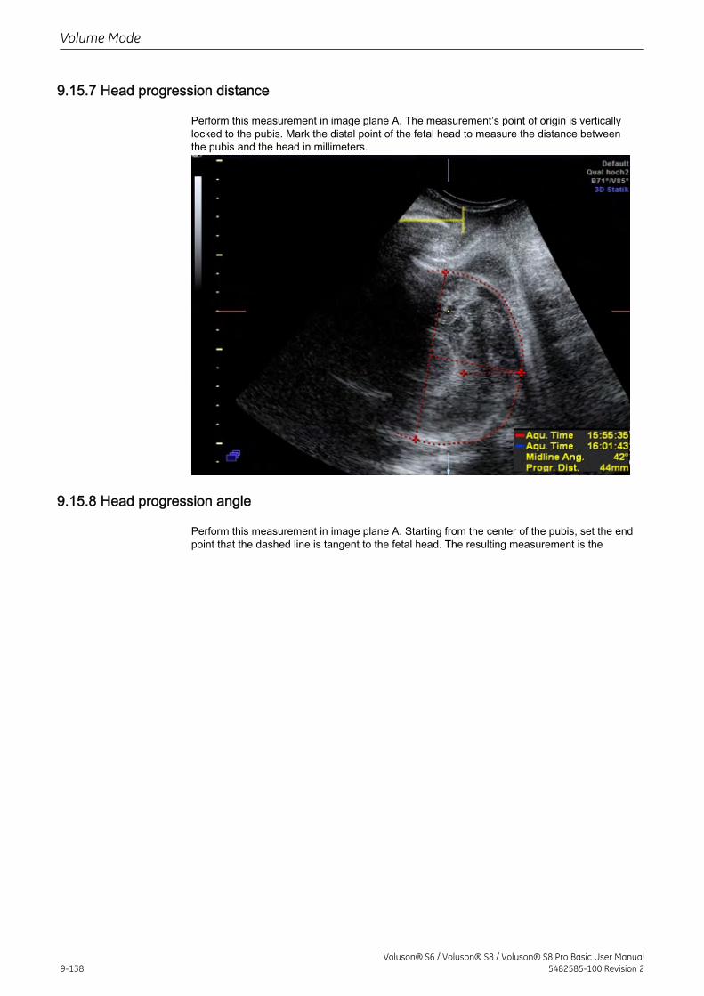
9.15.7 Head progression distance
Perform this measurement in image plane A. The measurement’s point of origin is verticallylocked to the pubis. Mark the distal point of the fetal head to measure the distance betweenthe pubis and the head in millimeters.
9.15.8 Head progression angle
Perform this measurement in image plane A. Starting from the center of the pubis, set the endpoint that the dashed line is tangent to the fetal head. The resulting measurement is the
Volume Mode
9-138Voluson® S6 / Voluson® S8 / Voluson® S8 Pro Basic User Manual
5482585-100 Revision 2
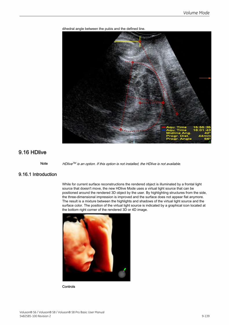
dihedral angle between the pubis and the defined line.
9.16 HDlive
Note HDliveTM is an option. If this option is not installed, the HDlive is not available.
9.16.1 Introduction
While for current surface reconstructions the rendered object is illuminated by a frontal lightsource that doesn't move, the new HDlive Mode uses a virtual light source that can bepositioned around the rendered 3D object by the user. By highlighting structures from the side,the three-dimensional impression is improved and the surface does not appear flat anymore.The result is a mixture between the highlights and shadows of the virtual light source and thesurface color. The position of the virtual light source is indicated by a graphical icon located atthe bottom right corner of the rendered 3D or 4D image.
Controls
Volume Mode
Voluson® S6 / Voluson® S8 / Voluson® S8 Pro Basic User Manual5482585-100 Revision 2 9-139
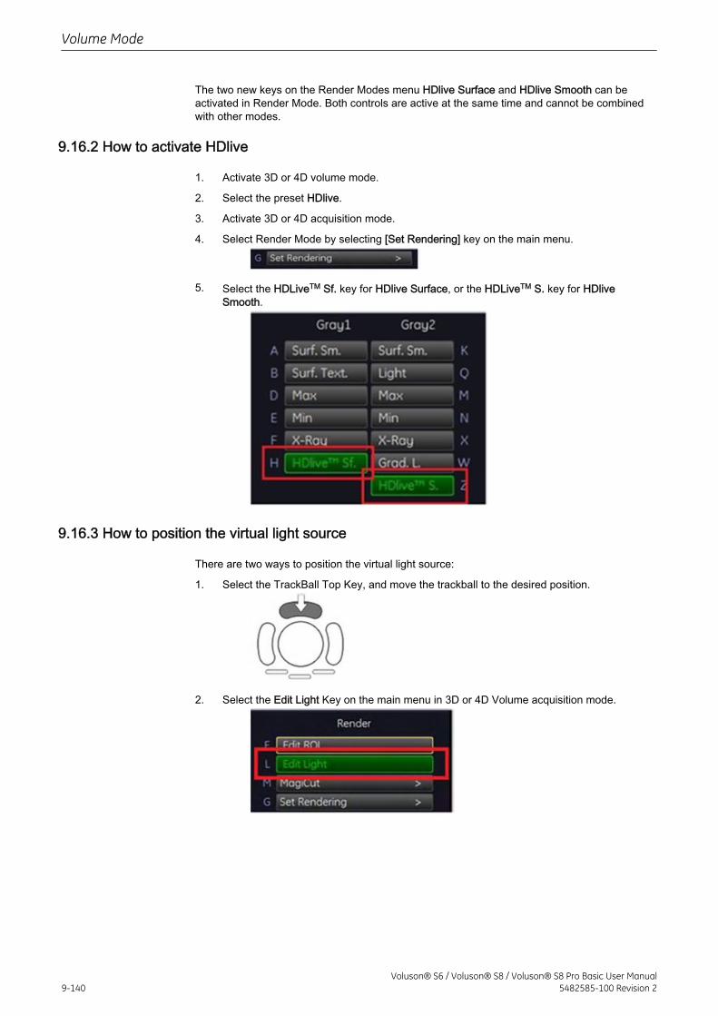
The two new keys on the Render Modes menu HDlive Surface and HDlive Smooth can beactivated in Render Mode. Both controls are active at the same time and cannot be combinedwith other modes.
9.16.2 How to activate HDlive
1. Activate 3D or 4D volume mode.
2. Select the preset HDlive.
3. Activate 3D or 4D acquisition mode.
4. Select Render Mode by selecting [Set Rendering] key on the main menu.
5. Select the HDLiveTM Sf. key for HDlive Surface, or the HDLiveTM S. key for HDliveSmooth.
9.16.3 How to position the virtual light source
There are two ways to position the virtual light source:
1. Select the TrackBall Top Key, and move the trackball to the desired position.
2. Select the Edit Light Key on the main menu in 3D or 4D Volume acquisition mode.
Volume Mode
9-140Voluson® S6 / Voluson® S8 / Voluson® S8 Pro Basic User Manual
5482585-100 Revision 2
Chapter 10
Elastography Mode
Describes the general functions of the Elastography Mode.Image quality is the essential performance of the system.Please read this chapter carefully.
Voluson® S6 / Voluson® S8 / Voluson® S8 Pro Basic User Manual5482585-100 Revision 2 10-1
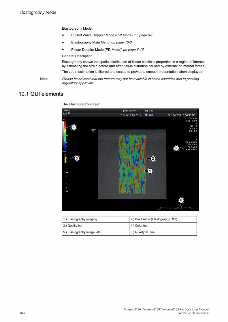
Elastography Mode:
• 'Pulsed Wave Doppler Mode (PW Mode)' on page 8-2
• 'Elastography Main Menu' on page 10-3
• 'Power Doppler Mode (PD Mode)' on page 8-15General DescriptionElastography shows the spatial distribution of tissue elasticity properties in a region of interestby estimating the strain before and after tissue distortion caused by external or internal forces.The strain estimation is filtered and scaled to provide a smooth presentation when displayed.
Note Please be advised that the feature may not be available in some countries due to pendingregulatory approvals.
10.1 GUI elements
The Elastography screen:
1.) Elastography imaging 2.) Box Frame (Elastography ROI)
3.) Quality bar 4.) Color bar
5.) Elastography image info 6.) Quality TL line
Elastography Mode
10-2Voluson® S6 / Voluson® S8 / Voluson® S8 Pro Basic User Manual
5482585-100 Revision 2
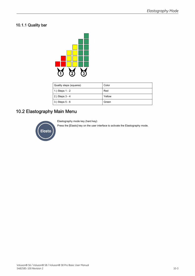
10.1.1 Quality bar
Quality steps (squares) Color
1.) Steps 1 - 2 Red
2.) Steps 3 - 4 Yellow
3.) Steps 5 - 6 Green
10.2 Elastography Main Menu
Elastography mode key (hard key)Press the [Elasto] key on the user interface to activate the Elastography mode.
Elastography Mode
Voluson® S6 / Voluson® S8 / Voluson® S8 Pro Basic User Manual5482585-100 Revision 2 10-3
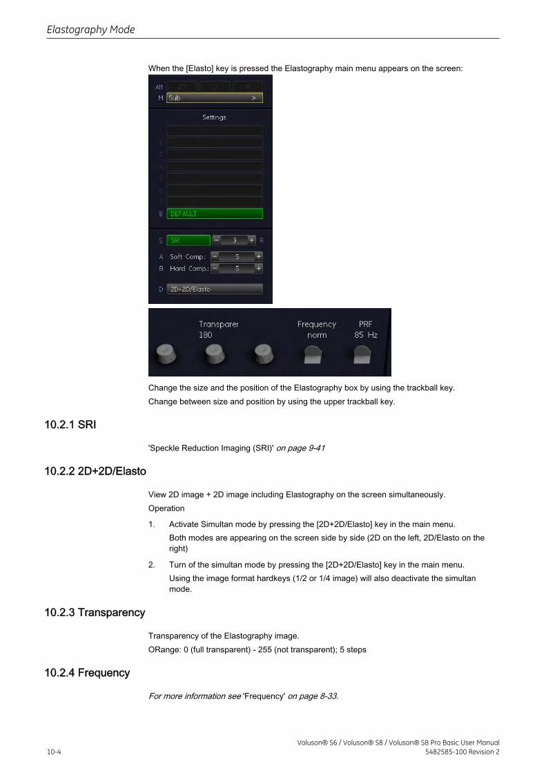
When the [Elasto] key is pressed the Elastography main menu appears on the screen:
Change the size and the position of the Elastography box by using the trackball key.Change between size and position by using the upper trackball key.
10.2.1 SRI
'Speckle Reduction Imaging (SRI)' on page 9-41
10.2.2 2D+2D/Elasto
View 2D image + 2D image including Elastography on the screen simultaneously.Operation
1. Activate Simultan mode by pressing the [2D+2D/Elasto] key in the main menu.Both modes are appearing on the screen side by side (2D on the left, 2D/Elasto on theright)
2. Turn of the simultan mode by pressing the [2D+2D/Elasto] key in the main menu.Using the image format hardkeys (1/2 or 1/4 image) will also deactivate the simultanmode.
10.2.3 Transparency
Transparency of the Elastography image.ORange: 0 (full transparent) - 255 (not transparent); 5 steps
10.2.4 Frequency
For more information see 'Frequency' on page 8-33.
Elastography Mode
10-4Voluson® S6 / Voluson® S8 / Voluson® S8 Pro Basic User Manual
5482585-100 Revision 2
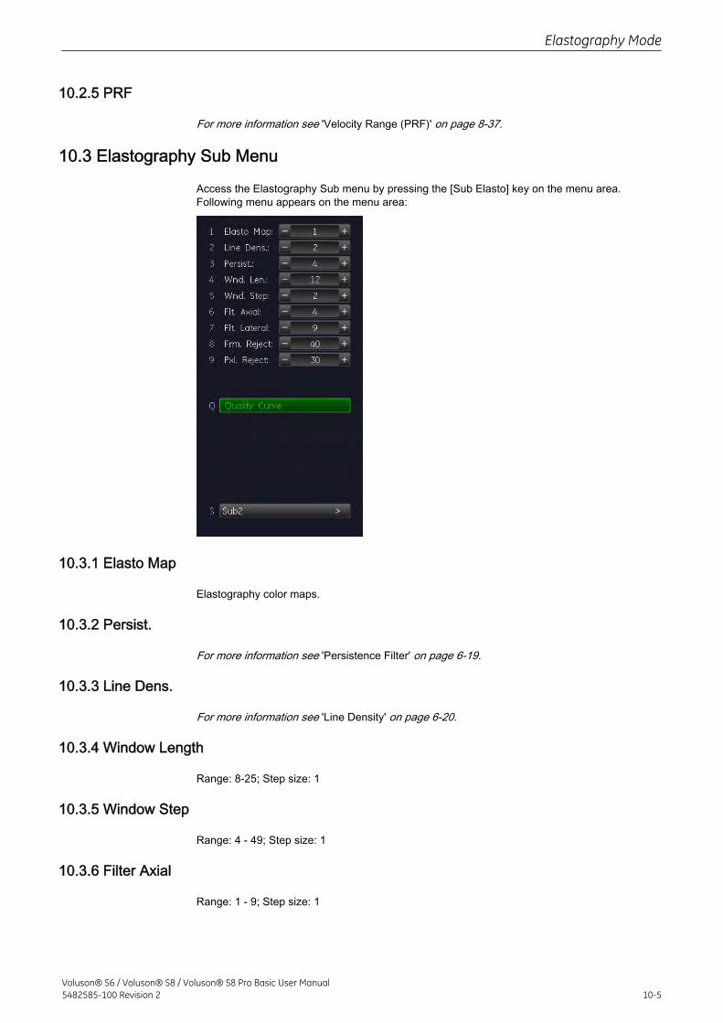
10.2.5 PRF
For more information see 'Velocity Range (PRF)' on page 8-37.
10.3 Elastography Sub Menu
Access the Elastography Sub menu by pressing the [Sub Elasto] key on the menu area.Following menu appears on the menu area:
10.3.1 Elasto Map
Elastography color maps.
10.3.2 Persist.
For more information see 'Persistence Filter' on page 6-19.
10.3.3 Line Dens.
For more information see 'Line Density' on page 6-20.
10.3.4 Window Length
Range: 8-25; Step size: 1
10.3.5 Window Step
Range: 4 - 49; Step size: 1
10.3.6 Filter Axial
Range: 1 - 9; Step size: 1
Elastography Mode
Voluson® S6 / Voluson® S8 / Voluson® S8 Pro Basic User Manual5482585-100 Revision 2 10-5
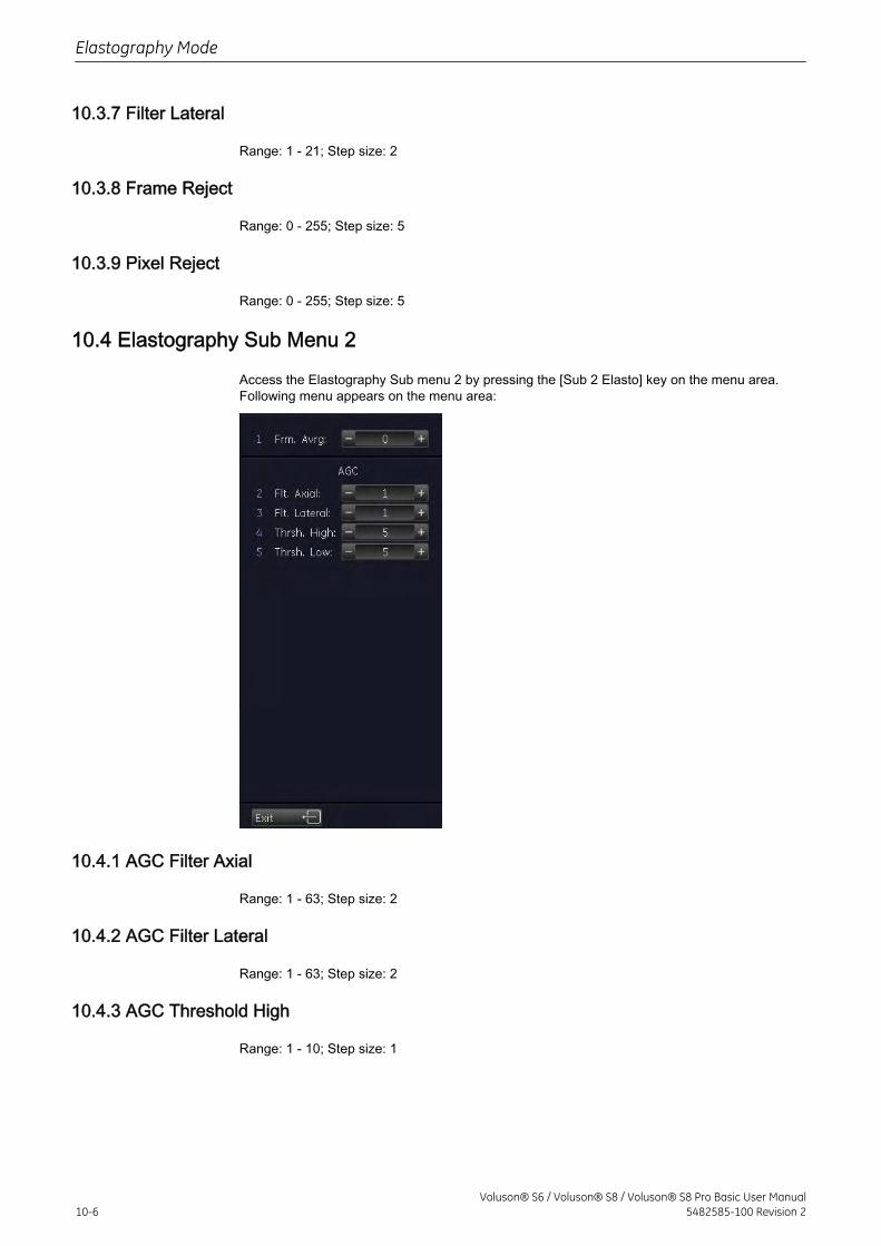
10.3.7 Filter Lateral
Range: 1 - 21; Step size: 2
10.3.8 Frame Reject
Range: 0 - 255; Step size: 5
10.3.9 Pixel Reject
Range: 0 - 255; Step size: 5
10.4 Elastography Sub Menu 2
Access the Elastography Sub menu 2 by pressing the [Sub 2 Elasto] key on the menu area.Following menu appears on the menu area:
10.4.1 AGC Filter Axial
Range: 1 - 63; Step size: 2
10.4.2 AGC Filter Lateral
Range: 1 - 63; Step size: 2
10.4.3 AGC Threshold High
Range: 1 - 10; Step size: 1
Elastography Mode
10-6Voluson® S6 / Voluson® S8 / Voluson® S8 Pro Basic User Manual
5482585-100 Revision 2

10.4.4 AGC Threshold Low
Range: 1 - 10; Step size: 1
10.4.5 Frame Averaging
Range: 1 - 9; Step size: 1
Elastography Mode
Voluson® S6 / Voluson® S8 / Voluson® S8 Pro Basic User Manual5482585-100 Revision 2 10-7

This page was intentionally left blank.
Elastography Mode
10-8Voluson® S6 / Voluson® S8 / Voluson® S8 Pro Basic User Manual
5482585-100 Revision 2
Chapter 11
Measurements and PatientWorksheets (Reports)
Describes the general functions of generic measurements, calculations and patient worksheets.
Voluson® S6 / Voluson® S8 / Voluson® S8 Pro Basic User Manual5482585-100 Revision 2 11-1
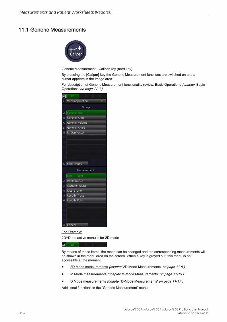
11.1 Generic Measurements
Generic Measurement - Caliper key (hard key)By pressing the [Caliper] key the Generic Measurement functions are switched on and acursor appears in the image area.For description of Generic Measurement functionality review: Basic Operations (chapter 'BasicOperations' on page 11-3 ).
For Example:2D+D the active menu is for 2D mode
By means of these items, the mode can be changed and the corresponding measurements willbe shown in the menu area on the screen. When a key is greyed out, this menu is notaccessible at the moment.
• 2D Mode measurements (chapter '2D Mode Measurements' on page 11-5 )
• M Mode measurements (chapter 'M-Mode Measurements' on page 11-15 )
• D Mode measurements (chapter 'D-Mode Measurements' on page 11-17 )Additional functions in the “Generic Measurement” menu:
Measurements and Patient Worksheets (Reports)
11-2Voluson® S6 / Voluson® S8 / Voluson® S8 Pro Basic User Manual
5482585-100 Revision 2
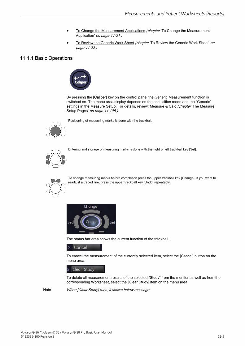
• To Change the Measurement Applications (chapter 'To Change the MeasurementApplication' on page 11-21 )
• To Review the Generic Work Sheet (chapter 'To Review the Generic Work Sheet' onpage 11-22 )
11.1.1 Basic Operations
By pressing the [Caliper] key on the control panel the Generic Measurement function isswitched on. The menu area display depends on the acquisition mode and the “Generic”settings in the Measure Setup. For details, review: Measure & Calc (chapter 'The MeasureSetup Pages' on page 11-105 )
Positioning of measuring marks is done with the trackball.
Entering and storage of measuring marks is done with the right or left trackball key [Set].
To change measuring marks before completion press the upper trackball key [Change]. If you want toreadjust a traced line, press the upper trackball key [Undo] repeatedly.
The status bar area shows the current function of the trackball.
To cancel the measurement of the currently selected item, select the [Cancel] button on themenu area.
To delete all measurement results of the selected “Study” from the monitor as well as from thecorresponding Worksheet, select the [Clear Study] item on the menu area.
Note When [Clear Study] runs, it shows below message.
Measurements and Patient Worksheets (Reports)
Voluson® S6 / Voluson® S8 / Voluson® S8 Pro Basic User Manual5482585-100 Revision 2 11-3
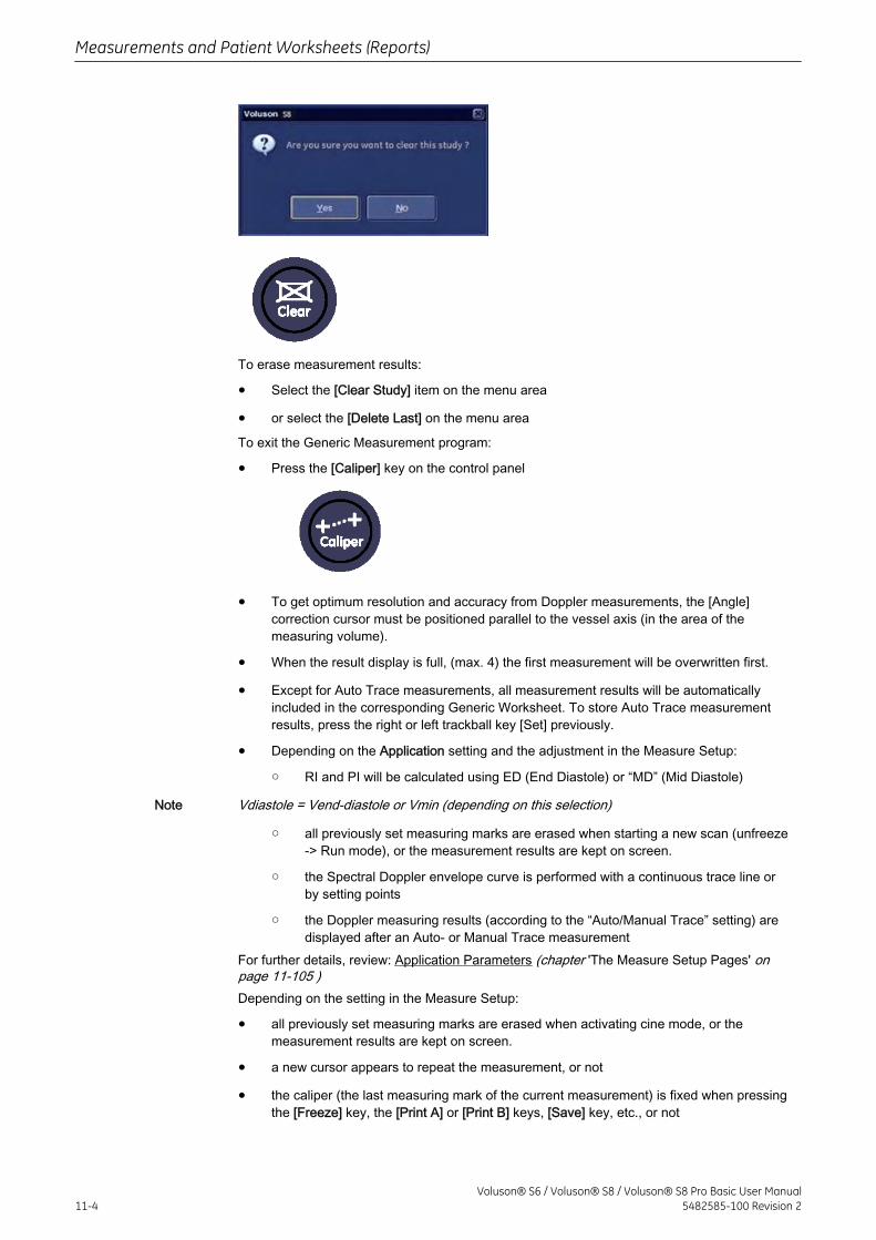
To erase measurement results:
• Select the [Clear Study] item on the menu area
• or select the [Delete Last] on the menu area
To exit the Generic Measurement program:
• Press the [Caliper] key on the control panel
• To get optimum resolution and accuracy from Doppler measurements, the [Angle]correction cursor must be positioned parallel to the vessel axis (in the area of themeasuring volume).
• When the result display is full, (max. 4) the first measurement will be overwritten first.
• Except for Auto Trace measurements, all measurement results will be automaticallyincluded in the corresponding Generic Worksheet. To store Auto Trace measurementresults, press the right or left trackball key [Set] previously.
• Depending on the Application setting and the adjustment in the Measure Setup:
○ RI and PI will be calculated using ED (End Diastole) or “MD” (Mid Diastole)
Note Vdiastole = Vend-diastole or Vmin (depending on this selection)
○ all previously set measuring marks are erased when starting a new scan (unfreeze-> Run mode), or the measurement results are kept on screen.
○ the Spectral Doppler envelope curve is performed with a continuous trace line orby setting points
○ the Doppler measuring results (according to the “Auto/Manual Trace” setting) aredisplayed after an Auto- or Manual Trace measurement
For further details, review: Application Parameters (chapter 'The Measure Setup Pages' onpage 11-105 )Depending on the setting in the Measure Setup:
• all previously set measuring marks are erased when activating cine mode, or themeasurement results are kept on screen.
• a new cursor appears to repeat the measurement, or not
• the caliper (the last measuring mark of the current measurement) is fixed when pressingthe [Freeze] key, the [Print A] or [Print B] keys, [Save] key, etc., or not
Measurements and Patient Worksheets (Reports)
11-4Voluson® S6 / Voluson® S8 / Voluson® S8 Pro Basic User Manual
5482585-100 Revision 2
For further details, review: Global Parameters (chapter 'The Measure Setup Pages' on page11-105 )
• Moreover, many display properties depend on the setting in the Measure Setup. ForExample: cursor and font of measurement result is displayed in small, medium or largesize
For further adjustments and detailed information review: Global Parameters (chapter 'TheMeasure Setup Pages' on page 11-105 )
To change the current measurement application, Select the [Appli.] item on the menu area.For further details, review: To Change the Measurement Application (chapter 'To Change theMeasurement Application' on page 11-21 ).
To review, modify, print, etc. the Generic Work Sheet, Press the [Report] key on the controlpanel. For further details, review: To Review the Generic Work Sheet (chapter 'To Review theGeneric Work Sheet' on page 11-22 ).
11.1.2 2D Mode Measurements
• For details about adjusting 2D Measurement settings, review: Measure Setup - Measure& Calc (chapter 'The Measure Setup Pages' on page 11-105 )
• The “Factory” Generic Sub Category for 2D Imaging Mode (see image above) supports 4Study types and following Measure methods:
Study Measure
(chapter 'GenericDistanceMeasurements' onpage 11-6 )
Distance 2 Points (chapter 'Distance 2 Points' on page 11-6 )Distance 2 Lines (chapter 'Distance 2 Lines' on page 11-6 ) LengthTrace (chapter 'Length Trace' on page 11-7 ) Length Point (chapter'Length Point' on page 11-7 ) Stenosis %Distance (chapter'Stenosis %Distance' on page 11-7 ) Ratio D1/D2
(chapter 'GenericArea Measurements'on page 11-8 )
Area Trace (chapter 'Area Trace' on page 11-8 ) Area Point(chapter 'Area Point' on page 11-8 ) Area 2 Distances (chapter'Area 2 Distances' on page 11-9 ) Ellipse (chapter 'Ellipse' on page11-9 ) Stenosis %Area (chapter 'Stenosis %Area' on page 11-9 )Ratio A1/A2
(chapter 'GenericVolumeMeasurement' onpage 11-10 )
3 Distances (chapter '3 Distances' on page 11-10 ) Ellipse (chapter'Ellipse' on page 11-11 ) 1 Distance + Ellipse (chapter '1 Distance +Ellipse' on page 11-11 ) 1 Distance (chapter '1 Distance' on page11-11 ) Multiplane (chapter 'Multiplane' on page 11-11 )
(chapter 'GenericAngle Measurement'on page 11-13 )
Angle 3 Points (chapter 'Angle 3 Point' on page 11-13 ) Angle 2Lines (chapter 'Angle 2 Line' on page 11-13 )
Measurements and Patient Worksheets (Reports)
Voluson® S6 / Voluson® S8 / Voluson® S8 Pro Basic User Manual5482585-100 Revision 2 11-5
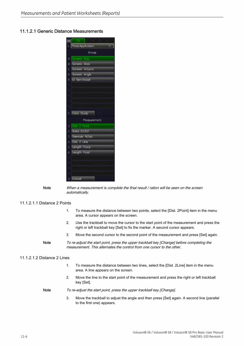
11.1.2.1 Generic Distance Measurements
Note When a measurement is complete the final result / ration will be seen on the screenautomatically.
11.1.2.1.1 Distance 2 Points
1. To measure the distance between two points, select the [Dist. 2Point] item in the menuarea. A cursor appears on the screen.
2. Use the trackball to move the cursor to the start point of the measurement and press theright or left trackball key [Set] to fix the marker. A second cursor appears.
3. Move the second cursor to the second point of the measurement and press [Set] again.
Note To re-adjust the start point, press the upper trackball key [Change] before completing themeasurement. This alternates the control from one cursor to the other.
11.1.2.1.2 Distance 2 Lines
1. To measure the distance between two lines, select the [Dist. 2Line] item in the menuarea. A line appears on the screen.
2. Move the line to the start point of the measurement and press the right or left trackballkey [Set].
Note To re-adjust the start point, press the upper trackball key [Change].
3. Move the trackball to adjust the angle and then press [Set] again. A second line (parallelto the first one) appears.
Measurements and Patient Worksheets (Reports)
11-6Voluson® S6 / Voluson® S8 / Voluson® S8 Pro Basic User Manual
5482585-100 Revision 2
4. Move this line using the trackball to the end point of the measurement and then press[Set].
11.1.2.1.3 Length Trace
1. To measure the distance between two points using trace, select the [Length Trace] itemin the menu area. A cursor appears on the screen.
2. Move the cursor to the start of the measurement and press the right or left trackball key[Set] to fix the marker. Begin trace.
Note To re-adjust the traced line, press the upper trackball key [Undo] repeatedly.
3. Trace to the end and press the [Set] key again to fix the mark.
11.1.2.1.4 Length Point
1. To measure the distance between several points (as much as desired), select the[Length Point] item in the menu area. A cursor appears on the screen.
2. Move the cursor to the start of the measurement and press the right or left trackball key[Set] to fix the marker.
3. Move the trackball again to adjust the next line between two points and then press [Set]again.
Note To re-adjust a line, press the upper trackball key [Undo] repeatedly.
4. Set as much points as required in the same manner.
5. To finish the measurement and to display the result, press the [Set] key once again.
11.1.2.1.5 Stenosis %Distance
1. To measure a Stenosis, select the [Stenosis %Dist] item in the menu area. A cursorappears on the screen.
2. Perform the measurement of the outer distance of the stenosis using the trackball andthe right or left trackball key [Set]. A second cursor appears.
3. Perform the measurement of the inner distance of the stenosis and press the [Set] key.Remark:The results (such as outer and inner distance and the Stenosis %) appear automatically.
Measurements and Patient Worksheets (Reports)
Voluson® S6 / Voluson® S8 / Voluson® S8 Pro Basic User Manual5482585-100 Revision 2 11-7
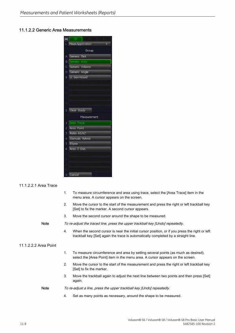
11.1.2.2 Generic Area Measurements
11.1.2.2.1 Area Trace
1. To measure circumference and area using trace, select the [Area Trace] item in themenu area. A cursor appears on the screen.
2. Move the cursor to the start of the measurement and press the right or left trackball key[Set] to fix the marker. A second cursor appears.
3. Move the second cursor around the shape to be measured.
Note To re-adjust the traced line, press the upper trackball key [Undo] repeatedly.
4. When the second cursor is near the initial cursor position, or if you press the right or lefttrackball key [Set] again the trace is automatically completed by a straight line.
11.1.2.2.2 Area Point
1. To measure circumference and area by setting several points (as much as desired),select the [Area Point] item in the menu area. A cursor appears on the screen.
2. Move the cursor to the start of the measurement and press the right or left trackball key[Set] to fix the marker.
3. Move the trackball again to adjust the next line between two points and then press [Set]again.
Note To re-adjust a line, press the upper trackball key [Undo] repeatedly.
4. Set as many points as necessary, around the shape to be measured.
Measurements and Patient Worksheets (Reports)
11-8Voluson® S6 / Voluson® S8 / Voluson® S8 Pro Basic User Manual
5482585-100 Revision 2
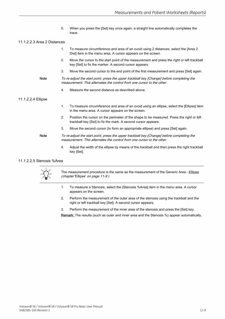
5. When you press the [Set] key once again, a straight line automatically completes thetrace.
11.1.2.2.3 Area 2 Distances
1. To measure circumference and area of an ovoid using 2 distances, select the [Area 2Dist] item in the menu area. A cursor appears on the screen.
2. Move the cursor to the start point of the measurement and press the right or left trackballkey [Set] to fix the marker. A second cursor appears.
3. Move the second cursor to the end point of the first measurement and press [Set] again.
Note To re-adjust the start point, press the upper trackball key [Change] before completing themeasurement. This alternates the control from one cursor to the other.
4. Measure the second distance as described above.
11.1.2.2.4 Ellipse
1. To measure circumference and area of an ovoid using an ellipse, select the [Ellipse] itemin the menu area. A cursor appears on the screen.
2. Position the cursor on the perimeter of the shape to be measured. Press the right or lefttrackball key [Set] to fix the mark. A second cursor appears.
3. Move the second cursor (to form an appropriate ellipse) and press [Set] again.
Note To re-adjust the start point, press the upper trackball key [Change] before completing themeasurement. This alternates the control from one cursor to the other.
4. Adjust the width of the ellipse by means of the trackball and then press the right trackballkey [Set].
11.1.2.2.5 Stenosis %Area
The measurement procedure is the same as the measurement of the Generic Area - Ellipse(chapter 'Ellipse' on page 11-9 ).
1. To measure a Stenosis, select the [Stenosis %Area] item in the menu area. A cursorappears on the screen.
2. Perform the measurement of the outer area of the stenosis using the trackball and theright or left trackball key [Set]. A second cursor appears.
3. Perform the measurement of the inner area of the stenosis and press the [Set] key.Remark: The results (such as outer and inner area and the Stenosis %) appear automatically..
Measurements and Patient Worksheets (Reports)
Voluson® S6 / Voluson® S8 / Voluson® S8 Pro Basic User Manual5482585-100 Revision 2 11-9
11.1.2.3 Generic Volume Measurement
11.1.2.3.1 3 Distances
1. To measure volume of an ovoid using three distances, select the [3 Dist] item in themenu area. A cursor appears on the screen.
2. Move the cursor to the start point of the measurement and press the right or left trackballkey [Set] to fix the marker. A second cursor appears.
3. Move the second cursor to the end point of the first measurement and press [Set] again.
Note To re-adjust the start point, press the upper trackball key [Change] before completing themeasurement. This alternates the control from one cursor to the other.
4. Measure the second distance as described above.
Note
• When using single image mode, measure the two distances. Press [Freeze] toreturn to scan mode and scan the second image. Press [Freeze] again. A newcursor for the third distance measurement appears.
• If you have scanned the second image in Dual mode previously, you can measurethe third distance within this second (half) image.
5. Perform the measurement of the third distance in the same manner.
Measurements and Patient Worksheets (Reports)
11-10Voluson® S6 / Voluson® S8 / Voluson® S8 Pro Basic User Manual
5482585-100 Revision 2
11.1.2.3.2 Ellipse
The measurement procedure is the same than the measurement of the Generic Area - Ellipse(chapter 'Ellipse' on page 11-9 ).
Remark: After the measurement, the volume of the ellipse is displayed.
11.1.2.3.3 1 Distance + Ellipse
1. To measure volume of an ovoid using one distance and ellipse, select the [1 Dist Ellipse]item in the menu area. A cursor appears on the screen.
2. Move the cursor to the start point of the distance measurement and press the right or lefttrackball key [Set]. A second cursor appears.
3. Move the second cursor to the end point of the distance measurement and press [Set]again.
Note To re-adjust the start point, press the upper trackball key [Change] before completing themeasurement. This alternates the control from one cursor to the other.
• When using single image mode, measure the two distances. Press [Freeze] toreturn to scan mode and scan the second image. Press [Freeze] again. A newcursor for the ellipse measurement appears.
• If you have scanned the second image in Dual mode previously, you can measurethe ellipse within this second (half) image.
4. Move the cursor to the start point of the ellipse measurement and press the right or lefttrackball key [Set]. A second cursor appears.
5. Move the second cursor (to form an appropriate ellipse) and press [Set] again.
Note To re-adjust the start point, press the upper trackball key [Change].
6. Adjust the width of the ellipse by means of the trackball and then press the right trackballkey [Set].
11.1.2.3.4 1 Distance
1. To measure volume of a globe-like volume using one distance, select the [1 Dist] item inthe menu area. A cursor appears on the screen.
2. Use the trackball to move the cursor to the start point of the measurement and press theright or left trackball key to fix the marker. A second cursor appears.
3. Move the second cursor to the second point of the measurement and press [Set] again.
Note To re-adjust the start point, press the upper trackball key [Change] before completing themeasurement. This alternates the control from one cursor to the other.
11.1.2.3.5 Multiplane
This measuring program allows for volume determination of any organ, which was stored by avolume scan. Several parallel planes are laid through the organ and the areas of these planesare determined. A measuring program calculates the volume from the measured areas and thedistance between the areas. The larger the number of areas, the more exact the volumecalculation result will be.Condition: a stored volume scan (Sectional Planes view).
To measure volume using the Multplane method in 3D Mode:
1. Select the reference image in which the measurement is to be performed. (A, B or C)
Measurements and Patient Worksheets (Reports)
Voluson® S6 / Voluson® S8 / Voluson® S8 Pro Basic User Manual5482585-100 Revision 2 11-11
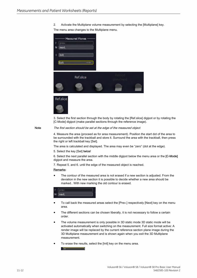
2. Activate the Multiplane volume measurement by selecting the [Multiplane] key.The menu area changes to the Multiplane menu.
3. Select the first section through the body by rotating the [Ref.slice] digipot or by rotating the[C-Mode] digipot (make parallel sections through the reference image).
Note The first section should be set at the edge of the measured object.
4. Measure the area (proceed as for area measurement). Position the start dot of the area tobe surrounded with the trackball and store it. Surround the area with the trackball, then pressthe right or left trackball key [Set].The area is calculated and displayed. The area may even be “zero” (dot at the edge).5. Select the key [Set] twice!6. Select the next parallel section with the middle digipot below the menu area or the [C-Mode]digipot and measure the area.7. Repeat 5. and 6. until the edge of the measured object is reached.Remarks:
• The contour of the measured area is not erased if a new section is adjusted. From thedeviation in the new section it is possible to decide whether a new area should bemarked.. With new marking the old contour is erased.
• To call back the measured areas select the [Prev.] respectively [Next] key on the menuarea.
• The different sections can be chosen liberally, it is not necessary to follow a certainorder.
• The volume measurement is only possible in 3D static mode 3D static mode will beactivated automatically when switching on the measurement. Full size format active: Arender image will be replaced by the current reference section plane image during the3D Multiplane measurement and is shown again when you exit the 3D Multiplanemeasurement.
• To erase the results, select the [Init] key on the menu area.
Measurements and Patient Worksheets (Reports)
11-12Voluson® S6 / Voluson® S8 / Voluson® S8 Pro Basic User Manual
5482585-100 Revision 2
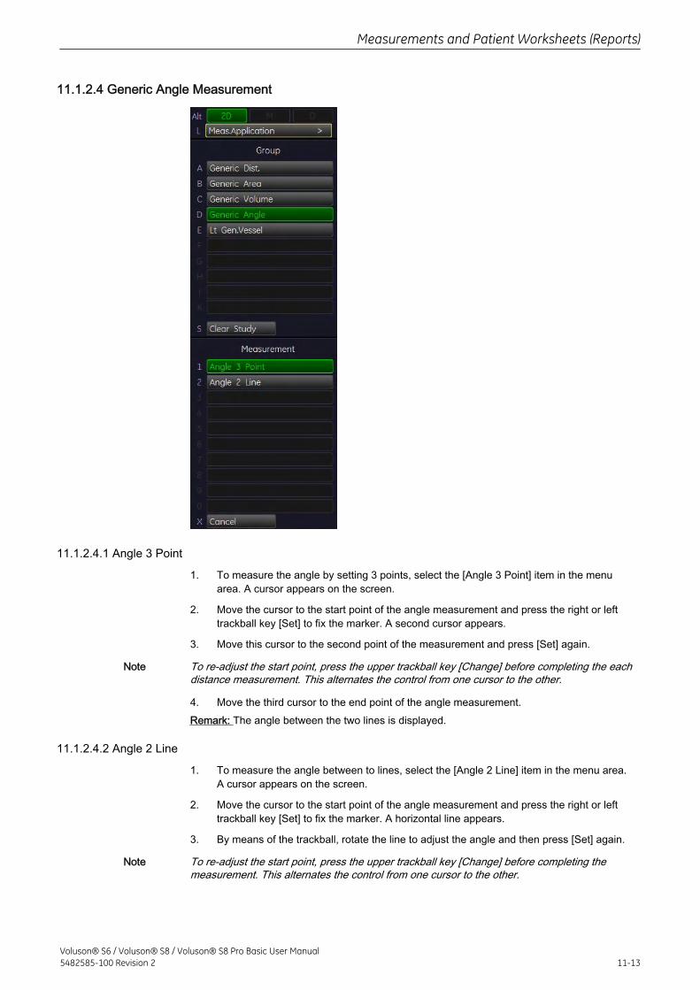
11.1.2.4 Generic Angle Measurement
11.1.2.4.1 Angle 3 Point
1. To measure the angle by setting 3 points, select the [Angle 3 Point] item in the menuarea. A cursor appears on the screen.
2. Move the cursor to the start point of the angle measurement and press the right or lefttrackball key [Set] to fix the marker. A second cursor appears.
3. Move this cursor to the second point of the measurement and press [Set] again.
Note To re-adjust the start point, press the upper trackball key [Change] before completing the eachdistance measurement. This alternates the control from one cursor to the other.
4. Move the third cursor to the end point of the angle measurement.Remark: The angle between the two lines is displayed.
11.1.2.4.2 Angle 2 Line
1. To measure the angle between to lines, select the [Angle 2 Line] item in the menu area.A cursor appears on the screen.
2. Move the cursor to the start point of the angle measurement and press the right or lefttrackball key [Set] to fix the marker. A horizontal line appears.
3. By means of the trackball, rotate the line to adjust the angle and then press [Set] again.
Note To re-adjust the start point, press the upper trackball key [Change] before completing themeasurement. This alternates the control from one cursor to the other.
Measurements and Patient Worksheets (Reports)
Voluson® S6 / Voluson® S8 / Voluson® S8 Pro Basic User Manual5482585-100 Revision 2 11-13
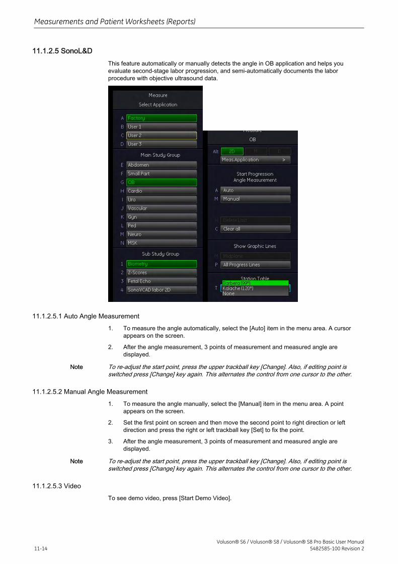
11.1.2.5 SonoL&DThis feature automatically or manually detects the angle in OB application and helps youevaluate second-stage labor progression, and semi-automatically documents the laborprocedure with objective ultrasound data.
11.1.2.5.1 Auto Angle Measurement
1. To measure the angle automatically, select the [Auto] item in the menu area. A cursorappears on the screen.
2. After the angle measurement, 3 points of measurement and measured angle aredisplayed.
Note To re-adjust the start point, press the upper trackball key [Change]. Also, if editing point isswitched press [Change] key again. This alternates the control from one cursor to the other.
11.1.2.5.2 Manual Angle Measurement
1. To measure the angle manually, select the [Manual] item in the menu area. A pointappears on the screen.
2. Set the first point on screen and then move the second point to right direction or leftdirection and press the right or left trackball key [Set] to fix the point.
3. After the angle measurement, 3 points of measurement and measured angle aredisplayed.
Note To re-adjust the start point, press the upper trackball key [Change]. Also, if editing point isswitched press [Change] key again. This alternates the control from one cursor to the other.
11.1.2.5.3 Video
To see demo video, press [Start Demo Video].
Measurements and Patient Worksheets (Reports)
11-14Voluson® S6 / Voluson® S8 / Voluson® S8 Pro Basic User Manual
5482585-100 Revision 2
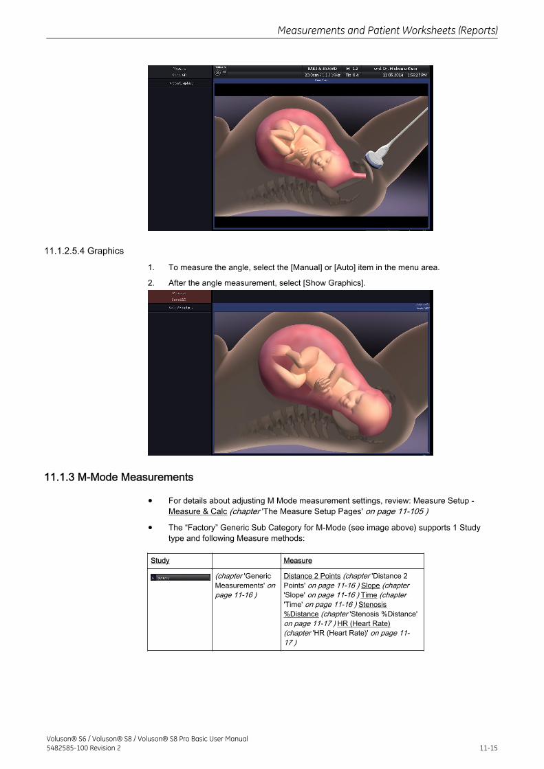
11.1.2.5.4 Graphics
1. To measure the angle, select the [Manual] or [Auto] item in the menu area.
2. After the angle measurement, select [Show Graphics].
11.1.3 M-Mode Measurements
• For details about adjusting M Mode measurement settings, review: Measure Setup -Measure & Calc (chapter 'The Measure Setup Pages' on page 11-105 )
• The “Factory” Generic Sub Category for M-Mode (see image above) supports 1 Studytype and following Measure methods:
Study Measure
(chapter 'GenericMeasurements' onpage 11-16 )
Distance 2 Points (chapter 'Distance 2Points' on page 11-16 ) Slope (chapter'Slope' on page 11-16 ) Time (chapter'Time' on page 11-16 ) Stenosis%Distance (chapter 'Stenosis %Distance'on page 11-17 ) HR (Heart Rate)(chapter 'HR (Heart Rate)' on page 11-17 )
Measurements and Patient Worksheets (Reports)
Voluson® S6 / Voluson® S8 / Voluson® S8 Pro Basic User Manual5482585-100 Revision 2 11-15
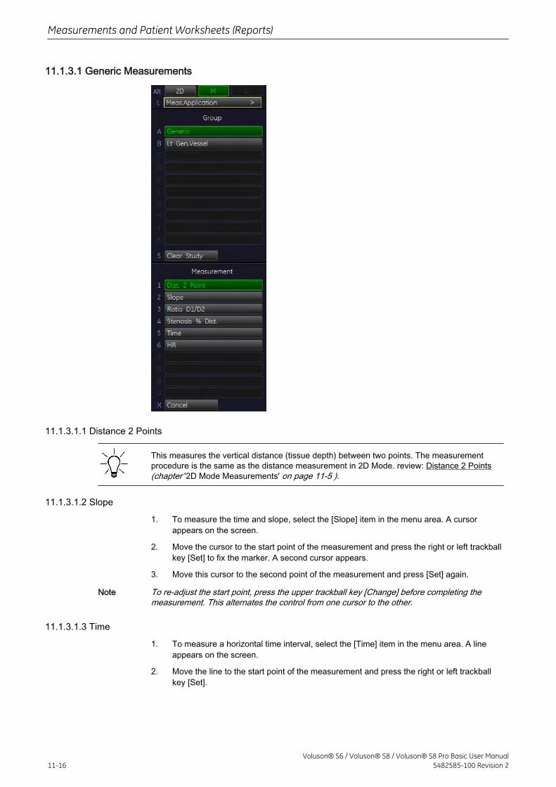
11.1.3.1 Generic Measurements
11.1.3.1.1 Distance 2 Points
This measures the vertical distance (tissue depth) between two points. The measurementprocedure is the same as the distance measurement in 2D Mode. review: Distance 2 Points(chapter '2D Mode Measurements' on page 11-5 ).
11.1.3.1.2 Slope
1. To measure the time and slope, select the [Slope] item in the menu area. A cursorappears on the screen.
2. Move the cursor to the start point of the measurement and press the right or left trackballkey [Set] to fix the marker. A second cursor appears.
3. Move this cursor to the second point of the measurement and press [Set] again.
Note To re-adjust the start point, press the upper trackball key [Change] before completing themeasurement. This alternates the control from one cursor to the other.
11.1.3.1.3 Time
1. To measure a horizontal time interval, select the [Time] item in the menu area. A lineappears on the screen.
2. Move the line to the start point of the measurement and press the right or left trackballkey [Set].
Measurements and Patient Worksheets (Reports)
11-16Voluson® S6 / Voluson® S8 / Voluson® S8 Pro Basic User Manual
5482585-100 Revision 2
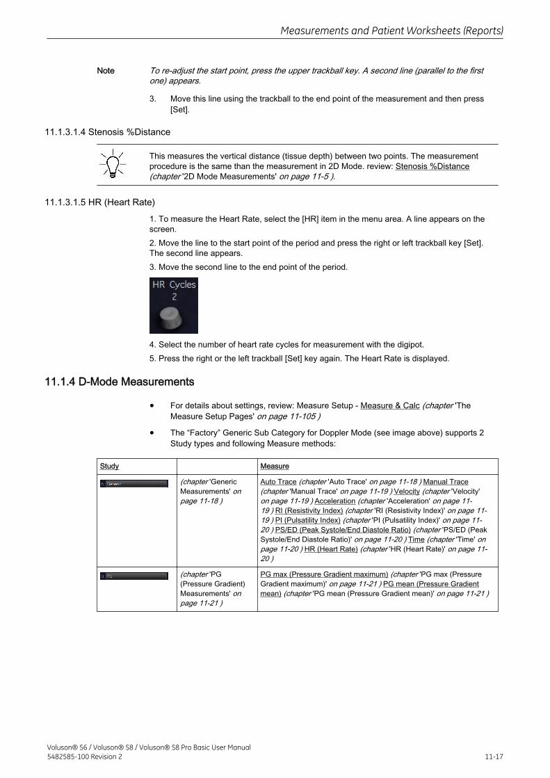
Note To re-adjust the start point, press the upper trackball key. A second line (parallel to the firstone) appears.
3. Move this line using the trackball to the end point of the measurement and then press[Set].
11.1.3.1.4 Stenosis %Distance
This measures the vertical distance (tissue depth) between two points. The measurementprocedure is the same than the measurement in 2D Mode. review: Stenosis %Distance(chapter '2D Mode Measurements' on page 11-5 ).
11.1.3.1.5 HR (Heart Rate)
1. To measure the Heart Rate, select the [HR] item in the menu area. A line appears on thescreen.2. Move the line to the start point of the period and press the right or left trackball key [Set].The second line appears.3. Move the second line to the end point of the period.
4. Select the number of heart rate cycles for measurement with the digipot.5. Press the right or the left trackball [Set] key again. The Heart Rate is displayed.
11.1.4 D-Mode Measurements
• For details about settings, review: Measure Setup - Measure & Calc (chapter 'TheMeasure Setup Pages' on page 11-105 )
• The “Factory” Generic Sub Category for Doppler Mode (see image above) supports 2Study types and following Measure methods:
Study Measure
(chapter 'GenericMeasurements' onpage 11-18 )
Auto Trace (chapter 'Auto Trace' on page 11-18 ) Manual Trace(chapter 'Manual Trace' on page 11-19 ) Velocity (chapter 'Velocity'on page 11-19 ) Acceleration (chapter 'Acceleration' on page 11-19 ) RI (Resistivity Index) (chapter 'RI (Resistivity Index)' on page 11-19 ) PI (Pulsatility Index) (chapter 'PI (Pulsatility Index)' on page 11-20 ) PS/ED (Peak Systole/End Diastole Ratio) (chapter 'PS/ED (PeakSystole/End Diastole Ratio)' on page 11-20 ) Time (chapter 'Time' onpage 11-20 ) HR (Heart Rate) (chapter 'HR (Heart Rate)' on page 11-20 )
(chapter 'PG(Pressure Gradient)Measurements' onpage 11-21 )
PG max (Pressure Gradient maximum) (chapter 'PG max (PressureGradient maximum)' on page 11-21 ) PG mean (Pressure Gradientmean) (chapter 'PG mean (Pressure Gradient mean)' on page 11-21 )
Measurements and Patient Worksheets (Reports)
Voluson® S6 / Voluson® S8 / Voluson® S8 Pro Basic User Manual5482585-100 Revision 2 11-17
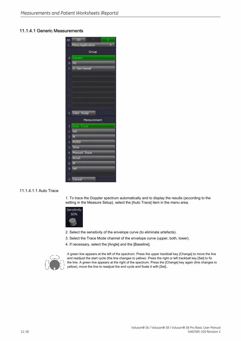
11.1.4.1 Generic Measurements
11.1.4.1.1 Auto Trace
1. To trace the Doppler spectrum automatically and to display the results (according to thesetting in the Measure Setup), select the [Auto Trace] item in the menu area.
2. Select the sensitivity of the envelope curve (to eliminate artefacts).3. Select the Trace Mode channel of the envelope curve (upper, both, lower).4. If necessary, select the [Angle] and the [Baseline].
A green line appears at the left of the spectrum. Press the upper trackball key [Change] to move the lineand readjust the start cycle (the line changes to yellow). Press the right or left trackball key [Set] to fixthe line. A green line appears at the right of the spectrum. Press the [Change] key again (line changes toyellow), move the line to readjust the end cycle and fixate it with [Set]..
Measurements and Patient Worksheets (Reports)
11-18Voluson® S6 / Voluson® S8 / Voluson® S8 Pro Basic User Manual
5482585-100 Revision 2
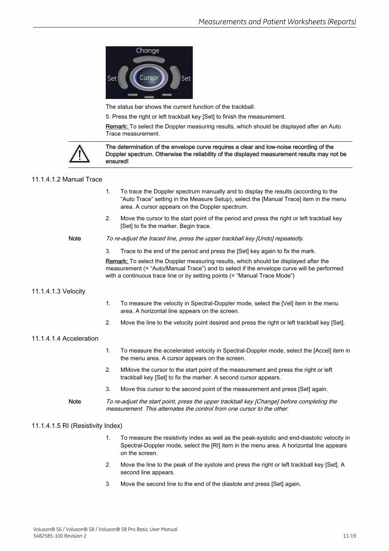
The status bar shows the current function of the trackball.5. Press the right or left trackball key [Set] to finish the measurement.Remark: To select the Doppler measuring results, which should be displayed after an AutoTrace measurement.
The determination of the envelope curve requires a clear and low-noise recording of theDoppler spectrum. Otherwise the reliability of the displayed measurement results may not beensured!
11.1.4.1.2 Manual Trace
1. To trace the Doppler spectrum manually and to display the results (according to the“Auto Trace” setting in the Measure Setup), select the [Manual Trace] item in the menuarea. A cursor appears on the Doppler spectrum.
2. Move the cursor to the start point of the period and press the right or left trackball key[Set] to fix the marker. Begin trace.
Note To re-adjust the traced line, press the upper trackball key [Undo] repeatedly.
3. Trace to the end of the period and press the [Set] key again to fix the mark.Remark: To select the Doppler measuring results, which should be displayed after themeasurement (= “Auto/Manual Trace”) and to select if the envelope curve will be performedwith a continuous trace line or by setting points (= “Manual Trace Mode”)
11.1.4.1.3 Velocity
1. To measure the velocity in Spectral-Doppler mode, select the [Vel] item in the menuarea. A horizontal line appears on the screen.
2. Move the line to the velocity point desired and press the right or left trackball key [Set].
11.1.4.1.4 Acceleration
1. To measure the accelerated velocity in Spectral-Doppler mode, select the [Accel] item inthe menu area. A cursor appears on the screen.
2. MMove the cursor to the start point of the measurement and press the right or lefttrackball key [Set] to fix the marker. A second cursor appears.
3. Move this cursor to the second point of the measurement and press [Set] again.
Note To re-adjust the start point, press the upper trackball key [Change] before completing themeasurement. This alternates the control from one cursor to the other.
11.1.4.1.5 RI (Resistivity Index)
1. To measure the resistivity index as well as the peak-systolic and end-diastolic velocity inSpectral-Doppler mode, select the [RI] item in the menu area. A horizontal line appearson the screen.
2. Move the line to the peak of the systole and press the right or left trackball key [Set]. Asecond line appears.
3. Move the second line to the end of the diastole and press [Set] again.
Measurements and Patient Worksheets (Reports)
Voluson® S6 / Voluson® S8 / Voluson® S8 Pro Basic User Manual5482585-100 Revision 2 11-19
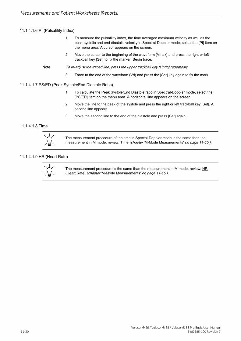
11.1.4.1.6 PI (Pulsatility Index)
1. To measure the pulsatility index, the time averaged maximum velocity as well as thepeak-systolic and end-diastolic velocity in Spectral-Doppler mode, select the [PI] item onthe menu area. A cursor appears on the screen.
2. Move the cursor to the beginning of the waveform (Vmax) and press the right or lefttrackball key [Set] to fix the marker. Begin trace.
Note To re-adjust the traced line, press the upper trackball key [Undo] repeatedly.
3. Trace to the end of the waveform (Vd) and press the [Set] key again to fix the mark.
11.1.4.1.7 PS/ED (Peak Systole/End Diastole Ratio)
1. To calculate the Peak Systole/End Diastole ratio in Spectral-Doppler mode, select the[PS/ED] item on the menu area. A horizontal line appears on the screen.
2. Move the line to the peak of the systole and press the right or left trackball key [Set]. Asecond line appears.
3. Move the second line to the end of the diastole and press [Set] again.
11.1.4.1.8 Time
The measurement procedure of the time in Spectal-Doppler mode is the same than themeasurement in M mode. review: Time (chapter 'M-Mode Measurements' on page 11-15 ).
11.1.4.1.9 HR (Heart Rate)
The measurement procedure is the same than the measurement in M mode. review: HR(Heart Rate) (chapter 'M-Mode Measurements' on page 11-15 ).
Measurements and Patient Worksheets (Reports)
11-20Voluson® S6 / Voluson® S8 / Voluson® S8 Pro Basic User Manual
5482585-100 Revision 2
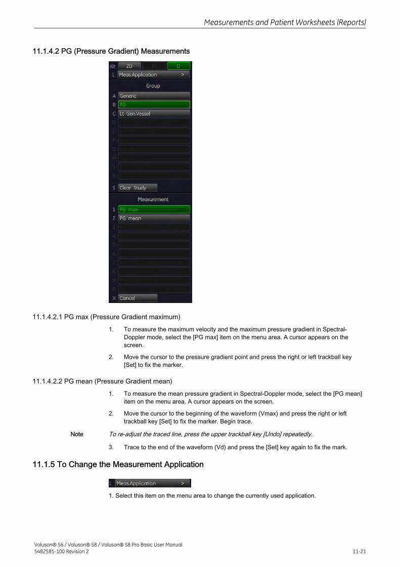
11.1.4.2 PG (Pressure Gradient) Measurements
11.1.4.2.1 PG max (Pressure Gradient maximum)
1. To measure the maximum velocity and the maximum pressure gradient in Spectral-Doppler mode, select the [PG max] item on the menu area. A cursor appears on thescreen.
2. Move the cursor to the pressure gradient point and press the right or left trackball key[Set] to fix the marker.
11.1.4.2.2 PG mean (Pressure Gradient mean)
1. To measure the mean pressure gradient in Spectral-Doppler mode, select the [PG mean]item on the menu area. A cursor appears on the screen.
2. Move the cursor to the beginning of the waveform (Vmax) and press the right or lefttrackball key [Set] to fix the marker. Begin trace.
Note To re-adjust the traced line, press the upper trackball key [Undo] repeatedly.
3. Trace to the end of the waveform (Vd) and press the [Set] key again to fix the mark.
11.1.5 To Change the Measurement Application
1. Select this item on the menu area to change the currently used application.
Measurements and Patient Worksheets (Reports)
Voluson® S6 / Voluson® S8 / Voluson® S8 Pro Basic User Manual5482585-100 Revision 2 11-21
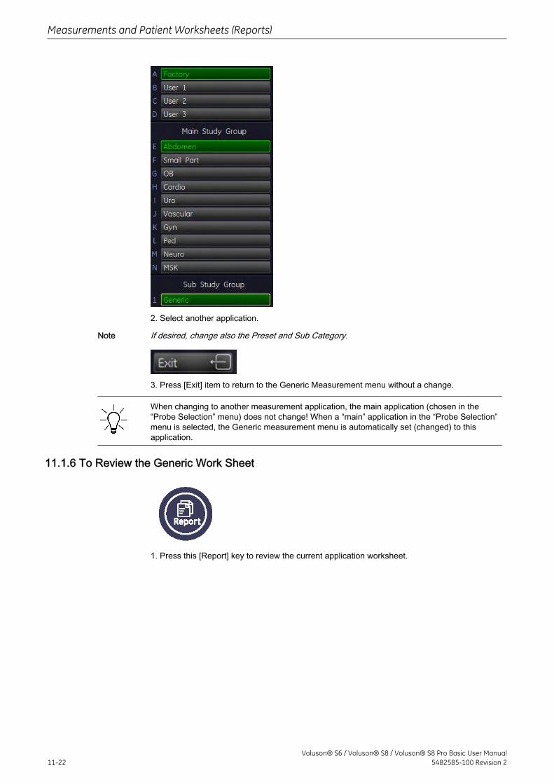
2. Select another application.
Note If desired, change also the Preset and Sub Category.
3. Press [Exit] item to return to the Generic Measurement menu without a change.
When changing to another measurement application, the main application (chosen in the“Probe Selection” menu) does not change! When a “main” application in the “Probe Selection”menu is selected, the Generic measurement menu is automatically set (changed) to thisapplication.
11.1.6 To Review the Generic Work Sheet
1. Press this [Report] key to review the current application worksheet.
Measurements and Patient Worksheets (Reports)
11-22Voluson® S6 / Voluson® S8 / Voluson® S8 Pro Basic User Manual
5482585-100 Revision 2
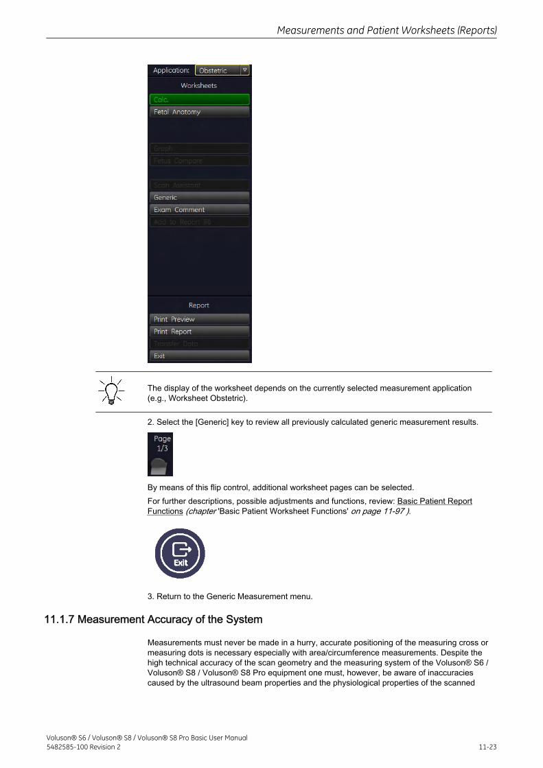
The display of the worksheet depends on the currently selected measurement application(e.g., Worksheet Obstetric).
2. Select the [Generic] key to review all previously calculated generic measurement results.
By means of this flip control, additional worksheet pages can be selected.For further descriptions, possible adjustments and functions, review: Basic Patient ReportFunctions (chapter 'Basic Patient Worksheet Functions' on page 11-97 ).
3. Return to the Generic Measurement menu.
11.1.7 Measurement Accuracy of the System
Measurements must never be made in a hurry, accurate positioning of the measuring cross ormeasuring dots is necessary especially with area/circumference measurements. Despite thehigh technical accuracy of the scan geometry and the measuring system of the Voluson® S6 /Voluson® S8 / Voluson® S8 Pro equipment one must, however, be aware of inaccuraciescaused by the ultrasound beam properties and the physiological properties of the scanned
Measurements and Patient Worksheets (Reports)
Voluson® S6 / Voluson® S8 / Voluson® S8 Pro Basic User Manual5482585-100 Revision 2 11-23
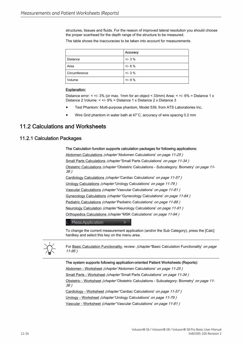
structures, tissues and fluids. For the reason of improved lateral resolution you should choosethe proper scanhead for the depth range of the structure to be measured.The table shows the inaccuracies to be taken into account for measurements.
Accuracy
Distance +/- 3 %
Area +/- 6 %
Circumference +/- 3 %
Volume +/- 9 %
Explanation:Distance error: < +/- 3% (or max. 1mm for an object < 33mm) Area: < +/- 6% = Distance 1 xDistance 2 Volume: < +/- 9% = Distance 1 x Distance 2 x Distance 3
• Test Phantom: Multi-purpose phantom, Model 539, from ATS Laboratories Inc,
• Wire Grid phantom in water bath at 47˚C, accuracy of wire spacing 0.2 mm
11.2 Calculations and Worksheets
11.2.1 Calculation Packages
The Calculation function supports calculation packages for following applications:Abdomen Calculations (chapter 'Abdomen Calculations' on page 11-25 )Small Parts Calculations (chapter 'Small Parts Calculations' on page 11-34 )Obstetric Calculations (chapter 'Obstetric Calculations - Subcategory: Biometry' on page 11-36 )Cardiology Calculations (chapter 'Cardiac Calculations' on page 11-57 )Urology Calculations (chapter 'Urology Calculations' on page 11-79 )Vascular Calculations (chapter 'Vascular Calculations' on page 11-81 )Gynecology Calculations (chapter 'Gynecology Calculations' on page 11-84 )Pediatric Calculations (chapter 'Pediatric Calculations' on page 11-88 )Neurology Calculation (chapter 'Neurology Calculations' on page 11-91 )Orthopedics Calculations (chapter 'MSK Calculations' on page 11-94 )
To change the current measurement application (and/or the Sub Category), press the [Calc]hardkey and select this key on the menu area.
For Basic Calculation Functionality, review: (chapter 'Basic Calculation Functionality' on page11-95 )
The system supports following application-oriented Patient Worksheets (Reports):Abdomen - Worksheet (chapter 'Abdomen Calculations' on page 11-25 )Small Parts - Worksheet (chapter 'Small Parts Calculations' on page 11-34 )Obstetric - Worksheet (chapter 'Obstetric Calculations - Subcategory: Biometry' on page 11-36 )Cardiology - Worksheet (chapter 'Cardiac Calculations' on page 11-57 )Urology - Worksheet (chapter 'Urology Calculations' on page 11-79 )Vascular - Worksheet (chapter 'Vascular Calculations' on page 11-81 )
Measurements and Patient Worksheets (Reports)
11-24Voluson® S6 / Voluson® S8 / Voluson® S8 Pro Basic User Manual
5482585-100 Revision 2
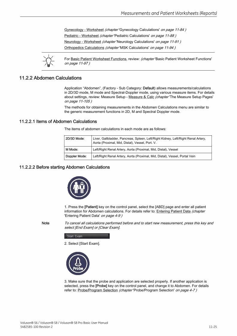
Gynecology - Worksheet (chapter 'Gynecology Calculations' on page 11-84 )Pediatric - Worksheet (chapter 'Pediatric Calculations' on page 11-88 )Neurology - Worksheet (chapter 'Neurology Calculations' on page 11-91 )Orthopedics Calculations (chapter 'MSK Calculations' on page 11-94 )
For Basic Patient Worksheet Functions, review: (chapter 'Basic Patient Worksheet Functions'on page 11-97 )
11.2.2 Abdomen Calculations
Application “Abdomen”, (Factory - Sub Category: Default) allows measurements/calculationsin 2D/3D mode, M mode and Spectral-Doppler mode, using various measure items. For detailsabout settings, review: Measure Setup - Measure & Calc (chapter 'The Measure Setup Pages'on page 11-105 )The methods for obtaining measurements in the Abdomen Calculations menu are similar tothe generic measurement functions in 2D, M and Spectral Doppler mode.
11.2.2.1 Items of Abdomen CalculationsThe items of abdomen calculations in each mode are as follows:
2D/3D Mode: Liver, Gallbladder, Pancreas, Spleen, Left/Right Kidney, Left/Right Renal Artery,Aorta (Proximal, Mid, Distal), Vessel, Port. V.
M Mode: Left/Right Renal Artery, Aorta (Proximal, Mid, Distal), Vessel
Doppler Mode: Left/Right Renal Artery, Aorta (Proximal, Mid, Distal), Vessel, Portal Vein
11.2.2.2 Before starting Abdomen Calculations
1. Press the [Patient] key on the control panel, select the [ABD] page and enter all patientinformation for Abdomen calculations. For details refer to: Entering Patient Data (chapter'Entering Patient Data' on page 4-9 )
Note To cancel all calculations performed before and to start new measurement, press this key andselect [End Exam] or [Clear Exam].
2. Select [Start Exam].
3. Make sure that the probe and application are selected properly. If another application isselected, press the [Probe] key on the control panel, and change it to Abdomen. For detailsrefer to: Probe/Program Selection (chapter 'Probe/Program Selection' on page 4-7 )
Measurements and Patient Worksheets (Reports)
Voluson® S6 / Voluson® S8 / Voluson® S8 Pro Basic User Manual5482585-100 Revision 2 11-25

11.2.2.3 Abdomen Calculations in 2D Mode
• Distance Measurements (chapter 'Distance Measurements' on page 11-26 ) (likeLength, Height, etc.)
• Vessel Area/Vessel Diameter (chapter 'Vessel Area/Vessel Diameter' on page 11-26 )
• Stenosis Area/Stenosis Diameter (chapter 'Stenosis Area/Stenosis Diameter' on page11-28 )
11.2.2.4 Distance MeasurementsTo measure a distance in 2D mode:
1. Press the [Calc] key on the control panel.
2. Select the desired item. For example: select [Liver].
3. Select the desired measurement parameter. For example: select [Length].
4. Use the trackball to move the cursor to the start point of the measurement and press theright or left trackball key [Set] to fix the marker. A second cursor appears.
5. Move the second cursor to the second point of the measurement and press [Set] again.
Note To re-adjust the start point, press the upper trackball key [Change] before completing themeasurement. This alternates the control from one cursor to the other.
11.2.2.5 Vessel Area/Vessel DiameterTo measure the Vessel Area or the Vessel Diameter in 2D mode:
Measurements and Patient Worksheets (Reports)
11-26Voluson® S6 / Voluson® S8 / Voluson® S8 Pro Basic User Manual
5482585-100 Revision 2
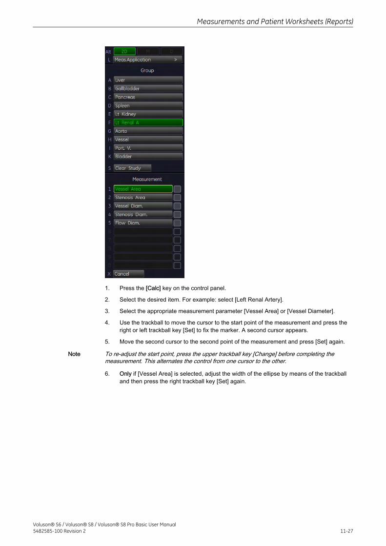
1. Press the [Calc] key on the control panel.
2. Select the desired item. For example: select [Left Renal Artery].
3. Select the appropriate measurement parameter [Vessel Area] or [Vessel Diameter].
4. Use the trackball to move the cursor to the start point of the measurement and press theright or left trackball key [Set] to fix the marker. A second cursor appears.
5. Move the second cursor to the second point of the measurement and press [Set] again.
Note To re-adjust the start point, press the upper trackball key [Change] before completing themeasurement. This alternates the control from one cursor to the other.
6. Only if [Vessel Area] is selected, adjust the width of the ellipse by means of the trackballand then press the right trackball key [Set] again.
Measurements and Patient Worksheets (Reports)
Voluson® S6 / Voluson® S8 / Voluson® S8 Pro Basic User Manual5482585-100 Revision 2 11-27
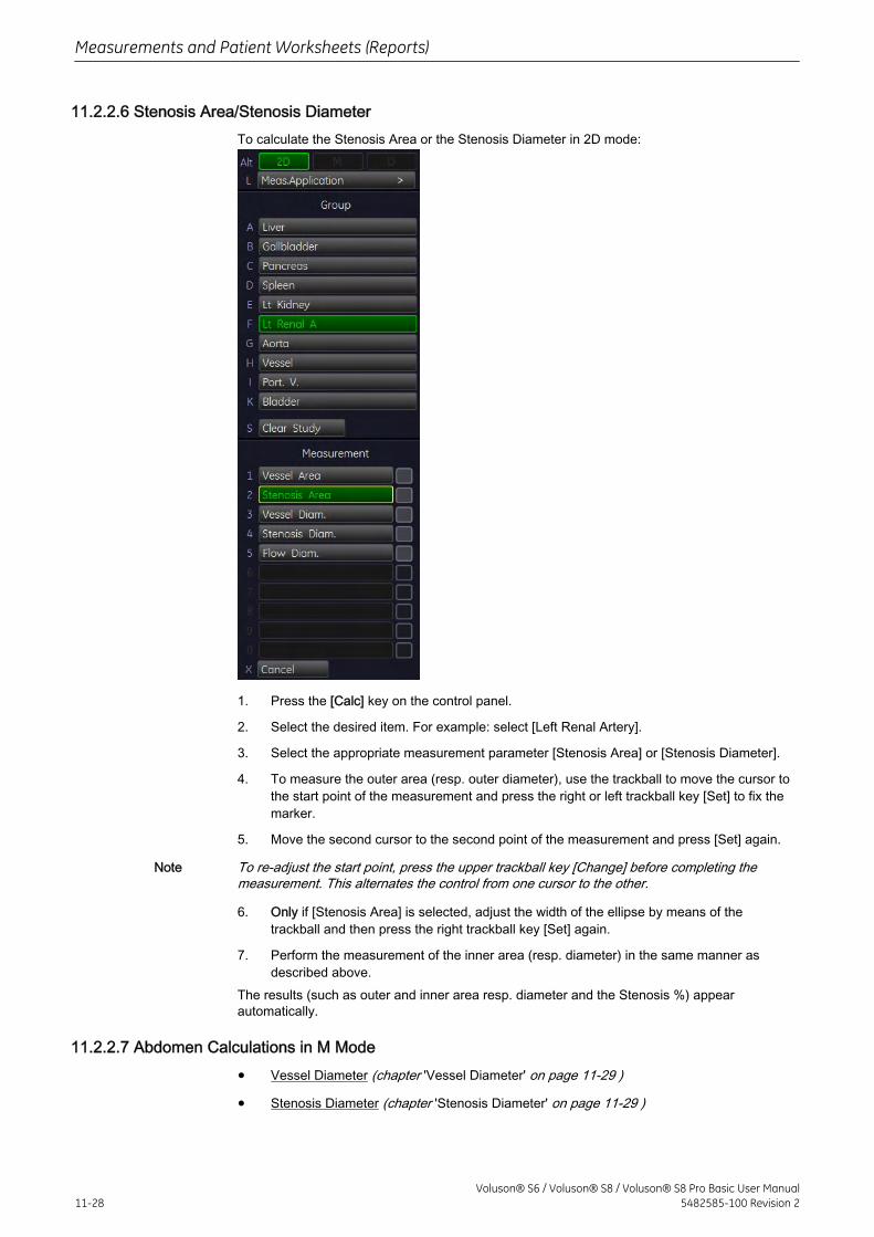
11.2.2.6 Stenosis Area/Stenosis DiameterTo calculate the Stenosis Area or the Stenosis Diameter in 2D mode:
1. Press the [Calc] key on the control panel.
2. Select the desired item. For example: select [Left Renal Artery].
3. Select the appropriate measurement parameter [Stenosis Area] or [Stenosis Diameter].
4. To measure the outer area (resp. outer diameter), use the trackball to move the cursor tothe start point of the measurement and press the right or left trackball key [Set] to fix themarker.
5. Move the second cursor to the second point of the measurement and press [Set] again.
Note To re-adjust the start point, press the upper trackball key [Change] before completing themeasurement. This alternates the control from one cursor to the other.
6. Only if [Stenosis Area] is selected, adjust the width of the ellipse by means of thetrackball and then press the right trackball key [Set] again.
7. Perform the measurement of the inner area (resp. diameter) in the same manner asdescribed above.
The results (such as outer and inner area resp. diameter and the Stenosis %) appearautomatically.
11.2.2.7 Abdomen Calculations in M Mode
• Vessel Diameter (chapter 'Vessel Diameter' on page 11-29 )
• Stenosis Diameter (chapter 'Stenosis Diameter' on page 11-29 )
Measurements and Patient Worksheets (Reports)
11-28Voluson® S6 / Voluson® S8 / Voluson® S8 Pro Basic User Manual
5482585-100 Revision 2
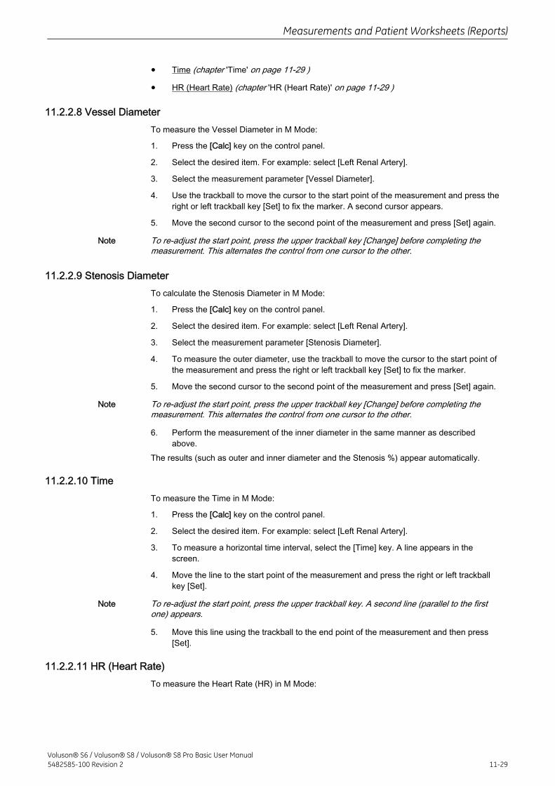
• Time (chapter 'Time' on page 11-29 )
• HR (Heart Rate) (chapter 'HR (Heart Rate)' on page 11-29 )
11.2.2.8 Vessel DiameterTo measure the Vessel Diameter in M Mode:
1. Press the [Calc] key on the control panel.
2. Select the desired item. For example: select [Left Renal Artery].
3. Select the measurement parameter [Vessel Diameter].
4. Use the trackball to move the cursor to the start point of the measurement and press theright or left trackball key [Set] to fix the marker. A second cursor appears.
5. Move the second cursor to the second point of the measurement and press [Set] again.
Note To re-adjust the start point, press the upper trackball key [Change] before completing themeasurement. This alternates the control from one cursor to the other.
11.2.2.9 Stenosis DiameterTo calculate the Stenosis Diameter in M Mode:
1. Press the [Calc] key on the control panel.
2. Select the desired item. For example: select [Left Renal Artery].
3. Select the measurement parameter [Stenosis Diameter].
4. To measure the outer diameter, use the trackball to move the cursor to the start point ofthe measurement and press the right or left trackball key [Set] to fix the marker.
5. Move the second cursor to the second point of the measurement and press [Set] again.
Note To re-adjust the start point, press the upper trackball key [Change] before completing themeasurement. This alternates the control from one cursor to the other.
6. Perform the measurement of the inner diameter in the same manner as describedabove.
The results (such as outer and inner diameter and the Stenosis %) appear automatically.
11.2.2.10 TimeTo measure the Time in M Mode:
1. Press the [Calc] key on the control panel.
2. Select the desired item. For example: select [Left Renal Artery].
3. To measure a horizontal time interval, select the [Time] key. A line appears in thescreen.
4. Move the line to the start point of the measurement and press the right or left trackballkey [Set].
Note To re-adjust the start point, press the upper trackball key. A second line (parallel to the firstone) appears.
5. Move this line using the trackball to the end point of the measurement and then press[Set].
11.2.2.11 HR (Heart Rate)To measure the Heart Rate (HR) in M Mode:
Measurements and Patient Worksheets (Reports)
Voluson® S6 / Voluson® S8 / Voluson® S8 Pro Basic User Manual5482585-100 Revision 2 11-29
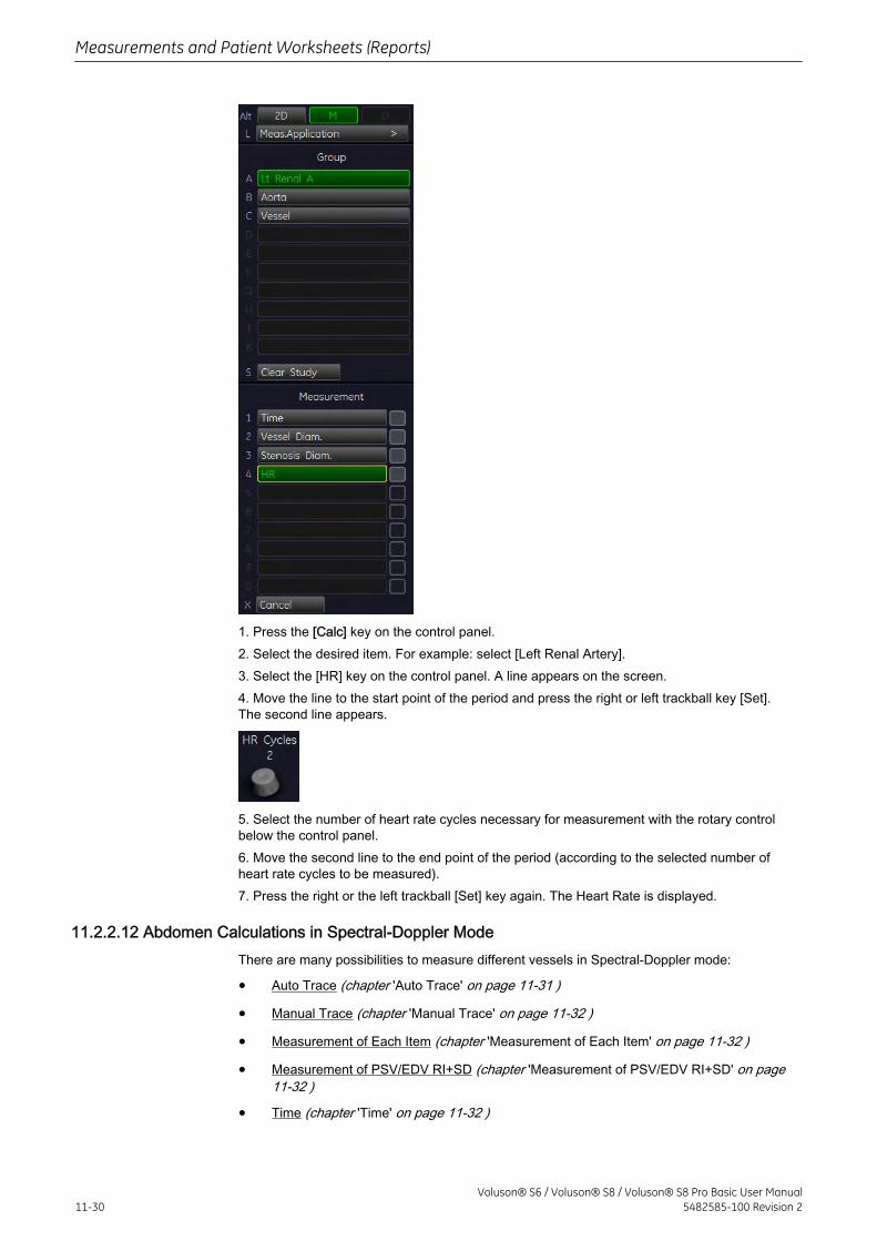
1. Press the [Calc] key on the control panel.2. Select the desired item. For example: select [Left Renal Artery].3. Select the [HR] key on the control panel. A line appears on the screen.4. Move the line to the start point of the period and press the right or left trackball key [Set].The second line appears.
5. Select the number of heart rate cycles necessary for measurement with the rotary controlbelow the control panel.6. Move the second line to the end point of the period (according to the selected number ofheart rate cycles to be measured).7. Press the right or the left trackball [Set] key again. The Heart Rate is displayed.
11.2.2.12 Abdomen Calculations in Spectral-Doppler ModeThere are many possibilities to measure different vessels in Spectral-Doppler mode:
• Auto Trace (chapter 'Auto Trace' on page 11-31 )
• Manual Trace (chapter 'Manual Trace' on page 11-32 )
• Measurement of Each Item (chapter 'Measurement of Each Item' on page 11-32 )
• Measurement of PSV/EDV RI+SD (chapter 'Measurement of PSV/EDV RI+SD' on page11-32 )
• Time (chapter 'Time' on page 11-32 )
Measurements and Patient Worksheets (Reports)
11-30Voluson® S6 / Voluson® S8 / Voluson® S8 Pro Basic User Manual
5482585-100 Revision 2
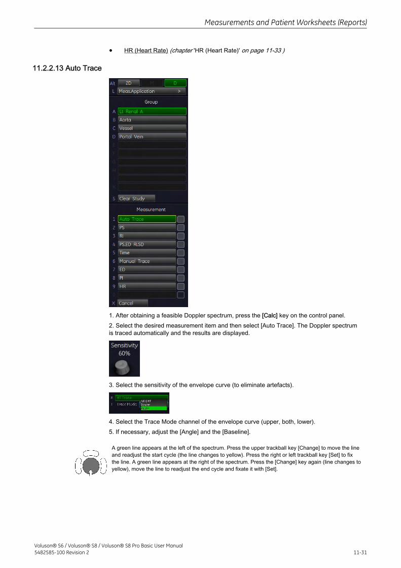
• HR (Heart Rate) (chapter 'HR (Heart Rate)' on page 11-33 )
11.2.2.13 Auto Trace
1. After obtaining a feasible Doppler spectrum, press the [Calc] key on the control panel.2. Select the desired measurement item and then select [Auto Trace]. The Doppler spectrumis traced automatically and the results are displayed.
3. Select the sensitivity of the envelope curve (to eliminate artefacts).
4. Select the Trace Mode channel of the envelope curve (upper, both, lower).5. If necessary, adjust the [Angle] and the [Baseline].
A green line appears at the left of the spectrum. Press the upper trackball key [Change] to move the lineand readjust the start cycle (the line changes to yellow). Press the right or left trackball key [Set] to fixthe line. A green line appears at the right of the spectrum. Press the [Change] key again (line changes toyellow), move the line to readjust the end cycle and fixate it with [Set].
Measurements and Patient Worksheets (Reports)
Voluson® S6 / Voluson® S8 / Voluson® S8 Pro Basic User Manual5482585-100 Revision 2 11-31
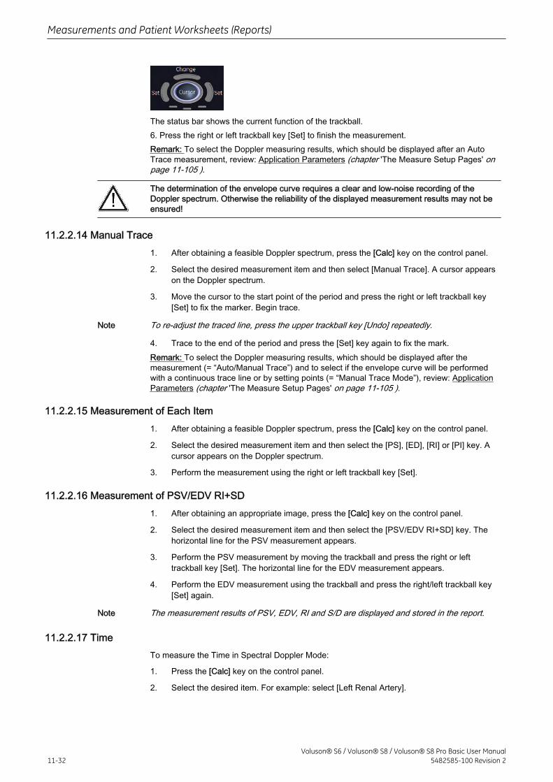
The status bar shows the current function of the trackball.6. Press the right or left trackball key [Set] to finish the measurement.Remark: To select the Doppler measuring results, which should be displayed after an AutoTrace measurement, review: Application Parameters (chapter 'The Measure Setup Pages' onpage 11-105 ).
The determination of the envelope curve requires a clear and low-noise recording of theDoppler spectrum. Otherwise the reliability of the displayed measurement results may not beensured!
11.2.2.14 Manual Trace1. After obtaining a feasible Doppler spectrum, press the [Calc] key on the control panel.
2. Select the desired measurement item and then select [Manual Trace]. A cursor appearson the Doppler spectrum.
3. Move the cursor to the start point of the period and press the right or left trackball key[Set] to fix the marker. Begin trace.
Note To re-adjust the traced line, press the upper trackball key [Undo] repeatedly.
4. Trace to the end of the period and press the [Set] key again to fix the mark.Remark: To select the Doppler measuring results, which should be displayed after themeasurement (= “Auto/Manual Trace”) and to select if the envelope curve will be performedwith a continuous trace line or by setting points (= “Manual Trace Mode”), review: ApplicationParameters (chapter 'The Measure Setup Pages' on page 11-105 ).
11.2.2.15 Measurement of Each Item1. After obtaining a feasible Doppler spectrum, press the [Calc] key on the control panel.
2. Select the desired measurement item and then select the [PS], [ED], [RI] or [PI] key. Acursor appears on the Doppler spectrum.
3. Perform the measurement using the right or left trackball key [Set].
11.2.2.16 Measurement of PSV/EDV RI+SD1. After obtaining an appropriate image, press the [Calc] key on the control panel.
2. Select the desired measurement item and then select the [PSV/EDV RI+SD] key. Thehorizontal line for the PSV measurement appears.
3. Perform the PSV measurement by moving the trackball and press the right or lefttrackball key [Set]. The horizontal line for the EDV measurement appears.
4. Perform the EDV measurement using the trackball and press the right/left trackball key[Set] again.
Note The measurement results of PSV, EDV, RI and S/D are displayed and stored in the report.
11.2.2.17 TimeTo measure the Time in Spectral Doppler Mode:
1. Press the [Calc] key on the control panel.
2. Select the desired item. For example: select [Left Renal Artery].
Measurements and Patient Worksheets (Reports)
11-32Voluson® S6 / Voluson® S8 / Voluson® S8 Pro Basic User Manual
5482585-100 Revision 2
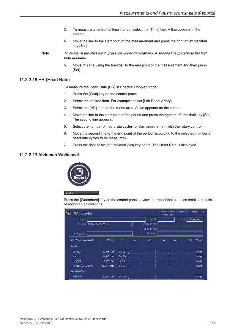
3. To measure a horizontal time interval, select the [Time] key. A line appears in thescreen.
4. Move the line to the start point of the measurement and press the right or left trackballkey [Set].
Note To re-adjust the start point, press the upper trackball key. A second line (parallel to the firstone) appears.
5. Move this line using the trackball to the end point of the measurement and then press[Set].
11.2.2.18 HR (Heart Rate)To measure the Heart Rate (HR) in Spectral Doppler Mode:
1. Press the [Calc] key on the control panel.
2. Select the desired item. For example: select [Left Renal Artery].
3. Select the [HR] item on the menu area. A line appears on the screen.
4. Move the line to the start point of the period and press the right or left trackball key [Set].The second line appears.
5. Select the number of heart rate cycles for the measurement with the rotary control.
6. Move the second line to the end point of the period (according to the selected number ofheart rate cycles to be measured).
7. Press the right or the left trackball [Set] key again. The Heart Rate is displayed.
11.2.2.19 Abdomen Worksheet
Press the [Worksheet] key on the control panel to view the report that contains detailed resultsof abdomen calculations
Measurements and Patient Worksheets (Reports)
Voluson® S6 / Voluson® S8 / Voluson® S8 Pro Basic User Manual5482585-100 Revision 2 11-33
With this flip control additional worksheet pages can be selected.To close the worksheet, select the [Exit] key on the menu area.For additional description please refer to Basic Patient Worksheet Functions (chapter 'BasicPatient Worksheet Functions' on page 11-97 ).
11.2.3 Small Parts Calculations
Application “Small Parts”, (Factory - Sub Category: Default, Breast) allows measurements/calculations in 2D/3D mode, M mode and Spectral-Doppler mode, using various measureitems. For details about settings, review: Measure Setup - Measure & Calc (chapter 'TheMeasure Setup Pages' on page 11-105 )The methods for obtaining measurements in the Small Parts Calculations menu are similar tothe generic measurement functions in 2D, M and Spectral Doppler mode.
11.2.3.1 Items of Small Parts Calculations - Subcategory: DefaultThe items of small parts calculations in each mode are as follows:
2D/3D Mode Left/Right Thyroid, Left/Right Testicle
M Mode: Vessel
Doppler Mode: Vessel
11.2.3.2 Items of Small Parts Calculations - Subcategory: BreastThe items of small parts calculations in each mode are as follows:
2D/3D Mode Left/Right Lesion 1, Left/Right Lesion 2, Left/Right Lesion3, Left/Right Lesion 4, Left/Right Lesion 5
M Mode: Vessel
Doppler Mode: Vessel
11.2.3.3 Before starting Small Parts Calculations
1. Press the [Patient] key on the control panel, select the [SM P] page and enter all patientinformation for Small Parts calculations. For details refer to: Entering Patient Data (chapter'Entering Patient Data' on page 4-9 )
Note To cancel all calculations performed before and to start new measurement, press this key andselect [End Exam] or [Clear Exam].
2. Select [Start Exam].
Measurements and Patient Worksheets (Reports)
11-34Voluson® S6 / Voluson® S8 / Voluson® S8 Pro Basic User Manual
5482585-100 Revision 2
3. Make sure that the probe and application are selected properly. If another application isselected, press the [Probe] key on the control panel, and change it to Small Parts. For detailsrefer to: Probe/Program Selection (chapter 'Probe/Program Selection' on page 4-7 )
11.2.3.4 Small Parts Calculations in 2D Mode
• Distance Measurements (like Length, Height, etc.)
• Vessel Area/Vessel Diameter
• Stenosis Area/Stenosis Diameter
The measurement procedures in 2D Mode are the same than in application “Abdomen”.review: Abdomen Calculations in 2D Mode (chapter 'Abdomen Calculations' on page 11-25 ).
11.2.3.5 Small Parts Calculations in M Mode
• Vessel Diameter
• Stenosis Diameter
• Time
• HR (Heart Rate)
The measurement procedures in M Mode are the same than in application “Abdomen”. review:Abdomen Calculations in M Mode (chapter 'Abdomen Calculations' on page 11-25 ).
11.2.3.6 Small Parts Calculations in Spectral-Doppler Mode
• Auto Trace
• Manual Trace
• Measurement of Each Item
• Measurement of PSV/EDV RI+SD
• Time
• HR (Heart Rate)
The measurement procedures in Spectral Doppler Mode are the same than in application“Abdomen”. review: Abdomen Calculations in Spectral Doppler Mode (chapter 'AbdomenCalculations' on page 11-25 ).
11.2.3.7 Small Parts - Worksheet
Measurements and Patient Worksheets (Reports)
Voluson® S6 / Voluson® S8 / Voluson® S8 Pro Basic User Manual5482585-100 Revision 2 11-35
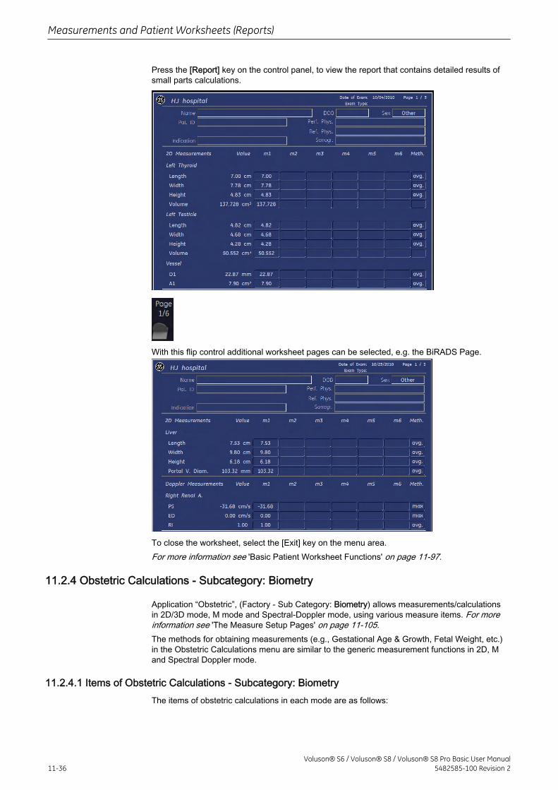
Press the [Report] key on the control panel, to view the report that contains detailed results ofsmall parts calculations.
With this flip control additional worksheet pages can be selected, e.g. the BiRADS Page.
To close the worksheet, select the [Exit] key on the menu area.For more information see 'Basic Patient Worksheet Functions' on page 11-97.
11.2.4 Obstetric Calculations - Subcategory: Biometry
Application “Obstetric”, (Factory - Sub Category: Biometry) allows measurements/calculationsin 2D/3D mode, M mode and Spectral-Doppler mode, using various measure items. For moreinformation see 'The Measure Setup Pages' on page 11-105.The methods for obtaining measurements (e.g., Gestational Age & Growth, Fetal Weight, etc.)in the Obstetric Calculations menu are similar to the generic measurement functions in 2D, Mand Spectral Doppler mode.
11.2.4.1 Items of Obstetric Calculations - Subcategory: BiometryThe items of obstetric calculations in each mode are as follows:
Measurements and Patient Worksheets (Reports)
11-36Voluson® S6 / Voluson® S8 / Voluson® S8 Pro Basic User Manual
5482585-100 Revision 2
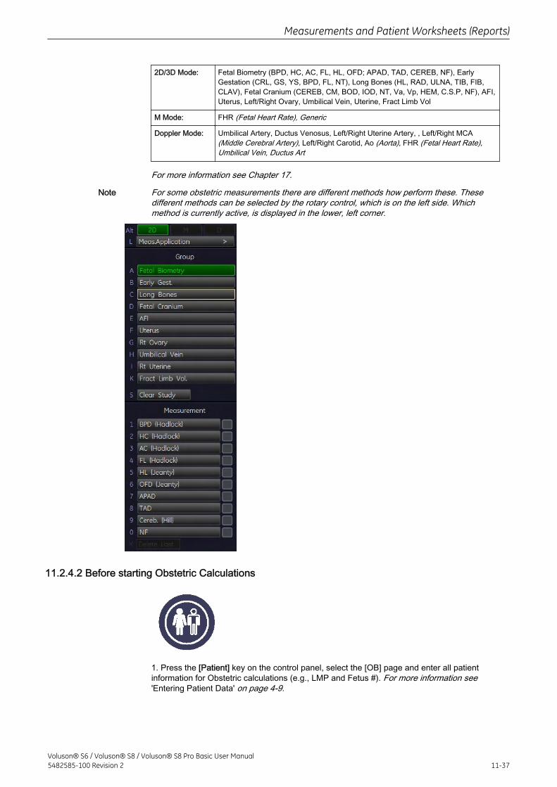
2D/3D Mode: Fetal Biometry (BPD, HC, AC, FL, HL, OFD; APAD, TAD, CEREB, NF), EarlyGestation (CRL, GS, YS, BPD, FL, NT), Long Bones (HL, RAD, ULNA, TIB, FIB,CLAV), Fetal Cranium (CEREB, CM, BOD, IOD, NT, Va, Vp, HEM, C.S.P, NF), AFI,Uterus, Left/Right Ovary, Umbilical Vein, Uterine, Fract Limb Vol
M Mode: FHR (Fetal Heart Rate), Generic
Doppler Mode: Umbilical Artery, Ductus Venosus, Left/Right Uterine Artery, , Left/Right MCA(Middle Cerebral Artery), Left/Right Carotid, Ao (Aorta), FHR (Fetal Heart Rate),Umbilical Vein, Ductus Art
For more information see Chapter 17.
Note For some obstetric measurements there are different methods how perform these. Thesedifferent methods can be selected by the rotary control, which is on the left side. Whichmethod is currently active, is displayed in the lower, left corner.
11.2.4.2 Before starting Obstetric Calculations
1. Press the [Patient] key on the control panel, select the [OB] page and enter all patientinformation for Obstetric calculations (e.g., LMP and Fetus #). For more information see'Entering Patient Data' on page 4-9.
Measurements and Patient Worksheets (Reports)
Voluson® S6 / Voluson® S8 / Voluson® S8 Pro Basic User Manual5482585-100 Revision 2 11-37
Note To cancel all calculations performed before and to start new measurement, press this key andselect [End Exam] or [Clear Exam].
Each OB exam supports multiple gestation studies with separate worksheet information foreach fetus.
For multiple gestation examinations the corresponding “Fetus #” (max. 4 fetuses) must beentered in this page before measurements are performed.
If a Fetus number has been entered, several fetuses can be measured on one patient.
Select this flip switch control to change from fetus A to B or C or fetus D.
2. Make sure that the probe and application are selected properly. If another application isselected, press the [Probe] key on the control panel, and change it to Obstetric. For moreinformation see 'Probe/Program Selection' on page 4-7.
11.2.4.3 Obstetric Calculations in 2D Mode
• 'Distance Measurements' on page 11-39 (like BPD, FL, etc.)
• 'Circumference Measurements' on page 11-40 (like HC, AC, etc.)
• 'AFI Calculation' on page 11-42
Measurements and Patient Worksheets (Reports)
11-38Voluson® S6 / Voluson® S8 / Voluson® S8 Pro Basic User Manual
5482585-100 Revision 2
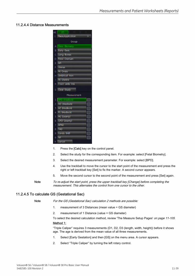
11.2.4.4 Distance Measurements
1. Press the [Calc] key on the control panel.
2. Select the study for the corresponding item. For example: select [Fetal Biometry].
3. Select the desired measurement parameter. For example: select [BPD].
4. Use the trackball to move the cursor to the start point of the measurement and press theright or left trackball key [Set] to fix the marker. A second cursor appears.
5. Move the second cursor to the second point of the measurement and press [Set] again.
Note To re-adjust the start point, press the upper trackball key [Change] before completing themeasurement. This alternates the control from one cursor to the other.
11.2.4.5 To calculate GS (Gestational Sac)
Note For the GS (Gestational Sac) calculation 2 methods are possible:
1. measurement of 3 Distances (mean value = GS diameter)
2. measurement of 1 Distance (value = GS diameter)To select the desired calculation method, review 'The Measure Setup Pages' on page 11-105.Method 1:“Triple Caliper” requires 3 measurements (D1, D2, D3 (length, width, height)) before it showsage. The age is derived from the mean value of all three measurements.
1. Select [Early Gestation] and then [GS] on the menu area. A cursor appears.
2. Select “Triple Caliper” by turning the left rotary control.
Measurements and Patient Worksheets (Reports)
Voluson® S6 / Voluson® S8 / Voluson® S8 Pro Basic User Manual5482585-100 Revision 2 11-39
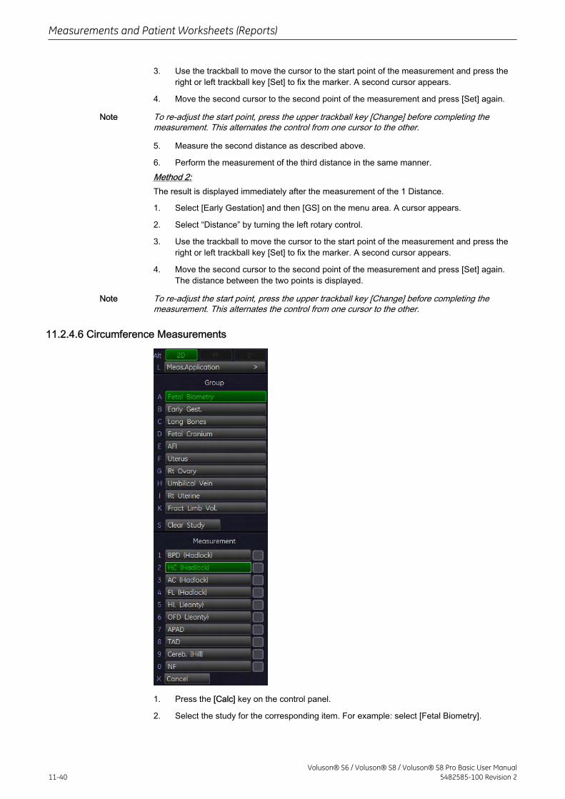
3. Use the trackball to move the cursor to the start point of the measurement and press theright or left trackball key [Set] to fix the marker. A second cursor appears.
4. Move the second cursor to the second point of the measurement and press [Set] again.
Note To re-adjust the start point, press the upper trackball key [Change] before completing themeasurement. This alternates the control from one cursor to the other.
5. Measure the second distance as described above.
6. Perform the measurement of the third distance in the same manner.Method 2:The result is displayed immediately after the measurement of the 1 Distance.
1. Select [Early Gestation] and then [GS] on the menu area. A cursor appears.
2. Select “Distance” by turning the left rotary control.
3. Use the trackball to move the cursor to the start point of the measurement and press theright or left trackball key [Set] to fix the marker. A second cursor appears.
4. Move the second cursor to the second point of the measurement and press [Set] again.The distance between the two points is displayed.
Note To re-adjust the start point, press the upper trackball key [Change] before completing themeasurement. This alternates the control from one cursor to the other.
11.2.4.6 Circumference Measurements
1. Press the [Calc] key on the control panel.
2. Select the study for the corresponding item. For example: select [Fetal Biometry].
Measurements and Patient Worksheets (Reports)
11-40Voluson® S6 / Voluson® S8 / Voluson® S8 Pro Basic User Manual
5482585-100 Revision 2
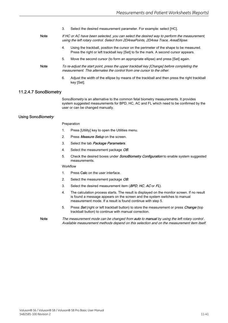
3. Select the desired measurement parameter. For example: select [HC].
Note If HC or AC have been selected, you can select the desired way to perform the measurement,using the left rotary control. Select from 2DAreaPoints, 2DArea Trace, AreaEllipse.
4. Using the trackball, position the cursor on the perimeter of the shape to be measured.Press the right or left trackball key [Set] to fix the mark. A second cursor appears.
5. Move the second cursor (to form an appropriate ellipse) and press [Set] again.
Note To re-adjust the start point, press the upper trackball key [Change] before completing themeasurement. This alternates the control from one cursor to the other.
6. Adjust the width of the ellipse by means of the trackball and then press the right trackballkey [Set].
11.2.4.7 SonoBiometrySonoBiometry is an alternative to the common fetal biometry measurements. It providessystem suggested measurements for BPD, HC, AC and FL which need to be confirmed by theuser or can be changed manually.
Using SonoBiometryPreparation
1. Press [Utility] key to open the Utilities menu.
2. Press Measure Setup on the screen.
3. Select the tab Package Parameters.
4. Select the measurement package OB.
5. Check the desired boxes under SonoBiometry Configuration to enable system suggestedmeasurements.
Workflow
1. Press Calc on the user interface.
2. Select the measurement package OB.
3. Select the desired measurement item (BPD, HC, AC or FL).
4. The calculation process starts. The result is displayed on the monitor screen. If no resultis found a message appears on the screen and the system switches to manualmeasurement mode. If a result is found continue with step 5.
5. Press Set (right or left trackball button) to store the measurement or press Change (toptrackball button) to continue with manual correction.
Note The measurement mode can be changed from auto to manual by using the left rotary control .Available measurement methods depend on this selection and on the measurement item itself.
Measurements and Patient Worksheets (Reports)
Voluson® S6 / Voluson® S8 / Voluson® S8 Pro Basic User Manual5482585-100 Revision 2 11-41
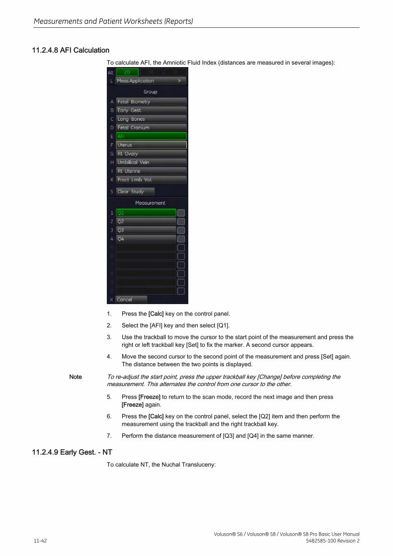
11.2.4.8 AFI CalculationTo calculate AFI, the Amniotic Fluid Index (distances are measured in several images):
1. Press the [Calc] key on the control panel.
2. Select the [AFI] key and then select [Q1].
3. Use the trackball to move the cursor to the start point of the measurement and press theright or left trackball key [Set] to fix the marker. A second cursor appears.
4. Move the second cursor to the second point of the measurement and press [Set] again.The distance between the two points is displayed.
Note To re-adjust the start point, press the upper trackball key [Change] before completing themeasurement. This alternates the control from one cursor to the other.
5. Press [Freeze] to return to the scan mode, record the next image and then press[Freeze] again.
6. Press the [Calc] key on the control panel, select the [Q2] item and then perform themeasurement using the trackball and the right trackball key.
7. Perform the distance measurement of [Q3] and [Q4] in the same manner.
11.2.4.9 Early Gest. - NTTo calculate NT, the Nuchal Transluceny:
Measurements and Patient Worksheets (Reports)
11-42Voluson® S6 / Voluson® S8 / Voluson® S8 Pro Basic User Manual
5482585-100 Revision 2
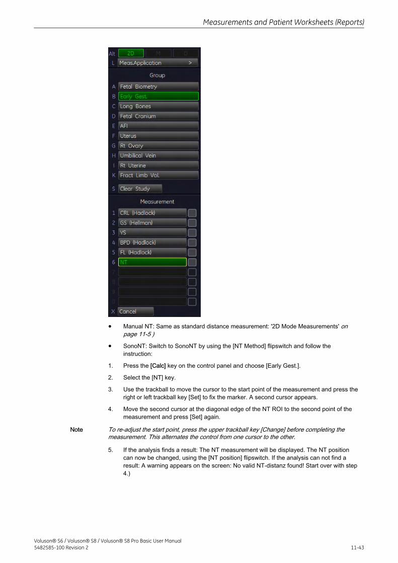
• Manual NT: Same as standard distance measurement: '2D Mode Measurements' onpage 11-5 )
• SonoNT: Switch to SonoNT by using the [NT Method] flipswitch and follow theinstruction:
1. Press the [Calc] key on the control panel and choose [Early Gest.].
2. Select the [NT] key.
3. Use the trackball to move the cursor to the start point of the measurement and press theright or left trackball key [Set] to fix the marker. A second cursor appears.
4. Move the second cursor at the diagonal edge of the NT ROI to the second point of themeasurement and press [Set] again.
Note To re-adjust the start point, press the upper trackball key [Change] before completing themeasurement. This alternates the control from one cursor to the other.
5. If the analysis finds a result: The NT measurement will be displayed. The NT positioncan now be changed, using the [NT position] flipswitch. If the analysis can not find aresult: A warning appears on the screen: No valid NT-distanz found! Start over with step4.)
Measurements and Patient Worksheets (Reports)
Voluson® S6 / Voluson® S8 / Voluson® S8 Pro Basic User Manual5482585-100 Revision 2 11-43
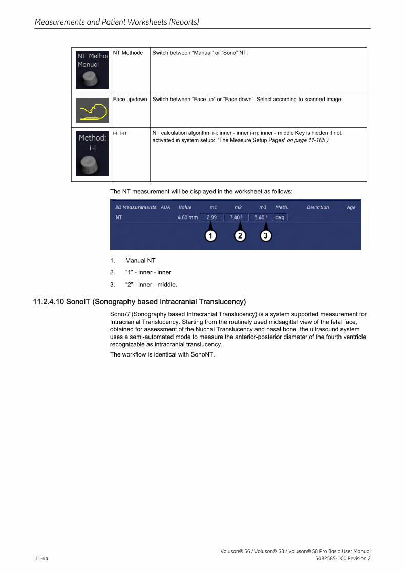
NT Methode Switch between “Manual” or “Sono” NT.
Face up/down Switch between “Face up” or “Face down”. Select according to scanned image.
i-i, i-m NT calculation algorithm i-i: inner - inner i-m: inner - middle Key is hidden if notactivated in system setup:. 'The Measure Setup Pages' on page 11-105 )
The NT measurement will be displayed in the worksheet as follows:
1. Manual NT
2. “1” - inner - inner
3. “2” - inner - middle.
11.2.4.10 SonoIT (Sonography based Intracranial Translucency)SonoIT (Sonography based Intracranial Translucency) is a system supported measurement forIntracranial Translucency. Starting from the routinely used midsagittal view of the fetal face,obtained for assessment of the Nuchal Translucency and nasal bone, the ultrasound systemuses a semi-automated mode to measure the anterior-posterior diameter of the fourth ventriclerecognizable as intracranial translucency.The workflow is identical with SonoNT.
Measurements and Patient Worksheets (Reports)
11-44Voluson® S6 / Voluson® S8 / Voluson® S8 Pro Basic User Manual
5482585-100 Revision 2
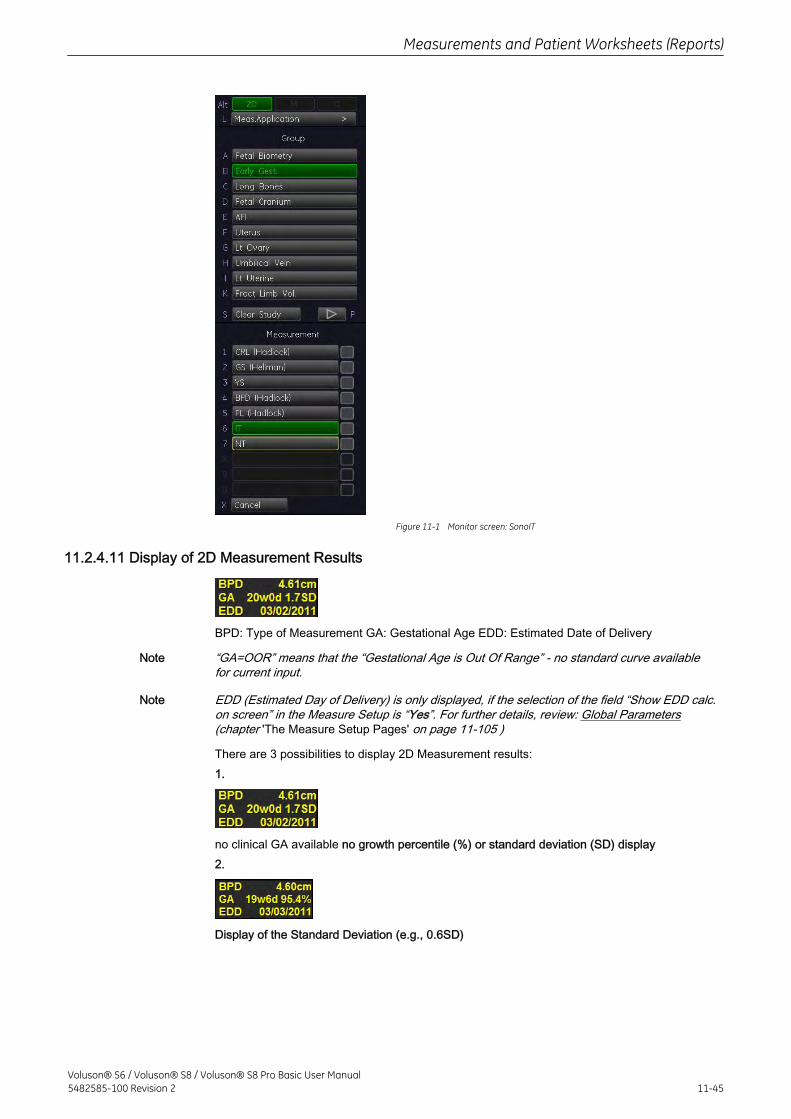
Figure 11-1 Monitor screen: SonoIT
11.2.4.11 Display of 2D Measurement Results
BPD: Type of Measurement GA: Gestational Age EDD: Estimated Date of Delivery
Note “GA=OOR” means that the “Gestational Age is Out Of Range” - no standard curve availablefor current input.
Note EDD (Estimated Day of Delivery) is only displayed, if the selection of the field “Show EDD calc.on screen” in the Measure Setup is “Yes”. For further details, review: Global Parameters(chapter 'The Measure Setup Pages' on page 11-105 )
There are 3 possibilities to display 2D Measurement results:1.
no clinical GA available no growth percentile (%) or standard deviation (SD) display2.
Display of the Standard Deviation (e.g., 0.6SD)
Measurements and Patient Worksheets (Reports)
Voluson® S6 / Voluson® S8 / Voluson® S8 Pro Basic User Manual5482585-100 Revision 2 11-45
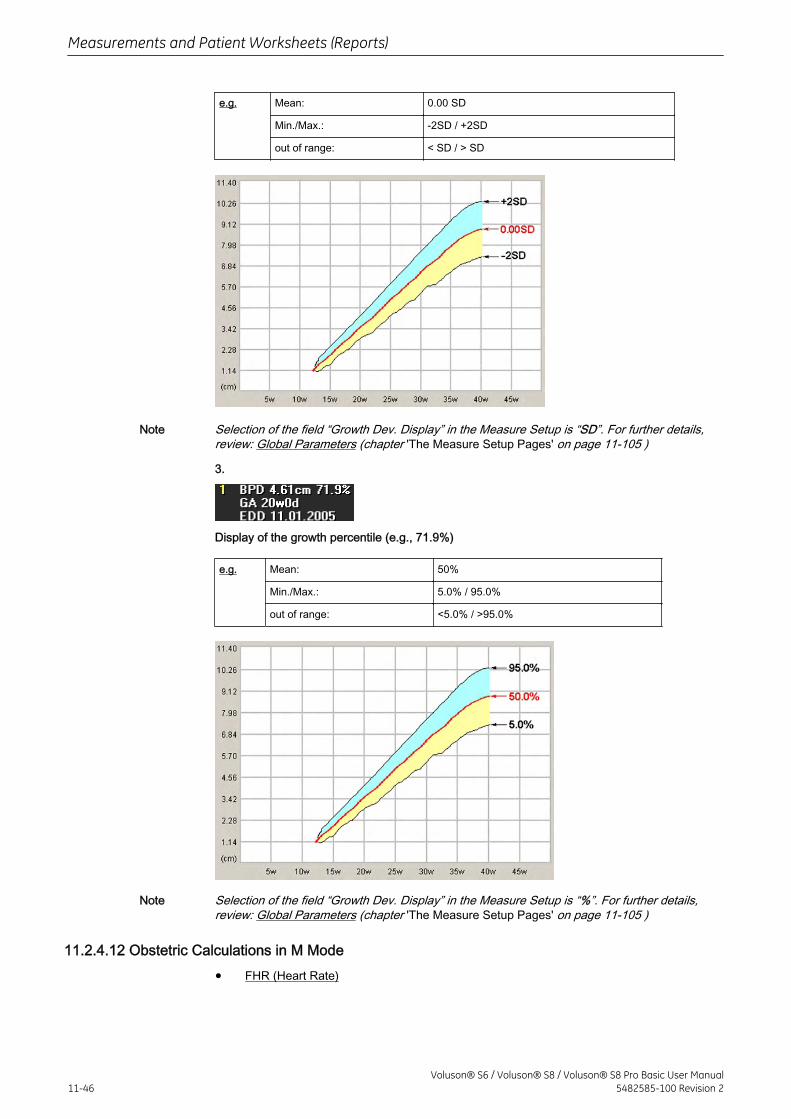
e.g. Mean: 0.00 SD
Min./Max.: -2SD / +2SD
out of range: < SD / > SD
Note Selection of the field “Growth Dev. Display” in the Measure Setup is “SD”. For further details,review: Global Parameters (chapter 'The Measure Setup Pages' on page 11-105 )
3.
Display of the growth percentile (e.g., 71.9%)
e.g. Mean: 50%
Min./Max.: 5.0% / 95.0%
out of range: <5.0% / >95.0%
Note Selection of the field “Growth Dev. Display” in the Measure Setup is “%”. For further details,review: Global Parameters (chapter 'The Measure Setup Pages' on page 11-105 )
11.2.4.12 Obstetric Calculations in M Mode
• FHR (Heart Rate)
Measurements and Patient Worksheets (Reports)
11-46Voluson® S6 / Voluson® S8 / Voluson® S8 Pro Basic User Manual
5482585-100 Revision 2
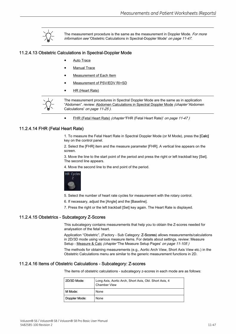
The measurement procedure is the same as the measurement in Doppler Mode. For moreinformation see 'Obstetric Calculations in Spectral-Doppler Mode' on page 11-47.
11.2.4.13 Obstetric Calculations in Spectral-Doppler Mode
• Auto Trace
• Manual Trace
• Measurement of Each Item
• Measurement of PSV/EDV RI+SD
• HR (Heart Rate)
The measurement procedures in Spectral Doppler Mode are the same as in application“Abdomen”. review: Abdomen Calculations in Spectral Doppler Mode (chapter 'AbdomenCalculations' on page 11-25 ).
• FHR (Fetal Heart Rate) (chapter 'FHR (Fetal Heart Rate)' on page 11-47 )
11.2.4.14 FHR (Fetal Heart Rate)1. To measure the Fetal Heart Rate in Spectral Doppler Mode (or M Mode), press the [Calc]key on the control panel.2. Select the [FHR] item and the measure parameter [FHR]. A vertical line appears on thescreen.3. Move the line to the start point of the period and press the right or left trackball key [Set].The second line appears.4. Move the second line to the end point of the period.
5. Select the number of heart rate cycles for measurement with the rotary control.6. If necessary, adjust the [Angle] and the [Baseline].7. Press the right or the left trackball [Set] key again. The Heart Rate is displayed.
11.2.4.15 Obstetrics - Subcategory Z-ScoresThis subcategory contains measurements that help you to obtain the Z-scores needed foranalysation of the fetal heart.Application “Obstetric”, (Factory - Sub Category: Z-Scores) allows measurements/calculationsin 2D/3D mode using various measure items. For details about settings, review: MeasureSetup - Measure & Calc (chapter 'The Measure Setup Pages' on page 11-105 )The methods for obtaining measurements (e.g., Aortic Arch View, Short Axis View etc.) in theObstetric Calculations menu are similar to the generic measurement functions in 2D.
11.2.4.16 Items of Obstetric Calculations - Subcategory: Z-scoresThe items of obstetric calculations - subcategory z-scores in each mode are as follows:
2D/3D Mode: Long Axis, Aortic Arch, Short Axis, Obl. Short Axis, 4Chamber View
M Mode: None
Doppler Mode: None
Measurements and Patient Worksheets (Reports)
Voluson® S6 / Voluson® S8 / Voluson® S8 Pro Basic User Manual5482585-100 Revision 2 11-47
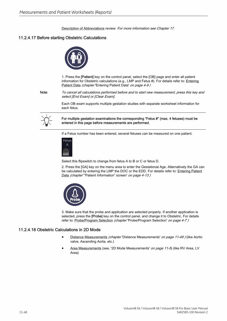
Description of Abbreviations review: For more information see Chapter 17.
11.2.4.17 Before starting Obstetric Calculations
1. Press the [Patient] key on the control panel, select the [OB] page and enter all patientinformation for Obstetric calculations (e.g., LMP and Fetus #). For details refer to: EnteringPatient Data (chapter 'Entering Patient Data' on page 4-9 )
Note To cancel all calculations performed before and to start new measurement, press this key andselect [End Exam] or [Clear Exam].
Each OB exam supports multiple gestation studies with separate worksheet information foreach fetus.
For multiple gestation examinations the corresponding “Fetus #” (max. 4 fetuses) must beentered in this page before measurements are performed.
If a Fetus number has been entered, several fetuses can be measured on one patient.
Select this flipswitch to change from fetus A to B or C or fetus D.2. Press the [GA] key on the menu area to enter the Gestational Age. Alternatively the GA canbe calculated by entering the LMP the DOC or the EDD. For details refer to: Entering PatientData (chapter '“Patient Information” screen' on page 4-13 )
3. Make sure that the probe and application are selected properly. If another application isselected, press the [Probe] key on the control panel, and change it to Obstetric. For detailsrefer to: Probe/Program Selection (chapter 'Probe/Program Selection' on page 4-7 )
11.2.4.18 Obstetric Calculations in 2D Mode
• Distance Measurements (chapter 'Distance Measurements' on page 11-49 ) (like Aorticvalve, Ascending Aorta, etc.)
• Area Measurements (see, '2D Mode Measurements' on page 11-5) (like RV Area, LVArea)
Measurements and Patient Worksheets (Reports)
11-48Voluson® S6 / Voluson® S8 / Voluson® S8 Pro Basic User Manual
5482585-100 Revision 2

11.2.4.19 Distance Measurements
1. Press the [Calc] key on the control panel.
2. Select the [Meas. Applicat.] key
3. Select [Fetal Echo]
4. Select a study for the corresponding item. For example: select [Aortic arch].
5. Select the desired measurement parameter. For example: select [Anulus].
6. Use the trackball to move the cursor to the start point of the measurement and press theright or left trackball key [Set] to fix the marker. A second cursor appears.
7. Move the second cursor to the second point of the measurement and press [Set] again.
Note To re-adjust the start point, press the upper trackball key [Change] before completing themeasurement. This alternates the control from one cursor to the other.
8. If necessary, choose another measurement parameter and continue with steps 6, 7 and8 until you have taken enough measurements.
REFERENCE: Schneider C. et. al., “Development of Z-scores for fetal cardiac dimensionsfrom echocardio-graphy”, Ultrasound Obstet Gynecol. Vol. 26, 2005, pages 599-605.Fomulas:Z-scores = (ln(actual) - ln(predicted cardiac dimensions)) / Root MSEln (predicted cardiac dimensions) = m.ln(FL, GA or BPD) + cFL...femur length; GA...gestational age in completed weeks; BPD...biparietal diameter;m...multiplier; c...intercept
Measurements and Patient Worksheets (Reports)
Voluson® S6 / Voluson® S8 / Voluson® S8 Pro Basic User Manual5482585-100 Revision 2 11-49
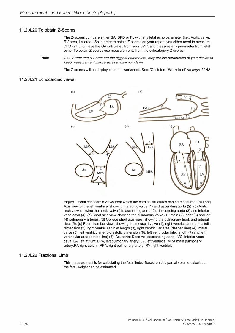
11.2.4.20 To obtain Z-ScoresThe Z-scores compare either GA, BPD or FL with any fetal echo parameter (i.e.: Aortic valve,RV area, LV area). So in order to obtain Z-scores on your report, you either need to measureBPD or FL, or have the GA calculated from your LMP; and measure any parameter from fetalecho. To obtain Z-scores use measurements from the subcategory Z-scores.
Note As LV area and RV area are the biggest parameters, they are the parameters of your choice tokeep measurement inaccuracies at minimum level.
The Z-scores will be displayed on the worksheet. See, 'Obstetric - Worksheet' on page 11-52
11.2.4.21 Echocardiac views
Figure 1 Fetal echocardic views from which the cardiac structures can be measured. (a) LongAxis view of the left ventricel showing the aortic valve (1) and ascending aorta (2). (b) Aorticarch view showing the aortic valve (1), ascending aorta (2), descending aorta (3) and inferiorvena cava (4). (c) Short axis view showing the pulmonary valve (1), main (2), right (3) and left(4) pulmonary arteries. (d) Oblique short axis view, showing the pulmonary trunk and arterialduct (5). (e) Four chamber view, showing the tricuspid valve (1), right ventricular end-diastolicdimension (2), right ventricular inlet length (3), right ventricular area (dashed line) (4), mitralvalve (5), left ventricular end-diastolic dimension (6), left ventricular inlet length (7) and leftventricular area (dotted line) (8). Ao, aorta; Desc Ao, descending aorta; IVC, inferior venacava; LA, left atrium; LPA, left pulmonary artery; LV, left ventricle; MPA main pulmonaryartery;RA right atrium; RPA, right pulmonary artery; RV right ventricle.
11.2.4.22 Fractional LimbThis measurement is for calculating the fetal limbs. Based on this partial volume-calculationthe fetal weight can be estimated.
Measurements and Patient Worksheets (Reports)
11-50Voluson® S6 / Voluson® S8 / Voluson® S8 Pro Basic User Manual
5482585-100 Revision 2
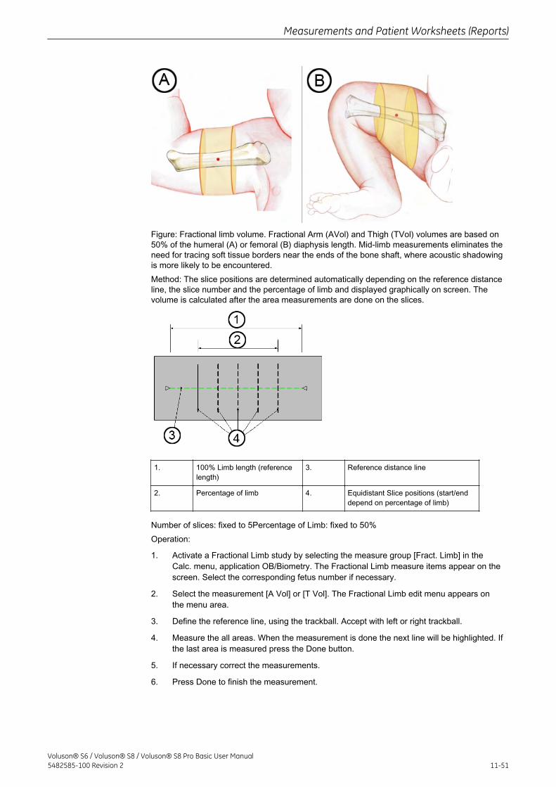
Figure: Fractional limb volume. Fractional Arm (AVol) and Thigh (TVol) volumes are based on50% of the humeral (A) or femoral (B) diaphysis length. Mid-limb measurements eliminates theneed for tracing soft tissue borders near the ends of the bone shaft, where acoustic shadowingis more likely to be encountered.Method: The slice positions are determined automatically depending on the reference distanceline, the slice number and the percentage of limb and displayed graphically on screen. Thevolume is calculated after the area measurements are done on the slices.
1. 100% Limb length (referencelength)
3. Reference distance line
2. Percentage of limb 4. Equidistant Slice positions (start/enddepend on percentage of limb)
Number of slices: fixed to 5Percentage of Limb: fixed to 50%Operation:
1. Activate a Fractional Limb study by selecting the measure group [Fract. Limb] in theCalc. menu, application OB/Biometry. The Fractional Limb measure items appear on thescreen. Select the corresponding fetus number if necessary.
2. Select the measurement [A Vol] or [T Vol]. The Fractional Limb edit menu appears onthe menu area.
3. Define the reference line, using the trackball. Accept with left or right trackball.
4. Measure the all areas. When the measurement is done the next line will be highlighted. Ifthe last area is measured press the Done button.
5. If necessary correct the measurements.
6. Press Done to finish the measurement.
Measurements and Patient Worksheets (Reports)
Voluson® S6 / Voluson® S8 / Voluson® S8 Pro Basic User Manual5482585-100 Revision 2 11-51
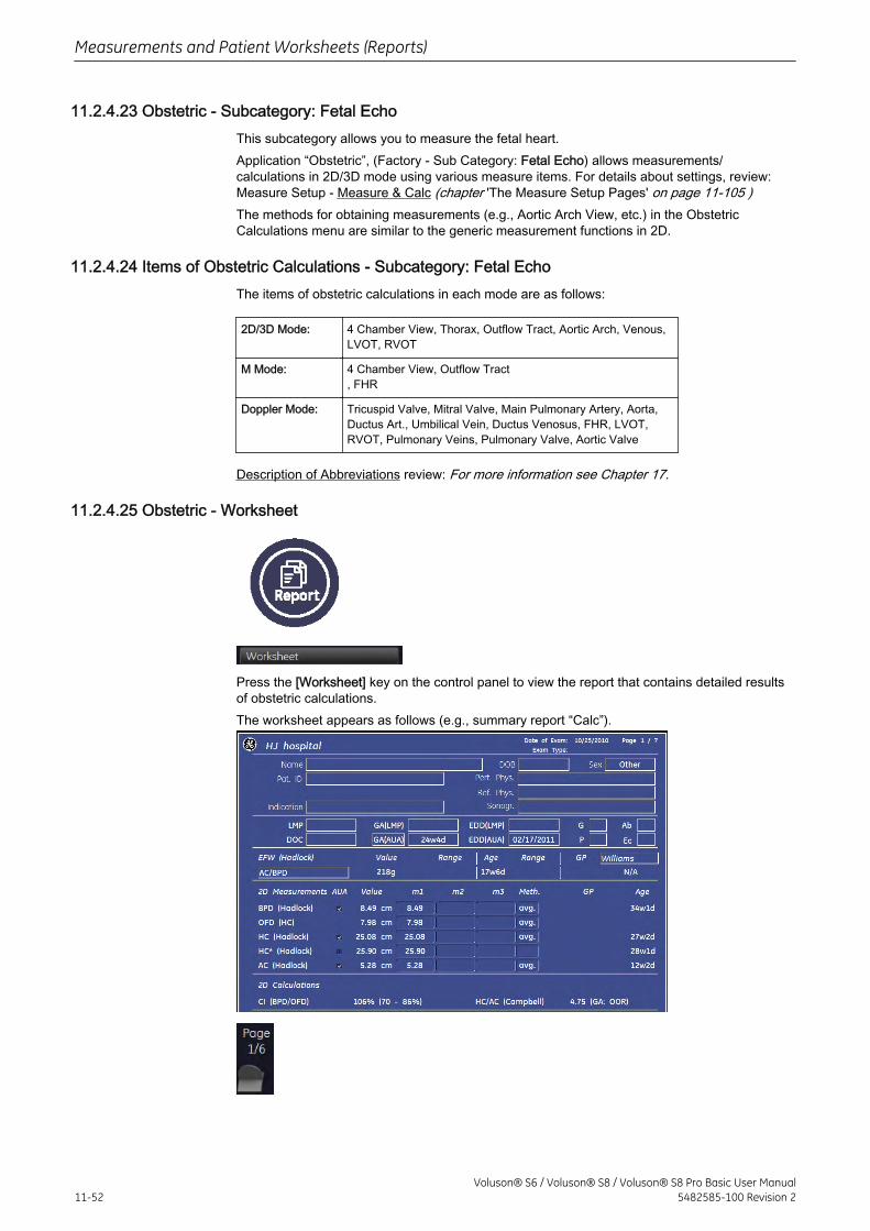
11.2.4.23 Obstetric - Subcategory: Fetal EchoThis subcategory allows you to measure the fetal heart.Application “Obstetric”, (Factory - Sub Category: Fetal Echo) allows measurements/calculations in 2D/3D mode using various measure items. For details about settings, review:Measure Setup - Measure & Calc (chapter 'The Measure Setup Pages' on page 11-105 )The methods for obtaining measurements (e.g., Aortic Arch View, etc.) in the ObstetricCalculations menu are similar to the generic measurement functions in 2D.
11.2.4.24 Items of Obstetric Calculations - Subcategory: Fetal EchoThe items of obstetric calculations in each mode are as follows:
2D/3D Mode: 4 Chamber View, Thorax, Outflow Tract, Aortic Arch, Venous,LVOT, RVOT
M Mode: 4 Chamber View, Outflow Tract, FHR
Doppler Mode: Tricuspid Valve, Mitral Valve, Main Pulmonary Artery, Aorta,Ductus Art., Umbilical Vein, Ductus Venosus, FHR, LVOT,RVOT, Pulmonary Veins, Pulmonary Valve, Aortic Valve
Description of Abbreviations review: For more information see Chapter 17.
11.2.4.25 Obstetric - Worksheet
Press the [Worksheet] key on the control panel to view the report that contains detailed resultsof obstetric calculations.The worksheet appears as follows (e.g., summary report “Calc”).
Measurements and Patient Worksheets (Reports)
11-52Voluson® S6 / Voluson® S8 / Voluson® S8 Pro Basic User Manual
5482585-100 Revision 2
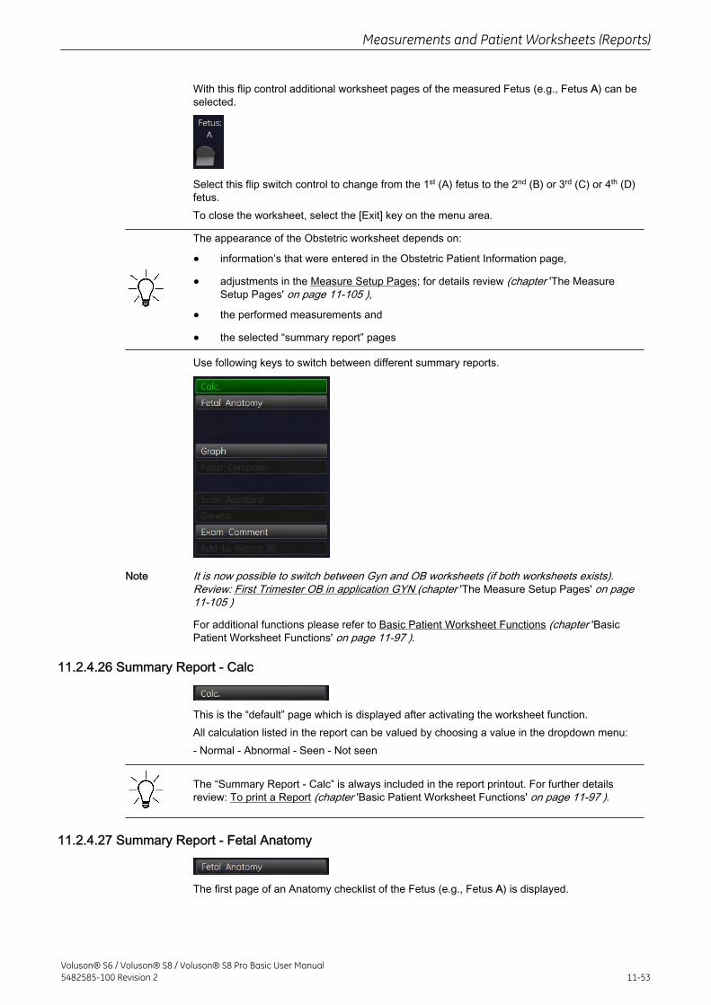
With this flip control additional worksheet pages of the measured Fetus (e.g., Fetus A) can beselected.
Select this flip switch control to change from the 1st (A) fetus to the 2nd (B) or 3rd (C) or 4th (D)fetus.To close the worksheet, select the [Exit] key on the menu area.
The appearance of the Obstetric worksheet depends on:
• information’s that were entered in the Obstetric Patient Information page,
• adjustments in the Measure Setup Pages; for details review (chapter 'The MeasureSetup Pages' on page 11-105 ),
• the performed measurements and
• the selected “summary report” pages
Use following keys to switch between different summary reports.
Note It is now possible to switch between Gyn and OB worksheets (if both worksheets exists).Review: First Trimester OB in application GYN (chapter 'The Measure Setup Pages' on page11-105 )
For additional functions please refer to Basic Patient Worksheet Functions (chapter 'BasicPatient Worksheet Functions' on page 11-97 ).
11.2.4.26 Summary Report - Calc
This is the “default” page which is displayed after activating the worksheet function.All calculation listed in the report can be valued by choosing a value in the dropdown menu:- Normal - Abnormal - Seen - Not seen
The “Summary Report - Calc” is always included in the report printout. For further detailsreview: To print a Report (chapter 'Basic Patient Worksheet Functions' on page 11-97 ).
11.2.4.27 Summary Report - Fetal Anatomy
The first page of an Anatomy checklist of the Fetus (e.g., Fetus A) is displayed.
Measurements and Patient Worksheets (Reports)
Voluson® S6 / Voluson® S8 / Voluson® S8 Pro Basic User Manual5482585-100 Revision 2 11-53
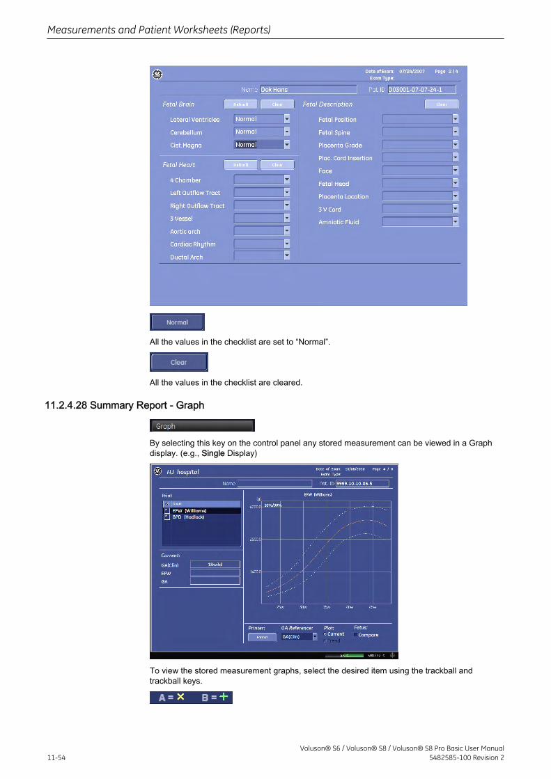
All the values in the checklist are set to “Normal”.
All the values in the checklist are cleared.
11.2.4.28 Summary Report - Graph
By selecting this key on the control panel any stored measurement can be viewed in a Graphdisplay. (e.g., Single Display)
To view the stored measurement graphs, select the desired item using the trackball andtrackball keys.
Measurements and Patient Worksheets (Reports)
11-54Voluson® S6 / Voluson® S8 / Voluson® S8 Pro Basic User Manual
5482585-100 Revision 2
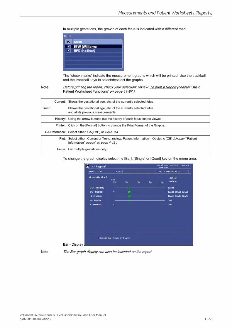
In multiple gestations, the growth of each fetus is indicated with a different mark.
The “check marks” indicate the measurement graphs which will be printed. Use the trackballand the trackball keys to select/deselect the graphs.
Note Before printing the report, check your selection; review: To print a Report (chapter 'BasicPatient Worksheet Functions' on page 11-97 ).
Current: Shows the gestational age, etc. of the currently selected fetus
Trend Shows the gestational age, etc. of the currently selected fetusand all its previous measurements.
History: Using the arrow buttons (tu) the history of each fetus can be viewed.
Printer: Click on the [Format] button to change the Print Format of the Graphs.
GA Reference: Select either: GA(LMP) or GA(AUA)
Plot: Select either: Current or Trend. review: Patient Information – Obstetric (OB) (chapter '“PatientInformation” screen' on page 4-13 )
Fetus: For multiple gestations only.
To change the graph display select the [Bar], [Single] or [Quad] key on the menu area.
Bar - Display
Note The Bar graph display can also be included on the report.
Measurements and Patient Worksheets (Reports)
Voluson® S6 / Voluson® S8 / Voluson® S8 Pro Basic User Manual5482585-100 Revision 2 11-55
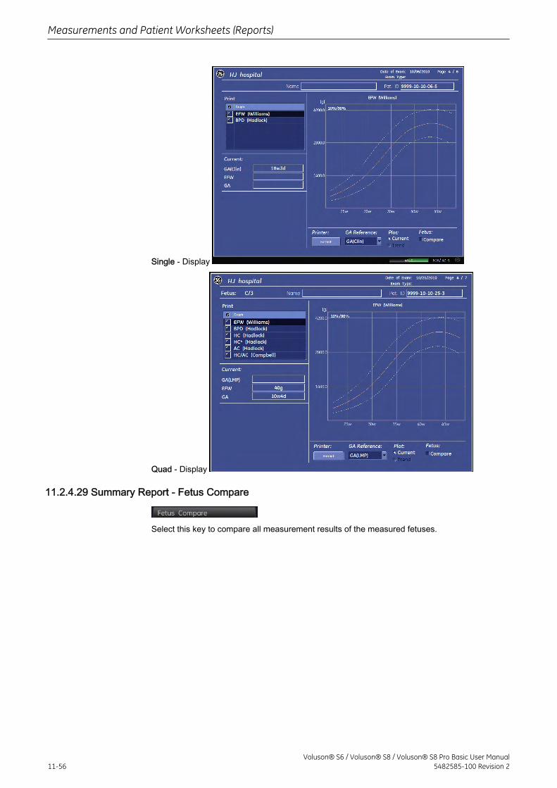
Single - Display
Quad - Display
11.2.4.29 Summary Report - Fetus Compare
Select this key to compare all measurement results of the measured fetuses.
Measurements and Patient Worksheets (Reports)
11-56Voluson® S6 / Voluson® S8 / Voluson® S8 Pro Basic User Manual
5482585-100 Revision 2
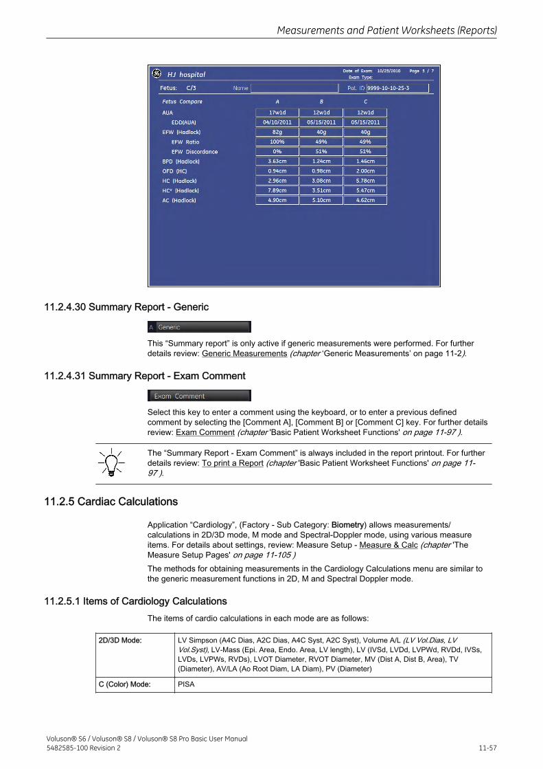
11.2.4.30 Summary Report - Generic
This “Summary report” is only active if generic measurements were performed. For furtherdetails review: Generic Measurements (chapter ‘Generic Measurements’ on page 11‐2).
11.2.4.31 Summary Report - Exam Comment
Select this key to enter a comment using the keyboard, or to enter a previous definedcomment by selecting the [Comment A], [Comment B] or [Comment C] key. For further detailsreview: Exam Comment (chapter 'Basic Patient Worksheet Functions' on page 11-97 ).
The “Summary Report - Exam Comment” is always included in the report printout. For furtherdetails review: To print a Report (chapter 'Basic Patient Worksheet Functions' on page 11-97 ).
11.2.5 Cardiac Calculations
Application “Cardiology”, (Factory - Sub Category: Biometry) allows measurements/calculations in 2D/3D mode, M mode and Spectral-Doppler mode, using various measureitems. For details about settings, review: Measure Setup - Measure & Calc (chapter 'TheMeasure Setup Pages' on page 11-105 )The methods for obtaining measurements in the Cardiology Calculations menu are similar tothe generic measurement functions in 2D, M and Spectral Doppler mode.
11.2.5.1 Items of Cardiology CalculationsThe items of cardio calculations in each mode are as follows:
2D/3D Mode: LV Simpson (A4C Dias, A2C Dias, A4C Syst, A2C Syst), Volume A/L (LV Vol.Dias, LVVol.Syst), LV-Mass (Epi. Area, Endo. Area, LV length), LV (IVSd, LVDd, LVPWd, RVDd, IVSs,LVDs, LVPWs, RVDs), LVOT Diameter, RVOT Diameter, MV (Dist A, Dist B, Area), TV(Diameter), AV/LA (Ao Root Diam, LA Diam), PV (Diameter)
C (Color) Mode: PISA
Measurements and Patient Worksheets (Reports)
Voluson® S6 / Voluson® S8 / Voluson® S8 Pro Basic User Manual5482585-100 Revision 2 11-57
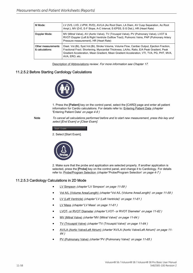
M Mode: LV (IVS, LVD, LVPW, RVD), AV/LA (Ao Root Diam, LA Diam, AV Cusp Separation, Ao RootAmpl.), MV (D-E, E-F Slope, A-C Interval, E-EPSS, E-S Dist.), HR (Heart Rate)
Doppler Mode: MV (Mitral Valve), AV (Aortic Valve), TV (Tricuspid Valve), PV (Pulmonary Valve), LVOT &RVOT-Doppler (Left & Right Ventricle Outflow Tract), Pulmonic Veins, PAP (Pulmonary ArteryPressure measurement), HR (Heart Rate)
Other measurements& calculations:
Diast. Vol.(Bi), Syst.Vol.(Bi), Stroke Volume, Volume Flow, Cardiac Output, Ejection Fraction,Fractional Fract. Shortening, Myocardial Thickness, LA/Ao, Ratio, E/A Peak Gradient, PeakGradient Acceleration, Mean Gradient, Mean Gradient Acceleration, VTI, TVA, PG, PHT, MVA,AVA, ERO, etc.
Description of Abbreviations review: For more information see Chapter 17.
11.2.5.2 Before Starting Cardiology Calculations
1. Press the [Patient] key on the control panel, select the [CARD] page and enter all patientinformation for Cardio calculations. For details refer to: Entering Patient Data (chapter'Entering Patient Data' on page 4-9 )
Note To cancel all calculations performed before and to start new measurement, press this key andselect [End Exam] or [Clear Exam].
2. Select [Start Exam].
2. Make sure that the probe and application are selected properly. If another application isselected, press the [Probe] key on the control panel, and change it to Cardiology. For detailsrefer to: Probe/Program Selection (chapter 'Probe/Program Selection' on page 4-7 )
11.2.5.3 Cardiology Calculations in 2D Mode
• LV Simpson (chapter 'LV Simpson' on page 11-59 )
• Vol A/L (Volume Area/Length) (chapter 'Vol A/L (Volume Area/Length)' on page 11-59 )
• LV (Left Ventricle) (chapter 'LV (Left Ventricle)' on page 11-61 )
• LV Mass (chapter 'LV Mass' on page 11-61 )
• LVOT- or RVOT Diameter (chapter 'LVOT- or RVOT Diameter' on page 11-62 )
• MV (Mitral Valve) (charter 'MV (Mitral Valve)' on page 11-64 )
• TV (Tricuspid Valve) (chapter 'TV (Tricuspid Valve)' on page 11-64 )
• AV/LA (Aortic Valve/Left Atrium) (charter 'AV/LA (Aortic Valve/Left Atrium)' on page 11-64 )
• PV (Pulmonary Valve) (charter 'PV (Pulmonary Valve)' on page 11-65 )
Measurements and Patient Worksheets (Reports)
11-58Voluson® S6 / Voluson® S8 / Voluson® S8 Pro Basic User Manual
5482585-100 Revision 2
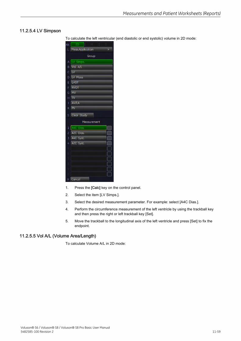
11.2.5.4 LV SimpsonTo calculate the left ventricular (end diastolic or end systolic) volume in 2D mode:
1. Press the [Calc] key on the control panel.
2. Select the item [LV Simps.].
3. Select the desired measurement parameter. For example: select [A4C Dias.].
4. Perform the circumference measurement of the left ventricle by using the trackball keyand then press the right or left trackball key [Set].
5. Move the trackball to the longitudinal axis of the left ventricle and press [Set] to fix theendpoint.
11.2.5.5 Vol A/L (Volume Area/Length)To calculate Volume A/L in 2D mode:
Measurements and Patient Worksheets (Reports)
Voluson® S6 / Voluson® S8 / Voluson® S8 Pro Basic User Manual5482585-100 Revision 2 11-59
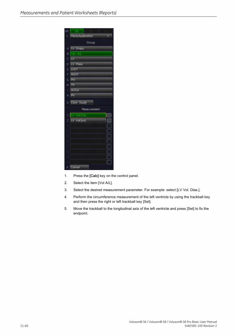
1. Press the [Calc] key on the control panel.
2. Select the item [Vol A/L].
3. Select the desired measurement parameter. For example: select [LV Vol. Dias.].
4. Perform the circumference measurement of the left ventricle by using the trackball keyand then press the right or left trackball key [Set].
5. Move the trackball to the longitudinal axis of the left ventricle and press [Set] to fix theendpoint.
Measurements and Patient Worksheets (Reports)
11-60Voluson® S6 / Voluson® S8 / Voluson® S8 Pro Basic User Manual
5482585-100 Revision 2
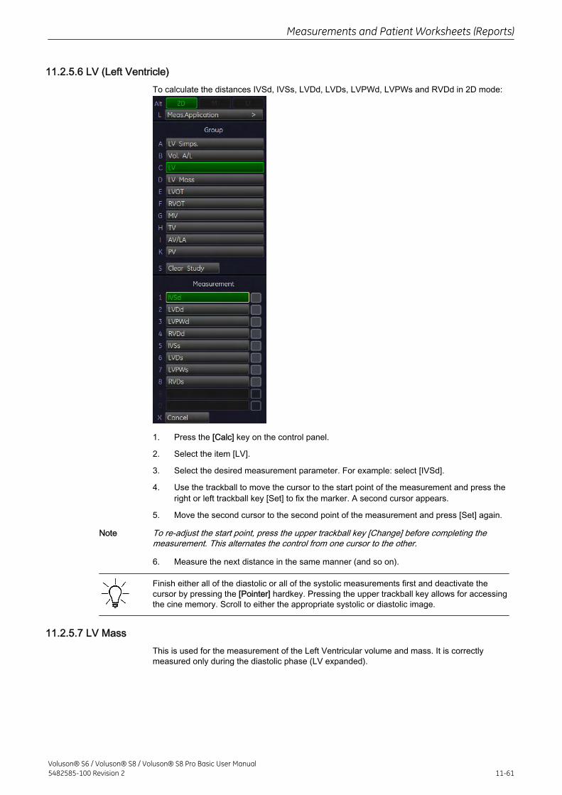
11.2.5.6 LV (Left Ventricle)To calculate the distances IVSd, IVSs, LVDd, LVDs, LVPWd, LVPWs and RVDd in 2D mode:
1. Press the [Calc] key on the control panel.
2. Select the item [LV].
3. Select the desired measurement parameter. For example: select [IVSd].
4. Use the trackball to move the cursor to the start point of the measurement and press theright or left trackball key [Set] to fix the marker. A second cursor appears.
5. Move the second cursor to the second point of the measurement and press [Set] again.
Note To re-adjust the start point, press the upper trackball key [Change] before completing themeasurement. This alternates the control from one cursor to the other.
6. Measure the next distance in the same manner (and so on).
Finish either all of the diastolic or all of the systolic measurements first and deactivate thecursor by pressing the [Pointer] hardkey. Pressing the upper trackball key allows for accessingthe cine memory. Scroll to either the appropriate systolic or diastolic image.
11.2.5.7 LV MassThis is used for the measurement of the Left Ventricular volume and mass. It is correctlymeasured only during the diastolic phase (LV expanded).
Measurements and Patient Worksheets (Reports)
Voluson® S6 / Voluson® S8 / Voluson® S8 Pro Basic User Manual5482585-100 Revision 2 11-61
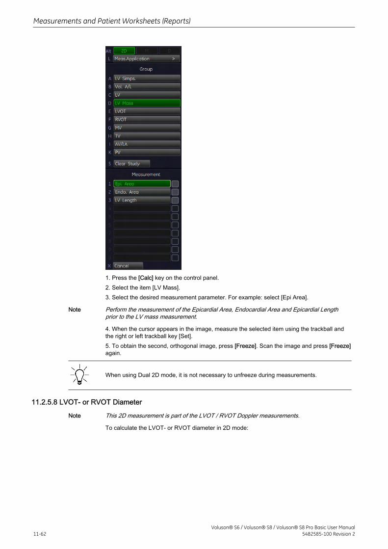
1. Press the [Calc] key on the control panel.2. Select the item [LV Mass].3. Select the desired measurement parameter. For example: select [Epi Area].
Note Perform the measurement of the Epicardial Area, Endocardial Area and Epicardial Lengthprior to the LV mass measurement.
4. When the cursor appears in the image, measure the selected item using the trackball andthe right or left trackball key [Set].5. To obtain the second, orthogonal image, press [Freeze]. Scan the image and press [Freeze]again.
When using Dual 2D mode, it is not necessary to unfreeze during measurements.
11.2.5.8 LVOT- or RVOT Diameter
Note This 2D measurement is part of the LVOT / RVOT Doppler measurements.
To calculate the LVOT- or RVOT diameter in 2D mode:
Measurements and Patient Worksheets (Reports)
11-62Voluson® S6 / Voluson® S8 / Voluson® S8 Pro Basic User Manual
5482585-100 Revision 2
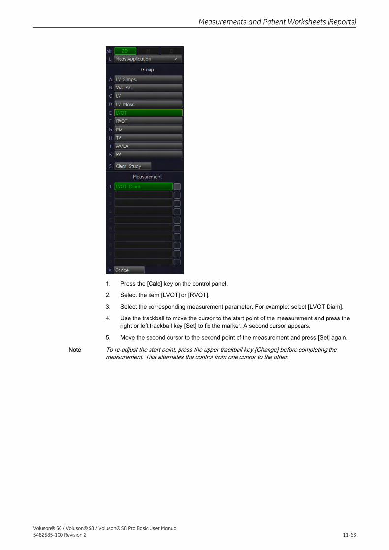
1. Press the [Calc] key on the control panel.
2. Select the item [LVOT] or [RVOT].
3. Select the corresponding measurement parameter. For example: select [LVOT Diam].
4. Use the trackball to move the cursor to the start point of the measurement and press theright or left trackball key [Set] to fix the marker. A second cursor appears.
5. Move the second cursor to the second point of the measurement and press [Set] again.
Note To re-adjust the start point, press the upper trackball key [Change] before completing themeasurement. This alternates the control from one cursor to the other.
Measurements and Patient Worksheets (Reports)
Voluson® S6 / Voluson® S8 / Voluson® S8 Pro Basic User Manual5482585-100 Revision 2 11-63
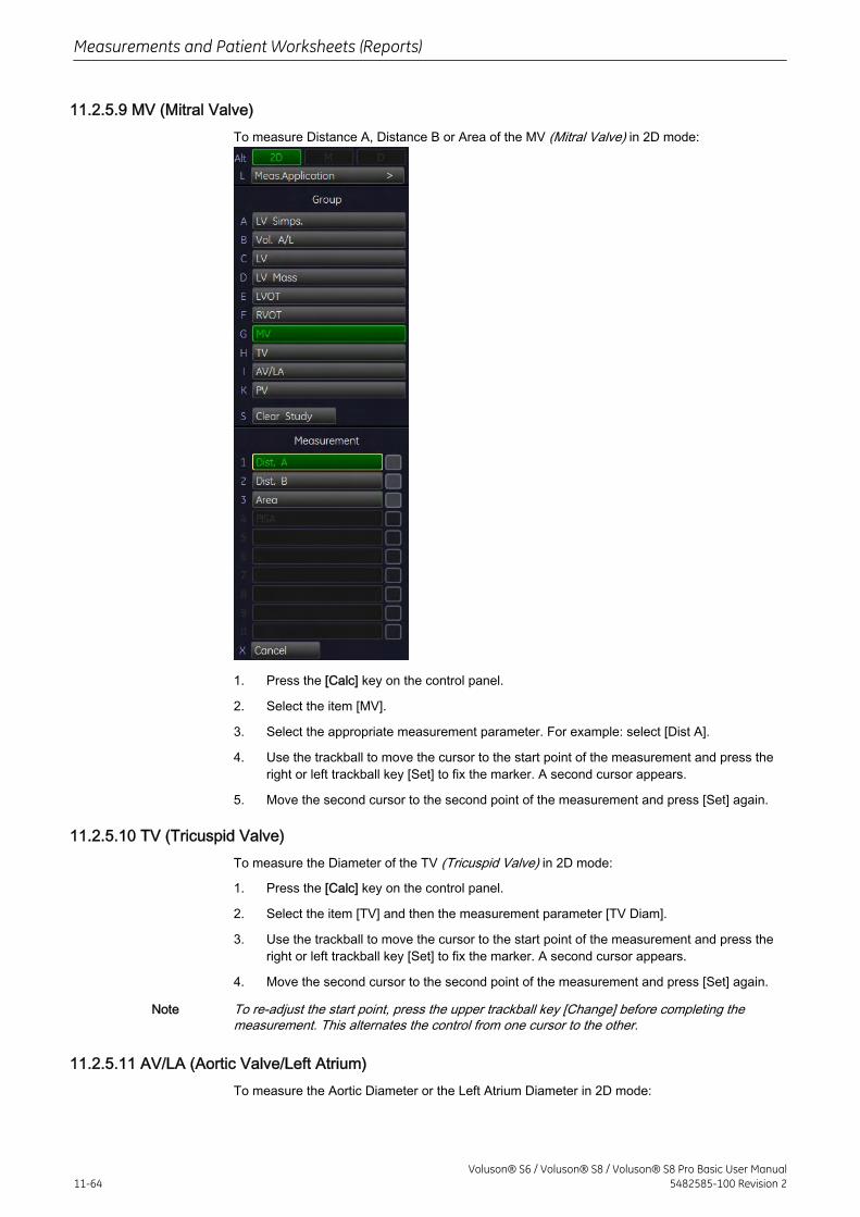
11.2.5.9 MV (Mitral Valve)To measure Distance A, Distance B or Area of the MV (Mitral Valve) in 2D mode:
1. Press the [Calc] key on the control panel.
2. Select the item [MV].
3. Select the appropriate measurement parameter. For example: select [Dist A].
4. Use the trackball to move the cursor to the start point of the measurement and press theright or left trackball key [Set] to fix the marker. A second cursor appears.
5. Move the second cursor to the second point of the measurement and press [Set] again.
11.2.5.10 TV (Tricuspid Valve)To measure the Diameter of the TV (Tricuspid Valve) in 2D mode:
1. Press the [Calc] key on the control panel.
2. Select the item [TV] and then the measurement parameter [TV Diam].
3. Use the trackball to move the cursor to the start point of the measurement and press theright or left trackball key [Set] to fix the marker. A second cursor appears.
4. Move the second cursor to the second point of the measurement and press [Set] again.
Note To re-adjust the start point, press the upper trackball key [Change] before completing themeasurement. This alternates the control from one cursor to the other.
11.2.5.11 AV/LA (Aortic Valve/Left Atrium)To measure the Aortic Diameter or the Left Atrium Diameter in 2D mode:
Measurements and Patient Worksheets (Reports)
11-64Voluson® S6 / Voluson® S8 / Voluson® S8 Pro Basic User Manual
5482585-100 Revision 2
1. Press the [Calc] key on the control panel.
2. Select the item [AV/LA] and then the desired measurement parameter [Ao Root Diam] or[LA Diam].
3. Use the trackball to move the cursor to the start point of the measurement and press theright or left trackball key [Set] to fix the marker. A second cursor appears.
4. Move the second cursor to the second point of the measurement and press [Set] again.
Note To re-adjust the start point, press the upper trackball key [Change] before completing themeasurement. This alternates the control from one cursor to the other.
11.2.5.12 PV (Pulmonary Valve)To measure the Diameter of the PV (Pulmonary Valve) in 2D mode:
1. Press the [Calc] key on the control panel.
2. Select the item [PV] and then the measurement parameter [PV Diam].
3. Use the trackball to move the cursor to the start point of the measurement and press theright or left trackball key [Set] to fix the marker. A second cursor appears.
4. Move the second cursor to the second point of the measurement and press [Set] again.
Note To re-adjust the start point, press the upper trackball key [Change] before completing themeasurement. This alternates the control from one cursor to the other.
11.2.5.13 Cardiology Calculations in CFM Mode
• PISA (chapter 'PISA' on page 11-65 )
11.2.5.14 PISATo measure the PISA Radius of the Mitral Valve (MV), Tricuspid Valve (TV), Aortic Valve (AV)and Pulmonary Valve (PV) in Color Flow Mode:
Measurements and Patient Worksheets (Reports)
Voluson® S6 / Voluson® S8 / Voluson® S8 Pro Basic User Manual5482585-100 Revision 2 11-65
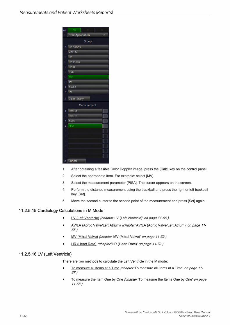
1. After obtaining a feasible Color Doppler image, press the [Calc] key on the control panel.
2. Select the appropriate item. For example: select [MV].
3. Select the measurement parameter [PISA]. The cursor appears on the screen.
4. Perform the distance measurement using the trackball and press the right or left trackballkey [Set].
5. Move the second cursor to the second point of the measurement and press [Set] again.
11.2.5.15 Cardiology Calculations in M Mode
• LV (Left Ventricle) (chapter 'LV (Left Ventricle)' on page 11-66 )
• AV/LA (Aortic Valve/Left Atrium) (chapter 'AV/LA (Aortic Valve/Left Atrium)' on page 11-68 )
• MV (Mitral Valve) (chapter 'MV (Mitral Valve)' on page 11-69 )
• HR (Heart Rate) (chapter 'HR (Heart Rate)' on page 11-70 )
11.2.5.16 LV (Left Ventricle)There are two methods to calculate the Left Ventricle in the M mode:
• To measure all Items at a Time (chapter 'To measure all Items at a Time' on page 11-67 )
• To measure the Item One by One (chapter 'To measure the Items One by One' on page11-68 )
Measurements and Patient Worksheets (Reports)
11-66Voluson® S6 / Voluson® S8 / Voluson® S8 Pro Basic User Manual
5482585-100 Revision 2
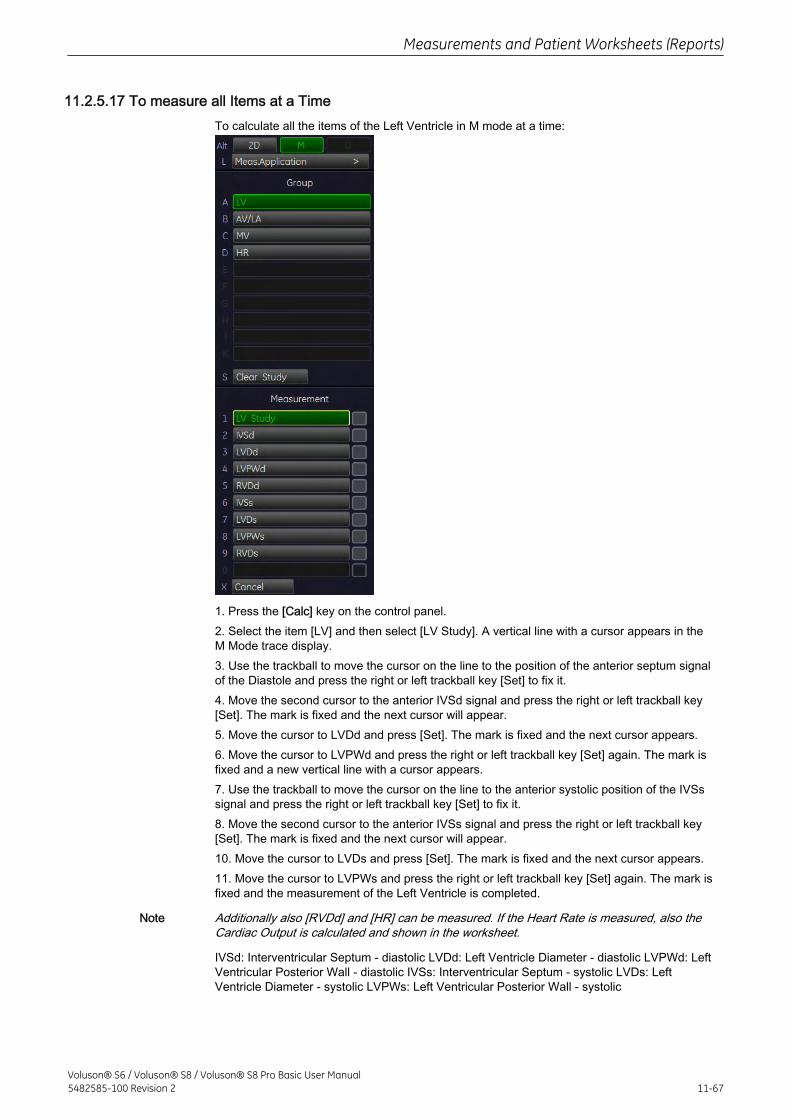
11.2.5.17 To measure all Items at a TimeTo calculate all the items of the Left Ventricle in M mode at a time:
1. Press the [Calc] key on the control panel.2. Select the item [LV] and then select [LV Study]. A vertical line with a cursor appears in theM Mode trace display.3. Use the trackball to move the cursor on the line to the position of the anterior septum signalof the Diastole and press the right or left trackball key [Set] to fix it.4. Move the second cursor to the anterior IVSd signal and press the right or left trackball key[Set]. The mark is fixed and the next cursor will appear.5. Move the cursor to LVDd and press [Set]. The mark is fixed and the next cursor appears.6. Move the cursor to LVPWd and press the right or left trackball key [Set] again. The mark isfixed and a new vertical line with a cursor appears.7. Use the trackball to move the cursor on the line to the anterior systolic position of the IVSssignal and press the right or left trackball key [Set] to fix it.8. Move the second cursor to the anterior IVSs signal and press the right or left trackball key[Set]. The mark is fixed and the next cursor will appear.10. Move the cursor to LVDs and press [Set]. The mark is fixed and the next cursor appears.11. Move the cursor to LVPWs and press the right or left trackball key [Set] again. The mark isfixed and the measurement of the Left Ventricle is completed.
Note Additionally also [RVDd] and [HR] can be measured. If the Heart Rate is measured, also theCardiac Output is calculated and shown in the worksheet.
IVSd: Interventricular Septum - diastolic LVDd: Left Ventricle Diameter - diastolic LVPWd: LeftVentricular Posterior Wall - diastolic IVSs: Interventricular Septum - systolic LVDs: LeftVentricle Diameter - systolic LVPWs: Left Ventricular Posterior Wall - systolic
Measurements and Patient Worksheets (Reports)
Voluson® S6 / Voluson® S8 / Voluson® S8 Pro Basic User Manual5482585-100 Revision 2 11-67
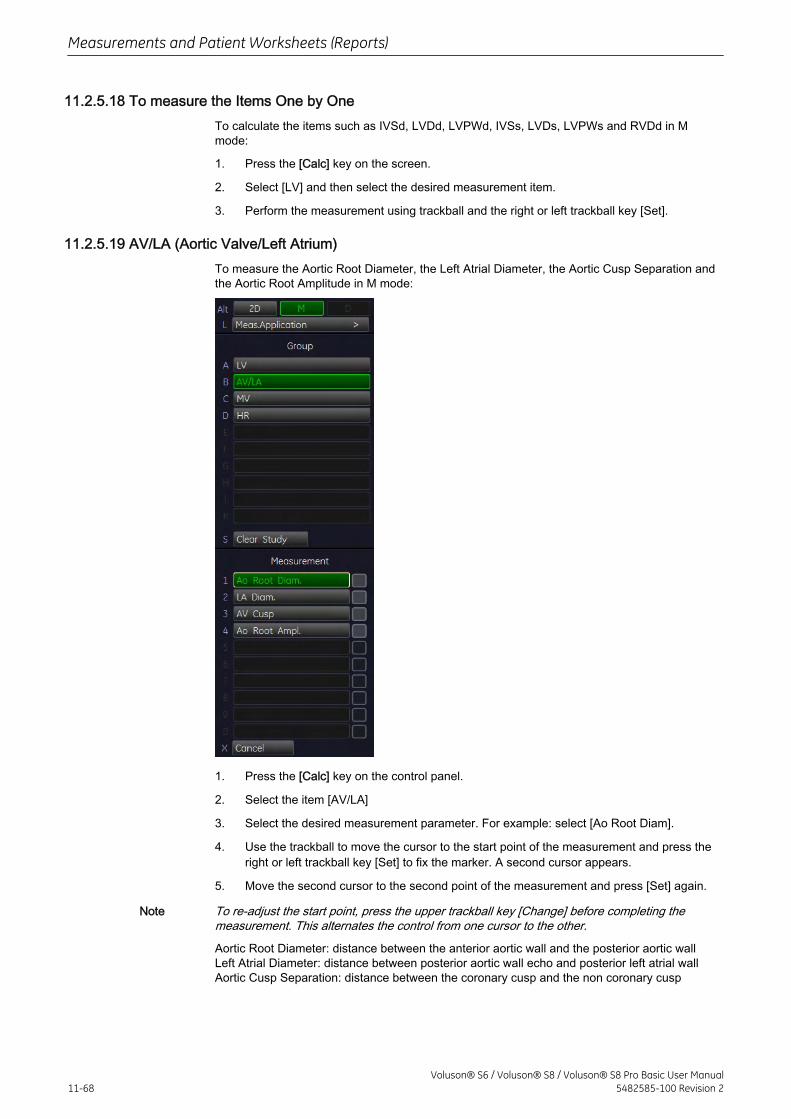
11.2.5.18 To measure the Items One by OneTo calculate the items such as IVSd, LVDd, LVPWd, IVSs, LVDs, LVPWs and RVDd in Mmode:
1. Press the [Calc] key on the screen.
2. Select [LV] and then select the desired measurement item.
3. Perform the measurement using trackball and the right or left trackball key [Set].
11.2.5.19 AV/LA (Aortic Valve/Left Atrium)To measure the Aortic Root Diameter, the Left Atrial Diameter, the Aortic Cusp Separation andthe Aortic Root Amplitude in M mode:
1. Press the [Calc] key on the control panel.
2. Select the item [AV/LA]
3. Select the desired measurement parameter. For example: select [Ao Root Diam].
4. Use the trackball to move the cursor to the start point of the measurement and press theright or left trackball key [Set] to fix the marker. A second cursor appears.
5. Move the second cursor to the second point of the measurement and press [Set] again.
Note To re-adjust the start point, press the upper trackball key [Change] before completing themeasurement. This alternates the control from one cursor to the other.
Aortic Root Diameter: distance between the anterior aortic wall and the posterior aortic wallLeft Atrial Diameter: distance between posterior aortic wall echo and posterior left atrial wallAortic Cusp Separation: distance between the coronary cusp and the non coronary cusp
Measurements and Patient Worksheets (Reports)
11-68Voluson® S6 / Voluson® S8 / Voluson® S8 Pro Basic User Manual
5482585-100 Revision 2

11.2.5.20 MV (Mitral Valve)There are two methods to calculate the Mitral Valve in the M mode:
• To measure all Items at a Time (chapter 'To measure all Items at a Time' on page 11-69 )
• To measure the Items One by One (chapter 'To measure the Items One by One' on page11-70 )
11.2.5.21 To measure all Items at a TimeTo calculate all the items of the Mitral Valve in M mode at a time:
1. Press the [Calc] key on the control panel.
2. Select the item [MV] and then select [All].
3. The +D cursor appears on the M mode image. Move the cursor to the D point and pressthe right or left trackball key to fix the mark.
4. The +E cursor appears on the screen. Move the cursor to the E point and press the rightor left trackball key to fix the mark.
5. The + F cursor appears on the screen. Move the cursor to the F point and press the rightor left trackball key to fix the mark.
6. The +A cursor appears on the screen. Move the cursor to the A point and press the rightor left trackball key to fix the mark.
7. The +C cursor appears on the screen. Move the cursor to the C point and press the rightor left trackball key to fix the mark.
Measurements and Patient Worksheets (Reports)
Voluson® S6 / Voluson® S8 / Voluson® S8 Pro Basic User Manual5482585-100 Revision 2 11-69
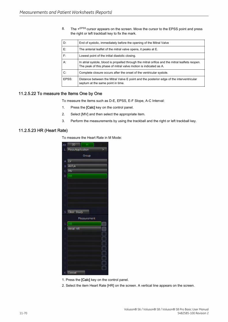
8. The +EPSS cursor appears on the screen. Move the cursor to the EPSS point and pressthe right or left trackball key to fix the mark.
D: End of systolic, immediately before the opening of the Mitral Valve
E: The anterial leaflet of the mitral valve opens, it peaks at E.
F: Lowest point of the initial diastolic closing.
A: In atrial systole, blood is propelled through the mitral orifice and the mitral leaflets reopen.The peak of this phase of mitral valve motion is indicated as A.
C: Complete closure occurs after the onset of the ventricular systole.
EPSS: Distance between the Mitral Valve E point and the posterior edge of the interventricularseptum at the same point in time.
11.2.5.22 To measure the Items One by OneTo measure the items such as D-E, EPSS, E-F Slope, A-C Interval:
1. Press the [Calc] key on the control panel.
2. Select [MV] and then select the appropriate item.
3. Perform the measurements by using the trackball and the right or left trackball key.
11.2.5.23 HR (Heart Rate)To measure the Heart Rate in M Mode:
1. Press the [Calc] key on the control panel.2. Select the item Heart Rate [HR] on the screen. A vertical line appears on the screen.
Measurements and Patient Worksheets (Reports)
11-70Voluson® S6 / Voluson® S8 / Voluson® S8 Pro Basic User Manual
5482585-100 Revision 2
3. Move the line to the start point of the period and press the right or left trackball key [Set].The second line appears.
4. Select the number of heart rate cycles necessary for measurement with the rotary control.5. Move the second line to the end point of the period (according to the selected number ofheart rate cycles to be measured).6. Press the right or the left trackball [Set] key again. The Heart Rate is displayed.
11.2.5.24 Cardiology Calculations in Spectral-Doppler Mode
• MV (Mitral Valve) (chapter 'MV (Mitral Valve)' on page 11-71 )
• AV (Aortic Valve) (chapter 'AV (Aortic Valve)' on page 11-73 )
• TV (Tricuspid Valve) (chapter 'TV (Tricuspid Valve)' on page 11-74 )
• PV (Pulmonary Valve) (chapter 'PV (Pulmonary Valve)' on page 11-75 )
• LVOT- or RVOT Doppler (chapter 'LVOT- or RVOT Doppler' on page 11-76 )
• Pulmonary Veins (chapter 'Pulmonary Veins' on page 11-76 )
• PAP (Pulmonary Artery Pressure Measurement) (chapter 'PAP (Pulmonary ArteryPressure Measurement)' on page 11-77 )
• HR (Heart Rate) (chapter 'HR (Heart Rate)' on page 11-78 )
11.2.5.25 MV (Mitral Valve)There are different methods to perform measurements and calculations of the Mitral Valve inthe Spectral-Doppler mode:
• Manual Trace (chapter 'Manual Trace' on page 11-72 )
• To measure the Items One by One (chapter 'To measure the Items One by One' on page11-72 )
Measurements and Patient Worksheets (Reports)
Voluson® S6 / Voluson® S8 / Voluson® S8 Pro Basic User Manual5482585-100 Revision 2 11-71
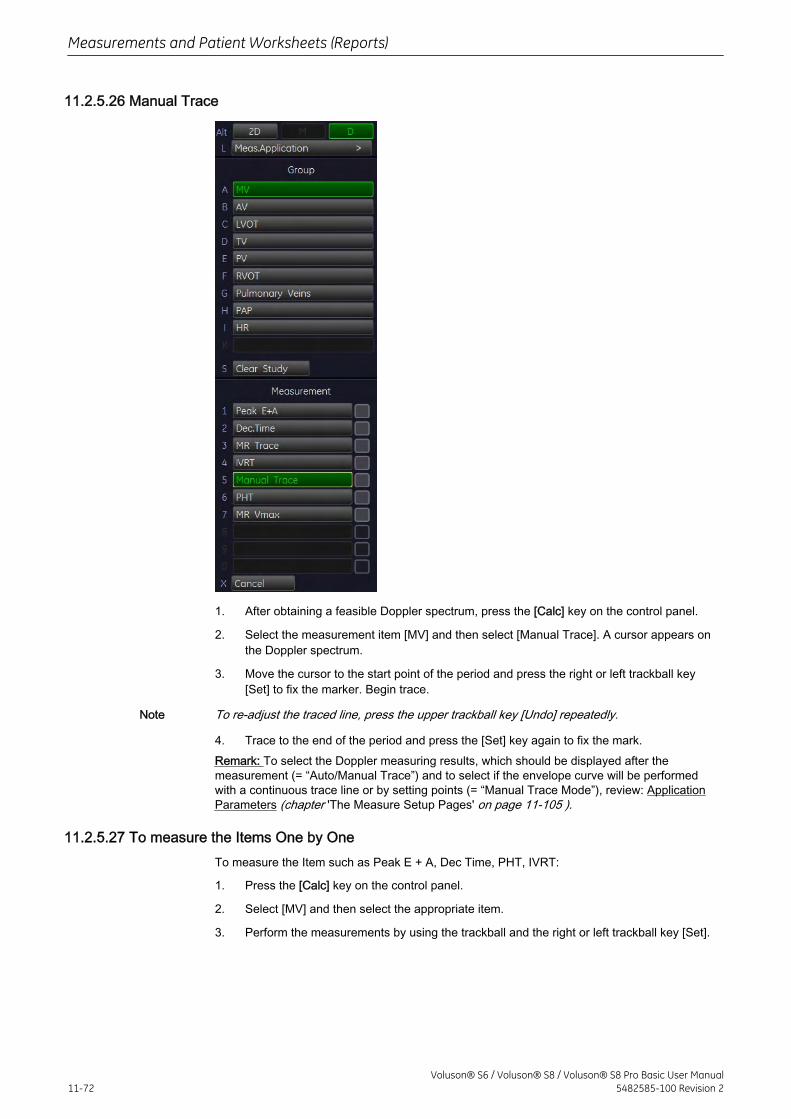
11.2.5.26 Manual Trace
1. After obtaining a feasible Doppler spectrum, press the [Calc] key on the control panel.
2. Select the measurement item [MV] and then select [Manual Trace]. A cursor appears onthe Doppler spectrum.
3. Move the cursor to the start point of the period and press the right or left trackball key[Set] to fix the marker. Begin trace.
Note To re-adjust the traced line, press the upper trackball key [Undo] repeatedly.
4. Trace to the end of the period and press the [Set] key again to fix the mark.Remark: To select the Doppler measuring results, which should be displayed after themeasurement (= “Auto/Manual Trace”) and to select if the envelope curve will be performedwith a continuous trace line or by setting points (= “Manual Trace Mode”), review: ApplicationParameters (chapter 'The Measure Setup Pages' on page 11-105 ).
11.2.5.27 To measure the Items One by OneTo measure the Item such as Peak E + A, Dec Time, PHT, IVRT:
1. Press the [Calc] key on the control panel.
2. Select [MV] and then select the appropriate item.
3. Perform the measurements by using the trackball and the right or left trackball key [Set].
Measurements and Patient Worksheets (Reports)
11-72Voluson® S6 / Voluson® S8 / Voluson® S8 Pro Basic User Manual
5482585-100 Revision 2
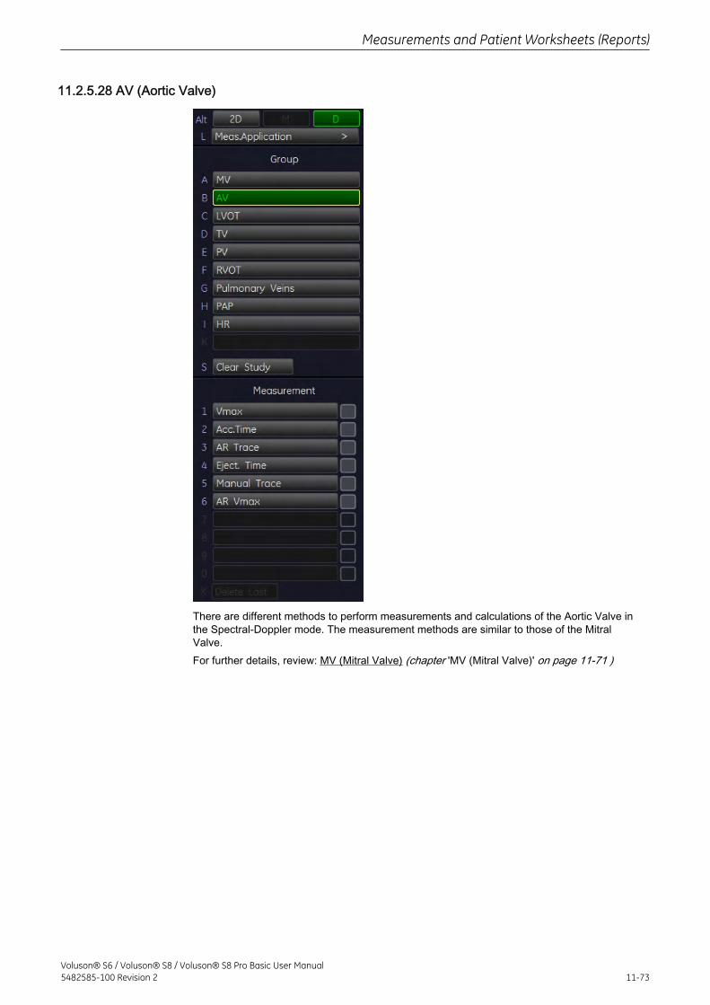
11.2.5.28 AV (Aortic Valve)
There are different methods to perform measurements and calculations of the Aortic Valve inthe Spectral-Doppler mode. The measurement methods are similar to those of the MitralValve.For further details, review: MV (Mitral Valve) (chapter 'MV (Mitral Valve)' on page 11-71 )
Measurements and Patient Worksheets (Reports)
Voluson® S6 / Voluson® S8 / Voluson® S8 Pro Basic User Manual5482585-100 Revision 2 11-73
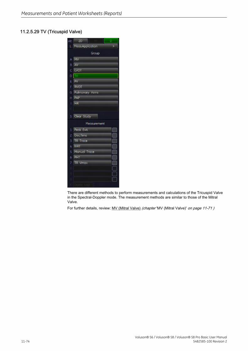
11.2.5.29 TV (Tricuspid Valve)
There are different methods to perform measurements and calculations of the Tricuspid Valvein the Spectral-Doppler mode. The measurement methods are similar to those of the MitralValve.For further details, review: MV (Mitral Valve) (chapter 'MV (Mitral Valve)' on page 11-71 )
Measurements and Patient Worksheets (Reports)
11-74Voluson® S6 / Voluson® S8 / Voluson® S8 Pro Basic User Manual
5482585-100 Revision 2
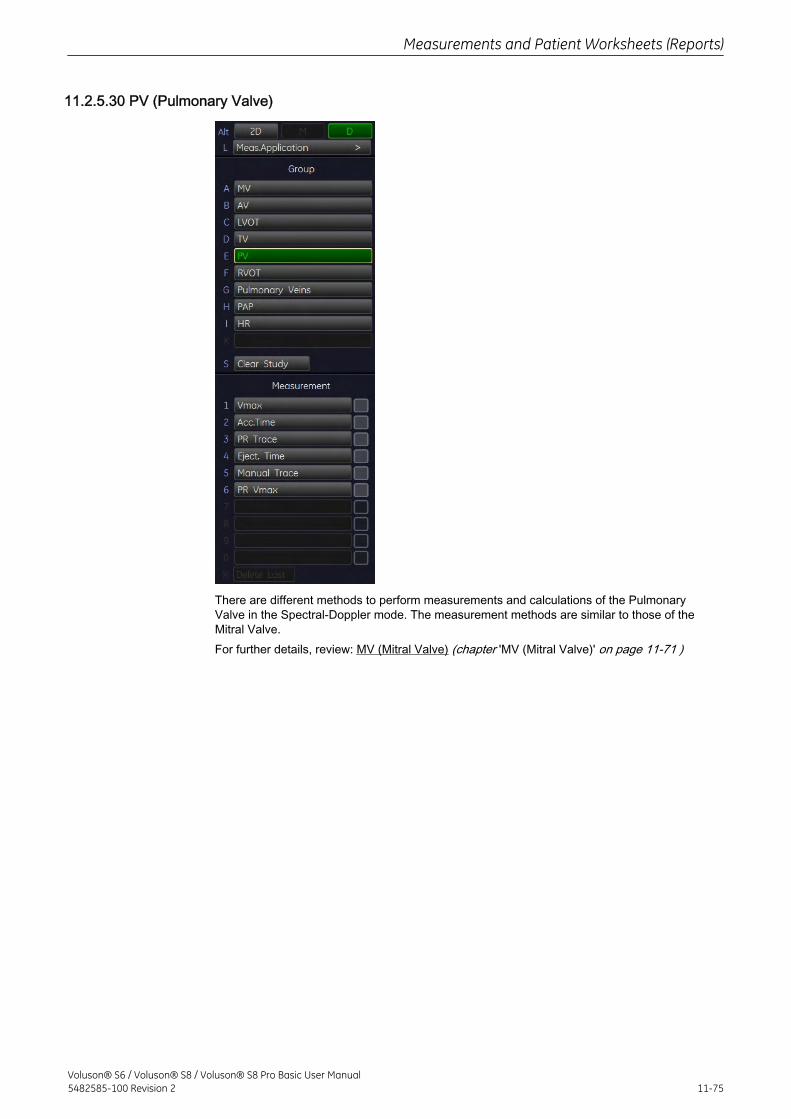
11.2.5.30 PV (Pulmonary Valve)
There are different methods to perform measurements and calculations of the PulmonaryValve in the Spectral-Doppler mode. The measurement methods are similar to those of theMitral Valve.For further details, review: MV (Mitral Valve) (chapter 'MV (Mitral Valve)' on page 11-71 )
Measurements and Patient Worksheets (Reports)
Voluson® S6 / Voluson® S8 / Voluson® S8 Pro Basic User Manual5482585-100 Revision 2 11-75
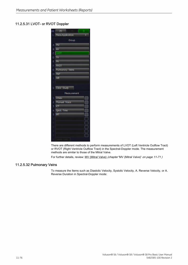
11.2.5.31 LVOT- or RVOT Doppler
There are different methods to perform measurements of LVOT (Left Ventricle Outflow Tract)or RVOT (Right Ventricle Outflow Tract) in the Spectral-Doppler mode. The measurementmethods are similar to those of the Mitral Valve.For further details, review: MV (Mitral Valve) (chapter 'MV (Mitral Valve)' on page 11-71 )
11.2.5.32 Pulmonary VeinsTo measure the Items such as Diastolic Velocity, Systolic Velocity, A. Reverse Velocity, or A.Reverse Duration in Spectral-Doppler mode:
Measurements and Patient Worksheets (Reports)
11-76Voluson® S6 / Voluson® S8 / Voluson® S8 Pro Basic User Manual
5482585-100 Revision 2
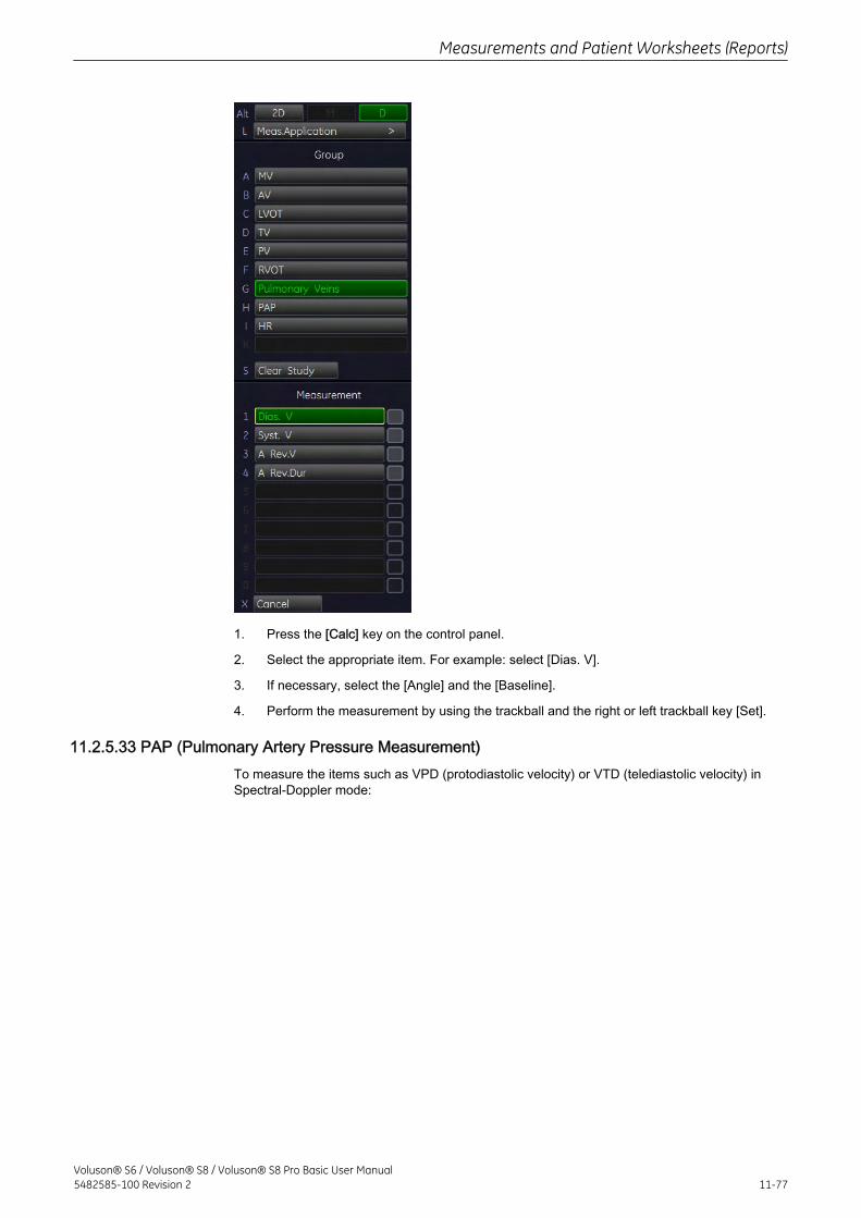
1. Press the [Calc] key on the control panel.
2. Select the appropriate item. For example: select [Dias. V].
3. If necessary, select the [Angle] and the [Baseline].
4. Perform the measurement by using the trackball and the right or left trackball key [Set].
11.2.5.33 PAP (Pulmonary Artery Pressure Measurement)To measure the items such as VPD (protodiastolic velocity) or VTD (telediastolic velocity) inSpectral-Doppler mode:
Measurements and Patient Worksheets (Reports)
Voluson® S6 / Voluson® S8 / Voluson® S8 Pro Basic User Manual5482585-100 Revision 2 11-77
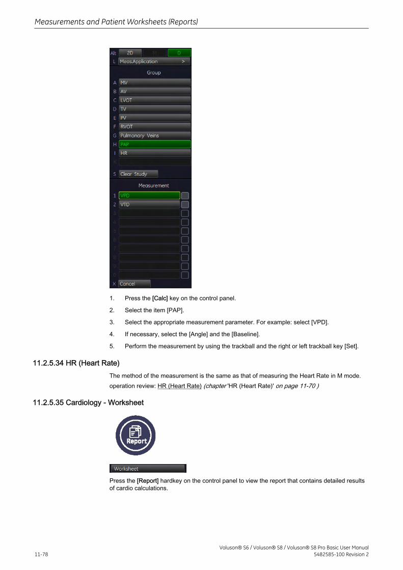
1. Press the [Calc] key on the control panel.
2. Select the item [PAP].
3. Select the appropriate measurement parameter. For example: select [VPD].
4. If necessary, select the [Angle] and the [Baseline].
5. Perform the measurement by using the trackball and the right or left trackball key [Set].
11.2.5.34 HR (Heart Rate)The method of the measurement is the same as that of measuring the Heart Rate in M mode.operation review: HR (Heart Rate) (chapter 'HR (Heart Rate)' on page 11-70 )
11.2.5.35 Cardiology - Worksheet
Press the [Report] hardkey on the control panel to view the report that contains detailed resultsof cardio calculations.
Measurements and Patient Worksheets (Reports)
11-78Voluson® S6 / Voluson® S8 / Voluson® S8 Pro Basic User Manual
5482585-100 Revision 2
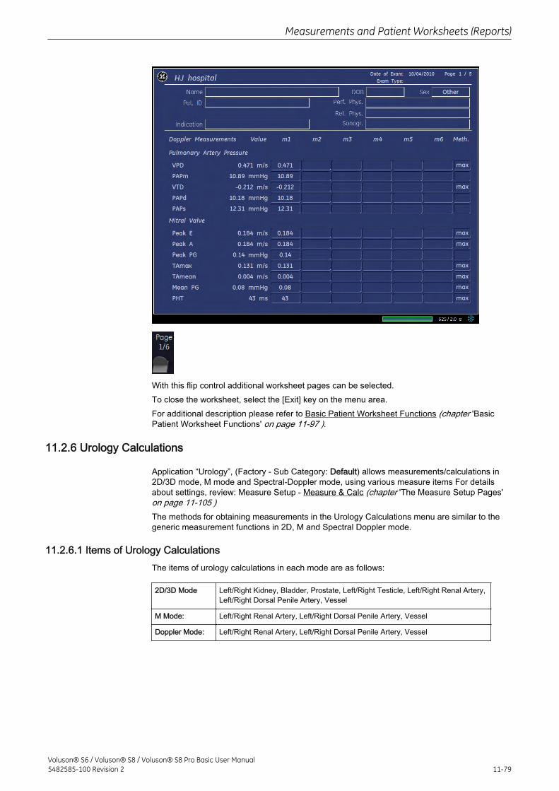
With this flip control additional worksheet pages can be selected.To close the worksheet, select the [Exit] key on the menu area.For additional description please refer to Basic Patient Worksheet Functions (chapter 'BasicPatient Worksheet Functions' on page 11-97 ).
11.2.6 Urology Calculations
Application “Urology”, (Factory - Sub Category: Default) allows measurements/calculations in2D/3D mode, M mode and Spectral-Doppler mode, using various measure items For detailsabout settings, review: Measure Setup - Measure & Calc (chapter 'The Measure Setup Pages'on page 11-105 )The methods for obtaining measurements in the Urology Calculations menu are similar to thegeneric measurement functions in 2D, M and Spectral Doppler mode.
11.2.6.1 Items of Urology CalculationsThe items of urology calculations in each mode are as follows:
2D/3D Mode Left/Right Kidney, Bladder, Prostate, Left/Right Testicle, Left/Right Renal Artery,Left/Right Dorsal Penile Artery, Vessel
M Mode: Left/Right Renal Artery, Left/Right Dorsal Penile Artery, Vessel
Doppler Mode: Left/Right Renal Artery, Left/Right Dorsal Penile Artery, Vessel
Measurements and Patient Worksheets (Reports)
Voluson® S6 / Voluson® S8 / Voluson® S8 Pro Basic User Manual5482585-100 Revision 2 11-79
11.2.6.2 Before starting Urology Calculations
1. Press the [Patient] key on the control panel, select the [URO] page and enter all patientinformation for Urology calculations. For details refer to: Entering Patient Data (chapter'Entering Patient Data' on page 4-9 )
Note To cancel all calculations performed before and to start new measurement, press this key andselect [End Exam] or [Clear Exam].
2. Press [Start Exam].
3. Make sure that the probe and application are selected properly. If another application isselected, press the [Probe] key on the control panel, and change it to Urology. For details referto: Probe/Program Selection (chapter 'Probe/Program Selection' on page 4-7 )
11.2.6.3 Urology Calculations in 2D Mode
• Distance Measurements (like Length, Height, etc.)
• Vessel Area/Vessel Diameter
• Stenosis Area/Stenosis Diameter
The measurement procedures in 2D Mode are the same than in application “Abdomen”.review: Abdomen Calculations in 2D Mode in 'Abdomen Calculations' on page 11-25.
11.2.6.4 Urology Calculations in M Mode
• Vessel Diameter
• Stenosis Diameter
• Time
• HR (Heart Rate)
The measurement procedures in M Mode are the same than in application “Abdomen”. review:Abdomen Calculations in M Mode in 'Abdomen Calculations' on page 11-25.
11.2.6.5 Urology Calculations in Spectral-Doppler Mode
• Auto Trace
• Manual Trace
Measurements and Patient Worksheets (Reports)
11-80Voluson® S6 / Voluson® S8 / Voluson® S8 Pro Basic User Manual
5482585-100 Revision 2
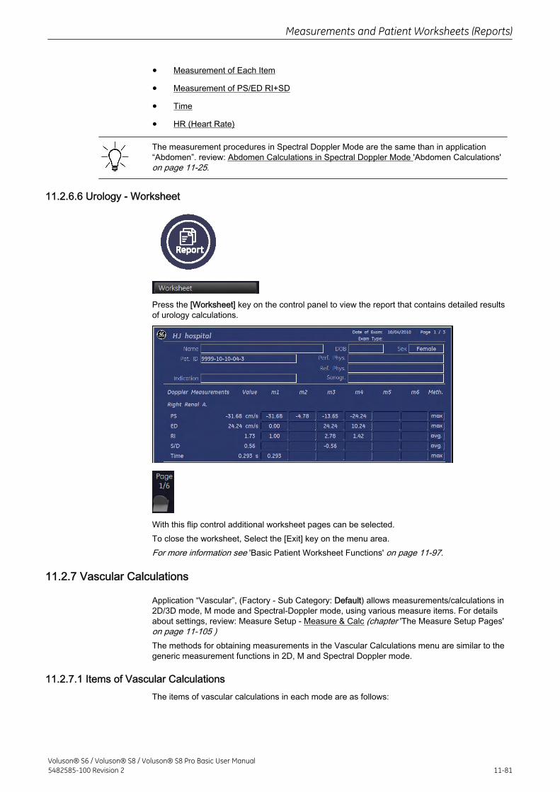
• Measurement of Each Item
• Measurement of PS/ED RI+SD
• Time
• HR (Heart Rate)
The measurement procedures in Spectral Doppler Mode are the same than in application“Abdomen”. review: Abdomen Calculations in Spectral Doppler Mode 'Abdomen Calculations'on page 11-25.
11.2.6.6 Urology - Worksheet
Press the [Worksheet] key on the control panel to view the report that contains detailed resultsof urology calculations.
With this flip control additional worksheet pages can be selected.To close the worksheet, Select the [Exit] key on the menu area.For more information see 'Basic Patient Worksheet Functions' on page 11-97.
11.2.7 Vascular Calculations
Application “Vascular”, (Factory - Sub Category: Default) allows measurements/calculations in2D/3D mode, M mode and Spectral-Doppler mode, using various measure items. For detailsabout settings, review: Measure Setup - Measure & Calc (chapter 'The Measure Setup Pages'on page 11-105 )The methods for obtaining measurements in the Vascular Calculations menu are similar to thegeneric measurement functions in 2D, M and Spectral Doppler mode.
11.2.7.1 Items of Vascular CalculationsThe items of vascular calculations in each mode are as follows:
Measurements and Patient Worksheets (Reports)
Voluson® S6 / Voluson® S8 / Voluson® S8 Pro Basic User Manual5482585-100 Revision 2 11-81
2D/3D Mode Left/Right CCA (Common Carotid Artery), Left/Right ECA (External Carotid Artery),Left/Right ICA (Internal Carotid Artery), Left/Right Bulb, Left/Right Vertebral Artery,Left/Right Subclavian Artery, Vessel
M Mode: Left/Right CCA, Left/Right ECA, Left/Right ICA, Left/Right Bulb, Left/Right VertebralArtery, Left/Right Subclavian Artery, Vessel
Doppler Mode: Left/Right CCA, Left/Right ECA, Left/Right ICA, Left/Right Bulb, Left/Right VertebralArtery, Left/Right Subclavian Artery, Vessel
11.2.7.2 Before starting Vascular Calculations
1. Press the [Patient] key on the control panel, select the [VAS] page and enter all patientinformation for Vascular calculations. For details refer to: Entering Patient Data (chapter'Entering Patient Data' on page 4-9 )
Note To cancel all calculations performed before and to start new measurement, press this key andselect [End Exam] or [Clear Exam].
2. Press [Start Exam].
3. Make sure that the probe and application are selected properly. If another application isselected, press the [Probe] key on the control panel, and change it to Vascular. For detailsrefer to: Probe/Program Selection (chapter 'Probe/Program Selection' on page 4-7 )
11.2.7.3 Vascular Calculations in 2D Mode
• Distance Measurements (like “Intima Media Thickness” and “Flow Diameter”)
• Vessel Area/Vessel Diameter
• Stenosis Area/Stenosis Diameter
• IMT
The measurement procedures in 2D Mode are the same than in application “Abdomen”.Review: Abdomen Calculations in 2D Mode in 'Abdomen Calculations' on page 11-25.
11.2.7.4 Vascular Calculations in M Mode
• Vessel Diameter
• Stenosis Diameter
• Time
• HR (Heart Rate)
Measurements and Patient Worksheets (Reports)
11-82Voluson® S6 / Voluson® S8 / Voluson® S8 Pro Basic User Manual
5482585-100 Revision 2
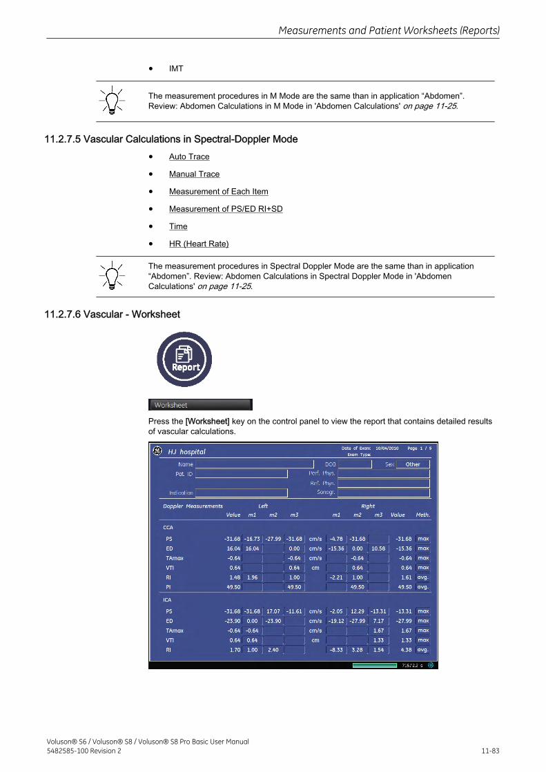
• IMT
The measurement procedures in M Mode are the same than in application “Abdomen”.Review: Abdomen Calculations in M Mode in 'Abdomen Calculations' on page 11-25.
11.2.7.5 Vascular Calculations in Spectral-Doppler Mode
• Auto Trace
• Manual Trace
• Measurement of Each Item
• Measurement of PS/ED RI+SD
• Time
• HR (Heart Rate)
The measurement procedures in Spectral Doppler Mode are the same than in application“Abdomen”. Review: Abdomen Calculations in Spectral Doppler Mode in 'AbdomenCalculations' on page 11-25.
11.2.7.6 Vascular - Worksheet
Press the [Worksheet] key on the control panel to view the report that contains detailed resultsof vascular calculations.
Measurements and Patient Worksheets (Reports)
Voluson® S6 / Voluson® S8 / Voluson® S8 Pro Basic User Manual5482585-100 Revision 2 11-83
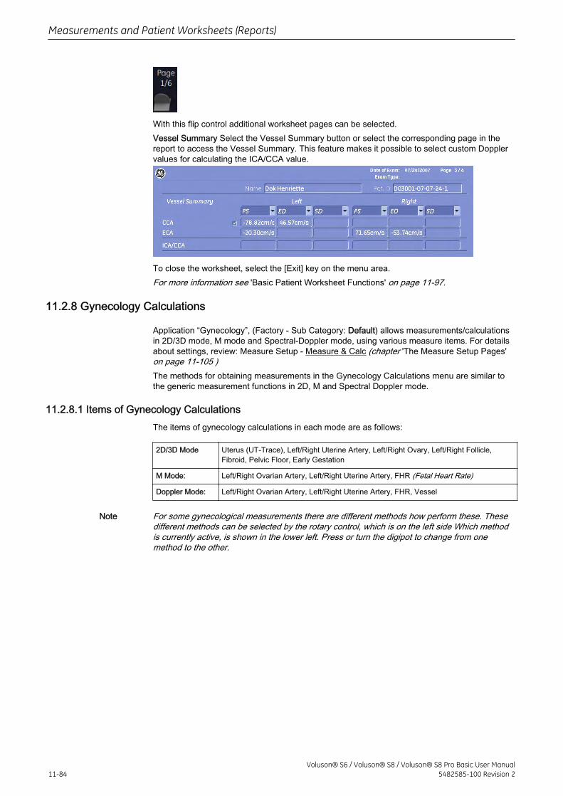
With this flip control additional worksheet pages can be selected.Vessel Summary Select the Vessel Summary button or select the corresponding page in thereport to access the Vessel Summary. This feature makes it possible to select custom Dopplervalues for calculating the ICA/CCA value.
To close the worksheet, select the [Exit] key on the menu area.For more information see 'Basic Patient Worksheet Functions' on page 11-97.
11.2.8 Gynecology Calculations
Application “Gynecology”, (Factory - Sub Category: Default) allows measurements/calculationsin 2D/3D mode, M mode and Spectral-Doppler mode, using various measure items. For detailsabout settings, review: Measure Setup - Measure & Calc (chapter 'The Measure Setup Pages'on page 11-105 )The methods for obtaining measurements in the Gynecology Calculations menu are similar tothe generic measurement functions in 2D, M and Spectral Doppler mode.
11.2.8.1 Items of Gynecology CalculationsThe items of gynecology calculations in each mode are as follows:
2D/3D Mode Uterus (UT-Trace), Left/Right Uterine Artery, Left/Right Ovary, Left/Right Follicle,Fibroid, Pelvic Floor, Early Gestation
M Mode: Left/Right Ovarian Artery, Left/Right Uterine Artery, FHR (Fetal Heart Rate)
Doppler Mode: Left/Right Ovarian Artery, Left/Right Uterine Artery, FHR, Vessel
Note For some gynecological measurements there are different methods how perform these. Thesedifferent methods can be selected by the rotary control, which is on the left side Which methodis currently active, is shown in the lower left. Press or turn the digipot to change from onemethod to the other.
Measurements and Patient Worksheets (Reports)
11-84Voluson® S6 / Voluson® S8 / Voluson® S8 Pro Basic User Manual
5482585-100 Revision 2
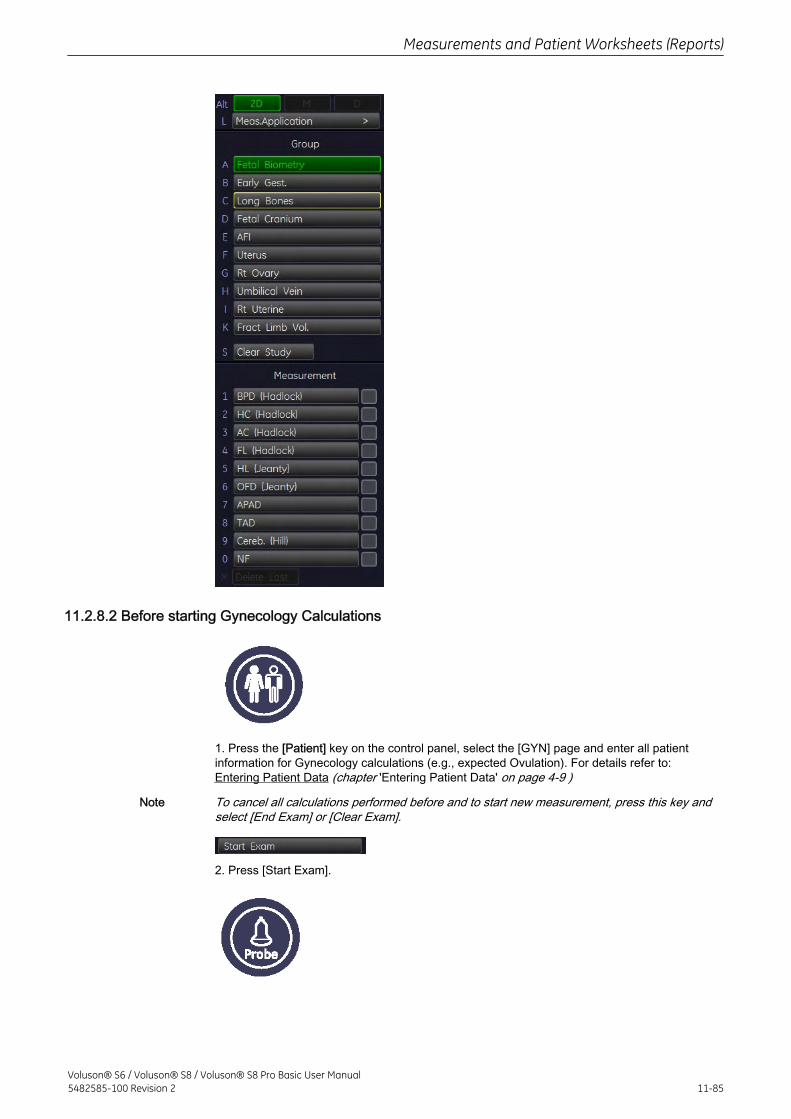
11.2.8.2 Before starting Gynecology Calculations
1. Press the [Patient] key on the control panel, select the [GYN] page and enter all patientinformation for Gynecology calculations (e.g., expected Ovulation). For details refer to:Entering Patient Data (chapter 'Entering Patient Data' on page 4-9 )
Note To cancel all calculations performed before and to start new measurement, press this key andselect [End Exam] or [Clear Exam].
2. Press [Start Exam].
Measurements and Patient Worksheets (Reports)
Voluson® S6 / Voluson® S8 / Voluson® S8 Pro Basic User Manual5482585-100 Revision 2 11-85
3. Make sure that the probe and application are selected properly. If another application isselected, press the [Probe] key on the control panel, and change it to Gynecology. For detailsrefer to: Probe/Program Selection (chapter 'Probe/Program Selection' on page 4-7 )
11.2.8.3 Gynecology Calculations in 2D Mode
• Distance Measurements (like Length, Endo. Thickness, etc.)
• Angular Measurements like (urethal rotation)
• Area Measurements (like Levator hiatus stress)
The measurement procedures in 2D Mode are the same than in application “Abdomen”.Review: Abdomen Calculations in 2D Mode in 'Abdomen Calculations' on page 11-25.
11.2.8.4 Gynecology Calculations in M Mode
• Vessel Diameter
• Stenosis Diameter
• Time
• HR (Heart Rate)
The measurement procedures in M Mode are the same than in application “Abdomen”.Review: Abdomen Calculations in M Mode in 'Abdomen Calculations' on page 11-25.
11.2.8.5 Gynecology Calculations in Spectral-Doppler Mode
• Auto Trace
• Manual Trace
• Measurement of Each Item
• Measurement of PS/ED RI+SD
• Time
• HR (Heart Rate)
The measurement procedures in Spectral Doppler Mode are the same than in application“Abdomen”. Review: Abdomen Calculations in Spectral Doppler Mode in 'AbdomenCalculations' on page 11-25.
• FHR (Fetal Heart Rate)
The measurement procedure of the Fetal Heart Rate in Spectral Doppler Mode is the samethan in application “Obstetrics”. Review: Obstetric Calculations in Spectral Doppler Modein'Obstetric Calculations - Subcategory: Biometry' on page 11-36.
11.2.8.6 Gynecology - Worksheet
Measurements and Patient Worksheets (Reports)
11-86Voluson® S6 / Voluson® S8 / Voluson® S8 Pro Basic User Manual
5482585-100 Revision 2
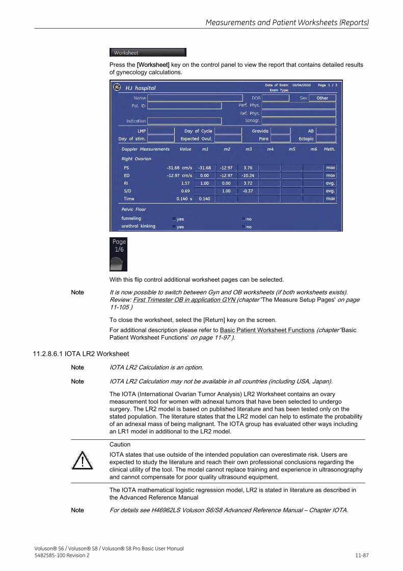
Press the [Worksheet] key on the control panel to view the report that contains detailed resultsof gynecology calculations.
With this flip control additional worksheet pages can be selected.
Note It is now possible to switch between Gyn and OB worksheets (if both worksheets exists).Review: First Trimester OB in application GYN (chapter 'The Measure Setup Pages' on page11-105 )
To close the worksheet, select the [Return] key on the screen.For additional description please refer to Basic Patient Worksheet Functions (chapter 'BasicPatient Worksheet Functions' on page 11-97 ).
11.2.8.6.1 IOTA LR2 Worksheet
Note IOTA LR2 Calculation is an option.
Note IOTA LR2 Calculation may not be available in all countries (including USA, Japan).
The IOTA (International Ovarian Tumor Analysis) LR2 Worksheet contains an ovarymeasurement tool for women with adnexal tumors that have been selected to undergosurgery. The LR2 model is based on published literature and has been tested only on thestated population. The literature states that the LR2 model can help to estimate the probabilityof an adnexal mass of being malignant. The IOTA group has evaluated other ways includingan LR1 model in additional to the LR2 model.
CautionIOTA states that use outside of the intended population can overestimate risk. Users areexpected to study the literature and reach their own professional conclusions regarding theclinical utility of the tool. The model cannot replace training and experience in ultrasonographyand cannot compensate for poor quality ultrasound equipment.
The IOTA mathematical logistic regression model, LR2 is stated in literature as described inthe Advanced Reference Manual
Note For details see H46962LS Voluson S6/S8 Advanced Reference Manual – Chapter IOTA.
Measurements and Patient Worksheets (Reports)
Voluson® S6 / Voluson® S8 / Voluson® S8 Pro Basic User Manual5482585-100 Revision 2 11-87
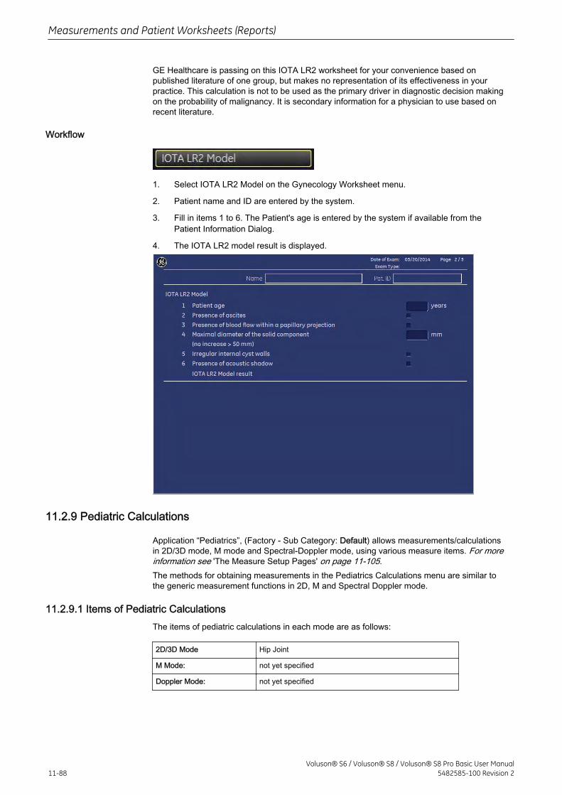
GE Healthcare is passing on this IOTA LR2 worksheet for your convenience based onpublished literature of one group, but makes no representation of its effectiveness in yourpractice. This calculation is not to be used as the primary driver in diagnostic decision makingon the probability of malignancy. It is secondary information for a physician to use based onrecent literature.
Workflow
1. Select IOTA LR2 Model on the Gynecology Worksheet menu.
2. Patient name and ID are entered by the system.
3. Fill in items 1 to 6. The Patient's age is entered by the system if available from thePatient Information Dialog.
4. The IOTA LR2 model result is displayed.
11.2.9 Pediatric Calculations
Application “Pediatrics”, (Factory - Sub Category: Default) allows measurements/calculationsin 2D/3D mode, M mode and Spectral-Doppler mode, using various measure items. For moreinformation see 'The Measure Setup Pages' on page 11-105.The methods for obtaining measurements in the Pediatrics Calculations menu are similar tothe generic measurement functions in 2D, M and Spectral Doppler mode.
11.2.9.1 Items of Pediatric CalculationsThe items of pediatric calculations in each mode are as follows:
2D/3D Mode Hip Joint
M Mode: not yet specified
Doppler Mode: not yet specified
Measurements and Patient Worksheets (Reports)
11-88Voluson® S6 / Voluson® S8 / Voluson® S8 Pro Basic User Manual
5482585-100 Revision 2
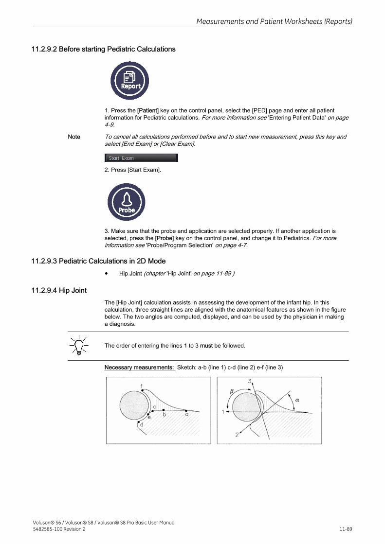
11.2.9.2 Before starting Pediatric Calculations
1. Press the [Patient] key on the control panel, select the [PED] page and enter all patientinformation for Pediatric calculations. For more information see 'Entering Patient Data' on page4-9.
Note To cancel all calculations performed before and to start new measurement, press this key andselect [End Exam] or [Clear Exam].
2. Press [Start Exam].
3. Make sure that the probe and application are selected properly. If another application isselected, press the [Probe] key on the control panel, and change it to Pediatrics. For moreinformation see 'Probe/Program Selection' on page 4-7.
11.2.9.3 Pediatric Calculations in 2D Mode
• Hip Joint (chapter 'Hip Joint' on page 11-89 )
11.2.9.4 Hip JointThe [Hip Joint] calculation assists in assessing the development of the infant hip. In thiscalculation, three straight lines are aligned with the anatomical features as shown in the figurebelow. The two angles are computed, displayed, and can be used by the physician in makinga diagnosis.
The order of entering the lines 1 to 3 must be followed.
Necessary measurements: Sketch: a-b (line 1) c-d (line 2) e-f (line 3)
Measurements and Patient Worksheets (Reports)
Voluson® S6 / Voluson® S8 / Voluson® S8 Pro Basic User Manual5482585-100 Revision 2 11-89
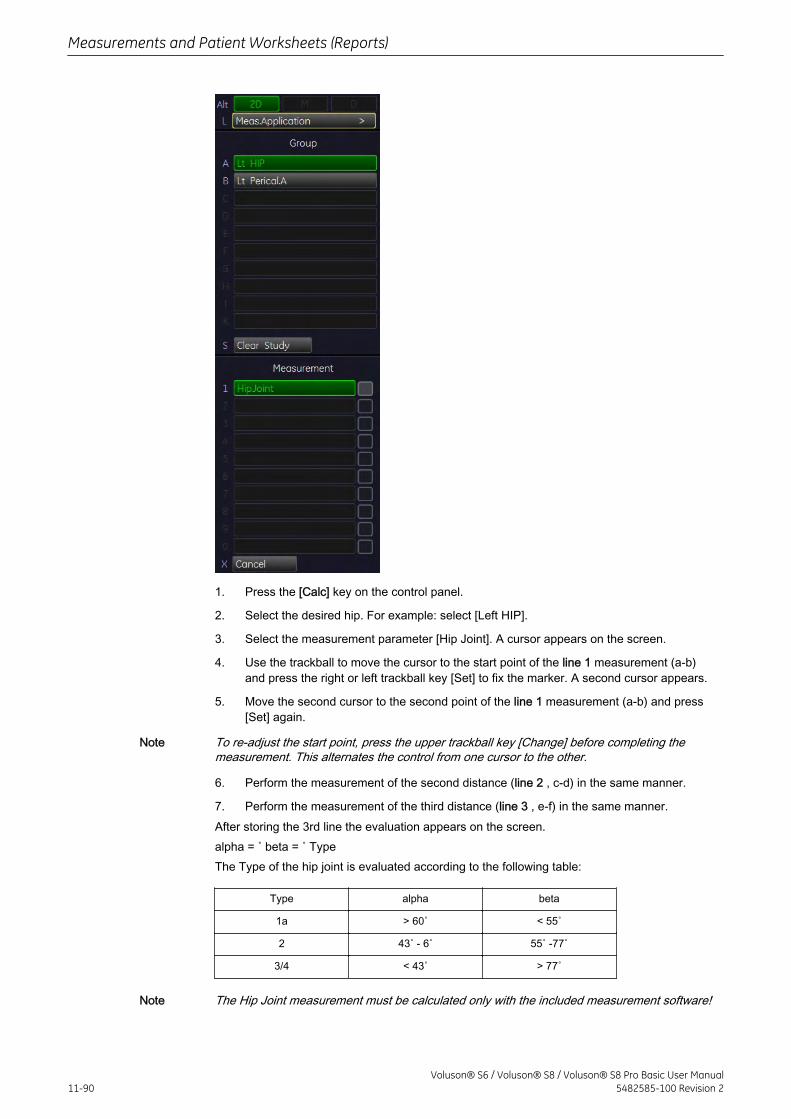
1. Press the [Calc] key on the control panel.
2. Select the desired hip. For example: select [Left HIP].
3. Select the measurement parameter [Hip Joint]. A cursor appears on the screen.
4. Use the trackball to move the cursor to the start point of the line 1 measurement (a-b)and press the right or left trackball key [Set] to fix the marker. A second cursor appears.
5. Move the second cursor to the second point of the line 1 measurement (a-b) and press[Set] again.
Note To re-adjust the start point, press the upper trackball key [Change] before completing themeasurement. This alternates the control from one cursor to the other.
6. Perform the measurement of the second distance (line 2 , c-d) in the same manner.
7. Perform the measurement of the third distance (line 3 , e-f) in the same manner.After storing the 3rd line the evaluation appears on the screen.alpha = ˚ beta = ˚ TypeThe Type of the hip joint is evaluated according to the following table:
Type alpha beta
1a > 60˚ < 55˚
2 43˚ - 6˚ 55˚ -77˚
3/4 < 43˚ > 77˚
Note The Hip Joint measurement must be calculated only with the included measurement software!
Measurements and Patient Worksheets (Reports)
11-90Voluson® S6 / Voluson® S8 / Voluson® S8 Pro Basic User Manual
5482585-100 Revision 2
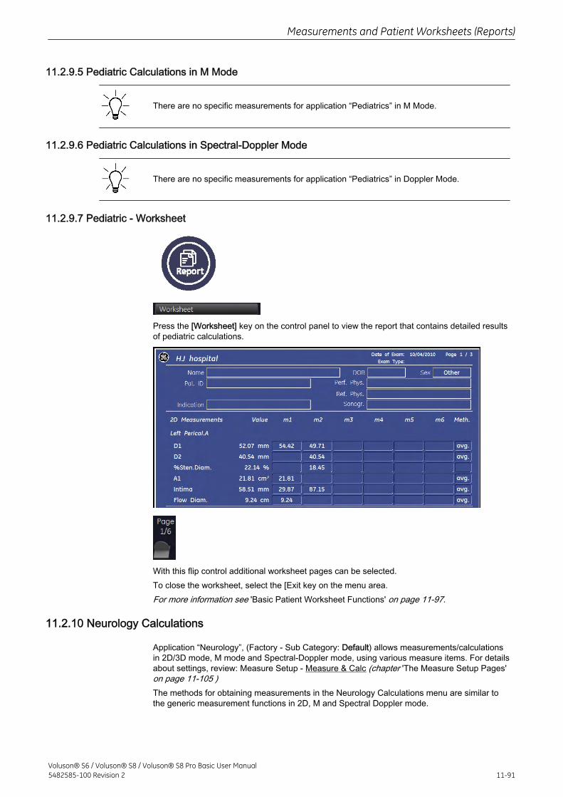
11.2.9.5 Pediatric Calculations in M Mode
There are no specific measurements for application “Pediatrics” in M Mode.
11.2.9.6 Pediatric Calculations in Spectral-Doppler Mode
There are no specific measurements for application “Pediatrics” in Doppler Mode.
11.2.9.7 Pediatric - Worksheet
Press the [Worksheet] key on the control panel to view the report that contains detailed resultsof pediatric calculations.
With this flip control additional worksheet pages can be selected.To close the worksheet, select the [Exit key on the menu area.For more information see 'Basic Patient Worksheet Functions' on page 11-97.
11.2.10 Neurology Calculations
Application “Neurology”, (Factory - Sub Category: Default) allows measurements/calculationsin 2D/3D mode, M mode and Spectral-Doppler mode, using various measure items. For detailsabout settings, review: Measure Setup - Measure & Calc (chapter 'The Measure Setup Pages'on page 11-105 )The methods for obtaining measurements in the Neurology Calculations menu are similar tothe generic measurement functions in 2D, M and Spectral Doppler mode.
Measurements and Patient Worksheets (Reports)
Voluson® S6 / Voluson® S8 / Voluson® S8 Pro Basic User Manual5482585-100 Revision 2 11-91
11.2.10.1 Items of Neurology CalculationsThe items of neurology calculations in each mode are as follows:
2D/3D Mode Left/Right ACA (Anterior Cerebral Artery), Left/Right MCA (Middle Cerebral Artery),Left/Right PCA (Posterior Cerebral Artery), Basilar Artery, A-Com A. (AnteriorCommon Artery), Left/Right P-Com A. (Posterior Common Artery), Left/Right CCA(Common Carotid Artery), Left/Right ICA (Internal Carotid Artery), Left/RightVertebral Artery, Vessel
M Mode: Left/Right ACA, Left/Right MCA, Left/Right PCA, Basilar Artery, A-Com A., Left/RightP-Com A., Left/Right CCA, Left/Right ICA, Left/Right Vertebral Artery, Vessel
Doppler Mode: Left/Right ACA, Left/Right MCA, Left/Right PCA, Basilar Artery, A-Com A., Left/RightP-Com A., Left/Right CCA, Left/Right ICA, Left/Right Vertebral Artery, Vessel
11.2.10.2 Before starting Neurology Calculations
1. Press the [Patient] key on the control panel, select the [NEURO] page and enter all patientinformation for Neurology calculations. For details refer to: Entering Patient Data (chapter'Entering Patient Data' on page 4-9 )
Note To cancel all calculations performed before and to start new measurement, press this key andselect [End Exam] or [Clear Exam].
2. Press [Start Exam].
3. Make sure that the probe and application are selected properly. If another application isselected, press the [Probe] key on the control panel, and change it to Neurology. For detailsrefer to: Probe/Program Selection (chapter 'Probe/Program Selection' on page 4-7 )
11.2.10.3 Neurology Calculations in 2D Mode
• Distance Measurements (e.g., Flow Diameter)
• Vessel Area/Vessel Diameter
• Stenosis Area/Stenosis Diameter
The measurement procedures in 2D Mode are the same than in application “Abdomen”.Review: Abdomen Calculations in 2D Mode in 'Abdomen Calculations' on page 11-25.
11.2.10.4 Neurology Calculations in M Mode
• Vessel Diameter
• Stenosis Diameter
Measurements and Patient Worksheets (Reports)
11-92Voluson® S6 / Voluson® S8 / Voluson® S8 Pro Basic User Manual
5482585-100 Revision 2
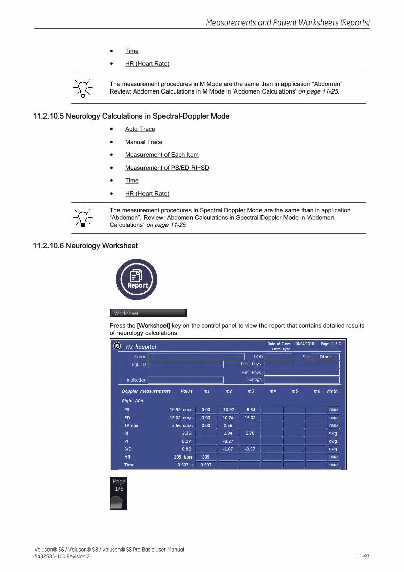
• Time
• HR (Heart Rate)
The measurement procedures in M Mode are the same than in application “Abdomen”.Review: Abdomen Calculations in M Mode in 'Abdomen Calculations' on page 11-25.
11.2.10.5 Neurology Calculations in Spectral-Doppler Mode
• Auto Trace
• Manual Trace
• Measurement of Each Item
• Measurement of PS/ED RI+SD
• Time
• HR (Heart Rate)
The measurement procedures in Spectral Doppler Mode are the same than in application“Abdomen”. Review: Abdomen Calculations in Spectral Doppler Mode in 'AbdomenCalculations' on page 11-25.
11.2.10.6 Neurology Worksheet
Press the [Worksheet] key on the control panel to view the report that contains detailed resultsof neurology calculations.
Measurements and Patient Worksheets (Reports)
Voluson® S6 / Voluson® S8 / Voluson® S8 Pro Basic User Manual5482585-100 Revision 2 11-93
With this flip control additional worksheet pages can be selected.To close the worksheet, exit the [Exit] key on the menu area.For more information see 'Basic Patient Worksheet Functions' on page 11-97.
11.2.11 MSK Calculations
There are no measurements/calculations specified for application “MSK”.
11.2.11.1 Items of MSK Calculations
There are no items specified for application “MSK”.
11.2.11.2 Before starting MSK Calculations
1. Press the [Patient] key on the control panel, select the [MSK] page and enter all patientinformation for MSK calculations. For details refer to: Entering Patient Data (chapter 'EnteringPatient Data' on page 4-9 )
Note To cancel all calculations performed before and to start new measurement, press this key andselect [End Exam] or [Clear Exam].
2. Press [Start Exam].
3. Make sure that the probe and application are selected properly. If another application isselected, press the [Probe] key on the control panel, and change it to MSK. For details refer to:Probe/Program Selection (chapter 'Probe/Program Selection' on page 4-7 )
11.2.11.3 MSK - Worksheet
For application “MSK”, there is no specific worksheet available.
Measurements and Patient Worksheets (Reports)
11-94Voluson® S6 / Voluson® S8 / Voluson® S8 Pro Basic User Manual
5482585-100 Revision 2
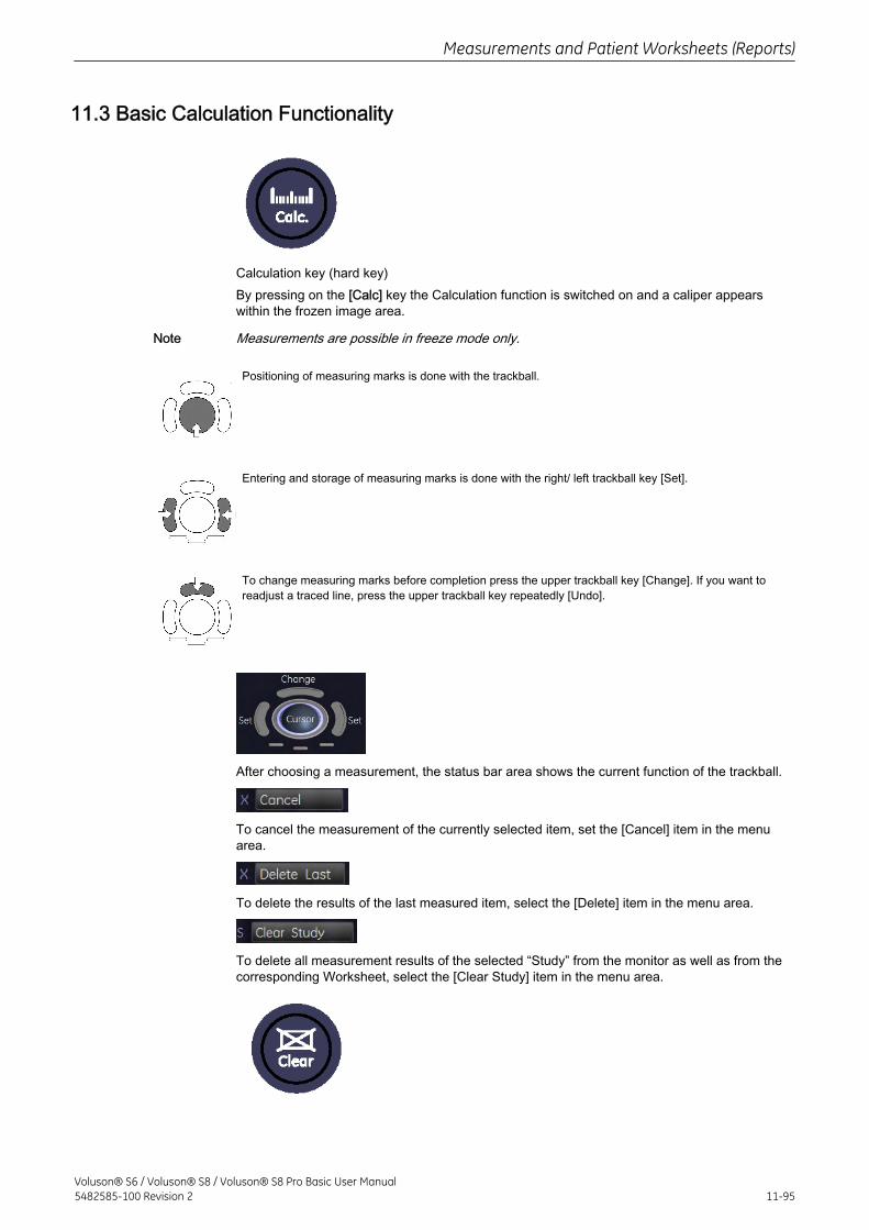
11.3 Basic Calculation Functionality
Calculation key (hard key)By pressing on the [Calc] key the Calculation function is switched on and a caliper appearswithin the frozen image area.
Note Measurements are possible in freeze mode only.
Positioning of measuring marks is done with the trackball.
Entering and storage of measuring marks is done with the right/ left trackball key [Set].
To change measuring marks before completion press the upper trackball key [Change]. If you want toreadjust a traced line, press the upper trackball key repeatedly [Undo].
After choosing a measurement, the status bar area shows the current function of the trackball.
To cancel the measurement of the currently selected item, set the [Cancel] item in the menuarea.
To delete the results of the last measured item, select the [Delete] item in the menu area.
To delete all measurement results of the selected “Study” from the monitor as well as from thecorresponding Worksheet, select the [Clear Study] item in the menu area.
Measurements and Patient Worksheets (Reports)
Voluson® S6 / Voluson® S8 / Voluson® S8 Pro Basic User Manual5482585-100 Revision 2 11-95
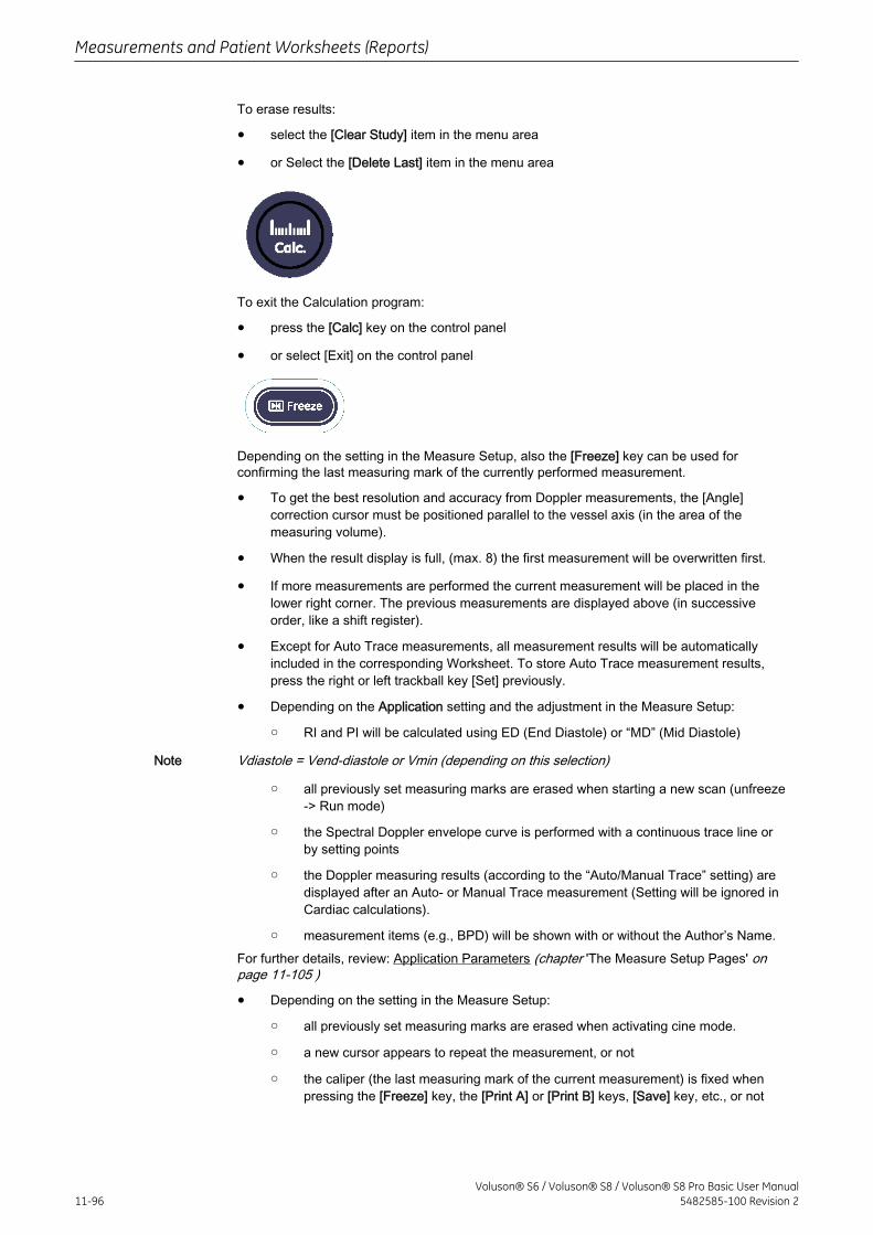
To erase results:
• select the [Clear Study] item in the menu area
• or Select the [Delete Last] item in the menu area
To exit the Calculation program:
• press the [Calc] key on the control panel
• or select [Exit] on the control panel
Depending on the setting in the Measure Setup, also the [Freeze] key can be used forconfirming the last measuring mark of the currently performed measurement.
• To get the best resolution and accuracy from Doppler measurements, the [Angle]correction cursor must be positioned parallel to the vessel axis (in the area of themeasuring volume).
• When the result display is full, (max. 8) the first measurement will be overwritten first.
• If more measurements are performed the current measurement will be placed in thelower right corner. The previous measurements are displayed above (in successiveorder, like a shift register).
• Except for Auto Trace measurements, all measurement results will be automaticallyincluded in the corresponding Worksheet. To store Auto Trace measurement results,press the right or left trackball key [Set] previously.
• Depending on the Application setting and the adjustment in the Measure Setup:
○ RI and PI will be calculated using ED (End Diastole) or “MD” (Mid Diastole)
Note Vdiastole = Vend-diastole or Vmin (depending on this selection)
○ all previously set measuring marks are erased when starting a new scan (unfreeze-> Run mode)
○ the Spectral Doppler envelope curve is performed with a continuous trace line orby setting points
○ the Doppler measuring results (according to the “Auto/Manual Trace” setting) aredisplayed after an Auto- or Manual Trace measurement (Setting will be ignored inCardiac calculations).
○ measurement items (e.g., BPD) will be shown with or without the Author’s Name.For further details, review: Application Parameters (chapter 'The Measure Setup Pages' onpage 11-105 )
• Depending on the setting in the Measure Setup:
○ all previously set measuring marks are erased when activating cine mode.
○ a new cursor appears to repeat the measurement, or not
○ the caliper (the last measuring mark of the current measurement) is fixed whenpressing the [Freeze] key, the [Print A] or [Print B] keys, [Save] key, etc., or not
Measurements and Patient Worksheets (Reports)
11-96Voluson® S6 / Voluson® S8 / Voluson® S8 Pro Basic User Manual
5482585-100 Revision 2
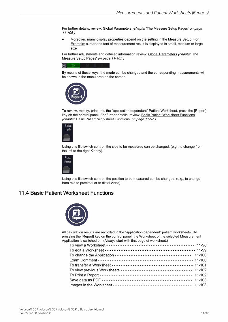
For further details, review: Global Parameters (chapter 'The Measure Setup Pages' on page11-105 )
• Moreover, many display properties depend on the setting in the Measure Setup. ForExample: cursor and font of measurement result is displayed in small, medium or largesize
For further adjustments and detailed information review: Global Parameters (chapter 'TheMeasure Setup Pages' on page 11-105 )
By means of these keys, the mode can be changed and the corresponding measurements willbe shown in the menu area on the screen.
To review, modify, print, etc. the “application dependent” Patient Worksheet, press the [Report]key on the control panel. For further details, review: Basic Patient Worksheet Functions(chapter 'Basic Patient Worksheet Functions' on page 11-97 ).
Using this flip switch control, the side to be measured can be changed. (e.g., to change fromthe left to the right Kidney).
Using this flip switch control, the position to be measured can be changed. (e.g., to changefrom mid to proximal or to distal Aorta)
11.4 Basic Patient Worksheet Functions
All calculation results are recorded in the “application dependent” patient worksheets. Bypressing the [Report] key on the control panel, the Worksheet of the selected MeasurementApplication is switched on. (Always start with first page of worksheet.)
To view a Worksheet - - - - - - - - - - - - - - - - - - - - - - - - - - - - - - - - - - - - - - 11-98To edit a Worksheet - - - - - - - - - - - - - - - - - - - - - - - - - - - - - - - - - - - - - - - 11-99To change the Application - - - - - - - - - - - - - - - - - - - - - - - - - - - - - - - - - 11-100Exam Comment - - - - - - - - - - - - - - - - - - - - - - - - - - - - - - - - - - - - - - - - - 11-100To transfer a Worksheet - - - - - - - - - - - - - - - - - - - - - - - - - - - - - - - - - - - 11-101To view previous Worksheets - - - - - - - - - - - - - - - - - - - - - - - - - - - - - - - 11-102To Print a Report - - - - - - - - - - - - - - - - - - - - - - - - - - - - - - - - - - - - - - - - 11-102Save data as PDF - - - - - - - - - - - - - - - - - - - - - - - - - - - - - - - - - - - - - - - 11-103Images in the Worksheet - - - - - - - - - - - - - - - - - - - - - - - - - - - - - - - - - - 11-103
Measurements and Patient Worksheets (Reports)
Voluson® S6 / Voluson® S8 / Voluson® S8 Pro Basic User Manual5482585-100 Revision 2 11-97
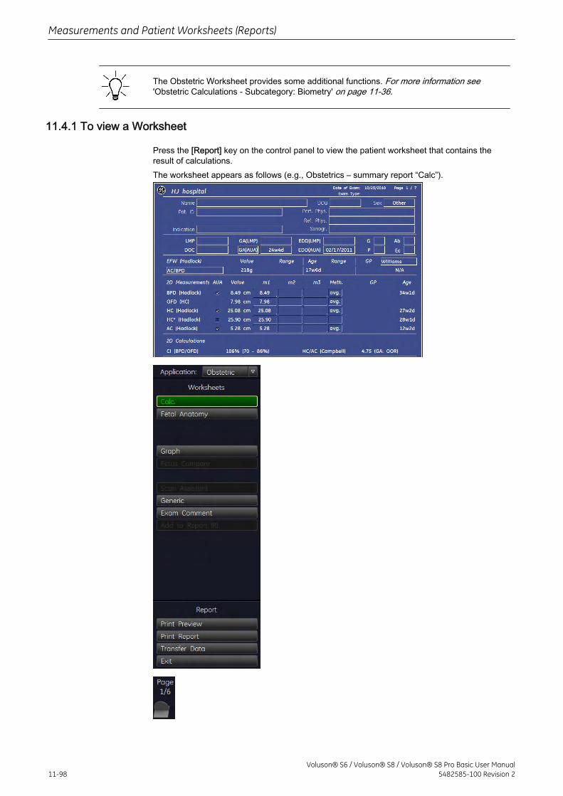
The Obstetric Worksheet provides some additional functions. For more information see'Obstetric Calculations - Subcategory: Biometry' on page 11-36.
11.4.1 To view a Worksheet
Press the [Report] key on the control panel to view the patient worksheet that contains theresult of calculations.The worksheet appears as follows (e.g., Obstetrics – summary report “Calc”).
Measurements and Patient Worksheets (Reports)
11-98Voluson® S6 / Voluson® S8 / Voluson® S8 Pro Basic User Manual
5482585-100 Revision 2
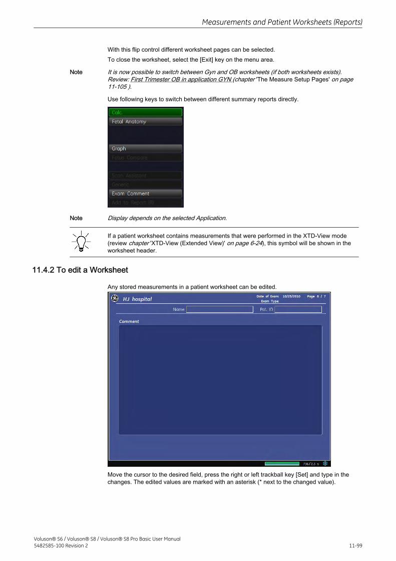
With this flip control different worksheet pages can be selected.To close the worksheet, select the [Exit] key on the menu area.
Note It is now possible to switch between Gyn and OB worksheets (if both worksheets exists).Review: First Trimester OB in application GYN (chapter 'The Measure Setup Pages' on page11-105 ).
Use following keys to switch between different summary reports directly.
Note Display depends on the selected Application.
If a patient worksheet contains measurements that were performed in the XTD-View mode(review chapter 'XTD-View (Extended View)' on page 6-24), this symbol will be shown in theworksheet header.
11.4.2 To edit a Worksheet
Any stored measurements in a patient worksheet can be edited.
Move the cursor to the desired field, press the right or left trackball key [Set] and type in thechanges. The edited values are marked with an asterisk (* next to the changed value).
Measurements and Patient Worksheets (Reports)
Voluson® S6 / Voluson® S8 / Voluson® S8 Pro Basic User Manual5482585-100 Revision 2 11-99
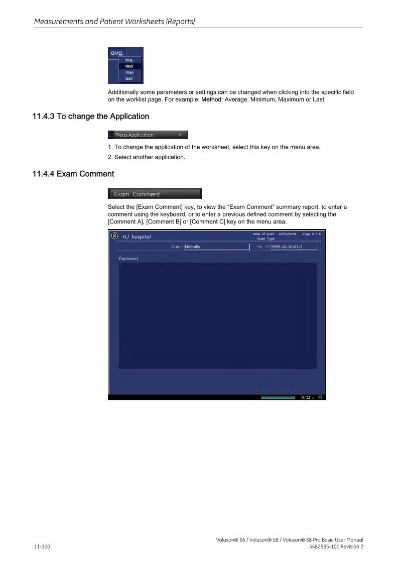
Additionally some parameters or settings can be changed when clicking into the specific fieldon the worklist page. For example: Method: Average, Minimum, Maximum or Last
11.4.3 To change the Application
1. To change the application of the worksheet, select this key on the menu area.2. Select another application.
11.4.4 Exam Comment
Select the [Exam Comment] key, to view the “Exam Comment” summary report, to enter acomment using the keyboard, or to enter a previous defined comment by selecting the[Comment A], [Comment B] or [Comment C] key on the menu area.
Measurements and Patient Worksheets (Reports)
11-100Voluson® S6 / Voluson® S8 / Voluson® S8 Pro Basic User Manual
5482585-100 Revision 2
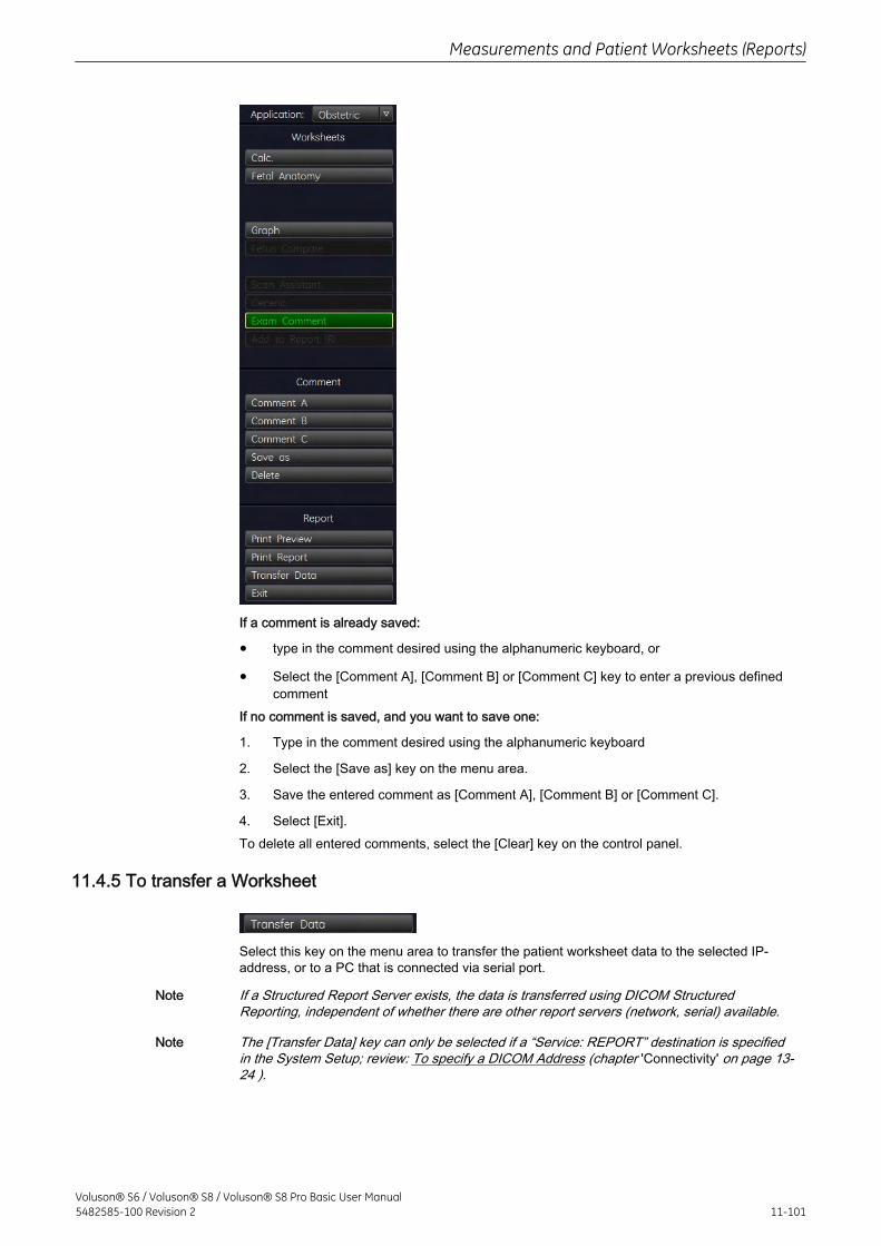
If a comment is already saved:
• type in the comment desired using the alphanumeric keyboard, or
• Select the [Comment A], [Comment B] or [Comment C] key to enter a previous definedcomment
If no comment is saved, and you want to save one:
1. Type in the comment desired using the alphanumeric keyboard
2. Select the [Save as] key on the menu area.
3. Save the entered comment as [Comment A], [Comment B] or [Comment C].
4. Select [Exit].To delete all entered comments, select the [Clear] key on the control panel.
11.4.5 To transfer a Worksheet
Select this key on the menu area to transfer the patient worksheet data to the selected IP-address, or to a PC that is connected via serial port.
Note If a Structured Report Server exists, the data is transferred using DICOM StructuredReporting, independent of whether there are other report servers (network, serial) available.
Note The [Transfer Data] key can only be selected if a “Service: REPORT” destination is specifiedin the System Setup; review: To specify a DICOM Address (chapter 'Connectivity' on page 13-24 ).
Measurements and Patient Worksheets (Reports)
Voluson® S6 / Voluson® S8 / Voluson® S8 Pro Basic User Manual5482585-100 Revision 2 11-101
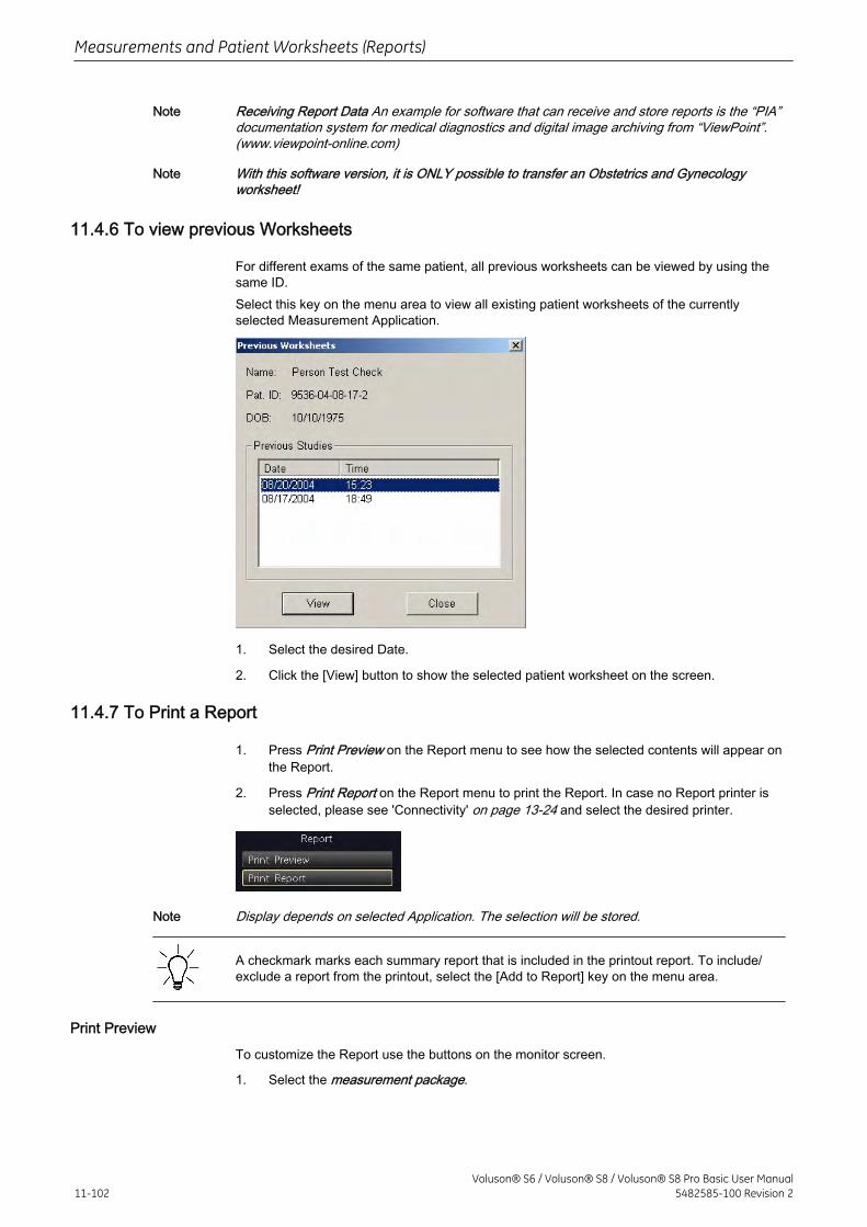
Note Receiving Report Data An example for software that can receive and store reports is the “PIA”documentation system for medical diagnostics and digital image archiving from “ViewPoint”.(www.viewpoint-online.com)
Note With this software version, it is ONLY possible to transfer an Obstetrics and Gynecologyworksheet!
11.4.6 To view previous Worksheets
For different exams of the same patient, all previous worksheets can be viewed by using thesame ID.Select this key on the menu area to view all existing patient worksheets of the currentlyselected Measurement Application.
1. Select the desired Date.
2. Click the [View] button to show the selected patient worksheet on the screen.
11.4.7 To Print a Report
1. Press Print Preview on the Report menu to see how the selected contents will appear onthe Report.
2. Press Print Report on the Report menu to print the Report. In case no Report printer isselected, please see 'Connectivity' on page 13-24 and select the desired printer.
Note Display depends on selected Application. The selection will be stored.
A checkmark marks each summary report that is included in the printout report. To include/exclude a report from the printout, select the [Add to Report] key on the menu area.
Print Preview
To customize the Report use the buttons on the monitor screen.
1. Select the measurement package.
Measurements and Patient Worksheets (Reports)
11-102Voluson® S6 / Voluson® S8 / Voluson® S8 Pro Basic User Manual
5482585-100 Revision 2
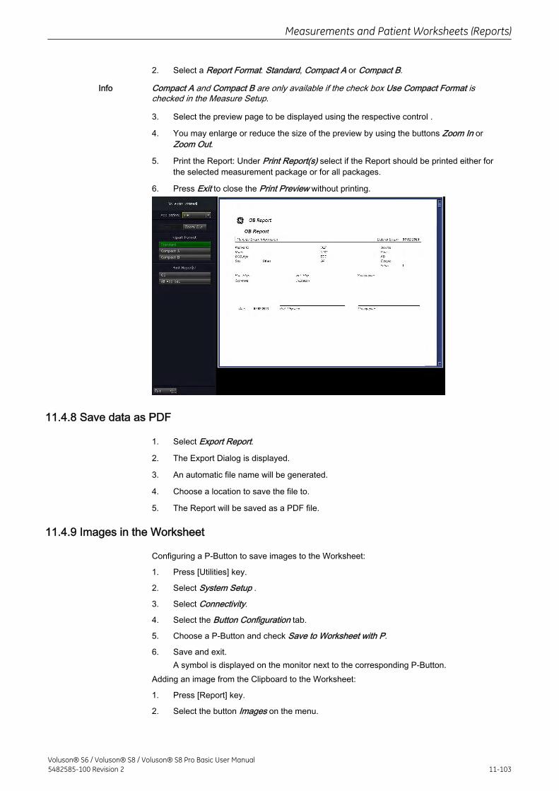
2. Select a Report Format: Standard, Compact A or Compact B.
Info Compact A and Compact B are only available if the check box Use Compact Format ischecked in the Measure Setup.
3. Select the preview page to be displayed using the respective control .
4. You may enlarge or reduce the size of the preview by using the buttons Zoom In orZoom Out.
5. Print the Report: Under Print Report(s) select if the Report should be printed either forthe selected measurement package or for all packages.
6. Press Exit to close the Print Preview without printing.
11.4.8 Save data as PDF
1. Select Export Report.
2. The Export Dialog is displayed.
3. An automatic file name will be generated.
4. Choose a location to save the file to.
5. The Report will be saved as a PDF file.
11.4.9 Images in the Worksheet
Configuring a P-Button to save images to the Worksheet:
1. Press [Utilities] key.
2. Select System Setup .
3. Select Connectivity.
4. Select the Button Configuration tab.
5. Choose a P-Button and check Save to Worksheet with P.
6. Save and exit.A symbol is displayed on the monitor next to the corresponding P-Button.
Adding an image from the Clipboard to the Worksheet:
1. Press [Report] key.
2. Select the button Images on the menu.
Measurements and Patient Worksheets (Reports)
Voluson® S6 / Voluson® S8 / Voluson® S8 Pro Basic User Manual5482585-100 Revision 2 11-103
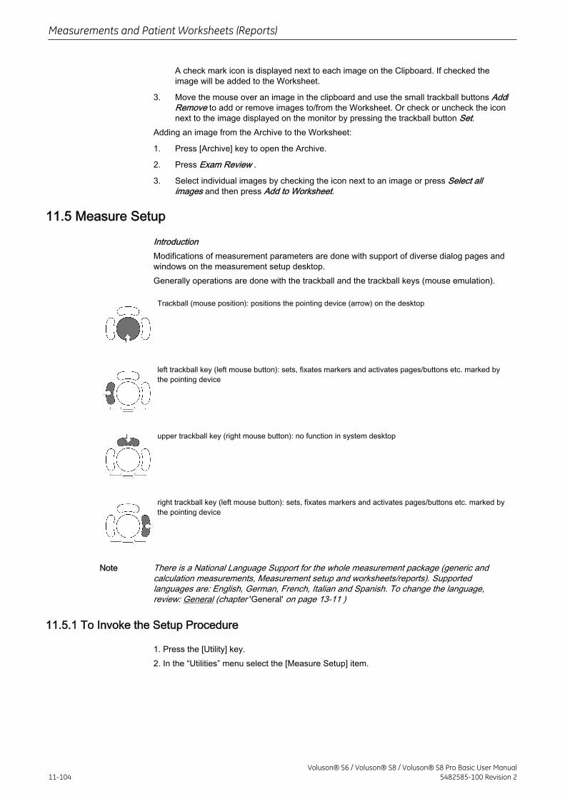
A check mark icon is displayed next to each image on the Clipboard. If checked theimage will be added to the Worksheet.
3. Move the mouse over an image in the clipboard and use the small trackball buttons Add/Remove to add or remove images to/from the Worksheet. Or check or uncheck the iconnext to the image displayed on the monitor by pressing the trackball button Set.
Adding an image from the Archive to the Worksheet:
1. Press [Archive] key to open the Archive.
2. Press Exam Review .
3. Select individual images by checking the icon next to an image or press Select allimages and then press Add to Worksheet.
11.5 Measure Setup
IntroductionModifications of measurement parameters are done with support of diverse dialog pages andwindows on the measurement setup desktop.Generally operations are done with the trackball and the trackball keys (mouse emulation).
Trackball (mouse position): positions the pointing device (arrow) on the desktop
left trackball key (left mouse button): sets, fixates markers and activates pages/buttons etc. marked bythe pointing device
upper trackball key (right mouse button): no function in system desktop
right trackball key (left mouse button): sets, fixates markers and activates pages/buttons etc. marked bythe pointing device
Note There is a National Language Support for the whole measurement package (generic andcalculation measurements, Measurement setup and worksheets/reports). Supportedlanguages are: English, German, French, Italian and Spanish. To change the language,review: General (chapter 'General' on page 13-11 )
11.5.1 To Invoke the Setup Procedure
1. Press the [Utility] key.2. In the “Utilities” menu select the [Measure Setup] item.
Measurements and Patient Worksheets (Reports)
11-104Voluson® S6 / Voluson® S8 / Voluson® S8 Pro Basic User Manual
5482585-100 Revision 2
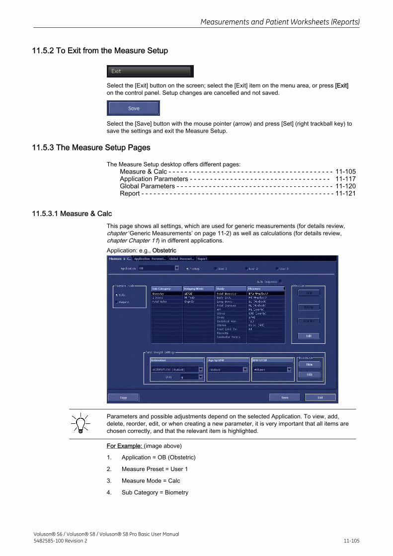
11.5.2 To Exit from the Measure Setup
Select the [Exit] button on the screen; select the [Exit] item on the menu area, or press [Exit]on the control panel. Setup changes are cancelled and not saved.
Select the [Save] button with the mouse pointer (arrow) and press [Set] (right trackball key) tosave the settings and exit the Measure Setup.
11.5.3 The Measure Setup Pages
The Measure Setup desktop offers different pages:Measure & Calc - - - - - - - - - - - - - - - - - - - - - - - - - - - - - - - - - - - - - - - - - 11-105Application Parameters - - - - - - - - - - - - - - - - - - - - - - - - - - - - - - - - - - - 11-117Global Parameters - - - - - - - - - - - - - - - - - - - - - - - - - - - - - - - - - - - - - - - 11-120Report - - - - - - - - - - - - - - - - - - - - - - - - - - - - - - - - - - - - - - - - - - - - - - - - 11-121
11.5.3.1 Measure & CalcThis page shows all settings, which are used for generic measurements (for details review,chapter ‘Generic Measurements’ on page 11‐2) as well as calculations (for details review,chapter Chapter 11) in different applications.Application: e.g., Obstetric
Parameters and possible adjustments depend on the selected Application. To view, add,delete, reorder, edit, or when creating a new parameter, it is very important that all items arechosen correctly, and that the relevant item is highlighted.
For Example: (image above)
1. Application = OB (Obstetric)
2. Measure Preset = User 1
3. Measure Mode = Calc
4. Sub Category = Biometry
Measurements and Patient Worksheets (Reports)
Voluson® S6 / Voluson® S8 / Voluson® S8 Pro Basic User Manual5482585-100 Revision 2 11-105
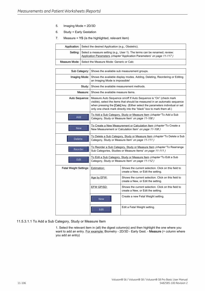
5. Imaging Mode = 2D/3D
6. Study = Early Gestation
7. Measure = YS (is the highlighted, relevant item)
Application: Select the desired Application (e.g., Obstetric).
Setting: Select a measure setting (e.g., User 1). The terms can be renamed; review:Application Parameters (chapter 'Application Parameters' on page 11-117 )
Measure Mode: Select the Measure Mode: Generic or Calc
Sub Category: Shows the available sub measurement groups.
Imaging Mode: Shows the available display modes. Adding, Deleting, Reordering or Editingan Imaging Mode is impossible!
Study: Shows the available measurement methods.
Measure: Shows the available measure items.
Auto Sequence: Measure Auto Sequence on/off If Auto Sequence is “On” (check markvisible), select the items that should be measured in an automatic sequencewhen pressing the [Calc] key. (Either select the parameters individual or setonly one check mark directly into the “black” box to mark them all.)
To Add a Sub Category, Study or Measure Item (chapter 'To Add a SubCategory, Study or Measure Item' on page 11-106 )
To Create a New Measurement or Calculation Item (chapter 'To Create aNew Measurement or Calculation Item' on page 11-108 )
To Delete a Sub Category, Study or Measure Item (chapter 'To Delete a SubCategory, Study or Measure Item' on page 11-111 )
To Reorder a Sub Category, Study or Measure Item (chapter 'To RearrangeSub Categories, Studies or Measure Items' on page 11-111 )
To Edit a Sub Category, Study or Measure Item (chapter 'To Edit a SubCategory, Study or Measure Item' on page 11-112 )
Fetal Weight Settings: Estimation: Shows the current selection. Click on this field tocreate a New, or Edit the setting.
Age by EFW: Shows the current selection. Click on this field tocreate a New, or Edit the setting.
EFW GP/SD: Shows the current selection. Click on this field tocreate a New, or Edit the setting.
Create a new Fetal Weight setting.
Edit a Fetal Weight setting.
11.5.3.1.1 To Add a Sub Category, Study or Measure Item
1. Select the relevant item in (all) the digest column(s) and then highlight the one where youwant to add an entry. For example: Biometry - 2D/3D - Early Gest. - Measure (= column whereyou add an entry)
Measurements and Patient Worksheets (Reports)
11-106Voluson® S6 / Voluson® S8 / Voluson® S8 Pro Basic User Manual
5482585-100 Revision 2
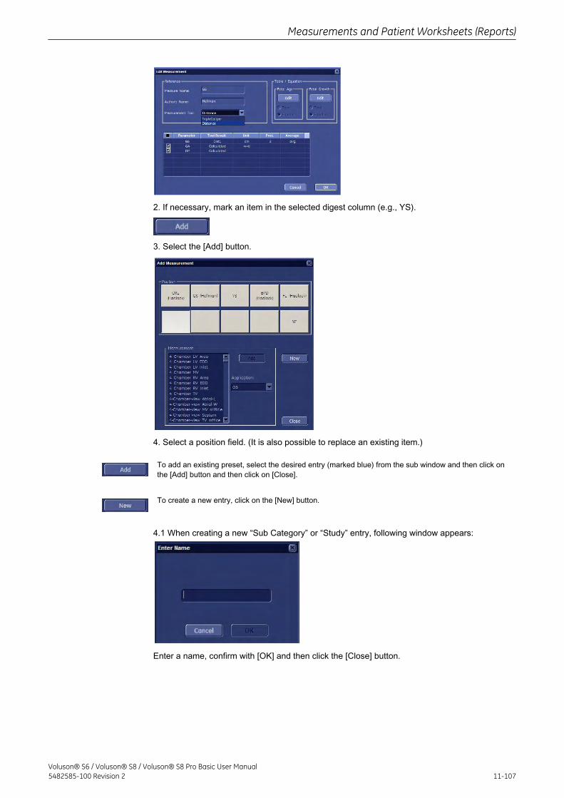
2. If necessary, mark an item in the selected digest column (e.g., YS).
3. Select the [Add] button.
4. Select a position field. (It is also possible to replace an existing item.)
To add an existing preset, select the desired entry (marked blue) from the sub window and then click onthe [Add] button and then click on [Close].
To create a new entry, click on the [New] button.
4.1 When creating a new “Sub Category” or “Study” entry, following window appears:
Enter a name, confirm with [OK] and then click the [Close] button.
Measurements and Patient Worksheets (Reports)
Voluson® S6 / Voluson® S8 / Voluson® S8 Pro Basic User Manual5482585-100 Revision 2 11-107
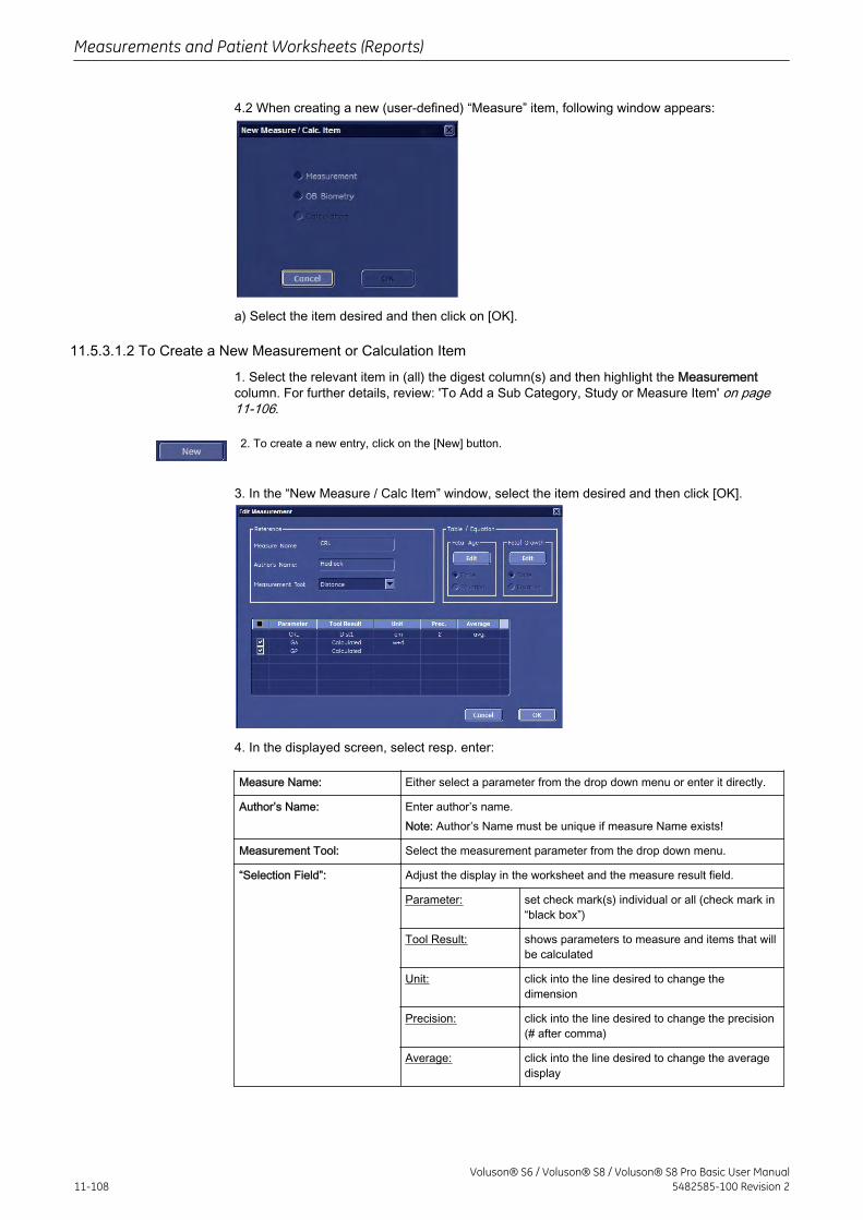
4.2 When creating a new (user-defined) “Measure” item, following window appears:
a) Select the item desired and then click on [OK].
11.5.3.1.2 To Create a New Measurement or Calculation Item
1. Select the relevant item in (all) the digest column(s) and then highlight the Measurementcolumn. For further details, review: 'To Add a Sub Category, Study or Measure Item' on page11-106.
2. To create a new entry, click on the [New] button.
3. In the “New Measure / Calc Item” window, select the item desired and then click [OK].
4. In the displayed screen, select resp. enter:
Measure Name: Either select a parameter from the drop down menu or enter it directly.
Author’s Name: Enter author’s name.Note: Author’s Name must be unique if measure Name exists!
Measurement Tool: Select the measurement parameter from the drop down menu.
“Selection Field”: Adjust the display in the worksheet and the measure result field.
Parameter: set check mark(s) individual or all (check mark in“black box”)
Tool Result: shows parameters to measure and items that willbe calculated
Unit: click into the line desired to change thedimension
Precision: click into the line desired to change the precision(# after comma)
Average: click into the line desired to change the averagedisplay
Measurements and Patient Worksheets (Reports)
11-108Voluson® S6 / Voluson® S8 / Voluson® S8 Pro Basic User Manual
5482585-100 Revision 2
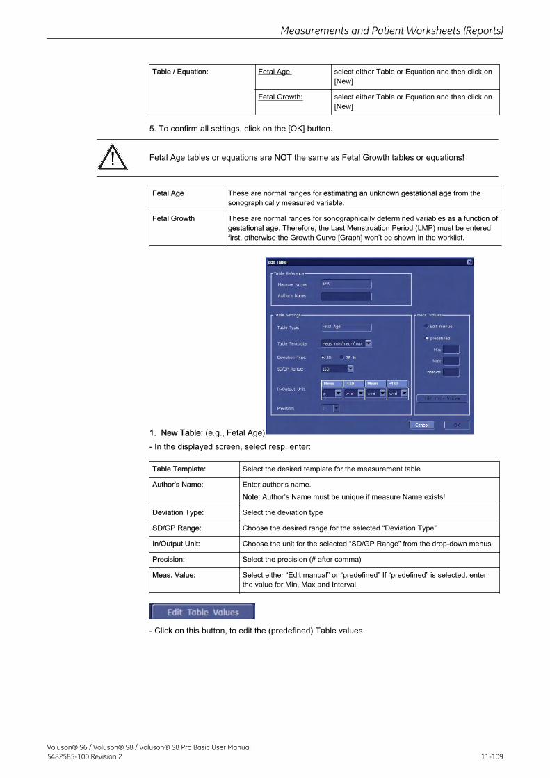
Table / Equation: Fetal Age: select either Table or Equation and then click on[New]
Fetal Growth: select either Table or Equation and then click on[New]
5. To confirm all settings, click on the [OK] button.
Fetal Age tables or equations are NOT the same as Fetal Growth tables or equations!
Fetal Age These are normal ranges for estimating an unknown gestational age from thesonographically measured variable.
Fetal Growth These are normal ranges for sonographically determined variables as a function ofgestational age. Therefore, the Last Menstruation Period (LMP) must be enteredfirst, otherwise the Growth Curve [Graph] won’t be shown in the worklist.
1. New Table: (e.g., Fetal Age)- In the displayed screen, select resp. enter:
Table Template: Select the desired template for the measurement table
Author’s Name: Enter author’s name.Note: Author’s Name must be unique if measure Name exists!
Deviation Type: Select the deviation type
SD/GP Range: Choose the desired range for the selected “Deviation Type”
In/Output Unit: Choose the unit for the selected “SD/GP Range” from the drop-down menus
Precision: Select the precision (# after comma)
Meas. Value: Select either “Edit manual” or “predefined” If “predefined” is selected, enterthe value for Min, Max and Interval.
- Click on this button, to edit the (predefined) Table values.
Measurements and Patient Worksheets (Reports)
Voluson® S6 / Voluson® S8 / Voluson® S8 Pro Basic User Manual5482585-100 Revision 2 11-109
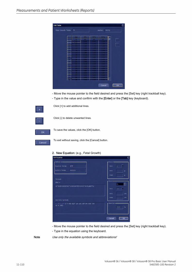
- Move the mouse pointer to the field desired and press the [Set] key (right trackball key).- Type in the value and confirm with the [Enter] or the [Tab] key (keyboard).
Click [+] to add additional lines.
Click [-] to delete unwanted lines.
To save the values, click the [OK] button.
To exit without saving, click the [Cancel] button.
2. New Equation: (e.g., Fetal Growth)
- Move the mouse pointer to the field desired and press the [Set] key (right trackball key).- Type in the equation using the keyboard.
Note Use only the available symbols and abbreviations!
Measurements and Patient Worksheets (Reports)
11-110Voluson® S6 / Voluson® S8 / Voluson® S8 Pro Basic User Manual
5482585-100 Revision 2
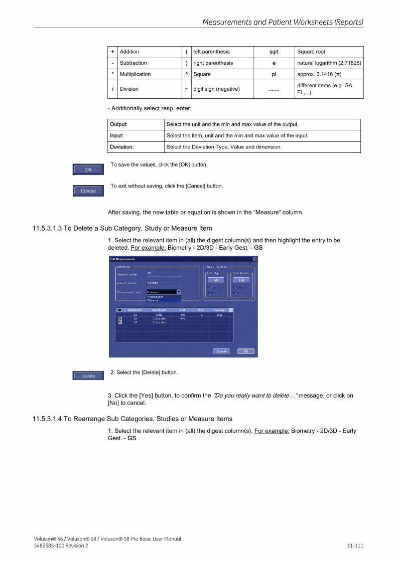
+ Addition ( left parenthesis sqrt Square root
- Subtraction ) right parenthesis e natural logarithm (2.71828)
* Multiplication ^ Square pi approx. 3.1416 (π)
/ Division ~ digit sign (negative) ....... different items (e.g. GA,FL,...)
- Additionally select resp. enter:
Output: Select the unit and the min and max value of the output.
Input: Select the item, unit and the min and max value of the input.
Deviation: Select the Deviation Type, Value and dimension.
To save the values, click the [OK] button.
To exit without saving, click the [Cancel] button.
After saving, the new table or equation is shown in the “Measure” column.
11.5.3.1.3 To Delete a Sub Category, Study or Measure Item
1. Select the relevant item in (all) the digest column(s) and then highlight the entry to bedeleted. For example: Biometry - 2D/3D - Early Gest. - GS
2. Select the [Delete] button.
3. Click the [Yes] button, to confirm the “Do you really want to delete…” message, or click on[No] to cancel.
11.5.3.1.4 To Rearrange Sub Categories, Studies or Measure Items
1. Select the relevant item in (all) the digest column(s). For example: Biometry - 2D/3D - EarlyGest. - GS
Measurements and Patient Worksheets (Reports)
Voluson® S6 / Voluson® S8 / Voluson® S8 Pro Basic User Manual5482585-100 Revision 2 11-111
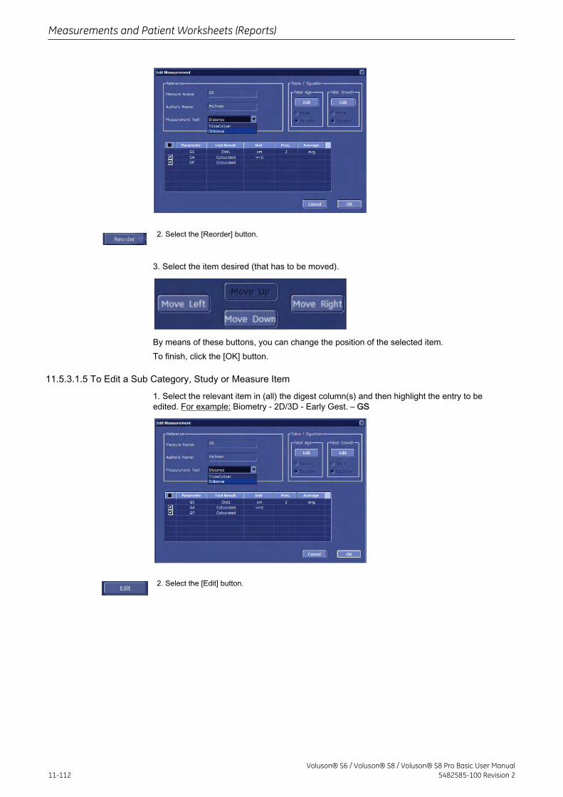
2. Select the [Reorder] button.
3. Select the item desired (that has to be moved).
By means of these buttons, you can change the position of the selected item.To finish, click the [OK] button.
11.5.3.1.5 To Edit a Sub Category, Study or Measure Item
1. Select the relevant item in (all) the digest column(s) and then highlight the entry to beedited. For example: Biometry - 2D/3D - Early Gest. – GS
2. Select the [Edit] button.
Measurements and Patient Worksheets (Reports)
11-112Voluson® S6 / Voluson® S8 / Voluson® S8 Pro Basic User Manual
5482585-100 Revision 2
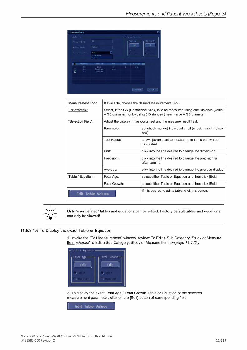
Measurement Tool: If available, choose the desired Measurement Tool.
For example: Select, if the GS (Gestational Sack) is to be measured using one Distance (value= GS diameter), or by using 3 Distances (mean value = GS diameter)
“Selection Field”: Adjust the display in the worksheet and the measure result field.
Parameter: set check mark(s) individual or all (check mark in “blackbox)
Tool Result: shows parameters to measure and items that will becalculated
Unit: click into the line desired to change the dimension
Precision: click into the line desired to change the precision (#after comma)
Average: click into the line desired to change the average display
Table / Equation: Fetal Age: select either Table or Equation and then click [Edit]
Fetal Growth: select either Table or Equation and then click [Edit]
If it is desired to edit a table, click this button.
Only “user defined” tables and equations can be edited. Factory default tables and equationscan only be viewed!
11.5.3.1.6 To Display the exact Table or Equation
1. Invoke the “Edit Measurement” window. review: To Edit a Sub Category, Study or MeasureItem (chapter'To Edit a Sub Category, Study or Measure Item' on page 11-112 )
2. To display the exact Fetal Age / Fetal Growth Table or Equation of the selectedmeasurement parameter, click on the [Edit] button of corresponding field.
Measurements and Patient Worksheets (Reports)
Voluson® S6 / Voluson® S8 / Voluson® S8 Pro Basic User Manual5482585-100 Revision 2 11-113
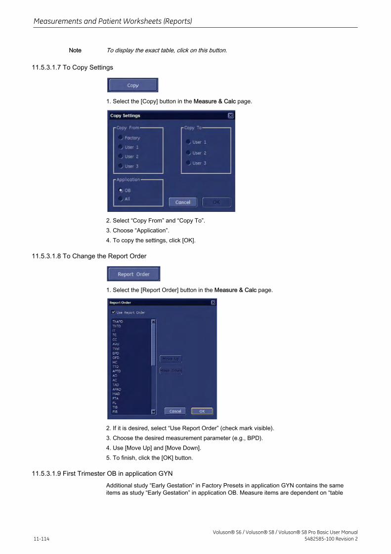
Note To display the exact table, click on this button.
11.5.3.1.7 To Copy Settings
1. Select the [Copy] button in the Measure & Calc page.
2. Select “Copy From” and “Copy To”.3. Choose “Application”.4. To copy the settings, click [OK].
11.5.3.1.8 To Change the Report Order
1. Select the [Report Order] button in the Measure & Calc page.
2. If it is desired, select “Use Report Order” (check mark visible).3. Choose the desired measurement parameter (e.g., BPD).4. Use [Move Up] and [Move Down].5. To finish, click the [OK] button.
11.5.3.1.9 First Trimester OB in application GYN
Additional study “Early Gestation” in Factory Presets in application GYN contains the sameitems as study “Early Gestation” in application OB. Measure items are dependent on “table
Measurements and Patient Worksheets (Reports)
11-114Voluson® S6 / Voluson® S8 / Voluson® S8 Pro Basic User Manual
5482585-100 Revision 2
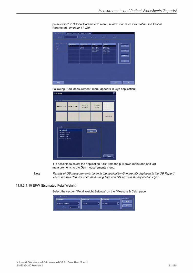
preselection” in “Global Parameters” menu; review: For more information see 'GlobalParameters' on page 11-120.
Following “Add Measurement” menu appears in Gyn application:
It is possible to select the application “OB” from the pull down menu and add OBmeasurements to the Gyn measurements menu.
Note Results of OB measurements taken in the application Gyn are still displayed in the OB Report!There are two Reports when measuring Gyn and OB items in the application Gyn!
11.5.3.1.10 EFW (Estimated Fetal Weight)
Select the section “Fetal Weight Settings” on the “Measure & Calc” page.
Measurements and Patient Worksheets (Reports)
Voluson® S6 / Voluson® S8 / Voluson® S8 Pro Basic User Manual5482585-100 Revision 2 11-115
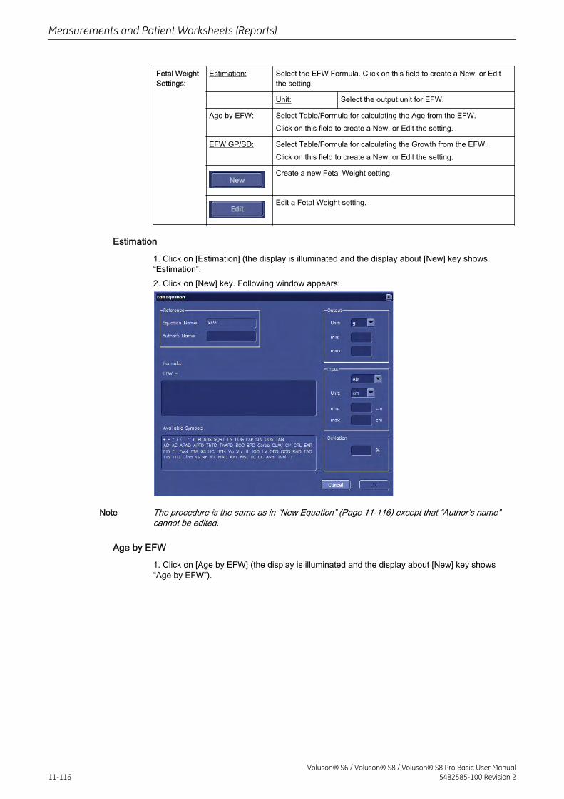
Fetal WeightSettings:
Estimation: Select the EFW Formula. Click on this field to create a New, or Editthe setting.
Unit: Select the output unit for EFW.
Age by EFW: Select Table/Formula for calculating the Age from the EFW.Click on this field to create a New, or Edit the setting.
EFW GP/SD: Select Table/Formula for calculating the Growth from the EFW.Click on this field to create a New, or Edit the setting.
Create a new Fetal Weight setting.
Edit a Fetal Weight setting.
Estimation
1. Click on [Estimation] (the display is illuminated and the display about [New] key shows“Estimation”.2. Click on [New] key. Following window appears:
Note The procedure is the same as in “New Equation” (Page 11-116) except that “Author’s name”cannot be edited.
Age by EFW
1. Click on [Age by EFW] (the display is illuminated and the display about [New] key shows“Age by EFW”).
Measurements and Patient Worksheets (Reports)
11-116Voluson® S6 / Voluson® S8 / Voluson® S8 Pro Basic User Manual
5482585-100 Revision 2
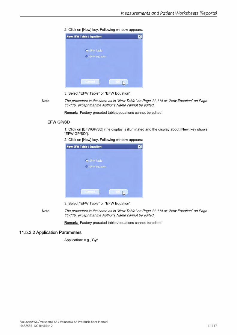
2. Click on [New] key. Following window appears:
3. Select “EFW Table” or “EFW Equation”.
Note The procedure is the same as in “New Table” on Page 11-114 or “New Equation” on Page11-116, except that the Author’s Name cannot be edited.
Remark: Factory preseted tables/equations cannot be edited!
EFW GP/SD
1. Click on [EFWGP/SD] (the display is illuminated and the display about [New] key shows“EFW GP/SD”).2. Click on [New] key. Following window appears:
3. Select “EFW Table” or “EFW Equation”.
Note The procedure is the same as in “New Table” on Page 11-114 or “New Equation” on Page11-116, except that the Author’s Name cannot be edited.
Remark: Factory preseted tables/equations cannot be edited!
11.5.3.2 Application ParametersApplication: e.g., Gyn
Measurements and Patient Worksheets (Reports)
Voluson® S6 / Voluson® S8 / Voluson® S8 Pro Basic User Manual5482585-100 Revision 2 11-117
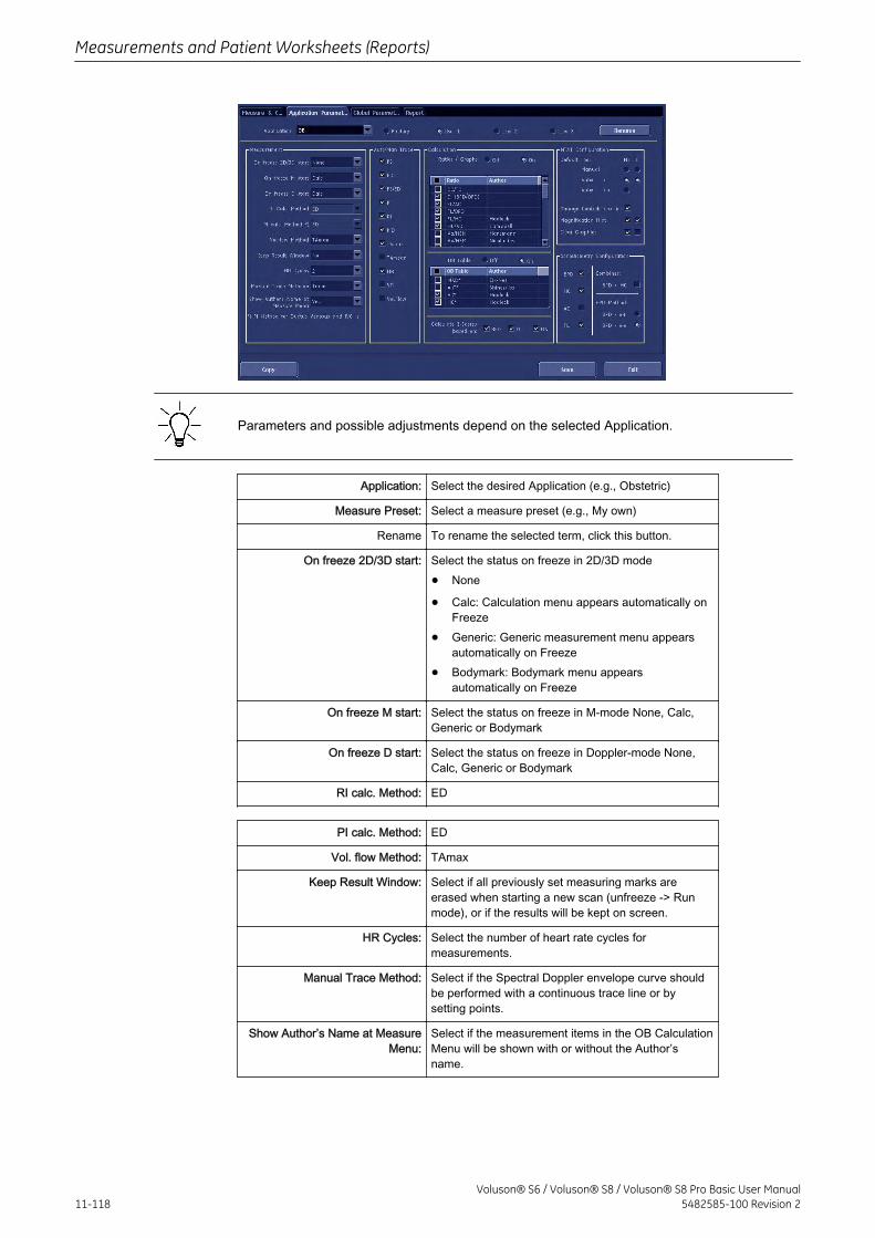
Parameters and possible adjustments depend on the selected Application.
Application: Select the desired Application (e.g., Obstetric)
Measure Preset: Select a measure preset (e.g., My own)
Rename To rename the selected term, click this button.
On freeze 2D/3D start: Select the status on freeze in 2D/3D mode
• None
• Calc: Calculation menu appears automatically onFreeze
• Generic: Generic measurement menu appearsautomatically on Freeze
• Bodymark: Bodymark menu appearsautomatically on Freeze
On freeze M start: Select the status on freeze in M-mode None, Calc,Generic or Bodymark
On freeze D start: Select the status on freeze in Doppler-mode None,Calc, Generic or Bodymark
RI calc. Method: ED
PI calc. Method: ED
Vol. flow Method: TAmax
Keep Result Window: Select if all previously set measuring marks areerased when starting a new scan (unfreeze -> Runmode), or if the results will be kept on screen.
HR Cycles: Select the number of heart rate cycles formeasurements.
Manual Trace Method: Select if the Spectral Doppler envelope curve shouldbe performed with a continuous trace line or bysetting points.
Show Author’s Name at MeasureMenu:
Select if the measurement items in the OB CalculationMenu will be shown with or without the Author’sname.
Measurements and Patient Worksheets (Reports)
11-118Voluson® S6 / Voluson® S8 / Voluson® S8 Pro Basic User Manual
5482585-100 Revision 2
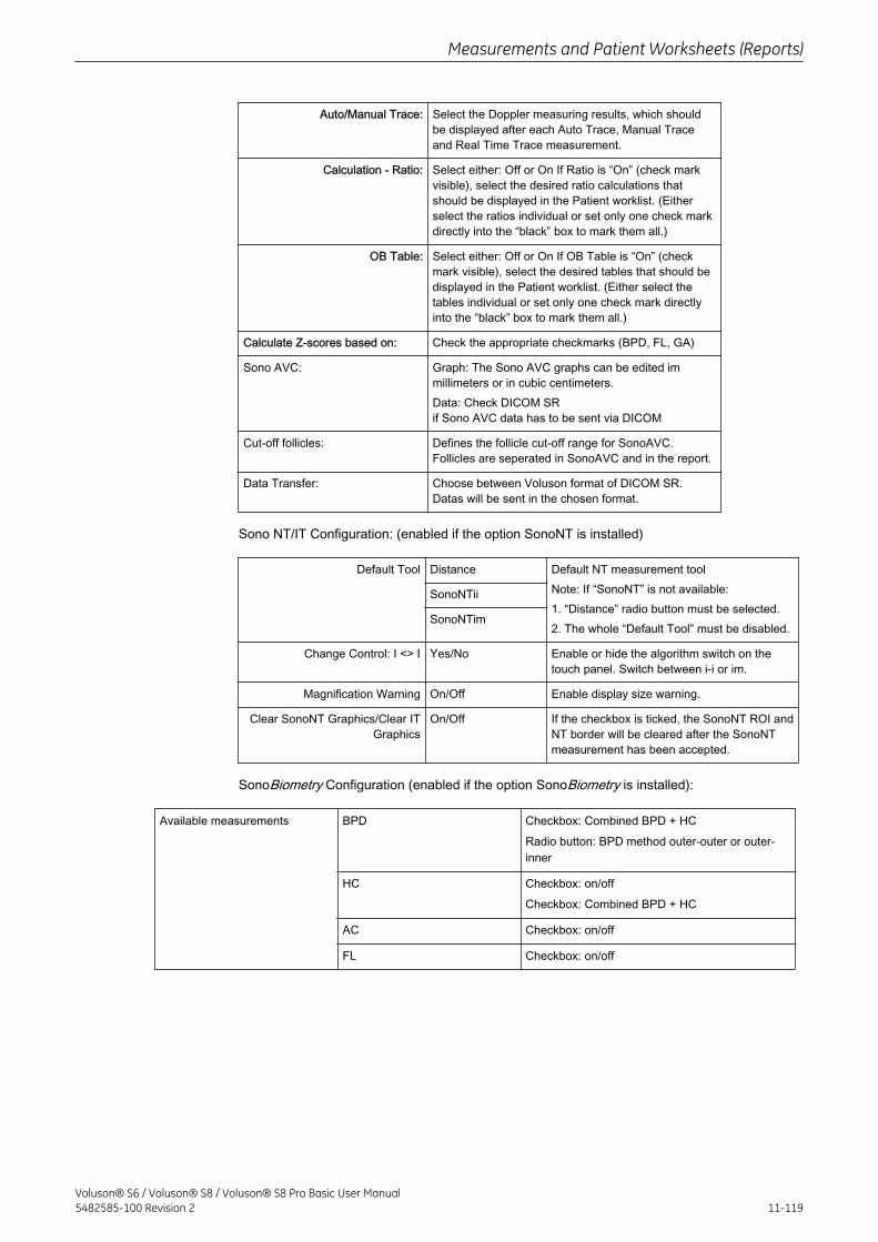
Auto/Manual Trace: Select the Doppler measuring results, which shouldbe displayed after each Auto Trace, Manual Traceand Real Time Trace measurement.
Calculation - Ratio: Select either: Off or On If Ratio is “On” (check markvisible), select the desired ratio calculations thatshould be displayed in the Patient worklist. (Eitherselect the ratios individual or set only one check markdirectly into the “black” box to mark them all.)
OB Table: Select either: Off or On If OB Table is “On” (checkmark visible), select the desired tables that should bedisplayed in the Patient worklist. (Either select thetables individual or set only one check mark directlyinto the “black” box to mark them all.)
Calculate Z-scores based on: Check the appropriate checkmarks (BPD, FL, GA)
Sono AVC: Graph: The Sono AVC graphs can be edited immillimeters or in cubic centimeters.Data: Check DICOM SRif Sono AVC data has to be sent via DICOM
Cut-off follicles: Defines the follicle cut-off range for SonoAVC.Follicles are seperated in SonoAVC and in the report.
Data Transfer: Choose between Voluson format of DICOM SR.Datas will be sent in the chosen format.
Sono NT/IT Configuration: (enabled if the option SonoNT is installed)
Default Tool Distance Default NT measurement toolNote: If “SonoNT” is not available:1. “Distance” radio button must be selected.2. The whole “Default Tool” must be disabled.
SonoNTii
SonoNTim
Change Control: I <> I Yes/No Enable or hide the algorithm switch on thetouch panel. Switch between i-i or im.
Magnification Warning On/Off Enable display size warning.
Clear SonoNT Graphics/Clear ITGraphics
On/Off If the checkbox is ticked, the SonoNT ROI andNT border will be cleared after the SonoNTmeasurement has been accepted.
SonoBiometry Configuration (enabled if the option SonoBiometry is installed):
Available measurements BPD Checkbox: Combined BPD + HCRadio button: BPD method outer-outer or outer-inner
HC Checkbox: on/offCheckbox: Combined BPD + HC
AC Checkbox: on/off
FL Checkbox: on/off
Measurements and Patient Worksheets (Reports)
Voluson® S6 / Voluson® S8 / Voluson® S8 Pro Basic User Manual5482585-100 Revision 2 11-119
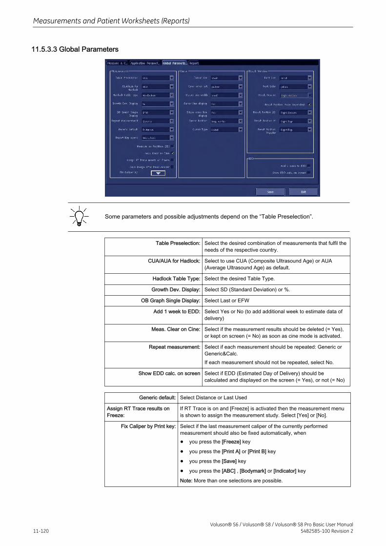
11.5.3.3 Global Parameters
Some parameters and possible adjustments depend on the “Table Preselection”.
Table Preselection: Select the desired combination of measurements that fulfil theneeds of the respective country.
CUA/AUA for Hadlock: Select to use CUA (Composite Ultrasound Age) or AUA(Average Ultrasound Age) as default.
Hadlock Table Type: Select the desired Table Type.
Growth Dev. Display: Select SD (Standard Deviation) or %.
OB Graph Single Display: Select Last or EFW
Add 1 week to EDD: Select Yes or No (to add additional week to estimate data ofdelivery)
Meas. Clear on Cine: Select if the measurement results should be deleted (= Yes),or kept on screen (= No) as soon as cine mode is activated.
Repeat measurement: Select if each measurement should be repeated: Generic orGeneric&Calc.If each measurement should not be repeated, select No.
Show EDD calc. on screen Select if EDD (Estimated Day of Delivery) should becalculated and displayed on the screen (= Yes), or not (= No)
Generic default: Select Distance or Last Used
Assign RT Trace results onFreeze:
If RT Trace is on and [Freeze] is activated then the measurement menuis shown to assign the measurement study. Select [Yes] or [No].
Fix Caliper by Print key: Select if the last measurement caliper of the currently performedmeasurement should also be fixed automatically, when
• you press the [Freeze] key
• you press the [Print A] or [Print B] key
• you press the [Save] key
• you press the [ABC] , [Bodymark] or [Indicator] key
Note: More than one selections are possible.
Measurements and Patient Worksheets (Reports)
11-120Voluson® S6 / Voluson® S8 / Voluson® S8 Pro Basic User Manual
5482585-100 Revision 2
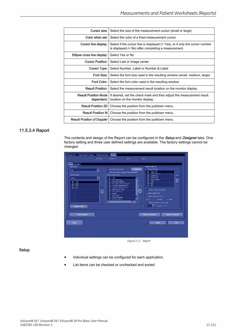
Cursor size: Select the size of the measurement cursor (small or large).
Color when set: Select the color of a fixed measurement cursor.
Cursor line display: Select if the cursor line is displayed (= Yes), or if only the cursor numberis displayed (= No) after completing a measurement.
Ellipse cross line display: Select Yes or No
Cursor Position: Select Last or Image center
Cursor Type: Select Number, Label or Number & Label
Font Size: Select the font size used in the resulting window (small, medium, large)
Font Color: Select the font color used in the resulting window
Result Position: Select the measurement result location on the monitor display.
Result Position Modedependent:
If desired, set the check mark and then adjust the measurement resultlocation on the monitor display:
Result Position 2D Choose the position from the pulldown menu.
Result Position M Choose the position from the pulldown menu.
Result Position of Doppler Choose the position from the pulldown menu.
11.5.3.4 ReportThe contents and design of the Report can be configured in the Setup and Designer tabs. Onefactory setting and three user defined settings are available. The factory settings cannot bechanged.
Figure 11-2 Report
Setup
• Individual settings can be configured for each application.
• List items can be checked or unchecked and sorted.
Measurements and Patient Worksheets (Reports)
Voluson® S6 / Voluson® S8 / Voluson® S8 Pro Basic User Manual5482585-100 Revision 2 11-121
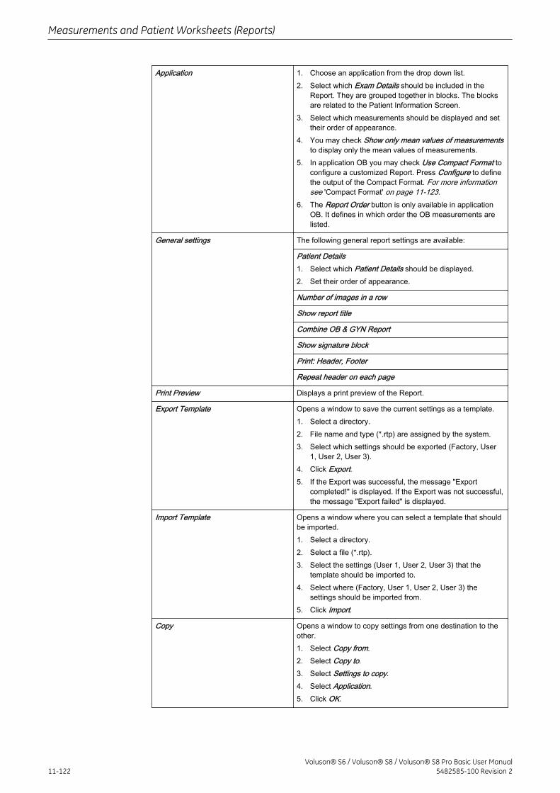
Application 1. Choose an application from the drop down list.2. Select which Exam Details should be included in the
Report. They are grouped together in blocks. The blocksare related to the Patient Information Screen.
3. Select which measurements should be displayed and settheir order of appearance.
4. You may check Show only mean values of measurementsto display only the mean values of measurements.
5. In application OB you may check Use Compact Format toconfigure a customized Report. Press Configure to definethe output of the Compact Format. For more informationsee 'Compact Format' on page 11-123.
6. The Report Order button is only available in applicationOB. It defines in which order the OB measurements arelisted.
General settings The following general report settings are available:
Patient Details1. Select which Patient Details should be displayed.2. Set their order of appearance.
Number of images in a row
Show report title
Combine OB & GYN Report
Show signature block
Print: Header, Footer
Repeat header on each page
Print Preview Displays a print preview of the Report.
Export Template Opens a window to save the current settings as a template.1. Select a directory.2. File name and type (*.rtp) are assigned by the system.3. Select which settings should be exported (Factory, User
1, User 2, User 3).4. Click Export.5. If the Export was successful, the message "Export
completed!" is displayed. If the Export was not successful,the message "Export failed" is displayed.
Import Template Opens a window where you can select a template that shouldbe imported.1. Select a directory.2. Select a file (*.rtp).3. Select the settings (User 1, User 2, User 3) that the
template should be imported to.4. Select where (Factory, User 1, User 2, User 3) the
settings should be imported from.5. Click Import.
Copy Opens a window to copy settings from one destination to theother.1. Select Copy from.2. Select Copy to.3. Select Settings to copy.4. Select Application.5. Click OK.
Measurements and Patient Worksheets (Reports)
11-122Voluson® S6 / Voluson® S8 / Voluson® S8 Pro Basic User Manual
5482585-100 Revision 2
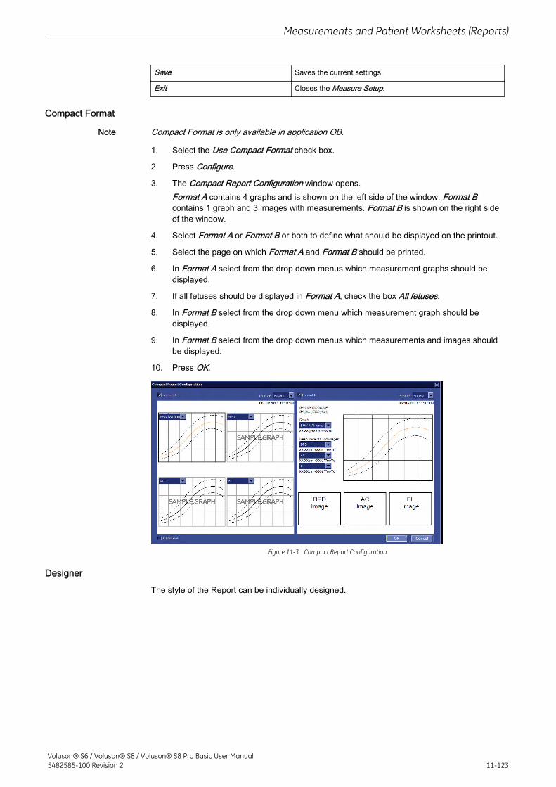
Save Saves the current settings.
Exit Closes the Measure Setup.
Compact Format
Note Compact Format is only available in application OB.
1. Select the Use Compact Format check box.
2. Press Configure.
3. The Compact Report Configuration window opens.Format A contains 4 graphs and is shown on the left side of the window. Format Bcontains 1 graph and 3 images with measurements. Format B is shown on the right sideof the window.
4. Select Format A or Format B or both to define what should be displayed on the printout.
5. Select the page on which Format A and Format B should be printed.
6. In Format A select from the drop down menus which measurement graphs should bedisplayed.
7. If all fetuses should be displayed in Format A, check the box All fetuses.
8. In Format B select from the drop down menu which measurement graph should bedisplayed.
9. In Format B select from the drop down menus which measurements and images shouldbe displayed.
10. Press OK.
Figure 11-3 Compact Report Configuration
Designer
The style of the Report can be individually designed.
Measurements and Patient Worksheets (Reports)
Voluson® S6 / Voluson® S8 / Voluson® S8 Pro Basic User Manual5482585-100 Revision 2 11-123
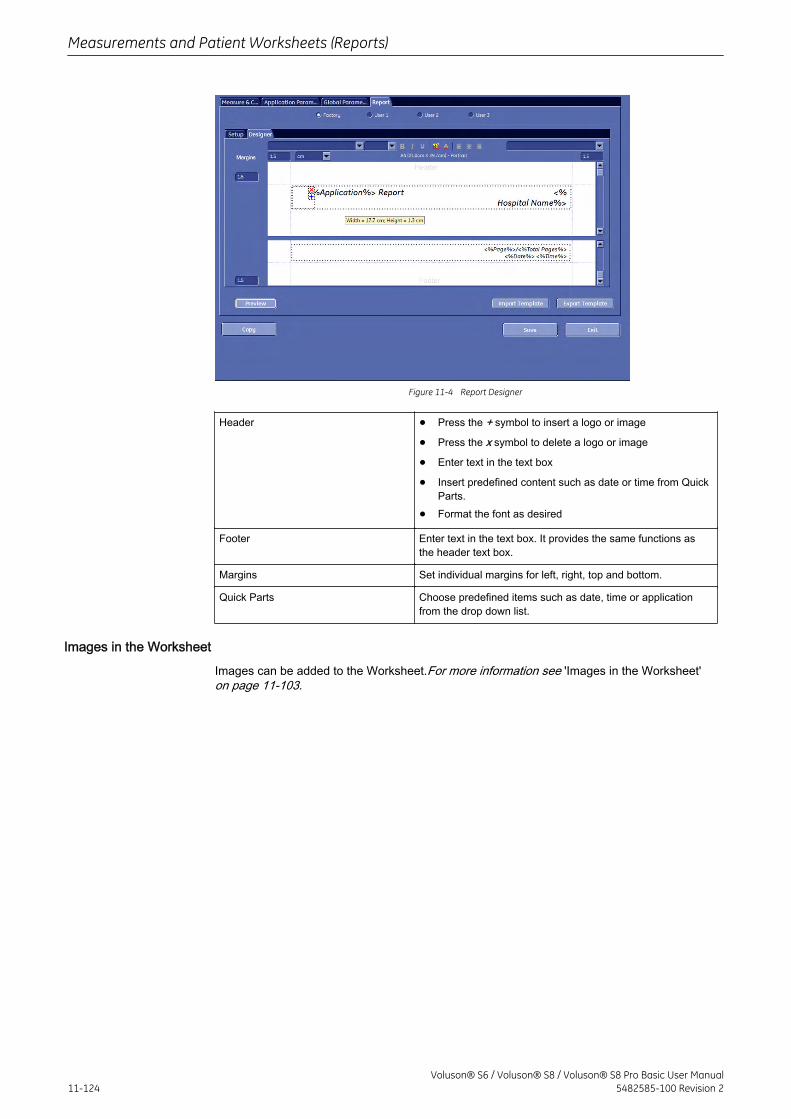
Figure 11-4 Report Designer
Header • Press the + symbol to insert a logo or image
• Press the x symbol to delete a logo or image
• Enter text in the text box
• Insert predefined content such as date or time from QuickParts.
• Format the font as desired
Footer Enter text in the text box. It provides the same functions asthe header text box.
Margins Set individual margins for left, right, top and bottom.
Quick Parts Choose predefined items such as date, time or applicationfrom the drop down list.
Images in the Worksheet
Images can be added to the Worksheet.For more information see 'Images in the Worksheet'on page 11-103.
Measurements and Patient Worksheets (Reports)
11-124Voluson® S6 / Voluson® S8 / Voluson® S8 Pro Basic User Manual
5482585-100 Revision 2
Chapter 12
Archive
Describes the general functions of the archive, like image history, patient archive and exams.
Voluson® S6 / Voluson® S8 / Voluson® S8 Pro Basic User Manual5482585-100 Revision 2 12-1
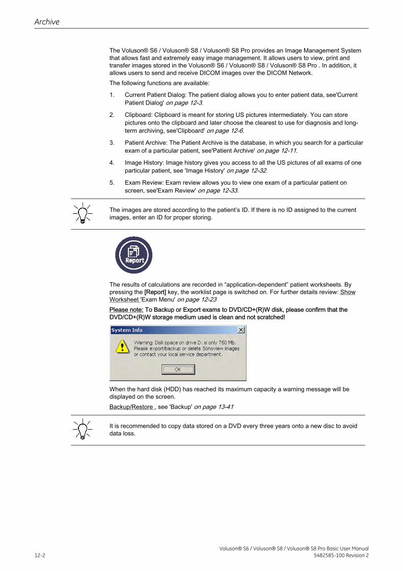
The Voluson® S6 / Voluson® S8 / Voluson® S8 Pro provides an Image Management Systemthat allows fast and extremely easy image management. It allows users to view, print andtransfer images stored in the Voluson® S6 / Voluson® S8 / Voluson® S8 Pro . In addition, itallows users to send and receive DICOM images over the DICOM Network.The following functions are available:
1. Current Patient Dialog: The patient dialog allows you to enter patient data, see'CurrentPatient Dialog' on page 12-3.
2. Clipboard: Clipboard is meant for storing US pictures intermediately. You can storepictures onto the clipboard and later choose the clearest to use for diagnosis and long-term archiving, see'Clipboard' on page 12-6.
3. Patient Archive: The Patient Archive is the database, in which you search for a particularexam of a particular patient, see'Patient Archive' on page 12-11.
4. Image History: Image history gives you access to all the US pictures of all exams of oneparticular patient, see 'Image History' on page 12-32.
5. Exam Review: Exam review allows you to view one exam of a particular patient onscreen, see'Exam Review' on page 12-33.
The images are stored according to the patient’s ID. If there is no ID assigned to the currentimages, enter an ID for proper storing.
The results of calculations are recorded in “application-dependent” patient worksheets. Bypressing the [Report] key, the worklist page is switched on. For further details review: ShowWorksheet 'Exam Menu' on page 12-23Please note: To Backup or Export exams to DVD/CD+(R)W disk, please confirm that theDVD/CD+(R)W storage medium used is clean and not scratched!
When the hard disk (HDD) has reached its maximum capacity a warning message will bedisplayed on the screen.Backup/Restore , see 'Backup' on page 13-41
It is recommended to copy data stored on a DVD every three years onto a new disc to avoiddata loss.
Archive
12-2Voluson® S6 / Voluson® S8 / Voluson® S8 Pro Basic User Manual
5482585-100 Revision 2
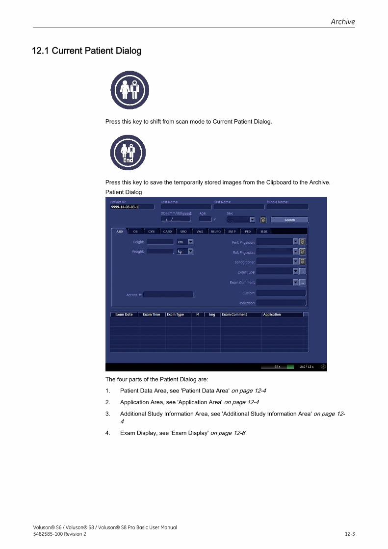
12.1 Current Patient Dialog
Press this key to shift from scan mode to Current Patient Dialog.
Press this key to save the temporarily stored images from the Clipboard to the Archive.Patient Dialog
The four parts of the Patient Dialog are:
1. Patient Data Area, see 'Patient Data Area' on page 12-4
2. Application Area, see 'Application Area' on page 12-4
3. Additional Study Information Area, see 'Additional Study Information Area' on page 12-4
4. Exam Display, see 'Exam Display' on page 12-6
Archive
Voluson® S6 / Voluson® S8 / Voluson® S8 Pro Basic User Manual5482585-100 Revision 2 12-3
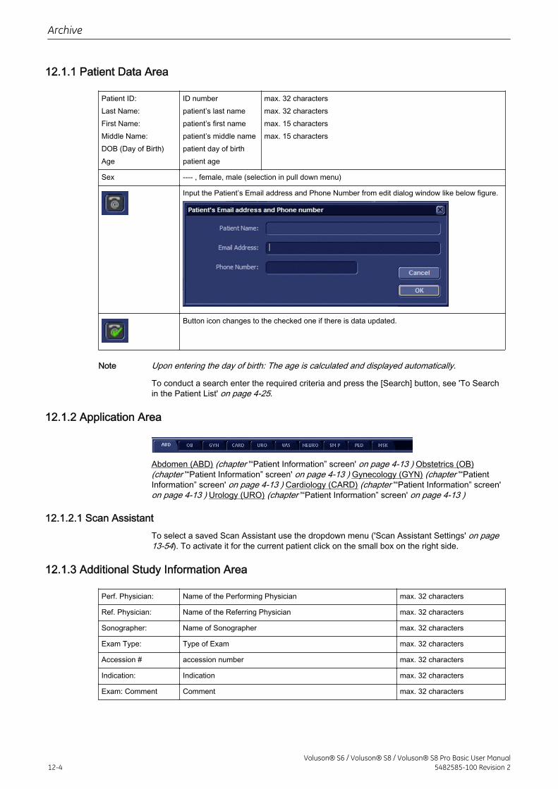
12.1.1 Patient Data Area
Patient ID:Last Name:First Name:Middle Name:DOB (Day of Birth)Age
ID numberpatient’s last namepatient’s first namepatient’s middle namepatient day of birthpatient age
max. 32 charactersmax. 32 charactersmax. 15 charactersmax. 15 characters
Sex ---- , female, male (selection in pull down menu)
Input the Patient’s Email address and Phone Number from edit dialog window like below figure.
Button icon changes to the checked one if there is data updated.
Note Upon entering the day of birth: The age is calculated and displayed automatically.
To conduct a search enter the required criteria and press the [Search] button, see 'To Searchin the Patient List' on page 4-25.
12.1.2 Application Area
Abdomen (ABD) (chapter '“Patient Information” screen' on page 4-13 ) Obstetrics (OB)(chapter '“Patient Information” screen' on page 4-13 ) Gynecology (GYN) (chapter '“PatientInformation” screen' on page 4-13 ) Cardiology (CARD) (chapter '“Patient Information” screen'on page 4-13 ) Urology (URO) (chapter '“Patient Information” screen' on page 4-13 )
12.1.2.1 Scan AssistantTo select a saved Scan Assistant use the dropdown menu ('Scan Assistant Settings' on page13-54). To activate it for the current patient click on the small box on the right side.
12.1.3 Additional Study Information Area
Perf. Physician: Name of the Performing Physician max. 32 characters
Ref. Physician: Name of the Referring Physician max. 32 characters
Sonographer: Name of Sonographer max. 32 characters
Exam Type: Type of Exam max. 32 characters
Accession # accession number max. 32 characters
Indication: Indication max. 32 characters
Exam: Comment Comment max. 32 characters
Archive
12-4Voluson® S6 / Voluson® S8 / Voluson® S8 Pro Basic User Manual
5482585-100 Revision 2
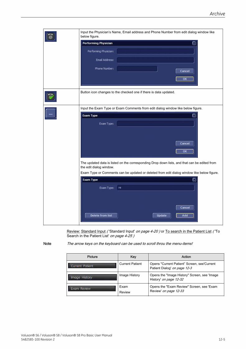
Input the Physician’s Name, Email address and Phone Number from edit dialog window likebelow figure.
Button icon changes to the checked one if there is data updated.
Input the Exam Type or Exam Comments from edit dialog window like below figure.
The updated data is listed on the corresponding Drop down lists, and that can be edited fromthe edit dialog window.Exam Type or Comments can be updated or deleted from edit dialog window like below figure.
Review: Standard Input ( 'Standard Input' on page 4-20 ) or To search in the Patient List ( 'ToSearch in the Patient List' on page 4-25 )
Note The arrow keys on the keyboard can be used to scroll throu the menu-items!
Picture Key Action
Current Patient Opens "Current Patient” Screen, see'CurrentPatient Dialog' on page 12-3
Image History Opens the "Image History" Screen, see 'ImageHistory' on page 12-32
ExamReview
Opens the "Exam Review" Screen, see 'ExamReview' on page 12-33
Archive
Voluson® S6 / Voluson® S8 / Voluson® S8 Pro Basic User Manual5482585-100 Revision 2 12-5
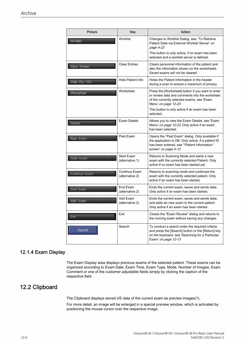
Picture Key Action
Worklist Changes to Worklist Dialog. see, 'To RetrievePatient Data via External Worklist Server' onpage 4-22This button is only active, if no exam has beenselected and a worklist server is defined.
Clear Entries Clears personnel information of the patient andalso the information shown on the worksheets.Saved exams will not be cleared.
Hide Patient Info Hides the Patient Information in the headerduring a scan to ensure a maximum of privacy.
Worksheet Press the [Worksheet] button if you want to enteror review data and comments into the worksheetof the currently selected exams, see 'ExamMenu' on page 12-23This button is only active if an exam has beenselected.
Exam Details Allows you to view the Exam Details, see 'ExamMenu' on page 12-23. Only active if an examhas been selected.
Past Exam Opens the “Past Exam” dialog. Only available ifthe application is OB. Only active, if a patient IDhas been entered, see '“Patient Information”screen' on page 4-13
Start Exam(alternative 1)
Returns to Scanning Mode and starts a newexam with the currently selected Patient. Onlyactive if no exam has been started yet.
Continue Exam(alternative 2)
Returns to scanning mode and continues theexam with the currently selected patient. Onlyactive if an exam has been started.
End Exam(alternative 2)
Ends the current exam, saves and sends data.Only active if an exam has been started.
Add Exam(alternative 2)
Ends the current exam, saves and sends data;and adds an new exam to the current patient.Only active if an exam has been started.
Exit Closes the "Exam Review" dialog and returns tothe running exam without saving any changes.
Search To conduct a search enter the required criteriaand press the [Search] button or the [Return] keyon the keyboard, see 'Searching for a ParticularExam' on page 12-13
12.1.4 Exam Display
The Exam Display area displays previous exams of the selected patient. These exams can beorganized according to Exam Date, Exam Time, Exam Type, Mode, Number of Images, ExamComment or one of the customer adjustable fields simply by clicking the caption of therespective field.
12.2 Clipboard
The Clipboard displays stored US data of the current exam as preview images(1).For more detail, an image will be enlarged in a special preview window, which is activated bypositioning the mouse cursor over the respective image.
Archive
12-6Voluson® S6 / Voluson® S8 / Voluson® S8 Pro Basic User Manual
5482585-100 Revision 2
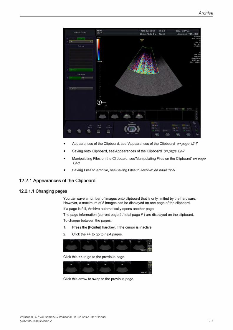
• Appearances of the Clipboard, see 'Appearances of the Clipboard' on page 12-7
• Saving onto Clipboard, see'Appearances of the Clipboard' on page 12-7
• Manipulating Files on the Clipboard, see'Manipulating Files on the Clipboard' on page12-8
• Saving Files to Archive, see'Saving Files to Archive' on page 12-9
12.2.1 Appearances of the Clipboard
12.2.1.1 Changing pagesYou can save a number of images onto clipboard that is only limited by the hardware.However, a maximum of 8 images can be displayed on one page of the clipboard.If a page is full, Archive automatically opens another page.The page information (current page # / total page # ) are displayed on the clipboard.To change between the pages:
1. Press the [Pointer] hardkey, if the cursor is inactive.
2. Click the >> to go to next pages.
Click this << to go to the previous page.
Click this arrow to swap to the previous page.
Archive
Voluson® S6 / Voluson® S8 / Voluson® S8 Pro Basic User Manual5482585-100 Revision 2 12-7
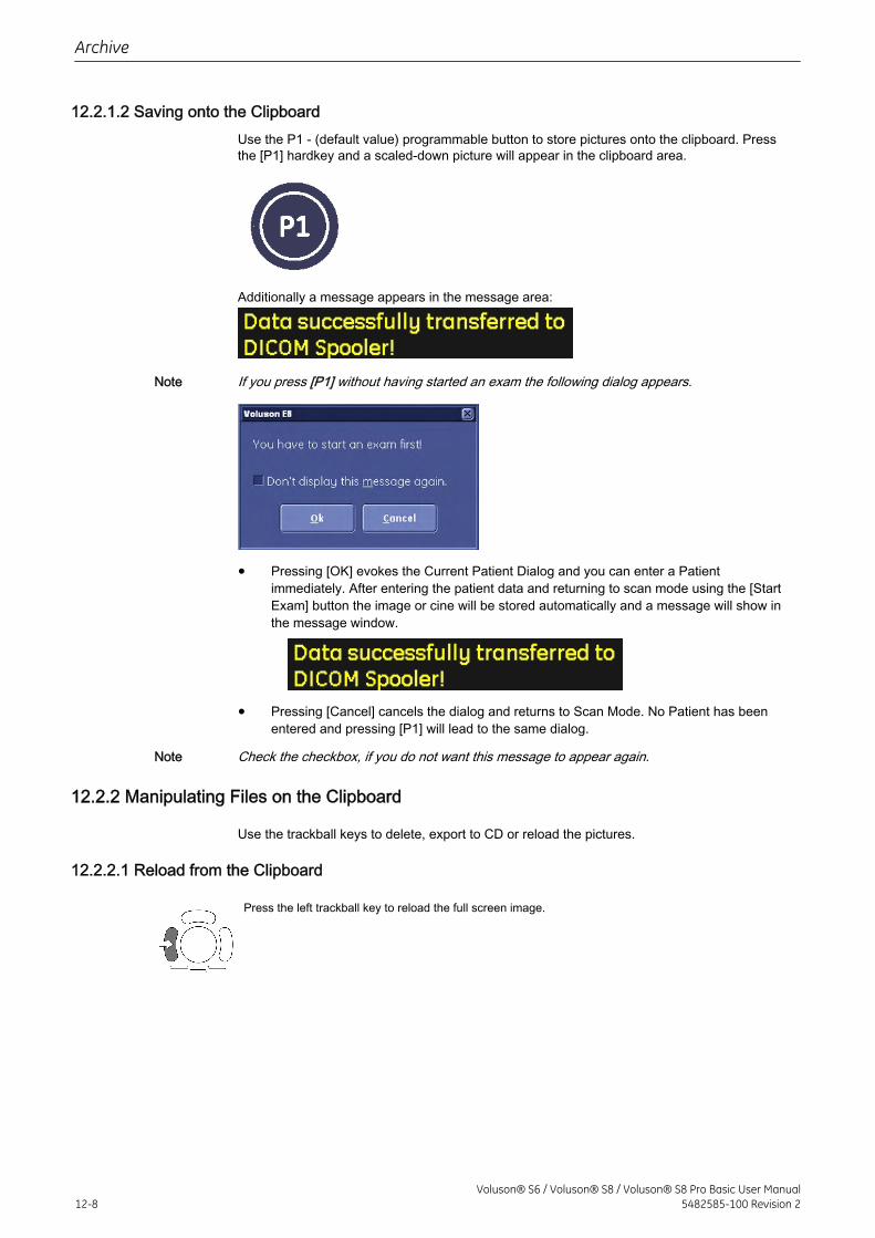
12.2.1.2 Saving onto the ClipboardUse the P1 - (default value) programmable button to store pictures onto the clipboard. Pressthe [P1] hardkey and a scaled-down picture will appear in the clipboard area.
Additionally a message appears in the message area:
Note If you press [P1] without having started an exam the following dialog appears.
• Pressing [OK] evokes the Current Patient Dialog and you can enter a Patientimmediately. After entering the patient data and returning to scan mode using the [StartExam] button the image or cine will be stored automatically and a message will show inthe message window.
• Pressing [Cancel] cancels the dialog and returns to Scan Mode. No Patient has beenentered and pressing [P1] will lead to the same dialog.
Note Check the checkbox, if you do not want this message to appear again.
12.2.2 Manipulating Files on the Clipboard
Use the trackball keys to delete, export to CD or reload the pictures.
12.2.2.1 Reload from the Clipboard
Press the left trackball key to reload the full screen image.
Archive
12-8Voluson® S6 / Voluson® S8 / Voluson® S8 Pro Basic User Manual
5482585-100 Revision 2
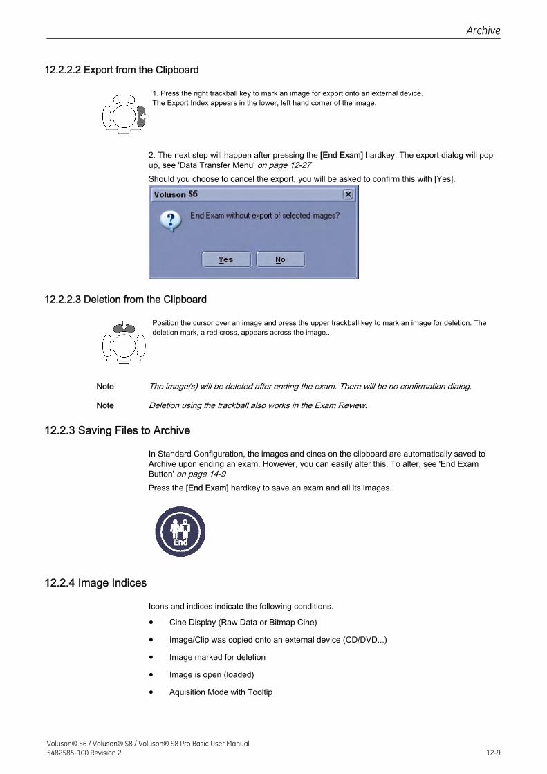
12.2.2.2 Export from the Clipboard
1. Press the right trackball key to mark an image for export onto an external device.The Export Index appears in the lower, left hand corner of the image.
2. The next step will happen after pressing the [End Exam] hardkey. The export dialog will popup, see 'Data Transfer Menu' on page 12-27Should you choose to cancel the export, you will be asked to confirm this with [Yes].
12.2.2.3 Deletion from the Clipboard
Position the cursor over an image and press the upper trackball key to mark an image for deletion. Thedeletion mark, a red cross, appears across the image..
Note The image(s) will be deleted after ending the exam. There will be no confirmation dialog.
Note Deletion using the trackball also works in the Exam Review.
12.2.3 Saving Files to Archive
In Standard Configuration, the images and cines on the clipboard are automatically saved toArchive upon ending an exam. However, you can easily alter this. To alter, see 'End ExamButton' on page 14-9Press the [End Exam] hardkey to save an exam and all its images.
12.2.4 Image Indices
Icons and indices indicate the following conditions.
• Cine Display (Raw Data or Bitmap Cine)
• Image/Clip was copied onto an external device (CD/DVD...)
• Image marked for deletion
• Image is open (loaded)
• Aquisition Mode with Tooltip
Archive
Voluson® S6 / Voluson® S8 / Voluson® S8 Pro Basic User Manual5482585-100 Revision 2 12-9
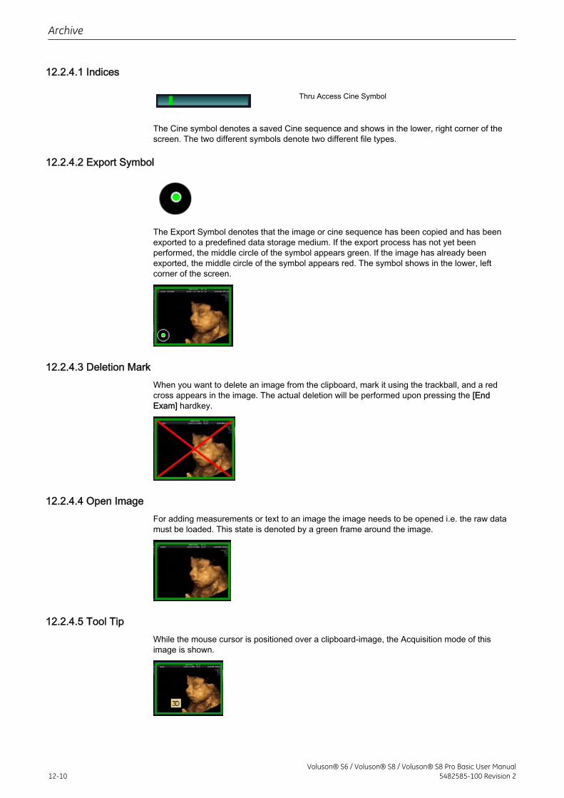
12.2.4.1 Indices
Thru Access Cine Symbol
The Cine symbol denotes a saved Cine sequence and shows in the lower, right corner of thescreen. The two different symbols denote two different file types.
12.2.4.2 Export Symbol
The Export Symbol denotes that the image or cine sequence has been copied and has beenexported to a predefined data storage medium. If the export process has not yet beenperformed, the middle circle of the symbol appears green. If the image has already beenexported, the middle circle of the symbol appears red. The symbol shows in the lower, leftcorner of the screen.
12.2.4.3 Deletion MarkWhen you want to delete an image from the clipboard, mark it using the trackball, and a redcross appears in the image. The actual deletion will be performed upon pressing the [EndExam] hardkey.
12.2.4.4 Open ImageFor adding measurements or text to an image the image needs to be opened i.e. the raw datamust be loaded. This state is denoted by a green frame around the image.
12.2.4.5 Tool TipWhile the mouse cursor is positioned over a clipboard-image, the Acquisition mode of thisimage is shown.
Archive
12-10Voluson® S6 / Voluson® S8 / Voluson® S8 Pro Basic User Manual
5482585-100 Revision 2
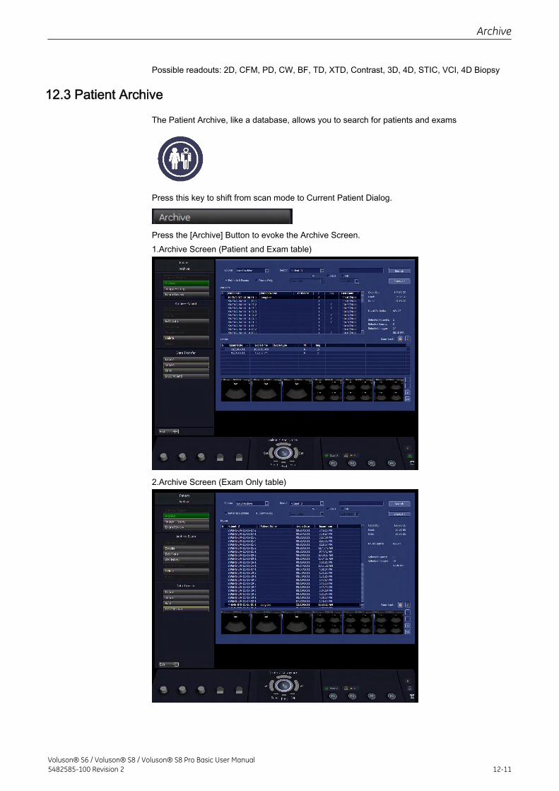
Possible readouts: 2D, CFM, PD, CW, BF, TD, XTD, Contrast, 3D, 4D, STIC, VCI, 4D Biopsy
12.3 Patient Archive
The Patient Archive, like a database, allows you to search for patients and exams
Press this key to shift from scan mode to Current Patient Dialog.
Press the [Archive] Button to evoke the Archive Screen.1.Archive Screen (Patient and Exam table)
2.Archive Screen (Exam Only table)
Archive
Voluson® S6 / Voluson® S8 / Voluson® S8 Pro Basic User Manual5482585-100 Revision 2 12-11
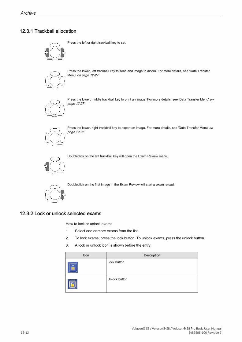
12.3.1 Trackball allocation
Press the left or right trackball key to set.
Press the lower, left trackball key to send and image to dicom. For more details, see 'Data TransferMenu' on page 12-27
Press the lower, middle trackball key to print an image. For more details, see 'Data Transfer Menu' onpage 12-27
Press the lower, right trackball key to export an image. For more details, see 'Data Transfer Menu' onpage 12-27
Doubleclick on the left trackball key will open the Exam Review menu.
Doubleclick on the first image in the Exam Review will start a exam reload.
12.3.2 Lock or unlock selected exams
How to lock or unlock exams
1. Select one or more exams from the list.
2. To lock exams, press the lock button. To unlock exams, press the unlock button.
3. A lock or unlock icon is shown before the entry.
Icon Description
Lock button
Unlock button
Archive
12-12Voluson® S6 / Voluson® S8 / Voluson® S8 Pro Basic User Manual
5482585-100 Revision 2
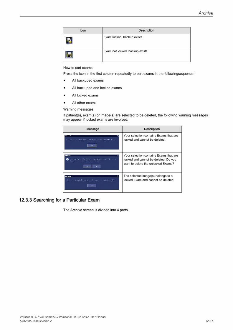
Icon Description
Exam locked, backup exists
Exam not locked, backup exists
How to sort examsPress the icon in the first column repeatedly to sort exams in the followingsequence:
• All backuped exams
• All backuped and locked exams
• All locked exams
• All other exams
Warning messagesIf patient(s), exam(s) or image(s) are selected to be deleted, the following warning messagesmay appear if locked exams are involved:
Message Description
Your selection contains Exams that arelocked and cannot be deleted!
Your selection contains Exams that arelocked and cannot be deleted! Do youwant to delete the unlocked Exams?
The selected image(s) belongs to alocked Exam and cannot be deleted!
12.3.3 Searching for a Particular Exam
The Archive screen is divided into 4 parts.
Archive
Voluson® S6 / Voluson® S8 / Voluson® S8 Pro Basic User Manual5482585-100 Revision 2 12-13
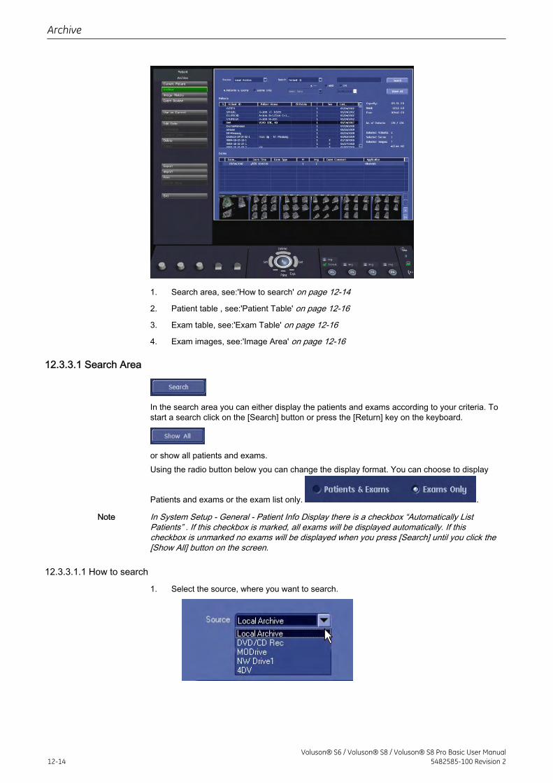
1. Search area, see:'How to search' on page 12-14
2. Patient table , see:'Patient Table' on page 12-16
3. Exam table, see:'Exam Table' on page 12-16
4. Exam images, see:'Image Area' on page 12-16
12.3.3.1 Search Area
In the search area you can either display the patients and exams according to your criteria. Tostart a search click on the [Search] button or press the [Return] key on the keyboard.
or show all patients and exams.Using the radio button below you can change the display format. You can choose to display
Patients and exams or the exam list only. .
Note In System Setup - General - Patient Info Display there is a checkbox “Automatically ListPatients” . If this checkbox is marked, all exams will be displayed automatically. If thischeckbox is unmarked no exams will be displayed when you press [Search] until you click the[Show All] button on the screen.
12.3.3.1.1 How to search
1. Select the source, where you want to search.
Archive
12-14Voluson® S6 / Voluson® S8 / Voluson® S8 Pro Basic User Manual
5482585-100 Revision 2
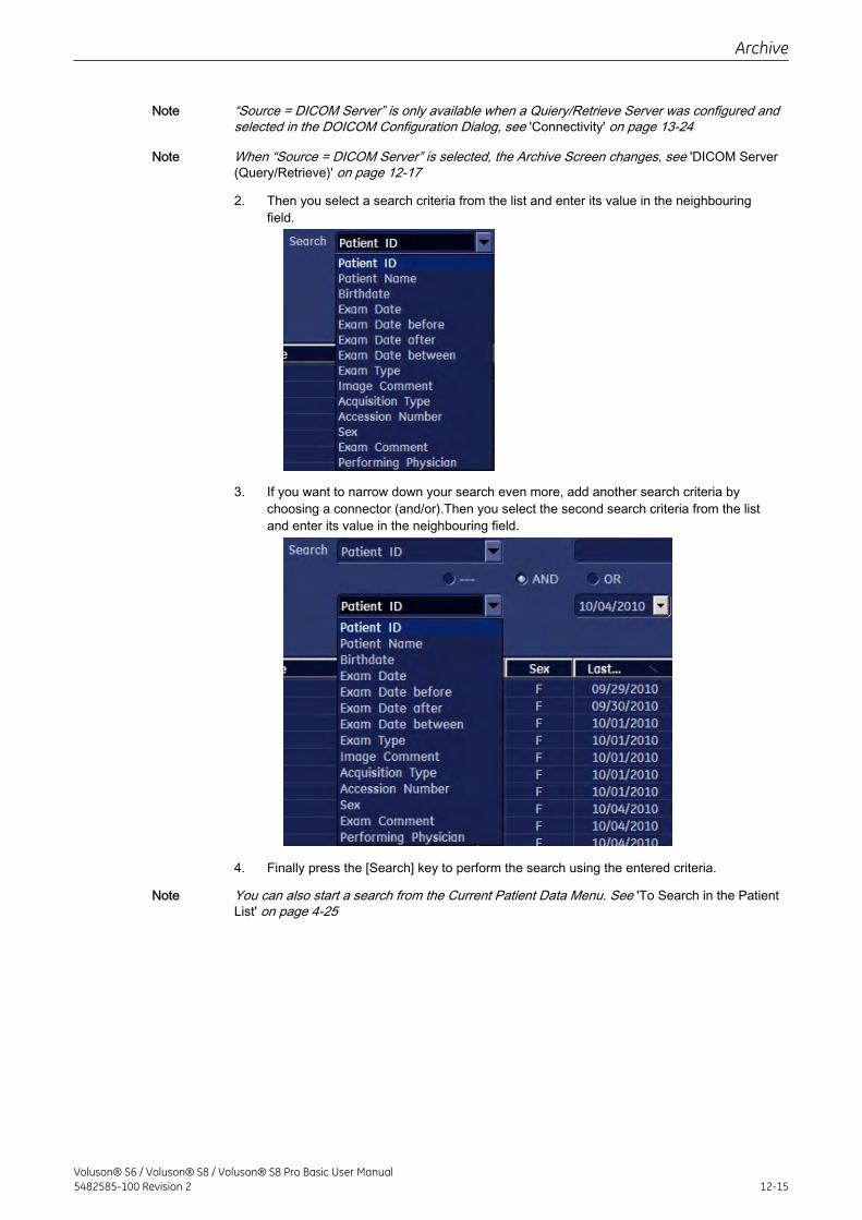
Note “Source = DICOM Server” is only available when a Quiery/Retrieve Server was configured andselected in the DOICOM Configuration Dialog, see 'Connectivity' on page 13-24
Note When “Source = DICOM Server” is selected, the Archive Screen changes, see 'DICOM Server(Query/Retrieve)' on page 12-17
2. Then you select a search criteria from the list and enter its value in the neighbouringfield.
3. If you want to narrow down your search even more, add another search criteria bychoosing a connector (and/or).Then you select the second search criteria from the listand enter its value in the neighbouring field.
4. Finally press the [Search] key to perform the search using the entered criteria.
Note You can also start a search from the Current Patient Data Menu. See 'To Search in the PatientList' on page 4-25
Archive
Voluson® S6 / Voluson® S8 / Voluson® S8 Pro Basic User Manual5482585-100 Revision 2 12-15
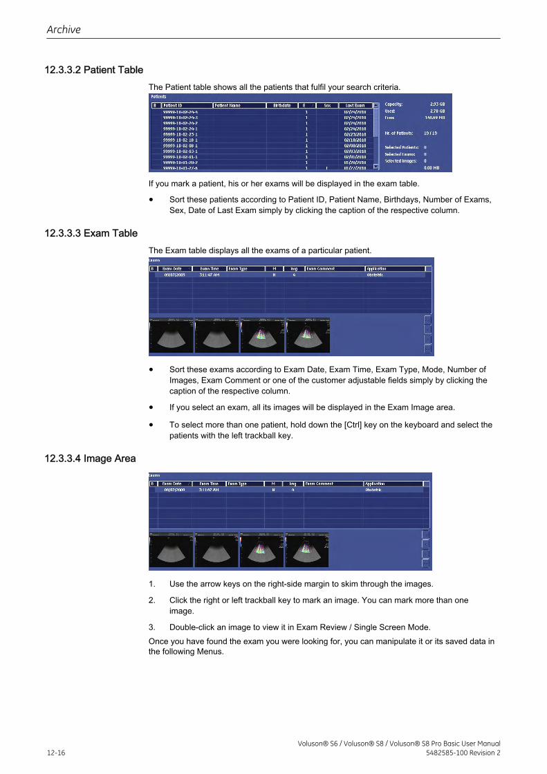
12.3.3.2 Patient TableThe Patient table shows all the patients that fulfil your search criteria.
If you mark a patient, his or her exams will be displayed in the exam table.
• Sort these patients according to Patient ID, Patient Name, Birthdays, Number of Exams,Sex, Date of Last Exam simply by clicking the caption of the respective column.
12.3.3.3 Exam TableThe Exam table displays all the exams of a particular patient.
• Sort these exams according to Exam Date, Exam Time, Exam Type, Mode, Number ofImages, Exam Comment or one of the customer adjustable fields simply by clicking thecaption of the respective column.
• If you select an exam, all its images will be displayed in the Exam Image area.
• To select more than one patient, hold down the [Ctrl] key on the keyboard and select thepatients with the left trackball key.
12.3.3.4 Image Area
1. Use the arrow keys on the right-side margin to skim through the images.
2. Click the right or left trackball key to mark an image. You can mark more than oneimage.
3. Double-click an image to view it in Exam Review / Single Screen Mode.Once you have found the exam you were looking for, you can manipulate it or its saved data inthe following Menus.
Archive
12-16Voluson® S6 / Voluson® S8 / Voluson® S8 Pro Basic User Manual
5482585-100 Revision 2
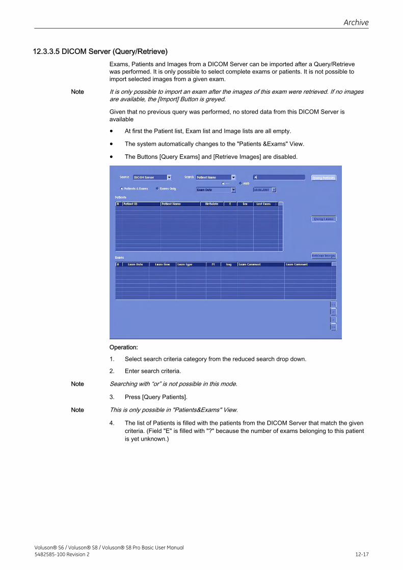
12.3.3.5 DICOM Server (Query/Retrieve)Exams, Patients and Images from a DICOM Server can be imported after a Query/Retrievewas performed. It is only possible to select complete exams or patients. It is not possible toimport selected images from a given exam.
Note It is only possible to import an exam after the images of this exam were retrieved. If no imagesare available, the [Import] Button is greyed.
Given that no previous query was performed, no stored data from this DICOM Server isavailable
• At first the Patient list, Exam list and Image lists are all empty.
• The system automatically changes to the "Patients &Exams" View.
• The Buttons [Query Exams] and [Retrieve Images] are disabled.
Operation:
1. Select search criteria category from the reduced search drop down.
2. Enter search criteria.
Note Searching with “or” is not possible in this mode.
3. Press [Query Patients].
Note This is only possible in "Patients&Exams" View.
4. The list of Patients is filled with the patients from the DICOM Server that match the givencriteria. (Field "E" is filled with "?" because the number of exams belonging to this patientis yet unknown.)
Archive
Voluson® S6 / Voluson® S8 / Voluson® S8 Pro Basic User Manual5482585-100 Revision 2 12-17
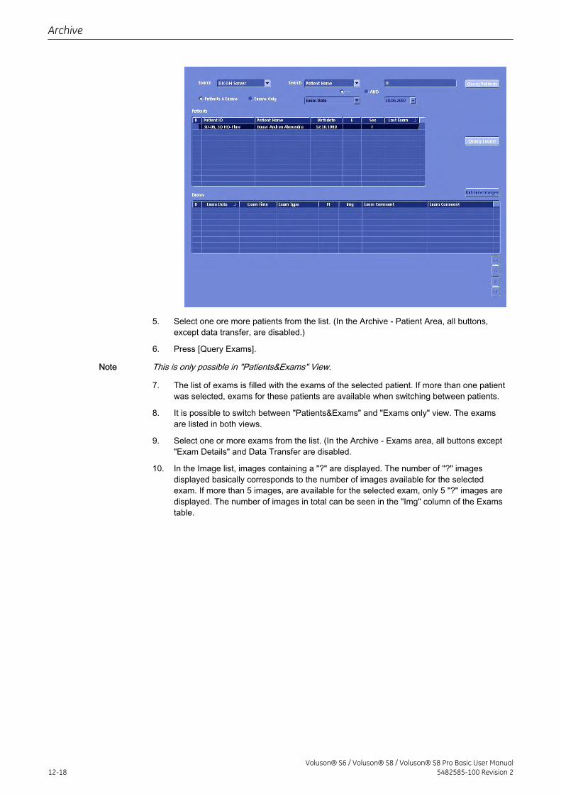
5. Select one ore more patients from the list. (In the Archive - Patient Area, all buttons,except data transfer, are disabled.)
6. Press [Query Exams].
Note This is only possible in "Patients&Exams" View.
7. The list of exams is filled with the exams of the selected patient. If more than one patientwas selected, exams for these patients are available when switching between patients.
8. It is possible to switch between "Patients&Exams" and "Exams only" view. The examsare listed in both views.
9. Select one or more exams from the list. (In the Archive - Exams area, all buttons except"Exam Details" and Data Transfer are disabled.
10. In the Image list, images containing a "?" are displayed. The number of "?" imagesdisplayed basically corresponds to the number of images available for the selectedexam. If more than 5 images, are available for the selected exam, only 5 "?" images aredisplayed. The number of images in total can be seen in the "Img" column of the Examstable.
Archive
12-18Voluson® S6 / Voluson® S8 / Voluson® S8 Pro Basic User Manual
5482585-100 Revision 2
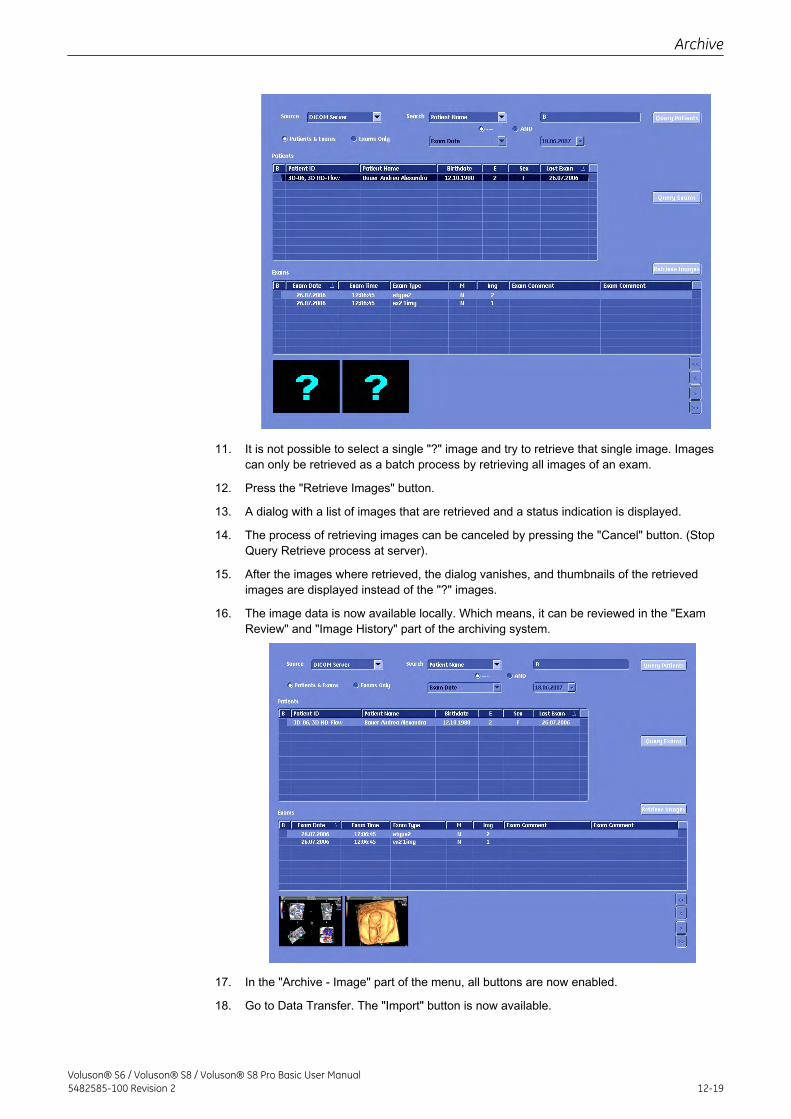
11. It is not possible to select a single "?" image and try to retrieve that single image. Imagescan only be retrieved as a batch process by retrieving all images of an exam.
12. Press the "Retrieve Images" button.
13. A dialog with a list of images that are retrieved and a status indication is displayed.
14. The process of retrieving images can be canceled by pressing the "Cancel" button. (StopQuery Retrieve process at server).
15. After the images where retrieved, the dialog vanishes, and thumbnails of the retrievedimages are displayed instead of the "?" images.
16. The image data is now available locally. Which means, it can be reviewed in the "ExamReview" and "Image History" part of the archiving system.
17. In the "Archive - Image" part of the menu, all buttons are now enabled.
18. Go to Data Transfer. The "Import" button is now available.
Archive
Voluson® S6 / Voluson® S8 / Voluson® S8 Pro Basic User Manual5482585-100 Revision 2 12-19
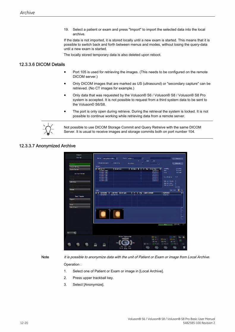
19. Select a patient or exam and press "Import" to import the selected data into the localarchive.
If the data is not imported, it is stored locally until a new exam is started. This means that it ispossible to switch back and forth between menus and modes, without losing the query-datauntil a new exam is started.The locally stored temporary data is also deleted upon reboot.
12.3.3.6 DICOM Details
• Port 105 is used for retrieving the images. (This needs to be configured on the remoteDICOM server.)
• Only DICOM images that are marked as US (ultrasound) or "secondary capture" can beretrieved. (No CT images for example.)
• Only data that was requested by the Voluson® S6 / Voluson® S8 / Voluson® S8 Prosystem is accepted. It is not possible to request from a third system data to be sent tothe Voluson© S6/S8.
• The port is only open during retrieve. During the retrieval the system is locked. It is notpossible to continue working while retrieving data from a remote server.
Not possible to use DICOM Storage Commit and Query Retreive with the same DICOMServer. It is usual to receive images and storage commits both on port number 104.
12.3.3.7 Anonymized Archive
Note It is possible to anonymize data with the unit of Patient or Exam or image from Local Archive.
Operation :
1. Select one of Patient or Exam or image in [Local Archive].
2. Press upper trackball key.
3. Select [Anonymize].
Archive
12-20Voluson® S6 / Voluson® S8 / Voluson® S8 Pro Basic User Manual
5482585-100 Revision 2
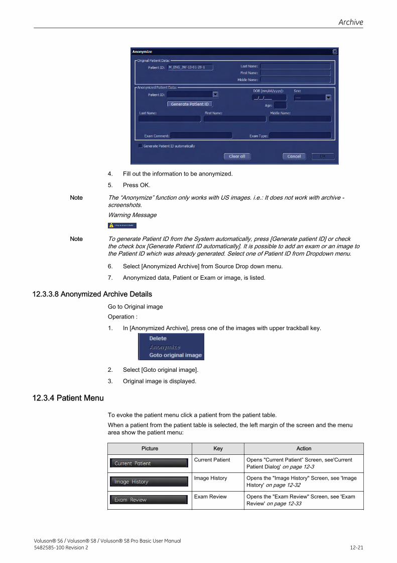
4. Fill out the information to be anonymized.
5. Press OK.
Note The “Anonymize” function only works with US images. i.e.: It does not work with archive -screenshots.Warning Message
Note To generate Patient ID from the System automatically, press [Generate patient ID] or checkthe check box [Generate Patient ID automatically]. It is possible to add an exam or an image tothe Patient ID which was already generated. Select one of Patient ID from Dropdown menu.
6. Select [Anonymized Archive] from Source Drop down menu.
7. Anonymized data, Patient or Exam or image, is listed.
12.3.3.8 Anonymized Archive DetailsGo to Original imageOperation :
1. In [Anonymized Archive], press one of the images with upper trackball key.
2. Select [Goto original image].
3. Original image is displayed.
12.3.4 Patient Menu
To evoke the patient menu click a patient from the patient table.When a patient from the patient table is selected, the left margin of the screen and the menuarea show the patient menu:
Picture Key Action
Current Patient Opens "Current Patient” Screen, see'CurrentPatient Dialog' on page 12-3
Image History Opens the "Image History" Screen, see 'ImageHistory' on page 12-32
Exam Review Opens the "Exam Review" Screen, see 'ExamReview' on page 12-33
Archive
Voluson® S6 / Voluson® S8 / Voluson® S8 Pro Basic User Manual5482585-100 Revision 2 12-21
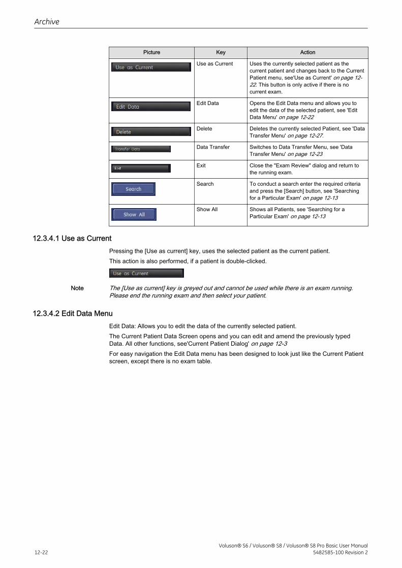
Picture Key Action
Use as Current Uses the currently selected patient as thecurrent patient and changes back to the CurrentPatient menu, see'Use as Current' on page 12-22. This button is only active if there is nocurrent exam.
Edit Data Opens the Edit Data menu and allows you toedit the data of the selected patient, see 'EditData Menu' on page 12-22
Delete Deletes the currently selected Patient, see 'DataTransfer Menu' on page 12-27.
Data Transfer Switches to Data Transfer Menu, see 'DataTransfer Menu' on page 12-23
Exit Close the "Exam Review" dialog and return tothe running exam.
Search To conduct a search enter the required criteriaand press the [Search] button, see 'Searchingfor a Particular Exam' on page 12-13
Show All Shows all Patients, see 'Searching for aParticular Exam' on page 12-13
12.3.4.1 Use as CurrentPressing the [Use as current] key, uses the selected patient as the current patient.This action is also performed, if a patient is double-clicked.
Note The [Use as current] key is greyed out and cannot be used while there is an exam running.Please end the running exam and then select your patient.
12.3.4.2 Edit Data MenuEdit Data: Allows you to edit the data of the currently selected patient.The Current Patient Data Screen opens and you can edit and amend the previously typedData. All other functions, see'Current Patient Dialog' on page 12-3For easy navigation the Edit Data menu has been designed to look just like the Current Patientscreen, except there is no exam table.
Archive
12-22Voluson® S6 / Voluson® S8 / Voluson® S8 Pro Basic User Manual
5482585-100 Revision 2
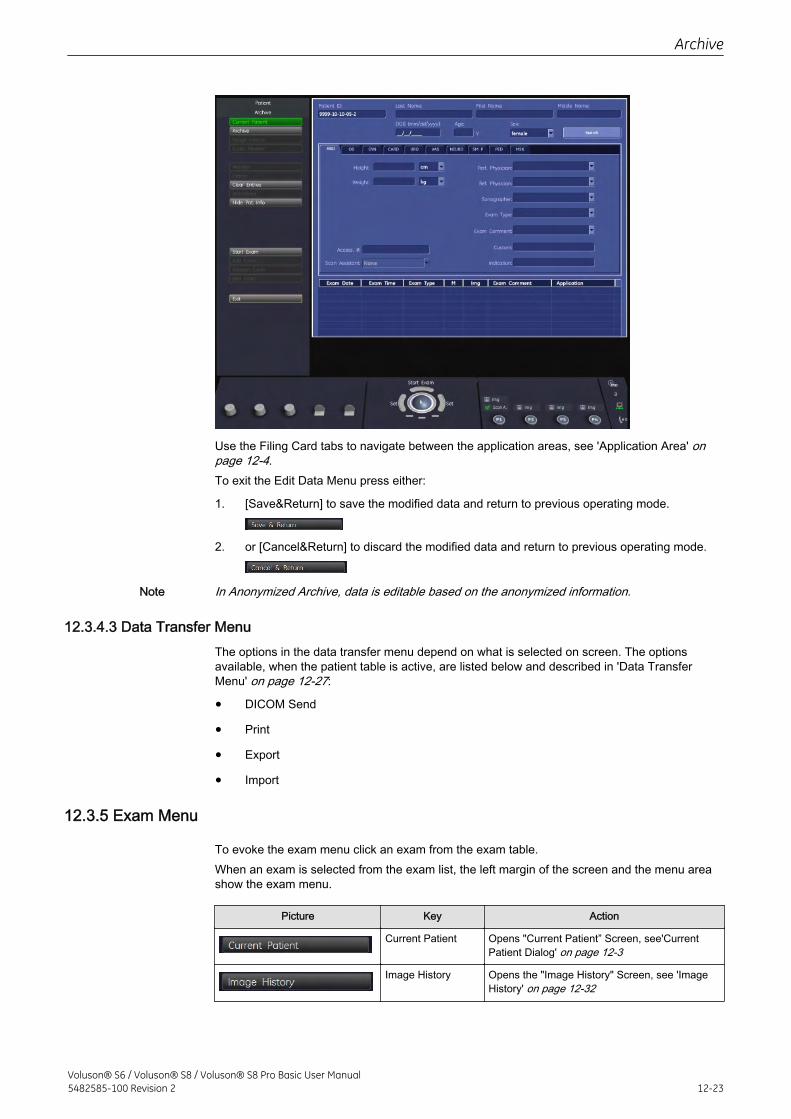
Use the Filing Card tabs to navigate between the application areas, see 'Application Area' onpage 12-4.To exit the Edit Data Menu press either:
1. [Save&Return] to save the modified data and return to previous operating mode.
2. or [Cancel&Return] to discard the modified data and return to previous operating mode.
Note In Anonymized Archive, data is editable based on the anonymized information.
12.3.4.3 Data Transfer MenuThe options in the data transfer menu depend on what is selected on screen. The optionsavailable, when the patient table is active, are listed below and described in 'Data TransferMenu' on page 12-27:
• DICOM Send
• Export
• Import
12.3.5 Exam Menu
To evoke the exam menu click an exam from the exam table.When an exam is selected from the exam list, the left margin of the screen and the menu areashow the exam menu.
Picture Key Action
Current Patient Opens "Current Patient” Screen, see'CurrentPatient Dialog' on page 12-3
Image History Opens the "Image History" Screen, see 'ImageHistory' on page 12-32
Archive
Voluson® S6 / Voluson® S8 / Voluson® S8 Pro Basic User Manual5482585-100 Revision 2 12-23
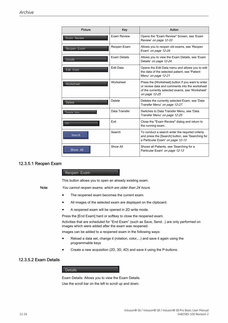
Picture Key Action
Exam Review Opens the "Exam Review" Screen, see 'ExamReview' on page 12-33
Reopen Exam Allows you to reopen old exams, see 'ReopenExam' on page 12-24.
Exam Details Allows you to view the Exam Details, see 'ExamDetails' on page 12-24.
Edit Data Opens the Edit Data menu and allows you to editthe data of the selected patient, see 'PatientMenu' on page 12-21
Worksheet Press the [Worksheet] button if you want to enteror review data and comments into the worksheetof the currently selected exams, see 'Worksheet'on page 12-25
Delete Deletes the currently selected Exam, see 'DataTransfer Menu' on page 12-27.
Data Transfer Switches to Data Transfer Menu, see 'DataTransfer Menu' on page 12-25
Exit Close the "Exam Review" dialog and return tothe running exam.
Search To conduct a search enter the required criteriaand press the [Search] button, see 'Searching fora Particular Exam' on page 12-13
Show All Shows all Patients, see 'Searching for aParticular Exam' on page 12-13
12.3.5.1 Reopen Exam
This button allows you to open an already existing exam.
Note You cannot reopen exams, which are older than 24 hours.
• The reopened exam becomes the current exam.
• All images of the selected exam are displayed on the clipboard.
• A reopened exam will be opened in 2D write mode.
Press the [End Exam] hard or softkey to close the reopened exam.Activities that are scheduled for “End Exam” (such as Save, Send...) are only performed onimages which were added after the exam was reopened.Images can be added to a reopened exam in the following ways:
• Reload a data set, change it (rotation, color,...) and save it again using theprogrammable keys
• Create a new acquisition (2D, 3D, 4D) and save it using the P-buttons.
12.3.5.2 Exam Details
Exam Details: Allows you to view the Exam Details.Use the scroll bar on the left to scroll up and down.
Archive
12-24Voluson® S6 / Voluson® S8 / Voluson® S8 Pro Basic User Manual
5482585-100 Revision 2
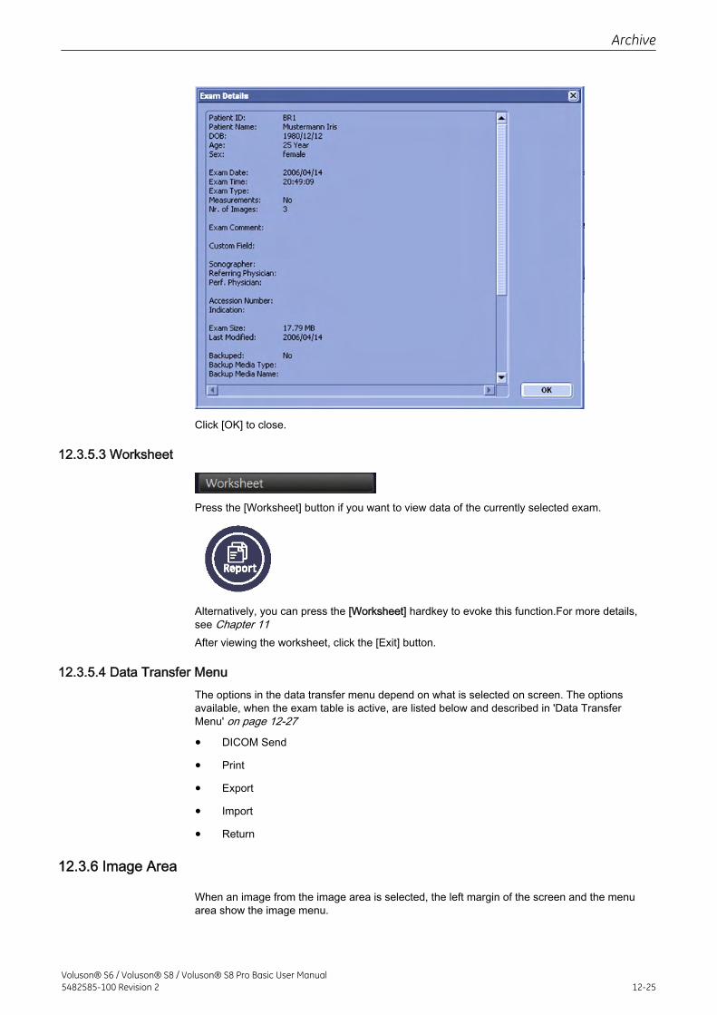
Click [OK] to close.
12.3.5.3 Worksheet
Press the [Worksheet] button if you want to view data of the currently selected exam.
Alternatively, you can press the [Worksheet] hardkey to evoke this function.For more details,see Chapter 11After viewing the worksheet, click the [Exit] button.
12.3.5.4 Data Transfer MenuThe options in the data transfer menu depend on what is selected on screen. The optionsavailable, when the exam table is active, are listed below and described in 'Data TransferMenu' on page 12-27
• DICOM Send
• Export
• Import
• Return
12.3.6 Image Area
When an image from the image area is selected, the left margin of the screen and the menuarea show the image menu.
Archive
Voluson® S6 / Voluson® S8 / Voluson® S8 Pro Basic User Manual5482585-100 Revision 2 12-25
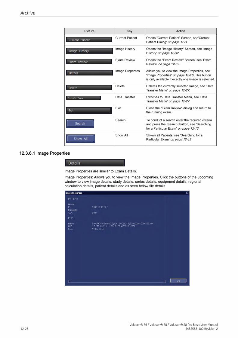
Picture Key Action
Current Patient Opens "Current Patient” Screen, see'CurrentPatient Dialog' on page 12-3
Image History Opens the "Image History" Screen, see 'ImageHistory' on page 12-32
Exam Review Opens the "Exam Review" Screen, see 'ExamReview' on page 12-33
Image Properties Allows you to view the Image Properties, see'Image Properties' on page 12-26. This buttonis only available if exactly one image is selected.
Delete Deletes the currently selected Image, see 'DataTransfer Menu' on page 12-27.
Data Transfer Switches to Data Transfer Menu, see 'DataTransfer Menu' on page 12-27
Exit Close the "Exam Review" dialog and return tothe running exam.
Search To conduct a search enter the required criteriaand press the [Search] button, see 'Searchingfor a Particular Exam' on page 12-13
Show All Shows all Patients, see 'Searching for aParticular Exam' on page 12-13
12.3.6.1 Image Properties
Image Properties are similar to Exam Details.Image Properties: Allows you to view the Image Properties. Click the buttons of the upcomingwindow to view image details, study details, series details, equipment details, regionalcalculation details, patient details and as seen below file details.
Archive
12-26Voluson® S6 / Voluson® S8 / Voluson® S8 Pro Basic User Manual
5482585-100 Revision 2
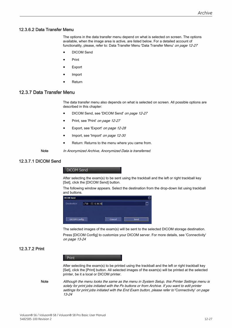
12.3.6.2 Data Transfer MenuThe options in the data transfer menu depend on what is selected on screen. The optionsavailable, when the image area is active, are listed below. For a detailed account offunctionality, please, refer to: Data Transfer Menu 'Data Transfer Menu' on page 12-27
• DICOM Send
• Export
• Import
• Return
12.3.7 Data Transfer Menu
The data transfer menu also depends on what is selected on screen. All possible options aredescribed in this chapter:
• DICOM Send, see 'DICOM Send' on page 12-27
• Print, see 'Print' on page 12-27
• Export, see 'Export' on page 12-28
• Import, see 'Import' on page 12-30
• Return: Returns to the menu where you came from.
Note In Anonymized Archive, Anonymized Data is transferred.
12.3.7.1 DICOM Send
After selecting the exam(s) to be sent using the trackball and the left or right trackball key[Set], click the [DICOM Send] button.The following window appears. Select the destination from the drop-down list using trackballand buttons.
The selected images of the exam(s) will be sent to the selected DICOM storage destination.Press [DICOM Config] to customize your DICOM server. For more details, see 'Connectivity'on page 13-24
12.3.7.2 Print
After selecting the exam(s) to be printed using the trackball and the left or right trackball key[Set], click the [Print] button. All selected images of the exam(s) will be printed at the selectedprinter, be it a local or DICOM printer.
Note Although the menu looks the same as the menu in System Setup, this Printer Settings menu issolely for print jobs initiated with the Px buttons or from Archive. If you want to edit printersettings for print jobs initiated with the End Exam button, please refer to 'Connectivity' on page13-24
Archive
Voluson® S6 / Voluson® S8 / Voluson® S8 Pro Basic User Manual5482585-100 Revision 2 12-27
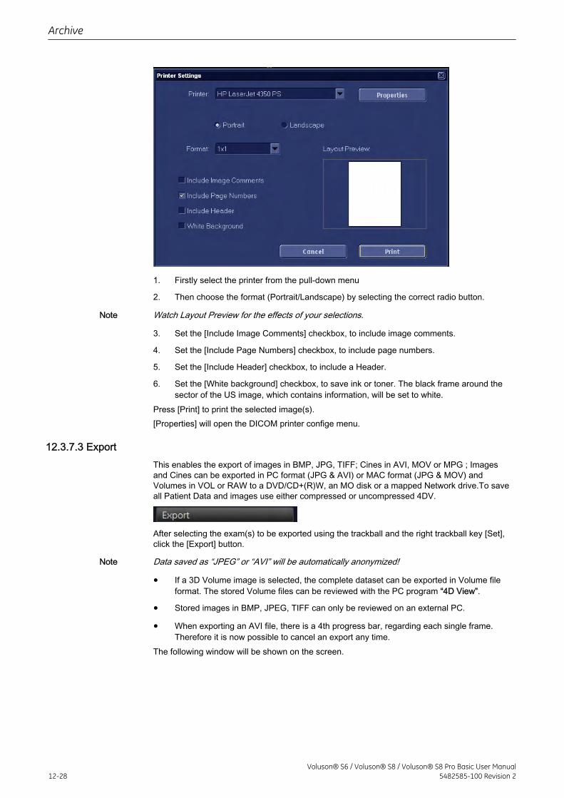
1. Firstly select the printer from the pull-down menu
2. Then choose the format (Portrait/Landscape) by selecting the correct radio button.
Note Watch Layout Preview for the effects of your selections.
3. Set the [Include Image Comments] checkbox, to include image comments.
4. Set the [Include Page Numbers] checkbox, to include page numbers.
5. Set the [Include Header] checkbox, to include a Header.
6. Set the [White background] checkbox, to save ink or toner. The black frame around thesector of the US image, which contains information, will be set to white.
Press [Print] to print the selected image(s).[Properties] will open the DICOM printer confige menu.
12.3.7.3 ExportThis enables the export of images in BMP, JPG, TIFF; Cines in AVI, MOV or MPG ; Imagesand Cines can be exported in PC format (JPG & AVI) or MAC format (JPG & MOV) andVolumes in VOL or RAW to a DVD/CD+(R)W, an MO disk or a mapped Network drive.To saveall Patient Data and images use either compressed or uncompressed 4DV.
After selecting the exam(s) to be exported using the trackball and the right trackball key [Set],click the [Export] button.
Note Data saved as “JPEG” or “AVI” will be automatically anonymized!
• If a 3D Volume image is selected, the complete dataset can be exported in Volume fileformat. The stored Volume files can be reviewed with the PC program “4D View”.
• Stored images in BMP, JPEG, TIFF can only be reviewed on an external PC.
• When exporting an AVI file, there is a 4th progress bar, regarding each single frame.Therefore it is now possible to cancel an export any time.
The following window will be shown on the screen.
Archive
12-28Voluson® S6 / Voluson® S8 / Voluson® S8 Pro Basic User Manual
5482585-100 Revision 2
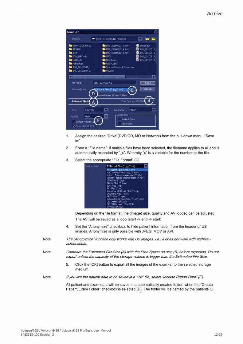
1. Assign the desired “Drive”(DVD/CD, MO or Network) from the pull-down menu. “Savein:”
2. Enter a “File name”. If multiple files have been selected, the filename applies to all and isautomatically extended by “_x”. Whereby “x” is a variable for the number or the file.
3. Select the appropriate “File Format” (C).
Depending on the file format, the (image) size, quality and AVI-codec can be adjusted.The AVI will be saved as a loop (start -> end -> start)
4. Set the “Anonymize” checkbox, to hide patient information from the header of USimages. Anonymize is only possible with JPEG, MOV or AVI.
Note The “Anonymize” function only works with US images. i.e.: It does not work with archive -screenshots.
Note Compare the Estimated File Size (A) with the Free Space on disc (B) before exporting. Do notexport unless the capacity of the storage volume is bigger than the Estimated File Size.
5. Click the [OK] button to export all the images of the exam(s) to the selected storagemedium.
Note If you like the patient data to be saved in a “.txt” file, select “Include Report Data” (E)
All patient and exam data will be saved in a automatically created folder, when the “CreatePatient/Exam Folder” checkbox is selected (D). The folder will be named by the patients ID.
Archive
Voluson® S6 / Voluson® S8 / Voluson® S8 Pro Basic User Manual5482585-100 Revision 2 12-29
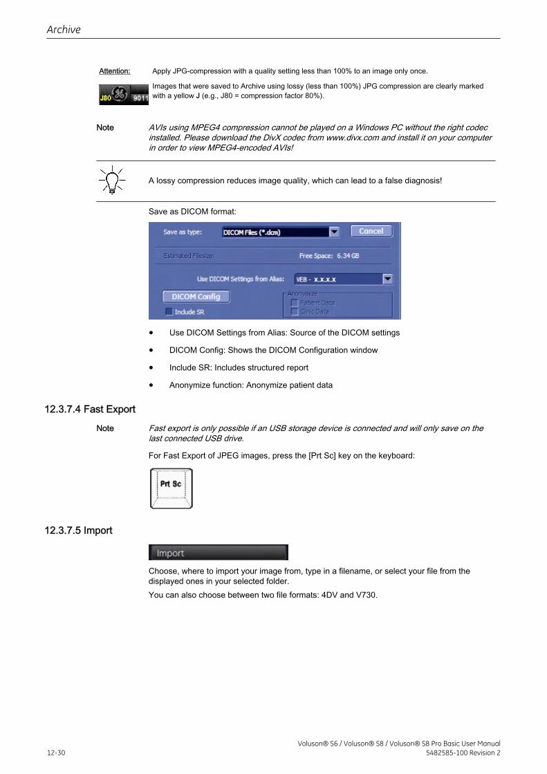
Attention: Apply JPG-compression with a quality setting less than 100% to an image only once.
Images that were saved to Archive using lossy (less than 100%) JPG compression are clearly markedwith a yellow J (e.g., J80 = compression factor 80%).
Note AVIs using MPEG4 compression cannot be played on a Windows PC without the right codecinstalled. Please download the DivX codec from www.divx.com and install it on your computerin order to view MPEG4-encoded AVIs!
A lossy compression reduces image quality, which can lead to a false diagnosis!
Save as DICOM format:
• Use DICOM Settings from Alias: Source of the DICOM settings
• DICOM Config: Shows the DICOM Configuration window
• Include SR: Includes structured report
• Anonymize function: Anonymize patient data
12.3.7.4 Fast Export
Note Fast export is only possible if an USB storage device is connected and will only save on thelast connected USB drive.
For Fast Export of JPEG images, press the [Prt Sc] key on the keyboard:
12.3.7.5 Import
Choose, where to import your image from, type in a filename, or select your file from thedisplayed ones in your selected folder.You can also choose between two file formats: 4DV and V730.
Archive
12-30Voluson® S6 / Voluson® S8 / Voluson® S8 Pro Basic User Manual
5482585-100 Revision 2
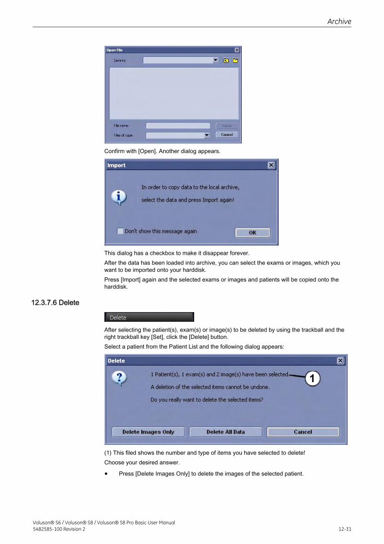
Confirm with [Open]. Another dialog appears.
This dialog has a checkbox to make it disappear forever.After the data has been loaded into archive, you can select the exams or images, which youwant to be imported onto your harddisk.Press [Import] again and the selected exams or images and patients will be copied onto theharddisk.
12.3.7.6 Delete
After selecting the patient(s), exam(s) or image(s) to be deleted by using the trackball and theright trackball key [Set], click the [Delete] button.Select a patient from the Patient List and the following dialog appears:
(1) This filed shows the number and type of items you have selected to delete!Choose your desired answer.
• Press [Delete Images Only] to delete the images of the selected patient.
Archive
Voluson® S6 / Voluson® S8 / Voluson® S8 Pro Basic User Manual5482585-100 Revision 2 12-31
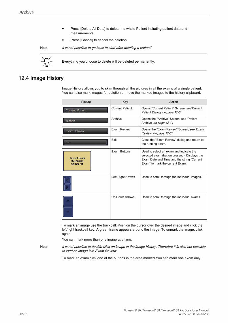
• Press [Delete All Data] to delete the whole Patient including patient data andmeasurements.
• Press [Cancel] to cancel the deletion.
Note It is not possible to go back to start after deleting a patient!
Everything you choose to delete will be deleted permanently.
12.4 Image History
Image History allows you to skim through all the pictures in all the exams of a single patient.You can also mark images for deletion or move the marked images to the history clipboard.
Picture Key Action
Current Patient Opens "Current Patient” Screen, see'CurrentPatient Dialog' on page 12-3
Archive Opens the "Archive" Screen, see 'PatientArchive' on page 12-11
Exam Review Opens the "Exam Review" Screen, see 'ExamReview' on page 12-33
Exit Close the "Exam Review" dialog and return tothe running exam.
Exam Buttons Used to select an exam and indicate theselected exam (button pressed). Displays theExam Date and Time and the string “CurrentExam” to mark the current Exam.
Left/Right Arrows Used to scroll through the individual images.
Up/Down Arrows Used to scroll through the individual exams.
To mark an image use the trackball: Position the cursor over the desired image and click theleft/right trackball key. A green frame appears around the image. To unmark the image, clickagain.You can mark more than one image at a time.
Note It is not possible to double-click an image in the image history. Therefore it is also not possibleto load an image into Exam Review.
To mark an exam click one of the buttons in the area marked.You can mark one exam only!
Archive
12-32Voluson® S6 / Voluson® S8 / Voluson® S8 Pro Basic User Manual
5482585-100 Revision 2
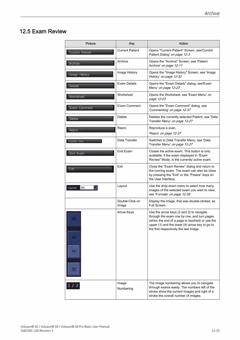
12.5 Exam Review
Picture Key Action
Current Patient Opens "Current Patient” Screen, see'CurrentPatient Dialog' on page 12-3
Archive Opens the "Archive" Screen, see 'PatientArchive' on page 12-11
Image History Opens the "Image History" Screen, see 'ImageHistory' on page 12-32
Exam Details Opens the "Exam Details" dialog, see'ExamMenu' on page 12-23
Worksheet Opens the Worksheet, see 'Exam Menu' onpage 12-23
Exam Comment Opens the "Exam Comment" dialog, see'Commenting' on page 12-37
Delete Deletes the currently selected Patient, see 'DataTransfer Menu' on page 12-27
Repro Reproduce a scan.'Repro' on page 12-37
Data Transfer Switches to Data Transfer Menu, see 'DataTransfer Menu' on page 12-27
End Exam Closes the active exam. This button is onlyavailable, if the exam displayed in "ExamReview" Mode, is the currently active exam.
Exit Close the "Exam Review" dialog and return tothe running exam. The exam can also be closeby pressing the “Exit” or the “Freeze” keys onthe User Interface.
Layout Use the drop-down menu to select how manyimages of the selected exam you wish to view,see 'Formats' on page 12-38
Double-Click onImage
Display the image, that was double-clicked, asFull Screen.
Arrow Keys Use the arrow keys (2 and 3) to navigatethrough the exam row by row, and turn pages(when the end of a page is reached) or use theupper (1) and the lower (4) arrow key to go tothe first respectively the last image.
ImageNumbering
The image numbering allows you to navigatethrough exams easily. The numbers left of thestroke show the current images and right of astroke the overall number of images.
Archive
Voluson® S6 / Voluson® S8 / Voluson® S8 Pro Basic User Manual5482585-100 Revision 2 12-33
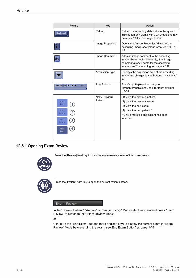
Picture Key Action
Reload Reload the according data set into the system.This button only works with 3D/4D data and rawdata, see 'Reload' on page 12-35
Image Properties Opens the "Image Properties" dialog of theaccording image, see 'Image Area' on page 12-25
Image Comment Adds an image comment to the accordingimage. Button looks differently, if an imagecomment already exists for the accordingimage, see 'Commenting' on page 12-37.
Acquisition Type Displays the acquisition type of the accordingimage and changes it, see'Buttons' on page 12-39.
Play Buttons Start/Stop/Step used to navigatethroughthrough cines , see 'Buttons' on page12-39
Next/ PreviousPatien
(1) View the previous patient(2) View the previous exam(3) View the next exam(4) View the next patient ** Only if more the one patient has beenselected!
12.5.1 Opening Exam Review
Press the [Review] hard key to open the exam review screen of the current exam.
orPress the [Patient] hard key to open the current patient screen.
In the "Current Patient", "Archive" or "Image History" Mode select an exam and press "ExamReview" to switch to the "Exam Review Mode".orConfigure the "End Exam" buttons (hard and soft key) to display the current exam in "ExamReview" Mode before ending the exam, see 'End Exam Button' on page 14-9
Archive
12-34Voluson® S6 / Voluson® S8 / Voluson® S8 Pro Basic User Manual
5482585-100 Revision 2
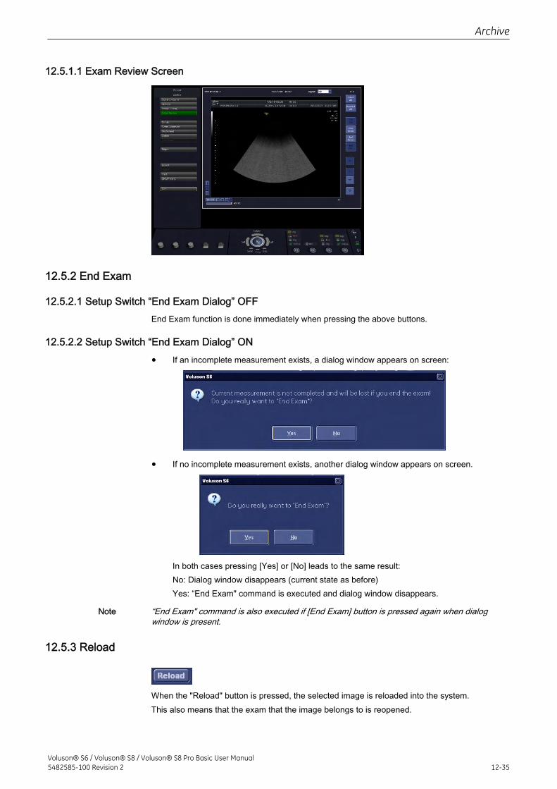
12.5.1.1 Exam Review Screen
12.5.2 End Exam
12.5.2.1 Setup Switch “End Exam Dialog” OFFEnd Exam function is done immediately when pressing the above buttons.
12.5.2.2 Setup Switch “End Exam Dialog” ON
• If an incomplete measurement exists, a dialog window appears on screen:
• If no incomplete measurement exists, another dialog window appears on screen.
In both cases pressing [Yes] or [No] leads to the same result:No: Dialog window disappears (current state as before)Yes: “End Exam" command is executed and dialog window disappears.
Note “End Exam" command is also executed if [End Exam] button is pressed again when dialogwindow is present.
12.5.3 Reload
When the "Reload" button is pressed, the selected image is reloaded into the system.This also means that the exam that the image belongs to is reopened.
Archive
Voluson® S6 / Voluson® S8 / Voluson® S8 Pro Basic User Manual5482585-100 Revision 2 12-35
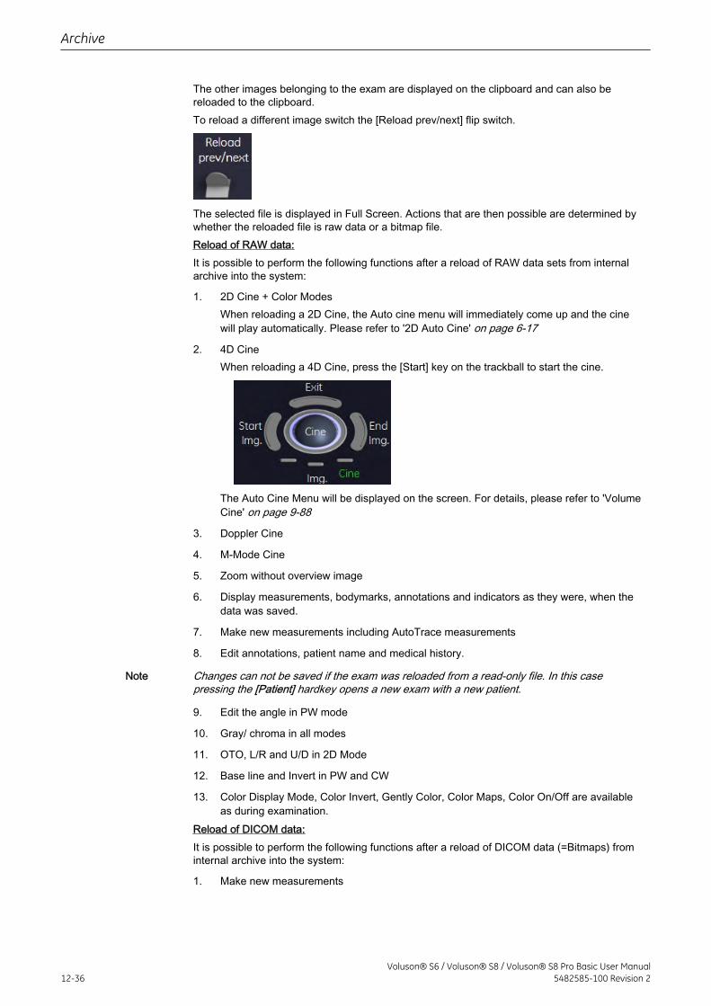
The other images belonging to the exam are displayed on the clipboard and can also bereloaded to the clipboard.To reload a different image switch the [Reload prev/next] flip switch.
The selected file is displayed in Full Screen. Actions that are then possible are determined bywhether the reloaded file is raw data or a bitmap file.Reload of RAW data:It is possible to perform the following functions after a reload of RAW data sets from internalarchive into the system:
1. 2D Cine + Color ModesWhen reloading a 2D Cine, the Auto cine menu will immediately come up and the cinewill play automatically. Please refer to '2D Auto Cine' on page 6-17
2. 4D CineWhen reloading a 4D Cine, press the [Start] key on the trackball to start the cine.
The Auto Cine Menu will be displayed on the screen. For details, please refer to 'VolumeCine' on page 9-88
3. Doppler Cine
4. M-Mode Cine
5. Zoom without overview image
6. Display measurements, bodymarks, annotations and indicators as they were, when thedata was saved.
7. Make new measurements including AutoTrace measurements
8. Edit annotations, patient name and medical history.
Note Changes can not be saved if the exam was reloaded from a read-only file. In this casepressing the [Patient] hardkey opens a new exam with a new patient.
9. Edit the angle in PW mode
10. Gray/ chroma in all modes
11. OTO, L/R and U/D in 2D Mode
12. Base line and Invert in PW and CW
13. Color Display Mode, Color Invert, Gently Color, Color Maps, Color On/Off are availableas during examination.
Reload of DICOM data:It is possible to perform the following functions after a reload of DICOM data (=Bitmaps) frominternal archive into the system:
1. Make new measurements
Archive
12-36Voluson® S6 / Voluson® S8 / Voluson® S8 Pro Basic User Manual
5482585-100 Revision 2
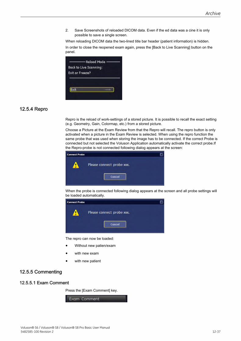
2. Save Screenshots of reloaded DICOM data. Even if the ed data was a cine it is onlypossible to save a single screen.
When reloading DICOM data the two-lined title bar header (patient information) is hidden.In order to close the reopened exam again, press the [Back to Live Scanning] button on thepanel.
12.5.4 Repro
Repro is the reload of work-settings of a stored picture. It is possible to recall the exact setting(e.g. Geometry, Gain, Colormap, etc.) from a stored picture.Choose a Picture at the Exam Review from that the Repro will recall. The repro button is onlyactivated when a picture in the Exam Review is selected. When using the repro function thesame probe that was used when storing the image has to be connected. If the correct Probe isconnected but not selected the Voluson Application automatically activate the correct probe.Ifthe Repro-probe is not connected following dialog appears at the screen:
When the probe is connected following dialog appears at the screen and all probe settings willbe loaded automatically.
The repro can now be loaded:
• Without new patien/exam
• with new exam
• with new patient
12.5.5 Commenting
12.5.5.1 Exam CommentPress the [Exam Comment] key.
Archive
Voluson® S6 / Voluson® S8 / Voluson® S8 Pro Basic User Manual5482585-100 Revision 2 12-37
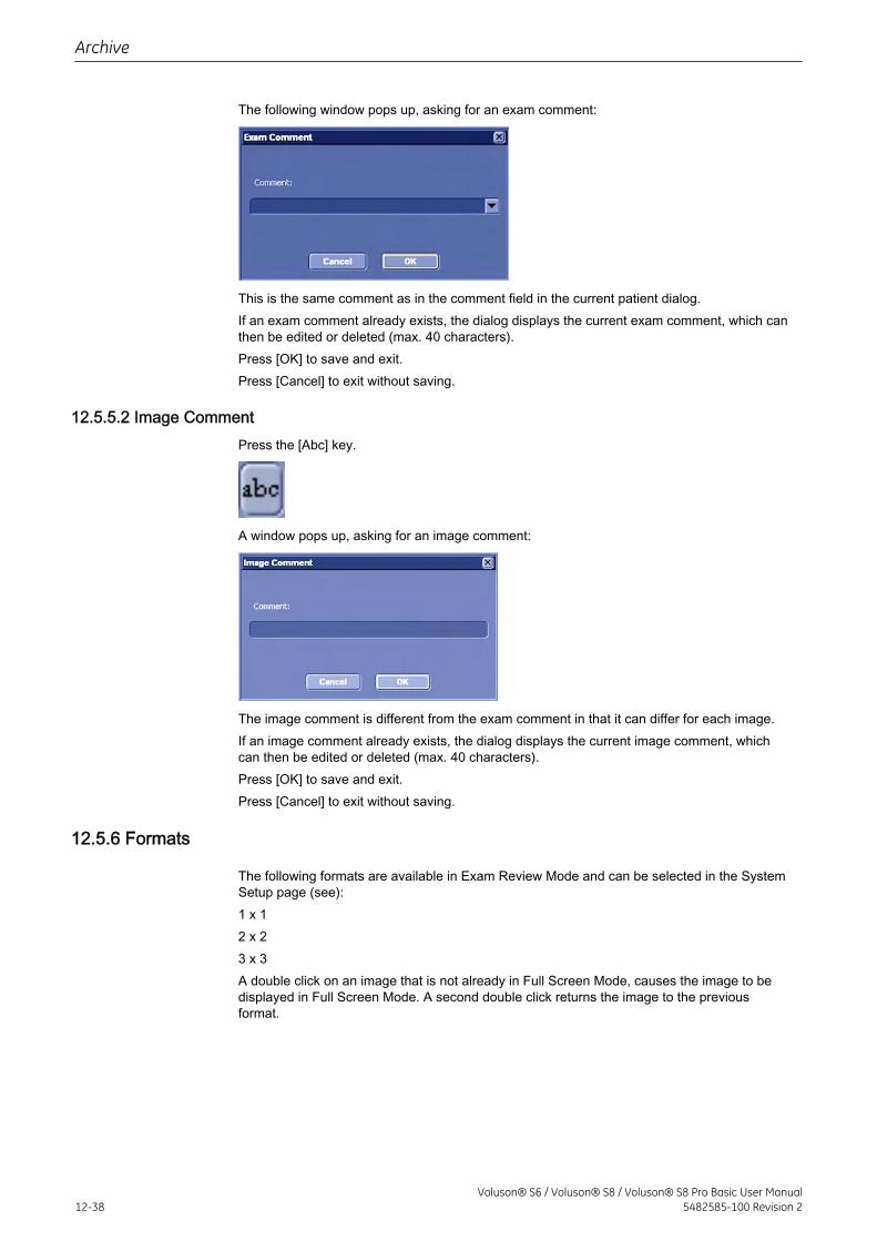
The following window pops up, asking for an exam comment:
This is the same comment as in the comment field in the current patient dialog.If an exam comment already exists, the dialog displays the current exam comment, which canthen be edited or deleted (max. 40 characters).Press [OK] to save and exit.Press [Cancel] to exit without saving.
12.5.5.2 Image CommentPress the [Abc] key.
A window pops up, asking for an image comment:
The image comment is different from the exam comment in that it can differ for each image.If an image comment already exists, the dialog displays the current image comment, whichcan then be edited or deleted (max. 40 characters).Press [OK] to save and exit.Press [Cancel] to exit without saving.
12.5.6 Formats
The following formats are available in Exam Review Mode and can be selected in the SystemSetup page (see):1 x 12 x 23 x 3A double click on an image that is not already in Full Screen Mode, causes the image to bedisplayed in Full Screen Mode. A second double click returns the image to the previousformat.
Archive
12-38Voluson® S6 / Voluson® S8 / Voluson® S8 Pro Basic User Manual
5482585-100 Revision 2
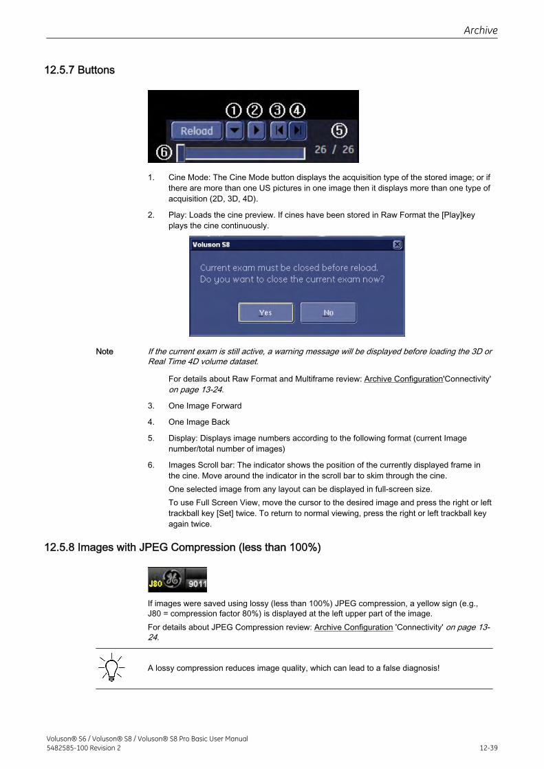
12.5.7 Buttons
1. Cine Mode: The Cine Mode button displays the acquisition type of the stored image; or ifthere are more than one US pictures in one image then it displays more than one type ofacquisition (2D, 3D, 4D).
2. Play: Loads the cine preview. If cines have been stored in Raw Format the [Play]keyplays the cine continuously.
Note If the current exam is still active, a warning message will be displayed before loading the 3D orReal Time 4D volume dataset.
For details about Raw Format and Multiframe review: Archive Configuration'Connectivity'on page 13-24.
3. One Image Forward
4. One Image Back
5. Display: Displays image numbers according to the following format (current Imagenumber/total number of images)
6. Images Scroll bar: The indicator shows the position of the currently displayed frame inthe cine. Move around the indicator in the scroll bar to skim through the cine.One selected image from any layout can be displayed in full-screen size.To use Full Screen View, move the cursor to the desired image and press the right or lefttrackball key [Set] twice. To return to normal viewing, press the right or left trackball keyagain twice.
12.5.8 Images with JPEG Compression (less than 100%)
If images were saved using lossy (less than 100%) JPEG compression, a yellow sign (e.g.,J80 = compression factor 80%) is displayed at the left upper part of the image.For details about JPEG Compression review: Archive Configuration 'Connectivity' on page 13-24.
A lossy compression reduces image quality, which can lead to a false diagnosis!
Archive
Voluson® S6 / Voluson® S8 / Voluson® S8 Pro Basic User Manual5482585-100 Revision 2 12-39
12.6 Selecting Exams
This chapter describes how to select, load, remove and back up exams. It also describes howto transfer exams to another system via the DICOM network.
• To Use the Exams List 'To Use the Exams Only List' on page 12-40
• To Select the Exams 'To Select the Exams' on page 12-41
• To Sort the Exams 'To Sort the Exams' on page 12-41
• To Search for Exams 'To Search for Exams' on page 12-41
• To Review the Exams 'Exam Review' on page 12-33
• To Delete Exams 'Data Transfer Menu' on page 12-27
• To Send Exams 'Data Transfer Menu' on page 12-27
• To Print Exams 'Data Transfer Menu' on page 12-27
• To Export Exams 'Data Transfer Menu' on page 12-27
• To Backup the Exams 'Backup' on page 13-41
• To Restore the Backup Exams 'Backup' on page 13-41
12.6.1 To Use the Exams Only List
Click the [Archive] button.
Click the [ExamsOnly] radio button and the display format is changed to a list of exams only.
Click the [Show All] button and the complete list of exams is displayed.
To change the display of the “Exams List” review: Search Area'Searching for a ParticularExam' on page 12-13
Archive
12-40Voluson® S6 / Voluson® S8 / Voluson® S8 Pro Basic User Manual
5482585-100 Revision 2
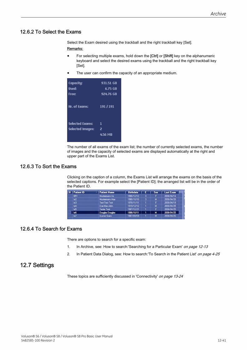
12.6.2 To Select the Exams
Select the Exam desired using the trackball and the right trackball key [Set].Remarks:
• For selecting multiple exams, hold down the [Ctrl] or [Shift] key on the alphanumerickeyboard and select the desired exams using the trackball and the right trackball key[Set].
• The user can confirm the capacity of an appropriate medium.
The number of all exams of the exam list; the number of currently selected exams, the numberof images and the capacity of selected exams are displayed automatically at the right andupper part of the Exams List.
12.6.3 To Sort the Exams
Clicking on the caption of a column, the Exams List will arrange the exams on the basis of theselected captions. For example select the [Patient ID]; the arranged list will be in the order ofthe Patient ID.
12.6.4 To Search for Exams
There are options to search for a specific exam:
1. In Archive, see: How to search:'Searching for a Particular Exam' on page 12-13
2. In Patient Data Dialog, see: How to search:'To Search in the Patient List' on page 4-25
12.7 Settings
These topics are sufficiently discussed in 'Connectivity' on page 13-24
Archive
Voluson® S6 / Voluson® S8 / Voluson® S8 Pro Basic User Manual5482585-100 Revision 2 12-41

This page was intentionally left blank.
Archive
12-42Voluson® S6 / Voluson® S8 / Voluson® S8 Pro Basic User Manual
5482585-100 Revision 2
Chapter 13
Utilities and System Setup
Describes the general functions of the utilites and system setup, like setup procedures andbackups.
Voluson® S6 / Voluson® S8 / Voluson® S8 Pro Basic User Manual5482585-100 Revision 2 13-1
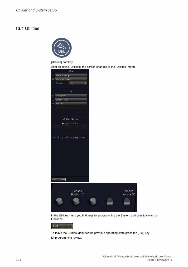
13.1 Utilities
[Utilities] hardkey .After selecting [Utilities], the screen changes to the “Utilities” menu.
In the Utilities menu you find keys for programming the System and keys to switch onfunctions.
To leave the Utilities Menu for the previous operating state press the [Exit] key.for programming review:
Utilities and System Setup
13-2Voluson® S6 / Voluson® S8 / Voluson® S8 Pro Basic User Manual
5482585-100 Revision 2
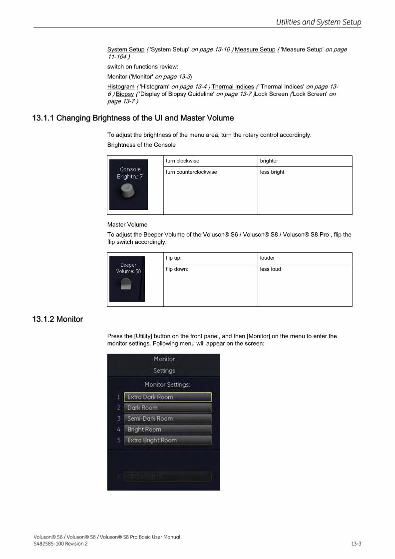
System Setup ( 'System Setup' on page 13-10 ) Measure Setup ( 'Measure Setup' on page11-104 )switch on functions review:Monitor ('Monitor' on page 13-3)Histogram ( 'Histogram' on page 13-4 ) Thermal Indices ( 'Thermal Indices' on page 13-6 ) Biopsy ( 'Display of Biopsy Guideline' on page 13-7 )Lock Screen ('Lock Screen' onpage 13-7 )
13.1.1 Changing Brightness of the UI and Master Volume
To adjust the brightness of the menu area, turn the rotary control accordingly.Brightness of the Console
turn clockwise brighter
turn counterclockwise less bright
Master VolumeTo adjust the Beeper Volume of the Voluson® S6 / Voluson® S8 / Voluson® S8 Pro , flip theflip switch accordingly.
flip up: louder
flip down: less loud
13.1.2 Monitor
Press the [Utility] button on the front panel, and then [Monitor] on the menu to enter themonitor settings. Following menu will appear on the screen:
Utilities and System Setup
Voluson® S6 / Voluson® S8 / Voluson® S8 Pro Basic User Manual5482585-100 Revision 2 13-3
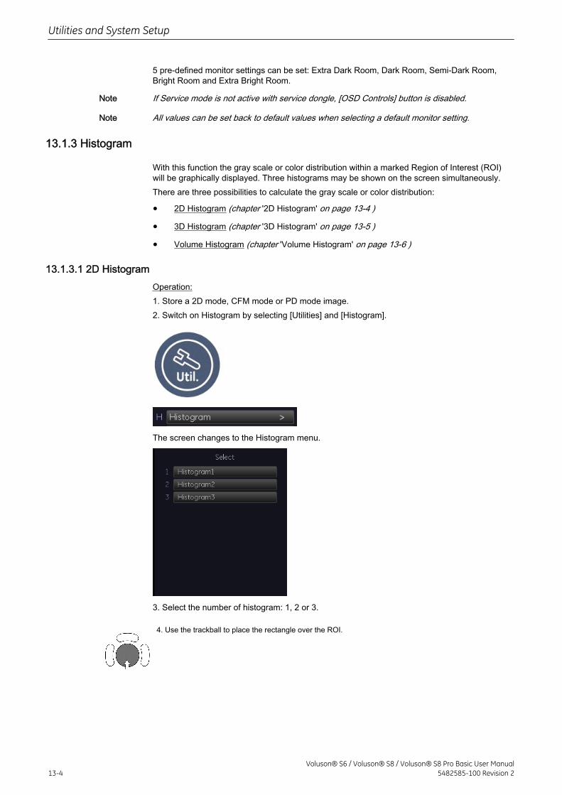
5 pre-defined monitor settings can be set: Extra Dark Room, Dark Room, Semi-Dark Room,Bright Room and Extra Bright Room.
Note If Service mode is not active with service dongle, [OSD Controls] button is disabled.
Note All values can be set back to default values when selecting a default monitor setting.
13.1.3 Histogram
With this function the gray scale or color distribution within a marked Region of Interest (ROI)will be graphically displayed. Three histograms may be shown on the screen simultaneously.There are three possibilities to calculate the gray scale or color distribution:
• 2D Histogram (chapter '2D Histogram' on page 13-4 )
• 3D Histogram (chapter '3D Histogram' on page 13-5 )
• Volume Histogram (chapter 'Volume Histogram' on page 13-6 )
13.1.3.1 2D HistogramOperation:1. Store a 2D mode, CFM mode or PD mode image.2. Switch on Histogram by selecting [Utilities] and [Histogram].
The screen changes to the Histogram menu.
3. Select the number of histogram: 1, 2 or 3.
4. Use the trackball to place the rectangle over the ROI.
Utilities and System Setup
13-4Voluson® S6 / Voluson® S8 / Voluson® S8 Pro Basic User Manual
5482585-100 Revision 2
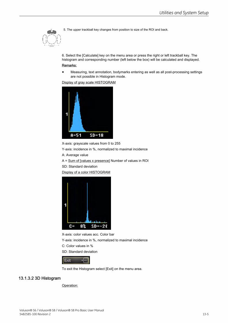
5. The upper trackball key changes from position to size of the ROI and back.
6. Select the [Calculate] key on the menu area or press the right or left trackball key. Thehistogram and corresponding number (left below the box) will be calculated and displayed.Remarks:
• Measuring, text annotation, bodymarks entering as well as all post-processing settingsare not possible in Histogram mode.
Display of gray scale HISTOGRAM
X-axis: grayscale values from 0 to 255Y-axis: incidence in %, normalized to maximal incidenceA: Average valueA = Sum of [values x presence] Number of values in ROISD: Standard deviationDisplay of a color HISTOGRAM
X-axis: color values acc. Color barY-axis: incidence in %, normalized to maximal incidenceC: Color values in %SD: Standard deviation
To exit the Histogram select [Exit] on the menu area.
13.1.3.2 3D HistogramOperation:
Utilities and System Setup
Voluson® S6 / Voluson® S8 / Voluson® S8 Pro Basic User Manual5482585-100 Revision 2 13-5
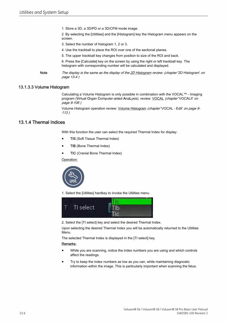
1. Store a 3D, a 3D/PD or a 3D/CFM mode image.2. By selecting the [Utilities] and the [Histogram] key the Histogram menu appears on thescreen.3. Select the number of histogram 1, 2 or 3.4. Use the trackball to place the ROI over one of the sectional planes.5. The upper trackball key changes from position to size of the ROI and back.6. Press the [Calculate] key on the screen by using the right or left trackball key. Thehistogram with corresponding number will be calculated and displayed.
Note The display is the same as the display of the 2D Histogram review: (chapter '2D Histogram' onpage 13-4 )
13.1.3.3 Volume HistogramCalculating a Volume Histogram is only possible in combination with the VOCAL™ - Imagingprogram (Virtual Organ Computer-aided AnaLysis). review: VOCAL (chapter 'VOCALII' onpage 9-106 )Volume Histogram operation review: Volume Histogram (chapter 'VOCAL - Edit' on page 9-113 )
13.1.4 Thermal Indices
With this function the user can select the required Thermal Index for display:
• TIS (Soft Tissue Thermal Index)
• TIB (Bone Thermal Index)
• TIC (Cranial Bone Thermal Index)
Operation:
1. Select the [Utilites] hardkey to invoke the Utilities menu.
2. Select the [TI select] key and select the desired Thermal Index.Upon selecting the desired Thermal Index you will be automatically returned to the UtilitiesMenu.The selected Thermal Index is displayed in the [TI select] key.Remarks:
• While you are scanning, notice the index numbers you are using and which controlsaffect the readings.
• Try to keep the index numbers as low as you can, while maintaining diagnosticinformation within the image. This is particularly important when scanning the fetus.
Utilities and System Setup
13-6Voluson® S6 / Voluson® S8 / Voluson® S8 Pro Basic User Manual
5482585-100 Revision 2
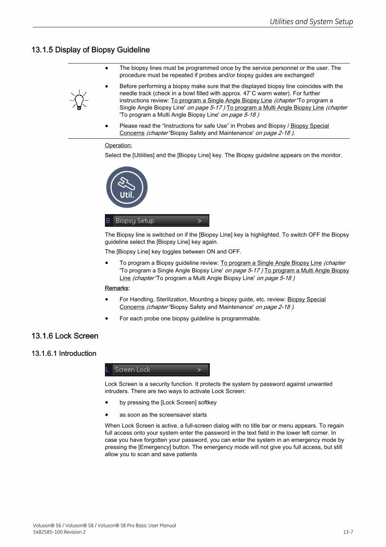
13.1.5 Display of Biopsy Guideline
• The biopsy lines must be programmed once by the service personnel or the user. Theprocedure must be repeated if probes and/or biopsy guides are exchanged!
• Before performing a biopsy make sure that the displayed biopsy line coincides with theneedle track (check in a bowl filled with approx. 47˚C warm water). For furtherinstructions review: To program a Single Angle Biopsy Line (chapter 'To program aSingle Angle Biopsy Line' on page 5-17 ) To program a Multi Angle Biopsy Line (chapter'To program a Multi Angle Biopsy Line' on page 5-18 )
• Please read the “Instructions for safe Use” in Probes and Biopsy / Biopsy SpecialConcerns (chapter 'Biopsy Safety and Maintenance' on page 2-18 ).
Operation:Select the [Utilities] and the [Biopsy Line] key. The Biopsy guideline appears on the monitor.
The Biopsy line is switched on if the [Biopsy Line] key is highlighted. To switch OFF the Biopsyguideline select the [Biopsy Line] key again.The [Biopsy Line] key toggles between ON and OFF.
• To program a Biopsy guideline review: To program a Single Angle Biopsy Line (chapter'To program a Single Angle Biopsy Line' on page 5-17 ) To program a Multi Angle BiopsyLine (chapter 'To program a Multi Angle Biopsy Line' on page 5-18 )
Remarks:
• For Handling, Sterilization, Mounting a biopsy guide, etc. review: Biopsy SpecialConcerns (chapter 'Biopsy Safety and Maintenance' on page 2-18 ).
• For each probe one biopsy guideline is programmable.
13.1.6 Lock Screen
13.1.6.1 Introduction
Lock Screen is a security function. It protects the system by password against unwantedintruders. There are two ways to activate Lock Screen:
• by pressing the [Lock Screen] softkey
• as soon as the screensaver starts
When Lock Screen is active, a full-screen dialog with no title bar or menu appears. To regainfull access onto your system enter the password in the text field in the lower left corner. Incase you have forgotten your password, you can enter the system in an emergency mode bypressing the [Emergency] button. The emergency mode will not give you full access, but stillallow you to scan and save patients
Utilities and System Setup
Voluson® S6 / Voluson® S8 / Voluson® S8 Pro Basic User Manual5482585-100 Revision 2 13-7
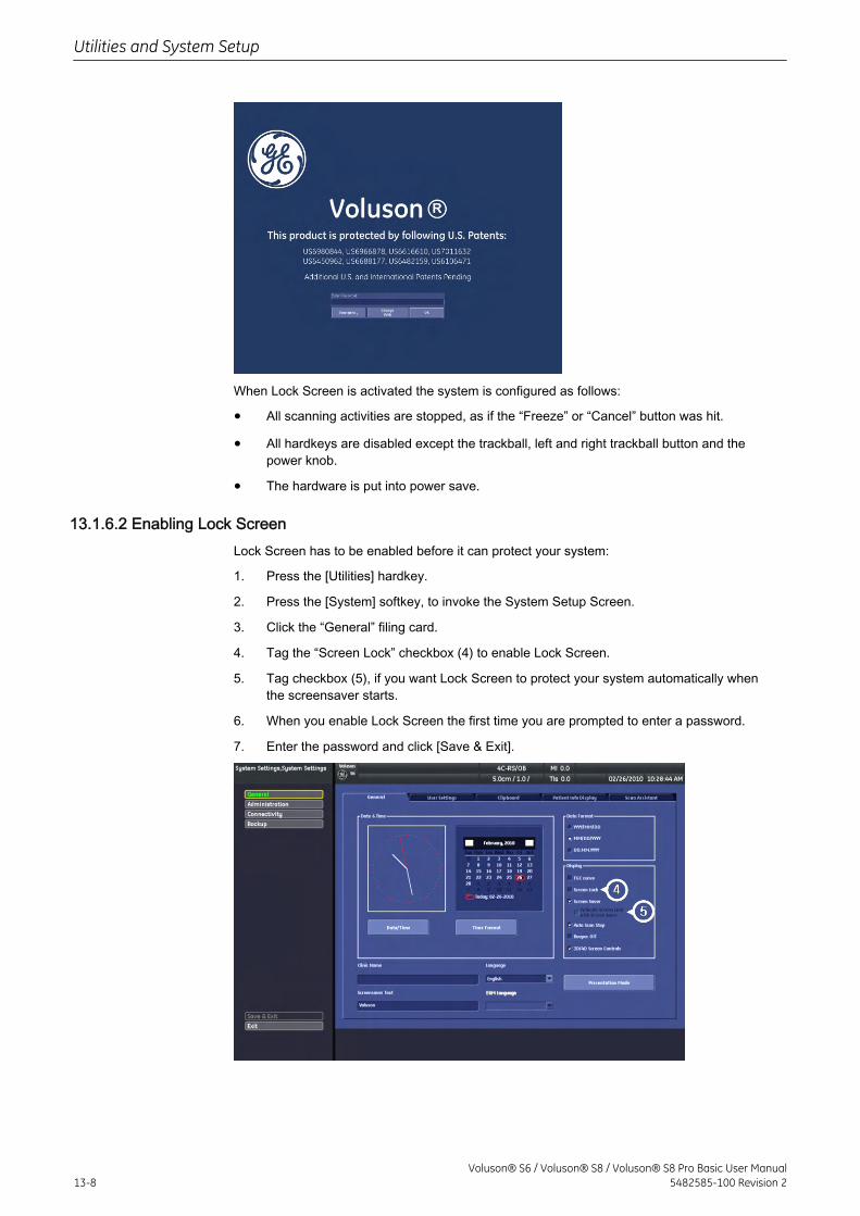
When Lock Screen is activated the system is configured as follows:
• All scanning activities are stopped, as if the “Freeze” or “Cancel” button was hit.
• All hardkeys are disabled except the trackball, left and right trackball button and thepower knob.
• The hardware is put into power save.
13.1.6.2 Enabling Lock ScreenLock Screen has to be enabled before it can protect your system:
1. Press the [Utilities] hardkey.
2. Press the [System] softkey, to invoke the System Setup Screen.
3. Click the “General” filing card.
4. Tag the “Screen Lock” checkbox (4) to enable Lock Screen.
5. Tag checkbox (5), if you want Lock Screen to protect your system automatically whenthe screensaver starts.
6. When you enable Lock Screen the first time you are prompted to enter a password.
7. Enter the password and click [Save & Exit].
Utilities and System Setup
13-8Voluson® S6 / Voluson® S8 / Voluson® S8 Pro Basic User Manual
5482585-100 Revision 2
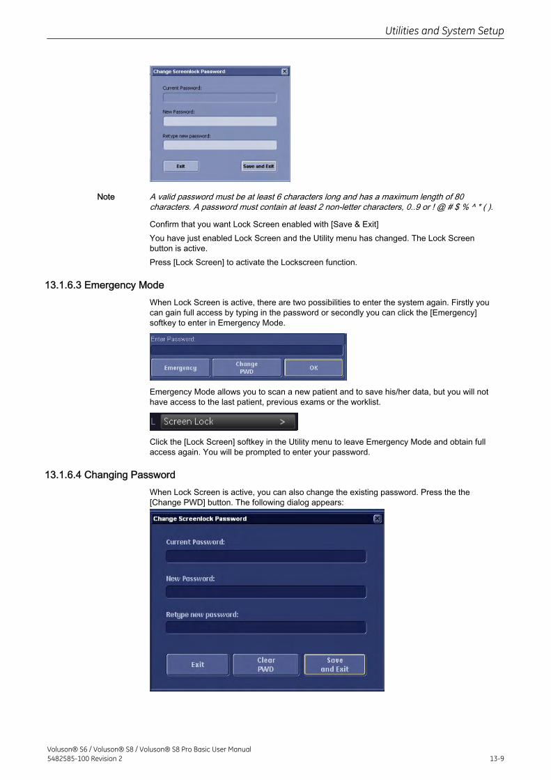
Note A valid password must be at least 6 characters long and has a maximum length of 80characters. A password must contain at least 2 non-letter characters, 0..9 or ! @ # $ % ^ * ( ).
Confirm that you want Lock Screen enabled with [Save & Exit]You have just enabled Lock Screen and the Utility menu has changed. The Lock Screenbutton is active.Press [Lock Screen] to activate the Lockscreen function.
13.1.6.3 Emergency ModeWhen Lock Screen is active, there are two possibilities to enter the system again. Firstly youcan gain full access by typing in the password or secondly you can click the [Emergency]softkey to enter in Emergency Mode.
Emergency Mode allows you to scan a new patient and to save his/her data, but you will nothave access to the last patient, previous exams or the worklist.
Click the [Lock Screen] softkey in the Utility menu to leave Emergency Mode and obtain fullaccess again. You will be prompted to enter your password.
13.1.6.4 Changing PasswordWhen Lock Screen is active, you can also change the existing password. Press the the[Change PWD] button. The following dialog appears:
Utilities and System Setup
Voluson® S6 / Voluson® S8 / Voluson® S8 Pro Basic User Manual5482585-100 Revision 2 13-9
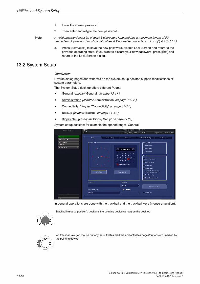
1. Enter the current password.
2. Then enter and retype the new password.
Note A valid password must be at least 6 characters long and has a maximum length of 80characters. A password must contain at least 2 non-letter characters, ..9 or ! @ # $ % ^ * ( ).
3. Press [Save&Exit] to save the new password, disable Lock Screen and return to theprevious operating state. If you want to discard your new password, press [Exit] andreturn to the Lock Screen dialog.
13.2 System Setup
IntroductionDiverse dialog pages and windows on the system setup desktop support modifications ofsystem parameters.The System Setup desktop offers different Pages:
• General (chapter 'General' on page 13-11 )
• Administration (chapter 'Administration' on page 13-22 )
• Connectivity (chapter 'Connectivity' on page 13-24 )
• Backup (chapter 'Backup' on page 13-41 )
• Biopsy Setup (chapter 'Biopsy Setup' on page 5-15 )System setup desktop: for example the opened page: “General”
In general operations are done with the trackball and the trackball keys (mouse emulation).
Trackball (mouse position): positions the pointing device (arrow) on the desktop
left trackball key (left mouse button): sets, fixates markers and activates pages/buttons etc. marked bythe pointing device
Utilities and System Setup
13-10Voluson® S6 / Voluson® S8 / Voluson® S8 Pro Basic User Manual
5482585-100 Revision 2
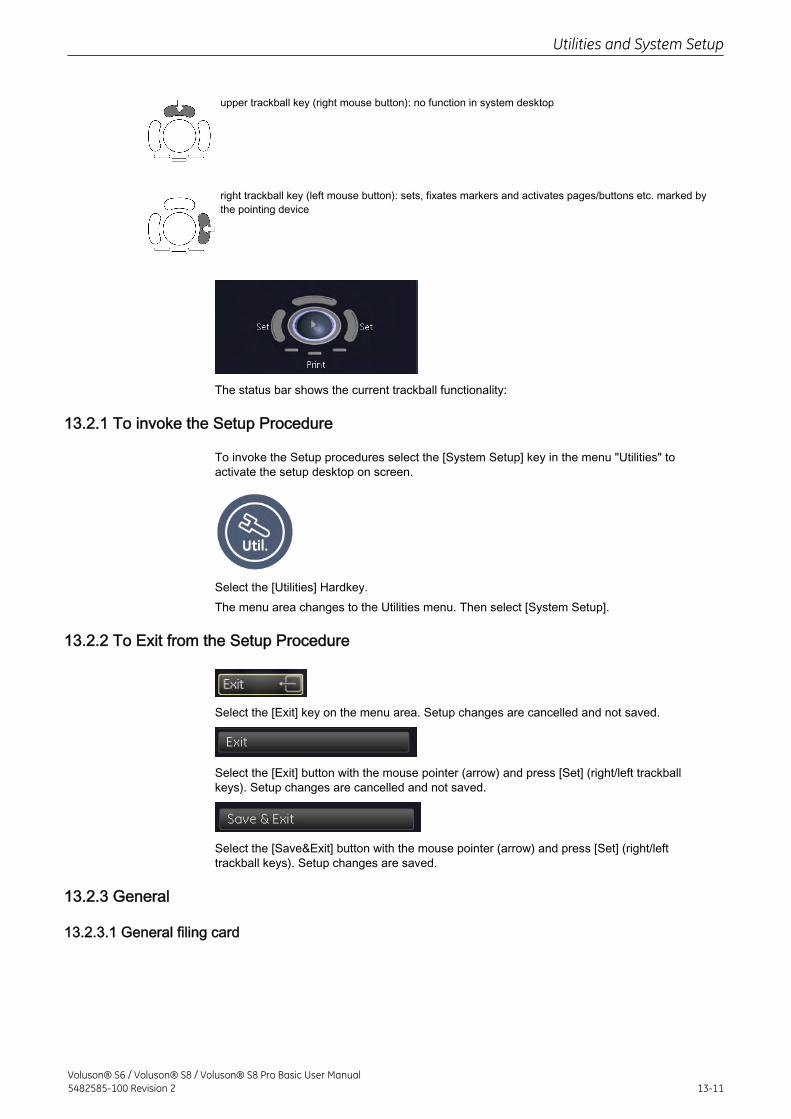
upper trackball key (right mouse button): no function in system desktop
right trackball key (left mouse button): sets, fixates markers and activates pages/buttons etc. marked bythe pointing device
The status bar shows the current trackball functionality:
13.2.1 To invoke the Setup Procedure
To invoke the Setup procedures select the [System Setup] key in the menu "Utilities" toactivate the setup desktop on screen.
Select the [Utilities] Hardkey.The menu area changes to the Utilities menu. Then select [System Setup].
13.2.2 To Exit from the Setup Procedure
Select the [Exit] key on the menu area. Setup changes are cancelled and not saved.
Select the [Exit] button with the mouse pointer (arrow) and press [Set] (right/left trackballkeys). Setup changes are cancelled and not saved.
Select the [Save&Exit] button with the mouse pointer (arrow) and press [Set] (right/lefttrackball keys). Setup changes are saved.
13.2.3 General
13.2.3.1 General filing card
Utilities and System Setup
Voluson® S6 / Voluson® S8 / Voluson® S8 Pro Basic User Manual5482585-100 Revision 2 13-11
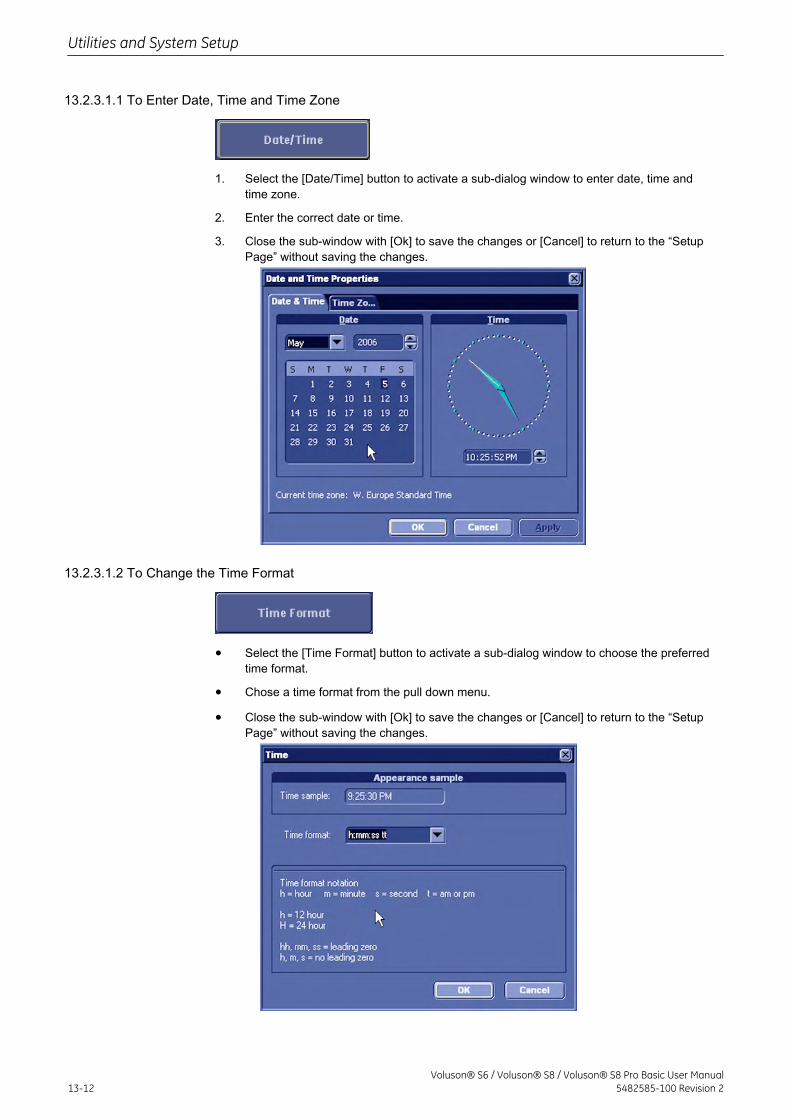
13.2.3.1.1 To Enter Date, Time and Time Zone
1. Select the [Date/Time] button to activate a sub-dialog window to enter date, time andtime zone.
2. Enter the correct date or time.
3. Close the sub-window with [Ok] to save the changes or [Cancel] to return to the “SetupPage” without saving the changes.
13.2.3.1.2 To Change the Time Format
• Select the [Time Format] button to activate a sub-dialog window to choose the preferredtime format.
• Chose a time format from the pull down menu.
• Close the sub-window with [Ok] to save the changes or [Cancel] to return to the “SetupPage” without saving the changes.
Utilities and System Setup
13-12Voluson® S6 / Voluson® S8 / Voluson® S8 Pro Basic User Manual
5482585-100 Revision 2
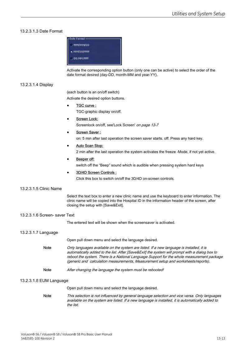
13.2.3.1.3 Date Format
Activate the corresponding option button (only one can be active) to select the order of thedate format desired (day-DD, month-MM and year-YY).
13.2.3.1.4 Display
(each button is an on/off switch)Activate the desired option buttons.
• TGC curve :TGC-graphic display on/off.
• Screen Lock:Screenlock on/off, see'Lock Screen' on page 13-7
• Screen Saver :on: 5 min after last operation the screen saver starts. off: Press any hard key.
• Auto Scan Stop:2 min after the last operation the system activates the freeze -Mode, if not yet active.
• Beeper off:switch off the “Beep” sound which is audible when pressing system hard keys
• 3D/4D Screen Controls :Click this box to switch on/off the 3D/4D on-screen controls.
13.2.3.1.5 Clinic Name
Select the text box to enter a new clinic name and use the keyboard to enter information. Theclinic name will be copied into the Hospital ID in the information header of the screen, afterclosing the setup with [Save&Exit].
13.2.3.1.6 Screen- saver Text
The entered text will be shown when the screensaver is activated.
13.2.3.1.7 Language
Open pull down menu and select the language desired.
Note Only languages available on the system are listed. If a new language is installed, it isautomatically added to the list. After [Save&Exit] the system will prompt with a dialog box toreboot the system. There is a National Language Support for the whole measurement package(generic and calculation measurements, Measurement setup and worksheets/reports).
Note After changing the language the system must be rebooted!
13.2.3.1.8 EUM Language
Open pull down menu and select the language desired.
Note This selection is not influenced by general language selection and vice versa. Only languagesavailable on the system are listed. If a new language is installed, it is automatically added tothe list.
Utilities and System Setup
Voluson® S6 / Voluson® S8 / Voluson® S8 Pro Basic User Manual5482585-100 Revision 2 13-13
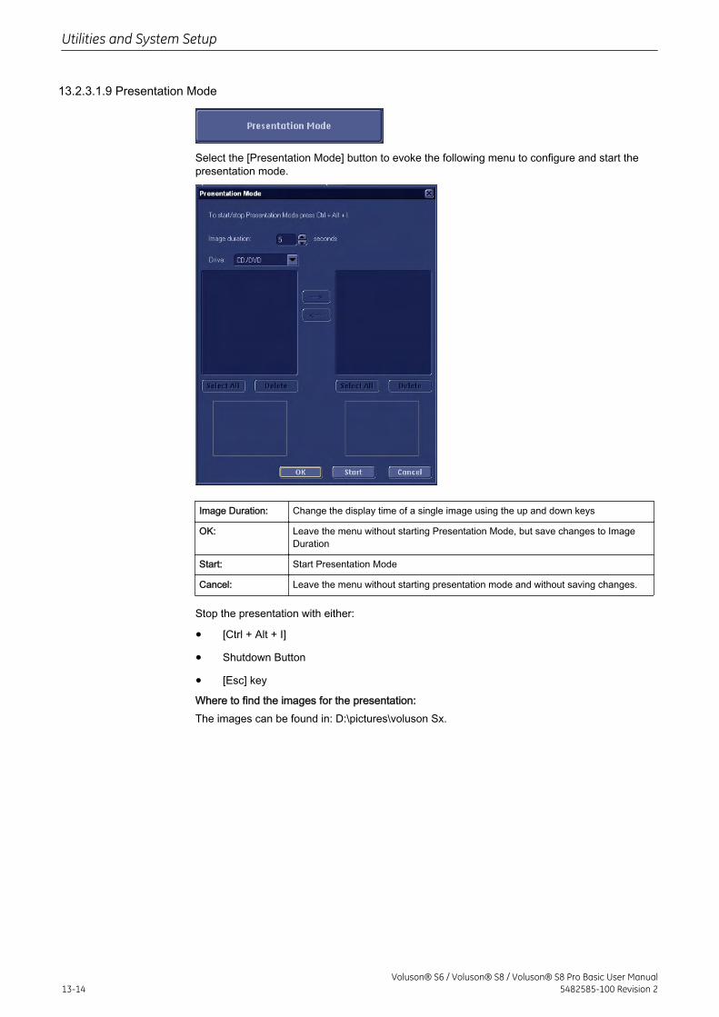
13.2.3.1.9 Presentation Mode
Select the [Presentation Mode] button to evoke the following menu to configure and start thepresentation mode.
Image Duration: Change the display time of a single image using the up and down keys
OK: Leave the menu without starting Presentation Mode, but save changes to ImageDuration
Start: Start Presentation Mode
Cancel: Leave the menu without starting presentation mode and without saving changes.
Stop the presentation with either:
• [Ctrl + Alt + I]
• Shutdown Button
• [Esc] key
Where to find the images for the presentation:The images can be found in: D:\pictures\voluson Sx.
Utilities and System Setup
13-14Voluson® S6 / Voluson® S8 / Voluson® S8 Pro Basic User Manual
5482585-100 Revision 2
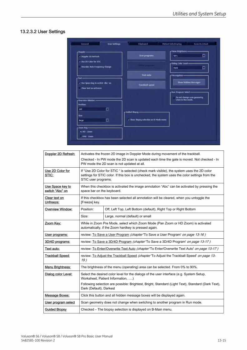
13.2.3.2 User Settings
Doppler 2D Refresh: Activates the frozen 2D image in Doppler Mode during movement of the trackball.Checked - In PW mode the 2D scan is updated each time the gate is moved. Not checked - InPW mode the 2D scan is not updated at all.
Use 2D Color forSTIC:
If “Use 2D Color for STIC “ is selected (check mark visible), the system uses the 2D colorsettings for STIC color. If this box is unchecked, the system uses the color settings from theSTIC user programs.
Use Space key toswitch “Abc” on
When this checkbox is activated the image annotation “Abc” can be activated by pressing thespace bar on the keyboard.
Clear text onUnfreeze:
If this checkbox has been selected all annotation will be cleared, when you untoggle the[Freeze] key.
Overview Window: Position: Off, Left Top, Left Bottom (default), Right Top or Right Bottom
Size: Large, normal (default) or small
Zoom Key: While in Zoom Pre Mode, select which Zoom Mode (Pan Zoom or HD Zoom) is activatedautomatically, if the Zoom hardkey is pressed again.
User programs: review: To Save a User Program (chapter 'To Save a User Program' on page 13-16 )
3D/4D programs: review: To Save a 3D/4D Program (chapter 'To Save a 3D/4D Program' on page 13-17 )
Text auto: review: To Enter/Overwrite Text Auto (chapter 'To Enter/Overwrite Text Auto' on page 13-17 )
Trackball Speed: review: To Adjust the Trackball Speed (chapter 'To Adjust the Trackball Speed' on page 13-19 )
Menu Brightness: The brightness of the menu (operating) area can be selected. From 0% to 90%.
Dialog color Level: Select the desired color level for the dialogs of the user interface (e.g. System Setup,Worksheet, Patient Information, ….)Following selection are possible: Brightest, Bright, Standard (Light Text), Standard (Dark Text),Dark (Default), Darkest
Message Boxes: Click this button and all hidden message boxes will be displayed again.
User program select Scan geometry does not change when switching to another program in Run mode.
Guided Biopsy Checked – The biopsy selection is displayed on B-Main menu.
Utilities and System Setup
Voluson® S6 / Voluson® S8 / Voluson® S8 Pro Basic User Manual5482585-100 Revision 2 13-15
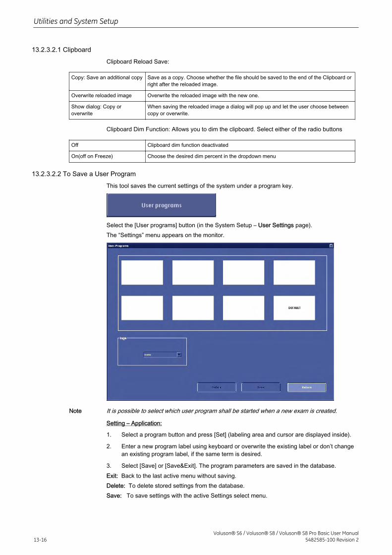
13.2.3.2.1 Clipboard
Clipboard Reload Save:
Copy: Save an additional copy Save as a copy. Choose whether the file should be saved to the end of the Clipboard orright after the reloaded image.
Overwrite reloaded image Overwrite the reloaded image with the new one.
Show dialog: Copy oroverwrite
When saving the reloaded image a dialog will pop up and let the user choose betweencopy or overwrite.
Clipboard Dim Function: Allows you to dim the clipboard. Select either of the radio buttons
Off Clipboard dim function deactivated
On(off on Freeze) Choose the desired dim percent in the dropdown menu
13.2.3.2.2 To Save a User Program
This tool saves the current settings of the system under a program key.
Select the [User programs] button (in the System Setup – User Settings page).The “Settings” menu appears on the monitor.
Note It is possible to select which user program shall be started when a new exam is created.
Setting – Application:
1. Select a program button and press [Set] (labeling area and cursor are displayed inside).
2. Enter a new program label using keyboard or overwrite the existing label or don’t changean existing program label, if the same term is desired.
3. Select [Save] or [Save&Exit]. The program parameters are saved in the database.Exit: Back to the last active menu without saving.Delete: To delete stored settings from the database.Save: To save settings with the active Settings select menu.
Utilities and System Setup
13-16Voluson® S6 / Voluson® S8 / Voluson® S8 Pro Basic User Manual
5482585-100 Revision 2
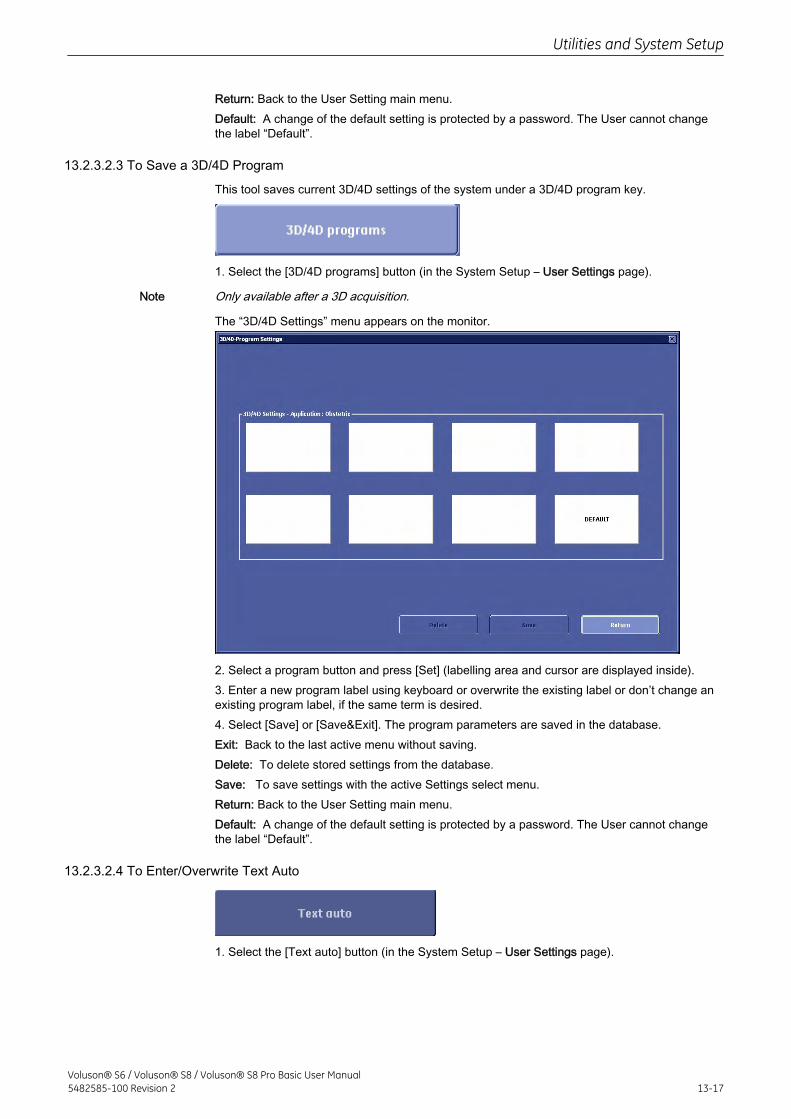
Return: Back to the User Setting main menu.Default: A change of the default setting is protected by a password. The User cannot changethe label “Default”.
13.2.3.2.3 To Save a 3D/4D Program
This tool saves current 3D/4D settings of the system under a 3D/4D program key.
1. Select the [3D/4D programs] button (in the System Setup – User Settings page).
Note Only available after a 3D acquisition.
The “3D/4D Settings” menu appears on the monitor.
2. Select a program button and press [Set] (labelling area and cursor are displayed inside).3. Enter a new program label using keyboard or overwrite the existing label or don’t change anexisting program label, if the same term is desired.4. Select [Save] or [Save&Exit]. The program parameters are saved in the database.Exit: Back to the last active menu without saving.Delete: To delete stored settings from the database.Save: To save settings with the active Settings select menu.Return: Back to the User Setting main menu.Default: A change of the default setting is protected by a password. The User cannot changethe label “Default”.
13.2.3.2.4 To Enter/Overwrite Text Auto
1. Select the [Text auto] button (in the System Setup – User Settings page).
Utilities and System Setup
Voluson® S6 / Voluson® S8 / Voluson® S8 Pro Basic User Manual5482585-100 Revision 2 13-17
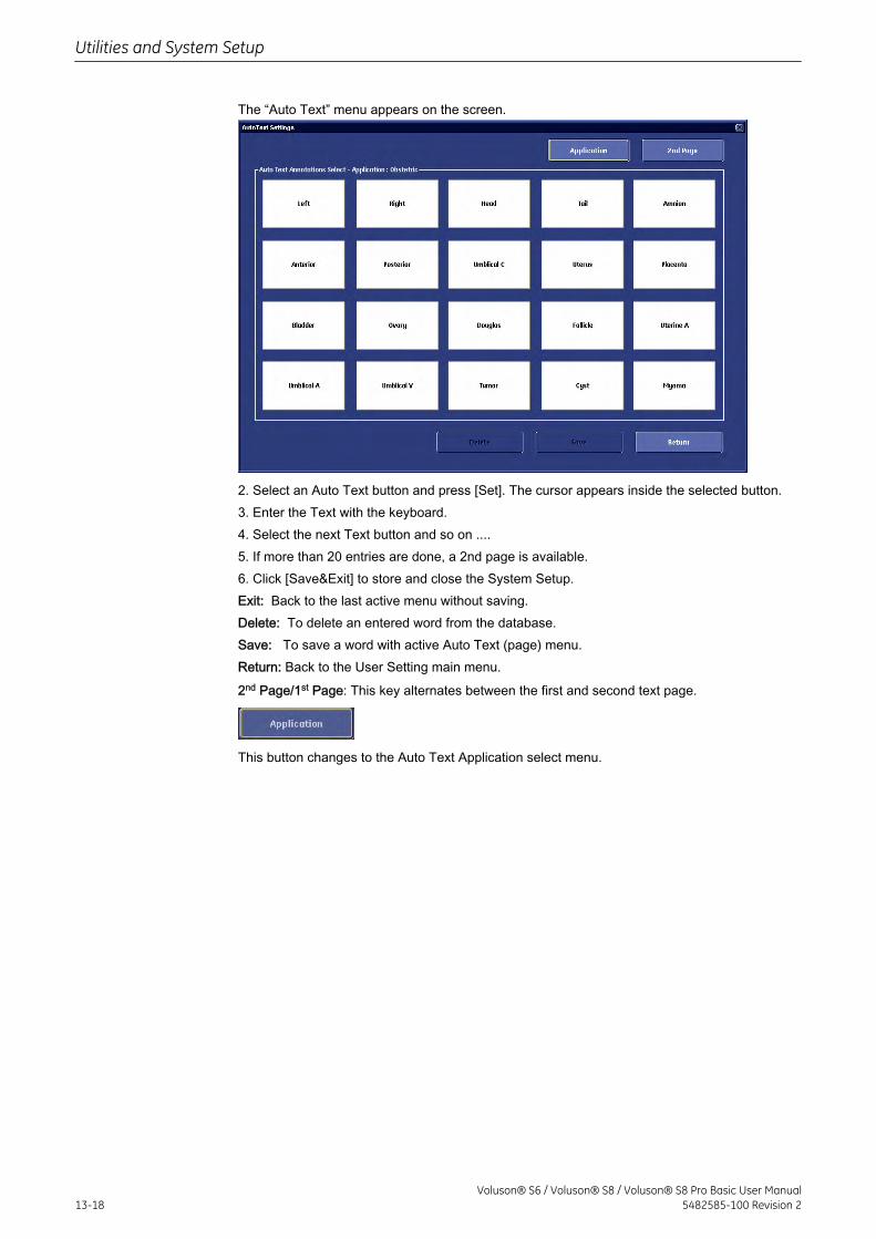
The “Auto Text” menu appears on the screen.
2. Select an Auto Text button and press [Set]. The cursor appears inside the selected button.3. Enter the Text with the keyboard.4. Select the next Text button and so on ....5. If more than 20 entries are done, a 2nd page is available.6. Click [Save&Exit] to store and close the System Setup.Exit: Back to the last active menu without saving.Delete: To delete an entered word from the database.Save: To save a word with active Auto Text (page) menu.Return: Back to the User Setting main menu.
2nd Page/1st Page: This key alternates between the first and second text page.
This button changes to the Auto Text Application select menu.
Utilities and System Setup
13-18Voluson® S6 / Voluson® S8 / Voluson® S8 Pro Basic User Manual
5482585-100 Revision 2
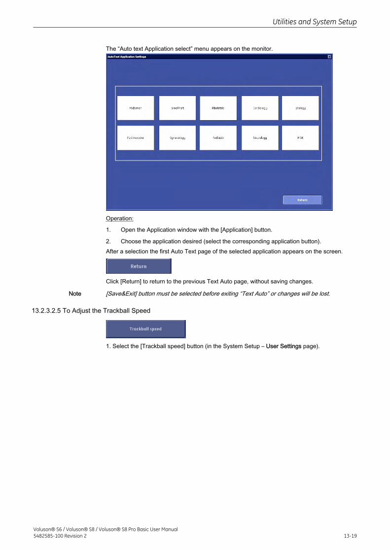
The “Auto text Application select” menu appears on the monitor.
Operation:
1. Open the Application window with the [Application] button.
2. Choose the application desired (select the corresponding application button).After a selection the first Auto Text page of the selected application appears on the screen.
Click [Return] to return to the previous Text Auto page, without saving changes.
Note [Save&Exit] button must be selected before exiting “Text Auto” or changes will be lost.
13.2.3.2.5 To Adjust the Trackball Speed
1. Select the [Trackball speed] button (in the System Setup – User Settings page).
Utilities and System Setup
Voluson® S6 / Voluson® S8 / Voluson® S8 Pro Basic User Manual5482585-100 Revision 2 13-19
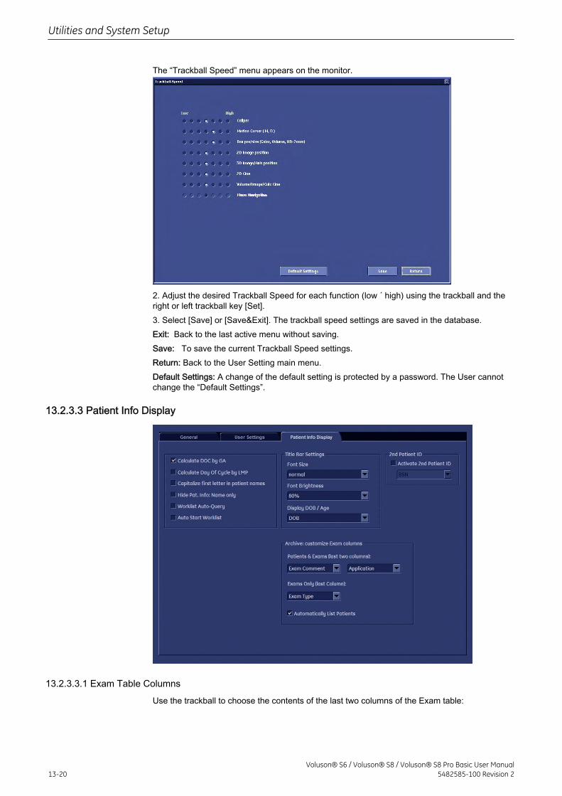
The “Trackball Speed” menu appears on the monitor.
2. Adjust the desired Trackball Speed for each function (low ´ high) using the trackball and theright or left trackball key [Set].3. Select [Save] or [Save&Exit]. The trackball speed settings are saved in the database.Exit: Back to the last active menu without saving.Save: To save the current Trackball Speed settings.Return: Back to the User Setting main menu.Default Settings: A change of the default setting is protected by a password. The User cannotchange the “Default Settings”.
13.2.3.3 Patient Info Display
13.2.3.3.1 Exam Table Columns
Use the trackball to choose the contents of the last two columns of the Exam table:
Utilities and System Setup
13-20Voluson® S6 / Voluson® S8 / Voluson® S8 Pro Basic User Manual
5482585-100 Revision 2
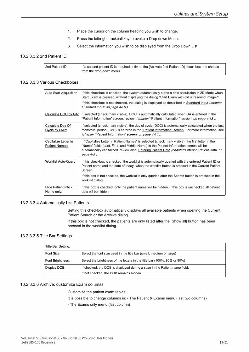
1. Place the cursor on the column heading you wish to change.
2. Press the left/right trackball key to evoke a Drop down Menu.
3. Select the information you wish to be displayed from the Drop Down List.
13.2.3.3.2 2nd Patient ID
2nd Patient ID If a second patient ID is required activate the [Activate 2nd Patient ID] check box and choosefrom the drop down menu.
13.2.3.3.3 Various Checkboxes
Auto Start Acquisition If this checkbox is checked, the system automatically starts a new acquisition in 2D Mode whenStart Exam is pressed, without displaying the dialog “Start Exam with old ultrasound Image?”.If this checkbox is not checked, the dialog is displayed as described in Standard Input (chapter'Standard Input' on page 4-20 )
Calculate DOC by GA: If selected (check mark visible), DOC is automatically calculated when GA is entered in the“Patient Information” screen; review: (chapter '“Patient Information” screen' on page 4-13 ).
Calculate Day OfCycle by LMP:
If selected (check mark visible), the day of cycle (DOC) is automatically calculated when the lastmenstrual period (LMP) is entered in the “Patient Information” screen; For more information, see(chapter '“Patient Information” screen' on page 4-13 ).
Capitalize Letter inPatient Names:
If “Capitalize Letter in Patient Names” is selected (check mark visible), the first letter in the“Name” fields (Last, First, and Middle Name) in the Patient Information screen will beautomatically capitalized. review also: Entering Patient Data (chapter 'Entering Patient Data' onpage 4-9 )
Worklist Auto-Query If this checkbox is checked, the worklist is automatically queried with the entered Patient ID orPatient name and the date of today, when the worklist button is pressed in the Current PatientScreen.If this box is not checked, the worklist is only queried after the Search button is pressed in theworklist dialog.
Hide Patient Info -Name only:
If this box is checked, only the patient name will be hidden. If this box is unchecked all patientdata wil be hidden.
13.2.3.3.4 Automatically List Patients
Setting this checkbox automatically displays all available patients when opening the CurrentPatient Search or the Archive dialog.If this box is not checked, the patients are only listed after the [Show all] button has beenpressed in the worklist dialog.
13.2.3.3.5 Title Bar Settings
Title Bar Setting:
Font Size: Select the font size used in the title bar (small, medium or large)
Font Brightness: Select the brightness of the letters in the title bar (100%, 90% or 80%)
Display DOB: If checked, the DOB is displayed during a scan in the Patient name field.If not checked, the DOB remains hidden.
13.2.3.3.6 Archive: customize Exam columss
Customize the patient exam tables.It is possible to change columns in: - The Patient & Exams menu (last two columns)- The Exams only menu (last column)
Utilities and System Setup
Voluson® S6 / Voluson® S8 / Voluson® S8 Pro Basic User Manual5482585-100 Revision 2 13-21
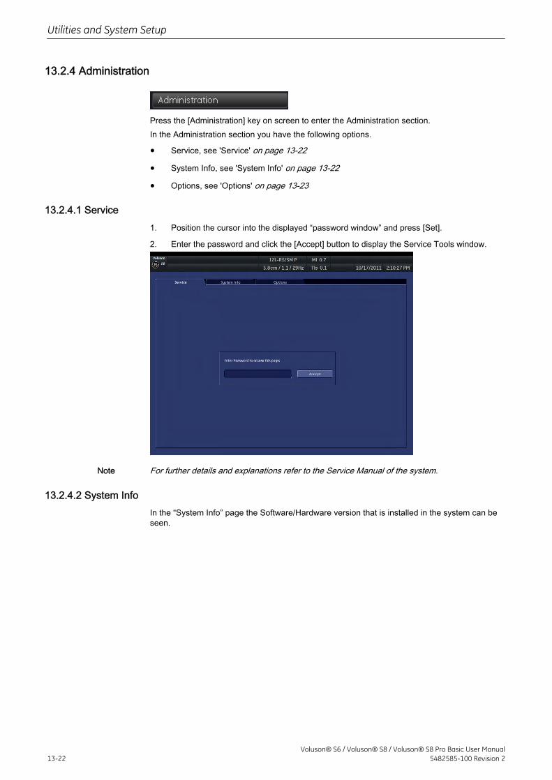
13.2.4 Administration
Press the [Administration] key on screen to enter the Administration section.In the Administration section you have the following options.
• Service, see 'Service' on page 13-22
• System Info, see 'System Info' on page 13-22
• Options, see 'Options' on page 13-23
13.2.4.1 Service1. Position the cursor into the displayed “password window” and press [Set].
2. Enter the password and click the [Accept] button to display the Service Tools window.
Note For further details and explanations refer to the Service Manual of the system.
13.2.4.2 System InfoIn the “System Info” page the Software/Hardware version that is installed in the system can beseen.
Utilities and System Setup
13-22Voluson® S6 / Voluson® S8 / Voluson® S8 Pro Basic User Manual
5482585-100 Revision 2
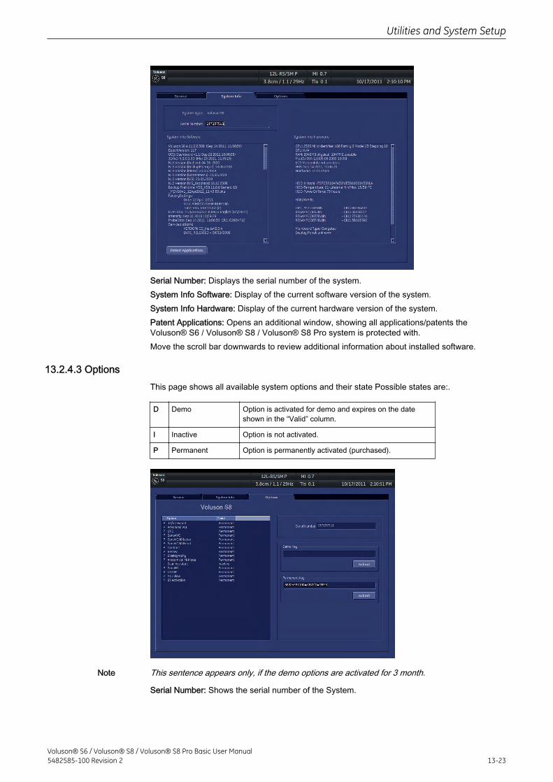
Serial Number: Displays the serial number of the system.System Info Software: Display of the current software version of the system.System Info Hardware: Display of the current hardware version of the system.Patent Applications: Opens an additional window, showing all applications/patents theVoluson® S6 / Voluson® S8 / Voluson® S8 Pro system is protected with.Move the scroll bar downwards to review additional information about installed software.
13.2.4.3 OptionsThis page shows all available system options and their state Possible states are:.
D Demo Option is activated for demo and expires on the dateshown in the “Valid” column.
I Inactive Option is not activated.
P Permanent Option is permanently activated (purchased).
Note This sentence appears only, if the demo options are activated for 3 month.
Serial Number: Shows the serial number of the System.
Utilities and System Setup
Voluson® S6 / Voluson® S8 / Voluson® S8 Pro Basic User Manual5482585-100 Revision 2 13-23
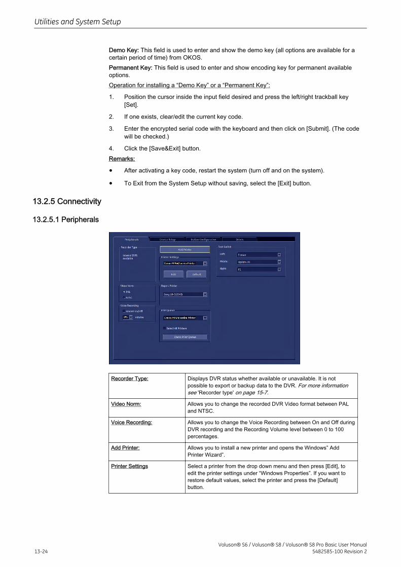
Demo Key: This field is used to enter and show the demo key (all options are available for acertain period of time) from OKOS.Permanent Key: This field is used to enter and show encoding key for permanent availableoptions.Operation for installing a “Demo Key” or a “Permanent Key”:
1. Position the cursor inside the input field desired and press the left/right trackball key[Set].
2. If one exists, clear/edit the current key code.
3. Enter the encrypted serial code with the keyboard and then click on [Submit]. (The codewill be checked.)
4. Click the [Save&Exit] button.Remarks:
• After activating a key code, restart the system (turn off and on the system).
• To Exit from the System Setup without saving, select the [Exit] button.
13.2.5 Connectivity
13.2.5.1 Peripherals
Recorder Type: Displays DVR status whether available or unavailable. It is notpossible to export or backup data to the DVR. For more informationsee 'Recorder type' on page 15-7.
Video Norm: Allows you to change the recorded DVR Video format between PALand NTSC.
Voice Recording: Allows you to change the Voice Recording between On and Off duringDVR recording and the Recording Volume level between 0 to 100percentages.
Add Printer: Allows you to install a new printer and opens the Windows” AddPrinter Wizard”.
Printer Settings Select a printer from the drop down menu and then press [Edit], toedit the printer settings under “Windows Properties”. If you want torestore default values, select the printer and press the [Default]button.
Utilities and System Setup
13-24Voluson® S6 / Voluson® S8 / Voluson® S8 Pro Basic User Manual
5482585-100 Revision 2
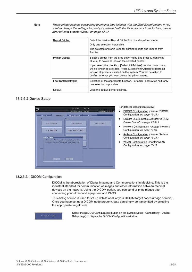
Note These printer settings solely refer to printing jobs initiated with the [End Exam] button. If youwant to change the settings for print jobs initiated with the Px buttons or from Archive, pleaserefer to 'Data Transfer Menu' on page 12-27
Report Printer: Select the desired Report Printer from the drop-down menu.Only one selection is possible.The selected printer is used for printing reports and images fromArchive.
Printer Queue: Select a printer from the drop down menu and press [Clean PrintQueue] to delete all jobs on the selected printer.If you select the checkbox [Select All Printers] the drop down menuwill no longer be available. Press [Clean Print Queue] to delete alljobs on all printers installed on the system. You will be asked toconfirm whether you want delete the printer queue.
Foot Switch left/right: Selection of the appropriate function. For each Foot Switch half, onlyone selection is possible.
Default Load the default printer settings.
13.2.5.2 Device Setup
For detailed description review:
• DICOM Configuration (chapter 'DICOMConfiguration' on page 13-25 )
• DICOM Queue Status (chapter 'DICOMQueue Status' on page 13-31 )
• Network Configuration (chapter 'NetworkConfiguration' on page 13-33)
• Archive Configuration (chapter 'ArchiveConfiguration' on page 13-33 )
• WLAN Configuration (chapter'WLANConfiguration' on page 13-35
13.2.5.2.1 DICOM Configuration
DICOM is the abbreviation of Digital Imaging and Communications in Medicine. This is theindustrial standard for communication of images and other information between medicaldevices on the network. Using the DICOM option, you can send or print images afterconnecting your ultrasound equipment and PACS.This dialog section is used to set up details of all of your DICOM target nodes (image servers).Once you have set up a DICOM node properly, data can simply be transmitted by selectingthe appropriate target node.
Select the [DICOM Configuration] button (in the System Setup - Connectivity - DeviceSetup page) to display the DICOM Configuration window.
Utilities and System Setup
Voluson® S6 / Voluson® S8 / Voluson® S8 Pro Basic User Manual5482585-100 Revision 2 13-25
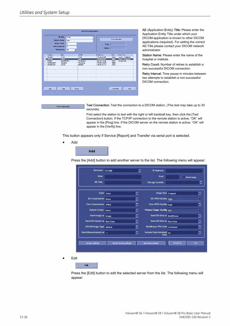
AE (Application Entity) Title: Please enter theApplication Entity Title under which yourDICOM-application is known to other DICOMapplications (required). For setting the correctAE-Title please contact your DICOM networkadministrator.Station Name: Please enter the name of thehospital or institute.Retry Count: Number of retries to establish anon-successful DICOM connection.Retry Interval: Time pause in minutes betweentwo attempts to establish a non-successfulDICOM connection.
Test Connection: Test the connection to a DICOM station. (This test may take up to 30seconds).First select the station to test with the right or left trackball key, then click the [TestConnection] button. If the TCP/IP connection to the remote station is active, “OK” willappear in the [Ping] line. If the DICOM server on the remote station is active, “OK” willappear in the [Verify] line.
This button appears only if Service [Report] and Transfer via serial port is selected.
• Add
Press the [Add] button to add another server to the list. The following menu will appear:
• Edit
Press the [Edit] button to edit the selected server from the list. The following menu willappear:
Utilities and System Setup
13-26Voluson® S6 / Voluson® S8 / Voluson® S8 Pro Basic User Manual
5482585-100 Revision 2
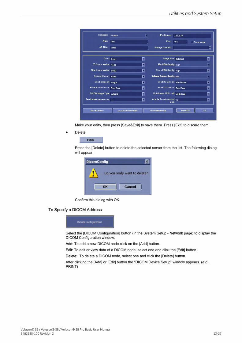
Make your edits, then press [Save&Exit] to save them. Press [Exit] to discard them.
• Delete
Press the [Delete] button to delete the selected server from the list. The following dialogwill appear:
Confirm this dialog with OK.
To Specify a DICOM Address
Select the [DICOM Configuration] button (in the System Setup - Network page) to display theDICOM Configuration window.Add: To add a new DICOM node click on the [Add] button.Edit: To edit or view data of a DICOM node, select one and click the [Edit] button.Delete: To delete a DICOM node, select one and click the [Delete] button.After clicking the [Add] or [Edit] button the “DICOM Device Setup” window appears. (e.g.,PRINT)
Utilities and System Setup
Voluson® S6 / Voluson® S8 / Voluson® S8 Pro Basic User Manual5482585-100 Revision 2 13-27
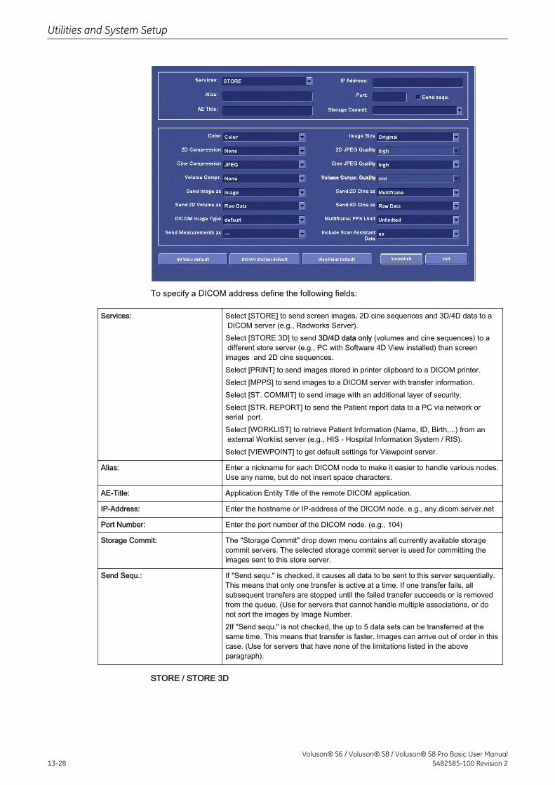
To specify a DICOM address define the following fields:
Services: Select [STORE] to send screen images, 2D cine sequences and 3D/4D data to a DICOM server (e.g., Radworks Server).Select [STORE 3D] to send 3D/4D data only (volumes and cine sequences) to a different store server (e.g., PC with Software 4D View installed) than screenimages and 2D cine sequences.Select [PRINT] to send images stored in printer clipboard to a DICOM printer.Select [MPPS] to send images to a DICOM server with transfer information.Select [ST. COMMIT] to send image with an additional layer of security.Select [STR. REPORT] to send the Patient report data to a PC via network orserial port.Select [WORKLIST] to retrieve Patient Information (Name, ID, Birth,...) from an external Worklist server (e.g., HIS - Hospital Information System / RIS).Select [VIEWPOINT] to get default settings for Viewpoint server.
Alias: Enter a nickname for each DICOM node to make it easier to handle various nodes.Use any name, but do not insert space characters.
AE-Title: Application Entity Title of the remote DICOM application.
IP-Address: Enter the hostname or IP-address of the DICOM node. e.g., any.dicom.server.net
Port Number: Enter the port number of the DICOM node. (e.g., 104)
Storage Commit: The "Storage Commit" drop down menu contains all currently available storagecommit servers. The selected storage commit server is used for committing theimages sent to this store server.
Send Sequ.: If "Send sequ." is checked, it causes all data to be sent to this server sequentially.This means that only one transfer is active at a time. If one transfer fails, allsubsequent transfers are stopped until the failed transfer succeeds or is removedfrom the queue. (Use for servers that cannot handle multiple associations, or donot sort the images by Image Number.2If "Send sequ." is not checked, the up to 5 data sets can be transferred at thesame time. This means that transfer is faster. Images can arrive out of order in thiscase. (Use for servers that have none of the limitations listed in the aboveparagraph).
STORE / STORE 3D
Utilities and System Setup
13-28Voluson® S6 / Voluson® S8 / Voluson® S8 Pro Basic User Manual
5482585-100 Revision 2
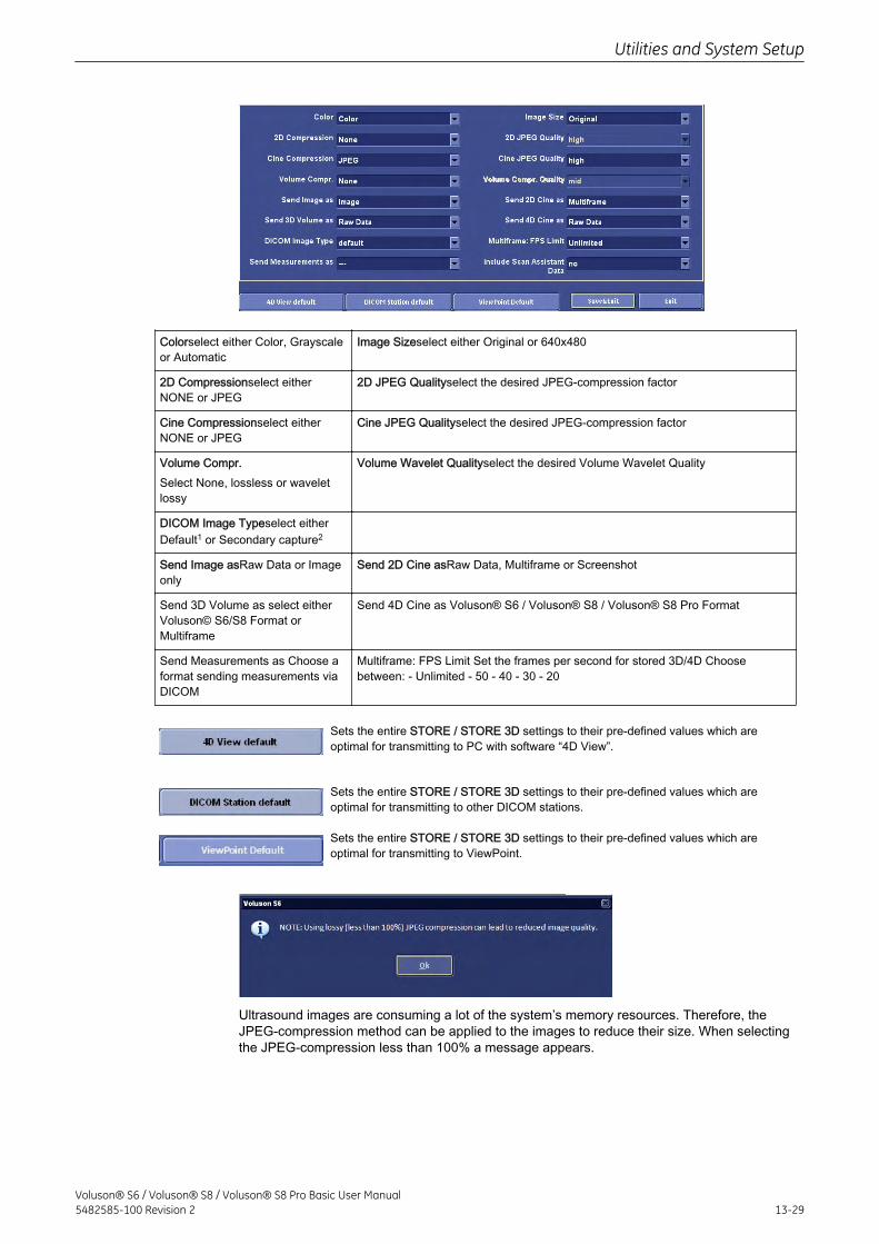
Colorselect either Color, Grayscaleor Automatic
Image Sizeselect either Original or 640x480
2D Compressionselect eitherNONE or JPEG
2D JPEG Qualityselect the desired JPEG-compression factor
Cine Compressionselect eitherNONE or JPEG
Cine JPEG Qualityselect the desired JPEG-compression factor
Volume Compr.Select None, lossless or waveletlossy
Volume Wavelet Qualityselect the desired Volume Wavelet Quality
DICOM Image Typeselect eitherDefault1 or Secondary capture2
Send Image asRaw Data or Imageonly
Send 2D Cine asRaw Data, Multiframe or Screenshot
Send 3D Volume as select eitherVoluson© S6/S8 Format orMultiframe
Send 4D Cine as Voluson® S6 / Voluson® S8 / Voluson® S8 Pro Format
Send Measurements as Choose aformat sending measurements viaDICOM
Multiframe: FPS Limit Set the frames per second for stored 3D/4D Choosebetween: - Unlimited - 50 - 40 - 30 - 20
Sets the entire STORE / STORE 3D settings to their pre-defined values which areoptimal for transmitting to PC with software “4D View”.
Sets the entire STORE / STORE 3D settings to their pre-defined values which areoptimal for transmitting to other DICOM stations.
Sets the entire STORE / STORE 3D settings to their pre-defined values which areoptimal for transmitting to ViewPoint.
Ultrasound images are consuming a lot of the system’s memory resources. Therefore, theJPEG-compression method can be applied to the images to reduce their size. When selectingthe JPEG-compression less than 100% a message appears.
Utilities and System Setup
Voluson® S6 / Voluson® S8 / Voluson® S8 Pro Basic User Manual5482585-100 Revision 2 13-29
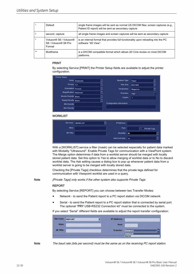
1 Default single frame images will be sent as normal US DICOM files; screen captures (e.g.,Patient ID report) will be sent as secondary capture
2 second. capture all single frame images and screen captures will be sent as secondary capture
* Voluson® S6 / Voluson®S8 / Voluson® S8 ProFormat
is an internal format that provides full functionality upon reloading into the PCsoftware “4D View”.
** Multiframe is a DICOM compatible format which allows 2D Cine review on most DICOMplatforms.
PRINTBy selecting Service [PRINT] the Printer Setup fields are available to adjust the printerconfiguration.
WORKLIST
With a [WORKLIST] service a filter (mask) can be selected especially for patient data markedwith Modality "Ultrasound". Enable Private Tags for communication with a ViewPoint system.The Merge option determines if data from a worklist server should be merged with locallystored patient data. Set this option to Yes to allow merging of worklist data or to No to discardworklist data. The Ask setting causes a dialog box to pop up whenever patient data from aworklist server is going to be merged with locally stored data.Checking the [Private Tags] checkbox determines that the private tags defined forcommunication with Viewpoint worklist are used in a query.
Note [Private Tags] only works if the other system also supports Private Tags.
REPORTBy selecting Service [REPORT] you can choose between two Transfer Modes:
• Network - to send the Patient report to a PC report station via DICOM network
• Serial - to send the Patient report to a PC report station that is connected by serial port.The optional “PRY USB-RS232 Connection kit” must be connected to the system.
If you select “Serial” different fields are available to adjust the report transfer configuration:
Note The baud rate (bits per second) must be the same as on the receiving PC report station.
Utilities and System Setup
13-30Voluson® S6 / Voluson® S8 / Voluson® S8 Pro Basic User Manual
5482585-100 Revision 2
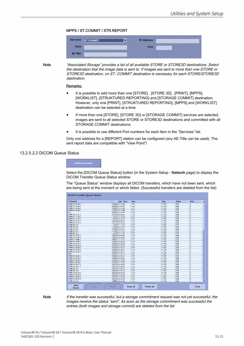
MPPS / ST.COMMIT / STR.REPORT
Note “Associated Storage” provides a list of all available STORE or STORE3D destinations. Selectthe destination that the image data is sent to. If images are sent to more than one STORE orSTORE3D destination, on ST. COMMIT destination is necessary for each STORE/STORE3Ddestination.
Remarks:
• It is possible to add more than one [STORE] , [STORE 3D] , [PRINT], [MPPS],[WORKLIST], [STRUKTURED REPORTING] and [STORAGE COMMIT] destination.However, only one [PRINT], [STRUKTURED REPORTING], [MPPS] and [WORKLIST]destination can be selected at a time.
• If more than one [STORE], [STORE 3D] or [STORAGE COMMIT] services are selected,images are sent to all selected STORE or STORE3D destinations and committed with allSTORAGE COMMIT destinations.
• It is possible to use different Port numbers for each item in the “Services” list.
Only one address for a [REPORT] station can be configured (any AE-Title can be used). Thesent report data are compatible with “View Point”!
13.2.5.2.2 DICOM Queue Status
Select the [DICOM Queue Status] button (in the System Setup - Network page) to display theDICOM Transfer Queue Status window.The “Queue Status” window displays all DICOM transfers, which have not been sent, whichare being sent at the moment or which failed. (Successful transfers are deleted from the list).
Note If the transfer was successful, but a storage commitment request was not yet successful, theimages receive the status “sent”. As soon as the storage commitment was successful theentries (both images and storage commit) are deleted from the list.
Utilities and System Setup
Voluson® S6 / Voluson® S8 / Voluson® S8 Pro Basic User Manual5482585-100 Revision 2 13-31
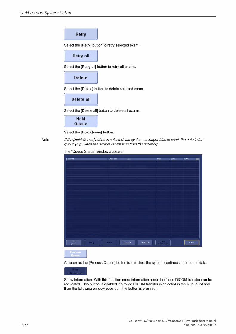
Select the [Retry] button to retry selected exam.
Select the [Retry all] button to retry all exams.
Select the [Delete] button to delete selected exam.
Select the [Delete all] button to delete all exams.
Select the [Hold Queue] button.
Note If the [Hold Queue] button is selected, the system no longer tries to send the data in thequeue (e.g. when the system is removed from the network).
The “Queue Status” window appears.
As soon as the [Process Queue] button is selected, the system continues to send the data.
Show Information: With this function more information about the failed DICOM transfer can berequested. This button is enabled if a failed DICOM transfer is selected in the Queue list andthan the following window pops up if the button is pressed:
Utilities and System Setup
13-32Voluson® S6 / Voluson® S8 / Voluson® S8 Pro Basic User Manual
5482585-100 Revision 2
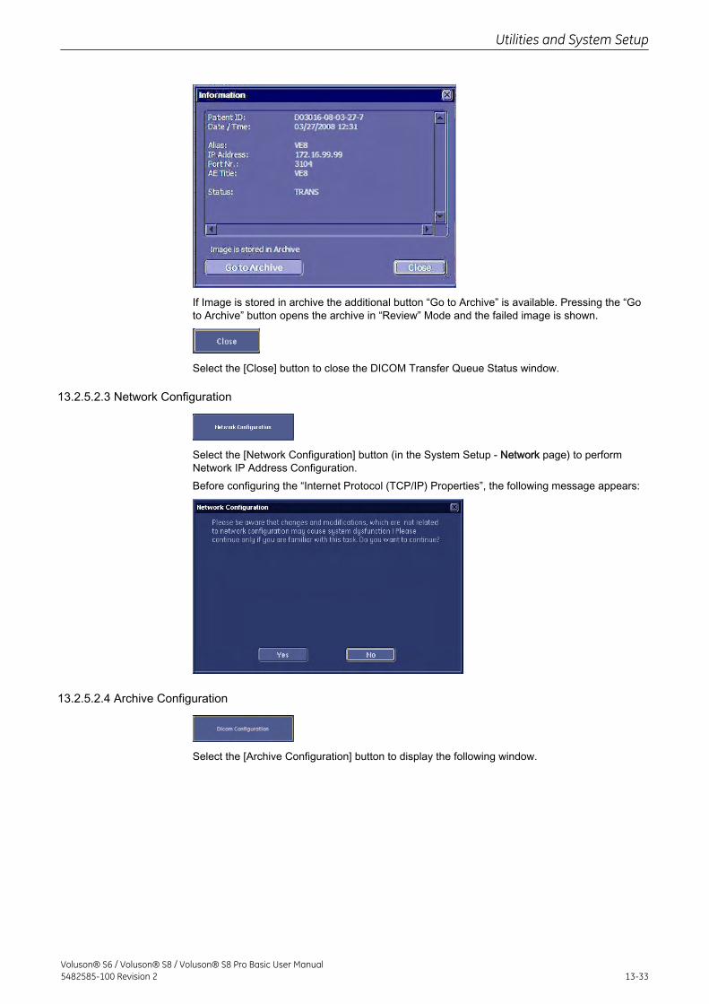
If Image is stored in archive the additional button “Go to Archive” is available. Pressing the “Goto Archive” button opens the archive in “Review” Mode and the failed image is shown.
Select the [Close] button to close the DICOM Transfer Queue Status window.
13.2.5.2.3 Network Configuration
Select the [Network Configuration] button (in the System Setup - Network page) to performNetwork IP Address Configuration.Before configuring the “Internet Protocol (TCP/IP) Properties”, the following message appears:
13.2.5.2.4 Archive Configuration
Select the [Archive Configuration] button to display the following window.
Utilities and System Setup
Voluson® S6 / Voluson® S8 / Voluson® S8 Pro Basic User Manual5482585-100 Revision 2 13-33
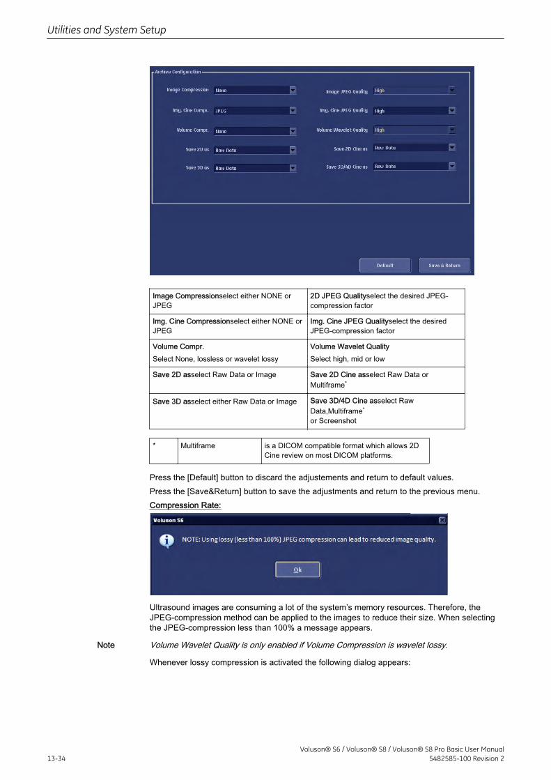
Image Compressionselect either NONE orJPEG
2D JPEG Qualityselect the desired JPEG-compression factor
Img. Cine Compressionselect either NONE orJPEG
Img. Cine JPEG Qualityselect the desiredJPEG-compression factor
Volume Compr.Select None, lossless or wavelet lossy
Volume Wavelet QualitySelect high, mid or low
Save 2D asselect Raw Data or Image Save 2D Cine asselect Raw Data orMultiframe*
Save 3D asselect either Raw Data or Image Save 3D/4D Cine asselect RawData,Multiframe*
or Screenshot
* Multiframe is a DICOM compatible format which allows 2DCine review on most DICOM platforms.
Press the [Default] button to discard the adjustements and return to default values.Press the [Save&Return] button to save the adjustments and return to the previous menu.Compression Rate:
Ultrasound images are consuming a lot of the system’s memory resources. Therefore, theJPEG-compression method can be applied to the images to reduce their size. When selectingthe JPEG-compression less than 100% a message appears.
Note Volume Wavelet Quality is only enabled if Volume Compression is wavelet lossy.
Whenever lossy compression is activated the following dialog appears:
Utilities and System Setup
13-34Voluson® S6 / Voluson® S8 / Voluson® S8 Pro Basic User Manual
5482585-100 Revision 2
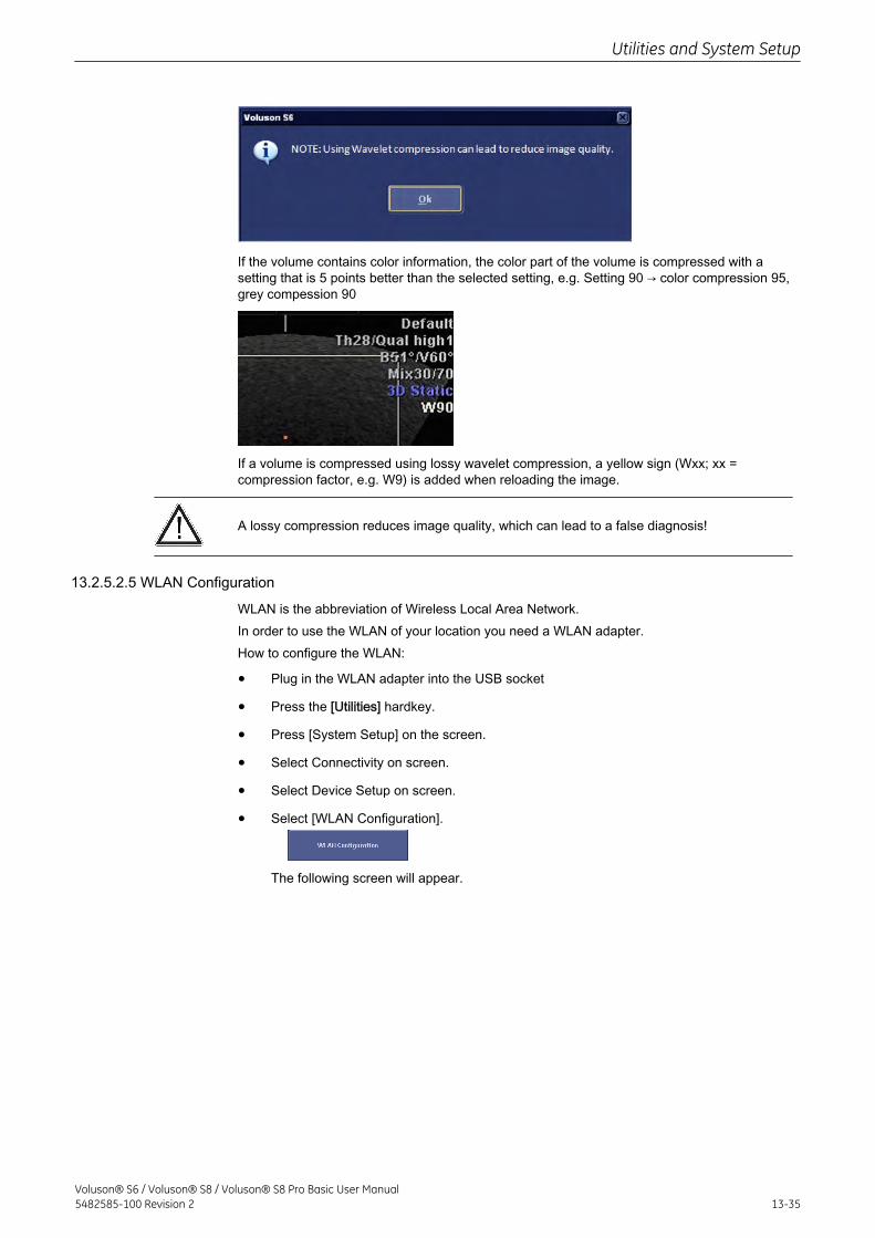
If the volume contains color information, the color part of the volume is compressed with asetting that is 5 points better than the selected setting, e.g. Setting 90 → color compression 95,grey compession 90
If a volume is compressed using lossy wavelet compression, a yellow sign (Wxx; xx =compression factor, e.g. W9) is added when reloading the image.
A lossy compression reduces image quality, which can lead to a false diagnosis!
13.2.5.2.5 WLAN Configuration
WLAN is the abbreviation of Wireless Local Area Network.In order to use the WLAN of your location you need a WLAN adapter.How to configure the WLAN:
• Plug in the WLAN adapter into the USB socket
• Press the [Utilities] hardkey.
• Press [System Setup] on the screen.
• Select Connectivity on screen.
• Select Device Setup on screen.
• Select [WLAN Configuration].
The following screen will appear.
Utilities and System Setup
Voluson® S6 / Voluson® S8 / Voluson® S8 Pro Basic User Manual5482585-100 Revision 2 13-35
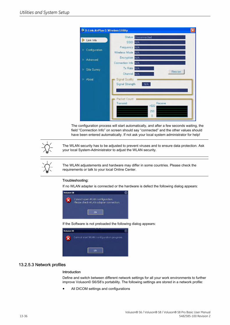
The configuration process will start automatically, and after a few seconds waiting, thefield “Connection Info” on screen should say “connected” and the other values shouldhave been entered automatically. If not ask your local system administrator for help!
The WLAN security has to be adjusted to prevent viruses and to ensure data protection. Askyour local System-Administrator to adjust the WLAN security.
The WLAN adjustements and hardware may differ in some countries. Please check therequirements or talk to your local Online Center.
Troubleshooting:If no WLAN adapter is connected or the hardware is defect the following dialog appears:
If the Software is not preloaded the following dialog appears:
13.2.5.3 Network profilesIntroductionDefine and switch between different network settings for all your work environments to furtherimprove Voluson© S6/S8’s portability. The following settings are stored in a network profile:
• All DICOM settings and configurations
Utilities and System Setup
13-36Voluson® S6 / Voluson® S8 / Voluson® S8 Pro Basic User Manual
5482585-100 Revision 2
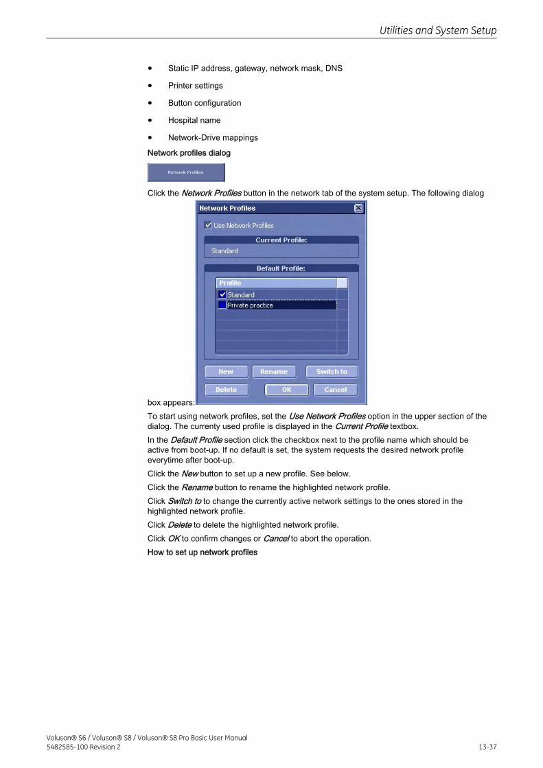
• Static IP address, gateway, network mask, DNS
• Printer settings
• Button configuration
• Hospital name
• Network-Drive mappings
Network profiles dialog
Click the Network Profiles button in the network tab of the system setup. The following dialog
box appears:To start using network profiles, set the Use Network Profiles option in the upper section of thedialog. The currenty used profile is displayed in the Current Profile textbox.In the Default Profile section click the checkbox next to the profile name which should beactive from boot-up. If no default is set, the system requests the desired network profileeverytime after boot-up.Click the New button to set up a new profile. See below.Click the Rename button to rename the highlighted network profile.Click Switch to to change the currently active network settings to the ones stored in thehighlighted network profile.Click Delete to delete the highlighted network profile.Click OK to confirm changes or Cancel to abort the operation.How to set up network profiles
Utilities and System Setup
Voluson® S6 / Voluson® S8 / Voluson® S8 Pro Basic User Manual5482585-100 Revision 2 13-37
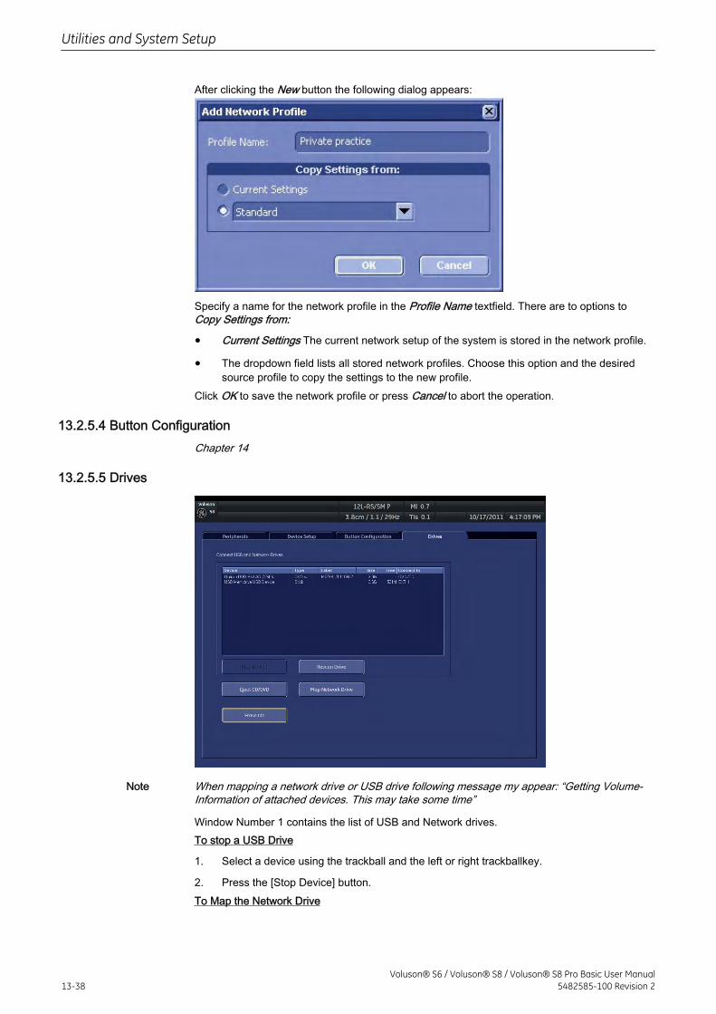
After clicking the New button the following dialog appears:
Specify a name for the network profile in the Profile Name textfield. There are to options toCopy Settings from:
• Current Settings The current network setup of the system is stored in the network profile.
• The dropdown field lists all stored network profiles. Choose this option and the desiredsource profile to copy the settings to the new profile.
Click OK to save the network profile or press Cancel to abort the operation.
13.2.5.4 Button ConfigurationChapter 14
13.2.5.5 Drives
Note When mapping a network drive or USB drive following message my appear: “Getting Volume-Information of attached devices. This may take some time”
Window Number 1 contains the list of USB and Network drives.To stop a USB Drive
1. Select a device using the trackball and the left or right trackballkey.
2. Press the [Stop Device] button.To Map the Network Drive
Utilities and System Setup
13-38Voluson® S6 / Voluson® S8 / Voluson® S8 Pro Basic User Manual
5482585-100 Revision 2
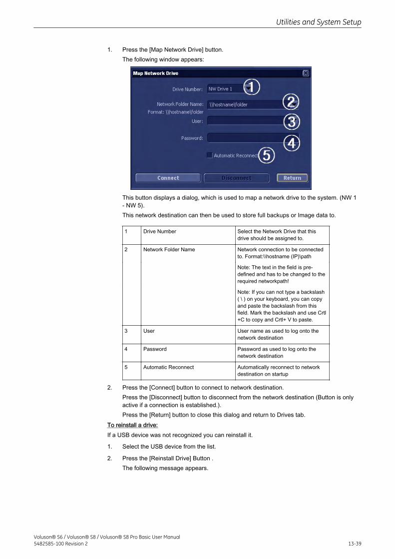
1. Press the [Map Network Drive] button.The following window appears:
This button displays a dialog, which is used to map a network drive to the system. (NW 1- NW 5).This network destination can then be used to store full backups or Image data to.
1 Drive Number Select the Network Drive that thisdrive should be assigned to.
2 Network Folder Name Network connection to be connectedto. Format:\\hostname (IP)\path
Note: The text in the field is pre-defined and has to be changed to therequired networkpath!
Note: If you can not type a backslash( \ ) on your keyboard, you can copyand paste the backslash from thisfield. Mark the backslash and use Crtl+C to copy and Crtl+ V to paste.
3 User User name as used to log onto thenetwork destination
4 Password Password as used to log onto thenetwork destination
5 Automatic Reconnect Automatically reconnect to networkdestination on startup
2. Press the [Connect] button to connect to network destination.Press the [Disconnect] button to disconnect from the network destination (Button is onlyactive if a connection is established.).Press the [Return] button to close this dialog and return to Drives tab.
To reinstall a drive:If a USB device was not recognized you can reinstall it.
1. Select the USB device from the list.
2. Press the [Reinstall Drive] Button .The following message appears.
Utilities and System Setup
Voluson® S6 / Voluson® S8 / Voluson® S8 Pro Basic User Manual5482585-100 Revision 2 13-39
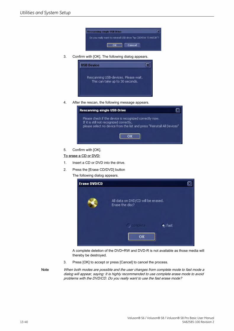
3. Confirm with [OK]. The following dialog appears.
4. After the rescan, the following message appears.
5. Confirm with [OK].To erase a CD or DVD:
1. Insert a CD or DVD into the drive.
2. Press the [Erase CD/DVD] buttonThe following dialog appears.
A complete deletion of the DVD+RW and DVD-R is not available as those media willthereby be destroyed.
3. Press [OK] to accept or press [Cancel] to cancel the process.
Note When both modes are possible and the user changes from complete mode to fast mode adialog will appear, saying: It is highly recommended to use complete erase mode to avoidproblems with the DVD/CD. Do you really want to use the fast erase mode?
Utilities and System Setup
13-40Voluson® S6 / Voluson® S8 / Voluson® S8 Pro Basic User Manual
5482585-100 Revision 2
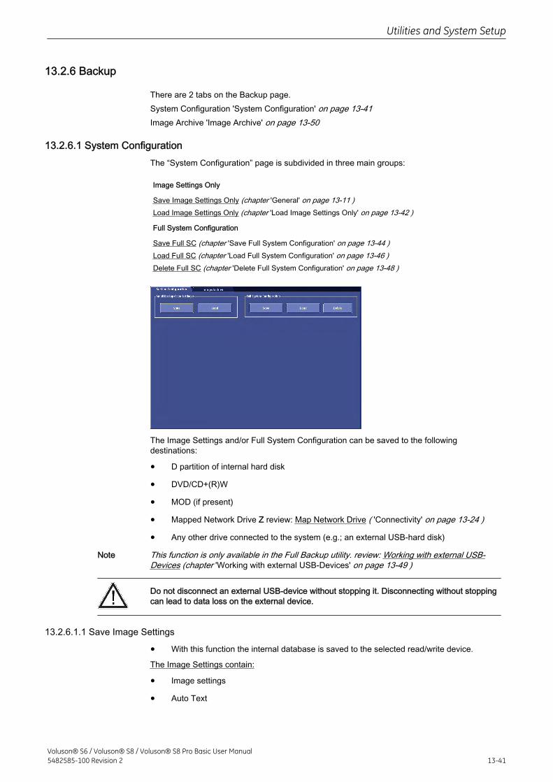
13.2.6 Backup
There are 2 tabs on the Backup page.System Configuration 'System Configuration' on page 13-41Image Archive 'Image Archive' on page 13-50
13.2.6.1 System ConfigurationThe “System Configuration” page is subdivided in three main groups:
Image Settings Only
Save Image Settings Only (chapter 'General' on page 13-11 )Load Image Settings Only (chapter 'Load Image Settings Only' on page 13-42 )
Full System Configuration
Save Full SC (chapter 'Save Full System Configuration' on page 13-44 )Load Full SC (chapter 'Load Full System Configuration' on page 13-46 )Delete Full SC (chapter 'Delete Full System Configuration' on page 13-48 )
The Image Settings and/or Full System Configuration can be saved to the followingdestinations:
• D partition of internal hard disk
• DVD/CD+(R)W
• MOD (if present)
• Mapped Network Drive Z review: Map Network Drive ( 'Connectivity' on page 13-24 )
• Any other drive connected to the system (e.g.; an external USB-hard disk)
Note This function is only available in the Full Backup utility. review: Working with external USB-Devices (chapter 'Working with external USB-Devices' on page 13-49 )
Do not disconnect an external USB-device without stopping it. Disconnecting without stoppingcan lead to data loss on the external device.
13.2.6.1.1 Save Image Settings
• With this function the internal database is saved to the selected read/write device.
The Image Settings contain:
• Image settings
• Auto Text
Utilities and System Setup
Voluson® S6 / Voluson® S8 / Voluson® S8 Pro Basic User Manual5482585-100 Revision 2 13-41
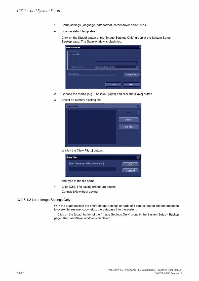
• Setup settings (language, date format, screensaver on/off, etc.)
• Scan assistant templates
1. Click on the [Save] button of the “Image Settings Only” group in the System Setup -Backup page. The Save window is displayed.
2. Choose the media (e.g., DVD/CD+(R)W) and click the [Save] button.
3. Select an already existing file.
or click the [New File...] button.
and type in the file name.
4. Click [OK]. The saving procedure begins.Cancel: Exit without saving.
13.2.6.1.2 Load Image Settings Only
With the Load function the entire Image Settings or parts of it can be loaded into the databaseto overwrite, restore, copy, etc... the database into the system.1. Click on the [Load] button of the “Image Settings Only” group in the System Setup - Backuppage. The Load/Save window is displayed.
Utilities and System Setup
13-42Voluson® S6 / Voluson® S8 / Voluson® S8 Pro Basic User Manual
5482585-100 Revision 2
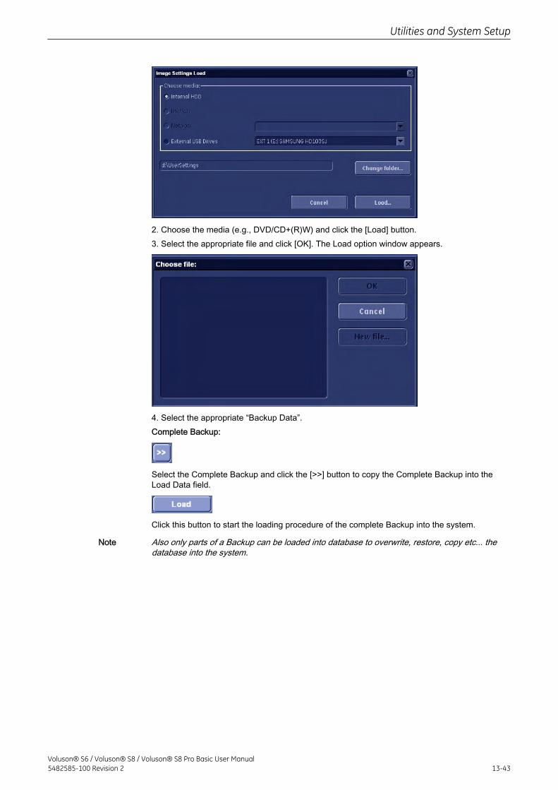
2. Choose the media (e.g., DVD/CD+(R)W) and click the [Load] button.3. Select the appropriate file and click [OK]. The Load option window appears.
4. Select the appropriate “Backup Data”.Complete Backup:
Select the Complete Backup and click the [>>] button to copy the Complete Backup into theLoad Data field.
Click this button to start the loading procedure of the complete Backup into the system.
Note Also only parts of a Backup can be loaded into database to overwrite, restore, copy etc... thedatabase into the system.
Utilities and System Setup
Voluson® S6 / Voluson® S8 / Voluson® S8 Pro Basic User Manual5482585-100 Revision 2 13-43
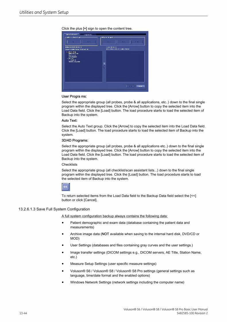
Click the plus [+] sign to open the content tree.
User Progra ms:Select the appropriate group (all probes, probe & all applications, etc..) down to the final singleprogram within the displayed tree. Click the [Arrow] button to copy the selected item into theLoad Data field. Click the [Load] button. The load procedure starts to load the selected item ofBackup into the system.Auto Text:Select the Auto Text group. Click the [Arrow] to copy the selected item into the Load Data field.Click the [Load] button. The load procedure starts to load the selected item of Backup into thesystem.3D/4D Programs:Select the appropriate group (all probes, probe & all applications etc..) down to the final singleprogram within the displayed tree. Click the [Arrow] button to copy the selected item into theLoad Data field. Click the [Load] button. The load procedure starts to load the selected item ofBackup into the system.ChecklistsSelect the appropriate group (all checklist/scan assistant lists...) down to the final singleprogram within the displayed tree. Click the [Load] button. The load procedure starts to loadthe selected item of Backup into the system.
To return selected items from the Load Data field to the Backup Data field select the [<<]button or click [Cancel].
13.2.6.1.3 Save Full System Configuration
A full system configuration backup always contains the following data:
• Patient demographic and exam data (database containing the patient data andmeasurements)
• Archive image data (NOT available when saving to the internal hard disk, DVD/CD orMOD)
• User Settings (databases and files containing gray curves and the user settings.)
• Image transfer settings (DICOM settings e.g., DICOM servers, AE Title, Station Name,etc.)
• Measure Setup Settings (user specific measure settings)
• Voluson® S6 / Voluson® S8 / Voluson® S8 Pro settings (general settings such aslanguage, time/date format and the enabled options)
• Windows Network Settings (network settings including the computer name)
Utilities and System Setup
13-44Voluson® S6 / Voluson® S8 / Voluson® S8 Pro Basic User Manual
5482585-100 Revision 2
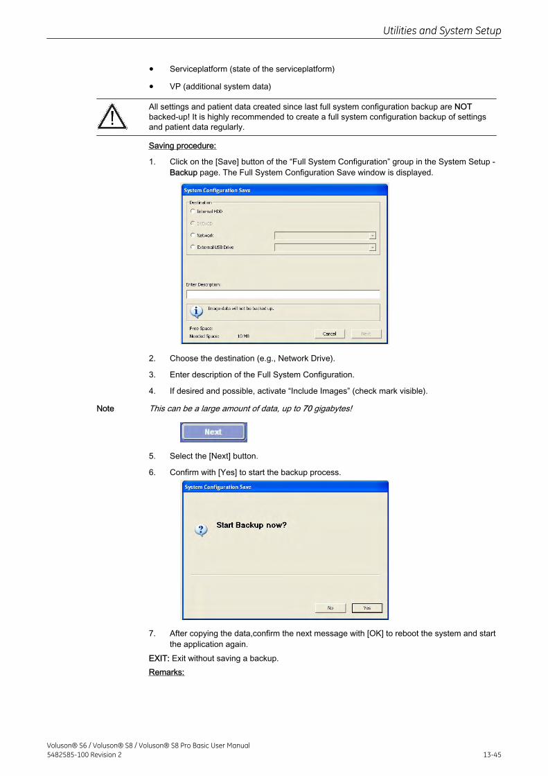
• Serviceplatform (state of the serviceplatform)
• VP (additional system data)
All settings and patient data created since last full system configuration backup are NOTbacked-up! It is highly recommended to create a full system configuration backup of settingsand patient data regularly.
Saving procedure:
1. Click on the [Save] button of the “Full System Configuration” group in the System Setup -Backup page. The Full System Configuration Save window is displayed.
2. Choose the destination (e.g., Network Drive).
3. Enter description of the Full System Configuration.
4. If desired and possible, activate “Include Images” (check mark visible).
Note This can be a large amount of data, up to 70 gigabytes!
5. Select the [Next] button.
6. Confirm with [Yes] to start the backup process.
7. After copying the data,confirm the next message with [OK] to reboot the system and startthe application again.
EXIT: Exit without saving a backup.Remarks:
Utilities and System Setup
Voluson® S6 / Voluson® S8 / Voluson® S8 Pro Basic User Manual5482585-100 Revision 2 13-45
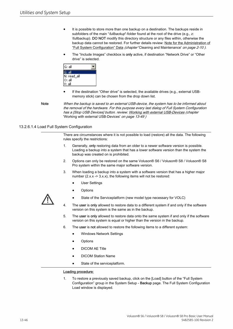
• It is possible to store more than one backup on a destination. The backups reside insubfolders of the main “fullbackup”-folder found at the root of the drive (e.g., z:\fullbackup). DO NOT modify this directory structure or any files within, otherwise thebackup data cannot be restored. For further details review: Note for the Administration of“Full System Configuration” Data (chapter 'Cleaning and Maintenance' on page 2-10 ).
• The “Include Images” checkbox is only active, if destination “Network Drive” or “Otherdrive” is selected.
• If the destination “Other drive” is selected, the available drives (e.g., external USB-memory stick) can be chosen from the drop down list.
Note When the backup is saved to an external USB-device, the system has to be informed aboutthe removal of the hardware. For this purpose every last dialog of Full System Configurationhas a [Stop USB Devices] button. review: Working with external USB-Devices (chapter'Working with external USB-Devices' on page 13-49 )
13.2.6.1.4 Load Full System Configuration
There are circumstances where it is not possible to load (restore) all the data. The followingrules specify the restrictions:
1. Generally, only restoring data from an older to a newer software version is possible.Loading a backup into a system that has a lower software version than the system thebackup was created on is prohibited.
2. Options can only be restored on the same Voluson® S6 / Voluson® S8 / Voluson® S8Pro system within the same major software version.
3. When loading a backup into a system with a software version that has a higher majornumber (2.x.x -> 3.x.x), the following items will not be restored:
• User Settings
• Options
• State of the Serviceplatform (new model type necessary for VOLC)
4. The user is only allowed to restore data to a different system if and only if the softwareversion on this system is the same as in the backup.
5. The user is only allowed to restore data onto the same system if and only if the softwareversion on this system is equal or higher than the version in the backup.
6. The user is not allowed to restore the following items to a different system:
• Windows Network Settings
• Options
• DICOM AE Title
• DICOM Station Name
• State of the serviceplatform.
Loading procedure:
1. To restore a previously saved backup, click on the [Load] button of the “Full SystemConfiguration” group in the System Setup - Backup page. The Full System ConfigurationLoad window is displayed.
Utilities and System Setup
13-46Voluson® S6 / Voluson® S8 / Voluson® S8 Pro Basic User Manual
5482585-100 Revision 2
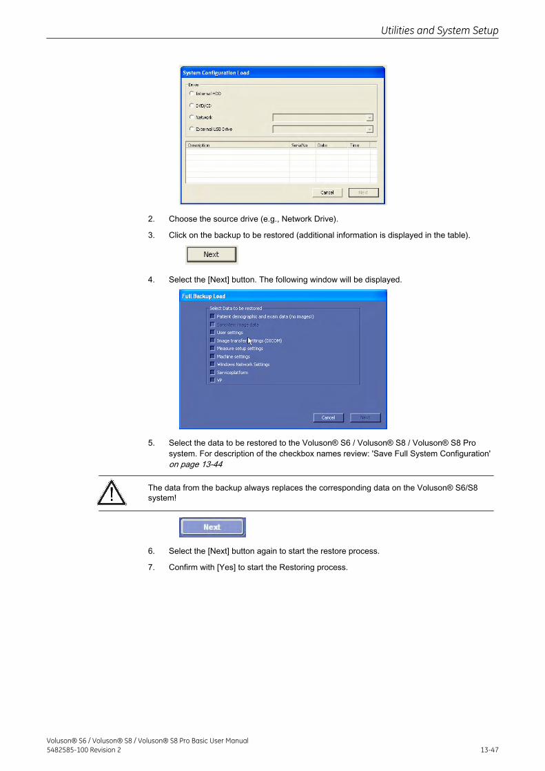
2. Choose the source drive (e.g., Network Drive).
3. Click on the backup to be restored (additional information is displayed in the table).
4. Select the [Next] button. The following window will be displayed.
5. Select the data to be restored to the Voluson® S6 / Voluson® S8 / Voluson® S8 Prosystem. For description of the checkbox names review: 'Save Full System Configuration'on page 13-44
The data from the backup always replaces the corresponding data on the Voluson® S6/S8system!
6. Select the [Next] button again to start the restore process.
7. Confirm with [Yes] to start the Restoring process.
Utilities and System Setup
Voluson® S6 / Voluson® S8 / Voluson® S8 Pro Basic User Manual5482585-100 Revision 2 13-47
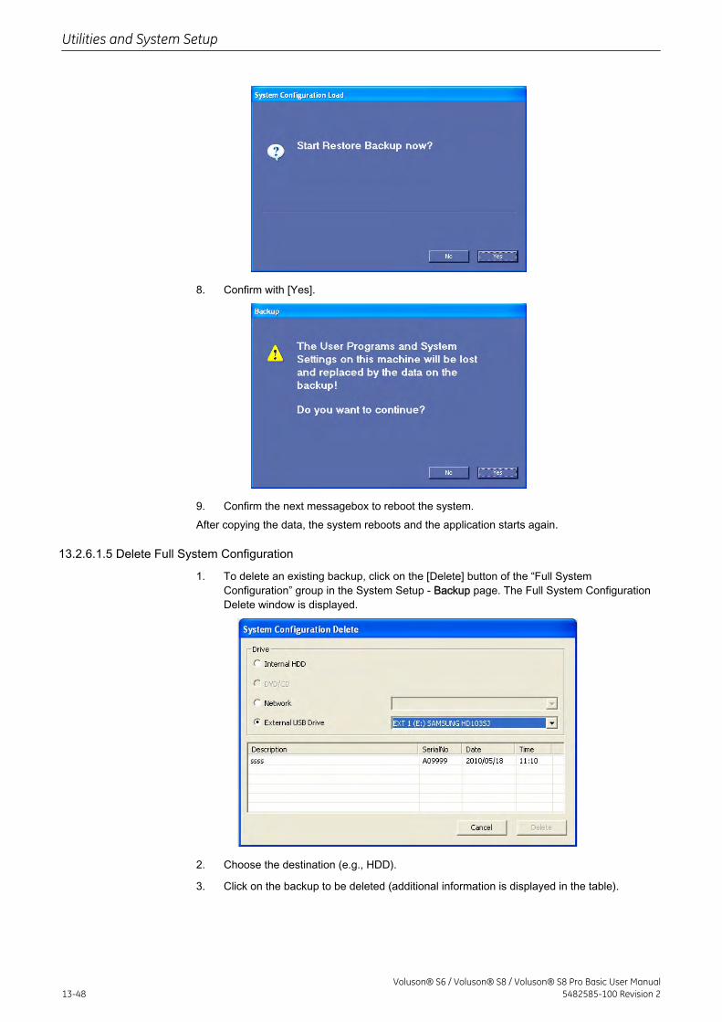
8. Confirm with [Yes].
9. Confirm the next messagebox to reboot the system.After copying the data, the system reboots and the application starts again.
13.2.6.1.5 Delete Full System Configuration
1. To delete an existing backup, click on the [Delete] button of the “Full SystemConfiguration” group in the System Setup - Backup page. The Full System ConfigurationDelete window is displayed.
2. Choose the destination (e.g., HDD).
3. Click on the backup to be deleted (additional information is displayed in the table).
Utilities and System Setup
13-48Voluson® S6 / Voluson® S8 / Voluson® S8 Pro Basic User Manual
5482585-100 Revision 2
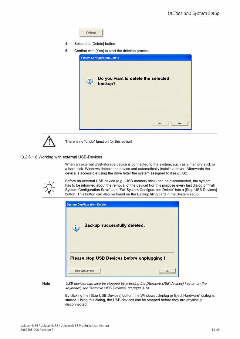
4. Select the [Delete] button.
5. Confirm with [Yes] to start the deletion process.
There is no “undo” function for this action!
13.2.6.1.6 Working with external USB-Devices
When an external USB-storage device is connected to the system, such as a memory stick ora hard disk, Windows detects the device and automatically installs a driver. Afterwards thedevice is accessible using the drive letter the system assigned to it (e.g., G:).
Before an external USB-device (e.g., USB-memory stick) can be disconnected, the systemhas to be informed about the removal of the device! For this purpose every last dialog of “FullSystem Configuration Save” and “Full System Configuration Delete” has a [Stop USB Devices]button. This button can also be found on the Backup filing card in the System setup.
Note USB devices can also be stopped by pressing the [Remove USB devices] key on on thekeyboard, see 'Remove USB Devices' on page 3-14.
By clicking the [Stop USB Devices] button, the Windows „Unplug or Eject Hardware“ dialog isstarted. Using this dialog, the USB-devices can be stopped before they are physicallydisconnected.
Utilities and System Setup
Voluson® S6 / Voluson® S8 / Voluson® S8 Pro Basic User Manual5482585-100 Revision 2 13-49
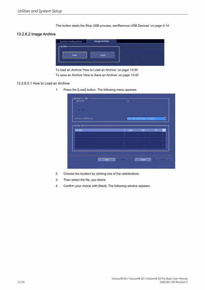
This button starts the Stop USB process, see'Remove USB Devices' on page 3-14
13.2.6.2 Image Archive
To load an Archive 'How to Load an Archive' on page 13-50To save an Archive 'How to Save an Archive' on page 13-52
13.2.6.2.1 How to Load an Archive
1. Press the [Load] button. The following menu appears:
2. Choose the location by clicking one of the radiobuttons.
3. Then select the file, you desire.
4. Confirm your choice with [Next]. The following window appears.
Utilities and System Setup
13-50Voluson® S6 / Voluson® S8 / Voluson® S8 Pro Basic User Manual
5482585-100 Revision 2
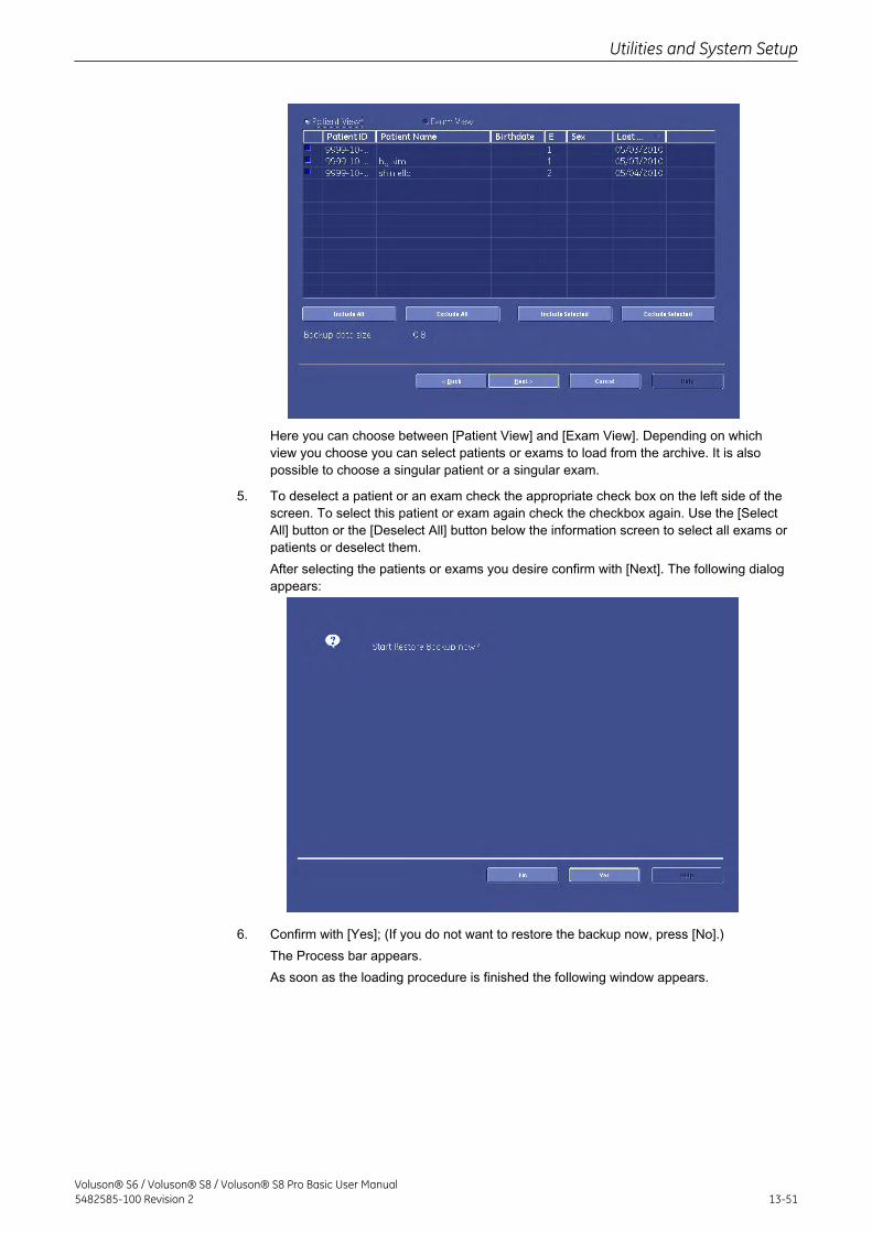
Here you can choose between [Patient View] and [Exam View]. Depending on whichview you choose you can select patients or exams to load from the archive. It is alsopossible to choose a singular patient or a singular exam.
5. To deselect a patient or an exam check the appropriate check box on the left side of thescreen. To select this patient or exam again check the checkbox again. Use the [SelectAll] button or the [Deselect All] button below the information screen to select all exams orpatients or deselect them.After selecting the patients or exams you desire confirm with [Next]. The following dialogappears:
6. Confirm with [Yes]; (If you do not want to restore the backup now, press [No].)The Process bar appears.As soon as the loading procedure is finished the following window appears.
Utilities and System Setup
Voluson® S6 / Voluson® S8 / Voluson® S8 Pro Basic User Manual5482585-100 Revision 2 13-51
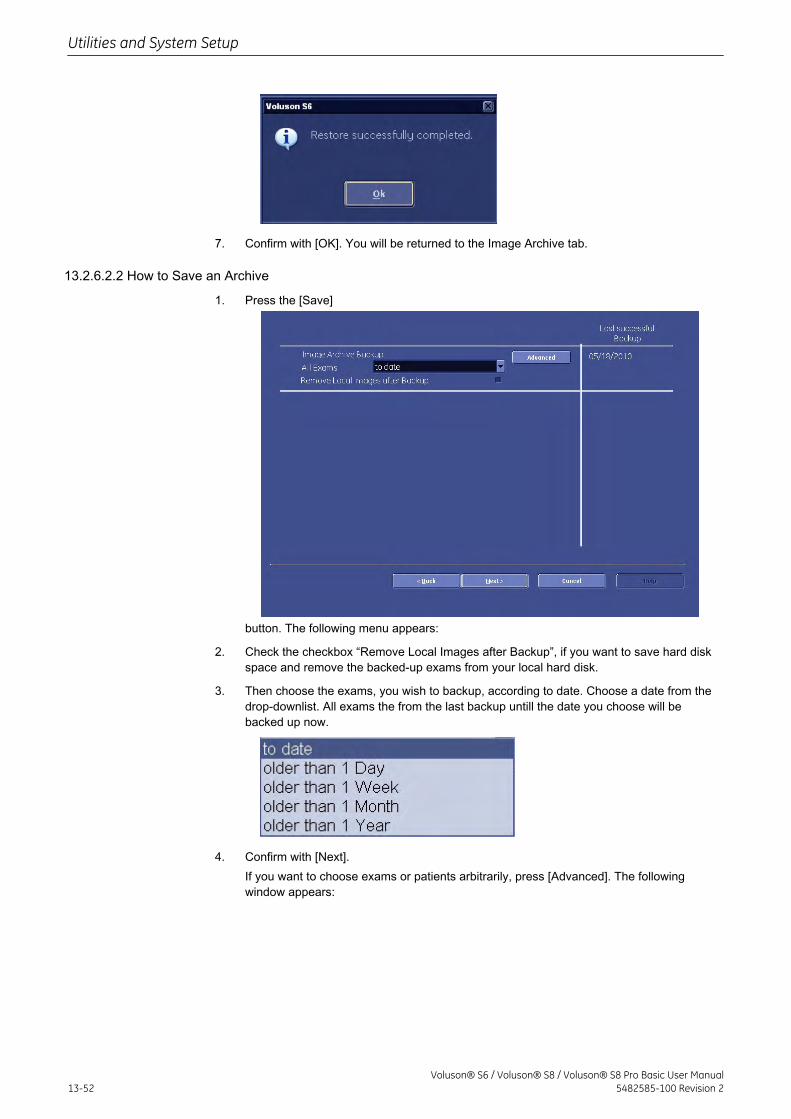
7. Confirm with [OK]. You will be returned to the Image Archive tab.
13.2.6.2.2 How to Save an Archive
1. Press the [Save]
button. The following menu appears:
2. Check the checkbox “Remove Local Images after Backup”, if you want to save hard diskspace and remove the backed-up exams from your local hard disk.
3. Then choose the exams, you wish to backup, according to date. Choose a date from thedrop-downlist. All exams the from the last backup untill the date you choose will bebacked up now.
4. Confirm with [Next].If you want to choose exams or patients arbitrarily, press [Advanced]. The followingwindow appears:
Utilities and System Setup
13-52Voluson® S6 / Voluson® S8 / Voluson® S8 Pro Basic User Manual
5482585-100 Revision 2
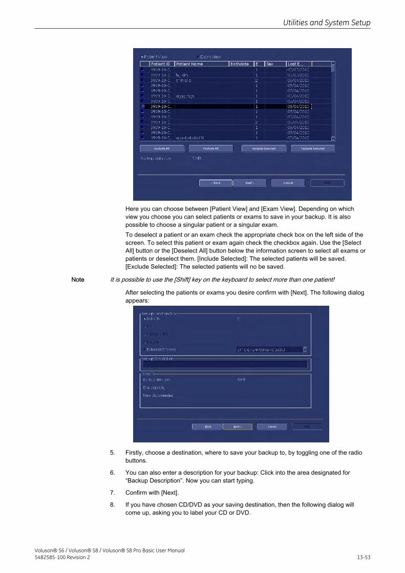
Here you can choose between [Patient View] and [Exam View]. Depending on whichview you choose you can select patients or exams to save in your backup. It is alsopossible to choose a singular patient or a singular exam.To deselect a patient or an exam check the appropriate check box on the left side of thescreen. To select this patient or exam again check the checkbox again. Use the [SelectAll] button or the [Deselect All] button below the information screen to select all exams orpatients or deselect them. [Include Selected]: The selected patients will be saved.[Exclude Selected]: The selected patients will no be saved.
Note It is possible to use the [Shift] key on the keyboard to select more than one patient!
After selecting the patients or exams you desire confirm with [Next]. The following dialogappears:
5. Firstly, choose a destination, where to save your backup to, by toggling one of the radiobuttons.
6. You can also enter a description for your backup: Click into the area designated for“Backup Description”. Now you can start typing.
7. Confirm with [Next].
8. If you have chosen CD/DVD as your saving destination, then the following dialog willcome up, asking you to label your CD or DVD.
Utilities and System Setup
Voluson® S6 / Voluson® S8 / Voluson® S8 Pro Basic User Manual5482585-100 Revision 2 13-53
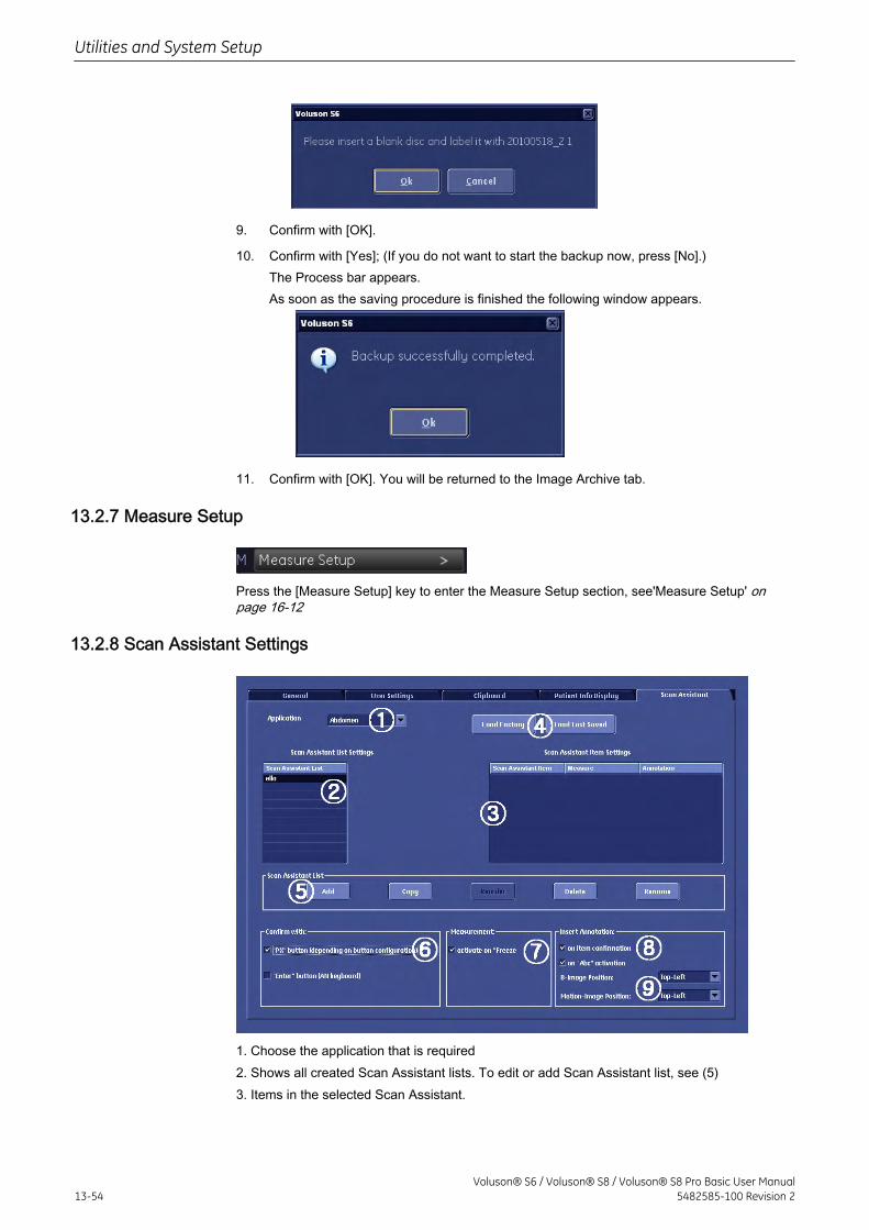
9. Confirm with [OK].
10. Confirm with [Yes]; (If you do not want to start the backup now, press [No].)The Process bar appears.As soon as the saving procedure is finished the following window appears.
11. Confirm with [OK]. You will be returned to the Image Archive tab.
13.2.7 Measure Setup
Press the [Measure Setup] key to enter the Measure Setup section, see'Measure Setup' onpage 16-12
13.2.8 Scan Assistant Settings
1. Choose the application that is required2. Shows all created Scan Assistant lists. To edit or add Scan Assistant list, see (5)3. Items in the selected Scan Assistant.
Utilities and System Setup
13-54Voluson® S6 / Voluson® S8 / Voluson® S8 Pro Basic User Manual
5482585-100 Revision 2
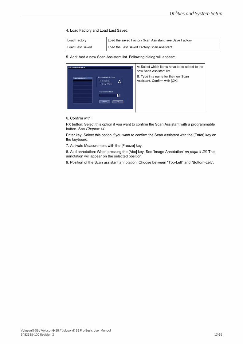
4. Load Factory and Load Last Saved:
Load Factory Load the saved Factory Scan Assistant, see Save Factory
Load Last Saved Load the Last Saved Factory Scan Assistant
5. Add: Add a new Scan Assistant list. Following dialog will appear:
A: Select which items have to be added to thenew Scan Assistant list.B: Type in a name for the new ScanAssistant. Confirm with [OK].
6. Confirm with:PX button: Select this option if you want to confirm the Scan Assistant with a programmablebutton. See Chapter 14.Enter key: Select this option if you want to confirm the Scan Assistant with the [Enter] key onthe keyboard.7. Activate Measurement with the [Freeze] key.8. Add annotation: When pressing the [Abc] key. See 'Image Annotation' on page 4-26. Theannotation will appear on the selected position.9. Position of the Scan assistant annotation. Choose between “Top-Left” and “Bottom-Left”.
Utilities and System Setup
Voluson® S6 / Voluson® S8 / Voluson® S8 Pro Basic User Manual5482585-100 Revision 2 13-55

This page was intentionally left blank.
Utilities and System Setup
13-56Voluson® S6 / Voluson® S8 / Voluson® S8 Pro Basic User Manual
5482585-100 Revision 2

Chapter 14
Programmable Keys
Describes the general function of the programmable keys.
Voluson® S6 / Voluson® S8 / Voluson® S8 Pro Basic User Manual5482585-100 Revision 2 14-1
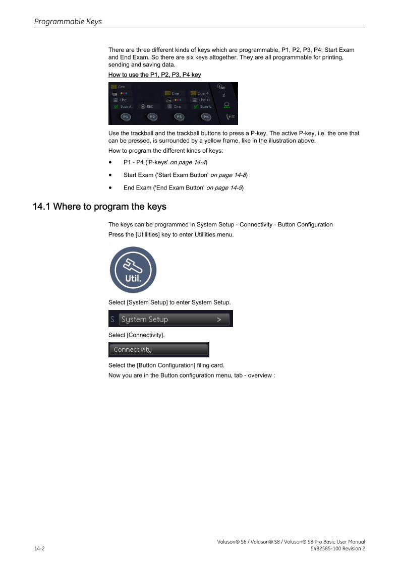
There are three different kinds of keys which are programmable, P1, P2, P3, P4; Start Examand End Exam. So there are six keys altogether. They are all programmable for printing,sending and saving data.How to use the P1, P2, P3, P4 key
Use the trackball and the trackball buttons to press a P-key. The active P-key, i.e. the one thatcan be pressed, is surrounded by a yellow frame, like in the illustration above.How to program the different kinds of keys:
• P1 - P4 ('P-keys' on page 14-4)
• Start Exam ('Start Exam Button' on page 14-8)
• End Exam ('End Exam Button' on page 14-9)
14.1 Where to program the keys
The keys can be programmed in System Setup - Connectivity - Button ConfigurationPress the [Utillities] key to enter Utillities menu.
Select [System Setup] to enter System Setup.
Select [Connectivity].
Select the [Button Configuration] filing card.Now you are in the Button configuration menu, tab - overview :
Programmable Keys
14-2Voluson® S6 / Voluson® S8 / Voluson® S8 Pro Basic User Manual
5482585-100 Revision 2
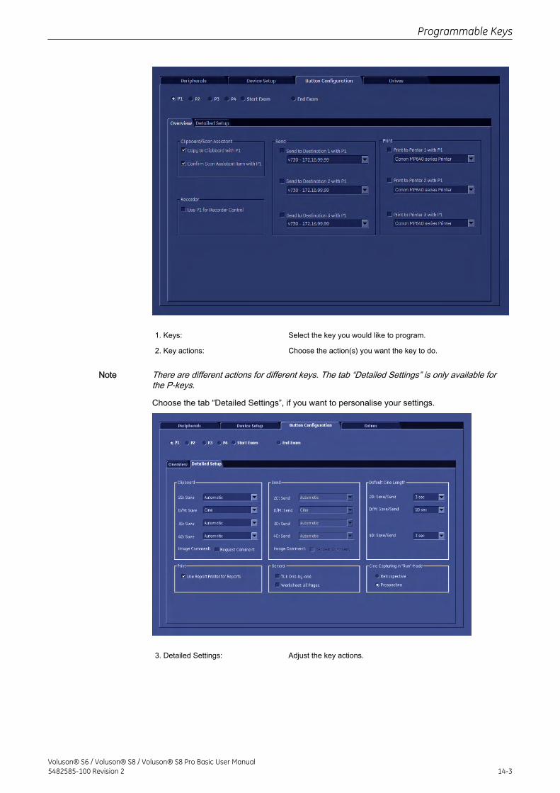
1. Keys: Select the key you would like to program.
2. Key actions: Choose the action(s) you want the key to do.
Note There are different actions for different keys. The tab “Detailed Settings” is only available forthe P-keys.
Choose the tab “Detailed Settings”, if you want to personalise your settings.
3. Detailed Settings: Adjust the key actions.
Programmable Keys
Voluson® S6 / Voluson® S8 / Voluson® S8 Pro Basic User Manual5482585-100 Revision 2 14-3
14.2 P-keys
There are 4 different actions which can be programmed onto a P-key. Each P-key (P1-P4) canbe programmed to perform several actions, except when you choose “4. Record on an DVRRecorder”.
1. Save to Clipboard:If the P-Button is configured to save the image to the clipboard, the current image or cine(depending on the settings in the button configuration page) is moved to the clipboard.The format of th estored file can be configured in System Setup - Archive Configurationpage, see 'Connectivity' on page 13-24.
2. Send:If the P Button is configured to send the image to a DICOM destination, the currentimage or cine is sent to a DICOM server. In this case a separate association is used foreach image. (If the images are sent on end exam, a single association is used for allimages.No image is moved to the clipboard (except when the P Button is configured to save aswell).The format of the stored file can be configured for each destination separately in theSystem Setup - DICOM Configuration page, see'Connectivity' on page 13-24If the P Button is pressed in write mode, the system continues in write mode, after thefiles have been added to the DICOM queue.Send warning:If DICOM send jobs are marked as "failed" in the DICOM queue following temporarymessage is displayed in the message area:
Note If DICOM spooler is opened and closed the message will be shown again when a new job failsto send
3. Print:Images can be printed on various printers: USB or Video Printers, DICOM printers.Depending on format configuration DICOM images are intermediately stored until awhole page is filled and then printed automatically.
Note There will be no DICOM print dialog!
If the P-Button is pressed in write mode, the system will continue in write mode, after thefiles have been added to the DICOM queue, have been printed or stored.
4. Record on an DVR Recorder:
Note No other action can be programmed onto a P-key simultaneously with “Record on an DVRRecorderR
Note When a DVD reached its maximum capacity a warning message will appear on the screen:DVD full, please change. In this case change the DVD to a new, blank one! : Supportedformat : DVD+RW only.
5. DVR Menu:
Programmable Keys
14-4Voluson® S6 / Voluson® S8 / Voluson® S8 Pro Basic User Manual
5482585-100 Revision 2
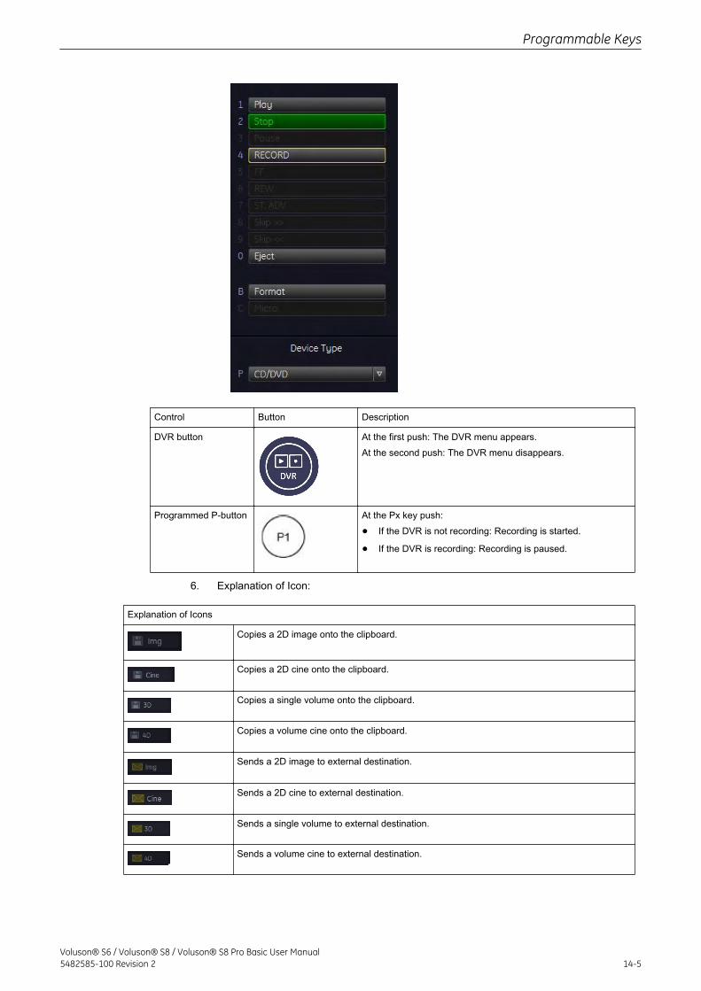
Control Button Description
DVR button At the first push: The DVR menu appears.At the second push: The DVR menu disappears.
Programmed P-button At the Px key push:
• If the DVR is not recording: Recording is started.
• If the DVR is recording: Recording is paused.
6. Explanation of Icon:
Explanation of Icons
Copies a 2D image onto the clipboard.
Copies a 2D cine onto the clipboard.
Copies a single volume onto the clipboard.
Copies a volume cine onto the clipboard.
Sends a 2D image to external destination.
Sends a 2D cine to external destination.
Sends a single volume to external destination.
Sends a volume cine to external destination.
Programmable Keys
Voluson® S6 / Voluson® S8 / Voluson® S8 Pro Basic User Manual5482585-100 Revision 2 14-5
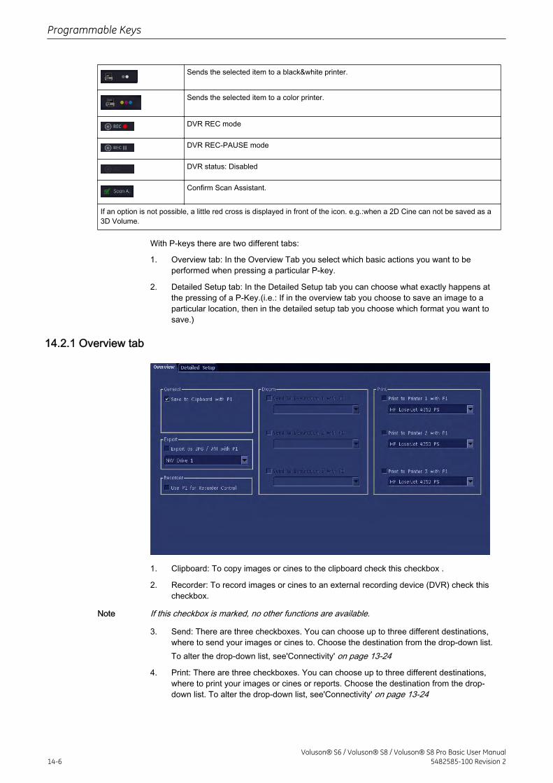
Sends the selected item to a black&white printer.
Sends the selected item to a color printer.
DVR REC mode
DVR REC-PAUSE mode
DVR status: Disabled
Confirm Scan Assistant.
If an option is not possible, a little red cross is displayed in front of the icon. e.g.:when a 2D Cine can not be saved as a3D Volume.
With P-keys there are two different tabs:
1. Overview tab: In the Overview Tab you select which basic actions you want to beperformed when pressing a particular P-key.
2. Detailed Setup tab: In the Detailed Setup tab you can choose what exactly happens atthe pressing of a P-Key.(i.e.: If in the overview tab you choose to save an image to aparticular location, then in the detailed setup tab you choose which format you want tosave.)
14.2.1 Overview tab
1. Clipboard: To copy images or cines to the clipboard check this checkbox .
2. Recorder: To record images or cines to an external recording device (DVR) check thischeckbox.
Note If this checkbox is marked, no other functions are available.
3. Send: There are three checkboxes. You can choose up to three different destinations,where to send your images or cines to. Choose the destination from the drop-down list.To alter the drop-down list, see'Connectivity' on page 13-24
4. Print: There are three checkboxes. You can choose up to three different destinations,where to print your images or cines or reports. Choose the destination from the drop-down list. To alter the drop-down list, see'Connectivity' on page 13-24
Programmable Keys
14-6Voluson® S6 / Voluson® S8 / Voluson® S8 Pro Basic User Manual
5482585-100 Revision 2
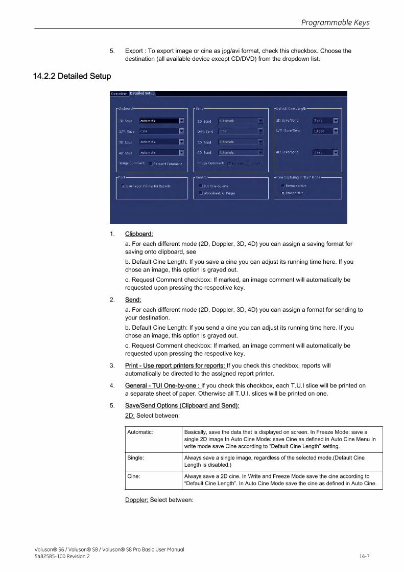
5. Export : To export image or cine as jpg/avi format, check this checkbox. Choose thedestination (all available device except CD/DVD) from the dropdown list.
14.2.2 Detailed Setup
1. Clipboard:a. For each different mode (2D, Doppler, 3D, 4D) you can assign a saving format forsaving onto clipboard, seeb. Default Cine Length: If you save a cine you can adjust its running time here. If youchose an image, this option is grayed out.c. Request Comment checkbox: If marked, an image comment will automatically berequested upon pressing the respective key.
2. Send:a. For each different mode (2D, Doppler, 3D, 4D) you can assign a format for sending toyour destination.b. Default Cine Length: If you send a cine you can adjust its running time here. If youchose an image, this option is grayed out.c. Request Comment checkbox: If marked, an image comment will automatically berequested upon pressing the respective key.
3. Print - Use report printers for reports: If you check this checkbox, reports willautomatically be directed to the assigned report printer.
4. General - TUI One-by-one : If you check this checkbox, each T.U.I slice will be printed ona separate sheet of paper. Otherwise all T.U.I. slices will be printed on one.
5. Save/Send Options (Clipboard and Send):2D: Select between:
Automatic: Basically, save the data that is displayed on screen. In Freeze Mode: save asingle 2D image In Auto Cine Mode: save Cine as defined in Auto Cine Menu Inwrite mode save Cine according to “Default Cine Length” setting.
Single: Always save a single image, regardless of the selected mode.(Default CineLength is disabled.)
Cine: Always save a 2D cine. In Write and Freeze Mode save the cine according to“Default Cine Length”. In Auto Cine Mode save the cine as defined in Auto Cine.
Doppler: Select between:
Programmable Keys
Voluson® S6 / Voluson® S8 / Voluson® S8 Pro Basic User Manual5482585-100 Revision 2 14-7
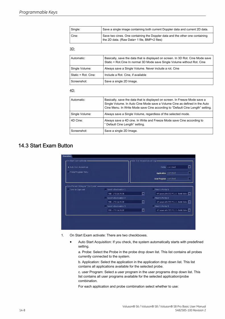
Single: Save a single image containing both current Doppler data and current 2D data.
Cine: Save two cines. One containing the Doppler data and the other one containingthe 2D data. (Raw Data= 1 file, BMP=2 files)
3D:
Automatic: Basically, save the data that is displayed on screen. In 3D Rot. Cine Mode saveStatic + Rot.Cine In normal 3D Mode save Single Volume without Rot. Cine
Single Volume: Always save a Single Volume. Never include a rot. Cine
Static + Rot. Cine: Include a Rot. Cine, if available
Screenshot: Save a single 2D Image.
4D:
Automatic: Basically, save the data that is displayed on screen. In Freeze Mode save aSingle Volume. In Auto Cine Mode save a Volume Cine as defined in the AutoCine Menu. In Write Mode save Cine according to “Default Cine Length” setting.
Single Volume: Always save a Single Volume, regardless of the selected mode.
4D Cine: Always save a 4D cine. In Write and Freeze Mode save Cine according to“ Default Cine Length” setting.
Screenshot: Save a single 2D Image.
14.3 Start Exam Button
1. On Start Exam activate: There are two checkboxes.
• Auto Start Acquisition: If you check, the system automatically starts with predefinedsetting.a. Probe: Select the Probe in the probe drop down list. This list contains all probescurrently connected to the system.b. Application: Select the application in the application drop down list. This listcontains all applications available for the selected probe.c. user Program: Select a user program in the user programs drop down list. Thislist contains all user programs available for the selected application/probecombination.For each application and probe combination select whether to use:
Programmable Keys
14-8Voluson® S6 / Voluson® S8 / Voluson® S8 Pro Basic User Manual
5482585-100 Revision 2
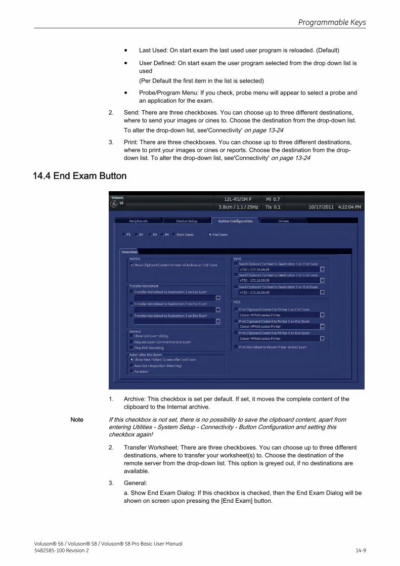
• Last Used: On start exam the last used user program is reloaded. (Default)
• User Defined: On start exam the user program selected from the drop down list isused(Per Default the first item in the list is selected)
• Probe/Program Menu: If you check, probe menu will appear to select a probe andan application for the exam.
2. Send: There are three checkboxes. You can choose up to three different destinations,where to send your images or cines to. Choose the destination from the drop-down list.To alter the drop-down list, see'Connectivity' on page 13-24
3. Print: There are three checkboxes. You can choose up to three different destinations,where to print your images or cines or reports. Choose the destination from the drop-down list. To alter the drop-down list, see'Connectivity' on page 13-24
14.4 End Exam Button
1. Archive: This checkbox is set per default. If set, it moves the complete content of theclipboard to the Internal archive.
Note If this checkbox is not set, there is no possibility to save the clipboard content, apart fromentering Utilities - System Setup - Connectivity - Button Configuration and setting thischeckbox again!
2. Transfer Worksheet: There are three checkboxes. You can choose up to three differentdestinations, where to transfer your worksheet(s) to. Choose the destination of theremote server from the drop-down list. This option is greyed out, if no destinations areavailable.
3. General:a. Show End Exam Dialog: If this checkbox is checked, then the End Exam Dialog will beshown on screen upon pressing the [End Exam] button.
Programmable Keys
Voluson® S6 / Voluson® S8 / Voluson® S8 Pro Basic User Manual5482585-100 Revision 2 14-9
Note If both checkboxes, namely “Open Review Pageon End Exam” and “Show New Patient Screenafter End Exam” are selected, then the Exam Review page will be shown first. The next step isclosing the Exam. And finally the “Current Patient” page will be displayed.
b. Request Exam Comment on End Exam: If this checkbox is checked, you will beprompted to enter an Exam Comment upon pressing the [End Exam] button.c. Show New Patient Screen after End Exam:If this checkbox is checked, an empty“Current Patient” screen is automatically opened upon pressing the [End Exam] button.
Note If both checkboxes, namely “Open Review Pageon End Exam” and “Show New Patient Screenafter End Exam” are selected, then the Exam Review page will be shown first. The next step isclosing the Exam. And finally the “Current Patient” page will be displayed.
4. Send: There are three checkboxes. You can choose up to three different destinations,where to send your images or cines to. Choose the destination from the drop-down list.To alter the drop-down list, see'Connectivity' on page 13-24
5. Print: There are three checkboxes. You can choose up to three different destinations,where to print your images or cines or reports. Choose the destination from the drop-down list. To alter the drop-down list, see'Connectivity' on page 13-24Print Worksheet to Report Printer on End Exam: If this checkbox is set, worksheets willonly be printed at an assigned report printer.
6. Actions after End Exam:a. Show new patient screen after End ExamAfter End Exam the New Patient screen will appear to start with a new patient.b. Auto Start Acquisition (New Key)After End Exam a new acquisition starts without creating a new patient.c. No Action
Programmable Keys
14-10Voluson® S6 / Voluson® S8 / Voluson® S8 Pro Basic User Manual
5482585-100 Revision 2

Chapter 15
Connections
Describes the external devices and how to install / connect them.
Voluson® S6 / Voluson® S8 / Voluson® S8 Pro Basic User Manual5482585-100 Revision 2 15-1
15.1 How to Connect Auxiliary Devices Safely
Peripherals, that have been ordered simultaneously with the Voluson® S6 / Voluson® S8 /Voluson® S8 Pro , are usually already mounted and connected. The first mounting andconnecting will usually be performed by a GE system technician.Basic Concept:Video Copy Processors (VCP) and Video tape recorders (VTR) are to be connected here asdescribed in the chapter Connections.The Voluson® S6 / Voluson® S8 / Voluson® S8 Pro provides several inputs and outputs (I/O)such as Audio, Video, Ethernet, USB, DICOM and Printer signals. Special care must be takenwhen connecting these items to other devices.The IEC 60601 standard provides a guideline for safely interconnecting medical devices insystems.“Equipment connected to the analog or digital interface must comply with the respectiveIEC/UL standards (e.g. IEC 60950/UL 60950 for data processing equipment and IEC 60601-1/UL 60601-1 for medical equipment). Furthermore, all configurations shall comply with IEC60601. Everybody who connects additional equipment to the signal input portion or signaloutput portion configures a medical system, and is therefore responsible that the systemcomplies with the requirements of IEC 60601. If in doubt, consult the technical servicedepartment or your local representative.”
1. The medical device may be connected to a single IEC XXX device (protection class I)placed in a room which is not medically used.
2. If the device is to be connected in a medically-used room the following rule applies:
• IEC 60601 compliant devices may be connected as such.
• IEC XXX compliant devices (protection class I) may be connected with anadditional safety measure.
For all situations 1 and 2, the additional device shall be installed outside the patientenvironment.Additional protective earth connection between the 2 devices, or a safety isolation mainstransformer for the other device.Special care has to be taken, if the device is connected to computer network (e.g., Ethernet),because other devices could be connected without any control. There could be a potentialdifference between the protective earth and any line of the computer network including theshield.In this case the only way to operate the system safely is to use an isolated signal link withminimum air clearance and creepage distance of the isolation device in agreement withIEC60601 incl. national deviations. For computer networks there are media convertersavailable which convert the electrical to optical signals. Please consider that this converter hasto comply with IEC xxx standards and is battery operated. review: Connector Panel (rear side)(chapter 'Connector Panels' on page 15-5 )Additionally the IEC60601 requires control measurement of leakage currents.The system integrator (any person connecting the medical device to other devices) isresponsible that the connections are safe.IEC XXX Stands for standards such as: IEC 60601 for medical devices IEC 60950 forinformation technology equipment etc.
15.1.1 Important Notes: Connecting Auxiliary Equipmen
For USB connections, a separation device has to be used.
Connections
15-2Voluson® S6 / Voluson® S8 / Voluson® S8 Pro Basic User Manual
5482585-100 Revision 2
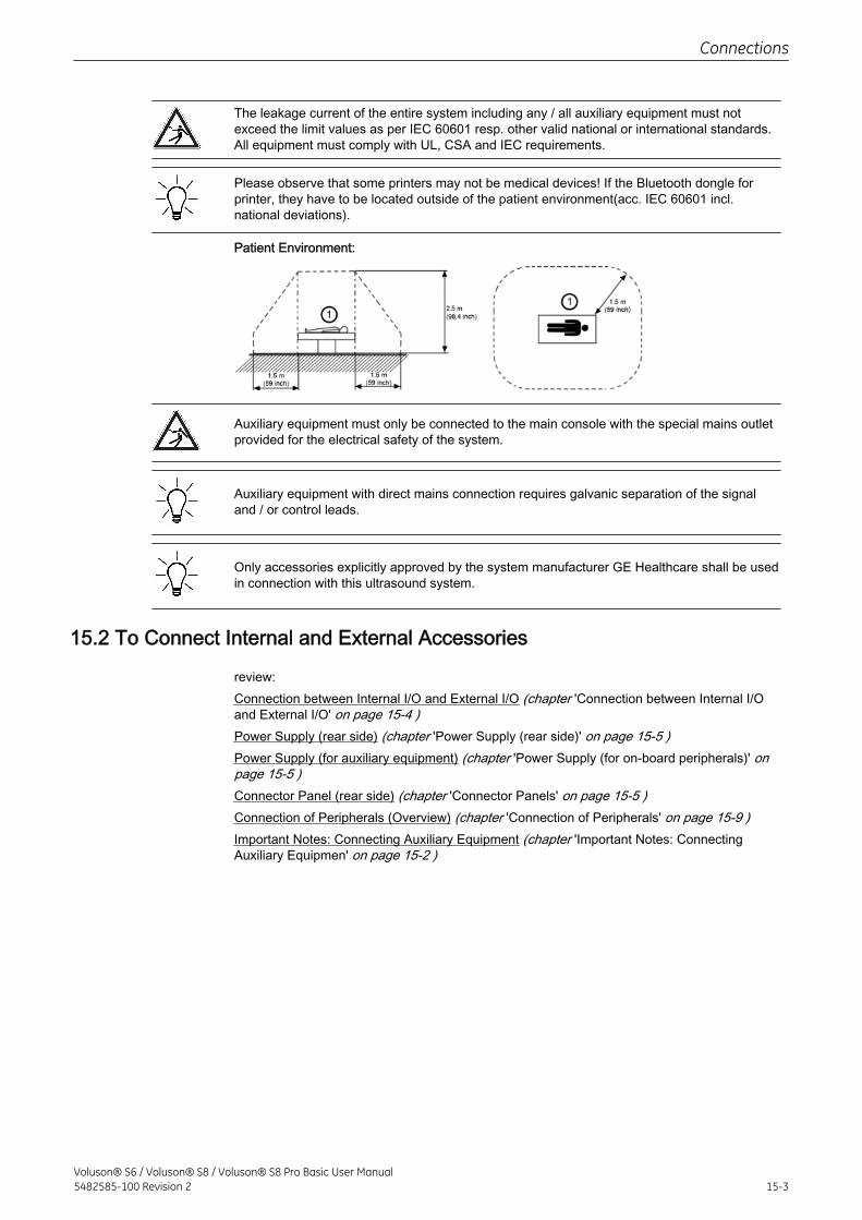
The leakage current of the entire system including any / all auxiliary equipment must notexceed the limit values as per IEC 60601 resp. other valid national or international standards.All equipment must comply with UL, CSA and IEC requirements.
Please observe that some printers may not be medical devices! If the Bluetooth dongle forprinter, they have to be located outside of the patient environment(acc. IEC 60601 incl.national deviations).
Patient Environment:
Auxiliary equipment must only be connected to the main console with the special mains outletprovided for the electrical safety of the system.
Auxiliary equipment with direct mains connection requires galvanic separation of the signaland / or control leads.
Only accessories explicitly approved by the system manufacturer GE Healthcare shall be usedin connection with this ultrasound system.
15.2 To Connect Internal and External Accessories
review:Connection between Internal I/O and External I/O (chapter 'Connection between Internal I/Oand External I/O' on page 15-4 )Power Supply (rear side) (chapter 'Power Supply (rear side)' on page 15-5 )Power Supply (for auxiliary equipment) (chapter 'Power Supply (for on-board peripherals)' onpage 15-5 )Connector Panel (rear side) (chapter 'Connector Panels' on page 15-5 )Connection of Peripherals (Overview) (chapter 'Connection of Peripherals' on page 15-9 )Important Notes: Connecting Auxiliary Equipment (chapter 'Important Notes: ConnectingAuxiliary Equipmen' on page 15-2 )
Connections
Voluson® S6 / Voluson® S8 / Voluson® S8 Pro Basic User Manual5482585-100 Revision 2 15-3
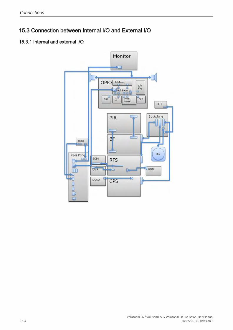
15.3 Connection between Internal I/O and External I/O
15.3.1 Internal and external I/O
Connections
15-4Voluson® S6 / Voluson® S8 / Voluson® S8 Pro Basic User Manual
5482585-100 Revision 2
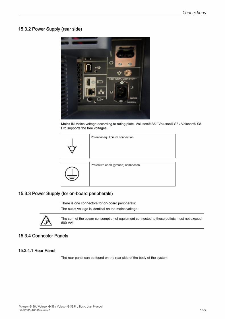
15.3.2 Power Supply (rear side)
Mains IN Mains voltage according to rating plate. Voluson® S6 / Voluson® S8 / Voluson® S8Pro supports the free voltages.
Potential equilibrium connection
Protective earth (ground) connection
15.3.3 Power Supply (for on-board peripherals)
There is one connectors for on-board peripherals:The outlet voltage is identical on the mains voltage.
The sum of the power consumption of equipment connected to these outlets must not exceed600 VA!
15.3.4 Connector Panels
15.3.4.1 Rear PanelThe rear panel can be found on the rear side of the body of the system.
Connections
Voluson® S6 / Voluson® S8 / Voluson® S8 Pro Basic User Manual5482585-100 Revision 2 15-5
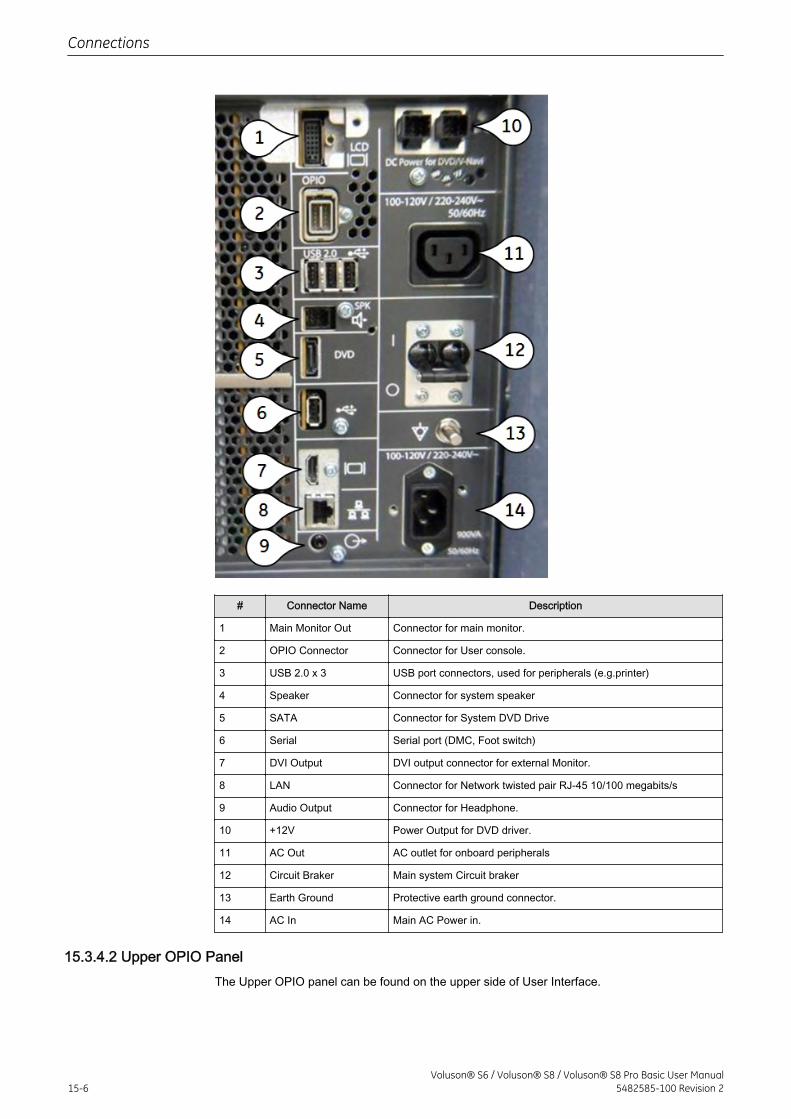
# Connector Name Description
1 Main Monitor Out Connector for main monitor.
2 OPIO Connector Connector for User console.
3 USB 2.0 x 3 USB port connectors, used for peripherals (e.g.printer)
4 Speaker Connector for system speaker
5 SATA Connector for System DVD Drive
6 Serial Serial port (DMC, Foot switch)
7 DVI Output DVI output connector for external Monitor.
8 LAN Connector for Network twisted pair RJ-45 10/100 megabits/s
9 Audio Output Connector for Headphone.
10 +12V Power Output for DVD driver.
11 AC Out AC outlet for onboard peripherals
12 Circuit Braker Main system Circuit braker
13 Earth Ground Protective earth ground connector.
14 AC In Main AC Power in.
15.3.4.2 Upper OPIO PanelThe Upper OPIO panel can be found on the upper side of User Interface.
Connections
15-6Voluson® S6 / Voluson® S8 / Voluson® S8 Pro Basic User Manual
5482585-100 Revision 2
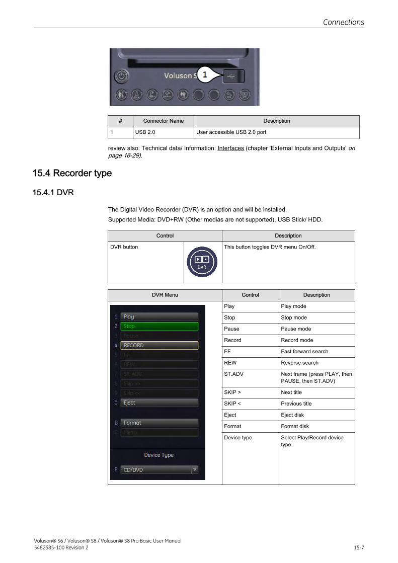
# Connector Name Description
1 USB 2.0 User accessible USB 2.0 port
review also: Technical data/ Information: Interfaces (chapter 'External Inputs and Outputs' onpage 16-29).
15.4 Recorder type
15.4.1 DVR
The Digital Video Recorder (DVR) is an option and will be installed.Supported Media: DVD+RW (Other medias are not supported), USB Stick/ HDD.
Control Description
DVR button This button toggles DVR menu On/Off.
DVR Menu Control Description
Play Play mode
Stop Stop mode
Pause Pause mode
Record Record mode
FF Fast forward search
REW Reverse search
ST.ADV Next frame (press PLAY, thenPAUSE, then ST.ADV)
SKIP > Next title
SKIP < Previous title
Eject Eject disk
Format Format disk
Device type Select Play/Record devicetype.
Connections
Voluson® S6 / Voluson® S8 / Voluson® S8 Pro Basic User Manual5482585-100 Revision 2 15-7
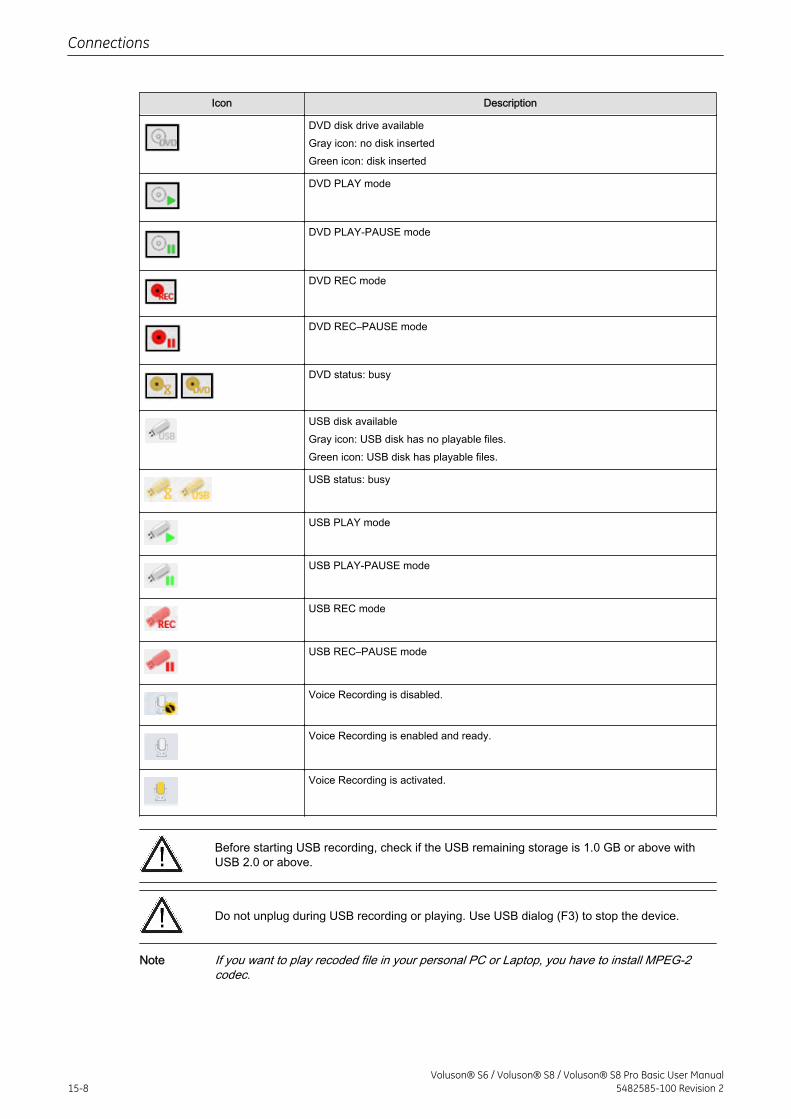
Icon Description
DVD disk drive availableGray icon: no disk insertedGreen icon: disk inserted
DVD PLAY mode
DVD PLAY-PAUSE mode
DVD REC mode
DVD REC–PAUSE mode
DVD status: busy
USB disk availableGray icon: USB disk has no playable files.Green icon: USB disk has playable files.
USB status: busy
USB PLAY mode
USB PLAY-PAUSE mode
USB REC mode
USB REC–PAUSE mode
Voice Recording is disabled.
Voice Recording is enabled and ready.
Voice Recording is activated.
Before starting USB recording, check if the USB remaining storage is 1.0 GB or above withUSB 2.0 or above.
Do not unplug during USB recording or playing. Use USB dialog (F3) to stop the device.
Note If you want to play recoded file in your personal PC or Laptop, you have to install MPEG-2codec.
Connections
15-8Voluson® S6 / Voluson® S8 / Voluson® S8 Pro Basic User Manual
5482585-100 Revision 2
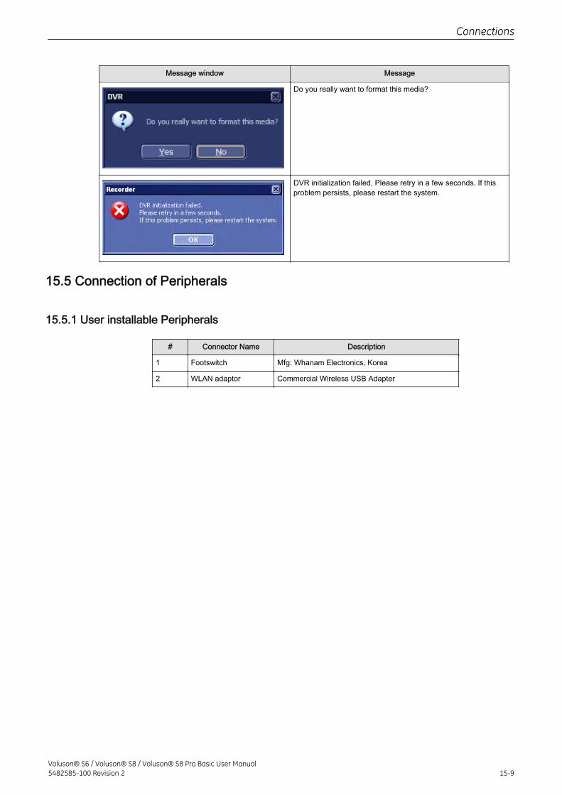
Message window Message
Do you really want to format this media?
DVR initialization failed. Please retry in a few seconds. If thisproblem persists, please restart the system.
15.5 Connection of Peripherals
15.5.1 User installable Peripherals
# Connector Name Description
1 Footswitch Mfg: Whanam Electronics, Korea
2 WLAN adaptor Commercial Wireless USB Adapter
Connections
Voluson® S6 / Voluson® S8 / Voluson® S8 Pro Basic User Manual5482585-100 Revision 2 15-9
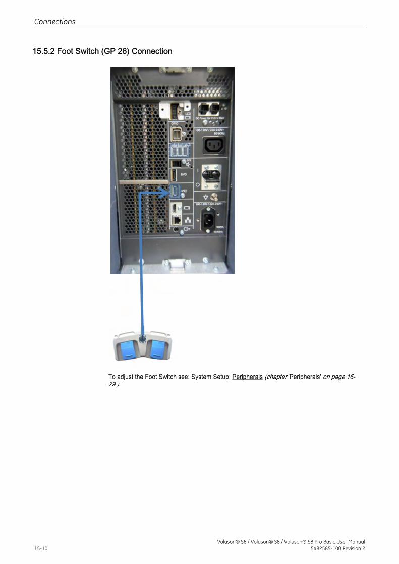
15.5.2 Foot Switch (GP 26) Connection
To adjust the Foot Switch see: System Setup: Peripherals (chapter 'Peripherals' on page 16-29 ).
Connections
15-10Voluson® S6 / Voluson® S8 / Voluson® S8 Pro Basic User Manual
5482585-100 Revision 2
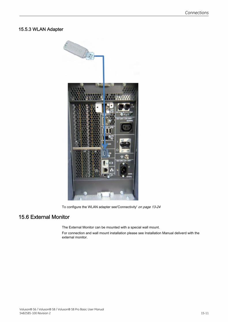
15.5.3 WLAN Adapter
To configure the WLAN adapter see'Connectivity' on page 13-24
15.6 External Monitor
The External Monitor can be mounted with a special wall mount.For connection and wall mount installation please see Installation Manual deliverd with theexternal monitor.
Connections
Voluson® S6 / Voluson® S8 / Voluson® S8 Pro Basic User Manual5482585-100 Revision 2 15-11
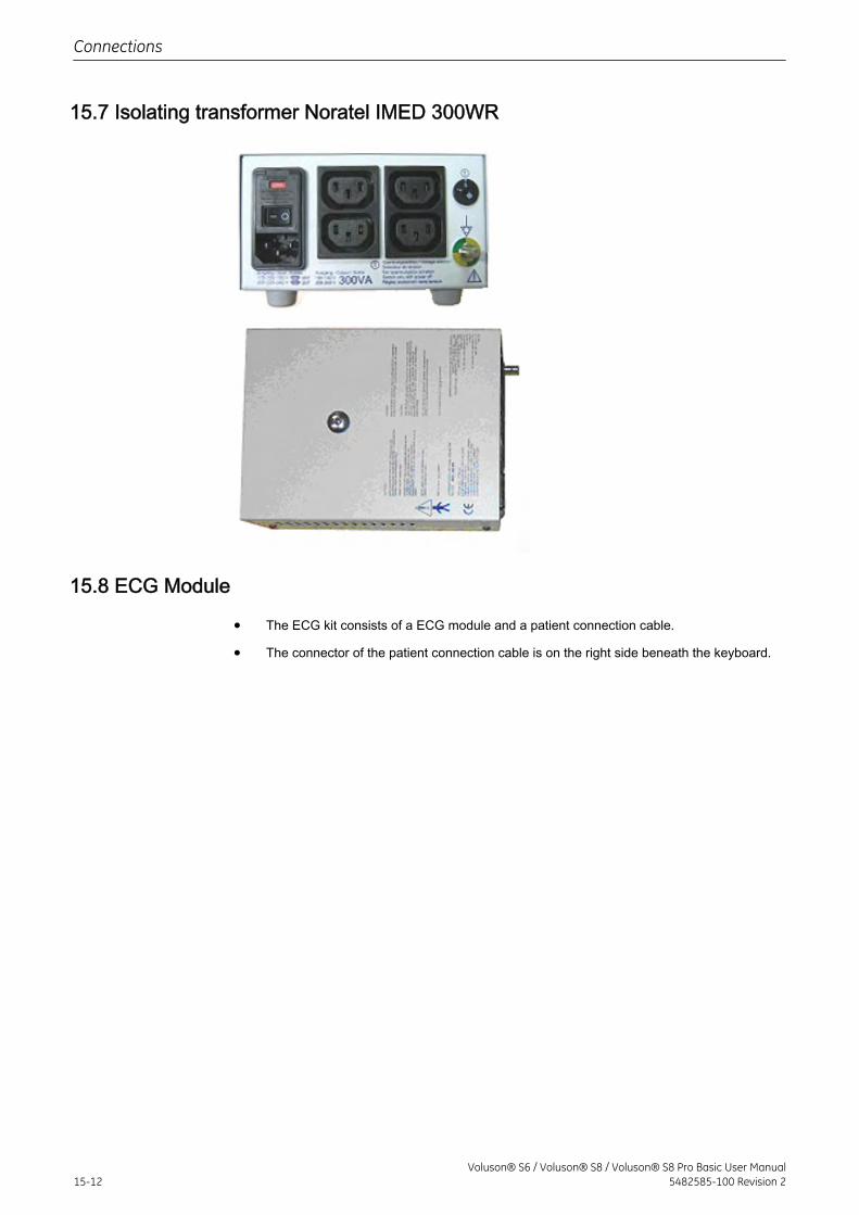
15.7 Isolating transformer Noratel IMED 300WR
15.8 ECG Module
• The ECG kit consists of a ECG module and a patient connection cable.
• The connector of the patient connection cable is on the right side beneath the keyboard.
Connections
15-12Voluson® S6 / Voluson® S8 / Voluson® S8 Pro Basic User Manual
5482585-100 Revision 2
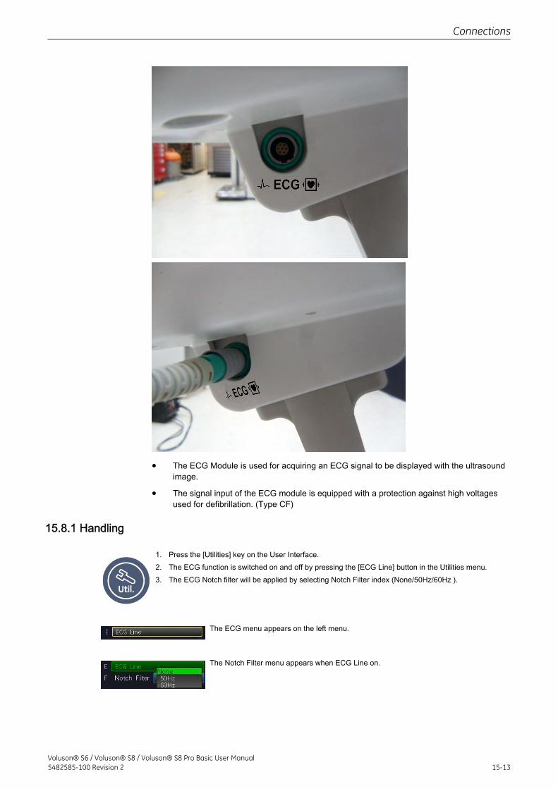
• The ECG Module is used for acquiring an ECG signal to be displayed with the ultrasoundimage.
• The signal input of the ECG module is equipped with a protection against high voltagesused for defibrillation. (Type CF)
15.8.1 Handling
1. Press the [Utilities] key on the User Interface.2. The ECG function is switched on and off by pressing the [ECG Line] button in the Utilities menu.3. The ECG Notch filter will be applied by selecting Notch Filter index (None/50Hz/60Hz ).
The ECG menu appears on the left menu.
The Notch Filter menu appears when ECG Line on.
Connections
Voluson® S6 / Voluson® S8 / Voluson® S8 Pro Basic User Manual5482585-100 Revision 2 15-13
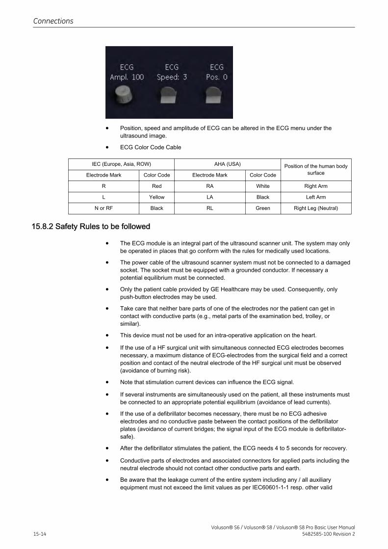
• Position, speed and amplitude of ECG can be altered in the ECG menu under theultrasound image.
• ECG Color Code Cable
IEC (Europe, Asia, ROW) AHA (USA) Position of the human bodysurfaceElectrode Mark Color Code Electrode Mark Color Code
R Red RA White Right Arm
L Yellow LA Black Left Arm
N or RF Black RL Green Right Leg (Neutral)
15.8.2 Safety Rules to be followed
• The ECG module is an integral part of the ultrasound scanner unit. The system may onlybe operated in places that go conform with the rules for medically used locations.
• The power cable of the ultrasound scanner system must not be connected to a damagedsocket. The socket must be equipped with a grounded conductor. If necessary apotential equilibrium must be connected.
• Only the patient cable provided by GE Healthcare may be used. Consequently, onlypush-button electrodes may be used.
• Take care that neither bare parts of one of the electrodes nor the patient can get incontact with conductive parts (e.g., metal parts of the examination bed, trolley, orsimilar).
• This device must not be used for an intra-operative application on the heart.
• If the use of a HF surgical unit with simultaneous connected ECG electrodes becomesnecessary, a maximum distance of ECG-electrodes from the surgical field and a correctposition and contact of the neutral electrode of the HF surgical unit must be observed(avoidance of burning risk).
• Note that stimulation current devices can influence the ECG signal.
• If several instruments are simultaneously used on the patient, all these instruments mustbe connected to an appropriate potential equilibrium (avoidance of lead currents).
• If the use of a defibrillator becomes necessary, there must be no ECG adhesiveelectrodes and no conductive paste between the contact positions of the defibrillatorplates (avoidance of current bridges; the signal input of the ECG module is defibrillator-safe).
• After the defibrillator stimulates the patient, the ECG needs 4 to 5 seconds for recovery.
• Conductive parts of electrodes and associated connectors for applied parts including theneutral electrode should not contact other conductive parts and earth.
• Be aware that the leakage current of the entire system including any / all auxiliaryequipment must not exceed the limit values as per IEC60601-1-1 resp. other valid
Connections
15-14Voluson® S6 / Voluson® S8 / Voluson® S8 Pro Basic User Manual
5482585-100 Revision 2
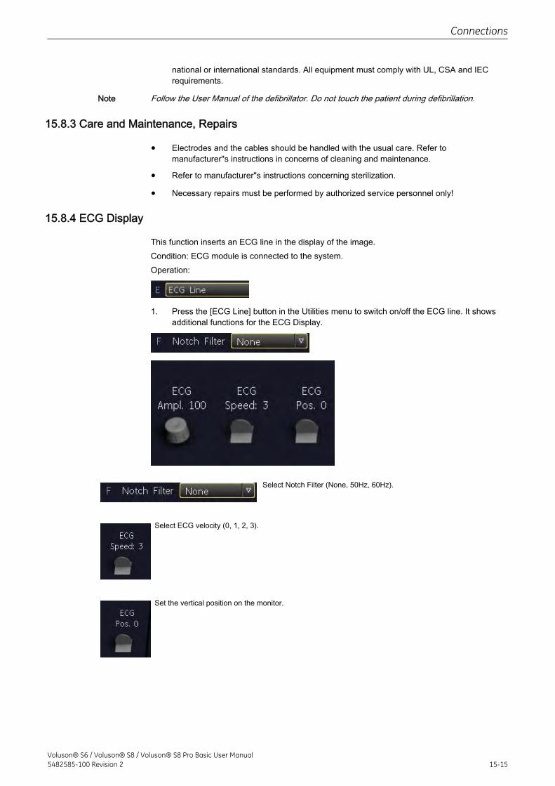
national or international standards. All equipment must comply with UL, CSA and IECrequirements.
Note Follow the User Manual of the defibrillator. Do not touch the patient during defibrillation.
15.8.3 Care and Maintenance, Repairs
• Electrodes and the cables should be handled with the usual care. Refer tomanufacturer"s instructions in concerns of cleaning and maintenance.
• Refer to manufacturer"s instructions concerning sterilization.
• Necessary repairs must be performed by authorized service personnel only!
15.8.4 ECG Display
This function inserts an ECG line in the display of the image.Condition: ECG module is connected to the system.Operation:
1. Press the [ECG Line] button in the Utilities menu to switch on/off the ECG line. It showsadditional functions for the ECG Display.
Select Notch Filter (None, 50Hz, 60Hz).
Select ECG velocity (0, 1, 2, 3).
Set the vertical position on the monitor.
Connections
Voluson® S6 / Voluson® S8 / Voluson® S8 Pro Basic User Manual5482585-100 Revision 2 15-15
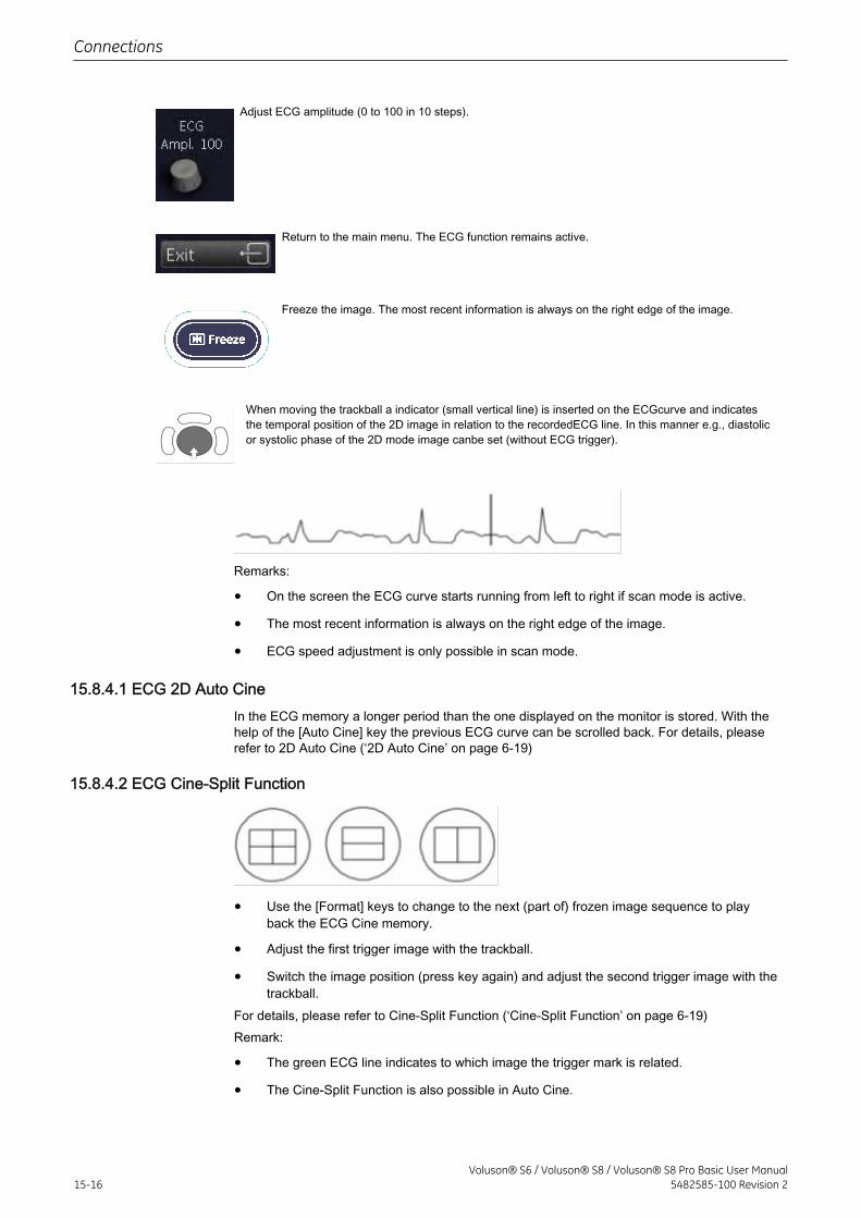
Adjust ECG amplitude (0 to 100 in 10 steps).
Return to the main menu. The ECG function remains active.
Freeze the image. The most recent information is always on the right edge of the image.
When moving the trackball a indicator (small vertical line) is inserted on the ECGcurve and indicatesthe temporal position of the 2D image in relation to the recordedECG line. In this manner e.g., diastolicor systolic phase of the 2D mode image canbe set (without ECG trigger).
Remarks:
• On the screen the ECG curve starts running from left to right if scan mode is active.
• The most recent information is always on the right edge of the image.
• ECG speed adjustment is only possible in scan mode.
15.8.4.1 ECG 2D Auto CineIn the ECG memory a longer period than the one displayed on the monitor is stored. With thehelp of the [Auto Cine] key the previous ECG curve can be scrolled back. For details, pleaserefer to 2D Auto Cine (‘2D Auto Cine’ on page 6‐19)
15.8.4.2 ECG Cine-Split Function
• Use the [Format] keys to change to the next (part of) frozen image sequence to playback the ECG Cine memory.
• Adjust the first trigger image with the trackball.
• Switch the image position (press key again) and adjust the second trigger image with thetrackball.
For details, please refer to Cine-Split Function (‘Cine-Split Function’ on page 6‐19)Remark:
• The green ECG line indicates to which image the trigger mark is related.
• The Cine-Split Function is also possible in Auto Cine.
Connections
15-16Voluson® S6 / Voluson® S8 / Voluson® S8 Pro Basic User Manual
5482585-100 Revision 2
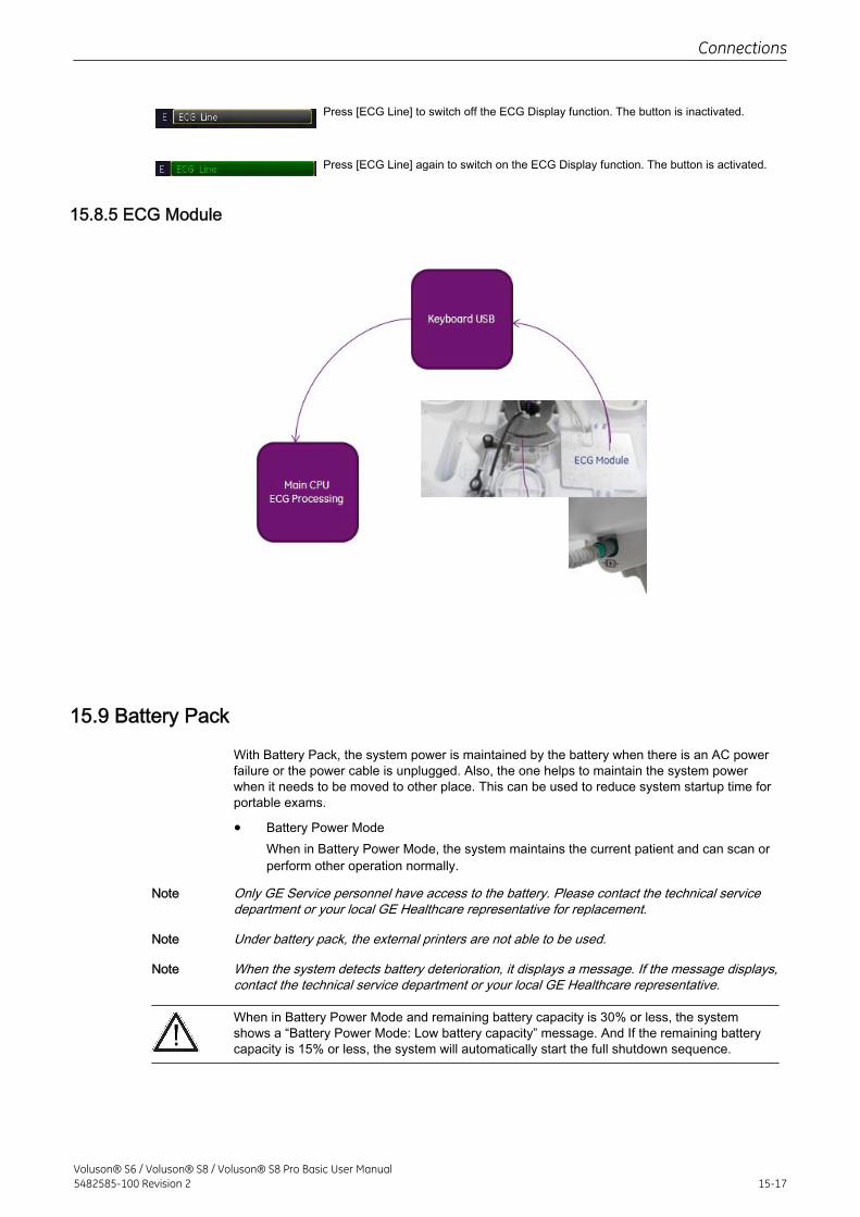
Press [ECG Line] to switch off the ECG Display function. The button is inactivated.
Press [ECG Line] again to switch on the ECG Display function. The button is activated.
15.8.5 ECG Module
15.9 Battery Pack
With Battery Pack, the system power is maintained by the battery when there is an AC powerfailure or the power cable is unplugged. Also, the one helps to maintain the system powerwhen it needs to be moved to other place. This can be used to reduce system startup time forportable exams.
• Battery Power ModeWhen in Battery Power Mode, the system maintains the current patient and can scan orperform other operation normally.
Note Only GE Service personnel have access to the battery. Please contact the technical servicedepartment or your local GE Healthcare representative for replacement.
Note Under battery pack, the external printers are not able to be used.
Note When the system detects battery deterioration, it displays a message. If the message displays,contact the technical service department or your local GE Healthcare representative.
When in Battery Power Mode and remaining battery capacity is 30% or less, the systemshows a “Battery Power Mode: Low battery capacity” message. And If the remaining batterycapacity is 15% or less, the system will automatically start the full shutdown sequence.
Connections
Voluson® S6 / Voluson® S8 / Voluson® S8 Pro Basic User Manual5482585-100 Revision 2 15-17
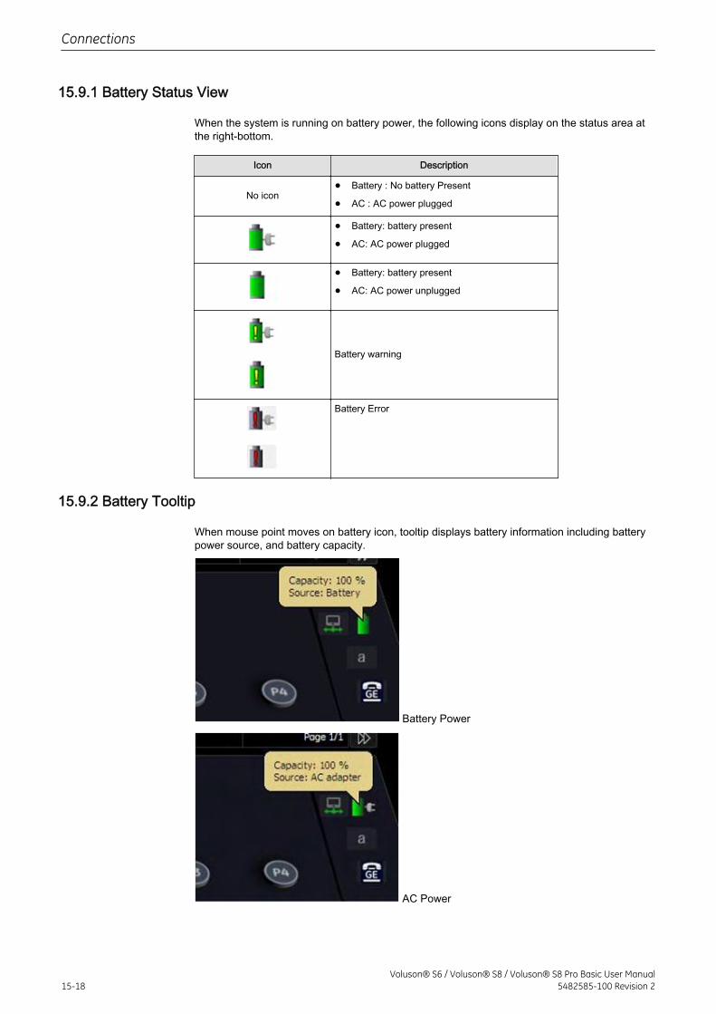
15.9.1 Battery Status View
When the system is running on battery power, the following icons display on the status area atthe right-bottom.
Icon Description
No icon• Battery : No battery Present
• AC : AC power plugged
• Battery: battery present
• AC: AC power plugged
• Battery: battery present
• AC: AC power unplugged
Battery warning
Battery Error
15.9.2 Battery Tooltip
When mouse point moves on battery icon, tooltip displays battery information including batterypower source, and battery capacity.
Battery Power
AC Power
Connections
15-18Voluson® S6 / Voluson® S8 / Voluson® S8 Pro Basic User Manual
5482585-100 Revision 2
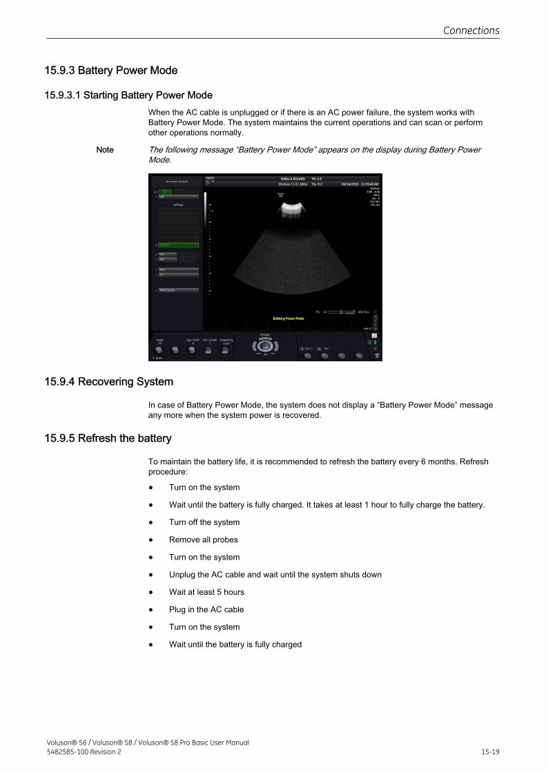
15.9.3 Battery Power Mode
15.9.3.1 Starting Battery Power ModeWhen the AC cable is unplugged or if there is an AC power failure, the system works withBattery Power Mode. The system maintains the current operations and can scan or performother operations normally.
Note The following message “Battery Power Mode” appears on the display during Battery PowerMode.
15.9.4 Recovering System
In case of Battery Power Mode, the system does not display a “Battery Power Mode” messageany more when the system power is recovered.
15.9.5 Refresh the battery
To maintain the battery life, it is recommended to refresh the battery every 6 months. Refreshprocedure:
• Turn on the system
• Wait until the battery is fully charged. It takes at least 1 hour to fully charge the battery.
• Turn off the system
• Remove all probes
• Turn on the system
• Unplug the AC cable and wait until the system shuts down
• Wait at least 5 hours
• Plug in the AC cable
• Turn on the system
• Wait until the battery is fully charged
Connections
Voluson® S6 / Voluson® S8 / Voluson® S8 Pro Basic User Manual5482585-100 Revision 2 15-19

This page was intentionally left blank.
Connections
15-20Voluson® S6 / Voluson® S8 / Voluson® S8 Pro Basic User Manual
5482585-100 Revision 2

Chapter 16
Technical Data / Information
All technical data of the ultrasound device.
Voluson® S6 / Voluson® S8 / Voluson® S8 Pro Basic User Manual5482585-100 Revision 2 16-1
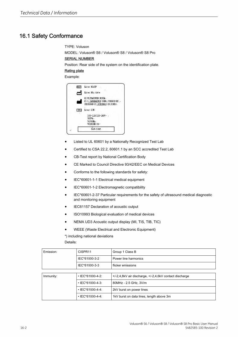
16.1 Safety Conformance
TYPE: VolusonMODEL: Voluson® S6 / Voluson® S8 / Voluson® S8 ProSERIAL NUMBERPosition: Rear side of the system on the identification plate.Rating plateExample:
• Listed to UL 60601 by a Nationally Recognized Test Lab
• Certified to CSA 22.2, 60601.1 by an SCC accredited Test Lab
• CB-Test report by National Certification Body
• CE Marked to Council Directive 93/42/EEC on Medical Devices
• Conforms to the following standards for safety:
• IEC*60601-1-1 Electrical medical equipment
• IEC*60601-1-2 Electromagnetic compatibility
• IEC*60601-2-37 Particular requirements for the safety of ultrasound medical diagnosticand monitoring equipment
• IEC61157 Declaration of acoustic output
• ISO10993 Biological evaluation of medical devices
• NEMA UD3 Acoustic output display (MI, TIS, TIB, TIC)
• WEEE (Waste Electrical and Electronic Equipment)
*) including national deviationsDetails:
Emission: CISPR11 Group 1 Class B
IEC*61000-3-2 Power line harmonics
IEC*61000-3-3 flicker emissions
Immunity: • IEC*61000-4-2: +/-2,4,8kV air discharge, +/-2,4,6kV contact discharge
• IEC*61000-4-3: 80MHz - 2.5 GHz, 3V/m
• IEC*61000-4-4: 2kV burst on power lines
• IEC*61000-4-4: 1kV burst on data lines, length above 3m
Technical Data / Information
16-2Voluson® S6 / Voluson® S8 / Voluson® S8 Pro Basic User Manual
5482585-100 Revision 2
• IEC*61000-4-5: 1kV differential mode 2kV common mode
• IEC*61000-4-6: 150 kHz-80 MHz, 0.1V (80% AM, 1kHz)
• IEC*61000-4-8: Power frequency magnetic field
• IEC*61000-4-11: voltage dips
Maximum operating altitude: 3000m; depending on the properties of the connected electronic devices the maximumoperating altitude is limited to the altitude stated in the corresponding user manual ofthe connected electronic device
Pollution degree: 2
Overvoltage category: II
Material group: IIIb
Electrical safety: IEC*60601-1(IEC60601-1), UL60601-1
Mechanical safety: IEC*60601-1(IEC60601-1), UL60601-1
Thermal safety: IEC*60601-1(IEC60601-1), UL60601-1
Electro-magnetic influence: In the working frequency range of the ultrasound system from 1 to 16 MHz an influenceon the ultrasound image can be visible in the range from 200..500mV/m depending onthe probe connected.
Duty cycle: 100% on
Safety classification: Class I applied parts type BF or type CF acc. to IEC60601IPX0 : No protection against ingress of water(system)IPX7 : ProbeIPX8 : footswitch
Ambient temperature: 18ºC to 30ºC resp. +64ºF to +86ºF (operation temp. of instrument)-10ºC to 50ºC resp. +14ºF to +122ºF (stock temp.)-10ºC to 50ºC resp. +14ºF to +122ºF (transport temp.)
Barometric pressure: 700 to 1060 hPa (operation condition)700 to 1060 hPa (stock and transport condition)
Humidity: 30 to 80% RH no condensation (operation condition)10 to 90% RH no condensation (stock and transport condition)
Humidity protection: covered, no humidity protection
16.2 Physical Attributes
16.2.1 Dimensions / Weight
Width: 620 mm (24.4 in)
Depth: 850 mm (33.4 in)
Height: min. 975 mm (38.4 in); max. 1725 mm (67.9 in)adjustable
Weight: Basic system (without accessories) approx. 90 kg
16.2.2 Power Supply
Power requirements: 220V - 240VAC; 100V - 120 V AC
Frequenzy: 50 Hz, 60 Hz (± 2%)
Technical Data / Information
Voluson® S6 / Voluson® S8 / Voluson® S8 Pro Basic User Manual5482585-100 Revision 2 16-3
Power consumption: nominal 900VA including all optionsTypical power consumption with 500VA load approx. 1.75Aat 230V/50Hz without peipherals
Thermal output: 1200 BTU/h
Fan: Perceived noise level: max. 40 dB/A
16.2.3 AC Power Cord Set
Power cord: Type SJT, SJE, SJO or SJTO, 14AWG, 3-Conductor,VW-1, 125 V or 250 V, 10 A, max 3.0 mlong;One end with Hospital Grade Type, NEMA 5-15P or 6-15P. Other end with appliance coupler."CAUTION Grounding reliability can only be achieved when the equipment is connected to anequipment receptacle marked "Hospital Only" or "Hospital Grade"".
16.2.4 Battery pack
Battery: U8034/5450061, TOTEX Battery including a rechargeable Lithium Ion battery and a BatteryManagement Module. The battery consists of (12) Lithium Ion rechargeable cells, assembled ina 4 line / 3 parallel configuration and size of battery pack is 80mm X 100mm. Each cell has anaverage voltage of 3.6V and a typical capacity of 2.05Ah giving a battery pack of 14.4V and 6Ahtypical.
Nominal Voltage: Operation voltage is 14.4V
Capacity: Charge : Maximum charge current is 3A.Discharge : Discharge power is 240W max at continuous @ 12V AND 150W typ at continuous@ 14.4V
Initial Impedance: Total Output Impedance < 80m ohm
Environmental Conditions (Discharge/ Charge /Storage)
OperatingEnvironment:
Temperature(Charging): 0-55 ºCTemperature(Discharging): 0-55 ºCHumidity: 10 to 80% RH . non-condensingPressure: 700-1060 hPa(3000m -> 701hPa)
Storage Environment: Temperature: -10-50 ºCHumidity: 10 to 90% RH . non-condensingPressure: 700-1060 hPa(3000m -> 701hPa)
TransportationEnvironment:
Temperature: -10-50 ºCHumidity: 10 to 90% RH . non-condensingPressure: 700-1060 hPa(3000m -> 701hPa)
16.2.5 Keyboard
Floating keyboard: adjustable in height:
Rotation: adjustable +/- 30˚ from center
Alphanumerickeyboard:
Backlit
Hard key buttons: Ergonomic layout, Interactive Back-lightning
Recording keys: Integrated for remote control up to 4 peripherals of DICOM devices, one dedicated DVDrecording key
Technical Data / Information
16-4Voluson® S6 / Voluson® S8 / Voluson® S8 Pro Basic User Manual
5482585-100 Revision 2
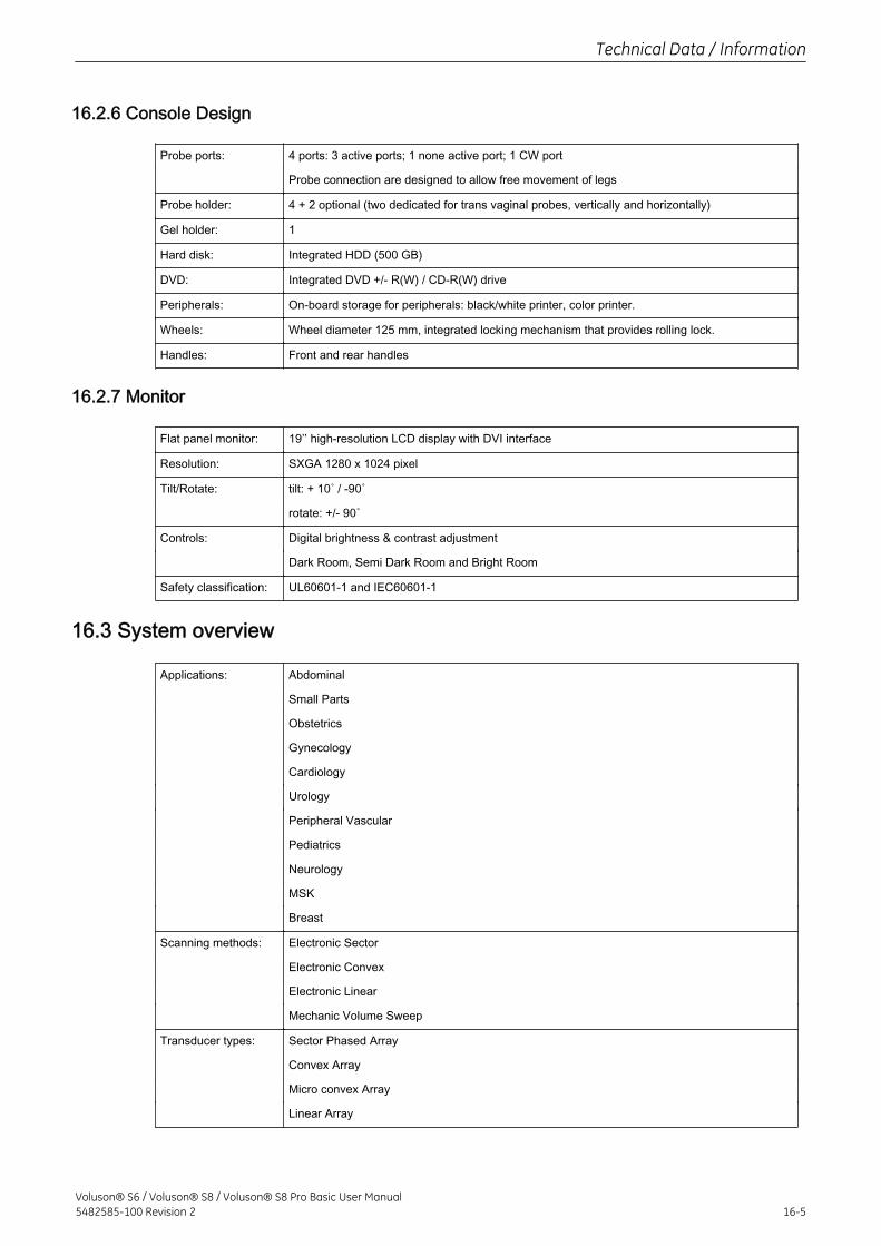
16.2.6 Console Design
Probe ports: 4 ports: 3 active ports; 1 none active port; 1 CW port
Probe connection are designed to allow free movement of legs
Probe holder: 4 + 2 optional (two dedicated for trans vaginal probes, vertically and horizontally)
Gel holder: 1
Hard disk: Integrated HDD (500 GB)
DVD: Integrated DVD +/- R(W) / CD-R(W) drive
Peripherals: On-board storage for peripherals: black/white printer, color printer.
Wheels: Wheel diameter 125 mm, integrated locking mechanism that provides rolling lock.
Handles: Front and rear handles
16.2.7 Monitor
Flat panel monitor: 19’’ high-resolution LCD display with DVI interface
Resolution: SXGA 1280 x 1024 pixel
Tilt/Rotate: tilt: + 10˚ / -90˚
rotate: +/- 90˚
Controls: Digital brightness & contrast adjustment
Dark Room, Semi Dark Room and Bright Room
Safety classification: UL60601-1 and IEC60601-1
16.3 System overview
Applications: Abdominal
Small Parts
Obstetrics
Gynecology
Cardiology
Urology
Peripheral Vascular
Pediatrics
Neurology
MSK
Breast
Scanning methods: Electronic Sector
Electronic Convex
Electronic Linear
Mechanic Volume Sweep
Transducer types: Sector Phased Array
Convex Array
Micro convex Array
Linear Array
Technical Data / Information
Voluson® S6 / Voluson® S8 / Voluson® S8 Pro Basic User Manual5482585-100 Revision 2 16-5
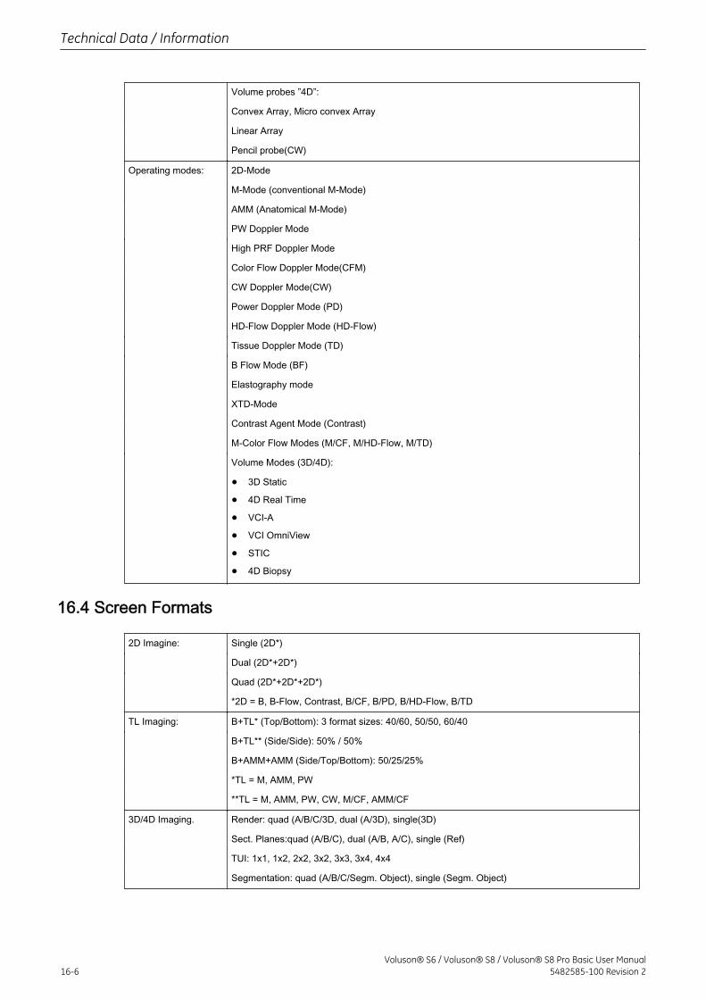
Volume probes ”4D”:
Convex Array, Micro convex Array
Linear Array
Pencil probe(CW)
Operating modes: 2D-Mode
M-Mode (conventional M-Mode)
AMM (Anatomical M-Mode)
PW Doppler Mode
High PRF Doppler Mode
Color Flow Doppler Mode(CFM)
CW Doppler Mode(CW)
Power Doppler Mode (PD)
HD-Flow Doppler Mode (HD-Flow)
Tissue Doppler Mode (TD)
B Flow Mode (BF)
Elastography mode
XTD-Mode
Contrast Agent Mode (Contrast)
M-Color Flow Modes (M/CF, M/HD-Flow, M/TD)
Volume Modes (3D/4D):
• 3D Static
• 4D Real Time
• VCI-A
• VCI OmniView
• STIC
• 4D Biopsy
16.4 Screen Formats
2D Imagine: Single (2D*)
Dual (2D*+2D*)
Quad (2D*+2D*+2D*)
*2D = B, B-Flow, Contrast, B/CF, B/PD, B/HD-Flow, B/TD
TL Imaging: B+TL* (Top/Bottom): 3 format sizes: 40/60, 50/50, 60/40
B+TL** (Side/Side): 50% / 50%
B+AMM+AMM (Side/Top/Bottom): 50/25/25%
*TL = M, AMM, PW
**TL = M, AMM, PW, CW, M/CF, AMM/CF
3D/4D Imaging. Render: quad (A/B/C/3D, dual (A/3D), single(3D)
Sect. Planes:quad (A/B/C), dual (A/B, A/C), single (Ref)
TUI: 1x1, 1x2, 2x2, 3x2, 3x3, 3x4, 4x4
Segmentation: quad (A/B/C/Segm. Object), single (Segm. Object)
Technical Data / Information
16-6Voluson® S6 / Voluson® S8 / Voluson® S8 Pro Basic User Manual
5482585-100 Revision 2
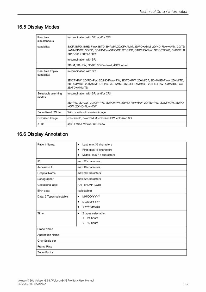
16.5 Display Modes
Real timesimultaneous
in combination with SRI and/or CRI:
capability: B/CF, B/PD, B/HD-Flow, B/TD, B+AMM,2D/CF+AMM, 2D/PD+AMM, 2D/HD-Flow+AMM, 2D/TD+AMM3D/CF, 3D/PD, 3D/HD-FlowSTIC/CF, STIC/PD, STIC/HD-Flow, STIC/TDB+B, B+B/CF, B+B/PD or B+B/HD-Flow
in combination with SRI:
2D+M, 2D+PW, 3D/BF, 3D/Contrast, 4D/Contrast
Real time Triplexcapability:
in combination with SRI:
2D/CF+PW, 2D/PD+PW, 2D/HD-Flow+PW, 2D/TD+PW, 2D+M/CF, 2D+M/HD-Flow, 2D+M/TD,2D+AMM/CF, 2D+AMM/HD-Flow, 2D+AMM/TD2D/CF+AMM/CF, 2D/HD-Flow+AMM/HD-Flow,2D/TD+AMM/TD
Selectable alterningmodes:
in combination with SRI and/or CRI:
2D+PW, 2D+CW, 2D/CF+PW, 2D/PD+PW, 2D/HD-Flow+PW, 2D/TD+PW, 2D/CF+CW, 2D/PD+CW, 2D/HD-Flow+CW
Zoom Read / Write: With or without overview image
Colorized Image: colorized B, colorized M, colorized PW, colorized 3D
XTD: split: Frame review / XTD-view
16.6 Display Annotation
Patient Name: • Last: max 32 characters
• First: max 15 characters
• Middle: max 15 characters
ID: max 32 characters
Accession #: max 16 characters
Hospital Name: max 30 Characters
Sonographer: max 32 Characters
Gestational age: (OB) or LMP (Gyn)
Birth date: (selectable)
Date: 3 Types selectable • MM/DD/YYYY
• DD/MM/YYYY
• YYYY/MM/DD
Time: • 2 types selectable:○ 24 hours
○ 12 hours
Probe Name
Application Name
Gray Scale bar
Frame Rate
Zoom Factor
Technical Data / Information
Voluson® S6 / Voluson® S8 / Voluson® S8 Pro Basic User Manual5482585-100 Revision 2 16-7
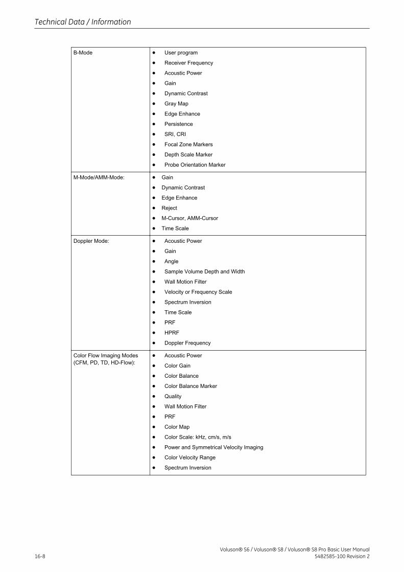
B-Mode • User program
• Receiver Frequency
• Acoustic Power
• Gain
• Dynamic Contrast
• Gray Map
• Edge Enhance
• Persistence
• SRI, CRI
• Focal Zone Markers
• Depth Scale Marker
• Probe Orientation Marker
M-Mode/AMM-Mode: • Gain
• Dynamic Contrast
• Edge Enhance
• Reject
• M-Cursor, AMM-Cursor
• Time Scale
Doppler Mode: • Acoustic Power
• Gain
• Angle
• Sample Volume Depth and Width
• Wall Motion Filter
• Velocity or Frequency Scale
• Spectrum Inversion
• Time Scale
• PRF
• HPRF
• Doppler Frequency
Color Flow Imaging Modes(CFM, PD, TD, HD-Flow):
• Acoustic Power
• Color Gain
• Color Balance
• Color Balance Marker
• Quality
• Wall Motion Filter
• PRF
• Color Map
• Color Scale: kHz, cm/s, m/s
• Power and Symmetrical Velocity Imaging
• Color Velocity Range
• Spectrum Inversion
Technical Data / Information
16-8Voluson® S6 / Voluson® S8 / Voluson® S8 Pro Basic User Manual
5482585-100 Revision 2
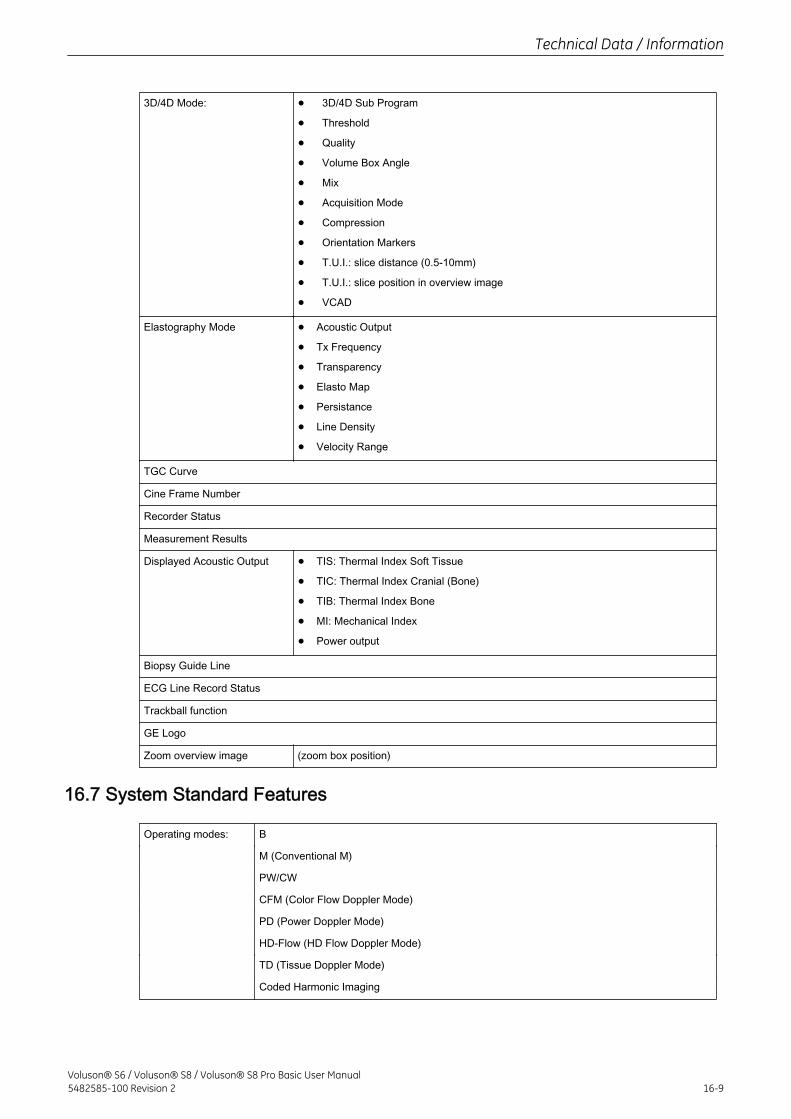
3D/4D Mode: • 3D/4D Sub Program
• Threshold
• Quality
• Volume Box Angle
• Mix
• Acquisition Mode
• Compression
• Orientation Markers
• T.U.I.: slice distance (0.5-10mm)
• T.U.I.: slice position in overview image
• VCAD
Elastography Mode • Acoustic Output
• Tx Frequency
• Transparency
• Elasto Map
• Persistance
• Line Density
• Velocity Range
TGC Curve
Cine Frame Number
Recorder Status
Measurement Results
Displayed Acoustic Output • TIS: Thermal Index Soft Tissue
• TIC: Thermal Index Cranial (Bone)
• TIB: Thermal Index Bone
• MI: Mechanical Index
• Power output
Biopsy Guide Line
ECG Line Record Status
Trackball function
GE Logo
Zoom overview image (zoom box position)
16.7 System Standard Features
Operating modes: B
M (Conventional M)
PW/CW
CFM (Color Flow Doppler Mode)
PD (Power Doppler Mode)
HD-Flow (HD Flow Doppler Mode)
TD (Tissue Doppler Mode)
Coded Harmonic Imaging
Technical Data / Information
Voluson® S6 / Voluson® S8 / Voluson® S8 Pro Basic User Manual5482585-100 Revision 2 16-9
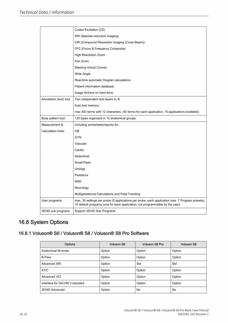
Coded Excitation (CE)
SRI (Speckle reduction imaging)
CRI (Compound Resolution Imaging (Cross Beam))
FFC (Focus & Frequency Composite)
High Resolution Zoom
Pan Zoom
Steering Virtual Convex
Wide Angle
Real-time automatic Doppler calculations
Patient information database
Image Archive on hard drive
Annotation (text) tool: Two independent text layers A, B
Auto text memory:
max 400 terms with 12 characters, (40 terms for each application, 10 applications available)
Body pattern tool: 130 types organized in 10 anatomical groups
Measurement & Including worksheets/reports for:
Calculation tools: OB
GYN
Vascular
Cardio
Abdominal
Small-Parts
Urology
Pediatrics
MSK
Neurology
Multigestational Calculations and Fetal Trending
User programs: max. 35 settings per probe (5 applications per probe, each application max. 7 Program presets),10 default programs (one for each application, not programmable by the user)
3D/4D sub programs Support 3D/4D Sub Programs
16.8 System Options
16.8.1 Voluson® S6 / Voluson® S8 / Voluson® S8 Pro Software
Options Voluson S6 Voluson S8 Pro Voluson S8
Anatomical M-mode Option Option Option
B-Flow Option Option Option
Advanced SRI Option Std Std
STIC Option Option Option
Advanced VCI Option Option Option
Interface for DICOM 3 standard Option Option Option
3D/4D Advanced Option No No
Technical Data / Information
16-10Voluson® S6 / Voluson® S8 / Voluson® S8 Pro Basic User Manual
5482585-100 Revision 2
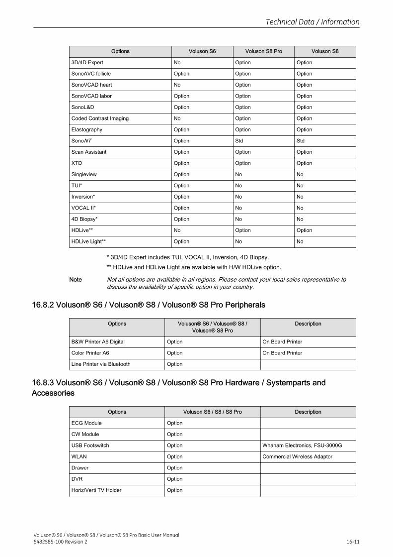
Options Voluson S6 Voluson S8 Pro Voluson S8
3D/4D Expert No Option Option
SonoAVC follicle Option Option Option
SonoVCAD heart No Option Option
SonoVCAD labor Option Option Option
SonoL&D Option Option Option
Coded Contrast Imaging No Option Option
Elastography Option Option Option
SonoNT Option Std Std
Scan Assistant Option Option Option
XTD Option Option Option
Singleview Option No No
TUI* Option No No
Inversion* Option No No
VOCAL II* Option No No
4D Biopsy* Option No No
HDLive** No Option Option
HDLive Light** Option No No
* 3D/4D Expert includes TUI, VOCAL II, Inversion, 4D Biopsy.** HDLive and HDLive Light are available with H/W HDLive option.
Note Not all options are available in all regions. Please contact your local sales representative todiscuss the availability of specific option in your country.
16.8.2 Voluson® S6 / Voluson® S8 / Voluson® S8 Pro Peripherals
Options Voluson® S6 / Voluson® S8 /Voluson® S8 Pro
Description
B&W Printer A6 Digital Option On Board Printer
Color Printer A6 Option On Board Printer
Line Printer via Bluetooth Option
16.8.3 Voluson® S6 / Voluson® S8 / Voluson® S8 Pro Hardware / Systemparts andAccessories
Options Voluson S6 / S8 / S8 Pro Description
ECG Module Option
CW Module Option
USB Footswitch Option Whanam Electronics, FSU-3000G
WLAN Option Commercial Wireless Adaptor
Drawer Option
DVR Option
Horiz/Verti TV Holder Option
Technical Data / Information
Voluson® S6 / Voluson® S8 / Voluson® S8 Pro Basic User Manual5482585-100 Revision 2 16-11
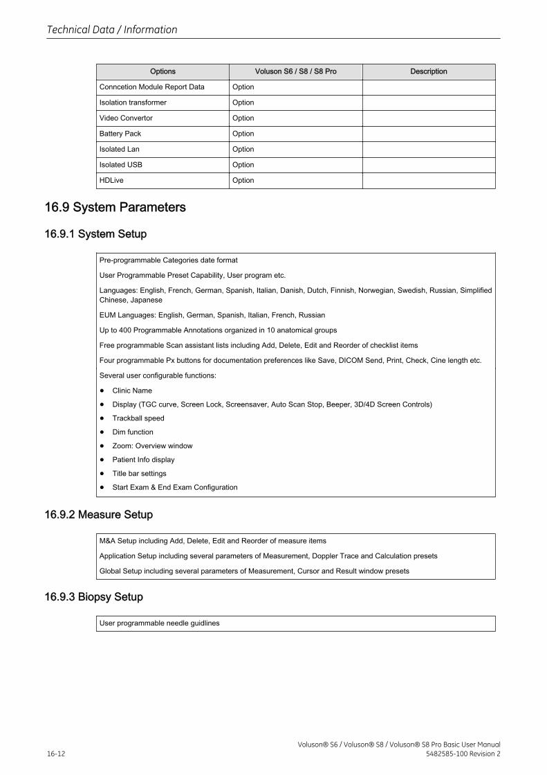
Options Voluson S6 / S8 / S8 Pro Description
Conncetion Module Report Data Option
Isolation transformer Option
Video Convertor Option
Battery Pack Option
Isolated Lan Option
Isolated USB Option
HDLive Option
16.9 System Parameters
16.9.1 System Setup
Pre-programmable Categories date format
User Programmable Preset Capability, User program etc.
Languages: English, French, German, Spanish, Italian, Danish, Dutch, Finnish, Norwegian, Swedish, Russian, SimplifiedChinese, Japanese
EUM Languages: English, German, Spanish, Italian, French, Russian
Up to 400 Programmable Annotations organized in 10 anatomical groups
Free programmable Scan assistant lists including Add, Delete, Edit and Reorder of checklist items
Four programmable Px buttons for documentation preferences like Save, DICOM Send, Print, Check, Cine length etc.
Several user configurable functions:
• Clinic Name
• Display (TGC curve, Screen Lock, Screensaver, Auto Scan Stop, Beeper, 3D/4D Screen Controls)
• Trackball speed
• Dim function
• Zoom: Overview window
• Patient Info display
• Title bar settings
• Start Exam & End Exam Configuration
16.9.2 Measure Setup
M&A Setup including Add, Delete, Edit and Reorder of measure items
Application Setup including several parameters of Measurement, Doppler Trace and Calculation presets
Global Setup including several parameters of Measurement, Cursor and Result window presets
16.9.3 Biopsy Setup
User programmable needle guidlines
Technical Data / Information
16-12Voluson® S6 / Voluson® S8 / Voluson® S8 Pro Basic User Manual
5482585-100 Revision 2
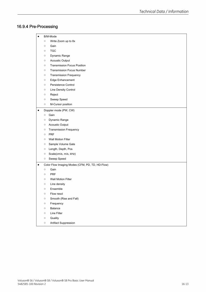
16.9.4 Pre-Processing
• B/M-Mode○ Write Zoom up to 8x
○ Gain
○ TGC
○ Dynamic Range
○ Acoustic Output
○ Transmission Focus Position
○ Transmission Focus Number
○ Transmission Frequency
○ Edge Enhancement
○ Persistence Control
○ Line Density Control
○ Reject
○ Sweep Speed
○ M-Cursor position
• Doppler mode (PW, CW)○ Gain
○ Dynamic Range
○ Acoustic Output
○ Transmission Frequency
○ PRF
○ Wall Motion Filter
○ Sample Volume Gate
○ Length, Depth, Pos
○ Scale(cm/s, m/s, kHz)
○ Sweep Speed
• Color Flow Imaging Modes (CFM, PD, TD, HD-Flow)○ Gain
○ PRF
○ Wall Motion Filter
○ Line density
○ Ensemble
○ Flow resol
○ Smooth (Rise and Fall)
○ Frequency
○ Balance
○ Line Filter
○ Quality
○ Artifact Suppression
Technical Data / Information
Voluson® S6 / Voluson® S8 / Voluson® S8 Pro Basic User Manual5482585-100 Revision 2 16-13
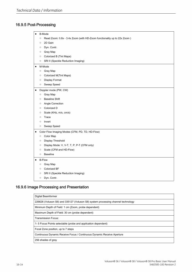
16.9.5 Post-Processing
• B-Mode○ Read Zoom: 0.8x - 3.4x Zoom (with HD-Zoom functionality up to 22x Zoom )
○ 2D Gain
○ Dyn. Contr.
○ Gray Map
○ Colorized B (Tint Maps)
○ SRI II (Speckle Reduction Imaging)
• M-Mode○ Gray Map
○ Colorized M(Tint Maps)
○ Display Format
○ Sweep Speed
• Doppler mode (PW, CW)○ Gray Map
○ Baseline Shift
○ Angle Correction
○ Colorized D
○ Scale (KHz, m/s, cm/s)
○ Trace
○ Invert
○ Sweep Speed
• Color Flow Imaging Modes (CFM, PD, TD, HD-Flow)○ Color Map
○ Display Threshold
○ Display Mode: V, V-T, T, P, P-T (CFM only)
○ Scale (CFM and HD-Flow)
○ Baseline
• B-Flow○ Gray Map
○ Colorized BF
○ SRI II (Speckle Reduction Imaging)
○ Dyn. Contr.
16.9.6 Image Processing and Presentation
Digital Beamformer
226626 (Voluson S6) and 335127 (Voluson S8) system processing channel technology
Minimum Depth of Field: 1 cm (Zoom, probe dependent)
Maximum Depth of Field: 30 cm (probe dependent)
Transmission Focus:
1- 5 Focus Points selectable (probe and application dependent)
Focal Zone position, up to 7 steps
Continuous Dynamic Receive Focus / Continuous Dynamic Receive Aperture
256 shades of gray
Technical Data / Information
16-14Voluson® S6 / Voluson® S8 / Voluson® S8 Pro Basic User Manual
5482585-100 Revision 2
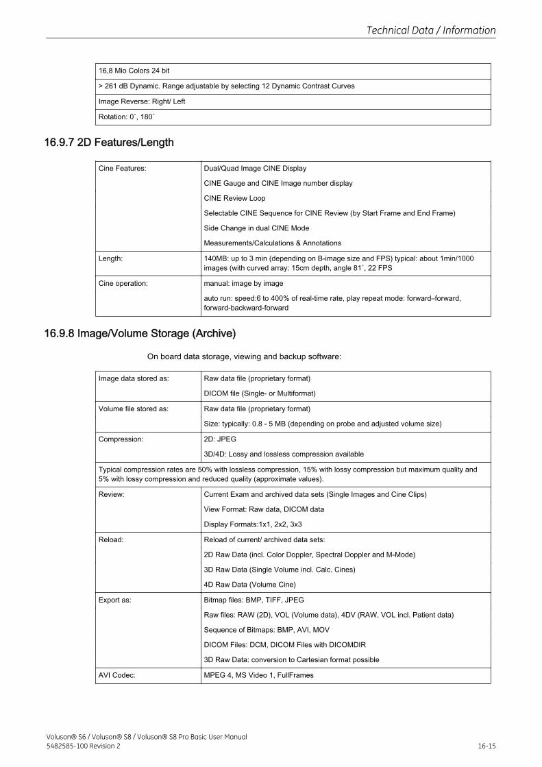
16,8 Mio Colors 24 bit
> 261 dB Dynamic. Range adjustable by selecting 12 Dynamic Contrast Curves
Image Reverse: Right/ Left
Rotation: 0˚, 180˚
16.9.7 2D Features/Length
Cine Features: Dual/Quad Image CINE Display
CINE Gauge and CINE Image number display
CINE Review Loop
Selectable CINE Sequence for CINE Review (by Start Frame and End Frame)
Side Change in dual CINE Mode
Measurements/Calculations & Annotations
Length: 140MB: up to 3 min (depending on B-image size and FPS) typical: about 1min/1000images (with curved array: 15cm depth, angle 81˚, 22 FPS
Cine operation: manual: image by image
auto run: speed:6 to 400% of real-time rate, play repeat mode: forward–forward,forward-backward-forward
16.9.8 Image/Volume Storage (Archive)
On board data storage, viewing and backup software:
Image data stored as: Raw data file (proprietary format)
DICOM file (Single- or Multiformat)
Volume file stored as: Raw data file (proprietary format)
Size: typically: 0.8 - 5 MB (depending on probe and adjusted volume size)
Compression: 2D: JPEG
3D/4D: Lossy and lossless compression available
Typical compression rates are 50% with lossless compression, 15% with lossy compression but maximum quality and5% with lossy compression and reduced quality (approximate values).
Review: Current Exam and archived data sets (Single Images and Cine Clips)
View Format: Raw data, DICOM data
Display Formats:1x1, 2x2, 3x3
Reload: Reload of current/ archived data sets:
2D Raw Data (incl. Color Doppler, Spectral Doppler and M-Mode)
3D Raw Data (Single Volume incl. Calc. Cines)
4D Raw Data (Volume Cine)
Export as: Bitmap files: BMP, TIFF, JPEG
Raw files: RAW (2D), VOL (Volume data), 4DV (RAW, VOL incl. Patient data)
Sequence of Bitmaps: BMP, AVI, MOV
DICOM Files: DCM, DICOM Files with DICOMDIR
3D Raw Data: conversion to Cartesian format possible
AVI Codec: MPEG 4, MS Video 1, FullFrames
Technical Data / Information
Voluson® S6 / Voluson® S8 / Voluson® S8 Pro Basic User Manual5482585-100 Revision 2 16-15
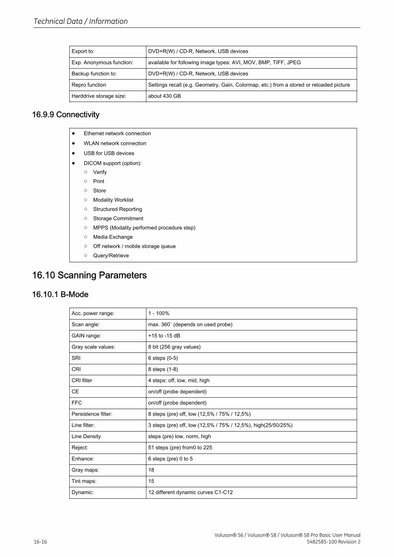
Export to: DVD+R(W) / CD-R, Network, USB devices
Exp. Anonymous function: available for following image types: AVI, MOV, BMP, TIFF, JPEG
Backup function to: DVD+R(W) / CD-R, Network, USB devices
Repro function Settings recall (e.g. Geometry, Gain, Colormap, etc.) from a stored or reloaded picture
Harddrive storage size: about 430 GB
16.9.9 Connectivity
• Ethernet network connection
• WLAN network connection
• USB for USB devices
• DICOM support (option):○ Verify
○ Store
○ Modality Worklist
○ Structured Reporting
○ Storage Commitment
○ MPPS (Modality performed procedure step)
○ Media Exchange
○ Off network / mobile storage queue
○ Query/Retrieve
16.10 Scanning Parameters
16.10.1 B-Mode
Acc. power range: 1 - 100%
Scan angle: max. 360˚ (depends on used probe)
GAIN range: +15 to -15 dB
Gray scale values: 8 bit (256 gray values)
SRI 6 steps (0-5)
CRI 8 steps (1-8)
CRI filter 4 steps: off, low, mid, high
CE on/off (probe dependent)
FFC on/off (probe dependent)
Persistence filter: 8 steps (pre) off, low (12,5% / 75% / 12,5%)
Line filter: 3 steps (pre) off, low (12,5% / 75% / 12,5%), high(25/50/25%)
Line Density steps (pre) low, norm, high
Reject: 51 steps (pre) from0 to 225
Enhance: 6 steps (pre) 0 to 5
Gray maps: 18
Tint maps: 15
Dynamic: 12 different dynamic curves C1-C12
Technical Data / Information
16-16Voluson® S6 / Voluson® S8 / Voluson® S8 Pro Basic User Manual
5482585-100 Revision 2
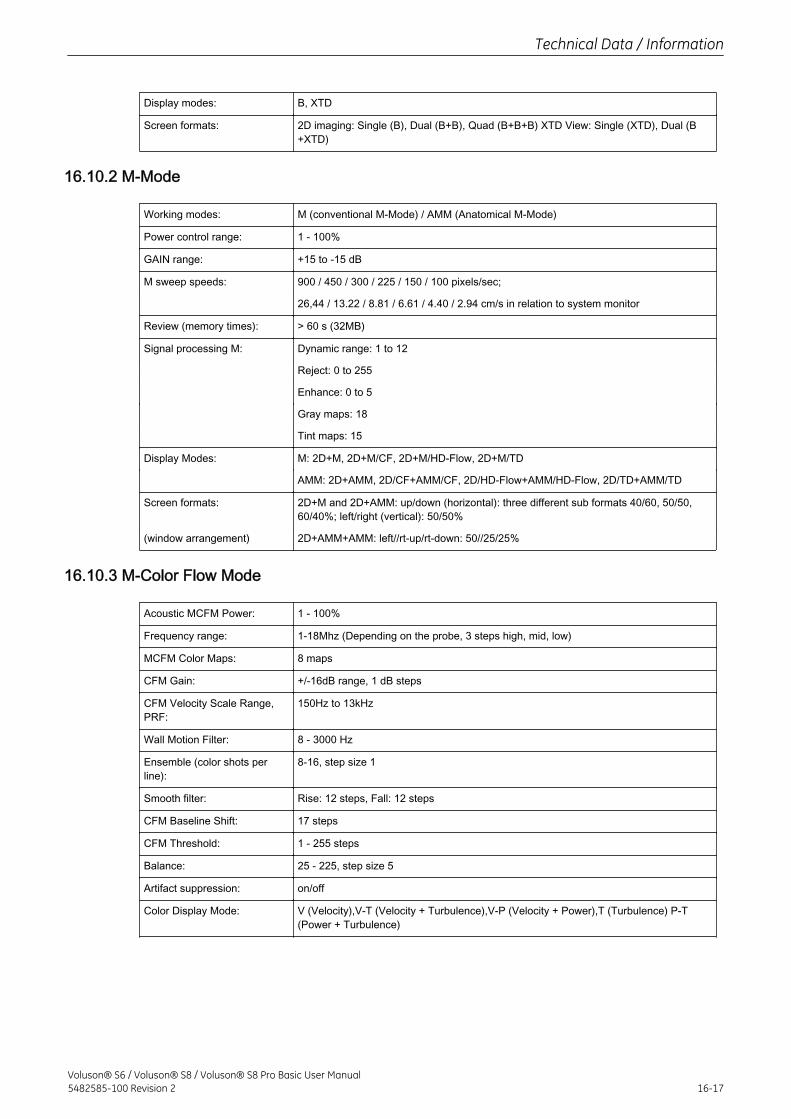
Display modes: B, XTD
Screen formats: 2D imaging: Single (B), Dual (B+B), Quad (B+B+B) XTD View: Single (XTD), Dual (B+XTD)
16.10.2 M-Mode
Working modes: M (conventional M-Mode) / AMM (Anatomical M-Mode)
Power control range: 1 - 100%
GAIN range: +15 to -15 dB
M sweep speeds: 900 / 450 / 300 / 225 / 150 / 100 pixels/sec;
26,44 / 13.22 / 8.81 / 6.61 / 4.40 / 2.94 cm/s in relation to system monitor
Review (memory times): > 60 s (32MB)
Signal processing M: Dynamic range: 1 to 12
Reject: 0 to 255
Enhance: 0 to 5
Gray maps: 18
Tint maps: 15
Display Modes: M: 2D+M, 2D+M/CF, 2D+M/HD-Flow, 2D+M/TD
AMM: 2D+AMM, 2D/CF+AMM/CF, 2D/HD-Flow+AMM/HD-Flow, 2D/TD+AMM/TD
Screen formats: 2D+M and 2D+AMM: up/down (horizontal): three different sub formats 40/60, 50/50,60/40%; left/right (vertical): 50/50%
(window arrangement) 2D+AMM+AMM: left//rt-up/rt-down: 50//25/25%
16.10.3 M-Color Flow Mode
Acoustic MCFM Power: 1 - 100%
Frequency range: 1-18Mhz (Depending on the probe, 3 steps high, mid, low)
MCFM Color Maps: 8 maps
CFM Gain: +/-16dB range, 1 dB steps
CFM Velocity Scale Range,PRF:
150Hz to 13kHz
Wall Motion Filter: 8 - 3000 Hz
Ensemble (color shots perline):
8-16, step size 1
Smooth filter: Rise: 12 steps, Fall: 12 steps
CFM Baseline Shift: 17 steps
CFM Threshold: 1 - 255 steps
Balance: 25 - 225, step size 5
Artifact suppression: on/off
Color Display Mode: V (Velocity),V-T (Velocity + Turbulence),V-P (Velocity + Power),T (Turbulence) P-T(Power + Turbulence)
Technical Data / Information
Voluson® S6 / Voluson® S8 / Voluson® S8 Pro Basic User Manual5482585-100 Revision 2 16-17
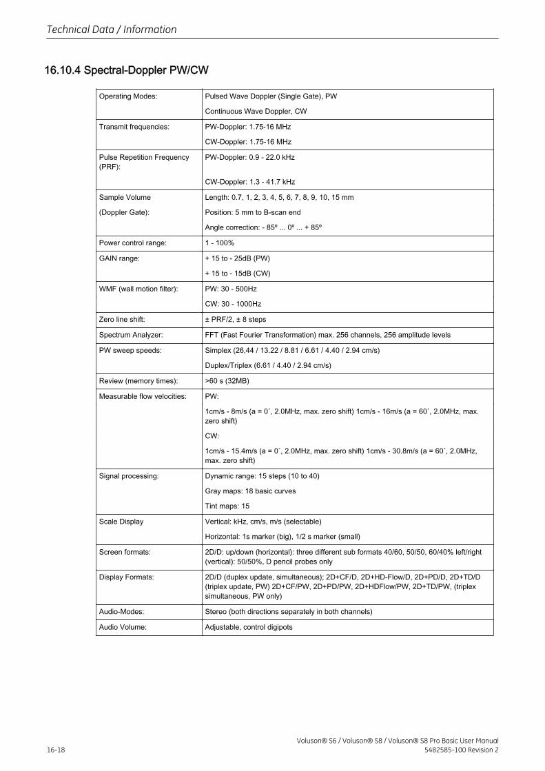
16.10.4 Spectral-Doppler PW/CW
Operating Modes: Pulsed Wave Doppler (Single Gate), PW
Continuous Wave Doppler, CW
Transmit frequencies: PW-Doppler: 1.75-16 MHz
CW-Doppler: 1.75-16 MHz
Pulse Repetition Frequency(PRF):
PW-Doppler: 0.9 - 22.0 kHz
CW-Doppler: 1.3 - 41.7 kHz
Sample Volume Length: 0.7, 1, 2, 3, 4, 5, 6, 7, 8, 9, 10, 15 mm
(Doppler Gate): Position: 5 mm to B-scan end
Angle correction: - 85º ... 0º ... + 85º
Power control range: 1 - 100%
GAIN range: + 15 to - 25dB (PW)
+ 15 to - 15dB (CW)
WMF (wall motion filter): PW: 30 - 500Hz
CW: 30 - 1000Hz
Zero line shift: ± PRF/2, ± 8 steps
Spectrum Analyzer: FFT (Fast Fourier Transformation) max. 256 channels, 256 amplitude levels
PW sweep speeds: Simplex (26,44 / 13.22 / 8.81 / 6.61 / 4.40 / 2.94 cm/s)
Duplex/Triplex (6.61 / 4.40 / 2.94 cm/s)
Review (memory times): >60 s (32MB)
Measurable flow velocities: PW:
1cm/s - 8m/s (a = 0˚, 2.0MHz, max. zero shift) 1cm/s - 16m/s (a = 60˚, 2.0MHz, max.zero shift)
CW:
1cm/s - 15.4m/s (a = 0˚, 2.0MHz, max. zero shift) 1cm/s - 30.8m/s (a = 60˚, 2.0MHz,max. zero shift)
Signal processing: Dynamic range: 15 steps (10 to 40)
Gray maps: 18 basic curves
Tint maps: 15
Scale Display Vertical: kHz, cm/s, m/s (selectable)
Horizontal: 1s marker (big), 1/2 s marker (small)
Screen formats: 2D/D: up/down (horizontal): three different sub formats 40/60, 50/50, 60/40% left/right(vertical): 50/50%, D pencil probes only
Display Formats: 2D/D (duplex update, simultaneous); 2D+CF/D, 2D+HD-Flow/D, 2D+PD/D, 2D+TD/D(triplex update, PW) 2D+CF/PW, 2D+PD/PW, 2D+HDFlow/PW, 2D+TD/PW, (triplexsimultaneous, PW only)
Audio-Modes: Stereo (both directions separately in both channels)
Audio Volume: Adjustable, control digipots
Technical Data / Information
16-18Voluson® S6 / Voluson® S8 / Voluson® S8 Pro Basic User Manual
5482585-100 Revision 2
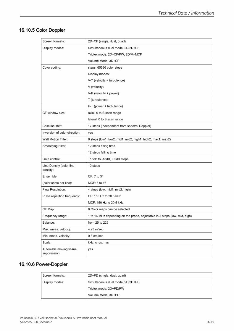
16.10.5 Color Doppler
Screen formats: 2D+CF (single, dual, quad)
Display modes: Simultaneous dual mode: 2D/2D+CF
Triplex mode: 2D+CF/PW, 2D/M+MCF
Volume Mode: 3D+CF
Color coding: steps: 65536 color steps
Display modes:
V-T (velocity + turbulence)
V (velocity)
V-P (velocity + power)
T (turbulence)
P-T (power + turbulence)
CF window size: axial: 0 to B scan range
lateral: 0 to B scan range
Baseline shift: 17 steps (independent from spectral Doppler)
Inversion of color direction: yes
Wall Motion Filter: 8 steps (low1, low2, mid1, mid2, high1, high2, max1, max2)
Smoothing Filter: 12 steps rising time
12 steps falling time
Gain control: +15dB to -15dB, 0.2dB steps
Line Density (color linedensity):
10 steps
Ensemble CF: 7 to 31
(color shots per line): MCF: 8 to 16
Flow Resolution: 4 steps (low, mid1, mid2, high)
Pulse repetition frequency: CF: 150 Hz to 20.5 kHz
MCF: 150 Hz to 20.5 kHz
CF Map: 8 Color maps can be selected
Frequency range: 1 to 16 MHz depending on the probe, adjustable in 3 steps (low, mid, high)
Balance: from 25 to 225
Max. meas. velocity: 4.23 m/sec
Min. meas. velocity: 0.3 cm/sec
Scale: kHz, cm/s, m/s
Automatic moving tissuesuppression:
yes
16.10.6 Power-Doppler
Screen formats: 2D+PD (single, dual, quad)
Display modes: Simultaneous dual mode: 2D/2D+PD
Triplex mode: 2D+PD/PW
Volume Mode: 3D+PD;
Technical Data / Information
Voluson® S6 / Voluson® S8 / Voluson® S8 Pro Basic User Manual5482585-100 Revision 2 16-19
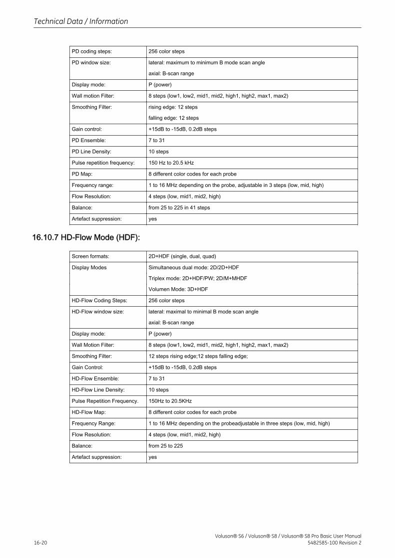
PD coding steps: 256 color steps
PD window size: lateral: maximum to minimum B mode scan angle
axial: B-scan range
Display mode: P (power)
Wall motion Filter: 8 steps (low1, low2, mid1, mid2, high1, high2, max1, max2)
Smoothing Filter: rising edge: 12 steps
falling edge: 12 steps
Gain control: +15dB to -15dB, 0.2dB steps
PD Ensemble: 7 to 31
PD Line Density: 10 steps
Pulse repetition frequency: 150 Hz to 20.5 kHz
PD Map: 8 different color codes for each probe
Frequency range: 1 to 16 MHz depending on the probe, adjustable in 3 steps (low, mid, high)
Flow Resolution: 4 steps (low, mid1, mid2, high)
Balance: from 25 to 225 in 41 steps
Artefact suppression: yes
16.10.7 HD-Flow Mode (HDF):
Screen formats: 2D+HDF (single, dual, quad)
Display Modes Simultaneous dual mode: 2D/2D+HDF
Triplex mode: 2D+HDF/PW; 2D/M+MHDF
Volumen Mode: 3D+HDF
HD-Flow Coding Steps: 256 color steps
HD-Flow window size: lateral: maximal to minimal B mode scan angle
axial: B-scan range
Display mode: P (power)
Wall Motion Filter: 8 steps (low1, low2, mid1, mid2, high1, high2, max1, max2)
Smoothing Filter: 12 steps rising edge;12 steps falling edge;
Gain Control: +15dB to -15dB, 0.2dB steps
HD-Flow Ensemble: 7 to 31
HD-Flow Line Density: 10 steps
Pulse Repetition Frequency. 150Hz to 20.5KHz
HD-Flow Map: 8 different color codes for each probe
Frequency Range: 1 to 16 MHz depending on the probeadjustable in three steps (low, mid, high)
Flow Resolution: 4 steps (low, mid1, mid2, high)
Balance: from 25 to 225
Artefact suppression: yes
Technical Data / Information
16-20Voluson® S6 / Voluson® S8 / Voluson® S8 Pro Basic User Manual
5482585-100 Revision 2

16.10.8 Tissue Doppler Mode (TD)
Screen formats: 2D+TD (single, dual, quad)
Display modes: Simultaneous dual mode: 2D/2D+TD
Triplex mode: 2D+TD/PW, 2D/M+MTD
TD coding steps: 65536 color steps
Depth range: axial: 0 to B-scan range
lateral: 0 to B-scan-range
Zero line shift: 17 steps
Inversion of color direction: yes
Smoothing Filter: 12 steps rising time
12 steps falling time
Gain control: +15dB to -15dB, 0.2dB steps
Line Density (color linedensity):
10 steps
Ensemble (color shots perline):
3 to 31
Flow Resolution: 4 steps (low, mid1, mid2, high)
Pulse repetition frequency: 150 Hz to 20.5 kHz
TD Map: 4 different TD Map
Frequency range: 1 to 16 MHz depending on the probe,adjustable in 3 steps (low, mid, high)
Balance: from 25 to 225
Max. meas. velocity: 4.23 m/sec
Min. meas. velocity: 0.3 cm/sec
Display Mode: V (velocity)
Scale: kHz, cm/s, m/s
16.10.9 Volume Scan Module
Vol. scan size: max. 64 MB for gray volumes
max. 90 MB for color volumes
The required memory space depends on scan parameters (VOL-box size and quality(low , mid1 , mid2 , high1 , high2 , max). typical:0.8-5 MB
Lines/2D-image: max. 1024 (typ. 80 to 350)
2D-images/volume: max. 4096 (dependent on acquisition mode)
VOL-Frames/sec.: max. 40 (typ. 4-8) The frame rate depends on scan parameters: VOL-Box size, qualityand probe.
4D Volume Cine: up to 128 volumes
Display of sectional planeimages:
synchronous with control setting, arbitrary movement in volume, monitored position involume.
Rotation: 360º, 1° or 3° increments (X-, Y- and Z-axis)
Magnification: adjustable from 0.3 to a factor of 4.00
Acquisition Modes: 3D Static:
3D (2D incl. CRI)
Technical Data / Information
Voluson® S6 / Voluson® S8 / Voluson® S8 Pro Basic User Manual5482585-100 Revision 2 16-21
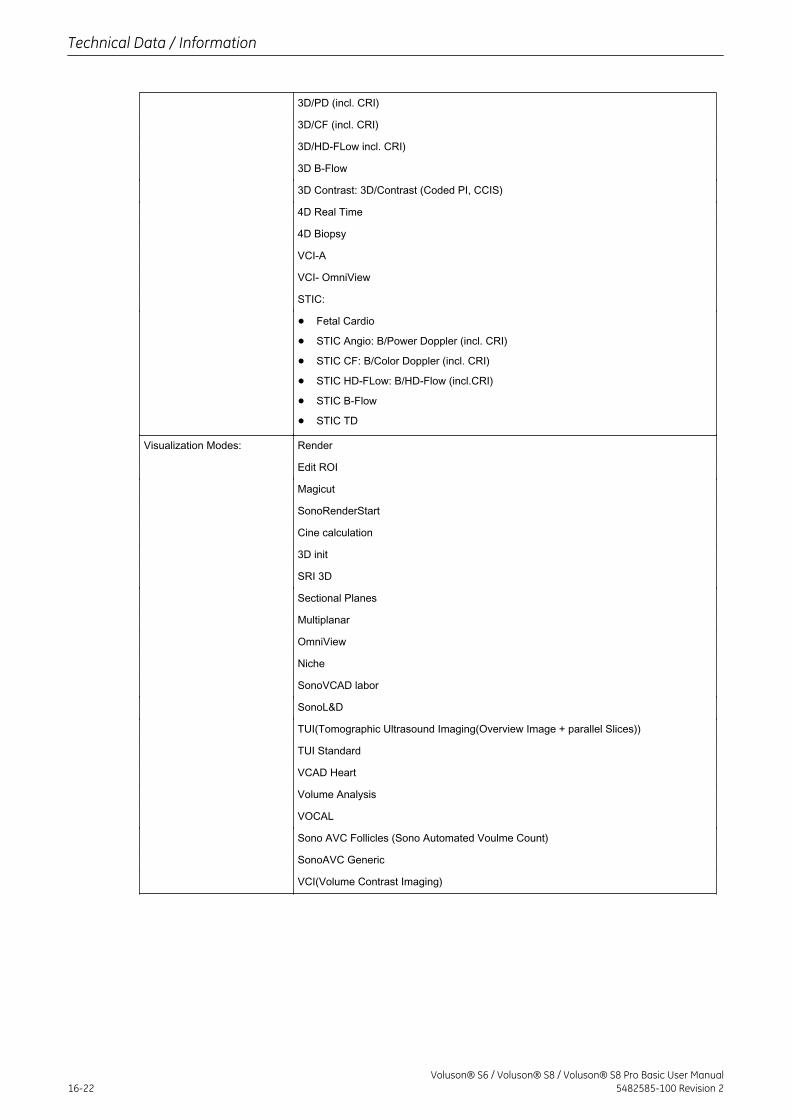
3D/PD (incl. CRI)
3D/CF (incl. CRI)
3D/HD-FLow incl. CRI)
3D B-Flow
3D Contrast: 3D/Contrast (Coded PI, CCIS)
4D Real Time
4D Biopsy
VCI-A
VCI- OmniView
STIC:
• Fetal Cardio
• STIC Angio: B/Power Doppler (incl. CRI)
• STIC CF: B/Color Doppler (incl. CRI)
• STIC HD-FLow: B/HD-Flow (incl.CRI)
• STIC B-Flow
• STIC TD
Visualization Modes: Render
Edit ROI
Magicut
SonoRenderStart
Cine calculation
3D init
SRI 3D
Sectional Planes
Multiplanar
OmniView
Niche
SonoVCAD labor
SonoL&D
TUI(Tomographic Ultrasound Imaging(Overview Image + parallel Slices))
TUI Standard
VCAD Heart
Volume Analysis
VOCAL
Sono AVC Follicles (Sono Automated Voulme Count)
SonoAVC Generic
VCI(Volume Contrast Imaging)
Technical Data / Information
16-22Voluson® S6 / Voluson® S8 / Voluson® S8 Pro Basic User Manual
5482585-100 Revision 2
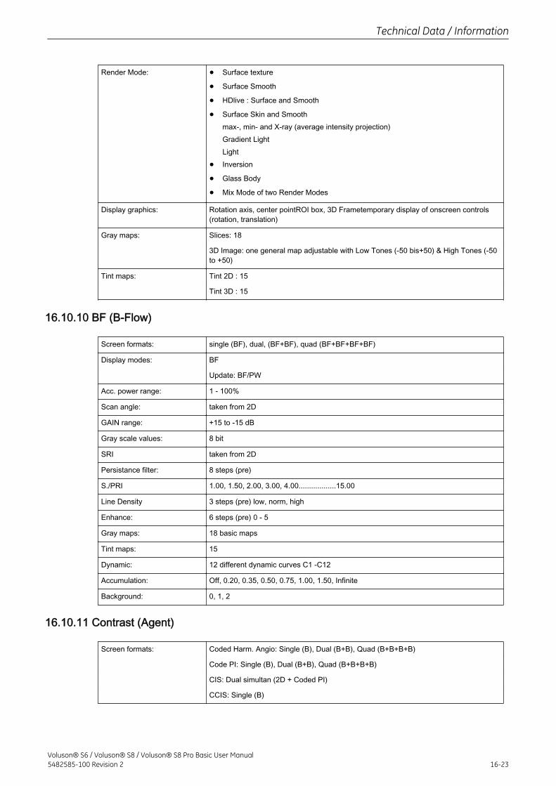
Render Mode: • Surface texture
• Surface Smooth
• HDlive : Surface and Smooth
• Surface Skin and Smoothmax-, min- and X-ray (average intensity projection)Gradient LightLight
• Inversion
• Glass Body
• Mix Mode of two Render Modes
Display graphics: Rotation axis, center pointROI box, 3D Frametemporary display of onscreen controls(rotation, translation)
Gray maps: Slices: 18
3D Image: one general map adjustable with Low Tones (-50 bis+50) & High Tones (-50to +50)
Tint maps: Tint 2D : 15
Tint 3D : 15
16.10.10 BF (B-Flow)
Screen formats: single (BF), dual, (BF+BF), quad (BF+BF+BF+BF)
Display modes: BF
Update: BF/PW
Acc. power range: 1 - 100%
Scan angle: taken from 2D
GAIN range: +15 to -15 dB
Gray scale values: 8 bit
SRI taken from 2D
Persistance filter: 8 steps (pre)
S./PRI 1.00, 1.50, 2.00, 3.00, 4.00..................15.00
Line Density 3 steps (pre) low, norm, high
Enhance: 6 steps (pre) 0 - 5
Gray maps: 18 basic maps
Tint maps: 15
Dynamic: 12 different dynamic curves C1 -C12
Accumulation: Off, 0.20, 0.35, 0.50, 0.75, 1.00, 1.50, Infinite
Background: 0, 1, 2
16.10.11 Contrast (Agent)
Screen formats: Coded Harm. Angio: Single (B), Dual (B+B), Quad (B+B+B+B)
Code PI: Single (B), Dual (B+B), Quad (B+B+B+B)
CIS: Dual simultan (2D + Coded PI)
CCIS: Single (B)
Technical Data / Information
Voluson® S6 / Voluson® S8 / Voluson® S8 Pro Basic User Manual5482585-100 Revision 2 16-23
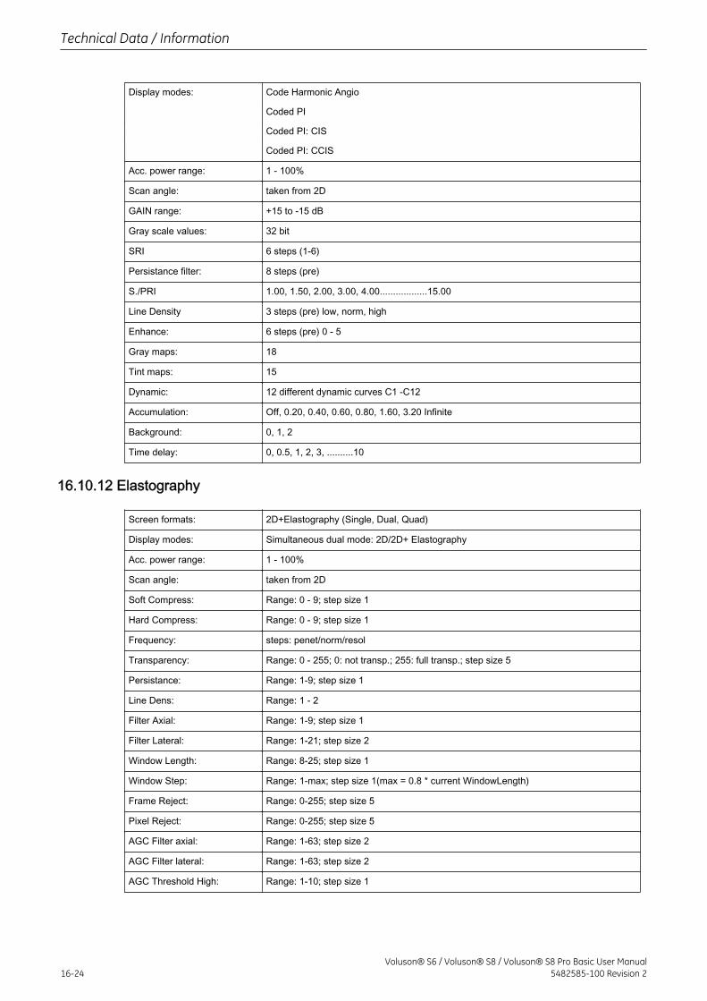
Display modes: Code Harmonic Angio
Coded PI
Coded PI: CIS
Coded PI: CCIS
Acc. power range: 1 - 100%
Scan angle: taken from 2D
GAIN range: +15 to -15 dB
Gray scale values: 32 bit
SRI 6 steps (1-6)
Persistance filter: 8 steps (pre)
S./PRI 1.00, 1.50, 2.00, 3.00, 4.00..................15.00
Line Density 3 steps (pre) low, norm, high
Enhance: 6 steps (pre) 0 - 5
Gray maps: 18
Tint maps: 15
Dynamic: 12 different dynamic curves C1 -C12
Accumulation: Off, 0.20, 0.40, 0.60, 0.80, 1.60, 3.20 Infinite
Background: 0, 1, 2
Time delay: 0, 0.5, 1, 2, 3, ..........10
16.10.12 Elastography
Screen formats: 2D+Elastography (Single, Dual, Quad)
Display modes: Simultaneous dual mode: 2D/2D+ Elastography
Acc. power range: 1 - 100%
Scan angle: taken from 2D
Soft Compress: Range: 0 - 9; step size 1
Hard Compress: Range: 0 - 9; step size 1
Frequency: steps: penet/norm/resol
Transparency: Range: 0 - 255; 0: not transp.; 255: full transp.; step size 5
Persistance: Range: 1-9; step size 1
Line Dens: Range: 1 - 2
Filter Axial: Range: 1-9; step size 1
Filter Lateral: Range: 1-21; step size 2
Window Length: Range: 8-25; step size 1
Window Step: Range: 1-max; step size 1(max = 0.8 * current WindowLength)
Frame Reject: Range: 0-255; step size 5
Pixel Reject: Range: 0-255; step size 5
AGC Filter axial: Range: 1-63; step size 2
AGC Filter lateral: Range: 1-63; step size 2
AGC Threshold High: Range: 1-10; step size 1
Technical Data / Information
16-24Voluson® S6 / Voluson® S8 / Voluson® S8 Pro Basic User Manual
5482585-100 Revision 2
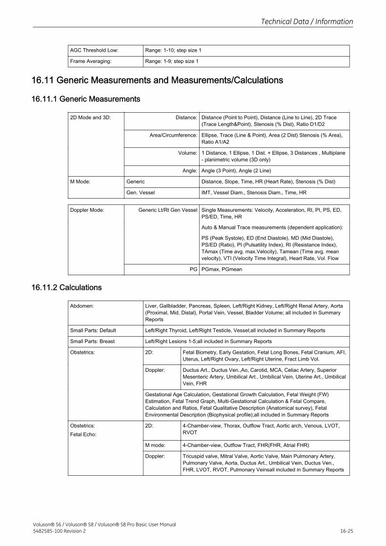
AGC Threshold Low: Range: 1-10; step size 1
Frame Averaging: Range: 1-9; step size 1
16.11 Generic Measurements and Measurements/Calculations
16.11.1 Generic Measurements
2D Mode and 3D: Distance: Distance (Point to Point), Distance (Line to Line), 2D Trace(Trace Length&Point), Stenosis (% Dist), Ratio D1/D2
Area/Circumference: Ellipse, Trace (Line & Point), Area (2 Dist) Stenosis (% Area),Ratio A1/A2
Volume: 1 Distance, 1 Ellipse, 1 Dist. + Ellipse, 3 Distances , Multiplane- planimetric volume (3D only)
Angle: Angle (3 Point), Angle (2 Line)
M Mode: Generic Distance, Slope, Time, HR (Heart Rate), Stenosis (% Dist)
Gen. Vessel IMT, Vessel Diam., Stenosis Diam., Time, HR
Doppler Mode: Generic Lt/Rt Gen Vessel Single Measurements: Velocity, Acceleration, RI, PI, PS, ED,PS/ED, Time, HR
Auto & Manual Trace measurements (dependent application):
PS (Peak Systole), ED (End Diastole), MD (Mid Diastole),PS/ED (Ratio), PI (Pulsatility Index), RI (Resistance Index),TAmax (Time avg. max.Velocity), Tamean (Time avg. meanvelocity), VTI (Velocity Time Integral), Heart Rate, Vol. Flow
PG PGmax, PGmean
16.11.2 Calculations
Abdomen: Liver, Gallbladder, Pancreas, Spleen, Left/Right Kidney, Left/Right Renal Artery, Aorta(Proximal, Mid, Distal), Portal Vein, Vessel, Bladder Volume; all included in SummaryReports
Small Parts: Default Left/Right Thyroid, Left/Right Testicle, Vessel;all included in Summary Reports
Small Parts: Breast Left/Right Lesions 1-5;all included in Summary Reports
Obstetrics: 2D: Fetal Biometry, Early Gestation, Fetal Long Bones, Fetal Cranium, AFI,Uterus, Left/Right Ovary, Left/Right Uterine, Fract Limb Vol.
Doppler: Ductus Art., Ductus Ven.,Ao, Carotid, MCA, Celiac Artery, SuperiorMesenteric Artery, Umbilical Art., Umbilical Vein, Uterine Art., UmbilicalVein, FHR
Gestational Age Calculation, Gestational Growth Calculation, Fetal Weight (FW)Estimation, Fetal Trend Graph, Multi-Gestational Calculation & Fetal Compare,Calculation and Ratios, Fetal Qualitative Description (Anatomical survey), FetalEnvironmental Description (Biophysical profile);all included in Summary Reports
Obstetrics:Fetal Echo:
2D: 4-Chamber-view, Thorax, Outflow Tract, Aortic arch, Venous, LVOT,RVOT
M mode: 4-Chamber-view, Outflow Tract, FHR(FHR, Atrial FHR)
Doppler: Tricuspid valve, Mitral Valve, Aortic Valve, Main Pulmonary Artery,Pulmonary Valve, Aorta, Ductus Art., Umbilical Vein, Ductus Ven.,FHR, LVOT, RVOT, Pulmonary Veinsall included in Summary Reports
Technical Data / Information
Voluson® S6 / Voluson® S8 / Voluson® S8 Pro Basic User Manual5482585-100 Revision 2 16-25
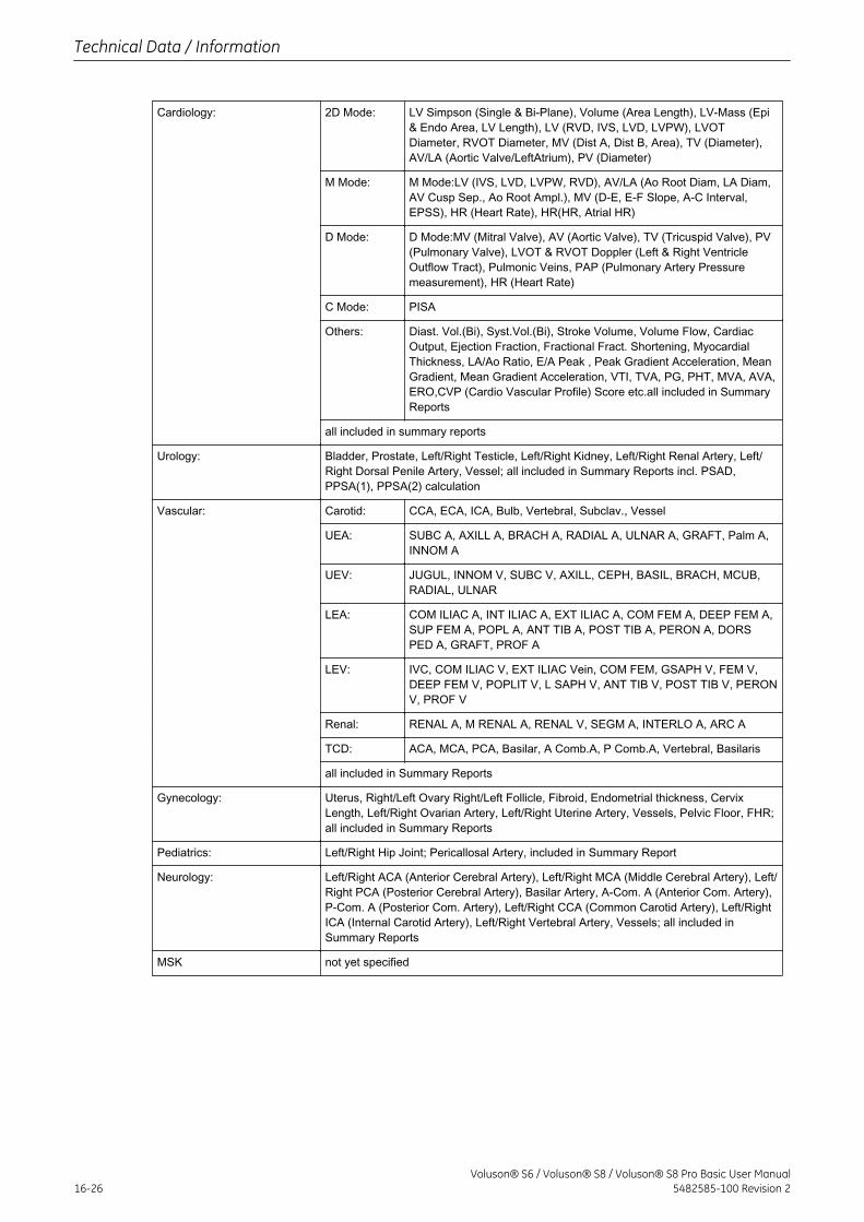
Cardiology: 2D Mode: LV Simpson (Single & Bi-Plane), Volume (Area Length), LV-Mass (Epi& Endo Area, LV Length), LV (RVD, IVS, LVD, LVPW), LVOTDiameter, RVOT Diameter, MV (Dist A, Dist B, Area), TV (Diameter),AV/LA (Aortic Valve/LeftAtrium), PV (Diameter)
M Mode: M Mode:LV (IVS, LVD, LVPW, RVD), AV/LA (Ao Root Diam, LA Diam,AV Cusp Sep., Ao Root Ampl.), MV (D-E, E-F Slope, A-C Interval,EPSS), HR (Heart Rate), HR(HR, Atrial HR)
D Mode: D Mode:MV (Mitral Valve), AV (Aortic Valve), TV (Tricuspid Valve), PV(Pulmonary Valve), LVOT & RVOT Doppler (Left & Right VentricleOutflow Tract), Pulmonic Veins, PAP (Pulmonary Artery Pressuremeasurement), HR (Heart Rate)
C Mode: PISA
Others: Diast. Vol.(Bi), Syst.Vol.(Bi), Stroke Volume, Volume Flow, CardiacOutput, Ejection Fraction, Fractional Fract. Shortening, MyocardialThickness, LA/Ao Ratio, E/A Peak , Peak Gradient Acceleration, MeanGradient, Mean Gradient Acceleration, VTI, TVA, PG, PHT, MVA, AVA,ERO,CVP (Cardio Vascular Profile) Score etc.all included in SummaryReports
all included in summary reports
Urology: Bladder, Prostate, Left/Right Testicle, Left/Right Kidney, Left/Right Renal Artery, Left/Right Dorsal Penile Artery, Vessel; all included in Summary Reports incl. PSAD,PPSA(1), PPSA(2) calculation
Vascular: Carotid: CCA, ECA, ICA, Bulb, Vertebral, Subclav., Vessel
UEA: SUBC A, AXILL A, BRACH A, RADIAL A, ULNAR A, GRAFT, Palm A,INNOM A
UEV: JUGUL, INNOM V, SUBC V, AXILL, CEPH, BASIL, BRACH, MCUB,RADIAL, ULNAR
LEA: COM ILIAC A, INT ILIAC A, EXT ILIAC A, COM FEM A, DEEP FEM A,SUP FEM A, POPL A, ANT TIB A, POST TIB A, PERON A, DORSPED A, GRAFT, PROF A
LEV: IVC, COM ILIAC V, EXT ILIAC Vein, COM FEM, GSAPH V, FEM V,DEEP FEM V, POPLIT V, L SAPH V, ANT TIB V, POST TIB V, PERONV, PROF V
Renal: RENAL A, M RENAL A, RENAL V, SEGM A, INTERLO A, ARC A
TCD: ACA, MCA, PCA, Basilar, A Comb.A, P Comb.A, Vertebral, Basilaris
all included in Summary Reports
Gynecology: Uterus, Right/Left Ovary Right/Left Follicle, Fibroid, Endometrial thickness, CervixLength, Left/Right Ovarian Artery, Left/Right Uterine Artery, Vessels, Pelvic Floor, FHR;all included in Summary Reports
Pediatrics: Left/Right Hip Joint; Pericallosal Artery, included in Summary Report
Neurology: Left/Right ACA (Anterior Cerebral Artery), Left/Right MCA (Middle Cerebral Artery), Left/Right PCA (Posterior Cerebral Artery), Basilar Artery, A-Com. A (Anterior Com. Artery),P-Com. A (Posterior Com. Artery), Left/Right CCA (Common Carotid Artery), Left/RightICA (Internal Carotid Artery), Left/Right Vertebral Artery, Vessels; all included inSummary Reports
MSK not yet specified
Technical Data / Information
16-26Voluson® S6 / Voluson® S8 / Voluson® S8 Pro Basic User Manual
5482585-100 Revision 2
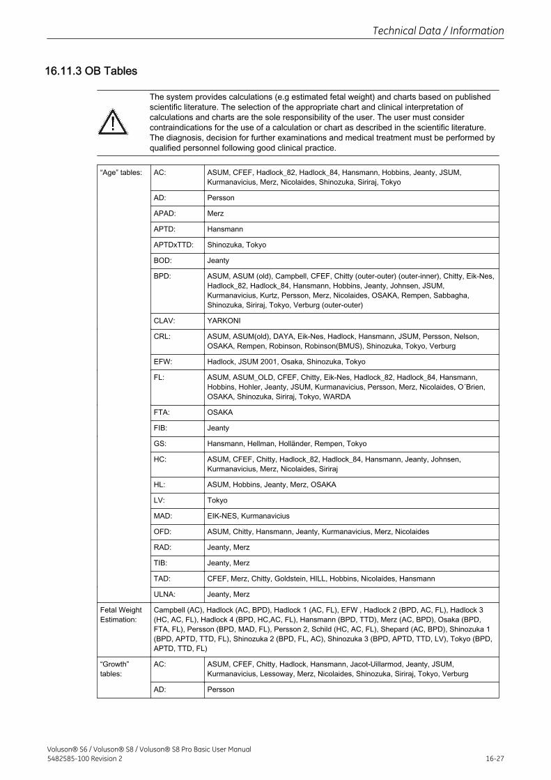
16.11.3 OB Tables
The system provides calculations (e.g estimated fetal weight) and charts based on publishedscientific literature. The selection of the appropriate chart and clinical interpretation ofcalculations and charts are the sole responsibility of the user. The user must considercontraindications for the use of a calculation or chart as described in the scientific literature.The diagnosis, decision for further examinations and medical treatment must be performed byqualified personnel following good clinical practice.
“Age” tables: AC: ASUM, CFEF, Hadlock_82, Hadlock_84, Hansmann, Hobbins, Jeanty, JSUM,Kurmanavicius, Merz, Nicolaides, Shinozuka, Siriraj, Tokyo
AD: Persson
APAD: Merz
APTD: Hansmann
APTDxTTD: Shinozuka, Tokyo
BOD: Jeanty
BPD: ASUM, ASUM (old), Campbell, CFEF, Chitty (outer-outer) (outer-inner), Chitty, Eik-Nes,Hadlock_82, Hadlock_84, Hansmann, Hobbins, Jeanty, Johnsen, JSUM,Kurmanavicius, Kurtz, Persson, Merz, Nicolaides, OSAKA, Rempen, Sabbagha,Shinozuka, Siriraj, Tokyo, Verburg (outer-outer)
CLAV: YARKONI
CRL: ASUM, ASUM(old), DAYA, Eik-Nes, Hadlock, Hansmann, JSUM, Persson, Nelson,OSAKA, Rempen, Robinson, Robinson(BMUS), Shinozuka, Tokyo, Verburg
EFW: Hadlock, JSUM 2001, Osaka, Shinozuka, Tokyo
FL: ASUM, ASUM_OLD, CFEF, Chitty, Eik-Nes, Hadlock_82, Hadlock_84, Hansmann,Hobbins, Hohler, Jeanty, JSUM, Kurmanavicius, Persson, Merz, Nicolaides, O´Brien,OSAKA, Shinozuka, Siriraj, Tokyo, WARDA
FTA: OSAKA
FIB: Jeanty
GS: Hansmann, Hellman, Holländer, Rempen, Tokyo
HC: ASUM, CFEF, Chitty, Hadlock_82, Hadlock_84, Hansmann, Jeanty, Johnsen,Kurmanavicius, Merz, Nicolaides, Siriraj
HL: ASUM, Hobbins, Jeanty, Merz, OSAKA
LV: Tokyo
MAD: EIK-NES, Kurmanavicius
OFD: ASUM, Chitty, Hansmann, Jeanty, Kurmanavicius, Merz, Nicolaides
RAD: Jeanty, Merz
TIB: Jeanty, Merz
TAD: CFEF, Merz, Chitty, Goldstein, HILL, Hobbins, Nicolaides, Hansmann
ULNA: Jeanty, Merz
Fetal WeightEstimation:
Campbell (AC), Hadlock (AC, BPD), Hadlock 1 (AC, FL), EFW , Hadlock 2 (BPD, AC, FL), Hadlock 3(HC, AC, FL), Hadlock 4 (BPD, HC,AC, FL), Hansmann (BPD, TTD), Merz (AC, BPD), Osaka (BPD,FTA, FL), Persson (BPD, MAD, FL), Persson 2, Schild (HC, AC, FL), Shepard (AC, BPD), Shinozuka 1(BPD, APTD, TTD, FL), Shinozuka 2 (BPD, FL, AC), Shinozuka 3 (BPD, APTD, TTD, LV), Tokyo (BPD,APTD, TTD, FL)
“Growth”tables:
AC: ASUM, CFEF, Chitty, Hadlock, Hansmann, Jacot-Uillarmod, Jeanty, JSUM,Kurmanavicius, Lessoway, Merz, Nicolaides, Shinozuka, Siriraj, Tokyo, Verburg
AD: Persson
Technical Data / Information
Voluson® S6 / Voluson® S8 / Voluson® S8 Pro Basic User Manual5482585-100 Revision 2 16-27
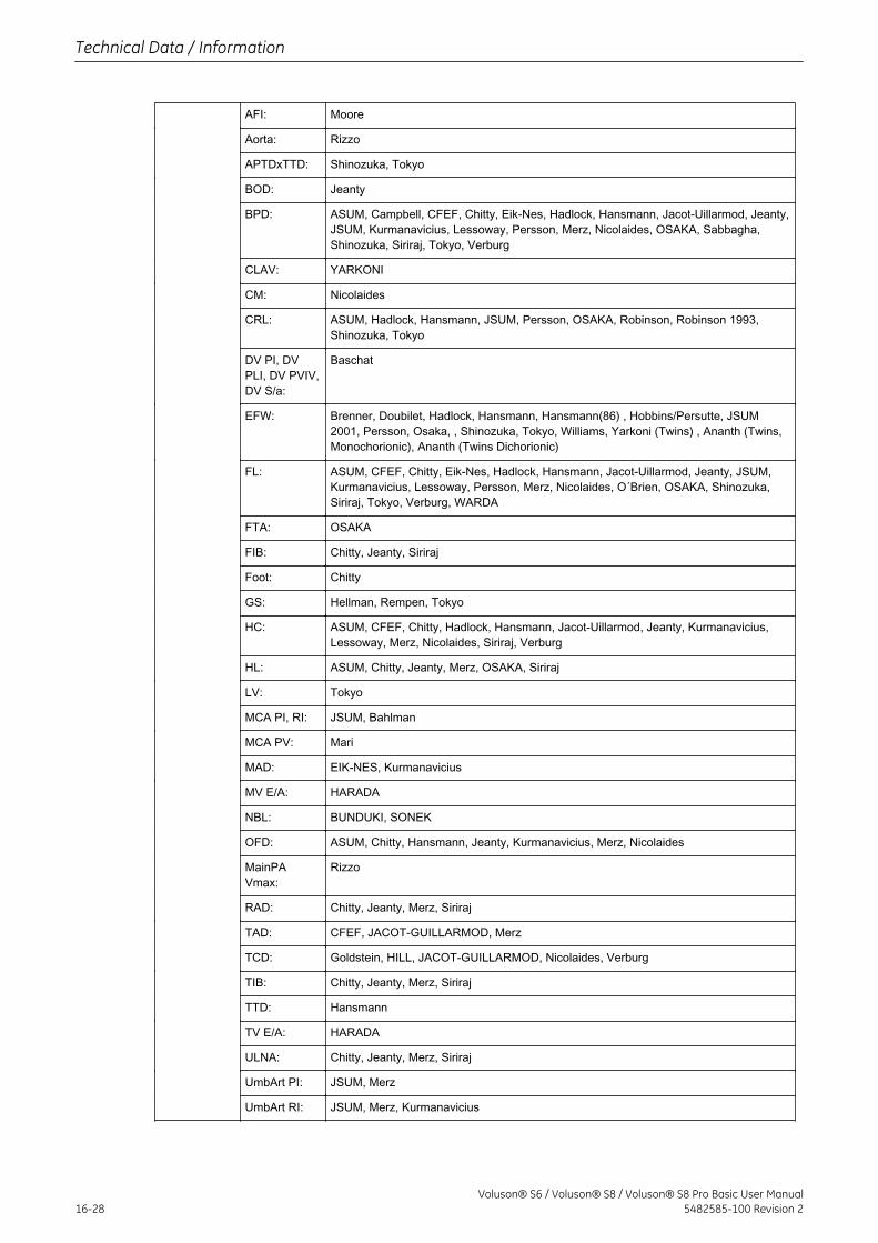
AFI: Moore
Aorta: Rizzo
APTDxTTD: Shinozuka, Tokyo
BOD: Jeanty
BPD: ASUM, Campbell, CFEF, Chitty, Eik-Nes, Hadlock, Hansmann, Jacot-Uillarmod, Jeanty,JSUM, Kurmanavicius, Lessoway, Persson, Merz, Nicolaides, OSAKA, Sabbagha,Shinozuka, Siriraj, Tokyo, Verburg
CLAV: YARKONI
CM: Nicolaides
CRL: ASUM, Hadlock, Hansmann, JSUM, Persson, OSAKA, Robinson, Robinson 1993,Shinozuka, Tokyo
DV PI, DVPLI, DV PVIV,DV S/a:
Baschat
EFW: Brenner, Doubilet, Hadlock, Hansmann, Hansmann(86) , Hobbins/Persutte, JSUM2001, Persson, Osaka, , Shinozuka, Tokyo, Williams, Yarkoni (Twins) , Ananth (Twins,Monochorionic), Ananth (Twins Dichorionic)
FL: ASUM, CFEF, Chitty, Eik-Nes, Hadlock, Hansmann, Jacot-Uillarmod, Jeanty, JSUM,Kurmanavicius, Lessoway, Persson, Merz, Nicolaides, O´Brien, OSAKA, Shinozuka,Siriraj, Tokyo, Verburg, WARDA
FTA: OSAKA
FIB: Chitty, Jeanty, Siriraj
Foot: Chitty
GS: Hellman, Rempen, Tokyo
HC: ASUM, CFEF, Chitty, Hadlock, Hansmann, Jacot-Uillarmod, Jeanty, Kurmanavicius,Lessoway, Merz, Nicolaides, Siriraj, Verburg
HL: ASUM, Chitty, Jeanty, Merz, OSAKA, Siriraj
LV: Tokyo
MCA PI, RI: JSUM, Bahlman
MCA PV: Mari
MAD: EIK-NES, Kurmanavicius
MV E/A: HARADA
NBL: BUNDUKI, SONEK
OFD: ASUM, Chitty, Hansmann, Jeanty, Kurmanavicius, Merz, Nicolaides
MainPAVmax:
Rizzo
RAD: Chitty, Jeanty, Merz, Siriraj
TAD: CFEF, JACOT-GUILLARMOD, Merz
TCD: Goldstein, HILL, JACOT-GUILLARMOD, Nicolaides, Verburg
TIB: Chitty, Jeanty, Merz, Siriraj
TTD: Hansmann
TV E/A: HARADA
ULNA: Chitty, Jeanty, Merz, Siriraj
UmbArt PI: JSUM, Merz
UmbArt RI: JSUM, Merz, Kurmanavicius
Technical Data / Information
16-28Voluson® S6 / Voluson® S8 / Voluson® S8 Pro Basic User Manual
5482585-100 Revision 2
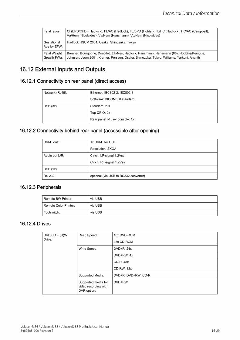
Fetal ratios: CI (BPD/OFD) (Hadlock), FL/AC (Hadlock), FL/BPD (Hohler), FL/HC (Hadlock), HC/AC (Campbell),Va/Hem (Nicolaides), Va/Hem (Hansmann), Vp/Hem (Nicolaides)
GestationalAge by EFW:
Hadlock, JSUM 2001, Osaka, Shinozuka, Tokyo
Fetal WeightGrowth FWg:
Brenner, Bourgogne, Doubilet, Eik-Nes, Hadlock, Hansmann, Hansmann (86), Hobbins/Persutte,Johnsen, Jsum 2001, Kramer, Persson, Osaka, Shinozuka, Tokyo, Williams, Yarkoni, Ananth
16.12 External Inputs and Outputs
16.12.1 Connectivity on rear panel (direct access)
Network (RJ45): Ethernet, IEC802-2, IEC802-3
Software: DICOM 3.0 standard
USB (3x): Standard: 2.0
Top OPIO: 2x
Rear panel of user console: 1x
16.12.2 Connectivity behind rear panel (accessible after opening)
DVI-D out: 1x DVI-D for OUT
Resolution: SXGA
Audio out L/R: Cinch, LF-signal 1.2Vss
Cinch, RF-signal 1.2Vss
USB (1x):
RS 232. optional (via USB to RS232 converter)
16.12.3 Peripherals
Remote BW Printer: via USB
Remote Color Printer: via USB
Footswitch: via USB
16.12.4 Drives
DVD/CD + (R)WDrive:
Read Speed: 16x DVD-ROM
48x CD-ROM
Write Speed: DVD+R: 24x
DVD+RW: 4x
CD-R: 48x
CD-RW: 32x
Supported Media: DVD+R, DVD+RW, CD-R
Supported media forvideo recording withDVR option:
DVD+RW
Technical Data / Information
Voluson® S6 / Voluson® S8 / Voluson® S8 Pro Basic User Manual5482585-100 Revision 2 16-29
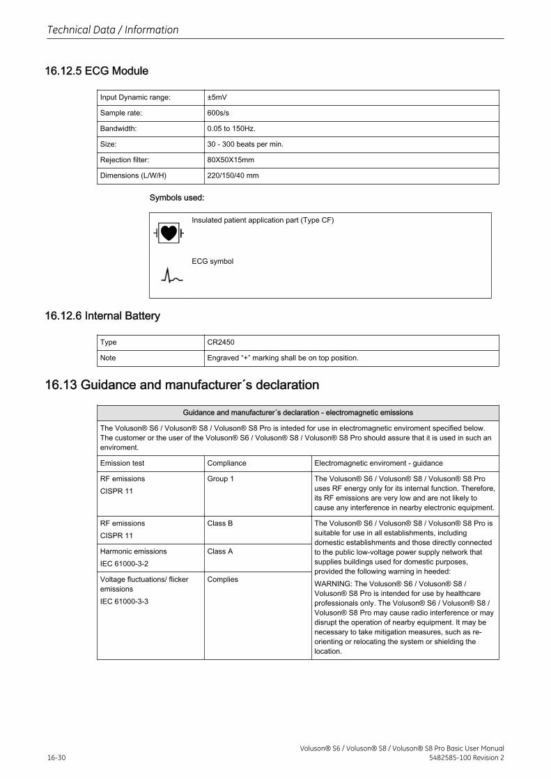
16.12.5 ECG Module
Input Dynamic range: ±5mV
Sample rate: 600s/s
Bandwidth: 0.05 to 150Hz.
Size: 30 - 300 beats per min.
Rejection filter: 80X50X15mm
Dimensions (L/W/H) 220/150/40 mm
Symbols used:
Insulated patient application part (Type CF)
ECG symbol
16.12.6 Internal Battery
Type CR2450
Note Engraved “+” marking shall be on top position.
16.13 Guidance and manufacturer´s declaration
Guidance and manufacturer´s declaration - electromagnetic emissions
The Voluson® S6 / Voluson® S8 / Voluson® S8 Pro is inteded for use in electromagnetic enviroment specified below.The customer or the user of the Voluson® S6 / Voluson® S8 / Voluson® S8 Pro should assure that it is used in such anenviroment.
Emission test Compliance Electromagnetic enviroment - guidance
RF emissionsCISPR 11
Group 1 The Voluson® S6 / Voluson® S8 / Voluson® S8 Prouses RF energy only for its internal function. Therefore,its RF emissions are very low and are not likely tocause any interference in nearby electronic equipment.
RF emissionsCISPR 11
Class B The Voluson® S6 / Voluson® S8 / Voluson® S8 Pro issuitable for use in all establishments, includingdomestic establishments and those directly connectedto the public low-voltage power supply network thatsupplies buildings used for domestic purposes,provided the following warning in heeded:WARNING: The Voluson® S6 / Voluson® S8 /Voluson® S8 Pro is intended for use by healthcareprofessionals only. The Voluson® S6 / Voluson® S8 /Voluson® S8 Pro may cause radio interference or maydisrupt the operation of nearby equipment. It may benecessary to take mitigation measures, such as re-orienting or relocating the system or shielding thelocation.
Harmonic emissionsIEC 61000-3-2
Class A
Voltage fluctuations/ flickeremissionsIEC 61000-3-3
Complies
Technical Data / Information
16-30Voluson® S6 / Voluson® S8 / Voluson® S8 Pro Basic User Manual
5482585-100 Revision 2
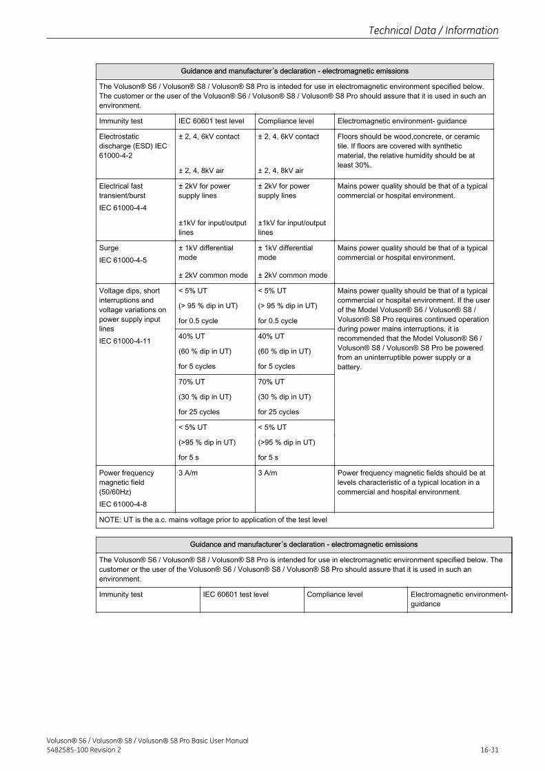
Guidance and manufacturer´s declaration - electromagnetic emissions
The Voluson® S6 / Voluson® S8 / Voluson® S8 Pro is inteded for use in electromagnetic environment specified below.The customer or the user of the Voluson® S6 / Voluson® S8 / Voluson® S8 Pro should assure that it is used in such anenvironment.
Immunity test IEC 60601 test level Compliance level Electromagnetic environment- guidance
Electrostaticdischarge (ESD) IEC61000-4-2
± 2, 4, 6kV contact ± 2, 4, 6kV contact Floors should be wood,concrete, or ceramictile. If floors are covered with syntheticmaterial, the relative humidity should be atleast 30%.
± 2, 4, 8kV air ± 2, 4, 8kV air
Electrical fasttransient/burstIEC 61000-4-4
± 2kV for powersupply lines
± 2kV for powersupply lines
Mains power quality should be that of a typicalcommercial or hospital environment.
±1kV for input/outputlines
±1kV for input/outputlines
SurgeIEC 61000-4-5
± 1kV differentialmode
± 1kV differentialmode
Mains power quality should be that of a typicalcommercial or hospital environment.
± 2kV common mode ± 2kV common mode
Voltage dips, shortinterruptions andvoltage variations onpower supply inputlinesIEC 61000-4-11
< 5% UT < 5% UT Mains power quality should be that of a typicalcommercial or hospital environment. If the userof the Model Voluson® S6 / Voluson® S8 /Voluson® S8 Pro requires continued operationduring power mains interruptions, it isrecommended that the Model Voluson® S6 /Voluson® S8 / Voluson® S8 Pro be poweredfrom an uninterruptible power supply or abattery.
(> 95 % dip in UT) (> 95 % dip in UT)
for 0.5 cycle for 0.5 cycle
40% UT 40% UT
(60 % dip in UT) (60 % dip in UT)
for 5 cycles for 5 cycles
70% UT 70% UT
(30 % dip in UT) (30 % dip in UT)
for 25 cycles for 25 cycles
< 5% UT < 5% UT
(>95 % dip in UT) (>95 % dip in UT)
for 5 s for 5 s
Power frequencymagnetic field(50/60Hz)IEC 61000-4-8
3 A/m 3 A/m Power frequency magnetic fields should be atlevels characteristic of a typical location in acommercial and hospital environment.
NOTE: UT is the a.c. mains voltage prior to application of the test level
Guidance and manufacturer´s declaration - electromagnetic emissions
The Voluson® S6 / Voluson® S8 / Voluson® S8 Pro is intended for use in electromagnetic environment specified below. Thecustomer or the user of the Voluson® S6 / Voluson® S8 / Voluson® S8 Pro should assure that it is used in such anenvironment.
Immunity test IEC 60601 test level Compliance level Electromagnetic environment-guidance
Technical Data / Information
Voluson® S6 / Voluson® S8 / Voluson® S8 Pro Basic User Manual5482585-100 Revision 2 16-31
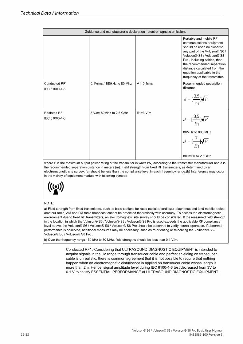
Guidance and manufacturer´s declaration - electromagnetic emissions
Portable and mobile RFcommunications equipmentshould be used no closer toany part of the Voluson® S6 /Voluson® S8 / Voluson® S8Pro , including cables, thanthe recommended separationdistance calculated from theequation applicable to thefrequency of the transmitter.
Conducted RF*IEC 61000-4-6
0.1Vrms / 150kHz to 80 Mhz V1=0.1rms Recommended separationdistance
Radiated RFIEC 61000-4-3
3 V/m; 80MHz to 2.5 GHz E1=3 V/m
80MHz to 800 MHz
800MHz to 2.5GHz
where P is the maximum output power rating of the transmitter in watts (W) according to the transmitter manufacturer and d isthe recommended separation distance in meters (m). Field strength from fixed RF transmitters, as determined by anelectromagnetic site survey, (a) should be less than the compliance level in each frequency range.(b) Interference may occurin the vicinity of equipment marked with following symbol:
NOTE:a) Field strength from fixed transmitters, such as base stations for radio (cellular/cordless) telephones and land mobile radios,amateur radio, AM and FM radio broadcast cannot be predicted theoretically with accuracy. To access the electromagneticenvironment due to fixed RF transmitters, an electromagnetic site survey should be considered. If the measured field strengthin the location in which the Voluson® S6 / Voluson® S8 / Voluson® S8 Pro is used exceeds the applicable RF compliancelevel above, the Voluson® S6 / Voluson® S8 / Voluson® S8 Pro should be observed to verify normal operation. If abnormalperformance is observed, additional measures may be necessary, such as re-orienting or relocating the Voluson® S6 /Voluson® S8 / Voluson® S8 Pro .b) Over the frequency range 150 kHz to 80 MHz, field strengths should be less than 0.1 V/m.
Conducted RF* : Considering that ULTRASOUND DIAGNOSTIC EQUIPMENT is intended toacquire signals in the uV range through transducer cable and perfect shielding on transducercable is unrealistic, there is common agreement that it is not possible to require that nothinghappen when an electromagnetic disturbance is applied on transducer cable whose length ismore than 2m. Hence, signal amplitude level during IEC 6100-4-6 test decreased from 3V to0.1 V to satisfy ESSENTIAL PERFORMANCE of ULTRASOUND DIAGNOSTIC EQUIPMENT.
Technical Data / Information
16-32Voluson® S6 / Voluson® S8 / Voluson® S8 Pro Basic User Manual
5482585-100 Revision 2
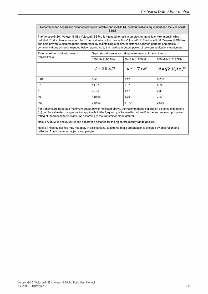
Recommended separation distances between portable and mobile RF communications equipment and the Voluson©S6/S8
The Voluson® S6 / Voluson® S8 / Voluson® S8 Pro is intended for use in an electromagnetic environment in whichradiated RF distubance are controlled. The customer or the user of the Voluson® S6 / Voluson® S8 / Voluson® S8 Procan help prevent electromagnetic interference by maintaining a minimum distance between portable and mobile RFcommunications as recommended below, according to the maximum output power of the communications equipment.
Rated maximum output power oftransmitter W
Separation distance according to frequency of transmitter m
150 kHz to 80 Mhz 80 MHz to 800 Mhz 800 MHz to 2,5 GHz
0.01 3.50 0.12 0.233
0.1 11.07 0.37 0.74
1 35.00 1.17 2.33
10 110.68 3.70 7.40
100 350.00 11.70 23.30
For transmitters rated at a maximum output power not listed above, the recommended separation distance d in meters(m) can be estimated using equation applicable to the frequency of transmitter, where P is the maximum output powerrating of the transmitter in watts (W) according to the transmitter manufacturer.
Note 1 At 80MHz and 800MHz, the separation distance for the higher frequency range applies.
Note 2 These guidelines may not apply in all situations. Electromagnetic propagation is affected by absorption andreflection from structures, objects and people.
Technical Data / Information
Voluson® S6 / Voluson® S8 / Voluson® S8 Pro Basic User Manual5482585-100 Revision 2 16-33

This page was intentionally left blank.
Technical Data / Information
16-34Voluson® S6 / Voluson® S8 / Voluson® S8 Pro Basic User Manual
5482585-100 Revision 2

Chapter 17
ANNEX- Abbreviations
Description of abbreviations, sorted alphabetically
Voluson® S6 / Voluson® S8 / Voluson® S8 Pro Basic User Manual5482585-100 Revision 2 17-1
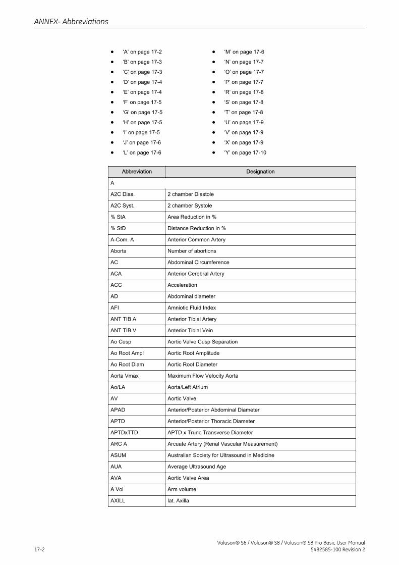
• ‘A’ on page 17‐2
• ‘B’ on page 17‐3
• ‘C’ on page 17‐3
• ‘D’ on page 17‐4
• ‘E’ on page 17‐4
• ‘F’ on page 17‐5
• ‘G’ on page 17‐5
• ‘H’ on page 17‐5
• ‘I’ on page 17‐5
• ‘J’ on page 17‐6
• ‘L’ on page 17‐6
• ‘M’ on page 17‐6
• ‘N’ on page 17‐7
• ‘O’ on page 17‐7
• ‘P’ on page 17‐7
• ‘R’ on page 17‐8
• ‘S’ on page 17‐8
• ‘T’ on page 17‐8
• ‘U’ on page 17‐9
• ‘V’ on page 17‐9
• ‘X’ on page 17‐9
• ‘Y’ on page 17‐10
Abbreviation Designation
A
A2C Dias. 2 chamber Diastole
A2C Syst. 2 chamber Systole
% StA Area Reduction in %
% StD Distance Reduction in %
A-Com. A Anterior Common Artery
Aborta Number of abortions
AC Abdominal Circumference
ACA Anterior Cerebral Artery
ACC Acceleration
AD Abdominal diameter
AFI Amniotic Fluid Index
ANT TIB A Anterior Tibial Artery
ANT TIB V Anterior Tibial Vein
Ao Cusp Aortic Valve Cusp Separation
Ao Root Ampl Aortic Root Amplitude
Ao Root Diam Aortic Root Diameter
Aorta Vmax Maximum Flow Velocity Aorta
Ao/LA Aorta/Left Atrium
AV Aortic Valve
APAD Anterior/Posterior Abdominal Diameter
APTD Anterior/Posterior Thoracic Diameter
APTDxTTD APTD x Trunc Transverse Diameter
ARC A Arcuate Artery (Renal Vascular Measurement)
ASUM Australian Society for Ultrasound in Medicine
AUA Average Ultrasound Age
AVA Aortic Valve Area
A Vol Arm volume
AXILL lat. Axilla
ANNEX- Abbreviations
17-2Voluson® S6 / Voluson® S8 / Voluson® S8 Pro Basic User Manual
5482585-100 Revision 2
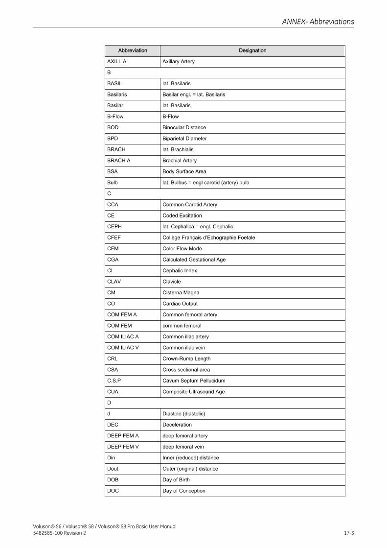
Abbreviation Designation
AXILL A Axillary Artery
B
BASIL lat. Basilaris
Basilaris Basilar engl. = lat. Basilaris
Basilar lat. Basilaris
B-Flow B-Flow
BOD Binocular Distance
BPD Biparietal Diameter
BRACH lat. Brachialis
BRACH A Brachial Artery
BSA Body Surface Area
Bulb lat. Bulbus = engl carotid (artery) bulb
C
CCA Common Carotid Artery
CE Coded Excitation
CEPH lat. Cephalica = engl. Cephalic
CFEF Collège Français d’Echographie Foetale
CFM Color Flow Mode
CGA Calculated Gestational Age
CI Cephalic Index
CLAV Clavicle
CM Cisterna Magna
CO Cardiac Output
COM FEM A Common femoral artery
COM FEM common femoral
COM ILIAC A Common iliac artery
COM ILIAC V Common iliac vein
CRL Crown-Rump Length
CSA Cross sectional area
C.S.P Cavum Septum Pellucidum
CUA Composite Ultrasound Age
D
d Diastole (diastolic)
DEC Deceleration
DEEP FEM A deep femoral artery
DEEP FEM V deep femoral vein
Din Inner (reduced) distance
Dout Outer (original) distance
DOB Day of Birth
DOC Day of Conception
ANNEX- Abbreviations
Voluson® S6 / Voluson® S8 / Voluson® S8 Pro Basic User Manual5482585-100 Revision 2 17-3
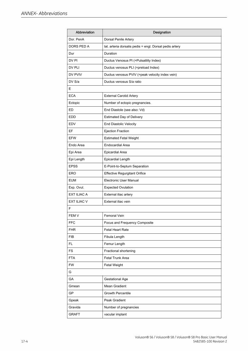
Abbreviation Designation
Dor. PenA Dorsal Penile Artery
DORS PED A lat. arteria dorsalis pedis = engl. Dorsal pedis artery
Dur Duration
DV PI Ductus Venosus PI (=Pulsatility Index)
DV PLI Ductus venosus PLI (=preload Index)
DV PVIV Ductus venosus PVIV (=peak velocity index vein)
DV S/a Ductus venosus S/a ratio
E
ECA External Carotid Artery
Ectopic Number of ectopic pregnancies.
ED End Diastole (see also: Vd)
EDD Estimated Day of Delivery
EDV End Diastolic Velocity
EF Ejection Fraction
EFW Estimated Fetal Weight
Endo Area Endocardial Area
Epi Area Epicardial Area
Epi Length Epicardial Length
EPSS E-Point-to-Septum Separation
ERO Effective Regurgitant Orifice
EUM Electronic User Manual
Exp. Ovul. Expected Ovulation
EXT ILIAC A External iliac artery
EXT ILIAC V External iliac vein
F
FEM V Femoral Vein
FFC Focus and Frequency Composite
FHR Fetal Heart Rate
FIB Fibula Length
FL Femur Length
FS Fractional shortening
FTA Fetal Trunk Area
FW Fetal Weight
G
GA Gestational Age
Gmean Mean Gradient
GP Growth Percentile
Gpeak Peak Gradient
Gravida Number of pregnancies
GRAFT vacular implant
ANNEX- Abbreviations
17-4Voluson® S6 / Voluson® S8 / Voluson® S8 Pro Basic User Manual
5482585-100 Revision 2
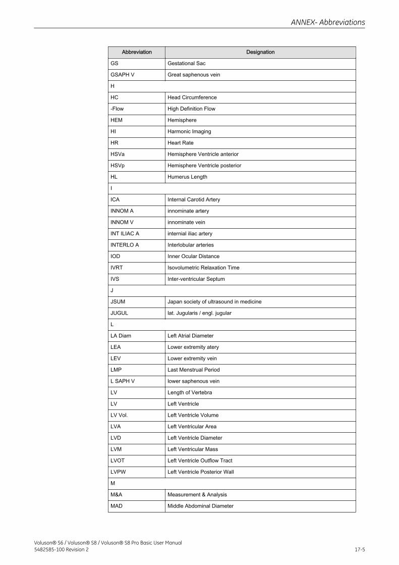
Abbreviation Designation
GS Gestational Sac
GSAPH V Great saphenous vein
H
HC Head Circumference
-Flow High Definition Flow
HEM Hemisphere
HI Harmonic Imaging
HR Heart Rate
HSVa Hemisphere Ventricle anterior
HSVp Hemisphere Ventricle posterior
HL Humerus Length
I
ICA Internal Carotid Artery
INNOM A innominate artery
INNOM V innominate vein
INT ILIAC A internial iliac artery
INTERLO A Interlobular arteries
IOD Inner Ocular Distance
IVRT Isovolumetric Relaxation Time
IVS Inter-ventricular Septum
J
JSUM Japan society of ultrasound in medicine
JUGUL lat. Jugularis / engl. jugular
L
LA Diam Left Atrial Diameter
LEA Lower extremity atery
LEV Lower extremity vein
LMP Last Menstrual Period
L SAPH V lower saphenous vein
LV Length of Vertebra
LV Left Ventricle
LV Vol. Left Ventricle Volume
LVA Left Ventricular Area
LVD Left Ventricle Diameter
LVM Left Ventricular Mass
LVOT Left Ventricle Outflow Tract
LVPW Left Ventricle Posterior Wall
M
M&A Measurement & Analysis
MAD Middle Abdominal Diameter
ANNEX- Abbreviations
Voluson® S6 / Voluson® S8 / Voluson® S8 Pro Basic User Manual5482585-100 Revision 2 17-5
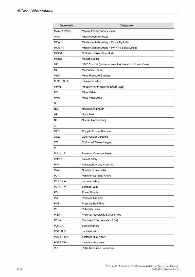
Abbreviation Designation
MainPA Vmax Main pulmonary artery Vmax
MCA Middle Cephalic Artery
MCA PI Middle Cephalic Artery + Pulsatility Index
MCA PV Middle Cephalic Artery + PV = PS peak systolic
MCFM M Mode + Color Flow Mode
MCUB median cubital
MD “Mid” Diastole (minimum velocity)(see also: Vd and Vmin)
MI Mechanical Index
MnG Mean Pressure Gradient
M RENAL A main renal artery
MPPS Modality Performed Procedure Step
MV Mitral Valve
MVA Mitral Valve Area
N
NBL Nasal Bone Length
NF Neck Fold
NT Nuchal Translucency
O
OFD Occipito Frontal Diameter
OOD Outer Ocular Distance
OTI Optimized Tissue Imaging
P
P-Com. A Posterior Common Artery
Palm A palmar artery
PAP Pulmonary Artery Pressure
Para Number of live births
PCA Posterior Cerebral Artery
PERON A peroneal artery
PERON V peroneal vein
PD Power Doppler
PG Pressure Gradient
PHT Pressure Half Time
PI Pulsatility Index
PISA Proximal Isovelocity Surface Area
PPSA Predicted PSA (see also: PSA)
POPL A popliteal artery
POPLIT V popliteal vein
POST TIB A posterior tibial artery
POST TIB V posterior tibial vein
PRF Pulse Repetition Frequency
ANNEX- Abbreviations
17-6Voluson® S6 / Voluson® S8 / Voluson® S8 Pro Basic User Manual
5482585-100 Revision 2
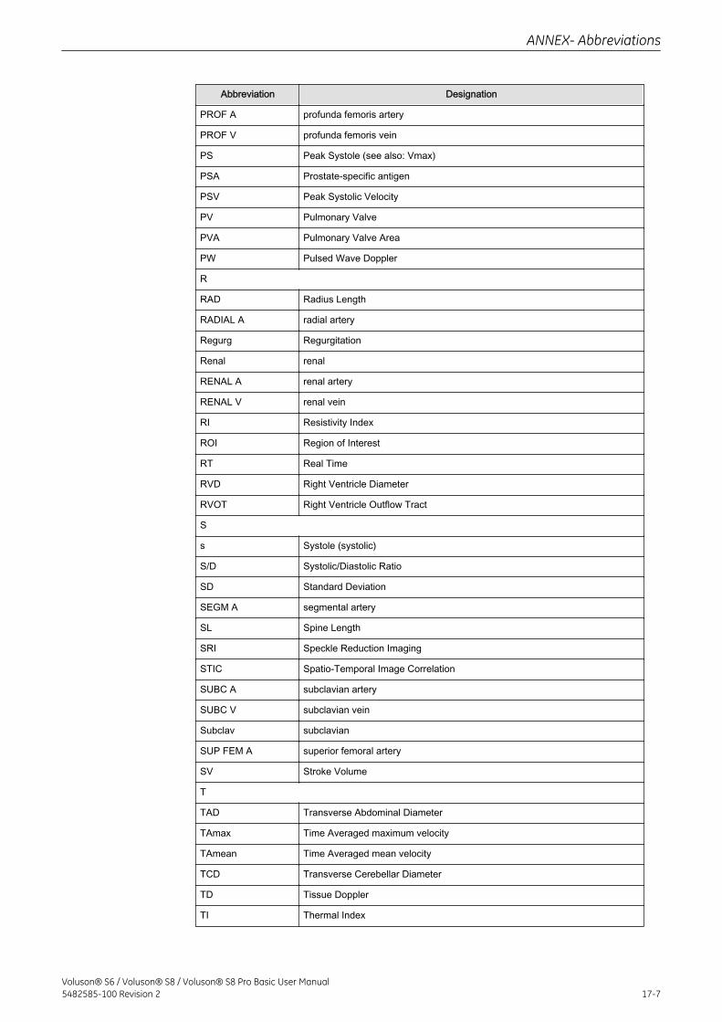
Abbreviation Designation
PROF A profunda femoris artery
PROF V profunda femoris vein
PS Peak Systole (see also: Vmax)
PSA Prostate-specific antigen
PSV Peak Systolic Velocity
PV Pulmonary Valve
PVA Pulmonary Valve Area
PW Pulsed Wave Doppler
R
RAD Radius Length
RADIAL A radial artery
Regurg Regurgitation
Renal renal
RENAL A renal artery
RENAL V renal vein
RI Resistivity Index
ROI Region of Interest
RT Real Time
RVD Right Ventricle Diameter
RVOT Right Ventricle Outflow Tract
S
s Systole (systolic)
S/D Systolic/Diastolic Ratio
SD Standard Deviation
SEGM A segmental artery
SL Spine Length
SRI Speckle Reduction Imaging
STIC Spatio-Temporal Image Correlation
SUBC A subclavian artery
SUBC V subclavian vein
Subclav subclavian
SUP FEM A superior femoral artery
SV Stroke Volume
T
TAD Transverse Abdominal Diameter
TAmax Time Averaged maximum velocity
TAmean Time Averaged mean velocity
TCD Transverse Cerebellar Diameter
TD Tissue Doppler
TI Thermal Index
ANNEX- Abbreviations
Voluson® S6 / Voluson® S8 / Voluson® S8 Pro Basic User Manual5482585-100 Revision 2 17-7
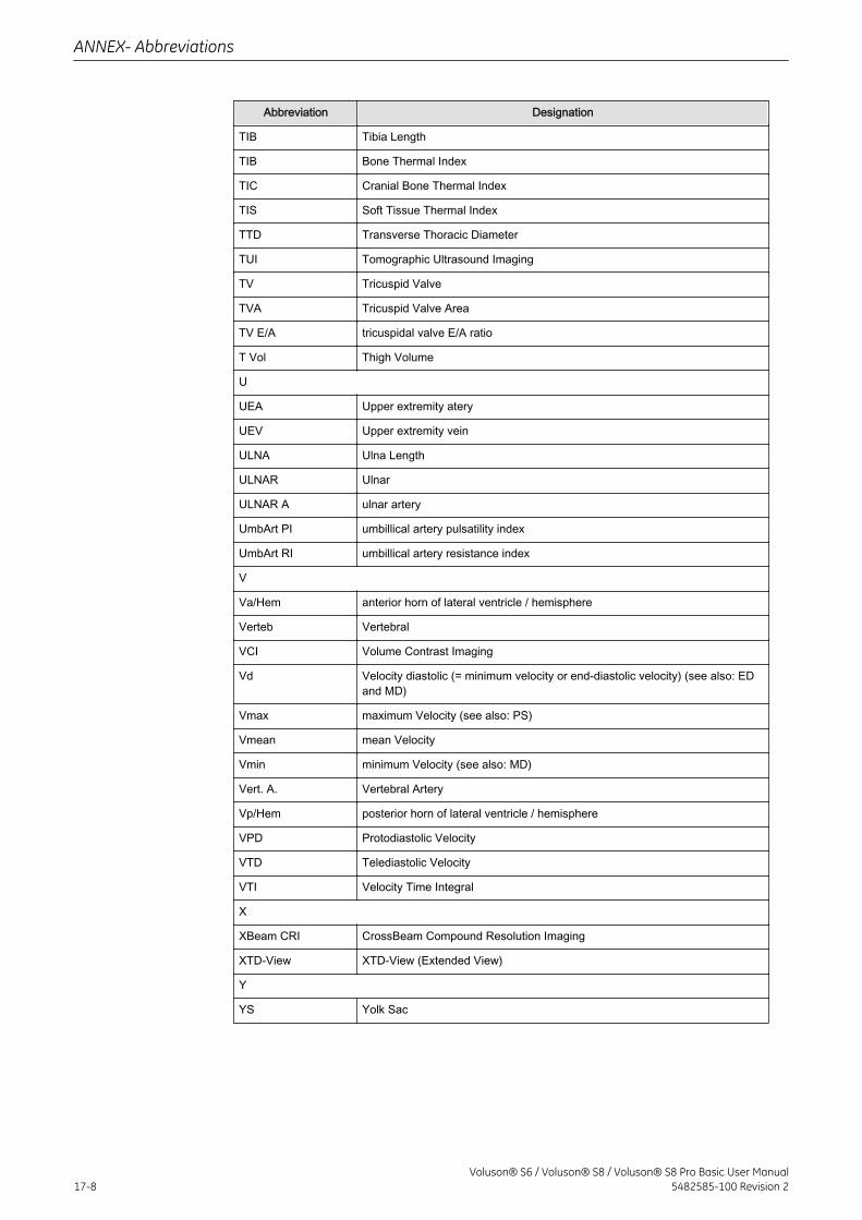
Abbreviation Designation
TIB Tibia Length
TIB Bone Thermal Index
TIC Cranial Bone Thermal Index
TIS Soft Tissue Thermal Index
TTD Transverse Thoracic Diameter
TUI Tomographic Ultrasound Imaging
TV Tricuspid Valve
TVA Tricuspid Valve Area
TV E/A tricuspidal valve E/A ratio
T Vol Thigh Volume
U
UEA Upper extremity atery
UEV Upper extremity vein
ULNA Ulna Length
ULNAR Ulnar
ULNAR A ulnar artery
UmbArt PI umbillical artery pulsatility index
UmbArt RI umbillical artery resistance index
V
Va/Hem anterior horn of lateral ventricle / hemisphere
Verteb Vertebral
VCI Volume Contrast Imaging
Vd Velocity diastolic (= minimum velocity or end-diastolic velocity) (see also: EDand MD)
Vmax maximum Velocity (see also: PS)
Vmean mean Velocity
Vmin minimum Velocity (see also: MD)
Vert. A. Vertebral Artery
Vp/Hem posterior horn of lateral ventricle / hemisphere
VPD Protodiastolic Velocity
VTD Telediastolic Velocity
VTI Velocity Time Integral
X
XBeam CRI CrossBeam Compound Resolution Imaging
XTD-View XTD-View (Extended View)
Y
YS Yolk Sac
ANNEX- Abbreviations
17-8Voluson® S6 / Voluson® S8 / Voluson® S8 Pro Basic User Manual
5482585-100 Revision 2


GE Ultrasound Korea, Ltd.9, Sunhwan-ro 214beon-gil, Jungwon-gu, Seongnam-si,Gyeonggi-do,Koreawww.gehealthcare.com