
VoLTE by IP Multimedia SubsystemSIP Voice Call Setup. Appendix 5. SDP Information. Appendix 6....
65
Mutale Chewe VoLTE by IP Multimedia Subsystem Programmatic Implementing of Voice Service on LTE Helsinki Metropolia University of Applied Sciences Bachelors of Engineering Information Technology Thesis 31 March 2015
Transcript of VoLTE by IP Multimedia SubsystemSIP Voice Call Setup. Appendix 5. SDP Information. Appendix 6....

Mutale Chewe
VoLTE by IP Multimedia Subsystem
Programmatic Implementing of Voice Service on LTE
Helsinki Metropolia University of Applied Sciences
Bachelors of Engineering Information Technology
Thesis
31 March 2015
Helsinki Metropolia University of Applied Sciences Abstract
Author Title Subtitle Number of Pages Date
Mutale Chewe VoLTE by IP Multimedia Subsystem Programmatic Implementing of Voice Service on LTE 47 Pages + 6 Appendices 30 March 2015
Degree Bachelor of Engineering
Degree Programme Information Technology
Specialisation option Data Networks/Software Engineering
Instructor(s)
Dr Tero Nurminen, Principal lecture
A test-driven approach for rapidly deploying Voice over LTE (VoLTE) would prove essential, considering the revenues being lost to Internet protocol (IP) based solutions such as Voice over IP (VoIP). Subsequently voice development for LTE networks is indispensable considering that VoIP has no Quality of Service (QoS) guarantee, which consequently renders it unreliable. The thesis project aimed at analysing and describing the implementation of VoLTE from a programmatic perspective, focusing on end-to-end validation of a basic VoLTE configuration by using industrial test tools to validate functional and logical entities requisite in achieving a cumulative delay of less than 200 ms, widely held and shown to be the minimum acceptable latency for a practically deployable VoLTE system. The test scope primarily centred on signalling, transport methods and call handling functions. Validating deployment scenarios were executed using LTE capable network configuration test emulators that included an R&S CMW500 development test platform manufactured by Rohde & Schwarz and the Spirent E2010S. The final analysis showed that scheduling methods, packet bundling and codecs can improve voice quality. Ultimately the basic VoLTE topology showed finer performance with increased bandwidth and data speeds in a wider frequency range for FDD implementation. Consequently VoLTE by IP Multimedia Subsystems (IMS)-enabled Multimedia telephony (MMtel) proved practical having met the mouth-to-ear delay of less than 200 ms.
Keywords
VoLTE, MMtel, IMS, LTE, 4G

Contents
Abstract
Abbreviations
1 Introduction to VoLTE (Voice over LTE) 1
2 Voice Service over LTE Mobile Broadband 2
2.1 Voice Solutions in LTE 3
2.2 Circuit Switched Fall Back (CSFB) Voice Solution 4
2.3 Simultaneous Voice and LTE 6
2.4 VoLTE by Generic Access (VoLGA) 6
2.5 Interoperability Solution for Voice over LTE 7
3 LTE Network Overview 10
3.1 E-UTRAN Access Network Architecture 10
3.2 VoLTE Deployment Architecture 10
4 Operational VoLTE Protocols and Interfaces 13
5 VoLTE Call Handling in the EPC 19
6 IP Multimedia Subsystem (IMS) 22
6.1 IMS Operational Scenario for VoLTE 22
6.2 VoLTE IMS Functional Architecture 24
7 VoLTE End to End Signalling and Call Management 24
8 VoLTE Test Environment 26
8.1 Running the Test 27
8.2 VoLTE End to End Signalling Test Tool Selection 30

9 Optimizing VoLTE Packet Transport 32
9.1 Test Review 32
9.1 Packet Latency Histograms 37
9.2 Standardised 3GPPQoS for VoLTE 39
10 Discussion 43
11 Conclusion 45
References 47
Appendices
Appendix 1. VoLTE Bearer Associated Parameters.
Appendix 2. QCI Characteristics of EPS Bearer QOS Profile.
Appendix 3. Example Session Establishment (Invite message).
Appendix 4. SIP Voice Call Setup.
Appendix 5. SDP Information.
Appendix 6. INVITE SDP Information /LTE User Equipment Categories.
Appendix 7. VoLTE UE Attachment and IMS Registration Message Sequence.
Appendix 8. VoLTE Terminal to Terminal Call Establishment – Origination Side.
Appendix 9. VoLTE Terminal to Terminal Call Clearing – Initiated Message Se-
quence.

Abbreviation
3GPP Third (3rd) Generation Partnership Project
4G Fourth (4th) Generation (mobile network)
AMR-NB Adaptive Multi-Rate Narrowband
AMR-WB Adaptive Multi-Rate Wideband
APN Access Point Name
CS Circuit Switched
CSFB Circuit Switched Fall Back
DL Downlink
ENodeB Evolved Node Base station
EPC Evolved Packet Core
EPS Evolved Packet System
FDD Frequency Division Duplex
GSM Global System for Mobile Communication
GSMA Global System for Mobile Communication Association
GTP-U GPRS Tunneling Protocol User Plane
HLR Home Location Register
IMS IP Multimedia Subsystem
IP Internet Protocol
LI Lawful Interception
LTE Long Term Evolution
MAC Medium Access Control
MAP Mobile Application Part
MME Mobility Management Entity
MMS Multimedia Messaging Service
MMTel Multimedia telephony
MSC Mobile Switching Center
MSISDN Mobile Subscriber Integrated Services Digital Network
MGCP
SDP
Media Gateway Control Protocol
Session Description Protocol
RSVP Resource Reservation Protocol
NAS Non Access Stratum
PDCP Packet Data Convergence Protocol
NGMN Next Generation Mobile Network
OTT Over The Top
POTS Plain Old Telephone Service
P-CSCF Proxy Call Session Control Function
PCEF Policy and Charging Enforcement Function
QoS Quality of Service
RRC Radio Resource Control
RLC Radio Link Control
RoHC Robust Header Compression
RTP Real-time Transport Protocol
RTCP Real-time Transport Control Protocol
S1AP S1 (interface) Application Protocol
S-CSCF Serving Call Session Control Function
SDP Session Description Protocol
SIP Session Initiation Protocol
SRVCC Single Radio Voice Call Continuity
SS7 Signalling System No. 7
UL Uplink
UE User Equipment
UM Unacknowledged Mode
VANC VoLGA Access Network Controller
VoIP Voice over (IP) Internet Protocol
VoLTE Voice over (LTE) Long Term Evolution
X2AP X2 Application Protocol
X2 X2 Signalling Transport
1
1 Introduction to VoLTE (Voice over LTE)
It is no longer an issue of Voice of Long Term Evolution (VoLTE) standards and ad hoc
deployment scenarios that is hindering the full scale deployment of a functional packet
switched voice over LTE. It is the implementation of VoLTE approached from a pro-
grammatic perspective which needs being applied in test systems leading to a packet
voice solution on LTE. VoLTE-IMS is undisputedly the ultimate future solution for end-
to-end packet voice services, on a data-driven communication networks such as LTE
4th Generation (4G), and future evolutions such as 5G. A programmatic approach in
knitting VoLTE networking procedures has now become imperative to realising a func-
tional globally reaching VoLTE system, with room to concurrently run alongside a rich
suit of real-time multimedia services. VoLTE will complete the need to have an all-in-
one mobile network communication system that provides both high speed data ser-
vices over a mobile broadband, and equally support voice functions. This is not the
case in current LTE networks. [1; 2; 3; 4.]
Since the days of Plain Old Telephony System (POTS), voice calls have dominated
revenues generated by mobile network and phone companies [1]. Providing voice call
service is now facing serious revenue challenges and competition from many Internet
Protocol (IP) based voice solutions. Examples include Skype. VoLTE will be an essen-
tial service necessity for the future evolution of IP network capabilities, to support
packet voice services which will mean a technological leap from Circuit Switched (CS)
networks with no data services, to a completely high speed PSN network, capable of
supporting an assortment of multimedia services. VoLTE is helped by a lean LTE net-
work architecture that reduces packet delays while increasing bandwidth. This enables
it to support High Defination (HD) voice or other multimedia services. [3; 5.] Physical
transmission resource configurations are highly flexible and dynamic in LTE.
GSMA IR.92 documents a VoLTE deployment standard based on IP Multimedia Sub-
system (IMS), a packet voice profile development description that has now become an
industrial reference standard for VoLTE deployment. [2,33 ;13.] Users have waited
long enough to have High Definition (HD) voice services possible over LTE. As pointed
out above, there is a market being lost and VoLTE development should be a matter of
urgency, if mobile service providers want to start benefiting from the IP voice service
market, which they are fast losing to application developers exploiting public IP connec-

2
tivity to provided VoIP solutions. There has been more theorizing about VoLTE de-
ployment architectures and strategies than there has been any programmatic devel-
opment and testing in practice of different designs, presented as path ways to an oper-
ational VoLTE service. VoLTE deployment options are characterized by strategies
mostly based on a provider’s short term integration strategy and much less on purely
advancing new technology solutions. There are currently many design propositions for
Multimedia telephony (MMtel) services over LTE, and other access network systems
such as Worldwide Interoperability for Microwave Access (WiMAX). [2, 32; 9; 11.] It is
expected that MMtel solutions will be interoperable if they will stand a chance of being
a global standard. IP Multimedia Subsystem (IMS) as an integrating platform has
proved to be the best approach, to implement Packet Switched (PS) voice. Different
voice deployment strategies on LTE will be highlighted in chapter 2, for a better under-
standing of reasons behind the choice of deploying VoLTE using IMS in any future so-
lution for packet switched services. This will not only integrate old and future networks
but offer possibilities to support a myriad of new multimedia services that will operate in
parallel. [2; 6; 7.]
2 Voice service over LTE mobile broadband
The VoLTE-IMS multimedia telephony (MMTel) solution is poised to become the future
of voice solutions over Packet Switched Networks (PSN). Opportunities seldom come
without challenges. VoLTE is such a challenge in need of tested implementations. An
operational carrier grade or HD PSN voice service is yet to be realized in practice, de-
spite having long been defined and standardized. The minimum mandatory features for
VoLTE contained in 3GPP specifications, in particular release 8, which outlines the
IMS-based telephony service [7; 8]. Data services have continued to grow as a new
revenue stream that has come to rival voice calls, and it follows that VoLTE will in-
crease data usage and hence provide a means of increasing network investment re-
turns. VoLTE completes the Packet Network (PN) as an all-round network capable of
providing voice running concurrent with high speed data communication services over
LTE. VoLTE will require a practical approach in developing test implementations and to
help realize the prescribed standards and service requirements contained in IR.92 [13].
The Groupe Speciale Mobile Association (GSMA) IR.92 voice profile for IMS is pivoted
to be an industrial standard to guide the building of a carrier grade voice over LTE that
will also provide operators with a capability to create a new service suit [8,150].
3
IMS aided by Session Initiation Protocol (SIP) signaling, promises to make possible
the development of a global reaching high speed broadband packet voice service as
functionally described in 3GPP standards from release 8 - 12 . [3; 4;11.] This thesis
attempts to outline an operational VoLTE deployment architecture, developed from a
programming perspective of an end-to-end packet voice solution. The objective is to
demonstrate a practical test-driven path to a deployable VoLTE service by validating
test topologies and scenarios. The study also aimed to help set the tone for a pro-
grammable development path, and to take VoLTE from theory to practical deployment
by IMS.
2.1 Voice solutions in LTE
LTE with its packet core known as the Evolved Packet Core (EPC), does not support
Circuit-Switched (CS) voice, and therefore deploying voice service over LTE alongside
data with additional services over LTE is a technical challenge yet to be resolved. To
this end, there has been continuous effort in the telecommunication industry to design
working VoLTE deployment. VoLTE is synonymous with the Global System for Mobile
Communication Association (GSMA) specification for voice over LTE contained in
GSMA IR.92, which is a 3GPP multimedia telephony (MMtel) standard. [3, 20.] The
current mobile communication trends point to the fact that MMtel solutions will replace
GSM/WCDMA and CDMA circuit-switched solutions in evolved future packet-switched
radio and core network systems using IMS as a call conductor [4].
Consumers have been flooded with many third party Over The Top (OTT) voice solu-
tions. However OTT solutions provide no QoS guarantee, measure or related assur-
ance and cannot be integrated with circuit-switched networks, which implies that a
global interworking service cannot be achieved. [ 2; 31-3.] OTT solutions have no
guaranteed emergency support or lawful interception provisions deployed with them,
which poses regulatory problems as mandated [2]. This is the reason why better
broadband solutions are required. To this end, extensive work has been done by 3GPP
in standardizing and specifying of technologies that describe minimum requirements for
developing voice over broadband, importantly Release 8 being the first to define the
voice profile of LTE-IMS [8; 13]. Delivering carrier grade voice call capacity is what dif-
ferentiates VoLTE from VoIP which works on the bases of best effort over public Inter-
net.

4
There are varied solutions conceived for supporting voice in LTE networks. All early
solutions used with LTE, are CS-based which require hand over for voice continuation.
Conversely they employ LTE as a high speed data only network, while using other in-
tegrating solutions that use legacy circuit-switched voice solutions to provide the voice
service. The list below, contains some of the common LTE voice solutions [14; 28; 30].
There is no solution with a single implementation. Many of the listed voice methods
have various improved versions from the initial specifications. The choice from a ser-
vice provider’s perspective is mostly decided by their rollout strategy and their network
coverage consistence [9].
Circuit Switched Fall Back (CSFB) Single Radio Voice Call Continuity (SRVCC) Simultaneous Voice with LTE (SV-LTE) VoLTE-IMS Voice over LTE by Generic Access (VoLGA) [14; 28; 30].
These listed voice continuation solutions for LTE are explained below, to help appreci-
ate the idea behind the thesis choice of asserting that VoLTE by IMS represents the
future of implementing voice over LTE. As provisional measures, these options will be
necessary now and possibly also in the future, to provide voice continuity in cases
where LTE coverage fails. The ultimate aim is to eliminate the cost of operators having
to maintain a set of different networks for either data or voice in the future. As older
technology becomes obsolete, the sensible solutions will require building new capable
voice technologies for packet networks like LTE and its future evolution. These should
be fully contained to provide not only data services but voice and video, including other
multimedia services. Conceiving new services in the near future will be the best way to
satisfy the trend and evolution of communication services as sort by users.[8;38.]
2.2 Circuit Switched Fall Back (CSFB) Voice solution
CSFB is an IMS-VoLTE complementary voice method mostly utilized in cases when
LTE coverage is patchy and not reliable or alternatively in its absence. In CSFB, call
routing is executed over a CS network through a PSN to CSN handover via an SGs
interface between the Mobility Management Entity (MME) in the PN and the Mobile
Switching Centre (MSC) in legacy network where the call is migrated. The connection

5
is based on Stream Control Transfer Protocol (SCTP) an IP signaling as opposed to
SS7 signaling used in conventional CS networks [2,159]. CSFB presents a drawback
with an inability to concurrently handle both a voice and data session at the same time.
One can only switch between the two services by connecting to LTE for data and
2G/UTRAN for voice [1, 30]. The above scenario is out of line with the user trends of
mobile devices. Figure 1 shows a mobile terminating voice call procedure, which is
employed when a User Equipment (UE) needs to switch from LTE to a 3G/2G network.
Figure 1: Circuit Switched Fallback, mobile terminating voice call procedure. Repro-duced from NTT DOCOMO [16]
As can be observed in figure 1, the user equipment requires to be connected to differ-
ent networks for either voice or data, and neither service can be used concurrently with
the other. CSFB is standardized in 3GPP TS 23.272 [30]. Handover procedures (attach
and detach procedures) are described in the 3GPP specification mentioned in the par-
agraph above. When a CS call concludes in CS domain, it is possible to return a UE
connection to the Evolved Universal Terrestrial Radio Access Network (E-UTRAN)
without any special or specific CS fallback mechanisms required [12]. When the UE
moves to E-UTRAN, if the Evolved Packet Systems (EPS) service was suspended dur-
ing the CS service, it is resumed according to a procedure not covered in this short
description of CSFB. As shown in Figure 1, the MSC and MME are central to execut-
ing a fallback over an SGs interface.

6
2.3 Simultaneous Voice and LTE
Simultaneous Voice and LTE (SV-LTE) is user equipment-specific. The UE has to be
capable of using two different radio systems in parallel operation, one for voice and the
other for data network access. The device here stays connected to Wideband Code
Division Multiple Access (WCDMA)/GSM/CDMA for voice and LTE for data service, an
issue that reduces battery life on the user equipment [9]. In a CDMA to LTE scenario,
SV-LTE is a commonly employed solution which can be used as a bridging solution of
integrating LTE with CDMA. This solution has the advantage of data speeds not being
affected by an ongoing voice call. Figure 2 below shows the dual access network view
of SV-LTE. It can be seen that the UE is attached to both a BTS and enodeB.
Figure 2: The network principal of simultaneous voice. Reproduced from Voice solu-tions in LTE [9].
Circuit switched voice continuity solutions in LTE might seem a cheaper option for op-
erators now, but they don’t represent the realization of a total packet high speed
broadband voice service, viewed from a network evolution perspective and user trends.
SV-LTE is not a very popular voice method in LTE comparing with CSFB.
2.4 VoLTE by Generic Access (VoLGA)
VoLGA uses virtualized CS via a VoLGA access network controller (VANC) to offer
voice with LTE radio returned to couple with a CSN [9; 23 ; 4]. The VoLGA voice solu-
tion uses CS core only from legacy networks with an added issue of requiring new net-
work elements (VANC) to be able to work. This is a cost best avoided by employing
better solutions. VoLGA is reminiscent of 3GPP Generic Access Network (GAN). It is
driven by a GAN controller to bridge an IP access network such as LTE core with a
UMTS or GERAN core network. The GAN provides a way to access a CS core from a

7
packet core using a virtual connection, and hence requires no specific enhancements
or support in either network. VoLGA offers two working configurations, A-mode and lu-
mode [23]. The A-mode supports a GSM CS driven connection through tunneling NAS
protocols between a UE and the packet core network using EPS bearers through the
A interface towards MSC in a UTRAN, UMTS or GERAN circuit core network.[15.]
Figure 3 shows VoLGA architecture and the need for a VANC device.
Figure 3: The principal of voice over LTE by Generic access.(VoLGA). Reproduced from NTT DOCOMO [9]. VoLGA Iu-mode employs the Iu-CS interface where VoLGA A-mode uses the A inter-
face. Comparing with CSFB, VoLGA in the above highlighted design is able to use
voice and data simultaneously.
2.5 Interoperability solution for Voice over LTE
The previous section highlighted the many voice options available for consideration
when deploying VoLTE to bridge coverage. However, even more important as an ele-
ment for a global reaching network, is the concept of interoperability across different
network system configurations, considering VoLTE when IMS voice service is not
available to support services such as roaming in a visited network domain [2]. A device
would need to use WCDMA/GSM to initiate or receive voice calls. The calls here have
to be executed in the CS domain which means that even as the voice solutions move
towards PS voice, there ought to be a solution to still connect to other forms of technol-
ogy used by other customers using a different network. In many MMTel services pro-
posed to be established, users should be able to start a voice session, add or drop
media such as voice if and when desired [8]. Operators wishing to deploy VoLTE have

8
the possibility to offer users more than just voice services but also a rich set of real-
time services such as High Definition (HD) voice calls, video and optional multimedia
services dubbed as the Rich Communication Suite (RCS) , which are designed to be
made available anywhere on any capable and IP connected UE [6]. Assuring mobility
and service on demand is the highlight of multimedia telephony service in a nutshell.
Some leading operators like Sprint are hoping to start offering VoLTE by the end of the
year 2015 at the latest. Figure 5 shows Single Radio Voice Call Continuity (SRVCC)
architecture necessary for VoLTE interoperability with circuit switched networks, to
support voice continuity in case of loss of LTE coverage. In a single radio voice conti-
nuity call, the call control still remains tied with the IMS domain like a VoLTE call. This
makes it a preferable VoLTE fallback mechanism compared with the CSFB method,
were the control is completely switched to the circuit network rendering the use of other
IP services unusable after the switch [14]. Figure 5 below also shows a Sv interface
between the MME and MSC which is used for switching. The IMS network has to have
Service Centralization and Continuity (SCC) application servers to be able to support
SRVCC. [28; 39.] The SCC application server(s) is required for signaling handling.
Figure 5: Sv interface for Handing over from PSN voice to CS voice. Reproduced from Different flavours of SRVCC [14].
Though SRVCC control resides in the IMS network, an attachment to LTE is required
to switch to CDMA 2000 from E-UTRAN or from UTRAN/GERAN. SRVCC was first
defined in 3GPP Rel-8 and requires introducing new protocol interface and procedures
between MME and MSC for SRVCC from LTE to UTRAN/GERAN. This also includes
between MME and any 3GPP interworking functionality for SRVCC from E-UTRAN to
CDMA [11]. They are many switching scenarios defined for different interworking func-
tions between different access networks contained in 3GPP Rel-9. An example is the

9
support for emergency calls (E911) for SRVCC that are anchored in the IMS domain
[39,4-7]. The subject of SRVCC procedures has continued to evolve and includes
many enhanced features that are now supported from release 8 to 13. However, these
features are too numerous to be discussed in the limited scope of this thesis. VoLTE
via IMS is an ideal choice for MMtel voice solution with capabilities of providing carrier
grade (HD) voice service. MMtel is practical on high-speed packet capable core net-
works like WiMAX or LTE [4]. IMS is currently the obvious means to achieve MMtel as
an end to end all packet solution for both WiMAX and LTE high-speed-data networks.
VoLTE will be critical in the evolution towards an all-IP voice service alongside data.
Wireless subscribers using LTE will have to be able to make VoLTE calls enabled by
IMS through a P-GW which is an IP point attachment for a UE. This is done by estab-
lishing an EPS bearer from the subscriber to the selected P-GW. Each bearer comes
with a GTP-U tunnel. Figure 5 below, shows an illustration of bearers required for traffic
between eNobeB and S-GW, including between S-GW and P-GW [3, 20].
Figure 5: VoLTE system showing the abstract concept of bearers, Modified from Erics-
son VoLTE white paper (2014)[4,9].
As can be seen in figure 5, data bearers are created as required for any different media
added to a session. Figure 5 shows two bearers, one for voice and another one for any
enabled media that a user might add to a session. For a bearer to be created there is a
requirement for an always-on IP connectivity to a Packet Data Network (PDN) by a UE
[3]. In a VoLTE configuration, a PDN connection is established followed by an IMS Ac-
cess Point Name (APN) discovery, and IMS registration. After registration to an IMS
network, the UE can then route uplink voice packets over the EPC premised on the
uplink packet filters in the traffic flow template (TFT) through the Packet Gateway (P-
GW) [3;11].

10
3 LTE network overview
3.1 E-UTRAN access network architecture
The LTE radio network is officially named Evolved Universal Terrestrial Radio Access
Network (E-UTRAN) [5]. It is a single box radio consisting of all radio functionalities in
eNodeB [2, 65]. The radio system is based on a distinct user and control plane archi-
tecture unlike GSM or 3G, though direct tunneling in GPRS is possible via a G-TPU
tunnel. The LTE downlink uses Orthogonal Frequency Division Multiple Access (OFD-
MA) and uplink uses Single Carrier Frequency Division Multiple Access (SC-FDMA) [5,
5; 40, 11-42]. The LTE radio architecture has important aspects that make VoLTE via-
ble as a packet voice solution [11,111-115]. Network capacity in LTE is enhanced, so is
the resources allocation in the frequency domain at a clock speed of 180 kHz resource
blocks both in uplink and downlink with a robust packet scheduling [40, 60-86]. The
uplink user-specific allocation is continuous and henceforth enables single carrier
transmission, but the downlink can use resource blocks unrestricted from any part of
the frequency spectrum. Even more interesting for the case of VoLTE is the impres-
sive data speeds of up to 150 Mbps user data in downlink with a 20 MHz transmission
bandwidth operating with 2x2 MIMO. This rate can be increased to 300 Mbps with 4 x 4
MIMO. In the downlink, up to 75 Mbps can be obtained [5, 5.]
3.2 VoLTE deployment architecture
Apart from the access network packet handling characteristics, the EPC protocol layers
have critical functions that require systematic programming into the call process logic
over the underlying IP transport protocols. The eNodeB provides the air interface to the
user equipment and runs admission control for EPC registration [3,182]. It is possible
for one eNodeB to be connected to many MMEs and S-GWs for extended reliability
known as S1 flex [5, 64]. Common to both data and voice over LTE, are functionalities
executed on the eNodeB like radio resource management (RRM), admission control,
packet scheduling, ciphering, header compression and air interface signalling
[32;42;43;45;50]. These functionalities are highly programmable. Examples are high-
lighted in appendix 3,4,5 and 6. Packet scheduling is particularly of critical interest to a
successful VoLTE deployment, considering that delay has to be minimized, as well as
packet loss. There is also a question of retransmission at this protocol layer as well as
the mac layer defined in 3GPP TS 36.321[41].

11
LTE is designed with an evolutionary separate user and control planes as shown by the
dotted line and solid line in Figure 6 below. This structure allows for flexible scaling of
the network. The Serving Gateway (S-GW) and the Packet Data (PDN-GW provide the
service connection point for IMS functionality which will be described for voice solutions
here, as a user plane entity [4 ; 11,110]. The solid lines show the data path and related
elements in the user plane. The user plane is the data packet carrying path. The pack-
ets upon being transmitted from the user equipment to the eNodeB are forwarded to
the S-GW towards the PDN, upon the discovery of an available service and access
point name for an IMS network to facilitate multimedia services [5,30] .Figure 6 shows
the user and control plan paths in a basic VoLTE configuration as defined in 3GPP
release 8. To be noted specially is P-GW which is the logical entity that provides up
tunnel management and switching [5, 29]. The detailed VoLTE operation of entities in
the EPC and IMS network are highlighted in detail in chapter 5 and 6 respectively.
Figure 6: 3GPP LTE Network architecture showing the network entities laying in the user and
signaling plane between eNodeB’s through the core networks, towards a PDN.
The user plane programming should take the bearer creation into consideration. Bear-
ers are abstract concepts that can be implemented programmatically as objects, with
methods to forward data packet according to defined priority classes that can take pa-
rameters upon session negotiation, to a call process function. On the other hand, it is
important to note that the EPC anchoring point of the IMS network is an IMS APN
which is discoverable on the Gx interface towards the PDN-GW [13]. Creating classes
in the sense of executing procedures and resource utilization requires private classes
for either the user or data planes for data integrity.

12
The EPC architecture is an enabler of VoLTE considering that it does not support Cir-
cuit Switched (CS) voice. This is where a packet voice solution becomes a relevant
challenge in need of realizing. Developing a practical VoLTE system cannot in this con-
text begin without a quick architectural review to provide the network outlook of how
elements fit together. This LTE architecture, in particular relation to the subject of voice
over LTE by IMS, offers a greater advantage in many respects, such as, the SIP signal-
ing and dual planes described in chapter 6 and shown in figure 7 respectively. The
EPC, which might require traffic- related real-time adjustments, has in recent times
attracted new techniques in programmable services such as voice. Companies like
Ericsson are getting ahead with test system tending towards 5G already [4]. The isolat-
ing of the control plane, which carries signaling messages and the user plane which is
the data carrier provide the network with flexible network dimensioning capability and
better traffic engineering.
Figure 7: A Topology of MMTel by MMTel by IMS. Reproduced from Ericsson white paper [4,8].
The attached procedure from active mode requesting connection to connection to a
known IMS Access Point Name (APN) is excuted as shown in Figure 13. Considering
the above topology, the device will require IMS registation with its MMTel identifier as
shown in Appendix 7. Security and authentication is required beforehand. Security is
crucial, when registering to either the access network, EPC or IMS in a VoLTE
deployment. The UE has to be authenticated using the information contained in the
Universal Subscriber Identity Model (USIM) [25]. The security keys for accessing the
radio access network are stored here. VoLTE security is not in the scope of this thesis
and therefore not discussed here.
13
4 Operational VoLTE protocols and Interfaces
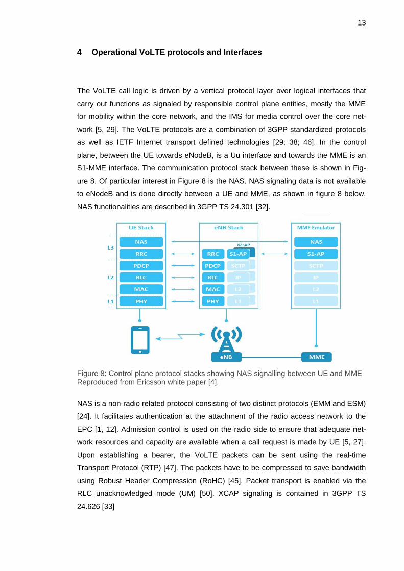
The VoLTE call logic is driven by a vertical protocol layer over logical interfaces that
carry out functions as signaled by responsible control plane entities, mostly the MME
for mobility within the core network, and the IMS for media control over the core net-
work [5, 29]. The VoLTE protocols are a combination of 3GPP standardized protocols
as well as IETF Internet transport defined technologies [29; 38; 46]. In the control
plane, between the UE towards eNodeB, is a Uu interface and towards the MME is an
S1-MME interface. The communication protocol stack between these is shown in Fig-
ure 8. Of particular interest in Figure 8 is the NAS. NAS signaling data is not available
to eNodeB and is done directly between a UE and MME, as shown in figure 8 below.
NAS functionalities are described in 3GPP TS 24.301 [32].
Figure 8: Control plane protocol stacks showing NAS signalling between UE and MME Reproduced from Ericsson white paper [4].
NAS is a non-radio related protocol consisting of two distinct protocols (EMM and ESM)
[24]. It facilitates authentication at the attachment of the radio access network to the
EPC [1, 12]. Admission control is used on the radio side to ensure that adequate net-
work resources and capacity are available when a call request is made by UE [5, 27].
Upon establishing a bearer, the VoLTE packets can be sent using the real-time
Transport Protocol (RTP) [47]. The packets have to be compressed to save bandwidth
using Robust Header Compression (RoHC) [45]. Packet transport is enabled via the
RLC unacknowledged mode (UM) [50]. XCAP signaling is contained in 3GPP TS
24.626 [33]
14
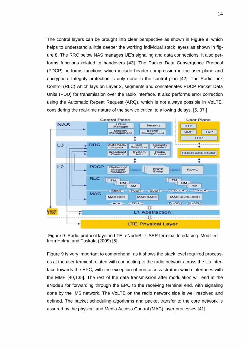
The control layers can be brought into clear perspective as shown in Figure 9, which
helps to understand a little deeper the working individual stack layers as shown in fig-
ure 8. The RRC below NAS manages UE’s signaling and data connections. It also per-
forms functions related to handovers [43]. The Packet Data Convergence Protocol
(PDCP) performs functions which include header compression in the user plane and
encryption. Integrity protection is only done in the control plan [42]. The Radio Link
Control (RLC) which lays on Layer 2, segments and concatenates PDCP Packet Data
Units (PDU) for transmission over the radio interface. It also performs error correction
using the Automatic Repeat Request (ARQ), which is not always possible in VoLTE,
considering the real-time nature of the service critical to allowing delays. [5, 37.]
Figure 9: Radio protocol layer in LTE, eNodeB - USER terminal Interfacing. Modified from Holma and Toskala (2009) [5].
Figure 9 is very important to comprehend, as it shows the stack level required process-
es at the user terminal related with connecting to the radio network across the Uu inter-
face towards the EPC, with the exception of non-access stratum which interfaces with
the MME [40,135]. The rest of the data transmission after modulation will end at the
eNodeB for forwarding through the EPC to the receiving terminal end, with signaling
done by the IMS network. The VoLTE on the radio network side is well resolved and
defined. The packet scheduling algorithms and packet transfer to the core network is
assured by the physical and Media Access Control (MAC) layer processes [41].

15
The end-to-end packet voice service functions will require performing transport and
signaling operations across the EPC towards an IMS access point. When a voice call is
made by VoLTE-enabled user equipment, the radio signal has to be processed by a
digital analog converter at the mobile terminal and scheduling applied for uplink radio
transmission at the physical layer, which includes encoding and encryption. Figure 10
shows the physical layer system that connects the user equipment to the radio network
showing the details of the radio related signaling and required processes at every stack
layer. All radio related protocols in LTE end in the eNodeB [6, 12].
Figure 10: User Data protocol stacks from UE, eNodeB and EPC. Modified from Jyrki T. J. Penttinen (2004) [2]
The allocation of an IP address to the UE is carried out by the PDN-GW via the S8a
interface. This IP connection as shown in figure 10 is enabled by GTP-U tunneling in
accordance with the IP protocol stack. The PDN-GW is the getaway to other external
IP networks such as Internet. They are scenarios when UE can be allocated an IP ad-
dress from an external PDN to apply in a call session. In this case, all the traffic is tun-
neled through the external network [3; 4; 7]. The latter point is in fact one roaming
scenario. An IP address is always allocated when a UE sends a PDN connection re-
quest. This happens whenever the UE performs an attach procedure. It may also sub-
sequently happen when a new PDN connection is required. A Dynamic Host Configu-
ration Protocol (DHCP) has to be performed at this point. There is an alternative of
querying an external DHCP server that can provide the IP address to the UE [7]. DHC
is supported by both IPv4 and IPv6.
16
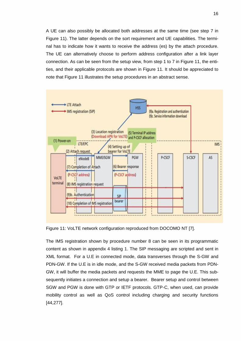
A UE can also possibly be allocated both addresses at the same time (see step 7 in
Figure 11). The latter depends on the sort requirement and UE capabilities. The termi-
nal has to indicate how it wants to receive the address (es) by the attach procedure.
The UE can alternatively choose to perform address configuration after a link layer
connection. As can be seen from the setup view, from step 1 to 7 in Figure 11, the enti-
ties, and their applicable protocols are shown in Figure 11. It should be appreciated to
note that Figure 11 illustrates the setup procedures in an abstract sense.
Figure 11: VoLTE network configuration reproduced from DOCOMO NT [7].
The IMS registration shown by procedure number 8 can be seen in its programmatic
content as shown in appendix 4 listing 1. The SIP messaging are scripted and sent in
XML format. For a U.E in connected mode, data transverses through the S-GW and
PDN-GW. If the U.E is in idle mode, and the S-GW received media packets from PDN-
GW, it will buffer the media packets and requests the MME to page the U.E. This sub-
sequently initiates a connection and setup a bearer. Bearer setup and control between
SGW and PGW is done with GTP or IETF protocols. GTP-C, when used, can provide
mobility control as well as QoS control including charging and security functions
[44,277].

17
4.1 Basic Configuration for VoLTE
VoLTE by IMS can be shown to be a choice method of implementing end to end packet
voice solution for UMTS LTE. IMS is access-independent, which implies that it works
with any access network technology, and that adds even more to the appeal of using
this type of configuration [8]. It leads to network convergence and supporting interoper-
ability. The basic network capability is the general standardized requirements of LTE to
LTE-Advanced as recognized by ITU-R and also considering 3GPP release 8 to 12
specifications [2, 13]. Figure 12 shows the logical divisions of the network as can be
perceived from the functional segment point of view [12]. The figure shows how an LTE
network can be divided in the three parts in practice, being the terminal end, access
network and the evolved packet core. VoLTE extends a control network (IMS) as can
be seen in Figure 12 below [22].
Figure 12: VoLTE network configuration. Reproduced from DOCOMO NT (2012) [7].
IMS and LTE are defined independently. It follows that IMS does not depend on the
existence of LTE or the opposite [12]. However, VoLTE requires pairing IMS with LTE
to provide a PS voice service where the two networks are scalable independent of
each other. IMS in this context plays the controller to support voice traffic, while LTE

18
does the work of performing as tasked and instructed by the IMS network to achieve an
end to end packet voice capability [18]. Voice sessions are established at the request
of capable user equipment. IMS dictates the establishment of a desired session envi-
ronment called quality of service (QoS), on any service session requested for voice
[27].
The programming of request classes and response functions is a primary development
objective whose implementation should be guided by the nature of operations in ques-
tion, to determine the nature of functions according to what other processes are al-
lowed access to the function and which methods are evoked (see Appendix 1, Table
1). The packet radio side and LTE core network are well developed in a programmatic
sense of executing packet processing for network transport system and routing process
[5]. Considering how mobile networks are already expected to evolve into 5G and ex-
pand connectivity, network-based services will be expected to be supported by advanc-
ing aspects of mobile network transport infrastructure, both on the air interfaces and
core network, including media control and call process management intelligence.
The modular architectures of the Evolved Packet System (EPS) and LTE network to-
pology are ideal for upgrading one part at a time if and when required to enhance ca-
pacity or functionalities. Central to optimizing VoLTE will be the need to refine tune the
transport network, which aggregates and transfers traffic among various service points
in the network [4]. The transport network should be able to deliver ubiquitous connec-
tivity. Developing programmability into the transport layer will enables innovative user
and network services to be implemented easily and faster. Designing software imple-
mentation for intelligent programmable transport will set VoLTE on a stronger quality
assurance path to deployment with additional services which can be integrated as de-
sired or demanded by users [8,133].
In validating the viability of an end to end VoLTE transport beyond the access network
and U.E processes, of a basic topology in Figure 12, the next chapter deals with
Evolved Packet Core (EPC) transport and call handing.

19
5 VoLTE call handling in the EPC
5.1 VoLTE process overview over EPC
Session Initiation Protocol (SIP) plays a critical role in signaling over the EPC. It is the
language spoken by the IMS to the EPC. The IMS also uses SIP to communicate with
the User Equipment (UE) [10; 20]. The UE initiates an IMS domain registration process
with its MMTel identifier using SIP messages. During this process the device has to be
authenticated. The INVITE request contains a Session Description Protocol (SDP) that
describes the preferred media information such as which voice coding is preferred or
supported [48]. Adaptive Multi-Rate Wideband (AMR-WB) is used for HD voice or
Adaptive Multi-Rate Narrowband (AMR-NB) which is also an ideal codec choice for
VoLTE [34].
The IMS domain uses the SIP negotiation information contained in the SDP over the
standardized interfaces (see Appendix 4 Listing 1). The Policy and Charging Enforce-
ment Function (PCEF), applies QoS and charging resolutions, but charging will not be
discussed in this thesis. Ideally the response result from the PCEF will be to establish a
dedicated EPC and radio bearer with a guaranteed bit rate for VoLTE media packets
and stop any data transaction after a VoLTE call ends accordingly. The S1-U interface
that connects the S-GW to the eNodeB is used for setting up GPRS Tunneling Protocol
(GTP)-U tunnel for user data traffic [3, 59].
Charging functionalists are not covered in this thesis considering the scope of demon-
strating an end to end operational VoLTE. However it can be pointed out that the policy
and charging rule function is responsible for call policy and charging control. A Gx inter-
face provides the connection of the S-GW or P-GW on the EPC side of the VoLTE to-
pology. The PCRF is an intermediate functionality between the EPC and the IMS net-
work [8].
The IMS network or any other external IP network will be connected to the EPC
through an SGi interface. Bridging the charging functionality between the EPC and
IMS, is done through an Rx interface that connects the PCRF to the P-CSCF which is
in the IMS domain (see Figure 13). The IMS network entities are separately discussed
and explained in chapter 6, explaining their VoLTE role in the configuration tested in
chapter 8, following the GSMA Permanent Reference Document (PRD) IR.92 [13].

20
MME handles Non-Access-Stratum (NAS) functions and coordinates mobility in the
LTE and interworking with non-3GPP access networks (UMTS, GPRS) [32]. VoLTE
packets do not have to go through the MME. The MME also performs authentication
and authorization of network resource access which includes user tracking, security
negotiations and NAS signaling [44,275]. This gives the advantage of expanding sig-
naling and traffic capacity independent of other network elements. The S-GW is the
User Plane (UP) gateway during inter-eNodeB handovers and is responsible for tunnel
management and switching of the UP packets for inter-3GPP mobility over the S4 inter-
face [3, 15]. Figure 13 below shows the topology of the EPC and E-UTRAN bringing to
the fall the interconnecting interfaces between elements.
Figure 13: VoLTE access and core network interfaces. Reproduced from DOCOMO technical journal [7].
Some of the most important functions of S-GW include downlink packet buffering and
initiation of paging UE when they are in idle mode. Further it also performs transport
level Downlink (DL) and Uplink (UL) packet marking, routing and forwarding [2; 3;
44,277]. Other functions have been mentioned in chapter 6, which relate to other enti-
ties that interface with S-GW such as the MME, PDN-GW, or Policy and Charging
Rules Function (PCRF). These companion entities help in many VoLTE functionalities
such as call set up, modifying or clearing bearers for the UE as shown in figure 13
where a VoLTE call set up is illustrated. Considering a request received from the PDN-
GW or PCRF, the S-GW may also relay commands on to the MME so that it redirects a
tunnel to an eNodeB. This operation is called a path change [12].

21
Serving Gateway ( S-GW ) act as local mobility anchors when supporting path change
involving handovers between neighboring eNodeB's [7]. In this case, the P-GW plays
the global IP mobility anchor point which acts as a router, allocating IP addresses to
UE in the registration procedure as shown in figure 14 below.
Figure 14: VoLTE call setup procedure. Reproduced from DOCOMO technical journal [7]
The P-GW also does the bearer management including other functions such as the
enforcement of call policies and charging as passed by the PCEF including lawful in-
terception, deep packet inspection and packet filtering. Above all, the P-GW is the get-
away to a PDN (Internet and operator services etc.). If UE has to migrate form an S-
GW to another S-GW, the bearers have to be switched to the new S-GW. In this case,
the PDN-GW will receive a switching request to change the traffic flow to the new S-
GW. Any given PDN-GW can be connected to more than one PCRF, S-GW or an ex-
ternal network [3]. For an UE that is associated with a given PDN-GW, there can only
be one S-GW, although a connection to additional external networks or PCRFs is sup-
ported. Where connectivity to more than one PDN is supported via a PDN-GW, the
PDN-GW can request the S-GW to provide bearer resources for data flow, when there
is a need to forward data during X2 handovers. The mobility scenarios also include
switching from one S-GW to another controlled by the MME [16].

22
6 IP Multimedia Subsystem (IMS)
6.1 IMS operational scenario for VoLTE
Figure 14 highlights a basic VoLTE used in validation tests analysed in this thesis. The
IMS entities are requisite to call setup and flow. The Interrogating Call Session Control
Function (I-CSCF), Proxy Call Session Control Function (P-CSCF), Serving Call Ses-
sion Control Function (S-CSCF) and Application server (AS) are shown in figure 15.
The PCRF is a boundary entity and resides in the S-GW in many deployment scenari-
os. It is connected via the P-GW of an LTE network to bridge an end-to-end packet
service upon which voice packets can be transported, resulting in a carrier grade ser-
vice. IMS is SIP signalling driven. It differs from PS domain in the sense that it uses a
one protocol, one functionality computer network styled configuration [44,269]. Figure
15 shows a VoLTE home network topology with three of the four call session control
functions shown as mentioned above in opening of this section.
Figure 15: An open IMS core implementation of IMS Call Session Control Functions: Reproduced from Sprint white paper [12]
The Emergency – CSCF is not shown in Figure 15 considering the basic nature of the
topology. It is not required when considering a basic end to end call scenario. Important
elements and interfaces to note in Figure 15 include the SGi, Rx, Gx interfaces and the
IMS CSCF connection to the PCRF and HSS. These are basically the central elements
in establishing a VoLTE call setup. For a user within a home network supporting VoL-
TE-IMS like the one shown in Figure 15, the IMS first point of contact is the Proxy Call
Session Control Function (P-CSCF). All SIP signalling from the U.E or from the IMS
network to the U.E is sent to/from the P-CSCF respectively [8, 63].

23
The P-CSCF performs SIP compression for IMS originating signalling if requested by
U.E in the SIP negotiation. On the terminal end the compression is done by the packet
data convergence protocol (PDCP) if required [42; 46]. The P-CSCF executes security
association and applies integrity and confidentiality to SIP messages that provide sig-
nalling in the network [8]. The process mentioned above is executed on UE upon regis-
tration, where IP security association is negotiated with the P-CSCF using SIP [3, 33].
The programming of attachment and negotiation procedures amount to functional han-
dling of service parameters that guarantee QoS for packet voice over LTE. In a test
case where a UE is both authenticated by the LTE network and the IMS network, a
default EPS bearer is established between the UE and a P-GW. This provides the sig-
nalling path to successfully establish a VoLTE session based on interaction with the P-
CSCF entity. The P-CSCF then sends the message for resource appropriation by the
S-CSCF which is explained below.
The call setup involves sending a SIP “Invite” message to S-CSCF (see appendix 3
listing 1). The message contains a Session Description Protocol (SDP) that carries the
QoS requirement being negotiated for [46]. SIP messages over LTE are encapsulated
and only processed by the end control plane entity which in this case is a P-CSCF [18].
QoS requests are sent through the Rx interface (using the diameter protocol) to the
Policy and Charging Rules Function (PCRF) from the P-CSCF. The PCRF is where
charging and QoS rules are resolved for any requested session, which can then be
sent across the Gx interface to the Policy and Charging Enforcement (PCEF) [27]. The
PCEF is located within the P-GW in the LTE network although not shown in figure 14.
The functions of the P-GW were already been discussed in chapter 2. It should be
mentioned here that upon all the setup being completed by IMS the packet transport is
done in the LTE network through the P-GW ( see voice call setup in appendix 4 listing
1). It is at this point a request to establish a “dedicated bearer” with a QoS Class Identi-
fier (QCI) value of 1, which is sent to the UE. It is then that a connection with the S-GW
is made. A voice call setup is shown in detail in Figure 14. IMS will only take further
action once there is an indication that a call has been lost or has ended. Termination of
a call is effected by a “BYE” SIP message notification to the S-CSCF via P-CSCF [3].
Charging P-CSCF processing is effected in the P-CSCF but is not discussed here. It
can be pointed out that from practicalities of end-to-end signalling delays, anchoring
calls in the IMS home network would be preferable in roaming scenarios [8, 22]. Other
deployment configurations would function with a longer delay than can be experienced

24
if the IMS domain was contained in the home network. In this case it is expected that
in a roaming scenario, a user attaches to the visited networks IMS upon establishing a
connection after the stored parameters hosted in the HSS are exported. There might
be no need to have IMS networks at either ends of U.E in localized deployments [2].
6.2 VoLTE IMS functional architecture
Excluding the charging function, IMS entities and key functionalities are listed below.
The list is followed by a descriptive role of some of the entities in VoLTE programmatic
development framework for a practical end to end VoLTE service over LTE. The listed
entities facilitate a comprehensive VoLTE operation, interworking and support services
[44, 177-186]. Only the highlighted functions are discussed in this thesis.
Session management/routing entities (CSCFs)
Data Bases (HSS )
Services (AS, MRFC, MRFP)
Interworking functions( BGCF, MGCF, IMS-MGW, SGW)
Support functions(PCRF, SEG, IBCF, TrGW, LRF)
There are four distinct types of Call Session Control Function (S-CSCF) that provide
session management and routing signalling messages. These entities are Proxy-CSCF
(P-CSCF), Serving-CSCF(S-CSCF), Interrogating-CSCF (I-CSCF) and Emergency-
CSCF (E-CSCF) [8, 23; 26]. The end-to-end VoLTE call relevant entity’s role in a call
session is highlighted below, but not all entities are discussed in the scope and aim of
this thesis. These include the emergency session defined in 3GPP TS 23.167 [26].
Also not covered in this basic VoLTE system is charging and roaming [44,196-205].
This thesis is limited to simulations involving only session management (CSCFs) one
support function and the data base (HSS). The next chapter explains call management
and end to end signalling in a successful VoLTE call [7, 49].
7 VoLTE end to end Signalling and Call management
VoLTE is made possible by EPC transport directed by IMS control [12]. End to end
signalling means the complete processing of setting up VoLTE calls by a request from
the user equipment to another user.

25
Session Initiation Protocol, a peer to peer signalling protocol, is used by IMS and the
U.E in setting up and clearing the VoLTE calls (see Appendix 3 – 7)[10; 8 ; 44,169].
SIP is useful in not only establishing but negotiating service parameters that guarantee
quality of service (see Appendix 6 Listing 1). IMS based VoLTE offers additional multi-
media services which are consistent with trends expected to dominate the service mar-
kets in the near future.
The MME is the key control-node in the LTE control plan. It is responsible for idle mode
UE (User Equipment) tracking and paging procedure including retransmissions [3]. It is
involved in the bearer activation or deactivation process and is also responsible for
choosing the SGW for a UE at the initial attach and at time of intra-LTE handover in-
volving Core Network (CN) node relocation [4; 5]. It is responsible for authenticating
users by querying the HSS. The Non-Access Stratum (NAS) signaling terminates at the
MME and it is also responsible for generation and allocation of temporary identities to
UEs [32]. It checks the authorization of the UE to camp on the service provider’s Public
Land Mobile Network (PLMN) and enforces UE roaming restrictions. The MME is the
termination point in the network for ciphering/integrity protection for NAS signaling and
handles the security key management [3]. Lawful interception of signaling is also sup-
ported by the MME, including the provision of control plane functionalities for mobility
between LTE and 2G/3G access networks with the S3 interface terminating at the
MME from the SGSN. There is also an S6a interface towards the home HSS for roam-
ing U.Es.
The peer-to-peer architecture guarantees an end-to-end reachability over IP connec-
tion. With the advent of Internet Protocol Version 6 (IPv6), there is an enormous num-
ber of addresses for user devices. However, interoperability of IPv4 and IPv6 is an on-
going matter that requires solutions if VoLTE is to become a global standard. To this
effect, NAT software has been under development from various venders [48,230-242].
A device requires only the service of one IMS network. LTE IP connectivity is premised
on IPv6 and user devices are programmed to use IPv6 as a higher priority when avail-
able. IPv4 is only used in instances where IPv6 is not available. IPv6 has light headers
that compliment Robust Header Compression (ROHC) which is necessary when pack-
etizing the voice packets at the physical layer [45].

26
8 VoLTE test environment
The VoLTE test approach was carried out in this thesis project to enable a program-
matic approach for quickly deploying a functional VoLTE service over LTE by test-
driven methods. This provides a generic way of experimenting with various testing plat-
forms that included LTE capable emulators and test tools like R&S CMW500 develop-
ment test platform manufactured by Rohde & Schwarz and Spirent E2010S. This com-
bination of tools is adequate for an end-to-end VoLTE testing capability [19; 21]. Below
is the LTE call setup window of the CMW500 showing radio parameters to be config-
ured in a test scenario.
Figure 16: LTE access side call setup window for test configuration
The setup configuration window for LTE as shown above is configurable according to
the test goals and targeted investigations. Considering the main result analyzed in
chapter 9. The test settings are shown in table 1 below. The tests can be repeated
with differing settings as desired to observe performance differences. LTE can take
QPSK, 16-QAM or 64-QAM modulation. MIMO is preferable.
27
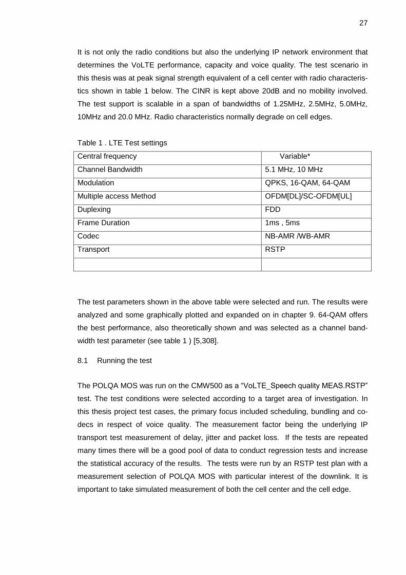
It is not only the radio conditions but also the underlying IP network environment that
determines the VoLTE performance, capacity and voice quality. The test scenario in
this thesis was at peak signal strength equivalent of a cell center with radio characteris-
tics shown in table 1 below. The CINR is kept above 20dB and no mobility involved.
The test support is scalable in a span of bandwidths of 1.25MHz, 2.5MHz, 5.0MHz,
10MHz and 20.0 MHz. Radio characteristics normally degrade on cell edges.
Table 1 . LTE Test settings
Central frequency Variable*
Channel Bandwidth 5.1 MHz, 10 MHz
Modulation QPKS, 16-QAM, 64-QAM
Multiple access Method OFDM[DL]/SC-OFDM[UL]
Duplexing FDD
Frame Duration 1ms , 5ms
Codec NB-AMR /WB-AMR
Transport RSTP
The test parameters shown in the above table were selected and run. The results were
analyzed and some graphically plotted and expanded on in chapter 9. 64-QAM offers
the best performance, also theoretically shown and was selected as a channel band-
width test parameter (see table 1 ) [5,308].
8.1 Running the test
The POLQA MOS was run on the CMW500 as a “VoLTE_Speech quality MEAS.RSTP”
test. The test conditions were selected according to a target area of investigation. In
this thesis project test cases, the primary focus included scheduling, bundling and co-
decs in respect of voice quality. The measurement factor being the underlying IP
transport test measurement of delay, jitter and packet loss. If the tests are repeated
many times there will be a good pool of data to conduct regression tests and increase
the statistical accuracy of the results. The tests were run by an RSTP test plan with a
measurement selection of POLQA MOS with particular interest of the downlink. It is
important to take simulated measurement of both the cell center and the cell edge.

28
Considering tests on the control network topology as shown in figure 17, it was as-
sumed that LTE radio performance characteristic could meet VoLTE needs and was
therefore not a subject of measurement here, but tools for measuring radio perfor-
mance in a VoLTE call were available in the form of TEMS software available in the
Metropolia telecommunication laboratory. An open source IMS server was used as a
test platform, of a proven free tool readily available from Open source IMS core organi-
zation [17]. The open source software allowed for test cases by customizing a code to
test parameters and functions which provided a necessary convenience. Figure 17
below shows the topology of functionalities hosted on the test IMS Core.
Figure 17: An open IMS core implementation of IMS Call Session Control Functions. Reproduced from Open IMS [17].
The individual functionalities such as I-CSCF, P-CSCF and S-CSCF shown in a test
configuration in Figure 17 have been explained in chapter 6, and the implementation
also shown in figure 15, shows a VoLTE topology end-to-end.
The above implementation contains IMS Call Session Control Functions and a light-
weight Home Subscriber Server (HSS). There are more entities in the IMS architec-
tures which extend functionalities such as those needed for interoperability. Otherwise
the above topology only represents a best architecture.

29
The open source code IMS implementation allowed creating test scenarios, which
could be evaluated from the signaling logs created by the software (see Appendix
5).Some selected basic VoLTE and RCS scalable tests for voice were done and the
results analyzed as described in chapter 9. The test tools were configured to provide
end-to-end VoLTE call performance, from one device on one end of the network to
another end and to evaluate the peer-to-peer voice performance based on the topology
shown in Figure 15. Issues of interoperability were ignored. The ProLab [54] test tool in
particular provides an accurate emulation of the IMS call set up at all stack levels,
which include QoS and creating dedicated bearers. Listed below are some of the es-
sential tests cases made.
VoLTE interface protocol functional tests
Voice quality
End-to-end VoLTE/RCS testing solution included IMS core, UE, media servers, net-
work impairment and media quality testing, as well as media transport analysis. HD
voice is what VoLTE leverages and it follows that any VoLTE deployment success will
in fact be judged on the voice quality. CS8 and Nomad HD testing tool provided by
Spirent provides a great tool for VoLTE Voice Quality Testing [21]. The CS8 Mobile
Device Tester is coupled with a Nomad HD for verifying voice quality based on a col-
lection of performance indicators, like packet delays using emulated topologies. It
proved to be a reliable tool for evaluating latency, which is the primary voice quality
issue in most IP network voice systems. There are many test challenges to overcome
considering that different VoLTE designs and implementations will yield different quality
of voice.
However in the final analysis the primary test results were recorded with CMW500. The
gathered test results are reviewed in chapter 9. The test results are later brought into
contest in the discussion and conclusion.

30
8.2 VoLTE end to end signalling test tool selection
They are several networking test platforms that can be used to emulate VoLTE entities
and interfaces like the dsTest from Developing Solutions, a registered trademark [20].
The benefit of investigating by using multiple test tools expanded the scope of test
methods, test setups and more variety in test scenarios. Consistency in results across
simulated VoLTE call setup and traffic flow templates offers test assurance. Figure 16
below shows a dsTest emulated VoLTE configuration across the S5/S8 interface be-
tween the PGW and P-CSCF, which provided a session initiation procedures through
the PCRF over the Gx and Rx interfaces. User information from an HSS database in
the form of a service profile in XML format is required over the Sh interface for initiating
a call through the PCRF, networking with CSCF and PGW.
Figure 18: dsTest attachment and call setup procedure emulation. Modified from De-veloping solutions [20]
The setup test shown above was explained in detail in chapter 5. The diameter protocol
is widely used for providing Authentication, Authorization and Accounting (AAA) ser-
vices in IP networks. In a VoLTE scenario it proves important for use in session negoti-
ations or IP mobility as in the above test case. Signalling in IP networks is Protocol-
driven. Tools like MAPS, an acronym for Message Automation & Protocol Simulation
developed by GL Communications, provides an ideal test platform for emulating VoLTE
test topologies and signalling. The test platform leverages diameter protocol on many

31
VoLTE interface test cases. In the test set up shown in Figure 19, the following inter-
faces are simulated Cx, Dx, Gx, Rx, S6a, S6d, S13, and Sh interfaces. The Home
Subscriber Server (HSS) , Application Function (AF), Policy and Charging Rules Func-
tion (PCRF), Call Session Control Function (CSCF), Serving GPRS Support Node
(SGSN) are all set up as shown in the topology in Figure 19. Other entities included are
Policy and Charging Enforcement Function (PCEF), Equipment Identity Register (EIR),
Packet Data Network Gateway (PDN-GW), and Application Server (AS). All the inter-
faces shown in Figure 17 can be tested by Diameter. Any of the three access networks
can be selected for providing IP connectivity.
Figure 19: Protocol by Interface test for VoLTE emulation network. Reproduced from GL Communication [52]
Using MAPS diameter gives an advantage of providing various different ways to send
parameters on supported interfaces and test function methods to be programmed in a
VoLTE configuration for many procedures, which include location management, user
data handling, and authentication and notification procedures among others, over the
S6a interface [2; 3; 5]. Equipment identity check procedure from EIR server is per-
formed over the S13 interface. There is also capability for testing Authentication Au-
thorization (AA) procedure over Rx and Gx interfaces and also user data handling,
which can be done over the Sh interface as shown in the Figure 19. Message se-
quences have to be made by tests script or optionally imported from a template [52].

32
9 Optimizing VoLTE packet transport
9.1 Test review
Packet transport over LTE has generally good performance that can measure less than
100ms – 200ms end-to-end delay [10]. Optimization of the voice packet system re-
quires not only good packet scheduling by terminal ends, but reliable transport proto-
cols in the EPC. Bandwidth for real-time sessions supported by robust VoLTE protocols
that support real-time transport and reduces overhead is a requirement in succeeding
with packet voice, as shown in many test scenarios (see Appendix 7). Packet handling
and buffering in PSN results in delay. This is why data bottleneck issues have to be
resolved by good scheduling and codec selection. For LTE, AMR has been recom-
mended by 3GPP [34; 35,177]. Codec choice, Transmission Time Interval (TTI) and
packet bundling show that there is a voice capacity variation according to the configu-
ration as can be seen in table 2 below. Reliability is an issue that requires providing
guaranteed transmission within the delay budget. It is also a consideration in achieving
quality voice and enhancing voice capacity (see Appendix 2 table 1 for delay budges of
different media types). Considering using semi-persistence scheduling, see perfor-
mance data in Figure 22. TTI bundling at 20 ms is shown in Figure 21, which depicts
the concept of TTI bundling. Table 2 below gives a picture of the related possible con-
figuration by delay budget showing the maximum packets in each bundle and the re-
sulting voice capacity.
Table 2: VoLTE capacity with TTI bundling at 5.1 MHz
Delay budget(ms) 30 40 70 80
Max TTI/packet 6 10 20 24
VoLTE capacity with TTI bundling at 5.1 MHz 121 138 164 173
The voice retainability against increased capacity would require further measurement
or mathematical calculation to obtain a theoretical value but can be expected to be as
good as in GSM/WCDMA, which in the best cases can be 0.3% call drop rate [2, 261].
It therefore follows that the rational way for MMtel is using codecs with variable voice
signal encoding rates. 3GPP and GSMA has mandated the use of narrowband UMTS
AMR codec with LTE [34]. Adaptive Multi-Rate AMR speech codec is largely used to
support backward compatibility with circuit-switched networks but yet assure sufficient

33
voice quality to VoLTE [3,182]. But VoLTE comes with a promise of high definition (HD)
voice, which requires even higher bit rates. Wideband AMR is employed for HD voice.
AMR is limited to 12.20Kbits/s a setback not extended to IMS-based packet voice
which can possibly use the maximum of near 23.85 Kbits/s. SIP negotiations through
session description protocol SDP has to include preferred codec in the functional pro-
gramming of session setup (see Appendix 5, Listing 2a). It should however be noted
that between fixed VoIP and 3GPP endpoints, wideband codec would require trans-
coding support between G.722 and AMR codec (G.722.2) [3, 85; 36]. Figure 20 below
shows the results of contrasting rates of a VoLTE configuration in consideration of the
resulting voice capacity per MHZ. The tests show that voice quality can be traded for
expanded capacity, since low rate codecs will produce lower voice quality than higher
rate codes such as wideband AMR as compared to narrow band AMR. In this instance
it can be seen that HD voice would have almost half the number of users per cell when
operating at a maximum of 23.85 Kbps. The test results with different AMR rates show
that a low rate creates more capacity, as shown in Figure 18 below. But the low rate
while increasing capacity will reduce voice quality.
Figure 20: AMR codec rates and VoLTE spectral efficiency
It can be seen from Figure 20, that given a topology set to using a rate of 12.2 Kbps, It
can be expected that the voice capacity would be at least 46 users per MHz in every
cell. The voice quality is satisfactory even though the quality is not HD at this rate. A
higher codec such as WB-AMR would be required to achieve that. 3GPP has exten-
sively defined codec specification in the 3GPP document TS 26.103 [37].

34
Improving voice quality has shown not only to be achieved by selecting appropriate
scheduling, but bundling packets and making the best of bandwidth [11,127-141]. This
area of investigation still requires more optimisation but test indications point to the fact
that semi-persistent scheduling when coupled with packet bundling improves voice
quality better than without bundling [5, 273]. Shown in Figure 19 below is a concept of
bundling packets within a transmission time interval. An AMR 12.2 Kbps packet size is
31 bytes and 8 KHz sampling rate with a 40 - 60 byte header which would do well
compressed [5, 261].
Figure 21: TTI bundling in uplink [5, 273]
It is verifiable that uplink coverage can be maximized with continuous transmission at
the maximum power by the user equipment [5,273]. Repeating the same data has an
added effect of statistical benefit on packet loss analysis. Considering AMR AT 12.2
Kbps using a delay budget of 40 ms (see table 2 and also Figure 22 ). It can be seen
by simulation values or alternatively also through calculation that applying TTI bundling
would offer energy accumulation gain of ~ 1.85 dB. This level of gain would translate
into an improved capacity nearing 19.9% compared to transmission without bundling. It
follows that bundling would be recommended to enhance performance.

35
One of most important notable test results for VoLTE that can be observed is the con-
trol channel limitation of dynamic scheduling in the downlink, when no packet bundling
is applied. In other reported tests, semi-persistence scheduling shows greater capacity
of anything from 50–125 % compared to dynamic scheduling [5, 270]. Figure 22 below
shows a cumulative distribution function of performance in the downlink comparing the
performance of three scheduling schemes as shown.
Figure 22: Air interface delay in downlink: Distribution function of AMR at 12.2 Kbps
On the contrary, comparing the performance in the uplink shows that the performance
of dynamic scheduling is completely limited by the control channel. In the uplink, semi-
persistence scheduling shows little performance losses on account of control channel
limitation. These results mean that in general semi-persistent scheduling would be the
best to apply in most VoLTE systems. Considering a VoLTE system supporting both
half and full duplex FDD mode and radio time slots at periods of 10 ms, where each
slot has a time period of 0.5 ms, the performance shown above would be helped
20 ms slots per radio frame and two carrier frequency domains in UL/DL. These meas-
urements are ITU-T P.862 and ITU-T P.863 recommended.

36
Figure 21 below shows a cumulative mouth to ear delay. In summary, the test results
for end to end transport time delays as obtained form the system described in the the-
sis satisfies QoS expectations considering the delay is less than the break point of
200 ms.
Figure 23: Cumulative mouth to ear delay in [ms], observed in test topology
The times shown in Figure 23 exclude signaling overhead which accounts for less than
10% at most. The mouth-to-ear transport delay measured in Figure 23 was approxi-
mately 100 ms – 120 ms, an impressive performance in comparison with conventional
circuit calls. The Test topology at 5.1MHz showed impressive results registering
~25% less delay of the budget delay tabulated in appendix 2 table 1 on the GBR bear-
er. That would be ticked off as being a high quality call bench mark translating to the
very upper values of quality using E-model rating (R) exceeding 90. This corresponds
with mouth-to-ear delay of between 70ms – 110ms in using a configuration with a delay
budget of 160 ms.

37
9.1 Packet latency histograms
Analyzing packet loss provides a critical measurement of QoS and VoLTE perfor-
mance. LTE bearers support varying QoS requirements for different IP applications
based on media type, a concept central to offering QoS control in voice and other real-
time multimedia applications. [5,185.] QoS parameters such as data rate, latency and
packet error rate require being at the minimal, if not eliminated in any successful VoL-
TE implementation [35,156]. The highlighted Jitter value of 0.01 in Figure 24 below,
represents 10 ms.
Figure 24: Air interface delay in downlink: Distribution function of AMR at 12.2 Kbps
Packet loss and delay top the list of VoLTE issues that require careful design and
transport configuration to overcome. The results in figure 22 can be plotted statistically
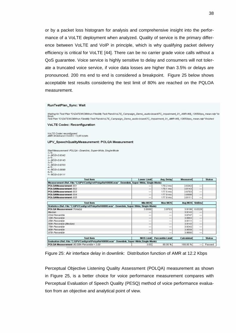
38
or by a packet loss histogram for analysis and comprehensive insight into the perfor-
mance of a VoLTE deployment when analyzed. Quality of service is the primary differ-
ence between VoLTE and VoIP in principle, which is why qualifying packet delivery
efficiency is critical for VoLTE [44]. There can be no carrier grade voice calls without a
QoS guarantee. Voice service is highly sensitive to delay and consumers will not toler-
ate a truncated voice service, if voice data losses are higher than 3.5% or delays are
pronounced. 200 ms end to end is considered a breakpoint. Figure 25 below shows
acceptable test results considering the test limit of 80% are reached on the PQLOA
measurement.
Figure 25: Air interface delay in downlink: Distribution function of AMR at 12.2 Kbps
Perceptual Objective Listening Quality Assessment (POLQA) measurement as shown
in Figure 25, is a better choice for voice performance measurement compares with
Perceptual Evaluation of Speech Quality (PESQ) method of voice performance evalua-
tion from an objective and analytical point of view.
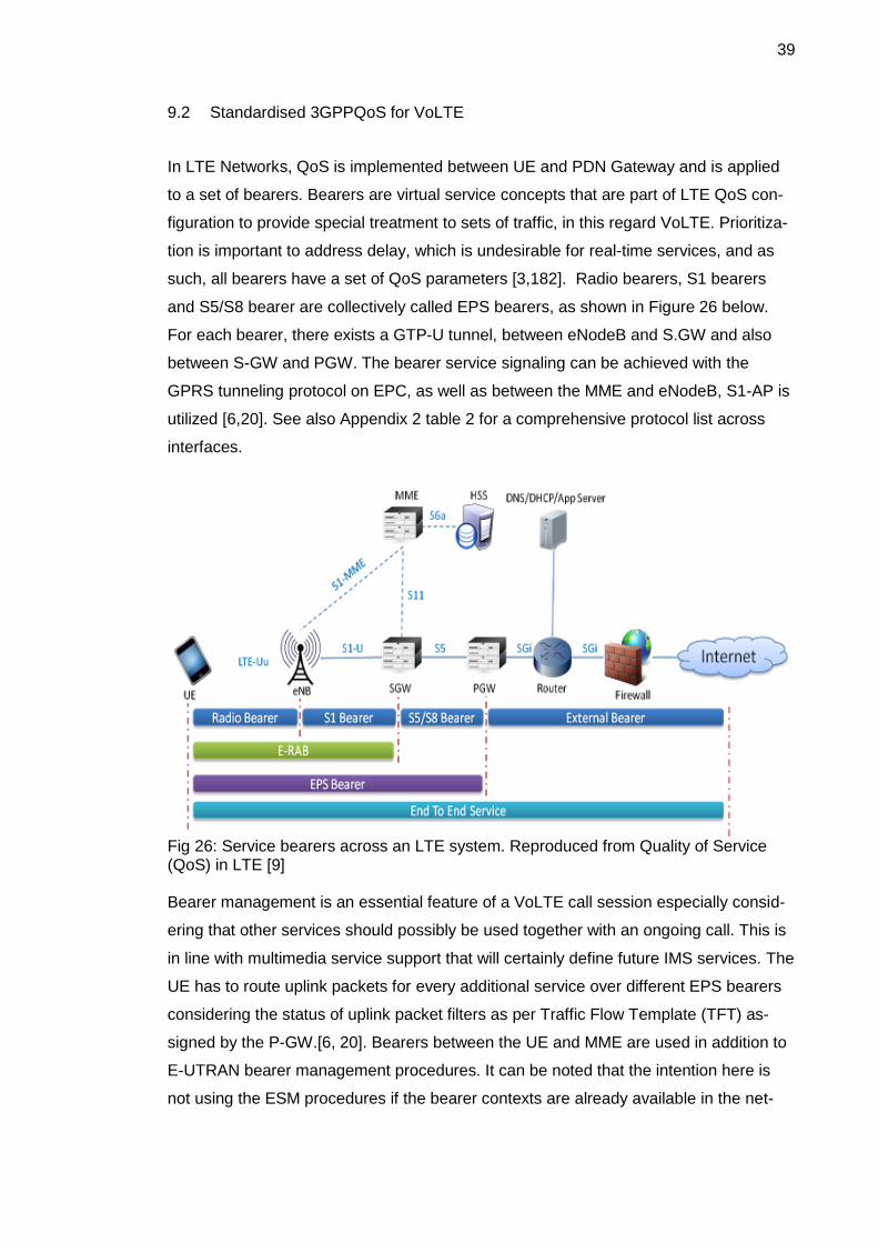
39
9.2 Standardised 3GPPQoS for VoLTE
In LTE Networks, QoS is implemented between UE and PDN Gateway and is applied
to a set of bearers. Bearers are virtual service concepts that are part of LTE QoS con-
figuration to provide special treatment to sets of traffic, in this regard VoLTE. Prioritiza-
tion is important to address delay, which is undesirable for real-time services, and as
such, all bearers have a set of QoS parameters [3,182]. Radio bearers, S1 bearers
and S5/S8 bearer are collectively called EPS bearers, as shown in Figure 26 below.
For each bearer, there exists a GTP-U tunnel, between eNodeB and S.GW and also
between S-GW and PGW. The bearer service signaling can be achieved with the
GPRS tunneling protocol on EPC, as well as between the MME and eNodeB, S1-AP is
utilized [6,20]. See also Appendix 2 table 2 for a comprehensive protocol list across
interfaces.
Fig 26: Service bearers across an LTE system. Reproduced from Quality of Service (QoS) in LTE [9] Bearer management is an essential feature of a VoLTE call session especially consid-
ering that other services should possibly be used together with an ongoing call. This is
in line with multimedia service support that will certainly define future IMS services. The
UE has to route uplink packets for every additional service over different EPS bearers
considering the status of uplink packet filters as per Traffic Flow Template (TFT) as-
signed by the P-GW.[6, 20]. Bearers between the UE and MME are used in addition to
E-UTRAN bearer management procedures. It can be noted that the intention here is
not using the ESM procedures if the bearer contexts are already available in the net-

40
work. Figure 26 shows the concept of bearer application across VoLTE working nodes.
Bearers are only present over the EPC and not over the IMS network. They work hand
in hand with tunneling protocols to carry signaling or media information from one inter-
face to another.
There are two types of bearers to aid QoS in LTE. They are dedicated bearers and
default bearers. There are two default bearers. One bearer is always involved in estab-
lishing an attachment to LTE network by UE. This is used for the signaling information
between EPC and IMS network. The dedicated bearer is always established for actual
data transfer and QoS provision [40,184]. The dedicated bearer can be divided into
Non-GBR and GBR. The GBR bearer type is used for providing guaranteed bit rate
and is represented with parameters like GBR and MBR. It has a minimum guaran-
teed bit rate per EPS bearer, which is specified independently for both uplink and
downlink. As for MBR it is the maximum, which is specified independently for either
uplink or downlink. The downside of non-GBR bearers is that they do not pro-
vide guaranteed bit rate. Non-GBR bearers’ parameters include A- AMBR and UE-
AMBR [40,186]. The -A-AMBR/ APN aggregate maximum bit rate is defined as the
maximum allowed total non-GBR throughput to a specific APN and is also speci-
fied interdependently for uplink and downlink. Figure 27 below shows an illustrated
bearer division employed for Qos. The bearer working details are shown in Figure 28,
where the non-GBR use is shown alongside GBR bearers.
Fig 27: Bearer definition in LTE. Reproduced from Quality of Service (QoS) in LTE [9]
Each default bearer is attached to some PDN network and is allocated a distinct IP
address while a dedicated bearer does not need this since it is attached to a default

41
bearer. Bearers have associated Quality of service Class Identifiers (QCI). The QCI
defines IP level packet priority levels. When programming a VoLTE application, it is
important to define the class hierarchy priority. VoLTE implementation normally re-
quires 1 default and at least one dedicated bearer. The default bearer is used for sig-
naling SIP messages related to the IMS network and applies a QCI of 5. The dedicated
bearer is used for VoLTE traffic and applies a QCI of 1.The dedicated bearer is howev-
er linked to the default bearer. If a user wishes to add another session, a new bearer
has to be created with an appropriate QCI that fits the required purpose as shown in
Figure 28 below.
Fig 28: Bearer creation in LTE. Reproduced from NETMANIAS technical documents
[55]
The first default bearer is associated with IMS PDN and has a specific IP address. It
has throughput limitations defined by A-AMBR and UE-AMBR. The packet delay
schedule per bear type is summarized in table 3. For example QCI of 5 translates into
an IP packet that has the highest priority of 1, which precedes other IP packets, and
has a maximum delay of 100 ms between UE and PGW with a packet loss percentage
up to 10-6. This is well enough for VoLTE calls. The second default bearer is associated
with Internet PDN with similar parameters as the first except working with a QCI of 9, a
low priority with a maximum delay of at least 300 ms between UE and PGW with a
packet loss percentage up to 10-6 .[51; 40,181-186.]
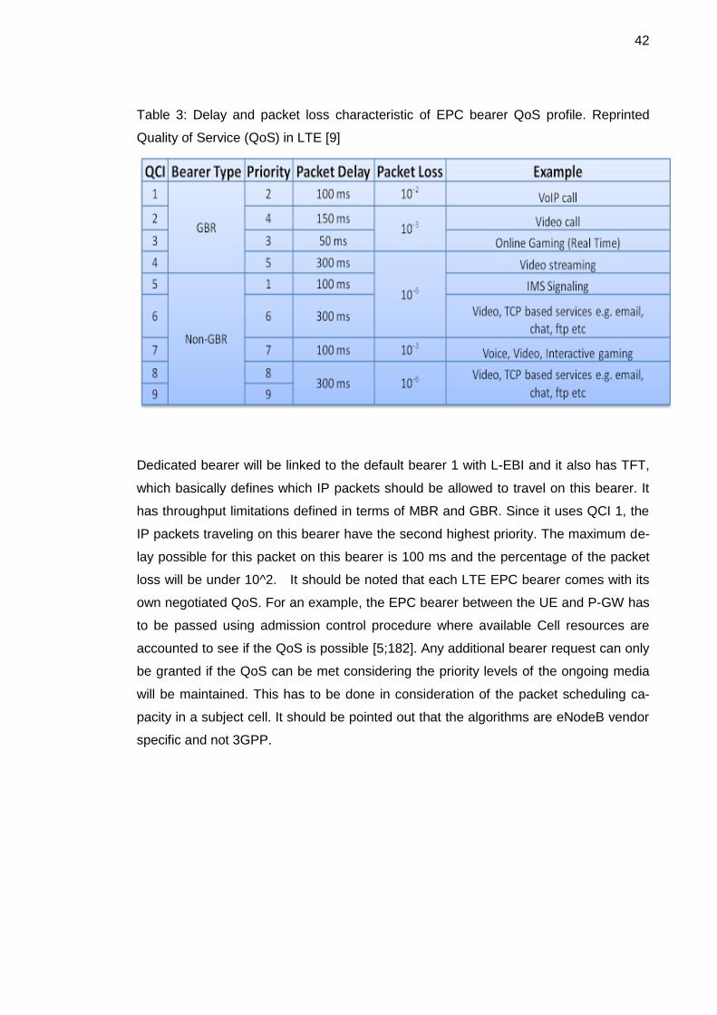
42
Table 3: Delay and packet loss characteristic of EPC bearer QoS profile. Reprinted
Quality of Service (QoS) in LTE [9]
Dedicated bearer will be linked to the default bearer 1 with L-EBI and it also has TFT,
which basically defines which IP packets should be allowed to travel on this bearer. It
has throughput limitations defined in terms of MBR and GBR. Since it uses QCI 1, the
IP packets traveling on this bearer have the second highest priority. The maximum de-
lay possible for this packet on this bearer is 100 ms and the percentage of the packet
loss will be under 10^2. It should be noted that each LTE EPC bearer comes with its
own negotiated QoS. For an example, the EPC bearer between the UE and P-GW has
to be passed using admission control procedure where available Cell resources are
accounted to see if the QoS is possible [5;182]. Any additional bearer request can only
be granted if the QoS can be met considering the priority levels of the ongoing media
will be maintained. This has to be done in consideration of the packet scheduling ca-
pacity in a subject cell. It should be pointed out that the algorithms are eNodeB vendor
specific and not 3GPP.

43
10 Discussion
Programming operational VoLTE has several demonstrable difficulties that require
Lean methods of overcoming within the 3GPP functional specifications. VoLTE being a
new area of communication does not have many reference working models that one
can derive prior performance data from, examples being codec rate performance as
shown here and other test results [35,122-123]. The journey to a deployable VoLTE
service for mobile phone subscribers is slowly beginning to show that more test topolo-
gies are required for test purposes to be built and analyzed. The technical implementa-
tion of VoLTE will require standardization to promote interoperability between different
implementations. AMR and AMR-WB adaptation ability supported by RTP payload
formats have shown to enhance VoLTE performance in many tests and should be
standardized.
Work on VoLTE by Sprint, NTT DoCoMo and Ericsson was highly motivating and influ-
ential in this thesis project. Many test cases simulated were mostly based on MMtel
topologies modified from VoLTE white papers produced by Ericsson, NTT DoCoMo
and additionally GSM organizations’ permanent documents. LTE performance data as
contained in the reference materials are freely available as written material or online
sources. The challenges posed in translating theory and standards into an operational
product are enormous and require continuous experimental iterations from a software
perspective.
The thesis scope offered an extensive insight into many different areas of communica-
tion systems from the radio side to the packet core processes, which all makes VoLTE
possible. It was difficult to narrow-down and select every piece of good information
adequate to describe precisely the end-to-end working of a VoLTE call, considering so
many deployment variations. Critical issues such as device support, regulatory
(law-based) functions such as emergency calls, lawful interception and numbering
plans, which are globally portable, remain a challenge to resolve [26; 8, 32.].
The topic of VoLTE by IMS is extensive. Finding an approach that places programming
VoLTE into perspective against the fact that VoLTE programming in practice comes
down to networking in an abstract sense, is a complication. It dwelled upon me that the
future of VoLTE on the user device side will provide incentives for customized applica-
tions such as Java mobile programming or Android. Ericsson has current ongoing pro-

44
jects on a C++ based programming implementation of VoLTE. 3GPP standards pre-
sent additional challenges for better lack of programmable clarity. Network providers
such as SPRINT for their part operate a WiMAX network, whose core network tech-
nology is quite different from LTE. This brings us to the realization that perhaps the
functional interoperability will certainly come down to the choice of implementing packet
voice. This points to access-independent technology, provided by IP multimedia sub-
systems.
The advantages of IMS do not only include the rich multimedia services such as Rich
Communication Suite (RCS), push to talk, video sharing, multimedia streaming service,
and Interactive gaming, which can be expected to be deployed as IMS services grow in
the near future. Video-conferencing in particular has a great appeal in business around
the world. It can be restated that, IMS-based deployment of VoLTE tests showed ac-
ceptable performance to prove a winner in providing an end-to-end all packet VoLTE
service for consumers and global interoperability with great flexibility and diversity in
services to be expected and potentially provided. MIMO antenna technology also
shows great bandwidth boosting that promises high packet transport capability, which
can only be expected to increase further as the trend has been. Multimedia services
are increasingly accounting for a high percentage of traffic on many networks, such
that development in this area is certainly the future of mobile communication. Soon,
any service provider will not ignore the need to develop a viable VoLTE system.
HD voice realization is possible with VoLTE. The call setup time can be optimized to a
1 s delay, a significant improvement compared to the 4 s benchmark thought as opti-
mized in circuit-switched systems and sometimes even far worse in VoIP calls. Indica-
tions are that the packet size bears an impact on voice capacity. It can be restated that
VoLTE by IMS brings even more advantage by saving power on devices by discontinu-
ous reception (DRX) functionality native to LTE access technology. A programmatic
approach to IP-telephony is waiting to take off on the back of high speed broadband
networks like LTE 4/5G. Particular emphasis can be placed on IMS for a good reason,
being that many other services will be built on the same and work alongside packet
voice. Supporting programmable service integration and scalability then becomes
even more complicated considering the above fact. It has been here highlighted that
programming of VoLTE application as a full packet-switched voice service will support
the 3GPP specifications as well as network requirements in releasing an operational
VoLTE by at least release 12 standards.

45
11 Conclusion
The goal of project was demonstrating a test-driven VoLTE deployment in a program-
matic sense in respect of a basic VoLTE topology and IR 92 standard, which is the IMS
profile for voice and SMS .programmatic implementation of VoLTE as an approach to
deploying an operational voice capability via LTE packet core and IMS is a feasible test
driven approach as shows in this thesis. The tests verified the results reported in VoL-
TE test cases of a viable VoLTE topology that employed a 1.4-20MHz bandwidth with
a 150Mbps DL and 75Mbps UL in either FDD/TDD LTE implementation to support full
HD voice quality [40,365]. VoLTE call simulations at 2 x 2 MIMO broadband with a
wide band codec showed to be the ideal for HD quality voice. AMR codec which is rec-
ommended for VoLTE showed variable voice capacity and good spectral efficiency as
evidenced from analysing codec rates obtained from test results. POLQA analysis of
voice quality showed that the quality is affected by various network parameters mainly
related to delays, packet loss and bandwidth limitations. Codec selection and schedul-
ing algorithms on the user-air interface side is dependent on network configuration and
user device capability. The official ITU-T test results also confirmed the major im-
provement of the perceived voice quality provided by the bandwidth extension from
narrowband to wideband codec. The results gathered on TTI bundling and codec rates
showed that the voice quality-to-voice capacity relation is such that low rate codecs
provide better voice capacity but inferior voice quality, compared to high rate codecs
which show the opposite result.
The results on AMR-NB applied with three distinct bundling and codec rates showed
that at low rate, AMR offered more capacity per cell per MHz of bandwidth. Other tests
have also shown that at lower rates of 12.65 Kbps AMR-WB provides the same high
quality as G.722 used at its maximum bit rate of 64 Kbps, which would make it better
placed to offer more voice capacity than G.722 per cell and per bandwidth. The analy-
sis of data on a statistical level and probability of speech intelligibility or interruption of
voice stream caused by consecutive packet losses and time exceeding maximum per-
missible time for voice packet transport would be valuable research further into the
topic of Voice of LTE including arears in bandwidth adaptation.
The test results passed the benchmark of less than 200 ms end-to-end delay without
retransmission. This is ideal for a practical VoLTE deployment on a 1.4-20MHz band
width with a 150 Mbps DL and 75 Mbps UL in a FDD/TDD LTE implementation, con-

46
forming to 3GPP specifications defined in IR 92. However, there is more need to de-
velop packet scheduling algorithms to improve VoLTE performance. The test results
here showed as in many other tests on scheduling performance, that semi-persistent
scheduling is only limited by PDSCH bandwidth and not the control channel resources.
It follows that semi-persistent scheduling, is limited by the user plane, and not the con-
trol plane. Also to note in VoLTE are issues of non-standardised universal public user
identities for VoLTE users. It should be expected that VoLTE users should be able to
start and connect sessions from different networks. This should include both circuit-
switched and packet-switched. In this regard, there is a need to find a way of phone
number mapping (ENUM) MSISDN to URLs or SIP URIs of any particular user for
global reachability and seamless call migration between packet voice and circuit voice.
Test tools customized with VoLTE process test cases are also critical considering
many different voice scenarios in a VoLTE system. It can be concluded that with the
development of LTE-Advanced for IMT-Advanced (Release 10-12) which promises
higher data rates of up to 1 Gbit/s at low mobility or 100 Mbits/s with 100 MHz band-
width support, VoLTE can be expected to fully mature into a reliable voice solution of
unparalleled quality. Multimedia Broadcast Multicast Service, if introduced in the LTE
configuration would add more reliability to support HD voice with advanced terminals
that can combine data streams. Simulations are not always reflective of real world situ-
ations and here lays the limitation of results acquired strictly from a laboratory setup as
in this project.
The project was successful in demonstrating and also validating a basic VoLTE topolo-
gy as a viable deployment. The performance influence on voice capacity by scheduling
and packet bundling provided important results useful in understanding the perfor-
mance effects of a given scheduling method when deploying VoLTE. The project in
summary showed that VoLTE development can best be executed by test-driven packet
transport programming of session logic based on verified VoLTE components and func-
tionalities.

47
References
1 Alcatel Lucent. The declining profitability trend of mobile data: Assessing net-work costs and planning for sustainability revenue growth [online]. Available from:http://www3.alcatellcent.com/belllabs/advisorysevies/documents/Declining_Profitability_Trend_of_Mobile_Data_EN_Market_Analysis. [Accessed 9 Janu-ary 2015].
2 The LTE/SAE Deployment Handbook. Nokia Siemens Network Innovation Cen-ter. Jyrki T. J. Penttinen Editor, Spain: Wiley&Sons Ltd; October 2004.
3 Poikselka M, Holma H, Hongisto H, Kallio, Toskala A. Voice over LTE. 1st ed. A John Wiley & Sons, Ltd; 2012.
4 Voice and video calling over LTE. Ericsson White paper; November 2014[online] Available from: http://www.ericsson.com/res/docs/whitepapers/wp-voice-and-video-calling-over-lte.pdf: [Accessed 20 January 2015].
5 LTE for UMTS; OFDMA and SC-FDMA Based Radio Access: Editors, Harri Holma, Antti Toskala. John Wiley & Sons Ltd; 2009.
6 B.Gabriel. Examing the case of VoLTE and rich multimedia communications. White Paper. Heavy reading.pdf (online); 2000. URL:http://www.ericsson.com/res/docs/2012/HR_VoLTE_WP_Final.pdf: Ac-cessed on 21.01.2015.
7 Tanaka I. et al. Overview of GSMA VoLTE Profile. NTT Docomo Technical jounal 2012;13(3): 13-19.
8 Poikselkä M, Mayer G. The IMS IP Multimedia Concepts and Services, Third Ed. John Wiley & Sons, Ltd, 2009.
9 Voice solutions in LTE.[online]. Available from: http://4g-lte-world.blogspot.fi/2012/05/voice-solutions-in-lte.html. May 12, 2012. Accessed 20 January 2015].
10 Alan B. Johnston. SIP: Understanding the Session Initiation Protocol. Third Edi-tion, Artech House; 2009.
11 Erik Dahlman, Stefan Parkvall, Johan Sköld. 4G, LTE/LTE-Advanced for Mobile Broadband. Oxford: Academic Press;2011.
12 IMS Multimedia Telephony. 3G4G Blog [online]. URL: http://blog.3g4g.co.uk/search/label/VoLTE. [Accessed 20 January 2015].
13 GSM Association Non-confidential Official Document IR.92. IMS Profile for Voice and SMS.
14 Different flavours of SRVCC [online]. URL: http://blog.3g4g.co.uk/2014/01/different-flavours-of-srvcc-single.html . Accessed 20 January 2015.

48
15 VoLGA - Voice over LTE via Generic Access [online] http://lteworld.org/lte/volga-voice-over-lte-generic-access. Accessed 20 January 2015.
16 Changes and Challenges of the Network Business: Partnership with R&D Divi-sion: NTT DOCOMO Technical journal vol.11 No. 3 https://www.nttdocomo.co.jp/english/corporate/technology/rd/technical_journal/bn/vol11_3/.
17 Open IMS Core[online].http://www.openimscore.org/. Accessed 20 January 2015.
18 3rd Generation Partnership Project; Technical Specification Group Services and System Aspects; IP Multimedia Subsystem (IMS); Multimedia Telephony; Media handling and interaction (Release 9), 3GPP TS 26.114 V9.1.0; (2009-12).
19 R&S®CMW500 - Production Test [online]. URL:http://www.rohde-schwarz.com/en/product/cmw500-productstartpage_63493-10341.html.
20 Developing systems registered trade mark [online]. URL:http://www.developingsolutions.com/volte-testing-with-dstest/
21 VoLTE and RCS test solutions.URL: http://www.spirent.com/Products/VoLTE_Services_Test_Solution
22 3GPP TS 23.237 V9.2.0 (2009-09) IP Multimedia Subsystem (IMS) Service Continuity Stage 2.
23 Voice over LTE via Generic Access (VoLGA)[online]: A Whitepaper - August 2009.URL: http://cm-networks.de/volga-a-whitepaper.pdf. [Accessed 20 Janu-ary 2015].
24 3GPP TS 24.301. Protocol details of the NAS, 3GPP org. URL:http://www.3gpp.org/technologies/keywords-acronyms/96-nas. [Accessed 29 September 2014].
25 3GPP, 3rd generation partnership project; Technical Specification Group Core Network; Numbering, addressing and identification (Release 5), 3GPP TS 23.003.
26 3rd Generation Partnership Project; Technical Specification Group Services and System Aspects; IP Multimedia Subsystem (IMS) emergency sessions (Re-lease 7), 3GPP TS 23.167.
27 3rd Generation Partnership Project; Technical Specification Group Services and System Aspects; Policy and charging control architecture (Release 11), 3GPP TS 23.203.

49
28 3rd Generation Partnership Project; Technical Specification Group Services and System Aspects; Single Radio Voice Call Continuity (SRVCC); Stage 2 (Re-lease 8), 3GPP TS 23.216.
29 3rd Generation Partnership Project; Technical Specification Group Services and System Aspects; Architectural requirements (Release 9), 3GPP TS 23.221.
30 3rd Generation Partnership Project; Technical Specification Group Services and System Aspects; Circuit Switched (CS) fallback in Evolved Packet System (EPS); Stage 2 (Release 10), 3GPP TS 23.272.
31 3rd Generation Partnership Project; Technical Specification Group Core Net-work and Terminals; IP Multimedia Call Control Protocol based on Session Ini-tiation Protocol (SIP) and Session Description Protocol (SDP); Stage 3 (Re-lease 5), 3GPP TS 24.229.
32 3rd Generation Partnership Project; Technical Specification Group Core Net-work and Terminals; Non-Access-Stratum (NAS) protocol for Evolved Packet System (EPS); Stage 3 (Release 8), 3GPP TS 24.301.
33 LTE Backhaul with the Tellabs 8600 Smart Routers: Tellabs; 2012.
34 3rd Generation Partnership Project; Technical Specification Group Services and System Aspects; Mandatory speech CODEC speech processing functions; AMR speech CODEC; General description (Release 6), 3GPP TS 26.071.
35 Shyam Chakraborty, Janne Peisa, Tomas Frankkila, Per Synnergren: IMS Mul-timedia Telephony over Cellular Systems. VoIP Evolution in a Converged Tele-communication World: John Wiley & Sons, Ltd.
36 The Evolution of the Signalling challenge in 3G & 4G Networks. White paper: Heavy reading; June 2012.
37 3rd Generation Partnership Project; Technical Specification Group Services and System Aspects; Speech Codec List for GSM and UMTS; (Release 1999), 3GPP TS 26.103.
38 3rd Generation Partnership Project; Technical Specification Group Services and System Aspects; IP Multimedia Subsystem (IMS); Multimedia Telephony; Media handling and interaction (Release 9), 3GPP. TS 26.114.
39 Qualcomm. VoLTE with SRVCC. The second phase of voice evolution for mo-bile LTE devices: White paper, October 2012.
40 LTE and the Evolution to 4G Wireless. Design and measurements challenges: Moray Rumney editor. Agilent technology. 2009.
41 3rd Generation Partnership Project; Technical Specification Group Radio Ac-cess Network; Evolved Universal Terrestrial Radio Access (E-UTRA) Medium Access Control (MAC) protocol specification (Release 8), 3GPP TS 36.321.
42 3rd Generation Partnership Project; Technical Specification Group Radio Ac-cess Network; Evolved Universal Terrestrial Radio Access (E-UTRA); Packet Data Convergence Protocol (PDCP) specification (Release 8),3GPP TS 36.323.

50
43 3rd Generation Partnership Project; Technical Specification Group Radio Ac-cess Network; Evolved Universal Terrestrial Radio Access (E-UTRA) Radio Re-source Control (RRC); Protocol specification (Release 8), 3GPP TS 36.331.
44 UMTS Networks and beyond: Cornelia Kappler: deZem GmbH, Germany: John Wiley and sons, Ltd 2009.
45 3rd Generation Partnership Project; Technical Specification Group Radio Ac-cess Network; Packet Data Convergence Protocol (PDCP) specification (Re-lease 7), TS 25.323 (IETF RFC 3095).
46 SIP: Session Initiation Protocol, IETF RFC 3261,The Internet society; 2002.
47 RTP: A Transport Protocol for Real-Time Applications. RFC 3550, IETF 2003.
48 Daniel Minoli, Voice Over IP version6, Architecture for the next generation VoIP networks, Newnes, Oxford 2006.
49 LTE E-UTRAN and its Access Side Protocols, Radisy white paper.
50 3rd Generation Partnership Project; Technical Specification Group Radio Ac-cess Network; Evolved Universal Terrestrial Radio Access (E-UTRA) Radio Link Control (RLC) protocol specification (Release 8), 3GPP TS 36.322.
51 Quality of service in LTE [online].3G4Gblog URL: http://4g-lte-world.blogspot.fi/2013/01/quality-of-service-qos-in-lte.html [Accessed 20 Janu-ary 2015].
52 MAPS™ Diameter Protocol Emulator [online]. URL: http://www.gl.com/maps-diameter-newsletter.html .[Accessed 20 January 2015].
53 VoLTE Service Description and Implementation Guidelines: GSM Association, Official Document FCM.0; Version 1.1 March 2014
54 Sprint ProLab Terminal emulator: A comprehensive testing solution for termi-nals in SIP, IMS, H.323 and 3G networks. http://www.spirent.com/~/media/Datasheets/ProLab/Spirent_ProLab_Terminal_Emulation.pdf.[Accessed 30 January 2015].
55 LTE Identification III: EPS Session/Bearer Identifiers. http://www.netmanias.com/en/post/techdocs/5907/identification-identifier-lte/lte-identification-iii-eps-session-bearer-identifiers. [Accessed 3 March 2015].

Appendix
1 (9)
Appendix 1: Table 1. VoLTE bearer associated parameters
Table 2. Radio and EPC interfaces and applicable protocols on each interface. Data
gathered from Harri Holma, Antti Toskala (2009)[5]
Interface Protocol Specification Fig/Thesis
page
LTE-Uu CP:RRC/PDCP/RLC/MAC/PHY
UP:PDCP/RLC/MAC/PHY
36.300[6]
(stage 2)
X2 CP: X2AP/SCTP/IP
UP:GTP-U/UDP/IP
36.413[7]
36.413[8]
S1-MME S1AP/SCTP/UDP/IP 36.413[9]
S1-U GTP-U/UDP/IP 29.274[8]
S10 GTP-C/UDP/IP 29.274[8]
S11 GTP-C/UDP/IP 29.274[8]
S5/S8(GTP) GTP/UDP/IP 29.274[8]
S5/S8(PMIP) CP:PMIP/IP
UP:GRE/IP
29.274[10]
SGi IP(also Diameter & Radius) 29.061[11]
S6a Diameter/SCTP/IP 29.272[12]
Gx Diameter/SCTP/IP 29.212[13]
Gxc Diameter/SCTP/IP 29.212[13]
Rx Diameter/SCTP/IP 29.214[14]
UE-MME EMM, ESM 29.301[15]
Interface Protocol Specification Fig/Thesis page
S3 GTP-C/UDP/IP 29.274[8]
S4 GTP/UDP/IP 29.274[8]
S12 GTP-U/UDP/IP 29.274[8]
S16 GTP/UDP/IP 29.274[8]
S6d Diameter/SCTP/IP 29.274[12]
SGs SGsAP/SCTP/IP 29.274[21]
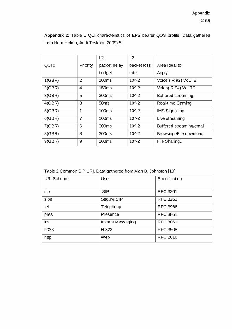
Appendix
2 (9)
Appendix 2: Table 1 QCI characteristics of EPS bearer QOS profile. Data gathered
from Harri Holma, Antti Toskala (2009)[5]
QCI #
Priority
L2
packet delay
budget
L2
packet loss
rate
Area Ideal to
Apply
1(GBR) 2 100ms 10^-2 Voice (IR.92) VoLTE
2(GBR) 4 150ms 10^-2 Video(IR.94) VoLTE
3(GBR) 5 300ms 10^-2 Buffered streaming
4(GBR) 3 50ms 10^-2 Real-time Gaming
5(GBR) 1 100ms 10^-2 IMS Signalling
6(GBR) 7 100ms 10^-2 Live streaming
7(GBR) 6 300ms 10^-2 Buffered streaming/email
8(GBR) 8 300ms 10^-2 Browsing /File download
9(GBR) 9 300ms 10^-2 File Sharing..
Table 2 Common SIP URI. Data gathered from Alan B. Johnston [10]
URI Scheme Use Specification
sip SIP RFC 3261
sips Secure SIP RFC 3261
tel Telephony RFC 3966
pres Presence RFC 3861
im Instant Messaging RFC 3861
h323 H.323 RFC 3508
http Web RFC 2616
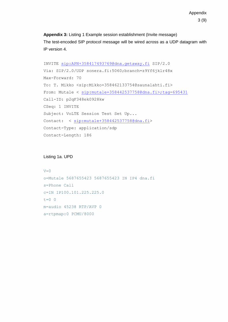
Appendix
3 (9)
Appendix 3: Listing 1 Example session establishment (Invite message)
The test-encoded SIP protocol message will be wired across as a UDP datagram with
IP version 4.
INVITE sip:[email protected] SIP/2.0
Via: SIP/2.0/UDP sonera.fi:5060;branch=z9Yf6jklr48x
Max-Forward: 70
To: T. Mikko <sip:[email protected]>
From: Mutale < sip:[email protected]>;tag=695431
Call-ID: p2qF348ek0928kw
CSeq: 1 INVITE
Subject: VoLTE Session Test Set Up...
Contact: < sip:[email protected]>
Contact-Type: application/sdp
Contact-Length: 186
Listing 1a. UPD
V=0
o=Mutale 5687655423 5687655423 IN IP4 dna.fi
s=Phone Call
c=IN IP100.101.225.225.0
t=0 0
m=audio 45238 RTP/AVP 0
a=rtpmap:0 PCMU/8000

Appendix
4 (9)
Appendix 4: Listing 1: SIP voice call setup. SIP protocol message will be wired across
as a SDP datagram with IP version 6.
INVITE sip: [email protected] SIP/2.0
Via: SIP/2.0/UDP [7575::a:b:c:d]:1200; branch=abc123
max-Forward: 40
Route:<sip:[7575::44:22:99:55]:7442;lr>,<
sip:[email protected];lr>
P-Access-Network-Info:3GPP-E-UTRAN-TDD;utran-cell-id-
3gpp=244005F7F8F5
P-Preferred-Service: urn:urn-5:3gpp-service.ims.icsi.mmtel
privacy:none
From:<sip:[email protected]>;tag=343546
To:<sip:[email protected]>
Call-ID:cb07syduhd994dg8djk56474
Cseq:127 INVITE
Require:sec-agree
Proxy-Require:sec-agree
Supported: precondition, 100rel, 199
Security-Verify: ipsec-3gpp; alg=hmac-sha-1-96; spi-
c=4567353634;
spi-s=45464833; port-c=8642; port-s=7532
contact:<sip:[7777::a:b:c:d]:1200;;+g.3gpp.icsi-ref="urn%Aurn-7%
3gpp-service.ims.icsi.mmtel"
Accept-Contact: *;+g.3gpp.icsi-ref="urn%3Aurn-7%
3gpp-service.ims.icsi.mmtel"
Allow: INVITE, ACK, CANCEL, BYE, PRACK, UPDATE, REFER, MESSAGE,
OPTIONS
Accept:application/sdp, application/3gpp-ims+xml
Content-Type: application/sdp
Content-Length: ( )

Appendix
5 (9)
Appendix 5: Listing 2a. SDP Information.
v=0 //protocol version
0=- 4546489444 4546482441 IN IP6 7777::a:b:c:d //session owner
s=- //session subject(optional)
c=IN IP6 7777::a:b:c:d
t=0 0
m=audio 49255 RTP/AVP 97 98
a=rtpmap:97 AMR/8000/1
a=fmtp: 97 mode-charge-capability=2; max-red=220
b=AS:30
b=RS:0
b=RR:0
a=rtpmap: 98 telephone-event/8000/1
a=fmtp:98 0-15
a=ptime:20
a=maxptime:240
a=inactive
a=curr:qos local none
a=curr:qos remote none
a=curr:qos mandatory local sendrecv
a=des:qos none remote sendrecv

Appendix
6 (9)
Appendix 6: Listing 1. INVITE SDP Information.
INVITE tel:+358417496339 SIP/2.0
Via SIP/2.0/UDP mgcfxx.homexx.fi
Route:<sip:icscfxx.homexx.fi;lr>
From:<tel:+358417496339>;tag=mutale
To:<tel:+358417496339>
P-Charging-Vector:icid-value="ByhferU0fx+4";orig-ioi=homexx.fi
P-Asserted-Identity:<tel:+358417496339>
P-Asserted-Service:urn:urn-dna:3gpp-service-ims.icsi.mmtel"
Accept-Contact:*;3gpp-icsi.ref="urn%Aurn-dna%3A3gpp-service-
ims.icsi.mmtel"
Contact:<sip:mgcfxx.homexx.fi>;g.3gpp-icsi.ref="urn%3Aurn-
dna%3A3gpp-service-ims.icsi.mmtel"
Call-ID:snipper1
CSeq: 2810 INVITE
Appendix 6 : Listing 2. LTE user equipment categories depending on maximum peak
data rate and MIMO capabilities support. With 3GPP Release 10, which is referred to
as LTE Advanced. Data gathered from http://en.wikipedia.org/wiki/E-UTRA
User equip-ment category
Maximum L1 data-rate downlink
Maximum number of DL MIMO lay-
ers
Maximum L1 data-rate uplink
3GPP release
Category 1 10.3 Mbit/s 1 5.2 Mbit/s Release 8
Category 2 51.0 Mbit/s 2 25.5 Mbit/s Release 8
Category 3 102.0 Mbit/s 2 51.0 Mbit/s Release 8
Category 4 150.8 Mbit/s 2 51.0 Mbit/s Release 8
Category 5 299.6 Mbit/s 4 75.4 Mbit/s Release 8
Category 6 301.5 Mbit/s 2 or 4 51.0 Mbit/s Release 10
Category 7 301.5 Mbit/s 2 or 4 102.0 Mbit/s Release 10
Category 8 2,998.6 Mbit/s 8 1,497.8 Mbit/s Release 10
Category 9 452.2 Mbit/s 2 or 4 51.0 Mbit/s Release 11
Category 10 452.2 Mbit/s 2 or 4 102.0 Mbit/s Release 11

Appendix
7 (9)
Appendix 7 : VoLTE UE Attachment and IMS Registration message sequence
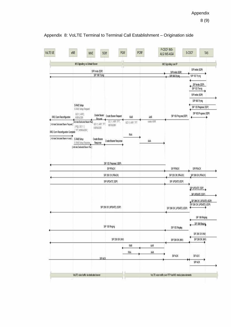
Appendix
8 (9)
Appendix 8: VoLTE Terminal to Terminal Call Establishment – Origination side

Appendix
9 (9)
Appendix 9: VoLTE Terminal to Terminal Call Clearing – Initiated message sequence