Voltage Controlled Current Source - Anmesys.com · The AMS220 Voltage Controlled Current Source...
37
AMS220 Voltage Controlled Current Source with Acve Common Mode Rejecon USERʹS MANUAL USERʹS MANUAL
Transcript of Voltage Controlled Current Source - Anmesys.com · The AMS220 Voltage Controlled Current Source...

AMS220Voltage Controlled Current Source
with Ac�ve Common Mode Rejec�on
USERʹS MANUALUSERʹS MANUAL

Manual version 2.3

TABLE OF CONTENTS
1 INTRODUCTION......................................................................................................................... 3
1.1 Intended use ..................................................................................................................... 3
1.3 Elimination of Common mode errors in low resistance measurements .......................... 4
1.4 Tests to identify the occurrence of common mode errors .............................................. 7
2 DEVICE DESCRIPTION .............................................................................................................. 10
2.1 Functional elements on the AMS220 front panel .......................................................... 10
2. 2 Functional elements on the rear panel .......................................................................... 12
3 TESTING THE DEVICE .............................................................................................................. 14
3.1 Quick test of the AMS220 using the lock-in amplifier or DAQ ....................................... 14
3.2 Quick test of the AMS220 with the dedicated AMS560 preamplifier ............................ 16
4 MEASUREMENTS USING THE AMS220 ................................................................................... 17
4.1 Measurements of electrical resistance using the lock-in amplifier and the AMS220 .... 18
4.1.1 Connecting the AMS220 and setting the lock-in amplifier..................................... 18
4.1.2 Setting of the AMS220 reference ground and connection of signal wire shields .. 19
4.2 Simultaneous measurement of normal and the Hall resistance .................................... 22
4.3 Measurements using the dedicated preamplifiers AMS560/AMS540 ........................... 23
4.3.1 Key specifications of the AMS560/AMS540 ........................................................... 23
4.3.2 Connecting the AMS560/AMS540 preamplifier ..................................................... 23
4.3.3 Very low resistance measurements using the AMS560 preamplifier .................... 24
4.4 Using standard voltage preamplifiers in measurements with the AMS220 .................. 25
4.5 Resistance measurements using DAQ devices ............................................................... 27
4.6 Using the AMS220 as a “classical” current source (two-wire connection) .................... 28
5 TECHNICAL SPECIFICATIONS OF THE AMS220 ........................................................................ 30
6 CONNECTION OF THE CONNECTORS (AMS220, AMS560, AMS540) ...................................... 31
6.1 Connection of the connectors For the AMS220 ............................................................. 31
6.2 Connection of the connectors For the AMS560/AMS540 .............................................. 32
7 ADDITIONAL INFORMATION ................................................................................................... 34
7.1 Electronic waste treatment ............................................................................................ 34
7.2 Warranty and service ..................................................................................................... 34
7.3 Manufacturer’s important warnings and declarations .................................................. 34
7.4 Manufacturer’s Contact details ...................................................................................... 35

2

3
1 INTRODUCTION
1.1 INTENDED USE
The AMS220 Voltage Controlled Current Source with Active Common Mode Rejection, preferentially designed for use with lock-in amplifiers, brings a unique possibility to perform low-level electrical measurements requiring precise current excitation at the negligible level of common mode voltage. If the AMS220 is used with a highly sensitive lock-in amplifier or in combination with the AMS560 preamplifier, the measurements of very low resistances become a routine even in the most demanding conditions; typical example represent measurements of resistances less than 1 mΩ at temperatures below 500 mK. This is feasible thanks to the combination of the lock-in technique (which enables to perform very low voltage measurements also in the background of significant disturbance signals, if common mode signals are sufficiently low) and the unique, patented, architecture of the AMS220 (which ensures active rejection of common mode signals that naturally arise at current excitation of the load). In this sense the AMS220 in conjunction with the lock-in amplifier represents a favourable replacement for an AC resistance/impedance bridge.
Although the AMS220 is optimized for measurements by means of lock-in amplifiers, it can be used also in combination with various types of DAQ devices. The AMS220 enables a routine use of lock-in amplifiers and DAQ devices in applications where current excitation of the load/sensor is required. For example, the abovementioned functionality of the AC resistance bridge can be obtained very easily by interconnecting the sine output and the inputs of the lock-in amplifier with the appropriate input and outputs on the AMS220 front panel (see Fig. 1.1-1). As the AMS220 provides current excitation of the measured load at simultaneous suppression of common mode voltage signals sensed on the load, such measuring configuration is highly resistant against “overload problems” frequently observed in experiments, where “classic” resistance bridges or lock-in amplifiers in combination with “classical” current sources are used to measure (very) low resistances.
Fig. 1.1-1 Block diagram of connection of the AMS220 with the lock-in amplifier to obtain functionality of the AC resistance/impedance bridge. The lock-in amplifier and the AMS220 are interconnected by three BNC cables.

4
The functionality which makes the AMS220 unique and principally distinguishes it from competitive products is the original patented technology of active common mode voltage rejection*). This feature predestines the AMS220 to be used in measurements of very low resistances by four-wire technique, or in measurements of very small changes of resistive sensors connected in the Wheatstone bridge circuit. Advantages of resistance measurements using the AMS220 (operating with enabled circuits of active common mode rejection) compared with classical measuring configurations with the load grounded at one end are explained in the following section on an example of low electrical resistance measurement.
*) U.S. patent #9,285,809 B2, Mar. 2016: Current source with active common mode rejection
1.3 ELIMINATION OF COMMON MODE ERRORS IN LOW RESISTANCE MEASUREMENTS
The four-wire (Kelvin) method is usually used to measure low resistances to eliminate errors due to lead and contact resistances. However, this does not guarantee correct results of very low resistance measurements, because measurements of low-level signals are frequently affected by common mode errors. In a typical four-wire resistance measurement, as illustrated in Fig. 1.3-1, the test current IT is forced through the resistance RT being measured, and the voltage VD across the measured resistance is sensed. In real experiments, however, the measured resistance RT = VD / IT is determined as RT = VM / IT, where VM is the value provided by the voltmeter sensing the voltage VD. Especially at very low resistance measurements, VM often differs from VD due to common mode error, even with the use of high precision instruments dedicated to measure very small voltage differences (e.g. lock-in amplifiers).
Fig. 1.3-1 Depiction of a typical four-wire resistance measurement with a block diagram of the signal processing by the voltmeter
If a digital voltmeter processes the output voltage signal VO of the differential amplifier at its input, as depicted in Fig. 1.3-1, the result of this processing is VM. The output voltage of the ideal differential amplifier operating with a differential gain GD would be VO
ideal = GDVD. However, if the voltage difference across the inputs of the differential amplifier V2 ̶ V1 = VD is much less than the common mode voltage VCM = (V2 + V1) / 2 (i.e. VD << VCM), VO can significantly differ from VO
ideal. In such case, the common mode voltage will affect the output voltage VO. For a “real” differential amplifier, VO can be expressed as VO = GD (V2 ‒ V1) + GCM (V2 + V1)/2 = GDVD + GCM VCM , (1)

5
where GCM is the common mode gain. The ratio GD /|GCM| = CMRR (so-called common mode rejection ratio) characterizes the extent to which the common mode voltage is rejected by the differential amplifier. The CMRR can be expressed also in decibels, being then referred to as common mode rejection*) (CMR); CMR = 20 log10 CMRR. *) CMR is a key specification of an instrument/device. It indicates how much of the common mode signal will appear in the measurement. In fact, limiting capability of instruments to reject common mode signals represents serious limitations for very low resistance measurements (including those performed by means of Kelvin method), because resistances in the current path may cause common mode voltage, which can be even several orders of magnitude greater than the sensed voltage (VD). Nowadays technology limit is approximately 140 dB (CMRR = 107, i.e. amplification of the differential voltage across the amplifier inputs is 10 million times greater than the amplification of the common mode signal). Typically, the CMR varies between 80 dB (CMRR = 104) and 120 dB (CMRR = 106).
Typical situations where common mode errors occur to a significant extent are measurements of very low electrical resistances where the resistance of the electric current path is much higher than the measured resistance itself. As the result, a much higher voltage drop occurs on the supply current leads than on the measured resistance.
Let us imagine measuring the test resistor of 100 µΩ. If current IT = 10 mA is forced through this resistor, the corresponding voltage across the resistor will be VD = 1 µV (= 100 µΩ x 10 mA). Let resistances of both branches of the current path (RIA, RIB) are 20 Ω, as depicted in Fig. 1.3-2.
When using a “classical” current source with one of the outputs connected to the signal ground (single-ended current source), as illustrated in Fig. 1.3-2, the common mode voltage of the value VCM ≈ 20 Ω × 10 mA = 200 mV appears at the input of the voltage sensing instrument. (Note that in this example VCM is much greater than VD = 1 µV). At using an industry standard lock-in amplifier with CMR ≈ 100 dB (i.e. CMRR ≈ 105) to sense the voltage, the corresponding common mode error will be at level of 200 mV /105 = 2 µV. Thus, the value provided by the lock-in amplifier, being a sum of VD (1 µV) and the common mode error (2 µV), will be 3 µV instead of 1 µV. Correspondingly, the resistance gained from the experiment is 300 µΩ instead of 100 µΩ! To ensure the correct result at the output of the voltage sensing instrument, the common mode voltage signals on its inputs need to be eliminated.
Fig. 1.3-2 Four-wire resistance measurement setup at the use of a current source with one of the current outputs connected to the signal ground. The indicated measured value (affected by common mode error) is illustrative, with respect to the discussed example.

6
Common mode errors in low resistance measurements can be avoided by use of the AMS220 voltage controlled current source with active common mode rejection!
When using the AMS220 to measure the test resistor, as illustrated in Fig. 1.3-3, the patented circuit of active common mode rejection (ACTIVE CMR) monitors the voltage sensed by the inputs (A, B) of the voltage sensing device and using a feedback loop “shifts” the voltage potentials of the current outputs in order to assure zero common mode voltage of the monitored signal (VCM → 0 V). Thanks to the patented technology, the component VCM originating in the lead and contact resistances in the current path can be suppressed to less than few microvolts. It can be estimated that at use of a measuring device with CMR ≈ 100 dB or greater the common mode error can be eliminated to the level of tens of picovolts or less! Thus, the measured voltage for the taken example will be 1 µV, just as expected for the test resistance of 100 µΩ.
Fig. 1.3-3 Example of four-wire resistance measurement setup utilizing the AMS220 voltage controlled current source with active common mode rejection (*) U.S. Patent #9,285,809)
The AMS220 in combination with an industry standard lock-in amplifier represents an advantageous solution to perform routine and reliable resistance measurements by the four-wire method. The functionality of an AC resistance bridge can be obtained very simply, by interconnecting the reference voltage output (Sine Out) and the voltage sensing inputs of the lock-in amplifier with the corresponding input and outputs of the AMS220, while the measured resistor/sample is connected to the AMS220, as schematically shown in Fig. 1.1-1. The excitation current provided by the AMS220 is proportional to the reference voltage provided by the lock-in amplifier and the selected voltage to current conversion factor of the AMS220.
If the AMS220 in active common mode rejection regime (ACTIVE CMR - ENABLED) is used to excite the measured resistor/sample, the voltage potentials at the voltage sensing terminals of the measured resistor/sample are monitored by the AMS220. Simultaneously, the AMS220 adjusts the voltage potentials of the current outputs so that the common mode voltage of the sensed signals is kept at the potential of the signal ground. As the result, voltage potentials V(A) and V(B) applied to the corresponding inputs A and B of the lock-in amplifier are practically symmetrical with respect to the signal ground (as depicted in Fig. 1.3-4 by solid lines); this indicates practically zero common mode voltage, and assures reliable lock-in detection not affected by common mode signal at the measuring (lock-in) frequency. Just the combination of the active common mode rejection ability of the AMS220 and the lock-in technique (which enables very low voltage measurements also in the background of significant disturbance signals, if however, the common mode signal at measuring frequency is sufficiently low) eminently shifts reliability limits of very

7
low resistance measurements. Note that the greatest improvements due to use of the AMS220 can be expected in experiments where the sum of the resistances distributed in the current path is very much greater than the measured resistance.
Fig. 1.3-4 Time dependence of the voltage potentials V(A) and V(B) sensed by the inputs of the lock-in amplifier in resistance measurements using the AMS220 with active common mode rejection enabled (solid lines). For comparison, analogous situation is depicted for case when the active common mode rejection circuit of the AMS220 is disabled (dashed lines), i.e. the AMS220 operates analogously as a “classical” current source. Note that in the latter case a huge common mode voltage signal [V(A)+V(B)]/2 exactly at the driving/measuring frequency and of the same phase as the measured AC signal is present.
1.4 Tests to identify the occurrence of common mode errors
Realization of the following tests should help to identify existing or potential problems in resistance measurement setups and eventually indicate a requirement to use the AMS220 voltage controlled current source with active common mode rejection.
A simple test to identify common mode errors in four-wire resistance measurement can be done by a trivial modification of the original four-wire resistance measurement setup as shown in Fig. 1.4-1a to one from Fig. 1.4-1b, where both voltage inputs (VA, VB) sense the same electrical signal. Because the sensed voltage difference in the modified connection is zero, the correct resistance measurement must give the value of 0 Ω.
However, this simplified test yields information relevant only to the particular experimental conditions (particular load, specific temperature, etc.), but it does not necessarily reveal possible system weaknesses in all cases where the setup can be used. For example, it can be insufficient for systems where the resistance of current path (i.e. resistance of current leads and/or contact resistances) varies significantly due to temperature changes. This simple test can also be conditionally ineffective at use of so-called differential current sources, which drive the load "symmetrically", i.e. voltage on their outputs IA and IB is of the same absolute value, but of the opposite polarity. If both current branches have equal resistances, the common mode voltage is zero, and so the common mode error is also zero in this specific case. However, when this balance is broken, e.g. by different contact resistances, the potentials of voltage signals sensed on the test resistance move towards the potential of the output connected with the branch of lower resistance, and the common mode voltage becomes non-zero. This causes the common mode error that increases with increasing resistance imbalance in current branches

8
Fig. 1.4-1 Tests to identify common mode errors. Schematic depiction of the standard four-wire resistance measurement setup (a), its modification for the simplified test (b), and the connection for the thorough test (c). When the purpose of the thorough test is to check the measuring instrument, without testing the complex wiring, resistance under the test can be replaced by a shortcut.
A thorough test can be performed using the connection shown in Fig. 1.4-1c that contains resistors allowing to change the resistances of the current branches by means of the switches SA and SB. Resistances (RA and RB) of these resistors should be comparable to resistances of current paths in real experiments and should not be less than the estimated maximum resistance change of the current path that may occur in (different) experiments. Detailed inspection shall be performed by measuring all possible combinations of the resistances of current branches (RIA, RIB) created by the switches SA and SB. A properly measuring system must provide the value of 0 Ω for any of these combinations. Fig. 1.4-2 shows examples (for two different types of utilized current sources) how the results of the test can look like if RA = RB = 10 Ω, and the CMR of the voltage sensing unit is 100 dB.
Fig. 1.4-2 Possible common mode errors in resistance measurements utilizing a single-ended (a) or differential (b) current source. A settling time of an instrument/setup is represented by intervals between steady readings.
Results of the test as shown in Fig. 1.4-2 can be estimated for different CMR of an instrument**) using the table below. Note that the higher the resistance values RA and RB, the higher the common mode errors.
CMR [dB] 80 90 100 110 120 130 140
ΔRS-E [µΩ] 1000 316 100 31.6 10 3.16 1
ΔRDIF [µΩ] 500 158 50 15.8 5 1.58 0.5 **) The CMR depends on frequency and instrument settings. For instance, the CMR of a lock-in amplifier is less for AC coupling than for DC one. Manufacturers usually specify the CMR for DC coupling.

9
BLANK PAGE FOR NOTES

10
2 DEVICE DESCRIPTION
2.1 FUNCTIONAL ELEMENTS ON THE AMS220 FRONT PANEL
Fig. 2.1–1 The AMS220 front panel.
The front panel (see Fig. 2.1-1) contains connectors to interconnect the AMS220 with a lock-in amplifier or DAQ, control elements of the voltage to current converter, elements that provide the interconnection between the AMS220 and the measured load/sensor, and indication elements.
The input connector (1) in the VREF IN section is used for providing the reference (control) voltage for the voltage to current converter of the AMS220. When using the AMS220 in combination with the lock-in amplifier, the sine voltage generated by the lock-in amplifier is applied to it. The range of control voltages which can be applied to this connector (1) is from -5 V to +5 V.
The OVLD (2) indication diode in the VREF IN section indicates that the permitted level of the input control/reference signal ≈3.6 Vrms/±5 V(dc) applied to the input connector (1) is exceeded.
The VA (3) and VB (4) output connectors in the V-OUT section serve for the signal output of the measured voltage, i.e. of the voltage signals carried to the VA and VB inputs [pins No. 8 and No. 15 of the V-IN I-OUT connector (5)]. When using the AMS220 with the lock-in amplifier, these outputs are connected to the A and B signal inputs of the lock-in amplifier, while the lock-in amplifier must always be switched to the differential mode of measuring the input signal, A-B.

11
The CANNON D-SUB 15 V-IN I-OUT connector (5) is used to connect current leads to the measured load (pins No. 1 and No. 9) and leads carrying voltage sensed at the load (pins No. 8 and No. 15), see Tab. 2.1–1. The V-IN I-OUT connector (5) also contains an input (pin No. 12) for the connection of the AMS220 to the electrical ground of the experiment (as a rule, the shield of the experiment), outputs to connect the shields of current leads (terminals 2, 3, 10), and outputs to connect the shields of voltage wires (terminals 6, 7, 14).
PIN Label Use
1 IA Output – current lead
2 I-SHLD Shield of current leads
3 I-SHLD Shield of current leads
6 V-SHLD Shield of voltage signal wires
7 V-SHLD Shield of voltage signal wires
8 VA Input – voltage signal wire
9 IB Output – current lead
10 I-SHLD Shield of current leads
12 GND Interconnected with the GND panel socket (16)
14 V-SHLD Shield of voltage signal wires
15 VB Input – voltage signal wire Tab. 2.1-1 Connection of the V-IN I-OUT (5) connector of the AMS220. (The same connection has also the V-IN I-OUT connector of the AMS560/AMS540 Preamplifier.)
The CURRENT CONTROL switch (6) is used for adjusting a voltage to current conversion range, while the indicated conversion constant is related to the voltage applied to the input connector (1) in the VREF IN section.
The ACTIVE CMR switch (7) is used for toggling between the modes used for the excitation of the resistive load by electric current. In the DISABLED position, one end of the load is not controlled, so the instrument behaves as a “classical” current source. In the ENABLED position, the active common mode rejection circuit is enabled, ensuring the excitation of the resistive load in a way that the common mode voltage sensed at the voltage outputs load is minimal.
The ACTIVE CMR LED (8) indicates that the active common mode rejection circuit is activated.
The CM-ERR indication LED (9) indicates the exceeding of the allowed range of operating voltages of the current control unit in the active mode of common mode rejection. When the LED is on, it generally indicates a break or very high resistance in the supply current lead circuit connected to the pin No. 9 of the V-IN I-OUT connector (5).
The V-LIMIT indication LED (10) indicates the exceeding of the allowed range of operating voltages of the current control unit. When the LED is on, it generally indicates that the resistance of the supply current leads and/or contact resistances in the current circuit are too high or that at least one current lead is broken.)
The OPERATE/SHUNT switch (11) is used for toggling the device between the operating mode (the OPERATE position) and the sleep mode (SHUNT). In the sleep mode (SHUNT), no current flows into the connected load, and the VA (3) and VB (4) outputs are disconnected from the measured load.

12
When the LED operating mode indicator (12) is on, it indicates that the device is in operating mode (the OPERATE/SHUNT switch (11) is in the OPERATE position).
The POWER indication diode (13) indicates ON/OFF state of the device.
2. 2 FUNCTIONAL ELEMENTS ON THE REAR PANEL
Fig. 2.2–1 The AMS220 rear panel.
The rear panel comprises the functional elements located on the AMS220 (see Fig. 2.2-1) having
the following purpose:
The ON/OFF switch (14) is used to switch the device ON/OFF.
The AC INPUT (15) power connector serves for connecting the 12 Vac power supply. The power supply must be based on the transformer with a floating (not earthed) secondary transformer coil. The required current-carrying capacity must be minimally 0.6 A(ac). A suitable power supply/adapter is usually included in the AMS220 delivery (in Europe and some selected countries).
The GND panel socket (16) ensures the accessibility of the device electrical ground. It is directly electrically connected to the terminal 12 of the V-IN I-OUT connector (5).
The SIGNAL AMPLIFIER (17) connector serves for supplying power to the specialized
preamplifiers (e.g. the AMS540 or AMS560).
The CURRENT MONITOR output connector (18) serves for monitoring current provided by the device. When functioning properly (i.e. no overloads are indicated), the signal on the connector output (19) is approximately a half (±3%) of the control/reference signal.

13
Important note:
The connection of the external device to the CURRENT MONITOR (18) output means also its connection to the electrical ground of the AMS220 circuits (via 50 Ω resistor), whose operation may be affected by this connection. Therefore, it is desired to analyse/sense the signal from the output (18) by means of instruments not affecting electrical potential level of the sensed signals.

14
3 TESTING THE DEVICE
3.1 QUICK TEST OF THE AMS220 USING THE LOCK-IN AMPLIFIER OR DAQ
A quick test of the AMS220 can be performed using block diagram shown in Fig. 3.1-1.
Fig. 3.1-1 Block diagram of connection to perform quick test of the AMS220 with help of a lock-in amplifier and the AMS-10R test connector. The lock-in amplifier and the AMS220 are interconnected by three BNC cables. The pair of BNC cables interconnecting lock-in amplifier inputs (A, B) and outputs of the AMS220 (VA, VB) should be twisted. The same connection is suggested for phase setting of the lock-in amplifier to perform ac resistance measurements.
As follows from Fig. 3.1-1, in addition to the AMS220 the following equipment is needed to perform this test:
✓ the AMS-10R test connector with a built-in test resistor 10 Ohm (±1 %) (included in the AMS220 delivery)
✓ the BNC-BNC type cables (3 pcs included in the AMS220 delivery)
✓ the lock-in amplifier
If the lock-in amplifier is not available, an analogical test can be performed using a DAQ device provided that:
• The DAQ device can measure input signals in the differential mode.
• The shield of signal cables interconnecting the DAQ device and the AMS220 is connected to the analogue ground of the DAQ at one side, and to the shields of the VA and VB outputs of the AMS220 on the opposite one (see Fig. 4.5-1). (BNC-to-banana socket adapters included in the AMS220 delivery can be used for this purpose.)

15
The test procedure comprises the following steps:
1. Turn OFF the AMS220 and the lock-in amplifier.
2. Connect the lock-in amplifier oscillator output to the input (1) in the VREFIN section on the AMS220 front panel.
3. Connect the VA and VB outputs of the AMS220 to the A and B inputs of the lock-in amplifier. Use equal length BNC cables. As a rule, the cables should be as short as possible and twisted.
4. Turn the lock-in amplifier ON and perform the following settings:
a. Select the differential mode (A-B) of the input signal measurement.
b. Select the AC coupling of the input signal.
c. Select the GROUND option for grounding the shields of the BNC signal cables connected to the lock-in amplifier input.
d. Adjust the oscillator signal to 1 Vrms, 11 Hz. (In general, the control voltage for the AMS220 should not exceed 3.6 Vrms).
e. Select internal reference for the lock-in amplifier detection or apply reference signal to the corresponding reference input of the lock-in amplifier.
5. Turn the AMS220 ON, while the OPERATE/SHUNT switch (11) is in the SHUNT position.
6. Enable the active common mode voltage rejection circuit on the AMS220 using the ACTIVE CMR switch (ENABLED option). (The OPERATE/SHUNT switch (11) is still in the SHUNT position.)
7. Connect the AMS-10R test connector to the V-IN I-OUT connector.
8. Set voltage to current conversion ratio to 10 mA/V using the rotary switch (6) on the AMS220 front panel. When changing the voltage-current conversion coefficient using the rotary switch (6), the OPERATE/SHUNT switch (11) has to be in the SHUNT position.
9. Activate the current flow (set OPERATE for the OPERATE/SHUNT switch).
10. Adjust the lock-in amplifier phase.
11. Now the lock-in amplifier should detect voltage 100 mVrms. A corresponding change in the voltage detected by the lock-in amplifier should be observed as a result of changing current by changing a voltage to current conversion ratio or by readjusting the amplitude of the signal of the lock-in amplifier oscillator.
Note: In the tests performed as described above, the measured electrical resistance is representing by the in-phase component of the signal (X-component).

16
3.2 QUICK TEST OF THE AMS220 WITH THE DEDICATED AMS560 PREAMPLIFIER
Block diagram of connection to perform quick test of the AMS220 in conjunction with the dedicated AMS560 (or AMS540) preamplifier is shown in Fig. 3.2-1. As follows from this figure, following additional equipment is needed to perform this test:
✓ the test connector AMS-R22 with the built-in resistor of 0.22 Ohm (±5 %) (included in the AMS560 delivery)
✓ the AMS015 cable system (transmission of signals and powering) (included in the AMS560 delivery)
Fig. 3.2-1 Block diagram of connection to perform quick test of the AMS220 operating in conjunction with the AMS560 preamplifier with help of the AMS-R22 test connector. The same connection is suggested for phase setting of lock-in amplifier to perform ac resistance measurements with help of the AMS560 (or AMS540) preamplifier.
The test is performed as a continuation of the test described in the section 3.1, as follows:
12. Set the SHUNT mode of the AMS220.
13. Replace the AMS-10R test connector by the test connector AMS-R22 with the built-in
resistor of 0.22 Ohm and perform the measurement using an excitation current of 1 mA. Record the observed value (which should be close to 0.22 mV).
16. Set the SHUNT mode of the AMS220.
17. Turn the AMS220 OFF.
18. Disconnect the test connector AMS-R22 from the input of the AMS220 and connect it to the input of the AMS560.
19. Interconnect the AMS560 and the AMS220 by the AMS015 cable system.
20. Turn the AMS220 ON.
21. Activate the excitation current of 1 mA again. Now the lock-in amplifier should detect the 1000-times amplified signal (i.e. close to 220 mV).
22. To perform measurement(s) as correct as possible perform new adjustment of the lock-in amplifier phase and repeat the measurement. (Such procedure will eliminate effect of possible small phase shift caused by the preamplifier.)

17
4 MEASUREMENTS USING THE AMS220
General rules:
• It is allowed to connect the AMS220 to the measuring circuit only when the AMS220 is switched OFF, while the devices to which it is going to be connected must also be switched OFF.
• As a general principle, when switching the AMS220 connected to other devices ON or OFF, it is strongly suggested that the AMS220 is switched ON as the last one and switched OFF as the first one, while the OPERATE/SHUNT switch (11) is in the SHUNT position during this process.
• When changing the voltage-current conversion coefficient on the AMS220 using the rotary switch (6), it is strongly suggested that the OPERATE/SHUNT switch (11) is in the SHUNT position.
• AMS220 is the device with the floating ground; subsequently, it is necessary to connect it to the defined electrical ground, preferably to the electrical ground of the experiment shield (see section 4.1.2).
Important settings:
• In four-wire measurements, the voltage sensing device (a lock-in amplifier or a DAQ device) must operate in the differential mode (A-B).
• In four-wire AC-measurements by means of a lock-in amplifier use AC-coupling of the input signal whenever possible.
• In four-wire measurements of electrical resistance by using a lock-in amplifier, the phase adjustment is carried out during the initial settings; it is not advisable to change the phase setting in the course of measurements. It is recommended to set the lock-in amplifier phase by resistance measurement using the AMS-10R, or the AMS-R22 test connector.
• When performing resistance measurement with dual-phase lock-in amplifiers, once the phase is adjusted (as suggested in the point above), the in-phase component of the signal (X-component), i.e. not the amplitude without consideration of the signal phase, must be read as a result to determine electrical resistance.
• In resistance measurements, the circuit of the active common mode rejection should be enabled (ACTIVE CMR - ENABLED). Disabling of this circuit can be recommended only in situations when the electrical resistance of current circuit (consisting of the resistance of current leads and contact resistances in the current circuit) does not exceed the measured load resistance significantly, and the CMR parameter of the voltage sensing device is high enough to eliminate the effect of the common mode voltage on the measurement (see the discussion in section 1.3).

18
4.1 MEASUREMENTS OF ELECTRICAL RESISTANCE USING THE LOCK-IN AMPLIFIER AND THE AMS220
The principal block diagram of electrical resistance measurements with the lock-in amplifier is
shown in Fig. 4.1-1. In order to start the measurement, the following steps must be taken in
accordance with the following section 4.1.1.
Fig. 4.1-1 The principal block diagram of electrical resistance measurement setup using the lock-in amplifier and the AMS220. The lock-in amplifier and the AMS220 are interconnected by three BNC cables. The pair of BNC cables interconnecting lock-in amplifier inputs (A, B) and voltage outputs of the AMS220 (VA, VB) should be twisted.
4.1.1 Connecting the AMS220 and setting the lock-in amplifier
Perform the following tasks while all the devices are switched OFF:
1. Interconnect the input connector (1) in the VREF IN section on the AMS220 front panel with the output of the sine signal from the lock-in amplifier. It is usually labelled as SINE OUT and led on the front panel of the lock-in amplifier.
2. Interconnect the output connectors VA (3) and VB (4) on the AMS220 front panel with the voltage inputs A and B of the lock-in amplifier.
3. Connect the shielded pairs of current and voltage leads from the measured load/sample to the V-IN I-OUT (5) connector on the AMS220 front panel (see section 4.1.2).
The following procedure is recommended after switching the lock-in amplifier ON:
4. Select the differential mode for measuring the input signal, A-B, on the lock-in amplifier.
5. Switch the AMS220 ON (at the time of switching it on, the OPERATE/SHUNT switch (11) must be in the SHUNT position).
6. Set the amplitude and frequency of the control signal for the AMS220 (the recommended frequency range is 9 - 23 Hz).
7. Use the ACTIVE CMR switch (7) to enable the active common mode voltage rejection
circuit (the ENABLED option) and activate the current flow (set OPERATE for the
OPERATE/SHUNT switch).

19
8. Set the lock-in amplifier phase. It is recommended to set the lock-in amplifier phase by performing test resistance measurement using the AMS-10R test resistor by connecting it to the V-IN I-OUT (5) connector. (Alternatively, control voltage signal as applied to the input connector (1) in the VREF IN section can be also used to set the lock-in amplifier phase.) The phase adjustment should be done only during the initial settings; it is not advisable to change the phase setting in the course of measurements.
Note that only the in-phase component of the signal (X-component), i.e. not the detected amplitude without consideration of phase of the signal, represents the measured electrical resistance!
4.1.2 Setting of the AMS220 reference ground and connection of signal wire shields
In measurements of very low signals in micro-volt or nano-volt regions, proper grounding and shielding plays a key role. Because the AMS220 is the instrument with the floating ground, exceptional attention must be paid to the definition of the AMS220 reference ground and to the method of connecting signal wire shields.
In general, it is necessary to avoid the formation of ground loops in the circuit to which the AMS220 is connected (e.g., as a result of connecting the shields of various signal cables on their both ends), and to avoid the formation of direct galvanic connection between various local electric grounds in the experimental setup. Therefore, if the AMS220 is used in conjunction with an industry standard lock-in amplifier (as shown in Fig. 4.1-1), diagram of interconnection of the AMS220 with experiment (Fig. 4.1-2), grounding scheme of the AMS220 (Fig. 4.1-3) and interconnection of shielded signal wires between the lock-in amplifier and the AMS220 (Fig. 4.1-4) as shown in figures below need to be considered.
Fig. 4.1-2 The principal block diagram of the signal wires and signal wire shields. Indicated numbers represent pin numbers of the D-SUB 15 connector (5) of the AMS220.

20
Fig. 4.1-3 The principal electrical grounding scheme of the AMS220.
Fig. 4.1-4 The principal scheme of the lock-in amplifier and the AMS220 interconnected via three BNC cables (shown in block diagram in Fig. 4.1-1). If the lock-in amplifier has selected “GROUND” option, then the electrical ground of the AMS220 is interconnected with the ground of the lock-in amplifier via shields of signal cables and the internal resistor RGROUND of the lock-in amplifier.

21
As mentioned, the AMS220 is the device with the floating ground, thus a suitable reference electrical ground must be defined for proper measurements. The recommended ground definition connection is following:
i. The AMS220 and the experiment shield are interconnected by means of a single lead, which is led to the terminal 12 of the connector (5), as shown in Fig. 4.1.2.
ii. The shields of signal cables are electrically connected only at the side the AMS220, i.e., there is no electrical connection of the cable shields at the side of the experiment/cryostat (see Fig. 4.1-2).
iii. Alternatively to the point (ii), in case that the shields of signal cables are electrically connected at the side of experiment/cryostat (e.g. because of cryostat construction), then no connection of the cable shields should be done at the side of the AMS220.
While keeping the abovementioned principles, the following cases are possible:
a) In the case that the experiment has a grounded shield, and the connection is made pursuant to the point (i) above, the electrical ground of the AMS220 will be defined by the electric potential of the experiment shield; so because of internal connections of the AMS220 shields of the VA and VB outputs have the same electrical ground as the experiment shield (see Fig. 4.1-3). Therefore, if performing measurements with help of a lock-in amplifier, it is necessary to select appropriate grounding mode of the shields of the signal inputs A and B on the lock-in amplifier (typically “FLOAT” setting); this prevents creation of undesired low-impedance interconnection between the electrical ground of the lock-in amplifier and the electrical ground of the experiment.
b) On the contrary, if the electric shield of the experiment is not connected to the defined electric potential (i.e. one is floating), it is recommended to select “GROUND” option on the lock-in amplifier, which ensures connection between the electrical ground of the lock-in amplifier with the electrical ground of the AMS220 via shields of signal BNC cables (see Fig. 4.1-2, Fig. 4.1-3 and Fig. 4.1-4). Regarding to the connection pursuant to the point (i) above, this will ensure also definition of the electrical ground of the experiment shield; in this case electric potential of the shields of experiment will be defined by the (grounded) shields of signal inputs (A and B) of the lock-in amplifier.

22
4.2 SIMULTANEOUS MEASUREMENT OF NORMAL AND THE HALL RESISTANCE
The setup for electrical resistance measurement can be directly used for measuring the Hall resistance. When using one more lock-in amplifier, it can be easily extended to perform simultaneous measurement of normal and the Hall resistance.
As shown in Fig.4.2-1, the Hall voltage sensing is carried out by the “main” circuit with the AMS220. This is desirable mainly because the Hall voltage signals are usually less than signals on the sensor/sample in the direction of the current flow, so the control of voltage potential levels of the sensed signals should be preferably optimized with respect to the measurement of the Hall voltage. The second lock-in amplifier should be configured for sensing of signals with defined potential against the ground.
The reference voltage output of the lock-in amplifier #1 (SINE OUT) can be used as the reference signal for the lock-in amplifier #2 (as depicted in Fig.4.2-1). Also, TTL synchronization output signal from the lock-in amplifier #1 can be favourably used for the purposes of phase-sensitive detection by the lock-in amplifier #2.
Fig.4.2-1 The principal block diagram of the simultaneous measurement of normal and the Hall resistance.

23
4.3 MEASUREMENTS USING THE DEDICATED PREAMPLIFIERS AMS560/AMS540
For especially sensitive applications, where sensed voltage on the measured resistance is extremely small, preamplifiers AMS560 and AMS540 are recommended to be used with the AMS220 current source. The preamplifiers are powered directly by the AMS220. AMS560 preamplifier (Gain=1000) is intended for use to perform very low resistance measurements (with excitation currents greater than ≈50 µA). It can be also favourably used to perform sensitive measurements with DAQ devices not having millivolt ranges. Frequency range of the AMS560 is from DC to 200 Hz, thus covering the whole frequency range of the AMS220 operating in the active common mode rejection regime (ACTIVE CMR – ENABLED). AMS540 preamplifier (Gain=100) is dedicated for use in applications requiring high input impedance of a voltage-sensing instrument (with a bias current of the inputs not exceeding tens of picoamperes). It can be also favourably used to perform sensitive measurements with DAQ devices not having millivolt ranges. The frequency range of the AMS 540 is from DC to 20 kHz.
4.3.1 Key specifications of the AMS560/AMS540
AMS560:
Gain: 1000 (60 dB) Frequency range: DC - 200 Hz. Input bias current: typically 30 nA at 25°C Maximum input signal: 5 mV Maximum output signal without indication of ”overload”: 5.2 V Supply voltage (nom.): ±12 V (acceptable supply voltage range: ±11 V ÷ ±16 V)
AMS540:
Gain: 100 (40 dB) Frequency range: DC - 20 kHz Input bias current: less than 20 pA at 25°C (typically less than 5 pA at 25°C) Maximum input signal: 50 mV Maximum output signal without indication of ”overload”: 5.2 V Supply voltage (nom.): ±12 V (acceptable supply voltage range: ±11 V ÷ ±16 V)
4.3.2 Connecting the AMS560/AMS540 preamplifier
As the AMS220 and the AMS560 (AMS540) input connectors (V-IN I-OUT) have equal electrical connection (see Table 2.1-1), the insertion of the preamplifier to the measurement setup is very simple, and can be divided into following steps:
1. First, connect and debug the measuring circuit for the measurement without using the preamplifier as described in section 4.1. Switch OFF the AMS220 and all device(s) connected to it.
2. Disconnect the signal cables from the V-IN I-OUT connector (5) of the AMS220.

24
3. Then, with all the devices switched OFF, interconnect the AMS220 and the preamplifier using the AMS015 cable system (transferring control signals and powering the preamplifier).
4. Connect the signal cables to the V-IN I-OUT connector of the preamplifier.
5. Switch ON the devices in the same way as when switching them without using the preamplifier. [First, switch ON the lock-in amplifier and then the AMS220. Always ensure that when switching ON the AMS220, the OPERATE/SHUNT switch (11) is in the SHUNT position.] When the settings of the experiment are correct, the lock-in amplifier detects signals 1000-times (100-times) higher than without using the AMS560 (AMS540).
After performing the steps above make following settings:
• Set differential mode (A-B) of the voltage sensing device (a lock-in amplifier or a DAQ).
• In measurements using a lock-in amplifier select AC-coupling of the input signal.
• Enable circuit of active common mode rejection of the AMS220 (ACTIVE CMR - ENABLED) if the setup is going to be used to perform resistance measurements.
Note: Only dedicated preamplifiers AMS560 and AMS540 (which are specially designed) can be inserted into the signal path between the measured load/sensor/sample and the AMS220. Standard voltage preamplifiers commonly supplied with lock-in amplifiers cannot be used in this manner (see section 4.4).
4.3.3 Very low resistance measurements using the AMS560 preamplifier
The AMS560 preamplifier (Gain = 1000) is specially designed to perform measurements of very low resistances. Thanks to the design that assures monitoring and transfer of common mode signals to the AMS220 it can be inserted into the signal path between the measured resistance and the AMS220, as illustrated in Fig. 4.3-1. Placing the AMS560 in the close vicinity of the signal source helps to reduce the level of disturbances affecting the measurement. It is suggested to use excitation currents greater than ≈50 µA in resistance measurements performed with help of the AMS560. Note that especially in very low resistance measurements the circuit of active common mode rejection of the AMS220 must be enabled (ACTIVE CMR - ENABLED).
Fig. 4.3-1 Connection of the AMS560 preamplifier and the AMS220 in resistance measurements.
25
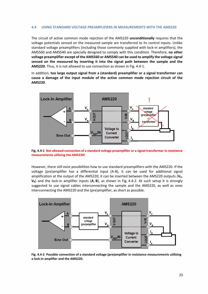
4.4 USING STANDARD VOLTAGE PREAMPLIFIERS IN MEASUREMENTS WITH THE AMS220
The circuit of active common mode rejection of the AMS220 unconditionally requires that the voltage potentials sensed on the measured sample are transferred to its control inputs. Unlike standard voltage preamplifiers (including those commonly supplied with lock-in amplifiers), the AMS560 and AMS540 are specially designed to comply with this condition. Therefore, no other voltage preamplifier except of the AMS560 or AMS540 can be used to amplify the voltage signal sensed on the measured by inserting it into the signal path between the sample and the AMS220. Thus, it is not allowed to use connection as shown in Fig. 4.4-1.
In addition, too large output signal from a (standard) preamplifier or a signal transformer can cause a damage of the input module of the active common mode rejection circuit of the AMS220.
Fig. 4.4-1 Not allowed connection of a standard voltage preamplifier or a signal transformer in resistance measurements utilizing the AMS220!
However, there still exist possibilities how to use standard preamplifiers with the AMS220. If the voltage (pre)amplifier has a differential input (A-B), it can be used for additional signal amplification at the output of the AMS220; it can be inserted between the AMS220 outputs (VA, VB) and the lock-in amplifier inputs (A, B), as shown in Fig. 4.4-2. At such setup it is strongly suggested to use signal cables interconnecting the sample and the AMS220, as well as ones interconnecting the AMS220 and the (pre)amplifier, as short as possible.
Fig. 4.4-2 Possible connection of a standard voltage (pre)amplifier in resistance measurements utilizing a lock-in amplifier and the AMS220.

26
Another possibility is to split the voltage signals sensed on the sample and apply these (same) signals to the inputs of the AMS220 as well as of the (standard) voltage pre(amplifier), as depicted in Fig. 4.4-3. Because the AMS220 monitors voltage signal sensed on the sample it can properly eliminate common mode voltage at the input of the (pre)amplifier. Signal from the output of the (pre)amplifier is applied directly to the input of the lock-in amplifier.
Fig. 4.4-3 Possible connection of a standard voltage (pre)amplifier in resistance measurements utilizing a lock-in amplifier and the AMS220.

27
4.5 RESISTANCE MEASUREMENTS USING DAQ DEVICES
Analogous connections as for the measurements using lock-in amplifiers apply for the measurements using DAQ devices. In this case voltage inputs of a DAQ (typically assigned as V-HI, V-LO) are considered instead of lock-in amplifier inputs (A, B), as well as the analog output of the DAQ instead of Sine-Out signal of the lock-in amplifier. Note that the DAQ device must be configured to measure input voltage signal in the differential mode.
When carrying out the connection between the DAQ analog electrical ground and the AMS220 electrical ground, it is necessary to follow the DAQ device user guide and the instruction provided in the section 4.1.2 of this manual. Example of interconnection of the DAQ unit and the AMS220 to perform resistance measurements is shown in the figure below.
Fig. 4.5-1 Example of connection of a DAQ unit and the AMS220 to perform resistance measurements.
Note: As input ranges of DAQ units typically lie in the interval 1 V ÷ 10 V for voltage measurement, experimental setup shown in Fig. 4.5-1 may be insufficient for sensitive measurement of low resistances. Utilizing of the AMS560 or the AMS540 preamplifier enables to extend the typical input ranges to the interval of 1 mV ÷ 10 mV or 10 mV ÷ 100 mV, respectively.

28
4.6 USING THE AMS220 AS A “CLASSICAL” CURRENT SOURCE (TWO-WIRE CONNECTION)
The AMS220 can be also used in the “classical” current source configuration provided that (i) control/reference voltage is applied to its input (1) in the VREF section and that (ii) circuit of active common mode rejection is disabled. It is necessary to ensure the definition of the AMS220 electrical ground, which must be defined against the signal ground of the voltage reference. This is naturally fulfilled when both the AMS220 and the voltage reference have defined electrical ground as shown in Fig. 4. 6-1. Note that voltage difference between these (local) grounds must be less than 1 V.
Fig.4.6-1 The AMS220 as a "classical" current source at use with the voltage reference having defined electrical ground (i.e. not a "floating" voltage reference), while the AMS220 is connected to the ground of the test/measurement setup.
If only the voltage reference has defined electrical ground, a suitable solution is to interconnect the electrical ground of the voltage reference and the AMS220 electrical ground, say by using the GND panel socket (16), as shown in Fig. 4. 6-2.
Fig.4.6-2 The AMS220 as a "classical" current source at use with the voltage reference having defined electrical ground, while the ground of the voltage reference is used to define the electrical ground of the AMS220.
29
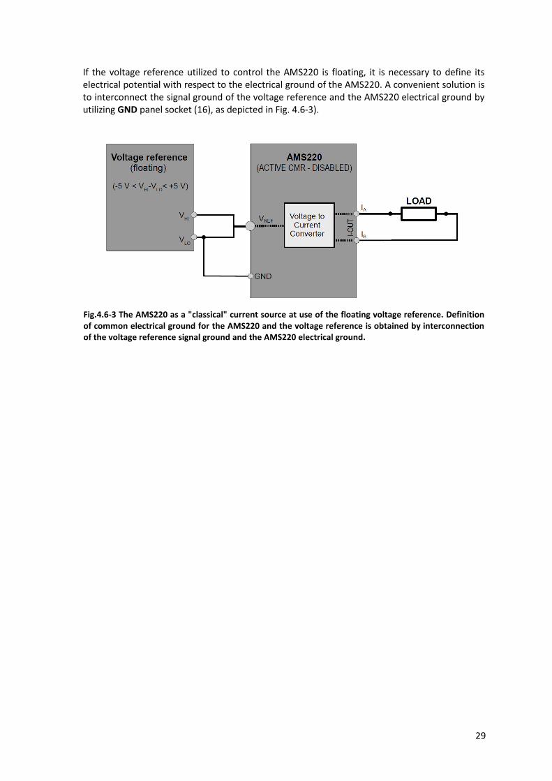
If the voltage reference utilized to control the AMS220 is floating, it is necessary to define its electrical potential with respect to the electrical ground of the AMS220. A convenient solution is to interconnect the signal ground of the voltage reference and the AMS220 electrical ground by utilizing GND panel socket (16), as depicted in Fig. 4.6-3).
Fig.4.6-3 The AMS220 as a "classical" current source at use of the floating voltage reference. Definition of common electrical ground for the AMS220 and the voltage reference is obtained by interconnection of the voltage reference signal ground and the AMS220 electrical ground.

30
5 TECHNICAL SPECIFICATIONS OF THE AMS220
Power supply (AC) 12 - 13 V (AC) / 0.6 A / 50-60 Hz
Maximum power input 7 W
Voltage to current conversion ranges 0.001, 0.01, 0.1, 1 and 10 [mA/V]
Accuracy of the voltage to current conversion (DC) 0.08 %
Temperature drift 50 ppm/°C
Reference voltage range (AC/DC) 0 ÷ 3.6 V (rms) / -5 V ÷ +5 V (DC)
Input resistance of the reference voltage input 100 kΩ
Maximum output current AC/DC 36 mA (rms) / ±50 mA (DC)
Operating modes ACTIVE CMR - ENABLED
ACTIVE CMR - DISABLED
Targeted frequency range for ACTIVE CMR - ENABLED operation mode DC - 200 Hz
Targeted frequency range for ACTIVE CMR - DISABLED operation mode DC-20 kHz (DC-2 kHz for 1µA/V)
Operating voltage swing on the current output IA against the reference ground (typ.)
up to ±(6.5 V – |VREF/2|) (±0.3 V)
Operating voltage swing on the current output IB against the reference ground (typ.)
up to ±6.6 V (±0.3 V)
Operating range of voltage differences on the current outputs IA, IB
up to ±13.4 V
Maximum voltage at the current outputs IA, IB (against the reference ground)
±10 V
Maximum voltage difference on the current outputs IA, IB
±20 V
Dimensions (L W H) 230 mm 158 mm 120 mm
Weight including accessories (typ.) 2.3 kg

31
6 CONNECTION OF THE CONNECTORS (AMS220, AMS560, AMS540)
6.1 CONNECTION OF THE CONNECTORS FOR THE AMS220
V-IN I-OUT connector of the AMS220 current source and of the AMS560/AMS540 Preamplifier
(CANNON D-SUB 15, female)
PIN Label Use
1 IA Output – current lead
2 I-SHLD Shield of current leads
3 I-SHLD Shield of current leads
6 V-SHLD Shield of voltage signal wires
7 V-SHLD Shield of voltage signal wires
8 VA Input – voltage signal wire
9 IB Output – current lead
10 I-SHLD Shield of current leads
12 GND Instrument signal ground - internally interconnected with the GND panel socket (16)
14 V-SHLD Shield of voltage signal wires
15 VB Input – voltage signal wire
SIGNAL AMPLIFIER connector (17) of the AMS220 (CANNON D SUB 9, female)
PIN Use
1 +Ucc, the signal amplifier positive supply voltage
2-5 Control signals for the common mode rejection circuit
6 -Ucc, the signal amplifier negative supply voltage
7, 8 GND, electrical ground of the signal amplifier power supply
9 Control signal for the common mode rejection circuit

32
6.2 CONNECTION OF THE CONNECTORS FOR THE AMS560/AMS540
I-IN V-OUT connector of the AMS560/AMS540 Preamplifier
(CANNON D-SUB 15, male)
PIN Label Use
1 IA Input – current lead
2 I-SHLD Shield of current leads
3 I-SHLD Shield of current leads
6 V-SHLD Shield of voltage signal wires
7 V-SHLD Shield of voltage signal wires
8 VA Output – voltage signal wire
9 IB Input – current lead
10 I-SHLD Shield of current leads
12 GND Instrument electrical ground
14 V-SHLD Shield of voltage signal wires
15 VB Output – voltage signal wire
POWER & CONTROL connector of the AMS560/540 Preamplifier (CANNON D SUB 9, male)
PIN Use
1 +Ucc, the signal amplifier positive supply voltage
2-5 Control signals for the common mode rejection circuit
6 -Ucc, the signal amplifier negative supply voltage
7, 8 GND, electrical ground of the signal amplifier power supply
9 Control signal for the common mode rejection circuit

33
BLANK PAGE FOR NOTES

34
7 ADDITIONAL INFORMATION
7.1 ELECTRONIC WASTE TREATMENT
At the end of its service life, do not dispose the equipment as unsorted municipal waste!
Pursuant to the Directive 2002/96/EC of the European Parliament and of the Council, an
independent electrical and electronic equipment waste collection system exists in the EC member states. In order to dispose this electronic equipment in accordance with the applicable legislation, please contact a responsible authority in your region/country or the equipment manufacturer/supplier, who will inform you of the possibilities of taking the equipment back or its return for environmentally suitable recycling.
7.2 WARRANTY AND SERVICE
The manufacturer warrants this device for a period of 12 months. When exercising the right to a warranty repair, please, contact the manufacturer or distributor. All warranty claims must be accompanied by a proof of purchase.
The right to free repair of the product during the warranty period expires if
a damage was caused due to improper connection, wrong maintenance, its use in the unsuitable (damp or chemically aggressive) environment, or as a result of mechanical damage to the device,
any intervention to the equipment was done outside authorized service centers,
the equipment was not used in accordance with this instruction manual.
The AMS220 is serviced exclusively by the manufacturer.
7.3 MANUFACTURER’S IMPORTANT WARNINGS AND DECLARATIONS
The use of the AMS220 in a manner other than that described in this instruction manual can result in its damage or damage of other devices connected to the measuring circuit together with the AMS220. Also, it has to be taken into consideration that devices connected to the same electrical circuit as the AMS220 are susceptible to damage if their specifications are not in accordance with the technical specifications of the AMS220. For instance, users who use the lock-in amplifiers (or another sensitive instrument) should check that the range of voltage which can be safely applied to its inputs is compatible with the range of voltage which can appear on the AMS220 current outputs. (The values of these voltages for the AMS220 are given in section 5 of the Technical Specifications of this manual.) The manufacturer shall not be liable for any damages of other devices/equipment caused by incompatibility of the used equipment, or any other use of these devices inconsistent with this instruction manual.

35
The AMS220 is designed exclusively for use in dry heated premises. The device is powered by a safe alternating voltage. The manufacturer of the AMS220 hereby declares that he is not a manufacturer of the power adapter supplied with the instrument. When using the adapter, follow the instructions of its manufacturer. Note that only a 12 Vac transformer-based power supply with current-carrying capacity of minimum 0.6 A and with a floating (not earthed) secondary coil of the transformer is allowed to be used for powering the AMS220!
7.4 MANUFACTURER’S CONTACT DETAILS
ANMESYS s.r.o.
Atletická 16
040 01 Košice
Slovak Republic
phone: +421 910 905687
e-mail: [email protected]
www.anmesys.com
Updated versions of this instruction manual as well as additional information on the product and possible changes of the above contact details shall be continuously published on www.anmesys.com.
Information in this manual is subject of change without notice ©2018 ANMESYS s.r.o.