Voltage Control of Multiterminal VSC-HVDC Transmission Systems for Offshore Wind Power Plants:...
11
IEEE TRANSACTIONS ON INDUSTRIAL ELECTRONICS, VOL. 60, NO. 6, JUNE 2013 2381 Voltage Control of Multiterminal VSC-HVDC Transmission Systems for Offshore Wind Power Plants: Design and Implementation in a Scaled Platform Agustí Egea-Alvarez, Student Member, IEEE, Fernando Bianchi, Adrià Junyent-Ferré, Member, IEEE, Gabriel Gross, and Oriol Gomis-Bellmunt, Senior Member, IEEE Abstract—This paper deals with multiterminal voltage source converter (VSC) HVDC transmission systems for the connec- tion of offshore wind power plants to the main land ac grid. A droop-based control scheme is considered. The droop controllers have been designed base on a mixed sensitivity criterion by solving a convex optimization problem with linear matrix inequalities. The system is analyzed by means of simulations and experimentally in a scaled platform. Simulations show the control performance during a wind speed change and a voltage sag in the main ac grid. Experimental results include wind power changes (increase and decrease) and an eventual VSC loss (both considering grid-side and wind farm VSC loss). In all the cases, the simulation and the experimental results have shown a good system performance. Index Terms—HVDC, multiterminal HVDC (M-HVDC), off- shore wind power, voltage control, wind power generation. I. I NTRODUCTION O FFSHORE WIND farms present a number of benefits compared to traditional onshore wind farms. Namely, the availability of higher wind speed, the ease of transport of very large structures (allowing larger wind turbines), and the limited available inland locations to install new wind farms in some countries (mainly in Europe) render them a promising alternative [1]. Thus, the number of offshore wind farms has grown in the recent years. Eight hundred sixty-six megawatt of offshore wind power was installed in Europe during 2011 [2] (9% of the total new wind power installed in Europe). An important topic of discussion related to offshore wind generation is the transmission system. An offshore wind farm Manuscript received February 15, 2012; revised May 29, 2012 and October 22, 2012; accepted November 6, 2012. Date of publication November 29, 2012; date of current version February 6, 2013. This work was supported by the Ministerio de Ciencia e Innovación under Project ENE2009-08555. A. Egea-Alvarez, A. Junyent-Ferré, and G. Gross are with the Centre d’Innovació Tecnològica en Convertidors Estàtics i Accionaments, Depar- tament d’Enginyeria Elèctrica, Universitat Politècnica de Catalunya, 08028 Barcelona, Spain (e-mail: [email protected]; adria.junyent@citcea. upc.edu; [email protected]). F. Bianchi is with the Catalonia Institute for Energy Research (IREC), 08963 Sant Adrià de Besòs, Spain (e-mail: [email protected]). O. Gomis-Bellmunt is with Centre d’Innovació Tecnològica en Convertidors Estàtics i Accionaments, Departament d’Enginyeria Elèctrica, Universitat Politècnica de Catalunya, 08028 Barcelona, Spain, and also with the Catalonia Institute for Energy Research (IREC), 08963 Sant Adrià de Besòs, Spain (e-mail: [email protected]). Color versions of one or more of the figures in this paper are available online at http://ieeexplore.ieee.org. Digital Object Identifier 10.1109/TIE.2012.2230597 can be connected to the main ac grid using transmission systems based on ac or dc technology [3]. The choice between these technologies depends on the cost of the installation which depends, in turn, on the transmission distance and power. The need to compensate for the impedance of the lines in ac trans- mission [4] makes its price grow with the distance at a higher rate than dc transmission, whereas dc transmission implies a high fixed cost due to the need of large power converters. Thus, there is a break-even distance from which the dc options becomes lower priced than ac [5], [6]. Until recently, HVDC, transmission systems were based on current-fed line-commutated converters. New converter topologies and lower priced fast-switching semiconductors have recently made it possible to build voltage source converter (VSC)-based HVDC transmission systems. The benefits of using VSC and fast switching are the ability to independently control the active and reactive power while reducing the size of the output filters needed to have a low harmonic distortion [7]–[10]. Most of the existing HVDC transmission systems use point- to-point connections [11]. This means that each individual wind farm converter is directly connected to the main ac grid by means of a dc cable. The opportunity to create new dc grids [6] offshore, both interconnecting different countries and transmitting all the wind power generated, has risen the interest in converting point-to-point connections to meshed dc grids. The connection of different wind farms and different onshore ac grids can be performed with a common dc grid based in a multiterminal HVDC (M-HVDC) grid arrangement, where the terminals are wind farms or grid connections. M-HVDC grids present a number of challenges compared to point-to-point connections. The M-HVDC protection require- ments have been studied in [6], [8], and [12]. One of the main obstacles to the development of dc grids offshore is the need for HVDC circuit breaker technology that is not commercially available yet [6], although some relevant advances on this topic have been reported [13]. On the other hand, M-HVDC power balance and voltage control are a critical issue, particularly for the operation of the system under fault conditions [14], [15]. Different operation scenarios of an M-HVDC grid using droop control for decentralized voltage regulation were analyzed in [16]. A droop design criterion based on steady- state conditions is introduced in [17]. The development of dy- namic models of M-HVDC grids and a droop controller design 0278-0046/$31.00 © 2012 IEEE
Transcript of Voltage Control of Multiterminal VSC-HVDC Transmission Systems for Offshore Wind Power Plants:...
IEEE TRANSACTIONS ON INDUSTRIAL ELECTRONICS, VOL. 60, NO. 6, JUNE 2013 2381
Voltage Control of Multiterminal VSC-HVDCTransmission Systems for Offshore Wind Power
Plants: Design and Implementation in aScaled Platform
Agustí Egea-Alvarez, Student Member, IEEE, Fernando Bianchi, Adrià Junyent-Ferré, Member, IEEE,Gabriel Gross, and Oriol Gomis-Bellmunt, Senior Member, IEEE
Abstract—This paper deals with multiterminal voltage sourceconverter (VSC) HVDC transmission systems for the connec-tion of offshore wind power plants to the main land ac grid. Adroop-based control scheme is considered. The droop controllershave been designed base on a mixed sensitivity criterion by solvinga convex optimization problem with linear matrix inequalities. Thesystem is analyzed by means of simulations and experimentallyin a scaled platform. Simulations show the control performanceduring a wind speed change and a voltage sag in the main ac grid.Experimental results include wind power changes (increase anddecrease) and an eventual VSC loss (both considering grid-sideand wind farm VSC loss). In all the cases, the simulation and theexperimental results have shown a good system performance.
Index Terms—HVDC, multiterminal HVDC (M-HVDC), off-shore wind power, voltage control, wind power generation.
I. INTRODUCTION
O FFSHORE WIND farms present a number of benefitscompared to traditional onshore wind farms. Namely,
the availability of higher wind speed, the ease of transport ofvery large structures (allowing larger wind turbines), and thelimited available inland locations to install new wind farms insome countries (mainly in Europe) render them a promisingalternative [1]. Thus, the number of offshore wind farms hasgrown in the recent years. Eight hundred sixty-six megawatt ofoffshore wind power was installed in Europe during 2011 [2](9% of the total new wind power installed in Europe).
An important topic of discussion related to offshore windgeneration is the transmission system. An offshore wind farm
Manuscript received February 15, 2012; revised May 29, 2012 and October 22,2012; accepted November 6, 2012. Date of publication November 29, 2012;date of current version February 6, 2013. This work was supported by theMinisterio de Ciencia e Innovación under Project ENE2009-08555.
A. Egea-Alvarez, A. Junyent-Ferré, and G. Gross are with the Centred’Innovació Tecnològica en Convertidors Estàtics i Accionaments, Depar-tament d’Enginyeria Elèctrica, Universitat Politècnica de Catalunya, 08028Barcelona, Spain (e-mail: [email protected]; [email protected]; [email protected]).
F. Bianchi is with the Catalonia Institute for Energy Research (IREC),08963 Sant Adrià de Besòs, Spain (e-mail: [email protected]).
O. Gomis-Bellmunt is with Centre d’Innovació Tecnològica en ConvertidorsEstàtics i Accionaments, Departament d’Enginyeria Elèctrica, UniversitatPolitècnica de Catalunya, 08028 Barcelona, Spain, and also with the CataloniaInstitute for Energy Research (IREC), 08963 Sant Adrià de Besòs, Spain(e-mail: [email protected]).
Color versions of one or more of the figures in this paper are available onlineat http://ieeexplore.ieee.org.
Digital Object Identifier 10.1109/TIE.2012.2230597
can be connected to the main ac grid using transmission systemsbased on ac or dc technology [3]. The choice between thesetechnologies depends on the cost of the installation whichdepends, in turn, on the transmission distance and power. Theneed to compensate for the impedance of the lines in ac trans-mission [4] makes its price grow with the distance at a higherrate than dc transmission, whereas dc transmission implies ahigh fixed cost due to the need of large power converters.Thus, there is a break-even distance from which the dc optionsbecomes lower priced than ac [5], [6].
Until recently, HVDC, transmission systems were basedon current-fed line-commutated converters. New convertertopologies and lower priced fast-switching semiconductorshave recently made it possible to build voltage source converter(VSC)-based HVDC transmission systems. The benefits of usingVSC and fast switching are the ability to independently controlthe active and reactive power while reducing the size of theoutput filters needed to have a low harmonic distortion [7]–[10].
Most of the existing HVDC transmission systems use point-to-point connections [11]. This means that each individualwind farm converter is directly connected to the main ac gridby means of a dc cable. The opportunity to create new dcgrids [6] offshore, both interconnecting different countries andtransmitting all the wind power generated, has risen the interestin converting point-to-point connections to meshed dc grids.The connection of different wind farms and different onshoreac grids can be performed with a common dc grid based in amultiterminal HVDC (M-HVDC) grid arrangement, where theterminals are wind farms or grid connections.
M-HVDC grids present a number of challenges compared topoint-to-point connections. The M-HVDC protection require-ments have been studied in [6], [8], and [12]. One of the mainobstacles to the development of dc grids offshore is the needfor HVDC circuit breaker technology that is not commerciallyavailable yet [6], although some relevant advances on this topichave been reported [13]. On the other hand, M-HVDC powerbalance and voltage control are a critical issue, particularly forthe operation of the system under fault conditions [14], [15].Different operation scenarios of an M-HVDC grid usingdroop control for decentralized voltage regulation wereanalyzed in [16]. A droop design criterion based on steady-state conditions is introduced in [17]. The development of dy-namic models of M-HVDC grids and a droop controller design
0278-0046/$31.00 © 2012 IEEE
2382 IEEE TRANSACTIONS ON INDUSTRIAL ELECTRONICS, VOL. 60, NO. 6, JUNE 2013
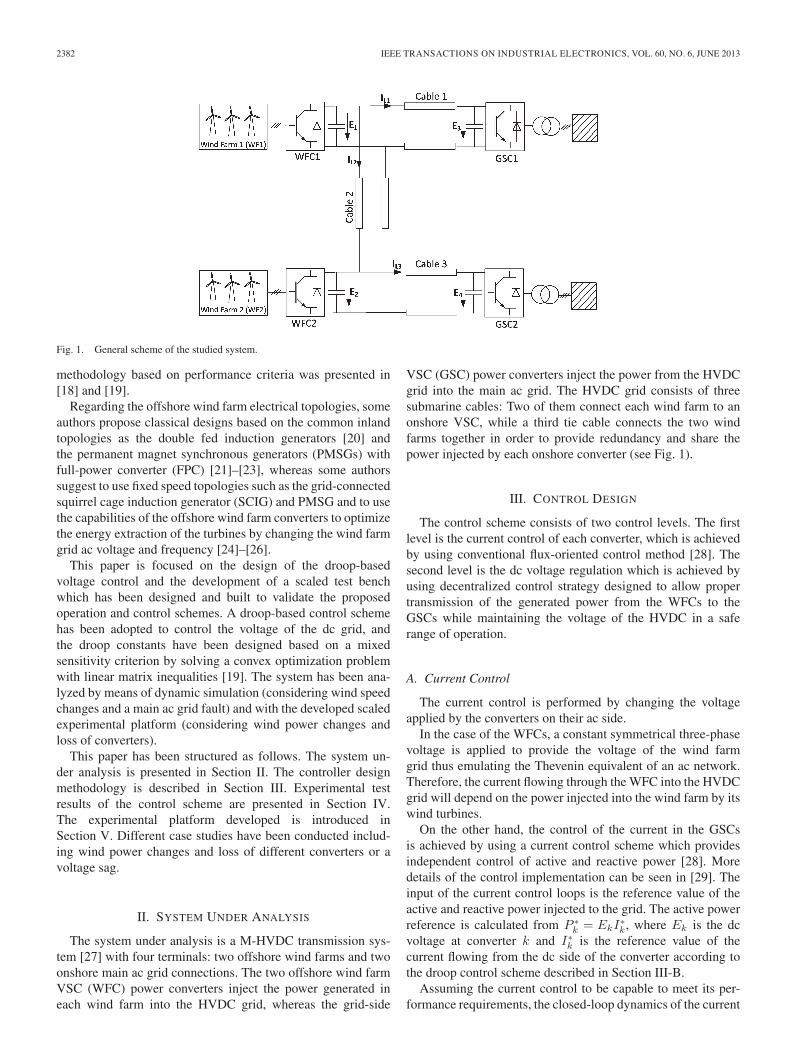
Fig. 1. General scheme of the studied system.
methodology based on performance criteria was presented in[18] and [19].
Regarding the offshore wind farm electrical topologies, someauthors propose classical designs based on the common inlandtopologies as the double fed induction generators [20] andthe permanent magnet synchronous generators (PMSGs) withfull-power converter (FPC) [21]–[23], whereas some authorssuggest to use fixed speed topologies such as the grid-connectedsquirrel cage induction generator (SCIG) and PMSG and to usethe capabilities of the offshore wind farm converters to optimizethe energy extraction of the turbines by changing the wind farmgrid ac voltage and frequency [24]–[26].
This paper is focused on the design of the droop-basedvoltage control and the development of a scaled test benchwhich has been designed and built to validate the proposedoperation and control schemes. A droop-based control schemehas been adopted to control the voltage of the dc grid, andthe droop constants have been designed based on a mixedsensitivity criterion by solving a convex optimization problemwith linear matrix inequalities [19]. The system has been ana-lyzed by means of dynamic simulation (considering wind speedchanges and a main ac grid fault) and with the developed scaledexperimental platform (considering wind power changes andloss of converters).
This paper has been structured as follows. The system un-der analysis is presented in Section II. The controller designmethodology is described in Section III. Experimental testresults of the control scheme are presented in Section IV.The experimental platform developed is introduced inSection V. Different case studies have been conducted includ-ing wind power changes and loss of different converters or avoltage sag.
II. SYSTEM UNDER ANALYSIS
The system under analysis is a M-HVDC transmission sys-tem [27] with four terminals: two offshore wind farms and twoonshore main ac grid connections. The two offshore wind farmVSC (WFC) power converters inject the power generated ineach wind farm into the HVDC grid, whereas the grid-side
VSC (GSC) power converters inject the power from the HVDCgrid into the main ac grid. The HVDC grid consists of threesubmarine cables: Two of them connect each wind farm to anonshore VSC, while a third tie cable connects the two windfarms together in order to provide redundancy and share thepower injected by each onshore converter (see Fig. 1).
III. CONTROL DESIGN
The control scheme consists of two control levels. The firstlevel is the current control of each converter, which is achievedby using conventional flux-oriented control method [28]. Thesecond level is the dc voltage regulation which is achieved byusing decentralized control strategy designed to allow propertransmission of the generated power from the WFCs to theGSCs while maintaining the voltage of the HVDC in a saferange of operation.
A. Current Control
The current control is performed by changing the voltageapplied by the converters on their ac side.
In the case of the WFCs, a constant symmetrical three-phasevoltage is applied to provide the voltage of the wind farmgrid thus emulating the Thevenin equivalent of an ac network.Therefore, the current flowing through the WFC into the HVDCgrid will depend on the power injected into the wind farm by itswind turbines.
On the other hand, the control of the current in the GSCsis achieved by using a current control scheme which providesindependent control of active and reactive power [28]. Moredetails of the control implementation can be seen in [29]. Theinput of the current control loops is the reference value of theactive and reactive power injected to the grid. The active powerreference is calculated from P ∗
k = EkI∗k, where Ek is the dc
voltage at converter k and I∗k is the reference value of thecurrent flowing from the dc side of the converter according tothe droop control scheme described in Section III-B.
Assuming the current control to be capable to meet its per-formance requirements, the closed-loop dynamics of the current

EGEA-ALVAREZ et al.: CONTROL OF VSC-HVDC TRANSMISSION SYSTEMS FOR OFFSHORE WIND POWER PLANTS 2383
Fig. 2. Static current–voltage characteristic of a GSC. The thin line shows thecharacteristic under a voltage sag of 50%.
can be modeled as a first-order system with a time constant τ ,that is,
Ik(s) =1
τs+ 1I∗k(s) (1)
where I(s) is the dc current actually injected or extracted fromthe multiterminal.
B. Voltage Control
The purpose of the voltage control is to ensure an adequatepower transmission and it should be decentralized so that thecontrol law applied by an HVDC converter only depends onlocal measurements made by that converter and does not needto rely on long distance communications between differentterminals. The common formulation of this controller is theso-called droop control concept [16]. The droop controller isa proportional control law that regulates the dc voltage andprovides power sharing between the different power converters.
During normal operation mode, the WFCs inject all thegenerated current into the HVDC grid, as described earlier,while the GSCs maintain the dc voltage almost constant bymeans of the droop control law given by
I∗k = Kk(Ek − E0,k), k = 3, 4 (2)
where Ik and Ek are the dc current and the dc voltage in theconverter k, respectively, Kk is the droop gain, and E0,k is aset-point voltage.
During severe terrestrial grid faults, the GSCs may not becapable of transferring all the power coming from the WFC intothe terrestrial grid as the ac current needed would exceed therating of the GSCs. In such condition, the GSCs enter currentlimitation mode, extracting only a constant current value. Ifthe power injected from the wind farm side is higher than thepower extracted for the grid side, the voltage of the HVDC gridwould start to increase as a result of the power unbalance. Thisbehavior is shown by static current–voltage curve in Fig. 2. Thecurrent limitation mode corresponds to the hyperbola and lineto normal operation (when the droop control is applied), whereVac is the ac voltage. Notice that the maximum current IgsH thatcan be extracted by the GSCs depends on the ac grid voltage;thus, for a 50% voltage drop in the ac grid, the maximumcurrent would drop by 50%.
Fig. 3. Static current–voltage characteristic of a WFC.
In order to prevent the dc voltage from increasing beyondthe allowed limits, the WFCs must also switch their operatingmode to power reduction mode when the dc voltages reach thelimits EwfL. Thus, the WFCs reduce the power injected into theHVDC grid by using a droop control law
I∗k = −Kk(Ek − E0,k), k = 1, 2. (3)
The static current–voltage for WFCs is shown in Fig. 3. Thetwo operating regions of the WFCs can be seen: droop powerreduction and normal operation (power injection). In addition,the WFCs present also a current limitation mode to set thecurrent at IwfH in case of an excess of power coming from thewind turbines. A control implementation of the WFC controlcan be seen in [30].
The controller adaptation is done automatically by the con-verters obeying static voltage–current characteristics as shownin the previous figures [16]. The droop gains Kk must bedesigned in order to ensure stability and performance under anypossible operating modes and also during the transitions amongthem. That means that the decentralized control law mustensure stability and performance for a time-varying system.
A design procedure for the droop control based on Lyapunovstability criterion has been introduced in [19]. In the sequel,a brief explanation of this procedure is presented, and moredetails can be found in [19]. The first step consists in deter-mining a dynamic model of the HVDC network consideringthe dynamics of the long transmission lines (represented as Π-circuits), the capacitors near the converters, and the topology ofthe network. In the case of the four-terminal network in Fig. 1,this model results in
M :
{x = Ax+Bqq,p = Cpx,
(4)
where
x = [E1, . . . , E4, , IL1, . . . , IL3
]T (5)
q = [I∗1, . . . , I∗4]
T (6)
p = [E1, . . . , E4]T (7)
and the matrices A, Bp, and Cp are obtained from the electricalequations of the HVDC circuit [18]. The states are the dcvoltage at each node Ek and current through the cables IL,k.The multiterminal inputs are the currents incoming or outgoing
2384 IEEE TRANSACTIONS ON INDUSTRIAL ELECTRONICS, VOL. 60, NO. 6, JUNE 2013
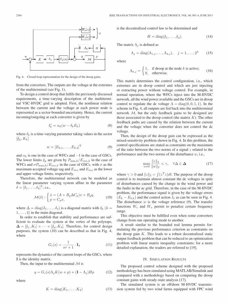
Fig. 4. Closed-loop representation for the design of the droop gains.
from the converters. The outputs are the voltage at the extremesof the multiterminal (see Fig. 1).
To design a control droop that fulfils the previously discussedrequirements, a time-varying description of the multitermi-nal VSC-HVDC grid is adopted. First, the nonlinear relationbetween the current and the voltage at each power node isrepresented as a sector-bounded uncertainty. Hence, the currentincoming/outgoing at each converter is given by
I∗k = αk(w − δkEk) (8)
where δk is a time-varying parameter taking values in the sector[δk,Kk]
w = [E0,1, . . . , E0,4]T (9)
and αk is one in the case of WFCs and −1 in the case of GSCs.The lower limits δk are given by Pmin,k/Emn,k in the case ofWFCs and σPmax,k/Emx,k in the case of GSCs, with σ as themaximum accepted voltage sag and Emn and Emx as the lowerand upper voltage limits, respectively.
Therefore, the multiterminal network can be modeled asthe linear parameter varying system affine in the parameterδ = [δ1, . . . , δ4]
T, i.e.,
M(δ) :
{x = (A+BqΔCp)x+Bqq,p = Cpx,
(10)
where Δ = diag(δ1, . . . , δ4) is a diagonal matrix with δk (k =1, . . . , 4) in the main diagonal.
In order to establish that stability and performance are suf-ficient to evaluate the system at the vertex of the polytope,Δ = [δ1,K1]× · · · × [δ4,K4]. Therefore, for control designpurposes, the system (10) can be described as that in Fig. 4,where
Gc(s) =1
sτ + 1· I4 (11)
represents the dynamics of the current loops of the GSCs, whereI is the identity matrix.
Then, the input to the multiterminal M is
q = Gc(s)ΛjK(w + p) + (I− Λj)Hp (12)
where
K = diag(K1, . . . ,K4) (13)
is the decentralized control law to be determined and
H = diag(δ1, . . . , δ4). (14)
The matrix Λj is defined as
Λj = diag(Λ1,j , . . . ,Λ4,j), j = 1, . . . , 24 (15)
where
Λk,j =
{1, if droop at the node k is active;0, otherwise.
(16)
This matrix determines the control configuration, i.e., whichextremes are in droop control and which are just injectingor extracting power without voltage control. For example, innormal operation, where the WFCs inject into the M-HVDCnetwork, all the wind power available and the GSCs are in droopcontrol to regulate the dc voltage Λ = diag(0, 0, 1, 1). In thescheme in Fig. 4, all outputs are fed back into the multiterminalnetwork M, but the only feedback gains to be designed arethose associated to the droop control (the matrix K). The otherfeedback paths are caused by the relation between the currentand the voltage when the converter does not control the dcvoltage.
Then, the design of the droop gain can be expressed as themixed-sensitivity problem shown in Fig. 4. In this problem, thecontrol specifications are stated as constraints on the maximumof the ratio between the two norms of a signal z related to theperformance and the two norms of the disturbance w, i.e.,
maxw �=0
‖z‖2‖w‖2
< γ, ∀Δ ∈ Δ (17)
where γ > 0 and ‖z‖2 =∫(zTz)dt. The purpose of the droop
control is to maintain almost constant the dc voltages in spiteof disturbances caused by the change in the wind power andthe faults in the ac grid. Therefore, in the case of the M-HVDCproblem, the performance signal is given by the voltage errors(Ek − E0,k) and the control action Ik as can be seen in Fig. 4.The disturbance w is the voltage reference (9). The transferfunctions We and Wu permit to penalize certain frequencyrange.
This objective must be fulfilled even when some converterschange from one operating mode to another.
A result similar to the bounded real lemma permits for-mulating the previous performance criterion as constraints onthe droop gain K. This leads to a robust decentralized staticoutput feedback problem that can be reduced to an optimizationproblem with linear matrix inequality constraints; for a moredetailed explanation, the readers are refereed to [19].
IV. SIMULATION RESULTS
The proposed control scheme designed with the proposedmethodology has been simulated using MATLAB/Simulink andcompared with a methodology based on computing the droopconstant gains with steady-state analysis [17].
The simulated system is an offshore M-HVDC transmis-sion system fed by two wind farms equipped with FPC wind
EGEA-ALVAREZ et al.: CONTROL OF VSC-HVDC TRANSMISSION SYSTEMS FOR OFFSHORE WIND POWER PLANTS 2385
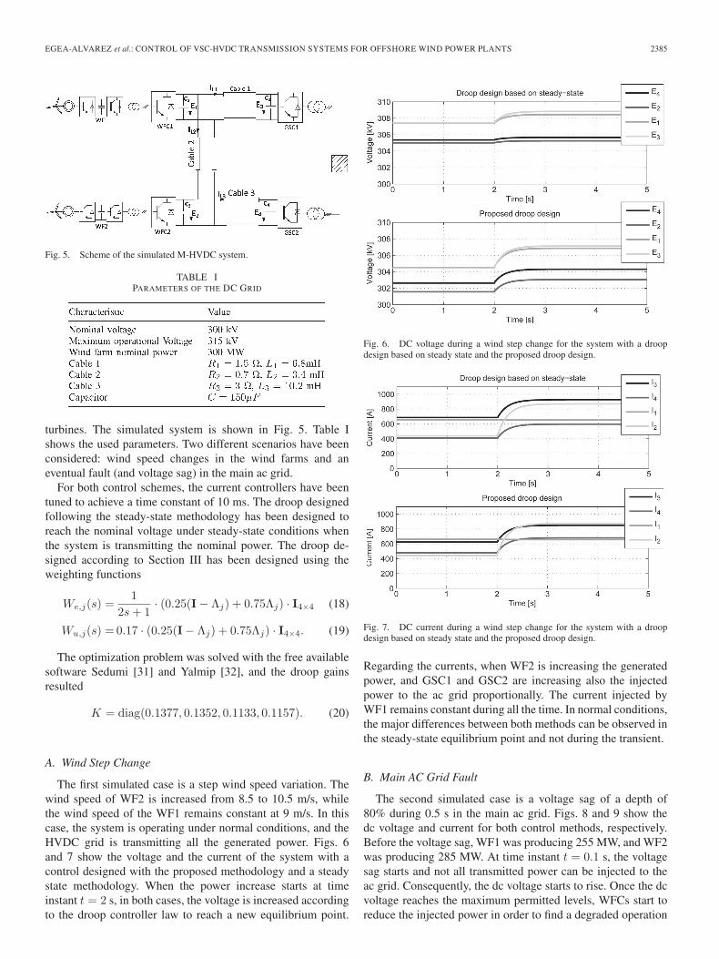
Fig. 5. Scheme of the simulated M-HVDC system.
TABLE IPARAMETERS OF THE DC GRID
turbines. The simulated system is shown in Fig. 5. Table Ishows the used parameters. Two different scenarios have beenconsidered: wind speed changes in the wind farms and aneventual fault (and voltage sag) in the main ac grid.
For both control schemes, the current controllers have beentuned to achieve a time constant of 10 ms. The droop designedfollowing the steady-state methodology has been designed toreach the nominal voltage under steady-state conditions whenthe system is transmitting the nominal power. The droop de-signed according to Section III has been designed using theweighting functions
We,j(s) =1
2s+ 1· (0.25(I− Λj) + 0.75Λj) · I4×4 (18)
Wu,j(s) = 0.17 · (0.25(I− Λj) + 0.75Λj) · I4×4. (19)
The optimization problem was solved with the free availablesoftware Sedumi [31] and Yalmip [32], and the droop gainsresulted
K = diag(0.1377, 0.1352, 0.1133, 0.1157). (20)
A. Wind Step Change
The first simulated case is a step wind speed variation. Thewind speed of WF2 is increased from 8.5 to 10.5 m/s, whilethe wind speed of the WF1 remains constant at 9 m/s. In thiscase, the system is operating under normal conditions, and theHVDC grid is transmitting all the generated power. Figs. 6and 7 show the voltage and the current of the system with acontrol designed with the proposed methodology and a steadystate methodology. When the power increase starts at timeinstant t = 2 s, in both cases, the voltage is increased accordingto the droop controller law to reach a new equilibrium point.
Fig. 6. DC voltage during a wind step change for the system with a droopdesign based on steady state and the proposed droop design.
Fig. 7. DC current during a wind step change for the system with a droopdesign based on steady state and the proposed droop design.
Regarding the currents, when WF2 is increasing the generatedpower, and GSC1 and GSC2 are increasing also the injectedpower to the ac grid proportionally. The current injected byWF1 remains constant during all the time. In normal conditions,the major differences between both methods can be observed inthe steady-state equilibrium point and not during the transient.
B. Main AC Grid Fault
The second simulated case is a voltage sag of a depth of80% during 0.5 s in the main ac grid. Figs. 8 and 9 show thedc voltage and current for both control methods, respectively.Before the voltage sag, WF1 was producing 255 MW, and WF2was producing 285 MW. At time instant t = 0.1 s, the voltagesag starts and not all transmitted power can be injected to theac grid. Consequently, the dc voltage starts to rise. Once the dcvoltage reaches the maximum permitted levels, WFCs start toreduce the injected power in order to find a degraded operation
2386 IEEE TRANSACTIONS ON INDUSTRIAL ELECTRONICS, VOL. 60, NO. 6, JUNE 2013
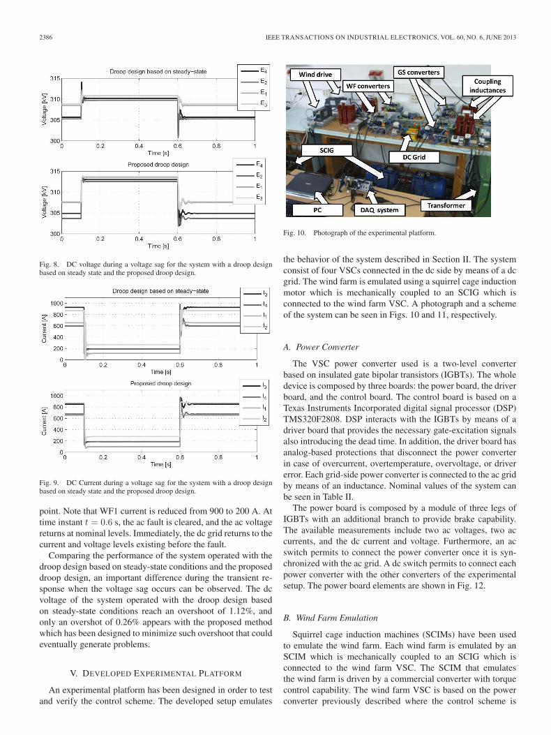
Fig. 8. DC voltage during a voltage sag for the system with a droop designbased on steady state and the proposed droop design.
Fig. 9. DC Current during a voltage sag for the system with a droop designbased on steady state and the proposed droop design.
point. Note that WF1 current is reduced from 900 to 200 A. Attime instant t = 0.6 s, the ac fault is cleared, and the ac voltagereturns at nominal levels. Immediately, the dc grid returns to thecurrent and voltage levels existing before the fault.
Comparing the performance of the system operated with thedroop design based on steady-state conditions and the proposeddroop design, an important difference during the transient re-sponse when the voltage sag occurs can be observed. The dcvoltage of the system operated with the droop design basedon steady-state conditions reach an overshoot of 1.12%, andonly an overshot of 0.26% appears with the proposed methodwhich has been designed to minimize such overshoot that couldeventually generate problems.
V. DEVELOPED EXPERIMENTAL PLATFORM
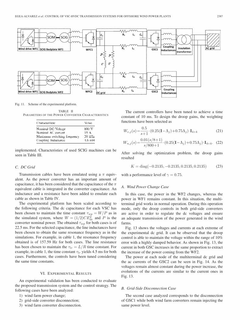
An experimental platform has been designed in order to testand verify the control scheme. The developed setup emulates
Fig. 10. Photograph of the experimental platform.
the behavior of the system described in Section II. The systemconsist of four VSCs connected in the dc side by means of a dcgrid. The wind farm is emulated using a squirrel cage inductionmotor which is mechanically coupled to an SCIG which isconnected to the wind farm VSC. A photograph and a schemeof the system can be seen in Figs. 10 and 11, respectively.
A. Power Converter
The VSC power converter used is a two-level converterbased on insulated gate bipolar transistors (IGBTs). The wholedevice is composed by three boards: the power board, the driverboard, and the control board. The control board is based on aTexas Instruments Incorporated digital signal processor (DSP)TMS320F2808. DSP interacts with the IGBTs by means of adriver board that provides the necessary gate-excitation signalsalso introducing the dead time. In addition, the driver board hasanalog-based protections that disconnect the power converterin case of overcurrent, overtemperature, overvoltage, or drivererror. Each grid-side power converter is connected to the ac gridby means of an inductance. Nominal values of the system canbe seen in Table II.
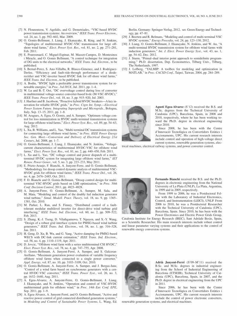
The power board is composed by a module of three legs ofIGBTs with an additional branch to provide brake capability.The available measurements include two ac voltages, two accurrents, and the dc current and voltage. Furthermore, an acswitch permits to connect the power converter once it is syn-chronized with the ac grid. A dc switch permits to connect eachpower converter with the other converters of the experimentalsetup. The power board elements are shown in Fig. 12.
B. Wind Farm Emulation
Squirrel cage induction machines (SCIMs) have been usedto emulate the wind farm. Each wind farm is emulated by anSCIM which is mechanically coupled to an SCIG which isconnected to the wind farm VSC. The SCIM that emulatesthe wind farm is driven by a commercial converter with torquecontrol capability. The wind farm VSC is based on the powerconverter previously described where the control scheme is
EGEA-ALVAREZ et al.: CONTROL OF VSC-HVDC TRANSMISSION SYSTEMS FOR OFFSHORE WIND POWER PLANTS 2387
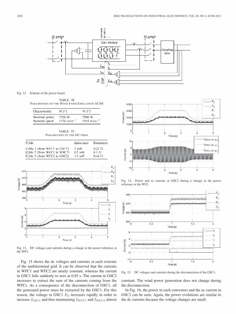
Fig. 11. Scheme of the experimental platform.
TABLE IIPARAMETERS OF THE POWER CONVERTER CHARACTERISTICS
implemented. Characteristies of used SCIG machines can beseen in Table III.
C. DC Grid
Transmission cables have been emulated using a π equiv-alent. As the power converter has an important amount ofcapacitance, it has been considered that the capacitance of the πequivalent cable is integrated in the converter capacitance. Aninductance and a resistance have been added to emulate eachcable as shown in Table IV.
The experimental platform has been scaled according tothe following criteria. The dc capacitance for each VSC hasbeen chosen to maintain the time constant τwp = W/P as inthe simulated system, where W = (1/2)CE2
dc and P is theconverter nominal power. The obtained τwp for both cases is of22.5 ms. For the selected capacitance, the line inductances havebeen chosen to obtain the same resonance frequency as in thesimulations. For example, in cable 1, the resonance frequencyobtained is of 157.59 Hz for both cases. The line resistancehas been chosen to maintain the τlr = L/R time constant. Forexample, in cable 1, the time constant τlr yields 4.5 ms for bothcases. Furthermore, the controls have been tuned consideringthe same time constants.
VI. EXPERIMENTAL RESULTS
An experimental validation has been conducted to evaluatethe proposed transmission system and the control strategy. Thefollowing cases have been analyzed:
1) wind farm power change;2) grid-side converter disconnection;3) wind farm converter disconnection.
The current controllers have been tuned to achieve a timeconstant of 10 ms. To design the droop gains, the weightingfunctions have been selected as
We,j(s)=0.5
s+1·(0.25(I−Λj)+0.75Λj)·I4×4 (21)
Wu,j(s)=0.01(s/8+1)
s/800+1·(0.25(I−Λj)+0.75Λj)·I4×4. (22)
After solving the optimization problem, the droop gainsresulted
K = diag(−0.2135,−0.2135, 0.2135, 0.2135) (23)
with a performance level of γ = 0.75.
A. Wind Power Change Case
In this case, the power in the WF2 changes, whereas thepower in WF1 remains constant. In this situation, the multi-terminal grid works in normal operation. During this operationmode, only the droop controls in both grid-side convertersare active in order to regulate the dc voltages and ensurean adequate transmission of the power generated in the windfarms.
Fig. 13 shows the voltages and currents at each extreme ofthe experimental dc grid. It can be observed that the droopcontrol is able to maintain the voltage within the range of 10%error with a highly damped behavior. As shown in Fig. 13, thecurrent in both GSC increases in the same proportion to extractthe increase of the power coming from the WF2.
The power at each node of the multiterminal dc grid andthe ac currents of the GSC2 can be seen in Fig. 14. As thevoltages remain almost constant during the power increase, theevolutions of the currents are similar to the current ones inFig. 13.
B. Grid-Side Disconnection Case
The second case analyzed corresponds to the disconnectionof GSC1 while both wind farm converters remain injecting thesame power level.
2388 IEEE TRANSACTIONS ON INDUSTRIAL ELECTRONICS, VOL. 60, NO. 6, JUNE 2013
Fig. 12. Scheme of the power board.
TABLE IIIPARAMETERS OF THE WIND FARM EMULATION SCIM
TABLE IVPARAMETERS OF THE DC GRID
Fig. 13. DC voltages and currents during a change in the power reference atthe WF2.
Fig. 15 shows the dc voltages and currents at each extremeof the multiterminal grid. It can be observed that the currentsin WFC1 and WFC2 are nearly constant, whereas the currentin GSC1 falls suddenly to zero at 0.85 s. The current in GSC2increases to extract the sum of the currents coming from theWFCs. As a consequence of the disconnection of GSC1, allthe generated power must be extracted by the GSC1. For thisreason, the voltage in GSC1 E3 increases rapidly in order toincrease IGSC1 and thus maintaining IWFC1 and IWFC2 almost
Fig. 14. Power and ac currents at GSC2 during a change in the powerreference at the WF2.
Fig. 15. DC voltages and currents during the disconnection of the GSC1.
constant. The wind power generation does not change duringthe disconnection.
In Fig. 16, the power in each converters and the ac current inGSC2 can be seen. Again, the power evolutions are similar tothe dc currents because the voltage changes are small.

EGEA-ALVAREZ et al.: CONTROL OF VSC-HVDC TRANSMISSION SYSTEMS FOR OFFSHORE WIND POWER PLANTS 2389
Fig. 16. Power and ac currents in the GSC2 during the disconnection of theGSC1.
Fig. 17. DC voltages and currents during the disconnection of the WFC1.
C. Wind Farm Converter Disconnection
In the last case, the WFC1 is disconnected, whereas theWFC2 remains injecting the same power level. As a result of thedisconnection, the total power injected into the multiterminalgrid reduces suddenly. Fig. 17 shows the dc voltages andcurrents in each converter. It can be observed that current inthe WFC1 falls to zero and the voltages decrease in all nodes.The droop control causes a reduction of the voltages whichpermits to decrease the currents extracted by each GSCs andthus maintaining the power balance. It is interesting to notethat the responses are well damped as in previous cases andthe current overshoots observed in Fig. 17 are caused by theimplementations of the disconnection of the WFC1. Power andac currents are shown in Fig. 18.
VII. CONCLUSION
This paper has addressed the operation and control of multi-terminal VSC-HVDC transmission systems for offshore windfarms. A droop-based control scheme has been designed to
Fig. 18. Power and ac currents of the GSC2 during the disconnection of theWF1.
ensure the dc grid voltage stability, wind farm power correctevacuation, and power sharing between the grid-side converters.A design methodology based on Lyapunov theory has been em-ployed to adjust the droop constants in the different converters.
The M-HVDC grid has been simulated considering amegawatt-range power system in two different case studies:wind speed change and main ac grid fault. Simulations show acomparison between the proposed droop design methodologyand a classical approach. A better performance during tran-sients can be observed with the designed control.
A test bench has been designed and built to validate experi-mentally the control scheme in a scaled platform. The platformis comprised of SCIMs driven by torque-controlled frequencyconverters that emulate the wind and provide mechanical torqueto SCIGs which are connected to the wind farm VSCs. Thedc grid links two wind farm VSCs with two grid-side VSCswhich are connected to the ac grid. The control scheme has beenimplemented directly in the VSC DSPs.
Several case studies have been conducted in the scaled ex-perimental platform including wind power variations, loss ofa grid-side VSC, and loss of a wind farm VSC. The resultshave shown a good system performance, according to thespecifications of the control scheme.
REFERENCES
[1] B. Snyder and M. J. Kaiser, “Ecological and economic cost-benefitanalysis of offshore wind energy,” Renew. Energy, vol. 34, no. 6,pp. 1567–1578, Jun. 2009.
[2] 2011 European Statistics, EWEA Std., Feb. 2012.[3] P. Bresesti, W. Kling, R. Hendriks, and R. Vailati, “HVDC connection
of offshore wind farms to the transmission system,” IEEE Trans. EnergyConvers., vol. 22, no. 1, pp. 37–43, Mar. 2007.
[4] N. B. Negra, J. Todorovic, and T. Ackermann, “Loss evaluation of HVACand HVDC transmission solutions for large offshore wind farms,” Elect.Power Syst. Res., vol. 76, no. 11, pp. 916–927, Jul. 2006.
[5] B. Van Eeckhout, D. Van Hertem, M. Reza, K. Srivastava, andR. Belmans, “Economic comparison of VSC HVDC and HVAC as trans-mission system for a 300 MW offshore wind farm,” Eur. Trans. Elect.Power, vol. 20, no. 5, pp. 661–671, Jul. 2010.
[6] D. V. Hertem and M. Ghandhari, “Multi-terminal VSC HVDC for theEuropean supergrid: Obstacles,” Renew. Sustain. Energy Rev., vol. 14,no. 9, pp. 3156–3163, Dec. 2010.
2390 IEEE TRANSACTIONS ON INDUSTRIAL ELECTRONICS, VOL. 60, NO. 6, JUNE 2013
[7] N. Flourentzou, V. Agelidis, and G. Demetriades, “VSC-based HVDCpower transmission systems: An overview,” IEEE Trans. Power Electron.,vol. 24, no. 3, pp. 592–602, Mar. 2009.
[8] O. Gomis-Bellmunt, J. Liang, J. Ekanayake, R. King, and N. Jenkins,“Topologies of multiterminal HVDC-VSC transmission for large off-shore wind farms,” Elect. Power Syst. Res., vol. 81, no. 2, pp. 271–281,Feb. 2011.
[9] E. Pouresmaeil, C. Miguel-Espinar, M. Massot-Campos, D. Montesinosi Miracle, and O. Gomis Bellmunt, “A control technique for integrationof DG units to the electrical networks,” IEEE Trans. Ind. Electron., to bepublished.
[10] S. Bernal-Perez, S. Ano-Villalba, R. Blasco-Gimenez, and J. Rodriguez-Derlee, “Efficiency and fault-ride-through performance of a diode-rectifier and VSC-inverter based HVDC link for off-shore wind farms,”IEEE Trans. Ind. Electron., to be published.
[11] A. Bodin, “HVDC light a preferable power transmission system for re-newable energies,” in Proc. 3rd IYCE, Jul. 2011, pp. 1–4.
[12] W. Lu and B.-T. Ooi, “DC overvoltage control during loss of converterin multiterminal voltage-source converter-based hvdc (M-VSC-HVDC),”IEEE Trans. Power Del., vol. 18, no. 3, pp. 915–920, Jul. 2003.
[13] J. Haefner and B. Jacobson, “Proactive hybrid HVDC breakers—A key in-novation for reliable HVDC grids,” in Proc. Cigre Int. Symp.—ElectricalPower System Future. Integrating Supergrids and Microgrids., Bologna,Italy, Sep. 13–15, 2011, pp. 1–8.
[14] M. Aragues, A. Egea, O. Gomis, and A. Sumper, “Optimum voltage con-trol for loss minimization in HVDC multi-terminal transmission systemsfor large offshore wind farms,” Elect. Power Syst. Res., vol. 89, pp. 54–63,Aug. 2012.
[15] L. Xu, B. Williams, and L. Yao, “Multi-terminal DC transmission systemsfor connecting large offshore wind farms,” in Proc. IEEE Power EnergySoc. Gen. Meet.—Conversion and Delivery of Electrical Energy 21stCentury, Jul. 2008, pp. 1–7.
[16] O. Gomis-Bellmunt, J. Liang, J. Ekanayake, and N. Jenkins, “Voltage-current characteristics of multiterminal HVDC-VSC for offshore windfarms,” Elect. Power Syst. Res., vol. 81, no. 2, pp. 440–450, Feb. 2011.
[17] L. Xu and L. Yao, “DC voltage control and power dispatch of a multi-terminal HVDC system for integrating large offshore wind farms,” IETRenew. Power Gener., vol. 5, no. 3, pp. 223–233, May 2011.
[18] E. Prieto-Araujo, F. Bianchi, A. Junyent-Ferre, and O. Gomis-Bellmunt,“Methodology for droop control dynamic analysis of multiterminal VSC-HVDC grids for offshore wind farms,” IEEE Trans. Power Del., vol. 26,no. 4, pp. 2476–2485, Oct. 2011.
[19] F. D. Bianchi and O. Gomis-Bellmunt, “Droop control design for multi-terminal VSC-HVDC grids based on LMI optimization,” in Proc. 50thConf. Decision Control, 2011, pp. 4823–4828.
[20] A. Junyent-Ferre, O. Gomis-Bellmunt, A. Sumper, M. Sala, andM. Mata, “Modeling and control of the doubly fed induction generatorwind turbine,” Simul. Modell. Pract. Theory, vol. 18, no. 9, pp. 1365–1381, Oct. 2010.
[21] M. Parker, L. Ran, and S. Finney, “Distributed control of a fault-tolerant modular multilevel inverter for direct-drive wind turbine gridinterfacing,” IEEE Trans. Ind. Electron., vol. 60, no. 2, pp. 509–522,Feb. 2013.
[22] S. Zhang, K.-J. Tseng, D. Vilathgamuwa, T. Nguyen, and X.-Y. Wang,“Design of a robust grid interface system for PMSG-based wind turbinegenerators,” IEEE Trans. Ind. Electron., vol. 58, no. 1, pp. 316–328,Jan. 2011.
[23] H. Geng, D. Xu, B. Wu, and G. Yang, “Active damping for PMSG-basedWECS with DC-link current estimation,” IEEE Trans. Ind. Electron.,vol. 58, no. 4, pp. 1110–1119, Apr. 2011.
[24] D. Jovcic, “Offshore wind farm with a series multiterminal CSI HVDC,”Elect. Power Syst. Res., vol. 78, no. 4, pp. 747–755, Apr. 2008.
[25] O. Gomis-Bellmunt, A. Junyent-Ferré, A. Sumper, and S. Galceran-Arellano, “Maximum generation power evaluation of variable frequencyoffshore wind farms when connected to a single power converter,”Appl. Energy, vol. 87, no. 10, pp. 3103–3109, Oct. 2010.
[26] O. Gomis-Bellmunt, A. Junyent-Ferre, A. Sumper, and J. Bergas-Jane,“Control of a wind farm based on synchronous generators with a cen-tral HVDC-VSC converter,” IEEE Trans. Power Syst., vol. 26, no. 3,pp. 1632–1640, Aug. 2011.
[27] A. Egea-Alvarez, A. Junyent-Ferre, O. Gomis-Bellmunt, J. Liang,J. Ekanayake, and N. Jenkins, “Operation and control of VSC-HVDCmultiterminal grids for offshore wind,” in Proc. 14th Eur. Conf. EPE,Sep. 2011, pp. 1–9.
[28] A. Egea-Alvarez, A. Junyent-Ferré, and O. Gomis-Bellmunt, “Active andreactive power control of grid connected distributed generation systems,”in Modeling and Control of Sustainable Power Systems, L. Wang, Ed.
Berlin, Germany: Springer-Verlag, 2012, ser. Green Energy and Technol-ogy, pp. 47–81.
[29] J. Beerten and R. Belmans, “Modeling and control of multi-terminal VSCHVDC systems,” Energy Procedia, vol. 24, pp. 123–130, 2012.
[30] J. Liang, O. Gomis-Bellmunt, J. Ekanayake, N. Jenkins, and W. An, “Amulti-terminal HVDC transmission system for offshore wind farms withinduction generators,” Int. J. Elect. Power Energy Syst., vol. 43, no. 1,pp. 54–62, Dec. 2012.
[31] J. Sturm, “Primal–dual interior point approach to semidefinite program-ming,” Ph.D. dissertation, Dep. Econometrics, Tilburg Univ., Tilburg,The Netherlands, 1997.
[32] J. Lofberg, “YALMIP: A toolbox for modeling and optimization inMATLAB,” in Proc. CACSD Conf., Taipei, Taiwan, 2004, pp. 284–289.
Agustí Egea-Alvarez (S’12) received the B.S. andM.Sc. degrees from the Technical University ofCatalonia (UPC), Barcelona, Spain, in 2008 and2010, respectively, where he has been working to-ward the Ph.D. degree in electrical engineeringsince 2010.
Since 2008, he has been with the Centred’Innovació Tecnolàgica en Convertidors Estàtics iAccionaments, UPC. His current research interestsinclude control and operation of high-voltage directcurrent systems, renewable generation systems, elec-
trical machines, electrical railway systems, and power converter control.
Fernando Bianchi received the B.S. and the Ph.D.degrees in electronic engineering from the NationalUniversity of La Plata (UNLP), La Plata, Argentina,in 1999 and in 2005, respectively.
From 1999 to 2006, he was a Postdoctoral Fel-low with the Laboratory of Industrial Electronics,Control, and Instrumentation (LEICI), UNLP. From2006 to 2010, he was a Postdoctoral Researcherwith the Technical University of Catalonia (UPC),Barcelona, Spain. Since 2010, he has been with thePower Electronics and Electric Power Grids Group,
Catalonia Institute for Energy Research (IREC), Sant Adriàde Besàs, Spain,as a Scientific Researcher. His main research interests include robust controland linear parameter varying systems and their applications to the control ofrenewable energy conversion systems.
Adrià Junyent-Ferré (S’09–M’11) received theB.Sc. and M.Sc. degrees in industrial engineer-ing from the School of Industrial Engineering ofBarcelona (ETSEIB), Technical University of Cat-alonia (UPC), Barcelona, Spain, in 2007, and thePh.D. degree in electrical engineering from the UPCin 2011.
Since 2006, he has been with the Centred’Innovació Tecnolàgica en Convertidors Estàtics iAccionaments, UPC. His current research interestsinclude the control of power electronic converters,
renewable generation systems, and electrical machines.

EGEA-ALVAREZ et al.: CONTROL OF VSC-HVDC TRANSMISSION SYSTEMS FOR OFFSHORE WIND POWER PLANTS 2391
Gabriel Gross received the M.Sc. degree in elec-trical engineering from the Technical University ofCatalonia (UPC), Barcelona, Spain, in 2004. He iscurrently working toward the Ph.D. degree at theUPC, focusing on active current-sharing techniquesfor battery chargers.
Since 2004, he has been with the Centred’Innovació Tecnolàgica en Convertidors Estàticsi Accionaments, UPC, working on various R&Dprojects for industry, focusing on software and hard-ware design for automation, motion control, battery
chargers, photovoltaic inverters, microgrids, and other power converter appli-cations. More recently, he has started working on the design of synchronouselectric machines, mainly, permanent-magnet synchronous motors for middleand high power. His research interests include digital signal processing andcontrol for power converters.
Oriol Gomis-Bellmunt (M’07–SM’12) received theB.Sc. and M.Sc. degrees in industrial engineer-ing from the School of Industrial Engineering ofBarcelona (ETSEIB), Technical University of Cat-alonia (UPC), Barcelona, Spain, in 2001 and thePh.D. in electrical engineering from the UPC in2007.
In 1999, he joined Engitrol S.L., where he workedas a Project Engineer in the automation and controlindustry. In 2003, he developed part of his Ph.D. the-sis at the German Aerospace Center (DLR), Braun-
schweig, Germany. Since 2004, he has been with the Department of ElectricalEngineering, UPC, where he is a Lecturer and participates in the Centred’Innovació Tecnolàgica en Convertidors Estàtics i Accionaments researchgroup. Since 2009, he has also been with the Catalonia Institute for EnergyResearch (IREC), Sant Adriàde Besàs, Spain. His research interests includethe fields linked with smart actuators, electrical machines, power electronics,renewable energy integration in power systems, industrial automation, andengineering education.