Volta – HYCOS PROJECT TRAINING SESSION December 2006
59
WMO / OMM Volta – HYCOS PROJECT TRAINING SESSION December 2006 TRAINING IN HYDROMETY INSTALLATION OF A HYDROMETRIC STATION KNOWLEDGE OF THE FIELD – THEORETICAL ASPECTS
Transcript of Volta – HYCOS PROJECT TRAINING SESSION December 2006

WMO / OMM
Volta – HYCOS PROJECT
TRAINING SESSION December 2006
TRAINING IN HYDROMETY
INSTALLATION OF A HYDROMETRIC STATION KNOWLEDGE OF THE FIELD – THEORETICAL ASPECTS
Volta – HYCOS Project Training Course on "Hydrometry"
2
WARNING The present work deals with the installation of hydrometric stations and their management. Being a vast and complex subject it is illusory to pretend to exhaustively explore it in an way in only a few pages. Complemented by notes, sites visits and exchange of experiences among participants, this document should normally be a good guide for old and new hydrometrist intending this course. This document, the diffusion of which is strictly limited, was prepared from cited references from which we have extracted what is considered to be the most informative parts and from the professional experience of the author.

Volta – HYCOS Project Training Course on "Hydrometry"
3
CONTENTS 1 NATURAL RIVER BEDS .......................................................................................................................... 5
1.1 GEOMETRY OF THE RIVER BED.............................................................................................................. 5 1.2 THE RIVER BED.................................................................................................................................... 5 1.3 THE LONGITUDINAL PROFILE ............................................................................................................... 6 1.4 CROSS SECTION ............................................................................................................................................ 7 1.5 NATURE OF BED............................................................................................................................................ 9
2 THE FLOWS ............................................................................................................................................. 11 2.1 CHARACTERISTICS PARAMETERS................................................................................................................. 11 2.2 REGIMES OF FLOW....................................................................................................................................... 13 2.3 HYDRAULIC CONTROLS ............................................................................................................................... 17
3 THE HYDROMETRIC STATION.......................................................................................................... 24 3.1 MAJOR PARAMETERS MEASURED ................................................................................................................ 24 3.2 CHOICE OF THE SITE .................................................................................................................................... 24 3.3 CHARACTERISTICS SECTIONS ...................................................................................................................... 28 3.4 SECTIONS OF ARTIFICIAL CONTROL ............................................................................................................. 30
4 WEIRS AND SILLS.................................................................................................................................. 31 4.1 TRIANGULAR THIN-CRESTED WEIRS ............................................................................................................ 31 4.2 RECTANGULAR SHARP-CRESTED WEIRS....................................................................................................... 32 4.3 CHOICE OF THE TYPE OF THE THIN WALLED WEIR........................................................................................ 35 4.4 BROAD-CRESTED WEIRS .............................................................................................................................. 36 4.5 OTHER DEVICES........................................................................................................................................... 38
5 SENSORS................................................................................................................................................... 41 5.1 CHARACTERISTICS OF THE SENSORS ............................................................................................................ 41 5.2 THE STAFF GAUGES ..................................................................................................................................... 41 5.3 THE DIRECT SENSORS .................................................................................................................................. 44 5.4 SENSORS USING THE HYDROSTATIC PRESSURES........................................................................................... 49
6 THE STATION FILE ............................................................................................................................... 55 7 PROCESS OF HYDROMETRIC DATA ACQUISITION.................................................................... 58 8 ANNEX....................................................................................................................................................... 59
BIBLIOGRAPHICAL REFERENCES
- Manuel d’hydrométrie ORSTOM - Tome V - Tracé de la courbe de tarage et calcul des débits. G. JACCON. - Manuel d’hydrométrie ORSTOM - Tome IV - Mesure des débits à partir des vitesses. M. ALDEGHERI - Hydrométrie appliquée aux cours d’eau. M. AUDINET. Coll.de la D.E.R.E.F. - L’hydrologie de l’ingénieur. G. REMENIERAS. Coll. de la D.E.R.E.F. - Cycle postgrade inter-universitaire en hydrologie et hydrogéologie. Résumé des cours. Cours de base, fondements et spécialisation en hydrologie. n° 184 - V. LAGLAINE, I.NOURI, F.D. VUATAZ. Lausanne 1990. - Hydrologie de surface. M. ROCHE - Hydrologie générale - Principes et applications. J. LLAMAS

Volta – HYCOS Project Training Course on "Hydrometry"
4
Volta – HYCOS Project Training Course on "Hydrometry"
5
INTRODUCTION
For the hydrologists, the continuous monitoring of water almost generally means, the notion of the flow measurement station, (current name of an old process), which is mostly the only one still used and which consists of measuring and recording in analog or digital form, the variations of water level at a given section in a river. In fact, other reliable and permanent methods of monitoring the water flows through the water level at stations exist: the dam spillways, the hydraulic structures, the pumping stations are excellent forms of flow measurement structures. One can hope that in the coming years a direct method of flow measurements which avoids the measurements of the intermediate variable (the water level) will be developed. There are few channels reaches equipped with measurement stations that use ultrasonic methods to measure the velocity of flow of water because it is still expensive and not widely used. Unfortunately,it is likely that we will continue to use the traditional flow measurement station for a while. The relationship that exists between the flow at a river cross section and the water level, under which this river flows, is a very complex function of the geometric and hydrological characteristics of the section under reference and of the channel containing it, the extension of which can be considerable.
1 NATURAL RIVER BEDS
As a vector of flow, the river bed imposes on the flow several constraints due to its form and to the roughness of its sides. The main problem in developing rating curves for hydrometric stations is the instability in time of these two river bed characteristics. 1.1 Geometry of the river bed The geometry of the river bed is the definition and the description of the natural river bed, considered in the plan, longitudinal profile and in its cross section. These are viewed in the context of the limits of a reach for a hydrometric station. 1.2 The River bed Its examination, in the field or through aerial photography, allows to differenciate:
a) The rocky beds or main rocks, which plan depends on the resistance to erosion of geologic formations and on the tectonic events the trace is generally very irregular and follows the direction of the faults and fractures;
b) the river beds completely alluvial that J.C LEBRETON classifies and describes as follows, according to the erosive nature of the banks and of the general slope:

Volta – HYCOS Project Training Course on "Hydrometry"
6
• the meandering river beds which are the most common ones are sinusodal regular with wave length that is of the order of 7 to 12 times the width : the meanders generally move towards the downstream ;
• the dentritic beds are characterised by islands and numerous inetrconnection ; these dentritic beds correspond to a river with high slope and to a river with high sediment transport;
• the rectilinear beds are rare and do not cover long sections of 10 times the width; in these channels, the minor bed is sinusodial and goes from one bank to another forming controls and depressions.
The hydrometric station is normally located in a rectilinear channel reach. But it is not always the case in practice and a close examination of the plan must be carefully made in order to detect any secondary tributaries which could exist, sometimes at many kilometres from the main river bed. The peculiarities of the plan are made up of the tributaries and sub-tributaries, each of which can have an influence on the flow at the site of the gauging station installed nearby.
1.3 The longitudinal profile The channel is considered from the upstream towards the downstream. The longitudinal profile is represented in the vertical plan following the line of maximum depth at each cross sectional profile (figure 1.1). Two lines constitute the profile: the first one, the lower one corresponds to the trace of the bed slope on the vertical plan, the second one, the upper one, is the free water surface line. On figure 1.1 two water surface lines have been traced each one respectively corresponding to low level flows, and to high flows. The profile of high water is generally more regular than the profile of low water which is an allure of a broken line, like the trace of the river bed. The lower points of the bottom (valley bottom) are the wetted areas (between the points A and B on figure 1.1), deep zones at low flows, and the higher points are the sills or maigres, areas at low depth and at current rapid (in A or in B on figure 1.1). The longitudinal slope of the bottom of the bed is very variable. This slope is defined by the sine of the angle between the bottom and the horizontal plan. The mean longitudinal slope is defined in a channel by the sine of the angle with the horizontal of the line joining two successive thresholds. We will call it simply by the expression bed slope and it will be symbolised by the letter I
I=sinØ

Staff gauge Free surface (high water)
Free surface (low water)
Distances
Altitudes
Figure 1.1 : Longitudinal profile (taken from G. JACCON). In a channel of a hydrometric station, the measurement of the bed slope is carried out by levelling of the bottom of the bed over several hundreds of meters, on each side of the staff gauge. We can therefore determine the two thresholds to be used for the calculation of bed slope. I. The slope of the bed is a geometric characteristic which is less variable in time, even for the mobile beds, since they specially depend on the topography of the region. The water surface slope, J, is the sine of the angle the water line makes with the horizontal plan. This water surface slope must not be confused with I: it is a characteristic of the flow and it generally varies with the changes in the quantity of flow. 1.4 Cross section In hydraulics, the plane section of a river bed which is perpendicular to the direction of flow is called cross section. In spite of the fact that this direction is not always well defined, this kind of section is not actually vertical, because of the slope of the bed. For the hydrologist, the cross section is a vertical section with a direction perpendicular to the banks; this definition is very close to the previous one if we place ourselves in a singularity of a plan. The geometrical elements of the cross section are all defined according to the level of changes in water level. The water level recorder usually chosen is the maximal depth; in the cross section containing the staff gauges, called the section of the staff gauge, we will always use the height read on the gauge, also called the staff gauge reading. These elements are (figure 1.2):
- the wetted area S, part of the cross section occupied by water the wetted areas is expressed in m2;
- the wetted Perimeter P, the length of the line of contact between the wetted
area and the bed (expressed in meters) ;
Volta – HYCOS Project Training Course on "Hydrometry"
7

- The hydraulic radius R = S/P, quotient of the wetted area and the wetted
perimeter, over a homogeneous length expressed in meters;
- the width at the water surface I, measured to the surface (line AC) expressed in meters;
- the mean depth h m = S/I, quotient of the wetted area and the width at the
water surface expressed in meters. Wetted areas together with the hydraulic radius are frequently used in the establishment of the rating curves. It is therefore important to calculate them correctly. The cross sectional profile is used for the measurement of the width at the water surface at pre-determined gauge heights.
Free surface
Figure 1.2 : geometrical elements of the cross section.
The other geometrical elements are calculated as followed:
- Wetted area, it is calculated from the bottom by the methods of the trapezoids, expressed by the following formula:
Volta – HYCOS Project Training Course on "Hydrometry"
8
ΔS =1 1
21
1i i
i ih h+
−−
−( )
∆S being the increasing of the wetted area between the two depths hi-1 and h I with corresponding width of Ii-1 and Ii the first value of S corresponding to the lowest level obtained either by planimetering, or by counting of the squares on the millimetre paper. - mean depth, it is calculated as hm = S/1 - wettted perimeter, it is the sum of the real distances from the floor; this distance, between two water level, is equal to the square root of the sum of the squares of the vertical and the horizontal distance (Pythagoras theorem).

Hydraulic radius, it is calculated by R = S/p To sum up:
- The geometry of the bed is defined by three main elements: the slope I of the bed, the wetted area S and the hydraulic radius R:
- The establishment of the curves S (h) and R(h), from the cross-sectional profile of the gauging section is necessary to construct the rating curve;
- The sharp changes in slope and the rapid variations of the cross- section are the peculiarities.
1.5 Nature of bed It affects the process of flow through the roughness of the bed and the mobility of the material. 1.5.1 Roughness It characterises the resistance of the bed to the flow of water: it varies from one section to another with the physical nature of the material and with its granulometry. The presence of undulations in the sandy beds (unsymmetrical dunes or small rides regularly spaced), or the existence of reported secondary elements (vegetation, stones, debris) considerably increase the roughness. The roughness of the bed can be evaluated by the value of the coefficient n of the MANNING formula written as:
Volta – HYCOS Project Training Course on "Hydrometry"
9
U = 1 2 3 1 2
nR J/ /
Or by the value of the coefficient K of the STRICKLER formula which is its equivalent:
U = K R J2 3 1 2/ / Where: U: being the mean velocity of flow in m/s R: the hydraulic radius in m J: the water surface slope. The dimensions of the coefficient L-1/3 T. its value can be calculated by:
n = R JU
2 3 1 2/ /
when the three elements U, R and J have been measured during flow
measurements. Table 1.2 – some indicative values of the coefficient of the roughness Nature of the river bed
n K = 1
n
Concrete beds 0.015 70 Clean natural beds with plane horizontal bottom
0.020
50
Clean natural beds with rough bottom
0.030
33
Natural river beds with vegetation
0.050 to 0.100 20 to 10
Volta – HYCOS Project Training Course on "Hydrometry"
10
1.5.2 Mobility All the beds which have not been formed in a hard rock, a conglomerate or in compact clay are mobile and more or less quickly eroded. This erosion may play an important role in the chronological stability of the relationship height-flow. The mobility of the material appears to be different depending upon whether it is at the bottom of the bed or the banks. The emphasis is particularly laid on the bottom of the bed when the velocity of flow is high (high longitudinal slope) and when the material is fine and without any cohesion. The mobility of the bottom takes the form of alternate phases of movement with scouring and deposition. The processes which govern these movements are fairly complex and are sometimes not well explained: some floods scour, some deposit, and others go without any apparent action. But during exceptional floods, the quantity of material moved can be significant: the most noticeable examples are observed at stations with sandy bottom, located in rocky defiles, upstream of a sudden expansion of the bed. The passage of a very high flood leads to a rapid increase of the water surface slope, due to the effect of contraction of the site and to the slow rise of the water level towards the downstream. It is therefore not uncommon to see the wet section increase as by over-scouring of the bed as by elevation of the level of the water. The mobility of the bed can be caused by the action of man. Erosion of the bed can be aggravated in a spectacular way when materials are extracted from the downstream; it is the case of gravel exploitation from river beds with encumbered rocks. Important modifications of the trace of the bed can be observed when some works modify in an artificial way the structure or the morphology of the bank. In general , any physical modification brought to the bed of a river by deposition or removal of material modifies the conditions of flow and the geometric characteristics of the bed until the concerned channel in the upstream of the disturbed section achieves a new hydrodynamic equilibrium.
2 THE FLOWS
The hydraulics of flow in free surface establishes fundamental relations between geometric parameters of the bed and the flows. These relations can only be applied in some flow regimes, which we will study through their hydraulic characteristics. This chapter is not a lesson on hydraulics: it only contains the definition of the terms and serrves only as a reminder of the principles. 2.1 Characteristics parameters We will successively define flow, the mean velocity, the total energy as head and the hydraulic slope. 2.1.1 The flow It measures the quantity of the water passing a section at a given time: it is the volume of water which flows through the wetted section in one second. The flow is designated by the letter Q; its dimension is L3T-1 and its units are the m3/s in the SI units [L3T-1]; Its values at the limnimetric section is a function of the catchment area, among other things. 2.1.2 Velocity of flow It characterises the dynamics of the flow. Its dimension is LT-1 and it is expressed in m/s or in cm/s. The instantaneous velocity of the water particles can vary in time and in direction according to turbulence existing in the natural flow. These variations, more or less cyclic, are often revealed by the changes in the number rotations of a hydrometric current meter; the operator must therefore choose a time of measurement covering numerous successive cycles, to obtain a truely mean velocity or local velocity. The local velocity is different from one point to another at the wetted section. The velocity distribution varies with the form of the section: the maximum values are situated near the surface, generally near the vertical of the deepest section and the lateral velocitys decrease towards the banks and the bed, firstly slowly, and then very quickly because of the roughness. If we designate by V the local velocity at an ordinary point within the wetted section S, the mean velocity U in the section the average of the local velocitys. It is like that:
Volta – HYCOS Project Training Course on "Hydrometry"
11
U = 1S
vdS∫∫
The flow, the velocity and the wetted area are linked by the fundamental equation Q = U*S, showing that the velocity varies as the inverse of the wetted surface, in a channel where the flow remains constant.

2.1.3 Total energy and head The total energy balance of a liquid in motion is the combination of many terms, representative of the velocity of flow (kinetic energy), internal pressures (energy of pressure), the potential energy due to position or due to the effect of gravity) it also results from other forces such as inertia and friction, which may manifest or not. Related to the unit weight or to a level of arbitrary reference, the total mechanic energy of the water particle is called the head. The head is the height at which the particle is supposed to be if all its mechanic energy was integrally transformed into energy of position or in potential energy. It is generally designated by the symbol H. In the cross-section of a regular reach, the head H is given the BERNOUILLI formula:
Volta – HYCOS Project Training Course on "Hydrometry"
12
H = h + aU
g
2
2
where - h is the height of the free water surface in relation to the level of reference,
expressed in meter; - U is the mean velocity expressed in m/s; - G is the acceleration due to gravity; - A is a velocity correct coefficient for the section.
In a straight channel of regular section, the coefficient has a value very close to l; the expression of H can therefore be simplified:
H = h + U
g
2
2
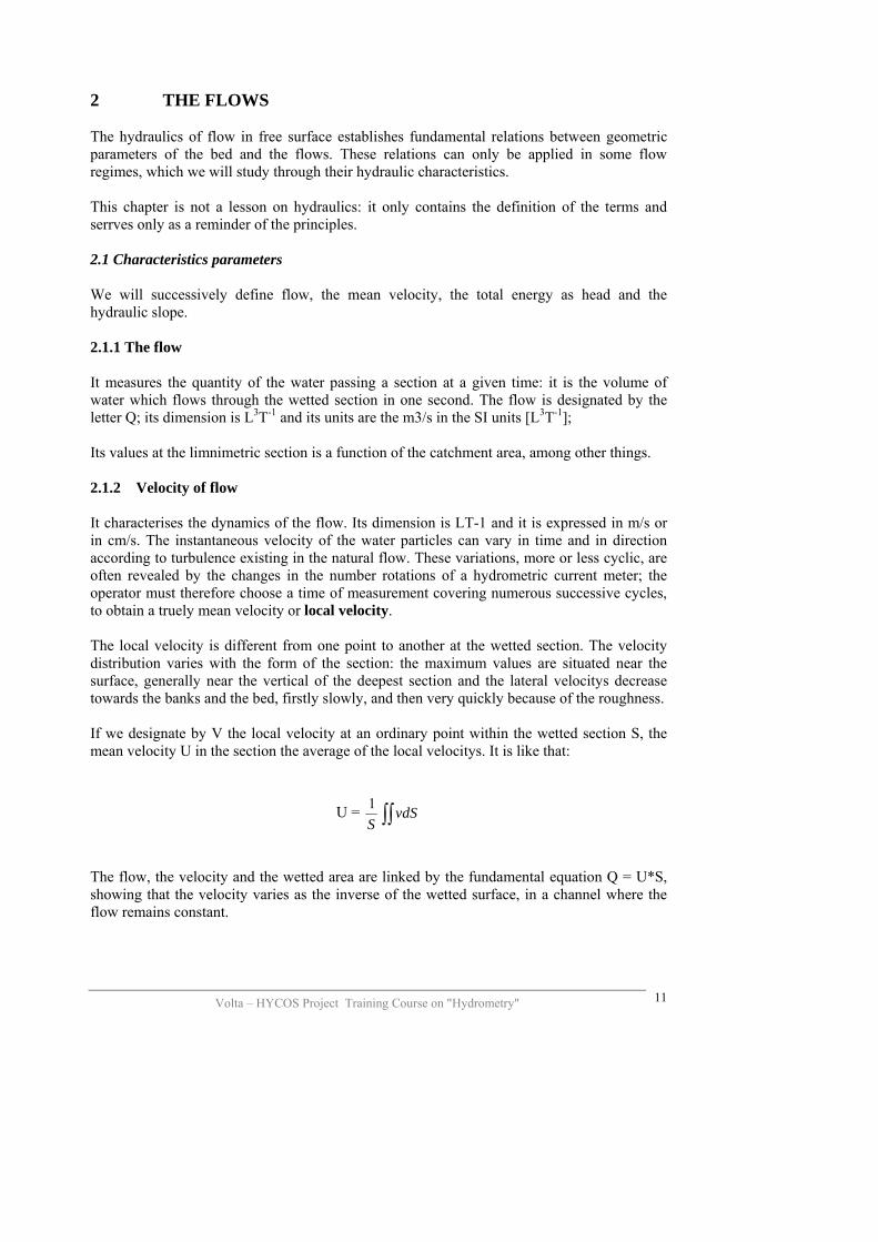
The head thus expressed, has two terms: -h which is the height representing the potential energy of the particle of water, in relation to a level reference; - U2/2g which is the kinetic energy head of the water particle. 2.1.4 Loss of head and hydraulic slope In the longitudinal profile, the water surface line is determined by reporting the value of the height of water h in each cross-section. If we add to h the kinetic height U2/2g above the free surface, we define a new line called total energy line, representing the energy crossing the section. Figure 2.1 gives a representation of these two lines, in a channel reach S1 - S2 of slope I. Because we had the water surface slope J by the angle of the water line with the horizontal plan, we can define the slope of the line of slope of the head I by the angle it makes with the horizontal. It is important to well differentiate:
- the slope I of the bed which is a geometrical characteristic of the bed, independent of the flow, measurable and varies less in time;
- the slope J of the free water surface which a characteristic of the flow,
variable with the flow and is easily measurable in the field (when it is not too low);
- the slope of the total energy line i which is also a characteristic of the flow,
varies with the flow, and is representative of the total energy and not directly measurable in the field.
In general, the values I and of j are neighbours and the water surface slope, measurable, is sometimes used, in replacement of the slope of the head in the practical application of the hydraulic formulas.
Line of head Loss of head between S1 and S2
Kinetic head
Potential height Bottom
Altitude of reference
Free surface
Figure 2.1: Free water surface and line of head To sum up, a flow is characterised by:
- Its flow Q and by the mean velocity U, defined by the fundamental relation Um/s = Q m3/s / Sm2;
- Its energy of head, evaluated by the a height of water which two components are the height h of the free surface and the kinetical height U2/2g;
- Its line of head that slope I is, in practice, evaluated by the hydraulic slope J of the water surface line.
- 2.2 Regimes of flow Hydraulics studies the properties of different regimes of flow. The application of theoretical formulas to a natural flow supposes the previous identification of its regime from its characteristics. 2.2.1 Laminar and turbulent flow This classification refers to the viscosity and to the turbulence of the particles. Natural flow is almost always turbulent. This classification has not got any practical utility for the hydrologist.
Volta – HYCOS Project Training Course on "Hydrometry"
13

Volta – HYCOS Project Training Course on "Hydrometry"
14
2.2.2 Steady and non steady flow This classification refers to the variability of the regime with time, in a given cross-section. A flow is said to be steady when its characteristics do not change with time. This peculiarity means that:
- The flow remains the same in time (but varies from the upstream to the downstream of the channels),
- In a cross-section, the mean velocity, the wetted surface, the water level and the total head, all remain constant.
- The hydraulic head and the free surface line do not change. This definition cannot, in the strictest sense be applied to natural rivers which flow variability in time is the main characteristic and justifies the hydrometric measures. But except from the periods of rapid flood, the flow variation is small enough to classify the flow as steady. On the contrary the flow regime of is not steady or variable:
- When the channel is crossed by a wave of a natural or artificial flood (dam releases),
- When constant flow is entering a channel, the mean velocity and the hydraulic slope can vary under the influence of changing conditions downstream (flood of a tributary, filling of a reservoir or the influence of a wetland for instance).
2.2.3 Uniform and varied flow This classification refers to the changes in the flow regime from upstream towards downstream of a channel (variability in space). A flow is said to be uniform when the characteristics do not change from one section to another. In other words:
- The flow must necessarily be steady: continuity of the flow; - The cross-section of the flow channel must remain identical throughout the
whole channel: wetted surface and depth are the same value; - The local velocities are constant along the same trajectory and the trajectories
are rectilinear or parallel to each other and to the river bed (the contrary in turbulent flows).
In uniform flow, the total energy line is parallel to the bed slope and at the free surface; the loss of head is exactly compensated because of the nature of the bed. Such flow regime can only exist in an artificial channel. Such phenomenon is rarely observed in the natural channels but it generally establishes in channels of constant slope and regular geometry, over a long distance. The fundamental formula of uniform regime has been established by CHEZY in 1775. It is written as:
Where: U is the mean velocity; R – The hydraulic radius; i – the slope of the line of head (equals to J and to I); C – A variable coefficient, function of the hydraulic radius and the nature of the channel sides. Among the empirical formulae expressing the coefficient C of CHEZY, we will keep that of STRICKLER, already cited, which is written as follows:
C = K R1/6,
That is to say:
, for the mean velocity; And:
, for the flow; It is under this form that the STRICKLER formula is used in the estimation of the maximum flows that could not be completely measured in the field. If the cross section is stable and with regular form, the geometric elements of S and R are known with a high degree of accuracy. The hydraulic slope can be measured during the flood or at a later time; only the roughness coefficient n = 1/K is not directly measurable: it can only be calculated from the complete flow measurements or estimated by the theoretical values proposed by MANNING. When the slope is unknown, it is preferable to associate K and i1/2, and to calculate the value of their product, from complete flow measurements. The CHEZY formula shows that in the case of a uniform flow regime, the flow Q can only be obtained under a given hydraulic radius R. The level of water corresponding is said to be normal depth. Therefore for each flow corresponds a normal depth (hn). Non-uniform flow is varied: all the hydraulic characteristics change from one section of the channel to another, no matter whether the regime is steady or not (Fig. 2.2).
Volta – HYCOS Project Training Course on "Hydrometry"
15
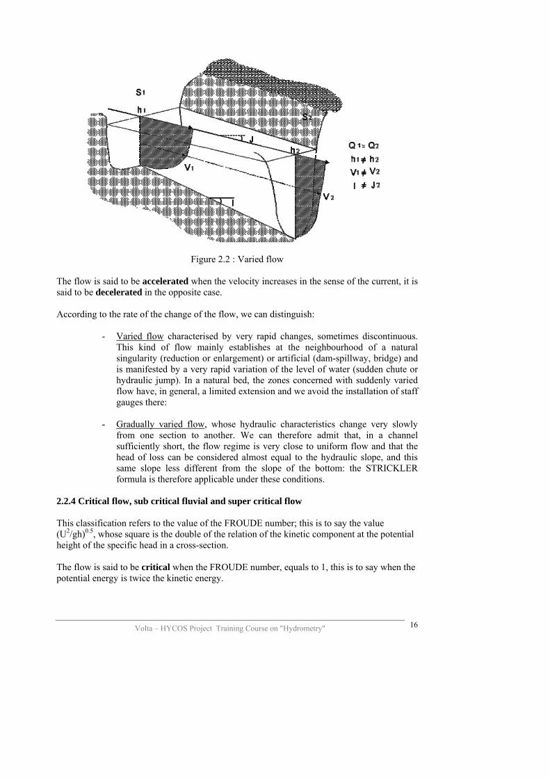
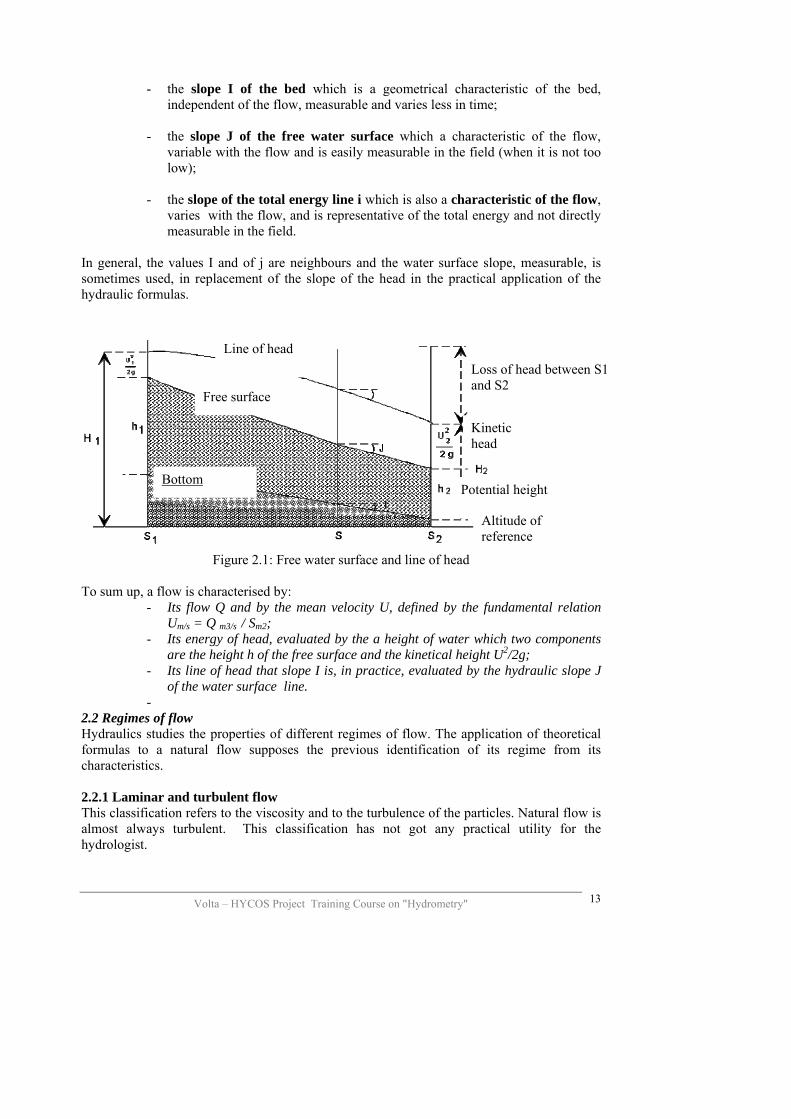
Figure 2.2 : Varied flow
The flow is said to be accelerated when the velocity increases in the sense of the current, it is said to be decelerated in the opposite case. According to the rate of the change of the flow, we can distinguish:
- Varied flow characterised by very rapid changes, sometimes discontinuous. This kind of flow mainly establishes at the neighbourhood of a natural singularity (reduction or enlargement) or artificial (dam-spillway, bridge) and is manifested by a very rapid variation of the level of water (sudden chute or hydraulic jump). In a natural bed, the zones concerned with suddenly varied flow have, in general, a limited extension and we avoid the installation of staff gauges there:
- Gradually varied flow, whose hydraulic characteristics change very slowly
from one section to another. We can therefore admit that, in a channel sufficiently short, the flow regime is very close to uniform flow and that the head of loss can be considered almost equal to the hydraulic slope, and this same slope less different from the slope of the bottom: the STRICKLER formula is therefore applicable under these conditions.
2.2.4 Critical flow, sub critical fluvial and super critical flow This classification refers to the value of the FROUDE number; this is to say the value (U2/gh)0.5, whose square is the double of the relation of the kinetic component at the potential height of the specific head in a cross-section. The flow is said to be critical when the FROUDE number, equals to 1, this is to say when the potential energy is twice the kinetic energy.
Volta – HYCOS Project Training Course on "Hydrometry"
16

When former increases in relation to the second, the flow in the section is subcritical (Fr <1). When it decreases, the flow is super critical (Fr>1). The simplified expression of the specific head in a cross-section for a steady uniform flow or gradually varied is:
Volta – HYCOS Project Training Course on "Hydrometry"
17
H = h + U
g
2
2 (1)
This can also be written like as:
H = h + QgS
2
22 (2)
If we choose a flow Q, to build the representative curve of H for this flow in relation to the depth h: each point of this curve is obtained by summing the ordinates of the right of the potential energy (of equation H = h) and the hyperbole of kinetic energy of equation H = Q2 / 2gS2). When the head is more than the critical value Hc, the flow can be said to be under two regimes:
- The first with a low depth h < hc, hc being the critical height, and a high velocity: it is the super critical regime.
- The other with a high depth h > hc and a low velocity: it is the subcritical regime.
In practice one of the two regimes settle in a spontaneous way in relation to the hydraulic slope. If the slope is high, the velocity of flow is high, the regime is super critical or rapid; if the slope is low, the velocity is reduced, and the regime is subcritical or slow. It is generally like that for the majority of the channels of the hydrometric stations where we look for important height of water as well as for low velocity in order to improve the accuracy and the quality of the measurements. To sum up:
- A flow is steady, in a given section, when the flow, the velocity and the height do not vary with time (or vary very slowly);
- A flow is gradually varied when its hydraulic characteristics vary progressively upstream to downstream: J is less different from I.
- A subcritical flow is characterised by a high depth of flow and a low velocity, and the hydraulic elements are influenced by the flow conditions downstream.
2.3 Hydraulic controls The notion of hydraulic control is important to understand the functioning of the hydrometric reach. The control occurs under different forms and the development of the rating curve depends on these properties. 2.3.1 Definition A flow in a limnetric section is said to be under control, when the geometric characteristics are such that the water level is a stable function of flow, or in other words, with the geometry of the channel remaining invariable, the same flow always flows under the same height
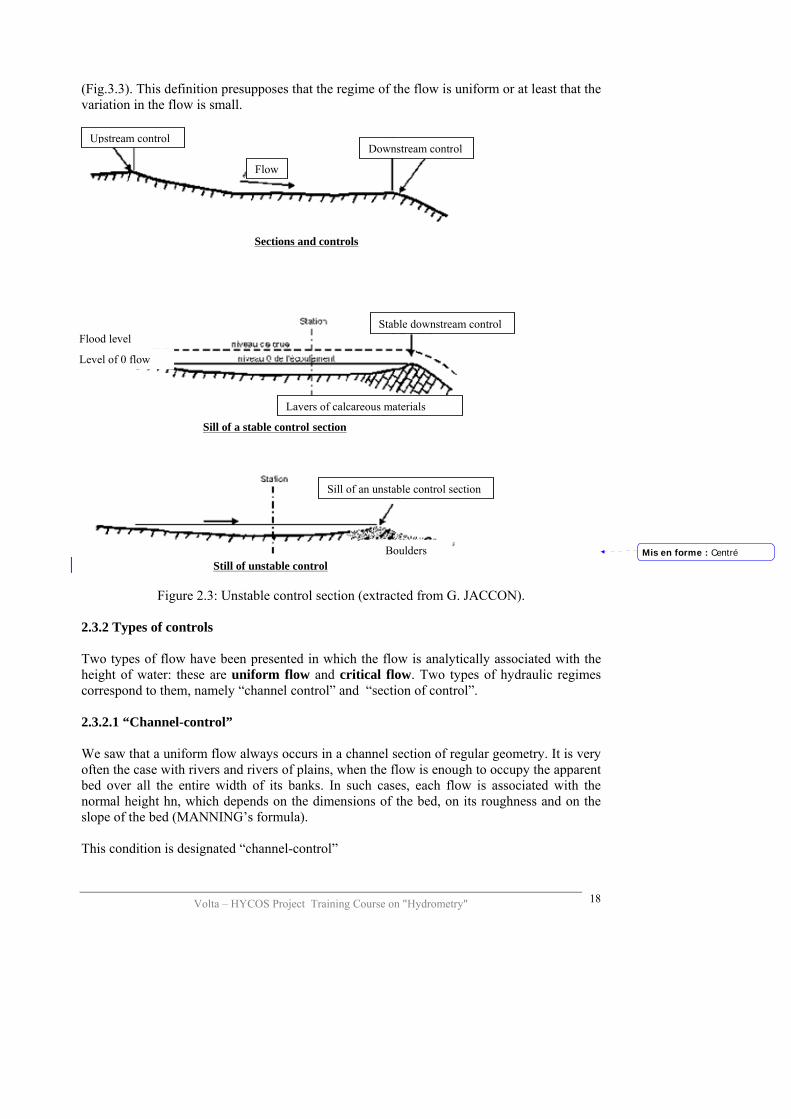
(Fig.3.3). This definition presupposes that the regime of the flow is uniform or at least that the variation in the flow is small.
Volta – HYCOS Project Training Course on "Hydrometry"
18
Figure 2.3: Unstable control section (extracted from G. JACCON).
2.3.2 Types of controls Two types of flow have been presented in which the flow is analytically associated with the height of water: these are uniform flow and critical flow. Two types of hydraulic regimes correspond to them, namely “channel control” and “section of control”. 2.3.2.1 “Channel-control” We saw that a uniform flow always occurs in a channel section of regular geometry. It is very often the case with rivers and rivers of plains, when the flow is enough to occupy the apparent bed over all the entire width of its banks. In such cases, each flow is associated with the normal height hn, which depends on the dimensions of the bed, on its roughness and on the slope of the bed (MANNING’s formula). This condition is designated “channel-control”
Boulders
Sill of an unstable control section
Sill of a stable control section
Layers of calcareous materials
Level of 0 flow
Flood level Stable downstream control
Sections and controls
Upstream control Downstream control
Flow
Still of unstable control Mis en forme : Centré

Volta – HYCOS Project Training Course on "Hydrometry"
19
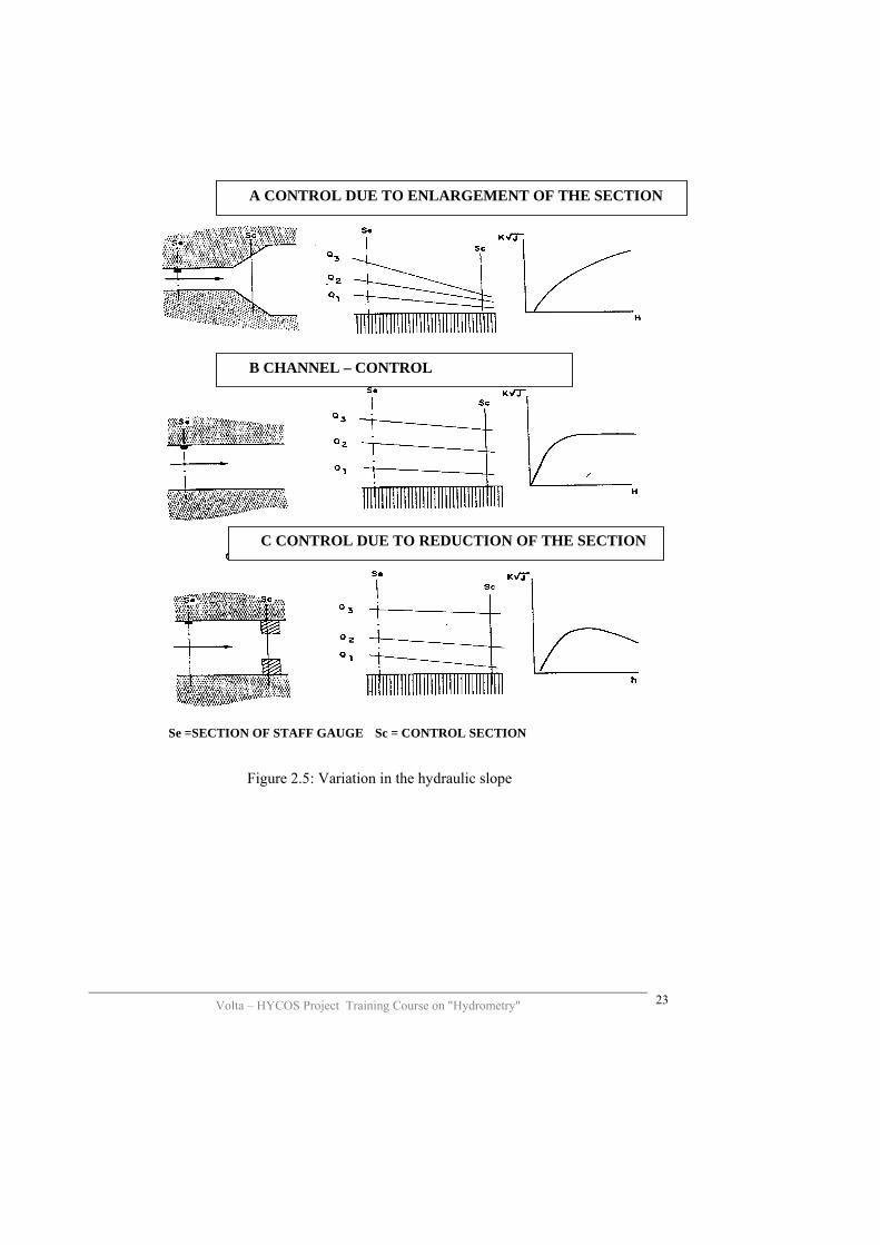
“Channel-control” exists in all natural beds where the conditions are favourable; this is to say far from the exceptions. The slope of the bed must be high enough to ensure a good transfer of the flow, because a uniform regime cannot establish in a flat bed. Otherwise the cross sectional profile of the bed must have a regular geometric form: this kind of form generally limits the effect of “channel-control” only to the apparent bed. 2.3.2.2 “Control section” The non-uniform flow becomes a varied flow when we come near the control of the bed.
The sills together with the bridges slow down the flow towards the upstream, and as a consequence a rise in the water surface level is observed. This very characteristic form is called curve of ramous. In the section concerned by the ramous, the flow is placed under the control of a section where the changes in the regimes are made, section located at the right of the control.
Figure 2.4 representing the shape of the water surface line for three different controls, shows that two possible situations exist:
- in the three pictures on the left, the control is not high enough to decrease the line of water below the critical level: the regime remains subcritical. Nevertheless there is a hydraulic gradient upstream of the obstacle that accelerates quickly on the right of the control, and then a slow come back to the normal level.
- In the three pictures on the right, opposition the contrary e, the subcritical flow
regime changes into a super critical flow regime due to the critical section located at the intersection of the critical and normal levels of the curves. The come back to the sub critical flow regime is created by a hydraulic jump, which is evidence of the existence of a critical section.
In this case, the upstream channel is completely isolated from downstream channel by the critical section, then becomes like the control section. The control is said to be complete. On the contrary, when a critical section does not exist, the upstream channel remains partially influenced by the flow of the downstream channel: the control section is located again at the right of the sill but the control is only partial. When an obstacle leads to the existence of a critical section, the current is said to be unsubmerged. If the flow by increasing leads to the disappearance of the critical section, the obstacle is then said to be submerge: the flow over a control, without any transition critical flow regime, is submerged.

Volta – HYCOS Project Training Course on "Hydrometry"
20
Nn = normal depth Sc = critical section
Nc = critical depth Ic =critical slope
A SILL
Figure 2.4: Effect of a control on the water surface line
fall
jump
B REDUCTION
C SUDDEN CHANGE IN SLOPE OF BED
Volta – HYCOS Project Training Course on "Hydrometry"
21
2.3.3 Stability of control A perfect control is a permanent control in space and in time. A complete and stable control section is fundamentally ideal for the hydrologist who must always look for it, when he has to site a station. The best complete controls are the rapids, hydraulic jumps and cascades of rocky channels, the natural cross sills constituted by the resisting rocky bar or the artificial weir or spillways when their structure is solid and when their anchorage to the soil is firm. When a well located and complete control does not exist, the control becomes partial and even the question of control becomes much less clear: it is obvious that the flow is sensitive to the downstream conditions but it is not always easy to identify and locate them with precision. 2.3.3.1 Stability in space Generally, the flow occurs under several successive controls, further downstream. These controls are successive when the flow increases and are submerged, on average and in high waters, by the hydraulic gradients of a most important control, like a sudden change or contraction of the bed, near a bridge. Such control is said to be complex. The efficiency of the “channel-control” is also limited to some extent by the range of water level. At low flows the control is achieved by the sandy bars and by the gravels in the minor bed, while in very high waters, there is an invasion of the major bed, the flow becomes very complex and is followed by many anomalies (localised hydraulic gradients, counter currents, etc.). 2.3.3.2 Stability in time In addition to a spatial variability of the partial control, is variability in time. The causes of the instability of the control are many: they occur, in an independently or simultaneously way, in the geometry of the bed and in the hydraulic characteristics of the channel. The geometric deformations of the bed are due to the factors listed above: natural mobility of the beds and of the channel sides periodical increase in the vegetation, civil emergency work (bridges, raiders) or rehabilitation and cleaning works. The modifications of the hydraulic characteristics are generally the result of partial controls, influenced by downstream temporary variation in the level due to the flood in a tributary, to an effect of the pools of water, to the erosion of mobile sill. It can also be due to a rapid variation of the flow (temporary situation of non-permanence). The instability of the control necessarily affects the relationship between the height and the flow but with variable consequences according to:
- Its amplitude: the change in rating curve can be partial or total, insignificant or large;
- Its periodicity: the relation can remain stable during long periods;

Volta – HYCOS Project Training Course on "Hydrometry"
22
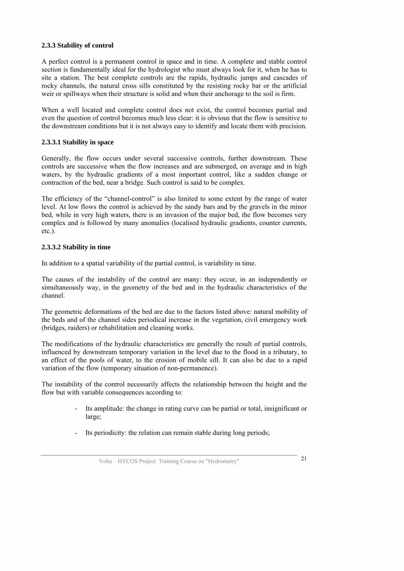
- Its rate of changes can be abrupt or very progressive. The high instability of the bed is sometimes limited by the construction of concrete sills, to which it is asked to improve the sensitivity of the station and sometimes to facilitate the measurement of the low flows. These sills are similar to two standard types, generally associated: the weirs at wick sill and the sill at lateral contradiction. 2.3.4 Functioning of the control The hydraulic control from downstream to upstream is done on only the longitudinal characteristic of the flow section: the hydraulic slope. If the STRICKLER formula is applied – regular geometric channel for less varied flow regime – the hydraulic slope is linked to the flow by the expression: Q = K SR2/3 J1/2
In this expression K, S and R refer to the staff gauge section. J, on the hand, depends on the height of water at the section, this is to say the normal height hn as well as on the height of water in the section of control hc. When the flow increases, the variation of J depends on the difference (hn – hc).
- J increases with the flow (figure 2.5a): it is the case when the control section is localised at a sudden enlargement of the minor bed, on a weir sill or at a rupture of slope;
- J remains constant when the flow increases (figure 2.5b): it is the case of the “ channel-control”; the hydraulic slope remains almost equal to the (longitudinal) bed slope;
- J decreases when the flow increases (figure 2.5c) when the control section is situated on an abrupt reduction (lateral high contraction for instance).
The multiplicity of the controls of the same staff gauge can naturally lead to much more complex conditions, even if the conditions of flow remain acceptable for the application of the STICKLER formula. The variation of J with h can successively be increasing and decreasing, and then increasing again. What is important as far as hydraulic control is concerned is the temporal and spatial stability of the conditions of flow. To sum up:
- A flow in a channel is said to be under hydraulic control when for each flow there is a corresponding well defined level of water;
- The control can be located at a control section or, on the contrary be located in a section of the bed (channel-control);
- The fundamental quality of a good control is its stability: In space by its efficiency for the flows; In time by the stability of its geometric and hydraulic characteristics.
Volta – HYCOS Project Training Course on "Hydrometry"
23
A CONTROL DUE TO ENLARGEMENT OF THE SECTION
B CHANNEL – CONTROL
C CONTROL DUE TO REDUCTION OF THE SECTION
Se =SECTION OF STAFF GAUGE Sc = CONTROL SECTION
Figure 2.5: Variation in the hydraulic slope

Volta – HYCOS Project Training Course on "Hydrometry"
24
3 THE HYDROMETRIC STATION The levels of the rivers, lakes or reservoirs directly serve for the prediction of the flows, the delimitations of the zones influenced by floods, and for the construction of hydraulic structures. By their relation with the flows of rivers or the volume of water contained in the reservoirs and in the lakes, the levels of water constitute the basic information for the determination of flows or storages. The water level or the height of water, is the height of the water surface of a river, of a lake or any other liquid body relative to a point of reference. In general the accuracy required for its observation is one centimetre, and three millimetres at the staff gauge stations with continuous recording. The criteria for the sitting of the station must respond to the final objective of the measurements and to the accessibility of the site, because of the geometrical and hydraulic properties of the channel. The hydraulic conditions also constitute an important factor for the choice of the site along the river, especially when the water levels are used in the calculation of the flows. The stations located on lakes and reservoirs are normally situated near the spillways, but upstream enough to avoid the influence of the phenomenon of scouring of the level due to the increasing velocity. 3.1 Major parameters measured The two main parameters measured are:
- The water height taken in a discontinuous way on a staff gauge and, or if the variations in the water level with time are rapid, in a continuous form through water level recorders;
- The flows, which is very rarely measurable in a continuous form, but rather measured periodically.
The other measured parameters are:
- The geometry of the section: longitudinal and cross topographical profiles, - The hydraulic slope, rarely measured continuously, except in cases where the
measurements are necessary for flow calculations, - The suspended matters (clay and sand) and in solution (by analysis or by
measurement of the conductivity of water) and other physicochemical parameters of the water.
3.2 Choice of the site Two types of criteria are taken into account in the choice of a hydrometric site. One deals with the mode and the management of the station: accessibility, monitoring, presence of an observer, etc. The other deals with the natural properties of the site as far as the geometry and the hydraulic regime of the flow are concerned: suitability for the hydrometric measurements, stability of the control and the sensitivity of the station.

3.2.1 Adaptation to the measurements The chosen site should allow for the observation of all the water levels and the measurements of all the flows, be they low or very high. This choice implies that the totality of the flow passes the across section of measurement and that the water level measuring equipment is stable without any risk of destruction, or of submergence. This also implies that the measurements are carried out in good conditions: the staff gauge is readable without any risk, flat and stable free water surface (no matter the flow), low flow for the current meters or good lateral mixing for chemical dilution techniques. This first condition of the suitability of the station for the measurements seems evident but many hydrologists very often forget to take it into consideration: it is the reason why many stations sited are not goods stations, despites high investments used to try to salvage them. 3.2.2 Stability The relationship between water level and flow at a hydrometric station must also be very stable. It is therefore necessary to choose a channel, formed in a resistant material or at least of good cohesion and above all always required, in a systematic way, the stable controls and if possible complete controls. This second condition requires the choice of a channel under sub-critical flow regime with downstream control, as well as a location of the sills or control sections with assessment of the limits of efficiency of each one of them (Fig. 3.1 and 3.2).
A Before the flood
B During the flood
Staff gauge Control section
Submerged control section Staff gauge
New control section lower than before the flood
C After the floodStaff gauge
Figure 3.1: Changes in an unstable control section during a flood.
Volta – HYCOS Project Training Course on "Hydrometry"
25

It is always difficult in practice to know with precision the stability of a control section during a simple reconnaissance field visit, even if we have credible topographical documents at our disposal, the stability of the bed is not easy to appreciate especially in the case of alluvial beds.
A Section before scouring
B Section after scouring
Part of a bank lost
Figure 3.2: Changes in an unstable riverbank
3.2.3 Sensitivity The sensitivity of a hydrometric station is better when a big variation read at the staff gauge corresponds to a small increase in the flow crossing the section of the staff gauge. It can be
expressed by the ratio ΔΔ
Qh
or better, since the precision relative to the flow is more important
than the absolute precision, by the ratio
Volta – HYCOS Project Training Course on "Hydrometry"
26
ΔΔQ Q
h/ .
The value of the ratio ΔΔQ
h/ Q expressed in % by centimetre is variable according to the level
but must stay as low as possible. In fact there is no standard method to define a “standard value” of the sensitivity so as to allow for comparisons with other stations. A definition of the sensitivity has been proposed by J.C. LAMBLE of the Scottish Development Department, Edinburg: “It is the increase in height of water in mm corresponding to a percentage increase in flow for the reading on a staff gauge exceeded 95% of the time on mean annual value” The STRICKLER formula applied to a rectangular channel of width l is written:
Q = K l hm5/3 J1/2
S = l hm
R = hm By deriving this expression, we obtain:

dQdh
K l hm J l U= =53
53
2 3 1 2/ /
And dQ Qdh
/ 5hm
=3
These two relations show that for a given flow, the sensitivity is better when the width and the mean velocity are small and when the depth is high (Fig. 3.3). The sensitivity of a station is better in narrow and deep sections (high range of water levels) and in those of sub critical flow regimes.
Very wide and shallow section Less sensitive
Narrow and deep section Very sensitive
Sensitivity of a section
Figure 3.3: Sensitivity of a water level measuring section.
To sum up: The hydraulic qualities of a hydrometric station are classified in order of priority:
- Its suitability for complete and good quality measurements; - Its stability to decrease the number of flow measurements required, which is
always a very expensive and difficult operation; - Its sensitivity to improve accuracy of measurement.
Volta – HYCOS Project Training Course on "Hydrometry"
27

Volta – HYCOS Project Training Course on "Hydrometry"
28
3.3 Characteristics sections It is less frequent to see the hydrometric station associated with only one cross section. Different sections are generally used for the measurement of the water level and the flows. The hydrometric station can therefore expand over a channel reach for many kilometres. But the only section of reference for the definition of the relation Water level-flow, is the staff gauge section. 3.3.1 Staff gauge section A hydrometric station always has staff gauges installed: it is strictly the only essential permanent structure required. The staff gauge section is the vertical section which includes the zero graduation, and therefore in general the lowest element of the staff gauge. When the station includes many staff gauges installed at different cross sections, either to measure the hydraulic slope, or to follow the variations of water level during the flow measurements or either to temporarily double staff gauges threaten of destruction, one of the sections must imperatively be designed as principal staff gauge, in accordance with the three criteria of choice of sites presented in the previous paragraph. A staff gauge is generally composed of metric elements separated or grouped in sections of variable length. These elements must be aligned in the section of staff gauge: when this is not possible because of technical reasons, we must try to avoid any discontinuity in the readings by ensuring an over lapping between the elements taking into account the surface slope. In the rivers with rapid variation in water level, the continuous recording of the water level is achieved by a water level recorder, which must be aligned with the staff gage readings. In general, at the same hydrometric station, it is necessary to avoid as much as possible to have many water level measurements sections. 3.3.2 Control section Generally located at the downstream of the staff gauge section, the control section, when it exists, can therefore be confused with the staff gauge section. It is the case for instance of the measurement sills at lateral contraction. The control section is therefore a section at critical flow, in which the height for a given flow (critical height) does only depend on the geometry of the section. Another type of complete control is seen in natural beds provided with chutes or rapid zones. We cite Gérard HIEZ (IRD): in GUYANE, the staff gauges were installed, when ever possible, at the upstream of hydraulic jumps or rapids constituting remarkable control sections. The section at the right of the staff gauge is sometimes perfectly ‘undefined” (for example the station of MARIPA on the OYAPOQUE) and the bed can be encumbered with islands and rocks. These stations present, in general, excellent qualities of sensitivity and stability because they are situated at the immediate upstream of an absolute control. Unfortunately, this almost ideal case, where the control is complete and perfectly defined is not the most common. Very often the control section is vague, runs towards downstream

Volta – HYCOS Project Training Course on "Hydrometry"
29
when the level of water increases and stabilises at a control of the bed (elbow, bridge), or is lost in a “channel-control” 3.3.3 Flow measurements sections In steady flow conditions the same flow (or more of less considered to be so) occurs at all sections of hydrometric channel. Therefore the measurement of this flow anywhere is allowed. We choose to do it in a section offering best guaranteed accurate measurements. This flow is declared to transit at the time of the measurement, at the staff gauge section. Regular and stable cross section, sufficient current velocity, parallel flow lines are the criteria for a gauging section with current meter. These conditions are not always easy to obtain at proximity of the staff gauge sections, because it generally exists an opposition between low, medium and high waters. For measuring high water flows in a channel, a section of low slope is chosen to limit the violence of the current. It can be equipped with a graduated cable, or rope. There is no inconvenience to place this gauging section far from the section of the staff gauge if the flow remains unchanged. On the contrary for low flows, one encounters an insufficiency either in depths or velocitys. Moreover the gauging must be done as close as possible to the section of the staff gauge because of the rapid variation of the low flows (exchange with the ground water due to percolation). As a result, very often, the measurements of the low flow are much more difficult to achieve than those of medium and high flows. The use of calibrated weirs become useful when the flow is less than 500l/s. The use of chemical dilution methods involves the choice of a gauging section but on the contrary a long channel of many hectometres or kilometres depending upon the flow and the time for mixing of the waters. To sum up:
- three types of characteristic sections are defined in the hydrometric channel (Q constant all along the channel):
• the section of the staff gauge is perfectly situated by the zero of the main staff gauge; • the control section which can be located with precision or on the contrary may not
exist at all; • the gauging section chosen is the most favourable place for the measurement of the
flow. - The only section of reference for the measurement in a hydrometric station is
the staff gauge section: all the measurement of levels or flow undertaken at other sections are associated with this section.

Volta – HYCOS Project Training Course on "Hydrometry"
30
3.4 Sections of artificial control We just saw the criteria for the choice of hydrometric stations for the proper functioning of a hydrometric station and for the stability of the water level-flow relation defined for that station. Despite the care in this choice, we are sometimes obliged, particularly in the case of small rivers with narrow beds, unstable, encumbered bed blocks and with low current of water, to install at the section a hydraulic structure, or more conveniently, we take advantage of an old sill control to install the station. In this later case of course it will not be possible to use the hydraulic formula for the determination of the flows, but the existing sill will eventually need some supplementary works, to ensure a good stability of the relation H/Q. It is necessary to be conscious that the building of such hydraulic structure is very expensive, the cost of this work can be more or less compensated by the eventual suppression or at least slight reduction of the number flow measurements necessary to establish the rating curve for the station. A proper dimensioning will permit a variable sensitivity in the whole range of the flows to be measured. No matter the type of artificial control constructed, it must include a sill or control section, that will create upstream conditions and the hydraulic structures that will impose downstream conditions of flow. The operation of stations with hydraulic structures is confronted with various problems such as:
- Rigid construction and maintenance of the station in order to be conform to the conditions for which the formula of the flow was established,
- These conditions are sometimes difficult to obtain during the operational phase, particularly in rivers with high sediment flow. The hydraulic conditions in the approach canal are therefore subject to important variations sometimes affecting at an unacceptable level the rating curve. The eventual changes (trees, vegetation, etc.) of some parts of the station will have exactly the same effect.
- The rise of the natural water level, implying the construction of the hydraulic structures can have annoying consequences in the upstream because of the risks of innudation particularly during periods of floods.
- The Parshall Flume or Venturi Flume will be preferred to other hydraulic structures either board-crested or thin-crested weirs because the risk of sedimentation in the upstream will be significant in weirs.
The characteristics and the conditions of installation of these structures are widely dealt with in new books such as: Applied Hydrometry to Rivers (“Hydrometrie appliquée aux cours d’eau”) of M. Audinet or Engineering Hydrology (“Hydrologie de l’ingenieur”) of G. Réméniéras.

4 WEIRS AND SILLS 4.1 Triangular thin-crested weirs In the range of conditions for which available experimental data are available, the triangular thin-crested weir is a very precise device of measuring flows. It is constructed by cutting a symmetrical V-notch in a thin plate. The bisector of the angle of the V-notch must be vertical and equidistant near the canal of approach. The sides of the weirs must be flat and smooth, especially on the upstream face and it must be perpendicular to the sides and at the bottom of the canal.
Volta – HYCOS Project Training Course on "Hydrometry"
31
Section of the thin plate
Figure 4.1: Triangular thin-crested weir
Fundamental formula of flow The general formula of the flow over a triangular thin-crested weir is:
Q g tge ec h=8
152
25
2α
where: Q is the flow (m3/s) Ce the coefficient of the flow (α, h/p, p/B) g the acceleration due to the gravity (m2/s) α the angle formed by the walls of the V-notch he the fictitious water head of the upstream water surface above the base of the V-notch (m). Three dimensions of triangular weirs are recommended by the International Standards Organisation (ISO):
- The V-notch type 90° where the spacing of the top of the V-notch is equal to
twice the vertical height corresponding (tg α/2 = 1) - The V-notch type 1/2 (α = 53°8’) where the spacing of the top of the top of
the V-notch is equal to the corresponding vertical height (tg α/2 = 0.5) - The V-notch type (tg α/2 = 0.5) where the spacing of the top of the V-notch
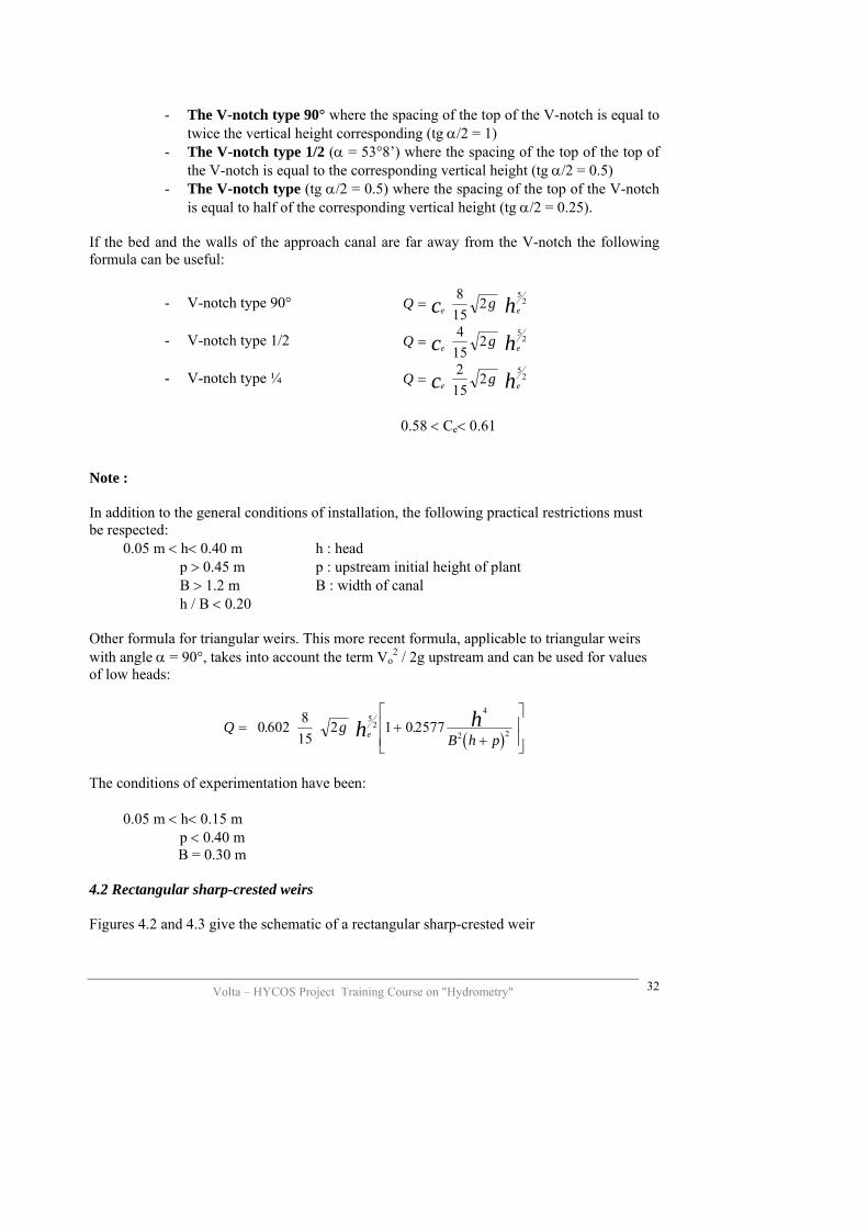
is equal to half of the corresponding vertical height (tg α/2 = 0.25). If the bed and the walls of the approach canal are far away from the V-notch the following formula can be useful:
Q ge ec h=8
152
52- V-notch type 90°
Q ge ec h25
2=4
15- V-notch type 1/2
Q ge ec h25
2=2
15- V-notch type ¼
0.58 < Ce< 0.61
Note : In addition to the general conditions of installation, the following practical restrictions must be respected: 0.05 m < h< 0.40 m h : head p > 0.45 m p : upstream initial height of plant B > 1.2 m B : width of canal h / B < 0.20 Other formula for triangular weirs. This more recent formula, applicable to triangular weirs with angle α = 90°, takes into account the term Vo
2 / 2g upstream and can be used for values of low heads:
( )
Volta – HYCOS Project Training Course on "Hydrometry"
32
Q gB h peh h= +
+
⎡
⎣⎢⎢
⎤
⎦⎥⎥
0 602 815
2 1 0 25775
2
4
2 2. .
The conditions of experimentation have been: 0.05 m < h< 0.15 m p < 0.40 m B = 0.30 m 4.2 Rectangular sharp-crested weirs Figures 4.2 and 4.3 give the schematic of a rectangular sharp-crested weir
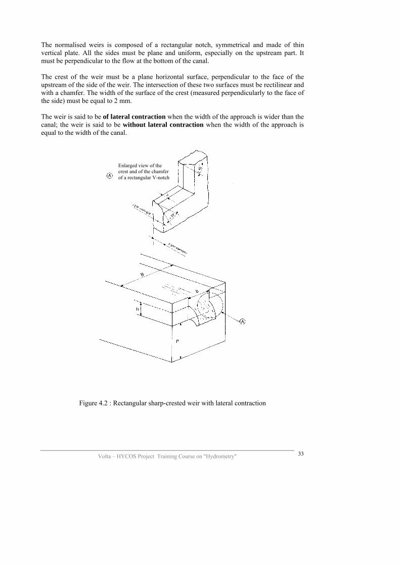
The normalised weirs is composed of a rectangular notch, symmetrical and made of thin vertical plate. All the sides must be plane and uniform, especially on the upstream part. It must be perpendicular to the flow at the bottom of the canal. The crest of the weir must be a plane horizontal surface, perpendicular to the face of the upstream of the side of the weir. The intersection of these two surfaces must be rectilinear and with a chamfer. The width of the surface of the crest (measured perpendicularly to the face of the side) must be equal to 2 mm. The weir is said to be of lateral contraction when the width of the approach is wider than the canal; the weir is said to be without lateral contraction when the width of the approach is equal to the width of the canal.
Volta – HYCOS Project Training Course on "Hydrometry"
33
Enlarged view of the crest and of the chamfer of a rectangular V-notch
Figure 4.2 : Rectangular sharp-crested weir with lateral contraction

Volta – HYCOS Project Training Course on "Hydrometry"
34
Schematic Profile
Plan view
Figure 4.3: Rectangular sharp-crested weir without lateral contraction Fundamental formula of the flow: The most general formula of flow recommended by the International Standard Organisation (ISO) for a rectangular sharp-crested weirs is the formula of Kindsvater-Carter:
Q g be e ec h=23
23
2
Where : Q is the flow (m3/s) Ce the coefficient of the discharge g the acceleration due to gravity (m/s2) be the fictitious width of the V-notch (m) he the fictitious piezometric head of the water surface in the upstream in relation to the
level of the crest (m) With: be = b + kb where b is the width of the weir he = h + kh where h is the measured head

In practice hc = h + 0.001 m. In the case of the rectangular sharp-crested weir without lateral contraction:
Ce = 0.602 + 0.075 h / p P is the height of the weir measured from the bottom of the canal. In the case of weirs with lateral contraction:
Ce = a + a’ h / p
Volta – HYCOS Project Training Course on "Hydrometry"
35
The values of Ce and of kb are given on figures 4.4a and 4.4b according to the relation b / B of contraction between the width b of the V-notch and the width B of the upstream canal.
Value of h/p
Value of b/B
Figure 4.4: rectangular thin walled weir. a) value of Ce according to h/p b) value of kb according to b/B
There are other possible formula for rectangular walled weirs without lateral contraction: the formula of REHBOCK; the formula of SIA (Société Suisse des Igénieurs et Architectes); the formula of CASTEX NOUGARO (Institute of Mechanics of Toulouse). We will refer to the work of M. AUDINET: Hydrometry Applied to Rivers (“Hydrométrie appliquée au cours d’’eau”) for the conditions of use of these formulae. 4.3 Choice of the type of the thin walled weir The triangular weirs are preferably used in place of the rectangular ones for the measurements of low flows, because it is not advised to use the rectangular weirs of less than 30 cm width.
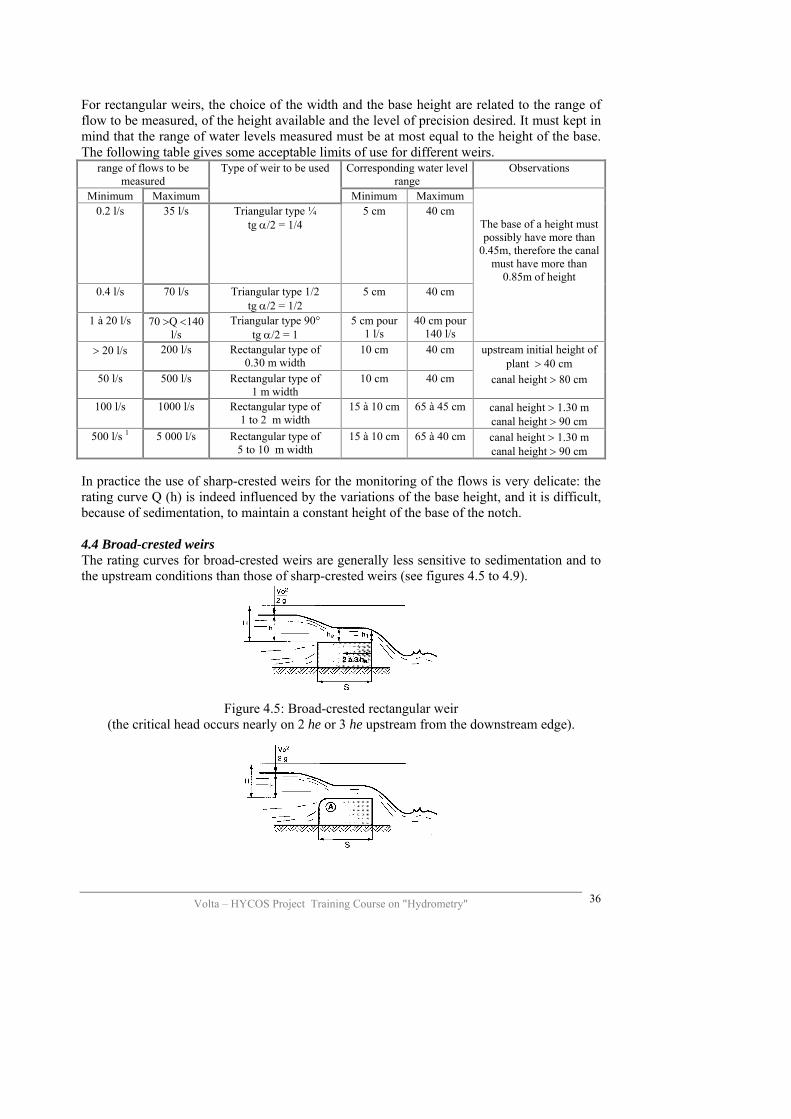
For rectangular weirs, the choice of the width and the base height are related to the range of flow to be measured, of the height available and the level of precision desired. It must kept in mind that the range of water levels measured must be at most equal to the height of the base. The following table gives some acceptable limits of use for different weirs.
range of flows to be measured
Type of weir to be used Corresponding water level range
Observations
Minimum Maximum Minimum Maximum 0.2 l/s 35 l/s Triangular type ¼
tg α/2 = 1/4 5 cm 40 cm
The base of a height must possibly have more than
0.45m, therefore the canal must have more than
0.85m of height 0.4 l/s 70 l/s Triangular type 1/2
tg α/2 = 1/2 5 cm 40 cm
1 à 20 l/s 70 >Q <140 l/s
Triangular type 90° tg α/2 = 1
5 cm pour 1 l/s
40 cm pour 140 l/s
> 20 l/s 200 l/s Rectangular type of 0.30 m width
10 cm 40 cm upstream initial height of plant > 40 cm
50 l/s 500 l/s Rectangular type of 1 m width
10 cm 40 cm canal height > 80 cm
100 l/s 1000 l/s Rectangular type of 1 to 2 m width
15 à 10 cm 65 à 45 cm canal height > 1.30 m canal height > 90 cm
500 l/s 1 5 000 l/s Rectangular type of 5 to 10 m width
15 à 10 cm 65 à 40 cm canal height > 1.30 m canal height > 90 cm
In practice the use of sharp-crested weirs for the monitoring of the flows is very delicate: the rating curve Q (h) is indeed influenced by the variations of the base height, and it is difficult, because of sedimentation, to maintain a constant height of the base of the notch. 4.4 Broad-crested weirs The rating curves for broad-crested weirs are generally less sensitive to sedimentation and to the upstream conditions than those of sharp-crested weirs (see figures 4.5 to 4.9).
Figure 4.5: Broad-crested rectangular weir
(the critical head occurs nearly on 2 he or 3 he upstream from the downstream edge).
Volta – HYCOS Project Training Course on "Hydrometry"
36

Figure 4.6: rectangular broad-crested weir, round edge upstream
Volta – HYCOS Project Training Course on "Hydrometry"
37
Figure 4.7: schema of a 22° control (Neyrtec)
Roller back filler sand sill
Sand, limonssill
Values of the coefficient m
Figure 4.8 : trapezoidal broad-crested weir
Values of the coefficient m
Figure 4.9 Triangular broad-crested weir The fundamental formula for calculating the flows for broad-crested weirs
Q m l g H= 2 3 2/ Where
– m is a coefficient which varies according to the characteristics of the weir. The following table give some approximate values of the coefficient.
– L is the width of the weir – H = h + Vo2/2g represents the head, considered sometimes in practice to be the
height of water upstream of the weir relative to the weir base, when the approach velocity Vo is small and can be neglected.
H S meter 0.10 m 0.50 m 1 m 1.50 m 3 m 5 m 0.10 0.38 0.35 0.33 0.33 0.34 0.35 0.50 0.45 0.40 0.35 0.35 0.35 0.35 1.00 0.45 0.45 0.40 0.36 0.35 0.35 1.50 0.45 0.45 0.43 0.39 0.36 0.35
Values of the m coefficient
When the upstream edge is not rounded or chamfered but rectangular, the values of the coefficient m must be reduced by about 10%. One can distinguish several types of broad-crested weirs and these include:
- the normal weir or Creager, where it is produced neither a surpression nor a depression, for a determined head which has serve to calculate the form. The coefficient of the flow is function of the slope of the upstream canal and of the relation of the height of the base height (mean coefficient: 0.47 to 0.49).
- the Crump triangular broad-crested weir, vertical contraction weir
possessing the following advantages: - its construction in a rectangular canal is relatively easy, - it offers an easy passage to floating objects, - it is solid and not very liable to deterioration.
For all these types of weirs, we will refer to the book of M. AUDINET (op. cit.) for the conditions of use and formula for calculation of the flows. 4.5 Other devices We will cite:
- the ressaut gauges weirs of hydraulical type, functioning in a range of flows going 0.8 l/s to 152 l/s,
- the metallic weirs, they installed in masonry canals, of rectangular section and of gentle slope. The flow expressed in 1/s and per metre of width varies from 7 l/s for width of 0.70 put at base height of O.12m to 1378 l/s for a width of 1.45 m and a base height of 0.48 m.
- the Venturi Flume –Parshall Flume. These type of equipment will be preferred for stations with high sediment flow, the later always presenting considerable disadvantages relating to under mining downstream, the increasing of the water level upstream, etc.
The general formula of a gauge with submerged hydraulic jump is as follows:
Q k c gl h= 2
322
Where: Q is the flow k is a coefficient varying from 0.95 to 1.00 depending on the gauges c is a coefficient which is function of the width l1and l2 l2 is the width of the narrow part l1 is the width of the broad part upstream g is the acceleration due to gravity h is the height of the water level above the foundation upstream in the part of width l1.
Volta – HYCOS Project Training Course on "Hydrometry"
38

Volta – HYCOS Project Training Course on "Hydrometry"
39
Direction of the flow
VIEW PLAN
UNSUBMERGED FLOW (horizontal foundation)
UNSUBMERGED FLOW (increased foundation)
UNSUBMERGED FLOW (decreased foundation)
Figure 4.10: Hydraulic jump gauge: schematic of principle
Type H or H calibrated channels. Flume. The device is made up of a rectangular channel ending by an enlargement with lateral side walls that are vertical. The bottom of the canal ends in isosceles trapezoid which small base is turned towards downstream, and the lateral sidewalls have the form of a rectangular trapezoid; the shape of the V-notch is an isoscele trapezoid inclined according to the horizontal (fig. 4.11). This type channel gauging, are less fragile than the triangular weir and are better adapted to the measurements of waters carrying sediments, because they are less subject to the scouring.
Volta – HYCOS Project Training Course on "Hydrometry"
40
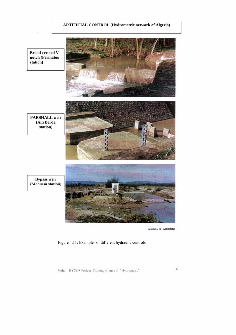
ARTIFICIAL CONTROL (Hydrometric network of Algeria)
Broad-crested V-notch (Fermatou station)
PARSHALL weir (Aïn Berda
station)
Bypass weir (Maoussa station)
Figure 4.11: Examples of different hydraulic controls
Volta – HYCOS Project Training Course on "Hydrometry"
41
5 SENSORS The staff gauge is still today the reference for water level measurements. It is almost always associated with a real water level sensor. The usual sensors are classified into two categories:
- the direct sensors measuring the depth, - the indirect sensors measuring a physical parameter associated with the water
level, this physical parameter being mostly the hydrostatic pressure. 5.1 characteristics of the sensors
- range of measurement: generally from 0 to 10m for most of the river - sensitivity: smallest variation in water height level (h) resulting in a
measurable signal - precision: characteristics of ability of the sensor to give a value as close as
possible to the real value of the water level; linked to the sum of the elementary errors at the level of the sensor and the transducer
- the stability of the response: absence of derive, no “background noise” covering the signal no cycles due to the phenomenon of hystersis,…
- time of response or velocity of tracking rate: when the water level varies rapidly, the sensor must be able to respond to this variation which can be of the order of several metres per hour
- mechanical resistance to the shocks or to the abrasion: particularly important in rivers mountains torrents
- cost and constraints of installation - simplicity of the system and reliability (durability).
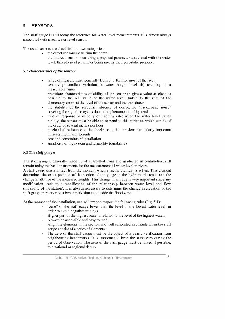
5.2 The staff gauges The staff gauges, generally made up of enamelled irons and graduated in centimetres, still remain today the basic instruments for the measurement of water level in rivers. A staff gauge exists in fact from the moment when a metric element is set up. This element determines the exact position of the section of the gauge in the hydrometric reach and the change in altitude of the measured heights. This change in altitude is very important since any modification leads to a modification of the relationship between water level and flow (invalidity of the station). It is always necessary to determine the change in elevation of the staff gauge in relation to a benchmark situated outside the flood zone. At the moment of the installation, one will try and respect the following rules (Fig. 5.1):
- “zero” of the staff gauge lower than the level of the lowest water level, in order to avoid negative readings
- Higher part of the highest scale in relation to the level of the highest waters, - Always be accessible and easy to read, - Align the elements in the section and well calibrated in altitude when the staff
gauge consist of a series of elements. - The zero of the staff gauge must be the object of a yearly verification from
neighbouring benchmarks. It is important to keep the same zero during the period of observation. The zero of the staff gauge must be linked if possible, to a national or regional datum.
Volta – HYCOS Project Training Course on "Hydrometry"
42
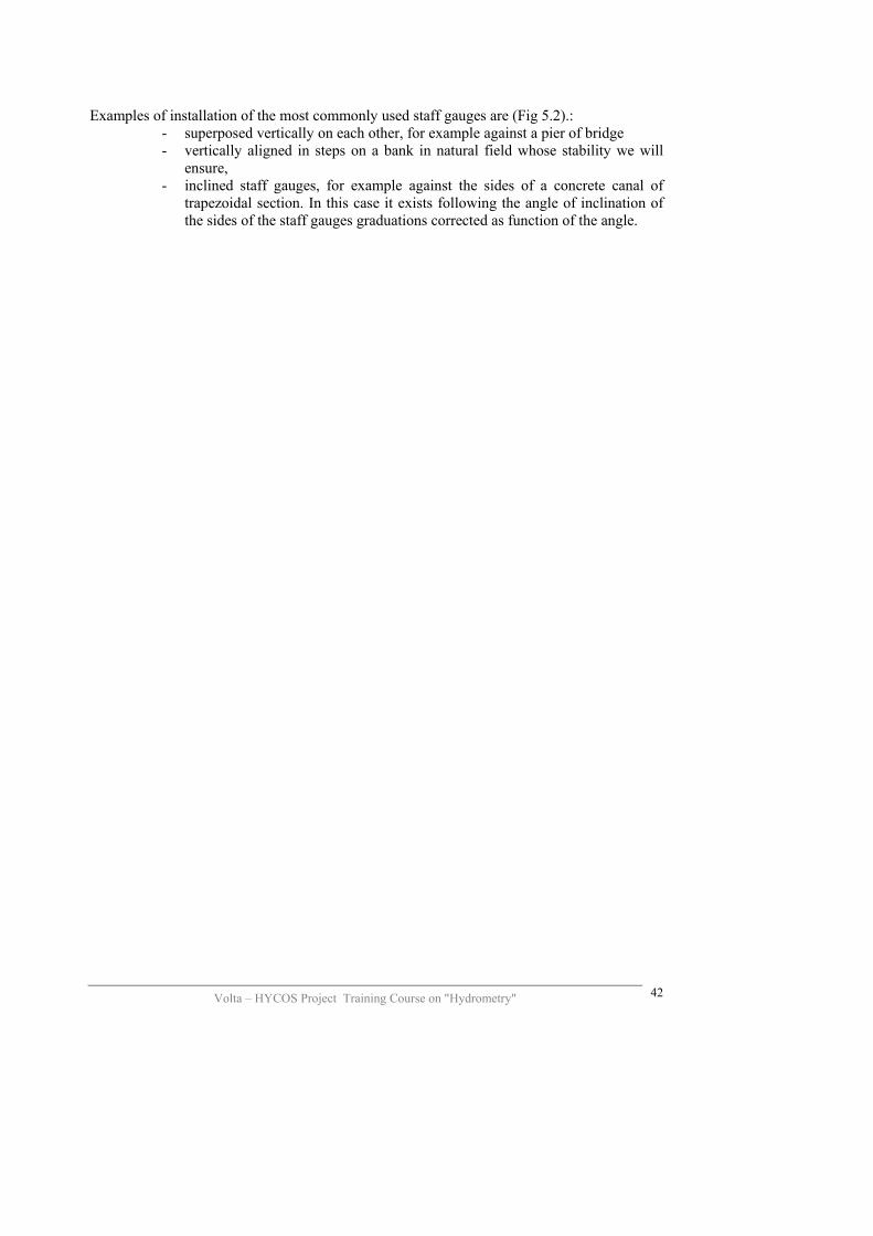
Examples of installation of the most commonly used staff gauges are (Fig 5.2).:
- superposed vertically on each other, for example against a pier of bridge - vertically aligned in steps on a bank in natural field whose stability we will
ensure, - inclined staff gauges, for example against the sides of a concrete canal of
trapezoidal section. In this case it exists following the angle of inclination of the sides of the staff gauges graduations corrected as function of the angle.

Volta – HYCOS Project Training Course on "Hydrometry"
VERY BAD INSTALLATION
GOOD TURBULENCES ATTENUATED
Well of the staff gauge
Pier of a bridge
To be concreted
Staff gauges well installed
Figure 5.1: Examples of installation of staff gauges.
43
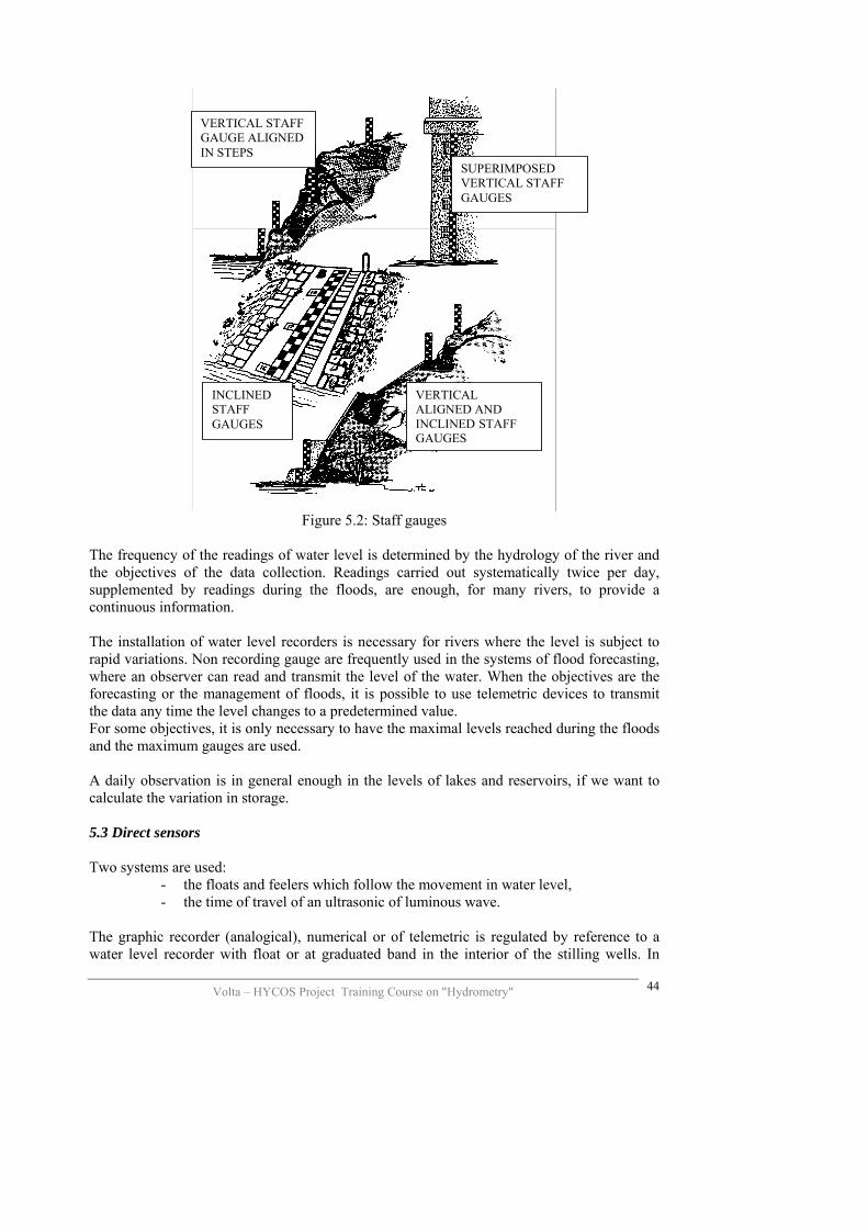
VEGIN
RTICAL STAFF AUGE ALIGNED STEPS
SUPERIMPOSED VERTICAL STAFF GAUGES
INCLINED STAFF GAUGES
VERTICAL ALIGNED AND INCLINED STAFF GAUGES
Figure 5.2: Staff gauges
The frequency of the readings of water level is determined by the hydrology of the river and the objectives of the data collection. Readings carried out systematically twice per day, supplemented by readings during the floods, are enough, for many rivers, to provide a continuous information. The installation of water level recorders is necessary for rivers where the level is subject to rapid variations. Non recording gauge are frequently used in the systems of flood forecasting, where an observer can read and transmit the level of the water. When the objectives are the forecasting or the management of floods, it is possible to use telemetric devices to transmit the data any time the level changes to a predetermined value. For some objectives, it is only necessary to have the maximal levels reached during the floods and the maximum gauges are used. A daily observation is in general enough in the levels of lakes and reservoirs, if we want to calculate the variation in storage. 5.3 Direct sensors Two systems are used:
- the floats and feelers which follow the movement in water level, - the time of travel of an ultrasonic of luminous wave.
The graphic recorder (analogical), numerical or of telemetric is regulated by reference to a water level recorder with float or at graduated band in the interior of the stilling wells. In
Volta – HYCOS Project Training Course on "Hydrometry"
44

Volta – HYCOS Project Training Course on "Hydrometry"
45
addition to that, a vertical or inclined gauge adjusted to the same zero, allow the control of the level in the wells corresponding to that of the river. For bubble n sensors that do not require a stilling well, vertical or inclined gauges, are use as reference gauge. Small differences could be noticed because of the fact of the velocity of water at the extremity of the outlet pipe of the stilling well. Great differences may show that this outlet pipe is blocked. 5.3.1 The sensors
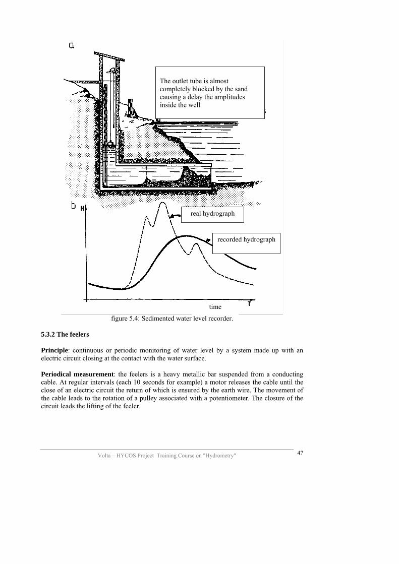
- principle: see the different devices on figure 5.3. - qualities: simplicity, robustness , high strength - disadvantages: civil engineering works sometimes very important, - very uncertain results when used in rivers with high sediment transport (figure
5.4) - sensitivity: depends much on the definition of the mechanical parts and the
maintenance - precision: linked to the resistant couple “pulley-graphical recording system”
and to the diameter of the float and the pulley; the theoretical precision given by the manufacturer can come down to the mm in better conditions, in practice one cannot expect better results more than 5 mm.
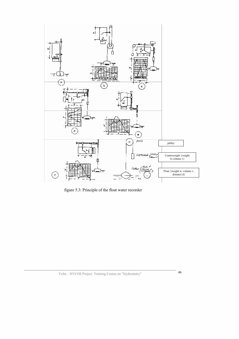
pulley
Contreweight {weight w,volume v}
Float {weight w,distance d}
volume v,
figure 5.3: Principle of the float water recorder
Volta – HYCOS Project Training Course on "Hydrometry"
46
Volta – HYCOS Project Training Course on "Hydrometry"
47
figure 5.4: Sedimented water level recorder.
The outlet tube is almost completely blocked by the sand causing a delay the amplitudes inside the well
real hydrograph
recorded hydrograph
time
5.3.2 The feelers Principle: continuous or periodic monitoring of water level by a system made up with an electric circuit closing at the contact with the water surface. Periodical measurement: the feelers is a heavy metallic bar suspended from a conducting cable. At regular intervals (each 10 seconds for example) a motor releases the cable until the close of an electric circuit the return of which is ensured by the earth wire. The movement of the cable leads to the rotation of a pulley associated with a potentiometer. The closure of the circuit leads the lifting of the feeler.

Volta – HYCOS Project Training Course on "Hydrometry"
48
We can associate with this category of water level recorders immersed electrodes developed by the CEMAGREF. The water level recorder is made up of one or many gauges equipped with electrical resistances each cm. The periodical monitoring of the state of these resistances allows for the knowledge of those immersed due to difference in conductivity between air and water. Continuous measurement: an electrode is placed at the water level surface; any movement of this electrode leads to an equivalent movement of a motorised electrode and whose electrical resistance subject to a predetermined value: this system is an electrical float more sensitive than the mechanical float (1 mm). This principle is used in a piezograph with feeler built by the CEMAGREF (the transducer is a vertical water level recorder). According to the report of CEMAGREF of 1987, less than 1% of the French stock of water level sensors are the feeler type.. 5.3.3 The ultrasonics Principles: the distance between an emitter /receptor of ultrasonic waves (frequency higher to 15 kHz) and the water level is deducted to the time of course of these waves. If c is the velocity of propagation of the waves and t the necessary time required for the going and the coming of a perpendicular wave, then h = c* t/2, where h = distance of the emitter at the water level surface. The ultrasonic emitter (called transducer) possesses the property of converting the impulsions of electric energy into acoustic waves or vice versa. It is associated to an electronic circuit which engenders the electric energy at high frequency, transmits it and measure the time spent between the sending and the return of the signal. Two techniques are used:
- the immersed water level sensors - the aerial water level sensors. -
Comparison of the ultrasonics in air and in water In air In water Frequencies used Velocity of propagation Amortisement Resolution Minimal distance Velocity of tracking rate
20 kHz à 100 kHz 330 m/s à 0°C 10-3 dB/cm > 5 mm About 10 cm Many m by second
100 kHz à 1 Mhz 1400 m/s à 0°C 10-6 dB/cm < 1 mm Some cm Many m/s
: Precision: it depends on the quality of the time measurement (determination of t), the knowledge of c, the position and the orientation of the sensors and the corrections, particularly the compensation for temperature. The measurement of the time is very precise thanks to a quartz watch.

Volta – HYCOS Project Training Course on "Hydrometry"
49
It is a variable with the temperature (c increases by 0.28% per degree, that to say about 4 m/s in water) and with some sensitive factors such as the salinity or the presence of bubbles of air in the water; wind and humidity; The influencing factors are very difficult to take into account beside the temperature; the corrections realised concern the elimination of the spurious values, the smoothing over a period of time and the periodical calibrations with a sensor of another type. The techniques of immerged ultrasonic is now perfectly operational and precise, especially in the laminar flows. The aerial sensors are less precise but they are of great interest for flows with high sediment loaded.. 5.3.4 Luminous waves The principle is the same, but the velocity of propagation of the luminous waves is 300 000 km/s. Then the necessity of working over an sufficient interval of time Dt. An enough recent study of CEMAGREF showed that this technique can be used (distance meters with laser of infrared rays) but the price of these devices will be almost double of the other sensors. 5.4 Sensors using the hydrostatic pressures Two fundamental principles are used:
- the indirect measure of the hydrostatic pressure by a pneumatic system at open enceinte known under the name of “bubble to bubble”,
- the direct measure of the hydrostatic pressure by a of pressure sensor. 5.4.1 “The bubble in principle” Principle: a constant flow of compressed gas (compressed air or azotes) moves in a tube leading to a river under open pressure. The source of the gas is either a bottle of compressed gas (in old devices) or compressor fed by batteries and solar panel in newer equipment. The air flow is regulated at 2 bubbles per second by means of a visualisor. The operational is regulated at about 2 or 3 bars depending on the range of measurement and the length of the tube. The variations of the pressure due to water level rise are measured by the transducer which

- either an aneroid capsule associated with a disposal of graphic recording (figure 5.5 sketch c);
- either a system of float on a column of mercury, case of “Télimip” of Neyrtec (figure 5.6);
- either a mercury manometer: a feeler allows a motor to monitor the variations of the level of mercury (figure 5.4 sketch f);
- either by a balance of pressure: the pressure is converted by the mamometric capsule into a force which acts on a beam balance at variable weight; the equilibrium is a permanent way established by the movement of this weight by a servoengine (figure 5.5 sketch g – to SEBA, OMEGA model);
- either by a piezo-resitive sensor (OTT – HYDROLOGIC).
Bottle of gas data recording and transmission modem
power regulator
Source of compressed gas
sensor
Conduct for pressure measurements
Compressor Compressor
Water level
compressed gas toward mamometer
Toward the river d’eau (pressure mesuring point) Mis en forme : Anglais
(Royaume-Uni)
Pulley of chart recorder
Volta – HYCOS Project Training Course on "Hydrometry"
50
Figure 5.5 : schema the bubble in of principle gauge.
mercury
Section tube s1
Section tube s2
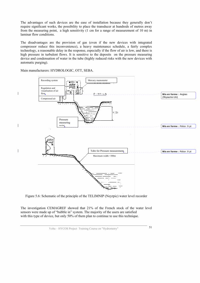
The advantages of such devices are the ease of installation because they generally don’t require significant works, the possibility to place the transducer at hundreds of metres away from the measuring point, a high sensitivity (1 cm for a range of measurement of 10 m) in laminar flow conditions. The disadvantages are the provision of gas (even if the new devices with integrated compressor reduce this inconvenience), a heavy maintenance schedule, a fairly complex technology, a reasonable delay in the response, especially if the flow of air is low, and there is high pressure in turbulent flows. It is sensitive to the deposits on the pressure measuring device and condensation of water in the tube (highly reduced risks with the new devices with automatic purging). Main manufacturers: HYDROLOGIC, OTT, SEBA.
Recording system
Volta – HYCOS Project Training Course on "Hydrometry"
51
Figure 5.6: Schematic of the principle of the TELIMNIP (Neyrpic) water level recorder
The investigation CEMAGREF showed that 21% of the French stock of the water level sensors were made up of “bubble in” system. The majority of the users are satisfied with this type of device, but only 50% of them plan to continue to use this technique.
Maximum width =300m
Regulation and visualisation of air flow
Mercury mamometer
Pressure measuring point
Tube for Pressure measurement
Compressed air
Mis en forme : Anglais(Royaume-Uni)
Mis en forme : Police :9 pt
Mis en forme : Police :9 pt
Volta – HYCOS Project Training Course on "Hydrometry"
52
5.4.2 Sensors for direct pressure measurement Principle: the sensors for pressure measurement are based on the principle of transformation into an electrical signal of a mechanical deformation of an elastic membrane (Fig. 5.7). The technologies used to achieve this transformation are the following:
- variation of the electric field, either by a transformer with mobile ferrite, or by a condensator at air in which an armature is mobile.
- Variation of the conductivity, either in a gauge of constraint in which many gauges stuck to the membrane see their resistance vary with the their expansion, or in a piezo-resistive capsule achieved by diffusion (spread) of bridges of resistance, linked to each other and whose equilibrium is modified by the variation of pressure. This principle is the most used one.
- Piezo-electricity: a quartz, or a ceramic, subject to a mechanical constraint, proportionally modifies an alternative current which crosses it; the piezo-electric are the most accurate, but because of their cost their use is limited today to the devices in laboratories.

Figure 5.7 Types of pressure sensors A pressure sensor is made up of various elements which are the following:
- the transducer, based on one of the principles above; note that the air vent conduit is indispensable since the variations of pressure measured are relative to atmospheric pressure;
- the power module, varies according to the sensors (from 220 VA to 5 VC by battery and by solar panels;
- the preamplification/amplification set whose role is to treat the resultant signal from the transducer.
- Sensitivity: from 0.5 mm to 1 cm depending upon the range of measurement. - Precision: excellent in the flows not loaded. - Stability of the response: the pressure sensors of metallic membrane are very
sensitive to the variations of temperature (compensation indispensable at the level of the transducer) and to a decalibration due to the fatigue of the membrane (correction by periodical calibration).
Volta – HYCOS Project Training Course on "Hydrometry"
53
Volta – HYCOS Project Training Course on "Hydrometry"
54
Advantages: easy installation due to small size of the sensor, which can be protected against the shocks, and to the distance between sensor and recorder which is limited only by the length of the cable (up to 1 km if the signal is digital); high sensivity and excellent precision; big autonomy of functioning on the field. Disadvantages: presence of a hysterisis linked to the membrane which results in a non linearity of the response (must also be as weak as possible), malfunctionings linked to the problems of condensation in the air vent of the transducer (especially if this tube is a capillary), temperature compensation is necessary and adapted to each transducer. Main manufacturers (in Western Europe):
- AUTEG (Grenoble): transducer sensor at differential pressure 85 - DRUCK (GB): piezo-resistive sensor PDCR 830 distributed by CR2M - SERPE-IESM (ex ELSYDE) piezo-resistive sensor SP13 - OTT (Germany) : ceramic piezo-resistive sensor ODS4, dist. By WILD
LEITZ - SEBA (Germany): piezo-resistive sensor type DS, dist. by TUBAFOR.
These days, pressure sensors are the majority of the measuring equipment on French hydrometric network. They present the best choice quality/price (800 to 1500 euros per sensor), and the manufacturers improve the equipment consistently.

6 THE STATION FILE Although most often neglected or forgotten, the station file must normally be opened as soon as the first staff gauge is installed and all the information related to the functioning of the station during the whole period of its observation must be collected. The information concerns: **the objectives of the station described by:
- a presentation of the objective of the installations, an extract of the area map, a plan of the station, etc.,
DESCRIPTION OF THE LOCATION OF A STATION
EC. GENERAL DIRECTION OF INTERIOR WATERS, DIRECTION OF WATERS QUALITY
CATCHMENT
STATION DATA
TYPE PROV SUB-CATCHMENT ORDER N°
TOWARDS THE EAST TOWARDS THE NORTH
Station plan showing the location of a station compared to the main and secondary roads, the streets, the towns, the benchmarks, the tributaries, etc.
Volta – HYCOS Project Training Course on "Hydrometry"
55

**the equipment of the station described by:
- its nature: staff gauges, water level recorders, gauging controls, etc., - its type: metric gauges, water level recorder type “bubble in”, rectangular weir
of broad crested type, etc. - its characteristics: total height of the gauge, altitude of zero, number, location
and calibration of the elements, etc. - its history: date of installation, rehabilitation, possible damages (dates and
type of damages), replacement of elements, etc.
Dam
Volta – HYCOS Project Training Course on "Hydrometry"
56
**the level and topographical surveys which give the following results:
- the exact situation of the gauge and its position in relation to a control, - the situation and the description of the benchmark datum in relation to which
the staff gauge zero was measured, - the longitudinal profile, with the mean slope of the bed, the natural controls
and the depressions, - the form of the cross section, with the value of the geometrical elements and
their variability over years, - the history of the works likely to have affect the geometry of the channel:
controls, bridges, etc.
Lake
River Bridge
Mis en forme : Police :10 pt,Italique
Mis en forme : Police :10 pt,Italique
Mis en forme : Police :10 pt,Italique
Mis en forme : Police :10 pt,Italique
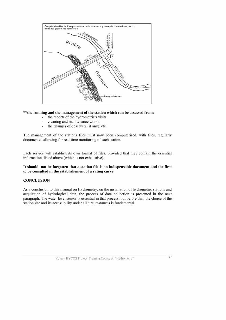
**the running and the management of the station which can be assessed from:
- the reports of the hydrometrists visits - cleaning and maintenance works - the changes of observers (if any), etc.
The management of the stations files must now been computerised, with files, regularly documented allowing for real-time monitoring of each station. Each service will establish its own format of files, provided that they contain the essential information, listed above (which is not exhaustive). It should not be forgotten that a station file is an indispensable document and the first to be consulted in the establishement of a rating curve. CONCLUSION As a conclusion to this manual on Hydrometry, on the installation of hydrometric stations and acquisition of hydrological data, the process of data collection is presented in the next paragraph. The water level sensor is essential in that process, but before that, the choice of the station site and its accessibility under all circumstances is fundamental.
Volta – HYCOS Project Training Course on "Hydrometry"
57
Volta – HYCOS Project Training Course on "Hydrometry"
58
7 PROCESS OF HYDROMETRIC DATA ACQUISITION SENSORS The sensor is made out of a component which detects (sensor) the parameter to be measured (the water level) and a transducer which records it. Functions:
- detection of water level - definition of the height
INTERFACE Functions:
- transformation of measurement - possible corrections - conversion from analog to digital - recording
TRANSMISSION Functions:
- emission - information channel
by cables by land line telephone or GSM by radio, or by satellite
- reception DATA BANKS Preliminary treatment before storage:
- treatment of the information in real or delayed time - storage (untreated data) - screening of data (operational files).

Volta – HYCOS Project Training Course on "Hydrometry"
59
8 ANNEX Station visit form
STATION FILE File n°1 Identification
Name Hydrologic N° Lat.
River Catchment Long.
Country Catchment area Alt.
Positioned on the Web site Coordinates in decimals Current situation and data. Staff gauges and recorder
Beginning of the observations
Name of the gauge reader, annual remuneration
Current transmission mode
Telephone and GSM coverage
Travel time to station and accessibility during floods
Is the control stable ? Objective of the station
Purpose of station Conformity to the HYCOS norms
Description of the necessary works required to conform to the norms
and costs