Vol.8, No.1, pp.1–14, March 2014 DOI 10.1007/s40069-013 ... · Shear Resistant Mechanism into...
14
Shear Resistant Mechanism into Base Components: Beam Action and Arch Action in Shear-Critical RC Members Je-Pyong Jeong 1), *, and Woo Kim 2) (Received February 27, 2013, Accepted December 13, 2013) Abstract: In the present paper, a behavioral model is proposed for study of the individual contributions to shear capacity in shear- critical reinforced concrete members. On the basis of the relationship between shear and bending moment (V = dM/dx) in beams subjected to combined shear and moment loads, the shear resistant mechanism is explicitly decoupled into the base components— beam action and arch action. Then the overall behavior of a beam is explained in terms of the combination of these two base components. The gross compatibility condition between the deformations associated with the two actions is formulated utilizing the truss idealization together with some approximations. From this compatibility condition, the ratio of the shear contribution by the tied arch action is determined. The performance of the model is examined by a comparison with the experimental data in literatures. The results show that the proposed model can explain beam shear behavior in consistent way with clear physical significance. Keywords: arch action, beams, reinforced concrete, truss model, shear strength. 1. Introduction Up to now, the beam shear problem remains one of the more controversial aspects of structural reinforced concrete analysis and design, and it has been generally agreed that the truss model theory provides a more promising way to treat the problem. That is not only because it provides a clear concept of how a reinforced concrete beam resists shear after cracking, but also because the effect of various loading conditions can be included in a logical way (ASCE-ACI Committee 445 1998; ASCE-ACI Committee 426 1973; Hsu 1993). The classical shear analysis of Ritter and Mo ¨rsch explains the shear behavior in the cracked state by a truss analogy, using a truss with parallel chords with 45° inclined concrete struts and no stresses across the cracks. In this model the bending moment is carried by the top chord (concrete compression zone) and the bottom chord (main longitudinal reinforcement), and the applied shear force is fully carried by the web by means of inclined compressive stresses in the concrete and tension in the stirrups. This simplified version of truss model has long provided the basis for the formulation of general shear design codes, such as in ACI- 318 (1999) and Eurocode-2 (Commission of the European Communities 1991). During last four decades, the concept of the truss model theory has been greatly extended, and now several approaches have been developed (Marti 1985; Nielsen 1984; Vecchio and Collins 1986; Schlaich et al. 1987; Ramirez and Breen 1991). An excellent review of the current theories as well as available experimental evidences are given by ASCE-ACI Committee (ASCE-ACI Committee 445; ASCE-ACI Committee 426). One approach (ACI Committee 318) has been to add a concrete contribution term to the web shear reinforcement contribution, assuming a parallel chord truss with the strut angle of 45°. Another approach (CEB/FIP 1990; Commis- sion of the European Communities 1991) has been the use of a parallel chord truss with a variable angle of inclination of the diagonal struts. This approach is referred to as the standard truss model with no explicit concrete contribution, and is explained by the existence of aggregate interlocking and the dowel action, which make a lower inclination of the concrete struts and a higher effectiveness of the stirrups. A combination of the variable-angle truss with parallel chords and a concrete contribution has also been proposed. This approach has been referred to as the modified truss model (American Association of State Highway and Transportation Officials 2002; Ramirez and Breen 1991). These resent approaches, however, does not directly account for the individual components of the concrete con- tribution in shear resistant mechanism, such as the shear carried by the concrete compression zone, the dowel action, and the aggregate interlocking action, which are distinguish- able from one another (Taylor 1974). The constituent resistant 1) Department of Civil & Environmental Engineering, Honam University, Kwangju 506-714, Korea. *Corresponding Author; E-mail: [email protected] 2) Department of Civil Engineering, Chonnam National University, Gwangju 500-757, Korea. Copyright Ó The Author(s) 2014. This article is published with open access at Springerlink.com International Journal of Concrete Structures and Materials Vol.8, No.1, pp.1–14, March 2014 DOI 10.1007/s40069-013-0064-x ISSN 1976-0485 / eISSN 2234-1315 1
Transcript of Vol.8, No.1, pp.1–14, March 2014 DOI 10.1007/s40069-013 ... · Shear Resistant Mechanism into...

Shear Resistant Mechanism into Base Components: Beam Actionand Arch Action in Shear-Critical RC Members
Je-Pyong Jeong1),*, and Woo Kim2)
(Received February 27, 2013, Accepted December 13, 2013)
Abstract: In the present paper, a behavioral model is proposed for study of the individual contributions to shear capacity in shear-
critical reinforced concrete members. On the basis of the relationship between shear and bending moment (V = dM/dx) in beams
subjected to combined shear and moment loads, the shear resistant mechanism is explicitly decoupled into the base components—
beam action and arch action. Then the overall behavior of a beam is explained in terms of the combination of these two base
components. The gross compatibility condition between the deformations associated with the two actions is formulated utilizing
the truss idealization together with some approximations. From this compatibility condition, the ratio of the shear contribution by
the tied arch action is determined. The performance of the model is examined by a comparison with the experimental data in
literatures. The results show that the proposed model can explain beam shear behavior in consistent way with clear physical
significance.
Keywords: arch action, beams, reinforced concrete, truss model, shear strength.
1. Introduction
Up to now, the beam shear problem remains one of themore controversial aspects of structural reinforced concreteanalysis and design, and it has been generally agreed that thetruss model theory provides a more promising way to treatthe problem. That is not only because it provides a clearconcept of how a reinforced concrete beam resists shear aftercracking, but also because the effect of various loadingconditions can be included in a logical way (ASCE-ACICommittee 445 1998; ASCE-ACI Committee 426 1973;Hsu 1993).The classical shear analysis of Ritter and Morsch explains
the shear behavior in the cracked state by a truss analogy,using a truss with parallel chords with 45� inclined concretestruts and no stresses across the cracks. In this model thebending moment is carried by the top chord (concretecompression zone) and the bottom chord (main longitudinalreinforcement), and the applied shear force is fully carried bythe web by means of inclined compressive stresses inthe concrete and tension in the stirrups. This simplifiedversion of truss model has long provided the basis for the
formulation of general shear design codes, such as in ACI-318 (1999) and Eurocode-2 (Commission of the EuropeanCommunities 1991). During last four decades, the concept ofthe truss model theory has been greatly extended, and nowseveral approaches have been developed (Marti 1985;Nielsen 1984; Vecchio and Collins 1986; Schlaich et al.1987; Ramirez and Breen 1991). An excellent review of thecurrent theories as well as available experimental evidencesare given by ASCE-ACI Committee (ASCE-ACI Committee445; ASCE-ACI Committee 426).One approach (ACI Committee 318) has been to add a
concrete contribution term to the web shear reinforcementcontribution, assuming a parallel chord truss with the strutangle of 45�. Another approach (CEB/FIP 1990; Commis-sion of the European Communities 1991) has been the use ofa parallel chord truss with a variable angle of inclination ofthe diagonal struts. This approach is referred to as thestandard truss model with no explicit concrete contribution,and is explained by the existence of aggregate interlockingand the dowel action, which make a lower inclination of theconcrete struts and a higher effectiveness of the stirrups. Acombination of the variable-angle truss with parallel chordsand a concrete contribution has also been proposed. Thisapproach has been referred to as the modified truss model(American Association of State Highway and TransportationOfficials 2002; Ramirez and Breen 1991).These resent approaches, however, does not directly
account for the individual components of the concrete con-tribution in shear resistant mechanism, such as the shearcarried by the concrete compression zone, the dowel action,and the aggregate interlocking action, which are distinguish-able from one another (Taylor 1974). The constituent resistant
1)Department of Civil & Environmental Engineering,
Honam University, Kwangju 506-714, Korea.
*Corresponding Author; E-mail: [email protected])Department of Civil Engineering, Chonnam National
University, Gwangju 500-757, Korea.
Copyright � The Author(s) 2014. This article is published
with open access at Springerlink.com
International Journal of Concrete Structures and MaterialsVol.8, No.1, pp.1–14, March 2014DOI 10.1007/s40069-013-0064-xISSN 1976-0485 / eISSN 2234-1315
1

components of various truss approaches are summarized andcompared at Table 1. It can be seen that the shear force by theconcrete compression zone is not directly accounted.In the early investigations (Lorentsen 1965; Leonhardt
1965; Kani 1964), complex models combined with arch andtruss, as typically shown in Fig. 1, were recognized from theobservation of crack patterns and the evidences measured indifferent beams. In this model the compression chord of thetruss is curved, so that the behavior of a beam is representedpartly by tied arch and partly by beam. Thus, a substantialload is carried essentially by the tied arch action. Leonhardt(1965) observed that a remarkable shear is resisted by aninclined top chord (the concrete compression zone). In thenormal T beams he tested, the web element carried less thanhalf of the total shear force even under ultimate loadingstages, and the distribution ratio was largely dependent uponthe ratio between web stiffness and chord stiffness. In spite ofbetter representation of the behavior of beams, however, thismodel has been used largely as a conceptual tool to describebeam behavior rather than a precise analytical model. This ismainly because the geometry of the arch rib (inclined topchord) cannot be precisely defined due to the nature of astatically indeterminate system (ASCE-ACI Committee 426).Therefore, the present work is intended to numerically
formulate the truss model with an inclined compression chordshown in Fig. 1 by decoupling the beam behavior into the tiedarch and the beam. The theoretical base concept for thepresent approach is based on the relationship between shearand bending moment in a cracked reinforced concrete beam,i.e., V = dM/dx. Utilizing some idealizations together withthe recent elaborations by Collins and Mitchell (1991) and
Table 1 Resistant components of various truss models
Model Resistant components Responses
Vc Vs(=Vt) h fv stirrup stress DT tension shift
Vuc (= va) Vci Vd
Classical trussmodel
X X X s 45� 1qvbwzo
ðV Þ 1/2(V)
Standard trussmodel type (a)
X X X s Variable tan hqvbwzo
ðV Þ 1/2(V) coth
Modified truss model
ACI s
Lump sum Vc (fixed)
s 45� 1qvbwzo
ðV � VcÞ 1/2(V - Vc)
EC-2 s
Lump sum Vc (fixed)
s Variable tan hqvbwzo
ðV � VcÞ 1/2(V - Vc) coth
AASHTOLRFD
X s
(vari able)
X s Variable tan hqvbwzo
ðV � VciÞ 1/2(V - Vci) coth
Complex truss model
Type (b) s X or s X s Irregular variable Undefined
Type (c) s X or s X s Irregular variable Undefined
Type (d) s X or s X s Irregular variable Undefined
(a)
(c)
(d)
θ
θ
θ
(b)
θ
Fig. 1 Refined truss idealization with inclined compressionchord. a Standard truss model. b Fan truss model (Marti1985). c Truss model combined with Strut-Tie (Walrav-en and Niwa). d Refined truss model (Leonhardt 1965)
2 | International Journal of Concrete Structures and Materials (Vol.8, No.1, March 2014)

Hsu (1993), a gross compatibility condition is established andformulated between the deformation associated with the tiedarch and the deformation with the web. Thereby, the beamshear resistant mechanism is decoupled into the base com-ponents. The performance of the present approach is brieflyexamined by a comparison with the existing experimentaldata and a sensitivity study. It is also shown that the theo-retical results can explain in a rigorous and consistent way theexperimentally observed behavior of beam failing in shear.
2. Derivation of Base Concept
Consider a simply supported reinforced concrete beamdirectly loaded as shown in Fig. 2a, in which shear forceV and moment M act simultaneously throughout the shearspan. After flexural cracking the moment on a cross sectionis resisted by the internal force couple C and Twith the leverarm of z, that is M = Tz = Cz. When this relationship of theflexural resistance is combined with the well-known rela-tionship between shear and the rate of change of bendingmoment along a beam V = dM/dx, the shear force can beexpressed as a sum of two terms (Park and Paulay 1975;Kim and Jeong 2011a, b, c):
V ¼ zdT
dxþ T
dz
dx: ð1Þ
As known from various proceeding studies, the first termarises from the transmission of a steel force into the concreteby means of bond stresses, and it is said to be the shearresistant component by beam action (Kani 1964; Park andPaulay 1975). Consider a segment cut out from the beambetween two adjacent vertical cross sections distance dx apartin Fig. 2a, the difference of tension dT causes shear force onthe bottom face of the web element mnop as shown in Fig. 2b.As the same manner, the difference of compressive resultantdC acts on the upper face. These shear forces on the top andbottom of the web element produce a couple moment zdT(=zdC), which must be balanced by the moment of shearforces acting on the vertical faces mn and op. Thus, the ver-tical shear force is expressed by the first term of Eq. (1).The second term in Eq. (1) directly implies the vertical
component of the inclined compression resultant force C, andit is referred to the shear component by arch action (Kani1964); Park and Paulay 1975). That is because the compres-sion resultant is equal to the tension resultant T and the slopeof the resultant is mathematically expressed dz/dx as shown inFig. 2c. This means that the beam behaves as a tied-arch, anda part of the applied shear is carried by the inclined top chord.From such mechanical interpretation on Eq. (1), it is seen
that the applied shear is essentially resisted by a combinationof the two base components that are distinctively differentactions—beam action and arch action. Thus, the extent towhich each action contributes to shear resistance in a beamwill depend on the compatibility of deformations associatedwith these actions. If such beam shear behavior could bedecoupled into the base components, the shear resistantmechanism would be much clearly described. Accordingly,
for the purpose of the present study, it is to employ a factor-adefined by follows (Kim and Jeong 2011a, 2011b, 2011c):
a ¼ Shear resisted by arch action
Total shearð2Þ
By this definition, the value of a varies between 0 and 1 anddepends on the compatibility condition of the deformationsassociated with the beam and arch action.
2.1 Smeared Truss Idealization with InclinedChordAs in a usual smeared truss modeling (Hsu 1993), the
stress field in the beam segment shaded in Fig. 2a can beidealized to have three discrete elements with each having adifferent function to resist the applied loads as shown inFig. 3a. The area within the compression stress block isassumed to concentrate at the location of the resultant C andform the top chord. The longitudinal tensile steel bars andthe surrounding concrete are also assumed to be concen-trated at the geometric centroid and constitute the bottomchord. The middle element separated from the tension andcompression chords can be treated as a web shear elementsubjected to pure shear.In order to include the shear resistant mechanism due to
the arch action, an inclined top chord is installed in thepresent model, instead of a paralleled chord, With its incli-nation, the top chord has a function to resist not only againstthe compression resultant C caused by the applied moment
(a)
(c)(b)
Fig. 2 Mechanical interpretation of shear resistant compo-nents. a A reinforced concrete beam. b Beam action ofzdT/dx. c Arch action of Cdz/dx
International Journal of Concrete Structures and Materials (Vol.8, No.1, March 2014) | 3

M but also against the part of the applied shear aV, and inturns the rest of the shear (1 - a)V must be allocated to theweb shear element. Consecutively extending such idealiza-tion to whole span of a beam may lead to an idealized formof a tied arch having a membrane shear element inside asshown in Fig. 4a, in which the lever arm z varies from z0 atthe maximum moment section to 0 at the support section.The force transmitted between the elements is dC/dx (=dT/dx). This force acts as a form of shear flow on the web shearelement, while it acts as a form of distributed axial force onthe chords.In a simple strut-and-tie model, the tensile force of the tie
(bottom chord) is constant throughout the span (dT/dx = 0),so that beam action cannot be developed in the web shearelement. Accordingly, the shear and moment must be fullyresisted by the inclined top (strut) and bottom chords, asshown in Fig. 3c. From the view of the present model, it issaid that a simple strut-and-tie model is the extreme case ofthe present model when a is 1.0. On the other hand, a par-allel chord truss model (dz/dx = 0 as seen in Fig. 3b) cannotrely on the arch action to sustain shear, thus it is the otherextreme case of the present model with a of 0. It may berealized therefore that the internal force flow of usual beamscan be closely described by a proper assignment of the valueof a, as conceptually illustrated in Fig. 3d.
2.2 Gross Compatibility ConditionThe idealization above make it possible to evaluate the
state of the cross sectional deformation of a reinforcedconcrete beam. Consider the deformation of the elementmnop in a beam under a concentrated load as shown inFig. 4a. The final deformation of the element can bedecomposed into the two base components—the deforma-tion associated with the arch action and the deformationassociated with the beam action. As stated before, thebending moment causes the internal couple C and T at thechords, resulting in the axial shortening of the top chord andthe axial elongation of the bottom chord. Thus these axialdeformations eventually produce a bending curvature on theelement as shown in Fig. 4b.The element further undergoes a shear deformation
because it is subjected to a pure shear dT/dx, which is equalto (1 - a)V/z, as shown in Fig. 4c. Linear distortion can beassumed with the average shear strain of cw. It is seen fromthe figure that the shear strain is equal to the amount that theupper edge displaces horizontally with respect to the lowerside divided by the depth of the element. Consequently, thisshear deformation of the web shear element should becompatible with the relative displacements of the top and
(a) (c)
(d)
(b)
Fig. 3 Smeared truss idealization. a The present approach.b Truss with parallel chord. c Simple strut-and-tiemodel. d Conceptual illustration of the present model
(a)
(c) (d)(b)
(e)
Fig. 4 Gross compatibility condition. a Idealized beam and itsdeformation. b Bending deformation. c Shear defor-mation. d Combined deformation. e Compatibility ofdeformation between web and chords
4 | International Journal of Concrete Structures and Materials (Vol.8, No.1, March 2014)

bottom chord with respect to the bending planes m0–n0,which are designated by um and un respectively in Fig. 4c,because the element is connected to the chords. The relativedisplacements of the chords can be visualized easily if thebending deformation and the couple C and T acting on thechords are omitted and the all elements are stretched asshown in Fig. 4e.By the symmetry, the relative displacement of the top
chord at the loading section must be zero. And the dis-placement of the top chord um at the section m–n, a–x apartfrom the loading section, is equal to the elongation of the topchord due to the distributed axial force dC/dx over the lengthof a–x. Therefore, the um can be obtained by successiveintegrations over the length. As the same manner, togetherwith zero displacement at the support section due to thesupport restraint, the relative displacement of the bottomchord un is also obtained. Thus,
um ¼Zx
a
1
ðEAÞtc
Zx
a
dC
0@
1Adx ð3aÞ
un ¼Zx
0
1
ðEAÞbc
Zx
a
dT
0@
1Adx ð3bÞ
where (EA)tc and (EA)bc are the axial stiffness of the topchord and the bottom chord respectively. These relativedisplacements of the chords should be compatible with theshear deformation of the web shear element as sketched inFig. 4e. Thus, the following relationship should besatisfied:
cw ¼ um þ unz
ð4Þ
From the view of the gross compatibility relationshipabove, it can be seen that the ratio of contribution by eachaction to total shear resistance in a beam is dependent on therelative stiffness ratio between the chords and the web (Kimand Jeong 2011a, 2011b, 2011c).
2.3 Simplified Arch Shape FunctionThe presence of non-zero values of dz/dx in the present
approach is eventually leading to variable lever arm lengthz over the span of a beam. Combining the definition ofaV = Cdz/dx with the relationship of C = Vx/z in a pris-matic simple beam subjected to a direct point loading, thefactor-a can be expressed in terms of z and x as follow:
a ¼ xdz
zdxð5Þ
For the establishment of the present approach, the value of ais assumed to remain constant over the shear span in a givenprismatic beam. Then, with the boundary condition of z = zoat x = a, the general solution of Eq. (5) can be obtained interm of the lever arm z over the shear span as the followingform:
zx ¼x
a
� �azo ð6Þ
where zo is the lever arm calculated from the conventionalbeam theory. Figure 5 shows the geometrical expressions ofEq. (6) as a varies from 0 to 1.0. As seen in the figure,Eq. (6) represents a simple arch shape, and its curvature ismainly dependent on the value of a. For example, whena = 0, Eq. (6) becomes zx = zo with dz/dx = 0 over theentire span, corresponding to the traditional beam theorywith no arch action. While, when a = 1.0, Eq. (6) stands fora straight line from the support to the loading point, repre-senting the situation in which the load is carried by a simplestrut-and-tie action.It is noted that for the beams subjected to other type of
loadings rather than direct point loadings, the correspondingarch shape function can be obtained by the same mannerabove, and it will be the following general form (Kim andJeong 2011a, b, c):
zx ¼Mx
Mmax
� �a
zo ð7Þ
where Mmax is the maximum moment at a zero shear section.Utilizing this general expression, the arch shape can beeasily formulated for a beam subjected to various types ofloadings, such as uniform loaded beams or eccentricallyloaded columns, on condition that an appropriate a isknown. Now it becomes clear that the crux of the presentapproach is the assignment of a value to the factor-a, and thevalue can be determined from the gross compatibility con-dition of Eq. (4).
3. Formulation
3.1 Web Shear ElementAs stated before, the web shear element can be treated as a
membrane element subjected to pure shear force (1 -
a)V. After diagonal cracking, the concrete is separated bydiagonal cracks into a series of concrete struts as shown inFig. 6a. The shear force produces a set of bi-axial stress fieldconstituted with the compressive principal stress f2 and thetensile principal stress f1 with inclination angle of h as shownin Fig. 6. The reinforcing bars are assumed to be a linkmember transmitting axial force only. The behavior of such a
Fig. 5 Simplified arch shapes in a point loaded simple beam
International Journal of Concrete Structures and Materials (Vol.8, No.1, March 2014) | 5

membrane element is well explained by either Collins’MCFT (Vecchio and Collins 1986) or Hsu’s STM (Hsu1993).The equilibrium conditions, which relate the concrete
stresses and the stirrup stress to the applied shear stress, canbe expressed in terms of average stresses. These relation-ships are derived from the Mohr’s circle shown in Fig. 6.These are
f2 ¼ ð1� aÞv tan h þ cot hð Þ � f1 ð8Þ
ft ¼ ð1� aÞv tan h � f1 ð9Þ
fx ¼ ð1� aÞv cot h � f1 ð10Þ
where v is an average shear stress defined by V/bwz, f2 ispositive in compression, and f1 is positive in tension. Fromthe vertical force equilibrium the transverse concrete stress ftof Eq. (9) must be balanced by the stirrup stress:
qvfv ¼ 1� að Þvtanh � f1; for qv [ 0 ð11aÞ
0 ¼ 1� að Þvtanh � f1; for qv ¼ 0 ð11bÞ
In the same manner, the longitudinal concrete stress fx ofEq. (10) is balanced by the chords and the horizontal websteels, if any. When the horizontal web steels are notprovided, it is transferred to the top and bottom chord. Theequilibrium of the resultants on the right face is shown bythe force polygon in Fig. 6b, and the longitudinalcompressive resultant Nb produced by the fx is
Nb ¼ fxbwz ¼ ð1� aÞV cot h � f1bwz ð12Þ
The acting point of this resultant will be z/2 from the centerof the bottom chord. The average stress and average strain of
the concrete in each principal direction (axis 1–2 in Fig. 6a) isassumed to obey the material laws developed by Vecchio andCollins (Vecchio and Collins 1986), as summarized inFigs. 7a and 7b. Thus, after diagonal cracking with takingfcr = 0.33
ffiffiffiffif 0c
p(MPa), for principal tensile direction;
e1 ¼ 0:0020:33
ffiffiffiffif 0c
pf1
� 1
!2
ð13Þ
For principal compressive direction with takingeco = 0.002;
e2 ¼ 0:002 1�ffiffiffiffiffiffiffiffiffiffiffiffiffiffiffiffiffiffiffiffiffiffiffiffiffiffiffiffiffiffiffiffiffiffiffiffiffiffiffiffiffiffiffiffi1� ð0:8þ 170e1Þf2=f 0
c
q� �ð14Þ
In beams having vertical stirrups, the transverse averagestrain et can be approximately evaluated using CEB/FIP MC-90 (1990) the equation for tension stiffening effect, which isshown in Fig. 7c. Replacing fs by fv of Eq. (11), then esmcorresponds to et. Thus the following relationship isobtained:
et ¼1
Esqv
ð1� aÞv tan h � f1 þ 0:132ffiffiffiffif 0c
q� �� �ð15Þ
From the compatibility condition satisfying Mohr’s straincircle shown in Fig. 7d, the average shear strain cwof theweb shear element is expressed in terms of e1, e2, and et asfollows:
cw ¼ ðe1 þ e2Þ sin 2h ð16aÞ
¼ 2ðet þ e2Þ tan h ð16bÞ
Substituting Eqs. (13), (14) and (15) for e1, e2 and etrespectively in Eq. (16), the shear strain cw of the webelement is eventually expressed in terms of f1, f2 and h.
3.2 Redistribution of Resultants in a SectionAs previously stated, the vertical component of the axial
force in the inclined top chord is the shear carried by the archaction, and it is designated by aV. This shear force will becombined with flexural compression resultant C, eventuallyleading to form an inclined thrust line (arch). For theextension of the present approach to a simple strut-and tiemodel, it may be technically required that the shear force aVis accompanied by the longitudinal resultant Na, and whoseacting point is temporarily denoted by za as shown in Fig. 8.That is,
Na ¼ aV cot h ð17Þ
It has been known that significant longitudinal forces arecaused by each base action. By such induction of thelongitudinal forces at a cross section, the internal couple Co
and To calculated from the conventional beam theory due tothe bending moment is redistributed to meet the equilibriumcondition over the section. Figure 9 shows the forces Na andNb acting on the points za and 0.5z from the reinforcementlevel in addition to the internal force couple Co - DC and
(a)
(c) (d) (e)
(b)
Fig. 6 Equilibrium condition in web shear element. a Crackedweb. b Sectional resultants. c Stresses on webelement. d Stresses on web concrete. e Stresses onweb steel
6 | International Journal of Concrete Structures and Materials (Vol.8, No.1, March 2014)

To ? DT. To satisfy the equilibrium condition in longitudinaldirection, the change in the compression resultant DC andthat in steel tension DT are seen to be
DC ¼ 1
zoðNaza þ 0:5NbzÞ ð18aÞ
DT ¼ 1
zoNaðzo � zaÞ þ Nbðzo � 0:5zÞ½ � ð18bÞ
The redistributed compression resultant Co - DC and thelongitudinal force due to the arch action Na should becombined to form a final compression resultant C in a sec-tion. Hence, as shown in Fig. 9, the final acting point z willbe
z ¼ ðCo � DCÞzo þ NazaCo � DC þ Na
ð19Þ
The lever arm length z above is established on the basis ofthe force equilibrium conditions at a section. Whereas thez defined by Eq. (7) is mathematically derived on the basis ofthe assumption of constant a throughout the shear span.These values of z must be identical to each other. Byequating these two equations with substituting Eqs. (12),(17) and (18) and the approximation of za % z, the inclinedangle h is expressed in terms of a and f1:
cot hx ¼Mx
zo1
ðRxÞa � 1� �
þ f1bwzoðRxÞa 1:5� 0:5ðRxÞað ÞVx a 1� ðRxÞaf g þ ð1� aÞ 1:5� 0:5ðRxÞaf gð Þ
ð20Þ
where Rx = Mx/Mmax, that is the sectional moment ratio withrespect to the maximum moment of a beam.From the moment equilibrium at a section with za % z, the
final compression force C in the top chord and the tensionforce T in the bottom chord should be
C ¼ ðCo � DCÞ zozþ Na ¼
M
z� Nb
2ð21aÞ
(a)
(c)
(d)
(b)
Fig. 7 Material laws in a cracked reinforced concrete ele-ment. a Average tensile stress–strain curve. b Averagecompressive stress–strain curve. c Tension stiffeningeffect in CEB/FIP MC-90. d Mohr’s strain circle
(a) (b)
Fig. 8 Sectional resultants related to arch action
(a) (b)
Fig. 9 Shear–moment interaction in a section
International Journal of Concrete Structures and Materials (Vol.8, No.1, March 2014) | 7

T ¼ To þ DT þ ðCo � DCÞ zo � z
z¼ M
zþ Nb
2ð21bÞ
Figure 10 shows the final configuration of the resultantsacting at a section. From the figure, it can be realized that theequilibriums in both the shear and the moment are simul-taneously satisfied at the section. Also, the slope of the thrustin the top chord is Va/C, which is equivalent to dz/dx inFig. 2c. As the section approaches toward the support, theslope dz/dx becomes steeper because C becomes smallerowing to the smaller sectional moment. This is the primaryreason for which a tied-arch action is formed in crackedreinforced concrete beams.
3.3 Relative Displacements of Top and BottomChordAs described before, the relative displacements of the top
and bottom chords um and un can be evaluated by Eq. (3).Utilizing Eqs. (2) and (7) together with Fig. 4, dC/dx and dT/dx at each section are simply expressed in terms of a and Vx:
dC
dx¼ dT
dx¼ ð1� aÞVx
zoðRxÞað22Þ
For the evaluation of the axial stiffness of the top and bottomchord, some approximations are required because the actualstress distributions are relatively complex. It may bereasonable estimation that the effective depth of thecompression chord is equal to the depth of the rectangularcompression stress block and remains constant along thespan as sketched in Fig. 11. With this approximation and thesubstitution of Eq. (22), Eq. (3a) becomes
um ¼Zx
a
1
EcAtc
Z x
a
ð1� aÞVx
zoðRxÞadx
� �dx
¼ Va
zo
x
EcAtcð2� aÞ 1� Rxð Þ1�ah i
ð23aÞ
where Ec is the concrete elastic modulus, and Atc is theeffective area of the top chord estimated based on theeffective depth defined above. The axial deformation of thetension chord due to dT/dx, which corresponds to the relativedisplacement un, is approximately evaluated using CEB/FIP
MC-90 the tension stiffening effect expression (Fig. 7c). Inapplying this formula to a beam, the height of the effectivetensile tie is normally assumed to be about 2.5(h - d) asshown in Fig. 11 (CEB-FIP 1990). Hence, Eq. (3b) can berewritten as follow:
un ¼Va
zo
x
EsAsð2� aÞ 1� Rxð Þ1�ah i
� x0:13
ffiffiffiffiffifck
p
Esqeff
!� 0
ð23bÞ
where qeff ¼ As
b�2:5ðh�dÞ and x is distance from the support.
3.4 Solution AlgorithmAll of the relationships required to determine the value of
a have been discussed above. For a specific section in abeam with vertical stirrups at a given load, a suitable itera-tive procedure is as follows:
Step-1: Assume a value of aStep-2: Choose a value of e1, then calculate f1 fromEq. (13)Step-3: Calculate z from Eq. (7), and h from Eq. (20)Step-4: Calculate f2 from Eq. (8), and fv from Eq. (11)Step-5: Calculate e2 from Eq. (14), and et from Eq. (15)Step-6: Calculate cwfrom Eq. (16a) and cw from Eq. (16b)
Then, check that cwfrom Eq. (16a) = cw from Eq. (16b) ornot.If cwfrom Eq. (16a) = cw from Eq. (16b), return to Step-
2.If cwfrom Eq. (16a) % cw from Eq. (16b), go to Step-7.
Step-7: Calculate umfrom Eq. (23a), and un from Eq. (23b)Step-8: Check that cw = (um ? un)/z or not.
If cw = (um ? un)/z, return to Step-1 and repeatIf cw % (um ? un)/z, take the last assumed a value.With the help of a spread sheet calculator, the procedure
above is easily performed. As a tip for fast iteration, it isrecommended to use the inverse value of the shear span-to-depth ratio of the beam considered as an initial value of a inStep-1.
Fig. 10 Final configuration of sectional resultants Fig. 11 Idealization of tie and arch
8 | International Journal of Concrete Structures and Materials (Vol.8, No.1, March 2014)

4. Verification
As part of a large investigation of the shear behavior inreinforced concrete beams at Stuttgart University in early1960s, Leonhardt (1965) investigated the effectiveness ofstirrups on the shear strength of beams. The four beams hetested had the identical web reinforcement and longitudinalreinforcement with the same geometry, and only the webwidth varied in these beams. Accordingly, q and qv werechanged as listed in Table 2. This work is the most com-prehensive investigation reported on typical shear-criticalreinforced concrete beams under combined action of
bending and shear, and it is used here as the basis of theexamination for the principle described above.At several loading stages after cracking, the values of a are
calculated at the mid-shear span of each beam utilizing theprocedure described in previous section, and the results aresummarized in Fig. 12. From the figure, it can be observedthat the values gradually increase and converge to a certainultimate value as the load increases from the cracking loadthrough the failure load. The results clearly imply that afterformation of diagonal cracks, the resistant mechanisms havegradually changed from the beam action to the arch actionwith increasing load intensity. With increase of applied load
Table 2 Comparisons with, the test results performed by Leonhardt (1965)
Specimen
ET1ET2 ET3 ET4
Beam properties
fck (MPa) 27.93 27.93 27.93 27.93
bw (cm) 30 15 10 5
d (cm) 30 30 30 30
a (cm) 105 105 105 105
a/d 3.5 3.5 3.5 3.5
q (%) 1.40 2.80 4.20 8.40
qv (%) 0.17 0.34 0.51 1.03
fy (MPa) 460 460 460 460
fav (MPa) 314 314 314 314
Vn,f (kN) 140.9 140.9 140.9 140.9
Measured value
Vu (kN) 142.2 116.7 98.1 88.3
fv at Vu (MPa) 161.7 314 314 314
Predicted value
au 0.360 0.395 0.415 0.462
hu (x = a/2) (�) 44.6 45.4 43.6 41.4
zx (x = a/2) (cm) 21.04 20.46 20.18 19.63
fv at Vu (MPa) 150.3 315.7 294.2 284.4
Va = auVu 51.2 46.6 42.8 41.2
Vci by Eq. (26) 74.5 37.3 24.8 12.4
Vs (kN) 16.5 32.6 34.2 35.9
Vu = Va ? Vci ? Vs (kN) 142.2 116.5 101.8 89.5
Vu Predicted / Vu Measured 1.00 0.99 1.04 1.01
Failure mode Flexure Stirrups yielding
International Journal of Concrete Structures and Materials (Vol.8, No.1, March 2014) | 9
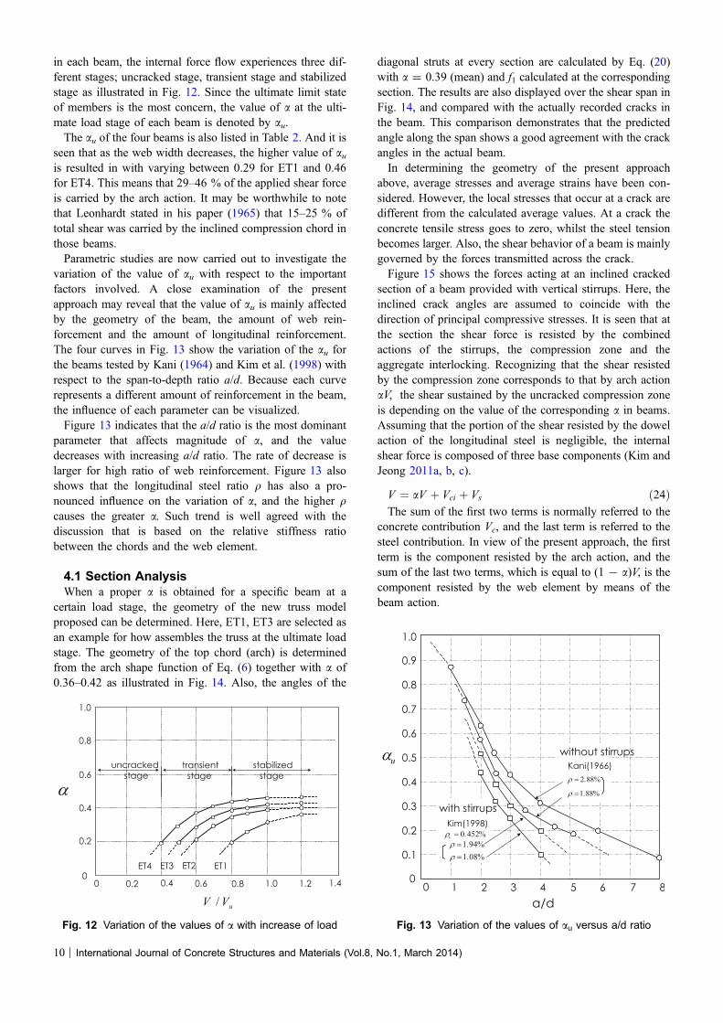
in each beam, the internal force flow experiences three dif-ferent stages; uncracked stage, transient stage and stabilizedstage as illustrated in Fig. 12. Since the ultimate limit stateof members is the most concern, the value of a at the ulti-mate load stage of each beam is denoted by au.The au of the four beams is also listed in Table 2. And it is
seen that as the web width decreases, the higher value of auis resulted in with varying between 0.29 for ET1 and 0.46for ET4. This means that 29–46 % of the applied shear forceis carried by the arch action. It may be worthwhile to notethat Leonhardt stated in his paper (1965) that 15–25 % oftotal shear was carried by the inclined compression chord inthose beams.Parametric studies are now carried out to investigate the
variation of the value of au with respect to the importantfactors involved. A close examination of the presentapproach may reveal that the value of au is mainly affectedby the geometry of the beam, the amount of web rein-forcement and the amount of longitudinal reinforcement.The four curves in Fig. 13 show the variation of the au forthe beams tested by Kani (1964) and Kim et al. (1998) withrespect to the span-to-depth ratio a/d. Because each curverepresents a different amount of reinforcement in the beam,the influence of each parameter can be visualized.Figure 13 indicates that the a/d ratio is the most dominant
parameter that affects magnitude of a, and the valuedecreases with increasing a/d ratio. The rate of decrease islarger for high ratio of web reinforcement. Figure 13 alsoshows that the longitudinal steel ratio q has also a pro-nounced influence on the variation of a, and the higher qcauses the greater a. Such trend is well agreed with thediscussion that is based on the relative stiffness ratiobetween the chords and the web element.
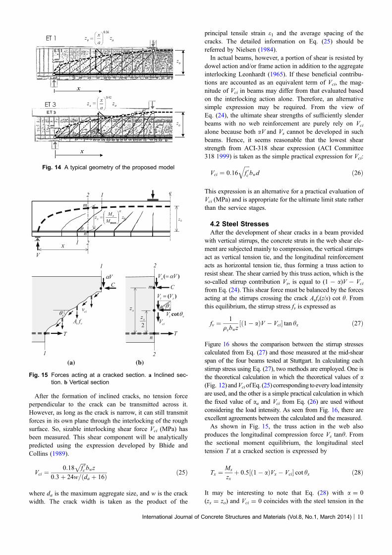
4.1 Section AnalysisWhen a proper a is obtained for a specific beam at a
certain load stage, the geometry of the new truss modelproposed can be determined. Here, ET1, ET3 are selected asan example for how assembles the truss at the ultimate loadstage. The geometry of the top chord (arch) is determinedfrom the arch shape function of Eq. (6) together with a of0.36–0.42 as illustrated in Fig. 14. Also, the angles of the
diagonal struts at every section are calculated by Eq. (20)with a = 0.39 (mean) and f1 calculated at the correspondingsection. The results are also displayed over the shear span inFig. 14, and compared with the actually recorded cracks inthe beam. This comparison demonstrates that the predictedangle along the span shows a good agreement with the crackangles in the actual beam.In determining the geometry of the present approach
above, average stresses and average strains have been con-sidered. However, the local stresses that occur at a crack aredifferent from the calculated average values. At a crack theconcrete tensile stress goes to zero, whilst the steel tensionbecomes larger. Also, the shear behavior of a beam is mainlygoverned by the forces transmitted across the crack.Figure 15 shows the forces acting at an inclined cracked
section of a beam provided with vertical stirrups. Here, theinclined crack angles are assumed to coincide with thedirection of principal compressive stresses. It is seen that atthe section the shear force is resisted by the combinedactions of the stirrups, the compression zone and theaggregate interlocking. Recognizing that the shear resistedby the compression zone corresponds to that by arch actionaV, the shear sustained by the uncracked compression zoneis depending on the value of the corresponding a in beams.Assuming that the portion of the shear resisted by the dowelaction of the longitudinal steel is negligible, the internalshear force is composed of three base components (Kim andJeong 2011a, b, c).
V ¼ aV þ Vci þ Vs ð24ÞThe sum of the first two terms is normally referred to the
concrete contribution Vc, and the last term is referred to thesteel contribution. In view of the present approach, the firstterm is the component resisted by the arch action, and thesum of the last two terms, which is equal to (1 - a)V, is thecomponent resisted by the web element by means of thebeam action.
Fig. 12 Variation of the values of a with increase of load Fig. 13 Variation of the values of au versus a/d ratio
10 | International Journal of Concrete Structures and Materials (Vol.8, No.1, March 2014)
After the formation of inclined cracks, no tension forceperpendicular to the crack can be transmitted across it.However, as long as the crack is narrow, it can still transmitforces in its own plane through the interlocking of the roughsurface. So, sizable interlocking shear force Vci (MPa) hasbeen measured. This shear component will be analyticallypredicted using the expression developed by Bhide andCollins (1989).
Vci ¼0:18
ffiffiffiffif 0c
pbwz
0:3þ 24w=ðda þ 16Þ ð25Þ
where da is the maximum aggregate size, and w is the crackwidth. The crack width is taken as the product of the
principal tensile strain e1 and the average spacing of thecracks. The detailed information on Eq. (25) should bereferred by Nielsen (1984).In actual beams, however, a portion of shear is resisted by
dowel action and/or frame action in addition to the aggregateinterlocking Leonhardt (1965). If these beneficial contribu-tions are accounted as an equivalent term of Vci, the mag-nitude of Vci in beams may differ from that evaluated basedon the interlocking action alone. Therefore, an alternativesimple expression may be required. From the view ofEq. (24), the ultimate shear strengths of sufficiently slenderbeams with no web reinforcement are purely rely on Vci
alone because both aV and Vs cannot be developed in suchbeams. Hence, it seems reasonable that the lowest shearstrength from ACI-318 shear expression (ACI Committee318 1999) is taken as the simple practical expression for Vci:
Vci ¼ 0:16ffiffiffiffif 0c
qbwd ð26Þ
This expression is an alternative for a practical evaluation ofVci (MPa) and is appropriate for the ultimate limit state ratherthan the service stages.
4.2 Steel StressesAfter the development of shear cracks in a beam provided
with vertical stirrups, the concrete struts in the web shear ele-ment are subjected mainly to compression, the vertical stirrupsact as vertical tension tie, and the longitudinal reinforcementacts as horizontal tension tie, thus forming a truss action toresist shear. The shear carried by this truss action, which is theso-called stirrup contribution Vs, is equal to (1 - a)V - Vcifrom Eq. (24). This shear force must be balanced by the forcesacting at the stirrups crossing the crack Avfv(z/s) cot h. Fromthis equilibrium, the stirrup stress fv is expressed as
fv ¼1
qvbwzð1� aÞV � Vci½ � tan hx ð27Þ
Figure 16 shows the comparison between the stirrup stressescalculated from Eq. (27) and those measured at the mid-shearspan of the four beams tested at Stuttgart. In calculating eachstirrup stress using Eq. (27), two methods are employed. One isthe theoretical calculation in which the theoretical values of a(Fig. 12) andVciofEq. (25) corresponding to every load intensityare used, and the other is a simple practical calculation in whichthe fixed value of au and Vci from Eq. (26) are used withoutconsidering the load intensity. As seen from Fig. 16, there areexcellent agreements between the calculated and the measured.As shown in Fig. 15, the truss action in the web also
produces the longitudinal compression force Vs tanh. Fromthe sectional moment equilibrium, the longitudinal steeltension T at a cracked section is expressed by
Tx ¼Mx
zxþ 0:5½ð1� aÞVx � Vci� cot hx ð28Þ
It may be interesting to note that Eq. (28) with a = 0(zx = zo) and Vci = 0 coincides with the steel tension in the
Fig. 14 A typical geometry of the proposed model
(a) (b)
Fig. 15 Forces acting at a cracked section. a Inclined sec-tion. b Vertical section
International Journal of Concrete Structures and Materials (Vol.8, No.1, March 2014) | 11
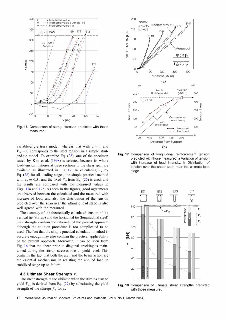
variable-angle truss model, whereas that with a = 1 andVci = 0 corresponds to the steel tension in a simple strut-and-tie model. To examine Eq. (28), one of the specimentested by Kim et al. (1998) is selected because its wholeload-tension histories at three sections in the shear span areavailable as illustrated in Fig. 17. In calculating Tx byEq. (28) for all loading stages, the simple practical methodwith au = 0.51 and the fixed Vci from Eq. (26) is used, andthe results are compared with the measured values inFigs. 17a and 17b. As seen in the figures, good agreementsare observed between the calculated and the measured withincrease of load, and also the distribution of the tensionpredicted over the span near the ultimate load stage is alsowell agreed with the measured.The accuracy of the theoretically calculated tension of the
vertical tie (stirrup) and the horizontal tie (longitudinal steel)may strongly confirm the rationale of the present approachalthough the solution procedure is too complicated to beused. The fact that the simple practical calculation method isaccurate enough may also confirm the practical applicabilityof the present approach. Moreover, it can be seen fromFig. 16 that the shear prior to diagonal cracking is main-tained during the stirrup stresses rise to yield level. Thisconfirms the fact that both the arch and the beam action arethe essential mechanisms in resisting the applied load instabilized stage up to failure.
4.3 Ultimate Shear Strength Vu
The shear strength at the ultimate when the stirrups start toyield Vu,y is derived from Eq. (27) by substituting the yieldstrength of the stirrups fvy for fv.
Fig. 16 Comparison of stirrup stressed predicted with thosemeasured
(a)
(b)
Fig. 17 Comparison of longitudinal reinforcement tensionpredicted with those measured. a Variation of tensionwith increase of load intensity. b Distribution oftension over the shear span near the ultimate loadstage
Fig. 18 Comparison of ultimate shear strengths predictedwith those measured
12 | International Journal of Concrete Structures and Materials (Vol.8, No.1, March 2014)

Vu;y ¼1
1� auVci þ Asfvy
z
scot hx
� ��Vu;f ð29Þ
where Vu,f is the shear force when flexural failure occurs.Figure 18 shows the comparison of the strengths predictedfrom Eq. (29) with the measured results of the four beamstested at Stuttgart. It is seen that the three beams failed bystirrup yielding, the other (ET1) failed by flexure in whichthe shear strength exceeded the flexural strength. Within thiscomparison it can be said that Eq. (29) yields a very closepredictions for the shear strengths of beams failed by stirrupyielding. The failures associated with the arch action will bethe crushing/splitting of concrete arch, the yielding of steeltie, and the anchorage failure in the joint between arch andtie. All of these failure modes and the web concrete crushingfailure are not dealt with in the present paper.
5. Conclusions
On the basis of the relationship between shear and the rateof change in bending moment (V = dM/dx = zdT/dx ? Tdz/dx) in reinforced concrete beams subjected to shear andbending, a behavioral model has been proposed in the presentpaper. In the model the rate of the change in the lever arm (dz/dx) is accounted for, so that the shear resistant mechanism hasbeen decoupled into two base components—the arch actionand the beam action. The ratio (denoted by factor-a) of con-tribution to shear resistance by the tied arch action in a beamis numerically derived from the gross compatibility ofdeformations associated with the base actions. Then, theactual behavior of shear-critical beams is formulated bymeans of interpolating between the sectional approach and thetied arch approach using the value of the factor-a. The ade-quacy of the new approach has been briefly examined bysome test results in literatures, and the results show anexcellent agreement between the predicted and the measured.From the present study, it can be concluded that the factor-a isappeared to be the most crucial parameter for understandingthe behavior of shear-critical reinforced concrete members.
Acknowledgments
This work was supported by LINC (Leaders in Industry-university Cooperation) in Honam University and NRF(National Research Foundation of Korea). The authors wishto gratefully acknowledge this financial support.
Open Access
This article is distributed under the terms of the CreativeCommons Attribution License which permits any use,distribution, and reproduction in any medium, provided theoriginal author(s) and the source are credited.
References
ACI Committee 318. (1999). Building code requirement for
reinforced concrete and commentary (318R-99) (p. 391).
Detroit, MI: ACI.
American Association of State Highway and Transportation
Officials (2002), AASHTO LRFD Bridge Design Specifi-
cations, 2002 Interim Revisions, pp. 305–315.
ASCE-ACI Committee 426. (1973). The shear strength of
reinforced concrete members. Journal of Structural Divi-
sion, ASCE, 99(6), 1091–1187.
ASCE-ACI Committee 445. (1998). Recent approaches to shear
design of structural concrete. Journal of Structural Engi-
neering, 124(5), 1375–1417.
Bhide, S. B., & Collins, M. P. (1989). Influence of axial tension
on the shear capacity of reinforced concrete member. ACI
Structural Journal, 86(5), 570–581.
Collins, M. P., & Mitchell, D. (1991). Prestressed concrete
structures (pp. 210–220). Eaglewood Cliffs, NJ: Prentice-
Hall.
Comite Euro International Du Beton (CEB/FIP)(1990), CEB-
FIP Model Code for Concrete Structures, Bulletin
d’Information No. 124/125, p. 437.
Commission of the European Communities (1991), Eurocode
No. 2: Design of Concrete Structures, Part 1: General rules
and Rules for Buildings, ENV 1992-1-1, p. 253.
Hsu, T. T. C. (1993). Unified theory of reinforced concrete (pp.
250–350). Boca Raton, FL: CRC.
Kani, G. N. J. (1964). The riddle of shear failure and its solu-
tion. ACI Journal, 61(4), 441–467.
Kim, W., & Jeong, J.-P. (2011a). Non-Bernoulli-compatibility
truss model for RC member subjected to combined action
of flexure and shear, part I-its derivation of theoretical
concept. KSCE Journal of Civil Engineering, 15(1),
101–108.
Kim, W., & Jeong, J.-P. (2011b). Non-Bernoulli-Compatibility
truss model for RC member subjected to combined action
of flexure and shear, part II-its practical solution. KSCE
Journal of Civil Engineering, 15(1), 109–117.
Kim, W., & Jeong, J.-P. (2011c). Decoupling of arch action in
shear-critical reinforced concrete beam. ACI Structural
Journal, 108(4), 395–404.
Kim, D.-J., Kim, W., & White, R. N. (1998). Prediction of
reinforcement tension produced by arch action in RC
beams. ASCE, Journal of Structural Engineering, 124(6),
611–622.
Leonhardt, F. (1965). Reducing the shear reinforcement in
reinforced concrete beams and slabs. Magazine of Concrete
Research, 17(53), 187–198.
Lorentsen, M. (1965). Theory for the combined action of
bending moment and shear in reinforced concrete and
prestressed concrete beams. ACI Journal, 62(4), 420–430.
Marti, P. (1985). Basic tools of reinforced concrete beam design.
ACI Journal, 82(1), 46–56.
Nielsen, M. P. (1984). Limit analysis and Concrete Plasticity.
Eaglewood Cliffs, NJ: Prentice-Hall. 420.
International Journal of Concrete Structures and Materials (Vol.8, No.1, March 2014) | 13

Park, R., & Paulay, T. (1975). Reinforced concrete structures
(pp. 133–138). New York, NY: Wiley.
Ramirez, J. A., & Breen, J. A. (1991). Evaluation of a modified
truss model approach for beams in shear. ACI Structural
Journal, 88(5), 562–571.
Schlaich, J., Schafer, I., & Jennewein, M. (1987). Towards a
consistent design of structural concrete. PCI Journal, 32(3),
74–150.
Taylor, H. P. J. (1974). The fundamental behavior of reinforced
concrete beams in bending and shear (pp. 43–77). Detroit,
MI: ACI SP-42.
Vecchio, F. J., & Collins, M. P. (1986). The modified com-
pression field theory for reinforced concrete elements
subjected to shear. ACI Journal, 83(2), 219–231.
14 | International Journal of Concrete Structures and Materials (Vol.8, No.1, March 2014)