
VOL. TRADE - americanradiohistory.com · MODEL D-612 UNMATCHED .. . FOR ... (Communication Receiver...
68
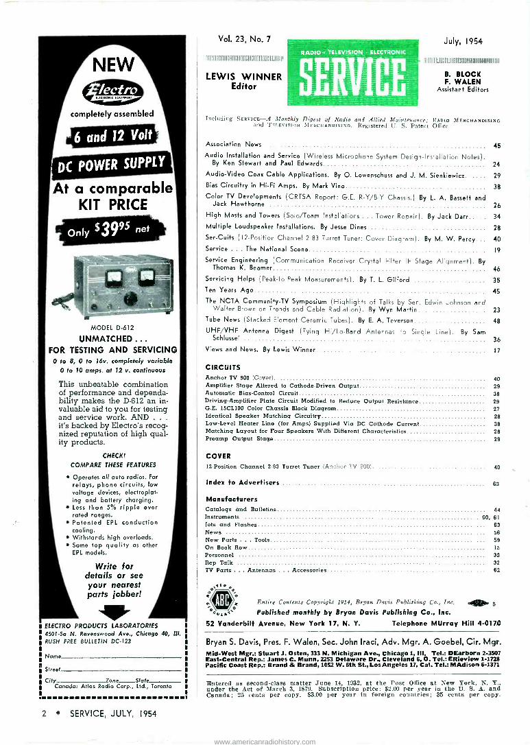
VOL. 23 THE TECHNICAL JOURNAL OF THE TELEVISION -RADIO TRADE 12-poilflon turret tuner or ciannels 2 fo 83 with 6AN4 rf amp, vhf/uhf 6ÁN4 mixer ana 6T4 as an oscillator. (See circuit anoints, this issue] -_-_-'- JULY o jt5;_r '_ £ , ns 01140 'LZ ONb'13A312 67_Z IS 59 3 zso£ A1901OVa NCSlib3d www.americanradiohistory.com
Transcript of VOL. TRADE - americanradiohistory.com · MODEL D-612 UNMATCHED .. . FOR ... (Communication Receiver...

VOL. 23 THE TECHNICAL JOURNAL OF THE TELEVISION -RADIO TRADE
12-poilflon turret tuner or ciannels 2 fo 83 with 6AN4 rf amp, vhf/uhf 6ÁN4 mixer ana 6T4 as an oscillator.
(See circuit anoints, this issue]
-_-_-'-
JULY
o jt5;_r '_ £ , ns 01140 'LZ ONb'13A312
67_Z IS 59 3 zso£ A1901OVa NCSlib3d
www.americanradiohistory.com

you get the same quality and
dependability in RADIART Replacement
Vibrators -the of Ag Ai/ THE RADIART CORP. CLEVELAND 13, OHIO
VIBRATORS - TV ANTENNAS - AUTO AERIALS - ROTORS - POWER SUPPLIES
www.americanradiohistory.com
ei/ UHF&VHI, LEAD-IN'
AD -VANTAGES:
j Lowest losses at UHF and VHF frsqueicies.
2 Great aorasion resistance and medlarical strength.
3 No time-consuming end seal required; easy to install.
4 No inte-nal moisture to cause signal bss.
5 No kinking when used with antenna rotors.
6 Resista n fc snow, ice, rain, and wind.
7 Resista it e ultraviolet rays from the stn.
8 Use; Belden Weldohm con- ductor for lc ng conductor life.
9 Can be clamped tightly in stand -aft insulators without crushin 3. No special fittings req. ired.
10 Conductor spacing is constant even when the lead-in is tran;po.,ed.
11 No ;trippin3 problem for at- tacling the conductor.
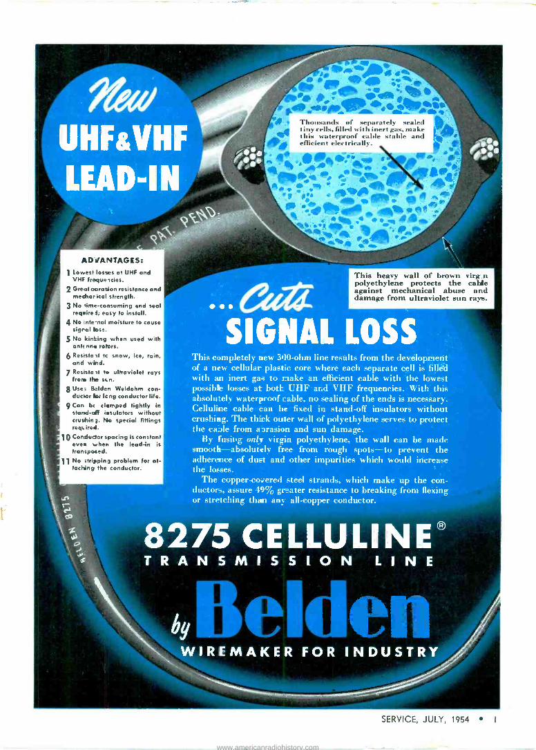
Thousands of separately sealed tiny cells, filled with inert gas, make this waterproof cable stable and efficient electrically.
This heavy wall of brown virg_n polyethylene protects the cable against mechanical abuse and damage from ultraviolet sun rays.
SIGNAL LOSS This completely new 300 -ohm line results from the development of a new cellular plastic core where each separate cell is fill&l with an inert gas to make an efficient cable with the lowest possible losses at both UHF and VHF frequencies. With this absolutely waterproof cable, no sealing of the ends is necessary. Celluline cable tan be fixed in stand-off insulators without crushing. The thick outer wall of polyethylene serves to protect the cable from abrasion and sun damage.
By fusing only virgin polyethylene, the wall can be made smooth -absolutely free from rough spots-to prevent the adherence of dust and other impurities which would increase the losses.
The copper -covered steel strands, which make up the con- ductors, assure 49% greater resistance to breaking from flexing or stretching than any all -copper conductor.
8275 CELLULINE® TRANSMISSION LINE
WIREMAKER FOR INDUSTRY
SERVICE, JULY, 1954 1
www.americanradiohistory.com
NEW
completely assembled
DC POWER SUPPLY
At a comparable KIT PRICE
MODEL D-612
UNMATCHED .. .
FOR TESTING AND SERVICING 0 to 8, 0 to 16v. completely variable
0 to 10 amps. at 12 v. continuous
This unbeatable combination of performance and dependa- bility makes the D-612 an in- valuable aid to you for testing and service work. AND .. .
it's backed by Electro's recog- nized reputation of high qual- ity products.
CHECK!
COMPARE THESE FEATURES
Operates all auto radios. For relays, phone circuits, low voltage devices, electroplat- ing and battery charging. Less than 5% ripple over rated ranges. Patented EPL conduction cooling. Withstands high overloads. Same top quality as other EPL models.
Write for details or see your nearest parts jobber!
AIP" ELECTRO PRODUCTS LABORATORIES 4501 -Sa N. Ravenswood Ave., Chicago 40, III. RUSH FREE BULLETIN DC -123
Name
S'reet
City 7one_State Canada: Atlas Radio Corp., Ltd., Toronto
Vol. 23, No. 7
IIIIIIIIIIIIIIIIIIIIIIIIIIIIIIIIIIIIIIIIIIIIIIIIIIIIIIIIIIIIIIIIIIIIIII
LEWIS WINNER Editor
RA010 TELEVISION ELECTRONIC
SERVICE
July, 1954
III!lllllllfllll1111)llllllllllllllllllllllllhlllllllllllllllllllllL
B. BLOCK F. WALEN
Assistant Editors
Including SERVICE-A Monthly Digest of Radio and Allied Maintenance; RADIO MERCHANDISING and TELEVISION MERCHANDISING. Registered U. S. Patent Office.
Association News
Audio Installation and Service (Wireless Microphone System Design -Installation Notes) By Ken Stewart and Paul Edwards
Audio -Video Coax Cable Applications. By O. Lowenschuss and J. M. Sienkiewicz
Bias Circuitry in Hi-Fi Amps. By Mark Vino
Color TV Developments (CRTSA Report: G.E. R-Y/B-Y Chassis.) By L. A. Bassett and Jack Hawthorne
High Masts and Towers (Solo/Team Installations ... Tower Repair). By Jack Darr
Multiple Loudspeaker Installations. By Jesse Dines
Ser -Cuits ( 12 -Position Channel 2-83 Turret Tuner: Cover Diagram). By M. VV. Percy.. Service ... The National Scene
Service Engineering (Communication Receiver Crystal Filter IF Stage Alignment). By Thomas K. Beamer
Servicing Helps (Peak -to -Peak Measurements). By T. L. Gilford Ten Years Ago
The NCTA Community -TV Symposium (Highlights of Talks by Sen. Edwin Johnson and Walter Brown on Trends and Cable Radiation). By Wyn Martin
Tube News (Stacked -Element Ceramic Tubes). By E. A. Teverson
UHF/VHF Antenna Digest (Tying Hi/Lo-Band Antennas to Single Line). By Sam Schlussel
Views and News. By Lewis Winner
CIRCUITS
45
24
29
38
26
34
28
40
19
46
35
45
23
48
36
17
Anchor TV 900 (Cover) 40 Amplifier Stage Altered to Cathode -Driven Output 29 Automatic Bias -Control Circuit 38 Driving -Amplifier Plate Circuit Modified to Reduce Output Resistance 29 G.E. 15CL100 Color Chassis Block Diagram 27 Identical Speaker Matching Circuitry 28 Low -Level Heater Line (for Amps) Supplied Via DC Cathode Current 38 Matching Layout for Four Speakers With Different Characteristics 28 Preamp Output Stage 29
COVER 12 -Position Channel 2.83 Turret Tuner (Anchor TV 900) 40
Index to Advertisers 63
Manufacturers Catalogs and Bulletins 44 Instruments 60, 61
Jots and Flashes 63
News 56 New Parts . . . Tools 59
On Book Row 15
Personnel 33
Rep Talk 32
TV Parts ... Antennas ... Accessories 62
ED
ABC>= Entire Contents Copyright 1954, Bryan Davis Publishing Co., Inc. map, 5
Published monthly by Bryan Davis Publishing Co., Inc.
52 Vanderbilt Avenue. New York 17, N. Y. Telephone MUrray Hill 4-0170
Bryan S. Davis, Pres. F. Walen, Sec. John Iraci, Adv. Mgr. A. Goebel, Cir. Mgr. Mid -West Mgr.: Stuart J. Osten, 333 N. Michigan Ave., Chicago 1, III. Tel.: DEarborn 2-3507 East-Central Rep.: James C. Munn, 2253 Delaware Dr., Cleveland 6, O. Tel.: ERieview 1-1728 Pacific Coast Rep.: Brand & Brand, 1052 W. 6th St., Los Angeles 17, Cal. Tel.: MAdison 6-1371
Entered as second-class matter June 14, 1932, at the Post Office at New York, N. Y., under the Act of March 3, 1679. Subscription price: $2.00 per year in the II. S. A. and Canada; 25 cents per copy. $3.00 per year in foreign countries; 35 cents per copy.
2 SERVICE, JULY, 1954
www.americanradiohistory.com

SUPER - PERFORMANCE
n Tt ,.
s-j
MAKE THE SCREEN TEST!
111 Measure the space between reflector elements of any other big screen antenna.
Note that the TRI -KING has closer spacing between reflector elements for improved per- formance. The TRI-KING's element spacing is the proven maximum for a full 1/10 wave length.
SUPER TRI -KING
Model TK1800
WIND TUNNEL TESTED to exact- ing aircraft standards. Test results prove that a full size TRI -KING an- tenna can withstaid 30% hig-er wind velocities than any other large screen antenna.
ORDER NOW- IMMEDIATE VELIVERY !
lilt Price
$44.50 $52.95
Model TK1500 (Also available in single bay)
CLEAR BEAM'S 1RIKUG Patent Applied For
POSITIVE GHOST REJECTION! Clear Beam proudly an- nounces the new TRI -KING, combining for the first time a Radar -type reflector screen with the improved TRI -KING dipole assembly. A real champion with many Clear Beam features including rugged, quality construction and Quik- Rig assembly that outsells all other big screen antennas. Sold on a money back guarantee.
WRITE FOR COMPLETE INFORMATION TODAY
Clear Beam Antenna Corp, CU -471(
100 PROSPECT AVENUE BURBANK, CALIFORNIA THornwall 2-4886 Victoria 9-2141
WAREHOUSES IN: Son Francisco Portland Seattle Chicago Kansas City Detroit Dallas Baltimore
SERVICE, JULY, 1954 3
www.americanradiohistory.com

Mr. Dealer... NEWCOMB puts you into
the HI-FI PROFIT PICTURE!
At last you can sell high fidelity components at a full
profit! Newcomb, nationally advertised and famous for
quality leadership in sound since 1937, now offers two
completely new amplifiers for radio, TV and record dealers
to sell competitively at full profit. Just look at all the
advantages you'll enjoy under Newcomb's new sales plan:
FULL PROFIT TO YOU - Your selling price will be exactly the same as the Audiophile Net Price listed by distributors.
EASY TO SELL - Newcomb's new D -Series Amplifiers
AVAILABLE NOW FOR SALE
TO YOUR
CUSTOMERS: D-12
AMPLIFIER
ONLY $9950 AUDIOPHILE
NET
answer a great need in the high fidelity field. They're engi-
neered for top quality, dependable sound reproduction; designed for eye appeal and easy installation; and priced for easy sale.
NATIONALLY ADVERTISED -Newcomb Amplifiers are advertised in High Fidelity, Saturday Review, Time,
The New Yorker, Schwann's and The New York Times
Magazine. What's more, you'll get newspaper mats, radio
spots, counter card, window banners and booklets for use
in promoting these new units to your customers.
MODEL D-10 10 watts at less than 1% distortion 20-20,000 cycles ±1 db six position recording curve selector built- in rumble filter input selector built-in matched and fully compensated magnetic pickup pre -amplifier 6 inputs microphone input tape input new,
easier -to -operate "interlocked" tone circuit bass tone control treble tone control "loudness" control
"Ad justa -Panel" easy installation feature potted output transformer doubly protected against humidity by cellulose
acetate insulation removable "gold" anodized panel plate "petite" non -glare pilot hum balance control hum 75 db
below 10 watts output impedances 8 and 16 ohms tubes: 1-6SC7, 1-12AX7,'2-6V6GT, 1-6AX5GT U/L approved
D-10 AMPLIFIER
ONLY $6950
AUDIOPHILE NET
MODEL D-12 12 watts at less than 1% distortion 20- 20,000 cycles ±1 db selects up to 36 different recording curves new rumble filter and input selector large potted output transformer doubly protected against humid- ity by cellulose acetate insulation advanced design wide range separate bass and treble tone controls built-in matched and fully
compensated magnetic pickup pre -amplifier 6 inputs microphone input tape input new tape
output jack "loudness'' control "loudness" compensation switch "Adjusta-Panel" easy installation feature removable "gold" anodized panel plate "petite" non -glare pilot hum balance control hum 80 db below 12 watts output impedances 8 and 16 ohms tubes: 2-12AX7, 2-6V6GT, 1-5Y3 U/L approved.
NEWCOMB True High Fidelity Since 1937
HIGH FIDELITY AMPLIFIERS TUNERS REMOTE
r Mail this coupon NOW for full details
Newcomb Audio Products Co. Dept. E-7
6824 Lexington Ave., Hollywood 38, Calif.
Please send me full details on the new Newcomb D-10 and D-12
High Fidelity Amplifiers, and how I can sell these units profitably.
Please include the name of my nearest Newcomb distributor.
L
Company Name
Address
City Zone-State
My Name
My Preferred Distributor is
J
CONTROL UNITS
4 SERVICE, JULY, 1954
www.americanradiohistory.com

When the profile of the Cadillac looked like this
derstandable that the profile of a V.O.M. might look like this
But this is the profile of today's Cadillac
And if you buy a V.O.M. that is truly of today it will have a profile like this
In cars, streamlining symbolizes the tremendous advances in automotive engineering and perform- ance. In fine test equipment, too, streamlining signifies the difference.
The flush switches, dials and jacks of the Smoothie make it easy to slip in your pocket, carrying case or tool kit, eliminate snag hazards on your bench.
But even more-the streamlining expresses externally the advanced internal design which makes the Triplett Model 630 as superior to the obsolete knobby bumpy -faced testers as the Cadillac of today is to the Cadillac of fifty years ago. These internal design features include such devel- opments as selector switch of molded construction, completely enclosed; elimination of harness wiring, etc. Your most frequently used tester- your V.O.M.-should be the best-the one of which many thousands are in use in laboratories today-the Smoothie, Triplett Model 630 Volt -Ohm - Mil -Ammeter, $39.50 net. Ask your parts jobber or write Triplett Electrical Instrument Company, Bluffton, Ohio. Only Triplett offers you a ten day free trial on all test equipment.
' * o !1
www.americanradiohistory.com

F II HEAVY-DUTY
TOP-QUALITY I PLIERS KIT with 10 CBS-Hytron Pliers Kit Stamps
PICK UP THESE FINE IMPORTED TOOLS. Examine the beautiful finish of their drop -forged tool steel. Try their comfortable handle grips. Feel the precise balance ... the powerful leverage. Go ahead ! Cut some eight -penny nails. Like cutting cheese, wasn't it? And not a trace of a nick in the tough, care- fully matched jaws. You will be proud to own these husky, quality pliers. Tested ... guaranteed
. they can take it. And did you notice that two are unique? Nothing else just like them ... they are "musts" for your tool kit. Yes sir, this free Pliers Kit (packed in an attractive, handy plastic case) is an offer you cannot afford to miss!
The 61/2 -Inch Diagonals are husky, box -join:, fully polished side cutters with precisely matched jaws. Size is right: Compact, but big enough ... with comfortable, full-fashioned, full - polished handles ... to do repeated, tough cutting jobs with ease. The 8 -Inch Long -Nose .s unique. Extra -long (2.I" inches), spring -tempered jaws combine with extra -long, knurled handles for powerful leverage. Hand -honed cutting knives. Beautifully chrome -plated. The 6 -Inch All -Purpose is also unique. Combines: Flat and round nose. Jaws shaped for positive gripping. Two wire strippers. Two side cutters. Finish of handles is gun-metal; jaws are fully polished. This tool has everything.
Manufacturers of Receiving Tubes Since 1921
RECEIVING TRANSMITTING SPECIAL-PURPOSE
YTRO f CBS-HYTRON Main Office: Ds,vers, Mass.
A Division of Columbia Broadcasting System, Inc.
A member of the CBS family: CBS Radio CBS Television Columbia Records, Inc. CBS Laboratories CBS -Columbia CBS International and CBS-Hytron
TV PICTURE TUBES CRYSTAL DIODES AND TRANSISTORS
LIMITED OFFER From July 1 through August 31 ... Your CBS-Hytron distributor will give you 1
Pliers Kit Stamp with your purchase of 25 CBS-Hytron receiving tubes.
/rQEciYrrmry-L's f+
Aiy,PlffiF.Sté7.'
Get This Pliers Kit Stamp Book .. . and stamps from your CBS-Hytron dis-sibu- tor: One Pliers Kit Stamp for 25 CBS- Hytron receiving tubes. Each Stamp is im- printed with your CBS-Hytron distributor's code number. Redeem your Stamps with him. This offer is valid only in areas where such offers are legal ... and it is limited: July 1
through August 31. Don't miss it. Be sure to get your free CBS-Hytron Pliers Kit. See it at your CBS-Hytron distributor's ... today!
6 SERVICE, JULY, 1954
www.americanradiohistory.com

Can You afford to take a Chance ON ANYTHING LESS THAN BUSS QUALITY IN FUSES?
ífctndßte/ Dependable electrical protection ... isn't that
what you rightly expect of a fuse? For you rely on the fuse alone to safeguard your equipment when there is trouble in the circuit - and just as important, a fuse should never give a "false alarm" by blowing needlessly.
To make sure of proper operation under all service conditions, every BUSS fuse normally used by the Electronic Industries is tested in a sensitive electronic device that rejects any fuse that is not properly constructed, correctly calibrated and right in all physical dimensions.
And there's no need to sacrifice quality on any type of fuse, for BUSS offers a complete line of fuses to the Electronic Industries: - standard type, dual -element (slow blowing), renewable and one-time types ... in sizes from 1/500 ampere up.
And in sales and service - your customer doesn't question quality when you furnish BUSS fuses. The BUSS trademark and the BUSS reputa- tion for `trouble -free' fuses have been firmly estab- lished over the past 39 years by the millions and millions of installations for home, farm, and in- dustry. So be doubly safe - protect your profits and your reputation - standardize on genuine BUSS fuses.
Tor more information mai/ this Coupon
V TRUSTWORTHY NAMES IN ELECTRICAL PROTECTION
BUSSMANN Mfg. Co. (Division of McGraw Electric Co.) University at Jefferson, St. Louis 7, Mo. Please send me bulletin SFB containing facts on BUSS small dimension fuses and fuse holders.
Name
Title
Company
Address
City & Zone State S-753
SERVICE, JULY, 1954 7
www.americanradiohistory.com

Exclusive.' Electro -Lens Focusing*
New Winegard INTERCEPTOR Grabs and Boosts the Signal... Focuses lt...like a Lens
Completely new in appearance. Completely new in electrical design Sensational in results! The new INTERCEPTOR antenna now ccmbines the famous Winegard Multi -Resonant Dipole with the most sensational electronic design of the decade .. .
Electro Lens Focusing.' This exclusive Winegard feature literally grabs the signal out of the air and focuses it on
the dri-en element the same as an ordinary lens focuses light. The result ... a picture gloriously brilliant ... sharp and clear. A picture up until now unobtainable!
Never before has one antenna incorporated so many outstanding and exclusive features. The INTERCEPTOR gives highest possible gain and still maintains rejection from the back and sides that really shuts out co -channel interference. Its Electro -Lens Focusicg makes it an ideal fringe area antenna without the bu!k required by present fringe antennas. Small, light- weight and compact, the INTERCEPTOR's neat appearance will be appreciated by owners of the finest homes.
Attention: Servicemen! You will notice we show no charts trying to
establish fabulous claims. We suggest you order a Winegard INTERCEPTOR today. If your regular jobber does not have it, please contact us. Test it for yourself. The INTERCEPTOR is its own best salesman!
A Winegard Exclusive ... Electro -Lens Focusing. All channels (2-13). Light, rigid, quick to assemble, easy to install. Low wind resistance. Designed for color reception.
For cDmplet information on the Winegard INTERCEPTOR VHF antenna with exclusive Electra -Lens Focusing, send for Bulletin No. L-4.
WI N E G A R D COMPANY 3000 Scotten Boulevard, Burlington, Iowa
*Patent Pending
8 SERVICE, JULY, 1954
www.americanradiohistory.com

NEXT MOVE'S UP TO YOU!
«CHEMICALS ... Everything You Need! rail C.0 PLI.O-BOND
<rì CEMENT No. 43-2 7 oz.
List $0.65
G -C TV LTAGE
CORO . .
No. 47.2 2 or. List $1.20
G -C PLASTIC CEMENT o. 32.2* 2 oz. Liss SO 65
G -C RADIO SERVICE
SOLVENT No, 31-2 2 oz. List $0.25
G -C ELECTRONIC CONTACT
CLEANER No. 210.2 2 oz. List 40.55
G -C TELEVISION TUBE
KOAT No. 49-2 2 oz. Lust $0.95
G -C M TIK RECORD.
ING H AD CLEANER No. 53-2 2 oz. List $1.60
G -C RUBBER -TO -METAL 8.
PHONO DRIVE CEMENT No. 35-2 2 oz. List $0.65
G -C DE -OX -ID No- 19-2 2 oz. List $1.60
G -C VINYLITE CEMENT No. 58-2 2 oz. List $0.65
G -C RADIO-TV SERVICE CEMENT No. 30-2 2 oz.
List $0.65
G -C ELECTRICAL $ RESISTOR CEMENT
No. 27-2 2 oz. List $0.65
90 CHEMICALS FOR . . . BETTER TV-RADIO SERVICING
With the largest, most complete line of quality chemicals in the industry,
G -C is the name you should remember whenever you need cement,
solvent, cleaners, lubricants and all the rest. Yes, with close to a hundred
different G -C Chemicals now available-everything you need- the
next move's up to you!
FREE CATA.OG .. .
big, 64 -page illustrated G -C Catalog No. 156. Get it at your jobber .. or send :postcard direct. GENERAL CEMENT MFG. CO.
901 TAYLOR AVENUE, ROCKFORD, ILLINOIS
www.americanradiohistory.com

New service -aids
221tLi
Walsco TV Lead -In and Rotor Receptacles
Used effectively as wall outlets for any
type of lead-in or rotator cable. They
also fit over and fasten to the insìdé flange of feed-thru. Matching plugs included.
2 prong (Cat. no. 1552) $.63 dealer net 5 prong (Cat. no. 1553) 5.90 dealer net
to solve servicing puzzles
Walsco Universal Feed-Thru Bushing
Fits all standard types of coaxial, tubular and twin -lead wires,. Can to terminated to open line., enabling you to bring 300 ohm twin lead through wall and into room. The bushing fits walls up to 14" thick. Dealer net $1.17 (Cat. no. 1551)
.G:... ". me ABM Min .O5 OM IOW`I gii BOW Me
UM. riii11/ iiii 933114 nor
Walsco Window-Thru Bushing
A new, simple way to bring lead wires into the home without drilling holes, etc. Used effectively on both VHF and UHF. Walsco supplies the adhesive to cement capacitator discs to window pane. A quick, easy, weatherproof installation. Dea er net $.59 (Cat. no. 1555)
nun= GOQPOQaQ0u
Walsco Electronic Chemicals in Spray Cans
Just spray it on! "Instant -spray" cans cut chemical application time in half. No messy applicators.. Can't leak, break, spill or evaporate... it's air -tight. Insist on WALSCO chemical spray cans containing-Contactene, Tubecoat, Anti -Corona Lacquer, and Wrinkle Varnish.
3602 Crenshaw Boulevard, Los Angeles 36, California
Canadian Facbry Distributor: ATLAS RADIO CORP., Ltd., 560 King St., West, Toronto 2-B
Export Distributor:. AD AURIEMA, Inc., 89 Broad St., New York 4, N.Y.
WALSCO counter displays featuring chemicals in
spray cans are at
jobbers everywhere.
www.americanradiohistory.com

avoid "RHUBARBS" The key to successful servicing is a satisfied customer. In tele-
vision servicing, customer satisfaction is assured only when your
highly technical knowledge is employed with components that
meet or exceed performance expectations. Taking chances
with components of questionable quality leads eventually to
"rhubarbs" with dissatisfied customers. Nothing can be moue
harmful to the future of your television servicing business.
Always back up your quality work with dependable component
parts. You can depend on Du Mont quality picture tubes to co
more for your service.
Replacement Sales, Cathode Ray Tube Division
Allen B. Du Mont Laboratories, [tic., Clifton, N. J.
PIONEER IN BIG PICTURE TUBES ORIGINATOR OF THE FAMOUS BENT -GUN AND SELFOCUS
LEADER IN HIGH RESOLUTION MAJOR SUPPLIER TO MOST FINE TELEVISION RECEIVER MANUFACTURERS *Trade -mai
www.americanradiohistory.com

I'm building my Electronics On DELCO and
UNITED MOTORS SERVICE DIVISIONS OF GENERAL MOTORS CORPORATION
It pays to deal with names you know-names that through years of service have won national respect for dependability and business integrity. Through these great names you can build a better electronics business on a solid foundation that offers many exclusive advantages to the industry.
ONE SOURCE
ONE POLICY
ONE BILLING OPERATION
READY-MADE MARKET
TECHNICAL ASSISTANCE
DISTRIBUTION
QUALITY
Delco offers special application parts as well as complete coverage of the most important universal parts groups.
A single sales policy for all electronics parts eliminates the confusion of dealing with many manufacturers.
Means fewer records to keep, fewer purchase orders; cuts bookkeeping time and costs to a minimum.
In addition to universal replacement parts, Delco is the sole source for original equipment replacement parts on all Delco radios. Current bulletins and field schools play an important part in keeping the industry well posted on new developments.
United Motors Service maintains 21 strategically located warehouses to assure ample supply of all parts.
You are assured of uniformity of parts, built to high standards of production and to exacting specifications.
SPEAKERS AUTO RADIO AERIALS VIBRATORS CONTROLS COILS
12 SERVICE, JULY, 1954
www.americanradiohistory.com
A GENERAL MOTORS PRODUCT
CAPACITORS RECEIVING TUBES
A UNITED MOTORS LINE
PICTURE TUBES CONDENSERS TRANSFORMERS
SERVICE, JULY, 1954 13
www.americanradiohistory.com

without equal FOR
4 -BAY
"CONICAL-V-BEAMS7
PERFORMANCE!
The finest long distance array ever produced ... for the ultimate in fringe area reception
Guaranteed to outperform any antenna or combination of cut -to -frequency antenna.
When used with Telrex Duo -Band ?. splines, the 8X -TV comprises the
finest in reception on channels 2 to 83. This famous Telrex antenna has proven unequalled for performance for distances up to 200 miles. When
you check the facts on antenna, you'll agree that Telrex is BEST BY EVERY TEST!
Every genuine Telrex antenna features rugged all -aluminum, all-weather construction
Over 60 different models for every installation need, near or far, are included in the new Telrex
catalog. Ask for your copy, today!
"Conical -V -Beams" are produced under U. S. Pat- ent No. 23,346, Canadian Patent No. 500,436 and British Patent No. 691,485 - other patents pending. Sold only through authorized distributors.
INC.
"CONICAL -V -BEAMS"
ERICA OUTSTANDING
TELEVISION BEAM
ASBURY PARK 4 NEW JERSEY
MAKERS OF THE FAMOUS "BEAMED POWER" COMMUNICATION ROTARIES
14 SERVICE, JULY, 1954
www.americanradiohistory.com

On f.4k how RIDER'S TELEVISION MANUAL. . . . VOLUME 13: Factory -prepared, factory -
authorized servicing information on TV receivers manufactured in the period
from September '53 to May '54. Lists makes and models of over 65 manufacturers,
and also contains servicing information on color TV chassis. Includes replace-
ment parts listing, and cumulative index, listing all items covered in previous
volumes. 2300 pages, 8/ x 11", bound in binder, priced at $24.00; John F. Rider
Publisher, Inc., 480 Canal St., New York 13, N. Y.
* * *
TELEVISION RECEIVER SERVICING, VOL. I.... By E. A. W. SPREADBURY: Volume
covers time -base circuits in TV receivers. Chapters review: blank screen symp-
toms; obtaining a raster ; applying a signal ; synchronization; examining interlace
quality; the synchronized time -base; kv boost; picture shift; tube circuits; fly-
wheel sync circuits ; dc restoration; and use of instruments. -310 pages, 8/" x 5/"; lee and Sons, Ltd., Dorset House, Stamford St., London, England.
* * *
How TO LOCATE AND ELIMINATE RADIO AND TV INTERFERENCE. . . . BY FRED D.
RowE: A practical book covering all types of devices causing interfering signals,
how to locate them and exactly what to do to correct the difficulties. Some of
the topics detailed are: antennas and interference; basic interference sources and
sounds; locating the source ; power -line interference and filters ; and eliminating
interference at the TV receiver. 122 pages, 53'x" x 8/", paper bound, priced at
$1.80; John F. Rider Publisher, Inc.
* * *
INTRODUCTORY CIRCUIT THEORY ... BY ERNST A. GUILLEMIN: An excellent text
covering methods of steady-state and transient circuit analysis, as well as basic
concepts essential to synthesis procedures. Author deals with the importance
of network topology as a means of determining an appropriate set of variables ;
he covers the significance and usefulness of the principle of duality, and complex
frequency, and discusses the concept of the impedance function. 550 pages, priced
at $8.50; John Wiley and Sons, Inc., 440 Fourth Ave., New York 16, N. Y.
* * *
TECHNICIAN'S GUIDE TO TV PICTURE TUBES...BY IRA REMER: An informative
manual with basic information on picture tubes and accessories. Detailed are
recognition of faults occurring in picture tubes, their correction where possible ;
rejuvenation equipment and handling of similar devices; details surrounding the
optical accessories used with picture tubes; and replacement questions surround-
ing pictures tubes, sweep accessories, and other related devices. The color picture
tube is also discussed. 160 pages, 5/" x 81/:;", paper bound, priced at $2.40;
John F. Rider Publisher, Inc.
* * *
SUCCESSFUL SERVICE MANAGEMENT: One of the most useful trilogies on business
practices, merchandising, and technical data ever published. Contains all of the
information needed to set up and organize an efficient service business....Included
in the business practices section is such material as accounting for the Service
shop and preparation of Federal income tax returns. Under merchandising are
included a discussion of the value of advertising and promotion, as well as specific
how -to -do -it material on advertising, direct mail, window and store displays, and
other means to increase service business.... The technical data section includes
material on troubleshooting with a 'scope, alignment techniques, uhf servicing,
and service tips. Profusely illustrated. -318 pages, loose leaf ; Available through
authorized General Electric tube distributors as part of a management program.
"The ORIGINAL
NON -INFLAMMABLE NON-CONDUCTIVE
LUBRICANT CLEANER"
Available in 2 oz., 4 oz., 8 oz.
QUIETROLE . .. the original and most reliable lubricant cleaner quiets noisy tele- visiion and radio controls, switches° and other moving pacts. Why take less . . .
avoid imitations . . . order QUIETROLE, developed after years of research.
NO GUM! NO GOO! NO GRIME!
Carried by recognized job- bers . . . everywhere! Ur equaled for TV front end switches. Contains no "thinner".
manufactured by
QUIETROLE COMPANY
Spartanburg, South Carolina
SERVICE, JULY, 1954 15
www.americanradiohistory.com

GET OFF THE SPOT l BONDED ELECTRONIC
TECHNICIAN PROGRAM Once you gain the confidence of customers, you're on your way to increased volume and
profits. The Raytheon Bonded Electronic Technician program is designed to help you do just that. The Raytheon Registered Bond Certificate, the Raytheon Creed Display Decal and Identification Cards, featuring your bonded status and the fine Raytheon "Code of Ethics", inspire customer confidence. And a recent survey proved that wherever Raytheon Bonded
,oNEY'RE Technicians took full advantage of their Bonded status - used it to in - c of spire customer confidence - business improved by at least ten per cent. Ask your Raytheon Tube Distributor if you can qualify for this im-
portant sales advantage. If you can, the bond is yours at no cost to you - it is Raytheon's investment in your future.
111
RAYTHEO A .UF - .RING COMPAN g Tube Div
Newton, Mass., Chicago, Ill., Atlanta, Ga., Los Angeles, Cal.
RECEIVING AND PICTURE TUBES RELIABLE SUBMINIATURE AND MINIATURE TUBES SEMICONDUCTOR DIODES AND TRANSISTORS NUCLEONIC TUBES MICROWAVE T
7111111111111111111111K
ex ewe. in elecGicnicd
16 SERVICE, JULY, 1954
www.americanradiohistory.com

nmwuuuumuuunwMunuuumuunummmmulunmm11nllluaWnluWimuumnuununnmHUHiHHI
As Lively and Progressive As Ever*
To MOST OF Us, even the hardened old timers, TV and radio are truly miracles of the electronic world. And, as many have often viewed, TV is probably humanity's greatest blessing. Even in the halls of Congress, TV has been applauded as one of the great inventions of the ages ; having restored the home to its rightful place as the center of family pleasure and entertainment. Indeed, any medium that makes home more than a place to eat and sleep, is certainly precious to our welfare and life generally.
With so gleaming and beaming a horizon, we still have apostles of doom wandering about, tossing morbid state- ments and figures around.
Of course, no one denies that problems do not obtain ;
there are many roads that still have cracks, potholes and ruts, making driving difficult. We know that in- competence, indifference to ethical standards, and the race for the dollar, has created ill will and blemished many a record. We know, too, that because of these con- ditions, it has often been difficult to avoid sharp waves of friction and confusion. It has become necessary to dis- play keen resourcefulness and courage to forge ahead. Industry has met that challenge, perhaps not everywhere in every community and city, but in the majority of towns, villages and urban areas throughout the country.
This has been an enormous job, but it has been and is being done, thanks to planned thinking, sparked by alert associations. The consumer has become aware of those who have chosen to follow the forthright trail pre- scribed by association groups. They have found that those who have banded together for a common cause are not only completely reliable, but capable of performing an installation, a service call or a maintenance assign- ment with more know-how, and in a completely profes- sional manner.
Often, it has been said that folks are becoming less and less interested in keeping their receivers in good operat- ing condition. And to compound the problem, we have been told that the seasons continue as threats to good business. As we have noted on several occasions, sea- sons have actually been found to be stimulants. To illus- trate, whereas years ago practically everyone raced to the seashore or mountain resorts for relief during the sum- mer months, today, thanks to air conditioning, millions are staying home and tuning in. It has been reported that this summer over a million families will keep cooler at home. Eight years ago, there were only about 15,000 air conditioners in operation. Today, the nation has been sold on the comforts of conditioning, and not only for the small homes, but in apartment houses as well. Several alert service shops in the east have found that the conditioned home represents a fertile market for repair and maintenance. They uncovered this golden fact
From talks delivered by ye ed before the annual all -industry banquet of the Radio -Television Servicemen's Association of Pittsburgh, and the annual outing of the Radio and TV Service Men's Association of Luzerne County, Wilkes Barre, Pa. See page 45, this issue.
'See page 23, this issue, NCTA Symposium report.
iuumnuuunuuuüninummmmmumimuunnnnmmuuuHnumuuwuunuwuuunnnnuumuuuunn
through a consistent mail and personal -contact campaign to owners of conditioners, working through dealers and distributors. In several coordinated deals, letters have been sent out by freezer dealers to consumers recom- mending the services of an approved radio, TV and phono shop. Letters have been followed up by mail from the service shop, and phone calls have supplemented the written notices. While the season is young, shop owners have been rubbing hands with glee, for the results have been described as outstanding.
In community TV1, many Service Men have also found gilded opportunities. There'll always be communities, or even sections of communities, that do not now receive nor ever will receive satisfactory TV signals, either from the station in the community of from those in neighboring areas. The potential market for this service is truly vast, and as the records show, it can be operated profitably even in rural communities.
Earlier, it was said that there are too many bearers of gloom still strolling about. If these weary folks would take a look at the record and study the reasons for the dismal conditions they complain about, they would shed their cloaks of misery and begin a crusade that would rouse instead of bury.
Few have realized that the cause of the bulk of drop- outs in small business has been due to general incompe- tence. According to a survey conducted by a government agency, over 50% of the troubles has been caused by a lack of skill and a lack of knowledge of the industry.
Realistic Service Men have always fared well because they have studied and analyzed the prospects and prob- lems facing their industry, not only as individuals, but as members of their community and their lively associ- ations. They are not isolationists as many have tagged them. Folks in town have learned to respect their judg- ment and their skill. They have been alerted to the fact that it takes more than a flashlight and screwdriver to repair a modern receiver, be it radio or TV, or phono.
Manufacturers also have been lending a valued assist counseling consumers on what one must do today to keep equipment in order. Pitching in, via TV stations across the country, one tube manufacturer has begun to show a lively spot film telling viewers that : Television receivers have more than 500 different parts, and a good Service Man must know what each one does, where each one is located, and which one is causing the trouble in more than 150 different makes of sets now available. All this, the film continues, requires months of intensive schooling and plenty of practical experience in repairing sets ; an in- vestment of thousands of dollars for test equipment, and another big investment in tubes, parts and trucks. Quick, economical TV repairs, call for professional skill, tech- nical knowledge, and honest workmanship.
The conscientious shop owner has always been able to render such service, as advertised. He has always fol- lowed the rigid code, and as result, he has found that there's plenty of bounce in servicing today; for the indus- try is as lively and progressive as ever.-L.W.
SERVICE, JULY, 1954 17
www.americanradiohistory.com

The R A 4: K 5i P STOPS co -channel and adjacent channel interference caused by rear signal pick-up!
Highest front -to -back ratio ever built into an antenna! No rear pick-up; eliminates "venetian blinds"! Largest screen area: 70 square feet! Very high all -channel gain. Incorporates basic Champion design, including Tri -Pole, with additional elements! Completely preassembled I
Table of Front -to -Back Ratios
(Relative Voltage)
Channels
2
Front -to -Back Ratios
9:1
3
4
10:1
11:1
5 20:1
6 18:1
Only Low Band channels shown, since co -channel Interference is not encoun- tered on High Bond channels.
330
300
270
240
o
Channel S
A
30 Oslo Above Tuned Reference Dipole
IM MM.
IMPORTANT ... don't be misled by polar patterns representing relative POWER. Remem- ber, power is the square of voltage. All Channel Master polar patterns ore presented in relative VOLTAGE.
model no. 326-2 VHF -UHF antenna
$6390 list
2 radical new antennas
by CHANNEL MASTER The most beautiful antenna ever made! The only indoor antenna featuring powerful outdoor design principles - Bow -Tie and Screen. J DESIGNED FOR POWER!
On UHF: For primary and secondary areas. In many cases, performance is equal to actual outdoor installa- tions. Good directivity on all channels.
On VHF: Ideal in areas of strong VHF signals.
STYLED FOR BEAUTY !
Designed by a well-known industrial desi3ner, the WONDER BOW is proof that indoor antennas can be beautiful as well as powerful. Wins customer approval on beauty alone!
The first gain figures ever to be published far an indoor antenna!
Goln Above Tuned Reference Dipole
Gold and black ,ork, 416
Silver and black ,,ad, t 417
CHANNEL MASTER CORP. r r
5835 list
Write for complete technical literature.
The World's Largest Manufacturer of TV Antennas Copyright 1954, Channel Master Corp.
VHF -UHF
indoor
antenna
'Pat. No. D-171560
www.americanradiohistory.com

SI?JjFiCi.. l'le lational Scene
HEALTHY INDUSTRY CLIMB FORECAST FOR FALL -WINTER --A solid rise in business should pre- vail during the next six months, RETMA's set division chairman predicted recently. His
optimism was based on the news that authoritative statistics on production and sales had enabled set makers to judge their output wisely and avoid the creation of danger- ously high inventories. The radio -electronic -TV industry accordingly, he said, has
been able to enter the second half of the year with balanced inventories. . . . These views were also shared by the association's prexy, who announced during an annual re- port meeting that we are now on a sounder basis than a year ago because of the lower -
level inventory conditions. Commenting on color, he said that while the market has been slow in developing, there are indications that it will now gain momentum and we can look forward to a steadily growing interest in color equipment. . . . Enthusiasm for the future was also voiced by the chairman of the board of a leading tube and set manufac- turer during an annual stockholders meeting. He felt that not only would the radio and TV industry continue to grow, but that opportunities in commercial and industrial elec- tronics would spiral, too. He invisioned a volume of more than a billion dollars in seven years or so, and a continuing rise. In his opinion, there are really no limits as to what electronics can do for industry. Electronifying in industry is just beginning, he said.
UHF -ONLY ASKED FOR AREAS WHERE 14-83 BANDS PREDOMINATE --A proposal that intermixed stations in 10 key markets switch over to u or v operation only, depending on the pre- dominance of high or low -band channels in those areas, was filed in Washington recently. Cities included in the plan were: San Francisco (presently with 3 v and 1 u stations); Miami (1 v and 2 u) ; Louisville (2 v and 1 u); Portland, Me., (1 v, 2 u); Boston (2 m, 1 u) ; St. Louis (1 v, 3 u) ; Oklahoma City (2 v, 2 u) ; Dayton (2 v, 1-u); Pittsburgh (1 v, 2
u) ; and Milwaukee (1 v, 2 u). . . . The brief also revealed estimated number of total and uhf sets in these areas: San Francisco -70,000 u (840,000 total) ; Miami -120,000 u (240,- 000 t); Louisville -82,000 u (370,000 t); Portland -70,000u (90,000 t) ; Boston -105,000 u (1,400,000 t); St. Louis -215,000 u (620,000 t); Oklahoma City -83,000 u (260,000 t); Dayton -32,000 u (637,000 t); Pittsburgh -250,000 u (943,000 t); and Milwaukee -218,000 u_
(668,000 t). . . . Substantial quantities of the so-called u_ -sets were described as being actually converted veryhigh chassis. . . . In a letter accompanying the proposal, it
was noted that the change to all v or u_ might eliminate almost 50 per cent of the prob- lems in one stroke, without serious dislocation.
UHF A SUCCESS, OPERATOR TELLS SENATE COMMITTEE --There's 95% conversion in Columbus, Ga., probably the only city in the country where it costs more to buy time on a uhf rather than a vhf station, and everyone is very happy with the situation. So testified a representative of WDAK-TV (Columbus) channel 28, before the Washington sub -committee investigating the ultrahighs. Committee members were told that the station's worst problem is Madison Ave., headquarters of many key ad agencies in New York City, where the impression seems to be that there are no useful uhf stations. Senators learned that there were at least nine other uhf stations now doing very well, and it would not be long before others joined the success parade.
CONVERT -A -SET CONTEST LAUNCHED IN ST. LOUIS --A uhf convert -a -set contest, expected to promote about 70,000 conversions over a three-month period, has been launched over WTVI in East St. Louis. Viewers are being asked to submit the names of five friends whom they believe will convert to uhf, and in addition write a 15 -word essay on why they like the station. Prizes being offered include an air-conditioned home, convertible, air conditioners, refrigerators, stoves, diamond rings, piano, and even some lessons. . . .
Over 150 daily and weekly newspapers, in a 25 -county area served by the telecaster, and billboards, taxicabs and radio too are being used to promote the conversion drive. . . .
Names of conversion prospects will be sent to dealers and Service Men.
SERVICE, JULY, 1954 19
www.americanradiohistory.com

Sl?JIFfCi.. lalional Scene
SUBSTANTIAL PRODUCTION OF 19" COLOR SETS SEEN FOR THIRD -FOURTH QUARTERS --Promised de- livery of large -screen picture tubes for color chassis has prompted a number of manufac- turers to announce that they'll soon have quite a few chassis on the market. . . . Re- porting on tube sizes, a representative of one company said that their large -screen version would be closest in size to the popular 21" b -w tube and provide 205 square inches of picture -screen area. The production capacity of the plant offering these tubes is 10,000 a month, and it was said, demand may make this rate necessary by late September. It was also predicted that industry would produce between 50,000 and 60,000 large -screen color tubes this year.
SINGLE -GUN COLOR -CHASSIS DEVELOPMENTS STIRRING --Within the next few weeks, licensees of one lab in the East will attend the showing of new color models using single -gun tubes featuring built-in radiation suppression. While chassis displayed will be bench models, it is felt that it will be possible to use them as practical prototypes for production purposes.
BIG PUSH FOR TWO-STEP HI-FI DISTRIBUTION PLANS UNDERWAY --Unique merchandising programs, which it is felt will stimulate sales of hi-fi gear through Service Men, are now being readied for the field. Plans revolve about rebates and special models for the market. . . . In one approach, conceived by a Pacific coast manufacturer, two chassis have been exclusively designed for the program. Models will be available to bonafide audio Ser- vice Men at a special discount. These sales will be entered separately and reported on a special form to the manufacturer, who will reimburse the distributor to provide a profit on each shop or dealer sale. . . . In another plan, prepared by a Chicago speaker manu- facturer, shops or dealers will also be able to buy equipment at a discount, and distrib- utors who have been designated as hi-fi wholesalers, will get an additional discount on all verified sales.
ULTRAHIGH BOOSTER SOUGHT FOR WATERBURY, CONN.--Permission to install an experimental uhf -TV station booster in the Waterbury, Conn., area, was filed recently with the Com- mission. The booster, with 10 watts of power, would it was said serve to retransmit programs of WATR-TV (channel 53).
COMPLETE PRINTED -CIRCUIT TV CHASSIS BEING READIED FOR MARKET --A 26 -tube cascode, 41 -mc receiver, using nine printed -circuit sections (plus a standard tube -transformer unit) has been developed on the Pacific coast, and will soon be marketed under brand names. Re- ceiver will contain four stages of ifi and an aluminized picture tube. The 22 sections have been designed for plug-in so that they can be removed quickly in case of trouble. Receivers will be offered in 21, 24 and 27 -inch models.
TEXAS SERVICE ASSOCIATION PLANS THREE-DAY MEETING IN AUGUST --The 2nd annual electronics: fair and clinic, conducted by the Texas Electronics Association, will be held in Fort. Worth on August 27, 28, 29, in the Grand Ballroom of the Hotel Adolphus. . . . Scheduled'.
talks will cover transistors, public relations and advertising, uhf receivers and.
antennas, test equipment and color receivers.
AWARDS TO TELECASTERS FOR FRIENDLY HELP --The valued technical and promotional as- sistance supplied by TV stations to Service Men has been applauded on a number of occa- sions. In recognition of this outstanding service, one antenna manufacturer has an- nounced the establishment of a TV engineer's award. . . . A short time ago, the chief engineer of WDTV in Pittsburgh received the first of these awards. . . . In late Sep- tember, it has been reported, a plaque will be presented to another TV broadcaster for his friendly help to those in servicing.--L.W.
20 SERVICE, JULY, 1954
www.americanradiohistory.com

R Antenna Rama A DYNAMIC NEW CONCEPT
in the Manufacture and Marketing of TV Antennas,
Auto Radio Aerials and Accessories
LENGTH OF EXPERIENCE
Ward electronic engineers have pioneered many important advances in TV and Radio communications - advances which have set the pattern for others.
DEPTH OF PRICES
Whatever the budget may indicate, Ward offers the right
answer with TV antennas, auto radio aerials and accessories at the right ,- price ... profitable i for you, too. i f
LET SAM WORK
FOR YOU!
`I
ti
BREADTH OF LINE
HEIGHT OF QUALITY
Every TV and radio prod- uct which proudly bears '
the Ward name represents the finest materia money can buy.
RANGE OF MODELS
That Ward dealers may best serve their patrons, Ward offers a wide selec-
tion of antennas and acces-
sories to meet every need.
The new Ward line in-
cludes TV antennas, auto radio aerials, and acces-
sories ... engineered and styled for complete cus-
tomer satisfaction.
PROMOTION Eye catching displays, mailing pieces, catalog sheets.
National advertising plus local cooperation for you.
ERCHANDISING Actual sales leads plus products and prices that make selling easy for Ward dealers.
WAR i PRODUCTS CORP.
DIVISION OF THE GABRIEL COMPANY
1148 Euclid Ave., Cleveland 15, Ohio Canadian Distributor: ATLAS RADIO CO., LTD., TORONTO, CANADA
SERVICE, JULY, 1954 211
www.americanradiohistory.com
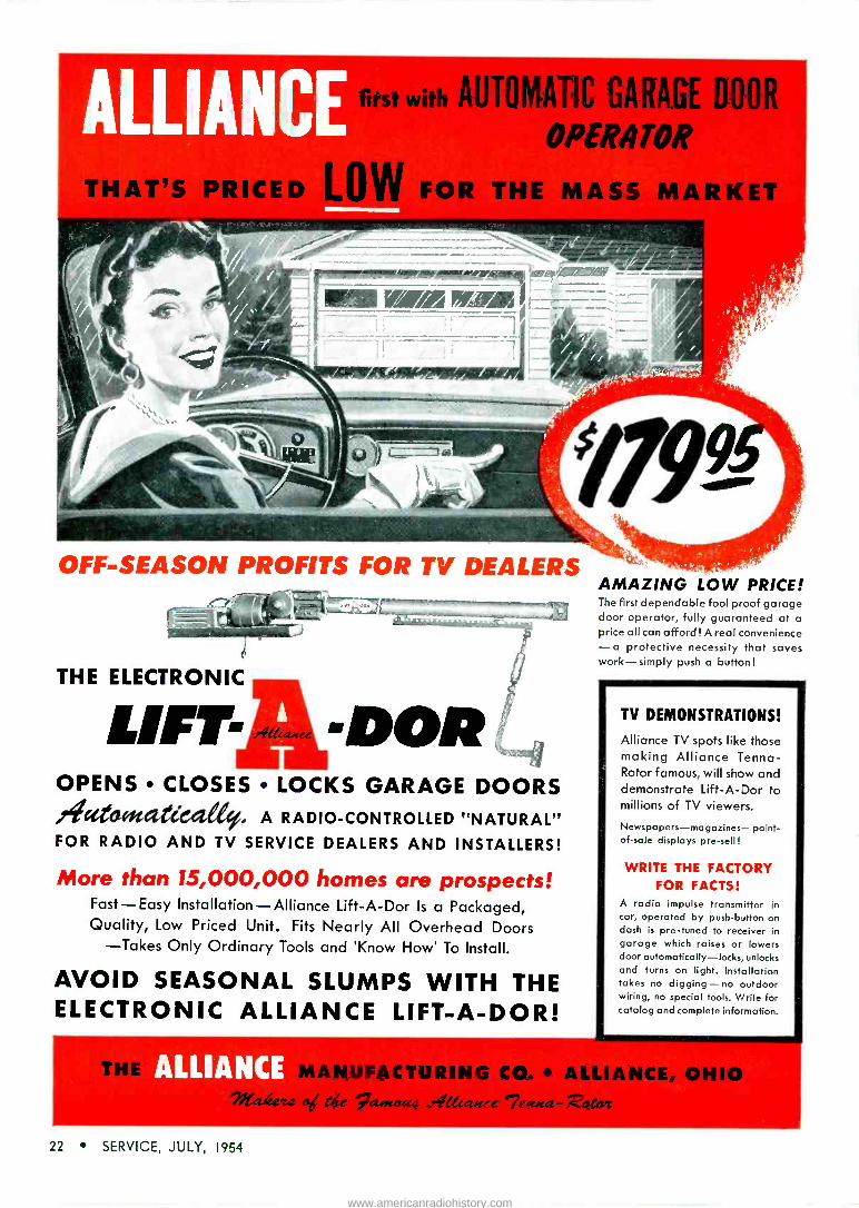
THAT PRICED
first with AUTOMATIC GARAGE DOOR
OPERATOR
FOR THE MASS MARKET
OFF-SEASON PROFITS FOR TV DEALERS
THE ELECTRONIC
LIFT - OPENS CLOSES LOCKS GARAGE DOORS ,eiceteetetticalety, A RADIO -CONTROLLED "NATURAL" FOR RADIO AND TV SERVICE DEALERS AND INSTALLERS!
More than 15,000,000 homes are prospects! Fast-Easy Installation-Alliance Lift-A-Dor Is a Packaged, Quality, Low Priced Unit. Fits Nearly All Overhead Doors
-Takes Only Ordinary Tools and `Know How' To Install.
AVOID SEASONAL SLUMPS WITH THE ELECTRONIC ALLIANCE LIFT-A-DOR!
AMAZING LOW PRICE! The first dependable fool proof garage door operator, fully guaranteed at a price all can afford! A real convenience -a protective necessity that saves work-simply push a button!
TV DEMONSTRATIONS!
Alliance TV spots like those making Alliance Tenna- Rotor famous, will show and demonstrate Lift-A-Dor to millions of TV viewers.
Newspapers-ma gazines-point- of-sale displays pre -sell!
WRITE THE FACTORY FOR FACTS!
A radio impulse transmitter in car, operated by push-button on dash is pre -tuned to receiver in garage which raises or lowers door automatically-locks, unlocks and turns on light. Installation takes no digging - no outdoor wiring, no special tools. Write for catalog and complete information.
ALL MANUFACTURING CO.* ALLIANC , OHIO 71alc za od táe 7a."coua reiiaaeec %fflca-Zataz
22 SERVICE, JULY, 1954
www.americanradiohistory.com

The NCTA Community -TV Symposium
SMALL TowNs and small communities of this great country of ours represent the very heart and soul of America, and what is good for them is good for this nation.
So observed Senator Edwin C. John- son in presenting his views on the dynamic impact of TV's new dimen- sion, Community TV, at the annual NCTA* meeting in New York, a few weeks ago. Now, he said, it has be- come possible to bring the magic of TV to thousands of areas, which would be blacked out because of eco- nomic and geographic problems.
Declaring that the potential market for community TV can only be de- scribed by the super word-vast, the Senator said that systems can operate profitably in communities with as few as 5,000 people; and in this country there are more than 2,500 such cities and towns. Noting that it is doubtful that half or even three -fourths of these 2,500 communities will ever have tele- vision stations of their own, or receive satisfactory service from nearby cities, he said: "Here is a vast market of millions of people who will demand the blessings of good television enter- tainment in their own homes, once they learn that there is no technical reason against having it."
Even today, community TV is not exactly an infant industry. For there are now more than 300 separate sys- tems in operation serving some 275,000 households, reaching a volume of service which no longer can be ignored, conference members were told.
Reviewing some of the technical and legal problems that do obtain today in community service, the Senator said that such a service is premised upon picking up signals of operating sta- tions and relaying those signals to sub -
*National Community TV Association.
by WYN MARTIN scribers through closed circuits. Thus one of the burning questions has been what rights have community operators to those signals, or what are the proprietary rights of the originating station or the network in the programs delivered to subscribers?
The function and role of the commu- nity pickup is to strengthen signals of the originating station for distant areas where otherwise the reception would not be satisfactory.
A station's programs are free, it was said, waiting for and available to any- one with a receiver to tune in on them and view them; actually stations are anxious that more and more people buy receivers and tune in their pro- grams, since they use the number of listeners they serve to attract advertis- ing. Thus a community TV's function, explained the Senator, is one of pro- viding a technical service which re- sults merely in an extension and ex- pansion of the coverage of the station and thus is helpful to the station and at the same time serves the public interest.
Therefore, he pointed out, such a
service is neither a broadcast nor a common carrier operation and, thus it should not be subject to regula- tion by the Commission, or by a state utility agency in the case of a solely intra -state operation. Certainly, oper- ators were told, they are not engaged in broadcasting nor in interstate com- munications for hire, but were simply furnishing a purely local antenna serv- ice. And as such, systems were no more a common carrier than a hotel
Above, left: NCTA prexy Martin Malarkey, Jr., (right) discussing coax cables with Amphenol field engineer at meeting. Right: Senator Edwin C. Johnson who delivered key address
at conference.
with one master antenna, which serves its many rooms.
One of the outstanding developments of the community operation, continued Senator Johnson, is the friendly and cooperative relations with the TV broadcast industry. So far as he knew, only one station licensee has sought to deny the pickup of his programs. This cordial relationship is understandable, he said, when it is realized that oper- ators provide the station with an addi- tional audience and market not ordi- narily reached by his signal. He noted that most licensees with whom he has talked feel that community systems constitute a very desirable adjunct to
their business.
Radiation from Community TV Cable
IN ANOTHER revealing conference re- port, Walter N. Brown* discussed the problems arising from radiation or leakage of signals via community TV cable systems. Radiation from many systems has been strong enough to encourage non -subscribers to erect an- tennas near the cable lines and operate their receivers from signals radiated by the cable system. And in areas where there is direct signal available from TV stations, radiation from cable systems has been found to cause ghosts, black bars, or other types of
interference. Reviewing the general nature of the
problem, Brown said that in an ideal system the entire system and the sets connected to it would be perfectly shielded. Thus the only entry of sig- nals would be through the antennas, and the signals traveling inside the systems would be confined by an im -
(Continued on page 50)
*Consultant, U. S. Wire and Cable Corp.
SERVICE, JULY, 1954 23
www.americanradiohistory.com

Wireless Microphone System Design and Installation T ... New Products for
AUDIO INSTALLATION AND SERVICE `' Hi-Fi - Phono - Tape - P A
Amplifiers - Speakers
ON THE LECTURE platform, in the athletic stadium, before a night-club audience, on stage or in the pulpit, many have objected to being anchored before a fixed mike stand or entwined with reels of lead feeding to a more flexible breast, lapel or hand mike. It has often been felt that the ideal approach to this situation would obtain in a lineless lightweight mike with which one could roam about.
In one effort to meet this require- ment, a stick microphone featuring use of a non -licensed or FM induction system, has been evolved".
In developing the wireless tech- nique, it was found that the stick -type mike could be so designed that it would be self-contained, readily handled from one person to another, or placed in a microphone stand and used conven- tionally. Thus performers would not have to dress themselves in the micro- phone. And having no interconnecting cables, the unit would not be subject to wear and tear and require less main-
tenance. The concealment factor was felt to be a minor point.
Frequency modulation was chosen because it was found to assure a con- stant overall gain, notwithstanding the varying coupling between transmitter and pickup element. In addition, the desire to obtain an effective signal-to- noise performance, with a transmitter of limited power, dictated the use of an FM system.
One of the key items in a system of this type is the antenna for the transmitter. It was found that within practical limits the size of the antenna would not affect the performance of an induction system. Studies have disclosed that any antenna can be reduced to an equivalent magnetic dipole, the only effect of size variation appearing in the change of power required to produce the desired
'Shure Vagabond Model 88 Wireless Microphone System.
'National Scene, SERVICE ; October, 1953.
LL
N
m 0
E E
d
Raised Dance Floor
Receiving Antenna
Backstage Areo
Backstage Area
Above: Typical night-club installation. Primary area of cover- age (dance floor) is indicated by heavy outline. Dotted line indicates loop antenna stapled to edge of raised dance floor. Loop need not be enlarged to enclose entire stage and stair- ways, but merely to secure coverage over area needed.
by KEN STEWART
and PAUL EDWARDS
field strength. An effective solution appeared in a ferrite -core inductor 3" long, weighing 2 ounces.
The transmitter, using five sub - miniatures, operates from a 30 -volt hearing -aid battery and a 1.3-v mer- cury cell. The circuit, divided into two parts, has a two -tube audio and three - tube rf section.
Two tetrode voltage amps were cas- caded in the audio portion; this served to provide a gain of 55 db at 1000 cycles. For the desired degree of modulation, a miniature vc was in- cluded between the two stages. During tests it was found that motorboating occurred at low frequencies when the amp was connected to the reactance modulator, due to modulation of the plate supply voltage. This was eli- minated by adding a decoupling filter in the first audio stage and restricting the if response of the audio amp.
An 80 microsecond preemphasis, in the transmitter, and corresponding
(Continued on page 52)
$Based, in part, on a report prepared by Thomas W. Phinney, Shure Brothers, Inc. presented at Sept., '53 NEC meeting in Chicago, and published in March -April, '54 transactions of IRE Professional Group on Audio.
Below: Wireless mike receiving antenna layouts. Loop A will pick up more noise than loop B because the enclosed area is larger. The signal pickup will be about equal for A and B. Loops C and D have equal enclosed areas and hence will pick up about the same amount of noise. However, loop C will pick up more signal than loop D because the transmitter cannot be taken as far away from the receiving antenna wire within loop C as it can within loop D.
24 SERVICE, JULY, 1954
www.americanradiohistory.com

Audio: Turntable Mats ...Tri -Speaker Systems ...Ceramic Cartridges e e .
A 3 -way speaker system employing com- bination woofer -mid -range and tweeter reproducers together with an inductance - capacitance type dividing network, housed within a balanced double -port bass chamber. The woofer section of the speaker is said to employ a heavy duty diaphragm capable of large low fre- quency excursion without acoustic break- up. The mid -range section provides two separate concentric horn radiators. The tweeter is comprised of a driver unit em- ploying a lightweight phenolic dia- phragm, Alnico V gold dot magnet, and reciprocating flare wide angle horn. A balance control is provided in the network tweeter circuit to permit adjustment of tonal quality. (Companion with Diffusi - cone 8 and Model 4401 Tweeter System; University Loudspeakers, Inc., 80 S.
Kensico Ave., White Plains, N. Y.)
Portable extension speaker, with acoustic fiberglass cone. Has a 4 -in -1 switch that turns on either TV set speaker or ex- tension or both. (Floritone models 100 and 200; Sootins, Inc., 321 N.W. 3d Ave.,
Miami 36, Fla.)
Cartridge with ceramic element, said to
have a 30 to 15,000 cps response on RCA
12-6-51V test record. Output is .70
nominal, on test record at 1,000
Cartridge said to fit all standard
volt,
cps.
tone
arms, both manual and record changer
type, with RETMA standard 1/2" mounting
centers, and plug-in head types. One
replaceable stylus is furnished, with
diamond or sapphire tip; one -mil tip
radius for slow speed recordings or three -
mil tip for 78. (Model 51-1-j; Asiatic Corp.,
Conneaut, O.)
Poured foam -rubber turnable mat, t/4" thick and 93/4" in diameter. Has a felt back, metal grommet (designed to prevent central core from grabbing spindle), and a 45 -rpm wide spindle adaptor. (Disc -O -
Foam; Disc -O -Foam Sales Corp., 164 Duane St., N. Y. 13, N. Y.)
Right: Wireless mike football stadium installation. Conventional closed loop receiving antenna is not used here. Instead, an open wire is run the length of the field, along ths. sidelines. In the installation shown, the wire is broken at the middle and the two ends brought to the two outside antenna terminals in the receiver. The center antenna terminal of the receiver is connected to the ground strap. The far ends of the two antenna wires are connected to pipes driven into the ground, which completes the antenna circuit. Such a ground connection may not always be necessary although somewhat better per- formance can be expected when it is used. Witn an open wire receiving antenna of this type, the transmitter of the system must remain fairly close to the wire. Also, the amount of noise picked up by the system will be greater than it would be if the shaded area were enclosed in a normal receiving loop antenna. Whether or not this higher noise level will be acceptable will depend upon local conditions and the use which is made of the signal from the receiver, i.e., stadium public address use will tolerate higher noise levels than radio
broadcasting.
A 10 -watt amplifier, available in kit form.
Also made up in kit form are Williamson type all triode amplifier delivering 16.5
watts, and an auditorium ampliSer de-
livering 40-55 wats. A preamp featuring a record equalizer and tone control is also
provided as a kit. lïats include all neces-
sary transformers, chokes, sectional
chassis and complete instructions for
assembly, including photographs, draw- ings and decals. (Models HF 12, 18 and 40; Triad Transformer Corp., 4055
Redwood Ave.: Venice, Calif.)
Portable magnetic tape recorder -playback
with built-in amplifier. May be regulated
by visual or auditory controls. (Model
M-33; Magnecord.)
15F1 Max
1515 Fi t. Max
Football Field
%iiiiyry///i/i/í// / I%%Ì//// Pipemean, wire
to Pipe Driven Several Feel Info soil
Ar boner Must Stay Wtthin Shaded Arlo
Receiver
Receiving Antenna Buried oder Sod
SERVICE, JULY, 1954 25
www.americanradiohistory.com

by L. A. BASSETT and JACK HAWTHORNE Radio and TV Department, General Electric Company
GENERALLY SPEAKING, color TV re- ceivers are high -quality monochrome sets to which have been added the necessary circuits to detect and recon- struct the original red, green and blue voltages generated by the studio cam- eras. These color voltages, together with the monochrome picture detail voltages, are then applied to the re- spective red, green and blue guns of tri -color picture tubes to reproduce the original colored scene.
RF Tuner
In the G.E. model 15CL100 the tuner unit is quite similar, physically and electrically, to previous G.E. rf tuners.
The tuner unit consists of a low - noise, grounded grid preamp 6BK7A, a high -gain 6AK5 pentode rf amplifier, and a 6U8 converter -os- cillator combination. The oscillator operates nominally at 41.25 mc above the audio carrier on each channel.
The if output of the converter is low -impedance coupled into the if am- plifier section, and agc voltage is ap- plied to the second rf stage to control its gain.
The fundamental differences be- tween this tuner and an ordinary monochrome tuner are :
(1) The oscillator circuits are de- signed with a slightly narrower fine tuning range and better drift charac- teristics for greater frequency stability. These factors are important in a color receiver since excursions of the oscil- lator too far off proper frequency may cause excessive 920-kc beat interfer- ence, or going in the other direction, will cause a loss of color information.
(2) The limits allowed for tilt or saddle -back of the rf response are re- stricted to the tolerances indicated in Fig. 2. As will be noted, the rf curves of the color tuner on each channel are almost ideal curves. This is required to provide reasonably flat response
across the portion of the passband which contains the color -conveying sidebands.
Servicewise, the only special con- sideration required is that of the align- ment tolerances mentioned.
The IF System
In many respects, the if system is quite similar to the if systems found in high quality intercarrier-type mono- chrome receivers. Primarily, the sys- tem consists of four stagger -tuned pentode amplifiers, the last of which feeds two detector circuits rather than just one, as in monochrome practice.
The output of the tuner unit is low impedance coupled into the bottom end of the first if grid tank circuit and the input capacity of the first 6BA6 if tube. In this form of bottom coupling, the degree of coupling between the converter plate tank circuit, consisting of an iron -core unit and the converter output capacity, and the if input tank circuit is controlled by the magnitude of the theoretical common impedance, Z, between the coaxial inner conductor and ground. In this case, the im- pedance is represented by the capacity of the coax line and three traps. This system is often referred to as trap coupling. The traps are used for ac- companying audio and adjacent chan- nel audio and video carrier attenua- tion. Their effect, together with the passband characteristics of the follow- ing stages, provide attenuation figures of approximately 80 db at 38 mc, and 52 db at 47.25 mc.
The tank circuits and three bifilar coupling transformers, are stagger - tuned in a conventional manner. As
mentioned previously, the fourth if amplifier (6CB6) feeds two detector circuits. The first to be considered is the chroma detector. The response of this detector, together with the pre- ceding stages, is shown in Fig. 3. Here, it will be noted, we find a re- sponse curve which would be con- sidered entirely unsuitable for a mon- ochrome receiver. However, at this point, we desire only to obtain chroma information which is centered about a subcarrier frequency of approximately 3.58 mc and an audio if signal at 4.5 mc. The chroma subcarrier, in terms of intermediate frequencies, falls at approximately 42.2 mc. As noted in this waveform, a chroma shelf is built into the chroma detector response, cen- tered at this frequency. The accom- panying audio carrier, 41.25 mc, is down only 25 db at this point, and hence, the chroma detector output be- comes a convenient source of 4.5 mc information.
Coupled into the chroma detector is the Y or monochrome detector. This detector is tuned to the center of the if passband at approximately 44.15 mc. The response of this detector, together with the responses of all the preceding tank circuits, is also shown in Fig. 3. This response is similar to a conven- tional monochrome if curve, except that it is perhaps a bit wider than usual and that the accompanying audio attenuation is much greater, i.e., 80 db. This is permissable since the audio carrier has already been obtained from the chroma detector assembly.
The output of the Y detector con- sists of the usual video brightness de- tail information as well as composite
i.. Part Ill of CRTSA Color Symposium Reporft:
The G. E. R-Y/B-Y Color Chassis 26 SERVICE, JULY, 1954
www.americanradiohistory.com

sync. The polarity of the detector output is positive white.
A word of caution regarding if alignment. Naturally, an attempt should always be made to follow close- ly the manufacturers' specifications for receiver alignment. However, it is of even greater importance in color TV if systems. This may be seen if we consider the example of an if system which is poorly aligned or if the fine tuning control of the tuner were im- properly adjusted. In the case of the Y signal, either of these troubles would cause the usual monochrome symptoms of smear or 4.5 -mc crystali- zation effects. Additionally, if color programs were being viewed, an ex- cessive 4.5 -mc signal level at the Y detector would cause harsh 920-kc beats to appear. This would be caused by a heterodyne action between the 4.5 -mc signal and 3.58 -mc chroma sideband information.
Similarly, other undesirable effects would be noted in the chroma detector output under the foregoing malad- justed conditions. Just as in the Y channel, excessive 4.5 -mc signal level at the chroma detector would cause 920-kc beat effects, while going in the opposite direction we might find the chroma if information falling off of the chroma shelf, down into the 41.25 - mc trap. In this case, we would lose chroma information altogether. It, therefore, becomes obvious that, when aligning such an if system, one should follow the prescribed procedure as closely as possible to achieve the de- sired results. Actually, this particular if system may easily be aligned by anyone already familiar with such procedures. The fact that two detec- tors must be aligned requires only a few more minutes time than would be required for most four -stage sys- tems.
The first three stages of the if sys- tem are controlled by agc voltage de- rived from an agc keyer tube. These tubes are 6BA6s and have been chosen because of their excellent linearity characteristics under conditions of high applied agc bias. This is an im- portant consideration in a color re- ceiver, since non -linearity in the if system might impair the receivers ability to display truly saturated color information and, in extreme cases, may actually cause erroneous hue in- formation. One must bear this in mind when troubleshooting agc diffi-
(Continued on page 30)
$At the CRTSA Color TV Symposium, Fred Miller of General Electric discussed sub -carrier sync and matrixing circuity in the G. E. chassis.
A
R Amp
Sparer
Audio system
Con- eerter
4.5 MC IF Lim and Det
IF Amplifier
Chrome Det
41.
R -Y Det
R Y
Amp
90. B -Y Dat
358MC
Car ber Amp
AGG Beyer
AGG to RF and
F Ampo
i
G -Y Amp
90* Phase
shifter
B Y
Amp
Buret Gate
4-0
3SBMC Cryetol Ringer
3 SB MG
Amp end Limiter
R.d Amp
Green Amp
Blue Amp
DC Raotarere
Red .Output
Green Blue Output Output
Color Biller
Y Amp
Vert s.aep
Y Slgnal
Rar AFC and
Sheep
Deflect Yoke
s--.
Blgnal
Ha and Vertical
Dyne mie C ones rg
Vert Blanking
Hors Blanking
Blanking 3,000V Dynamic and DC Focus
10.000V Dyne c and DC Con eºrgen ce
V f
;Wu )Green
Red
Picture Tube
RV Rents na Reg ulafor
20,000V Regulated e
Fig. 1 (above). Block diagram of the G. E. color receiver; model I5CL100.
Picture Sound Picture Sound
iNj+\ N Typical Monochrome Desired '°Color°°
R F Response Tuner Response
Fig. 2 (above). Waveforms of b -w cf response and desired tuner response.
Fig. 3 (below). Y if channel response (A) and chroma if channel response
41.26MC
42.5MC 55%
45.75MC 46%
45.0 MC 100%
1 1
42.2 MC
41.6MC
39.75 MC
50%
41.25 MC
CD
Chroma "shelf 11
/ 45.75MC 50%
47. 25M0
SERVICE, JULY, 1954 27
www.americanradiohistory.com

O300 oh -.
Matching Transformer
}4
5 Ohms
1
16 Ohms I_- 16 Ohms 16 Ohms
Pri. Sec.
16 Ohms
300 Ofens
Amplifier Output
Pri.
Matching Transforme s
II
16 Ohm
Sec. PrI.
16 Ohm
Sec. Pri.l
o
Sec.
16 Ohm
wE ó-' IIó
Pr i Sec.
16 Ohms
Fig. 1. Two methods used to match identical speakers to an amplifier; when they are placed relatively close to each other (A), and far apart from each other (B). When four speakers (close -together), 16 ohms each, are to be matched to a 300 -ohm amplifier, only one matching trans- former is needed with primary of 300 ohms to match amplifier and secondary of 16/4, or 4 ohms. When four, separated speakers, 16 ohms each, are to be matched, four matching transformers are required, each with primary impedance of 300 x 4, or 1200 ohms, and 16 -ohm secondary.
Multiple LOUDSPEAKER Installations by JESSE DINES, Educational Director. Ram Electronic Sales Co.
SPEAKERS CAN BE CONNECTED SO that they are relatively close to the ampli- fier (as in an intercom system in a business office), or, on the other hand, so that they are at quite a distance from the amplifier, as in a very large auditorium. In the former case, it is necessary to use ony one mt*; in the latter, however, a separate mt must be used with each speaker to keep the losses of the lines (interconnecting the speakers) at a minimum.
Parts (a) and (b) of Fig. 1 illus- trate the foregoing two cases, respec-
tively, with typical examples in which four 16 -ohm speakers are used. In (a), the impedance of the amplifier output is 300 ohms and the mt primary, therefore, is equal to it; the secondary impedance is calculated by formula :
R (total) = R (of 1 resistor)/Number of resistors; for more than two parallel resistors equal in value. How- ever, in (b), the primary impedance of each mt must be 1,200 ohms-so that four in parallel will equal 300 ohms; the secondary impedance of each trans-
*Matching transformer.
former is equal to the impedance of the speaker and, therefore, 16 ohms, in this case.
On occasion, it is necessary to con- nect two or more speakers with dif- ferent impedance ratings to an ampli- fier. Although it would be most convenient to connect them directly, it is necessary that each differently -rated speaker he connected to a separate mt. A typical problem, shown in Fig. 2, indicates that four speakers with dif-
(Continued on page 30)
Fig. 2 (below). Method used to match four different speakers to an amplifier and determine the primary impedances of the matching trans- formers. In solving this problem, the plot shown in Fig. 3 (below, right) for voltage versus power for commonly -encountered speaker impedance values, should be used. Here we find that Z = 240 ohms, P = 10 W total power dissipation) and E = 50 V; ZA = Es/Ps = (50)2/1 = 2500 ohms; Zs = E2/Ps = (50)2/2 = 1250 ohms; Zc = E2/12c = (50)2/3 = 833 ohms; Z = E2/PD = (50)2/4 = 625 ohms.
1000 3 sum0 cas a2
n
J000` / a
umOtYeZ / ..
E-
2'
l4LJ \4,-'000` 3 sumo Oca . e2
o
28 SERVICE, JULY, 1954
www.americanradiohistory.com

Audio -Video COAX
CABLE Applications by O. LOWENSCHUSS and J. M. SIENKIEWICZ
THE AVAILABLE RANGE of coax cable capacitance, Co, is normally small. Thus, to use this cable the final driving stage must be altered to obtain a lower output impedance. This can be accom- plished by one of two methods. In the first approach a plate -coupled final amplifier stage can be converted into a cathode -coupled stage; Fig_ 1. A conventional plate -coupled amplifier can be modified by removing the cathode bypass capacitor, if any, and connecting the coax cable to the cathode. The second method is to alter the existing plate circuit of the amplifier stage by tapping down on the load resistor or inserting a small resistor in series with the existing plate load resistor, as shown in Fig. 2.
The output resistance of the stage is
now less than R2. One should select the value of R2 that will give a value of the output resistance required to allow the necessary cable length for a selected coax cable.
It will be noted that both methods trade output impedance for gain; if
very low output impedance is required, the gain is materially reduced. If there
is no gain to spare, an additional cath- ode follower, similar to that described earlier', can be constructed.
Typical Example
Let us now apply the principles de- scribed to a practical problem, using the circuit shown in Fig. 3 which is
representative of the output stage of a
commercial variable -reluctance equali- zer preamplifier. Since the cathode re- sistor is bypassed, the output resistance of the triode output stage is nearly equal to 80,000 ohms, which is its plate resistance as shown in the tube manual. The graph, shown in Fig. 4
reveals that not more than 16' of RG - 59/U coax cable can be used without causing excessive distortion. Suppose this preamp were to be located in the projection booth of a movie theater, and connected to the power amplifier, mounted near the screen, through a
150 -foot RG -59/U coax cable. Refer- ence to Fig. 4 shows that the output
(Continued on page 30)
'SERVICE; June, 1953.
Fig. 4. Chart designed to permit determination of maximum coax cable length versus effective resistance at 20 toc, allow- ing 1 db drop only. The 13.5 + 2.6 mmfd-per-foot cables include RG7/U, RG22/U, RG62/U and RG71/U. In the 28 + 5.6 mmfd.- per-foot category are RG8/U RG10/U, RG17/U, RG18/U RG19/U, RG20/U, RG29/U, RG34/U, RG35/U, RG117/U, and
RG118/U.
IMe;
600,000 400,000
#00,000
100,000
60,000 40,000
6
Ó 20,000
10,000
11,000
4,000
2,000
1,000
_ r3 _
P w _ v
I i I I . I 1 1 I I II I ..
- N ' e o á v g ó 8 reef
O R,
Remove I
Cathode-" Cop I
If Any Lx
(Above) Fig. 1. Amplifier stage altered to a cathode - driven output stage to lower ouput resistance.
(Above) Fig. 2. Plate circuit of a driving amplifier stage altered to reduce output resistance.
(Below) Fig. 3. Output stage of a typical preamp
I/2 12AR7
Audio s1g noI From First Preo rnplif ler Stage
I Meg 2,200
Ohms
0.08 Mid
0.25 Meg
+300 V
9+ 30 MN
Fig. 5. Coax chart designed to permit evalution of maximum cable length versus effective resistance at 4.5 mc, allowing 1
db drop only. Same types of cables detailed in Fig. 4 were used in preparing this plot.
1,000
600 400
200
100
60
40
20
10
6
1 1
si m 1 .1 1 1
0 M Oo ó 01
Feet
SERVICE, JULY, 1954 29
www.americanradiohistory.com

"Better than Originals!"
THE NEW PLASTIC -COATED H. V. COIL WITH
4 -WAY BETTER PROTECTION.
FB414.FB415-Above, specific replace- ments for over 100 Emerson TV Mod- els and Chassis.
More PLASKOIL units now available
FB412-Specific replacement for 83 Airline, Raytheon, and Truetone models.
FB410-Multi-purpose flyback with AGC
winding and universal mounting.
FB401-Widely used °G.E. Type replacement
flyback.
FB404-Direct-Drive replacement flyback for RCA, Capehart,
Emerson, etc.
NO INCREASE IN PRICE FOR THIS PREMIUM FEATURE
First again with the latest-Halldorson's exclusive new PLASKOIL employs a special process that virtually encapsulates vital windings-gives you 4 -way better protec- tion:
CORONA RESISTANT-Superior dielectric properties guard against flash-overs and break -downs. HEAT RESISTANT - Permits safer "hot cage" operation. NON -HYGROSCOPIC - Unexcelled pro- tection against moisture. STRUCTURALLY STRONGER - No chip- ping or cracking. Unlike wax, is not brittle.
Get Halldorson PLASKOIL units at your distributor today. Better than originals. Halldorson Transformer Co., 4500 Ravens- wood, Chicago 40, Ill.
SINCE 1913
RF800- Horizontal
Width -Linearity Coil with
AGC winding.
Only HALLDORSON
Gives You PLASKOIL!
Loudspeakers (Continued from page 28)
ferent power ratings (1, 2, 3, and 4 watts) are connected to a 240 -ohm am- plifier. The primary impedance of each tit must be calculated separately by using the P = E2/R formula. How- ever, before this is done, the voltage across the primaries of the nits (which are all in parallel and therefore have the same voltage) must first be found. This voltage can be found through the use of the foregoing formula where E (across the mt primaries) _ VZ (to-
tal) x P (total) . The total impedance equals Z,,,, or 2 ohms; the total power equals 1 + 2 + 3 + 4 or 10 watts. Therefore E = x/240 x 10 or approximately 50 v. A good way to check the correctness of the impedance calculations is to substitue them in the following formula: R=1/1/Rl+ 1/R2 + 1/R2. The answer should be 240 ohms.
For guidance, full use should be made of the chart shown in Fig. 3 (p. 28) ; a plot of voltage versus power, for com- monly -encountered speaker impedance values. This graph may be used in place of the I = E/R and P = E2/R
equations. Its application is easily demonstrated by using the earlier ex- ample where voltage was calculated to be approximately 50. Looking at the horizontal axis of the graph where P = 10 watts, and at the impedance line of 240 ohms (between the 200 and 250 -ohm bars) and then studying the left of the chart, where the vertical voltage axis obtains, you will find that E = 50 volts.
Coax Cables (Continued from page 29)
resistance for this cable length should not exceed 8000 ohms.
The output resistance can be low- ered by any of three methods:
(1) An additional cathode follower can be included on a preamp chassis.
(2) The cathode resistor can be re- moved and the final stage operated as a cathode follower. If this is done, and the load resistor is shorted, the output resistance will be about 600 ohms, but the gain will be reduced by about 30 db.
(3) The load resistor can be re- placed by a voltage divider of about 100,000 and 8,000 ohms, with the out- put taken across the 8,000 -ohm re- sistor. In this case, the gain will be reduced by about 24 db.
Coax cable transmission lines, when applied properly, allow one to locate portable and permanent chassis at any convenient point about the home, shop, or on the job. Signal transmission with an absolute minimum of distor- tion and loss of power can be achieved. Space requirements are also reduced, since chassis can be located in any unused area available.
Piping of music and video programs about the home, restaurants, or else- where can be achieved inexpensively and without signal deterioration.
Color TV (Continued from page 27)
culties, particularly with respect to gassy if tubes.
The Y Channel
The Y section of the receiver is sim- ilar to the video amplifier found in a monochrome model. However, in this case, the video or brightness detail in- formation is fed to the red, green and blue adders instead of directly to the picture tube. This section consists of the 6U8 Y cathode follower and 6U8 amplifiers.
The cathode follower is included to provide a convenient low impedance source of video information, whose
30 SERVICE, JULY, 1954
www.americanradiohistory.com

Fig. 4. Chroma channel response.
level may be varied without effecting changes in the tuning or the Q of asso- ciated compensating networks or traps. The video signal is obtained from a cathode potentiometer and fed to the first Y amplifier. The cathode pot is ganged with a gain pot in the chroma channel for operating convenience.
The Y channel includes two traps tuned to 4.5 and 3.58 mc, respectively. These frequencies would produce un- desirable interference in the picture if allowed to pass through the Y channel. The only unusual component found in the Y channel is a delay line ; the chroma or picture color component voltages arc delayed approximately .8 microsecond. Consequently, the line was designed to provide a Y delay of similar duration.
The video output voltage from the 6U8 is fed simultaneously to the red, green and blue adders. These adders are resistor networks. Here the Y signal is added to each of the color difference signals R -Y, G -Y and B -Y to form the red, green and blue com- ponents of the picture. The relative gains of the following red, green and blue amplifiers are adjusted so that the picture tube guns are driven with the correct amount of video to provide a black and white picture in the absence of color information.
Chroma Channel
As mentioned earlier, the chroma detector output primarily consists of 3.58 mc and related sideband informa- tion as well as 4.5 -mc intercarrier sound if signal.
Chroma information consists of the burst signal and chroma sidebands of 3.58 mc, which are amplitude modu- lated to convey color saturation and phase modulated to convey hue. This signal is fed to a bandpass amplifier. Allied circuitry are aligned to produce response shown in Fig. 4. A 4.5 -mc trap is included to reject the sound carrier, which would otherwise pro- duce 920-kc beat effects in the picture. (Should 920-kc beat effects ever cause difficulty, it is easy to determine whether the chroma or Y channel
(Continued on page 54)
1
LOOK TO THE LITTLE INDIAN FOR
THEVALUE IN
MOLDED PAPER TUBULAR CAPACITORS
the Sangamo
The Telechief will outlive all
other tubulars! Major manu-
facturers' test and stamp of approval prove that
Telechiefs have longer life. They
have a final insulation resist-
ance value 10 to 15 times
greater than any other paper tubular-because they're molded in HUMIDITITE!
SC541t
NW'
The Telechief out-
performs all other molded paper tubulars
in moisture resistance ... in high temperature opera-
tion ...in holding its rated capacity under all conditions.
EXTRA VALUE AT NO EXTRA COST! This amaz-
ing new capacitor - that meets specifications so
tough that no previously existing paper tubular
could approach them-is a premium tubular at the
price of an ordinary one. See your Sangamo Distributor
today!
TiFoee wlr.o-hrav deee Sityeetto- .....r...
SANGAMO ELECTRIC COMPANY MARION, ILLINOIS
SERVICE, JULY, 1954 31
www.americanradiohistory.com

way :.. rgantic offspring of cyclotron, the
8evatron-world's greatest magnet- can send masses of protons hurtling
around its 135' -diameter race track at almost the speed of light. "Idea", to
penetrate deep into the atomic nucleus where lie secrets of matter and energ
With us, the "American Idea" is, b directed effort and applied know -ho
to continue to lead in bringing you electronic products of the higest quality.
Complete line of "Full Vision" Microphones
D33 Broadcast D-22 Public Address
Replacement Phonograph Cartridges
INSIST ON AMERICAN FOR QUALITY
Send tor FREE Catalog 47
Maiet,t, microphone co.
370 South Fair Oaks Ave. .Pasadena, 1, Calif.
Rep Talk EDWARD. MILLER, formerly with the Sandia Corp., has been appointed branch manager for the Kittleson Co., Los An- geles, in the Albuquerque, N. M., office at 210 Cagua Dr., NE. Company has been named rep for New London Instrument Co., in California, Arizona, New Mexico and Nevada.... George Davis Sales Co., Los Angeles, is now rep for the Haiti - crafters Co., for communications and in- dustrial radio -telephone equipment, and for Don Good, Inc., in southern Cali- fornia and Arizona.... The Los Angeles chapter of the Reps has changed the format of its monthly meetings, and will alternate between noon and evening meet- ings. ... William Tauber has been added to the sales staff of Land -C -Air Sales Co., 42 Oak Ave., Tuckahoe N. Y., and will cover upstate New York jobbers.... Hagerty -Scott Co., 10116 Puritan Ave., Detroit, Mich. is now rep for Buxton Industries, in the state of Michigan... .
For the northwest territory, including Washington, Oregon, Montana and Idaho, Hi -Lo TV Antenna Corp. has named Frank Wedel Co., 3215 Western Ave., Seatle 1, Wash. . Paul Niel Asso- ciates (New England area) ; Custom Sound and Vision, Ltd. (eastern Can- ada) ; and Dick Hyde Co. (Inter -moun- tain and Rocky mountain territories), have been appointed reps for Berlant Associates. . . . Fred I. Tourtelot Co., 407 S. Dearborn St., Chicago, Ill., is now rep for Cal-Tronics Corp., in northern Illinois, northern Indiana, and southwest Michigan.... Brach Manufacturing Corp.. has named Robert Harris as rep for the New York state territory, except metro- politan New York City. . Louis D. Cohen, 2630 S.W. 22nd Terr., Miami, Fla. (Cuba and Puerto Rico) ; Gene Piety,
2030 Home Rule St., Honolulu, Hawaii (Hawaii) ; and Roger Minthorne, 7521 N.E. Glison St., Portland 16, Ore. (Washington, Oregon, Idaho, Alaska and British Columbia), have been named reps for iE Manufacturing.... Burt F. Honl- sher, 2018 Jessie Ave., Ft. Wayne, Incl. (Indiana),and William M. Linz,
7115 N. obile Ave., Chicago, Ill. (Illi- nois), have been appointed wholesale dis- tributor reps for the Astron Corp.
Newly -elected board of governors of The Reps (seated, left to right): M. K. Smith, Atlanta; Leroy Beier, Chicago; Russ Diethert, Chicago (subsequently elected chairman); and R. W. Ferris, Kansas City. Standing, left to right: B. C. Landis, New York; Walter T. Hannigan, Boston; W. S. Trinkle, Philadel- phia; and Mose C. Branum, Dallas. Ninth board member, Norman B. Neeley of Los An- geles, was not present for the photograph.
P1111 LO Radio Television &
Communication Wires & Cables
RADIO - TELEVISION WIRE
300 OHM LEAD
300 OHM
TRANSMISSION LINE CABLES
..
t-...,
MICROPHONE CABLES
...,-139.)M1111111 l^!;
INTERCOMMUNICATING & PUBLIC ADDRESS CABLES
,,,>>: , »,,, "''". .I
INDOOR AERIAL WIRE
ROTOR CABLES
CORD, CORD SETS & POWER SUPPLY CORDS
o--- -
Jee
O
/ t,rd`.î'
Quality e.. Prodaccts for
Quálity, Results!
Couiyléte talo;
request!
PAALO Plastics Corp. 25-3 Foster St., Worcester, Mass.
32 SERVICE, JULY, I^54
www.americanradiohistory.com

OH.JEL
ALLEN J. DUSAULT has been appointed sales manager for the transistor division of CBS-Hvtron, Danvers, Mass.
Allen J. Dusault Herbert Jacobs
HERBERT JACOBS has been named general manager of Jerrold Electronics Corp., Philadelphia, Pa.
* * *
RALPH L. WEBER, secretary, is now ex- ecutive vice president; BURT ANDERSON, vice president in charge of sales, and FRED R. COOPER, vice president in charge of engineering, for the Grainer Trans- former Corp., Chicago, Ill.
Ralph L. Weber Marshall L. Remund
MARSHALL L. REMUND has become job- ber sales manager of Jensen Industries, Inc., 329 S. \Vood St., Chicago, Ill.
* * *
JOSEPH ROCHE is now publications man- ager for the service department of CBS - Columbia, 3400 47th Ave., Long Island City 1, N. Y. ROCHE previously held a similar position with Allen B. DuMont Labs, Inc. . . . DANIEL NEWMAN is now assistant director of service.
* * *
DONALD H. ROGERS, formerly chief engi- ner of Blonder -Tongue Labs, has joined the engineering department of Jerrold.
* * *
THOMAS C. SoBs has been appointed ad- vertising and sales promotion manager of the Allen D. Cardwell Electronics Pro- ductions Corp., Plainville, Conn.
* * *
PETER BUTTACAVOLI, technical supervisor of the Teleset service department, has been appointed manager of field technical services of the Allen B. DuMont Labs, Inc., Clifton, N. J.
* * *
EDMUND L. BATAILLE has been named sales manager of The Winslow Co., Inc., Newark 5, N. J.
* *
WILLIAM EDWARDS, formerly associated with Utah Radio Products and Crescent Industries, has joined the staff of Oxford Electric Corp., Chicago, Ill., as a sales engineer.
* * *
JAMES R. BUTLER has been appointed di- rector of advertising and sales promotion for Magnecord, Inc., Chicago, Ill. Butler was formerly with Raytheon Manufactur- ing Co.
The Wo4Idi 7uie I Communication VIBRATORS
CERAMIC STACK SPACERS
I/4" DIAMETER POWER CONTACTS
DRIVER -TYPE COIL CONSTRUCTION
SPECIAL REED HINGE and WIRING
POWER CAPABILITY UP TO 15 AMPERES
A COMPLETE LINE OF REPLACEMENT
VIBRATORS FOR AUTOMOTIVE, HOUSEHOLD and
TWO-WAY COMMUNICATION SETS
ATR VIBRATORS are proven units of the high- est quality, engineered Ito perfection.. They are backed by more than 23 years of vibra- tor design and research, development and manufacturing. ATR pioneered in the vib-ator field.
T ro - Just off the Press!
1 1954 ATR VIBRATOR
MASTER MANUAL
See your ,loacz oz write daetazy today doe easxfeete iK¡ozotatio«
COMMERCIAL
AMERICAN TELEVISION & RADIO CO. 2ualee Piaclucta 5e cee 1931
SAINT PAUL 1, MINNESOTA-U. S. A.
SERVICE, JULY, 1954 33
www.americanradiohistory.com

Solo and Team Installations . . . Tower Repair Hints
Survey truck with antenna which can be raised up to 70 feet to receive and test signal strength and other data recorded on test re- ceiver shown on ground. (Courtesy FICA)
High Masts and Towers by JACK DARR
IT HAS BEEN FOUND that one man can install even fairly high towers on flat roofs. Peaked roofs almost always require two or more men. On flat roofs, the following installation meti'od has been used. Two sections of a tower should be assembled and bolted to the base. Guy wires can then be fastened to the top of this section, tem- porarily pushed up into place. The lengths of the guy wires needed for this section can then be determined. The tower can then be lowered, the two back guys fastened, and the top 12' of the tower bolted in place with the top guys fastened and looped around the tower, to keep them out of the way. The whole tower can then be pushed up, and, holding to the front guy, temporarily guyed in place. It can then be guyed, plumbed, and the top guys tightened. The mast section holding the antennas can be installed while it remains still on the roof. The antennas can then be installed by climbing the tower and dropping them
Dual leadin wires from a dual antenna installation anchored to wall with woodscrew standoffs. A small hole bored in the wall with masonry bit can be plugged with wooden dowel, and
standoff screwed into wood.
into place un the mast; finally the leadin can be run down the sides.
If roof conditions permit, solo in- stallations of this type may be made on the shorter masts. Two guys on one side should be measured, fastened temporarily into place, and the mast then raised, and held by the other guy wire while it is fastened. The two - man job would be much faster, of course.
If an antenna should fall down, either due to strong winds or some mechanical failure, repair is possible. Spare parts for most popular makes are available at distributors; the soft aluminum used for the antenna ele- ments can be straightened out. If the elements are broken then replacement will be necessary. In an emergency one must become very resourceful. When the main boom on one antenna broke recently, repair was effected by sawing a piece of thin -wall tubing down the center, making two half - cylinders. These were then bolted through the boom.
The quality of workmanship is ex- tremely important in tower -mast work. Taller masts and towers are much more difficult to erect and maintain than the smaller types. Therefore, every bit of material and workmanship which goes into an installation must be evaluated carefully. The omission of even such a small item as a soldering lug or a standoff insulator may cause one to spend an unhappy and unprofit- able half -day, lowering and re -raising an extremely tall tower, to replace a broken leadin wire. On those Long - John type yagis, the point of leadin attachment is around four or five feet from the mast. It has been found that usually at least two standoffs should be used between the antenna and the mast; if the leadin is firmly fastened here, the likelihood of wind flexing and breakage will be greatly reduced.
When installing open -wire line down the mast and the side of the house, one should use standoffs at least every ten feet. This type of line should be pulled and held taut. Although most of it is
(Continued on page 49)
34 SERVICE, JULY, 1954
www.americanradiohistory.com
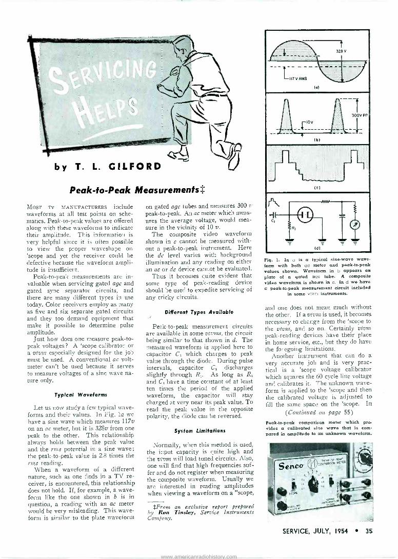
by T. L. ClLFORD
Peak -to -Peak Measurements
MOST TV MANUFACTURERS include waveforms at all test points on sche- matics. Peak -to -peak values are offered along with these waveforms to indicate their amplitude. This information is very helpful since it is often possible to view the proper waveshape on 'scope and yet the receiver could be defective because the waveform ampli- tude is insufficient.
Peak -to -peak measurements are in- valuable when servicing gated agc and gated sync separator circuits, and there are many different types in use today. Color receivers employ as many as five and six separate gated circuits and they too demand equipment that make it possible to determine pulse amplitude.
Just how does one measure peak -to - peak voltages? A 'scope calibrator or a vtvm especially designed for the job must be used. A conventional ac volt- meter can't be used because it serves to measure voltages of a sine wave na- ture only.
Typical Waveforms
Let us now study a few typical wave- forms and their values. In Fig. la we have a sine wave which measures 117v on an ac meter, but it is 328v from one peak to the other. This relationship always holds between the peak value and the rms potential in a sine wave; the peak -to -peak value is 2.8 times the rms reading.
When a waveform of a different nature, such as one finds in a TV re- ceiver, is encountered, this relationship does not hold. If, for example, a wave- form like the one shown in b is in question, a reading with an ac meter would be very misleading. This wave- form is similar to the plate waveform
on gated agc tubes and measures 300 y
peak -to -peak. An ac meter which meas- ures the average voltage, would mea- sure in the vicinity of 10 v.
The composite video waveform shown in c cannot be measured with- out a peak -to -peak instrument. Here the dc level varies with background illumination and any reading on either an ac or dc device cannot be evaluated.
Thus it becomes quite evident that some type of peak -reading device should be used to expedite servicing of any tricky circuits.
Different Types Available
Peak -to -peak measurement circuits are available in some vtvms, the circuit being similar to that shown in d. The measured waveform is applied here to capacitor C1 which charges to peak value through the diode. During pulse intervals, capacitor C1 discharges slightly through R1. As long as R1
and C, have a time constant of at least ten times the period of the applied waveform, the capacitor will stay charged at very near its peak value. To read the peak value in the opposite polarity, the diode can be reversed.
System Limitations
Normally, when this method is used, the input capacity is quite high and the vtvm will load tuned circuits. Also, one will find that high frequencies suf- fer and do not register when measuring the composite waveform. Usually we are interested in reading amplitudes when viewing a waveform on a "scope,
*From an exclusive report prepared by Ron Tinsley, Service Instruments Company.
Ällk- 328 V
.1_,,7v RMS 91. (a)
1r300V
-__ PP
__LI0v (>)
: --1.-., _ - (:)
J 0 011
RI
(,1)-
fì -
Fig. 1. In a is a typical sine -wave wave- form with both ac meter and peak -to -peak values shown. Waveform in b appears on plate of a gated agc tube. A composite video waveform is shown in c. In d we have a peak -to -peak measurement circuit included
in some vtvm instruments.
and one does not mean much without the other. If a vtvm is used, it becomes necessary to change from the 'scope to the 'vtvm, and so on. Certainly vtvm peak -reading devices have their place in home service, etc., but they do have the foregoing limitations.
Another instrument that can do a very accurate job and is very prac- tical is a 'scope voltage calibrator which squares the 60 -cycle line voltage and calibrates it. The unknown wave- form is applied to the 'scope and then the calibrated voltage is adjusted to fill the same space on the 'scope. In
(Continued on page 55)
Peak -to -peak comparison meter which pro- vides a calibrated sine wave that is com- pared in amplitude to an unknown waveform.
SERVICE, JULY, 1954 35
www.americanradiohistory.com
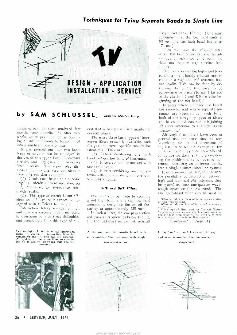
Techniques for Tying Separate Bands to Single Line
V _____,r DESIGN APPLICATION
INSTALLATION SERVICE
by SAM S C H L U S S E L, Channel Master Corp.
INTERACTION FILTERS, analyzed last month, were described as filter net- works which permit antennas operat- ing on different bands to be combined into a single transmission line.
It was pointed out that two basic types of circuits can be employed in devices of this type: Parallel -resonant circuits and high-pass and low-pass filter circuits. The report also dis- closed that parallel -resonant circuits have inherent shortcomings:
(1) Leads must be cut to a specific length to obtain efficient operation on vhf; otherwise, an impedance mis- match results.
(2) This type of circuit is not effi- cient on uhf because it cannot be de- signed with sufficient bandwidth.
Interaction filters employing high and low-pass circuits have been found to overcome both of these difficulties and accordingly it is this type of cir-
Left to right: At left is a vhf interaction filter. In center, an interaction filter for combining one vhf and one uhf antenna. At right is an interaction filter for combin- ing up to two vhf antennas with one uhf
antenna.
cuit that is being used in a number of current filters.
There are three basic types of inter- action filters presently available, each designed to cover specific installation situations. They are:
(1) Filters combining one high band and one low band vhf antenna.
(2) Filters combining one uhf with one vhf antenna.
(3) Filters combining one uhf an- tenna with one high -hand and one low - band rhf antenna.
VHF and UHF Filters
One unit can be made to combine a vhf high -band and a vhf low -band antenna by designing the cut-off fre- quency at approximately 125 mc'.
In such a filter, the low-pass section will pass all frequencies below 125 mc, and the high-pass section will pass all
A vhf yogi and uht bow -tie joined with
an interaction filter and used with single
transmission line.
frequencies above 125 mc. (One must remember that the low band ends at 88 mc, and the high band begins at 174 mc.)
Then we have the vhf-ith f filter which has been found to have the ad- vantage of unlimited bandwidth, and does not require any specific lead lengths.
One can also use the high- and low- pass filter as a highly efficient unit to combine a vhf and vhf antenna into one leadin. This can be clone by de- signing the cutoff frequency to be somewhere between 216 Inc (the end of the vhf band) and 47O me (the be- ginning of the uhf band).2
In areas where all three TV bands are received, and where separate an- tennas are required for each band, both of the foregoing types of filters can be combined into one unit joining all three antennas to a single trans- mission line'
Although these filters have been in general use for some time, to our knowledge no detailed discussion of the installation techniques required for all three types has ever been offered. Many are for the first time encounter- ing the problem of tying together an- tennas, operating on different bands, into a single transmission line system.
It is recommended that, to eliminate the possibility of interaction between high and low -band vhf antennas, they be spaced at least one -quarter wave- length apart on the low band. The vhf hi/lo-band filter can be used to
'Channel Master Tenna-Tie is representative of this type of filter.
»Channel Master Ultra -Tie; cutoff frequency is 325 mc.
'This type of filter, such as Channel Master Triple -Tie, combines one vhf low -band antenna, one vhf high -band antenna, and one uhf antenna into a single transmission -line system.
(Continued on page 54)
A high -band vhf and low -band vhf yogi
tied to an interaction filter for use with a
single lead.
36 SERVICE, JULY, 1954
www.americanradiohistory.com
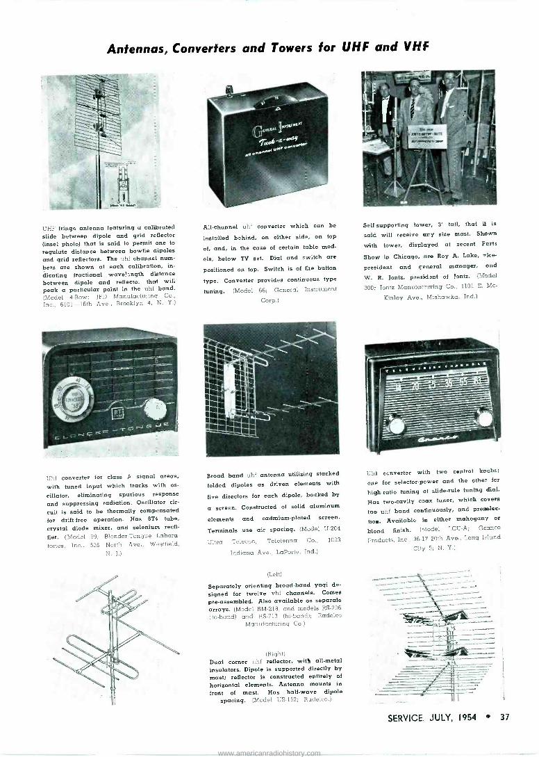
Antennas, Converters and Towers for UHF and VHF
UHF fringe antenna featuring u calibrated slide between dipole and grid reflector (inset photo) that is said to permit one to
regulate distance between bowtie dipoles and grid reflectors. The uhf channel num- bers are shown at each calibration, in-
dicating fractional wave! _ngth distance between dipole and reflecto'. that wili peak a particular point in the uhf band. (Model 4 -Bow; IT'D Manufacturing Co.,
Inc., 6101 -16th Ave., Brooklyn 4, N. Y.)
Uhf converter for class A signal areas,
with tuned input which tracks with os-
cillator, eliminating spurious response and suppressing radiation. Oscillator cir-
cuit is said to be thermally compensated for drift -free operation. Has 6T4 tube, crystal diode mixer, and selenium recti-
fier. (Model 99; Blonder -Tongue Labora-
tories, Inc., 526 North Ave., Westfield, N. I.)
All -channel uhf converter which can be
installed behind, on either side, on top
of, and, in the case of certain table mod-
els, below TV set. Dial and switch are
positioned on top. Switch is of the button
type. Converter provides continuous type
tuning. (Model 66; General Instrument
Corp.)
Broad band uhf antenna utilizing stacked
folded dipoles as driven elements with
five directors for each dipole, backed by
a screen. Constructed of solid aluminum
elements and cadmium -plated screen.
Terminals use air spacing. (Model U-204
Ultra Telecon; Teletenna Co., 1033
Indiana Ave., LaPorte, Ind.)
(Left)
Separately orienting broad -band yagi de-
signed for twelve vhf channels. Comes pre -assembled. Also available as separate arrays. (Model RM -218, and models RS -206
(lo -band) and RS -713 (hi -band); Radelco Manufacturing Co.)
(Right) Dual corner uhf reflector, with all -metal insulators. Dipole is supported directly by mast; reflector is constructed entirely of
horizontal elements. Antenna mounts in
front of mast. Has half -wave dipole spacing. (Model US -152; Radelco.)
Self supporting tower, 3' tall, that i3 is
said will receive any size mast. Shown
with tower, displayed at recent Parts
Show in Chicago, are Roy A. Lake, vice-
president and general manager, and
W. R. Jontz, president of Jontz. (Model
300; Jontz Manufacturing Co.. 1101 E. Mc-
Kinley Ave.., Mishawka, Ind.)
Uhf eonverter with two control knobs;
cute for selector -power and the other for
high -ratio tuning of slide -rule tuning <Eal.
Has two -cavity coax tuner, which covers
the uhf band continuously, and preselec-
tion. Available in either mahogany or
blond finish. (Model LCU-A; Guarico
Products, Inc., 36-17 20th Ave., Long Island
City 5; N. Y.)
-. &1..:._._.. li SERVICE JULY, 1954 37
www.americanradiohistory.com

BIAS Circuitry in Hi-Fi Amps Cathode -Biasing Systems Used to Provide DC Heater Current . . .
Faulty Bias Symptoms and Cures by MARK VINO
Fig. 1. Basic circuit providing automatic bias control. In the Brook amplifier, push-pull cathode followers are inserted between the input transformer and output stage. The A lead is connected to plate of separate rectifier.
Fig. 2. Low-level heaters supplied with cc cathode current, eliminating hum from heater -to - cathode leakage in the tube.
IT IS POSSIBLE to bias an amplifier with an automatic control system. One such circuit for output stages has ap- peared in recent years'; it operates from a separate voltage source, as in fixed -bias circuits, but it varies the bias voltage to provide opti- mum operation at different power levels. The circuit' shown in Fig 1, provides class A operation up to about 5 watts, after which there is a gradual transition to class AB,, at 30 watts. The bias voltage on the output stage is dependent on the plate current flow through V,, which in turn is controlled by the amplitude of the output signal current through R,. (The voltage drop across R, is injected as a signal between grid and cathode of V,.)
Direct -Coupled Bias In direct -coupled circuits the plate
voltage of one stage is applied directly to the following grid. This must be counterbalanced by a slightly higher positive voltage between cathode and the grid return, leavii.g the final grid potential negative with espect to cathode. A common appht ation of this principle is in the first voltage amplifier and cathode -loaded phase- splitter of the Williamson amplifier.
Cathode Bias Circuits to Provide DC Heater Current
The current flowing in the cathode - bias resistor of a pair of output tubes is often about 150 mils; the value of current needed for most 12 -volt heat- ers and certain 6 -volt heaters. One can take advantage of this by inserting the heaters of the lowest level stages (preamps low-level voltage amplifiers, etc.), in series with the output stage cathode line, as illustrated in Fig. 2.
The problem of hum pickup from these heaters is thereby eliminated, since the heaters are being operated on dc instead of ac. The dc source of heater current is absolutely free, as the output cathode current has to flow whether or not it is used for heaters, and one saves all or part of the price of a high -wattage cathode resistor.
The circuit of Fig. 2 sometimes comes in handy when installing a pre -
(Continued on page 57) 1J sed in the Brook amplifier.
38 SERVICE, JULY, 1954
www.americanradiohistory.com

A PERFORMANCE
Introducing the longest line of replacement loud speakers with the
lowest inventory requirement.
The highest performance in replacement loud speakers at the
lowest cost.
THE NEW Viking Replacement Speakers by JENSEN.
Completely redesigned for all today's requirements, the new Viking
speakers are completely streamlined both fer stocking, selling and
performance. Viking is the most complete line for radio, TV, replace-
ment and general purpose applications-there are 13 models includ-
ing 3 ovals BUT because of the ingenuity of the Jensen design, you need only one
universally applicable model in each speaker size. Your inventory
requirements are lower than for any other speaker line-your stock
investment is cut to the bone.
And the Viking speakers are universal. The new Viking design is
the most compact, has the least depth of all the replacement speak-
ers. They'll fit into even the most crowded sets. And with the most
compact design Viking has introduced greatly improved efficiency,
heavier magnets, truly permanent alignment, at no increase in price
in all models 6" and smaller.
Free with all sizes from 3" to 6" Viking speakers new free, easy -
mount combination transformer and chassis mount bracket.
ellMANUFACTURING COMPANY engen
Division of The Muter Company 6601 South Laramie Avenue Chicago 38, Illinois In Canada: COPPER WIRE PRODUCTS, LTD., Licensee
www.americanradiohistory.com

THE ADVENT of commercial uhf TV broadcasting introduced numerous probems, particularly in the design of a tuner which could operate over the wide range of 50 to 900 me for low and high -band use.
Recently, a solution was found in a 3 -tube unit' featuring a novel turret switch. In the circuit, a 6T4 is used in the local oscillator, which functions on the fundamental and above signal frequency on all channels, an impor- tant factor, since allocations are based on this standard to lessen interference problems.
The oscillator is of the ultra-audion type ; found to be very stable at all fre- quencies Voltage requirements were not found to be critical; B+ varies from 10 nia on channel 2 to 28 ma on channel 83. Optimized injection is said to be assured with link coupling fed in at the cathode of the mixer, using a 6AN4 mixer -amplifier tube to
[See Front Cover]
12 -Position Channel 2 -to -83 Turret Tuner With RF Amp and Tube Mixer t
achieve conversion gain, rather than loss, found to be the case with crystals.
The rf amplifier employs another 6AN4, connected in a grounded -grid circuit, resulting in a gain of 6 db at channel 83. The vhf performance of this tube has been found to be equal to cascode type front ends currently used in vhf tuners.
In the past, it was opined, that the cross -modulation characteristics of the 6AN4, when used in grounded -grid circuitry, would prove to be very poor. However during a test in a tube plant lab, it was found that the cross -modu- lation factor of the tube was better than in crystal -type tuners. One does not deny that it is possible to obtain lower noise factors in crystal -type tuners with the use of selected crystals ;
but it has been found that many of the absolute noise measurements are pure- ly academic and can not be taken at
'Anchor Radio model TV -900.
Circuit of Anchor TV -900 12 -position turret tuner capable of receiving any channel from 2 to 83. Unit features rf amplification plus a tube mixer operating in the veryhigh and ultrahigh bands. (See Cover.)
IF OuIDYf
Loe 4a. COupUng Leo
eso Reo
RSI
Ant.nna
C40 6AN4
C3
W, 31
Lw
de UHF Antenna
Segm.nt
IlfCe
250V
135 V
= C3
Ci
UHF Antenna Segment
C30
L30
UHF RF Segment
VHF RF e
S.gment J
6AN4
2
C20
L20
O.Cillato S.gment
:keel Re
Ce e a2 CI C14 LO x Re Re 00000 Nee,»
13 000000
LII
their face value. Many other factors such as impedance match, tracking and tuner insertion loss etc., must be con- sidered.
A maximum of twelve channels can be inserted into the turret assembly of the toner. Grouping is optional in ac- cordance with local requirements. The channel segments, consisting of a set of three which fit into the oscillator, rf and antenna section of the tuner, contain the proper lumped 1-c combina- tions, pretuned to a specific channel frequency. The antenna segment con- tains L and C.g which are series resonant with the input of the rf am- plifier and are coupled through L,1 to the antenna. The rf segment contains a double -tuned transformer (L,,, L2 and Cgs) which couples the output of the rf amplifier to the input of the mixer. The oscillator segment contains the frequency -determining resonant circuit, L. and C., and inductor L21, which primarily serves as the local os- cillator feed (link coupling) to the mixer.
The difference between the vhf rf and the uhf rf segments are merely in the method used to reduce the tube loading of the resonant circuits in- volved. Because of the large fre- quency range required for complete coverage of the present TV spectrum, it was found necessary to incorporate both inductors and capacitors in the segments. By changing the values of these inductances and capacitances mounted on the segments, full cover- age was found possible and complete control of bandwidth, gain etc., was maintained. Thus each channel could be optimized and no wide -range com- promises made.
Physically the turret assembly, on which the segments mount, consists of
(Continued on page 42)
t From exclusive information supplied by William Claps, chief electronics engineer, Anchor Radio Corp.
40 SERVICE, JULY, 1954
www.americanradiohistory.com

...and STILL THE LEADER IN ITS FIELD
for performance, versatility and value - the popular PRECISION
ES -500A HIGH SENSITIVITY
WIDE -RANGE
5" OSCLIOSCOPE
The famous ES -500A incorpo- rates advan:ed engineering features arC refinements so necessary to meet the more critical needs of modern electronic c'rcuit analysis, AM, FM and TV.
SERIES ES -50031: it louvered, black ripple -finished, heavy gauge steel case, 81/4 x 141 x 18". Com- plete with removable light shield, calibrating mask and detailed instruct òn manual Net Price: $173.70
AT LAST... A Reliable, General -Purpose
5" OSCILLOSCOPE at PricedOnly X12750
The new ES -520 is PRECISION -engineered in response to long and growing demand for a reliable, factory -made, general purpose 'scope at a price within reach of all to whom initial investment is of extreme importance.
The ES -520 conforms to every PRECISION standard of quality, workman- ship and performance. It is a completely factory -engineered, factory -wired and
factory -calibrated instrument ... ready to go to work fcr you the moment you
take it out of its carton!
SPECIFICATIONS
* Push -Pull vertical drive. 20 millivolts per inch sensitivity. * 3 -Step, frequency -compensated, vertical input attenuator. * Vertical frequency response 20 cycles to 500 KC within 2 DB * 1 volt, peak -to -peak, built-in vertical voltage calibrator.
* Excellent vertical square wave response from 20 cycles to 50 KC. tir Push-pull horizontal drive. 50 millivolts per inch. * 'H' frequency response 20 cps to 200 KC within 3 DB (at full gain). * Internal linear sweep 10 cycles to 30 KC. Neg. and pos. sweep synch. * Tube Complement: 12AU7 'V' cathode follower and amplifier, 6C4
phase-splitter, 12AZ7 push-pull 'V' drive. 6AB4 'H' amplifier, 12AZ7 push-pull 'H' drive. 12AU7 sweep oscillator. 6X4 rectifier, 1V2 high potential rectifier, NE -51 calibration regulator, 5UP1 CR tube.
* Built-in 60 cycle sine -sweep phasing control. * Beam modulation input terminal at front of panel. * All 4 deflection plates directly accessible at rear. * Filter -type, removable calibrated graph -screen. * Etched, anodized, heavy gauge aluminum panel.
SERIES ES -520: In black ripple finished, rugged steel cabinet, 8'/4 x 141/2 x
161/2". Complete with all tubes, inc!uding 5UP1 CR tube. Comprehensive instruc- tion manual. Code: Quest. Shipping weight: 30 lbs. Net Price: $127.50.
PRECISION TI'T EOUImNT PRECISION Apparatus Company, Inc.
92-27 HORACE HARDING BLVD., ELMHURST 6, N. Y.
Export Division; 458 Broadway, New York 13, U.S.A. Cables: Morhanex Canada: Atlas Radio Corp., Ltd., 560 King Street W., Toronto 2B
SERVICE, JULY, 1954 41
www.americanradiohistory.com

there is
a correct
CORNELL-DUBILIER REPLACEMENT*
VIBRATOR for every
original equipment vibrator made
all you need is C -D
*ask your distributor for your "C -D VIBRATOR GUIDE"
CONSISTENTLY DEPENDABLE
CORNELL-DUBILIER SOUTH PLAINFIELD, NEW JERSEY
ROTORS CAPACITORS VIBRATORS ANTENNAS CONVERTERS
(Continued from page 40) two separate turret sections, mechan- ically coupled together but electrically shielded from one another by means of a metal partition which form two complete cavities within the tuner housing. The front cavity houses the oscillator turret in which the oscillator segments arc placed. The back cavity contains the amplifier turret on which the rf and antenna segments are in- stalled. The metal partition separating these two cavities tends to reduce oscillator radiation to a minimum. To further aid in controlling oscillator radiation, a multiple section power
lead filter system was included; Rs, C,2, R3 and C14.
The fine tuning capacitor, C,, con- sists of two cylindrical plates con- nected to the grid and plate leads from the 6T4 and a gold -coated mica plate which is moved to and away from the cylindrical plates to change the capa- city between the oscillator grid and plate circuitry. Mechanically this is accomplished Pv means of a cam mounted outside of the tuner housing and rotated with the fine tuning shaft.
The TV signal, be it vhf or uhf is coupled by L41 to L«,, which is pre - tuned with C4a, and the input imped-
ance of the rf amplifier, to a specific channel frequency. Since the input of the grounded -grid amplifier is on the order of 100 ohms, the loading effect of the tube is controlled by the size of C.. The smaller the capacity, the less the loading effect. Beginning with channel 14, the loading effect is fur- ther reduced by the addition of C41.
The self bias and plate current is fed through L. with Ro and C. cathode - bias resistor and bypass capacitor. The rf amplifier is thus shunt fed.
No agc connection is provided, mainly because of the difficulty in ob- taining an rf ground at the grid of the amplifier over the complete fre- quency range. However, in this type of tuner, overloading, which normally occurs without agc, first shows up in the mixer due to the gain of the am- plifier. Now, when the signal level approaches the oscillator -injection level, the output of the mixer will no longer increase proportionally to the signal increase. Distortion of the sig- nal is further minimized because of the low input impedance of the grounded - grid amplifier in normal operation and due too to the fact, that this input impedance changes only slightly with grid current How caused by strong signals.
Thus, due to the linearity of the rf amplifier operating at a 1.3-v bias with 200 y at the plate, plus the minimized clipping effect in the grounded -grid amplifier and mixer, agc was not found necessary. During actual field tests it was found impossible to overload the tuner.
The output of the amplifier on chan- nels 2 to 13, requires no reduction in
tube loading and the plate circuit is
simply tuned by La,. To reduce tube loading on channels 14 through 83, a
shunt -fed system was incorporated; uhf rf segment L3 C. and the tube are resonant and B+ is fed to the tube through a choke. A two -section rc fil-
ter (C3, R3, C7, R7 and Ca) is used in plate supply to the amplifier. Its func- tion is to reduce the plate voltage to 200 and eliminate resonant lead effects from the amplifier, thus effecting com- plete isolation of the amplifier.
The mixer -input circuit consists of Ls,, and C., which are resonant and coupled to L3,. This arrangement was found to assure the required double - hump response and a bandwidth of 6 to h mc. Control of the bandwidth is accomplished primarily by the coupling between L3. and L3,, and the loaded Q of the mixer circuit. The complete resonant circuit is C., L33 and Ln, with mixer loading across Ln. Here we find that L. controls mixer loading at the lower frequencies, while C. be- comes effective over the higher fre-
42 SERVICE, JULY, 1954
www.americanradiohistory.com

quency range; L.1 also provides in- jection to the mixer. The amount is
optimized by the amount of coupling with the oscillator coil L. R. and C,,
the cathode resistor and bypass ca- pacitor for the mixer, together with the plate circuit resistors, R. and R61,
establish the characteristics of the 6AN4 as a mixer.
The plate circuit of the mixer is tuned to the if. In the schematic low - side coupling is shown. However, on the tuner, this if transformer assembly is mounted as a separate unit, which facilitates variations without affecting the tuner circuitry.
From the Service Man's viewpoint, the tuner provides an extension of vhf practices into the uhf range. If it be- comes necessary to change the oscil- lator tube and it is desired to trim the oscillator, a hole provided in the center of the fine tuning cam permits access to the oscillator slug. Thus the oscillator segment can be quickly re- tuned on any channel from 2 to 83, in the same manner as on a vhf tuner.
Actually the only field adjustments provided are the if transformer and the oscillator segment. There are no provisions for other adjustments nor are they required in field service. In this tuner, three tuned circuits plus the rf amplifier are effective; this has been found not only to improve perform- ance, but aid in minimizing the radia- tion problem.
The entire construction of this tuner has been based on control of radiation, with a view of bringing them below FCC standards.
Summarizing, the tuner features separate oscillator and rf cavities, no solid metal shaft extending through the tuner, and power distribution on the top side of the chassis with feed - through capacitors to the various sec- tions of the tuner circuitry ; eleven of the feed -through capacitors are used in the filter networks. All rf ground returns of the mixer and amplifier stages are floating. This was accom- plished with specially shaped metal pieces that form the connecting pat- tern and by-pass systems all at once.
This particular type of wiring method was necessary to achieve elec- tronic duplication of chassis in produc- tion. On the other hand it also pro- vided a cold chassis, of extreme im- portance in combating radiation prob- lems. Not only did this eliminate the need for solder bonding of any of the structural metal parts, but it also al- lowed the chassis to be mounted on top of the turret assembly with the use of spring clips. This approach provided a one -plane tuner chassis, quickly re- movable for service, with all connec- tion and components fully accessible.
CRYSTAL PICKUP CARTRIDGES
feehetV,92 cartridges you are most likely to encounter
in your service work!
MODEL RK -54 Replacement Kit List Price 522.55 ° .
TECHNICAL DATA AND REPLACEMENT CHART IS ENCLOSED.
Lists 192 Crystal Cartridges manufactured by
five leading cartridge manufacturers.
Lowest investment for broadest coverage! The RK -54 is beyond all doubt the most practical Replacement K i t on the market! Proof? Simply this -you get the broadest coverage at the lowest investment-only $22.55 list!
Think of it -3 Crystal Cartridges replace 192 of those specific Cartridges most likely to be in need of replacement! Two of the Cartridges consistently have been "best sellers" in the Shure line-as established by actual sales to Servicemen! The Cartridges are: Model W22AB, 3 -Speed, 2 -Needle Cartridge-Model W26B, All -Purpose, Single -Needle Cartridge-Model W78, 78 RPM, Dual -Volt, Dual - Weight Cartridge. Model W78 is the new, versatile Cartridge that replaces 149
other Cartridges! This Cartridge alone will become a sensation overnight! Order a Replacement Kit from your Distributor today --once you have worked with this practical kit you will find that these three Cartridges are dependable re-
placements-will make your service work faster, easier and more profitable!
TRANSPARENT PLASTIC BOX IS FREE! This Handy Box is 5" long, 3%" wide, 1%" deep.
pignik 0[,--2(te SERVICE, JULY, 1954 43
www.americanradiohistory.com

TUNG-SOL TUBE QUALITY &4/4 dnQ/ulletind PAYS OFF IN SALES !
Black and White Picture Tubes
Special Purpose Tubes
Radio and TV Receiving Tubes
Dial Lamps
The performance quality of Tung -Sol Tubes will keep customers convinced that you're the best serviceman in the business. Tung -Sol Tubes meet highest set manu- facturers' specs-protect you against call-backs Tell your supplier you'd rather have Tung -Sol
TUNG-SOL ELECTRIC INC., Newark 4, N. J.
Sales Offices: Atlanta, Chicago, Columbus, Culver City (Los Angeles), Dallas, Denver, Detroit, Newark, Seattle
TUNG-SOL ELECTRON TUBES
P. R. MALLORY AND CO., INC., Distributor Division, P. O. Box 1558, Indianapolis, Ind., has published a 61 -page stand- ard stock catalog, 554, describing batteries, capacitors, con- trols, resistors, rectifier stacks, switches, vibrators, mobile and ac -operated power supplies, TV components and equip- ment, and test equipment.
* * *
MUELLER ELECTRIC Co., 1583 E. 31st St., Cleveland 14, Ohio, has released an 8 -page catalog, 150, detailing battery and test clips, insulators for clips, antenna -clamp stand-off insulators and battery charging jumpers. .. .
* * *
INTERNATIONAL RESISTANCE CO., 401 N. Broad St., Phila- delphia 8, Pa., has prepared catalog data bulletin G-1, on type my high -voltage resistors.... Catalog data bulletin F-1, detailing data on 43 types of yip high -frequency resistors, and bulletin N-1, on type 1N series germanium diodes, are also available.
JAN HARDWARE MANUFACTURING CO., 75 N. 11th St., Brooklyn 11, N. Y., has released a 6 -page data chart, list- ing stock magnetic shields and bezel combinations which fit most standard picture tubes. Also described are by in- sulated couplings, panel bearings, jack covers. shaft locks, bushing extenders and shock testers.
* * *
RECOTON CORP., 147 W. 22nd St., New York 11, N. Y., has issued a revised Simplified Reference Guide, containing in- formation on replacement needles. A replacement needle chart and manufacturers' cross index are included.
:k * *
UNITED TRANSFORMER CORP., 150 Varick St., New York 13, N. Y.. has published a 26 -page catalog, A, describing its line of transformers. Detailed are: linear standard audio types; output transformers; compact audio units ; herme- tically -sealed components; variable inductors; inter -stage and line filters, and audio amplifiers, in kit form, featuring pc chassis.
TECHNICAL APPLIANCE CORP., Sherburne, N. Y., has an- nounced publication of localized catalogs, arranged to in- clude only those antennas and accessories that are specifically designed for the area served by a Service Man.
* * *
'l'RIAD TRANSFORMER CORP., 4055 Redwood Ave., Venice, Calif., has issued a 28 -page catalog, TR -54, listing more than 500 transformers, as well as 11 new amplifier kits for hi-fi, plus hermetically -sealed power components, an instrument power supply, filament chokes, and power and audio trans- formers.
IIALLDORSON TRANSFORMER CO., 4500 Ravenswood Ave., Chicago 40, III., has published catalog 22 which features an expanded line of transformers, with special emphasis on TV components. Both specific and multi -purpose replacements for popular TV models and chassis are described and illus- trated. Catalog also contains comprehensive range of power and audio transformers, reactors, and varivolts.
* * *
CHANNEL MASTER CORP., Ellenville, N. Y., has announced publication of a 20 -page loose-leaf general catalog which illustrates and describes more than 125 different items, in- cluding both vhf and uhf antennas, masting, towers, mounts, interaction filters, and general accessories. Most of the antenna information is supplemented by technical data, in- cluding gain curves and horizontal polar patterns.
44 SERVICE, JULY, 1954
www.americanradiohistory.com

4,o ciati'h4 RTSA, Pittsburgh
Tonx F. COCHRAN has been reelected president of the Radio and Television Servicemen's Association of Pittsburgh, Inc.
Others elected include: Philip J. Polito, first vice presi- dent ; J. A. Shafer, second vice president ; E. A. Roberts, treasurer; Tons Ging, secretary; and Bert Brezenger, pro- gram and publicity chairman.
At an all -industry banquet of the group in the Elks Club. Dan Creato, RCA Service Company vice prexy and ye editor were honored guests. Dan reviewed the prospects of color TV, while ye ed presented a report on trends in industry.
Those at the dinner included the chief engineers and man- agers of local TV stations, component and set distributors. and members of RTSA.
Bert Brezenger served as toastmaster. * * *
RTG, L. I.
THE GUILD NEws, published by the Radio Television Guild of Long Island, continues to sparkle with timely photo - reports on service aids, association activities and color TV. Current issue describes working color demonstrations staged recently before the group using RCA color set and Tele - chrome Chromalvzer.
Discussed also are techniques to be used in renewing an old cabinet with flocking material, and improving flyback checkers. A quiz, entitled How do you rate with your cus- tomers. was another featured item in the News,
* * *
ORTSA, Wisconsin
VERNON TOWNSEND has been elected president of the Indian - head Radio-TV Servicemen's Association, Eau Claire, Wis. Other elected officers include: Earl Kratch, vice president; C. Lip. Stiemke, secretary, and Upton St. Clair, treasurer.
Nominations and elections followed the annual banquet meeting at the Empire Cafe, Chippewa Falls.
* * *
RSA, Luzerne County, Pa.
THE EiGI):TH ANNUAL clambake of the Radio Servicemen's Association of Luzerne County, Wilkes-Barre, Pa., was re- cently held at Lily Lake.
Among those at the outing were Fred Scleniadt, ,Milan Krupa, Joseph Czapracki, Maurice Rader, Bert Brezenger, Leon Helk, William Landsberg, William Deardorf, Max Leibowitz, John Wheaton and O. Capetelli, representing RSA, FRSAP, PRTSA, MRSA, LRTA, ARTT, RTSEA, ESFETA, ARTSNY and RTG, from Luzerne County, Pitts- burgh, Harrisburg, Scranton, Williamsport, Altoona, Cham- bersburg, New York City and Long Island.
Ye ed was guest speaker.
TEN YEARS AGO TUBE supplies for consumers were reported to be on the increase for the remainder of the year, due to increased production, stockpiles of military types and backlog cutbacks. . Results of a magazine survey among receiver owners revealed that 65% of those interviewed planned to buy a radio after the war ; 57% of this group chose radio -phono combinations, 22% chose a table model, 21% a console and 3% selected TV.... Ralph S. Mueller described the evolution of the clip.... Front cover featured circuit of a high-fidelity audio system of a 12 -tube AM/FM receiver (Zenith 12H689) with 6 -position push-button tone control. . . .
Dan Fairbanks, formerly with IRC, was named jobber sales man- ager for Cornell-Dubilier Electric Corp. . . . Illinois Condenser Co. added another floor to its facilities at their plant at 1160 N. Howe St., Chicago. Jerome J. Kurland joined the company as chemical engineer.
TUNG-SOL TECHNICAL DATA
PAYS OFF IN SERVICE!
T-58 730 pages 500 tube types
NEW! 1954 Edition! T-70 160 pages of dota on CR tubes, receiving and special tcbes, dial lamps
T-31 300 blueprint base d aç-ans for 1100 tube types
Here's the most practical set of rube reference books in the industry-all the information you need for everyday jobs! They're easy ro read-easy to use (always lie flat when open.) You'll get work done faster with Tung -Sol Technical Data Books. Ask your tube supplier about them.
TUNG-SOL maker All -Glass Sealed Beam Lamps, Miniature Lamps, Signal Flashers, Picture Tubes, Radio, TV and Special Purpose Electron Tubes and Semiconductor Products
TUNG-SOL TECHNICAL
SERVICE, JULY, 1954 45
www.americanradiohistory.com

The TARZIAN
TUNER
UW 13 All Channel
Combination UHF- VHF
A compact, combination tuner (the world's smallest) for covering the entire UHF -VHF bands.
Straight line electrical sequence of com- partmented circuits.
Simple, coaxial tuning.
O Stage shielded.
OVERALL PERFORMANCE MAKES ANY SET A BETTER SET.
Frite for folder covering complete description and performance data.
SARKES TARZIAN, Inc. Tuner Division Bloomington, Indiana
Service Engineering
field and shop notes
by THOMAS K. BEAMER
THE CRYSTAL filter in a communication -type receiver is used as a series -resonant circuit. The crystal is ground to the intermediate frequency, and when switched into the circuit, allows only the exact -frequency signal to pass. In effect, it is a very steep -sided bandpass filter; so sharp that it usually distorts voice transmissions. Because of this needle -point characteristic the if stages must be precisely tuned to the exact frequency; otherwise very poor results will be obtained. There are several techniques that can be used to align the if stages.
Instrument Setup for Alignment
One of the simplest is to set a signal generator to the exact crystal frequency, using the crystal itself as a standard. Both the receiver and signal generator must be warmed up for at least a half-hour, before beginning the alignment, to avoid the effects of temperature drift. The crystal should be left in the receiver. (This method applies only to those sets which use the plug-in type of crystal; if the crystal is con- cealed in a can, another approach must be used.) The crystal must be removed from its socket and the signal generator output lead connected to one pin. The hot lead of an ac vtvm should be connected to the other, connecting the grounds of the two instruments together, although this is not too essential. The vtvin should now be set to its lowest scale, 3 y or so, and the signal generator's attenuator set to approxi- mately the output needed for alignment; this should be about half -scale on its lowest range. If the attenuator is frequency - sensitive, this setting should not be disturbed. It may cause a change in frequency if moved. Next, the signal -generator should be tuned to the approximate frequency (kc) of the crystal, 455, 456, or whatever it is, and tuned very slowly until a reading is noted upon the meter. This reading need not be large ; anything that will give a readable deflection will be sufficient. When the signal generator is peaked upon the crystal frequency, it should be disconnected from the crystal, connected to the set, and the alignment can be begun. The signal generator is now tuned to the exact frequency of the crystal. The crystal can be left out of the circuit entirely until the if stages have been aligned, or replaced
Setting signal -genera- tor to exact frequen- cy of crystal. One lead of generator is connected to crystal; one lead to ac-vtvm. Signal generator is tuned for maximum deflection on vtvm; it is then on exact frequency of crystal.
46 SERVICE, JULY, 1954
www.americanradiohistory.com
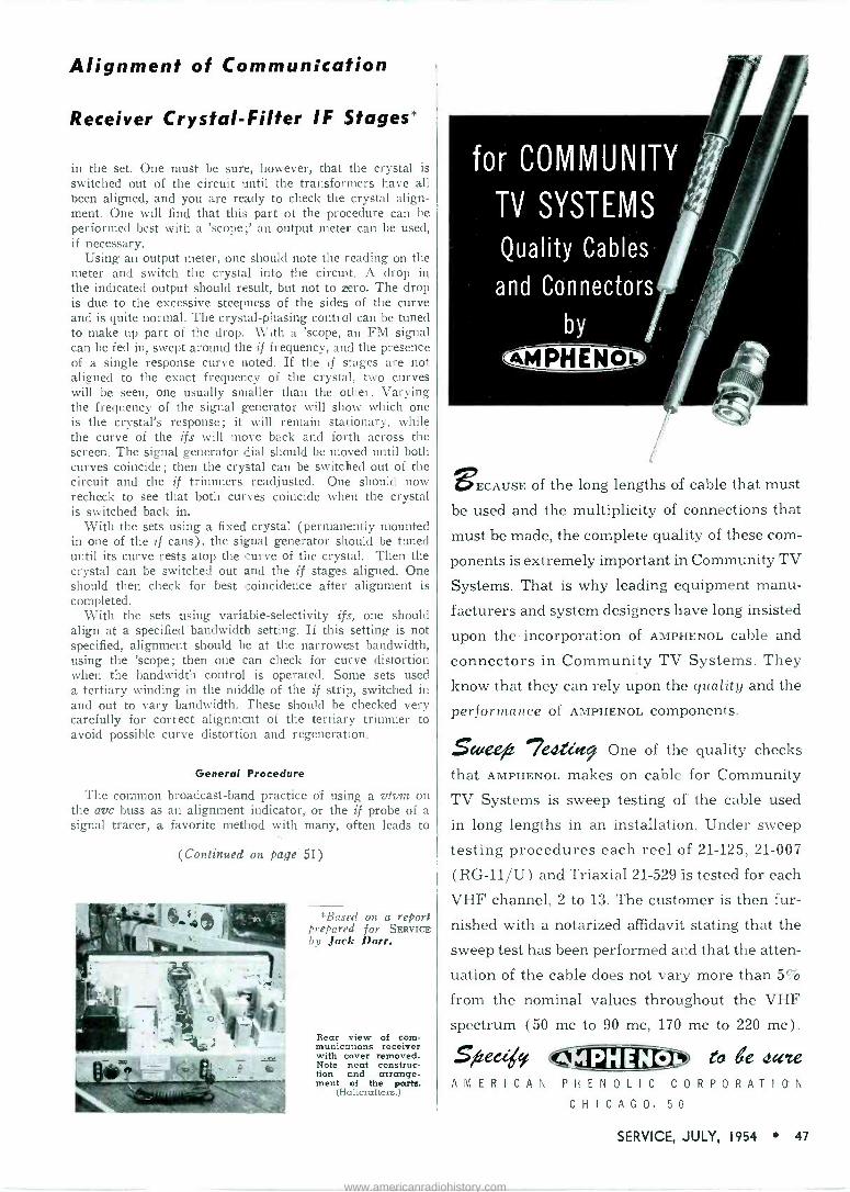
Alignment of Communication
Receiver Crystal -Filter IF Stages*
in the set. One must be sure, however, that the crystal is switched out of the circuit until the transformers have all been aligned, and you are ready to check the crystal align- ment. One will find that this part of the procedure can be performed best with a 'scope;' an output meter can be used, if necessary.
Using an output meter, one should note the reading on the meter and switch the crystal into the circuit. A drop in the indicated output should result, but not to zero. The drop is due to the excessive steepness of the sides of the curve and is quite normal. The crystal -phasing control can be tuned to make up part of the drop. With a 'scope, an FM signal can be fed in, swept around the if frequency, and the presence of a single response curve noted. If the if stages are not aligned to the exact frequency of the crystal, two curves will be seen, one usually smaller than the other. Varying the frequency of the signal generator will show which one is the crystal's response; it will remain stationary, while the curve of the ifs will move back and forth across the screen. The signal generator dial should be moved until both curves coincide; then the crystal can be switched out of the circuit and the if trimmers readjusted. One should now recheck to see that both curves coincide when the crystal is switched back in.
With the sets using a fixed crystal (permanently mounted in one of the if cans), the signal generator should be tuned until its curve rests atop the curve of the crystal. Then the crystal can be switched out and the if stages aligned. One should then check for best coincidence after alignment is completed.
With the sets using variable -selectivity ifs, one should align at a specified bandwidth setting. If this setting is not specified, alignment should be at the narrowest bandwidth, using the 'scope; then one can check for curve distortion when the bandwidth control is operated. Some sets used a tertiary winding in the middle of the if strip, switched in and out to vary bandwidth. These should be checked very carefully for correct alignment of the tertiary trimmer to avoid possible curve distortion and regeneration.
General Procedure
The common broadcast -band practice of using a vtvin on the avc buss as an alignment indicator, or the if probe of a signal tracer, a favorite method with many, often leads to
(Continued on page 51)
*Basest on a report prepared for SERVICE by Jack Darr.
Rear view of com- munications receiver with cover removed. Note neat construc- tion and arrange- ment of the paru.
(Halicrafters.)
for COMMUNITY
TV SYSTEMS
Quality Cables
and Connectors
BECAUSE of the long lengths of cable that must
be used and the multiplicity of connections that
must be made, the complete quality of these com-
ponents is extremely important in Community TV
Systems. That is why leading equipment manu-
facturers and system designers have long insisted
upon the incorporation of AMPHENOL cable and
connectors in Community TV Systems. They
know that they can rely upon the quality and the
performance of AMPHENOL components.
ScueeA 9817ecteiet9 One of the quality checks
that AMPHENOL makes on cable for Community
TV Systems is sweep testing of the cable used
in long lengths in an installation. Under sweep
testing procedures each reel of 21-125, 21-007
(RG -11/U) and Triaxial 21-529 is tested for each
VHF channel, 2 to 13. The customer is then fur-
nished with a notarized affidavit stating that the
sweep test has been performed and that the atten-
uation of the cable does not vary more than 5%
from the nominal values throughout the VHF
spectrum (50 mc to 90 mc, 170 mc to 220 mc) .
AMERICAN AMPHENok PHENOLIC CORPORATION CHICAGO. 50
SERVICE, JULY, 1954 47
www.americanradiohistory.com

j13 THE ABILITY OF TUBES to operate satisfactorily under wide variations of temperature, vibration conditions and shock has always been considered as a principal feature, particularly for in- dustrial and military applications. On many occasions, it has been found that extreme temperatures and severe vi- bration were the basic causes of tube failures.
A number of avenues of development have been followed to produce rugged tubes that would stand up under all types of adverse conditions.
Realizing that rapid strides in elec- tronics pointed toward the future need for tubes not only with unique high- performance properties, but also capa- ble of unprecedented mass -production should a national emergency arise, en- gineers of one manufacturer' sug- gested to the Navy- that a special re- search project be set up to develop tubes that would meet such specs.
The government approved the plan and a few weeks ago the results of
(Right)
Characteristics of Stacked -Element
dews by E. A. TEVERSON
the study were annotu.ced. It was found that a new type of rugged tube could be made by using a ceramic en- velope or cap, instead of the usual glass bulb, with the elements stacked one atop the other in the assembly process. In addition, ceramic spacers could be employed instead of mica.
In describing the tube at a confer- ence in N. Y. City, Dr. Bennett S.
Ellefson, director of research for Syl- vania, said that sealing is done with a bell -jar system; a glass dome under which the stacked parts are placed, air -evacuated, and the tube envelope sealed over the stacked parts.
Commenting on the tube's rugged- ness, and ability to withstand shock and %ibration without deterioration of performance, Dr. Ellefson said that contributing to this ruggedness was the substitution of ceramic spacers for
'Sylvania. 'Bureau of Ships.
Stacked tube assembly, center, showing a mount on which the tube components have been stacked by automatic production
methods. Finished tube is at the right. (Sylvania)
mica spacers. In extreme operating conditions, it was said, mica has a
tendency to spall and flake under vi- bration and shock, causing mechanical tube failure.
Whereas a feature of the new de- velopment was the ceramic envelope, the stacked structure of the tube was described as lending itself to the use of either a glass or ceramic envelope, depending upon the ultimate applica- tion.
The complete mount of the tube is
assembled on two small pins. First a
plate, a spacer ceramic, a grid, a
spacer ceramic, a cathode, a spacer ceramic, and so on until the top is
reached. When the stack is completed, the small pins are then electrically riveted.
The ceramic material used for the envelope and stem is aluminum oxide. Sealing the envelope and stem together is a single-step process. No mica is
used in the mount, and it can, there- fore, be placed on a ceramic stem and
Left: Exploded view of the ceramic tube's stem and mount; in progression on two small pins are stacked a plate, spacer ceramic, grid, spacer ceramic, cathode, spacer ceramic, and so on until the top is reached. Drawing at right shows the difference between the cathode support assembly of a conven- tional vacuum tube, left, and that of a stacked tube. Wire loops of the cathode fit over the rivet insulator posts, and the two ceramic washers at the top then are lodged above the loops.
48 SERVICE, JULY, 1954
www.americanradiohistory.com
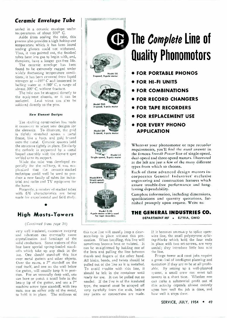
Ceramic Envelope Tube
sealed in a ceramic envelope under temperatures of about 950° C.
Aside from sealing the tube, this process also provides a high baking -out temperature which it has been found sealing glasses could not withstand. Thus, it was pointed out, the finished tubes have less gas to begin with, and, therefore, have a longer gas -free life.
The ceramic envelope has been found to be extremely rugged under widely fluctuating temperature condi- tions; it has been removed from liquid nitrogen at -195° C and immersed in boiling water at +100° C, a range of almost 300° C, without fracture.
The tube can be strapped directly to the equipment chassis, or it can be socketed. Lead wires can also be soldered directly to the pins.
New Element Designs
The stacking construction has made it necessary to adapt new designs for the elements. To illustrate, the grid is tightly stretched across a metal frame, like a harp, and gold brazed onto the metal. Ceramic spacers hold the structure tightly in place. Similarly the cathode is supported by a metal looped assembly with the element spot welded onto its support.
While the tube was developed es- pecially for the military, it was em- phasized that the ceramic -stacked technique could well be used to pro- duce a new family of tubes for indus- trial and radio and TV equipment for the home.
Presently, a number of stacked tubes with 616 characteristics are being made for experimental and field study.
High Masts -Towers (Continued from page 34)
very well insulated, excessive swaying and vibration can eventually cause crystallization and breakage of the solid conductors. Some makers of this line have special spring -loaded stand- offs which take up any slack in the ine. One should stand-off this line over metal gutters and other objects. Over the eaves, a 7" standoff on the roof itself, and one on the wall below the gutter, will usually keep it in posi- tion. For an unusually deep wall, one can bore or punch a small hole in the heavy lip of the gutter, and use a 7" machine screw type standoff, with two nuts, one on either side of the metal, to hold it in place. The stiffness of
Model SS 3 -speed, 2 -pole motor
Model DSS 3 -speed, 4 -pole motor
Model DR 2 -speed, 4 -pole motor
>` Model LC Single speed, 2 -pole motor
Model D-10 4 -pole motor widely used
for tape recorders
The Complete Line of
Quality Phonomotors
FOR PORTABLE PHONOS
FOR HI-FI UNITS
FOR COMBINATIONS
FOR RECORD CHANGERS
FOR TAPE RECORDERS
FOR REPLACEMENT USE
FOR EVERY PHONO APPLICATION
Whatever your phonomotor or tape recorder requirements, you'll find the exact answer in the famous Smooth Power line of single -speed, dual -speed and three -speed motors. Illustrated at the left are just a few of the many different types from which to choose. Each of these advanced design motors in- corporates General Industries' exclusive engineering and construction features which assure trouble -free performance and long- lasting dependability. Complete information, including dimensions, specifications and quantity quotations, fur- nished promptly upon request. Write to:
THE GENERAL INDUSTRIES CO. DEPARTMENT MF EL'!RIA, OHIO
this type line will usually keep a clear- ance -loop in place without this pre- caution. When handling, this line will sometimes become bent or twisted. It can be straightened by holding one of the bars and pulling the line between thumb and fingers of the other hand. All kinks, bends, and twists should be pulled out of the line as it is installed. To avoid trouble with this line, it should be left in the container until ready for use. It can be pulled out as needed. If the line is of the insulated type, the enamel must be scraped off very carefully from the ends, before any joints or connections are made.
If it becomes necessary to splice open - wire line, the small polystyrene splic- ing -blocks which hold the four ends in place with two set -screws, are very useful; they introduce little loss into the line.
Fringe tower and mast jobs require a great deal of intelligent planning and execution if they are to be at all profit- able. By setting up a well -planned system, a small crew can erect tall towers in a short time. Whether one can make a substantial profit out of this activity depends almost entirely upon how well the job is done, and how well it stays done.
SERVICE, JULY, 1954 49
www.americanradiohistory.com

kfl 1
HE WANTS
iir:_,,-)i TECHNICAL EXCELLENCE
SHE WANTS
FINE FURNITURE
YOU SATISFY BOTH WITH
Manfredi HI-FI SPEAKER ENCLOSURES
HUMMINGBIRD - Model 800 for 8" speaker; 1200 for 12" speaker. Com- pact without loss of performance ... excellent tonal fidelity.
FLAMINGO - Model 2000 - Univer- sal cabinet and speaker enclosure . , , maintains high acoustical integ rity. Houses complete hi-fi system . , .
finest woods and veneers, 361/8" x 221/4" x 181/2" deep.
You protect your own reputa- tion when you sell a Manfredi cabinet or enclosure-the woods stand up...performance stands out! This excellence has been the mark of Manfredi craftsmen for over a quarter - century. Write for illustrated brochure.
Man f rcJí [WOOD PRODUCTS CORP.:
226 New York Ave., Huntington, L. I., N. Y.
Community TV (Contiuucd from page 23)
permeable shield and dissipated inside the cable in terminating and isolation resistors, and in the input circuits of amplifiers and receivers.
In a practical cable system, though, it was noted, the shielding is perme- able, and minute fractions of the signal carried within the system leak out at various and sundry points.
There are a great many different sources or causes of radiation, some being related to system design and others a consequence of defective workmanship, materials or mainte- nance, or of the ravages of time, Brown emphasized.
In a commentary on signal levels and radiation, the cable specialist said that since all system leaks involve radiation of some fraction or percent- age of the total signal carried inter- nally by the system, the level at which the system operates has a direct effect on the strength and nuisance value of the radiated signal. In different types of systems, it was noted the maximum levels range from 30 db above one millivolt per channel to 66 db and higher; the higher levels permit use of fewer amplifier stations, longer runs, and cables of higher loss. However, it was emphasized the savings achieved by use of higher levels must be bal- anced against the cost of the increased attention which must be given to radi- ation problems both at the time of installation and during maintenance of operation. It has been found that types of cable and shielding or maintenance methods producing negligible radiation in a system operating at 40 db can produce serious interference and steal- ing' problems when used in a similar system operating at 60 db. Noting specific sources of radiation, Brown listed receiving antennas, which may radiate local oscillator harmonics or other signals originating in the equip- ment to which they are connected; splitters, tapoffs and other accessories ;
cable connectors and cable splices. Cable connectors were described as
a very important and often unsus- pected source of leakage in systems which have been in operation for a year or more. Such leakage may vary widely with humidity and temperature and may either disappear or be aggra- vated when the connector is manipu- lated.
Noting that the TV signal from the amp fitting flows through the outer shield walls of the connector and then into the cable braid, Brown said that even a very small resistance in the
>Many have used induction field probes and multi -element yagis pointed at cable, with ele- ment tips almost touching to pick up community TV signals.
The COMPLETE line .
Paging
8 Talk -Back
Speakers
DR Double -Reentrant Projectors
ALNICO -V -PLUS
Driver Units
Public Address need!
WRITE NOW for FREE Catalog 553 FULL GRIP, VELVET -ACTION
Mike Stands
1442 39th Sf., Brooklyn 18, N. Y. In Condo. Ado. Radio Corp., Ud.. Toronto, OM.
outer shield connection can cause seri- ous radiation ; with an amplifier run- ning at lv output, a connector resist- ance of 0.075 ohm will develop a volt- age of 1000 microvolts applied between the amplifier case and the braid of the cable, with no perceptible change in the signal inside the cable. Thus, conferees were told that because of the wide variation of contact resistance with temperature, humidity, and han- dling, troubles of this sort frequently elude accurate diagnosis.
It was also reported that small solderless coax connectors tend to loosen from temperature cycling and develop contact resistance between two sections of the connector. Sol- derless connectors, which have been sealed with waterproof compound, dis- connected, and then reconnected, fre- quently develop vary high contact re- sistance between two parts due to some of the compound becoming lodged in the joint, it was said. Deterioration of the joint between the cable braid and the connector was cited as another source of contact resistance. This trouble was described as resulting from loss of clamping ferrule pressure or moisture entry and attendant cor- rosion.
Braided coax cable was held prob- ably responsible for some 75% of the
50 SERVICE, JULY, 1954
www.americanradiohistory.com

radiation from community antenna systems, although it receives credit for about 99% of the radiation. Semi - flexible coax cables with continuous tubular metallic outer conductors, it has been found, do not produce any measurable radiation.
Cable -Radiation Cure Proposals
Five ways to reduce cable radiation were proposed:
Single braided cable should be re- placed with a double braided cable; by far the most expensive solution, this approach should not be undertaken hastily.
All single braided cable running above some intermediate level, say 30 db, should be replaced with double braided cable.
Signal levels in the cable should be reduced; this usually requires inser- tion of additional intermediate ampli- fiers which may, however, be highly desirable for other reasons.
The entire line, including coax cables and messenger, can be covered with a single sheath of highly conduct- ing metallic foil, preferably aluminum. Strips of household freezer foil, ap- plied lengthwise to the line in 50' or greater lengths and overlapped one foot at joints and bound tightly have been found to cut radiation as much or more than installation of double - shielded double -jacketed cable. The wrapping, it was noted, can be applied selectively and on short notice to com- bat stealing or to satisfy radiation complaints. It was found that there is a serious practical disadvantage of aluminum foil wrapping; the perma- nence of the shielding effect depends on the permanence of the bonds at the ends of the lengthwise pieces of foil and upon the wrapping not becoming broken. (No paint of sufficiently high conductivity to provide economical cable shielding has been found, and it appears unlikely that such a paint can be developed.)
[Next Month: System Amps and Cables]
Service Engineering (Continued
trouble in comet sets. The trouble seems to be due to a reradiation of an if signal from the unshielded por- tion of the probes themselves, which cause the if stages to spill over. The old-fashioned output meter across the speaker will probably give the best results as a general alignment indica- tor. One should be sure that the noise limiter is switched out of the circuit when aligning, as some very peculiar curves can be obtained when the set is aligned with this in the circuit.
Recalibration
Recalibration of multi -band re- ceivers is quite different from the practice followed with broadcast chassis, with no padder and only one trimmer. Tracking is another problem frequently encountered; the set may be right at both ends of the band, but severely out of calibration in the center. This is often caused by the oscillator trimmer set on the image instead of the fundamental.
The rf and antenna -stage alignment will also affect sensitivity of these sets; most of them incorporate at least one stage of tuned rf amplifica- tion, sometimes two, with both trimmer and padder adjustments for each band, making very accurate adjustments important.
Trimmer adjustments are usually mounted adjacent to the coils tuned by them, and are accessible through holes in the bottom cover of the set, which must be in place during align- ment. Trimmers and padders are seldom labelled and it is a good idea to identify them with numbers on the bottom plate, at each access hole, to speed the process. It might be helpful to note the frequency at which each is adjusted, also; C-10, B 8 me which would mean C-10, band B. These are generally arranged in rows, so that
from page 47) all the trimmers or padders for one band will be in the same row. It might also be a good idea to draw a line between the rows, designating one as band, B, C, etc., to avoid confusion. In some sets, low -frequency padding adjustments are made from the top of the chassis, while the high -frequency trimmers are tuned from beneath; in others all adjustments are made from the bottom.
On cocoon models it is conventional practice to begin alignment with the highest -frequency band, working down to the lowest. When adjusting oscilla- tor trimmers, especially on the bands above 10 me or so, one must be sure that the oscillator trimmer is not set on the image frequency, the beat -note generated about twice the if frequency away from the correct setting. To check for this, the output of the signal generator should be increased and tuned to a point twice the if down the dial. The image heard there will be much weaker than the signal. Oscilla_ tors in most sets work above the received signal.
If the dial is off, quite a bit, it is sometimes easier to walk the signal down the dial to the correct point than to try to adjust to it after setting the dial. The signal on the set should be tuned, noting which way it must be moved; i.e., up or down the dial. If it must be moved up to a higher fre- quency, the trimmer must be loosened to leave less capacity in the circuit. The trimmer should be turned just a bit, and the dial moved until the signal is tuned in. The trimmer and dial should be moved alternately until the signal is heard at the correct place on the dial. This operation is not as difficult as it sounds, and is
actually speedier than trying to locate the correct signal by turning the trimmer, since most of the trimmers
(Continued on page 55)
RETMA MEDAL OF HONOR WINNER OLD TIMER PREXYS MEET
(Left)
Robert C. Sprague, left, chairman of the board of Sprague Electric, receiving the RETMA Medal of Honor from Glenn Mc- Daniel, RETMA president, during annual association meeting in Chicago. Sprague, third to receive the medal in the asso- ciation's history, was honored for his con- tributions to the progress of the electronics
industry.
(Right)
Incoming president of Radio's Old Timers, Charley Golenpaul (right) presenting out- going president Ray Triplett, who has rounded out his 50th anniversary as a radio -electronic equipment manufacturer, with a testimonial plaque, which mounts gold-plated Triplett tube tester of the '29 vintage, during the recent Parts Show in
Chicago.
SERVICE, JULY, 1954 51
www.americanradiohistory.com

YOU CAN WIN A NEW FORD!
Nothing to buy! Nothing to sell!
Just Illustrate and Explain a New Application for
International Rectifier Corporation Selenium Diodes
50 PRIZES Grand Prize
New Ford V-8 Mainliner Tudor Sedan and 49 other
valuable prizes INTERNATIONAL RECTIFIER COW_ PORATION'S Selenium Diode Ap- plication Contest is open to every- one! Here's all you have to do - pick up an official entry blank from your favorite parts distrib. utor. Illustrate and explain a new practical application for Interna. tional Rectifier Selenium Diodes. Have the entry blank counter- signed by your distributor's sales- man and then forward it to us before January 1,1955. Rules and regulations for this contest are included in the entry blank along with helpful hints on selenium diode applications.
JUDGES-Dr. Lee de Forest-United Engineering Labs., Los Angeles, California. J. T. Cataldo, F. W. Parrish-International Rectifier Corp.
SAMPLE ENTRY -APPLICATION-
-EXPLANATION- Typical application for providing fixed bias for push-pull stage of an audio system using International Rectifier Corp. Selenium Diode in conjunction with a voltage divider and filter net- work... etc.,... etc.
DON'T DELAY! ENTRY BLANKS ARE AVAILABLE FROM YOUR
PARTS DISTRIBUTOR CONTEST ENDS JANUARY 1ST, 1955
INTERNATIONAL RECTIFIER CORP. EL SEGUNDO, CALIFORNIA
Audio (Continued from page 24)
deemphasis in the receiver, provides an effective signal-to-noise ratio. The problem of obtaining sufficient audio gain together with the necessary pre - emphasis, system designers found could be solved by providing an omni- directional ceramic microphone car- tridge, with a response which very closely approximated the desired pre - emphasis curve.
In the rf section of the transmitter a self-controlled oscillator, reactance modulator and a rf amp were included.
The use of any sort of afc in the transmitter was found to be impracti- cal due to the complex circuitry and the minute space available; thus it was necessary to design an oscillator -mod- ulator circuit with sufficient frequency stability. This has been achieved by a modulator grid -bias circuit, with the bias derived from a self -rectified volt- age developed by oscillator and amp grids. As the plate and filament batteries weaken, it was noted that the transconductance of the reactance modulator tends to be reduced, causing the carrier frequency to shift. How- ever, the circuit has been so designed that the dc grid bias of the modulator is changed in such a fashion that its transconductance variation is substan- tially reduced.
The complete transmitter, excluding the antenna and tubes, occupies a volume of about one cubic inch. Here there are eight capacitors, eleven resistors, a volume control, five sub- miniature tube sockets, and a powdered iron core oscillator coil, a cylinder 1" in diameter and 1.3" long. Two printed circuit plates form the basic structure of this chassis.
In the receiver, a superhet, there's a pentode, tuned rf amp with a band- width of 150 kc; a pentode mixer with a separate triode oscillator is used. A pentode reactance modulator provides
afc. In a wide -band if amp there are two pentode amp stages, two cascaded triode limiters and a Foster -Seeley discriminator ; output of the discrimi- nator is fed through a gated, cathode follower triode to the audio output terminals of the receiver. In a car- rier -operated squelch circuit, there is a triode dc amp.
A double -target tuning eye, con- trolled by the outputs of the discrimi- nator and the first limiter, has been included to aid tuning. With this eye. it is possible to tune both the oscillator and antenna circuits of the transmitter. A 3 -position switch on the receiver shifts the frequency of the oscillator in 50-kc steps to provide three operat- ing channels. These can be used when more than one system might be oper- ated simultaneously in the same area or when strong interference is experi- enced on any one channel. In view of the rf amp's 150-kc bandwidth, no retuning of the receiver is required.
Installation Notes
Usually, the receiving antenna for this system will consist of a copper wire installed in the form of a loop surrounding the operating area. The effectiveness of such a receiving loop will vary with the shape and area of the loop. The amount of noise picked up by the loop (in a given location) will be proportional to its enclosed area, while the amount of signai picked up from the transmitter will decrease rapidly as the distance between the transmitter and the closest part of the loop is increased.
A length of copper wire of any con- venient size can be tacked or taped around the operating area. Ordinary magnet wire or bell wire has been found satisfactory, the gauge being determined by mechanical considera- tions. The wire can be placed under the floor, tacked around the baseboard or platform edge or around the ceiling,
Faster, Easier, more PROFITABLE Operation Get into the MASTER habit!
Brings you the product data of the industry in one handy book - all products vital to your daily sales and service operations. In the customer's home, across the counter or on the bench, you'll value the MASTER'S
thoroughly complete descriptions, specs, illus- trations and prices . . . all systematically organized in 18 big sections. Over 1300 pages of unabridged catalog data direct from the manufacturers. Keeps you abreast of oll latest Electronic products. Increase your sales and speed-up your buying - the MASTER way.
As $ Low
Eliminates As Small
Catalogs and
Loose
Literature
95 at your parts distributor. Publisher's price $6.50.
OFFICIAL BUYING
GUIDE OF
ELECTRONICS -TV-
RADIO INDUSTRY
1370 pages
8"x11"-S lbs.
Over 8,000 flies.
Just a few of the
more than 85,000
items included:
Tubes-Transmitters Test Equip.- Receivers
Transformers
Capacitors- Antennas
Resistors-Wire & Cable
Coils & Relays
Recording & PA
Harderare iì Toois
Get your MASTER now from leading parts distributors or write to: United Catalog Publishers, Inc., 110 Lafayette St., N. Y. 13
52 SERVICE, JULY, 1954
www.americanradiohistory.com
sewed around the edge of a carpet, etc. However, at all times the enclosed area must be kept as small as possible. The wire does not have to be insu- lated ; however, it should not be shorted to any pipes or electrical conduits.
The optimum shape and connection of the receiving antenna are deter- mined by experiment after the system is placed in operation. It is best that a temporary installation be set up until the best shape is determined.
After one decides on installation of the loop antenna, a location for the receiver must be determined ; two ends of the loop antenna must be connected to the receiver antenna terminals. The receiver should be placed as close to the loop as possible, and located where it is readily accessible and where connections to a power line and pa system, etc., can be conveniently made.
If the loop must be located at a dis- tance from the receiver, connection between the receiver and loop can be made by running parallel wires about 2" apart from the ends of the loop to the receiver location. This distance must be kept as small as possible. In some installations, TV twin -lead can be used for this purpose.
The voltage output and sensitivity of the system depends upon the output connection and setting of the trans- mitter gain control. In the receiver, there is provision for a microphone - level and phono -level outputs.
Typical Installations
In a night-club installation, the primary area of coverage desired is
the dance floor. The loop antenna wire should be stapled to the edge of the raised dance floor, and in addition, the upper runway and stair enclosed by the antenna wire. This will enable the me to use the microphone from the wing of the stage as he walks on stage.
Good performance can be achieved in the enclosed area and extending 10'-15' beyond the dance floor, outside the loop. The point of particular interest in this installation is the extension of the loop area to cover the runway and stair where operation of the microphone might be desired.
* * *
HERBERT A. BERNREUTER
Herbert A. Bernreuter, vice president and general manager of the Simpson Electric Co., 5200 W. Kinzie St., Chicago, Ill., died recently.
He was a director of Bach -Simpson Ltd., and held many patents in the elec- trical and electronic fields.
more servicemen prefer
STANCOR REPLACEMENT TRANSFORMERS
than all other brands combined*
because they like the .. ease of installation
completeness of the Stancor line
availability of accurate replacement information
rugged, breakdown -proof construction
quick delivery from distributor's stock
Stancor transformers are listed in Photofact Folders and Counterfacts
Brand Name Surveys, Chicago, Illinois; brand preference survey of electronic re- placement components, May, 1954. Answered by servicemen from all over the U. S.
FREE NEW STANCO7t GENERAL CATALOG
listing over 500 transformers for TV, radio, high fidelity, communications and other electronic applications. Available from your local Stancor distributor or by writ- ing Standard Division, Chicago Standard Transformer Corporation.
CHICAGO STANDARD TRANSFORMER CORPORATION 3588 ELSTON AVENUE CHICAGO 18, ILLINOIS EXPORT SALES: Roburn Agencies, Inc.
431 Greenwich Street, New York 13, N. Y.
FTR DIODE SELF-SERVICE DISPENSERS
A packaging program featuring self- service dispensers designed for germanium diodes, has been introduced by Federal Telephone and Radio Co., 100 Kingsland Rd., Clifton, N. J. Three packages and two types of dispensers have been created. Available are : Single diodes in cello- phane -wrapped packages, either individu- ally or in 50 -unit cartons, and five and ten unit packs of single crystal -stabilized diodes in reusable, clear plastic cases with hinged, snap -lock covers. Wall dispensers contain 50 of one diode type in individual packages; and counter dispenser accom- modates single packs, as well as the plas- tic cases with a choice of five or ten diodes to a container.
SERVICE, JULY, 1954 53
www.americanradiohistory.com

:2at r e mRt-<>:>.><:_. . iº 0.1R:>:>:::::::; `i Agre
Elik ituTEST
WAVE TRAP METER
Accurately Determines Line Filter or Antenna Wave Trap
Within Seconds.
RedV.es effects of i terf.r,ng
Nigh D toits used
fa meit .ffieiear t *moves most yiowe sosend NeTer..c. from amateur red... f oteri prend costs, dioMrn,,, etc
LINE FILTER
4 MODELS AVAILABLE
Aeweet<d, deter mia, d awssv,e heist is b..d. 51mrTlpn(>aSiy cht<4s iitao,on, elta,,, b;o.
,Nota,. anede .oFlogt, video .:90oi ot
tole* ,pa«et
Eloniastai 1n>wt4 ine i.dirrdval Filters or W Jeeps.
Elimbl.t.s hours troróte.shenJ
ày YVL... Redree. awe's i.v.ntory 41 Eittea5 ond lane
FILTRAN WAVE TRAPS
S Moduls
15 to 160 MC
Reduces. *Resin. e+ex effects of re. te,lean9 5,90.6 tótu Flo. et Tv or radie Cereplesely sh:etded.orereets JJIoy sitenol mek, KIP_
L*w puss fire*., , no tuning od tesigents Pt,,,. so,V
KINE-TEST Model
KT1
Electronics MFG CO.
EXECUTIVE OFFICES and PLANT
576 WEST MERRICK RD. LYNBROOK,N.Y.
r
NAME
idaire
VIDAIRE ELECTRONICS 576 West Merrick Rd.
Please Send FREE A LYNIROON.N.Y.II
Latest catalog "TV INTERFERENCE AND ITS REMEDIES
ADDRESS
CITY_ STATE
Color TV (Continued from page 31)
traps are at fault, since the chroma may be turned off with a customer -op- erated chroma control.
This particular receiver is of the R-Y/B-Y type, as opposed to an I- Q receiver. The sync detectors are made to detect along the R -Y and B -Y vectors, rather than along I and Q vectors. In this case, the R -Y and B -Y signals are treated with equal bandwidth, being approximately the same as the bandwidth required for the Q channel alone. This may be noted from Fig. 4 (p. 31), wherein the band- width of the chroma channel is shown to be - 600 kc referred to 3.58 mc. It has been determined by numerous ob- servers that widening the bandwidth of the chroma channel adds little, if any- thing to the ultimate color picture qual- ity. (One must bear in mind that the Y signals essentially provide all picture detail information and that only lim- ited detail is required in the reproduc- tion of the chroma portion of the pic- ture.)
In the process of bandpass limiting in the chroma channel, the chroma signals become unavoidably delayed, as would any signal which is passed through a low-pass filter or other band -limiting device. With the actual bandwidth employed, this delay be- comes approximately .8 microsecond. It is for this reason that a similar delay is incorporated in the Y channel to assure simultaneous arrival of both signal components at the adders. One distinct advantage of an R -Y, B -Y equal bandwidth receiver is the fact that only one delay line is required rather than two, as would be the case in an I -Q receiver which treats both pieces of chroma information with un- equal bandwidth.
As indicated, chroma signal output is taken from the chroma cathode fol- lower. Here again, it is necessary to obtain an adjustable level, low -im- pedance output. This requirement is established by the following sync color detectors.
It has been found necessary to shut off the chroma channel during the horizontal retrace interval to prevent erroneous operation of the dc restorers in the grid circuits of the picture tube. To prevent this difficulty, a negative - polarity horizontal blanking pulse is fed to the grid of the chroma cathode follower.
The chroma channel actually sup- plies two output signals. The first is the adjustable level chroma signal which is fed to the synchronous de- tectors, as mentioned. The other signal is also a composite chroma signal which is fed to the burst gate.
[To Be Continued]
lh4 60 ligT
R V ANTENNA
UNCONDITIONALLY
GUARAN7ffD for
100 MILES oNVHF
0 MILES oNUHf
BLACK&WHITE on
ALL CHANNELS 2-83 IN ALL DIRECTIONS
WITHOUT A ROTORMOTOR OF ANY KIND
ALL CHANNEL ANTENNA CORP. 47-39 49th STREET, WOODSIDE 77, N. Y.
EXETER 2-1336
TV Antennas (Continued from page 36)
combine single channel and broad- band yagis. Consequently, it is a pop- ular device not only in two -channel areas, but also in areas capable of re- ceiving many channels, particularly fringe areas. In such locations, it is not uncommon to find a filter combin- ing broad -band yagis for both the high band and the low band.
In areas where both uhf and vhf channels can be received, Service Men often have a choice of installing an all -channel vhf -uhf antenna or sepa- rate antennas for each baand. It is frequently more desirable for one to use separate antennas for each band because there then is the opportunity to select antennas peaked for the chan- nels involved; in addition one also has the opportunity of orienting the an- tennas separately.
Two different interaction filters are available for these situations, as noted. One type' combines a single uhf an- tenna with a single vhf antenna. It makes no difference what type of an- tennas are joined; these can be yagis, or broad -band types.
In many cases uhf stations have gone on the air in those areas where separate yagis had previously been
54 SERVICE, JULY, 1954
www.americanradiohistory.com
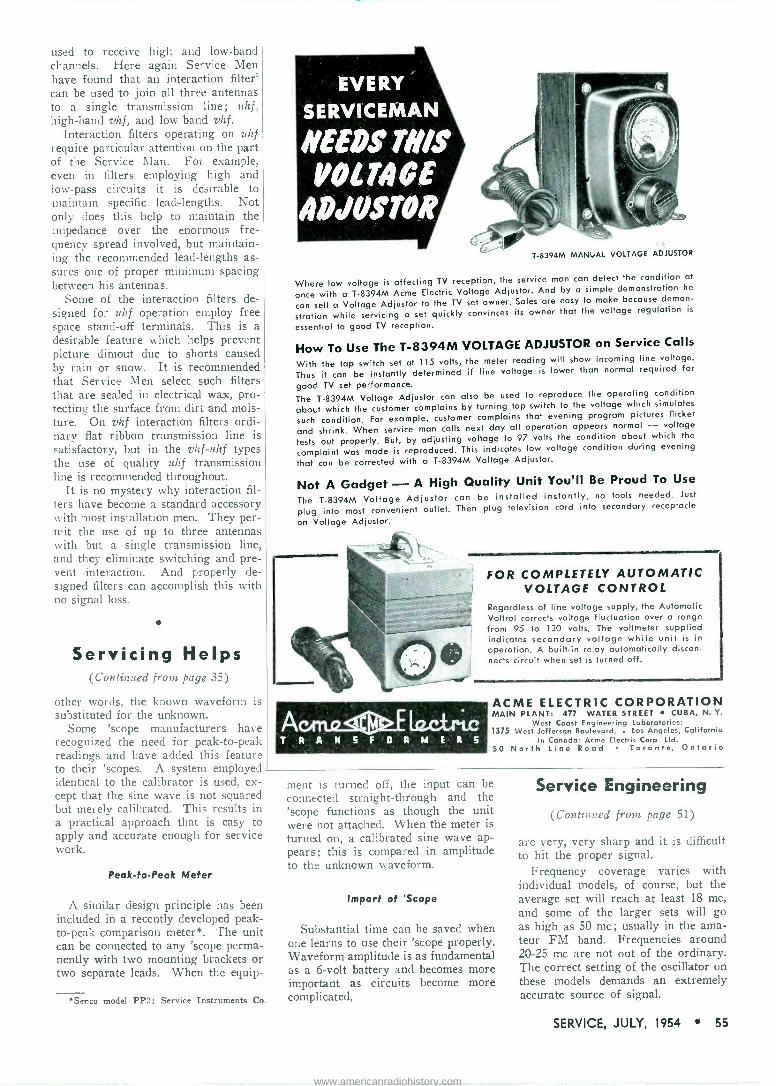
used to receive high and low -band channels. Here again Service Men have found that an interaction filters can be used to join all three antennas to a single transmission line; uhf, high -band vhf, and low -band vhf.
Interaction filters operating on uhf require particular attention on the part of the Service Man. For example, even in filters employing high and low-pass circuits it is desirable to maintain specific lead -lengths. Not only does this help to maintain the impedance over the enormous fre- quency spread involved, but maintain- ing the recommended lead -lengths as- sures one of proper minimum spacing between his antennas.
Some of the interaction filters de- signed for uhf operation employ free space stand-off terminals. This is a desirable feature which helps prevent picture dimout due to shorts caused by rain or snow. It is recommended that Service Men select such filters that are sealed in electrical wax, pro- tecting the surface from dirt and mois- ture. On vhf interaction filters ordi- nary flat ribbon transmission line is satisfactory, but in the vhf -uhf types the use of quality uhf transmission line is recommended throughout.
It is no mystery why interaction fil- lers have become a standard accessory with most installation men. They per- mit the use of up to three antennas with but a single transmission line, and they eliminate switching and pre- vent interaction. And properly de- signed filters can accomplish this with no signal loss.
Servicing Helps (Continued from page 35)
other words, the known waveform is substituted for the unknown.
Some 'scope manufacturers have recognized the need for peak -to -peak readings and have added this feature to their 'scopes. A system employed identical to the calibrator is used, ex- cept that the sine wave is not squared but merely calibrated. This results in a practical approach that is easy to apply and accurate enough for service work.
Peak -to -Peak Meter
A similar design principle has been included in a recently developed peak - to -peak comparison meter*. The unit can be connected to any 'scope perma- nently with two mounting brackets or two separate leads. When the equip -
EVERY
SERVICEMAN
NEEDS THIS VOLTAGE
ADJUSTOR
T -8394M MANUAL VOLTAGE ADJUSTOR
Where low voltage is affecting TV reception, the service man can detect the condition at
once with a T -8394M Acme Electric Voltage Adjustor. And by a simple demonstration he
can sell a Voltage Adjustor to the TV set owner. Sales are easy to make because demon-
stration while servicing a set quickly convinces its owner that the voltage regulation is
essential to good TV reception.
How To Use The T -8394M VOLTAGE ADJUSTOR on Service Calls
With the tap switch set at 115 volts, the meter reading will show incoming line voltage.
Thus it can be instantly determined if line voltage is lower than normal required for
good TV set performance.
The T -8394M Voltage Adjustor can also be used to reproduce the operating condition
about which the customer complains by turning tap switch to the voltage which simulates
such condition. For example, customer complains that evening program pictures flicker
and shrink. When service man calls next day all operation appears normal - voltage
tests out properly. But, by adjusting voltage to 97 volts the condition about which the
complaint was made is reproduced. This indicates low voltage condition during evening
that can be corrected with a T -8394M Voltage Adjustor.
Not A Gadget -A High Quality Unit You'll Be Proud To Use
The T -8394M Voltage Adjustor can be installed instantly, no tools needed. Just
plug into most convenient outlet. Then plug television cord into secondary receptacle
on Voltage Adjustor.
FOR COMPLETELY AUTOMATIC VOLTAGE CONTROL
Regardless of line voltage supply, the Automatic Voltrol corrects voltage fluctuation over a range from 95 to 130 volts. The voltmeter supplied indicates secondary voltage while unit is in operation. A built-in relay automatically discon- nects circuit when set is turned off.
ACME ELECTRIC CORPORATION MAIN PLANT: 477 WATER STREET CUBA, N. Y.
West Coast Engineering Laboratories: 1375 West Jefferson Boulevard. Los Angeles, California
In Canada: Acme Electric Corp. Ltd. 50 North Line Road Toronto, Ontario
Senco model PP2; Service Instruments Co.
ment is turned off, the input can be connected straight -through and the 'scope functions as though the unit were not attached. When the meter is turned on, a calibrated sine wave ap- pears; this is compared in amplitude to the unknown waveform.
Import of 'Scope
Substantial time can be saved when one learns to use their 'scope properly. Waveform amplitude is as fundamental as a 6 -volt battery and becomes more important as circuits become more complicated.
Service Engineering
(Continued from page 51)
are very, very sharp and it is difficult to hit the proper signal.
Frequency coverage varies with individual models, of course, but the average set will reach at least 18 mc, and some of the larger sets will go as high as 50 mc; usually in the ama- teur FM band. Frequencies around 20-25 mc are not out of the ordinary. The correct setting of the oscillator on these models demands an extremely accurate source of signal.
SERVICE, JULY, 1954 55
www.americanradiohistory.com

look for the Howard W. Sams
"BOOK TREE"
ePlpToiACT I Me
at your PARTS
DISTRIBUTOR
Make it a habit to "browse" at the
Howard W. Sams "Book Tree". You'll find it at your Parts
Distributor. It's loaded with the
time -saving, profit - building books you
want and need. Keep ahead with
these timely, practical publica-
tions that help you learn more and
earn more daily.
LOOK FOR THESE TITLES: Television Books
"Telecasting Operat. ions" .... ...... $7.95 "Photofact Television Course" 3.00 "TV Servicing Short -Cuts"..... ... 1.50 "TV Test Instruments" ... .... 3.00 "UHF Converters" 1.00 "UHF Antennas" 1.50 "'television Antennas" 2.00 "Servicing TV in the Customer's Home" 1.50 "Making Money in TV Servicing" 1.25 "TV 'rube Location Guide" Vols. 4, 3, 2. each 2.00 "TV Tube Location Guide" Vol. 1... 1.50
Audio Publications "Recording & Reproduction of Sound" $7.95 "Audio Amplifiers" Vols. .1, 3. 2. each .. 3.95
Record Changer Manuals "Automatic (Changer Manual" Vols. f., 1,:i, each. $3.00 "Automatic Changer Manual" Vol. 2 .. 4.95
Handy Service Guides "Radio Receiver Tube Replacement Guide" $1.25 "AM -FM Servicing Short -Cuts" 1.50 "Dial Cord Stringing Guide" Vols. 4, 3, 2,1, each 1.00
Auto Radio Service Manuals "Auto Radio Manual" Vols. 3, 2. each. $3.00 "Auto Radio Manual" Vol. 1. 4.95
Communications Receivers "Communications Receivers" Vols. 2, 1, each.$3.00
Coyne and Boyce Books "Coyne TV Servicing Cyclopedia" $5.95 "Coyne Transistors" 1.50 "Coyne Practical TV Servicing" 4.25 "Coyne Latest 'l'est Instruments" 3.25 "Coyne TV & Radio Handbook" 2.75 "Coyne Industrial Electronics" 3.75 "Boyce Video Handbook" 5.95 "Boyce Radio Handbook" 4.95
See these and dozens of other invaluable books on the Howard W. Sams "Book Tree"!
HOWARD W. SAMS & CO., INC. Indianapolis 5, Indiana
Look for these books
order them at your Parts Distributor
CBS-HYTRON KITS A pliers kit, available free with the
purchase of CBS-Hytron receiving tubes, from July 1 through August 31, has been announced by CBS-Hytron, Danvers, Mass.
Kit consists of a set of three pliers in a plastic carrying case. Pliers are 6" diagonal, a box -joint side -cutter with matched jaws; 8" long -nose, that is chrome -plated and has hand -honed cut- ting knives ; and 6" all-purpose, which combines flat and round nose, two wire strippers, and two side cutters.
An improved tube -and -tool caddy, that features a scuff -proof, soil -resistant vinyl plastic covering; heavy-duty metal cor- ner reinforcements; more space for GT tubes (holds 68 GT tubes, 210 tubes in all) ; one -inch deeper tool compartments; roomier door pocket for flashlight, man- uals, etc. ; 10" x 12" test mirror mounted inside the cover, has also been announced.
INTERNATIONAL RECTIFIER SELENIUM DIODE APPLICATION CONTEST
A nationwide contest, for new applica- tions of selenium diodes, has been an- nounced by the International Rectifier Corp., 1521 E. Grand Ave., El Segundo, Calif.
A Ford V-8 Tudor Maiuliner sedan will be awarded to the contestant sub- mitting the most useful and practical new application. In addition, 50 secondary prizes totaling $1500 will be awarded. The contest has no special requirements for participation and any and all persons are urged to compete. Deadline for all en- tries is January 1, 1955.
Dr. Lee deForesi, United Engineering Laboratories, Los Angeles, will be a con- sultant to final selection of the winning entry along with contest judges J. T. Cataldo, assistant general manager, and F. Il'. Parrish, design engineer.
* * *
TARZIAN SELENIUM SALVAGE DRIVE
A selenium rectifier salvage campaign, designed to alleviate an acute shortage of selenium throughout the country, has been announced by Sarkes Tarzian Inc., Rec- tifier Division, 415 N. College Ave., Bloomington, In(l.
Company will pay, in the form of credit against future purchases, for burned out or defective out -of -warranty recti- fiers, regardless of make. Call types wanted include 1" or 1.25" (models 65 through 150), awl 1.5"-l.6"-2" (models 250 through 500).
MAKES THE CLIPS! ALL TYPES -ALL SIZES at jobbers everywhere
Wee -Pee -Wee Clips
Pee -Wee Clips
Alligator Clip/A) Crocodile Clips
Shown in typical flexible insulator
Needle Clips zÿ Test Clips
SEND FOR FREE CLIP & INSULATOR SAMPLES! Pick from illustrations above.
5 INSULATOR COLORS now available for easy lead iden- tification. Black, Red, White, Blue and Yellow. Samples furnished on request. NEW CATALOG No. y573 ON REQUEST
y
SAMPLE BOARD
;V tt lli
li
efeffl.. IIIIIIII
Ask about handy, low cost display and selec- tion board, for depart- ment heads, ¡obbers, etc.
1573Y EAST 31st STREET CLEVELAND 14, OHIO
JENSEN MOVES TO CHICAGO SUBURB
Jensen Industries, Inc., has moved both factory and office headquarters from Chi- cago to 7333 W. Harrison, Forest Park, 111,
Facilities at Forest Park are all on one floor and provide double the floor space of all three floors in the old building.
* * *
SYLVANIA DISTRIBUTOR -DEALER PROMOTION
A 3 -month promotion, which will slake available to distributors and dealers an aluminum TV set carrier, Classe Chassis, for transporting TV sets, has been an- nounced by Sylvania Electric Products Inc., Nev; York, N. Y.
TV set carrier is of all aluminum con- struction and weighs 131 pounds, includ- ing ball -bearing rubber wheels.
56 SERVICE, JULY, 1954
www.americanradiohistory.com

Hi-Fi Amp Bias Circuitry (Continued from page 38)
amp into a system whose heater supply was not designed for low-level stages, and where the preamp introduces hum derived from heater -to -cathode coup- ling in the preamp tube. If the output tubes draw 150 mils of current, as do 6L6s, for example, the preamp filament can be connected into the output cath- ode circuit, rather than to the heater winding of the power transformer. The preamp tube itself, of course, must have a 150 -mil heater ; 6SC7s or 6SL7s must be replaced by 12SC7s or 12SL7s. Certain tubes designed espe- cially for preamp use, such as the 12AY7, can be operated with either a 6.3 y, .3 a heater supply, or a 12.6 v, .15 a supply, depending on whether the two heater sections are connected in parallel or in series.
When a tube filament forms part of the cathode bias resistance, the orig- inal cathode resistor must he changed to one of lower value. The new value may be calculated by Ohm's law, where E = the original cathode -to - ground voltage minus 12.6 (the volt- age used up by the tube heater), and I = .15 amp. It may also be checked experimentally; when the cathode-to-
NEW MULTIMETER
KIT
$2650
CONDENSER CHECKER KIT
$1950
VACUUM TUBE VOLTMETER KIT
$2450
TUBE CHECKER KIT
...d $2950
9;U
ground voltage of the new circuit is
the same as it was previously (assum- ing no original defects) R is of the correct value.
Symptoms of Faulty Bias
Incorrect bias voltage increases the distortion level of an amplifier by a large factor. This is especially true for high -amplitude signals, which cause the amplifier to overload and the sound to become mushy.
Too negative a bias will distort the sound but not damage the tubes. A bias voltage which is too little negative, on the other hand, or actually positive, will cause surplus current to flow and will quickly destroy the tube, possibly with internal fireworks. A fairly com- mon occurrence, especially with output tubes, is to find that a replacement for a defective tube soon goes bad itself. Insufficient negative bias must be suspected.
Correction In the fixed -bias power supply cir-
cuit (Fig. 4, June, 1954), the ground in the heater -return circuit of the rectifier was inadvertently omitted.
. SIGRNAL l, TRACER KIT
$2350
featllu't
e 3 NEW
SCOPE KI
$5950
TEST EQUIPMENT BUILD YOUR OWN - INCREASE KNOWLEDGE - SAVE MONEY - BUY DIRECT FROM MANUFAC- TURER ... Top quality instruments in kit form featuring latest design and cir- cuit developments. Completely detailed step-by-step construction manual-clear pictoria'.s - complete schematics. All sheet metal work punched, formed and finished.. Low kit prices include tubes,
i chassis, cabinet and all necessary con - f structional components.
Kits for the school -service shop- F' industrial laboratory-hobbyist, etc.
Write for free catalog for further information.
HEATH COMPANY BENTON HARBOR 11
MICHIGAN GRID DIP
METER KIT
$195°',
Mr. Serviceman
oxFoRws
REAR DECK SPEAKERS
mean MORE
PROFITABLE AUTO RADIO
WORK for YOU!
Preferred for Original
Equipment - Proven for
Replacement
Model RD -69
brr x 9rr $1340
Suggested list prict3
Model RD -57
5" x 7"
$1215 Suggested list prices
Sold Through Recognized Jobbers Only!
OXFORD ELECTRIC
CORPORATION 3911 SOUTH MICHIGAN AVENUE
CHICAGO 15, ILLINOIS EXPORT- ROBURNAGENCIES, NEW YORK CITY IN CANADA-ATLAS RADIO CORP. LTD., TORONTO
SERVICE, JULY, 1954 57
www.americanradiohistory.com
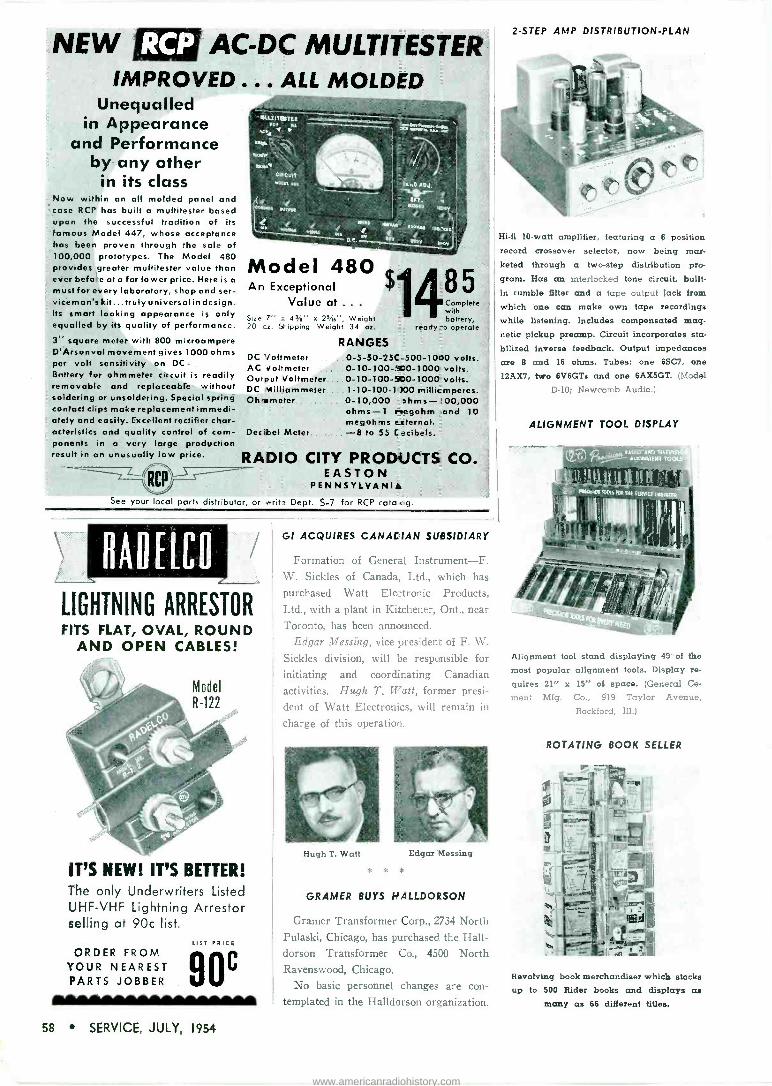
2 -STEP AMP DISTRIBUTION -PLAN
NEW AC -DC MULTITESTER IMPROVED ... ALL MOLDED
Unequalled in Appearance
and Performance by any other
in its class Now within an all molded panel and case RCP has built a multitester based upon the successful tradition of its famous Model 447, whose acceptance has been proven through the sale of 100,000 prototypes. The Model 480 provides greater multitester value than ever before at a far lower price. Here is a
must for every laboratory, shop and ser- viceman's kit...truly universal in design. Its smart looking appearance is only equalled by its quality of performance.
3' square meter with 800 microampere D'Arsonval movement gives 1000 ohms per volt sensitivity on DC
Battery for ohmmeter circuit is readily removable and replaceable without soldering or unsoldering. Special spring contact clips make replacement immedi- ately and easily. Excellent rectifier char- acteristics and quality control cf com- ponents in a very large production result in an unusually low price.
RCP -'
MlìtrETïrru .,... ' ̀ '.. OCY ' Ml y --_ á RT_rwwn. \ .,
Azar. \ CIrCUIt Mire,.,.
ERT- MOO IOOY
'.
rov00 ,EOYxC OOYVOO
OO yq w4-- t
Model 480 An Exceptional
Value at ... Size 7" e 4%" x 25/i6", Weight 20 cz. Shipping Weight 34 ro.
DC Voltmeter AC Voltmeter Ou -put Voltmeter DC Nilliammeter Oh it meter
Decibel Meter.
RANGES 0-5-50.250-500-1000 volts.' 0-10-100-0-1000 volts. 0-10-100-500-1000 volts. 1-10-t00-1 200 millir moeres. 0-10,000 shms-'00,000 ohms -1 r-tegohm and 10 megohms External. -8 to 55 L ecibels.
RADIO CITY PRODUCTS CO. EASTON
PEN NSYL.VANI See your local ports distributor, or Grit-' Dept. S-7 for RCP ..ato Co.
LIGHTNING ARRESTOR FITS FLAT, OVAL, ROUND
AND OPEN CABLES!
IT'S NEW! IT'S BETTER! The only Underwriters Listed UHF -VHF Lightning Arrestor selling at 90c list.
ORDER FROM 90e YOUR NEAREST PARTS JOBBER
GI ACQUIRES CANACIAN SUBSIDIARY
Formation of General Instrument-F. W. Sickles of Canada, Ltd., which has
purchased Watt Electronic Products,
Ltd., with a plant in Kitchener, Ont., near
Toronto, has been announced.
Edgar Messing, vice president of F. W.
Sickles division, will be responsible for
initiating and coordinating Canadian
activities. Hugh T. Ii7att, former presi-
dent of Watt Electronics, will remain in
charge of this operation.
Hugh T. Watt Edgar Messing
* * *
GRAMER BUYS MALLDORSON
Gramer Transformer Corp., 2734 North Pulaski, Chicago, has purchased the Hall- dorson Transformer Co., 4500 North Ravenswood, Chicago.
No basic personnel changes are con- templated in the Halldorson organization.
Hi-fi 10 -watt amplifier, featuring a 6 position record crossover selector, now being mar- keted through a two-step distribution pro-
gram. Has an interlocked tone circuit, built- in rumble filter and a tape output jack from
which one can make own tape recordings while listening. Includes compensated mag- netic pickup preamp. Circuit incorporates sta-
bilized inverse feedback. Output impedances are 8 and 16 ohms. Tubes: one 6SC7, one
12AX7, two 6V6GTs and one 6AX5GT. (Model
D-10; Newcomb Audio.)
ALIGNMENT TOOL DISPLAY
Alignment tool stand displaying 49' of the most popular alignment tools. Display re-
quires 21" x 15" of space. (General Ce -
men; Mfg. Co., 919 Taylor Avenue, Rockford, Ill.)
ROTATING BOOK SELLER
Revolving book merchandiser which stocks up to 500 Rider books and displays as
many as 66 different titles.
58 SERVICE, JULY, 1954
www.americanradiohistory.com

Tools
Parts... MULTICORE SOLDER SERVICE PAK
A line of 5 -core non -corrosive Ersin- flux solder in a service pak that features a wooden spool, is now available from the Multicore Sales Corp., 164 Duane St., New York 13, N. Y.
Solders are available with 60% tin/40% lead (red pak), 50% tin/50% lead (yel- low), and 40% tin/60% lead (green). Gauges and alloys are printed on each pak.
Solder has a thin wall 5 -core construc- tion that is said to assure flux continuity and prevent dry joints. Flux is a high- grade water -white rosin, homogeneously activated, that is claimed to be non -cor- rosive even after a long exposure to humidity.
C -D MINIATURE MICA CAPACITOR
A midget mica capacitor, hi -Q type, in the form of an encapsulated unit, Super Micadon, (capacitor section is separately processed in its entirety and then inserted and sealed into a preinolded case) has been developed by the Cornell-Dubilier Electric Corp., South Plainfield, N. J. Two sizes are available: 5A, 51/64" x 15/32" x 7/32", and IA, 53/64" square x 9/32".
Units, designed with flat, clinched wire leads are said to feature a temperature range of from -55° C to +130° C, and capacitance range up to 20,000 mmfd at 300 dew.
SIMPSON COLOR PROBE AND BOOSTER AMPLIFIER
A color adapter cable, Chromatic Probe, and booster amplifier, for alignment and adjustment of color TV sets, for use with either the 480 Genescope or 479 AM -FM signal generator, has been developed by the Simpson Electric Co., 5200 W. Kinzie St., Chicago 44, Ill.
Accessories convert monochrome sweep marker systems into chromatic systems. Probe increases b -w TV test applications for either model. Booster amplifier serves to check certain low -gain video ampli- fiers in color TV chassis and may be re- quired for other tests also, in case a low - gain 'scope is being used.
azzil;%Q 72/. da e
MODEL
ES -200 Brings the TV or Radio sound right to the viewer or listener
Either speaker may be switched on or off.
Volume control for ad- justing sound level.
Available Through Parts Distributors From Coast To Coast
AUTO RADIO ANTENNAS
THE
ONLY COMPLETE
LINE
SNYDER SNYDER MFG. CO., PHILADELPHIA 40, 0. S. A.
BELLEVUE TUBE MILL, INC.. PHILADE_PNIA
SNYDER ANTENN-GINEERS LTD., TORON70 14
WORLD EXPORT ROBLRN)AGENCIES, INC., N.T.
SERVICE, JULY, 1954 59
www.americanradiohistory.com

NEW SUPER POST TOWERS for TELEVISION ANTENNAS
in FRINGE AREAS
Available in Heights from 33 ft. t. 100 H.
TOWERS OF STRENGTH TO LAST A LIFETIME
Self-supporting tower built up of gal- vanized steel sections. No guy wires necessary. Easy to erect. Safe and resistant to high wind. Available in heights 33 ft., 47 ft., 60 ft., 73 ft., 87 ft.. and 100 ft. with bases in proportion.
FRINGE AREA TV BUYERS MUST HAVE SPECIALLY BUILT TOWERS FOR CLEAR RECEPTION
Tower and the TV set go hand in hand as a package sale to rural TV buyers. Provides an extra sale and profit to dealers. An excellent fast selling ac- cessory for jobbers and dealers.
TERRITORIES OPEN FOR JOBBER DEALER FRANCHISE
Write for complete structural details. packing, prices, discounts, and terri- torial assignment.
MANUFACTURED BY
AERMOTOR CO. DEPT. 6407, 2500 ROOSEVELT ROAD CHICAGO 8, ILL.
BUILDERS OF STEEL TOWERS SINCE 1888
SNYDER DUAL REAR -DECK AUTO- RADIO ANTENNA
.\ dual rear deck auto -radio antenna kit, is now available from the Snyder Manufacturing Co., Philadelphia 40 Pa.
Two styles are featured : a swivel, and hall and socket. The former, RD -8 and the RD -8B, has a matched impedance hi -Q transformer for country and low -signal area reception. Ball and socket, RD -9 and the RD -9B have a matched im- pedance hi -Q transformer.
Kits include 2 antenna staffs, 22' hi -Q coax harness consisting of a 15' length (rear deck to radio), a 7' length T -con- nector lead (antenna to antenna) and one M/P plug adapter, plus five body cable clips for mounting cable on car. Coax cable harness is a shielded hi -Q cable which interconnects dual antennas to car radio and abolishes splicing and taping.
Coming Events Western Electronic Show Pan -Pacific Auditorium, Los Angeles, Calif. August 25, 26 and 27, 1954 Hi-Fi Show: International Sight -Sound Exposition Palmer House, Chicago, III. Sept. 30, Oct. 1 and 2, 1954 National Electronics Conference Hotel Sherman, Chicago, III. October 4, 5 and 6, 1954
WHEN YOU CHANGE YOUR ADDRESS
Be sure to notify the Subscription Department of SERVICE at 52 Vanderbilt Avenue, New York 17, N. Y., giving the old as well as the new address, and do this at least four weeks in advance.. The Pos+ Office Department does not forward maga- zines unless you pay additional postage, and we cannot duplicate copies mailed to the old address. We ask your cooperation.
HICKOK UNIVERSAL NOISE GENERATOR
A noise generator, 755, for measure- ment of noise factor, has been introduced by The Hickok Electrical Instrument Co., 10521 Dupont Ave., Cleveland 8, Ohio.
Unit contains two indicating meters and is divided into a z'tz'ni section and a gen- erator noise section. In the voltmeter section, meter readings arc provided for 0-.1, .5, 1 and 5 y, zero center. In the output section, db -meter output readings include 300, 75 and 50 ohms.
Instrument features built-in stand-by position for noise output, and noise diodes built into probe whereby the output noise is connected directly to receiver input. A vhf head with 100-1000 inc is avail- able.
EICO VTVM AND PROBE
.A peak -to -peak viìui. 232, in kit or wired form, is now available from Elec- tronic Instrument Co., Inc., 84 Withers St., Brooklyn 11, N. Y.
Specifications include : iic voltmeter- ranges 0-1.5, 5, 15, 50, 150, 500, 1500 y; ac voltmeter-ranges rois reading of sine waves same as dc; peak -to -peak reading of sine and complex waves 0-4, 14, 42, 140, 420, 1400, 4200 v; separate scale for 0-1.5 y rams and corresponding 0-4 p -p ranges; frequency response 30 cps to 3
me: ohmmeter readings 0-1000 megohms in 7 ranges.
A high -voltage probe, HVP-2, designed for use with ally rtz-7n or 20,000 -ohms/ volt multimeters for measurements up to 30,000 y, is also available.
60 SERVICE, JULY, 1954
www.americanradiohistory.com

Instruments GRANCO UHF SIGNAL GENERATOR
A uhf signal -gain generator, SU -200, that features coax tuning elements ; con- tinuous tuning over entire uhf band; cali- bration in both frequency and channel designations; balanced detector meter cir- cuit and gain control has been announced by Granco Products, Inc., 36-17 20th Ave., Long Island City 5, N. Y.
Frequency range is 440 to 910 mc, with an accuracy said to be ±2%, indicated by a single direct -reading scale. Instru- ment measures gain, tracking, ca;ibration, accuracy and range of uhf tuners, con- verters, antennas, strips, boosters and re- ceivers. Can act as a signal power source for various types of measuring equipment, such as .'hf bridges and slotted lines.
,
WESTON SWEEP GENERATOR
A sweep generator, model 984, designed for troubleshooting of sound and video if circuits, associated trap circuits, TV tun- ers, video amplifiers and all-purpose vis- ual alignment has been announced by Weston Electrical Instrument Corp., 614 Frelingliuysen Ave., Newark. N. J. RF output : frequency -modulated signal, 'TV channels 2 to 13 ; complete FM coverage available by means of two preset selector positions. Frequencies are fundamentals of oscillator frequency. If video output: Frequency modulated signals ranging to 50 mc, continuous tuning-. Sweep width :
Full 10 -me on all channels. Output vol- tage (nos) is 0.1 volt ; sweep is linear.
SYLVANIA VTVM
A vacuum -tube -voltmeter, 302 Poly- meter, featuring a subminiature vacuum - tube rf probe, peak -to -peak scale, 7" meter movement, lighted scale, patented linearity circuit, input impedance of 17 megohms, shielded ac and rf leads, and screw -on connectors, has been announced by Sylvania Electric Products Inc., 1221 W. 3rd St., Williamsport, Pa.
Instrument reads peak -to -peak voltages from 200 my to 2,800 v, dc voltages from 200 my to 2,800 y, dc voltages, ± polarity from 50 my to 1,000 v, ac voltages from 50 my to 1,000 y, rf voltages from 100 my to 300 y in the band of 10 kc to 300 mc, resistance from .5 ohm to 1,000 megohms and db from -20 to +61.4. DC voltage range may be extended to 30,000 y by using a 30 -kv dc voltage multiplier probe, model 225.
*
EMC TUBE -TESTER
A tube -tester, 208, that checks octal, ]octal, miniature and noval base tubes for tube quality as well as shorts, leakages, continuity or opens between any two ele- ments of the tube, has been introduced by Electronics Measurements Corporation, 280 Lafayette Street, N. Y. 12
Incorporated is a visual line voltage cheek. Individual sockets are furnished for each tube type and elements are numbered according to pin number in RETMA base numbering systems.
Another feature enables tester to match and check Id -fi tubes, such as 1614, KT66, and 5881. A picture tube adaptor is also available.
NEW
RIDER BOOKS
RELEASED
IN JUNE! ADVANCED TELEVISION SERVICING TECHNIQUES
written by the RETMA (Radio Elec- tronic Television Manufacturers' Association) Pilot Training School Teaching Staff.
A completely new approach to books for TV
service technicians. Written by experts who are teaching every day. The contents have been tried and proven to be the finest ever written. Completely practical. A step-by-step approach to how to service every section of a
TV receiver with every kind of test equip- ment-by resistance measurement, by voltage measurement, by means of the scope. It ex- plains the uses of test equipment of all kinds in connection with TV receiver servicing, such as sweep generators - signal generators - vacuum tube voltmeters-scopes, ohmmeters! Approx. 175 (81/2x1 I") pages. Soft cover.
Only $3.60 ATTENTION TEACHERS: The main book
above and a Laboratory Manual for use with it, as well as the Teacher's Guide also are available. Write for details.
SPECIALIZED AUTO RADIO MANUALS
VOL. 4-A covers Chrysler, DeSoto, Dodge, Dodge Trucks, Plymouth. 160
(81/2x I I") pages. Soft cover. Only 3.00 Cover 5 years' production (1950 thru 1954)
of factory installed car radios. Identical data from other sources is just not available! Each volume contains: Parts List, Schematics, Tube Layout, Voltages, Trimmer Location, Chassis Views, Chassis Pictures, Dial Stringing, and complete installation and removal in- formation. VOL. 1-A covers Ford, Lincoln, Mercury.
208 (8/2xI I") pages. Soft cover. Only $3.00 VOL. 2-A covers Buick ... Cadillac ...
Oldsmobile. 200 (81/2x1 I") pages. Soft cover Only 3.00
VOL. 3-A covers Chevrolet, Pontiac, GMC Trucks, Chevrolet Trucks. 128 (81/2x I I") pages. Soft cover. Only 1.80
COLOR TV DICTIONARY by J. R. JOHNSON
First complete explanation of new color TV terms with their definitions that everyone- service technicians, students, engineers, ama- teurs-interested in color television must be familiar with. This is more than a dictionary! Over 50 illustrations. 72 (51/2x81/2") pages, soft cover. Only $1.25
R -C & R -L TIME CONSTANT edited by
ALEXANDER SCHURE, Ph.D., Ed.D. First in a series of review books written
expressly for the student who is studying elec- tronics or the technician who has studied electronics and wishes to understand Time Constant (R -C and R -L) more clearly. It sup- plements the contents of courses in textbooks which are on a technical institute level. Covers practical applications of Time Constant and how it affects circuit operation. 52 (51/2x81/2") pages. Soft cover. Only $.90
Write for information on all RIDER books. Buy these books now from your jobber ... bookstore ... If not available from these sources, write to.
lea F /OEl1 PUBLISHER, INC. eW Qnel sweet, New real 3. N. T
SERVICE, JULY, 1954 61
www.americanradiohistory.com
KESTER Since the most important single step in Radio - Television Servicing h soldering ... it's just plain good sense to use the best -KESTER SOLDER ... Key Name in Solder for More Than 50 Years.
KESTER SOLDER COMPANY 4244 Wrightwood Avenue Chicago 39, Illinois
Nework 5, New Jersey Brantford, Canada
SOLDE THE NEW MODEL TV -11
TUBE TESTER
Ares v 4 5 0 Operates on 105.130 Volt 60 Cres $ A.C. Hand rubbed oak cabinet com- plete
T with portable cover
Uses the new self-cleaning Lever Action Switches for individual element testing. Be- cause all elements are numbered according to pin number in the RMA base numbering system, the user can instantly identify which element is under test. Tubes having tapped filaments and tubes with filaments terminating in more than one pin are truly tested with the Model TV-ll as any of the pins may be placed in the neutral position when necessary. Uses no combination type sockets. Instead individual sockets are used for each type of tube. Thus it is impossible to damage a tube by inserting it in the wrong socket. Free -moving, built-in roll chart pro- vides complete data for all tubes. Phono jack on front panel for plugging in either phones or external amplifier detects microphonic tubes or noise due to faulty elements and loose external connections.
EXTRA SERVICE-The Model TV -11 may be used as sn extremely sensitive Condenser Leakage Checker. A relaxation type oscillator incorporated in this model will detect leakages even when the frequency Is one per minute.
SHIPPED ON APPROVAL NO MONEY WITH ORDER -NO C.O.D. Try It for 10 days before you buy. If completely satisfied send $11.50 and pay balance at rate of $6.00 per month for 6 months.-No Interest or Carrying Charges Added. If not completely satisfied, return to us, no explanation necessary.
MOSS ELECTRONIC DISTRIBUTING CO., INC. Dept. D-48, 3849 Tenth Ave., New York 34, N. Y.
rnsh one Model TV -11. I agree to pay $11.50 within 10 days after receipt and $6.00 per month thereafter.
NAME
ADDRESS
CITY ZONE STATE
TV Parts... Accessories
VIDAIRE LINE FILTERS
Line filters, LP 1-4 (low-pass devices designed to pass all frequencies below 10 kc and attenuate all frequencies above) are now available from Vidaire Elec- tronics Manufacturing Co., Lynbrook, N. Y.
Most TV interference entering the re- ceiver through the line is said to. be re- duced or eliminated by utilizing one or more of the filters, which are shielded to prevent stray pickup of signals
A vertical retrace line eliminator, Elini- .4-Trace designed to blank vertical re- trace lines, is also available.
Models LP -2 and TE -3 (illustrated) are intended for subchassis mounting.
MERIT-PHILCO REPLACEMENT TRANSFORMERS
Seven hz' horizontal deflection trans- formers, HT' 0.-15 through HVO-21, de- signed as exact replacements for Philco units, are now available from the Merit Coil and Transformer Corp., 4427 North Clark St., Chicago 40, Ill.
Transformers are said to cover 90 per cent of all Philco chassis and models pro- duced prior to and during '53. Mount- ing bracket of these models is an exact replica of the Philco units that they re- place.
62 SERVICE, JULY, 1954
www.americanradiohistory.com
INN
ADVERTISERS IN SERVICE
JULY, 1954
Page
Acme Electric Corp. 55
Aermotor Co. 60 All Channel Antenna Corp. 54 Alliance Mfg. Co. 22 American Microphone Co. 32
American Phenolic Corp. 47 American Television & Radio Co. 33 Atlas Sound Corp. 50
Belden Mfg. Co. 1
Bussmann Mfg. Co. 7
Buxton Industries, Inc. 63
CBS-Hytron (Div. Columbia Broadcasting System) 6
Channel Master Corp. 18
Chicago Standard Transformer Corp 53 Clear Beam TV Antennas 3
Cornell-Dubilier Radiart 42 Crosley Div. AVCO Mfg. Corp 64
Allen B. DuMont Laboratories, Inc 11
Electro Products Laboratories 2
General Cement Mfg. Co 9 The General Industries Co. 49
Halldorson Transformer Co 30 The Heath Co. 57
International Rectifier Corp. 52
Jensen Mfg. Co., Inc. 39
Kester Solder Co. 62
P. R. Mallory & Co., Inc. Inside Back Cover Manfredi Wood Products Corp. 50 Moss Electronic Dist. Co., Inc 6? Muei!er Electric Co. 56
Newcomb Audio Products Co
Oxford Electric Corp. 57
Phalo Plastics Corp. 32 Precision Apparatus Co., Inc. 41
Quietrole Co. 15
Rad -El -Co Mfg. Co. 58 The Radiart Corp Inside Front Cover Radio City Products Co , Inc 58 Radio Corporation of America.. Back Cover Raytheon Mfg. Co. 16 John F. Rider Publisher, Inc. 61
Sangamo Electric Co Howard W. Sams & Co., Inc. Shure Brothers, Inc. Snyder Mfg. Co.
31
56 43
59
Sarkes Tarzian, Inc., Tuner Div 46 14
Triplett Electrical Instrument Co 5 Tung -Sol Electric, Inc. 44, 45
United Catalog Publishers 52 United Motors Service Div.
(General Motors Corp.) 12, 13
Vidaire Electronics Mfg. Co. 54, 61 Walsco Electronics Corp. 10 The Ward Products Corp. Div.
The Gabriel Co. 21 Winegard Co. 8
Telrex, Inc.
4
JOTS AND FLASHES A st-SST.ANTIAL INCREASE in portable radio popularity during the first quarter of this year has been reported by Ray V. Buivid, G.E. radio sales manager. Industry retail sales figures, he said, show that the portable radio has Lettered its share of total sales by about 31 per cent during the first part of this year com- pared with a similar period in '53. . . .
Dr. Allen B. DuMont, president of Allen B. DuMont Laboratories, Inc., was re- cently named Father of the I ear in the field of Science by the Boys' Clubs of America.... Manufacturers were urged to tap the nearly 4/ -billion dollars in sales that lie outside the radio and TV set fields by Burton Browns, in a recent address before the N.Y. chapter of The Reps. Today, he said, there are sonic 1,339 specific applications of electronic equipment by such industries as the air- lines, ceramic manufacturers, chemical manufacturers, construction contractors, cosmetic manufacturers, food processors, glass manufacturers, plastics, railroads, petroleum, and others. . Queens Eve- ning Trade School, 47th Ave., and 37th St., Long Island City 1, N.Y., is offering free courses in radio and TV service. Classes meet two nights a week, from 7-9 P.M. Registration for all classes will be held Sept. 13-14, from 7-9 P.M., in the school auditorium. . The '54 annual convention of the Audio Engineer- ing Society, to be held at the Hotel New Yorker, is scheduled for October 13-17.... G. E. has announced it is ready to supply color TV systems for closed circuit use in education, business and industry. System is composed of color camera, camera control console together with a remote control unit for controlling all elements of focusing, angulation, and lens selection, a rack -mounted power supply providing a regulated source of dc power, and a receiver. . State and city of- ficials, civic and business leaders of Indianapolis recently joined in formally dedicating the new home of Howard W. Sans and Co., Inc., at Sams Park, 34th and Sutherland Ave., Indianapolis, Ind.
. '54 NEDA battery index is now available. Single copies are free, and larger quantities are available at $5.75 per hundred, by writing to 228 N. La- Salle St., Chicago 1, Ill. . Radio Receptor, Inc., New York City, has changed the name of its selectron and germanium division to semi -conductor division. Jerome R. Meltzer has been appointed assistant sales manager of the division's distributor sales department.
All radio receivers (eight -tube sets) for the '55 Lincoln and Mercury models will be manufactured by the Radio Com- munication division of Bendix Aviation Corp.... An internal house organ, Sales Symphony, published by Phalo Plastics Corp., received the premiere award in the Creative Awards Competition held recently by the National Advertising Agency Network. . . 1500 Service Men attended Raytheon's Service Saver and Bonded Electronic Technician meetings held recently throughout the northwest. Over 600 attended meetings held in Ohio and western Pennsylvania, and 500 were at meetings held in New England. . .
A new single -story plant annex of Graneo Products, Inc., 36-17 20th Ave., Long Island City, N.Y., was opened recently. Structure is equipped with latest ma- chinery, assembly lines and test posi- tions to provide for more than twice the previous production capacity of uhf converters and instruments.
THE BIG 3 of SALES SUCCESS
WITH BUXTON POWER -VUE
ANTENNAS Z(Je g4.4e t.ite t zade
1. WHAT THEY WANT
2. WHAT THEY CAN SELL
- PROFITABLY
3. WHAT PERFORMS BEST
IN THEIR AREAS
FOR EXAMPLE:
COBRA* CONE (Conicals)
PROVED UNIVERSALLY HIGH GAIN for practically all areas. WINNING UNQUESTIONED APPROVAL wherever used.... An EXCLUSIVE KEY FEATURE: Quick -Lock "2 BOLT" COBRA HEAD (Greater element separation achieves longer, cleaner, clearer signal.) Other important features, too.
\ONICALS
NO. 3cc POWER -VUE COBRA CONE (An outstanding sales number)
The PLAIN FACTS about BUXTON POWER -VUE YAGIS
I MAINTAINED HIGH GAIN via correct design.
2. APPROVED PHYSICAL STRENGTH Aluminum alloys, Steel Support brackets, non -break insulators.
3 "E -Z UP" ASSEMBLY. Either pre -assembled Snap -Out, or One -Piece, Elements.
YAGIS
1/ j/ A FULL LINE OF YAGI TYPES
Broad Band, Delta Match, etc. BUXTON ALSO BUILDS: PowerVue Straight Dipoles, Arrows, V Stacks, Diamondbacks, Folded Dipoles and Fringe Area Antennas. And Accessories. 'A Buxton Name
SOLD NATIONALLY THROUGH JOBBERS
BUXTON INDUSTRIES, INC. S -I
88 North Fair Oaks Ave., Pasadena, California
PLEASE SEND INFORMATION AS CHECKED:
FULL INFORMATION & PRICES.
Name & Address of NEAREST JOBBER
Name
Street
City Zone State
SERVICE, JULY, 1954 63
www.americanradiohistory.com

A look inside will show you why
CROSLEY SUPER -V IS A SERVICE MAN'S DREAM
Everything about this exciting new TV set was planned and built with you in mind! Crosley's own revolutionary vertical circuit makes checkups simpler than ever. Changing a tube takes only a few minutes (they're all at the back
Bonnet -type cabinet lifts right off
No u1)re chassis tugging
e Every tube accessible at rear oottmeK
in easy reach) and more complicated service requires only the loosening of 6 screws; lifting the entire cabinet off.
Men who've serviced the Super -V
call it the greatest forward step in TV chassis design.
Points wired on terminal strips-easier circuit tracing
Crosley Division RO Cincinnati
25, Ohio
64 SERVICE, JULY, 1954
www.americanradiohistory.com

- _ J
xe /0,
!P 44
,e)
OP
Do It Faster... You speed selection of tie right Vibrator for any job wl en you use the current Mallory Vibrator Guide. Ii's your com- plete cross-reference and service guide- See your Malloy Dis-
tributor about this hang y book . . _ or write P.O. ßo{ 1558,
Indianapolis 6, Indiana
Do a Lot... With a Little
Jf + +Y f
e,pee L
4*. Y
Ó O`-
xteP > xe.
Cover 75% of Your Replacement Needs
with Just 6 Mallory Vibrators
You don't need a large inventory when you rely on Mallory Vibrators for your replacement work. A selec-
tion of just six Mallory Vibrators gives you coverage of 75% of your jobs.
And you can use Mallory Vibrators with complete confidence that their performance will satisfy you ... and your customers. Mallory not only made the first commercial vibrator but supplies more to set makers than all other manufacturers combined.
P R. MALLORY L CO Inc
MALLOR CAPACITORS CONTROLS VIBRATORS SWITCHES RESISTORS
RECTIFIERS POWER SUPPLIES FILTERS MERCURY BATTERIES
APPROVED PRECISION PRODUCTS
f
P. R. MALLORY & CO. Inc., INDIANAPOLIS 6, INDIANA
www.americanradiohistory.com

They look alike...
...but what a difference!
These RCA types today give you .. LONGER LIFE
ma woe No eft/ 1111. `
Here are 3 more examples of how regular RCA receiving tubes are con- stantly being improved to meet the changing requirements of radio and television applications. These RCA types provide you with the superior performance usually claimed for higher priced specialty designed types.
RCA -6J6 features pure tungsten heaters for improved life ... uses a special cathode material to help main- tain characteristics throughout the life of the tube. Each tube mount is adjusted to provide increased uni -
SUPERIOR PERFORMANCE
formity of characteristics of each triode unit.
RCA-6CB6 uses a No. 2 grid of im- proved design, resulting in lower grid operating temperature and longer tube life. Special controls on materials and processing improve uniformity of plate cutoff and reduce variations in characteristics when heater voltage fluctuates.
RCA -6AÚ6 uses a double helical heater, resulting in an extremely low hum level. Inverted pinched cathode reduces possible motion of tube ele -
AT NO EXTRA COST
ments thus minimizing microphonics. The superior performance of regular
RCA receiving tubes-at regular prices-eliminates unnecessary call- backs, assures you of greater customer satisfaction, results in increased profits for you.
> > 1 When you sell a receiving tube, your reputation and profit depend on its performance and reliability. So, you can't afford to buy anything less than the best in receiving tubes ... and the best are RCA.
RADIO CORPORATION of AMERICA ELECTRON TUBES HARRISON. N.J.
www.americanradiohistory.com