VoIP Telephone Basic Programming Guide - hubbellcdn and... · 2019-01-03 · VoIP Telephone Basic...
27
Pub. 42004-481C G A I - T R O N I C S ® A H U B B E L L C O M P A N Y VoIP Telephone Basic Programming Guide T ABLE OF C ONTENTS GAI-TRONICS 3030 KUTZTOWN RD. READING, PA 19605 USA 610-777-1374 800-492-1212 Fax: 610-796-5954 VISIT WWW.GAI-TRONICS.COM FOR PRODUCT LITERATURE AND MANUALS Confidentiality Notice .....................................................................................................................1 Introduction.....................................................................................................................................1 Set-up & Configuration ..................................................................................................................2 Quick Start .............................................................................................................................................. 2 IP Settings ................................................................................................................................................ 3 SIP Settings Page..................................................................................................................................... 5 Unit Settings Page ................................................................................................................................... 8 Clock Settings Page ............................................................................................................................... 11 Dialing & Memories Pages ................................................................................................................... 12 Memories and Comfort Strings Sub-page ........................................................................................... 12 Memory Lists Sub-page ...................................................................................................................... 13 Basic Info Sub-page ............................................................................................................................ 15 Audio Settings Page ......................................................................................................................16 Multicast Settings Page.................................................................................................................18 Logic Settings Page .......................................................................................................................20 Inputs ..................................................................................................................................................... 20 Outputs .................................................................................................................................................. 23 Troubleshooting ............................................................................................................................25
Transcript of VoIP Telephone Basic Programming Guide - hubbellcdn and... · 2019-01-03 · VoIP Telephone Basic...
Pub. 42004-481C
G A I - T R O N I C S ®
A H U B B E L L C O M P A N Y
VoIP Telephone Basic Programming Guide
T A B L E O F C O N T E N T S
GAI-TRONICS 3030 KUTZTOWN RD. READING, PA 19605 USA 610-777-1374 800-492-1212 Fax: 610-796-5954
VISIT WWW.GAI-TRONICS.COM FOR PRODUCT LITERATURE AND MANUALS
Confidentiality Notice .....................................................................................................................1
Introduction .....................................................................................................................................1
Set-up & Configuration ..................................................................................................................2
Quick Start .............................................................................................................................................. 2
IP Settings ................................................................................................................................................ 3
SIP Settings Page..................................................................................................................................... 5
Unit Settings Page ................................................................................................................................... 8
Clock Settings Page ............................................................................................................................... 11
Dialing & Memories Pages ................................................................................................................... 12 Memories and Comfort Strings Sub-page ........................................................................................... 12
Memory Lists Sub-page ...................................................................................................................... 13
Basic Info Sub-page ............................................................................................................................ 15
Audio Settings Page ......................................................................................................................16
Multicast Settings Page .................................................................................................................18
Logic Settings Page .......................................................................................................................20
Inputs ..................................................................................................................................................... 20
Outputs .................................................................................................................................................. 23
Troubleshooting ............................................................................................................................25
Pub. 42004-481C
G A I - T R O N I C S ®
A H U B B E L L C O M P A N Y
VoIP Telephone Basic Programming Guide
GAI-TRONICS 3030 KUTZTOWN RD. READING, PA 19605 USA 610-777-1374 800-492-1212 Fax: 610-796-5954
VISIT WWW.GAI-TRONICS.COM FOR PRODUCT LITERATURE AND MANUALS
Confidentiality Notice
This manual is provided solely as an installation, operation, and maintenance guide and contains sensitive
business and technical information that is confidential and proprietary to GAI-Tronics. GAI-Tronics
retains all intellectual property and other rights in or to the information contained herein, and such
information may only be used in connection with the operation of your GAI-Tronics product or system.
This manual may not be disclosed in any form, in whole or in part, directly or indirectly, to any third
party.
The following are trademarks of GAI-Tronics Corporation:
SmartSeries® Page/Party
® RED ALERT
® SmartVolume
TM
Introduction
This guide provides information on the basic configuration and programming of GAI-Tronics’ VoIP
Telephones. Advanced features are addressed by Pub. 42004-396, which can be accessed via the unit’s
embedded browser home page by selecting the “web support” link. This document can also be found at
the GAI-Tronics website (www.gai-tronics.com/products/manuals_specs.htm).
NOTE: All references to “telephones” in this document are understood to be GAI-Tronics RED
ALERT®, SMART Industrial, or VoIP/WiFi Telephones.
For questions about configuring VoIP Telephones, please contact:
Service Group
GAI-Tronics Corporation
3030 Kutztown Road
Reading, PA 19605
800-492-1212 (8 a.m. to 5 p.m. EST) 610-777-1374 outside the USA
Pub. 42004-481C VoIP Telephone Basic Programming Guide Page 2 of 25
P:\Standard IOMs - Current Release\42004 Instr. Manuals\42004-481C.docx 07/17
Set-up & Configuration
Quick Start
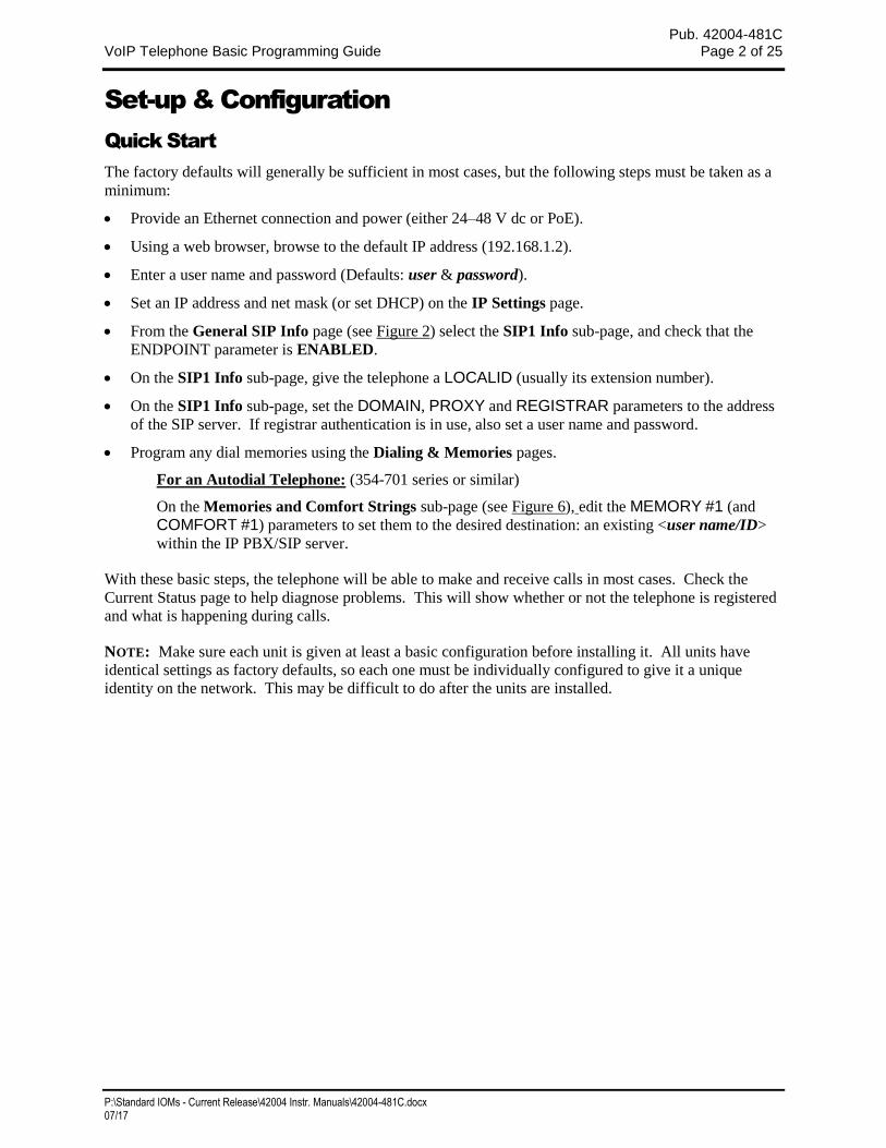
The factory defaults will generally be sufficient in most cases, but the following steps must be taken as a
minimum:
Provide an Ethernet connection and power (either 24–48 V dc or PoE).
Using a web browser, browse to the default IP address (192.168.1.2).
Enter a user name and password (Defaults: user & password).
Set an IP address and net mask (or set DHCP) on the IP Settings page.
From the General SIP Info page (see Figure 2) select the SIP1 Info sub-page, and check that the
ENDPOINT parameter is ENABLED.
On the SIP1 Info sub-page, give the telephone a LOCALID (usually its extension number).
On the SIP1 Info sub-page, set the DOMAIN, PROXY and REGISTRAR parameters to the address
of the SIP server. If registrar authentication is in use, also set a user name and password.
Program any dial memories using the Dialing & Memories pages.
For an Autodial Telephone: (354-701 series or similar)
On the Memories and Comfort Strings sub-page (see Figure 6), edit the MEMORY #1 (and
COMFORT #1) parameters to set them to the desired destination: an existing <user name/ID>
within the IP PBX/SIP server.
With these basic steps, the telephone will be able to make and receive calls in most cases. Check the
Current Status page to help diagnose problems. This will show whether or not the telephone is registered
and what is happening during calls.
NOTE: Make sure each unit is given at least a basic configuration before installing it. All units have
identical settings as factory defaults, so each one must be individually configured to give it a unique
identity on the network. This may be difficult to do after the units are installed.
Pub. 42004-481C VoIP Telephone Basic Programming Guide Page 3 of 25
P:\Standard IOMs - Current Release\42004 Instr. Manuals\42004-481C.docx 07/17
IP Settings
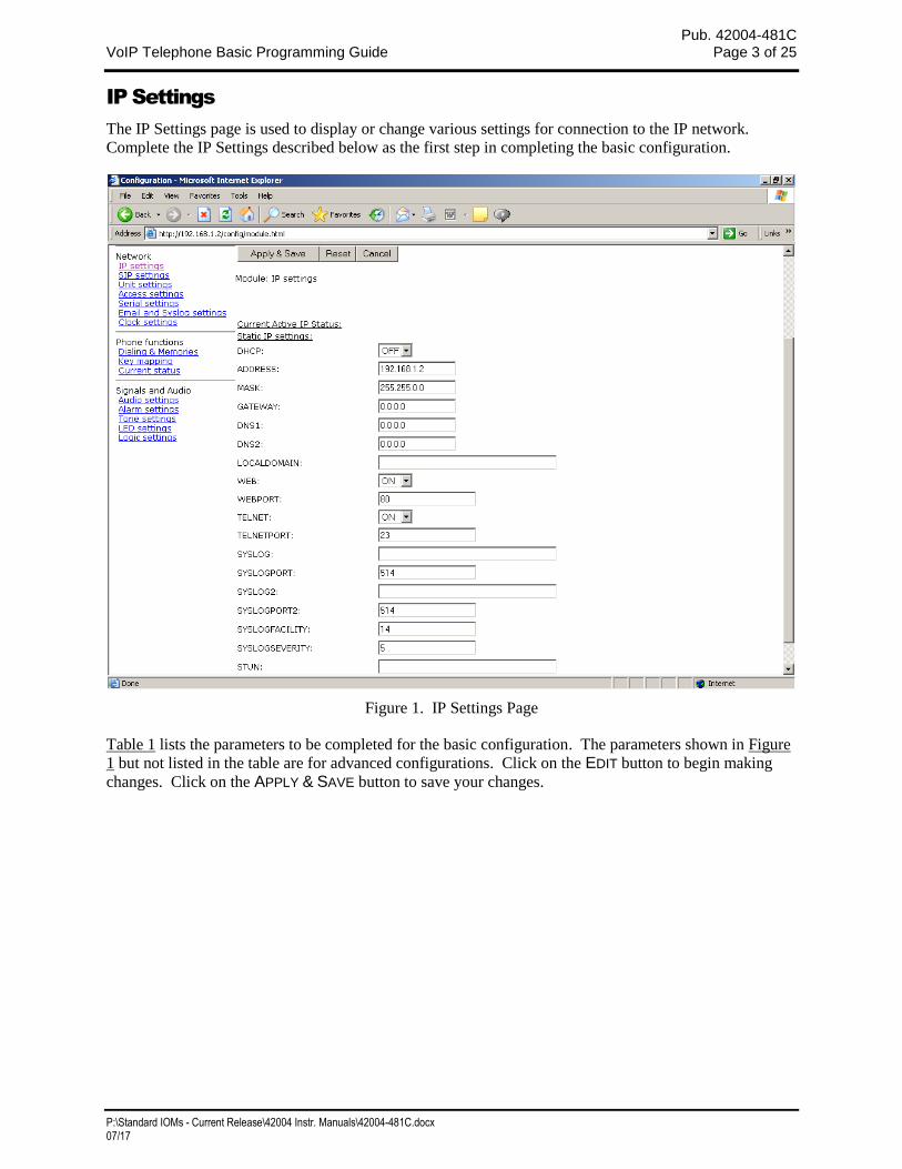
The IP Settings page is used to display or change various settings for connection to the IP network.
Complete the IP Settings described below as the first step in completing the basic configuration.
Figure 1. IP Settings Page
Table 1 lists the parameters to be completed for the basic configuration. The parameters shown in Figure
1 but not listed in the table are for advanced configurations. Click on the EDIT button to begin making
changes. Click on the APPLY & SAVE button to save your changes.
Pub. 42004-481C VoIP Telephone Basic Programming Guide Page 4 of 25
P:\Standard IOMs - Current Release\42004 Instr. Manuals\42004-481C.docx 07/17
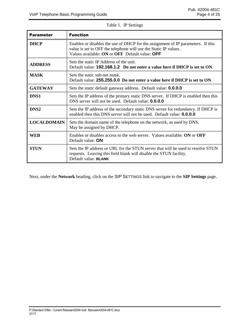
Table 1. IP Settings
Parameter Function
DHCP Enables or disables the use of DHCP for the assignment of IP parameters. If this
value is set to OFF the telephone will use the Static IP values.
Values available: ON or OFF Default value: OFF
ADDRESS Sets the static IP Address of the unit.
Default value: 192.168.1.2 Do not enter a value here if DHCP is set to ON.
MASK Sets the static sub-net mask.
Default value: 255.255.0.0 Do not enter a value here if DHCP is set to ON.
GATEWAY Sets the static default gateway address. Default value: 0.0.0.0
DNS1 Sets the IP address of the primary static DNS server. If DHCP is enabled then this
DNS server will not be used. Default value: 0.0.0.0
DNS2 Sets the IP address of the secondary static DNS server for redundancy. If DHCP is
enabled then this DNS server will not be used. Default value: 0.0.0.0
LOCALDOMAIN Sets the domain name of the telephone on the network, as used by DNS.
May be assigned by DHCP.
WEB Enables or disables access to the web server. Values available: ON or OFF
Default value: ON
STUN Sets the IP address or URL for the STUN server that will be used to resolve STUN
requests. Leaving this field blank will disable the STUN facility.
Default value: BLANK
Next, under the Network heading, click on the SIP SETTINGS link to navigate to the SIP Settings page.
Pub. 42004-481C VoIP Telephone Basic Programming Guide Page 5 of 25
P:\Standard IOMs - Current Release\42004 Instr. Manuals\42004-481C.docx 07/17
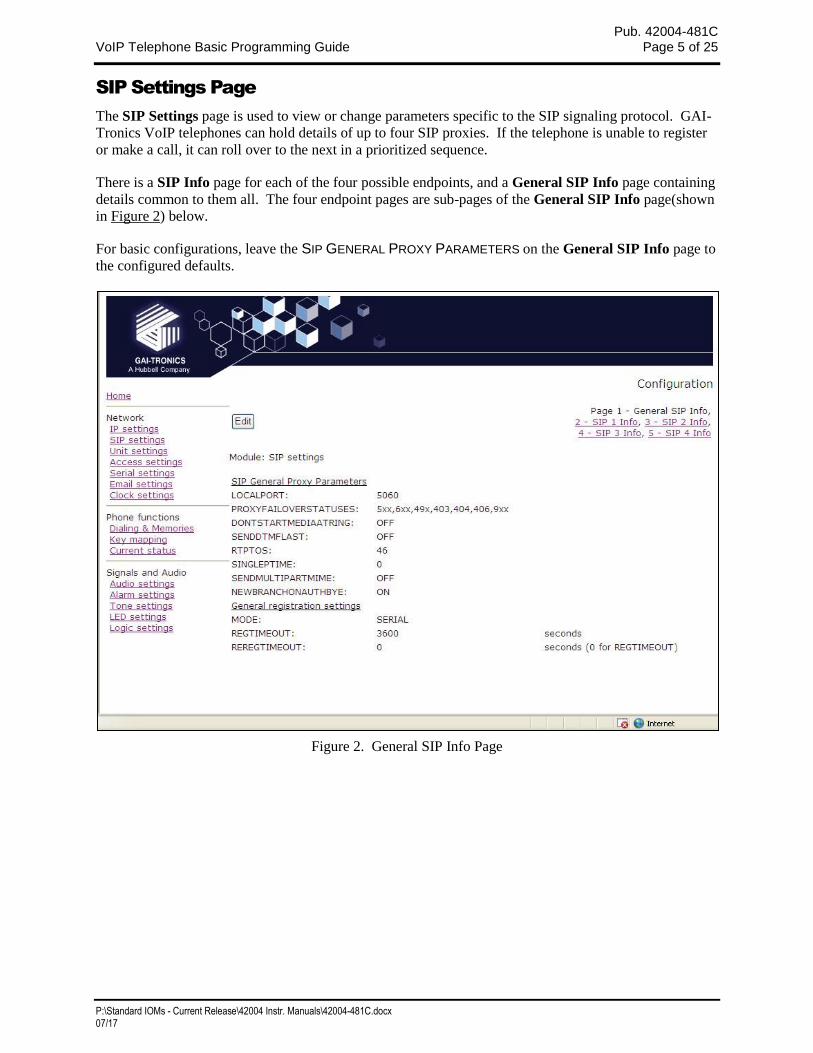
SIP Settings Page
The SIP Settings page is used to view or change parameters specific to the SIP signaling protocol. GAI-
Tronics VoIP telephones can hold details of up to four SIP proxies. If the telephone is unable to register
or make a call, it can roll over to the next in a prioritized sequence.
There is a SIP Info page for each of the four possible endpoints, and a General SIP Info page containing
details common to them all. The four endpoint pages are sub-pages of the General SIP Info page(shown
in Figure 2) below.
For basic configurations, leave the SIP GENERAL PROXY PARAMETERS on the General SIP Info page to
the configured defaults.
Figure 2. General SIP Info Page
Pub. 42004-481C VoIP Telephone Basic Programming Guide Page 6 of 25
P:\Standard IOMs - Current Release\42004 Instr. Manuals\42004-481C.docx 07/17
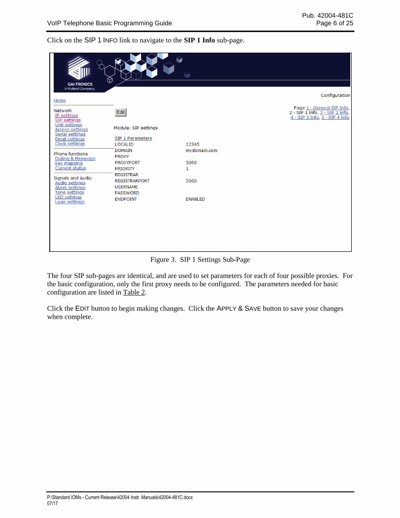
Click on the SIP 1 INFO link to navigate to the SIP 1 Info sub-page.
Figure 3. SIP 1 Settings Sub-Page
The four SIP sub-pages are identical, and are used to set parameters for each of four possible proxies. For
the basic configuration, only the first proxy needs to be configured. The parameters needed for basic
configuration are listed in Table 2.
Click the EDIT button to begin making changes. Click the APPLY & SAVE button to save your changes
when complete.
Pub. 42004-481C VoIP Telephone Basic Programming Guide Page 7 of 25
P:\Standard IOMs - Current Release\42004 Instr. Manuals\42004-481C.docx 07/17
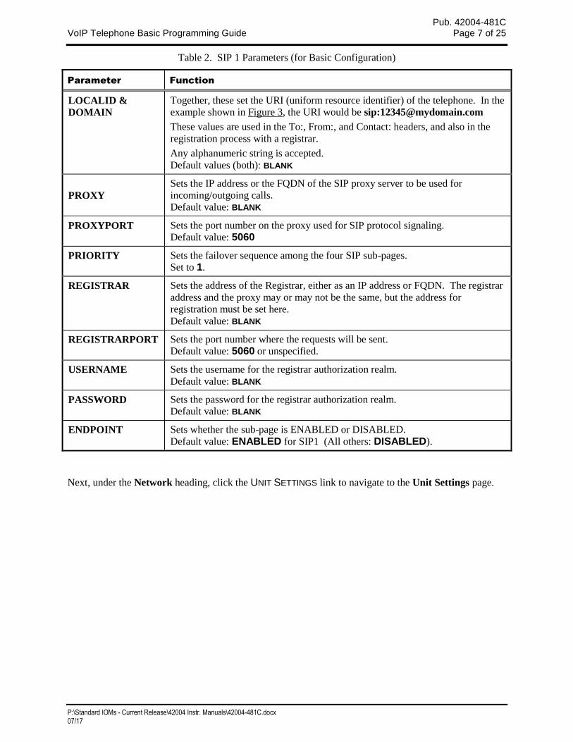
Table 2. SIP 1 Parameters (for Basic Configuration)
Parameter Function
LOCALID &
DOMAIN
Together, these set the URI (uniform resource identifier) of the telephone. In the
example shown in Figure 3, the URI would be sip:[email protected]
These values are used in the To:, From:, and Contact: headers, and also in the
registration process with a registrar.
Any alphanumeric string is accepted.
Default values (both): BLANK
PROXY
Sets the IP address or the FQDN of the SIP proxy server to be used for
incoming/outgoing calls.
Default value: BLANK
PROXYPORT Sets the port number on the proxy used for SIP protocol signaling.
Default value: 5060
PRIORITY Sets the failover sequence among the four SIP sub-pages.
Set to 1.
REGISTRAR Sets the address of the Registrar, either as an IP address or FQDN. The registrar
address and the proxy may or may not be the same, but the address for
registration must be set here.
Default value: BLANK
REGISTRARPORT Sets the port number where the requests will be sent.
Default value: 5060 or unspecified.
USERNAME Sets the username for the registrar authorization realm.
Default value: BLANK
PASSWORD Sets the password for the registrar authorization realm.
Default value: BLANK
ENDPOINT Sets whether the sub-page is ENABLED or DISABLED.
Default value: ENABLED for SIP1 (All others: DISABLED).
Next, under the Network heading, click the UNIT SETTINGS link to navigate to the Unit Settings page.
Pub. 42004-481C VoIP Telephone Basic Programming Guide Page 8 of 25
P:\Standard IOMs - Current Release\42004 Instr. Manuals\42004-481C.docx 07/17
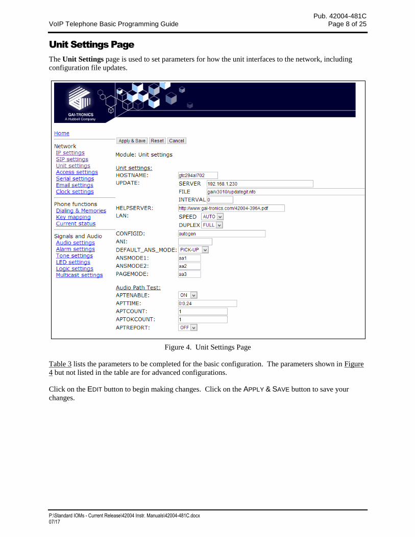
Unit Settings Page
The Unit Settings page is used to set parameters for how the unit interfaces to the network, including
configuration file updates.
Figure 4. Unit Settings Page
Table 3 lists the parameters to be completed for the basic configuration. The parameters shown in Figure
4 but not listed in the table are for advanced configurations.
Click on the EDIT button to begin making changes. Click on the APPLY & SAVE button to save your
changes.
Pub. 42004-481C VoIP Telephone Basic Programming Guide Page 9 of 25
P:\Standard IOMs - Current Release\42004 Instr. Manuals\42004-481C.docx 07/17
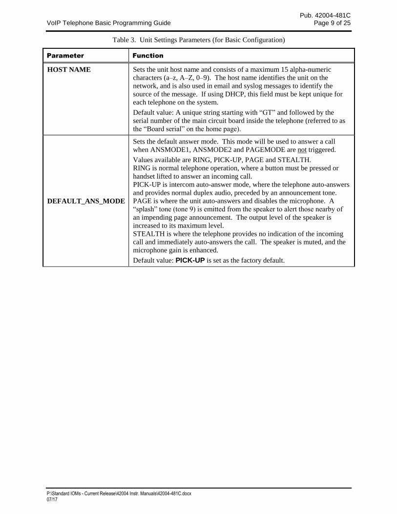
Table 3. Unit Settings Parameters (for Basic Configuration)
Parameter Function
HOST NAME Sets the unit host name and consists of a maximum 15 alpha-numeric
characters (a–z, A–Z, 0–9). The host name identifies the unit on the
network, and is also used in email and syslog messages to identify the
source of the message. If using DHCP, this field must be kept unique for
each telephone on the system.
Default value: A unique string starting with “GT” and followed by the
serial number of the main circuit board inside the telephone (referred to as
the “Board serial” on the home page).
DEFAULT_ANS_MODE
Sets the default answer mode. This mode will be used to answer a call
when ANSMODE1, ANSMODE2 and PAGEMODE are not triggered.
Values available are RING, PICK-UP, PAGE and STEALTH.
RING is normal telephone operation, where a button must be pressed or
handset lifted to answer an incoming call.
PICK-UP is intercom auto-answer mode, where the telephone auto-answers
and provides normal duplex audio, preceded by an announcement tone.
PAGE is where the unit auto-answers and disables the microphone. A
“splash” tone (tone 9) is emitted from the speaker to alert those nearby of
an impending page announcement. The output level of the speaker is
increased to its maximum level.
STEALTH is where the telephone provides no indication of the incoming
call and immediately auto-answers the call. The speaker is muted, and the
microphone gain is enhanced.
Default value: PICK-UP is set as the factory default.
Pub. 42004-481C VoIP Telephone Basic Programming Guide Page 10 of 25
P:\Standard IOMs - Current Release\42004 Instr. Manuals\42004-481C.docx 07/17
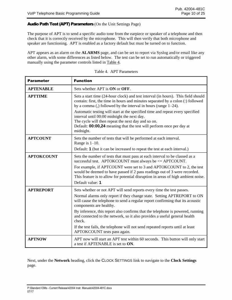
Audio Path Test (APT) Parameters (On the Unit Settings Page)
The purpose of APT is to send a specific audio tone from the earpiece or speaker of a telephone and then
check that it is correctly received by the microphone. This will then verify that both microphone and
speaker are functioning. APT is enabled as a factory default but must be turned on to function.
APT appears as an alarm on the ALARMS page, and can be set to report via Syslog and/or email like any
other alarm, with some differences as listed below. The test can be set to run automatically or triggered
manually using the parameter controls listed in Table 4.
Table 4. APT Parameters
Parameter Function
APTENABLE Sets whether APT is ON or OFF.
APTTIME Sets a start time (24-hour clock) and test interval (in hours). This field should
contain: first, the time in hours and minutes separated by a colon (:) followed
by a comma (,) followed by the interval in hours (range 1–24).
Automatic testing will start at the specified time and repeat every specified
interval until 00:00 midnight the next day.
The cycle will then repeat the next day and so on.
Default: 00:00,24 meaning that the test will perform once per day at
midnight.
APTCOUNT Sets the number of tests that will be performed at each interval.
Range is 1–10.
Default: 1 (but it can be increased to repeat the test at each interval.)
APTOKCOUNT Sets the number of tests that must pass at each interval to be classed as a
successful test. APTOKCOUNT must always be <= APTCOUNT.
For example, if APTCOUNT were set to 3 and APTOKCOUNT to 2, the test
would be deemed to have passed if 2 pass readings out of 3 were recorded.
This feature is to allow for potential disruption in areas of high ambient noise.
Default value: 1
APTREPORT Sets whether or not APT will send reports every time the test passes.
Normal alarms only report if they change state. Setting APTREPORT to ON
will cause the telephone to send a regular report confirming that its acoustic
components are healthy.
By inference, this report also confirms that the telephone is powered, running
and connected to the network, so it also provides a useful general health
check.
If the test fails, the telephone will not send repeated reports until at least
APTOKCOUNT tests pass again.
APTNOW APT now will start an APT test within 60 seconds. This button will only start
a test if APTENABLE is set to ON.
Next, under the Network heading, click the CLOCK SETTINGS link to navigate to the Clock Settings
page.
Pub. 42004-481C VoIP Telephone Basic Programming Guide Page 11 of 25
P:\Standard IOMs - Current Release\42004 Instr. Manuals\42004-481C.docx 07/17
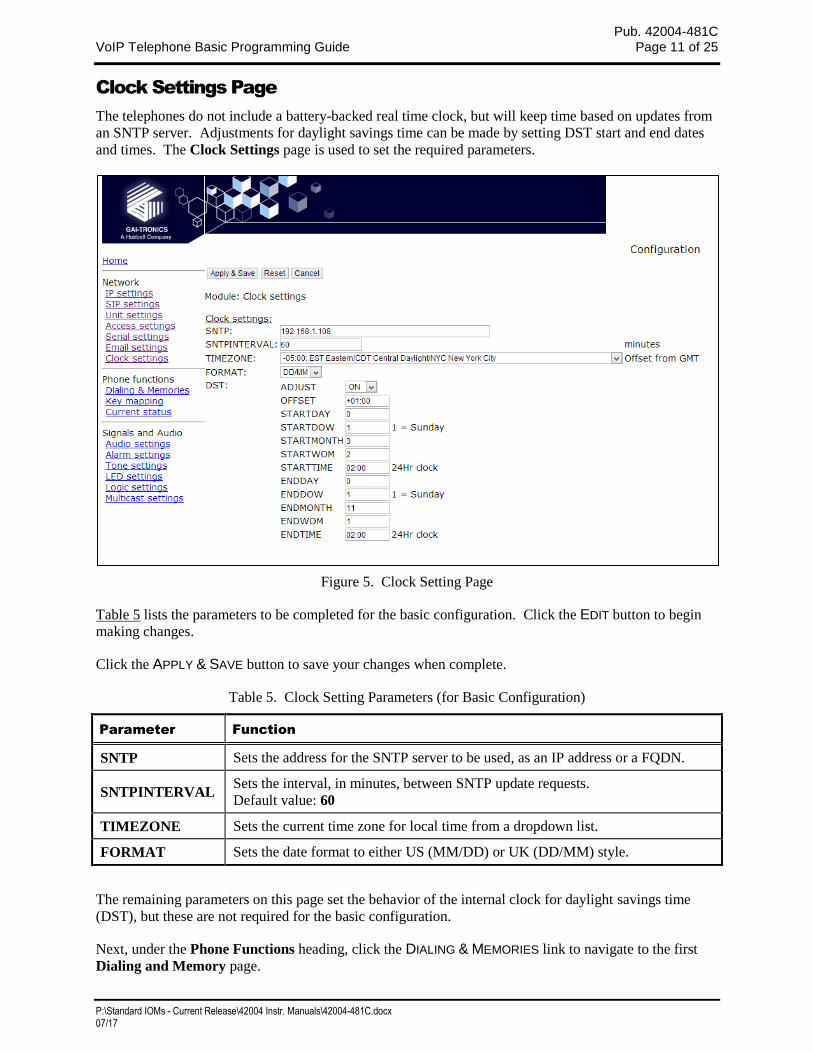
Clock Settings Page
The telephones do not include a battery-backed real time clock, but will keep time based on updates from
an SNTP server. Adjustments for daylight savings time can be made by setting DST start and end dates
and times. The Clock Settings page is used to set the required parameters.
Figure 5. Clock Setting Page
Table 5 lists the parameters to be completed for the basic configuration. Click the EDIT button to begin
making changes.
Click the APPLY & SAVE button to save your changes when complete.
Table 5. Clock Setting Parameters (for Basic Configuration)
Parameter Function
SNTP Sets the address for the SNTP server to be used, as an IP address or a FQDN.
SNTPINTERVAL Sets the interval, in minutes, between SNTP update requests.
Default value: 60
TIMEZONE Sets the current time zone for local time from a dropdown list.
FORMAT Sets the date format to either US (MM/DD) or UK (DD/MM) style.
The remaining parameters on this page set the behavior of the internal clock for daylight savings time
(DST), but these are not required for the basic configuration.
Next, under the Phone Functions heading, click the DIALING & MEMORIES link to navigate to the first
Dialing and Memory page.
Pub. 42004-481C VoIP Telephone Basic Programming Guide Page 12 of 25
P:\Standard IOMs - Current Release\42004 Instr. Manuals\42004-481C.docx 07/17
Dialing & Memories Pages
The Dialing & Memories pages are used to set various “dialing” actions, i.e., how the telephone initiates
calls. Depending on the model, the telephone front panel may have a numeric keypad, memory buttons,
both, or neither. The numeric telephone keypad is used to enter a number (user ID) one digit at a time,
whereas memory buttons or the hookswitch of an Autodial Telephone refer to complete, predetermined
numbers/users.
Each memory button is assigned a memory list, consisting of one or more memories. Calls initiated by
pressing that memory button automatically divert to the next number in the list if the call fails to be
answered.
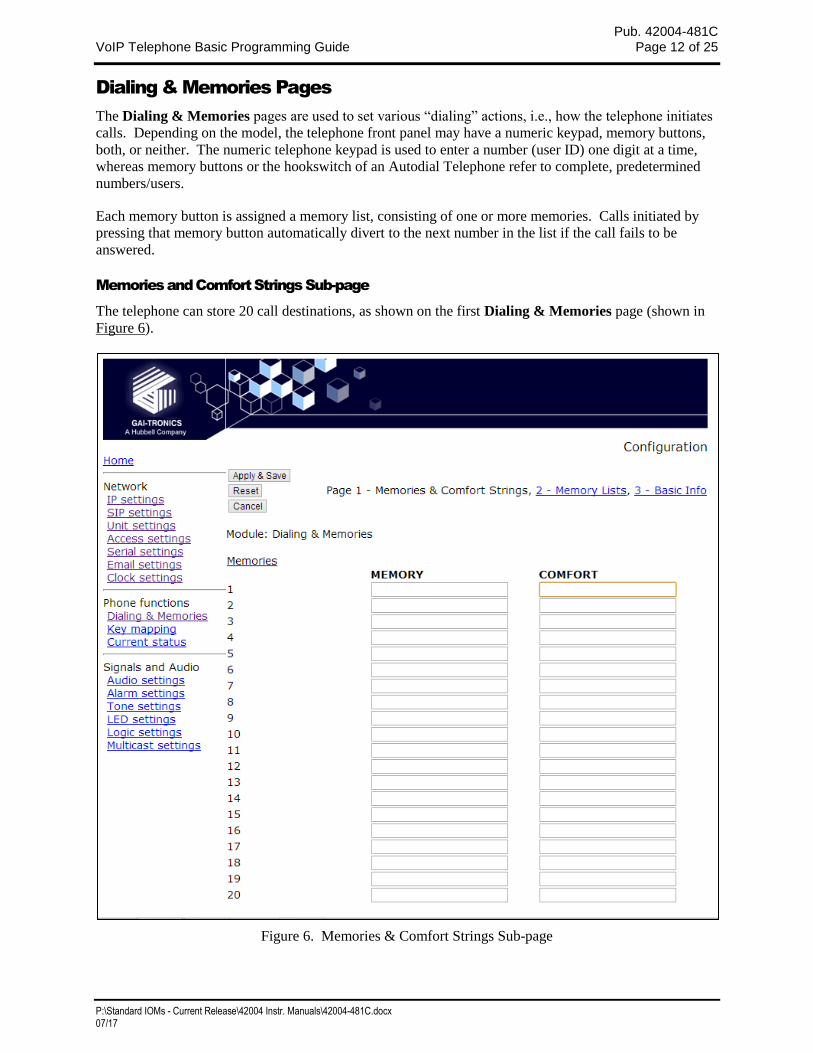
Memories and Comfort Strings Sub-page
The telephone can store 20 call destinations, as shown on the first Dialing & Memories page (shown in
Figure 6).
Figure 6. Memories & Comfort Strings Sub-page
Pub. 42004-481C VoIP Telephone Basic Programming Guide Page 13 of 25
P:\Standard IOMs - Current Release\42004 Instr. Manuals\42004-481C.docx 07/17
The telephone auto-dial memory buttons are pre-configured from the factory. Only the destination
telephone numbers or addresses (Memory) must be entered. The Comfort String can also be configured,
if desired.
Click the EDIT button to begin making changes. Click the APPLY & SAVE button to save your changes
when complete.
Table 6. Autodial Destination Parameters
Parameter Function
MEMORY Each of the 20 possible entries is either a
1. <usename>/<user ID> of an IP PBX/SIP server that is generally set as a sequence
of digits; or
2. A SIP URI for a per-to-peer connection.
COMFORT
Each of the 20 possible entries can also be assigned a COMFORT string, which is a
string of digits that will be played back to the user as DTMF when the call is being set
up. This simulates the dialing digit tones heard on a normal telephone. If these comfort
digits are desired, the comfort string must be entered.
NOTE: These memories (telephone numbers or addresses) are not assigned directly to the hookswitch or
EMERGENCY button. They must be set up in the Memory Lists sub-page. Click on the Memory Lists
link to navigate to the Memory Lists sub-page.
Memory Lists Sub-page
Memory Lists are strings of Memories (telephone numbers or addresses assigned on the Memories and
Comfort Strings Sub-page) that the telephone will call in sequence when the associated button is pressed.
The telephone can hold up to 11 memory lists (0–10). List 0 is the Emergency List and is mapped to a
button designated as EMERGENCY, if the telephone is so equipped.
Pub. 42004-481C VoIP Telephone Basic Programming Guide Page 14 of 25
P:\Standard IOMs - Current Release\42004 Instr. Manuals\42004-481C.docx 07/17
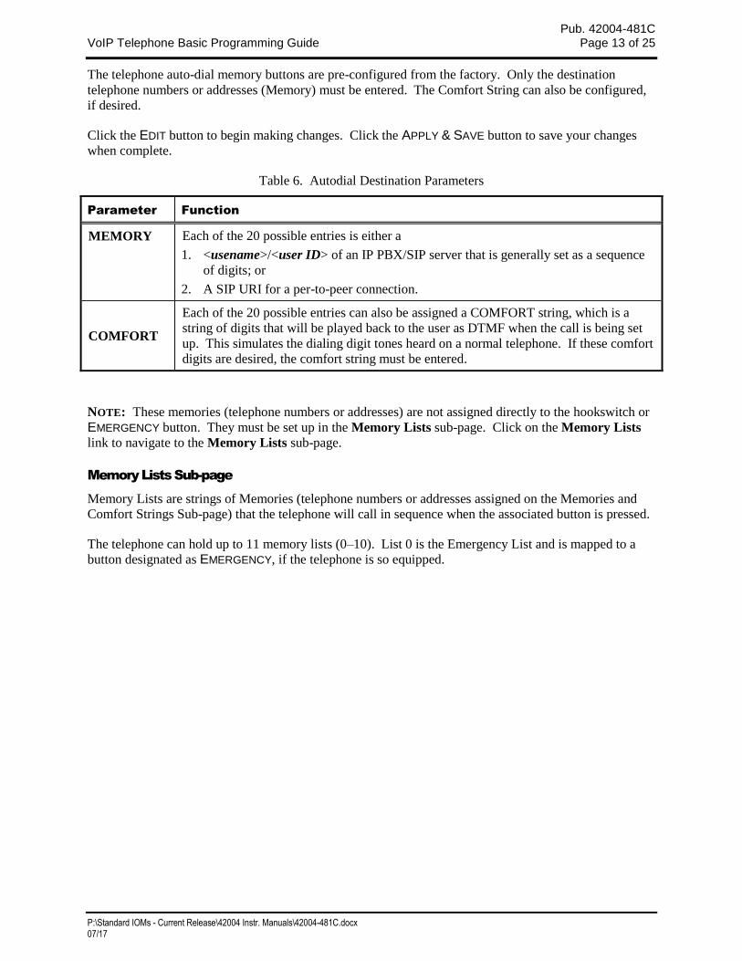
Figure 7. Memories Lists Sub-Page
A list can also be set to activate as soon as the handset is lifted if the telephone is to have auto-dial
capability(See the Basic Info Sub-page section for further information).
Click the EDIT button to begin making changes. Click the APPLY & SAVE button to save your changes
when complete.
Table 7. Dialing and Memories Parameters
Parameter Function
LIST Each list can contain up to 20 memory entries, separated by commas.
For example, if you wanted the MEM1 button to call the memory 1 (usually a
telephone number or address), if that failed to then call memory 5, and if that failed
call memory 10, you would enter “1, 5, 10” in the List box for List 1.
When a memory list in invoked, the telephone will attempt to place a call to each
memory in the list in sequence until a call is successful or it reaches the end of the
list.
Each memory can appear in more than one list.
WAKEANDDIAL
When set to ON, the telephone will come off hook and start to process the list as
soon as the appropriate button is pressed. This is factory set for hands-free
telephones, but can be set for handset telephones if required.
Pub. 42004-481C VoIP Telephone Basic Programming Guide Page 15 of 25
P:\Standard IOMs - Current Release\42004 Instr. Manuals\42004-481C.docx 07/17
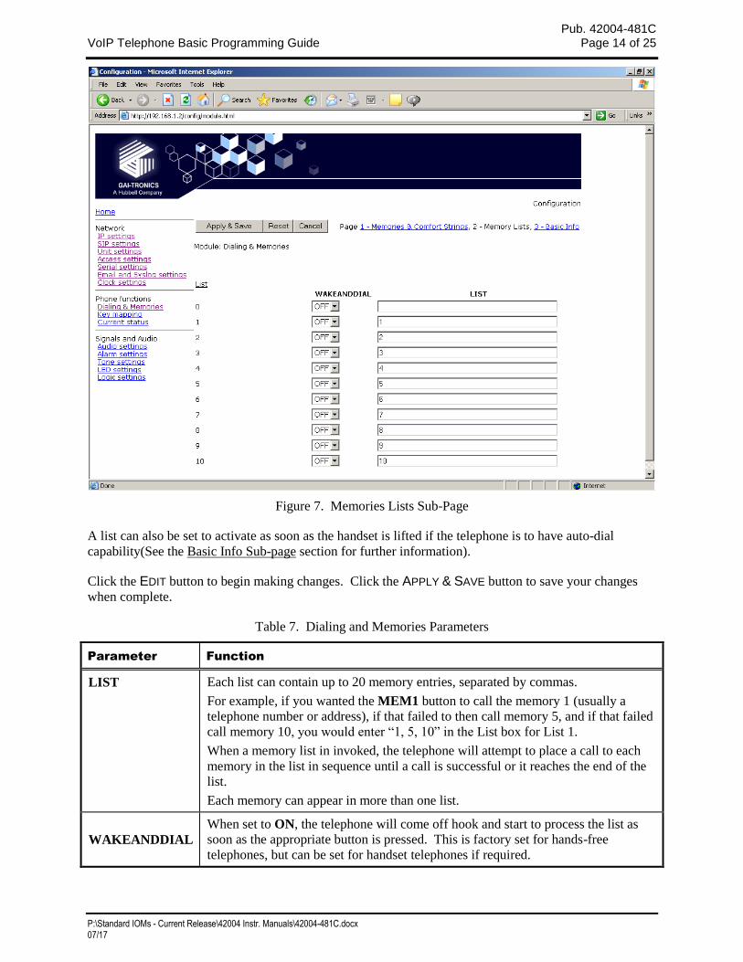
Next, click on the BASIC INFO link to navigate to the Basic Info sub-page.
Basic Info Sub-page
This page is used to edit an additional parameter (OFFHOOK) for the dialing configuration. This
parameter is factory configured for most of the telephone models covered by this manual and does not
require modification.
Figure 8. Basic Info Sub-page
The remaining parameters shown in Figure 8, but not listed in Table 8, are for advanced configurations
and should NOT be changed from the factory defaults.
Click on the EDIT button to begin making a change. Click on the APPLY & SAVE button to save your
change.
Table 8. Dialing and Memories Parameter (for Basic Configuration)
Parameter Function
OFFHOOK Sets a memory list number to be invoked when the handset is taken off hook (in a
handset model).
In most cases, this parameter is factory set for the specific telephone model and will not
need to be changed. For an Autodial Telephone, this is set to a memory list number.
Pub. 42004-481C VoIP Telephone Basic Programming Guide Page 16 of 25
P:\Standard IOMs - Current Release\42004 Instr. Manuals\42004-481C.docx 07/17
Next, under the Signals & Audio heading, click on the AUDIO SETTINGS link to navigate to the Audio
Settings page.
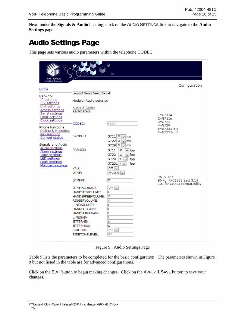
Audio Settings Page
This page sets various audio parameters within the telephone CODEC.
Figure 9. Audio Settings Page
Table 9 lists the parameters to be completed for the basic configuration. The parameters shown in Figure
9 but not listed in the table are for advanced configurations.
Click on the EDIT button to begin making changes. Click on the APPLY & SAVE button to save your
changes.
Pub. 42004-481C VoIP Telephone Basic Programming Guide Page 17 of 25
P:\Standard IOMs - Current Release\42004 Instr. Manuals\42004-481C.docx 07/17
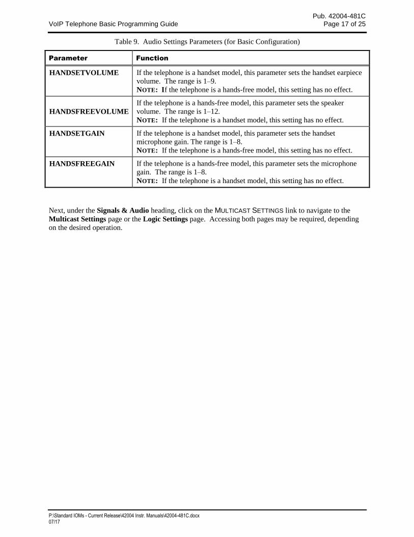
Table 9. Audio Settings Parameters (for Basic Configuration)
Parameter Function
HANDSETVOLUME If the telephone is a handset model, this parameter sets the handset earpiece
volume. The range is 1–9.
NOTE: If the telephone is a hands-free model, this setting has no effect.
HANDSFREEVOLUME
If the telephone is a hands-free model, this parameter sets the speaker
volume. The range is 1–12.
NOTE: If the telephone is a handset model, this setting has no effect.
HANDSETGAIN If the telephone is a handset model, this parameter sets the handset
microphone gain. The range is 1–8.
NOTE: If the telephone is a hands-free model, this setting has no effect.
HANDSFREEGAIN If the telephone is a hands-free model, this parameter sets the microphone
gain. The range is 1–8.
NOTE: If the telephone is a handset model, this setting has no effect.
Next, under the Signals & Audio heading, click on the MULTICAST SETTINGS link to navigate to the
Multicast Settings page or the Logic Settings page. Accessing both pages may be required, depending
on the desired operation.
Pub. 42004-481C VoIP Telephone Basic Programming Guide Page 18 of 25
P:\Standard IOMs - Current Release\42004 Instr. Manuals\42004-481C.docx 07/17
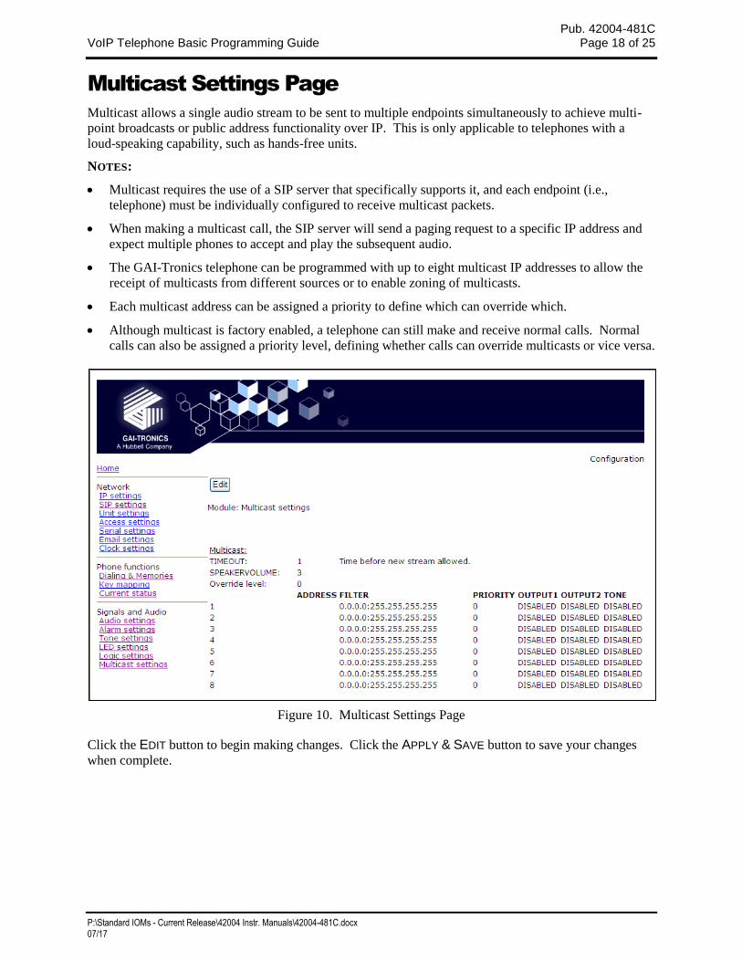
Multicast Settings Page
Multicast allows a single audio stream to be sent to multiple endpoints simultaneously to achieve multi-
point broadcasts or public address functionality over IP. This is only applicable to telephones with a
loud-speaking capability, such as hands-free units.
NOTES:
Multicast requires the use of a SIP server that specifically supports it, and each endpoint (i.e.,
telephone) must be individually configured to receive multicast packets.
When making a multicast call, the SIP server will send a paging request to a specific IP address and
expect multiple phones to accept and play the subsequent audio.
The GAI-Tronics telephone can be programmed with up to eight multicast IP addresses to allow the
receipt of multicasts from different sources or to enable zoning of multicasts.
Each multicast address can be assigned a priority to define which can override which.
Although multicast is factory enabled, a telephone can still make and receive normal calls. Normal
calls can also be assigned a priority level, defining whether calls can override multicasts or vice versa.
Figure 10. Multicast Settings Page
Click the EDIT button to begin making changes. Click the APPLY & SAVE button to save your changes
when complete.
Pub. 42004-481C VoIP Telephone Basic Programming Guide Page 19 of 25
P:\Standard IOMs - Current Release\42004 Instr. Manuals\42004-481C.docx 07/17
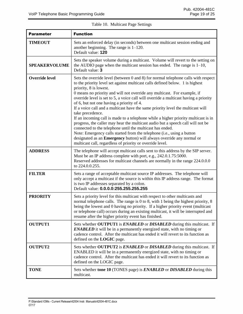
Table 10. Multicast Page Settings
Parameter Function
TIMEOUT Sets an enforced delay (in seconds) between one multicast session ending and
another beginning. The range is 1–120.
Default value: 120
SPEAKERVOLUME
Sets the speaker volume during a multicast. Volume will revert to the setting on
the AUDIO page when the multicast session has ended. The range is 1–10,
Default value: 3
Override level Sets the override level (between 0 and 8) for normal telephone calls with respect
to the priority level set against multicast calls defined below. 1 is highest
priority, 8 is lowest.
0 means no priority and will not override any multicast. For example, if
override level is set to 5, a voice call will override a multicast having a priority
of 6, but not one having a priority of 4.
If a voice call and a multicast have the same priority level the multicast will
take precedence.
If an incoming call is made to a telephone while a higher priority multicast is in
progress, the caller may hear the multicast audio but a speech call will not be
connected to the telephone until the multicast has ended.
Note: Emergency calls started from the telephone (i.e., using a button
designated as an Emergency button) will always override any normal or
multicast call, regardless of priority or override level.
ADDRESS The telephone will accept multicast calls sent to this address by the SIP server.
Must be an IP address complete with port, e.g., 242.0.1.75:5000.
Reserved addresses for multicast channels are normally in the range 224.0.0.0
to 224.0.0.255.
FILTER Sets a range of acceptable multicast source IP addresses. The telephone will
only accept a multicast if the source is within this IP address range. The format
is two IP addresses separated by a colon.
Default value: 0.0.0.0:255.255.255.255
PRIORITY Sets a priority level for this multicast with respect to other multicasts and
normal telephone calls. The range is 0 to 8, with 1 being the highest priority, 8
being the lowest and 0 having no priority. If a higher priority event (multicast
or telephone call) occurs during an existing multicast, it will be interrupted and
resume after the higher priority event has finished.
OUTPUT1 Sets whether OUTPUT1 is ENABLED or DISABLED during this multicast. If
ENABLED it will be in a permanently energized state, with no timing or
cadence control. After the multicast has ended it will revert to its function as
defined on the LOGIC page.
OUTPUT2 Sets whether OUTPUT2 is ENABLED or DISABLED during this multicast. If
ENABLED it will be in a permanently energized state, with no timing or
cadence control. After the multicast has ended it will revert to its function as
defined on the LOGIC page.
TONE Sets whether tone 10 (TONES page) is ENABLED or DISABLED during this
multicast.
Pub. 42004-481C VoIP Telephone Basic Programming Guide Page 20 of 25
P:\Standard IOMs - Current Release\42004 Instr. Manuals\42004-481C.docx 07/17
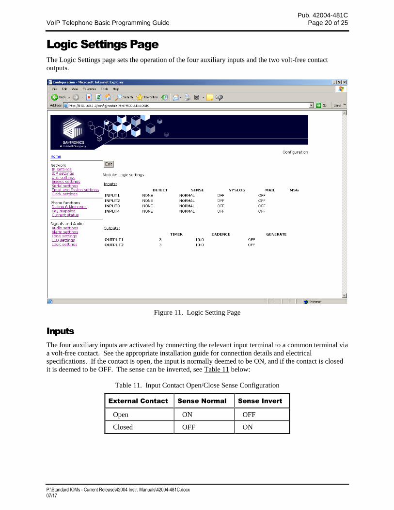
Logic Settings Page
The Logic Settings page sets the operation of the four auxiliary inputs and the two volt-free contact
outputs.
Figure 11. Logic Setting Page
Inputs
The four auxiliary inputs are activated by connecting the relevant input terminal to a common terminal via
a volt-free contact. See the appropriate installation guide for connection details and electrical
specifications. If the contact is open, the input is normally deemed to be ON, and if the contact is closed
it is deemed to be OFF. The sense can be inverted, see Table 11 below:
Table 11. Input Contact Open/Close Sense Configuration
External Contact Sense Normal Sense Invert
Open ON OFF
Closed OFF ON
Pub. 42004-481C VoIP Telephone Basic Programming Guide Page 21 of 25
P:\Standard IOMs - Current Release\42004 Instr. Manuals\42004-481C.docx 07/17
The auxiliary inputs can be configured to report their status to a remote site using two methods:
Syslog output over TCP
SMTP mail message
For each input, the following parameters can be set:
Table 12. Input Contact Configuration
Parameter Function
DETECT Specifies whether an input will report being set to its ON condition only (ON),
its OFF condition only (OFF), on either event (ON+OFF), or not at all (NONE).
The ON and OFF states are affected by the SENSE setting below.
SENSE
If set to NORMAL, a contact closure will report as OFF. If set to INVERT, a
contact closure will report as ON.
Default value: NORMAL
SYSLOG Enables or disables SYSLOG reporting for the selected input. Syslog settings
are on the IP Setting page. Refer to Pub. 42004-396 for further information on
syslog reporting, if required.
MAIL Enables or disables SMTP reporting for the selected input. SMTP settings are
on the Email Settings page. Refer to Pub. 42004-396 for further information if
required.
MSG Replaces the default text message Aux_in <input_number> with the text entered
(maximum 40 characters). The status <on/off> is appended to the end of the
text. If the MSG value is blank, the default message is reinstated.
The message sent (for both mail and syslog reports), takes the form:
HOSTNAME COUNT TIME MSG ON/OFF
Where:
HOSTNAME is from the Unit Settings page
COUNT is a volatile event counter (rolls over at 10000)
TIME is the event time and date from the unit’s clock
MSG is the message set by the MSG field above. If no message has been set,
the default is “Aux_in x”.
ON/OFF is either the word ON or OFF according to the state of the input,
taking account of the SENSE setting.
Pub. 42004-481C VoIP Telephone Basic Programming Guide Page 22 of 25
P:\Standard IOMs - Current Release\42004 Instr. Manuals\42004-481C.docx 07/17
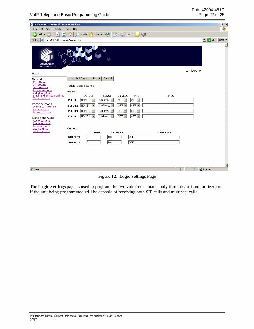
Figure 12. Logic Settings Page
The Logic Settings page is used to program the two volt-free contacts only if multicast is not utilized; or
if the unit being programmed will be capable of receiving both SIP calls and multicast calls.
Pub. 42004-481C VoIP Telephone Basic Programming Guide Page 23 of 25
P:\Standard IOMs - Current Release\42004 Instr. Manuals\42004-481C.docx 07/17
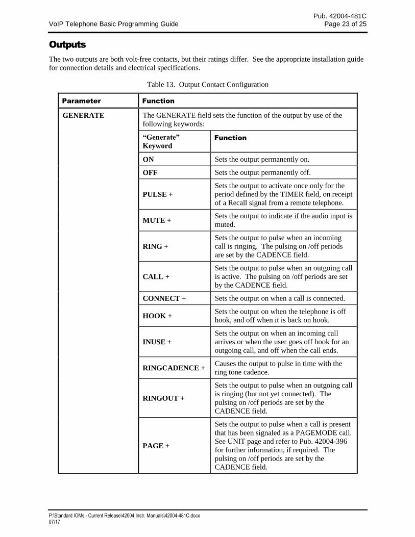
Outputs
The two outputs are both volt-free contacts, but their ratings differ. See the appropriate installation guide
for connection details and electrical specifications.
Table 13. Output Contact Configuration
Parameter Function
GENERATE The GENERATE field sets the function of the output by use of the
following keywords:
“Generate”
Keyword Function
ON Sets the output permanently on.
OFF Sets the output permanently off.
PULSE +
Sets the output to activate once only for the
period defined by the TIMER field, on receipt
of a Recall signal from a remote telephone.
MUTE + Sets the output to indicate if the audio input is
muted.
RING +
Sets the output to pulse when an incoming
call is ringing. The pulsing on /off periods
are set by the CADENCE field.
CALL +
Sets the output to pulse when an outgoing call
is active. The pulsing on /off periods are set
by the CADENCE field.
CONNECT + Sets the output on when a call is connected.
HOOK + Sets the output on when the telephone is off
hook, and off when it is back on hook.
INUSE +
Sets the output on when an incoming call
arrives or when the user goes off hook for an
outgoing call, and off when the call ends.
RINGCADENCE + Causes the output to pulse in time with the
ring tone cadence.
RINGOUT +
Sets the output to pulse when an outgoing call
is ringing (but not yet connected). The
pulsing on /off periods are set by the
CADENCE field.
PAGE +
Sets the output to pulse when a call is present
that has been signaled as a PAGEMODE call.
See UNIT page and refer to Pub. 42004-396
for further information, if required. The
pulsing on /off periods are set by the
CADENCE field.
Pub. 42004-481C VoIP Telephone Basic Programming Guide Page 24 of 25
P:\Standard IOMs - Current Release\42004 Instr. Manuals\42004-481C.docx 07/17
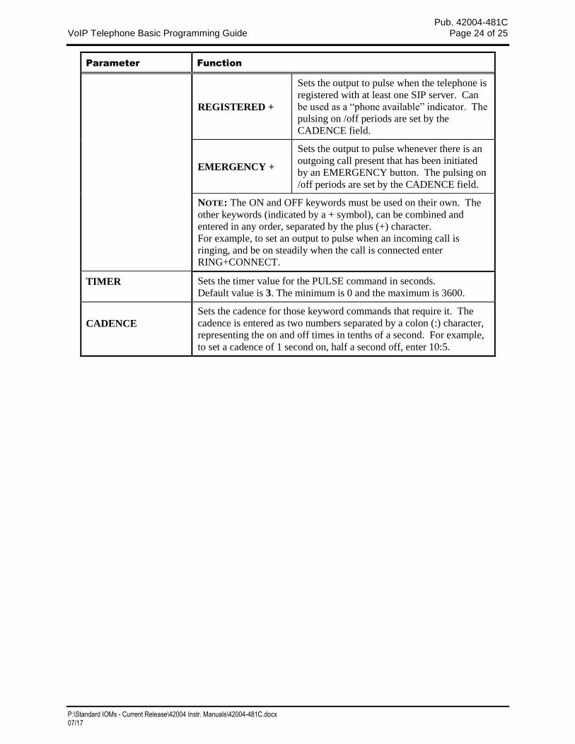
Parameter Function
REGISTERED +
Sets the output to pulse when the telephone is
registered with at least one SIP server. Can
be used as a “phone available” indicator. The
pulsing on /off periods are set by the
CADENCE field.
EMERGENCY +
Sets the output to pulse whenever there is an
outgoing call present that has been initiated
by an EMERGENCY button. The pulsing on
/off periods are set by the CADENCE field.
NOTE: The ON and OFF keywords must be used on their own. The
other keywords (indicated by a + symbol), can be combined and
entered in any order, separated by the plus (+) character.
For example, to set an output to pulse when an incoming call is
ringing, and be on steadily when the call is connected enter
RING+CONNECT.
TIMER Sets the timer value for the PULSE command in seconds.
Default value is 3. The minimum is 0 and the maximum is 3600.
CADENCE
Sets the cadence for those keyword commands that require it. The
cadence is entered as two numbers separated by a colon (:) character,
representing the on and off times in tenths of a second. For example,
to set a cadence of 1 second on, half a second off, enter 10:5.
Pub. 42004-481C VoIP Telephone Basic Programming Guide Page 25 of 25
P:\Standard IOMs - Current Release\42004 Instr. Manuals\42004-481C.docx 07/17
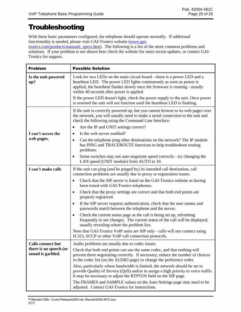
Troubleshooting
With these basic parameters configured, the telephone should operate normally. If additional
functionality is needed, please visit GAI-Tronics website (www.gai-
tronics.com/products/manuals_specs.htm). The following is a list of the more common problems and
solutions. If your problem is not shown here check the website for more recent updates, or contact GAI-
Tronics for support.
Problem Possible Solution
Is the unit powered
up?
Look for two LEDs on the main circuit board—there is a power LED and a
heartbeat LED. The power LED lights continuously as soon as power is
applied, the heartbeat flashes slowly once the firmware is running - usually
within 40 seconds after power is applied.
If the power LED doesn't light, check the power supply to the unit. Once power
is restored the unit will not function until the heartbeat LED is flashing.
I can’t access the
web pages.
If the unit is correctly powered up, but you cannot browse to its web pages over
the network, you will usually need to make a serial connection to the unit and
check the following using the Command Line Interface:
Are the IP and UNIT settings correct?
Is the web server enabled?
Can the telephone ping other destinations on the network? The IP module
has PING and TRACEROUTE functions to help troubleshoot routing
problems.
Some switches may not auto-negotiate speed correctly - try changing the
LAN speed (UNIT module) from AUTO to 10.
I can’t make calls If the unit can ping (and be pinged by) its intended call destination, call
connection problems are usually due to proxy or registration issues.
Check that the SIP server is listed on the GAI-Tronics website as having
been tested with GAI-Tronics telephones.
Check that the proxy settings are correct and that both end points are
properly registered.
If the SIP server requires authentication, check that the user names and
passwords match between the telephone and the server.
Check the current status page as the call is being set up, refreshing
frequently to see changes. The current status of the call will be displayed,
usually revealing where the problem lies.
Note that GAI-Tronics VoIP units are SIP only - calls will not connect using
H.323, SCCP or other VoIP call connection protocols.
Calls connect but
there is no speech (or
sound is garbled.
Audio problems are usually due to codec issues.
Check that both end points can use the same codec, and that nothing will
prevent them negotiating correctly. If necessary, reduce the number of choices
in the codec list (on the AUDIO page) or change the preference order.
Also, particularly where bandwidth is limited, the network should be set to
provide Quality of Service (QoS) and/or to assign a high priority to voice traffic.
It may be necessary to adjust the RTPTOS field on the SIP page.
The FRAMES and SAMPLE values on the Auto Settings page may need to be
adjusted. Contact GAI-Tronics for instructions.
(Rev. 10/06)
WarrantyEquipment. GAI-Tronics warrants for a period of one (1) year from the date of shipment, that anyGAI-Tronics equipment supplied hereunder shall be free of defects in material and workmanship, shallcomply with the then-current product specifications and product literature, and if applicable, shall be fitfor the purpose specified in the agreed-upon quotation or proposal document. If (a) Seller’s goods proveto be defective in workmanship and/or material under normal and proper usage, or unfit for the purposespecified and agreed upon, and (b) Buyer’s claim is made within the warranty period set forth above,Buyer may return such goods to GAI-Tronics’ nearest depot repair facility, freight prepaid, at which timethey will be repaired or replaced, at Seller’s option, without charge to Buyer. Repair or replacement shallbe Buyer’s sole and exclusive remedy. The warranty period on any repaired or replacement equipmentshall be the greater of the ninety (90) day repair warranty or one (1) year from the date the originalequipment was shipped. In no event shall GAI-Tronics warranty obligations with respect to equipmentexceed 100% of the total cost of the equipment supplied hereunder. Buyer may also be entitled to themanufacturer’s warranty on any third-party goods supplied by GAI-Tronics hereunder. The applicabilityof any such third-party warranty will be determined by GAI-Tronics.
Services. Any services GAI-Tronics provides hereunder, whether directly or through subcontractors,shall be performed in accordance with the standard of care with which such services are normallyprovided in the industry. If the services fail to meet the applicable industry standard, GAI-Tronics willre-perform such services at no cost to buyer to correct said deficiency to Company's satisfaction providedany and all issues are identified prior to the demobilization of the Contractor’s personnel from the worksite. Re-performance of services shall be Buyer’s sole and exclusive remedy, and in no event shall GAI-Tronics warranty obligations with respect to services exceed 100% of the total cost of the servicesprovided hereunder.
Warranty Periods. Every claim by Buyer alleging a defect in the goods and/or services providedhereunder shall be deemed waived unless such claim is made in writing within the applicable warrantyperiods as set forth above. Provided, however, that if the defect complained of is latent and notdiscoverable within the above warranty periods, every claim arising on account of such latent defect shallbe deemed waived unless it is made in writing within a reasonable time after such latent defect is orshould have been discovered by Buyer.
Limitations / Exclusions. The warranties herein shall not apply to, and GAI-Tronics shall not beresponsible for, any damage to the goods or failure of the services supplied hereunder, to the extentcaused by Buyer’s neglect, failure to follow operational and maintenance procedures provided with theequipment, or the use of technicians not specifically authorized by GAI-Tronics to maintain or service theequipment. THE WARRANTIES AND REMEDIES CONTAINED HEREIN ARE IN LIEU OF ANDEXCLUDE ALL OTHER WARRANTIES AND REMEDIES, WHETHER EXPRESS OR IMPLIED BYOPERATION OF LAW OR OTHERWISE, INCLUDING ANY WARRANTIES OFMERCHANTABILITY OR FITNESS FOR A PARTICULAR PURPOSE.
Return PolicyIf the equipment requires service, contact your Regional Service Center for a return authorization number(RA#). Equipment should be shipped prepaid to GAI-Tronics with a return authorization number and apurchase order number. If the equipment is under warranty, repairs or a replacement will be made inaccordance with the warranty policy set forth above. Please include a written explanation of all defects toassist our technicians in their troubleshooting efforts.
Call 800-492-1212 (inside the USA) or 610-777-1374 (outside the USA) for help identifying theRegional Service Center closest to you.