VoIP Features Oriented Uplink Scheduling Scheme in
20
1. Introduction VoIP services have been considered as one of the most important services in the next generation wireless systems. VoIP service requires the same quality of service (QoS) requirement as constant bit rate services. For this reason, the IEEE 802.16 standard has defined an unsolicited grant service (UGS) to guarantee the QoS. However, the UGS is inadequate to support VoIP services with silence suppression because of the waste of radio bandwidth in the silent-periods. In the UGS, a base station (BS) periodically allocates a maximum-size radio bandwidth (grant) during the silent-periods even though a subscriber station (SS) does not have a packet to transmit in the silent-periods. To solve this problem, (Lee et al., 2005) proposed an extended real time polling service (ertPS) to support VoIP services with silence suppression. The ertPS can manage the grant-size according to the voice activity in order to save the radio bandwidth in silent-period. Unfortunately, the waste of radio bandwidth and the increase of access delay can still exist when the ertPS is applied to the system because the grant-size and grant-interval used by the ertPS cannot correspond with the packet-size and the packet-generation-interval of the VoIP services in the application layer. Recently, the IEEE 802.16’s Task Group m (TGm), which was approved by IEEE to develop an amendment to IEEE 802.16 standard in 2006, published the draft evaluation methodology document in which several kinds of VoIP speech codecs are considered such as G.711, G.723.1, G.729, enhanced variable rate codec (EVRC), and adaptive multi-rate (AMR) (Srinivasan, 2007). These VoIP speech codecs generate packets with different packet-size and packet-generation-interval as shown in Table 1. However, the IEEE 802.16 standard does not define the QoS parameter generation method, because they have focused on only medium access control (MAC) and physical (PHY) layer. For this reason, IEEE 802.16 based systems need the QoS parameter mapping algorithm to obtain the features of the VoIP services in the application layer. Hong and Kwon (Hong & Kwon, 2006) proposed the QoS parameter mapping algorithm to exploit the feature of the VoIP services in IEEE 802.16 systems which statistically measures the peak data rate of VoIP services and calculates the QoS parameters. However, the algorithm needs significant time to measure the VoIP traffic to perform the statistical analysis, and the QoS parameters cannot correspond to the features of the VoIP services when the number of samples of the VoIP traffic is not sufficient to analyze the features of the VoIP service. To overcome these problems, this chapter designs a cross-layer QoS parameter mapping scheme which exploits the information of the VoIP speech codec included in the session description protocol (SDP) to generate the QoS parameters for VoIP scheduling algorithms. Sung-Min Oh and Jae-Hyun Kim School of Electrical and Computer Engineering, Ajou University Republic of Korea VoIP Features Oriented Uplink Scheduling Scheme in Wireless Networks 10 www.intechopen.com
Transcript of VoIP Features Oriented Uplink Scheduling Scheme in

1. Introduction
VoIP services have been considered as one of the most important services in the nextgeneration wireless systems. VoIP service requires the same quality of service (QoS)requirement as constant bit rate services. For this reason, the IEEE 802.16 standard has definedan unsolicited grant service (UGS) to guarantee the QoS. However, the UGS is inadequateto support VoIP services with silence suppression because of the waste of radio bandwidthin the silent-periods. In the UGS, a base station (BS) periodically allocates a maximum-sizeradio bandwidth (grant) during the silent-periods even though a subscriber station (SS) doesnot have a packet to transmit in the silent-periods. To solve this problem, (Lee et al., 2005)proposed an extended real time polling service (ertPS) to support VoIP services with silencesuppression. The ertPS can manage the grant-size according to the voice activity in order tosave the radio bandwidth in silent-period. Unfortunately, the waste of radio bandwidth andthe increase of access delay can still exist when the ertPS is applied to the system because thegrant-size and grant-interval used by the ertPS cannot correspond with the packet-size andthe packet-generation-interval of the VoIP services in the application layer.Recently, the IEEE 802.16’s Task Group m (TGm), which was approved by IEEE to develop anamendment to IEEE 802.16 standard in 2006, published the draft evaluation methodologydocument in which several kinds of VoIP speech codecs are considered such as G.711,G.723.1, G.729, enhanced variable rate codec (EVRC), and adaptive multi-rate (AMR)(Srinivasan, 2007). These VoIP speech codecs generate packets with different packet-size andpacket-generation-interval as shown in Table 1. However, the IEEE 802.16 standard does notdefine the QoS parameter generation method, because they have focused on only mediumaccess control (MAC) and physical (PHY) layer. For this reason, IEEE 802.16 based systemsneed the QoS parameter mapping algorithm to obtain the features of the VoIP services inthe application layer. Hong and Kwon (Hong & Kwon, 2006) proposed the QoS parametermapping algorithm to exploit the feature of the VoIP services in IEEE 802.16 systems whichstatistically measures the peak data rate of VoIP services and calculates the QoS parameters.However, the algorithm needs significant time to measure the VoIP traffic to perform thestatistical analysis, and the QoS parameters cannot correspond to the features of the VoIPservices when the number of samples of the VoIP traffic is not sufficient to analyze the featuresof the VoIP service. To overcome these problems, this chapter designs a cross-layer QoSparameter mapping scheme which exploits the information of the VoIP speech codec includedin the session description protocol (SDP) to generate the QoS parameters for VoIP schedulingalgorithms.
Sung-Min Oh and Jae-Hyun KimSchool of Electrical and Computer Engineering, Ajou University
Republic of Korea
VoIP Features Oriented Uplink Scheduling Scheme in Wireless Networks
10
www.intechopen.com

2 VoIP Technologies
(a) G.7xx with silence suppression (b) EVRC
(c) AMR
Fig. 1. Traffic models for various VoIP speech codecs
Moreover, this chapter proposes a new cross-layer VoIP scheduling algorithm which exploitsthe QoS parameters generated by the proposed QoS parameter mapping scheme. Theconventional VoIP scheduling algorithms have been designed considering a specific VoIPspeech codec. The UGS has been designed to guarantee a QoS for G.7xx (i.e. G.711, G.723.1,and G.729) without silence suppression, and the ertPS has been developed to support EVRC.In particular, the ertPS is designed to compensate for the resource inefficiency of the UGSin the silent-periods. Unfortunately, the ertPS is not an optimal VoIP scheduling algorithmfor the whole VoIP speech codecs. In the ertPS, a BS periodically allocates a minimum-sizegrant to a SS every 20 msec regardless of the voice activity in the silent-period. However,the AMR speech codec generates a packet every 160 msec in the silent-period. Thus, theertPS can cause the waste of radio bandwidth in the silent-period when it supports the AMRspeech codec. To overcome this inefficiency of the ertPS, Oh et al (Oh et al., 2008) proposeda new VoIP scheduling algorithm, which is called as a hybrid VoIP (HV) algorithm in thischapter. The HV algorithm adapts a random access scheme in the silent-period to saveradio bandwidth. However, it can suffer from an overhead occurred in the silent-periodwhen the EVRC is applied in the application layer. The problems of VoIP schedulingalgorithms according to the VoIP speech codecs are detailed in section 3. Consequently,this chapter proposes the cross-layer VoIP scheduling algorithm to support all available VoIPspeech codecs. The main feature of the cross-layer VoIP scheduling algorithm is that it candynamically adjust the grant-interval in the silent-period according to the VoIP speech codecapplied in the application layer. By this feature, the proposed scheduling algorithm can saveradio bandwidth guaranteeing a QoS for all VoIP speech codecs in the silent-period. Thedescription of the proposed scheduling algorithm is presented in section 4.
2. Traffic models for various VoIP speech codecs
This section describes traffic models for various VoIP speech codecs which are presented inFig. 1 where each VoIP speech codec has individual features in their packet generation policy(ITU-T-G711, 2000; ITU-T-G7231, 1996; ITU-T-G729, 2007; 3GPP2-EVRC, 2004; 3GPP-TS-26201,2001; 3GPP-TS-26092, 2002; 3GPP-TS-26071, 1999). Fig. 1 (a) represents a traffic model for
220 VoIP Technologies
www.intechopen.com
VoIP Features Oriented Uplink Scheduling Scheme in Wireless Networks 3
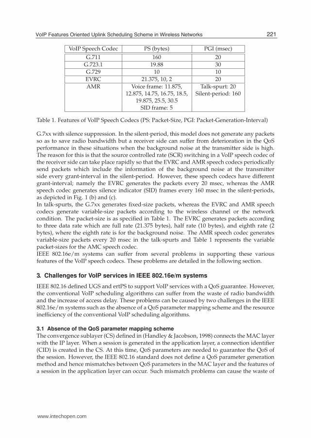
VoIP Speech Codec PS (bytes) PGI (msec)
G.711 160 20
G.723.1 19.88 30
G.729 10 10
EVRC 21.375, 10, 2 20
AMR Voice frame: 11.875, Talk-spurt: 2012.875, 14.75, 16.75, 18.5, Silent-period: 160
19.875, 25.5, 30.5SID frame: 5
Table 1. Features of VoIP Speech Codecs (PS: Packet-Size, PGI: Packet-Generation-Interval)
G.7xx with silence suppression. In the silent-period, this model does not generate any packetsso as to save radio bandwidth but a receiver side can suffer from deterioration in the QoSperformance in these situations when the background noise at the transmitter side is high.The reason for this is that the source controlled rate (SCR) switching in a VoIP speech codec ofthe receiver side can take place rapidly so that the EVRC and AMR speech codecs periodicallysend packets which include the information of the background noise at the transmitterside every grant-interval in the silent-period. However, these speech codecs have differentgrant-interval; namely the EVRC generates the packets every 20 msec, whereas the AMRspeech codec generates silence indicator (SID) frames every 160 msec in the silent-periods,as depicted in Fig. 1 (b) and (c).In talk-spurts, the G.7xx generates fixed-size packets, whereas the EVRC and AMR speechcodecs generate variable-size packets according to the wireless channel or the networkcondition. The packet-size is as specified in Table 1. The EVRC generates packets accordingto three data rate which are full rate (21.375 bytes), half rate (10 bytes), and eighth rate (2bytes), where the eighth rate is for the background noise. The AMR speech codec generatesvariable-size packets every 20 msec in the talk-spurts and Table 1 represents the variablepacket-sizes for the AMC speech codec.IEEE 802.16e/m systems can suffer from several problems in supporting these variousfeatures of the VoIP speech codecs. These problems are detailed in the following section.
3. Challenges for VoIP services in IEEE 802.16e/m systems
IEEE 802.16 defined UGS and ertPS to support VoIP services with a QoS guarantee. However,the conventional VoIP scheduling algorithms can suffer from the waste of radio bandwidthand the increase of access delay. These problems can be caused by two challenges in the IEEE802.16e/m systems such as the absence of a QoS parameter mapping scheme and the resourceinefficiency of the conventional VoIP scheduling algorithms.
3.1 Absence of the QoS parameter mapping scheme
The convergence sublayer (CS) defined in (Handley & Jacobson, 1998) connects the MAC layerwith the IP layer. When a session is generated in the application layer, a connection identifier(CID) is created in the CS. At this time, QoS parameters are needed to guarantee the QoS ofthe session. However, the IEEE 802.16 standard does not define a QoS parameter generationmethod and hence mismatches between QoS parameters in the MAC layer and the features ofa session in the application layer can occur. Such mismatch problems can cause the waste of
221VoIP Features Oriented Uplink Scheduling Scheme in Wireless Networks
www.intechopen.com

4 VoIP Technologies
(a) (b)
(c) (d)
Fig. 2. Examples of the mismatch problem between the QoS parameters in the MAC layerand the features of VoIP services in the application layer; default QoS parameters (grant-size:38 bytes and grant-interval: 10 msec), VoIP speech codec (G. 711 without silencesuppression), and VoIP scheduling algorithm ((a) UGS and (b) ertPS), {default QoSparameters (grant-size: 188 bytes and grant-interval: 20 msec), VoIP speech codec (G. 729without silence suppression), and VoIP scheduling algorithm ((c) UGS and (d) ertPS)}
radio bandwidth or the increase of access delay. To describe the mismatch problems in detail,this chapter gives examples as shown in Fig. 2.Figs. 2 (a) and (b) represent the mismatch problems. In this case, the default values of theQoS parameters are set by considering the G.729 . In addition, VoIP scheduling algorithms,as shown in Fig. 2 (a) and (b), are UGS and ertPS, respectively. As depicted in Fig. 2 (a),the access delay increases by 40 msec to transmit a packet due to the mismatch problem. ABS periodically allocates a fixed-size grant (38 bytes) every 10 msec even though a SS needsadditional bandwidth to transmit a packet, because the UGS cannot request any additionalbandwidth. Due to this problem, the access delay can increase linearly when the systemcontinuously receives data packets from the upper layer. This anomalistic phenomenon cancause serious deterioration of the QoS performance for VoIP services. Unlike UGS, the ertPScan prevent the increase of access delay, as shown in Fig. 2 (b). The reason is that the ertPScan request additional bandwidth by the bandwidth-request-header. However, the radiobandwidth (188 bytes) can be wasted every 20 msec; because a BS periodically allocates agrant (188 bytes) every 10 msec even though data packets are generated every 20 msec.Figs. 2 (c) and (d) also represent the mismatch problem. In this case, the default values ofthe QoS parameters are set by considering the G.711. As depicted in Fig. 2 (c), a packet canexperience an access delay of 10 msec every 20 msec. In addition, 112 bytes of bandwidth is
222 VoIP Technologies
www.intechopen.com

VoIP Features Oriented Uplink Scheduling Scheme in Wireless Networks 5
wasted every 20 msec when UGS is applied to the system. The ertPS can save the waste ofradio bandwidth as shown in Fig. 2 (d). However, the access delay still exists because of themismatch between the grant-interval and the packet-generation-interval.As mentioned above, the mismatch problem can cause the waste of radio bandwidth orthe increase of access delay. To solve the mismatch problem, this chapter proposes a newcross-layer QoS mapping scheme, which will be described in section 4.
3.2 Resource inefficiency of the conventional VoIP scheduling algorithms
The UGS and ertPS methods are inefficient in their use of the wireless resource. In UGS,a BS periodically allocates the maximum-size grant to a SS regardless of the voice activityeven though the data rate of the VoIP services with silence suppression decreases in thesilent-periods. Because of this resource inefficiency of the UGS, the ertPS has been designedto support VoIP services with silence suppression. The ertPS can manage the grant-sizeaccording to the voice activity. In order to change this, the ertPS has two main features. Firstly,it exploits a generic-MAC-header to inform a BS of the SS’s voice activity. Lee et al (Lee et al.,2005) defined a Grant-Me (GM) bit using a reserved bit in the generic-MAC-header. When ina silent-period the voice activity indicated by the GM bit is ’0’ whereas in a talk-spurt, the GMbit is ’1’. Secondly, a BS periodically allocates a grant to transmit a generic-MAC-header inthe silent-period. By using this feature, a SS can transmit a generic-MAC-header even thoughthere is no packet to transmit in the silent-period.On the other hand, the grant for a generic-MAC-header is wasted during the silent-periodfrom considering the wireless resource aspects. As shown in Fig. 3 (a), a grant is wasted every20 msec when the G.7xx situation with silence suppression is applied to the system. When theAMR speech codec is applied to the system, seven grants are wasted every 160 msec duringthe silent-period, as shown in Fig. 3 (b).To overcome this inefficiency of the ertPS, (Oh et al., 2008) proposed a HV algorithm with threemain features. Firstly, a BS does not periodically allocate a grant to a SS in the silent-periodin order to save the uplink bandwidth. Secondly, the HV adopts the random access scheme totransmit a packet in the silent-period. Thirdly, it also uses the random access scheme when thevoice activity changes from a silent-period to a talk-spurt, because the transition time from oneto the other is unpredictable. The HV exploits a bandwidth-request-and-uplink-sleep-control(BRUSC) header in order to inform a BS of the SS’s voice activity and request the requiredbandwidth. The BRUSC header has a reserved bit which is defined as a silence talkspurt (ST)bit in (Oh et al., 2008), and this has a bandwidth request (BR) field which can be specified as arequired bandwidth in bytes. In the HV method, the SS transmit a BRUSC header by using therandom access scheme when a packet to transmit is generated in a silent-period, or when thevoice activity changes from being in a silent-period to a talk-spurt. At this time, the grant-sizeis the same with the bandwidth required by the BRUSC header.Unfortunately, the HV algorithm can suffer from collisions when the EVRC is applied to thesystem. In case of the AMR speech codec and G.7xx with silence suppression, the collisioncannot affect the QoS performance for the VoIP services, because the transmission rate of aBRUSC header is very low. However, a SS transmits a BRUSC header every 20 msec during asilent-period by the random access scheme when the EVRC is applied to the system as shownin Fig. 3 (c). For this reason, the message overhead required to transmit a packet rapidlyincreases because the transmission rate of a BRUSC header increases. For this problem, the HValgorithm may be inadequate for EVRC. Consequently, this chapter proposes the cross-layerVoIP scheduling algorithm to support the whole VoIP speech codecs with efficient use of radio
223VoIP Features Oriented Uplink Scheduling Scheme in Wireless Networks
www.intechopen.com

6 VoIP Technologies
(a) ertPS for G.7xx with silence suppression (b) ertPS for AMR speech codec
(c) HV algorithm for EVRC
Fig. 3. Resource inefficiency of the conventional VoIP scheduling algorithms
bandwidth.
4. Proposed cross-layer framework for VoIP services
In order to overcome the challenges of the VoIP services in IEEE 802.16e/m systemsmentioned in section 3, we design the cross-layer framework for VoIP services which isshown in Fig. 4. It consists of the cross-layer QoS parameter mapping scheme and thenew cross-layer VoIP scheduling algorithm. The description of the cross-layer QoS parametermapping scheme and the cross-layer VoIP scheduling algorithm are as follows.
4.1 Cross-layer framework for VoIP services
We propose the cross-layer QoS parameter mapping scheme to compensate for the absenceof the QoS parameter mapping scheme in IEEE 802.16e/m systems. The cross-layer QoSparameter mapping scheme consists of three functions such as the QoS parameter creationfunction, CID creation function, and CID mapping function as shown in Fig. 4.
4.1.1 QoS parameter creation function
The QoS parameter creation function is the main function in the cross-layer QoS parametermapping scheme. It generates the QoS parameters using the session information in theapplication layer. When a VoIP session is opened in the application layer, the session initiationfunction activates a session initiation protocol (SIP) to connect a session between the enddevices. At this time, the SIP message includes a SDP to deliver the session information, e.g.media type, transport protocol, media format, and so on, for guaranteeing the required QoS. InSDP, a field ’m’ presents the media information such as m= (media) (port) (transport) (formatlist). For example, ’m=audio 49170 RTP/AVP 0’ means that media is audio, port numberis 49170, transport protocol is real time protocol (RTP) with audio video profile (AVP), and
224 VoIP Technologies
www.intechopen.com

VoIP Features Oriented Uplink Scheduling Scheme in Wireless Networks 7
Fig. 4. Cross-layer framework for VoIP services
voice codec is G.711 (0) (Handley & Jacobson, 1998). In this chapter, the proposed schemeuses the field ’m’ to identify the kinds of VoIP speech codec applied in the application layer.The features of VoIP services can be identified by the kinds of VoIP speech codec as shownin Table 1. For this reason, the QoS parameter creation function can obtain the features of theVoIP services such as the packet-size and packet-generation-interval from the SDP. Therefore,the QoS parameter creation function can generate the QoS parameters using the features ofVoIP services as shown in Table 2.
4.1.2 CID creation function
The CID creation function generates a CID between a BS and a SS. It transmits a dynamicservice addition request (DSA-REQ) message which includes the QoS parameter set, as shownin Table 2, to a call admission control function in a BS. The call admission control functiondecides whether the system supports the VoIP service or not based on the QoS parameter set
QoS parameter set Values
Maximum sustained traffic rate PS × PGI
Maximum traffic burst PS
Minimum reserved traffic rate PS × PGI
Minimum tolerable traffic rate PS × PGI
Unsolicited grant interval PGI
Unsolicited polling interval PGI
SDU inter-arrival interval PGI
Table 2. QoS Parameter Mapping Example for the VoIP Scheduling Algorithms
225VoIP Features Oriented Uplink Scheduling Scheme in Wireless Networks
www.intechopen.com

8 VoIP Technologies
in the DSA-REQ message, and it sends a DSA response (DSA-RSP) message which includes aCID if the system can support the VoIP services. The CID creation function delivers the CIDto the CID mapping function, when it receives the DSA-RSP message from the call admissioncontrol function.
4.1.3 CID mapping function
When the CID mapping function receives a CID from the CID creation function, it updates aCID table which consists of CID and the information of the user datagram protocol (UDP)/IPheader such as the source/destination UDP port number, source/destination IP address, andprotocol, and so on. The CID mapping function identifies a packet received from the IP layerusing the information of the UDP/IP header, and it searches the CID which correspondswith the information of the UDP/IP header. For examples, the CID mapping function canidentify a packet which includes a SIP message using the UDP port number because theUDP port number of SIP is 5060 or 5061. In addition, it can identify a VoIP packet using asource/destination IP address. The reason is that the source/destination IP addresses of thepackets in a VoIP session are fixed. After the packet identification and CID mapping, the CIDmapping function stores the packets in a queue which corresponds with the CID. The IEEE802.16 systems transmit the packets stored in the queue by using VoIP scheduling algorithms.
4.2 Cross-layer VoIP scheduling algorithm
In order to solve the inefficiency of the conventional VoIP scheduling algorithms mentionedin section 3, we propose the new cross-layer VoIP scheduling algorithm. This proposedalgorithm has three main features. Firstly, it exploits the QoS parameters, e.g. thegrant-size and the grant-interval, generated by the cross-layer QoS parameter mappingscheme. Secondly, it adjusts the grant allocation policy according to the kinds of VoIPspeech codec in the silent-period to save the uplink bandwidth. When the G.7xx with silencesuppression is applied in the application layer, a BS stops the periodic grant allocation duringthe silent-periods in the proposed algorithm. When the EVRC or AMR speech codecs areapplied in the application layer, a BS periodically allocates a grant every 20 msec or 160 msecduring silent-periods, respectively. Thirdly, it adopts the random access scheme only when thevoice activity changes from a silent-period to a talk-spurt. In addition, the proposed algorithmuses a BRUSC header to inform a BS of the SS’s voice activity, as in the HV algorithm. In thischapter, we define that the ST bit ‘0’ means a silent-period, whereas the ST bit ‘1’ means atalk-spurt.
4.2.1 In case of silent-period
Figs. 5 (a), (b), and (c) represent the cross-layer VoIP scheduling algorithm for G.7xx, AMRspeech codec, and EVRC, respectively. As shown in Fig. 5, a SS sends a BRUSC header withthe ST bit ’0’ by using the polling scheme when the voice activity changes from a talk-spurtto a silent-period. When a BS receives a BRUSC header with the ST bit being ’0’, the BS stopsthe grant allocation or periodically allocates the grant. In case of G.7xx, the BS stops theperiodic grant allocation in order to save radio bandwidth in the silent-period. In case of theAMR speech codec and EVRC, the BS periodically allocates a grant every 160 msec and 20msec during the silent-period, respectively. The grant-size corresponds with the bandwidthspecified in the BR field of the BRUSC header.
226 VoIP Technologies
www.intechopen.com

VoIP Features Oriented Uplink Scheduling Scheme in Wireless Networks 9
(a) for G.7xx with silence suppression (b) for the AMR speech codec
(c) for EVRC
Fig. 5. Cross-layer VoIP scheduling algorithm
4.2.2 In case of talk-spurt
A BS periodically allocates a grant to a SS. The grant-size can be variable according to thedata rate of the AMR speech codec. The proposed algorithm uses a BRUSC header orgrant-management subheader for the variable data rate in the talk-spurt, similar to the HValgorithm. When the voice activity changes from a silent-period to a talk-spurt, a SS transmitsa BRUSC header with the ST bit ‘1’ by the random access scheme, as shown in Fig. 5. Inthe random access scheme, a SS transmits a ranging-request (RNG-REQ) message through aranging subchannel to obtain the radio bandwidth in order to transmit a BRUSC header. ARNG-REQ message includes an orthogonal ranging code randomly selected by the SS. Thegrant-size is determined by the packet-size. When a BS receives the BRUSC header with theST bit as ‘1’, the BS allocates a grant to the SS at the next frame, and it periodically assigns agrant to the SS every grant-interval.
5. Performance evaluation
This section represents the performance evaluation results for the cross-layer QoS parametermapping scheme and cross-layer VoIP scheduling algorithm. In order to compare the resourceefficiency and QoS performance, we evaluate the system performance in terms of the averagenumber of the allocated subchannel and average access delay. The average number of theallocated subchannel indicates the total number of subchannels, which is allocated by a BSper second. The average access delay means the average time to transmit a packet from a SSto a BS. In addition, we analyze the VoIP capacity according to the VoIP scheduling algorithmswhere the VoIP capacity means the maximum tolerable number of VoIP users.
227VoIP Features Oriented Uplink Scheduling Scheme in Wireless Networks
www.intechopen.com
10 VoIP Technologies
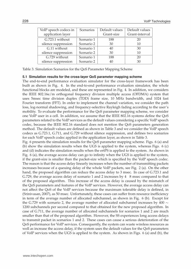
VoIP speech codecs in Scenarios Default values Default valuesapplication layer Grant-size Grant-interval
G.723.1 without Scenario 1 188 20silence suppression Scenario 2 30 10
G.11 without Scenario 1 40 30silence suppression Scenario 2 30 10
G.729 without Scenario 1 188 20silence suppression Scenario 2 40 30
Table 3. Simulation Scenarios for the QoS Parameter Mapping Scheme
5.1 Simulation results for the cross-layer QoS parameter mapping scheme
The end-to-end performance evaluation simulator for the cross-layer framework has beenbuilt as shown in Fig. 4. In the end-to-end performance evaluation simulator, the wholefunctional blocks are modeled, and these are represented in Fig. 4. In addition, we considersthe IEEE 802.16e/m orthogonal frequency division multiple access (OFDMA) system thatuses 5msec time division duplex (TDD) frame size, 10 MHz bandwidth, and 1024 fastFourier transform (FFT). In order to implement the channel variation, we consider the pathloss, log-normal shadowing, and frequency-selective Rayleigh fading according to the user’smobility. To evaluate the performance for the QoS parameter mapping scheme, we considerone VoIP user in a cell. In addition, we assume that the IEEE 802.16 systems define the QoSparameters related to the VoIP services as the default values considering a specific VoIP speechcodec, because the IEEE 802.16 standard does not mention the QoS parameters generationmethod. The default values are defined as shown in Table 3 and we consider the VoIP speechcodecs as G.723.1, G.711, and G.729 without silence suppression, and defines two scenariosfor each VoIP speech codec applied in the application layer, as shown in Table 3.Fig. 6 presents the simulation results for the QoS parameter mapping scheme. Figs. 6 (a) and(b) show the simulation results when the UGS is applied to the system, whereas Figs. 6 (c)and (d) indicates the simulation results when the ertPS is applied to the system. As shown inFig. 6 (a), the average access delay can go to infinity when the UGS is applied to the system,if the grant-size is smaller than the packet-size which is specified by the VoIP speech codec.The reason is that the access delay linearly increases when the number of transmitting packetsincreases because of a queuing delay of the whole VoIP packets, see Fig. 2 (a). On the otherhand, the proposed algorithm can reduce the access delay to 3 msec. In case of G.723.1 andG.729, the average access delay of scenario 1 and 2 increases by 4 8 msec compared to thatof the proposed algorithm. This increase of the access delay is caused by the mismatch ofthe QoS parameters and features of the VoIP services. However, the average access delay cannot affect the QoS of the VoIP services because the maximum tolerable delay is defined, in(Srinivasan, 2007), as 50 msec. Unfortunately, these cases can suffer from resource inefficiencyin term of the average number of allocated subchannel, as shown in Fig. 6 (b). Except forthe G.729 with scenario 2, the average number of allocated subchannel increases by 400 ∼
1200 subchannels per second compared to that obtained for the new proposed algorithm. Incase of G.711, the average number of allocated subchannels for scenarios 1 and 2 are muchsmaller than that of the proposed algorithm. However, the SS experiences long access delaysto transmit packet in scenarios 1 and 2. These cases can cause a serious deterioration of theQoS performance for VoIP services. Consequently, the system can waste wireless resources aswell as increase the access delay, if the system uses the default values for the QoS parametersof VoIP services when the UGS is applied to the system. As shown in Figs. 6 (a) and (b), the
228 VoIP Technologies
www.intechopen.com

VoIP Features Oriented Uplink Scheduling Scheme in Wireless Networks 11
proposed algorithm can save the waste of wireless resources and as well as reduce the accessdelays.Unlike the UGS, the ertPS can manage the grant-size according to the packet-size. For thisreason, the ertPS can improve the system performance even though the system exploits thedefault values for the QoS parameters of VoIP services. As shown in Figs. 6 (c) and (d), theaccess delay and the average number of allocated subchannels when using the conventionalalgorithm with the ertPS decrease compared to those obtained for the conventional algorithmwith the UGS. The average access delay can be reduced from ”infinity” to less than 10 msecin the case of G.711. However, the waste of radio bandwidth and the increase of access delaysstill exist because of the mismatch of the grant-interval and the packet-generation-interval.In the case of G.723.1, the SS has to wait for a grant in scenario 1 because a BS periodicallyallocates a grant every 20 msec even though a packet is generated every 30 msec in theapplication layer. In scenario 2 of G.723.1, the SS does not need to wait for a grant because aBS allocates a grant every 10 msec. However, this case can waste two grants every 30 msec.For this inefficiency, the average number of allocated subchannel increases by about 200 %compared to the proposed algorithm as shown in Fig. 6 (d). In the case of G.729, a transmittingpacket is delayed because the grant-interval is larger than the packet-generation-interval.For this reason, the average number of allocated subchannel decreases in scenarios 1 and 2compared to that of the proposed algorithm whereas the average access delay increases by 1016 msec. Therefore, the cross-layer QoS parameter mapping scheme can improve the systemperformance in terms of the number of allocated subchannels and access delays.
5.2 Numerical results for the cross-layer VoIP scheduling algorithm
This subsection represents the system performance for the new cross-layer VoIP schedulingalgorithm in terms of the VoIP capacity. The VoIP capacity means the maximum supportablenumber of VoIP users. In order to analyze the system performance, the voice traffic has beenmodeled as an exponentially distributed ON-OFF system with mean ON-time 1/λ and meanOFF-time 1/µ. Fig. 7 represents the one-dimensional Markov chain for N independent VoIPusers (Oh et al., 2008). In Fig. 7, each state indicates the number of VoIP users in the ONstate. Since the sum of the whole steady-state probability is unit, the steady-state probabilityis derived as
pN(k) =
(
Nk
)(
µ
λ + µ
)k ( λ
λ + µ
)(N−k)
,
k = 0,1,2, · · · , N. (1)
The average number of VoIP users in the silent-period (NOFF) is
NOFF(N) =Nλ
λ + µ, (2)
where N is the number of VoIP users.In this chapter, the unit of the grant-size is defined as the number of slots. The average numberof uplink slots required every grant-interval for a VoIP user in each scheduler is given by
SUGS = SON max, (3)
SertPS =
(
SON
λ+
SGMH
µ
)
, (4)
229VoIP Features Oriented Uplink Scheduling Scheme in Wireless Networks
www.intechopen.com

12 VoIP Technologies
ヰ
ヵ
ヱヰ
ヱヵ
ヲヰ
ヲヵ
ンヰ
I094503 I0933 I094;
vヴラヮラゲWS
}IWミ;ヴキラ"ヱ
}IWミ;ヴキラ"ヲ
Cxgtcig
ceeg
uu"fgnc{"*o
uge+ Kphkpkv{
(a) average access delay with UGS
ヰヲヰヰヴヰヰヶヰヰΒヰヰ
ヱヰヰヰヱヲヰヰヱヴヰヰヱヶヰヰヱΒヰヰヲヰヰヰヲヲヰヰ
FくΑヲンくヱ FくΑヱヱ FくΑヲΓ
vヴラヮラゲWS
}IWミ;ヴキラ"ヱ
}IWミ;ヴキラ"ヲ
Cxgtcig"pwo
dgtqh"cnnqecvgf"
uwdejcppgn"*%"uwd
ejcppgnu1ugeqpf+
(b) average number of allocated subchannels withUGS
2468:323436383:
I094503 I0933 I094;
RtqrqugfUegpctkq"3Uegpctkq"4
Cxgtcig
ceeg
uu"fgnc{"*o
uge+
(c) average access delay with ertPS
2
722
3222
3722
4222
4722
5222 RtqrqugfUegpctkq"3Uegpctkq"4
Cxgtcig
"pwo
dgtq
h"cnnq
ecvgf"
uwde
jcpp
gn"*%"uwd
ejcp
pgnu1ugeqp
f+
(d) average number of allocated subchannels withertPS
Fig. 6. Simulation results for the cross-layer QoS parameter mapping scheme
SHV(N, F) =
(
SON
λ+
SSI + SBRUSCRHV(N, F)
(TGIS/TGIT)µ
)
, (5)
Spro(N, F) =
(
SON
λ+
SSI + SBRUSCRpro(N, F)
(TGIS/TGIT)µ
)
, (6)
where SON max, SON , SSI , and SGMH are the number of uplink slots required to senda maximum-size speech frame, variable-size speech frame, silence(or noise) frame, andgeneric-MAC header, respectively. F is the number of bandwidth request ranging codes. Notethat the SGMH in (4) can be changed to SSI in the EVRC, because the EVRC generates a noiseframe every packet-generation-interval. TGIT (sec) and TGIS (sec) indicate the grant-intervalduring the talk-spurts and the grant-interval during the silent-periods, respectively. In (5) and(6), RHV and Rpro represent the average number of retransmissions for a BRUSC header in theHV algorithm and the new proposed algorithm, respectively.The average number of uplink slots required every grant-interval for a VoIP user in theUGS and ertPS is independent on the number of VoIP users and the number of bandwidth
230 VoIP Technologies
www.intechopen.com

VoIP Features Oriented Uplink Scheduling Scheme in Wireless Networks 13
2 3 4 P/3 P
Pそ
た
*P/3+そ
4た
4そ
*P/3+た
そ
PたFig. 7. Markov chain model for N independent VoIP users with exponentially distributedON-OFF system
request ranging codes, because a BS periodically allocates a grant to a SS every grant-interval.However, in the HV, a SS sends a BRUSC header to transmit a SID frame every TGIS by therandom access scheme in the silent-period. For this reason, the average number of contendingusers (NC(N)) in a frame is
NC HV(N) = NOFF(N)×TMF
TGIS, (7)
where TMF is the MAC frame size. In (7), the second term on the right side means thetransmission rate of one user in a frame. In the random access scheme, the SS transmitsa ranging-request (RNG-REQ) message through a ranging subchannel to obtain the radiobandwidth to transmit a BRUSC header. A RNG-REQ message includes an orthogonalranging code randomly selected by the SS. When several SSs simultaneously choose the sameorthogonal ranging code in a ranging subchannel, they experience a collision. In the randomaccess scheme, other SSs should not select the ranging code which is already selected by a SSin a frame. Thus, the success probability (PSUC(N, F)) in a frame is given by
PSUC(N, F) =
(
1 −1
F
)NC HV (N)−1
. (8)
The average number of retransmissions in the HV algorithm is given by
RHV(F) =∞
∑k=0
kPSUC(N, F)(1 − PSUC(N, F))k−1
=1
PSUC(N, F). (9)
By using (2), (7), and (8), the average number of retransmission in the HV can be derived as
RHV(N, F) =
(
1 −1
F
)1− Nλλ+µ ×
TMFTGIS
. (10)
In the proposed algorithm, a SS transmits a BRUSC header by the random access scheme onlywhen a voice activity changes from a silent-period to a talk-spurt, unlike in the HV algorithm.
231VoIP Features Oriented Uplink Scheduling Scheme in Wireless Networks
www.intechopen.com

14 VoIP Technologies
Thus, the average number of contending users in a frame is equal to NOFF(N)× TMF. For thisreason, the average number of retransmissions in the new proposed algorithm is
Rpro(N, F) =
(
1 −1
F
)1− Nλλ+µ ×TMF
. (11)
At this time, the VoIP capacity (m) for each VoIP scheduling algorithm can be defined asfollows.
m(N, F) =TGIT
TMF×
STOT
S(N, F), (12)
where STOT is the total number of uplink slots in a frame (Srinivasan, 2007) and S(N, F) meansthe average number of uplink slots required every TGIT for each VoIP scheduling algorithmsuch as SUGS, SertPS, SHV , and Spro. In (12), the term on the right side represents the product ofthe number of frame during the grant-interval of the talk-spurt and the maximum supportablenumber of VoIP users in a frame. Unfortunately, the S(N, F) of HV and proposed algorithm isgiven with respect to the number of VoIP users and the number of bandwidth request rangingcodes as shown in (5), (6), (10), and (11). For this reason, it is difficult to analyze the VoIPcapacity in the HV and proposed algorithms.For the simple analysis process, we approximately analyze the average number ofretransmission as follows.
RHV(N, F) =
(
1 −1
F
)1− Nλλ+µ ×
TMFTGIS
= 1 +λTMF N
(λ + µ)TGIS×
1
F+
(
λTMF N(λ+µ)TGIS
)
×
(
λTMF N(λ+µ)TGIS
+ 1)
2×
(
1
F
)2
+ · · · .(13)
By using MacLaurin series, RHV(N, F) can be written as (13). Here, IEEE 802.16 definesthe number of orthogonal ranging codes as 256 where the ranging code consists of initial,handover, bandwidth request, and periodic ranging codes. However, the number of rangingcodes in a frame can be above 256 because the number of ranging slots which consists of 256ranging codes can be one or more. Thus, F can be a sufficiently large number. For this reason,RHV(N, F) can be approximately given by
RHV(N, F) ≈ 1 +λ
λ + µ×
TMF
TGIS×
1
F× N, (14)
where 1/F is much less than one. Here, (14) is substituted for (5). Fig. 8 depicts the averagenumber of uplink slots required every grant-interval for a VoIP user (SHV(N, F)) according tothe number of VoIP users and number of bandwidth request ranging code when VoIP speechcodec is the EVRC. As shown in Fig. 8, N and F can be neglected in terms of SHV(N, F).In addition, this result is similar to the case of the AMR speech codec and G.7xx, becausethose speech codecs generate packets by using the lower transmission rate in the silent-period.Therefore, SHV(N, F) can be approximately represented as
SHV ≈
(
SON
λ+
SSID + SBRUSC
(TGIS/TGIT)
)
. (15)
As in the HV algorithm, the new proposed algorithm can approximately analyze theSpro(N, F) as (16), because the proposed algorithm transmits a BRUSC header only when the
232 VoIP Technologies
www.intechopen.com

VoIP Features Oriented Uplink Scheduling Scheme in Wireless Networks 15
0 100 200 300 4004
4.5
5
5.5
6
6.5
7
7.5
8
8.5
SH
V(N
,F)
N
F = 200
F = 300
F = 40016 QAM 1/2
QPSK 1/2
Fig. 8. SHV(N, F) vs. N and F (MCS level = QPSK 1/2 and 16 QAM 1/2, VoIP speech codec =EVRC, STOT = 144 slots, TMF = 5 msec, FFT size = 1024, λ = 2.5, µ = 1.67, and bandwidth = 10MHz)
voice activity changes from silent-period to talk-spurt.
Spro ≈
(
SON
λ+
SSID + SBRUSC
(TGIS/TGIT)
)
. (16)
By using (14) and (15), (12) can be derived as
m =TGIT
TMF×
STOT
S, (17)
where S is the average number of uplink slots required every TGIT for each VoIP schedulingalgorithm. In (17), the VoIP capacity can be easily analyzed, because m is not dependent onthe N and F.Fig. 9 presents numerical results for the VoIP capacity according to the modulation and codingscheme (MCS) levels. It can be seen that the HV and the proposed algorithm can increase theVoIP capacity except for the EVRC compared to the conventional ertPS and UGS, respectively.The reason is that the algorithms can save the uplink bandwidth in the silent-period by usingthe random access or the adaptation of the grant-interval. However, the HV and the proposedalgorithm could not obtain the gain in terms of VoIP capacity when the VoIP speech codecis the EVRC, as shown in Fig. 9 (e). The HV is particularly inefficient in using the radiobandwidth compared to the ertPS when the VoIP speech codec is the EVRC, because the HVtransmits a BRUCS header to send a noise frame of the EVRC every 20 msec. By using thisfeature of the HV, the VoIP capacity decreases by 29 % compared to when the ertPS is used.Unlike the HV, the proposed algorithm can efficiently use the radio bandwidth because of theadaptation of the grant-interval when the VoIP speech codec is the EVRC as well as the G.711and AMR speech codec.
233VoIP Features Oriented Uplink Scheduling Scheme in Wireless Networks
www.intechopen.com

16 VoIP Technologies
(a) G.723.1 with silence suppression (b) G.729 with silence suppression
(c) G.711 with silence suppression (d) AMR
(e) EVRC
Fig. 9. VoIP capacity vs. VoIP scheduling algorithms and MCS levels (STOT = 144 slots, TMF =5 msec, FFT size = 1024, λ = 2.5, µ = 1.67, compressed RTP/UDP/IP header size = 3 bytes andbandwidth = 10 MHz)
234 VoIP Technologies
www.intechopen.com
VoIP Features Oriented Uplink Scheduling Scheme in Wireless Networks 17
As shown in Fig. 9, the gain of the HV and the proposed algorithm depends on the kinds ofVoIP speech codec in the application layer. The gain increases by 70 % when the VoIP speechcodec is G.723.1 or G.729, as shown in Figs. 9 (a) and (b). The G.723.1 and G.729 generatea small-size voice frame in talk-spurt, whose size is 19.88 bytes and 10 bytes, respectively.For this reason, the number of supportable VoIP users increases with respect to other VoIPspeech codecs due to the saved bandwidth in the silent-periods. From these numerical results,the HV and the proposed algorithm can support 150 ∼ 400 VoIP users more than the otheralgorithms. Consequently, the HV and the proposed algorithm, which do not periodicallyallocate a grant in the silent-period, can increase the VoIP capacity and the proposed algorithmcan in particular increase the VoIP capacity by 15 % ∼ 70 % regardless of the kinds of VoIPspeech codec in the application layer.
6. Conclusion
VoIP traffic can have various features according to the kinds of VoIP speech codecs, hencewireless systems need to consider the features of VoIP speech codec. In this chapter, wehave considered variable packet-size and packet-generation-interval for main VoIP speechcodecs, and proposed a new cross-layer framework to efficiently support a VoIP service inIEEE 802.16 systems. The cross-layer framework for a VoIP service consists of a cross-layerQoS parameter mapping scheme and a cross-layer VoIP scheduling algorithm. The cross-layerQoS parameter mapping scheme directly obtains the QoS parameters for a VoIP service usingthe QoS information of the application layer. The cross-layer VoIP scheduling algorithmefficiently supports a VoIP service based on the QoS parameters generated by the proposedcross-layer QoS parameter mapping scheme. By the performance evaluation results, it hasbeen shown that the new algorithm can efficiently support a VoIP service regardless of thekinds of VoIP codec in the application layer.
7. References
3GPP-TS-26071 (1999). 3GPP TS 26.071 v3.0.1: Mandatory speech codec speech processingfunctions AMR speech codec; general description.
3GPP-TS-26092 (2002). 3GPP TS 26.092 v5.0.0: AMR speech codec; comfort noise aspects.3GPP-TS-26201 (2001). 3GPP TS 26.201 v5.0.0: AMR wideband speech codec; frame structure.3GPP2-EVRC (2004). 3GPP2 C.S0014-A v1.0: Enhanced variable rate codec.Handley, M. & Jacobson, V. (1998). RFC 2327 - SDP: Session description protocol.Hong, S. E. & Kwon, O. H. (2006). Considerations for voip services in IEEE 802.16 broadband
wireless access systems, Proceedings of IEEE VTC spring, pp. 1226–1230.IEEE (2006). IEEE standard for local and metropolitan area networks - part 16: air interface
for fixed and mobile broadband wireless access systems amendment 2.ITU-T-G711 (2000). ITU-T recommendation G.711 appendix II: A comfort noise payload
definition for ITU-T G.711 use in packet-based multimedia communication systems.ITU-T-G7231 (1996). ITU-T recommendation G.723.1 appendix A: Silence compression
scheme.ITU-T-G729 (2007). ITU-T recommendation G.729: Coding of speech at 8 kbit/s using
conjugate-structure algebraic-code-excited linear prediction.Lee, H. W., Kwon, T. S. & Cho, D. H. (2005). An enhanced uplink scheduling algorithm based
on voice activity for voip services in IEEE 802.16d/e systems, IEEE Commun. Lett.Vol. 9: 691–692.
235VoIP Features Oriented Uplink Scheduling Scheme in Wireless Networks
www.intechopen.com

18 VoIP Technologies
Oh, S. M., Cho, S. H., Kwun, J. H. & Kim, J. H. (2008). VoIP scheduling algorithm for AMRspeech codec in IEEE 802.16e/m system, IEEE Commun. Lett. Vol. 12(No. 5).
Oh, S. M. & Kim, J. H. (2005). The analysis of the optimal contention period for broadbandwireless access network, Proceedings of IEEE PWN 05, pp. 215–220.
Srinivasan, R. (2007). Draft IEEE 802.16m evaluation mothodology document.
236 VoIP Technologies
www.intechopen.com

VoIP TechnologiesEdited by Dr Shigeru Kashihara
ISBN 978-953-307-549-5Hard cover, 336 pagesPublisher InTechPublished online 14, February, 2011Published in print edition February, 2011
InTech EuropeUniversity Campus STeP Ri Slavka Krautzeka 83/A 51000 Rijeka, Croatia Phone: +385 (51) 770 447 Fax: +385 (51) 686 166www.intechopen.com
InTech ChinaUnit 405, Office Block, Hotel Equatorial Shanghai No.65, Yan An Road (West), Shanghai, 200040, China
Phone: +86-21-62489820 Fax: +86-21-62489821
This book provides a collection of 15 excellent studies of Voice over IP (VoIP) technologies. While VoIP isundoubtedly a powerful and innovative communication tool for everyone, voice communication over theInternet is inherently less reliable than the public switched telephone network, because the Internet functionsas a best-effort network without Quality of Service guarantee and voice data cannot be retransmitted. Thisbook introduces research strategies that address various issues with the aim of enhancing VoIP quality. Wehope that you will enjoy reading these diverse studies, and that the book will provide you with a lot of usefulinformation about current VoIP technology research.
How to referenceIn order to correctly reference this scholarly work, feel free to copy and paste the following:
Sung-Min Oh and Jae-Hyun Kim (2011). VoIP Features Oriented Uplink Scheduling Scheme in WirelessNetworks, VoIP Technologies, Dr Shigeru Kashihara (Ed.), ISBN: 978-953-307-549-5, InTech, Available from:http://www.intechopen.com/books/voip-technologies/voip-features-oriented-uplink-scheduling-scheme-in-wireless-networks

© 2011 The Author(s). Licensee IntechOpen. This chapter is distributedunder the terms of the Creative Commons Attribution-NonCommercial-ShareAlike-3.0 License, which permits use, distribution and reproduction fornon-commercial purposes, provided the original is properly cited andderivative works building on this content are distributed under the samelicense.