Voice Traffic Performance over Wireless LAN using the Point Coordination Function Wei Supervisor:...
43
Voice Traffic Performance over Wireless LAN using the Point Coordination Function Wei Wei Supervisor: Prof. Sven-Gustav Häggman Instructor: Researcher Michael Hall Helsinki University of Technology Communications Laboratory April, 2004
-
Upload
drusilla-sherman -
Category
Documents
-
view
215 -
download
0
Transcript of Voice Traffic Performance over Wireless LAN using the Point Coordination Function Wei Supervisor:...

Voice Traffic Performance over Wireless LAN using the Point
Coordination Function
Wei Wei
Supervisor: Prof. Sven-Gustav Häggman
Instructor: Researcher Michael Hall
Helsinki University of Technology
Communications Laboratory
April, 2004

Contents
• Background
• Objectives
• Introduction to WLAN
• Simulation
• Results
• Conclusions
• Future work

Why WLAN?
• Mobility
- It brings increased efficiency and productivity.
• Flexibility
- Fast and easy deployment.
- Can be set up where the wired networks are
imposible or difficult to reach.

Voice over WLAN (1)
• Nowadays, IEEE 802.11 WLAN standard is being accepted widely and rapidly for many different environments.
• Mainly, WLAN is used for Internet based services like web browsing, email, and file transfers.

Voice over WLAN (2)
• However, demand for supporting real-time traffic applications such as voice over WLAN has been increasing.
• To meet this need, IEEE 802.11 standard defines an optional medium access protocol, Point Coordination Function (PCF).

Objectives
• To implement the basic PCF algorithm in a time-driven simulation program written in C language.
• To measure some metrics such as throughput, delay, frame loss rate, etc.
• To evaluate the voice traffic performance in WLAN using PCF to investigate if PCF is capable of the real-time applications such as voice service.
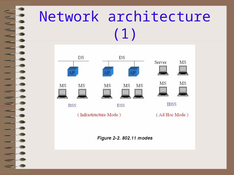
Network architecture (1)

Network architecture (2)
• Basically, WLAN network consists of four components: Distribution System, Access Point, Mobile Station, and wireless medium.
• Distribution System (DS): - A backbone network that connects several
access points or Basic Service Sets. - Wired or wireless, implemented independently. - In general, Ethernet is used as the backbone
network technology.

Network architecture (3)
• Access Point (AP):
- Connected to the DS, wireless-to-wired bridging function.
• Mobile Station (MS):
- In general, it’s referred to laptop computer.• Wireless medium:
- Frequency Hopping, Direct Sequence Spread Spectrum, Infra-red.

Network architecture (4)
• Basic Service Set (BSS):
- It consists of a group of stations that are under control of DCF or PCF.
• Extended Service Set (ESS):
- It consists of several BSSs via DS.
- Provides larger network coverage area.

Network architecture (5)
• IEEE 802.11 defines two operation modes: Ad-hoc mode and Infrastructure mode.
• Ad-hoc mode: - A set of 802.11 wireless stations
communicate directly with each other, without using access point.
- Also called Independent Basic Service Set (IBSS).

Network architecture (6)
• Infrastructure mode:
- The network consists of at least one access point and a set of mobile stations.
- AP bridges the wireless traffic to a wired Ethernet or the Internet.
- AP can be compared with a base station used in a celluar network.

IEEE 802.11 MAC layer
• IEEE 802.11 defines two medium access methods: the mandatory Distributed Coordination Function (DCF) for non-real-time applications, and the optional Point Coordination Function (PCF) for real-time applications.
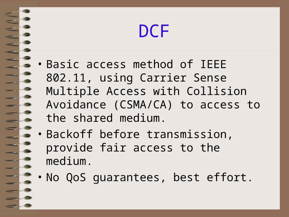
DCF
• Basic access method of IEEE 802.11, using Carrier Sense Multiple Access with Collision Avoidance (CSMA/CA) to access to the shared medium.
• Backoff before transmission, provide fair access to the medium.
• No QoS guarantees, best effort.

PCF
• Optional access method, resides on top of DCF.
• To support real-time applications.
• Centralized control.
• Polling based access mechanism.

Coexistence of DCF and PCF
Taken from IEEE 802.11 standard

Inter-Frame Space (IFS)
• Basically 3 different IFSs.• Short IFS (SIFS)• PCF IFS (PIFS)• DCF IFS (DIFS)• SIFS < PIFS < DIFS• IFS determines priority: - After a SIFS, only polled MS can send - After a PIFS, only AP can send (PCF control) - After a DIFS, every station can send according to CSMA/CA (DCF)

PCF operation (1)
• The time on the medium is divided into two parts: Contention-Free Period (CFP) controlled by PCF and Contention Period (CP) controlled by DCF.

PCF operation (2)
• During a CFP, at least 2 maximum size frames transmitted.
• During a CP, at least 1 maximum size frame transmitted, including RTS/CTS and ACK.

PCF operation (3)

PCF polling scheme (1)
• A poll list is created when the MSs supporting real-time service negotiate with Point Coordinator (PC) during the association procedure.
• The MSs are put on the poll list in order.
• The poll list gives the highest privilege to PCF supported MSs.
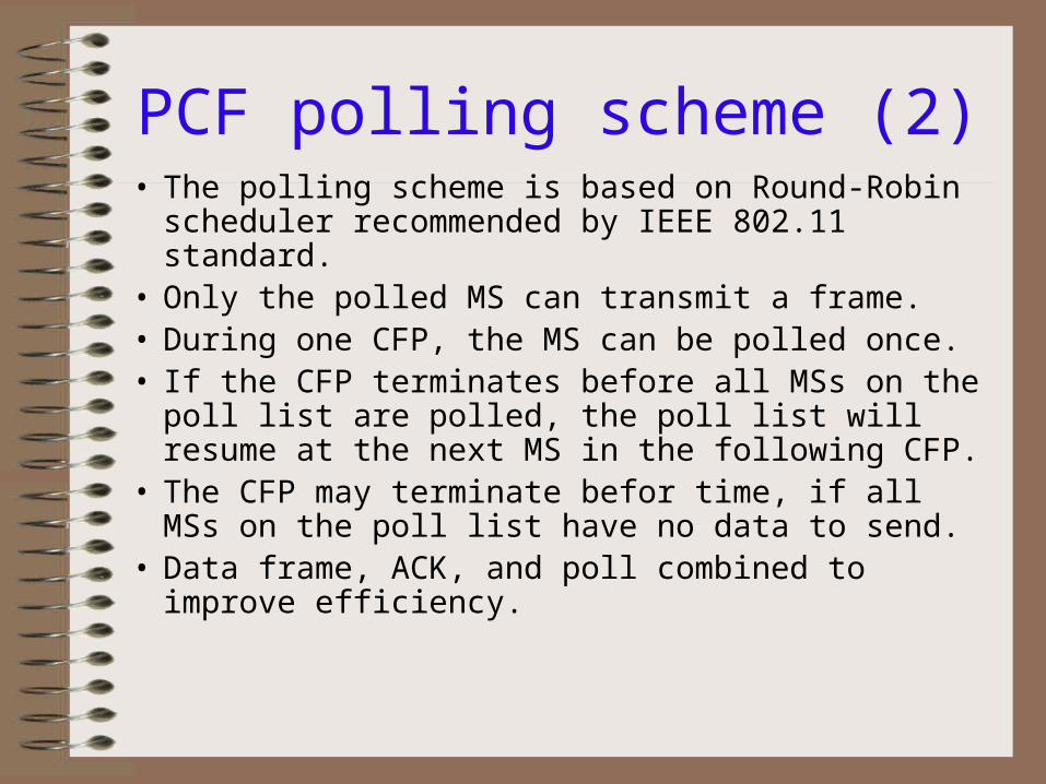
PCF polling scheme (2)• The polling scheme is based on Round-Robin scheduler
recommended by IEEE 802.11 standard.• Only the polled MS can transmit a frame.• During one CFP, the MS can be polled once.• If the CFP terminates before all MSs on the poll list are
polled, the poll list will resume at the next MS in the following CFP.
• The CFP may terminate befor time, if all MSs on the poll list have no data to send.
• Data frame, ACK, and poll combined to improve efficiency.

Simulation scenario• A single BSS in an infrastructure network configuration.

Simulation model assumptions (1)
• Only use voice traffic during CFP, not consider data traffic during CP.
• RTP/UDP/IP/MAC/PHY, this adds an overall overhead of 78 bytes to every voice packet.
• G.711 PCM voice codec used, fixed traffic interval 20ms or 40ms, 160bytes or 320bytes payload, respectively.
• Buffer size = 1.

Simulation model assumptions (2)
• Power saving mode is neglected.• Foreshortened CFP is neglected.• Fragmentation/Defragmentation is
neglected.• Broadcast/Multicast frames not considered.• Mobility, multipath interference, and
hidden-node problem are not considered.• Basic rate used: 11 Mbps.

Functions included in simulation (1)
• One access point and specific number of VoIP stations
• Voice connections: bi-directional deterministic stream of frames with calculated duration and inter-frame interval, PCM over RTP over UDP over IP over LLC over MAC over PHY assumed
• SIFS and PIFS times

Functions included in simulation (2)
• Acknowledgement, beacon, CF-poll, and CF-end frames
• Piggybacking of Ack and CF-poll information
• Random generation of erroneous frames
• Recording of simulation data

Simulation parameters
Channel rate 11 Mbps
Channel frame error rate (CFER)
0.03
Voice payload 160/320 bytes
Slot time 20 s
SIFS 10 s
PIFS 30 s
DIFS 50 s
Metrics
• Superframe size
• Maximum number of VoIP MS
• Throughput
• Frame loss rate
• Access delay

Results: superframe size
• Normalized throughput for different SF using 160-byte payload
160-byte payl oadtraffi c i nterval =20ms, CFER=0. 03
00. 10. 20. 30. 40. 50. 60. 70. 80. 9
1
5 10 15 20 25 30 35 40Number of VoI P MS
Norm
alized t
hro
ughput
SF10SF15SF20SF25SF30

Results: superframe size
• Normalized throughput for different SF using 320-byte payload
320-byte payl oadtraffi c i nterval = 40ms, CFER = 0. 03
00. 10. 20. 30. 40. 50. 60. 70. 80. 9
1
5 10 15 20 25 30 35 40 45 50Number of VoI P MS
Norm
alized t
hro
ughput
SF30SF35SF40SF45SF50

Results: max. number of VoIP MS for 160-byte payload
160-byte payl oadtraffi c i nterval = 20ms, CFER = 0. 03
0. 50. 550. 6
0. 650. 7
0. 750. 8
0. 850. 9
0. 951
0 5 10 15 20 25 30 35 40 45Number of VoI P MS
Norm
aliz
ed t
hro
ughput
SF20

Results: max. number of VoIP MS for 320-byte payload
320-byte payl oadtraffi c i nterval = 40ms, CFER = 0. 03
0. 50. 550. 6
0. 650. 7
0. 750. 8
0. 850. 9
0. 951
0 5 10 15 20 25 30 35 40 45 50 55Number of VoI P MS
Norm
aliz
ed t
hro
ughput
SF40

Results: capacity
SF20 160-byte payl oad vs. SF40 320-byte payl oadCFER = 0. 03
00. 5
11. 5
22. 5
33. 5
44. 5
5
0 5 10 15 20 25 30 35 40 45 50 55Number of VoI P MS
Capacity (
Mbps)
SF20SF40

Results: frame loss rate
SF20 160-byte payl oad vs. SF40 320-byte payl oad
0
0. 1
0. 2
0. 3
0. 4
0. 5
0. 6
0 5 10 15 20 25 30 35 40 45Number of VoI P MS
Fram
e loss
rate
SF20SF40

Results: average access delay for different SF using 160-byte payload
160-byte payl oadtraffi c i nterval = 20ms, CFER = 0. 03
0
2
4
6
8
10
12
5 10 15 20 25 30 35 40Number of VoI P MS
Access
dela
y (
ms)
SF10SF15SF20SF25SF30SF35SF40

Results: average access delay for different SF using 320-byte payload
320-byte payl oadtraffi c i nterval = 40ms, CFER = 0. 03
0
5
10
15
20
25
5 10 15 20 25 30 35 40 45 50Number of VoI P MS
Access
dela
y (
ms)
SF30SF35SF40SF45SF50

Results: comparison of average access delay btw. 160 and 320-byte payload
SF20 160-byte payl oad vs. SF40 320-byte payl oadCFER = 0. 03
02468
101214161820
0 5 10 15 20 25 30 35 40 45 50 55Number of VoI P MS
Access
dela
y (
ms)
SF20SF40
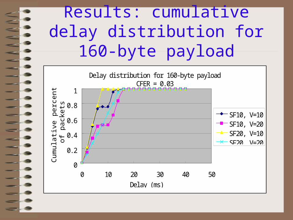
Results: cumulative delay distribution for 160-byte payload
Del ay di stri buti on for 160-byte payl oadCFER = 0. 03
0
0. 2
0. 4
0. 6
0. 8
1
0 10 20 30 40 50Del ay (ms)
Cum
ula
tive
perc
enta
ge
of
pack
ets SF10, V=10
SF10, V=20SF20, V=10SF20, V=20

Results: cumulative delay distribution for 320-byte payload
Del ay di stri buti on for 320-byte payl oadCFER = 0. 03
0
0. 2
0. 4
0. 6
0. 8
1
0 10 20 30 40 50Del ay (ms)
Cum
ula
tive
perc
enta
ge
of
pack
ets
SF20, V=10SF20, V=20SF40, V=10SF40, V=20

Conclusions
• The proper superframe size should be approximately similar to the traffic interval, which results in good performance.
• Longer payload provides higher normalized throughput and lower frame loss rate, but longer access delay.
• Maximum number of VoIP MS: for 160-byte payload, 21; for 320-byte payload, 36.
• When the number of VoIP MS increases, performance degrades dramatically. PCF provides limited QoS.
Future works
• Perform an authentic evaluation in a WLAN - Assumptions - Realistic traffic model• PCF problems - unpredictable Beacon frame delay resulting in shortened
CFP - unknown transmission time of polled stations making it
difficult for PC to predict and control the polling scheldule for the remainder of CFP
• IEEE 802.11e introduced EDCF and HCF to support QoS

Q & A
Thank you for your attention!