VOGUE - Valor Fireplaces Title PDF manuals/English... · VOGUE 4001746-15 ©2012, Miles Industries...
50
V OGUE 4001746-15 ©2012, Miles Industries Ltd. Manufactured by MILES INDUSTRIES LTD., British Columbia, Canada www.valorfireplaces.com Ce guide est disponible en français sur demande. DV ZC Gaz Fireplace 1300ILN/P (Logs) & 1300IRN/P (Rocks) WARNING: If the information in these instructions is not followed exactly, a fire or explosion may result causing property damage, personal injury or loss of life. WHAT TO DO IF YOU SMELL GAS • Do not try to light the appliance. • Do not touch any electrical switch; do not use any phone in your building. • Immediately call your gas supplier from a neighbor’s phone. Follow the gas supplier’s instructions. • If you cannot reach your gas supplier, call the fire department. This appliance is only for use with the type of gas indicated on the rating plate. This appliance is not convertible for use with other gases, unless a certified kit is used. This appliance is a domestic room-heating appliance. It must not be used for any other purposes such as drying clothes, etc. This appliance is suitable for installation in a bedroom or bed sitting room. Installation & Owner’s Manual Do not store or use gasoline or other flammable vapors and liquids in the vicinity of this or any other appliance. Installation and service must be performed by a qualified installer, service agency or the gas supplier. This appliance may be installed in an after-market permanently located, manufactured (mobile) home where not prohibited by local codes. INSTALLER Leave this manual with the appliance. CONSUMER Retain this manual for future reference. Massachusetts: The piping and final gas connection must be performed by a licensed plumber or gas fitter in the State of Massachusetts. Also, see Carbon Monoxide Detector requirements under “Safety and Warning Information” on page 6. Please read this manual BEFORE installing and operating this appliance. HOT GLASS WILL CAUSE BURNS. DO NOT TOUCH GLASS UNTIL COOLED. NEVER ALLOW CHILDREN TO TOUCH GLASS.
Transcript of VOGUE - Valor Fireplaces Title PDF manuals/English... · VOGUE 4001746-15 ©2012, Miles Industries...

VOGUE
4001746-15©2012, Miles Industries Ltd.
Manufactured byMILES INDUSTRIES LTD., British Columbia, Canada
www.valorfi replaces.com
Ce guide est disponible en français sur demande.
DV ZC Gaz Fireplace1300ILN/P (Logs) & 1300IRN/P (Rocks)
WARNING: If the information in these instructions is not followed exactly, a fi re or explosion may result causing property damage, personal injury or loss of life.
WHAT TO DO IF YOU SMELL GAS
• Do not try to light the appliance.• Do not touch any electrical switch; do not
use any phone in your building.• Immediately call your gas supplier from
a neighbor’s phone. Follow the gas supplier’s instructions.
• If you cannot reach your gas supplier, call the fi re department.
This appliance is only for use with the type of gas indicated on the rating plate. This appliance is not convertible for use with other gases, unless a certifi ed kit is used.This appliance is a domestic room-heating appliance. It must not be used for any other purposes such as drying clothes, etc.This appliance is suitable for installation in a bedroom or bed sitting room.
Installation & Owner’s Manual
Do not store or use gasoline or other fl ammable vapors and liquids in the vicinity of this or any other appliance.
Installation and service must be performed by a qualifi ed installer, service agency or the gas supplier.
This appliance may be installed in an after-market permanently located, manufactured (mobile) home where not prohibited by local codes.
INSTALLERLeave this manual with the appliance.
CONSUMERRetain this manual for future reference.
Massachusetts: The piping and fi nal gas connection must be performed by a licensed plumber or gas fi tter in the State of Massachusetts. Also, see Carbon Monoxide Detector requirements under “Safety and Warning Information” on page 6.
Please read this manual BEFORE installing and operating this appliance.
HOT GLASS WILL CAUSE BURNS.
DO NOT TOUCH GLASS UNTIL COOLED.
NEVER ALLOW CHILDREN TO TOUCH GLASS.

2
CAUTION—HOT! HOT! HOT! This appliance is a HEATING appliance and it becomes very hot when in operation.
UNDER ANY CIRCUMSTANCES, DO NOT PLACE any object, furniture, draperies or other item LESS THAN 36 inches (0.9 m) IN FRONT OF THE FIREPLACE.
CHILDREN and PETSRadiant heat can heat surfaces such as the hearth in front of the fi replace to temperatures that, although approved safe, can be quite uncomfortable to touch or step on—particularly for children and pets. Children and pets should always be supervised when in the room where the appliance is located. Remote control handset should be kept out of reach of children. In the presence of children, we STRONGLY RECOMMEND that you install in front of the fi replace: a fi re screen or, to protect young toddlers, a “hearth gate”—see Options on page 41.
HOT SURFACESBe aware that, although safe, some combustible materials and fi nishes, even though installed at listed clearances may, over time, shrink, discolor, warp or show cracks. The 1300I requires the installation of the cement board provided with the engine.Convective heat will exit the unit and travel up the wall surface if not impeded. Protruding mantels and projections can help direct the heat away from the wall. AVOID PLACING heat sensitive items such as televisions, paintings, decorations, etc. above fi replaces or near the edge of protrusions unless appropriate.
The information contained in this installation manual is believed to be correct at the time of printing. Miles Industries Ltd. reserves the right to change or modify any information or specifi cations without notice. Miles Industries Ltd. grants no warranty, implied or stated, for the installation or maintenance of your heater, and assumes no responsibility for any consequential damage(s).
Designed and Manufactured by / forMiles Industries Ltd.
190–2255 Dollarton Highway, North Vancouver, BC, CANADA V7H 3B1Tel. 604-984-3496 Fax 604-984-0246
www.valorfi replaces.com© Copyright Miles Industries Ltd., 2012
Do not put furniture or other objects
in this space in front of the fireplace:36” (0.9 m)
Fireplace
Hearth

3
Safety and Your Fireplace
Safety and Your Fireplace
Please Follow These Important Child Safety Precautions and Recommendations,• Parts of your Valor Fireplace become
extremely hot while in operation.
• The glass viewing window temperature can exceed 500 F at full capacity. Momentary contact with a hot glass surface can cause a severe burn, even if the fi replace is operating at reduced heating capacity.
• The glass window will remain hot for an extended period of time after the fi replace has been turned off. Ensure that children are prevented from touching the fi replace during the cool down period.
• Toddlers and Young Children must be closely supervised at all times when they are in the same room as the operating fi replace. They lack full awareness of danger and rely on your protection. Toddlers, in particular, do not have the motor skills and response refl exes to
withdraw in the event of accidental contact with a hot surface.
• A physical barrier is strongly recommended if there are young children, or at-risk individuals in the house. Install an approved after-market safety gate to keep toddlers, young children and other at-risk individuals a safe distance from the fi replace.
• Keep the remote control handset out of reach of children at all times. A wall mount storage holster is provided with your remote control handset.
• Ensure that the fi replace, including the pilot light, is completely turned off when children are present and close supervision and safety barriers are not available—see page 36 of Owner’s Information section.
• If the fi replace is not going to be used for the summer or any extended period of time, remove the batteries from the remote control handset and receiver. It is recommended that batteries are replaced annually in any event—see page 35.
Please Read and Carefully Follow all Safety Warnings and Operating Instructions Contained in Your Owners Manual
(Replacement Manuals are available by contacting our service department at 1-800-468-2567 or visit www.valorfi replaces.com).

4
Safety and Your Fireplace .............................................................................3Safety and Warning Information...................................................................5Specifi cations ................................................................................................8Overview .........................................................................................................9Dimensions & Location ...............................................................................10Mantel Clearances .......................................................................................11Framing & Hearth Requirements ................................................................13Venting ..........................................................................................................15Co-Axial Venting ..........................................................................................16Co-Linear Venting ........................................................................................20Installation Planning ....................................................................................21Appliance Preparation .................................................................................22Window Removal .........................................................................................25Supply Gas installation ...............................................................................25Ceramic Liners Installation .........................................................................27Logs Installation (1300IL) ............................................................................28Rocks Installation (1300IR) .........................................................................29Window Refi tting .........................................................................................31Remote Control Initial Set-up .....................................................................31Operation Check & Aeration Settings Adjustment ...................................32Remote Control Handset Wall Holder Installation ....................................32Owner’s Information ....................................................................................33Remote Control Operation ..........................................................................37Options .........................................................................................................41Lighting Instructions ...................................................................................42Wiring Diagram ............................................................................................43Approved Venting Components .................................................................44Warranty .......................................................................................................46Spare Parts ...................................................................................................47
Table of Contents
= Updated content◊
◊
◊
◊
◊

5
Safety and Warning Information
Children and adults should be ALERTED to the hazards of high surface temperature and should STAY AWAY to avoid burns or clothing ignition.
YOUNG CHILDREN should be CAREFULLY SUPERVISED when they are in the same room as the appliance. Toddlers, young children and others may be susceptible to ACCIDENTAL CONTACT BURNS. A physical barrier is recommended if there are at risk individuals in the house. To restrict access to a fi replace or stove, INSTALL AN ADJUSTABLE SAFETY GATE to keep toddlers, young children and other at risk individuals out of the room and away from hot surfaces.
DO NOT place furniture or any other combustible household objects within 36” of the fi replace front.
READ and UNDERSTAND all instructions carefully before starting the installation. FAILURE TO FOLLOW these installation instructions may result in possible fi re hazard and will void the warranty.Prior to the fi rst fi ring of the fi replace, READ the Owner’s Information section of this manual.
DO NOT USE this appliance if any part has been under water. Immediately, CALL a qualifi ed service technician to inspect the unit and to replace any part of the control system and any gas control that has been under water.THIS UNIT IS NOT FOR USE WITH SOLID FUEL.
Installation and repair should be PERFORMED by a qualifi ed service person. The appliance and venting system should be INSPECTED before initial use and at least annually by a professional service person. More frequent cleaning may be required due to excessive lint from carpeting, bedding, etc. It is IMPERATIVE that the unit’s control compartment, burner, and circulating air passageways BE KEPT CLEAN to provide for adequate combustion and ventilation air.Always KEEP the appliance clear and free from combustible materials, gasoline, and other fl ammable vapors and liquids.NEVER OBSTRUCT the fl ow of combustion and ventilation air. Keep the front of the appliance CLEAR of all obstacles and materials for servicing and proper operation.Due to the high temperature, the appliance should be LOCATED out of traffi c areas and away from furniture and draperies. Clothing or fl ammable material SHOULD NOT BE PLACED on or near the appliance.
This unit MUST be used with a vent system as described in this installation manual. NO OTHER vent system or components MAY BE USED.This gas fi replace and vent assembly MUST be vented directly to the outside and MUST NEVER be attached to a chimney serving a separate solid fuel burning appliance. Each gas appliance MUST USE a separate vent system. Common vent systems are PROHIBITED.INSPECT the external vent cap on a regular basis to make sure that no debris, plants, trees, shrubs are interfering with the air fl ow.The glass door assembly MUST be in place and sealed before the unit can be placed into safe operation.DO NOT OPERATE this appliance with the glass door removed, cracked, or broken. Replacement of the glass door should be performed by a licensed or qualifi ed service person. DO NOT strike or slam the glass door.The glass door assembly SHALL ONLY be replaced as a complete unit, as supplied by the fi replace manufacturer. NO SUBSTITUTE material may be used.DO NOT USE abrasive cleaners on the glass door assembly. DO NOT ATTEMPT to clean the glass door when it is hot.TURN OFF the gas before servicing this appliance. It is recommended that a qualifi ed service technician perform an appliance check-up at the beginning of each heating season.Any safety screen or guard removed for servicing MUST BE REPLACED before operating this appliance.
BE CAREFUL not to put any decorating objects sensitive to heat to close above or around the fi replace as it gets very hot when operating.DO NOT use this heater as a temporary source of heat during construction.
This appliance is a DOMESTIC ROOM-HEATING AP-PLIANCE. It must not be used for any other purposes such as drying clothes, etc.
OWNER’S INFO

6
HOT SURFACES. Be aware that, although safe, some combustible materials and fi nishes, even though installed at listed clearances may, over time, shrink, discolor, warp or show cracks. The 1300I requires the installation of the cement board provided with the engine.Convective heat will exit the unit and travel up the wall surface if not impeded. Protruding mantels and projections can help direct the heat away from the wall. AVOID PLACING heat sensitive items such as televisions, paintings, decorations, etc. above fi replaces or near the edge of protrusions unless appropriate.Radiant heat can heat surfaces such as the hearth in front of the fi replace to temperatures that, although approved safe, can be quite uncomfortable to touch or step on—particularly for children and pets. Accessory screens and guards will reduce the radiant heat on these surfaces.
Safety and Warning Information
Operating Your Fireplace for the First TimeWhen operating your new fi replace for the fi rst time, some vapors may be released due to the burning of curing compounds used in the manufacture of the appliance. They may cause a slight odor and could cause the fl ames to be the full height of the fi rebox, or even slightly higher, for the fi rst few hours of operation. It is also possible that these vapors could set off any smoke detection alarms in the immediate vicinity. These vapors are quite normal on new appliances. We recommend opening a window to vent the room. After a few hours use, the vapors will have disappeared and the fl ames will be at their normal height.
State of California. Proposition 65 Warning.Fuels used in gas, wood-burning or oil fi red appliances, and the products of combustion of such fuels, contain chemicals known to the State of California to cause cancer, birth defects and other reproductive harm. California Health & Safety Code Sec. 25249.6.
State of Massachusetts Carbon Monoxide Detector/Vent Terminal Signage RequirementsFor all side wall horizontally vented gas fueled equipment installed in every dwelling, building or structure used in whole or in part for residential purposes, including those owned or operated by the Commonwealth and where the side wall exhaust vent termination is less than seven (7) feet above fi nished grade in the area of the venting, including but not limited to decks and porches, the following requirements shall be satisfi ed:
1. INSTALLATION OF CARBON MONOXIDE DETECTORS. At the time of installation of the side wall horizontal vented gas fueled equipment, the installing plumber or gas fi tter shall observe that a hard wired carbon monoxide detector with an alarm and battery back-up is installed on the fl oor level where the gas equipment is to be installed. In addition, the installing plumber or gas fi tter shall observe that a battery operated or hard wired carbon monoxide detector with an alarm is installed on each additional level of the dwelling, building or structure served by the side wall horizontal vented gas fueled equipment. It shall be the responsibility of the property owner to secure the services of qualifi ed licensed professionals for the installation of hard wired carbon monoxide detectors.
a. In the event that the side wall horizontally vented gas fueled equipment is installed in a crawl space or an attic, the hard wired carbon monoxide detector with alarm and battery back-up may be installed on the next adjacent fl oor level.
b. In the event that the requirements of this subdivision can not be met at the time of completion of installation, the owner shall have a period of thirty (30) days to comply with the above requirements; provided, however, that during said thirty (30) day period, a battery operated carbon monoxide detector with an alarm shall be installed.
2. APPROVED CARBON MONOXIDE DETECTORS. Each carbon monoxide detector as required in accordance with the above provisions shall comply with NFPA 720 and be ANSI/UL 2034 listed and IAS certifi ed.
OWNER’S INFO
7
Safety and Warning Information
1. Detailed instructions for the installation of the venting system design or the venting system components; and
2. A complete parts list for the venting system design or venting system.
(d) MANUFACTURER REQUIREMENTS - GAS EQUIPMENT VENTING SYSTEM NOT PROVIDED. When the manufacturer of a Product Approved side wall horizontally vented gas fueled equipment does not provide the parts for venting the fl ue gases, but identifi es “special venting systems”, the following requirements shall be satisfi ed by the manufacturer:
1. The referenced “special venting system” instructions shall be included with the appliance or equipment installation instructions; and
2. The “special venting systems” shall be Product Approved by the Board, and the instructions for that system shall include a parts list and detailed installation instructions.
(e) A copy of all installation instructions for all Product Approved side wall horizontally vented gas fueled equipment, all venting instructions, all parts lists for venting instructions, and/or all venting design instructions shall remain with the appliance or equipment at the completion of the installation.
3. SIGNAGE. A metal or plastic identifi cation plate shall be permanently mounted to the exterior of the building at a minimum height of eight (8) feet above grade directly in line with the exhaust vent terminal for the horizontally vented gas fueled heating appliance or equipment. The sign shall read, in print size no less than one-half (1/2) inch in size, “GAS VENT DIRECTLY BELOW. KEEP CLEAR OF ALL OBSTRUCTIONS”.
4. INSPECTION. The state or local gas inspector of the side wall horizontally vented gas fueled equipment shall not approve the installation unless, upon inspection, the inspector observes carbon monoxide detectors and signage installed in accordance with the provisions of 248 CMR 5.08(2)(a)1 through 4.
(b) EXEMPTIONS: The following equipment is exempt from 248 CMR 5.08(2)(a)1 through 4:
1. The equipment listed in Chapter 10 entitled “Equipment Not Required To Be Vented” in the most current edition of NFPA 54 as adopted by the Board; and
2. Product Approved side wall horizontally vented gas fueled equipment installed in a room or structure separate from the dwelling, building or structure used in whole or in part for residential purposes.
(c) MANUFACTURER REQUIREMENTS - GAS EQUIPMENT VENTING SYSTEM PROVIDED. When the manufacturer of Product Approved side wall horizontally vented gas equipment provides a venting system design or venting system components with the equipment, the instructions provided by the manufacturer for installation of the equipment and the venting system shall include:
OWNER’S INFO

8
RatingsModel N PGas Natural PropaneAltitude (Ft.)* 0-4,500 feet*Input Maximum (Btu/h) 30,000 28,000Input Minimum (Btu/h) 6,500 14,500Manifold Pressure (in w.c.)
3.7” 10.5”
Minimum Supply Pressure (in w.c.)
5” 11”
Maximum Supply Pressure (in w.c.)
10” 14”
Main Burner Injector Marking
Cat #82-850
Cat #92-300
Pilot Injector Marking #51 #30Min. Rate By-Pass Screw #125 #125
*High Altitude InstallationsInput ratings are shown in BTU per hour and are certifi ed without deration for elevations up to 4,500 feet (1,370 m) above sea level.For elevations above 4,500 feet (1,370 m) in USA, installations must be in accordance with the current ANSI Z223.1 and/or local codes having jurisdiction. Heating value of gas in some areas is reduced to compensate for elevation—consult your local gas utility to confi rm.
Specifi cations
Approval & CodesThis appliance is certifi ed to ANSI Z21.88-2009/CSA 2.33-2009 American National Standard / CSA Standard for Vented Gas Fireplace Heaters for use in Canada and USA, and to CGA 2.17-91 High Altitude Standard in Canada. This appliance is for direct vent installations.
This appliance complies with CSA P4.1-09 Testing method for measuring annual fi replace effi ciencies.
The installation must conform to local codes or, in the absence of local codes, with the National Fuel Gas Code, ANSI Z223.1 or the Natural Gas and Propane Installation Code CAN/CGA-B149. Only qualifi ed licensed or trained personnel should install this appliance.
This appliance must be electrically grounded in accordance with local codes, or, in the absence of local codes, with the National Electrical Code, ANSI/NFPA 70 or the Canadian Electrical Code, CSA C22.1.
For installations at elevations above 4,500 feet (1,370 m) in Canada, please consult provincial and/or local authorities having jurisdiction.
Supply GasHeater engines 1300ILN and 1300IRN are used with natural gas.Heater engines 1300ILP and 1300IRP are used with propane gas.The supply pressure must be between the limits shown in the Ratings section above.
The supply connection is 3/8” NPT male and located on the left hand side of the fi rebox. A shut-off valve (not supplied) is required on the supply line to isolate the unit during service.
Conversion KitsThe 1300 Vogue is supplied as natural gas or propane gas and is fi eld convertible between fuels. See instructions packaged with the conversion kit for further information.
ElectricalThe 1300 does not require an electrical power source to operate as a heater. However, it requires electrical power to operate optional 1355LHK Lighting Harness Kit or 1270RBK Remote Blower Kit.
X
INSTALLATION

9
Overview
Fire On/Off Wall Switch (optional) Mantel—See Mantel Clearances
Hearth. Non-combustible as required—See Framing & Hearth Requirements for clearance
Optional Decorative Light Dimmer Switch—not provided, see your electrician
SSSSSSSSurrou dddnd PPP Pllllattte ((( (ifififif used)d)d)d)FFor options, see pages
23-24No plate: Appliance
may be installed withno surround plate using
13376CSK Clean SurroundInstallation Kit.
1335 three-sided, and 1337 four-sided d
surround plates: Mustinstall over bare fi nished wall with any additionaltile, etc., butted up to or installed overtop of the
surround plate.1365 and 1370 four-
ssided surround plates:MMay install over fi nishedwall with or without tile,etc. running behind the
surround plate.
1300I
Combustible Floor
Framing—See Framing & Hearth Requirements
Cement Board—See Surround Plate requirements on page 23 for positioning of cement board
Remote Handset Wall Holder
WWWalllll FF FiiniiishhhAAny fi nishes applied over
cement board must be non-combustible. See
above note on surround plates when using tiles ,
etc.
1/2” Insulation Board. Required under non-combustible hearth surfaces in some cases. See Framing & Hearth Requirements section.
Combustible Framing Allowed Beneath Fireplace. When the appliance is installed directly on carpeting, tile or other combustible material other than wood fl ooring, the appliance shall be installed on a metal or wood panel extending the full width and recessed depth of the appliance.
See pages 23-24 BEFORE framing this appliance!!
WARNINGHOT HEARTH / FLOOR! The hearth or fl oor HOT HEARTH / FLOOR! The hearth or fl oor in front of the fi replace may become very in front of the fi replace may become very hot when the fi replace heats. Do not use the hot when the fi replace heats. Do not use the hearth as a seat or shelf. Solid wood fl ooring hearth as a seat or shelf. Solid wood fl ooring in front of the fi replace (if allowed) may in front of the fi replace (if allowed) may shrink during the heating season due to heat. shrink during the heating season due to heat.
WARNINGSome materials or items, although safe, Some materials or items, although safe, may discolor, shrink, warp, crack, peel, and may discolor, shrink, warp, crack, peel, and so on because of the heat produced by the so on because of the heat produced by the fi replace. Avoid placing candles, paintings, fi replace. Avoid placing candles, paintings, photos, and other items sensitive to heat photos, and other items sensitive to heat around the fi replace.around the fi replace.
! !
INSTALLATION

10
Dimensions & Location
Location
Dimensions
enterCineLi
x x
6-5/8” dia. Venting
21-5/8”
43”
32-1/2”
26”
21-1
/8”
21”
6-3/
8”
7-1/
2”37
-1/2
” to
top
of c
emen
t b
oar
d
36”
to u
nd
ersi
de
of h
ead
er
Electrical(for optionalambientlight only)
Electrical(for optionalambientlight only)
Zero Clearanceto Stand-Offsat Top
Gas
Gas line access
5-1/2”(139 mm)
20”20”(508 mm)8 m
Hole size3-3/4 x 2-1/2”
63-3/4
”
45”45”
Cle
aran
ce t
o S
tan
d-o
ffs
Zer
o C
le and
Sid
esat
Bac
k an
INSTALLATION

11
Combustible Mantel—Left Side View
Mantel Clearances
Bottom of Unit
Face of Finished Wall
Four-Sided Trims, if used - extend below bottom of unit (for dimensions, seeinstructions packaged with trim)
0 2” 4” 6” 8” 10” 12”
38”
36”
34”
32”
29”
26”
21-1/8”
Do not putfurniture or objectswithin 36” (914 mm)of front of appliance
Mantel Projection(from Face of Cement Board)
MantelHeight(fromBottomof Unit)
Fireplace Opening
Firebox Height
Ceiling
36” M
in. t
o C
eilin
g
5-1/2”(139 mm)
20”(508 mm)
Hole size3-3/4 x 2-1/2”
Left Side View
INSTALLATION

12
2” 1”4”5” 3”
2”1”
4”5”
3”
32-1/2”
Fireplace Opening
Wall
Min. 6” between edge
of openingand wall
Face of FinishedWall
NoteRight Side Clearances are the same
Shading denotesallowable location
for combustiblemantel legs
Combustible Sidewall / Mantel Leg—Top View
Mantel Clearances
FIREPLACE
Top View
INSTALLATION

13
Rules1. When using a 3-sided surround plate or no surround plate, any hearth/fl oor in front of fi replace less than 2 inches
from bottom of unit must be non-combustible and project a minimum distance of 9 inches. The hearth/fl oor must have a non-combustible fi nish applied over the 1/2 inch insulation board provided with the 3-sided surround plate 1335. Order separately if not using a surround plate. This insulation board acts as a thermal break.
2. Combustible baseboards (1 inch thick or less) located on wall below base of unit are acceptable.3. a) With four-sided trims: Unit will need to be raised in every case by minimum of 1 inch to accommodate a four-
sided trim.b) With three-sided trims or no trim: Bottom of heater must be at least 2 inches above combustible hearth/fl oor fi nish in front. Non-combustible hearth applied over insulation board required if bottom of fi replace is less than 2 inches above combustible fl oor in front (see 1.).
Framing & Hearth Requirements
Framing Dimensions, unit raised on wall, without hearth
21-1/2”
36”
43-1/2”
1/2” thick cement board required above and oneach side of engine (supplied w/engine)Cement board at sides is not required when using 1365 4-sided surround or1370 4-sided surround
Between undersideof header and bottomof firebox
Combustible framing allowedbeneath fireplace. When
the appliance is installed directly on carpeting, tile or other
combustible material otherthan wood flooring, the appliance
shall be installed on a metal or wood panel extending the
full width and recessed depth of the appliance
WARNINGSAFETY WARNING! The Vogue is a very effective radiant heater. The hearth/fl oor in front of the heater can get very hot. Locating the unit raised above the hearth/fl oor or adding a generic freestanding screen in front of the unit can greatly reduce hearth temperatures. When using a 3-sided trim or when the fi nishing does not include a trim, any hearth within 2 inches of the base of the heater must be constructed of non-combustible materials (see diagrams in the following pages). Note that some materials, although safe can degrade due to heat—take this into consideration when choosing materials.
!
INSTALLATION

14
Framing & Hearth Requirements
Framing Dimensions with Hearth
Surface of Combustible Floor or Carpet
#1335 Three-Sided Trim is flushwith bottom of appliance.
Wood is AllowedDirectly Below
Fireplace
Surface of Combustible Floor or Carpet
e-Sided Trim is flushbottom of appliance.
Wood is AllowedDirectly Below
Fireplace
Non-Combustible Finish
Three-SidedTrims
Less than 2”
1/2” Insulation Board suppliedwith 3-sidedsurround plate(excess may be cut off or run below fireplace)
Min. 9” of hearth protection required if bottom of heater is less than 2” above combustible floor
Non-combustible substrate construction detail - Required when using 3-sided surround plates or no surround plate and hearth/fl oor is within 2” of bottom of appliance
21-1/2”
36”
43-1/2”
When using 3-sided surround plate or no surroundplate, any surface directly in front of the unit which is at a height of less than 2” from the bottom of the unit must be non-combustible extending a minimum of 9” and have a 1/2” insulation boardbeneath (supplied with 3-sided surround 1335 - order insulation board separately if not using asurround plate). See Non-combustible substrate construction details diagram below.
1/2” thick cement board required above and oneach side of engine (supplied w/engine)Cement board at sides is not required when using 1365 4-sided surround or1370 4-sided surround
Between undersideof header and bottomof firebox
Combustible framing allowedbeneath fireplace. When
the appliance is installed directly on carpeting, tile or other
combustible material otherthan wood flooring, the appliance
shall be installed on a metal or wood panel extending the
full width and recessed depth of the appliance
Hearth
Bottom of firebox
CementBoard
Min. 1” between top offinished hearth and bottom of firebox if using #1337 Four-Sided Trim.Min. 2-3/4” if using #1365 or #1370 Four-Sided Surrounds.
INSTALLATION

15
Venting
Vent MaterialThis unit is approved for installation using 4 x 6-5/8 in co-axial direct vent pipe and accessories as listed in the Approved Venting Components table on pages 44–45 of this manual. Follow the installation instruc-tions supplied with the individual venting accessories.
This unit may also be converted to co-linear (2 x 3 in) venting for use in solid-fuel burning fi replaces and chimneys using adapters and accessories—see the Approved Venting Components table on pages 44–45 of this manual.
Vent SealingSeal all outer co-axial pipe joints, including elbows, with approved “high temperature” self-adhesive aluminum foil tape. Wrap the tape completely around all joints and press fi rmly to seal.
Wall ThicknessThe appliance vent is suitable for penetrating a com-bustible wall assembly up to 8 inches in thickness. A non-combustible wall can be of any thickness up to the maximum horizontal run of vent pipe allowed for the particular installation.
Framing Vent in Combustible Walls & CeilingsWhen penetrating through combustible walls and ceilings, frame a minimum of 10 in x 10 in opening and ensure that the insulation is kept clear of the vent pipe using either a wall thimble or an attic insulation shield. Follow the installation instructions supplied with the individual venting components.
10” (254 mm)
10” (254 mm)
Align the vent center to the center of the frame
Tape all joints(including allelbow joints)
INSTALLATION

16
Co-Axial Venting
HORIZONTALTERMINATION2-PIECE
WALLTHIMBLE
PIPELENGTH
PIPELENGTH
PIPELENGTH
PIPELENGTH
90˚ ELBOW
CEILINGFIRESTOP
ATTICFIRESTOP
ATTICINSULATIONSHIELD
FLASHING
STORMCOLLAR
VERTICALTERMINATION
Important Installer Notice – Weather Sealing & Vapor Barriers
It is the installer’s responsibility to ensure that vent installations through exterior walls are caulked and weatherproofed in such a manner as to:
• Prevent rain water from entering the wall from the weather side by adequately caulking the outer vent plate to the exterior wall surface.
• Prevent moisture inside the home from penetrating into the wall structure by ensuring the inside wall plate is adequately sealed to the inside vapor barrier.
• Prevent rain water and moisture from entering the walls by sealing the joints between the outer vent tube and the inner and outer wall plates.
We recommend the use of a high quality polyurethane sealant.
Typical Co-axial Venting Components
INSTALLATION

17
How to Read the Venting ChartThe chart below applies to co-axial roof or wall termination.1. The total length of the vent pipe cannot exceed
40 feet.2. The minimum vertical height with roof termination is
6 feet.3. Any combination of rise and run can be used as
long as they are within the allowable limits shown on the chart below.
4. A maximum of 4 x 90 degrees elbows—or equivalent (2 x 45 degrees = 90 degrees)—can be used.
5. Each 90 degrees elbow installed on the horizontal plane is equivalent to a 3 feet horizontal pipe; therefore, 3 feet must be subtracted from allowable horizontal run. (45 degrees elbow is equivalent to 18 inches horizontal pipe.)
6. All horizontal pipe runs must be graded 1/4 inch per foot upwards in the direction of the exhaust fl ow. The fi nal pipe length, when terminating through the wall may be graded downwards slightly to prevent water migration.
7. A restrictor is required for all installations—see next section.
2 4 6 8 10 12 14 16 18 20
Example 1
V Value = V1 (6’) + V2 (6’) + V3 (2’)= 14’H Value = H1 (3’) + H2 (3’) = 6’#2 Restrictor position required
VER
TIC
AL
RIS
E (ft
)
HORIZONTAL RUN (ft)
40
38
36
34
32
30
28
26
24
22
20
18
16
14
12
10
8
6
4
2
Venting Chart4 x 90º ELBOWS MAXIMUM (or equivalent)
#4 Restrictor
Example 1
NO INSTALLATION
NO INSTALLATION
Min. 2’ beforeelbow
MINIMUMVERTICALRISE: 2’
V1
V2
V3
H1
H2
Min. 12” pipe
Max. 24” pipe ifmin. vertical riseis used
45° elbow directlyon flue collar
Max. 6” pipe ifmin. verticalrise is used
1” min.all around
vertical pipe
3” min.above top of
horizontal pipe
1” min. aroundbottom & sides ofhorizontal pipe
#3 Restrictor
#2 Restrictor
#1 Restrictor
Allowable Co-Axial Vent Confi gurations
Co-Axial Venting INSTALLATION

18
Co-Axial Venting
RestrictorMANY INSTALLATIONS REQUIRE A RESTRICTOR for improved fl ame picture and performance, This unit is supplied with one restrictor having four different positions or settings. The level of restriction required depends on the vertical rise in the venting system and, to a lesser degree, the horizontal run and number of elbows.
The amount of restriction is based on laboratory tests. The ideal restrictor position may vary slightly, especially when the vent pipe length is near the limits of the acceptable confi gurations for each type of restrictor.
The chart on the previous page shows the vent restrictor required relative to the length of the vent pipe.
To install the restrictor:
1. On an engine previously installed, open the panels on each side of the window. Remove the window skirt, the window, the logs, the right and rear top brick panels.
2. According to the installation, look up the venting chart on the previous page to know what position the restrictor should be fi tted in.
3. Remove the screws (2) on each side of the venting port in the fi rebox roof.
4. Place the restrictor in the required position over the port aligning it with the two screw holes.
5. Fit the screws and tighten.6. Continue the installation or, for
an engine previously installed, replace the right and rear top brick panels, the logs, the window and the window skirt. Close the side panels.
Position #1 Position #2
Position #3 Position #4
INSTALL HERE
INSTALLATION

19
Vent Termination• The vent terminal must be located on an outside
wall or through the roof.• This direct vent appliance is designed to operate
when an undisturbed airfl ow hits the outside vent terminal from any direction.
• The minimum clearances from this terminal that must be maintained when located on an outside wall are shown in the fi gure below. Any reduction in these clearances could result in a disruption
of the airfl ow or a safety hazard. Local codes or regulations may require greater clearances.
• The vent terminal must not be recessed into a wall or siding.
• The vent terminal should be positioned where it will not be covered by snowdrifts.
• Sidewall vent terminations within 7’ of grade require a terminal guard.
Co-Axial Venting
V G
A
Min. 72”Max. 72”
Alcove detail (open on one side) Normal ceiling/soffi t clearances apply.
KEY VENT TERMINAL LOCATIONS - MINIMUM DISTANCES MINIMUM CLEARANCE
Inches CmA Clearance above grade, verandah, porch, deck or balcony 12 30B Clearance to window or door that may be opened 12 30C Clearance to permanently closed window (recommended to prevent condensation on window) 12 30D Vertical clearance to ventilated soffi t located above the terminal within a horizontal distance of
2 feet (60 cm) from the center-line of the terminal 18 46
E Clearance to unventilated soffi t 12 30F Clearance to outside corner 12 30G Clearance to inside corner 12 30H Horizontal clearance to center-line of meter/regulator assembly located within 15 feet (4,6 m)
below the terminal36 90
I Clearance to service regulator vent outlet 36 90J Clearance to non-mechanical air supply inlet to the building or the combustion air inlet to any
other appliance12 30
K Clearance to a mechanical air supply inlet 72 180L Clearance above paved sidewalk or a paved driveway located on public property
Note: A vent must not terminate directly above a sidewalk or paved driveway, which is located between two single-family dwellings and serves both dwellings
84 210
M Clearance under a verandah, porch, deck or balconyOnly permitted if veranda, porch, deck or balcony is fully open on a minimum of 2 sides beneath the fl oor
12 30
Note: Local codes and regulations may require different clearances.
INSTALLATION

20
Co-Axial Venting
10-1/2”(267 mm)
3”(76 mm)
7-1/2”(191 mm)
7-1/8”(181 mm)
Conversion to Co-Linear Liners using generic Co-Linear AdaptersCo-linear portion of vent system may only be installed within a solid-fuel burning fi replace and chimney.The appliance must not be connected to a chimney fl ue serving a separate solid-fuel burning appliance.Requires a Co-Axial to Co-Linear appliance Adapter, two lengths of 2-ply 3” dia. fl exible chimney liner approved for venting gas appliances, a co-linear termination kit and fl ashing or a co-linear to co-axial adapter and either a high wind vertical vent terminal cap or a low profi le vertical termination. Firebox top zero clearance stand-offs supplied with the heater are not required for this application.
Rules for Co-Linear Venting• Maximum 40 feet vertical pipe• Minimum 10 feet vertical• Maximum offset 8 feet with liners at minimum 45 degrees
from horizontal plane• Restrictor: Use #4 position for all co-linear installations—
refer to page 17 for restrictor positioning.
Flashing
2 x 3”liners
3” min.bend radius
Co-linearadapter
2 x 3”liners
Co-linearadapter
Vogueengine
Approved co-linear termination or approved
co-linear adapterand approvedco-axialtermination
Co-Linear Venting
Dura-Vent #46DVA-GCLCo-Axial to Co-Linear Adapter
Vogue with co-linear adapter Co-Linear installation into existing F/P
Roof Pitch
Minimum "H" (feet)
Flat to 7/12 1'
Over 7/12 to 8/12 1.5'
Over 8/12 to 9/12 2’
Over 9/12 to 10/12 2.5’
Over 10/12 to 11/12 3.25’
Over 11/12 to 12/12 4’
Over 12/12 to 14/12 5’
Vertical Vent Termination
INSTALLATION

21
Installation Planning
Installer—READ THIS FIRST1. YOU NEED TO KNOW FROM THE
HOMEOWNER:- The height of the fl oor or hearth fi nish;- The thickness and type of the wall fi nish around the fi rebox opening;- What accessories (trim, decorative lighting, remote control wall switch, etc.) will be installed with this fi replace;- The venting confi guration.
2. Unpack the appliance.3. Check that you have everything.4. Finish the framing.5. If you are using the 1376CSK Clean Surround
Installation Kit, install it now.6. Fit the appliance into framing.7. Fix the appliance to the framing.8. Install the venting system.9. Position the restrictor.10. Connect and test the gas supply.11. Install the ceramic liners, fuel bed and rocks.12. Refi t the window.13. Connect the electrical wiring for optional decorative
light if used.14. Install the optional wall switch if required.15. Put the batteries in receiver and remote control
handset.16. Initialize the remote control system.
17. Verify the operation and adjust aeration settings.18. Install the remote control handset wall holder.19. Instruct the homeowner on the operation and
maintenance of the fi replace.20. Install the Trim Kit if required.21. Finish the wall around the fi replace.
10”
10”
3” Inlet & ExhaustCollars
7-5/8” dia.collar
559FSK Flashing Kit559CLT Co-Linear Terminal
Alternate to 559CLT/559FSK Conversion
Terminal Cap
Co-Linear to Co-Axial Adapter
Co-Linear Venting
Flashing
Co-linear terminal confi gurations
INSTALLATION

22
Appliance Preparation
Unpacking the applianceTo assist you, we have included the cement that may be required in the installation. The boards may need to be removed and reinstalled. One of the boards is fi xed temporarily to the back of the appliance for transportation purpose. When disassembling the crate into which the appliance is located, be careful not to damage this board.Beware of sharp edges! Wear gloves!1. Remove the cardboard wrapping and the wood
pallet from the appliance and discard.2. Remove the cement board from the rear of the
appliance and set aside with screws for future use.3. Unpack any loose items from around the appliance.4. Remove the window and set aside in a safe place
to avoid damage—see next page.5. Verify that you have all the components
required for the installation, including:- liners and rocks (in separate carton);- trim kit;- venting components and accessories;- electrical components if installing optional decorative light wall switch.
6. The standoffs are supplied fl at on the fi rebox and fi xed at one end. Bend them as shown and fi x the loose end to the top of the fi rebox.
7. Remove the 4 screws retaining the engine to its pallet.
8. Taking great care not to cut your hands on the sheet metal edges, lift the appliance out of its packing base and place in the framing. Make sure that the unit is at the right height with consideration to the trim and the height of the hearth or combustible fl ooring.
Fold Lines
INSTALLATION

23
Appliance Preparation
OPTION 1—with 1335 or 1337 Trims (narrow), Appliance FLUSH to Framing
• Sheet metal front face of the appliance is fl ush with the framing studs.
• Cement board required on top and on each side of the appliance’s opening.
• Additional fi nishes such as tile, etc., can be butted up to or installed overtop of edge of surround trim. There is no space to install tiles behind the 1335 and 1337 trims.
• Incorporate the hearth insulation board (supplied with the 3-sided surround plate 1335) in the construction of the hearth as required, following the guidelines provided in the Framing & Hearth Requirements section of this manual.
1/2” (13 mm) cement board + thickness of non-combustible tile, etc. (if used)
cement board
Option 2—with 1365 or 1370, Protruding
steel stud
cement board mounted on top of appliance case
fl ushcement board
front face of appliance
Option 1—with 1335 or 1337, Flush
OPTION 2—with 1365 or 1370 Trims (wide), Appliance PROTRUDING from Framing
• Sheet metal front face of the appliance protrudes in front of the framing studs by 1/2” (13 mm) plus thickness of any non-combustible material over top, such as tiles.
• Cement board side pieces are not required for this option. Top cement board piece may be cut as necessary to span from top surface of appliance to the header above. A steel stud (not supplied) may be added to support the lower edge of the board if necessary.
• Drywall install up to sides of appliance.• Surround can be installed fl at against or fl oating
from the fi nished wall surface.
Fitting the appliance into framingRecess the appliance in the framing in accordance with the surround trim that will be used (if any) and the wall fi nish details. NOTE: There are three options to consider when positioning the appliance in the framing. Options 1 and 2 are for installations using a surround trim. If you are using a surround trim and you want tile, etc., installed behind, you must use Option 2 when positioning the appliance into the framing.
front face of appliance
INSTALLATION

24
Appliance Preparation
Fixing the appliance to the framing1. Screw the appliance to the fl oor or wood surface
with 4 countersunk wood or cement screws (not provided).
2. Screw the appliance to the side studs from the inside of the appliance case behind the side doors—1 screw each side.NOTE: Fasteners may be adjusted later after the wall fi nish is completed and the trim or surround (if any) is applied.
OPTION 3—No Trim (1376 Kit), Appliance RECESSED into Framing
• Follow installation instructions provided with 1376CSK Clean Surround Installation Kit.
• Appliance recessed 1/2 inch (13 mm) into framing so that its bottom front panel edge is fl ush with the framing. Follow installation instructions supplied with 1376CSK Kit.
• Cement board required on top, on each side, and on the bottom of the appliance’s opening for this option. (Bottom piece supplied with 1376CSK Kit).
• Drywall (or combustible material) installs up to outside perimeter of cement board.
• Tile (or non-combustible material) may be installed overtop of cement board up to the appliance’s opening.
Option 3—with 1376, Recessed
Framing Support
Appliance’s edge
This edge must be fl ush with framing
NO WALL FINISH ALLOWED WITHIN THE PERIMETER OF OPENING
Cement Board
1376CSK Kit
INSTALLATION

25
Window Removal
The window is held in place by a spring-loaded lever on each side. 1. To remove the window, locate the levers on each
side of the window towards the top. Using your fi nger, pull the lever towards you and unhook it from the window frame bracket.
2. Gently pull the top of the window outward.3. Lift the window out of its bottom railing and set it
aside in a safe place to avoid damage.
Section Views
Window frame
Bottom railing
Supply Gas installation
The gas supply inlet connection is a 3/8” NPT male connector and is located on the left hand side of the fi rebox.
Use only new black iron or steel pipes or copper tubing if acceptable—check local codes. Note that in USA, copper tubing must be internally tinned for protection against sulfur compounds.
Unions in gas lines should be of ground joint type.
The gas supply line must be sized and installed to provide a supply of gas suffi cient to meet the maximum demand of the appliance without undue loss of pressure.
Sealant used must be resistant to the action of all gas constituents including LP gas. Sealant should be applied lightly to male threads to ensure excess sealant does not enter gas lines.
X
INSTALLATION

26
Supply Gas Installation
The unit is supplied with a stainless steel fl ex line to allow the appliance to be disconnected for service. The fl ex line is supplied loose to avoid damage during shipping. Connect the fl ex to the appliance valve as shown below. An individual shut-off valve (not supplied is required on the supply line ahead of the fl ex connector.
Pressure test the supply line for leaks.
The appliance and its individual shut-off valve must be disconnected from the gas supply piping system during any pressure testing of that system at test pressures in excess of 1/2 psig (3.5 kPa).
The appliance must be isolated from the gas supply piping system by closing its individual manual shut-off valve during any pressure testing of the gas supply piping system at test pressures equal to or less than 1/2 psig (3.5 kPa).
Failure to either disconnect or isolate the appliance during pressure testing may result in regulator or valve damages and void the warranty. Consult your dealer in case of damages.
Pressure Test PointsThe minimum supply pressure is given in the section Specifi cations of this manual—page 8.
All piping and connections must be tested for leaks after installation or servicing. All leaks must be corrected immediately.
When testing for leaks:
• Make sure that the appliance is turned off.• Open the manual shut-off valve.• Test for leaks by applying a liquid detergent or soap
solution to all joints. Bubbles forming indicate a gas leak.Never use an open fl ame to check for leaks.Correct any leak detected immediately.
The pressure test tapping locations are shown in the fi gures above. An internal regulator within the valve controls the burner manifold pressure. The correct pressure range is shown in the table in section Specifi cations of this manual on page 8. The pressure check should be made with the burner alight and at its highest setting. See Lighting Instructions section for full operating details on page 42.
Valve Assembly
Pressure Testing
Control Valve
Supplied loose
3/8” NPT male connector
Manifold Test Pressure
Valve Inlet Pressure
Manifold Pressure Adjustment behind Plastic Cap
INSTALLATION

27
Ceramic Liners Installation
The following guidelines apply to all liners.
1. Inside the fi rebox, on the top of each side, release the screw of the side brick anchors (one per side).
2. Place the rear panel against the back of the fi rebox, behind the retainer at bottom.
3. Hold the left hand side panel at an angle and insert it totally inside the fi rebox, behind the top outer edge of the fi rebox. This will greatly facilitate the installation. Slide the bottom fi rst and then the top against the side of the fi rebox. Rotate the side brick anchor to hold the panel in place.
4. Place the top panel over the top edge of the rear and side panels. Leave the panel to balance there until right hand side panel is installed.
5. Hold the right hand side panel at an angle and insert it totally inside the fi rebox, behind the top outer edge of the fi rebox. This will greatly facilitate the installation. Slide the bottom fi rst and then the top against the side of the fi rebox. You may have to lift the top panel slightly to avoid scratching it. Rotate the side brick anchor to hold the panel in place.
6. Make any adjustment by moving the rear top panel slightly.
7. Tighten the side brick anchors on each side of the fi rebox.
Top of panel behind the top outer edge of the fi rebox
Top of panel behind the top outer edge of the fi rebox
INSTALLATION

28
Logs Installation (1300IL)
Please note that the position of the logs is critical to insure proper performance of the appliance.
4. Identify the right cross log; it has a hole under on of its end and it is the shortest cross log. Place it on the right pin located on the rear log. Rest its other end in the crook of the front right log.
5. Identify the middle cross log. It does not have a hole underneath. Place its narrow end on the fl at depression in the rear log next to the right cross log on the rear log. Place its wider end on the front log.
6. Identify the left cross log; it has a hole under its narrow end. Place its narrow end on the pin located on the rear log. Rest its wider end on the the crook in the front left log at an angle of approximately 30 degrees from the center line of the fi replace to allow for the fl ame to come up in front of the rear log.
1. Place the rear log centering it side to side in the fi rebox. Position forward until it sits against the sheet metal return behind the burner.
2. Place the front left log on top of the burner with its front edge resting on the vertical fl ange in front of the burner.
3. Place the front right log on the top of the burner with its left end abutted to the front left log and its front edge resting on the vertical fl ange in front of the burner.Center the front logs side to side in relation to the fi rebox. The seams of the two front logs align with the middle peg of the cast grate.
Rear Log against
Sheet Metal Return
Burner
Vertical fl ange in front of the burner
INSTALLATION

29
1. Place the cast platform in the fi rebox locating it’s rear feet in the holes on the bottom of the fi rebox as indicated.
2. Place the ceramic rock base inside the cast platform. Make sure that it sits against the tabs behind the burner as indicated.
Ceramic base to sit against tabs behind burner
The fuel bed elements include the cast iron platform, the ceramic rock base, rocks and twigs. Unpack them very carefully to avoid damage.
Optional. Two bags of loose coals are included with the appliance. If desired, the coals can be distributed on the bottom of the fi rebox on each side of the log set and in front of the cast grate.
Logs Installation (1300IL)
Rocks Installation (1300IR)
INSTALLATION

30
3. The underside of each ceramic rock is identifi ed by a number and a specifi c protruding positioning triangle.
Install the six rocks from left to right starting with rock no. 1.
4. Place the left twig across the second and third rocks from the left; rest its end on the edge of the platform as shown. Make sure to leave a gap between the twig and the fi rst rock to allow fl ame to come up between the twig and the rock.
5. Place the right twig across the second and third rocks from the right; rest its end near the edge of the platform as shown. Make sure to leave a gap between the twig and the fi rst rock to allow fl ame to come up between the twig and the rock.
All Rocks Installed
Rock identifi cation
Triangular hole in
ceramic base
Please note that the position of the rocks and twigs (when used) is critical to insure proper performance of the appliance.
Rocks Installation (1300IR)INSTALLATION

31
Window Refi tting
1. To refi t the window, place it in its bottom railing and push its top against the fi rebox.
2. While you hold it, pull the side levers back into the window brackets on each side.
3. Pull out the top of the window and release it to insure the springs return it.
4. Apply light hand pressure against the window frame sides to bed-in the window seal.
5. If the Hot Glass Warning plate has been removed from the front lower corner of the window, reinstall it by sliding it between the glass and the frame as indicated.
Section Views
Remote Control Initial Set-up
The receiver and the handset of the remote control system must be initially synchronized before the fi rst use.
1. Insert alkaline batteries in the remote control receiver and handset. The receiver is located left of the fi rebox.
2. With a sharp object, press and hold the receiver’s reset button until you hear one short and one long beeps. Release the reset button after the second beep.
3. Within the subsequent 20 seconds, press the small fl ame button ( ) on the remote handset until you hear two short beeps confi rming the sychronization is set.
This is a one time setting only and is not required when changing the batteries in the remote receiver. The remote control system is now ready to use.
IMPORTANT: To ensure a safe operation, ensure that the spring-loaded mechanism functions properly.
Hot Glass Warning Plate
INSTALLATION

32
Operation Check & Aeration Settings Adjustment
Operation CheckTurn the fi replace fl ame up and down using the remote control to confi rm that the full range of inputs is achieved—see the remote control operation instructions on pages 37–41.
Aeration SettingsLight the fi re and allow the unit to warm up for 10–15 minutes to evaluate the fl ame picture. Burners are equipped with an adjustable shutter to control primary aeration. See the fi gures below. The shutter is factory-set to an aeration gap which will give optimum performance for the vast majority of installations.
In a few unusual installations, the fl ame picture may be improved by adjusting the aeration. The need for adjustment should be determined only by operating the appliance with the ceramic rocks and window installed.
Increasing aeration will cause the fl ames to appear more transparent and blue showing more ceramic rock glow.
Decreasing aeration will cause the fl ames to appear more yellow or orange showing less ceramic rock glow.
Too little aeration may result in black carbon forming and dropping into the fi rebox.
Air Shutter
Remote Control Handset Wall Holder Installation
The remote control kit for this fi replace comes complete with a wall-mounted holder. This holder is not required in all installations but is provided as an optional feature for those customers who wish to mount the remote handset to the wall.To install the holder to the wall, fi nd a convenient location and use the hardware provided with the kit. See the diagram below for required hardware and confi gurations. Note that the holder can be installed at the base of a light switch plate.IMPORTANT. The location of the remote control handset is important to assure proper temperature regulation. To obtain a constant temperature, we recommend that the handset should be between 3 and 15 feet away from the appliance but not directly above it. We also advise that the handset should be located away from any other heat source and not in direct sunlight as this may affect the temperature sensor located in the remote handset.
Packing Contents:
1 Wall Bracket A
2 Screws B
1 Screw C
2 Wall Anchor D
1 Spacer E (detach before assembly)
1 Wall Bracket F
Switch Plate
Alternative 1
Alternative 2 Alternative 3
Open
Open
Close
CloseNG
Flashback shield (for LPG only)
LPG Air Shutter Slider Open
Close
LPG
NG Air Shutter Slider & Cover
INSTALLATION

33
Owner’s Information
Read the important safety information on pages 3 and 5 of this manual. Operating Your FireplaceFor your safety, this appliance is fi tted with a fl ame supervision device which will shut-off the gas supply if, for any reason, the pilot fl ame goes out. This device incorporates a fi xed probe, which senses the heat from the pilot fl ame. If the probe is cool, the device will prevent any gas fl ow unless manually lighting the pilot. See full lighting instructions on page 42 of this manual.
Performance of LPG appliances may be affected by the quality of commercial gas supplied in your area.
Cleaning
Important - Glass cleaning - Mineral depositsOne of the by-products of the combustion process in a gas appliance is a mineral which can show up as a white fi lm on the ceramic glass of the viewing door.The composition of the deposit varies with location and time. It is believed to be associated with the varying sulfur content of the gas. You may have the problem intermittently.We have consulted with ceramic glass manufacturers and they cannot offer a defi nitive solution to this problem. Dealers have tried various cleaning products with varying results. The following are recommendations and are not meant to guarantee results.NOTE: This is a problem beyond Miles Industries’ control and is not covered under warranty.• Clean the glass regularly as soon as you notice the
buildup (white fi lm). If the fi lm is left for a longer period of time, it will bake on. It is then much harder, if not impossible, to remove.
• NEVER use an abrasive cleaner on the ceramic glass. Any abrasion of the surface has the immediate effect of compromising the strength of the glass. An emulsion type cleaner is recommended.
• Use a soft damp cloth to apply the cleaner. Dry the glass with a soft, dry, preferably cotton cloth. Most paper towels and synthetic materials are abrasive to ceramic glass and should be avoided.
• Our dealers have had good results from the products listed below. We cannot, however, guarantee the results of these products. » BRASSO, POLISH PLUS by KELKEM, COOK TOP CLEAN CREME by ELCO, WHITE OFF by RUTLAND, TURTLE WAX
Do not clean the glass while it is hot. Always securely replace the window before lighting. If broken, the glass pane may only be replaced as a complete window unit as supplied by the manufacturer.To remove the window for cleaning:1. Find the levers on each
side of the window towards the top. Using your fi nger, pull the lever towards you and unhook it from the window frame bracket.
2. Gently pull the top of the window outward.
3. Lift the window out of its bottom railing and set it aside in a safe place to avoid damage.
Spring Loaded Window Levers
Warranty Card at the back of this manual.
WARNINGDO NOT TOUCH THE GLASS WHILE IT IS HOT! DO NOT TOUCH THE GLASS WHILE IT IS HOT! Let the fi replace cool fi rst before cleaning it.Let the fi replace cool fi rst before cleaning it.
Do not put furniture or other objects
in this space in front of the fireplace:36” (0.9 m)
Fireplace
Hearth
WARNINGEXTREMELY HOT!!!
• Some parts of your fi replace are EXTREMELY HOT, particularly the window.
• DO NOT LET CHILDREN touch the glass or any parts of your fi replace even after it is turned off as it is still hot.
• USE A SAFETY SCREEN or a GATE to reduce the risk of burns.
• Keep the remote control handset OUT OF REACH of children.
• • Some materials or items, although safe, may Some materials or items, although safe, may discolor, shrink, warp, crack, peel, and so on discolor, shrink, warp, crack, peel, and so on because of the heat produced by the fi replace. because of the heat produced by the fi replace. AVOID PLACINGAVOID PLACING candles, paintings, photos, candles, paintings, photos, and other items and other items SENSITIVE TO HEATSENSITIVE TO HEAT within 36 inches (0.9 m) around the fi replace.
• • HOT HEARTH / FLOOR!HOT HEARTH / FLOOR! The hearth or fl oor The hearth or fl oor in front of the fi replace may become very hot in front of the fi replace may become very hot when the fi replace heats. Do not use the hearth when the fi replace heats. Do not use the hearth as a seat or shelf. Solid wood fl ooring in front of as a seat or shelf. Solid wood fl ooring in front of the fi replace (if allowed) may shrink during the the fi replace (if allowed) may shrink during the heating season due to heat.heating season due to heat.
!!
OWNER’S INFO

34
Owner’s Information
Pilot Flame can be seen between logs (1300IL) or left of the fi rst rock (1300IR)
Pilot Flame
Correct Flame Picture—Logs
Correct Flame Picture—Rocks
Thermocouple Probe must be in Flame
To refi t the window:1. Place it in its bottom railing and push its top against
the fi rebox.2. While you hold it, pull the side levers back into the
window brackets on each side.3. Pull out the top of the window and release it to
insure the springs return it.4. Apply light hand pressure against the window frame
sides to bed-in the window seal.Soot or dust can be brushed from the ceramic logs and fi rebox walls using a soft brush. Dust can also be removed from the burner using a soft brush after removing the ceramic logs. When cleaning, make sure that no particles are brushed into the slots of the burner.
ChecksA periodic check of the pilot and burner fl ames should be made. Check after the fi re has been on for at least 30 minutes. The pilot fl ame must cover the tip of the thermocouple probe. The main burner fl ame pattern will vary from appliance to appliance depending on the type of installation and climatic conditions.
Light fi xture without glass cover
100W Halogen Light Bulb (119mm)
The appliance area must always be kept clear and free from combustible materials, gasoline and other fl ammable vapors and liquids. Inspect the vent terminal outdoors regularly to make sure that snow, trees, bushes, leaves, or other objects do not obstruct it. Examine the vent system and terminal regularly. We recommend annually.
Light Bulb Replacement (if installed)The appliance may be equipped with a decorative light inside the fi rebox located in front of the window. To replace the light bulb, follow these steps:1. Turn off the decorative light wall
switch.2. Locate the light fi xture. Loosen the screws of
the glass cover retaining tabs.
3. While holding the glass cover so it does not fall and shatter, swivel one or both of its retaining tabs to free the glass. Gently remove the glass cover.
4. Remove the light bulb from its socket by pushing towards one end.
5. With a gloved hand, replace with a new light bulb using a 100 watts halogen 130 volts (type J T3, 119 mm long).
6. Test the bulb by turning the wall switch on. Turn the switch off again to complete the operation.NOTE: If the bulb is new and not functioning, turn off the dimmer switch and call your local electrician for inspection.
7. Put the glass cover back in place and, while holding it, turn the retaining tab(s) to retain the glass.
8. Tighten the tabs’ screws.
Light fi xture with glass cover TabTab
OWNER’S INFO

35
Owner’s Information
Batteries
Low battery signal: see page 41.
BEFORE changing the batteries, turn off the valve using the manual On/Off switch —see instructions next page.The appliance uses four 1.5 V AA alkaline batteries for its remote control receiver and one 9 V alkaline battery for its handset. Batteries should last one to two seasons, depending on usage. Removing the batteries in the off-season will extend the battery life. Should the batteries lose power, the control may be operated by manually turning the control knob at the valve or by turning off the valve at the switch.To replace the batteries in the remote control receiver: 1. Open the side panel to the left of the window.2. The receiver is located under the valve and it is
retained to its platform by a Velcro tab. Grab the receiver and pull it out from it’s platform.
3. Slide and remove the receiver cover.4. Replace the 4 AA batteries.5. Replace the cover.6. Put the receiver back on its platform pushing it in
so it attaches to the Velcro tab. If it was unhooked, replace the antenna in its clip.IMPORTANT: The antenna MUST NOT TOUCH the ignition wire to avoid a short-circuit.
If the antenna was unhooked when replacing batteries, hook it back to its clip.NOTE: It MUST NOT TOUCH the ignition wire!
Antenna
Ignition Wire
!CAUTIONDO NOT USE a screwdriver or other metallic object to remove the batteries from the receiver or the handset! This could cause a short circuit to the receiver.
CAUTIONTo avoid short-circuit to the receiver, position the antenna so that it DOES NOT TOUCH the ignition wire.
Lighting, Operation and Rating InformationThe Lighting, Operation and Rating information is located on a plate at the right hand side of the fi rebox behind the side door.To access the plate, open the right hand side door and grab the plate and slide it out to read it. There is important information on both sides of the plate.
ServicingIf any attention is required for your appliance, contact your supplier quoting the model number. It will be helpful if the appliance serial number can also be quoted. This number is on the rating plate, which is located on the right hand side of the fi rebox behind the side door. Open the side door and slide the plate out. The replacement parts are shown at the end of this manual. Please always quote the part number and description when requesting spare parts.
WARNINGDO NOT ATTEMPT TO TOUCH THE DATA PLATE WHILE THE FIREPLACE IS STILL HOT! Let the fi replace cool fi rst before touching it.
The data plate is located on the right of the fi rebox behind the side door.
WARNINGDO NOT ATTEMPT TO CHANGE THE BATTER-IES WHILE THE FIREPLACE IS STILL HOT! Let the fi replace cool fi rst before touching it.
!
!
OWNER’S INFO

36
Owner’s Information
Wall Switch (optional)
Manual On/Off Switch
ON
OFF
Thermostatic Remote Control
Wall Switch Manual ON/OFF SwitchRemote control handset
Fireplace Control DevicesThere are three ways to control your fi replace.1. Thermostatic Remote Control;2. Wall Switch (optional);3. Manual On/Off Switch.
The manual On/Off switch must be ON for the fi replace to function. It can be used to shut off the fi replace in case of emergency—see above.
The Thermostatic Remote Control can be programmed to function automatically—see pages 37–41.
The Wall Switch (optional) can be used to turn on, off and to increase or decrease the fl ame height—see 1265WSK—Wall Switch Kit.
NOTE: The remote control in the AUTO mode will override the wall switch.
How to Turn Your Fireplace OFF (including pilot)Familiarize yourself with each of these methods before operating your fi replace.
Press and hold the OFF button for a second (either on the handset or the wall switch).If the fl ames are on, they go down and you hear the valve motor wind down. You hear a clunk and a beep indicating that the valve has received the signal from the remote control.
How to Ensure Your Fireplace Cannot Be Turned ON InadvertentlyYou can use one of the two following methods to ensure that your fi replace will not turn on when you don’t want it on.
First, ensure your fi replace is turned off—including the pilot—and cold BEFORE going ahead.
• You can prevent your fi replace from lighting by pressing the O button on the manual ON/OFF switch on the gas valve—see image at the bottom of the page.
• Alternately, remove all batteries from the receiver as well as the battery from the handset.
Automatic Shut-Off (in certain conditions)Your fi replace’s remote control is equipped with an automatic shut-off mechanism which is activated in certain conditions. See page 41 in the Remote Control Operation section for a description of this feature.
The receiver and gas valve are located on the left of the fi rebox behind the side door.
X
OWNER’S INFO

37
Remote Control Operation
When the pilot is off, it will take 2 minutes before it can be lit again.
TO TURN ON APPLIANCE TO TURN OFF APPLIANCE
FLAME HEIGHT ADJUSTMENT
• On the valve, turn MAN knob on the ON, full counterclockwise position.
• Place ON/OFF switch (if equipped) in I (ON position). STANDBY MODE (Pilot Flame)
• Press and hold (small fl ame) to set appliance at pilot fl ame.
• Simultaneously press the OFF and (large fl ame) buttons until a short beep confi rms the start sequence has begun; release buttons.
• Continuing beeps confi rm the ignition is in process.
• Once pilot ignition is confi rmed, there is main gas fl ow.
• After main burner ignition the handset will automatically go into temperature (TEMP) control mode.
• Press OFF button.
When the pilot is off, it will take 2 minutes before it can be lit again.
• In standby mode: Press and hold (large fl ame) button to increase fl ame height.
CAUTIONWhen pilot ignition is confi rmed, motor turns automatically to maximum fl ame height.
NOTE: Before using the remote control system for the fi rst time, the receiver and the handset must be synchronized. See the section Remote Control Initial Set-up on page 31 of this manual.
Set (scrollsthrough
modes andsettings)
OFF (returns to set mode,
turns the burner and the pilot off)
Large flame button (flamesup, sets hours,temperature)
Small flame button (flamesdown and off, sets minutes, temperature)
Current temperature
(F or C)
Current time (12 or 24 hour clock)
Modes (Manual, Temperature, Timer)
Handset sensor
Battery status
Current programmed
period (Timer)
Period start or end
(Temp, Timer)
Display Overview
Handset Overview
Note: In the TEMP or TIMER modes, the remote handset senses the room temperature and adjusts the fl ame accordingly. To communicate, the handset should be within 15 feet (4.5 meters) of the fi replace. Do not leave the handset on the mantel or hearth.
IMPORTANT: BEFORE YOU BEGIN, please note that on this system, the settings of time, temperature and automatic ON/OFF can only be programmed when the function display is fl ashing. Be patient when programming as it can take a few seconds to set.
OWNER’S INFO

38
Remote Control Operation
SETTING THE TIME
SETTING ºC/24-HOUR OR ºF/12-HOUR CLOCK
MODES OF OPERATION
NOTE: Manual mode can also be reached by pressing either the (large fl ame) or the (small fl ame) buttons.
• Press and hold (small fl ame) button to decrease fl ame height or to set the appliance at pilot fl ame.
• For fi ne adjustment tap the (large fl ame) or (small fl ame) buttons.
• Briefl y pressing the SET button changes the mode of operation in the following order: → →
→ → and back to .
• Double-click (small fl ame) button. “LO” will be displayed.NOTE: Flame goes to high fi re fi rst before going to designated low fi re.
• In MAN mode, press OFF and (small fl ame) buttons until display changes from Farenheit/12-hour clock to Celsius/24-hour clock and vice versa.
• The time display will fl ash after either: » Installing the battery or » Simultaneously pressing the (large fl ame) and (small fl ame) buttons.
• Press (large fl ame) button to set the hour.
• Press (small fl ame) button to set the minute.
• Press OFF or simply wait to return to MAN mode.
• Double-click (large fl ame) button. Flame automatically goes to high fi re. “HI” will be displayed.
• - Manual Mode - Manual Flame Height Adjustment.
Express Low and High Fire
• - Daytime Tempera-ture Mode (Appliance must be in standby mode; pilot ignited) - The room temperature is measured and compared to the set temperature. The fl ame height is then auto-matically adjusted to achieve the Daytime Set Temperature.
• - Nighttime Setback Temperature Mode (Appliance must be in standby mode; pilot ignited) - The room temperature is measured and compared to the Nighttime Setback temperature. The fl ame height is then automati-cally adjusted to achieve the Night-time Setback Temperature.
• - Timer Mode (Appliance must be in standby mode; pilot ignited) - The timers P1 and P2 (Program 1, Program 2) each can be programmed to go ON and OFF at specifi c times. For instructions see Timer Programming Mode.
NOTE: The display shows the set temperature every 30 seconds.
x 2
x 2
MAN
MAN
MAN
TEMPTEMP
TEMP
TIMER
TEMP
TIMER
OWNER’S INFO

39
Remote Control Operation
SETTING THE ON / OFF TEMPERATURES
• Briefl y press SET button to scroll to TEMP (sun) mode. Hold the SET button until the TEMP fl ashes.
• Press (large fl ame) button to increase the Daytime Set Temperature.
• Press (small fl ame) button to decrease Daytime Set Temperature.
• Press OFF or simply wait to complete programming.
SETTING THE “DAYTIME” TEMPERATURESETTING THE “NIGHTTIME SETBACK” TEMPERATURE
Default Settings: (sun), 23ºC / 74ºF Default Settings: (moon), “--” (OFF)
• Press (large fl ame) button to increase Nighttime Setback Temperature.
• Press (small fl ame) button to decrease Nighttime Setback Temperature.
• Press OFF or simply wait to complete programming.
• Briefl y press SET button to scroll to TEMP (moon) mode. Hold the SET button until the TEMP fl ashes.
Tip
Set the different parameters when they are fl ashing.
TEMP
TEMP
TEMP
TEMP
OWNER’S INFO

40
Remote Control Operation
SETTING PROGRAM TIMERS• You can program two periods of time between 12:00
am and 11:50 pm in each 24-hour cycle.• The Programs P1 and P2 must be set in the
following order during a 24-hour cycle: , , and .
• The icon indicates the beginning of the period (ON) and the icon indicates the end of the period (OFF).
• If = or = , the programming is cancelled.
• To keep the fi replace ON all night, set at 11:50 am and at 12:00 am.
Default settings:Program 1: 6:00 am 8:00 amProgram 2: 11:50 pm 11:50 pm
• Briefl y press SET button to scroll to TIMER mode.
• Hold the SET button until (sun) is displayed and the time fl ashes.
• Briefl y press SET button to scroll to TIMER (moon) while the time fl ashes.
• Press (large fl ame) button to set the hour.
• Press (large fl ame) button to set the hour.
• Press (small fl ame) button to set the minutes.
• Press (small fl ame) button to set the minutes.
SETTING P1 ON TIME SETTING P2 ON TIME• Briefl y press SET to scroll to TIMER mode
(sun) while the time fl ashes.• Follow the instructions given to set P1 ON time.
SETTING P2 OFF TIME• Briefl y press SET to scroll to TIMER mode
(moon) while the time fl ashes.• Follow the instructions given to set P1 OFF time.
Press OFF button to save these settings. The timers are programmed. See the diagram on programming sequences on the following page.
Tip
If you want to program only one period, program and with desired times and program and with the same time as .
SETTING P1 OFF TIME
P1
P1
P1
P1
P1P1
P2
P2
P2
P2
P2
P2
P1
P1
P1
P1
P1
P1
P2
P2
P2
P2
P2
OWNER’S INFO

41
Options
Ceramic Liners (required)1340CBL—Ceramic black fl uted liners1350EBL—Enamel black linersTrims (required)1335MTB—Three-Sided Black Trim1335MTP—Three-Sided Polished Trim1337MFB—Four-Sided Black Trim1337MTP—Four-Sided Polished Trim1365FSP—Four-Sided Surround Polished1365FSB—Four-Sided Surround Black1370GSB—Glass Surround Black1376CSK—Clean Surround Installation KitConversion Kit (optional)1300PCK—Conversion Kit to Propane Gas1300NCK—Conversion Kit to Natural Gas
Wall Switch (optional)1265WSK—Wall Switch Kit1355LHK—Decorative Lighting KitHeat duct system (optional)1270RBK—Remote blower kitRefl ective liner (optional)1345RGP—Refl ective glass panel (to use with 1340CBL)Hearth Gate (optional)Hearth gates such as Cardinal’s VersaGates are available at retail stores carrying safety products for children.
Remote Control Operation
AUTOMATIC TURN DOWN
AUTOMATIC SHUT OFF
LOW BATTERY INDICATION
HANDSET / RECEIVER MATCH
Remote handset: The battery icon will show when the battery needs to be replaced.Replace with one 9 V alkaline battery.Receiver: Three short ‘beeps’ will sound when the motor turns when the batteries need to be replaced. Replace with four 1.5 V alkaline batteries.
The remote control handset and receiver are program-med to function together. In case of a replacement of the handset or the receiver, you will need to reset the receiver to allow them to function together. Contact your dealer for details.
• No communication. If there is no communication between the receiver and the handset for a period of 6 hours, the appliance goes into pilot mode.
• No change in fl ame height. If there is no change in fl ame height for a period of 6 hours, the appliance goes into pilot mode.NOTE: In TEMP or TIMER modes, the fl ame height will vary according to room temperature. The appli-ance will continue to work normally. However, if the room temperature remains the same for 6 hours, the appliance will go into pilot mode.
• Low batteries in the receiver. With low battery power in the receiver the system shuts off completely.NOTE: This does not apply when the power supply is interrupted.
• No change in pilot. The appliance shuts off completely when it is continually in pilot position—without any change—for a period of 5 days.
Timer Programming Example (default temperatures shown)
6:00 a.m.—P1 Start time
4:00 p.m.—P2 Start time
6:00 a.m.—P1 Start time
8:00 a.m.—P1 End time
10:00 p.m.—P2 End time
Set temp 74˚F Set temp 40˚FSet temp 74˚FSet temp 40˚F
☼ ☼ ☼
☼ ☼☽ ☽
☽ ☽
CAUTIONDO NOT USE a screwdriver or other metallic object to remove the batteries from the battery box or the handset! This could cause a short circuit.
OWNER’S INFO

42
Lighting Instructions
WARNING: If you do not follow these instructions exactly a re or ex losion ay result causin ro erty da a e ersonal in ury or loss of life
i i i A
FOR YOUR SAFETY, READ BEFORE LIGHTING
A. This appliance has a pilot which must be lighted by hand or by remote control. Follow these instructions exactly. Tosave gas, turn the pilot off when not using the appliance for a prolonged period of time.
r.WHAT TO DO IF YOU SMELL GAS
r’s phone. Follow the gas supplier’s instructions.r
C. Use only your hand to push in or turn the control knobs. Never use tools. If the knobs will not push in or turn by hand,
D. Do not use this appliance if any part has been under water ce technician to inspect the appliance and to replace any part of the control system and any gas control, which has been under water.
LIGHTING INSTRUCTIONS1. STOP! Read the safety information above. Dependent on model, switch #1 may be mounted directly to valve see Fig 2A.
TO TURN OFF GAS TO APPLIANCE
2. SET ON/OFF SWITCH (1) TO “OFF” POSITION. W r. If you smell gas, STOP! Follow “B” in the safety information above on this label. If you don’t smell gas, go to the next step.
3. AUTOMAAdjustment knob (3) to lowest setting
( );On the remote control handset, press and hold the ‘off ’ button and (large flame)
When the pilot is lit, the Flame Adjustment knob (3) will automatically rotate to the highest setting.Press the (small flame)
4. MANUAL W
Set Flame Adjustment knob (3) to the lowest setting ( );
If the pilot will not stay lit after several tries, turn the gas control knob (3) to “OFF” ( ) and call your local service technician or gas supplier.
Adjustment knob (3) up ( ) or downmanually or use the up/down ‘flame’ buttons on the remote control handset to adjust the
Fi
1. AUTOMATIC SHUTPress and hold the (small flame)
2. MANUAL SHUT-OFF (using only the ON/OFF switch (1))Press “O” the ON/OFF switch (1) to shut-off the appliance.
OWNER’S INFO

43
Wiring Diagram
Optional Wall Switch Kit 1265WSK
ConnectorRedYellow
GV60 Wiring Diagram
INSTALLATION

44
Approved Direct Vent Suppliers for Valor Models 1200, 1300 and 1500
Venting Parts Description
Venting Parts Code / availability by Manufacturer
DU
RA
-VEN
T
SELK
IRK
ICC
EXC
EL
DIR
ECT
SEC
UR
E VE
NT
RLH
IN
DU
STR
IES
AM
ERIV
ENT
MIL
ES
IND
UST
RIE
S
Term
inat
ion
Cap
s
Hor
izon
tal Co-axial Kit, 26” long — — — — — — —
Standard Co-axial 46DVA-HC 4DT-HC TM-4HT — — 4DHC round —
Deluxe Co-axial — — TM-4DHT — — 4DHCS square —
High Wind Co-axial — — — SV4CHC — — —
Vert
ical
Standard Co-axial 46DVA-VC 4DT-VC TM-4VT — HSDV4658-13134DVC
— 4DH-1313
High Wind Co-axial 46DVA-VCH — — SV4CGV — — —
Extended Co-axial 46DVA-VCE — — — — — —
Co-linear — — — 3PDVCVHS-C33U-99 HCL-99-33
559CLTHCL-913-33HS-C33F-1313 HCL-1313-33
Snorkel, 14” Rise 46DVA-SNK14 4DT-ST14 TM-4ST14 — — 4D14S —
Snorkel, 36” Rise 46DVA-SNK36 4DT-ST36 TM-4ST36 — — 4D36S —
Vent
Ada
pter
s / C
oupl
ers Universal Adapter 3”
Flex Coupler 2150 — TM-CFAA3 — — — —
— — — — — — — —
Co-linear Flex Connector 46DVA-ADF — — — — — —
Co-axial-to-Co-linear Adapter 46DVA-GCL — TM-4CAA — — 4DCAB33 —
Co-linear-to-Co-axialAdapter 46DVA-GK — TM-4CTA — — 4DCAT33 —
Alu
min
um
Flex
ible
Lin
er
3” diameterNOTE: 2-ply liner approved to CAN/ULC S635 suitable for venting gas appliances. As manufactured by Z-Flex, Flexmaster or others.
2280 Series 3” ACFL — — — 3AFL-35 —
Adj
usta
ble
Pipe
Len
gth
4” x
6-5
/8”
4” to 10”Galvanized
— 4DT-ADJ
— — — 4D7A or 4D7AB(3” to 5”) —
Black 4DT-ADJ(B)
1-1/2” to 6”Galvanized
— — — SV4LA
— 4D12A or 4D12AB(3” to 10”) —
Black SV4LBA
1-1/2” to 12”Galvanized
— — TC-4DLT SV4LA12
— 4D16A or 4D16AB(3” to 14”) —
Black TC-4DLTB SV4LBA12
1-1/2” to 24”Galvanized
— — — SV4LA24
— 4D26A or 4D26AB(3” to 24”) —
Black SV4LBA24
DV
45°
Elbo
ws
Galvanized 46DVA-E45 — TE-4DE45 — —
4D45L —
Black 46DVA-E45B — TE-4DE45B SV4EBR45 4D45LB —
Galvanized Swivel—
4DT-EL45—
SV4E45— — —
Black Swivel 4DT-EL45(B) SV4EB45
DV
90°
Elbo
ws
Galvanized 46DVA-E90 — TE-4DE90 — —
4D90L —
Black 46DAV-E90B — TE-4DE90B SV4EBR90 4D90LB —
Galvanized Swivel — 4DT-EL90—
SV4E90— — —
Black Swivel — 4DT-EL90(B) SV4EB90
Approved Venting ComponentsINSTALLATION

45
Venting Parts Description
Venting Parts Code / availability by Manufacturer
DU
RA
-VEN
T
SELK
IRK
ICC
EXC
EL
DIR
ECT
SEC
UR
E VE
NT
RLH
IN
DU
STR
IES
AM
ERIV
ENT
MIL
ES
IND
UST
RIE
S
Pipe
s 4”
x 6
5/8
” ( I
D x
OD
)
6” longGalvanized 46DVA-06 4DT-06 TC-4DL6 SV4L6
— — — Black 46DVA-06B 4DT-06(B) TC-4DL6B SV4LB6
7” longGalvanized
— — — — —4D7
—Black 4D7B
9” longGalvanized 46DVA-09 4DT-09
— — — — — Black 46DVA-09B 4DT-09(B)
12” longGalvanized 46DVA-12 4DT-12 TC-4DL1 SV4L12
— 4D12
— Black 46DVA-12B 4DT-12(B) TC-4DL1B SV4LB12 4D12B
18” longGalvanized 46DVA-18 4DT-18
— — — — — Black 46DVA-18B 4DT-18(B)
24” longGalvanized 46DVA-24 4DT-24 TC-4DL2 SV4L24
— 4D2
— Black 46DVA-24B 4DT-24(B) TC-4DL2B SV4LB24 4D2B
36” longGalvanized 46DVA-36 4DT-36
— SV4L36
— 4D3
— Black 46DVA-36B 4DT-36(B) SV4LB36 4D3B
48” longGalvanized 46DVA-48 4DT-48 TC-4DL4 SV4L48
— 4D4
— Black 46DVA-48B 4DT-48(B) TC-4DL4B SV4LB48 4D4B
Fla
shin
gs
Roof Flashing0/12-6/12 46DVA-F6 4DT-AF6 TF-4FA SV4FA — 4DF
(0/12-5/12) —
Roof Flashing7/12-12/12 46DVA-F12 4DT-AF12 TF-4FB SV4B — 4DF12
(6/12-12/12) —
Flat Roof Flashing 46DVA-FF — TF-4F SV4F — — 559FSK
Masonry Flashing — — TF-4MF — — — —
Vario
us V
entin
g Sy
stem
Par
ts
Wall Thimble 46DVA-WT 4DT-WT TM-4WT SV4RSM — 4DWT —
Storm Collar 46DVA-SC 4DT-SC TM-SC SV4AC — 4DSC —
Decorative Plate 46DVA-DC 4DT-CS TM-4TR SV4PF — 4DFPB —
Cathedral Ceiling Support 46DVA-CS 4DT-CCS — — — 4DRSB —
Ceiling Firestop / Floor Support 46DVA-FS 4DT-FS TM-CS
SV4BF— 4DFSP —
SV4SD
Attic Radiation Shield / Firestop — — TM-4AS — —
4DAIS12 (12”)—
4DAIS36 (36”)
Wall Strap 46DVA-WS 4DTWS TM-WS — — 4DWS —
Vinyl Siding Standoff 46DVA-VSS 4DT-VS TM-VSS SV4VS — 4DHVS —
Elbow Strap / Offset Support 46DVA-ES 4DT-OS TM-OS — — — —
Terminal Guard 46DVA-WG — — — — — —
Notes: 1) Follow instructions supplied with each manufacturer’s components. 2) Unless otherwise specifi ed, all the parts and assemblies from the above table are to be used with 4” x 6-5/8” pipes. 3) Do not mix components from different vent manufacturers.4) Termination caps manufactured by RLH Industries or American Metal Products are from Homestyle Chimney Collection and can be
ordered in one of the following fi nishes: a) aluminium; b) black powder coated; c) solid copper.
Approved Venting Components INSTALLATION

46
Warranty
1. Extended Warranty CoverageFor a period of up to ten (10) years, Miles Industries Ltd., (the “Company”) or its appointed distributor will at its option pay the initial purchaser for the repair of, or will exchange the following parts or components which are found to be defective in material or workmanship under normal conditions of use and service:
2. Two-Year Parts Warranty In addition, for two (2) years from the date of purchase, the Company, at its option, can repair or exchange all parts and components not listed above but that are found to have a bona fi de defect in material or workmanship under normal conditions of use.
3. Conditions and Limitationsa) The warranty registration card must be completed by the initial owner and returned to the Company within 90 days of purchase.b) Installation and maintenance must be performed by an authorized and trained dealer in accordance with the Company’s installation
instructions.c) This warranty is void where installation of the unit does not conform to all applicable codes including national and local gas
appliance installation codes and building and fi re codes.d) The owner must comply with all operating instructions.e) The Company is not responsible for the labor costs to remove defective parts or re-install repaired or replacement parts.f) The fi rst purchaser or user of the unit will be responsible for any shipping charges for replacement parts as well as travel time
incurred by the dealer to perform the warranty work.g) This warranty applies to non-commercial use and service and is void if it is apparent that there is abuse, misuse, alteration,
improper installation, accident or lack of maintenance to the unit.h) This warranty does not cover damage to the unit through:
i) Improper installation, operational or environmental conditions.ii) Inadequate ventilation in the area or competition for air from other household equipment or appliances.iii) Damage due to chemicals, dampness, condensation, or sulphur in the fuel supply lines which exceeds industry standards.
i) This warranty does not cover glass, log breakage or damage to the unit while in transit.j) The Company does not allow anyone to extend, alter or modify this warranty and assumes no responsibility for direct, indirect or
consequential damages caused by the unit. State or provincial laws where the fi rst purchaser or user resides may provide specifi c rights to extend this warranty and, if so, the Company’s sole obligation under this warranty is to provide labor and/or materials in accordance with those laws.
4. Discharge of LiabilityAfter two (2) years from the date of purchase, the Company may, at its option, fully discharge all obligations under this warranty by paying to the fi rst purchaser/user the wholesale price of any defective parts.
5. No Other WarrantyAll obligations to repair this unit are defi ned in this warranty. Some states or provinces may specifi cally mandate additional warranties on the part of manufacturers, but in the absence of such specifi c legislation, there is no other warranty or obligation expressed or implied.
Part or Component Defect Covered Maximum Warranty PeriodExterior steel casing Corrosion 10 yearsGlass Loss of structural integrity 10 yearsCast iron parts Corrosion 10 years
Firebox and heat exchanger Corrosion (but not discoloration) causing loss of structural integrity 10 years
WARRANTY PROGRAM
WARRANTY PROGRAM
VA
LOR
C O M F ORT
VA
LOR
C O M F ORT
VA
LOR
C O M F ORT
If you have a problem with this unit, please contact your dealer or supplier immediately. Under no circumstances should you attempt to service the unit in any way by yourself. The warranties in paragraphs 1 and 2 are provided only to the fi rst purchaser/user of this unit, are not transferable and are subject to the conditions and limitations in paragraphs 3, 4 and 5. Please review the conditions and limitations carefully and strictly follow their requirements.
OWNER’S INFO

47
Code Description Part Number
1 Intake Collar 40009252 Intake Collar Gasket 40009423 Top Standoff (2) 40019064 Air Inlet Duct Assembly 40020215 Front Brick Support 4001849BY6 Rear Log Support 4001854BY7 Side Brick Anchor (2) 40012838 LH Explosion Relief Assembly 40012869 RH Explosion Relief Assembly 4001287
10 Window Frame Assembly 400173911a Burner Module Assembly NG 4001740S11b Burner Module Assembly LPG 4001749S12a Pilot Assembly NG 400169012b Pilot Assembly LPG 400169113 Thermocouple 4000061
14a Pilot Injector #51 NG 400073514b Pilot Injector #30 LPG 400073615 Pilot Tube 400073216 Pilot Hood 2 Flame 400073017 Extended Nut 400185518 Electrode 4001856
19a Burner Assembly NG 400166519b Burner Assembly LPG 400166620a Air Shutter Slider LPG 320B29320b Air Shutter Slider NG 400234521a Flashback Shield LPG 300037121b Air Shutter Cover NG 400234622a Injector Elbow #850 NG 973001022b Injector Elbow #300 LPG 973003523 Valve to Burner Pipe Assembly 4001279X24 Location Support Assembly (2) 400185025 Top Gasket 400126926 Bottom Gasket 400136327 Sealing Gasket 400136428 Side Gasket (2) 4001268
29a GV60 Complete Valve NG 400310529b GV60 Complete Valve LPG 400311430 Cable Interruptor 400103531 Switch with Cable 400103632 Ignition Cable 4001039
32a Ignition Cable Sleeve 400224433 Thermocurrent Interruptor 400103734 Pipe S/S Flex 4000345
Spare Parts
Code Description Part Number
36 Magnet dia. 16 x 4.5mm 420K55137 Rock Set 400179138 Base 400179239 Rock no. 1 400182140 Rock no. 2 400182241 Rock no. 3 400182342 Rock no. 4 400182443 Rock no. 5 400182544 Rock no. 6 400182645 LH Twig 400182746 RH Twig 400182847 Cast Platform 4001675EB49 Remote Control Handset 400191050 Remote Control Wall Holder 900000851 Receiver 400191152 Wiring Harness 400118753 Cable Clip 400001254 Ceramic Liner Setsa Ceramic Fluted Black Set 1340CBLb Enamel Black Set 1350EBL55 LH Panela Ceramic Fluted Black 4002003b Enamel Black 4001797EB56 Top Panela Ceramic Fluted Black 4002006b Enamel Black 400200657 Rear Panela Ceramic Fluted Black 4002005b Enamel Black 4001799EB58 RH Panela Ceramic Fluted Black 4002004b Enamel Black 4001798EB59 Restrictor 400122260 Log Set Complete 400169661 Rear Log 400169762 Front Left Log 400169963 Front Right Log 400170064 Right Cross Log 400170165 Middle Cross Log 400169866 Left Cross Log 400177267 Loose Coals 400184368 Cast Iron Grate 4001401AH69 Hot Glass Warning Plate 4003093
OWNER’S INFO
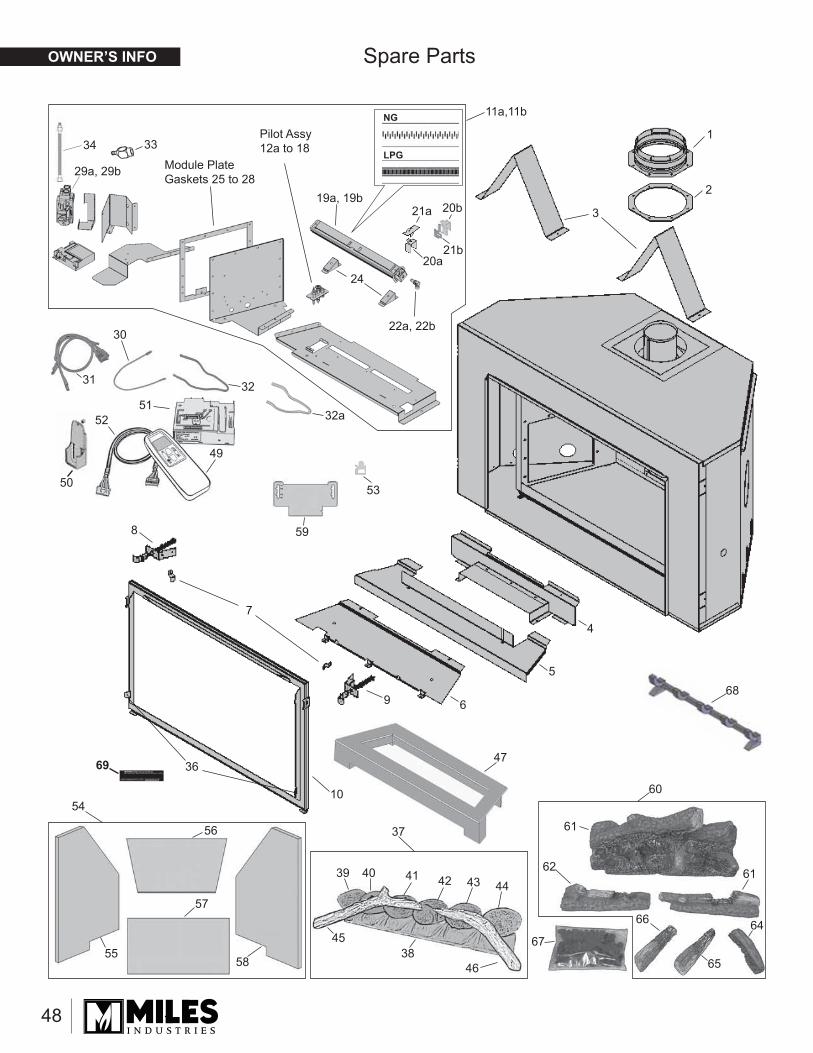
1
2
3
4
5
6
7
8
9
10
53
59
36
11a,11b
Pilot Assy 12a to 18
19a, 19b
22a, 22b
24
Module Plate Gaskets 25 to 28
33
29a, 29b
34
NG
LPG
21a
21b20a
20b
68
67
60
61
62 61
64
65
66
54
55
57
56
58
39 40 41 42 43 44
38
37
45
46
30
31 32
32a
49
50
5152
47
48
Spare Parts
69
OWNER’S INFO

Thank You ...For purchasing a Valor by Miles Industries. Your new radiant gas heater is a technical appliance that must be installed by a qualifi ed dealer.
Please circle where appropriate - ask your installer or your dealer if in doubt. The information provided will be used for customer records only.
Online Warranty registration at www.valorfi replaces.com
Cut out page, fi ll information, and mail to Miles Industries Ltd.
Model: 1300I NG (natural gas) LPG (propane) Serial No:
Front/Trim code/description (e.g. 1370GSB Glass Surround):
Purchase date (mm-dd-yyyy):
Home Owner Name:
Address:
City: Province/State: Postal Code/Zip:
Phone: ( ) Email Address:
Store Type: Fire shop Hardware Contractor Other
Purchase Decision: Male Female Both
Age: Under 30 30-39 40-49 50-59 60+
Heard of this product through:
Friend Brochure Advertising Mailing Store Internet Other
Installation Type:
New home Renovation Other
Reason for Purchase:
Performance Flame Appeal Design Control Previous owner Recommendation Price Other
Dealer Name:
Address:
City: Province/State: Postal Code/Zip:
Phone: ( )

Tape Shut
Thank you for choosing a Valor Product
Postageneeded
Miles Industries Ltd.190 - 2255 Dollarton HighwayNorth Vancouver, BC V7H 3B1 Canada
Fold here
Online Warranty registration at www.valorfi replaces.com