V.N. Litvinenko, ElC Collaboration Meeting, Hampton University, 19-23 May, 2008 Vladimir N....
22
V.N. Litvinenko, ElC Collaboration Meeting, Hampton University, 19-23 May, 2008 Vladimir N. Litvinenko C-AD, Brookhaven National Laboratory, Upton, NY, USA Department of Physics and Astronomy, Stony Brook University Coherent electron cooling Cooling intense high-energy hadron beams remains a major challenge for accelerator physics. Synchrotron radiation is too feeble, while efficiency of two other cooling methods falls rapidly either at high bunch intensities (i.e. stochastic cooling of protons) or at high energies (i.e. e-cooling). Possibility of coherent electron cooling using instabilities in electron beam was discussed by Derbenev since early 1980's . this talk is a first specific scheme with complete theoretical evaluation of its performance. The scheme is based present- day accelerator technology - a high-gain free-electron laser driven by an energy recovery linac. I will present some numerical examples and results on eRHIC luminosity increases. I also will discuss a proof-of- principle experiment using R&D ERL at RHIC. in collaboration with Yaroslav S. Derbenev Thomas Jefferson National Accelerator Facility, Newport News, VA, USA *First paper: Vladimir N. Litvinenko, Yaroslav S. Derbenev, Free-Electron Lasers and High-Energy Electron Cooling, Proc. of 29th International FEL Conference, Novosibirsk, Russia, August 2008, http://accelconf.web.cern.ch/AccelConf/f07/HTML/AUTHOR.HTM p. 268
-
date post
21-Dec-2015 -
Category
Documents
-
view
224 -
download
1
Transcript of V.N. Litvinenko, ElC Collaboration Meeting, Hampton University, 19-23 May, 2008 Vladimir N....

V.N. Litvinenko, ElC Collaboration Meeting, Hampton University, 19-23 May, 2008
Vladimir N. Litvinenko C-AD, Brookhaven National Laboratory, Upton, NY, USA
Department of Physics and Astronomy, Stony Brook University
Coherent electron cooling
Cooling intense high-energy hadron beams remains a major challenge for accelerator physics. Synchrotron radiation is too feeble, while efficiency of two other cooling methods falls rapidly either at high bunch intensities (i.e. stochastic cooling of protons) or at high energies (i.e. e-cooling). Possibility of coherent electron cooling using instabilities in electron beam was discussed by Derbenev since early 1980's . this talk is a first specific scheme with complete theoretical evaluation of its performance. The scheme is based present-day accelerator technology - a high-gain free-electron laser driven by an energy recovery linac. I will present some numerical examples and results on eRHIC luminosity increases. I also will discuss a proof-of-principle experiment using R&D ERL at RHIC.
in collaboration with Yaroslav S. DerbenevThomas Jefferson National Accelerator Facility, Newport News, VA, USA
*First paper: Vladimir N. Litvinenko, Yaroslav S. Derbenev, Free-Electron Lasers and High-Energy Electron Cooling, Proc. of 29th International FEL Conference, Novosibirsk, Russia, August 2008, http://accelconf.web.cern.ch/AccelConf/f07/HTML/AUTHOR.HTM p. 268

V.N. Litvinenko, ElC Collaboration Meeting, Hampton University, 19-23 May, 2008
Contributions from George Bell, Ilan Ben-Zvi, Michael Blaskiewicz, David Bruhwiler, Alexei Fedotov, Dmitry Kayran, Eduard Pozdeyev, Gang Wang
Collaboration on Coherent Electron Cooling includes scientists from BNL, Jlab, BINP (Novosibirsk), FNAL, Dubna, UCLA, TechX, LBNL… open for others: http://www.bnl.gov/cad/ecooling/cec.asp
Content
Why it is needed for EIC?
A bit of history
Principles of Coherent Electron Cooling
(CeC)
Analytical estimations, Simulations
Proof of Principle test using R&D ERL
V.N. Litvinenko, ElC Collaboration Meeting, Hampton University, 19-23 May, 2008
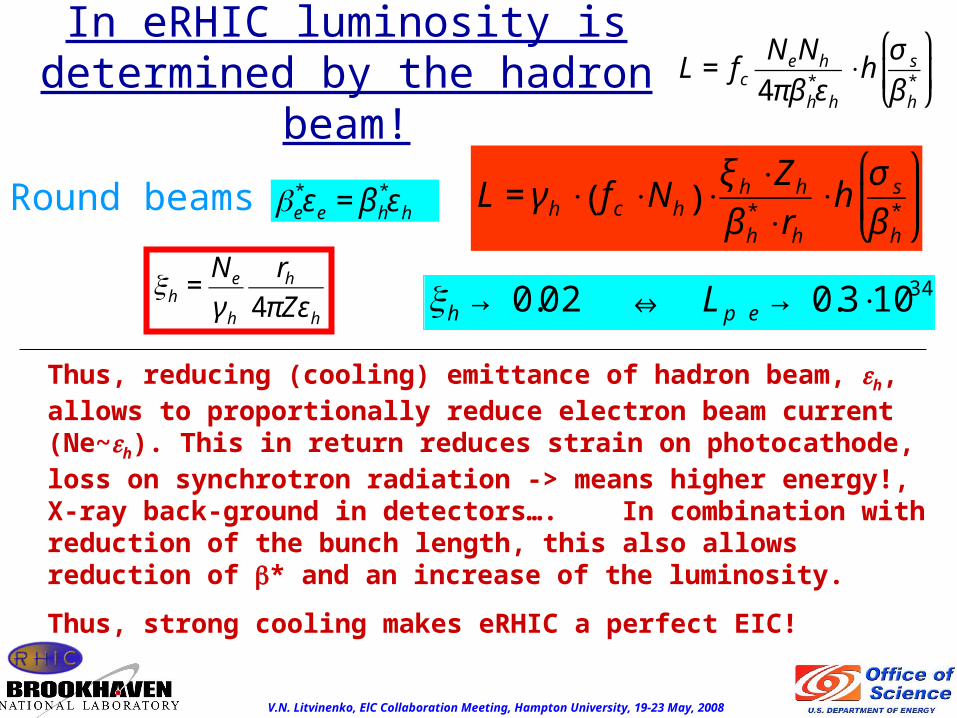
In eRHIC luminosity is determined by the hadron
beam!
€
βe*εe = β h
*εh €
L = fc
NeNh
4πβ h*εh
⋅hσ s
β h*
⎛
⎝ ⎜
⎞
⎠ ⎟
€
L = γ h ⋅ fc ⋅Nh( ) ⋅ξ h ⋅Zh
β h* ⋅rh
⋅hσ s
β h*
⎛
⎝ ⎜
⎞
⎠ ⎟
Thus, reducing (cooling) emittance of hadron beam, h, allows to proportionally reduce electron beam current (Ne~h). This in return reduces strain on photocathode, loss on synchrotron radiation -> means higher energy!, X-ray back-ground in detectors…. In combination with reduction of the bunch length, this also allows reduction of β* and an increase of the luminosity.
Thus, strong cooling makes eRHIC a perfect EIC!
Round beams
€
ξh → 0.02 ⇔ Lp e → 0.3⋅1034
€
ξh =Ne
γ h
rh
4πZεh

V.N. Litvinenko, ElC Collaboration Meeting, Hampton University, 19-23 May, 2008
Decrements for hadron beamswith coherent electron cooling
Machine SpeciesEnergy GeV/n
Trad.StochasticCooling,
hrs
Synchrotron radiation, hrs
Trad.Electron cooling
hrs
CoherentElectron
Cooling, hrs 1D/3D
RHIC PoP
Au 40 - - - 0.02/0.06
eRHIC Au 130 ~1 20,961 ~ 1 0.015/0.05
eRHIC p 325 ~100 40,246 > 30 0.1/0.3
LHC p 7,000 ~ 1,000 13/26 0.3/<1

V.N. Litvinenko, ElC Collaboration Meeting, Hampton University, 19-23 May, 2008
History possibility and various options of coherent electron cooling were
suggested by Yaroslav Derbenev about 27 years ago
• Y.S. Derbenev, Proceedings of the 7th National Accelerator Conference, V. 1, p. 269, (Dubna, Oct. 1980)
• Coherent electron cooling, Ya. S. Derbenev, Randall Laboratory of Physics, University of Michigan, MI, USA, UM HE 91-28, August 7, 1991
• Ya.S.Derbenev, Electron-stochastic cooling, DESY , Hamburg, Germany, 1995 ……….

V.N. Litvinenko, ElC Collaboration Meeting, Hampton University, 19-23 May, 2008
Q: What’s new?
A1. Accelerator technology progressed in last 20+ years and – energy recovery linacs with high quality e-beam– high gain amplification in FELs at m and nm wavelengths
became reality in last decadeA2. A practical scheme with a complete theoretical
evaluation had been developed (vl/yd) in 2007/2008A3. Checks of most important tolerances on e-beam,
hadron beam and lattice had been performedA4. The scheme had been presented at major international
forums (FEL’07 and COOL’07), at major accelerator labs (BNL, CERN, BINP, Jlab…) and passed fist tests of scrutiny

V.N. Litvinenko, ElC Collaboration Meeting, Hampton University, 19-23 May, 2008
Coherent electron cooling, ultra-relativistic case (>>1) Start from longitudinal cooling
Amplifier of the e-beam modulation via FEL with gain GFEL~102-103
Modulator:region 1 a quarter to a half of plasma oscillation
Kicker: region 2, less then a quarter of plasma oscillation
Longitudinal dispersion for hadrons
Electrons
Hadrons
<- L1 -> <- L2 ->
E>EoEo
E<Eo
Most versatile option
€
ω p =4πnee
2
me
€
RD //,lab =cσ γ
γ 2ωpe
<< λ FEL
€
RD⊥ =cγσ θe
ωpe
> RD //
vh
2 RD//
FEL
2 R
D
€
q = −Ze ⋅(1− cosωp t)
ϕ1 = ωpL1 /cγ
FEL
€
FEL =λ w
2γ 2(1+ aw
2 )
€
LGo =λ w
4πρ 3
€
LG = LGo(1+ Λ)
GFEL = eLFEL / LG
€
Δϕ =LFEL
3LG
€
Δt = −D ⋅γ − γ o
γ o
; D = D free + Dchicane;
D free =L
γ 2; Dchicane = lchicane ⋅θ
2
€
kcm =π
γ oλ FEL
€
Δϕ =4πρ ⇒ ϕ = −8G ⋅Ze
πβεnkcm
⋅cos kcmz( )
r E = −
r ∇ϕ = −ˆ z
8G ⋅Ze
πβεn
⋅sin kcmz( )
€
ρamp =G ⋅Ze
2πβεn
⋅4kcm
πcos kcmz( )
€
Q = −GFEL ⋅4Ze
€
A⊥ =
2πβ⊥εn /γ o
€
QλFEL≈ ρ(z)
0
λFEL
∫ cos kFELz( )dz
QλFEL(max) ≈ −2Ze; ρ k = −Ze
4k
πA⊥
FEL
Ez
€
ΔE i = −8G ⋅Z 2e2
πβεn
L2 ⋅sin kFELDE − Eo
Eo
⎛
⎝ ⎜
⎞
⎠ ⎟
⋅sinϕ 2
ϕ p 2
⎛
⎝ ⎜ ⎜
⎞
⎠ ⎟ ⎟⋅ sin
ϕ1
2
⎛
⎝ ⎜
⎞
⎠ ⎟2
€
ω p t
€
−q /Ze

V.N. Litvinenko, ElC Collaboration Meeting, Hampton University, 19-23 May, 2008
Completely Analytical Solution© Michael Blaskiewicz, Gang Wang - to be published in Phys. Rev. BIn full agreement with the model used for coherent electron

V.N. Litvinenko, ElC Collaboration Meeting, Hampton University, 19-23 May, 2008
R=3; Z=0; T=0 – Asymmetry of electron velocity distribution pancake-shaped wake
QuickTime™ and aYUV420 codec decompressor
are needed to see this picture.
QuickTime™ and aYUV420 codec decompressor
are needed to see this picture.
©Tech-X: Courtesy of D.Bruhwiler & G. Bell

V.N. Litvinenko, ElC Collaboration Meeting, Hampton University, 19-23 May, 2008
©Tech-X
QuickTime™ and aTIFF (LZW) decompressor
are needed to see this picture.
Vx (rms) = Vy (rms) = 2.8E4 m/s, Vz (rms) 9.0E3 m/s
QuickTime™ and aYUV420 codec decompressor
are needed to see this picture.
Note: Given the density and box size above, the number of actual electrons in the slice shown is only8.10E15 e-/m^3)(5.3E-5 m)(2.1E-6 m)(1.0E-4 m) = 90n order to get reasonable statistics, each electron was split into N microparticles having the same charge/mass ratio. In the simulations, N=3500. An individual wake behind a gold ion will be much noisier
QuickTime™ and aYUV420 codec decompressor
are needed to see this picture.

V.N. Litvinenko, ElC Collaboration Meeting, Hampton University, 19-23 May, 2008
Amplifier of the e-beam modulation via High Gain FEL andLongitudinal dispersion for hadrons
Modulator:region 1 a quarter to a half of plasma oscillation
Kicker: region 2
E>EoEo
E<Eo
Electrons
Hadrons
<- L1 -><- L2 ->
Economic option
Coherent electron cooling, ultra-relativistic case (>>1)
Electron density modulation is amplified in the FEL and made into a train with duration of Nc ~ Lgain/w alternating hills (high density) and valleys (low density) with period of FEL wavelength . Maximum gain for the electron density of HG FEL is ~ 103.
€
vgroup = (c + 2v //) /3 = c 1−1+ aw
2
3γ 2
⎛
⎝ ⎜
⎞
⎠ ⎟= c 1−
1
2γ 2
⎛
⎝ ⎜
⎞
⎠ ⎟+
c
3γ 21− 2aw
2( ) = vhadrons +
c
3γ 21− 2aw
2( )
Economic option requires: 2aw2 < 1 !!!

V.N. Litvinenko, ElC Collaboration Meeting, Hampton University, 19-23 May, 2008
Analytical formula for damping decrement• 1/2 of plasma oscillation in the modulator creates a pancake of electrons with the charge -2Ze
• electron clamp is well within Δz~FEL /2
• gain in SASE FEL is G ~ 102-103
• electron beam is wider than - it is 1D field• Length of the region 2 is ~ beta-function
€
2γ oλ FEL
€
ζ =− ΔE i
E − Eo
= A ⋅L2
β⋅χ ⋅sinc ϕ 3( ) ⋅sincϕ 2 ⋅ sin
ϕ1
2
⎛
⎝ ⎜
⎞
⎠ ⎟2
A =8G
π⋅
Z 2
A⋅
rp
εn,hσ ε
; χ = kFELD ⋅σ ε ;
sinc ϕ( ) = sin ϕ( ) / x; ϕ 3 = kFELDε; ε =E − Eo
Eo
€
L2
β⋅χ ⋅sinc ϕ 3( ) ⋅sincϕ 2 ⋅ sin
ϕ1
2
⎛
⎝ ⎜
⎞
⎠ ⎟2
~ 1
€
χ =1
€
a = 3.8317σ ε
€
δ =a ⋅sinΩst
δ 2 ′ = − 2A ⋅a2 ⋅cos2 Ωst ⋅sina
σ ε
⋅χ ⋅sinΩst ⎛
⎝ ⎜
⎞
⎠ ⎟
= −2A ⋅ δ 2 ⋅J1 χ ⋅a
σ ε
⎛
⎝ ⎜
⎞
⎠ ⎟
€
2J1(x)
xe−x 2 / 2∫ dx = 0.889
Beam-Average decrement
€
ζCeC = ζσ τ ,e
σ τ ,h
= κ ⋅8G
π⋅
Z 2
A⋅
rp ⋅σ τ ,e
εn,h σ ε ⋅σ τ ,h( ); κ ~ 1
L
•Electron bunches are usually much shorter and cooling time for the entire bunch is proportional to the bunch-lengths ratios

V.N. Litvinenko, ElC Collaboration Meeting, Hampton University, 19-23 May, 2008
Note that damping decrement:
a) does not depend on the energy of particles !
b) Improves as cooling goes on
!!!! Protons in RHIC & LHC
€
ζCeC ~1
ε long,hε trans,h€
ζCeC = ζσ τ ,e
σ τ ,h
= κ ⋅8G
π⋅
Z 2
A⋅
rp ⋅σ τ ,e
εn,h σ ε ⋅σ τ ,h( ); κ ~ 1
Analytical formula for damping decrement

V.N. Litvinenko, ElC Collaboration Meeting, Hampton University, 19-23 May, 2008
Transverse cooling• Transverse cooling can be
obtained by using coupling with longitudinal motion via transverse dispersion
• Sharing of cooling decrements is similar to sum of decrements theorem for synchrotron radiation damping, i.e. decrement of longitudinal cooling can be split into appropriate portions to cool both transversely and longitudinally: Js+Jh+Jv=1
• Vertical (better to say the second eigen mode) cooling is coming from transverse coupling
Non-achromatic chicane installed at theexit of the FEL before the kicker sectionturns the wave-fronts of the charged planesin electron beam
R260
€
δ ct( ) = −R26 ⋅ x
€
ΔE = −eZ 2 ⋅Eo ⋅L2 ⋅sin k DE − Eo
Eo
+ R16 ′ x − R26x + R36 ′ y + R46y ⎛
⎝ ⎜
⎞
⎠ ⎟
⎧ ⎨ ⎩
⎫ ⎬ ⎭
;
€
Δx = −Dx ⋅eZ 2 ⋅Eo ⋅L2 ⋅kR26x + ....
€
ζ⊥ =J⊥ζ CeC ; ζ // = (1− 2J⊥)ζ CeC ;
dεx
dt= −
εx
τ CeC⊥
;dσ ε
2
dt= −
σ ε2
τ CeC //
τ CeC⊥ =1
2J⊥ζ CeC
; τ CeC⊥ =1
2(1− 2J⊥)ζ CeC
;

V.N. Litvinenko, ElC Collaboration Meeting, Hampton University, 19-23 May, 2008
Coherent e-Cooling for eRHIC(protons are the main challenge)
Electrons
1Energy 0.177 GeVEnergy 1.770E+08 eV 346.38N, aρt/βunχh 3.12E+10Charge 5.0 nCBunχh nth 0.050 nsχBunχh nt, ϕu 0.015 Pak χuρρnt 100.0 A
, , Emittance norm RMS 5 ρaδEittanχ, RMS 1.443E-08 ρaδsE/E 2.26E-04sE 4.00E+04 VLon ittanχ 2.000E-06 V sχ
Main Parameters CeCModulator Length 15 mKicker length 5 mPeak current, e 100.0 AAmplification 200.00Wavelength 500 nmw 5 cm
FEL bandwidth 0.1
Cooling timeEmittance, Full bunch 0.086 hrsAmpl, Full bunch 0.171 hrsLocal 50.23 secLength of the system 32.49 mFEL length 12.49 mFEL gain length 0.99 m
HadronsZ 1A 1Energy per nucleon 325 GeVEnergy per nucleon 3.250000E+11 eV 346.38 =, /N part bunch 2.00 +11E
Chaρ 32.04 nCBunχh nth 0.433 nsχBunχh nt, RMS 0.130 Pak χuρρnt 29.50 A
, Emmitance norm 2 ρaδEitanχ, ρaδ 5.77398E-09sE/E 4.00E-04

V.N. Litvinenko, ElC Collaboration Meeting, Hampton University, 19-23 May, 2008
Main advantages of ERL + cooling
• Main point is very simple: if one cools the emittance of a hadron beam in electron-hadron collider, the intensity of the electron beam can be reduced proportionally without any loss in luminosity or increase in the beam-beam parameter for hadrons
• Hadron beam size is reduced in the IR triplets - hence it opens possibility of further β* squeeze and increase in luminosity
• Electron beam current goes down -> relaxed gun!, losses for synchrotron radiation going down, X-ray background in the detectors goes down….
€
ξ p =rp
4π⋅
Ne
ε p norm
;
€
L = γ p
fcolN p
β p* rp
ξ p
€
Ne
ε p norm
= const ⇒ ξ p = const; L = const
Ne ∝ε p norm ⇒ Ie ∝ε p norm ⇒ PSR ∝ε p norm!

V.N. Litvinenko, ElC Collaboration Meeting, Hampton University, 19-23 May, 2008
€
X =εx
εxo
; S =σ s
σ so
⎛
⎝ ⎜
⎞
⎠ ⎟
2
=σ E
σ sE
⎛
⎝ ⎜
⎞
⎠ ⎟
2
;
dX
dt=
1
τ IBS⊥
1
X 3 / 2S1/ 2 −ξ⊥
τ CeC
1
S;
dS
dt=
1
τ IBS //
1
X 3 / 2Y−
1− 2ξ⊥
τ CeC
1
X;
Stationary state: IBS vs. CeC
€
xn 0 = 2μm; σ s0 =13 cm; σ δ 0 = 4 ⋅10−4
τ IBS⊥ =4.6 hrs; τ IBS // =1.6 hrs;€
s2
τ IBS //
=Nrc
2c
25πγ 3εx3 / 2σ s
f χ m( )β yv
; εx
τ IBS⊥
=Nrc
2c
25πγ 3εx3 / 2σ s
H
β y1/ 2 f χ m( ) ;κ =1
f χ m( ) =dχ
χχ m
∞
∫ lnχ
χ m
⎛
⎝ ⎜
⎞
⎠ ⎟e
−χ ; χ m =rcm
2c 4
bmaxσ E2 ;bmax ≅ n−1/ 3; rc =
e2
mc 2; (e− > Ze;m− > Am)
IBS in RHIC foreRHIC, 250 GeV, Np=2.1011
Beta-cool, A.Fedotov
€
X =τ CeC
τ IBS //τ IBS⊥
1
ξ⊥ 1− 2ξ⊥( ); S =
τ CeC
τ IBS //
⋅τ IBS⊥
τ IBS //
⋅ξ⊥
1− 2ξ⊥( )3
Stationary solution:
€
εx n = 0.2μm; σ s = 4.9 cm
This allows a) keep the luminosity as it is b) reduce polarized beam current down to 25 mA (5 mA for e-
I)c) increase electron beam energy to 20 GeV (30 GeV for e-I)d) increase luminosity by reducing β* from 25 cm down to 5
cm
0
0.5
1
1.5
2
2.5
0
3
6
9
12
15
0 0.05 0.1 0.15 0.2 0.25
Norm emittance, m
, RMS bunch length cm
, Norm emittance
m , RMS bunch length cm
, Time hours
J.LeDuff, "Single and Multiple Touschek effects", Proceedings of CERN Accelerator School, Rhodes, Greece, 20 September - 1 October, 1993, Editor: S.Turner, CERN 95-06, 22 November 1995, Vol. II, p. 57
V.N. Litvinenko, ElC Collaboration Meeting, Hampton University, 19-23 May, 2008
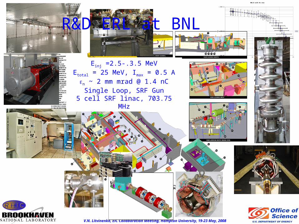
Einj =2.5-.3.5 MeVEtotal = 25 MeV, Imax = 0.5 An ~ 2 mm mrad @ 1.4 nC
Single Loop, SRF Gun5 cell SRF linac, 703.75 MHz
BNL1X with He vessel
1.00E+09
1.00E+10
1.00E+11
0 5 10 15 20 25
Eacc (MV/m)
Qo Qo
R&D ERL at BNL

V.N. Litvinenko, ElC Collaboration Meeting, Hampton University, 19-23 May, 2008
QuickTime™ and aTIFF (Uncompressed) decompressor
are needed to see this picture.
N per bunch 1 109 Z, A 79, 197
Energy Au, GeV/n 40 42.63
RMS bunch length, nsec 3.2 Relative energy spread 0.037%
Emittance norm, m 2.5 β, m* 8
Energy e-, MeV 21.79 Peak current, A 60
Charge per bunch, nC 4 x 1.4 Bunch length, RMS, psec 83
Emittance norm, m 4 Relative energy spread 0.15%
β, m 5 L1 (lab frame) ,m 4
ωpe, CM, Hz 5.03 109 Number of plasma oscillations 0.256
D, m 611 D, m 3.3
FEL, m 18 w, cm 5
aw 0.555 LGo, m 0.67
Amplitude gain =150, Lw , m
6.75 (7) LG3D, m 1.35
L2 (lab frame) ,m 3 Cooling time, local, minimum
0.05 minutes
Nturns, Ñ, 5% BW 8 106> 6 104 Cooling time, beam, min
2.6 minutes
PoP test using BNL R&D ERL:Au ions in RHIC with 40 GeV/n, Lcooler = 14 m

V.N. Litvinenko, ElC Collaboration Meeting, Hampton University, 19-23 May, 2008
2-3 MeV
2-3 MeV
20 MeV
20 MeV
20 MeV
2-3 MeV
SC RF Gun
SC 5 Cell cavity
Beam dump
IR-2 layout for Coherent Electron Cooling proof-of-principle experiment
DX DX
19.6 m
Modulator4 mWiggler 7m
Kicker3 m

V.N. Litvinenko, ElC Collaboration Meeting, Hampton University, 19-23 May, 2008
See presentation by D.Kayran at 3:10 p.m., Tue, May 20Parallel session: Accelerators

V.N. Litvinenko, ElC Collaboration Meeting, Hampton University, 19-23 May, 2008
Conclusions• Coherent electron cooling is very promising
method for significant increases in luminosity and energy reach in eRHIC
• It could be the key for reducing electron beam current from polarized gun and increased reach in eRHIC c.m. energy
• We plan a proof of principle experiment of coherent electron cooling with Au ions in RHIC at ~ 40 GeV/n and existing R&D ERL as part of EIC R&D