VMX12V(C) Owner's Manual... · 2016. 4. 4. · y or death to the motorcycle operator, ... 6-26...
101
LIT-11626-19-27 5GK-28199-16 VMX12V(C) OWNER’S MANUAL
Transcript of VMX12V(C) Owner's Manual... · 2016. 4. 4. · y or death to the motorcycle operator, ... 6-26...

LIT-11626-19-27 5GK-28199-16
VMX12V(C)
OWNER’S MANUAL
EAU10041

INTRODUCTION
EAU10080
Congratulations on your purchase of the Yamaha VMX12V. This model is the result of Yamaha’s vast experience in the pro-duction of fine sporting, touring, and pacesetting racing machines. It represents the high degree of craftsmanship and reli-ability that have made Yamaha a leader in these fields.This manual will give you an understanding of the operation, inspection, and basic maintenance of this motorcycle. If youhave any questions concerning the operation or maintenance of your motorcycle, please consult a Yamaha dealer.The design and manufacture of this Yamaha motorcycle fully comply with the emissions standards for clean air applicableat the date of manufacture. Yamaha has met these standards without reducing the performance or economy of operation ofthe motorcycle. To maintain these high standards, it is important that you and your Yamaha dealer pay close attention to therecommended maintenance schedules and operating instructions contained within this manual.

IMPORTANT MANUAL INFORMATION
EAU10130
Particularly important information is distinguished in this manual by the following notations:
NOTE:
�
This manual should be considered a permanent part of this motorcycle and should remain with it even if the motorcycleis subsequently sold.
�
Yamaha continually seeks advancements in product design and quality. Therefore, while this manual contains the mostcurrent product information available at the time of printing, there may be minor discrepancies between your motorcycle
and this manual. If you have any questions concerning this manual, please consult your Yamaha dealer.
WARNING
EWA10010
PLEASE READ THIS MANUAL AND THE “YOU AND YOUR MOTORCYCLE: RIDING TIPS” BOOKLET CAREFULLYAND COMPLETELY BEFORE OPERATING THIS MOTORCYCLE. DO NOT ATTEMPT TO OPERATE THIS MOTORCY-CLE UNTIL YOU HAVE ATTAINED ADEQUATE KNOWLEDGE OF ITS CONTROLS AND OPERATING FEATURESAND UNTIL YOU HAVE BEEN TRAINED IN SAFE AND PROPER RIDING TECHNIQUES. REGULAR INSPECTIONSAND CAREFUL MAINTENANCE, ALONG WITH GOOD RIDING SKILLS, WILL ENSURE THAT YOU SAFELY ENJOY
THE CAPABILITIES AND THE RELIABILITY OF THIS MOTORCYCLE.
The Safety Alert Symbol means ATTENTION! BECOME ALERT! YOUR SAFETY IS INVOLVED!
Failure to follow WARNING instructions could result in severe injury or death to themotorcycle operator, a bystander or a person inspecting or repairing the motorcycle.
A CAUTION indicates special precautions that must be taken to avoid damage to the motorcycle.
A NOTE provides key information to make procedures easier or clearer.
WARNING
CAUTION:
NOTE:
IMPORTANT MANUAL INFORMATION
EAU10192
AFFIX DEALER
LABEL HERE
VMX12V(C)OWNER’S MANUAL
©2005 by Yamaha Motor Corporation, U.S.A.1st edition, April 2005
All rights reserved.Any reprinting or unauthorized use without the written permission of Yamaha Motor Corporation, U.S.A.
is expressly prohibited.Printed in Japan.
P/N LIT-11626-19-27

TABLE OF CONTENTS
SAFETY INFORMATION
...................1-1Location of important labels .............1-5
DESCRIPTION
...................................2-1Left view ...........................................2-1Right view .........................................2-2Controls and instruments..................2-3
INSTRUMENT AND CONTROL FUNCTIONS
........................................3-1Main switch ......................................3-1Indicator and warning lights .............3-1Speedometer unit ............................3-2Tachometer .....................................3-3Coolant temperature gauge .............3-3Handlebar switches .........................3-3Clutch lever ......................................3-5Shift pedal ........................................3-5Brake lever ......................................3-5Brake pedal .....................................3-6Fuel tank cap ...................................3-6Fuel ..................................................3-7Starter (choke) lever ........................3-8Steering lock ....................................3-8Rider seat ........................................3-9Helmet holder ................................3-10Adjusting the front fork ...................3-10Adjusting the shock absorber
assemblies .................................3-12V-Boost ..........................................3-14Sidestand .......................................3-14
Ignition circuit cut-off system ......... 3-15
PRE-OPERATION CHECKS
.............. 4-1Pre-operation check list ................... 4-2
OPERATION AND IMPORTANT RIDING POINTS
.................................. 5-1Starting and warming up a cold
engine .......................................... 5-1Starting a warm engine ................... 5-2Shifting ............................................ 5-3Engine break-in ............................... 5-4Parking ............................................ 5-5
PERIODIC MAINTENANCE AND MINOR REPAIR
.................................. 6-1PERIODIC MAINTENANCE ............ 6-1Owner’s tool kit ................................ 6-1Periodic maintenance chart for the
emission control system .............. 6-3General maintenance and lubrication
chart ............................................. 6-4Removing and installing the cowling
and panels ................................... 6-8Checking the spark plugs ................ 6-9Canister (for California only) ......... 6-10Engine oil and oil filter cartridge .... 6-11Final gear oil .................................. 6-14Coolant .......................................... 6-15Cleaning the air filter element ....... 6-18Carburetors ................................... 6-19
Checking the throttle cable free play ............................................ 6-19
Valve clearance ............................ 6-20Tires .............................................. 6-20Cast wheels .................................. 6-22Accessories and replacement
parts ........................................... 6-23Clutch lever ................................... 6-23Adjusting the brake lever free
play ............................................ 6-24Adjusting the rear brake light
switch ......................................... 6-24Checking the front and rear brake
pads ........................................... 6-25Checking the brake and clutch fluid
levels ......................................... 6-25Changing the brake and clutch
fluids .......................................... 6-26Checking and lubricating the
cables ........................................ 6-27Checking and lubricating the throttle
grip and cable ............................ 6-27Checking and lubricating the brake
and shift pedals ......................... 6-27Checking and lubricating the brake
and clutch levers ........................ 6-28Checking and lubricating the
centerstand and sidestand ........ 6-28Lubricating the rear suspension .... 6-29Checking the front fork .................. 6-29Checking the steering ................... 6-30

TABLE OF CONTENTS
Checking the wheel bearings ........6-30Battery ...........................................6-31Replacing the fuses .......................6-33Replacing the headlight bulb .........6-34Replacing a turn signal light bulb or
the tail/brake light bulb ...............6-35Front wheel ....................................6-36Rear wheel ....................................6-37Troubleshooting .............................6-39Troubleshooting charts ..................6-40
MOTORCYCLE CARE AND STORAGE
...........................................7-1Care .................................................7-1Storage ............................................7-3
SPECIFICATIONS
..............................8-1
CONSUMER INFORMATION
..............9-1Identification numbers .....................9-1Reporting safety defects ..................9-3Motorcycle noise regulation .............9-4Maintenance record .........................9-5YAMAHA MOTOR CORPORATION,
U.S.A. STREET AND ENDURO MOTORCYCLE LIMITED WARRANTY .................................9-7
YAMAHA EXTENDED SERVICE (Y.E.S.) ........................................9-9

1-1
1
SAFETY INFORMATION
EAU10272
MOTORCYCLES ARE SINGLETRACK VEHICLES. THEIR SAFEUSE AND OPERATION ARE DEPEN-DENT UPON THE USE OF PROPERRIDING TECHNIQUES AS WELL ASTHE EXPERTISE OF THE OPERA-TOR. EVERY OPERATOR SHOULDKNOW THE FOLLOWING REQUIRE-MENTS BEFORE RIDING THIS MO-TORCYCLE.HE OR SHE SHOULD:
�
OBTAIN THOROUGH INSTRUC-TIONS FROM A COMPETENTSOURCE ON ALL ASPECTS OFMOTORCYCLE OPERATION.
�
OBSERVE THE WARNINGSAND MAINTENANCE REQUIRE-MENTS IN THE OWNER’S MAN-UAL.
�
OBTAIN QUALIFIED TRAININGIN SAFE AND PROPER RIDINGTECHNIQUES.
�
OBTAIN PROFESSIONAL TECH-NICAL SERVICE AS INDICATEDBY THE OWNER’S MANUALAND/OR WHEN MADE NECES-SARY BY MECHANICAL CONDI-
TIONS.
Safe riding
�
Always make pre-operationchecks. Careful checks may helpprevent an accident.
�
This motorcycle is designed to car-ry the operator and a passenger.
�
The failure of motorists to detectand recognize motorcycles in traf-fic is the predominating cause ofautomobile/motorcycle accidents.Many accidents have been causedby an automobile driver who didnot see the motorcycle. Makingyourself conspicuous appears tobe very effective in reducing thechance of this type of accident.
Therefore:
�
Wear a brightly colored jacket.
�
Use extra caution when you areapproaching and passingthrough intersections, since in-tersections are the most likelyplaces for motorcycle accidentsto occur.
�
Ride where other motorists cansee you. Avoid riding in another
motorist’s blind spot.
�
Many accidents involve inexperi-enced operators. In fact, many op-erators who have been involved inaccidents do not even have a cur-rent motorcycle license.
�
Make sure that you are qualifiedand that you only lend your mo-torcycle to other qualified opera-tors.
�
Know your skills and limits.Staying within your limits mayhelp you to avoid an accident.
�
We recommend that you prac-tice riding your motorcyclewhere there is no traffic until youhave become thoroughly famil-iar with the motorcycle and all ofits controls.
�
Many accidents have been causedby error of the motorcycle opera-tor. A typical error made by the op-erator is veering wide on a turndue to EXCESSIVE SPEED or un-dercornering (insufficient lean an-gle for the speed).
�
Always obey the speed limit andnever travel faster than warrant-

SAFETY INFORMATION
1-2
1
ed by road and traffic conditions.
�
Always signal before turning orchanging lanes. Make sure thatother motorists can see you.
�
The posture of the operator andpassenger is important for propercontrol.
�
The operator should keep bothhands on the handlebar andboth feet on the operator foot-rests during operation to main-tain control of the motorcycle.
�
The passenger should alwayshold onto the operator, the seatstrap or grab bar, if equipped,with both hands and keep bothfeet on the passenger footrests.
�
Never carry a passenger unlesshe or she can firmly place bothfeet on the passenger footrests.
�
Never ride under the influence ofalcohol or other drugs.
�
This motorcycle is designed foron-road use only. It is not suitablefor off-road use.
Protective apparel
The majority of fatalities from motorcy-
cle accidents are the result of head in-juries. The use of a safety helmet is thesingle most critical factor in the preven-tion or reduction of head injuries.
�
Always wear an approved helmet.
�
Wear a face shield or goggles.Wind in your unprotected eyescould contribute to an impairmentof vision that could delay seeing ahazard.
�
The use of a jacket, heavy boots,trousers, gloves, etc., is effective inpreventing or reducing abrasionsor lacerations.
�
Never wear loose-fitting clothes,otherwise they could catch on thecontrol levers, footrests, or wheelsand cause injury or an accident.
�
Never touch the engine or exhaustsystem during or after operation.They become very hot and cancause burns. Always wear protec-tive clothing that covers your legs,ankles, and feet.
�
A passenger should also observethe above precautions.
Modifications
Modifications made to this motorcyclenot approved by Yamaha, or the re-moval of original equipment, may ren-der the motorcycle unsafe for use andmay cause severe personal injury.Modifications may also make your mo-torcycle illegal to use.
Loading and accessories
Adding accessories or cargo to yourmotorcycle can adversely affect stabili-ty and handling if the weight distributionof the motorcycle is changed. To avoidthe possibility of an accident, use ex-treme caution when adding cargo oraccessories to your motorcycle. Useextra care when riding a motorcyclethat has added cargo or accessories.Here are some general guidelines tofollow if loading cargo or adding acces-sories to your motorcycle:
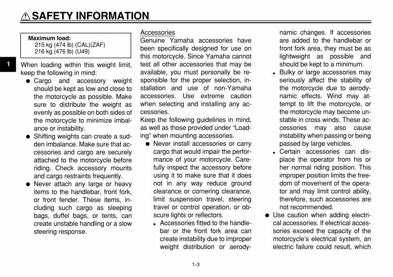
LoadingThe total weight of the operator, pas-senger, accessories and cargo mustnot exceed the maximum load limit.
SAFETY INFORMATION
1-3
1
When loading within this weight limit,keep the following in mind:
�
Cargo and accessory weightshould be kept as low and close tothe motorcycle as possible. Makesure to distribute the weight asevenly as possible on both sides ofthe motorcycle to minimize imbal-ance or instability.
�
Shifting weights can create a sud-den imbalance. Make sure that ac-cessories and cargo are securelyattached to the motorcycle beforeriding. Check accessory mountsand cargo restraints frequently.
�
Never attach any large or heavyitems to the handlebar, front fork,or front fender. These items, in-cluding such cargo as sleepingbags, duffel bags, or tents, cancreate unstable handling or a slowsteering response.
AccessoriesGenuine Yamaha accessories havebeen specifically designed for use onthis motorcycle. Since Yamaha cannottest all other accessories that may beavailable, you must personally be re-sponsible for the proper selection, in-stallation and use of non-Yamahaaccessories. Use extreme cautionwhen selecting and installing any ac-cessories.Keep the following guidelines in mind,as well as those provided under “Load-ing” when mounting accessories.
�
Never install accessories or carrycargo that would impair the perfor-mance of your motorcycle. Care-fully inspect the accessory beforeusing it to make sure that it doesnot in any way reduce groundclearance or cornering clearance,limit suspension travel, steeringtravel or control operation, or ob-scure lights or reflectors.
�
Accessories fitted to the handle-bar or the front fork area cancreate instability due to improperweight distribution or aerody-
namic changes. If accessoriesare added to the handlebar orfront fork area, they must be aslightweight as possible andshould be kept to a minimum.
�
Bulky or large accessories mayseriously affect the stability ofthe motorcycle due to aerody-namic effects. Wind may at-tempt to lift the motorcycle, orthe motorcycle may become un-stable in cross winds. These ac-cessories may also causeinstability when passing or beingpassed by large vehicles.
�
Certain accessories can dis-place the operator from his orher normal riding position. Thisimproper position limits the free-dom of movement of the opera-tor and may limit control ability,therefore, such accessories arenot recommended.
�
Use caution when adding electri-cal accessories. If electrical acces-sories exceed the capacity of themotorcycle’s electrical system, anelectric failure could result, which
Maximum load:
215 kg (474 lb) (CAL)(ZAF)216 kg (476 lb) (U49)

SAFETY INFORMATION
1-4
1
could cause a dangerous loss oflights or engine power.
Gasoline and exhaust gas
�
GASOLINE IS HIGHLY FLAMMA-BLE:
�
Always turn the engine off whenrefueling.
�
Take care not to spill any gaso-line on the engine or exhaustsystem when refueling.
�
Never refuel while smoking or inthe vicinity of an open flame.
�
Never start the engine or let it runfor any length of time in a closedarea. The exhaust fumes are poi-sonous and may cause loss ofconsciousness and death within ashort time. Always operate yourmotorcycle in an area that has ad-equate ventilation.
�
Always turn the engine off beforeleaving the motorcycle unattendedand remove the key from the mainswitch. When parking the motorcy-cle, note the following:
�
The engine and exhaust systemmay be hot, therefore, park the
motorcycle in a place where pe-destrians or children are not like-ly to touch these hot areas.
�
Do not park the motorcycle on aslope or soft ground, otherwise itmay fall over.
�
Do not park the motorcycle neara flammable source, (e.g., a ker-osene heater, or near an openflame), otherwise it could catchfire.
�
When transporting the motorcyclein another vehicle, make sure thatit is kept upright. If the motorcycleshould lean over, gasoline mayleak out of the carburetor or fueltank.
�
If you should swallow any gaso-line, inhale a lot of gasoline vapor,or allow gasoline to get into youreyes, see your doctor immediate-ly. If any gasoline spills on yourskin or clothing, immediately washthe affected area with soap andwater and change your clothes.

SAFETY INFORMATION
1-5
1
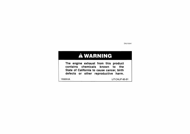
EAU10381
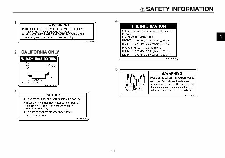
Location of important labels
Please read the following important labels carefully before operating this vehicle.
SAFETY INFORMATION
1-6
1
1
3
2 CALIFORNIA ONLY
4
5
00
2-1
1
2
3
4
5
6
7
8
9
DESCRIPTION
EAU10410
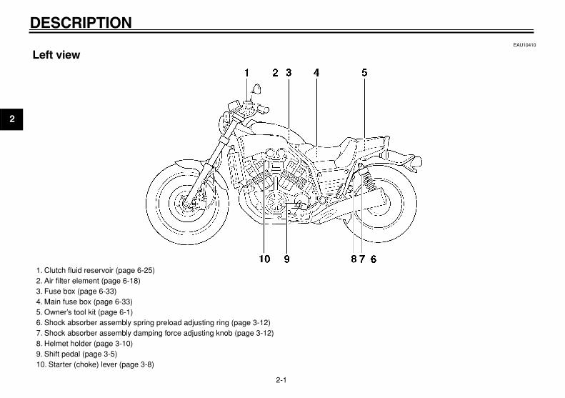
Left view
1. Clutch fluid reservoir (page 6-25)2. Air filter element (page 6-18)3. Fuse box (page 6-33)4. Main fuse box (page 6-33)5. Owner’s tool kit (page 6-1)6. Shock absorber assembly spring preload adjusting ring (page 3-12)7. Shock absorber assembly damping force adjusting knob (page 3-12)8. Helmet holder (page 3-10)9. Shift pedal (page 3-5)10. Starter (choke) lever (page 3-8)

DESCRIPTION
2-2
2
3
4
5
6
7
8
9
EAU10420
Right view
1. Fuel tank cap (page 3-6)2. Battery (page 6-31)3. Coolant reservoir (page 6-15)4. Front brake fluid reservoir (page 6-25)5. Main switch (page 3-1)6. Radiator cap (page 6-15)7. Radiator (page 6-15)8. Engine oil filter cartridge (page 6-11)9. Engine oil level check window (page 6-11)10. Brake pedal (page 3-6)11. Rear brake fluid reservoir (page 6-25)
DESCRIPTION
2-3
1
2
3
4
5
6
7
8
9
EAU10430
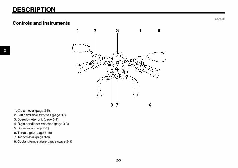
Controls and instruments
1. Clutch lever (page 3-5)2. Left handlebar switches (page 3-3)3. Speedometer unit (page 3-2)4. Right handlebar switches (page 3-3)5. Brake lever (page 3-5)6. Throttle grip (page 6-19)7. Tachometer (page 3-3)8. Coolant temperature gauge (page 3-3)

3-1
2
3
4
5
6
7
8
9
INSTRUMENT AND CONTROL FUNCTIONS
EAU10450
Main switch
The main switch controls the ignitionand lighting systems. The various mainswitch positions are described below.
EAU10510
ON
All electrical systems are supplied withpower, and the headlight, meter light-ing, taillight and position lights comeon, and the engine can be started. Thekey cannot be removed.
EAU10660
OFF
All electrical systems are off. The keycan be removed.
EAU10822
P (Parking)
The meter lighting, taillight and positionlights are on, but all other electrical sys-tems are off. The key can be removed.The key must be pushed in from the“OFF” position to be turned to “P”.
CAUTION:
ECA11020
Do not use the parking position foran extended length of time, other-
wise the battery may discharge.
EAU11003
Indicator and warning lights
EAU11040
Turn signal indicator light “TURN”
This indicator light flashes when theturn signal switch is pushed to the left orright.
EAU11070
Neutral indicator light “NEUTRAL”
This indicator light comes on when thetransmission is in the neutral position.
1. Push.2. Turn.
1. Neutral indicator light “NEUTRAL”2. Turn signal indicator light “TURN”3. Fuel level warning light “FUEL”4. High beam indicator light “HIGH BEAM”5. Oil level warning light “OIL LEVEL”

INSTRUMENT AND CONTROL FUNCTIONS
3-2
1
2
3
4
5
6
7
8
9
EAU11090
High beam indicator light “HIGH BEAM”
This indicator light comes on when thehigh beam of the headlight is switchedon.
EAU32330
Oil level warning light “OIL LEVEL”
This warning light comes on when theengine oil level is low.The electrical circuit of the warning lightcan be checked according to the follow-ing procedure.
1. Set the engine stop switch to“RUN” and turn the key to “ON”.
2. Shift the transmission into the neu-tral position or pull the clutch lever.
3. Push the start switch. If the warn-ing light does not come on, have aYamaha dealer check the electri-cal circuit.
NOTE:
Even if the oil level is sufficient, thewarning light may flicker when riding ona slope or during sudden accelerationor deceleration, but this is not a mal-
function.
EAU32320
Fuel level warning light “FUEL”
This warning light comes on when thefuel level drops below approximately3.0 L (0.79 US gal) (0.66 Imp.gal).When this occurs, set the fuel reserveswitch to the “RES” position and refuelas soon as possible.The electrical circuit of the warning lightcan be checked according to the follow-ing procedure.
1. Set the engine stop switch to“RUN” and turn the key to “ON”.
2. Shift the transmission into the neu-tral position or pull the clutch lever.
3. Push the start switch. If the warn-ing light does not come on, have aYamaha dealer check the electri-cal circuit.
EAU11630
Speedometer unit
The speedometer unit is equipped witha speedometer, an odometer and atripmeter. The speedometer showsriding speed. The odometer shows thetotal distance traveled. The tripmetershows the distance traveled since itwas last set to zero with the reset knob.The tripmeter can be used to estimatethe distance that can be traveled with afull tank of fuel. This information will en-able you to plan future fuel stops.
1. Tripmeter reset knob2. Odometer3. Tripmeter

INSTRUMENT AND CONTROL FUNCTIONS
3-3
2
3
4
5
6
7
8
9
EAU11851
Tachometer
The electric tachometer allows the riderto monitor the engine speed and keep itwithin the ideal power range.
CAUTION:
ECA10031
Do not operate the engine in the ta-chometer red zone.
Red zone: 9000 r/min and above
EAU12171
Coolant temperature gauge
With the key in the “ON” position, thecoolant temperature gauge indicatesthe temperature of the coolant. Thecoolant temperature varies with chang-es in the weather and engine load. Ifthe needle reaches or enters the redzone, stop the vehicle and let the en-gine cool. (See page 6-40.)
CAUTION:
ECA10020
Do not operate the engine if it is
overheated.
EAU12343
Handlebar switches
Left
Right
1. Tachometer2. Tachometer red zone
1. Coolant temperature gauge2. Coolant temperature gauge red zone
1. Dimmer switch “LIGHTS”2. Turn signal switch “TURN”3. Horn switch “HORN”
1. Engine stop switch “ENGINE STOP”2. Fuel reserve switch “FUEL”3. Start switch “START”

INSTRUMENT AND CONTROL FUNCTIONS
3-4
1
2
3
4
5
6
7
8
9
EAU12410
Dimmer switch “LIGHTS”
Set the switch to “HI” for the high beamand to “LO” for the low beam.
EAU12420
Turn signal switch “TURN”
To signal a right-hand turn, push thisswitch to the right. To signal a left-handturn, push the switch to the left. Whenreleased, the switch returns to the cen-ter position.Since this model is equipped with aself-canceling system, the turn signallights will self-cancel after the vehiclehas traveled both about 150 m (490 ft)and for approximately 15 seconds.However, the turn signal lights can alsobe canceled manually by pushing theswitch in after it has returned to the cen-ter position.
NOTE:
The self-canceling system only oper-ates when the vehicle is moving, so thatthe turn signal lights will not self-cancelwhile you are stopped at an intersec-
tion.
EAU12510
Horn switch “HORN”
Press this switch to sound the horn.
EAU12650
Engine stop switch “ENGINE STOP”
Set this switch to “RUN” before startingthe engine. Set this switch to “OFF” tostop the engine in case of an emergen-cy, such as when the vehicle overturnsor when the throttle cable is stuck.
EAU12690
Start switch “START”
Push this switch to crank the enginewith the starter.
CAUTION:
ECA10050
See page 5-1 for starting instruc-
tions prior to starting the engine.
EAU12790
Fuel reserve switch “FUEL”
During normal operation, this switchshould be kept in the “ON” position. Ifthe fuel warning light comes on whileriding, set the switch to “RES”, refuel assoon as possible, and then set theswitch back to “ON”.
NOTE:
After switching to “RES”, approximately3.0 L (0.79 US gal) (0.66 Imp.gal) of
fuel remain in the fuel tank.

INSTRUMENT AND CONTROL FUNCTIONS
3-5
2
3
4
5
6
7
8
9
EAU12820
Clutch lever
The clutch lever is located at the lefthandlebar grip. To disengage theclutch, pull the lever toward the handle-bar grip. To engage the clutch, releasethe lever. The lever should be pulledrapidly and released slowly for smoothclutch operation.The clutch lever is equipped with aclutch switch, which is part of the igni-tion circuit cut-off system. (Seepage 3-15.)
EAU12870
Shift pedal
The shift pedal is located on the leftside of the engine and is used in com-bination with the clutch lever whenshifting the gears of the 5-speed con-stant-mesh transmission equipped onthis motorcycle.
EAU12890
Brake lever
The brake lever is located at the righthandlebar grip. To apply the frontbrake, pull the lever toward the handle-bar grip.
1. Clutch lever
1. Shift pedal
1. Brake lever

INSTRUMENT AND CONTROL FUNCTIONS
3-6
1
2
3
4
5
6
7
8
9
EAU12941
Brake pedal
The brake pedal is on the right side ofthe motorcycle. To apply the rearbrake, press down on the brake pedal.
EAU13060
Fuel tank cap
To remove the fuel tank cap
1. Push the levers on the left andright side of the rider seat backrestas shown and slide the rider seatbackrest forward.
2. Insert the key into the lock, andthen turn it 1/4 turn clockwise. Thelock will be released and the fueltank cap can be removed.
To install the fuel tank cap
1. Insert the fuel tank cap into thetank opening with the key insertedin the lock and with the mark on thecap facing forward.
2. Turn the key counterclockwise tothe original position, and then re-move it.
3. Slide the rider seat backrest rear-ward and push it down.
NOTE:
The fuel tank cap cannot be installed
1. Brake pedal
1. Opening lever
1. Unlock.

INSTRUMENT AND CONTROL FUNCTIONS
3-7
2
3
4
5
6
7
8
9
unless the key is in the lock. In addition,the key cannot be removed if the cap is
not properly installed and locked.
WARNING
EWA10130
Make sure that the fuel tank cap is
properly installed before riding.
EAU13210
Fuel
Make sure that there is sufficient fuel inthe tank. Fill the fuel tank to the bottomof the filler tube as shown.
WARNING
EWA10880
�
Do not overfill the fuel tank, oth-erwise it may overflow when thefuel warms up and expands.
�
Avoid spilling fuel on the hot en-
gine.
CAUTION:
ECA10070
Immediately wipe off spilled fuelwith a clean, dry, soft cloth, since
fuel may deteriorate painted surfac-
es or plastic parts.
EAU13300
CAUTION:
ECA11400
Use only unleaded gasoline. The useof leaded gasoline will cause severedamage to internal engine parts,such as the valves and piston rings,
as well as to the exhaust system.
Your Yamaha engine has been de-signed to use regular unleaded gaso-line with a pump octane number[(R+M)/2] of 86 or higher, or a researchoctane number of 91 or higher. Ifknocking (or pinging) occurs, use agasoline of a different brand or premi-um unleaded fuel. Use of unleaded fuelwill extend spark plug life and reduce
1. Fuel tank filler tube2. Fuel level
Recommended fuel:
UNLEADED GASOLINE ONLY
Fuel tank capacity:
15.0 L (3.96 US gal) (3.30 Imp.gal)
Fuel reserve amount:
3.0 L (0.79 US gal) (0.66 Imp.gal)

INSTRUMENT AND CONTROL FUNCTIONS
3-8
1
2
3
4
5
6
7
8
9
maintenance costs.
Gasohol
There are two types of gasohol: gaso-hol containing ethanol and that contain-ing methanol. Gasohol containingethanol can be used if the ethanol con-tent does not exceed 10%. Gasoholcontaining methanol is not recom-mended by Yamaha because it cancause damage to the fuel system or ve-hicle performance problems.
EAU13630
Starter (choke) lever
Starting a cold engine requires a richerair-fuel mixture, which is supplied bythe starter (choke).Move the lever in direction (a) to turn onthe starter (choke).Move the lever in direction (b) to turn offthe starter (choke).
EAU13730
Steering lock
To lock the steering
1. Turn the handlebar all the way tothe right.
2. Open the steering lock cover, andthen insert the key.
3. Turn the key 1/8 turn counterclock-wise, push it in while turning thehandlebar slightly to the left, andthen turn the key 1/8 turn clock-wise.
4. Check that the steering is locked,remove the key, and then close thelock cover.
1. Starter (choke) lever (page 3-8)
1. Steering lock
1
INSTRUMENT AND CONTROL FUNCTIONS
3-9
2
3
4
5
6
7
8
9
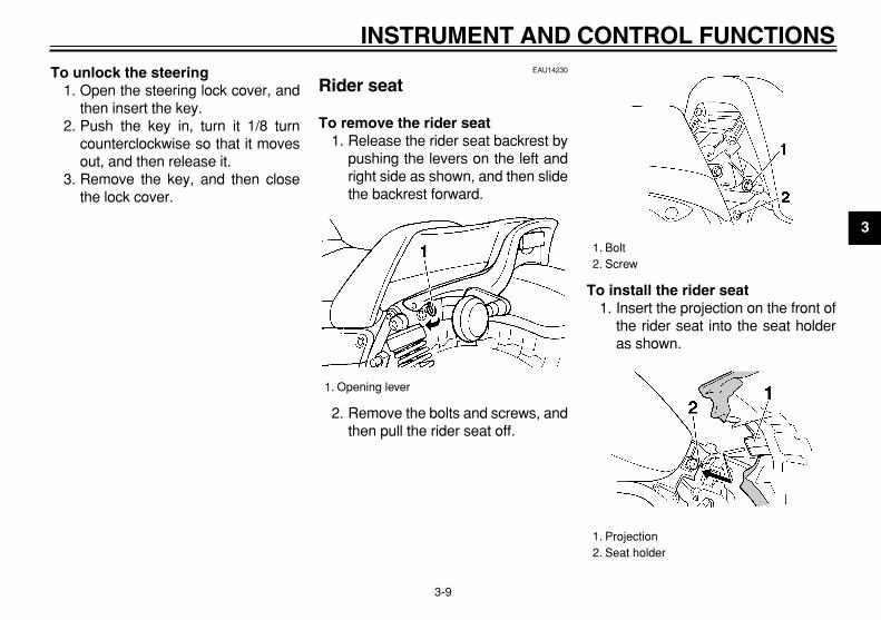
To unlock the steering
1. Open the steering lock cover, andthen insert the key.
2. Push the key in, turn it 1/8 turncounterclockwise so that it movesout, and then release it.
3. Remove the key, and then closethe lock cover.
EAU14230
Rider seat
To remove the rider seat
1. Release the rider seat backrest bypushing the levers on the left andright side as shown, and then slidethe backrest forward.
2. Remove the bolts and screws, andthen pull the rider seat off.
To install the rider seat
1. Insert the projection on the front ofthe rider seat into the seat holderas shown.
1. Opening lever
1. Bolt2. Screw
1. Projection2. Seat holder

INSTRUMENT AND CONTROL FUNCTIONS
3-10
1
2
3
4
5
6
7
8
9
2. Place the rider seat in the originalposition, and then tighten the boltsand screws.
NOTE:
Make sure that the seat is properly se-
cured before riding.
3. Return the rider seat backrest tothe original position.
EAU14281
Helmet holder
To open the helmet holder, insert thekey into the lock, and then turn the keyas shown.To lock the helmet holder, place it in theoriginal position, and then remove thekey.
WARNING
EWA10160
Never ride with a helmet attached tothe helmet holder, since the helmetmay hit objects, causing loss of con-
trol and possibly an accident.
EAU14660
Adjusting the front fork
This front fork is equipped with airvalves for adjusting the spring rate.
WARNING
EWA10180
Always adjust both fork legs equal-ly, otherwise poor handling and loss
of stability may result.
Adjust the spring rate as follows.1. Elevate the front wheel by placing
the vehicle on the centerstand.
NOTE:
When checking and adjusting the airpressure, there should be no weight on
the front end of the vehicle.
2. Remove the air valve cap fromeach fork leg.
1. Helmet holder2. Unlock.

INSTRUMENT AND CONTROL FUNCTIONS
3-11
2
3
4
5
6
7
8
9
3. Check the air pressure in each forkleg with an air pressure gauge.
NOTE:
An optional air pressure gauge is avail-
able at a Yamaha dealer.
4. To increase the spring rate andthereby harden the suspension, in-crease the air pressure with an airpump or compressed air. To de-crease the spring rate and therebysoften the suspension, decreasethe air pressure by pushing eachvalve stem down.
CAUTION:
ECA10090
Never exceed the maximum air pres-sure, otherwise the front fork oil
seals may become damaged.
WARNING
EWA11180
There must be no difference in airpressure between the left and rightfork legs, otherwise poor handling
and loss of stability may result.
5. Securely install the air valve caps.
1. Front fork air valve cap2. Front fork air valve
1. Air pressure gauge
Spring rate:
Minimum/standard (soft):Air pressure = 40 kPa (5.7 psi) (0.4 kgf/cm
2
)Maximum (hard):
Air pressure = 100 kPa (14 psi) (1.0 kgf/cm
2
)
INSTRUMENT AND CONTROL FUNCTIONS
3-12
1
2
3
4
5
6
7
8
9
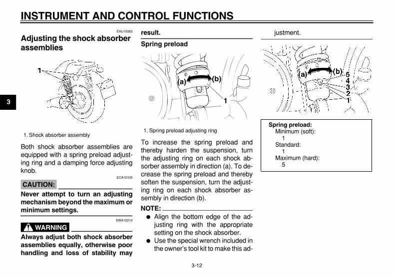
EAU15083
Adjusting the shock absorber assemblies
Both shock absorber assemblies areequipped with a spring preload adjust-ing ring and a damping force adjustingknob.
CAUTION:
ECA10100
Never attempt to turn an adjustingmechanism beyond the maximum or
minimum settings.
WARNING
EWA10210
Always adjust both shock absorberassemblies equally, otherwise poorhandling and loss of stability may
result.
Spring preload
To increase the spring preload andthereby harden the suspension, turnthe adjusting ring on each shock ab-sorber assembly in direction (a). To de-crease the spring preload and therebysoften the suspension, turn the adjust-ing ring on each shock absorber as-sembly in direction (b).
NOTE:
�
Align the bottom edge of the ad-justing ring with the appropriatesetting on the shock absorber.
�
Use the special wrench included inthe owner’s tool kit to make this ad-
justment.
1. Shock absorber assembly
1. Spring preload adjusting ring
1
(a) (b)
Spring preload:
Minimum (soft):1
Standard:1
Maximum (hard):5
INSTRUMENT AND CONTROL FUNCTIONS
3-13
2
3
4
5
6
7
8
9
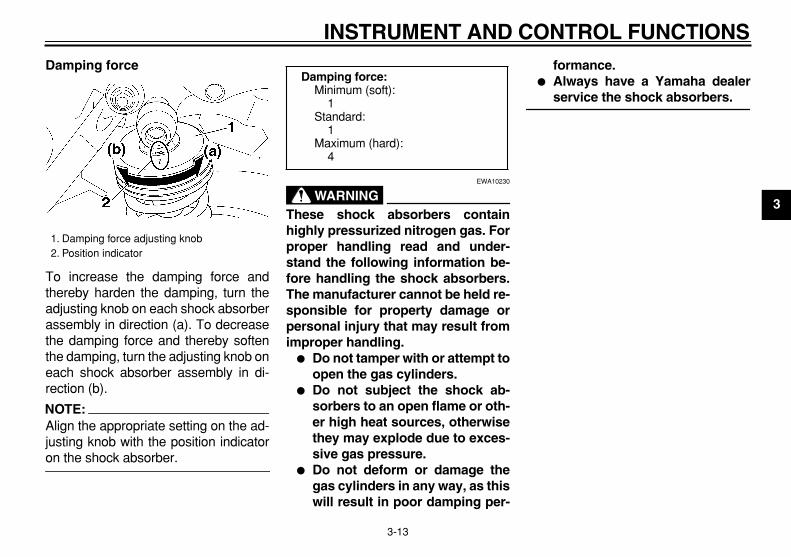
Damping force
To increase the damping force andthereby harden the damping, turn theadjusting knob on each shock absorberassembly in direction (a). To decreasethe damping force and thereby softenthe damping, turn the adjusting knob oneach shock absorber assembly in di-rection (b).
NOTE:
Align the appropriate setting on the ad-justing knob with the position indicator
on the shock absorber.
WARNING
EWA10230
These shock absorbers containhighly pressurized nitrogen gas. Forproper handling read and under-stand the following information be-fore handling the shock absorbers.The manufacturer cannot be held re-sponsible for property damage orpersonal injury that may result fromimproper handling.
�
Do not tamper with or attempt toopen the gas cylinders.
�
Do not subject the shock ab-sorbers to an open flame or oth-er high heat sources, otherwisethey may explode due to exces-sive gas pressure.
�
Do not deform or damage thegas cylinders in any way, as thiswill result in poor damping per-
formance.
�
Always have a Yamaha dealer
service the shock absorbers.
1. Damping force adjusting knob2. Position indicator
Damping force:
Minimum (soft):1
Standard:1
Maximum (hard):4
INSTRUMENT AND CONTROL FUNCTIONS
3-14
1
2
3
4
5
6
7
8
9
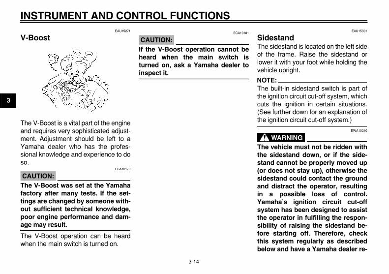
EAU15271
V-Boost
The V-Boost is a vital part of the engineand requires very sophisticated adjust-ment. Adjustment should be left to aYamaha dealer who has the profes-sional knowledge and experience to doso.
CAUTION:
ECA10170
The V-Boost was set at the Yamahafactory after many tests. If the set-tings are changed by someone with-out sufficient technical knowledge,poor engine performance and dam-
age may result.
The V-Boost operation can be heardwhen the main switch is turned on.
CAUTION:
ECA10181
If the V-Boost operation cannot beheard when the main switch isturned on, ask a Yamaha dealer to
inspect it.
EAU15301
Sidestand
The sidestand is located on the left sideof the frame. Raise the sidestand orlower it with your foot while holding thevehicle upright.
NOTE:
The built-in sidestand switch is part ofthe ignition circuit cut-off system, whichcuts the ignition in certain situations.(See further down for an explanation of
the ignition circuit cut-off system.)
WARNING
EWA10240
The vehicle must not be ridden withthe sidestand down, or if the side-stand cannot be properly moved up(or does not stay up), otherwise thesidestand could contact the groundand distract the operator, resultingin a possible loss of control.Yamaha’s ignition circuit cut-offsystem has been designed to assistthe operator in fulfilling the respon-sibility of raising the sidestand be-fore starting off. Therefore, checkthis system regularly as describedbelow and have a Yamaha dealer re-

INSTRUMENT AND CONTROL FUNCTIONS
3-15
2
3
4
5
6
7
8
9
pair it if it does not function proper-
ly.
EAU15321
Ignition circuit cut-off system
The ignition circuit cut-off system (com-prising the sidestand switch, clutchswitch and neutral switch) has the fol-lowing functions.
�
It prevents starting when the trans-mission is in gear and the side-stand is up, but the clutch lever isnot pulled.
�
It prevents starting when the trans-mission is in gear and the clutch le-ver is pulled, but the sidestand isstill down.
�
It cuts the running engine when thetransmission is in gear and the sid-estand is moved down.
Periodically check the operation of theignition circuit cut-off system accordingto the following procedure.
WARNING
EWA10260
�
The vehicle must be placed onthe centerstand during this in-spection.
�
If a malfunction is noted, have aYamaha dealer check the sys-
tem before riding.
INSTRUMENT AND CONTROL FUNCTIONS
3-16
1
2
3
4
5
6
7
8
9
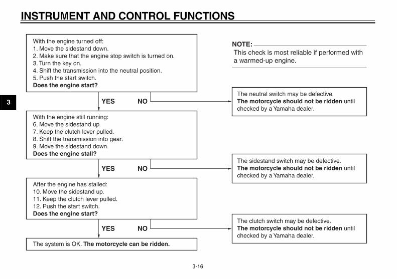
With the engine turned off:1. Move the sidestand down.2. Make sure that the engine stop switch is turned on.3. Turn the key on. 4. Shift the transmission into the neutral position.5. Push the start switch.Does the engine start?
With the engine still running:6. Move the sidestand up.7. Keep the clutch lever pulled.8. Shift the transmission into gear.9. Move the sidestand down.Does the engine stall?
After the engine has stalled:10. Move the sidestand up.11. Keep the clutch lever pulled.12. Push the start switch.Does the engine start?
The system is OK. The motorcycle can be ridden.
This check is most reliable if performed witha warmed-up engine.
The neutral switch may be defective.The motorcycle should not be ridden untilchecked by a Yamaha dealer.
The sidestand switch may be defective.The motorcycle should not be ridden untilchecked by a Yamaha dealer.
The clutch switch may be defective.The motorcycle should not be ridden untilchecked by a Yamaha dealer.
YES NO
YES NO
YES NO
NOTE:

4-1
2
3
4
5
6
7
8
9
PRE-OPERATION CHECKS
EAU15591
The condition of a vehicle is the owner’s responsibility. Vital components can start to deteriorate quickly and unexpectedly,even if the vehicle remains unused (for example, as a result of exposure to the elements). Any damage, fluid leakage or lossof tire air pressure could have serious consequences. Therefore, it is very important, in addition to a thorough visual inspec-tion, to check the following points before each ride.
NOTE:
Pre-operation checks should be made each time the vehicle is used. Such an inspection can be accomplished in a very short
time; and the added safety it assures is more than worth the time involved.
WARNING
EWA11150
If any item in the Pre-operation check list is not working properly, have it inspected and repaired before operating
the vehicle.

PRE-OPERATION CHECKS
4-2
1
2
3
4
5
6
7
8
9
EAU15603
Pre-operation check list
ITEM CHECKS PAGE
Fuel
�
Check fuel level in fuel tank.
�
Refuel if necessary.
�
Check fuel line for leakage.3-7
Engine oil
�
Check oil level in engine.
�
If necessary, add recommended oil to specified level.
�
Check vehicle for oil leakage.6-11
Final gear oil
�
Check vehicle for oil leakage. 6-14
Coolant
�
Check coolant level in reservoir.
�
If necessary, add recommended coolant to specified level.
�
Check cooling system for leakage.6-15
Front brake
�
Check operation.
�
If soft or spongy, have Yamaha dealer bleed hydraulic system.
�
Check lever free play.
�
Adjust if necessary.
�
Check brake pads for wear.
�
Replace if necessary.
�
Check fluid level in reservoir.
�
If necessary, add recommended brake fluid to specified level.
�
Check hydraulic system for leakage.
6-24, 6-25
Rear brake
�
Check operation.
�
If soft or spongy, have Yamaha dealer bleed hydraulic system.
�
Check brake pads for wear.
�
Replace if necessary.
�
Check fluid level in reservoir.
�
If necessary, add recommended brake fluid to specified level.
�
Check hydraulic system for leakage.
6-25
PRE-OPERATION CHECKS
4-3
2
3
4
5
6
7
8
9
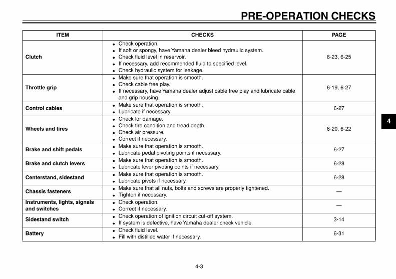
Clutch
�
Check operation.
�
If soft or spongy, have Yamaha dealer bleed hydraulic system.
�
Check fluid level in reservoir.
�
If necessary, add recommended fluid to specified level.
�
Check hydraulic system for leakage.
6-23, 6-25
Throttle grip
�
Make sure that operation is smooth.
�
Check cable free play.
�
If necessary, have Yamaha dealer adjust cable free play and lubricate cable and grip housing.
6-19, 6-27
Control cables
�
Make sure that operation is smooth.
�
Lubricate if necessary.6-27
Wheels and tires
�
Check for damage.
�
Check tire condition and tread depth.
�
Check air pressure.
�
Correct if necessary.
6-20, 6-22
Brake and shift pedals
�
Make sure that operation is smooth.
�
Lubricate pedal pivoting points if necessary.6-27
Brake and clutch levers
�
Make sure that operation is smooth.
�
Lubricate lever pivoting points if necessary.6-28
Centerstand, sidestand
�
Make sure that operation is smooth.
�
Lubricate pivots if necessary.6-28
Chassis fasteners
�
Make sure that all nuts, bolts and screws are properly tightened.
�
Tighten if necessary.—
Instruments, lights, signals and switches
�
Check operation.
�
Correct if necessary.—
Sidestand switch
�
Check operation of ignition circuit cut-off system.
�
If system is defective, have Yamaha dealer check vehicle.3-14
Battery
�
Check fluid level.
�
Fill with distilled water if necessary.6-31
ITEM CHECKS PAGE

5-1
1
2
3
4
5
6
7
8
9
OPERATION AND IMPORTANT RIDING POINTS
EAU15950
WARNING
EWA10270
�
Become thoroughly familiarwith all operating controls andtheir functions before riding.Consult a Yamaha dealer re-garding any control or functionthat you do not thoroughly un-derstand.
�
Never start the engine or oper-ate it in a closed area for anylength of time. Exhaust fumesare poisonous, and inhalingthem can cause loss of con-sciousness and death within ashort time. Always make surethat there is adequate ventila-tion.
�
Before starting out, make surethat the sidestand is up. If thesidestand is not raised com-pletely, it could contact theground and distract the opera-tor, resulting in a possible loss
of control.
EAU32300
Starting and warming up a cold engine
In order for the ignition circuit cut-offsystem to enable starting, one of thefollowing conditions must be met:
�
The transmission is in the neutralposition.
�
The transmission is in gear withthe clutch lever pulled and the sid-estand up.
WARNING
EWA10290
�
Before starting the engine,check the function of the igni-tion circuit cut-off system ac-cording to the proceduredescribed on page 3-15.
�
Never ride with the sidestand
down.
1. Turn the key to “ON” and makesure that the engine stop switch isset to “RUN”.
CAUTION:
ECA10220
If the fuel level warning light comeson, check the fuel level, and, if nec-
essary, refuel as soon as possible.
2. Shift the transmission into the neu-tral position.
NOTE:
When the transmission is in the neutralposition, the neutral indicator lightshould be on, otherwise have aYamaha dealer check the electrical cir-
cuit.
3. Turn the starter (choke) on andcompletely close the throttle. (Seepage 3-8.)
4. Start the engine by pushing thestart switch.
NOTE:
If the engine fails to start, release thestart switch, wait a few seconds, andthen try again. Each starting attemptshould be as short as possible to pre-serve the battery. Do not crank the en-gine more than 10 seconds on any one
attempt.
CAUTION:
ECA10230
�
The oil level warning light andfuel level warning light shouldcome on when the start switchis pushed, and they should go
OPERATION AND IMPORTANT RIDING POINTS
5-2
2
3
4
5
6
7
8
9
off when the start switch is re-leased.
�
If the oil level warning light flick-ers or remains on after starting,immediately stop the engine,and then check the engine oillevel and the vehicle for oil leak-age. If necessary, add engineoil, and then check the warninglight again. If the warning lightdoes not come on when push-ing the start switch, or if it doesnot go off after starting with suf-ficient engine oil, have aYamaha dealer check the elec-trical circuit.
�
If the fuel level warning light re-mains on after starting, stop theengine, and then check the fuellevel. If necessary, refuel assoon as possible, and thencheck the warning light again. Ifthe warning light does not comeon when pushing the startswitch, or if it does not go off af-ter starting with sufficient fuel,have a Yamaha dealer check the
electrical circuit.
5. After starting the engine, move thestarter (choke) back halfway.
CAUTION:
ECA11130
For maximum engine life, alwayswarm the engine up before startingoff. Never accelerate hard when the
engine is cold!
6. When the engine is warm, turn thestarter (choke) off.
NOTE:
The engine is warm when it respondsnormally to the throttle with the starter(choke) turned off. To avoid the possi-bility of excessive exhaust emissions,never leave the starter (choke) on long-er than necessary. The time necessaryfor starter (choke) use depends uponthe ambient temperature. Tempera-tures above 10 °C (50 °F) require about7 seconds of starter (choke) use andtemperatures below 10 °C (50 °F) re-quire about 35 seconds with the starter(choke) turned on, then about 2.5 min-utes with the starter (choke) in the half-
way position.
EAU16640
Starting a warm engine
Follow the same procedure as for start-ing a cold engine with the exceptionthat the starter (choke) is not requiredwhen the engine is warm.

OPERATION AND IMPORTANT RIDING POINTS
5-3
1
2
3
4
5
6
7
8
9
EAU16671
Shifting
Shifting gears lets you control theamount of engine power available forstarting off, accelerating, climbing hills,etc.The gear positions are shown in the il-lustration.
NOTE:
To shift the transmission into the neu-tral position, press the shift pedal downrepeatedly until it reaches the end of its
travel, and then slightly raise it.
CAUTION:
ECA10260
�
Even with the transmission inthe neutral position, do not
coast for long periods of timewith the engine off, and do nottow the motorcycle for long dis-tances. The transmission isproperly lubricated only whenthe engine is running. Inade-quate lubrication may damagethe transmission.
�
Always use the clutch whilechanging gears to avoid damag-ing the engine, transmission,and drive train, which are notdesigned to withstand the
shock of forced shifting.
EAU16680
To start out and accelerate
1. Pull the clutch lever to disengagethe clutch.
2. Shift the transmission into firstgear. The neutral indicator lightshould go out.
3. Open the throttle gradually, and atthe same time, release the clutchlever slowly.
4. At the recommended shift pointsshown in the following table, closethe throttle, and at the same time,
quickly pull the clutch lever in.5. Shift the transmission into second
gear. (Make sure not to shift thetransmission into the neutral posi-tion.)
6. Open the throttle part way andgradually release the clutch lever.
7. Follow the same procedure whenshifting to the next higher gear.
NOTE:
Always shift gears at the recommended
shift points.
EAU16700
To decelerate
1. Apply both the front and the rearbrakes to slow the motorcycle.
2. Shift the transmission into firstgear when the motorcycle reaches20 km/h (12.5 mi/h). If the engine isabout to stall or runs very roughly,pull the clutch lever in and use thebrakes to stop the motorcycle.
3. Shift the transmission into the neu-tral position when the motorcycleis almost completely stopped. Theneutral indicator light should comeon.
1. Shift pedal

OPERATION AND IMPORTANT RIDING POINTS
5-4
2
3
4
5
6
7
8
9
EAU16720
Recommended shift points
The recommended shift points duringacceleration and deceleration areshown in the table below.
EAU16841
Engine break-in
There is never a more important periodin the life of your engine than the periodbetween 0 and 1600 km (1000 mi). Forthis reason, you should read the follow-ing material carefully.Since the engine is brand new, do notput an excessive load on it for the first1600 km (1000 mi). The various parts inthe engine wear and polish themselvesto the correct operating clearances.During this period, prolonged full-throt-tle operation or any condition that mightresult in engine overheating must beavoided.
EAU17121
0–1000 km (0–600 mi)
Avoid prolonged operation above 4500r/min.
1000–1600 km (600–1000 mi)
Avoid prolonged operation above 5500r/min.
CAUTION:
ECA10331
After 1000 km (600 mi) of operation,the engine oil and final gear oil must
be changed, and the oil filter car-
tridge or element replaced.
1600 km (1000 mi) and beyond
The vehicle can now be operated nor-mally.
CAUTION:
ECA10310
�
Keep the engine speed out ofthe tachometer red zone.
�
If any engine trouble should oc-cur during the engine break-inperiod, immediately have aYamaha dealer check the vehi-
cle.
Shift up points:
1st
→
2nd: 16 km/h (10 mi/h)2nd
→
3rd: 24 km/h (15 mi/h)3rd
→
4th: 32 km/h (20 mi/h)4th
→
5th: 40 km/h (25 mi/h)
Shift down points:
5th
→
4th: 20 km/h (12.5 mi/h)4th
→
3rd: 20 km/h (12.5 mi/h)3rd
→
2nd: 20 km/h (12.5 mi/h)2nd
→
1st: 20 km/h (12.5 mi/h)
OPERATION AND IMPORTANT RIDING POINTS
5-5
1
2
3
4
5
6
7
8
9
EAU17200
Parking
When parking, stop the engine, andthen remove the key from the mainswitch.
WARNING
EWA10310
�
Since the engine and exhaustsystem can become very hot,park in a place where pedestri-ans or children are not likely totouch them.
�
Do not park on a slope or on softground, otherwise the vehicle
may overturn.

6-1
2
3
4
5
6
7
8
9
PERIODIC MAINTENANCE AND MINOR REPAIR
EAU17231
Safety is an obligation of the owner. Pe-riodic inspection, adjustment and lubri-cation will keep your vehicle in thesafest and most efficient condition pos-sible. The most important points of mo-torcycle inspection, adjustment, andlubrication are explained on the follow-ing pages.
Maintenance, replacement, or repairof the emission control devices andsystems may be performed by anyrepair establishment or individualthat is certified (if applicable).
WARNING
EWA10320
If you are not familiar with mainte-nance work, have a Yamaha dealer
do it for you.
EAU17301
PERIODIC MAINTENANCE
PROPER PERIODIC MAINTENANCEOF YOUR VEHICLE IS IMPORTANTIN ORDER TO ENJOY LONG, PLEA-SURABLE SERVICE. ESPECIALLYIMPORTANT ARE THE MAINTE-NANCE SERVICES RELATED TOEMISSIONS CONTROL. THESECONTROLS NOT ONLY FUNCTIONTO ENSURE CLEANER AIR, BUTARE ALSO VITAL TO PROPER EN-GINE OPERATION AND MAXIMUMPERFORMANCE. IN THE FOLLOW-ING PERIODIC MAINTENANCECHARTS, THE SERVICES RELATEDTO EMISSIONS CONTROL AREGROUPED SEPARATELY. THESESERVICES REQUIRE SPECIALIZEDDATA, KNOWLEDGE, AND EQUIP-MENT. YAMAHA DEALERS ARETRAINED AND EQUIPPED TO PER-FORM THESE PARTICULAR SER-VICES.
EAU17551
Owner’s tool kit
The tool kit is located inside the storagecompartment behind the rider seatbackrest. (See page 3-9.)
The service information included in thismanual and the tools provided in the
1. Owner’s tool kit2. Rider backrest

PERIODIC MAINTENANCE AND MINOR REPAIR
6-2
1
2
3
4
5
6
7
8
9
owner’s tool kit are intended to assistyou in the performance of preventivemaintenance and minor repairs. How-ever, additional tools such as a torquewrench may be necessary to performcertain maintenance work correctly.
NOTE:
If you do not have the tools or experi-ence required for a particular job, have
a Yamaha dealer perform it for you.
WARNING
EWA10340
Modifications not approved byYamaha may cause loss of perfor-mance, excessive emissions, andrender the vehicle unsafe for use.Consult a Yamaha dealer before at-
tempting any changes.

PERIODIC MAINTENANCE AND MINOR REPAIR
6-3
2
3
4
5
6
7
8
9
EAU17600
Periodic maintenance chart for the emission control system
* Since these items require special tools, data and technical skills, have a Yamaha dealer perform the service.
No. ITEM ROUTINE
INITIAL ODOMETER READINGS
600 mi (1000 km)
or 1 month
4000 mi (7000 km)
or 6 months
8000 mi (13000 km)
or 12 months
12000 mi (19000 km)
or 18 months
16000 mi (25000 km)
or 24 months
20000 mi (31000 km)
or 30 months
1 *
Fuel line
�
Check fuel hoses for cracks or damage.
�
Replace if necessary.
√ √ √ √ √
2 *
Fuel filter
�
Replace. Replace.
3
Spark plugs
�
Check condition.
�
Adjust gap and clean.
�
Replace every 8000 mi (13000 km) or 12 months.
√
Replace.
√
Replace.
√
4 *
Valve clearance
�
Check and adjust valve clear-ance when engine is cold.
Every 26600 mi (42000 km)
5 *
Crankcase breather system
�
Check breather hose for cracks or damage.
�
Replace if necessary.
√ √ √ √ √
6 *
Carburetor synchro- nization
�
Adjust synchronization of carbu-retors.
√ √ √ √ √ √
7 *
Idle speed
�
Check and adjust engine idle speed.
√ √ √ √ √
8 *
Exhaust system
�
Check for leakage.
�
Tighten if necessary.
�
Replace gasket(s) if necessary.
√ √ √ √ √
9 *
Evaporative emis- sion control system (For California only)
�
Check control system for dam-age.
�
Replace if necessary.
√ √

PERIODIC MAINTENANCE AND MINOR REPAIR
6-4
1
2
3
4
5
6
7
8
9
EAU32183
General maintenance and lubrication chart
No. ITEM ROUTINE
INITIAL ODOMETER READINGS
600 mi (1000 km)
or 1 month
4000 mi (7000 km)
or 6 months
8000 mi (13000 km)
or 12 months
12000 mi (19000 km)
or 18 months
16000 mi (25000 km)
or 24 months
20000 mi (31000 km)
or 30 months
1 *
Air filter element
�
Clean with compressed air.
�
Replace if necessary.
√ √ √ √ √
2 *
Battery
�
Check specific gravity and breather hose for proper opera-tion.
√ √ √ √ √
3 *
Clutch
�
Check operation and fluid leak-age.
�
Correct if necessary.
√ √ √ √ √ √
4 *
Front brake
�
Check operation, fluid level, and for fluid leakage.
�
Replace brake pads if neces-sary.
√ √ √ √ √ √
5 *
Rear brake
�
Check operation, fluid level, and for fluid leakage.
�
Replace brake pads if neces-sary.
√ √ √ √ √ √
6 *
Brake hoses
�
Check for cracks or damage.
√ √ √ √ √
�
Replace. Every 4 years
7 *
Wheels
�
Check runout and for damage.
�
Replace if necessary.
√ √ √ √ √
8 *
Tires
�
Check tread depth and for dam-age.
�
Replace if necessary.
�
Check air pressure.
�
Correct if necessary.
√ √ √ √ √

PERIODIC MAINTENANCE AND MINOR REPAIR
6-5
2
3
4
5
6
7
8
9
9 *
Wheel bearings
�
Check bearings for smooth operation.
�
Replace if necessary.
√ √ √ √ √
10
*
Swingarm pivot bearings
�
Check bearing assemblies for looseness.
�
Moderately repack with lith-ium-soap-based grease.
√
Repack.
11
*
Steering bearings
�
Check bearing assemblies for looseness.
�
Moderately repack with lith-ium-soap-based grease every 16000 mi (25000 km) or 24 months.
√ √ √ √
Repack.
√
12
*
Chassis fasteners
�
Check all chassis fitting and fas-teners.
�
Correct if necessary.
√ √ √ √ √
13
Brake and clutch lever pivot shafts
�
Apply lithium-soap-based grease (all-purpose grease) lightly.
√ √ √ √ √
14
Brake and shift pedal pivot shafts
�
Apply lithium-soap-based grease (all-purpose grease) lightly.
√ √ √ √ √
15
*
Centerstand and sidestand pivots
�
Check operation.
�
Apply lithium-soap-based grease (all-purpose grease) lightly.
√ √ √ √ √
No. ITEM ROUTINE
INITIAL ODOMETER READINGS
600 mi (1000 km)
or 1 month
4000 mi (7000 km)
or 6 months
8000 mi (13000 km)
or 12 months
12000 mi (19000 km)
or 18 months
16000 mi (25000 km)
or 24 months
20000 mi (31000 km)
or 30 months
PERIODIC MAINTENANCE AND MINOR REPAIR
6-6
1
2
3
4
5
6
7
8
9
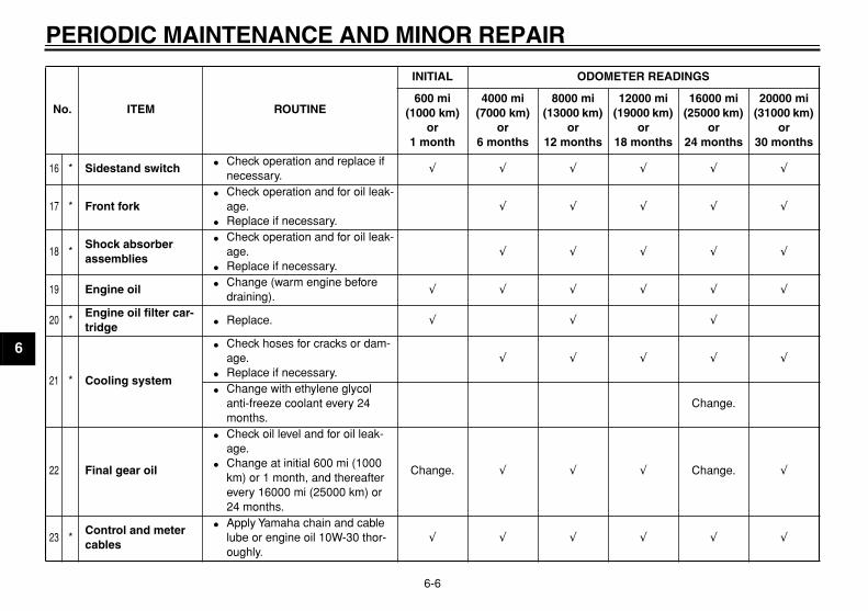
16
*
Sidestand switch
�
Check operation and replace if necessary.
√ √ √ √ √ √
17
*
Front fork
�
Check operation and for oil leak-age.
�
Replace if necessary.
√ √ √ √ √
18
*
Shock absorber assemblies
�
Check operation and for oil leak-age.
�
Replace if necessary.
√ √ √ √ √
19
Engine oil
�
Change (warm engine before draining).
√ √ √ √ √ √
20
*
Engine oil filter car- tridge
�
Replace.
√ √ √
21
*
Cooling system
�
Check hoses for cracks or dam-age.
�
Replace if necessary.
√ √ √ √ √
�
Change with ethylene glycol anti-freeze coolant every 24 months.
Change.
22
Final gear oil
�
Check oil level and for oil leak-age.
�
Change at initial 600 mi (1000 km) or 1 month, and thereafter every 16000 mi (25000 km) or 24 months.
Change.
√ √ √
Change.
√
23
*
Control and meter cables
�
Apply Yamaha chain and cable lube or engine oil 10W-30 thor-oughly.
√ √ √ √ √ √
No. ITEM ROUTINE
INITIAL ODOMETER READINGS
600 mi (1000 km)
or 1 month
4000 mi (7000 km)
or 6 months
8000 mi (13000 km)
or 12 months
12000 mi (19000 km)
or 18 months
16000 mi (25000 km)
or 24 months
20000 mi (31000 km)
or 30 months

PERIODIC MAINTENANCE AND MINOR REPAIR
6-7
2
3
4
5
6
7
8
9
* Since these items require special tools, data and technical skills, have a Yamaha dealer perform the service.
NOTE:
From 24000 mi (37000 km) or 36 months, repeat the maintenance intervals starting from 8000 mi (13000 km) or 12 months.
EAU17660
NOTE:
�
The air filter needs more frequent service if you are riding in unusually wet or dusty areas.
�
Hydraulic brake and clutch systems
�
After disassembling the brake or clutch master cylinders, caliper cylinders or clutch release cylinder, always changethe fluid. Regularly check the brake and clutch fluid levels and fill the reservoirs as required.
�
Replace the oil seals on the inner parts of the brake or clutch master cylinders, caliper cylinders and clutch releasecylinder every two years.
�
Replace the brake and clutch hoses every four years or if cracked or damaged.
24
*
Throttle grip hous- ing and cable
�
Check operation and free play.
�
Adjust the throttle cable free play if necessary.
�
Lubricate the throttle grip hous-ing and cable.
√ √ √ √ √
No. ITEM ROUTINE
INITIAL ODOMETER READINGS
600 mi (1000 km)
or 1 month
4000 mi (7000 km)
or 6 months
8000 mi (13000 km)
or 12 months
12000 mi (19000 km)
or 18 months
16000 mi (25000 km)
or 24 months
20000 mi (31000 km)
or 30 months

PERIODIC MAINTENANCE AND MINOR REPAIR
6-8
1
2
3
4
5
6
7
8
9
EAU18721
Removing and installing the cowling and panels
The cowling and panels shown need tobe removed to perform some of themaintenance jobs described in thischapter. Refer to this section each timethe cowling or a panel needs to be re-moved and installed.
EAU19120
Cowling A
To remove the cowling1. Insert the key into the lock, and
then turn it clockwise.
2. Pull the cowling off as shown.
To install the cowlingAlign the holders under the cowling withthe projections on the frame.
3. Push down on the rear of the cowl-ing until it locks in place.
4. Remove the key from the lock.
EAU19180
Panel A
To remove the panel1. Remove cowling A. (See
page 6-8.)2. Remove the screws, and then take
the panel off.
To install the panel1. Place the panel in the original po-
sition, and then install the screws.2. Install the cowling.
1. Cowling A2. Panel A3. Panel B
1. Unlock.
1. Holder2. Projection
1. Screw
PERIODIC MAINTENANCE AND MINOR REPAIR
6-9
2
3
4
5
6
7
8
9
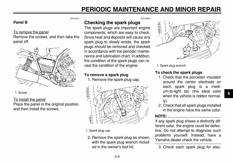
EAU19210
Panel B
To remove the panelRemove the screws, and then take thepanel off.
To install the panelPlace the panel in the original position,and then install the screws.
EAU19543
Checking the spark plugs
The spark plugs are important enginecomponents, which are easy to check.Since heat and deposits will cause anyspark plug to slowly erode, the sparkplugs should be removed and checkedin accordance with the periodic mainte-nance and lubrication chart. In addition,the condition of the spark plugs can re-veal the condition of the engine.
To remove a spark plug
1. Remove the spark plug cap.
2. Remove the spark plug as shown,with the spark plug wrench includ-ed in the owner’s tool kit.
To check the spark plugs
1. Check that the porcelain insulatoraround the center electrode oneach spark plug is a medi-um-to-light tan (the ideal colorwhen the vehicle is ridden normal-ly).
2. Check that all spark plugs installedin the engine have the same color.
NOTE:
If any spark plug shows a distinctly dif-ferent color, the engine could be defec-tive. Do not attempt to diagnose suchproblems yourself. Instead, have a
Yamaha dealer check the vehicle.
3. Check each spark plug for elec-
1. Screw
1. Spark plug cap
1. Spark plug wrench

PERIODIC MAINTENANCE AND MINOR REPAIR
6-10
1
2
3
4
5
6
7
8
9
trode erosion and excessive car-bon or other deposits, and replaceit if necessary.
To install a spark plug
1. Measure the spark plug gap with awire thickness gauge and, if nec-essary, adjust the gap to specifica-tion.
2. Clean the surface of the spark pluggasket and its mating surface, and
then wipe off any grime from thespark plug threads.
3. Install the spark plug with thespark plug wrench, and then tight-en it to the specified torque.
NOTE:
If a torque wrench is not available wheninstalling a spark plug, a good estimateof the correct torque is 1/4–1/2 turnpast finger tight. However, the sparkplug should be tightened to the speci-
fied torque as soon as possible.
4. Install the spark plug cap.
EAU19672
Canister (for California only)
This model is equipped with a canisterto prevent the discharging of fuel vaporinto the atmosphere.
�
Check each hose connection.
�
Check each hose and canister forcracks or damage. Replace ifdamaged.
�
Make sure the vent hose is notblocked. Clean it if necessary.
Specified spark plug:
NGK/DPR8EA-9DENSO/X24EPR-U9
1. Spark plug gap
Spark plug gap:
0.8–0.9 mm (0.031–0.035 in)
Tightening torque:
Spark plug:18 Nm (1.8 m·kgf, 13 ft·lbf)

PERIODIC MAINTENANCE AND MINOR REPAIR
6-11
2
3
4
5
6
7
8
9
EAU19871
Engine oil and oil filter cartridge
The engine oil level should be checkedbefore each ride. In addition, the oilmust be changed and the oil filter car-tridge replaced at the intervals speci-fied in the periodic maintenance andlubrication chart.
To check the engine oil level
1. Place the vehicle on the center-stand.
NOTE:
Make sure that the vehicle is positionedstraight up when checking the oil level.A slight tilt to the side can result in a
false reading.
2. Start the engine, warm it up forseveral minutes, and then turn itoff.
3. Wait a few minutes until the oil set-tles, and then check the oil levelthrough the check window locatedat the bottom-right side of thecrankcase.
NOTE:
The engine oil should be between the
minimum and maximum level marks.
4. If the engine oil is below the mini-mum level mark, add sufficient oilof the recommended type to raiseit to the correct level.
To change the engine oil (with or without oil filter cartridge replace-ment)
1. Start the engine, warm it up forseveral minutes, and then turn itoff.
2. Place an oil pan under the engineto collect the used oil.
3. Remove the engine oil filler capand drain bolt to drain the oil fromthe crankcase.
1. Engine oil level check window2. Maximum level mark3. Minimum level mark
1. Engine oil filler cap
PERIODIC MAINTENANCE AND MINOR REPAIR
6-12
1
2
3
4
5
6
7
8
9
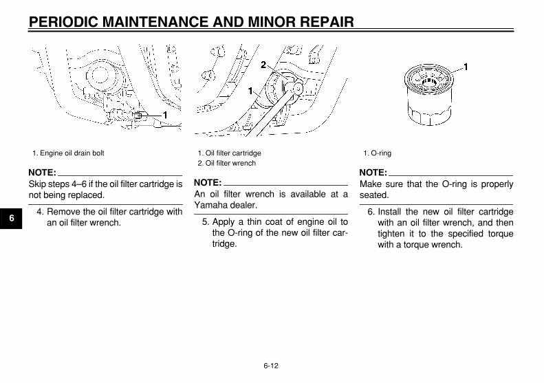
NOTE:
Skip steps 4–6 if the oil filter cartridge is
not being replaced.
4. Remove the oil filter cartridge withan oil filter wrench.
NOTE:
An oil filter wrench is available at a
Yamaha dealer.
5. Apply a thin coat of engine oil tothe O-ring of the new oil filter car-tridge.
NOTE:
Make sure that the O-ring is properly
seated.
6. Install the new oil filter cartridgewith an oil filter wrench, and thentighten it to the specified torquewith a torque wrench.
1. Engine oil drain bolt
1. Oil filter cartridge2. Oil filter wrench
1. O-ring

PERIODIC MAINTENANCE AND MINOR REPAIR
6-13
2
3
4
5
6
7
8
9
7. Install the engine oil drain bolt, andthen tighten it to the specifiedtorque.
8. Add the specified amount of therecommended engine oil, and theninstall and tighten the oil filler cap.
CAUTION:
ECA11620
�
In order to prevent clutch slip-page (since the engine oil alsolubricates the clutch), do notmix any chemical additives. Donot use oils with a diesel speci-fication of “CD” or oils of a high-er quality than specified. Inaddition, do not use oils labeled“ENERGY CONSERVING II” orhigher.
�
Make sure that no foreign mate-
rial enters the crankcase.
9. Start the engine, and then let it idlefor several minutes while checkingit for oil leakage. If oil is leaking, im-mediately turn the engine off andcheck for the cause.
NOTE:
After the engine is started, the engineoil level warning light should go off if the
oil level is sufficient.
CAUTION:
ECA10400
If the oil level warning light flickersor remains on, immediately turn theengine off and have a Yamaha dealer
check the vehicle.
10. Turn the engine off, and thencheck the oil level and correct it ifnecessary.
1. Torque wrench
Tightening torque:
Oil filter cartridge:17.5 Nm (1.75 m·kgf, 12.7 ft·lbf)
Tightening torque:
Engine oil drain bolt:43 Nm (4.3 m·kgf, 31 ft·lbf)
Recommended engine oil:
See page 8-1.
Oil quantity:
Without oil filter cartridge replace-ment:
3.50 L (3.70 US qt) (3.08 Imp.qt)With oil filter cartridge replacement:
3.80 L (4.02 US qt) (3.34 Imp.qt)

PERIODIC MAINTENANCE AND MINOR REPAIR
6-14
1
2
3
4
5
6
7
8
9
EAU20000
Final gear oil
The final gear case must be checkedfor oil leakage before each ride. If anyleakage is found, have a Yamaha deal-er check and repair the vehicle. In addi-tion, the final gear oil must be changedas follows at the intervals specified inthe periodic maintenance and lubrica-tion chart.
WARNING
EWA10370
�
Make sure that no foreign mate-rial enters the final gear case.
�
Make sure that no oil gets on the
tire or wheel.
To check the final gear oil level
1. Place the vehicle on the center-stand.
NOTE:
�
The final gear oil level must bechecked on a cold engine.
�
Make sure that the vehicle is posi-tioned straight up when checkingthe oil level. A slight tilt to the side
can result in a false reading.
2. Remove the oil filler bolt, and thencheck the oil level in the final gearcase.
NOTE:
The oil level should be at the brim of the
filler hole.
3. If the oil is below the brim of the fill-er hole, add sufficient oil of the rec-ommended type to raise it to thecorrect level.
To change the final gear oil
1. Place an oil pan under the finalgear case to collect the used oil.
2. Remove the oil filler bolt and drainbolt to drain the oil from the finalgear case.
3. Install the final gear oil drain bolt,and then tighten it to the specifiedtorque.
4. Add the recommended final gearoil to the brim of the filler hole.
NOTE:
GL4 is a quality rating. Hypoid gear oils
rated GL5 or GL6 may also be used.
5. Install and tighten the filler bolt.6. Check the final gear case for oil
leakage. If oil is leaking, check forthe cause.
1. Final gear oil filler bolt2. Correct oil level3. Final gear oil drain bolt
Tightening torque:
Final gear oil drain bolt:23 Nm (2.3 m·kgf, 17 ft·lbf)
Recommended final gear oil:
Hypoid gear oil SAE 80 (API GL4) or multi-grade hypoid gear oil SAE 80W-90
Oil quantity:
0.20 L (0.21 US qt) (0.18 Imp.qt)

PERIODIC MAINTENANCE AND MINOR REPAIR
6-15
2
3
4
5
6
7
8
9
EAU20070
Coolant
The coolant level should be checkedbefore each ride. In addition, the cool-ant must be changed at the intervalsspecified in the periodic maintenanceand lubrication chart.
EAU20241
To check the coolant level
1. Place the vehicle on the center-stand and hold it in an upright po-sition.
2. Remove cowling A. (Seepage 6-8.)
NOTE:
�
The coolant level must be checkedon a cold engine since the levelvaries with engine temperature.
�
Make sure that the vehicle is posi-tioned straight up when checkingthe coolant level. A slight tilt to the
side can result in a false reading.
3. Check the coolant level in the cool-ant reservoir.
NOTE:
The coolant should be between the
minimum and maximum level marks.
4. If the coolant is at or below theminimum level mark, remove thecoolant reservoir cap and addcoolant to the maximum levelmark.
5. Install the coolant reservoir capand the cowling.
CAUTION:
ECA10470
�
If coolant is not available, usedistilled water or soft tap waterinstead. Do not use hard wateror salt water since it is harmfulto the engine.
�
If water has been used insteadof coolant, replace it with cool-ant as soon as possible, other-wise the engine may not besufficiently cooled and the cool-ing system will not be protectedagainst frost and corrosion.
�
If water has been added to thecoolant, have a Yamaha dealercheck the antifreeze content ofthe coolant as soon as possible,otherwise the effectiveness of
the coolant will be reduced.
WARNING
EWA10380
Never attempt to remove the radiator
cap when the engine is hot.
NOTE:
�
The radiator fan is automaticallyswitched on or off according to the
1. Maximum level mark2. Minimum level mark
Coolant reservoir capacity (up to the maximum level mark):
0.30 L (0.32 US qt) (0.26 Imp.qt)
PERIODIC MAINTENANCE AND MINOR REPAIR
6-16
1
2
3
4
5
6
7
8
9
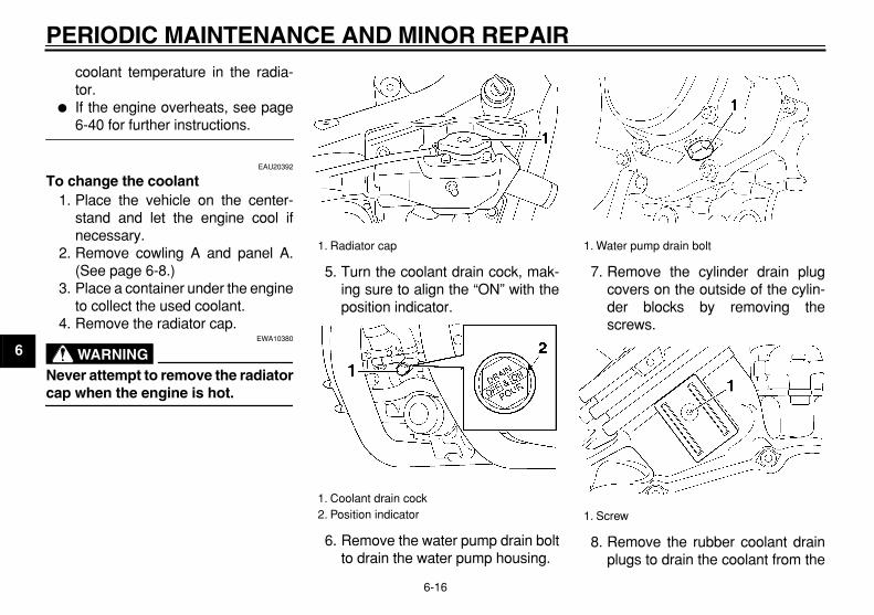
coolant temperature in the radia-tor.
�
If the engine overheats, see page
6-40 for further instructions.
EAU20392
To change the coolant
1. Place the vehicle on the center-stand and let the engine cool ifnecessary.
2. Remove cowling A and panel A.(See page 6-8.)
3. Place a container under the engineto collect the used coolant.
4. Remove the radiator cap.
WARNING
EWA10380
Never attempt to remove the radiator
cap when the engine is hot.
5. Turn the coolant drain cock, mak-ing sure to align the “ON” with theposition indicator.
6. Remove the water pump drain boltto drain the water pump housing.
7. Remove the cylinder drain plugcovers on the outside of the cylin-der blocks by removing thescrews.
8. Remove the rubber coolant drainplugs to drain the coolant from the
1. Radiator cap
1. Coolant drain cock2. Position indicator
1. Water pump drain bolt
1. Screw

PERIODIC MAINTENANCE AND MINOR REPAIR
6-17
2
3
4
5
6
7
8
9
engine.
9. After the coolant is completelydrained, thoroughly flush the cool-ing system with clean tap water.
10. Install the water pump drain bolt,and then tighten it to the specifiedtorque.
NOTE:
Check the washer for damage and re-
place it if necessary.
11. Install the rubber coolant drainplugs, and then install the cylinder
drain plug covers.
NOTE:
Check the rubber plugs for damage
and replace them if necessary.
12. Turn the coolant drain cock, mak-ing sure to align the “OFF” with theposition indicator.
13. Pour the recommended coolantinto the reservoir to the maximumlevel, and then install the cap.
14. Pour the recommended coolantinto the radiator until it is full.
CAUTION:
ECA10470
�
If coolant is not available, use
distilled water or soft tap waterinstead. Do not use hard wateror salt water since it is harmfulto the engine.
�
If water has been used insteadof coolant, replace it with cool-ant as soon as possible, other-wise the engine may not besufficiently cooled and the cool-ing system will not be protectedagainst frost and corrosion.
�
If water has been added to thecoolant, have a Yamaha dealercheck the antifreeze content ofthe coolant as soon as possible,otherwise the effectiveness of
the coolant will be reduced.
15. Install the radiator cap, start theengine, let it idle for several min-utes, and then turn it off.
16. Remove the radiator cap to checkthe coolant level in the radiator. Ifnecessary, add sufficient coolantuntil it reaches the top of the radia-tor, and then install the radiatorcap.
17. Check the coolant level in the res-ervoir. If necessary, remove the
1. Rubber coolant drain plug
Tightening torque:
Water pump drain bolt:43 Nm (4.3 m·kgf, 31 ft·lbf)
Antifreeze/water mixture ratio:
1:1
Recommended antifreeze:
High-quality ethylene glycol anti-freeze containing corrosion inhibitors for aluminum engines
Coolant quantity:
Radiator capacity (including all routes):
2.75 L (2.91 US qt) (2.42 Imp.qt)Coolant reservoir capacity (up to the maximum level mark):
0.30 L (0.32 US qt) (0.26 Imp.qt)

PERIODIC MAINTENANCE AND MINOR REPAIR
6-18
1
2
3
4
5
6
7
8
9
coolant reservoir cap, add coolantto the maximum level mark, andthen install the cap.
18. Start the engine, and then checkthe vehicle for coolant leakage. Ifcoolant is leaking, have a Yamahadealer check the cooling system.
19. Install the cowling and the panel.
EAU20510
Cleaning the air filter element
The air filter element should be cleanedat the intervals specified in the periodicmaintenance and lubrication chart.Clean the air filter element more fre-quently if you are riding in unusuallywet or dusty areas.
1. Remove cowling A. (Seepage 6-8.)
2. Remove the air filter case cover byremoving the screws.
3. Pull the air filter element out.
4. Lightly tap the air filter element toremove most of the dust and dirt,and then blow the remaining dirtout with compressed air as shown.If the air filter element is damaged,replace it.
5. Insert the air filter element into theair filter case.
CAUTION:
ECA10480
�
Make sure that the air filter ele-ment is properly seated in theair filter case.
�
The engine should never be op-erated without the air filter ele-ment installed, otherwise thepiston(s) and/or cylinder(s) may
1. Screw
1. Air filter element

PERIODIC MAINTENANCE AND MINOR REPAIR
6-19
2
3
4
5
6
7
8
9
become excessively worn.
6. Install the air filter case cover by in-stalling the screws.
7. Install the cowling.
EAU21271
Carburetors
The carburetors are important parts ofthe engine and emission control sys-tem, which require very sophisticatedadjustment. Therefore, all carburetoradjustments should be left to a Yamahadealer, who has the necessary profes-sional knowledge and experience.
EAU21381
Checking the throttle cable free play
The throttle cable free play should mea-sure 3.0–5.0 mm (0.12–0.20 in) at thethrottle grip. Periodically check thethrottle cable free play and, if neces-sary, have a Yamaha dealer adjust it.
1. Throttle cable free play

PERIODIC MAINTENANCE AND MINOR REPAIR
6-20
1
2
3
4
5
6
7
8
9
EAU21401
Valve clearance
The valve clearance changes with use,resulting in improper air-fuel mixtureand/or engine noise. To prevent thisfrom occurring, the valve clearancemust be adjusted by a Yamaha dealerat the intervals specified in the periodicmaintenance and lubrication chart.
EAU32380
Tires
To maximize the performance, durabil-ity, and safe operation of your motorcy-cle, note the following points regardingthe specified tires.
Tire air pressure
The tire air pressure should be checkedand, if necessary, adjusted before eachride.
WARNING
EWA10500
�
The tire air pressure must bechecked and adjusted on coldtires (i.e., when the temperatureof the tires equals the ambienttemperature).
�
The tire air pressure must be ad-justed in accordance with theriding speed and with the totalweight of rider, passenger, car-go, and accessories approved
for this model.
WARNING
EWA10510
Proper loading of your vehicle is im-portant for several characteristics ofyour vehicle, such as handling,braking, performance and safety. Donot carry loosely packed items thatcan shift. Securely pack your heavi-est items close to the center of thevehicle, and distribute the weightevenly from side to side. Properlyadjust the suspension for your load,
Tire air pressure (measured on cold tires):
0–90 kg (0–198 lb):
Front:225 kPa (33 psi) (2.25 kgf/cm
2
)Rear:
225 kPa (33 psi) (2.25 kgf/cm
2
)
90–215 kg (198–474 lb) (CAL)(ZAF)90–216 kg (198–476 lb) (U49):
Front:225 kPa (33 psi) (2.25 kgf/cm
2
)Rear:
250 kPa (36 psi) (2.50 kgf/cm
2
)
Maximum load*:
215 kg (474 lb) (CAL)(ZAF)216 kg (476 lb) (U49)
* Total weight of rider, passenger, car-go and accessories

PERIODIC MAINTENANCE AND MINOR REPAIR
6-21
2
3
4
5
6
7
8
9
and check the condition and pres-sure of your tires. NEVER OVER-LOAD YOUR VEHICLE. Make surethat the total weight of the cargo, rid-er, passenger, and accessories(cowling, saddlebags, etc. if ap-proved for this model) does not ex-ceed the maximum load of thevehicle. Operation of an overloadedvehicle could cause tire damage, an
accident, or even injury.
Tire inspection
Always check the tires before operatingthe motorcycle. If a tire tread shows
crosswise lines (minimum tread depth),if the tire has a nail or glass fragmentsin it, or if the sidewall is cracked, con-tact a Yamaha dealer immediately andhave the tire replaced.
WARNING
EWA10580
�
It is dangerous to ride with aworn-out tire. When a tire treadbegins to show crosswise lines,have a Yamaha dealer replacethe tire immediately.
�
The replacement of all wheel-and brake-related parts, includ-ing the tires, should be left to aYamaha dealer, who has thenecessary professional knowl-
edge and experience.
Tire information
This motorcycle is equipped with tube-less tires, and cast wheels.
WARNING
EWA10460
�
The front and rear tires shouldbe of the same make and de-sign, otherwise the handlingcharacteristics of the vehiclecannot be guaranteed.
�
After extensive tests, only thetires listed below have been ap-proved for this model by
Yamaha Motor Co., Ltd.
WARNING
EWA10600
This motorcycle is fitted with su-per-high-speed tires. Note the fol-lowing points in order to make the
1. Tire sidewall2. Tire wear indicator3. Tire tread depth
Minimum tire tread depth (front and rear):
1.0 mm (0.04 in)
Front tire:
Size:110/90-18M/C 61V
Manufacturer/model:BRIDGESTONE/G525DUNLOP/F20
Rear tire:
Size:150/90-15M/C 74V
Manufacturer/model:BRIDGESTONE/G526DUNLOP/K525
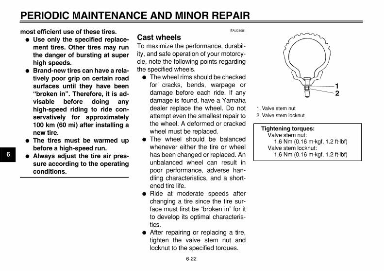
PERIODIC MAINTENANCE AND MINOR REPAIR
6-22
1
2
3
4
5
6
7
8
9
most efficient use of these tires.
�
Use only the specified replace-ment tires. Other tires may runthe danger of bursting at superhigh speeds.
�
Brand-new tires can have a rela-tively poor grip on certain roadsurfaces until they have been“broken in”. Therefore, it is ad-visable before doing anyhigh-speed riding to ride con-servatively for approximately100 km (60 mi) after installing anew tire.
�
The tires must be warmed upbefore a high-speed run.
�
Always adjust the tire air pres-sure according to the operating
conditions.
EAU21981
Cast wheels
To maximize the performance, durabil-ity, and safe operation of your motorcy-cle, note the following points regardingthe specified wheels.
�
The wheel rims should be checkedfor cracks, bends, warpage ordamage before each ride. If anydamage is found, have a Yamahadealer replace the wheel. Do notattempt even the smallest repair tothe wheel. A deformed or crackedwheel must be replaced.
�
The wheel should be balancedwhenever either the tire or wheelhas been changed or replaced. Anunbalanced wheel can result inpoor performance, adverse han-dling characteristics, and a short-ened tire life.
�
Ride at moderate speeds afterchanging a tire since the tire sur-face must first be “broken in” for itto develop its optimal characteris-tics.
�
After repairing or replacing a tire,tighten the valve stem nut andlocknut to the specified torques.
1. Valve stem nut2. Valve stem locknut
Tightening torques:
Valve stem nut:1.6 Nm (0.16 m·kgf, 1.2 ft·lbf)
Valve stem locknut:1.6 Nm (0.16 m·kgf, 1.2 ft·lbf)
21
PERIODIC MAINTENANCE AND MINOR REPAIR
6-23
2
3
4
5
6
7
8
9
EAU22011
Accessories and replacement parts
WARNING
EWA10621
This vehicle is not designed to pull atrailer or to be attached to a sidecar.The accessories or replacementparts you choose for your vehicleshould be designed specifically forthis model, and they must be se-curely mounted to maintain the in-herent stability of the originaldesign. Genuine Yamaha Parts andAccessories are designed and test-ed to be compatible with your vehi-cle. Please consider GenuineYamaha Parts and Accessories be-fore making a purchase. Use ofnon-Yamaha-approved accessoriesor replacement parts may causeloss of handling stability and ridingsafety. Since Yamaha cannot con-trol the quality of accessories orparts manufactured by other compa-nies, Yamaha cannot be held liablefor any consequences caused bythe use of items which have not
been approved by Yamaha.
EAU22072
Clutch lever
Since this model is equipped with a hy-draulic clutch, adjusting the clutch leverfree play is not needed. However, it isnecessary to check the clutch fluid leveland check the hydraulic system forleakage before each ride. If the clutchlever free play does become excessive,and shifting becomes rough or clutchslippage occurs, causing poor acceler-ation, there may be air in the clutch sys-tem. If there is air in the hydraulicsystem, have a Yamaha dealer bleedthe system before operating the motor-cycle.
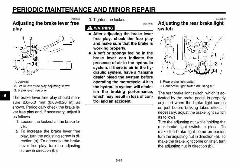
PERIODIC MAINTENANCE AND MINOR REPAIR
6-24
1
2
3
4
5
6
7
8
9
EAU22092
Adjusting the brake lever free play
The brake lever free play should mea-sure 2.0–5.0 mm (0.08–0.20 in) asshown. Periodically check the brake le-ver free play and, if necessary, adjust itas follows.
1. Loosen the locknut at the brake le-ver.
2. To increase the brake lever freeplay, turn the adjusting screw in di-rection (a). To decrease the brakelever free play, turn the adjustingscrew in direction (b).
3. Tighten the locknut.
WARNING
EWA10630
�
After adjusting the brake leverfree play, check the free playand make sure that the brake isworking properly.
�
A soft or spongy feeling in thebrake lever can indicate thepresence of air in the hydraulicsystem. If there is air in the hy-draulic system, have a Yamahadealer bleed the system beforeoperating the motorcycle. Air inthe hydraulic system will dimin-ish the braking performance,which may result in loss of con-
trol and an accident.
EAU22270
Adjusting the rear brake light switch
The rear brake light switch, which is ac-tivated by the brake pedal, is properlyadjusted when the brake light comeson just before braking takes effect. Ifnecessary, adjust the brake light switchas follows.Turn the adjusting nut while holding therear brake light switch in place. Tomake the brake light come on earlier,turn the adjusting nut in direction (a). Tomake the brake light come on later, turnthe adjusting nut in direction (b).
1. Locknut2. Brake lever free play adjusting screw3. Brake lever free play
1. Rear brake light switch2. Rear brake light switch adjusting nut
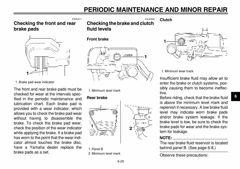
PERIODIC MAINTENANCE AND MINOR REPAIR
6-25
2
3
4
5
6
7
8
9
EAU22311
Checking the front and rear brake pads
The front and rear brake pads must bechecked for wear at the intervals spec-ified in the periodic maintenance andlubrication chart. Each brake pad isprovided with a wear indicator, whichallows you to check the brake pad wearwithout having to disassemble thebrake. To check the brake pad wear,check the position of the wear indicatorwhile applying the brake. If a brake padhas worn to the point that the wear indi-cator almost touches the brake disc,have a Yamaha dealer replace thebrake pads as a set.
EAU22680
Checking the brake and clutch fluid levels
Front brake
Rear brake
Clutch
Insufficient brake fluid may allow air toenter the brake or clutch systems, pos-sibly causing them to become ineffec-tive.Before riding, check that the brake fluidis above the minimum level mark andreplenish if necessary. A low brake fluidlevel may indicate worn brake padsand/or brake system leakage. If thebrake level is low, be sure to check thebrake pads for wear and the brake sys-tem for leakage.
NOTE:
The rear brake fluid reservoir is located
behind panel B. (See page 6-8.)
Observe these precautions:
1. Brake pad wear indicator
1. Minimum level mark
1. Panel B2. Minimum level mark
1. Minimum level mark
PERIODIC MAINTENANCE AND MINOR REPAIR
6-26
1
2
3
4
5
6
7
8
9
�
When checking the fluid level,make sure that the top of the brakeor clutch fluid reservoir is level.
�
Use only the recommended qualitybrake fluid, otherwise the rubberseals may deteriorate, causingleakage and poor braking or clutchperformance.
�
Refill with the same type of brakefluid. Mixing fluids may result in aharmful chemical reaction andlead to poor braking or clutch per-formance.
�
The brake or clutch fluid reservoirdiaphragm will lose its shape fromthe negative pressure if the fluidlevel goes down too far. Be sure toreturn the diaphragm to its originalshape before installing it into thebrake or clutch fluid reservoir.
�
Be careful that water does not en-ter the brake or clutch fluid reser-voir when refilling. Water willsignificantly lower the boiling point
of the fluid and may result in vaporlock.
�
Brake fluid may deteriorate paint-ed surfaces or plastic parts. Al-ways clean up spilled fluidimmediately.
�
As the brake pads wear, it is nor-mal for the brake fluid level to grad-ually go down. However, if thebrake fluid level goes down sud-denly, have a Yamaha dealercheck the cause.
EAU22750
Changing the brake and clutch fluids
Have a Yamaha dealer change thebrake and clutch fluids at the intervalsspecified in the NOTE after the periodicmaintenance and lubrication chart. Inaddition, have the oil seals of the brakeand clutch master cylinders and cali-pers as well as the brake and clutchhoses replaced at the intervals listedbelow or whenever they are damagedor leaking.
�
Oil seals: Replace every twoyears.
�
Brake and clutch hoses: Replaceevery four years.
Recommended brake and clutch flu-id:
DOT 4 brake fluid

PERIODIC MAINTENANCE AND MINOR REPAIR
6-27
2
3
4
5
6
7
8
9
EAU23090
Checking and lubricating the cables
The operation of all control cables andthe condition of the cables should bechecked before each ride, and the ca-bles and cable ends should be lubricat-ed if necessary. If a cable is damagedor does not move smoothly, have aYamaha dealer check or replace it.
WARNING
EWA10710
Damage to the outer housing of ca-bles may result in internal rustingand cause interference with cablemovement. Replace damaged ca-bles as soon as possible to prevent
unsafe conditions.
EAU23111
Checking and lubricating the throttle grip and cable
The operation of the throttle grip shouldbe checked before each ride. In addi-tion, the cable should be lubricated atthe intervals specified in the periodicmaintenance chart.
EAU23131
Checking and lubricating the brake and shift pedals
The operation of the brake and shiftpedals should be checked before eachride, and the pedal pivots should be lu-bricated if necessary.
Recommended lubricant:
Yamaha Chain and Cable Lube or engine oil SAE 10W-30 (API SE)

PERIODIC MAINTENANCE AND MINOR REPAIR
6-28
1
2
3
4
5
6
7
8
9
EAU23140
Checking and lubricating the brake and clutch levers
The operation of the brake and clutchlevers should be checked before eachride, and the lever pivots should be lu-bricated if necessary.
EAU23211
Checking and lubricating the centerstand and sidestand
The operation of the centerstand andsidestand should be checked beforeeach ride, and the pivots and met-al-to-metal contact surfaces should belubricated if necessary.
WARNING
EWA10740
If the centerstand or sidestand doesnot move up and down smoothly,have a Yamaha dealer check or re-
pair it.
Recommended lubricant:
Lithium-soap-based grease (all-pur-pose grease)
Recommended lubricant:
Lithium-soap-based grease (all-pur-pose grease)
Recommended lubricant:
Lithium-soap-based grease (all-pur-pose grease)
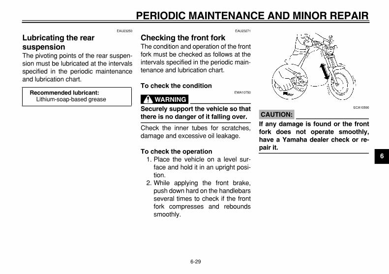
PERIODIC MAINTENANCE AND MINOR REPAIR
6-29
2
3
4
5
6
7
8
9
EAU23250
Lubricating the rear suspension
The pivoting points of the rear suspen-sion must be lubricated at the intervalsspecified in the periodic maintenanceand lubrication chart.
EAU23271
Checking the front fork
The condition and operation of the frontfork must be checked as follows at theintervals specified in the periodic main-tenance and lubrication chart.
To check the condition
WARNING
EWA10750
Securely support the vehicle so that
there is no danger of it falling over.
Check the inner tubes for scratches,damage and excessive oil leakage.
To check the operation
1. Place the vehicle on a level sur-face and hold it in an upright posi-tion.
2. While applying the front brake,push down hard on the handlebarsseveral times to check if the frontfork compresses and reboundssmoothly.
CAUTION:
ECA10590
If any damage is found or the frontfork does not operate smoothly,have a Yamaha dealer check or re-
pair it.
Recommended lubricant:
Lithium-soap-based grease
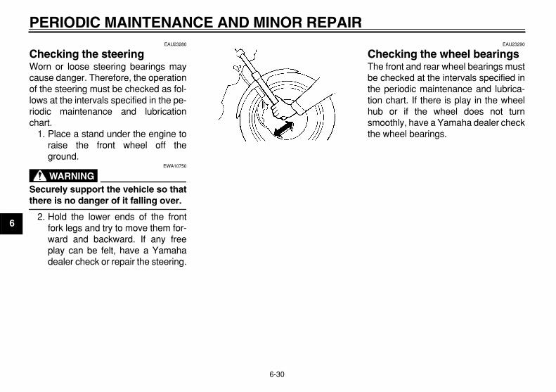
PERIODIC MAINTENANCE AND MINOR REPAIR
6-30
1
2
3
4
5
6
7
8
9
EAU23280
Checking the steering
Worn or loose steering bearings maycause danger. Therefore, the operationof the steering must be checked as fol-lows at the intervals specified in the pe-riodic maintenance and lubricationchart.
1. Place a stand under the engine toraise the front wheel off theground.
WARNING
EWA10750
Securely support the vehicle so that
there is no danger of it falling over.
2. Hold the lower ends of the frontfork legs and try to move them for-ward and backward. If any freeplay can be felt, have a Yamahadealer check or repair the steering.
EAU23290
Checking the wheel bearings
The front and rear wheel bearings mustbe checked at the intervals specified inthe periodic maintenance and lubrica-tion chart. If there is play in the wheelhub or if the wheel does not turnsmoothly, have a Yamaha dealer checkthe wheel bearings.

PERIODIC MAINTENANCE AND MINOR REPAIR
6-31
2
3
4
5
6
7
8
9
EAU23351
Battery
A poorly maintained battery will corrodeand discharge quickly. The electrolytelevel, battery lead connections andbreather hose routing should bechecked before each ride and at the in-tervals specified in the periodic mainte-nance and lubrication chart.
To check the electrolyte level
1. Place the vehicle on the center-stand.
NOTE:
Make sure that the vehicle is positioned
straight up when checking the electro-
lyte level.
2. Check the electrolyte level in thebattery.
NOTE:
The electrolyte should be between the
minimum and maximum level marks.
3. If the electrolyte is at or below theminimum level mark, continue withthe following steps.
4. Remove the rider seat. (Seepage 3-9.)
5. Disconnect the negative batterylead from the battery.
6. Disconnect the positive battery
lead and the starter motor leadfrom the starter motor relay.
7. Disconnect the couplers shown.8. Remove the ignition coil assem-
blies by removing the bolts.
1. Battery2. Battery breather hose3. Pass through the cable guide.
1. Maximum level mark2. Minimum level mark
1. Starter motor lead (black)2. Positive battery lead (red)3. Negative battery lead
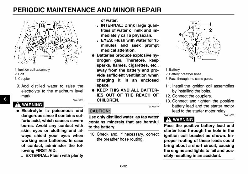
PERIODIC MAINTENANCE AND MINOR REPAIR
6-32
1
2
3
4
5
6
7
8
9
9. Add distilled water to raise theelectrolyte to the maximum levelmark.
WARNING
EWA10760
�
Electrolyte is poisonous anddangerous since it contains sul-furic acid, which causes severeburns. Avoid any contact withskin, eyes or clothing and al-ways shield your eyes whenworking near batteries. In caseof contact, administer the fol-lowing FIRST AID.
�
EXTERNAL: Flush with plenty
of water.
�
INTERNAL: Drink large quan-tities of water or milk and im-mediately call a physician.
�
EYES: Flush with water for 15minutes and seek promptmedical attention.
�
Batteries produce explosive hy-drogen gas. Therefore, keepsparks, flames, cigarettes, etc.,away from the battery and pro-vide sufficient ventilation whencharging it in an enclosedspace.
�
KEEP THIS AND ALL BATTER-IES OUT OF THE REACH OF
CHILDREN.
CAUTION:
ECA10610
Use only distilled water, as tap watercontains minerals that are harmful
to the battery.
10. Check and, if necessary, correctthe breather hose routing.
11. Install the ignition coil assembliesby installing the bolts.
12. Connect the couplers.13. Connect and tighten the positive
battery lead and the starter motorlead to the starter motor relay.
WARNING
EWA10780
Pass the positive battery lead andstarter lead through the hole in theignition coil bracket as shown. Im-proper routing of these leads couldbring about a short circuit, causingthe engine and lights to fail and pos-
sibly resulting in an accident.
1. Ignition coil assembly2. Bolt3. Coupler
1. Battery 2. Battery breather hose3. Pass through the cable guide.

PERIODIC MAINTENANCE AND MINOR REPAIR
6-33
2
3
4
5
6
7
8
9
14. Connect and tighten the negativebattery lead to the battery.
15. Install the rider seat.
To store the battery
1. If the vehicle will not be used formore than one month, remove thebattery, fully charge it, and thenplace it in a cool, dry place.
2. If the battery will be stored for morethan two months, check the specif-ic gravity of the electrolyte at leastonce a month and fully charge thebattery whenever necessary.
3. Fully charge the battery before in-stallation.
4. After installation, make sure thatthe battery leads are properly con-nected to the battery terminals andthat the breather hose is properlyrouted, in good condition, and notobstructed.
CAUTION:
ECA10600
If the breather hose is positioned insuch a way that the frame is ex-posed to electrolyte or gas expelledfrom the battery, the frame couldsuffer structural and external dam-
ages.
EAU23570
Replacing the fuses
The main fuse box is located under therider seat. (See page 3-9.)
The fuse box, which contains the fusesfor the individual circuits, is located un-der cowling A. (See page 6-8.)
1. Positive battery lead (red)2. Starter motor lead (black)
1. Main fuse2. Spare main fuse

PERIODIC MAINTENANCE AND MINOR REPAIR
6-34
1
2
3
4
5
6
7
8
9
If a fuse is blown, replace it as follows.1. Turn the key to “OFF” and turn off
the electrical circuit in question.2. Remove the blown fuse, and then
install a new fuse of the specifiedamperage.
CAUTION:
ECA10640
Do not use a fuse of a higher amper-age rating than recommended toavoid causing extensive damage tothe electrical system and possibly a
fire.
3. Turn the key to “ON” and turn onthe electrical circuit in question tocheck if the device operates.
4. If the fuse immediately blowsagain, have a Yamaha dealercheck the electrical system.
EAU23780
Replacing the headlight bulb
This model is equipped with a quartzbulb headlight. If the headlight bulbburns out, replace it as follows.
1. Remove the headlight unit by re-moving the screws.
2. Disconnect the headlight coupler,and then remove the bulb cover.
1. Headlight fuse2. Signaling system fuse3. Ignition fuse4. Radiator fan fuse5. Spare fuse
Specified fuses:
Main fuse: 30.0 A
Headlight fuse: 15.0 A
Signaling system fuse: 10.0 A
Radiator fan fuse: 10.0 A
Ignition fuse: 10.0 A
1. Screw
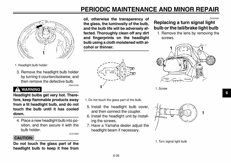
PERIODIC MAINTENANCE AND MINOR REPAIR
6-35
2
3
4
5
6
7
8
9
3. Remove the headlight bulb holderby turning it counterclockwise, andthen remove the defective bulb.
WARNING
EWA10790
Headlight bulbs get very hot. There-fore, keep flammable products awayfrom a lit headlight bulb, and do nottouch the bulb until it has cooled
down.
4. Place a new headlight bulb into po-sition, and then secure it with thebulb holder.
CAUTION:
ECA10660
Do not touch the glass part of theheadlight bulb to keep it free from
oil, otherwise the transparency ofthe glass, the luminosity of the bulb,and the bulb life will be adversely af-fected. Thoroughly clean off any dirtand fingerprints on the headlightbulb using a cloth moistened with al-
cohol or thinner.
5. Install the headlight bulb cover,and then connect the coupler.
6. Install the headlight unit by install-ing the screws.
7. Have a Yamaha dealer adjust theheadlight beam if necessary.
EAU24281
Replacing a turn signal light bulb or the tail/brake light bulb
1. Remove the lens by removing thescrews.
1. Headlight bulb holder
1. Do not touch the glass part of the bulb.
1. Screw
1. Turn signal light bulb

PERIODIC MAINTENANCE AND MINOR REPAIR
6-36
1
2
3
4
5
6
7
8
9
2. Remove the defective bulb bypushing it in and turning it counter-clockwise.
3. Insert a new bulb into the socket,push it in, and then turn it clock-wise until it stops.
4. Install the lens by installing thescrews.
CAUTION:
ECA10680
Do not overtighten the screws, oth-
erwise the lens may break.
EAU24360
Front wheel
EAU24430
To remove the front wheel
WARNING
EWA10820
�
It is advisable to have a Yamahadealer service the wheel.
�
Securely support the motorcy-cle so that there is no danger of
it falling over.
1. Place the motorcycle on the cen-terstand.
2. Disconnect the speedometer ca-ble from the front wheel.
3. Remove the brake calipers by re-moving the bolts.
CAUTION:
ECA11060
Do not pull the brake lever after thebrake caliper has been removed,otherwise the brake pads will be
forced shut.
4. Loosen the front wheel axle pinchbolt, then the wheel axle.
5. Pull the wheel axle out, and thenremove the wheel.
EAU24842
To install the front wheel
1. Install the speedometer gear unitinto the wheel hub so that the pro-jections mesh with the slots.
1. Tail/brake light bulb
1. Speedometer cable2. Bolt3. Front wheel axle pinch bolt4. Wheel axle

PERIODIC MAINTENANCE AND MINOR REPAIR
6-37
2
3
4
5
6
7
8
9
2. Lift the wheel up between the forklegs.
NOTE:
Make sure that the slot in the speedom-eter gear unit fits over the retainer on
the fork leg.
3. Insert the wheel axle.
4. Install the brake calipers by install-ing the bolts.
NOTE:
Make sure that there is enough spacebetween the brake pads before install-ing the brake calipers onto the brake
discs.
5. Take the motorcycle off the center-stand so that the front wheel is onthe ground.
6. Tighten the wheel axle, then thefront wheel axle pinch bolt and thebrake caliper bolts to the specifiedtorques.
7. Connect the speedometer cable.8. Push down hard on the handlebar
several times to check for properfork operation.
EAU25080
Rear wheel
EAU37960
To remove the rear wheel
WARNING
EWA10820
�
It is advisable to have a Yamahadealer service the wheel.
�
Securely support the motorcy-cle so that there is no danger of
it falling over.
1. Remove the axle nut, and thenloosen the rear wheel axle pinchbolt.
1. Retainer
Tightening torques:
Wheel axle:58 Nm (5.8 m·kgf, 42 ft·lbf)
Front wheel axle pinch bolt:20 Nm (2.0 m·kgf, 14 ft·lbf)
Brake caliper bolt:40 Nm (4.0 m·kgf, 29 ft·lbf)
1. Axle nut

PERIODIC MAINTENANCE AND MINOR REPAIR
6-38
1
2
3
4
5
6
7
8
9
2. Place the motorcycle on the cen-terstand.
3. Remove the brake caliper by re-moving the bolts.
4. Disconnect the brake torque rodfrom the brake caliper bracket byremoving the nut and the bolt.
5. While supporting the rear wheel,pull the wheel axle out.
6. Remove the brake caliper bracketand spacer.
7. Pull the wheel to the right to sepa-rate it from the final gear case, andthen remove it.
CAUTION:
ECA11180
Do not push the brake pedal afterthe wheel has been removed togeth-er with the brake disc, otherwise the
brake pads will be forced shut.
EAU37970
To install the rear wheel
1. Apply a light coating of lithi-um-soap-based grease to thesplines of the final gear case andwheel hub.
2. Install the wheel, brake caliperbracket, spacer and wheel axle.
3. Install the brake caliper by install-
1. Rear wheel axle pinch bolt
1. Nut2. Brake torque rod3. Bolt4. Spacer5. Brake caliper bracket
1
3
2
45

PERIODIC MAINTENANCE AND MINOR REPAIR
6-39
2
3
4
5
6
7
8
9
ing the bolts.
NOTE:
Make sure that there is enough spacebetween the brake pads before install-ing the brake caliper onto the brake
disc.
4. Connect the brake torque rod tothe brake caliper bracket by install-ing the bolt and the nut.
5. Install the axle nut, and then slight-ly tighten it.
6. Take the motorcycle off the center-stand so that the rear wheel is onthe ground.
7. Tighten the rear wheel axle pinchbolt, the axle nut, the brake caliperbolts and the brake torque rod nutto the specified torques.
EAU25870
Troubleshooting
Although Yamaha motorcycles receivea thorough inspection before shipmentfrom the factory, trouble may occur dur-ing operation. Any problem in the fuel,compression, or ignition systems, forexample, can cause poor starting andloss of power.The following troubleshooting chartsrepresent quick and easy proceduresfor checking these vital systems your-self. However, should your motorcyclerequire any repair, take it to a Yamahadealer, whose skilled technicians havethe necessary tools, experience, andknow-how to service the motorcycleproperly.Use only genuine Yamaha replace-ment parts. Imitation parts may look likeYamaha parts, but they are often inferi-or, have a shorter service life and canlead to expensive repair bills.
Tightening torques:
Axle nut:150 Nm (15.0 m·kgf, 108 ft·lbf)
Brake caliper bolt:40 Nm (4.0 m·kgf, 29 ft·lbf)
Brake torque rod nut:23 Nm (2.3 m·kgf, 17 ft·lbf)
Rear wheel axle pinch bolt:16 Nm (1.6 m·kgf, 11 ft·lbf)

PERIODIC MAINTENANCE AND MINOR REPAIR
6-40
1
2
3
4
5
6
7
8
9
EAU25941
Troubleshooting charts
Starting problems or poor engine performance
WARNING
EWA10840
Keep away open flames and do not smoke while checking or working on the fuel system.
Check the fuel level inthe fuel tank.
1. FuelThere is enough fuel.
There is no fuel.
Check the compression.
Supply fuel.
Operate the electric starter.
2. CompressionThere is compression.
There is no compression.
Check the ignition.
Have a Yamaha dealercheck the vehicle.
Remove the spark plugsand check the electrodes.
3. IgnitionWet
Dry
Wipe off with a dry cloth and correct the spark plug gaps, or replace the spark plugs.
Have a Yamaha dealer check the vehicle. The engine does not start.Check the battery.
Open the throttle halfway and operatethe electric starter.
Operate the electric starter.
4. Battery The engine turns over quickly.
The engine turns over slowly.
The battery is good.
Check the electrolyte and batterylead connections, and charge thebattery if necessary.
The engine does not start. Have a Yamaha dealer check the vehicle.
The engine does not start. Check the compressoin.

PERIODIC MAINTENANCE AND MINOR REPAIR
6-41
2
3
4
5
6
7
8
9
Engine overheating
WARNING
EWA10400
�
Do not remove the radiator cap when the engine and radiator are hot. Scalding hot fluid and steam may beblown out under pressure, which could cause serious injury. Be sure to wait until the engine has cooled.
�
After removing the radiator cap retaining bolt, place a thick rag, like a towel, over the radiator cap, and thenslowly rotate the cap counterclockwise to the detent to allow any residual pressure to escape. When the hissing
sound has stopped, press down on the cap while turning it counterclockwise, and then remove the cap.
NOTE:
If coolant is not available, tap water can be temporarily used instead, provided that it is changed to the recommended coolant
as soon as possible.
Wait until the engine has cooled.
Check the coolant level in the reservoir and radiator.
The coolant level is OK.
The coolant level is low.Check the cooling systemfor leakage.
Have a Yamaha dealer checkand repair the cooling system.
Add coolant. (See NOTE.)
Start the engine. If the engine overheats again, have a Yamaha dealer check and repair the cooling system.
There isleakage.
There is no leakage.

7-1
1
2
3
4
5
6
7
8
9
MOTORCYCLE CARE AND STORAGE
EAU26060
Care
While the open design of a motorcyclereveals the attractiveness of the tech-nology, it also makes it more vulnera-ble. Rust and corrosion can developeven if high-quality components areused. A rusty exhaust pipe may go un-noticed on a car, however, it detractsfrom the overall appearance of a motor-cycle. Frequent and proper care doesnot only comply with the terms of thewarranty, but it will also keep your mo-torcycle looking good, extend its lifeand optimize its performance.
Before cleaning
1. Cover the muffler outlets with plas-tic bags after the engine hascooled down.
2. Make sure that all caps and coversas well as all electrical couplersand connectors, including thespark plug caps, are tightly in-stalled.
3. Remove extremely stubborn dirt,like oil burnt onto the crankcase,with a degreasing agent and abrush, but never apply such prod-
ucts onto seals, gaskets and wheelaxles. Always rinse the dirt and de-greaser off with water.
Cleaning
CAUTION:
ECA10770
�
Avoid using strong acidic wheelcleaners, especially on spokedwheels. If such products areused on hard-to-remove dirt, donot leave the cleaner on the af-fected area any longer than in-structed. Also, thoroughly rinsethe area off with water, immedi-ately dry it, and then apply a cor-rosion protection spray.
�
Improper cleaning can damagewindshields, cowlings, panelsand other plastic parts. Use onlya soft, clean cloth or spongewith mild detergent and water toclean plastic.
�
Do not use any harsh chemicalproducts on plastic parts. Besure to avoid using cloths orsponges which have been incontact with strong or abrasivecleaning products, solvent or
thinner, fuel (gasoline), rust re-movers or inhibitors, brake flu-id, antifreeze or electrolyte.
�
Do not use high-pressure wash-ers or steam-jet cleaners sincethey cause water seepage anddeterioration in the following ar-eas: seals (of wheel and swing-arm bearings, fork and brakes),electric components (couplers,connectors, instruments,switches and lights), breatherhoses and vents.
�
For motorcycles equipped witha windshield: Do not use strongcleaners or hard sponges asthey will cause dulling orscratching. Some cleaning com-pounds for plastic may leavescratches on the windshield.Test the product on a small hid-den part of the windshield tomake sure that it does not leaveany marks. If the windshield isscratched, use a quality plasticpolishing compound after
washing.

MOTORCYCLE CARE AND STORAGE
7-2
2
3
4
5
6
7
8
9
After normal useRemove dirt with warm water, a milddetergent, and a soft, clean sponge,and then rinse thoroughly with cleanwater. Use a toothbrush or bottlebrushfor hard-to-reach areas. Stubborn dirtand insects will come off more easily ifthe area is covered with a wet cloth fora few minutes before cleaning.
After riding in the rain, near the sea oron salt-sprayed roadsSince sea salt or salt sprayed on roadsduring winter are extremely corrosive incombination with water, carry out thefollowing steps after each ride in therain, near the sea or on salt-sprayedroads.
NOTE:
Salt sprayed on roads in the winter may
remain well into spring.
1. Clean the motorcycle with cold wa-ter and a mild detergent, after theengine has cooled down.
CAUTION:
ECA10790
Do not use warm water since it in-creases the corrosive action of the
salt.
2. After drying the motorcycle, applya corrosion protection spray on allmetal, including chrome- and nick-el-plated, surfaces to prevent cor-rosion.
After cleaning
1. Dry the motorcycle with a chamoisor an absorbing cloth.
2. Use a chrome polish to shinechrome, aluminum and stain-less-steel parts, including the ex-haust system. (Even the thermallyinduced discoloring of stain-less-steel exhaust systems can beremoved through polishing.)
3. To prevent corrosion, it is recom-mended to apply a corrosion pro-tection spray on all metal,including chrome- and nickel-plat-ed, surfaces.
4. Use spray oil as a universal clean-er to remove any remaining dirt.
5. Touch up minor paint damagecaused by stones, etc.
6. Wax all painted surfaces.7. Let the motorcycle dry completely
before storing or covering it.
WARNING
EWA11130
�
Make sure that there is no oil orwax on the brakes or tires.
�
If necessary, clean the brakediscs and brake linings with aregular brake disc cleaner or ac-etone, and wash the tires withwarm water and a mild deter-gent. Before riding at higherspeeds, test the motorcycle’sbraking performance and cor-
nering behavior.
CAUTION:
ECA10800
�
Apply spray oil and wax spar-ingly and make sure to wipe offany excess.
�
Never apply oil or wax to anyrubber and plastic parts, buttreat them with a suitable careproduct.
�
Avoid using abrasive polishingcompounds as they will wear
away the paint.

MOTORCYCLE CARE AND STORAGE
7-3
1
2
3
4
5
6
7
8
9
NOTE:
Consult a Yamaha dealer for advice on
what products to use.
EAU26230
Storage
Short-term
Always store your motorcycle in a cool,dry place and, if necessary, protect itagainst dust with a porous cover.
CAUTION:
ECA10810
�
Storing the motorcycle in apoorly ventilated room or cover-ing it with a tarp, while it is stillwet, will allow water and humid-ity to seep in and cause rust.
�
To prevent corrosion, avoiddamp cellars, stables (becauseof the presence of ammonia)and areas where strong chemi-
cals are stored.
Long-term
Before storing your motorcycle for sev-eral months:
1. Follow all the instructions in the“Care” section of this chapter.
2. For motorcycles equipped with afuel cock that has an “OFF” posi-tion: Turn the fuel cock lever to
“OFF”.3. Drain the carburetor float cham-
bers by loosening the drain bolts;this will prevent fuel deposits frombuilding up. Pour the drained fuelinto the fuel tank.
4. Fill up the fuel tank and add fuelstabilizer (if available) to preventthe fuel tank from rusting and thefuel from deteriorating.
5. Perform the following steps to pro-tect the cylinders, piston rings, etc.from corrosion.a. Remove the spark plug caps
and spark plugs.b. Pour a teaspoonful of engine oil
into each spark plug bore.c. Install the spark plug caps onto
the spark plugs, and then placethe spark plugs on the cylinderhead so that the electrodes aregrounded. (This will limit spark-ing during the next step.)
d. Turn the engine over severaltimes with the starter. (This willcoat the cylinder walls with oil.)
e. Remove the spark plug capsfrom the spark plugs, and then

MOTORCYCLE CARE AND STORAGE
7-4
2
3
4
5
6
7
8
9
install the spark plugs and thespark plug caps.
WARNING
EWA10950
To prevent damage or injury fromsparking, make sure to ground thespark plug electrodes while turning
the engine over.
6. Lubricate all control cables and thepivoting points of all levers andpedals as well as of the sidestand/centerstand.
7. Check and, if necessary, correctthe tire air pressure, and then liftthe motorcycle so that both of itswheels are off the ground. Alterna-tively, turn the wheels a little everymonth in order to prevent the tiresfrom becoming degraded in onespot.
8. Cover the muffler outlets with plas-tic bags to prevent moisture fromentering them.
9. Remove the battery and fullycharge it. Store it in a cool, dryplace and charge it once a month.Do not store the battery in an ex-cessively cold or warm place [less
than 0 °C (30 °F) or more than30 °C (90 °F)]. For more informa-tion on storing the battery, seepage 6-31.
NOTE:
Make any necessary repairs before
storing the motorcycle.

8-1
1
2
3
4
5
6
7
8
9
SPECIFICATIONS
EAU2633D
Dimensions:
Overall length: 2300 mm (90.6 in)
Overall width: 795 mm (31.3 in)
Overall height: 1160 mm (45.7 in)
Seat height: 765 mm (30.1 in)
Wheelbase: 1590 mm (62.6 in)
Ground clearance: 145 mm (5.71 in)
Minimum turning radius: 2900 mm (114.2 in)
Weight:
With oil and fuel: 283.0 kg (624 lb) (U49)284.0 kg (626 lb) (CAL)(ZAF)
Engine:
Engine type: Liquid cooled 4-stroke, DOHC
Cylinder arrangement: V-type 4-cylinder
Displacement: 1198.0 cm
3
(73.10 cu.in)Bore
×
stroke: 76.0
×
66.0 mm (2.99
×
2.60 in)Compression ratio:
10.50 :1Starting system:
Electric starter
Lubrication system: Wet sump
Engine oil:
Type: SAE10W30 or SAE10W40 or SAE15W40or SAE20W40 or SAE20W50 (ZAF)YAMALUBE 4, SAE10W30 or SAE20W40(CAL)(U49)
For ZAF
For U49, CAL
Recommended engine oil grade: API service SE, SF, SG type or higher
Engine oil quantity:
Without oil filter cartridge replacement: 3.50 L (3.70 US qt) (3.08 Imp.qt)
With oil filter cartridge replacement: 3.80 L (4.02 US qt) (3.34 Imp.qt)
Final gear oil:
Type: SAE80 API GL-4 Hypoid gear oil
Quantity: 0.20 L (0.21 US qt) (0.18 Imp.qt)
Cooling system:
Coolant reservoir capacity (up to the maxi-mum level mark):
0.30 L (0.32 US qt) (0.26 Imp.qt)Radiator capacity (including all routes):
2.75 L (2.91 US qt) (2.42 Imp.qt)
Air filter:
Air filter element: Dry element
Fuel:
Recommended fuel: Regular unleaded gasoline only (ZAF)Unleaded gasoline only (CAL)(U49)
Fuel tank capacity: 15.0 L (3.96 US gal) (3.30 Imp.gal)
Fuel reserve amount: 3.0 L (0.79 US gal) (0.66 Imp.gal)
Carburetor:
Manufacturer: MIKUNI
Type
×
quantity: BDS35 x 4
Spark plug (s):
Manufacturer/model: NGK/DPR8EA-9
-20 -10 0 10 20 30 40 50 ˚C
SAE 10W-30
SAE 15W-40
SAE 20W-40
SAE 20W-50
SAE 10W-40
10° 30° 50° 70° 90° 110°0° 130°F
YAMALUBE 4 (10W30)or SAE 10W30
YAMALUBE 4 (20W40)or SAE 20W40
–10° 0° 10° 20° 30° 40°–20° 50°C

SPECIFICATIONS
8-2
2
3
4
5
6
7
8
9
Manufacturer/model: DENSO/X24EPR-U9
Spark plug gap: 0.8–0.9 mm (0.031–0.035 in)
Clutch:
Clutch type: Wet, multiple-disc
Transmission:
Primary reduction system: Spur gear
Primary reduction ratio: 87/49 (1.776)
Secondary reduction system: Shaft drive
Secondary reduction ratio: 21/27
×
33/09 (2.852)Transmission type:
Constant mesh 5-speedOperation:
Left foot operation
Gear ratio:
1st: 43/17 (2.529)
2nd: 39/22 (1.773)
3rd: 31/23 (1.348)
4th: 28/26 (1.077)
5th: 26/28 (0.928)
Chassis:
Frame type: Double cradle
Caster angle: 29.00 °
Trail: 119.0 mm (4.69 in)
Front tire:
Type: Tubeless
Size: 110/90-18M/C 61V
Manufacturer/model: BRIDGESTONE/G525
Manufacturer/model: DUNLOP/F20
Rear tire:
Type: Tubeless
Size: 150/90-15M/C 74V
Manufacturer/model: BRIDGESTONE/G526
Manufacturer/model: DUNLOP/K525
Loading:
Maximum load: 215 kg (474 lb) (CAL)(ZAF)216 kg (476 lb) (U49)
* (Total weight of rider, passenger, cargo and accessories)
Tire air pressure (measured on coldtires):
Loading condition: 0–90 kg (0–198 lb)
Front: 225 kPa (33 psi) (2.25 kgf/cm
2
)Rear:
225 kPa (33 psi) (2.25 kgf/cm
2
)Loading condition:
90–215 kg (198–474 lb) (CAL)(ZAF)90–216 kg (198–476 lb) (U49)
Front: 225 kPa (33 psi) (2.25 kgf/cm
2
)Rear:
250 kPa (36 psi) (2.50 kgf/cm
2
)
Front wheel:
Wheel type: Cast wheel
Rim size: 18M/C x MT2.15
Rear wheel:
Wheel type: Cast wheel
Rim size: 15M/C x MT3.50
Front brake:
Type: Dual disc brake
Operation: Right hand operation
Recommended fluid: DOT 4

SPECIFICATIONS
8-3
1
2
3
4
5
6
7
8
9
Rear brake:
Type: Single disc brake
Operation: Right foot operation
Recommended fluid: DOT 4
Front suspension:
Type: Telescopic fork
Spring/shock absorber type: Coil-air spring/oil damper
Wheel travel: 140.0 mm (5.51 in)
Rear suspension:
Type: Swingarm
Spring/shock absorber type: Coil spring/oil damper
Wheel travel: 100.0 mm (3.94 in)
Electrical system:
Ignition system: Transistorized coil ignition (digital)
Charging system: AC magneto
Battery:
Model: YB16AL-A2
Voltage, capacity: 12 V, 16.0 Ah
Headlight:
Bulb type: Halogen bulb
Bulb voltage, wattage
×
quantity:
Headlight: 12 V, 60 W/55.0 W
×
1Tail/brake light:
12 V, 8.0 W/27.0 W
×
2Front turn signal/position light:
12 V, 23 W/8.0 W
×
2Rear turn signal light:
12 V, 21.0 W
×
2Meter lighting:
14 V, 3.0 W
×
2Neutral indicator light:
14 V, 3.0 W
×
1High beam indicator light:
14 V, 3.0 W
×
1Oil level warning light:
14 V, 3.0 W
×
1Turn signal indicator light:
14 V, 3.0 W
×
1Fuel level warning light:
14 V, 3.0 W
×
1
Fuses:
Main fuse: 30.0 A
Headlight fuse: 15.0 A
Signaling system fuse: 10.0 A
Ignition fuse: 10.0 A
Radiator fan fuse: 10.0 A

9-1
2
3
4
5
6
7
8
9
CONSUMER INFORMATION
EAU26351
Identification numbers
Record the key identification number,vehicle identification number and mod-el label information in the spaces pro-vided below for assistance whenordering spare parts from a Yamahadealer or for reference in case the vehi-cle is stolen.KEY IDENTIFICATION NUMBER:
VEHICLE IDENTIFICATION NUMBER:
MODEL LABEL INFORMATION:
EAU26390
Key identification number
The key identification number isstamped into the key. Record this num-ber in the space provided and use it forreference when ordering a new key.
EAU26400
Vehicle identification number
The vehicle identification number isstamped into the steering head pipe.Record this number in the space pro-vided.
NOTE:
The vehicle identification number isused to identify your motorcycle andmay be used to register your motorcy-cle with the licensing authority in your
area.
1. Key identification number
1. Vehicle identification number

CONSUMER INFORMATION
9-2
1
2
3
4
5
6
7
8
9
EAU26530
Model label
The model label is affixed under cowl-ing A. (See page 6-8.) Record the infor-mation on this label in the spaceprovided. This information will be need-ed when ordering spare parts from aYamaha dealer.
1. Model label

CONSUMER INFORMATION
9-3
2
3
4
5
6
7
8
9
EAU26550
Reporting safety defects
If you believe that your vehicle has a defect which could cause a crash or could cause injury or death, you should immediatelyinform the National Highway Traffic Safety Administration (NHTSA) in addition to notifying Yamaha Motor Corporation,U.S.A. If NHTSA receives similar complaints, it may open an investigation, and if it finds that a safety defect exists in a groupof vehicles, it may order a recall and remedy campaign. However, NHTSA cannot become involved in individual problemsbetween you, your dealer, or Yamaha Motor Corporation, U.S.A.To contact NHTSA, you may either call the Auto Safety Hotline toll-free at 1-800-424-9393 (or 366-0123 in Washington, D.C.area) or write to: NHTSA, U.S. Department of Transportation, Washington, D.C. 20590. You can also obtain other informationabout motor vehicle safety from the Hotline.

CONSUMER INFORMATION
9-4
1
2
3
4
5
6
7
8
9
EAU26560
Motorcycle noise regulation
TAMPERING WITH NOISE CONTROL SYSTEM PROHIBITED:
Federal law prohibits the following acts or the causing thereof: (1) The removal or rendering inoperative by any person otherthan for purposes of maintenance, repair, or replacement of any device or element of design incorporated into any new ve-hicle for the purpose of noise control prior to its sale or delivery to the ultimate purchaser or while it is in use or (2) the use ofthe vehicle after such device or element of design has been removed or rendered inoperative by any person.“AMONG THOSE ACTS PRESUMED TO CONSTITUTE TAMPERING ARE THE ACTS LISTED BELOW”.These acts include tampering with the following systems; i.e., modification, removal, etc.
Exhaust system
�
Muffler
�
Exhaust pipe
�
Silencer
Intake system
�
Air cleaner case
�
Air cleaner element
�
Intake duct

CONSUMER INFORMATION
9-5
2
3
4
5
6
7
8
9
EAU26632
Maintenance record
Copies of work orders and/or receipts for parts purchased and installed on your vehicle will be required to document thatmaintenance has been completed in accordance with the emissions warranty. The chart below is printed only as a reminderthat maintenance work is required. It is not acceptable proof of maintenance work.
Maintenanceinterval
Date ofservice
MileageServicing dealer
name and addressRemarks
600 mi(1000 km) or
1 month4000 mi
(7000 km) or6 months8000 mi
(13000 km) or12 months12000 mi
(19000 km) or18 months16000 mi
(25000 km) or24 months20000 mi
(31000 km) or30 months24000 mi
(37000 km) or36 months28000 mi
(43000 km) or42 months

CONSUMER INFORMATION
9-6
1
2
3
4
5
6
7
8
9
32000 mi(49000 km) or
48 months36000 mi
(55000 km) or54 months40000 mi
(61000 km) or60 months
Maintenanceinterval
Date ofservice
MileageServicing dealer
name and addressRemarks

CONSUMER INFORMATION
9-7
2
3
4
5
6
7
8
9
EAU26661
YAMAHA MOTOR CORPORATION, U.S.A. STREET AND ENDURO MOTORCYCLE LIMITED WARRANTY
CONSUMER INFORMATION
9-8
1
2
3
4
5
6
7
8
9

CONSUMER INFORMATION
9-9
2
3
4
5
6
7
8
9
EAU26750
YAMAHA EXTENDED SERVICE (Y.E.S.) Keep your Yamaha protected even after your warranty expires with genuine Yamaha Extended Service (Y.E.S.).
Y.E.S. is designed and administered by Yamaha Motor Corporation to provide maximum owner satisfaction. You get uninterrupted factory-backed coverage for extra peace of mind.
Y.E.S. is flexible. You choose the plan that’s right foryou: 12 months, 24 months, 36 months or, on certain models, even 48 months beyond your warranty period.
Y.E.S. is designed and administered by the same Yamaha people who handle your warranty – and itshows in the comprehensive coverage benefits. There are no mileage limitations. Coverage isn’t limited to “moving parts” or the “drive train” like many other plans. And Y.E.S. covers manufacturing defects just like the warranty. See the sample contract at your Yamahadealer to see how comforting uninterrupted factory-backed protection can be.
You don’t have to pay anything for covered repairs. There’s no deductible to pay, and repairs aren’t“pro-rated.” You don’t have any “out-of-pocket” expenses for covered repairs.
In addition, Travel and Recreation Interruption Protection (TRIP) is included at no extra cost. TRIP gives you up to $150 reimbursement per occurrence for any reasonable expenses you incur because your Yamaha needs covered service: replacement vehicle rental, emergency towing, phone calls, even food and lodging when you are away from home. This superb coverage goes into effect when you purchase Y.E.S., so it applies to any warranty repairs as well as covered repairs during your entire Y.E.S. plan period.
Y.E.S. coverage is honored at any authorized Yamaha dealer nationwide.
Y.E.S. coverage is transferable to a new owner if yousell or trade-in. That can make your Yamaha much more valuable!
This excellent Y.E.S. plan coverage is only available to Yamaha owners like you, and only while your Yamaha is still within the Yamaha Limited Warranty period. So visit your authorized Yamaha dealer to get all the facts. He can show you how easy it is to protect your investment with Yamaha Extended Service.

CONSUMER INFORMATION
9-10
1
2
3
4
5
6
7
8
9
We urge you to act now. You’ll get the excellent benefits of TRIP coverage right away, and you’ll rest easy knowing you’ll have strong factory-backed protection even after your Yamaha Limited Warranty expires.
A special note:If visiting your dealer isn’t convenient, contact Yamaha with your Primary ID number (your frame number). We’ll be happy to help you get the Y.E.S. coverage you need.
Yamaha Service MarketingP.O. Box 6555Cypress, CA 906301-(866)-YES-EXTD (1-866-937-3983)

INDEX
A
Accessories and replacement parts ........6-23Air filter element, cleaning .......................6-18
B
Battery .....................................................6-31Brake and clutch fluid levels, checking....6-25Brake and clutch fluids, changing............6-26Brake and clutch levers, checking and
lubricating ..............................................6-28Brake and shift pedals, checking and
lubricating ..............................................6-27Brake lever ................................................3-5Brake lever free play, adjusting ...............6-24Brake pedal ...............................................3-6
C
Cables, checking and lubricating.............6-27Canister (for California only) ....................6-10Carburetors..............................................6-19Care...........................................................7-1Centerstand and sidestand, checking and
lubricating ..............................................6-28Clutch lever......................................3-5
,
6-23Coolant ....................................................6-15Coolant temperature gauge.......................3-3Cowling and panels, removing and
installing ..................................................6-8
D
Dimmer switch ...........................................3-4
E
Engine break-in .........................................5-4Engine oil and oil filter cartridge ..............6-11Engine, starting a warm.............................5-2Engine stop switch.....................................3-4
F
Final gear oil ............................................6-14Front and rear brake pads, checking.......6-25Front fork, adjusting.................................3-10Front fork, checking.................................6-29Fuel ...........................................................3-7Fuel level warning light..............................3-2Fuel reserve switch ...................................3-4Fuel tank cap.............................................3-6Fuses, replacing ......................................6-33
H
Handlebar switches ...................................3-3Headlight bulb, replacing.........................6-34Helmet holder ..........................................3-10High beam indicator light...........................3-2Horn switch................................................3-4
I
Identification numbers ...............................9-1Ignition circuit cut-off system ...................3-15Indicator and warning lights.......................3-1
K
Key identification number ..........................9-1
L
Labels, location of .....................................1-5
M
Main switch................................................3-1Maintenance and lubrication, periodic.......6-4Maintenance, emission control system .....6-3Maintenance, periodic ...............................6-1Maintenance record...................................9-5Model label ................................................9-2
N
Neutral indicator light.................................3-1Noise regulation ........................................9-4
O
Oil level warning light ................................ 3-2
P
Parking ...................................................... 5-5Part locations ............................................ 2-1Pre-operation check list............................. 4-2
R
Rear brake light switch, adjusting ........... 6-24Rear suspension, lubricating................... 6-29Rider seat.................................................. 3-9
S
Safety defects, reporting ........................... 9-3Safety information ..................................... 1-1Shifting ...................................................... 5-3Shift pedal ................................................. 3-5Shock absorber assemblies, adjusting.... 3-12Sidestand ................................................ 3-14Spark plugs, checking ............................... 6-9Specifications ............................................ 8-1Speedometer unit...................................... 3-2Starter (choke) lever.................................. 3-8Starting and warming up a cold engine..... 5-1Start switch................................................ 3-4Steering, checking................................... 6-30Steering lock ............................................. 3-8Storage...................................................... 7-3
T
Tachometer ............................................... 3-3Throttle cable free play, checking ........... 6-19Throttle grip and cable, checking and
lubricating ............................................. 6-27Tires ........................................................ 6-20Tool kit....................................................... 6-1Troubleshooting ...................................... 6-39

INDEX
Troubleshooting charts ........................... 6-40Turn signal indicator light .......................... 3-1Turn signal light bulb or tail/brake light bulb,
replacing ............................................... 6-35Turn signal switch ..................................... 3-4
V
Valve clearance ...................................... 6-20V-Boost ................................................... 3-14Vehicle identification number .................... 9-1
W
Warranty, extended................................... 9-9Warranty, limited ....................................... 9-7Wheel bearings, checking....................... 6-30Wheel (front) ........................................... 6-36Wheel (rear) ............................................ 6-37Wheels .................................................... 6-22

PRINTED ON RECYCLED PAPERYAMAHA MOTOR CO., LTD.
PRINTED IN JAPAN2005.5–0.1×1 !
(E)