VMOTO MONACO OWNER HANDBOOK - Scooter Community
40
VMOTO MONACO OWNER HANDBOOK
Transcript of VMOTO MONACO OWNER HANDBOOK - Scooter Community

VMOTO MONACO
OWNER
HANDBOOK

1 VMOTO MONACO V1 ............................................................................................. 4
2 GENERAL INFORMATION..................................................................................... 5
2.1 Description.......................................................................................................... 5
2.2 Specifications...................................................................................................... 6
2.3 Inspection Tips.................................................................................................... 7
2.4 Safety Precautions............................................................................................... 7
2.5 Torque Settings ................................................................................................... 8
2.6 Lubrication Points............................................................................................. 10
2.7 Trouble Shooting .............................................................................................. 12
2.7.1 Engine Fails to Start:................................................................................. 12
2.7.2 Poor spark ................................................................................................. 12
2.7.3 Poor idle .................................................................................................... 13
2.7.4 Poor acceleration and loss of power ......................................................... 13
3 INSPECTION AND ADJUSTMENT ...................................................................... 14
3.1 Regular Maintenance Schedule......................................................................... 14
3.2 Checking and Changing Engine Oil ................................................................. 14
3.3 Final Drive Gear Oil ......................................................................................... 16
3.4 Brake System .................................................................................................... 17
3.4.1 Front Brake Lever Free Play..................................................................... 17
3.4.2 Brake Fluid................................................................................................ 17
3.4.3 Refill Brake Fluid ..................................................................................... 17
3.4.4 Bleed Brake Line ...................................................................................... 18
3.4.5 Front Brake Disk....................................................................................... 18
3.4.6 Rear Brake Adjustment............................................................................. 18
3.4.7 Inspection of Brake Lining and Wheel ..................................................... 19
3.5 Tyre and Tyre Pressure ..................................................................................... 20
3.6 Air Filter............................................................................................................ 21
3.7 Battery............................................................................................................... 22
3.8 Spark Plug......................................................................................................... 22
3.9 Fuel Filter.......................................................................................................... 23
3.10 Carburettor Idle Speed ...................................................................................... 23
3.11 Throttle Valve ................................................................................................... 24
3.11.1 Throttle Lever Play Adjustment................................................................ 24
3.11.2 Carburettor Throttle Cable Play................................................................ 25
3.12 V Belt ................................................................................................................ 25
3.13 Lubrication........................................................................................................ 27
3.13.1 Engine oil level ......................................................................................... 27
3.13.2 Oil renewal................................................................................................ 27
4 CHASSIS .................................................................................................................. 29
4.1 Removal of Cover ............................................................................................. 29
5 TROUBLESHOOTING CHASSIS PROBLEMS .................................................... 30
5.1 Steering/ Suspension/ Front Wheels/ Front Brakes .......................................... 30
5.1.1 Troubleshooting ........................................................................................ 31
5.2 Front Wheel ...................................................................................................... 32
5.2.1 Inspection of Wheel Rim .......................................................................... 33
5.3 Rear Wheel........................................................................................................ 34

5.3.1 Brake lining assembly (brake shoe, brake shoe spring)............................ 35
5.4 Rear Shock Absorber ........................................................................................ 35
6 ELECTRICAL SYSTEM ......................................................................................... 36
6.1 Maintenance & troubleshooting........................................................................ 36
6.1.1 Starter System ........................................................................................... 38
6.2 Battery............................................................................................................... 38
6.2.1 Charging the battery.................................................................................. 39
6.2.2 Rectifier..................................................................................................... 39
6.2.3 Starter Relay.............................................................................................. 40
6.2.4 Operation of starter relay. ......................................................................... 40

1 VMOTO MONACO V1
This Owner Handbook was compiled by Gledhill & Associates and remains the property
of Gledhill & Associates. This document may not be copied or distributed without the
expressed permission of Gledhill & Associates.
While all care has been taken in the compilation of this document, variation in
manufacturer’s specification and production values may lead to some differences from
your model of the scooter. Therefore care should be taken when undertaking
maintenance or adjustments to check for compliance between the details in this manual
and your scooter.

2 GENERAL INFORMATION
2.1 Description

2.2 Specifications
Total Length 1920 mm
Total Width 705 mm
Total Height 1165 mm
Wheel Base 1265 mm
Ground Clearance 120 mm
Weight (dry) 100 Kg
Engine Style Single cylinder, 4 stroke, air cooled.
Engine Type 153QMI-3
Bore & Stroke 52.4 mm x 57.8 mm
Intake Valve Gap (mm) 0.08 – 0.10
Exhaust Valve Gap (mm) 0.08 – 0.10
Lubrication Pump and splash
Fuel Type 92/95 unleaded
Fuel Capacity 6.8 litre
Displacement 124.6 cc
Nominal Engine Capacity 125 cc
Maximum Power 6,2 KW @ 8000 rpm
Standard Power 5.5 KW @ 7500 rpm
Idle Speed 1800 +/- 100
Ignition Type CDI
Starting Method Electric starter or kickstart
Clutch Dry Shoe, Acentric
Drive V-belt CVT
Front Brake Hydraulic disc
Rear Brake Cable drum
Front Tyre Specification 120/70 – 12/4PR 25 psi
Rear Tyre Specification 130/70 – 12/4PR 30 psi
Max Load Weight 150 Kg
Fuel Consumption (economy running) 2.8 litre/100 Km
Max Speed 83 Km/Hr
Engine Oil Type SAE 20W-40
Engine Oil Quantity 900 cc
Gear Oil Type SAE 90#
Gear Oil Quantity 120 cc
Air Cleaner Type Paper filter
Carburettor Type CVK
Throttle Valve Diameter 24 mm
Venturi Diameter 22.1 mm
Throttle Valve Type Butterfly
Ignition Type CDI
Spark Advance BTDC 13deg/2950 rpm
Spark Plug NGK CR7HSA
Spark Plug Gap 0.6 - 0.7 mm

Battery 12V 7AH
Head Lamp (H/L) 12V 35W/35W x1
Rear Lamp 12V 5W x1
Brake Lamp 12V 21W x1
Turn Lamp 12V 10W x4
Suspension Front Telescopic
Suspension Rear Rocker Arm
Frame Steel Tube
2.3 Inspection Tips
1. Bolts and bolt heads use the International Standard (Metric) measurement system.
Use of tools other than those complying with the Metric system may cause
damage to the parts.
2. Clean parts of any outside dirt or deposits before maintenance to prevent the
chance of contaminants dropping into the engine and causing damage.
3. Use kerosene to clean-up disassembled parts. Check and measure parts after
clean-up. Apply engine oil for lubrication to any contact and sliding surfaces of
parts.
4. The packing, metal gasket, O-ring, seal, clamp, and clipper should be replaced
with new ones after disassembly.
5. Pay attention to the orientation and relative positions of the major components.
Arrange the parts in order during disassembly. Make marks if necessary to avoid
mistakes in re-assembly.
6. Removing parts should start from small to big, from outside to inside. Assembly
is in reverse order of disassembly.
7. The oil seals should be replaced with new ones after disassembly. The contact
surface should be cleaned-up. Check shafts for scratches or burrs. Use special
tools for assembly to avoid damaging the seal lip area. The manufacturer logo
should face outward on seals and bearings. Apply grease at seal lip area.
8. Disconnect the battery negative (-) terminal before maintenance. Connect the
positive (+) terminal first in assembly. Apply a thin layer of grease on terminals,
and cover with terminal caps.
2.4 Safety Precautions
Warning: Engine Exhaust
Keep the area well ventilated during engine operation. Do not operate engine in an
enclosed area. Carbon monoxide (CO) in exhaust fumes may lead to loss of
consciousness and even death.
Warning: Petrol
Petrol is highly flammable. Avoid any naked flame during inspection of the petrol tank or
of a petrol leak.
Warning: Battery Gasses and Battery Liquid

1. The battery liquid is highly corrosive. Avoid contact of the liquid with skin or eye.
If any contact occurs, wash with large quantities of clean water and in the case of
eye contact, consult a doctor.
2. The hydrogen released from battery during charging is explosive. Keep the area
well ventilated during battery charging and avoid naked flame.
Warning: Brake Fluid
Brake fluid can damage the paint and some plastics. Cover the parts that can be damaged
with cloth during maintenance of hydraulic brakes. If the brake fluid is spilt on plastic or
a painted component, remove the fluid and wash the surface with water immediately.
Warning: High Temperature of Engine
The engine cover, cylinder, and exhaust pipe can be at a high temperature after the engine
has been running. Wait for the engine to cool before working on it or use protective
gloves.
2.5 Torque Settings
(Monaco representative figure)
Standard Torque Values of Bolts and Nuts
Specification Torque (kg-cm) Specification Torque (kg-cm)
5 mm Bolt and Nut 40 8 mm Bolt and Nut 220
5 mm Flange Bolt and Nut 50 8 mm Flange Bolt and Nut 270
6 mm Bolt and Nut 100 10 mm Bolt and Nut 350
6 mm Flange Bolt and Nut 120 10 mm Flange Bolt and Nut 400
6 mm SH Bolt and Nut 90 12 mm Bolt and Nut 550
Torque Values of Chassis Components
No. Tightening Location Specification Torque (kg-cm)

1 Front Wheel Axle Self-lock Nut M12 500~600
2 Brake Disk Hex Bolt M5 180~280
3 Brake Clipper Tightening Bolt M8x35 210~250
4 Speed Meter Cable Nut X 60
5 Front Fork Bearing Tightening Nut M25x1.0 600~650
6 Rear Wheel Axle Self-lock Nut M16x10 600~900
7 Rear Brake Connecting Rod Bolt M16x32 50~80
8 Rear Brake Pin Self-lock Nut M8 250~270
9 Rear Upper Cushion Tightening Bolt M10×46 200~300
10 Rear Lower Cushion Tightening Bolt M8×35 200~300
Torque Values of Engine Components
Tightening Location Specification Torque (kg-cm) Quantities
Cylinder Head Bolt M6 80~100 4
Cylinder Stud Bolt M8x182.5 500~800 2
M8x195.5 2
Cylinder Intake Pipe Stud Bolt M6x50 500~800 2
Muffler and Exhaust Pipe Tightening Screw M6 100~120 2
Muffler & Right Crankcase Upper Tightening
Screw
M8x42 300~400 1
Muffler & Right Crankcase Lower Tightening
Screw
M8x38 300~400 1
Spark Plug M10 100~120 1
Valve Gap Adjust Lock Bolt M5 50~90 2
Fuel Filter Nut Cap M30 150~200 1
Cooler Fan Lock CR M6x18 500~800 4
Wire Assembly Lock Screw M6x20 800~1000 2
Start Clutch Gear Tightening Nut M22 (R.T.) 800~1000 1
Driven Belt Pulley Assembly M12 400~600 1
Gearbox Cover Tightening Bolt M6x28 100~1200 3
M6x35 3
Gearbox Oil Fill Cover Screw M8 90~150 1
Gearbox Oil Drain Cover Screw M8x12 90~150 1
Clutch Side Cover Screw M6x40 50~80 6
M6x65 2
Starter Arm Tightening Screw M6x22 100~120 1

2.6 Lubrication Points
(Monaco representative figure)
Chassis
Lubrication Area Lubrication Type
Inner Side of Acceleration Lever Grease
Steering Bearing Grease
Speed Meter Gear Grease
Front Wheel Axle Bearing Grease
Front Wheel Axle Grease
Main and Side Stand Axles Grease
Rear Wheel Bearing Grease
Seat Cover Lock Grease
Speed Meter Cable Grease
Throttle Wire Grease
Rear Brake Cable Grease
Brake Assembly Brake Fluid

Engine
Lubrication Area Lubrication Type
Piston and Piston Rings SAE 10W-40 and API SE,SG Engine Oil
Piston Pin
Big End of Connecting Rod
Rocker Arm Frictional Contact Area
Cam Shaft and Chain
Cylinder Frictional Area
Oil Pump Chain
Gears Contact Surface
Bearing Operation Area
O Rings
Seal Lip Area
Starter Frictional Surface High Temperature Durable Grease
Starting Cam Gear
Spring Operation Frictional Area
Generator Connector Adhesives
Gearbox Ventilation Tube

2.7 Trouble Shooting
2.7.1 Engine Fails to Start:
Check the following possible causes -
� No fuel
� Dirty fuel filter
� Obstructed fuel pipe
� Obstructed ventilation tube on the fuel tank
� Damaged carburettor float needle valve
� Carburettor float chamber dirty
� Faulty carburettor float
� No spark from spark plugs
� Poor spark from spark plugs
� Dirty spark plugs
� Incorrect spark plug gap
� Wet spark plugs
� Loose adjustment screws in the carburettor
� Carburettor choke not operating
� Blocked carburettor idle nozzle
� Dirty air filter
� Engine flooded with fuel
� Loose spark plug
� Dead battery
� Poor contact of battery terminals
� Ignition or starter switch faulty
� Starter relay faulty
� Loose contacts or wiring
� Starter gear and clutch gear seriously worn
� Starter gear and clutch gear not engaging
� Faulty starter motor
2.7.2 Poor spark
� Loose spark plugs
� Worn spark plugs
� Damaged high-voltage wiring
� Faulty distributor coils
� Ignition switch high resistance
� Relays faulty
� Loose spark plug connector
� Faulty C.D.I.
� Faulty distributor high-voltage wiring

� Main wiring broken or short circuit
� Ignition coil broken or short circuit
2.7.3 Poor idle
� Dirty spark plugs
� Incorrect spark plug gaps
� Incorrect ignition timing
� Dirty air filter
� Faulty carburettor float needle valve
� Faulty carburettor choke valve
� Leaks in the contact of carburettor and inlet tube
� Obstructed carburettor idle jet
� Leaking head gasket
� Severely worn cylinder, piston, piston rings
2.7.4 Poor acceleration and loss of power
� Brakes binding
� Air filter grill dirty
� Dirty spark plugs
� Incorrect spark plug gap
� Incorrect ignition timing
� Incorrect adjustment of carburettor
� Faulty choke valve in carburettor
� Dirty or obstructed carburettor jets
� Faulty carburettor float needle valve
� Dirty fuel filter
� Blocked fuel lines
� Leaking cylinder head gasket
� Worn cylinder, piston, piston ring

3 INSPECTION AND ADJUSTMENT
3.1 Regular Maintenance Schedule
Explanation:
(1) Follow the regular maintenance schedule to ensure the motorcycle’s function and life.
(2) I : Inspection (including clean up, lubrication, refill, or replace parts),
C: Clean, R: Replace, A: Adjust, T: Tighten (check).
km or time 300
km
1000
km
2000
km
3000
km
4000
km
5000
km
6000
km
7000
km
8000
km
9000
km
10000
km
11000
km
12000
km
Maintenance
Item
(1
mo.)
(3
mo.)
(6
mo.)
(9
mo.)
(12
mo.)
(15
mo.)
(18
mo.)
(21
mo.)
(24
mo.)
(27
mo.)
(30
mo.)
(33
mo.)
(36
mo.)
Engine Oil R R R R R R R R R R R R R
Oil Strainer
Screen
C C C
Gear Oil R R R
Brake I I I I I I I I I I I I I
Tyres I I I
Air Cleaner I R R
Battery I I I
Spark Plug C C C C
Fuel Filter R R
Carburettor I I C
Valve A A A A
V Belt I
Bolts and
Nuts T T T T T T
Note:
(1) If ridden on dusty roads or in wet conditions, shorten the inspection and replacement
schedule for air filter.
(2) If ridden under heavy load, frequent long distance travel, shorten the replacement
schedule for engine oil.
(3) Clean the spark plug regularly, and replace the spark plug if necessary.
3.2 Checking and Changing Engine Oil
Place motorcycle on the main stand.
Note:
The chart above recommends changing the engine oil every 1,000 Km even though the
handbook that comes with the scooter recommends every 4,000 Km. Better performance
and a longer lasting engine can be obtained by changing every 1,000 Km. Since the
quantity of oil involved is only 750 cc for a change, the cost of the more frequent changes
can be justified.

Checking:
Stop engine for 2~3 minutes after it is warm. Remove the engine oil gauge and check if
the oil level is below the lower limit.
Fill engine oil to the level between upper and lower limits.
Changing Engine Oil:
Note: Change engine oil according to regular maintenance schedule. If ridden with heavy
loads or long distances, shorten the maintenance schedule for oil changes.
● Put oil tray under the left crankcase and remove the oil drain plug. Re-install the drain
plug when the engine oil is drained. (Note that on some engines the drain plug and the
oil strainer plug are the same.)
Clean up the oil filter
Inspection: (1) If O-ring is damaged, replace with new one.
(2) If there is any dirt or foreign objects, clean up before re-assembly.
Note:
(1) Torque of oil strainer screen: 150 ~ 200 kg-cm.
(2) Lubrication Type: SAE 10W-40
Engine oil capacity
Engine disassembled : 900c.c.
Oil Change : 750 c.c.
(3) Check if there is any leakage after oil change. Warm the engine and check the
engine oil level again.
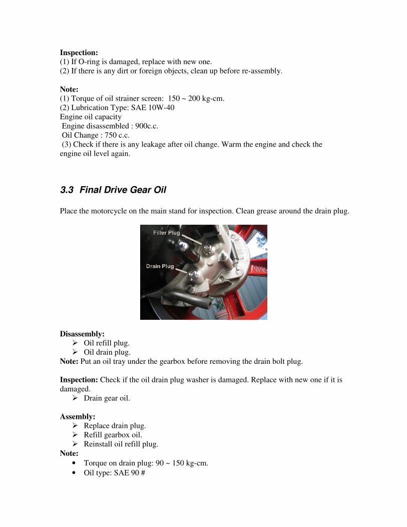
3.3 Final Drive Gear Oil
Place the motorcycle on the main stand for inspection. Clean grease around the drain plug.
Disassembly:
� Oil refill plug.
� Oil drain plug.
Note: Put an oil tray under the gearbox before removing the drain bolt plug.
Inspection: Check if the oil drain plug washer is damaged. Replace with new one if it is
damaged.
� Drain gear oil.
Assembly:
� Replace drain plug.
� Refill gearbox oil.
� Reinstall oil refill plug.
Note:
• Torque on drain plug: 90 ~ 150 kg-cm.
• Oil type: SAE 90 #

• Oil capacity
• Gearbox disassembled : 110 c.c.
• Regular Maintenance : 90 c.c.
Check if there is any leaking after oil refill.
3.4 Brake System
3.4.1 Front Brake Lever Free Play
Note: Front brake lever free play is 10~20 mm.
Adjustment: The free play of the front brake lever is not adjustable on this
scooter.
3.4.2 Brake Fluid
Inspection: The front brake fluid level should show half way up the visage window. If it
is below, refill the brake fluid and check for leakage in the brake system.
Warning: If there is low or no load when the brake lever is activated, check if there is air
in the brake system or if there is fluid leakage.
3.4.3 Refill Brake Fluid
Place the motorcycle on the main stand for inspection.
Disassembly:
� 2 tightening bolts on reservoir cover.
� Diaphragm.
� Refill brake fluid to correct level.
Assembly: Assembly is in reverse order of disassembly procedures.
Warning:
(1) Refill the same type of brake fluid. Mixing different fluid types may cause damage to
the brake.
(2) Do not let water into the master cylinder.
(3) If the brake fluid is splashed on plastic parts or paint, wipe it off immediately, and
wash with water.

3.4.4 Bleed Brake Line
(1) Apply suitable plastic tube on drain plug, and put a tray under drain hole.
(2) Slowly apply front brake several times.
(3) Hold the front brake lever, and maintain pressure.
(4) Loosen the bleeder valve.
(5) Tighten the valve, and then release the brake lever.
(6) Repeat procedure 1 to 5, until all air has been expelled.
Note: Torque of bleeder valve: 60 kg-cm.
3.4.5 Front Brake Disk
Inspection: If there are scratches or if there is damage, or wear, replace with new one.
Note: The minimum disk thickness: 3.0 mm.
Brake disk eccentricity.
Note: A. The max. eccentricity: 0.5 mm.
B. If eccentricity is not within the limit, check tyre roundness. If wheel rim
roundness is not within the limit, change the brake disk
3.4.6 Rear Brake Adjustment
Note: The free play of rear brake lever:
10 ~ 20 mm.

Adjustment: Adjust the adjustment nut.
3.4.7 Inspection of Brake Lining and Wheel
Inspection: Check the wear indicator plate. If the index is higher than the limit, check the
wear of wheel rim and brake lining.
Disassembly:
� 2 tightening bolts on exhaust pipe connector.
� 2 tightening bolts between exhaust pipe and right crankcase.
� Tightening nut on rear wheel axle.
� Washer.
� Rear wheel.
Inspection: check rear wheel rim inner diameter. If it is badly worn, replace
with a new one.
Note:
(1) Use vacuum to clean wheel rim and lining.
(2) Use the Vernier callipers to measure the diameter of wheel rim. If the diameter is
larger than 111 mm, then replace with new one.

� Disassemble the brake shoe and brake shoe spring.
Inspection: Measure the brake lining
thickness at three points with Vernier callipers
(two ends and centre). If badly worn, replace with new one (brake shoe and brake shoe
spring).
Note:
(1) Useable thickness is 2.0 mm.
(2) If less than useable thickness, replace with new parts.
Assembly: Assembly is in reverse order of disassembly procedures.
Note:
(1) Torque of rear wheel bearing bolt: 600 ~ 900 kg-cm.
(2) Torque of 2 bolts on exhaust pipe connector: 100 ~ 120 kg-cm.
(3) Torque of 2 bolts on exhaust pipe and right crankcase: 300 ~ 400 kg-cm.
3.5 Tyre and Tyre Pressure
Inspection: Check if tyre has been cracked, damage, worn, inclusions (stone, nail, glass,
etc.). If tyre is in poor condition, replace with new one.
Note: Tyre specifications in specification table.
Tyre pressure
Note: Measure tyre pressure when cool.
Note: Tyre pressure.
Front tyre: 175kPa(1.78 ㎏/㎝ 2 25.38 PSI)
Rear tyre: 210kPa(2.14 ㎏/㎝ 2 30.45 PSI)

Warning: Don’t over-load the motorcycle. Damage to the tyres may occur if the
motorcycle is overloaded.
3.6 Air Filter
Disassembly:
� Air filter side cover tightening bolt.
� Air filter side cover.
� Filter tightening bolt.
� Filter.
Inspection: Check if filter is dirty or broken. If dirty or broken, replace with a new one.
Note:
(1) If ridden on dusty roads or in wet conditions, shorten the replacement schedule for the
air filter.
(2) Don’t start engine when air filter is not installed. Dirt or foreign objects introduced as
a result may result in engine damage.
Assembly: Assembly is in reverse order of disassembly procedures.
Note: Please install air filter and side cover closely.

3.7 Battery
Disassembly:
Foot mat. (If present)
Battery box cover.
Disconnect the battery negative “-”
cable, and then the positive “+” cable.
Warning: Do not touch tools with any metal parts of the frame while disconnecting
positive “+” cable. A resulting short circuit could cause sparking and damage to the
battery.
Inspection: This motorcycle uses a lead/acid wet cell battery. Top up as required with
distilled water or battery electrolysis fluid
Assembly: Assembly is in reverse order of disassembly procedures.
Warning: First connect the positive “+” cable and then the negative“-” cable.
3.8 Spark Plug
Disassemble:
� Remove spark plug HT lead.
Note: Blow away deposits around the spark plug with blower before removing spark plug.
Otherwise, the dust may drop into cylinder resulting in damage to the engine.
Inspection: Check if spark plug has carbon deposits, is burned, or cracked. Use a steel
brush to remove carbon deposits and adjust the spark plug gap. Replace a burned or
cracked spark plug with new one.

Note: Spark plug specification:
CR7HAS (NGK).
Spark plug gap: 0.6 ~ 0.7 mm.
Warning: Install the spark plug initially by hand, and then tighten it with spark plug
wrench. Do not over tighten the spark plug.
Note: Torque of spark plug: 100 ~ 120 kg-cm.
3.9 Fuel Filter
Inspection: Check if it is hardened, damaged, or leaking. If any of these conditions exist,
replace with new one.
3.10 Carburettor Idle Speed
Note:
Place the motorcycle on the main stand for inspection.
Start engine and adjust idle speed at when the engine has warmed up.

* Adjust Procedure *
� Measure the engine idle speed with an appropriate gauge.
� Adjust idle speed to adequate range with phillips head screw driver.
Note:
(1) Increase engine speed by rotating the screw clockwise.
(2) Reduce engine speed by rotating the screw counter-clockwise.
(3) Engine idle speed range:
1800±100 rpm.
3.11 Throttle Valve
Inspection: Check if the throttle valve operation is smooth.
Note:
(1) Throttle lever free play: 2 ~ 6 mm.
(2) Micro-adjustment is performed at throttle lever. Macro-adjustment is performed at
carburettor throttle valve cable.
3.11.1 Throttle Lever Play Adjustment
Procedures:
� Open dust boot.
� Loose lock bolt.
� Adjust by rotating the adjusting nut.

Note:
1. Increase engine speed by rotating the nut clockwise.
2. Reduce engine speed by rotating the nut counter-clockwise.
� Tighten adjusting nut after adjustment.
� Close dust boot.
3.11.2 Carburettor Throttle Cable Play
Adjustment Procedure:
Note: First, adjust the throttle lever play. If it does not satisfy the specification, then
adjust the carburettor throttle play.
� Loosen the locking nut.
� Rotate the adjusting nut.
Note:
1. Increase play by rotating the screw clockwise.
2. Reduce play by rotating the screw counter-clockwise.
� Tighten the nut after adjustment.
3.12 V Belt
Note: Place motorcycle on the main stand for inspection.

Disassembly:
� Loose the air duct tightening ring.
� Kick start arm tightening bolt.
� Kick start arm.
� 8 clutch side cover tightening bolts.
� Clutch side plate.
� Gasket.
� Secure the drive plate, and remove the lock nut and gasket.
� Drive plate.

� V belt.
Inspection: Check if the V belt has cracked, deteriorating. If it is in poor condition,
replace it with a new V belt.
Note:
(1) Check the belt length.
Wear limit: 18.0 mm or 8000km
(2) Belt specification:
BANDO VS BELT 743 20 30
Assembly: Assembly is in reverse order of disassembly procedures.
Warning: Do not apply any grease on pulley or V belt
Note:
(1) Drive plate screw is left-threaded.
(2) Torque of drive plate nut: 800 ~ 1000 kg-cm.
(3) Torque of clutch side nut: 50 ~ 60 kg-cm.
(4) Torque of kick starter arm screw: 100 ~ 120 kg-cm.
3.13 Lubrication
3.13.1 Engine oil level
� The engine must be in cold and the scooter positioned on its stand on level ground.
� Inspect the oil level with the dip stick on the filler cap.
� Top up to the correct level with oil of the recommended type.
3.13.2 Oil renewal
� Renew the oil easily while the engine hot.

� Place a vessel under the engine, remove the sump plug and the oil level gauge.
(Note that on some engines the drain is also the oil strainer and is located at the bottom of
the sump)
After draining the oil, clean the oil level gauge (check the O-ring seal) and fit the drain
plug (strainer) again.
Tightening torque: 150 kg-cm
Add oil to the required level through the oil level gauge.
Lubrication Type: SAE 10W-40. Engine oil capacity - Engine disassembled:900c.c., Oil
change: 750c.c.
Replace the oil level gauge.
Note: Run the engine after a few minutes, then recheck the oil level.

4 CHASSIS
4.1 Removal of Cover

Dismount floor panels following the sequence shown in the list:
Caution:
1. Take care not to damage body panels while removing.
2. Take care not to damage lugs while removing.
3. When replacing, take care not to scratch panels or crush wiring.
4. Ensure all lugs are engaged in their relative slots.
5 TROUBLESHOOTING CHASSIS PROBLEMS
5.1 Steering/ Suspension/ Front Wheels/ Front Brakes
Note:
1. Lower leg shield must be removed before the front wheel is removed. Raise the
wheel above ground and support the scooter body firmly.
2. The brake cylinder and lining should be kept free from grease during work on the
front suspension.
Helmet Case
Carrier
Bottom Plate
Leg Shield, Lower Leg Shield, Rear
Lower Handlebar
Cover
Front Mudguard
Mudguard, Fixed ,
Front
Cover Set, Leg
Shield
Lower Side Leg
Shield
Right and Left Side
cover
Front Leg Shield
Upper Handle Bar
Cover
Rear View Mirror

5.1.1 Troubleshooting
Steering too tight (heavy)
1. The bearing at the top of the steering column too tight.
2. Bearing of the steering column broken.
3. The conical base of the steering bearing damaged.
4. Front fork bent.
5. Front wheel shaft bent.
6. Insufficient tyre pressure.
Steers to Right or Left: 1. Front fork component bent.
2. Front and left shock absorbers uneven in operation.
3. Front axle bent or not assembled straight.
4. Front tyre damaged.
5. Wheel rim damaged.
Front shock absorber too flexible:
1. Shock absorber spring constant too low.
2. Shock absorber spring fatigue.
3. Lack of oil in the shock absorber due to leakage.
4. Loose front fork axle bolts.
Front shock absorber noise:
1. Noise coming from friction between the shock absorber and the outer tube joint.
2. Noise coming from friction between the shock absorber spring and the outer tube.
3. Noise coming from shock absorber movement due to loose mounting.
4. Bent moving parts of the absorber.
Front wheel swing:
1. Bent wheel rim.
2. Insufficiently tightened bolts of front wheel axle.
3. Badly fitted or damaged front wheel bearing.
4. Worn tyres.
Inefficient braking
1. Unclean or oily brake lining/pads surface.
2. Excessive wear of the brake lining/pads.
3. Deformed brake discs.
4. Inefficient braking due to air in the braking system.
5. Insufficient brake fluid.
6. Deteriorated brake fluid.
7. Brake line clogged.
8. Improper mounting of brake calliper body.
9. Damaged seal of the piston of the brake calliper.
10. Bent brake rod.
Brakes difficult to operate:
1. Brake line clogged.
2. The brake calliper damaged.
3. The piston the main cylinder damaged or binding.
4. The brake rod bent.
Uneven braking effort.

1. Dirty brake lining/pads or brake disc.
2. Wheel incorrectly mounted.
3. Deformed brake disc.
4. Clogged brake line.
5. Wear of the brake lining/pads.
6. Damage of the seal of the brake calliper piston.
7. Deteriorated brake fluid.
8. Air in the brake system.
5.2 Front Wheel Place the scooter on the main stand for maintenance.
Disassembly:
� Speed meter cable nut.
� 2 tightening bolts on calliper.
� Calliper.
Note: Do not apply brake when removing calliper from brake disk.
� Front wheel.
Inspection: Check for eccentricity and wear.

Note: If eccentricity is higher than 0.2mm, replace with new one.
� Speedometer gear assembly.
5.2.1 Inspection of Wheel Rim
� Put wheel rim on rotation stand.
� Rotate the wheel slowly and use dial-gauge to measure eccentricity
Note:
1. The transverse eccentricity should be within 3.0 mm
2. The lateral eccentricity should be within 3.0mm.
Caution:
1. Speedometer gear assembly fillister and wheel hub flange should be
aligned.
2. The wheel hub flange fillister and front fork flange should be fully
matched.

Note:
Torque of rear wheel axle self-lock nut: 600~ 900 kg-cm.
Torque of brake calliper tightening bolt: 210 ~250 kg-cm.
Torque of speed meter cable nut: 60kg-cm
5.3 Rear Wheel
Place the scooter on the main stand for maintenance.
Disassembly:
1. Exhaust pipe.
2. Lock screw nut and washer.
3. Rear wheel.
Note:
1. Use vacuum to clean wheel rim and lining.
2. The transverse eccentricity should be within 3.0mm.
3. The lateral eccentricity should be within 3.0 mm

5.3.1 Brake lining assembly (brake shoe, brake shoe spring).
Inspection:
Using Vernier callipers make three measurements (two ends and centre) of the lining
thickness. If the lining is less than 2.0 mm, replace
the assembly.
Warning:
Do not get any grease on the brake lining.
Disassembly:
� Loosen the rear brake adjusting nut and remove brake cable.
� Brake arm cover.
� Brake spring.
� Rear brake connecting rod.
� Rear brake cam axle.
Assembly: Assembly is in reverse order of disassembly.
Note:
Apply a thin layer of grease to the contact areas
Torque of rear brake connecting rod bolt: 50 ~80 kg-cm.
Torque of lock pin nut: 250 ~270 kg-cm.
Torque of rear wheel self-locking nut: 600 ~ 900 kg-cm.
5.4 Rear Shock Absorber Place the scooter on the main stand for maintenance.
Disassembly:
� 2 attaching bolts on air filter.
� Air filter.

� Upper and lower attaching bolts on rear shock absorber.
� Shock absorber.
Inspection: Check if the shock absorber is worn, scratched, leaking, or bent.
Note: Torque of shock absorber upper and lower attaching bolts: 200 ~ 300 kg-cm.
6 ELECTRICAL SYSTEM
6.1 Maintenance & troubleshooting
Maintenance: 1. Warning:
The liquid in the battery is diluted sulphuric acid. If it contacts your skin or eye, wash
with copious amounts of water and in the case of eye contact consult a doctor.
2. Check if electrolyte in the battery is sufficient. If not, add distilled water till the
liquid level reach the upper limit line
3. If a battery is unused for a long time, its charge will decrease. A recharging is
necessary around every 3 months for unused batteries.
4. To charge the battery, remove it from the scooter and loosen the filler plugs. Do
not connect or disconnect the charger terminals while power is on as sparking
may ignite hydrogen gas from the battery.
5. During battery charging, hydrogen is produced. Avoid naked flame near the
charging battery.
6. The battery should be recharged at an electrolyte temperature of less than 45 . ℃
7. Ensure the main ignition switch is off when connecting or disconnecting power to
the charger to avoid damage to electronic components.
8. If fresh electrolyte is poured in a new battery, a recharge may be necessary.

9. Avoid dropping or causing heavy impact to the C.D.I of the ignition system.
10. Check all electrical connectors for solid contact.
11. Spark plugs of a suitable heat value and gap are to be used (see specifications).
Troubleshooting: Battery Recharging System:
No voltage:
1. Battery cable disconnected.
2. Fuse blown.
3. Defective of flywheel magneto.
4. Excessive battery discharging :
a. Electrolyte leaked.
b. Pollutants in battery electrolyte.
c. Short circuit in battery.
d. Defective rectifier.
Low voltage:
1. Insufficient recharging.
2. Leaking of electrolyte.
3. Bad cell in battery.
4. Defective battery terminals.
5. Defective recharging system.
6. Defective rectifier.
Excessive specific weight of electrolyte:
1. Insufficient recharging.
2. Leaking of electrolyte.
3. Reaction between sulphuric acid and pole plates.
Too low capacity:
1. Insufficient recharging.
2. Pole plates reacting with sulphuric acid.
3. Insufficient electrolyte.
4. Pole plates damaged due to excessive recharging.
Inefficient recharging system:
1. Bad contact at connectors, short circuit, or broken circuit.
2. Defective rectifier.
3. Defective of flywheel magneto.
a. Armature winding short circuited or broken.
b. Magneto coil short circuited or broken.
Ignition System:
No Spark at Plugs:
1. Defective of flywheel magneto.
2. Defective high-tension coil.
3. Defective C.D.I .
4. Defective spark plugs.
5. Defective contact, breaking, or short circuit, for example:
a. Connection between flywheel magneto and C.D.I .
b. Connection between C.D.I and the main switch.

c. Connection between C.D.I and the high-tension coil.
Engine not running smoothly:
1. Defective ignition first circuit:
a. Bad contact in circuitry or cable.
b. Defective of flywheel magneto.
2. Bad ignition secondary circuit.
a. The ignition coil insulation defect causing electric leakage.
b. Defective magneto coil.
I. Short circuit between coil layers.
II. Defective coil.
c. Defective spark plug.
I. Spark plug covered by carbon.
II. Electric leakage in ceramic part of spark plug.
d. d. Electric leakage from spark plug rubber screen.
3. Defective ignition timing.
a. Defective flywheel magneto.
b. Defective C.D.I .
c. Too large gap of spark plug.
d. Too high electric resistance of spark plug.
6.1.1 Starter System
Starter motor not operating.
1. Damaged battery.
2. Battery circuit broken, bad contact or too large resistance at connections.
3. Fuse blown.
4. Defective ignition switch.
5. Defective front and/or rear brake switches.
6. Defective starter motor switch.
7. Defective starter motor relay.
8. Defective starter motor.
9. Electric cables defective or broken.
10. Starter motor drive pinion locked with the over speed clutch gear.
Starter motor power insufficient:
1. Insufficient battery charge.
2. Bad contact on starter electric cables.
3. Binding in the starter motor pinion.
4. Armature shaft bent.
5. Commutator unclean or worn.
6. Motor brush worn or spring too weak.
7. Starter motor or relay defective.
6.2 Battery
Inspection:
Use specific gravity gauge to measure the electrolyte.

Note: Electrolyte’s specific gravity and charge level comparison table (20oC). Electrolyte Specific
Gravity
1.280 1.250 1.220 1.190 1.120
Charge Level Full
Charge
¾
Charged
½
Charged
¼
Charged
Totally
Discharged
6.2.1 Charging the battery
Connect battery and charger terminals positive to positive and negative to negative
Warning: Battery releases explosive gas during charging. Ensure adequate ventilation.
Note:
1. Standard charging current: 0.6 A for 5~10 hours.
2. Quick charging current: 6.0 A for 30 minutes.
3. Do not use quick charge except for emergency as battery life can be shortened.
4. Measure the battery voltage 30 minutes after battery is charged. The battery
voltage should be higher than 12.8 V.
6.2.2 Rectifier
Note:
(1) Check if wire harness is undamaged before checking rectifier and end
resistor. Check if rectifier connectors are secure.
(2) Keep fingers away from tester probe. The circuit resistance measurement can be
invalidated with body resistance included.

.
6.2.3 Starter Relay
6.2.4 Operation of starter relay.
Place the scooter on the main stand for inspection.
Inspection: Turn the main switch to “ON” position and press the starter
button.
Note:
(1) If there is a snap sound, then the function is normal.
(2) If there is no snap sound, then the function is abnormal.
Please check:
1. Starter relay ground circuit.
2. Starter relay voltage.