VMAX Dmx and Symmetrix All Commands at One Place
45
COMMAND EXPLANATION Symconfigure –h Provides brief, online help information including definitions and syntax Symconfigure –version Lists the SYMCLI, SYMAPI, and configuration server version information Symconfigure verify Verifies that the configuration currently running in the specified Symmetrix symconfigure -sid 45 abort Aborting a Hung Session symconfigure –freespace view how much available “unformatted” disk space is in the Symmetrix. CREATING DEVICES symconfigure -sid 23 verify Verify that you can open a session on the service processor. symdev list -da all –space (or) symdisk list Identify free space location. create dev count=2 size=8000 emulation=fba config=2-way-mir; Adding a New device count = the number of devices to create. size = the size of the device needed in number of cylinders. emulation = the device emulation type config = the device configuration type. delete dev xx, raidset = [TRUE | FALSE] deleting a symm device Update the symapi_db.bin on all attached servers running Solutions Enabler (symcfg discover) MAPPING DEVICES symdev list Confirm new devices were created. symconfigure -sid 23 verify Verify that you can open a session on the service processor.
-
Upload
venkatesh-chittimeni -
Category
Documents
-
view
372 -
download
7
description
VMAX Dmx and Symmetrix All Commands at One Place
Transcript of VMAX Dmx and Symmetrix All Commands at One Place

COMMAND EXPLANATIONSymconfigure –h Provides brief, online help information including
definitions and syntaxSymconfigure –version Lists the SYMCLI, SYMAPI, and configuration
server version informationSymconfigure verify Verifies that the configuration currently running in
the specified Symmetrixsymconfigure -sid 45 abort Aborting a Hung Sessionsymconfigure –freespace view how much available “unformatted” disk space
is in the Symmetrix. CREATING DEVICES
symconfigure -sid 23 verify Verify that you can open a session on the service processor.
symdev list -da all –space (or) symdisk list Identify free space location.create dev count=2 size=8000 emulation=fba config=2-way-mir;
Adding a New device count = the number of devices to create.size = the size of the device needed in number of cylinders.emulation = the device emulation typeconfig = the device configuration type.
delete dev xx, raidset = [TRUE |FALSE] deleting a symm deviceUpdate the symapi_db.bin on all attached servers running Solutions Enabler (symcfg discover)
MAPPING DEVICES symdev list Confirm new devices were created.symconfigure -sid 23 verify Verify that you can open a session on the service
processor.symdev list or symdev list –noport Select the device(s) to map.symcfg list –available –addresses –sa 5a –p 0 Determine available host addressesmap dev 1f2 to dir 5b:0, lun=1f wwn=10000000c9224fa8;
For peripheral device addressing (FC-SW or FC-AL) and to automatically update/refresh the VCMDB:
map dev aa to dir 4a:1, target=a, lun=1d; For SCSI:map dev cc to dir 12a:1, vbus=1, target=5, lun=12;
For fibre FC-SW or FC-AL with using volume set addressing: (HP)(Vbus-Fiber Virtual FA bus)
Update the symapi_db.bin on all attached servers running Solutions Enabler (symcfg discover)
symdev list –sa 4a –p 1 Verify devices are mapped.UNMAPPING DEVICES Select Devices to Unmap symdev list Select the device(s) to unmap.

symdev list –sa xx –p x If selecting device(s) on a specific port to unmap:symdev list –multiport If you need to see device(s) mapped to multiple
ports:symdev show 35 If you need see one device's mapping information:Stop I/O on Affected Devices symld -g unmapdg write_disable To write-disable a device on all ports:symld -g unmapdg write_disable -sa 5a -p 1 To write disable a device on a select port:symdev write_disable xxxx –sa xx –p x It is also possible to write-disable a device without
using device groups by using the following
To create a regular type of device group: symdg create-g dgname To create a regular type of device group:symld -g dgname add dev 55 Add device(s) to device group:symld -g dgname addall dev -range 34:3f To add a range of devices:UNMAP unmap dev ff:100 from dir 12a:0; To unmap a range of devices:unmap dev 101 from dir 4a:0; To unmap a device:unmap dev ccd from dir all:all; To unmap devices from all directors:Update the symapi_db.bin on all attached servers running Solutions Enabler (symcfg discover)
FORMING META DEVICES symconfigure -sid 23 verify Verify that you can open a session on the service
processorsymdev list (or) symdev list –noport Verify the devices are unmapped.symdev list –noport Select the devices to form the meta.symmir -g dgname split Split standards and BCVs if they are used to form a
meta.symld -g dgname remove DEV001 DEV006 Remove meta member candidates from device
groupsFORMING CONCATENATED & STRIPED META DEVICES
form meta from dev 0b8 config=concatenated; add dev 015:016 to meta 0b8;
To create a concatenated meta (manually selecting all members):
form meta from dev 011 config=striped stripe_size=1920 count=3;
To create a striped meta (letting the software automatically select the members):
symconfigure –sid 23 –v –f filename commit Run the symconfigure command.Update symapi_db.bin on all attached Servers running Solutions Enabler (symcfg Discover)
Display the meta device. symdev show xxx (where xxx is the meta head) or symdev list –meta

remove dev 0b9 from meta 0b8; To remove a meta member or members from the tail of a concatenated meta device
symmir -g dgname split Split meta device from BCV meta before removing member.
ADDING DEVICES IN STRIPED META
symconfigure -sid 23 verifyVerify that you can open a session on the service processor.
symmir –g dgname splitSplit standards and BCVs before adding them to a meta device
add dev 444 to meta 443, protect_data=true, bcv_meta_head=333; To add a device to a striped meta:symconfigure –sid 23 –v –f filename commit Run the symconfigure command.Update the symapi_db.bin on all attached servers running Solutions Enabler (symcfg discover) symdev list –meta Display the meta device.DISSOLVING META DEVICES
symconfigure -sid 23 verifyVerify that you can open a session on the service processor.
symmir -g dgname split Split meta device from meta BCV before dissolvingdissolve meta dev 0b8; To dissolve a meta:symconfigure –sid 23 –v –f filename commit Run the symconfigure command.symdev list –meta Verify that meta device is dissolvedBCV
symbcv list pdTo list all BCV devices that are visible to your host, enter:
symbcv list devTo list all BCV devices, regardless of whether they are visible to your host, enter:
symmir -g prod -full establishTo initiate a full establish on all the BCV pairs in the prod device group
symmir -g prod -full establish DEV001To initiate a full establish on one BCV pair, DEV001, in the prod device group, enter
symmir -g prod -full establish DEV001 BCV ld BCV005 DEV002 BCV ld BCV007 DEV003 BCV ld BCV008
To initiate a full establish on more than one BCV pair (list) in the prod device group with one command, enter:
symmir -full establish DEV003 BCV dev 0b2 symmir establish: Selected Devicessymmir split symmir splitsymmir restore -full –noprompt symmir restore
CLONE symclone –g ProdDB create DEV001 sym ld DEV005 symclone –g ProdDB create DEV001 sym ld DEV006 Multiple Clone Copies

symclone-g clonegrp activate SRC001 sym ld TGT002 -not_ready The clone volume is placed in NR state
symclone -g clonegrp activate -consistentCreate a consistent image of a heterogeneous database environment
symclone -g clonegrp terminate SRC001 sym ld TGT002 Terminate a Copy Sessionsymclone –g clonegrp restore SRC001 sym ld TGT002 Restore from a TimeFinder Clonesymclone list The symclone list / query command:symclone activate SRC001 sym ld TGT001 –nop Activate the symclone Sessionsymclone terminate SRC001 sym ld TGT001 –nop Terminate the symclone SessionSYMMSNAP OPERATIONS
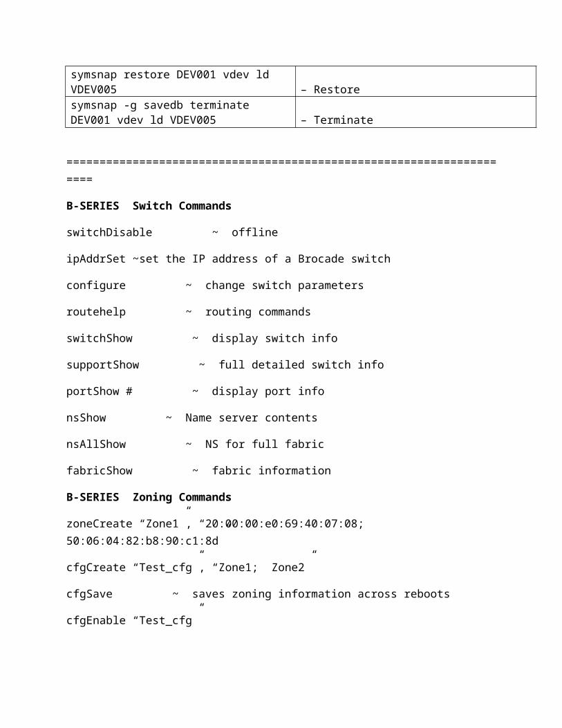
symsnap -g savedb create DEV001 vdev ld VDEV005 -svp save_db – Createsymsnap -g savedb activate DEV001 vdev ld VDEV005 – Activatesymsnap restore DEV001 vdev ld VDEV005 – Restoresymsnap -g savedb terminate DEV001 vdev ld VDEV005 – Terminate
=====================================================================
B-SERIES Switch Commands
switchDisable ~ offline
ipAddrSet ~set the IP address of a Brocade switch
configure ~ change switch parameters
routehelp ~ routing commands
switchShow ~ display switch info
supportShow ~ full detailed switch info
portShow # ~ display port info
nsShow ~ Name server contents
nsAllShow ~ NS for full fabric
fabricShow ~ fabric information

B-SERIES Zoning Commands
zoneCreate “Zone1”, “20:00:00:e0:69:40:07:08; 50:06:04:82:b8:90:c1:8d”
cfgCreate “Test_cfg”, “Zone1; Zone2”
cfgSave ~ saves zoning information across reboots
cfgEnable “Test_cfg”
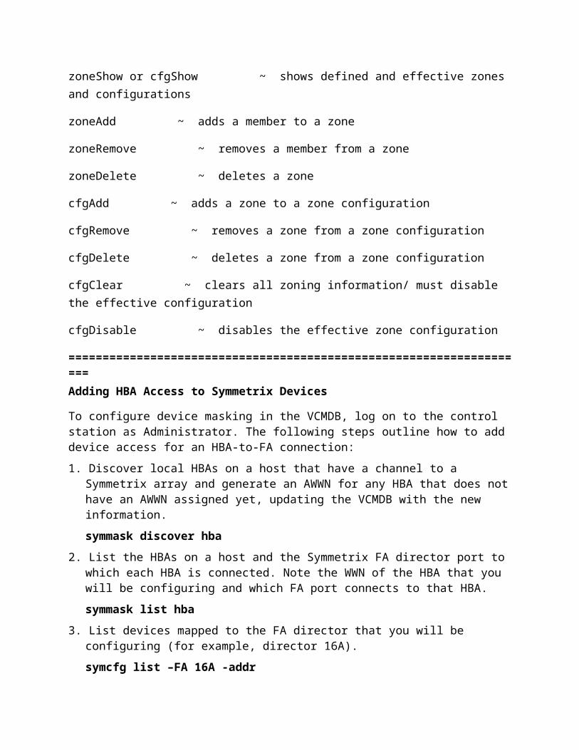
zoneShow or cfgShow ~ shows defined and effective zones and configurations
zoneAdd ~ adds a member to a zone
zoneRemove ~ removes a member from a zone
zoneDelete ~ deletes a zone
cfgAdd ~ adds a zone to a zone configuration
cfgRemove ~ removes a zone from a zone configuration
cfgDelete ~ deletes a zone from a zone configuration
cfgClear ~ clears all zoning information/ must disable the effective configuration
cfgDisable ~ disables the effective zone configuration
====================================================================
Adding HBA Access to Symmetrix Devices
To configure device masking in the VCMDB, log on to the control station as Administrator. The following steps outline how to add device access for an HBA-to-FA connection:
1. Discover local HBAs on a host that have a channel to a Symmetrix array and generate an AWWN for any HBA that does not have an AWWN assigned yet, updating the VCMDB with the new information.
symmask discover hba
2. List the HBAs on a host and the Symmetrix FA director port to which each HBA is connected. Note the WWN of the HBA that you will be configuring and which FA port connects to that HBA.
symmask list hba
3. List devices mapped to the FA director that you will be configuring (for example, director 16A).
symcfg list –FA 16A -addr
4. Make an entry for the HBA-to-FA connection in the VCMDB2, specifying devices that the HBA can access. For example, add a range of devices (0030 through 0034) to the VCMDB on the Symmetrix array (–sid 814), specifying the HBA’s WWN and the FA director/port that the HBA connects to.
symmask –sid 814 –wwn 20000000c920b484 add devs 0030:0034 –dir 16A -p 0
5. When you finish making HBA entries in the VCMDB, proceed with the following steps. Back up the revised VCMDB to a file (for example, a file called MyDevMaskBackup).
symmask –sid 814 backup –file MyDevMaskBackup
6. Refresh the WWN-related profile tables in the Symmetrix cache with the latest VCMDB data. The following command updates the cache on all FA directors with the contents of the VCMDB.
symmask refresh
7. Reboot the host whose HBA entry you added to the VCMDB.
8. When you reboot a host, you need to scan the Symmetrix devices and refresh the SYMAPI database.
symcfg discover
Removing Devices
You can remove some devices associated with an HBA entry, or you can remove the entire set of devices associated with an HBA entry. Removing some devices (but not all) requires syntax similar to that for adding devices and the same refresh, backup, and discover steps after completing the remove operation.
To remove devices 0031 and 0033 from the 0030-to-0034 range of devices that was added previously:
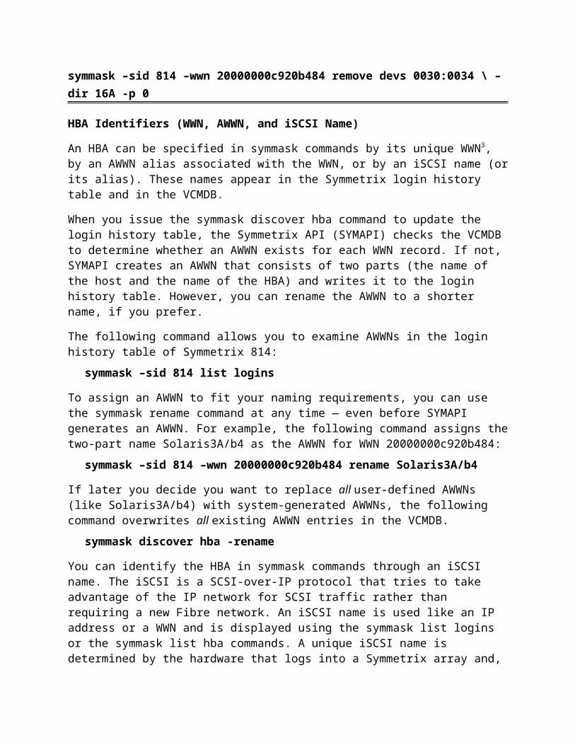
symmask –sid 814 –wwn 20000000c920b484 remove devs 0031,0033 –dir 16A -p 0
To remove the remaining devices in the 0030-to-0034 device range, you can specify individual devices or the range with an option (–force) that allows you to remove a noncontiguous range. For example: symmask –sid 814 –wwn 20000000c920b484 remove devs 0030:0034 \ –dir 16A -p 0
HBA Identifiers (WWN, AWWN, and iSCSI Name)
An HBA can be specified in symmask commands by its unique WWN3, by an AWWN alias associated with the WWN, or by an iSCSI name (or its alias). These names appear in the Symmetrix login history table and in the VCMDB.
When you issue the symmask discover hba command to update the login history table, the Symmetrix API (SYMAPI) checks the VCMDB to determine whether an AWWN exists for each WWN record. If not, SYMAPI creates an AWWN that consists of two parts (the name of the
host and the name of the HBA) and writes it to the login history table. However, you can rename the AWWN to a shorter name, if you prefer.
The following command allows you to examine AWWNs in the login history table of Symmetrix 814:
symmask –sid 814 list logins
To assign an AWWN to fit your naming requirements, you can use the symmask rename command at any time — even before SYMAPI generates an AWWN. For example, the following command assigns the two-part name Solaris3A/b4 as the AWWN for WWN 20000000c920b484:
symmask –sid 814 –wwn 20000000c920b484 rename Solaris3A/b4
If later you decide you want to replace all user-defined AWWNs (like Solaris3A/b4) with system-generated AWWNs, the following command overwrites all existing AWWN entries in the VCMDB.
symmask discover hba -rename
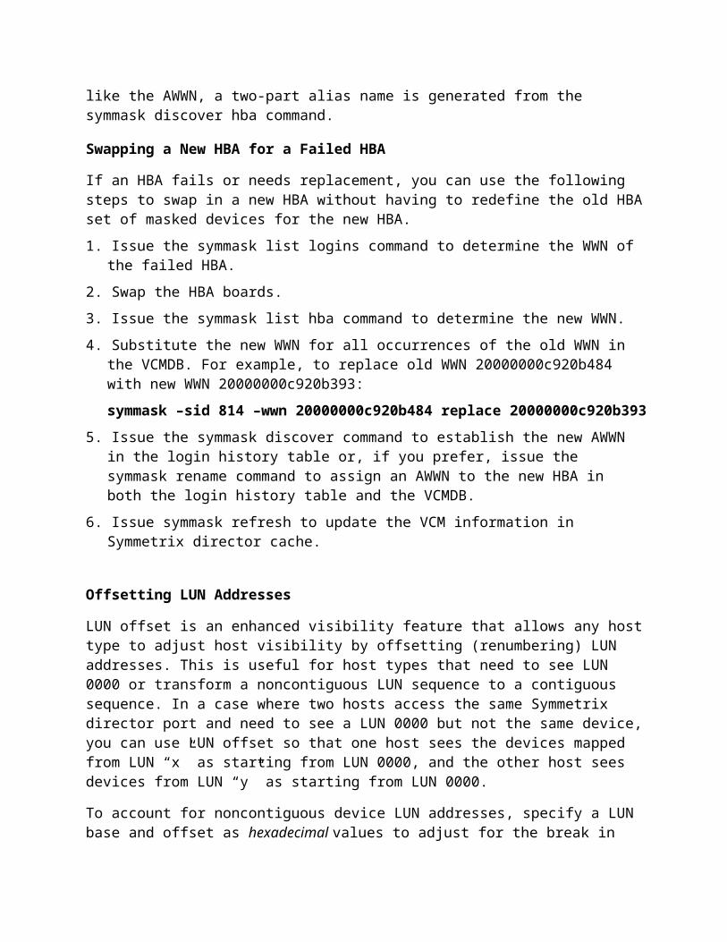
You can identify the HBA in symmask commands through an iSCSI name. The iSCSI is a SCSI-over-IP protocol that tries to take advantage of the IP network for SCSI traffic rather than requiring a new Fibre network. An iSCSI name is used like an IP address or a WWN and is displayed using the symmask list logins or the symmask list hba commands. A unique iSCSI name is determined by the hardware that logs into a Symmetrix array and, like the AWWN, a two-part alias name is generated from the symmask discover hba command.
Swapping a New HBA for a Failed HBA
If an HBA fails or needs replacement, you can use the following steps to swap in a new HBA without having to redefine the old HBA set of masked devices for the new HBA.
1. Issue the symmask list logins command to determine the WWN of the failed HBA.
2. Swap the HBA boards.
3. Issue the symmask list hba command to determine the new WWN.
4. Substitute the new WWN for all occurrences of the old WWN in the VCMDB. For example, to replace old WWN 20000000c920b484 with new WWN 20000000c920b393:
symmask –sid 814 –wwn 20000000c920b484 replace 20000000c920b393
5. Issue the symmask discover command to establish the new AWWN in the login history table or, if you prefer, issue the symmask rename command to assign an AWWN to the new HBA in both the login history table and the VCMDB.
6. Issue symmask refresh to update the VCM information in Symmetrix director cache.
Offsetting LUN Addresses

LUN offset is an enhanced visibility feature that allows any host type to adjust host visibility by offsetting (renumbering) LUN addresses. This is useful for host types that need to see LUN 0000 or transform a noncontiguous LUN sequence to a contiguous sequence. In a case where two hosts access the same Symmetrix director port and need to see a LUN 0000 but not the same device, you can use LUN offset so that one host sees the devices mapped from LUN “x” as starting from LUN 0000, and the other host sees devices from LUN “y” as starting from LUN 0000.
To account for noncontiguous device LUN addresses, specify a LUN base and offset as hexadecimal values to adjust for the break in the LUN sequence. The base hex value represents the first LUN in a renumbered LUN sequence. The offset hex value added to the base value determines where to begin renumbering. For example, if a host needs to detect LUN 0000 but you want your host to detect only LUNs 0005 through 0008, you can specify a LUN base address of 0000 and an offset of 0005. The following command renumbers LUNs 0005 through 0008 as LUNs 0000 through 0003:
symmask –sid 814 set lunoffset on 0005 0000 –dir 16A -p 0 –wwn 20000000c920b484
On the other hand, if your masked devices for an HBA-to-FA connection had LUN addresses 0000–0003 and 0007–0009, you would need to specify a LUN base address of 0004 and an offset of 0003 (to renumber LUNs 0007–0009 as LUNs 0004–0006). You can record only one gap per HBA-to-FA connection. If you have multiple hosts that cannot discover devices with noncontiguous LUN addresses, you need to issue the symmask set lunoffset command for each host.
Add and Remove Masked Devices:
symmask -sid 0128 -awnn Host3b/4a add devs 0014,0015 -dir 16a -p 0
Removing Meta Members: symmaskdb –sid xxxx -meta_member remove
Initializing the Database:symmaskdb -sid 0128 init -file BackupDevMask1 (name)
Viewing the Login History Table:symmask –s id 6196 list logins
Refreshing Director Profile Tables: symmask refresh ,symmask discover hba
Viewing the Database:# symmaskdb -sid 0128 list database
Sort for port at a dir :symmaskdb -sid 6196 list database -dir 2b -p 1Viewing Device Capacity:symmaskdb -sid 6196 list capacity -host api145 (host name)
symmaskdb -sid 6196 list assignment -dev 0040:0043 (mapped dev to host)symmaskdb -sid 6196 list devs -wwn 10000000c9238053 (List devs configured to host n size)
Managing a Backup Database File :symmaskdb -sid 0128 backup -file BackupDevMask (back up file name)
Restoring a Database:symmaskdb -sid 0128 restore -file BackupDevMask symmaskdb -sid 0128 restore -file BackupDevMask -skip_authentication (skip authen from restore)
Converting a Database Type: symmaskdb -sid 0128 convert -vcmdb_type type_4
Writing Directly to the VCMDB:symmaskdb -sid 0128 set -no_direct_io (disallows the use of versions of SYMCLIprior to version 5.3. -no_direct_io )
Symmetrix locks. 0-15 (with the exception # 9)symcfg list -lockn all -v (If you are viewing from the host attached to the symm in question)
symcfg -sid XXXX list -lockn all (Remote viewing -this will tell you all the symm locks (config,optm,vcm)
symcfg -sid XXX list -lockn all -v (will show you more details who put the lock and how long it was held
ie: E301XXXX - This was set by customer EX02XXXX- This was held by CE. DO NOT release any lock that was put there by the CE.
Releasing Symmetrix locks:symcfg -lockn <number> release -force (if releasing from the host attached to symm)
symcfg -sid XXXX -lockn <number> release -force (ie: symcfg -sid XXXX -lockn 15 release -force)
Device locks # 9:symdev -sid XXXX -lock list (if viewing from remote host)
symdev -lock list (will show all the devices that are locked - (from attached host) at times,however, you need to discover any new changes to see the lock if it comes back unknown (means there are no locks) then do
symcfg discover: this will discover any changes made. After the prompt comes back. retry the symdev -lock list command it should show you all the devices, if any, that are locked on the symm.
Releasing device lock:
Caution: if you notice that there is a -L next to the flag setting: This indicates that there is a long lock that is normal. (most likely a symreplicate process.) before releasing lock check with your replicate manager and see if they can stop the process so that you can work with the devices in question.
symdev -lock 9 release -force -nop
symdev -sid XXXX -lock 9 release -force -nop: (that stands for NO Prompt- so that you are not prompted for each and every device that is locked.
=====================================================================EMC: SRDF modes
SRDF — General monitor and control operations; SRDF/S — Synchronous mode ; SRDF/A — Asynchronous mode
SRDF/AR — Automated Replication ; SRDF/CG — Consistency Groups ;
Conceptually, even operationally, SRDF is very similar to Timefinder. About the only difference is that SRDF works across Symms; while Timefinder works internally to one Symm.
That difference, intersymm vs intrasym, means that SRDF operations can cover quite a bit of ground geographically. With the advent of geographically separated symms, the integrity of the data from one symm to the other becomes a concern. EMC has a number of operational modes in which the SRDF operates. The choice between these operational modes is a balancing act between how quickly the calling application gets an acknowledgement back versus how sure you need to be that the data has been received on the remote symm.
Synchronous modeSynchronous mode basically means that the remote symm must have the I/O in cache before the calling application receives the acknowledgement. Depending on distance between symms, this may have a significant impact on performance which is the main reason that EMC suggests this set up in a campus (damn near co-located) environment only.
If you're particularly paranoid about ensuring data on one symm is on the other, you can enable the Domino effect (I think you're supposed to be hearing suspense music in the background right about now...). Basically, the domino effect ensures that the R1 devices will become "not ready"

if the R2 devices can't be reached for any reason - effectively shutting down the filesystem(s) until the problem can be resolved.
#symrdf -g prod set mode sync
Semi-synchronous modeIn semi-synchronous mode, the R2 devices are one (or less) write I/O out of sync with their R1 device counterparts. The application gets the acknowledgement as soon as the first write I/O gets to the local cache. The second I/O isn't acknowledged until the first is in the remote cache. This should speed up the application over the synchronous mode. It does, however, mean that your data might be a bit out of sync with the local symm.
#symrdf -g prod set mode semi
Adaptive Copy-Write PendingThis mode copies data over to the R2 volumes as quickly as it can; however, doesn't delay the acknowledgement to the application. This mode is useful where some data loss is permissible and local performance is paramount.
There's a configurable skew parameter that lists the maximum allowable dirty tracks. Once that number of pending I/Os is reached, the system switches to the predetermined mode (probably semi-synchronous) until the remote symm catches up. At that point, it switches back to adaptive copy-write pending mode.
Adaptive Copy – Disk
The adaptive copy disk mode is designed for situations requiring the transfer of large amounts of data without loss of performance. Because the Symmetrix array cannot fully guard against data loss should a failure occur, it is recommended that you use this mode temporarily to transfer the bulk of your data to target (R2) devices, and then switch to a full SRDF mode (synchronous or semi-synchronous) or adaptive copy-write pending mode (if you can tolerate some lack of synchronization between the remotely mirrored pairs) to ensure full data protection. When you set the SRDF mode to adaptive copy disk, the Symmetrix array acknowledges all writes to source (R1) devices as if they were local devices. New data accumulates on the source (R1) device and is marked by the source (R1) side as invalid tracks until it is subsequently transferred to the target (R2) device. The remote director transfers each write to the target (R2) device whenever link paths become available.
For example, to turn on the adaptive copy disk mode for the prod group, enter:
#symrdf -g prod set mode acp_disk
To turn the adaptive copy disk mode off for the prod group, enter:
#symrdf -g prod set mode acp_off

This attribute also has a user-configurable skew (maximum number of invalid tracks threshold), that when exceeded, causes the remotely mirrored device to operate in the predetermined SRDF state (synchronous or semi-synchronous) when this mode is in effect. As soon as the number of invalid tracks drops for a device below this value, the remotely mirrored pair reverts back to the adaptive copy write pending mode.
Adaptive Copy Change Skew
This attribute is used to modify the adaptive copy skew threshold. When the skew threshold is exceeded, the remotely mirrored pair operates in the predetermined SRDF state (synchronous or semi-synchronous). As soon as the number of invalid tracks drops below this value, the remotely mirrored pair reverts back to the adaptive copy mode. The skew value is configured at the device level and may be set to a value between 0 and 65,534 tracks. For devices larger than a 2 GB capacity drive, a value of 65,535 can be specified to target all the tracks of any given drive.
For example, to change the adaptive copy skew value to all tracks of device BCV023 of group prod, enter: #symrdf -g prod set acp_skew 65535 BCV023
To change the adaptive copy skew value to 30,000 tracks for device
BCV023 of group prod, enter:
#symrdf -g prod set acp_skew 30000 BCV023
R2 Not Ready
This attribute is used to set the R2 Not Ready if there are invalid tracks. Invalid tracks could be either remote invalids on the source (R1) side or target (R2) invalids on the source (R1) side. Invalid tracks occur when the user enables the target (R2) for Read/Write status. If there are invalid tracks, the device RDF status is set to Not Ready. Set the nr_if_invalid argument to on or off. For example, to set the target (R2) side of the SRDF configuration to the Not Ready state if there are invalid tracks for device BCV023 of group prod, enter:
#symrdf -g prod set nr_if_invalid on BCV023
DOMINO FEATURE: Domino mode is recommended to ensure data currency on all symmetrix frame that there is no possibility of inconsistent data at R2 side incase of SRDF link failure .If Domino mode is not enabled & if all SRDF links fail and the application continues to modify the data on the R1, but the new data is not replicated to the R2 side. The R2 only contains a copy of data up to the point of CA links failure. If additional failure occurs, such as a system failure before the SRDF link is fixed. This can cause the application to fail over to the R2 side, & the application will have to deal with non-current data. The inconsistent and therefore unusable data will result from the following sequence of circumstances

Domino mode is not enabled SRDF links fail the application continues to modify the data the link is restoredresynchoronization from R1 to R2 starts but does not finish
The disadvantage of enabling Domino Mode is that when SRDF link fails, all I/Os will be refused (to those devices) until the SRDF link is restored. Or manual intervention is undertaken to disable domino mode.
#symrdf -g prod set domino off
#symrdf -g prod set domino on
SRDF-A(Asynchronous):SRDF-A provides a long-distance replication solution with minimal impact on performance. This level is intended for customers requiring minimal host application impact, who need to maintain a restorable copy of data at the R2 side, which preserves data consistency within the database. In the event of a disaster at the R1 site or if SRDF links are lost during data transfer, a partial delta set of data is discarded. However, a dependent write consistent point-in-time copy of data is retained on the target side.
#symrdf -g prod set mode async
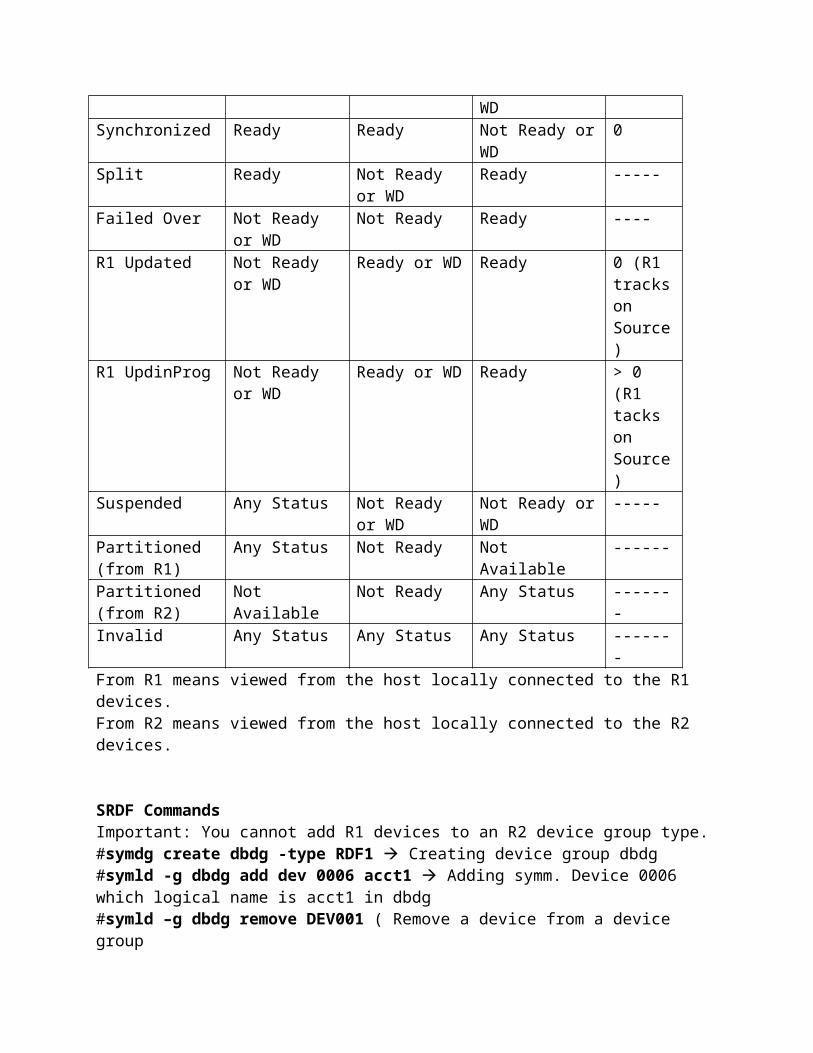
SRDF PAIR STATE
R1 STATE(Source)
RDF LINK STATUS
R2 STATE(Target)
Invalid Tracks
SynchInProg Ready Ready Not Ready or WD > 0Synchronized Ready Ready Not Ready or WD 0Split Ready Not Ready or
WDReady -----
Failed Over Not Ready or WD
Not Ready Ready ----
R1 Updated Not Ready or WD
Ready or WD Ready 0 (R1 tracks on Source)
R1 UpdinProg Not Ready or WD
Ready or WD Ready > 0 (R1 tacks on Source)
Suspended Any Status Not Ready or WD
Not Ready or WD -----
Partitioned (from R1)
Any Status Not Ready Not Available ------
Partitioned (from R2)
Not Available Not Ready Any Status -------
Invalid Any Status Any Status Any Status -------From R1 means viewed from the host locally connected to the R1 devices.From R2 means viewed from the host locally connected to the R2 devices.
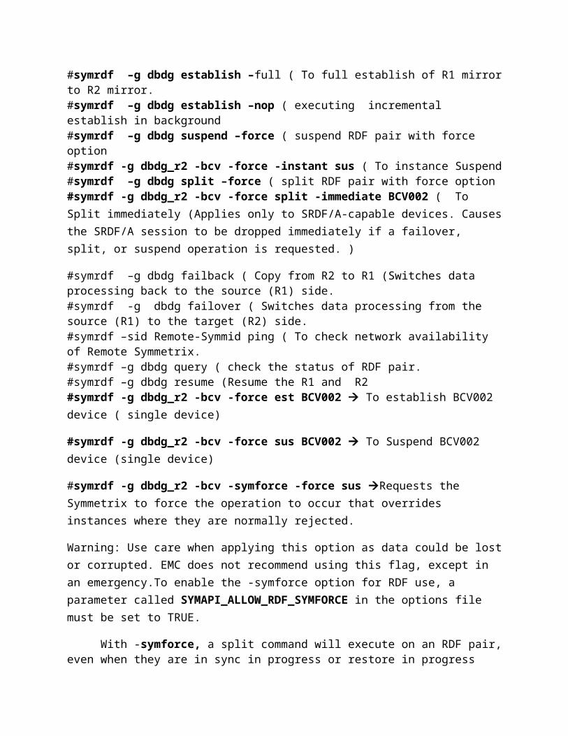
SRDF CommandsImportant: You cannot add R1 devices to an R2 device group type.#symdg create dbdg -type RDF1 Creating device group dbdg#symld -g dbdg add dev 0006 acct1 Adding symm. Device 0006 which logical name is acct1 in dbdg#symld –g dbdg remove DEV001 ( Remove a device from a device group#symrdf –g dbdg establish –full ( To full establish of R1 mirror to R2 mirror.#symrdf –g dbdg establish –nop ( executing incremental establish in background#symrdf –g dbdg suspend –force ( suspend RDF pair with force option#symrdf -g dbdg_r2 -bcv -force -instant sus ( To instance Suspend#symrdf –g dbdg split –force ( split RDF pair with force option#symrdf -g dbdg_r2 -bcv -force split -immediate BCV002 ( To Split immediately (Applies only to SRDF/A-capable devices. Causes the SRDF/A session to be dropped immediately if a failover, split, or suspend operation is requested. )
#symrdf –g dbdg failback ( Copy from R2 to R1 (Switches data processing back to the source (R1) side.#symrdf -g dbdg failover ( Switches data processing from the source (R1) to the target (R2) side.#symrdf –sid Remote-Symmid ping ( To check network availability of Remote Symmetrix.#symrdf –g dbdg query ( check the status of RDF pair.#symrdf –g dbdg resume (Resume the R1 and R2#symrdf -g dbdg_r2 -bcv -force est BCV002 To establish BCV002 device ( single device)
#symrdf -g dbdg_r2 -bcv -force sus BCV002 To Suspend BCV002 device (single device)
#symrdf -g dbdg_r2 -bcv -symforce -force sus Requests the Symmetrix to force the operation to occur that overrides instances where they are normally rejected.
Warning: Use care when applying this option as data could be lost or corrupted. EMC does not recommend using this flag, except in an emergency.To enable the -symforce option for RDF use, a parameter called SYMAPI_ALLOW_RDF_SYMFORCE in the options file must be set to TRUE.
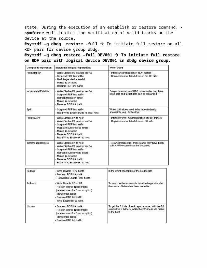
With -symforce, a split command will execute on an RDF pair, even when they are in sync in progress or restore in progress state. During the execution of an establish or restore command, -symforce will inhibit the verification of valid tracks on the device at the source.#symrdf –g dbdg restore –full To initiate full restore on all RDF pair for device group dbdg.#symrdf –g dbdg restore –full DEV001 To initiate full restore on RDF pair with logical device DEV001 in dbdg device group.

1) symmaskdbBacks up, restores, initializes, and shows the contents of the Device Maskingdatabase.
1) symmaskdb list no_assignment -dir all -sid 92It will list all the devices from the SYMM 92 which are not yet masked for any HBA forany FA port, mean these devices are not
available to any host. But these devices are mapped to respective FAs.

2) symmaskdb list -sid 92 no_assignment -dir 16c -p 0 It will show all the devices mapped to FA 16c0 but not masked for any HBA.
3) symmaskdb list -sid 92 assignment -dev 287 It will show masking info for the SYMM dev id 287 from the SYMM 92.Below output is showing the Dir, port and HBA PWWN info, to whom this device isassigned.
4) symmaskdb -sid 92 list database -dir all It will list whole masking database for the SYMM 92.
2. symmaskSets up or modifies Symmetrix Device Masking functionality.For help --- symmask –h
1) symmask -sid 92 list loginsIt will show all the zoned HBA's login status to the FA.
2)symmask -sid 92 list logins -dir 16c -p 0This command is showing the login status of HBAs for the FA 16CA (Dir 16c and Port 03) symmask -sid 92 -wwn 2100001b321a7151 -dir 16c -p 0 add dev 287It will mask the device 287 for the hba "2100001b321a7151" on the FA 16c0. Then thehost zoned with FA 16c0 will be able to see this device.
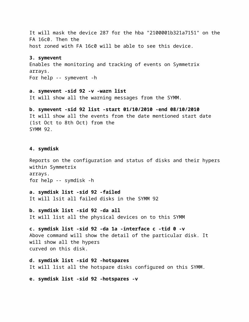
3. symeventEnables the monitoring and tracking of events on Symmetrix arrays.For help -- symevent -h
a. symevent -sid 92 -v -warn listIt will show all the warning messages from the SYMM.
b. symevent -sid 92 list -start 01/10/2010 -end 08/10/2010It will show all the events from the date mentioned start date (1st Oct to 8th Oct) from theSYMM 92.
4. symdisk
Reports on the configuration and status of disks and their hypers within Symmetrixarrays.for help -- symdisk -h
a. symdisk list -sid 92 -failedIt will lsit all failed disks in the SYMM 92
b. symdisk list -sid 92 -da allIt will list all the physical devices on to this SYMM

c. symdisk list -sid 92 -da 1a -interface c -tid 0 -vAbove command will show the detail of the particular disk. It will show all the hyperscurved on this disk.
d. symdisk list -sid 92 -hotsparesIt will list all the hotspare disks configured on this SYMM.
e. symdisk list -sid 92 -hotspares -vIt will give the details of the hotspare status and also it invoked or not ?
3. symdevDisplays information for the selected, or all, Symmetrix devices.For help issue - suymdev –h
a. symdev list -sid 92It will show all the created devices/volumes on to the SYMM 92.symdev list -sid 92 -vIt will show the detail information for all the volumes.If you want to see detail of any one volume, then issuesymdev show -sid <symm device id>
b. symdev list -sid 92 -fa 15c -p 1It will list the device mapped to the FA 15c and port 1
c. To make a NR device to Ready.symdev -sid 92 ready <SymDevName>
d. To make a device Not Readysymdev -sid 92 not_ready <SymDevName>
e. To make the device write disable of particular FA 15C Port 0symdev -sid 92 write_disable <SymDevName> -sa 15c -p 0
f. To make the device write enable on particular FA 15c port 0symdev -sid 92 rw_enable <SymDevName> -sa 15c -p 0
g. symdev list -sid 92 -inventoryIt will show over all inventory lists like below..
h. symdev list -sid 92 -vcm -vIt will show the details of the VCM DB device from this SYMMi. symdev list -sid 92 -DA allIt will list all the volumes and the DA information for them.
j.You can list all volumes with specific configurationsymdev list -sid 92 -raid5 -protection 3+1

orsymdev list -sid 92 -raid5 -protection 7+1Above commands will list all RAID5 volumes created on to this SYMMsymdev list -sid 92 -raid6 -protection 6+2symdev list -sid 92 -raid6 -protection 14+2
j.symdev list -sid 92 -r1 -- will list all R1 volumes created on to this SYMMsymdev list -sid 92 -r2 -- will list all R2 volumes created on to this SYMM
k. symdev list -sid 92 -da 1a -interface cThe above command will list volumes created from the disks attached to DA 1a and theinterface or loop c
2. symconfigureAllows the user to manage configuration changes affecting devices of specifiedSymmetrix arrays, as well as manage device reservations, and virtual provisioning.For help you need to issue - symconfigure –h
a. symconfigure list -sid 92 -freespaces -units MBIt will show the free space on the SYMM 92 (unalocated space.)
b. symconfigure -version -v -sid 92It will show the detail version of the installed SolutionEnabler and the enginuity code ofthe SYMM mentioned.
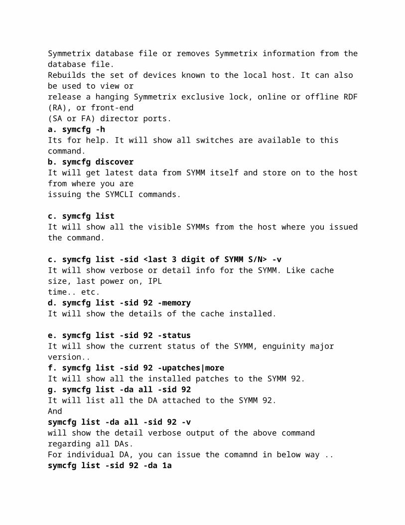
1. symcfgDiscovers or displays Symmetrix configuration information. Refreshes the host'sSymmetrix database file or removes Symmetrix information from the database file.Rebuilds the set of devices known to the local host. It can also be used to view orrelease a hanging Symmetrix exclusive lock, online or offline RDF (RA), or front-end(SA or FA) director ports.a. symcfg -hIts for help. It will show all switches are available to this command.b. symcfg discoverIt will get latest data from SYMM itself and store on to the host from where you areissuing the SYMCLI commands.
c. symcfg listIt will show all the visible SYMMs from the host where you issued the command.
c. symcfg list -sid <last 3 digit of SYMM S/N> -vIt will show verbose or detail info for the SYMM. Like cache size, last power on, IPLtime.. etc.
d. symcfg list -sid 92 -memoryIt will show the details of the cache installed.
e. symcfg list -sid 92 -statusIt will show the current status of the SYMM, enguinity major version..f. symcfg list -sid 92 -upatches|moreIt will show all the installed patches to the SYMM 92.g. symcfg list -da all -sid 92It will list all the DA attached to the SYMM 92.Andsymcfg list -da all -sid 92 -vwill show the detail verbose output of the above command regarding all DAs.For individual DA, you can issue the comamnd in below way ..symcfg list -sid 92 -da 1aorsymcfg list -sid 92 -da 1a -vh. symcfg list -fa all -sid 92It will show all the FA installed on to the SYMM 92 Andsymcfg list -fa all -sid 92 -vwill show the detail and verbose output of the above command.same for single FA, you can issue the command in below manner..symcfg list -sid 92 -fa 1c
i. symcfg list -sid 92 -ra allIt will list all the configured RA director on the SYMM 92j. symcfg list -sid 92 -connectionsIt will show, what type of Hosts are connected with this SYMM and on which FA.
k. symcfg list -sid 92 -env_dataIt will show all the environment data on the screen
l. symcfg list -sid 92 -connections -capacityIt will show what total space is allocated to all the hosts.
m. symcfg list -sid 92 -lockn allIt will list the lock no. present in the SYMM 92.
symcfg list -sid 92 -lockn all -vwill show the detail of the lock.
n. symcfg -sid 92 monitorIt will show the present status of all the pool created on to this SYMM 92.Symmetrix ID: 000190300692
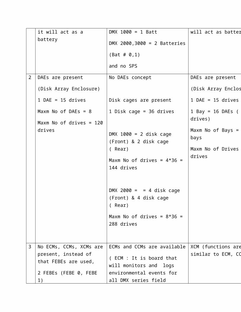
DMX 800 DMX 1000, 2000, 3000 DMX 3
1 No Batteries, instead of that SPS are used, it will act as a battery
Batteries are available,
DMX 1000 = 1 Batt
DMX 2000,3000 = 2 Batteries
(Bat # 0,1)
and no SPS
No Batteries, instead of that SPS are used, it will act as battery
2 DAEs are present
(Disk Array Enclosure)
1 DAE = 15 drives
Maxm No of DAEs = 8
Maxm No of drives = 120 drives
No DAEs concept
Disk cages are present
1 Disk cage = 36 drives
DMX 1000 = 2 disk cage (Front) & 2 disk cage ( Rear)
Maxm No of drives = 4*36 = 144 drives
DMX 2000 = = 4 disk cage (Front) & 4 disk cage ( Rear)
Maxm No of drives = 8*36 = 288 drives
DAEs are present
(Disk Array Enclosure)
1 DAE = 15 drives
1 Bay = 16 DAEs ( 240 drives)
Maxm No of Bays = 10 bays
Maxm No of Drives = 2400 drives
3 No ECMs, CCMs, XCMs are present, instead of that FEBEs are used,
2 FEBEs (FEBE 0, FEBE 1)
Front End Back End Adapter
ECMs and CCMs are available
( ECM : It is board that will monitors and logs environmental events for all DMX series field replaceable units (FRUs).
FRUs include devices such as director boards, memory boards, port bypass cards, smoke detector unit (SDU), power supplies, fans and switches
XCM (functions are similar to ECM, CCM)
ECM+CCM= XCM
4 No SP, instead of that
KVM (Keyboard, Video, Mouse)
Server
UPS
SP (Service Processor) is present No SP, instead of that
KVM (Keyboard, Video, Mouse)
Server
UPS
5 LCCs are present
1 DAE = 2 LCC and 2 PS
4 DAE = 2 SPS
LCC will connect drives and directors through DI
PBCs instead of LCCs
Function is similar to LCC
LCCs are present
1 DAE = 2 LCC and 2 PS
4 DAE = 2 SPS
LCC will connect drives and directors through DI
6 SPE (SPS for System bay)
SPS (SPS for Disk bay)
No SPS are present SPS for system bay
SPS for disk bay
EMC Symmetrix DMX-4 EMC Symmetrix V-Max
DMX: Direct Matrix Architecture
V-Max: Virtual Matrix Architecture
Max Capacity: 1 PB Raw Storage
Max Capacity: 2 PB of Usable Storage
Max Drives: 1900. On RPQ: 2400 max
Max Drives: 2400
Symmetrix Management Console 6.0
Symmetrix Management Console 7.0

Solutions Enabler 6.0 Solutions Enabler 7.0
Predecessor of DMX-4 is DMX-3
Predecessor of V-Max is DMX-4
4 Ports per Director 8 Ports per Director
No Engine based concept Engine based concept
24 slots The concept of slots is gone
1 System bay, 9 Storage bays 1 System bay, 10 Storage bays
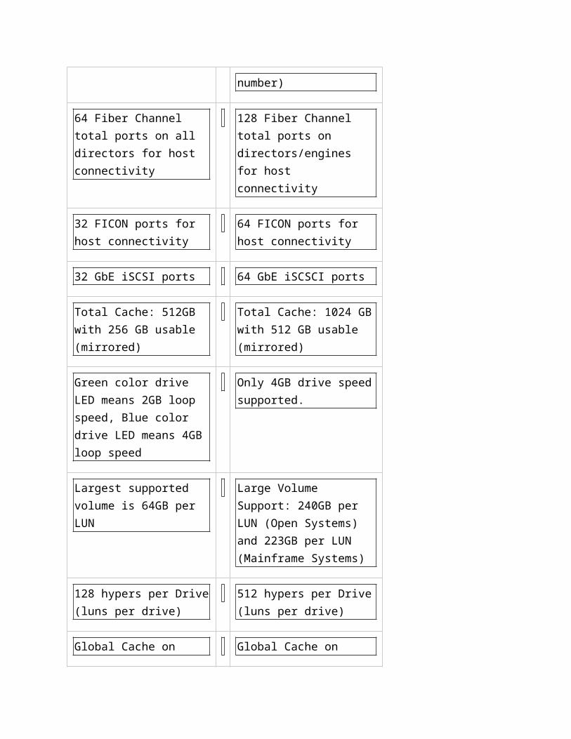
No engines 8 Engines in one System (serial number)
64 Fiber Channel total ports on all directors for host connectivity
128 Fiber Channel total ports on directors/engines for host connectivity
32 FICON ports for host connectivity
64 FICON ports for host connectivity
32 GbE iSCSI ports 64 GbE iSCSCI ports
Total Cache: 512GB with 256 GB usable (mirrored)
Total Cache: 1024 GB with 512 GB usable (mirrored)
Green color drive LED means 2GB loop speed, Blue color drive LED means 4GB loop speed
Only 4GB drive speed supported.
Largest supported volume is 64GB per LUN
Large Volume Support: 240GB per LUN (Open Systems) and 223GB per
LUN (Mainframe Systems)
128 hypers per Drive (luns per drive)
512 hypers per Drive (luns per drive)
Global Cache on Global Memory Directors
Global Cache on local engines chips: again as cache is shared between multiple engines, cache latency is expected as multiple engines request this IO
Total SRDF Groups supported 128
Total SRDF Groups supported 250
16 Groups on Single Port for SRDF
64 Groups on Single Port for SRDF
RAID Levels
0 Striped array with no fault tolerance 1 Disk mirroring 2 Nested RAID (i.e., 1 + 0, 0 + 1, etc.) 3 Parallel access array with dedicated parity disk 4 Striped array with independent disks and a dedicated parity disk 5 Striped array with independent disks and distributed parity 6 Striped array with independent disks and DUAL distributed parity
Physical drives or groups of RAID protected drives can be logically split into volumes known as logical volumes, commonly referred to as Logical Unit Numbers (LUNs).
LUN masking is a process that provides data access control by defining which LUNs a host can access. LUN masking function is typically implemented at the front end controller. This ensures that volume access by servers is controlled appropriately, preventing unauthorized or accidental use in a distributed environment…
EMC CLARiiON -UltraFlex technology for dual protocol connectivity, online expansion via IO modules, andreadiness for future technologies—such as 8 Gb/s Fibre Channel and 10 Gb/s iSCSI. -Scalable from up to 960 disks -Supports flash drives with 30 times more IOPS capability.

-Supports different types and sizes of drives, and RAID types (0, 1, 1+0, 3, 5, 6) -Supports up to 16 GB of available cache memory per controller (Storage Processor) -Enhances availability with non disruptive upgrade and failover -Ensures data protection through mirrored write cache and cache vaulting -Provides data integrity through disk scrubbing. The background verification process runs continually and reads all sectors of all the disks. If a block is unreadable, the back-end error handling recovers the bad sectors from parity or mirror data. -Supports storage-based local and remote data replication for backup and disaster recovery through SnapView and MirrorView software.
EMC Symmetrix-Incrementally scalable to 2,400 disks- Supports Flash-based solid-state drives- Dynamic global cache memory (16 GB–512 GB)- Advanced processing power (up to 130 PowerPC)- Large number of concurrent data paths available (32–128 data paths) for I/O processing- High data processing bandwidth (up to 128 GB/s)- Data protection with RAID 1, 1+0 (also known as 10 for mainframe), 5, and 6- Storage-based local and remote replication for business continuity through TimeFinder and SRDF Software
Direct-attached storage (DAS): This type of storage connects directly to a server (host) or a group of servers in a cluster. Storage can be either internal or external to the server. External DAS alleviated the challenges of limited internal storage capacity.Applications access data from DAS using block-level access protocols.
Storage area network (SAN): This is a dedicated, high-performance Fibre Channel (FC) network to facilitate block-level communication between servers and storage. Storage is partitioned and assigned to a server for accessing its data. SAN offers scalability, availability, performance, and cost benefits compared to DAS.
SAN implementation uses:– Copper cables for short distance– Optical fiber cables for long distance
Two types of optical cables
– Single-mode Can carry single beams of light Distance up to 10 KM– Multi-mode Can carry multiple beams of light simultaneously Distance up to 500 meters
A Standard connector (SC) and a Lucent connector (LC) are two commonly used connectors for fiber optic cables. An SC is used for data transmission speeds up to 1 Gb/s, whereas an LC is

used for speeds up to 4 Gb/s. A Straight Tip (ST) is a fiber optic connector with a plug and a socket that is locked with a half-twisted bayonet lock. In the early days of FC deployment, fiber optic cabling predominantly used ST connectors. This connector is often used with Fibre Channel patch panels.
Network-attached storage (NAS): This is dedicated storage for file serving applications. Unlike a SAN, it connects to an existing communication network (LAN) and provides file access to heterogeneous clients. Because it is purposely built for providing storage to file server applications, it offers higher scalability, availability, performance, and cost benefits compared to general purpose file servers.
-CIFS, NFS
Internet Protocol SAN (IP-SAN): One of the latest evolutions in storage architecture, IP-SAN is a convergence of technologies used in SAN and NAS. IP-SAN provides block-level communication across a local or wide area network (LAN or WAN), resulting in greater consolidation and availability of data.
Block-level access is the basic mechanism for disk access. In this type of access, data is stored and retrieved from disks by specifying the logical block address. The block address is derived based on the geometric configuration of the disks. Block size defines the basic unit of data storage and retrieval by an application Databases, such as Oracle and SQL Server, define the block size for data access and the location of the data on the disk in terms of the logical block address when an I/O operation is performed. File-level access is an abstraction of block-level access. File-level access to data is provided by specifying the name and path of the file. It uses the underlying block-level access to
Point-to-point is the simplest FC configuration — two devices are connected directly to each other. This configuration provides a dedicated connection for data transmission between nodes. However, the point-to-point configuration offers limited connectivity, as only two devices can communicate with each other at a given time. Moreover, it cannot be scaled to accommodate a large number of network devices. Standard DAS uses point-to-point connectivity.
FC-AL configuration, devices are attached to a shared loop. FC-AL has the characteristics of a token ring topology and a physical star topology. In FC-AL, each device contends with other devices to perform I/O operations. Devices on the loop must “arbitrate” to gain control of the loop. At any given time, only one device can perform I/O operations on the loop.
Fibre Channel switched fabric (FC-SW) network providesinterconnected devices, dedicated bandwidth, and scalability. The addition or removal of a device in a switched fabric is minimally disruptive; it does not affect the ongoing traffic between other devices.FC-SW is also referred to as fabric connect. A fabric is a logical space in which all nodes communicate with one another in a network.
N_port: An end point in the fabric. This port is also known as the node port. Typically, it is a host port (HBA) or a storage array port that is connected to a switch in a switched fabric.
NL_port: A node port that supports the arbitrated loop topology. This port is also known as the node loop port.
E_port: An FC port that forms the connection between two FC switches. This port is also known as the expansion port. The E_port on an FC switch connects to the E_port of another FC switch in the fabric through a link, which is called an InterSwitch Link (ISL). ISLs are used to transfer host-to storage data as well as the fabric management traffic from one switch to another. ISL is also one of the scaling mechanisms in SAN connectivity.
F_port: A port on a switch that connects an N_port. It is also known as a fabric port and cannot participate in FC-AL.
FL_port: A fabric port that participates in FC-AL. This port is connected to the NL_ports on an FC-AL loop. A FL_port also connects a loop to a switch in a switched fabric. As a result, allNL_ports in the loop can participate in FC-SW. This configuration is referred to as a public loop.In contrast, an arbitrated loop without any switches is referred to as a private loop. A private loop contains nodes with NL_ports, and does not contain FL_port.
G_port: A generic port that can operate
ISL connects two or more FC switches to each other using E-Ports
Login Types in a Switched Network
Fabric login (FLOGI) is performed between an N_port and an F_port. To log on to the fabric, adevice sends a FLOGI frame with the World Wide Node Name (WWNN) and World Wide PortName (WWPN) parameters to the login service at the well-known FC address FFFFFE. In turn, the switch accepts the login and returns an Accept (ACC) frame with the assigned FC address for the device. Immediately after the FLOGI, the N_port registers itself with the local name server on the switch, indicating its WWNN, WWPN, and assigned FC address.
Port login (PLOGI) is performed between an N_port and another N_port to establish a session.N_port returns an ACC to the initiator N_port. Next, the N_ports exchange service parameters relevant to the session.
Process login (PRLI) is also performed between an N_port and another N_ port. This login relates to the FC upper layer protocols (ULP) such as SCSI. N_ports exchange SCSI-3-related service parameters. N_ports share information about the ULP type in use, the SCSI initiator, or the target.
ZONING:

Zoning is an FC switch function that enables nodes within the fabric to be logically segmented into groups that can communicate with each other.
Port zoning: It uses the FC addresses of the physical ports to define zones. In port zoning, access to data is determined by the physical switch port to which a node is connected. The FC address is dynamically assigned when the port logs on to the fabric. Therefore, any change in the fabric configuration affects zoning. Port zoning is also called hard zoning. Although this method is secure, it requires updating of zoning configuration information in the event of fabricreconfiguration.
WWN zoning: It uses World Wide Names to define zones. WWN zoning is also referred to as soft zoning. A major advantage of WWN zoning is its flexibility. It allows the SAN to be re-cabled without reconfiguring the zone information. This is possible because the WWN is static to the node port.
Mixed zoning: It combines the qualities of both WWN zoning and port zoning. Using mixedzoning enables a specific port to be tied to the WWN of a node.
Describe basic architecture of– iSCSI– FCIP– FCoE
Fibre Channel over Ethernet (FCoE)A new protocol that maps Fibre Channel protocol natively over Ethernet
FCoE allows the use of multi-function network/storage adapters called Converged Network Adapters (CNA) consolidating both network and storage traffic.
What is Virtualization Virtualization is a technique of abstracting physical resources in to logical view
What is a Backup? Backup is an additional copy of data that can be used for restore and recovery purposes

Full backup is a backup of the complete data on the production volumes at a certain point in time. A full backup copy is created by copying the data on the production volumes to a secondary storagedevice.
Incremental backup copies the data that has changed since the last full or incremental backup,whichever has occurred more recently. This is much faster because the volume of data backed up is restricted to changed data, but it takes longer to restore.
Cumulative or differential backup copies the data that has changed since the last full backup. This method takes longer than incremental backup but is faster to restore.
Synthetic or constructed full backup is another type of backup that is used in implementations where the production volume resources cannot be exclusively reserved for a backup process for extended periods to perform a full backup. It is usually created from the most recent full backup and all the incremental backups performed after that full backup. A synthetic full backup enables a full backup copy to be created offline without disrupting the I/O operation on the production volume. This also frees up network resources from the backup process, making them available for other production uses.
Replication:Local and remote
TimeFinder

TimeFinder is a family of EMC replication products that operate in a single Symmetrix array and non-disruptively create and manage point-in-time copies of data volumes. TimeFinder runs in Symmetrix Enginuity but is controlled by TimeFinder software running on an attached host. It can be administered by the user through Solutions Enabler Command Line Interface, Symmetrix Management Console (SMC), EMC Control Center (ECC) or Mainframe Enablers. TimeFinder includes the following sets of products:
TimeFinder/Mirror
TimeFinder/Mirror is the original TimeFinder product that has been in existence for about 12 years. It provides full copies of source volumes through a technique of hardware mirroring. The target volume for a TimeFinder/Mirror process is a Business Continuance Volume (BCV); a specially designated volume within the Symmetrix configuration. When a BCV is fully synchronized with a data device, the BCV is separated or split, and made available to a host for backup or other host processes.
Full Copy Mode (MIRROR)
-On session start, the entire contents of the Source device is copied to the Target device in the background-Most vendor implementations provide the ability to track changes.– Made to the Source or Target– Enables incremental re-synchronization
TimeFinder/Clone
TimeFinder/Clone provides single or multiple point-in-time copies of full volumes or individual datasets. Cloned data is available to a host immediately upon activation, even if the copy process has not completed.
– No invalid tracks, Rather than invalids to keep track of syncing– Use Protected tracks on Source– Use Indirect on Target
Pointer Based Full Volume Replication (CLONE)-Provide full copy of source data on the target. -Target device is made accessible for business operation as soon as the replication session is started-Point-in-Time is determined by time of session activation-Two modes– Copy on First Access (deferred)– Full Copy modeTarget device is at least as large as the source device
TimeFinder/Snap
TimeFinder/Snap provides pointer-only based replicas simultaneously on multiple target devices from a single source device. With a space saving TimeFinder/Snap only changed data is written to a pool of save devices. Data reconstruction is from the source device and the pointers into the change tracking save pool. Data may be copied from a single source device to as many as 128 target virtual devices.
Pointer Based Virtual Replication (SNAP)
Targets (Vdev) do not hold actual data, but hold pointers to where the data is located (SAV or log) pool– Target requires a small fraction of the size of the source volumes- A replication session is setup between source and target devices– Target devices are accessible immediately when the session is started– At the start of the session the target device holds pointers to data on source device typically recommended if the changes to the source are less than 30%
TimeFinder Consistency Groups
Set of devices with normal character in order to maintain integrity of database distributed in multiple SRDF units.
BC Terminologies (continued)
Recovery Point Objective (RPO)Point in time to which systems and data must be recovered after an outageAmount of data loss that a business can endure
Recovery Time Objective (RTO)Time within which systems, applications, or functions must be recovered after an outageAmount of downtime that a business can endure and survive
Synchronous Replication- Write must be committed to source and replica before acknowledging the host
Semi-synchronous ReplicationWrite is committed to the source and immediately acknowledged to the host
Secondary: Adaptive copy –Write pending mode, disk mode.
Concurrent, dynamic,domino,SRDF over IP,SRDF-STAR,SRDF/A , SRDF/AR.
Write-back cache: Data is placed in cache and an acknowledgment is sent to the hostimmediately. Later, data from several writes are committed (de-staged) to the disk. Write responsetimes are much faster, as the write operations are isolated from the mechanical delays of the disk.However, uncommitted data is at risk of loss in the event of cache failures.

Write-through cache: Data is placed in the cache and immediately written to the disk, and anacknowledgment is sent to the host. Because data is committed to disk as it arrives, the risks ofdata loss are low but write response time is longer because of the disk operations.
Least Recently Used (LRU): A algorithm that continuously monitors data access in cache andidentifies the cache pages that have not been accessed for a long time. LRU either frees up these pages or marks them for reuse. This algorithm is based on the assumption that data which hasn’t been accessed for a while will not be requested by the host. However, if a page contains write data that has not yet been committed to disk, data will first be written to disk before the page is reused.
Most Recently Used (MRU): An algorithm that is the converse of LRU. In MRU, the pages that have been accessed most recently are freed up or marked for reuse. This algorithm is based on the assumption that recently accessed data may not be required for a while.
Water masking: Flushing of data from cache, if its almost full
Failover: symrdf failover-Make copy of data on target Symmetrix volumes (R2) available toattached hosts
Failback: symrdf failbackResumes operation using primary host and copy of data on sourcevolumes (R1) Power Vaulting :=> Introduced in DMX 3 to reduce system power down time=> During power down, data from global memory is dumped into the power vault devices, this process is called as vault save=> once the power is back up, data from power vault devices will be copied to Global Memory, this process is called as vault restore=> Capacity of PV devices is 5GB, 4.5 GB is used to store the data and remaining 0.5GB is for future use=> per DA processor there will be 4PV devices
=> PV devices are configured as first logical in the physical drive, so that it can be accessed faster during power down..