VM700T Video Measurement Set Service Manualdownload.tek.com/manual/070963005.pdfService Manual...
360
Service Manual VM700T Video Measurement Set 070-9630-05 Warning The servicing instructions are for use by qualified personnel only. To avoid personal injury, do not perform any servicing unless you are qualified to do so. Refer to all safety summaries prior to performing service. www.tektronix.com
Transcript of VM700T Video Measurement Set Service Manualdownload.tek.com/manual/070963005.pdfService Manual...
Service Manual
VM700T
Video Measurement Set
070-9630-05
Warning
The servicing instructions are for use by qualifiedpersonnel only. To avoid personal injury, do notperform any servicing unless you are qualified todo so. Refer to all safety summaries prior toperforming service.
www.tektronix.com
Copyright © Tektronix, Inc. All rights reserved.
Tektronix products are covered by U.S. and foreign patents, issued and pending. Information in this publication supercedes
that in all previously published material. Specifications and price change privileges reserved.
Tektronix, Inc., P.O. Box 500, Beaverton, OR 97077
TEKTRONIX and TEK are registered trademarks of Tektronix, Inc.

WARRANTY
Tektronix warrants that the products that it manufactures and sells will be free from defects in materials and workmanship
for a period of one (1) year from the date of shipment. If a product proves defective during this warranty period, Tektronix,
at its option, either will repair the defective product without charge for parts and labor, or will provide a replacement in
exchange for the defective product.
In order to obtain service under this warranty, Customer must notify Tektronix of the defect before the expiration of the
warranty period and make suitable arrangements for the performance of service. Customer shall be responsible for
packaging and shipping the defective product to the service center designated by Tektronix, with shipping charges prepaid.
Tektronix shall pay for the return of the product to Customer if the shipment is to a location within the country in which the
Tektronix service center is located. Customer shall be responsible for paying all shipping charges, duties, taxes, and any
other charges for products returned to any other locations.
This warranty shall not apply to any defect, failure or damage caused by improper use or improper or inadequate
maintenance and care. Tektronix shall not be obligated to furnish service under this warranty a) to repair damage resulting
from attempts by personnel other than Tektronix representatives to install, repair or service the product; b) to repair
damage resulting from improper use or connection to incompatible equipment; c) to repair any damage or malfunction
caused by the use of non-Tektronix supplies; or d) to service a product that has been modified or integrated with other
products when the effect of such modification or integration increases the time or difficulty of servicing the product.
THIS WARRANTY IS GIVEN BY TEKTRONIX IN LIEU OF ANY OTHER WARRANTIES, EXPRESS OR
IMPLIED. TEKTRONIX AND ITS VENDORS DISCLAIM ANY IMPLIED WARRANTIES OF
MERCHANTABILITY OR FITNESS FOR A PARTICULAR PURPOSE. TEKTRONIX’ RESPONSIBILITY TO
REPAIR OR REPLACE DEFECTIVE PRODUCTS IS THE SOLE AND EXCLUSIVE REMEDY PROVIDED TO
THE CUSTOMER FOR BREACH OF THIS WARRANTY. TEKTRONIX AND ITS VENDORS WILL NOT BE
LIABLE FOR ANY INDIRECT, SPECIAL, INCIDENTAL, OR CONSEQUENTIAL DAMAGES IRRESPECTIVE
OF WHETHER TEKTRONIX OR THE VENDOR HAS ADVANCE NOTICE OF THE POSSIBILITY OF SUCH
DAMAGES.

VM700T Video Measurement Set Service Manual i
Table of Contents
General Safety Summary xv. . . . . . . . . . . . . . . . . . . . . . . . . . . . . . . . . . . . . . . . . .Service Safety Summary xvii. . . . . . . . . . . . . . . . . . . . . . . . . . . . . . . . . . . . . . . . . .
Preface xix. . . . . . . . . . . . . . . . . . . . . . . . . . . . . . . . . . . . . . . . . . . . . . . . . . .Contents of the Manual xix. . . . . . . . . . . . . . . . . . . . . . . . . . . . . . . . . . . . . . . . . . .Contacting Tektronix xx. . . . . . . . . . . . . . . . . . . . . . . . . . . . . . . . . . . . . . . . . . . . .
Specification
Electrical Characteristics 1--1. . . . . . . . . . . . . . . . . . . . . . . . . . . . . . . . . . . . . . . . . .Physical Characteristics 1--4. . . . . . . . . . . . . . . . . . . . . . . . . . . . . . . . . . . . . . . . . . .Power Requirements 1--4. . . . . . . . . . . . . . . . . . . . . . . . . . . . . . . . . . . . . . . . . . . . . .Environmental 1--4. . . . . . . . . . . . . . . . . . . . . . . . . . . . . . . . . . . . . . . . . . . . . . . . . .Power Line Conditioner for Option A1 and A2 Power Cords 1--10. . . . . . . . . . . . . .PAL Measurement Specifications 1--12. . . . . . . . . . . . . . . . . . . . . . . . . . . . . . . . . . .Measure Mode 1--12. . . . . . . . . . . . . . . . . . . . . . . . . . . . . . . . . . . . . . . . . . . . . . . . . .Auto Mode 1--17. . . . . . . . . . . . . . . . . . . . . . . . . . . . . . . . . . . . . . . . . . . . . . . . . . . . .NTSC Measurement Specifications 1--21. . . . . . . . . . . . . . . . . . . . . . . . . . . . . . . . . .Measure Mode 1--21. . . . . . . . . . . . . . . . . . . . . . . . . . . . . . . . . . . . . . . . . . . . . . . . . .Auto Mode 1--26. . . . . . . . . . . . . . . . . . . . . . . . . . . . . . . . . . . . . . . . . . . . . . . . . . . . .Audio Option 40, Option 41, and Option 42 Specifications 1--31. . . . . . . . . . . . . . .Automatic Audio Test Specifications 1--31. . . . . . . . . . . . . . . . . . . . . . . . . . . . . . . . .Audio Analyzer Specifications 1--32. . . . . . . . . . . . . . . . . . . . . . . . . . . . . . . . . . . . . .Audio Spectrum Specifications 1--34. . . . . . . . . . . . . . . . . . . . . . . . . . . . . . . . . . . . .Multitone Analyzer Specifications 1--35. . . . . . . . . . . . . . . . . . . . . . . . . . . . . . . . . . .A/V Timing Specifications (Option 42) 1--36. . . . . . . . . . . . . . . . . . . . . . . . . . . . . . .Option 48 GPIB Specification 1--36. . . . . . . . . . . . . . . . . . . . . . . . . . . . . . . . . . . . . .Option 1S SDI Specification 1--38. . . . . . . . . . . . . . . . . . . . . . . . . . . . . . . . . . . . . . .
Operating Information
Installation 2--1. . . . . . . . . . . . . . . . . . . . . . . . . . . . . . . . . . . . . . . . . . . . . . . . . . . . .Unpackaging 2--1. . . . . . . . . . . . . . . . . . . . . . . . . . . . . . . . . . . . . . . . . . . . . . . .Power Requirements 2--1. . . . . . . . . . . . . . . . . . . . . . . . . . . . . . . . . . . . . . . . . .Changing Line Voltage Range and Fuse 2--2. . . . . . . . . . . . . . . . . . . . . . . . . . .Power Cord 2--2. . . . . . . . . . . . . . . . . . . . . . . . . . . . . . . . . . . . . . . . . . . . . . . . .Power Line Conditioner Accessory 2--2. . . . . . . . . . . . . . . . . . . . . . . . . . . . . . .Installing the Power Line Conditioner 2--3. . . . . . . . . . . . . . . . . . . . . . . . . . . .Power On Diagnostics 2--4. . . . . . . . . . . . . . . . . . . . . . . . . . . . . . . . . . . . . . . . .Calibrating the Touch Screen 2--5. . . . . . . . . . . . . . . . . . . . . . . . . . . . . . . . . . .Setting the Power On Mode 2--7. . . . . . . . . . . . . . . . . . . . . . . . . . . . . . . . . . . .
Measurement Set Operating Modes 2--8. . . . . . . . . . . . . . . . . . . . . . . . . . . . . . . . . .Waveform Mode 2--8. . . . . . . . . . . . . . . . . . . . . . . . . . . . . . . . . . . . . . . . . . . . .Vector Mode 2--9. . . . . . . . . . . . . . . . . . . . . . . . . . . . . . . . . . . . . . . . . . . . . . . .Measure Mode 2--9. . . . . . . . . . . . . . . . . . . . . . . . . . . . . . . . . . . . . . . . . . . . . . .Picture Mode 2--9. . . . . . . . . . . . . . . . . . . . . . . . . . . . . . . . . . . . . . . . . . . . . . . .Auto Mode 2--9. . . . . . . . . . . . . . . . . . . . . . . . . . . . . . . . . . . . . . . . . . . . . . . . . .
User-Programmable Functions 2--10. . . . . . . . . . . . . . . . . . . . . . . . . . . . . . . . . . . . . .Hardcopy 2--10. . . . . . . . . . . . . . . . . . . . . . . . . . . . . . . . . . . . . . . . . . . . . . . . . . . . . . .Remote Operation 2--10. . . . . . . . . . . . . . . . . . . . . . . . . . . . . . . . . . . . . . . . . . . . . . . .
Table of Contents
ii VM700T Video Measurement Set Service Manual
Front Panel Controls 2--11. . . . . . . . . . . . . . . . . . . . . . . . . . . . . . . . . . . . . . . . . . . . . .Touch Screen 2--11. . . . . . . . . . . . . . . . . . . . . . . . . . . . . . . . . . . . . . . . . . . . . . . .Keypad 2--12. . . . . . . . . . . . . . . . . . . . . . . . . . . . . . . . . . . . . . . . . . . . . . . . . . . . .Control Knob 2--14. . . . . . . . . . . . . . . . . . . . . . . . . . . . . . . . . . . . . . . . . . . . . . . .Equipment/Signal Sources Required 2--15. . . . . . . . . . . . . . . . . . . . . . . . . . . . . .Bandwidth 2--15. . . . . . . . . . . . . . . . . . . . . . . . . . . . . . . . . . . . . . . . . . . . . . . . . .Connecting Inputs and Outputs 2--15. . . . . . . . . . . . . . . . . . . . . . . . . . . . . . . . . .
Rear Panel and Connections 2--16. . . . . . . . . . . . . . . . . . . . . . . . . . . . . . . . . . . . . . . .Equipment/Video Signal Sources Required 2--18. . . . . . . . . . . . . . . . . . . . . . . . . . . .Connecting Audio Option 40 to a Source 2--19. . . . . . . . . . . . . . . . . . . . . . . . . . . . .
Input Connector Pin Assignments 2--19. . . . . . . . . . . . . . . . . . . . . . . . . . . . . . . .Connecting Audio Option 41 to a Source 2--20. . . . . . . . . . . . . . . . . . . . . . . . . . . . .
Option 41 Audio Signal Interconnection Cable 2--20. . . . . . . . . . . . . . . . . . . . .GPIB Option 48 Signal Connections and Rear Panel 2--21. . . . . . . . . . . . . . . . . . . .
GPIB Indicator LED 2--21. . . . . . . . . . . . . . . . . . . . . . . . . . . . . . . . . . . . . . . . . .SDI Option 1S Rear Panel Connections 2--22. . . . . . . . . . . . . . . . . . . . . . . . . . . . . . .
Theory of OperationOverview of The VM700T System 3--1. . . . . . . . . . . . . . . . . . . . . . . . . . . . . . . . . .Module Functional Description 3--3. . . . . . . . . . . . . . . . . . . . . . . . . . . . . . . . . . . . .Analog Input Board (A1) 3--3. . . . . . . . . . . . . . . . . . . . . . . . . . . . . . . . . . . . . . . . . .
Loop-Through Inputs 3--3. . . . . . . . . . . . . . . . . . . . . . . . . . . . . . . . . . . . . . . . . .Mode Control 3--3. . . . . . . . . . . . . . . . . . . . . . . . . . . . . . . . . . . . . . . . . . . . . . . .Clamped Input Amplifiers 3--3. . . . . . . . . . . . . . . . . . . . . . . . . . . . . . . . . . . . . .Clamp and Bias Generator 3--3. . . . . . . . . . . . . . . . . . . . . . . . . . . . . . . . . . . . .Channel Selection 3--3. . . . . . . . . . . . . . . . . . . . . . . . . . . . . . . . . . . . . . . . . . . .Differential Amplifier 3--5. . . . . . . . . . . . . . . . . . . . . . . . . . . . . . . . . . . . . . . . .Dynamic Offset Generator and Offset Amplifier 3--5. . . . . . . . . . . . . . . . . . . .Variable-Gain Amplifier 3--5. . . . . . . . . . . . . . . . . . . . . . . . . . . . . . . . . . . . . . .Dither Generator and Dither Amplifier 3--5. . . . . . . . . . . . . . . . . . . . . . . . . . . .Calibration DAC 3--5. . . . . . . . . . . . . . . . . . . . . . . . . . . . . . . . . . . . . . . . . . . . .Sync Selection 3--6. . . . . . . . . . . . . . . . . . . . . . . . . . . . . . . . . . . . . . . . . . . . . . .DVM Selection and DVM 3--6. . . . . . . . . . . . . . . . . . . . . . . . . . . . . . . . . . . . . .
The Genlock Board (A2) 3--7. . . . . . . . . . . . . . . . . . . . . . . . . . . . . . . . . . . . . . . . . .Sync Stripper 3--7. . . . . . . . . . . . . . . . . . . . . . . . . . . . . . . . . . . . . . . . . . . . . . . .Crystal Oscillator 3--7. . . . . . . . . . . . . . . . . . . . . . . . . . . . . . . . . . . . . . . . . . . . .FH Generator 3--9. . . . . . . . . . . . . . . . . . . . . . . . . . . . . . . . . . . . . . . . . . . . . . . .Phase-Locked Loop (PLL) 3--9. . . . . . . . . . . . . . . . . . . . . . . . . . . . . . . . . . . . .Divide-by-2 Frequency Divider 3--9. . . . . . . . . . . . . . . . . . . . . . . . . . . . . . . . .Frame Decoder 3--9. . . . . . . . . . . . . . . . . . . . . . . . . . . . . . . . . . . . . . . . . . . . . .Frame Rate Synthesizer 3--9. . . . . . . . . . . . . . . . . . . . . . . . . . . . . . . . . . . . . . . .Stripped Sync Processing 3--9. . . . . . . . . . . . . . . . . . . . . . . . . . . . . . . . . . . . . .Output Generator 3--10. . . . . . . . . . . . . . . . . . . . . . . . . . . . . . . . . . . . . . . . . . . . .Control 3--10. . . . . . . . . . . . . . . . . . . . . . . . . . . . . . . . . . . . . . . . . . . . . . . . . . . . .Status 3--10. . . . . . . . . . . . . . . . . . . . . . . . . . . . . . . . . . . . . . . . . . . . . . . . . . . . . .
Table of Contents
VM700T Video Measurement Set Service Manual iii
The Analog-to-Digital (ADC) Board (A3) 3--11. . . . . . . . . . . . . . . . . . . . . . . . . . . . .+2.5 V and --2.5 V Regulators 3--11. . . . . . . . . . . . . . . . . . . . . . . . . . . . . . . . . . .Signal Conditioning Amplifier 3--11. . . . . . . . . . . . . . . . . . . . . . . . . . . . . . . . . .A/D Converter 3--11. . . . . . . . . . . . . . . . . . . . . . . . . . . . . . . . . . . . . . . . . . . . . . .Buffer 3--11. . . . . . . . . . . . . . . . . . . . . . . . . . . . . . . . . . . . . . . . . . . . . . . . . . . . . .Output Latch 3--11. . . . . . . . . . . . . . . . . . . . . . . . . . . . . . . . . . . . . . . . . . . . . . . .Line and Frame Pulse Pipeline 3--13. . . . . . . . . . . . . . . . . . . . . . . . . . . . . . . . . .Overrange Detector 3--13. . . . . . . . . . . . . . . . . . . . . . . . . . . . . . . . . . . . . . . . . . .Sample Clock 3--13. . . . . . . . . . . . . . . . . . . . . . . . . . . . . . . . . . . . . . . . . . . . . . .
Filter Switch Board (A4) 3--14. . . . . . . . . . . . . . . . . . . . . . . . . . . . . . . . . . . . . . . . . .Filter Select and Control 3--14. . . . . . . . . . . . . . . . . . . . . . . . . . . . . . . . . . . . . . .Slot 0 3--14. . . . . . . . . . . . . . . . . . . . . . . . . . . . . . . . . . . . . . . . . . . . . . . . . . . . . .Slots 1-5 3--14. . . . . . . . . . . . . . . . . . . . . . . . . . . . . . . . . . . . . . . . . . . . . . . . . . . .Output Amplifier 3--14. . . . . . . . . . . . . . . . . . . . . . . . . . . . . . . . . . . . . . . . . . . . .
CPU Board (A5) 3--16. . . . . . . . . . . . . . . . . . . . . . . . . . . . . . . . . . . . . . . . . . . . . . . . .System Bus 3--16. . . . . . . . . . . . . . . . . . . . . . . . . . . . . . . . . . . . . . . . . . . . . . . . .EPROM 3--17. . . . . . . . . . . . . . . . . . . . . . . . . . . . . . . . . . . . . . . . . . . . . . . . . . . .NVRAM 3--17. . . . . . . . . . . . . . . . . . . . . . . . . . . . . . . . . . . . . . . . . . . . . . . . . . .NVRAM SIMM 3--17. . . . . . . . . . . . . . . . . . . . . . . . . . . . . . . . . . . . . . . . . . . . . .Flash EPROM 3--17. . . . . . . . . . . . . . . . . . . . . . . . . . . . . . . . . . . . . . . . . . . . . . .DRAM 3--17. . . . . . . . . . . . . . . . . . . . . . . . . . . . . . . . . . . . . . . . . . . . . . . . . . . . .Real-Time Clock 3--17. . . . . . . . . . . . . . . . . . . . . . . . . . . . . . . . . . . . . . . . . . . . .Display ASIC and VRAM 3--17. . . . . . . . . . . . . . . . . . . . . . . . . . . . . . . . . . . . . .Front Panel Processor 3--18. . . . . . . . . . . . . . . . . . . . . . . . . . . . . . . . . . . . . . . . .
CPU I/O Board (A20) 3--18. . . . . . . . . . . . . . . . . . . . . . . . . . . . . . . . . . . . . . . . . . . . .Serial Ports 3--18. . . . . . . . . . . . . . . . . . . . . . . . . . . . . . . . . . . . . . . . . . . . . . . . . .Parallel Port Interface 3--19. . . . . . . . . . . . . . . . . . . . . . . . . . . . . . . . . . . . . . . . .32-Bit Counter 3--19. . . . . . . . . . . . . . . . . . . . . . . . . . . . . . . . . . . . . . . . . . . . . . .Connector 3--19. . . . . . . . . . . . . . . . . . . . . . . . . . . . . . . . . . . . . . . . . . . . . . . . . .
Data Acquisition/Controller Board (A18) 3--20. . . . . . . . . . . . . . . . . . . . . . . . . . . . .Video Data and Clock Inputs 3--20. . . . . . . . . . . . . . . . . . . . . . . . . . . . . . . . . . .FIFO/Demultiplexor 3--20. . . . . . . . . . . . . . . . . . . . . . . . . . . . . . . . . . . . . . . . . .Acquisition Control 3--20. . . . . . . . . . . . . . . . . . . . . . . . . . . . . . . . . . . . . . . . . . .Acquisition Clock 3--20. . . . . . . . . . . . . . . . . . . . . . . . . . . . . . . . . . . . . . . . . . . .Data Bus Interface 3--20. . . . . . . . . . . . . . . . . . . . . . . . . . . . . . . . . . . . . . . . . . . .Data Acquisition Memory (Static RAM) 3--20. . . . . . . . . . . . . . . . . . . . . . . . . .Min-Max ASIC 3--20. . . . . . . . . . . . . . . . . . . . . . . . . . . . . . . . . . . . . . . . . . . . . .Controller Section 3--22. . . . . . . . . . . . . . . . . . . . . . . . . . . . . . . . . . . . . . . . . . . .Bus Buffers 3--22. . . . . . . . . . . . . . . . . . . . . . . . . . . . . . . . . . . . . . . . . . . . . . . . .Controller ASIC 3--22. . . . . . . . . . . . . . . . . . . . . . . . . . . . . . . . . . . . . . . . . . . . . .Address Decoding 3--22. . . . . . . . . . . . . . . . . . . . . . . . . . . . . . . . . . . . . . . . . . . .Output Latches and Analog Input Board Interface 3--22. . . . . . . . . . . . . . . . . . .Clamp Counters 3--22. . . . . . . . . . . . . . . . . . . . . . . . . . . . . . . . . . . . . . . . . . . . . .Status Counter 3--24. . . . . . . . . . . . . . . . . . . . . . . . . . . . . . . . . . . . . . . . . . . . . . .ECL-To-TTL Conversion 3--24. . . . . . . . . . . . . . . . . . . . . . . . . . . . . . . . . . . . . .Data and Address Latches onto the BCD0-12 Bus 3--24. . . . . . . . . . . . . . . . . . .Trigger RAM 3--24. . . . . . . . . . . . . . . . . . . . . . . . . . . . . . . . . . . . . . . . . . . . . . . .Sequencer (State Machine) 3--24. . . . . . . . . . . . . . . . . . . . . . . . . . . . . . . . . . . . .Dynamic Settings 3--25. . . . . . . . . . . . . . . . . . . . . . . . . . . . . . . . . . . . . . . . . . . .
Front Panel Board (A10A1) 3--27. . . . . . . . . . . . . . . . . . . . . . . . . . . . . . . . . . . . . . . .
Table of Contents
iv VM700T Video Measurement Set Service Manual
Keypad Board (A10A2) 3--28. . . . . . . . . . . . . . . . . . . . . . . . . . . . . . . . . . . . . . . . . . .Control Knob 3--28. . . . . . . . . . . . . . . . . . . . . . . . . . . . . . . . . . . . . . . . . . . . . . . .Push Buttons 3--28. . . . . . . . . . . . . . . . . . . . . . . . . . . . . . . . . . . . . . . . . . . . . . . .LEDs 3--28. . . . . . . . . . . . . . . . . . . . . . . . . . . . . . . . . . . . . . . . . . . . . . . . . . . . . .
Main Interconnect Board (Left and Right) (A11) 3--29. . . . . . . . . . . . . . . . . . . . . . .Picture Monitor (A14) 3--29. . . . . . . . . . . . . . . . . . . . . . . . . . . . . . . . . . . . . . . . . . . .
Video Amplifier 3--29. . . . . . . . . . . . . . . . . . . . . . . . . . . . . . . . . . . . . . . . . . . . . .+12 V and + 5 V Supplies 3--29. . . . . . . . . . . . . . . . . . . . . . . . . . . . . . . . . . . . . .Vertical Deflection 3--29. . . . . . . . . . . . . . . . . . . . . . . . . . . . . . . . . . . . . . . . . . . .Horizontal Deflection 3--30. . . . . . . . . . . . . . . . . . . . . . . . . . . . . . . . . . . . . . . . .High Voltage 3--31. . . . . . . . . . . . . . . . . . . . . . . . . . . . . . . . . . . . . . . . . . . . . . . .Trace Rotation 3--31. . . . . . . . . . . . . . . . . . . . . . . . . . . . . . . . . . . . . . . . . . . . . . .
Power Supply (A15) 3--31. . . . . . . . . . . . . . . . . . . . . . . . . . . . . . . . . . . . . . . . . . . . . .Input Power Rectifier 3--31. . . . . . . . . . . . . . . . . . . . . . . . . . . . . . . . . . . . . . . . .Housekeeping Power Supply 3--31. . . . . . . . . . . . . . . . . . . . . . . . . . . . . . . . . . . .Inverter Switching Circuit 3--31. . . . . . . . . . . . . . . . . . . . . . . . . . . . . . . . . . . . . .+12 V and 15 V Regulators 3--32. . . . . . . . . . . . . . . . . . . . . . . . . . . . . . . . . . . . .Alarm Sensing 3--33. . . . . . . . . . . . . . . . . . . . . . . . . . . . . . . . . . . . . . . . . . . . . . .Alarm Logic 3--33. . . . . . . . . . . . . . . . . . . . . . . . . . . . . . . . . . . . . . . . . . . . . . . .Fan Drive 3--33. . . . . . . . . . . . . . . . . . . . . . . . . . . . . . . . . . . . . . . . . . . . . . . . . . .
Option 40 Audio Measurements 3--33. . . . . . . . . . . . . . . . . . . . . . . . . . . . . . . . . . . . .Audio Processor Board (A12) 3--33. . . . . . . . . . . . . . . . . . . . . . . . . . . . . . . . . . . . . .Audio Processor Interface 3--34. . . . . . . . . . . . . . . . . . . . . . . . . . . . . . . . . . . . . . . . .
Address Decoders 3--34. . . . . . . . . . . . . . . . . . . . . . . . . . . . . . . . . . . . . . . . . . . .Bus Buffers 3--34. . . . . . . . . . . . . . . . . . . . . . . . . . . . . . . . . . . . . . . . . . . . . . . . .Address Buffers 3--34. . . . . . . . . . . . . . . . . . . . . . . . . . . . . . . . . . . . . . . . . . . . .
Interrupt Generator/Status Port 3--35. . . . . . . . . . . . . . . . . . . . . . . . . . . . . . . . . . . . .Interrupt Generator 3--35. . . . . . . . . . . . . . . . . . . . . . . . . . . . . . . . . . . . . . . . . . .Data Buffers 3--35. . . . . . . . . . . . . . . . . . . . . . . . . . . . . . . . . . . . . . . . . . . . . . . . .Reset Register 3--35. . . . . . . . . . . . . . . . . . . . . . . . . . . . . . . . . . . . . . . . . . . . . . .
DSP Processor and I/O Interface 3--35. . . . . . . . . . . . . . . . . . . . . . . . . . . . . . . . . . . .Oscillator 3--35. . . . . . . . . . . . . . . . . . . . . . . . . . . . . . . . . . . . . . . . . . . . . . . . . . .Communication Ports 3--35. . . . . . . . . . . . . . . . . . . . . . . . . . . . . . . . . . . . . . . . .
Audio Data Register 3--36. . . . . . . . . . . . . . . . . . . . . . . . . . . . . . . . . . . . . . . . . . . . . .CPU Access Disable 3--36. . . . . . . . . . . . . . . . . . . . . . . . . . . . . . . . . . . . . . . . . .
Static RAM 3--36. . . . . . . . . . . . . . . . . . . . . . . . . . . . . . . . . . . . . . . . . . . . . . . . . . . . .P Memory 3--36. . . . . . . . . . . . . . . . . . . . . . . . . . . . . . . . . . . . . . . . . . . . . . . . . .X-Data and Y-Data Memory 3--36. . . . . . . . . . . . . . . . . . . . . . . . . . . . . . . . . . . .Program Loading 3--36. . . . . . . . . . . . . . . . . . . . . . . . . . . . . . . . . . . . . . . . . . . . .Control Lines 3--36. . . . . . . . . . . . . . . . . . . . . . . . . . . . . . . . . . . . . . . . . . . . . . . .
Audio Analog Board (A13) 3--37. . . . . . . . . . . . . . . . . . . . . . . . . . . . . . . . . . . . . . . .Input Amplifiers 3--37. . . . . . . . . . . . . . . . . . . . . . . . . . . . . . . . . . . . . . . . . . . . .Signal Input 3--37. . . . . . . . . . . . . . . . . . . . . . . . . . . . . . . . . . . . . . . . . . . . . . . . .Stepped Attenuator 3--37. . . . . . . . . . . . . . . . . . . . . . . . . . . . . . . . . . . . . . . . . . .Input Amplifier 3--37. . . . . . . . . . . . . . . . . . . . . . . . . . . . . . . . . . . . . . . . . . . . . .
400 Hz Notch Filter/DAC Output 3--39. . . . . . . . . . . . . . . . . . . . . . . . . . . . . . . . . . .Notch Filter Operation 3--39. . . . . . . . . . . . . . . . . . . . . . . . . . . . . . . . . . . . . . . .DAC Output 3--39. . . . . . . . . . . . . . . . . . . . . . . . . . . . . . . . . . . . . . . . . . . . . . . . .
Option 40 A/D Converter 3--40. . . . . . . . . . . . . . . . . . . . . . . . . . . . . . . . . . . . . . . . . .Input Clamp 3--40. . . . . . . . . . . . . . . . . . . . . . . . . . . . . . . . . . . . . . . . . . . . . . . . .CH 2 (and CH 1) Amplifier 3--40. . . . . . . . . . . . . . . . . . . . . . . . . . . . . . . . . . . . .A/D Converter 3--40. . . . . . . . . . . . . . . . . . . . . . . . . . . . . . . . . . . . . . . . . . . . . . .
Table of Contents
VM700T Video Measurement Set Service Manual v
Audio Board Control 3--40. . . . . . . . . . . . . . . . . . . . . . . . . . . . . . . . . . . . . . . . . . . . .Opto-Isolators 3--40. . . . . . . . . . . . . . . . . . . . . . . . . . . . . . . . . . . . . . . . . . . . . . .Synchronizer 3--41. . . . . . . . . . . . . . . . . . . . . . . . . . . . . . . . . . . . . . . . . . . . . . . .Counter/Decoder 3--41. . . . . . . . . . . . . . . . . . . . . . . . . . . . . . . . . . . . . . . . . . . . .Control Register 3--41. . . . . . . . . . . . . . . . . . . . . . . . . . . . . . . . . . . . . . . . . . . . .Master Oscillator and Clock Divider 3--41. . . . . . . . . . . . . . . . . . . . . . . . . . . . .Calibration DAC 3--42. . . . . . . . . . . . . . . . . . . . . . . . . . . . . . . . . . . . . . . . . . . . .
Floating Power Supply 3--42. . . . . . . . . . . . . . . . . . . . . . . . . . . . . . . . . . . . . . . . . . . .Grounds 3--42. . . . . . . . . . . . . . . . . . . . . . . . . . . . . . . . . . . . . . . . . . . . . . . . . . . .
Option 41 Audio Analog Board 3--42. . . . . . . . . . . . . . . . . . . . . . . . . . . . . . . . . . . . .6 Balanced Input Selector 3--42. . . . . . . . . . . . . . . . . . . . . . . . . . . . . . . . . . . . . .
Option 48 GPIB Interface Board (A19) 3--44. . . . . . . . . . . . . . . . . . . . . . . . . . . . . . .Option 1S Serial Digital Measurements 3--47. . . . . . . . . . . . . . . . . . . . . . . . . . . . . . .
SDI Rear Panel Interface Assembly 3--47. . . . . . . . . . . . . . . . . . . . . . . . . . . . . .SDI Board 3--47. . . . . . . . . . . . . . . . . . . . . . . . . . . . . . . . . . . . . . . . . . . . . . . . . .
Performance Verification
Self Diagnostics 4--1. . . . . . . . . . . . . . . . . . . . . . . . . . . . . . . . . . . . . . . . . . . . . . . . .Test Equipment Required 4--6. . . . . . . . . . . . . . . . . . . . . . . . . . . . . . . . . . . . . . . . . .System Verification Procedures 4--7. . . . . . . . . . . . . . . . . . . . . . . . . . . . . . . . . . . . .
Audio Option Verification Procedure 4--13. . . . . . . . . . . . . . . . . . . . . . . . .Test Equipment Required 4--13. . . . . . . . . . . . . . . . . . . . . . . . . . . . . . . . . . . . . . . . . .
Audio Option 40 Verification Procedure 4--15. . . . . . . . . . . . . . . . . . . . . . .Check Level Measurement Accuracy and Flatness 4--15. . . . . . . . . . . . . . . . . . . . . .
Specifications Checked 4--15. . . . . . . . . . . . . . . . . . . . . . . . . . . . . . . . . . . . . . . .Option 40 Level Accuracy and Flatness 4--15. . . . . . . . . . . . . . . . . . . . . . . . . . .
Check Distortion and Distortion Measurement Accuracy 4--17. . . . . . . . . . . . . . . . .Specification Checked 4--17. . . . . . . . . . . . . . . . . . . . . . . . . . . . . . . . . . . . . . . . .Option 40 Distortion Measurement Accuracy 4--17. . . . . . . . . . . . . . . . . . . . . .
Check Frequency and Phase Measurement Accuracy 4--18. . . . . . . . . . . . . . . . . . . .Specifications Checked 4--18. . . . . . . . . . . . . . . . . . . . . . . . . . . . . . . . . . . . . . . .Option 40 Frequency Accuracy and Channel Phase Difference 4--18. . . . . . . . .
Audio Option 41 Triple-Input Verification Procedure 4--19. . . . . . . . . . . .Configuring Source Selection Audio 4--19. . . . . . . . . . . . . . . . . . . . . . . . . . . . . . . . .Check Level Measurement Accuracy and Flatness 4--20. . . . . . . . . . . . . . . . . . . . . .
Option 41 Level Accuracy and Flatness 4--20. . . . . . . . . . . . . . . . . . . . . . . . . . .Check Distortion and Distortion Measurement Accuracy 4--22. . . . . . . . . . . . . . . . .
Option 41 Distortion Measurement Accuracy 4--22. . . . . . . . . . . . . . . . . . . . . .Check Frequency and Phase Measurement Accuracy 4--23. . . . . . . . . . . . . . . . . . . .
Option 41 Frequency Accuracy and Channel Phase Difference 4--23. . . . . . . . .
SDI Option 1S Performance Verification 4--25. . . . . . . . . . . . . . . . . . . . . .Preliminary Setup 4--26. . . . . . . . . . . . . . . . . . . . . . . . . . . . . . . . . . . . . . . . . . . . . . . .SDI Analog Ref Input 4--27. . . . . . . . . . . . . . . . . . . . . . . . . . . . . . . . . . . . . . . . . . . . .Eye Diagram Application 4--28. . . . . . . . . . . . . . . . . . . . . . . . . . . . . . . . . . . . . . . . . .Jitter Application 4--30. . . . . . . . . . . . . . . . . . . . . . . . . . . . . . . . . . . . . . . . . . . . . . . .Interchannel Timing Application 4--34. . . . . . . . . . . . . . . . . . . . . . . . . . . . . . . . . . . .SDI Output 4--35. . . . . . . . . . . . . . . . . . . . . . . . . . . . . . . . . . . . . . . . . . . . . . . . . . . . .
Table of Contents
vi VM700T Video Measurement Set Service Manual
Adjustment Procedure
Test Equipment Required 5--1. . . . . . . . . . . . . . . . . . . . . . . . . . . . . . . . . . . . . . . . . .System Adjustment Procedures 5--2. . . . . . . . . . . . . . . . . . . . . . . . . . . . . . . . . . . . .Extended Adjustment Procedure 5--15. . . . . . . . . . . . . . . . . . . . . . . . . . . . . . . . . . . .Option 1S Adjustment Procedure 5--22. . . . . . . . . . . . . . . . . . . . . . . . . . . . . . . . . . . .
Maintenance
Servicing Preparation 6--1. . . . . . . . . . . . . . . . . . . . . . . . . . . . . . . . . . . . . . . . . . . . .Inspection and Cleaning 6--4. . . . . . . . . . . . . . . . . . . . . . . . . . . . . . . . . . . . . . . . . . .Repackaging the Instrument 6--5. . . . . . . . . . . . . . . . . . . . . . . . . . . . . . . . . . . . . . . .
Repackaging 6--5. . . . . . . . . . . . . . . . . . . . . . . . . . . . . . . . . . . . . . . . . . . . . . . .Removal and Replacement Instructions 6--6. . . . . . . . . . . . . . . . . . . . . . . . . . . . . . .VM700T Rack Mounting Instructions 6--44. . . . . . . . . . . . . . . . . . . . . . . . . . . . . . . .
Troubleshooting Procedures 6--49. . . . . . . . . . . . . . . . . . . . . . . . . . . . . . . . .Troubleshooting Techniques 6--50. . . . . . . . . . . . . . . . . . . . . . . . . . . . . . . . . . . . . . . .Isolating Operational Faults 6--51. . . . . . . . . . . . . . . . . . . . . . . . . . . . . . . . . . . . . . . .Diagnostics 6--55. . . . . . . . . . . . . . . . . . . . . . . . . . . . . . . . . . . . . . . . . . . . . . . . . . . . .Troubleshooting the Power Supply and CRT Display 6--90. . . . . . . . . . . . . . . . . . . .Troubleshooting Option 40 and Option 41 (Audio) 6--95. . . . . . . . . . . . . . . . . . . . . .Troubleshooting Option 48 (GPIB) 6--99. . . . . . . . . . . . . . . . . . . . . . . . . . . . . . . . . .Troubleshooting Option 1S (SDI) 6--100. . . . . . . . . . . . . . . . . . . . . . . . . . . . . . . . . . .SDI Option Diagnostics 6--104. . . . . . . . . . . . . . . . . . . . . . . . . . . . . . . . . . . . . . . . . . .
Options
Standard Options (Option 01 and Option 11) 7--1. . . . . . . . . . . . . . . . . . . . . . . . . . .Application Options (Option 1G, Option 20, Option 21, Option 30, Option 42) 7--1Audio Options (Option 40 and Option 41) 7--3. . . . . . . . . . . . . . . . . . . . . . . . . . . . .Serial Digital Interface (Option 1S) 7--4. . . . . . . . . . . . . . . . . . . . . . . . . . . . . . . . . .GPIB Interface (Option 48) 7--4. . . . . . . . . . . . . . . . . . . . . . . . . . . . . . . . . . . . . . . .White Phosphor CRT (Option 74) 7--4. . . . . . . . . . . . . . . . . . . . . . . . . . . . . . . . . . .Cabinet and Mounting Options (Option 1C, VM7FR1, VM7FC1) 7--5. . . . . . . . . .Auxiliary Software Options (VMBKUP, VMT, VMREMGR) 7--5. . . . . . . . . . . . .Optional Accessories 7--5. . . . . . . . . . . . . . . . . . . . . . . . . . . . . . . . . . . . . . . . . . . . .Power Cord Options 7--6. . . . . . . . . . . . . . . . . . . . . . . . . . . . . . . . . . . . . . . . . . . . . .
Replaceable Electrical Parts
Diagrams
Block Diagram 9--1. . . . . . . . . . . . . . . . . . . . . . . . . . . . . . . . . . . . . . . . . . . . . . . . . .Interconnection Diagram 9--1. . . . . . . . . . . . . . . . . . . . . . . . . . . . . . . . . . . . . . . . . .
Replaceable Mechanical Parts
Parts Ordering Information 10--1. . . . . . . . . . . . . . . . . . . . . . . . . . . . . . . . . . . . . . . . .Using the Replaceable Mechanical Parts List 10--1. . . . . . . . . . . . . . . . . . . . . . . . . .
Table of Contents
VM700T Video Measurement Set Service Manual vii
List of Figures
Figure 2--1: Power line conditioner with a rackmounted VM700T 2--3.
Figure 2--2: VM700T Startup menu 2--5. . . . . . . . . . . . . . . . . . . . . . . . . . .
Figure 2--3: Touch screen calibration (display) 2--6. . . . . . . . . . . . . . . . . .
Figure 2--4: Touch screen calibration (panel) 2--6. . . . . . . . . . . . . . . . . . .
Figure 2--5: Panel calibration values 2--7. . . . . . . . . . . . . . . . . . . . . . . . . .
Figure 2--6: Diagnostic configuration menu 2--7. . . . . . . . . . . . . . . . . . . .
Figure 2--7: Set diagnostics power up mode menu 2--8. . . . . . . . . . . . . . .
Figure 2--8: The VM700T Video Measurement Set front panel 2--11. . . .
Figure 2--9: Measurement set keypad 2--12. . . . . . . . . . . . . . . . . . . . . . . . .
Figure 2--10: VM700T Video Measurement Set rear panel 2--16. . . . . . . .
Figure 2--11: Video signal input connectors 2--18. . . . . . . . . . . . . . . . . . . .
Figure 2--12: Cables and connectors supplied with Audio Option 40 2--19
Figure 2--13: Option 40 connectors and pin assignments 2--19. . . . . . . . .
Figure 2--14: Option 41 input connector pin locations 2--20. . . . . . . . . . . .
Figure 2--15: GPIB board rear panel 2--21. . . . . . . . . . . . . . . . . . . . . . . . . .
Figure 2--16: VM700T rear panel with Option 1S installed 2--23. . . . . . .
Figure 2--17: Option 1S rear panel 2--23. . . . . . . . . . . . . . . . . . . . . . . . . . . .
Figure 3--1: Analog input board (A1) block diagram 3--4. . . . . . . . . . . . .
Figure 3--2: Genlock board (A2) block diagram 3--8. . . . . . . . . . . . . . . . .
Figure 3--3: ADC board block diagram 3--12. . . . . . . . . . . . . . . . . . . . . . . .
Figure 3--4: Filter switch board (A4) block diagram 3--15. . . . . . . . . . . . .
Figure 3--5: CPU board block diagram 3--16. . . . . . . . . . . . . . . . . . . . . . . .
Figure 3--6: CPU I/O board block diagram 3--18. . . . . . . . . . . . . . . . . . . .
Figure 3--7: Acquisition circuitry block diagram 3--21. . . . . . . . . . . . . . . .
Figure 3--8: Controller section block diagram 3--23. . . . . . . . . . . . . . . . . .
Figure 3--9: Dither generator 64-step dither waveform 3--26. . . . . . . . . . .
Figure 3--10: Front panel board block diagram 3--27. . . . . . . . . . . . . . . . .
Figure 3--11: Keypad board (A10A2) block diagram 3--28. . . . . . . . . . . . .
Figure 3--12: Picture Monitor simplified block diagram 3--30. . . . . . . . . .
Figure 3--13: Simplified block diagram of the power supply 3--32. . . . . .
Figure 3--14: Audio Processor block diagram 3--34. . . . . . . . . . . . . . . . . . .
Figure 3--15: Audio Analog block diagram 3--38. . . . . . . . . . . . . . . . . . . . .
Figure 3--16: Audio Analog block diagram 3--43. . . . . . . . . . . . . . . . . . . . .
Figure 3--17: GPIB board location in the measurement set 3--44. . . . . . . .
Figure 3--18: Block diagram of the GPIB interface option board 3--45. . .
Figure 3--19: GPIB rear panel arrangement 3--46. . . . . . . . . . . . . . . . . . . .
Figure 3--20: Option 1S block diagram 3--48. . . . . . . . . . . . . . . . . . . . . . . .
Table of Contents
viii VM700T Video Measurement Set Service Manual
Figure 4--1: VM700T Startup Menu 4--1. . . . . . . . . . . . . . . . . . . . . . . . . .
Figure 4--2: Instrument run modes menu 4--2. . . . . . . . . . . . . . . . . . . . . .
Figure 4--3: Configure directory 4--3. . . . . . . . . . . . . . . . . . . . . . . . . . . . . .
Figure 4--4: Power-up diagnostics selection display 4--4. . . . . . . . . . . . . .
Figure 4--5: Diagnostic selection file showing an unselected choice 4--4.
Figure 4--6: Option 40 cable connections, level accuracy and
flatness check 4--16. . . . . . . . . . . . . . . . . . . . . . . . . . . . . . . . . . . . . . . . . .
Figure 4--7: Option 40 cable connections, distortion measurement
accuracy check 4--17. . . . . . . . . . . . . . . . . . . . . . . . . . . . . . . . . . . . . . . . .
Figure 4--8: Option 41 cable connections, level accuracy and
flatness check 4--21. . . . . . . . . . . . . . . . . . . . . . . . . . . . . . . . . . . . . . . . . .
Figure 4--9: Option 41 cable connections, distortion measurement
accuracy check 4--22. . . . . . . . . . . . . . . . . . . . . . . . . . . . . . . . . . . . . . . . .
Figure 5--1: Adjustment locations 5--5. . . . . . . . . . . . . . . . . . . . . . . . . . . . .
Figure 5--2: VM700T startup menu 5--11. . . . . . . . . . . . . . . . . . . . . . . . . . .
Figure 5--3: Display monitor centering adjustments 5--12. . . . . . . . . . . . .
Figure 5--4: Touch screen calibration (display) 5--12. . . . . . . . . . . . . . . . . .
Figure 5--5: Touch screen calibration (panel) 5--13. . . . . . . . . . . . . . . . . . .
Figure 5--6: Panel calibration values 5--13. . . . . . . . . . . . . . . . . . . . . . . . . .
Figure 5--7: Example gain-phase analyzer flatness waveforms 5--18. . . . .
Figure 5--8: VM700T startup menu 5--21. . . . . . . . . . . . . . . . . . . . . . . . . . .
Figure 5--9: Instrument run modes menu 5--21. . . . . . . . . . . . . . . . . . . . . .
Figure 5--10: Loosening the right-side cover 5--23. . . . . . . . . . . . . . . . . . . .
Figure 5--11: Cable requirements for adjusting the Cable Meter 5--26. . .
Figure 5--12: Location of CPU board dip switch and SDI board test point
and adjustment resistor 5--28. . . . . . . . . . . . . . . . . . . . . . . . . . . . . . . . .
Figure 5--13: Adjusting the eye crossing horizontal position 5--30. . . . . . .
Figure 5--14: Adjusting the rising edge of the SDI Eye Diagramapplication 5--31. . . . . . . . . . . . . . . . . . . . . . . . . . . . . . . . . . . . . . . . . . . .
Figure 6--1: Locating the major standard assemblies 6--7. . . . . . . . . . . .
Figure 6--2: Removing a cover panel 6--8. . . . . . . . . . . . . . . . . . . . . . . . . .
Figure 6--3: Removing the left card cage center support 6--10. . . . . . . . . .
Figure 6--4: Installing the I/O board in the card cage 6--10. . . . . . . . . . . .
Figure 6--5: Locating audio option boards in the left-side card cage 6--11
Figure 6--6: Orientation of the cable adapter collar 6--13. . . . . . . . . . . . . .
Figure 6--7: Option 41 (Triple-Input Audio) input connector
pin locations 6--13. . . . . . . . . . . . . . . . . . . . . . . . . . . . . . . . . . . . . . . . . . .
Table of Contents
VM700T Video Measurement Set Service Manual ix
Figure 6--8: Ferrite forms installed on the Option 41 interconnection
cable 6--14. . . . . . . . . . . . . . . . . . . . . . . . . . . . . . . . . . . . . . . . . . . . . . . . .
Figure 6--9: Loosening the screws on the right card cage retainer 6--16. .
Figure 6--10: Location of right card cage circuit boards 6--17. . . . . . . . . .
Figure 6--11: Acquisition Memory board (A18) cables 6--19. . . . . . . . . . . .
Figure 6--12: SDI board (A22) cable connections 6--21. . . . . . . . . . . . . . . .
Figure 6--13: Installing the SDI Rear Panel Interface (A23) assembly 6--22
Figure 6--14: Disconnecting the Analog Input board connectors 6--24. . .
Figure 6--15: Removing screws from the signal input connector plate 6--25
Figure 6--16: Removing the Genlock board 6--27. . . . . . . . . . . . . . . . . . . .
Figure 6--17: Removing the ADC board 6--29. . . . . . . . . . . . . . . . . . . . . . .
Figure 6--18: Removing the Filter Switch board 6--31. . . . . . . . . . . . . . . . .
Figure 6--19: Locating the bezel retaining screws 6--33. . . . . . . . . . . . . . . .
Figure 6--20: Disconnecting the STBY/ON circuit board 6--34. . . . . . . . .
Figure 6--21: Removing the retaining screws from the Keypad board 6--35
Figure 6--22: Orienting connector J933 for installation on the
Keypad board 6--36. . . . . . . . . . . . . . . . . . . . . . . . . . . . . . . . . . . . . . . . .
Figure 6--23: Removing the CRT assembly retaining screws 6--37. . . . . .
Figure 6--24: Removing the power supply retaining screws 6--39. . . . . . .
Figure 6--25: Removing the Interconnect board assembly retaining
screws 6--41. . . . . . . . . . . . . . . . . . . . . . . . . . . . . . . . . . . . . . . . . . . . . . . .
Figure 6--26: Removing the cooling fan 6--42. . . . . . . . . . . . . . . . . . . . . . . .
Figure 6--27: Construction of rack slides 6--45. . . . . . . . . . . . . . . . . . . . . . .
Figure 6--28: Rail detail for mounting rack slides 6--46. . . . . . . . . . . . . . .
Figure 6--29: Mounting stationary rack sections 6--47. . . . . . . . . . . . . . . .
Figure 6--30: Installing and removing the VM700T from the rack 6--48.
Figure 6--31: VM700T diagnostics menus overview 6--57. . . . . . . . . . . . . .
Figure 6--32: VM700T diagnostic menus overview (cont.) 6--58. . . . . . . . .
Figure 6--33: VM700T startup menu 6--59. . . . . . . . . . . . . . . . . . . . . . . . . .
Figure 6--34: Low level diagnostics menu 6--60. . . . . . . . . . . . . . . . . . . . . .
Figure 6--35: Low level diagnostic OVERALL RUN MODE menu 6--61.
Figure 6--36: Custom run mode menu 6--62. . . . . . . . . . . . . . . . . . . . . . . . .
Figure 6--37: Build CUSTOM TEST SEQUENCE menu for display 6--63
Figure 6--38: Front Panel diagnostic selection buttons 6--64. . . . . . . . . . .
Figure 6--39: Special power-up boot modes 6--65. . . . . . . . . . . . . . . . . . . . .
Figure 6--40: VM700T Startup menu 6--66. . . . . . . . . . . . . . . . . . . . . . . . . .
Figure 6--41: Diagnostic Utilities menu 6--66. . . . . . . . . . . . . . . . . . . . . . . .
Figure 6--42: Clear File System Utility menu 6--68. . . . . . . . . . . . . . . . . . .
Figure 6--43: Clear CPU NVRAM Utility menu 6--68. . . . . . . . . . . . . . . . .
Table of Contents
x VM700T Video Measurement Set Service Manual
Figure 6--44: Touch screen calibration (display) 6--69. . . . . . . . . . . . . . . . .
Figure 6--45: Touch screen calibration (panel) 6--69. . . . . . . . . . . . . . . . . .
Figure 6--46: Panel calibration values 6--70. . . . . . . . . . . . . . . . . . . . . . . . .
Figure 6--47: Diagnostic configuration menu 6--70. . . . . . . . . . . . . . . . . . .
Figure 6--48: Set diagnostics power-up mode menu 6--71. . . . . . . . . . . . . .
Figure 6--49: Instrument run modes menu 6--72. . . . . . . . . . . . . . . . . . . . .
Figure 6--50: Normal Boot switch setting 6--73. . . . . . . . . . . . . . . . . . . . . .
Figure 6--51: High level diagnostics menu 6--74. . . . . . . . . . . . . . . . . . . . . .
Figure 6--52: Select run mode, the high level diagnostic initial menu 6--75
Figure 6--53: Interactive run mode menu after running first main
test 6--77. . . . . . . . . . . . . . . . . . . . . . . . . . . . . . . . . . . . . . . . . . . . . . . . . . .
Figure 6--54: Power-up diagnostics selection display 6--78. . . . . . . . . . . .
Figure 6--55: High level diagnostics test blocks 6--79. . . . . . . . . . . . . . . . .
Figure 6--56: Instrument Run Modes menu 6--85. . . . . . . . . . . . . . . . . . . .
Figure 6--57: Boot switch setting to enable diagnostic output to
serial port 0 6--86. . . . . . . . . . . . . . . . . . . . . . . . . . . . . . . . . . . . . . . . . . .
Figure 6--58: Diagnostics Configuration menu 6--86. . . . . . . . . . . . . . . . . .
Figure 6--59: VM700T rear panel 6--87. . . . . . . . . . . . . . . . . . . . . . . . . . . . .
Figure 6--60: Front-panel power supply and over temperature
indicators 6--90. . . . . . . . . . . . . . . . . . . . . . . . . . . . . . . . . . . . . . . . . . . . .
Figure 6--61: Power supply LED indicators 6--91. . . . . . . . . . . . . . . . . . . .
Figure 6--62: Power supply test points 6--93. . . . . . . . . . . . . . . . . . . . . . . . .
Figure 6--63: Procedure for troubleshooting the audio option boards 6--95
Figure 6--64: Test positions on the Audio Analog board 6--96. . . . . . . . . .
Figure 6--65: SDI board cable connections and J5 pinouts 6--102. . . . . . . .
Figure 6--66: Option 1S simplified block diagram 6--105. . . . . . . . . . . . . . .
Figure 6--67: Signal connections for performing Option 1S
diagnostic tests 6--105. . . . . . . . . . . . . . . . . . . . . . . . . . . . . . . . . . . . . . . . .
Figure 9--1: VM700T Video Measurement Set simplified block
diagram 9--3. . . . . . . . . . . . . . . . . . . . . . . . . . . . . . . . . . . . . . . . . . . . . .
Figure 9--2: VM700T Video Measurement Set interconnectiondiagram 9--4. . . . . . . . . . . . . . . . . . . . . . . . . . . . . . . . . . . . . . . . . . . . . .
Figure 10--1: Front assemblies and power supply 10--15. . . . . . . . . . . . . . .
Figure 10--2: Circuit boards 10--17. . . . . . . . . . . . . . . . . . . . . . . . . . . . . . . . .
Figure 10--3: Chassis assembly 10--19. . . . . . . . . . . . . . . . . . . . . . . . . . . . . . .
Figure 10--4: Cabinet and accessories 10--21. . . . . . . . . . . . . . . . . . . . . . . . .
Figure 10--5: Option 1S circuit boards 10--23. . . . . . . . . . . . . . . . . . . . . . . .
Figure 10--6: Circuit board fuse locations 10--25. . . . . . . . . . . . . . . . . . . . . .
Table of Contents
VM700T Video Measurement Set Service Manual xi
List of Tables
Table 1--1: Input characteristics 1--1. . . . . . . . . . . . . . . . . . . . . . . . . . . . .
Table 1--2: Digitizer 1--2. . . . . . . . . . . . . . . . . . . . . . . . . . . . . . . . . . . . . . . .
Table 1--3: Synchronization 1--3. . . . . . . . . . . . . . . . . . . . . . . . . . . . . . . . .
Table 1--4: Physical characteristics 1--4. . . . . . . . . . . . . . . . . . . . . . . . . . .
Table 1--5: Power requirements 1--4. . . . . . . . . . . . . . . . . . . . . . . . . . . . . .
Table 1--6: Environmental specification 1--4. . . . . . . . . . . . . . . . . . . . . . .
Table 1--7: Certifications and compliances 1--6. . . . . . . . . . . . . . . . . . . . .
Table 1--8: Safety standards 1--7. . . . . . . . . . . . . . . . . . . . . . . . . . . . . . . . .
Table 1--9: Safety certification compliance 1--7. . . . . . . . . . . . . . . . . . . . .
Table 1--10: Rear panel signal connectors 1--8. . . . . . . . . . . . . . . . . . . . .
Table 1--11: Optional power cords 1--9. . . . . . . . . . . . . . . . . . . . . . . . . . .
Table 1--12: AC Electrical Characteristics 1--10. . . . . . . . . . . . . . . . . . . . .
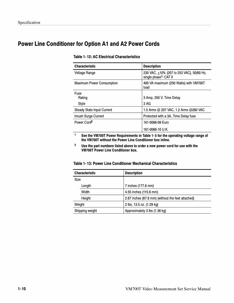
Table 1--13: Power Line Conditioner Mechanical Characteristics 1--10.
Table 1--14: Power Line Conditioner Environmental Characteristics 1--11
Table 1--15: Bar Line Time 1--12. . . . . . . . . . . . . . . . . . . . . . . . . . . . . . . . .
Table 1--16: Bounce 1--12. . . . . . . . . . . . . . . . . . . . . . . . . . . . . . . . . . . . . . . .
Table 1--17: Burst Frequency 1--13. . . . . . . . . . . . . . . . . . . . . . . . . . . . . . . .
Table 1--18: Chrominance to Luminance 1--13. . . . . . . . . . . . . . . . . . . . . .
Table 1--19: Chrominance Noise 1--13. . . . . . . . . . . . . . . . . . . . . . . . . . . . .
Table 1--20: Chrominance Nonlinearity 1--13. . . . . . . . . . . . . . . . . . . . . . .
Table 1--21: Color Bar 1--13. . . . . . . . . . . . . . . . . . . . . . . . . . . . . . . . . . . . .
Table 1--22: Differential Gain and Phase 1--14. . . . . . . . . . . . . . . . . . . . . .
Table 1--23: Frequency Response and Group Delay 1--14. . . . . . . . . . . . .
Table 1--24: Horizontal Blanking 1--14. . . . . . . . . . . . . . . . . . . . . . . . . . . .
Table 1--25: Horizontal Timing 1--14. . . . . . . . . . . . . . . . . . . . . . . . . . . . . .
Table 1--26: Incidental Carrier Phase Modulation 1--15. . . . . . . . . . . . . .
Table 1--27: Jitter 1--15. . . . . . . . . . . . . . . . . . . . . . . . . . . . . . . . . . . . . . . . .
Table 1--28: K-Factor 1--15. . . . . . . . . . . . . . . . . . . . . . . . . . . . . . . . . . . . . .
Table 1--29: Level Meter 1--15. . . . . . . . . . . . . . . . . . . . . . . . . . . . . . . . . . . .
Table 1--30: Line Frequency 1--15. . . . . . . . . . . . . . . . . . . . . . . . . . . . . . . .
Table 1--31: Luminance Nonlinearity 1--15. . . . . . . . . . . . . . . . . . . . . . . . .
Table 1--32: MultiBurst 1--16. . . . . . . . . . . . . . . . . . . . . . . . . . . . . . . . . . . .
Table 1--33: Noise Spectrum 1--16. . . . . . . . . . . . . . . . . . . . . . . . . . . . . . . .
Table 1--34: SCH Phase 1--16. . . . . . . . . . . . . . . . . . . . . . . . . . . . . . . . . . . .
Table 1--35: Two Field 1--16. . . . . . . . . . . . . . . . . . . . . . . . . . . . . . . . . . . . .
Table 1--36: Vertical Blanking 1--16. . . . . . . . . . . . . . . . . . . . . . . . . . . . . . .
Table 1--37: VITS ID 1--17. . . . . . . . . . . . . . . . . . . . . . . . . . . . . . . . . . . . . . .
Table of Contents
xii VM700T Video Measurement Set Service Manual
Table 1--38: Line Blanking timing measurements 1--17. . . . . . . . . . . . . . .
Table 1--39: Field Blanking timing measurements 1--17. . . . . . . . . . . . . .
Table 1--40: Other Timing measurements 1--18. . . . . . . . . . . . . . . . . . . . .
Table 1--41: Amplitude and Phase measurements 1--18. . . . . . . . . . . . . . .
Table 1--42: Frequency Response measurements 1--19. . . . . . . . . . . . . . . .
Table 1--43: Waveform Distortion measurements 1--19. . . . . . . . . . . . . . .
Table 1--44: Low Frequency Error 1--20. . . . . . . . . . . . . . . . . . . . . . . . . . .
Table 1--45: Noise measurements 1--20. . . . . . . . . . . . . . . . . . . . . . . . . . . . .
Table 1--46: Incidental Carrier Phase Modulation 1--20. . . . . . . . . . . . . .
Table 1--47: Bar Line Time 1--21. . . . . . . . . . . . . . . . . . . . . . . . . . . . . . . . .
Table 1--48: Bounce 1--21. . . . . . . . . . . . . . . . . . . . . . . . . . . . . . . . . . . . . . . .
Table 1--49: Burst Frequency 1--22. . . . . . . . . . . . . . . . . . . . . . . . . . . . . . . .
Table 1--50: Chrominance-to-Luminance Gain and Delay 1--22. . . . . . . .
Table 1--51: Chrominance Frequency Response 1--22. . . . . . . . . . . . . . . .
Table 1--52: Chrominance Noise 1--22. . . . . . . . . . . . . . . . . . . . . . . . . . . . .
Table 1--53: Chrominance Non-Linearity 1--22. . . . . . . . . . . . . . . . . . . . . .
Table 1--54: ColorBar 1--22. . . . . . . . . . . . . . . . . . . . . . . . . . . . . . . . . . . . . .
Table 1--55: SMPTE color bar nominal values 1--23. . . . . . . . . . . . . . . . .
Table 1--56: Differential Gain and Phase 1--23. . . . . . . . . . . . . . . . . . . . . .
Table 1--57: Frequency Response and Group Delay 1--23. . . . . . . . . . . . .
Table 1--58: Horizontal Blanking 1--23. . . . . . . . . . . . . . . . . . . . . . . . . . . .
Table 1--59: Horizontal Timing 1--23. . . . . . . . . . . . . . . . . . . . . . . . . . . . . .
Table 1--60: Incidental Carrier Phase Modulation 1--24. . . . . . . . . . . . . .
Table 1--61: Jitter 1--24. . . . . . . . . . . . . . . . . . . . . . . . . . . . . . . . . . . . . . . . .
Table 1--62: K-Factor 1--24. . . . . . . . . . . . . . . . . . . . . . . . . . . . . . . . . . . . . .
Table 1--63: Level Meter 1--24. . . . . . . . . . . . . . . . . . . . . . . . . . . . . . . . . . .
Table 1--64: Line Frequency 1--24. . . . . . . . . . . . . . . . . . . . . . . . . . . . . . . .
Table 1--65: Luminance Non-Linearity 1--25. . . . . . . . . . . . . . . . . . . . . . . .
Table 1--66: Multiburst 1--25. . . . . . . . . . . . . . . . . . . . . . . . . . . . . . . . . . . . .
Table 1--67: Noise Spectrum 1--25. . . . . . . . . . . . . . . . . . . . . . . . . . . . . . . .
Table 1--68: SCH Phase 1--25. . . . . . . . . . . . . . . . . . . . . . . . . . . . . . . . . . . .
Table 1--69: Short Time Distortion 1--25. . . . . . . . . . . . . . . . . . . . . . . . . . .
Table 1--70: Two Field 1--25. . . . . . . . . . . . . . . . . . . . . . . . . . . . . . . . . . . . .
Table 1--71: VITS ID 1--26. . . . . . . . . . . . . . . . . . . . . . . . . . . . . . . . . . . . . . .
Table 1--72: Vertical Blanking 1--26. . . . . . . . . . . . . . . . . . . . . . . . . . . . . . .
Table 1--73: RS-170A horizontal blanking interval timing 1--26. . . . . . . .
Table 1--74: RS-170A vertical blanking interval 1--27. . . . . . . . . . . . . . . .
Table 1--75: FCC horizontal blanking interval timing 1--27. . . . . . . . . . .
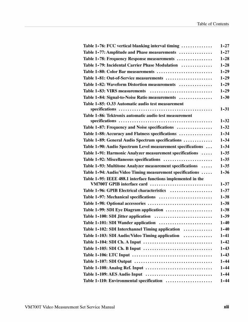
Table of Contents
VM700T Video Measurement Set Service Manual xiii
Table 1--76: FCC vertical blanking interval timing 1--27. . . . . . . . . . . . . .
Table 1--77: Amplitude and Phase measurements 1--27. . . . . . . . . . . . . . .
Table 1--78: Frequency Response measurements 1--28. . . . . . . . . . . . . . . .
Table 1--79: Incidental Carrier Phase Modulation 1--28. . . . . . . . . . . . . .
Table 1--80: Color Bar measurements 1--29. . . . . . . . . . . . . . . . . . . . . . . . .
Table 1--81: Out-of-Service measurements 1--29. . . . . . . . . . . . . . . . . . . . .
Table 1--82: Waveform Distortion measurements 1--29. . . . . . . . . . . . . . .
Table 1--83: VIRS measurements 1--29. . . . . . . . . . . . . . . . . . . . . . . . . . . .
Table 1--84: Signal-to-Noise Ratio measurements 1--30. . . . . . . . . . . . . . .
Table 1--85: O.33 Automatic audio test measurement
specifications 1--31. . . . . . . . . . . . . . . . . . . . . . . . . . . . . . . . . . . . . . . . . .
Table 1--86: Tektronix automatic audio test measurement
specifications 1--32. . . . . . . . . . . . . . . . . . . . . . . . . . . . . . . . . . . . . . . . . .
Table 1--87: Frequency and Noise specifications 1--32. . . . . . . . . . . . . . . .
Table 1--88: Accuracy and Flatness specifications 1--34. . . . . . . . . . . . . . .
Table 1--89: General Audio Spectrum specifications 1--34. . . . . . . . . . . . .
Table 1--90: Audio Spectrum Level measurement specifications 1--34. . .
Table 1--91: Harmonic Analyzer measurement specifications 1--35. . . . .
Table 1--92: Miscellaneous specifications 1--35. . . . . . . . . . . . . . . . . . . . . .
Table 1--93: Multitone Analyzer measurement specifications 1--35. . . . .
Table 1--94: Audio/Video Timing measurement specifications 1--36. . . . .
Table 1--95: IEEE 488.1 interface functions implemented in the
VM700T GPIB interface card 1--37. . . . . . . . . . . . . . . . . . . . . . . . . . . .
Table 1--96: GPIB Electrical characteristics 1--37. . . . . . . . . . . . . . . . . . .
Table 1--97: Mechanical specifications 1--38. . . . . . . . . . . . . . . . . . . . . . . .
Table 1--98: Optional accessories 1--38. . . . . . . . . . . . . . . . . . . . . . . . . . . . .
Table 1--99: SDI Eye Diagram application 1--38. . . . . . . . . . . . . . . . . . . . .
Table 1--100: SDI Jitter application 1--39. . . . . . . . . . . . . . . . . . . . . . . . . .
Table 1--101: SDI Wander application 1--40. . . . . . . . . . . . . . . . . . . . . . . .
Table 1--102: SDI Interchannel Timing application 1--40. . . . . . . . . . . . .
Table 1--103: SDI Audio/Video Timing application 1--41. . . . . . . . . . . . .
Table 1--104: SDI Ch. A Input 1--42. . . . . . . . . . . . . . . . . . . . . . . . . . . . . . .
Table 1--105: SDI Ch. B Input 1--43. . . . . . . . . . . . . . . . . . . . . . . . . . . . . . .
Table 1--106: LTC Input 1--43. . . . . . . . . . . . . . . . . . . . . . . . . . . . . . . . . . . .
Table 1--107: SDI Output 1--44. . . . . . . . . . . . . . . . . . . . . . . . . . . . . . . . . . .
Table 1--108: Analog Ref. Input 1--44. . . . . . . . . . . . . . . . . . . . . . . . . . . . . .
Table 1--109: AES Audio Input 1--44. . . . . . . . . . . . . . . . . . . . . . . . . . . . . .
Table 1--110: Environmental specification 1--44. . . . . . . . . . . . . . . . . . . . .
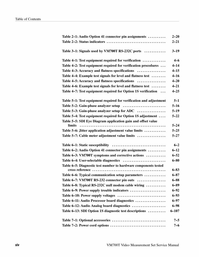
Table of Contents
xiv VM700T Video Measurement Set Service Manual
Table 2--1: Audio Option 41 connector pin assignments 2--20. . . . . . . . . .
Table 2--2: Status indicators 2--21. . . . . . . . . . . . . . . . . . . . . . . . . . . . . . . . .
Table 3--1: Signals used by VM700T RS-232C ports 3--19. . . . . . . . . . . .
Table 4--1: Test equipment required for verification 4--6. . . . . . . . . . . . .
Table 4--2: Test equipment required for verification procedures 4--14. . .
Table 4--3: Accuracy and flatness specifications 4--15. . . . . . . . . . . . . . . .
Table 4--4: Example test signals for level and flatness test 4--16. . . . . . . .
Table 4--5: Accuracy and flatness specifications 4--20. . . . . . . . . . . . . . . .
Table 4--6: Example test signals for level and flatness test 4--21. . . . . . . .
Table 4--7: Test equipment required for Option 1S verification 4--25. . .
Table 5--1: Test equipment required for verification and adjustment 5--1
Table 5--2: Gain-phase analyzer setup 5--16. . . . . . . . . . . . . . . . . . . . . . . .
Table 5--3: Gain-phase analyzer setup for ADC 5--19. . . . . . . . . . . . . . . .
Table 5--4: Test equipment required for Option 1S adjustment 5--22. . . .
Table 5--5: SDI Eye Diagram application gain and offset value
limits 5--24. . . . . . . . . . . . . . . . . . . . . . . . . . . . . . . . . . . . . . . . . . . . . . . .
Table 5--6: Jitter application adjustment value limits 5--25. . . . . . . . . . . .
Table 5--7: Cable meter adjustment value limits 5--27. . . . . . . . . . . . . . . .
Table 6--1: Static susceptibility 6--2. . . . . . . . . . . . . . . . . . . . . . . . . . . . . .
Table 6--2: Audio Option 41 connector pin assignments 6--12. . . . . . . . . .
Table 6--3: VM700T symptoms and corrective actions 6--52. . . . . . . . . . .
Table 6--4: User-selectable diagnostics 6--80. . . . . . . . . . . . . . . . . . . . . . . .
Table 6--5: Diagnostic test number to hardware components tested
cross reference 6--83. . . . . . . . . . . . . . . . . . . . . . . . . . . . . . . . . . . . . . . . .
Table 6--6: Typical communication setup parameters 6--87. . . . . . . . . . . .
Table 6--7: VM700T RS-232 connector pin outs 6--88. . . . . . . . . . . . . . . .
Table 6--8: Typical RS-232C null modem cable wiring 6--89. . . . . . . . . . .
Table 6--9: Power supply trouble indicators 6--92. . . . . . . . . . . . . . . . . . . .
Table 6--10: Power supply voltages 6--93. . . . . . . . . . . . . . . . . . . . . . . . . . .
Table 6--11: Audio Processor board diagnostics 6--97. . . . . . . . . . . . . . . . .
Table 6--12: Audio Analog board diagnostics 6--98. . . . . . . . . . . . . . . . . . .
Table 6--13: SDI Option 1S diagnostic test descriptions 6--107. . . . . . . . . .
Table 7--1: Optional accessories 7--5. . . . . . . . . . . . . . . . . . . . . . . . . . . . . .
Table 7--2: Power cord options 7--6. . . . . . . . . . . . . . . . . . . . . . . . . . . . . . .
VM700T Video Measurement Set Service Manual xv
General Safety Summary
Review the following safety precautions to avoid injury and prevent damage tothis product or any products connected to it. To avoid potential hazards, use thisproduct only as specified.
Only qualified personnel should perform service procedures.
To avoid potential hazards, use this product only as specified.
Use Proper Power Cord. Use only the power cord specified for this product andcertified for the country of use.
Use Proper Voltage Setting. Before applying power, ensure that the line selector isin the proper position for the power source being used.
Ground the Product. This product is grounded through the grounding conductorof the power cord. To avoid electric shock, the grounding conductor must beconnected to earth ground. Before making connections to the input or outputterminals of the product, ensure that the product is properly grounded.
Observe All Terminal Ratings. To avoid fire or shock hazard, observe all ratingsand markings on the product. Consult the product manual for further ratingsinformation before making connections to the product.
Do Not Operate Without Covers. Do not operate this product with covers or panelsremoved.
Use Proper Fuse. Use only the fuse type and rating specified for this product.
Avoid Exposed Circuitry. Do not touch exposed connections and componentswhen power is present.
Do Not Operate With Suspected Failures. If you suspect there is damage to thisproduct, have it inspected by qualified service personnel.
Do Not Operate in Wet/Damp Conditions.
Do Not Operate in an Explosive Atmosphere.
Keep Product Surfaces Clean and Dry.
Provide Proper Ventilation. Refer to the manual’s installation instructions fordetails on installing the product so it has proper ventilation.
To Avoid Fire orPersonal Injury
General Safety Summary
xvi VM700T Video Measurement Set Service Manual
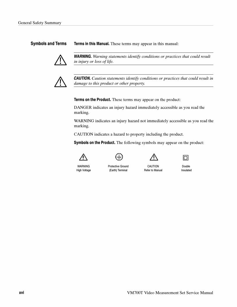
Terms in this Manual. These terms may appear in this manual:
WARNING.Warning statements identify conditions or practices that could result
in injury or loss of life.
CAUTION. Caution statements identify conditions or practices that could result in
damage to this product or other property.
Terms on the Product. These terms may appear on the product:
DANGER indicates an injury hazard immediately accessible as you read themarking.
WARNING indicates an injury hazard not immediately accessible as you read themarking.
CAUTION indicates a hazard to property including the product.
Symbols on the Product. The following symbols may appear on the product:
Protective Ground
(Earth) Terminal
CAUTION
Refer to Manual
Double
Insulated
WARNING
High Voltage
Symbols and Terms
VM700T Video Measurement Set Service Manual xvii
Service Safety Summary
Only qualified personnel should perform service procedures. Read this ServiceSafety Summary and the General Safety Summary before performing any serviceprocedures.
Do Not Service Alone. Do not perform internal service or adjustments of thisproduct unless another person capable of rendering first aid and resuscitation ispresent.
Disconnect Power. To avoid electric shock, disconnect the main power by meansof the power cord or, if provided, the power switch.
Use Caution When Servicing the CRT. To avoid electric shock or injury, useextreme caution when handling the CRT. Only qualified personnel familiar withCRT servicing procedures and precautions should remove or install the CRT.
CRTs retain hazardous voltages for long periods of time after power is turned off.Before attempting any servicing, discharge the CRT by shorting the anode tochassis ground. When discharging the CRT, connect the discharge path to groundand then the anode. Rough handling may cause the CRT to implode. Do not nickor scratch the glass or subject it to undue pressure when removing or installing it.When handling the CRT, wear safety goggles and heavy gloves for protection.
Use Care When Servicing With Power On. Dangerous voltages or currents mayexist in this product. Disconnect power, remove battery (if applicable), anddisconnect test leads before removing protective panels, soldering, or replacingcomponents.
To avoid electric shock, do not touch exposed connections.
X-Radiation. To avoid x-radiation exposure, do not modify or otherwise alter thehigh-voltage circuitry or the CRT enclosure. X-ray emissions generated withinthis product have been sufficiently shielded.

Service Safety Summary
xviii VM700T Video Measurement Set Service Manual
VM700T Video Measurement Set Service Manual xix
Preface
This is a service manual for the VM700T Video Measurement Set. It is amodule-level repair manual for use by a qualified service person in the isolationof faulty modules and repair by module exchange.
Contents of the Manual
This manual contains the following sections:
1. Specification lists the major specifications of the VM700T as an instrument.Option specifications are contained in the associated Option User Manuals.
2. Operating Information introduces the VM700T, gives the basic installationinstructions, describes its major features, and the controls and connectors ofthe instruments.
3. Theory of Operation contains functional block descriptions of the VM700Tcircuit board modules to aid in understanding the instrument for servicing.
4. Performance Verification has the procedures for verifying the operation ofthe VM700T and the audio options.
5. Adjustment Procedure has the procedures for returning the VM700T tospecification after a circuit board module exchange.
6. Maintenance provides the customer service information and illustrated,step-by-step procedures for removing and replacing the field-replaceablemodules of the VM700T. Installation instructions for the rack mountedinstrument are in this section. Troubleshooting and diagnostic information isprovided to help you troubleshoot the VM700T to isolate a faulty circuitboard module for a module exchange repair.
7. Options has a listing with a short description of the available options for theVM700T.
8. Replaceable Electrical Parts List refers you to the Replaceable Mechanical
Parts List for the list of replaceable electrical parts.
9. Diagrams provides an overall block diagram and a circuit board interconnec-tion diagram to assist in faulty module isolation procedures.
10. Replaceable Mechanical Parts List has exploded views and gives the lists ofthe replaceable mechanical parts to aid in locating a replacement mechanicalpart. The assembly Tektronix part numbers are also included in this list as aconvenience.
Preface
xx VM700T Video Measurement Set Service Manual
Contacting Tektronix
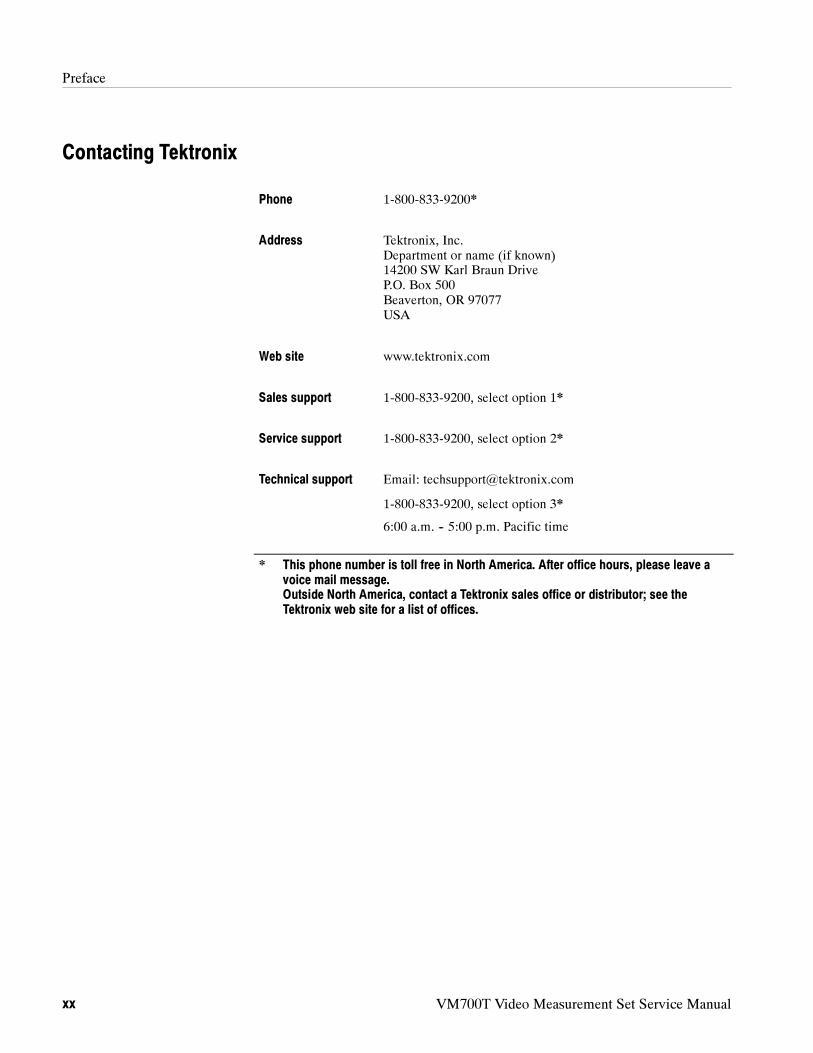
Phone 1-800-833-9200*
Address Tektronix, Inc.Department or name (if known)14200 SW Karl Braun DriveP.O. Box 500Beaverton, OR 97077USA
Web site www.tektronix.com
Sales support 1-800-833-9200, select option 1*
Service support 1-800-833-9200, select option 2*
Technical support Email: [email protected]
1-800-833-9200, select option 3*
6:00 a.m. -- 5:00 p.m. Pacific time
* This phone number is toll free in North America. After office hours, please leave avoice mail message.Outside North America, contact a Tektronix sales office or distributor; see theTektronix web site for a list of offices.
VM700T Video Measurement Set Service Manual 1- 1
Specification
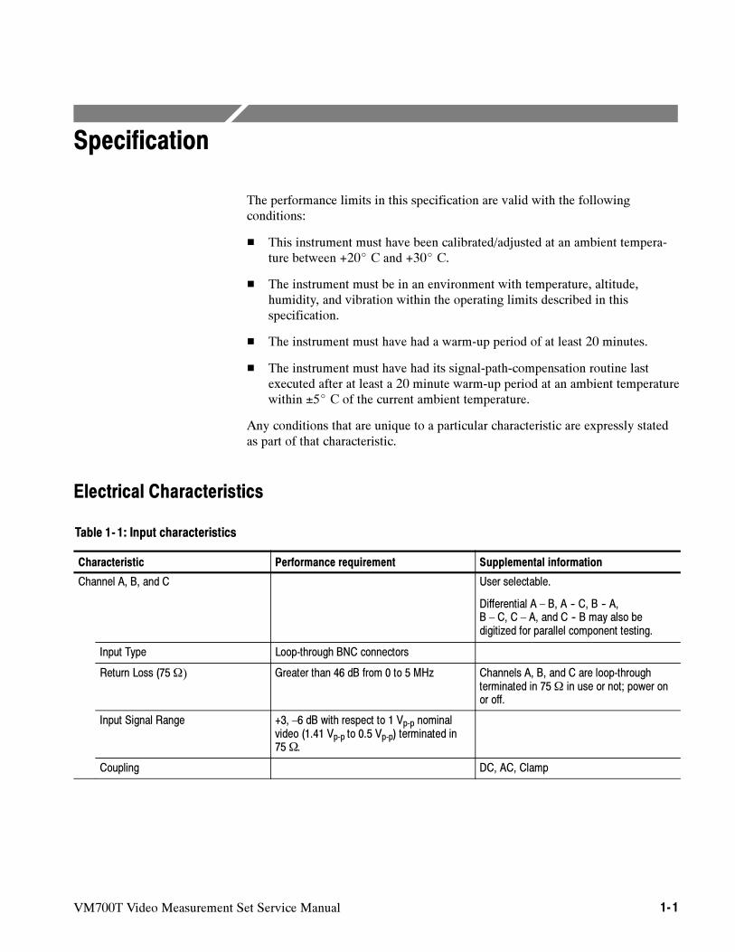
The performance limits in this specification are valid with the followingconditions:
This instrument must have been calibrated/adjusted at an ambient tempera-ture between +20 C and +30 C.
The instrument must be in an environment with temperature, altitude,humidity, and vibration within the operating limits described in thisspecification.
The instrument must have had a warm-up period of at least 20 minutes.
The instrument must have had its signal-path-compensation routine lastexecuted after at least a 20 minute warm-up period at an ambient temperaturewithin ±5 C of the current ambient temperature.
Any conditions that are unique to a particular characteristic are expressly statedas part of that characteristic.
Electrical Characteristics
Table 1- 1: Input characteristics
Characteristic Performance requirement Supplemental information
Channel A, B, and C User selectable.
Differential A – B, A -- C, B -- A,B – C, C – A, and C -- B may also bedigitized for parallel component testing.
Input Type Loop-through BNC connectors
Return Loss (75Ω) Greater than 46 dB from 0 to 5 MHz Channels A, B, and C are loop-throughterminated in 75Ω in use or not; power onor off.
Input Signal Range +3, –6 dB with respect to 1 Vp-p nominalvideo (1.41 Vp-p to 0.5 Vp-p) terminated in75Ω.
Coupling DC, AC, Clamp
Specification
1- 2 VM700T Video Measurement Set Service Manual
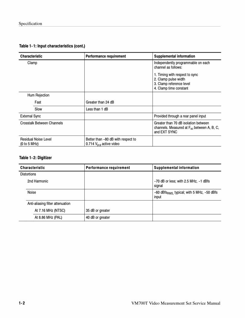
Table 1- 1: Input characteristics (cont.)
Characteristic Supplemental informationPerformance requirement
Clamp Independently programmable on eachchannel as follows:
1. Timing with respect to sync2. Clamp pulse width3. Clamp reference level4. Clamp time constant
Hum Rejection
Fast Greater than 24 dB
Slow Less than 1 dB
External Sync Provided through a rear panel input
Crosstalk Between Channels Greater than 70 dB isolation betweenchannels. Measured at Fsc between A, B, C,and EXT SYNC
Residual Noise Level(0 to 5 MHz)
Better than --80 dB with respect to0.714 Vp-p active video
Table 1- 2: Digitizer
Characteristic Performance requirement Supplemental information
Distortions
2nd Harmonic --70 dB or less; with 2.5 MHz, --1 dBfssignal
Noise --60 dBfsRMS, typical; with 5 MHz, --50 dBfsinput
Anti-aliasing filter attenuation
At 7.16 MHz (NTSC) 35 dB or greater
At 8.86 MHz (PAL) 40 dB or greater
Specification
VM700T Video Measurement Set Service Manual 1- 3
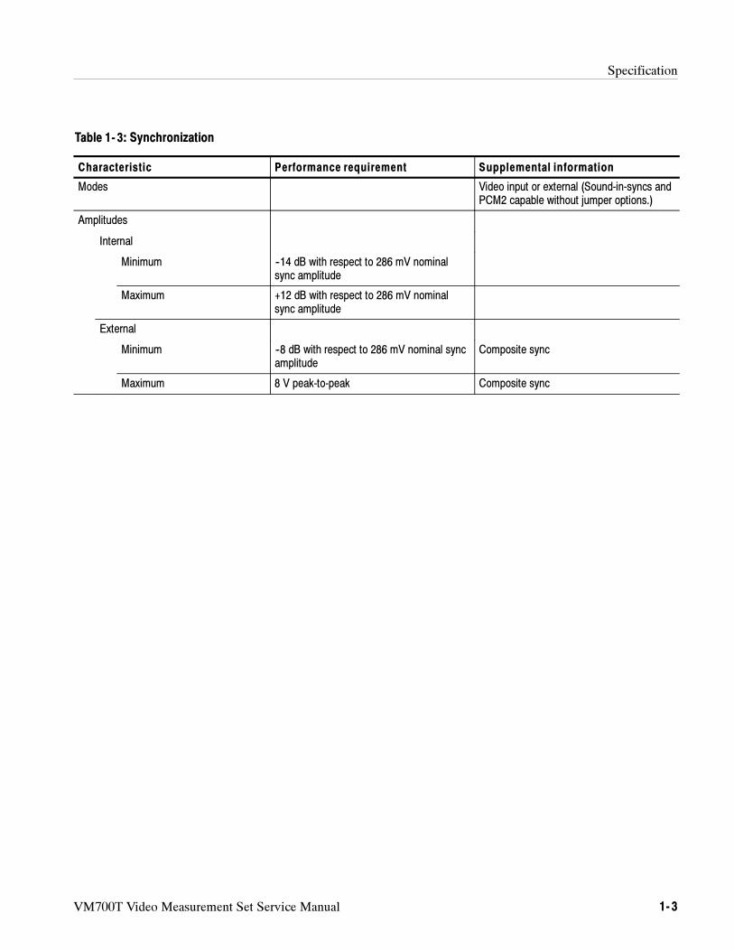
Table 1- 3: Synchronization
Characteristic Performance requirement Supplemental information
Modes Video input or external (Sound-in-syncs andPCM2 capable without jumper options.)
Amplitudes
Internal
Minimum --14 dB with respect to 286 mV nominalsync amplitude
Maximum +12 dB with respect to 286 mV nominalsync amplitude
External
Minimum --8 dB with respect to 286 mV nominal syncamplitude
Composite sync
Maximum 8 V peak-to-peak Composite sync
Specification
1- 4 VM700T Video Measurement Set Service Manual
Physical Characteristics
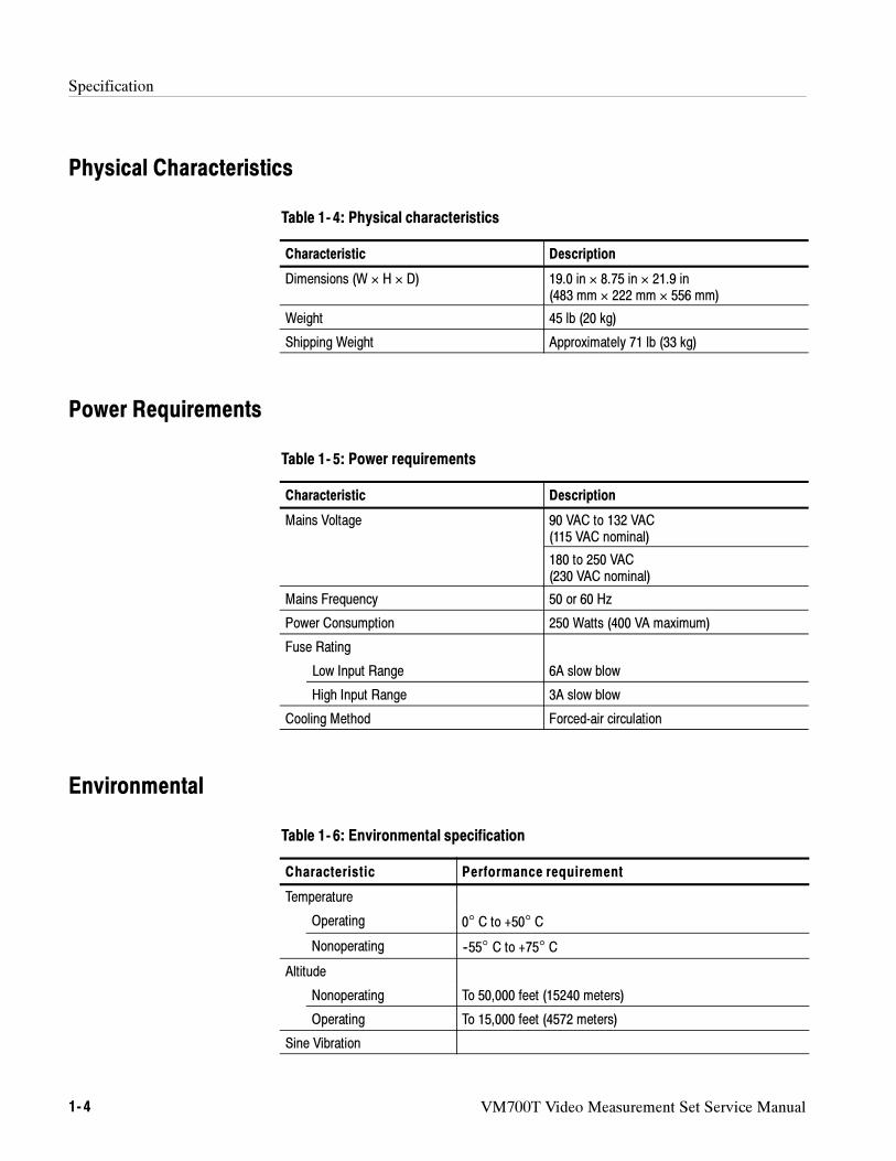
Table 1- 4: Physical characteristics
Characteristic Description
Dimensions (W × H × D) 19.0 in × 8.75 in × 21.9 in(483 mm × 222 mm × 556 mm)
Weight 45 lb (20 kg)
Shipping Weight Approximately 71 lb (33 kg)
Power Requirements
Table 1- 5: Power requirements
Characteristic Description
Mains Voltage 90 VAC to 132 VAC(115 VAC nominal)
180 to 250 VAC(230 VAC nominal)
Mains Frequency 50 or 60 Hz
Power Consumption 250 Watts (400 VA maximum)
Fuse Rating
Low Input Range 6A slow blow
High Input Range 3A slow blow
Cooling Method Forced-air circulation
Environmental
Table 1- 6: Environmental specification
Characteristic Performance requirement
Temperature
Operating 0° C to +50° C
Nonoperating --55° C to +75° C
Altitude
Nonoperating To 50,000 feet (15240 meters)
Operating To 15,000 feet (4572 meters)
Sine Vibration
Specification
VM700T Video Measurement Set Service Manual 1- 5
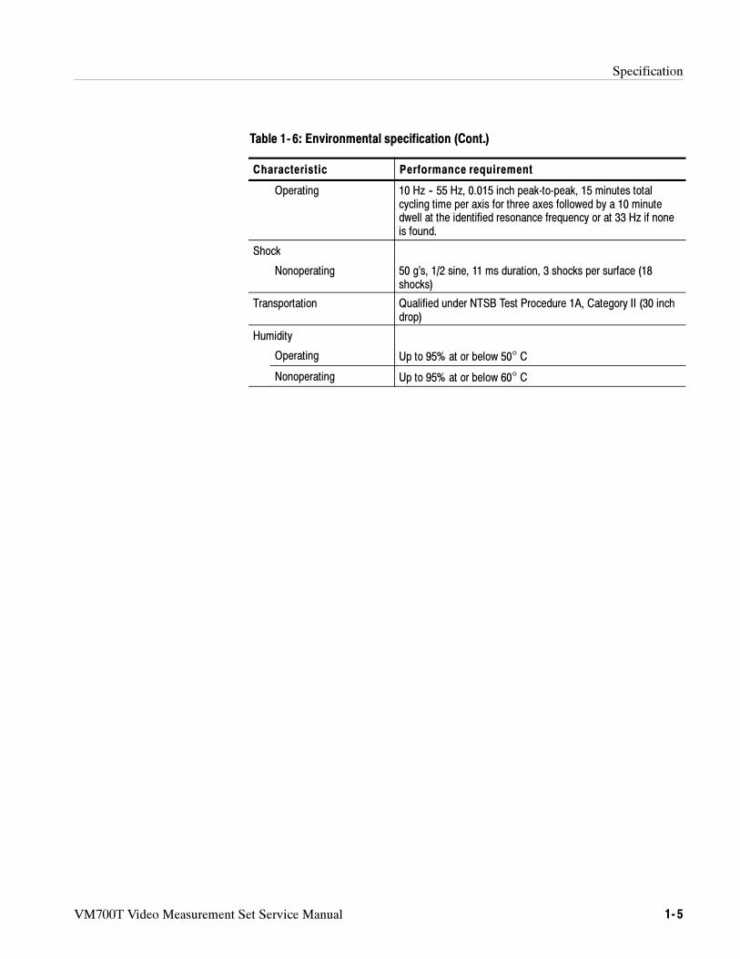
Table 1- 6: Environmental specification (Cont.)
Characteristic Performance requirement
Operating 10 Hz -- 55 Hz, 0.015 inch peak-to-peak, 15 minutes totalcycling time per axis for three axes followed by a 10 minutedwell at the identified resonance frequency or at 33 Hz if noneis found.
Shock
Nonoperating 50 g’s, 1/2 sine, 11 ms duration, 3 shocks per surface (18shocks)
Transportation Qualified under NTSB Test Procedure 1A, Category II (30 inchdrop)
Humidity
Operating Up to 95% at or below 50° C
Nonoperating Up to 95% at or below 60° C
Specification
1- 6 VM700T Video Measurement Set Service Manual
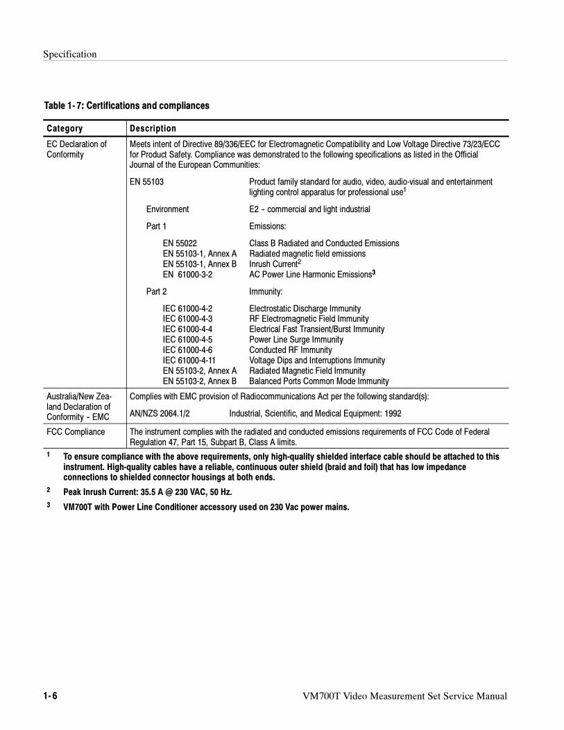
Table 1- 7: Certifications and compliances
Category Description
EC Declaration ofConformity
Meets intent of Directive 89/336/EEC for Electromagnetic Compatibility and Low Voltage Directive 73/23/ECCfor Product Safety. Compliance was demonstrated to the following specifications as listed in the OfficialJournal of the European Communities:
EN 55103 Product family standard for audio, video, audio-visual and entertainmentlighting control apparatus for professional use1
Environment E2 -- commercial and light industrial
Part 1 Emissions:
EN 55022 Class B Radiated and Conducted EmissionsEN 55103-1, Annex A Radiated magnetic field emissionsEN 55103-1, Annex B Inrush Current2
EN 61000-3-2 AC Power Line Harmonic Emissions3
Part 2 Immunity:
IEC 61000-4-2 Electrostatic Discharge ImmunityIEC 61000-4-3 RF Electromagnetic Field ImmunityIEC 61000-4-4 Electrical Fast Transient/Burst ImmunityIEC 61000-4-5 Power Line Surge ImmunityIEC 61000-4-6 Conducted RF ImmunityIEC 61000-4-11 Voltage Dips and Interruptions ImmunityEN 55103-2, Annex A Radiated Magnetic Field ImmunityEN 55103-2, Annex B Balanced Ports Common Mode Immunity
Australia/New Zea-land Declaration ofConformity -- EMC
Complies with EMC provision of Radiocommunications Act per the following standard(s):
AN/NZS 2064.1/2 Industrial, Scientific, and Medical Equipment: 1992
FCC Compliance The instrument complies with the radiated and conducted emissions requirements of FCC Code of FederalRegulation 47, Part 15, Subpart B, Class A limits.
1 To ensure compliance with the above requirements, only high-quality shielded interface cable should be attached to thisinstrument. High-quality cables have a reliable, continuous outer shield (braid and foil) that has low impedanceconnections to shielded connector housings at both ends.
2 Peak Inrush Current: 35.5 A @ 230 VAC, 50 Hz.
3 VM700T with Power Line Conditioner accessory used on 230 Vac power mains.
Specification
VM700T Video Measurement Set Service Manual 1- 7
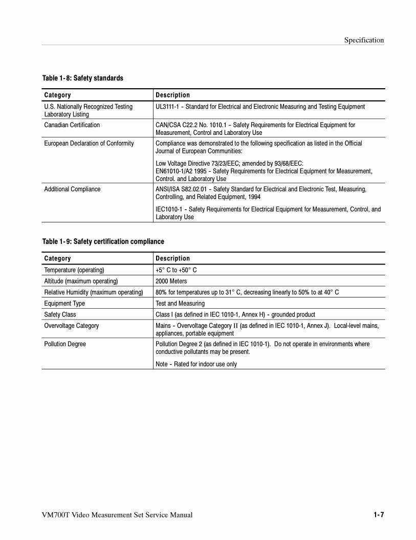
Table 1- 8: Safety standards
Category Description
U.S. Nationally Recognized TestingLaboratory Listing
UL3111-1 -- Standard for Electrical and Electronic Measuring and Testing Equipment
Canadian Certification CAN/CSA C22.2 No. 1010.1 -- Safety Requirements for Electrical Equipment forMeasurement, Control and Laboratory Use
European Declaration of Conformity Compliance was demonstrated to the following specification as listed in the OfficialJournal of European Communities:
Low Voltage Directive 73/23/EEC; amended by 93/68/EEC:EN61010-1/A2 1995 -- Safety Requirements for Electrical Equipment for Measurement,Control. and Laboratory Use
Additional Compliance ANSI/ISA S82.02.01 -- Safety Standard for Electrical and Electronic Test, Measuring,Controlling, and Related Equipment, 1994
IEC1010-1 -- Safety Requirements for Electrical Equipment for Measurement, Control, andLaboratory Use
Table 1- 9: Safety certification compliance
Category Description
Temperature (operating) +5° C to +50° C
Altitude (maximum operating) 2000 Meters
Relative Humidity (maximum operating) 80% for temperatures up to 31° C, decreasing linearly to 50% to at 40° C
Equipment Type Test and Measuring
Safety Class Class I (as defined in IEC 1010-1, Annex H) -- grounded product
Overvoltage Category Mains -- Overvoltage Category II (as defined in IEC 1010-1, Annex J). Local-level mains,appliances, portable equipment
Pollution Degree Pollution Degree 2 (as defined in IEC 1010-1). Do not operate in environments whereconductive pollutants may be present.
Note -- Rated for indoor use only
Specification
1- 8 VM700T Video Measurement Set Service Manual
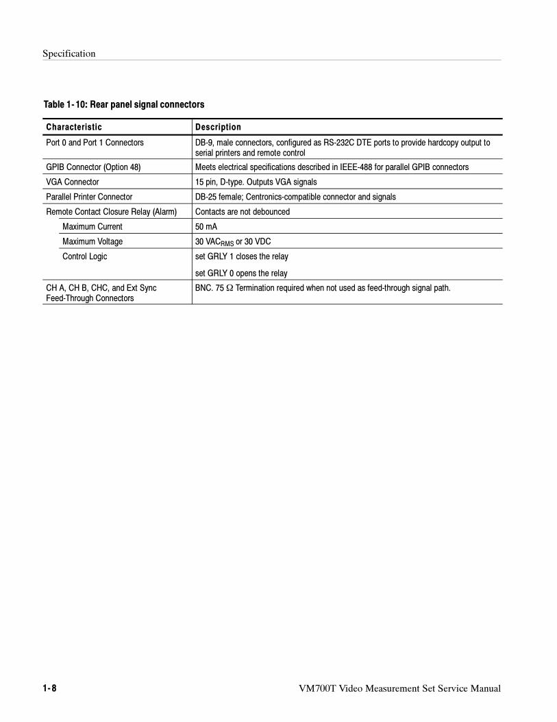
Table 1- 10: Rear panel signal connectors
Characteristic Description
Port 0 and Port 1 Connectors DB-9, male connectors, configured as RS-232C DTE ports to provide hardcopy output toserial printers and remote control
GPIB Connector (Option 48) Meets electrical specifications described in IEEE-488 for parallel GPIB connectors
VGA Connector 15 pin, D-type. Outputs VGA signals
Parallel Printer Connector DB-25 female; Centronics-compatible connector and signals
Remote Contact Closure Relay (Alarm) Contacts are not debounced
Maximum Current 50 mA
Maximum Voltage 30 VACRMS or 30 VDC
Control Logic set GRLY 1 closes the relay
set GRLY 0 opens the relay
CH A, CH B, CHC, and Ext SyncFeed-Through Connectors
BNC. 75Ω Termination required when not used as feed-through signal path.
Specification
VM700T Video Measurement Set Service Manual 1- 9
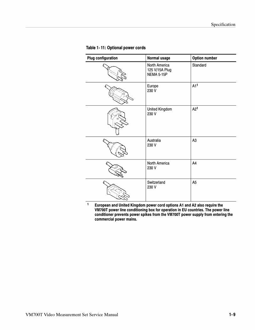
Table 1- 11: Optional power cords
Plug configuration Normal usage Option number
North America125 V/15A PlugNEMA 5-15P
Standard
Europe230 V
A11
United Kingdom230 V
A21
Australia230 V
A3
North America230 V
A4
Switzerland230 V
A5
1 European and United Kingdom power cord options A1 and A2 also require theVM700T power line conditioning box for operation in EU countries. The power lineconditioner prevents power spikes from the VM700T power supply from entering thecommercial power mains.
Specification
1- 10 VM700T Video Measurement Set Service Manual
Power Line Conditioner for Option A1 and A2 Power Cords
Table 1- 12: AC Electrical Characteristics
Characteristic Description
Voltage Range 230 VAC, +10% (207 to 253 VAC), 50/60 Hz,single phase1, CAT II
Maximum Power Consumption 400 VA maximum (250 Watts) with VM700Tload
FuseRating 3 Amp, 250 V, Time Delay
Style 3 AG
Steady State Input Current 1.5 Arms @ 207 VAC, 1.2 Arms @260 VAC
Inrush Surge Current Protected with a 3A, Time Delay fuse
Power Cord2 161-0066-09 Euro
161-0066-10 U.K.
1 See the VM700T Power Requirements in Table 1- 5 for the operating voltage range ofthe VM700T without the Power Line Conditioner box inline.
2 Use the part numbers listed above to order a new power cord for use with theVM700T Power Line Conditioner box.
Table 1- 13: Power Line Conditioner Mechanical Characteristics
Characteristic Description
Size
Length 7 inches (177.8 mm)
Width 4.55 inches (115.6 mm)
Height 2.67 inches (67.8 mm) (without the feet attached)
Weight 2 lbs, 13.5 oz. (1.29 kg)
Shipping weight Approximately 3 lbs (1.36 kg)
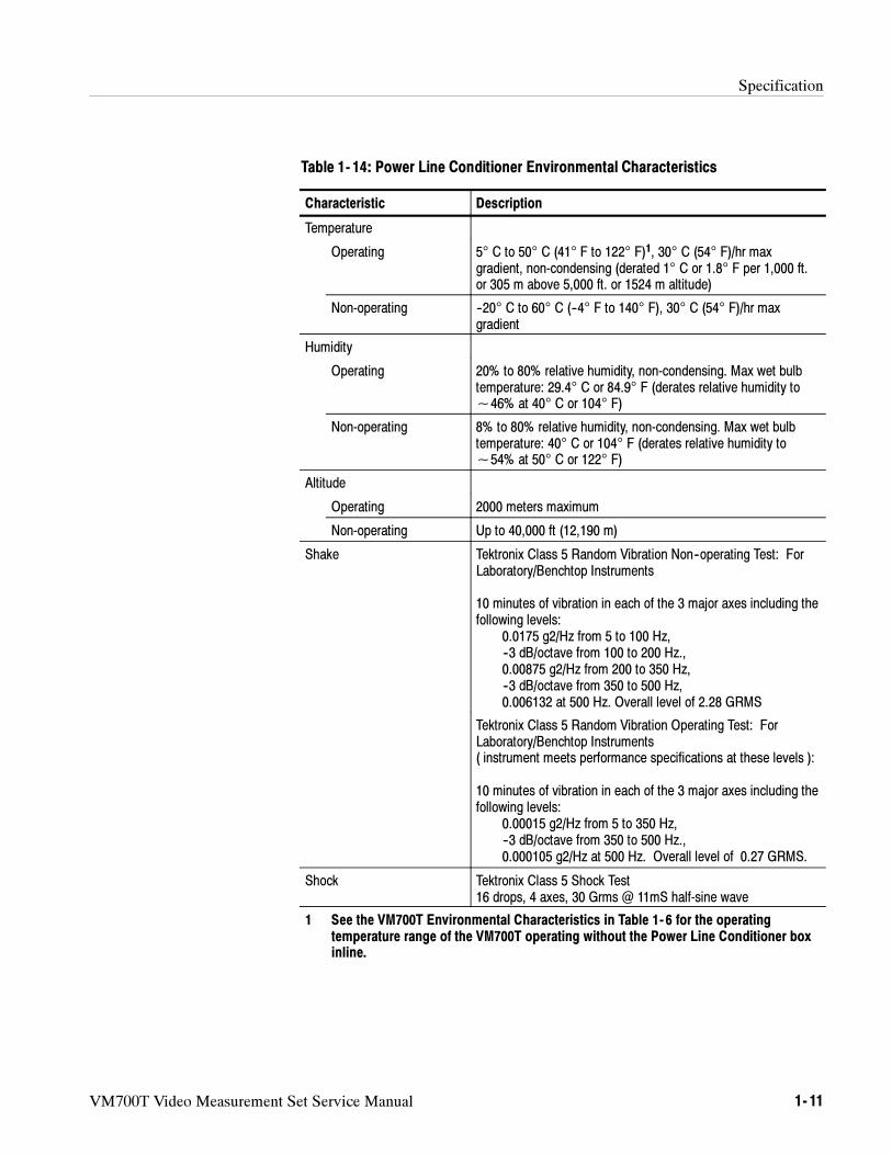
Specification
VM700T Video Measurement Set Service Manual 1- 11
Table 1- 14: Power Line Conditioner Environmental Characteristics
Characteristic Description
Temperature
Operating 5° C to 50° C (41° F to 122° F)1, 30° C (54° F)/hr maxgradient, non-condensing (derated 1° C or 1.8° F per 1,000 ft.or 305 m above 5,000 ft. or 1524 m altitude)
Non-operating --20° C to 60° C (--4° F to 140° F), 30° C (54° F)/hr maxgradient
Humidity
Operating 20% to 80% relative humidity, non-condensing. Max wet bulbtemperature: 29.4° C or 84.9° F (derates relative humidity to~46% at 40° C or 104° F)
Non-operating 8% to 80% relative humidity, non-condensing. Max wet bulbtemperature: 40° C or 104° F (derates relative humidity to~54% at 50° C or 122° F)
Altitude
Operating 2000 meters maximum
Non-operating Up to 40,000 ft (12,190 m)
Shake Tektronix Class 5 Random Vibration Non--operating Test: ForLaboratory/Benchtop Instruments
10 minutes of vibration in each of the 3 major axes including thefollowing levels:
0.0175 g2/Hz from 5 to 100 Hz,--3 dB/octave from 100 to 200 Hz.,0.00875 g2/Hz from 200 to 350 Hz,--3 dB/octave from 350 to 500 Hz,0.006132 at 500 Hz. Overall level of 2.28 GRMS
Tektronix Class 5 Random Vibration Operating Test: ForLaboratory/Benchtop Instruments( instrument meets performance specifications at these levels ):
10 minutes of vibration in each of the 3 major axes including thefollowing levels:
0.00015 g2/Hz from 5 to 350 Hz,--3 dB/octave from 350 to 500 Hz.,0.000105 g2/Hz at 500 Hz. Overall level of 0.27 GRMS.
Shock Tektronix Class 5 Shock Test16 drops, 4 axes, 30 Grms @ 11mS half-sine wave
1 See the VM700T Environmental Characteristics in Table 1- 6 for the operatingtemperature range of the VM700T operating without the Power Line Conditioner boxinline.
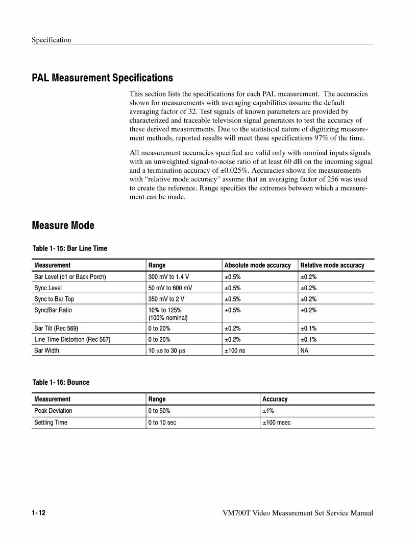
Specification
1- 12 VM700T Video Measurement Set Service Manual
PAL Measurement Specifications
This section lists the specifications for each PAL measurement. The accuraciesshown for measurements with averaging capabilities assume the defaultaveraging factor of 32. Test signals of known parameters are provided bycharacterized and traceable television signal generators to test the accuracy ofthese derived measurements. Due to the statistical nature of digitizing measure-ment methods, reported results will meet these specifications 97% of the time.
All measurement accuracies specified are valid only with nominal inputs signalswith an unweighted signal-to-noise ratio of at least 60 dB on the incoming signaland a termination accuracy of ±0.025%. Accuracies shown for measurementswith “relative mode accuracy” assume that an averaging factor of 256 was usedto create the reference. Range specifies the extremes between which a measure-ment can be made.
Measure Mode
Table 1- 15: Bar Line Time
Measurement Range Absolute mode accuracy Relative mode accuracy
Bar Level (b1 or Back Porch) 300 mV to 1.4 V ±0.5% ±0.2%
Sync Level 50 mV to 600 mV ±0.5% ±0.2%
Sync to Bar Top 350 mV to 2 V ±0.5% ±0.2%
Sync/Bar Ratio 10% to 125%(100% nominal)
±0.5% ±0.2%
Bar Tilt (Rec 569) 0 to 20% ±0.2% ±0.1%
Line Time Distortion (Rec 567) 0 to 20% ±0.2% ±0.1%
Bar Width 10 s to 30 s ±100 ns NA
Table 1- 16: Bounce
Measurement Range Accuracy
Peak Deviation 0 to 50% ±1%
Settling Time 0 to 10 sec ±100 msec
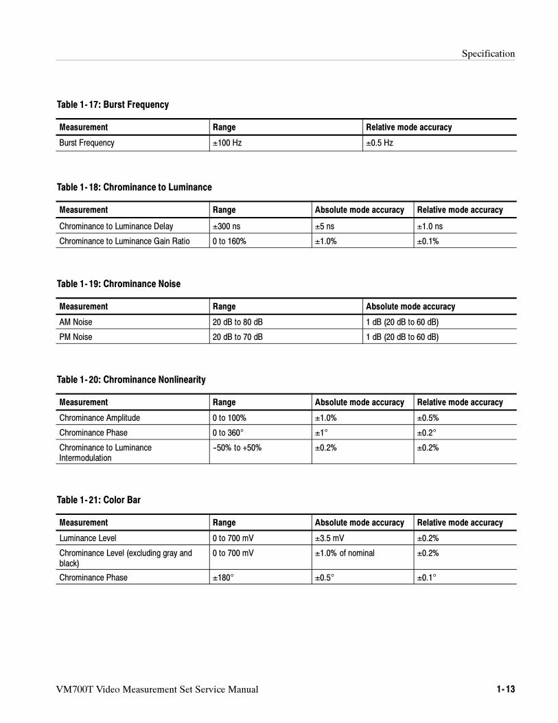
Specification
VM700T Video Measurement Set Service Manual 1- 13
Table 1- 17: Burst Frequency
Measurement Range Relative mode accuracy
Burst Frequency ±100 Hz ±0.5 Hz
Table 1- 18: Chrominance to Luminance
Measurement Range Absolute mode accuracy Relative mode accuracy
Chrominance to Luminance Delay ±300 ns ±5 ns ±1.0 ns
Chrominance to Luminance Gain Ratio 0 to 160% ±1.0% ±0.1%
Table 1- 19: Chrominance Noise
Measurement Range Absolute mode accuracy
AM Noise 20 dB to 80 dB 1 dB (20 dB to 60 dB)
PM Noise 20 dB to 70 dB 1 dB (20 dB to 60 dB)
Table 1- 20: Chrominance Nonlinearity
Measurement Range Absolute mode accuracy Relative mode accuracy
Chrominance Amplitude 0 to 100% ±1.0% ±0.5%
Chrominance Phase 0 to 360° ±1° ±0.2°
Chrominance to LuminanceIntermodulation
--50% to +50% ±0.2% ±0.2%
Table 1- 21: Color Bar
Measurement Range Absolute mode accuracy Relative mode accuracy
Luminance Level 0 to 700 mV ±3.5 mV ±0.2%
Chrominance Level (excluding gray andblack)
0 to 700 mV ±1.0% of nominal ±0.2%
Chrominance Phase ±180° ±0.5° ±0.1°
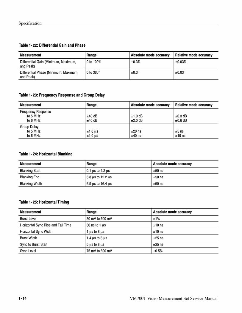
Specification
1- 14 VM700T Video Measurement Set Service Manual
Table 1- 22: Differential Gain and Phase
Measurement Range Absolute mode accuracy Relative mode accuracy
Differential Gain (Minimum, Maximum,and Peak)
0 to 100% ±0.3% ±0.03%
Differential Phase (Minimum, Maximum,and Peak)
0 to 360° ±0.3° ±0.03°
Table 1- 23: Frequency Response and Group Delay
Measurement Range Absolute mode accuracy Relative mode accuracy
Frequency Responseto 5 MHzto 6 MHz
±40 dB±40 dB
±1.0 dB±2.0 dB
±0.3 dB±0.6 dB
Group Delayto 5 MHzto 6 MHz
±1.0 s±1.0 s
±20 ns±40 ns
±5 ns±10 ns
Table 1- 24: Horizontal Blanking
Measurement Range Absolute mode accuracy
Blanking Start 0.1 s to 4.2 s ±50 ns
Blanking End 6.8 s to 12.2 s ±50 ns
Blanking Width 6.9 s to 16.4 s ±50 ns
Table 1- 25: Horizontal Timing
Measurement Range Absolute mode accuracy
Burst Level 80 mV to 600 mV ±1%
Horizontal Sync Rise and Fall Time 80 ns to 1 s ±10 ns
Horizontal Sync Width 1 s to 8 s ±10 ns
Burst Width 1.4 s to 3 s ±25 ns
Sync to Burst Start 5 s to 8 s ±25 ns
Sync Level 75 mV to 600 mV ±0.5%
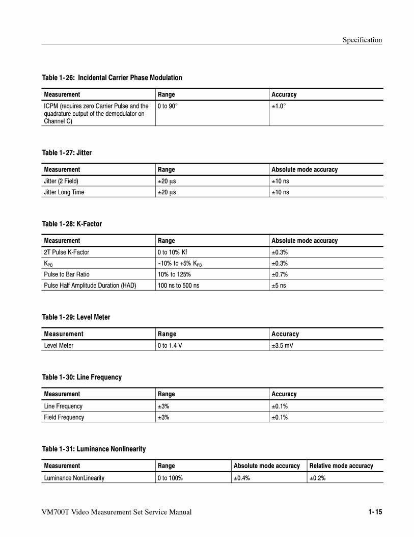
Specification
VM700T Video Measurement Set Service Manual 1- 15
Table 1- 26: Incidental Carrier Phase Modulation
Measurement Range Accuracy
ICPM (requires zero Carrier Pulse and thequadrature output of the demodulator onChannel C)
0 to 90° ±1.0°
Table 1- 27: Jitter
Measurement Range Absolute mode accuracy
Jitter (2 Field) ±20 s ±10 ns
Jitter Long Time ±20 s ±10 ns
Table 1- 28: K-Factor
Measurement Range Absolute mode accuracy
2T Pulse K-Factor 0 to 10% Kf ±0.3%
KPB --10% to +5% KPB ±0.3%
Pulse to Bar Ratio 10% to 125% ±0.7%
Pulse Half Amplitude Duration (HAD) 100 ns to 500 ns ±5 ns
Table 1- 29: Level Meter
Measurement Range Accuracy
Level Meter 0 to 1.4 V ±3.5 mV
Table 1- 30: Line Frequency
Measurement Range Accuracy
Line Frequency ±3% ±0.1%
Field Frequency ±3% ±0.1%
Table 1- 31: Luminance Nonlinearity
Measurement Range Absolute mode accuracy Relative mode accuracy
Luminance NonLinearity 0 to 100% ±0.4% ±0.2%
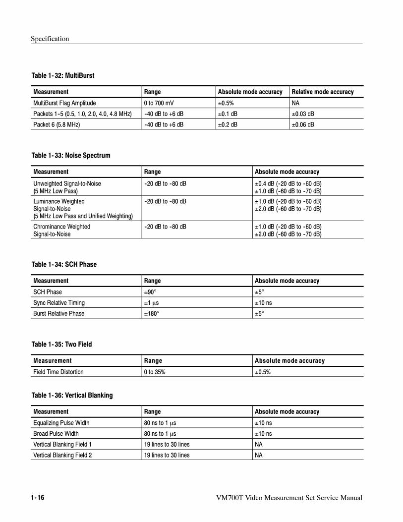
Specification
1- 16 VM700T Video Measurement Set Service Manual
Table 1- 32: MultiBurst
Measurement Range Absolute mode accuracy Relative mode accuracy
MultiBurst Flag Amplitude 0 to 700 mV ±0.5% NA
Packets 1--5 (0.5, 1.0, 2.0, 4.0, 4.8 MHz) --40 dB to +6 dB ±0.1 dB ±0.03 dB
Packet 6 (5.8 MHz) --40 dB to +6 dB ±0.2 dB ±0.06 dB
Table 1- 33: Noise Spectrum
Measurement Range Absolute mode accuracy
Unweighted Signal-to-Noise(5 MHz Low Pass)
--20 dB to --80 dB ±0.4 dB (--20 dB to --60 dB)±1.0 dB (--60 dB to --70 dB)
Luminance WeightedSignal-to-Noise(5 MHz Low Pass and Unified Weighting)
--20 dB to --80 dB ±1.0 dB (--20 dB to --60 dB)±2.0 dB (--60 dB to --70 dB)
Chrominance WeightedSignal-to-Noise
--20 dB to --80 dB ±1.0 dB (--20 dB to --60 dB)±2.0 dB (--60 dB to --70 dB)
Table 1- 34: SCH Phase
Measurement Range Absolute mode accuracy
SCH Phase ±90° ±5°
Sync Relative Timing ±1 s ±10 ns
Burst Relative Phase ±180° ±5°
Table 1- 35: Two Field
Measurement Range Absolute mode accuracy
Field Time Distortion 0 to 35% ±0.5%
Table 1- 36: Vertical Blanking
Measurement Range Absolute mode accuracy
Equalizing Pulse Width 80 ns to 1 s ±10 ns
Broad Pulse Width 80 ns to 1 s ±10 ns
Vertical Blanking Field 1 19 lines to 30 lines NA
Vertical Blanking Field 2 19 lines to 30 lines NA
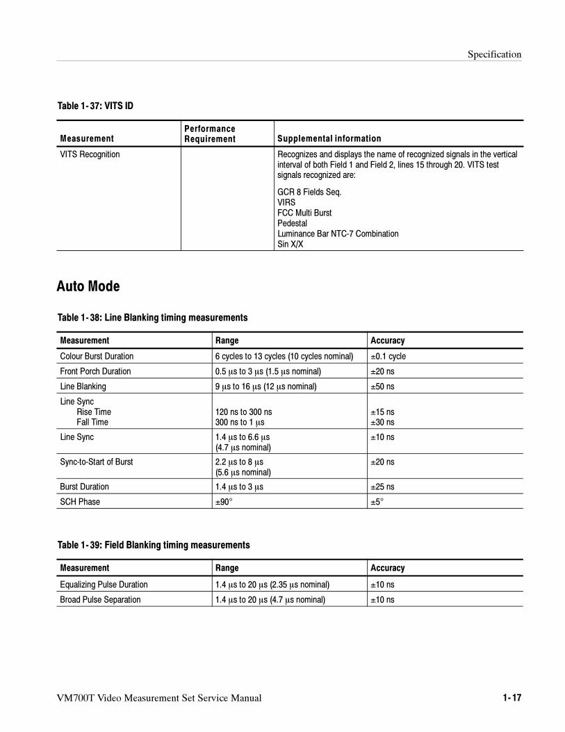
Specification
VM700T Video Measurement Set Service Manual 1- 17
Table 1- 37: VITS ID
MeasurementPerformanceRequirement Supplemental information
VITS Recognition Recognizes and displays the name of recognized signals in the verticalinterval of both Field 1 and Field 2, lines 15 through 20. VITS testsignals recognized are:
GCR 8 Fields Seq.VIRSFCC Multi BurstPedestalLuminance Bar NTC-7 CombinationSin X/X
Auto Mode
Table 1- 38: Line Blanking timing measurements
Measurement Range Accuracy
Colour Burst Duration 6 cycles to 13 cycles (10 cycles nominal) ±0.1 cycle
Front Porch Duration 0.5 s to 3 s (1.5 s nominal) ±20 ns
Line Blanking 9 s to 16 s (12 s nominal) ±50 ns
Line SyncRise TimeFall Time
120 ns to 300 ns300 ns to 1 s
±15 ns±30 ns
Line Sync 1.4 s to 6.6 s(4.7 s nominal)
±10 ns
Sync-to-Start of Burst 2.2 s to 8 s(5.6 s nominal)
±20 ns
Burst Duration 1.4 s to 3 s ±25 ns
SCH Phase ±90° ±5°
Table 1- 39: Field Blanking timing measurements
Measurement Range Accuracy
Equalizing Pulse Duration 1.4 s to 20 s (2.35 s nominal) ±10 ns
Broad Pulse Separation 1.4 s to 20 s (4.7 s nominal) ±10 ns
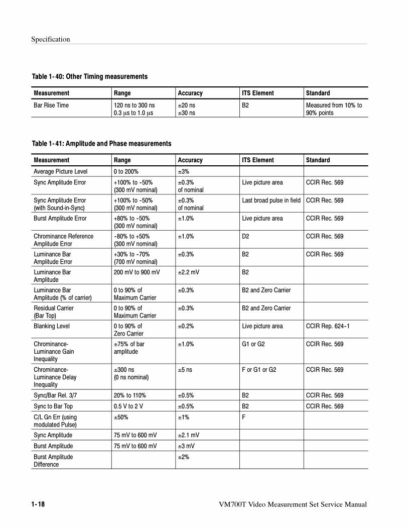
Specification
1- 18 VM700T Video Measurement Set Service Manual
Table 1- 40: Other Timing measurements
Measurement Range Accuracy ITS Element Standard
Bar Rise Time 120 ns to 300 ns0.3 s to 1.0 s
±20 ns±30 ns
B2 Measured from 10% to90% points
Table 1- 41: Amplitude and Phase measurements
Measurement Range Accuracy ITS Element Standard
Average Picture Level 0 to 200% ±3%
Sync Amplitude Error +100% to --50%(300 mV nominal)
±0.3%of nominal
Live picture area CCIR Rec. 569
Sync Amplitude Error(with Sound-in-Sync)
+100% to --50%(300 mV nominal)
±0.3%of nominal
Last broad pulse in field CCIR Rec. 569
Burst Amplitude Error +80% to --50%(300 mV nominal)
±1.0% Live picture area CCIR Rec. 569
Chrominance ReferenceAmplitude Error
--80% to +50%(300 mV nominal)
±1.0% D2 CCIR Rec. 569
Luminance BarAmplitude Error
+30% to --70%(700 mV nominal)
±0.3% B2 CCIR Rec. 569
Luminance BarAmplitude
200 mV to 900 mV ±2.2 mV B2
Luminance BarAmplitude (% of carrier)
0 to 90% ofMaximum Carrier
±0.3% B2 and Zero Carrier
Residual Carrier(Bar Top)
0 to 90% ofMaximum Carrier
±0.3% B2 and Zero Carrier
Blanking Level 0 to 90% ofZero Carrier
±0.2% Live picture area CCIR Rep. 624--1
Chrominance-Luminance GainInequality
±75% of baramplitude
±1.0% G1 or G2 CCIR Rec. 569
Chrominance-Luminance DelayInequality
±300 ns(0 ns nominal)
±5 ns F or G1 or G2 CCIR Rec. 569
Sync/Bar Rel. 3/7 20% to 110% ±0.5% B2 CCIR Rec. 569
Sync to Bar Top 0.5 V to 2 V ±0.5% B2 CCIR Rec. 569
C/L Gn Err (usingmodulated Pulse)
±50% ±1% F
Sync Amplitude 75 mV to 600 mV ±2.1 mV
Burst Amplitude 75 mV to 600 mV ±3 mV
Burst AmplitudeDifference
±2%
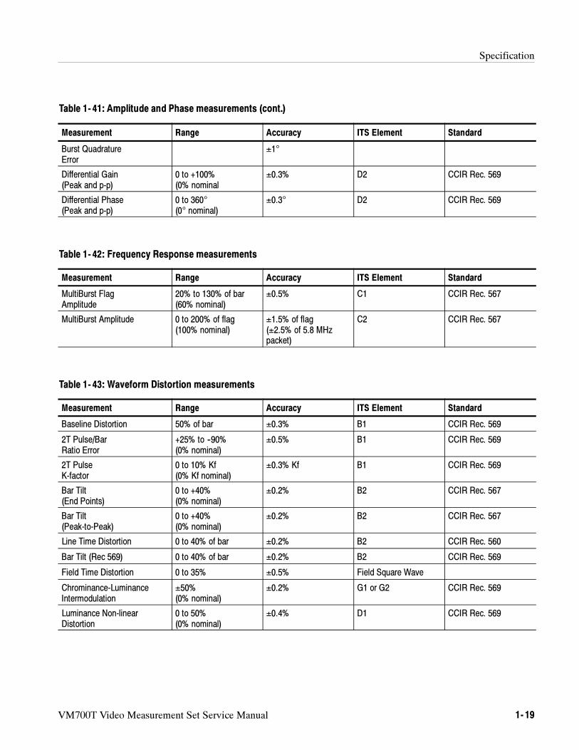
Specification
VM700T Video Measurement Set Service Manual 1- 19
Table 1- 41: Amplitude and Phase measurements (cont.)
StandardITS ElementAccuracyRangeMeasurement
Burst QuadratureError
±1°
Differential Gain(Peak and p-p)
0 to +100%(0% nominal
±0.3% D2 CCIR Rec. 569
Differential Phase(Peak and p-p)
0 to 360°
(0° nominal)±0.3° D2 CCIR Rec. 569
Table 1- 42: Frequency Response measurements
Measurement Range Accuracy ITS Element Standard
MultiBurst FlagAmplitude
20% to 130% of bar(60% nominal)
±0.5% C1 CCIR Rec. 567
MultiBurst Amplitude 0 to 200% of flag(100% nominal)
±1.5% of flag(±2.5% of 5.8 MHzpacket)
C2 CCIR Rec. 567
Table 1- 43: Waveform Distortion measurements
Measurement Range Accuracy ITS Element Standard
Baseline Distortion 50% of bar ±0.3% B1 CCIR Rec. 569
2T Pulse/BarRatio Error
+25% to --90%(0% nominal)
±0.5% B1 CCIR Rec. 569
2T PulseK-factor
0 to 10% Kf(0% Kf nominal)
±0.3% Kf B1 CCIR Rec. 569
Bar Tilt(End Points)
0 to +40%(0% nominal)
±0.2% B2 CCIR Rec. 567
Bar Tilt(Peak-to-Peak)
0 to +40%(0% nominal)
±0.2% B2 CCIR Rec. 567
Line Time Distortion 0 to 40% of bar ±0.2% B2 CCIR Rec. 560
Bar Tilt (Rec 569) 0 to 40% of bar ±0.2% B2 CCIR Rec. 569
Field Time Distortion 0 to 35% ±0.5% Field Square Wave
Chrominance-LuminanceIntermodulation
±50%(0% nominal)
±0.2% G1 or G2 CCIR Rec. 569
Luminance Non-linearDistortion
0 to 50%(0% nominal)
±0.4% D1 CCIR Rec. 569
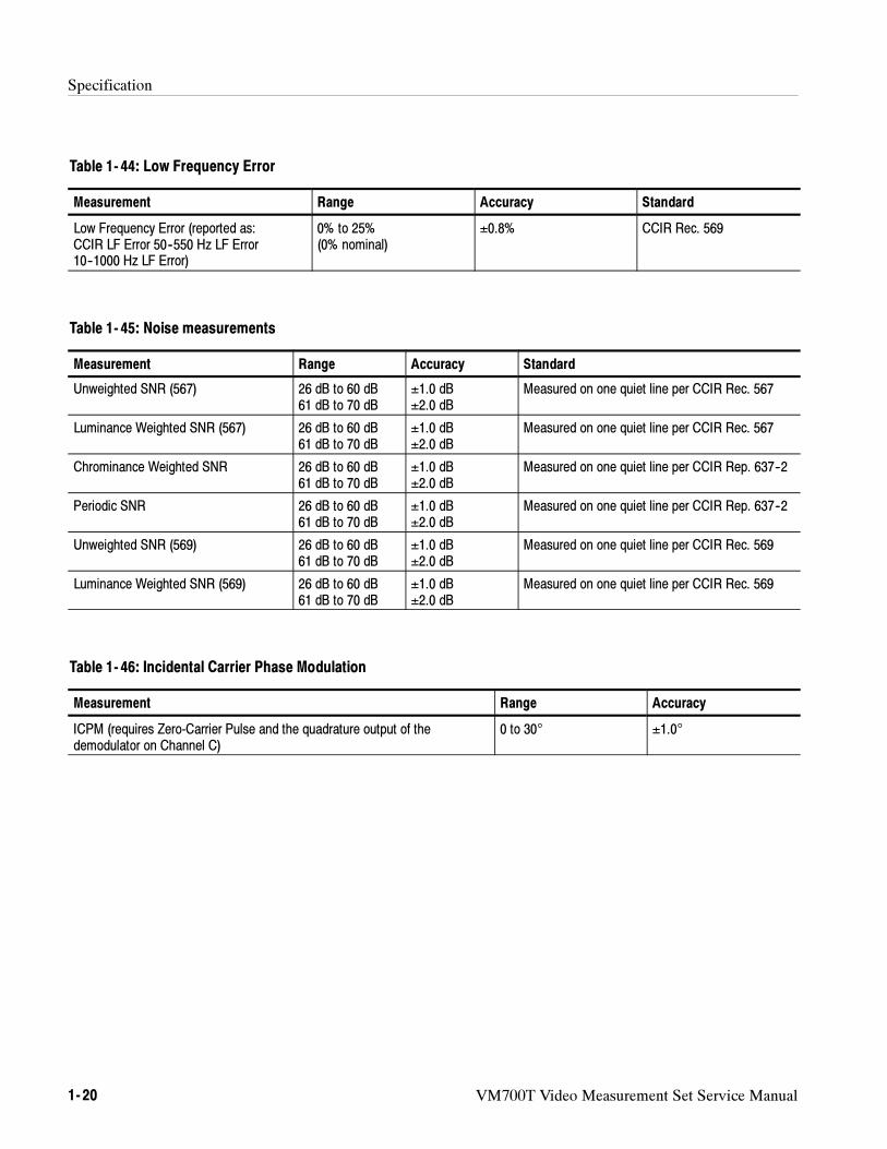
Specification
1- 20 VM700T Video Measurement Set Service Manual
Table 1- 44: Low Frequency Error
Measurement Range Accuracy Standard
Low Frequency Error (reported as:CCIR LF Error 50--550 Hz LF Error10--1000 Hz LF Error)
0% to 25%(0% nominal)
±0.8% CCIR Rec. 569
Table 1- 45: Noise measurements
Measurement Range Accuracy Standard
Unweighted SNR (567) 26 dB to 60 dB61 dB to 70 dB
±1.0 dB±2.0 dB
Measured on one quiet line per CCIR Rec. 567
Luminance Weighted SNR (567) 26 dB to 60 dB61 dB to 70 dB
±1.0 dB±2.0 dB
Measured on one quiet line per CCIR Rec. 567
Chrominance Weighted SNR 26 dB to 60 dB61 dB to 70 dB
±1.0 dB±2.0 dB
Measured on one quiet line per CCIR Rep. 637--2
Periodic SNR 26 dB to 60 dB61 dB to 70 dB
±1.0 dB±2.0 dB
Measured on one quiet line per CCIR Rep. 637--2
Unweighted SNR (569) 26 dB to 60 dB61 dB to 70 dB
±1.0 dB±2.0 dB
Measured on one quiet line per CCIR Rec. 569
Luminance Weighted SNR (569) 26 dB to 60 dB61 dB to 70 dB
±1.0 dB±2.0 dB
Measured on one quiet line per CCIR Rec. 569
Table 1- 46: Incidental Carrier Phase Modulation
Measurement Range Accuracy
ICPM (requires Zero-Carrier Pulse and the quadrature output of thedemodulator on Channel C)
0 to 30° ±1.0°
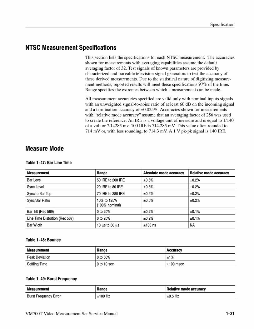
Specification
VM700T Video Measurement Set Service Manual 1- 21
NTSC Measurement Specifications
This section lists the specifications for each NTSC measurement. The accuraciesshown for measurements with averaging capabilities assume the defaultaveraging factor of 32. Test signals of known parameters are provided bycharacterized and traceable television signal generators to test the accuracy ofthese derived measurements. Due to the statistical nature of digitizing measure-ment methods, reported results will meet these specifications 97% of the time.Range specifies the extremes between which a measurement can be made.
All measurement accuracies specified are valid only with nominal inputs signalswith an unweighted signal-to-noise ratio of at least 60 dB on the incoming signaland a termination accuracy of ±0.025%. Accuracies shown for measurementswith “relative mode accuracy” assume that an averaging factor of 256 was usedto create the reference. An IRE is a voltage unit of measure and is equal to 1/140of a volt or 7.14285 mv. 100 IRE is 714.285 mV. This value often rounded to714 mV or, with less rounding, to 714.3 mV. A 1 V pk-pk signal is 140 IRE.
Measure Mode
Table 1- 47: Bar Line Time
Measurement Range Absolute mode accuracy Relative mode accuracy
Bar Level 50 IRE to 200 IRE ±0.5% ±0.2%
Sync Level 20 IRE to 80 IRE ±0.5% ±0.2%
Sync to Bar Top 70 IRE to 280 IRE ±0.5% ±0.2%
Sync/Bar Ratio 10% to 125%(100% nominal)
±0.5% ±0.2%
Bar Tilt (Rec 569) 0 to 20% ±0.2% ±0.1%
Line Time Distortion (Rec 567) 0 to 20% ±0.2% ±0.1%
Bar Width 10 s to 30 s ±100 ns NA
Table 1- 48: Bounce
Measurement Range Accuracy
Peak Deviation 0 to 50% ±1%
Settling Time 0 to 10 sec ±100 msec
Table 1- 49: Burst Frequency
Measurement Range Relative mode accuracy
Burst Frequency Error ±100 Hz ±0.5 Hz
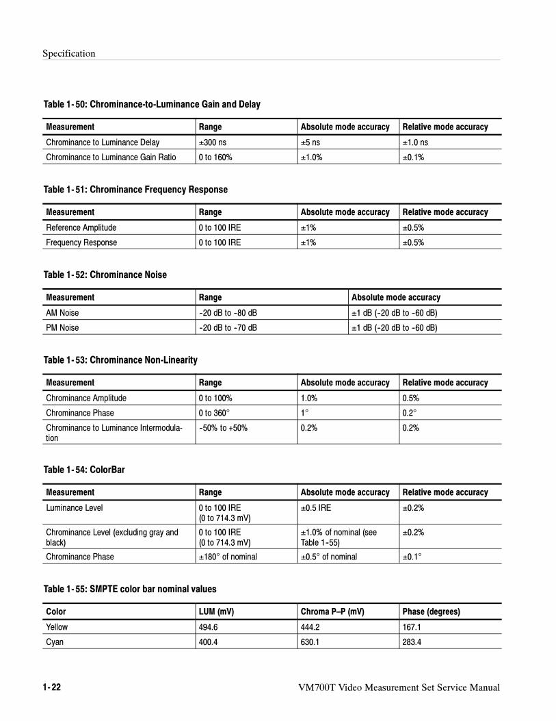
Specification
1- 22 VM700T Video Measurement Set Service Manual
Table 1- 50: Chrominance-to-Luminance Gain and Delay
Measurement Range Absolute mode accuracy Relative mode accuracy
Chrominance to Luminance Delay ±300 ns ±5 ns ±1.0 ns
Chrominance to Luminance Gain Ratio 0 to 160% ±1.0% ±0.1%
Table 1- 51: Chrominance Frequency Response
Measurement Range Absolute mode accuracy Relative mode accuracy
Reference Amplitude 0 to 100 IRE ±1% ±0.5%
Frequency Response 0 to 100 IRE ±1% ±0.5%
Table 1- 52: Chrominance Noise
Measurement Range Absolute mode accuracy
AM Noise --20 dB to --80 dB ±1 dB (--20 dB to --60 dB)
PM Noise --20 dB to --70 dB ±1 dB (--20 dB to --60 dB)
Table 1- 53: Chrominance Non-Linearity
Measurement Range Absolute mode accuracy Relative mode accuracy
Chrominance Amplitude 0 to 100% 1.0% 0.5%
Chrominance Phase 0 to 360° 1° 0.2°
Chrominance to Luminance Intermodula-tion
--50% to +50% 0.2% 0.2%
Table 1- 54: ColorBar
Measurement Range Absolute mode accuracy Relative mode accuracy
Luminance Level 0 to 100 IRE(0 to 714.3 mV)
±0.5 IRE ±0.2%
Chrominance Level (excluding gray andblack)
0 to 100 IRE(0 to 714.3 mV)
±1.0% of nominal (seeTable 1--55)
±0.2%
Chrominance Phase ±180° of nominal ±0.5° of nominal ±0.1°
Table 1- 55: SMPTE color bar nominal values
Color LUM (mV) Chroma P–P (mV) Phase (degrees)
Yellow 494.6 444.2 167.1
Cyan 400.4 630.1 283.4
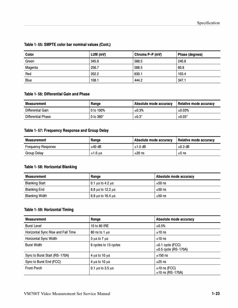
Specification
VM700T Video Measurement Set Service Manual 1- 23
Table 1- 55: SMPTE color bar nominal values (Cont.)
Phase (degrees)Chroma P–P (mV)LUM (mV)Color
Green 345.9 588.5 240.8
Magenta 256.7 588.5 60.8
Red 202.2 630.1 103.4
Blue 108.1 444.2 347.1
Table 1- 56: Differential Gain and Phase
Measurement Range Absolute mode accuracy Relative mode accuracy
Differential Gain 0 to 100% ±0.3% ±0.03%
Differential Phase 0 to 360° ±0.3° ±0.03°
Table 1- 57: Frequency Response and Group Delay
Measurement Range Absolute mode accuracy Relative mode accuracy
Frequency Response ±40 dB ±1.0 dB ±0.3 dB
Group Delay ±1.0 s ±20 ns ±5 ns
Table 1- 58: Horizontal Blanking
Measurement Range Absolute mode accuracy
Blanking Start 0.1 s to 4.2 s ±50 ns
Blanking End 6.8 s to 12.2 s ±50 ns
Blanking Width 6.9 s to 16.4 s ±50 ns
Table 1- 59: Horizontal Timing
Measurement Range Absolute mode accuracy
Burst Level 10 to 80 IRE ±0.5%
Horizontal Sync Rise and Fall Time 80 ns to 1 s ±10 ns
Horizontal Sync Width 3 s to 7 s ±10 ns
Burst Width 6 cycles to 13 cycles ±0.1 cycle (FCC)±0.5 cycle (RS–170A)
Sync to Burst Start (RS–170A) 4 s to 10 s ±150 ns
Sync to Burst End (FCC) 4 s to 10 s ±25 ns
Front Porch 0.1 s to 3.5 s ±10 ns (FCC)±10 ns (RS–170A)
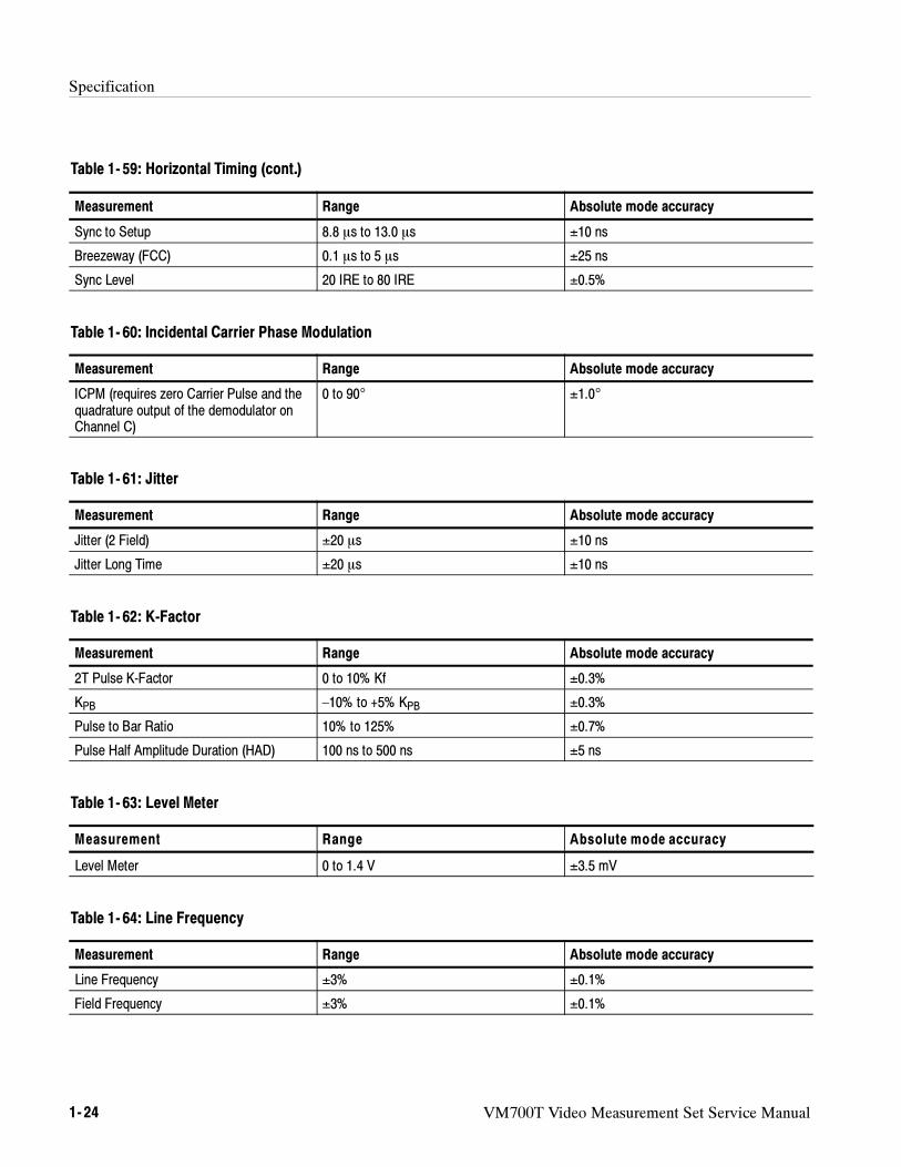
Specification
1- 24 VM700T Video Measurement Set Service Manual
Table 1- 59: Horizontal Timing (cont.)
Measurement Absolute mode accuracyRange
Sync to Setup 8.8 s to 13.0 s ±10 ns
Breezeway (FCC) 0.1 s to 5 s ±25 ns
Sync Level 20 IRE to 80 IRE ±0.5%
Table 1- 60: Incidental Carrier Phase Modulation
Measurement Range Absolute mode accuracy
ICPM (requires zero Carrier Pulse and thequadrature output of the demodulator onChannel C)
0 to 90° ±1.0°
Table 1- 61: Jitter
Measurement Range Absolute mode accuracy
Jitter (2 Field) ±20 s ±10 ns
Jitter Long Time ±20 s ±10 ns
Table 1- 62: K-Factor
Measurement Range Absolute mode accuracy
2T Pulse K-Factor 0 to 10% Kf ±0.3%
KPB –10% to +5% KPB ±0.3%
Pulse to Bar Ratio 10% to 125% ±0.7%
Pulse Half Amplitude Duration (HAD) 100 ns to 500 ns ±5 ns
Table 1- 63: Level Meter
Measurement Range Absolute mode accuracy
Level Meter 0 to 1.4 V ±3.5 mV
Table 1- 64: Line Frequency
Measurement Range Absolute mode accuracy
Line Frequency ±3% ±0.1%
Field Frequency ±3% ±0.1%
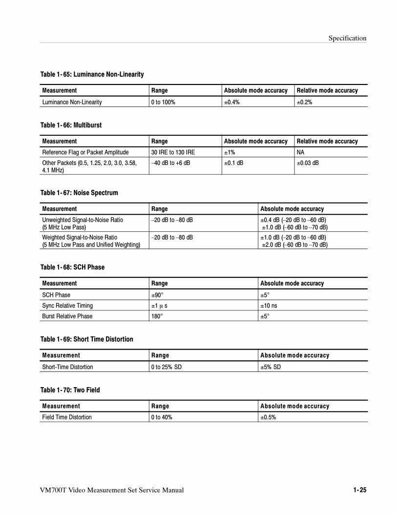
Specification
VM700T Video Measurement Set Service Manual 1- 25
Table 1- 65: Luminance Non-Linearity
Measurement Range Absolute mode accuracy Relative mode accuracy
Luminance Non-Linearity 0 to 100% ±0.4% ±0.2%
Table 1- 66: Multiburst
Measurement Range Absolute mode accuracy Relative mode accuracy
Reference Flag or Packet Amplitude 30 IRE to 130 IRE ±1% NA
Other Packets (0.5, 1.25, 2.0, 3.0, 3.58,4.1 MHz)
–40 dB to +6 dB ±0.1 dB ±0.03 dB
Table 1- 67: Noise Spectrum
Measurement Range Absolute mode accuracy
Unweighted Signal-to-Noise Ratio(5 MHz Low Pass)
–20 dB to –80 dB ±0.4 dB (–20 dB to –60 dB)±1.0 dB (–60 dB to –70 dB)
Weighted Signal-to-Noise Ratio(5 MHz Low Pass and Unified Weighting)
–20 dB to –80 dB ±1.0 dB (–20 dB to –60 dB)±2.0 dB (–60 dB to –70 dB)
Table 1- 68: SCH Phase
Measurement Range Absolute mode accuracy
SCH Phase ±90° ±5°
Sync Relative Timing ±1 s ±10 ns
Burst Relative Phase 180° ±5°
Table 1- 69: Short Time Distortion
Measurement Range Absolute mode accuracy
Short-Time Distortion 0 to 25% SD ±5% SD
Table 1- 70: Two Field
Measurement Range Absolute mode accuracy
Field Time Distortion 0 to 40% ±0.5%
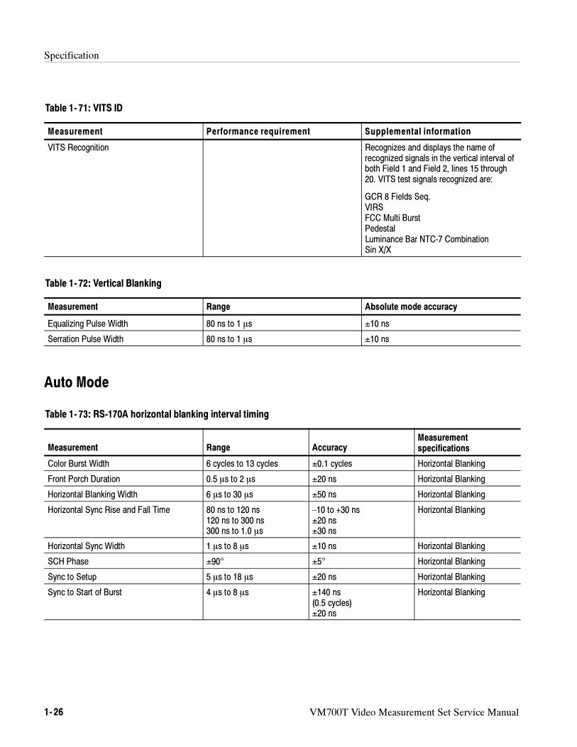
Specification
1- 26 VM700T Video Measurement Set Service Manual
Table 1- 71: VITS ID
Measurement Performance requirement Supplemental information
VITS Recognition Recognizes and displays the name ofrecognized signals in the vertical interval ofboth Field 1 and Field 2, lines 15 through20. VITS test signals recognized are:
GCR 8 Fields Seq.VIRSFCC Multi BurstPedestalLuminance Bar NTC-7 CombinationSin X/X
Table 1- 72: Vertical Blanking
Measurement Range Absolute mode accuracy
Equalizing Pulse Width 80 ns to 1 s ±10 ns
Serration Pulse Width 80 ns to 1 s ±10 ns
Auto Mode
Table 1- 73: RS-170A horizontal blanking interval timing
Measurement Range AccuracyMeasurementspecifications
Color Burst Width 6 cycles to 13 cycles ±0.1 cycles Horizontal Blanking
Front Porch Duration 0.5 s to 2 s ±20 ns Horizontal Blanking
Horizontal Blanking Width 6 s to 30 s ±50 ns Horizontal Blanking
Horizontal Sync Rise and Fall Time 80 ns to 120 ns120 ns to 300 ns300 ns to 1.0 s
–10 to +30 ns±20 ns±30 ns
Horizontal Blanking
Horizontal Sync Width 1 s to 8 s ±10 ns Horizontal Blanking
SCH Phase ±90° ±5° Horizontal Blanking
Sync to Setup 5 s to 18 s ±20 ns Horizontal Blanking
Sync to Start of Burst 4 s to 8 s ±140 ns(0.5 cycles)±20 ns
Horizontal Blanking
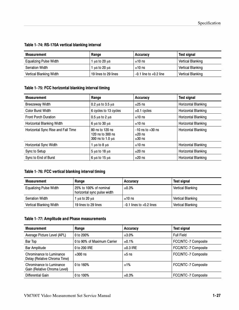
Specification
VM700T Video Measurement Set Service Manual 1- 27
Table 1- 74: RS-170A vertical blanking interval
Measurement Range Accuracy Test signal
Equalizing Pulse Width 1 s to 20 s ±10 ns Vertical Blanking
Serration Width 1 s to 20 s ±10 ns Vertical Blanking
Vertical Blanking Width 19 lines to 29 lines –0.1 line to +0.2 line Vertical Blanking
Table 1- 75: FCC horizontal blanking interval timing
Measurement Range Accuracy Test signal
Breezeway Width 0.2 s to 3.5 s ±25 ns Horizontal Blanking
Color Burst Width 6 cycles to 13 cycles ±0.1 cycles Horizontal Blanking
Front Porch Duration 0.5 s to 2 s ±10 ns Horizontal Blanking
Horizontal Blanking Width 6 s to 30 s ±10 ns Horizontal Blanking
Horizontal Sync Rise and Fall Time 80 ns to 120 ns120 ns to 300 ns300 ns to 1.0 s
–10 ns to +30 ns±20 ns±30 ns
Horizontal Blanking
Horizontal Sync Width 1 s to 8 s ±10 ns Horizontal Blanking
Sync to Setup 5 s to 18 s ±20 ns Horizontal Blanking
Sync to End of Burst 6 s to 15 s ±20 ns Horizontal Blanking
Table 1- 76: FCC vertical blanking interval timing
Measurement Range Accuracy Test signal
Equalizing Pulse Width 25% to 100% of nominalhorizontal sync pulse width
±0.3% Vertical Blanking
Serration Width 1 s to 20 s ±10 ns Vertical Blanking
Vertical Blanking Width 19 lines to 29 lines –0.1 lines to +0.2 lines Vertical Blanking
Table 1- 77: Amplitude and Phase measurements
Measurement Range Accuracy Test signal
Average Picture Level (APL) 0 to 200% ±3.0% Full Field
Bar Top 0 to 90% of Maximum Carrier ±0.1% FCC/NTC–7 Composite
Bar Amplitude 0 to 200 IRE ±0.3 IRE FCC/NTC–7 Composite
Chrominance to LuminanceDelay (Relative Chroma Time)
±300 ns ±5 ns FCC/NTC–7 Composite
Chrominance to LuminanceGain (Relative Chroma Level)
0 to 160% ±1% FCC/NTC–7 Composite
Differential Gain 0 to 100% ±0.3% FCC/NTC–7 Composite
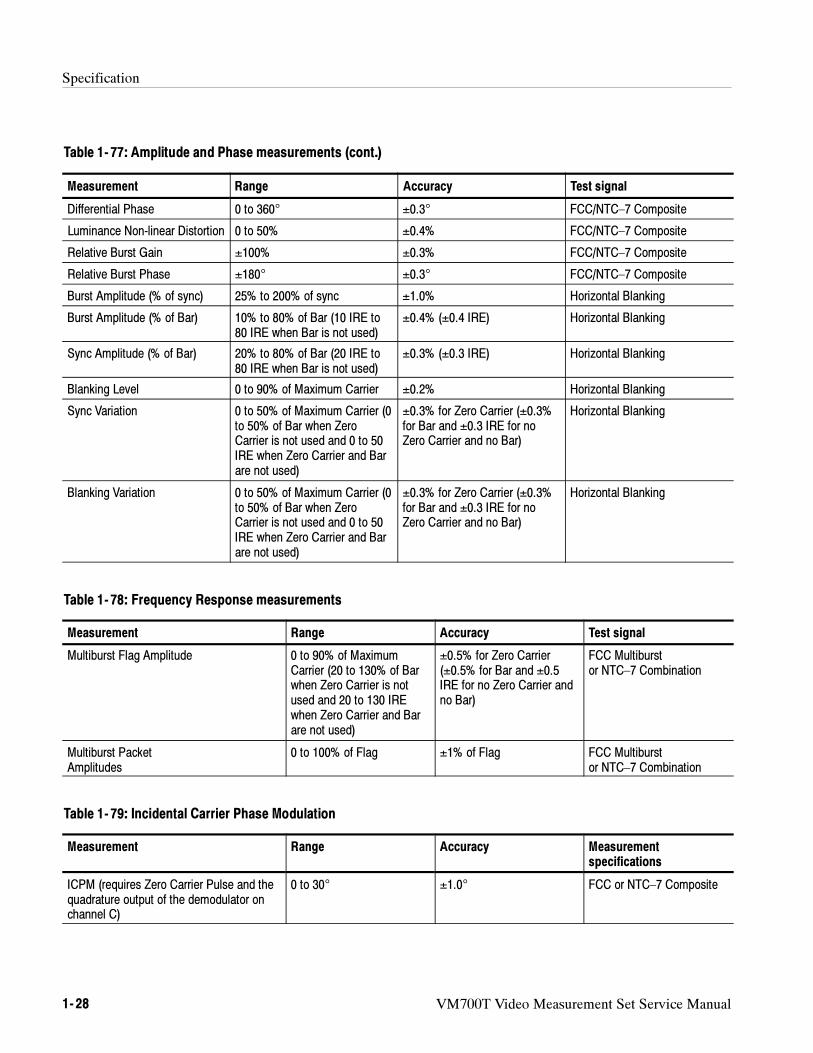
Specification
1- 28 VM700T Video Measurement Set Service Manual
Table 1- 77: Amplitude and Phase measurements (cont.)
Measurement Test signalAccuracyRange
Differential Phase 0 to 360° ±0.3° FCC/NTC–7 Composite
Luminance Non-linear Distortion 0 to 50% ±0.4% FCC/NTC–7 Composite
Relative Burst Gain ±100% ±0.3% FCC/NTC–7 Composite
Relative Burst Phase ±180° ±0.3° FCC/NTC–7 Composite
Burst Amplitude (% of sync) 25% to 200% of sync ±1.0% Horizontal Blanking
Burst Amplitude (% of Bar) 10% to 80% of Bar (10 IRE to80 IRE when Bar is not used)
±0.4% (±0.4 IRE) Horizontal Blanking
Sync Amplitude (% of Bar) 20% to 80% of Bar (20 IRE to80 IRE when Bar is not used)
±0.3% (±0.3 IRE) Horizontal Blanking
Blanking Level 0 to 90% of Maximum Carrier ±0.2% Horizontal Blanking
Sync Variation 0 to 50% of Maximum Carrier (0to 50% of Bar when ZeroCarrier is not used and 0 to 50IRE when Zero Carrier and Barare not used)
±0.3% for Zero Carrier (±0.3%for Bar and ±0.3 IRE for noZero Carrier and no Bar)
Horizontal Blanking
Blanking Variation 0 to 50% of Maximum Carrier (0to 50% of Bar when ZeroCarrier is not used and 0 to 50IRE when Zero Carrier and Barare not used)
±0.3% for Zero Carrier (±0.3%for Bar and ±0.3 IRE for noZero Carrier and no Bar)
Horizontal Blanking
Table 1- 78: Frequency Response measurements
Measurement Range Accuracy Test signal
Multiburst Flag Amplitude 0 to 90% of MaximumCarrier (20 to 130% of Barwhen Zero Carrier is notused and 20 to 130 IREwhen Zero Carrier and Barare not used)
±0.5% for Zero Carrier(±0.5% for Bar and ±0.5IRE for no Zero Carrier andno Bar)
FCC Multiburstor NTC–7 Combination
Multiburst PacketAmplitudes
0 to 100% of Flag ±1% of Flag FCC Multiburstor NTC–7 Combination
Table 1- 79: Incidental Carrier Phase Modulation
Measurement Range Accuracy Measurementspecifications
ICPM (requires Zero Carrier Pulse and thequadrature output of the demodulator onchannel C)
0 to 30° ±1.0° FCC or NTC–7 Composite
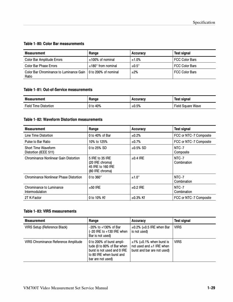
Specification
VM700T Video Measurement Set Service Manual 1- 29
Table 1- 80: Color Bar measurements
Measurement Range Accuracy Test signal
Color Bar Amplitude Errors ±100% of nominal ±1.0% FCC Color Bars
Color Bar Phase Errors ±180° from nominal ±0.5° FCC Color Bars
Color Bar Chrominance to Luminance GainRatio
0 to 200% of nominal ±2% FCC Color Bars
Table 1- 81: Out-of-Service measurements
Measurement Range Accuracy Test signal
Field Time Distortion 0 to 40% ±0.5% Field Square Wave
Table 1- 82: Waveform Distortion measurements
Measurement Range Accuracy Test signal
Line Time Distortion 0 to 40% of Bar ±0.2% FCC or NTC–7 Composite
Pulse to Bar Ratio 10% to 125% ±0.7% FCC or NTC–7 Composite
Short Time WaveformDistortion (IEEE 511)
0 to 25% SD ±0.5% SD NTC–7Composite
Chrominance Nonlinear Gain Distortion 5 IRE to 35 IRE(20 IRE chroma)45 IRE to 160 IRE(80 IRE chroma)
±0.4 IRE NTC–7Combination
Chrominance Nonlinear Phase Distortion 0 to 360° ±1.0° NTC–7Combination
Chrominance to LuminanceIntermodulation
±50 IRE ±0.2 IRE NTC–7Combination
2T K-Factor 0 to 10% Kf ±0.3% Kf FCC or NTC–7 Composite
Table 1- 83: VIRS measurements
Measurement Range Accuracy Test signal
VIRS Setup (Reference Black) –20% to +130% of Bar(–20 IRE to +130 IRE whenBar is not used)
±0.2% (±0.5 IRE when Baris not used)
VIRS
VIRS Chrominance Reference Amplitude 0 to 200% of burst ampli-tude (0 to 80% of Bar whenburst is not used and 0 IREto 80 IRE when burst andbar are not used)
±1% (±0.1% when burst isnot used and ±1 IRE whenburst and bar are not used)
VIRS
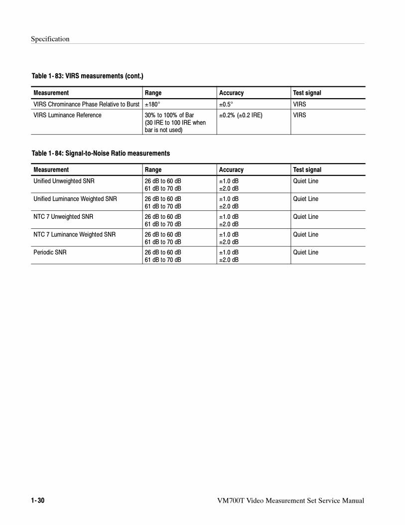
Specification
1- 30 VM700T Video Measurement Set Service Manual
Table 1- 83: VIRS measurements (cont.)
Test signalAccuracyRangeMeasurement
VIRS Chrominance Phase Relative to Burst ±180° ±0.5° VIRS
VIRS Luminance Reference 30% to 100% of Bar(30 IRE to 100 IRE whenbar is not used)
±0.2% (±0.2 IRE) VIRS
Table 1- 84: Signal-to-Noise Ratio measurements
Measurement Range Accuracy Test signal
Unified Unweighted SNR 26 dB to 60 dB61 dB to 70 dB
±1.0 dB±2.0 dB
Quiet Line
Unified Luminance Weighted SNR 26 dB to 60 dB61 dB to 70 dB
±1.0 dB±2.0 dB
Quiet Line
NTC 7 Unweighted SNR 26 dB to 60 dB61 dB to 70 dB
±1.0 dB±2.0 dB
Quiet Line
NTC 7 Luminance Weighted SNR 26 dB to 60 dB61 dB to 70 dB
±1.0 dB±2.0 dB
Quiet Line
Periodic SNR 26 dB to 60 dB61 dB to 70 dB
±1.0 dB±2.0 dB
Quiet Line
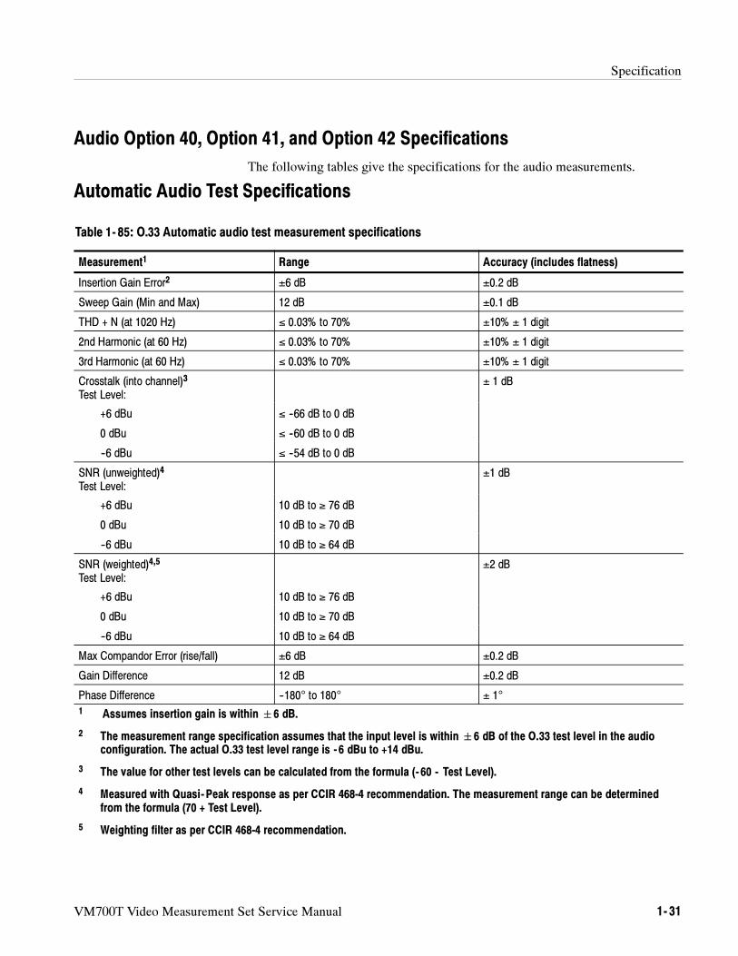
Specification
VM700T Video Measurement Set Service Manual 1- 31
Audio Option 40, Option 41, and Option 42 Specifications
The following tables give the specifications for the audio measurements.
Automatic Audio Test Specifications
Table 1- 85: O.33 Automatic audio test measurement specifications
Measurement1 Range Accuracy (includes flatness)
Insertion Gain Error2 ±6 dB ±0.2 dB
Sweep Gain (Min and Max) 12 dB ±0.1 dB
THD + N (at 1020 Hz) ≤ 0.03% to 70% ±10% ± 1 digit
2nd Harmonic (at 60 Hz) ≤ 0.03% to 70% ±10% ± 1 digit
3rd Harmonic (at 60 Hz) ≤ 0.03% to 70% ±10% ± 1 digit
Crosstalk (into channel)3
Test Level:± 1 dB
+6 dBu ≤ --66 dB to 0 dB
0 dBu ≤ --60 dB to 0 dB
--6 dBu ≤ --54 dB to 0 dB
SNR (unweighted)4
Test Level:±1 dB
+6 dBu 10 dB to ≥ 76 dB
0 dBu 10 dB to ≥ 70 dB
--6 dBu 10 dB to ≥ 64 dB
SNR (weighted)4,5
Test Level:±2 dB
+6 dBu 10 dB to ≥ 76 dB
0 dBu 10 dB to ≥ 70 dB
--6 dBu 10 dB to ≥ 64 dB
Max Compandor Error (rise/fall) ±6 dB ±0.2 dB
Gain Difference 12 dB ±0.2 dB
Phase Difference --180° to 180° ± 1°
1 Assumes insertion gain is within6 dB.
2 The measurement range specification assumes that the input level is within6 dB of the O.33 test level in the audioconfiguration. The actual O.33 test level range is - 6 dBu to +14 dBu.
3 The value for other test levels can be calculated from the formula (- 60 - Test Level).
4 Measured with Quasi- Peak response as per CCIR 468-4 recommendation. The measurement range can be determinedfrom the formula (70 + Test Level).
5 Weighting filter as per CCIR 468-4 recommendation.
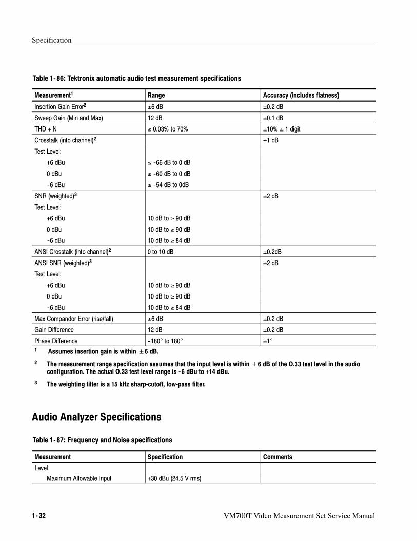
Specification
1- 32 VM700T Video Measurement Set Service Manual
Table 1- 86: Tektronix automatic audio test measurement specifications
Measurement1 Range Accuracy (includes flatness)
Insertion Gain Error2 ±6 dB ±0.2 dB
Sweep Gain (Min and Max) 12 dB ±0.1 dB
THD + N ≤ 0.03% to 70% ±10% ± 1 digit
Crosstalk (into channel)2 ±1 dB
Test Level:
+6 dBu ≤ --66 dB to 0 dB
0 dBu ≤ --60 dB to 0 dB
--6 dBu ≤ --54 dB to 0dB
SNR (weighted)3 ±2 dB
Test Level:
+6 dBu 10 dB to ≥ 90 dB
0 dBu 10 dB to ≥ 90 dB
--6 dBu 10 dB to ≥ 84 dB
ANSI Crosstalk (into channel)2 0 to 10 dB ±0.2dB
ANSI SNR (weighted)3 ±2 dB
Test Level:
+6 dBu 10 dB to ≥ 90 dB
0 dBu 10 dB to ≥ 90 dB
--6 dBu 10 dB to ≥ 84 dB
Max Compandor Error (rise/fall) ±6 dB ±0.2 dB
Gain Difference 12 dB ±0.2 dB
Phase Difference --180° to 180° ±1°
1 Assumes insertion gain is within6 dB.
2 The measurement range specification assumes that the input level is within6 dB of the O.33 test level in the audioconfiguration. The actual O.33 test level range is - 6 dBu to +14 dBu.
3 The weighting filter is a 15 kHz sharp-cutoff, low-pass filter.
Audio Analyzer Specifications
Table 1- 87: Frequency and Noise specifications
Measurement Specification Comments
Level
Maximum Allowable Input +30 dBu (24.5 V rms)
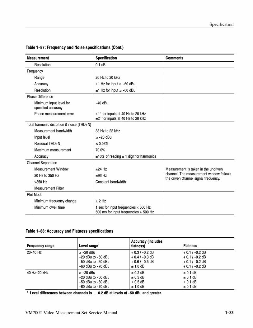
Specification
VM700T Video Measurement Set Service Manual 1- 33
Table 1- 87: Frequency and Noise specifications (Cont.)
Measurement CommentsSpecification
Resolution 0.1 dB
Frequency
Range 20 Hz to 20 kHz
Accuracy ±1 Hz for input ≥ --60 dBu
Resolution ±1 Hz for input ≥ --60 dBu
Phase Difference
Minimum input level forspecified accuracy
--40 dBu
Phase measurement error ±1° for inputs at 40 Hz to 20 kHz±2° for inputs at 40 Hz to 20 kHz
Total harmonic distortion & noise (THD+N)
Measurement bandwidth 33 Hz to 22 kHz
Input level ≥ --20 dBu
Residual THD+N ≤ 0.03%
Maximum measurement 70.0%
Accuracy ±10% of reading ± 1 digit for harmonics
Channel Separation
Measurement Window ±24 Hz Measurement is taken in the undriven
20 Hz to 350 Hz ±96 Hz channel. The measurement window followsthe driven channel signal frequency
>350 Hz Constant bandwidththe driven channel signal frequency.
Measurement Filter
Plot Mode
Minimum frequency change ± 2 Hz
Minimum dwell time 1 sec for input frequencies < 500 Hz;500 ms for input frequencies ≥ 500 Hz
Table 1- 88: Accuracy and Flatness specifications
Frequency range Level range1Accuracy (includesflatness) Flatness
20--40 Hz ≥ --20 dBu--20 dBu to --50 dBu--50 dBu to --60 dBu--60 dBu to --70 dBu
+ 0.3 / --0.2 dB+ 0.4 / --0.3 dB+ 0.6 / --0.5 dB± 1.0 dB
+ 0.1 / --0.2 dB+ 0.1 / --0.2 dB+ 0.1 / --0.2 dB+ 0.1 / --0.2 dB
40 Hz--20 kHz ≥ --20 dBu--20 dBu to --50 dBu--50 dBu to --60 dBu--60 dBu to --70 dBu
± 0.2 dB± 0.3 dB± 0.5 dB± 1.0 dB
± 0.1 dB± 0.1 dB± 0.1 dB± 0.1 dB
1 Level differences between channels is 0.2 dB at levels of - 50 dBu and greater.
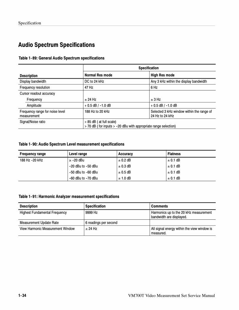
Specification
1- 34 VM700T Video Measurement Set Service Manual
Audio Spectrum Specifications
Table 1- 89: General Audio Spectrum specifications
Specification
Description Normal Res mode High Res mode
Display bandwidth DC to 24 kHz Any 3 kHz within the display bandwidth
Frequency resolution 47 Hz 6 Hz
Cursor readout accuracy
Frequency ± 24 Hz ± 3 Hz
Amplitude + 0.5 dB / --1.0 dB + 0.5 dB / --1.0 dB
Frequency range for noise levelmeasurement
188 Hz to 20 kHz Selected 3 kHz window within the range of24 Hz to 24 kHz
Signal/Noise ratio > 85 dB ( at full scale)> 70 dB ( for inputs > --20 dBu with appropriate range selection)
Table 1- 90: Audio Spectrum Level measurement specifications
Frequency range Level range Accuracy Flatness
188 Hz --20 kHz ≥ --20 dBu ± 0.2 dB ± 0.1 dB
--20 dBu to --50 dBu ± 0.3 dB ± 0.1 dB
--50 dBu to --60 dBu ± 0.5 dB ± 0.1 dB
--60 dBu to --70 dBu ± 1.0 dB ± 0.1 dB
Table 1- 91: Harmonic Analyzer measurement specifications
Description Specification Comments
Highest Fundamental Frequency 9999 Hz Harmonics up to the 20 kHz measurementbandwidth are displayed.
Measurement Update Rate 6 readings per second
View Harmonic Measurement Window ± 24 Hz All signal energy within the view window ismeasured.
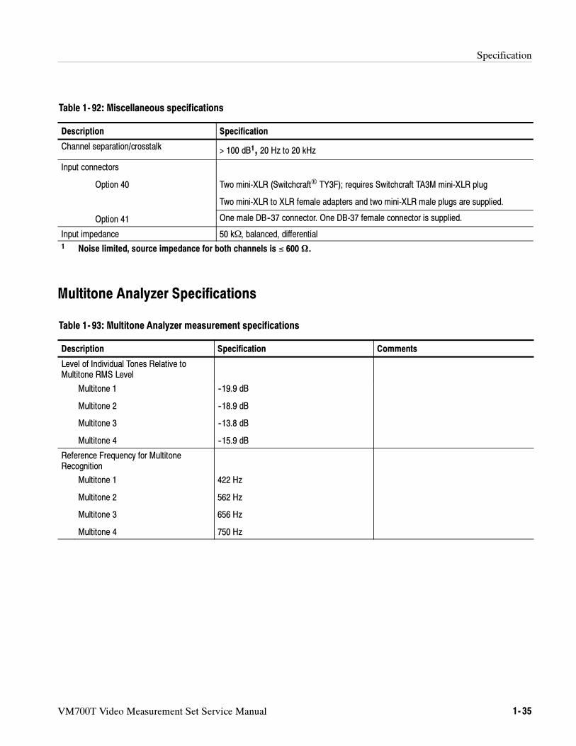
Specification
VM700T Video Measurement Set Service Manual 1- 35
Table 1- 92: Miscellaneous specifications
Description Specification
Channel separation/crosstalk > 100 dB1, 20 Hz to 20 kHz
Input connectors
Option 40 Two mini-XLR (Switchcraft TY3F); requires Switchcraft TA3M mini-XLR plug
Two mini-XLR to XLR female adapters and two mini-XLR male plugs are supplied.
Option 41 One male DB--37 connector. One DB-37 female connector is supplied.
Input impedance 50 kΩ, balanced, differential1 Noise limited, source impedance for both channels is ≤ 600 Ω.
Multitone Analyzer Specifications
Table 1- 93: Multitone Analyzer measurement specifications
Description Specification Comments
Level of Individual Tones Relative toMultitone RMS Level
Multitone 1
Multitone 2
Multitone 3
Multitone 4
--19.9 dB
--18.9 dB
--13.8 dB
--15.9 dB
Reference Frequency for MultitoneRecognition
Multitone 1
Multitone 2
Multitone 3
Multitone 4
422 Hz
562 Hz
656 Hz
750 Hz
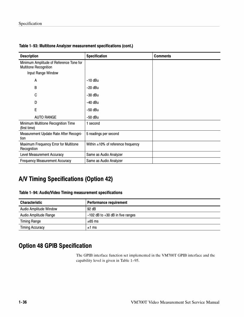
Specification
1- 36 VM700T Video Measurement Set Service Manual
Table 1- 93: Multitone Analyzer measurement specifications (cont.)
Description CommentsSpecification
Minimum Amplitude of Reference Tone forMultitone Recognition
Input Range Window
A
B
C
D
E
AUTO RANGE
--10 dBu
--20 dBu
--30 dBu
--40 dBu
--50 dBu
--50 dBu
Minimum Multitone Recognition Time(first time)
1 second
Measurement Update Rate After Recogni-tion
5 readings per second
Maximum Frequency Error for MultitoneRecognition
Within ±10% of reference frequency
Level Measurement Accuracy Same as Audio Analyzer
Frequency Measurement Accuracy Same as Audio Analyzer
A/V Timing Specifications (Option 42)
Table 1- 94: Audio/Video Timing measurement specifications
Characteristic Performance requirement
Audio Amplitude Window 92 dB
Audio Amplitude Range --102 dB to +30 dB in five ranges
Timing Range ±65 ms
Timing Accuracy ±1 ms
Option 48 GPIB Specification
The GPIB interface function set implemented in the VM700T GPIB interface and the
capability level is given in Table 1--95.
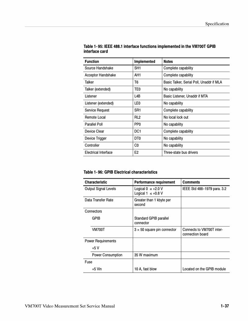
Specification
VM700T Video Measurement Set Service Manual 1- 37
Table 1- 95: IEEE 488.1 interface functions implemented in the VM700T GPIBinterface card
Function Implemented Notes
Source Handshake SH1 Complete capability
Acceptor Handshake AH1 Complete capability
Talker T6 Basic Talker, Serial Poll, Unaddr if MLA
Talker (extended) TE0 No capability
Listener L4B Basic Listener, Unaddr if MTA
Listener (extended) LE0 No capability
Service Request SR1 Complete capability
Remote Local RL2 No local lock out
Parallel Poll PP0 No capability
Device Clear DC1 Complete capability
Device Trigger DT0 No capability
Controller C0 No capability
Electrical Interface E2 Three-state bus drivers
Table 1- 96: GPIB Electrical characteristics
Characteristic Performance requirement Comments
Output Signal Levels Logical 0 ≥ +2.0 VLogical 1 ≤ +0.8 V
IEEE Std 488--1979 para. 3.2
Data Transfer Rate Greater than 1 kbyte persecond
Connectors
GPIB Standard GPIB parallelconnector
VM700T 3 × 50 square pin connector Connects to VM700T inter-connection board
Power Requirements
+5 V
Power Consumption 35 W maximum
Fuse
+5 Vin 10 A, fast blow Located on the GPIB module
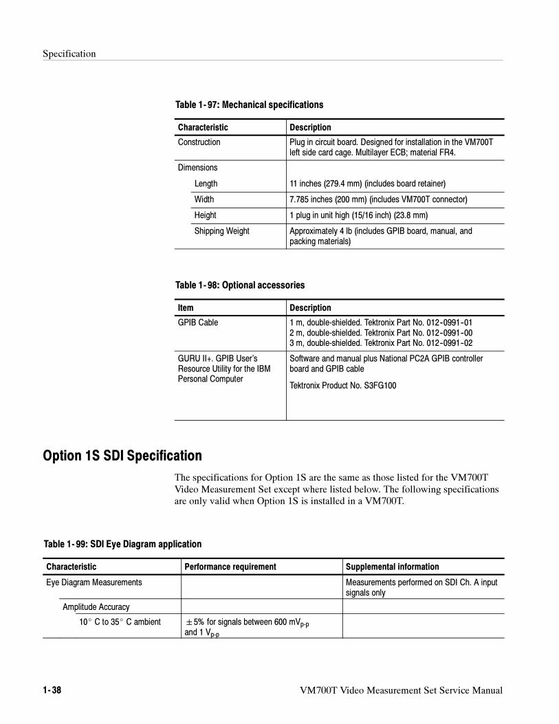
Specification
1- 38 VM700T Video Measurement Set Service Manual
Table 1- 97: Mechanical specifications
Characteristic Description
Construction Plug in circuit board. Designed for installation in the VM700Tleft side card cage. Multilayer ECB; material FR4.
Dimensions
Length 11 inches (279.4 mm) (includes board retainer)
Width 7.785 inches (200 mm) (includes VM700T connector)
Height 1 plug in unit high (15/16 inch) (23.8 mm)
Shipping Weight Approximately 4 lb (includes GPIB board, manual, andpacking materials)
Table 1- 98: Optional accessories
Item Description
GPIB Cable 1 m, double-shielded. Tektronix Part No. 012--0991--012 m, double-shielded. Tektronix Part No. 012--0991--003 m, double-shielded. Tektronix Part No. 012--0991--02
GURU II+. GPIB User’sResource Utility for the IBMPersonal Computer
Software and manual plus National PC2A GPIB controllerboard and GPIB cable
Tektronix Product No. S3FG100
Option 1S SDI Specification
The specifications for Option 1S are the same as those listed for the VM700TVideo Measurement Set except where listed below. The following specificationsare only valid when Option 1S is installed in a VM700T.
Table 1- 99: SDI Eye Diagram application
Characteristic Performance requirement Supplemental information
Eye Diagram Measurements Measurements performed on SDI Ch. A inputsignals only
Amplitude Accuracy
10 C to 35 C ambient 5% for signals between 600 mVp-pand 1 Vp-p
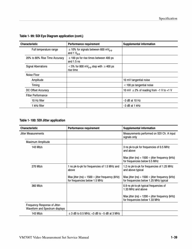
Specification
VM700T Video Measurement Set Service Manual 1- 39
Table 1- 99: SDI Eye Diagram application (cont.)
Characteristic Supplemental informationPerformance requirement
Full temperature range 10% for signals between 600 mVp-pand 1 Vp-p
20% to 80% Rise Time Accuracy 100 ps for rise times between 400 psand 1.5 ns
Signal Aberrations <5% for 800 mVp-p step with≥400 psrise time
Noise Floor
Amplitude 10 mV tangential noise
Timing <100 ps tangential noise
DC Offset Accuracy 10 mV2% of reading from --1 V to +1 V
Filter Performance
10 Hz filter --3 dB at 10 Hz
1 kHz filter --3 dB at 1 kHz
Table 1- 100: SDI Jitter application
Characteristic Performance requirement Supplemental information
Jitter Measurements Measurements performed on SDI Ch. A inputsignals only
Maximum Amplitude
143 Mb/s 3 ns pk-to-pk for frequencies of 0.5 MHzand above
Max jitter (ns) = 1500÷jitter frequency (kHz)for frequencies below 0.5 MHz
270 Mb/s 1 ns pk-to-pk for frequencies of 1.5 MHz andabove
Max jitter (ns) = 1500÷jitter frequency (kHz)for frequencies below 1.5 MHz
1.2 ns pk-to-pk for frequencies of 1.25 MHzand above typical
Max jitter (ns) = 1500÷jitter frequency (kHz)for frequencies below 1.25 MHz typical
360 Mb/s 0.9 ns pk-to-pk typical frequencies of1.33 MHz and above
Max jitter (ns) = 1200÷jitter frequency (kHz)for frequencies below 1.33 MHz
Frequency Response of Jitter-Waveform and Spectrum displays
143 Mb/s 3 dB to 0.5 MHz; +3 dB to --5 dB at 3 MHz
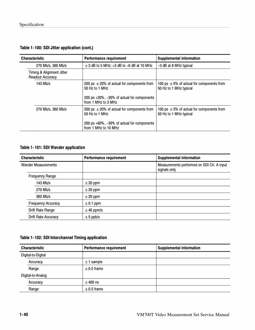
Specification
1- 40 VM700T Video Measurement Set Service Manual
Table 1- 100: SDI Jitter application (cont.)
Characteristic Supplemental informationPerformance requirement
270 Mb/s, 360 Mb/s 3 dB to 5 MHz; +3 dB to --6 dB at 10 MHz --3 dB at 8 MHz typical
Timing & Alignment JitterReadout Accuracy
143 Mb/s 200 ps20% of actual for components from50 Hz to 1 MHz
200 ps +20%, --30% of actual for componentsfrom 1 MHz to 3 MHz
100 ps5% of actual for components from50 Hz to 1 MHz typical
270 Mb/s, 360 Mb/s 200 ps20% of actual for components from50 Hz to 1 MHz
200 ps +60%, --30% of actual for componentsfrom 1 MHz to 10 MHz
100 ps5% of actual for components from50 Hz to 1 MHz typical
Table 1- 101: SDI Wander application
Characteristic Performance requirement Supplemental information
Wander Measurements Measurements performed on SDI Ch. A inputsignals only
Frequency Range
143 Mb/s 20 ppm
270 Mb/s 20 ppm
360 Mb/s 20 ppm
Frequency Accuracy 0.1 ppm
Drift Rate Range 40 ppm/s
Drift Rate Accuracy 5 ppb/s
Table 1- 102: SDI Interchannel Timing application
Characteristic Performance requirement Supplemental information
Digital-to-Digital
Accuracy 1 sample
Range 0.5 frame
Digital-to-Analog
Accuracy 400 ns
Range 0.5 frame
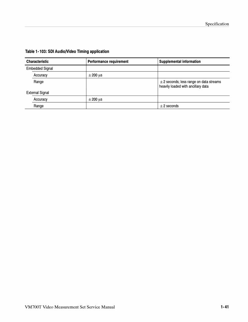
Specification
VM700T Video Measurement Set Service Manual 1- 41
Table 1- 103: SDI Audio/Video Timing application
Characteristic Performance requirement Supplemental information
Embedded Signal
Accuracy 200 s
Range 2 seconds; less range on data streamsheavily loaded with ancillary data
External Signal
Accuracy 200 s
Range 2 seconds
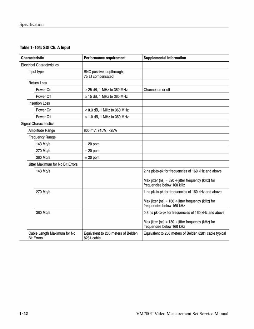
Specification
1- 42 VM700T Video Measurement Set Service Manual
Table 1- 104: SDI Ch. A Input
Characteristic Performance requirement Supplemental information
Electrical Characteristics
Input type BNC passive loopthrough;75Ω compensated
Return Loss
Power On ≥25 dB, 1 MHz to 360 MHz Channel on or off
Power Off ≥15 dB, 1 MHz to 360 MHz
Insertion Loss
Power On <0.3 dB, 1 MHz to 360 MHz
Power Off <1.0 dB, 1 MHz to 360 MHz
Signal Characteristics
Amplitude Range 800 mV; +15%, --25%
Frequency Range
143 Mb/s 20 ppm
270 Mb/s 20 ppm
360 Mb/s 20 ppm
Jitter Maximum for No Bit Errors
143 Mb/s 2 ns pk-to-pk for frequencies of 160 kHz and above
Max jitter (ns) = 320÷jitter frequency (kHz) forfrequencies below 160 kHz
270 Mb/s 1 ns pk-to-pk for frequencies of 160 kHz and above
Max jitter (ns) = 160÷jitter frequency (kHz) forfrequencies below 160 kHz
360 Mb/s 0.8 ns pk-to-pk for frequencies of 160 kHz and above
Max jitter (ns) = 130÷jitter frequency (kHz) forfrequencies below 160 kHz
Cable Length Maximum for NoBit Errors
Equivalent to 200 meters of Belden8281 cable
Equivalent to 250 meters of Belden 8281 cable typical
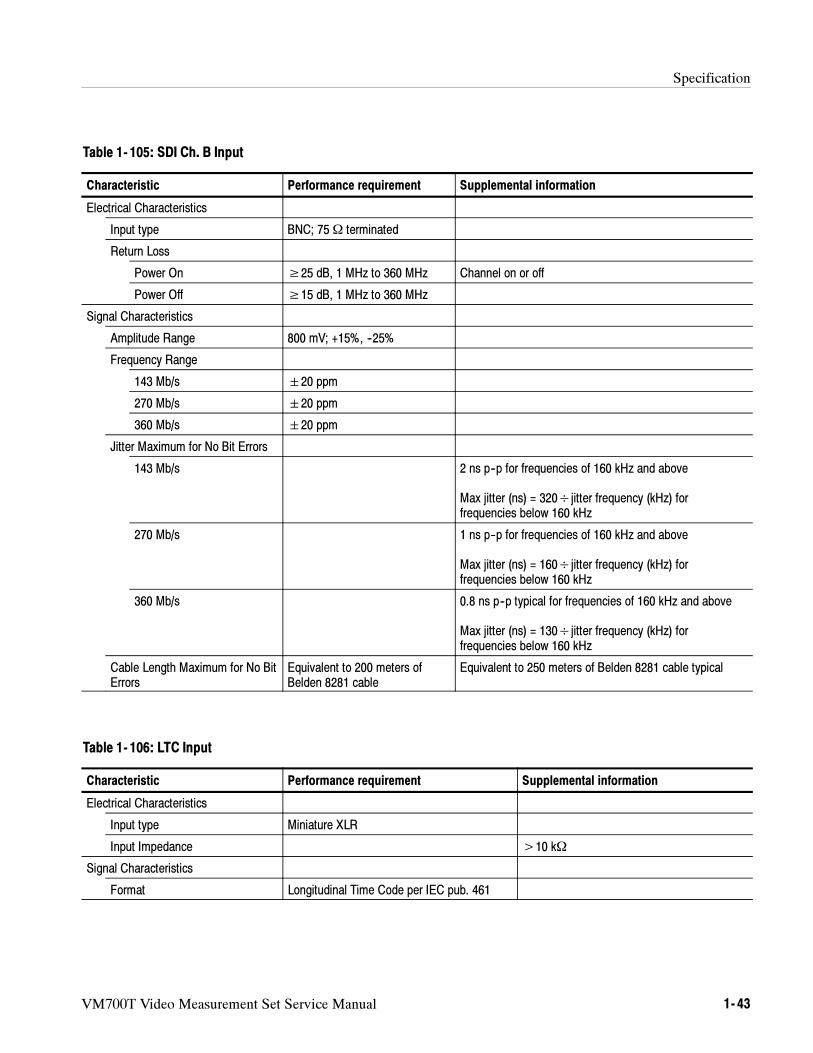
Specification
VM700T Video Measurement Set Service Manual 1- 43
Table 1- 105: SDI Ch. B Input
Characteristic Performance requirement Supplemental information
Electrical Characteristics
Input type BNC; 75Ω terminated
Return Loss
Power On ≥25 dB, 1 MHz to 360 MHz Channel on or off
Power Off ≥15 dB, 1 MHz to 360 MHz
Signal Characteristics
Amplitude Range 800 mV; +15%, --25%
Frequency Range
143 Mb/s 20 ppm
270 Mb/s 20 ppm
360 Mb/s 20 ppm
Jitter Maximum for No Bit Errors
143 Mb/s 2 ns p--p for frequencies of 160 kHz and above
Max jitter (ns) = 320÷jitter frequency (kHz) forfrequencies below 160 kHz
270 Mb/s 1 ns p--p for frequencies of 160 kHz and above
Max jitter (ns) = 160÷jitter frequency (kHz) forfrequencies below 160 kHz
360 Mb/s 0.8 ns p--p typical for frequencies of 160 kHz and above
Max jitter (ns) = 130÷jitter frequency (kHz) forfrequencies below 160 kHz
Cable Length Maximum for No BitErrors
Equivalent to 200 meters ofBelden 8281 cable
Equivalent to 250 meters of Belden 8281 cable typical
Table 1- 106: LTC Input
Characteristic Performance requirement Supplemental information
Electrical Characteristics
Input type Miniature XLR
Input Impedance >10 kΩ
Signal Characteristics
Format Longitudinal Time Code per IEC pub. 461
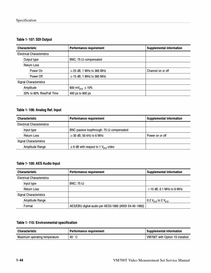
Specification
1- 44 VM700T Video Measurement Set Service Manual
Table 1- 107: SDI Output
Characteristic Performance requirement Supplemental information
Electrical Characteristics
Output type BNC; 75Ω compensated
Return Loss
Power On ≥25 dB, 1 MHz to 360 MHz Channel on or off
Power Off ≥15 dB, 1 MHz to 360 MHz
Signal Characteristics
Amplitude 800 mVp-p 10%
20% to 80% Rise/Fall Time 400 ps to 800 ps
Table 1- 108: Analog Ref. Input
Characteristic Performance requirement Supplemental information
Electrical Characteristics
Input type BNC passive loopthrough; 75Ω compensated
Return Loss ≥30 dB, 50 kHz to 6 MHz Power on or off
Signal Characteristics
Amplitude Range 6 dB with respect to 1 Vp-p video
Table 1- 109: AES Audio Input
Characteristic Performance requirement Supplemental information
Electrical Characteristics
Input type BNC; 75Ω
Return Loss >15 dB, 0.1 MHz to 6 MHz
Signal Characteristics
Amplitude Range 0.2 Vp-p to 2 Vp-p
Format AES/EBU digital-audio per AES3-1992 (ANSI S4.40--1992)
Table 1- 110: Environmental specification
Characteristic Performance requirement Supplemental information
Maximum operating temperature 45 C VM700T with Option 1S installed
VM700T Video Measurement Set Service Manual 2- 1
Operating Information
The VM700T Video Measurement Set is a multi-function television test andmeasurement device with an easy to use interface. The measurement set performsthe functions of a waveform monitor, vectorscope, automatic measurement set,and a noise measurement set on acquired television signals. The measurement setdoes measurements on video signals obtained from either live TV signals(broadcast or cable) or television test equipment. You can select numeric valuedisplays to confirm signal path quality or graphic displays for more detailedanalysis of the applied signal.
The measurement set can be operated directly using the front panel or remotelyusing one of the RS-232C ports on the rear panel.
Installation
The standard measurement set is a rack mounted unit. Refer to the VM700T Rack
Mounting Instructions on page 6--44 for the rack mounting installation instruc-tions. The following unpacking and power requirements information is repeatedthere. You can also order the measurement set as a cabinet style unit.
When you unpackage the measurement set, keep the shipping carton andpackaging material. If you need to return the measurement set for servicing, youwill then have packaging available that provides adequate protection forshipment.
The VM700T Video Measurement Set operates with line frequencies of 50 Hz or60 Hz, over two line voltage ranges. The nominal setting of the low voltagerange is 115 VAC. The nominal setting of the high voltage range is 230 VAC.There are two power switches on the measurement set.
The main power switch is on the rear panel above the power cord receptacle.
The Stby/On switch is on the front panel.
Both power switches must be on to operate the measurement set.
WARNING. Dangerous voltages are present within the Power Supply module
when the rear-panel power switch is on, regardless of the position of the
front-panel power switch. Do not operate the measurement set with any covers
removed. Refer all servicing of the measurement set to a qualified service
person.
Unpackaging
Power Requirements
Operating Information
2- 2 VM700T Video Measurement Set Service Manual
The voltage range selection switch and fuse holder are located in the lower leftcorner of the rear panel (see Figure 2--10 on page 2--16). The measurement set isshipped from the factory set to the operating voltage of the destination (115 VACor 230 VAC).
If the setting is not correct, you must change it before connecting the power cordto the power source. Set the voltage range selection switch (located on the rearpanel of the measurement set) to the correct position for operation.
CAUTION.When changing the line voltage selector switch you must also change
the fuse to provide proper protection for the operating voltage in use. The 3A
slow-blow fuse provides the proper protection in the 230 VAC range and the 6A
slow-blow fuse provides protection for operation in the 115 VAC range.
A detachable three-wire power cord with a three-contact plug is provided witheach measurement set for connecting to both the power source and protectiveground. The protective-ground connector in the plug connects (through theprotective-ground conductor) to the accessible metal parts of the measurementset. For electrical-shock protection, insert this plug only into a power-sourceoutlet that has a properly grounded protective-ground contact.
Measurement sets are shipped with the power cord required for the country ofdestination. Refer to the Options section for information on the availablepower-cord options. Contact your Tektronix representative or local Tektronixfield office for additional power-cord information. European power cord optionsA1 and A2 require an additional accessory for operation in the EU countries.When the VM700T Video Measurement Set is ordered with either the A1 or theA2 power cord option, the VM700T Power Line Conditioning accessory is alsoprovided.
The Power Line Conditioner accessory to the VM700T assures that the VM700Tmeets the Line Harmonics requirements of the European Union when operatedfrom a 230 Vac mains source.
The line conditioner is for use only with the VM700T when operating theVM700T from a 230 Vac mains source. The Power Line Conditioner provides nobenefit when the VM700T is operated from a 120 Vac mains source and shouldNOT be used.
NOTE. The VM700T will not be damaged if operated from a 230 Vac mains
source without the Power Line Conditioner connected to the power input.
Changing Line VoltageRange and Fuse
Power Cord
Power LineConditioner Accessory
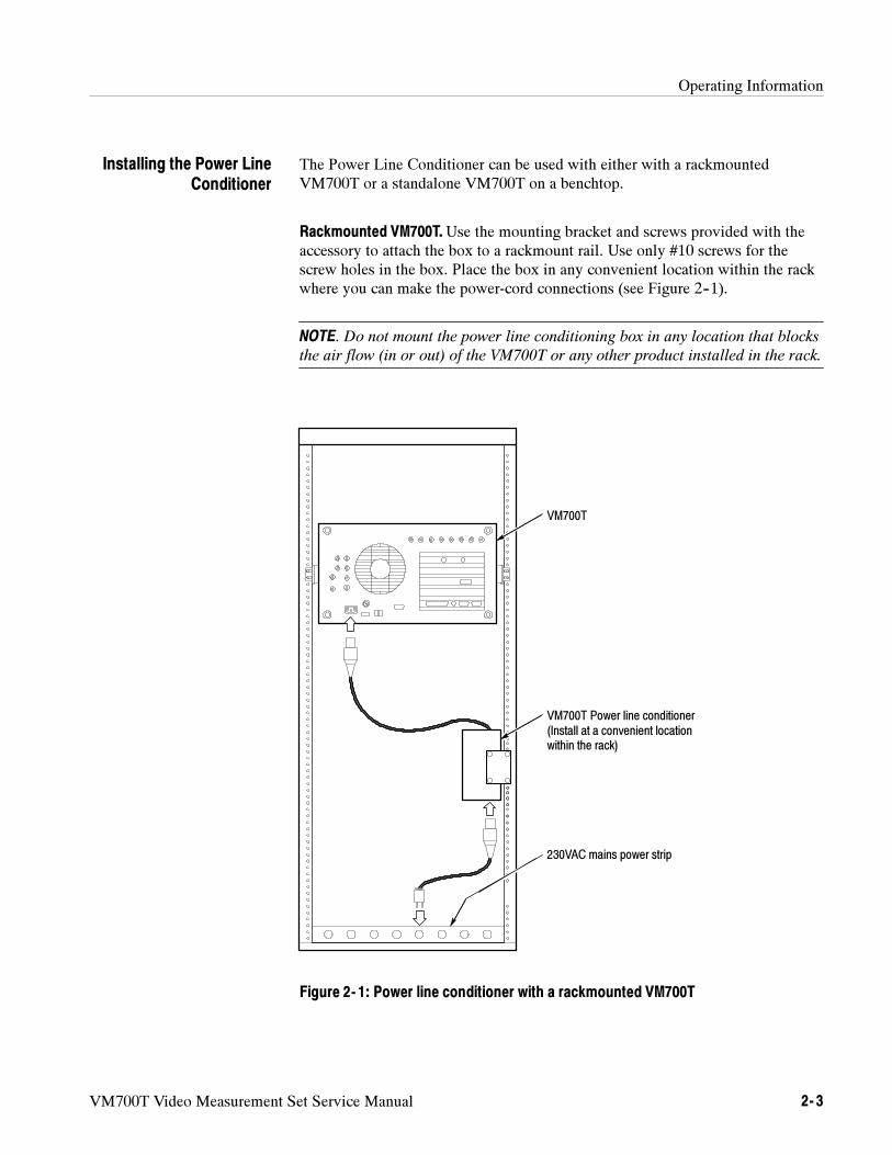
Operating Information
VM700T Video Measurement Set Service Manual 2- 3
The Power Line Conditioner can be used with either with a rackmountedVM700T or a standalone VM700T on a benchtop.
Rackmounted VM700T.Use the mounting bracket and screws provided with theaccessory to attach the box to a rackmount rail. Use only #10 screws for thescrew holes in the box. Place the box in any convenient location within the rackwhere you can make the power-cord connections (see Figure 2--1).
NOTE. Do not mount the power line conditioning box in any location that blocks
the air flow (in or out) of the VM700T or any other product installed in the rack.
VM700T
VM700T Power line conditioner(Install at a convenient locationwithin the rack)
230VAC mains power strip
Figure 2- 1: Power line conditioner with a rackmounted VM700T
Installing the Power LineConditioner
Operating Information
2- 4 VM700T Video Measurement Set Service Manual
Benchtop Mounting. For a standalone VM700T on a benchtop or for portable use,apply the four adhesive rubber feet provided with the accessory to the bottom ofthe box at the corners. Place the conditioner box in a convenient location whereyou can make the power cord connections.
Power Cord Connections. Connect the Power Line Conditioner in the power linebetween the AC mains and the VM700T power input connector in the followingorder:
1. Plug the output power cord connected to the box into the AC power inputconnector of the VM700T.
2. Plug the AC mains power cord into the AC input connector of the power lineconditioner box.
3. Plug the AC mains power cord into the 230 Vac mains source.
The measurement set, as shipped from the factory, is configured to skipdiagnostics at power on for a quicker start up. You can run diagnostics at poweron by doing an Auto Reset. Refer to Auto Reset on page 6--84 for information onforcing an Auto Reset. If any of the diagnostic tests fail, refer your measurementset to a qualified service person.
You may want to access the diagnostics for a couple of operating selections.These are setting the power on run mode (either to run the diagnostics at poweron or to skip them for a quick start) and calibrating the touch screen.
Power On Diagnostics
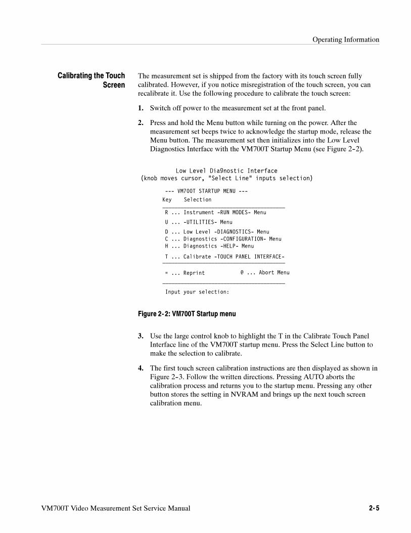
Operating Information
VM700T Video Measurement Set Service Manual 2- 5
The measurement set is shipped from the factory with its touch screen fullycalibrated. However, if you notice misregistration of the touch screen, you canrecalibrate it. Use the following procedure to calibrate the touch screen:
1. Switch off power to the measurement set at the front panel.
2. Press and hold the Menu button while turning on the power. After themeasurement set beeps twice to acknowledge the startup mode, release theMenu button. The measurement set then initializes into the Low LevelDiagnostics Interface with the VM700T Startup Menu (see Figure 2--2).
Low Level Diagnostic Interface(knob moves cursor, “Select Line” inputs selection)
Key Selection________________________________________
H ... Diagnostics -HELP- Menu
R ... Instrument -RUN MODES- Menu
D ... Low Level -DIAGNOSTICS- Menu
________________________________________
= ... Reprint________________________________________
Input your selection:
U ... -UTILITIES- Menu
T ... Calibrate -TOUCH PANEL INTERFACE-
--- VM700T STARTUP MENU ---
C ... Diagnostics -CONFIGURATION- Menu
@ ... Abort Menu
Figure 2- 2: VM700T Startup menu
3. Use the large control knob to highlight the T in the Calibrate Touch PanelInterface line of the VM700T startup menu. Press the Select Line button tomake the selection to calibrate.
4. The first touch screen calibration instructions are then displayed as shown inFigure 2--3. Follow the written directions. Pressing AUTO aborts thecalibration process and returns you to the startup menu. Pressing any otherbutton stores the setting in NVRAM and brings up the next touch screencalibration menu.
Calibrating the TouchScreen
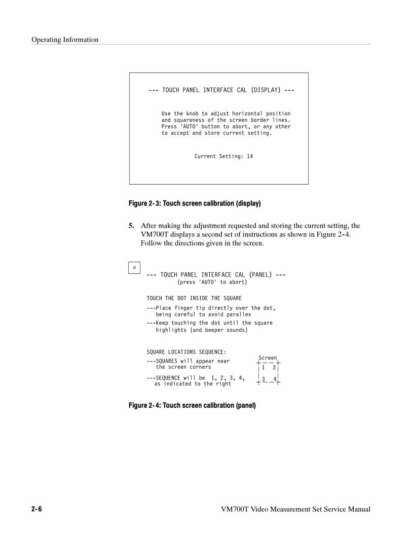
Operating Information
2- 6 VM700T Video Measurement Set Service Manual
Use the knob to adjust horizontal position
--- TOUCH PANEL INTERFACE CAL (DISPLAY) ---
and squareness of the screen border lines.Press ‘AUTO’ button to abort, or any otherto accept and store current setting.
Current Setting: 14
Figure 2- 3: Touch screen calibration (display)
5. After making the adjustment requested and storing the current setting, theVM700T displays a second set of instructions as shown in Figure 2--4.Follow the directions given in the screen.
--- TOUCH PANEL INTERFACE CAL (PANEL) ---(press ‘AUTO’ to abort)
TOUCH THE DOT INSIDE THE SQUARE
---Place finger tip directly over the dot,being careful to avoid parallex
---Keep touching the dot until the squarehighlights (and beeper sounds)
1 2
3 4
SQUARE LOCATIONS SEQUENCE:
---SQUARES will appear nearthe screen corners
---SEQUENCE will be 1, 2, 3, 4,
Screen
as indicated to the right
Figure 2- 4: Touch screen calibration (panel)
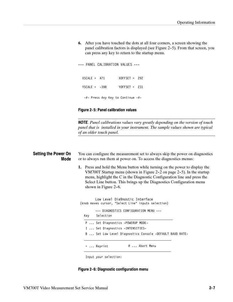
Operating Information
VM700T Video Measurement Set Service Manual 2- 7
6. After you have touched the dots at all four corners, a screen showing thepanel calibration factors is displayed (see Figure 2--5). From that screen, youcan press any key to return to the startup menu.
XSCALE = 471 XOFFSET = 292
--- PANEL CALIBRATION VALUES ---
-#- Press Any Key to Continue -#-
YSCALE = -398 YOFFSET = 231
Figure 2- 5: Panel calibration values
NOTE. Panel calibrations values vary greatly depending on the version of touch
panel that is installed in your instrument. The sample values shown are typical
of an older touch panel.
You can configure the measurement set to always skip the power on diagnosticsor to always run them at power on. To access the diagnostics menus:
1. Press and hold the Menu button while turning on the power to display theVM700T Startup menu (shown in Figure 2--2 on page 2--5). In the startupmenu, highlight the C in the Diagnostic Configuration line and press theSelect Line button. This brings up the Diagnostics Configuration menushown in Figure 2--6.
Low Level Diagnostic Interface(knob moves cursor, “Select Line” inputs selection)
Key Selection
P ... Set Diagnostics -POWERUP MODE-
B ... Set Low Level Diagnostics Console -DEFAULT BAUD RATE-
= ... Reprint
Input your selection:
I ... Set Diagnostics -INTENSITIES-
--- DIAGNOSTICS CONFIGURATION MENU ---
@ ... Abort Menu
Figure 2- 6: Diagnostic configuration menu
Setting the Power OnMode
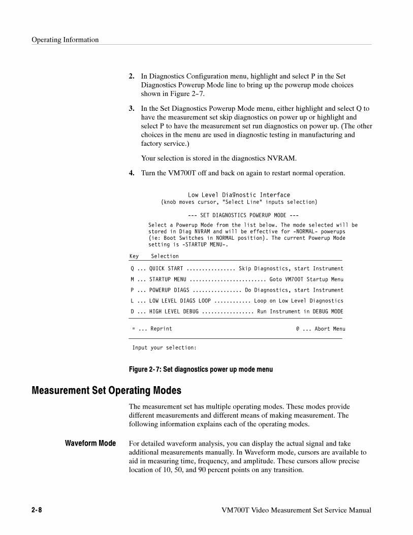
Operating Information
2- 8 VM700T Video Measurement Set Service Manual
2. In Diagnostics Configuration menu, highlight and select P in the SetDiagnostics Powerup Mode line to bring up the powerup mode choicesshown in Figure 2--7.
3. In the Set Diagnostics Powerup Mode menu, either highlight and select Q tohave the measurement set skip diagnostics on power up or highlight andselect P to have the measurement set run diagnostics on power up. (The otherchoices in the menu are used in diagnostic testing in manufacturing andfactory service.)
Your selection is stored in the diagnostics NVRAM.
4. Turn the VM700T off and back on again to restart normal operation.
Low Level Diagnostic Interface(knob moves cursor, “Select Line” inputs selection)
Key Selection
= ... Reprint
Input your selection:
--- SET DIAGNOSTICS POWERUP MODE ---
@ ... Abort Menu
Select a Powerup Mode from the list below. The mode selected will bestored in Diag NVRAM and will be effective for -NORMAL- powerups(ie: Boot Switches in NORMAL position). The current Powerup Modesetting is -STARTUP MENU-.
Q ... QUICK START Skip Diagnostics, start Instrument................
M ... STARTUP MENU Goto VM700T Startup Menu.........................
P ... POWERUP DIAGS Do Diagnostics, start Instrument................
L ... LOW LEVEL DIAGS LOOP Loop on Low Level Diagnostics............
D ... HIGH LEVEL DEBUG Run Instrument in DEBUG MODE.................
Figure 2- 7: Set diagnostics power up mode menu
Measurement Set Operating Modes
The measurement set has multiple operating modes. These modes providedifferent measurements and different means of making measurement. Thefollowing information explains each of the operating modes.
For detailed waveform analysis, you can display the actual signal and takeadditional measurements manually. In Waveform mode, cursors are available toaid in measuring time, frequency, and amplitude. These cursors allow preciselocation of 10, 50, and 90 percent points on any transition.
Waveform Mode
Operating Information
VM700T Video Measurement Set Service Manual 2- 9
You can expand the waveform display around any vertical or horizontal point.Since the data is digitized, the display is bright at all expansion factors. The axesautomatically expand with the waveform, so all units are correct as displayed.
The Vector mode provides the normal vectorscope display. You can rotate orexpand the vectors; the rotation angle and gain values are displayed numericallyon the screen.
A unique “Find Colorbars” feature searches the video signal for color bars anddisplays the vectors if it finds a color bars test signal. You can use the SelectLine choice in both Waveform mode and Vector mode to quickly specify any linefor display or automatic measurement if an appropriate video test signal is beingmeasured.
Measure mode provides graphic displays of measurements such as noisespectrum, group delay, and K-factor, for adjustment or closer analysis of themeasurement. You can make relative-to-reference measurements against a storedreference to minimize or eliminate signal source errors. Signal averaging can beused to reduce the effects of random noise in measurements where averaging isappropriate.
Picture mode permits you to quickly verify the signal source. You can select anyline on the picture to view in either the waveform display or the vector displayfor analysis of that line.
Auto mode makes standardized video measurements automatically, includingthose specified in the RS-250B/EIA-250C, NTC-7, and RS-170A video signalstandards. You can select the limits used on the measurements to determineout-of-limits conditions. The measurement set generates a caution or alarmmessage if a measurement falls outside the selected limits. You can select theformat for the auto mode measurement reports and schedule the report printingtimes.
If your measurement set has Option 1S installed, the VM700T resembles twoseparate instruments in one package: one analog and one digital. You can switchbetween the analog and digital functions by selecting Digital Mode or AnalogMode from one of these locations: the Configuration menu (two locations), theMeasure menu, or through remote control.
NOTE. To access any of the functions of Option 1S, you must set the VM700T to
Digital Mode. To access any of the analog measurement applications of the
VM700T, you must set the VM700T to Analog Mode.
Vector Mode
Measure Mode
Picture Mode
Auto Mode
Analog/Digital Mode(Option 1S Only)
Operating Information
2- 10 VM700T Video Measurement Set Service Manual
When you switch between Digital Mode and Analog Mode, the operation of thefront-panel buttons does not change except for the following five buttons:Waveform, Vector, Picture, Measure, and Auto. The Waveform and Picturebuttons access the SDI Waveform and the SDI Picture applications respectively.The Vector button accesses the SDI Lightning application. The Measure modebutton operation changes so that the measurement choices shown in the Measuremenu will be only those relevant to the selected signal source type (analog ordigital). When the VM700T is set to Digital Mode, the Auto mode buttonprovides direct access to the SDI Format Monitor application.
Option 1S adds a new soft key to the Measure mode screen and changes thename of one of the existing soft keys. The new SDI soft key changes themeasurement set to Digital Mode and displays the SDI applications. The originalVideo soft key is renamed to Analog Video. The Analog Video soft key changesthe measurement set to Analog Mode and displays the analog measurementapplications.
User-Programmable Functions
You can define a sequence of operations as a new function. For example, you cancreate a function that makes the measurements on a transmitter demodulatorvideo output. You can label this function DEMOD, build it to make all themeasurements, and provide a printout of the results. You can also call anotherfunction from within a function to produce a set of measurements.
Hardcopy
You can use a printer that supports PostScript or 24-pin Epson graphics throughthe standard RS-232C interface to hard copy the on-screen information. You canused most types of ASCII printers to print the results of Automatic measure-ments using the same interface. You can also send hard copy output to a parallelprinter through the Centronics-compatible parallel printer port.
Remote Operation
The measurement set can be operated from a remote terminal through either ofthe RS-232C ports to monitor unattended transmission systems or to put systemsunder computer control. The VGA output connector on the rear panel provides acopy of the measurement set display for remote viewing on a standard VGAmonitor. A GPIB port is added for remote control or hard-copy output to a GPIBprinter with Option 48 installed.
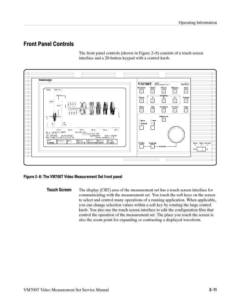
Operating Information
VM700T Video Measurement Set Service Manual 2- 11
Front Panel Controls
The front panel controls (shown in Figure 2--8) consists of a touch screeninterface and a 20-button keypad with a control knob.
Figure 2- 8: The VM700T Video Measurement Set front panel
The display (CRT) area of the measurement set has a touch screen interface forcommunicating with the measurement set. You touch the soft keys on the screento select and control many operations of a running application. When applicable,you can change selection values within a soft key by rotating the large controlknob. You also use the touch screen interface to edit the configuration files thatcontrol the operation of the measurement set. The place you touch the screen isalso the zoom point for expanding or contracting a displayed waveform.
Touch Screen
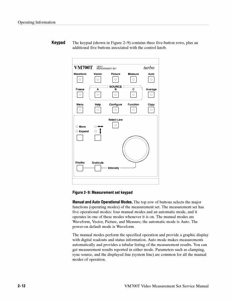
Operating Information
2- 12 VM700T Video Measurement Set Service Manual
The keypad (shown in Figure 2--9) contains three five-button rows, plus anadditional five buttons associated with the control knob.
Figure 2- 9: Measurement set keypad
Manual and Auto Operational Modes. The top row of buttons selects the majorfunctions (operating modes) of the measurement set. The measurement set hasfive operational modes: four manual modes and an automatic mode, and itoperates in one of these modes whenever it is on. The manual modes areWaveform, Vector, Picture, and Measure; the automatic mode is Auto. Thepower-on default mode is Waveform.
The manual modes perform the specified operation and provide a graphic displaywith digital readouts and status information. Auto mode makes measurementsautomatically and provides a tabular listing of the measurement results. You canget measurement results reported in either mode. Parameters such as clamping,sync source, and the displayed line (system line) are common for all the manualmodes of operation.
Keypad
Operating Information
VM700T Video Measurement Set Service Manual 2- 13
NOTE. Manual mode parameters do not carry over to Auto mode. You must set
parameters for both the Auto mode and the manual modes. The parameter files
are reached through the directory and file structure accessed by the Configure
button.
Freeze, Source Selection, and Average Functions. The second row in the keypadcontains the Freeze button, the input channel selection buttons (grouped asSOURCE A, B, and C), and the Average button.
Freeze Button. When you select Freeze, signal acquisition is halted. Thedisplay can be moved, expanded or contracted, as described below underControl Knob, but the display is not updated.
Source Selection Button. For all operational modes, one of the inputsources is always selected. For some of the manual modes, an input sourcecan be inverted. In Waveform and Vector modes, an inverted source can bethe sole input or it can be added to another input. In Measure mode, aninverted source can only be added to another source.
Source Invert. To invert a single source, press and hold the source buttonuntil the measurement set beeps (approximately one second). When a sourceis inverted, the LED on the source button flashes. To invert a second sourceand add it to another, press and hold the normal source and, while holding it,quickly press and release the inverted source. The LED on the invertedsource will flash.
Average Button. The Average button enables uncorrelated or random noisereduction on the signal in Waveform and Vector modes and averaging of thesignal in Measure mode. The amount of noise reduction (up to 30.10 dB) isset with the Noise soft keys. The number of averages (up to 256) is set withthe Average Num soft keys.
Support Functions. The third row down in the keypad contains support functions:Menu, Help, Configure, Function, and Copy. Turn any of these functions on bypressing the associated front-panel button. Of these, Copy turns off either afterthe copy is sent or after pressing the Cancel soft key that appears in theConfigure menu when a copy is pending. Help is turned off by pressing the Helpbutton a second time. The remaining functions are turned off either by pressingthe button a second time or by selecting a different operational mode in the toprow.
Menu Button. The Menu button displays a menu of soft keys across thebottom of the touch screen. In some cases, touching a soft key displays afurther submenu of soft keys.
Operating Information
2- 14 VM700T Video Measurement Set Service Manual
Help Button. Pressing the Help button activates the Help function. WhileHelp is activated, pressing a button or selecting a soft key displays a briefexplanation of that button or soft key’s function. When the Help function isactive, all buttons and soft keys except Help lose their normal function, andthe LED on the Help button flashes. Pressing the Help button a second timeturns off the Help function.
Configure Button. Configure accesses the Configuration files used tocontrol the operation of the measurement set. You can also create, edit,rename, print, and delete functions with selections available in the Configu-ration menu. For a full description of the Configure button and the menusaccessed, refer to the VM700T Option 01 (NTSC) and Option 11 (PAL) User
Manual.
Function Button. The Function button accesses user-created functions andthe selection choices for running them. For a full description of creating andediting functions, refer to the VM700T RS-232 Interface Programmer
Manual.
Copy Button. The Copy button sends a copy of the display (in user-select-able 24-pin Epson or PostScript format) to the measurement set print spoolerto queue for printing.
The LED in the Copy button flashes as long as the copy remains in thespooler. To delete the copy from the spooler, press the Configure button, andselect the Cancel Copy soft key. This soft key only appears when a copy ispending in the spooler.
To print the spooled copy, a suitable printer must be attached to one of themeasurement set serial ports or to the parallel printer port. You also have toset the Communications configuration file parameters to those needed for theattached printer.
The action of the control knob depends on its assignment for the current mode ofoperation. For example, in Waveform mode, rotating the control knob affectshorizontal or vertical movement of the display or horizontal or vertical expansionof the display, depending on the selections of the Move/Expand button and the“left/right/up/down” button. In Auto mode, rotating the control knob scrollsthrough the list of measurements. When a user-configurable parameter is selectedfor changing, you can rotate the control knob to make the change. For informa-tion on the specific functions of the control knob in each mode, refer to therelevant sections of the user documentation.
Display and Graticule Intensity Control. To change the intensity of eitherthe display or the graticule, hold down the appropriate button (Display orGraticule), and rotate the control knob.
Control Knob
Operating Information
VM700T Video Measurement Set Service Manual 2- 15
Select Line Button. The Select Line button changes the function of thecontrol knob from the default Move/Expand action to line selection. TheLED in the Select Line button is on when Select Line is active. To scrollthrough the field line by line, press the Select Line button and rotate thecontrol knob.
Depending on the operational mode, a menu of soft keys may also appearwhen the Select Line button is pressed. Refer to the relevant sections of theuser documentation for a description of the Select Line soft keys and thespecific control knob functions. In the diagnostic menus, use the Select Linebutton to activate a selected choice. For additional information on diagnosticoperation, refer to Diagnostics, beginning on page 6--55.
Most measurements can only be made using either off-air (live) signals or signalsfrom a generator that have the appropriate test signals in the vertical interval. Nouseful measurement information is displayed if the test signals are not correct forthe measurement being made.
The bandwidth of the measurement set is 0 Hz (DC) to approximately 6.8 MHz(video signals).
The measurement set has three video loop-through inputs, one external syncloop-through, two RS-232C DTE ports, a Centronics-compatible printer port,and a VGA output connector on the rear panel (Figure 2-3). The audio options(Option 40 and Option 41) add appropriate connectors for application of theaudio signals to the option circuitry. The GPIB Interface (Option 48) add astandard GPIB connector for remote control and GPIB hardcopy output.
You can connect any video signal (of the appropriate format) to any of the threevideo inputs for normal operation. The serial ports (Port 0 and Port 1) can beused for output to serial printers or for remote control of the measurement set.The printer output port supports Centronics-compatible parallel printers. TheVGA output provides support for viewing the measurement set display on aremote VGA monitor. Certain options, such as Camera and Component, requireconnections to specific inputs for correct operation. Refer to the appropriateoption user manual when connecting signals to make those option measure-ments.
Equipment/Signal SourcesRequired
Bandwidth
Connecting Inputs andOutputs
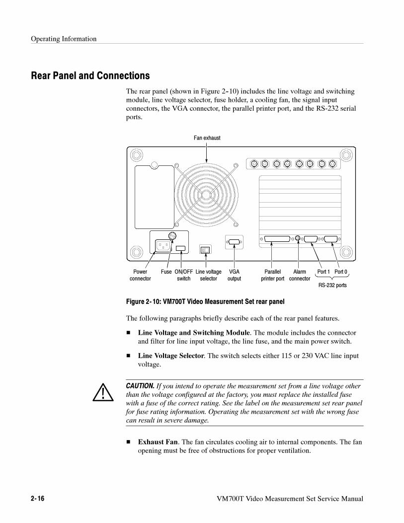
Operating Information
2- 16 VM700T Video Measurement Set Service Manual
Rear Panel and Connections
The rear panel (shown in Figure 2--10) includes the line voltage and switchingmodule, line voltage selector, fuse holder, a cooling fan, the signal inputconnectors, the VGA connector, the parallel printer port, and the RS-232 serialports.
Port 1 Port 0Powerconnector
Fuse Line voltageselector
ON/OFFswitch
Alarmconnector
VGAoutput
RS-232 ports
Parallelprinter port
Fan exhaust
Figure 2- 10: VM700T Video Measurement Set rear panel
The following paragraphs briefly describe each of the rear panel features.
Line Voltage and Switching Module. The module includes the connectorand filter for line input voltage, the line fuse, and the main power switch.
Line Voltage Selector. The switch selects either 115 or 230 VAC line inputvoltage.
CAUTION. If you intend to operate the measurement set from a line voltage other
than the voltage configured at the factory, you must replace the installed fuse
with a fuse of the correct rating. See the label on the measurement set rear panel
for fuse rating information. Operating the measurement set with the wrong fuse
can result in severe damage.
Exhaust Fan. The fan circulates cooling air to internal components. The fanopening must be free of obstructions for proper ventilation.
Operating Information
VM700T Video Measurement Set Service Manual 2- 17
Signal Inputs.2 These are the connections for Channel A, B, and C signalinputs to the measurement set.
External Sync. This input allows you to connect the measurement set to anexternal sync source.
RS-232 Ports. These ports are the serial interface from the measurement setto a printer for printing displayed data, screens, and logging information.The RS 232 ports also enables you to access the measurement set remotelyusing a terminal or a PC. Refer to the VM700T RS-232 Interface
Programmer Manual for information on configuring the measurement set forremote access and the remote control commands.
CAUTION. Peripheral equipment operating on ac mains voltages must be
properly grounded to prevent applying a floating voltage to the measurement set
internal circuitry that can cause damage.
Parallel Printer Port. You can use this port to connect the measurement setto a Centronics-compatible parallel printer. Uploading firmware upgrades isalso done through the printer port. The firmware and uploading program aredistributed on disk and uploaded from a personal computer through theparallel printer port. You will need a computer-to-computer data cable (forexample and XT compatible LapLink cable) to make the connection foruploading.
VGA Output. You can view the measurement set display on a standardVGA monitor connected to the VGA output connector.
2 The signal inputs and the external sync connector are loop-through connections that must be terminated in 75Ω when theyare not used. Three 75Ω terminations are provided as standard accessories.
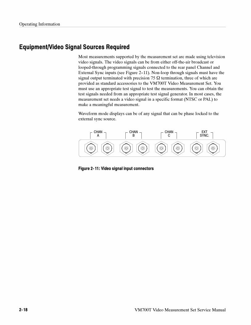
Operating Information
2- 18 VM700T Video Measurement Set Service Manual
Equipment/Video Signal Sources Required
Most measurements supported by the measurement set are made using televisionvideo signals. The video signals can be from either off-the-air broadcast orlooped-through programming signals connected to the rear panel Channel andExternal Sync inputs (see Figure 2--11). Non-loop through signals must have thesignal output terminated with precision 75 Ω termination, three of which areprovided as standard accessories to the VM700T Video Measurement Set. Youmust use an appropriate test signal to test the measurements. You can obtain thetest signals needed from an appropriate test signal generator. In most cases, themeasurement set needs a video signal in a specific format (NTSC or PAL) tomake a meaningful measurement.
Waveform mode displays can be of any signal that can be phase locked to theexternal sync source.
CHANA
CHANB
CHANC
EXTSYNC.
Figure 2- 11: Video signal input connectors
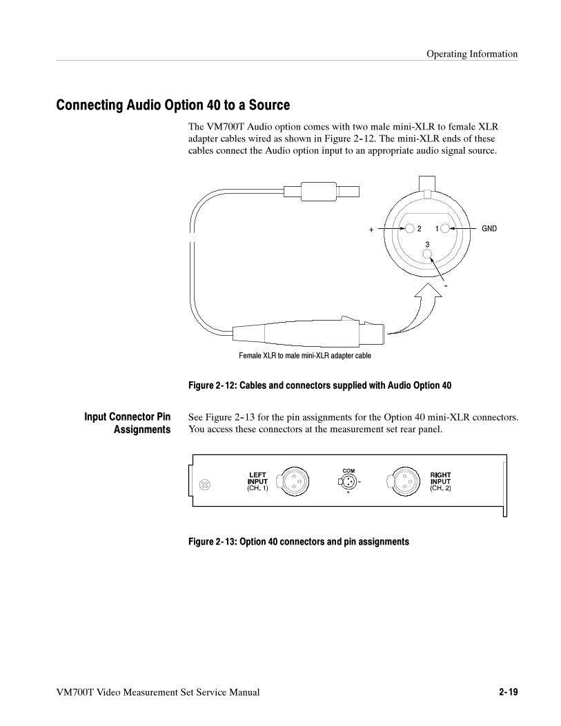
Operating Information
VM700T Video Measurement Set Service Manual 2- 19
Connecting Audio Option 40 to a Source
The VM700T Audio option comes with two male mini-XLR to female XLRadapter cables wired as shown in Figure 2--12. The mini-XLR ends of thesecables connect the Audio option input to an appropriate audio signal source.
GND+
--
12
3
Female XLR to male mini-XLR adapter cable
Figure 2- 12: Cables and connectors supplied with Audio Option 40
See Figure 2--13 for the pin assignments for the Option 40 mini-XLR connectors.You access these connectors at the measurement set rear panel.
Figure 2- 13: Option 40 connectors and pin assignments
Input Connector PinAssignments
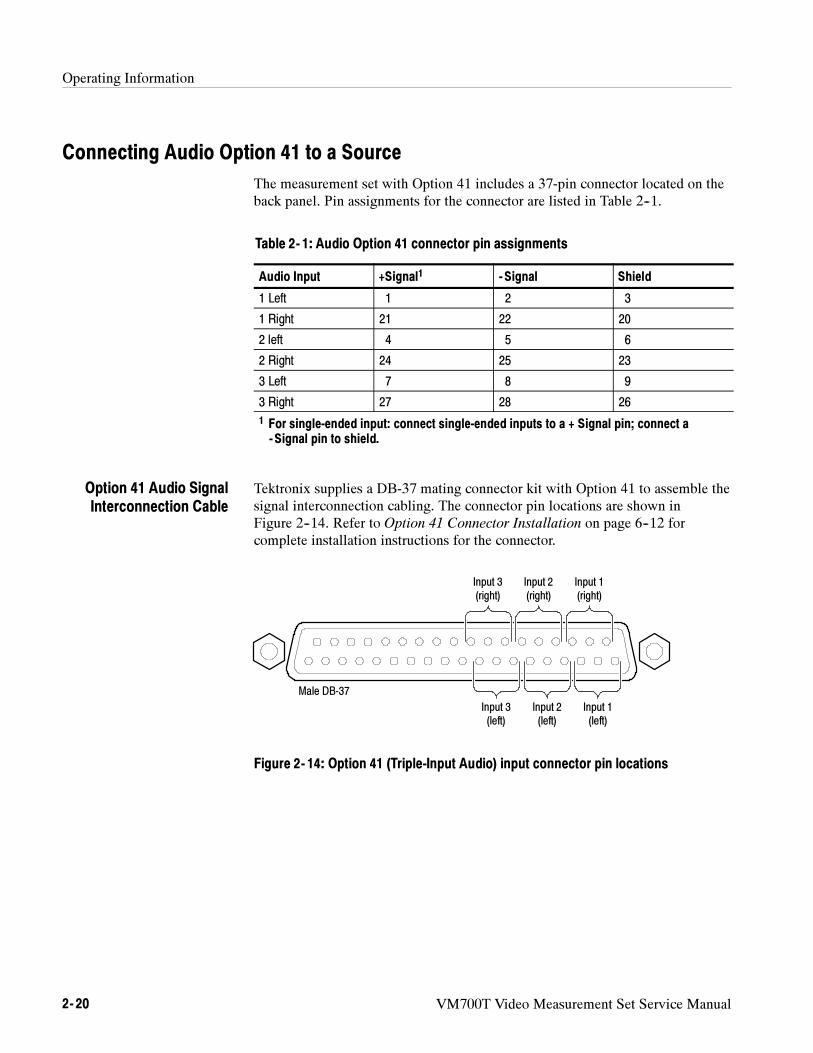
Operating Information
2- 20 VM700T Video Measurement Set Service Manual
Connecting Audio Option 41 to a Source
The measurement set with Option 41 includes a 37-pin connector located on theback panel. Pin assignments for the connector are listed in Table 2--1.
Table 2- 1: Audio Option 41 connector pin assignments
Audio Input +Signal1 - Signal Shield
1 Left 1 2 3
1 Right 21 22 20
2 left 4 5 6
2 Right 24 25 23
3 Left 7 8 9
3 Right 27 28 26
1 For single-ended input: connect single-ended inputs to a + Signal pin; connect a-Signal pin to shield.
Tektronix supplies a DB-37 mating connector kit with Option 41 to assemble thesignal interconnection cabling. The connector pin locations are shown inFigure 2--14. Refer to Option 41 Connector Installation on page 6--12 forcomplete installation instructions for the connector.
Input 3(right)
Input 2(right)
Input 1(right)
Input 3(left)
Input 2(left)
Input 1(left)
Male DB-37
Figure 2- 14: Option 41 (Triple-Input Audio) input connector pin locations
Option 41 Audio SignalInterconnection Cable
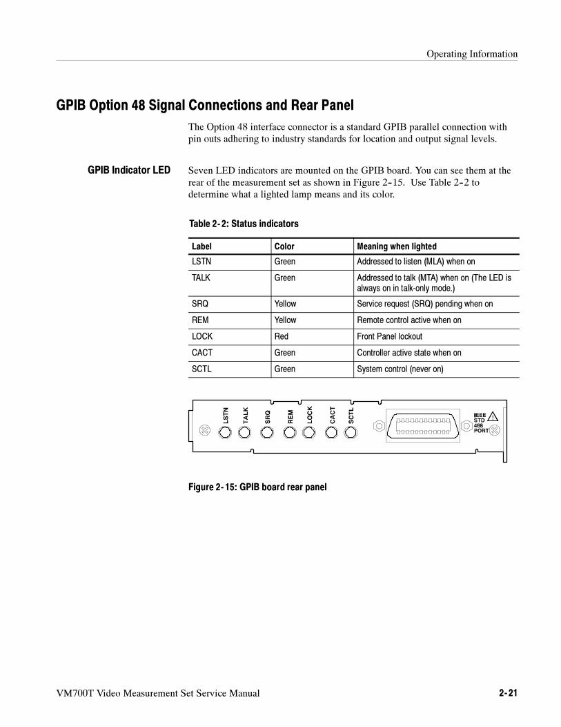
Operating Information
VM700T Video Measurement Set Service Manual 2- 21
GPIB Option 48 Signal Connections and Rear Panel
The Option 48 interface connector is a standard GPIB parallel connection withpin outs adhering to industry standards for location and output signal levels.
Seven LED indicators are mounted on the GPIB board. You can see them at therear of the measurement set as shown in Figure 2--15. Use Table 2--2 todetermine what a lighted lamp means and its color.
Table 2- 2: Status indicators
Label Color Meaning when lighted
LSTN Green Addressed to listen (MLA) when on
TALK Green Addressed to talk (MTA) when on (The LED isalways on in talk-only mode.)
SRQ Yellow Service request (SRQ) pending when on
REM Yellow Remote control active when on
LOCK Red Front Panel lockout
CACT Green Controller active state when on
SCTL Green System control (never on)
Figure 2- 15: GPIB board rear panel
GPIB Indicator LED
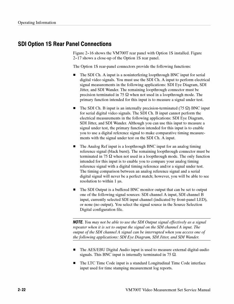
Operating Information
2- 22 VM700T Video Measurement Set Service Manual
SDI Option 1S Rear Panel Connections
Figure 2--16 shows the VM700T rear panel with Option 1S installed. Figure2--17 shows a close-up of the Option 1S rear panel.
The Option 1S rear-panel connectors provide the following functions:
The SDI Ch. A input is a noninterfering loopthrough BNC input for serialdigital video signals. You must use the SDI Ch. A input to perform electricalsignal measurements in the following applications: SDI Eye Diagram, SDIJitter, and SDI Wander. The remaining loopthrough connector must beprecision terminated in 75 Ω when not used in a loopthrough mode. Theprimary function intended for this input is to measure a signal under test.
The SDI Ch. B input is an internally precision-terminated (75 Ω) BNC inputfor serial digital video signals. The SDI Ch. B input cannot perform theelectrical measurements in the following applications: SDI Eye Diagram,SDI Jitter, and SDI Wander. Although you can use this input to measure asignal under test, the primary function intended for this input is to enableyou to use a digital reference signal to make comparative timing measure-ments with the signal under test on the SDI Ch. A input.
The Analog Ref input is a loopthrough BNC input for an analog timingreference signal (black burst). The remaining loopthrough connector must beterminated in 75 Ω when not used in a loopthrough mode. The only functionintended for this input is to enable you to compare your analog timingreference signal with a digital timing reference and/or a signal under test.The timing comparison between an analog reference signal and a serialdigital signal will never be a perfect match; however, you will be able to seeresolution to within 1 s.
The SDI Output is a buffered BNC monitor output that can be set to outputone of the following signal sources: SDI channel A input, SDI channel Binput, currently selected SDI input channel (indicated by front-panel LED),or none (no output). You select the signal source in the Source SelectionDigital configuration file.
NOTE. You may not be able to use the SDI Output signal effectively as a signal
repeater when it is set to output the signal on the SDI channel A input. The
output of the SDI channel A signal can be interrupted when you access one of
the following applications: SDI Eye Diagram, SDI Jitter, and SDI Wander.
The AES/EBU Digital Audio input is used to measure external digital-audiosignals. This BNC input is internally terminated in 75 Ω.
The LTC Time Code input is a standard Longitudinal Time Code interfaceinput used for time stamping measurement log reports.
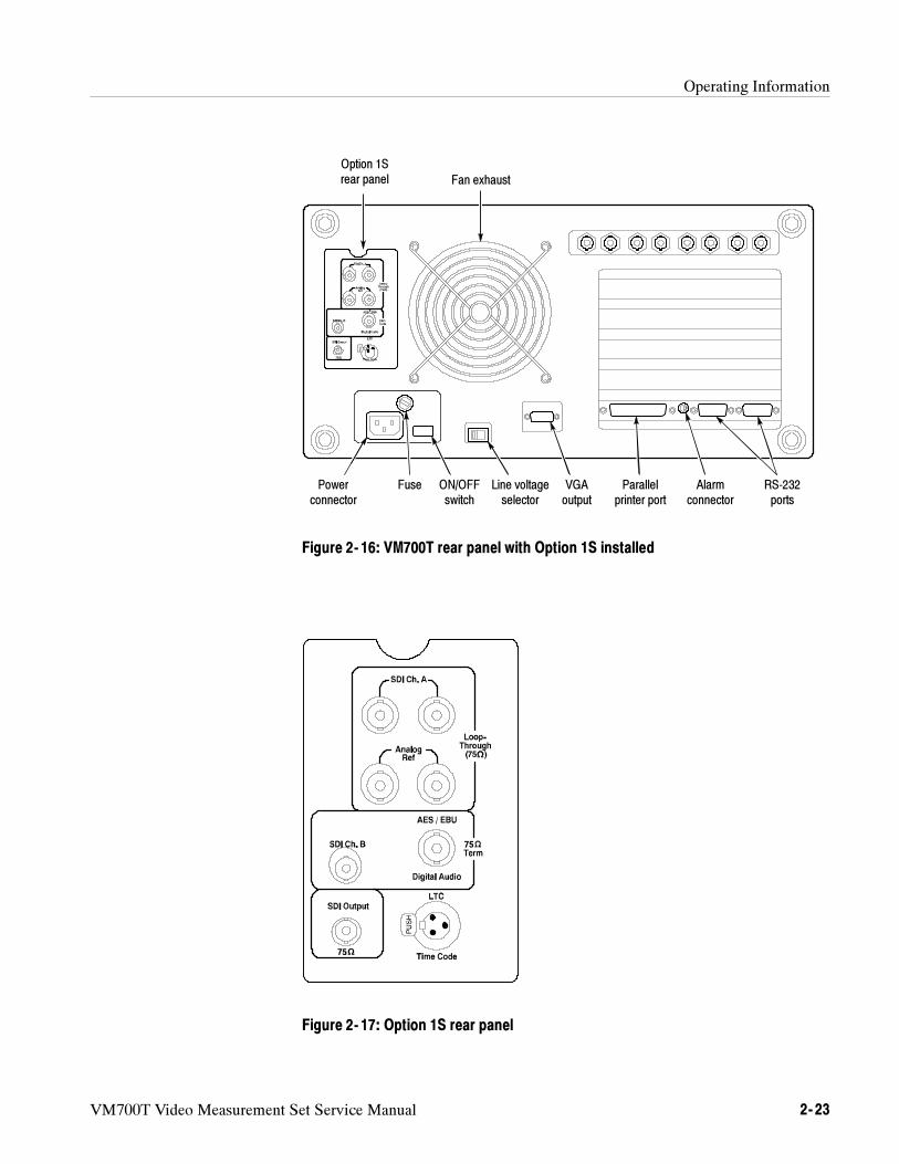
Operating Information
VM700T Video Measurement Set Service Manual 2- 23
Powerconnector
Fuse Line voltageselector
ON/OFFswitch
Alarmconnector
VGAoutput
RS-232ports
Parallelprinter port
Fan exhaust
Option 1Srear panel
Figure 2- 16: VM700T rear panel with Option 1S installed
Figure 2- 17: Option 1S rear panel
Operating Information
2- 24 VM700T Video Measurement Set Service Manual
VM700T Video Measurement Set Service Manual 3- 1
Theory of Operation
This section describes the electrical operation of the VM700T Video Measure-ment Set using the major circuit blocks as modules.
This section has two main parts:
Overview of the VM700T System describes the system operation of themodules (circuit boards).
Module Functional Description describes circuit operation of the modulesfrom a functional-circuit block perspective. Block diagram illustrationsaccompany the appropriate text.
Overview of The VM700T System
The video signal enters the VM700T analog input board (A1) through one ofthree high-impedance loop-through connectors (see the overall block diagram inthe diagrams sections of this manual). After it buffers and clamps the inputsignal and selects a channel, the A1 board passes the signal to the A4 filterswitch board where analog filtering (signal conditioning) occurs. After filteringthe filter switch board returns the video signal to the A1 board for analogprocessing (offset, gain, and dither are dynamically applied). The signal thenpasses to the analog-to-digital (ADC) converter board (A3) where it is digitized.
The A2 genlock board uses an external sync or the sync from one of the threevideo input channels to create a sampling pulse synchronized (genlocked) to theincoming sync pulses. A 10-bit, analog-to-digital flash converter digitizes thevideo signal. After digital conversion, the differential ECL data is clocked to theacquisition/controller board (A18).
The data acquisition/controller board (A18) converts the ECL data to single-ended TTL data and stores it in the acquisition memory. The data acquisitionmemory consists of static RAM accessible by the CPU during data acquisition(the memory appears to be dual ported).
Besides converting ECL data to single-ended TTL, the controller portion of theboard controls data acquisition patterns that handle the following analogprocessing hardware functions: clamping, input selection, sync source, filterselection, offset, gain, dither, and genlock.
Theory of Operation
3- 2 VM700T Video Measurement Set Service Manual
The CPU board (A5) contains a microprocessor, a floating-point unit, real-timeclock, Flash EPROM, NVRAM, display memory, and display driver hardware.The display driver hardware converts acquired data to video and drives theVM700T display. A monochrome VGA output to the rear panel is also derivedfrom the display driver hardware The Flash EPROM stores application programsand the NVRAM stores system and configuration files created by the user.
The front panel interface hardware is also on the CPU board. This interfacecontrols the touch-panel, control knob, and keyboard interfaces to the CPUmicroprocessor.
The audio option boards for Option 40 and 41 provide the interface for audio testsignals into the VM700T. Operation of the audio option measurements arediscussed in VM700T Option 40/41/42 Audio Measurements User manual.
A second option requiring additional hardware is Option 48, the GPIB option.This option provides a interface for remote control in a GPIB controlled system.Operation of the GPIB option is described in the VM700T GPIB Interface
Option 48 Programmer manual.
Theory of Operation
VM700T Video Measurement Set Service Manual 3- 3
Module Functional Description
This part describes the operation of each circuit board module in the VM700T.Block diagrams accompanying the text show the functions of the modules.
Analog Input Board (A1)
The analog input board performs input selection and applies bias, clamping,offset, gain, and dither to the input video before digital conversion. This boardalso contains a calibration DAC (digital-to-analog converter) that is automati-cally switched into the signal path to ensure accuracy. A block diagram of themodule is shown in Figure 3--1.
The three video channels and the external sync signals have independenthigh-impedance loop-through inputs. The clamped-input amplifiers are highinput impedance devices to minimize loading of the loop-through signals.
The mode control block passes or decodes instructions from the acquisition/con-troller board. These instructions control the clamped amplifiers, sync selection,channel selection, calibration DAC/cal relay operation, and the DVM selection.
The clamped input amplifiers (there are three, one for each channel) can eitherDC couple or DC restore (clamp) the video signal. Clamping is applied beforechannel selection to allow independent clamping of video signals that aresynchronous but mis-timed relative to each other. The bias level for each channelis summed with the buffered video just before clamping.
The clamp and bias generator supplies the analog clamp and bias voltages toeach clamped input amplifier. Three dual DAC devices are used to provide thesix outputs used, a clamp and bias level to the clamped input amplifier in eachchannel.
The DAC devices receive data and address information from the acquisition/con-troller board. The 3 address bits select the appropriate DAC (clamp or bias forchannels A, B, or C) while the 8 data bits are converted to the actual clamp orbias voltage.
Output from the clamped amplifiers is fed to a switching matrix that enables theuser to select various combinations of input channels.
Loop-Through Inputs
Mode Control
Clamped Input Amplifiers
Clamp and Bias Generator
Channel Selection

Theory of Operation
3- 4 VM700T Video Measurement Set Service Manual
Σ Σ
a Possible front panel selections (using hardware and software):A;, B, C, AB, AC, BC, BA, CA,, and CB.
Possible channel selection combinations in hardware:A;, B, C, AB, AC, BC, A, B.
Loop-Through Inputs
Chan A
Chan B
Chan C
ExtSync
Cal DAC
Clamped InputAmplifier To Filter
Switch Board
DifferentialAmplifier
5
2
5
2
5
2
4
15
33
3
SyncSelection
Clamp and BiasGenerator
ModeControl
DVMSelection
ToAcquisition/
DVM(VFC)
DitherGenerator
To ADCBoard
DitherAmplifier
VariableGain Amplifier
OffsetAmplifier
From FilterSwitch Board
FromAcquisition/
Dynamic OffsetGenerator
DVM SelectionControl Signals
To GenlockBoard
SyncBuffer
Controller
Controller
Cal Switch
Channel Selection a
Figure 3- 1: Analog input board (A1) block diagram
Theory of Operation
VM700T Video Measurement Set Service Manual 3- 5
The differential amplifier combines the differential output of the switchingmatrix and produces a single-ended video output signal which is connected bycoaxial cable to the filter switch board. After being filtered (if filtering is needed)the video signal returns to the analog input board for offset, gain, and ditherprocessing.
An acquisition description supplied by application software causes the acquisi-tion/controller board to dynamically apply dynamic offset, programmablevariable gain, and dither to the input video.
Data bits from the acquisition/controller board drive the dynamic offset generatorDAC and provide a dynamic offset range of –1.28 to +1.27 volts in 10-mV steps.This offset is summed with the video signal to keep the signal centered in thedynamic range of the analog-to-digital converter (ADC). The video signal withoffset applied is buffered by the offset amplifier and passed to the variable gainamplifier.
The variable gain amplifier consists of a resistive divider range switch followedby an amplifier with continuously variable, voltage-controlled gain. The controlvoltage comes from a 12-bit DAC whose input code comes from a look-up tablecontained in a programmable logic device. Outputs from the look-up table alsocontrol the range switch. The input to the look-up table is the five bit gaincontrol word from the acquisition/controller board. Together, these componentsprovide a gain range of 0 to 7.75 in steps of 0.25.
Dither data bits from the acquisition/controller board can be converted to 64analog levels (usually, only the first 32 levels are used) to effectively increase theresolution of the 10-bit ADC. The dither amplifier buffers the processed videosignal before passing it to the ADC board where it is digitized.
The calibration DAC is a precision digital-to-analog converter used for gaincompensation over the analog signal path (including the analog-to-digitalconverter). A calibration switch on each input channel couples the calibrationsignal onto the signal path at regular intervals. The output of the ADC providescalibration information that is stored in a look-up table. The VM700T uses thelook-up table information to maintain its luminance accuracy specificationwithout the need for periodic readjustments.
Differential Amplifier
Dynamic Offset Generatorand Offset Amplifier
Variable-Gain Amplifier
Dither Generator andDither Amplifier
Calibration DAC
Theory of Operation
3- 6 VM700T Video Measurement Set Service Manual
The VM700T gets sync from one of two sources:
directly from the channel A, B, or C loop-through inputs
from the external sync loop-through input
To maintain a high impedance level for the video loop-through inputs, the syncselection buffers the selected signal. Following the sync selection is an amplifierthat returns the video to the nominal one-volt level required by the sync strippercircuitry on the genlock board.
The sync stripper needs a negative-going sync pulse. To enable the instrument tolock to inverted video, the amplifier following the sync selection can beprogrammed to invert the (inverted) video selected as the sync source (pushdown the front panel SOURCE A/B/C button for about one second to invert thevideo).
NOTE. Video appears on the display in whatever orientation (inverted or
non-inverted) it appears at the input connector. When you push the SOURCE
A/B/C button only the video used as the sync source is inverted.
The DVM measures the average picture level (APL). The VM700T measures theanalog average as the video exits to the filter switch board. This analog voltageis converted to a frequency output and sent to the acquisition/controller boardwhere it is averaged by a counter. The counter output is read by applications thatfurnish the APL readout on the display.
Fifteen other inputs to the DVM selection block are selected by two multi-plexers. The following selections are included:
Outputs of the clamped amplifiers
Offset amplifier
Dither amplifier
Calibration DAC
Video from the filter switch board
Analog ground
Clamp levels for channels A, B, and C
TEMPSENSE from a thermistor
+REF output from the precision voltage reference
Sync Selection
DVM Selection and DVM
Theory of Operation
VM700T Video Measurement Set Service Manual 3- 7
The Genlock Board (A2)
The genlock board sends a constant frequency sampling strobe to the analog-to-digital converter (ADC) board. The NTSC and PAL television standards aresupported by both the genlock board and application firmware. A block diagramof the genlock board is shown in Figure 3--2.
The sampling strobe may be generated by one of the following three methods, ormodes:
The strobe may be phase locked to the incoming video signal (synchronoussampling mode), to force 910 (NTSC) or 1135 (PAL) samples per line.
The strobe may be phase locked to an internal crystal oscillator running at 20.25MHz (asynchronous sampling mode). This method of generating the samplingstrobe avoids errors that could be caused by unstable signals typically found invideo cassette recorders (VCR).
When timing measurement precision is most important or when greater timingresolution is desired, the strobe may be exactly 20.25 MHz (20.25 MHzsampling mode). This mode of operation eliminates the small timing errorsinherent in phase-locked loop systems.
In addition, the genlock board sends line and frame sync strobes to the ADCboard.
The sync stripper removes all luminance and chrominance information from thebaseband composite video signal, but leaves the horizontal and vertical syncinformation. The sync stripper provides this information on its horizontal syncand composite sync (combined horizontal and vertical sync) outputs.
Video signals from VCRs sometimes contain only rudimentary vertical syncinformation, which can cause the sync stripper to mis-trigger. A 200 microse-cond delay allows the sync stripper to function properly in the presence of thiskind of vertical sync.
Some countries place digital audio on the horizontal sync pulse using sound insync (SIS). A menu selection in the waveform application engages circuitry inthe sync stripper to sustain good performance in the presence of SIS.
A temperature-compensated crystal oscillator provides a 20.25 MHz clock with 5parts per million (ppm) accuracy. It is divided to either an NTSC or PALline-rate frequency and used as one of the selections for the phase-locked loopreference clock. It is also used as the sampling strobe in 20.25 MHz samplingmode.
Sync Stripper
Crystal Oscillator
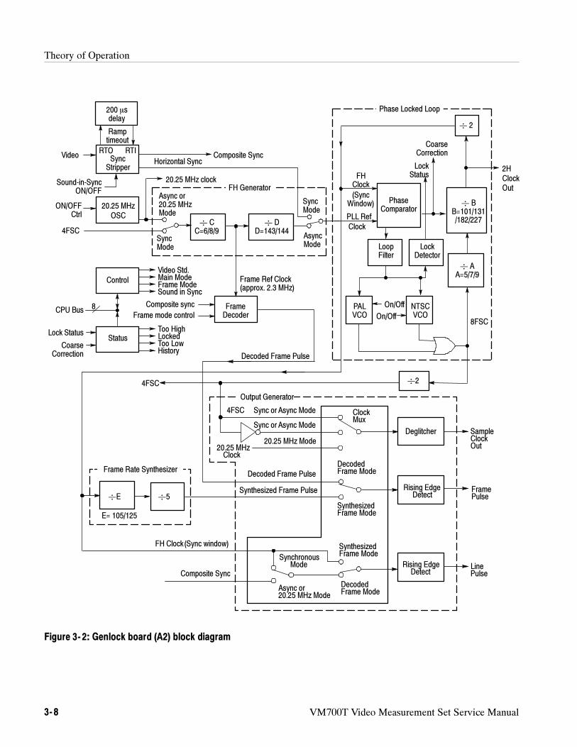
Theory of Operation
3- 8 VM700T Video Measurement Set Service Manual
Decoded Frame Pulse
20.25 MHz
ClockMux
FH Clock(Sync window)
Deglitcher
Rising EdgeDetect
Rising EdgeDetect
Synthesized Frame Pulse
Sync or Async Mode
FramePulse
LinePulse
SampleClockOut
20.25 MHz Mode
Output Generator
Clock
Synthesized
Decoded
4FSC 2
5E
E= 105/125
4FSC
Frame Rate Synthesizer
SyncStripper
(SyncWindow)
FHClock
200 sdelay
Ramptimeout
RTO RTIVideo
Sound-in-SyncON/OFF
20.25 MHzOSC
ON/OFFCtrl
Horizontal Sync
Async or20.25 MHzMode
20.25 MHz clock
4FSC
Control
Status
CPU Bus
Lock Status
CoarseCorrection
Video Std.Main ModeFrame ModeSound in Sync
Too HighLockedToo LowHistory
CC=6/8/9
DD=143/144
Frame Ref Clock(approx. 2.3 MHz)
AsyncMode
FH Generator
SyncMode
Composite Sync
Composite sync
Frame mode controlFrameDecoder
Clock
PLL Ref
Decoded Frame Pulse
2HClockOut
AA=5/7/9
2
PhaseComparator
CoarseCorrection
LockStatus
NTSCVCO
PALVCO
Phase Locked Loop
BB=101/131/182/227
LockDetector
LoopFilter
8FSC
SyncMode
On/Off
8
Sync or Async Mode
Frame Mode
Frame Mode
On/Off
Composite Sync
Async or
SynthesizedFrame ModeSynchronous
20.25 MHz Mode
Mode
DecodedFrame Mode
Figure 3- 2: Genlock board (A2) block diagram
Theory of Operation
VM700T Video Measurement Set Service Manual 3- 9
The FH generator provides an NTSC or PAL line-rate frequency reference clockto the phase-locked loop, using either the horizontal sync output from the syncstripper or the line-rate frequency derived from the 20.25 MHz crystal clock. TheFH generator also provides a timing reference to the frame decoder.
The PLL takes in a reference clock at the PAL or NTSC line-rate frequency andoutputs a frequency of 8 times the color subcarrier frequency (8Fsc). The PLL isnot used in 20.25 MHz sampling mode.
The phase comparator compares the reference clock to the output of the PLLfeedback circuit and generates a correction voltage to keep the two synchronized.The feedback circuit outputs a window centered on the leading edge of thereference clock. If the reference clock falls outside the window, the PLL isunlocked, and the coarse correction circuitry activates to quickly bring thereference clock back into the window. The loop filter smooths and integrates thecorrection voltage, which is then used to drive the voltage-controlled oscillators(VCO).
Two VCO generate the 8Fsc clock, one for PAL and the other for NTSC. Controllogic enables one VCO at a time. The output of the selected VCO is divided tothe line-rate frequency and fed back to the phase comparator.
A divide-by-2 counter divides the 8Fsc VCO output frequency to four times thecolor sub-carrier frequency (4Fsc) and ensures a 50% duty cycle output.
The frame decoder examines the composite sync signal from the sync stripper todetermine the location of vertical sync. The odd field detection modes output apulse on each odd-numbered field. The all field detection mode outputs a pulseon every field and uses an algorithm that can detect rudimentary vertical syncinformation produced by VCRs.
The frame rate synthesizer generates a frame-rate frequency output that is used inthe synthesized frame mode. The frame rate synthesizer does not operate in20.25 MHz sampling mode.
The stripped sync logic (not shown in the block diagram) removes noise fromthe sync stripper’s composite sync output. In sound-in-sync (SIS) mode, the SISpulses are removed by combining composite sync with the sync stripper’shorizontal sync output. Impulse noise (such as VCR head switches) is removedby gating composite sync with a 2 microsecond window pulse, centered on theleading edge of sync.
FH Generator
Phase-Locked Loop (PLL)
Divide-by-2Frequency Divider
Frame Decoder
Frame Rate Synthesizer
Stripped Sync Processing
Theory of Operation
3- 10 VM700T Video Measurement Set Service Manual
The output generator provides sampling, line, and frame strobes, to the analog-to-digital converter (ADC) board.
Sampling strobe output: A multiplexer selects either the four-times subcarrier(4Fsc) clock from the phase-locked loop or the 20.25 MHz crystal clock. Atransparent latch stops the clock output when changing sources, ensuring asmooth transition between them.
Line strobe output: A multiplexer selects either composite sync or the windowpulse from the phase-locked loop and converts it into a pulse one sample clockperiod in duration.
Frame strobe output: A multiplexer selects either the decoded frame pulse fromthe frame decoder or the synthesized frame pulse and converts it into a pulse onesample clock period in duration.
An 8-bit read/write register is used for mode control. Control bits select thevideo standard, sampling mode, frame mode, and sound-in-sync (SIS) mode.Logic provides enables for various hardware functions, with LEDs on the circuitboard to indicate which of them are in use.
An 8-bit read-only register is used to read genlock status. Some of the bitsindicate the current lock status and history. The remaining bits indicate VCOon/off status and the genlock hardware revision level. LEDs on the circuit boardindicate the current lock status and whether any unlocks have occurred since thelast read of the status register.
Output Generator
Control
Status
Theory of Operation
VM700T Video Measurement Set Service Manual 3- 11
The Analog-to-Digital (ADC) Board (A3)
The +2.5 V and --2.5 V regulators provide a balanced low-noise power source forthe A/D converter. The +2.5 V source is the output of a 5 V, 3-terminal regulatorstacked on the --2.5 V supply. The --2.5 V supply has a feedback circuit from theA/D converter VREF output. The feedback circuit adjust the --2.5 V output overa0.5 V range to hold the VREF output at ground reference.
The signal-conditioning amplifier is a buffer between the anti-aliasing filter andthe A/D Converter. The operational amplifier has 75 Ω input impedance,adjustable gain, and adjustable response. It has low distortion with 150 Ω outputloading and operates between the +5 V and --5.2 V supplies. Its low impedanceoutput directly drives the A/D Converter. An RC compensation network correctsfor the small rolloff of the anti-aliasing filter at 5 MHz.
The amplifier includes a limiter that restricts the output voltage to be between+1 V and --1 V to protect the A/D converter input from excessive signal levels orpower-up transients.
The A/D converter is a 12-bit monolithic converter that operates from 14 mega-samples per sec to 20.25 megasamples per second. It has a dynamic voltageinput range of0.5 V centered around its VREF output. The VREF output isheld at ground reference by the feedback to the --2.5 V power source so the inputvoltage range is centered around ground. The architecture of the A/D converterdelays the output by 3 clock cycles.
The differential clock input of the converter is driven by an ECL source that iscapacitively coupled to the clock input. The TTL level outputs of the A/Dconverter are divided down to ECL levels through a resistive divider networkand applied to buffers. A --1.3 V reference for the ECL buffer amplifiers isderived from the A/D converter’s balanced power supply.
The buffer is composed of 12 ECL buffers, one for each output line from theA/D converter. They are located close to the A/D Converter to minimize loadingon the converter outputs and unclocked to minimize delays.
The output latch supplies differential drive for the cable transporting the data tothe acquisition/controller. The latch is set and reset by ASYNC_SET andASYNC_RESET from the acquisition/controller board. It is clocked by theOUT_LATCH clock derived from the 4FSC signal.
+2.5 V and - 2.5 VRegulators
Signal ConditioningAmplifier
A/D Converter
Buffer
Output Latch
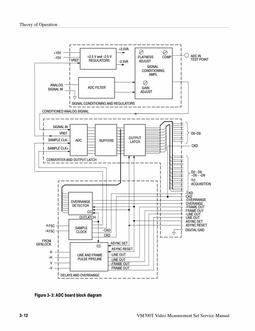
Theory of Operation
3- 12 VM700T Video Measurement Set Service Manual
ADC FILTER
+2.5 V and --2.5 VREGULATORS
SIGNAL
AMPLCONDITIONING
GAINADJUST
FLATNESSADJUST
+15V
--15V
+2.5VA
--2.5VA
ADC INTEST POINT
ANALOGSIGNAL IN
SAMPLE CLK+
SAMPLE CLK-- ADC BUFFERSOUTPUTLATCH
D0--D9
D0 - D9--D0 - --D9
--CKDCKD--OVERRANGEOVERANGE--FRAME OUTFRAME OUT--LINE OUTLINE OUTASYNC SETASYNC RESET
H
--V
4 FSC
FROMGENLOCK
CONDITIONEDANALOG SIGNAL
OVERRANGEDETECTOR
LINE AND FRAMEPULSE PIPELINE
--4FSC
--H
V
SAMPLECLOCK
DIGITAL GND
SIGNAL CONDITIONING AND REGULATORS
CONVERTERAND OUTPUT LATCH
DELAYS AND OVERRANGE
TOACQUISITION
COMP
--LINE OUT
LINE OUT--FRAME OUTFRAME OUT
--CKD
CKD
ASYNC SET
ASYNC RESET
CKD
OUTLATCH
CC
CC
VREF
SIGNAL IN
VREF
Figure 3- 3: ADC board block diagram
Theory of Operation
VM700T Video Measurement Set Service Manual 3- 13
H-sync and V-sync from the GenLock board are applied to the Line and FramePulse Pipeline. The pipeline is a series of flip-flops that delays the frame and linesync by the same amount as the A/D converter delays the video.
The Overrange detector checks to see if the eight most-significant bits of the10-bit samples are either all 1’s or all 0’s. If either event occurs, Overrange isasserted for that sample.
The 4FSC (four times the subcarrier frequency) signal from the GenLock boardis used to develop the sample clocks (SAMPLE CLK and --SAMPLE CLK) tothe ADC and the acquisition clocks (CKD and --CKD) for the acquisition/con-troller board. The clocks to the acquisition system are connected through a36-pin ribbon cable along with 10-bit data from the A/D converter and the FrameOut and Line Out signals.
Line and Frame PulsePipeline
Overrange Detector
Sample Clock
Theory of Operation
3- 14 VM700T Video Measurement Set Service Manual
Filter Switch Board (A4)
The filter switch board performs analog filtering of the video signal. Filtering isperformed by one of five filters mounted as daughter boards on the main circuitboard. The video signal is intercepted on the analog input board just afterchannel selection and then returned for analog processing (offset, gain, anddither). Figure 3--4 shows the filter switch board block diagram.
The filters are NTSC band width limit, Chroma bandpass, IEEE low pass,differentiated step, and low-frequency noise.
The acquisition/controller board provides inputs to the filter select and controlblock. After decoding, these inputs select and control the desired filter. Note thatonly the low-frequency noise filter has controllable characteristics. This blockalso requests a six-bit filter ID from the filter in each slot and transmits it to theacquisition/controller board.
The filter select and control block provides three types of outputs:
Filter selection
Filter poll, a request for filter I.D
Filter control (used only by the low-frequency noise filter)
Slot 0 is the straight-through path of the filter switch board; it has no connectorsfor mounting a filter. In place of a filter, a resistor network provides a smallamount of signal attenuation. The loss of each filter (in slots 1-5) is adjusted tomatch the loss from the resistance in slot 0.
Slots 1-5 accommodate the five plug-in filters.
The only filter with controllable parameters is the low-frequency noise filter.The –3 dB point on this filter can be set to 1 kHz, 7.5 kHz, 10 kHz, or 15 kHz.
The output amplifier provides the 75 Ω drive needed for the input to the analoginput board. When the acquisition/controller board asserts FIL3 the outputamplifier switches from unity gain to a gain of eight.
Filter Select and Control
Slot 0
Slots 1-5
Output Amplifier
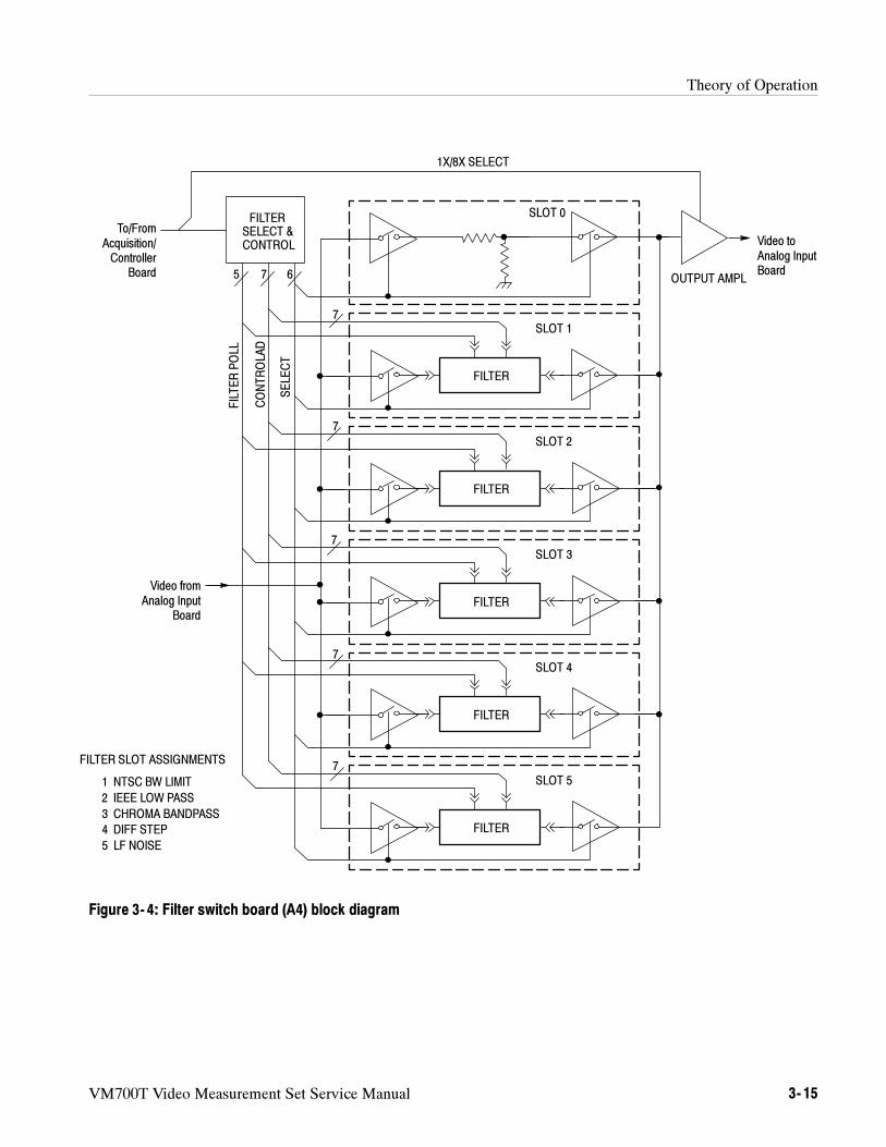
Theory of Operation
VM700T Video Measurement Set Service Manual 3- 15
FILTERSELECT &CONTROL
FILTER
FILTER
FILTER
FILTER
FILTER
SLOT 0
SLOT 1
SLOT 2
SLOT 3
SLOT 4
SLOT 5
To/FromAcquisition/Controller
Board
Video fromAnalog Input
Board
Video toAnalog InputBoard
1X/8X SELECT
5 7 6
7
7
7
7
7
OUTPUT AMPL
FILTER SLOT ASSIGNMENTS
1 NTSC BW LIMIT
2 IEEE LOW PASS
3 CHROMA BANDPASS
4 DIFF STEP
5 LF NOISE
SELECT
FILTERPOLL
CONTROLAD
Figure 3- 4: Filter switch board (A4) block diagram
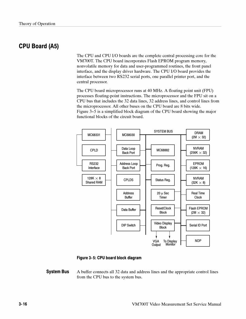
Theory of Operation
3- 16 VM700T Video Measurement Set Service Manual
CPU Board (A5)
The CPU and CPU I/O boards are the complete central processing core for theVM700T. The CPU board incorporates Flash EPROM program memory,nonvolatile memory for data and user-programmed routines, the front panelinterface, and the display driver hardware. The CPU I/O board provides theinterface between two RS232 serial ports, one parallel printer port, and thecentral processor.
The CPU board microprocessor runs at 40 MHz. A floating point unit (FPU)processes floating-point instructions. The microprocessor and the FPU sit on aCPU bus that includes the 32 data lines, 32 address lines, and control lines fromthe microprocessor. All other buses on the CPU board are 8 bits wide.Figure 3--5 is a simplified block diagram of the CPU board showing the majorfunctional blocks of the circuit board.
MC68331
CPLD
RS232Interface
128K¢ 8Shared RAM
MC68030
Data LoopBack Port
Address LoopBack Port
CPLDS
AddressBuffer
Data Buffer
DIP Switch
MC68882
Prog. Reg.
Status Reg.
20 SecTimer
Reset/ClockBlock
Video DisplayBlock
DRAM(2M¢ 32)
Real TimeClock
Serial ID Port
NVRAM(256K¢ 32)
EPROM(128K¢ 16)
NVRAM(32K¢ 8)
Flash EPROM(2M¢ 32)
NOP
SYSTEM BUS
Output MonitorVGA To Display
Figure 3- 5: CPU board block diagram
A buffer connects all 32 data and address lines and the appropriate control linesfrom the CPU bus to the system bus.
System Bus
Theory of Operation
VM700T Video Measurement Set Service Manual 3- 17
The EPROM is a 16-bit wide device with a maximum allowed memory of512 Kbytes. This is a read-only memory where the system boot-up code resides.
Under normal operation (after the boot sequence is complete) the CPU executesinstructions contained in Flash ROM (programmable read-only memory).
A 128k x 8 volatile static RAM module with battery-backup is used as thenonvolatile, random-access memory device. User programmed routines,front-panel setups, and measurement results are stored in the NVRAM. Thememory interface allows byte access only. The memory defaults to read only atpower on or after a system reset.
The NVRAM consists of two banks of 512 kilobytes SIMM of 32-bits width. Itis a low power static memory. The memory interface allows byte,word, and longword access. The memory defaults to read only at power up or after a systemreset. The memory interface supports 1, 2, and 4 MB SIMM parts.
The program memory is stored in Flash EPROM. Programming of the FlashEPROM is possible through the parallel printer port for system upgrades. Byte,word, 3-bytes, and long word access are allowed in read mode. Writes arerestricted to long word access during device programming. The memory defaultsto read only at power up or after a system reset.
This is the microprocessor’s working memory space. Memory sizes of 4, 8, or 16Megabytes in SIMM boards are supported. A dynamic RAM controller providesthe interface between the dynamic RAM and the CPU microprocessor.
A single time-keeper device provides a real-time clock, alarm, watchdog timer,and interval timer.
A display ASIC (application specific integrated circuit) processes the displayinformation and prepares it for display. The video RAM is divided into eight bitplanes (display memory layers). Data to be displayed is loaded in the videoRAM. Data is then read out of the VRAM as required for the display updates.Refresh information is written into alternate bit planes as the display data isbeing read from the active bit plane. A VGA output from the display systempermits viewing the display on an external VGA monitor. The VGA connector islocated on the back panel of the VM700T
EPROM
NVRAM
NVRAM SIMM
Flash EPROM
DRAM
Real-Time Clock
Display ASIC and VRAM
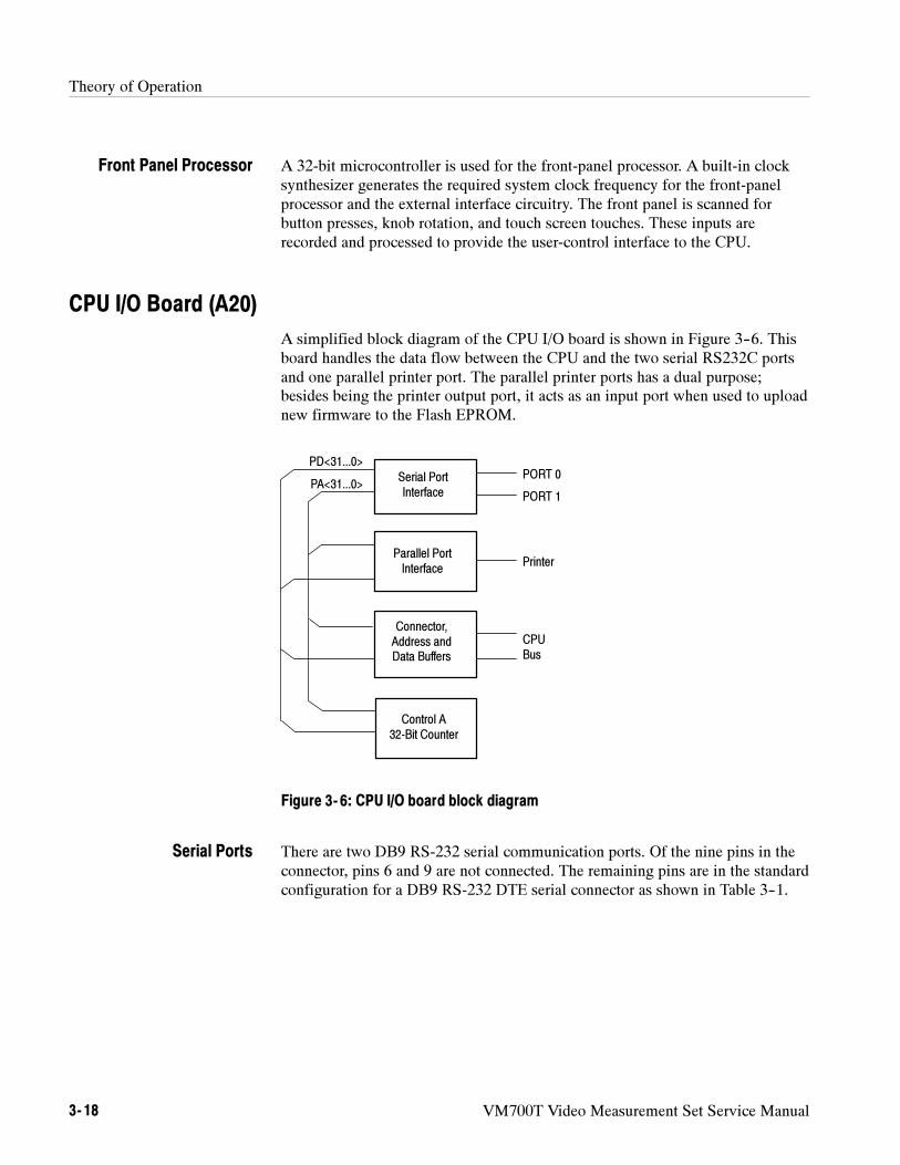
Theory of Operation
3- 18 VM700T Video Measurement Set Service Manual
A 32-bit microcontroller is used for the front-panel processor. A built-in clocksynthesizer generates the required system clock frequency for the front-panelprocessor and the external interface circuitry. The front panel is scanned forbutton presses, knob rotation, and touch screen touches. These inputs arerecorded and processed to provide the user-control interface to the CPU.
CPU I/O Board (A20)
A simplified block diagram of the CPU I/O board is shown in Figure 3--6. Thisboard handles the data flow between the CPU and the two serial RS232C portsand one parallel printer port. The parallel printer ports has a dual purpose;besides being the printer output port, it acts as an input port when used to uploadnew firmware to the Flash EPROM.
Parallel PortInterface
Printer
PORT 0
PORT 1
Serial PortInterface
Connector,Address andData Buffers
Control A32-Bit Counter
PD<31...0>
PA<31...0>
CPUBus
Figure 3- 6: CPU I/O board block diagram
There are two DB9 RS-232 serial communication ports. Of the nine pins in theconnector, pins 6 and 9 are not connected. The remaining pins are in the standardconfiguration for a DB9 RS-232 DTE serial connector as shown in Table 3--1.
Front Panel Processor
Serial Ports
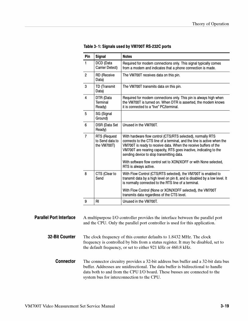
Theory of Operation
VM700T Video Measurement Set Service Manual 3- 19
Table 3- 1: Signals used by VM700T RS-232C ports
Pin Signal Notes
1 DCD (DataCarrier Detect)
Required for modem connections only. This signal typically comesfrom a modem and indicates that a phone connection is made.
2 RD (ReceiveData)
The VM700T receives data on this pin.
3 TD (TransmitData)
The VM700T transmits data on this pin.
4 DTR (DataTerminalReady)
Required for modem connections only. This pin is always high whenthe VM700T is turned on. When DTR is asserted, the modem knowsit is connected to a “live” PC/terminal.
5 SG (SignalGround)
6 DSR (Data SetReady)
Unused in the VM700T.
7 RTS (Requestto Send data tothe VM700T)
With hardware flow control (CTS/RTS selected), normally RTSconnects to the CTS line of a terminal, and the line is active when theVM700T is ready to receive data. When the receive buffers of theVM700T are nearing capacity, RTS goes inactive, indicating to thesending device to stop transmitting data.
With software flow control set to XON/XOFF or with None selected,RTS is always active.
8 CTS (Clear toSend
With Flow Control (CTS/RTS selected), the VM700T is enabled totransmit data by a high level on pin 8, and is disabled by a low level. Itis normally connected to the RTS line of a terminal.
With Flow Control (None or XON/XOFF selected), the VM700Ttransmits data regardless of the CTS level.
9 RI Unused in the VM700T.
A multipurpose I/O controller provides the interface between the parallel portand the CPU. Only the parallel port controller is used for this application.
The clock frequency of this counter defaults to 1.8432 MHz. The clockfrequency is controlled by bits from a status register. It may be disabled, set tothe default frequency, or set to either 921 kHz or 460.8 kHz.
The connector circuitry provides a 32-bit address bus buffer and a 32-bit data busbuffer. Addresses are unidirectional. The data buffer is bidirectional to handledata both to and from the CPU I/O board. These busses are connected to thesystem bus for interconnection to the CPU.
Parallel Port Interface
32-Bit Counter
Connector
Theory of Operation
3- 20 VM700T Video Measurement Set Service Manual
Data Acquisition/Controller Board (A18)
The combined Data Acquisition/Controller board (A18) does both data acquisi-tions and controlling of the acquisition process. The acquisition portion of theboard is a programmable data interface between the ADC board and the CPUmicroprocessor. The controller state machine can be programmed to recognizedata sequences and generate signals to the data acquisition section, telling itwhen to perform various tasks. Figure 3--7 shows a block diagram of the dataacquisition section of the Acquisition/Controller board.
Data from the ADC board enters the Acquisition/Controller board through a34-pin connector. The inputs are differential ECL-levels terminated by 100 Ω
resistors. ASYNC-SET and SYNC-RESET are outputs controlling the ADCboard.
The FIFO (first in/first out) consists of register files and a controlling device.The controller makes the synchronous register files behave as a FIFO file.
This block is the control and timing center of the Acquisition system. It handlesstatic RAM access arbitration, CPU dual-porting, state-machine instructioninterpretation, CPU handshaking, the real-time control, FIFO control, Min-Maxcontrol, static RAM control and address sequencing for these RAM.
The acquisition control clock circuit crystal oscillator running at 20.000 MHz.Various delayed versions of it are derived by a delay line. The clocks are used inthe acquisition ASIC for accurate timing of the control activities. One clockoutput is fed to the controller section.
Because the Acquisition/Controller board has its own 20 MHz clock (it isindependent of the CPU microprocessor) the CPU microprocessor interface isasynchronous into the acquisition section of the board. The data bus interfacecontrols connection between the CPU data bus and the acquisition data bus toallow static RAM accesses.
The acquisition memory consist of sixteen, 64 K x 4 bit fast (25 ns or loweraccess times) static type RAM in two rows of eight devices, with 17 total addressbits and 32-bit-wide data bus.
The min-max ASIC keeps a running record of the minimum and maximum videodata read from the FIFO, as well as latching whether a line or frame pulse or anover-flow or under-flow has occurred. Reading the Min-Max results resets thecircuit to begin a new accumulation.
Video Data andClock Inputs
FIFO/Demultiplexor
Acquisition Control
Acquisition Clock
Data Bus Interface
Data AcquisitionMemory (Static RAM)
Min-Max ASIC
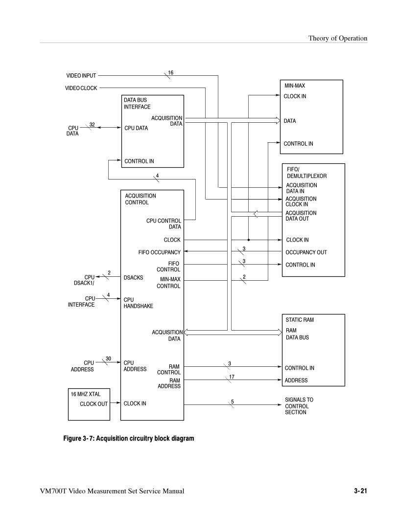
Theory of Operation
VM700T Video Measurement Set Service Manual 3- 21
DATA BUS
INTERFACE
CPU DATA
ACQUISITIONDATA
CONTROL IN
CPU CONTROLDATA
CLOCK
FIFO OCCUPANCY
FIFOCONTROL
MIN-MAX
CONTROL
DSACKS
CPUHANDSHAKE
ACQUISITIONDATA
RAM
DATA BUS
CONTROL IN
ADDRESS
CLOCK IN
CPUADDRESS
RAMADDRESS
RAMCONTROL
CLOCK IN
DATA
CONTROL IN
ACQUISITIONDATA IN
ACQUISITIONCLOCK IN
ACQUISITIONDATA OUT
CLOCK IN
OCCUPANCY OUT
CONTROL IN
VIDEO INPUT
VIDEOCLOCK
CPUDATA
CPUDSACK1/
CPUINTERFACE
CPUADDRESS
16 MHZ XTAL
CLOCK OUT
ACQUISITIONCONTROL
MIN-MAX
FIFO/DEMULTIPLEXOR
STATIC RAM
SIGNALS TOCONTROLSECTION
16
32
2
4
30
5
17
3
2
3
3
4
Figure 3- 7: Acquisition circuitry block diagram
Theory of Operation
3- 22 VM700T Video Measurement Set Service Manual
The controller portion of the board performs the following functions:
controls the VM700T analog front end
receives and processes digitized data from the ADC board and passes it toacquisition memory
controls acquisition patterns
Figure 3--8 shows a block diagram for the controller circuitry.
All 32 data lines and the required control and address lines from the system busare buffered on this board. Many of the data and address lines are buffered on theboard a second time before being used to drive multiple devices.
The majority of the control logic and high speed logic functions are incorporatedinto the controller ASIC (application specific integrated circuit). The controllernow has new functionality for DVM and clamp gating. The controller handlesCPU interfacing, DVM and clamp counter gating control, bus routing control,DVM counting, and some of the buffers that handle data flow.
Address decoding is handled by the same decoder as for the Acquisition sectionof the board.
This block controls the dynamic gains, offsets, input selections, and dither. Thedither counter is implemented in a PAL and octal D flip-flop. The output signalsfrom this block are fed directly to the Analog boards in the top compartment ofthe instrument. They perform the following actions:
enables the controller board DVM block
loads four control registers within the mode control and DVM selectionblocks
latches 12 (as 8 + 4) bits of data into the calibration DAC (located on theanalog input board)
loads 8 bits of data into each register of the bias and clamp level octal DAC(located on the analog input board)
There are stored patterns, selected by the four bits from the control register, arestored. The selected pattern provides gating for input signal clamping and theDVM. The gating information drives a triple timer/counter, U6. The ATRIG,BTRIG, and CTRIG outputs from the triple-timer/counter drive a one-shotmultivibrator on the analog input board. Trigger pulses are generated for eachline where clamping is to be applied. These pulses determine the point on a linewhere clamping begins; other control lines on this board control circuitry on theanalog input board that sets the clamp level and duration.
Controller Section
Bus Buffers
Controller ASIC
Address Decoding
Output Latchesand Analog InputBoard Interface
Clamp Counters
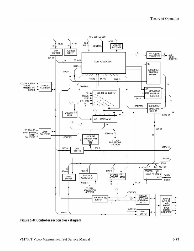
Theory of Operation
VM700T Video Measurement Set Service Manual 3- 23
ADDRESS
CLAMP
BUFFER
32D0-31
ADDRESSBUFFER
DATABUFFER
TRIGGER RAM
SCLK
5
CONTROL
SD12-27
13
CONTROL
2SD11,28
CONTROL
DATABUFFER
CONTROLWORD LATCH
16-BIT COUNTER
DATA
STATIC RAM2K X 32
CONTROLLER ASIC
ECL-TTL CONVERTER
SEQUENCER
STATIC RAM
STATUSCOUNTERS
ADDRESSLATCH
DATA LATCH
SEQUENCERADDRESSBUFFER
ADDRESSBUFFER
16K X 32
DYNAMICADDRESS LATCH
OUTPUTLATCHES
ANDANALOGINPUTBOARD
INTERFACE
CK
FRAME
LINE
OVR RNG
DATA
FRAME LSYNC
SCLK
SCLK
OE
SEQUENCER
REGISTER
OE
CLR
CONTROL
OE
OE
RCO
DATA
OE
OE
CONTROL
TO DATAACQUISITION
SECTION
TO DATAACQUISITIONSECTION
BCD0--12COUNTERS
TO ANALOGINPUT BOARD
CLAMPCOUNTERS
STATUS PULSESFROMDATAACQUISITION
BOARD
32
32
3 1116
14
14
CPU SYSTEM BUS
10
A0-1,A12-23 CONTROL
A24-31
BA10-15
SD0-31
SMA0-13
TA0-3
SD29-31
SMA13
CARRY
SD0-10
BD0-31
BA0-9
DATABUFFER
BD0-3
BD0-31
BD16-31
2
A2-11
16
13
13
SD0-31
BA0-15
CD13-15
ADDRESS
DATA
SMA9-12
4
10
SMA0-8
SD0-8
11
11
ADDRESSDECODER
TTL-TO-ECLCONVERTER
ADCMODECONTROL
22
CONTROL
8K X 4
DYNAMICSETTINGS
Figure 3- 8: Controller section block diagram
Theory of Operation
3- 24 VM700T Video Measurement Set Service Manual
A triple timer/counter counts status pulses from the acquisition section of theboard. The status pulses may be used by applications to indicate events occurringin an acquisition pattern.
The differential ECL signals from the ADC board (D0-D9, FRAME_OUT,LINE_OUT, CKD, and OVERRANGE) are converted to single-ended TTLoutputs before being used by the Acquisition/Controller board. A TTL-to-ECLconversion of OLS and PSR to ECL levels is also done. These signals (SyncReset and Async Set) control the modes of the ADC board so that it eitheroutputs all ones or zeros or does conversion operations.
The data from the ADC board are latched into data latches and clocked out bySCLK to resynchronize the data to the clock signal. Controller ASIC loads anaddress latch with 10 bits of address. Three additional bits (BCD13 -- 15) are addedfrom to complete the address. Bits from the control register, /RUN and /STOP,can switch the trigger RAM input from data latch output (normal operation) toaddress latch output. Switching the trigger RAM input to the output of theaddress latch allows the CPU microprocessor to access the trigger RAM. Themicroprocessor then writes a 4-bit pattern into the trigger RAM through a 4-bitenable buffer.
The 13 bits (10 bits of data plus over-range, FRAME, and LSYNC) are sent tothe trigger RAM and and to the data acquisition sections of the board.
The trigger RAM performs the actual word recognition. When the micropro-cessor writes an appropriate 4-bit wide pattern into the trigger RAM from a 4-bitenable buffer, the four output bits change when certain ranges of input data(identified by bit pattern) occur. The output is four bits of the 16-bit input to thesequencer.
Input data that could be programmed to trigger sequences may include suchthings as sync, tape dropout, or zero-carrier pulses.
Sequencer outputs drive the dynamic settings circuitry and send control bits tothe data acquisition board. These control bits cause the program counter on thedata acquisition board to jump to preset addresses.
As with the word recognition circuitry, the sequencer static RAM is loaded withprogram information from the CPU microprocessor. A bit from a control register(SRUN) enables address and data buffers of the system bus to have access tostatic RAM.
Sequencer Address and Data Buffers.When the address buffer is enabled, thesequencer static RAM can be read and written by the microprocessor from thedata buffer before starting the sequencer.
Status Counter
ECL-To-TTL Conversion
Data and Address Latchesonto the BCD0-12 Bus
Trigger RAM
Sequencer (StateMachine)
Theory of Operation
VM700T Video Measurement Set Service Manual 3- 25
Address Register. The normal input to static RAM is the 16 bits from thesequencer address register. The four TRIG bits, the 16-bit counter CARRY bit,and 11 bits (out of 32) from the output of static RAM comprise the 16-bit inputto the register. The TRIG bits are the output of trigger RAM. The 11 address bitsare the 11 LSBs from the output of the sequencer static RAM that are also fedthrough an address latch, to the dynamic settings static RAM as its normal input(nine of these address bits are used in current hardware; the other two arereserved for future expansion.)
Static RAM. The 32-bit word output of the static RAM memory block goes to anumber of circuits when the sequencer is running. Eleven bits of the output arefed to an address latch. The same 11 bits are also routed to the address register asthe program counter. Sixteen bits of the output are fed as data to the 16-bitcounter, while two more bits provide counter control. Three other of these bitsprovide signalling to the acquisition section of the board.
16-Bit Counter. Sixteen of the 32 bits output by the sequencer static RAM areused as data by the 16-bit counter. The two control bits determine the countdirection and whether the counter is to be loaded with the 16 data bits or is tohold the current count. When the counter overflows, the CARRY bit is returnedto the address register. The CARRY bit can be used to count samples, lines,frames, or whatever the application needs to count.
Dynamic Address Latch. The 11 bits received by this address latch are clockedthrough to the dynamic settings static RAM. These are the same 11 address bitsthat are returned to the address register from the output of the sequencer staticRAM, but delayed one clock cycle.
Control Word Latch. The control word latch holds a three-bit control word issuedto the data acquisition section of the board. These control bits cause the programcounter in the data acquisition section of the board to jump to preset addresses.
This circuitry sends additional front-end control data to the Analog Input,Genlock, and Filter Switch boards. The key requirement for this block is that itsoutputs must be able to change rapidly, because offset, gain, dither, inputselection, and filter selection may change many times during a single line ofvideo.
The CPU microprocessor can access the dynamic settings static RAM any time,even during an acquisition. The same control bit (SRUN) that disables thesequencer static RAM determines if the microprocessor access requiressynchronization.
Six of the eight bits sent to the dither generator are used as data; the other twoare for control. The dither generator’s four control states are the following:
clear
sequence to the next dither level
Dynamic Settings
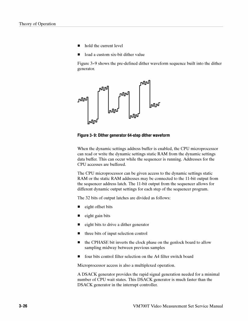
Theory of Operation
3- 26 VM700T Video Measurement Set Service Manual
hold the current level
load a custom six-bit dither value
Figure 3--9 shows the pre-defined dither waveform sequence built into the dithergenerator.
Figure 3- 9: Dither generator 64-step dither waveform
When the dynamic settings address buffer is enabled, the CPU microprocessorcan read or write the dynamic settings static RAM from the dynamic settingsdata buffer. This can occur while the sequencer is running. Addresses for theCPU accesses are buffered.
The CPU microprocessor can be given access to the dynamic settings staticRAM or the static RAM addresses may be connected to the 11-bit output fromthe sequencer address latch. The 11-bit output from the sequencer allows fordifferent dynamic output settings for each step of the sequencer program.
The 32 bits of output latches are divided as follows:
eight offset bits
eight gain bits
eight bits to drive a dither generator
three bits of input selection control
the CPHASE bit inverts the clock phase on the genlock board to allowsampling midway between previous samples
four bits control filter selection on the A4 filter switch board
Microprocessor access is also a multiplexed operation.
A DSACK generator provides the rapid signal generation needed for a minimalnumber of CPU wait states. This DSACK generator is much faster than theDSACK generator in the interrupt controller.
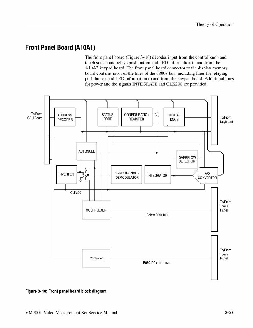
Theory of Operation
VM700T Video Measurement Set Service Manual 3- 27
Front Panel Board (A10A1)
The front panel board (Figure 3--10) decodes input from the control knob andtouch screen and relays push button and LED information to and from theA10A2 keypad board. The front panel board connector to the display memoryboard contains most of the lines of the 68008 bus, including lines for relayingpush button and LED information to and from the keypad board. Additional linesfor power and the signals INTEGRATE and CLK200 are provided.
OVERFLOWDETECTOR
ADDRESS
DECODER
To/FromCPU Board
AUTONULL
STATUSPORT
CONFIGURATION
REGISTERDIGITAL
KNOB
INVERTER SYNCHRONOUS
DEMODULATORINTEGRATOR
MULTIPLEXER
To/From
TouchPanel
To/From
Keyboard
CLK200
A/DCONVERTOR
Controller
To/From
TouchPanel
Below B050100
B050100 and above
Figure 3- 10: Front panel board block diagram
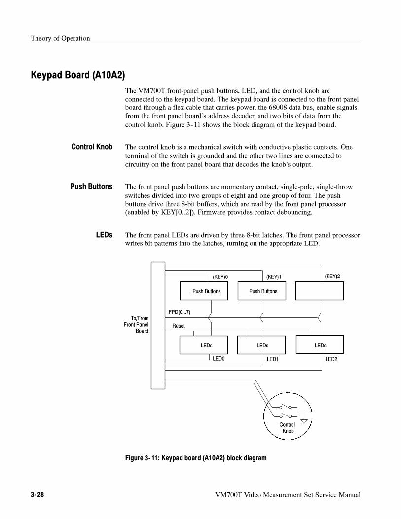
Theory of Operation
3- 28 VM700T Video Measurement Set Service Manual
Keypad Board (A10A2)
The VM700T front-panel push buttons, LED, and the control knob areconnected to the keypad board. The keypad board is connected to the front panelboard through a flex cable that carries power, the 68008 data bus, enable signalsfrom the front panel board’s address decoder, and two bits of data from thecontrol knob. Figure 3--11 shows the block diagram of the keypad board.
The control knob is a mechanical switch with conductive plastic contacts. Oneterminal of the switch is grounded and the other two lines are connected tocircuitry on the front panel board that decodes the knob’s output.
The front panel push buttons are momentary contact, single-pole, single-throwswitches divided into two groups of eight and one group of four. The pushbuttons drive three 8-bit buffers, which are read by the front panel processor(enabled by KEY[0..2]). Firmware provides contact debouncing.
The front panel LEDs are driven by three 8-bit latches. The front panel processorwrites bit patterns into the latches, turning on the appropriate LED.
To/FromFront Panel
Board
ControlKnob
Push Buttons Push Buttons
LEDs LEDs LEDs
LED0 LED1 LED2
Reset
FPD(0...7)
(KEY)0 (KEY)1 (KEY)2
Figure 3- 11: Keypad board (A10A2) block diagram
Control Knob
Push Buttons
LEDs
Theory of Operation
VM700T Video Measurement Set Service Manual 3- 29
Main Interconnect Board (Left and Right) (A11)
The VM700T has both attached assemblies and plug in modules. The plug inmodules are supplied with power, data, address, and control signals through theinterconnections to the Main Interconnect Board. There is a Left and Right board(for the plug in modules on the left and right sides of the VM700T) and aninterconnect board that ties the two sides together.
Picture Monitor (A14)
The Picture Monitor produces the visual display of the VM700T. It is hasvertical and horizontal deflection circuitry to drive the trace on the raster-scanCRT, a video amplifier, the high voltage circuitry, and the CRT in a completeassembly. A simplified block diagram is shown in Figure 3--12.
The Video Amplifier amplifies the incoming video signal to levels necessary todrive the CRT cathode. A input circuit provides impedance matching and currentdrive to the output video amplifier. The output video amplifier drives the CRTcathode. As the input video signal is increasing in amplitude, the inverted videosignal drives the cathode negative with respect to its +55V reference levelthereby causing the beam current to increase.
The incoming +12 V is filtered to provide the +12 V supply. A second +12 V(+12 V1) is obtained through R295. That voltage is applied to a 5 V zener diodeto supply a +5 V source.
The vertical deflection circuit provides the drive current to the vertical deflectionyoke. A free-running oscillator circuit produces a ramp signal and an amplifiedvertical deflection signal. The basic frequency of the oscillator is set to 60 Hz bythe adjustment of the VERT HOLD potentiometer. The length of the ramp signal,and consequently the vertical synchronization, is set by the V Sync signal.
When the V Sync is received, the vertical ramp is terminated, and a new onebegins. The RAMP OUT amplified to drive the vertical deflection yoke. Thevertical height of the display is set by the adjustment of the Vert Size potentiom-eter. The DC level adjustment of the vertical deflection circuit produces an offsetthat centers the display vertically. Vertical linearity of the raster is adjusted withthe Vertical Linearity potentiometer.
Video Amplifier
+12 V and + 5 V Supplies
Vertical Deflection
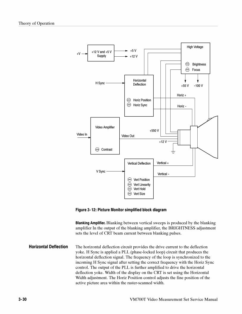
Theory of Operation
3- 30 VM700T Video Measurement Set Service Manual
+55 V --100 V
Vertical Deflection
High Voltage
HorizontalDeflection
Video Amplifier
Video Out
Contrast
Vert Position
Horiz Position
Horiz Sync
Vert Linearity
Vert Hold
Vert Size
Focus
+5 V
+12 V+V
Video In
H Sync
V Sync
+12 V and +5 VSupply
Brightness
+12 V
+550 V
Horiz +
Horiz --
Vertical +
Vertical --
Figure 3- 12: Picture Monitor simplified block diagram
Blanking Amplifier. Blanking between vertical sweeps is produced by the blankingamplifier In the output of the blanking amplifier, the BRIGHTNESS adjustmentsets the level of CRT beam current between blanking pulses.
The horizontal deflection circuit provides the drive current to the deflectionyoke. H Sync is applied a PLL (phase-locked loop) circuit that produces thehorizontal deflection signal. The frequency of the loop is synchronized to theincoming H Sync signal after setting the correct frequency with the Horiz Synccontrol. The output of the PLL is further amplified to drive the horizontaldeflection yoke. Width of the display on the CRT is set using the HorizontalWidth adjustment. The Horiz Position control adjusts the fine position of theactive picture area within the raster-scanned width.
Horizontal Deflection
Theory of Operation
VM700T Video Measurement Set Service Manual 3- 31
The high voltage supply provides the CRT anode voltage, the focus voltage, andthe +55 V and --100 V sources.
The main focus voltage is set by the FOCUS potentiometer. Dynamic focusingoptimizes the edge focusing of the CRT. The dynamic focusing waveform isshaped to produce the best edge focus in conjunction with the setting of theFOCUS pot for best overall focus.
The Trace Rotation circuit drives a separate deflection coil on the neck of theCRT. The adjustable voltage from the trace rotation potentiometer provides anoverall adjustment range for trace rotation of approximately 3.4.
Power Supply (A15)
The power supply is composed of a primary rectifier, the inverter switchingcircuit, 12 V and 15 V regulators, alarm-sensing circuitry that monitors forovervoltage, overcurrent, and over-temperature conditions, and the alarm logiccircuitry that shuts down the inverter switching circuitry in the event of aproblem. A simplified block diagram is shown in Figure 3--13.
The Input Power Rectifier receives the mains AC voltage and rectifies it toprovide the drive power to the inverter switching circuitry. A line voltage switchsets the supply to operate on a nominal voltage of either 115 VAC or 230 VAC.Input surge current and overvoltage protection components are included in theinput rectifier circuit to prevent major component damage in the event thatincorrect line voltage is applied to the AC input.
A second power supply provides the housekeeping (or keep-alive) power source.This supply provides power to the logic circuitry that controls the power supplySTBY/ON logic circuitry. One of the sensing signals (LINE SENSE) to thepower supply logic circuitry is developed from the secondary of the house-keeping supply transformer.
This circuitry comprises the Pulse Width Modulator, the Switching TransistorDrivers, the Switching Transistors, and the Secondary Rectifiers and Filters.
Secondary outputs of the power transformer are full-wave rectified and filtered toprovide +5 V, –5 V, +16.5 V, and –16.5 V. The +16.5 V and –16.5 V are furtherregulated to produce the +15 V and –15 V supplies to the VM700T and the+12 V display module power. The source voltage for the Fan Drive circuit is alsoprovided by the +12 V supply.
High Voltage
Trace Rotation
Input Power Rectifier
Housekeeping PowerSupply
Inverter Switching Circuit
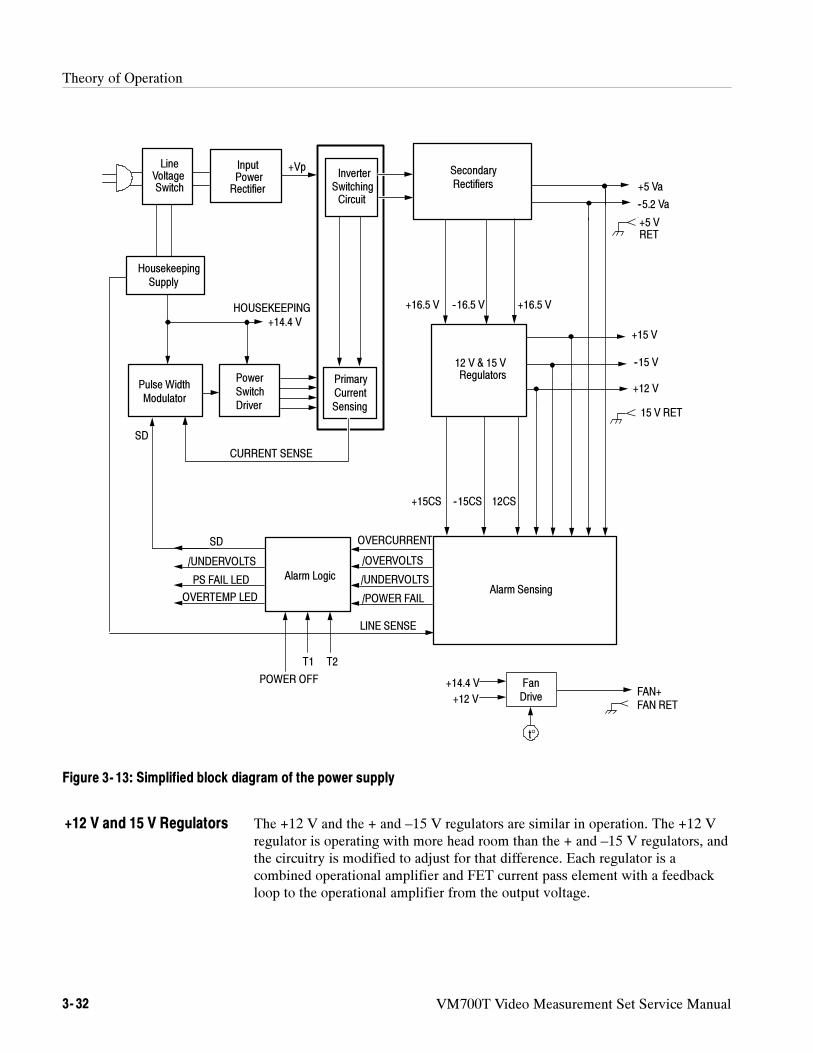
Theory of Operation
3- 32 VM700T Video Measurement Set Service Manual
/POWER FAIL
OVERCURRENT
/OVERVOLTS
/UNDERVOLTS
InputPowerRectifier
+VpInverter
SwitchingCircuit
Alarm LogicAlarm Sensing
+14.4 V
LINE SENSE
SD
+16.5 V --16.5 V
+5 Va
--5.2 Va
--15 V
--15CS+15CS
12 V & 15 VRegulators
+12 V
FAN+
/UNDERVOLTS
PS FAIL LED
OVERTEMP LED
T1 T2
POWER OFF
15 V RET
+5 VRET
Pulse WidthModulator
PowerSwitchDriver
HousekeepingSupply
LineVoltageSwitch
FanDrive
SecondaryRectifiers
FAN RET
12CS
+14.4 V
+15 V
+12 V
PrimaryCurrentSensing
+16.5 V
CURRENT SENSE
HOUSEKEEPING
SD
t°
Figure 3- 13: Simplified block diagram of the power supply
The +12 V and the + and –15 V regulators are similar in operation. The +12 Vregulator is operating with more head room than the + and –15 V regulators, andthe circuitry is modified to adjust for that difference. Each regulator is acombined operational amplifier and FET current pass element with a feedbackloop to the operational amplifier from the output voltage.
+12 V and 15 V Regulators
Theory of Operation
VM700T Video Measurement Set Service Manual 3- 33
The Alarm Sensing circuitry looks at the various supply voltages to check forundervoltage, overvoltage, overcurrent, and power fail conditions. The status ofthese conditions are the signals fed to the Alarm Logic circuitry.
Each of the alarm sensing outputs is monitored by the Alarm Logic circuitry.That circuitry also monitors the temperature sense signals. Depending on thestate of the sense signals, the Alarm Logic circuitry can issue a shutdown signal(SD) to the Pulse Width Modulator (PWM) to stop the power supply fromoperating. The Alarm Logic circuitry also drives the Over Temp LED and PSFail LED front-panel indicators as feedback to the user of the existing problem.
A separate Fan Drive circuit provides a temperature-related drive voltage to thefan. As the temperature rises, the fan is driven faster to compensate for the rise.The temperature sensing element for the voltage control is mounted on the 5 Vpower supply heat sink.
Option 40 Audio Measurements
This section describes the operation of the VM700T Video Measurement Setaudio option boards. The discussion provides the background informationneeded for fault isolation to the board level and board replacement; it does notinclude a component-level description (component-level circuit repair is beyondthe scope of this manual).
Audio Processor Board (A12)
The following paragraphs discuss the Audio processor board. Refer toFigure 3--14 as you read the discussion.
Alarm Sensing
Alarm Logic
Fan Drive
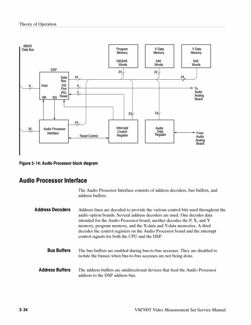
Theory of Operation
3- 34 VM700T Video Measurement Set Service Manual
68020Data Bus Program
MemoryX DataMemory
Y DataMemory
16K/64KWords
64KWords
64KWords
Interrupt/ControlRegister
AudioData
Register
Audio Processor
DSP
Host
DataBus
SSIPortIRQResetBG
Reset ControlFromAudioAnalogBoard
ToAudioAnalogBoard
8
32
24
24
24 24
24
2424
6
2
Interface
BR
Figure 3- 14: Audio Processor block diagram
Audio Processor Interface
The Audio Processor Interface consists of address decoders, bus buffers, andaddress buffers.
Address lines are decoded to provide the various control bits used throughout theaudio option boards. Several address decoders are used. One decodes dataintended for the Audio Processor board, another decodes the P, X, and Ymemory, program memory, and the X-data and Y-data memories. A thirddecodes the control registers on the Audio Processor board and the interruptcontrol signals for both the CPU and the DSP.
The bus buffers are enabled during bus-to-bus accesses. They are disabled toisolate the busses when bus-to-bus accesses are not being done.
The address buffers are unidirectional devices that feed the Audio Processoraddress to the DSP address bus.
Address Decoders
Bus Buffers
Address Buffers
Theory of Operation
VM700T Video Measurement Set Service Manual 3- 35
Interrupt Generator/Status Port
A function of this 32-bit control register is to control interrupts for the DSP(digital signal processor). It consists of an interrupt generator, data buffers, andread/write registers that hold the data for access when needed.
The interrupt generator contains the interrupt control lines for the DSP. Theinterrupts are generated by audio data. When enabled, left-channel audio dataand right-channel generate separate interrupts to keep the channel data separatedfor processing.
There are several data buffers. One data buffer holds the interrupts, the interruptenables, and the channel data indicator. The channel data indicator is used toindicate which channel data is held in the audio data register. That register isonly big enough to hold one sample, so it will contain either left channel data orright channel data (1 for left, 0 for right).
A second data buffer is a read-only buffer that holds the board version number.Software reads these bits to determine the hardware version installed in theVM700T. Other bits held in the data buffers indicate when a calibration is takingplace and show which audio option is installed (Option 40 or Option 41).
The reset register hold the reset bit as the last bit in the 32-bit interrupt register.When the audio processor resets, it sets the (RESET) line low to reset the DSP.This line stays low until the audio processor forces it high to start the DSP.
DSP Processor and I/O Interface
The DSP is the heart of the Audio Measurement System. The DSP has a 16-bitaddress bus and a 24-bit data bus. Devices on the DSP bus include addressdecoders and buffers used to provides the extra drive needed to drive the memoryload (18 memories).
A buffered oscillator running at 27.5 MHz provides the drive needed for theexternal clock input to the DSP.
The communication ports handle parallel data flow between the DSP and theCPU (the Host Port), and serial data flow to the D/A converters and controlregisters on the analog board. One of the communications ports allows commu-nications between the DSP and the CPU without having to do a bus request/busgrant operation. Another port is divided into two serial ports; one for serialcommunications and the other is the synchronous serial interface.
Interrupt Generator
Data Buffers
Reset Register
Oscillator
Communication Ports
Theory of Operation
3- 36 VM700T Video Measurement Set Service Manual
Audio Data Register
This register accepts serial data from the ADC on the analog board and convertsit to parallel data for the DSP or the CPU. A serial to parallel converter convertsthe serial data from either the ADC or the DSP (generated for diagnostics) to a24-bit parallel data word used by the DSP.
If the DSP is set to generate interrupts when audio data arrives, it must servicethe interrupts in a service routine. At the same time, the CPU can be trying toread or write data to the same address space being used by the DSP. The DSPalways gives up its bus to the CPU, but this can cause a problem. To avoid thisbus sharing problem, there is circuit that prevents CPU access to the bus duringthe data interrupt service routine.
Static RAM
The P (program), X (data), and Y (data) static RAM is composed of 18, 25-nsdevices. Each RAM is 4-bits wide, so six memory chips are used to make up the24-bit word. Each pair of chips accessed by the same write enable signalcorresponds to one 8-bit byte. Each byte has separate write enables, because theCPU accesses only a byte at a time. The static RAM is connected to the DSPaddress and data buses.
The program memory (the instructions for the DSP) may be held in either 16K X4 or 64K X 4 memory parts. Jumper connections on the board select the correctdevice memory size for the parts installed.
These memories are the X-data memory for the DSP and the Y-data memory.The DSP also has some small internal P, X, and Y memory. These three internalmemories (P, X, and Y) can be accessed at the same time by the DSP. Access tothe external P, X, and Y memories is one at a time. These memories are usedmainly for storing look-up tables and data and results (for example, fft and otherintermediate results are stored here).
The program instructions are loaded into the P memory from the audio processor.The usual action is for the audio processor to set the RESET bit to keep the DSPshut off and download the instructions into P memory. Then, the RESET isremoved, and the DSP executes the newly loaded code.
Each memory device has three memory control lines: WE (write enable), CE(chip enable), and OE (output enable). All memory devices are output enabled atthe same time; the read enable signals determine which memory is actuallyaccessed by the DSP.
CPU Access Disable
P Memory
X-Data andY-Data Memory
Program Loading
Control Lines
Theory of Operation
VM700T Video Measurement Set Service Manual 3- 37
Audio Analog Board (A13)
The following paragraphs discuss the Audio analog board. Refer to Figure 3--15as you read the discussion.
This section discusses the channel 2 (right channel) input amplifier, but thechannel 1 (left channel) input amplifier circuitry and function is the same. Theinput amplifiers are labeled on the board’s back panel.
The channel 2 analog signal enters the board through a 3-pin, mini-XLRconnector on the VM700T back panel. This connector is a balanced differentialinput. From the input, the analog signal is applied to NORM/CAL relay. Innormal operation, the relay is not energized, and the signal passes through (Caloperation is described later). The audio differential signal is AC-coupled toremove DC offset from the input signal.
NOTE. On option 41 boards, the analog signal enters through pins on a DB37
connector rather a mini-XLR connector. On Option 41 boards, relays select one
of the three different inputs for each channel. The control signals for these relays
travel on the audio-signal ribbon cable (but control and signal lines are isolated
by ground runs).
From the coupling capacitors, the signal is applied to an attenuator circuit. Eachstep of the attenuator is 10 dB. The default position provides unity gain (noattenuation). Attenuation steps of 10 dB and 20 dB are selectable.
The top of the range at unity gain is +10 dBu. With a 10 dB attenuator it is +20dBu, and with the maximum attenuation it is +30 dBu.
NOTE. Load resistance is not considered in measuring dBu. Similar to dBm, dBu
is voltage referenced only.
After exiting the stepped attenuator, the signal is applied to an input clampcircuit. The clamp circuit (±11.2 V input clamping) protects the operationalamplifier by holding its input below the supply voltage (low-noise performancecan be degraded or circuit devices can be damaged if input voltage exceedssupply). The nominal signal expected at the input to the amplifier is approxi-mately 3.5 V peak (just over 2 V rms).
The positive half and negative half of the differential signal are applied tooperational amplifiers that form an instrumentation amplifier. This is normally aunity gain stage, but it has selectable gain of 10 dB and 20 dB. The attenuatorpreceding can be 0 (no attenuation), --10 dB, or --20 dB. The differential input
Input Amplifiers
Signal Input
Stepped Attenuator
Input Amplifier
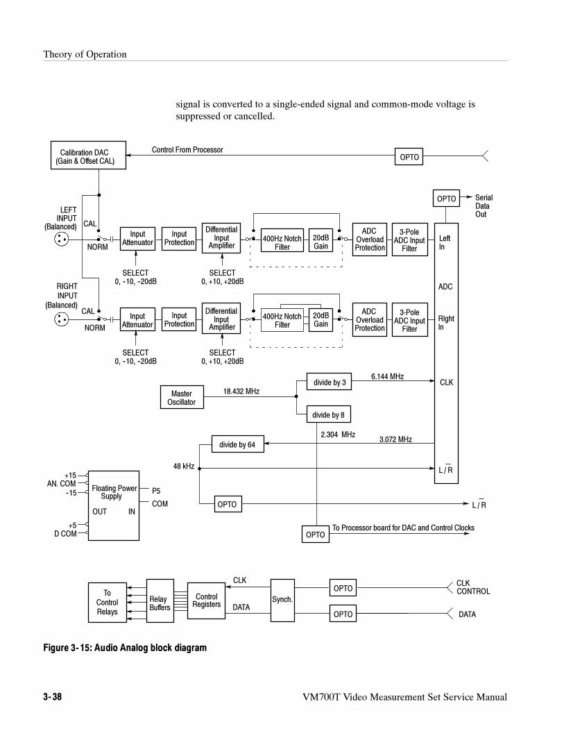
Theory of Operation
3- 38 VM700T Video Measurement Set Service Manual
signal is converted to a single-ended signal and common-mode voltage issuppressed or cancelled.
To Processor board for DAC and Control Clocks
divide by 3
RIghtIn
RIGHTINPUT
(Balanced)ADC
OverloadProtection
3-PoleADC InputFilter
DifferentialInput
Amplifier
InputProtection
InputAttenuator
CAL
NORM
400Hz NotchFilter
20dBGain
LEFTINPUT
(Balanced)ADC
OverloadProtection
3-PoleADC InputFilter
DifferentialInput
Amplifier
InputProtection
InputAttenuator
CAL
NORM
Calibration DAC(Gain & Offset CAL)
400Hz NotchFilter
ADC
20dBGain
LeftIn
SerialDataOut
L / R
CLK
MasterOscillator
18.432 MHz
OPTO
48 kHz
OPTO
OPTO
OPTO
DATA
CLKCONTROL
ControlRegisters DATA
CLK
Floating PowerSupply
P5
COM
6.144 MHz
2.304 MHz
SELECT0, --10, --20dB
SELECT0, +10, +20dB
Control From Processor
Synch.
3.072 MHz
OPTO
OPTO
L / R
divide by 8
divide by 64
+15AN. COM
+5D COM
--15
OUT IN
RelayBuffers
ToControlRelays
SELECT0, --10, --20dB
SELECT0, +10, +20dB
Figure 3- 15: Audio Analog block diagram
Theory of Operation
VM700T Video Measurement Set Service Manual 3- 39
400 Hz Notch Filter/DAC Output
The signal enters on the left and is applied to the contact arm of a relay thatswitches the notch filter in or out of the Channel 2 signal path. The filter isnormally out. When the relay is energized, the 400 Hz notch filter is inserted inthe signal path.
The notch filter circuitry has a bandpass filter at 400 Hz. The output of thebandpass filter is combined with the input signal. The gains are set 2:1 for aresulting output equal to the input signal minus the bandpass circuit output,forming a notch at 400 Hz. The output of notch filter goes to the A/D converter.
The incoming signal current from the DAC is applied to the summing junctionof a high-speed operational amplifier. This circuit converts the incoming currentto a signal voltage and applies it to the CAL side of the NORM/CAL relay.
Calibration Signals. There are two calibration signal choices:
The output of the DAC (used during diagnostics)
The output a high-speed, solid state switching device. This device selectseither ground or a high-precision 5 V reference and is chopped at 120 Hz.The symmetrical square wave developed by the switching is applied to theselected analog input through a coupling capacitor. Capacitive couplingshifts the DC level of the signal to ± 2.5 V. When the chop signal is notrunning, the output is at ground.
Calibration Channel Selection. A set of relay contacts determine the channel andside of the differential channel input that the calibration signal is applied to. Thecalibration selections signals drive this set of relays. In the unenergized state,channel 1 gets the calibration signal. The unselected channel is grounded.
Other relays switch the sense of the calibration signal so that both sides of thebalanced differential inputs may be calibrated using the single-ended calibrationsignal. During calibration the noninverting input is calibrated first, grounding theinverting input. When that half is finished, the relays switch to apply thecalibration signal to the inverting input to calibrate that side.
Notch Filter Operation
DAC Output
Theory of Operation
3- 40 VM700T Video Measurement Set Service Manual
Option 40 A/D Converter
The channel 1 and channel 2 circuits are identical; only the channel 2 circuit isdiscussed here.
The channel 2 signal is applied to a clamp circuit at the input of the amplifier.This clamp circuit protects the input of the A/D converter. The clamping circuitholds the input signal swing to approximately 4.4 volts peak (positive ornegative).
This circuit is actually a 150 kHz, low-pass filter. This filter is a 3-pole Besseltype circuit with exceptional phase performance.
The A/D converter is a delta-sigma type oversampling converter running at 64times the required output frequency. In this circuit, the 150 kHz low-pass filtercircuit at the input of the A/D converter provides anti-alias protection.
The analog data applied to the inputs of the A/D converter is processed by theconverter and output as serial digital data. The left/right channel data iscontrolled by the L/(R) signal and alternated in the data stream.
A/D Converter Self Cal. The CAL signal applied to the A/D converter causes a selfcalibration on the falling edge of the signal. During the self cal time, the A/Dconverter checks the DC offset on its analog inputs. The offset is stored in aregister and subtracted from the data sent from the converter. This operationzeros the internal offset of the converter and any offset generated by theoperational amplifiers (or any other DC offset) in front of the inputs. Up to250 mV offsets can be removed, but the usual offsets are not more than 10 mV.
During the Self Cal (offset calibration) a signal is sent to the DSP to keep it frominterrupting the A/D converter during calibration. That signal is removed whencalibration is complete.
Audio Board Control
The control signals sent between the audio digital and the audio analog board areoptically isolated, with one exception. The (CLR) signal, entering the analogboard is inverted to a CLR signal. This signal turns on the 2.304 MHz DACclock when the DAC is operating.
Five opto-isolators isolate the signals between the boards and allow the analogground on the audio board to float (to remain ungrounded from chassis or earthground).
Input Clamp
CH 2 (and CH 1) Amplifier
A/D Converter
Opto-Isolators
Theory of Operation
VM700T Video Measurement Set Service Manual 3- 41
Analog board input signals to be isolated enter the board through a buffer. Thebuffer receives its power from the VM700T.
The input signals enter through two of the opto-isolators (each device is a dualopto-isolator). The signals sent from the isolators are referenced to analog boardground. This means that the analog board digital ground and the digital boardground are not the same.
The other three opto-isolators take signals from the analog board and isolatethem for output to the digital board. These signals (associated with the A/Dconverter) are applied to a buffer to drive the opto-isolators.
The open-collector outputs of the opto-isolators are pulled high, in case a faultcauses the lines to be undriven.
The digital signals from the opto-isolators are synchronized to the clock signal.
After the signals are synchronized, they go to a counter/decoder circuit. Two ofthe signals determine the state of operation (diagnostics mode, dumping data tothe DACs, or receiving data from the A/D converter).
The Control Register is a 24-bit register (three 8-bit shift registers) that holds thecontrol word that controls operating states on the analog board. The serial controlword is clocked into the shift registers.
The control bits from the relay control register are buffered by relay drivers todrive the state-controlling relays.
The master oscillator is a integrated-circuit oscillator generating a signal at18.432 MHz. The 18.432 MHz signal divided by 3 and reapplied to the A/Dconverter.
Inside the A/D converter, the 6.144 MHz input clock is divided by 2 to3.072 MHz and supplied as an output. The 3.072 MHz clock is also provided asan inverted output by the A/D converter.
The 3.072 MHz clock is applied to a multiple divide-by-two divider, where it isdivided by 64 to supply the 48 kHz that is the effective sampling rate. That48 kHz is applied to the L/R input of the A/D converter.
The 48 kHz and the 3.072 MHz clock are also sent off the analog board.
The 18.432 MHz signal is also divided by 8 to produce a 2.034 MHz signal usedby the digital-to-analog converters. This signal clocks the control word to thecontrol registers.
Synchronizer
Counter/Decoder
Control Register
Master Oscillator andClock Divider
Theory of Operation
3- 42 VM700T Video Measurement Set Service Manual
A control signal used to hold off the 2.034 MHz. When the signal is low, the2.034 MHz is not generated. The signal is generated only when diagnostics arerun or when a new control word is written for changing gain or attenuation.
The DAC is an 18-bit D/A converter. Serial digital data sent by the DSP and aclock signal that is replicated by the DSP are applied to the DSP.
A shift register realigns the 24-bit data from the DSP so that valid data isshipped to the 18-bit DAC. The DAC expects leading, not trailing zeros, so theshift register shifts the data six bits for proper alignment.
This DAC circuit is used in diagnostics (discussed later).
The output of the DAC is a current signal is converted to a voltage signal.
Floating Power Supply
The mainframe interconnector provides +5 V and ground from the VM700T.The +5 V powers two low-noise, high-accuracy switching supplies.
One supply provides +5 volts at 1 ampere; the second switching supply provides+15 V and --15 V at 330 mA. This floating power supply isolates the analogcircuitry from possible noise sources in the VM700T power supplies.
The + and --15 V supplies are used to provide regulated + and --5V to the analogboard through three-terminal regulators. These + and --5 volt analog suppliespower the A/D converter and the DAC.
Several different grounds are used in the instrument. The grounds are separatedto keep ground loop signals and noises from being transferred via the groundingplanes of the circuit board.
Option 41 Audio Analog Board
The Audio Analog circuit board, A17A1, is identical to the A13 Audio Analogcircuit board in parts and operation. Option 41 provides an added circuit board,A17A2, to do the input channel selection from the three audio inputs. TheA17A2 circuit board along with the A17A1 (A13) circuit board make up the A17circuit board assembly for Option 41.
Selection of the left and right input signal source from one of the three possibleinputs of Option 41 is done by a set of relays and a relay selector/driver deviceon the A17A2 circuit board. Figure 3--16 shows a simplified diagram of the left
Calibration DAC
Grounds
6 Balanced Input Selector
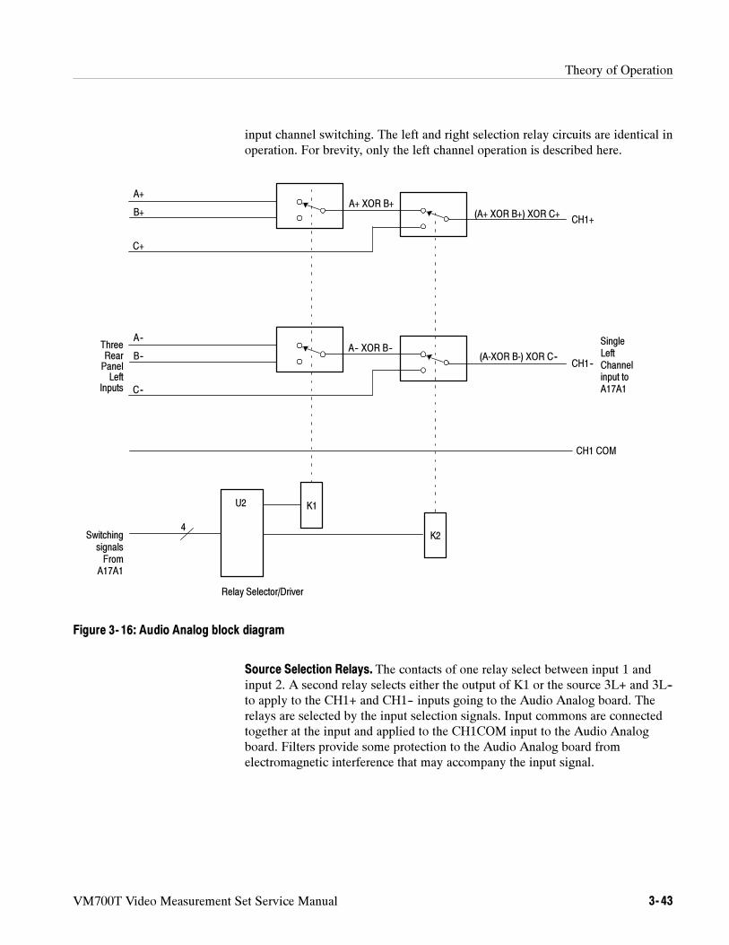
Theory of Operation
VM700T Video Measurement Set Service Manual 3- 43
input channel switching. The left and right selection relay circuits are identical inoperation. For brevity, only the left channel operation is described here.
ThreeRearPanelLeft
Inputs
U2 K1
K2
Relay Selector/Driver
SwitchingsignalsFrom
A17A1
4
(A-XOR B-) XOR C--
C--
B--
A--
CH1--
CH1 COM
SingleLeftChannelinput toA17A1
(A+ XOR B+) XOR C+
C+
B+
A+
CH1+
A+ XOR B+
A-- XOR B--
Figure 3- 16: Audio Analog block diagram
Source Selection Relays. The contacts of one relay select between input 1 andinput 2. A second relay selects either the output of K1 or the source 3L+ and 3L--to apply to the CH1+ and CH1-- inputs going to the Audio Analog board. Therelays are selected by the input selection signals. Input commons are connectedtogether at the input and applied to the CH1COM input to the Audio Analogboard. Filters provide some protection to the Audio Analog board fromelectromagnetic interference that may accompany the input signal.
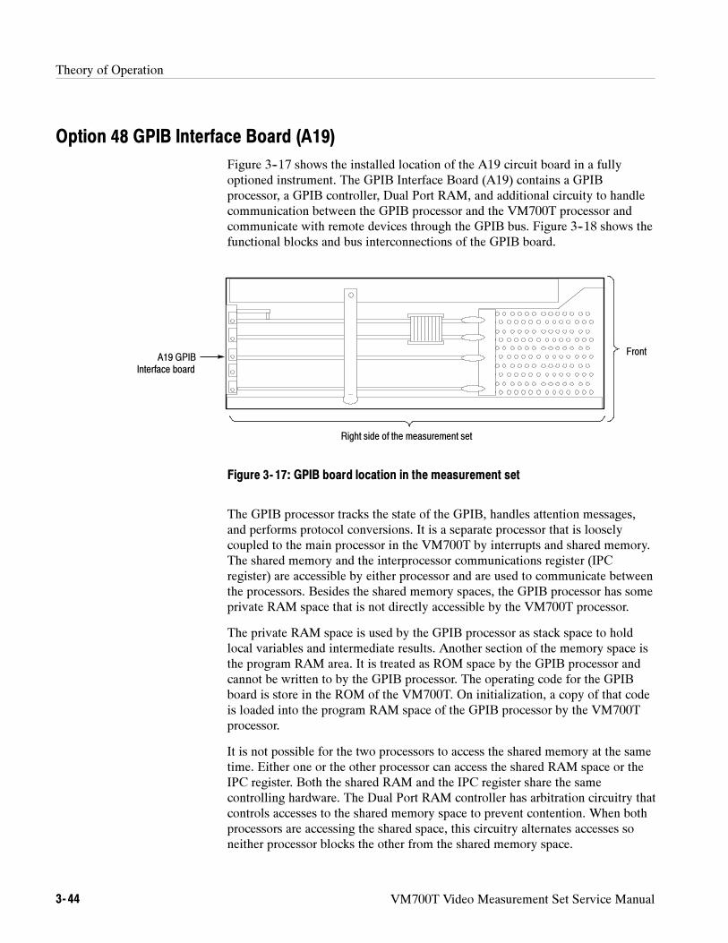
Theory of Operation
3- 44 VM700T Video Measurement Set Service Manual
Option 48 GPIB Interface Board (A19)
Figure 3--17 shows the installed location of the A19 circuit board in a fullyoptioned instrument. The GPIB Interface Board (A19) contains a GPIBprocessor, a GPIB controller, Dual Port RAM, and additional circuity to handlecommunication between the GPIB processor and the VM700T processor andcommunicate with remote devices through the GPIB bus. Figure 3--18 shows thefunctional blocks and bus interconnections of the GPIB board.
A19 GPIBInterface board
Front
Right side of the measurement set
Figure 3- 17: GPIB board location in the measurement set
The GPIB processor tracks the state of the GPIB, handles attention messages,and performs protocol conversions. It is a separate processor that is looselycoupled to the main processor in the VM700T by interrupts and shared memory.The shared memory and the interprocessor communications register (IPCregister) are accessible by either processor and are used to communicate betweenthe processors. Besides the shared memory spaces, the GPIB processor has someprivate RAM space that is not directly accessible by the VM700T processor.
The private RAM space is used by the GPIB processor as stack space to holdlocal variables and intermediate results. Another section of the memory space isthe program RAM area. It is treated as ROM space by the GPIB processor andcannot be written to by the GPIB processor. The operating code for the GPIBboard is store in the ROM of the VM700T. On initialization, a copy of that codeis loaded into the program RAM space of the GPIB processor by the VM700Tprocessor.
It is not possible for the two processors to access the shared memory at the sametime. Either one or the other processor can access the shared RAM space or theIPC register. Both the shared RAM and the IPC register share the samecontrolling hardware. The Dual Port RAM controller has arbitration circuitry thatcontrols accesses to the shared memory space to prevent contention. When bothprocessors are accessing the shared space, this circuitry alternates accesses soneither processor blocks the other from the shared memory space.
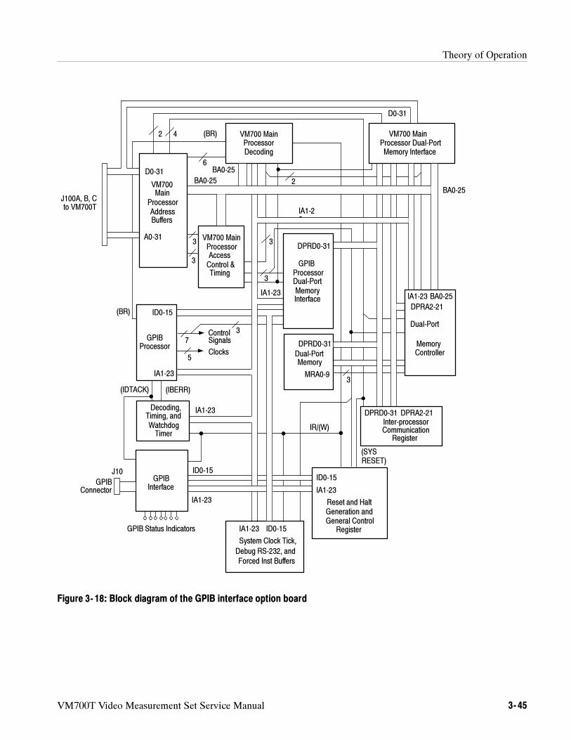
Theory of Operation
VM700T Video Measurement Set Service Manual 3- 45
D0-31
IR/(W)
3
1
IA1-23
BA0-25
DPRD0-31
DPRA2-21
IA1-23
BA0-25
MRA0-9
DPRD0-31
ID0-15
IA1-23
IA1-23
GPIBProcessorDual-PortMemoryInterface
IA1-23
ID0-15
IA1-23
DPRD0-31
BA0-25
GPIBInterface
J10
System Clock Tick,
Debug RS-232, and
Forced Inst Buffers
ID0-15
Reset and HaltGeneration andGeneral Control
Register
Decoding,Timing, andWatchdogTimer
GPIBProcessor
Inter-processorCommunication
Register
Dual-PortMemory
Dual-Port
MemoryController
VM700 Main
BA0-25
VM700 MainProcessorAccessControl &Timing
VM700 MainProcessorDecoding
ID0-15
J100A, B, Cto VM700T
GPIBConnector
2
3
6
3
42
(SYSRESET)
3
DPRA2-21
IA1-23
3
IA1-23
GPIB Status Indicators
VM700Main
ProcessorAddressBuffers
(BR)
(IDTACK) (IBERR)
(BR)
5Clocks
ControlSignals7
3
Processor Dual-PortMemory Interface
D0-31
A0-31
Figure 3- 18: Block diagram of the GPIB interface option board
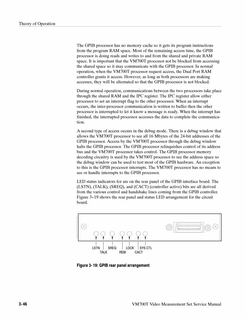
Theory of Operation
3- 46 VM700T Video Measurement Set Service Manual
The GPIB processor has no memory cache so it gets its program instructionsfrom the program RAM space. Most of the remaining access time, the GPIBprocessor is doing reads and writes to and from the shared and private RAMspace. It is important that the VM700T processor not be blocked from accessingthe shared space so it may communicate with the GPIB processor. In normaloperation, when the VM700T processor request access, the Dual Port RAMcontroller grants it access. However, as long as both processors are makingaccesses, they will be alternated so that the GPIB processor is not blocked.
During normal operation, communications between the two processors take placethrough the shared RAM and the IPC register. The IPC register allow eitherprocessor to set an interrupt flag to the other processor. When an interruptoccurs, the inter-processor communication is written to buffer then the otherprocessor is interrupted to let it know a message is ready. When the interrupt hasfinished, the interrupted processor accesses the data to complete the communica-tion.
A second type of access occurs in the debug mode. There is a debug window thatallows the VM700T processor to see all 16 Mbytes of the 24-bit addresses of theGPIB processor. Access by the VM700T processor through the debug windowhalts the GPIB processor. The GPIB processor relinquishes control of its addressbus and the VM700T processor takes control. The GPIB processor memorydecoding circuitry is used by the VM700T processor to see the address space sothe debug window can be used to test most of the GPIB hardware. An exceptionto this is the GPIB processor interrupts. The VM700T processor has no means tosee or handle interrupts to the GPIB processor.
LED status indicators for are on the rear panel of the GPIB interface board. The(LSTN), (TALK), (SREQ), and (CACT) (controller active) bits are all derivedfrom the various control and handshake lines coming from the GPIB controller.Figure 3--19 shows the rear panel and status LED arrangement for the circuitboard.
LSTN
TALK
SREQ
REM CACT
SYS CTLLOCK
Figure 3- 19: GPIB rear panel arrangement
Theory of Operation
VM700T Video Measurement Set Service Manual 3- 47
Option 1S Serial Digital Measurements
Option 1S is composed of three boards: the SDI Rear Panel Interface assembly,the SDI board, and a modified Acquisition Memory board.
The SDI Rear Panel Interface assembly contains the low-distortion loopthroughcircuitry for both the SDI Channel A and the Analog Reference inputs. For theother signal connectors, the purpose of the assembly is to provide physicalconnections for the signals into the measurement set.
The SDI board contains the analog and digital processing circuitry for the SDIapplications. The board’s purpose is to perform a variety of conversions on theincoming signals so they can be acquired by the Acquisition Memory board. TheSDI Board is split between a digital signal path and an analog data path. Thecircuit blocks of each data path, shown in Figure 3--20, is discussed below.
Digital Signal Path. The digital signal path is comprised of the following blocks asshown in Figure 3--20:
Equalizer. For SDI signals, the equalizer actively compensates for the distortionsthat occur when the SDI signal travels down a length of cable. The equalizeramplifies the signal and reshapes the waveform to make the edges fairly distinct.
Clock Recovery. This block is a phase-locked loop that creates a regular clockfrom the irregular data transitions that are contained within the SDI stream.
Deserializer. The deserializer takes the SDI data stream from the equalizer, andthe clock recovered from the clock-recovery circuitry, to convert the serializeddata into 10-bit parallel data. The alignment of the serial data is determined fromthe embedded TRS marks. Since they are the only data patterns where all 10 bitsare either zeros or ones, they provide a clear indication of how the data words arealigned in the SDI data stream.
Line and Frame Synthesizer. This block examines the 10-bit parallel data streamto identify the TRS marks that indicate line and frame transitions. For linetransitions, the synthesizer sets the line bit according to the H bit in the TRSXYZ word. For frame transitions, the synthesizer sets the frame bit according tothe V bit in the TRS XYZ word. The V bit is deglitched by requiring eightconsecutive XYZ words (four lines) with the V bit having the new value beforeactually setting the V bit itself.
Channel Selection MUX. The channel selection MUX selects between the twoSDI channels.
EDH Coprocessor. The EDH coprocessor detects and decodes EDH errors. Thecoprocessor also participates in the automatic rate detection function.
SDI Rear Panel InterfaceAssembly
SDI Board
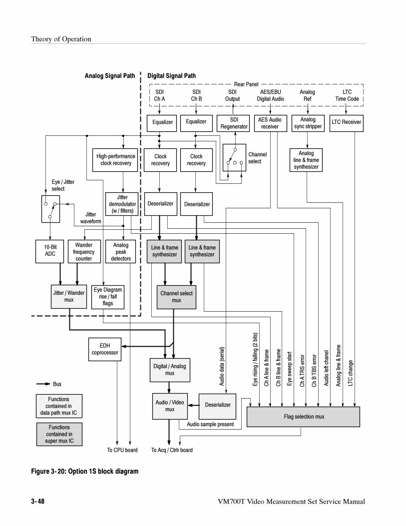
Theory of Operation
3- 48 VM700T Video Measurement Set Service Manual
Audiodata(serial)
Audio sample present
ChAline&fram
e
ChBline&fram
e
Eye
sweepstart
ChATRSerror
ChBTBSerror
Analogline&fram
e
LTCchange
Audioleftchanel
10-BitADC
Eye Diagramrise / fallflags
Jitter / Wandermux
Eye / Jitterselect
Wanderfrequencycounter
High-performanceclock recovery
Jitterdemodulator(w / filters)
Analogpeak
detectors
Equalizer
Clockrecovery
Deserializer
Channel selectmux
Equalizer
Clockrecovery
Deserializer
EDHcoprocessor
Digital / Analogmux
Audio / Videomux
Deserializer
Flag selection mux
SDICh A
SDICh B
SDIOutput
SDIRegenerator
Channelselect
AES/EBUDigital Audio
AES Audioreceiver
AnalogRef
Analogsync stripper
Analogline & framesynthesizer
LTCTime Code
LTC Receiver
Jitterwaveform
To Acq / Ctrlr board
Functionscontained in
data path mux IC
Eye
rising/falling(2bits)
Line & framesynthesizer
Line & framesynthesizer
To CPU board
Functionscontained insuper mux IC
Bus
Analog Signal Path Digital Signal Path
Rear Panel
Figure 3- 20: Option 1S block diagram
Theory of Operation
VM700T Video Measurement Set Service Manual 3- 49
Analog/Digital MUX. The analog/digital MUX selects between the Channel Aanalog data stream and the digital data stream.
Audio/Video MUX. The audio/video MUX selects between the analog or digitaldata stream and the audio data stream. It also has the capability to insert theexternal audio data stream in place of the SDI chrominance samples of the datastream for A/V timing measurements of external audio.
Flag Selection MUX. The SDI board has many status lines that can be multi-plexed onto the six flag lines into the Acquisition Memory board. The flagselection MUX controls this mapping.
Analog Data Path. The analog signal path is comprised of the following blocks asshown in Figure 3--20:
High-Performance Clock Recovery. This block performs the same function as theregular clock recovery function block, but it has been calibrated and has a fargreater jitter tolerance.
Jitter Demodulator. The jitter demodulator converts timing variations in therecovered clock into an analog voltage. Various filters can be selected for theoutput that goes to the 10-bit ADC.
Analog Peak Detectors. This block tracks the analog control voltage from thejitter demodulator. The detectors have rapid charging and slow decay.
10-Bit ADC. The 10-Bit ADC block is used to generate the samples for the eyediagram and for the jitter waveform. When fed the raw SDI signal and clockedby the output of the High-Performance Clock Recovery block, the ADCgenerates Eye information. When fed the control voltage from the jitterdemodulator, it generates the jitter waveform.
Wander Detector. The Wander Detector block uses a high-precision oscillator toprovide the time base for precise measurement of minute differences in theinterval between TRS marks. This timing information is sent down the analogdata path for further processing by the instrument software.
SDI Regenerator. The SDI regenerator takes the signal from the equalizer for useas the SDI signal to be output. It does not regenerate the clock.
NOTE. The signal from the SDI Ch. A input to the SDI regenerator is interrupted
whenever an analog application is run.
AES Audio Receiver. The AES audio receiver recovers the external audio serialdata stream. It outputs a serial data stream that is converted to parallel data bythe audio/video MUX.
Theory of Operation
3- 50 VM700T Video Measurement Set Service Manual
Analog Sync Detector. The analog sync detector recovers line and frame syncfrom the Analog Reference input signal.
LTC Receiver. The LTC Receiver block translates the LTC signal into registersthat can be read by the CPU.
The modified Acquisition Memory board contains all the analog circuitry, plus aseries of MUX’s to select between the analog and digital data streams and tochange the handling of the flags portion of the data stream. The AcquisitionMemory board also adds a FIFO that allows the controller state machine tocommunicate information to the CPU without having to place the information inacquisition memory. (This is the FIFO that the SDI_Format application’s FIFOOverflow error refers to.)
Modified AcquisitionMemory Board
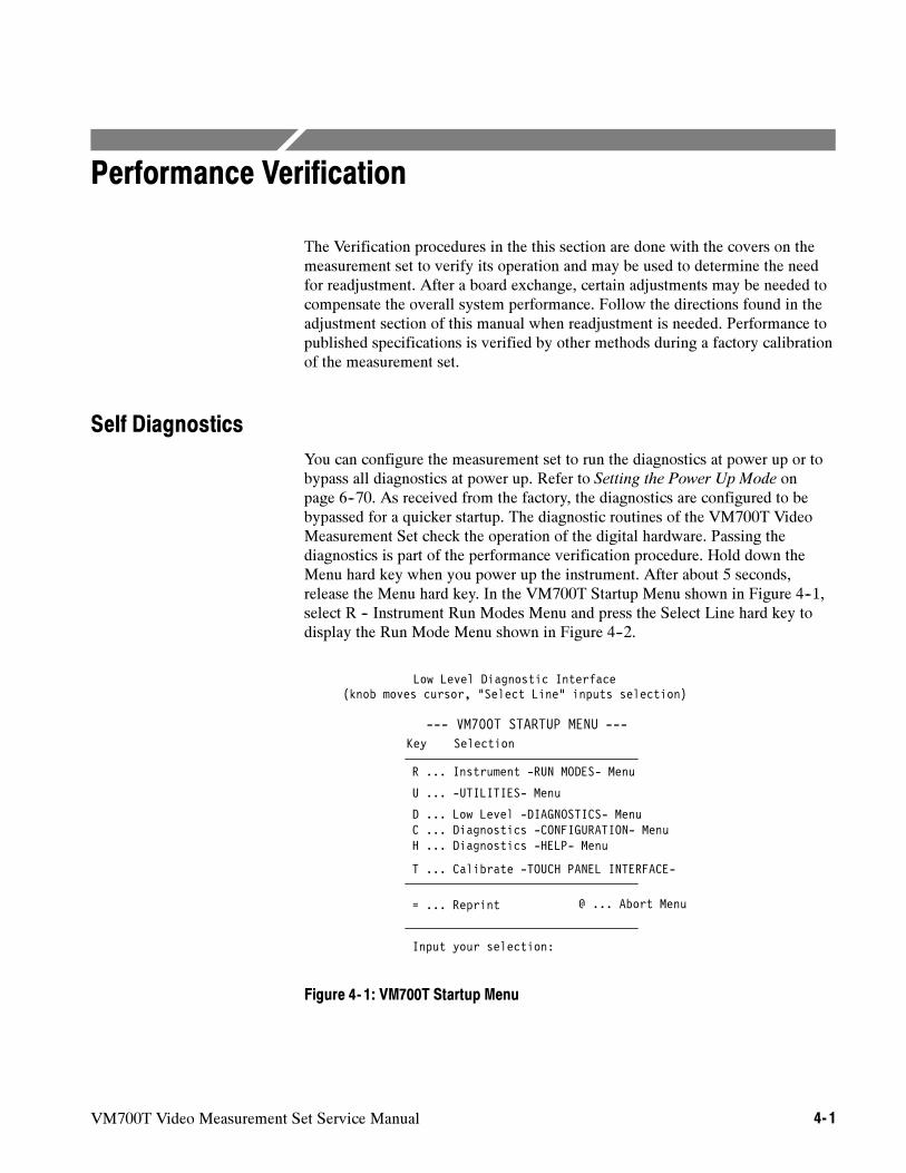
VM700T Video Measurement Set Service Manual 4- 1
Performance Verification
The Verification procedures in the this section are done with the covers on themeasurement set to verify its operation and may be used to determine the needfor readjustment. After a board exchange, certain adjustments may be needed tocompensate the overall system performance. Follow the directions found in theadjustment section of this manual when readjustment is needed. Performance topublished specifications is verified by other methods during a factory calibrationof the measurement set.
Self Diagnostics
You can configure the measurement set to run the diagnostics at power up or tobypass all diagnostics at power up. Refer to Setting the Power Up Mode onpage 6--70. As received from the factory, the diagnostics are configured to bebypassed for a quicker startup. The diagnostic routines of the VM700T VideoMeasurement Set check the operation of the digital hardware. Passing thediagnostics is part of the performance verification procedure. Hold down theMenu hard key when you power up the instrument. After about 5 seconds,release the Menu hard key. In the VM700T Startup Menu shown in Figure 4--1,select R -- Instrument Run Modes Menu and press the Select Line hard key todisplay the Run Mode Menu shown in Figure 4--2.
Low Level Diagnostic Interface(knob moves cursor, “Select Line” inputs selection)
Key Selection
H ... Diagnostics -HELP- Menu
R ... Instrument -RUN MODES- Menu
D ... Low Level -DIAGNOSTICS- Menu
= ... Reprint
Input your selection:
U ... -UTILITIES- Menu
T ... Calibrate -TOUCH PANEL INTERFACE-
--- VM700T STARTUP MENU ---
C ... Diagnostics -CONFIGURATION- Menu
@ ... Abort Menu
Figure 4- 1: VM700T Startup Menu
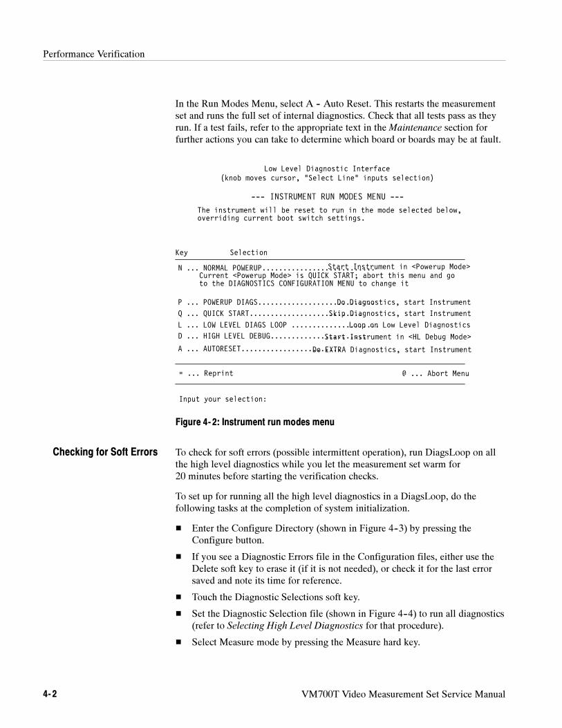
Performance Verification
4- 2 VM700T Video Measurement Set Service Manual
In the Run Modes Menu, select A -- Auto Reset. This restarts the measurementset and runs the full set of internal diagnostics. Check that all tests pass as theyrun. If a test fails, refer to the appropriate text in theMaintenance section forfurther actions you can take to determine which board or boards may be at fault.
to the DIAGNOSTICS CONFIGURATION MENU to change it
Low Level Diagnostic Interface(knob moves cursor, “Select Line” inputs selection)
Key Selection
D ... HIGH LEVEL DEBUG.......................
N ... NORMAL POWERUP...........................
P ... POWERUP DIAGS............................
= ... Reprint
Input your selection:
--- INSTRUMENT RUN MODES MENU ---
L ... LOW LEVEL DIAGS LOOP .....................
Do Diagnostics, start Instrument
Loop on Low Level Diagnostics
Start Instrument in <HL Debug Mode>
@ ... Abort Menu
Start Instrument in <Powerup Mode>
The instrument will be reset to run in the mode selected below,overriding current boot switch settings.
Current <Powerup Mode> is QUICK START; abort this menu and go
A ... AUTORESET........................Do EXTRA Diagnostics, start Instrument
Q ... QUICK START...........................Skip Diagnostics, start Instrument
Figure 4- 2: Instrument run modes menu
To check for soft errors (possible intermittent operation), run DiagsLoop on allthe high level diagnostics while you let the measurement set warm for20 minutes before starting the verification checks.
To set up for running all the high level diagnostics in a DiagsLoop, do thefollowing tasks at the completion of system initialization.
Enter the Configure Directory (shown in Figure 4--3) by pressing theConfigure button.
If you see a Diagnostic Errors file in the Configuration files, either use theDelete soft key to erase it (if it is not needed), or check it for the last errorsaved and note its time for reference.
Touch the Diagnostic Selections soft key.
Set the Diagnostic Selection file (shown in Figure 4--4) to run all diagnostics(refer to Selecting High Level Diagnostics for that procedure).
Select Measure mode by pressing the Measure hard key.
Checking for Soft Errors
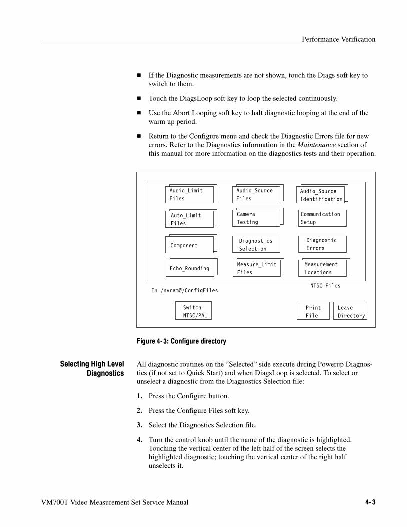
Performance Verification
VM700T Video Measurement Set Service Manual 4- 3
If the Diagnostic measurements are not shown, touch the Diags soft key toswitch to them.
Touch the DiagsLoop soft key to loop the selected continuously.
Use the Abort Looping soft key to halt diagnostic looping at the end of thewarm up period.
Return to the Configure menu and check the Diagnostic Errors file for newerrors. Refer to the Diagnostics information in theMaintenance section ofthis manual for more information on the diagnostics tests and their operation.
Audio_Limit
Files
Switch
NTSC/PAL
File
Leave
Directory
In /nvramØ/ConfigFiles
Audio_Source
FilesAudio_Source
Identification
Auto_Limit
Files
Communication
Setup
Component
NTSC Files
Diagnostic
ErrorsDiagnostics
Selection
Echo_RoundingMeasure_Limit
Files
Measurement
Locations
Camera
Testing
Figure 4- 3: Configure directory
All diagnostic routines on the “Selected” side execute during Powerup Diagnos-tics (if not set to Quick Start) and when DiagsLoop is selected. To select orunselect a diagnostic from the Diagnostics Selection file:
1. Press the Configure button.
2. Press the Configure Files soft key.
3. Select the Diagnostics Selection file.
4. Turn the control knob until the name of the diagnostic is highlighted.Touching the vertical center of the left half of the screen selects thehighlighted diagnostic; touching the vertical center of the right halfunselects it.
Selecting High LevelDiagnostics
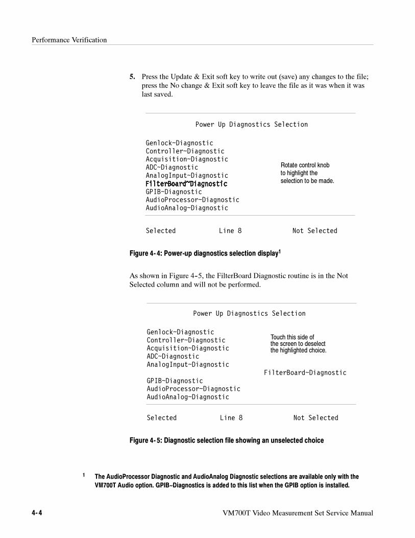
Performance Verification
4- 4 VM700T Video Measurement Set Service Manual
5. Press the Update & Exit soft key to write out (save) any changes to the file;press the No change & Exit soft key to leave the file as it was when it waslast saved.
Power Up Diagnostics Selection
Genlock~DiagnosticController~DiagnosticAcquisition~DiagnosticADC~DiagnosticAnalogInput~Diagnostic
GPIB~DiagnosticAudioProcessor~DiagnosticAudioAnalog~Diagnostic
Selected Line 8 Not Selected
Rotate control knobto highlight theselection to be made.
Figure 4- 4: Power-up diagnostics selection display1
As shown in Figure 4--5, the FilterBoard Diagnostic routine is in the NotSelected column and will not be performed.
Power Up Diagnostics Selection
Genlock~DiagnosticController~DiagnosticAcquisition~DiagnosticADC~DiagnosticAnalogInput~Diagnostic
FilterBoard~DiagnosticGPIB~DiagnosticAudioProcessor~DiagnosticAudioAnalog~Diagnostic
Selected Line 8 Not Selected
Touch this side ofthe screen to deselectthe highlighted choice.
Figure 4- 5: Diagnostic selection file showing an unselected choice
1 The AudioProcessor Diagnostic and AudioAnalog Diagnostic selections are available only with the
VM700T Audio option. GPIB~Diagnostics is added to this list when the GPIB option is installed.
Performance Verification
VM700T Video Measurement Set Service Manual 4- 5
When high-level diagnostics are run, any errors detected are written to theDiagnostic Errors file. The contents of this file can be printed using the Print Filesoft key, or the file can be deleted using the Delete soft key.
If diagnostic errors appear, refer to the Diagnostics information starting onpage 6--55.
The maximum capacity for the Diagnostic Errors file is 100 lines. If the numberof errors detected causes the file to exceed this length, the earlier results arescrolled out of the file buffer. When this occurs, the Diagnostic Errors fileincludes a message stating that some of the text has been scrolled out of the file.
Diagnostic Errors (File)
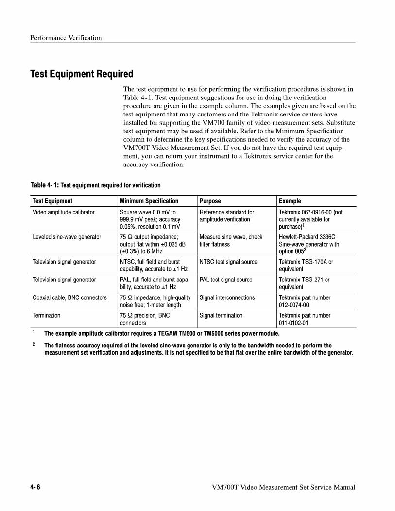
Performance Verification
4- 6 VM700T Video Measurement Set Service Manual
Test Equipment Required
The test equipment to use for performing the verification procedures is shown inTable 4--1. Test equipment suggestions for use in doing the verificationprocedure are given in the example column. The examples given are based on thetest equipment that many customers and the Tektronix service centers haveinstalled for supporting the VM700 family of video measurement sets. Substitutetest equipment may be used if available. Refer to the Minimum Specificationcolumn to determine the key specifications needed to verify the accuracy of theVM700T Video Measurement Set. If you do not have the required test equip-ment, you can return your instrument to a Tektronix service center for theaccuracy verification.
Table 4- 1: Test equipment required for verification
Test Equipment Minimum Specification Purpose Example
Video amplitude calibrator Square wave 0.0 mV to999.9 mV peak; accuracy0.05%, resolution 0.1 mV
Reference standard foramplitude verification
Tektronix 067-0916-00 (notcurrently available forpurchase)1
Leveled sine-wave generator 75Ω output impedance;output flat within ±0.025 dB(±0.3%) to 6 MHz
Measure sine wave, checkfilter flatness
Hewlett-Packard 3336CSine-wave generator withoption 0052
Television signal generator NTSC, full field and burstcapability, accurate to ±1 Hz
NTSC test signal source Tektronix TSG-170A orequivalent
Television signal generator PAL, full field and burst capa-bility, accurate to ±1 Hz
PAL test signal source Tektronix TSG-271 orequivalent
Coaxial cable, BNC connectors 75Ω impedance, high-qualitynoise free; 1-meter length
Signal interconnections Tektronix part number012-0074-00
Termination 75Ω precision, BNCconnectors
Signal termination Tektronix part number011-0102-01
1 The example amplitude calibrator requires a TEGAM TM500 or TM5000 series power module.
2 The flatness accuracy required of the leveled sine-wave generator is only to the bandwidth needed to perform themeasurement set verification and adjustments. It is not specified to be that flat over the entire bandwidth of the generator.
Performance Verification
VM700T Video Measurement Set Service Manual 4- 7
System Verification Procedures
NOTE. If the results yielded by the verification procedures in this section are
within the limits specified, further adjustment is not necessary and is not
recommended. Adjusting the measurement set unnecessarily (for example, to get
a “better” reading on a calibration result that is within limits) can introduce
errors into a functional instrument.
NOTE. This equipment requires a 20 minute warm-up period before starting the
verification procedures. The measurement set must be powered on for at least 20
minutes.
This procedure checks the amplitude accuracy of the instrument. An externallyapplied precision reference signal is used to check the complete signal paththrough the measurement set.
Test Equipment Required
Video amplitude calibration fixture (VAC). Tektronix 067-0916-00.
Coaxial cable, 75 Ω high-quality noise free; 1-meter length. Tektronix012-0074-00.
Procedure: Measure Squarewave
1. Connect the VAC to channel A of the measurement set (leave the inputunterminated).
2. Set the controls of the VAC for NTSC, +LUM, and 700.0 mV.
3. On the measurement set, press the Measure key, the Diags soft key (if notalready in Diagnostics mode), and the Measure Squarewave soft key.
4. Check the measurement set for a reading of 700 mV ± 2.1 mV.
NOTE. If the voltage measured in step 4 is out of the specified limits, go to
Adjust the Calibration DAC on page 5--9 in the Adjustment Procedure section.
5. Move the test signal and select the appropriate channel to repeat the checkfor channel B and channel C.
6. Disconnect the VAC from the measurement set.
Measure Squarewave
Performance Verification
4- 8 VM700T Video Measurement Set Service Manual
This procedure is to be used as a check for proper measurement set system leveladjustment. It checks the frequency response flatness over the instrument’soperating range.
Test Equipment Required
Leveled sine-wave generator, 75 Ω output impedance, output flat within±0.025 dB (±0.3%) to 6 MHz. Example: HP 3336C with option 005.
Termination, 75 Ω precision BNC. Tektronix 011-0102-01, or equivalent.
Coaxial cable, 75 Ω high-quality noise free; 1-meter length. Tektronix012-0074-00.
Procedure: Measure Sinewave
1. Connect the leveled sine-wave generator output to the measurement setchannel to be tested (start with channel A). Terminate the channel loop-through output connection in 75 Ω.
2. Set the leveled sine-wave generator for 50 kHz at an output level of 500 mVinto 75 Ω.
NOTE. If the example leveled sine-wave generator is being used, the output level
should be set for –3.81 dBm.
3. Press the Measure hardkey, then, if necessary, display the measurement setDiagnostics directory by pressing the Diags soft key. In diagnostics, run thesine-wave measurement application by pressing the Measure~Sinewave softkey.
4. After the measurement application has initialized, turn Averaging on bypressing the Average hardkey until the Average hardkey light is lit. When thedisplay stabilizes, press the Freeze hardkey. The Delta Amp reading shouldremain at 0. If the Delta Amp reading changes, press the Freeze key again, asmany times as needed, until the Delta Amp reading remains at 0. This is nowthe reference to which all other measurements are compared.
5. Set the leveled sine-wave generator for a frequency of 4.43 MHz; do notchange the output level.
6. To speed up the response to the frequency change, toggle the Averagehardkey off, then back on again after the display has re-stabilized.
7. Check that the amplitude is within ±0.5% (Delta Amp of ± 0.5% or less) ofthe 50 kHz reference level stored in step 4.
8. Set the leveled sine-wave generator for 5.8 MHz; do not change the outputlevel.
Measure Sinewave
Performance Verification
VM700T Video Measurement Set Service Manual 4- 9
9. Again, to speed up the response to the frequency change, toggle the Averagehardkey off, then back on again after the display has re-stabilized.
10. Check that the amplitude is within ±0.55% of the reference level stored instep 4.
11. Change the TV Standard parameter from PAL to NTSC by pressing the XYArrow hardkey. Change the filter selection from No Filter to the NTSCbandwidth limiting filter by pressing the Move/Expand hardkey until thefilter displays NTSC BW Lim.
12. Return the leveled sine-wave generator to 50 kHz; do not change the outputlevel.
13. To speed up the response to the frequency change, toggle the Averagehardkey off, then back on again after the display has re-stabilized.
14. Check that the amplitude is within ±0.5% of the reference level stored instep 4.
15. Reset the leveled sine-wave generator for 3.6 MHz; do not change the outputlevel.
16. To speed up the response to the frequency change, toggle the Averagehardkey off, then back on again after the display has re-stabilized.
17. Check that the amplitude is within ±0.5% of the reference level stored instep 4.
18. Change the Filter parameter from NTSC BW Lim to Chroma BP by pressingthe Move/Expand hardkey. Don’t change the settings on the leveledsine-wave generator.
19. To speed up the response to the filter change, toggle the Average hardkey off,then back on again after the display has re-stabilized.
20. Check that the amplitude is within ±0.5% of the reference level stored instep 4.
21. Change the TV standard parameter to PAL by pressing the XY Arrowhardkey.
22. Change the leveled sine-wave generator frequency to 4.43 MHz; do notchange the output level.
23. To speed up the response to the frequency change, toggle the Averagehardkey off, then back on again after the display has re-stabilized.
24. Check that the amplitude is within ±0.5% of the reference level stored instep 4.
25. Repeats steps 1 through 7 for channel B and channel C.
Performance Verification
4- 10 VM700T Video Measurement Set Service Manual
26. Disconnect the test equipment from the measurement set.
NOTE. If the response on channel A is out of limits, go to Adjusting FilterFlatness on page 5--6 in the Adjustment Procedure section of this manual.
If either channel B or channel C does not pass but channel A does, the Analog
input board may need replacement. Check with your nearest Tektronix represen-
tative or factory service for assistance and board replacement information.
This procedure checks the calibration of the internal oscillator using a signalsource of known frequency.
NOTE. To successfully run this procedure, the internal oscillator of the measure-
ment set must be completely stable. Power on the measurement set at least 20
minutes before performing this procedure.
Test Equipment Required
Television signal generator with full field and burst capability, accurate to±1 Hz. Tektronix TSG-170A or equivalent.
Coaxial cable, 75 Ω high-quality noise free; 1-meter length. Tektronix012-0074-00.
Termination, 75 Ω precision BNC. Tektronix 011-0102-01 or equivalent.
Specification Checked
Burst frequency accurate to ±10 Hz using the internal frequency reference.
NOTE. The frequency of the signal generator used must be accurate to ±1 Hz to
ensure a valid limit check reference on the burst frequency measurement.
Procedure: Measuring the Burst Frequency
1. Disconnect all signal inputs from the measurement set.
2. Press the Measure hardkey and touch the Video soft key, if necessary, torecall the Video measurement menu.
3. Touch the Burst Frequency soft key. With no signal applied, the measure-ment set displays a warning message that tells you to check the signal sourcebecause a signal cannot be found. The burst frequency measurement startsautomatically after 3 seconds (the Loss of Sync indicator blinks).
Measuring theBurst Frequency
Performance Verification
VM700T Video Measurement Set Service Manual 4- 11
4. Press the Menu hardkey and touch the Reference soft key in the menudisplay.
5. Touch the Zero Set soft key to set the measurement reference for the internaloscillator.
6. Connect the signal generator (full field and burst) to the channel A input(terminate the loop through with a 75 Ω BNC termination).
7. Check that the burst frequency measurement is 0 ± 10 Hz using the internalfrequency reference.
NOTE. If the measurement result obtained is outside of the specification limits,
go to Adjusting the Genlock Voltage-Controlled Oscillator on page 5--3 in the
Adjustment Procedure section.
Performance Verification
4- 12 VM700T Video Measurement Set Service Manual
VM700T Video Measurement Set Service Manual 4- 13
Audio Option Verification Procedure
The procedures in this section are designed to verify the operation of theVM700T Video Measurement Set Audio Option 40 and Audio Option 41.Before performing these procedures we recommend that you run the audio optiondiagnostics to ensure that the Audio Processor and Audio Analog boards areworking properly. Refer to the VM700T Option 01 (NTSC) & Option 11 (PAL)
User Manual or the VM700T Video Measurement Set Service Manual forinformation on how to select and run the Audio Option diagnostics.
NOTE. Performing the following procedures requires the fabrication of non-
standard adapters and cables. These are used to connect a sine-wave generator
to the VM700T audio option. The following list of test equipment describes the
cable ends needed; except for the provided female-XLR-to-male-mini-XLR
adapter cable, locating the components and fabricating the cables is the
responsibility of the user.
Test Equipment Required
The test equipment needed to perform the verification procedures is listed inTable 4--2. Test equipment suggestions for use in doing the verificationprocedure are given in the example column. The examples given are based on thetest equipment that many customers and the Tektronix service centers haveinstalled for supporting the VM700 family of video measurement sets. Substitutetest equipment may be used if available. Refer to the Minimum Specificationcolumn to determine the key specifications needed to verify the accuracy of theVM700T Video Measurement Set Audio option
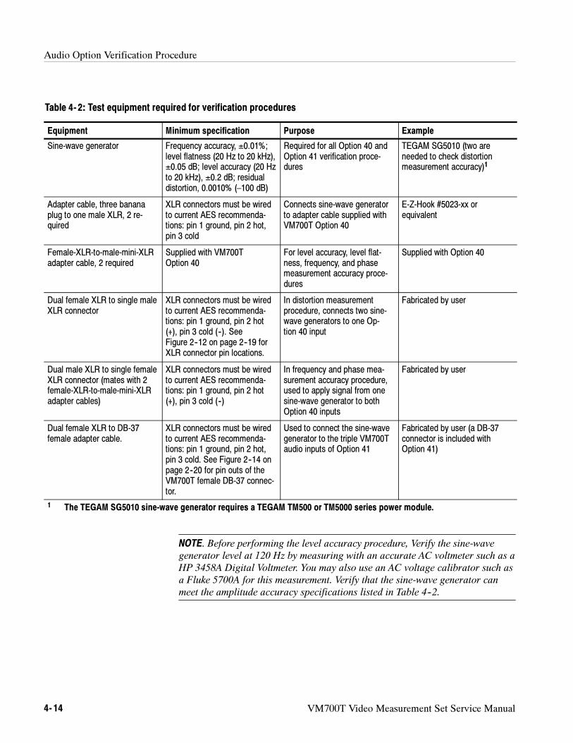
Audio Option Verification Procedure
4- 14 VM700T Video Measurement Set Service Manual
Table 4- 2: Test equipment required for verification procedures
Equipment Minimum specification Purpose Example
Sine-wave generator Frequency accuracy, ±0.01%;level flatness (20 Hz to 20 kHz),±0.05 dB; level accuracy (20 Hzto 20 kHz), ±0.2 dB; residualdistortion, 0.0010% (–100 dB)
Required for all Option 40 andOption 41 verification proce-dures
TEGAM SG5010 (two areneeded to check distortionmeasurement accuracy)1
Adapter cable, three bananaplug to one male XLR, 2 re-quired
XLR connectors must be wiredto current AES recommenda-tions: pin 1 ground, pin 2 hot,pin 3 cold
Connects sine-wave generatorto adapter cable supplied withVM700T Option 40
E-Z-Hook #5023-xx orequivalent
Female-XLR-to-male-mini-XLRadapter cable, 2 required
Supplied with VM700TOption 40
For level accuracy, level flat-ness, frequency, and phasemeasurement accuracy proce-dures
Supplied with Option 40
Dual female XLR to single maleXLR connector
XLR connectors must be wiredto current AES recommenda-tions: pin 1 ground, pin 2 hot(+), pin 3 cold (--). SeeFigure 2--12 on page 2--19 forXLR connector pin locations.
In distortion measurementprocedure, connects two sine-wave generators to one Op-tion 40 input
Fabricated by user
Dual male XLR to single femaleXLR connector (mates with 2female-XLR-to-male-mini-XLRadapter cables)
XLR connectors must be wiredto current AES recommenda-tions: pin 1 ground, pin 2 hot(+), pin 3 cold (--)
In frequency and phase mea-surement accuracy procedure,used to apply signal from onesine-wave generator to bothOption 40 inputs
Fabricated by user
Dual female XLR to DB-37female adapter cable.
XLR connectors must be wiredto current AES recommenda-tions: pin 1 ground, pin 2 hot,pin 3 cold. See Figure 2--14 onpage 2--20 for pin outs of theVM700T female DB-37 connec-tor.
Used to connect the sine-wavegenerator to the triple VM700Taudio inputs of Option 41
Fabricated by user (a DB-37connector is included withOption 41)
1 The TEGAM SG5010 sine-wave generator requires a TEGAM TM500 or TM5000 series power module.
NOTE. Before performing the level accuracy procedure, Verify the sine-wave
generator level at 120 Hz by measuring with an accurate AC voltmeter such as a
HP 3458A Digital Voltmeter. You may also use an AC voltage calibrator such as
a Fluke 5700A for this measurement. Verify that the sine-wave generator can
meet the amplitude accuracy specifications listed in Table 4--2.
VM700T Video Measurement Set Service Manual 4- 15
Audio Option 40 Verification Procedure
Use the following procedures to check the Option 40 Audio Option.
Check Level Measurement Accuracy and Flatness
This procedure verifies flatness and measurement accuracy by checking signallevels at specified frequencies.
NOTE. The actual frequencies and levels checked are not specified in this
procedure. If the measurement accuracy of certain frequencies and levels is
important to your application, we recommend that your test procedure include
those frequencies and levels.
Table 4--3 lists audio option accuracy and flatness specifications.
Table 4- 3: Accuracy and flatness specifications
Frequency range Level range1Accuracy(includes flatness) Flatness
20 -- 40 Hz ≥ – 20 dBu-- 20 dBu to -- 50 dBu– 50 dBu to – 60 dBu– 60 dBu to – 70 dBu
+ 0.3 / – 0.2 dB+ 0.4 / – 0.3 dB+ 0.6 / – 0.5 dB± 1.0 dB
+ 0.1 / – 0.2 dB+ 0.1 / – 0.2 dB+ 0.2 / – 0.3 dB+ 0.4 / – 0.5 dB
40 Hz – 20 kHz ≥ – 20 dBu– 20 dBu to – 50 dBu– 50 dBu to – 60 dBu– 60 dBu to – 70 dBu
± 0.2 dB± 0.3 dB± 0.5 dB± 1.0 dB
± 0.1 dB± 0.1 dB± 0.2 dB± 0.4 dB
1 Level difference between channels is ±0.2 dB at levels of –50 dBu and greater.
1. Power on the VM700T and associated test equipment and let them warm upfor 20 minutes.
2. Connect the sine-wave generator to the VM700T audio option left and rightmini-XLR input connectors. See Figure 4--6 for an example of cabling.
Specifications Checked
Option 40 LevelAccuracy and Flatness
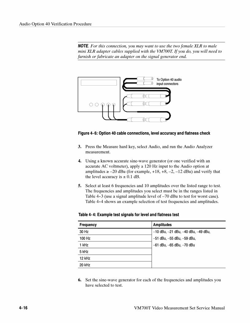
Audio Option 40 Verification Procedure
4- 16 VM700T Video Measurement Set Service Manual
NOTE. For this connection, you may want to use the two female XLR to male
mini XLR adapter cables supplied with the VM700T. If you do, you will need to
furnish or fabricate an adapter on the signal generator end.
To Option 40 audioinput connectors
Figure 4- 6: Option 40 cable connections, level accuracy and flatness check
3. Press the Measure hard key, select Audio, and run the Audio Analyzermeasurement.
4. Using a known accurate sine-wave generator (or one verified with anaccurate AC voltmeter), apply a 120 Hz input to the Audio option atamplitudes ≥ –20 dBu (for example, +18, +8, –2, –12 dBu) and verify thatthe level accuracy is ± 0.1 dB.
5. Select at least 6 frequencies and 10 amplitudes over the listed range to test.The frequencies and amplitudes you select must be in the ranges listed inTable 4--3 (use a signal amplitude level of –70 dBu to test for worst case).Table 4--4 shows an example selection of test frequencies and amplitudes.
Table 4- 4: Example test signals for level and flatness test
Frequency Amplitudes
30 Hz –10 dBu, –21 dBu, –40 dBu, –49 dBu,
100 Hz –51 dBu, –55 dBu, –59 dBu,
1 kHz –61 dBu, –65 dBu, –70 dBu
5 kHz
12 kHz
20 kHz
6. Set the sine-wave generator for each of the frequencies and amplitudes youhave selected to test.
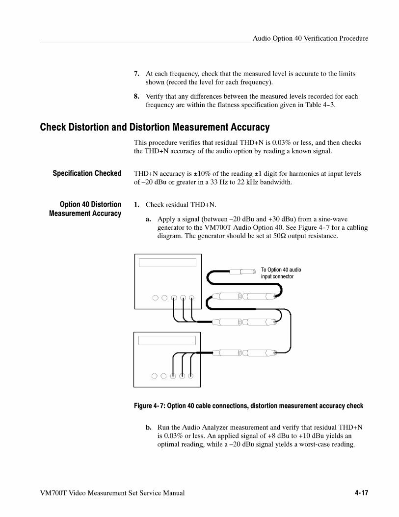
Audio Option 40 Verification Procedure
VM700T Video Measurement Set Service Manual 4- 17
7. At each frequency, check that the measured level is accurate to the limitsshown (record the level for each frequency).
8. Verify that any differences between the measured levels recorded for eachfrequency are within the flatness specification given in Table 4--3.
Check Distortion and Distortion Measurement Accuracy
This procedure verifies that residual THD+N is 0.03% or less, and then checksthe THD+N accuracy of the audio option by reading a known signal.
THD+N accuracy is ±10% of the reading ±1 digit for harmonics at input levelsof –20 dBu or greater in a 33 Hz to 22 kHz bandwidth.
1. Check residual THD+N.
a. Apply a signal (between –20 dBu and +30 dBu) from a sine-wavegenerator to the VM700T Audio Option 40. See Figure 4--7 for a cablingdiagram. The generator should be set at 50Ω output resistance.
To Option 40 audioinput connector
Figure 4- 7: Option 40 cable connections, distortion measurement accuracy check
b. Run the Audio Analyzer measurement and verify that residual THD+Nis 0.03% or less. An applied signal of +8 dBu to +10 dBu yields anoptimal reading, while a –20 dBu signal yields a worst-case reading.
Specification Checked
Option 40 DistortionMeasurement Accuracy
Audio Option 40 Verification Procedure
4- 18 VM700T Video Measurement Set Service Manual
2. Check THD+N Measurement Accuracy.
a. With 600 Ω output resistance selected, connect the outputs of twosine-wave generators in parallel to the left channel input of the AudioOption. See Figure 4--7 for a cabling diagram.
b. Set one sine-wave generator for a 2 VRMS output at 1 kHz and set thesecond sine-wave generator for a 0.02 V (20 mVRMS) at 3 kHz. Thesetwo signals add across the termination resistance to produce a 1 kHzsignal with a 1% third-harmonic distortion.
c. Run the Audio Analyzer measurement and check for a THD+N readingof 0.9% to 1.1%.
3. Move the input from the generators to the right channel and repeat step 2,part d.
Check Frequency and Phase Measurement Accuracy
This procedure requires an accurate frequency sine-wave generator or a digitalcounter to accurately set the frequency. The phase measurement requires thatboth channels have the same signal applied through equal length cables.
This procedure checks the following parameters:
Frequency accuracy: ±1 Hz ( or ± 0.01% + 1 digit, whichever is worse ) forinputs of –60 dBu or greater in the frequency range of 20 Hz to 20 kHz.
Channel phase difference: ±1° for inputs of 40 Hz to 20 kHz, ±2° for inputsof 20 Hz to 40 Hz at a level of –40 dBu or greater.
1. Connect the sine-wave generator output to both the left and right inputs ofthe Audio board (see Figure 4--6).
2. Set the sine-wave generator for a frequency and amplitude in the specifiedfrequency and amplitude range of the Audio option (20 Hz to 20 kHz,amplitude of –60 dBu or greater).
NOTE. Use a test signal level of at least –60 dBu and test at least 10 frequencies
over the entire range. Tested frequencies should include the specification limits
(20 Hz, 20 kHz) and the 40 Hz breakpoint. Example frequencies to test might
also include the following: 100 Hz, 200 Hz, 1 kHz, 2 kHz, 10 kHz.
3. Check that the measured frequency is accurate to the limits shown inTable 4--3 for the applied test signal frequency and level. Check that thephase difference between channels meets the phase difference specification.
Specifications Checked
Option 40 FrequencyAccuracy and Channel
Phase Difference
VM700T Video Measurement Set Service Manual 4- 19
Audio Option 41 Triple-Input Verification Procedure
This section describes the differences in operation between Option 40 andOption 41, and it gives the verification procedure for Option 41.
Configuring Source Selection Audio
The Option 41 software is similar to the Option 40 software except for theSource Selection Audio file.
The Source Selection Audio file lets you specify an Option 41 audio input(1, 2, 3) for a video source (A, B, C), and then select an appropriate audio sourcefile (if you want to use an audio source file other than the system default).
In the next steps you want to have source A to audio input 1, source B to 2, andsource C to 3.
To specify audio inputs and audio source files for video sources, use thefollowing procedure:
1. From Measure Mode, press the Configure front-panel button, touch theConfigure Files soft key followed by the Source_Selection Audio soft key.
2. Rotate the front panel knob to highlight the source (A, B, C) for which youare specifying an audio input and an audio source file.
3. Touch the highlighted audio input (1, 2, or 3) to select it.
4. Rotate the front-panel knob to change the audio input selection.
5. Touch the highlighted source file to select it.
6. Rotate the front-panel knob to change the audio source file selection (if youare using an audio source file other than the system default).
7. When you have specified the audio inputs and source files, touch the AcceptInput soft key.
8. If the change is correct, touch the Update & Exit soft key, otherwise, touchthe No Change & Exit soft key.
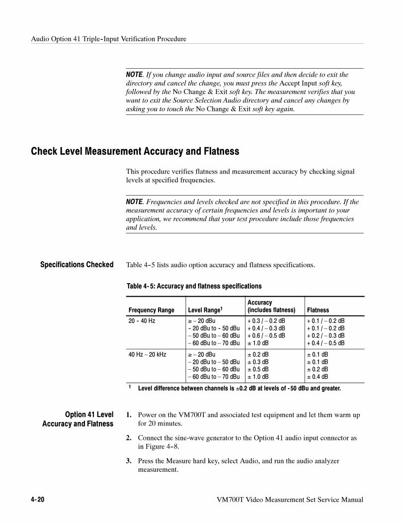
Audio Option 41 Triple--Input Verification Procedure
4- 20 VM700T Video Measurement Set Service Manual
NOTE. If you change audio input and source files and then decide to exit the
directory and cancel the change, you must press the Accept Input soft key,followed by the No Change & Exit soft key. The measurement verifies that youwant to exit the Source Selection Audio directory and cancel any changes by
asking you to touch the No Change & Exit soft key again.
Check Level Measurement Accuracy and Flatness
This procedure verifies flatness and measurement accuracy by checking signallevels at specified frequencies.
NOTE. Frequencies and levels checked are not specified in this procedure. If the
measurement accuracy of certain frequencies and levels is important to your
application, we recommend that your test procedure include those frequencies
and levels.
Table 4--5 lists audio option accuracy and flatness specifications.
Table 4- 5: Accuracy and flatness specifications
Frequency Range Level Range1Accuracy(includes flatness) Flatness
20 -- 40 Hz ≥ – 20 dBu-- 20 dBu to -- 50 dBu– 50 dBu to – 60 dBu– 60 dBu to – 70 dBu
+ 0.3 / – 0.2 dB+ 0.4 / – 0.3 dB+ 0.6 / – 0.5 dB± 1.0 dB
+ 0.1 / – 0.2 dB+ 0.1 / – 0.2 dB+ 0.2 / – 0.3 dB+ 0.4 / – 0.5 dB
40 Hz – 20 kHz ≥ – 20 dBu– 20 dBu to – 50 dBu– 50 dBu to – 60 dBu– 60 dBu to – 70 dBu
± 0.2 dB± 0.3 dB± 0.5 dB± 1.0 dB
± 0.1 dB± 0.1 dB± 0.2 dB± 0.4 dB
1 Level difference between channels is ±0.2 dB at levels of - 50 dBu and greater.
1. Power on the VM700T and associated test equipment and let them warm upfor 20 minutes.
2. Connect the sine-wave generator to the Option 41 audio input connector asin Figure 4--8.
3. Press the Measure hard key, select Audio, and run the audio analyzermeasurement.
Specifications Checked
Option 41 LevelAccuracy and Flatness
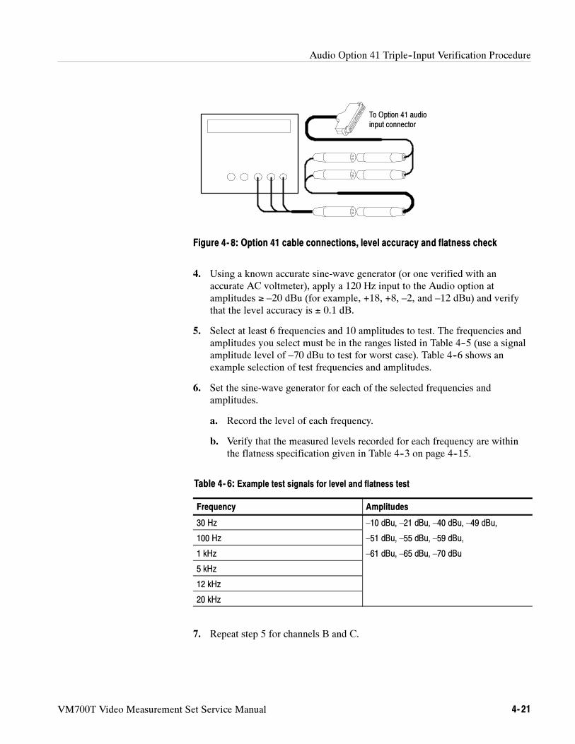
Audio Option 41 Triple--Input Verification Procedure
VM700T Video Measurement Set Service Manual 4- 21
To Option 41 audioinput connector
Figure 4- 8: Option 41 cable connections, level accuracy and flatness check
4. Using a known accurate sine-wave generator (or one verified with anaccurate AC voltmeter), apply a 120 Hz input to the Audio option atamplitudes ≥ –20 dBu (for example, +18, +8, –2, and –12 dBu) and verifythat the level accuracy is ± 0.1 dB.
5. Select at least 6 frequencies and 10 amplitudes to test. The frequencies andamplitudes you select must be in the ranges listed in Table 4--5 (use a signalamplitude level of –70 dBu to test for worst case). Table 4--6 shows anexample selection of test frequencies and amplitudes.
6. Set the sine-wave generator for each of the selected frequencies andamplitudes.
a. Record the level of each frequency.
b. Verify that the measured levels recorded for each frequency are withinthe flatness specification given in Table 4--3 on page 4--15.
Table 4- 6: Example test signals for level and flatness test
Frequency Amplitudes
30 Hz –10 dBu, –21 dBu, –40 dBu, –49 dBu,
100 Hz –51 dBu, –55 dBu, –59 dBu,
1 kHz –61 dBu, –65 dBu, –70 dBu
5 kHz
12 kHz
20 kHz
7. Repeat step 5 for channels B and C.
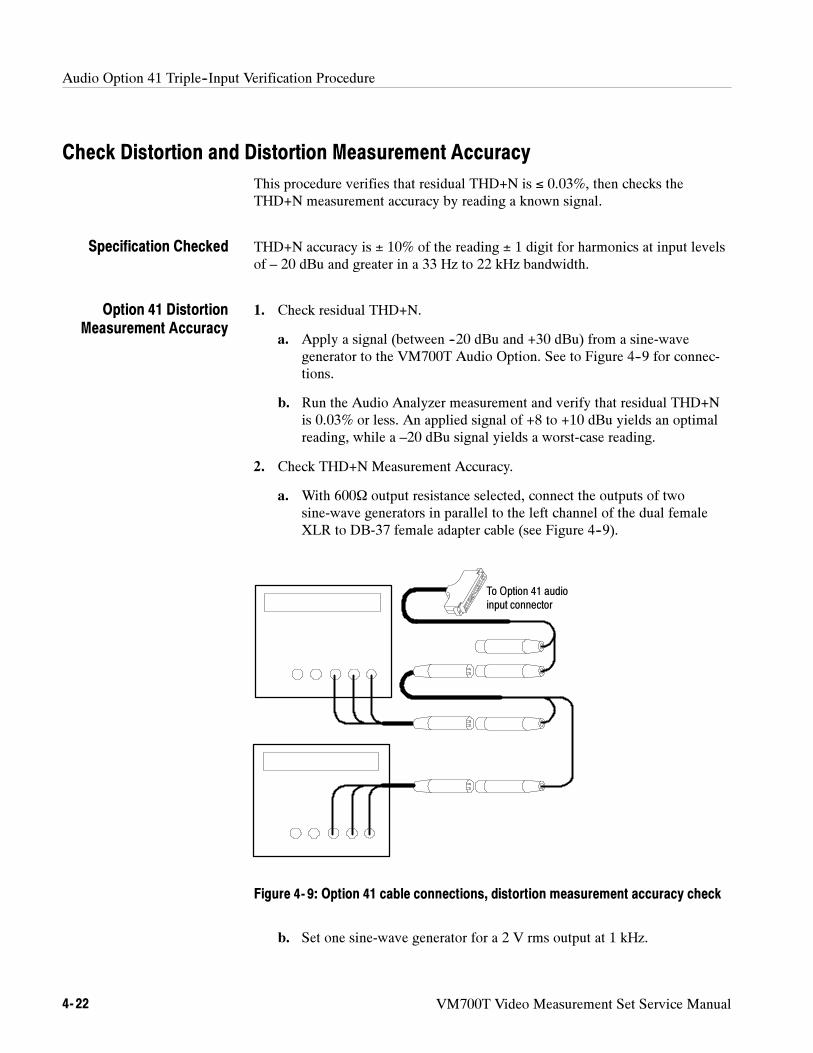
Audio Option 41 Triple--Input Verification Procedure
4- 22 VM700T Video Measurement Set Service Manual
Check Distortion and Distortion Measurement Accuracy
This procedure verifies that residual THD+N is ≤ 0.03%, then checks theTHD+N measurement accuracy by reading a known signal.
THD+N accuracy is ± 10% of the reading ± 1 digit for harmonics at input levelsof – 20 dBu and greater in a 33 Hz to 22 kHz bandwidth.
1. Check residual THD+N.
a. Apply a signal (between --20 dBu and +30 dBu) from a sine-wavegenerator to the VM700T Audio Option. See to Figure 4--9 for connec-tions.
b. Run the Audio Analyzer measurement and verify that residual THD+Nis 0.03% or less. An applied signal of +8 to +10 dBu yields an optimalreading, while a –20 dBu signal yields a worst-case reading.
2. Check THD+N Measurement Accuracy.
a. With 600Ω output resistance selected, connect the outputs of twosine-wave generators in parallel to the left channel of the dual femaleXLR to DB-37 female adapter cable (see Figure 4--9).
To Option 41 audioinput connector
Figure 4- 9: Option 41 cable connections, distortion measurement accuracy check
b. Set one sine-wave generator for a 2 V rms output at 1 kHz.
Specification Checked
Option 41 DistortionMeasurement Accuracy
Audio Option 41 Triple--Input Verification Procedure
VM700T Video Measurement Set Service Manual 4- 23
c. Set the second sine-wave generator for a 0.02 V (20 mV rms) at 3 kHz.These two signals add across the termination resistance to produce a1 kHz signal with a 1% third-harmonic distortion.
d. Run the Audio Analyzer measurement and check for a THD+N readingof 0.9% to 1.1%.
e. Move the generator signals to the right channel input and repeat step 2,part d.
3. Repeat step 2 for channels B and C; substitute the appropriate channel whenchannel A is called for.
Check Frequency and Phase Measurement Accuracy
This procedure requires an accurate frequency generator or a digital counter toset the frequency. The phase measurement requires that both channels have thesame signal applied.
This procedure checks the following parameters:
Frequency accuracy: ±1 Hz (or ±0.01% + 1 digit, whichever is worse) forinputs of –60 dBu and greater in the frequency range of 20 Hz to 20 kHz.
Channel phase difference: ±1° for inputs of 40 Hz to 20 kHz, ± 2° for inputsof 20 Hz to 40 Hz at levels of –40 dBu and greater.
1. As in Figure 4--9, connect the sine-wave generator output to the Audioboard.
2. Set the sine-wave generator for a frequency and amplitude in the specifiedfrequency and amplitude range of the Audio option (20 Hz to 20 kHz,amplitude of –60 dBu or greater).
NOTE. Use a test signal level of at least --60 dBu and test at least 10 frequencies
over the entire range. Tested frequencies should include the specification limits
(20 Hz, 20 kHz) and the 40 Hz breakpoint. Example frequencies to test might
also include the following: 100 Hz, 200 Hz, 1 kHz, 2 kHz, 10 kHz.
3. Check that the measured frequency is accurate to the limits shown inTable 4--5 for the applied test signal frequency and level, and that the phasedifference between channels meets the phase difference specification.
Specifications Checked
Option 41 FrequencyAccuracy and Channel
Phase Difference
Audio Option 41 Triple--Input Verification Procedure
4- 24 VM700T Video Measurement Set Service Manual
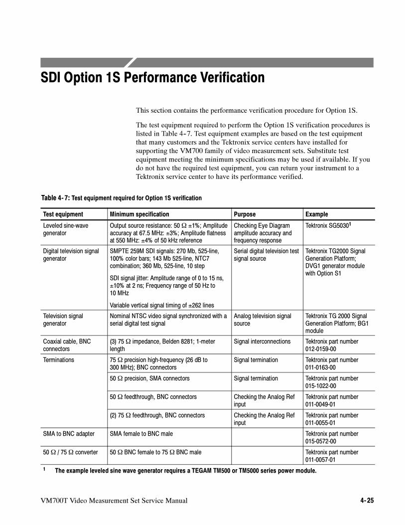
VM700T Video Measurement Set Service Manual 4- 25
SDI Option 1S Performance Verification
This section contains the performance verification procedure for Option 1S.
The test equipment required to perform the Option 1S verification procedures islisted in Table 4--7. Test equipment examples are based on the test equipmentthat many customers and the Tektronix service centers have installed forsupporting the VM700 family of video measurement sets. Substitute testequipment meeting the minimum specifications may be used if available. If youdo not have the required test equipment, you can return your instrument to aTektronix service center to have its performance verified.
Table 4- 7: Test equipment required for Option 1S verification
Test equipment Minimum specification Purpose Example
Leveled sine-wavegenerator
Output source resistance: 50Ω ±1%; Amplitudeaccuracy at 67.5 MHz: ±3%; Amplitude flatnessat 550 MHz: ±4% of 50 kHz reference
Checking Eye Diagramamplitude accuracy andfrequency response
Tektronix SG50301
Digital television signalgenerator
SMPTE 259M SDI signals: 270 Mb, 525-line,100% color bars; 143 Mb 525-line, NTC7combination; 360 Mb, 525-line, 10 step
SDI signal jitter: Amplitude range of 0 to 15 ns,±10% at 2 ns; Frequency range of 50 Hz to10 MHz
Variable vertical signal timing of ±262 lines
Serial digital television testsignal source
Tektronix TG2000 SignalGeneration Platform;DVG1 generator modulewith Option S1
Television signalgenerator
Nominal NTSC video signal synchronized with aserial digital test signal
Analog television signalsource
Tektronix TG 2000 SignalGeneration Platform; BG1module
Coaxial cable, BNCconnectors
(3) 75Ω impedance, Belden 8281; 1-meterlength
Signal interconnections Tektronix part number012-0159-00
Terminations 75Ω precision high-frequency (26 dB to300 MHz); BNC connectors
Signal termination Tektronix part number011-0163-00
50Ω precision, SMA connectors Signal termination Tektronix part number015-1022-00
50Ω feedthrough, BNC connectors Checking the Analog Refinput
Tektronix part number011-0049-01
(2) 75Ω feedthrough, BNC connectors Checking the Analog Refinput
Tektronix part number011-0055-01
SMA to BNC adapter SMA female to BNC male Tektronix part number015-0572-00
50Ω / 75Ω converter 50Ω BNC female to 75Ω BNC male Tektronix part number011-0057-01
1 The example leveled sine wave generator requires a TEGAM TM500 or TM5000 series power module.
SDI Option 1S Verification Procedure
4- 26 VM700T Video Measurement Set Service Manual
Preliminary Setup
Perform the following steps to setup the equipment for the Option 1S perfor-mance verification:
1. Connect power to the VM700T and turn the instrument on. Verify that theinstrument passes all diagnostics as the instrument powers up.
2. Press the VM700T front-panel Configure button. Select Mode: Digital ifnecessary using the Mode soft key.
NOTE. The VM700T must be set to Mode: Digital before you can perform the
Option 1S performance verification procedures.
3. Touch the Configure Files soft key, and then touch the Source_SelectionDigital soft key.
4. Highlight the Digital A: line using the front-panel knob, and then touch thehighlighted line to cause a box to appear around the current selection.
5. Turn the knob to select Auto Detect, and then touch the Accept Inputsoft key.
6. Highlight the Digital B: line using the knob, and then touch the highlightedline to cause a box to appear around the current selection.
7. Turn the knob to select Auto Detect, touch the Accept Input soft key, andthen touch the Update & Exit soft key to exit the configuration file.
NOTE. The VM700T and Option 1S must be warmed up for at least 20 minutes
before you perform the Option 1S performance verification procedures.
SDI Option 1S Verification Procedure
VM700T Video Measurement Set Service Manual 4- 27
SDI Analog Ref Input
The amplitude range specification for the SDI Analog Ref input is 6 dB withrespect to 1 Vpp video. Perform the following procedure to check the amplituderange of the SDI Analog Ref input:
1. Connect an NTSC black burst signal to the Option 1S Analog Ref input.Terminate the signal using two 75 Ω feedthrough terminators in series withone 50 Ω feedthrough terminator (provides a 0.5 Vpp signal).
2. Connect a 270 Mb, 525-line, 100% color bars signal to the Option 1SSDI Ch. A input. Terminate the SDI Ch. A input using a 75 Ω high-frequen-cy terminator.
3. Set the digital television signal generator for a vertical delay of 262 lines onthe 100% color bar signal.
4. Press the Source A button to select channel A for display, and then press theVM700T front-panel Measure button.
5. Touch the SDI_IC_Timing soft key. Press the front-panel Menu button, andthen touch the Relative Analog soft key.
6. Check the measurement reading:
VM700T firmware version 980422 and below: 16 mSec to 17 mSec.
VM700T firmware version 990512 and above: -- 16 mSec to -- 17 mSec.
7. Remove the three terminators from the signal on the Analog Ref input.
8. Check the measurement reading:
VM700T firmware version 980422 and below: 16 mSec to 17 mSec.
VM700T firmware version 990512 and above: --16 mSec to --17 mSec.
SDI Option 1S Verification Procedure
4- 28 VM700T Video Measurement Set Service Manual
Eye Diagram Application
Perform the following procedures to check the SDI Eye Diagram application.
The amplitude accuracy specification for the SDI Eye Diagram application is5% for signals between 600 mVpp and 1 Vpp. Perform the following procedureto check the amplitude accuracy of the SDI Eye Diagram application.
1. Connect a 67.5 MHz, 800 mVpp leveled sine wave to the SDI Ch. A input.Terminate the SDI Ch. A input with a 50 Ω precision terminator.
NOTE. If you are using the Tektronix SG 5030, connect the Output Head directly
to the SDI Ch. A input (no cable between the Output Head and the input).
2. Press the VM700T front-panel Measure button, and then touch theSDI_Eye Diagram soft key.
3. Press the VM700T front-panel Menu button.
4. Touch the Waveform soft key, and then select Free Run on (soft key ishighlighted).
5. Press the VM700T front-panel Menu button, and then touch theCursors/Units softkey.
6. Touch the Volt Cursor 1 soft key, and then use the front-panel knob toposition the cursor to the top of the sine wave.
NOTE. It may be necessary to expand the waveform to accurately position the
voltage cursors. You can expand the waveform by touching the waveform and
then using the front-panel knob to adjust the waveform display.
7. Touch the Volt Cursor 2 soft key, and then use the front-panel knob toposition the cursor to the bottom of the sine wave.
8. Check that the V1 -- V2 measurement readout is 770 mV to 820 mV(800 mV 3.8%).
Eye Diagram AmplitudeAccuracy
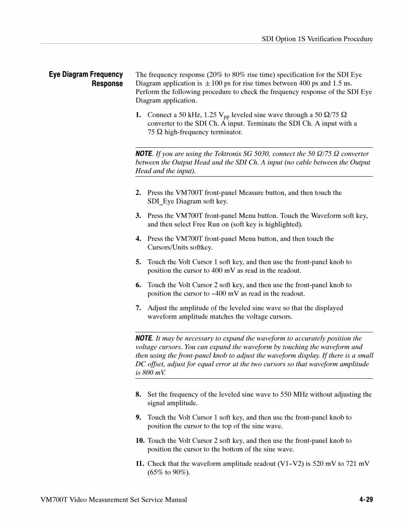
SDI Option 1S Verification Procedure
VM700T Video Measurement Set Service Manual 4- 29
The frequency response (20% to 80% rise time) specification for the SDI EyeDiagram application is 100 ps for rise times between 400 ps and 1.5 ns.Perform the following procedure to check the frequency response of the SDI EyeDiagram application.
1. Connect a 50 kHz, 1.25 Vpp leveled sine wave through a 50 Ω/75 Ω
converter to the SDI Ch. A input. Terminate the SDI Ch. A input with a75 Ω high-frequency terminator.
NOTE. If you are using the Tektronix SG 5030, connect the 50 Ω/75 Ω converter
between the Output Head and the SDI Ch. A input (no cable between the Output
Head and the input).
2. Press the VM700T front-panel Measure button, and then touch theSDI_Eye Diagram soft key.
3. Press the VM700T front-panel Menu button. Touch the Waveform soft key,and then select Free Run on (soft key is highlighted).
4. Press the VM700T front-panel Menu button, and then touch theCursors/Units softkey.
5. Touch the Volt Cursor 1 soft key, and then use the front-panel knob toposition the cursor to 400 mV as read in the readout.
6. Touch the Volt Cursor 2 soft key, and then use the front-panel knob toposition the cursor to --400 mV as read in the readout.
7. Adjust the amplitude of the leveled sine wave so that the displayedwaveform amplitude matches the voltage cursors.
NOTE. It may be necessary to expand the waveform to accurately position the
voltage cursors. You can expand the waveform by touching the waveform and
then using the front-panel knob to adjust the waveform display. If there is a small
DC offset, adjust for equal error at the two cursors so that waveform amplitude
is 800 mV.
8. Set the frequency of the leveled sine wave to 550 MHz without adjusting thesignal amplitude.
9. Touch the Volt Cursor 1 soft key, and then use the front-panel knob toposition the cursor to the top of the sine wave.
10. Touch the Volt Cursor 2 soft key, and then use the front-panel knob toposition the cursor to the bottom of the sine wave.
11. Check that the waveform amplitude readout (V1--V2) is 520 mV to 721 mV(65% to 90%).
Eye Diagram FrequencyResponse
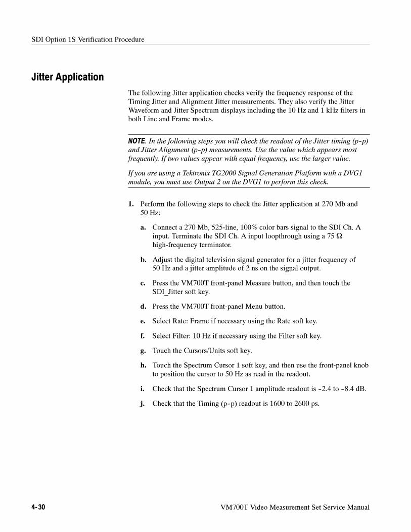
SDI Option 1S Verification Procedure
4- 30 VM700T Video Measurement Set Service Manual
Jitter Application
The following Jitter application checks verify the frequency response of theTiming Jitter and Alignment Jitter measurements. They also verify the JitterWaveform and Jitter Spectrum displays including the 10 Hz and 1 kHz filters inboth Line and Frame modes.
NOTE. In the following steps you will check the readout of the Jitter timing (p--p)
and Jitter Alignment (p--p) measurements. Use the value which appears most
frequently. If two values appear with equal frequency, use the larger value.
If you are using a Tektronix TG2000 Signal Generation Platform with a DVG1
module, you must use Output 2 on the DVG1 to perform this check.
1. Perform the following steps to check the Jitter application at 270 Mb and50 Hz:
a. Connect a 270 Mb, 525-line, 100% color bars signal to the SDI Ch. Ainput. Terminate the SDI Ch. A input loopthrough using a 75 Ω
high-frequency terminator.
b. Adjust the digital television signal generator for a jitter frequency of50 Hz and a jitter amplitude of 2 ns on the signal output.
c. Press the VM700T front-panel Measure button, and then touch theSDI_Jitter soft key.
d. Press the VM700T front-panel Menu button.
e. Select Rate: Frame if necessary using the Rate soft key.
f. Select Filter: 10 Hz if necessary using the Filter soft key.
g. Touch the Cursors/Units soft key.
h. Touch the Spectrum Cursor 1 soft key, and then use the front-panel knobto position the cursor to 50 Hz as read in the readout.
i. Check that the Spectrum Cursor 1 amplitude readout is --2.4 to --8.4 dB.
j. Check that the Timing (p--p) readout is 1600 to 2600 ps.
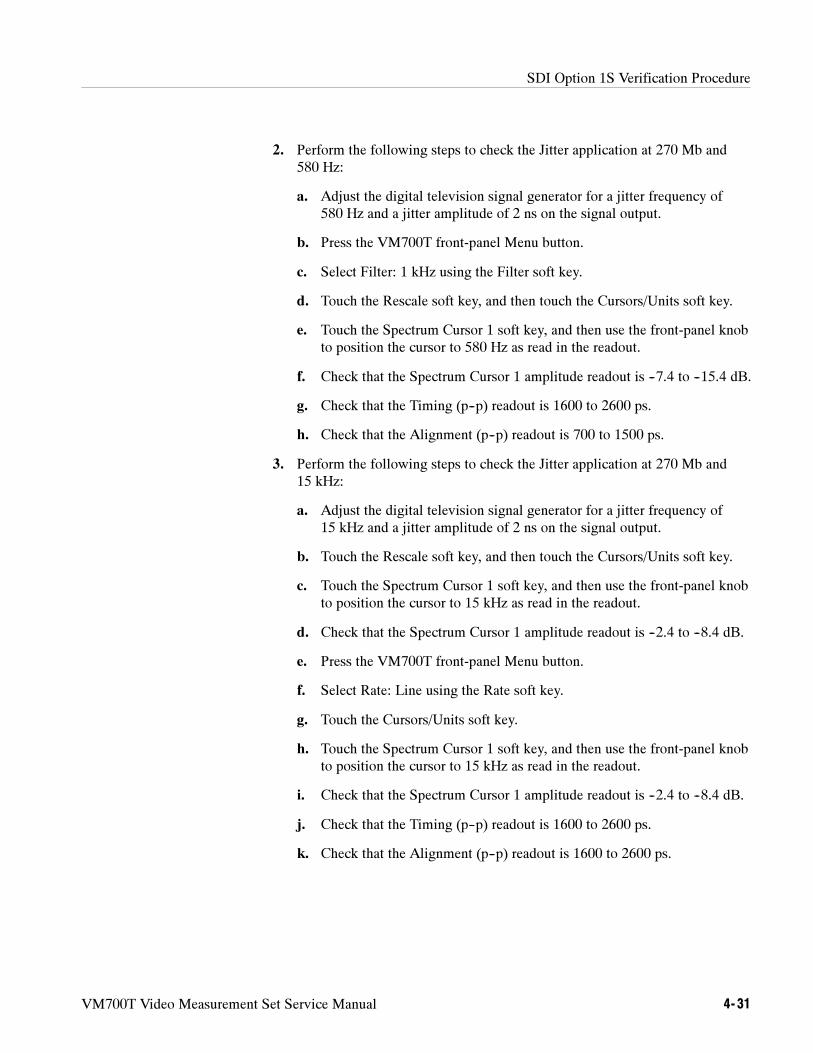
SDI Option 1S Verification Procedure
VM700T Video Measurement Set Service Manual 4- 31
2. Perform the following steps to check the Jitter application at 270 Mb and580 Hz:
a. Adjust the digital television signal generator for a jitter frequency of580 Hz and a jitter amplitude of 2 ns on the signal output.
b. Press the VM700T front-panel Menu button.
c. Select Filter: 1 kHz using the Filter soft key.
d. Touch the Rescale soft key, and then touch the Cursors/Units soft key.
e. Touch the Spectrum Cursor 1 soft key, and then use the front-panel knobto position the cursor to 580 Hz as read in the readout.
f. Check that the Spectrum Cursor 1 amplitude readout is --7.4 to --15.4 dB.
g. Check that the Timing (p--p) readout is 1600 to 2600 ps.
h. Check that the Alignment (p--p) readout is 700 to 1500 ps.
3. Perform the following steps to check the Jitter application at 270 Mb and15 kHz:
a. Adjust the digital television signal generator for a jitter frequency of15 kHz and a jitter amplitude of 2 ns on the signal output.
b. Touch the Rescale soft key, and then touch the Cursors/Units soft key.
c. Touch the Spectrum Cursor 1 soft key, and then use the front-panel knobto position the cursor to 15 kHz as read in the readout.
d. Check that the Spectrum Cursor 1 amplitude readout is --2.4 to --8.4 dB.
e. Press the VM700T front-panel Menu button.
f. Select Rate: Line using the Rate soft key.
g. Touch the Cursors/Units soft key.
h. Touch the Spectrum Cursor 1 soft key, and then use the front-panel knobto position the cursor to 15 kHz as read in the readout.
i. Check that the Spectrum Cursor 1 amplitude readout is --2.4 to --8.4 dB.
j. Check that the Timing (p--p) readout is 1600 to 2600 ps.
k. Check that the Alignment (p--p) readout is 1600 to 2600 ps.
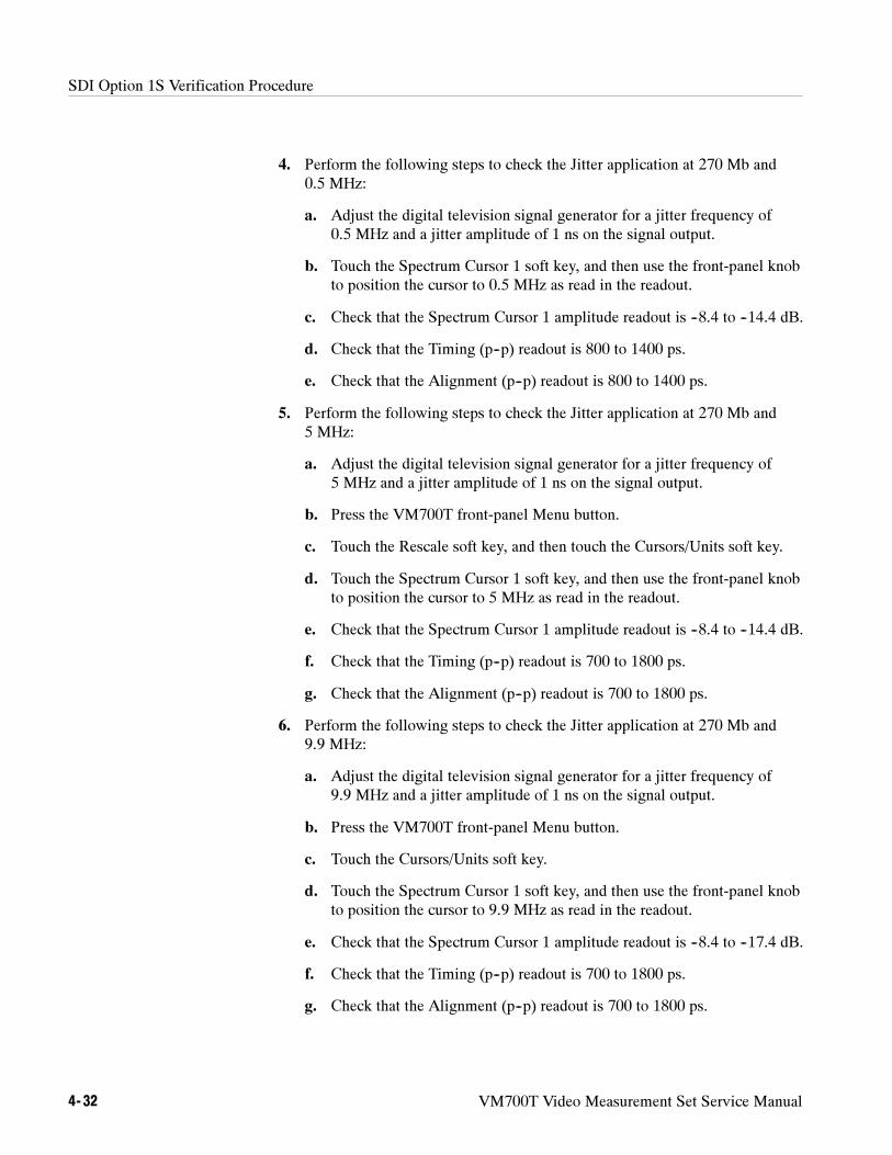
SDI Option 1S Verification Procedure
4- 32 VM700T Video Measurement Set Service Manual
4. Perform the following steps to check the Jitter application at 270 Mb and0.5 MHz:
a. Adjust the digital television signal generator for a jitter frequency of0.5 MHz and a jitter amplitude of 1 ns on the signal output.
b. Touch the Spectrum Cursor 1 soft key, and then use the front-panel knobto position the cursor to 0.5 MHz as read in the readout.
c. Check that the Spectrum Cursor 1 amplitude readout is --8.4 to --14.4 dB.
d. Check that the Timing (p--p) readout is 800 to 1400 ps.
e. Check that the Alignment (p--p) readout is 800 to 1400 ps.
5. Perform the following steps to check the Jitter application at 270 Mb and5 MHz:
a. Adjust the digital television signal generator for a jitter frequency of5 MHz and a jitter amplitude of 1 ns on the signal output.
b. Press the VM700T front-panel Menu button.
c. Touch the Rescale soft key, and then touch the Cursors/Units soft key.
d. Touch the Spectrum Cursor 1 soft key, and then use the front-panel knobto position the cursor to 5 MHz as read in the readout.
e. Check that the Spectrum Cursor 1 amplitude readout is --8.4 to --14.4 dB.
f. Check that the Timing (p--p) readout is 700 to 1800 ps.
g. Check that the Alignment (p--p) readout is 700 to 1800 ps.
6. Perform the following steps to check the Jitter application at 270 Mb and9.9 MHz:
a. Adjust the digital television signal generator for a jitter frequency of9.9 MHz and a jitter amplitude of 1 ns on the signal output.
b. Press the VM700T front-panel Menu button.
c. Touch the Cursors/Units soft key.
d. Touch the Spectrum Cursor 1 soft key, and then use the front-panel knobto position the cursor to 9.9 MHz as read in the readout.
e. Check that the Spectrum Cursor 1 amplitude readout is --8.4 to --17.4 dB.
f. Check that the Timing (p--p) readout is 700 to 1800 ps.
g. Check that the Alignment (p--p) readout is 700 to 1800 ps.
SDI Option 1S Verification Procedure
VM700T Video Measurement Set Service Manual 4- 33
7. Perform the following steps to check the Jitter application at 143 Mb and3 MHz:
a. Replace the 270 Mb signal on the SDI Ch. A input with a 143 Mb,525-line, NTC7 combination signal. Leave the SDI Ch. A inputterminated with the high-frequency terminator.
b. Adjust the digital television signal generator for a jitter frequency of3 MHz and a jitter amplitude of 1 ns on the signal output.
c. Touch the Spectrum Cursor 1 soft key, and then use the front-panel knobto position the cursor to 3 MHz as read in the readout.
d. Check that the Spectrum Cursor 1 amplitude readout is --14 to --22 dB.
e. Check that the Timing (p--p) readout is 700 to 1400 ps.
f. Check that the Alignment (p--p) readout is 700 to 1400 ps.
8. Perform the following steps to check the Jitter application at 360 Mb and15 kHz:
a. Replace the 143 Mb signal on the SDI Ch. A input with a 360 Mb,525-line, 10 step signal. Leave the SDI Ch. A input terminated with thehigh-frequency terminator.
b. Adjust the digital television signal generator for a jitter frequency of15 kHz and a jitter amplitude of 2 ns on the signal output.
c. Check that the Timing (p--p) readout is 1600 to 2600 ps.
d. Check that the Alignment (p--p) readout is 1600 to 2600 ps.
9. Perform the following steps to check the Jitter application at 360 Mb and9.9 MHz:
a. Adjust the digital television signal generator for a jitter frequency of9.9 MHz and a jitter amplitude of 0.7 ns on the signal output.
b. Touch the Spectrum Cursor 1 soft key, and then use the front-panel knobto position the cursor to 9.9 MHz as read in the readout.
c. Check that the Spectrum Cursor 1 amplitude readout is --9 to --18 dB.
d. Check that the Timing (p--p) readout is 490 to 1320 ps.
e. Check that the Alignment (p--p) readout is 490 to 1320 ps.
SDI Option 1S Verification Procedure
4- 34 VM700T Video Measurement Set Service Manual
Interchannel Timing Application
Perform the following procedure to check the SDI Interchannel Timingapplication.
1. Perform the following steps to check the digital-to-analog mode of the SDIInterchannel Timing application:
NOTE. The measurement reading you make in step e of this procedure assumes
you are using the Tektronix TG2000 Signal Generation Platform for this check.
For VM700T firmware version 980422 and below, there is a built-in timing
offset of 224.4 sec. For VM700T firmware version 990512 and above, there is a
built-in timing offset of 2.0 sec.
a. Connect an NTSC black burst signal to the Option 1S Analog Ref input.Terminate the Analog Ref loopthrough using a 75 Ω terminator.
b. Replace the 360 Mb signal on the SDI Ch. A input with a 270 Mb,525-line, 100% color bars signal. Leave the SDI Ch. A input terminatedwith the high-frequency terminator.
c. Press the VM700T front-panel Measure button, and then touch theSDI_IC_Timing soft key.
d. Press the front-panel Menu button, and then touch the Relative Analogsoft key.
e. Check the interchannel timing measurement reading:
VM700T firmware version 980422 and below: --224.0 to --224.8 s.
VM700T firmware version 990512 and above: --1.6 to --2.4 s.
2. Perform the following steps to check the digital-to-digital mode of the SDIInterchannel Timing application:
a. Remove the signal cable and terminator from the Option 1S Analog Refinput, and then remove the terminator from the SDI Ch. A inputloopthrough.
b. Connect a one meter cable from the SDI Ch. A input loopthrough to theSDI Ch. B input.
c. Touch the Relative Digital soft key.
d. Check for an interchannel timing measurement reading of37 ns.
e. Remove all cable and terminators from the VM700T.
SDI Option 1S Verification Procedure
VM700T Video Measurement Set Service Manual 4- 35
SDI Output
Perform the following procedure to check the SDI Output signal.
1. Connect a 270 Mb, 525-line, 100% color bars signal to the SDI Ch. B input.
2. Connect a one meter cable from the SDI Output to the SDI Ch. A input.Terminate the SDI Ch. A input using a 75 Ω high-frequency terminator.
3. Press the VM700T front-panel Configure button.
4. Touch the Configure Files soft key, and then touch the Source_SelectionDigital soft key.
5. Highlight the SDI Output line using the front-panel knob, and then touch thehighlighted line to cause a box to appear around the current selection.
6. Turn the knob to select Channel B, and then touch the Accept Input soft key.Touch the Update & Exit soft key to exit the configuration file.
7. Press the front-panel Measure button, and then touch the SDI_EyeDiagramsoft key.
8. Press the front-panel Menu button, and then touch the Measure soft key.
9. Touch the following soft keys if necessary to turn the measurements on (softkeys will be highlighted): Meas. Box, Eye Amplitude, Rise\Fall Times, andRise Time Adjusted.
NOTE. For the SDI Output check, the Average function must be turned off. Use
the front-panel Average button to turn off the Average function.
10. Check that the Amplitude readout is 720 mVolts to 880 mVolts.
11. Check that Risetime and Falltime readouts are both 400 pSec to 800 pSec.
12. Remove all cable and terminators from the VM700T.
SDI Option 1S Verification Procedure
4- 36 VM700T Video Measurement Set Service Manual
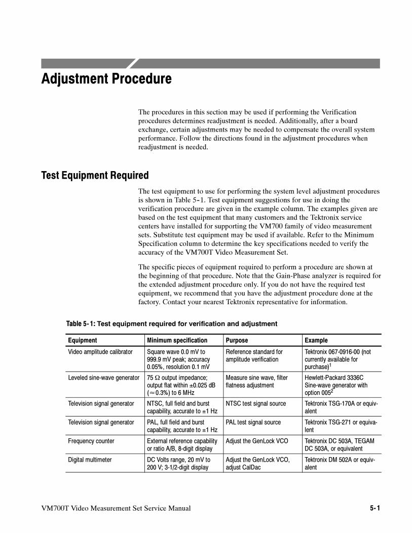
VM700T Video Measurement Set Service Manual 5- 1
Adjustment Procedure
The procedures in this section may be used if performing the Verificationprocedures determines readjustment is needed. Additionally, after a boardexchange, certain adjustments may be needed to compensate the overall systemperformance. Follow the directions found in the adjustment procedures whenreadjustment is needed.
Test Equipment Required
The test equipment to use for performing the system level adjustment proceduresis shown in Table 5--1. Test equipment suggestions for use in doing theverification procedure are given in the example column. The examples given arebased on the test equipment that many customers and the Tektronix servicecenters have installed for supporting the VM700 family of video measurementsets. Substitute test equipment may be used if available. Refer to the MinimumSpecification column to determine the key specifications needed to verify theaccuracy of the VM700T Video Measurement Set.
The specific pieces of equipment required to perform a procedure are shown atthe beginning of that procedure. Note that the Gain-Phase analyzer is required forthe extended adjustment procedure only. If you do not have the required testequipment, we recommend that you have the adjustment procedure done at thefactory. Contact your nearest Tektronix representative for information.
Table 5- 1: Test equipment required for verification and adjustment
Equipment Minimum specification Purpose Example
Video amplitude calibrator Square wave 0.0 mV to999.9 mV peak; accuracy0.05%, resolution 0.1 mV
Reference standard foramplitude verification
Tektronix 067-0916-00 (notcurrently available forpurchase)1
Leveled sine-wave generator 75 Ω output impedance;output flat within ±0.025 dB(≈0.3%) to 6 MHz
Measure sine wave, filterflatness adjustment
Hewlett-Packard 3336CSine-wave generator withoption 0052
Television signal generator NTSC, full field and burstcapability, accurate to ±1 Hz
NTSC test signal source Tektronix TSG-170A or equiv-alent
Television signal generator PAL, full field and burstcapability, accurate to ±1 Hz
PAL test signal source Tektronix TSG-271 or equiva-lent
Frequency counter External reference capabilityor ratio A/B, 8-digit display
Adjust the GenLock VCO Tektronix DC 503A, TEGAMDC 503A, or equivalent
Digital multimeter DC Volts range, 20 mV to200 V; 3-1/2-digit display
Adjust the GenLock VCO,adjust CalDac
Tektronix DM 502A or equiv-alent
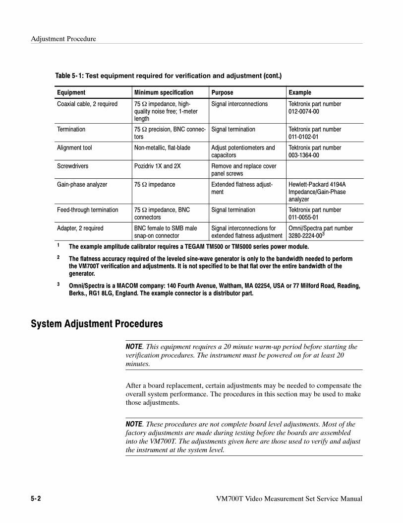
Adjustment Procedure
5- 2 VM700T Video Measurement Set Service Manual
Table 5- 1: Test equipment required for verification and adjustment (cont.)
Equipment ExamplePurposeMinimum specification
Coaxial cable, 2 required 75 Ω impedance, high-quality noise free; 1-meterlength
Signal interconnections Tektronix part number012-0074-00
Termination 75 Ω precision, BNC connec-tors
Signal termination Tektronix part number011-0102-01
Alignment tool Non-metallic, flat-blade Adjust potentiometers andcapacitors
Tektronix part number003-1364-00
Screwdrivers Pozidriv 1X and 2X Remove and replace coverpanel screws
Gain-phase analyzer 75 Ω impedance Extended flatness adjust-ment
Hewlett-Packard 4194AImpedance/Gain-Phaseanalyzer
Feed-through termination 75 Ω impedance, BNCconnectors
Signal termination Tektronix part number011-0055-01
Adapter, 2 required BNC female to SMB malesnap-on connector
Signal interconnections forextended flatness adjustment
Omni/Spectra part number3280-2224-003
1 The example amplitude calibrator requires a TEGAM TM500 or TM5000 series power module.
2 The flatness accuracy required of the leveled sine-wave generator is only to the bandwidth needed to performthe VM700T verification and adjustments. It is not specified to be that flat over the entire bandwidth of thegenerator.
3 Omni/Spectra is a MACOM company: 140 Fourth Avenue, Waltham, MA 02254, USA or 77 Milford Road, Reading,Berks., RG1 8LG, England. The example connector is a distributor part.
System Adjustment Procedures
NOTE. This equipment requires a 20 minute warm-up period before starting the
verification procedures. The instrument must be powered on for at least 20
minutes.
After a board replacement, certain adjustments may be needed to compensate theoverall system performance. The procedures in this section may be used to makethose adjustments.
NOTE. These procedures are not complete board level adjustments. Most of the
factory adjustments are made during testing before the boards are assembled
into the VM700T. The adjustments given here are those used to verify and adjust
the instrument at the system level.
Adjustment Procedure
VM700T Video Measurement Set Service Manual 5- 3
This procedure verifies the VM700T genlock VCO by comparing it to afrequency standard and describes the adjustment process if that is needed.
Test Equipment Required
Signal generator. Tektronix TSG-170A or equivalent for NTSC or TektronixTSG-271 or equivalent for PAL. Both signal generators are needed fordual-standard instruments.
Frequency counter with external reference or Ratio A/B. TektronixDC 503A, TEGAM DC 503A, or equivalent.
Digital voltmeter with 3-1/2-digit display.
Termination, 75 Ω precision BNC. Tektronix 011-0102-01.
Coaxial cables, 75 Ω high-quality, noise free BNC; 1-meter length, 2 each.Tektronix 012-0074-00.
Non-metallic, flat-blade adjusting tool. Tektronix 003-1364-00.
NOTE. This procedure requires access to a radio-frequency standard signal. If
you do not have access to a radio-frequency standard signal, do not attempt to
adjust the frequency of the VM700T genlock crystal oscillator.
Specification Checked
Genlock VCO: within ±5 Hz of a radio-frequency standard 1 MHz signal whenchecked with the following procedure. Single standard instruments, either NTSCor PAL, need only one VCO checked. For dual-standard instruments, both thePAL and the NTSC VCO must be checked.
Verifying the Genlock Voltage-Controlled Oscillator
1. Connect a radio-frequency standard 1 MHz signal to the external referenceinput of the frequency counter (channel B of the example counter).
2. Connect the subcarrier output of the appropriate video signal generator(NTSC or PAL) to the signal input of the frequency counter (channel A ofthe example counter).
3. Using the suggested frequency counter, the ratio of the channel A to channelB signal is used to determine when the frequency of the test signal isadjusted correctly. Adjust the signal generator until the frequency counterdisplays the exact TV standard subcarrier frequency for the VCO beingchecked (3.579545 MHz for NTSC or 4.43361875 for PAL).
4. Connect the composite video output of the signal generator to the VM700Tchannel A input (terminate channel A with the 75 Ω termination).
Adjust the GenlockVoltage-ControlledOscillator (VCO)
Adjustment Procedure
5- 4 VM700T Video Measurement Set Service Manual
5. With the VM700T powered off, remove the three top cover holding screws(found at the rear of the instrument) and slide the top cover panel backenough to expose the genlock board (just behind the CRT module). Power onthe instrument and allow it to warm for 20 minutes if not already warmedup.
6. For dual-standard instruments, select either NTSC or PAL mode, as neededfor the VCO being checked. This may be done by pressing the Measure hardkey then the Video~Standard soft key to identify the applied compositevideo signal source. Then press the Waveform hard key to return to theWaveform mode. Selecting the TV standard in this manner is temporary, andthe configuration returns to match that set in the Video Source file at the nextpower on. Alternately, you may use the Configure menus to set the VideoSource file for the TV standard you have applied to the channel.
7. Connect the DVM plus lead to TP 86 on the Genlock board and the minuslead to chassis ground. Check that the voltage is about 0 V (0 V ± 250 mV).The VM700T must be locked to the external input signal.
NOTE. If the VM700T meets the limits described, skip step 8 and go to step 9.
Adjusting the VM700T unnecessarily (for example, to get a “better” reading on
a calibration result that is within limits) can introduce errors into a functional
instrument.
8. Adjust the VCO adjusting screw for the TV standard you are checking(either NTSC or PAL) for a DVM reading as close as possible to 0 V (0 V± 250 mV or better). The VCOs are located in metal housings on theGenlock board near the back of the Display Monitor (CRT) (see Figure 5--1).
NOTE. If your instrument is a dual standard instrument, check both VCOs before
continuing with step 9.
9. Disconnect the DVM from the VM700T and reinstall the instrument covers.
10. Disconnect all signal inputs from the VM700T, then wait 5 minutes whilethe internal temperature of the instrument stabilizes.
11. Press the Measure hard key and touch the Video soft key, if necessary, torecall the Video measurement menu.
12. Touch the Burst Frequency soft key. With no signal applied, the VM700Tdisplays a warning message that tells you to check the signal source becausea signal cannot be found. The burst frequency measurement starts automati-cally after 3 seconds (the Loss of Sync indicator blinks).
13. Press the Menu hard key and touch the Reference soft key in the menudisplay.
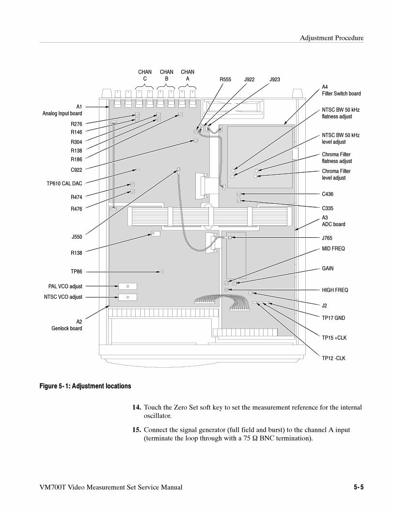
Adjustment Procedure
VM700T Video Measurement Set Service Manual 5- 5
CHANC
CHANB
CHANA R555 J922 J923
A4Filter Switch board
NTSC BW 50 kHzflatness adjust
NTSC BW 50 kHzlevel adjust
Chroma Filterflatness adjust
Chroma Filterlevel adjust
C436
C335
J765
MID FREQ
GAIN
HIGH FREQ
J2
TP17 GND
TP15 +CLK
TP12 -CLK
A3ADC board
A1Analog Input board
R276
R304
R186
C922
TP610 CAL DAC
R474
R476
J550
R138
PAL VCO adjust
NTSC VCO adjust
A2Genlock board
R146
R138
TP86
Figure 5- 1: Adjustment locations
14. Touch the Zero Set soft key to set the measurement reference for the internaloscillator.
15. Connect the signal generator (full field and burst) to the channel A input(terminate the loop through with a 75 Ω BNC termination).
Adjustment Procedure
5- 6 VM700T Video Measurement Set Service Manual
16. Check that the burst frequency measurement is 0 ± 10 Hz using the internalfrequency reference. Do this procedure for NTSC and PAL TV signals if theVM700T is a dual standard instrument.
NOTE. If the VM700T meets the limits described, skip step 17. Adjusting the
VM700T unnecessarily (for example, to get a “better” reading on a calibration
result that is within limits) can introduce errors into a functional instrument.
17. If adjustment is needed, slide the top cover back enough to expose theGenlock board and quickly adjust R138, TCXO REFERENCE, on theGenlock board to set the Burst Frequency measurement to zero. Slide the topcover back on the VM700T. After 5 minutes, check the Burst Frequencymeasurement again to verify that it remains within tolerance.
NOTE. If you performed this procedure after getting out-of-limit results from
Measuring the Burst Frequency in the Performance Verification procedure return
to finish the verification steps now.
This procedure is used to adjust the frequency response flatness over theoperating range of the VM700T after a board exchange repair or after it isdetermined that the flatness is out of tolerance by doing the Measure Sinewavecheck procedure.
Test Equipment Required
Leveled sine-wave generator, 75 Ω output impedance, output flat within±0.025 dB (±0.3%) to 6 MHz. Example: HP 3336C with option 005.
Termination, 75 Ω precision, Tektronix part number 011-0102-01, orequivalent.
Coaxial cable, 75 Ω high-quality noise free; 1-meter length. Tektronix partnumber 012-0074-00.
Adjusting Filter Flatness
1. Set the leveled sine-wave generator for 50 kHz at 500 mV into 75 Ω.
NOTE. If the example leveled sine-wave generator is being used, the output level
is set to –3.81 dBm.
2. Connect channel A of the VM700T to the leveled sine-wave generator andterminate the channel A loop-through output connection in 75 Ω.
Adjust Filter Flatness
Adjustment Procedure
VM700T Video Measurement Set Service Manual 5- 7
3. Press the Measure hard key and move to the VM700T Diagnostics directoryby pressing the Diags soft key if necessary. In the Diagnostics directory, runthe sine-wave measurement application by pressing the Measure~Sinewavesoft key.
4. Once the measurement application has initialized, turn averaging on bypressing the Average hard key until the Average hard key light is on. Whenthe display stabilizes, press the Freeze hard key. The Delta Amp readingshould remain at 0. If the Delta Amp reading changes, press the Freeze keyagain, as many times as needed, until the Delta Amp reading remains at 0.This is now the reference to which all other measurements are compared.
5. Set the leveled sine-wave generator for 4.43 MHz; do not change the outputlevel setting.
6. To speed up the response to the frequency change, toggle the Average hardkey off, then back on again after the display has re-stabilized.
7. Check that the change in amplitude is within ± 0.5% of the 50 kHz referencelevel stored in step 4. If the amplitude is in tolerance skip to step 8. If it isn’t,turn off Averaging (so you can see response changes). Adjust C57 (MidFrequency) on the ADC board to bring the flatness at 4.43 MHz intospecification (approximately ±0.02% or less difference when compared tothe 50 kHz reference).
8. Set the leveled sine-wave generator for 5.8 MHz, but do not change theoutput level setting.
9. If Averaging is on, speed up the response to the frequency change bytoggling the “Average” hard key off, then back on again after the display hasre-stabilized.
10. Check that the amplitude is within ± 0.55% of the reference level stored instep 4. If it is in tolerance skip to step 11.
If the amplitude is out of tolerance, you can try the adjustment of step 7 again toset the amount of change (Delta Amp) to the positive side of the tolerance (thatis, nearer the +0.02% limit) as a compromise. You may also need to start theprocedure all over again to re-establish the reference level (it may have driftedslightly from when you first acquired it).
You should next determine if the problem is only on one channel or on allchannels. If only one channel is involved, the Analog Input board may need theflatness adjustments for the input channels done (that procedure is described inthe Extended Adjustment Procedure later in this section). If all channels areinvolved, the ADC board may need adjustment or repair (part of the AnalogInput board is also a single-channel signal path, but the ADC board is the mostlikely problem area when all channels are affected).
Adjustment Procedure
5- 8 VM700T Video Measurement Set Service Manual
11. Change the TV standard parameter from PAL to NTSC by pressing the XYArrow hard key. Change the filter selection from No Filter to NTSCBand-Width Limiting Filter by pressing the Move/Expand hard key until thefilter displays NTSC BW Lim.
12. Return the leveled sine-wave generator to 50 kHz; do not change the outputlevel setting.
13. Let the display stabilize.
14. Adjust the NTSC BP filter 50 kHz Level adjust on the Filter Switch board sothat the change in amplitude (Delta Amp) is within ± 0.02% of the referencelevel stored in step 4. See Figure 5--1 on page 5--5 for the adjustmentlocations.
15. Reset the leveled sine-wave generator for 3.6 MHz; do not change the outputlevel setting.
16. Let the display stabilize.
17. Adjust the NTSC BP Filter Flatness adjust on the Filter Switch board so thechange in amplitude (Delta Amp) is within ± 0.02% of the reference levelstored in step 4.
18. Change the Filter parameter from NTSC BW Lim to Chroma BP by pressingthe Move/Expand hard key. Don’t change the settings on the leveledsine-wave generator.
19. Let the display stabilize.
20. Adjust the Chroma Filter Level adjust, so that the change in amplitude(Delta Amp) is within ± 0.02% of the reference level stored in step 5.
21. Change the TV standard parameter to PAL by pressing the XY Arrow hardkey.
22. Change the leveled sine-wave generator frequency to 4.43 MHz, but do notchange the output level setting.
23. Let the display stabilize.
24. Adjust the Chroma Filter Flatness adjust, so that the change in amplitude(Delta Amp) is within ± 0.02% of the reference level stored in step 4.
25. Disconnect the cables and test equipment from the VM700T.
Adjustment Procedure
VM700T Video Measurement Set Service Manual 5- 9
The ADC gain is auto-calibrated during normal VM700T operation. This checkand adjustment should only be done as part of a board exchange repair to set theadjustment to a nominal setting for auto-calibration.
Test Equipment Required
Non-metallic, flat-blade adjusting tool. Tektronix part number 003-1364-00.
Adjusting ADC Gain
1. Press the Measure key, then the Diags and the ADC Gain Adjust soft keys.
2. The VM700T should display 100% ± 3%.
NOTE. If the VM700T meets the limits described, skip step 3. Adjusting the
VM700T unnecessarily (for example, to get a “better” reading on a calibration
result that is within limits) can introduce errors into a functional instrument.
3. If the number displayed is outside the tolerance range, remove the top coverof the VM700T and carefully adjust R21, ADC Gain, on the ADC board(A3) to bring the number to 100%. See Figure 5--1 on page 5--5 for theadjustment location.
This procedure adjusts the calibration DAC. Run this procedure by selecting itwith the soft key in the Diags directory. Follow the directions displayed on theVM700T screen for adjusting the Analog Input board (A1) amplitude and offsetvoltages.
Test Equipment Required
Digital voltmeter with 3-1/2-digit display.
Non-metallic, flat-blade adjusting tool. Tektronix part number 003-1364-00.
NOTE. Run this procedure only if Verification Procedure 1 (Measure Square-
wave) yields incorrect results. Adjusting the VM700T unnecessarily (for
example, to get a “better” reading on a calibration result that is within limits)
can introduce errors into a functional instrument.
Adjusting the CalDAC
1. Press the Measure button and the Diags soft key.
2. Press the CalDAC adjustment soft key.
Adjust ADC Gain
Adjust the CalibrationDAC (CalDAC)
Adjustment Procedure
5- 10 VM700T Video Measurement Set Service Manual
3. Remove the VM700T top cover and connect the digital voltmeter to TP610on the analog input board (A1).
4. Adjust R474, CalDac Offset, on the Analog Input board for –1.2793 V.
5. Press the C button.
6. Adjust R476, CalDac Reference, on the Analog Input board for 0.0000 V.
7. Press the C button.
8. Check for a +1.2777 V (±0.001 V) reading at TP610.
9. Press the Measure button to exit the CalDAC procedure.
10. Power off the VM700T and replace the top cover.
NOTE. If you performed this procedure after getting out-of-limit results from
Verification Procedure 1 (Measure Squarewave), return to Procedure 1 now.
This procedure adjusts the display after a monitor or CPU board replacement.The replacement monitor, when supplied by Tektronix, has been aligned forproper operation in the VM700T, but Trace Rotation (a monitor control) andvertical and horizontal centering and size (CPU board controls) may be needed toalign the replacement display. The final procedure is to set the power-up displayintensity and calibrate the touch screen.
Test Equipment Required
Non-metallic, flat-blade adjusting tool. Tektronix part number 003-1364-00.
Adjusting the Display Monitor
1. Power off the instrument, disconnect its power cord, and remove the left-and right-side covers.
2. Reconnect power to the VM700T, press and hold the Waveform button whenyou turn the power on. After the instrument beeps twice release the button,and let it complete its power on initialization. The waveform graticule is thedefault display at power on.
3. Look at the lower left corner of the waveform graticule. It should form a 90degree right angle. If not, adjust the Trace Rotation control (located on theleft side of the monitor chassis) to level the form graticule trace across thescreen.
4. Turn the VM700T off.
Adjust the Display
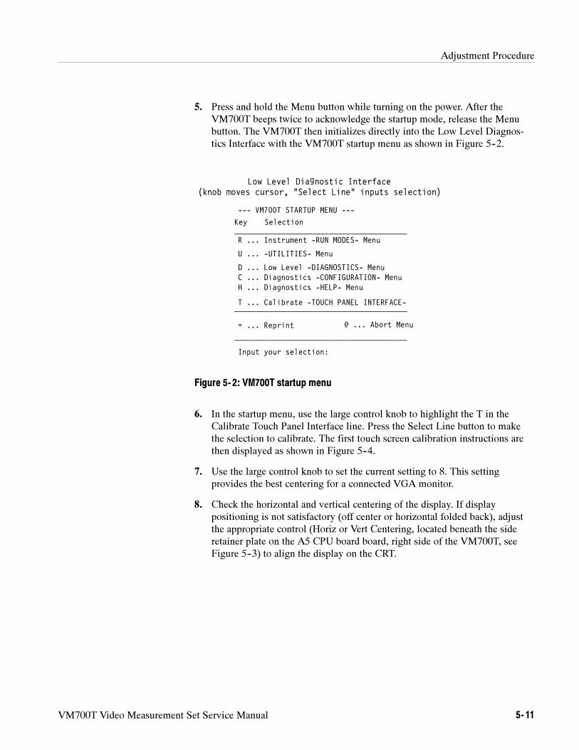
Adjustment Procedure
VM700T Video Measurement Set Service Manual 5- 11
5. Press and hold the Menu button while turning on the power. After theVM700T beeps twice to acknowledge the startup mode, release the Menubutton. The VM700T then initializes directly into the Low Level Diagnos-tics Interface with the VM700T startup menu as shown in Figure 5--2.
Low Level Diagnostic Interface(knob moves cursor, “Select Line” inputs selection)
Key Selection________________________________________
H ... Diagnostics -HELP- Menu
R ... Instrument -RUN MODES- Menu
D ... Low Level -DIAGNOSTICS- Menu
________________________________________
= ... Reprint________________________________________
Input your selection:
U ... -UTILITIES- Menu
T ... Calibrate -TOUCH PANEL INTERFACE-
--- VM700T STARTUP MENU ---
C ... Diagnostics -CONFIGURATION- Menu
@ ... Abort Menu
Figure 5- 2: VM700T startup menu
6. In the startup menu, use the large control knob to highlight the T in theCalibrate Touch Panel Interface line. Press the Select Line button to makethe selection to calibrate. The first touch screen calibration instructions arethen displayed as shown in Figure 5--4.
7. Use the large control knob to set the current setting to 8. This settingprovides the best centering for a connected VGA monitor.
8. Check the horizontal and vertical centering of the display. If displaypositioning is not satisfactory (off center or horizontal folded back), adjustthe appropriate control (Horiz or Vert Centering, located beneath the sideretainer plate on the A5 CPU board board, right side of the VM700T, seeFigure 5--3) to align the display on the CRT.
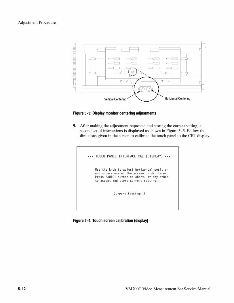
Adjustment Procedure
5- 12 VM700T Video Measurement Set Service Manual
Horizontal CenteringVertical Centering
Figure 5- 3: Display monitor centering adjustments
9. After making the adjustment requested and storing the current setting, asecond set of instructions is displayed as shown in Figure 5--5. Follow thedirections given in the screen to calibrate the touch panel to the CRT display.
Use the knob to adjust horizontal position
--- TOUCH PANEL INTERFACE CAL (DISPLAY) ---
and squareness of the screen border lines.Press ‘AUTO’ button to abort, or any otherto accept and store current setting.
Current Setting: 8
Figure 5- 4: Touch screen calibration (display)
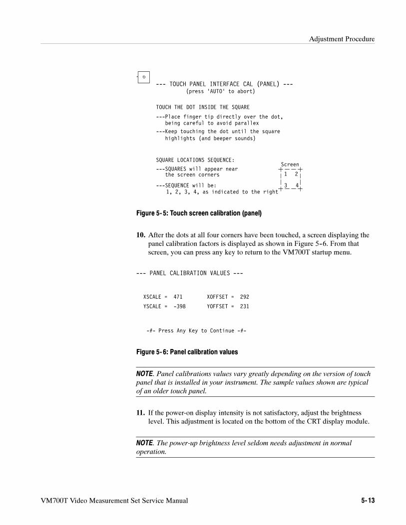
Adjustment Procedure
VM700T Video Measurement Set Service Manual 5- 13
.
--- TOUCH PANEL INTERFACE CAL (PANEL) ---(press ‘AUTO’ to abort)
TOUCH THE DOT INSIDE THE SQUARE
---Place finger tip directly over the dot,being careful to avoid parallex
---Keep touching the dot until the squarehighlights (and beeper sounds)
1 2
3 4
SQUARE LOCATIONS SEQUENCE:
---SQUARES will appear nearthe screen corners
---SEQUENCE will be:1, 2, 3, 4, as indicated to the right
Screen
Figure 5- 5: Touch screen calibration (panel)
10. After the dots at all four corners have been touched, a screen displaying thepanel calibration factors is displayed as shown in Figure 5--6. From thatscreen, you can press any key to return to the VM700T startup menu.
XSCALE = 471 XOFFSET = 292
--- PANEL CALIBRATION VALUES ---
-#- Press Any Key to Continue -#-
YSCALE = -398 YOFFSET = 231
Figure 5- 6: Panel calibration values
NOTE. Panel calibrations values vary greatly depending on the version of touch
panel that is installed in your instrument. The sample values shown are typical
of an older touch panel.
11. If the power-on display intensity is not satisfactory, adjust the brightnesslevel. This adjustment is located on the bottom of the CRT display module.
NOTE. The power-up brightness level seldom needs adjustment in normal
operation.
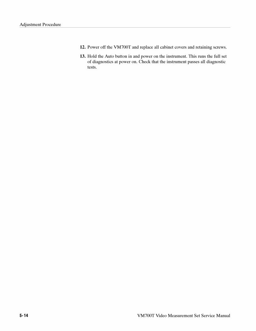
Adjustment Procedure
5- 14 VM700T Video Measurement Set Service Manual
12. Power off the VM700T and replace all cabinet covers and retaining screws.
13. Hold the Auto button in and power on the instrument. This runs the full setof diagnostics at power on. Check that the instrument passes all diagnostictests.
Adjustment Procedure
VM700T Video Measurement Set Service Manual 5- 15
Extended Adjustment Procedure
After a board exchange in the analog input section of the instrument, the analogsystem may need readjustment. This procedure first checks the overall systemresponse. If the verification checks fail, the system may need readjustment. Theadjustments provided are to compensate the system frequency response after aboard replacement; they are not complete board level adjustments. Use theadjustments only as necessary to return the instrument to specification.
NOTE. This procedure requires precision test equipment to make the needed
measurements for alignment. If you do not have the required test equipment, it is
recommend that you have the adjustment procedure done by Tektronix Customer
Service. Contact your nearest Tektronix representative for information.
Test Equipment Required
Gain-phase analyzer, 75 Ω output impedance. Example: Hewlett Packard4194A Impedance/Gain-phase analyzer.
Leveled sine-wave generator, 75 Ω output impedance; output flat within+0.025 dB ([0.3%) to 6 MHz. Example: Hewlett-Packard 3336C Sine-wavegenerator with option 005.
Coaxial cable, 75 Ω high-quality, low-noise BNC; 1-meter length, 2 each.Tektronix part number 012-0074-00.
Termination, 75 Ω feed-through BNC. Tektronix part number 011-0055-01.
Termination, 75 Ω precision BNC. Tektronix part number 011-0102-01.
Female-to-female adapter BNC. Tektronix part number 103-0070-00.
Adapter, snap-on SMB male to BNC female, 2 each. Example: Omni/Spectrapart number 3280-2224-00.
Non-metallic, flat-blade adjustment tool. Tektronix part number003-1364-00.
Specification Checked
Analog board frequency response: flat within 30 mdB to 8 MHz whenchecked with setup described.
System frequency response: flat within 30 mdB to 6 MHz when checkedwith setup described.
Adjust the FrequencyResponse
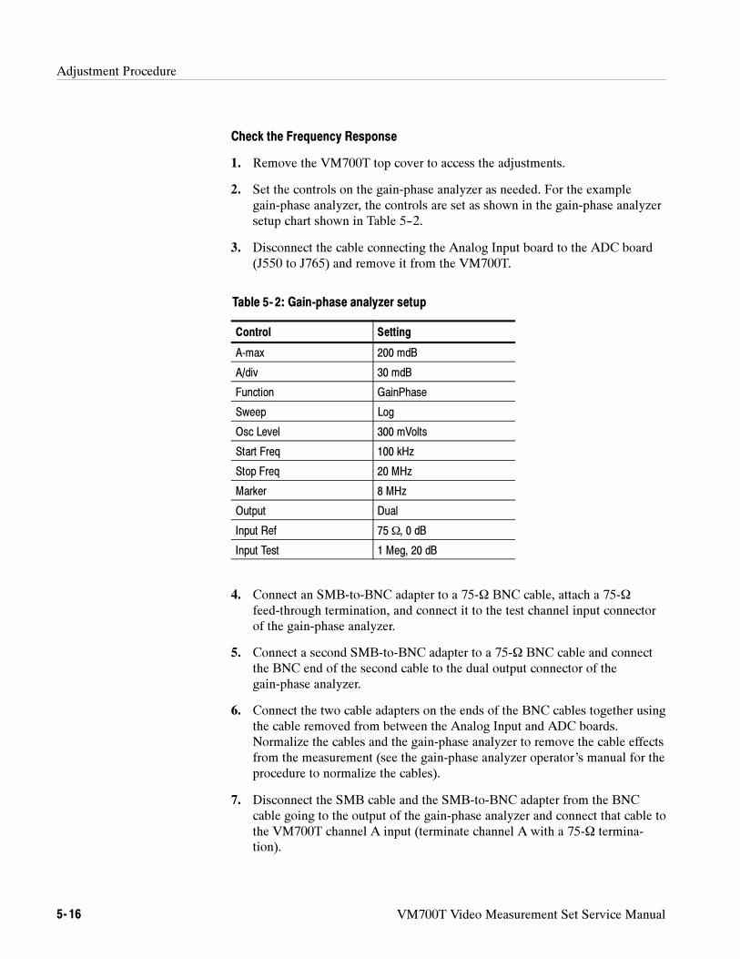
Adjustment Procedure
5- 16 VM700T Video Measurement Set Service Manual
Check the Frequency Response
1. Remove the VM700T top cover to access the adjustments.
2. Set the controls on the gain-phase analyzer as needed. For the examplegain-phase analyzer, the controls are set as shown in the gain-phase analyzersetup chart shown in Table 5--2.
3. Disconnect the cable connecting the Analog Input board to the ADC board(J550 to J765) and remove it from the VM700T.
Table 5- 2: Gain-phase analyzer setup
Control Setting
A-max 200 mdB
A/div 30 mdB
Function GainPhase
Sweep Log
Osc Level 300 mVolts
Start Freq 100 kHz
Stop Freq 20 MHz
Marker 8 MHz
Output Dual
Input Ref 75 Ω, 0 dB
Input Test 1 Meg, 20 dB
4. Connect an SMB-to-BNC adapter to a 75-Ω BNC cable, attach a 75-Ωfeed-through termination, and connect it to the test channel input connectorof the gain-phase analyzer.
5. Connect a second SMB-to-BNC adapter to a 75-Ω BNC cable and connectthe BNC end of the second cable to the dual output connector of thegain-phase analyzer.
6. Connect the two cable adapters on the ends of the BNC cables together usingthe cable removed from between the Analog Input and ADC boards.Normalize the cables and the gain-phase analyzer to remove the cable effectsfrom the measurement (see the gain-phase analyzer operator’s manual for theprocedure to normalize the cables).
7. Disconnect the SMB cable and the SMB-to-BNC adapter from the BNCcable going to the output of the gain-phase analyzer and connect that cable tothe VM700T channel A input (terminate channel A with a 75-Ω termina-tion).
Adjustment Procedure
VM700T Video Measurement Set Service Manual 5- 17
8. Connect the input of the gain-phase analyzer to J550 on the Analog Inputboard through the SMB cable, SMB-to-BNC adapter, and BNC cable justnormalized.
9. Bypass the Filter Switch board by removing the cables from J922 and J923on the Analog Input board and connecting the jumper (removed from J924)between J922 pin 2 and J923 pin 2.
10. Check that the frequency response for channel A is flat within 30 mdBpeak-to-peak (one major division on the example test equipment display) to8 MHz.
NOTE. If the frequency response for channel A meets the specification, do not
make any adjustment to attempt to improve the response curve of channel A.
11. If the channel A frequency response is outside the limits specified in step 11,adjust R186, C922, and R555 for a flat response on the analyzer out to8,018,669.64 Hz. (see Figure 5--1 on page 5--5 for adjustment locations).The following steps describe the procedure.
a. Set R186 and R555 at midrange.
b. Adjust C922 to get the 6 MHz to 10 MHz portion of the response curvecentered.
c. Adjust R555 to flatten the response ripple and C922 to control peakingand rolloff of the response curve.
d. If the best result is rolled off, adjust R186 to bring the response curve up.If the response curve is peaked, adjust R186 to roll it off. Note that theresponse is specified only to 8 MHz, so it is permissible to have peakingor roll off above 8 MHz to produce a flatter response curve from 0 to8 MHz.
12. Store a reference waveform of the channel A frequency response. On theexample Gain/Phase Analyzer, press Display, Superimpose, Store, andRecall A.
13. Select #1, select Input Source, and select B on the VM700T for channel Binput.
14. Move the cable and terminator to the channel B feedthrough connectors onthe rear panel of the VM700T.
15. Check that the channel B response curve matches the stored channel Aresponse curve within specification. If the response curve for channel B doesnot match the stored channel A trace, adjust R304 (and R138 if necessary) tomatch the the stored trace.
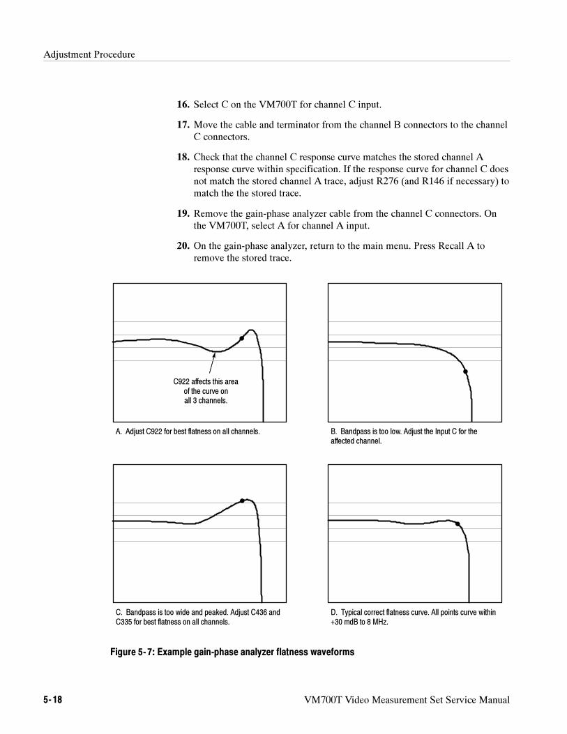
Adjustment Procedure
5- 18 VM700T Video Measurement Set Service Manual
16. Select C on the VM700T for channel C input.
17. Move the cable and terminator from the channel B connectors to the channelC connectors.
18. Check that the channel C response curve matches the stored channel Aresponse curve within specification. If the response curve for channel C doesnot match the stored channel A trace, adjust R276 (and R146 if necessary) tomatch the the stored trace.
19. Remove the gain-phase analyzer cable from the channel C connectors. Onthe VM700T, select A for channel A input.
20. On the gain-phase analyzer, return to the main menu. Press Recall A toremove the stored trace.
A. Adjust C922 for best flatness on all channels. B. Bandpass is too low. Adjust the Input C for theaffected channel.
C. Bandpass is too wide and peaked. Adjust C436 andC335 for best flatness on all channels.
D. Typical correct flatness curve. All points curve within+30 mdB to 8 MHz.
C922 affects this areaof the curve onall 3 channels.
Figure 5- 7: Example gain-phase analyzer flatness waveforms
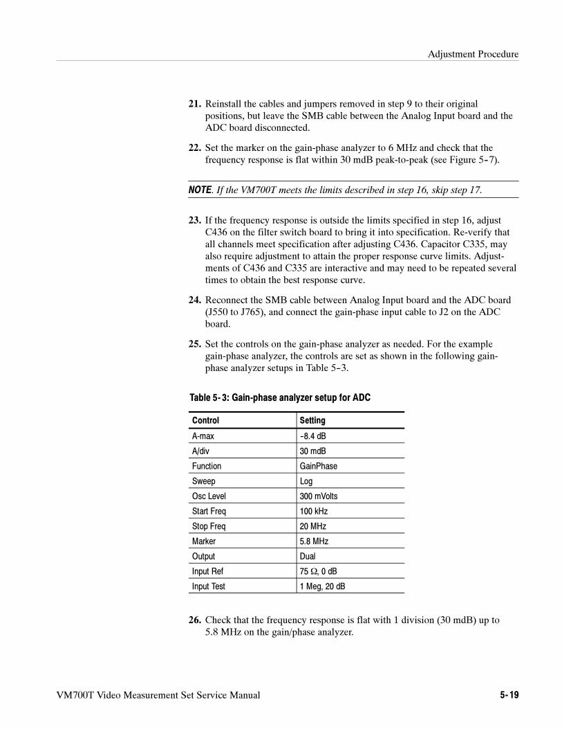
Adjustment Procedure
VM700T Video Measurement Set Service Manual 5- 19
21. Reinstall the cables and jumpers removed in step 9 to their originalpositions, but leave the SMB cable between the Analog Input board and theADC board disconnected.
22. Set the marker on the gain-phase analyzer to 6 MHz and check that thefrequency response is flat within 30 mdB peak-to-peak (see Figure 5--7).
NOTE. If the VM700T meets the limits described in step 16, skip step 17.
23. If the frequency response is outside the limits specified in step 16, adjustC436 on the filter switch board to bring it into specification. Re-verify thatall channels meet specification after adjusting C436. Capacitor C335, mayalso require adjustment to attain the proper response curve limits. Adjust-ments of C436 and C335 are interactive and may need to be repeated severaltimes to obtain the best response curve.
24. Reconnect the SMB cable between Analog Input board and the ADC board(J550 to J765), and connect the gain-phase input cable to J2 on the ADCboard.
25. Set the controls on the gain-phase analyzer as needed. For the examplegain-phase analyzer, the controls are set as shown in the following gain-phase analyzer setups in Table 5--3.
Table 5- 3: Gain-phase analyzer setup for ADC
Control Setting
A-max --8.4 dB
A/div 30 mdB
Function GainPhase
Sweep Log
Osc Level 300 mVolts
Start Freq 100 kHz
Stop Freq 20 MHz
Marker 5.8 MHz
Output Dual
Input Ref 75 Ω, 0 dB
Input Test 1 Meg, 20 dB
26. Check that the frequency response is flat with 1 division (30 mdB) up to5.8 MHz on the gain/phase analyzer.
Adjustment Procedure
5- 20 VM700T Video Measurement Set Service Manual
27. If the frequency response is not flat within 30 mdB, adjust C57 (the MIDFREQ adjustment) and R22 (the HIGH FREQ adjustment) as needed toobtain the correct response. See Figure 5--1 on page 5--5 for the adjustmentlocations.
28. Disconnect both gain-phase test cables from the VM700T.
29. Connect the sine-wave generator and a terminator to the inputs of channel A.Set the sine-wave generator for a frequency of 43.297 kHz at a level of--3.81 dBm.
30. Select Measure mode on the VM700T. Then touch the Measure Sinewavesoft key. The measured reading is the reference used to compare the rest ofthe measurement to. It should be approximately 500 mV peak-to-peak.
31. Set the sine-wave generator for a frequency of 4.424959 MHz at a level of--3.82 dBm.
32. Check to see that the measured amplitude is within ±0.02% of the referencelevel measured in step 30. If it is not, adjust C57 (MID FREQUENCY) untilthe measured value is within ±0.02%.
33. Set the sine-wave generator for a frequency of 5.793146 MHz at a level of--3.81 dBm.
34. Check to see that the measured amplitude is within ±0.55% of the referencelevel measured in step 30.
35. Power off the VM700T and remove all the test cables.
36. Reinstall the instrument cover panels.
A final test is to run the complete set of VM700T diagnostics to verify that thesystem passes the tests.
1. Press and hold the Menu button and power on the VM700T.
2. After about 10 seconds you should hear two beeps from the VM700T.Release the Menu button.
3. In the VM700T Startup Menu shown in Figure 5--8, use the large controlknob to select R -- Instrument Run Modes Menu.
Run the Diagnostics
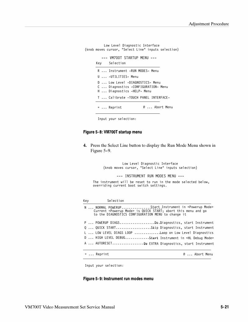
Adjustment Procedure
VM700T Video Measurement Set Service Manual 5- 21
Low Level Diagnostic Interface(knob moves cursor, “Select Line” inputs selection)
Key Selection
H ... Diagnostics -HELP- Menu
R ... Instrument -RUN MODES- Menu
D ... Low Level -DIAGNOSTICS- Menu
= ... Reprint
Input your selection:
U ... -UTILITIES- Menu
T ... Calibrate -TOUCH PANEL INTERFACE-
--- VM700T STARTUP MENU ---
C ... Diagnostics -CONFIGURATION- Menu
@ ... Abort Menu
Figure 5- 8: VM700T startup menu
4. Press the Select Line button to display the Run Mode Menu shown inFigure 5--9.
to the DIAGNOSTICS CONFIGURATION MENU to change it
Low Level Diagnostic Interface(knob moves cursor, “Select Line” inputs selection)
Key Selection
D ... HIGH LEVEL DEBUG..................
N ... NORMAL POWERUP......................
P ... POWERUP DIAGS.......................
= ... Reprint
Input your selection:
--- INSTRUMENT RUN MODES MENU ---
L ... LOW LEVEL DIAGS LOOP ................
Do Diagnostics, start Instrument
Loop on Low Level Diagnostics
Start Instrument in <HL Debug Mode>
@ ... Abort Menu
Start Instrument in <Powerup Mode>
The instrument will be reset to run in the mode selected below,overriding current boot switch settings.
Current <Powerup Mode> is QUICK START; abort this menu and go
A ... AUTORESET...................Do EXTRA Diagnostics, start Instrument
Q ... QUICK START......................Skip Diagnostics, start Instrument
Figure 5- 9: Instrument run modes menu
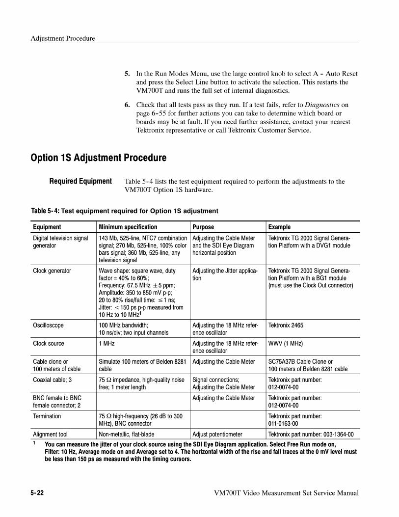
Adjustment Procedure
5- 22 VM700T Video Measurement Set Service Manual
5. In the Run Modes Menu, use the large control knob to select A -- Auto Resetand press the Select Line button to activate the selection. This restarts theVM700T and runs the full set of internal diagnostics.
6. Check that all tests pass as they run. If a test fails, refer to Diagnostics onpage 6--55 for further actions you can take to determine which board orboards may be at fault. If you need further assistance, contact your nearestTektronix representative or call Tektronix Customer Service.
Option 1S Adjustment Procedure
Table 5--4 lists the test equipment required to perform the adjustments to theVM700T Option 1S hardware.
Table 5- 4: Test equipment required for Option 1S adjustment
Equipment Minimum specification Purpose Example
Digital television signalgenerator
143 Mb, 525-line, NTC7 combinationsignal; 270 Mb, 525-line, 100% colorbars signal; 360 Mb, 525-line, anytelevision signal
Adjusting the Cable Meterand the SDI Eye Diagramhorizontal position
Tektronix TG 2000 Signal Genera-tion Platform with a DVG1 module
Clock generator Wave shape: square wave, dutyfactor = 40% to 60%;Frequency: 67.5 MHz5 ppm;Amplitude: 350 to 850 mV p-p;20 to 80% rise/fall time:≤1 ns;Jitter:<150 ps p-p measured from10 Hz to 10 MHz1
Adjusting the Jitter applica-tion
Tektronix TG 2000 Signal Genera-tion Platform with a BG1 module(must use the Clock Out connector)
Oscilloscope 100 MHz bandwidth;10 ns/div; two input channels
Adjusting the 18 MHz refer-ence oscillator
Tektronix 2465
Clock source 1 MHz Adjusting the 18 MHz refer-ence oscillator
WWV (1 MHz)
Cable clone or100 meters of cable
Simulate 100 meters of Belden 8281cable
Adjusting the Cable Meter SC75A37B Cable Clone or100 meters of Belden 8281 cable
Coaxial cable; 3 75 Ω impedance, high-quality noisefree; 1 meter length
Signal connections;Adjusting the Cable Meter
Tektronix part number:012-0074-00
BNC female to BNCfemale connector; 2
Adjusting the Cable Meter Tektronix part number:012-0074-00
Termination 75Ω high-frequency (26 dB to 300MHz), BNC connector
Tektronix part number:011-0163-00
Alignment tool Non-metallic, flat-blade Adjust potentiometer Tektronix part number: 003-1364-001 You can measure the jitter of your clock source using the SDI Eye Diagram application. Select Free Run mode on,
Filter: 10 Hz, Average mode on and Average set to 4. The horizontal width of the rise and fall traces at the 0 mV level mustbe less than 150 ps as measured with the timing cursors.
Required Equipment
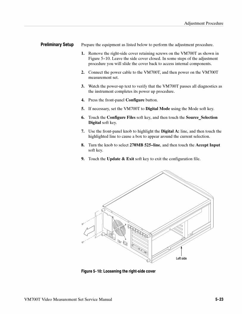
Adjustment Procedure
VM700T Video Measurement Set Service Manual 5- 23
Prepare the equipment as listed below to perform the adjustment procedure.
1. Remove the right-side cover retaining screws on the VM700T as shown inFigure 5--10. Leave the side cover closed. In some steps of the adjustmentprocedure you will slide the cover back to access internal components.
2. Connect the power cable to the VM700T, and then power on the VM700Tmeasurement set.
3. Watch the power-up text to verify that the VM700T passes all diagnostics asthe instrument completes its power up procedure.
4. Press the front-panel Configure button.
5. If necessary, set the VM700T to Digital Mode using the Mode soft key.
6. Touch the Configure Files soft key, and then touch the Source_SelectionDigital soft key.
7. Use the front-panel knob to highlight the Digital A: line, and then touch thehighlighted line to cause a box to appear around the current selection.
8. Turn the knob to select 270MB 525--line, and then touch the Accept Inputsoft key.
9. Touch the Update & Exit soft key to exit the configuration file.
Left side
Figure 5- 10: Loosening the right-side cover
Preliminary Setup
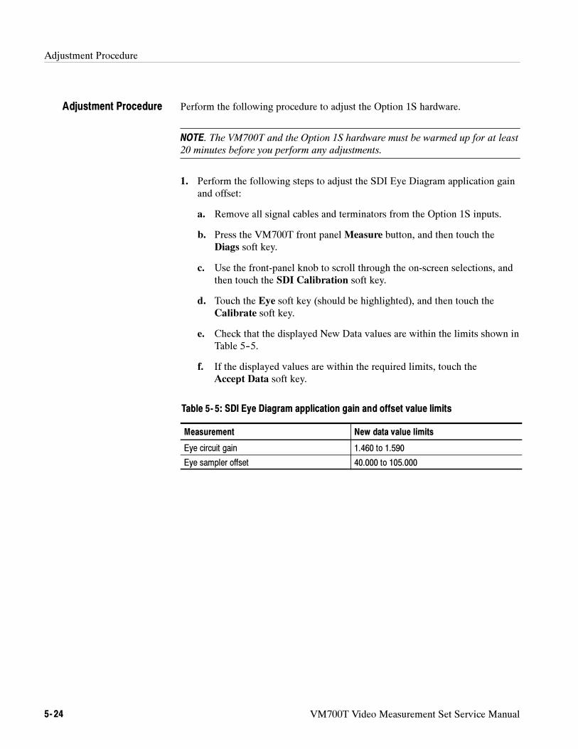
Adjustment Procedure
5- 24 VM700T Video Measurement Set Service Manual
Perform the following procedure to adjust the Option 1S hardware.
NOTE. The VM700T and the Option 1S hardware must be warmed up for at least
20 minutes before you perform any adjustments.
1. Perform the following steps to adjust the SDI Eye Diagram application gainand offset:
a. Remove all signal cables and terminators from the Option 1S inputs.
b. Press the VM700T front panel Measure button, and then touch theDiags soft key.
c. Use the front-panel knob to scroll through the on-screen selections, andthen touch the SDI Calibration soft key.
d. Touch the Eye soft key (should be highlighted), and then touch theCalibrate soft key.
e. Check that the displayed New Data values are within the limits shown inTable 5--5.
f. If the displayed values are within the required limits, touch theAccept Data soft key.
Table 5- 5: SDI Eye Diagram application gain and offset value limits
Measurement New data value limits
Eye circuit gain 1.460 to 1.590
Eye sampler offset 40.000 to 105.000
Adjustment Procedure
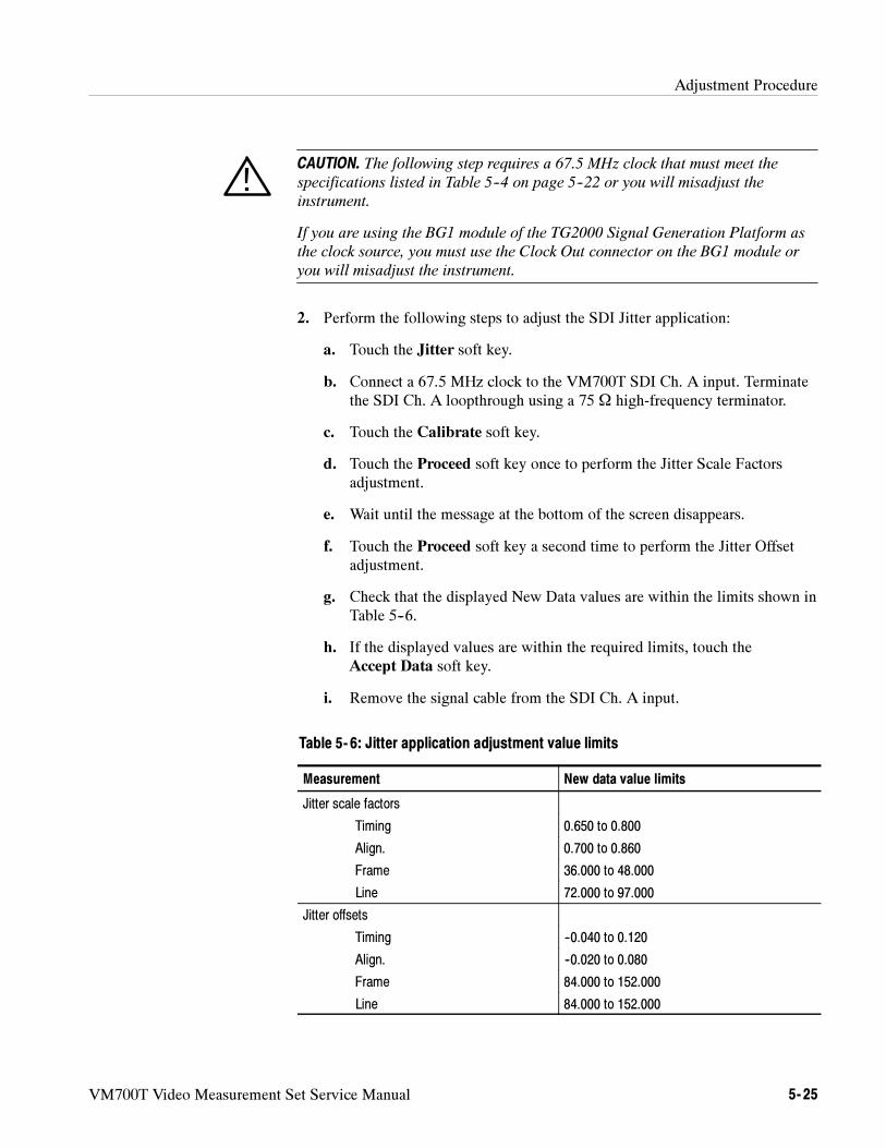
Adjustment Procedure
VM700T Video Measurement Set Service Manual 5- 25
CAUTION. The following step requires a 67.5 MHz clock that must meet the
specifications listed in Table 5--4 on page 5--22 or you will misadjust the
instrument.
If you are using the BG1 module of the TG2000 Signal Generation Platform as
the clock source, you must use the Clock Out connector on the BG1 module or
you will misadjust the instrument.
2. Perform the following steps to adjust the SDI Jitter application:
a. Touch the Jitter soft key.
b. Connect a 67.5 MHz clock to the VM700T SDI Ch. A input. Terminatethe SDI Ch. A loopthrough using a 75 Ω high-frequency terminator.
c. Touch the Calibrate soft key.
d. Touch the Proceed soft key once to perform the Jitter Scale Factorsadjustment.
e. Wait until the message at the bottom of the screen disappears.
f. Touch the Proceed soft key a second time to perform the Jitter Offsetadjustment.
g. Check that the displayed New Data values are within the limits shown inTable 5--6.
h. If the displayed values are within the required limits, touch theAccept Data soft key.
i. Remove the signal cable from the SDI Ch. A input.
Table 5- 6: Jitter application adjustment value limits
Measurement New data value limits
Jitter scale factors
Timing 0.650 to 0.800
Align. 0.700 to 0.860
Frame 36.000 to 48.000
Line 72.000 to 97.000
Jitter offsets
Timing --0.040 to 0.120
Align. --0.020 to 0.080
Frame 84.000 to 152.000
Line 84.000 to 152.000
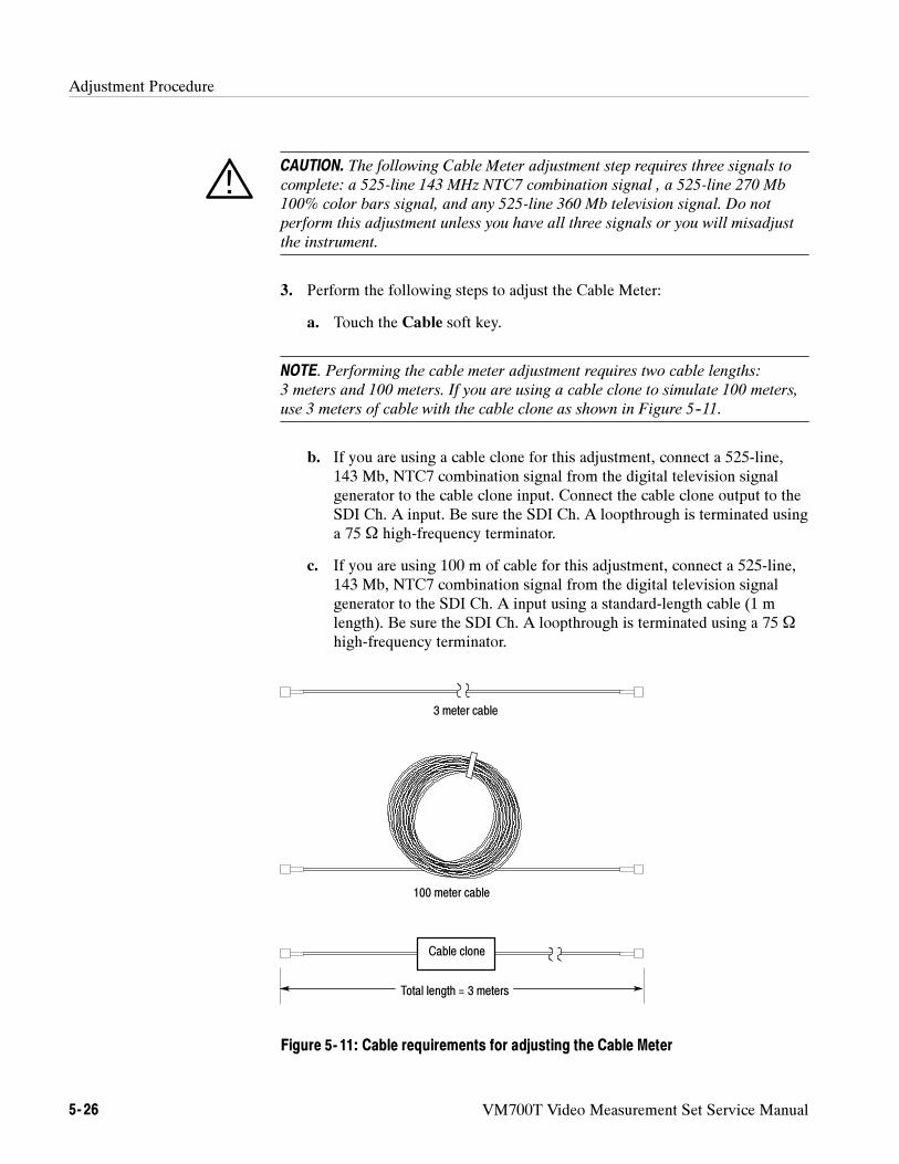
Adjustment Procedure
5- 26 VM700T Video Measurement Set Service Manual
CAUTION. The following Cable Meter adjustment step requires three signals to
complete: a 525-line 143 MHz NTC7 combination signal , a 525-line 270 Mb
100% color bars signal, and any 525-line 360 Mb television signal. Do not
perform this adjustment unless you have all three signals or you will misadjust
the instrument.
3. Perform the following steps to adjust the Cable Meter:
a. Touch the Cable soft key.
NOTE. Performing the cable meter adjustment requires two cable lengths:
3 meters and 100 meters. If you are using a cable clone to simulate 100 meters,
use 3 meters of cable with the cable clone as shown in Figure 5--11.
b. If you are using a cable clone for this adjustment, connect a 525-line,143 Mb, NTC7 combination signal from the digital television signalgenerator to the cable clone input. Connect the cable clone output to theSDI Ch. A input. Be sure the SDI Ch. A loopthrough is terminated usinga 75 Ω high-frequency terminator.
c. If you are using 100 m of cable for this adjustment, connect a 525-line,143 Mb, NTC7 combination signal from the digital television signalgenerator to the SDI Ch. A input using a standard-length cable (1 mlength). Be sure the SDI Ch. A loopthrough is terminated using a 75 Ω
high-frequency terminator.
3 meter cable
100 meter cable
Cable clone
Total length = 3 meters
Figure 5- 11: Cable requirements for adjusting the Cable Meter
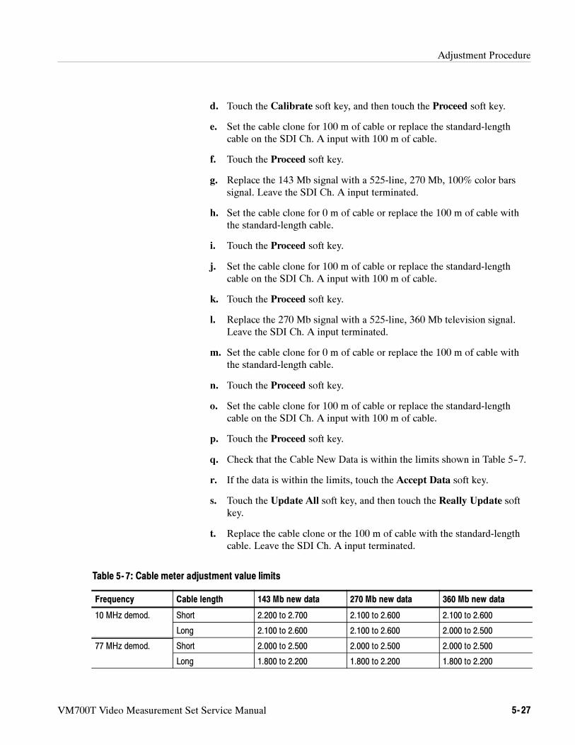
Adjustment Procedure
VM700T Video Measurement Set Service Manual 5- 27
d. Touch the Calibrate soft key, and then touch the Proceed soft key.
e. Set the cable clone for 100 m of cable or replace the standard-lengthcable on the SDI Ch. A input with 100 m of cable.
f. Touch the Proceed soft key.
g. Replace the 143 Mb signal with a 525-line, 270 Mb, 100% color barssignal. Leave the SDI Ch. A input terminated.
h. Set the cable clone for 0 m of cable or replace the 100 m of cable withthe standard-length cable.
i. Touch the Proceed soft key.
j. Set the cable clone for 100 m of cable or replace the standard-lengthcable on the SDI Ch. A input with 100 m of cable.
k. Touch the Proceed soft key.
l. Replace the 270 Mb signal with a 525-line, 360 Mb television signal.Leave the SDI Ch. A input terminated.
m. Set the cable clone for 0 m of cable or replace the 100 m of cable withthe standard-length cable.
n. Touch the Proceed soft key.
o. Set the cable clone for 100 m of cable or replace the standard-lengthcable on the SDI Ch. A input with 100 m of cable.
p. Touch the Proceed soft key.
q. Check that the Cable New Data is within the limits shown in Table 5--7.
r. If the data is within the limits, touch the Accept Data soft key.
s. Touch the Update All soft key, and then touch the Really Update softkey.
t. Replace the cable clone or the 100 m of cable with the standard-lengthcable. Leave the SDI Ch. A input terminated.
Table 5- 7: Cable meter adjustment value limits
Frequency Cable length 143 Mb new data 270 Mb new data 360 Mb new data
10 MHz demod. Short 2.200 to 2.700 2.100 to 2.600 2.100 to 2.600
Long 2.100 to 2.600 2.100 to 2.600 2.000 to 2.500
77 MHz demod. Short 2.000 to 2.500 2.000 to 2.500 2.000 to 2.500
Long 1.800 to 2.200 1.800 to 2.200 1.800 to 2.200
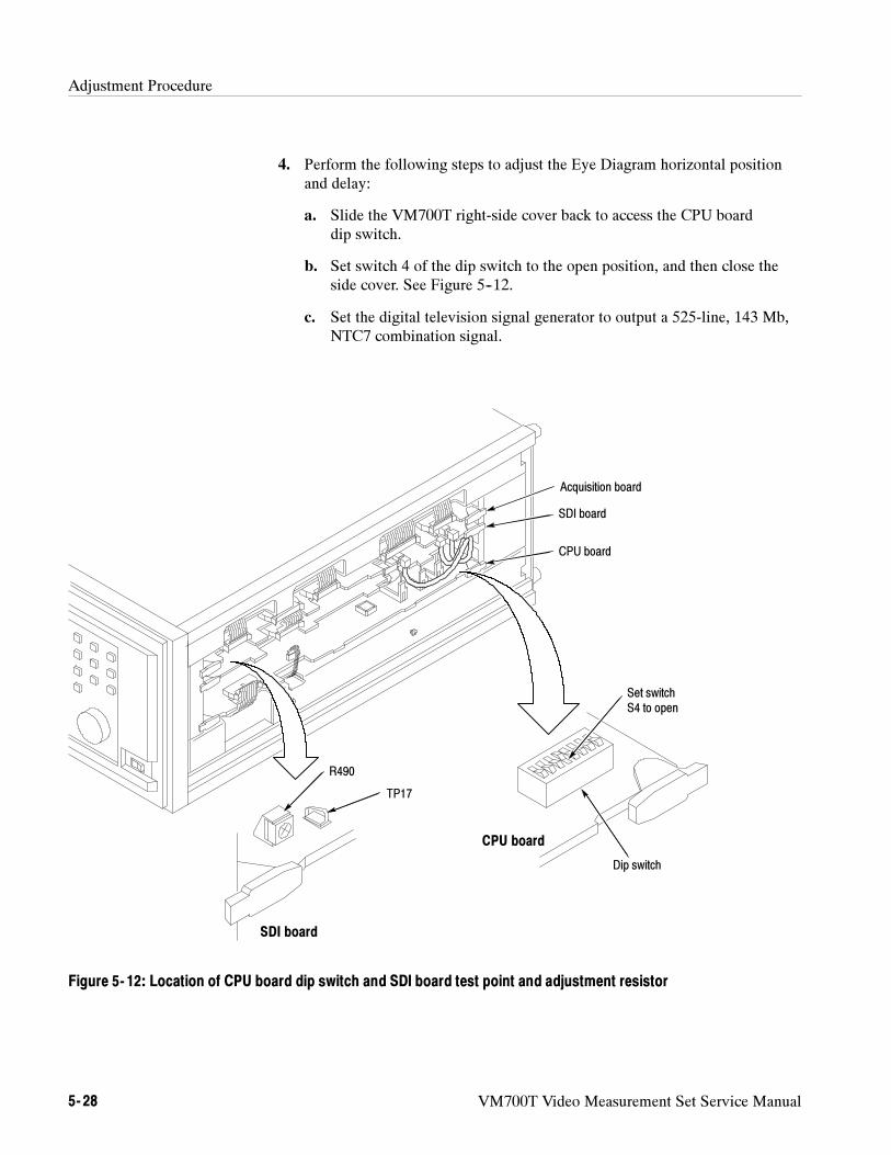
Adjustment Procedure
5- 28 VM700T Video Measurement Set Service Manual
4. Perform the following steps to adjust the Eye Diagram horizontal positionand delay:
a. Slide the VM700T right-side cover back to access the CPU boarddip switch.
b. Set switch 4 of the dip switch to the open position, and then close theside cover. See Figure 5--12.
c. Set the digital television signal generator to output a 525-line, 143 Mb,NTC7 combination signal.
Set switchS4 to open
Dip switch
TP17
R490
SDI board
CPU board
CPU board
SDI board
Acquisition board
Figure 5- 12: Location of CPU board dip switch and SDI board test point and adjustment resistor
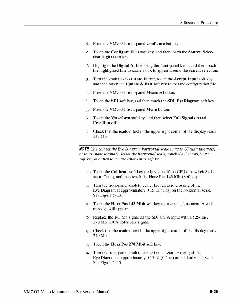
Adjustment Procedure
VM700T Video Measurement Set Service Manual 5- 29
d. Press the VM700T front-panel Configure button.
e. Touch the Configure Files soft key, and then touch the Source_Selec-tion Digital soft key.
f. Highlight the Digital A: line using the front-panel knob, and then touchthe highlighted line to cause a box to appear around the current selection.
g. Turn the knob to select Auto Detect, touch the Accept Input soft key,and then touch the Update & Exit soft key to exit the configuration file.
h. Press the VM700T front-panel Measure button.
i. Touch the SDI soft key, and then touch the SDI_EyeDiagram soft key.
j. Press the VM700T front-panel Menu button.
k. Touch theWaveform soft key, and then select Full Signal on andFree Run off.
l. Check that the readout text in the upper right corner of the display reads143 Mb.
NOTE. You can set the Eye Diagram horizontal scale units to UI (unit intervals)
or to ns (nanoseconds). To set the horizontal scale, touch the Cursors/Units
soft key, and then touch the Jitter Units soft key.
m. Touch the Calibrate soft key (only visible if the CPU dip switch S4 isset to Open), and then touch the Horz Pos 143 Mbit soft key.
n. Turn the front-panel knob to center the left zero crossing of theEye Diagram at approximately 0.15 UI (1 ns) on the horizontal scale.See Figure 5--13.
o. Touch the Horz Pos 143 Mbit soft key to save the adjustment. A waitmessage will appear.
p. Replace the 143 Mb signal on the SDI Ch. A input with a 525-line,270 Mb, 100% color bars signal.
q. Check that the readout text in the upper right corner of the display reads270 Mb.
r. Touch the Horz Pos 270 Mbit soft key.
s. Turn the front-panel knob to center the left zero crossing of theEye Diagram at approximately 0.15 UI (0.5 ns) on the horizontal scale.See Figure 5--13.
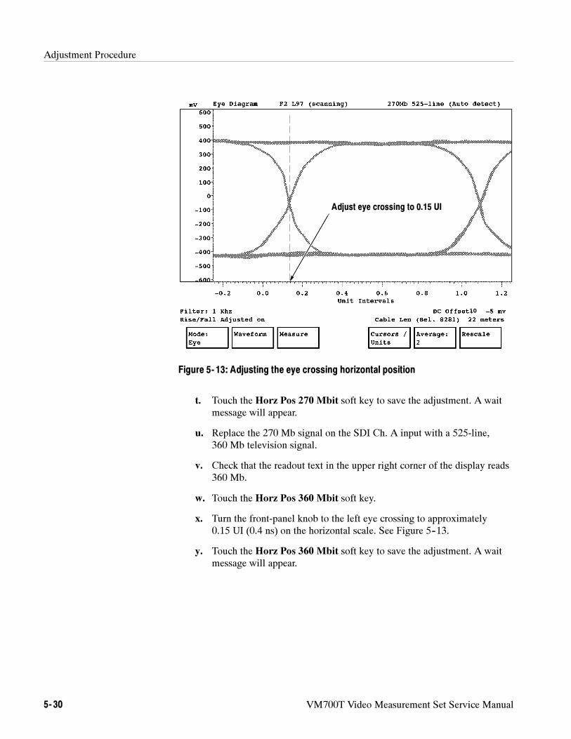
Adjustment Procedure
5- 30 VM700T Video Measurement Set Service Manual
10
Adjust eye crossing to 0.15 UI
Figure 5- 13: Adjusting the eye crossing horizontal position
t. Touch the Horz Pos 270 Mbit soft key to save the adjustment. A waitmessage will appear.
u. Replace the 270 Mb signal on the SDI Ch. A input with a 525-line,360 Mb television signal.
v. Check that the readout text in the upper right corner of the display reads360 Mb.
w. Touch the Horz Pos 360 Mbit soft key.
x. Turn the front-panel knob to the left eye crossing to approximately0.15 UI (0.4 ns) on the horizontal scale. See Figure 5--13.
y. Touch the Horz Pos 360 Mbit soft key to save the adjustment. A waitmessage will appear.
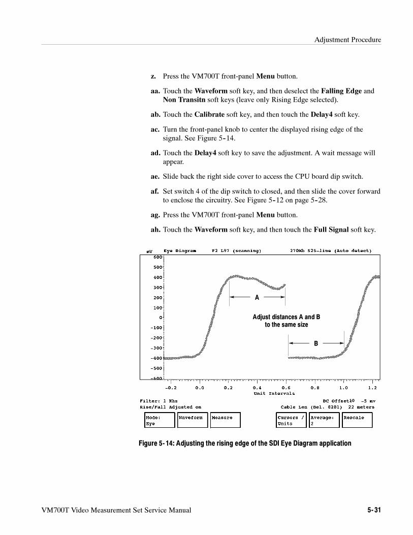
Adjustment Procedure
VM700T Video Measurement Set Service Manual 5- 31
z. Press the VM700T front-panel Menu button.
aa. Touch theWaveform soft key, and then deselect the Falling Edge andNon Transitn soft keys (leave only Rising Edge selected).
ab. Touch the Calibrate soft key, and then touch the Delay4 soft key.
ac. Turn the front-panel knob to center the displayed rising edge of thesignal. See Figure 5--14.
ad. Touch the Delay4 soft key to save the adjustment. A wait message willappear.
ae. Slide back the right side cover to access the CPU board dip switch.
af. Set switch 4 of the dip switch to closed, and then slide the cover forwardto enclose the circuitry. See Figure 5--12 on page 5--28.
ag. Press the VM700T front-panel Menu button.
ah. Touch theWaveform soft key, and then touch the Full Signal soft key.
10
A
B
Adjust distances A and Bto the same size
Figure 5- 14: Adjusting the rising edge of the SDI Eye Diagram application
Adjustment Procedure
5- 32 VM700T Video Measurement Set Service Manual
NOTE. The following step adjusts the 18 MHz reference oscillator by observing
the slip rate between the oscillator and the 1 MHz WWV reference signal. A slip
rate of 10 ns per second results in a maximum error of 0.01 ppm.
5. Perform the following step to adjust the 18 MHz reference oscillator.
a. Slide back the right side cover to access the SDI board test point andadjustment resistor. See Figure 5--12 on page 5--28.
b. Connect the 1 MHz WWV reference signal to channel 1 of youroscilloscope.
c. Connect a probe from channel 2 of the oscilloscope to TP17 on the SDIboard. See Figure 5--12 on page 5--28.
d. Set the oscilloscope as follows: 10 ns/div., DC coupled, channel 1 to500 mV/div. and 1 MΩ DC input, channel 2 to 500 mV/div. and 50 Ω
DC input, and triggered to channel 1 (WWV).
e. Adjust R490 on the SDI board (see Figure 5--12 on page 5--28) so thatthe channel 2 signal display on the oscilloscope is stationary (maximumhorizontal drift of less than 1 division per second).
f. Remove the probe from TP17 on the SDI board.
g. Slide the cover forward and install the side cover retaining screws. SeeFigure 5--10 on page 5--23.
h. Remove all cables and terminators from the VM700T.
VM700T Video Measurement Set Service Manual 6- 1
Maintenance
Preventive maintenance consists of cleaning, visual inspection, performanceverification, and, if needed, readjustment. The preventive maintenance scheduleestablished for the instrument should be based on its environment and theamount of use. Under average conditions, preventive maintenance should beperformed every 12 months of operation.
NOTE. If the instrument does not function properly, troubleshooting and
corrective measures should be taken immediately to prevent additional problems.
If the instrument fails during the warranty period, contact your local Tektronix
representative. No user repair should be attempted during the warranty period.
This section contains the following information:
Servicing preparation page 6--1
Inspection and cleaning page 6--4
Repackaging the instrument page 6--5
Removal/replacement instructions page 6--6
VM700T rack mounting instructions page 6--44
Troubleshooting procedures page 6--49
Servicing Preparation
CAUTION. The following procedures should be performed only by qualified
service personnel. Performing these procedures incorrectly could result in
damage to the instrument.
Before you begin to service this instrument, perform the following steps:
Read the General Safety Summary and the Service Safety Summary at thefront of this manual.
Read the Operating Information section of this manual.
Read the Preventing Electro-Static Damage instructions and theCustomer Service information on the following pages.
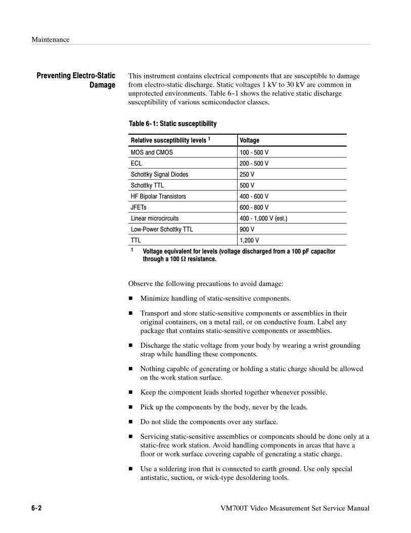
Maintenance
6- 2 VM700T Video Measurement Set Service Manual
This instrument contains electrical components that are susceptible to damagefrom electro-static discharge. Static voltages 1 kV to 30 kV are common inunprotected environments. Table 6--1 shows the relative static dischargesusceptibility of various semiconductor classes.
Table 6- 1: Static susceptibility
Relative susceptibility levels 1 Voltage
MOS and CMOS 100 - 500 V
ECL 200 - 500 V
Schottky Signal Diodes 250 V
Schottky TTL 500 V
HF Bipolar Transistors 400 - 600 V
JFETs 600 - 800 V
Linear microcircuits 400 - 1,000 V (est.)
Low-Power Schottky TTL 900 V
TTL 1,200 V
1 Voltage equivalent for levels (voltage discharged from a 100 pF capacitorthrough a 100 Ω resistance.
Observe the following precautions to avoid damage:
Minimize handling of static-sensitive components.
Transport and store static-sensitive components or assemblies in theiroriginal containers, on a metal rail, or on conductive foam. Label anypackage that contains static-sensitive components or assemblies.
Discharge the static voltage from your body by wearing a wrist groundingstrap while handling these components.
Nothing capable of generating or holding a static charge should be allowedon the work station surface.
Keep the component leads shorted together whenever possible.
Pick up the components by the body, never by the leads.
Do not slide the components over any surface.
Servicing static-sensitive assemblies or components should be done only at astatic-free work station. Avoid handling components in areas that have afloor or work surface covering capable of generating a static charge.
Use a soldering iron that is connected to earth ground. Use only specialantistatic, suction, or wick-type desoldering tools.
Preventing Electro-StaticDamage
Maintenance
VM700T Video Measurement Set Service Manual 6- 3
For service, parts, module exchange, returns, or technical support in the UnitedStates, call the Tektronix Customer Service line between 8:00 AM and 5:00 PMPacific Time, Monday through Friday at this phone number:
1-800-833-9200
Customer service personnel will direct your inquiry to the proper support group.
Exchanging VM700T Modules. If you call for a module exchange, you must supplythe instrument serial number, the firmware version number (accessed by pressingthe Configure button), and the module’s complete part number to ensurereceiving the correct replacement. If the module you request is in stock, it willusually be sent to you the same day.
After you receive the replacement module, the faulty module must be returnedimmediately to Tektronix using prepaid common-carrier freight. Use thepackaging material from the replacement module and the furnished shippinglabel to prepare the faulty module for shipment. Ship the faulty module to:
Tektronix Inc.
Customer Service MaterialsM/S 58-185PO Box 500Beaverton, Oregon 97077-0500
Tektronix charges a standard fee for each out-of-warranty module exchanged.This fee will be quoted when you request the exchange module. If the faultymodule is not received at the above address within 30 days of your request of anoperating exchange module, the full catalog price of the module will be invoiced.
If your module has been damaged or modified in any of the following ways it isnot eligible for exchange.
The module is damaged during repair attempts by personnel other thanTektronix Representatives.
The module is damaged through improper use or connection to incompatibleequipment.
The module has been modified by the customer.
The module has been modified to the customer’s specifications by Tektronix.
In these cases Tektronix invoices the full catalog price of a replacement module.Call your local Tektronix field office for further information.
Customer Service Outside the U.S. Customers outside the United States shouldcontact their local Tektronix sales subsidiary or distributor for details onservicing the VM700T.
Customer Service
Maintenance
6- 4 VM700T Video Measurement Set Service Manual
Inspection and Cleaning
CAUTION. Cleaning and general maintenance of the VM700T should be
performed only when the instrument is powered off and the power cord removed
from electrical mains.
The instrument should be cleaned often enough to prevent dust or dirt fromaccumulating. Dirt acts as a thermal insulating blanket that prevents effectiveheat dissipation, and can provide high-resistance electrical leakage paths betweenconductors or components in a humid environment.
Use the following tools to clean the instrument:
Clean, nonabrasive, lint-free cloth.
Nonabrasive liquid glass cleaner.
Isopropyl alcohol.
Static free vacuum cleaner with small brush attachment.
Cleaning the Exterior. Clean the dust from the outside of the instrument by wipingwith a soft cloth. You may use a brush to remove dust from around the selectorbuttons, knobs, and connectors. Hardened dirt may be removed with a clothdampened in water that contains a mild detergent or non-abrasive glass cleaner.Abrasive cleaners should not be used.
Cleaning the CRT Touch Screen. Clean the CRT touch screen by carefullyapplying a small quantity of glass cleaner and wiping the screen dry with a clean,nonabrasive, lint-free cloth.
Cleaning the Front Bezel Air Filters.At regular intervals, inspect the air filtersthrough the front-bezel air-intake slots for accumulated dust. Carefully vacuumthe front of the instrument to remove any accumulated dust.
Cleaning the Interior.Use low-pressure dry air to remove accumulated dust anddirt (high-velocity air can damage some parts). Hardened dirt or grease may beremoved with a cotton swab or pipe cleaner dampened with isopropyl alcohol.Abrasive cleaners should not be used. If the circuit board assemblies must beremoved for cleaning, follow the instructions in the removal and replacementprocedures of this section.
Cleaning
Maintenance
VM700T Video Measurement Set Service Manual 6- 5
CAUTION. Do not allow water to get inside any enclosed assembly or component.
Do not clean any plastic materials with organic cleaning solvents, such as
benzene, toluene, xylene, acetone, or similar compounds, because they may
damage the plastic.
After cleaning, allow the interior to thoroughly dry before applying power to theinstrument.
After cleaning, carefully check the instrument for defective connections,damaged parts, and improperly seated transistors, integrated circuits, or circuitboards. The remedy for most visible defects is obvious; however, if heat-damaged parts are discovered, determine the cause of overheating beforereplacing the damaged part, to prevent additional damage.
Periodic checks of the transistors and integrated circuits are not recommended.
Repackaging the Instrument
Repackage the instrument in the original manner to provide adequate protection.If the original packaging is not available or is unfit for use, repackage andidentify the instrument as described here.
If the instrument is to be shipped to a Tektronix Service Center for service orrepair, attach a tag to the instrument showing the following information:
Owner (with complete address) and the name of the person at your firm thatcan be contacted.
Instrument serial number and a description of the service required.
1. Obtain a corrugated cardboard carton whose inside dimensions are at leastsix inches greater than the dimensions of the instrument to allow room forcushioning. The shipping carton should have a test strength of at least275 pounds.
2. Surround the instrument with polyethylene sheeting to protect the finish.
3. Cushion the instrument on all sides by tightly packing dunnage or urethanefoam between the carton and the instrument. Allow three inches on all sidesfor cushioning.
4. Seal the carton with shipping tape or an industrial stapler.
Visual Inspection
Identification Tag
Repackaging
Maintenance
6- 6 VM700T Video Measurement Set Service Manual
Removal and Replacement Instructions
WARNING. This instrument contains hazardous voltages. Before removing covers
or performing disassembly/reassembly procedures, always shut off instrument
power at the rear-panel switch and disconnect the power cord from electrical
mains. Failure to do this may result in dangerous electrical shock.
CAUTION. To prevent static discharge damage, observe the precautions listed in
Preventing Electro-Static Damage on page 6--2.
This section includes removal and replacement procedures for the followingassemblies:
Cover panel page 6--8
I/O board page 6--9
Option 40 and Option 41 audio boards page 6--11
Option 41 connector installation page 6--12
Option 48 GPIB Interface board page 6--14
CPU board page 6--15
Acquisition Memory board page 6--18
Option 1S SDI board page 6--19
Analog Input board page 6--23
Genlock board page 6--25
ADC board page 6--28
Filter Switch board page 6--30
Display and control components page 6--32
Power supply, Interconnect board, VGA board, and cooling fan page 6--38
As you face the front of the VM700T (in its operating position), the CPU (A5) islocated in the right-side card cage along with the Acquisition Memory (A18).The I/O board and any of the hardware option boards are located in the left-sidecard cage. The analog section boards (Analog Input A1, Genlock A2, ADC A3,and Filter Switch A4) are mounted, with screws and standoffs, on a bulkheadunder the top cover panel (see Figure 6--1).
Locating the MajorStandard Assemblies
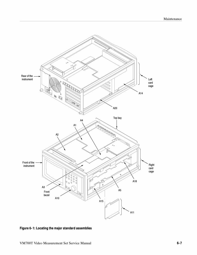
Maintenance
VM700T Video Measurement Set Service Manual 6- 7
A2
A1
A18
A15
A3
A10
A20
A14
Top bayA4
Rightcardcage
Leftcardcage
A5
A11
Front of theinstrument
Rear of theinstrument
Frontbezel
Figure 6- 1: Locating the major standard assemblies
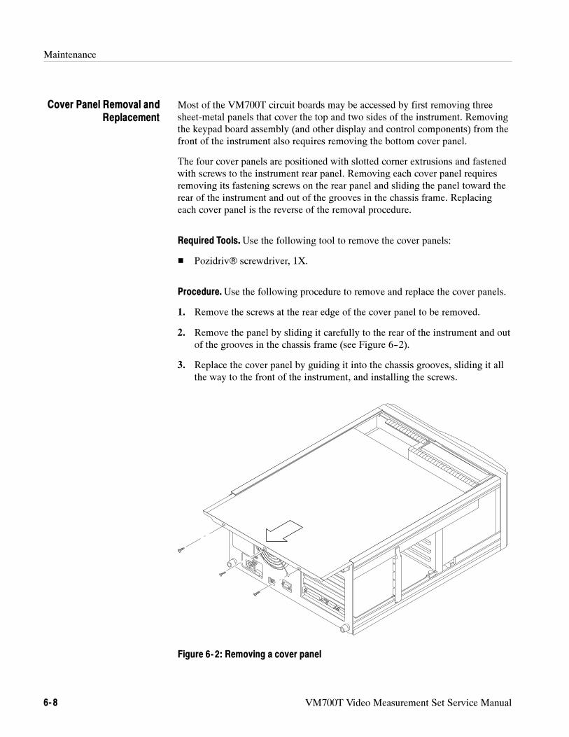
Maintenance
6- 8 VM700T Video Measurement Set Service Manual
Most of the VM700T circuit boards may be accessed by first removing threesheet-metal panels that cover the top and two sides of the instrument. Removingthe keypad board assembly (and other display and control components) from thefront of the instrument also requires removing the bottom cover panel.
The four cover panels are positioned with slotted corner extrusions and fastenedwith screws to the instrument rear panel. Removing each cover panel requiresremoving its fastening screws on the rear panel and sliding the panel toward therear of the instrument and out of the grooves in the chassis frame. Replacingeach cover panel is the reverse of the removal procedure.
Required Tools.Use the following tool to remove the cover panels:
Pozidriv screwdriver, 1X.
Procedure.Use the following procedure to remove and replace the cover panels.
1. Remove the screws at the rear edge of the cover panel to be removed.
2. Remove the panel by sliding it carefully to the rear of the instrument and outof the grooves in the chassis frame (see Figure 6--2).
3. Replace the cover panel by guiding it into the chassis grooves, sliding it allthe way to the front of the instrument, and installing the screws.
Figure 6- 2: Removing a cover panel
Cover Panel Removal andReplacement
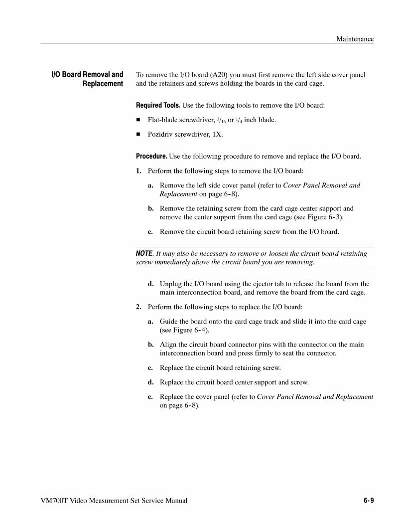
Maintenance
VM700T Video Measurement Set Service Manual 6- 9
To remove the I/O board (A20) you must first remove the left side cover paneland the retainers and screws holding the boards in the card cage.
Required Tools.Use the following tools to remove the I/O board:
Flat-blade screwdriver, 3/16 or 1/4 inch blade.
Pozidriv screwdriver, 1X.
Procedure.Use the following procedure to remove and replace the I/O board.
1. Perform the following steps to remove the I/O board:
a. Remove the left side cover panel (refer to Cover Panel Removal and
Replacement on page 6--8).
b. Remove the retaining screw from the card cage center support andremove the center support from the card cage (see Figure 6--3).
c. Remove the circuit board retaining screw from the I/O board.
NOTE. It may also be necessary to remove or loosen the circuit board retaining
screw immediately above the circuit board you are removing.
d. Unplug the I/O board using the ejector tab to release the board from themain interconnection board, and remove the board from the card cage.
2. Perform the following steps to replace the I/O board:
a. Guide the board onto the card cage track and slide it into the card cage(see Figure 6--4).
b. Align the circuit board connector pins with the connector on the maininterconnection board and press firmly to seat the connector.
c. Replace the circuit board retaining screw.
d. Replace the circuit board center support and screw.
e. Replace the cover panel (refer to Cover Panel Removal and Replacement
on page 6--8).
I/O Board Removal andReplacement
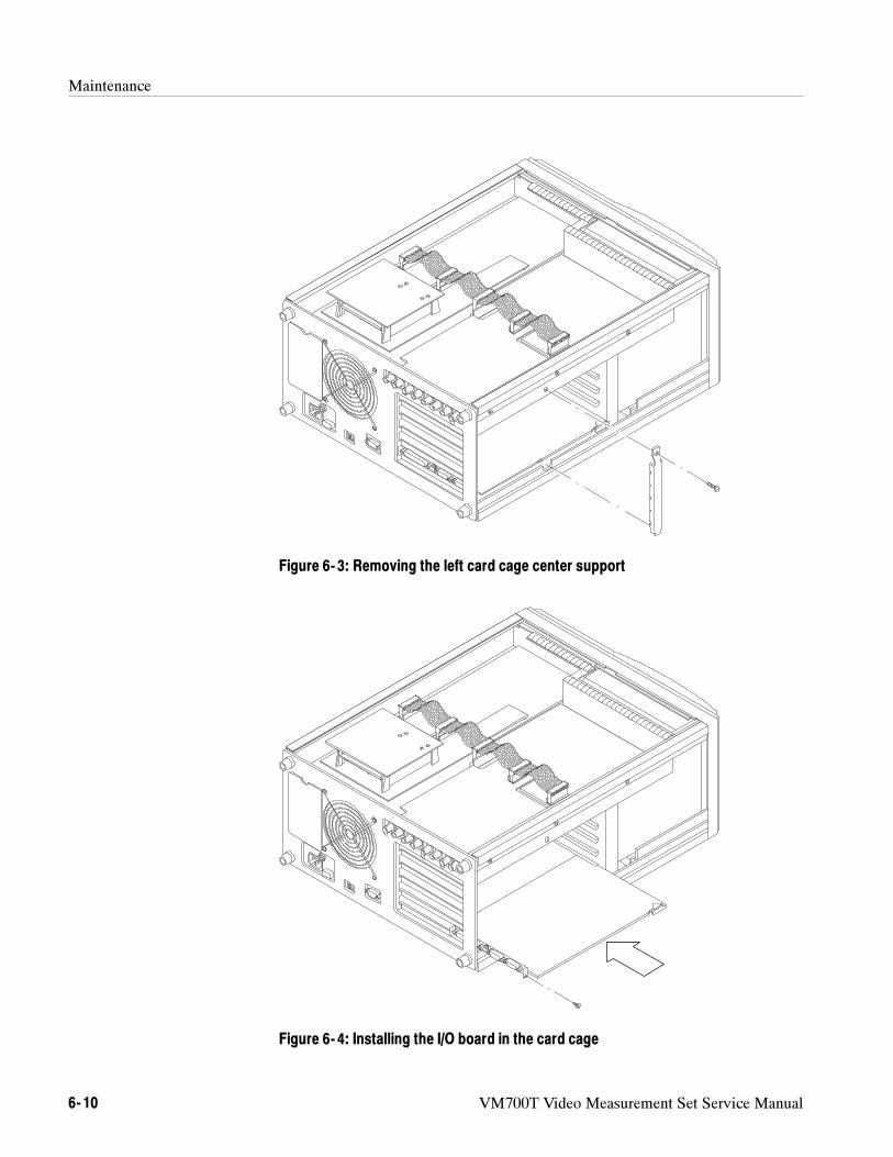
Maintenance
6- 10 VM700T Video Measurement Set Service Manual
Figure 6- 3: Removing the left card cage center support
Figure 6- 4: Installing the I/O board in the card cage
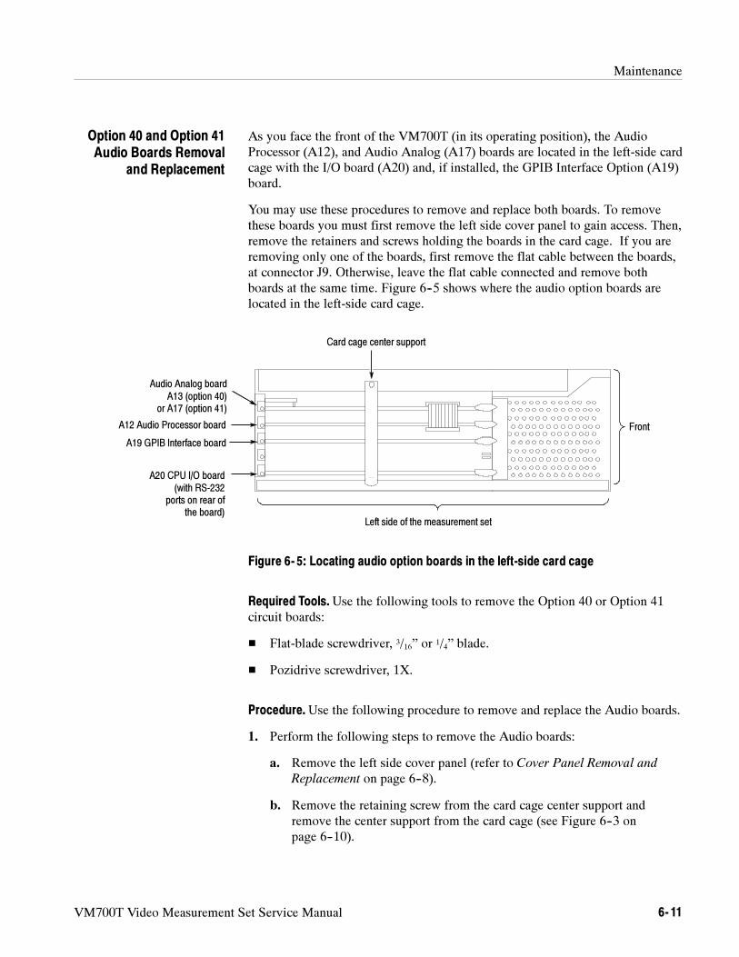
Maintenance
VM700T Video Measurement Set Service Manual 6- 11
As you face the front of the VM700T (in its operating position), the AudioProcessor (A12), and Audio Analog (A17) boards are located in the left-side cardcage with the I/O board (A20) and, if installed, the GPIB Interface Option (A19)board.
You may use these procedures to remove and replace both boards. To removethese boards you must first remove the left side cover panel to gain access. Then,remove the retainers and screws holding the boards in the card cage. If you areremoving only one of the boards, first remove the flat cable between the boards,at connector J9. Otherwise, leave the flat cable connected and remove bothboards at the same time. Figure 6--5 shows where the audio option boards arelocated in the left-side card cage.
Audio Analog boardA13 (option 40)
or A17 (option 41)
A12 Audio Processor board
A20 CPU I/O board(with RS-232
ports on rear ofthe board)
Card cage center support
Front
Left side of the measurement set
A19 GPIB Interface board
Figure 6- 5: Locating audio option boards in the left-side card cage
Required Tools.Use the following tools to remove the Option 40 or Option 41circuit boards:
Flat-blade screwdriver, 3/16” or 1/4” blade.
Pozidrive screwdriver, 1X.
Procedure.Use the following procedure to remove and replace the Audio boards.
1. Perform the following steps to remove the Audio boards:
a. Remove the left side cover panel (refer to Cover Panel Removal and
Replacement on page 6--8).
b. Remove the retaining screw from the card cage center support andremove the center support from the card cage (see Figure 6--3 onpage 6--10).
Option 40 and Option 41Audio Boards Removal
and Replacement
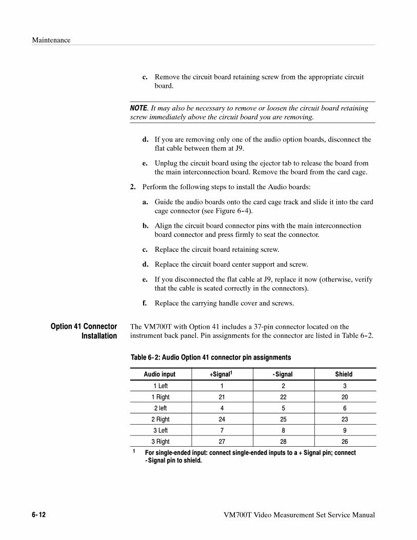
Maintenance
6- 12 VM700T Video Measurement Set Service Manual
c. Remove the circuit board retaining screw from the appropriate circuitboard.
NOTE. It may also be necessary to remove or loosen the circuit board retaining
screw immediately above the circuit board you are removing.
d. If you are removing only one of the audio option boards, disconnect theflat cable between them at J9.
e. Unplug the circuit board using the ejector tab to release the board fromthe main interconnection board. Remove the board from the card cage.
2. Perform the following steps to install the Audio boards:
a. Guide the audio boards onto the card cage track and slide it into the cardcage connector (see Figure 6--4).
b. Align the circuit board connector pins with the main interconnectionboard connector and press firmly to seat the connector.
c. Replace the circuit board retaining screw.
d. Replace the circuit board center support and screw.
e. If you disconnected the flat cable at J9, replace it now (otherwise, verifythat the cable is seated correctly in the connectors).
f. Replace the carrying handle cover and screws.
The VM700T with Option 41 includes a 37-pin connector located on theinstrument back panel. Pin assignments for the connector are listed in Table 6--2.
Table 6- 2: Audio Option 41 connector pin assignments
Audio input +Signal1 - Signal Shield
1 Left 1 2 3
1 Right 21 22 20
2 left 4 5 6
2 Right 24 25 23
3 Left 7 8 9
3 Right 27 28 26
1 For single-ended input: connect single-ended inputs to a + Signal pin; connect- Signal pin to shield.
Option 41 ConnectorInstallation
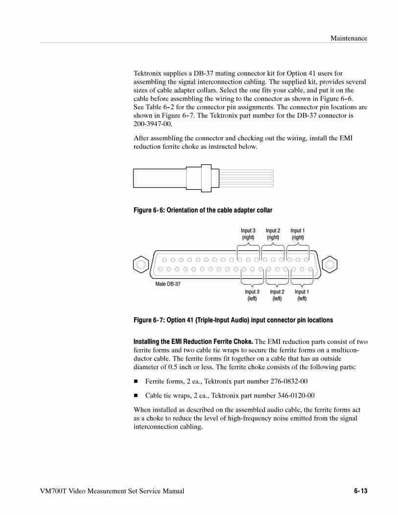
Maintenance
VM700T Video Measurement Set Service Manual 6- 13
Tektronix supplies a DB-37 mating connector kit for Option 41 users forassembling the signal interconnection cabling. The supplied kit, provides severalsizes of cable adapter collars. Select the one fits your cable, and put it on thecable before assembling the wiring to the connector as shown in Figure 6--6.See Table 6--2 for the connector pin assignments. The connector pin locations areshown in Figure 6--7. The Tektronix part number for the DB-37 connector is200-3947-00.
After assembling the connector and checking out the wiring, install the EMIreduction ferrite choke as instructed below.
Figure 6- 6: Orientation of the cable adapter collar
Input 3(right)
Input 2(right)
Input 1(right)
Input 3(left)
Input 2(left)
Input 1(left)
Male DB-37
Figure 6- 7: Option 41 (Triple-Input Audio) input connector pin locations
Installing the EMI Reduction Ferrite Choke. The EMI reduction parts consist of twoferrite forms and two cable tie wraps to secure the ferrite forms on a multicon-ductor cable. The ferrite forms fit together on a cable that has an outsidediameter of 0.5 inch or less. The ferrite choke consists of the following parts:
Ferrite forms, 2 ea., Tektronix part number 276-0832-00
Cable tie wraps, 2 ea., Tektronix part number 346-0120-00
When installed as described on the assembled audio cable, the ferrite forms actas a choke to reduce the level of high-frequency noise emitted from the signalinterconnection cabling.
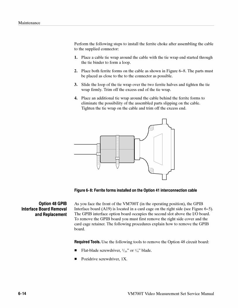
Maintenance
6- 14 VM700T Video Measurement Set Service Manual
Perform the following steps to install the ferrite choke after assembling the cableto the supplied connector:
1. Place a cable tie wrap around the cable with the tie wrap end started throughthe tie binder to form a loop.
2. Place both ferrite forms on the cable as shown in Figure 6--8. The parts mustbe placed as close to the to the connector as possible.
3. Slide the loop of the tie wrap over the two ferrite halves and tighten the tiewrap firmly. Trim off the excess end of the tie wrap.
4. Place an additional tie wrap around the cable behind the ferrite forms toeliminate the possibility of the assembled parts slipping on the cable.Tighten the tie wrap on the cable and trim off the excess end.
Figure 6- 8: Ferrite forms installed on the Option 41 interconnection cable
As you face the front of the VM700T (in the operating position), the GPIBInterface board (A19) is located in a card cage on the right side (see Figure 6--5).The GPIB interface option board occupies the second slot above the I/O board.To remove the GPIB board you must first remove the right side cover and thecard cage retainer. The following procedures explain how to remove the GPIBboard.
Required Tools.Use the following tools to remove the Option 48 circuit board:
Flat-blade screwdriver, 3/16” or 1/4” blade.
Pozidrive screwdriver, 1X.
Option 48 GPIBInterface Board Removal
and Replacement
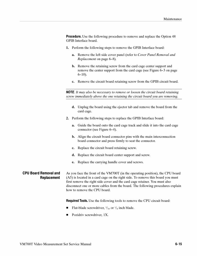
Maintenance
VM700T Video Measurement Set Service Manual 6- 15
Procedure.Use the following procedure to remove and replace the Option 48GPIB Interface board.
1. Perform the following steps to remove the GPIB Interface board:
a. Remove the left side cover panel (refer to Cover Panel Removal and
Replacement on page 6--8).
b. Remove the retaining screw from the card cage center support andremove the center support from the card cage (see Figure 6--3 on page6--10).
c. Remove the circuit board retaining screw from the GPIB circuit board.
NOTE. It may also be necessary to remove or loosen the circuit board retaining
screw immediately above the one retaining the circuit board you are removing.
d. Unplug the board using the ejector tab and remove the board from thecard cage.
2. Perform the following steps to replace the GPIB Interface board:
a. Guide the board onto the card cage track and slide it into the card cageconnector (see Figure 6--4).
b. Align the circuit board connector pins with the main interconnectionboard connector and press firmly to seat the connector.
c. Replace the circuit board retaining screw.
d. Replace the circuit board center support and screw.
e. Replace the carrying handle cover and screws.
As you face the front of the VM700T (in the operating position), the CPU board(A5) is located in a card cage on the right side. To remove this board you mustfirst remove the right side cover and the card cage retainer. You must alsodisconnect one or more cables from the board. The following procedures explainhow to remove the CPU board.
Required Tools.Use the following tools to remove the CPU circuit board:
Flat-blade screwdriver, 3/16 or 1/4 inch blade.
Pozidriv screwdriver, 1X.
CPU Board Removal andReplacement
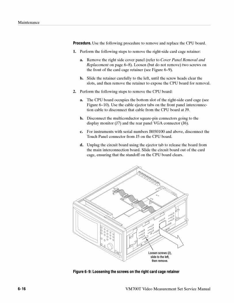
Maintenance
6- 16 VM700T Video Measurement Set Service Manual
Procedure.Use the following procedure to remove and replace the CPU board.
1. Perform the following steps to remove the right-side card cage retainer:
a. Remove the right side cover panel (refer to Cover Panel Removal and
Replacement on page 6--8). Loosen (but do not remove) two screws onthe front of the card cage retainer (see Figure 6--9).
b. Slide the retainer carefully to the left, until the screw heads clear theslots, and then remove the retainer to expose the CPU board for removal.
2. Perform the following steps to remove the CPU board:
a. The CPU board occupies the bottom slot of the right-side card cage (seeFigure 6--10). Use the cable ejector tabs on the front panel interconnec-tion cable to disconnect that cable from the CPU board at J9.
b. Disconnect the multiconductor square-pin connectors going to thedisplay monitor (J7) and the rear panel VGA connector (J6).
c. For instruments with serial numbers B050100 and above, disconnect theTouch Panel connector from J5 on the CPU board.
d. Unplug the circuit board using the ejector tab to release the board fromthe main interconnection board. Slide the circuit board out of the cardcage, ensuring that the standoff on the CPU board clears.
Loosen screws (2),slide to the left,then remove.
Figure 6- 9: Loosening the screws on the right card cage retainer
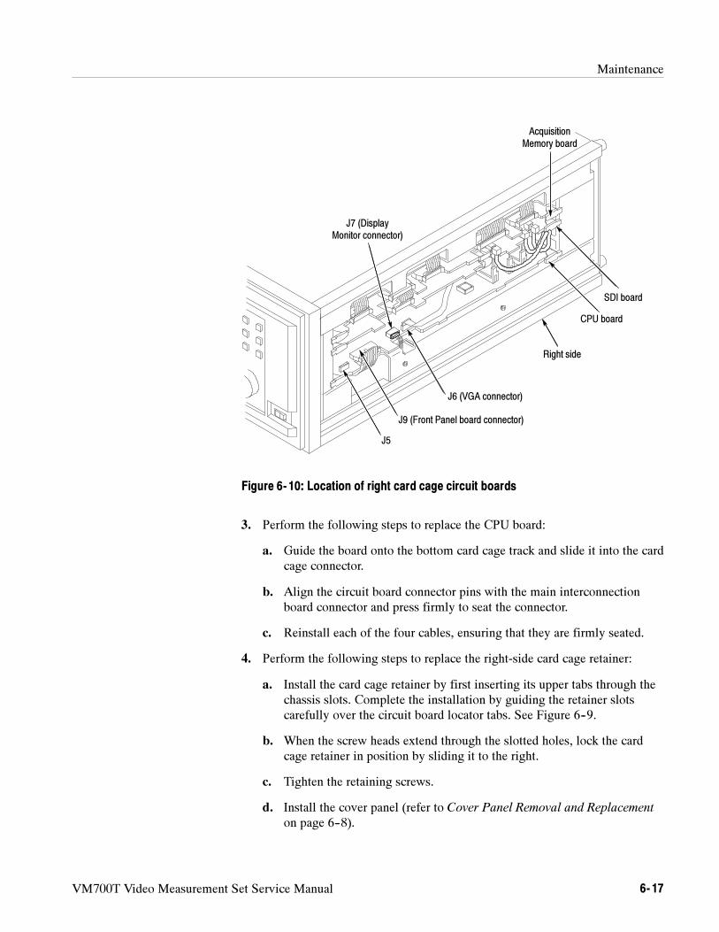
Maintenance
VM700T Video Measurement Set Service Manual 6- 17
SDI board
CPU board
AcquisitionMemory board
J7 (DisplayMonitor connector)
J9 (Front Panel board connector)
J6 (VGA connector)
Right side
J5
Figure 6- 10: Location of right card cage circuit boards
3. Perform the following steps to replace the CPU board:
a. Guide the board onto the bottom card cage track and slide it into the cardcage connector.
b. Align the circuit board connector pins with the main interconnectionboard connector and press firmly to seat the connector.
c. Reinstall each of the four cables, ensuring that they are firmly seated.
4. Perform the following steps to replace the right-side card cage retainer:
a. Install the card cage retainer by first inserting its upper tabs through thechassis slots. Complete the installation by guiding the retainer slotscarefully over the circuit board locator tabs. See Figure 6--9.
b. When the screw heads extend through the slotted holes, lock the cardcage retainer in position by sliding it to the right.
c. Tighten the retaining screws.
d. Install the cover panel (refer to Cover Panel Removal and Replacement
on page 6--8).
Maintenance
6- 18 VM700T Video Measurement Set Service Manual
As you face the front of the VM700T (in the operating position), the AcquisitionMemory board (A18) is located in a card cage on the right side. To remove thisboard you must first remove the right side cover and the card cage retainer. Youmust also disconnect four cables from the circuit board.
Required Tools.Use the following tools to remove the Acquisition Memorycircuit board:
Flat-blade screwdriver, 3/16 or 1/4 inch blade.
Pozidriv screwdriver, 1X.
Procedure.Use the following procedure to remove and replace the AcquisitionMemory board.
1. Perform the following steps to remove the Acquisition Memory board:
a. Remove the right side cover panel (refer to Cover Panel Removal and
Replacement on page 6--8).
b. Remove the card cage retainer (refer to step 1 on page 6--16).
c. The Acquisition Memory board occupies the top slot in the right-sidecard cage (see Figure 6--10). To remove this board, you must firstdisconnect the ribbon cables shown on the right side of Figure 6--11.
d. Spread the cable ejector tabs to disconnect each cable from the circuitboard.
e. Unplug the circuit board using the ejector tab to release the board fromthe main interconnection board. When the circuit board is loose, slide itout of the card cage.
2. Perform the following steps to replace the Acquisition Memory board:
a. Guide the board onto the top right-side card cage track and slide it intothe card cage connector.
b. Align the circuit board connector pins with the main interconnectionboard connector and press firmly to seat the connector.
c. Reinstall each of the cables to the Acquisition board, ensuring that theyare firmly seated in the board connectors (see Figure 6--11).
d. Install the card cage retainer (refer to step 4 on page 6--17).
e. Install the cover panel (refer to Cover Panel Removal and Replacement
on page 6--8).
Acquisition MemoryBoard Removal and
Replacement
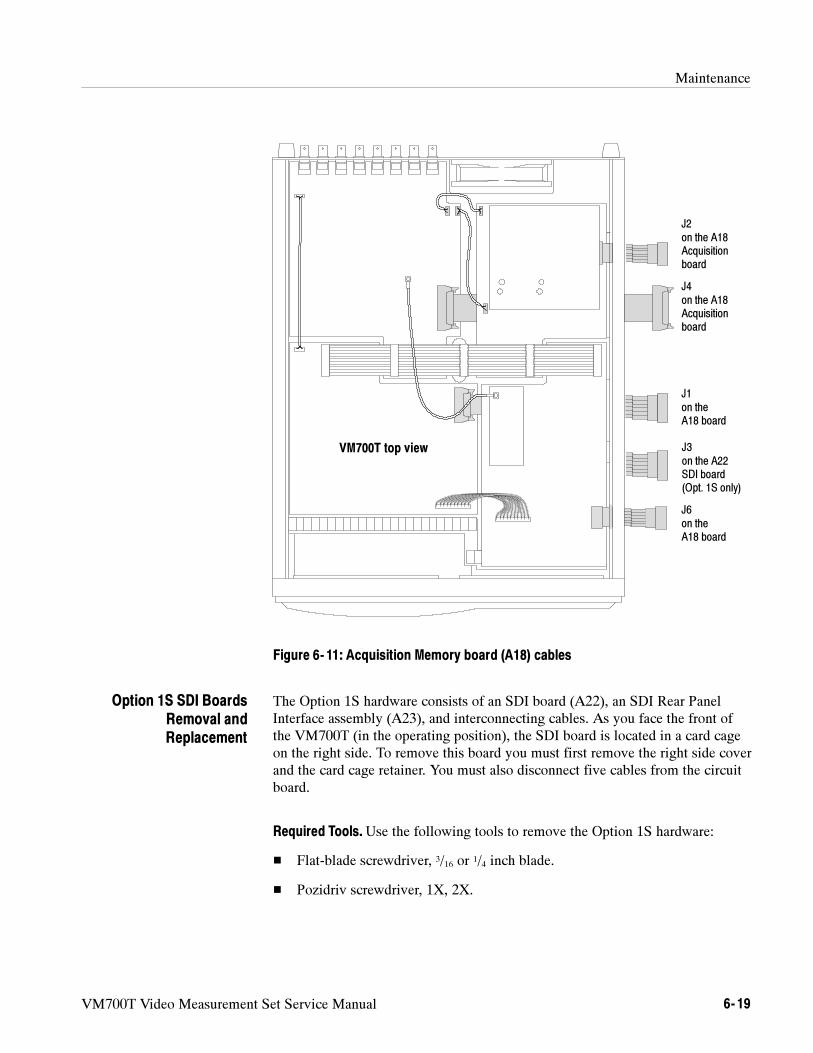
Maintenance
VM700T Video Measurement Set Service Manual 6- 19
J3on the A22SDI board(Opt. 1S only)
J4on the A18Acquisitionboard
J6on theA18 board
J1on theA18 board
J2on the A18Acquisitionboard
VM700T top view
Figure 6- 11: Acquisition Memory board (A18) cables
The Option 1S hardware consists of an SDI board (A22), an SDI Rear PanelInterface assembly (A23), and interconnecting cables. As you face the front ofthe VM700T (in the operating position), the SDI board is located in a card cageon the right side. To remove this board you must first remove the right side coverand the card cage retainer. You must also disconnect five cables from the circuitboard.
Required Tools.Use the following tools to remove the Option 1S hardware:
Flat-blade screwdriver, 3/16 or 1/4 inch blade.
Pozidriv screwdriver, 1X, 2X.
Option 1S SDI BoardsRemoval andReplacement
Maintenance
6- 20 VM700T Video Measurement Set Service Manual
SDI Board.Use the following procedure to remove and replace the Option 1S SDIcircuit board.
1. Perform the following steps to remove the SDI board:
a. Remove the right side cover panel (refer to Cover Panel Removal and
Replacement on page 6--8).
b. Remove the card cage retainer (refer to step 1 on page 6--16).
c. The SDI board occupies the second from the top slot in the right-sidecard cage (see Figure 6--10 on page 6--17). To remove this board, youmust first disconnect five cables from the board.
d. Disconnect the cables from the SDI board at J8, J7, J10, and J5 (seeFigure 6--12). Spread the cable ejector tabs to disconnect the cable fromthe SDI board at J3.
e. Unplug the circuit board using the ejector tab to release the board fromthe main interconnection board. When the circuit board is loose, slide itout of the card cage.
2. Perform the following steps to replace the SDI board:
a. Guide the SDI board onto the second from the top right-side card cagetrack and slide it into the card cage connector.
b. Align the circuit board connector pins with the main interconnectionboard connector and press firmly to seat the connector.
c. Reinstall each of the five cables to the SDI board, ensuring that they arefirmly seated in the board connectors (see Figure 6--12).
d. Install the card cage retainer (refer to step 4 on page 6--17).
e. Install the cover panel (refer to Cover Panel Removal and Replacement
on page 6--8).
SDI Rear Panel Interface Assembly.As you face the front of the VM700T (in theoperating position), the SDI Rear Panel Interface assembly (A23) is located onthe right side of the rear panel. To remove this assembly, you must first removethe right side cover and the card cage retainer so that you can disconnect fourcables from the SDI board.
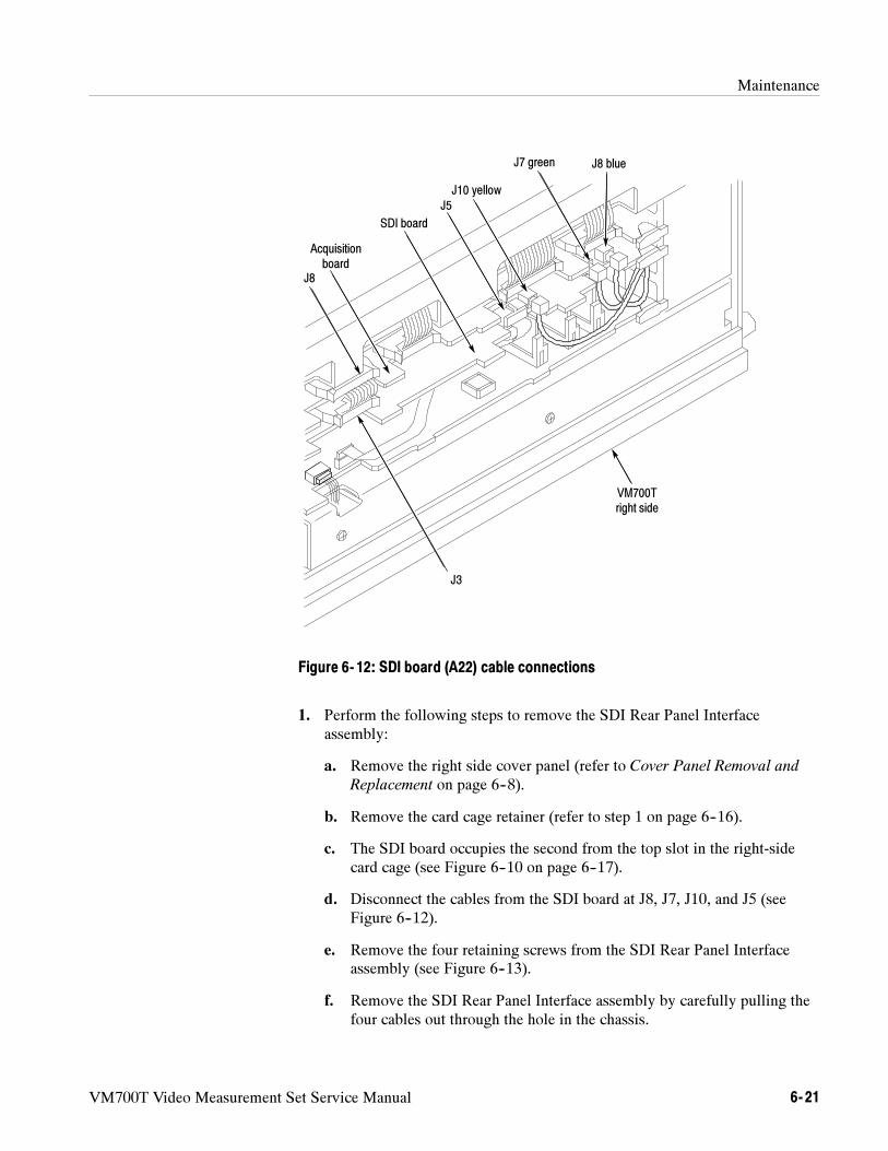
Maintenance
VM700T Video Measurement Set Service Manual 6- 21
SDI board
J8 blue
J5
J7 green
J10 yellow
VM700Tright side
J8
Acquisitionboard
J3
Figure 6- 12: SDI board (A22) cable connections
1. Perform the following steps to remove the SDI Rear Panel Interfaceassembly:
a. Remove the right side cover panel (refer to Cover Panel Removal and
Replacement on page 6--8).
b. Remove the card cage retainer (refer to step 1 on page 6--16).
c. The SDI board occupies the second from the top slot in the right-sidecard cage (see Figure 6--10 on page 6--17).
d. Disconnect the cables from the SDI board at J8, J7, J10, and J5 (seeFigure 6--12).
e. Remove the four retaining screws from the SDI Rear Panel Interfaceassembly (see Figure 6--13).
f. Remove the SDI Rear Panel Interface assembly by carefully pulling thefour cables out through the hole in the chassis.
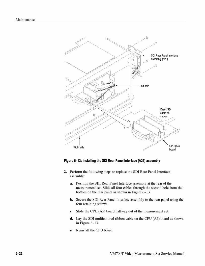
Maintenance
6- 22 VM700T Video Measurement Set Service Manual
SDI Rear Panel Interfaceassembly (A23)
2nd hole
CPU (A5)board
Dress SDIcable asshown
Right side
Figure 6- 13: Installing the SDI Rear Panel Interface (A23) assembly
2. Perform the following steps to replace the SDI Rear Panel Interfaceassembly:
a. Position the SDI Rear Panel Interface assembly at the rear of themeasurement set. Slide all four cables through the second hole from thebottom on the rear panel as shown in Figure 6--13.
b. Secure the SDI Rear Panel Interface assembly to the rear panel using thefour retaining screws.
c. Slide the CPU (A5) board halfway out of the measurement set.
d. Lay the SDI multicolored ribbon cable on the CPU (A5) board as shownin Figure 6--13.
e. Reinstall the CPU board.
Maintenance
VM700T Video Measurement Set Service Manual 6- 23
f. Plug in the three coaxial cables at J7, J8, and J10. See Figure 6--12 onpage 6--21 for the proper cable connections.
g. Plug in the multicolored ribbon cable at J5.
h. Install the card cage retainer (refer to step 4 on page 6--17).
i. Install the cover panel (refer to Cover Panel Removal and Replacement
on page 6--8).
Removing and replacing the Analog Input board (A1) consists of removing thetop cover, removing four wires and two ribbon cables, and removing the board’sretainer screws. With the screws removed, the board may be lifted from theVM700T chassis and set aside. Replacing the board is the reverse of thisprocedure. You may use the following procedures to remove and replace theanalog input board.
Required Tools.Use the following tools to remove the Analog Input circuitboard:
Pozidriv screwdriver, 1X, 2X.
Procedure.Use the following procedure to remove and replace the Analog Inputboard.
1. Perform the following steps to remove the Analog Input board:
a. Remove the top cover panel (refer to Cover Panel Removal and
Replacement on page 6--8).
b. Disconnect the wire at J132 and the shielded cable at J6 and move themaside (see Figure 6--14 for cable locations).
c. Disconnect the ribbon cable at J965.
d. Disconnect the power bus cable at its five connectors, and then removethe cable.
e. Remove the wire connecting A4 J915 to A1 J922 at the J922 end only.
f. Remove the wire connecting A4 J418 to A1 J923 at the J923 end only.
g. At the back of the instrument remove the screws holding the signal inputconnector to the instrument rear panel (see Figure 6--15).
h. Remove the eight board retaining screws (seven on the perimeter andone in the center) and carefully lift the board from the VM700T chassis.
Analog Input BoardRemoval andReplacement
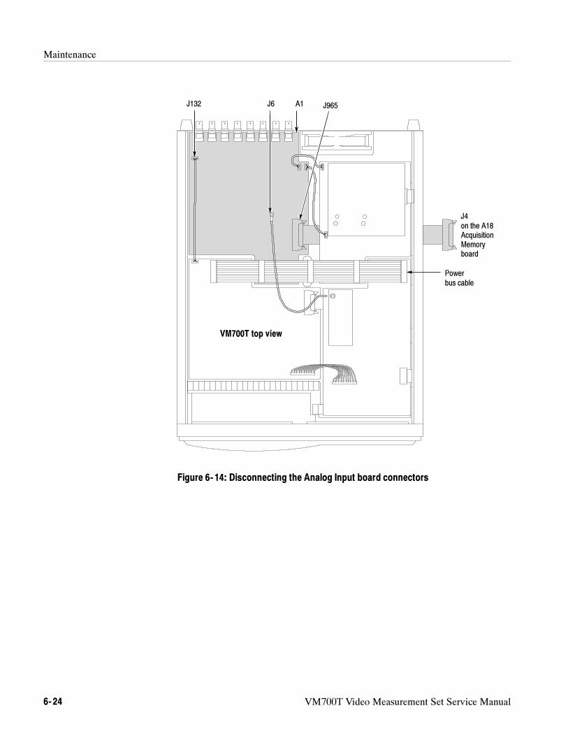
Maintenance
6- 24 VM700T Video Measurement Set Service Manual
J4on the A18AcquisitionMemoryboard
Powerbus cable
J132 A1 J965J6
VM700T top view
Figure 6- 14: Disconnecting the Analog Input board connectors
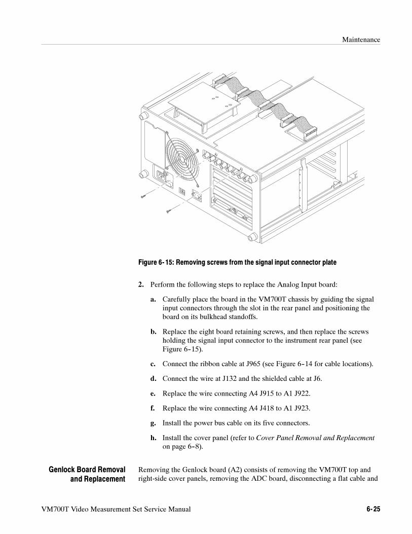
Maintenance
VM700T Video Measurement Set Service Manual 6- 25
Figure 6- 15: Removing screws from the signal input connector plate
2. Perform the following steps to replace the Analog Input board:
a. Carefully place the board in the VM700T chassis by guiding the signalinput connectors through the slot in the rear panel and positioning theboard on its bulkhead standoffs.
b. Replace the eight board retaining screws, and then replace the screwsholding the signal input connector to the instrument rear panel (seeFigure 6--15).
c. Connect the ribbon cable at J965 (see Figure 6--14 for cable locations).
d. Connect the wire at J132 and the shielded cable at J6.
e. Replace the wire connecting A4 J915 to A1 J922.
f. Replace the wire connecting A4 J418 to A1 J923.
g. Install the power bus cable on its five connectors.
h. Install the cover panel (refer to Cover Panel Removal and Replacement
on page 6--8).
Removing the Genlock board (A2) consists of removing the VM700T top andright-side cover panels, removing the ADC board, disconnecting a flat cable and
Genlock Board Removaland Replacement
Maintenance
6- 26 VM700T Video Measurement Set Service Manual
a wire, and removing seven screws. With the screws removed the board may belifted from the VM700T chassis and set aside. See Figure 6--16 for the locationof the genlock board. Use the following procedures to remove and replace theGenlock board.
Required Tools.Use the following tools to remove the Genlock circuit board:
Pozidriv screwdriver, 1X, 2X.
Procedure.Use the following procedure to remove and replace the Genlockboard.
1. Perform the following steps to remove the Genlock board:
a. Remove the top and right-side cover panels (refer to Cover Panel
Removal and Replacement on page 6--8).
b. Remove the card cage retainer (refer to step 1 on page 6--16).
c. Disconnect the flat 10-conductor cable between J111 (on the ADCboard) and J6 on the Genlock board (see Figure 6--16).
d. Disconnect the power bus cable at its five connectors, and then removethe cable.
e. Disconnect the ribbon cable between the Genlock board and theAcquisition Memory board from the Genlock board at J8.
f. Disconnect the wire at J10.
g. Remove the seven board retaining screws and carefully lift the boardfrom the VM700T chassis.
2. Perform the following steps to replace the Genlock board:
a. Place the Genlock board carefully on its hardware standoffs, ensuringthat the ribbon cable is positioned with its connector through the slot inthe right side of the instrument chassis (see Figure 6--16).
b. Install the seven board retaining screws.
c. Connect the wire at J10.
d. Connect the flat 10-conductor cable between J111 (on the ADC board)and J6.
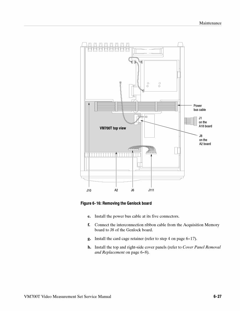
Maintenance
VM700T Video Measurement Set Service Manual 6- 27
Powerbus cable
J111J6A2J10
J1on theA18 board
J8on theA2 board
VM700T top view
Figure 6- 16: Removing the Genlock board
e. Install the power bus cable at its five connectors.
f. Connect the interconnection ribbon cable from the Acquisition Memoryboard to J8 of the Genlock board.
g. Install the card cage retainer (refer to step 4 on page 6--17).
h. Install the top and right-side cover panels (refer to Cover Panel Removal
and Replacement on page 6--8).
Maintenance
6- 28 VM700T Video Measurement Set Service Manual
Removing and replacing the ADC board (A3) consists of removing the instru-ment top and right-side covers, disconnecting three flat cable assemblies,disconnecting a shielded cable, and removing the screws holding the board inposition. With the screws removed the board may be lifted from the VM700Tchassis and set aside.
Required Tools.Use the following tools to remove the ADC circuit board:
Pozidriv screwdriver, 1X, 2X.
Procedure.Use the following procedure to remove and replace the ADC board.
1. Perform the following steps to remove the ADC board:
a. Remove the top and right-side cover panels (refer to Cover Panel
Removal and Replacement on page 6--8).
b. Remove the card cage retainer (refer to step 1 on page 6--16).
c. Disconnect the flat 10-conductor cable between J111 and J6 (on theGenlock board).
d. Disconnect the shielded cable between J765 (located on the ADC Filterboard) and J6 on the Analog Input board (see Figure 6--17).
e. At the Acquisition Memory board (right side of the instrument),disconnect the cable at J6.
f. Disconnect the power bus cable at its five connectors, and then removethe cable.
g. Remove the five board retaining screws and carefully lift the board fromthe VM700T chassis.
2. Perform the following steps to replace the ADC board:
a. Carefully place the board in the chassis and onto the bulkhead standoffs(be sure the cable extends out the side of the chassis).
b. Install the five board retaining screws.
c. Install the cable on its connector at J6 (on the Acquisition Memoryboard).
d. Install the flat 10-conductor cable between J6 (on the Genlock board)and J111.
e. Install the shielded cable at J765 (on the ADC Filter board).
ADC Board Removal andReplacement
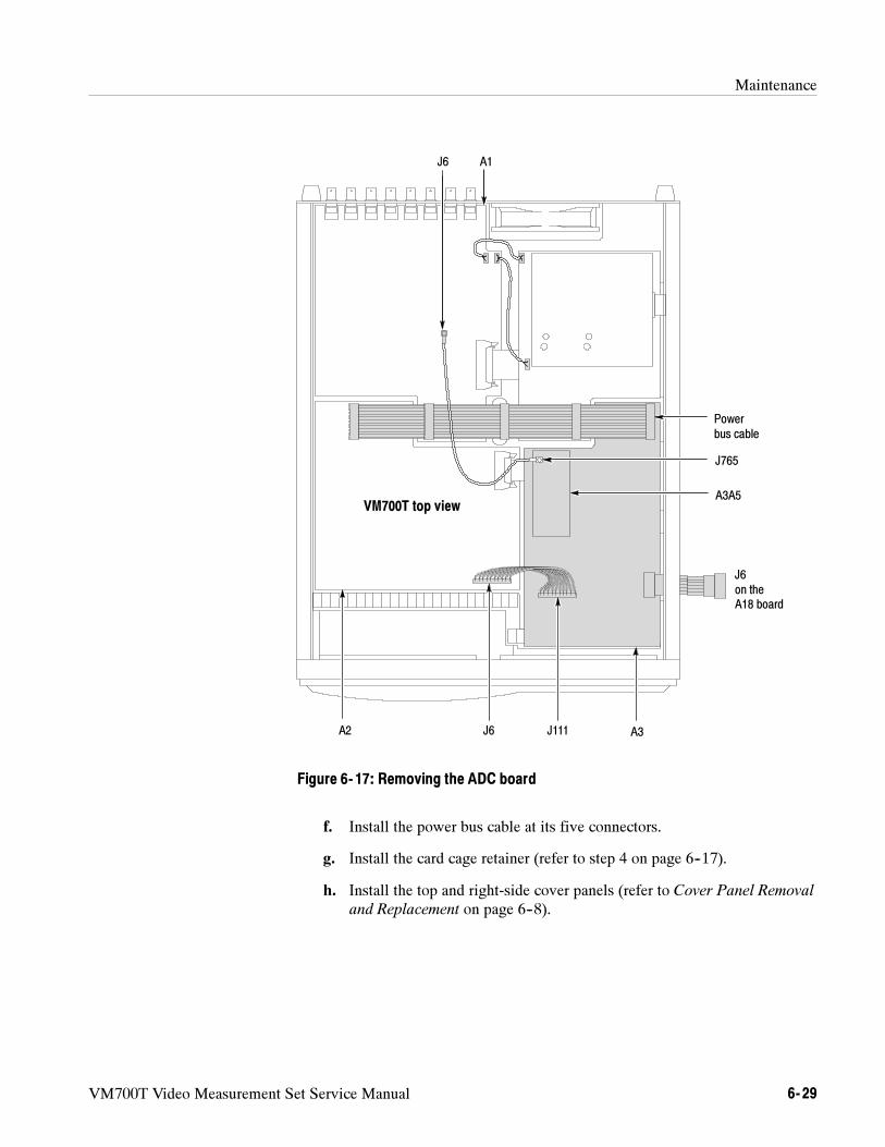
Maintenance
VM700T Video Measurement Set Service Manual 6- 29
J6
A3A5
J765
J6on theA18 board
Powerbus cable
A3J111J6A2
A1
VM700T top view
Figure 6- 17: Removing the ADC board
f. Install the power bus cable at its five connectors.
g. Install the card cage retainer (refer to step 4 on page 6--17).
h. Install the top and right-side cover panels (refer to Cover Panel Removal
and Replacement on page 6--8).
Maintenance
6- 30 VM700T Video Measurement Set Service Manual
Removing and replacing the Filter Switch board (A4) consists of removing theinstrument top and right-side covers, removing a flat cable assembly, discon-necting two wires and a cable, and removing the screws holding the board inposition. With the screws removed the board may be lifted from the VM700Tchassis and set aside. Replacing this board is the reverse of the removalprocedure. You may use the following procedures to remove and replace thefilter switch board.
Required Tools.Use the following tools to remove the Filter Switch circuit board:
Pozidriv screwdriver, 1X, 2X.
Procedure.Use the following procedure to remove and replace the Filter Switchboard.
1. Perform the following steps to remove the Filter Switch board:
a. Remove the top and right-side cover panels (refer to Cover Panel
Removal and Replacement on page 6--8).
b. Remove the card cage retainer (refer to step 1 on page 6--16).
c. Disconnect the power bus cable at its five connectors, and then removethe cable (see Figure 6--18).
d. Remove the wire connecting A4 J915 to A1 J922 at the J922 end only.
e. Remove the wire connecting A4 J418 to A1 J923 at the J923 end only.
f. Remove the cable from its connector at J2 on the Acquisition Memoryboard (A18).
g. Remove the five board retaining screws.
h. Carefully lift the board from the VM700T chassis and set it aside.
2. Perform the following steps to replace the Filter Switch board:
a. If the board has an insulator sheet, hold the it against the board toprevent folding and place the board in the chassis and onto the bulkheadstandoffs (be sure the cable extends out the side of the chassis).
b. Install the five board retaining screws.
c. Install the cable on its connector at J2 (on the Acquisition Memoryboard).
d. Install the power bus cable on its five connectors.
Filter Switch BoardRemoval andReplacement
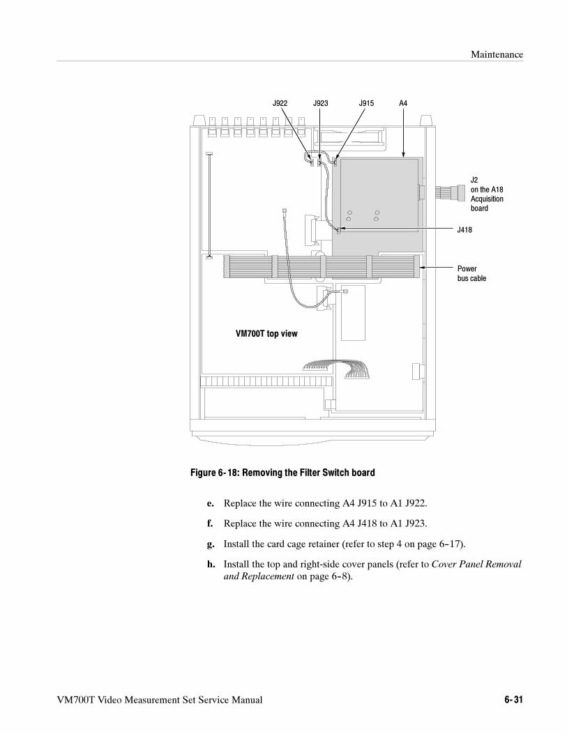
Maintenance
VM700T Video Measurement Set Service Manual 6- 31
J922 J915
J2on the A18Acquisitionboard
Powerbus cable
A4
J418
J923
VM700T top view
Figure 6- 18: Removing the Filter Switch board
e. Replace the wire connecting A4 J915 to A1 J922.
f. Replace the wire connecting A4 J418 to A1 J923.
g. Install the card cage retainer (refer to step 4 on page 6--17).
h. Install the top and right-side cover panels (refer to Cover Panel Removal
and Replacement on page 6--8).
Maintenance
6- 32 VM700T Video Measurement Set Service Manual
This section describes removing and replacing the VM700T componentsresponsible for instrument display and user interface. These components includethe CRT assembly, the touch panel, and the keypad board assembly. Removingand replacing these components requires first removing the instrument coverpanels, the CRT bezel, and (to remove the keypad board assembly) the right sidecard cage retainer.
This section describes removing and replacing the VM700T componentsresponsible for instrument display and user interface. These components includethe CRT assembly, the touch panel, and the keypad board assembly. Removingand replacing these components requires first removing the instrument coverpanels, the CRT bezel, and (to remove the keypad board assembly) the right sidecard cage retainer.
Required Tools.Use the following tools to remove the display and controlcomponents:
Flat-blade screwdriver, 3/16 or 1/4 inch blade.
Combination wrench or nut driver, 3/16 inch.
Pozidriv screwdriver, 1X, 2X.
CRT Bezel.Use the following procedure to remove and replace the CRT bezel.
1. Perform the following steps to remove CRT bezel:
a. Remove the instrument cover panels (refer to Cover Panel Removal and
Replacement on page 6--8).
b. Remove the four screws holding the bezel to the front frame (seeFigure 6--19). There is one screw on each side and one each in the topand bottom of the bezel.
c. Carefully separate the bezel from the frame and disconnect the5-conductor cable from the STBY/ON switch.
d. Remove the nut that holds the STBY/ON switch ground strap ringterminal to the keyboard bracket and disconnect the ground strap (seeFigure 6--20).
2. Replace the CRT bezel by performing step 1 in reverse order.
NOTE. Use care in tightening the bezel retaining screws. The threaded bezel
inserts can be stripped from the bezel if the screws are over-tightened.
Display and ControlComponents Removal and
Replacement
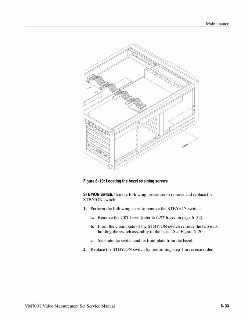
Maintenance
VM700T Video Measurement Set Service Manual 6- 33
Figure 6- 19: Locating the bezel retaining screws
STBY/ON Switch.Use the following procedure to remove and replace theSTBY/ON switch.
1. Perform the following steps to remove the STBY/ON switch:
a. Remove the CRT bezel (refer to CRT Bezel on page 6--32).
b. From the circuit side of the STBY/ON switch remove the two nutsholding the switch assembly to the bezel. See Figure 6--20.
c. Separate the switch and its front plate from the bezel.
2. Replace the STBY/ON switch by performing step 1 in reverse order.
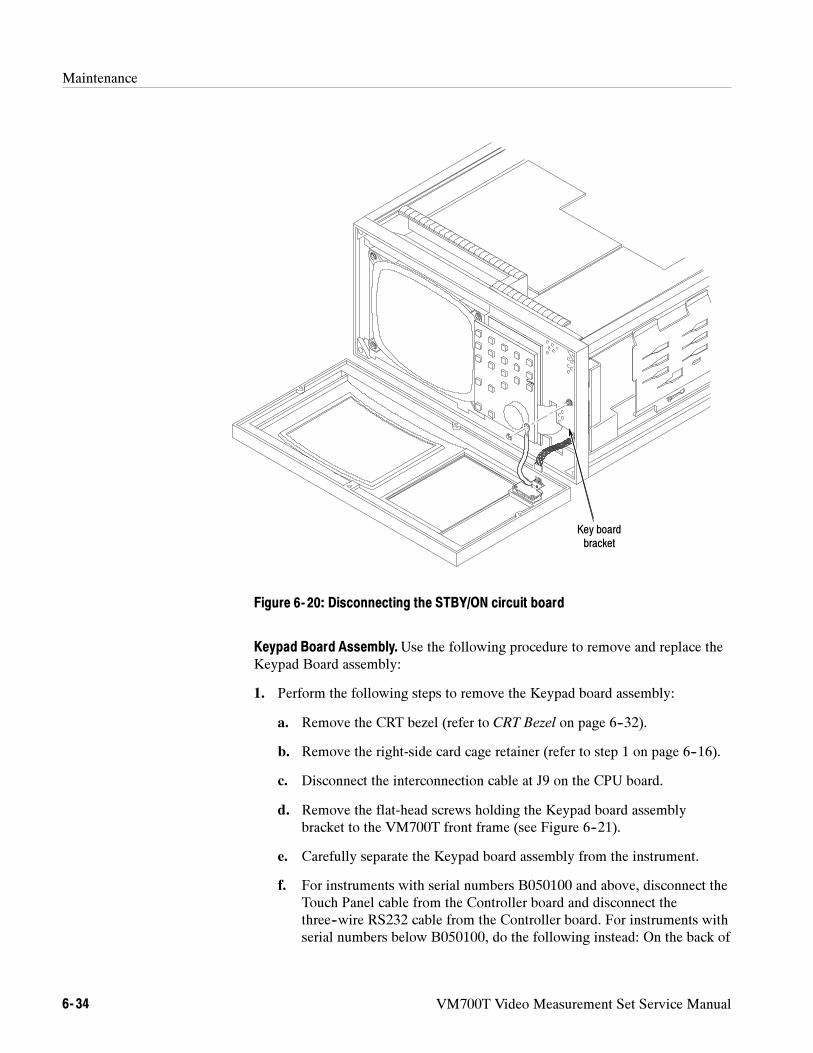
Maintenance
6- 34 VM700T Video Measurement Set Service Manual
Key boardbracket
Figure 6- 20: Disconnecting the STBY/ON circuit board
Keypad Board Assembly.Use the following procedure to remove and replace theKeypad Board assembly:
1. Perform the following steps to remove the Keypad board assembly:
a. Remove the CRT bezel (refer to CRT Bezel on page 6--32).
b. Remove the right-side card cage retainer (refer to step 1 on page 6--16).
c. Disconnect the interconnection cable at J9 on the CPU board.
d. Remove the flat-head screws holding the Keypad board assemblybracket to the VM700T front frame (see Figure 6--21).
e. Carefully separate the Keypad board assembly from the instrument.
f. For instruments with serial numbers B050100 and above, disconnect theTouch Panel cable from the Controller board and disconnect thethree--wire RS232 cable from the Controller board. For instruments withserial numbers below B050100, do the following instead: On the back of
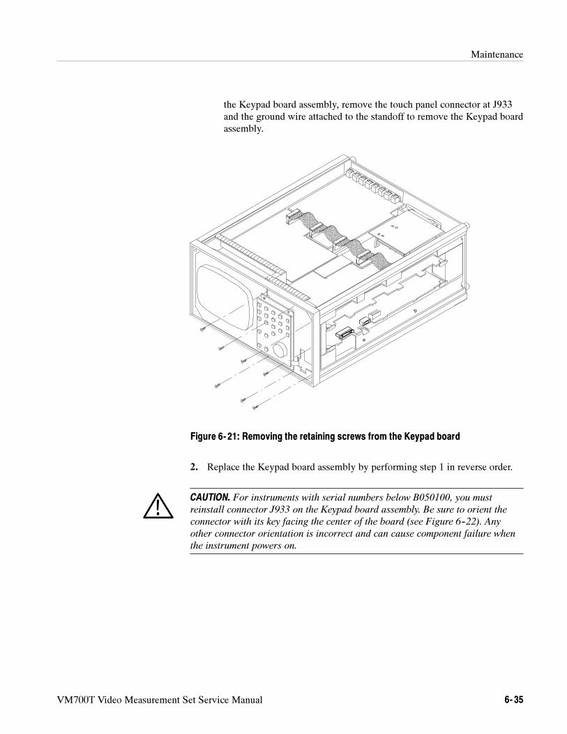
Maintenance
VM700T Video Measurement Set Service Manual 6- 35
the Keypad board assembly, remove the touch panel connector at J933and the ground wire attached to the standoff to remove the Keypad boardassembly.
Figure 6- 21: Removing the retaining screws from the Keypad board
2. Replace the Keypad board assembly by performing step 1 in reverse order.
CAUTION. For instruments with serial numbers below B050100, you must
reinstall connector J933 on the Keypad board assembly. Be sure to orient the
connector with its key facing the center of the board (see Figure 6--22). Any
other connector orientation is incorrect and can cause component failure when
the instrument powers on.
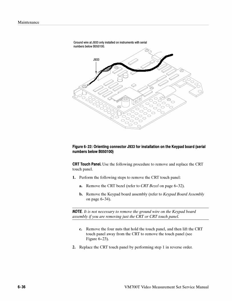
Maintenance
6- 36 VM700T Video Measurement Set Service Manual
J933
Ground wire at J933 only installed on instruments with serialnumbers below B050100.
Figure 6- 22: Orienting connector J933 for installation on the Keypad board (serialnumbers below B050100)
CRT Touch Panel.Use the following procedure to remove and replace the CRTtouch panel.
1. Perform the following steps to remove the CRT touch panel:
a. Remove the CRT bezel (refer to CRT Bezel on page 6--32).
b. Remove the Keypad board assembly (refer to Keypad Board Assembly
on page 6--34).
NOTE. It is not necessary to remove the ground wire on the Keypad board
assembly if you are removing just the CRT or CRT touch panel.
c. Remove the four nuts that hold the touch panel, and then lift the CRTtouch panel away from the CRT to remove the touch panel (seeFigure 6--23).
2. Replace the CRT touch panel by performing step 1 in reverse order.
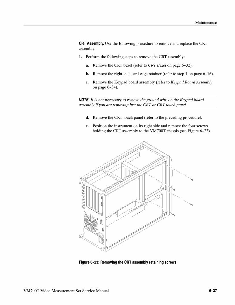
Maintenance
VM700T Video Measurement Set Service Manual 6- 37
CRT Assembly.Use the following procedure to remove and replace the CRTassembly.
1. Perform the following steps to remove the CRT assembly:
a. Remove the CRT bezel (refer to CRT Bezel on page 6--32).
b. Remove the right-side card cage retainer (refer to step 1 on page 6--16).
c. Remove the Keypad board assembly (refer to Keypad Board Assembly
on page 6--34).
NOTE. It is not necessary to remove the ground wire on the Keypad board
assembly if you are removing just the CRT or CRT touch panel.
d. Remove the CRT touch panel (refer to the preceding procedure).
e. Position the instrument on its right side and remove the four screwsholding the CRT assembly to the VM700T chassis (see Figure 6--23).
Figure 6- 23: Removing the CRT assembly retaining screws
Maintenance
6- 38 VM700T Video Measurement Set Service Manual
f. Slide the CRT assembly out of the chassis enough to remove the 10-wireconnector at the rear.
g. Remove the CRT assembly from the VM700T chassis and set it aside.
2. Replace the CRT touch panel by performing step 1 in reverse order.
This section describes how to remove and replace the power supply, the maininterconnect board, and the cooling fan.
Required Tools.Use the following tools to remove the display and controlcomponents:
Flat-blade screwdriver, 3/16 or 1/4 inch blade.
Pozidriv screwdriver, 2X.
Combination or open-end wrench, 11/32 inch.
Small wire cutters.
Power Supply Module. The power supply module is located on the right side ofthe VM700T, below the right-side card cage. You may remove the power supplyby first removing the cover panels of the VM700T (refer to Removing and
Replacing a Cover Panel on page 6--8 for more information) and turning theinstrument upside down. The following procedure describes removing andreplacing the power supply.
NOTE. The power supply module is field removeable for replacement only; it is
not a field-serviceable unit.
1. Perform the following steps to remove the power supply:
a. Remove the instrument cover panels (refer to Cover Panel Removal and
Replacement on page 6--8).
b. Position the VM700T with its bottom facing up and remove the wiresand connectors from the power supply. Disconnect the wires to theOn/Off switch from the switch.
NOTE. The connections are labeled on the power supply. You should also tag
each wire with a label as you remove it, for easy replacement later.
c. From the instrument bottom, remove four attaching screws (one screw isaccessed through a slot in the power supply housing). See Figure 6--24.
Power Supply,Interconnect Board,
VGA Board, and CoolingFan Removal and
Replacement
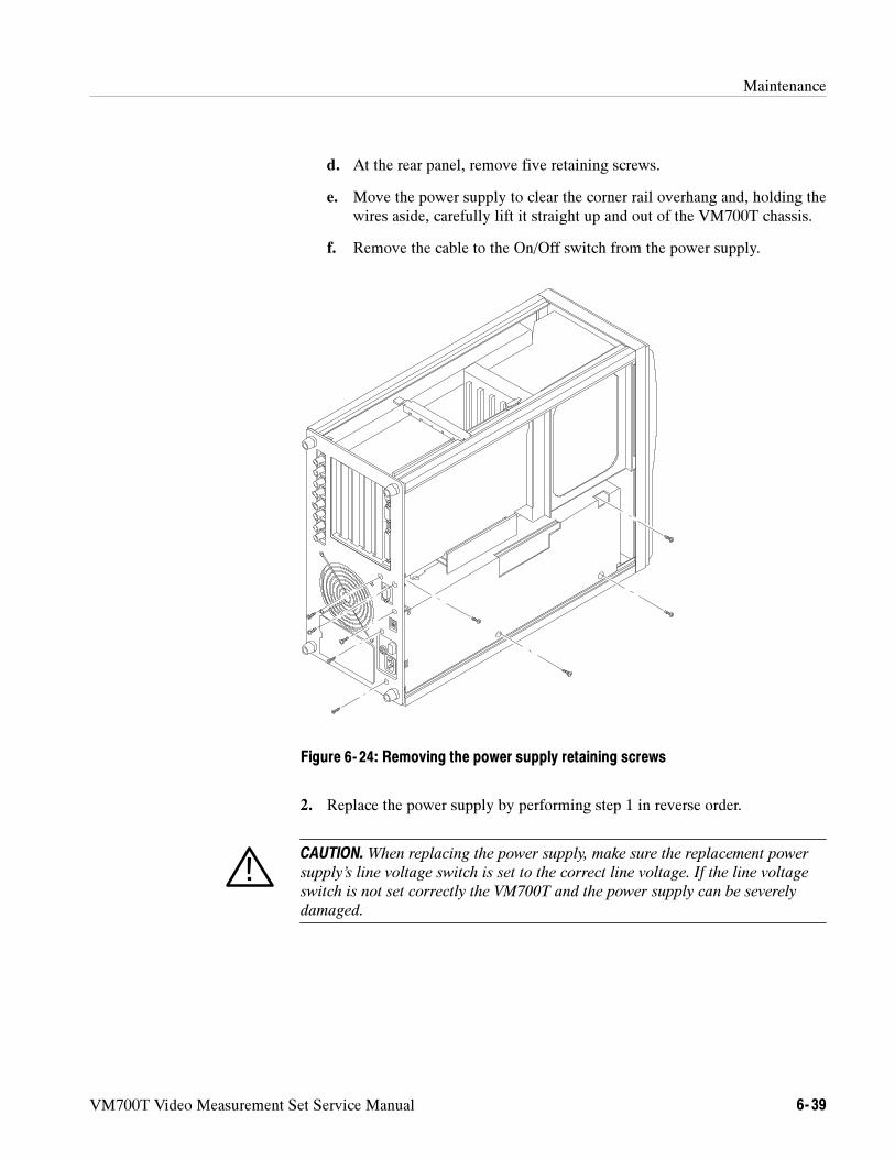
Maintenance
VM700T Video Measurement Set Service Manual 6- 39
d. At the rear panel, remove five retaining screws.
e. Move the power supply to clear the corner rail overhang and, holding thewires aside, carefully lift it straight up and out of the VM700T chassis.
f. Remove the cable to the On/Off switch from the power supply.
Figure 6- 24: Removing the power supply retaining screws
2. Replace the power supply by performing step 1 in reverse order.
CAUTION.When replacing the power supply, make sure the replacement power
supply’s line voltage switch is set to the correct line voltage. If the line voltage
switch is not set correctly the VM700T and the power supply can be severely
damaged.
Maintenance
6- 40 VM700T Video Measurement Set Service Manual
Interconnect Board Assembly (A11). The Interconnect board assembly (A11)consists of three circuit boards assembled with connectors, screws, and spacers.This assembly is replaced as a unit.
All VM700T circuit boards in the two card cages plug into the Interconnectboard assembly. Removing and replacing this assembly requires removing theboards from the card cages, removing wires and attaching screws, and lifting themain interconnect assembly from the instrument. The following proceduredescribes removing and replacing the main interconnect assembly.
1. Perform the following steps to remove the Interconnect board assembly:
a. Remove the instrument cover panels (refer to Cover Panel Removal and
Replacement on page 6--8).
b. Remove the CPU board from the right-side card cage (refer to CPU
Board (A5) Removal and Replacement on page 6--15).
c. Remove the Acquisition Memory board (refer to Acquisition Memory
Board (A18) Removal and Replacement on page 6--18).
d. Remove the I/O board (refer to I/O Board (A20) Removal and Replace-
ment on page 6--9).
e. Remove any installed option boards (refer to Option 40 and Option 41
Audio Boards (A12, A13, and A17) Removal and Replacement onpage 6--11, and Option 48 GPIB Interface Board (A19) Removal and
Replacement on page 6--14 for more information).
f. From the top of the instrument, disconnect the power bus cable at its fiveconnectors, and then remove the cable.
g. From the bottom of the instrument, remove the connectors and terminalwires between the power supply and the Interconnect board assembly.
h. Inside the left card cage, remove the six screws holding the Interconnectboard assembly to the card cage back panel (see Figure 6--25).
NOTE. The Interconnect board assembly retaining screws are easier to remove if
you first place the instrument on it’s right side and then use a long-shank
screwdriver (allowing more hand clearance) to remove them.
i. With the instrument placed upside down, carefully push the powersupply wiring aside and move the Interconnect board assembly up andout of the chassis.
2. Replace the Interconnect board assembly by performing step 1 in reverseorder.
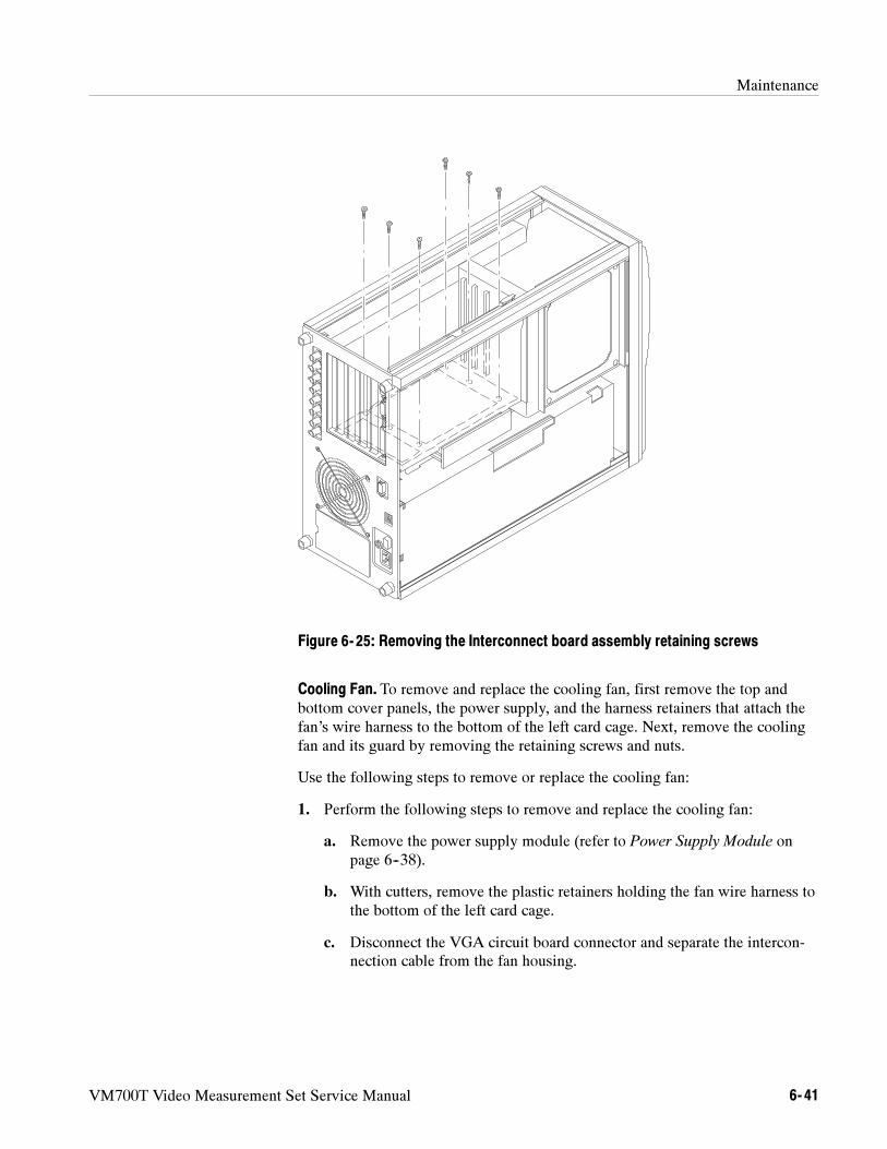
Maintenance
VM700T Video Measurement Set Service Manual 6- 41
Figure 6- 25: Removing the Interconnect board assembly retaining screws
Cooling Fan. To remove and replace the cooling fan, first remove the top andbottom cover panels, the power supply, and the harness retainers that attach thefan’s wire harness to the bottom of the left card cage. Next, remove the coolingfan and its guard by removing the retaining screws and nuts.
Use the following steps to remove or replace the cooling fan:
1. Perform the following steps to remove and replace the cooling fan:
a. Remove the power supply module (refer to Power Supply Module onpage 6--38).
b. With cutters, remove the plastic retainers holding the fan wire harness tothe bottom of the left card cage.
c. Disconnect the VGA circuit board connector and separate the intercon-nection cable from the fan housing.
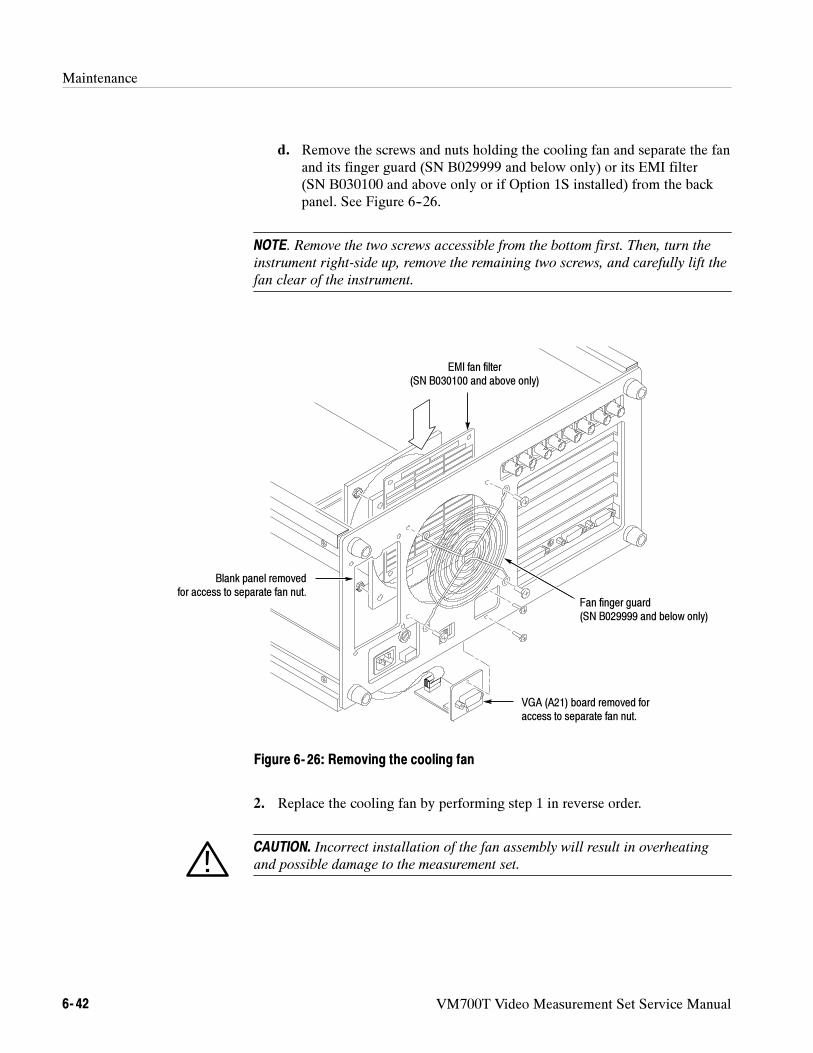
Maintenance
6- 42 VM700T Video Measurement Set Service Manual
d. Remove the screws and nuts holding the cooling fan and separate the fanand its finger guard (SN B029999 and below only) or its EMI filter(SN B030100 and above only or if Option 1S installed) from the backpanel. See Figure 6--26.
NOTE. Remove the two screws accessible from the bottom first. Then, turn the
instrument right-side up, remove the remaining two screws, and carefully lift the
fan clear of the instrument.
EMI fan filter(SN B030100 and above only)
Blank panel removedfor access to separate fan nut.
VGA (A21) board removed foraccess to separate fan nut.
Fan finger guard(SN B029999 and below only)
Figure 6- 26: Removing the cooling fan
2. Replace the cooling fan by performing step 1 in reverse order.
CAUTION. Incorrect installation of the fan assembly will result in overheating
and possible damage to the measurement set.
Maintenance
VM700T Video Measurement Set Service Manual 6- 43
NOTE. Reinstall plastic retainers to hold the fan wire harness to the bottom of
the left card cage. Reconnect the VGA cable to the fan housing with a cable tie.
When reinstalling the fan, make sure you have the fan positioned so that the air
flow is out of the VM700T.
VGA Connector Board.Use the following procedure to remove and replace theVGA Connector board.
1. Perform the following steps to remove the VGA Connector board:
a. Remove the instrument cover panels (refer to Cover Panel Removal and
Replacement on page 6--8).
b. Remove the attaching hardware for the VGA Connector board from therear of the VM700T (see Figure 6--26).
c. Pull the VGA Connector circuit board away from the fan housing anddisconnect the VGA ribbon cable from the connector on the rear of theVGA Connector board.
d. Remove the VGA Connector board from the VM700T.
2. Perform the following steps to replace the VGA Connector board:
a. Reconnect the VGA ribbon cable to the connector on the circuit board.
b. Position the VGA Connector board on the mounting plate against theinside surface of the rear panel under the fan housing.
c. Align the holes in the circuit board with the holes in the rear panelmounting plate, and install and tighten the attaching hardware.
d. Replace the cover panels (refer to Cover Panel Removal and Replace-
ment on page 6--8).
Maintenance
6- 44 VM700T Video Measurement Set Service Manual
VM700T Rack Mounting Instructions
When unpackaging the VM700T Video Measurement Set for installation, keepthe shipping carton and packaging material. If returning the VM700T for repairsshould become necessary, you will then have packaging available that willprovide adequate protection for shipment.
The VM700T will operate with line frequencies of 50 Hz or 60 Hz, over two linevoltage ranges. The low voltage range is from 90 VAC to 132 VAC; 115 VACnominal. The high voltage range is from 180 VAC to 250 VAC; 230 VACnominal.
WARNING. For your protection and to avoid damage to the measurement set,
shut the power off before removing or replacing any circuit boards, connectors,
or jumpers.
The voltage range selection switch and fuse holder are located on the lower leftcorner of the rear panel of the VM700T.
The VM700T is shipped from the factory set for 115 VAC operation. If thissetting must be changed to 230 VAC, simply set the voltage range selectionswitch to the 230 V position to operate in the high voltage range. The 6 Aslow-blow fuse provides the proper protection in the low voltage range and mustbe replaced with a 3 A slow-blow fuse for operation in the high voltage range.
NOTE. If you wish to use Password protection for your user-definable configura-
tion, DlP switch settings on the A5 CPU board must be changed. Refer to the
VM700T Option 01 (NTSC) and Option 11 (PAL) User Manual, Configuring theVM700T, for a detailed description of how Password operates.
Unpackaging
Power Requirements
Changing the Line VoltageRange and Fuse
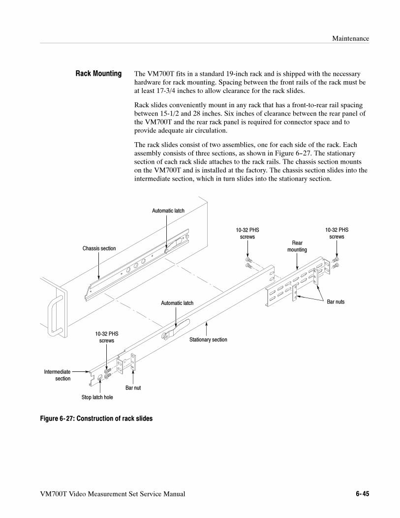
Maintenance
VM700T Video Measurement Set Service Manual 6- 45
The VM700T fits in a standard 19-inch rack and is shipped with the necessaryhardware for rack mounting. Spacing between the front rails of the rack must beat least 17-3/4 inches to allow clearance for the rack slides.
Rack slides conveniently mount in any rack that has a front-to-rear rail spacingbetween 15-1/2 and 28 inches. Six inches of clearance between the rear panel ofthe VM700T and the rear rack panel is required for connector space and toprovide adequate air circulation.
The rack slides consist of two assemblies, one for each side of the rack. Eachassembly consists of three sections, as shown in Figure 6--27. The stationarysection of each rack slide attaches to the rack rails. The chassis section mountson the VM700T and is installed at the factory. The chassis section slides into theintermediate section, which in turn slides into the stationary section.
Chassis section
Automatic latch
Stationary section
Intermediatesection
Stop latch hole
Rearmounting
Automatic latch Bar nuts
10-32 PHSscrews
10-32 PHSscrews
10-32 PHSscrews
Bar nut
Figure 6- 27: Construction of rack slides
Rack Mounting
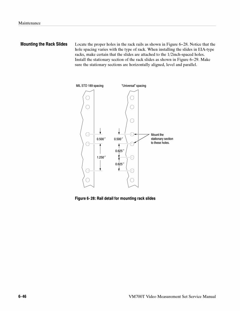
Maintenance
6- 46 VM700T Video Measurement Set Service Manual
Locate the proper holes in the rack rails as shown in Figure 6--28. Notice that thehole spacing varies with the type of rack. When installing the slides in EIA-typeracks, make certain that the slides are attached to the 1/2inch-spaced holes.Install the stationary section of the rack slides as shown in Figure 6--29. Makesure the stationary sections are horizontally aligned, level and parallel.
0.625
0.500
1.250
0.500
MIL STD 189 spacing “Universal” spacing
Mount thestationary sectionto these holes.
0.625
Figure 6- 28: Rail detail for mounting rack slides
Mounting the Rack Slides
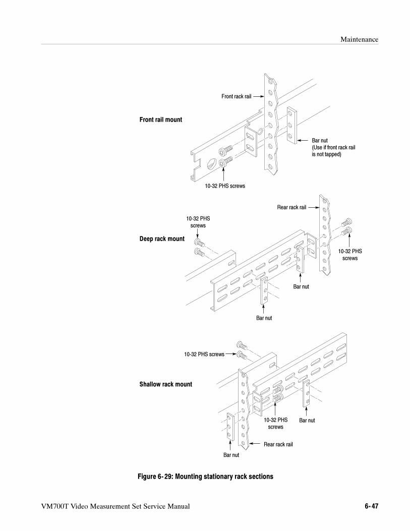
Maintenance
VM700T Video Measurement Set Service Manual 6- 47
10-32 PHS screws
Bar nut(Use if front rack railis not tapped)
Front rack rail
Rear rack rail
Deep rack mount
Shallow rack mount
Front rail mount
Bar nut
Bar nut
Bar nut
Bar nut
Rear rack rail
10-32 PHSscrews
10-32 PHSscrews
10-32 PHSscrews
10-32 PHS screws
Figure 6- 29: Mounting stationary rack sections
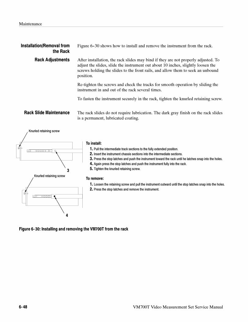
Maintenance
6- 48 VM700T Video Measurement Set Service Manual
Figure 6--30 shows how to install and remove the instrument from the rack.
After installation, the rack slides may bind if they are not properly adjusted. Toadjust the slides, slide the instrument out about 10 inches, slightly loosen thescrews holding the slides to the front rails, and allow them to seek an unboundposition.
Re-tighten the screws and check the tracks for smooth operation by sliding theinstrument in and out of the rack several times.
To fasten the instrument securely in the rack, tighten the knurled retaining screw.
The rack slides do not require lubrication. The dark gray finish on the rack slidesis a permanent, lubricated coating.
To install:
To remove:
1. Pull the intermediate track sections to the fully extended position.2. Insert the instrument chassis sections into the intermediate sections.3. Press the stop latches and push the instrument toward the rack until he latches snap into the holes.4. Again press the stop latches and push the instrument fully into the rack.5. Tighten the knurled retaining screw.
1. Loosen the retaining screw and pull the instrument outward until the stop latches snap into the holes.
2. Press the stop latches and remove the instrument.
3
Knurled retaining screw
4
Knurled retaining screw
Figure 6- 30: Installing and removing the VM700T from the rack
Installation/Removal fromthe Rack
Rack Adjustments
Rack Slide Maintenance
VM700T Video Measurement Set Service Manual 6- 49
Troubleshooting Procedures
The troubleshooting material provided in this section is general and is notintended to cover specific instrument malfunctions. This section contains thefollowing subsections:
Troubleshooting techniques page 6--50
Isolating operational faults page 6--51
Diagnostics page 6--55
Low level diagnostics page 6--59
Diagnostic utilities page 6--65
Calibrating the touch screen page 6--68
Setting the power-up mode page 6--70
VM700T boot switch and diagnostic LED page 6--73
Running the high-level diagnostics page 6--74
Auto reset (running all diagnostics) page 6--84
Viewing stored diagnostic information page 6--84
Viewing diagnostics remotely page 6--85
Troubleshooting the power supply and the CRT display page 6--90
Troubleshooting Option 40 and Option 41 (Audio) page 6--95
Troubleshooting Option 48 (GPIB) page 6--99
Troubleshooting Option 1S (SDI) page 6--100
More Information. The following useful troubleshooting information can be foundelsewhere in this manual:
Refer to Theory of Operation on page 3--1 for descriptions of the electricaloperation of the VM700T Video Measurement Set from a functional-circuitblock perspective.
Refer to Diagrams on page 9--1 for an instrument-level block diagram andinterconnection diagram.
Refer to Replaceable Mechanical Parts on page 10--1 for the list ofreplaceable parts accompanied by exploded view drawings of the instrument.

Troubleshooting Procedures
6- 50 VM700T Video Measurement Set Service Manual
Troubleshooting Techniques
The following procedure is designed to assist in isolating problems, which inturn expedites repairs and minimizes down time.
1. Ensure that the malfunction actually exists. This is done by running thediagnostics to ensure that the instrument is operating as intended byTektronix. Refer to Diagnostics beginning on page 6--55 for a description ofthe diagnostic tests and information on using diagnostics for troubleshootingmodule problems.
2. Determine and evaluate all trouble symptoms. This is accomplished byisolating the problem to a general area such as a replaceable module.
CAUTION. Use extreme care when probing with meter leads or probes, because of
the high component density and limited access within the instrument. The
inadvertent movement of leads or a probe could cause a short circuit or transient
voltage capable of destroying components.
3. Determine the nature of the problem. Attempt to make the determination ofwhether the instrument is out of calibration or if there has been a componentfailure. Once the type of failure has been determined, identify the functionalarea most likely at fault.
4. Visually inspect the suspect assembly for obvious defects. Most commonlythese will be broken or loose components, improperly seated components,overheated or burned components, chafed insulation, etc. In the case ofoverheated components, determine the cause of overheating and correct thecause before reapplying power.
5. Remove defective modules and exchange them with the factory. Refer toRemoval and Replacement Instructions on page 6--6. Refer also to Customer
Service on page 6--3 for information on the board exchange repair service.
WARNING. High voltages are present inside the VM700T chassis. These voltages
can cause serious injury. Leave all service procedures that require removing
instrument covers to qualified service personnel.
Troubleshooting the VM700T is a matter of following a logical series of stepsthat isolate a problem to a specific system module such as a circuit board, powersupply, or display monitor. After isolating the problem, repair consists ofreplacing the faulty module and checking the instrument for correct operation.
Troubleshooting Procedures
VM700T Video Measurement Set Service Manual 6- 51
Some VM700T faults can be isolated to just one system module. Correctingthese faults requires replacing the faulty module. Other faults may be caused byone or more defective system modules. In either case, the VM700T diagnosticsroutines can assist in isolating the fault to field-replaceable modules. Theseroutines can also evaluate each of the instrument’s major hardware componentsto provide a high degree of confidence that measurement results produced by theinstrument are correct.
The best way to repair multiple-module faults is to replace one module at a time,checking for correct operation after each replacement, until you have located andreplaced the faulty module.
Interconnecting Cables. Signals and power supply voltages are passed through theinstrument by a system of interconnecting cables. The connector holders on thesecables have numbers that identify terminal connectors. A triangular key symbolis used to identify pin 1 on the circuit board to assist in aligning the correct pinson the mating connector.
Isolating Operational Faults
This section presents a series of operational fault symptoms and suggestscorrective actions. The most efficient way to use the information involves atwo-step approach.
1. Compare the failure symptoms you are experiencing with the symptomspresented in Table 6--3.
2. Run the VM700T built-in diagnostics routines to assist in isolating thefailure.
Following these steps will assist you in isolating any VM700T fault to afield-replaceable module such as a circuit board.
For information on how to return defective instrument modules to Tektronix forrepair, refer to Customer Service on page 6--3.
Table 6--3 lists a series of instrument faults or failures, related possible causes,and suggested corrective actions. Run the complete set of diagnostic test todetermine if suspected modules pass or fail the testing before attempting anymodule exchanges. You can use the information in the table, along with theresults of the diagnostic tests, to characterize faulty VM700T operation as arepair guide.
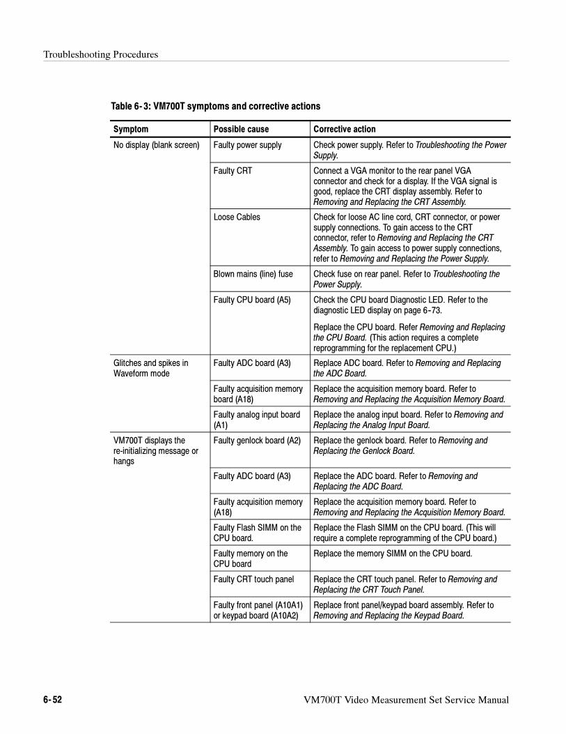
Troubleshooting Procedures
6- 52 VM700T Video Measurement Set Service Manual
Table 6- 3: VM700T symptoms and corrective actions
Symptom Possible cause Corrective action
No display (blank screen) Faulty power supply Check power supply. Refer to Troubleshooting the PowerSupply.
Faulty CRT Connect a VGA monitor to the rear panel VGAconnector and check for a display. If the VGA signal isgood, replace the CRT display assembly. Refer toRemoving and Replacing the CRT Assembly.
Loose Cables Check for loose AC line cord, CRT connector, or powersupply connections. To gain access to the CRTconnector, refer to Removing and Replacing the CRTAssembly. To gain access to power supply connections,refer to Removing and Replacing the Power Supply.
Blown mains (line) fuse Check fuse on rear panel. Refer to Troubleshooting thePower Supply.
Faulty CPU board (A5) Check the CPU board Diagnostic LED. Refer to thediagnostic LED display on page 6--73.
Replace the CPU board. Refer Removing and Replacingthe CPU Board. (This action requires a completereprogramming for the replacement CPU.)
Glitches and spikes inWaveform mode
Faulty ADC board (A3) Replace ADC board. Refer to Removing and Replacingthe ADC Board.
Faulty acquisition memoryboard (A18)
Replace the acquisition memory board. Refer toRemoving and Replacing the Acquisition Memory Board.
Faulty analog input board(A1)
Replace the analog input board. Refer to Removing andReplacing the Analog Input Board.
VM700T displays there-initializing message orhangs
Faulty genlock board (A2) Replace the genlock board. Refer to Removing andReplacing the Genlock Board.
Faulty ADC board (A3) Replace the ADC board. Refer to Removing andReplacing the ADC Board.
Faulty acquisition memory(A18)
Replace the acquisition memory board. Refer toRemoving and Replacing the Acquisition Memory Board.
Faulty Flash SIMM on theCPU board.
Replace the Flash SIMM on the CPU board. (This willrequire a complete reprogramming of the CPU board.)
Faulty memory on theCPU board
Replace the memory SIMM on the CPU board.
Faulty CRT touch panel Replace the CRT touch panel. Refer to Removing andReplacing the CRT Touch Panel.
Faulty front panel (A10A1)or keypad board (A10A2)
Replace front panel/keypad board assembly. Refer toRemoving and Replacing the Keypad Board.
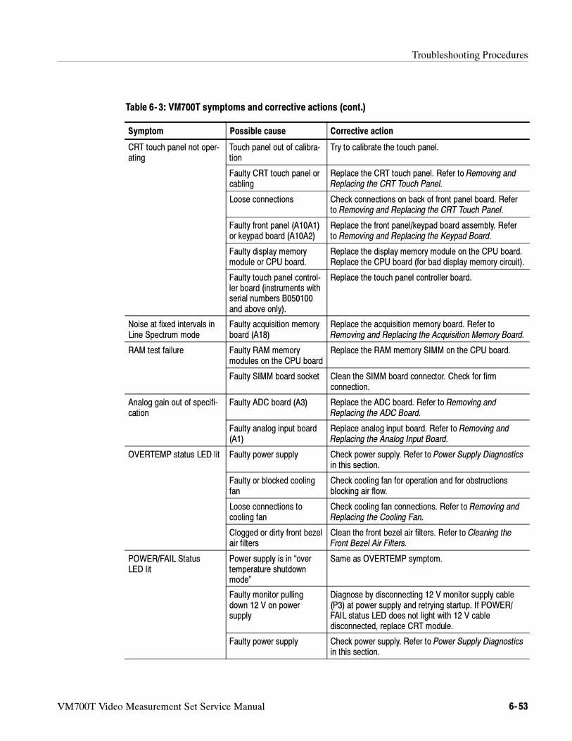
Troubleshooting Procedures
VM700T Video Measurement Set Service Manual 6- 53
Table 6- 3: VM700T symptoms and corrective actions (cont.)
Corrective actionPossible causeSymptom
CRT touch panel not oper-ating
Touch panel out of calibra-tion
Try to calibrate the touch panel.g
Faulty CRT touch panel orcabling
Replace the CRT touch panel. Refer to Removing andReplacing the CRT Touch Panel.
Loose connections Check connections on back of front panel board. Referto Removing and Replacing the CRT Touch Panel.
Faulty front panel (A10A1)or keypad board (A10A2)
Replace the front panel/keypad board assembly. Referto Removing and Replacing the Keypad Board.
Faulty display memorymodule or CPU board.
Replace the display memory module on the CPU board.Replace the CPU board (for bad display memory circuit).
Faulty touch panel control-ler board (instruments withserial numbers B050100and above only).
Replace the touch panel controller board.
Noise at fixed intervals inLine Spectrum mode
Faulty acquisition memoryboard (A18)
Replace the acquisition memory board. Refer toRemoving and Replacing the Acquisition Memory Board.
RAM test failure Faulty RAM memorymodules on the CPU board
Replace the RAM memory SIMM on the CPU board.
Faulty SIMM board socket Clean the SIMM board connector. Check for firmconnection.
Analog gain out of specifi-cation
Faulty ADC board (A3) Replace the ADC board. Refer to Removing andReplacing the ADC Board.
Faulty analog input board(A1)
Replace analog input board. Refer to Removing andReplacing the Analog Input Board.
OVERTEMP status LED lit Faulty power supply Check power supply. Refer to Power Supply Diagnosticsin this section.
Faulty or blocked coolingfan
Check cooling fan for operation and for obstructionsblocking air flow.
Loose connections tocooling fan
Check cooling fan connections. Refer to Removing andReplacing the Cooling Fan.
Clogged or dirty front bezelair filters
Clean the front bezel air filters. Refer to Cleaning theFront Bezel Air Filters.
POWER/FAIL StatusLED lit
Power supply is in “overtemperature shutdownmode”
Same as OVERTEMP symptom.
Faulty monitor pullingdown 12 V on powersupply
Diagnose by disconnecting 12 V monitor supply cable(P3) at power supply and retrying startup. If POWER/FAIL status LED does not light with 12 V cabledisconnected, replace CRT module.
Faulty power supply Check power supply. Refer to Power Supply Diagnosticsin this section.
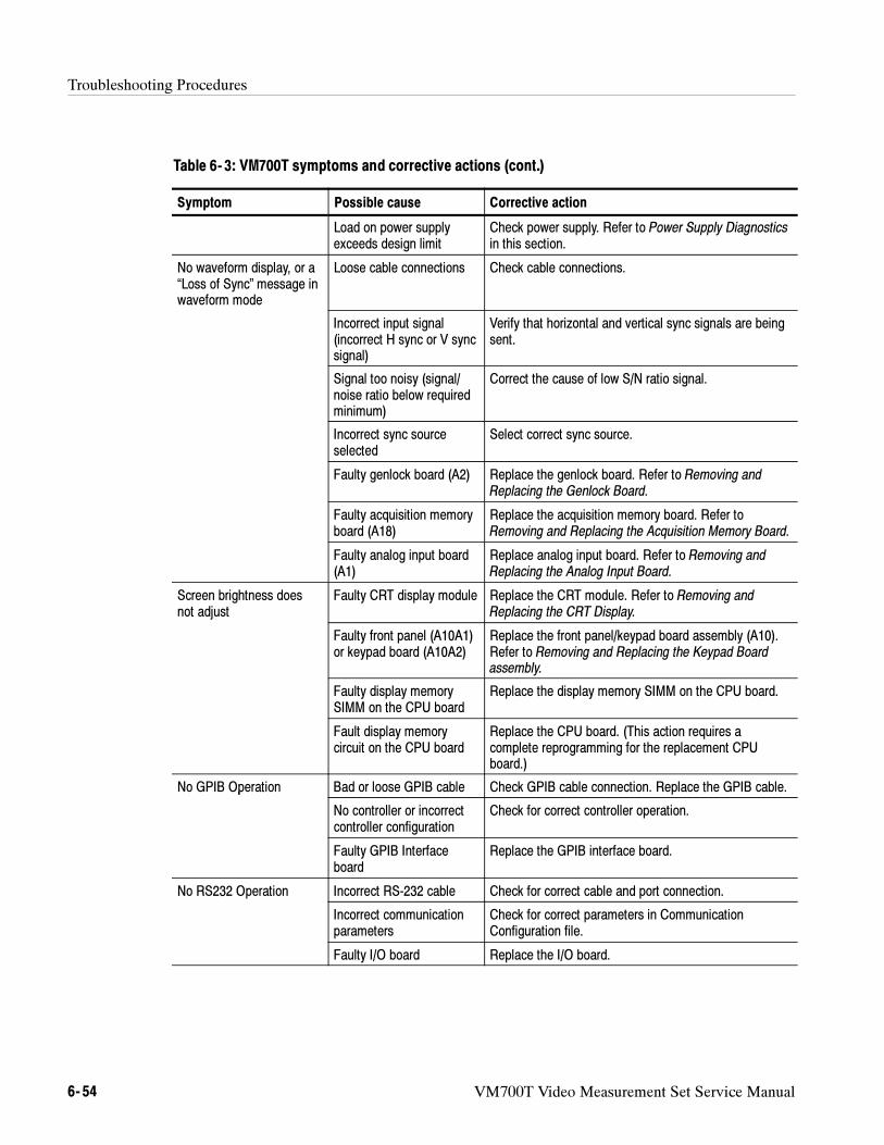
Troubleshooting Procedures
6- 54 VM700T Video Measurement Set Service Manual
Table 6- 3: VM700T symptoms and corrective actions (cont.)
Corrective actionPossible causeSymptom
Load on power supplyexceeds design limit
Check power supply. Refer to Power Supply Diagnosticsin this section.
No waveform display, or a“Loss of Sync” message inwaveform mode
Loose cable connections Check cable connections.
Incorrect input signal(incorrect H sync or V syncsignal)
Verify that horizontal and vertical sync signals are beingsent.
Signal too noisy (signal/noise ratio below requiredminimum)
Correct the cause of low S/N ratio signal.
Incorrect sync sourceselected
Select correct sync source.
Faulty genlock board (A2) Replace the genlock board. Refer to Removing andReplacing the Genlock Board.
Faulty acquisition memoryboard (A18)
Replace the acquisition memory board. Refer toRemoving and Replacing the Acquisition Memory Board.
Faulty analog input board(A1)
Replace analog input board. Refer to Removing andReplacing the Analog Input Board.
Screen brightness doesnot adjust
Faulty CRT display module Replace the CRT module. Refer to Removing andReplacing the CRT Display.
Faulty front panel (A10A1)or keypad board (A10A2)
Replace the front panel/keypad board assembly (A10).Refer to Removing and Replacing the Keypad Boardassembly.
Faulty display memorySIMM on the CPU board
Replace the display memory SIMM on the CPU board.
Fault display memorycircuit on the CPU board
Replace the CPU board. (This action requires acomplete reprogramming for the replacement CPUboard.)
No GPIB Operation Bad or loose GPIB cable Check GPIB cable connection. Replace the GPIB cable.p
No controller or incorrectcontroller configuration
Check for correct controller operation.
Faulty GPIB Interfaceboard
Replace the GPIB interface board.
No RS232 Operation Incorrect RS-232 cable Check for correct cable and port connection.
Incorrect communicationparameters
Check for correct parameters in CommunicationConfiguration file.
Faulty I/O board Replace the I/O board.
Troubleshooting Procedures
VM700T Video Measurement Set Service Manual 6- 55
Diagnostics
Diagnostics in the VM700T Video Measurement Set are divided into two sets,low level and high level. The distinction between the two types is based upon theoperating system; those diagnostics that run before the instrument’s operatingsystem is booted are referred to as low level; those that run as applicationsexecuted by the operating system are referred to as high level. The instrumentpauses noticeably when the operating system is booting, so messages aredisplayed indicating when this boot is occurring to aid the user in differentiatingbetween high-level and low-level diagnostics.
Grouping of diagnostics within the two sets is by circuit board. Within a circuitboard diagnostic are one or more tests; associated with each test is a mainpass/fail result and, where applicable, one or more sub-results. The purpose ofthis format is to present all the information used within a test to determine itsultimate pass/fail status. There is another diagnostic tests grouping, the OverallRun mode. The three choices are: Power Up mode, Auto Reset mode, andUser-Interactive mode. These are discussed later in this section in Selecting an
Overall Run Mode on page 6--61.
Diagnostics are normally bypassed for a quicker startup but they can beconfigured to run automatically during a normal instrument powerup. Thenormal powerup mode skips all diagnostics. Power-up modes can be selectedusing hardware boot switch settings on the CPU board (discussed later in thissection) or, in some cases, by pressing and holding certain front-panel buttonsduring powerup (referred to as ’backdoor boot modes’). For example, holdingthe Menu button in while turning on the power causes the VM700T to enter thelow-level diagnostic interface.
Interactive diagnostics provide the service person choices to control the tests thatrun and the manner in which they run. In the user interactive mode, any or alltests within a group of tests can be selected for execution.
Diagnostics displays can be routed to one of the instrument serial ports forviewing on a terminal. This is useful if a malfunction does not permit the testingprogress and results to be displayed on the VM700T CRT. A special setting ofthe boot switch is used to route the diagnostic test displays to the serial ports.
NOTE. Diagnostics can also be controlled and executed remotely through the
serial port. This method is most useful if the display system is inoperative or in a
service environment for programmed troubleshooting of the VM700T. Refer to
Viewing Diagnostics Remotely on page 6--85 for more information.
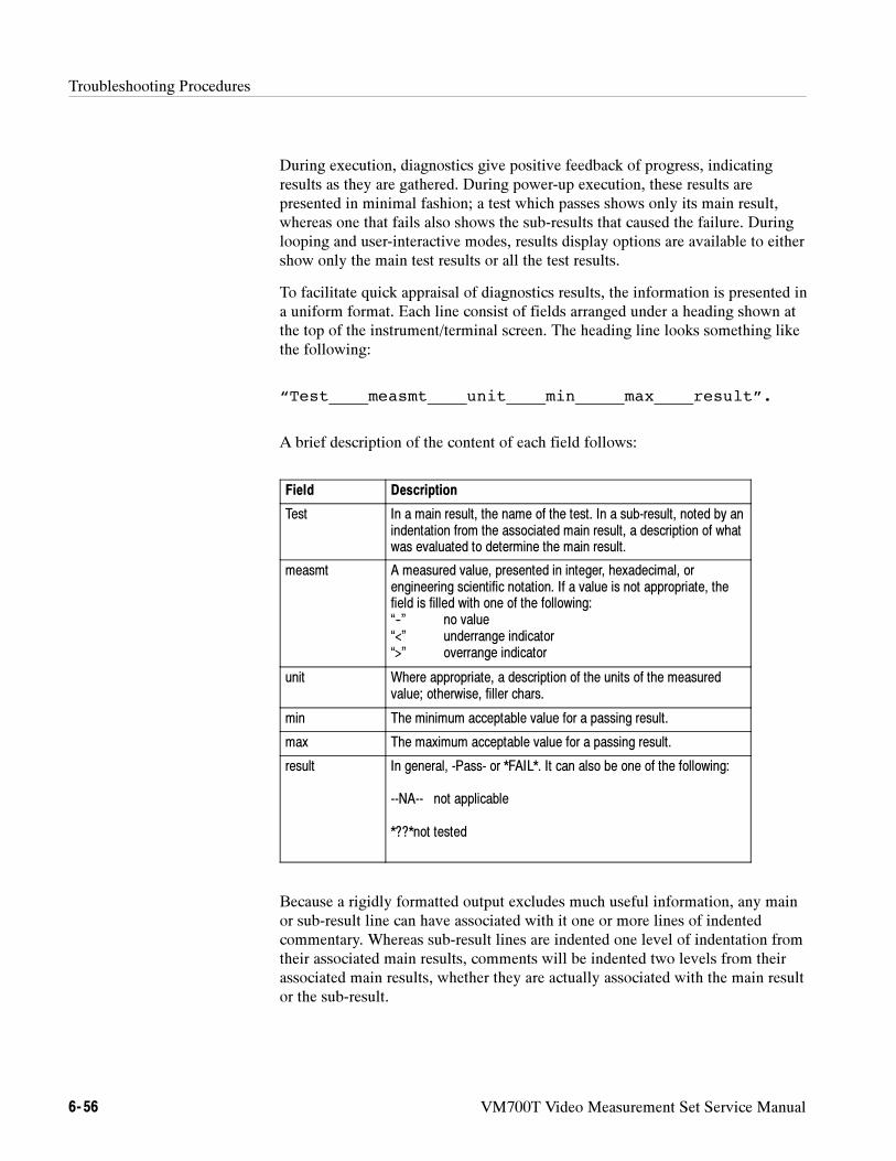
Troubleshooting Procedures
6- 56 VM700T Video Measurement Set Service Manual
During execution, diagnostics give positive feedback of progress, indicatingresults as they are gathered. During power-up execution, these results arepresented in minimal fashion; a test which passes shows only its main result,whereas one that fails also shows the sub-results that caused the failure. Duringlooping and user-interactive modes, results display options are available to eithershow only the main test results or all the test results.
To facilitate quick appraisal of diagnostics results, the information is presented ina uniform format. Each line consist of fields arranged under a heading shown atthe top of the instrument/terminal screen. The heading line looks something likethe following:
“Test____measmt____unit____min_____max____result”.
A brief description of the content of each field follows:
Field Description
Test In a main result, the name of the test. In a sub-result, noted by anindentation from the associated main result, a description of whatwas evaluated to determine the main result.
measmt A measured value, presented in integer, hexadecimal, orengineering scientific notation. If a value is not appropriate, thefield is filled with one of the following:“--” no value“<” underrange indicator“>” overrange indicator
unit Where appropriate, a description of the units of the measuredvalue; otherwise, filler chars.
min The minimum acceptable value for a passing result.
max The maximum acceptable value for a passing result.
result In general, -Pass- or *FAIL*. It can also be one of the following:
--NA-- not applicable
*??*not tested
Because a rigidly formatted output excludes much useful information, any mainor sub-result line can have associated with it one or more lines of indentedcommentary. Whereas sub-result lines are indented one level of indentation fromtheir associated main results, comments will be indented two levels from theirassociated main results, whether they are actually associated with the main resultor the sub-result.
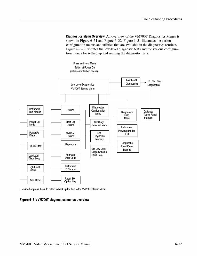
Troubleshooting Procedures
VM700T Video Measurement Set Service Manual 6- 57
Diagnostics Menu Overview.An overview of the VM700T Diagnostics Menus isshown in Figure 6--31 and Figure 6--32. Figure 6--31 illustrates the variousconfiguration menus and utilities that are available in the diagnostics routines.Figure 6--32 illustrates the low-level diagnostic tests and the various configura-tion menus for setting up and running the diagnostic tests.
Low Level Diagnostics
VM700T Startup Menu
DiagnosticsHelpMenu
Instrument
Powerup Modes
Instrument
Power Up
Quick Start
Low Level
Utilities
To Low Level
Press and Hold Menu
Button at Power On
List
Diagnostic
Front Panel
Buttons
Error Log
NVRAM SetDiagnosticIntensity
Low Level
Diagnostics
DiagnosticsConfiguration
Menu
Diagnostics
Set DiagsPowerup Mode
Set Low Level
Utilities
Utilities
Reprogrm
FirmwareDate Code
InstrumentID Number
Use Abort or press the Auto button to back up the tree to the VM700T Startup Menu
Auto Reset
PowerUp
High Level
CalibrateTouch PanelInterface
Diags ConsoleBaud Rate
Run Modes
Mode
Diags
Diags Loop
Debug
Reset SWOption Key
(release it after two beeps)
Figure 6- 31: VM700T diagnostics menus overview
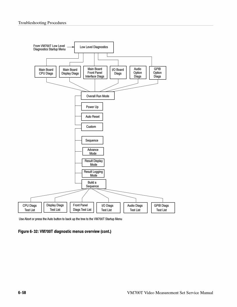
Troubleshooting Procedures
6- 58 VM700T Video Measurement Set Service Manual
Low Level Diagnostics
Main Board Main BoardDisplay Diags
Main Board
Overall Run Mode
Power Up
Auto Reset
Custom
Sequence
Advance
Result Display
Build a
CPU Diags
Test List
Display Diags
Test List
Front Panel
CPU Diags Front PanelInterface Diags
I/O Diags
Test List
I/O BoardDiags
Diags Test List
Use Abort or press the Auto button to back up the tree to the VM700T Startup Menu
AudioOption
GPIBOptionDiagsDiags
Audio Diags
Test List
GPIB Diags
Test List
Mode
Mode
Result LoggingMode
Sequence
From VM700T Low LevelDiagnostics Startup Menu
Figure 6- 32: VM700T diagnostic menus overview (cont.)
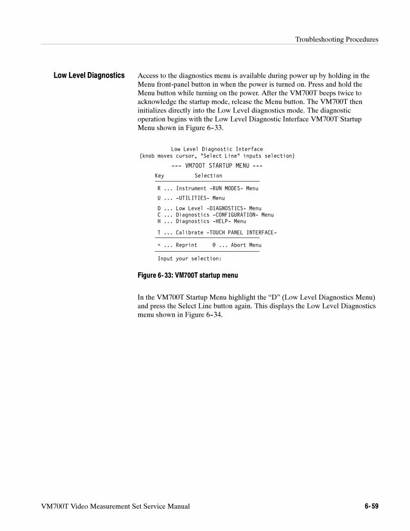
Troubleshooting Procedures
VM700T Video Measurement Set Service Manual 6- 59
Access to the diagnostics menu is available during power up by holding in theMenu front-panel button in when the power is turned on. Press and hold theMenu button while turning on the power. After the VM700T beeps twice toacknowledge the startup mode, release the Menu button. The VM700T theninitializes directly into the Low Level diagnostics mode. The diagnosticoperation begins with the Low Level Diagnostic Interface VM700T StartupMenu shown in Figure 6--33.
Low Level Diagnostic Interface(knob moves cursor, “Select Line” inputs selection)
Key Selection
H ... Diagnostics -HELP- Menu
R ... Instrument -RUN MODES- Menu
D ... Low Level -DIAGNOSTICS- Menu
= ... Reprint @ ... Abort Menu
Input your selection:
U ... -UTILITIES- Menu
T ... Calibrate -TOUCH PANEL INTERFACE-
--- VM700T STARTUP MENU ---
C ... Diagnostics -CONFIGURATION- Menu
Figure 6- 33: VM700T startup menu
In the VM700T Startup Menu highlight the “D” (Low Level Diagnostics Menu)and press the Select Line button again. This displays the Low Level Diagnosticsmenu shown in Figure 6--34.
Low Level Diagnostics
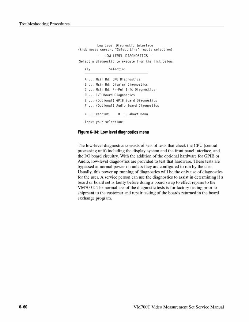
Troubleshooting Procedures
6- 60 VM700T Video Measurement Set Service Manual
--- LOW LEVEL DIAGNOSTICS---
Select a diagnostic to execute from the list below:
Key Selection
A ... Main Bd. CPU Diagnostics
B ... Main Bd. Display Diagnostics
C ... Main Bd. Fr-Pnl Infc Diagnostics
= ... Reprint @ ... Abort Menu
Input your selection:
Low Level Diagnostic Interface(knob moves cursor, “Select Line” inputs selection)
D ... I/O Board Diagnostics
E ... (Optional) GPIB Board Diagnostics
F ... (Optional) Audio Board Diagnostics
Figure 6- 34: Low level diagnostics menu
The low-level diagnostics consists of sets of tests that check the CPU (centralprocessing unit) including the display system and the front panel interface, andthe I/O board circuitry. With the addition of the optional hardware for GPIB orAudio, low-level diagnostics are provided to test that hardware. These tests arebypassed at normal power-on unless they are configured to run by the user.Usually, this power up running of diagnostics will be the only use of diagnosticsfor the user. A service person can use the diagnostics to assist in determining if aboard or board set is faulty before doing a board swap to effect repairs to theVM700T. The normal use of the diagnostic tests is for factory testing prior toshipment to the customer and repair testing of the boards returned in the boardexchange program.
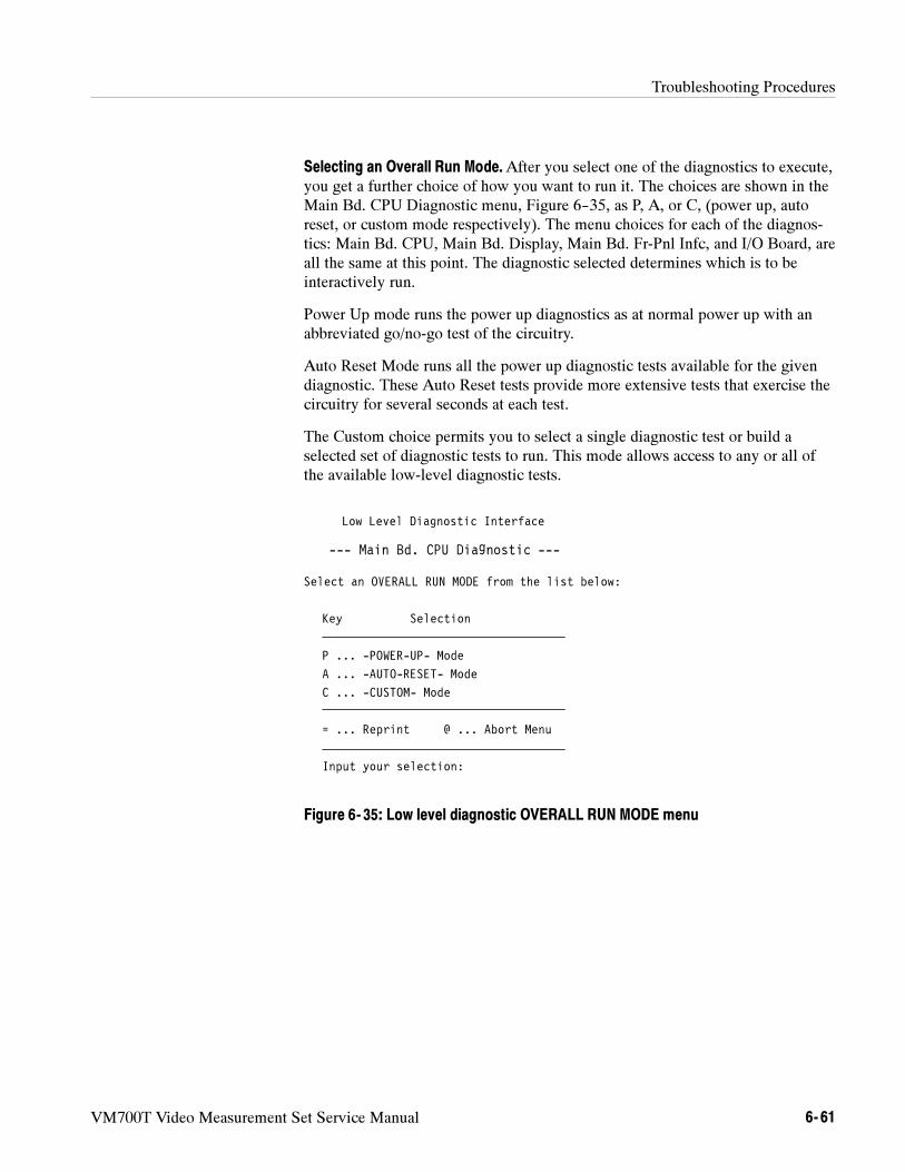
Troubleshooting Procedures
VM700T Video Measurement Set Service Manual 6- 61
Selecting an Overall Run Mode.After you select one of the diagnostics to execute,you get a further choice of how you want to run it. The choices are shown in theMain Bd. CPU Diagnostic menu, Figure 6--35, as P, A, or C, (power up, autoreset, or custom mode respectively). The menu choices for each of the diagnos-tics: Main Bd. CPU, Main Bd. Display, Main Bd. Fr-Pnl Infc, and I/O Board, areall the same at this point. The diagnostic selected determines which is to beinteractively run.
Power Up mode runs the power up diagnostics as at normal power up with anabbreviated go/no-go test of the circuitry.
Auto Reset Mode runs all the power up diagnostic tests available for the givendiagnostic. These Auto Reset tests provide more extensive tests that exercise thecircuitry for several seconds at each test.
The Custom choice permits you to select a single diagnostic test or build aselected set of diagnostic tests to run. This mode allows access to any or all ofthe available low-level diagnostic tests.
Low Level Diagnostic Interface
--- Main Bd. CPU Diagnostic ---
Select an OVERALL RUN MODE from the list below:
Key Selection
P ... -POWER-UP- Mode
A ... -AUTO-RESET- Mode
C ... -CUSTOM- Mode
= ... Reprint @ ... Abort Menu
Input your selection:
Figure 6- 35: Low level diagnostic OVERALL RUN MODE menu
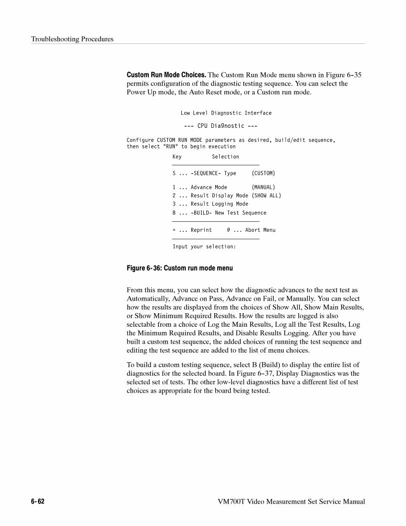
Troubleshooting Procedures
6- 62 VM700T Video Measurement Set Service Manual
Custom Run Mode Choices. The Custom Run Mode menu shown in Figure 6--35permits configuration of the diagnostic testing sequence. You can select thePower Up mode, the Auto Reset mode, or a Custom run mode.
Low Level Diagnostic Interface
--- CPU Diagnostic ---
Configure CUSTOM RUN MODE parameters as desired, build/edit sequence,
Key Selection
S ... -SEQUENCE- Type (CUSTOM)
1 ... Advance Mode (MANUAL)
2 ... Result Display Mode (SHOW ALL)
B ... -BUILD- New Test Sequence
= ... Reprint @ ... Abort Menu
Input your selection:
then select “RUN” to begin execution
3 ... Result Logging Mode
Figure 6- 36: Custom run mode menu
From this menu, you can select how the diagnostic advances to the next test asAutomatically, Advance on Pass, Advance on Fail, or Manually. You can selecthow the results are displayed from the choices of Show All, Show Main Results,or Show Minimum Required Results. How the results are logged is alsoselectable from a choice of Log the Main Results, Log all the Test Results, Logthe Minimum Required Results, and Disable Results Logging. After you havebuilt a custom test sequence, the added choices of running the test sequence andediting the test sequence are added to the list of menu choices.
To build a custom testing sequence, select B (Build) to display the entire list ofdiagnostics for the selected board. In Figure 6--37, Display Diagnostics was theselected set of tests. The other low-level diagnostics have a different list of testchoices as appropriate for the board being tested.

Troubleshooting Procedures
VM700T Video Measurement Set Service Manual 6- 63
Low Level Diagnostic Interface
--- Display Diagnostic ---
Build a new CUSTOM TEST SEQUENCE by selecting test from those listed.
Key Selects/Unselects
A ... Video ASIC
B ... Video RAM
C ... Video Interrupt
D ... Int’l Brite DAC
= ... Reprint @ ... Abort Menu
Selection(s): *** NONE ***
E ... Ext’l Brite DAC
F ... Int’l RAM DAC
G ... Ext’l RAM DAC
+ ... Select All - ... Un-Sel All
! ... Done Selecting
Figure 6- 37: Build CUSTOM TEST SEQUENCE menu for display
When the menu first appears, there are no selections made as indicated in thefigure. To add a test to the list, rotate the large control knob to highlight thechoice, then press the Select Line button. The selected choices are indicated byopening and closing angle brackets around the key letter and shown in theselections list. You can select all the choices in the list by highlighting the + andselecting it. All the choices can be unselected by highlighting the – andselecting it.
After you have made the test selections you want in the custom list, highlight the! and press Select Line button. This also returns to the next higher level menuwhere the choice to run the tests in the custom list you have just made isavailable. When you run the tests, all the selected major test headings and thetest results are shown along with the sub-test that run as part of the diagnostics.You can use the other added choice of editing the current test list if you want tomake a change in the custom test list without rebuilding the entire list.
NOTE. The custom list you build is not retained when exiting this menu.
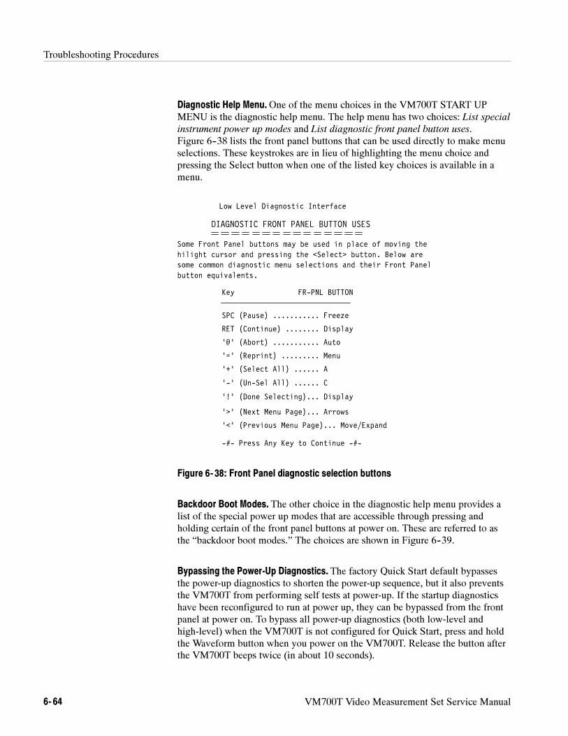
Troubleshooting Procedures
6- 64 VM700T Video Measurement Set Service Manual
Diagnostic Help Menu.One of the menu choices in the VM700T START UPMENU is the diagnostic help menu. The help menu has two choices: List specialinstrument power up modes and List diagnostic front panel button uses.Figure 6--38 lists the front panel buttons that can be used directly to make menuselections. These keystrokes are in lieu of highlighting the menu choice andpressing the Select button when one of the listed key choices is available in amenu.
Low Level Diagnostic Interface
DIAGNOSTIC FRONT PANEL BUTTON USES
Some Front Panel buttons may be used in place of moving the
Key FR-PNL BUTTON
SPC (Pause) ........... Freeze
RET (Continue) ........ Display
’@’ (Abort) ........... Auto
-#- Press Any Key to Continue -#-
hilight cursor and pressing the <Select> button. Below aresome common diagnostic menu selections and their Front Panelbutton equivalents.
’=’ (Reprint) ......... Menu
’+’ (Select All) ...... A
’-’ (Un-Sel All) ...... C
’!’ (Done Selecting)... Display
’>’ (Next Menu Page)... Arrows
’<’ (Previous Menu Page)... Move/Expand
Figure 6- 38: Front Panel diagnostic selection buttons
Backdoor Boot Modes. The other choice in the diagnostic help menu provides alist of the special power up modes that are accessible through pressing andholding certain of the front panel buttons at power on. These are referred to asthe “backdoor boot modes.” The choices are shown in Figure 6--39.
Bypassing the Power-Up Diagnostics. The factory Quick Start default bypassesthe power-up diagnostics to shorten the power-up sequence, but it also preventsthe VM700T from performing self tests at power-up. If the startup diagnosticshave been reconfigured to run at power up, they can be bypassed from the frontpanel at power on. To bypass all power-up diagnostics (both low-level andhigh-level) when the VM700T is not configured for Quick Start, press and holdthe Waveform button when you power on the VM700T. Release the button afterthe VM700T beeps twice (in about 10 seconds).
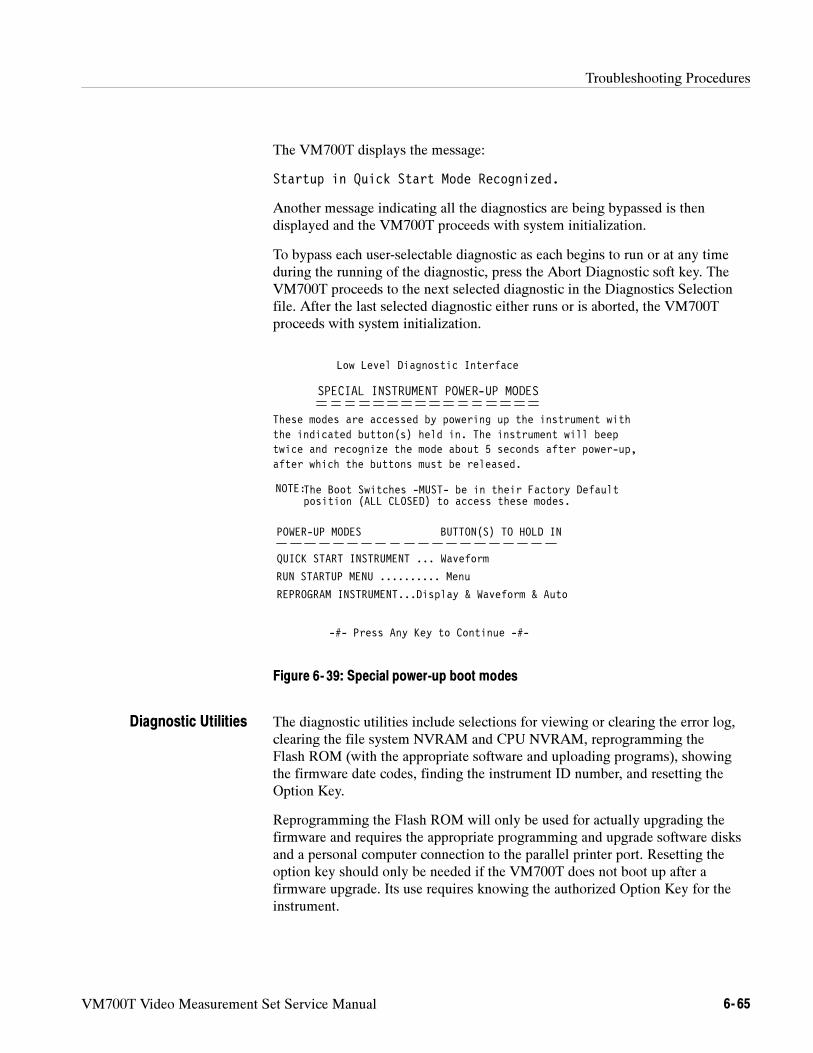
Troubleshooting Procedures
VM700T Video Measurement Set Service Manual 6- 65
The VM700T displays the message:
Startup in Quick Start Mode Recognized.
Another message indicating all the diagnostics are being bypassed is thendisplayed and the VM700T proceeds with system initialization.
To bypass each user-selectable diagnostic as each begins to run or at any timeduring the running of the diagnostic, press the Abort Diagnostic soft key. TheVM700T proceeds to the next selected diagnostic in the Diagnostics Selectionfile. After the last selected diagnostic either runs or is aborted, the VM700Tproceeds with system initialization.
Low Level Diagnostic Interface
SPECIAL INSTRUMENT POWER-UP MODES
These modes are accessed by powering up the instrument with
POWER-UP MODES BUTTON(S) TO HOLD IN
-#- Press Any Key to Continue -#-
the indicated button(s) held in. The instrument will beeptwice and recognize the mode about 5 seconds after power-up,after which the buttons must be released.
QUICK START INSTRUMENT ... Waveform
RUN STARTUP MENU .......... Menu
REPROGRAM INSTRUMENT...Display & Waveform & Auto
NOTE:The Boot Switches -MUST- be in their Factory Defaultposition (ALL CLOSED) to access these modes.
Figure 6- 39: Special power-up boot modes
The diagnostic utilities include selections for viewing or clearing the error log,clearing the file system NVRAM and CPU NVRAM, reprogramming theFlash ROM (with the appropriate software and uploading programs), showingthe firmware date codes, finding the instrument ID number, and resetting theOption Key.
Reprogramming the Flash ROM will only be used for actually upgrading thefirmware and requires the appropriate programming and upgrade software disksand a personal computer connection to the parallel printer port. Resetting theoption key should only be needed if the VM700T does not boot up after afirmware upgrade. Its use requires knowing the authorized Option Key for theinstrument.
Diagnostic Utilities
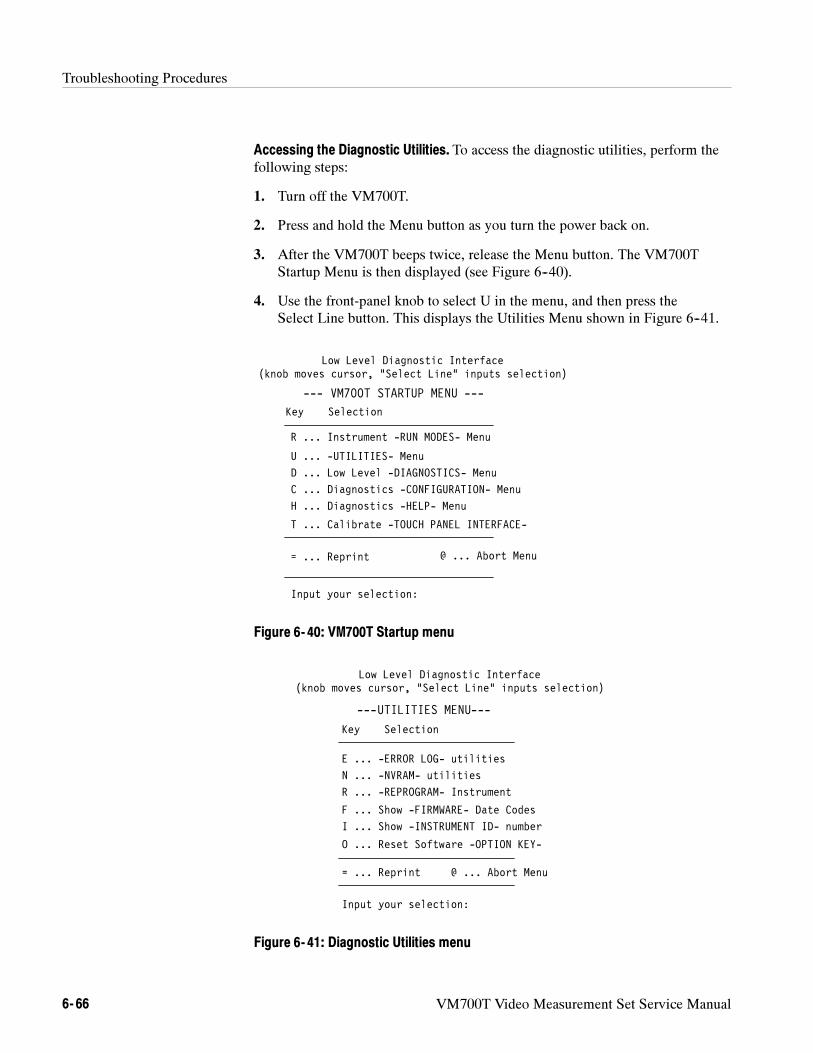
Troubleshooting Procedures
6- 66 VM700T Video Measurement Set Service Manual
Accessing the Diagnostic Utilities. To access the diagnostic utilities, perform thefollowing steps:
1. Turn off the VM700T.
2. Press and hold the Menu button as you turn the power back on.
3. After the VM700T beeps twice, release the Menu button. The VM700TStartup Menu is then displayed (see Figure 6--40).
4. Use the front-panel knob to select U in the menu, and then press theSelect Line button. This displays the Utilities Menu shown in Figure 6--41.
Low Level Diagnostic Interface(knob moves cursor, “Select Line” inputs selection)
Key Selection
H ... Diagnostics -HELP- Menu
R ... Instrument -RUN MODES- Menu
D ... Low Level -DIAGNOSTICS- Menu
= ... Reprint
Input your selection:
U ... -UTILITIES- Menu
T ... Calibrate -TOUCH PANEL INTERFACE-
--- VM700T STARTUP MENU ---
C ... Diagnostics -CONFIGURATION- Menu
@ ... Abort Menu
Figure 6- 40: VM700T Startup menu
Low Level Diagnostic Interface(knob moves cursor, “Select Line” inputs selection)
---UTILITIES MENU---
Key Selection
E ... -ERROR LOG- utilities
N ... -NVRAM- utilities
R ... -REPROGRAM- Instrument
F ... Show -FIRMWARE- Date Codes
= ... Reprint @ ... Abort Menu
Input your selection:
I ... Show -INSTRUMENT ID- number
O ... Reset Software -OPTION KEY-
Figure 6- 41: Diagnostic Utilities menu
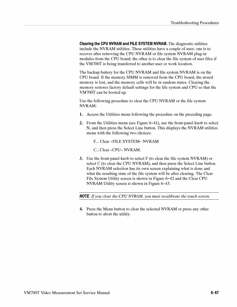
Troubleshooting Procedures
VM700T Video Measurement Set Service Manual 6- 67
Clearing the CPU NVRAM and FILE SYSTEM NVRAM. The diagnostic utilitiesinclude the NVRAM utilities. These utilities have a couple of uses: one is torecover after removing the CPU NVRAM or file system NVRAM plug-inmodules from the CPU board; the other is to clear the file system of user files ifthe VM700T is being transferred to another user or work location.
The backup battery for the CPU NVRAM and file system NVRAM is on theCPU board. If the memory SIMM is removed from the CPU board, the storedmemory is lost, and the memory cells will be in random states. Clearing thememory restores factory default settings for the file system and CPU so that theVM700T can be booted up.
Use the following procedure to clear the CPU NVRAM or the file systemNVRAM:
1. Access the Utilities menu following the procedure on the preceding page.
2. From the Utilities menu (see Figure 6--41), use the front-panel knob to selectN, and then press the Select Line button. This displays the NVRAM utilitiesmenu with the following two choices:
F... Clear --FILE SYSTEM-- NVRAM
C...Clear --CPU-- NVRAM.
3. Use the front-panel knob to select F (to clear the file system NVRAM) orselect C (to clear the CPU NVRAM), and then press the Select Line button.Each NVRAM selection has its own screen explaining what is done andwhat the resulting state of the file system will be after clearing. The ClearFile System Utility screen is shown in Figure 6--42 and the Clear CPUNVRAM Utility screen is shown in Figure 6--43.
NOTE. If you clear the CPU NVRAM, you must recalibrate the touch screen.
4. Press the Menu button to clear the selected NVRAM or press any otherbutton to abort the utility.
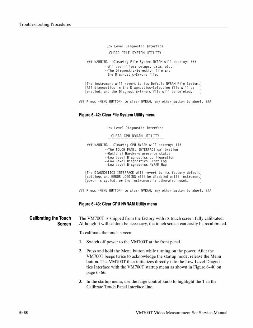
Troubleshooting Procedures
6- 68 VM700T Video Measurement Set Service Manual
Low Level Diagnostic Interface
CLEAR FILE SYSTEM UTILITY
### WARNING---Clearing File System NVRAM will destroy: ###
### Press -MENU BUTTON- to clear NVRAM, any other button to abort. ###
--All user files: setups, data, etc.--The Diagnostic~Selection file and
[The instrument will revert to its Default NVRAM File System.][All diagnostics in the Diagnostics~Selection file will be ]
the Diagnostic~Errors file.
[enabled, and the Diagnostic~Errors file will be deleted. ]
Figure 6- 42: Clear File System Utility menu
Low Level Diagnostic Interface
CLEAR CPU NVRAM UTILITY
### WARNING---Clearing CPU NVRAM will destroy: ###
### Press -MENU BUTTON- to clear NVRAM, any other button to abort. ###
--The TOUCH PANEL INTERFACE calibration--Optional Hardware presence status
[The DIAGNOSTICS INTERFACE will revert to its factory default][settings and ERROR LOGGING will be disabled until instrument]
--Low Level Diagnostics configuration
[power is cycled, or the instrument is otherwise reset. ]
--Low Level Diagnostics Error Log--Low Level Diagnostics NVRAM Map
Figure 6- 43: Clear CPU NVRAM Utility menu
The VM700T is shipped from the factory with its touch screen fully calibrated.Although it will seldom be necessary, the touch screen can easily be recalibrated.
To calibrate the touch screen:
1. Switch off power to the VM700T at the front panel.
2. Press and hold the Menu button while turning on the power. After theVM700T beeps twice to acknowledge the startup mode, release the Menubutton. The VM700T then initializes directly into the Low Level Diagnos-tics Interface with the VM700T startup menu as shown in Figure 6--40 onpage 6--66.
3. In the startup menu, use the large control knob to highlight the T in theCalibrate Touch Panel Interface line.
Calibrating the TouchScreen
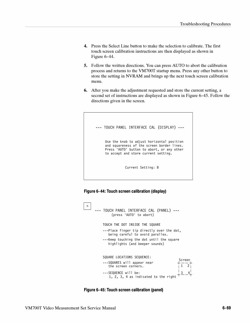
Troubleshooting Procedures
VM700T Video Measurement Set Service Manual 6- 69
4. Press the Select Line button to make the selection to calibrate. The firsttouch screen calibration instructions are then displayed as shown inFigure 6--44.
5. Follow the written directions. You can press AUTO to abort the calibrationprocess and returns to the VM700T startup menu. Press any other button tostore the setting in NVRAM and brings up the next touch screen calibrationmenu.
6. After you make the adjustment requested and store the current setting, asecond set of instructions are displayed as shown in Figure 6--45. Follow thedirections given in the screen.
Use the knob to adjust horizontal position
--- TOUCH PANEL INTERFACE CAL (DISPLAY) ---
and squareness of the screen border lines.Press ‘AUTO’ button to abort, or any otherto accept and store current setting.
Current Setting: 8
Figure 6- 44: Touch screen calibration (display)
--- TOUCH PANEL INTERFACE CAL (PANEL) ---(press ‘AUTO’ to abort)
TOUCH THE DOT INSIDE THE SQUARE
---Place finger tip directly over the dot,being careful to avoid parallex.
---Keep touching the dot until the squarehighlights (and beeper sounds)
1 2
3 4
SQUARE LOCATIONS SEQUENCE:
---SQUARES will appear nearthe screen corners.
---SEQUENCE will be:1, 2, 3, 4 as indicated to the right
Screen
Figure 6- 45: Touch screen calibration (panel)
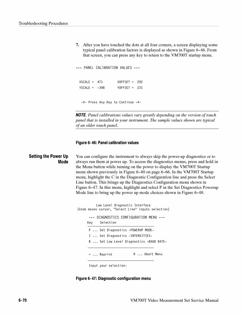
Troubleshooting Procedures
6- 70 VM700T Video Measurement Set Service Manual
7. After you have touched the dots at all four corners, a screen displaying sometypical panel calibration factors is displayed as shown in Figure 6--46. Fromthat screen, you can press any key to return to the VM700T startup menu.
XSCALE = 471 XOFFSET = 292
--- PANEL CALIBRATION VALUES ---
-#- Press Any Key to Continue -#-
YSCALE = -398 YOFFSET = 231
NOTE. Panel calibrations values vary greatly depending on the version of touch
panel that is installed in your instrument. The sample values shown are typical
of an older touch panel.
Figure 6- 46: Panel calibration values
You can configure the instrument to always skip the power-up diagnostics or toalways run them at power up. To access the diagnostics menus, press and hold inthe Menu button while turning on the power to display the VM700T Startupmenu shown previously in Figure 6--40 on page 6--66. In the VM700T Startupmenu, highlight the C in the Diagnostic Configuration line and press the SelectLine button. This brings up the Diagnostics Configuration menu shown inFigure 6--47. In this menu, highlight and select P in the Set Diagnostics PowerupMode line to bring up the power up mode choices shown in Figure 6--48.
Low Level Diagnostic Interface(knob moves cursor, “Select Line” inputs selection)
Key Selection
P ... Set Diagnostics -POWERUP MODE-
B ... Set Low Level Diagnostics -BAUD RATE-
= ... Reprint
Input your selection:
I ... Set Diagnostics -INTENSITIES-
--- DIAGNOSTICS CONFIGURATION MENU ---
@ ... Abort Menu
Figure 6- 47: Diagnostic configuration menu
Setting the Power UpMode
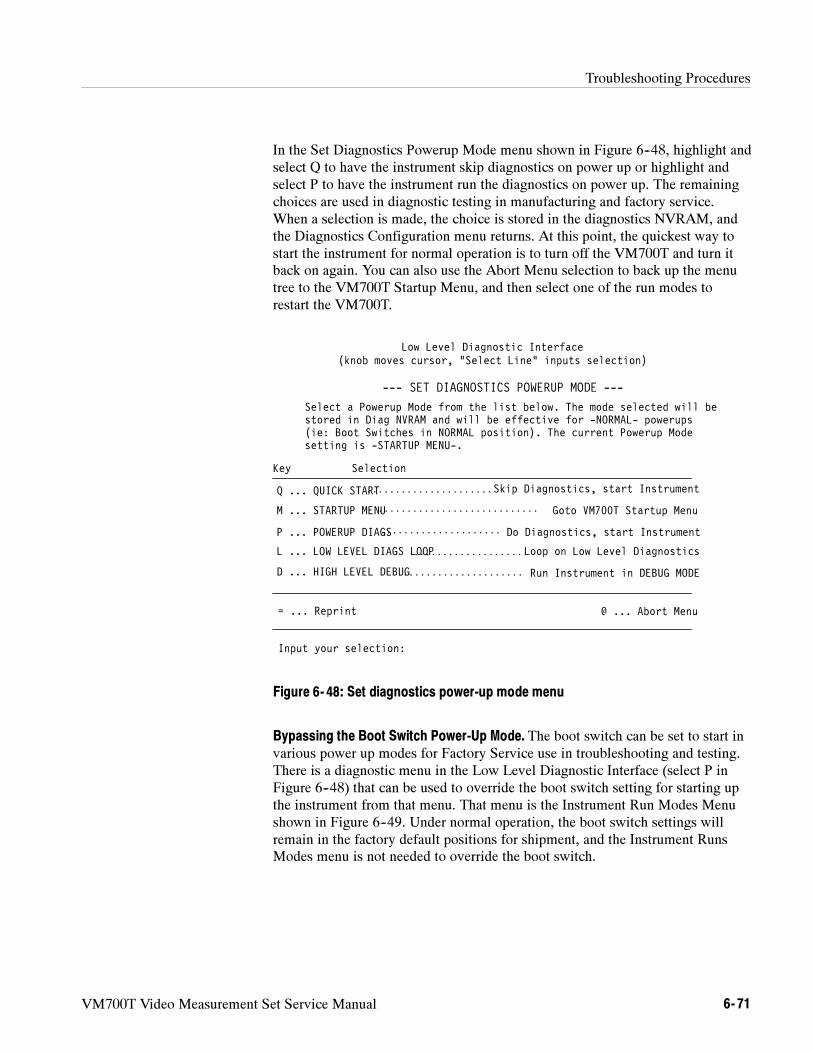
Troubleshooting Procedures
VM700T Video Measurement Set Service Manual 6- 71
In the Set Diagnostics Powerup Mode menu shown in Figure 6--48, highlight andselect Q to have the instrument skip diagnostics on power up or highlight andselect P to have the instrument run the diagnostics on power up. The remainingchoices are used in diagnostic testing in manufacturing and factory service.When a selection is made, the choice is stored in the diagnostics NVRAM, andthe Diagnostics Configuration menu returns. At this point, the quickest way tostart the instrument for normal operation is to turn off the VM700T and turn itback on again. You can also use the Abort Menu selection to back up the menutree to the VM700T Startup Menu, and then select one of the run modes torestart the VM700T.
Low Level Diagnostic Interface(knob moves cursor, “Select Line” inputs selection)
Key Selection
D ... HIGH LEVEL DEBUG
Q ... QUICK START
P ... POWERUP DIAGS
= ... Reprint
Input your selection:
M ... STARTUP MENU
--- SET DIAGNOSTICS POWERUP MODE ---
L ... LOW LEVEL DIAGS LOOP
Do Diagnostics, start Instrument
Goto VM700T Startup Menu
Loop on Low Level Diagnostics
Run Instrument in DEBUG MODE
@ ... Abort Menu
Skip Diagnostics, start Instrument
Select a Powerup Mode from the list below. The mode selected will bestored in Diag NVRAM and will be effective for -NORMAL- powerups(ie: Boot Switches in NORMAL position). The current Powerup Modesetting is -STARTUP MENU-.
. . . . . . . . . . . . . . . . . . . . . .
. . . . . . . . . . . . . . . . . . .
. . . . . . . . . . . . . . . . . . . . . . . . . . . .
. . . . . . . . . . . . . . . . . . . . . .
. . . . . . . . . . . . . . . . . . . . .
Figure 6- 48: Set diagnostics power-up mode menu
Bypassing the Boot Switch Power-Up Mode. The boot switch can be set to start invarious power up modes for Factory Service use in troubleshooting and testing.There is a diagnostic menu in the Low Level Diagnostic Interface (select P inFigure 6--48) that can be used to override the boot switch setting for starting upthe instrument from that menu. That menu is the Instrument Run Modes Menushown in Figure 6--49. Under normal operation, the boot switch settings willremain in the factory default positions for shipment, and the Instrument RunsModes menu is not needed to override the boot switch.
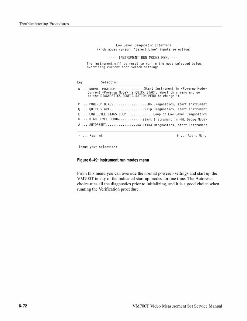
Troubleshooting Procedures
6- 72 VM700T Video Measurement Set Service Manual
to the DIAGNOSTICS CONFIGURATION MENU to change it
Low Level Diagnostic Interface(knob moves cursor, “Select Line” inputs selection)
Key Selection
D ... HIGH LEVEL DEBUG..................
N ... NORMAL POWERUP.....................
P ... POWERUP DIAGS.......................
= ... Reprint
Input your selection:
--- INSTRUMENT RUN MODES MENU ---
L ... LOW LEVEL DIAGS LOOP ................
Do Diagnostics, start Instrument
Loop on Low Level Diagnostics
Start Instrument in <HL Debug Mode>
@ ... Abort Menu
Start Instrument in <Powerup Mode>
The instrument will be reset to run in the mode selected below,overriding current boot switch settings.
Current <Powerup Mode> is QUICK START; abort this menu and go
A ... AUTORESET...................Do EXTRA Diagnostics, start Instrument
Q ... QUICK START......................Skip Diagnostics, start Instrument
Figure 6- 49: Instrument run modes menu
From this menu you can override the normal powerup settings and start up theVM700T in any of the indicated start up modes for one time. The Autoresetchoice runs all the diagnostics prior to initializing, and it is a good choice whenrunning the Verification procedure.
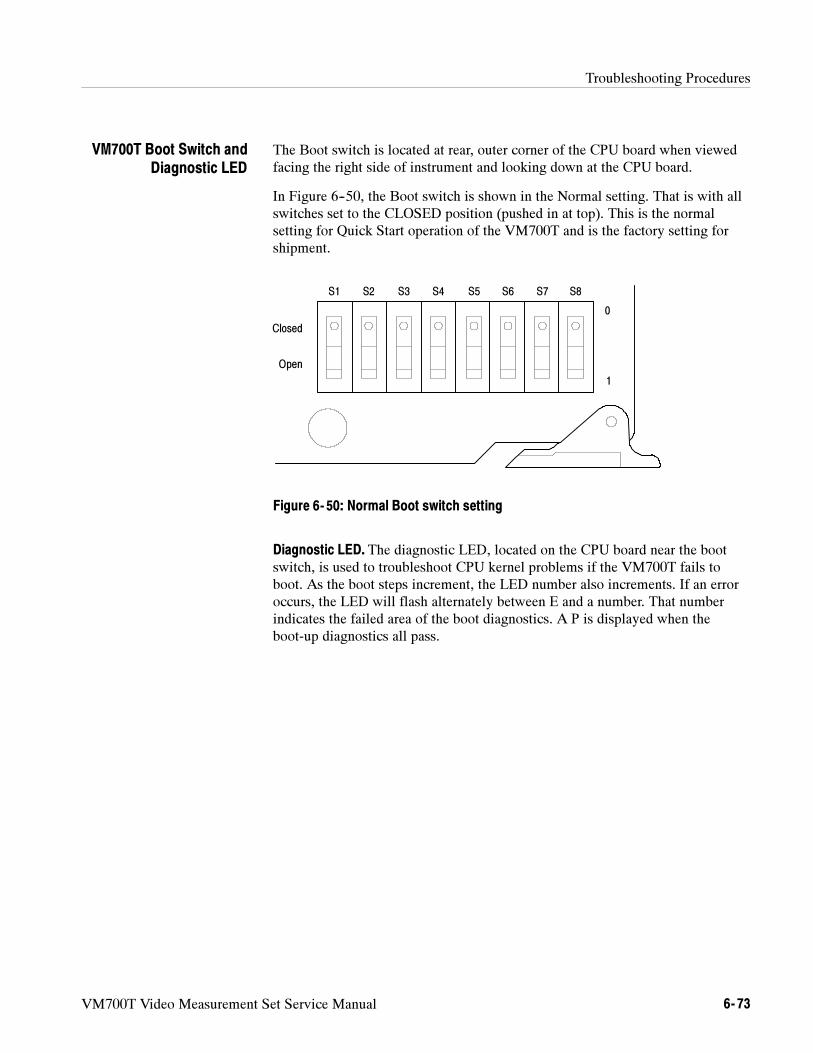
Troubleshooting Procedures
VM700T Video Measurement Set Service Manual 6- 73
The Boot switch is located at rear, outer corner of the CPU board when viewedfacing the right side of instrument and looking down at the CPU board.
In Figure 6--50, the Boot switch is shown in the Normal setting. That is with allswitches set to the CLOSED position (pushed in at top). This is the normalsetting for Quick Start operation of the VM700T and is the factory setting forshipment.
S1 S2 S3 S4 S5 S6 S7 S8
Closed
Open
0
1
Figure 6- 50: Normal Boot switch setting
Diagnostic LED. The diagnostic LED, located on the CPU board near the bootswitch, is used to troubleshoot CPU kernel problems if the VM700T fails toboot. As the boot steps increment, the LED number also increments. If an erroroccurs, the LED will flash alternately between E and a number. That numberindicates the failed area of the boot diagnostics. A P is displayed when theboot-up diagnostics all pass.
VM700T Boot Switch andDiagnostic LED
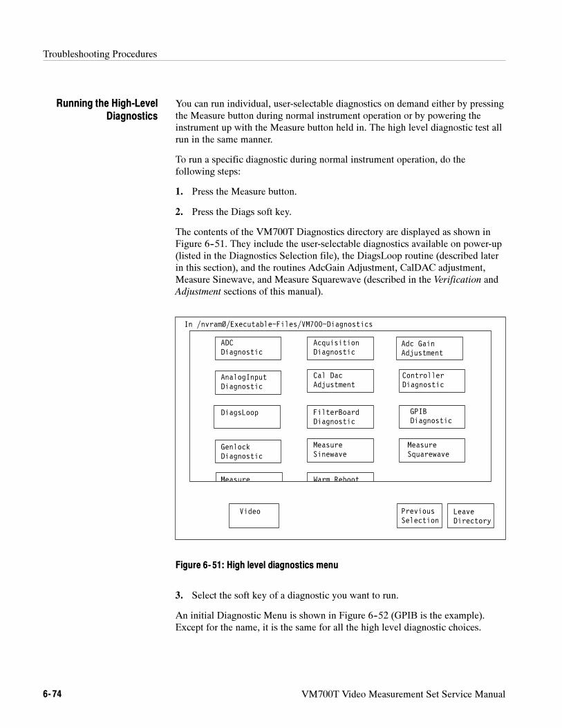
Troubleshooting Procedures
6- 74 VM700T Video Measurement Set Service Manual
You can run individual, user-selectable diagnostics on demand either by pressingthe Measure button during normal instrument operation or by powering theinstrument up with the Measure button held in. The high level diagnostic test allrun in the same manner.
To run a specific diagnostic during normal instrument operation, do thefollowing steps:
1. Press the Measure button.
2. Press the Diags soft key.
The contents of the VM700T Diagnostics directory are displayed as shown inFigure 6--51. They include the user-selectable diagnostics available on power-up(listed in the Diagnostics Selection file), the DiagsLoop routine (described laterin this section), and the routines AdcGain Adjustment, CalDAC adjustment,Measure Sinewave, and Measure Squarewave (described in the Verification andAdjustment sections of this manual).
ADCDiagnostic
Video PreviousSelection
LeaveDirectory
In /nvramØ/Executable~Files/VM700~Diagnostics
AcquisitionDiagnostic
Adc GainAdjustment
AnalogInputDiagnostic
ControllerDiagnostic
GenlockDiagnostic
GPIBDiagnostic
FilterBoardDiagnostic
MeasureTemperature
MeasureSinewave
MeasureSquarewave
Cal DacAdjustment
DiagsLoop
Warm_Reboot
Figure 6- 51: High level diagnostics menu
3. Select the soft key of a diagnostic you want to run.
An initial Diagnostic Menu is shown in Figure 6--52 (GPIB is the example).Except for the name, it is the same for all the high level diagnostic choices.
Running the High-LevelDiagnostics
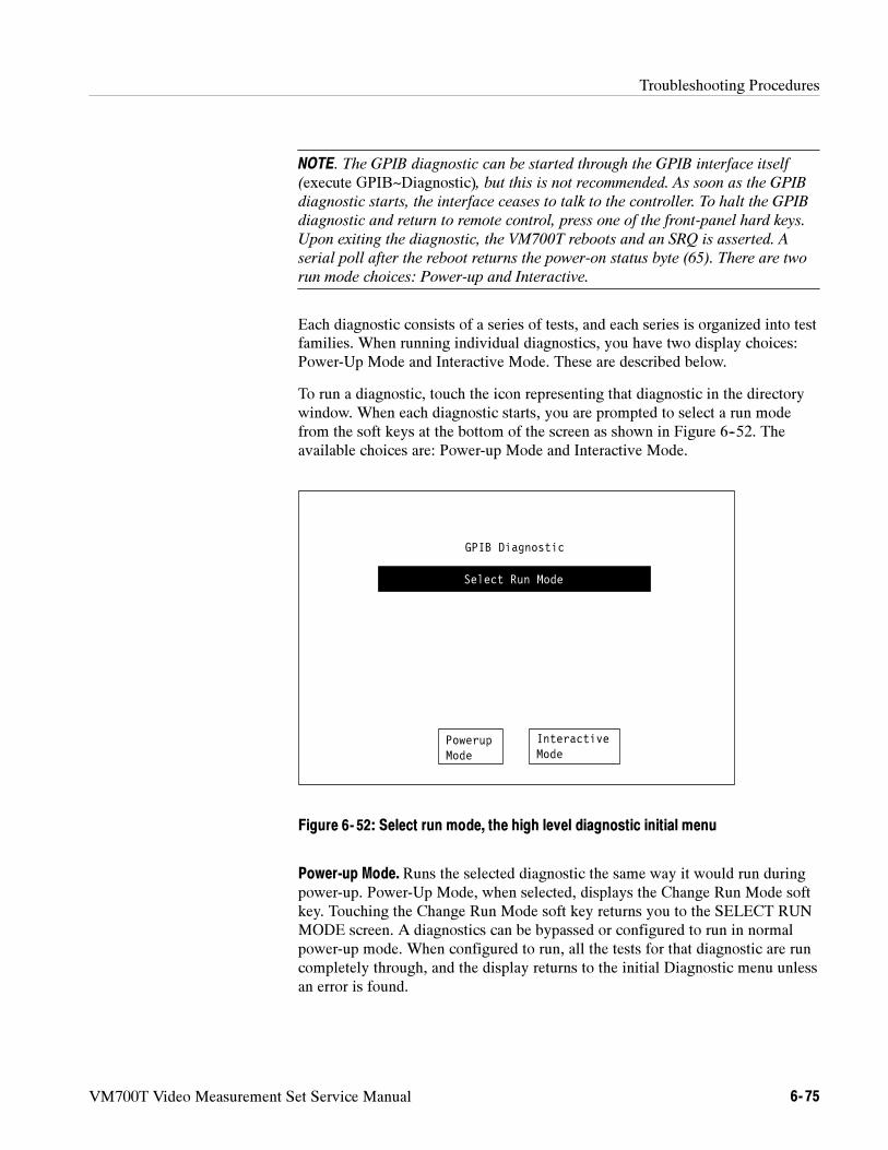
Troubleshooting Procedures
VM700T Video Measurement Set Service Manual 6- 75
NOTE. The GPIB diagnostic can be started through the GPIB interface itself
(execute GPIB~Diagnostic), but this is not recommended. As soon as the GPIB
diagnostic starts, the interface ceases to talk to the controller. To halt the GPIB
diagnostic and return to remote control, press one of the front-panel hard keys.
Upon exiting the diagnostic, the VM700T reboots and an SRQ is asserted. A
serial poll after the reboot returns the power-on status byte (65). There are two
run mode choices: Power-up and Interactive.
Each diagnostic consists of a series of tests, and each series is organized into testfamilies. When running individual diagnostics, you have two display choices:Power-Up Mode and Interactive Mode. These are described below.
To run a diagnostic, touch the icon representing that diagnostic in the directorywindow. When each diagnostic starts, you are prompted to select a run modefrom the soft keys at the bottom of the screen as shown in Figure 6--52. Theavailable choices are: Power-up Mode and Interactive Mode.
GPIB Diagnostic
Select Run Mode
PowerupMode
InteractiveMode
Figure 6- 52: Select run mode, the high level diagnostic initial menu
Power-up Mode. Runs the selected diagnostic the same way it would run duringpower-up. Power-Up Mode, when selected, displays the Change Run Mode softkey. Touching the Change Run Mode soft key returns you to the SELECT RUNMODE screen. A diagnostics can be bypassed or configured to run in normalpower-up mode. When configured to run, all the tests for that diagnostic are runcompletely through, and the display returns to the initial Diagnostic menu unlessan error is found.
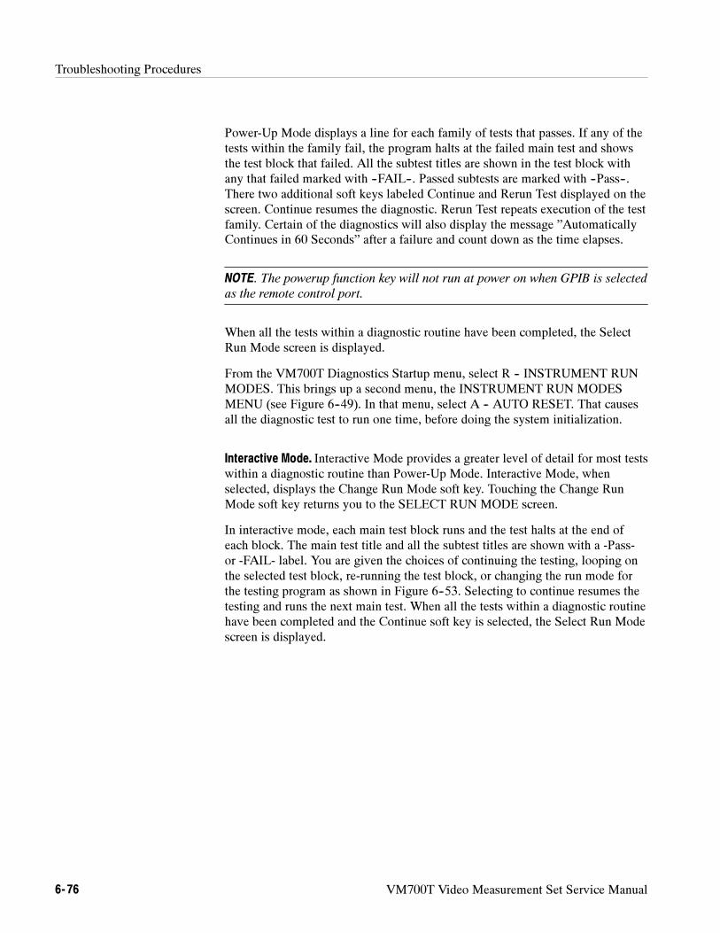
Troubleshooting Procedures
6- 76 VM700T Video Measurement Set Service Manual
Power-Up Mode displays a line for each family of tests that passes. If any of thetests within the family fail, the program halts at the failed main test and showsthe test block that failed. All the subtest titles are shown in the test block withany that failed marked with --FAIL--. Passed subtests are marked with --Pass--.There two additional soft keys labeled Continue and Rerun Test displayed on thescreen. Continue resumes the diagnostic. Rerun Test repeats execution of the testfamily. Certain of the diagnostics will also display the message ”AutomaticallyContinues in 60 Seconds” after a failure and count down as the time elapses.
NOTE. The powerup function key will not run at power on when GPIB is selected
as the remote control port.
When all the tests within a diagnostic routine have been completed, the SelectRun Mode screen is displayed.
From the VM700T Diagnostics Startup menu, select R -- INSTRUMENT RUNMODES. This brings up a second menu, the INSTRUMENT RUN MODESMENU (see Figure 6--49). In that menu, select A -- AUTO RESET. That causesall the diagnostic test to run one time, before doing the system initialization.
Interactive Mode. Interactive Mode provides a greater level of detail for most testswithin a diagnostic routine than Power-Up Mode. Interactive Mode, whenselected, displays the Change Run Mode soft key. Touching the Change RunMode soft key returns you to the SELECT RUN MODE screen.
In interactive mode, each main test block runs and the test halts at the end ofeach block. The main test title and all the subtest titles are shown with a -Pass-or -FAIL- label. You are given the choices of continuing the testing, looping onthe selected test block, re-running the test block, or changing the run mode forthe testing program as shown in Figure 6--53. Selecting to continue resumes thetesting and runs the next main test. When all the tests within a diagnostic routinehave been completed and the Continue soft key is selected, the Select Run Modescreen is displayed.
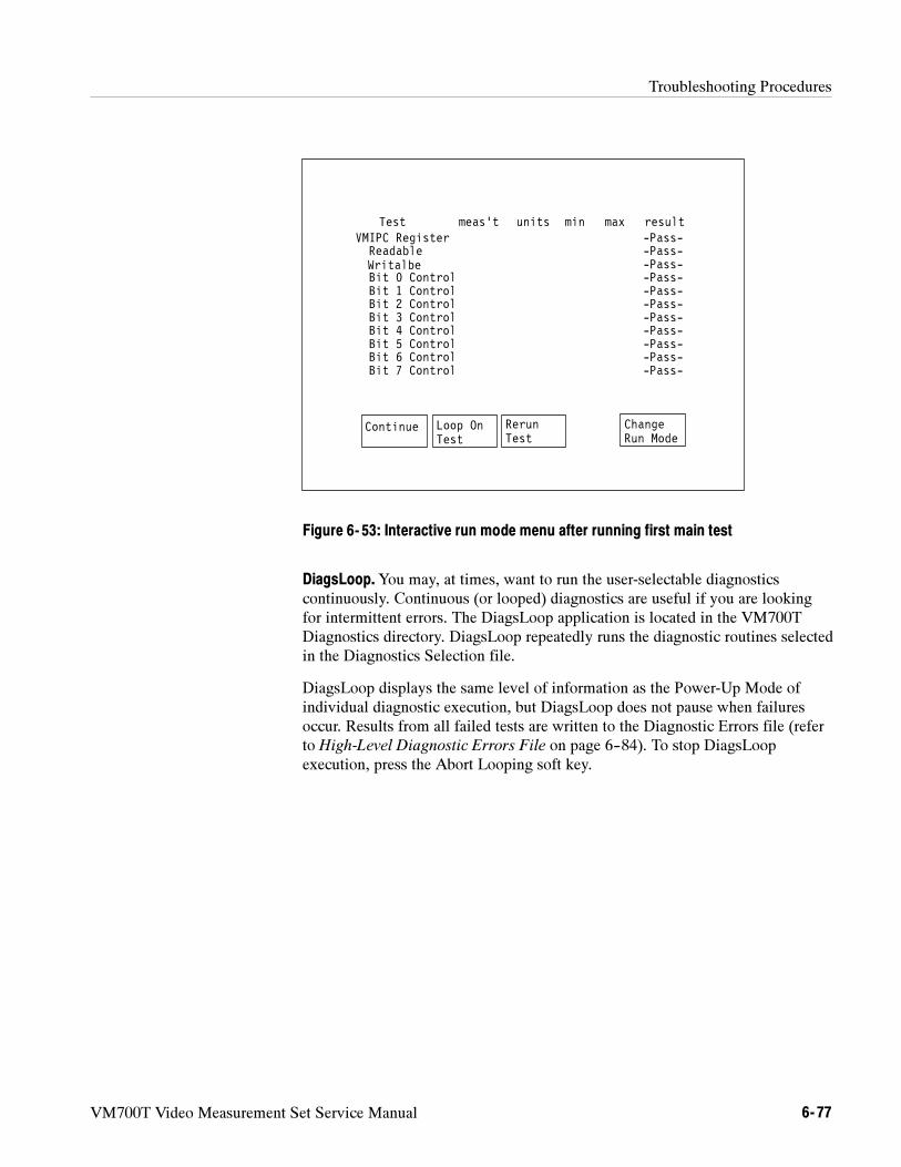
Troubleshooting Procedures
VM700T Video Measurement Set Service Manual 6- 77
Continue Loop OnTest
RerunTest
ChangeRun Mode
meas’t units min max resultTest-Pass--Pass--Pass--Pass--Pass--Pass--Pass--Pass--Pass--Pass--Pass-
VMIPC RegisterReadableWritalbeBit 0 ControlBit 1 Control
Bit 3 ControlBit 4 ControlBit 5 ControlBit 6 ControlBit 7 Control
Bit 2 Control
Figure 6- 53: Interactive run mode menu after running first main test
DiagsLoop.You may, at times, want to run the user-selectable diagnosticscontinuously. Continuous (or looped) diagnostics are useful if you are lookingfor intermittent errors. The DiagsLoop application is located in the VM700TDiagnostics directory. DiagsLoop repeatedly runs the diagnostic routines selectedin the Diagnostics Selection file.
DiagsLoop displays the same level of information as the Power-Up Mode ofindividual diagnostic execution, but DiagsLoop does not pause when failuresoccur. Results from all failed tests are written to the Diagnostic Errors file (referto High-Level Diagnostic Errors File on page 6--84). To stop DiagsLoopexecution, press the Abort Looping soft key.
Troubleshooting Procedures
6- 78 VM700T Video Measurement Set Service Manual
Diagnostics Selection File. The Diagnostics Selection file allows you to specifythe high-level diagnostics that run during Powerup Diagnostics or Diags Loop.When the VM700T is powered on with diagnostics enabled to run (not QuickStart), the diagnostics selected in the Diagnostics Selection file are run. Thecontents of the Diagnostics Selection file are shown in Figure 6--54.
Genlock~DiagnosticController~DiagnosticAcquisition~DiagnosticADC~DiagnosticAnalogInput~DiagnosticFilterBoard~DiagnosticAudioProcessor~DiagnosticAudioAnalog~DiagnosticGPIB~Diagnostics
Power Up Diagnostics Selection
Selected Line 6 Not Selected
Figure 6- 54: Power-up diagnostics selection display1
All diagnostic routines on the “Selected” side execute during Powerup Diagnos-tics or Diags Loop. To select or unselect a diagnostic from the DiagnosticsSelection file do the following steps:
1. Press the Configure button.
2. Press the Configure Files soft key.
3. Select the Diagnostics Selection file.
4. Turn the control knob until the diagnostic’s name is highlighted. Touchingthe vertical center of the left half of the screen selects the highlighteddiagnostic; touching the vertical center of the right half unselects it.
5. Press the Update & Exit soft key to write out (save) any changes to the file;press the No change & Exit soft key to leave the file as it was when it waslast saved.
High Level Diagnostics Test. Figure 6--55 illustrates the diagnostic test blocks ofthe high level diagnostics to assist you in determining the module interdependen-cies for the successful completion of the tests. Table 6--4 lists and describes theVM700T high-level diagnostic tests. Additional diagnostics are added to this listwith the addition of the hardware options (GPIB Interface, Audio Measurements,and Serial Digital Interface).
1 The AudioProcessor “Diagnostic and AudioAnalog” Diagnostic selections are available only with the
VM700T Audio option. GPIB~Diagnostics is added to this list when the GPIB option is installed.
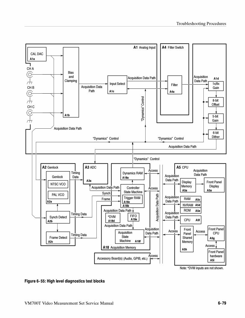
Troubleshooting Procedures
VM700T Video Measurement Set Service Manual 6- 79
Acquisition Data Path
Acquisition Data Path
Acquisition Data Path
Biasand
Clamping
Genlock
NTSC VCO
PAL VCO
Synch Detect
Frame Detect
ADC
*DVM
Dynamics RAM
ControllerState Machine
AcquisitionState
Machine
Acquisition Memory
GenlockA2 A3
FIFO
A18
Trigger RAM RAM
ROM
CPU
FrontPanelSharedMemory
CPUA5
Front PanelCPU
Front Panelhardware
Input Select Filter 1x/8xGain
8-bitOffset
5-bitGain
6-bitDither
CH A
CH B
CH C
Accessory Board(s) (Audio, GPIB, etc.)
CAL DAC
Analog InputA1
Timing Data
Timing Data
TimingData
Access
Access
Access
Access
Access
Access
“Dynam
ics”Control
AcquisitionDataPath
“Dynamics” Control
Filter SwitchA4
Acquisition Data Path
Synch
Frame
Note: *DVM inputs are not shown.
Acquisition DataPath
Acquisition Data Path AcquisitionData Path
“Dynamics” Control
“Dynamics” Control
AcquisitionData Path
AcquisitionData Path
AcquisitionData Path
AcquisitionData Path
AcquisitionData Path
Front PanelDisplay
NVRAM
Acquisition Data Path
DisplayMemory
A1a
A1b
A1c
A1d
A4a
A2a
A2b
A2c
A3aA18a
A18b
A18d
A18c
A18e
A18f
A5a A5a
A5c
A5d
A5e
A5f
A5h
A5g
A5i
Figure 6- 55: High level diagnostics test blocks
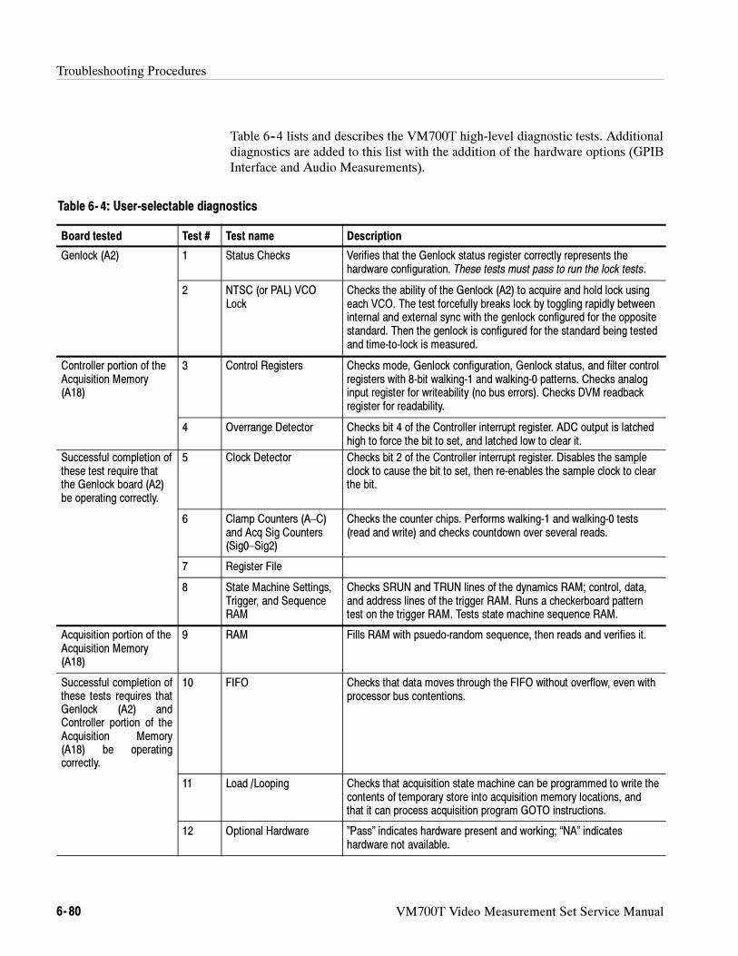
Troubleshooting Procedures
6- 80 VM700T Video Measurement Set Service Manual
Table 6--4 lists and describes the VM700T high-level diagnostic tests. Additionaldiagnostics are added to this list with the addition of the hardware options (GPIBInterface and Audio Measurements).
Table 6- 4: User-selectable diagnostics
Board tested Test # Test name Description
Genlock (A2) 1 Status Checks Verifies that the Genlock status register correctly represents thehardware configuration. These tests must pass to run the lock tests.
2 NTSC (or PAL) VCOLock
Checks the ability of the Genlock (A2) to acquire and hold lock usingeach VCO. The test forcefully breaks lock by toggling rapidly betweeninternal and external sync with the genlock configured for the oppositestandard. Then the genlock is configured for the standard being testedand time-to-lock is measured.
Controller portion of theAcquisition Memory(A18)
3 Control Registers Checks mode, Genlock configuration, Genlock status, and filter controlregisters with 8-bit walking-1 and walking-0 patterns. Checks analoginput register for writeability (no bus errors). Checks DVM readbackregister for readability.
4 Overrange Detector Checks bit 4 of the Controller interrupt register. ADC output is latchedhigh to force the bit to set, and latched low to clear it.
Successful completion ofthese test require thatthe Genlock board (A2)be operating correctly.
5 Clock Detector Checks bit 2 of the Controller interrupt register. Disables the sampleclock to cause the bit to set, then re-enables the sample clock to clearthe bit.
6 Clamp Counters (A–C)and Acq Sig Counters(Sig0–Sig2)
Checks the counter chips. Performs walking-1 and walking-0 tests(read and write) and checks countdown over several reads.
7 Register File
8 State Machine Settings,Trigger, and SequenceRAM
Checks SRUN and TRUN lines of the dynamics RAM; control, data,and address lines of the trigger RAM. Runs a checkerboard patterntest on the trigger RAM. Tests state machine sequence RAM.
Acquisition portion of theAcquisition Memory(A18)
9 RAM Fills RAM with psuedo-random sequence, then reads and verifies it.
Successful completion ofthese tests requires thatGenlock (A2) andController portion of theAcquisition Memory(A18) be operatingcorrectly.
10 FIFO Checks that data moves through the FIFO without overflow, even withprocessor bus contentions.
11 Load /Looping Checks that acquisition state machine can be programmed to write thecontents of temporary store into acquisition memory locations, andthat it can process acquisition program GOTO instructions.
12 Optional Hardware ”Pass” indicates hardware present and working; “NA” indicateshardware not available.
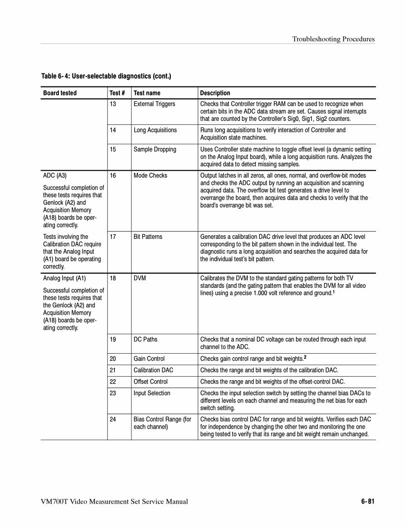
Troubleshooting Procedures
VM700T Video Measurement Set Service Manual 6- 81
Table 6- 4: User-selectable diagnostics (cont.)
DescriptionTest nameTest #Board tested
13 External Triggers Checks that Controller trigger RAM can be used to recognize whencertain bits in the ADC data stream are set. Causes signal interruptsthat are counted by the Controller’s Sig0, Sig1, Sig2 counters.
14 Long Acquisitions Runs long acquisitions to verify interaction of Controller andAcquisition state machines.
15 Sample Dropping Uses Controller state machine to toggle offset level (a dynamic settingon the Analog Input board), while a long acquisition runs. Analyzes theacquired data to detect missing samples.
ADC (A3)
Successful completion ofthese tests requires thatGenlock (A2) andAcquisition Memory(A18) boards be oper-ating correctly.
16 Mode Checks Output latches in all zeros, all ones, normal, and overflow-bit modesand checks the ADC output by running an acquisition and scanningacquired data. The overflow bit test generates a drive level tooverrange the board, then acquires data and checks to verify that theboard’s overrange bit was set.
Tests involving theCalibration DAC requirethat the Analog Input(A1) board be operatingcorrectly.
17 Bit Patterns Generates a calibration DAC drive level that produces an ADC levelcorresponding to the bit pattern shown in the individual test. Thediagnostic runs a long acquisition and searches the acquired data forthe individual test’s bit pattern.
Analog Input (A1)
Successful completion ofthese tests requires thatthe Genlock (A2) andAcquisition Memory(A18) boards be oper-ating correctly.
18 DVM Calibrates the DVM to the standard gating patterns for both TVstandards (and the gating pattern that enables the DVM for all videolines) using a precise 1.000 volt reference and ground.1
19 DC Paths Checks that a nominal DC voltage can be routed through each inputchannel to the ADC.
20 Gain Control Checks gain control range and bit weights.2
21 Calibration DAC Checks the range and bit weights of the calibration DAC.
22 Offset Control Checks the range and bit weights of the offset-control DAC.
23 Input Selection Checks the input selection switch by setting the channel bias DACs todifferent levels on each channel and measuring the net bias for eachswitch setting.
24 Bias Control Range (foreach channel)
Checks bias control DAC for range and bit weights. Verifies each DACfor independence by changing the other two and monitoring the onebeing tested to verify that its range and bit weight remain unchanged.
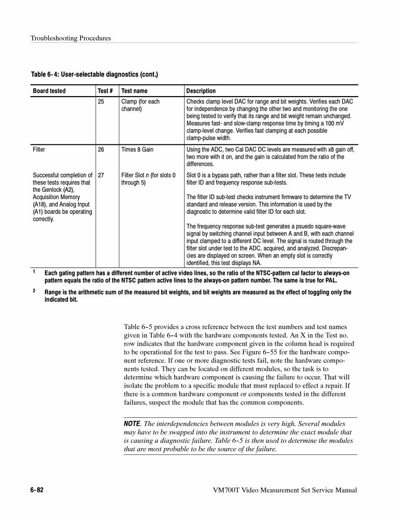
Troubleshooting Procedures
6- 82 VM700T Video Measurement Set Service Manual
Table 6- 4: User-selectable diagnostics (cont.)
DescriptionTest nameTest #Board tested
25 Clamp (for eachchannel)
Checks clamp level DAC for range and bit weights. Verifies each DACfor independence by changing the other two and monitoring the onebeing tested to verify that its range and bit weight remain unchanged.Measures fast- and slow-clamp response time by timing a 100 mVclamp-level change. Verifies fast clamping at each possibleclamp-pulse width.
Filter 26 Times 8 Gain Using the ADC, two Cal DAC DC levels are measured with x8 gain off,two more with it on, and the gain is calculated from the ratio of thedifferences.
Successful completion ofthese tests requires thatthe Genlock (A2),Acquisition Memory(A18), and Analog Input(A1) boards be operatingcorrectly.
27 Filter Slot n (for slots 0through 5)
Slot 0 is a bypass path, rather than a filter slot. These tests includefilter ID and frequency response sub-tests.
The filter ID sub-test checks instrument firmware to determine the TVstandard and release version. This information is used by thediagnostic to determine valid filter ID for each slot.
The frequency response sub-test generates a psuedo square-wavesignal by switching channel input between A and B, with each channelinput clamped to a different DC level. The signal is routed through thefilter slot under test to the ADC, acquired, and analyzed. Discrepan-cies are displayed on screen. When an empty slot is correctlyidentified, this test displays NA.
1 Each gating pattern has a different number of active video lines, so the ratio of the NTSC-pattern cal factor to always-onpattern equals the ratio of the NTSC pattern active lines to the always-on pattern number. The same is true for PAL.
2 Range is the arithmetic sum of the measured bit weights, and bit weights are measured as the effect of toggling only theindicated bit.
Table 6--5 provides a cross reference between the test numbers and test namesgiven in Table 6--4 with the hardware components tested. An X in the Test no.row indicates that the hardware component given in the column head is requiredto be operational for the test to pass. See Figure 6--55 for the hardware compo-nent reference. If one or more diagnostic tests fail, note the hardware compo-nents tested. They can be located on different modules, so the task is todetermine which hardware component is causing the failure to occur. That willisolate the problem to a specific module that must replaced to effect a repair. Ifthere is a common hardware component or components tested in the differentfailures, suspect the module that has the common components.
NOTE. The interdependencies between modules is very high. Several modules
may have to be swapped into the instrument to determine the exact module that
is causing a diagnostic failure. Table 6--5 is then used to determine the modules
that are most probable to be the source of the failure.
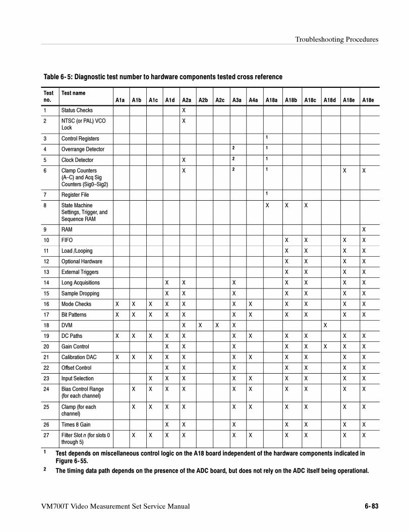
Troubleshooting Procedures
VM700T Video Measurement Set Service Manual 6- 83
Table 6- 5: Diagnostic test number to hardware components tested cross reference
Testno.
Test name
A1a A1b A1c A1d A2a A2b A2c A3a A4a A18a A18b A18c A18d A18e A18e
1 Status Checks X
2 NTSC (or PAL) VCOLock
X
3 Control Registers 1
4 Overrange Detector 2 1
5 Clock Detector X 2 1
6 Clamp Counters(A–C) and Acq SigCounters (Sig0–Sig2)
X 2 1 X X
7 Register File 1
8 State MachineSettings, Trigger, andSequence RAM
X X X
9 RAM X
10 FIFO X X X X
11 Load /Looping X X X X
12 Optional Hardware X X X X
13 External Triggers X X X X
14 Long Acquisitions X X X X X X X
15 Sample Dropping X X X X X X X
16 Mode Checks X X X X X X X X X X X
17 Bit Patterns X X X X X X X X X X X
18 DVM X X X X X
19 DC Paths X X X X X X X X X X X
20 Gain Control X X X X X X X X
21 Calibration DAC X X X X X X X X X X X
22 Offset Control X X X X X X X
23 Input Selection X X X X X X X X X
24 Bias Control Range(for each channel)
X X X X X X X X X X
25 Clamp (for eachchannel)
X X X X X X X X X X
26 Times 8 Gain X X X X X X X
27 Filter Slot n (for slots 0through 5)
X X X X X X X X X X
1 Test depends on miscellaneous control logic on the A18 board independent of the hardware components indicated inFigure 6- 55.
2 The timing data path depends on the presence of the ADC board, but does not rely on the ADC itself being operational.
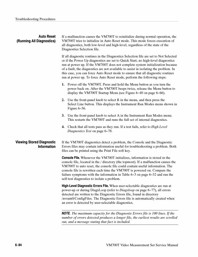
Troubleshooting Procedures
6- 84 VM700T Video Measurement Set Service Manual
If a malfunction causes the VM700T to reinitialize during normal operation, theVM700T tries to initialize in Auto Reset mode. This mode forces execution ofall diagnostics, both low-level and high-level, regardless of the state of theDiagnostics Selection file.
If all diagnostic routines in the Diagnostics Selection file are set to Not Selectedor if the Power Up diagnostics are set to Quick Start, no high-level diagnosticsrun at power up. If the VM700T does not complete system initialization becauseof a fault, the diagnostics are not available to assist in isolating the problem. Inthis case, you can force Auto Reset mode to ensure that all diagnostic routinesrun at power up. To force Auto Reset mode, perform the following steps:
1. Power off the VM700T. Press and hold the Menu button as you turn thepower back on. After the VM700T beeps twice, release the Menu button todisplay the VM700T Startup Menu (see Figure 6--40 on page 6--66).
2. Use the front-panel knob to select R in the menu, and then press theSelect Line button. This displays the Instrument Run Modes menu shown inFigure 6--56.
3. Use the front-panel knob to select A in the Instrument Run Modes menu.This restarts the VM700T and runs the full set of internal diagnostics.
4. Check that all tests pass as they run. If a test fails, refer to High Level
Diagnostics Test on page 6--78.
If the VM700T diagnostics detect a problem, the Console and the DiagnosticErrors files may contain information useful for troubleshooting a problem. Bothfiles can be printed using the Print File soft key.
Console File.Whenever the VM700T initializes, information is stored in theconsole file, located in the / directory (the topmost). If a malfunction causes theVM700T to auto reset, the console file could contain useful information. Theconsole file is rewritten each time the VM700T is powered on. Compare thefailure symptoms with the information in Table 6--3 on page 6--52 and run theself-test diagnostics to isolate a problem.
High-Level Diagnostic Errors File.When user-selectable diagnostics are run atpower-up or during DiagsLoop (refer to Diagsloop on page 6--77), all errorsdetected are written to the Diagnostic Errors file, found in directory/nvram0/ConfigFiles. The Diagnostic Errors file is automatically created whenan error is detected by user-selectable diagnostics.
NOTE. The maximum capacity for the Diagnostic Errors file is 100 lines. If the
number of errors detected produces a longer file, the earliest results are scrolled
out, and a message stating that fact is included.
Auto Reset(Running All Diagnostics)
Viewing Stored DiagnosticInformation
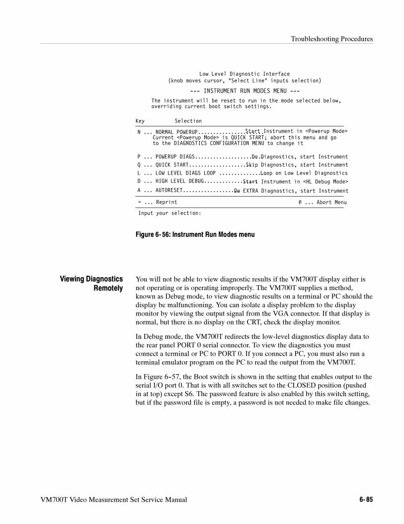
Troubleshooting Procedures
VM700T Video Measurement Set Service Manual 6- 85
to the DIAGNOSTICS CONFIGURATION MENU to change it
Low Level Diagnostic Interface(knob moves cursor, “Select Line” inputs selection)
Key Selection
D ... HIGH LEVEL DEBUG..................
N ... NORMAL POWERUP......................
P ... POWERUP DIAGS.......................
= ... Reprint
Input your selection:
--- INSTRUMENT RUN MODES MENU ---
L ... LOW LEVEL DIAGS LOOP ................
Do Diagnostics, start Instrument
Loop on Low Level Diagnostics
Start Instrument in <HL Debug Mode>
@ ... Abort Menu
Start Instrument in <Powerup Mode>
The instrument will be reset to run in the mode selected below,overriding current boot switch settings.
Current <Powerup Mode> is QUICK START; abort this menu and go
A ... AUTORESET...................Do EXTRA Diagnostics, start Instrument
Q ... QUICK START......................Skip Diagnostics, start Instrument
Figure 6- 56: Instrument Run Modes menu
You will not be able to view diagnostic results if the VM700T display either isnot operating or is operating improperly. The VM700T supplies a method,known as Debug mode, to view diagnostic results on a terminal or PC should thedisplay be malfunctioning. You can isolate a display problem to the displaymonitor by viewing the output signal from the VGA connector. If that display isnormal, but there is no display on the CRT, check the display monitor.
In Debug mode, the VM700T redirects the low-level diagnostics display data tothe rear panel PORT 0 serial connector. To view the diagnostics you mustconnect a terminal or PC to PORT 0. If you connect a PC, you must also run aterminal emulator program on the PC to read the output from the VM700T.
In Figure 6--57, the Boot switch is shown in the setting that enables output to theserial I/O port 0. That is with all switches set to the CLOSED position (pushedin at top) except S6. The password feature is also enabled by this switch setting,but if the password file is empty, a password is not needed to make file changes.
Viewing DiagnosticsRemotely
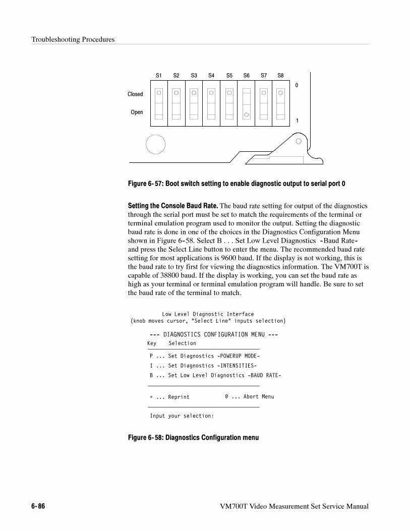
Troubleshooting Procedures
6- 86 VM700T Video Measurement Set Service Manual
S1 S2 S3 S4 S5 S6 S7 S8
Closed
Open
0
1
Figure 6- 57: Boot switch setting to enable diagnostic output to serial port 0
Setting the Console Baud Rate. The baud rate setting for output of the diagnosticsthrough the serial port must be set to match the requirements of the terminal orterminal emulation program used to monitor the output. Setting the diagnosticbaud rate is done in one of the choices in the Diagnostics Configuration Menushown in Figure 6--58. Select B . . . Set Low Level Diagnostics --Baud Rate--and press the Select Line button to enter the menu. The recommended baud ratesetting for most applications is 9600 baud. If the display is not working, this isthe baud rate to try first for viewing the diagnostics information. The VM700T iscapable of 38800 baud. If the display is working, you can set the baud rate ashigh as your terminal or terminal emulation program will handle. Be sure to setthe baud rate of the terminal to match.
Low Level Diagnostic Interface(knob moves cursor, “Select Line” inputs selection)
Key Selection
P ... Set Diagnostics -POWERUP MODE-
B ... Set Low Level Diagnostics -BAUD RATE-
= ... Reprint
Input your selection:
I ... Set Diagnostics -INTENSITIES-
--- DIAGNOSTICS CONFIGURATION MENU ---
@ ... Abort Menu
Figure 6- 58: Diagnostics Configuration menu
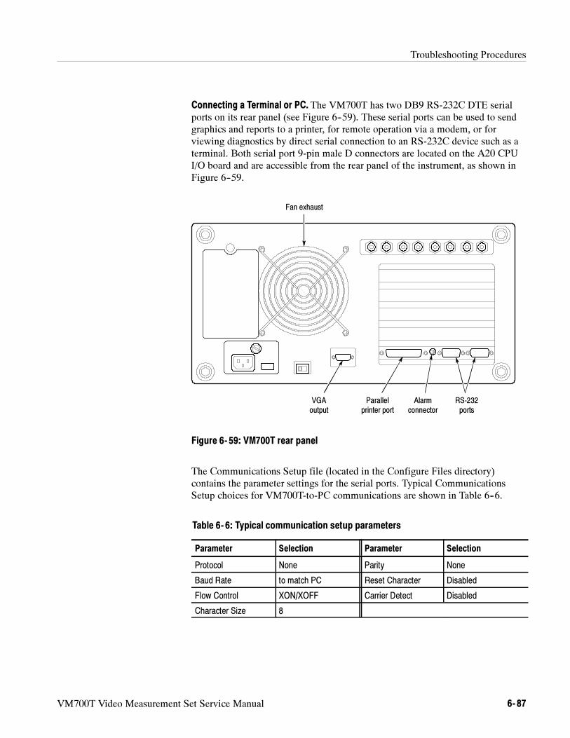
Troubleshooting Procedures
VM700T Video Measurement Set Service Manual 6- 87
Connecting a Terminal or PC. The VM700T has two DB9 RS-232C DTE serialports on its rear panel (see Figure 6--59). These serial ports can be used to sendgraphics and reports to a printer, for remote operation via a modem, or forviewing diagnostics by direct serial connection to an RS-232C device such as aterminal. Both serial port 9-pin male D connectors are located on the A20 CPUI/O board and are accessible from the rear panel of the instrument, as shown inFigure 6--59.
Alarmconnector
VGAoutput
RS-232ports
Parallelprinter port
Fan exhaust
Figure 6- 59: VM700T rear panel
The Communications Setup file (located in the Configure Files directory)contains the parameter settings for the serial ports. Typical CommunicationsSetup choices for VM700T-to-PC communications are shown in Table 6--6.
Table 6- 6: Typical communication setup parameters
Parameter Selection Parameter Selection
Protocol None Parity None
Baud Rate to match PC Reset Character Disabled
Flow Control XON/XOFF Carrier Detect Disabled
Character Size 8
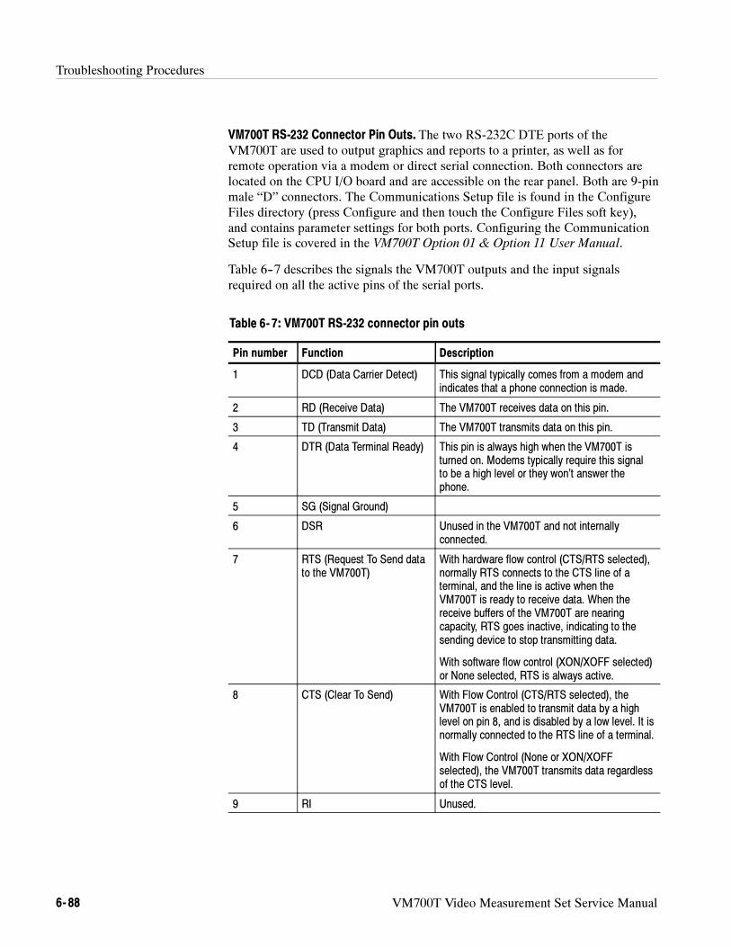
Troubleshooting Procedures
6- 88 VM700T Video Measurement Set Service Manual
VM700T RS-232 Connector Pin Outs. The two RS-232C DTE ports of theVM700T are used to output graphics and reports to a printer, as well as forremote operation via a modem or direct serial connection. Both connectors arelocated on the CPU I/O board and are accessible on the rear panel. Both are 9-pinmale “D” connectors. The Communications Setup file is found in the ConfigureFiles directory (press Configure and then touch the Configure Files soft key),and contains parameter settings for both ports. Configuring the CommunicationSetup file is covered in the VM700T Option 01 & Option 11 User Manual.
Table 6--7 describes the signals the VM700T outputs and the input signalsrequired on all the active pins of the serial ports.
Table 6- 7: VM700T RS-232 connector pin outs
Pin number Function Description
1 DCD (Data Carrier Detect) This signal typically comes from a modem andindicates that a phone connection is made.
2 RD (Receive Data) The VM700T receives data on this pin.
3 TD (Transmit Data) The VM700T transmits data on this pin.
4 DTR (Data Terminal Ready) This pin is always high when the VM700T isturned on. Modems typically require this signalto be a high level or they won’t answer thephone.
5 SG (Signal Ground)
6 DSR Unused in the VM700T and not internallyconnected.
7 RTS (Request To Send datato the VM700T)
With hardware flow control (CTS/RTS selected),normally RTS connects to the CTS line of aterminal, and the line is active when theVM700T is ready to receive data. When thereceive buffers of the VM700T are nearingcapacity, RTS goes inactive, indicating to thesending device to stop transmitting data.
With software flow control (XON/XOFF selected)or None selected, RTS is always active.
8 CTS (Clear To Send) With Flow Control (CTS/RTS selected), theVM700T is enabled to transmit data by a highlevel on pin 8, and is disabled by a low level. It isnormally connected to the RTS line of a terminal.
With Flow Control (None or XON/XOFFselected), the VM700T transmits data regardlessof the CTS level.
9 RI Unused.
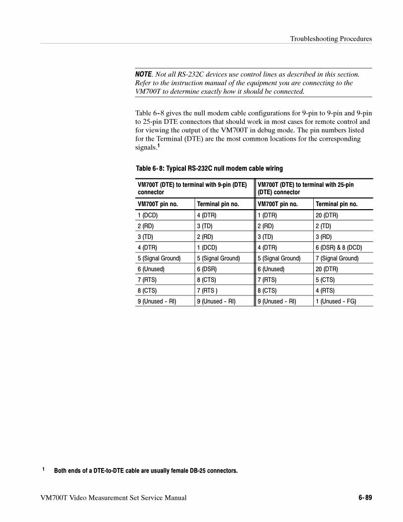
Troubleshooting Procedures
VM700T Video Measurement Set Service Manual 6- 89
NOTE. Not all RS-232C devices use control lines as described in this section.
Refer to the instruction manual of the equipment you are connecting to the
VM700T to determine exactly how it should be connected.
Table 6--8 gives the null modem cable configurations for 9-pin to 9-pin and 9-pinto 25-pin DTE connectors that should work in most cases for remote control andfor viewing the output of the VM700T in debug mode. The pin numbers listedfor the Terminal (DTE) are the most common locations for the correspondingsignals.1
Table 6- 8: Typical RS-232C null modem cable wiring
VM700T (DTE) to terminal with 9-pin (DTE)connector
VM700T (DTE) to terminal with 25-pin(DTE) connector
VM700T pin no. Terminal pin no. VM700T pin no. Terminal pin no.
1 (DCD) 4 (DTR) 1 (DTR) 20 (DTR)
2 (RD) 3 (TD) 2 (RD) 2 (TD)
3 (TD) 2 (RD) 3 (TD) 3 (RD)
4 (DTR) 1 (DCD) 4 (DTR) 6 (DSR) & 8 (DCD)
5 (Signal Ground) 5 (Signal Ground) 5 (Signal Ground) 7 (Signal Ground)
6 (Unused) 6 (DSR) 6 (Unused) 20 (DTR)
7 (RTS) 8 (CTS) 7 (RTS) 5 (CTS)
8 (CTS) 7 (RTS ) 8 (CTS) 4 (RTS)
9 (Unused -- RI) 9 (Unused -- RI) 9 (Unused -- RI) 1 (Unused -- FG)
1 Both ends of a DTE-to-DTE cable are usually female DB-25 connectors.
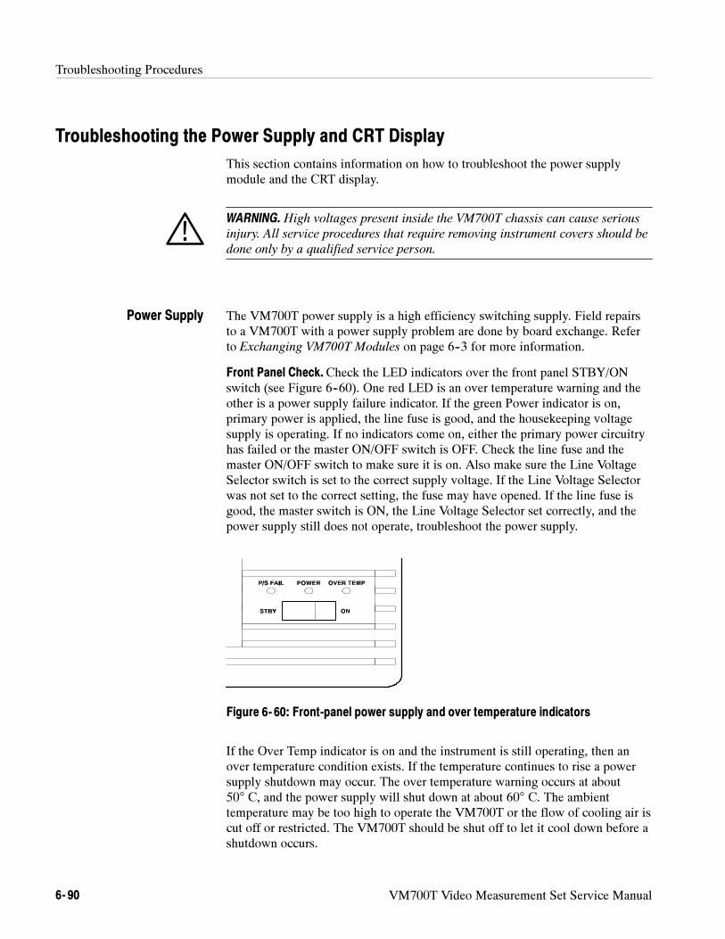
Troubleshooting Procedures
6- 90 VM700T Video Measurement Set Service Manual
Troubleshooting the Power Supply and CRT Display
This section contains information on how to troubleshoot the power supplymodule and the CRT display.
WARNING. High voltages present inside the VM700T chassis can cause serious
injury. All service procedures that require removing instrument covers should be
done only by a qualified service person.
The VM700T power supply is a high efficiency switching supply. Field repairsto a VM700T with a power supply problem are done by board exchange. Referto Exchanging VM700T Modules on page 6--3 for more information.
Front Panel Check. Check the LED indicators over the front panel STBY/ONswitch (see Figure 6--60). One red LED is an over temperature warning and theother is a power supply failure indicator. If the green Power indicator is on,primary power is applied, the line fuse is good, and the housekeeping voltagesupply is operating. If no indicators come on, either the primary power circuitryhas failed or the master ON/OFF switch is OFF. Check the line fuse and themaster ON/OFF switch to make sure it is on. Also make sure the Line VoltageSelector switch is set to the correct supply voltage. If the Line Voltage Selectorwas not set to the correct setting, the fuse may have opened. If the line fuse isgood, the master switch is ON, the Line Voltage Selector set correctly, and thepower supply still does not operate, troubleshoot the power supply.
Figure 6- 60: Front-panel power supply and over temperature indicators
If the Over Temp indicator is on and the instrument is still operating, then anover temperature condition exists. If the temperature continues to rise a powersupply shutdown may occur. The over temperature warning occurs at about50° C, and the power supply will shut down at about 60° C. The ambienttemperature may be too high to operate the VM700T or the flow of cooling air iscut off or restricted. The VM700T should be shut off to let it cool down before ashutdown occurs.
Power Supply
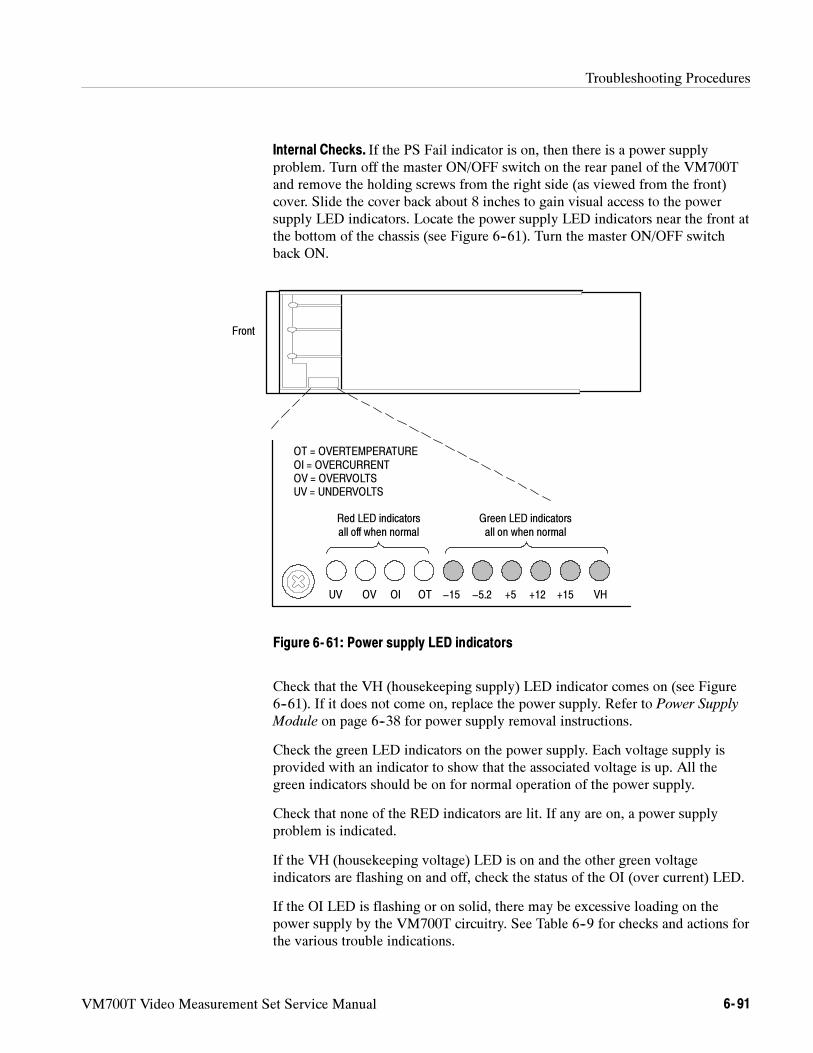
Troubleshooting Procedures
VM700T Video Measurement Set Service Manual 6- 91
Internal Checks. If the PS Fail indicator is on, then there is a power supplyproblem. Turn off the master ON/OFF switch on the rear panel of the VM700Tand remove the holding screws from the right side (as viewed from the front)cover. Slide the cover back about 8 inches to gain visual access to the powersupply LED indicators. Locate the power supply LED indicators near the front atthe bottom of the chassis (see Figure 6--61). Turn the master ON/OFF switchback ON.
VH+15+12+5−5.2−15OTOIOVUV
OT = OVERTEMPERATUREOI = OVERCURRENTOV = OVERVOLTSUV = UNDERVOLTS
Front
Red LED indicatorsall off when normal
Green LED indicatorsall on when normal
Figure 6- 61: Power supply LED indicators
Check that the VH (housekeeping supply) LED indicator comes on (see Figure6--61). If it does not come on, replace the power supply. Refer to Power Supply
Module on page 6--38 for power supply removal instructions.
Check the green LED indicators on the power supply. Each voltage supply isprovided with an indicator to show that the associated voltage is up. All thegreen indicators should be on for normal operation of the power supply.
Check that none of the RED indicators are lit. If any are on, a power supplyproblem is indicated.
If the VH (housekeeping voltage) LED is on and the other green voltageindicators are flashing on and off, check the status of the OI (over current) LED.
If the OI LED is flashing or on solid, there may be excessive loading on thepower supply by the VM700T circuitry. See Table 6--9 for checks and actions forthe various trouble indications.
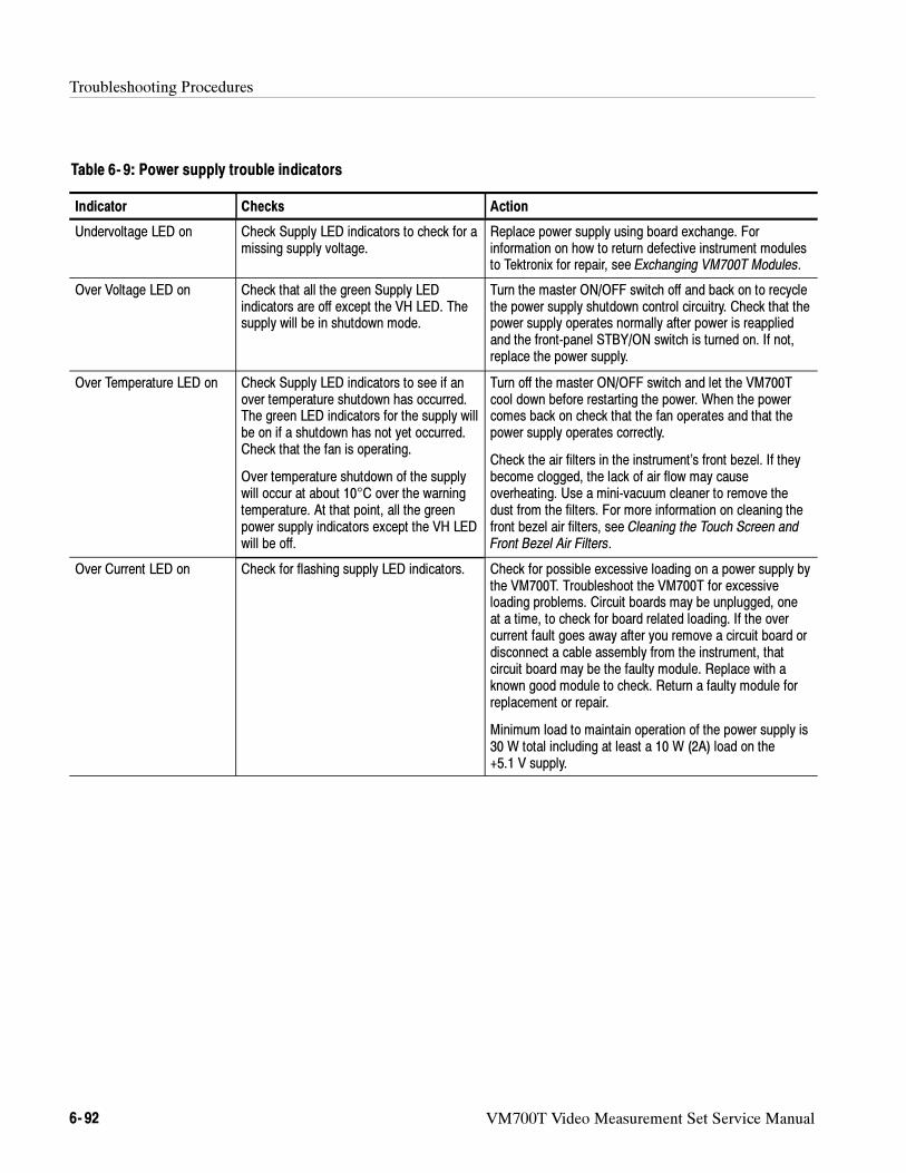
Troubleshooting Procedures
6- 92 VM700T Video Measurement Set Service Manual
Table 6- 9: Power supply trouble indicators
Indicator Checks Action
Undervoltage LED on Check Supply LED indicators to check for amissing supply voltage.
Replace power supply using board exchange. Forinformation on how to return defective instrument modulesto Tektronix for repair, see Exchanging VM700T Modules.
Over Voltage LED on Check that all the green Supply LEDindicators are off except the VH LED. Thesupply will be in shutdown mode.
Turn the master ON/OFF switch off and back on to recyclethe power supply shutdown control circuitry. Check that thepower supply operates normally after power is reappliedand the front-panel STBY/ON switch is turned on. If not,replace the power supply.
Over Temperature LED on Check Supply LED indicators to see if anover temperature shutdown has occurred.The green LED indicators for the supply willbe on if a shutdown has not yet occurred.Check that the fan is operating.
Over temperature shutdown of the supplywill occur at about 10°C over the warningtemperature. At that point, all the greenpower supply indicators except the VH LEDwill be off.
Turn off the master ON/OFF switch and let the VM700Tcool down before restarting the power. When the powercomes back on check that the fan operates and that thepower supply operates correctly.
Check the air filters in the instrument’s front bezel. If theybecome clogged, the lack of air flow may causeoverheating. Use a mini-vacuum cleaner to remove thedust from the filters. For more information on cleaning thefront bezel air filters, see Cleaning the Touch Screen andFront Bezel Air Filters.
Over Current LED on Check for flashing supply LED indicators. Check for possible excessive loading on a power supply bythe VM700T. Troubleshoot the VM700T for excessiveloading problems. Circuit boards may be unplugged, oneat a time, to check for board related loading. If the overcurrent fault goes away after you remove a circuit board ordisconnect a cable assembly from the instrument, thatcircuit board may be the faulty module. Replace with aknown good module to check. Return a faulty module forreplacement or repair.
Minimum load to maintain operation of the power supply is30 W total including at least a 10 W (2A) load on the+5.1 V supply.
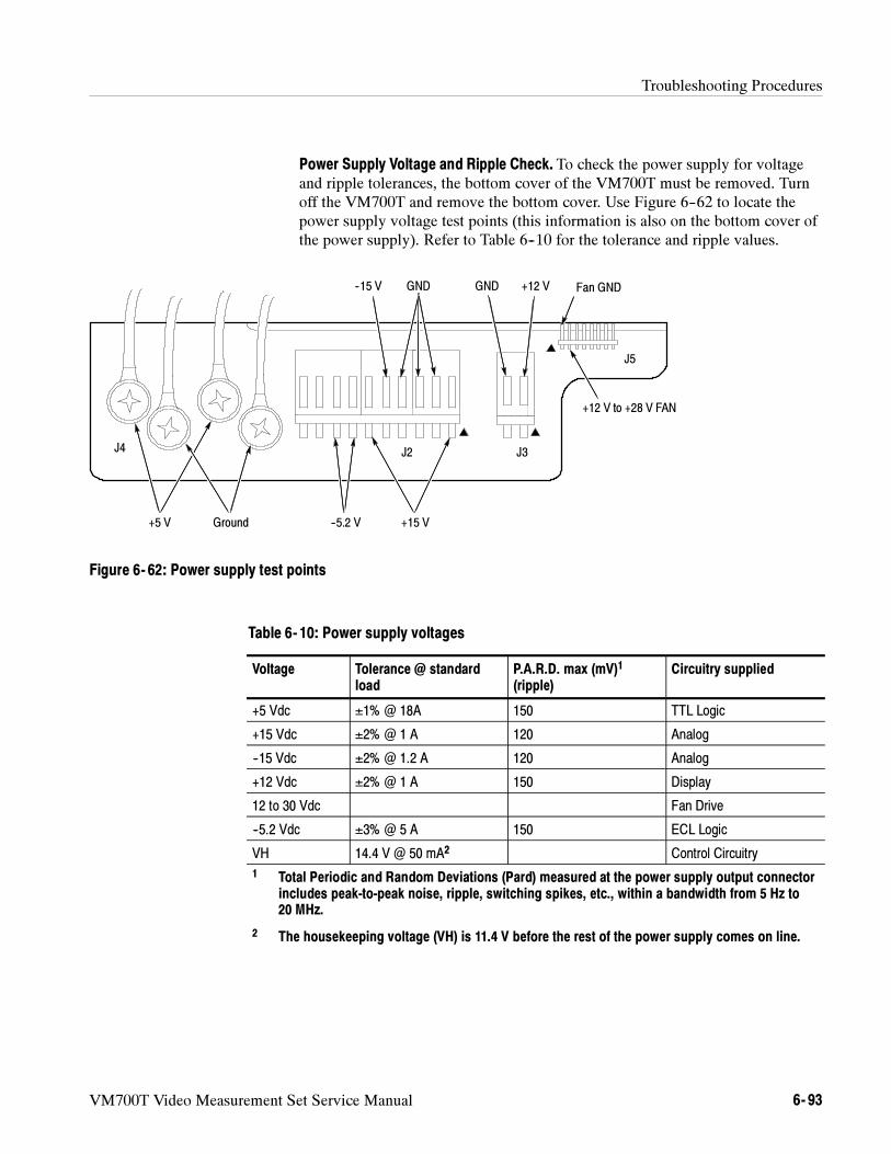
Troubleshooting Procedures
VM700T Video Measurement Set Service Manual 6- 93
Power Supply Voltage and Ripple Check. To check the power supply for voltageand ripple tolerances, the bottom cover of the VM700T must be removed. Turnoff the VM700T and remove the bottom cover. Use Figure 6--62 to locate thepower supply voltage test points (this information is also on the bottom cover ofthe power supply). Refer to Table 6--10 for the tolerance and ripple values.
+5 V Ground
+12 VGND
+15 V--5.2 V
--15 V GND
J2 J3J4
+12 V to +28 V FAN
J5
Fan GND
Figure 6- 62: Power supply test points
Table 6- 10: Power supply voltages
Voltage Tolerance @ standardload
P.A.R.D. max (mV)1
(ripple)Circuitry supplied
+5 Vdc ±1% @ 18A 150 TTL Logic
+15 Vdc ±2% @ 1 A 120 Analog
--15 Vdc ±2% @ 1.2 A 120 Analog
+12 Vdc ±2% @ 1 A 150 Display
12 to 30 Vdc Fan Drive
--5.2 Vdc ±3% @ 5 A 150 ECL Logic
VH 14.4 V @ 50 mA2 Control Circuitry
1 Total Periodic and Random Deviations (Pard) measured at the power supply output connectorincludes peak-to-peak noise, ripple, switching spikes, etc., within a bandwidth from 5 Hz to20 MHz.
2 The housekeeping voltage (VH) is 11.4 V before the rest of the power supply comes on line.
Troubleshooting Procedures
6- 94 VM700T Video Measurement Set Service Manual
The display module is a 9-inch diagonal, 640 x 480 pixel, monochrome CRTunit. The display is adjusted at the factory for optimum viewing brightness. Theinteractive touch screen is attached in front of the CRT. It can be removed forreplacement of the touch screen or the display module, if necessary.
If the CRT display fails, the faulty unit must be removed and replaced. Forinformation on replacing the CRT display module, refer to Removing and
Replacing Display and Control Components on page 6--32.
When a CRT display module is replaced, minor adjustments may be necessary tocenter the display or fine-adjust its brightness level. Refer to Adjusting the
Display on page 5--10 if readjustment is needed. Part of the Touch Screencalibration procedure also makes some adjustments to the display. If you replacethe touch screen, perform the touch screen calibration procedure on page 6--68.
Isolating a CRT Display Fault. Two types of CRT display failures can occur:
No display (blank screen)
No display and POWER SUPPLY FAIL LED lit
For no display (blank screen) CRT display symptoms, follow this procedure:
1. Connect an external VGA monitor to the rear panel VGA connector. If thereis no display on the external monitor, the problem may be in the CPU ordisplay driver circuitry on the CPU board. Exchange the CPU board with aknown good one to see if the display returns. If there is a VGA outputdisplay, but none on the CRT, continue with these checks.
2. Make sure that +12 V is present on pin 7 of the CRT display connector (onthe back of the display module). If +12 V is not present, remove the 10-pindrive connector to see if the +12 V comes up. If it does, the CRT displaymay be loading the power supply. Change to CRT display assembly andcheck again to see if the display returns.
3. With an oscilloscope, probe pins 6 (horizontal sync), 8 (video), and 9(vertical sync) of the CRT display connector for valid drive signals.
4. Adjust the brightness and contrast controls on the bottom of the CRT displayunit to see if they affect the display.
For blank screen and lighted POWER SUPPLY FAIL LED symptoms, followthis procedure:
1. Switch the instrument power off at the rear-panel switch.
2. Disconnect the CRT 12 V power connector (P3) at the power supply andswitch instrument power on to see if the display monitor was loading thepower supply. If the POWER SUPPLY FAIL LED is no longer lit with the12 V cable disconnected, replace the CRT display module.
Troubleshooting the CRTDisplay
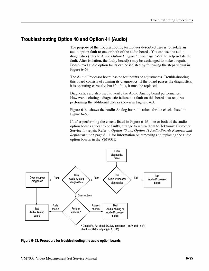
Troubleshooting Procedures
VM700T Video Measurement Set Service Manual 6- 95
Troubleshooting Option 40 and Option 41 (Audio)
The purpose of the troubleshooting techniques described here is to isolate anaudio option fault to one or both of the audio boards. You can use the audiodiagnostics (refer to Audio Option Diagnostics on page 6--97) to help isolate thefault. After isolation, the faulty board(s) may be exchanged to make a repair.Board-level audio option faults can be isolated by following the steps shown inFigure 6--63.
The Audio Processor board has no test points or adjustments. Troubleshootingthis board consists of running its diagnostics. If the board passes the diagnostics,it is operating correctly; but if it fails, it must be replaced.
Diagnostics are also used to verify the Audio Analog board performance.However, isolating a diagnostic failure to a fault on this board also requiresperforming the additional checks shown in Figure 6--63.
Figure 6--64 shows the Audio Analog board locations for the checks listed inFigure 6--63.
If, after performing the checks listed in Figure 6--63, one or both of the audiooption boards appear to be faulty, arrange to return them to Tektronix CustomerService for repair. Refer to Option 40 and Option 41 Audio Boards Removal and
Replacement on page 6--11 for information on removing and replacing the audiooption boards in the VM700T.
Does not run
Pass FailRunsDoes not passdiagnostic
* Check F1, F2; check DC/DC converter (+15 V and +5 V);check oscillator output (pin 2, U53)
Passeschecks
FailschecksBad
Audio Analogboard
BadAudio Analog orAudio Processor
board
Enterdiagnostics
menu
Run
Audio Processor
diagnostics
RunAudio Analogdiagnostics
Performchecks *
BadAudio Processor
board
Figure 6- 63: Procedure for troubleshooting the audio option boards
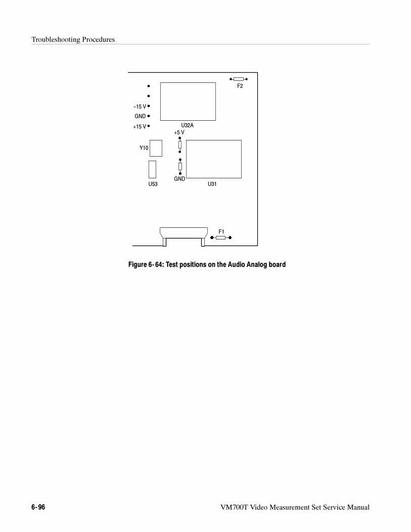
Troubleshooting Procedures
6- 96 VM700T Video Measurement Set Service Manual
F2
--15 V
+15 V
F1
U31
U32A
+5 V
Y10
U53
GND
GND
Figure 6- 64: Test positions on the Audio Analog board
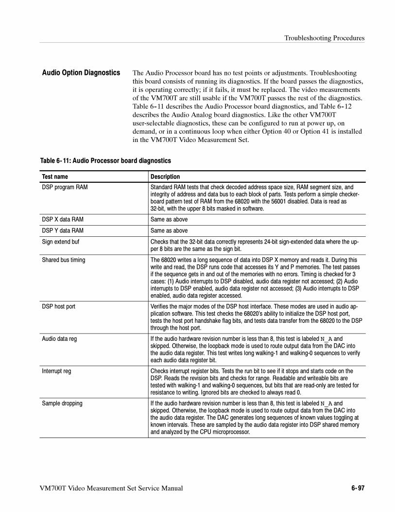
Troubleshooting Procedures
VM700T Video Measurement Set Service Manual 6- 97
The Audio Processor board has no test points or adjustments. Troubleshootingthis board consists of running its diagnostics. If the board passes the diagnostics,it is operating correctly; if it fails, it must be replaced. The video measurementsof the VM700T are still usable if the VM700T passes the rest of the diagnostics.Table 6--11 describes the Audio Processor board diagnostics, and Table 6--12describes the Audio Analog board diagnostics. Like the other VM700Tuser-selectable diagnostics, these can be configured to run at power up, ondemand, or in a continuous loop when either Option 40 or Option 41 is installedin the VM700T Video Measurement Set.
Table 6- 11: Audio Processor board diagnostics
Test name Description
DSP program RAM Standard RAM tests that check decoded address space size, RAM segment size, andintegrity of address and data bus to each block of parts. Tests perform a simple checker-board pattern test of RAM from the 68020 with the 56001 disabled. Data is read as32-bit, with the upper 8 bits masked in software.
DSP X data RAM Same as above
DSP Y data RAM Same as above
Sign extend buf Checks that the 32-bit data correctly represents 24-bit sign-extended data where the up-per 8 bits are the same as the sign bit.
Shared bus timing The 68020 writes a long sequence of data into DSP X memory and reads it. During thiswrite and read, the DSP runs code that accesses its Y and P memories. The test passesif the sequence gets in and out of the memories with no errors. Timing is checked for 3cases: (1) Audio interrupts to DSP disabled, audio data register not accessed; (2) Audiointerrupts to DSP enabled, audio data register not accessed; (3) Audio interrupts to DSPenabled, audio data register accessed.
DSP host port Verifies the major modes of the DSP host interface. These modes are used in audio ap-plication software. This test checks the 68020’s ability to initialize the DSP host port,tests the host port handshake flag bits, and tests data transfer from the 68020 to the DSPthrough the host port.
Audio data reg If the audio hardware revision number is less than 8, this test is labeled N_A andskipped. Otherwise, the loopback mode is used to route output data from the DAC intothe audio data register. This test writes long walking-1 and walking-0 sequences to verifyeach audio data register bit.
Interrupt reg Checks interrupt register bits. Tests the run bit to see if it stops and starts code on theDSP. Reads the revision bits and checks for range. Readable and writeable bits aretested with walking-1 and walking-0 sequences, but bits that are read-only are tested forresistance to writing. Ignored bits are checked to always read 0.
Sample dropping If the audio hardware revision number is less than 8, this test is labeled N_A andskipped. Otherwise, the loopback mode is used to route output data from the DAC intothe audio data register. The DAC generates long sequences of known values toggling atknown intervals. These are sampled by the audio data register into DSP shared memoryand analyzed by the CPU microprocessor.
Audio Option Diagnostics
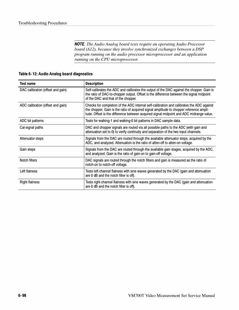
Troubleshooting Procedures
6- 98 VM700T Video Measurement Set Service Manual
NOTE. The Audio Analog board tests require an operating Audio Processor
board (A12), because they involve synchronized exchanges between a DSP
program running on the audio processor microprocessor and an application
running on the CPU microprocessor.
Table 6- 12: Audio Analog board diagnostics
Test name Description
DAC calibration (offset and gain) Self-calibrates the ADC and calibrates the output of the DAC against the chopper. Gain isthe ratio of DAC-to-chopper output. Offset is the difference between the signal midpointof the DAC and that of the chopper.
ADC calibration (offset and gain) Checks for completion of the ADC internal self-calibration and calibrates the ADC againstthe chopper. Gain is the ratio of acquired signal amplitude to chopper reference ampli-tude. Offset is the difference between acquired signal midpoint and ADC midrange value.
ADC bit patterns Tests for walking-1 and walking-0 bit patterns in DAC sample data.
Cal-signal paths DAC and chopper signals are routed via all possible paths to the ADC (with gain andattenuation set to 0) to verify continuity and separation of the two input channels.
Attenuator steps Signals from the DAC are routed through the available attenuator steps, acquired by theADC, and analyzed. Attenuation is the ratio of atten-off to atten-on voltage.
Gain steps Signals from the DAC are routed through the available gain stages, acquired by the ADC,and analyzed. Gain is the ratio of gain-on to gain-off voltage.
Notch filters DAC signals are routed through the notch filters and gain is measured as the ratio ofnotch-on to notch-off voltage.
Left flatness Tests left-channel flatness with sine waves generated by the DAC (gain and attenuationare 0 dB and the notch filter is off).
Right flatness Tests right-channel flatness with sine waves generated by the DAC (gain and attenuationare 0 dB and the notch filter is off).
Troubleshooting Procedures
VM700T Video Measurement Set Service Manual 6- 99
Troubleshooting Option 48 (GPIB)
Troubleshooting the GPIB board consists of running the GPIB diagnostics.The GPIB Diagnostic routine does extensive testing of the interface hardware.Failure of any diagnostic test indicates a hardware problem that requiresservicing. The VM700T may function for local operation, but may be faulty forremote operation if a GPIB Diagnostic test fails. Refer to Diagnostic Selection
File on page 6--78 to configure the Diagnostic Test Selection file to either run orskip the GPIB diagnostic when running the high-level diagnostics. The main testtitles are as follows:
VM IPC Register
VM Program RAM
VM Shared RAM
VM Private RAM
VM Cen Ctl Reg
VM Gpib Chip
GP Program RAM
GP Shared RAM
GP Private RAM
GP Spurious Ints
GP Int From VM
GP Clk Tick Int
GP Get Int
Each of these main tests have a number of subtests. Refer to Appendix B of theVM700T GPIB Interface Programmer Manual for the complete test list if youneed to further troubleshoot the GPIB board.
Troubleshooting Procedures
6- 100 VM700T Video Measurement Set Service Manual
Troubleshooting Option 1S (SDI)
The purpose of the troubleshooting techniques described here is to isolate an SDIoption fault to one or both of the SDI boards. After isolation, the faulty board(s)may be exchanged to make a repair.
Before You Troubleshoot. If you suspect that Option 1S is not operating properly,perform the following steps before you perform the troubleshooting procedures.
1. Verify that the VM700T is set to Mode: Digital.
NOTE. The VM700T must be set to Mode: Digital before you can access any
Option 1S functions. You cannot access any Option 1S functions if the VM700T
is set to Mode: Analog.
2. Verify that all Option 1S and VM700T diagnostics pass (refer to SDI Option
Diagnostics on page 6--104).
3. Inspect the rear-panel connectors for damage.
4. Inspect the internal cable connections between the SDI Rear Panel Interfaceassembly and the SDI board, and the cable between the SDI board and theAcquisition/Controller board.
The instructions for isolating the SDI option faults listed below are found on thefollowing pages:
No signal from the SDI Ch. A input
No signal from the SDI Ch. B input
No signal from the Analog Ref input
No signal from the AES/EBU Digital Audio input
No signal from the LTC Time Code input
No signal from the SDI Output connector
Perform the following steps when the VM700T will not display a known signalon the SDI Ch. A input:
1. Connect a digital video signal to the SDI Ch. A input and terminate theloopthrough connector.
2. Set the VM700T to display the channel A signal using the SDI Waveformapplication.
No Signal From theSDI Ch. A Input
Troubleshooting Procedures
VM700T Video Measurement Set Service Manual 6- 101
NOTE. The VM700T must be set to Mode: Digital. The Source Selection Digital
configuration file must be set Auto Detect or for the bit rate and standard of the
digital test signal.
3. Check for a Loss of Signal message on the display.
4. If hardware trouble is indicated other than the Loss of Signal message,replace the SDI board.
NOTE. Various user settings can dramatically alter the displayed waveform in
ways that may appear to indicate a malfunctioning circuit. In the SDI Waveform
application, these user settings include Menu selections of Style, Display,
Display Diff, Free Run, as well as the front panel controls of Move and Expand.
Verify these settings before assuming a malfunction exists.
5. Swap the SDI Ch. A and SDI Ch. B cable connections on the SDI board atJ7 and J8 (see Figure 6--65).
6. Connect the signal input to the SDI Ch. B input connector (leave theVM700T front panel set to display the channel A signal).
7. Check that there is a signal display.
8. If there is still no signal display on channel A, replace the SDI board.
9. If there is a signal display on channel A.
10. Check J5 pin 9 for 13 to 15 VDC (see Figure 6--65).
11. Check J5 pin 10 for --13 to --15 VDC.
12. If one or both voltages are bad, replace the SDI board.
13. If both voltages are good, remove the SDI Rear Panel Interface assembly.
14. Check that the cables are properly seated in their connectors on the SDI RearPanel Interface assembly.
15. Disconnect the flat cable and the green channel A cable from the SDI RearPanel Interface assembly.
16. Check each of the wires in the flat cable and the green cable for continuity.
17. If the cables are good, replace the SDI Rear Panel Interface assembly.
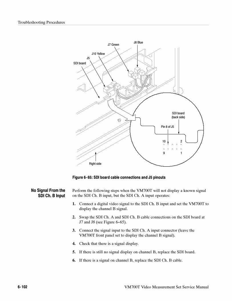
Troubleshooting Procedures
6- 102 VM700T Video Measurement Set Service Manual
J8 Blue
J5
J7 Green
J10 Yellow
SDI board
Right side
Pin 8 of J5
SDI board(back side)
1
2
9
10
Figure 6- 65: SDI board cable connections and J5 pinouts
Perform the following steps when the VM700T will not display a known signalon the SDI Ch. B input, but the SDI Ch. A input operates:
1. Connect a digital video signal to the SDI Ch. B input and set the VM700T todisplay the channel B signal.
2. Swap the SDI Ch. A and SDI Ch. B cable connections on the SDI board atJ7 and J8 (see Figure 6--65).
3. Connect the signal input to the SDI Ch. A input connector (leave theVM700T front panel set to display the channel B signal).
4. Check that there is a signal display.
5. If there is still no signal display on channel B, replace the SDI board.
6. If there is a signal on channel B, replace the SDI Ch. B cable.
No Signal From theSDI Ch. B Input
Troubleshooting Procedures
VM700T Video Measurement Set Service Manual 6- 103
Perform the following steps when the Analog Ref input does not operate, but theSDI Ch. A input operates:
1. Connect an NTSC television signal to the Analog Ref input.
2. Check for a video signal on J5 pin 8 on the SDI board. Leave the J5 cableinstalled and probe the board from the bottom as shown in Figure 6--65.
3. If the video signal is present on J5 pin 8, replace the SDI board.
4. If the video signal is not present, remove the SDI Rear Panel Interfaceassembly.
5. Disconnect the flat cable from the SDI Rear Panel Interface assembly, andthen check each of the 10 wires in the cable for continuity.
6. If the cable is good, replace the SDI Rear Panel Interface assembly.
Perform the following steps when the AES/EBU Digital Audio input does notoperate:
1. Connect an AES/EBU digital audio signal to Option 1S.
2. Check for an audio signal on J5 pin 2 of the SDI board (see Figure 6--65).
3. If the audio signal is present on J5 pin 2, replace the SDI board.
4. If the audio signal is not present, remove the SDI Rear Panel Interfaceassembly.
5. Disconnect the flat cable from the SDI Rear Panel Interface assembly, andthen check each of the 10 wires in the cable for continuity.
6. If the cable is good, replace the SDI Rear Panel Interface assembly.
Perform the following steps when the LTC Time Code input does not operate:
1. Connect a time code signal to Option 1S.
2. Check for a time code signal on J5 pins 4 and 5 of the SDI board (seeFigure 6--65).
3. If the time code signal is present on J5 pins 4 and 5, replace the SDI board.
4. If the time code signal is not present, remove the SDI Rear Panel Interfaceassembly.
5. Disconnect the flat cable from the SDI Rear Panel Interface assembly, andthen check each of the 10 wires in the cable for continuity.
6. If the cable is good, replace the SDI Rear Panel Interface assembly.
No Signal From theAnalog Ref Input
No Signal From theAES/EBU Digital Audio
Input
No Signal From theLTC Time Code Input
Troubleshooting Procedures
6- 104 VM700T Video Measurement Set Service Manual
Perform the following steps when the SDI Output connector provides no signal,but the SDI Ch. A and SDI Ch. B inputs operate:
1. Connect a digital video signal to the SDI Ch. A input and terminate theloopthrough connector.
2. Connect a cable from the SDI Output connector to the SDI Ch. B input.
3. Check that you can display the SDI Ch. B signal on the VM700T.
NOTE. Set the Source Selection Digital configuration file to output the selected
channel to the SDI Output connector.
4. If there is no signal display, disconnect the cable from J10 on the SDI board(see Figure 6--65).
5. Check the center pin of the J10 connector for a digital video signal.
6. If the video signal is not present, replace the SDI board.
7. If the video signal is present, replace the SDI Output cable.
SDI Option Diagnostics
Option 1S is composed of three modules and two sets of interconnects (seeFigure 6--66). The SDI and the Acquisition/Controller diagnostics effectivelyidentify failures to the Acquisition/Controller board, the SDI to Acquisition/Con-troller interconnect, and the SDI specific hardware when signal sources areconnected as shown in Figure 6--67. Most SDI specific hardware errors occur onthe SDI board.
NOTE. The analog measurements of the VM700T are still usable if the Option 1S
diagnostics fail but the VM700T passes the rest of the diagnostics.
Like the other VM700T user-selectable diagnostics, the Option 1S diagnosticscan be configured to run at power up, on demand, or in a continuous loop whenOption 1S is installed in the VM700T.
The following procedure provides instructions on how to connect signals toOption 1S in order to perform the full set of option diagnostics. The diagnosticsdo not verify any specifications; but they do provide a high level of confidencethat the option is working properly. Table 6--13 lists the Option 1S diagnostictests. To verify instrument operation to published specifications, refer to the SDIOption 1S Performance Verification on page 4--25.
No Signal From theSDI Output Connector
Running the Option 1SDiagnostics
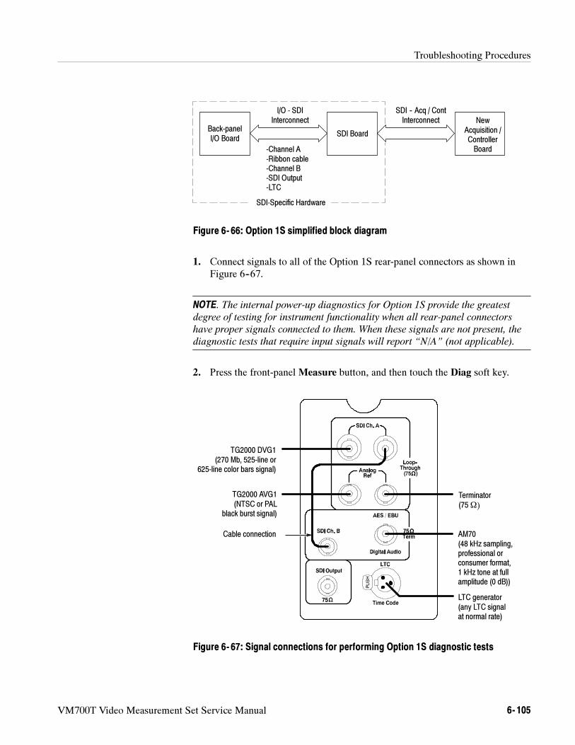
Troubleshooting Procedures
VM700T Video Measurement Set Service Manual 6- 105
Back-panelI/O Board
SDI Board
-Channel A-Ribbon cable-Channel B-SDI Output-LTC
I/O - SDIInterconnect
SDI-Specific Hardware
NewAcquisition /ControllerBoard
SDI -- Acq / ContInterconnect
Figure 6- 66: Option 1S simplified block diagram
1. Connect signals to all of the Option 1S rear-panel connectors as shown inFigure 6--67.
NOTE. The internal power-up diagnostics for Option 1S provide the greatest
degree of testing for instrument functionality when all rear-panel connectors
have proper signals connected to them. When these signals are not present, the
diagnostic tests that require input signals will report “N/A” (not applicable).
2. Press the front-panel Measure button, and then touch the Diag soft key.
TG2000 DVG1(270 Mb, 525-line or
625-line color bars signal)
TG2000 AVG1(NTSC or PAL
black burst signal)
Terminator(75Ω)
AM70(48 kHz sampling,professional orconsumer format,1 kHz tone at fullamplitude (0 dB))
LTC generator(any LTC signalat normal rate)
Cable connection
Figure 6- 67: Signal connections for performing Option 1S diagnostic tests
Troubleshooting Procedures
6- 106 VM700T Video Measurement Set Service Manual
3. Rotate the front-panel knob until you locate the SDI Diagnostic soft key.
4. Touch the SDI Diagnostic soft key to access the SDI diagnostic routine.
5. Touch the appropriate soft key to select the diagnostics run-mode type(Power-Up or Interactive).
NOTE. Diagnostics performed from the Measure menu offer two modes:
Power-Up and Interactive. In Power-Up mode, the diagnostics display a one-line
header for each test being run. Should the diagnostics encounter an error, the
measurement set waits for user acknowledgement.
In Interactive Mode, the diagnostics display more detail about each test being
performed. Before starting the next test in the list, the measurement set waits for
user acknowledgement.
6. Observe the displayed diagnostic test results as they are performed.Diagnostic tests that do not pass display a highlighted Fail message.
7. The Rerun Test soft key lets you rerun diagnostic tests.
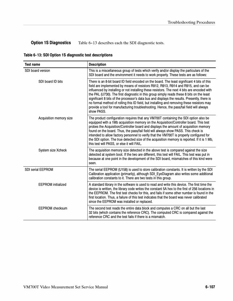
Troubleshooting Procedures
VM700T Video Measurement Set Service Manual 6- 107
Table 6--13 describes each the SDI diagnostic tests.
Table 6- 13: SDI Option 1S diagnostic test descriptions
Test name Description
SDI board version This is a miscellaneous group of tests which verify and/or display the particulars of theSDI board and the environment it needs to work properly. These tests are as follows:
SDI board ID bits There is an 8-bit board ID field encoded on the board. The least significant 4 bits of thisfield are implemented by means of resistors R912, R913, R914 and R915, and can beinfluenced by installing or not installing these resistors. The next 4 bits are encoded withthe PAL (U730). The first diagnostic in this group simply reads these 8 bits on the leastsignificant 8 bits of the processor’s data bus and displays the results. Presently, there isno formal method of rolling this ID field, but installing and removing these resistors mayprovide a tool for manufacturing troubleshooting. Hence, the pass/fail field will alwaysshow PASS.
Acquisition memory size The product configuration requires that any VM700T containing the SDI option also beequipped with a 1Mb acquisition memory on the Acquisition/Controller board. This testprobes the Acquisition/Controller board and displays the amount of acquisition memoryfound on the board. Thus, the pass/fail field will always show PASS. This check isintended to allow factory personnel to verify that the VM700T is properly configured forthe SDI option. The true detected size of the acquisition memory is reported. If it is 1 Mb,this test will PASS, or else it will FAIL.
System size Xcheck The acquisition memory size detected in the above test is compared against the sizedetected at system boot. If the two are different, this test will FAIL. This test was put inbecause at one point in the development of the SDI board, mismatches of this kind wereseen.
SDI serial EEPROM The serial EEPROM (U158) is used to store calibration constants. It is written by the SDICalibration application (primarily), although SDI_EyeDiagram also writes some additionalcalibration constants to it. There are two tests in this group.
EEPROM initialized A standard library in the software is used to read and write this device. The first time thedevice is written, the library code writes the constant 5A hex to the first of 256 locations inthe EEPROM. The first test checks for this, and fails if some other number is found in thefirst location. Thus, a failure of this test indicates that the board was never calibratedsince the EEPROM was installed or replaced.
EEPROM checksum The second test reads the entire data block and computes a CRC on all but the last32 bits (which contains the reference CRC). The computed CRC is compared against thereference CRC and the test fails if there is a mismatch.
Option 1S Diagnostics
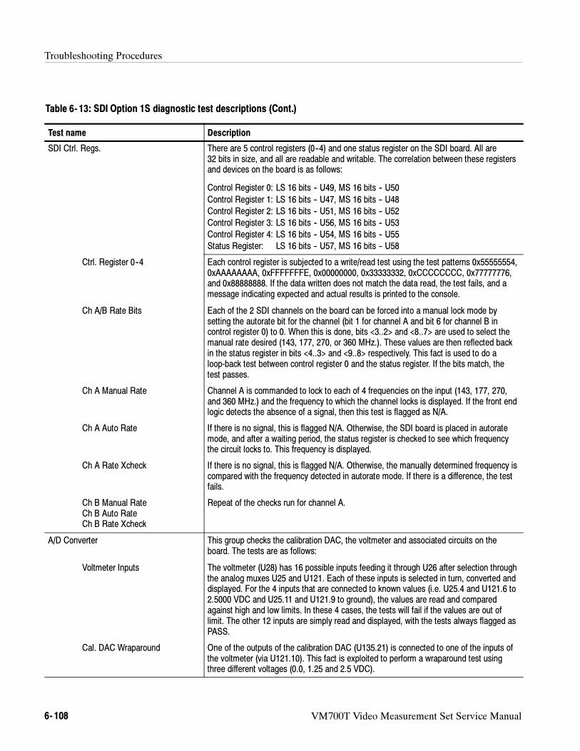
Troubleshooting Procedures
6- 108 VM700T Video Measurement Set Service Manual
Table 6- 13: SDI Option 1S diagnostic test descriptions (Cont.)
Test name Description
SDI Ctrl. Regs. There are 5 control registers (0--4) and one status register on the SDI board. All are32 bits in size, and all are readable and writable. The correlation between these registersand devices on the board is as follows:
Control Register 0: LS 16 bits -- U49, MS 16 bits -- U50
Control Register 1: LS 16 bits -- U47, MS 16 bits -- U48Control Register 2: LS 16 bits -- U51, MS 16 bits -- U52Control Register 3: LS 16 bits -- U56, MS 16 bits -- U53Control Register 4: LS 16 bits -- U54, MS 16 bits -- U55Status Register: LS 16 bits -- U57, MS 16 bits -- U58
Ctrl. Register 0--4 Each control register is subjected to a write/read test using the test patterns 0x55555554,0xAAAAAAAA, 0xFFFFFFFE, 0x00000000, 0x33333332, 0xCCCCCCCC, 0x77777776,and 0x88888888. If the data written does not match the data read, the test fails, and amessage indicating expected and actual results is printed to the console.
Ch A/B Rate Bits Each of the 2 SDI channels on the board can be forced into a manual lock mode bysetting the autorate bit for the channel (bit 1 for channel A and bit 6 for channel B incontrol register 0) to 0. When this is done, bits <3..2> and <8..7> are used to select themanual rate desired (143, 177, 270, or 360 MHz.). These values are then reflected backin the status register in bits <4..3> and <9..8> respectively. This fact is used to do aloop-back test between control register 0 and the status register. If the bits match, thetest passes.
Ch A Manual Rate Channel A is commanded to lock to each of 4 frequencies on the input (143, 177, 270,and 360 MHz.) and the frequency to which the channel locks is displayed. If the front endlogic detects the absence of a signal, then this test is flagged as N/A.
Ch A Auto Rate If there is no signal, this is flagged N/A. Otherwise, the SDI board is placed in autoratemode, and after a waiting period, the status register is checked to see which frequencythe circuit locks to. This frequency is displayed.
Ch A Rate Xcheck If there is no signal, this is flagged N/A. Otherwise, the manually determined frequency iscompared with the frequency detected in autorate mode. If there is a difference, the testfails.
Ch B Manual RateCh B Auto RateCh B Rate Xcheck
Repeat of the checks run for channel A.
A/D Converter This group checks the calibration DAC, the voltmeter and associated circuits on theboard. The tests are as follows:
Voltmeter Inputs The voltmeter (U28) has 16 possible inputs feeding it through U26 after selection throughthe analog muxes U25 and U121. Each of these inputs is selected in turn, converted anddisplayed. For the 4 inputs that are connected to known values (i.e. U25.4 and U121.6 to2.5000 VDC and U25.11 and U121.9 to ground), the values are read and comparedagainst high and low limits. In these 4 cases, the tests will fail if the values are out oflimit. The other 12 inputs are simply read and displayed, with the tests always flagged asPASS.
Cal. DAC Wraparound One of the outputs of the calibration DAC (U135.21) is connected to one of the inputs ofthe voltmeter (via U121.10). This fact is exploited to perform a wraparound test usingthree different voltages (0.0, 1.25 and 2.5 VDC).
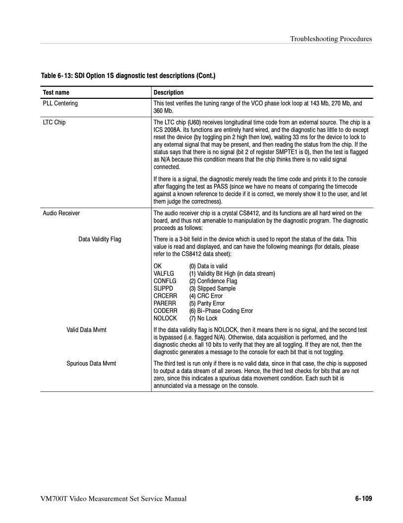
Troubleshooting Procedures
VM700T Video Measurement Set Service Manual 6- 109
Table 6- 13: SDI Option 1S diagnostic test descriptions (Cont.)
Test name Description
PLL Centering This test verifies the tuning range of the VCO phase lock loop at 143 Mb, 270 Mb, and360 Mb.
LTC Chip The LTC chip (U60) receives longitudinal time code from an external source. The chip is aICS 2008A. Its functions are entirely hard wired, and the diagnostic has little to do exceptreset the device (by toggling pin 2 high then low), waiting 33 ms for the device to lock toany external signal that may be present, and then reading the status from the chip. If thestatus says that there is no signal (bit 2 of register SMPTE1 is 0), then the test is flaggedas N/A because this condition means that the chip thinks there is no valid signalconnected.
If there is a signal, the diagnostic merely reads the time code and prints it to the consoleafter flagging the test as PASS (since we have no means of comparing the timecodeagainst a known reference to decide if it is correct, we merely show it to the user, and letthem judge the correctness).
Audio Receiver The audio receiver chip is a crystal CS8412, and its functions are all hard wired on theboard, and thus not amenable to manipulation by the diagnostic program. The diagnosticproceeds as follows:
Data Validity Flag There is a 3-bit field in the device which is used to report the status of the data. Thisvalue is read and displayed, and can have the following meanings (for details, pleaserefer to the CS8412 data sheet):
OK (0) Data is validVALFLG (1) Validity Bit High (in data stream)CONFLG (2) Confidence FlagSLIPPD (3) Slipped SampleCRCERR (4) CRC ErrorPARERR (5) Parity ErrorCODERR (6) Bi--Phase Coding ErrorNOLOCK (7) No Lock
Valid Data Mvmt If the data validity flag is NOLOCK, then it means there is no signal, and the second testis bypassed (i.e. flagged N/A). Otherwise, data acquisition is performed, and thediagnostic checks all 10 bits to verify that they are all toggling. If they are not, then thediagnostic generates a message to the console for each bit that is not toggling.
Spurious Data Mvmt The third test is run only if there is no valid data, since in that case, the chip is supposedto output a data stream of all zeroes. Hence, the third test checks for bits that are notzero, since this indicates a spurious data movement condition. Each such bit isannunciated via a message on the console.
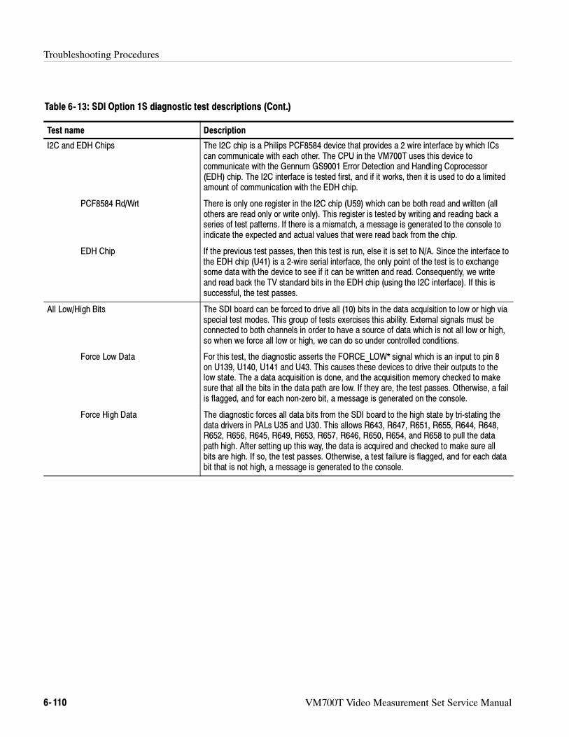
Troubleshooting Procedures
6- 110 VM700T Video Measurement Set Service Manual
Table 6- 13: SDI Option 1S diagnostic test descriptions (Cont.)
Test name Description
I2C and EDH Chips The I2C chip is a Philips PCF8584 device that provides a 2 wire interface by which ICscan communicate with each other. The CPU in the VM700T uses this device tocommunicate with the Gennum GS9001 Error Detection and Handling Coprocessor(EDH) chip. The I2C interface is tested first, and if it works, then it is used to do a limitedamount of communication with the EDH chip.
PCF8584 Rd/Wrt There is only one register in the I2C chip (U59) which can be both read and written (allothers are read only or write only). This register is tested by writing and reading back aseries of test patterns. If there is a mismatch, a message is generated to the console toindicate the expected and actual values that were read back from the chip.
EDH Chip If the previous test passes, then this test is run, else it is set to N/A. Since the interface tothe EDH chip (U41) is a 2-wire serial interface, the only point of the test is to exchangesome data with the device to see if it can be written and read. Consequently, we writeand read back the TV standard bits in the EDH chip (using the I2C interface). If this issuccessful, the test passes.
All Low/High Bits The SDI board can be forced to drive all (10) bits in the data acquisition to low or high viaspecial test modes. This group of tests exercises this ability. External signals must beconnected to both channels in order to have a source of data which is not all low or high,so when we force all low or high, we can do so under controlled conditions.
Force Low Data For this test, the diagnostic asserts the FORCE_LOW* signal which is an input to pin 8on U139, U140, U141 and U43. This causes these devices to drive their outputs to thelow state. The a data acquisition is done, and the acquisition memory checked to makesure that all the bits in the data path are low. If they are, the test passes. Otherwise, a failis flagged, and for each non-zero bit, a message is generated on the console.
Force High Data The diagnostic forces all data bits from the SDI board to the high state by tri-stating thedata drivers in PALs U35 and U30. This allows R643, R647, R651, R655, R644, R648,R652, R656, R645, R649, R653, R657, R646, R650, R654, and R658 to pull the datapath high. After setting up this way, the data is acquired and checked to make sure allbits are high. If so, the test passes. Otherwise, a test failure is flagged, and for each databit that is not high, a message is generated to the console.
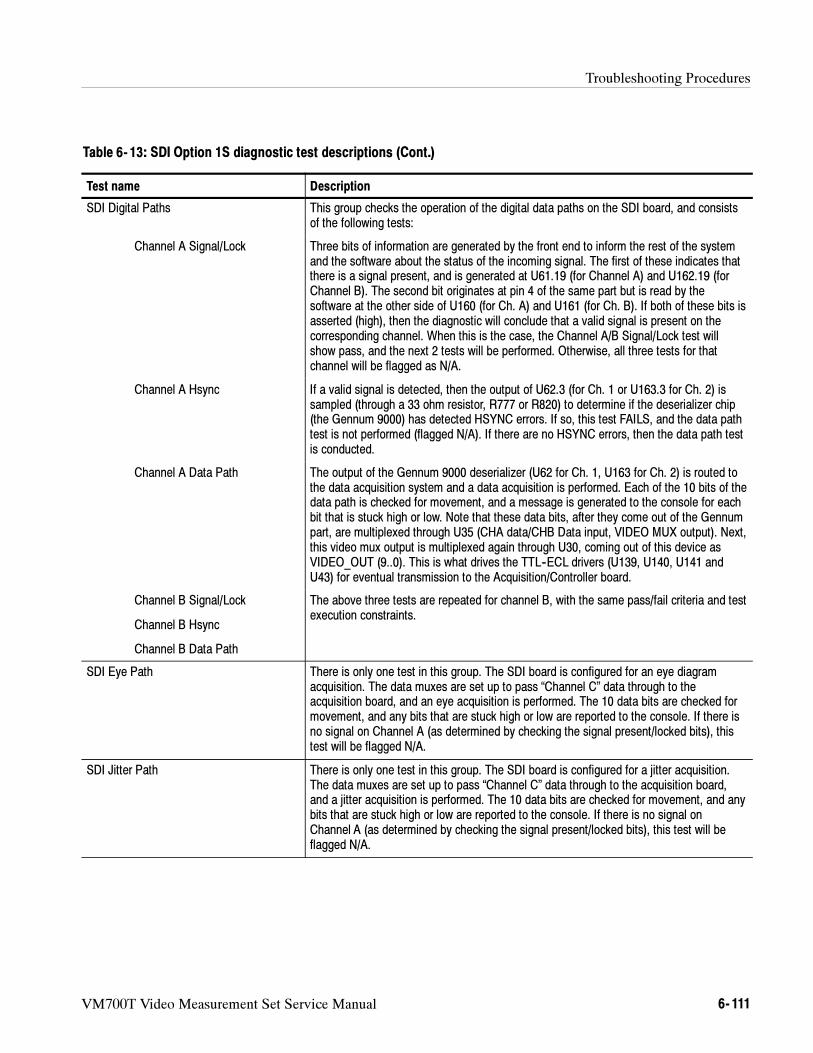
Troubleshooting Procedures
VM700T Video Measurement Set Service Manual 6- 111
Table 6- 13: SDI Option 1S diagnostic test descriptions (Cont.)
Test name Description
SDI Digital Paths This group checks the operation of the digital data paths on the SDI board, and consistsof the following tests:
Channel A Signal/Lock Three bits of information are generated by the front end to inform the rest of the systemand the software about the status of the incoming signal. The first of these indicates thatthere is a signal present, and is generated at U61.19 (for Channel A) and U162.19 (forChannel B). The second bit originates at pin 4 of the same part but is read by thesoftware at the other side of U160 (for Ch. A) and U161 (for Ch. B). If both of these bits isasserted (high), then the diagnostic will conclude that a valid signal is present on thecorresponding channel. When this is the case, the Channel A/B Signal/Lock test willshow pass, and the next 2 tests will be performed. Otherwise, all three tests for thatchannel will be flagged as N/A.
Channel A Hsync If a valid signal is detected, then the output of U62.3 (for Ch. 1 or U163.3 for Ch. 2) issampled (through a 33 ohm resistor, R777 or R820) to determine if the deserializer chip(the Gennum 9000) has detected HSYNC errors. If so, this test FAILS, and the data pathtest is not performed (flagged N/A). If there are no HSYNC errors, then the data path testis conducted.
Channel A Data Path The output of the Gennum 9000 deserializer (U62 for Ch. 1, U163 for Ch. 2) is routed tothe data acquisition system and a data acquisition is performed. Each of the 10 bits of thedata path is checked for movement, and a message is generated to the console for eachbit that is stuck high or low. Note that these data bits, after they come out of the Gennumpart, are multiplexed through U35 (CHA data/CHB Data input, VIDEO MUX output). Next,this video mux output is multiplexed again through U30, coming out of this device asVIDEO_OUT (9..0). This is what drives the TTL--ECL drivers (U139, U140, U141 andU43) for eventual transmission to the Acquisition/Controller board.
Channel B Signal/Lock
Channel B Hsync
Channel B Data Path
The above three tests are repeated for channel B, with the same pass/fail criteria and testexecution constraints.
SDI Eye Path There is only one test in this group. The SDI board is configured for an eye diagramacquisition. The data muxes are set up to pass “Channel C” data through to theacquisition board, and an eye acquisition is performed. The 10 data bits are checked formovement, and any bits that are stuck high or low are reported to the console. If there isno signal on Channel A (as determined by checking the signal present/locked bits), thistest will be flagged N/A.
SDI Jitter Path There is only one test in this group. The SDI board is configured for a jitter acquisition.The data muxes are set up to pass “Channel C” data through to the acquisition board,and a jitter acquisition is performed. The 10 data bits are checked for movement, and anybits that are stuck high or low are reported to the console. If there is no signal onChannel A (as determined by checking the signal present/locked bits), this test will beflagged N/A.

Troubleshooting Procedures
6- 112 VM700T Video Measurement Set Service Manual
Table 6- 13: SDI Option 1S diagnostic test descriptions (Cont.)
Test name Description
SDI Wander Path This test checks the drift rate circuitry. The DRIFT_SRC bits (2..0) into pins 9, 10, 11 ofU129 are set (via control register 1) to route CTRL_STEP (into pin 13) out to the outputs.DRIFT_CLK<2..0> is also set to select pin 2 of U130 (CHOPPER_EN) to the output(pin 5). Following this, 10000 cycles of the following sequence are performed:
Set U129.13 highSet U130.2 highSet U129.13 lowClock U130.2 twice
This causes the counters U132 and U133 to cycle through all their states several times,and for each of these states to be latched into U24. The output of U24 is routed to thedata acquisition. After the acquisition has been performed, the data is checked to ensurethat all 8 bits are moving. If so, the test passes. Otherwise, a message is generated tothe console for each bit that is stuck low or high.
Supermux Tests Acquired data consists of a 10-bit data sample and 4 flag bits captured synchronously.Each of these flag bits can be fed by a variety of sources, such as line and frame syncpulses from either channel, eye rise/fall flags, etc. This multiplexing is performed by fourmuxes that are implemented in a PLD (U35). Several of these bits are available as inputsto more than one of these 4 muxes. The supermux tests exploit this redundancy. Foreach supermux test, we set up the mux selector to route the same bit to as many of theflag bits as possible, and then we examine the flag bits in the acquired data to verify thatthe same state is acquired in all the flag bits.
Even though this description is grouped under one paragraph, the tests themselves hadto be broken out into separate groups because the diagnostic framework has a time limitfor the completion of each test. These groups, and the bits checked within each, are asfollows:
Fsyncs Checks frame sync A and B on Flags 3, 2, 1 and 0
Lsyncs Checks line sync A and B on Flags 3, 2, 1, and 0
Blanking Bits Checks horiz/vert blanking bits on Flags 3, 2, 1 and 0
Eye Flags Checks the eye rise flag on Flags 3 and 2.
VM700T Video Measurement Set Service Manual 7- 1
Options
This section provides a brief summary of the available options for the VM700TVideo Measurement Set at the time of printing of this manual. The Standardsoptions refers to the television standard, either Option 01 (NTSC) or Option 11(PAL), for which measurements are made. The application options make theappropriate measurements for the installed television standard.
Standard Options (Option 01 and Option 11)
When ordering the VM700T, you may specify the video standard you what yourinstrument to be capable of making measurement with. Option 01 is theSystem M NTSC video standard and Option 11 is the System BG/i PAL videostandard. You may also order the VM700T with both standards installed orpurchase a firmware upgrade to add a standard to make the VM700T a dual-standard Video Measurement Set.
Application Options (Option 1G, Option 20, Option 21, Option 30, Option 42)
The application options provide additional measurement capabilities notprovided in the standard Option 01 (NTSC) or Option 11 (PAL) firmware as partof the base instrument measurements. These may be ordered as part of theoriginal purchase or added later with an option upgrade.
The VM700T Video Measurement Set Option 1G (2T Echo and Rounding ofBlack & White) gives you access to two measurements, named Echo andRounding Errors, respectively. Echo determines multipath distortion. RoundingErrors measures rounding of the black-to-white and white-to-black signaltransitions.
The VM700T Video Measurement Set Option 20 (Teletext) gives you access totwo measurements: Teletext and SoundInSync. These measurement applicationsdetermine various parameters related to the transmission of digital information inthe vertical interval and in the sync pulse, respectively.
The following Camera Testing measurements are available with Option 21 of theVM700T Video Measurement Set.
Colorimetry measures the color fidelity of a camera’s output (CCD or tubecameras).
Defects identifies defective cells in CCD devices (CCD cameras only).
2T Echo and Rounding ofBlack and White
Measurement (Option 1G)
Teletext Measurement(Option 20)
Camera Measurements(Option 21)
Options
7- 2 VM700T Video Measurement Set Service Manual
Detail measures the artificial sharpening transitions added to the video inboth the horizontal and vertical directions as a percentage of transitionamplitude (CCD or tube cameras).
Fixed Pattern Noise identifies unwanted signal non-uniformities correlated toCCD cells (CCD cameras only).
Frequency Response measures the degradation in waveform amplitude as thefrequency of modulation increases (CCD or tube cameras). Measuresaliasing components for CCD cameras.
Gamma measures the input-to-output light transfer characteristic of animaging or display device (CCD or tube cameras).
Geometry and Registration measures geometric distortions in cameraimaging elements (CCD or tube cameras).
Shading measures variation in camera output luminance levels when lightinput is constant (CCD or tube cameras).
Vertical Smear measures the camera’s ability to handle excess light (CCDcameras only).
Option 30 (Component) of the VM700T Video Measurement Set gives youaccess to the following 12 measurements:
Bowtie measures timing and amplitude differences.
Channel Delay measures timing and amplitude differences as does Bowtie,but it works with signals containing jitter.
ColorBar measures the Y, Pb, and Pr amplitudes of each chroma packet.
K_Factor measures K-2T, K-5T, and Pulse-to-Bar ratio on component inputsignals.
Level Meter monitors peak-to-peak amplitude of a component signal.
Lightning displays two XY graphs on the screen.
Luminance NonLinearity measures luminance nonlinear distortion.
Component Multiburst measures frequency response.
Noise Spectrum measures noise level and performs spectrum analysis.
Overlay displays stacked or superimposed Y, Pb, and Pr component inputs.
Parade displays side-by-side Y, Pb, and Pr component inputs.
Vector provides an XY display of the Pb and Pr components.
ComponentMeasurements
(Option 30)
Options
VM700T Video Measurement Set Service Manual 7- 3
The Audio/Video Timing measurement option (Option 42) of the VM700T ispart of a system that measures the timing difference between audio and videoportions of a program that arrive from different transmission paths. This featureis used in conjunction with the VITS200 NTSC or VITS201 PAL insertiongenerators and the ASG100 or ASG140 Audio Signal Generators that are alsoequipped with the Audio/Video Timing measurement. The VM700T must haveeither Option 40 or Option 41 installed to operate with the Option 42 firmware.
Audio Options (Option 40 and Option 41)
The VM700T audio measurement options expands the power of the VM700TVideo Measurement Set to include comprehensive audio measurement capabili-ties.
VM700T Option 40 and Option 41 capabilities include:
automated and manual audio measurements
audio spectral analysis with harmonic analyzer
stereo monitoring
real-time display of audio parameters
multitone testing
These options also enable the VM700T to continuously monitor audio test linesfor the presence of a test sequence designed for automated testing (the TEKsequence). The audio option tests to ANSI standard T1.502-1988, EIA/TIA-250-C, or CCITT Recommendation O.33.
The audio results received with automatic monitoring can be included in theVM700T Auto Mode video measurements display, with the time and date of thelast sequence received. Timed reports and the logging of results can beperformed automatically. Also, a file in the VM700T Measurement Resultsdirectory is updated each time an audio auto test sequence is received andmeasured.
Option 40 has two stereo input channels connected through mini-XLR connec-tors. Two mini-XLR adapters are provided to make signal connections to theinputs. Option 41 provides for three stereo input channels connected through amale DB 37 connector. A female DB 37 connector is provided with Option 41 touse for fabricating the interconnecting cable that applies the signals to bemeasured to the three stereo inputs of the VM700T. Either Option 40 or Option41 may be installed in the VM700T, not both.
Audio/VideoTiming Measurement
(Option 42)
Option 40 and Option 41
Options
7- 4 VM700T Video Measurement Set Service Manual
Serial Digital Interface (Option 1S)
Option 1S provides the capability to display, capture, and analyze 270 Mbit,525-line and 625-line serial component, 143 Mbit serial composite, and360 Mbit serial component digital video signals. The Option 1S hardwareconsists of an SDI circuit board that installs into the right-side card cage, atwo-board input assembly that mounts onto the measurement set rear panel,updated instrument firmware, and several interconnecting cables.
The Option 1S rear panel connectors include two SDI inputs (one loopthroughand one internally terminated in 75 Ω), a buffered SDI output of one of the SDIinput channels, an AES/EBU digital audio input, a Longitudinal Time Codeinput for time stamping logged error files, and an analog loopthrough input to beused for a timing reference signal.
Option 1S provides the following key features:
Automatic analysis of 270 Mbit component, 143 Mbit composite, and360 Mbit component serial digital video signals
Continuous real-time format analyzer with event logging and frame capture(captured frames can be downloaded to a PC)
Longitudinal Time Code input for time stamping error events
External and embedded digital audio measurements including audio to videotiming measurements
Conformance testing to SMPTE 259M and SMPTE RP--165 digital errordetection and reporting
Ancillary data analysis with data distribution display
Relative to reference mode allowing signal comparisons
Digital video wander measurements
GPIB Interface (Option 48)
This option provides the hardware and firmware to support a GPIB interface forremote control of the VM700T or hard copy output to a GPIB printer.
White Phosphor CRT (Option 74)
This option provides a display module with a white phosphor CRT instead of thestandard green phosphor when a new instrument is ordered with Option 74 fromthe factory. All the display module adjustments are the same as those for thestandard CRT.
Options
VM700T Video Measurement Set Service Manual 7- 5
Cabinet and Mounting Options (Option 1C, VM7FR1, VM7FC1)
This option provides the VM700T in a cabinet version from the factory. Thestandard order configuration is rack mounted.
This field-installable option provides a rack mounting conversion kit for theVM700T. This kit converts a cabinetized measurement set to permit a rackmounting installation.
This field-installable option provide a conversion kit to install a cabinet on a rackmounted measurement set.
Auxiliary Software Options (VMBKUP, VMT, VMREMGR)
This software package assists in backing up the VM700T user-created files.These files can be reloaded to the same instrument or to another VM700T togenerate a common set of configuration files.
This software package assists in remote control of the VM700T using a personalcomputer. The software also allows you to capture text and graphics.
This software package aids you in handling the graphic displays and transferringthem to a personal computer for filing, display, or printing.
Optional Accessories
Table 7- 1: Optional accessories
Accessory DescriptionTektronix part orproduct number
Service manual VM700T servicing information 070-9630-XX
GPIB accessories Available with Option 48
Cables 1 m, double-shielded2 m, double-shielded3 m, double-shielded
012-0991-01012-0991-00012-0991-02
GURU II+ GPIB User’s Resource Utility for the IBM Personal Computer. This packageincludes software and manual plus National PC2A GPIB controller board;GPIB cable; software on floppy diskettes.
S3FG100
Cabinet Version(Option 1C)
Rack Mounting Kit(VM7FR1)
Cabinetizing Kit(VM7FC1)
VMBKUP
VMT
VMREMGR
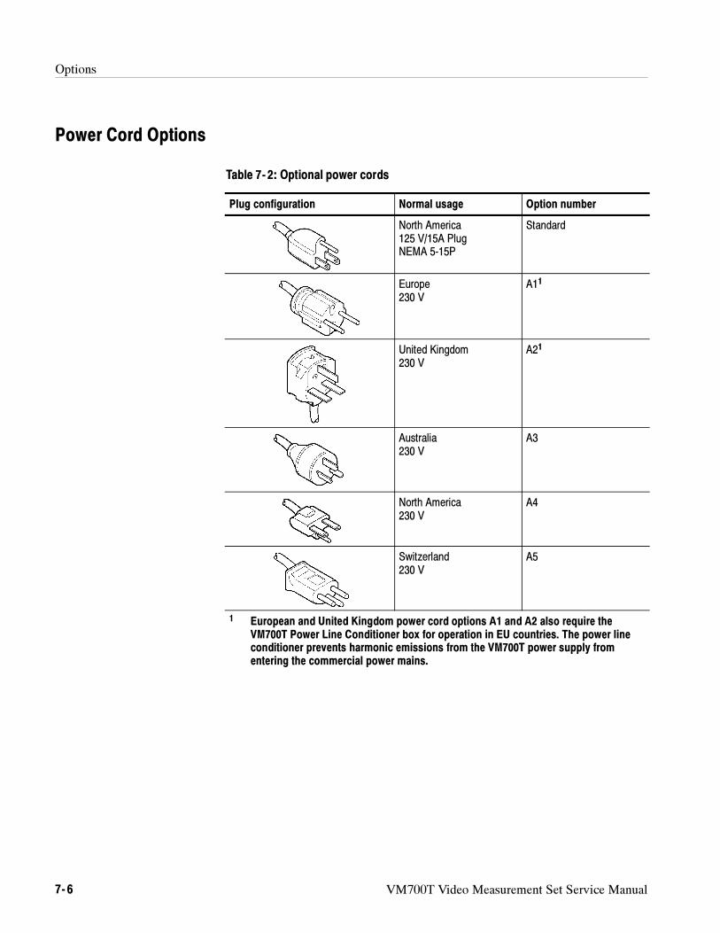
Options
7- 6 VM700T Video Measurement Set Service Manual
Power Cord Options
Table 7- 2: Optional power cords
Plug configuration Normal usage Option number
North America125 V/15A PlugNEMA 5-15P
Standard
Europe230 V
A11
United Kingdom230 V
A21
Australia230 V
A3
North America230 V
A4
Switzerland230 V
A5
1 European and United Kingdom power cord options A1 and A2 also require theVM700T Power Line Conditioner box for operation in EU countries. The power lineconditioner prevents harmonic emissions from the VM700T power supply fromentering the commercial power mains.
VM700T Video Measurement Set Service Manual 8- 1
Replaceable Electrical Parts
Individual electrical components are not listed because component-level repair isnot supported in VM700T Video Measurement Set.
The electrical modules for this instrument are listed in the Replaceable Mechani-
cal Parts list.
Replaceable Electrical Parts
8- 2 VM700T Video Measurement Set Service Manual
VM700T Video Measurement Set Service Manual 9- 1
Diagrams
The block diagram and interconnection diagram are provided to assist inidentifying the interaction between modules in troubleshooting to the modulelevel. Use the exploded view diagrams in the Replaceable Parts List section tolocate the modules installed in the VM700T.
Block Diagram
Each module in the instrument is assigned an assembly number (for example,A20). The assembly number appears on the block diagram. The overall blockdiagram is at the board level. More detailed block diagrams of the modules areshown in the Theory section with the discussion of the module circuit operation.
Interconnection Diagram
The interconnection diagram shows the connections made between modules toassist in tracing the signal and power distribution routes.
Diagrams
9- 2 VM700T Video Measurement Set Service Manual
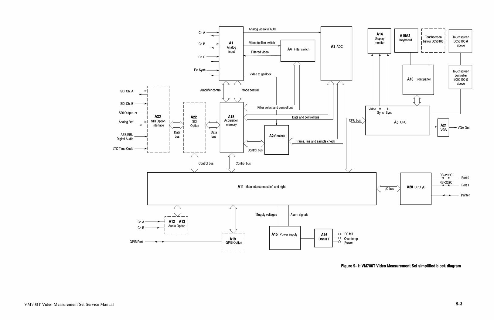
VM700T Video Measurement Set Service Manual 9- 3
Figure 9- 1: VM700T Video Measurement Set simplified block diagram
Ch A
Ch B
Ch C
Ext Sync
Analoginput
A1
Acquisitionmemory
A18
Filter switchA4ADCA3
Main interconnect left and rightA11
Audio Option
A12 A13
GPIB OptionA19
Power supplyA15
I/O bus
Displaymonitor
A14
Keyboard
A10A2 Touchscreenbelow B050100
Front panelA10
CPUA5
VGA
A21VGA Out
VSync Sync
Video H
RS--232C
RS--232C
Port 0
Port 1
Printer
CPU I/OA20
PS fail
Over tempPower
ON/OFF
A16
Alarm signalsSupply voltages
GenlockA2
Ch A
Ch B
GPIB Port
Frame, line and sample check
Data and control bus
Filter select and control bus
Video to genlock
Filtered video
Video to filter switch
Analog video to ADC
Mode controlAmplifier control
Control bus
CPU bus
Control bus
SDIOption
Control bus
SDI OptionInterface
Databus
SDI Ch. A
SDI Ch. B
Analog Ref
LTC Time Code
AES/EBUDigital Audio
SDI Output
A22A23
Databus
TouchscreenB050100 &above
TouchscreencontrollerB050100 &above
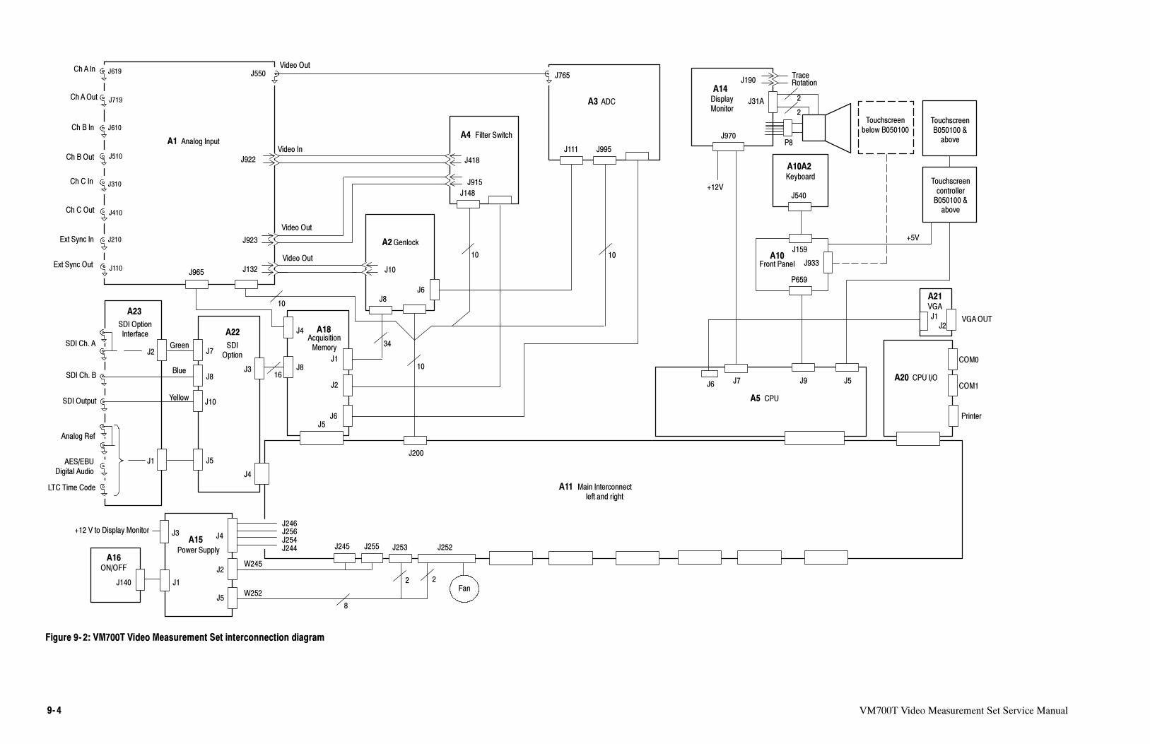
VM700T Video Measurement Set Service Manual9- 4
Figure 9- 2: VM700T Video Measurement Set interconnection diagram
ChA In
Ch B In
Ch B Out
Ext Sync Out
Ext Sync In
Ch C In
Ch C Out
Ch AOut
J619
J719
J610
J510
J310
J410
J210
J110
J923
J132
J550
J922
Video Out
Video In
Video Out
Video Out
10
J10
J6
J2
J8
34
J200
10
J765
J995
J1
J111
J915
J418
J148
COM0
COM1
Printer
J2W245
J245 J255
J4
J246J256J254J244
J5Fan
J252J253
W252
8
2 2
J970
J190TraceRotation
J31A
J5J6
J9J7
J933
J6
VGAOUT
J540
J159
P659
J140 J1
J3+12 V to Display Monitor
P8
2
2
+12V
J1J2
J4
J965
Analog InputA1
AcquisitionMemory
A18
Filter SwitchA4
ADCA3
GenlockA2
DisplayMonitor
A14
Keyboard
A10A2
Touchscreenbelow B050100
Front PanelA10
CPUA5
VGA
A21
CPU I/OA20
Power Supply
A15
ON/OFF
A16
Main Interconnectleft and right
A11
10 10
A22
J8J3
A23
J7J2
J8
J10
J5J1
J4
SDI Ch. A
SDI Ch. B
Analog Ref
LTC Time Code
AES/EBUDigital Audio
SDI Output
SDIOption
SDI OptionInterface
Green
Blue
Yellow
16
TouchscreenB050100 &above
TouchscreencontrollerB050100 &above
J5
+5V
VM700T Video Measurement Set Service Manual 10- 1
Replaceable Mechanical Parts
This section contains a list of the replaceable mechanical components for theVM700T Video Measurement Set. The replaceable modules are also included inthis parts list as well as in the Replaceable Electrical Parts List. Use this list toidentify and order replacement parts.
Parts Ordering Information
Replacement parts are available through your local Tektronix field office orrepresentative.
Changes to Tektronix products are sometimes made to accommodate improvedcomponents as they become available and to give you the benefit of the latestimprovements. Therefore, when ordering parts, it is important to include thefollowing information in your order:
part number
instrument type or model number
instrument serial number
instrument modification number, if applicable
If you order a part that has been replaced with a different or improved part, yourlocal Tektronix field office or representative will contact you concerning anychange in part number.
Using the Replaceable Mechanical Parts List
The tabular information in the Replaceable Mechanical Parts List is arranged forquick retrieval. Understanding the structure and features of the list will help youfind all of the information you need for ordering replacement parts. Thefollowing table describes the content of each column in the parts list.
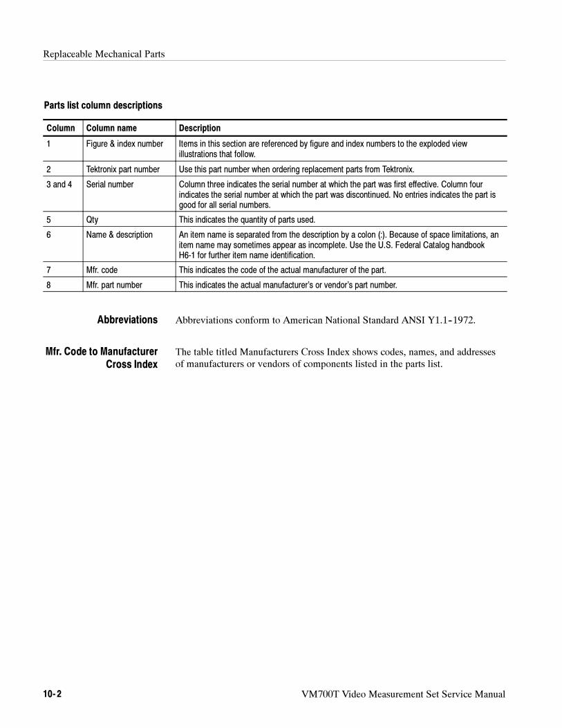
Replaceable Mechanical Parts
10- 2 VM700T Video Measurement Set Service Manual
Parts list column descriptions
Column Column name Description
1 Figure & index number Items in this section are referenced by figure and index numbers to the exploded viewillustrations that follow.
2 Tektronix part number Use this part number when ordering replacement parts from Tektronix.
3 and 4 Serial number Column three indicates the serial number at which the part was first effective. Column fourindicates the serial number at which the part was discontinued. No entries indicates the part isgood for all serial numbers.
5 Qty This indicates the quantity of parts used.
6 Name & description An item name is separated from the description by a colon (:). Because of space limitations, anitem name may sometimes appear as incomplete. Use the U.S. Federal Catalog handbookH6-1 for further item name identification.
7 Mfr. code This indicates the code of the actual manufacturer of the part.
8 Mfr. part number This indicates the actual manufacturer’s or vendor’s part number.
Abbreviations conform to American National Standard ANSI Y1.1--1972.
The table titled Manufacturers Cross Index shows codes, names, and addressesof manufacturers or vendors of components listed in the parts list.
Abbreviations
Mfr. Code to ManufacturerCross Index
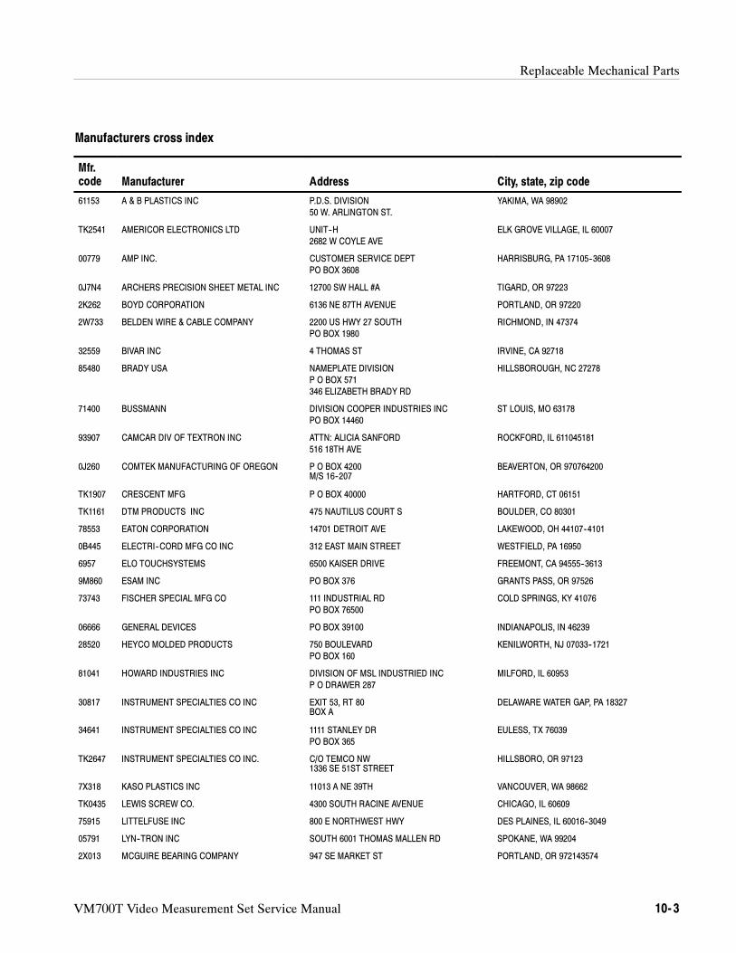
Replaceable Mechanical Parts
VM700T Video Measurement Set Service Manual 10- 3
Manufacturers cross index
Mfr.code Manufacturer Address City, state, zip code
61153 A & B PLASTICS INC P.D.S. DIVISION
50 W. ARLINGTON ST.
YAKIMA, WA 98902
TK2541 AMERICOR ELECTRONICS LTD UNIT--H
2682 W COYLE AVE
ELK GROVE VILLAGE, IL 60007
00779 AMP INC. CUSTOMER SERVICE DEPT
PO BOX 3608
HARRISBURG, PA 17105--3608
0J7N4 ARCHERS PRECISION SHEET METAL INC 12700 SW HALL #A TIGARD, OR 97223
2K262 BOYD CORPORATION 6136 NE 87TH AVENUE PORTLAND, OR 97220
2W733 BELDEN WIRE & CABLE COMPANY 2200 US HWY 27 SOUTH
PO BOX 1980
RICHMOND, IN 47374
32559 BIVAR INC 4 THOMAS ST IRVINE, CA 92718
85480 BRADY USA NAMEPLATE DIVISION
P O BOX 571
346 ELIZABETH BRADY RD
HILLSBOROUGH, NC 27278
71400 BUSSMANN DIVISION COOPER INDUSTRIES INC
PO BOX 14460
ST LOUIS, MO 63178
93907 CAMCAR DIV OF TEXTRON INC ATTN: ALICIA SANFORD
516 18TH AVE
ROCKFORD, IL 611045181
0J260 COMTEK MANUFACTURING OF OREGON P O BOX 4200M/S 16--207
BEAVERTON, OR 970764200
TK1907 CRESCENT MFG P O BOX 40000 HARTFORD, CT 06151
TK1161 DTM PRODUCTS INC 475 NAUTILUS COURT S BOULDER, CO 80301
78553 EATON CORPORATION 14701 DETROIT AVE LAKEWOOD, OH 44107--4101
0B445 ELECTRI--CORD MFG CO INC 312 EAST MAIN STREET WESTFIELD, PA 16950
6957 ELO TOUCHSYSTEMS 6500 KAISER DRIVE FREEMONT, CA 94555--3613
9M860 ESAM INC PO BOX 376 GRANTS PASS, OR 97526
73743 FISCHER SPECIAL MFG CO 111 INDUSTRIAL RD
PO BOX 76500
COLD SPRINGS, KY 41076
06666 GENERAL DEVICES PO BOX 39100 INDIANAPOLIS, IN 46239
28520 HEYCO MOLDED PRODUCTS 750 BOULEVARD
PO BOX 160
KENILWORTH, NJ 07033--1721
81041 HOWARD INDUSTRIES INC DIVISION OF MSL INDUSTRIED INC
P O DRAWER 287
MILFORD, IL 60953
30817 INSTRUMENT SPECIALTIES CO INC EXIT 53, RT 80BOX A
DELAWARE WATER GAP, PA 18327
34641 INSTRUMENT SPECIALTIES CO INC 1111 STANLEY DR
PO BOX 365
EULESS, TX 76039
TK2647 INSTRUMENT SPECIALTIES CO INC. C/O TEMCO NW1336 SE 51ST STREET
HILLSBORO, OR 97123
7X318 KASO PLASTICS INC 11013 A NE 39TH VANCOUVER, WA 98662
TK0435 LEWIS SCREW CO. 4300 SOUTH RACINE AVENUE CHICAGO, IL 60609
75915 LITTELFUSE INC 800 E NORTHWEST HWY DES PLAINES, IL 60016--3049
05791 LYN--TRON INC SOUTH 6001 THOMAS MALLEN RD SPOKANE, WA 99204
2X013 MCGUIRE BEARING COMPANY 947 SE MARKET ST PORTLAND, OR 972143574
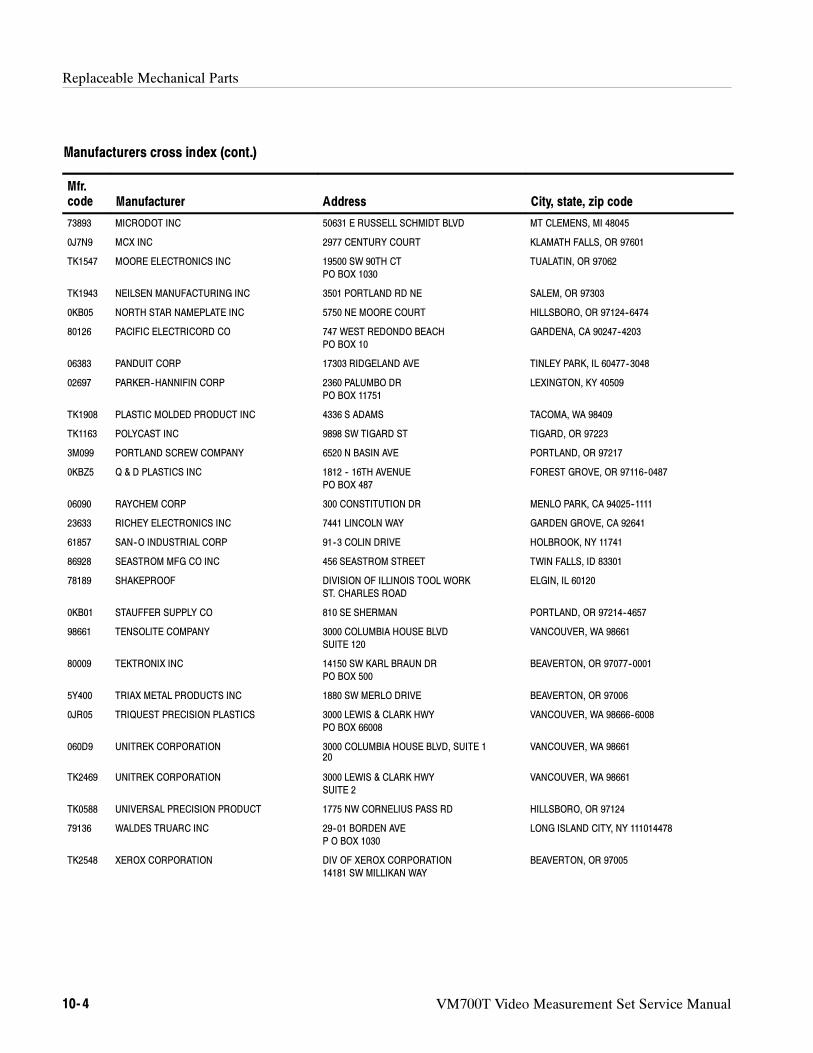
Replaceable Mechanical Parts
10- 4 VM700T Video Measurement Set Service Manual
Manufacturers cross index (cont.)
Mfr.code City, state, zip codeAddressManufacturer
73893 MICRODOT INC 50631 E RUSSELL SCHMIDT BLVD MT CLEMENS, MI 48045
0J7N9 MCX INC 2977 CENTURY COURT KLAMATH FALLS, OR 97601
TK1547 MOORE ELECTRONICS INC 19500 SW 90TH CT
PO BOX 1030
TUALATIN, OR 97062
TK1943 NEILSEN MANUFACTURING INC 3501 PORTLAND RD NE SALEM, OR 97303
0KB05 NORTH STAR NAMEPLATE INC 5750 NE MOORE COURT HILLSBORO, OR 97124--6474
80126 PACIFIC ELECTRICORD CO 747 WEST REDONDO BEACH
PO BOX 10
GARDENA, CA 90247--4203
06383 PANDUIT CORP 17303 RIDGELAND AVE TINLEY PARK, IL 60477--3048
02697 PARKER--HANNIFIN CORP 2360 PALUMBO DR
PO BOX 11751
LEXINGTON, KY 40509
TK1908 PLASTIC MOLDED PRODUCT INC 4336 S ADAMS TACOMA, WA 98409
TK1163 POLYCAST INC 9898 SW TIGARD ST TIGARD, OR 97223
3M099 PORTLAND SCREW COMPANY 6520 N BASIN AVE PORTLAND, OR 97217
0KBZ5 Q & D PLASTICS INC 1812 -- 16TH AVENUE
PO BOX 487
FOREST GROVE, OR 97116--0487
06090 RAYCHEM CORP 300 CONSTITUTION DR MENLO PARK, CA 94025--1111
23633 RICHEY ELECTRONICS INC 7441 LINCOLN WAY GARDEN GROVE, CA 92641
61857 SAN--O INDUSTRIAL CORP 91--3 COLIN DRIVE HOLBROOK, NY 11741
86928 SEASTROM MFG CO INC 456 SEASTROM STREET TWIN FALLS, ID 83301
78189 SHAKEPROOF DIVISION OF ILLINOIS TOOL WORK
ST. CHARLES ROAD
ELGIN, IL 60120
0KB01 STAUFFER SUPPLY CO 810 SE SHERMAN PORTLAND, OR 97214--4657
98661 TENSOLITE COMPANY 3000 COLUMBIA HOUSE BLVD
SUITE 120
VANCOUVER, WA 98661
80009 TEKTRONIX INC 14150 SW KARL BRAUN DR
PO BOX 500
BEAVERTON, OR 97077--0001
5Y400 TRIAX METAL PRODUCTS INC 1880 SW MERLO DRIVE BEAVERTON, OR 97006
0JR05 TRIQUEST PRECISION PLASTICS 3000 LEWIS & CLARK HWY
PO BOX 66008
VANCOUVER, WA 98666--6008
060D9 UNITREK CORPORATION 3000 COLUMBIA HOUSE BLVD, SUITE 120
VANCOUVER, WA 98661
TK2469 UNITREK CORPORATION 3000 LEWIS & CLARK HWY
SUITE 2
VANCOUVER, WA 98661
TK0588 UNIVERSAL PRECISION PRODUCT 1775 NW CORNELIUS PASS RD HILLSBORO, OR 97124
79136 WALDES TRUARC INC 29--01 BORDEN AVE
P O BOX 1030
LONG ISLAND CITY, NY 111014478
TK2548 XEROX CORPORATION DIV OF XEROX CORPORATION
14181 SW MILLIKAN WAY
BEAVERTON, OR 97005
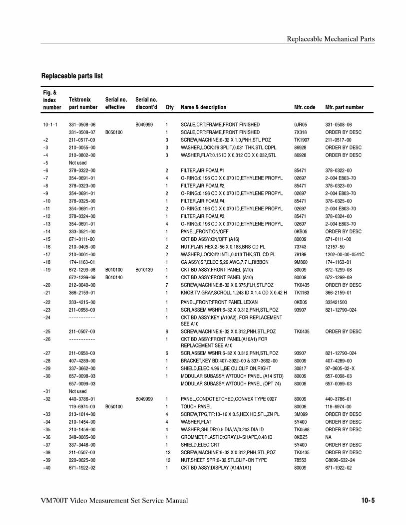
Replaceable Mechanical Parts
VM700T Video Measurement Set Service Manual 10- 5
Replaceable parts list
Fig. &
index
number
Tektronix
part number
Serial no.
effective
Serial no.
discont’d Qty Name & description Mfr. code Mfr. part number
10--1--1 331--0508--06 B049999 1 SCALE,CRT:FRAME,FRONT FINISHED 0JR05 331--0508--06
331--0508--07 B050100 1 SCALE,CRT:FRAME,FRONT FINISHED 7X318 ORDER BY DESC
--2 211--0517--00 3 SCREW,MACHINE:6--32 X 1.0,PNH,STL POZ TK1907 211--0517--00
--3 210--0055--00 3 WASHER,LOCK:#6 SPLIT,0.031 THK,STL CDPL 86928 ORDER BY DESC
--4 210--0802--00 3 WASHER,FLAT:0.15 ID X 0.312 OD X 0.032,STL 86928 ORDER BY DESC
--5 Not used
--6 378--0322--00 2 FILTER,AIR:FOAM,#1 85471 378--0322--00
--7 354--0691--01 4 O--RING:0.196 OD X 0.070 ID,ETHYLENE PROPYL 02697 2--004 E803--70
--8 378--0323--00 1 FILTER,AIR:FOAM,#2, 85471 378--0323--00
--9 354--0691--01 2 O--RING:0.196 OD X 0.070 ID,ETHYLENE PROPYL 02697 2--004 E803--70
--10 378--0325--00 1 FILTER,AIR:FOAM,#4, 85471 378--0325--00
--11 354--0691--01 2 O--RING:0.196 OD X 0.070 ID,ETHYLENE PROPYL 02697 2--004 E803--70
--12 378--0324--00 1 FILTER,AIR:FOAM,#3, 85471 378--0324--00
--13 354--0691--01 4 O--RING:0.196 OD X 0.070 ID,ETHYLENE PROPYL 02697 2--004 E803--70
--14 333--3521--00 1 PANEL,FRONT:ON/OFF 0KB05 ORDER BY DESC
--15 671--0111--00 1 CKT BD ASSY:ON/OFF (A16) 80009 671--0111--00
--16 210--0405--00 2 NUT,PLAIN,HEX:2--56 X 0.188,BRS CD PL 73743 12157--50
--17 210--0001--00 2 WASHER,LOCK:#2 INTL,0.013 THK,STL CD PL 78189 1202--00--00--0541C
--18 174--1163--01 1 CA ASSY,SP,ELEC:5,26 AWG,7.7 L,RIBBON 9M860 174--1163--01
--19 672--1299--08 B010100 B010139 1 CKT BD ASSY:FRONT PANEL (A10) 80009 672--1299--08
672--1299--09 B010140 1 CKT BD ASSY:FRONT PANEL (A10) 80009 672--1299--09
--20 212--0040--00 7 SCREW,MACHINE:8--32 X 0.375,FLH,STLPOZ TK0435 ORDER BY DESC
--21 366--2159--01 1 KNOB:TV GRAY,SCROLL 1.243 ID X 1.4 OD X 0.42 H TK1163 366--2159--01
--22 333--4215--00 1 PANEL,FRONT:FRONT PANEL,LEXAN 0KB05 333421500
--23 211--0658--00 1 SCR,ASSEM WSHR:6--32 X 0.312,PNH,STL,POZ 93907 821--12790--024
--24 -- -- -- -- -- -- -- -- -- -- -- 1 CKT BD ASSY:KEY (A10A2). FOR REPLACEMENT
SEE A10
--25 211--0507--00 6 SCREW,MACHINE:6--32 X 0.312,PNH,STL,POZ TK0435 ORDER BY DESC
--26 -- -- -- -- -- -- -- -- -- -- -- 1 CKT BD ASSY:FRONT PANEL(A10A1) FOR
REPLACEMENT SEE A10
--27 211--0658--00 6 SCR,ASSEM WSHR:6--32 X 0.312,PNH,STL,POZ 93907 821--12790--024
--28 407--4289--00 1 BRACKET,KEY BD:407--3922--00 & 337--3662--00 80009 407--4289--00
--29 337--3662--00 1 SHIELD,ELEC:4.96 L,BE CU,CLIP ON,RIGHT 30817 97--0605--02--X
--30 657--0098--03 1 MODULAR SUBASSY:W/TOUCH PANEL (A14 STD) 80009 657--0098--03
657--0099--03 MODULAR SUBASSY:W/TOUCH PANEL (OPT 74) 80009 657--0099--03
--31 Not used
--32 440--3786--01 B049999 1 PANEL,CONDCT:ETCHED,CONVEX TYPE 0927 80009 440--3786--01
119--6974--00 B050100 1 TOUCH PANEL 80009 119--6974--00
--33 213--1014--00 4 SCREW,TPG,TF:10--16 X 0.5,HEX HD,STL,ZN PL 3M099 ORDER BY DESC
--34 210--1454--00 4 WASHER,FLAT 5Y400 ORDER BY DESC
--35 210--1456--00 4 WASHER,SHLDR:0.5 DIA,W/0.203 DIA ID TK0588 ORDER BY DESC
--36 348--0085--00 1 GROMMET,PLASTIC:GRAY,U--SHAPE,0.48 ID 0KBZ5 NA
--37 337--3448--00 1 SHIELD,ELEC:CRT 5Y400 ORDER BY DESC
--38 211--0507--00 12 SCREW,MACHINE:6--32 X 0.312,PNH,STL,POZ TK0435 ORDER BY DESC
--39 220--0625--00 12 NUT,SHEET SPR:6--32,STLCLIP--ON TYPE 78553 C8090--632--24
--40 671--1922--02 1 CKT BD ASSY:DISPLAY (A14A1A1) 80009 671--1922--02
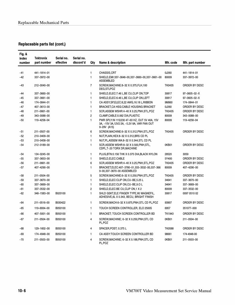
Replaceable Mechanical Parts
10- 6 VM700T Video Measurement Set Service Manual
Replaceable parts list (cont.)
Fig. &
index
number Mfr. part numberMfr. codeName & descriptionQty
Serial no.
discont’d
Serial no.
effective
Tektronix
part number
--41 441--1814--01 1 CHASSIS,CRT 0J260 441--1814--01
--42 337--3972--00 1 SHIELD,EMI:337--3648--00,337--3660--00,337--3661--00ASSEMBLED
80009 337--3972--00
--43 212--0040--00 7 SCREW,MACHINE:8--32 X 0.375,FLH,100DEG,STLPOZ
TK0435 ORDER BY DESC
--44 337--3660--00 1 SHIELD,ELEC:7.46 L,BE CU,CLIP ON,TOP 30817 97--0605--02--X
--45 337--3661--00 1 SHIELD,ELEC:6.46 L,BE CU,CLIP ON,LEFT 30817 97--0605--02--X
--46 174--0844--01 1 CA ASSY,SP,ELEC:8,22 AWG,16.18 L,RIBBON 9M860 174--0844--01
--47 407--3613--00 1 BRACKET,CA HSG:CABLE HOUSING BRACKET 0J260 ORDER BY DESC
--48 211--0661--00 1 SCR,ASSEM WSHR:4--40 X 0.25,PNH,STL,POZ TK0435 ORDER BY DESC
--49 343--0088--00 2 CLAMP,CABLE:0.062 DIA,PLASTIC 80009 343--0088--00
--50 119--4258--04 1 PWR SPLY:IN 115/230 47--63 HZ, OUT 5V 40A, 15V3A, --15V 3A,12V2.5A, --5.2V 8A, VAR FAN OUT9--29V (A15)
80009 119--4258--04
--51 211--0507--00 6 SCREW,MACHINE:6--32 X 0.312,PNH,STL,POZ TK0435 ORDER BY DESC
--52 210--0409--00 1 NUT,PLAIN,HEX:8--32 X 0.312,BRS CD PL
--53 210--0458--00 1 NUT,PL,ASSEM WA:8--32 X 0.344,STL CD PL
--54 212--0189--00 1 SCR,ASSEM WSHR:8--32 X 0.500,PNH,STL,CDPL,T--20 TORX DR,MACHINE
0KB01 ORDER BY DESC
--54 134--0245--00 1 PLUG,BTN:0.156 THK X 0.375 DIA,BLACK NYLON 28520 3059
--55 337--3653--00 1 SHIELD,ELEC:CABLE 5Y400 ORDER BY DESC
--56 211--0661--00 6 SCR,ASSEM WSHR:4--40 X 0.25,PNH,STL,POZ TK0435 ORDER BY DESC
--57 407--4290--00 1 BRACKET,ELEC:407--3780--01,333--3532--00,337--3669--00,337--3670--00 ASSEMBLED
80009 407--4290--00
--58 211--0504--00 5 SCREW,MACHINE:6--32 X 0.250,PNH,STL,POZ TK0435 ORDER BY DESC
--59 337--3670--00 1 SHIELD,ELEC:CLIP ON,CU--BE,5.25 L 34641 337--3670--00
--60 337--3669--00 1 SHIELD,ELEC:CLIP ON,CU--BE,9.O L 34641 337--3669--00
--61 337--3532--00 2 SHIELD,ELEC:BE CU,CLIP ON,1 X 2 80009 337--3532--00
--62 348--1583--00 B020100 1 SHLD GSKT,ELE FINGER TYPE,W/ MAGNEFIL,ADHESIVE,6L X 0.343, BECU, BRIGHT FINISH
30817 0097 0510 02
--64 211--0516--00 B030422 1 SCREW,MACH:6--32 X 0.875,PNH,STL CD PL,POZ 93907 ORDER BY DESC
--65 119--6934--00 B050100 1 TOUCH SCREEN CONTROLLER, ELO 2500S 6957 351077--000
--66 407--5001--00 B050100 1 BRACKET; TOUCH SCREEN CONTROLLER BD TK1943 ORDER BY DESC
--67 211--0504--00 B050100 4 SCREW,MACHINE; 6--32 X 0.250,PNH,STL CDPL,POZ
0KB01 211--0504--00
--68 129--1602--00 B050100 4 SPACER,POST; 0.375 L TK0588 ORDER BY DESC
--69 174--4948--00 B050100 1 CA ASSY:TOUCH SCREEN CONTROLLER BD 98661 174-4948-00
--70 211--0503--00 B050100 4 SCREW,MACHINE; 6--32 X 0.188,PNH,STL CDPL,POZ
0KB01 211--0503--00
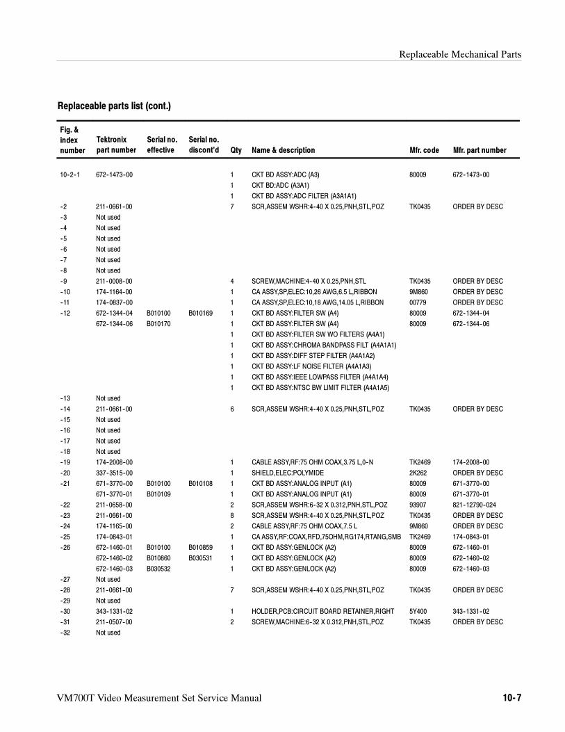
Replaceable Mechanical Parts
VM700T Video Measurement Set Service Manual 10- 7
Replaceable parts list (cont.)
Fig. &
index
number Mfr. part numberMfr. codeName & descriptionQty
Serial no.
discont’d
Serial no.
effective
Tektronix
part number
10--2--1 672--1473--00 1 CKT BD ASSY:ADC (A3) 80009 672--1473--00
1 CKT BD:ADC (A3A1)
1 CKT BD ASSY:ADC FILTER (A3A1A1)
--2 211--0661--00 7 SCR,ASSEM WSHR:4--40 X 0.25,PNH,STL,POZ TK0435 ORDER BY DESC
--3 Not used
--4 Not used
--5 Not used
--6 Not used
--7 Not used
--8 Not used
--9 211--0008--00 4 SCREW,MACHINE:4--40 X 0.25,PNH,STL TK0435 ORDER BY DESC
--10 174--1164--00 1 CA ASSY,SP,ELEC:10,26 AWG,6.5 L,RIBBON 9M860 ORDER BY DESC
--11 174--0837--00 1 CA ASSY,SP,ELEC:10,18 AWG,14.05 L,RIBBON 00779 ORDER BY DESC
--12 672--1344--04 B010100 B010169 1 CKT BD ASSY:FILTER SW (A4) 80009 672--1344--04
672--1344--06 B010170 1 CKT BD ASSY:FILTER SW (A4) 80009 672--1344--06
1 CKT BD ASSY:FILTER SW WO FILTERS (A4A1)
1 CKT BD ASSY:CHROMA BANDPASS FILT (A4A1A1)
1 CKT BD ASSY:DIFF STEP FILTER (A4A1A2)
1 CKT BD ASSY:LF NOISE FILTER (A4A1A3)
1 CKT BD ASSY:IEEE LOWPASS FILTER (A4A1A4)
1 CKT BD ASSY:NTSC BW LIMIT FILTER (A4A1A5)
--13 Not used
--14 211--0661--00 6 SCR,ASSEM WSHR:4--40 X 0.25,PNH,STL,POZ TK0435 ORDER BY DESC
--15 Not used
--16 Not used
--17 Not used
--18 Not used
--19 174--2008--00 1 CABLE ASSY,RF:75 OHM COAX,3.75 L,0--N TK2469 174--2008--00
--20 337--3515--00 1 SHIELD,ELEC:POLYMIDE 2K262 ORDER BY DESC
--21 671--3770--00 B010100 B010108 1 CKT BD ASSY:ANALOG INPUT (A1) 80009 671--3770--00
671--3770--01 B010109 1 CKT BD ASSY:ANALOG INPUT (A1) 80009 671--3770--01
--22 211--0658--00 2 SCR,ASSEM WSHR:6--32 X 0.312,PNH,STL,POZ 93907 821--12790--024
--23 211--0661--00 8 SCR,ASSEM WSHR:4--40 X 0.25,PNH,STL,POZ TK0435 ORDER BY DESC
--24 174--1165--00 2 CABLE ASSY,RF:75 OHM COAX,7.5 L 9M860 ORDER BY DESC
--25 174--0843--01 1 CA ASSY,RF:COAX,RFD,75OHM,RG174,RTANG,SMB TK2469 174--0843--01
--26 672--1460--01 B010100 B010859 1 CKT BD ASSY:GENLOCK (A2) 80009 672--1460--01
672--1460--02 B010860 B030531 1 CKT BD ASSY:GENLOCK (A2) 80009 672--1460--02
672--1460--03 B030532 1 CKT BD ASSY:GENLOCK (A2) 80009 672--1460--03
--27 Not used
--28 211--0661--00 7 SCR,ASSEM WSHR:4--40 X 0.25,PNH,STL,POZ TK0435 ORDER BY DESC
--29 Not used
--30 343--1331--02 1 HOLDER,PCB:CIRCUIT BOARD RETAINER,RIGHT 5Y400 343--1331--02
--31 211--0507--00 2 SCREW,MACHINE:6--32 X 0.312,PNH,STL,POZ TK0435 ORDER BY DESC
--32 Not used
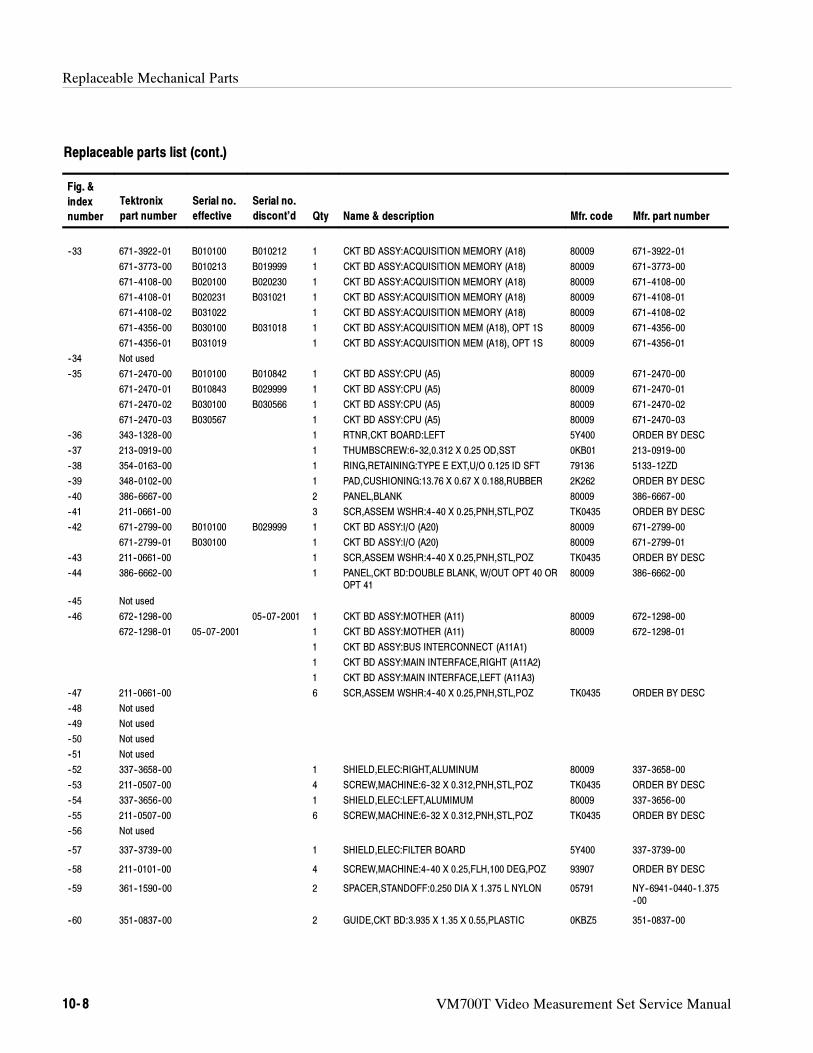
Replaceable Mechanical Parts
10- 8 VM700T Video Measurement Set Service Manual
Replaceable parts list (cont.)
Fig. &
index
number Mfr. part numberMfr. codeName & descriptionQty
Serial no.
discont’d
Serial no.
effective
Tektronix
part number
--33 671--3922--01 B010100 B010212 1 CKT BD ASSY:ACQUISITION MEMORY (A18) 80009 671--3922--01
671--3773--00 B010213 B019999 1 CKT BD ASSY:ACQUISITION MEMORY (A18) 80009 671--3773--00
671--4108--00 B020100 B020230 1 CKT BD ASSY:ACQUISITION MEMORY (A18) 80009 671--4108--00
671--4108--01 B020231 B031021 1 CKT BD ASSY:ACQUISITION MEMORY (A18) 80009 671--4108--01
671--4108--02 B031022 1 CKT BD ASSY:ACQUISITION MEMORY (A18) 80009 671--4108--02
671--4356--00 B030100 B031018 1 CKT BD ASSY:ACQUISITION MEM (A18), OPT 1S 80009 671--4356--00
671--4356--01 B031019 1 CKT BD ASSY:ACQUISITION MEM (A18), OPT 1S 80009 671--4356--01
--34 Not used
--35 671--2470--00 B010100 B010842 1 CKT BD ASSY:CPU (A5) 80009 671--2470--00
671--2470--01 B010843 B029999 1 CKT BD ASSY:CPU (A5) 80009 671--2470--01
671--2470--02 B030100 B030566 1 CKT BD ASSY:CPU (A5) 80009 671--2470--02
671--2470--03 B030567 1 CKT BD ASSY:CPU (A5) 80009 671--2470--03
--36 343--1328--00 1 RTNR,CKT BOARD:LEFT 5Y400 ORDER BY DESC
--37 213--0919--00 1 THUMBSCREW:6--32,0.312 X 0.25 OD,SST 0KB01 213--0919--00
--38 354--0163--00 1 RING,RETAINING:TYPE E EXT,U/O 0.125 ID SFT 79136 5133--12ZD
--39 348--0102--00 1 PAD,CUSHIONING:13.76 X 0.67 X 0.188,RUBBER 2K262 ORDER BY DESC
--40 386--6667--00 2 PANEL,BLANK 80009 386--6667--00
--41 211--0661--00 3 SCR,ASSEM WSHR:4--40 X 0.25,PNH,STL,POZ TK0435 ORDER BY DESC
--42 671--2799--00 B010100 B029999 1 CKT BD ASSY:I/O (A20) 80009 671--2799--00
671--2799--01 B030100 1 CKT BD ASSY:I/O (A20) 80009 671--2799--01
--43 211--0661--00 1 SCR,ASSEM WSHR:4--40 X 0.25,PNH,STL,POZ TK0435 ORDER BY DESC
--44 386--6662--00 1 PANEL,CKT BD:DOUBLE BLANK, W/OUT OPT 40 OROPT 41
80009 386--6662--00
--45 Not used
--46 672--1298--00 05--07--2001 1 CKT BD ASSY:MOTHER (A11) 80009 672--1298--00
672--1298--01 05--07--2001 1 CKT BD ASSY:MOTHER (A11) 80009 672--1298--01
1 CKT BD ASSY:BUS INTERCONNECT (A11A1)
1 CKT BD ASSY:MAIN INTERFACE,RIGHT (A11A2)
1 CKT BD ASSY:MAIN INTERFACE,LEFT (A11A3)
--47 211--0661--00 6 SCR,ASSEM WSHR:4--40 X 0.25,PNH,STL,POZ TK0435 ORDER BY DESC
--48 Not used
--49 Not used
--50 Not used
--51 Not used
--52 337--3658--00 1 SHIELD,ELEC:RIGHT,ALUMINUM 80009 337--3658--00
--53 211--0507--00 4 SCREW,MACHINE:6--32 X 0.312,PNH,STL,POZ TK0435 ORDER BY DESC
--54 337--3656--00 1 SHIELD,ELEC:LEFT,ALUMIMUM 80009 337--3656--00
--55 211--0507--00 6 SCREW,MACHINE:6--32 X 0.312,PNH,STL,POZ TK0435 ORDER BY DESC
--56 Not used
--57 337--3739--00 1 SHIELD,ELEC:FILTER BOARD 5Y400 337--3739--00
--58 211--0101--00 4 SCREW,MACHINE:4--40 X 0.25,FLH,100 DEG,POZ 93907 ORDER BY DESC
--59 361--1590--00 2 SPACER,STANDOFF:0.250 DIA X 1.375 L NYLON 05791 NY--6941--0440--1.375--00
--60 351--0837--00 2 GUIDE,CKT BD:3.935 X 1.35 X 0.55,PLASTIC 0KBZ5 351--0837--00
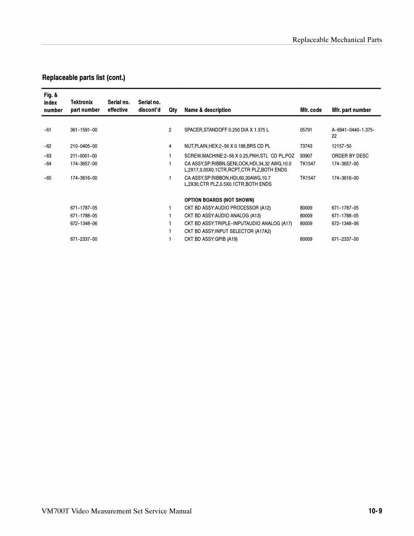
Replaceable Mechanical Parts
VM700T Video Measurement Set Service Manual 10- 9
Replaceable parts list (cont.)
Fig. &
index
number Mfr. part numberMfr. codeName & descriptionQty
Serial no.
discont’d
Serial no.
effective
Tektronix
part number
--61 361--1591--00 2 SPACER,STANDOFF:0.250 DIA X 1.375 L 05791 A--6941--0440--1.375--22
--62 210--0405--00 4 NUT,PLAIN,HEX:2--56 X 0.188,BRS CD PL 73743 12157--50
--63 211--0001--00 1 SCREW,MACHINE:2--56 X 0.25,PNH,STL CD PL,POZ 93907 ORDER BY DESC
--64 174--3657--00 1 CA ASSY,SP:RIBBN,GENLOCK,HDI,34,32 AWG,10.0L,2X17,0.05X0.1CTR,RCPT,CTR PLZ,BOTH ENDS
TK1547 174--3657--00
--65 174--3616--00 1 CA ASSY,SP:RIBBON,HDI,60,30AWG,10.7L,2X30,CTR PLZ,0.5X0.1CTR,BOTH ENDS
TK1547 174--3616--00
OPTION BOARDS (NOT SHOWN)
671--1787--05 1 CKT BD ASSY:AUDIO PROCESSOR (A12) 80009 671--1787--05
671--1788--05 1 CKT BD ASSY:AUDIO ANALOG (A13) 80009 671--1788--05
672--1348--06 1 CKT BD ASSY:TRIPLE--INPUTAUDIO ANALOG (A17) 80009 672--1348--06
1 CKT BD ASSY:INPUT SELECTOR (A17A2)
671--2337--00 1 CKT BD ASSY:GPIB (A19) 80009 671--2337--00
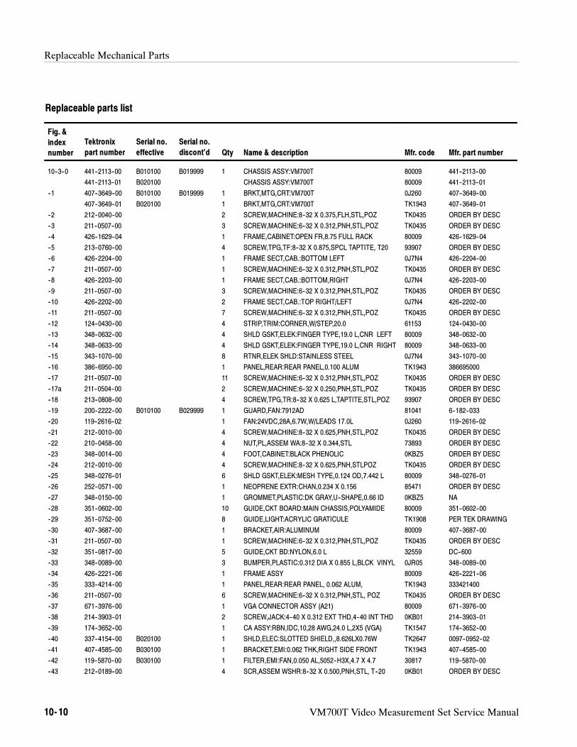
Replaceable Mechanical Parts
10- 10 VM700T Video Measurement Set Service Manual
Replaceable parts list
Fig. &
index
number
Tektronix
part number
Serial no.
effective
Serial no.
discont’d Qty Name & description Mfr. code Mfr. part number
10--3--0 441--2113--00 B010100 B019999 1 CHASSIS ASSY:VM700T 80009 441--2113--00
441--2113--01 B020100 CHASSIS ASSY:VM700T 80009 441--2113--01
--1 407--3649--00 B010100 B019999 1 BRKT,MTG,CRT:VM700T 0J260 407--3649--00
407--3649--01 B020100 1 BRKT,MTG,CRT:VM700T TK1943 407--3649--01
--2 212--0040--00 2 SCREW,MACHINE:8--32 X 0.375,FLH,STL,POZ TK0435 ORDER BY DESC
--3 211--0507--00 3 SCREW,MACHINE:6--32 X 0.312,PNH,STL,POZ TK0435 ORDER BY DESC
--4 426--1629--04 1 FRAME,CABINET:OPEN FR,8.75 FULL RACK 80009 426--1629--04
--5 213--0760--00 4 SCREW,TPG,TF:8--32 X 0.875,SPCL TAPTITE, T20 93907 ORDER BY DESC
--6 426--2204--00 1 FRAME SECT,CAB.:BOTTOM LEFT 0J7N4 426--2204--00
--7 211--0507--00 1 SCREW,MACHINE:6--32 X 0.312,PNH,STL,POZ TK0435 ORDER BY DESC
--8 426--2203--00 1 FRAME SECT,CAB.:BOTTOM,RIGHT 0J7N4 426--2203--00
--9 211--0507--00 3 SCREW,MACHINE:6--32 X 0.312,PNH,STL,POZ TK0435 ORDER BY DESC
--10 426--2202--00 2 FRAME SECT,CAB.:TOP RIGHT/LEFT 0J7N4 426--2202--00
--11 211--0507--00 7 SCREW,MACHINE:6--32 X 0.312,PNH,STL,POZ TK0435 ORDER BY DESC
--12 124--0430--00 4 STRIP,TRIM:CORNER,W/STEP,20.0 61153 124--0430--00
--13 348--0632--00 4 SHLD GSKT,ELEK:FINGER TYPE,19.0 L,CNR LEFT 80009 348--0632--00
--14 348--0633--00 4 SHLD GSKT,ELEK:FINGER TYPE,19.0 L,CNR RIGHT 80009 348--0633--00
--15 343--1070--00 8 RTNR,ELEK SHLD:STAINLESS STEEL 0J7N4 343--1070--00
--16 386--6950--00 1 PANEL,REAR:REAR PANEL,0.100 ALUM TK1943 386695000
--17 211--0507--00 11 SCREW,MACHINE:6--32 X 0.312,PNH,STL,POZ TK0435 ORDER BY DESC
--17a 211--0504--00 2 SCREW,MACHINE:6--32 X 0.250,PNH,STL,POZ TK0435 ORDER BY DESC
--18 213--0808--00 4 SCREW,TPG,TR:8--32 X 0.625 L,TAPTITE,STL,POZ 93907 ORDER BY DESC
--19 200--2222--00 B010100 B029999 1 GUARD,FAN:7912AD 81041 6--182--033
--20 119--2616--02 1 FAN:24VDC,28A,6.7W,W/LEADS 17.0L 0J260 119--2616--02
--21 212--0010--00 4 SCREW,MACHINE:8--32 X 0.625,PNH,STL,POZ TK0435 ORDER BY DESC
--22 210--0458--00 4 NUT,PL,ASSEM WA:8--32 X 0.344,STL 73893 ORDER BY DESC
--23 348--0014--00 4 FOOT,CABINET:BLACK PHENOLIC 0KBZ5 ORDER BY DESC
--24 212--0010--00 4 SCREW,MACHINE:8--32 X 0.625,PNH,STLPOZ TK0435 ORDER BY DESC
--25 348--0276--01 6 SHLD GSKT,ELEK:MESH TYPE,0.124 OD,7.442 L 80009 348--0276--01
--26 252--0571--00 1 NEOPRENE EXTR:CHAN,0.234 X 0.156 85471 ORDER BY DESC
--27 348--0150--00 1 GROMMET,PLASTIC:DK GRAY,U--SHAPE,0.66 ID 0KBZ5 NA
--28 351--0602--00 10 GUIDE,CKT BOARD:MAIN CHASSIS,POLYAMIDE 80009 351--0602--00
--29 351--0752--00 8 GUIDE,LIGHT:ACRYLIC GRATICULE TK1908 PER TEK DRAWING
--30 407--3687--00 1 BRACKET,AIR:ALUMINUM 80009 407--3687--00
--31 211--0507--00 1 SCREW,MACHINE:6--32 X 0.312,PNH,STL,POZ TK0435 ORDER BY DESC
--32 351--0817--00 5 GUIDE,CKT BD:NYLON,6.0 L 32559 DC--600
--33 348--0089--00 3 BUMPER,PLASTIC:0.312 DIA X 0.855 L,BLCK VINYL 0JR05 348--0089--00
--34 426--2221--06 1 FRAME ASSY 80009 426--2221--06
--35 333--4214--00 1 PANEL,REAR:REAR PANEL, 0.062 ALUM, TK1943 333421400
--36 211--0507--00 6 SCREW,MACHINE:6--32 X 0.312,PNH,STL, POZ TK0435 ORDER BY DESC
--37 671--3976--00 1 VGA CONNECTOR ASSY (A21) 80009 671--3976--00
--38 214--3903--01 2 SCREW,JACK:4--40 X 0.312 EXT THD,4--40 INT THD 0KB01 214--3903--01
--39 174--3652--00 1 CA ASSY:RBN,IDC,10,28 AWG,24.0 L,2X5 (VGA) TK1547 174--3652--00
--40 337--4154--00 B020100 1 SHLD,ELEC:SLOTTED SHIELD,,8.626LX0.76W TK2647 0097--0952--02
--41 407--4585--00 B030100 1 BRACKET,EMI:0.062 THK,RIGHT SIDE FRONT TK1943 407--4585--00
--42 119--5870--00 B030100 1 FILTER,EMI:FAN,0.050 AL,5052--H3X,4.7 X 4.7 30817 119--5870--00
--43 212--0189--00 4 SCR,ASSEM WSHR:8--32 X 0.500,PNH,STL, T--20 0KB01 ORDER BY DESC
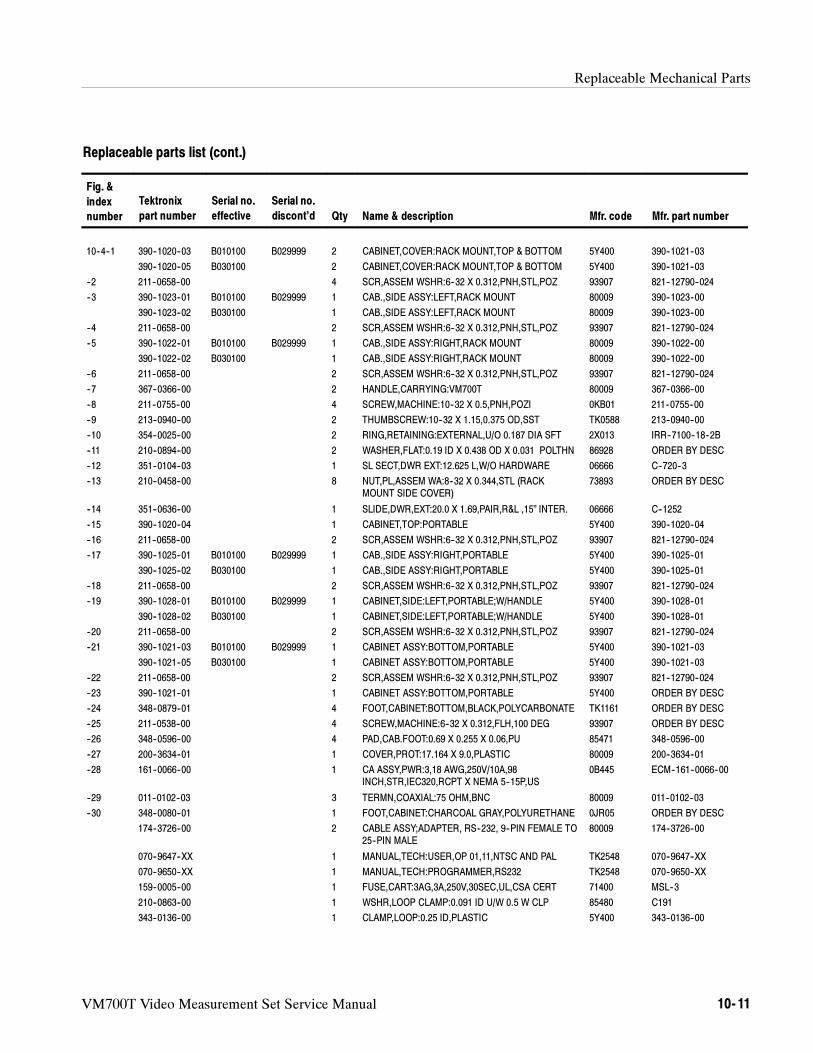
Replaceable Mechanical Parts
VM700T Video Measurement Set Service Manual 10- 11
Replaceable parts list (cont.)
Fig. &
index
number Mfr. part numberMfr. codeName & descriptionQty
Serial no.
discont’d
Serial no.
effective
Tektronix
part number
10--4--1 390--1020--03 B010100 B029999 2 CABINET,COVER:RACK MOUNT,TOP & BOTTOM 5Y400 390--1021--03
390--1020--05 B030100 2 CABINET,COVER:RACK MOUNT,TOP & BOTTOM 5Y400 390--1021--03
--2 211--0658--00 4 SCR,ASSEM WSHR:6--32 X 0.312,PNH,STL,POZ 93907 821--12790--024
--3 390--1023--01 B010100 B029999 1 CAB.,SIDE ASSY:LEFT,RACK MOUNT 80009 390--1023--00
390--1023--02 B030100 1 CAB.,SIDE ASSY:LEFT,RACK MOUNT 80009 390--1023--00
--4 211--0658--00 2 SCR,ASSEM WSHR:6--32 X 0.312,PNH,STL,POZ 93907 821--12790--024
--5 390--1022--01 B010100 B029999 1 CAB.,SIDE ASSY:RIGHT,RACK MOUNT 80009 390--1022--00
390--1022--02 B030100 1 CAB.,SIDE ASSY:RIGHT,RACK MOUNT 80009 390--1022--00
--6 211--0658--00 2 SCR,ASSEM WSHR:6--32 X 0.312,PNH,STL,POZ 93907 821--12790--024
--7 367--0366--00 2 HANDLE,CARRYING:VM700T 80009 367--0366--00
--8 211--0755--00 4 SCREW,MACHINE:10--32 X 0.5,PNH,POZI 0KB01 211--0755--00
--9 213--0940--00 2 THUMBSCREW:10--32 X 1.15,0.375 OD,SST TK0588 213--0940--00
--10 354--0025--00 2 RING,RETAINING:EXTERNAL,U/O 0.187 DIA SFT 2X013 IRR--7100--18--2B
--11 210--0894--00 2 WASHER,FLAT:0.19 ID X 0.438 OD X 0.031 POLTHN 86928 ORDER BY DESC
--12 351--0104--03 1 SL SECT,DWR EXT:12.625 L,W/O HARDWARE 06666 C--720--3
--13 210--0458--00 8 NUT,PL,ASSEM WA:8--32 X 0.344,STL (RACKMOUNT SIDE COVER)
73893 ORDER BY DESC
--14 351--0636--00 1 SLIDE,DWR,EXT:20.0 X 1.69,PAIR,R&L ,15” INTER. 06666 C--1252
--15 390--1020--04 1 CABINET,TOP:PORTABLE 5Y400 390--1020--04
--16 211--0658--00 2 SCR,ASSEM WSHR:6--32 X 0.312,PNH,STL,POZ 93907 821--12790--024
--17 390--1025--01 B010100 B029999 1 CAB.,SIDE ASSY:RIGHT,PORTABLE 5Y400 390--1025--01
390--1025--02 B030100 1 CAB.,SIDE ASSY:RIGHT,PORTABLE 5Y400 390--1025--01
--18 211--0658--00 2 SCR,ASSEM WSHR:6--32 X 0.312,PNH,STL,POZ 93907 821--12790--024
--19 390--1028--01 B010100 B029999 1 CABINET,SIDE:LEFT,PORTABLE;W/HANDLE 5Y400 390--1028--01
390--1028--02 B030100 1 CABINET,SIDE:LEFT,PORTABLE;W/HANDLE 5Y400 390--1028--01
--20 211--0658--00 2 SCR,ASSEM WSHR:6--32 X 0.312,PNH,STL,POZ 93907 821--12790--024
--21 390--1021--03 B010100 B029999 1 CABINET ASSY:BOTTOM,PORTABLE 5Y400 390--1021--03
390--1021--05 B030100 1 CABINET ASSY:BOTTOM,PORTABLE 5Y400 390--1021--03
--22 211--0658--00 2 SCR,ASSEM WSHR:6--32 X 0.312,PNH,STL,POZ 93907 821--12790--024
--23 390--1021--01 1 CABINET ASSY:BOTTOM,PORTABLE 5Y400 ORDER BY DESC
--24 348--0879--01 4 FOOT,CABINET:BOTTOM,BLACK,POLYCARBONATE TK1161 ORDER BY DESC
--25 211--0538--00 4 SCREW,MACHINE:6--32 X 0.312,FLH,100 DEG 93907 ORDER BY DESC
--26 348--0596--00 4 PAD,CAB.FOOT:0.69 X 0.255 X 0.06,PU 85471 348--0596--00
--27 200--3634--01 1 COVER,PROT:17.164 X 9.0,PLASTIC 80009 200--3634--01
--28 161--0066--00 1 CA ASSY,PWR:3,18 AWG,250V/10A,98INCH,STR,IEC320,RCPT X NEMA 5--15P,US
0B445 ECM--161--0066--00
--29 011--0102--03 3 TERMN,COAXIAL:75 OHM,BNC 80009 011--0102--03
--30 348--0080--01 1 FOOT,CABINET:CHARCOAL GRAY,POLYURETHANE 0JR05 ORDER BY DESC
174--3726--00 2 CABLE ASSY;ADAPTER, RS--232, 9--PIN FEMALE TO25--PIN MALE
80009 174--3726--00
070--9647--XX 1 MANUAL,TECH:USER,OP 01,11,NTSC AND PAL TK2548 070--9647--XX
070--9650--XX 1 MANUAL,TECH:PROGRAMMER,RS232 TK2548 070--9650--XX
159--0005--00 1 FUSE,CART:3AG,3A,250V,30SEC,UL,CSA CERT 71400 MSL--3
210--0863--00 1 WSHR,LOOP CLAMP:0.091 ID U/W 0.5 W CLP 85480 C191
343--0136--00 1 CLAMP,LOOP:0.25 ID,PLASTIC 5Y400 343--0136--00
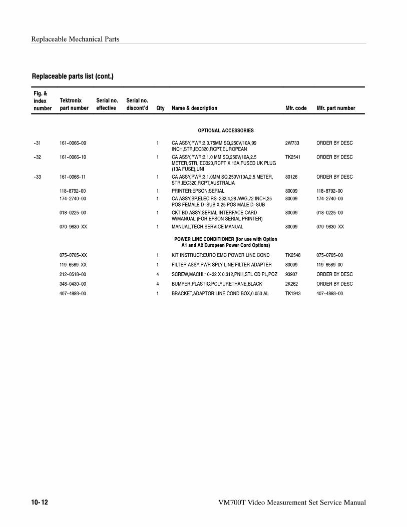
Replaceable Mechanical Parts
10- 12 VM700T Video Measurement Set Service Manual
Replaceable parts list (cont.)
Fig. &
index
number Mfr. part numberMfr. codeName & descriptionQty
Serial no.
discont’d
Serial no.
effective
Tektronix
part number
OPTIONAL ACCESSORIES
--31 161--0066--09 1 CA ASSY,PWR:3,0.75MM SQ,250V/10A,99INCH,STR,IEC320,RCPT,EUROPEAN
2W733 ORDER BY DESC
--32 161--0066--10 1 CA ASSY,PWR:3,1.0 MM SQ,250V/10A,2.5METER,STR,IEC320,RCPT X 13A,FUSED UK PLUG(13A FUSE),UNI
TK2541 ORDER BY DESC
--33 161--0066--11 1 CA ASSY,PWR:3,1.0MM SQ,250V/10A,2.5 METER,STR,IEC320,RCPT,AUSTRALIA
80126 ORDER BY DESC
118--8792--00 1 PRINTER:EPSON;SERIAL 80009 118--8792--00
174--2740--00 1 CA ASSY,SP,ELEC:RS--232,4,28 AWG,72 INCH,25POS FEMALE D--SUB X 25 POS MALE D--SUB
80009 174--2740--00
018--0225--00 1 CKT BD ASSY:SERIAL INTERFACE CARDW/MANUAL (FOR EPSON SERIAL PRINTER)
80009 018--0225--00
070--9630--XX 1 MANUAL,TECH:SERVICE MANUAL 80009 070--9630--XX
POWER LINE CONDITIONER (for use with OptionA1 and A2 European Power Cord Options)
075--0705--XX 1 KIT INSTRUCT:EURO EMC POWER LINE COND TK2548 075--0705--00
119--6589--XX 1 FILTER ASSY:PWR SPLY LINE FILTER ADAPTER 80009 119--6589--00
212--0518--00 4 SCREW,MACHI:10--32 X 0.312,PNH,STL CD PL,POZ 93907 ORDER BY DESC
348--0430--00 4 BUMPER,PLASTIC:POLYURETHANE,BLACK 2K262 ORDER BY DESC
407--4893--00 1 BRACKET,ADAPTOR:LINE COND BOX,0.050 AL TK1943 407--4893--00
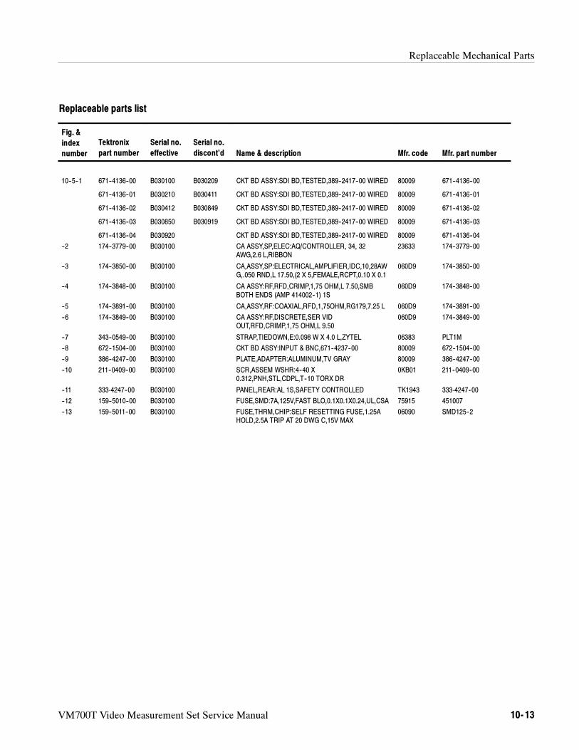
Replaceable Mechanical Parts
VM700T Video Measurement Set Service Manual 10- 13
Replaceable parts list
Fig. &
index
number
Tektronix
part number
Serial no.
effective
Serial no.
discont’d Name & description Mfr. code Mfr. part number
10--5--1 671--4136--00 B030100 B030209 CKT BD ASSY:SDI BD,TESTED,389--2417--00 WIRED 80009 671--4136--00
671--4136--01 B030210 B030411 CKT BD ASSY:SDI BD,TESTED,389--2417--00 WIRED 80009 671--4136--01
671--4136--02 B030412 B030849 CKT BD ASSY:SDI BD,TESTED,389--2417--00 WIRED 80009 671--4136--02
671--4136--03 B030850 B030919 CKT BD ASSY:SDI BD,TESTED,389--2417--00 WIRED 80009 671--4136--03
671--4136--04 B030920 CKT BD ASSY:SDI BD,TESTED,389--2417--00 WIRED 80009 671--4136--04
--2 174--3779--00 B030100 CA ASSY,SP,ELEC:AQ/CONTROLLER, 34, 32AWG,2.6 L,RIBBON
23633 174--3779--00
--3 174--3850--00 B030100 CA,ASSY,SP:ELECTRICAL,AMPLIFIER,IDC,10,28AWG,.050 RND,L 17.50,(2 X 5,FEMALE,RCPT,0.10 X 0.1
060D9 174--3850--00
--4 174--3848--00 B030100 CA ASSY:RF,RFD,CRIMP,1,75 OHM,L 7.50,SMBBOTH ENDS (AMP 414002--1) 1S
060D9 174--3848--00
--5 174--3891--00 B030100 CA,ASSY,RF:COAXIAL,RFD,1,75OHM,RG179,7.25 L 060D9 174--3891--00
--6 174--3849--00 B030100 CA ASSY:RF,DISCRETE,SER VIDOUT,RFD,CRIMP,1,75 OHM,L 9.50
060D9 174--3849--00
--7 343--0549--00 B030100 STRAP,TIEDOWN,E:0.098 W X 4.0 L,ZYTEL 06383 PLT1M
--8 672--1504--00 B030100 CKT BD ASSY:INPUT & BNC,671--4237--00 80009 672--1504--00
--9 386--4247--00 B030100 PLATE,ADAPTER:ALUMINUM,TV GRAY 80009 386--4247--00
--10 211--0409--00 B030100 SCR,ASSEM WSHR:4--40 X0.312,PNH,STL,CDPL,T--10 TORX DR
0KB01 211--0409--00
--11 333-4247--00 B030100 PANEL,REAR:AL 1S,SAFETY CONTROLLED TK1943 333-4247--00
--12 159--5010--00 B030100 FUSE,SMD:7A,125V,FAST BLO,0.1X0.1X0.24,UL,CSA 75915 451007
--13 159--5011--00 B030100 FUSE,THRM,CHIP:SELF RESETTING FUSE,1.25AHOLD,2.5A TRIP AT 20 DWG C,15V MAX
06090 SMD125--2
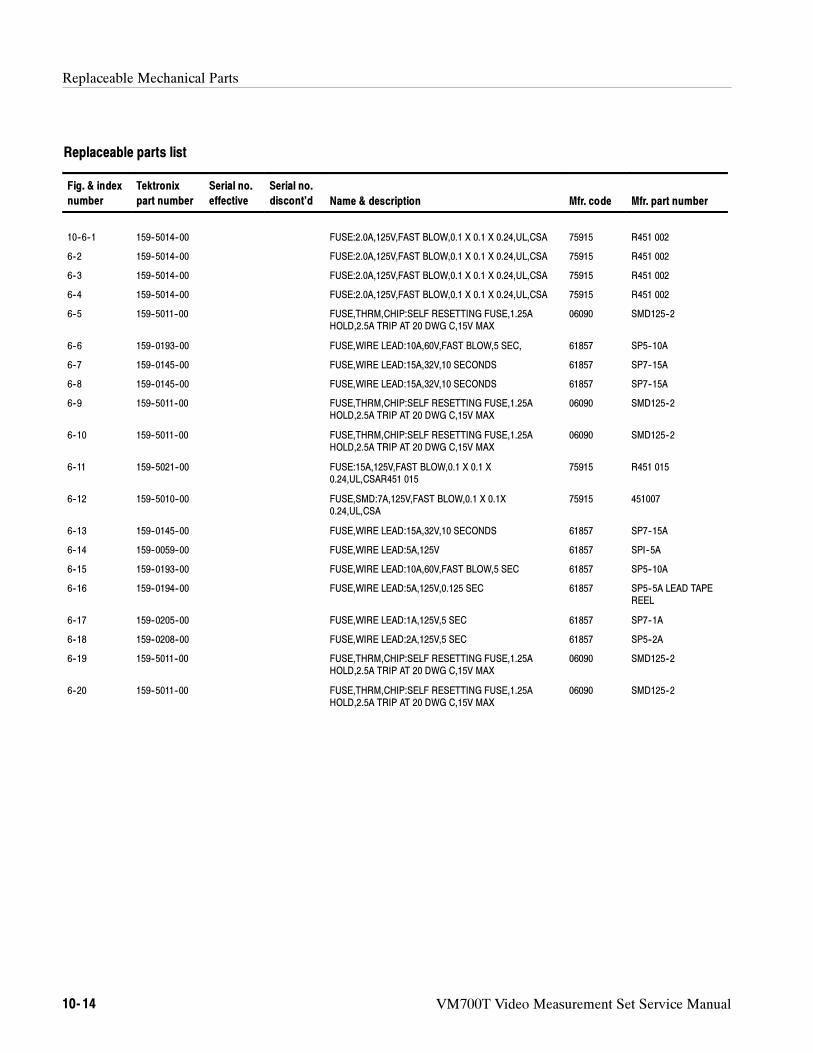
Replaceable Mechanical Parts
10- 14 VM700T Video Measurement Set Service Manual
Replaceable parts list
Fig. & index
number
Tektronix
part number
Serial no.
effective
Serial no.
discont’d Name & description Mfr. code Mfr. part number
10--6--1 159--5014--00 FUSE:2.0A,125V,FAST BLOW,0.1 X 0.1 X 0.24,UL,CSA 75915 R451 002
6--2 159--5014--00 FUSE:2.0A,125V,FAST BLOW,0.1 X 0.1 X 0.24,UL,CSA 75915 R451 002
6--3 159--5014--00 FUSE:2.0A,125V,FAST BLOW,0.1 X 0.1 X 0.24,UL,CSA 75915 R451 002
6--4 159--5014--00 FUSE:2.0A,125V,FAST BLOW,0.1 X 0.1 X 0.24,UL,CSA 75915 R451 002
6--5 159--5011--00 FUSE,THRM,CHIP:SELF RESETTING FUSE,1.25AHOLD,2.5A TRIP AT 20 DWG C,15V MAX
06090 SMD125--2
6--6 159--0193--00 FUSE,WIRE LEAD:10A,60V,FAST BLOW,5 SEC, 61857 SP5--10A
6--7 159--0145--00 FUSE,WIRE LEAD:15A,32V,10 SECONDS 61857 SP7--15A
6--8 159--0145--00 FUSE,WIRE LEAD:15A,32V,10 SECONDS 61857 SP7--15A
6--9 159--5011--00 FUSE,THRM,CHIP:SELF RESETTING FUSE,1.25AHOLD,2.5A TRIP AT 20 DWG C,15V MAX
06090 SMD125--2
6--10 159--5011--00 FUSE,THRM,CHIP:SELF RESETTING FUSE,1.25AHOLD,2.5A TRIP AT 20 DWG C,15V MAX
06090 SMD125--2
6--11 159--5021--00 FUSE:15A,125V,FAST BLOW,0.1 X 0.1 X0.24,UL,CSAR451 015
75915 R451 015
6--12 159--5010--00 FUSE,SMD:7A,125V,FAST BLOW,0.1 X 0.1X0.24,UL,CSA
75915 451007
6--13 159--0145--00 FUSE,WIRE LEAD:15A,32V,10 SECONDS 61857 SP7--15A
6--14 159--0059--00 FUSE,WIRE LEAD:5A,125V 61857 SPI--5A
6--15 159--0193--00 FUSE,WIRE LEAD:10A,60V,FAST BLOW,5 SEC 61857 SP5--10A
6--16 159--0194--00 FUSE,WIRE LEAD:5A,125V,0.125 SEC 61857 SP5--5A LEAD TAPEREEL
6--17 159--0205--00 FUSE,WIRE LEAD:1A,125V,5 SEC 61857 SP7--1A
6--18 159--0208--00 FUSE,WIRE LEAD:2A,125V,5 SEC 61857 SP5--2A
6--19 159--5011--00 FUSE,THRM,CHIP:SELF RESETTING FUSE,1.25AHOLD,2.5A TRIP AT 20 DWG C,15V MAX
06090 SMD125--2
6--20 159--5011--00 FUSE,THRM,CHIP:SELF RESETTING FUSE,1.25AHOLD,2.5A TRIP AT 20 DWG C,15V MAX
06090 SMD125--2
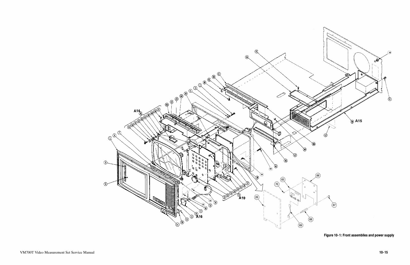
VM700T Video Measurement Set Service Manual 10- 15
14
53
54
52
55
A15
64
70
65
66
68
67
69
26
Figure 10- 1: Front assemblies and power supply

10- 16 VM700T Video Measurement Set Service Manual
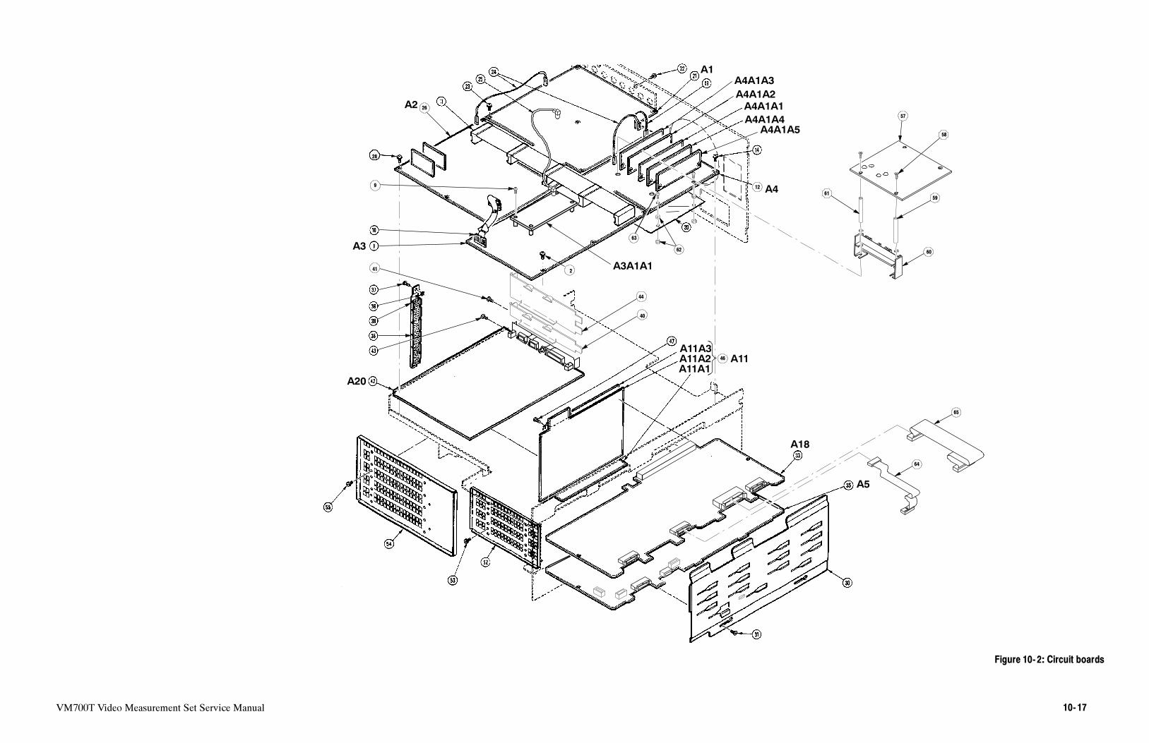
VM700T Video Measurement Set Service Manual 10- 17
A18
A5
A20
9
A3
A2
A1
A4A1A3
A4A1A2
A4A1A1
A4A1A4
A4A1A5
A4
57
58
6159
60
12
A3A1A1
63
64
65
62
26
28
2
40
41
44
A11A3
A11A2
A11A1
46 A11
Figure 10- 2: Circuit boards

10- 18 VM700T Video Measurement Set Service Manual
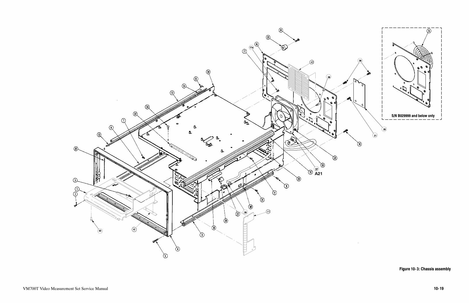
VM700T Video Measurement Set Service Manual 10- 19
17a
21
36
35
38
37
A21
39
S/N B029999 and below only
43
Figure 10- 3: Chassis assembly

10- 20 VM700T Video Measurement Set Service Manual
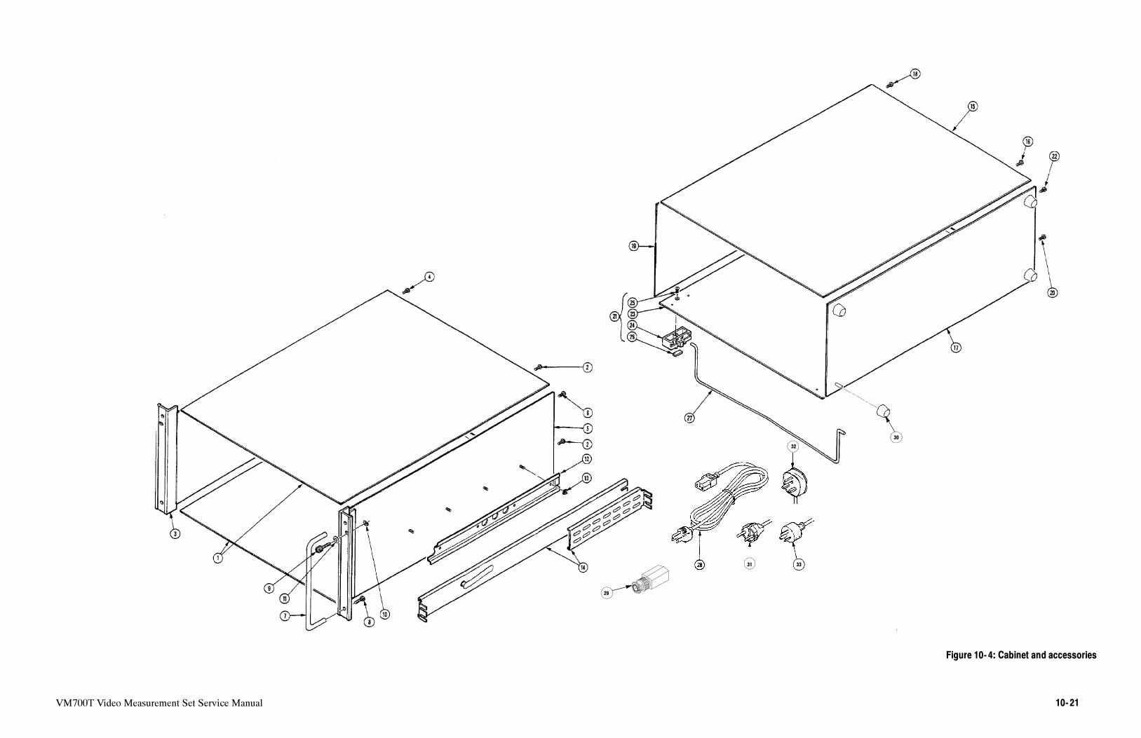
VM700T Video Measurement Set Service Manual 10- 21
3331
32
29
30
Figure 10- 4: Cabinet and accessories

10- 22 VM700T Video Measurement Set Service Manual

VM700T Video Measurement Set Service Manual 10- 23
1
2
3
4
5
6
7
8
9
10
1112
4
4
4
13
A22
A23
Figure 10- 5: Option 1S circuit boards

10- 24 VM700T Video Measurement Set Service Manual
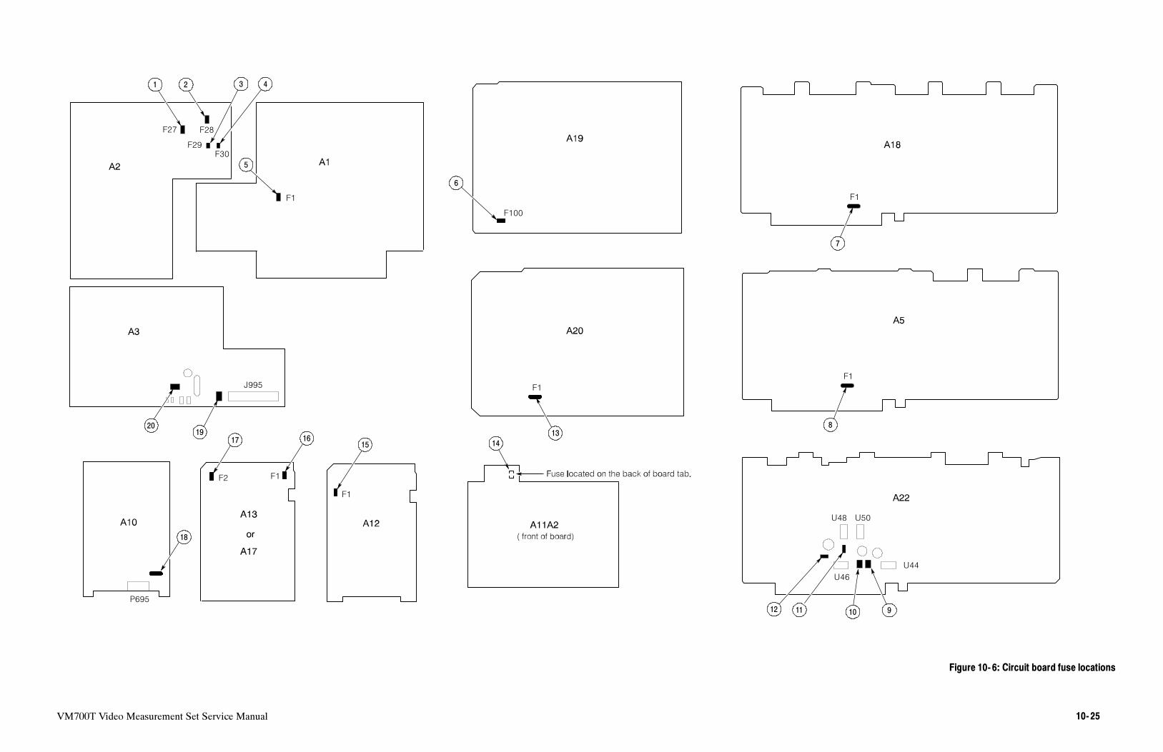
VM700T Video Measurement Set Service Manual 10- 25
J995 F1
F100
F28F27
F29
F30
F1 F1
F1
U48 U50
U44
U46
F1
F1F2
P695
1 2 3 4
5
6
7
8
9101112
13
14151617
18
1920
Figure 10- 6: Circuit board fuse locations

10- 26 VM700T Video Measurement Set Service Manual