VM - 1 31 - COLLISION INFORMATION. · - 2 31 - Collision Information VM. Warning VM 31 - Collision...
77
31 - COLLISION INFORMATION ............2 VM -1
Transcript of VM - 1 31 - COLLISION INFORMATION. · - 2 31 - Collision Information VM. Warning VM 31 - Collision...

31 - COLLISION INFORMATION . . . . . . . . . . . .2
VM - 1
31 - Collision Information
Warning . . . . . . . . . . . . . . . . . . . . . . . . . . . . . . . . .3
SAFETY NOTICE . . . . . . . . . . . . . . . . . . . . . . . . .4USE OF HEAT DURING REPAIR . . . . . . . . . . . .5
Standard Procedure . . . . . . . . . . . . . . . . . . . . . .5
SERVICE AFTER A SUPPLEMENTALRESTRAINT SYSTEM DEPLOYMENT . . . . . . .6
BASE COAT/CLEARCOAT FINISH . . . . . . . . . . .9FINESSE SANDING, BUFFING, AND POLISH-ING . . . . . . . . . . . . . . . . . . . . . . . . . . . . . . . . . .10
PAINT TOUCH-UP . . . . . . . . . . . . . . . . . . . . . . .11NON-STRUCTURAL SHEET METAL REPAIR .12WELDING AND WELD BONDING. . . . . . . . . . .24SECTIONING LOCATIONS AND PROCE-DURES . . . . . . . . . . . . . . . . . . . . . . . . . . . . . . .35
CORROSION PROTECTION. . . . . . . . . . . . . . .44
Specifications. . . . . . . . . . . . . . . . . . . . . . . . . . .45
VEHICLE IDENTIFICATION NUMBER . . . . . . .46
STANDARDIZED STEEL IDENTIFICATION . . .48
BODY OPENING DIMENSIONS . . . . . . . . . . . .55
FRAME DIMENSIONS . . . . . . . . . . . . . . . . . . . .57
BODY GAP AND FLUSH MEASUREMENTS . .65
PAINT CODES . . . . . . . . . . . . . . . . . . . . . . . . . .67
VEHICLE CERTIFICATION LABEL . . . . . . . . . .68
Locations . . . . . . . . . . . . . . . . . . . . . . . . . . . . . . .68
SEALERS AND SOUND DEADENERS . . . . . .69
SOUND DEADENER LOCATIONS . . . . . . . . . .70
STRUCTURAL ADHESIVE, FLEXIBLE ADHE-
SIVES AND SEAM SEALER LOCATIONS . . .77
- 2 31 - Collision Information VM

Warning
VM 31 - Collision Information 31 - 3

SAFETY NOTICE
CAUTION: All service and rebuilding instructions contained herein are applicable to, and for the
convenience of, the automotive trade only. All test and repair procedures on components or
assemblies in non-automotive applications should be repaired in accordance with instructions
supplied by the manufacturer of the total product.
Proper service and repair is important to the safe, reliable operation of all motor vehicles. The
service produces recommended and described in this publication were developed for
professional service personnel, and are effective methods for performing vehicle repair.
Following these procedures will help ensure efficient economical vehicle performance and
service reliability. Some service procedures require the use of special tools designed for
specific procedures. These special tools should be used as recommended throughout this
publication.
Special attention should be exercised when working with spring-or tension-loaded fasteners
and devices such as E-Clips, Circlips, Snap rings, etc., since careless removal may cause
personal injury. Always wear safety goggles when working on vehicles or vehicle components.
It is important to note that this publication contains various Cautions and Warnings. These
should be read carefully in order to minimize risk of personal injury or the possibility that
improper service methods may damage the vehicle or render it unsafe. It is important to note
that these Cautions and Warnings cover only the situations and procedures Chrysler Group
LLC has encountered and recommended. Chrysler Group LLC cannot possibly know, evaluate,
and advise the service trade of all conceivable ways in which service may be performed, or
of the possible hazards of each. Consequently, Chrysler Group LLC has not undertaken
any such broad service review. Accordingly, anyone uses a service procedure or tool that is not
recommended in this publication must be certain that neither personal safety, nor vehicle
safety, will be jeopardized by the service methods they select.
31 - 4 31 - Collision Information VM
USE OF HEAT DURING REPAIR
WARNING: Chrysler Group LLC engineering’s position on the use of heat during collision repair is as
follows:
• Any body panel or frame component damaged which is to be repaired and reused, must be
repaired using the “cold straightening” method. No heat may be used during the straightening
process.
• During rough straightening prior to panel replacement, damaged panels or frame components may
be heated to assist in body/frame realignment. The application of heat must be constrained to the
parts which will be replaced and not allowed to affect any other components.
This “no heat” recommendation is due to the extensive use of high strength and advanced high strength
steels in Chrysler Group LLC products. High-strength materials can be substantially and negatively affected
from heat input which will not be obviously known to the repairer or consumer.
Ignoring these recommendations may lead to serious compromises in the ability to protect occupants in a
future collision event, reduce the engineered qualities and attributes, or decrease the durability and
reliability of the vehicle.
This statement supersedes any previously released information by the Chrysler Group LLC.
Failure to follow these instructions may result in serious or fatal injury.
Standard Procedure
VM 31 - Collision Information 31 - 5
SERVICE AFTER A SUPPLEMENTAL RESTRAINT SYSTEM DEPLOYMENT
Any vehicle which is to be returned to use following a Supplemental Restraint System (SRS) component deployment
must have the deployed restraints replaced. In addition, the following guidelines MUST be observed.
• Following ANY major vehicle impact damage in the vicinity of an impact sensor or the ORC - It is
critical that the mounting surfaces and mounting brackets for the Occupant Restraint Controller (ORC),
front impact sensors and side impact sensors located within the proximity of the impact damage be closely
inspected and restored to their original conditions. Because the ORC and each impact sensor are used by the
SRS to monitor or confirm the direction and severity of a vehicle impact, improper orientation or insecure
fastening of these components may cause airbags not to deploy when required, or to deploy when not
required.
• Following ANY airbag deployment event - The Lower Anchors and Tethers for CHildren (LATCH) provisions,
the upper tether anchors and all interior trim panels must also be inspected.
• If the driver airbag is deployed - If the Driver AirBag (DAB) has been deployed, the DAB, the clockspring
and stalk unit, the steering column assembly including the intermediate shaft and coupler, both front seat belt
anchor buckle tensioners, both front seat belt retractor and tensioner assemblies, any front seat belt buckle
in use and all rear seat belt retractors and buckles in use must be replaced. The front impact sensors and the
steering wheel must also be inspected.
• If the knee airbag is deployed - If the Knee AirBag (KAB) (also known as the Inflatable Knee Blocker/IKB)
has been deployed, the KAB and the instrument panel steering column opening cover must also be replaced.
The instrument panel must also be inspected.
• If the passenger airbag is deployed - If the Passenger AirBag (PAB) has been deployed, the PAB, the PAB
wire harness or connector, and the instrument panel must be replaced.
• If a seat airbag is deployed - If a Seat AirBag (SAB) (also known as a pelvic and thoracic airbag) has been
deployed, the SAB, the seat back frame, the seat back foam, the seat back trim cover and the side impact
sensor on the same side of the vehicle as the deployed airbag must be replaced. Both front seat belt anchor
buckle tensioners, both front seat belt retractor and tensioner assemblies, any front seat belt buckle in use and
all rear seat belt retractors and buckles in use must be replaced.
• If a seat belt tensioner is deployed - The seat belt retractor and anchor buckle tensioners are deployed in
conjunction with the front airbags. All seat belt tensioners must be replaced if any airbag in the vehicle except
the Knee AirBag (KAB) has been deployed.
• If a side curtain airbag is deployed - If a side curtain airbag (also known as a Side AirBag Inflatable Curtain/
SABIC) has been deployed, the SABIC, the trim on the upper A and B-pillars (without a rear seat option) or on
the upper A and B-pillars and also on the C-pillars (with a rear seat option) as well as the side impact sensor
on the same side of the vehicle as the deployed airbag must be replaced. The headliner, both front seat
belt anchor buckle tensioners, both front seat belt retractor and tensioner assemblies, any front seat belt
buckle in use and all rear seat belt retractors and buckles in use must be replaced. The deploy brackets on
the B-pillar and on the C-pillar (with a rear seat option) for the same side of the vehicle as the deployed airbag
must be replaced following a side curtain airbag deployment.
The components identified with the deployed SRS components in the preceding list are not intended for reuse and
will be damaged or weakened as a result of an airbag deployment, which may or may not be obvious during a
visual inspection. All other vehicle components should be closely inspected following any SRS component
deployment, but are to be replaced only as required by the extent of the visible damage incurred.
SQUIB CIRCUIT DAMAGE
In addition to the preceding guidelines, be aware that the heat created by the initiator during an airbag or tensioner
deployment will cause collateral damage to the connected wiring (squib circuits) and connector insulators. There are
two methods by which an airbag or seat belt tensioner may be connected to the vehicle electrical system. The first
method involves a short pigtail harness and connector insulator that are integral to the airbag or tensioner unit
and are replaced as a unit with the service replacement airbag or seat belt tensioner. This connection method
typically requires no additional wiring repair following a deployment.
However, the second connection method involves a wire harness takeout and connector insulator that are
connected directly to the airbag or tensioner initiator or squib. These direct-connect type take outs and connector
insulators MUST be repaired following an airbag or seat belt tensioner deployment using the approved
Supplemental Restraint System Wiring Repairs procedure. (Refer to 10 - Restraints - Standard Procedure).
AIRBAG SQUIB STATUS
Multistage airbags with multiple initiators (squibs) must be checked to determine that all squibs were used during
the deployment event. The Driver AirBag (DAB) and Passenger AirBag (PAB) in this vehicle are deployed by
31 - 6 31 - Collision Information VM
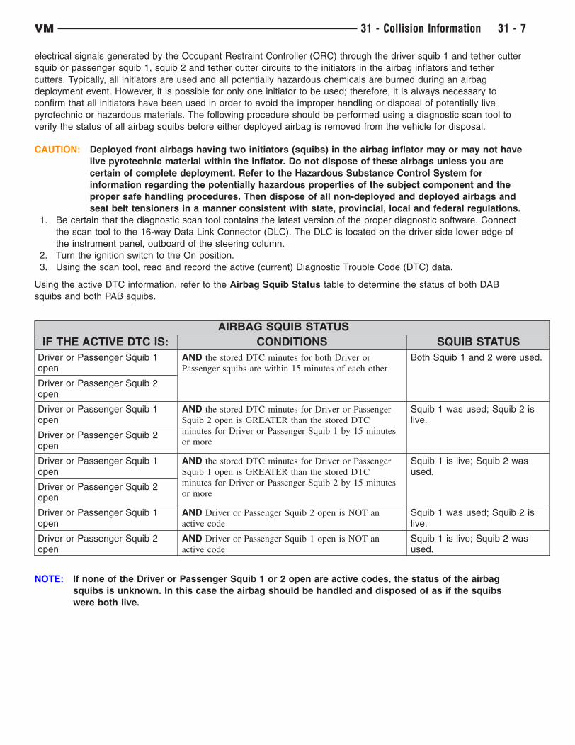
electrical signals generated by the Occupant Restraint Controller (ORC) through the driver squib 1 and tether cutter
squib or passenger squib 1, squib 2 and tether cutter circuits to the initiators in the airbag inflators and tether
cutters. Typically, all initiators are used and all potentially hazardous chemicals are burned during an airbag
deployment event. However, it is possible for only one initiator to be used; therefore, it is always necessary to
confirm that all initiators have been used in order to avoid the improper handling or disposal of potentially live
pyrotechnic or hazardous materials. The following procedure should be performed using a diagnostic scan tool to
verify the status of all airbag squibs before either deployed airbag is removed from the vehicle for disposal.
CAUTION: Deployed front airbags having two initiators (squibs) in the airbag inflator may or may not have
live pyrotechnic material within the inflator. Do not dispose of these airbags unless you are
certain of complete deployment. Refer to the Hazardous Substance Control System for
information regarding the potentially hazardous properties of the subject component and the
proper safe handling procedures. Then dispose of all non-deployed and deployed airbags and
seat belt tensioners in a manner consistent with state, provincial, local and federal regulations.
1. Be certain that the diagnostic scan tool contains the latest version of the proper diagnostic software. Connect
the scan tool to the 16-way Data Link Connector (DLC). The DLC is located on the driver side lower edge of
the instrument panel, outboard of the steering column.
2. Turn the ignition switch to the On position.
3. Using the scan tool, read and record the active (current) Diagnostic Trouble Code (DTC) data.
Using the active DTC information, refer to the Airbag Squib Status table to determine the status of both DAB
squibs and both PAB squibs.
AIRBAG SQUIB STATUS
IF THE ACTIVE DTC IS: CONDITIONS SQUIB STATUS
Driver or Passenger Squib 1open
AND the stored DTC minutes for both Driver or
Passenger squibs are within 15 minutes of each other
Both Squib 1 and 2 were used.
Driver or Passenger Squib 2open
Driver or Passenger Squib 1open
AND the stored DTC minutes for Driver or Passenger
Squib 2 open is GREATER than the stored DTC
minutes for Driver or Passenger Squib 1 by 15 minutes
or more
Squib 1 was used; Squib 2 islive.
Driver or Passenger Squib 2open
Driver or Passenger Squib 1open
AND the stored DTC minutes for Driver or Passenger
Squib 1 open is GREATER than the stored DTC
minutes for Driver or Passenger Squib 2 by 15 minutes
or more
Squib 1 is live; Squib 2 wasused.
Driver or Passenger Squib 2open
Driver or Passenger Squib 1open
AND Driver or Passenger Squib 2 open is NOT an
active code
Squib 1 was used; Squib 2 islive.
Driver or Passenger Squib 2open
AND Driver or Passenger Squib 1 open is NOT an
active code
Squib 1 is live; Squib 2 wasused.
NOTE: If none of the Driver or Passenger Squib 1 or 2 open are active codes, the status of the airbag
squibs is unknown. In this case the airbag should be handled and disposed of as if the squibs
were both live.
VM 31 - Collision Information 31 - 7
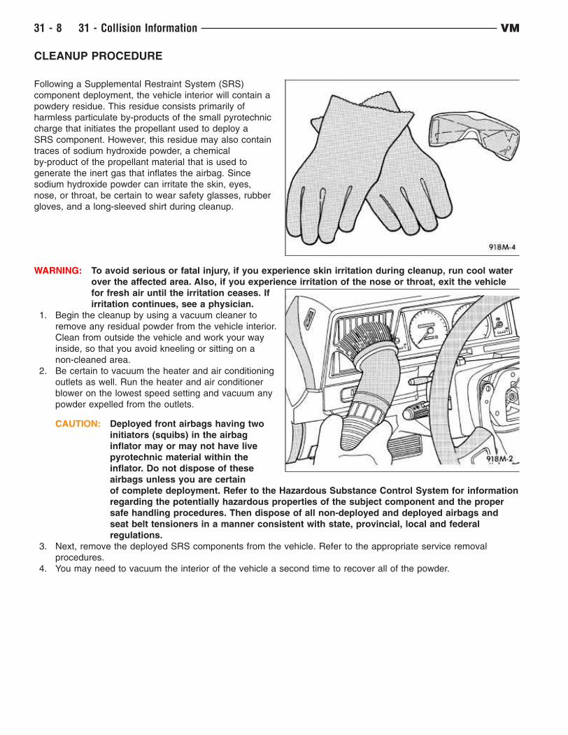
CLEANUP PROCEDURE
Following a Supplemental Restraint System (SRS)
component deployment, the vehicle interior will contain a
powdery residue. This residue consists primarily of
harmless particulate by-products of the small pyrotechnic
charge that initiates the propellant used to deploy a
SRS component. However, this residue may also contain
traces of sodium hydroxide powder, a chemical
by-product of the propellant material that is used to
generate the inert gas that inflates the airbag. Since
sodium hydroxide powder can irritate the skin, eyes,
nose, or throat, be certain to wear safety glasses, rubber
gloves, and a long-sleeved shirt during cleanup.
WARNING: To avoid serious or fatal injury, if you experience skin irritation during cleanup, run cool water
over the affected area. Also, if you experience irritation of the nose or throat, exit the vehicle
for fresh air until the irritation ceases. If
irritation continues, see a physician.
1. Begin the cleanup by using a vacuum cleaner to
remove any residual powder from the vehicle interior.
Clean from outside the vehicle and work your way
inside, so that you avoid kneeling or sitting on a
non-cleaned area.
2. Be certain to vacuum the heater and air conditioning
outlets as well. Run the heater and air conditioner
blower on the lowest speed setting and vacuum any
powder expelled from the outlets.
CAUTION: Deployed front airbags having two
initiators (squibs) in the airbag
inflator may or may not have live
pyrotechnic material within the
inflator. Do not dispose of these
airbags unless you are certain
of complete deployment. Refer to the Hazardous Substance Control System for information
regarding the potentially hazardous properties of the subject component and the proper
safe handling procedures. Then dispose of all non-deployed and deployed airbags and
seat belt tensioners in a manner consistent with state, provincial, local and federal
regulations.
3. Next, remove the deployed SRS components from the vehicle. Refer to the appropriate service removal
procedures.
4. You may need to vacuum the interior of the vehicle a second time to recover all of the powder.
31 - 8 31 - Collision Information VM
BASE COAT/CLEARCOAT FINISH
The original equipment paint finish is a multi step process that involves cleaning, applying electro de-position
(E-coat), anti-chip primer, basecoat, and clearcoat steps.
CAUTION: Do not use abrasive chemicals, abrasive compounds or harsh alkaline based cleaning solvents
on the painted surfaces of a vehicle. Failure to follow this caution can result in damage to
vehicle finish.
On most vehicles a two-part paint application (basecoat/clearcoat) is used. Color paint that is applied to primer is
called basecoat. A clear coat paint is then applied to protect the basecoat from ultraviolet light and to provide a
durable high-gloss finish.
VM 31 - Collision Information 31 - 9

FINESSE SANDING, BUFFING, AND POLISHING
CAUTION: Do not remove more than 0.5 mils of clearcoat finish when sanding, hand buffing or polishing.
Basecoat paint must retain clearcoat for durability.
CAUTION: If the finish has been finesse sanded in the past, it cannot be repeated. Failure to follow this
caution can result in damage to vehicle finish.
NOTE: Finesse sanding should only be performed by a trained automotive paint technician.
Minor acid etching, orange peel, or smudging in a clearcoat or single-stage finish can be reduced with light finesse
sanding, hand buffing and polishing. Use a Paint Thickness Gauge #PR-ETG-2X or equivalent to determine
clearcoat or single-stage paint thickness before and after the repair.
31 - 10 31 - Collision Information VM

PAINT TOUCH-UP
If the painted metal surface of a vehicle becomes scratched or chipped, it should be touched-up as soon as
possible to avoid corrosion.
WARNING: Use an OSHA approved respirator and safety glasses when spraying paint or solvents. Failure
to follow this warning may result in possible personal injury or death.
When repairing painted metal surfaces, for best results, use MOPART Scratch Filler/Primer, Touch-Up Paints and
Clear Top Coat.
1. Scrape any loose paint and corrosion from inside the scratch or chip.
WARNING: Avoid prolonged skin contact with petroleum or alcohol–based cleaning solvents. Failure
to follow this warning can result in possible personal injury or death.
2. Clean affected area with MOPART Tar/Road Oil Remover or equivalent, and allow to dry.
3. Fill the inside of the scratch or chip with a coat of filler/primer. Do not overlap primer onto good surface finish.
The applicator brush should be wet enough to puddle-fill the scratch or chip without running. Do not stroke
brush applicator on body surface. Allow the filler/primer to dry hard.
4. Cover the filler/primer with color touch-up paint. Do not overlap touch-up color onto the original color coat
around the scratch or chip. Butt the new color to the original color, if possible. Do not stroke applicator brush
on body surface. Allow touch-up paint to dry hard.
5. On vehicles with clearcoat, apply clear top coat to touch-up paint with the same technique as described in step
4. Allow clear top coat to dry hard. If desired, the clearcoat can be lightly finesse sanded (1500 grit) and
polished with rubbing compound.
VM 31 - Collision Information 31 - 11
NON-STRUCTURAL SHEET METAL REPAIR
Safety Notice
CAUTION: All Service and rebuilding instructions contained herein are applicable to, and for the
convenience of, the automotive repair industry only.
Proper service and repair is important to the safe, reliable operation of all motor vehicles. The service procedures
recommended and described in this publication were developed for professional service personnel, and are effective
methods for performing vehicle repair. Following these procedures will help ensure efficient and economical vehicle
performance and service reliability. Some service procedures require the use of special tools designed for specific
procedures. These special tools should be used as recommended throughout this publication.
It is important to note this publication contains various Cautions and Warnings. These should be read carefully in
order to minimize risk of personal injury or the possibility that improper service may damage the vehicle or render
it unsafe. It is important to note that these cautions and warnings cover only the situations and procedures Chrysler
Group LLC. has encountered and recommended. Chrysler Group LLC. cannot possibly know, evaluate, and advise
the service trade of all conceivable ways in which service may be performed, or the possible hazards of each.
Consequently, Chrysler has not undertaken any broad service review. Accordingly, anyone that uses a service
procedure or tool that is not recommended in this publication must be certain that neither personal safety, nor
vehicle safety will be jeopardized by the service methods they select.
Safety Precautions
WARNING: Always wear an approved respirator, as well as skin and eye protection per adhesive
manufacturer recommendations as stated in the product Safety Data Sheets (SDS).
Adhesives:
• Safety Data Sheets (SDS) must be available and understood before adhesives are handled.
• All personnel should be instructed on the proper procedures to prevent skin contact with solvents, curing
agents, and uncured base adhesives, which could cause allergic reactions or sensitization.
Types of Structural Adhesives
Overview: There are three basic chemistries used in the collision repair industry. The types of adhesives used
include Acrylic, Epoxy and Urethane. To achieve optimal results, it is best to use the chemistry that bonds best to
the substrate being repaired, is easiest to use and offers the most permanent, non-detectable repair at the most
economical repair cost. All three chemistries have their strengths and weaknesses.
NOTE: Structural adhesives that meet Chrysler Group LLC’s approved replacement materials
specifications include - Fusor 112B and 3M 08116
Adhesive Types:
• Acrylic Adhesives - Bond all types of bare metals and are excellent for cross bonding aluminum to steel.
They have good NVH (Noise Vibration Harshness) properties and some offer anti-corrosion properties, so
primers on bare metals are not necessary. Most acrylics have a fast room temperature cure, and are stable
with regards to temperature and moisture during cure. However, both of these can effect shelf life. Mix ratio is
modestly important although the performance properties can vary with a change in mix ratio. Acrylics are the
most forgiving of the three chemistries with regards to mix ratio accuracy.
• Epoxy Adhesives - Bond well to ridged and semi-ridged plastics and are generally easy to sand and feather
edge. Some may be too ridged for flexible substrates and they often require primers on bare metal
applications. Epoxies can be heat cured to increase strength and accelerate the curing process. They have a
long and stable shelf life. The mix ratio can vary by ± 50% and still cure. However, the performance properties
will vary when the mix ratio is incorrect. Epoxies are more forgiving than urethanes with regards to mix ratio
accuracy.
• Urethane Adhesive - Typically flexible and bond well to plastics. However, they usually require primers on
metal surfaces to protect against corrosion. Urethanes have good seam sealing and NVH qualities and are
frequently the optimal choice for seam sealers. They are sensitive to moisture during cure, packaging and
storage. Single component urethanes usually have a much shorter shelf life than two component urethanes.
Mix ratios are critical for urethanes. In most cases it cannot vary more than ± 5%. Therefore, hand mixing
is not recommended. Urethanes are the most unforgiving of the three chemistries with regards to mix
ratio accuracy.
31 - 12 31 - Collision Information VM
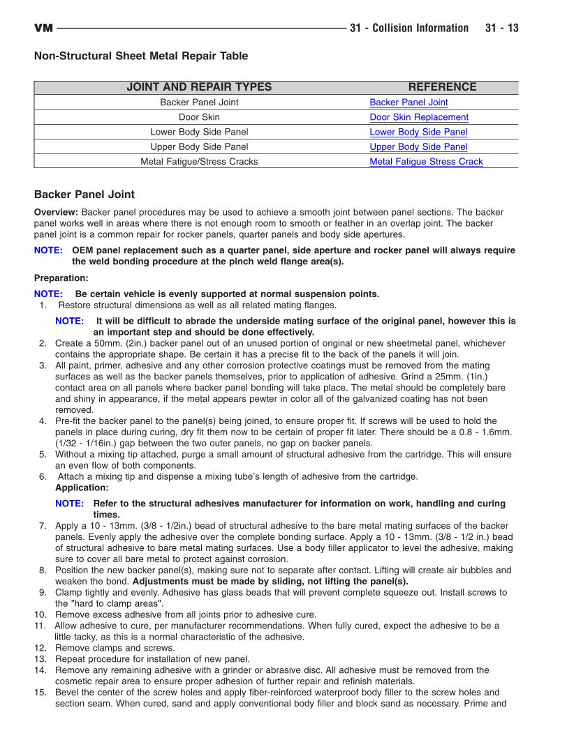
Non-Structural Sheet Metal Repair Table
JOINT AND REPAIR TYPES REFERENCE
Backer Panel Joint Backer Panel Joint
Door Skin Door Skin Replacement
Lower Body Side Panel Lower Body Side Panel
Upper Body Side Panel Upper Body Side Panel
Metal Fatigue/Stress Cracks Metal Fatigue Stress Crack
Backer Panel Joint
Overview: Backer panel procedures may be used to achieve a smooth joint between panel sections. The backer
panel works well in areas where there is not enough room to smooth or feather in an overlap joint. The backer
panel joint is a common repair for rocker panels, quarter panels and body side apertures.
NOTE: OEM panel replacement such as a quarter panel, side aperture and rocker panel will always require
the weld bonding procedure at the pinch weld flange area(s).
Preparation:
NOTE: Be certain vehicle is evenly supported at normal suspension points.
1. Restore structural dimensions as well as all related mating flanges.
NOTE: It will be difficult to abrade the underside mating surface of the original panel, however this is
an important step and should be done effectively.
2. Create a 50mm. (2in.) backer panel out of an unused portion of original or new sheetmetal panel, whichever
contains the appropriate shape. Be certain it has a precise fit to the back of the panels it will join.
3. All paint, primer, adhesive and any other corrosion protective coatings must be removed from the mating
surfaces as well as the backer panels themselves, prior to application of adhesive. Grind a 25mm. (1in.)
contact area on all panels where backer panel bonding will take place. The metal should be completely bare
and shiny in appearance, if the metal appears pewter in color all of the galvanized coating has not been
removed.
4. Pre-fit the backer panel to the panel(s) being joined, to ensure proper fit. If screws will be used to hold the
panels in place during curing, dry fit them now to be certain of proper fit later. There should be a 0.8 - 1.6mm.
(1/32 - 1/16in.) gap between the two outer panels, no gap on backer panels.
5. Without a mixing tip attached, purge a small amount of structural adhesive from the cartridge. This will ensure
an even flow of both components.
6. Attach a mixing tip and dispense a mixing tube’s length of adhesive from the cartridge.
Application:
NOTE: Refer to the structural adhesives manufacturer for information on work, handling and curing
times.
7. Apply a 10 - 13mm. (3/8 - 1/2in.) bead of structural adhesive to the bare metal mating surfaces of the backer
panels. Evenly apply the adhesive over the complete bonding surface. Apply a 10 - 13mm. (3/8 - 1/2 in.) bead
of structural adhesive to bare metal mating surfaces. Use a body filler applicator to level the adhesive, making
sure to cover all bare metal to protect against corrosion.
8. Position the new backer panel(s), making sure not to separate after contact. Lifting will create air bubbles and
weaken the bond. Adjustments must be made by sliding, not lifting the panel(s).
9. Clamp tightly and evenly. Adhesive has glass beads that will prevent complete squeeze out. Install screws to
the "hard to clamp areas".
10. Remove excess adhesive from all joints prior to adhesive cure.
11. Allow adhesive to cure, per manufacturer recommendations. When fully cured, expect the adhesive to be a
little tacky, as this is a normal characteristic of the adhesive.
12. Remove clamps and screws.
13. Repeat procedure for installation of new panel.
14. Remove any remaining adhesive with a grinder or abrasive disc. All adhesive must be removed from the
cosmetic repair area to ensure proper adhesion of further repair and refinish materials.
15. Bevel the center of the screw holes and apply fiber-reinforced waterproof body filler to the screw holes and
section seam. When cured, sand and apply conventional body filler and block sand as necessary. Prime and
VM 31 - Collision Information 31 - 13
paint per paint manufacturer recommendations.
16. Apply inner panel corrosion inhibiting materials (Mopar Cavity Wax part #6804292970 or equivalent).
Door Skin Replacement
Overview: Depending on the type of door to be repaired, a full skin or a belt cut will be required. Belt cut
replacement is necessary when a door with a full skin, around the window opening, has an angle that makes it to
difficult to get tools into to do a quality hem flange installation. A butt-joint is used at this seam.
Preparation:
1. Belt cut skins will require determining and cutting of
the sectioning locations on the original panel and on
the replacement panel.
2. Remove the door skin by grinding the outer edge (C)
until the seam is perforated.
3. Cut around weld nuggets and spot welds with a spot
weld cutting bit or similar weld removal tool.
4. If panel is attached with adhesive you may use heat,
from a non-flame heat source, up to 204°C. (400F°).
This will aid in loosening the bond.
5. With an air chisel and a flat bladed bit, remove outer
skin and any remaining hem flange.
6. Grind any remaining weld nuggets flush with door
frame, and remove all adhesive, paint, E-coating and
corrosion protective coatings from the area where
the structural adhesive will be applied, and where
the ’butt-joint" is to take place. The metal should
be completely bare and shiny in appearance, if the
metal appears pewter in color all of the galvanized
coating has not been removed.
7. Straighten door flange and any remaining damage
on door shell using the hammer and dolly method.
8. The area of the new door skin that will make contact
with the door shell will need to be scuffed with a
course abrasive pad or ground with a 50 grit grinding
disc. This will vary upon adhesive manufacturers,
be certain to check adhesive manufacturer
recommendations.
9. Dry fit the new panel. Determine where to place
clamps to hold the panel in place, as necessary.
CAUTION: Be certain the fit is good from the skin to door and door to door opening. Cured adhesive
is extremely strong and will not allow for (adjustments(.
10. Without a mixing tip attached, purge a small amount of structural adhesive from the cartridge. This will ensure
an even flow of both components.
11. Attach a mixing tip and dispense a mixing tube’s length of adhesive from the cartridge.
NOTE: Refer to the structural adhesives manufacturer for information on work, handling and curing
times.
Installation:
NOTE: Do not apply adhesive within 25mm. (1in.) of the belt cut location.
12. Apply a 10 - 13mm. (3/8 - 1/2 in.) bead of structural adhesive to bare metal mating surfaces. Use a body filler
applicator to level the adhesive, making sure to cover all bare metal to protect against corrosion.
NOTE: When applying adhesives be certain any and all drain holes remain open and clear of
obstructions.
13. Apply a second bead of adhesive to ensure proper bead thickness.
14. Position the new panel. If repositioning is necessary slide the panel, do not lift or separate panels.
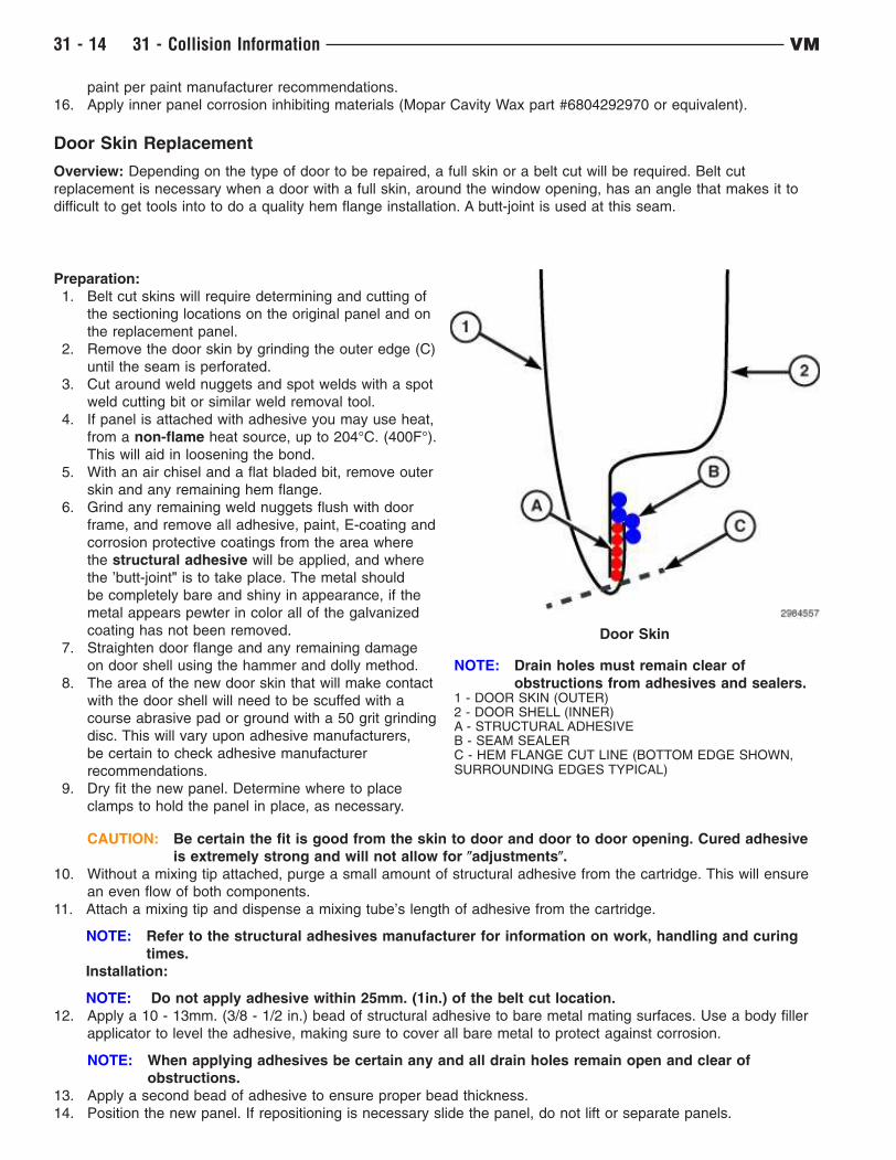
Door Skin
NOTE: Drain holes must remain clear of
obstructions from adhesives and sealers.1 - DOOR SKIN (OUTER)2 - DOOR SHELL (INNER)A - STRUCTURAL ADHESIVEB - SEAM SEALERC - HEM FLANGE CUT LINE (BOTTOM EDGE SHOWN,SURROUNDING EDGES TYPICAL)
31 - 14 31 - Collision Information VM
Adjustments must be made by sliding, not lifting the panel(s). Apply clamps to hold panel in position, as
necessary.
NOTE: There are many tools readily available to aid in the hem flange folding process.
15. Roll the hem flange over. Remove excess adhesive. This will save time, as compared to waiting until cured.
16. Re-check door gap and flushness to the vehicle opening and adjust as necessary.
17. Allow the adhesive to cure per manufacturer recommendations. When fully cured, expect the adhesive to be a
little tacky, as this is a normal characteristic of the adhesive. Remove clamps, if used.
18. Remove any excess cured adhesive with a grinder or abrasive disc. All adhesive must be removed from the
cosmetic repair area to ensure proper adhesion of repair and refinish materials.
19. Weld the butt-joint with GMAW (Gas Metal Arc Welding), if a belt cut was used. Clean and dress welds
accordingly.
20. Apply fiber-reinforced waterproof body filler to the section seam, as necessary. When cured sand and apply
conventional body filler and block sand.
21. Apply an epoxy or anti-corrosion primer. When cured, lightly scuff.
22. Seam seal the entire door. Duplicate the factory seam sealer. Apply a discrete bead around the rest of the door
to seal and protect, maintaining the original appearance.
23. Prime and paint per paint manufacturers recommendations.
24. Apply inner panel corrosion inhibiting materials (Mopar Cavity Wax part #68042970AA , or equivalent).
Lower Body Side Panel
Overview: Chrysler’s recommended repair procedure for body side aperture / quarter panel replacement include
butt joints using backer panels with structural adhesive at the sectioning joint, or a welded backer panel with a
welded butt joint using GMAW (Gas Metal Arc Welding). Resistance spot welding with structural adhesive, referred
to as weld bonding, should be used at all pinch welds and may be used at the drain trough and tail panel areas
as well. With the exception of the sectioning joint, the rule to follow is "Re-assemble as it was built from the OEM".
For further information on Weld / Weld Bonding, (Refer to Collision Information – Standard Procedure). GMAW (plug
or puddle) welds may be used in place of STRSW (Squeeze Type Resistance Spot Welding) only in areas that
specifically use spot welds and in areas that access limitations will not allow STRSW. GMAW cannot be used in the
weld bonding process. Never weld with GMAW within 25mm. (1in.) of any area where structural adhesive is used.
The weld "heat zone" will destroy the properties of the adhesive.
For locations and warnings that may apply to body side aperture / quarter panel sectioning locations reference
Sectioning Procedures, (Refer to Collision Information – Standard Procedure).
Chrysler approved replacement materials include -
• Structural Adhesives : Fusor 112B, 3M 08116.
• Anti-Flutter Adhesive (flexible) : Fusor 121 (Flexible Foam), 3M 04724 (NVH Dampening Material) and
Crest (CFF Flexi-Foam).
• Seam Sealer : Fusor 129, 3M 08308.
CAUTION: Proper angles and depths must be maintained throughout the entire cut to prevent damage to
surrounding components
VM 31 - Collision Information 31 - 15
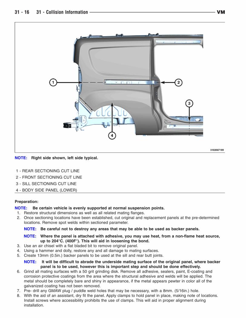
NOTE: Right side shown, left side typical.
1 - REAR SECTIONING CUT LINE
2 - FRONT SECTIONING CUT LINE
3 - SILL SECTIONING CUT LINE
4 - BODY SIDE PANEL (LOWER)
Preparation:
NOTE: Be certain vehicle is evenly supported at normal suspension points.
1. Restore structural dimensions as well as all related mating flanges.
2. Once sectioning locations have been established, cut original and replacement panels at the pre-determined
locations. Remove spot welds within sectioned parameter.
NOTE: Be careful not to destroy any areas that may be able to be used as backer panels.
NOTE: Where the panel is attached with adhesive, you may use heat, from a non-flame heat source,
up to 204°C. (400F°). This will aid in loosening the bond.
3. Use an air chisel with a flat bladed bit to remove original panel.
4. Using a hammer and dolly, restore any and all damage to mating surfaces.
5. Create 13mm (0.5in.) backer panels to be used at the sill and rear butt joints.
NOTE: It will be difficult to abrade the underside mating surface of the original panel, where backer
panel is to be used, however this is important step and should be done effectively.
6. Grind all mating surfaces with a 50 grit grinding disk. Remove all adhesive, sealers, paint, E-coating and
corrosion protective coatings from the area where the structural adhesive and welds will be applied. The
metal should be completely bare and shiny in appearance, if the metal appears pewter in color all of the
galvanized coating has not been removed.
7. Pre- drill any GMAW plug / puddle weld holes that may be necessary, with a 8mm. (5/16in.) hole.
8. With the aid of an assistant, dry fit the panel. Apply clamps to hold panel in place, making note of locations.
Install screws where accessibility prohibits the use of clamps. This will aid in proper alignment during
installation.
31 - 16 31 - Collision Information VM

9. Without a mixing tip installed, purge a small amount of structural adhesive from the cartridge. This will ensure
an even flow of both components.
10. Attach a mixing tip and dispense a mixing tube’s length of adhesive from the cartridge.
NOTE: Using scrap metal and adhesive, make test coupon samples and perform peel test to ensure
your STRSW equipment is ready to apply welds as required. The Weld/Weld Bonding section
will provide further information on peel testing and equipment set-up, (Refer to 31 - Collision
Information - Standard Procedure/Welding and Weld Bonding).
NOTE: Refer to the structural adhesives manufacturer for information on work, handling and curing
times.
Installation:
11. Install backer panels, to the sectioning butt-joint locations.
1 - OUTER WHEELHOUSE
2 - STRUCTURAL ADHESIVE
INNER BODY SIDE
FLEXIBLE ADHESIVE
12. Apply 10 - 13mm. (3/8 - 1/2in.) bead of structural adhesive (1) to the area where the two panels are to be
bonded and weld bonded. Do not apply to areas that will only be STRSW or GMAW welded.
13. Apply 10 - 13mm. (3/8 - 1/2in.) bead of flexible adhesive (2) to the area where the two panels are to be
bonded and weld bonded.
14. Smooth the adhesive with a body filler spreader or equivalent, to cover all bare metal surfaces. Apply a second
bead of adhesive to ensure proper adhesive thickness.
15. With the aid of an assistant place the panel to the vehicle. If the panel needs to be adjusted, slide the panel.
NOTE: Adjustments must be made by sliding, not lifting the panel(s). Lifting will cause air bubbles
and weaken the bond.
16. Install clamps and screws to locations determined during the dry fit process.
17. Remove all squeeze out of adhesive, prior to curing.
NOTE: Structural adhesive manufacturers will vary on time allowed for completion of STRSW in weld
bond zones. Check and follow adhesive manufacturer recommendations.
VM 31 - Collision Information 31 - 17
18. Apply STRSW to weld bond area immediately.
19. Once fully cured, remove clamps and screws. When fully cured, expect adhesive to remain a little tacky, as this
is a normal characteristic of the adhesive.
20. Complete STRSW and / or GMAW (plug / puddle ) welds.
21. Finish / Dress the welds as necessary. If screws were necessary bevel the screw holes. Prepare the joint and
screw holes by grinding the area with 50 grit grinding disc. Get in seams as best as possible without thinning
the metal.
22. Remove any excess cured adhesive with a grinder or abrasive disc. All adhesive must be removed from the
cosmetic repair area to ensure proper adhesion of repair and refinish materials.
23. Apply fiber-reinforced waterproof body filler to screw holes and joint. Complete the repair using conventional
body filler, and block sanding.
24. Apply an epoxy or anti-corrosion primer. When cured, lightly scuff and then apply seam sealer as necessary.
25. Prime and paint per paint manufacturer recommendations.
26. Apply inner panel corrosion inhibiting materials (Mopar Cavity Wax part #68042970AA, or equivalent).
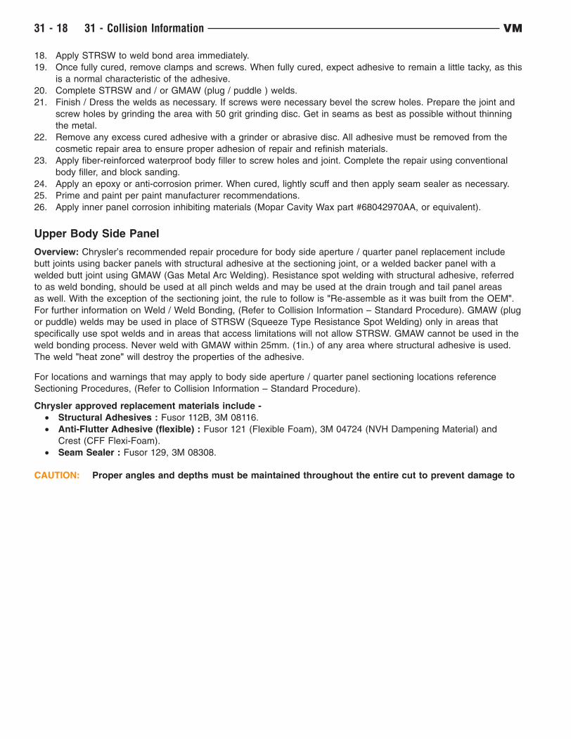
Upper Body Side Panel
Overview: Chrysler’s recommended repair procedure for body side aperture / quarter panel replacement include
butt joints using backer panels with structural adhesive at the sectioning joint, or a welded backer panel with a
welded butt joint using GMAW (Gas Metal Arc Welding). Resistance spot welding with structural adhesive, referred
to as weld bonding, should be used at all pinch welds and may be used at the drain trough and tail panel areas
as well. With the exception of the sectioning joint, the rule to follow is "Re-assemble as it was built from the OEM".
For further information on Weld / Weld Bonding, (Refer to Collision Information – Standard Procedure). GMAW (plug
or puddle) welds may be used in place of STRSW (Squeeze Type Resistance Spot Welding) only in areas that
specifically use spot welds and in areas that access limitations will not allow STRSW. GMAW cannot be used in the
weld bonding process. Never weld with GMAW within 25mm. (1in.) of any area where structural adhesive is used.
The weld "heat zone" will destroy the properties of the adhesive.
For locations and warnings that may apply to body side aperture / quarter panel sectioning locations reference
Sectioning Procedures, (Refer to Collision Information – Standard Procedure).
Chrysler approved replacement materials include -
• Structural Adhesives : Fusor 112B, 3M 08116.
• Anti-Flutter Adhesive (flexible) : Fusor 121 (Flexible Foam), 3M 04724 (NVH Dampening Material) and
Crest (CFF Flexi-Foam).
• Seam Sealer : Fusor 129, 3M 08308.
CAUTION: Proper angles and depths must be maintained throughout the entire cut to prevent damage to
31 - 18 31 - Collision Information VM
surrounding components
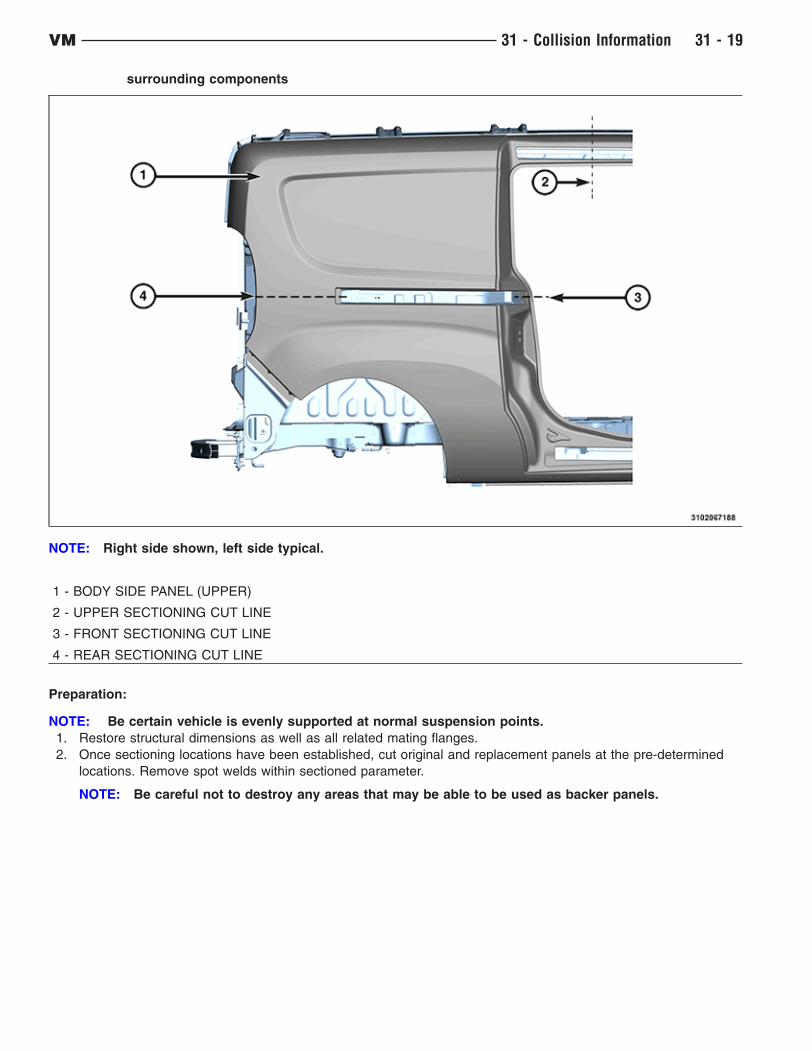
NOTE: Right side shown, left side typical.
1 - BODY SIDE PANEL (UPPER)
2 - UPPER SECTIONING CUT LINE
3 - FRONT SECTIONING CUT LINE
4 - REAR SECTIONING CUT LINE
Preparation:
NOTE: Be certain vehicle is evenly supported at normal suspension points.
1. Restore structural dimensions as well as all related mating flanges.
2. Once sectioning locations have been established, cut original and replacement panels at the pre-determined
locations. Remove spot welds within sectioned parameter.
NOTE: Be careful not to destroy any areas that may be able to be used as backer panels.
VM 31 - Collision Information 31 - 19
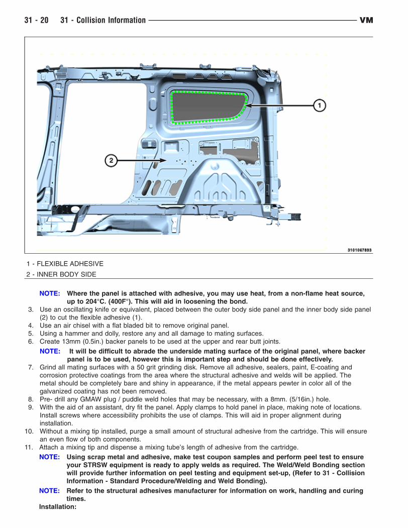
1 - FLEXIBLE ADHESIVE
2 - INNER BODY SIDE
NOTE: Where the panel is attached with adhesive, you may use heat, from a non-flame heat source,
up to 204°C. (400F°). This will aid in loosening the bond.
3. Use an oscillating knife or equivalent, placed between the outer body side panel and the inner body side panel
(2) to cut the flexible adhesive (1).
4. Use an air chisel with a flat bladed bit to remove original panel.
5. Using a hammer and dolly, restore any and all damage to mating surfaces.
6. Create 13mm (0.5in.) backer panels to be used at the upper and rear butt joints.
NOTE: It will be difficult to abrade the underside mating surface of the original panel, where backer
panel is to be used, however this is important step and should be done effectively.
7. Grind all mating surfaces with a 50 grit grinding disk. Remove all adhesive, sealers, paint, E-coating and
corrosion protective coatings from the area where the structural adhesive and welds will be applied. The
metal should be completely bare and shiny in appearance, if the metal appears pewter in color all of the
galvanized coating has not been removed.
8. Pre- drill any GMAW plug / puddle weld holes that may be necessary, with a 8mm. (5/16in.) hole.
9. With the aid of an assistant, dry fit the panel. Apply clamps to hold panel in place, making note of locations.
Install screws where accessibility prohibits the use of clamps. This will aid in proper alignment during
installation.
10. Without a mixing tip installed, purge a small amount of structural adhesive from the cartridge. This will ensure
an even flow of both components.
11. Attach a mixing tip and dispense a mixing tube’s length of adhesive from the cartridge.
NOTE: Using scrap metal and adhesive, make test coupon samples and perform peel test to ensure
your STRSW equipment is ready to apply welds as required. The Weld/Weld Bonding section
will provide further information on peel testing and equipment set-up, (Refer to 31 - Collision
Information - Standard Procedure/Welding and Weld Bonding).
NOTE: Refer to the structural adhesives manufacturer for information on work, handling and curing
times.
Installation:
31 - 20 31 - Collision Information VM
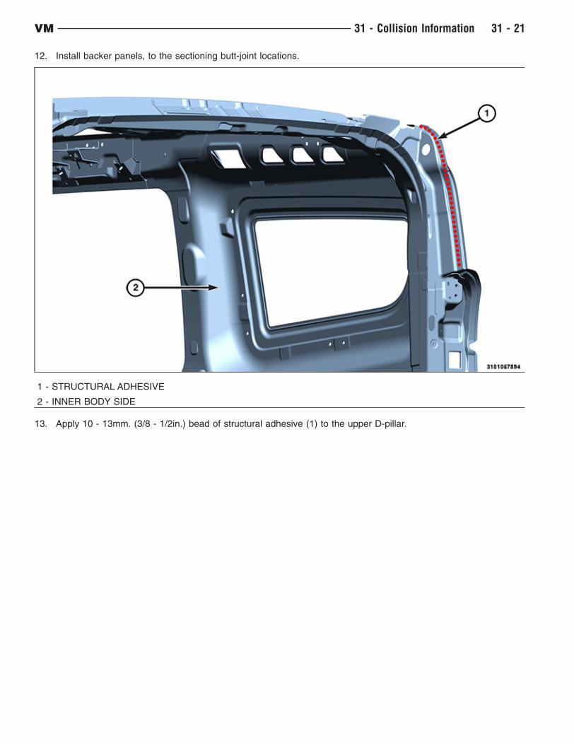
12. Install backer panels, to the sectioning butt-joint locations.
1 - STRUCTURAL ADHESIVE
2 - INNER BODY SIDE
13. Apply 10 - 13mm. (3/8 - 1/2in.) bead of structural adhesive (1) to the upper D-pillar.
VM 31 - Collision Information 31 - 21
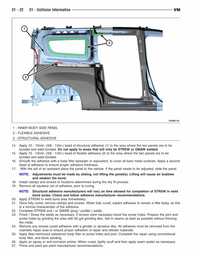
1 - INNER BODY SIDE PANEL
2 - FLEXIBLE ADHESIVE
3 - STRUCTURAL ADHESIVE
14. Apply 10 - 13mm. (3/8 - 1/2in.) bead of structural adhesive (1) to the area where the two panels are to be
bonded and weld bonded. Do not apply to areas that will only be STRSW or GMAW welded.
15. Apply 10 - 13mm. (3/8 - 1/2in.) bead of flexible adhesive (2) to the area where the two panels are to be
bonded and weld bonded.
16. Smooth the adhesive with a body filler spreader or equivalent, to cover all bare metal surfaces. Apply a second
bead of adhesive to ensure proper adhesive thickness.
17. With the aid of an assistant place the panel to the vehicle. If the panel needs to be adjusted, slide the panel.
NOTE: Adjustments must be made by sliding, not lifting the panel(s). Lifting will cause air bubbles
and weaken the bond.
18. Install clamps and screws to locations determined during the dry fit process.
19. Remove all squeeze out of adhesive, prior to curing.
NOTE: Structural adhesive manufacturers will vary on time allowed for completion of STRSW in weld
bond zones. Check and follow adhesive manufacturer recommendations.
20. Apply STRSW to weld bond area immediately.
21. Once fully cured, remove clamps and screws. When fully cured, expect adhesive to remain a little tacky, as this
is a normal characteristic of the adhesive.
22. Complete STRSW and / or GMAW (plug / puddle ) welds.
23. Finish / Dress the welds as necessary. If screws were necessary bevel the screw holes. Prepare the joint and
screw holes by grinding the area with 50 grit grinding disc. Get in seams as best as possible without thinning
the metal.
24. Remove any excess cured adhesive with a grinder or abrasive disc. All adhesive must be removed from the
cosmetic repair area to ensure proper adhesion of repair and refinish materials.
25. Apply fiber-reinforced waterproof body filler to screw holes and joint. Complete the repair using conventional
body filler, and block sanding.
26. Apply an epoxy or anti-corrosion primer. When cured, lightly scuff and then apply seam sealer as necessary.
27. Prime and paint per paint manufacturer recommendations.
31 - 22 31 - Collision Information VM
28. Apply inner panel corrosion inhibiting materials (Mopar Cavity Wax part #68042970AA, or equivalent).
Metal Fatigue/Stress Crack
Overview: On rare occasions you may encounter metal fatigue, also referred to as stress cracks. This will appear
as a crack starting at an edge and trailing away. Follow these steps for a proper repair:
1. Locate the trailing end of the crack and drill a 3mm. (1/8in.) hole at the very point at which it stops. This is
referred to as "Stop Drilling".
2. Remove all contaminants and coatings including primer, paint and anti-corrosion, from the repair area. Surface
should be clean and shiny (if pewter in color then anti-corrosion has not been removed).
3. Stitch weld the seam/crack closed using GMAW. Follow welding guidelines as found in Weld/Weld Bonding,
(Refer to Collision Information - Standard Procedure).
4. Dress the welds as necessary. Careful not to thin the base metal.
5. Depending on the location and visibility of the repair surface refinishing will vary from body filler, finishing and
painting to simply applying an epoxy or anticorrosion primer and rubberized undercoating, Mopar part
#05093417AA or equivalent.
6. Apply inner panel corrosion inhibiting materials (Mopar Cavity Wax part #68042970AA , or equivalent).
VM 31 - Collision Information 31 - 23

WELDING AND WELD BONDING
Safety Notice
CAUTION: All Service and rebuilding instructions contained herein are applicable to, and for the
convenience of, the automotive repair industry only
The service procedures recommended and described in this publication were developed for professional service
personnel, and are effective methods for performing vehicle repair.
It is important to note this publication contains various Cautions and Warnings. These should be read carefully in
order to minimize risk of personal injury or the possibility that improper service may damage the vehicle or render
it unsafe. Chrysler Group LLC. cannot possibly know, evaluate, and advise the service trade of all conceivable ways
in which service may be performed, or the possible hazards of each. Consequently, Chrysler has not undertaken
any broad service review. Accordingly, anyone that uses a service procedure or tool that is not recommended in this
publication must be certain that neither personal safety, nor vehicle safety will be jeopardized by the service
methods they select.
Safety Precautions
WARNING:
• When Welding and/or working with Adhesives always wear safety goggles and gloves to prevent
contact with chemicals and to prevent weld spatter, sparks, and sharp metal from causing bodily
injury.
• Wear an approved respirator while welding and during the application of adhesives to prevent
inhalation of harmful vapors.
• Always remove NVH (Noise Vibration and Harshness) foam from welding repair area, as material
is flammable.
WARNING: Failure to follow these instructions may result in possible serious or fatal injury
Welding
• Comply with all federal, state and local regulations to avoid any injuries due to shock, fires, fumes, sparks and
liquids.
• All flammable materials or liquid should be stored in tightly sealed and labeled containers, and used only in
well ventilated areas.
• No spark producing equipment should be permitted in any area where flammable materials are being handled
or stored.
Adhesives:
• Safety Data Sheets (SDS) must be available and understood before adhesives are handled.
• All personnel should be instructed on the proper procedures to prevent skin contact with solvents, curing
agents, and uncured base adhesives, which could cause allergic reactions or sensitization.
Introduction
Gas Metal Arc Welding
The purpose of this document is to clearly explain the welding options available to the collision repair technician and
how to determine that welding repairs are made properly. The primary types of welding covered in this section are
Squeeze Type Resistant Spot Welding (STRSW), Gas Metal Arc Welding (GMAW) and Weld Bonding (a
combination of STRSW and structural adhesive). Proper training and weld testing are required to ensure that a safe,
high quality, vehicle repair is made.
INDEX REFERENCE
Panel Removal Panel Removal
Key Points of a Welding Repair Key Points of a Welding
Repair
Requirements of a Welding Repair Requirements of a Welding
Repair
Modified Lap Joint Modified Lap Joint
31 - 24 31 - Collision Information VM
INDEX REFERENCE
Types of Welding (STRSW, GMAW and Weld Bonding) Types of Welding
Weld Processes (STRSW, GMAW and Weld Bonding) Weld Processes
Minimum Weld Nugget Requirement Chart Minimum Weld Nugget
Chart
Training and Qualification Training and Qualification
Panel Removal
WARNING: Always Wear Safety Goggles, Work Gloves, Hearing Protection and a Dust Mask when
removing welded panels this way. Failure to follow these instructions could result in serious or
fatal injury.
When removing panels and components for replacement, care must be taken not to damage the underlying
component. On welded and "Weld Bonded" panels spot welds must be removed using a spot weld cutting type tool,
or equivalent. On panels that are adhesive bonded or weld bonded it is acceptable to use heat up to 204°C.
(400°F.), from a Non-Open Flame heat source. This will loosen the bond, so less damage is inflicted to the mating
surface. After panel is removed, any remaining weld nugget should be ground smooth. Cut-off wheels should not
be used, as there is potential to remove material from the base material which would weaken the final repair. Place
an air hammer with a flat bladed chisel bit (or equivalent) in between panels and remove the panel. Care should
be taken as to not damage mating flanges and the surrounding components.
Key Points of a Welding Repair• Poor fit up will adversely affect weld quality and may result in a weld failure due to excessive metal stretching
around the nugget.
• Clamps should be used to bring parts together and hold them in position.
• Clamps should be insulated when using STRSW to control weld current shunting (This can be accomplished
with specialized clamps or by placing a insulating material such as cardboard between the clamp jaws and the
panels.)
• Number, size and location of welds should closely duplicate the original assembly. Do not place the new spot
weld directly on the original spot weld location. Placement of a new weld over an original weld location may
lead to metal fatigue or poor weld quality.
• Surface of the steel parts should be clean and free of scale, rust, paint, cured adhesives/sealers and any other
contaminants that could adversely affect the quality of the weld joint. This includes the removal of any E-coat
applied to the service part within 25mm. (1in.) of any welds.
• Proper corrosion protection must be installed when repairs are complete, (Refer to 31 - Collision Information/
Standard Procedure/Corrosion Protection).
• If the joint originally had adhesive, all E-coat must be removed where the adhesive is to be reapplied.
• "Weld-thru" primers are not recommended anywhere STRSW or GMAW are used.
• Do not remove base material from the base panel when releasing welds.
NOTE: Chrysler Group LLC recommends the same quantity of welds as the original panel, but placement
of the new weld should NOT be put directly on the original spot weld location. Placement of a new
weld over an original weld location may lead to metal fatigue or poor weld quality.
Requirements of a Welding Repair
The number one requirement of any welding repair is to restore the vehicle to its OEM condition. Materials and
technologies should duplicate original OEM conditions as much as possible. To meet this requirement, the
technician must ensure the following:
• Panel layering (shingling) is the same as original
• Part fit up is correct
• Equivalent sealers and/or adhesives are utilized
• Welds are replaced in the same size, quantity and location
• "Weld-thru" primers are NOT recommended
• Structural adhesives and sealers must be replaced where they were located
A significant amount of structural adhesive is used at the OEM to improve joint strength. It may be difficult to
determine if the material between the panels is an adhesive or a sealer, and for this reason, the following guideline
should be used: If in doubt, use a two-component, corrosion inhibiting, structural adhesive. GMAW welding
VM 31 - Collision Information 31 - 25
is not recommended within 25mm. (1in.) of the adhesive as it creates heat that will destroy the adhesive. STRSW
on the other hand, can weld through the adhesive and will not destroy its properties.
NOTE: Structural adhesives that meet Chrysler materials recommendations for adhesive strength and
corrosion protection qualities include Lord Fusor #112B and 3M #08816
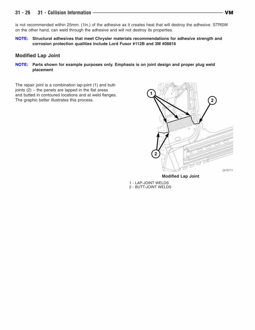
Modified Lap Joint
NOTE: Parts shown for example purposes only. Emphasis is on joint design and proper plug weld
placement
The repair joint is a combination lap-joint (1) and butt-
joints (2) – the panels are lapped in the flat areas
and butted in contoured locations and at weld flanges.
The graphic better illustrates this process.
Modified Lap Joint
1 - LAP-JOINT WELDS2 - BUTT-JOINT WELDS
31 - 26 31 - Collision Information VM
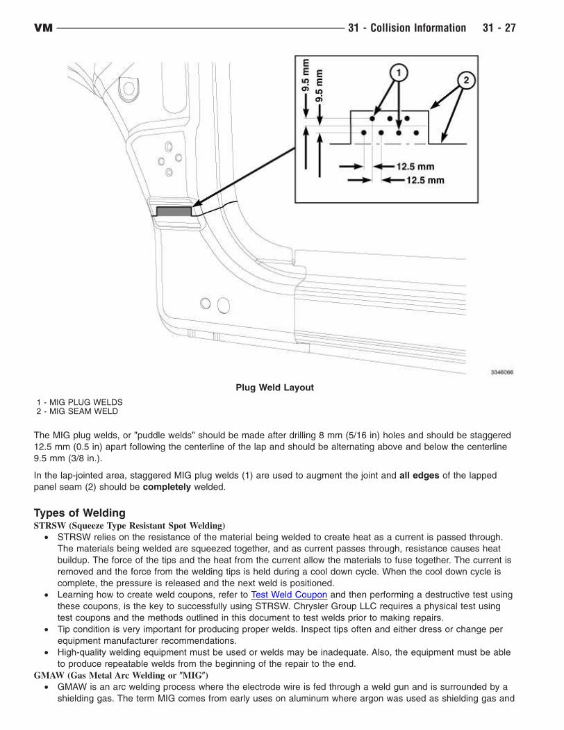
The MIG plug welds, or "puddle welds" should be made after drilling 8 mm (5/16 in) holes and should be staggered
12.5 mm (0.5 in) apart following the centerline of the lap and should be alternating above and below the centerline
9.5 mm (3/8 in.).
In the lap-jointed area, staggered MIG plug welds (1) are used to augment the joint and all edges of the lapped
panel seam (2) should be completely welded.
Types of WeldingSTRSW (Squeeze Type Resistant Spot Welding)
• STRSW relies on the resistance of the material being welded to create heat as a current is passed through.
The materials being welded are squeezed together, and as current passes through, resistance causes heat
buildup. The force of the tips and the heat from the current allow the materials to fuse together. The current is
removed and the force from the welding tips is held during a cool down cycle. When the cool down cycle is
complete, the pressure is released and the next weld is positioned.
• Learning how to create weld coupons, refer to Test Weld Coupon and then performing a destructive test using
these coupons, is the key to successfully using STRSW. Chrysler Group LLC requires a physical test using
test coupons and the methods outlined in this document to test welds prior to making repairs.
• Tip condition is very important for producing proper welds. Inspect tips often and either dress or change per
equipment manufacturer recommendations.
• High-quality welding equipment must be used or welds may be inadequate. Also, the equipment must be able
to produce repeatable welds from the beginning of the repair to the end.
GMAW (Gas Metal Arc Welding or (MIG()
• GMAW is an arc welding process where the electrode wire is fed through a weld gun and is surrounded by a
shielding gas. The term MIG comes from early uses on aluminum where argon was used as shielding gas and
Plug Weld Layout
1 - MIG PLUG WELDS2 - MIG SEAM WELD
VM 31 - Collision Information 31 - 27
the process was referred to as Metal Inert Gas welding. The GMAW process is currently the most common in
the uni-body repair environment.
Weld Bonding
• A method of joining metals using STRSW in conjunction/combination with a structural adhesive.
• Weld bonding provides the customer with a superior repair as compared to the traditional plug/puddle welding
process using GMAW. Structural adhesive should not be used in a joint that did not originally contain it.
• The repair joint or seam should duplicate the OE build as closely as possible, unless otherwise stated in the
collision information.
NOTE: Chrysler Group LLC. DOES NOT approve or endorse the use of structural adhesives alone in the
replacement of body panels.
Weld Processes
Squeeze Type Resistance Spot Welding (STRSW)Applications
• With advancements in equipment technologies, STRSW is not restricted to light gauge sheet metal any longer.
Heavier gauges of high strength and coated steel, currently used in vehicle structures, can now be welded in
the field, providing destructive testing is performed on each combination. This is to ensure quality welds are
being maintained.
Equipment Requirements• Equipment must produce two sided welds
• Equipment must have been tested to SAE J2667 with satisfactory results obtained
• Equipment must have the capability to create welds that comply with the Minimum Weld Nugget Requirement
Chart
• Technician must have the appropriate sheet metal measuring equipment to ensure their welds meet the
minimum weld nugget size for the actual panels being welded
Gas Metal Arc Welding (GMAW or (MIG()Applications
• Sheet metal repairs where STRSW is not available or practical, and truck frame repairs.
• The most common usage of GMAW on uncoated or galvanneal coated steel will utilize a 75% Argon - 25%
CO2 shielding gas mix, and AWS specification ER70S6 wire. When welding galvanized material, Flux Core
Arc Welding (FCAW) using AWS specification E71T-GS wire should be used to avoid weld porosity from
the zinc in the galvanizing.
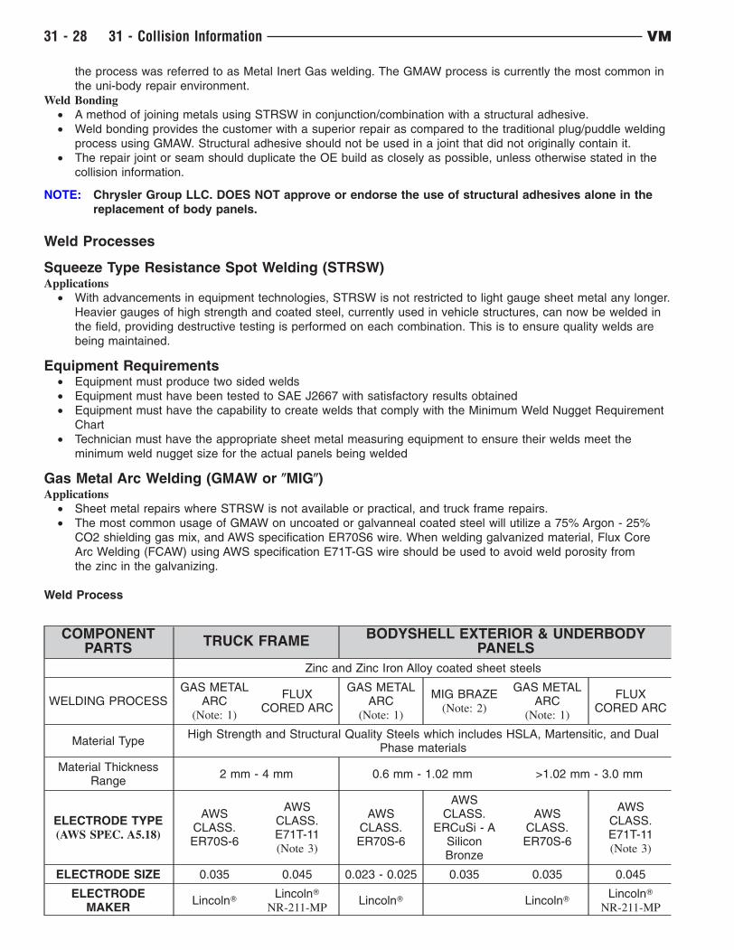
Weld Process
COMPONENTPARTS
TRUCK FRAMEBODYSHELL EXTERIOR & UNDERBODY
PANELS
Zinc and Zinc Iron Alloy coated sheet steels
WELDING PROCESSGAS METAL
ARC(Note: 1)
FLUXCORED ARC
GAS METALARC
(Note: 1)
MIG BRAZE(Note: 2)
GAS METALARC
(Note: 1)
FLUXCORED ARC
Material TypeHigh Strength and Structural Quality Steels which includes HSLA, Martensitic, and Dual
Phase materials
Material ThicknessRange
2 mm - 4 mm 0.6 mm - 1.02 mm >1.02 mm - 3.0 mm
ELECTRODE TYPE(AWS SPEC. A5.18)
AWSCLASS.ER70S-6
AWSCLASS.E71T-11(Note 3)
AWSCLASS.ER70S-6
AWSCLASS.
ERCuSi - ASiliconBronze
AWSCLASS.ER70S-6
AWSCLASS.E71T-11(Note 3)
ELECTRODE SIZE 0.035 0.045 0.023 - 0.025 0.035 0.035 0.045
ELECTRODEMAKER
LincolnTLincolnT
NR-211-MPLincolnT LincolnT
LincolnT
NR-211-MP
31 - 28 31 - Collision Information VM

COMPONENTPARTS
TRUCK FRAMEBODYSHELL EXTERIOR & UNDERBODY
PANELS
WIRE FEED SPEED(in/min)
245-250VerticalDown
110 VerticalDown
95-115 AllWelds
150-155 Flat& Horizontal
245-250VerticalDown
110 VerticalDown
70-90 Flat &Horizontal
70-90 Flat &Horizontal
70-90 Flat &Horizontal
70-90 Flat &Horizontal
TRAVEL SPEED(in/min)
10
VOLTAGE 19-20 15-18 16-19 18-19 19-20 15-18
POLARITY DCEP DCEN DCEP DCEP DCEP DCEN
GAS FLOW (cfh) 25-35 N/A 25-35 25-35 25-35 N/A
ELECTRICALSTICKOUT (in)
1/2 - 5/8 3/8 - 1/2 1/2 - 5/8 5/8 - 3/4 1/2- 5/8 3/8 - 1/2
GAS TYPE 75% Ar N/A 75% Ar 100% Ar 75% Ar N/A
25% CO2 25% CO2 25% CO2
TYPE OF ARCTRANSFER
Short Circuit Short Circuit Pulse Short Circuit
These Procedure Specifications are appropriate as of this publication. Procedures may be superseded with new
spec’s at a later date.
Always process to the thinner material thickness (TMT)
All persons performing welding must be qualified to weld in all positions.
NOTE:
1. Must remove Zinc Coating on both sides of metal at the weld zone.
2. MIG Braze welding process requires use of Pulse ArcT or STTT welding machine.
Equipment Requirements
• The preferred GMAW welder will be a 220V. unit with minimum output capacity of 150 amps (250 amps
suggested to avoid equipment limitations).
Limitations
• Welds must be "dressed", or ground down before applying topcoats.
• GMAW cannot weld through paints, sealers, or adhesives. Additionally, the zinc used in coated steels can lead
to reduced weld strength due to porosity. This porosity problem on materials with heavy coatings can be dealt
with by using FCAW.
• Due to the heat affected zone, structural adhesives cannot be applied within 25mm. (1in.) of GMAW welds.
Testing
• Weld coupons identical to the repair situation need to be created to help set up the welding equipment and
weld process. These coupons then should be destructively tested to ensure proper quality welds are being
made
Post Weld Procedures
• When welding has been completed, welds in cosmetic locations must be dressed.
• Welds will need to be smoothed down to the height of the surrounding panel without any thinning of the sheet
metal. This can be accomplished using one of many sanding or grinding products available in the aftermarket.
• Slag must always be removed prior to refinishing to restore corrosion protection and appearance.
• Corrosion inhibiting materials must be applied to seal the weld zone from future corrosion.
Minimum Weld Nugget Requirement Chart
*Governing Metal Thickness (GMT) **Minimum Weld Nugget Diameter
0.64mm. - 0.79mm. 3.5mm.
0.8mm. - 0.99mm. 4.0mm.
1.0mm. - 1.29mm. 4.5mm.
VM 31 - Collision Information 31 - 29

*Governing Metal Thickness (GMT) **Minimum Weld Nugget Diameter
1.3mm. - 1.59mm. 5.0mm.
1.6mm. - 1.89mm. 5.5mm.
1.9mm. - 2.29mm. 6.0mm.
2.3mm. - 2.69mm. 6.5mm.
2.7mm. - 3.04mm. 7.0mm.
*Governing Metal Thickness (GMT) = The minimum weld nugget for two thickness welds shall be based on the
thinner of the two sheets being welded. The minimum weld nugget diameter for three thickness welds shall be
based on the middle gauge of the three panels being welded (not necessarily the middle panel).
**Minimum nugget diameter should be measured with a venire caliper. If the weld is not round, measure the major
and minor diameter and average.
Equipment Limitations
• Each brand/model is limited to material capacity that can be welded
• The facility power supply can also impact equipment performance
Access Limitations
• Due to the existing structure of the vehicle being repaired, each weld must be evaluated for feasibility. Due to
power limitations of the equipment, tongs that are long and deep enough for certain welds may not be
available, and the weld will need to be made by another method.
CAUTION: All NVH foam must be removed from the repair area of the vehicle, as material is flammable.
Preparation
• Prior to making repairs with STRSW, weld coupons must be created for testing. The test joint must be an
exact duplicate of the original joint, including layering and adhesive application. The testing is required to
ensure the repair restores the vehicle to its originally produced condition using the minimum weld nugget
requirement chart.
• To correctly identify the material being welded or tested, the technician must posses an accurate material
thickness gauge
• No "improvements" to the vehicle design are allowed as this could have a negative impact on the vehicle as a
whole. The repair should mirror what was used on the vehicle at the assembly plant.
• Note, the weld is affected by more than just the thickness or number of panels being welded, but also material
coatings. Zinc based anti-corrosion coatings (i.e., galvannealing, galvanizing), sealers, adhesives, and E-coat
will affect welder performance. Any sandwich type coatings will increase weld time (and current in some
types of STRSW welders) required to accomplish an acceptable weld nugget.
• When preparing an E-coated panel for STRSW the E-coat must be removed from both of the mating flanges
within 25mm. (1in.) of any flange. Corrosion protection is required anytime you remove E-coat. A scuffing disc
should be used to remove the E-coat without damaging other sheet metal coatings
• If the panel originally had structural adhesives it should be reapplied prior to welding. The adhesive should
have a corrosion inhibitor and cover all bare metal.
• Prior to creating weld coupons and the final body repairs, all coatings and dirt/road debris must be removed.
Testing
• Weld coupons identical to the repair situation need to be made prior to performing any repair. These coupons
must be tested (peel test) to determine if the weld nugget meets the minimum size outlined above in the
Minimum Weld Nugget Requirement Chart. Keep in mind that different material coatings, coating thickness,
material thickness, and joint configurations have a direct impact on nugget size.
Weld Bonding
NOTE: Structural adhesive manufacturers will vary on time allowed for completion of STRSW in weld bond
zones. Check and follow adhesive manufacturer recommendations.
Application
• Weld bonding is the STRSW welding process utilizing structural adhesive between the panels that are
resistance welded together. The adhesive creates a very stiff structure, while the welding eliminates concerns
of the adhesives’ peel strength.
• Additionally, the adhesive acts as a sealer and provides a high level of corrosion protection.
Sealers and Adhesives
• Sealers are materials placed on top of a seam to control water and air intrusion.
• Adhesives, providing structural improvements, are found between panels welded together. Adhesives also
31 - 30 31 - Collision Information VM
provide the qualities of sealers when applied correctly.
• The Chrysler Group LLC. recommendation is to replace any suspected adhesive with a two-component,
corrosion inhibiting structural adhesive when any repairs are made, providing the STRSW process is
applicable.
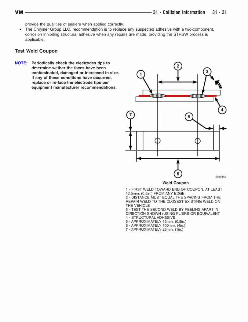
Test Weld Coupon
NOTE: Periodically check the electrodes tips to
determine wether the faces have been
contaminated, damaged or increased in size.
If any of these conditions have occurred,
replace or re-face the electrode tips per
equipment manufacturer recommendations.
Weld Coupon
1 - FIRST WELD TOWARD END OF COUPON, AT LEAST12.5mm. (0.5in.) FROM ANY EDGE2 - DISTANCE MUST EQUAL THE SPACING FROM THEREPAIR WELD TO THE CLOSEST EXISTING WELD ONTHE VEHICLE3 - TEST THE SECOND WELD BY PEELING APART INDIRECTION SHOWN (USING PLIERS OR EQUIVALENT4 - STRUCTURAL ADHESIVE5 - APPROXIMATELY 13mm. (0.5in.)6 - APPROXIMATELY 100mm. (4in.)7 - APPROXIMATELY 25mm. (1in.)
VM 31 - Collision Information 31 - 31
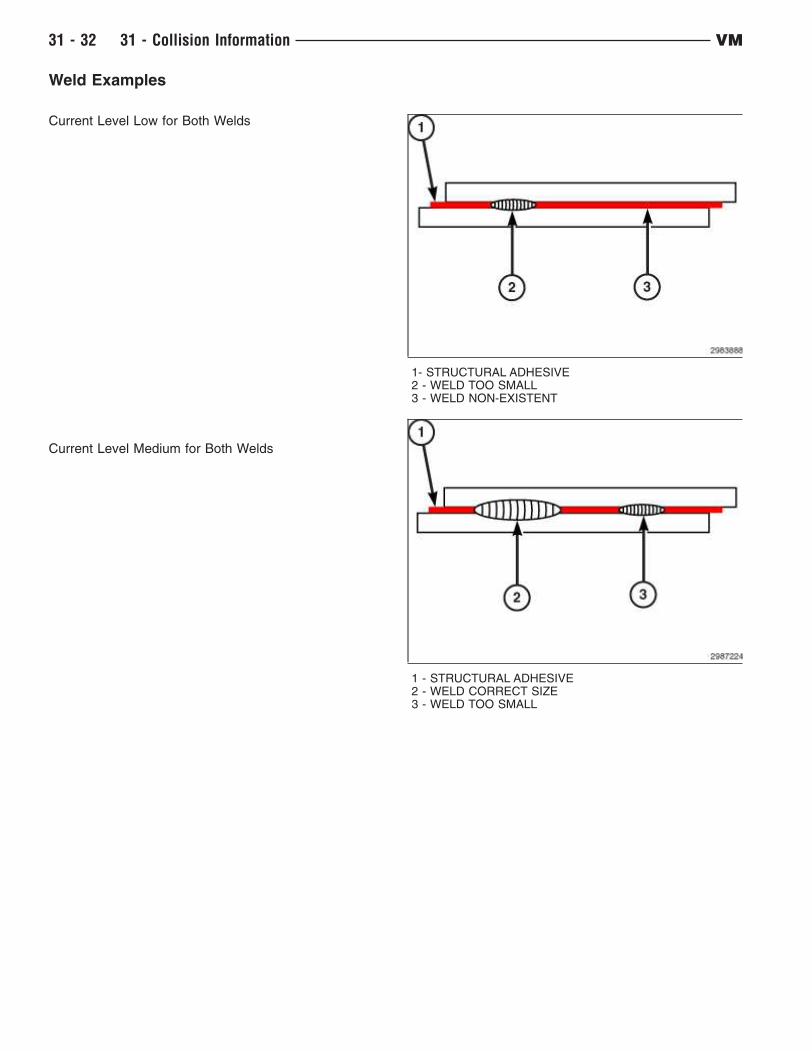
Weld Examples
Current Level Low for Both Welds
Current Level Medium for Both Welds
1- STRUCTURAL ADHESIVE2 - WELD TOO SMALL3 - WELD NON-EXISTENT
1 - STRUCTURAL ADHESIVE2 - WELD CORRECT SIZE3 - WELD TOO SMALL
31 - 32 31 - Collision Information VM
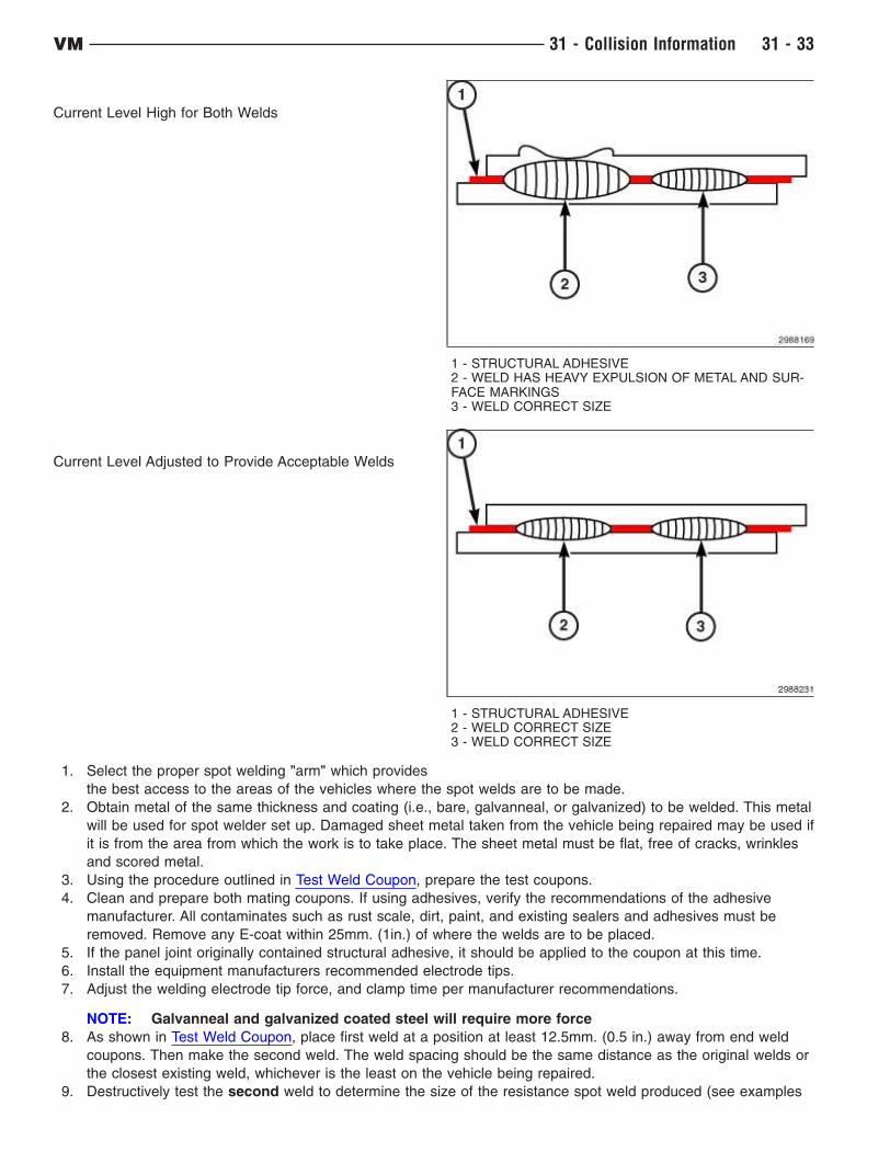
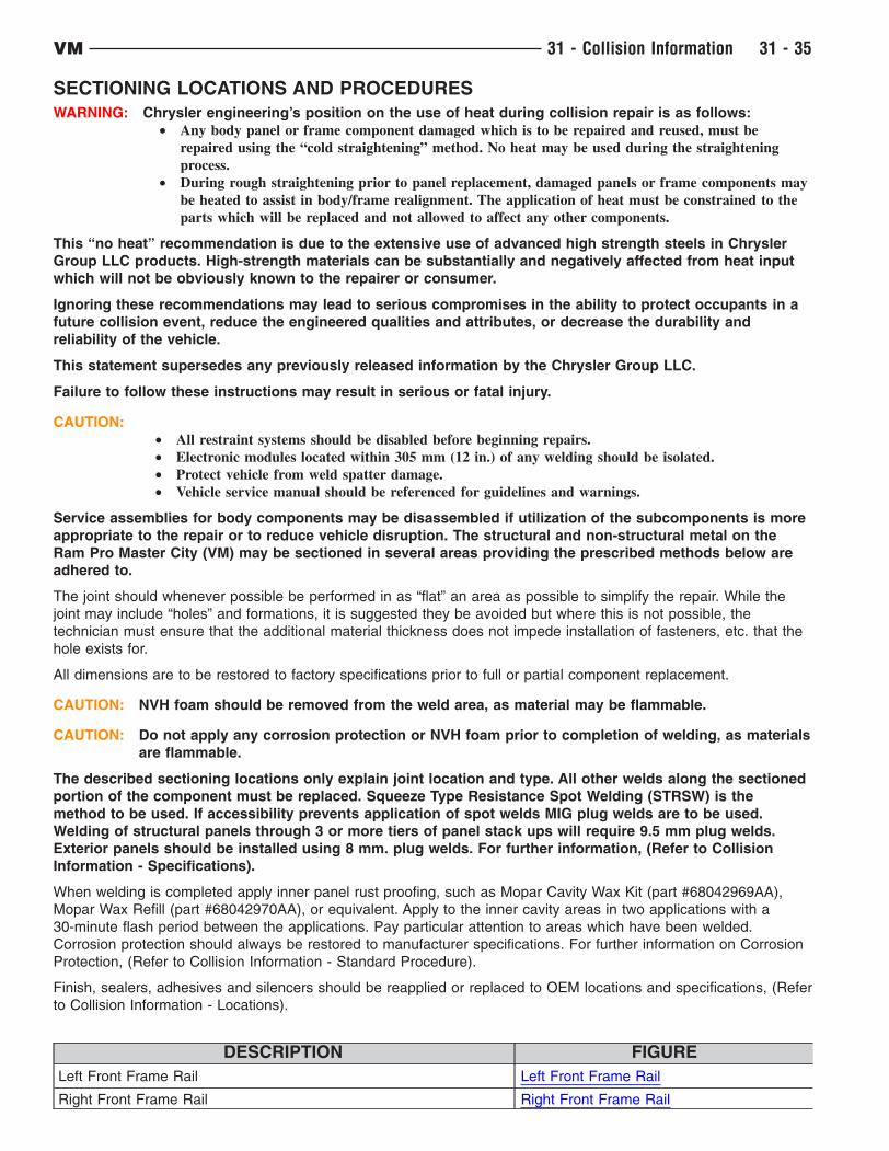
Current Level High for Both Welds
Current Level Adjusted to Provide Acceptable Welds
1. Select the proper spot welding "arm" which provides
the best access to the areas of the vehicles where the spot welds are to be made.
2. Obtain metal of the same thickness and coating (i.e., bare, galvanneal, or galvanized) to be welded. This metal
will be used for spot welder set up. Damaged sheet metal taken from the vehicle being repaired may be used if
it is from the area from which the work is to take place. The sheet metal must be flat, free of cracks, wrinkles
and scored metal.
3. Using the procedure outlined in Test Weld Coupon, prepare the test coupons.
4. Clean and prepare both mating coupons. If using adhesives, verify the recommendations of the adhesive
manufacturer. All contaminates such as rust scale, dirt, paint, and existing sealers and adhesives must be
removed. Remove any E-coat within 25mm. (1in.) of where the welds are to be placed.
5. If the panel joint originally contained structural adhesive, it should be applied to the coupon at this time.
6. Install the equipment manufacturers recommended electrode tips.
7. Adjust the welding electrode tip force, and clamp time per manufacturer recommendations.
NOTE: Galvanneal and galvanized coated steel will require more force
8. As shown in Test Weld Coupon, place first weld at a position at least 12.5mm. (0.5 in.) away from end weld
coupons. Then make the second weld. The weld spacing should be the same distance as the original welds or
the closest existing weld, whichever is the least on the vehicle being repaired.
9. Destructively test the second weld to determine the size of the resistance spot weld produced (see examples
1 - STRUCTURAL ADHESIVE2 - WELD HAS HEAVY EXPULSION OF METAL AND SUR-FACE MARKINGS3 - WELD CORRECT SIZE
1 - STRUCTURAL ADHESIVE2 - WELD CORRECT SIZE3 - WELD CORRECT SIZE
VM 31 - Collision Information 31 - 33

in Test Weld Coupon. If the weld is insufficient, adjust the welder per the welder manufacturer recommenda-
tions and repeat steps 7,8 and 9 until the proper weld size is achieved.
NOTE: If the first weld becomes too (hot( before the second weld reaches the correct size, reduce the
current settings for the first weld and continue increasing the current setting for the second weld
until the proper size for the second has been reached.
Final Weld Preparation
CAUTION: NVH foam should be removed from the weld area, as material may be flammable.
1. Visually verify that mating flanges are free of scale, rust, dirt, paint and cured adhesives/sealers, as well as
wrinkles. If cracked, wrinkled or scored metal exists the condition needs to be corrected at this time.
2. E-coat within 25mm. (1in.) needs to be removed for STRSW. If Weld Bonding, E-coat should be ground off
completely along seam.
NOTE: Corrosion resistance coating (i.e., galvanneal, galvanized) should not be removed during
cleanup of components.
3. If adhesive is to be used, apply it at this time. Clamp the component to the vehicle.
NOTE: Insulated clamps should be used, as not to shunt the weld current.
4. Visually verify that the welds to be made will not be placed directly over an existing weld.
5. After verifying that the welder control settings are the same required to produce the second weld on the test
coupons, make the welds on the vehicle.
NOTE: Structural adhesive manufacturers will vary on time allowed for completion of STRSW in weld
bond zones. Check and follow adhesive manufacturer recommendations.
6. If adhesive was used, clean up any excessive squeezeout prior to adhesive curing.
Training and Qualification
Training
As with any equipment, proper training is required, and in the case of welding equipment this is no exception. The
goal of automobile facilities and technicians is to restore the vehicle to its OEM condition.
Training must be considered a two-fold process:
• The technician must be well versed in how the equipment operates, how adjustments are made and what
effects those adjustments have on the weld. The technician must also clearly understand the maintenance
of the equipment and the impact of poor maintenance on welds and equipment longevity.
• The second and most important, aspect of the training, is weld quality confirmation. Destructive testing of weld
coupons must be performed to ensure the minimum weld size is created. Physical appearance of the weld is
not enough to determine the quality of the weld. Additionally, poor welds may also reduce the durability, or
quality , of the repaired vehicle in time.
It is required that technicians have received training regardless of the welding equipment or method they utilize.
Both training in the specific field of welding, and the particular equipment, are necessary to ensure safe, durable,
quality welds are obtained.
Qualification
To demonstrate welding skill, it is highly important that technicians obtain certification from an organization such as
the American Welding Society (AWS) or a certificate from the Inter-Industry Conference on Auto Collision Repair
(ICAR).
31 - 34 31 - Collision Information VM
SECTIONING LOCATIONS AND PROCEDURES
WARNING: Chrysler engineering’s position on the use of heat during collision repair is as follows:
• Any body panel or frame component damaged which is to be repaired and reused, must be
repaired using the “cold straightening” method. No heat may be used during the straightening
process.
• During rough straightening prior to panel replacement, damaged panels or frame components may
be heated to assist in body/frame realignment. The application of heat must be constrained to the
parts which will be replaced and not allowed to affect any other components.
This “no heat” recommendation is due to the extensive use of advanced high strength steels in Chrysler
Group LLC products. High-strength materials can be substantially and negatively affected from heat input
which will not be obviously known to the repairer or consumer.
Ignoring these recommendations may lead to serious compromises in the ability to protect occupants in a
future collision event, reduce the engineered qualities and attributes, or decrease the durability and
reliability of the vehicle.
This statement supersedes any previously released information by the Chrysler Group LLC.
Failure to follow these instructions may result in serious or fatal injury.
CAUTION:
• All restraint systems should be disabled before beginning repairs.
• Electronic modules located within 305 mm (12 in.) of any welding should be isolated.
• Protect vehicle from weld spatter damage.
• Vehicle service manual should be referenced for guidelines and warnings.
Service assemblies for body components may be disassembled if utilization of the subcomponents is more
appropriate to the repair or to reduce vehicle disruption. The structural and non-structural metal on the
Ram Pro Master City (VM) may be sectioned in several areas providing the prescribed methods below are
adhered to.
The joint should whenever possible be performed in as “flat” an area as possible to simplify the repair. While the
joint may include “holes” and formations, it is suggested they be avoided but where this is not possible, the
technician must ensure that the additional material thickness does not impede installation of fasteners, etc. that the
hole exists for.
All dimensions are to be restored to factory specifications prior to full or partial component replacement.
CAUTION: NVH foam should be removed from the weld area, as material may be flammable.
CAUTION: Do not apply any corrosion protection or NVH foam prior to completion of welding, as materials
are flammable.
The described sectioning locations only explain joint location and type. All other welds along the sectioned
portion of the component must be replaced. Squeeze Type Resistance Spot Welding (STRSW) is the
method to be used. If accessibility prevents application of spot welds MIG plug welds are to be used.
Welding of structural panels through 3 or more tiers of panel stack ups will require 9.5 mm plug welds.
Exterior panels should be installed using 8 mm. plug welds. For further information, (Refer to Collision
Information - Specifications).
When welding is completed apply inner panel rust proofing, such as Mopar Cavity Wax Kit (part #68042969AA),
Mopar Wax Refill (part #68042970AA), or equivalent. Apply to the inner cavity areas in two applications with a
30-minute flash period between the applications. Pay particular attention to areas which have been welded.
Corrosion protection should always be restored to manufacturer specifications. For further information on Corrosion
Protection, (Refer to Collision Information - Standard Procedure).
Finish, sealers, adhesives and silencers should be reapplied or replaced to OEM locations and specifications, (Refer
to Collision Information - Locations).
DESCRIPTION FIGURE
Left Front Frame Rail Left Front Frame Rail
Right Front Frame Rail Right Front Frame Rail
VM 31 - Collision Information 31 - 35

DESCRIPTION FIGURE
Inner Body Side Components DO NOT SECTION Inner Body Side Components Do Not Sec-tion
Sill/Rocker Panel Sill/Rocker Panel
Body Side Panel Body Side Panel
Rear Floor Panel Rear Floor Panel
Left Front Frame Rail
1 - LEFT FRONT FRAME RAIL INNER
2 - BATTERY MOUNTING BRACKET
Remove the spot welds that join the battery mounting bracket (2) to the left front frame rail inner (1). Remove the
battery mounting bracket (2).
31 - 36 31 - Collision Information VM
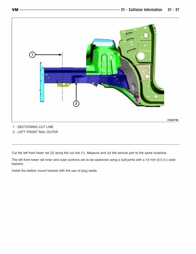
1 - SECTIONING CUT LINE
2 - LEFT FRONT RAIL OUTER
Cut the left front lower rail (2) along the cut line (1). Measure and cut the service part to the same locations.
The left front lower rail inner and outer portions are to be sectioned using a butt-joints with a 13 mm (0.5 in.) weld
backers.
Install the battery mount bracket with the use of plug welds.
VM 31 - Collision Information 31 - 37
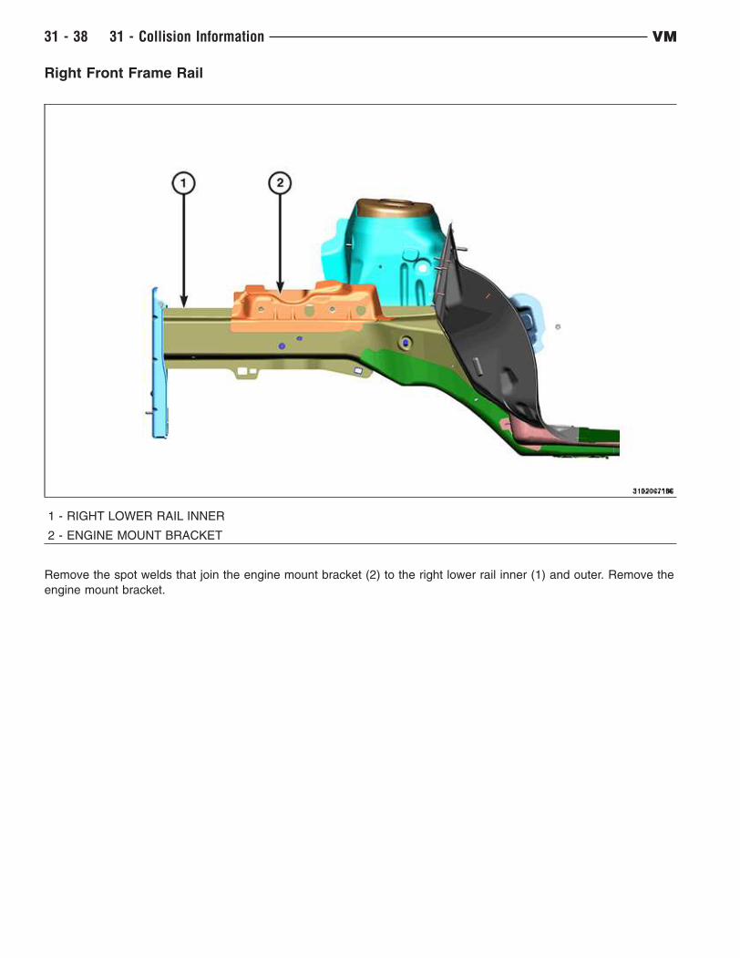
Right Front Frame Rail
1 - RIGHT LOWER RAIL INNER
2 - ENGINE MOUNT BRACKET
Remove the spot welds that join the engine mount bracket (2) to the right lower rail inner (1) and outer. Remove the
engine mount bracket.
31 - 38 31 - Collision Information VM
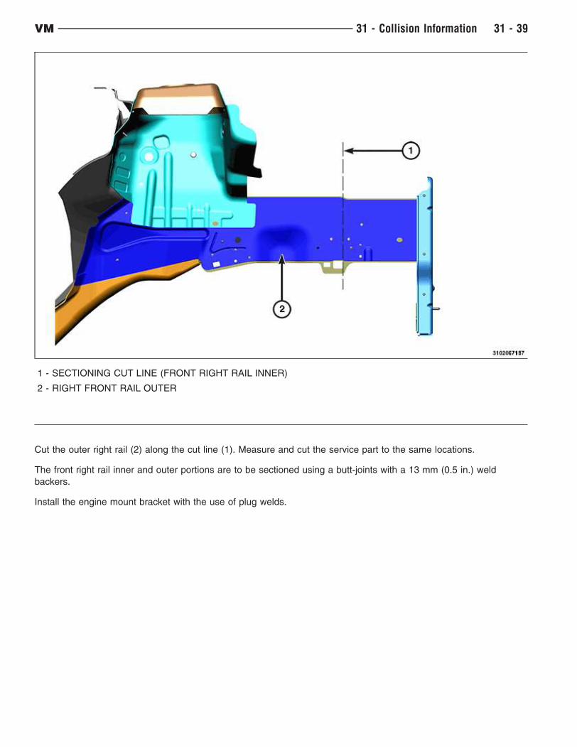
1 - SECTIONING CUT LINE (FRONT RIGHT RAIL INNER)
2 - RIGHT FRONT RAIL OUTER
Cut the outer right rail (2) along the cut line (1). Measure and cut the service part to the same locations.
The front right rail inner and outer portions are to be sectioned using a butt-joints with a 13 mm (0.5 in.) weld
backers.
Install the engine mount bracket with the use of plug welds.
VM 31 - Collision Information 31 - 39
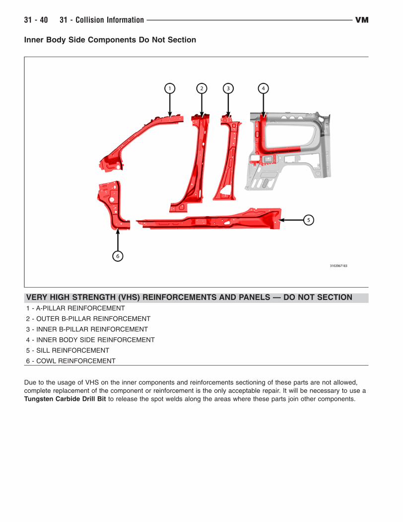
Inner Body Side Components Do Not Section
VERY HIGH STRENGTH (VHS) REINFORCEMENTS AND PANELS — DO NOT SECTION
1 - A-PILLAR REINFORCEMENT
2 - OUTER B-PILLAR REINFORCEMENT
3 - INNER B-PILLAR REINFORCEMENT
4 - INNER BODY SIDE REINFORCEMENT
5 - SILL REINFORCEMENT
6 - COWL REINFORCEMENT
Due to the usage of VHS on the inner components and reinforcements sectioning of these parts are not allowed,
complete replacement of the component or reinforcement is the only acceptable repair. It will be necessary to use a
Tungsten Carbide Drill Bit to release the spot welds along the areas where these parts join other components.
31 - 40 31 - Collision Information VM

Sill/Rocker Panel
1 - DOOR SURROUND PANEL
2 - SILL/ROCKER PANEL
3 - SILL SECTIONING CUT LINES
When cutting through the door surround for sill/rocker panel sectioning use care to ONLY cut through the door
surround. Do not cut into the sill reinforcement located beneath.
A butt-joint with a 13mm (0.5in.) weld backer panel is to be used for sectioning the sill/rocker area.
VM 31 - Collision Information 31 - 41
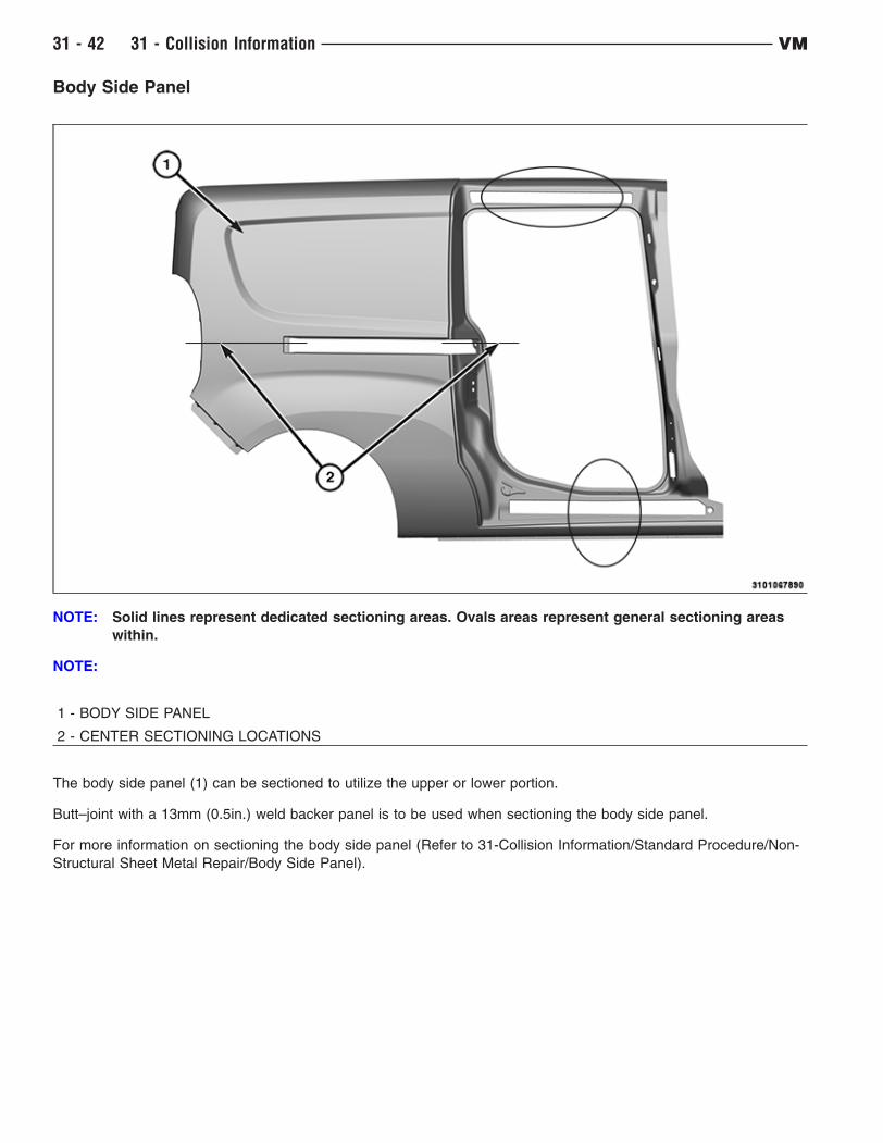
Body Side Panel
NOTE: Solid lines represent dedicated sectioning areas. Ovals areas represent general sectioning areas
within.
NOTE:
1 - BODY SIDE PANEL
2 - CENTER SECTIONING LOCATIONS
The body side panel (1) can be sectioned to utilize the upper or lower portion.
Butt–joint with a 13mm (0.5in.) weld backer panel is to be used when sectioning the body side panel.
For more information on sectioning the body side panel (Refer to 31-Collision Information/Standard Procedure/Non-
Structural Sheet Metal Repair/Body Side Panel).
31 - 42 31 - Collision Information VM

Rear Floor Panels
1 - RIGHT REAR FLOOR TRIM AREA
2 - RIGHT REAR FLOOR
3 - LEFT REAR FLOOR
4 - LEFT REAR FLOOR TRIM AREA
The right and left rear floors can be partially replaced at the forward seam.
Trial fit the rear floor panel and trim the front edge back as required
VM 31 - Collision Information 31 - 43
CORROSION PROTECTION
Corrosion Protection Restoration
"Corrosion protection" encompasses all the materials and coatings which protect a vehicle from corrosion and
include:
• Coated steels
• E-coat primer on the complete body
• Body sealing to eliminate water and air intrusion where panels join
• Structural adhesives in some joints
• Chip resistant primer applications on the entire body
• Paint application
• Underbody corrosion protection
• Inner panel corrosion protection added to repair areas
Corrosion protection must be restored during a repair anytime it may have been compromised. All areas that have
been subjected to structural pulls, clamping, straightening, welding, or any other any other operation that may
have imparted damage to the corrosion protection system will need to be addressed.
In the repair process corrosion protection is addressed in three phases: pre-refinish, refinish and post-refinish.
Pre-refinish
In the pre-finish phase, structural adhesives, seam sealers and other applied coatings are installed. Sheet metal
seams are sealed to prevent water intrusion into the "dry" areas of the vehicle, such as passenger
compartment, and also to prevent intrusions of contaminates, such as water and road salt, into seams causing
corrosion. Lap joints, hem flanges, and any panel mating locations need to be addressed during the repair and
treated to duplicate the original vehicle build.
All bare metal should be etch primed prior to applying seam sealer, following the refinish material provider’s
instructions for doing so, unless the manufacture of the sealer specifically states otherwise.
When working around pinch weld flanges, seam sealer should be installed to duplicate the original appearance and
function. If it is unclear whether the original sealing material between the flanges is strictly a sealer or structural
adhesive, always default to a structural adhesive such as Fusor 112B, or 3M 08116. For additional information
related to weld-bonding and welding around adhesives and sealers, (Refer to 31 - Collision Information - Standard
Procedure).
Roof and closure panels will require the use of Anti-Flutter foam. Where inner panel supports meet external panels,
the proper replacement materials in these areas are Mopar part #04864015AB, or equivalent, or Fusor 121, or 3M
04274 (NVH dampening material).
All hem flanges on closure panels should be sealed whether sealer is apparent or not. This includes those disturbed
during the repair, and those on new replacement panels. Either duplicate the existing bead in shape or size, or
where one is not obvious, seal the hem flange in a discrete fashion. Hem flanges should be sealed using Mopar
part #04318026, Fusor 129, or 3M 08308.
Lap joints, such as in floor pans, should be sealed to duplicate the sealer visible, but also addressed on any exterior
surface by sealing the lap wether visible or not.
NOTE: Chrysler does not recommend the use of any type of (weld-thru( primer during repairs. Weld-
bonding with corrosion protecting adhesives or sealers, along with final application of inner panel
corrosion protection is the proper method.
Refinish
All painted surfaces should be coated using a Chrysler group LLC approved refinish material. The refinish process
includes application of undercoats, primers (filler & sealer), basecoats and clearcoat. These approved materials
have been tested to the same material standards as the production materials.
Post-refinish
All new panels, and repair areas, must have inner panel corrosion protection applied after the painting operation is
complete, but before all the trim is reinstalled. Mopar Cavity Wax No. 68042970AA, or 3M Rustfighter #08891
should be applied to all interior cavities, weld flanges, hem flanges as well as any are affected by the repair
31 - 44 31 - Collision Information VM
especially where any type of welding was performed. Inner panel corrosion protection should be applied using
"pressure pot" equipment with wands which provide 360-degree material coverage for closed cavities, and
directional spray wands for visible coverage (Mopar kit #04271235). Additionally, the corrosion protecting material
must be applied in two coats with a minimum 30-minute flash time between applications.
Wheel wells and underbody panels which have been involved in the repair process should also have a final
undercoating applied. Use Mopar No. 05093417AA, or equivalent, and apply with "pressure pot" style application
equipment.
Any disturbed or removed NVH foam needs to be replaced. Use Mopar part No. 05142864AA, Fusor 130, or 3M
8463.
Following this arrangement, choice of materials, and proper application, the repaired vehicle should be as well
protected against corrosion as it was prior to the repair.
Specifications
VM 31 - Collision Information 31 - 45
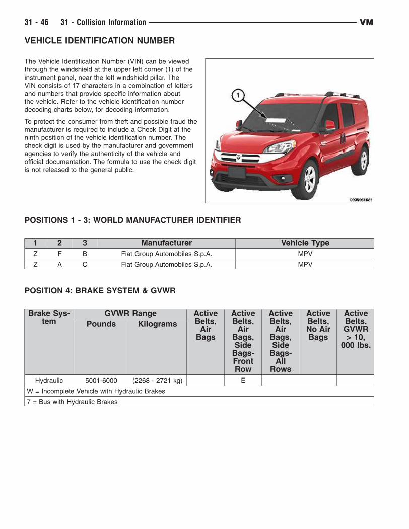
VEHICLE IDENTIFICATION NUMBER
The Vehicle Identification Number (VIN) can be viewed
through the windshield at the upper left corner (1) of the
instrument panel, near the left windshield pillar. The
VIN consists of 17 characters in a combination of letters
and numbers that provide specific information about
the vehicle. Refer to the vehicle identification number
decoding charts below, for decoding information.
To protect the consumer from theft and possible fraud the
manufacturer is required to include a Check Digit at the
ninth position of the vehicle identification number. The
check digit is used by the manufacturer and government
agencies to verify the authenticity of the vehicle and
official documentation. The formula to use the check digit
is not released to the general public.
POSITIONS 1 - 3: WORLD MANUFACTURER IDENTIFIER
1 2 3 Manufacturer Vehicle Type
Z F B Fiat Group Automobiles S.p.A. MPV
Z A C Fiat Group Automobiles S.p.A. MPV
POSITION 4: BRAKE SYSTEM & GVWR
Brake Sys-tem
GVWR Range ActiveBelts,
AirBags
ActiveBelts,
AirBags,Side
Bags-FrontRow
ActiveBelts,
AirBags,Side
Bags-All
Rows
ActiveBelts,No AirBags
ActiveBelts,GVWR> 10,
000 lbs.
Pounds Kilograms
Hydraulic 5001-6000 (2268 - 2721 kg) E
W = Incomplete Vehicle with Hydraulic Brakes
7 = Bus with Hydraulic Brakes
31 - 46 31 - Collision Information VM

Positions 5 - 7:
Define the following: brand, marketing name, drive wheels, cab/body type, drive position, and price series.
RAM PROMASTER CITY (636) MPV
FWD BODY TYPE DRIVE POSITION SERIES
R F A WAGON
Left Hand Drive
ST
R F B WAGON SLT
R F C VAN ST
R F D VAN SLT
POSITION 8: ENGINE
Code Displacement Cylinders Fuel Turbo Sales Codes
T 2.4 Liter 4 Gasoline No ED6
POSITION 9: CHECK DIGIT
0 through 9 or X
POSITION 10: MODEL YEAR
F = 2015
POSITION 11: ASSEMBLY PLANT
CODE PLANT
6 BURSA (TURKEY)
POSITION 12 - 17: PLANT SEQUENCE NUMBER
A six digit number assigned by assembly plant.
VM 31 - Collision Information 31 - 47
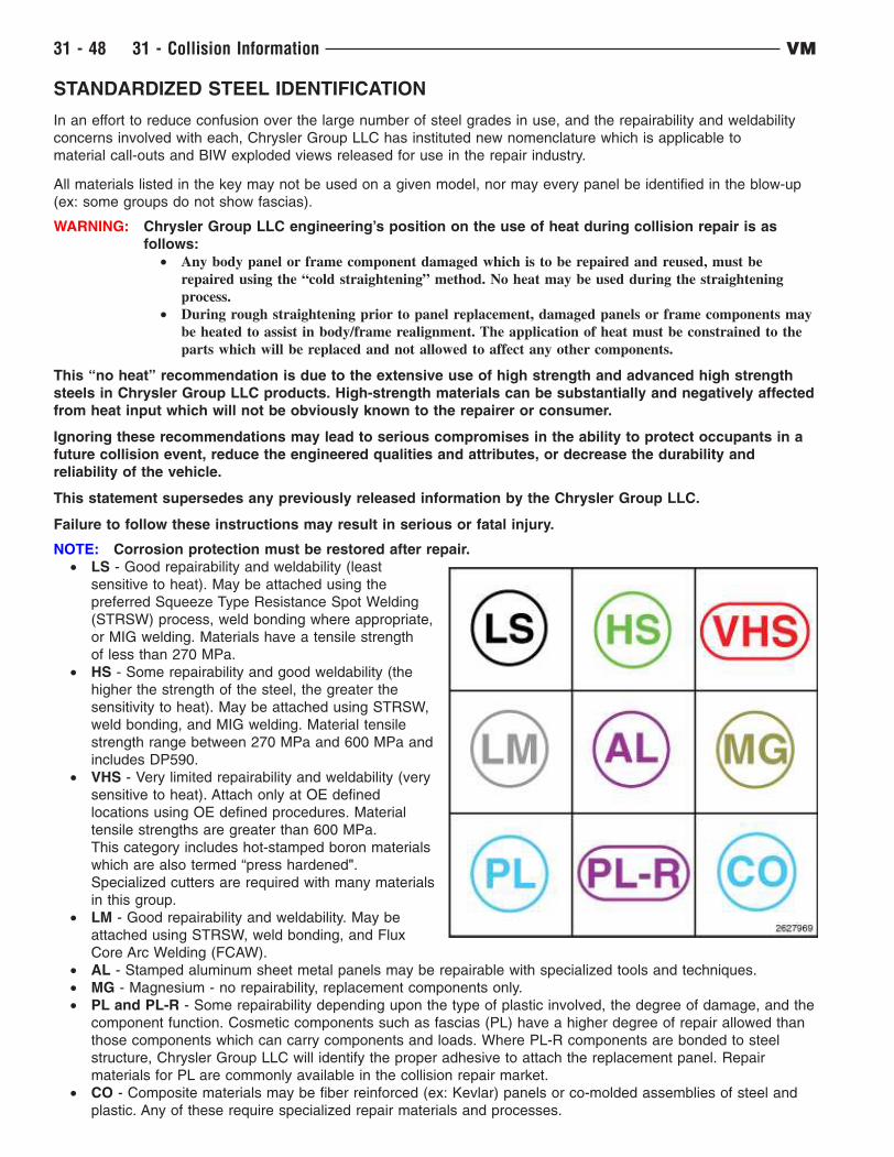
STANDARDIZED STEEL IDENTIFICATION
In an effort to reduce confusion over the large number of steel grades in use, and the repairability and weldability
concerns involved with each, Chrysler Group LLC has instituted new nomenclature which is applicable to
material call-outs and BIW exploded views released for use in the repair industry.
All materials listed in the key may not be used on a given model, nor may every panel be identified in the blow-up
(ex: some groups do not show fascias).
WARNING: Chrysler Group LLC engineering’s position on the use of heat during collision repair is as
follows:
• Any body panel or frame component damaged which is to be repaired and reused, must be
repaired using the “cold straightening” method. No heat may be used during the straightening
process.
• During rough straightening prior to panel replacement, damaged panels or frame components may
be heated to assist in body/frame realignment. The application of heat must be constrained to the
parts which will be replaced and not allowed to affect any other components.
This “no heat” recommendation is due to the extensive use of high strength and advanced high strength
steels in Chrysler Group LLC products. High-strength materials can be substantially and negatively affected
from heat input which will not be obviously known to the repairer or consumer.
Ignoring these recommendations may lead to serious compromises in the ability to protect occupants in a
future collision event, reduce the engineered qualities and attributes, or decrease the durability and
reliability of the vehicle.
This statement supersedes any previously released information by the Chrysler Group LLC.
Failure to follow these instructions may result in serious or fatal injury.
NOTE: Corrosion protection must be restored after repair.
• LS - Good repairability and weldability (least
sensitive to heat). May be attached using the
preferred Squeeze Type Resistance Spot Welding
(STRSW) process, weld bonding where appropriate,
or MIG welding. Materials have a tensile strength
of less than 270 MPa.
• HS - Some repairability and good weldability (the
higher the strength of the steel, the greater the
sensitivity to heat). May be attached using STRSW,
weld bonding, and MIG welding. Material tensile
strength range between 270 MPa and 600 MPa and
includes DP590.
• VHS - Very limited repairability and weldability (very
sensitive to heat). Attach only at OE defined
locations using OE defined procedures. Material
tensile strengths are greater than 600 MPa.
This category includes hot-stamped boron materials
which are also termed “press hardened".
Specialized cutters are required with many materials
in this group.
• LM - Good repairability and weldability. May be
attached using STRSW, weld bonding, and Flux
Core Arc Welding (FCAW).
• AL - Stamped aluminum sheet metal panels may be repairable with specialized tools and techniques.
• MG - Magnesium - no repairability, replacement components only.
• PL and PL-R - Some repairability depending upon the type of plastic involved, the degree of damage, and the
component function. Cosmetic components such as fascias (PL) have a higher degree of repair allowed than
those components which can carry components and loads. Where PL-R components are bonded to steel
structure, Chrysler Group LLC will identify the proper adhesive to attach the replacement panel. Repair
materials for PL are commonly available in the collision repair market.
• CO - Composite materials may be fiber reinforced (ex: Kevlar) panels or co-molded assemblies of steel and
plastic. Any of these require specialized repair materials and processes.
31 - 48 31 - Collision Information VM
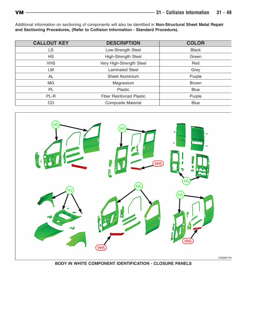
Additional information on sectioning of components will also be identified in Non-Structural Sheet Metal Repair
and Sectioning Procedures, (Refer to Collision Information - Standard Procedure).
CALLOUT KEY DESCRIPTION COLOR
LS Low-Strength Steel Black
HS High-Strength Steel Green
VHS Very High-Strength Steel Red
LM Laminated Steel Grey
AL Sheet Aluminium Purple
MG Magnesium Brown
PL Plastic Blue
PL-R Fiber Reinforced Plastic Purple
CO Composite Material Blue
BODY IN WHITE COMPONENT IDENTIFICATION - CLOSURE PANELS
VM 31 - Collision Information 31 - 49
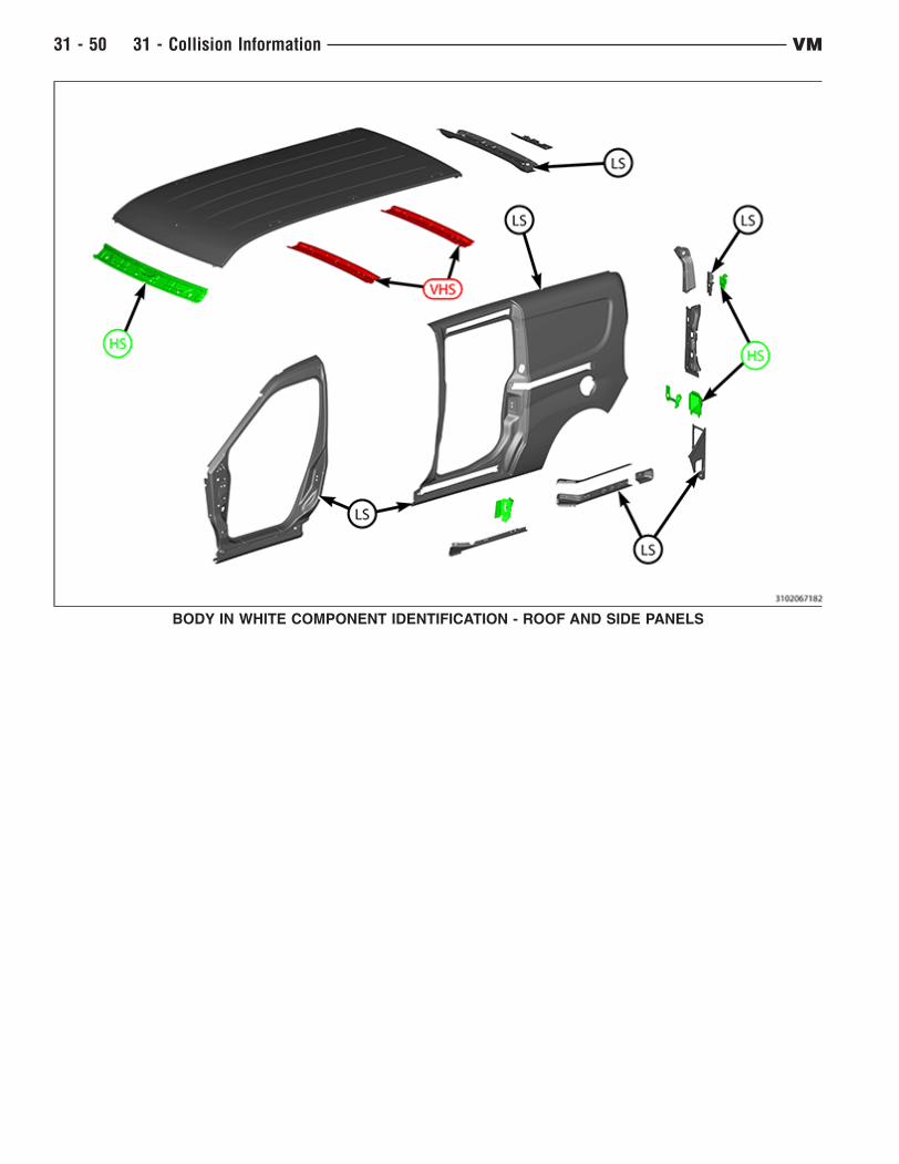
BODY IN WHITE COMPONENT IDENTIFICATION - ROOF AND SIDE PANELS
31 - 50 31 - Collision Information VM

BODY IN WHITE COMPONENT IDENTIFICATION - FRONT STRUCTURE
VM 31 - Collision Information 31 - 51
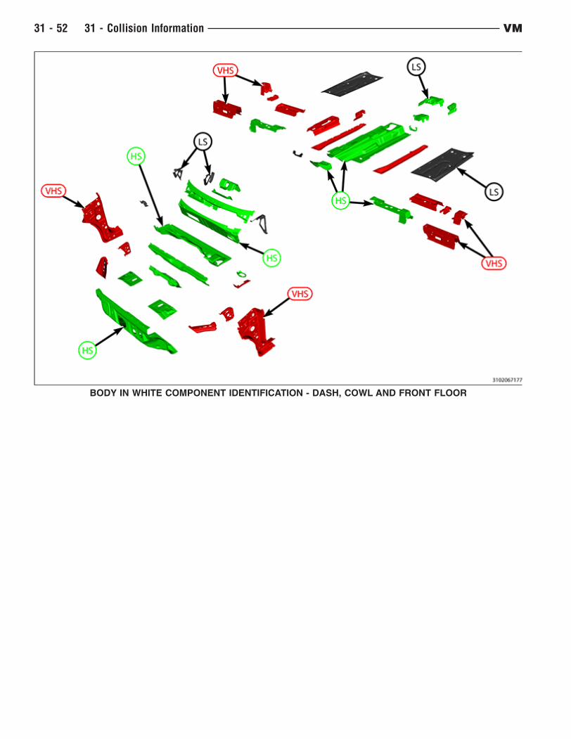
BODY IN WHITE COMPONENT IDENTIFICATION - DASH, COWL AND FRONT FLOOR
31 - 52 31 - Collision Information VM

BODY IN WHITE COMPONENT IDENTIFICATION - INNER PILLARS, SILL AND SLIDING DOOR HEADER
VM 31 - Collision Information 31 - 53

BODY IN WHITE COMPONENT IDENTIFICATION - INNER BODY SIDE, CENTER AND REAR FLOORS
31 - 54 31 - Collision Information VM
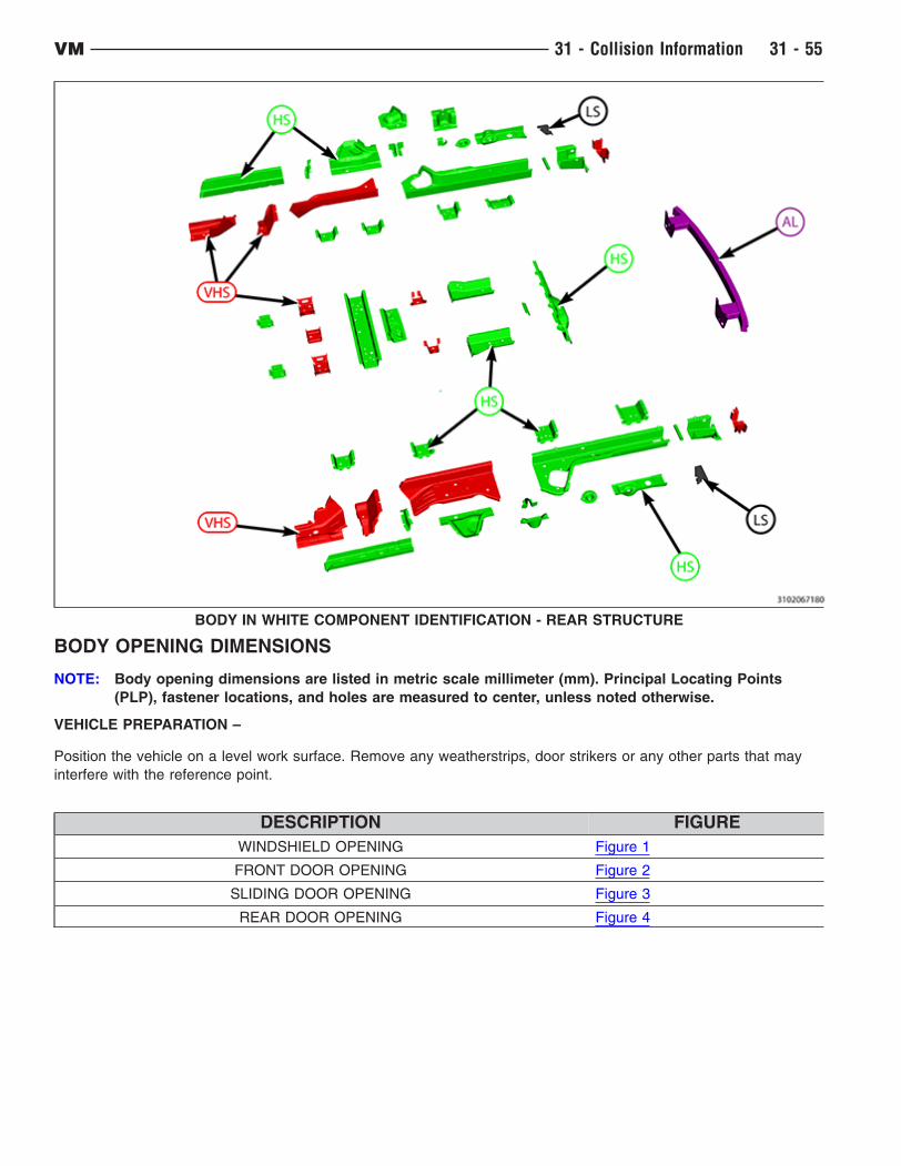
BODY OPENING DIMENSIONS
NOTE: Body opening dimensions are listed in metric scale millimeter (mm). Principal Locating Points
(PLP), fastener locations, and holes are measured to center, unless noted otherwise.
VEHICLE PREPARATION –
Position the vehicle on a level work surface. Remove any weatherstrips, door strikers or any other parts that may
interfere with the reference point.
DESCRIPTION FIGURE
WINDSHIELD OPENING Figure 1
FRONT DOOR OPENING Figure 2
SLIDING DOOR OPENING Figure 3
REAR DOOR OPENING Figure 4
BODY IN WHITE COMPONENT IDENTIFICATION - REAR STRUCTURE
VM 31 - Collision Information 31 - 55

Windshield Opening
Front Door Opening
NOTE: Right side shown. Left side typical.
31 - 56 31 - Collision Information VM
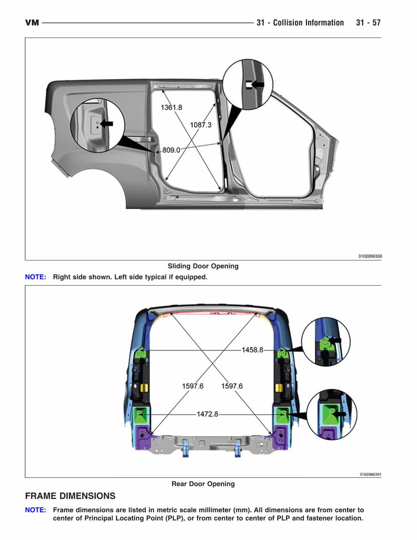
FRAME DIMENSIONS
NOTE: Frame dimensions are listed in metric scale millimeter (mm). All dimensions are from center to
center of Principal Locating Point (PLP), or from center to center of PLP and fastener location.
Sliding Door Opening
NOTE: Right side shown. Left side typical if equipped.
Rear Door Opening
VM 31 - Collision Information 31 - 57
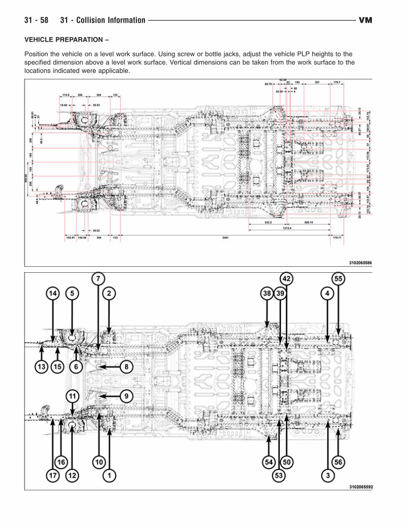
VEHICLE PREPARATION –
Position the vehicle on a level work surface. Using screw or bottle jacks, adjust the vehicle PLP heights to the
specified dimension above a level work surface. Vertical dimensions can be taken from the work surface to the
locations indicated were applicable.
31 - 58 31 - Collision Information VM
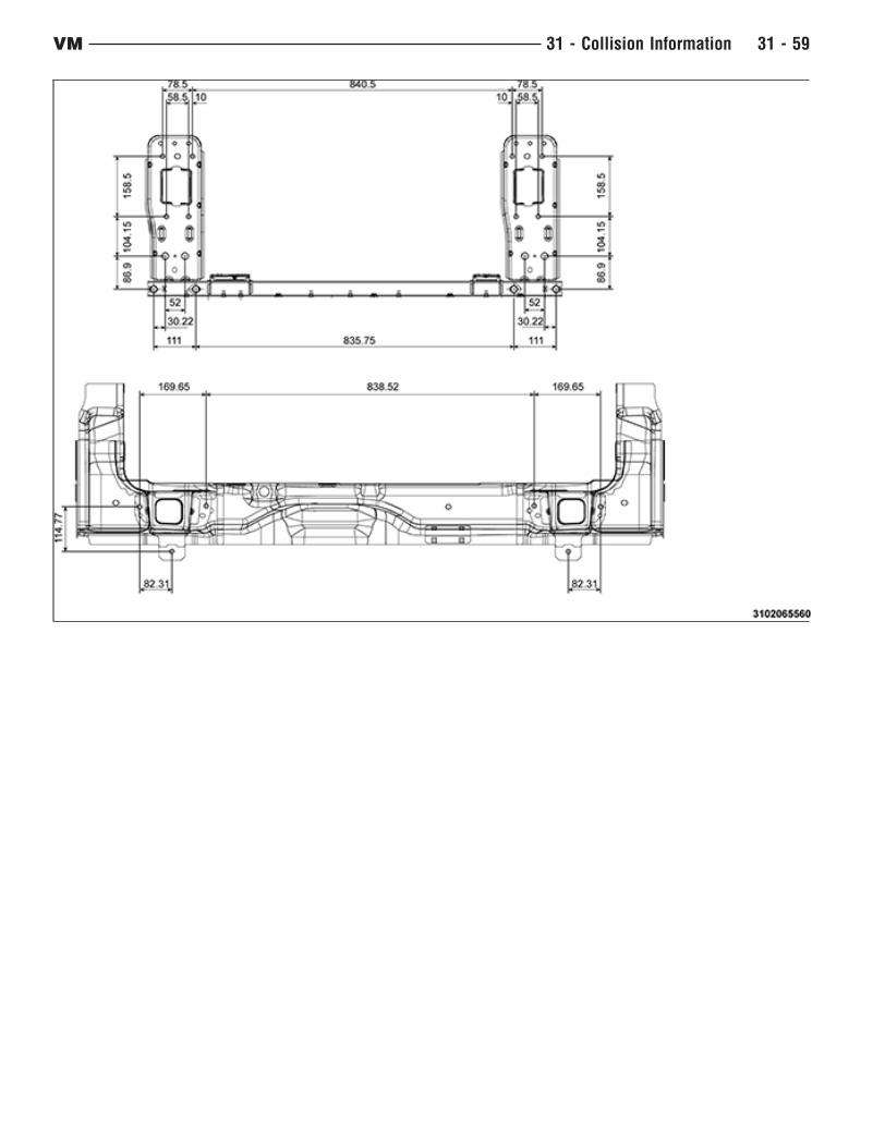
VM 31 - Collision Information 31 - 59
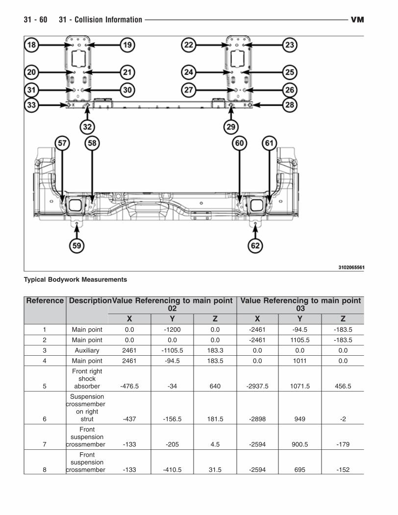
Typical Bodywork Measurements
Reference DescriptionValue Referencing to main point02
Value Referencing to main point03
X Y Z X Y Z
1 Main point 0.0 -1200 0.0 -2461 -94.5 -183.5
2 Main point 0.0 0.0 0.0 -2461 1105.5 -183.5
3 Auxiliary 2461 -1105.5 183.3 0.0 0.0 0.0
4 Main point 2461 -94.5 183.5 0.0 1011 0.0
5
Front rightshock
absorber -476.5 -34 640 -2937.5 1071.5 456.5
6
Suspensioncrossmember
on rightstrut -437 -156.5 181.5 -2898 949 -2
7
Frontsuspension
crossmember -133 -205 4.5 -2594 900.5 -179
8
Frontsuspension
crossmember -133 -410.5 31.5 -2594 695 -152
31 - 60 31 - Collision Information VM
Reference DescriptionValue Referencing to main point02
Value Referencing to main point03
X Y Z X Y Z
9
Frontsuspension
crossmember -133 -789.5 31.5 -2594 316 -152
10
Frontsuspension
crossmember -133 -995 4.5 -2594 110.5 -179
11
Suspensioncrossmember
on left strut -437 -1043.5 -181.5 -2898 62 -2
12
Front leftshock
absorber -476.5 -1166 640 -2937.5 -60.5 -456.5
13
Right sideenginemount -796.5 -137 404 -3257.5 968.5 220
14
Right sideenginemount -651.5 -106 404 -3112.5 999.5 220
15
Right sideenginemount -633 -141.5 404 -3094 964 220
16
Gearboxside enginemounting -581.5 -1054.5 340.5 -3042.5 51 157
17
Gearboxside enginemounting -734.5 -1054.5 340.5 -3195.5 51 157
18
Right sidefront crash
boxcrossmember -1093 -94.5 376 -3554 1011 192.5
19
Right sidefront crash
boxcrossmember -1093 -173 376 -3554 -932.5 192.5
20
Right sidefront crash
boxcrossmember -1093 -104.5 217.5 -3554 1001 34
21
Right sidefront crash
boxcrossmember -1093 -163 217.5 -3554 942.5 34
22
Left sidefront crash
boxcrossmember -1093 -1013.5 376 -3554 92 193
23
Left sidefront crash
boxcrossmember -1093 -1092 376 -3554 13.5 193
VM 31 - Collision Information 31 - 61
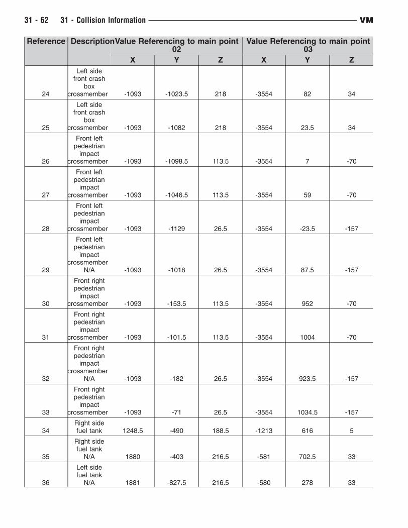
Reference DescriptionValue Referencing to main point02
Value Referencing to main point03
X Y Z X Y Z
24
Left sidefront crash
boxcrossmember -1093 -1023.5 218 -3554 82 34
25
Left sidefront crash
boxcrossmember -1093 -1082 218 -3554 23.5 34
26
Front leftpedestrian
impactcrossmember -1093 -1098.5 113.5 -3554 7 -70
27
Front leftpedestrian
impactcrossmember -1093 -1046.5 113.5 -3554 59 -70
28
Front leftpedestrian
impactcrossmember -1093 -1129 26.5 -3554 -23.5 -157
29
Front leftpedestrian
impactcrossmember
N/A -1093 -1018 26.5 -3554 87.5 -157
30
Front rightpedestrian
impactcrossmember -1093 -153.5 113.5 -3554 952 -70
31
Front rightpedestrian
impactcrossmember -1093 -101.5 113.5 -3554 1004 -70
32
Front rightpedestrian
impactcrossmember
N/A -1093 -182 26.5 -3554 923.5 -157
33
Front rightpedestrian
impactcrossmember -1093 -71 26.5 -3554 1034.5 -157
34Right sidefuel tank 1248.5 -490 188.5 -1213 616 5
35
Right sidefuel tank
N/A 1880 -403 216.5 -581 702.5 33
36
Left sidefuel tank
N/A 1881 -827.5 216.5 -580 278 33
31 - 62 31 - Collision Information VM
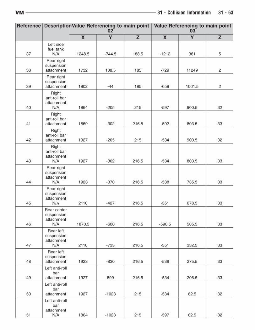
Reference DescriptionValue Referencing to main point02
Value Referencing to main point03
X Y Z X Y Z
37
Left sidefuel tank
N/A 1248.5 -744.5 188.5 -1212 361 5
38
Rear rightsuspensionattachment 1732 108.5 185 -729 11249 2
39
Rear rightsuspensionattachment 1802 -44 185 -659 1061.5 2
40
Rightant-roll barattachment
N/A 1864 -205 215 -597 900.5 32
41
Rightant-roll barattachment 1869 -302 216.5 -592 803.5 33
42
Rightant-roll barattachment 1927 -205 215 -534 900.5 32
43
Rightant-roll barattachment
N/A 1927 -302 216.5 -534 803.5 33
44
Rear rightsuspensionattachment
N/A 1923 -370 216.5 -538 735.5 33
45
Rear rightsuspensionattachment
N/A 2110 -427 216.5 -351 678.5 33
46
Rear centersuspensionattachment
N/A 1870.5 -600 216.5 -590.5 505.5 33
47
Rear leftsuspensionattachment
N/A 2110 -733 216.5 -351 332.5 33
48
Rear leftsuspensionattachment 1923 -830 216.5 -538 275.5 33
49
Left anti-rollbar
attachment 1927 899 216.5 -534 206.5 33
50
Left anti-rollbar
attachment 1927 -1023 215 -534 82.5 32
51
Left anti-rollbar
attachmentN/A 1864 -1023 215 -597 82.5 32
VM 31 - Collision Information 31 - 63
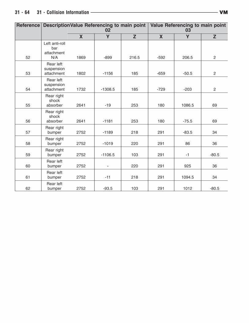
Reference DescriptionValue Referencing to main point02
Value Referencing to main point03
X Y Z X Y Z
52
Left anti-rollbar
attachmentN/A 1869 -899 216.5 -592 206.5 2
53
Rear leftsuspensionattachment 1802 -1156 185 -659 -50.5 2
54
Rear leftsuspensionattachment 1732 -1308.5 185 -729 -203 2
55
Rear rightshock
absorber 2641 -19 253 180 1086.5 69
56
Rear rightshock
absorber 2641 -1181 253 180 -75.5 69
57Rear rightbumper 2752 -1189 218 291 -83.5 34
58Rear rightbumper 2752 -1019 220 291 86 36
59Rear rightbumper 2752 -1106.5 103 291 -1 -80.5
60Rear leftbumper 2752 - 220 291 925 36
61Rear leftbumper 2752 -11 218 291 1094.5 34
62Rear leftbumper 2752 -93.5 103 291 1012 -80.5
31 - 64 31 - Collision Information VM
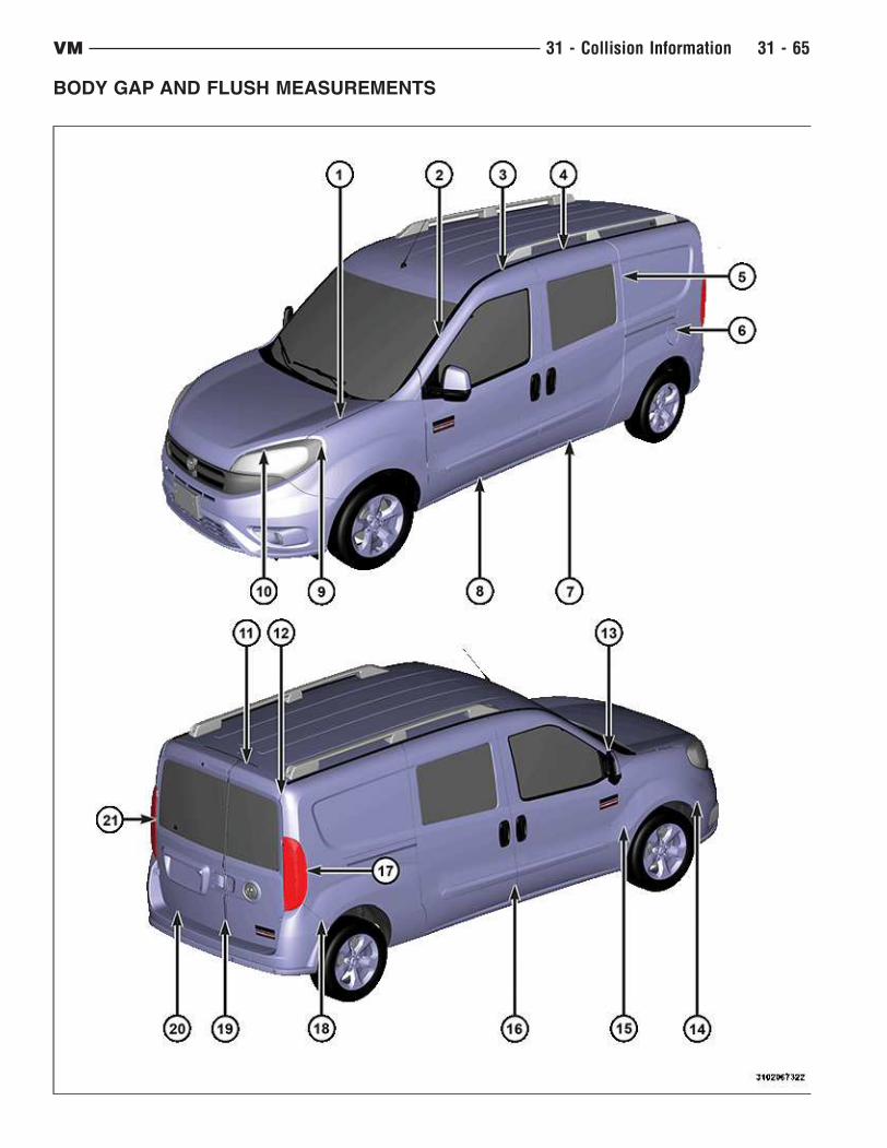
BODY GAP AND FLUSH MEASUREMENTS
VM 31 - Collision Information 31 - 65
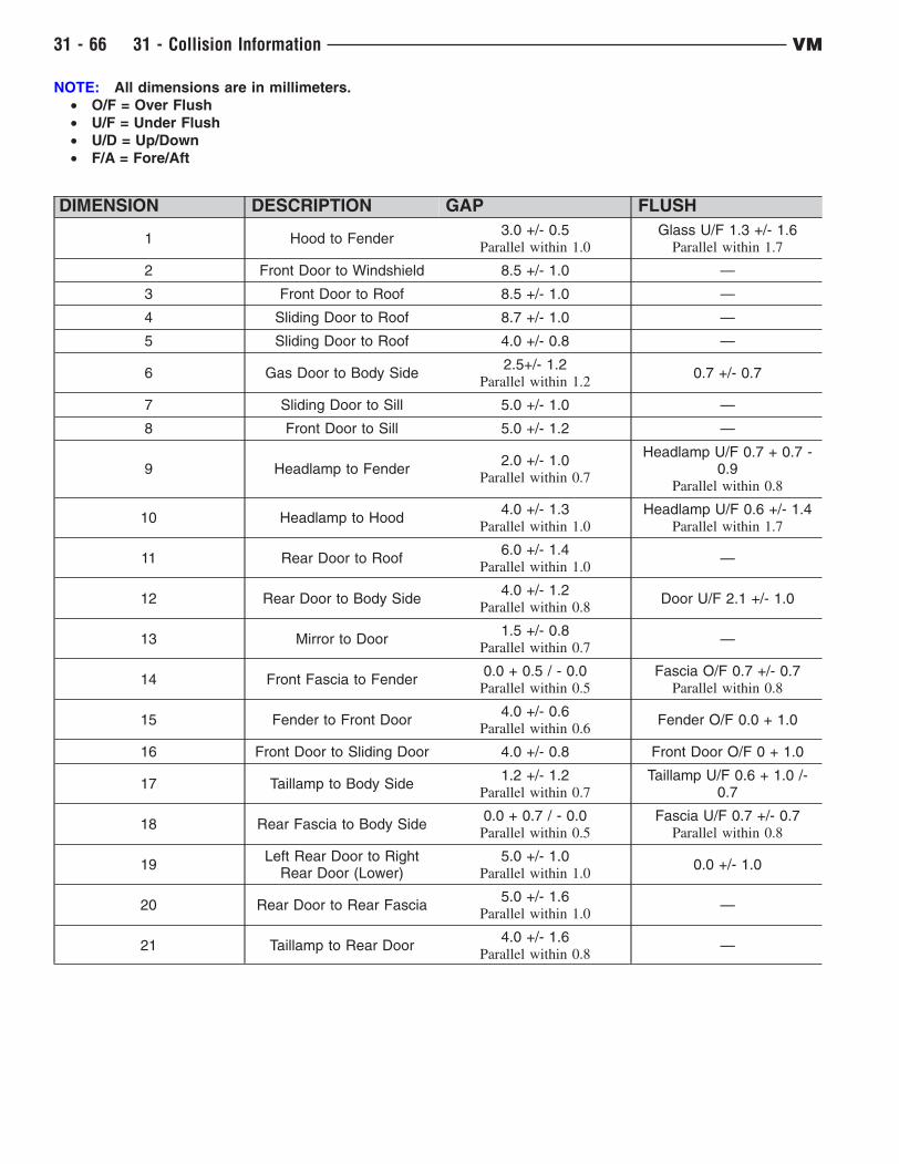
NOTE: All dimensions are in millimeters.
• O/F = Over Flush
• U/F = Under Flush
• U/D = Up/Down
• F/A = Fore/Aft
DIMENSION DESCRIPTION GAP FLUSH
1 Hood to Fender3.0 +/- 0.5
Parallel within 1.0
Glass U/F 1.3 +/- 1.6Parallel within 1.7
2 Front Door to Windshield 8.5 +/- 1.0 —
3 Front Door to Roof 8.5 +/- 1.0 —
4 Sliding Door to Roof 8.7 +/- 1.0 —
5 Sliding Door to Roof 4.0 +/- 0.8 —
6 Gas Door to Body Side2.5+/- 1.2
Parallel within 1.20.7 +/- 0.7
7 Sliding Door to Sill 5.0 +/- 1.0 —
8 Front Door to Sill 5.0 +/- 1.2 —
9 Headlamp to Fender2.0 +/- 1.0
Parallel within 0.7
Headlamp U/F 0.7 + 0.7 -0.9
Parallel within 0.8
10 Headlamp to Hood4.0 +/- 1.3
Parallel within 1.0
Headlamp U/F 0.6 +/- 1.4Parallel within 1.7
11 Rear Door to Roof6.0 +/- 1.4
Parallel within 1.0—
12 Rear Door to Body Side4.0 +/- 1.2
Parallel within 0.8Door U/F 2.1 +/- 1.0
13 Mirror to Door1.5 +/- 0.8
Parallel within 0.7—
14 Front Fascia to Fender0.0 + 0.5 / - 0.0Parallel within 0.5
Fascia O/F 0.7 +/- 0.7Parallel within 0.8
15 Fender to Front Door4.0 +/- 0.6
Parallel within 0.6Fender O/F 0.0 + 1.0
16 Front Door to Sliding Door 4.0 +/- 0.8 Front Door O/F 0 + 1.0
17 Taillamp to Body Side1.2 +/- 1.2
Parallel within 0.7
Taillamp U/F 0.6 + 1.0 /-0.7
18 Rear Fascia to Body Side0.0 + 0.7 / - 0.0Parallel within 0.5
Fascia U/F 0.7 +/- 0.7Parallel within 0.8
19Left Rear Door to Right
Rear Door (Lower)5.0 +/- 1.0
Parallel within 1.00.0 +/- 1.0
20 Rear Door to Rear Fascia5.0 +/- 1.6
Parallel within 1.0—
21 Taillamp to Rear Door4.0 +/- 1.6
Parallel within 0.8—
31 - 66 31 - Collision Information VM
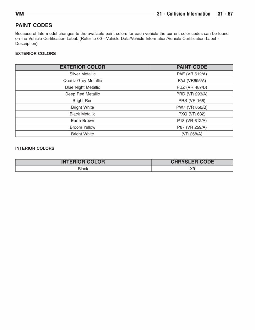
PAINT CODES
Because of late model changes to the available paint colors for each vehicle the current color codes can be found
on the Vehicle Certification Label. (Refer to 00 - Vehicle Data/Vehicle Information/Vehicle Certification Label -
Description)
EXTERIOR COLORS
EXTERIOR COLOR PAINT CODE
Silver Metallic PAF (VR 612/A)
Quartz Grey Metallic PAJ (VR695/A)
Blue Night Metallic PBZ (VR 487/B)
Deep Red Metallic PRD (VR 293/A)
Bright Red PRS (VR 168)
Bright White PW7 (VR 850/B)
Black Metallic PXQ (VR 632)
Earth Brown P18 (VR 612/A)
Broom Yellow P67 (VR 259/A)
Bright White (VR 268/A)
INTERIOR COLORS
INTERIOR COLOR CHRYSLER CODE
Black X9
VM 31 - Collision Information 31 - 67

VEHICLE CERTIFICATION LABEL
A vehicle certification label is attached to every Chrysler Group LLC vehicle. The label certifies that the vehicle
conforms to all applicable Federal Motor Vehicle Standards. The label also lists:
• Month and year of vehicle manufacture.
• Gross Vehicle Weight Rating (GVWR). The gross front and rear axle weight ratings (GAWR’s) are based on a
minimum rim size and maximum cold tire inflation pressure.
• Vehicle Identification Number (VIN).
• Type of vehicle.
• Type of rear wheels.
• Bar code.
• Month, Day and Hour (MDH) of final assembly.
• Paint and Trim codes.
• Country of origin.
The label is located on the driver-side door shut-face.
Locations
31 - 68 31 - Collision Information VM
SEALERS AND SOUND DEADENERSTerminology
• Work Time : The length of time a sealer can continue to be applied or tooled effectively.
• Set Time : Time when there is no longer product transfer.
• Handling Time : The time when a part can be safely transported and sealer can no longer be tooled or
repositioned.
• Full Cure Time : Time when a sealer has reached full strength.
• Paintable Time : Established time when refinish materials can safely be applied to a sealer.
Sealers
• Brushable : Single component sealer applied with a brush.
• Flowable : Sealer with low viscosity and self-leveling characteristics.
• Pumpable : A two component or one component sealer that seals interior and exterior joints and voids.
• Resistance Weld-through : Sealer / adhesive that can be used in conjunction with resistance spot welding.
• Sealer Tape : Preformed sealer.
• Sprayable : Sealer applied with a pneumatic dispenser to duplicate original textured appearance.
• Thumb Grade : Heavy bodied sealer for sealing large gaps and filling voids. Should remain soft and pliable.
Sound Deadeners
• Non-Structural Flexible Acoustical : Flexible foam with sealing and sound deadening properties.
• Non-Structural Ridged Acoustical : Ridged foam with sealing and sound deadening properties.
• Mastic Pads : Sound deadener pad that is preformed to fit a specific area.
Identifying Sealers
• Several types of sealers and sound deadeners are used during assembly. Therefore, specific applications may
not be identified in this publication. General applications and the various types of products for repair will be
featured to identify and replace OEM sealers and sound deadeners.
Helpful Sealer Tips
• Check shelf life or expiration date prior to beginning sealer applications.
• Be sure "work time" is appropriate for sealer application.
• Temperature, humidity and thickness of sealer will affect the work, set and paintable times.
• Test fit replacement panels prior to installation to insure tight fit and proper seal.
• Equalize 2K Products according to adhesive manufacturer’s recommendations.
• Always follow manufacturer’s recommendations for storage, usage and application to achieve best
performance of the product.
VM 31 - Collision Information 31 - 69

SOUND DEADENER LOCATIONS
DESCRIPTION FIGURE
HOOD FIGURE 1
DASH PANEL (EXTERIOR) FIGURE 2
DASH PANEL (INTERIOR) FIGURE 3
FRONT FLOOR (1 of 2) FIGURE 4
FRONT FLOOR (2 of 2) FIGURE 5
REAR TUNNEL FIGURE 6
REAR FLOOR (FRONT) FIGURE 7
REAR FLOOR (REAR) FIGURE 8
Hood
1 - HOOD2 - HOOD SILENCER PAD
31 - 70 31 - Collision Information VM
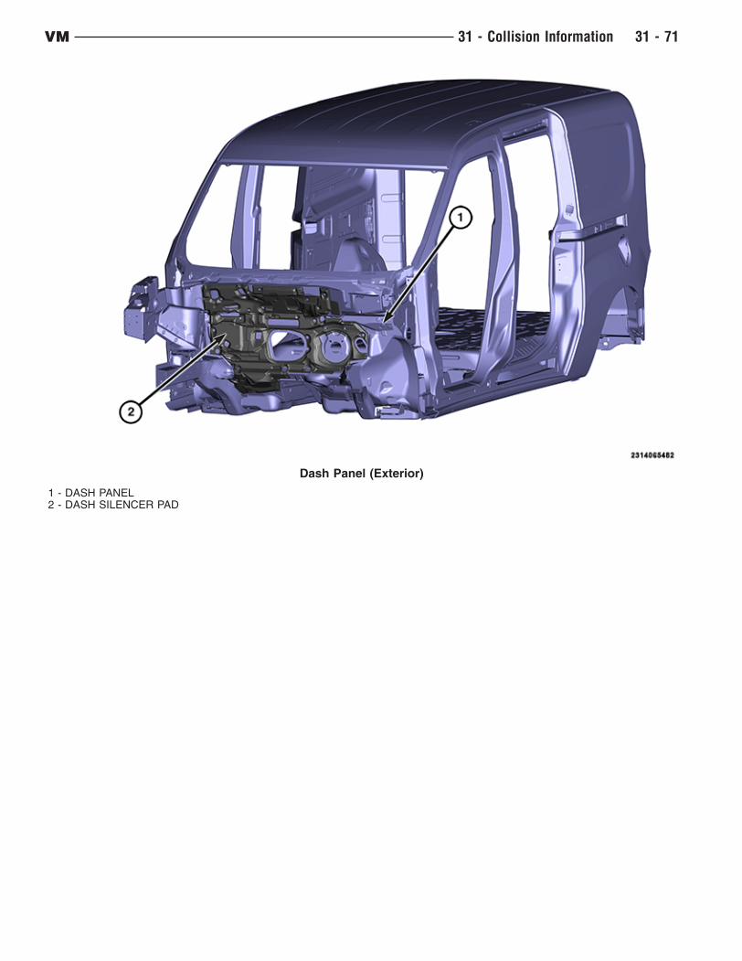
Dash Panel (Exterior)
1 - DASH PANEL2 - DASH SILENCER PAD
VM 31 - Collision Information 31 - 71
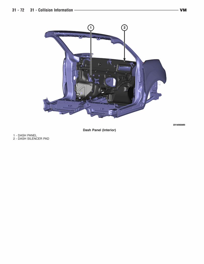
Dash Panel (Interior)
1 - DASH PANEL2 - DASH SILENCER PAD
31 - 72 31 - Collision Information VM
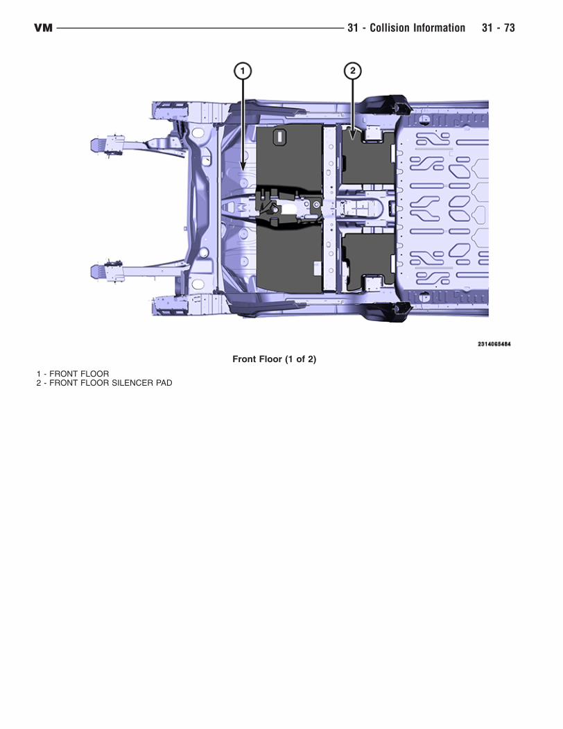
Front Floor (1 of 2)
1 - FRONT FLOOR2 - FRONT FLOOR SILENCER PAD
VM 31 - Collision Information 31 - 73
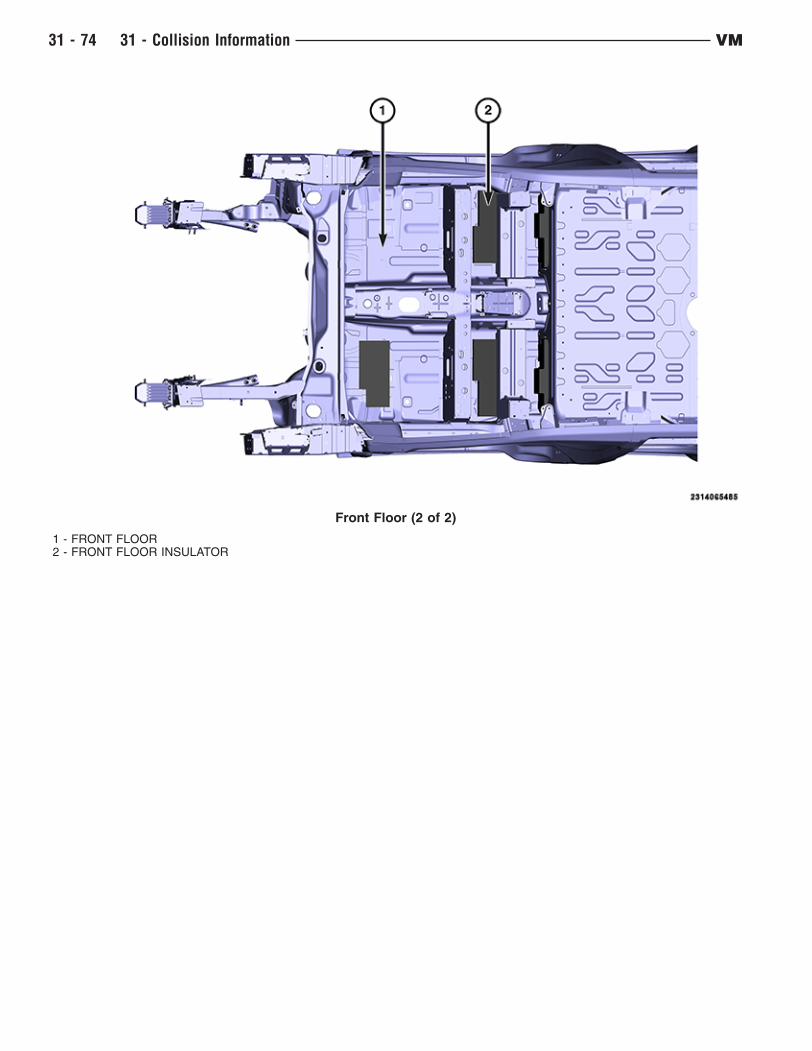
Front Floor (2 of 2)
1 - FRONT FLOOR2 - FRONT FLOOR INSULATOR
31 - 74 31 - Collision Information VM
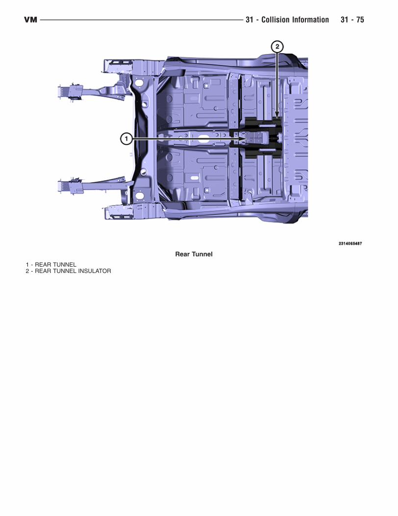
Rear Tunnel
1 - REAR TUNNEL2 - REAR TUNNEL INSULATOR
VM 31 - Collision Information 31 - 75

Rear Floor (Front)
1 - REAR FLOOR (FRONT)2 - REAR FLOOR FILLER FOAM3- REAR FLOOR INSULATION
31 - 76 31 - Collision Information VM

STRUCTURAL ADHESIVE, FLEXIBLE ADHESIVES AND SEAM SEALER LOCATIONS
Structural adhesives, flexible adhesives and seam sealers should only be applied by trained technicians. Follow the
manufactures instructions for proper applications of products.
• Structural adhesives are applied by itself or in conjunction with Squeeze Type Resistance Spot Welds and is
to be re-assembled in the same manner as vehicle build. Any situation where it is undetermined weather it is
structural adhesives or seam sealer always default to structural adhesive .
• Anti-flutter adhesives are applied to areas of the vehicle where adhesive properties with flexibility are
required. Typically found on supports and braces throughout the closure panels, roof and body side gas
fill areas.
• Seam sealers are only to be used topically, never within weld flanges or hem flanges. All sealers being
replaced should duplicate the factory style sealer in shape and size.
For additional information on Corrosion Protection, and Sealer and Sound Description, (Refer to Collision
Information - Standard Procedure).
Chrysler approved replacement materials include -
• Structural Adhesives : Fusor 112B, 3M 08116.
• Anti-Flutter Adhesives (flexible) : Fusor 121 (Flexible Foam), 3M 04724 (NVH dampening material) and
Crest– CFF Flexi-Foam.
• Seam Sealer : Mopar #04318026, Fusor 129, 3M 08308.
Rear Floor (Rear)
1 - REAR FLOOR (REAR)2 - REAR FLOOR INSULATION
VM 31 - Collision Information 31 - 77


![CICADA - USENIX · 1 vm 2 vm 3 vm 4 vm 5vm 6 vm 7 vm 8 vm 9 vm 2 vm 3 vm 4 vm 5 vm 6 vm 7 vm 8 vm 9 vm 1 rigid application (similar to VOC [1]) vm 1 vm 2 vm 3 vm 4 vm 5vm 6 vm 7 vm](https://static.fdocuments.us/doc/165x107/5f3ade2be7477529602b0cb3/cicada-usenix-1-vm-2-vm-3-vm-4-vm-5vm-6-vm-7-vm-8-vm-9-vm-2-vm-3-vm-4-vm-5-vm.jpg)


