Vivek kumar
12
TOPIC FULLY AND PARTIALLY SUB- MERGED ORIFICE SUBMITTED BY VIVEK KUMAR B-59 DEPARTMENT OF CIVIL ENGINEERING GUIDED BY ROF. VISHAL GAJGHATE
-
Upload
vk805186 -
Category
Engineering
-
view
82 -
download
2
Transcript of Vivek kumar

TOPICFULLY AND PARTIALLY SUB-MERGED
ORIFICE
SUBMITTED BYVIVEK KUMAR
B-59
DEPARTMENT OF CIVIL ENGINEERING
GUIDED BYPROF. VISHAL GAJGHATE
CONTENTS
• ORIFICE• DIAGRAM • DESCRIPTION• APPLICATION• FULLY SUB-MERGED ORIFICE• PARTIALLY SUB-MERGED ORIFICE

• An orifice plate is a device used for measuring flow rate, for reducing pressure or for restricting flow (in the latter two cases it is often called a restriction plate). Either a volumetric or mass flow rate may be determined, depending on the calculation associated with the orifice plate.
• It uses the same principle as a Venturi nozzle, namely Bernoulli's principle which states that there is a relationship between the pressure of the fluid and the velocity of the fluid. When the velocity increases, the pressure decreases and vice versa.
ORIFICE
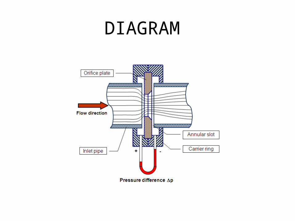
DIAGRAM
DESCRIPTION
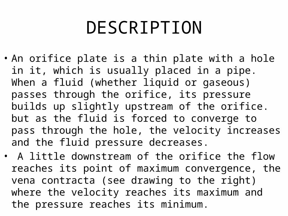
• An orifice plate is a thin plate with a hole in it, which is usually placed in a pipe. When a fluid (whether liquid or gaseous) passes through the orifice, its pressure builds up slightly upstream of the orifice. but as the fluid is forced to converge to pass through the hole, the velocity increases and the fluid pressure decreases.
• A little downstream of the orifice the flow reaches its point of maximum convergence, the vena contracta (see drawing to the right) where the velocity reaches its maximum and the pressure reaches its minimum.
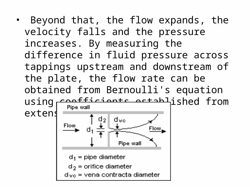
• Beyond that, the flow expands, the velocity falls and the pressure increases. By measuring the difference in fluid pressure across tappings upstream and downstream of the plate, the flow rate can be obtained from Bernoulli's equation using coefficients established from extensive research.

APPLICATION• Orifice plates are most commonly used to measure flow
rates in pipes, when the fluid is single-phase (rather than being a mixture of gases and liquids, or of liquids and solids) and well-mixed, the flow is continuous rather than pulsating, the fluid occupies the entire pipe (precluding silt or trapped gas), the flow profile is even and well-developed and the fluid and flow rate meet certain other conditions.
• Under these circumstances and when the orifice plate is constructed and installed according to appropriate standards, the flow rate can easily be determined using published formulae based on substantial research and published in industry, national and international standards.

FULLY SUB-MERGED ORIFICE
• Fully sub-merged orifice is one which has its whole of the outlet side submerged under liquid so that it discharges a jet of liquid into the liquid of the same kind. • It is also called totally drowned orifice.
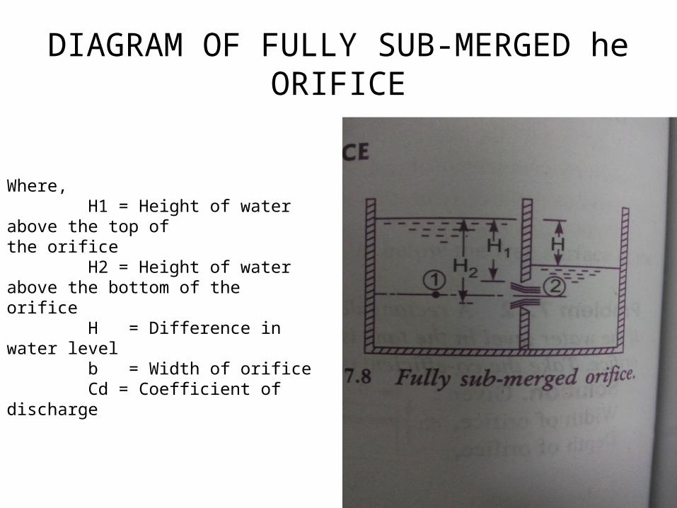
DIAGRAM OF FULLY SUB-MERGED he ORIFICE
Where, H1 = Height of water above the top of the orifice H2 = Height of water above the bottom of the orifice H = Difference in water level b = Width of orifice Cd = Coefficient of discharge
PARTIALLY SUB-MERGED ORIFICE
• Partially sub-merged orifice is the one which has its outlet side partially submerged under liquid.
• It is also known as partially drowned orifice.• Thus, the partially submerged orifice has two
portions. • The upper portion behaves as an orifice
discharging free while the lower portion behaves as a submerged orifice.

DIAGRAM OF PARTIALLY SUB-MERGED ORIFICE
Where, H1 = Height of water above the top of the orifice H2 = Height of water above the bottom of the orifice H = Difference in water level b = Width of orifice Cd = Coefficient of discharge

THANK
YOU