VITA 62 C OMPLIANT OWER UPPLY - Texim Europe · Product # VPX-6U-DC28P-001 Phone 1-888-567-9596 Doc...
10
Product # VPX-6U-DC28P-001 Phone 1-888-567-9596 www.synqor.com Doc.# 005-0006499 Rev. A 08/13/2014 Page 1 Operation: -40°C to 85°C (at Card Edge) 18V - 40V Continuous Input Voltage Input EMI Filtering 5 Outputs 1000W Maximum Output Power 91% Typical Efficiency VPX Features Outputs: VS1: } +12V @ 80A = 960W VS2: VS3: +5.0V @ 30A = 150W (AUX) +3.3V AUX @ 15A = 50W (AUX) +12V AUX @ 1A = 12W (AUX) -12V AUX @ 1A = 12W Maximum Total Output Power: 1000W Input EMI Filtering -40°C to 85°C Operating Temperature (at Card Edge) Over-current, over-voltage and over-temperature protection Current Sharing on +12V and +5.0V Remote Sense Standard VITA 62 Controls No Electrolytic Capacitors Compliance: (Full Load Operation Down to 18V IN ) — VITA 62 — MIL-STD-704 — MIL-STD-461 — VITA 47 / MIL-STD-810G • ESD Protection • Shock • Vibration • Rapid Decompression • Corrosion Resistance • Fungus Resistance • Altitude • Humidity Made in USA
Transcript of VITA 62 C OMPLIANT OWER UPPLY - Texim Europe · Product # VPX-6U-DC28P-001 Phone 1-888-567-9596 Doc...

Product # VPX-6U-DC28P-001 Phone 1-888-567-9596 www.synqor.com Doc.# 005-0006499 Rev. A 08/13/2014 Page 1
VPX 6U
Operation: -40°C to 85°C (at Card Edge)
VITA 62 ComplIAnT power Supply18V - 40V
Continuous Input VoltageInput EMI Filtering
5Outputs
1000WMaximum Output Power
91%Typical Efficiency
VPX Features
� Outputs: VS1: }+12V @ 80A = 960W VS2: VS3: +5.0V @ 30A = 150W (AUX) +3.3V AUX @ 15A = 50W (AUX) +12V AUX @ 1A = 12W (AUX) -12V AUX @ 1A = 12W
� Maximum Total Output Power: 1000W � Input EMI Filtering � -40°C to 85°C Operating Temperature (at Card Edge) � Over-current, over-voltage and over-temperature protection � Current Sharing on +12V and +5.0V � Remote Sense � Standard VITA 62 Controls � No Electrolytic Capacitors
� Compliance: (Full Load Operation Down to 18Vin)
— VITA 62 — MIL-STD-704 — MIL-STD-461 — VITA 47 / MIL-STD-810G• ESD Protection• Shock• Vibration• Rapid Decompression• Corrosion Resistance • Fungus Resistance • Altitude • Humidity
Made in USA
est1
Ditributed by Texim-Europe 4cm
Product # VPX-6U-DC28P-001 Phone 1-888-567-9596 www.synqor.com Doc.# 005-0006499 Rev. A 08/13/2014 Page 2
Technical SpecificaTion
VPX
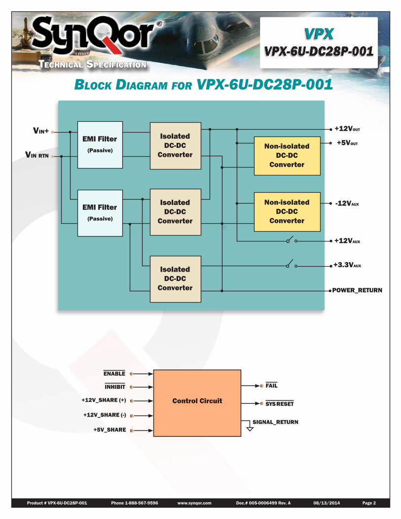
Block Diagram for VPX-6U-Dc28P-001
Vin+
Vin rTn
SYSRESET
FAIL
ENABLE
INHIBIT
+12VOUT
+5VOUT
+3.3VAUX
+12VAUX
-12VAUX
POWER_RETURN
+12V_SHARE (+)
+12V_SHARE (-)
+5V_SHARE SIGNAL_RETURN
Control Circuit
EMI Filter(Passive)
EMI Filter(Passive)
Isolated DC-DC
Converter
Isolated DC-DC
Converter
Isolated DC-DC
Converter
Non-isolated DC-DC
Converter
Non-isolated DC-DC
Converter

Product # VPX-6U-DC28P-001 Phone 1-888-567-9596 www.synqor.com Doc.# 005-0006499 Rev. A 08/13/2014 Page 3
VPX-6U-DC28P-001 Characteristics
VPX-6U-Dc28P-001 inPUt characteristicsParameter Min. Typ. Max. Units Notes & Conditions ABSOLUTE MAXIMUM RATINGS
Input Voltage
Non-Operating -1 60 V Continuous
Operating 40 V Continuous
Operating Transient Protection 50 V 100ms transient, square wave
Isolation Voltage 1500 V Input to Output and Input/Output to Case
Operating Temperature -40 85 °C Card edge temperature
Storage Temperature -55 105 °C
ELECTRICAL CHARACTERISTICS
Input Voltage
Continuous 18 40 V
Transient 18 50 V 50V Transient for 100ms
Under-Voltage Lockout
Turn-On Input Voltage Threshold 15 15.5 16 V
FEATURE CHARACTERISTICS
VITA 62 ON/OFF Control Control signals referenced to SIGNAL_RETURN
ENABLE* high-state Voltage 2 3.3 V ENABLE* regards a no-connect as a high
ENABLE* low-state Voltage 0.8 V
INHIBIT* high-state Voltage 2 3.3 V INHIBIT* regards a no-connect as a high
INHIBIT* low-state Voltage 0.8 V
Technical SpecificaTion
VPX
inPUt Voltage sPike INPUT VOLTAGE SPIKE SUPPRESSION Module Operates through these Spikes
Input Voltage Spike (Centered on Vin) ±250V, 100μs, Emax = 15mJ MIL-STD-1275D ±250V, 70μs, Emax = 2J MIL-STD-1275E ±200V, 10μs, Rs ≤ 0.5Ω MIL-STD-461C (CS06); DEF-STAN 61-5 ±400V, 5μs, Rs ≤ 0.5Ω MIL-STD-461C (CS06) ±600V, 10μs, Rs = 50Ω RTCA/DO-160E

Product # VPX-6U-DC28P-001 Phone 1-888-567-9596 www.synqor.com Doc.# 005-0006499 Rev. A 08/13/2014 Page 4
VPX-6U-Dc28P-001 oUtPUt characteristics
Parameter +12V +5V +3.3VAUX +12VAUX -12VAUX
OUTPUT CHARACTERISTICSOutput Voltage Set Point See Note 1
12V (+/-1%)
5V (+/-1%)
3.3V (+/-1%)
12V (+/-1%)
-12V (+/-1%)
Total Output Voltage Range See Note 2
12V (+/-4%)
5V (+/-3%)
3.3V (+/-2%)
12V (+/-4%)
-12V (+/-3%)
Output Voltage Ripple (pk-pk) See Note 3 80mV 50mV 80mV 80mV 50mV
Operating Current Range Maximum Total Output Power = 1000W 0-80A 0-30A 0-15A 0-1A 0-1A
Over-Voltage Protection 14.8V 6.0V 4.0V 14.8V NA
Current-Limit Inception 100.8A 40A 18A 2A 1.8A
Maximum Output Capacitance 10mF 10mF 10mF 1mF 10mF
MAXIMUM TOTAL OUTPUT POWER 1000W
Note 1: 28Vin, 50% loadNote 2: Over line, load, temperatureNote 3: Full Load, measured with 1µF capacitor and 10uF tantalum capacitor
Maximum Total Output Power = 1000W (At 70°C Card Edge Temperature)
= 800W (At 85°C Card Edge Temperature)
Temperature specifications are relative to the temperature at the thermal interface, on the flange opposite the wedge locks.
Technical SpecificaTion
VPX

Product # VPX-6U-DC28P-001 Phone 1-888-567-9596 www.synqor.com Doc.# 005-0006499 Rev. A 08/13/2014 Page 5
PIN Diagrams
POWERPOWER
P10P1P2P3P4P5P6P7 P9 P8 P7 P6 P5 P4 P3
D9 D8 D7C9 C8 C7B9 B8 B7A9 A8 A7
D6 D5 D4 D3C6 C5 C4 C3B6 B5 B4 B3A6 A5 A4 A3 P2 P1
D2 D1C2 C1B2 B1A2 A1
SIGNAL SIGNAL SIGNALPOWER POWER POWER
Pin DescriPtions
6U P0 ConnectorPIN FUNCTION DESCRIPTION
P7 +DC_IN Vin+
P6 +DC_IN Vin+
P5 -DC_IN Vin-
P4 -DC_IN Vin-
P3 Not currently used
P2 Not currently used
P1 CHASSIS Chassis
6U P1 ConnectorPIN FUNCTION DESCRIPTIONP10 +12V_MAIN
+12V main output voltage, 80A ratedP9 +12V_MAINA9 +12V_SENSE(+)
Should be connected to +12V_MAIN either remotely or at the connectorB9 +12V_SENSE(+)C9 +5V_SENSE(+) Should be connected to +5V_MAIN either remotely or at the connectorD9 LED_DISABLE Internally pulled up to 3.3V, connect to SIGNAL_RETURN to disable LEDA8 +12V_SENSE(-)
Should be connected to POWER_RETURN either remotely or at the connectorB8 +12V_SENSE(-)C8 Not currently usedD8 STARTUP_SYNC Startup synchronization for +5V_MAINA7 +12V_SHARE(+)
Active current share differential pair for +12V_MAINB7 +12V_SHARE(-)C7 +5V_SHARE Active current share for +5V_MAIND7 SIGNAL_RETURN Ground pin for control signalsP8 POWER_RETURN
Common output voltage return pin, 40A rated per pinP7 POWER_RETURNA6 Not currently usedB6 Not currently usedC6 -12V_AUX -12V auxiliary output voltage, 1A ratedD6 SYSRESET* System Reset is actively low. It will float when all outputs are within specificationA5 Not currently usedB5 Not currently usedC5 Not currently usedD5 Not currently usedA4 Not currently usedB4 Not currently usedC4 Not currently usedD4 Not currently usedA3 Not currently usedB3 +12V_AUX +12V auxiliary output voltage, 1A ratedC3 Not currently usedD3 Not currently usedP6 +5V_MAIN
+5V main output voltage, 30A ratedP5 +5V_MAINP4 POWER_RETURN
Common output voltage return pin, 40A rated per pinP3 POWER_RETURNA2 Not currently usedB2 FAIL* When any of the output is not within specification, FAIL* signal will be driven lowC2 INHIBIT* Input control signal as defined in VITA 62, referenced to SIGNAL_RETURND2 ENABLE* Input control signal as defined in VITA 62, referenced to SIGNAL_RETURNA1 Not currently usedB1 Not currently usedC1 Not currently usedD1 Not currently usedP2 +3.3V_AUX +3.3V auxiliary output voltage, 15A ratedP1 POWER_RETURN Common output voltage return pin, 40A rated per pin
Technical SpecificaTion
VPX

Product # VPX-6U-DC28P-001 Phone 1-888-567-9596 www.synqor.com Doc.# 005-0006499 Rev. A 08/13/2014 Page 6
Mechanical Diagrams
NOTES:1. ALL DIMENSIONS IN INCHES 2. TOLERANCES: X.XX 0.02in [0.5mm] X.XXX .010in [0.25mm] 3. CONNECTOR PART NUMBERS:
P0 - TE CONNECTIVITY 6450843-6 P0 - FOXCONN HM811J3-B84F P1 - TE CONNECTIVITY 6450849-6 P1 - FOXCONN HM811L3-B84F
4. WEIGHT: 3.59lbs (1.63kg) 5. SEE TABLE FOR KEYWAY POSITION AND ANGLE.
VPX-6U-DC28 [P,T] -001Key
PositionAlignment
AngleTE Connectivity
Part Number1 0° 1-1469492-12 0° 1-1469492-13 0° 1-1469492-1
VPX-6-DC270P-001Key
PositionAlignment
AngleTE Connectivity
Part Number1 315° 1-1469492-82 0° 1-1469492-13 0° 1-1469492-1
PIN 1 PIN 1P1 P0
.495 ±.015 Nominal[12.57 ±0.38]Maximum thickness of .565"with fully expanded Wedge-lok
.263[6.68]
.950 REF[24.13]
9.187[233.35]
8.400[213.36]
6.634 [168.49]
KEY 1 KEY 2 KEY 3 .393[9.98]
THERMAL SEATING PLANE
.301[7.65]
2.617[66.47]
3.335[84.7]
7.810[198.37]
8.585[218.06]
VPX
Mechanical DrawingS

Product # VPX-6U-DC28P-001 Phone 1-888-567-9596 www.synqor.com Doc.# 005-0006499 Rev. A 08/13/2014 Page 7
control featUresENABLE* Standard VITA 62 control signal. It is used to turn off all of the output voltages when it is high, including
+3.3V_AUX. When it is pulled low to SIGNAL_RETURN, +3.3V_AUX will be turned on and the status of the other outputs will be dependent on the state of INHIBIT*. ENABLE* signal regards a no-connect as a high.
INHIBIT* Standard VITA 62 control signal. It is used to turn off all the output voltages except +3.3V_AUX. When it is pulled low to SIGNAL_RETURN, VS1, VS2, VS3, +12V_AUX and -12V_AUX will be turned off. INHIBIT* signal regards a no-connect as a high. At power-on, if ENABLE* and INHIBIT* are configured to turn all outputs on, +3.3V_AUX will be powered up 100ms prior to when the other outputs are powered up.
FAIL* FAIL* signal is used to indicate a failure has occurred. It will be pulled low when any of the outputs are outside the voltage specification. FAIL* is an active low open-drain signal. It is expected there will be a pull-up resistor on the backplane to 3.3V. A typical resistor value is 4.7kΩ.
SYSRESET* SYSRESET* signal is an output generated from the module. It is used to indicate that startup has completed. At power-on, SYSRESET* is pulled low. It will be high impedance when all outputs are within voltage specification. It will be pulled low if any failure has occurred or if the outputs are disabled by the user during operation. SYSRESET* signal is an active low open-drain signal. It is expected there will be a pull-up resistor on the backplane to 3.3V. A typical resistor value is 4.7kΩ.
Vita 62 control statesENABLE* INHIBIT* +3.3V_AUX VS1, VS2, VS3, +12V_AUX, -12V_AUX
HIGH HIGH OFF OFF
LOW HIGH ON ON
HIGH LOW OFF OFF
LOW LOW ON OFF
Parallel oPeration+12V_MAIN Active current sharing on +12V_MAIN is supported. To implement the current sharing function,
+12V_SHARE(+) and +12V_SHARE(-) pins should be routed between all paralleled modules as a differential pair. ENABLE* and INHIBIT* should be connected together. High speed data communication is transmitted on these two lines. Control state is transmitted between the master unit and slave units on a cycle-by-cycle basis. Adding capacitance to these share lines must be avoided.
+5V_MAIN Active current sharing on +5V_MAIN is also supported, but with an analog sharing scheme that is different than the digital sharing scheme for the +12V_MAIN. To implement the current sharing function, +5V_SHARE, ENABLE*, INHIBIT* and STARTUP_SYNC should be connected together between all paralleled modules. These SHARE pins are referenced to POWER_RETURN. A clean ground plane is important, and ground drop between each module should be minimized.
+3.3V_AUX, +12V_AUX & -12V_AUX
Active current sharing is not supported on auxiliary outputs. However, all these auxiliary rails have OR’ing MOSFETs or OR’ing diodes implemented, so that they can still be operated in parallel. Total output current on these rails should not exceed the current rating of a single module.
aPPlication notes
Technical SpecificaTion
VPX

Product # VPX-6U-DC28P-001 Phone 1-888-567-9596 www.synqor.com Doc.# 005-0006499 Rev. A 08/13/2014 Page 8
Qualifications Tests and Screening
Dc-Dc conVerter anD filter screeningScreening Process Description S-Grade M-Grade
Baseplate Operating Temperature -55˚C to +100˚C -55˚C to +100˚C
Storage Temperature -65˚C to +135˚C -65˚C to +135˚C
Pre-Cap Inspection IPC-610, Class III Yes Yes
Temperature Cycling Method 1010, Condition B, 10 Cycles Yes
Burn-In 100˚C Baseplate 12 Hours 96 Hours
Final Electrical Test 100% 25˚C -55˚C, +25˚C, +100˚C
Final Visual Inspection MIL-STD-2008 Yes Yes
VPX moDUle QUalification (Vita 47 comPliant)Test Name Method
Random Vibration MIL-STD-810, 514.6 - Procedure I, Class V3
Shock MIL-STD-810, 516.6 - Procedure I, VI, Class OS2
Altitude MIL-STD-810, 500.5 - Procedure I, II, III
Fungus Resistance MIL-STD-810, 508.6
Corrosion Resistance ASTM G85, Annex A4
Humidity MIL-STD-810, 507.5 - Procedure II
High Temperature MIL-STD-810, 501.5 - Procedure I, II
Low Temperature MIL-STD-810, 502.5 - Procedure I, II
Temperature Cycling MIL-STD-202, 107 - Class C4
ESD EN61000-4-2, Level 4; 15kV Air Discharge
VPX
QualificaTionS anD Screening

Product # VPX-6U-DC28P-001 Phone 1-888-567-9596 www.synqor.com Doc.# 005-0006499 Rev. A 08/13/2014 Page 9
WarrantySynQor offers a two (2) year limited warranty. Complete warranty information is listed on our website or is available upon request from SynQor.Information furnished by SynQor is believed to be accurate and reliable. However, no responsibility is assumed by SynQor for its use, nor for any infringements of patents or other rights of third parties which may result from its use. No license is granted by implication or otherwise under any patent or patent rights of SynQor.
CONTACT SYNQOR FOR FURTHER INFORMATION AND TO ORDER:Phone: ___________________________ 978-849-0600Toll Free: _________________________ 888-567-9596Fax: _____________________________ 978-849-0602E-mail: ___________________________ [email protected]: ____________________________ www.synqor.comAddress: _________________________ 155 Swanson Road
Boxborough, MA 01719 USA
APPLICATION NOTESA variety of application notes and technical white papers can be downloaded in PDF format from our website.
PATENTS SynQor holds the following U.S. patents, one or more of which apply to each product listed in this document. Additional patent applications may be pending or filed in the future.
5,999,417 6,222,742 6,545,890 6,577,109 6,594,159 6,731,520
6,894,468 6,896,526 6,927,987 7,050,309 7,072,190 7,085,146
7,119,524 7,269,034 7,272,021 7,272,023 7,558,083 7,564,702
7,765,687 7,787,261 8,023,290 8,149,597 8,493,751 8,644,027
orDering information / Part nUmBering
Examples: VPX-6U-DC28P-001-SN
Series Package Size (U) Input Range Mil Std Filtering Output Voltage Combination Code Packaging Options
VPX - 6U - DC28 P - 001 - Y1Y2Y3
VPX -3U
6U-
DC28: 28V
DC270: 270V
P: P - MIL-STD-704 (B-F)
T: T - MIL-STD-704 A MIL-STD-1275 (B,D) DEF-STAN 61-5 (P6)/6
- 001: 001 -
Y1: Screening S - Standard (MCOTS) M - Military (MCOTS)Y2: Conformal Coating N - No Conformal Coating C - Conformal CoatingY3: TBD
VPX
orDering / parT nuMbering
Ordering Information
Partner in Electronic Components & Supply Chain Solutions
Texim Europe B.V.Elektrostraat 17NL-7483 PG HaaksbergenTel: +31 (0)53 573 33 [email protected]
Belgium United Kingdom
St. Mary’s House, Church LaneCarlton Le MoorlandLincoln LN5 9HSTel: +44 (0)1522 789 555Fax: +44 (0)845 299 22 [email protected]
Gentsesteenweg 1154-C22Chaussée de Gand 1154-C22B-1082 Brussel / BruxellesTel: +32 (0)2 462 01 00Fax: +32 (0)2 462 01 [email protected]
Denmark
Nørregade 15DK-9240 NibeTel: +45 88 20 26 30Fax: +45 88 20 26 [email protected]
The Netherlands
Elektrostraat 17NL-7483 PG HaaksbergenTel: +31 (0)53 573 33 33Fax: +31 (0)53 573 33 [email protected]
Germany
Martin-Kollar-Strasse 9D-81829 MünchenTel: +49 (0)89 436 086-0Fax: +49 (0)89 436 [email protected]
Germany
Justus-von-Liebig-Ring 7-9D-25451 QuickbornTel: +49 (0)4106 627 07-0Fax: +49 (0)4106 627 [email protected]
Austria
Warwitzstrasse 9 A-5020 SalzburgTel: +43 (0)662 216026Fax: +43 (0)662 [email protected]