Plumbing Supply | Pipe Fittings - Valves Supplier Plumbing ...
See discussions, stats, and author profiles for this publication at: https://www.researchgate.net/publication/30875035
Visualization Management and Inspection for Plumbing Construction Quality
Control
Article
Source: OAI
CITATIONS
0
READS
83
1 author:
Nj Shih
National Taiwan University of Science and Technology
83 PUBLICATIONS 241 CITATIONS
SEE PROFILE
All content following this page was uploaded by Nj Shih on 17 August 2015.
The user has requested enhancement of the downloaded file.
VISUALIZATION MANAGEMENT AND INSPECTION FOR PLUMBING CONSTRUCTION QUALITY CONTROL
NAAI-JUNG SHIH Professor Department of Architecture National Taiwan University of Science and Technology 43,Section 4,Keelung Road, Taipei, 106,Taiwan,ROC e.mail: [email protected]
AND
PIN-HUNG WANG Doctor student Department of Architecture National Taiwan University of Science and Technology 43,Section 4,Keelung Road, Taipei, 106,Taiwan,ROC Instructor Department of Architecture Kao Yuan University 1821, Jungshan Road, Luju Shiang, Kaohsiung, 821, Taiwan, ROC e.mail: [email protected]
Abstract. This research compares the working process at a construction site with the shop drawings made by a plumbing inspector for installed pipes. This study compared the 2D plumbing shop drawings with the 3D point cloud of the toilet in a campus building. A long-range 3D scanner was used to retrieve the point cloud records of pipes to build a visualization management system. The visual comparison was used to locate pipes at the construction site. We found the differences could be identified easily between the point cloud and shop drawings. The presence of point clouds created a new method to inspect plumbing locations, as a way to verify construction quality.
394 NAAI-JUNG SHIH AND PIN-HUNG WANG
1. Introduction
In general, building construction operations are conducted in accordance with an architect’s shop drawing. Construction contents proceed to integrate with the arrangement of shop drawings for related production work without causing conflicts and contradictions with each other. A construction company frequently has to coordinate with professional M&E (mechanical and electrical) and HVAC (heating, ventilating, and air conditioning) technicians. At a building construction site, there are many conditions that are coordinated insufficiently with the rest of the production or regulate construction contents, in accordance with actual construction situation (Ambrose 1992, p.64). Sometimes, construction contents may not conform to original design shop drawings, by being influenced by the client or the building management process. In addition, the user just needs to change the plans (Al-Momani 2000, p.51; Cox et al. 1999, p.427), or discover design mistakes that have to be corrected (Mokhtar et al. 1998, p.82). Therefore, the final result will differ from the original design shop drawings. From the beginning of construction to the finished building at the final stage, building design may be changed many times. Related plumbing also needs to be modified because of these changes. Other major changes may be instigated by management, which changes the function of whole building in the future. Therefore, it is very important to review design changes constantly and follow-up construction quality.
When the construction is finished, the architect would draw as-built shop drawings in accordance with the actual condition of the finished building in order to provide a referable drawing and to receive a certified occupancy permit. However, the whole construction period are made of many stages that proceed grouting or other construction operations that causes the plans to be never confirmed again in the future. For example, pipes and toilet drains in the wall cannot be described accurately after the concrete grouting is poured. The sealed layout makes it hard to measure the final location of the pipes or drain, so it cannot be clearly recorded or correctly redrawn for shop drawings.
During the construction process, the construction inspectors use a camera to record operations every time. Photographs just record the images of the construction site, it is still difficult to inspect the scale and dimension of works only from the pictures. Almost all the as-built shop drawings display as-seen information only seen by the naked eyes at the construction site when design change is made. The photos cannot be used as a kind of reference to draw as-built shop drawings.
In virtual reality (VR), visual effects are created to represent the real environment. The VR screen feels like being in a real construction site. Therefore, VR technology can be used to inspect construction projects
VISUALIZATION MANAGEMENT AND INSPECTION FOR... 395
(Savioja et al. 2004, p.85), to check the detail of a construction component’s configuration using a virtual reality model (Sampaio et al. 2004, p.141), and to reconstruct a 3D model to simulate and inspect possible problems during the design stage (Li et al. 2004, p.288). VR technology can be used to study and to check the construction situation from an off site location easily. The possible uses can be unlimited at a construction site with regards to problem inspection from an on-site or off-site computer screen.
This study believes that builders encounter many design changes, both large and small, during the construction. Its influence is as critical as shop drawings and building management. In order to retrieve information for later use, we use a 3D scanner to record plumbing information to visualize plumbing point clouds during construction process. The visualization of 3D point clouds has the same spatial information as the actual environment, so it can record the interrelationships of the three-dimensional plumbing in spaces. It not only can ensure the plumbing location in the plan, but also can present the three-dimensional plumbing space in accordance with construction quality inspection with point cloud records. This research uses known shop drawings to compare with the 3D point cloud scans of a construction site. The differences between the shop drawings and point cloud can be quickly checked, and the original shop drawings can be corrected as complete and accurate as possible to serve the needs of as-built final drawings.
2. 3D scan
A long-range 3D laser scanner can retrieve the surface geometries of remote objects as point clouds. The 3D scan of small objects at short range has been widely applied to the industrial design as part of the reverse engineering process. Previous industrial applications were not suitable for data retrieval of large objects like buildings until recent when the long-range laser scanner is developed. This study used a Cyrax 2500 to scan a building site as a way to record construction status. Originally, construction recorded with text, photos, and videos and was a tedious process. The 3D scan data could be used as a type of supplementary record in the analysis and evaluation of construction quality and quantity.
The scans provide finished records that include the configuration of the plumbing that is visible to the scanner. These records are useful for checking working quality. Since the clouds consist of x-, y-, and z-coordinates, as-built geometric information can be compared with 2D original shop drawings. Its plan can be brought up on a computer screen to verify any possible difference in between (Shih and Wang 2002, p.338; 2004, p.98).
A matrix of 999 points in width and 999 points in length was used to figure the shapes of the object surfaces that exposed to the scanner. If it can
396 NAAI-JUNG SHIH AND PIN-HUNG WANG
be recorded completely, it will be scanned from different orientations to create an omni view. This research scanned to record the plumbing locations from more than four orientations in each room. This system allows modifications of scan density and the juxtaposing of multiple scans in one scanworld. Scans can be registered using reference points shared by adjacent scans. The size and boundary of the scanworld is virtually unlimited.
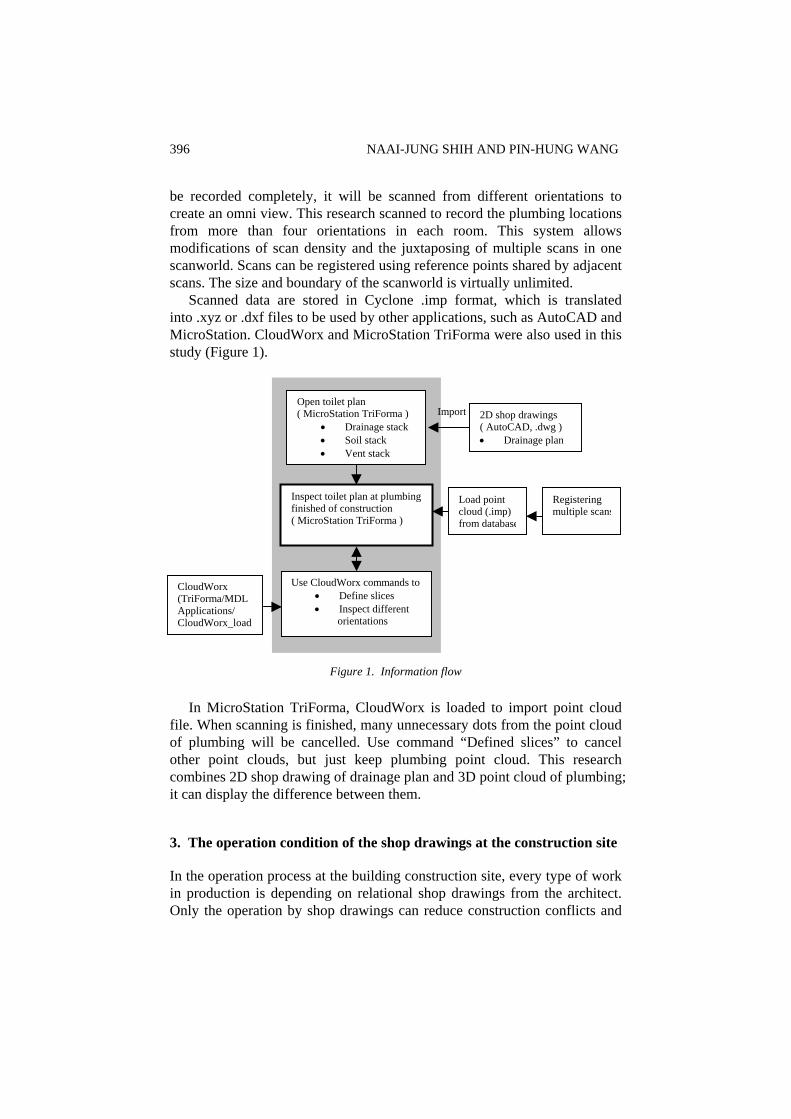
Scanned data are stored in Cyclone .imp format, which is translated into .xyz or .dxf files to be used by other applications, such as AutoCAD and MicroStation. CloudWorx and MicroStation TriForma were also used in this study (Figure 1).
Open toilet plan ( MicroStation TriForma )
• Drainage stack• Soil stack • Vent stack
Inspect toilet plan at plumbing finished of construction ( MicroStation TriForma )
Use CloudWorx commands to• Define slices • Inspect different
orientations
2D shop drawings ( AutoCAD, .dwg ) • Drainage plan
Registering multiple scans
Load point cloud (.imp) from database
Import
CloudWorx (TriForma/MDL Applications/ CloudWorx_load
Figure 1. Information flow
In MicroStation TriForma, CloudWorx is loaded to import point cloud file. When scanning is finished, many unnecessary dots from the point cloud of plumbing will be cancelled. Use command “Defined slices” to cancel other point clouds, but just keep plumbing point cloud. This research combines 2D shop drawing of drainage plan and 3D point cloud of plumbing; it can display the difference between them.
3. The operation condition of the shop drawings at the construction site
In the operation process at the building construction site, every type of work in production is depending on relational shop drawings from the architect. Only the operation by shop drawings can reduce construction conflicts and
VISUALIZATION MANAGEMENT AND INSPECTION FOR... 397
mistakes. Although the architect supplies diagram information for the shop drawings, they can produce construction conflict, or are not possible to use on the construction site. It usually needs an architect or contractor to coordinate construction so that every type of work in production can proceed smoothly despite coordination or design changes.
At the construction site, the construction and administrative department proceeds to build from and review the shop drawings. The architect is supposed to review the shop drawings as well. But the plumbing shop drawings are usually drawn separately and are never integrated with the other drawings. In fact, it is not permitted to integrate shop drawings with complete plumbing drawings. The pipes must be considered a three-dimensional environment with their pipe diameter and sluicing gradient (Stein and Reynolds 1992, p.643), which makes reading the drawings difficult. On the construction site, it is only possible to check single construction items and very difficult to review plumbing shop drawings. If a conflict arises, the architect is consulted and there is usually a formal record for follow-up, review, and acceptance. However, in the plumbing of a building under construction, shop drawings are used to present the plumbing lay out. It is used to as the basis for inspection and acceptance. So the shop drawings cannot describe clearly the plumbing’s location and passing route. Operation of the construction site is usually in accordance with personal construction experience. Although its function is the same as the original shop drawings, its configuration is different completely from the shop drawings or original design concept.
The owner of the building must understand that the completed building will be different from the architect’s built shop drawings. When the building is finished, the architect draws built shop drawings to match the condition of the finished building, however, the plumbing could be concealed by the concrete in building structure, or placed in the ceiling. If the architect wants to redraw the built shop drawings, he must not only expend time and risk not being able to complete the plans. There are many problems with plumbing during building construction.
Plumbing has always been a major concern for construction companies according to our interviews. The main reasons for this are regulated locations and the plumbing function in the shop drawings. Many plumbing layouts and passing routes must consider the condition of the construction site. Problems include missing construction items and other components. It must go by an alternative route or a substitutive plan has to be created. They also understand the follow-up necessary to maintain the work since when the building is finished; it will not be familiar and difficult to navigate. The new owner must expend much more time to test or build new pipes in order to avoid interfering or negatively influencing the original plumbing system.
398 NAAI-JUNG SHIH AND PIN-HUNG WANG
This research believes that the plumbing construction process period at present, outwardly is constructed from shop drawings, but is actually very different between actual conditions and the shop drawings. Since built shop drawings are drawn incomplete, this indicates the real configuration of the plumbing and leads to difficulty in doing follow-up jobs by building management.
4. Use 3D point cloud to obtain accurate VR construction information from a construction site
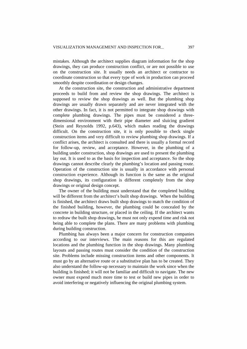
After the finished plumbing was laid out on a construction site, this research used a 3D scanner to record the spatial information of the plumbing (Figure 2). The 3D scanner has a three-dimensional recording function, so it is easy to transform the scan into 3D point cloud information to relay the spatial location of the plumbing. The 3D scanner can view and review the work from the visualization point cloud, and understand clearly the finished plumbing condition during different periods of construction.
Figure 2. Point cloud of plumbing (at male toilet)
There are limits to the scanning range of the 3D scanner. If the 3D scanner is recording interior spatial pipes, than it must register multiple scans, however, it may record clearly, and completely single spatial pipe information. At spatial reference points, it must consider which location to scan. This is an important factor for spatial scanning and registering. We must also consider the problems of registering since it must consider the overlapping of different scanning information. When it must decrease the number of scans and increase scan efficiency, part of the overlap will possibly compress. So the reference points should be centralized and it must combine three or more reference points. When these reference points are too centralized, it could result in inaccurate registering.
When this research was scanning the construction piping, the scanner’s movement was decreased as well as the register times of the scan. This was
VISUALIZATION MANAGEMENT AND INSPECTION FOR... 399
due to it spatial limits and scanning range. For this toilet plumbing research, we need four to five scans to register in order to present clear relationships and locations between the pipes and shaft.
This research uses pipes point clouds and Cyclone to analyze each section of the building, the relationship and location of the pipes, and measure correlative data, like pipe size, gradient, and distance to ceiling. Moreover, it helps to understand the different points between construction conditions and original shop drawings.
5. Inspection with original shop drawings
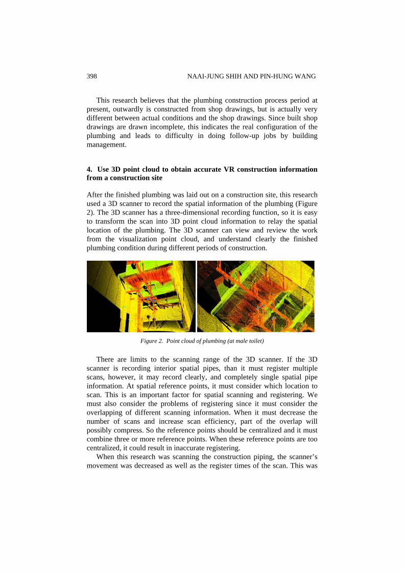
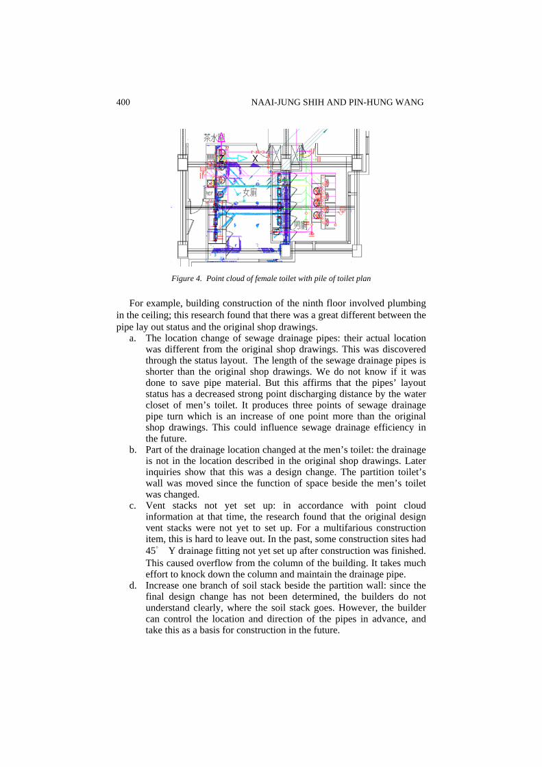
Beside the above-mentioned analysis of the relational pipes of the construction site, this research compared the scanning and original shop drawings with the pipes in the construction site. The research also reviewed the construction status of the shop drawings, or the difference between status information and original shop drawings. The point cloud information registering process can control some detail (Figure 3, Figure 4).
Drainage plan
Point cloud of plumbing
Figure 3. Point cloud of male toilet with pile of toilet plan
400 NAAI-JUNG SHIH AND PIN-HUNG WANG
Figure 4. Point cloud of female toilet with pile of toilet plan
For example, building construction of the ninth floor involved plumbing in the ceiling; this research found that there was a great different between the pipe lay out status and the original shop drawings.
a. The location change of sewage drainage pipes: their actual location was different from the original shop drawings. This was discovered through the status layout. The length of the sewage drainage pipes is shorter than the original shop drawings. We do not know if it was done to save pipe material. But this affirms that the pipes’ layout status has a decreased strong point discharging distance by the water closet of men’s toilet. It produces three points of sewage drainage pipe turn which is an increase of one point more than the original shop drawings. This could influence sewage drainage efficiency in the future.
b. Part of the drainage location changed at the men’s toilet: the drainage is not in the location described in the original shop drawings. Later inquiries show that this was a design change. The partition toilet’s wall was moved since the function of space beside the men’s toilet was changed.
c. Vent stacks not yet set up: in accordance with point cloud information at that time, the research found that the original design vent stacks were not yet to set up. For a multifarious construction item, this is hard to leave out. In the past, some construction sites had 45° Y drainage fitting not yet set up after construction was finished. This caused overflow from the column of the building. It takes much effort to knock down the column and maintain the drainage pipe.
d. Increase one branch of soil stack beside the partition wall: since the final design change has not been determined, the builders do not understand clearly, where the soil stack goes. However, the builder can control the location and direction of the pipes in advance, and take this as a basis for construction in the future.
VISUALIZATION MANAGEMENT AND INSPECTION FOR... 401
e. The location of the floor drain is different from the shop drawing: in the toilet, the original location and number of floor drains is different between shop drawings and the actual scan. One place, which needs a floor drain, is actually not there and there are two places beside the service sink for the new floor drain. This will affect the number of original floor drains and create final design change problems.
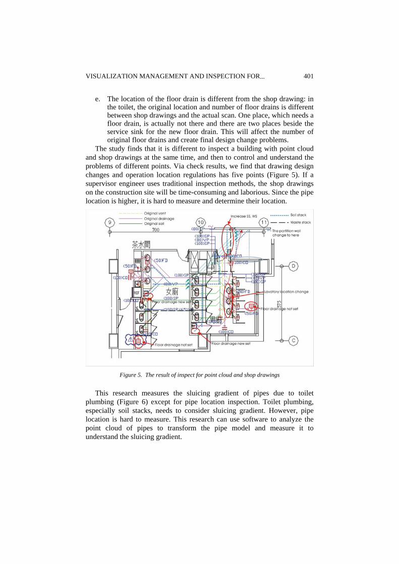
The study finds that it is different to inspect a building with point cloud and shop drawings at the same time, and then to control and understand the problems of different points. Via check results, we find that drawing design changes and operation location regulations has five points (Figure 5). If a supervisor engineer uses traditional inspection methods, the shop drawings on the construction site will be time-consuming and laborious. Since the pipe location is higher, it is hard to measure and determine their location.
Figure 5. The result of inspect for point cloud and shop drawings
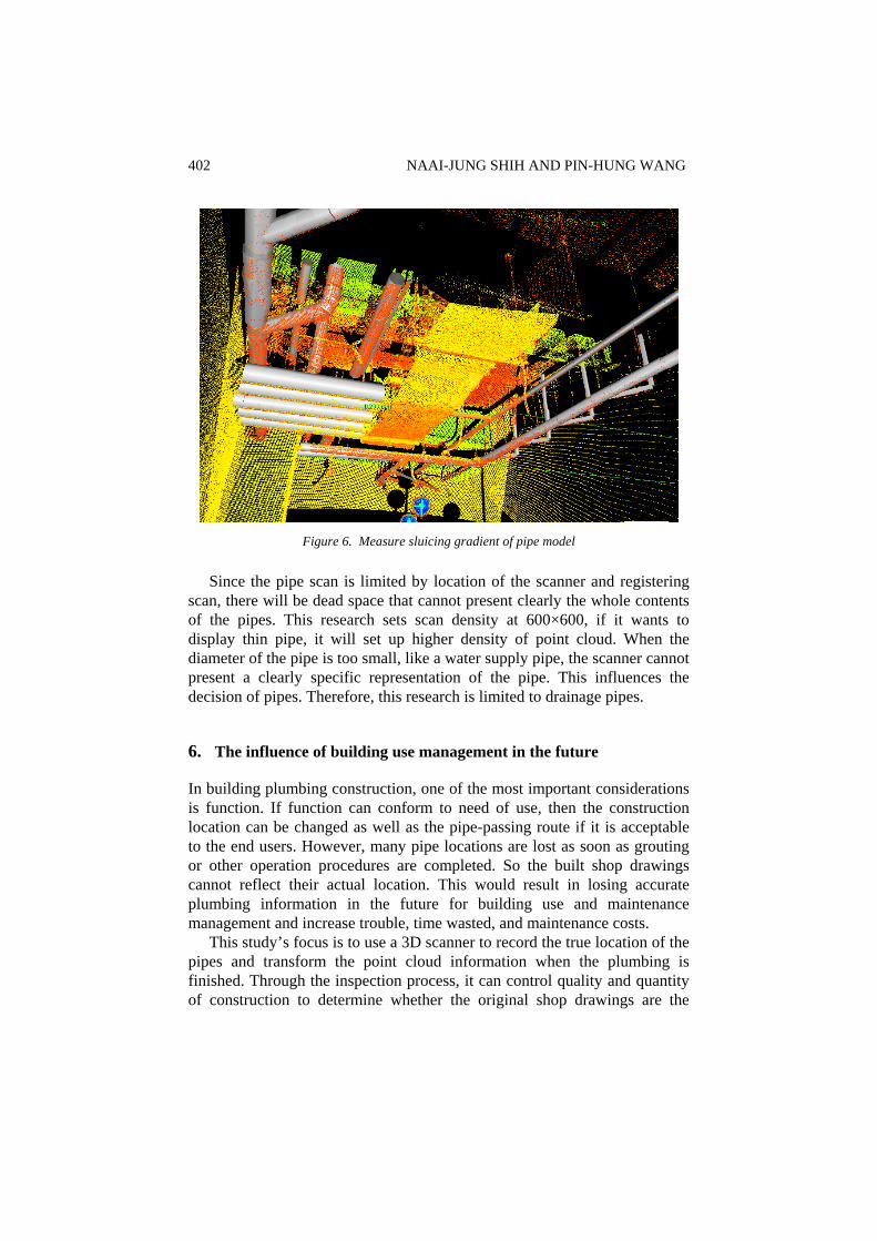
This research measures the sluicing gradient of pipes due to toilet plumbing (Figure 6) except for pipe location inspection. Toilet plumbing, especially soil stacks, needs to consider sluicing gradient. However, pipe location is hard to measure. This research can use software to analyze the point cloud of pipes to transform the pipe model and measure it to understand the sluicing gradient.
402 NAAI-JUNG SHIH AND PIN-HUNG WANG
Figure 6. Measure sluicing gradient of pipe model
Since the pipe scan is limited by location of the scanner and registering scan, there will be dead space that cannot present clearly the whole contents of the pipes. This research sets scan density at 600×600, if it wants to display thin pipe, it will set up higher density of point cloud. When the diameter of the pipe is too small, like a water supply pipe, the scanner cannot present a clearly specific representation of the pipe. This influences the decision of pipes. Therefore, this research is limited to drainage pipes.
6. The influence of building use management in the future
In building plumbing construction, one of the most important considerations is function. If function can conform to need of use, then the construction location can be changed as well as the pipe-passing route if it is acceptable to the end users. However, many pipe locations are lost as soon as grouting or other operation procedures are completed. So the built shop drawings cannot reflect their actual location. This would result in losing accurate plumbing information in the future for building use and maintenance management and increase trouble, time wasted, and maintenance costs.
This study’s focus is to use a 3D scanner to record the true location of the pipes and transform the point cloud information when the plumbing is finished. Through the inspection process, it can control quality and quantity of construction to determine whether the original shop drawings are the
VISUALIZATION MANAGEMENT AND INSPECTION FOR... 403
same, and the architect can use this point cloud record to change the built shop drawings.
Users can use the point cloud information to determine the pipes three-dimensional location in the building. It is not only different than the two-dimensional diagram information from the past, but also records clearly any direction in which these pipes are laid. This allows for convenient pipe management. In addition, point cloud information can be transformed into built shop drawings that present correct pipe location. There would be no more “hints” of where the pipes maybe located any more thereby producing convenient pipe management for the future.
7. Conclusion
This research used a pipes scanning process to find many construction behaviors based on construction schedule and the user’s need to change. This information is useful for any builder who wants to know of and control status change as quickly as possible. However, for the user or builder, it cannot be easy to control. Specialized building drawings and diagrams are hard to understand for the user. If it can use visualization 3D point cloud information to convey the actual construction’s general situation on site, it will help the user to understand the construction scheduled progress and quality.
Point cloud information will make construction inspection more convenient. This research found, via a point cloud and shop drawings inspection process, that it makes design changes easier since there is better correlation between the design diagrams and construction site. It takes the point cloud information as a reference for the finished building as built shop drawings. Its greatest help will involve follow-up issues for building management and building tenants.
It cannot be denied that the weight of the 3D scanner and the scanning method will influence the result of the scanning. So it must consider construction schedule progress and construction process influence. For large-scale building construction, if it creates information for a complete set of pipes, it must need to rely on much labor power and material resources. Behind scanning, the check work will be another item from the original construction organization.
The greatest relationship for scan precision regards small pipes. Pipes with small diameter are hard to determine in a spatial point cloud, so it must set higher density of matrix to scan. Because vision dead space is a problem for scanning, the set up and lay out of the scanner must be planned in advance. Moreover, interior visual angle problems must be accounted for
404 NAAI-JUNG SHIH AND PIN-HUNG WANG
with multiple scans and registering. This will allow it to present a more complete point cloud information and a better overall picture.
References
AMBROSE, J. E., 1992, Building construction – service systems, Van Nostrand Reinhold, New York.
AL-MOMANI, A. H., 2000, Construction delay: a quantitative analysis, International Journal of Project Management, 18(1), 51-59.
COX, I. D., MORRIS, J. P., ROGERSON, J. H., and JARED, G. E., 1999, A quantitative study of post contract award design changes in construction, Construction Management and Economics, 17(4), 427-439.
MOKHTAR, A., BÉDARD, C., and FAZIO, P., 1998, Information model for managing design changes in a collaborative environment, Journal of Computing in Civil Engineering, 12(2), 82-92.
SAVIOJA, L., MANTERE, M., OLLI, I., ÄYRÄVÄINEN, S., GRÖHN, M. and ISO-AHO, J., 2003, Utilizing virtual environments in construction projects, ITcon Electronic Journal of Information Technology in Construction, v.8, 85-99.
SAMPAIO, A. Z., HENRIQUES, P. and STUDER, P., 2005, Learning construction processes using virtual reality models, ITcon Electronic Journal of Information Technology in Construction, v.10, 141-151.
LI, H., CAO, Y. and LU, M., 2004, Semiautomated detection of design errors in 2D drawings using 3D reconstruction, Computer-Aided Civil and Infrastructure Engineering, 19(4), 288-294.
SHIH, N. J. and WANG, P. H., 2002, The application of reverse engineering for building construction management, Proceedings of the 20th Conference on Education in Computer Aided Architectural Design in Europe (eCAADe2002), Warsaw, Poland, 338-341.
SHIH, N. J. and WANG, P. H., 2004, Point-cloud-based comparison between construction schedule and as-nuilt progress: long range three-dimensional laser scanner’s approach, Journal of Architectural Engineering, 10(3), 98-102.
STEIN B. and REYNOLDS J. S., 1992, Mechanical and electrical equipment for buildings, 8th ed. New York: John Wiley & Sons, Inc.
View publication statsView publication stats