Visual Tracking at Sea - Information Engineering …cbibby/pubs/VTASPaper.pdf · 2005-01-18 ·...
6
Visual Tracking at Sea ∗ Charles Bibby and Ian Reid Dept of Engineering Science University of Oxford Oxford, OX13PJ, UK [email protected], [email protected] Abstract—We describe progress in the design, build and test of a mechatronic system capable of visually tracking objects at sea from a moving platform, such as a boat. The mechanism comprises three controllable degrees of freedom that can carry a small camera as payload. The camera position is stabilised using inertial sensing, and the stabilised images are processed using a published colour-based tracking algorithm to achieve visual pursuit of the target [1], [3]. We describe novel improvements to the tracker that enhance its performance in the case of tracking a target at sea. The system is demonstrated on real footage and its performance assessed. Index Terms— Visual tracking, Active vision, Visual servo- ing I. I NTRODUCTION Keeping a fix on a target at sea can be demanding. It is common practice in the marine community for a person to keep pointing at a target so as not to lose it. The UK’s Royal National Lifeboat Institution (RNLI) have used pan tilt cameras mounted up the mast of a lifeboat to aid their rescue missions but they still need to dedicate a full time operator to keep the camera pointing at the target. The problem on many occasions is the amount of motion a boat will experience in even moderate seas. For example +/- 45 ◦ at 40 − 60 ◦ /s would not be uncommon. If this mo- tion is present without visual reference points such as other vessels or landmarks, it can often become disorientating, making it very tough for a person to successfully follow a target. The core contributions of the paper are two-fold: (i) we describe novel improvements to published colour-based tracking that have measurably better performance in our application; (ii) we describe the integration of the algorithm into a mechatronic system. The paper is organised as follows: we begin with a description of the visual tracking algorithm together with our improvements in section II, then describe the full system in section III and present results and evaluation from field-tests in section IV. We conclude with a discussion of a number of areas for further research. II. VISUAL TRACKING ALGORITHM The Bhattacharyya coefficient is a measure of similarity between two probability distributions, defined for discrete distributions as ρ(p, q)= u √ p u q u (1) ∗ This work is partially supported by Servowatch UK Ltd It can be used for visual tracking by modelling a target by its colour histogram, q, and comparing it to the distribution p(y) in an image window centered at pixel location y. This representation has the virtue of conferring a degree of invariance to deformations in shape. This property makes it an attractive measure for problems, such as ours, where the principal goal is simply repeated localisation to provide an angular demand to a servo system. Equation (1) is iteratively maximised from a starting image location y 0 to find the new image location. Co- maniciu et al. [3] proposed that this maximisation could be effectively and efficiently achieved using the mean shift algorithm. This algorithm is based on the observation that the mean of a set of samples from a probability density function, in a window of finite support, will be biased towards a local maximum of the density function. Their derivation of this begins by linearising ρ about the current histogram ρ(p(y),q) ≈ 1 2 u p u (y 0 )q u + 1 2 x w x k(y,x) (2) where w x = u δ[I (x) − n] q u /p u (y 0 ) (3) and the summation over x is implicitly over all pixels in a window, the summation of u is over all bins in the histogram, and k is a kernel that weights pixels close to the centre of the window more than at the edges (often taken to be the Epanechnikov kernel which decreases linearly to zero at the edge from 1 in the centre). The current estimate of location is refined by replacing it with y 1 = ∑ x xw x k(x, y) ∑ x w x k(x, y) (4) until successive moves fail to improve the objective by more than a threshold. In various circumstances of interest, however, a stan- dard implementation of mean shift tracking using colour histograms fails to track adequately. In particular, in the following sections we introduce three simple changes that improve the reliability in our application. A. Using gradient information Footage taken at sea often lacks good colour contrast, but Comaniciu’s algorithm is not restricted to the use of colour information. To augment the colour information, we also compute histograms of image gradient magnitude,
Transcript of Visual Tracking at Sea - Information Engineering …cbibby/pubs/VTASPaper.pdf · 2005-01-18 ·...
Visual Tracking at Sea∗
Charles Bibby and Ian ReidDept of Engineering Science
University of OxfordOxford, OX13PJ, UK
[email protected], [email protected]
Abstract— We describe progress in the design, build andtest of a mechatronic system capable of visually trackingobjects at sea from a moving platform, such as a boat. Themechanism comprises three controllable degrees of freedomthat can carry a small camera as payload. The cameraposition is stabilised using inertial sensing, and the stabilisedimages are processed using a published colour-based trackingalgorithm to achieve visual pursuit of the target [1], [3]. Wedescribe novel improvements to the tracker that enhance itsperformance in the case of tracking a target at sea. The systemis demonstrated on real footage and its performance assessed.
Index Terms— Visual tracking, Active vision, Visual servo-ing
I. INTRODUCTION
Keeping a fix on a target at sea can be demanding. Itis common practice in the marine community for a personto keep pointing at a target so as not to lose it. The UK’sRoyal National Lifeboat Institution (RNLI) have used pantilt cameras mounted up the mast of a lifeboat to aid theirrescue missions but they still need to dedicate a full timeoperator to keep the camera pointing at the target.
The problem on many occasions is the amount of motiona boat will experience in even moderate seas. For example+/- 45◦ at 40− 60◦/s would not be uncommon. If this mo-tion is present without visual reference points such as othervessels or landmarks, it can often become disorientating,making it very tough for a person to successfully follow atarget.
The core contributions of the paper are two-fold: (i)we describe novel improvements to published colour-basedtracking that have measurably better performance in ourapplication; (ii) we describe the integration of the algorithminto a mechatronic system. The paper is organised asfollows: we begin with a description of the visual trackingalgorithm together with our improvements in section II,then describe the full system in section III and presentresults and evaluation from field-tests in section IV. Weconclude with a discussion of a number of areas for furtherresearch.
II. VISUAL TRACKING ALGORITHM
The Bhattacharyya coefficient is a measure of similaritybetween two probability distributions, defined for discretedistributions as
ρ(p, q) =∑
u
√puqu (1)
∗This work is partially supported by Servowatch UK Ltd
It can be used for visual tracking by modelling a target byits colour histogram, q, and comparing it to the distributionp(y) in an image window centered at pixel location y.This representation has the virtue of conferring a degree ofinvariance to deformations in shape. This property makesit an attractive measure for problems, such as ours, wherethe principal goal is simply repeated localisation to providean angular demand to a servo system.
Equation (1) is iteratively maximised from a startingimage location y0 to find the new image location. Co-maniciu et al. [3] proposed that this maximisation couldbe effectively and efficiently achieved using the mean shiftalgorithm. This algorithm is based on the observation thatthe mean of a set of samples from a probability densityfunction, in a window of finite support, will be biasedtowards a local maximum of the density function.
Their derivation of this begins by linearising ρ about thecurrent histogram
ρ(p(y), q) ≈ 12
∑
u
√pu(y0)qu +
12
∑
x
wxk(y, x) (2)
wherewx =
∑
u
δ[I(x)− n]√qu/pu(y0) (3)
and the summation over x is implicitly over all pixelsin a window, the summation of u is over all bins in thehistogram, and k is a kernel that weights pixels close to thecentre of the window more than at the edges (often takento be the Epanechnikov kernel which decreases linearly tozero at the edge from 1 in the centre). The current estimateof location is refined by replacing it with
y1 =∑
x xwxk(x, y)∑x wxk(x, y)
(4)
until successive moves fail to improve the objective bymore than a threshold.
In various circumstances of interest, however, a stan-dard implementation of mean shift tracking using colourhistograms fails to track adequately. In particular, in thefollowing sections we introduce three simple changes thatimprove the reliability in our application.
A. Using gradient information
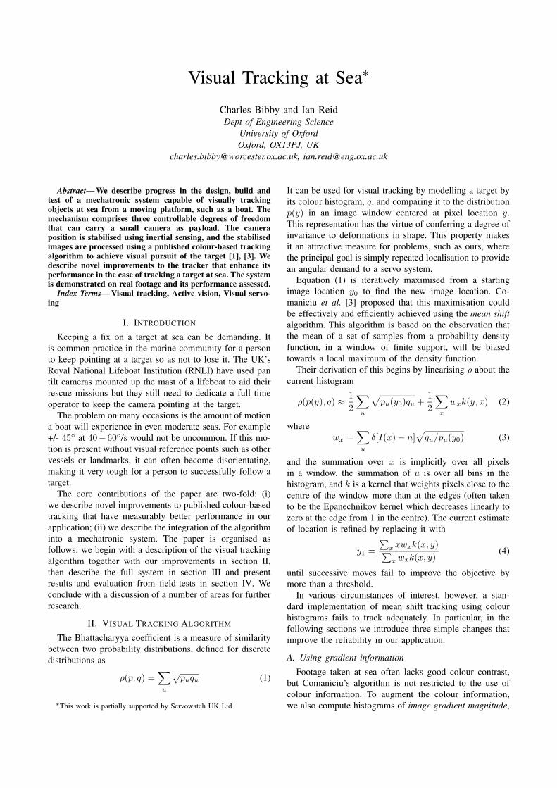
Footage taken at sea often lacks good colour contrast,but Comaniciu’s algorithm is not restricted to the use ofcolour information. To augment the colour information,we also compute histograms of image gradient magnitude,
where the image gradient is computed using standard finite-difference approximations in x and y from the monochromeimage.
The sequences in figure 1 illustrate a typical scenariowhere there is little colour contrast, and demonstrate thatthe use of gradient information is beneficial.
Fig. 1. Tracking in low colour-contrast images: (left) using colourhistograms only; (right) using a combination of colour and gradienthistograms
B. Background suppression
Other authors (e.g. [4]) have also noted the problemthat a target that shares some colours with the backgroundcan be difficult to track reliably. To address this problemwe have developed a method of background suppression,which also provides a metric of target suitability withrespect to mean shift tracking.
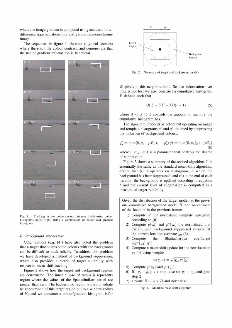
Figure 2 shows how the target and background regionsare constructed. The inner ellipse of radius h representsregion where the values of the Epanechnikov kernel aregreater than zero. The background region is the immediateneighbourhood of this target region out to a window radiusof h′, and we construct a colour/gradient histogram b for
TargetRegion
BackgroundRegion
h’ h
Fig. 2. Geometry of target and background models
all pixels in this neighbourhood. So that information overtime is not lost we also construct a cumulative histogram,B defined such that
B(t) ∝ b(t) + λB(t− 1) (5)
where 0 < λ < 1 controls the amount of memory thecumulative histogram has.
The algorithm proceeds as before but operating on imageand template histograms p∗ and q∗ obtained by suppressingthe influence of background colours:
q∗u = max(0, qu−µBu), p∗u(y) = max(0, pu(y)−µBu)(6)
where 0 < µ < 1 is a parameter that controls the degreeof suppression.
Figure 3 shows a summary of the revised algorithm. It isessentially the same as the standard mean-shift algorithm,except that (i) it operates on histograms in which thebackground has been suppressed; and (ii) at the end of eachiteration the background is updated according to equation5 and the current level of suppression is computed as ameasure of target reliability.
Given the distribution of the target model, q, the previ-ous cumulative background model B, and an estimateof the location in the previous frame:
1) Compute q∗ the normalised template histogramaccording to (6)
2) Compute p(y0) and p∗(y0) the normalised his-togram (and background suppressed version) atthe current location estimate y0 (6)
3) Compute the Bhattacharyya coefficientρ(p∗(y0), q∗)
4) Compute a mean shift update for the new locationy1 (4) using weights
w(y, u) =√q∗u, p∗u(y)
5) Compute p(y1) and p∗(y1)6) If ||y1 − y0|| < ε stop, else set y0 ← y1 and goto
step 27) Update B ← b+B and normalise.
Fig. 3. Modified mean shift algorithm

Fig. 4. (left) Tracking with background suppression active; (right) asnapshot of the histograms from a frame in the sequence
C. Coping with occlusion
If the starting point for the optimisation is outside thebasin of attraction, then the target will be lost since the al-gorithm will converge to an incorrect local maximum. Thisalso occurs regularly because of occlusion in the scene.Both can be ameliorated by filtering image location overtime and providing predictions via a motion model (e.g.Kalman Filtering), but ultimately some form of recoverymechanism is required. Particle filtering techniques addressthe problem of incorrect convergence since they have theability to represent a multi-model distribution over targetlocation, but pay a hefty computational price.
In order to obtain the ability to recover from failure,but without the burden of a full particle filter, we samplethe Bhattacharyya surface at discrete locations on a regulargrid whose size is commensurate with the current scale(see figure 5). This provides a coarse approximation to theBhattacharyya surface. Treating this as a likelihood, wecombine it with a prior to obtain a coarse posterior. Sinceour prior is obtained from the prediction step in a KalmanFilter, the posterior is simply the likelihood weighted bya Gaussian centred on the prediction and with covariancegiven by the filter’s prediction uncertainty.
The maximum in this coarse posterior is then chosen asthe starting point for iteration of the mean shift algorithm.Figure 6 shows an example of this process in operation.Note that the full Bhattacharyya surface is shown in thefigure for illustrative purposes only; during actual operationwe compute only the values at the discrete grid locationsto obtain a coarse sampling.
Fig. 5. The Bhattacharyya coefficient is evaluated at a set of discretelocations determined by tiling the image with windows of the currentscale outwards from the current location
D. Scaling
Comaniciu’s original solution to the question of a targetchanging scale over time was addressed via an ad-hoc testthat grew and shrunk the scale of the target region by±10%and chose the scale that gave the best Bhattacharyya coef-ficient. This method suffers from two significant problems:(i) the target is prone to collapse on itself if its distributionis relatively uniform; and (ii) the target window can explodeto encompass significant parts of the background unless thebackground is significantly different.
Though Collins [2] provides an elegant solution viascale-space, we have adopted a simpler method. It is stillbased on Comaniciu’s original idea, but using our coarsesampling of the Bhattacharyya surface to determine ifscale changes should be allowed. If the surface has lowcurvature at the boundaries of the current target window,this is suggestive that either the target has started tocollapse (and so parts of the full target are now consideredbackground and outside the target window) or that thetarget is poorly distinguished from the background. We usea simple measure defined as the difference between theBhattacharyya coefficient at the centre and the mean valueof the surrounding samples. If this difference falls below athreshold scale changes are disabled. Figure 7 shows thistechnique in action.
III. SYSTEM INTEGRATION
The visual tracking algorithm described in the previoussection has been fully integrated into a robotic systemincorporating 3 degrees of freedom (pan/tilt/roll), imagestabilisation, and visual tracking. The core componentsof the system are the mechanism and camera, an em-bedded PC running Linux for visual processing, a PICmicrocontroller running low-level control algorithms, andan InertiaCube (TM) inertial sensor1. This latter deviceprovides relatively drift-free orientation data via fusion oftwice-integrated acceleration sensing, a compass and solid-state gyros.
1InterSense InertiaCube2, Intersense Inc.

Fig. 6. Recovery from tracking failure: (left) shows typical behaviorof the unmodified algorithm in the presence of occlusions; (middle)shows the recovery after complete occlusion using the coarsely sampledBhattacharyya surface; (right) the full Bhattacharyya surface for eachframe
Visual processing is performed on the embedded PC, andvisual demands are sent to the PIC microcontroller whichis responsible for acquiring visual and inertial sensor data,and generating PWM signals for the servos.
The controller on the PIC comprises two main controlloops running at different frequencies. The first loop isto stabilise the platform and runs at 50Hz. It polls theInertiaCube for its current orientation and calculates theinverse kinematics to stabilise the orientation of the cam-era’s natural coordinate frame.
The second loop is fired from an interrupt every timea new image frame arrives (30Hz or 25Hz depending onthe camera being used). This loop calls the current trackerwith the new frame where a prediction is made of the x,ycoordinates that correspond to the best guess of the currenttarget location. These coordinates are then subtracted fromthe centre of the frame to give two error signals which drivea non-linear controller. The outputs from this controllerthen make relative changes to the signals produced fromthe inverse kinematics.
The final demand signals are transmitted at 50Hz, fromthe PC to the PIC microcontroller via a serial link. The PICmicrocontroller is continually reading the incoming serialdata and generates the corresponding PWM signals for theactuators, thus moving the camera and closing the feedbackloop for the visual controller. The reason for choosing this
Fig. 7. Changing scale: (left) scaling up; (right) scaling down
design is so that the stabilisation and the vision controllerscan be kept independent from one another. This means thatit is then possible to operate the system with stabilisationalone, vision alone, or both.
A. Visual Feedback
Design of the feedback control loop for vision proceededempirically. A straight proportional controller does notsupport a high enough gain for a fast response withoutbecoming unstable, while a proportional controller withderivative action improved matters but still provided in-sufficient gain for tracking fast moving targets. Finally athree stage controller with two proportional stages and aconstant saturated stage was implemented (see Figure 10).
B. Inertial Stabilisation
The InertiaCube provides three angular measurementsthat describe its orientation in a global coordinate frame.It is mounted on the mechanism platform, and thereforeprovides the world to base-frame transformation. The base-frame to tool-frame (i.e. platform to camera) transformation

Fig. 8. PTR Mechanism
Fig. 9. System overview
RPC is under control and we effectively want to keep theworld-frame to tool-frame transformation RWC constant.Thus the set of angles required for stabilisation comes from
RPC = RWCR�WP
From the mechanism forward kinematics RPC =Rz(ψ)Ry(φ)Rx(θ), so after some simple algebraic manip-ulation we obtain
φ = arcsin(RPC(3, 1))ψ = arctan(−RPC(3, 3)/RPC(3, 3))θ = arctan(−RPC(2, 1)/RPC(1, 1)) (7)
See figure 11 for the final control algorithm.
IV. RESULTS
Testing was conducted both on a custom built pan/tilt/rolldevice using small but high torque servos capable ofslew rates of up to 300 ◦/s, and a commercial pan/tiltmechanism specifically designed to operate in a marineenvironment (see figure 12). Figure 1 shows the use ofgradient information, Figure 4 background suppression,Figure 7 scaling, and Figures 13, 14 the complete systemin action.
V. CONCLUSIONS
The problem of visual tracking at sea poses someinteresting questions which we have begun to investi-gate through the use of an active camera platform anda simple but effective colour based tracker. In order toovercome some of the specific problems encountered in
Fig. 10. The piece-wise linear controller developed for visual feedbackcontrol
At each control cycle:
1) Calculate δt, time elapsed since last update2) Obtain RWP from InertiaCube3) Evaluate RPC = RWCR
�WP
4) Decompose RPC into pan (θ), tilt (φ) and roll (ψ)using (7).
5) Find target in image and let xerr, yerr be thedemand in pixel coordinates
6) Compute pan and tilt demands:
θerr = arctan(xerr cosψ − yerr sinψ)φerr = arctan(xerr sinψ + yerr cosψ)
7) Calculate θd, φd using the piecewise linear con-troller shown in figure 10
Fig. 11. Control algorithm
visual imagery at sea we have proposed several simplebut effective modifications that improve the robustness oftracking, and give a measure of confidence in our results.We have demonstrated successful tracking in several scenesincluding in the presence of unmodelled ego-motion whichis compensated by closed loop inertial feedback control.
We have not addressed the issue of automatic targetacquisition which would be crucial for search and res-cue missions, and which raises a number of interestingquestions, such as how to detect a salient target in thepresence of constantly moving, textured background likethe sea. Equally target re-acquisition after a period ofocclusion (in rough water a target is likely to disappear
Fig. 12. Tests were performed using both (left) a simple custom builtpan/tilt/roll device and (right) a commercial pan/tilt mechanism (Mic1-300from Forward Vision CCTV Ltd (www.fvcctv.co.uk))

Fig. 13. Stabilisation over a short video sequence: (left) stabilised image;(right) view from a hand-held video camera, with superimposed lines toillustrate motion
into troughs for periods) needs to be addressed. Thoughour coarsely sampled Bhattacharyya surface provides aneffective solution in some cases, further research will lookat sensible motion models for typical search/rescue targets.Moreover prolonged tracking would give the opportunityto derive a much stronger appearance model of a target,enhancing the prospects of correct re-acquisition.
REFERENCES
[1] G. Bradski. Computer vision face tracking for use in a perceptualuser interface. In IEEE Workshop on Applications of Computer Vision,pages 214–219, 1998.
[2] R. T. Collins. Mean-shift blob tracking through scale space. InProc. 21st IEEE Conf. on Computer Vision and Pattern Recognition,Madison, Wisconsin, volume 2, pages 234–240, 2003.
[3] D. Comaniciu, V. Ramesh, and P. Meer. Real-time tracking of non-rigid objects using mean shift. In Proc. 19th IEEE Conf. on ComputerVision and Pattern Recognition, Hilton Head Island, volume 2, pages142–149, 2000.
[4] F. M. Porikli and O. Tuzel. Fast object tracking by adaptive back-ground models and mean-shift analysis. In International ConferenceOn Computer Vision Systems (ICVS), 2003.
Fig. 14. Stabilisation and tracking over a 7 minute sequence