Visual and Animation Tools in Civil 3D · PDF fileThis session will cover Visual and Animation...
16
Visual and Animation Tools in Civil 3D FDOT State Kit for AutoCAD Civil 3D Visual and Animation Tools in Civil 3D FDOT State Kit for AutoCAD Civil 3D Mike Racca CADD APPLICATIONS SUPPORT Florida Department of Transportation (ECSO) Email: [email protected]
Transcript of Visual and Animation Tools in Civil 3D · PDF fileThis session will cover Visual and Animation...

Visual and Animation Tools
in Civil 3D
FDOT State Kit for AutoCAD Civil 3D
Visual and Animation Tools
in Civil 3D
FDOT State Kit for AutoCAD Civil 3D
Mike Racca
CADD APPLICATIONS SUPPORT
Florida Department of Transportation (ECSO)
Email: [email protected]

This session will cover Visual and Animation tools that are available in the
FDOT Civil 3D state kit. We will also look at rendering a Surface, Visualizing a Corridor
with code set styles and how to utilize various tool for design checks
Software prerequisites:
�The most current/latest version of the FDOT Civil 3D State kit should be
installed. This will ensure you are using the latest subassemblies developed
specific for FDOT roadway modeling Design Standards.
User prerequisites:
�Should have a good understanding of AutoCAD and a basic understanding of
AutoCAD Civil 3D.
2
Visual and Animation Tools in Civil 3D
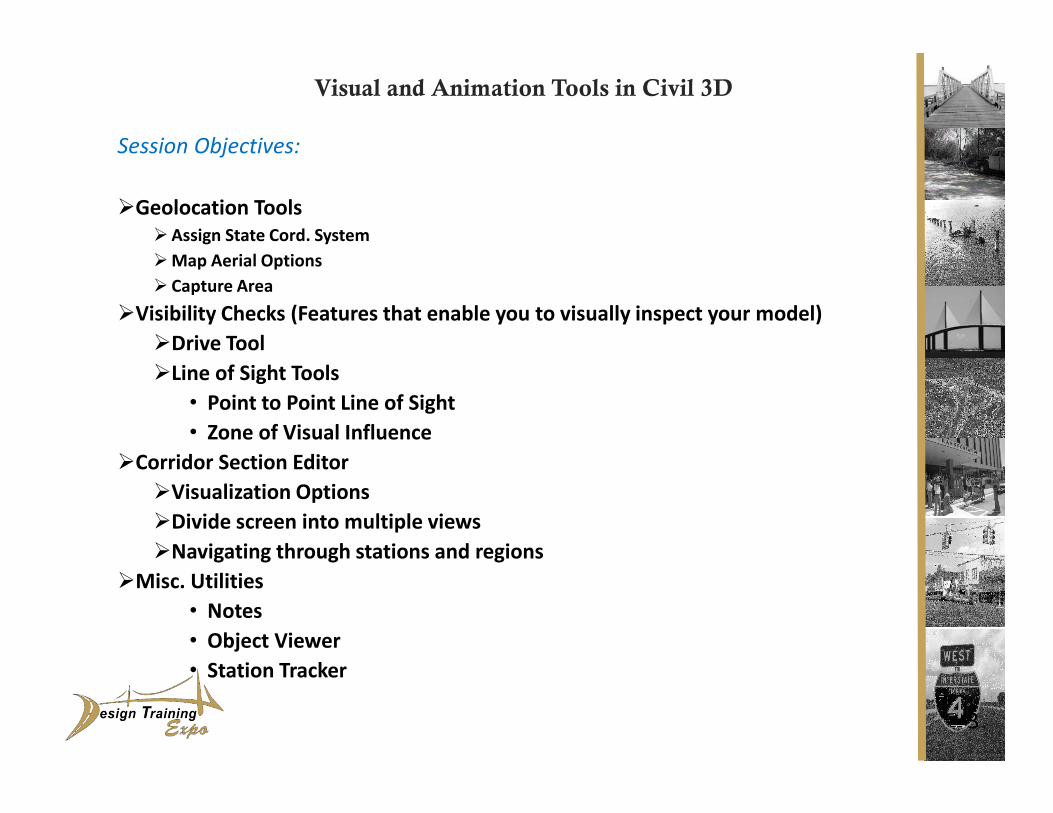
Session Objectives:
�Geolocation Tools
�Assign State Cord. System
�Map Aerial Options
� Capture Area
�Visibility Checks (Features that enable you to visually inspect your model)
�Drive Tool
�Line of Sight Tools
• Point to Point Line of Sight
• Zone of Visual Influence
�Corridor Section Editor
�Visualization Options
�Divide screen into multiple views
�Navigating through stations and regions
�Misc. Utilities
• Notes
• Object Viewer
• Station Tracker
3
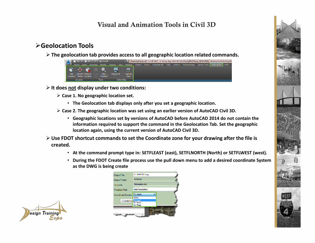
�Geolocation Tools
� The geolocation tab provides access to all geographic location related commands.
� It does not display under two conditions:
� Case 1. No geographic location set.
• The Geolocation tab displays only after you set a geographic location.
� Case 2. The geographic location was set using an earlier version of AutoCAD Civil 3D.
• Geographic locations set by versions of AutoCAD before AutoCAD 2014 do not contain the
information required to support the command in the Geolocation Tab. Set the geographic
location again, using the current version of AutoCAD Civil 3D.
�Use FDOT shortcut commands to set the Coordinate zone for your drawing after the file is
created.
• At the command prompt type in: SETFLEAST (east), SETFLNORTH (North) or SETFLWEST (west).
• During the FDOT Create file process use the pull down menu to add a desired coordinate System
as the DWG is being create
4
Visual and Animation Tools in Civil 3D

�Geolocation Tools
�Once the Geolocation ribbon is active/on, use it to view Aerial, Road or Hybrid aerial
maps.
�You can also Capture an area manually or per viewport for an imbedded aerial image in
your DWG file.
�After an Image is captured, select the image frame to adjust the Properties, or
update the image.
� Type MAPSTATUSBAR at the command prompt to display the current assigned Coordinate
system. Once turned on, it will display at the bottom of the UI.
5
Visual and Animation Tools in Civil 3D

�Visibility Checks
�Drive Tool
�Use the Drive command to simulate driving through a 3D model.
� Select an Alignment to access the Drive option on the Civil 3D ribbon.
�A drive path can be a 3D Polyline, alignment and profile, corridor feature line, grading feature
line, or survey figure.
� You can play, pause or reverse the display of driving through the model. You can change the
speed of the drive simulation, as well as the eye location, visual style, and target object.
� You can switch to another drive path while the drive command is active. If you have trouble
selecting a drive path from within the drive view, you can open a separate viewport to select a
path in plan view.
� Changes to the Drive settings persist while a drawing is open. When you close the drawing and
open it again, the Drive setting return to their default settings.
6
Visual and Animation Tools in Civil 3D

�Visibility Checks
7
Visual and Animation Tools in Civil 3D
Point to Point Check Sight DistanceZone of Visual Influence

�Visibility Checks
�Point to Point-Line of Sight Tools
�Use this tool to do a local sight distance check, example, at a high risk spot in an intersection.
This check is typically performed against a finished ground surface, or a composite surface.
1. Select the Analyze tab > Design Panel > Visibility Check drop-down > point to Point. (CMD
PointToPointCheck)
2. Select a surface or press Enter and select a surface from the list.
3. At the command line you are prompted to specify the following:
-Height of eye -Location of eye -Height of target -Location of target
A green arrow is displayed if the target is visible from the eye location, The command line
displays the distance from the eye to the target.
If the target is not visible from the eye location, the portion of the line of sight that is visible
is green and the line beyond the obstruction point is red. A message is displayed at the
command line indicating that the line of sight is obstructed. The name of the surface that is
causing the obstruction, the obstruction point coordinates, and the distance from the eye to
the target are listed.
4. Continue to specify targets or press ESC to end the command.
Note: All sight lines are drawn during a single command as an AutoCAD block on layer 0 so
that you can easily select them and delete them is necessary.
8
Visual and Animation Tools in Civil 3D
�Visibility Checks
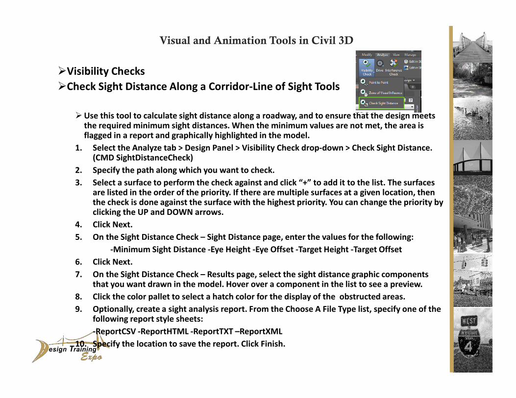
�Check Sight Distance Along a Corridor-Line of Sight Tools
�Use this tool to calculate sight distance along a roadway, and to ensure that the design meets the required minimum sight distances. When the minimum values are not met, the area is flagged in a report and graphically highlighted in the model.
1. Select the Analyze tab > Design Panel > Visibility Check drop-down > Check Sight Distance. (CMD SightDistanceCheck)
2. Specify the path along which you want to check.
3. Select a surface to perform the check against and click “+” to add it to the list. The surfaces are listed in the order of the priority. If there are multiple surfaces at a given location, then the check is done against the surface with the highest priority. You can change the priority by clicking the UP and DOWN arrows.
4. Click Next.
5. On the Sight Distance Check – Sight Distance page, enter the values for the following:
-Minimum Sight Distance -Eye Height -Eye Offset -Target Height -Target Offset
6. Click Next.
7. On the Sight Distance Check – Results page, select the sight distance graphic components that you want drawn in the model. Hover over a component in the list to see a preview.
8. Click the color pallet to select a hatch color for the display of the obstructed areas.
9. Optionally, create a sight analysis report. From the Choose A File Type list, specify one of the following report style sheets:
-ReportCSV -ReportHTML -ReportTXT –ReportXML
10. Specify the location to save the report. Click Finish.9
Visual and Animation Tools in Civil 3D

�Visibility Checks
�Zone of Visual Influence - Line of Sight Tools
�Use this tool to perform local visibility checks when you need to determine if a vertical object,
such as a traffic light or a tower, can be seen from with a certain radius. You can also use this
command to determine how far a driver can see from a stop line at an intersection.
� To check the validity of the deigned terrain, this check is typically performed against a finished
ground surface, or a composite surface.
� This command creates hatch patterns on the current drawing layer to indicate the difference
levels of visibility.
1. Set the layer you want to create the hatch patterns on. (CMD ZoneOfVisualInfluence)
2. Click Analyze tab > Design Panel > Visibility Check drop-down > Zone Of Visual Influence.
3. Select a Surface, or press Enter and select a surface from the list.
4. At the command line you are prompted to specify the following:
-Location of the object - Height of the object -Radius of the vision extent
After the command is complete, the colored areas (Hatch Patterns) on the surface within the
specified radius indicate the following:
10
Visual and Animation Tools in Civil 3D

�Section Editor
� Edits corridor sections using the View/Edit Corridor Section Tools, using tabular or grip editing.
�Use the Corridor Section Editor to apply assemblies overrides to a corridor section or a range of
sections and then view only those sections.
� To view both section view and its location along the corridor, open two horizontal viewports.
� You can view complex corridors that are modeled with multiple baselines. You can step through
corridor station or jump to any station of interest.
� Edit corridor and assembly parameters as required, using the following methods:
• Edit the assembly numerically by editing the subassembly parameters.
• Resize assembly parameters by grip editing the subassembly part geometry.
• Insert or remove subassemblies from a corridor station.
� If you have edited a subassembly by either adding or deleting a point, adding or deleting a link
or editing the subassembly geometry using grips, you cannot edit the values of the changed
parameters in the Corridor Section Editor.
1. Select a frequency line on the corridor near that section that you want to view.
2. Select the Section Editor icon located in the Modify Corridor Sections Panel.
3. After View/Editing sections click the Close icon on the far left of the ribbon to exit the editor.
If you forget and save and close your drawing first things will look weird. To get back, go to
your view tab and click on the WORLD icon and type PLAN at the command line, press enter
and then W for WORLD (press Enter).
11
Visual and Animation Tools in Civil 3D
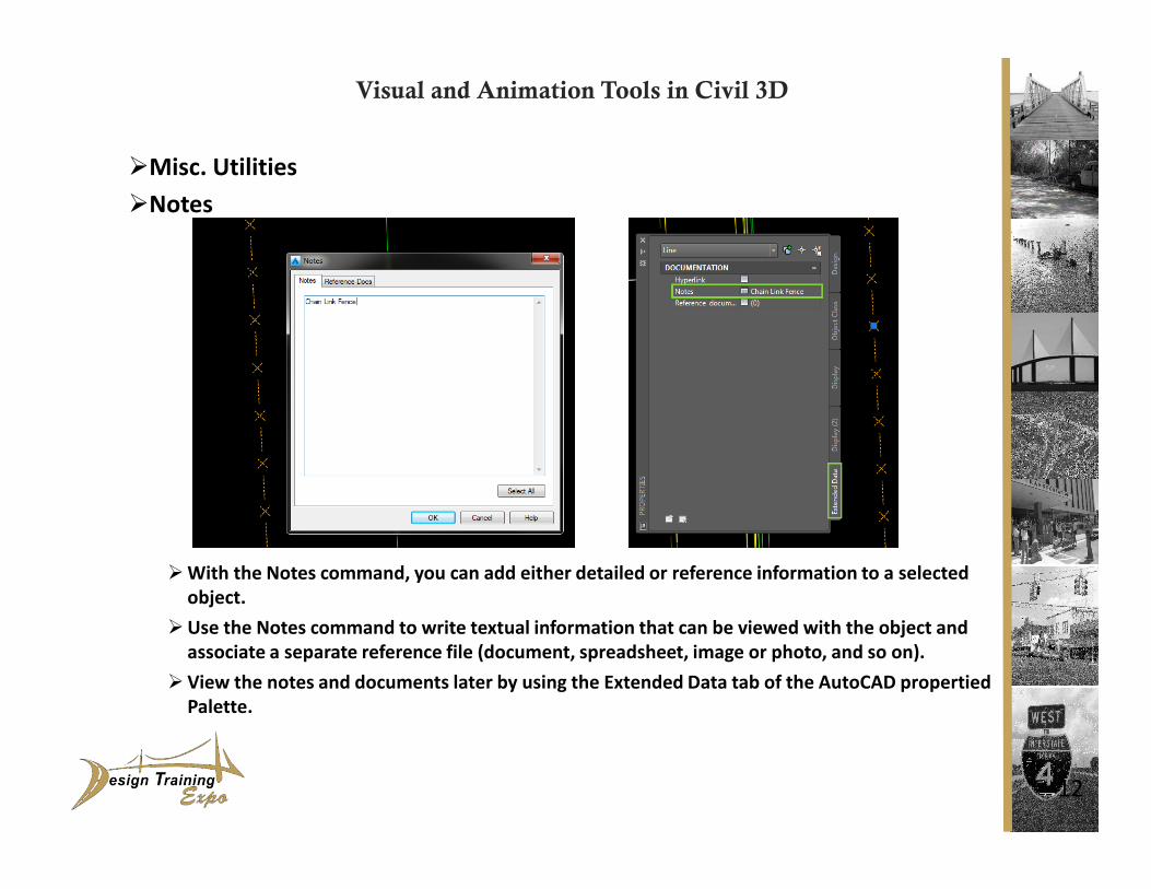
�Misc. Utilities
�Notes
�With the Notes command, you can add either detailed or reference information to a selected
object.
�Use the Notes command to write textual information that can be viewed with the object and
associate a separate reference file (document, spreadsheet, image or photo, and so on).
�View the notes and documents later by using the Extended Data tab of the AutoCAD propertied
Palette.
12
Visual and Animation Tools in Civil 3D

�Misc. Utilities
�Object Viewer
� The Object Viewer displays objects you select in you drawing, based on the current view that is
set in the drawing.
�AutoCAD Civil 3D objects are displayed in the Object Viewer using the Plan or Model setting
specified in their styles. For example, in a 3D view , objects are displayed using their Model
settings.
� The Object Viewer contains the View Cube and the Steering Wheel.
� To view a “realistic” 3D surface, the surface style assigned must show triangles on the surface.
1. Select the object you want to view (Surface, Corridor….). Right –click and choose Object
Viewer from the short-cut menu.
2. From the View Control list at the upper right of the Object Viewer, select any of the following:
• Top, Bottom, Left, Right, Front, or Back: Sets the current view to the selected view.
• SW Isometric, Se Isometric, NE Isometric, or NW Isometric: Sets the current view to the
selected isometric view.
3. From the Visual Style list, select one of the following object appearance styles:
• 3D Hidden, 3D Wireframe, Conceptual, Realistic.
4. Choose from the zoom options from the Object Viewer to increase or decrease the apparent
size of objects in the current viewport.
5. Click the “bulls eye” marker to set the view in the drawing to match the current view in the
Object Viewer.
13
Visual and Animation Tools in Civil 3D

�Misc. Utilities
�Station Tracker
� The Station Tracker provides visual cues to help you locate the stations that match your cursor
position when working with alignments, profiles and sections.
�When the cursor is above a horizontal alignment, and one or more profile views for the same
horizontal alignment are in a drawing, a temporary line is drawn in each profile view at the
station defined by the orthogonal projection of the cursor onto the horizontal alignment. The
temporary line is drawn to the fill height of the profile view, and moves as the cursor moves.
�When the cursor is within a profile view, a temporary line is drawn orthogonal to the horizontal
alignment at the cursor’s station. The line extends 200 world distance units to the left and right
sides of the horizontal alignment. As the cursor’s position changes in the profile view, the
temporary line’s position is redrawn at the new location.
�When the cursor is within a section view, a temporary line is drawn orthogonal to the
horizontal alignment at the station of the cross-section view. The line extends 200 world
distance units to the left and right sides of the horizontal alignment. Additional, a vertical line
is drawn in each associated profile view. The vertical line is drawn at the station of the section
view. The setting is controlled per drawing.
• Analyze tab > Inquiry panel > Station Tracker drop-down
14
Visual and Animation Tools in Civil 3D

1. _______________________________________________________________________________________________________________
2. _______________________________________________________________________________________________________________
3. _______________________________________________________________________________________________________________
4. _______________________________________________________________________________________________________________
5. _______________________________________________________________________________________________________________
6. _______________________________________________________________________________________________________________
7. _______________________________________________________________________________________________________________
8. _______________________________________________________________________________________________________________
9. ______________________________________________________________________________________________________________
10._______________________________________________________________________________________________________________
15
Notes:

Thank You!
Questions?
Any comments to improve your experience?
Email me:
The Civil 3D FDOT State kit is available for download at:
http://www.dot.state.fl.us/ecso/downloads/software/FDOT2016CADDSoftware.shtm
16
MIKE RACCA
CADD Applications Support
Florida Department of Transportation
Production Support Office - CAD
Email: [email protected]