
Visible Spectro-polarimeter (ViSP) Conceptual Design
19
-
Upload
abra-daniel -
Category
Documents
-
view
41 -
download
0
description
Visible Spectro-polarimeter (ViSP) Conceptual Design. David Elmore HAO/NCAR [email protected]. ViSP Mission*. Precision measurements of full state of polarization Simultaneously at diverse wavelengths Visible spectrum range Fully resolved line profiles Provides quantitative diagnostics of - PowerPoint PPT Presentation
Transcript of Visible Spectro-polarimeter (ViSP) Conceptual Design
August 25-28, 2003 ViSP 2
ViSP Mission*
• Precision measurements of full state of polarization– Simultaneously at diverse wavelengths– Visible spectrum range– Fully resolved line profiles
• Provides quantitative diagnostics of– Magnetic field vector as a function of solar
height– Variation in thermodynamic properties*From Instrument Science Requirements 2001, Sept. 17, B. Lites, C. Keller
August 25-28, 2003 ViSP 3
ViSP Participants
• Hector Socas-Navarro (PI)• Kim Streander (Program Manager)• David Elmore (Lead Engineer)• Paul Seagraves (Telescope modeling)
August 25-28, 2003 ViSP 4
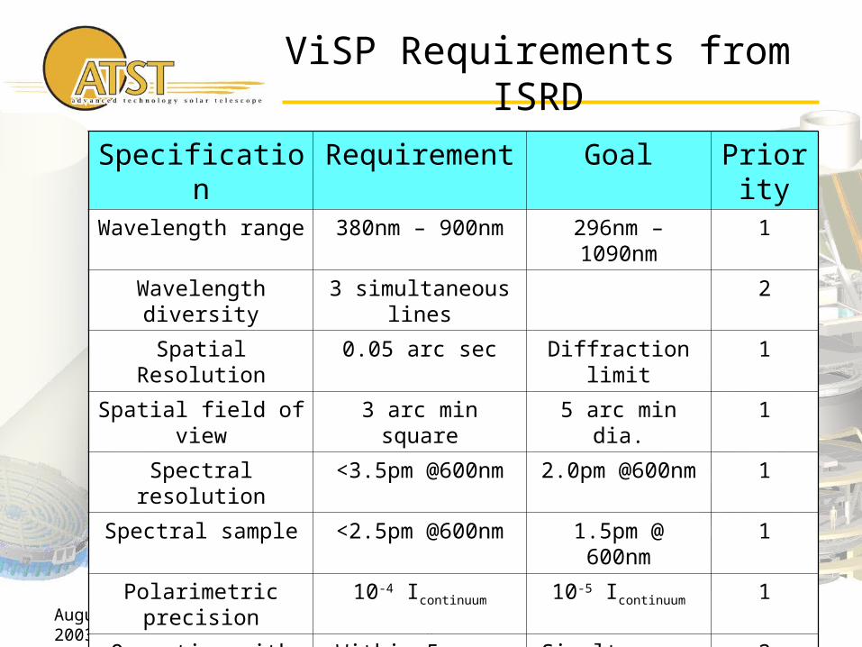
ViSP Requirements from ISRD
Specification Requirement Goal Priority
Wavelength range 380nm – 900nm 296nm – 1090nm 1
Wavelength diversity 3 simultaneous lines 2
Spatial Resolution 0.05 arc sec Diffraction limit 1
Spatial field of view 3 arc min square 5 arc min dia. 1
Spectral resolution <3.5pm @600nm 2.0pm @600nm 1
Spectral sample <2.5pm @600nm 1.5pm @ 600nm 1
Polarimetric precision 10-4 Icontinuum 10-5 Icontinuum 1
Operation with NIRSP Within 5 sec. Simultaneous 2
August 25-28, 2003 ViSP 5
Spectrograph Design Drivers
• Requirements• Telescope f/#• Size of Coudé room• Detector realities
August 25-28, 2003 ViSP 6
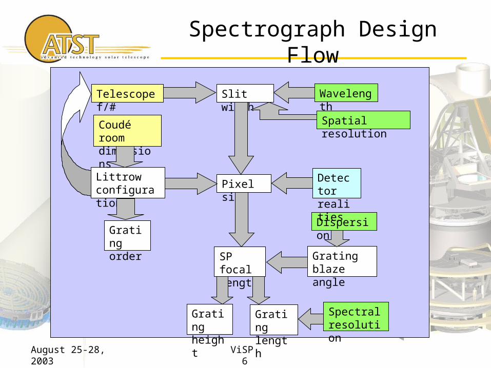
Spectrograph Design Flow
Telescope f/#
Pixel size
Slit width
Littrow configuration
Coudé room dimensions
Wavelength
Spatial resolution
SP focal length
Dispersion
Detector realities
Grating blaze angle
Grating length
Gratingheight
Spectralresolution
Gratingorder

August 25-28, 2003 ViSP 7
Spectrograph Specifications
Feed focal ratio f/40
Focal Length 2250mm
Slit Width 24mPixel Size 24mSlit Height 140mm
Grating Height 196mm
Grating Length 200mm
Grating Blaze Angle
57º
Based on VSP Coupling to Telescope.doc, Elmore (April 2003)

August 25-28, 2003 ViSP 8
Spectrograph Design
August 25-28, 2003 ViSP 9
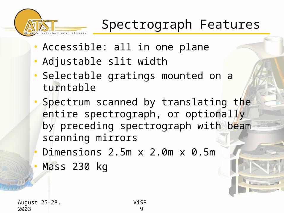
Spectrograph Features
• Accessible: all in one plane• Adjustable slit width• Selectable gratings mounted on a turntable• Spectrum scanned by translating the entire
spectrograph, or optionally by preceding spectrograph with beam scanning mirrors
• Dimensions 2.5m x 2.0m x 0.5m• Mass 230 kg

August 25-28, 2003 ViSP 10
Spectrograph PerformanceSpectral Resolution & Sample vs. Wavelength
0.00
1.00
2.00
3.00
4.00
5.00
6.00
7.00
300 400 500 600 700 800 900 1000 1100
Wavelength (nm)
Sam
ple
(p
m)
f/40 telescope, 2.25 m spectrograph, 24 micron slit
Resolution
SampleRequirement
August 25-28, 2003 ViSP 11
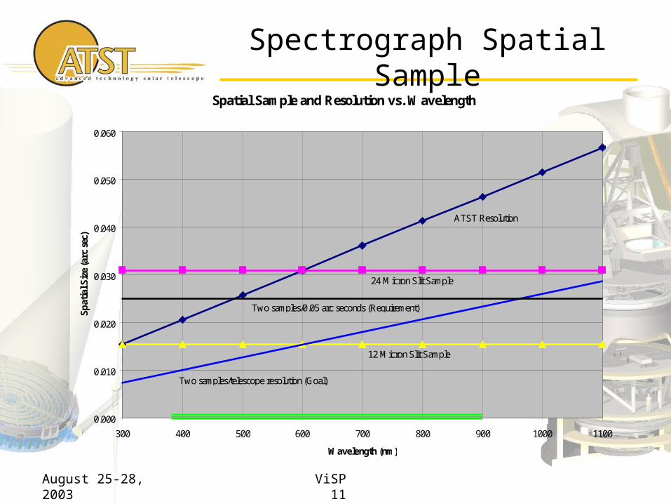
Spectrograph Spatial SampleSpatial Sample and Resolution vs. Wavelength
0.000
0.010
0.020
0.030
0.040
0.050
0.060
300 400 500 600 700 800 900 1000 1100
Wavelength (nm)
Sp
atia
l Siz
e (a
rc s
ec)
ATST Resolution
24 Micron Slit Sample
12 Micron Slit Sample
Two samples/telescope resolution (Goal)
Two samples/0.05 arc seconds (Requirement)

August 25-28, 2003 ViSP 12
Spectrograph Overview
• Design optimized for spatial sample equal to telescope spot size @600nm
• Dispersion optimized for spectro-polarimetry
• Finer spatial resolution possible using narrow slit and smaller pixels at the expense of lower flux
• Higher spectral resolution possible using narrow slit, smaller pixels, and higher blaze angle grating at the expense of lower flux
• 1.6m possible through the same slit as visible wavelengths at the expense of flux at 1.6m
August 25-28, 2003 ViSP 13
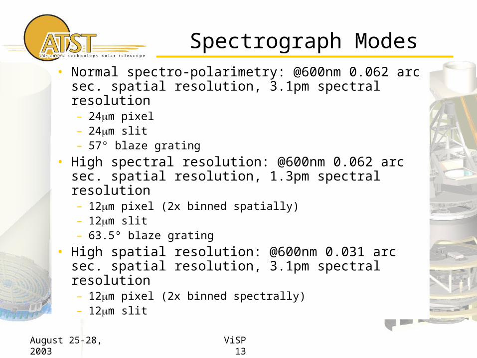
Spectrograph Modes
• Normal spectro-polarimetry: @600nm 0.062 arc sec. spatial resolution, 3.1pm spectral resolution– 24m pixel – 24m slit– 57º blaze grating
• High spectral resolution: @600nm 0.062 arc sec. spatial resolution, 1.3pm spectral resolution– 12m pixel (2x binned spatially)– 12m slit– 63.5º blaze grating
• High spatial resolution: @600nm 0.031 arc sec. spatial resolution, 3.1pm spectral resolution– 12m pixel (2x binned spectrally)– 12m slit
August 25-28, 2003 ViSP 14
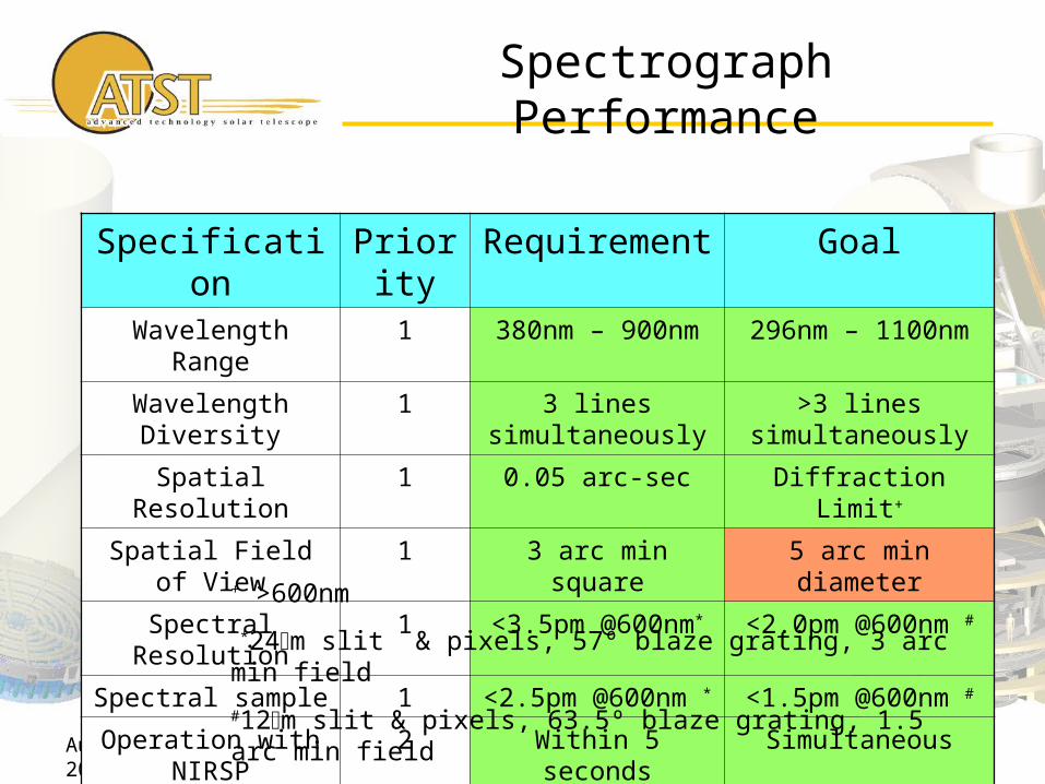
Spectrograph Performance
Specification Priority Requirement GoalWavelength Range 1 380nm – 900nm 296nm – 1100nm
Wavelength Diversity 1 3 lines simultaneously
>3 lines simultaneously
Spatial Resolution 1 0.05 arc-sec Diffraction Limit+
Spatial Field of View 1 3 arc min square 5 arc min diameter
Spectral Resolution 1 <3.5pm @600nm* <2.0pm @600nm #
Spectral sample 1 <2.5pm @600nm * <1.5pm @600nm #
Operation with NIRSP 2 Within 5 seconds Simultaneous+ >600nm
*24m slit & pixels, 57º blaze grating, 3 arc min field
#12m slit & pixels, 63.5º blaze grating, 1.5 arc min field

August 25-28, 2003 ViSP 15
Polarimeter Guidelines
• Time multiplexed polarization modulation and analysis used– Versatile– Issues are understood
• Calibration optics precede highly polarizing reflections (Calibration station at Gregory focus)
• Polarization modulators precede highly polarizing reflections (Modulator turret at Gregory focus)
• Seeing induced errors reduced at high modulation frequency (kHz)
• Seeing induced errors reduced using dual beam analyzer
August 25-28, 2003 ViSP 16
Polarimeter Concept (HPP)
• High Precision Polarimeter
– Modulator: High speed Piezo-elastic (PEM) or ferroelectric liquid crystal (FeLC) modulator at Gregory
– Analyzer: Linear polarizer at Gregory
– Advantages• kHz modulation frequency rejects residual seeing
• No highly polarizing optics between modulator and analyzer
– Disadvantages• Narrow wavelength range, but tunable
• 4 State Charge caching photo-detector required

August 25-28, 2003 ViSP 17
Polarimeter Concept (FAP)
• Fast Achromatic Polarimeter– Modulator: Rapidly rotating achromatic retarder at Gregory– Analyzer at detector: Linear polarizer for 8-state modulation
or high frequency FeLC + linear polarizer for 4-state modulation
– Advantages• kHz modulation frequency rejects residual seeing• Wavelength diversity possible
– Disadvantages• Highly polarizing optics between modulator and analyzer • Time varying polarimeter response matrix• Calibration intensive data collection and reduction• 4 State Charge caching photo-detector required
August 25-28, 2003 ViSP 18
Polarimeter Concept (SAP)
• Slow Achromatic Polarimeter– Modulator: Achromatic slowly rotating retarder at Gregory– Analyzer: Polarizing beam splitter at detectors– Advantages
• Wavelength diversity possible• Conventional CCD or IR detectors can be mixed with charge
caching photo-detectors (that use rapidly chopped FeLC before analyzer)
– Disadvantages• Highly polarizing optics between modulator and analyzer • Time varying polarimeter response matrix• Calibration intensive data collection and reduction• 8 State Charge caching detector needed for mixed scheme
August 25-28, 2003 ViSP 19
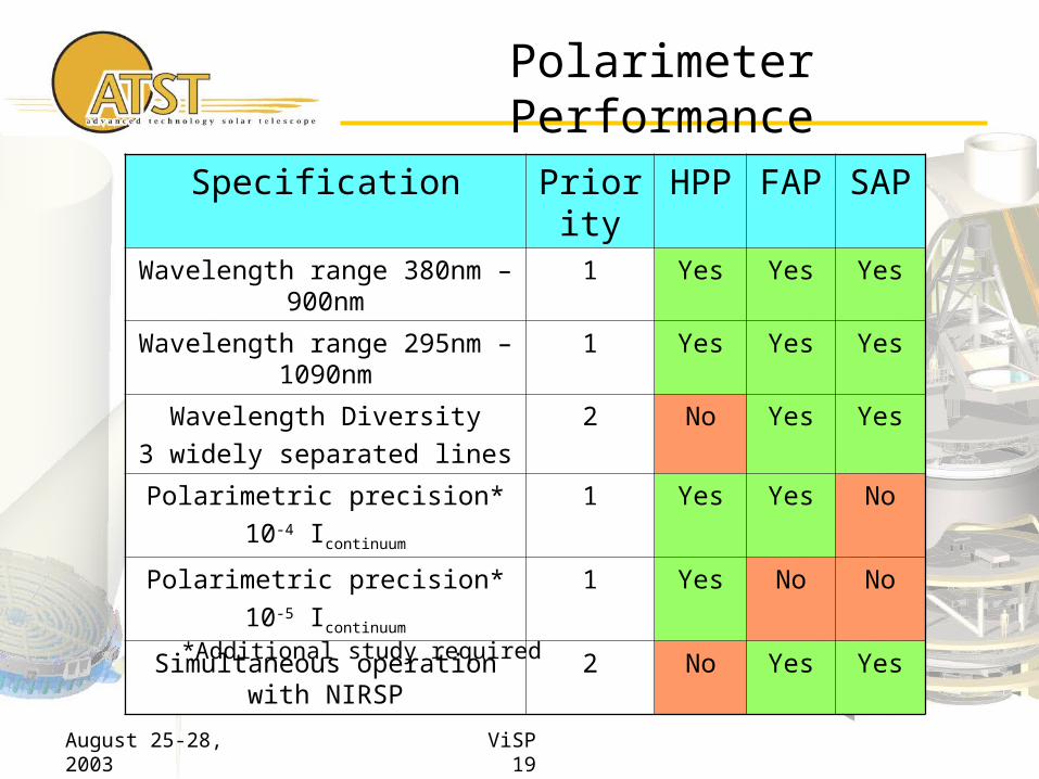
Polarimeter Performance
Specification Priority HPP FAP SAPWavelength range 380nm – 900nm 1 Yes Yes Yes
Wavelength range 295nm – 1090nm
1 Yes Yes Yes
Wavelength Diversity
3 widely separated lines
2 No Yes Yes
Polarimetric precision*
10-4 Icontinuum
1 Yes Yes No
Polarimetric precision*
10-5 Icontinuum
1 Yes No No
Simultaneous operation with NIRSP 2 No Yes Yes
*Additional study required