VIS (Valve-In-Star) Hydraulic Motors
85
D-i EATON Low Speed High Torque Motors E-MOLO-MC001-E3 July 2006 VIS (Valve-In-Star) Hydraulic Motors The next step in the evolution of low speed high torque (LSHT) hydraulic motors. VIS 30 Series VIS 40 Series VIS 45 Series
Transcript of VIS (Valve-In-Star) Hydraulic Motors

D-iEATON Low Speed High Torque Motors E-MOLO-MC001-E3 July 2006
VIS (Valve-In-Star) Hydraulic Motors
The next step in the evolution of low speed high torque (LSHT) hydraulic motors.
VIS 30 Series
VIS 40 Series
VIS 45 Series

D-ii EATON Low Speed High Torque Motors E-MOLO-MC001-E3 July 2006
VIS Motors
Highlights
Patented Shuttle for Increased Drive Spline Lubrication
Rigidity of Geroler® is Increased by 50%
Larger Bolts and Increased MaterialProperties for Stiffer Pressure Envelope
Two Piece Pre-Loaded Balance Platefor Better Starting Efficiency and HigherBack (Return) Pressure Capacity
Optimal Drive Spline and Shank Design
Larger Rolls and Improved StarGeometry for Lower Geroler Contact and Stress
Closed Loop Back-Pressure (Charge) Relief Valve
Product Description
The VIS (Valve-in-Star) Motors are the next step in the evolution of the low speed high torque (LSHT) hydraulic motors. The VIS design provides design advantages over other types of LSHT hydraulic motor valving resulting in a more compact package with better efficiency and higher pressure capability. These improvements have shown significant packaging and performance advantages in applications such as skid steer loaders, mini excavators, trenchers and logging equipment.
VIS motors are primarily intended for use in closed loop circuit applications. Consult your Eaton represen-tative for assistance on open loop circuit applications.

D-iiiEATON Low Speed High Torque Motors E-MOLO-MC001-E3 July 2006
Features, Benefits, and Applications
Features
• Patented VIS Geroler technology
• Simplified design - only three moving components:
- geroler star
- drive
- output shaft
• Pressure-balance Geroler - improves efficiency
• Shuttle valve option for reliable internal drive lubrication
• Variety of optional features
Benefits
• Extremely compact powerful package
• Highest output torque in its class
• High efficiency
• Reduced system temperatures
• High horsepower density
• Design flexibility
• Reliable and dependable performance
Applications
• Skid steer loaders
• Sprayers
• Underground boring equipment
• Forestry equipment
• Irrigation reels
• Grinders/Mixers
• Material handling equip-ment
• Augers and skid steer attachments
• Large turf care equipment
Standard Motor
The standard motor mounting flange is located as close to the output shaft as possible. This type of mounting supports the motor close to the shaft load. This mounting flange is also compatible with many standard gear boxes.
Wheel Motor
The wheel motor mounting flange is located near the center of the motor which permits part or all of the motor to be located inside the wheel or roller hub. In traction drive applications, loads can be positioned over the motor bearings for best bearing life. This wheel motor mounting flange provides design flexibility in many applications.
Bearingless Motor
The bearingless motor has the same drive components as the standard and wheel motors with the exception that the motor is assembled without the output shaft, bearings and bearing housing. The bearingless motor is especially suited for applications such as gear boxes, winch drives, reel and roll drives. Bearingless motor applications must be designed with a bearing supported internal spline to mate with the bearingless motor drive. Product designs using these hydraulic motors provide considerable cost savings.
Design FeaturesEaton hydraulic motors provide design flexibility. All VIS motors are available with various configurations consisting of:
• Displacement (Geroler)
• Output Shaft
• No Shaft (Bearingless Motor)
• Port Configuration
• Mounting Flange
• Park brake
• Other Special Features

D-iv EATON Low Speed High Torque Motors E-MOLO-MC001-E3 July 2006
Table of Contents
Highlights D-ii
Features, Benefits, and Applications D-iii
Table of Contents D-iv
Typical Hydraulic Circuit D-v
VIS 30 Series
Highlights D-1-1
Specifications D-1-2
Performance Data D-1-3
Dimensions D-1-5
Installation Information D-1-8
Dimensions Shafts D-1-9
Shaft Side Load Capacity D-1-10
Product Numbers D-1-13
Model Code D-1-15
VIS 30 Series Two-speedSpecifications D-1-16
Performance Data D-1-16
Dimensions D-1-17
Installation Information D-1-20
Product Numbers D-1-21
Model Code D-1-22
Brake Description D-1-23
Brake Dimensions D-1-24
Brake Shaft Dimensions and Sideload Curves D-1-25
VIS 40 Series
Highlights D-2-1
Specifications D-2-2
Performance Data D-2-3
Dimensions D-2-6
Installation Information D-2-10
Dimensions Shafts D-2-11
Side Load Capacity D-2-12
Oversize Flange 224,0 [8.82] B.C. D-2-14
Product Numbers D-2-17
Model Code D-2-19
VIS 40 Series Two-speedSpecifications D-2-20
Performance Data D-2-20
Dimensions D-2-21
Installation Information D-2-25
Product Numbers D-2-26
Model Code D-2-27
Brake Description D-2-28
Brake Shaft Dimensions/ Sideload Curves D-2-30
VIS 45 Series
Highlights D-3-1
Specifications D-3-2
Performance Data D-3-3
Dimensions D-3-6
Installation Information D-3-9
Dimensions Shafts D-3-10
Side Load Capacity D-3-12
Product Numbers D-3-13
Model Code D-3-15
VIS 45 Series Two-speedSpecifications D-3-16
Performance Data D-3-16
Dimensions D-3-17
Product Numbers D-3-20
Model Code D-3-21
D-vEATON Low Speed High Torque Motors E-MOLO-MC001-E3 July 2006
Hot OilShuttleValve
Closed Loop Back-Pressure (Charge) Relief Valve
Case Drain
A
B
Low (Charge) Pressure
High Pressure
B
D
A
S
Pump, Variable
B
D
A
B
A
S
Pump, Variable VIS Motor
ShuttleValve
Back-Press.(Charge)Relief Valve
P1 P2
Case Drain
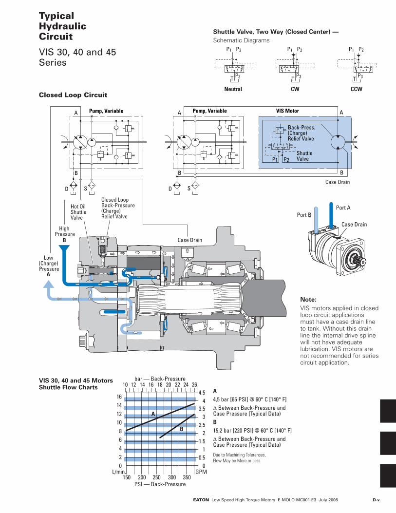
Typical Hydraulic Circuit
VIS 30, 40 and 45 Series
Closed Loop Circuit
PSI — Back-Pressure
bar — Back-Pressure
002468
10121416
0.51
1.52
2.5
GPML/min.
3
43.5
4.5
200 250150 300 350
141210
A
B
16 18 20 22 24 26
P1
P3
P2
T
Neutral
P3
CW
P1 P2
T P3
CCW
P1 P2
T
VIS 30, 40 and 45 Motors Shuttle Flow Charts A
4,5 bar [65 PSI] @ 60° C [140° F]∆ Between Back-Pressure and Case Pressure (Typical Data)B15,2 bar [220 PSI] @ 60° C [140° F]∆ Between Back-Pressure and Case Pressure (Typical Data)
Due to Machining Tolerances, Flow May be More or Less
Shuttle Valve, Two Way (Closed Center) —
Schematic Diagrams
Note:
VIS motors applied in closed loop circuit applications must have a case drain line to tank. Without this drain line the internal drive spline will not have adequate lubrication. VIS motors are not recommended for series circuit application.
Case Drain
Port APort B
D-vi EATON Low Speed High Torque Motors E-MOLO-MC001-E3 July 2006
B
APump, Fixed Displacement VIS Motor
Control Valve
Shuttle Valve
P1 P2
Case Drain
Hot OilShuttleValve
Case Drain
Return Pressure
High Pressure
Pump, Fixed Displacement
Control Valve
B
A
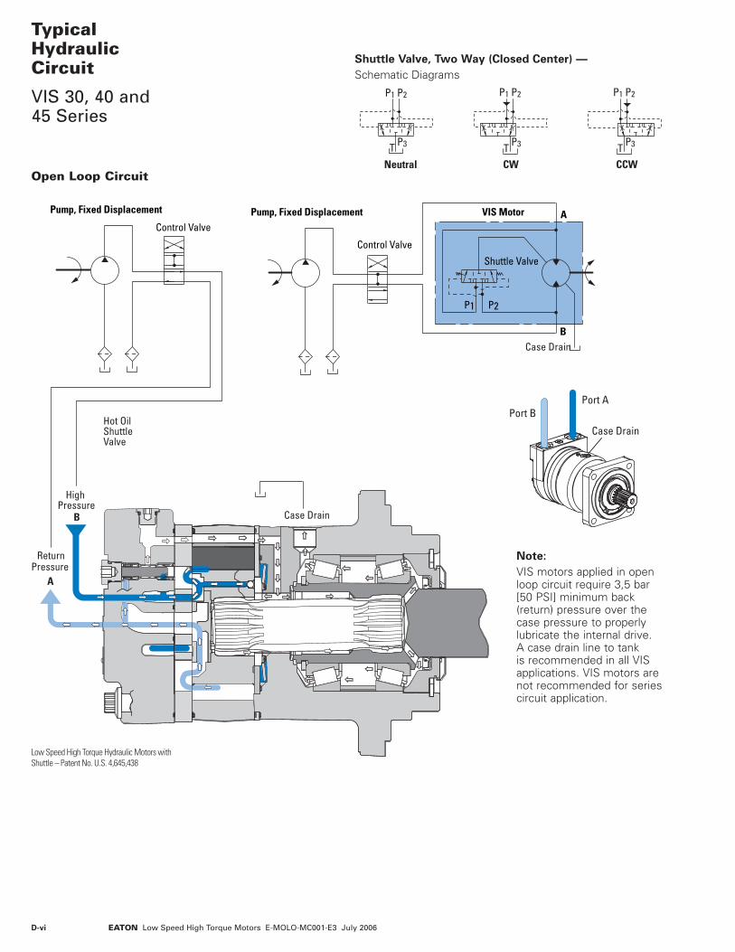
Typical Hydraulic Circuit
VIS 30, 40 and 45 Series
Open Loop Circuit
Case Drain
Port APort B
P1
P3
P2
T Neutral
P3
CW
P1 P2
T P3
CCW
P1 P2
T
Shuttle Valve, Two Way (Closed Center) —
Schematic Diagrams
Low Speed High Torque Hydraulic Motors with Shuttle – Patent No. U.S. 4,645,438
Note:
VIS motors applied in open loop circuit require 3,5 bar [50 PSI] minimum back (return) pressure over the case pressure to properly lubricate the internal drive. A case drain line to tank is recommended in all VIS applications. VIS motors are not recommended for series circuit application.

D-viiEATON Low Speed High Torque Motors E-MOLO-MC001-E3 July 2006
Typical Hydraulic Circuit
VIS 30, 40 and 45 Series
Two-speed Circuit
Two-Speed Brake Motor Circuit
ShuttleValve
High-pressureShuttleValve
Anti-cavitation Feature (Optional)
Selector Valve External Shift
Valve
Back-pressureRelief Valve
A
B
Case Drain
Anti-cavitation Feature (Optional)
Selector Valve External Shift Valve
Back-pressureRelief Valve
A
B
Case Drain
Brake ReleaseAnd
Boost Valve
Shuttle Valve
High-pressureShuttle Valve

D-viii EATON Low Speed High Torque Motors E-MOLO-MC001-E3 July 2006
Notes

D-1-1EATON Low Speed High Torque Motors E-MOLO-MC001-E3 July 2006
DescriptionThe Eaton VIS 30 motor is the most compact motor in the VIS motor line. It is rated at 151LPM [40 GPM] and pressures to 310 bar [4500 PSI]. Maximum continuous output torque capability is rated to 1632 Nm [14,400 lb-in.]. This motor provides high torque with high efficiency, smooth performance, and quiet operation. The motor utilizes patented VIS technology with improved high-strength Geroler, optimized drive geometry, and two-piece pre-loaded balance plate for increased starting efficiency, reduced leakage and higher back pressure capacity. A wide variety of options are available including two-speed option, brake options and case flow options for both closed-loop and open-loop applications
Features
• Patented VIS Geroler tech-nology
• Three moving compo-nents: (Geroler‚ star, drive, and output shaft)
• Two-piece pre-loaded pressure balance plate
• Shuttle valve option for reliable internal drive lubri-cation
• High-pressure capabil-ity – ratings compatible with high-pressure piston pumps
• Variety of optional fea-tures including two-speed option, brake packages, and case flow solutions for both closed-loop and open-loop applications.
Benefits
• Extremely Compact Powerful Package
• Highest Output Torque in its Class
• High Efficiency
• Reliable performance
• Reduced System Temperatures
• Quiet, Smooth Operation
• High Horsepower Density
• Design Flexibility
Applications
• Skid Steer Loaders
• Sprayers
• Underground Boring Equipment
• Forestry Equipment
• Irrigation Reels
• Grinders / Mixers
• Material Handling Equipment
• Augers
Sprayer Boring Injection MoldingSkid Steer
VIS 30 Series
Highlights
SpecificationsGeroler Element 4 Displacements
Flow l/min [GPM] 151 [40] Continuous***
170 [45] Intermittent**
Speed Up to 454 RPM
Pressure bar [PSI] 310 [4500] Cont.***
345 [5000] Inter.**
380 [5500] Peak.*
Torque Nm [lb - in] 1632 [14440] Cont.***
2034 [18000] Inter.**
*** Continuous— (Cont.) Continuous rating, motor may be run continuously at these ratings.** Intermittent— (Inter.) Intermittent operation, 10% of every minute.* Peak— (Peak) Peak operation, 1% of every minute.

D-1-2 EATON Low Speed High Torque Motors E-MOLO-MC001-E3 July 2006
VIS 30 Series
Specifications
End Cap
ShuttleValve
Balance Plate
BearingsDriveGeroler®
Face Seal MountingFlange
FrontRetainer
OutputShaft
ShaftSeal
Case Drain Port
Back PressureRelief Valve Valve
Plate
Seal Guard
Maximum Inlet Pressure:
400 bar [5800 PSI]
Do Not Exceed Pressure Rating (for displacement size see chart above).
Return Pressure (Back-Pressure):
Minimum – 3,5 bar [50 PSI] Maximum – 21 bar [300 PSI]
Note:
Return (back-pressure) must be 3,5 bar [50 PSI] greater than the case pressure.
Case Pressure:
Minimum – No Pressure Maximum – 3,5 bar [50 PSI]
Note:
The case must be full when the motor is operating. A case drain is recommended.
∆ Pressure:
The true ∆ bar [∆ PSI] between inlet port and outlet port
Continuous Rating:
Motor may be run continuously at these ratings
Intermittent Operation:
10% of every minute
Peak Operation:
1% of every minute
Recommended Fluids:
Premium quality, anti-wear type hydraulic oil with a viscosity of not less than 70 SUS at operating temperature.
Recommended Maximum System Operating Temp.:
82° C [180° F]
Recommended Filtration:
Per ISO Cleanliness Code, 4406: 20/18/13
Shuttle:
Standard
Back-Pressure Relief Valve:
Required for closed loop circuit.
SPECIFICATION DATA — VIS 30 SERIES MOTORS
Displ. cm3/r [in3/r] 325 [19.8] 400 [24.4] 505 [30.7] 570 [34.9] Max. Speed Continuous 440 357 284 249 (RPM) Intermittent 454 368 293 257 @ FlowFlow l/min [GPM] Continuous 151 [40] 151 [40] 151 [40] 151 [40] Intermittent 170 [45] 170 [45] 170 [45] 170 [45] Torque Continuous 1445 [12789] 1589 [14063] 1632 [14440] 1632 [14440] Nm [lb-in] Intermittent 1597 [14137] 1968 [17421] 2034 [18000] 2034 [18000]Pressure Continuous 310 [4500] 255 [3700] 203 [2950] 179 [2600] ∆ bar Intermittent 345 [5000] 320 [4635] 254 [3685] 223 [3240] [∆ PSI] Peak 380 [5500] 380 [5500] 305 [4420] 268 [3890] Weight Standard or 28,5 [62.9] 29,1 [64.2] 29,9 [66.0] 30,5 [67.2]kg [lb] Wheel Mount Bearingless 16,3 [36.0] 16,9 [37.3] 17,7 [39.1] 18,3 [40.3]Weight Two-speed Standard or 32,1 [70.8] 32,7 [72.1] 33,5 [73.9] 34,1 [75.1]kg [lb] Wheel Mount Two-speed Bearingless 19,9 [43.9] 20,5 [45.2] 21,3 [47.0] 21,9 [48.2]
A simultaneous maximum torque and maximum speed NOT recommended.
Note:
To assure best motor life, run motor for approximately one hour at 30% of rated pressure before application to full load. Be sure motor is filled with fluid prior to any load applications.

D-1-3EATON Low Speed High Torque Motors E-MOLO-MC001-E3 July 2006
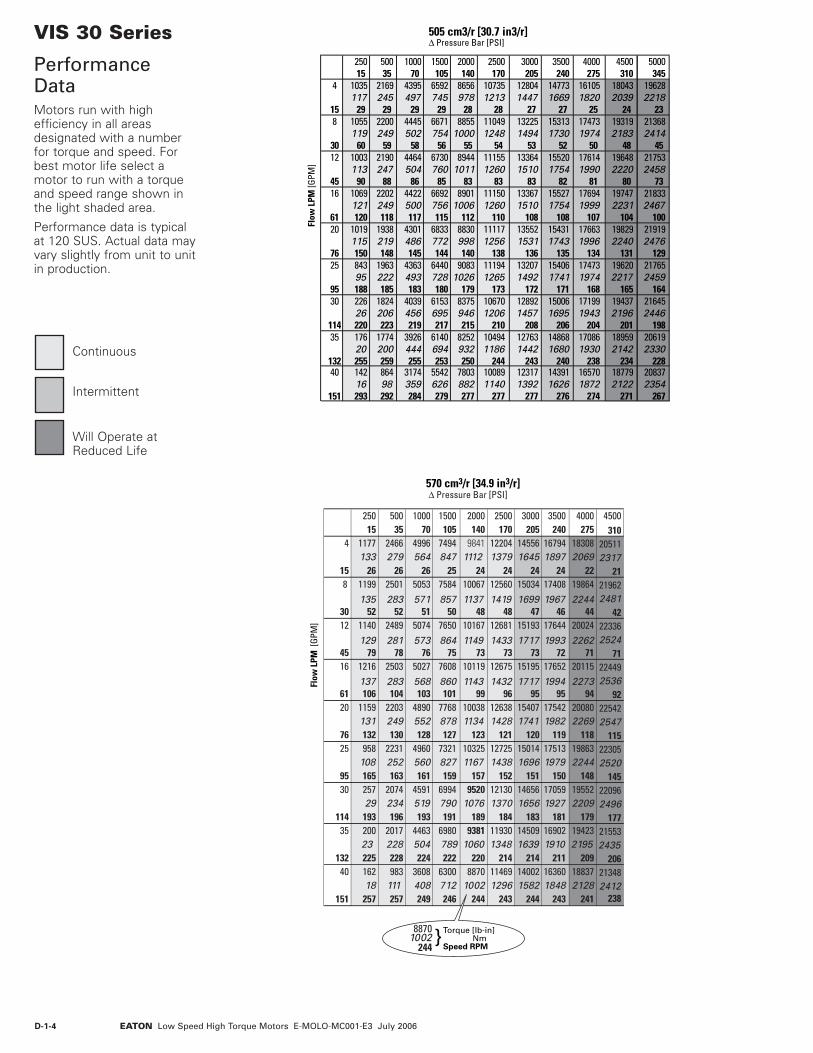
VIS 30 Series
Performance DataMotors run with high efficiency in all areas designated with a number for torque and speed. For best motor life select a motor to run with a torque and speed range shown in the light shaded area.
Performance data is typical at 120 SUS. Actual data may vary slightly from unit to unit in production.
500 1000 1500 2000 2500 3000 3500 4000 4500 5000 550035 70 105 140 170 205 240 275 310 345 380
1399 2834 4251 5583 6924 8258 9528 10387 11637 12659158 320 480 631 782 933 1076 1174 1315 1430
46 46 44 43 43 42 42 39 37 361419 2867 4303 5711 7126 8530 9876 11269 12460 13782 14840160 324 486 645 805 964 1116 1273 1408 1557 1677
91 90 87 85 84 83 81 78 74 70 661412 2879 4340 5768 7195 8619 10010 11360 12672 14029 15246160 325 490 652 813 974 1131 1284 1432 1585 1723137 133 132 129 129 129 127 126 124 113 109
1420 2852 4316 5741 7191 8621 10014 11412 12736 14081 15435160 322 488 649 812 974 1131 1289 1439 1591 1744184 181 179 174 170 168 168 166 161 154 151
1250 2774 4407 5695 7170 8741 9952 11392 12789 14137 15339141 313 498 643 810 988 1124 1287 1445 1597 1733229 226 223 217 214 211 209 208 203 200 197
1266 2814 4154 5858 7220 8518 9936 11269 12654 14037 15334143 318 469 662 816 962 1123 1273 1430 1586 1732287 283 280 277 269 266 264 260 256 254 248
1177 2605 3968 5401 6882 8315 9678 11092 12536 13960 15321133 294 448 610 778 939 1094 1253 1416 1577 1731345 340 336 333 325 323 320 316 312 307 303
1144 2532 3960 5322 6768 8232 9589 11019 12228 13298 15023129 286 447 601 765 930 1083 1245 1382 1503 1697402 396 392 387 378 377 372 369 363 353 354557 2047 3574 5032 6507 7944 9282 10687 12112 13439 1493863 231 404 569 735 898 1049 1207 1368 1518 1688452 440 433 430 429 430 428 425 420 413 408
25015
4 66875
15 468 680
7730 93
12 64773
45 13916 690
7861 18620 657
7476 23325 544
6195 291
14616341114133969210454
30
11435
13240
151
Δ Pressure Bar [PSI]325 cm3/r [19.8 in3/r]
Flo
w L
PM [G
PM]
Torque [lb-in] NmSpeed RPM
}6201701349
Δ Pressure Bar [PSI]400 cm3/r [24.4 in3/r]
Flo
w L
PM [G
PM]
250 500 1000 1500 2000 2500 3000 3500 4000 4500 5000 550015 35 70 105 140 170 205 240 275 310 345 380
4 823 1724 3493 5239 6880 8532 10177 11741 12800 14340 1560093 195 395 592 777 964 1150 1327 1446 1620 1763
15 37 37 37 36 35 35 34 34 32 30 298 838 1749 3533 5302 7038 8781 10511 12171 13887 15354 16983 18288
95 198 399 599 795 992 1188 1375 1569 1735 1919 20663030 7575 7474 7373 7171 6969 6868 6767 6666 6363 6060 5757 535312 797 1740 3548 5349 7108 8866 10622 12335 13999 15616 17289 18788
90 197 401 604 803 1002 1200 1394 1582 1764 1953 212345 113 111 108 107 105 105 105 103 102 101 92 8816 850 1750 3515 5319 7074 8862 10624 12341 14063 15695 17353 19021
96 198 397 601 799 1001 1200 1394 1589 1773 1961 214961 151 149 147 145 141 138 136 136 135 131 125 12320 810 1540 3419 5431 7018 8836 10771 12264 14039 15760 17421 18902
92 174 386 614 793 998 1217 1386 1586 1781 1968 213676 189 186 183 181 176 174 171 170 169 165 163 16025 670 1560 3467 5118 7219 8897 10497 12244 13887 15594 17299 18896
76 176 392 578 816 1005 1186 1383 1569 1762 1954 213595 236 233 230 227 225 218 216 215 211 208 206 20230 180 1450 3210 4890 6656 8480 10246 11927 13669 15448 17203 18881
20 164 363 552 752 958 1158 1348 1544 1745 1944 2133114 277 280 276 273 270 264 262 259 256 253 250 24635 140 1410 3120 4880 6559 8341 10144 11817 13579 15068 16388 18514
16 159 353 551 741 942 1146 1335 1534 1702 1852 2092132 321 326 321 318 314 307 306 302 299 295 287 28740 113 687 2522 4405 6201 8019 9789 11438 13170 14926 16561 18409
13 78 285 498 701 906 1106 1292 1488 1686 1871 2080151 368 367 357 352 349 348 349 347 345 341 335 331
Continuous
Intermittent
Will Operate at Reduced Life
D-1-4 EATON Low Speed High Torque Motors E-MOLO-MC001-E3 July 2006
VIS 30 Series
Performance DataMotors run with high efficiency in all areas designated with a number for torque and speed. For best motor life select a motor to run with a torque and speed range shown in the light shaded area.
Performance data is typical at 120 SUS. Actual data may vary slightly from unit to unit in production.
Δ Pressure Bar [PSI]505 cm3/r [30.7 in3/r]
Flo
w L
PM [G
PM]
250 500 1000 1500 2000 2500 3000 3500 4000 4500 500015 35 70 105 140 170 205 240 275 310 345
4 1035 2169 4395 6592 8656 10735 12804 14773 16105 18043 19628117 245 497 745 978 1213 1447 1669 1820 2039 2218
15 29 29 29 29 28 28 27 27 25 24 238 1055 2200 4445 6671 8855 11049 13225 15313 17473 19319 21368
119 249 502 754 1000 1248 1494 1730 1974 2183 241430 60 59 58 56 55 54 53 52 50 48 4512 1003 2190 4464 6730 8944 11155 13364 15520 17614 19648 21753
113 247 504 760 1011 1260 1510 1754 1990 2220 245845 90 88 86 85 83 83 83 82 81 80 7316 1069 2202 4422 6692 8901 11150 13367 15527 17694 19747 21833
121 249 500 756 1006 1260 1510 1754 1999 2231 246761 120 118 117 115 112 110 108 108 107 104 10020 1019 1938 4301 6833 8830 11117 13552 15431 17663 19829 21919
115 219 486 772 998 1256 1531 1743 1996 2240 247676 150 148 145 144 140 138 136 135 134 131 12925 843 1963 4363 6440 9083 11194 13207 15406 17473 19620 21765
95 222 493 728 1026 1265 1492 1741 1974 2217 245995 188 185 183 180 179 173 172 171 168 165 16430 226 1824 4039 6153 8375 10670 12892 15006 17199 19437 21645
26 206 456 695 946 1206 1457 1695 1943 2196 2446114 220 223 219 217 215 210 208 206 204 201 19835 176 1774 3926 6140 8252 10494 12763 14868 17086 18959 20619
20 200 444 694 932 1186 1442 1680 1930 2142 2330132 255 259 255 253 250 244 243 240 238 234 22840 142 864 3174 5542 7803 10089 12317 14391 16570 18779 20837
16 98 359 626 882 1140 1392 1626 1872 2122 2354151 293 292 284 279 277 277 277 276 274 271 267
250 500 1000 1500 2000 2500 3000 3500 4000 450015 35 70 105 140 170 205 240 275 310
4 1177 2466 4996 7494 9841 12204 14556 16794 18308 20511133 279 564 847 1112 1379 1645 1897 2069 2317
15 26 26 26 25 24 24 24 24 22 218 1199 2501 5053 7584 10067 12560 15034 17408 19864 21962
135 283 571 857 1137 1419 1699 1967 2244 248130 52 52 51 50 48 48 47 46 44 4212 1140 2489 5074 7650 10167 12681 15193 17644 20024 22336
129 281 573 864 1149 1433 1717 1993 2262 252445 79 78 76 75 73 73 73 72 71 7116 1216 2503 5027 7608 10119 12675 15195 17652 20115 22449
137 283 568 860 1143 1432 1717 1994 2273 253661 106 104 103 101 99 96 95 95 94 9220 1159 2203 4890 7768 10038 12638 15407 17542 20080 22542
131 249 552 878 1134 1428 1741 1982 2269 254776 132 130 128 127 123 121 120 119 118 11525 958 2231 4960 7321 10325 12725 15014 17513 19863 22305
108 252 560 827 1167 1438 1696 1979 2244 252095 165 163 161 159 157 152 151 150 148 14530 257 2074 4591 6994 9520 12130 14656 17059 19552 22096
29 234 519 790 1076 1370 1656 1927 2209 2496114 193 196 193 191 189 184 183 181 179 177
35 200 2017 4463 6980 9381 11930 14509 16902 19423 2155323 228 504 789 1060 1348 1639 1910 2195 2435
132 225 228 224 222 220 214 214 211 209 20640 162 983 3608 6300 8870 11469 14002 16360 18837 21348
18 111 408 712 1002 1296 1582 1848 2128 2412151 257 257 249 246 244 243 244 243 241 238
Torque [lb-in] NmSpeed RPM
}
570 cm3/r [34.9 in3/r]
Flo
w L
PM [
GPM
]
88701002
244
Continuous
Intermittent
Will Operate at Reduced Life

D-1-5EATON Low Speed High Torque Motors E-MOLO-MC001-E3 July 2006
46,10/45,34[1.815/1.785]
46,10/45,34[1.815/1.785]
Port B
Port A OptionalRelief Valve
XY
36,0/35,4 [1.42/1.41]
16,13/14,61 [.635/.575]8,1/7,7 [.32/.30]
97,2/96,8 [3.83/3.81]
139,70/139,57[5.500/5.495]Pilot Dia.
132,8/132,4[5.23/5.21]Dia.
80,5[3.17]Max. (2)
73,9[2.91] Max.
83,5[3.29]Max.
147,8 [5.82] Max.
108,2[7.12]Max.
184,15[7.250]Dia. B.C.
14,53/1,415[.572/.557]Dia. Thru (4)
Port A Port B15,2 [.60]R Min. (4)
Case DrainPort
VIS 30 Series
DimensionsStandard and Wheel Mount – SAE
Case Drain PortCross Section
70,56/69,0[2.78/2.72]
Port A Port B147,8 [5.82] Max.
80,5[3.17]Max. (2)
73,9[2.91]Max.
14,53/14,15[.572/.557]Dia. Thru (4)
83,5[3.29]Max.
147,3[5.80]Max. (2)
161,92[6.375]Dia. B.C.
14,5 [.57]R Min. (4)
XY
82,6/81,0 [3.25/3.19]
12,32/12,81 [.485/.465]24,6/24,2 [.97/.95]
126,98/126,92[4.999/4.997]Pilot Dia.
Case DrainPort
STANDARD MOTORS (SAE)
Displacement X Ycm3/r [in3/r] mm [inch] mm [inch]325 [19.8] 223,5 [8.80] 195,3 [7.69] 400 [24.4] 230,4 [9.07] 201,9 [7.95] 505 [30.7] 239,3 [9.42] 211,1 [8.31] 570 [34.9] 245,4 [9.66] 217,2 [8.55]
WHEEL MOTORS (SAE)
Displacement X Ycm3/r [in3/r] mm [inch] mm [inch] 325 [19.8] 138,7 [5.46] 110,5 [4.35] 400 [24.4] 145,5 [5.73] 117,1 [4.61] 505 [30.7] 154,5 [6.08] 126,2 [4.97] 570 [34.9] 160,5 [6.32] 132,3 [5.21]
Ports 1–1/16-12 UN-2B SAE O-ring Ports (2)9/16-18 UNF-2B SAE O-ring Case Drain Port (1)
Standard Rotation Viewed from Shaft End
Port A Pressurized — CW
Port B Pressurized — CCW
Standard Motors (SAE)
Wheel Motors (SAE)

D-1-6 EATON Low Speed High Torque Motors E-MOLO-MC001-E3 July 2006
34,6/34,0[1.36/1.34]
YX
Case DrainPort 14,73/13,21
[.580/.520]6,0/5,6[.24/.20]
98,5/98,1[3.88/3.86]
132,8/132,3[5.23/5.21]Dia.
160,02/159,82[6.300/6.292]Pilot Dia.Port
18,21/17,81[.717/.701]Dia. Thru (4)
180,8[7.12]Max. (2)
200,00[7.874]Dia. B.C.
15,2 [.60]R Min. (4)
80.5[3.17]Max.(2)
83.5[3.29]Max.
73,9[2.91]Max.
147,8 [5.82] Max.Port A Port B
18,3/17,7 [.72/.70]22,7/22,1 [.89/.87]31,8/29,2 [1.25/1.15]
124,3/123,7[4.89/4.87]Dia. 125,00/124,94
[4.921/4.919]Pilot Dia.
86,4/84,8 [3.40/3.34]9,2/8,6 [.36/.34]
XY
Case DrainPort
Case Drain PortCross Section
65,6/64,0[2.58/2.52]
Port
98,8[3.89]Max.
83,5[3.29]Max.
147,8 [5.82] Max.
73,9[2.91]Max.
14,46/13,54[.569/.533]Dia. Thru (4)
147,3[5.80]Max. (2)
14,5 [.57]R Min. (4)
160,00[6.299]Dia. B.C.
Port A Port B
VIS 30 Series
DimensionsStandard and Wheel Mount – ISO
STANDARD MOTORS (ISO)
Displacement X Ycm3/r [in3/r] mm [inch] mm [inch]325 [19.8] 211,6 [8.33] 183,1 [7.21]400 [24.4] 218,2 [8.59] 190,0 [7.48]505 [30.7] 227,3 [8.95] 198,9 [7.83] 570 [34.9] 233,4 [9.19] 205,2 [8.08]
WHEEL MOTORS (ISO)
Displacement X Ycm3/r [in3/r] mm [inch] mm [inch] 325 [19.8] 137,4 [5.41] 109,0 [4.29] 400 [24.4] 144,0 [5.67] 115,8 [4.56] 505 [30.7] 153,2 [6.03] 124,7 [4.91] 570 [34.9] 159,3 [6.27] 131,1 [5.16]
46,10/45,34[1.815/1.785]
46,10/45,34[1.815/1.785]
Port B
Port A
OptionalRelief Valve
Ports G 3/4 (BSP) O-ring Ports (2)
G 1/4 (BSP) O-ring Case Drain Port (1)
Standard Rotation Viewed from Shaft End
Port A Pressurized — CW
Port B Pressurized — CCW
Standard Motors (ISO)
Wheel Motors (ISO)

D-1-7EATON Low Speed High Torque Motors E-MOLO-MC001-E3 July 2006
Port
X
YMountingSurface
127,00/126,87[5.000/4.995]Pilot Dia.
12.45/11,94[4.90/.470]
20,6/19,6[.81/.77]
Shaft Face SealFurnished withMotor
VIS 30 Series
DimensionsBearingless
Port A Port B
147,8 [5.82] Max.
73,9[2.91]Max.
80,5[3.17]Max. (2)
83,5[3.29]Max.
195,1 [7.68] Max. (2)
MountingSurface
Return toCase Drain
14,53/14,17[.572/.558]Dia. Thru (4)
161,92 [6.375]Dia. Bolt Circle
45º
Case DrainPort 12,85
[.506]
70,10 [2.760]
Mating Coupling BlankEaton Part No. 13429-003
C 52,80 [2.08 ] Dia.D 49,00 [1.93 ] Dia.E 147,57 [5.81 ] Max.F 142,49 [5.61 ] Min. Full Form Dia.G 7,87 [ .310] Max.H 17,27 [ .680]J 33,30 [1.31 ]K 84,20 [3.315] Full Form Dia.L 69,60 [2.74 ]M 15
L
G H JK
F
M
DC
E
BEARINGLESS MOTORS
Displacement X Ycm3/r [in3/r] mm [inch] mm [inch] 325 [19.8] 141,2 [5.56] 113,3 [4.46] 400 [24.4] 148,1 [5.83] 120,1 [4.73] 505 [30.7] 157,2 [6.19] 129,0 [5.08] 570 [34.9] 163,3 [6.43] 135,1 [5.32]
Ports 1-1/16-12 UN-2B SAE O-ring Ports (2) 9/16-18 UNF-2B SAE O-ring Case Drain Port (1)
Or
G 3/4 (BSP) O-ring Ports (2)
G 1/4 (BSP) O-ring Case Drain Port (1)
Standard Rotation Viewed from Drive End
Port A Pressurized — CW
Port B Pressurized — CCW
For VIS 30 bearingless motor application information, contact your Eaton representative (mating coupling blanks available from Eaton Hydraulics).
Note:
After machining blank, part must be hardened per Eaton specification.
46,10/45,34[1.815/1.785]
46,10/45,34[1.815/1.785]
Port B
Port A OptionalRelief Valve

D-1-8 EATON Low Speed High Torque Motors E-MOLO-MC001-E3 July 2006
VIS 30 Series
Installation InformationBearingless
Circular
Major
MinorTip R.
Fillet R.Pitch
Form
Finish
Finish
45322X
3
4
2,5 (100)
66,83 ±0,25[2.631 ±.010]
39.88 ±0,25[1.570 ±.010]
55º ±5º
49,84 ±0,25[1.962 ±.010]
45º ±5º x 0,38 ±0,25 [.015 ±.010]or R 0,38 ±0,25 [.015± .010]
68,96 ±0,51[2.715 ±.020]Coupling Length
4.83 ±0,25[.190 ±.010] Oil Hole
-H-
31,0 ±0,25 [1.220 ±.010]
3,17 [.125] Max.Undercut
52,37[2.062]Min.
R 1,5±0,3[.06 ±.01]
R 1,5 ±0,3[.06 ±.01]
-G-
Oil Flow Path Thru Splineand Bearing(s)
Spline
Oil Flow Return to Case Drain
Case Drain
Spline Pitch ...............................................................................................8.5/17 Pressure Angle ............................................................................................. 30° Number of teeth ............................................................................................. 12 Class of Fit ................................................................................................. Ref. 5 Type of Fit .................................................................................................... Side Pitch Diameter ......................Ref. 35,858823 [1.4117647] 0,20 [.008] | HBase Diameter ...................................................... Ref. 31,054652 [1.2226241] Major Diameter ...................................39,17 [1.542] Max. 38,97 [1.534] Min. Minor Diameter ..................................................... 33,30 -33,48 [1.311 -1.318] Form Diameter, Min. .....................................................................38,33 [1.509] Fillet Radius .................................................................... 0,64 -0,76 [.025 -.030] Tip Radius ....................................................................... 0,25 -0,51 [.010 -.020] Finish ........................................................................................................1,6 (63) Involute Profile Variation .................................+0,000 -0,025 [+.0000 -.0010] Total Index Variation .....................................................................0,038 [.0015] Lead Variation ................................................................................0,013 [.0005] Circular Space Width: Maximum Actual ....................................................................5,898 [.2322] Minimum Effective .................................................................5,804 [.2285] Maximum Effective ....................................................... Ref. 5,857 [.2306] Minimum Actual ............................................................ Ref. 5,834 [.2297] Dimension Between Two Pins ............ Ref. 26,929 -27,084 [1.0602 -1.0663] Pin Diameter ......................................... 6,223 [.2450] Pins to Have 4,0 [.160] Wide Flat for Root Clearance
1 Internal spline in mating part to be per spline data. Specification material to be ASTM A304, 8620H carburize to a hardness of 60-64 HRc with case depth (to 50HRc) of 0,076 -1,27 [.030 -.050]. Dimensions apply after heat treat.
2 Mating part to have critical dimensions as shown. Oil holes must be provided and open for proper oil circulation.
3 Seal to be furnished with motor for proper oil circulation thru splines.
4 Similar to SAE “C” Four Bolt Flange.

D-1-9EATON Low Speed High Torque Motors E-MOLO-MC001-E3 July 2006
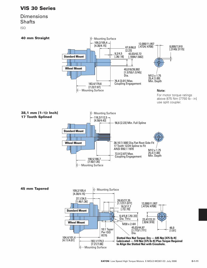
40,018/39,992[1.5755/1.5745]Dia.
74,7 [2.94] Max.Coupling Engagement
43,03/42,72[1.694/1.682]
8,000/7,910[.3149/.3115]
M12 x 1.7525,4 [1.00]Min. Depth
95,5/91,5[3.76/3.60] 63,8/62,2
[2.51/2.45]9,2/4,5[.36/.18]
12,000/11,957[.4724/.4708]
180,3/176,3[7.10/6.94]
Mounting Surface
Mounting Surface
Standard Mount
Wheel Mount
40 mm Straight
VIS 30 Series
DimensionsShaftsSAE
3/8-16 UNF-2B20,1 [.79]Min. Depth
[3.15/2.98]39,1 [1.54] Min. Full Spline
55,4 [2.18] MaxCoupling Engagement.
38,10 [1.500] Dia.Flat Root Side Fit17 Tooth 12/24 Spline to FitANSI B92.1 1970
164,6/160,6[6.48/6.32]
Mounting Surface
Mounting Surface
Standard Mount
Wheel Mount
79,8/75,71–1/2 Inch 17 Tooth Splined
44,45[1.750] Dia.
16,13/15,36[.635/.605]
4,1 [.16]Dia. Thru
5,54/5,20[.218/.205]
11,138/11,112[.4385/.4375]
31,7 [1.25]
1-1/4-18 UNEF - 2ASlotted Hex Nut Torque: Dry — 645 Nm [475 lb-ft]Lubricated — 510 Nm [375 lb-ft] Plus Torque Requiredto Align the Slotted Nut with Crosshole.
SAE J501 Standard Tapered Shaft125,00±0,17 Taper per Meter[1.500±.002 Taper per Foot]
55,76/54,99[2.195/2.165]
101,3/98,3[3.99/3.87] 179,0/175,0
[7.05/6.89]
94,5/90,2[3.72/3.55]
16,0/13,4[.63/.53]
Mounting Surface
Mounting Surface
Standard Mount
Wheel Mount
1–3/4 Inch Tapered
Note:
For motor torque ratings above 875 Nm [7750 lb - in] use split coupler.

D-1-10 EATON Low Speed High Torque Motors E-MOLO-MC001-E3 July 2006
VIS 30 Series
Shaft Side Load CapacitySAE
Mounting Surface
0
0 [1] [2] [3] [4] [5] [6] [inch][-5][-6] [-4] [-3] [-2] [-1]
20 40 60 80 100 120 140 mm-120-140-160 -80-100 -60 -40 -20
Standard Mount
0
[ 4000]
[ 8000]
[12000]
0
1000
2000
3000
4000
5000
[lb]kg
Mounting Surface
0
0 [1] [2] [3] [4] [5] [6] [7] [8] [9] [inch][-2][-3] [-1]
20 40 60 80 100 120 140 160 180 200 220 mm-60-80 -40 -20
Wheel Mount
0
[ 4000]
[ 8000]
[12000]
0
1000
2000
3000
4000
5000
[lb]kg
These curves indicate the radial load capacity on the motor shaft(s) at various locations.
The curve is based on B 10 bearing life (2000 hours of 12,000,000 shaft revolutions at 100 RPM) at rated output torque. To determine radial load at speeds other than 100 RPM, multiply the load values given on the bearing curve by the factors in the chart below.
RPM Multiplication Factor50 1.23100 1.00200 0.81300 0.72400 0.66500 0.62600 0.58700 0.56800 0.54
For 3,000,000 shaft revolutions or 500 hours — Increase these shaft loads 52%.
D-1-11EATON Low Speed High Torque Motors E-MOLO-MC001-E3 July 2006
VIS 30 Series
DimensionsShafts ISO
Note:
For motor torque ratings above 875 Nm [7750 lb - in] use split coupler.
M12 x 1.7525,4 [1.00]Min. Depth
56,6 [2.23] Min. Full Spline
72,9 [2.87] Max.Coupling Engagement
38,10 [1.500] Dia.Flat Root Side Fit17 Tooth 12/24 Spline to FitANSI B92.1 1970
190,5/186,7[7.50/7.35]
Mounting Surface
Mounting Surface
116,3/112,5[4.58/4.43]
Wheel Mount
Standard Mount
38,1 mm [1–1/2 Inch] 17 Tooth Splined
M12 x 1.7525,4 [1.00]Min. Depth
67,6/66,0[2.23]
9,2/4,5[.36/.18]
43,03/42,72[.1694/1.682]
40,018/39,992[1.5755/1.5745]Dia.
76,4 [3.01] Max.Coupling Engagement183,4/179,6
[7.22/7.07]
Mounting Surface
Mounting Surface
109,2/105,4[4.30/4.15]
Wheel Mount
Standard Mount
12,000/11,957[.4724/.4708] 8,000/7,910
[.3149/.3115]
40 mm Straight
28,63/27,35[1.127/1.077]
18,3/17,7[.72/.70]
6,4/5,8 [.25/.23]Dia. Thru
12,000/11,957[.4724/.4708]
23,47/23,31[.924/.918]
46,0[1.81]
45,03/44,97[1.773/1.771]Dia.
M30 x 2-6H
10:1 Taper Per ISOR775
104,4/101,4[4.11/4.01] 183,1/179,3
[7.21/7.06]
37,1/34,5[1.46/1.36]
Mounting Surface
Mounting Surface
Wheel Mount
Standard Mount
109,2/105,4[4.30/4.15]
Slotted Hex Nut Torque: Dry — 645 Nm [475 lb-ft]Lubricated — 510 Nm [375 lb-ft] Plus Torque Requiredto Align the Slotted Nut with Crosshole.
45 mm Tapered

D-1-12 EATON Low Speed High Torque Motors E-MOLO-MC001-E3 July 2006
VIS 30 Series
Shaft Side Load CapacityISO
Wheel Mount
Standard Mount
0
[ 4000]
[ 8000]
[12000]
0
1000
2000
3000
4000
5000
[lb]kg
0
[ 4000]
[ 8000]
[12000]
0
1000
2000
3000
4000
5000
[lb]kg
[inch]
mm
[inch]
mm
Mounting Surface
0 [1] [2] [3] [4] [5] [6] [7] [8] [9][-3] [-2] [-1]
20 40 60 80 100 140120 160 180 200 220-80 -60 -40 -20
Mounting Surface
0
0 [1] [2] [3] [4] [5] [6] [7][-6] [-5] [-4] [-3] [-2] [-1]
20 40 60 80 100 140 160120-120-140 -80-100 -60 -40 -20
0
0
These curves indicate the radial load capacity on the motor shaft(s) at various locations.
The curve is based on B 10 bearing life (2000 hours of 12,000,000 shaft revolutions at 100 RPM) at rated output torque. To determine radial load at speeds other than 100 RPM, multiply the load values given on the bearing curve by the factors in the chart below.
RPM Multiplication Factor50 1.23100 1.00200 0.81300 0.72400 0.66500 0.62600 0.58700 0.56800 0.54
For 3,000,000 shaft revolutions or 500 hours — Increase these shaft loads 52%.

D-1-13EATON Low Speed High Torque Motors E-MOLO-MC001-E3 July 2006
MOUNTING SHAFT PORT SIZE DISPL. cm3/ r [in3/ r] / PRODUCT NUMBER
325 400 505 570 [19.8] [24.4] [30.7] [34.9] 40 mm Straight G 3/4 (BSP) (2) G 1/4 (BSP) Drain Port (1) 159-0117 -0118 -0119 -0120 1–1/2 inch 17 Tooth Splined G 3/4 (BSP) (2) G 1/4 (BSP) Drain Port (1) 159-0122 -0123 -0124 -0125 45 mm Tapered G 3/4 (BSP) (2) G 1/4 (BSP) Drain Port (1) 159-0127 -0128 -0129 -0130
40 mm Straight G 3/4 (BSP) (2) G 1/4 (BSP) Drain Port (1) 160-0069 -0070 -0071 -0072 1–1/2 inch 17 Tooth Splined G 3/4 (BSP) (2) G 1/4 (BSP) Drain Port (1) 160-0074 -0075 -0076 -0077 45 mm Tapered G 3/4 (BSP) (2) G 1/4 (BSP) Drain Port (1) 160-0079 -0080 -0081 -0092
G 3/4 (BSP) (2) G 1/4 (BSP) Drain Port (1) 161-0067 -0068 -0069 -0070
VIS 30 Series
Product NumbersClosed Loop
MOUNTING SHAFT PORT SIZE DISPL. cm3/ r [in3/ r] / PRODUCT NUMBER
325 400 505 570 [19.8] [24.4] [30.7] [34.9] 40 mm Straight 1–1/16-12 UNF O-ring (2) 9/16-18 UNC Drain Port (1) 159-0103 -0094 -0104 -0105
1–1/2 inch 17 Tooth Splined 1–1/16-12 UNF O-ring (2) 9/16-18 UNC Drain Port (1) 159-0107 -0108 -0109 -0110
1–3/4 inch Tapered 1–1/16-12 UNF O-ring (2) 9/16-18 UNC Drain Port (1) 159-0112 -0113 -0114 -0115
40 mm Straight 1–1/16-12 UNF O-ring (2) 9/16-18 UNC Drain Port (1) 160-0054 -0055 -0056 -0057
1–1/2 inch 17 Tooth Splined 1–1/16-12 UNF O-ring (2) 9/16-18 UNC Drain Port (1) 160-0059 -0060 -0061 -0062
1–3/4 inch Tapered 1–1/16-12 UNF O-ring (2) 9/16-18 UNC Drain Port (1) 160-0064 -0065 -0066 -0067
1–1/16-12 UNF O-ring (2) 9/16-18 UNC Drain Port (1) 161-0045 -0064 -0065 -0090
Standard
Bearingless
Wheel
161-0068
Standard
Bearingless
Wheel
Use digit prefix —159-, 160-, or 161- plus four digit number from charts for complete product number—Example 161-0064.
Orders will not be accepted without three digit prefix.
SAE
ISO
Note:
The product numbers on this page are for motors used in closed loop circuits. They include a back-pressure relief valve that is set at 4,5 bar [65 PSI].
• A case drain is required for all closed loop VIS motor applications.
• The maximum case pres-sure for the VIS motor is 3,5 bar [50 PSI].
161-0064
D-1-14 EATON Low Speed High Torque Motors E-MOLO-MC001-E3 July 2006
MOUNTING SHAFT PORT SIZE DISPL. cm3/ r [in3/ r] / PRODUCT NUMBER
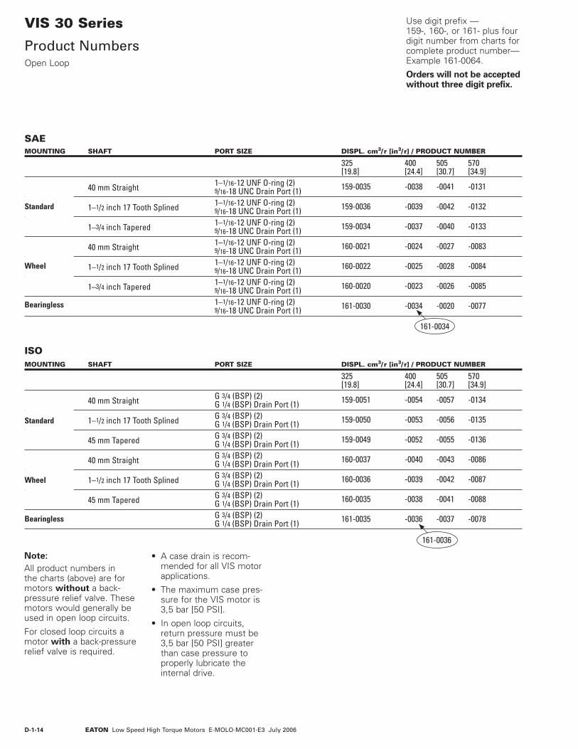
325 400 505 570 [19.8] [24.4] [30.7] [34.9] 40 mm Straight 1–1/16-12 UNF O-ring (2) 9/16-18 UNC Drain Port (1) 159-0035 -0038 -0041 -0131 1–1/2 inch 17 Tooth Splined 1–1/16-12 UNF O-ring (2) 9/16-18 UNC Drain Port (1) 159-0036 -0039 -0042 -0132 1–3/4 inch Tapered 1–1/16-12 UNF O-ring (2) 9/16-18 UNC Drain Port (1) 159-0034 -0037 -0040 -0133
40 mm Straight 1–1/16-12 UNF O-ring (2) 9/16-18 UNC Drain Port (1) 160-0021 -0024 -0027 -0083
1–1/2 inch 17 Tooth Splined 1–1/16-12 UNF O-ring (2) 9/16-18 UNC Drain Port (1) 160-0022 -0025 -0028 -0084 1–3/4 inch Tapered 1–1/16-12 UNF O-ring (2) 9/16-18 UNC Drain Port (1) 160-0020 -0023 -0026 -0085
1–1/16-12 UNF O-ring (2) 9/16-18 UNC Drain Port (1) 161-0030 -0034 -0020 -0077
Standard
Bearingless
Wheel
SAE
ISOMOUNTING SHAFT PORT SIZE DISPL. cm3/ r [in3/ r] / PRODUCT NUMBER
325 400 505 570 [19.8] [24.4] [30.7] [34.9] 40 mm Straight G 3/4 (BSP) (2) G 1/4 (BSP) Drain Port (1) 159-0051 -0054 -0057 -0134 1–1/2 inch 17 Tooth Splined G 3/4 (BSP) (2) G 1/4 (BSP) Drain Port (1) 159-0050 -0053 -0056 -0135
45 mm Tapered G 3/4 (BSP) (2) G 1/4 (BSP) Drain Port (1) 159-0049 -0052 -0055 -0136
• 40 mm Straight G 3/4 (BSP) (2) G 1/4 (BSP) Drain Port (1) 160-0037 -0040 -0043 -0086
1–1/2 inch 17 Tooth Splined G 3/4 (BSP) (2) G 1/4 (BSP) Drain Port (1) 160-0036 -0039 -0042 -0087 45 mm Tapered G 3/4 (BSP) (2) G 1/4 (BSP) Drain Port (1) 160-0035 -0038 -0041 -0088
G 3/4 (BSP) (2) G 1/4 (BSP) Drain Port (1) 161-0035 -0036 -0037 -0078
161-0036
Standard
Bearingless
Wheel
Use digit prefix —159-, 160-, or 161- plus four digit number from charts for complete product number—Example 161-0064.
Orders will not be accepted without three digit prefix.
VIS 30 Series
Product NumbersOpen Loop
Note:
All product numbers in the charts (above) are for motors without a back-pressure relief valve. These motors would generally be used in open loop circuits.
For closed loop circuits a motor with a back-pressure relief valve is required.
161-0034
• A case drain is recom-mended for all VIS motor applications.
• The maximum case pres-sure for the VIS motor is 3,5 bar [50 PSI].
• In open loop circuits, return pressure must be 3,5 bar [50 PSI] greater than case pressure to properly lubricate the internal drive.

D-1-15EATON Low Speed High Torque Motors E-MOLO-MC001-E3 July 2006
The following 16 - digit coding system has been developed to identify all of the configuration options for the VIS 30 motor. Use this model code to specify a motor with the desired features. All 16 digits of the code must be present when ordering. You may want to photocopy the matrix below to ensure that each number is entered in the correct box.
VIS 30 Series
Model Code
1 , 2 , 3 Product Series
ACD – VIS 30 Motor
4 , 5 Displacement cm3/r [in3/r]
20 – 325 [19.8]
24 – 400 [24.4]
31 – 505 [30.7]
35 – 570 [34.9]
6 Mounting Type
A – 4 Bolt Bearingless 127,00 [5.000] Pilot Dia. with 12,19 [.480] Pilot Length and 14,35 [.565] Dia. Holes on 161,92 [6.375] Dia. Bolt Circle
B – 4 Bolt Wheel Mount 160 [6.3] Pilot Dia. with 5,8 [.23] Pilot Length and 18,00 [.709] Dia. Holes on 200,00 [7.874] Dia. Bolt Circle (ISO Compatible)
F – 4 Bolt Standard Mount (SAE CC) 127,00 [5.000] Pilot Dia. with 12,2 [.48] Pilot Length and 14,32 [.564] Dia. Holes on 161,92 [6.375] Dia. Bolt Circle
G – 4 Bolt Wheel Mount 139,7 [5.50] Pilot Dia. with 7,9 [.31] Pilot Length and 14,32 [.564] Dia. Holes on 184,15 [7.250] Dia. Bolt Circle (SAE Compatible)
H – 4 Bolt Standard Mount 125,0 [4.92] Pilot Dia. with 8,9 [.35] Pilot Length and 14,00 [.551] Dia. Holes on 160,00 [6.299] Dia. Bolt Circle (ISO Compatible)
7 , 8 Output Shaft
00 – None (Bearingless)
01 – 45 mm Dia. 10:1 Tapered Shaft Per ISO R775 with M30 x 2- 6H Threaded Shaft End, 12W x 8H x 28L [.472W x .313H x 1.102L] Key
02 – 1–3/4 inch Dia. .125:1 Tapered Shaft Per SAE J 501 with 1-1/4–18 UNEF - 2A Threaded Shaft End, 11,11 [.4375] Square x 31,8 [1.25] Straight Key
07 – 40 mm Dia. Straight Shaft with M12 x 1,75 - 6H Thread in End, 12W x 8H x 63L [.472W x .313H x 2.480L] Key (SAE Compatible)
08 – 1–1/2 inch Dia. Flat Root Side Fit, 17 Tooth, 12/24 DP 30 Degree Involute Spline, 39,1 [1.54] Minimum Full Spline with 3/8 -16 UNC - 2B Thread in End (SAE Compatible)
09 – 1–1/2 inch Dia. Flat Root Side Fit, 17 Tooth, 12/24 DP30 Degree Involute Spline, 56,6 [2.23] Minimum Full Spline with M12 x 1,75 - 6H Thread in End (ISO Compatible)
10 – 40 mm Dia. Straight Shaft with M12 x 1,75 - 6H Thread in End, 12W x 8H x 67L [.472W x .313H x 2.630L] Key (ISO Compatible)
9 Ports
A – 1–1/16-12 UN-2B Size 12 O-ring Port, Accepts Fittings for SAE J1926
B – G 3/4 (BSP) Straight
Thread Port
10 Case Flow Options
A – Shuttle Valve with 9/16-18 UNF-2B, Size 6 O-ring Port Case Drain, Accepts Fittings for SAE J1926
B – Shuttle Valve with G 1/4 (BSP) Straight Thread Port Case Drain
11 Back-Pressure Relief
0 – None (for Open Loop Only)
1 – Set at 4,5 bar [65 PSI] (for Manual Pumps)
2 – Set at 15,2 bar [220 PSI] (for Servo Pumps)
4 – Set at 15,2 bar [300 PSI](for high charge Servo Pumps)
12 , 13 Special Features
00 – None
14 Paint/ SpecialPackaging
0 – No Paint, Individual Box
A – Painted Low Gloss Black, Individual Box
B – No Paint, Bulk Box Option
C – Painted Low Gloss Black, Bulk Box Option
15 Eaton Assigned Code when Applicable
0 – Assigned Code
16 Eaton Assigned Design Code
E – Assigned Design Code
321
A C D * * * * * * * * 0 0 * 0 D
54 6 87 9 10 11 12 13 14 15 16
• A case drain is recom-mended for all VIS motor applications.
• The maximum case pres-sure for the VIS motor is 3,5 bar [50 PSI].
• In open loop circuits, return pressure must be 3,5 bar [50 PSI] greater than case pressure to properly lubricate the internal drive.

D-1-16 EATON Low Speed High Torque Motors E-MOLO-MC001-E3 July 2006
End Cap
ShuttleValve
Balance Plate
BearingsDriveGeroler®
Face Seal MountingFlange
FrontRetainer
OutputShaft
ShaftSeal
Case Drain PortBack PressureRelief Valve Valve
Plate
SelectorPlate
SelectorValve
SealGuard
VIS 30 SeriesTwo-speed
Specifications
VIS 30 Series motors are available with an integral two-speed feature that allows the operator to shift the motor between low speed high torque (LSHT) mode and high speed low torque (HSLT) mode.
In the LSHT mode, output torque and rotation speed values are equal to those of the conventional VIS 30 motor. In the HSLT mode motor displacement is reduced by one third, resulting in a fifty percent increase in rotation speed and a torque output reduction of one third.
The VIS 30 two-speed motor is bidirectional. It will function with equal shaft
output in either rotation direction (CW or CCW) in both LSHT and HSLT modes. Shift on the fly technology allows full-power operation throughout the full duration of the shift.
Changing between modes is accomplished by changing the displacement in a ratio of 1 to 1.5. An external two-position three-way control valve is required for shifting pressure to the pilot port between low pressure (LSHT mode) and pilot signal pressure (HSLT mode).
An integral selector valve shifts the motor from LSHT mode to HSLT mode. Initially, low pressure is supplied to the pilot port. The selector valve is biased to LSHT mode by a return
spring. When pilot signal pressure is supplied to the pilot port and 3,5 ∆bar [50 PSI] is reached, the selector valve overcomes return spring force and the shifts the spool to select HSLT mode.
Oil on the opposite side of the spool is drained to tank via the drain port. The pressure difference between the pilot port and drain port must be maintained to keep the motor in the high speed mode. When pilot pressure is removed from the pilot port, the pressure in the pilot end of the spool valve is relieved and drained back through the control valve and the return spring forces the spool valve to LSHT position.
Pilot pressure may come from any source that will provide uninterrupted pressure during the high-speed mode operation. Allowable pilot pressure must be at least 3,5 ∆bar [50 PSI] and may be as high as full operating pressure of the motor.
All VIS 30 Series two-speed motors are equipped with a return line shuttle for closed circuit applications as standard equipment. All options available on the conventional VIS 30 are also available on VIS 30 two-speed motors.
In the LSHT mode, torque and speed values are equal to those of the conventional VIS 30 motor (refer to single speed motor performance data.) In the HSLT mode, rotation speed is increased by fifty percent and torque output is reduced by one third. The VIS 30 Two-speed motor will function with equal shaft output in either rotation direction (CW or CCW) in both LSHT and HSLT modes.
Performance Data

D-1-17EATON Low Speed High Torque Motors E-MOLO-MC001-E3 July 2006
46,10/45,34[1.815/1.785]
46,10/45,34[1.815/1.785]
Port B
Port A OptionalRelief Valve
VIS 30 SeriesTwo-speed
DimensionsStandard and Wheel Mount – SAE
Standard Motors (SAE)
STANDARD MOTORS (SAE)
Displacement X Y Z
cm3/r [in3/r] mm [inch] mm [inch] mm [inch]325 [19.8] 259,3 [10.21] 231,4 [9.11] 186,2 [7.33]400 [24.4] 265,9 [10.47] 238,0 [9.37] 193,0 [7.60]505 [30.7] 275,1 [10.83] 246,9 [9.72] 201,7 [7.94]570 [34.9] 281,2 [11.07] 253,0 [9.96] 208,0 [8.19]
Wheel Motors (SAE)
WHEEL MOTORS (SAE)
Displacement X Y Z
cm3/r [in3/r] mm [inch] mm [inch] mm [inch]325 [19.8] 174,5 [6.87] 146,6 [5.77] 101,3 [3.99]400 [24.4] 181,1 [7.13] 153,2 [6.03] 108,2 [4.26]505 [30.7] 190,2 [7.49] 162,1 [6.38] 116,8 [4.60]570 [34.9] 196,3 [7.73] 168,1 [6.62] 123,2 [4.85]
Ports 1–1/16 -12 UN-2B SAE O-ring Ports (2)9/16 -18 UNF -2B SAE O-ring Case Drain Port (1)7/16 -20 UNF -2B SAE O-ring Shift Ports (2)
Standard Rotation Viewed from Shaft End
Port A Pressurized — CWPort B Pressurized — CCW
8,1/7,7Y
X97,0/96,5[3.83/3.81]
132,8/132,4[5.23/5.21]Dia.
139,70/139,57[5.500/5.495]
14,53/14,15[.572/.557]Dia. Thru (4)
180,8[7.12]Max. (2)
15,2 [.60]R Min. (4)
184,15[7.250]Dia. B.C.
Case DrainPort Port
80,53[3.17]Max. (2)
48,3[1.90]Max. (2)
[3.29]Max.
73,9[2.91]Max.
147,8 [5.82] Max.
195,2 [7.69]Max.
71,8/71,0[2.83/2.79]
71,8/71,0[2.83/2.79]
Port A Port B
[.32/.30]35,9/35,4[1.42/1.41]16,13/14,61[.635/.575] Pilot Dia.
83,5
Z
XY
Z
82,6/81,0 [3.25/3.19]24,6/24,2 [.97/.95]12,32/12,81 [.485/.465]
126,98/126,92[4.999/4.997]Pilot Dia.
Case DrainPort
Case Drain PortCross Section
70,56/69,0[2.78/2.72]
80,5[3.17]Max. (2)
48,3[1.90]Max. (2)
83,5[3.29]Max.
147,8 [5.82] Max.
73,9[2.91]Max.
14,53/14,15[.572/.557]Dia. Thru (4)
78,1/71,0[2.83/2.79]
78,1/71,0[2.83/2.79]
147,3[5.80]Max. (2)
161,92[6.375]Dia. B.C.
Port A Port B 14,5 [.57]R Min. (4)
195,2 [7.69]Max.

D-1-18 EATON Low Speed High Torque Motors E-MOLO-MC001-E3 July 2006
VIS 30 SeriesTwo-speed
DimensionsStandard and Wheel Mount – ISO
Standard Motors (ISO)
STANDARD MOTORS (ISO)
Displacement X Y Z
cm3/r [in3/r] mm [inch] mm [inch] mm [inch]325 [19.8] 247,4 [9.74] 219,5 [8.64] 174,2 [6.86]400 [24.4] 253,7 [9.99] 225,8 [8.89] 180,8 [7.12]505 [30.7] 263,1 [10.36] 235,0 [9.25] 189,7 [7.47]570 [34.9] 269,2 [10.60] 241,0 [9.49] 196,1 [7.72]
Wheel Motors (ISO)
WHEEL MOTORS (ISO)
Displacement X Y Z
cm3/r [in3/r] mm [inch] mm [inch] mm [inch]325 [19.8] 173,2 [6.82] 145,3 [5.72] 100,1 [3.94]400 [24.4] 179,6 [7.07] 151,6 [5.97] 106,7 [4.20]505 [30.7] 189,0 [7.44] 160,8 [6.33] 115,6 [4.55]570 [34.9] 195,1 [7.68] 166,9 [6.57] 121,9 [4.80]
46,10/45,34[1.815/1.785]
46,10/45,34[1.815/1.785]
Port B
Port A
OptionalRelief Valve
Ports G 3/4 (BSP) O-ring Ports (2)
G 1/4 (BSP) O-ring Case Drain Port (1)7/16 -20 UNF -2B SAE O-ring Shift Ports (2)
Standard Rotation Viewed from Shaft End
Port A Pressurized — CWPort B Pressurized — CCW
Case Drain PortCross Section
65,6/64,0[2.58/2.52]
XY
14,73/13,21 [.580/.520]
98,5/98,1 [3.88/3.86]34,6/34,0 [1.36/1.34]
6,0/5,6 [.24/.20]
160,02/159,82 [6.300/6.292] Pilot Dia.
132,8/132,3 [5.23/5.21] Dia.
Z
80,5 [3.17]Max. (2)
73,9 [2.91] Max.
48,3 [1.90] Max. (2)
83,5 [3.29] Max.
180,8 [7.12] Max. (2)
195,2 [7.69] Max.
71,8/71,0 [2.83/2.79]
71,8/71,0 [2.83/2.79]
15,2 [.60]R Min. (4)
200,00[7.874]Dia. B.C.
18,21/17,81[.717/.701]Dia. Thru (4)
147,8 [5.82] Max.Port A Port B
Case DrainPort
Shift Drain PortShift Pilot Port
Z
18,3/17,7 [.72/.70]22,7/22,1 [.89/.87]31,8/29,2 [1.25/1.15]
124,3/123,7[4.89/4.87]Dia.
86,4/84,8 [3.40/3.34]9,2/8,6 [.36/.34]
XY
Case DrainPort
Case Drain PortCross Section
65,6/64,0[2.58/2.52]
Port
125,00/124,94[4.921/4.919]Pilot Dia.
80,5[3.17]Max. (2)
48,3[1.90]Max. (2)
83,5[3.29]Max.
147,8 [5.82] Max.
73,9[2.91]Max.
14,46/13,54[.569/.533]Dia. Thru (4)
78,1/71,0[2.83/2.79]
78,1/71,0[2.83/2.79]
147,3[5.80]Max. (2)
160,00[6.299]Dia. B.C.
Port A Port B 14,5 [.57]R Min. (4)
195,2 [7.69]Max.

D-1-19EATON Low Speed High Torque Motors E-MOLO-MC001-E3 July 2006
Shaft Face SealFurnished withMotorPort
XY
Z
MountingSurface
127,00/126,87[5.000/4.995]Pilot Dia.12.45/11,94[4.90/.470]
20,6/19,6[.81/.77]
VIS 30 SeriesTwo-speed
DimensionsBearingless
Port A Port B147,8 [5.82] Max.
80,5[3.17]Max. (2)
83,5[3.29]Max.
195,2 [7.69] Max.
78,1/71,0[2.83/2.79] 78,1/71,0
[2.83/2.79]
ShaftDrainPort
195,1 [7.68] Max. (2)
73,9[2.91]Max. 2.8414
MountingSurface
45º
Case DrainPort 12,85
[.506]
70,10 [2.760]
Return toCase Drain
14,53/14,17[.572/.558]Dia. Thru (4)
161,92 [6.375]Dia. Bolt Circle
BEARINGLESS MOTORS
Displacement X Y Z
cm3/r [in3/r] mm [inch] mm [inch] mm [inch]325 [19.8] 177,0 [6.97] 149,1 [5.87] 103,9 [4.09]400 [24.4] 183,6 [7.23] 155,7 [6.13] 110,7 [4.36]505 [30.7] 193,0 [7.60] 164,8 [6.49] 119,6 [4.71]570 [34.9] 199,1 [7.84] 170,9 [6.73] 126,0 [4.96]
Ports 1-1/16-12 UN-2B SAE O-ring Ports (2) 9/16-18 UNF-2B SAE O-ring Case Drain Port (1)7/16 -20 UNF -2B SAE O-ring Shift Ports (2)
Or
G 3/4 (BSP) O-ring Ports (2)
G 1/4 (BSP) O-ring Case Drain Port (1)7/16 -20 UNF -2B SAE O-ring Shift Ports (2)
Standard Rotation Viewed from Drive End
Port A Pressurized — CWPort B Pressurized — CCW
46,10/45,34[1.815/1.785]
46,10/45,34[1.815/1.785]
Port B
Port A OptionalRelief Valve
For VIS 30 bearingless motor application information, contact your Eaton representative (mating coupling blanks available from Eaton Hydraulics).
Note:
After machining blank, part must be hardened per Eaton specification.
Mating Coupling BlankEaton Part No. 13429-003
C 52,80 [2.08 ] Dia.D 49,00 [1.93 ] Dia.E 147,57 [5.81 ] Max.F 142,49 [5.61 ] Min. Full Form Dia.G 7,87 [ .310] Max.H 17,27 [ .680]J 33,30 [1.31 ]K 84,20 [3.315] Full Form Dia.L 69,60 [2.74 ]M 15
L
G H JK
F
M
DC
E

D-1-20 EATON Low Speed High Torque Motors E-MOLO-MC001-E3 July 2006
VIS 30 SeriesTwo-speed
Installation InformationBearingless
Circular
Major
MinorTip R.
Fillet R.Pitch
Form
Finish
Finish
45322X
3
4
2,5 (100)
66,83 ±0,25[2.631 ±.010]
39.88 ±0,25[1.570 ±.010]
55º ±5º
49,84 ±0,25[1.962 ±.010]
45º ±5º x 0,38 ±0,25 [.015 ±.010]or R 0,38 ±0,25 [.015± .010]
68,96 ±0,51[2.715 ±.020]Coupling Length
4.83 ±0,25[.190 ±.010] Oil Hole
-H-
31,0 ±0,25 [1.220 ±.010]
3,17 [.125] Max.Undercut
52,37[2.062]Min.
R 1,5±0,3[.06 ±.01]
R 1,5 ±0,3[.06 ±.01]
-G-
Oil Flow Path Thru Splineand Bearing(s)
Spline
Oil Flow Return to Case Drain
Case Drain
Spline Pitch ...............................................................................................8.5/17 Pressure Angle ............................................................................................. 30° Number of teeth ............................................................................................. 12 Class of Fit ................................................................................................. Ref. 5 Type of Fit .................................................................................................... Side Pitch Diameter ......................Ref. 35,858823 [1.4117647] 0,20 [.008] | H Base Diameter ...................................................... Ref. 31,054652 [1.2226241] Major Diameter ...................................39,17 [1.542] Max. 38,97 [1.534] Min. Minor Diameter ..................................................... 33,30 -33,48 [1.311 -1.318] Form Diameter, Min. .....................................................................38,33 [1.509] Fillet Radius .................................................................... 0,64 -0,76 [.025 -.030] Tip Radius ....................................................................... 0,25 -0,51 [.010 -.020] Finish ........................................................................................................1,6 (63) Involute Profile Variation .................................+0,000 -0,025 [+.0000 -.0010] Total Index Variation .....................................................................0,038 [.0015] Lead Variation ................................................................................0,013 [.0005] Circular Space Width: Maximum Actual ....................................................................5,898 [.2322] Minimum Effective .................................................................5,804 [.2285] Maximum Effective ....................................................... Ref. 5,857 [.2306] Minimum Actual ............................................................ Ref. 5,834 [.2297] Dimension Between Two Pins ............ Ref. 26,929 -27,084 [1.0602 -1.0663] Pin Diameter ......................................... 6,223 [.2450] Pins to Have 4,0 [.160] Wide Flat for Root Clearance
1 Internal spline in mating part to be per spline data. Specification material to be ASTM A304, 8620H carburize to a hardness of 60-64 HRc with case depth (to 50HRc) of 0,076 -1,27 [.030 -.050]. Dimensions apply after heat treat.
2 Mating part to have critical dimensions as shown. Oil holes must be provided and open for proper oil circulation.
3 Seal to be furnished with motor for proper oil circulation thru splines.
4 Similar to SAE “C” Four Bolt Flange.
D-1-21EATON Low Speed High Torque Motors E-MOLO-MC001-E3 July 2006
VIS 30 SeriesTwo-speed
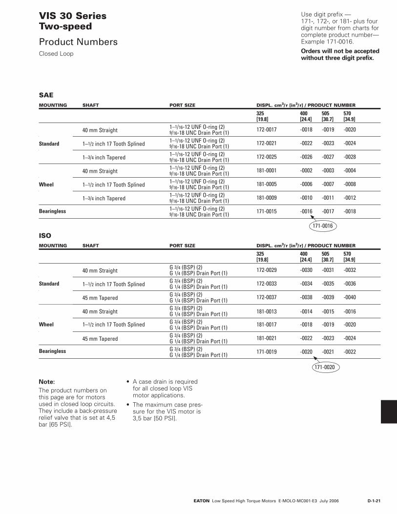
Product NumbersClosed Loop
MOUNTING SHAFT PORT SIZE DISPL. cm3/ r [in3/ r] / PRODUCT NUMBER
325 400 505 570 [19.8] [24.4] [30.7] [34.9] 40 mm Straight 1–1/16-12 UNF O-ring (2) 9/16-18 UNC Drain Port (1) 172-0017 -0018 -0019 -0020
1–1/2 inch 17 Tooth Splined 1–1/16-12 UNF O-ring (2) 9/16-18 UNC Drain Port (1) 172-0021 -0022 -0023 -0024
1–3/4 inch Tapered 1–1/16-12 UNF O-ring (2) 9/16-18 UNC Drain Port (1) 172-0025 -0026 -0027 -0028
40 mm Straight 1–1/16-12 UNF O-ring (2) 9/16-18 UNC Drain Port (1) 181-0001 -0002 -0003 -0004
1–1/2 inch 17 Tooth Splined 1–1/16-12 UNF O-ring (2) 9/16-18 UNC Drain Port (1) 181-0005 -0006 -0007 -0008
1–3/4 inch Tapered 1–1/16-12 UNF O-ring (2) 9/16-18 UNC Drain Port (1) 181-0009 -0010 -0011 -0012
1–1/16-12 UNF O-ring (2) 9/16-18 UNC Drain Port (1) 171-0015 -0016 -0017 -0018
Standard
Bearingless
Wheel
171-0016
MOUNTING SHAFT PORT SIZE DISPL. cm3/ r [in3/ r] / PRODUCT NUMBER
325 400 505 570 [19.8] [24.4] [30.7] [34.9] 40 mm Straight G 3/4 (BSP) (2) G 1/4 (BSP) Drain Port (1) 172-0029 -0030 -0031 -0032
1–1/2 inch 17 Tooth Splined G 3/4 (BSP) (2) G 1/4 (BSP) Drain Port (1) 172-0033 -0034 -0035 -0036
45 mm Tapered G 3/4 (BSP) (2) G 1/4 (BSP) Drain Port (1) 172-0037 -0038 -0039 -0040
40 mm Straight G 3/4 (BSP) (2) G 1/4 (BSP) Drain Port (1) 181-0013 -0014 -0015 -0016 1–1/2 inch 17 Tooth Splined G 3/4 (BSP) (2) G 1/4 (BSP) Drain Port (1) 181-0017 -0018 -0019 -0020 45 mm Tapered G 3/4 (BSP) (2) G 1/4 (BSP) Drain Port (1) 181-0021 -0022 -0023 -0024
G 3/4 (BSP) (2) G 1/4 (BSP) Drain Port (1) 171-0019 -0020 -0021 -0022
Standard
Bearingless
Wheel
Use digit prefix —171-, 172-, or 181- plus four digit number from charts for complete product number—Example 171-0016.
Orders will not be accepted without three digit prefix.
SAE
ISO
Note:
The product numbers on this page are for motors used in closed loop circuits. They include a back-pressure relief valve that is set at 4,5 bar [65 PSI].
171-0020
• A case drain is required for all closed loop VIS motor applications.
• The maximum case pres-sure for the VIS motor is 3,5 bar [50 PSI].
D-1-22 EATON Low Speed High Torque Motors E-MOLO-MC001-E3 July 2006
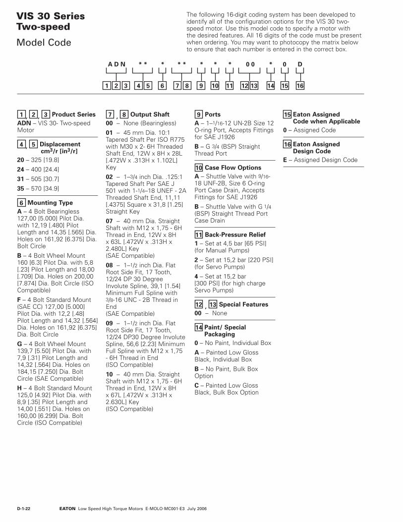
1 , 2 , 3 Product Series
ADN – VIS 30- Two-speed Motor
4 , 5 Displacement cm3/r [in3/r]
20 – 325 [19.8]
24 – 400 [24.4]
31 – 505 [30.7]
35 – 570 [34.9]
6 Mounting Type
A – 4 Bolt Bearingless 127,00 [5.000] Pilot Dia. with 12,19 [.480] Pilot Length and 14,35 [.565] Dia. Holes on 161,92 [6.375] Dia. Bolt Circle
B – 4 Bolt Wheel Mount 160 [6.3] Pilot Dia. with 5,8 [.23] Pilot Length and 18,00 [.709] Dia. Holes on 200,00 [7.874] Dia. Bolt Circle (ISO Compatible)
F – 4 Bolt Standard Mount (SAE CC) 127,00 [5.000] Pilot Dia. with 12,2 [.48] Pilot Length and 14,32 [.564] Dia. Holes on 161,92 [6.375] Dia. Bolt Circle
G – 4 Bolt Wheel Mount 139,7 [5.50] Pilot Dia. with 7,9 [.31] Pilot Length and 14,32 [.564] Dia. Holes on 184,15 [7.250] Dia. Bolt Circle (SAE Compatible)
H – 4 Bolt Standard Mount 125,0 [4.92] Pilot Dia. with 8,9 [.35] Pilot Length and 14,00 [.551] Dia. Holes on 160,00 [6.299] Dia. Bolt Circle (ISO Compatible)
7 , 8 Output Shaft
00 – None (Bearingless)
01 – 45 mm Dia. 10:1 Tapered Shaft Per ISO R775 with M30 x 2- 6H Threaded Shaft End, 12W x 8H x 28L [.472W x .313H x 1.102L] Key
02 – 1–3/4 inch Dia. .125:1 Tapered Shaft Per SAE J 501 with 1-1/4–18 UNEF - 2A Threaded Shaft End, 11,11 [.4375] Square x 31,8 [1.25] Straight Key
07 – 40 mm Dia. Straight Shaft with M12 x 1,75 - 6H Thread in End, 12W x 8H x 63L [.472W x .313H x 2.480L] Key (SAE Compatible)
08 – 1–1/2 inch Dia. Flat Root Side Fit, 17 Tooth, 12/24 DP 30 Degree Involute Spline, 39,1 [1.54] Minimum Full Spline with 3/8-16 UNC - 2B Thread in End (SAE Compatible)
09 – 1–1/2 inch Dia. Flat Root Side Fit, 17 Tooth, 12/24 DP30 Degree Involute Spline, 56,6 [2.23] Minimum Full Spline with M12 x 1,75 - 6H Thread in End (ISO Compatible)
10 – 40 mm Dia. Straight Shaft with M12 x 1,75 - 6H Thread in End, 12W x 8H x 67L [.472W x .313H x 2.630L] Key (ISO Compatible)
9 Ports
A – 1–1/16-12 UN-2B Size 12 O-ring Port, Accepts Fittings for SAE J1926
B – G 3/4 (BSP) Straight Thread Port
10 Case Flow Options
A – Shuttle Valve with 9/16-18 UNF-2B, Size 6 O-ring Port Case Drain, Accepts Fittings for SAE J1926
B – Shuttle Valve with G 1/4 (BSP) Straight Thread Port Case Drain
11 Back-Pressure Relief
1 – Set at 4,5 bar [65 PSI] (for Manual Pumps)
2 – Set at 15,2 bar [220 PSI] (for Servo Pumps)
4 – Set at 15,2 bar [300 PSI] (for high charge Servo Pumps)
12 , 13 Special Features
00 – None
14 Paint/ SpecialPackaging
0 – No Paint, Individual Box
A – Painted Low Gloss Black, Individual Box
B – No Paint, Bulk Box Option
C – Painted Low Gloss Black, Bulk Box Option
15 Eaton Assigned Code when Applicable
0 – Assigned Code
16 Eaton Assigned Design Code
E – Assigned Design Code
VIS 30 SeriesTwo-speed
Model Code
321
A D N * * * * * * * * 0 0 * 0 D
54 6 87 9 10 11 12 13 14 15
The following 16-digit coding system has been developed to identify all of the configuration options for the VIS 30 two-speed motor. Use this model code to specify a motor with the desired features. All 16 digits of the code must be present when ordering. You may want to photocopy the matrix below to ensure that each number is entered in the correct box.
16

D-1-23EATON Low Speed High Torque Motors E-MOLO-MC001-E3 July 2006
VIS 30 Series
Brake Description
Features
• Spring-Applied/Hydraulically Released Multi-Disc Brake
• Spring automatically applies brake when hydro-static pressure is absent
• Environmentally Protected
• Integral Design – Motor and brake as a sin-gle package to minimize length and cost.
• Infinite Braking – Eliminates machine creep associated with park pawl mechanisms
• Boost Feature – Increases holding capacity to match full motor output torque
• No adjustments needed
• Two Sets of Release and Boost Ports – Allows for multiple plumb-ing options and facilitates bleeding
Applications
• Skid Steer Loaders
• Mini Excavators
• Trenchers
• Road Rollers
• Anywhere load-holding is needed on a Low-Speed High-Torque drive system
Specifications
• Static Holding Torque – 780 N-m [6900 lb-in] minimum (spring only - no boost) 2621 N-m [23200 lb-in] minimum (@ 10,3 bar [150 PSI] boost)
3570 N-m [31600 lb-in] minimum (@ 15,2 bar [220 PSI] boost)
• Release Pressure – 10,3 bar [150 PSI] minimum for full release 68,9 bar [1000 PSI] maximum allowed at release port
• Case Pressure – 1,4 bar [20 PSI] continuous
3,5 bar [50 PSI] maximum
• Boost Pressure – 15,2 bar [220 PSI] continuous
34,5 bar [500 PSI] maximum
• Speed – 360 RPM maximum
• Emergency – After 3 consecutive stops, brake to still meet parking requirement

D-1-24 EATON Low Speed High Torque Motors E-MOLO-MC001-E3 July 2006
VIS 30 Series
Brake Dimensions
X
Y
134,14/133,38 [5.281/5.251]
B
A
4,54/4,04 [.179/.159]
2 X 26,3/25,5 [1.04/1.00]
2 X 56,8/56,0[2.24/2.22]
Port A
Port B
2X Shift Port
Z
Boost Port (2)
Case DrainPort
222,7 [8.77] Max.
2 X 213,1[8.39] Max.
4 X M16 x 2-6 HThreaded Hole
224,00 [8.819]Dia. B.C.
169,85/169,65[6.687/6.679]Dia.
140,00/139,88[5.5120/5.5070] Pilot Dia.
Release Port (2)
BRAKE MOTORS (TWO-SPEED)
Displacement X Y Zcm3/r [in3/r] mm [inch] mm [inch] mm [inch]325 [19.8] 286,1 [11.26] 258,9 [10.20] 213,5 [8.41]400 [24.4] 292,7 [11.52] 265,7 [10.46] 220,3 [8.67]505 [30.7] 301,9 [11.88] 274,7 [10.82] 229,3 [9.03]570 [34.9] 308,0 [12.12] 280,9 [11.06] 235,5 [9.27]
BRAKE MOTORS (SINGLE-SPEED)
Displacement A Bcm3/r [in3/r] mm [inch] mm [inch]325 [19.8] 220,9 [8.78] 250,2 [9.85]400 [24.4] 229,7 [9.05] 256,9 [10.11]505 [30.7] 238,7 [9.40] 265,9 [10.47]570 [34.9] 244,9 [9.64] 272,1 [10.71]
D-1-25EATON Low Speed High Torque Motors E-MOLO-MC001-E3 July 2006
VIS 30 Series
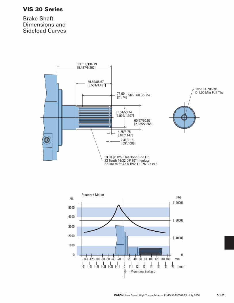
Brake Shaft Dimensions and Sideload Curves
1/2-13 UNC-2BD 1.00 Min Full Thd 73.00
[2.874] Min Full Spline
53.98 [2.125] Flat Root Side Fit33 Tooth 16/32 DP 30° InvoluteSpline to fit Ansi B92.1 1976 Class 5
51.04/50.74[2.009/1.997]
2.31/2.18[.091/.086]
4.25/3.75[.167/.147]
89.69/88.67[3.531/3.491]
138.10/136.19[5.437/5.362]
60.57/60.07[2.385/2.365]
Standard Mount
0
[ 4000]
[ 8000]
[12000]
0
1000
2000
3000
4000
5000
[lb]kg
[inch]
mm
Mounting Surface
0
0 [1] [2] [3] [4] [5] [6] [7][-6] [-5] [-4] [-3] [-2] [-1]
20 40 60 80 100 140 160120-120-140 -80-100 -60 -40 -20

D-1-26 EATON Low Speed High Torque Motors E-MOLO-MC001-E3 July 2006
Notes

D-2-1EATON Low Speed High Torque Motors E-MOLO-MC001-E3 July 2006
DescriptionThe VIS 40 Series is the newest addition to the VIS product line. The VIS 40 is very close in size to the VIS 30, but with increased drive train strength, it has even greater torque capability. Maximum continuous output torque capability is rated to 2531 Nm [22,400 lb-in] with a displacement range from 505cc to 940cc per revolution. VIS 40 motors can be run up to 151 LPM [40 GPM] with pressure capability up to 310 bar (4500 PSI]. The motor utilizes patented VIS technology with improved high-strength Geroler‚ optimized drive geometry, and two-piece pre-loaded balance plate for increased starting efficiency, reduced leakage and higher back pressure capacity. A wide variety of options are available including two-speed option, brake options and case flow options for both closed-loop and open loop applications.
Features
• Patented VIS Geroler technology
• Three moving compo-nents: (Geroler‚ star, drive, and output shaft)
• Maximized drive strength in compact package size
• Compact package size similar to VIS 30 Seriies.
• Two-piece pre-loaded pressure balance plate
• Variety of optional fea-tures including two-speed option, brake packages, and case flow solutions for both closed-loop and open-loop applications.
Benefits
• Extremely compact pow-erful package
• Increased torque capabil-ity
• Greatest horsepower den-sity in the VIS motor line
• High efficiency
• Quiet, smooth operation
• Reliable, trouble-free per-formance
• Design Flexibility
Applications
• Skid Steer Loaders and Attachments
• Snow Removal Equipment
• Trenchers
• Grapples
• Rough Terrain Forklifts
• Wood Processing – Saw Mills & Chippers
• Metal Forming
• Entertainment / Amusement Rides
• Industrial Processing
• Harvesters
Trencher Digger
VIS 40 Series
Highlights
SpecificationsGeroler Element 6 Displacements
Flow l/min [GPM] 151 [40] Continuous***
170 [45] Intermittent**
Speed Up to 293 RPM
Pressure bar [PSI] 310 [4500] Cont.***
345 [5000] Inter.**
380 [5500] Peak.*
Torque Nm [lb - in] 2531 [22400] Cont.***
3165 [28000] Inter.**
*** Continuous— (Cont.) Continuous rating, motor may be run continuously at these ratings.** Intermittent— (Inter.) Intermittent operation, 10% of every minute.* Peak— (Peak) Peak operation, 1% of every minute.
Port EquipmentSkid Steer
D-2-2 EATON Low Speed High Torque Motors E-MOLO-MC001-E3 July 2006
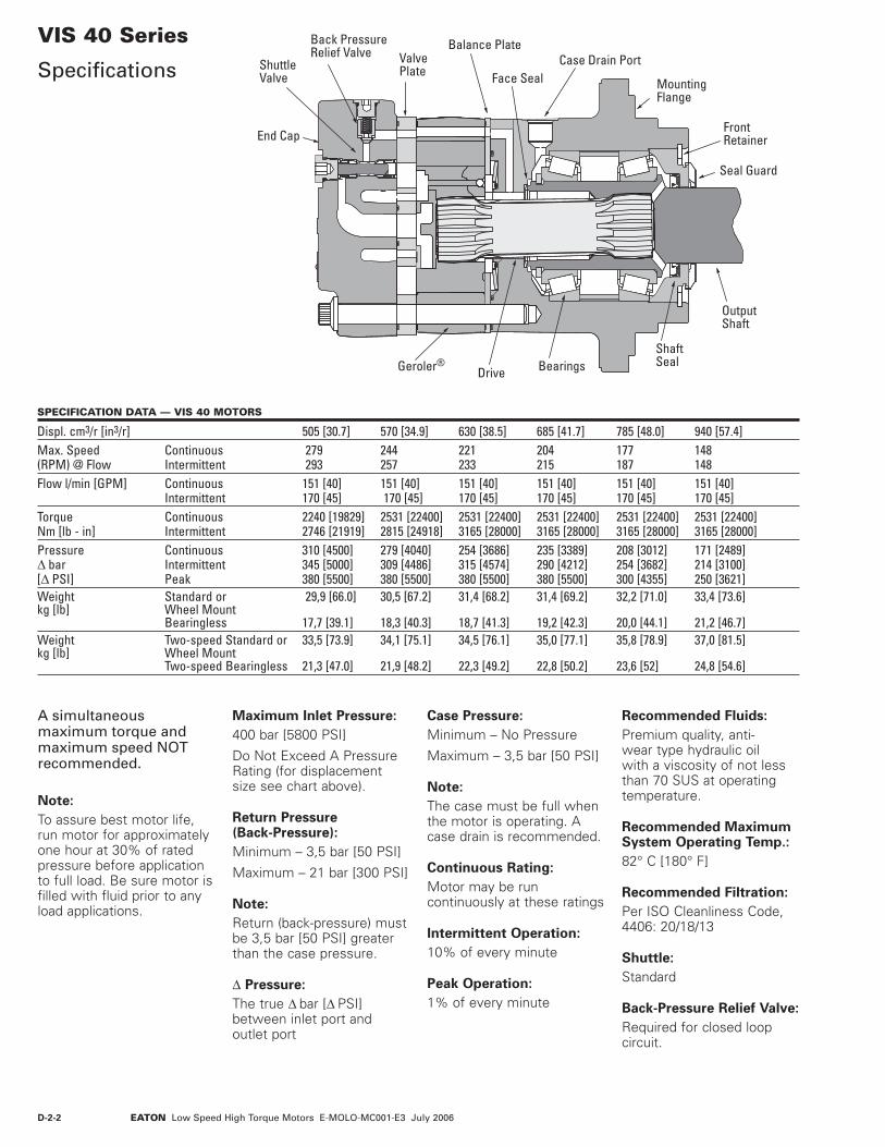
VIS 40 Series
Specifications
Maximum Inlet Pressure:
400 bar [5800 PSI]
Do Not Exceed A Pressure Rating (for displacement size see chart above).
Return Pressure (Back-Pressure):
Minimum – 3,5 bar [50 PSI]
Maximum – 21 bar [300 PSI]
Note:
Return (back-pressure) must be 3,5 bar [50 PSI] greater than the case pressure.
∆ Pressure:
The true ∆ bar [∆ PSI] between inlet port and outlet port
Case Pressure:
Minimum – No Pressure
Maximum – 3,5 bar [50 PSI]
Note:
The case must be full when the motor is operating. A case drain is recommended.
Continuous Rating:
Motor may be run continuously at these ratings
Intermittent Operation:
10% of every minute
Peak Operation:
1% of every minute
Recommended Fluids:
Premium quality, anti-wear type hydraulic oil with a viscosity of not less than 70 SUS at operating temperature.
Recommended Maximum System Operating Temp.:
82° C [180° F]
Recommended Filtration:
Per ISO Cleanliness Code, 4406: 20/18/13
Shuttle:
Standard
Back-Pressure Relief Valve:
Required for closed loop circuit.
SPECIFICATION DATA — VIS 40 MOTORS
Displ. cm3/r [in3/r] 505 [30.7] 570 [34.9] 630 [38.5] 685 [41.7] 785 [48.0] 940 [57.4] Max. Speed Continuous 279 244 221 204 177 148(RPM) @ Flow Intermittent 293 257 233 215 187 148Flow l/min [GPM] Continuous 151 [40] 151 [40] 151 [40] 151 [40] 151 [40] 151 [40] Intermittent 170 [45] 170 [45] 170 [45] 170 [45] 170 [45] 170 [45] Torque Continuous 2240 [19829] 2531 [22400] 2531 [22400] 2531 [22400] 2531 [22400] 2531 [22400] Nm [lb - in] Intermittent 2746 [21919] 2815 [24918] 3165 [28000] 3165 [28000] 3165 [28000] 3165 [28000]Pressure Continuous 310 [4500] 279 [4040] 254 [3686] 235 [3389] 208 [3012] 171 [2489] ∆ bar Intermittent 345 [5000] 309 [4486] 315 [4574] 290 [4212] 254 [3682] 214 [3100] [∆ PSI] Peak 380 [5500] 380 [5500] 380 [5500] 380 [5500] 300 [4355] 250 [3621] Weight Standard or 29,9 [66.0] 30,5 [67.2] 31,4 [68.2] 31,4 [69.2] 32,2 [71.0] 33,4 [73.6]kg [lb] Wheel Mount Bearingless 17,7 [39.1] 18,3 [40.3] 18,7 [41.3] 19,2 [42.3] 20,0 [44.1] 21,2 [46.7]Weight Two-speed Standard or 33,5 [73.9] 34,1 [75.1] 34,5 [76.1] 35,0 [77.1] 35,8 [78.9] 37,0 [81.5]kg [lb] Wheel Mount Two-speed Bearingless 21,3 [47.0] 21,9 [48.2] 22,3 [49.2] 22,8 [50.2] 23,6 [52] 24,8 [54.6]
End Cap
ShuttleValve
Balance Plate
BearingsDriveGeroler®
Face Seal MountingFlange
FrontRetainer
OutputShaft
ShaftSeal
Case Drain Port
Back PressureRelief Valve Valve
Plate
Seal Guard
A simultaneous maximum torque and maximum speed NOT recommended.
Note:
To assure best motor life, run motor for approximately one hour at 30% of rated pressure before application to full load. Be sure motor is filled with fluid prior to any load applications.

D-2-3EATON Low Speed High Torque Motors E-MOLO-MC001-E3 July 2006
VIS 40 Series
Performance DataMotors run with high efficiency in all areas designated with a number for torque and speed. For best motor life select a motor to run with a torque and speed range shown in the light shaded area.
Performance data is typical at 120 SUS. Actual data may vary slightly from unit to unit in production.
Δ Pressure Bar [PSI]505 cm3/r [30.7 in3/r]
Flo
w L
PM [G
PM]
250 500 1000 1500 2000 2500 3000 3500 4000 4500 5000 550015 35 70 105 140 170 205 240 275 310 345 380
4 1035 2169 4395 6592 8656 10735 12804 14773 16105 18043 19628117 245 497 745 978 1213 1447 1669 1820 2039 2218
15 29 29 29 29 28 28 27 27 25 24 238 1055 2200 4445 6671 8855 11049 13225 15313 17473 19319 21368 23010
119 249 502 754 1000 1248 1494 1730 1974 2183 2414 260030 60 59 58 56 55 54 53 52 50 48 45 4212 1003 2190 4464 6730 8944 11155 13364 15520 17614 19648 21753 23640
113 247 504 760 1011 1260 1510 1754 1990 2220 2458 267145 90 88 86 85 83 83 83 82 81 80 73 7016 1069 2202 4422 6692 8901 11150 13367 15527 17694 19747 21833 23932
121 249 500 756 1006 1260 1510 1754 1999 2231 2467 270461 120 118 117 115 112 110 108 108 107 104 100 9820 1019 1938 4301 6833 8830 11117 13552 15431 17663 19829 21919 23783
115 219 486 772 998 1256 1531 1743 1996 2240 2476 268776 150 148 145 144 140 138 136 135 134 131 129 12725 843 1963 4363 6440 9083 11194 13207 15406 17473 19620 21765 23775
95 222 493 728 1026 1265 1492 1741 1974 2217 2459 268695 188 185 183 180 179 173 172 171 168 165 164 16030 226 1824 4039 6153 8375 10670 12892 15006 17199 19437 21645 23756
26 206 456 695 946 1206 1457 1695 1943 2196 2446 2684114 220 223 219 217 215 210 208 206 204 201 198 195
35 176 1774 3926 6140 8252 10494 12763 14868 17086 18959 20619 2329420 200 444 694 932 1186 1442 1680 1930 2142 2330 2632
132 255 259 255 253 250 244 243 240 238 234 228 22840 142 864 3174 5542 7803 10089 12317 14391 16570 18779 20837 23162
16 98 359 626 882 1140 1392 1626 1872 2122 2354 2617151 293 292 284 279 277 277 277 276 274 271 267 263
570 cm3/r [34.9 in3/r]
Flo
w L
PM [G
PM]
Torque [lb-in] NmSpeed RPM
}88701002244
250 500 1000 1500 2000 2500 3000 3500 4000 4500 5000 550015 35 70 105 140 170 205 240 275 310 345 380
4 1177 2466 4996 7494 9841 12204 14556 16794 18308 20511 22313133 279 564 847 1112 1379 1645 1897 2069 2317 2521
15 26 26 26 25 24 24 24 24 22 21 208 1199 2501 5053 7584 10067 12560 15034 17408 19864 21962 24292 26158
135 283 571 857 1137 1419 1699 1967 2244 2481 2745 295530 52 52 51 50 48 48 47 46 44 42 40 3712 1140 2489 5074 7650 10167 12681 15193 17644 20024 22336 24729 26874
129 281 573 864 1149 1433 1717 1993 2262 2524 2794 303645 79 78 76 75 73 73 73 72 71 71 64 6216 1216 2503 5027 7608 10119 12675 15195 17652 20115 22449 24820 27206
137 283 568 860 1143 1432 1717 1994 2273 2536 2804 307461 106 104 103 101 99 96 95 95 94 92 88 8620 1159 2203 4890 7768 10038 12638 15407 17542 20080 22542 24918 27037
131 249 552 878 1134 1428 1741 1982 2269 2547 2815 305576 132 130 128 127 123 121 120 119 118 115 114 11225 958 2231 4960 7321 10325 12725 15014 17513 19863 22305 24743 27027
108 252 560 827 1167 1438 1696 1979 2244 2520 2796 305495 165 163 161 159 157 152 151 150 148 145 144 14130 257 2074 4591 6994 9520 12130 14656 17059 19552 22096 24606 27006
29 234 519 790 1076 1370 1656 1927 2209 2496 2780 3051114 193 196 193 191 189 184 183 181 179 177 174 17235 200 2017 4463 6980 9381 11930 14509 16902 19423 21553 23440 26481
23 228 504 789 1060 1348 1639 1910 2195 2435 2648 2992132 225 228 224 222 220 214 214 211 209 206 201 20140 162 983 3608 6300 8870 11469 14002 16360 18837 21348 23688 26331
18 111 408 712 1002 1296 1582 1848 2128 2412 2676 2975151 257 257 249 246 244 243 244 243 241 238 234 232
Continuous
Intermittent
Will Operate at Reduced Life

D-2-4 EATON Low Speed High Torque Motors E-MOLO-MC001-E3 July 2006
VIS 40 Series
Performance DataMotors run with high efficiency in all areas designated with a number for torque and speed. For best motor life select a motor to run with a torque and speed range shown in the light shaded area.
Performance data is typical at 120 SUS. Actual data may vary slightly from unit to unit in production.
Δ Pressure Bar [PSI]630 cm3/r [38.5 in3/r]
Flo
w L
PM [G
PM]
250 500 1000 1500 2000 2500 3000 3500 4000 4500 5000 550015 35 70 105 140 170 205 240 275 310 345 380
4 1298 2720 5511 8267 10856 13463 16058 18526 20197 22627 24615
15 23 23 23 23 22 22 22 22 20 19 188 1323 2759 5575 8366 11105 13856 16585 19204 21913 24227 26797 28856
30 48 47 46 45 44 43 42 42 40 38 36 3412 1257 2746 5598 8439 11216 13990 16760 19464 22089 24640 27279 29646
45 72 70 68 68 67 67 67 65 65 64 58 5616 1341 2761 5546 8393 11163 13982 16763 19472 22190 24765 27381 30012
61 96 94 93 92 89 87 86 86 86 83 79 7820 1278 2430 5394 8569 11073 13942 16996 19352 22151 24867 27488 29825
76 120 118 116 115 112 110 108 108 107 104 103 10225 1057 2461 5471 8076 11390 14038 16563 19320 21912 24605 27295 29815
95 150 148 146 144 143 138 137 136 134 132 130 12830 283 2288 5065 7716 10502 13381 16167 18819 21569 24375 27145 29792
114 175 177 175 173 171 167 166 164 163 160 158 15635 221 2225 4923 7700 10349 13160 16006 18646 21427 23776 25858 29212
132 204 207 203 202 199 194 194 191 190 187 182 18240 178 1084 3980 6950 9785 12652 15446 18048 20780 23551 26132 29047
147 307 623 934 1227 1521 1814 2093 2282 2556 2781
149 312 630 945 1255 1565 1874 2170 2476 2737 3028 3260
142 310 632 954 1267 1581 1894 2199 2496 2784 3082 3350
152 312 627 948 1261 1580 1894 2200 2507 2798 3094 3391
144 275 609 968 1251 1575 1920 2186 2503 2810 3106 3370
119 278 618 912 1287 1586 1871 2183 2476 2780 3084 3369
32 258 572 872 1187 1512 1827 2126 2437 2754 3067 3366
25 251 556 870 1169 1487 1808 2107 2421 2686 2922 3301
20 122 450 785 1106 1430 1745 2039 2348 2661 2952 3282151 233 233 226 223 221 221 221 220 219 216 213 210
Δ Pressure Bar [PSI]685 cm3/r [41.7 in3/r]
Flo
w L
PM [G
PM]
Torque [lb-in] NmSpeed RPM
}105981197
204
250 500 1000 1500 2000 2500 3000 3500 4000 4500 5000 5500
4 1406 2947 5969 8954 11758 14582 17392 20066 21875 24507 26661
8 1433 2989 6038 9062 12028 15007 17964 20800 23734 26241 29025 31254
12 1362 2974 6063 9141 12148 15152 18153 21082 23925 26688 29547 32110
16 1453 2991 6007 9090 12090 15145 18156 21091 24034 26823 29656 32506
20 1384 2632 5842 9281 11994 15100 18408 20960 23992 26934 29773 32304
25 1145 2666 5926 8748 12337 15205 17939 20926 23733 26650 29563 32293
30 307 2478 5486 8357 11375 14493 17511 20383 23361 26401 29401 32268
35 239 2410 5332 8340 11209 14254 17337 20196 23207 25752 28007 31640
40 193 1174 4311 7527 10598 13704 16730 19548 22507 25508 28304 31461
159 333 674 1012 1328 1647 1965 2267 2472 2769 3012
162 338 682 1024 1359 1696 2030 2350 2682 2965 3279 3531
154 336 685 1033 1373 1712 2051 2382 2703 3015 3338 3628
164 338 679 1027 1366 1711 2051 2383 2715 3031 3351 3673
156 297 660 1049 1355 1706 2080 2368 2711 3043 3364 3650
129 301 670 988 1394 1718 2027 2364 2681 3011 3340 3649
35 280 620 944 1285 1637 1978 2303 2639 2983 3322 3646
27 272 602 942 1266 1610 1959 2282 2622 2910 3164 3575
22 133 487 850 1197 1548 1890 2209 2543 2882 3198 3555
15 35 70 105 140 170 205 240 275 310 345 380
15 22 22 22 21 20 20 20 20 19 18 17
30 44 43 43 42 40 40 39 39 37 35 33 31
45 66 65 63 63 61 61 61 60 60 59 54 52
61 88 87 86 85 83 81 80 80 79 77 73 72
76 111 109 107 106 103 102 100 99 99 96 95 94
95 138 136 135 133 132 128 126 126 124 122 120 118
114 162 164 161 160 158 154 153 152 150 148 146 144
132 188 191 188 186 184 179 179 177 175 172 168 168
151 215 215 209 206 204 204 204 203 202 199 196 194
Continuous
Intermittent
Will Operate at Reduced Life
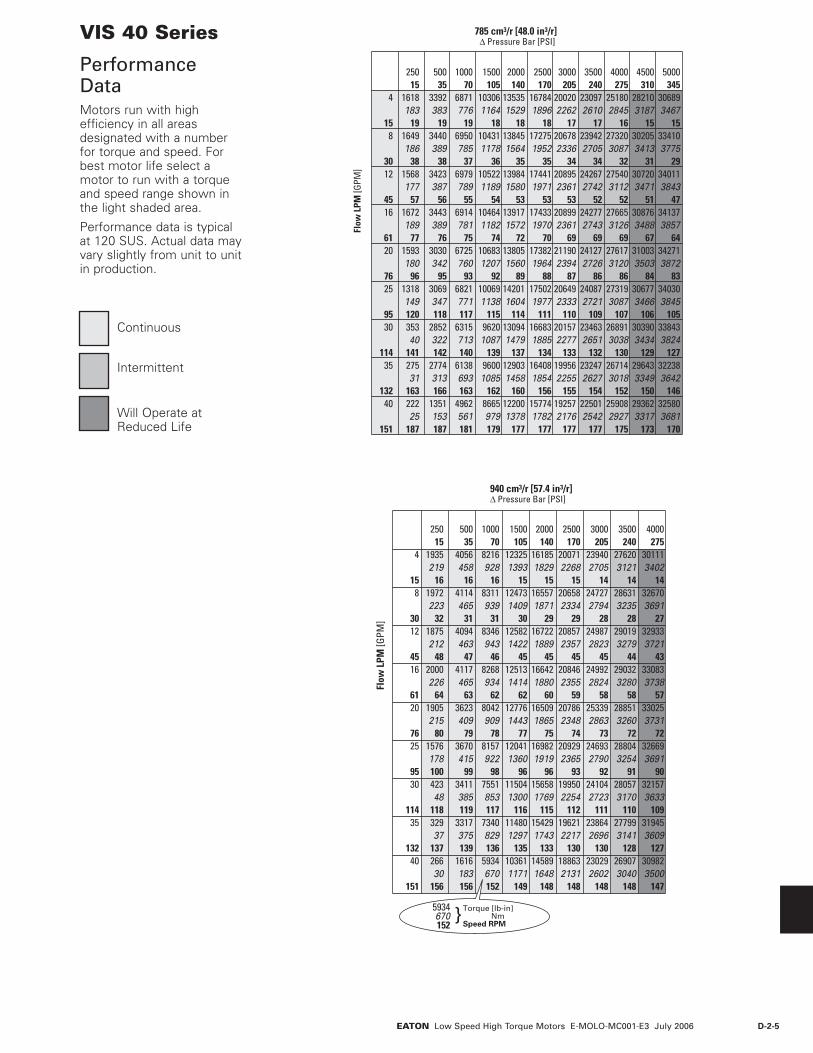
D-2-5EATON Low Speed High Torque Motors E-MOLO-MC001-E3 July 2006
VIS 40 Series
Performance DataMotors run with high efficiency in all areas designated with a number for torque and speed. For best motor life select a motor to run with a torque and speed range shown in the light shaded area.
Performance data is typical at 120 SUS. Actual data may vary slightly from unit to unit in production.
Δ Pressure Bar [PSI]785 cm3/r [48.0 in3/r]
Flo
w L
PM [G
PM]
250 500 1000 1500 2000 2500 3000 3500 4000 4500 500015 35 70 105 140 170 205 240 275 310 345
4 1618 3392 6871 10306 13535 16784 20020 23097 25180 28210 30689183 383 776 1164 1529 1896 2262 2610 2845 3187 3467
15 19 19 19 18 18 18 17 17 16 15 158 1649 3440 6950 10431 13845 17275 20678 23942 27320 30205 33410
186 389 785 1178 1564 1952 2336 2705 3087 3413 377530 38 38 37 36 35 35 34 34 32 31 2912 1568 3423 6979 10522 13984 17441 20895 24267 27540 30720 34011
177 387 789 1189 1580 1971 2361 2742 3112 3471 384345 57 56 55 54 53 53 53 52 52 51 4716 1672 3443 6914 10464 13917 17433 20899 24277 27665 30876 34137
189 389 781 1182 1572 1970 2361 2743 3126 3488 385761 77 76 75 74 72 70 69 69 69 67 6420 1593 3030 6725 10683 13805 17382 21190 24127 27617 31003 34271
180 342 760 1207 1560 1964 2394 2726 3120 3503 387276 96 95 93 92 89 88 87 86 86 84 8325 1318 3069 6821 10069 14201 17502 20649 24087 27319 30677 34030
149 347 771 1138 1604 1977 2333 2721 3087 3466 384595 120 118 117 115 114 111 110 109 107 106 10530 353 2852 6315 9620 13094 16683 20157 23463 26891 30390 33843
40 322 713 1087 1479 1885 2277 2651 3038 3434 3824114 141 142 140 139 137 134 133 132 130 129 12735 275 2774 6138 9600 12903 16408 19956 23247 26714 29643 32238
31 313 693 1085 1458 1854 2255 2627 3018 3349 3642132 163 166 163 162 160 156 155 154 152 150 14640 222 1351 4962 8665 12200 15774 19257 22501 25908 29362 32580
25 153 561 979 1378 1782 2176 2542 2927 3317 3681151 187 187 181 179 177 177 177 177 175 173 170
Δ Pressure Bar [PSI]940 cm3/r [57.4 in3/r]
Flo
w L
PM [G
PM]
Torque [lb-in] NmSpeed RPM
}5934670152
250 500 1000 1500 2000 2500 3000 3500 400015 35 70 105 140 170 205 240 275
4 1935 4056 8216 12325 16185 20071 23940 27620 30111219 458 928 1393 1829 2268 2705 3121 3402
15 16 16 16 15 15 15 14 14 148 1972 4114 8311 12473 16557 20658 24727 28631 32670
223 465 939 1409 1871 2334 2794 3235 369130 32 31 31 30 29 29 28 28 2712 1875 4094 8346 12582 16722 20857 24987 29019 32933
212 463 943 1422 1889 2357 2823 3279 372145 48 47 46 45 45 45 45 44 4316 2000 4117 8268 12513 16642 20846 24992 29032 33083
226 465 934 1414 1880 2355 2824 3280 373861 64 63 62 62 60 59 58 58 5720 1905 3623 8042 12776 16509 20786 25339 28851 33025
215 409 909 1443 1865 2348 2863 3260 373176 80 79 78 77 75 74 73 72 7225 1576 3670 8157 12041 16982 20929 24693 28804 32669
178 415 922 1360 1919 2365 2790 3254 369195 100 99 98 96 96 93 92 91 9030 423 3411 7551 11504 15658 19950 24104 28057 32157
48 385 853 1300 1769 2254 2723 3170 3633114 118 119 117 116 115 112 111 110 10935 329 3317 7340 11480 15429 19621 23864 27799 31945
37 375 829 1297 1743 2217 2696 3141 3609132 137 139 136 135 133 130 130 128 12740 266 1616 5934 10361 14589 18863 23029 26907 30982
30 183 670 1171 1648 2131 2602 3040 3500151 156 156 152 149 148 148 148 148 147
Continuous
Intermittent
Will Operate at Reduced Life
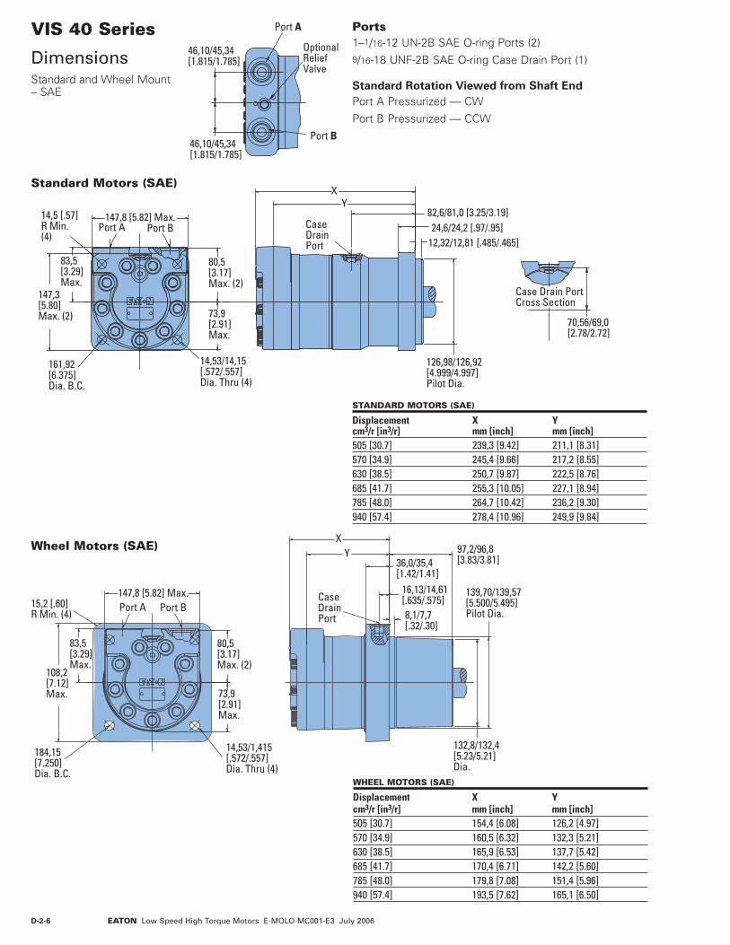
D-2-6 EATON Low Speed High Torque Motors E-MOLO-MC001-E3 July 2006
46,10/45,34[1.815/1.785]
46,10/45,34[1.815/1.785]
Port B
Port A
OptionalRelief Valve
XY
36,0/35,4 [1.42/1.41]
16,13/14,61 [.635/.575]8,1/7,7 [.32/.30]
97,2/96,8 [3.83/3.81]
139,70/139,57[5.500/5.495]Pilot Dia.
132,8/132,4[5.23/5.21]Dia.
80,5[3.17]Max. (2)
73,9[2.91] Max.
83,5[3.29]Max.
147,8 [5.82] Max.
108,2[7.12]Max.
184,15[7.250]Dia. B.C.
14,53/1,415[.572/.557]Dia. Thru (4)
Port A Port B15,2 [.60]R Min. (4)
Case DrainPort
VIS 40 Series
DimensionsStandard and Wheel Mount – SAE
Case Drain PortCross Section
70,56/69,0[2.78/2.72]
Port A Port B147,8 [5.82] Max.
80,5[3.17]Max. (2)
73,9[2.91]Max.
14,53/14,15[.572/.557]Dia. Thru (4)
83,5[3.29]Max.
147,3[5.80]Max. (2)
161,92[6.375]Dia. B.C.
14,5 [.57]R Min. (4)
XY
82,6/81,0 [3.25/3.19]
12,32/12,81 [.485/.465]24,6/24,2 [.97/.95]
126,98/126,92[4.999/4.997]Pilot Dia.
Case DrainPort
Standard Motors (SAE)
STANDARD MOTORS (SAE)
Displacement X Ycm3/r [in3/r] mm [inch] mm [inch]505 [30.7] 239,3 [9.42] 211,1 [8.31] 570 [34.9] 245,4 [9.66] 217,2 [8.55]630 [38.5] 250,7 [9.87] 222,5 [8.76]685 [41.7] 255,3 [10.05] 227,1 [8.94]785 [48.0] 264,7 [10.42] 236,2 [9.30]940 [57.4] 278,4 [10.96] 249,9 [9.84]
Wheel Motors (SAE)
WHEEL MOTORS (SAE)
Displacement X Ycm3/r [in3/r] mm [inch] mm [inch] 505 [30.7] 154,4 [6.08] 126,2 [4.97] 570 [34.9] 160,5 [6.32] 132,3 [5.21]630 [38.5] 165,9 [6.53] 137,7 [5.42]685 [41.7] 170,4 [6.71] 142,2 [5.60]785 [48.0] 179,8 [7.08] 151,4 [5.96]940 [57.4] 193,5 [7.62] 165,1 [6.50]
Ports 1–1/16-12 UN-2B SAE O-ring Ports (2)9/16-18 UNF-2B SAE O-ring Case Drain Port (1)
Standard Rotation Viewed from Shaft End
Port A Pressurized — CW
Port B Pressurized — CCW

D-2-7EATON Low Speed High Torque Motors E-MOLO-MC001-E3 July 2006
VIS 40 Series
DimensionsOversize Flange 224,0 [8.82] B.C.
80,5[3.17]Max.
83,5[3.29]Max
73,9[2.91]Max.
18,21/17,81[.717/.707]Dia. Thru (4)
191,5[7.54]
Max. (2)
145,7 [5.82] Max.11,2 [.44]R Min. (4)
224,00[8.819]Dia. B.C.
Port A Port B
XY
Port
127,3/126,7[5.01/4.99]Pilot Dia.
185,9/184,9[7.32/7.28]Pilot Dia.
170,00/169,80[6,693/6.685]Pilot Dia.
126,98/126,92[4.999/4.997]Pilot Dia.
139,98/139,88[5.511/5.507]Pilot Dia.
39,4/38,8 [1.55/1.53]19,3/18,7 [.76/.74]56,4/54,8
[2.22/2.16]] 4,6/4,0 [.18/.16]20,0/18,0 [.79/.71]18,3/17,7 [.72/.70]
Case Drain PortCross Section
Case DrainPort
46,10/45,34[1.815/1.785]
46,10/45,34[1.815/1.785]
Port B
Port A
OptionalRelief Valve
Ports 1–1/16-12 UN-2B SAE O-ring Ports (2)9/16-18 UNF-2B SAE O-ring Case Drain Port (1)
Standard Rotation Viewed from Shaft End
Port A Pressurized — CW
Port B Pressurized — CCW
STANDARD MOTORS (OVERSIZE)
Displacement X Ycm3/r [in3/r] mm [inch] mm [inch] 505 [30.7] 213,1 [8.39] 181,4 [8.36] 570 [34.9] 219,2 [8.63] 187,4 [8.60]630 [38.5] 224,5 [8.84] 192,5 [8.81]685 [41.7] 229,1 [9.02] 197,6 [8.99]785 [48.0] 238,5 [9.39] 206,8 [9.35]940 [57.4] 252,0 [9.92] 220,5 [9.89]
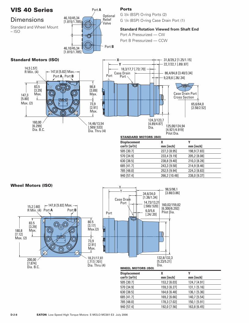
D-2-8 EATON Low Speed High Torque Motors E-MOLO-MC001-E3 July 2006
46,10/45,34[1.815/1.785]
46,10/45,34[1.815/1.785]
Port B
Port A
OptionalReliefValve
34,6/34,0[1.36/1.34]
YX
Case DrainPort 14,73/13,21
[.580/.520]6,0/5,6[.24/.20]
98,5/98,1[3.88/3.86]
132,8/132,3[5.23/5.21]Dia.
160,02/159,82[6.300/6.292]Pilot Dia.Port
18,21/17,81[.717/.701]Dia. Thru (4)
180,8[7.12]Max. (2)
200,00[7.874]Dia. B.C.
15,2 [.60]R Min. (4)
80.5[3.17]Max.(2)
83.5[3.29]Max.
73,9[2.91]Max.
147,8 [5.82] Max.Port A Port B
VIS 40 Series
DimensionsStandard and Wheel Mount – ISO
18,3/17,7 [.72/.70]22,7/22,1 [.89/.87]31,8/29,2 [1.25/1.15]
124,3/123,7[4.89/4.87]Dia. 125,00/124,94
[4.921/4.919]Pilot Dia.
86,4/84,8 [3.40/3.34]9,2/8,6 [.36/.34]
XY
Case DrainPort
Case Drain PortCross Section
65,6/64,0[2.58/2.52]
Port
98,8[3.89]Max.
83,5[3.29]Max.
147,8 [5.82] Max.
73,9[2.91]Max.
14,46/13,54[.569/.533]Dia. Thru (4)
147,3[5.80]Max. (2)
14,5 [.57]R Min. (4)
160,00[6.299]Dia. B.C.
Port A Port B
Standard Motors (ISO)
Wheel Motors (ISO)
Ports G 3/4 (BSP) O-ring Ports (2)
G 1/4 (BSP) O-ring Case Drain Port (1)
Standard Rotation Viewed from Shaft End
Port A Pressurized — CW
Port B Pressurized — CCW
STANDARD MOTORS (ISO)
Displacement X Ycm3/r [in3/r] mm [inch] mm [inch] 505 [30.7] 227,3 [8.95] 198,9 [7.83] 570 [34.9] 233,4 [9.19] 205,2 [8.08] 630 [38.5] 238,8 [9.40] 210,3 [8.28] 685 [41.7] 243,3 [9.58] 214,9 [8.46] 785 [48.0] 252,5 [9.94] 224,3 [8.83] 940 [57.4] 266,2 [10.48] 238,0 [9.37]
WHEEL MOTORS (ISO)
Displacement X Ycm3/r [in3/r] mm [inch] mm [inch] 505 [30.7] 153,2 [6.03] 124,7 [4.91] 570 [34.9] 159,3 [6.27] 131,1 [5.16] 630 [38.5] 164,6 [6.48] 136,1 [5.36] 685 [41.7] 169,2 [6.66] 140,7 [5.54] 785 [48.0] 178,3 [7.02] 150,1 [5.91] 940 [57.4] 192,0 [7.56] 163,8 [6.45]

D-2-9EATON Low Speed High Torque Motors E-MOLO-MC001-E3 July 2006
Port
X
YMountingSurface
127,00/126,87[5.000/4.995]Pilot Dia.
12.45/11,94[4.90/.470]
20,6/19,6[.81/.77]
Shaft Face SealFurnished withMotor
VIS 40 Series
DimensionsBearingless
For VIS 40 bearingless motor application information, contact your Eaton representative (mating coupling blanks available from Eaton Hydraulics).
Note:
After machining blank, part must be hardened per Eaton specification.
Port A Port B
147,8 [5.82] Max.
73,9[2.91]Max.
80,5[3.17]Max. (2)
83,5[3.29]Max.
195,1 [7.68] Max. (2)
MountingSurface
Return toCase Drain
14,53/14,17[.572/.558]Dia. Thru (4)
161,92 [6.375]Dia. Bolt Circle
45º
Case DrainPort 12,85
[.506]
70,10 [2.760]
EF
G
H
L
C D
J
K
Mating Coupling BlankEaton Part No. 13280-002
C 59,94 [2.36 ] Dia.D 49,00 [1.93 ] Dia.E 155,86 [6.14 ] Max.F 150,88 [5.94 ] Min. Full Form Dia.G 26,92 [1.06 ]H 33,30 [1.21 ] J 106,43 [4.19 ] Full Form Dia.K 72,64 [2.86 ] L 15
Ports 1-1/16-12 UN-2B SAE O-ring Ports (2) 9/16-18 UNF-2B SAE O-ring Case Drain Port (1)
Or
G 3/4 (BSP) O-ring Ports (2)
G 1/4 (BSP) O-ring Case Drain Port (1)
Standard Rotation Viewed from Drive End
Port A Pressurized — CW
Port B Pressurized — CCW
BEARINGLESS MOTORS
Displacement X Ycm3/r [in3/r] mm [inch] mm [inch] 505 [30.7] 157,2 [6.19] 129,0 [5.08] 570 [34.9] 163,3 [6.43] 135,1 [5.32] 630 [38.5] 168,4 [6.63] 140,5 [5.53] 685 [41.7] 173,2 [6.82] 145,3 [5.72] 785 [48.0] 182,2 [7.18] 154,4 [6.08] 940 [57.4] 196,1 [7.72] 168,1 [6.62]
46,10/45,34[1.815/1.785]
46,10/45,34[1.815/1.785]
Port B
Port A OptionalRelief Valve

D-2-10 EATON Low Speed High Torque Motors E-MOLO-MC001-E3 July 2006
VIS 40 Series
Installation InformationBearingless
45º ±3º
Circular
Major
MinorTip R.
Fillet R.Pitch
Form
Finish
Finish
22X
3
4
2,5 (100)
66,83±0,25[2.631±.010]
44,70 ±0,25[1.760 ±.010]
55º ±º5
49,84 ±0,25[1.962 ±.010]
45º ±5º x 0,38 ±0,25 [.015 ±.010]or R 0,38 ±0,25 [.015 ±.010]
68,96 ±0,51[2.715 ±.020]Coupling Length
4,83 ±0,25[.190 ±.010] Oil Hole
-H-
33,78 ±0,25 [1.330 ±.010]
3,17 [.125] Max.Undercut
52,37[2.062]Min.
R 1,5 ±0,3[.06 ±.01]
R 1,5 ±0,3[.06 ±.01]
-G-
Oil Flow Path Thru Splineand Bearing(s)
Spline
Oil Flow Return to Case Drain
Case Drain
Spline Pitch ................................................................................................10/20 Pressure Angle ............................................................................................. 30° Number of teeth ............................................................................................. 16 Class of Fit ................................................................................................. Ref. 5 Type of Fit .................................................................................................... SidePitch Diameter ......................Ref. 40,640000 [1.6000000] 0,20 [.008] | H Base Diameter ...................................................... Ref. 35,195272 [1.3856406] Major Diameter ............................................43,56 [1.715] Max. 43,18 [1.700] Min. Minor Diameter ............................................ 36,83 -37,08 [1.450 -1.460] Form Diameter, Min. .....................................................................42.47 [1.672] Fillet Radius .................................................................... 0,64 -0,76 [.025 -.030] Tip Radius ....................................................................... 0,25 -0,51 [.010 -.020] Finish ........................................................................................................1,6 (63) Involute Profile Variation .................................+0,000 -0,025 [+.0000 -.0010] Total Index Variation .....................................................................0,040 [.0016] Lead Variation ................................................................................0,013 [.0005] Circular Space Width: Maximum Actual ....................................................................4.105 [.1616] Minimum Effective .................................................................3,995 [.1573] Maximum Effective ....................................................... Ref. 4,056 [.1597] Minimum Actual ............................................................ Ref. 4,081 [.1582] Dimension Between Two Pins ............ Ref. 34,272 -34,450 [1.3493 -1.3563] Pin Diameter ..................................................................................4,389 [.1728]
1 Internal spline in mating part to be per spline data. Specification material to be ASTM A304, 8620H carburize to a hardness of 60-64 HRc with case depth (to 50HRc) of 0,076 -1,27 [.030 -.050]. Dimensions apply after heat treat.
2 Mating part to have critical dimensions as shown. Oil holes must be provided and open for proper oil circulation.
3 Seal to be furnished with motor for proper oil circulation thru splines.
4 Similar to SAE “C” Four Bolt Flange.

D-2-11EATON Low Speed High Torque Motors E-MOLO-MC001-E3 July 2006
40,018/39,992[1.5755/1.5745]Dia.
43,03/42,72[1.694/1.682]
8,000/7,910[.3149/.3115]
M12 x 1.7525,4 [1.00]Min. Depth
9,2/4,5[.36/.18]
12,000/11,957[.4724/.4708]
Mounting Surface
Mounting Surface
Standard Mount
Wheel Mount
95,5/91,5[3.76/3.60] 63,8/62,2
[2.51/2.45]
180,3/176,3[7.10/6.94]
74,7 [2.94] Max.Coupling Engagement
40 mm Straight
Note:
For motor torque ratings above 875 Nm [7750 lb - in] use split coupler.
3/8-16 UNF-2B20,1 [.79]Min. Depth
39,1 [1.54] Min. Full Spline
55,4 [2.18] Max.Coupling Engagement
38,10 [1.500] Dia.Flat Root Side Fit17 Tooth 12/24 Spline to FitANSI B92.1 1970
Mounting Surface
Mounting Surface
Standard Mount
Wheel Mount
79,8/75,7[3.15/2.98]
164,6/160,6[6.48/6.32]
44,45[1.750] Dia.
16,13/15,36[.635/.605]
4,1 [.16]Dia. Thru
5,54/5,20[.218/.205]
11,138/11,112[.4385/.4375]
31,7 [1.25]
1-1/4-18 UNEF - 2A
SAE J501 Standard Tapered Shaft125,00±0,17 Taper per Meter[1.500±.002 Taper per Foot]
55,76/54,99[2.195/2.165]
Mounting Surface
Mounting Surface
Standard Mount
Wheel Mount
Slotted Hex Nut Torque: Dry — 645 Nm [475 lb-ft]Lubricated — 510 Nm [375 lb-ft] Plus Torque Requiredto Align the Slotted Nut with Crosshole.
94,5/90,2[3.72/3.55]
16,0/13,4[.63/.53]
101,3/98,3[3.99/3.87] 179,0/175,0
[7.05/6.89]
1–1/2 Inch17 Tooth Splined
1–3/4 Inch Tapered
VIS 40 Series
Dimensions ShaftsSAE

D-2-12 EATON Low Speed High Torque Motors E-MOLO-MC001-E3 July 2006
VIS 40 Series
Side Load CapacitySAE
Mounting Surface
Mounting Surface
0
0 [1] [2] [3] [4] [5] [6] [inch][-5][-6] [-4] [-3] [-2] [-1]
20 40 60 80 100 120 140 mm-120-140-160 -80-100 -60 -40 -20
0
0 [1] [2] [3] [4] [5] [6] [7] [8] [9] [inch][-2][-3] [-1]
20 40 60 80 100 120 140 160 180 200 220 mm-60-80 -40 -20
Standard Mount
Wheel Mount
0
[ 4000]
[ 8000]
[12000]
0
1000
2000
3000
4000
5000
[lb]kg
0
[ 4000]
[ 8000]
[12000]
0
1000
2000
3000
4000
5000
[lb]kg
These curves indicate the radial load capacity on the motor shaft(s) at various locations.
The curve is based on B 10 bearing life (2000 hours of 12,000,000 shaft revolutions at 100 RPM) at rated output torque. To determine radial load at speeds other than 100 RPM, multiply the load values given on the bearing curve by the factors in the chart below.
RPM Multiplication Factor50 1.23100 1.00200 0.81300 0.72400 0.66500 0.62600 0.58700 0.56800 0.54
For 3,000,000 shaft revolutions or 500 hours — Increase these shaft loads 52%.

D-2-13EATON Low Speed High Torque Motors E-MOLO-MC001-E3 July 2006
VIS 40 Series
Dimensions Shafts Oversize Flange 224,0 [8.82] B.C.
Note:
For motor torque ratings above 875 Nm [7750 lb - in] use split coupler.
SAE Involute Spline, Flat RootSide Fit 16/32 DP 28 Tooth30 Pressure Angle
158,8/155,0[6.26/6.10] 93,0 [3.66]
Min. Full Spline
46,03/45,77[1.812/1.802] Dia.
M16 x 2,0 -6H45,0 [1.77] Min. Depth
46 mm 28 Tooth Splined
44,45[1.750] Dia.
16,13/15,36[.635/.605]
4,1 [.16]Dia. Thru
5,54/5,20[.218/.205]
11,138/11,112[.4385/.4375]
31,7 [1.25]
1-1/4-18 UNEF - 2A
SAE J501 Standard Tapered Shaft125,00±0,17 Taper per Meter[1.500±.002 Taper per Foot]
55,76/54,99[2.195/2.165]
Mounting Surface121,2/117,3[4.77/4.62]
42,9/40,6[1.69/1.60]
Slotted Hex Nut Torque: Dry — 645 Nm [475 lb-ft]Lubricated — 510 Nm [375 lb-ft] Plus Torque Requiredto Align the Slotted Nut with Crosshole.
1-3/4 Inch Tapered
40,018/39,992[1.5755/1.5745]Dia.
74,7 [2.94] Max.Coupling Engagement
43,03/42,72[1.694/1.682]
8,000/7,910[.3149/.3115]
M12 x 1.7525,4 [1.00]Min. Depth
122,4/118,6[4.82/4.67] 63,8/62,2
[2.51/2.45]
9,2/4,5[.36/.18]
12,000/11,957[.4724/.4708]
Mounting Surface40 mm Straight

D-2-14 EATON Low Speed High Torque Motors E-MOLO-MC001-E3 July 2006
VIS 40 Series
Side Load CapacityOversize Flange 224,0 [8.82] B.C.
Mounting Surface
0
0 [1] [2] [3] [4] [5] [6] [7] [inch][-5] [-4] [-3] [-2] [-1]
20 40 60 80 100 120 140 160 mm-120-140 -80-100 -60 -40 -200
[ 4000]
[ 8000]
[12000]
0
1000
2000
3000
4000
5000
[lb]kgThese curves indicate the radial load capacity on the motor shaft(s) at various locations.
The curve is based on B 10 bearing life (2000 hours of 12,000,000 shaft revolutions at 100 RPM) at rated output torque. To determine radial load at speeds other than 100 RPM, multiply the load values given on the bearing curve by the factors in the chart below.
RPM Multiplication Factor50 1.23100 1.00200 0.81300 0.72400 0.66500 0.62600 0.58700 0.56800 0.54
For 3,000,000 shaft revolutions or 500 hours — Increase these shaft loads 52%.

D-2-15EATON Low Speed High Torque Motors E-MOLO-MC001-E3 July 2006
VIS 40 Series
Dimensions Shafts ISO
Note:
For motor torque ratings above 875 Nm [7750 lb - in] use split coupler.
M12 x 1.7525,4 [1.00]Min. Depth
56,6 [2.23] Min. Full Spline
72,9 [2.87] Max.Coupling Engagement
38,10 [1.500] Dia.Flat Root Side Fit17 Tooth 12/24 Spline to FitANSI B92.1 1970
Mounting Surface
Mounting Surface
Wheel Mount
Standard Mount
190,5/186,7[7.50/7.35]
116,3/112,5[4.58/4.43]
38,1 mm [1–1/2 inch]17 Tooth Splined
28,63/27,35[1.127/1.077]
18,3/17,7[.72/.70]
6,4/5,8 [.25/.23]Dia. Thru
12,000/11,957[.4724/.4708]
23,47/23,31[.924/.918]
46,0[1.81]
45,03/44,97[1.773/1.771]Dia.
M30 x 2-6H
10:1 TaperPer ISOR775
Mounting Surface
Mounting Surface
Wheel Mount
Standard Mount
Slotted Hex Nut Torque: Dry — 645 Nm [475 lb-ft]Lubricated — 510 Nm [375 lb-ft] Plus Torque Requireto Align the Slotted Nut with Crosshole.
104,4/101,4[4.11/4.01] 183,1/179,3
[7.21/7.06]
37,1/34,5[1.46/1.36]
109,2/105,4[4.30/4.15]
45 mm Tapered
40,018/39,992[1.5755/1.5745]Dia.
76,4 [3.01] Max.Coupling Engagement
43,03/42,72[1.694/1.682]
8,000/7,910[.3149/.3115]
M12 x 1.7525,4 [1.00]Min. Depth
67,6/66,0[2.66/2.60]
9,2/4,5[.36/.18]
12,000/11,957[.4724/.4708]
Mounting Surface
Mounting Surface
Wheel Mount
Standard Mount
109,2/105,4[4.30/4.15]
183,4/179,6[7.22/7.07]
40 mm Straight
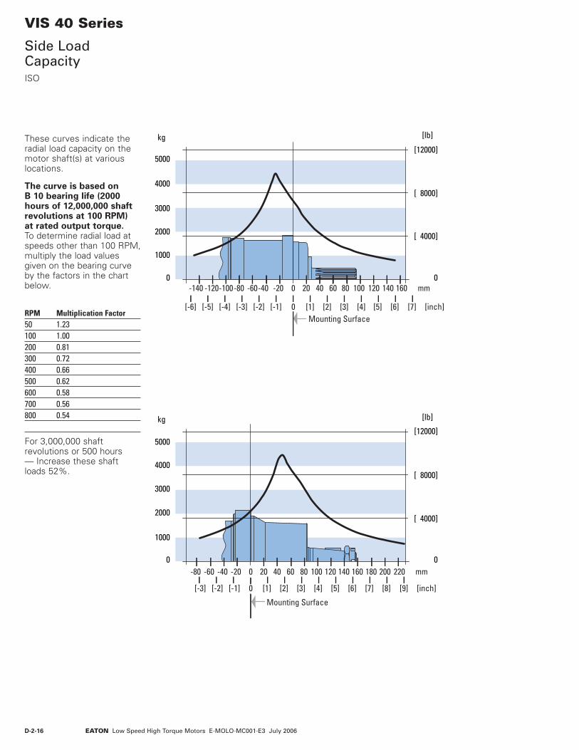
D-2-16 EATON Low Speed High Torque Motors E-MOLO-MC001-E3 July 2006
VIS 40 Series
Side Load CapacityISO
Mounting Surface
0
[ 4000]
[ 8000]
[12000]
0
1000
2000
3000
4000
5000
[lb]kg
0
0 [1] [2] [3] [4] [5] [6] [7] [inch][-6] [-5] [-4] [-3] [-2] [-1]
20 40 60 80 100 140 160 mm120-120-140 -80-100 -60-40 -20
Mounting Surface
0
[ 4000]
[ 8000]
[12000]
0
1000
2000
3000
4000
5000
[lb]kg
0
0 [1] [2] [3] [4] [5] [6] [7] [8] [9] [inch][-3] [-2] [-1]
20 40 60 80 100 140120 160 180 200 220 mm-80 -60 -40 -20
These curves indicate the radial load capacity on the motor shaft(s) at various locations.
The curve is based on B 10 bearing life (2000 hours of 12,000,000 shaft revolutions at 100 RPM) at rated output torque. To determine radial load at speeds other than 100 RPM, multiply the load values given on the bearing curve by the factors in the chart below.
RPM Multiplication Factor50 1.23100 1.00200 0.81300 0.72400 0.66500 0.62600 0.58700 0.56800 0.54
For 3,000,000 shaft revolutions or 500 hours — Increase these shaft loads 52%.
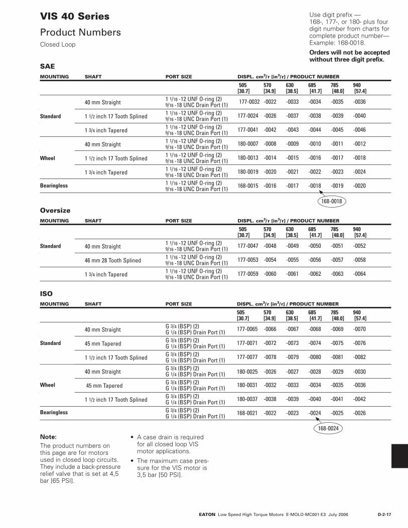
D-2-17EATON Low Speed High Torque Motors E-MOLO-MC001-E3 July 2006
VIS 40 Series
Product NumbersClosed Loop
MOUNTING SHAFT PORT SIZE DISPL. cm3/ r [in3/ r] / PRODUCT NUMBER
505 570 630 685 785 940 [30.7] [34.9] [38.5] [41.7] [48.0] [57.4] 40 mm Straight 1 1/16 -12 UNF O-ring (2) 9/16 -18 UNC Drain Port (1) 177-0032 -0022 -0033 -0034 -0035 -0036
1 1/2 inch 17 Tooth Splined 1 1/16 -12 UNF O-ring (2) 9/16 -18 UNC Drain Port (1) 177-0024 -0026 -0037 -0038 -0039 -0040
1 3/4 inch Tapered 1 1/16 -12 UNF O-ring (2) 9/16 -18 UNC Drain Port (1) 177-0041 -0042 -0043 -0044 -0045 -0046
40 mm Straight 1 1/16 -12 UNF O-ring (2) 9/16 -18 UNC Drain Port (1) 180-0007 -0008 -0009 -0010 -0011 -0012
1 1/2 inch 17 Tooth Splined 1 1/16 -12 UNF O-ring (2) 9/16 -18 UNC Drain Port (1) 180-0013 -0014 -0015 -0016 -0017 -0018
1 3/4 inch Tapered 1 1/16 -12 UNF O-ring (2) 9/16 -18 UNC Drain Port (1) 180-0019 -0020 -0021 -0022 -0023 -0024
1 1/16 -12 UNF O-ring (2) 9/16 -18 UNC Drain Port (1) 168-0015 -0016 -0017 -0018 -0019 -0020
Standard
Bearingless
Wheel
168-0018
MOUNTING SHAFT PORT SIZE DISPL. cm3/ r [in3/ r] / PRODUCT NUMBER
505 570 630 685 785 940 [30.7] [34.9] [38.5] [41.7] [48.0] [57.4] 40 mm Straight G 3/4 (BSP) (2) G 1/4 (BSP) Drain Port (1) 177-0065 -0066 -0067 -0068 -0069 -0070
45 mm Tapered G 3/4 (BSP) (2) G 1/4 (BSP) Drain Port (1) 177-0071 -0072 -0073 -0074 -0075 -0076
1 1/2 inch 17 Tooth Splined G 3/4 (BSP) (2) G 1/4 (BSP) Drain Port (1) 177-0077 -0078 -0079 -0080 -0081 -0082
40 mm Straight G 3/4 (BSP) (2) G 1/4 (BSP) Drain Port (1) 180-0025 -0026 -0027 -0028 -0029 -0030
45 mm Tapered G 3/4 (BSP) (2) G 1/4 (BSP) Drain Port (1) 180-0031 -0032 -0033 -0034 -0035 -0036
1 1/2 inch 17 Tooth Splined G 3/4 (BSP) (2) G 1/4 (BSP) Drain Port (1) 180-0037 -0038 -0039 -0040 -0041 -0042
G 3/4 (BSP) (2) G 1/4 (BSP) Drain Port (1) 168-0021 -0022 -0023 -0024 -0025 -0026
Standard
Bearingless
Wheel
Use digit prefix —168-, 177-, or 180- plus four digit number from charts for complete product number—Example: 168-0018.
Orders will not be accepted without three digit prefix.
SAE
ISO
168-0024Note:
The product numbers on this page are for motors used in closed loop circuits. They include a back-pressure relief valve that is set at 4,5 bar [65 PSI].
• A case drain is required for all closed loop VIS motor applications.
• The maximum case pres-sure for the VIS motor is 3,5 bar [50 PSI].
MOUNTING SHAFT PORT SIZE DISPL. cm3/ r [in3/ r] / PRODUCT NUMBER
505 570 630 685 785 940 [30.7] [34.9] [38.5] [41.7] [48.0] [57.4] 40 mm Straight 1 1/16 -12 UNF O-ring (2) 9/16 -18 UNC Drain Port (1) 177-0047 -0048 -0049 -0050 -0051 -0052
46 mm 28 Tooth Splined 1 1/16 -12 UNF O-ring (2) 9/16 -18 UNC Drain Port (1) 177-0053 -0054 -0055 -0056 -0057 -0058
1 3/4 inch Tapered 1 1/16 -12 UNF O-ring (2) 9/16 -18 UNC Drain Port (1) 177-0059 -0060 -0061 -0062 -0063 -0064
Standard
Oversize

D-2-18 EATON Low Speed High Torque Motors E-MOLO-MC001-E3 July 2006
Use digit prefix —168-, 177-, or 180- plus four digit number from charts for complete product number—Example 168-0029.
Orders will not be accepted without three digit prefix.
VIS 40 Series
Product NumbersOpen Loop
Note:
All product numbers in the charts (above) are for motors without a back-pressure relief valve. These motors would generally be used in open loop circuits.
For closed loop circuits a motor with a back-pressure relief valve is required.
• A case drain is recom-mended for all VIS motor applications.
• The maximum case pres-sure for the VIS motor is 3,5 bar [50 PSI].
• In open loop circuits, return pressure must be 3,5 bar [50 PSI] greater than case pressure to properly lubricate the internal drive.
MOUNTING SHAFT PORT SIZE DISPL. cm3/ r [in3/ r] / PRODUCT NUMBER
505 570 630 685 785 940 [30.7] [34.9] [38.5] [41.7] [48.0] [57.4] 40 mm Straight 1 1/16 -12 UNF O-ring (2) 9/16 -18 UNC Drain Port (1) 177-0083 -0084 -0085 -0086 -0087 -0088
1 1/2 inch 17 Tooth Splined 1 1/16 -12 UNF O-ring (2) 9/16 -18 UNC Drain Port (1) 177-0089 -0090 -0091 -0092 -0093 -0094
1 3/4 inch Tapered 1 1/16 -12 UNF O-ring (2) 9/16 -18 UNC Drain Port (1) 177-0095 -0096 -0097 -0098 -0099 -0100
40 mm Straight 1 1/16 -12 UNF O-ring (2) 9/16 -18 UNC Drain Port (1) 180-0043 -0044 -0045 -0046 -0047 -0048
1 1/2 inch 17 Tooth Splined 1 1/16 -12 UNF O-ring (2) 9/16 -18 UNC Drain Port (1) 180-0049 -0050 -0051 -0052 -0053 -0054
1 3/4 inch Tapered 1 1/16 -12 UNF O-ring (2) 9/16 -18 UNC Drain Port (1) 180-0055 -0056 -0006 -0057 -0058 -0059
1 1/16 -12 UNF O-ring (2) 9/16 -18 UNC Drain Port (1) 168-0027 -0028 -0010 -0029 -0030 -0031
Standard
Bearingless
Wheel
168-0029
MOUNTING SHAFT PORT SIZE DISPL. cm3/ r [in3/ r] / PRODUCT NUMBER
505 570 630 685 785 940 [30.7] [34.9] [38.5] [41.7] [48.0] [57.4] 40 mm Straight G 3/4 (BSP) (2) G 1/4 (BSP) Drain Port (1) 177-0119 -0120 -0121 -0122 -0029 -0124
45 mm Tapered G 3/4 (BSP) (2) G 1/4 (BSP) Drain Port (1) 177-0125 -0126 -0127 -0128 -0129 -0130
1 1/2 inch 17 Tooth Splined G 3/4 (BSP) (2) G 1/4 (BSP) Drain Port (1) 177-0131 -0132 -0133 -0134 -0135 -0136
40 mm Straight G 3/4 (BSP) (2) G 1/4 (BSP) Drain Port (1) 180-0060 -0061 -0062 -0063 -0064 -0065
45 mm Tapered G 3/4 (BSP) (2) G 1/4 (BSP) Drain Port (1) 180-0066 -0067 -0068 -0069 -0070 -0071
1 1/2 inch 17 Tooth Splined G 3/4 (BSP) (2) G 1/4 (BSP) Drain Port (1) 180-0072 -0073 -0074 -0075 -0076 -0077
G 3/4 (BSP) (2) G 1/4 (BSP) Drain Port (1) 168-0032 -0033 -0034 -0035 -0036 -0037
Standard
Bearingless
Wheel
SAE
ISO
168-0035
MOUNTING SHAFT PORT SIZE DISPL. cm3/ r [in3/ r] / PRODUCT NUMBER
505 570 630 685 785 940 [30.7] [34.9] [38.5] [41.7] [48.0] [57.4] 40 mm Straight 1 1/16 -12 UNF O-ring (2) 9/16 -18 UNC Drain Port (1) 177-0101 -0102 -0103 -0104 -0105 -0106
46 mm 28 Tooth Splined 1 1/16 -12 UNF O-ring (2) 9/16 -18 UNC Drain Port (1) 177-0107 -0108 -0109 -0110 -0111 -0112
1 3/4 inch Tapered 1 1/16 -12 UNF O-ring (2) 9/16 -18 UNC Drain Port (1) 177-0113 -0114 -0115 -0116 -0117 -0118
Standard
Oversize
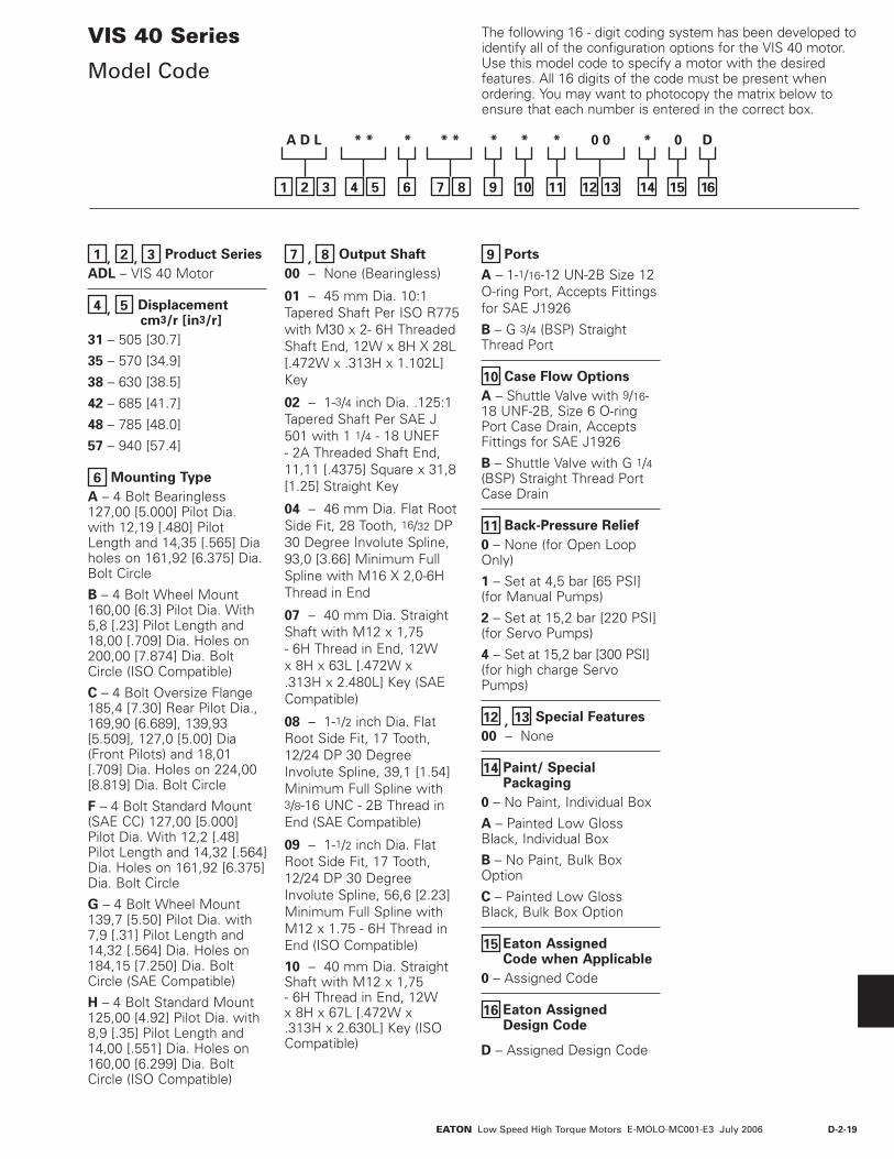
D-2-19EATON Low Speed High Torque Motors E-MOLO-MC001-E3 July 2006
The following 16 - digit coding system has been developed to identify all of the configuration options for the VIS 40 motor. Use this model code to specify a motor with the desired features. All 16 digits of the code must be present when ordering. You may want to photocopy the matrix below to ensure that each number is entered in the correct box.
VIS 40 Series
Model Code
1 , 2 , 3 Product Series
ADL – VIS 40 Motor
4 , 5 Displacement cm3/r [in3/r]
31 – 505 [30.7]
35 – 570 [34.9]
38 – 630 [38.5]
42 – 685 [41.7]
48 – 785 [48.0]
57 – 940 [57.4]
6 Mounting Type
A – 4 Bolt Bearingless 127,00 [5.000] Pilot Dia. with 12,19 [.480] Pilot Length and 14,35 [.565] Dia holes on 161,92 [6.375] Dia. Bolt Circle
B – 4 Bolt Wheel Mount 160,00 [6.3] Pilot Dia. With 5,8 [.23] Pilot Length and 18,00 [.709] Dia. Holes on 200,00 [7.874] Dia. Bolt Circle (ISO Compatible)
C – 4 Bolt Oversize Flange 185,4 [7.30] Rear Pilot Dia., 169,90 [6.689], 139,93 [5.509], 127,0 [5.00] Dia (Front Pilots) and 18,01 [.709] Dia. Holes on 224,00 [8.819] Dia. Bolt Circle
F – 4 Bolt Standard Mount (SAE CC) 127,00 [5.000] Pilot Dia. With 12,2 [.48] Pilot Length and 14,32 [.564] Dia. Holes on 161,92 [6.375] Dia. Bolt Circle
G – 4 Bolt Wheel Mount 139,7 [5.50] Pilot Dia. with 7,9 [.31] Pilot Length and 14,32 [.564] Dia. Holes on 184,15 [7.250] Dia. Bolt Circle (SAE Compatible)
H – 4 Bolt Standard Mount 125,00 [4.92] Pilot Dia. with 8,9 [.35] Pilot Length and 14,00 [.551] Dia. Holes on 160,00 [6.299] Dia. Bolt Circle (ISO Compatible)
7 , 8 Output Shaft
00 – None (Bearingless)
01 – 45 mm Dia. 10:1 Tapered Shaft Per ISO R775 with M30 x 2- 6H Threaded Shaft End, 12W x 8H X 28L [.472W x .313H x 1.102L] Key
02 – 1-3/4 inch Dia. .125:1 Tapered Shaft Per SAE J 501 with 1 1/4 - 18 UNEF - 2A Threaded Shaft End, 11,11 [.4375] Square x 31,8 [1.25] Straight Key
04 – 46 mm Dia. Flat Root Side Fit, 28 Tooth, 16/32 DP 30 Degree Involute Spline, 93,0 [3.66] Minimum Full Spline with M16 X 2,0-6H Thread in End
07 – 40 mm Dia. Straight Shaft with M12 x 1,75 - 6H Thread in End, 12W x 8H x 63L [.472W x .313H x 2.480L] Key (SAE Compatible)
08 – 1-1/2 inch Dia. Flat Root Side Fit, 17 Tooth, 12/24 DP 30 Degree Involute Spline, 39,1 [1.54] Minimum Full Spline with 3/8-16 UNC - 2B Thread in End (SAE Compatible)
09 – 1-1/2 inch Dia. Flat Root Side Fit, 17 Tooth, 12/24 DP 30 Degree Involute Spline, 56,6 [2.23] Minimum Full Spline with M12 x 1.75 - 6H Thread in End (ISO Compatible)
10 – 40 mm Dia. Straight Shaft with M12 x 1,75 - 6H Thread in End, 12W x 8H x 67L [.472W x .313H x 2.630L] Key (ISO Compatible)
9 Ports
A – 1-1/16-12 UN-2B Size 12 O-ring Port, Accepts Fittings for SAE J1926
B – G 3/4 (BSP) Straight Thread Port
10 Case Flow Options
A – Shuttle Valve with 9/16-18 UNF-2B, Size 6 O-ring Port Case Drain, Accepts Fittings for SAE J1926
B – Shuttle Valve with G 1/4 (BSP) Straight Thread Port Case Drain
11 Back-Pressure Relief
0 – None (for Open Loop Only)
1 – Set at 4,5 bar [65 PSI] (for Manual Pumps)
2 – Set at 15,2 bar [220 PSI] (for Servo Pumps)
4 – Set at 15,2 bar [300 PSI](for high charge Servo Pumps)
12 , 13 Special Features
00 – None
14 Paint/ SpecialPackaging
0 – No Paint, Individual Box
A – Painted Low Gloss Black, Individual Box
B – No Paint, Bulk Box Option
C – Painted Low Gloss Black, Bulk Box Option
15 Eaton Assigned Code when Applicable
0 – Assigned Code
16 Eaton Assigned Design Code
D – Assigned Design Code
321
A D L * * * * * * * * 0 0 * 0 D
54 6 87 9 10 11 12 13 14 15 16

D-2-20 EATON Low Speed High Torque Motors E-MOLO-MC001-E3 July 2006
End Cap
ShuttleValve
Balance Plate
BearingsDriveGeroler®
Face Seal MountingFlange
FrontRetainer
OutputShaft
ShaftSeal
Case Drain PortBack PressureRelief Valve Valve
Plate
SelectorPlate
SelectorValve
SealGuard
VIS 40 SeriesTwo-speed
Specifications
VIS 40 Series motors are available with an integral two-speed feature that allows the operator to shift the motor between low speed high torque (LSHT) mode and high speed low torque (HSLT) mode.
In the LSHT mode, output torque and rotation speed values are equal to those of the conventional VIS 40 motor. In the HSLT mode motor displacement is reduced by one third, resulting in a fifty percent increase in rotation speed and a torque output reduction of one third.
The VIS 40 two-speed motor is bidirectional. It will function with equal shaft output in either rotation
direction (CW or CCW) in both LSHT and HSLT modes. Shift on the fly technology allows full-power operation throughout the full duration of the shift.
Changing between modes is accomplished by changing the displacement in a ratio of 1 to 1.5. An external two-position three-way control valve is required for shifting pressure to the pilot port between low pressure (LSHT mode) and pilot signal pressure (HSLT mode).
An integral selector valve shifts the motor from LSHT mode to HSLT mode. Initially, low pressure is supplied to the pilot port. The selector valve is biased to LSHT mode by a return spring. When pilot signal pressure is supplied to the
pilot port and 3,5 ∆bar [50 PSI] is reached, the selector valve overcomes return spring force and the shifts the spool to select HSLT mode.
Oil on the opposite side of the spool is drained to tank via the drain port. The pressure difference between the pilot port and drain port must be maintained to keep the motor in the high speed mode. When pilot pressure is removed from the pilot port, the pressure in the pilot end of the spool valve is relieved and drained back through the control valve and the return spring forces the spool valve to LSHT position.
Pilot pressure may come from any source that will provide uninterrupted pressure during the high-speed mode operation. Allowable pilot pressure must be at least 3,5 ∆bar [50 PSI] and may be as high as full operating pressure of the motor.
All VIS 40 Series two-speed motors are equipped with a return line shuttle for closed circuit applications as standard equipment. All options available on the conventional VIS 40 are also available on VIS 40 two-speed motors.
In the LSHT mode, torque and speed values are equal to those of the conventional VIS 40 motor. In the HSLT mode, rotation speed is increased by fifty percent and torque output is reduced by one third. The VIS 40 two-speed motor will function with equal shaft output in either rotation direction (CW or CCW) in both LSHT and HSLT modes.
Performance Data

D-2-21EATON Low Speed High Torque Motors E-MOLO-MC001-E3 July 2006
45,341.785]
5,341.785]
Port B
Port A
OptionalRelief Valve
8,1/7,7Y
X97,0/96,5[3.83/3.81]
132,8/132,4[5.23/5.21]Dia.
139,70/139,57[5.500/5.495]
14,53/14,15[.572/.557]Dia. Thru (4)
180,8[7.12]Max. (2)
15,2 [.60]R Min. (4)
184,15[7.250]Dia. B.C.
Case DrainPort Port
80,53[3.17]Max. (2)
48,3[1.90]Max. (2)
[3.29]Max.
73,9[2.91]Max.
147,8 [5.82] Max.
195,2 [7.69]Max.
71,8/71,0[2.83/2.79]
71,8/71,0[2.83/2.79]
Port A Port B
[.32/.30]35,9/35,4[1.42/1.41]16,13/14,61[.635/.575] Pilot Dia.
83,5
Z
VIS 40 SeriesTwo-speed
DimensionsStandard and Wheel Mount – SAE
XY
Z
82,6/81,0 [3.25/3.19]24,6/24,2 [.97/.95]12,32/12,81 [.485/.465]
126,98/126,92[4.999/4.997]Pilot Dia.
Case DrainPort
Case Drain PortCross Section
70,56/69,0[2.78/2.72]
80,5[3.17]Max. (2)
48,3[1.90]Max. (2)
83,5[3.29]Max.
147,8 [5.82] Max.
73,9[2.91]Max.
14,53/14,15[.572/.557]Dia. Thru (4)
78,1/71,0[2.83/2.79]
78,1/71,0[2.83/2.79]
147,3[5.80]Max. (2)
161,92[6.375]Dia. B.C.
Port A Port B 14,5 [.57]R Min. (4)
195,2 [7.69]Max.
Standard Motors (SAE)
Wheel Motors (SAE)
Ports 1–1/16-12 UN-2B SAE O-ring Ports (2)9/16-18 UNF-2B SAE O-ring Case Drain Port (1)7/16 -20 UNF -2B SAE O-ring Shift Ports (2)
Standard Rotation Viewed from Shaft End
Port A Pressurized — CWPort B Pressurized — CCW
STANDARD MOTORS (SAE)
Displacement X Y Zcm3/r [in3/r] mm [inch] mm [inch] mm [inch]505 [30.7] 275,1 [10.83] 246,9 [9.72] 201,7 [7.94]570 [34.9] 281,2 [11.07] 253,0 [9.96] 208,0 [8.19]630 [38.5] 286,3 [11.27] 258,3 [10.17] 213,4 [8.40]685 [41.7] 290,8 [11.45] 262,9 [10.35] 217,7 [8.57]785 [48.0] 300,2 [11.82] 272,3 [10.72] 227,3 [8.95]940 [57.4] 313,9 [12.36] 286,0 [11.26] 241,0 [9.49]
WHEEL MOTORS (SAE)
Displacement X Y Zcm3/r [in3/r] mm [inch] mm [inch] mm [inch]505 [30.7] 190,2 [7.49] 162,1 [6.38] 116,8 [4.60]570 [34.9] 196,3 [7.73] 168,1 [6.62] 123,2 [4.85]630 [38.5] 201,4 [7.93] 173,5 [6.83] 128,5 [5.06]685 [41.7] 206,0 [8.11] 178,1 [7.01] 132,8 [5.23]785 [48.0] 215,4 [8.48] 187,5 [7.38] 142,5 [5.61]940 [57.4] 229,1 [9.02] 201,2 [7.92] 156,2 [6.15]

D-2-22 EATON Low Speed High Torque Motors E-MOLO-MC001-E3 July 2006
VIS 40 SeriesTwo-speed
DimensionsOversize Flange 224,0 [8.82] B.C.
126,98/126,92[4.999/4.997]Pilot Dia.
Case Drain PortCross Section
147,8 [5.82] Max.
80,5 [3.17] Max. (2)
48,3 [1.90] Max. (2)
73,9 [2.91] Max.
78,1/71,0 [2.83/2.79]
78,1/71,0 [2.83/2.79]
195,2 [7.69] Max.
83,5 [3.29] Max.191,5
[7.54] Max. (2)
11,2 [.44]R Min. (4)
224,00[8.819]Dia. B.C.
18,21/17,81[.717/.701]Dia. Thru (4)
XY
68,6/67,1 [2.70/2.64]20,0/18,0 [.79/.71]18,3/17,7 [.72/.70]
185,9/184,9 [7.32/7.28] Pilot Dia.
4,6/4,0 [.18/.16]19,3/18,7 [.76/.74]39,4/38,8 [1.55/1.53]
Z
170,00/169,80 [6.693/6.685] Pilot Dia.
139,98/139,88 [5.511/5.507] Pilot Dia.
127,3/126,7 [5.01/4.99] Pilot Dia.
Case DrainPort
Port A Port B
Shift Pilot PortShift Drain Port
46,10/45,34[1.815/1.785]
46,10/45,34[1.815/1.785]
Port B
Port A
OptionalRelief Valve
Ports 1–1/16-12 UN-2B SAE O-ring Ports (2)9/16-18 UNF-2B SAE O-ring Case Drain Port (1)7/16 -20 UNF -2B SAE O-ring Shift Ports (2)
Standard Rotation Viewed from Shaft End
Port A Pressurized — CWPort B Pressurized — CCW
OVERSIZE MOTORS
Displacement X Y Zcm3/r [in3/r] mm [inch] mm [inch] mm [inch]505 [30.7] 248,2 [9.77] 220,0 [8.66] 174,8 [6.88]570 [34.9] 254,3 [10.01] 226,1 [8.90] 181,1 [7.13]630 [38.5] 259,3 [10.21] 231,4 [9.11] 186,4 [7.34]685 [41.7] 263,9 [10.39] 236,0 [9.29] 190,8 [7.51]785 [48.0] 273,1 [10.75] 245,1 [9.65] 200,2 [7.88]940 [57.4] 286,8 [11.29] 258,8 [10.19] 213,9 [8.42]

D-2-23EATON Low Speed High Torque Motors E-MOLO-MC001-E3 July 2006
46,10/45,34[1.815/1.785]
46,10/45,34[1.815/1.785]
Port B
Port A
OptionalReliefValve
Case Drain PortCross Section
65,6/64,0[2.58/2.52]
XY
14,73/13,21 [.580/.520]
98,5/98,1 [3.88/3.86]34,6/34,0 [1.36/1.34]
6,0/5,6 [.24/.20]
160,02/159,82 [6.300/6.292] Pilot Dia.
132,8/132,3 [5.23/5.21] Dia.
Z
80,5 [3.17]Max. (2)
73,9 [2.91] Max.
48,3 [1.90] Max. (2)
83,5 [3.29] Max.
180,8 [7.12] Max. (2)
195,2 [7.69] Max.
71,8/71,0 [2.83/2.79]
71,8/71,0 [2.83/2.79]
15,2 [.60]R Min. (4)
200,00[7.874]Dia. B.C.
18,21/17,81[.717/.701]Dia. Thru (4)
147,8 [5.82] Max.Port A Port B
Case DrainPort
Shift Drain PortShift Pilot Port
VIS 40 SeriesTwo-speed
DimensionsStandard and Wheel Mount – ISO
Z
18,3/17,7 [.72/.70]22,7/22,1 [.89/.87]31,8/29,2 [1.25/1.15]
124,3/123,7[4.89/4.87]Dia.
86,4/84,8 [3.40/3.34]9,2/8,6 [.36/.34]
XY
Case DrainPort
Case Drain PortCross Section
65,6/64,0[2.58/2.52]
Port
125,00/124,94[4.921/4.919]Pilot Dia.
80,5[3.17]Max. (2)
48,3[1.90]Max. (2)
83,5[3.29]Max.
147,8 [5.82] Max.
73,9[2.91]Max.
14,46/13,54[.569/.533]Dia. Thru (4)
78,1/71,0[2.83/2.79]
78,1/71,0[2.83/2.79]
147,3[5.80]Max. (2)
160,00[6.299]Dia. B.C.
Port A Port B 14,5 [.57]R Min. (4)
195,2 [7.69]Max.
Standard Motors (ISO)
Wheel Motors (ISO)
Ports G 3/4 (BSP) O-ring Ports (2)
G 1/4 (BSP) O-ring Case Drain Port (1)7/16 -20 UNF -2B SAE O-ring Shift Ports (2)
Standard Rotation Viewed from Shaft End
Port A Pressurized — CWPort B Pressurized — CCW
STANDARD MOTORS (ISO)
Displacement X Y Zcm3/r [in3/r] mm [inch] mm [inch] mm [inch]505 [30.7] 263,1 [10.36] 235,0 [9.25] 189,7 [7.47]570 [34.9] 269,2 [10.60] 241,0 [9.49] 196,1 [7.72]630 [38.5] 274,3 [10.80] 246,4 [9.70] 201,4 [7.93]685 [41.7] 278,9 [10.98] 251,0 [9.88] 205,7 [8.10]785 [48.0] 288,0 [11.34] 260,1 [10.24] 215,1 [8.47]940 [57.4] 301,8 [11.88] 273,8 [10.78] 228,9 [9.01]
WHEEL MOTORS (ISO)
Displacement X Y Zcm3/r [in3/r] mm [inch] mm [inch] mm [inch]505 [30.7] 189,0 [7.44] 160,8 [6.33] 115,6 [4.55]570 [34.9] 195,1 [7.68] 166,9 [6.57] 121,9 [4.80]630 [38.5] 200,2 [7.88] 172,2 [6.78] 127,3 [5.01]685 [41.7] 204,7 [8.06] 176,8 [6.96] 131,6 [5.18]785 [48.0] 213,9 [8.42] 185,9 [7.32] 141,0 [5.55]940 [57.4] 227,6 [8.96] 199,6 [7.86] 154,7 [6.09]
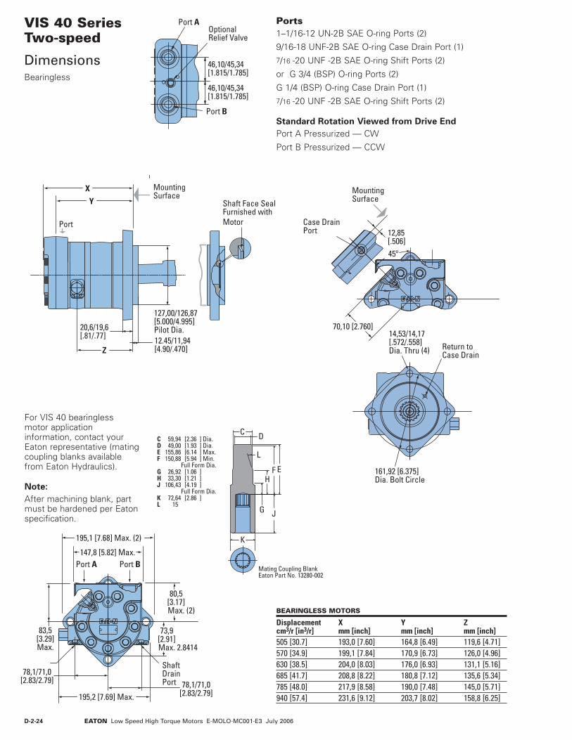
D-2-24 EATON Low Speed High Torque Motors E-MOLO-MC001-E3 July 2006
Shaft Face SealFurnished withMotorPort
XY
Z
MountingSurface
127,00/126,87[5.000/4.995]Pilot Dia.12.45/11,94[4.90/.470]
20,6/19,6[.81/.77]
VIS 40 SeriesTwo-speed
DimensionsBearingless
Ports 1–1/16-12 UN-2B SAE O-ring Ports (2)
9/16-18 UNF-2B SAE O-ring Case Drain Port (1)7/16 -20 UNF -2B SAE O-ring Shift Ports (2)
or G 3/4 (BSP) O-ring Ports (2)
G 1/4 (BSP) O-ring Case Drain Port (1)7/16 -20 UNF -2B SAE O-ring Shift Ports (2)
Standard Rotation Viewed from Drive End
Port A Pressurized — CW
Port B Pressurized — CCW
For VIS 40 bearingless motor application information, contact your Eaton representative (mating coupling blanks available from Eaton Hydraulics).
Note:
After machining blank, part must be hardened per Eaton specification.
BEARINGLESS MOTORS
Displacement X Y Zcm3/r [in3/r] mm [inch] mm [inch] mm [inch]505 [30.7] 193,0 [7.60] 164,8 [6.49] 119,6 [4.71]570 [34.9] 199,1 [7.84] 170,9 [6.73] 126,0 [4.96]630 [38.5] 204,0 [8.03] 176,0 [6.93] 131,1 [5.16]685 [41.7] 208,8 [8.22] 180,8 [7.12] 135,6 [5.34]785 [48.0] 217,9 [8.58] 190,0 [7.48] 145,0 [5.71]940 [57.4] 231,6 [9.12] 203,7 [8.02] 158,8 [6.25]
Port A Port B147,8 [5.82] Max.
80,5[3.17]Max. (2)
83,5[3.29]Max.
195,2 [7.69] Max.
78,1/71,0[2.83/2.79] 78,1/71,0
[2.83/2.79]
ShaftDrainPort
195,1 [7.68] Max. (2)
73,9[2.91]Max. 2.8414
MountingSurface
45º
Case DrainPort 12,85
[.506]
70,10 [2.760]
Return toCase Drain
14,53/14,17[.572/.558]Dia. Thru (4)
161,92 [6.375]Dia. Bolt Circle
46,10/45,34[1.815/1.785]
46,10/45,34[1.815/1.785]
Port B
Port A OptionalRelief Valve
EF
G
H
L
C D
J
K
Mating Coupling BlankEaton Part No. 13280-002
C 59,94 [2.36 ] Dia.D 49,00 [1.93 ] Dia.E 155,86 [6.14 ] Max.F 150,88 [5.94 ] Min. Full Form Dia.G 26,92 [1.06 ]H 33,30 [1.21 ] J 106,43 [4.19 ] Full Form Dia.K 72,64 [2.86 ] L 15

D-2-25EATON Low Speed High Torque Motors E-MOLO-MC001-E3 July 2006
Circular
Major
MinorTip R.
Fillet R.Pitch
Form
Finish
Finish
45322X
3
4
2,5 (100)
66,83 ±0,25[2.631 ±.010]
39.88 ±0,25[1.570 ±.010]
55º ±5º
49,84 ±0,25[1.962 ±.010]
45º ±5º x 0,38 ±0,25 [.015 ±.010]or R 0,38 ±0,25 [.015± .010]
68,96 ±0,51[2.715 ±.020]Coupling Length
4.83 ±0,25[.190 ±.010] Oil Hole
-H-
31,0 ±0,25 [1.220 ±.010]
3,17 [.125] Max.Undercut
52,37[2.062]Min.
R 1,5±0,3[.06 ±.01]
R 1,5 ±0,3[.06 ±.01]
-G-
Oil Flow Path Thru Splineand Bearing(s)
Spline
Oil Flow Return to Case Drain
Case Drain
Spline Pitch .............................................................................................. 8.5/17 Pressure Angle .............................................................................................30° Number of teeth .............................................................................................12 Class of Fit .................................................................................................Ref. 5 Type of Fit ....................................................................................................Side Pitch Diameter ..................... Ref. 35,858823 [1.4117647] 0,20 [.008] | HBase Diameter ......................................................Ref. 31,054652 [1.2226241] Major Diameter .................................. 39,17 [1.542] Max. 38,97 [1.534] Min. Minor Diameter .....................................................33,30 -33,48 [1.311 -1.318] Form Diameter, Min. .................................................................... 38,33 [1.509] Fillet Radius ....................................................................0,64 -0,76 [.025 -.030] Tip Radius .......................................................................0,25 -0,51 [.010 -.020] Finish ....................................................................................................... 1,6 (63) Involute Profile Variation ................................ +0,000 -0,025 [+.0000 -.0010] Total Index Variation .................................................................... 0,038 [.0015] Lead Variation ............................................................................... 0,013 [.0005] Circular Space Width: Maximum Actual ................................................................... 5,898 [.2322] Minimum Effective ................................................................ 5,804 [.2285] Maximum Effective .......................................................Ref. 5,857 [.2306] Minimum Actual ............................................................Ref. 5,834 [.2297] Dimension Between Two Pins ............Ref. 26,929 -27,084 [1.0602 -1.0663] Pin Diameter .........................................6,223 [.2450] Pins to Have 4,0 [.160] Wide Flat for Root Clearance
1 Internal spline in mating part to be per spline data. Specification material to be ASTM A304, 8620H carburize to a hardness of 60-64 HRc with case depth (to 50HRc) of 0,076 -1,27 [.030 -.050]. Dimensions apply after heat treat.
2 Mating part to have critical dimensions as shown. Oil holes must be provided and open for proper oil circulation.
3 Seal to be furnished with motor for proper oil circulation thru splines.
4 Similar to SAE “C” Four Bolt Flange.
VIS 40 SeriesTwo-speed
Installation InformationBearingless

D-2-26 EATON Low Speed High Torque Motors E-MOLO-MC001-E3 July 2006
VIS 40 SeriesTwo-speed
Product NumbersClosed Loop
Use digit prefix —176-, 178-, or 182- plus four digit number from charts for complete product number—Example 176-0022.
Orders will not be accepted without three digit prefix.
Note:
The product numbers on this page are for motors used in closed loop circuits. They include a back-pressure relief valve that is set at 4,5 bar [65 PSI].
MOUNTING SHAFT PORT SIZE DISPL. cm3/ r[in3/ r] / PRODUCT NUMBER
505 570 630 685 785 940 [30.7] [34.9] [38.5] [41.7] [48.0] [57.4] 40 mm Straight 1 1/16 -12 UNF O-ring (2) 9/16 -18 UNC Drain Port (1) 178-0021 -0022 -0023 -0024 -0025 -0026
1 1/2 inch 17 Tooth Splined 1 1/16 -12 UNF O-ring (2) 9/16 -18 UNC Drain Port (1) 178-0027 -0028 -0029 -0030 -0031 -0032
1 3/4 inch Tapered 1 1/16 -12 UNF O-ring (2) 9/16 -18 UNC Drain Port (1) 178-0033 -0034 -0035 -0036 -0037 -0038
40 mm Straight 1 1/16 -12 UNF O-ring (2) 9/16 -18 UNC Drain Port (1) 182-0002 -0003 -0004 -0005 -0006 -0007
1 1/2 inch 17 Tooth Splined 1 1/16 -12 UNF O-ring (2) 9/16 -18 UNC Drain Port (1) 182-0008 -0009 -0010 -0011 -0012 -0013
1 3/4 inch Tapered 1 1/16 -12 UNF O-ring (2) 9/16 -18 UNC Drain Port (1) 182-0014 -0015 -0016 -0017 -0018 -0019
1 1/16 -12 UNF O-ring (2) 9/16 -18 UNC Drain Port (1) 176-0019 -0020 -0021 -0022 -0023 -0024
Standard
Bearingless
Wheel
176-0022
MOUNTING SHAFT PORT SIZE DISPL. cm3/ r[in3/ r] / PRODUCT NUMBER
505 570 630 685 785 940 [30.7] [34.9] [38.5] [41.7] [48.0] [57.4] 40 mm Straight G 3/4 (BSP) (2) G 1/4 (BSP) Drain Port (1) 178-0057 -0058 -0059 -0060 -0061 -0062
45 mm Tapered G 3/4 (BSP) (2) G 1/4 (BSP) Drain Port (1) 178-0063 -0064 -0065 -0066 -0067 -0068
1 1/2 inch 17 Tooth Splined G 3/4 (BSP) (2) G 1/4 (BSP) Drain Port (1) 178-0069 -0070 -0071 -0072 -0073 -0074
40 mm Straight G 3/4 (BSP) (2) G 1/4 (BSP) Drain Port (1) 182-0020 -0021 -0022 -0023 -0024 -0025
45 mm Tapered G 3/4 (BSP) (2) G 1/4 (BSP) Drain Port (1) 182-0026 -0027 -0028 -0029 -0030 -0031
1 1/2 inch 17 Tooth Splined G 3/4 (BSP) (2) G 1/4 (BSP) Drain Port (1) 182-0032 -0033 -0034 -0035 -0036 -0037
G 3/4 (BSP) (2) G 1/4 (BSP) Drain Port (1) 176-0025 -0026 -0027 -0028 -0029 -0030
Standard
Bearingless
Wheel
SAE
ISO
176-0028
MOUNTING SHAFT PORT SIZE DISPL. cm3/ r[in3/ r] / PRODUCT NUMBER
505 570 630 685 785 940 [30.7] [34.9] [38.5] [41.7] [48.0] [57.4] 40 mm Straight 1 1/16 -12 UNF O-ring (2) 9/16 -18 UNC Drain Port (1) 178-0039 -0040 -0041 -0042 -0043 -0044
46 mm 28 Tooth Splined 1 1/16 -12 UNF O-ring (2) 9/16 -18 UNC Drain Port (1) 1178-0045 -0046 -0047 -0048 -0049 -0050
1 3/4 inch Tapered 1 1/16 -12 UNF O-ring (2) 9/16 -18 UNC Drain Port (1) 178-0051 -0052 -0053 -0054 -0055 -0056
Standard
Oversize
• A case drain is required for all closed loop VIS motor applications.
• The maximum case pres-sure for the VIS motor is 3,5 bar [50 PSI].

D-2-27EATON Low Speed High Torque Motors E-MOLO-MC001-E3 July 2006
VIS 40 SeriesTwo-speed
Model Code
1 , 2 , 3 Product Series
ADT – VIS 40- Two-speed Motor
4 , 5 Displacement – cm3/r [in3/r]
20 – 325 [19.8]
31 – 505 [30.7]
35 – 570 [34.9]
38 – 630 [38.5]
42 – 685 [41.7]
48 – 785 [48.0]
57 – 940 [57.4]
6 Mounting Type
A – 4 Bolt Bearingless 127,00 [5.000] Pilot Dia. with 12,19 [.480] Pilot Length and 14,35 [.565] Dia holes on 161,92 [6.375] Dia. Bolt Circle
B – 4 Bolt Wheel Mount 160,00 [6.3] Pilot Dia. With 5,8 [.23] Pilot Length and 18,00 [.709] Dia. Holes on 200,00 [7.874] Dia. Bolt Circle (ISO Compatible)
C – 4 Bolt Oversize Flange 185,4 [7.30] Rear Pilot Dia., 169,90 [6.689], 139,93 [5.509], 127,0 [5.00] Dia (Front Pilots) and 18,01 [.709] Dia. Holes on 224,00 [8.819] Dia. Bolt Circle
F – 4 Bolt Standard Mount (SAE CC) 127,00 [5.000] Pilot Dia. With 12,2 [.48] Pilot Length and 14,32 [.564] Dia. Holes on 161,92 [6.375] Dia. Bolt Circle
G – 4 Bolt Wheel Mount 139,7 [5.50] Pilot Dia. with 7,9 [.31] Pilot Length and 14,32 [.564] Dia. Holes on 184,15 [7.250] Dia. Bolt Circle (SAE Compatible)
H – 4 Bolt Standard Mount 125,00 [4.92] Pilot Dia. With 8,9 [.35] Pilot Length and 14,00 [.551] Dia. Holes on 160,00 [6.299] Dia. Bolt Circle (ISO Compatible)
7 , 8 Output Shaft
00 – None (Bearingless)
01 – 45 mm Dia. 10:1 Tapered Shaft Per ISO R775 with M30X2-6H Threaded Shaft End, 12W X 8H X 28L [.472W X .313H X 1.102L] Key
02 – 1-3/4 inch Dia. .125:1 Tapered Shaft Per SAE J501 with 1-1/4 - 18 UNEF-2A Threaded Shaft End, 11,11 [.4375] Square X 31,8 [1.25] Straight Key
04 – 46 mm Dia. Flat Root Side Fit, 28 Tooth, 16/32 DP 30 Degree Involute Spline, 93,0 [3.66] Minimum Ful Spline with M16 X 2,0-6H Thread in End
07 – 40 mm Dia. Straight Shaft with M12 X 1,75-6H Thread in End, 12W X 8H X 63L [.472W X .313H X 2.480L] Key (SAE Compatible)
08 – 1-1/2 inch Dia. Flat Root Side Fit, 17 Tooth, 12/24 DP 30 Degree Involute Spline, 39,1 [1.54] Minimum Full Spline with 3/8-16 UNC-2B Thread in End (SAE Compatible)
09 – 1-1/2 inch Dia. Flat Root Side Fit, 17 Tooth, 12/24 DP 30 Degree Involute Spline, 56,6 [2.23] Minimum Full Spline with M12 X 1.75-6H Thread in End (ISO Compatible)
10 – 40 mm Dia. Straight Shaft with M12 X 1,75-6H Thread in End, 12W X 8H X 67L [.472W X .313H X 2.630L] Key (ISO Compatible)
9 Ports
A – 1–1/16-12 UN-2B Size 12 O-ring Port, Accepts Fittings for SAE J1926
B – G 3/4 (BSP) Straight Thread Port
10 Case Flow Options
A – Shuttle Valve with 9/16-18 UNF-2B, Size 6 O-ring Port Case Drain, Accepts Fittings for SAE J1926
B – Shuttle Valve with G 1/4 (BSP) Straight Thread Port Case Drain
11 Back-Pressure Relief
1 – Set at 4,5 bar [65 PSI] (for Manual Pumps)
2 – Set at 15,2 bar [220 PSI] (for Servo Pumps)
4 – Set at 15,2 bar [300 PSI] (for high charge Servo Pumps)
12 , 13 Special Features
00 – None
14 – Paint/ SpecialPackaging
0 – No Paint, Individual Box
A – Painted Low Gloss Black, Individual Box
B – No Paint, Bulk Box Option
C – Painted Low Gloss Black, Bulk Box Option
15 – Eaton Assigned Code when Applicable
0 – Assigned Code
16 – Eaton Assigned Design Code
C – Assigned Design Code
321
A D T * * * * * * * * 0 0 * 0 C
54 6 87 9 10 11 12 13 14 15
The following 16 - digit coding system has been developed to identify all of the configuration options for the VIS 40 two-speed motor. Use this model code to specify a motor with the desired features. All 16 digits of the code must be present when ordering. You may want to photocopy the matrix below to ensure that each number is entered in the correct box.
16
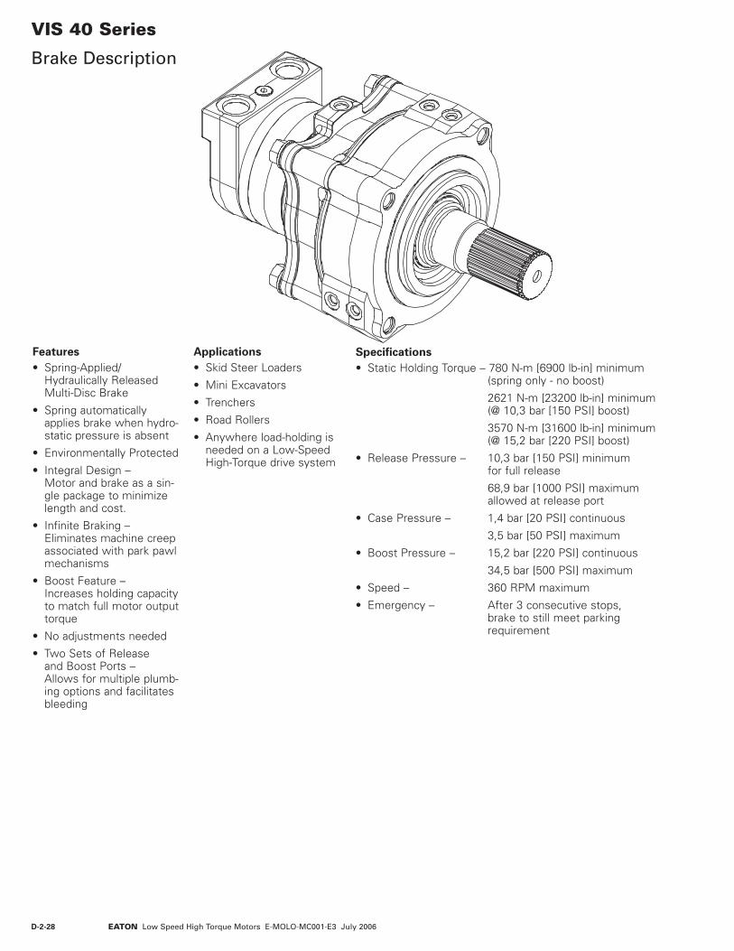
D-2-28 EATON Low Speed High Torque Motors E-MOLO-MC001-E3 July 2006
VIS 40 Series
Brake Description
Features
• Spring-Applied/Hydraulically Released Multi-Disc Brake
• Spring automatically applies brake when hydro-static pressure is absent
• Environmentally Protected
• Integral Design – Motor and brake as a sin-gle package to minimize length and cost.
• Infinite Braking – Eliminates machine creep associated with park pawl mechanisms
• Boost Feature – Increases holding capacity to match full motor output torque
• No adjustments needed
• Two Sets of Release and Boost Ports – Allows for multiple plumb-ing options and facilitates bleeding
Applications
• Skid Steer Loaders
• Mini Excavators
• Trenchers
• Road Rollers
• Anywhere load-holding is needed on a Low-Speed High-Torque drive system
Specifications
• Static Holding Torque – 780 N-m [6900 lb-in] minimum (spring only - no boost)
2621 N-m [23200 lb-in] minimum (@ 10,3 bar [150 PSI] boost)
3570 N-m [31600 lb-in] minimum (@ 15,2 bar [220 PSI] boost)
• Release Pressure – 10,3 bar [150 PSI] minimum for full release
68,9 bar [1000 PSI] maximum allowed at release port
• Case Pressure – 1,4 bar [20 PSI] continuous
3,5 bar [50 PSI] maximum
• Boost Pressure – 15,2 bar [220 PSI] continuous
34,5 bar [500 PSI] maximum
• Speed – 360 RPM maximum
• Emergency – After 3 consecutive stops, brake to still meet parking requirement

D-2-29EATON Low Speed High Torque Motors E-MOLO-MC001-E3 July 2006
VIS 40 Series
Brake Dimensions
X
Y
134,14/133,38 [5.281/5.251]
B
A
4,54/4,04 [.179/.159]
2 X 26,3/25,5 [1.04/1.00]
2 X 56,8/56,0[2.24/2.22]
Port A
Port B
2X Shift Port
Z
Boost Port (2)
Case DrainPort
222,7 [8.77] Max.
2 X 213,1[8.39] Max.
4 X M16 x 2-6 HThreaded Hole
224,00 [8.819]Dia. B.C.
169,85/169,65[6.687/6.679]Dia.
140,00/139,88[5.5120/5.5070] Pilot Dia.
Release Port (2)
BRAKE MOTORS (TWO-SPEED)
Displacement X Y Zcm3/r [in3/r] mm [inch] mm [inch] mm [inch]505 [30.7] 301,9 [11.88] 274,7 [10.82] 229,3 [9.03]570 [34.9] 308,0 [12.12] 280,9 [11.06] 235,5 [9.27]630 [38.5] 313,1 [12.32] 285,9 [11.27] 238,5 [9.27]685 [41.7] 317,9 [12.52] 290,7 [11.45] 245,3 [9.66]785 [48.0] 327,0 [12.88] 300,0 [11.80] 254,6 [10.02]940 [57.4] 340,7 [13.42] 313,7 [12.35] 268,3 [10.56]
BRAKE MOTORS (SINGLE-SPEED)
Displacement A Bcm3/r [in3/r] mm [inch] mm [inch]505 [30.7] 238,7 [9.40] 265,9 [10.47]570 [34.9] 244,9 [9.64] 272,1 [10.71]630 [38.5] 250,1 [9.85] 277,3 [10.92]685 [41.7] 254,7 [10.04] 281,9 [11.10]785 [48.0] 264,0 [10.40] 291,2 [11.46]940 [57.4] 277,7 [10.94] 304,9 [12.00]
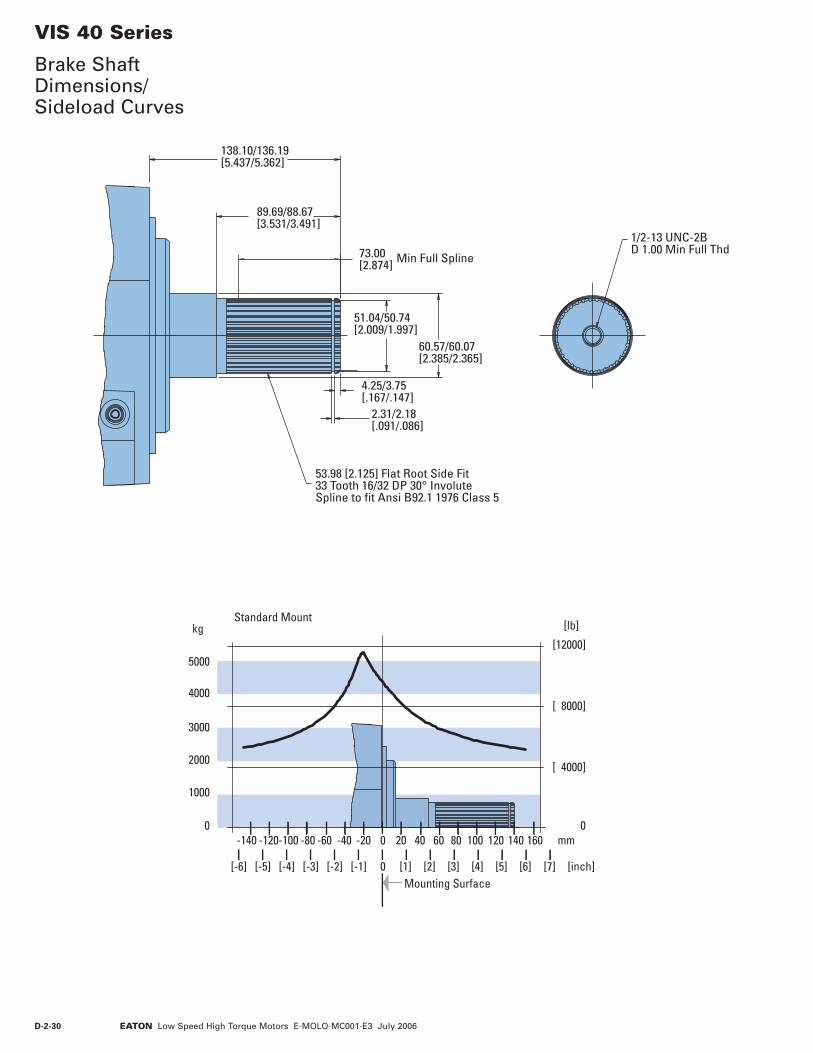
D-2-30 EATON Low Speed High Torque Motors E-MOLO-MC001-E3 July 2006
VIS 40 Series
Brake Shaft Dimensions/ Sideload Curves
1/2-13 UNC-2BD 1.00 Min Full Thd 73.00
[2.874] Min Full Spline
53.98 [2.125] Flat Root Side Fit33 Tooth 16/32 DP 30° InvoluteSpline to fit Ansi B92.1 1976 Class 5
51.04/50.74[2.009/1.997]
2.31/2.18[.091/.086]
4.25/3.75[.167/.147]
89.69/88.67[3.531/3.491]
138.10/136.19[5.437/5.362]
60.57/60.07[2.385/2.365]
Standard Mount
0
[ 4000]
[ 8000]
[12000]
0
1000
2000
3000
4000
5000
[lb]kg
[inch]
mm
Mounting Surface
0
0 [1] [2] [3] [4] [5] [6] [7][-6] [-5] [-4] [-3] [-2] [-1]
20 40 60 80 100 140 160120-120-140 -80-100 -60 -40 -20
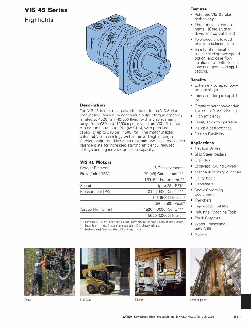
D-3-1EATON Low Speed High Torque Motors E-MOLO-MC001-E3 July 2006
DescriptionThe VIS 45 is the most powerful motor in the VIS Series product line. Maximum continuous output torque capability is rated to 4520 Nm [40,000 lb-in.] with a displacement range from 630cc to 1560cc per revolution. VIS 45 motors can be run up to 170 LPM [45 GPM] with pressure capability up to 310 bar [4500 PSI]. The motor utilizes patented VIS technology with improved high-strength Geroler, optimized drive geometry, and two-piece pre-loaded balance plate for increased starting efficiency, reduced leakage and higher back pressure capacity.
Skid Steer InjectorAuger
VIS 45 Series
Highlights
Features
• Patented VIS Geroler technology
• Three moving compo-nents: (Geroler‚ star, drive, and output shaft)
• Two-piece pre-loaded pressure balance plate
• Variety of optional fea-tures including two-speed option, and case flow solutions for both closed-loop and open-loop appli-cations.
Benefits
• Extremely compact pow-erful package
• Increased torque capabil-ity
• Greatest horsepower den-sity in the VIS motor line
• High efficiency
• Quiet, smooth operation
• Reliable performance
• Design Flexibility
Applications
• Traction Drives
• Skid Steer loaders
• Grapples
• Excavator Swing Drives
• Marine & Military Winches
• Utility Reels
• Harvesters
• Snow Grooming Equipment
• Trenchers
• Piggy-back Forklifts
• Industrial Machine Tools
• Truck Grapples
• Wood Processing – Saw Mills
• Augers
VIS 45 MotorsGeroler Element 5 Displacements
Flow l/min [GPM] 170 [45] Continuous***
189 [50] Intermittent**
Speed Up to 284 RPM
Pressure bar [PSI] 310 [4500] Cont.***
345 [5000] Inter.**
380 [5500] Peak*
Torque Nm [lb - in] 4520 [40000] Cont.***
5650 [50000] Inter.**
*** Continuous— (Cont.) Continuous rating, motor may be run continuously at these ratings.** Intermittent— (Inter.) Intermittent operation, 10% of every minute.* Peak— (Peak) Peak operation, 1% of every minute.
Port Equipment

D-3-2 EATON Low Speed High Torque Motors E-MOLO-MC001-E3 July 2006
VIS 45 Series
SpecificationsEnd Cap
Seals MountingFlange
OutputShaft
Geroler ®Drive
Rear Bearing(Oil Lubricated)
Seal Guard
ShuttleValve
Front Bearing(Grease Packed)
Back-pressureRelief Valve
Valve Plate
Maximum Inlet Pressure:
400 bar [5800 PSI]
Do Not Exceed A Pressure Rating (for displacement size see chart above).
Return Pressure (Back-Pressure):
Minimum – 3,5 bar [50 PSI]
Maximum – 21 bar [300 PSI]
Note:
Return (back-pressure) must be 3,5 bar [50 PSI] greater than the case pressure.
∆ Pressure:
The true ∆ bar [∆ PSI] between inlet port and outlet port
Case Pressure:
Minimum – No Pressure
Maximum – 3,5 bar [50 PSI]
Note:
The case must be full when the motor is operating. A case drain is recommended.
Continuous Rating:
Motor may be run continuously at these ratings
Intermittent Operation:
10% of every minute
Peak Operation:
1% of every minute
Recommended Fluids:
Premium quality, anti-wear type hydraulic oil with a viscosity of not less than 70 SUS at operating temperature.
Recommended Maximum System Operating Temp.:
82° C [180° F]
Recommended Filtration:
Per ISO Cleanliness Code, 4406: 20/18/13
Shuttle:
Standard
Back-Pressure Relief Valve:
Required for closed loop circuit.
SPECIFICATION DATA — VIS 45 SERIES MOTORS
Displ. cm3/r [in3/r] 630 [38.6] 805 [48.6] 990 [60.5] 1245 [76.0] 1560 [95.0]Max. Speed Continuous 256 198 164 129 104(RPM) Intermittent 284 220 183 143 115@ FlowFlow l/min Continuous 170 [45] 170 [45] 170 [45] 170 [45] 170 [45] [GPM] Intermittent 189 [50] 189 [50] 189 [50] 189 [50] 189 [50] Torque Continuous 2963 [26080] 3555 [31460] 4052 [35860] 4520 [40000] 4520 [40000]Nm [lb-in] Intermittent 3111 [27530] 3722 [32940] 4549 [40269] 5376 [47592] 5650 [50000]Pressure Continuous 310 [4500] 310 [4500] 258 [3740] 205 [2975] 164 [2380] ∆ bar Intermittent 345 [5000] 345 [5000] 322 [4675] 256 [3720] 205 [2975] [∆ PSI] Peak 379 [5500] 379 [5500] 379 [5500] 308 [4465] 246 [3570]Weight Standard or 53,8 [118.7] 55,2 [121.6] 56,7 [125.0] 58,7 [129.4] 61,2 [134.9]kg [lb] Wheel Mount Bearingless 28,3 [62.3] 29,6 [65.2] 31,1 [68.6] 33,1 [73.0] 35,6 [78.5]Weight Two-speed Standard or 58,5 [128.9] 59,8 [131.8] 61,3 [135.2] 63,3 [139.6] 65,8 [145.1]kg [lb] Wheel Mount Two-speed Bearingless 32,9 [72.5] 34,2 [75.4] 35,7 [78.8] 37,7 [83.2] 40,2 [88.7]
A simultaneous maximum torque and maximum speed NOT recommended.
Note:
To assure best motor life, run motor for approximately one hour at 30% of rated pressure before application to full load. Be sure motor is filled with fluid prior to any load applications.

D-3-3EATON Low Speed High Torque Motors E-MOLO-MC001-E3 July 2006
250 500 1000 1500 2000 2500 3000 3500 4000 4500 5000
250 500 1000 1500 2000 2500 3000 3500 4000 4500 5000
15 35 70 105 140 170 205 240 275 310 345
15 35 70 105 140 170 205 240 275 310 345
4 1270 2710 5530 8250 10300 12900 15540 17720 20820 23640 25740
4 1600 3350 7180 10670 13480 16640 19680 21740 25860 28500 31720
144 306 625 932 1164 1458 1756 2002 2353 2671 2909
181 379 811 1206 1523 1880 2224 2457 2922 3221 3584
15 23 23 23 22 22 21 20 19 18 17 15
15 19 18 17 17 17 17 16 15 14 13 12
8 1290 2720 5580 8290 10490 13110 15760 18070 21000 24100 26070
8 1620 3380 7240 10730 13740 16920 19950 22160 25920 28970 32200
146 307 631 937 1185 1481 1781 2042 2373 2723 2946
183 382 818 1212 1553 1912 2254 2504 2929 3274 3639
30 47 45 45 45 45 44 43 41 38 36 34
30 38 36 35 34 34 34 34 34 32 31 29
12 1310 2670 5440 8320 10820 13400 16370 18970 21230 24540 26840
12 1640 3310 7180 10770 14170 17290 20730 23270 26340 29420 32470
148 302 615 940 1223 1514 1850 2144 2399 2773 3033
185 374 811 1217 1601 1954 2342 2630 2976 3324 3669
45 71 68 68 67 67 66 64 62 61 58 54
45 56 55 52 52 51 51 50 50 49 47 45
16 1320 2600 5400 8250 10910 13730 16780 19710 21970 24870 27530
16 1660 3220 7010 10680 14290 17710 21240 24170 26830 30340 32940
149 294 610 932 1233 1551 1896 2227 2483 2810 3111
188 364 792 1207 1615 2001 2400 2731 3032 3428 3722
61 95 91 91 89 89 88 85 83 81 77 72
61 76 74 71 70 69 69 68 68 67 64 60
20 1290 2500 5270 8020 10690 13400 16730 20020 22320 25420
20 1600 3110 6840 10380 14000 17290 20990 24490 27270 31390
146 283 596 906 1208 1514 1890 2262 2522 2872
181 351 773 1173 1582 1954 2372 2767 3082 3547
76 119 114 114 113 113 111 108 104 103 97
76 95 92 88 87 86 86 85 85 84 80
24 1240 2440 5200 7920 10560 13430 16700 19970 22610 25730
24 1560 3030 6750 10250 13830 17340 21110 24450 27620 31460
140 276 588 895 1193 1518 1887 2257 2555 2907
176 342 763 1158 1563 1959 2385 2763 3121 3555
91 143 137 137 135 135 133 129 125 123 117
91 114 110 105 104 103 103 102 102 101 96
28 2190 5050 7870 10520 13480 16660 19860 22450 26080
28 2720 6560 10190 13780 17390 21090 24360 27420 31238
247 571 889 1189 1523 1883 2244 2537 2963
307 741 1151 1557 1965 2383 2753 3098 3529
106 160 160 157 157 155 150 146 143 136
106 128 123 121 120 120 119 119 117 111
32 2110 4870 7720 10300 13230 16370 19720 22320 25986
32 2620 6330 10000 13480 17070 20730 24180 27270 31064
238 550 872 1164 1495 1850 2228 2522 2936
296 715 1130 1523 1929 2342 2732 3082 3509
121 182 182 180 180 177 172 166 164 156
121 147 140 139 137 137 135 135 134 127
36 2090 4550 7330 10030 12890 15960 19220 22040 25655
36 2620 5910 9480 13140 16640 20200 23570 26910 30646
236 514 828 1133 1457 1803 2172 2491 2898
296 668 1071 1485 1880 2283 2663 3041 3462
136 205 205 202 202 199 193 187 184 175
136 165 158 156 154 154 152 152 150 143
40 4150 7120 9760 12490 15560 18820 21600 25185
40 5390 9220 12790 16120 19700 23080 26343 30019
469 805 1103 1411 1758 2127 2441 2845
609 1042 1445 1822 2226 2608 2976 3391
151 228 224 224 221 214 208 204 194
151 175 173 171 171 169 169 167 159
45 3970 6930 9500 12230 15340 18470 21207 24742
45 5150 8970 12450 15780 19420 22650 25848 29462
449 783 1074 1382 1733 2087 2396 2795
582 1014 1407 1783 2194 2559 2920 3328
170 256 252 252 249 241 234 229 218
170 198 196 193 193 191 191 189 179
50 3680 6660 9270 11920 15150 18300
50 4770 8610 12140 15380 19180 22440
416 753 1048 1347 1712 2068
539 973 1372 1738 2167 2536
189 284 280 280 276 268 259
189 220 217 215 215 212 212
Δ Pressure Bar [PSI]630 cm3/r [38.6 in3/r]
Flo
w L
PM
[G
PM
]
Torque [lb-in] NmSpeed RPM
}[9270]1048280
Δ Pressure Bar [PSI]805 cm3/r [48.6 in3/r]
Flo
w L
PM
[G
PM
]
VIS 45 Series
Performance DataMotors run with high efficiency in all areas designated with a number for torque and speed. For best motor life select a motor to run with a torque and speed range shown in the light shaded area.
Performance data is typical at 120 SUS. Actual data may vary slightly from unit to unit in production.
Continuous
Intermittent

D-3-4 EATON Low Speed High Torque Motors E-MOLO-MC001-E3 July 2006
250 500 1000 1500 2000 2500 3000 3500 4000 4500 4750
250 500 1000 1500 2000 2500 3000 3500 4000 4250
15 35 70 105 140 170 205 240 275 310 330
15 35 70 105 140 170 205 240 275 295
4 2000 4100 8630 12620 16050 20080 24150 28320 32590 35150 37040
4 2160 4800 9960 15150 20200 26450 30670 39180 42800 43220
226 463 975 1426 1814 2269 2729 3200 3683 3972 4186
244 542 1125 1712 2283 2989 3466 4427 4836 4884
15 15 15 15 15 14 14 14 13 12 11 10
15 12 11 11 11 11 10 10 9 9 9
8 2020 4130 8700 12740 16350 20420 24480 28400 32850 35670 37250
8 2250 4830 10370 15760 22010 27180 33330 39840 43660 44400
228 467 983 1440 1848 2307 2766 3209 3712 4031 4209
254 546 1172 1781 2487 3071 3766 4502 4934 5017
30 30 30 29 29 29 28 28 27 25 25 24
30 24 23 22 22 21 20 20 19 19 19
12 2050 4050 8630 12780 16870 20860 25440 28550 32920 35860 37630
12 2400 5390 10910 17290 22780 28470 34170 40140 44160 47220
232 458 975 1444 1906 2357 2875 3226 3720 4052 4252
271 609 1233 1954 2574 3217 3861 4536 4990 5336
45 45 45 44 44 43 43 41 41 41 40 39
45 36 33 33 32 32 32 32 31 31 30
16 2070 3940 8420 12680 17010 21380 26070 29660 33020 36620 38439
16 2410 5150 10930 16970 22880 28600 33900 39500 44510 47592
234 445 951 1433 1922 2416 2946 3352 3731 4138 4342
272 582 1235 1918 2585 3232 3831 4464 5030 5376
61 61 60 58 58 58 57 55 55 54 53 52
61 48 46 45 44 43 43 43 42 41 40
20 2000 3800 8220 12330 16660 20860 25760 30060 33550 37880 39766
20 2350 4890 10650 16470 21960 27450 33130 37710 43890 46933
226 429 929 1393 1883 2357 2911 3397 3791 4280 4492
266 553 1203 1861 2481 3102 3744 4261 4960 5302
76 76 75 73 73 72 71 69 69 68 66 64
76 60 59 57 56 56 56 55 55 54 52
24 1950 3700 8120 12180 16460 20890 25820 30090 33990 38366 40269
24 2190 4760 10460 15920 21230 26530 32320 37680 42670 45673
220 418 918 1376 1860 2361 2918 3400 3841 4334 4549
247 538 1182 1799 2399 2998 3652 4258 4822 5156
91 91 90 88 88 86 85 83 83 82 80 78
91 72 70 68 67 67 67 66 66 65 63
28 3320 7880 12100 16400 20990 25890 29900 33750 39106 39995
28 1990 4260 10070 15860 21200 26420 32480 37500 42464 45418
375 890 1367 1853 2372 2926 3379 3814 4280 4518
225 481 1138 1792 2396 2985 3670 4238 4797 5131
106 105 102 102 101 99 97 97 95 92 90
106 85 82 80 78 78 78 77 77 76 74
32 3210 7610 11870 16050 20600 25440 29680 33550 37890 39766
32 4100 9770 15410 20770 26300 31920 37240 42167 45103
363 860 1341 1814 2328 2875 3354 3791 4280 4492
463 1104 1741 2347 2972 3607 4208 4764 5095
121 120 117 117 115 114 110 110 109 106 103
121 94 91 90 89 89 88 88 87 84
36 3200 7100 11260 15640 20080 24800 28930 32716 36936 38759
36 4090 9060 14650 20060 25670 31110 36295 41087 43955
362 802 1272 1767 2269 2802 3269 3696 4173 4379
462 1024 1655 2267 2901 3515 4100 4642 4966
136 135 131 131 130 128 124 124 123 119 116
136 106 103 101 101 100 99 99 98 95
40 6480 10950 15220 19460 24170 28330 32023 36155 37935
40 8300 14150 19570 24900 30320 35373 40034 42836
732 1237 1720 2199 2731 3201 3618 4084 4286
938 1599 2211 2814 3426 3996 4523 4839
151 146 146 144 142 138 138 137 133 130
151 114 113 112 111 110 110 108 105
45 6190 10650 14810 19040 23830 27952 31599 35679 37432
45 8100 13970 19310 24610 29972 34967 39570 42343
699 1203 1674 2152 2693 3158 3570 4031 4229
915 1579 2182 2781 3686 3950 4470 4783
170 164 164 162 160 155 155 154 149 145
170 129 127 126 125 124 124 122 118
50 5740 10230 14450 18570 23540
50 7900 13790 19050 24310
649 1156 1633 2098 2660
893 1558 2153 2747
189 183 183 180 178 173
189 143 141 140 139
Δ Pressure Bar [PSI]1245 cm3/r [76.0 in3/r]
Flo
w L
PM
[G
PM
]
Δ Pressure Bar [PSI]990 cm3/r [60.5 in3/r]
Flo
w L
PM
[G
PM
]
Torque [lb-in] NmSpeed RPM
}[18570]
2098178
VIS 45 Series
Performance DataMotors run with high efficiency in all areas designated with a number for torque and speed. For best motor life select a motor to run with a torque and speed range shown in the light shaded area.
Performance data is typical at 120 SUS. Actual data may vary slightly from unit to unit in production.
Continuous
Intermittent

D-3-5EATON Low Speed High Torque Motors E-MOLO-MC001-E3 July 2006
VIS 45 Series
Performance DataMotors run with high efficiency in all areas designated with a number for torque and speed. For best motor life select a motor to run with a torque and speed range shown in the light shaded area.
Performance data is typical at 120 SUS. Actual data may vary slightly from unit to unit in production.
250 500 1000 1500 2000 2500 3000 3500 400015 35 70 105 140 170 205 240 275
4 2700 5670 11910 18520 24910 30860 37610 42320 48366305 641 1346 2093 2815 3487 4250 4782 5464
15 9 9
8 2810 5910 12400 19260 25590 31740 39310 44150 50457318 668 1401 2176 2892 3587 4442 4989 5700
30 19 19 18 18 18 17 16 15 15
9 9 9 8 8 8 8
12 3010 6300 13040 20490 26600 33070 39880 46670 53337340 712 1474 2315 3006 3737 4506 5274 6025
45 29 28 28 27 26 25 23 22 22
16 3020 6300 13360 20740 27270 33950 40450 48630 55577341 712 1510 2344 3082 3836 4571 5495 6279
61 38 38 37 36 35 34 31 29 29
20 2930 6150 13200 20490 27110 34830 39820 47662 54470331 695 1492 2315 3063 3936 4500 5384 6154
76 48 47 46 45 44 42 39 37 37
24 2780 5910 12880 19750 26930 34390 39310 47300 54057314 668 1455 2232 3043 3886 4442 5343 6107
91 58 56 55 54 53 50 47 44 44
28 5310 12500 19630 26600 33950 38740 46635 53297600 1413 2218 3006 3836 4378 5268 6021
106 66 64 63 62 59 55 52 52
32 5120 12070 19260 26260 33510 38180 45982 52550579 1364 2176 2967 3787 4314 5195 5937
121 75 74 72 70 67 62 58 58
36 5100 11270 18270 25590 33070 37652 45366576 1274 2065 2892 3737 4254 5125
136 85 83 81 79 76 70 66
40 10280 17760 24910 32630 37124 447501162 2007 2815 3687 4194 5055
151 92 90 88 84 78 73
45 9820 17280 24240 31793 36119 435771110 1953 2739 3592 4080 4923
170 104 101 99 95 87 82
50 9100 16600 236501028 1876 2672
189 115 113 110
Δ Pressure Bar [PSI]
1560 cm3/r [95.0 in3/r]
Flo
w L
PM
[G
PM
]
Torque [lb-in] NmSpeed RPM
}166001876113
Continuous
Intermittent

D-3-6 EATON Low Speed High Torque Motors E-MOLO-MC001-E3 July 2006
Case Drain PortSee Page XX
Port
83,9[3.30]Max.
93,5[3.68]Max.
250,1 [9.843] Dia. BC 20,83/20[.820/.80Dia. (4)
236,73/235,20[9.32/9.26] (2)
Y
X
20,6/20,0 [.81/.79]2,8/2,2 [.11/.09]
199,97/199,82[7.873/7.867]Pilot Dia.
9,14/8,64 [.36/.34]
125,64/124,36[4.945/4.895]
MountingSurface
Port A167,9 [6.61] Max.
93,5[3.58]Max.
83,9[3.30]Max.
45°
Case Drain
VIS 45 Series
DimensionsStandard Mount
STANDARD MOTORS
Displacement X Max. Ycm3/r [in3/r] mm [inch] mm [inch]630 [38.6] 260,9 [10.27] 228,6 [ 9.00]805 [48.6] 271,3 [10.68] 239,0 [ 9.41]990 [60.5] 283,7 [11.17] 251,5 [ 9.90]1245 [76.0] 299,7 [11.80] 267,7 [10.54]1560 [95.0] 319,5 [12.58] 287,5 [11.32]
Ports 1–5/16-12 UN-2B SAE O-ring Ports (2)9/16-18 UNF-2B SAE O-ring Case Drain Port (1)
Or G 1 (BSP) O-ring Ports (2)
G 1/4 (BSP) O-ring Case Drain Port (1)
Standard Rotation Viewed from Shaft End
Port A Pressurized — CW
Port B Pressurized — CCW
Port A
Port B
54,1 [2.13]
54,1 [2.13]

D-3-7EATON Low Speed High Torque Motors E-MOLO-MC001-E3 July 2006
250,01 [9.843] Dia.
200,00/199,85[7.874/7.868]Pilot Dia.
Port
9,2/8,6[.36/.34]
48,90/47,62[1.925/1.875]
20,75/20,39[.817/.803] Dia. (4)
23,2/22,6 [.91/.89]236,73/235,20[9.32/9.26] (2)
83,9[3.30]Max.
93,5[3.68]Max.
XY
MountingSurface
Case Drain Port
88,6/87,6[3.49/3.45]
150,9/149,3[5.94/5.88] R.
Port A167,9 [6.61] Max.
93,5[3.58]Max.
83,9[3.30]Max.
45°
Case Drain
VIS 45 Series
DimensionsWheel Mount
WHEEL MOTORS
Displacement X Max. Ycm3/r [in3/r] mm [inch] mm [inch] 630 [38.6] 184,2 [7.25] 151,9 [5.98] 805 [48.6] 194,6 [7.66] 162,3 [6.39]990 [60.5] 207,0 [8.15] 174,8 [6.88]1245 [76.0] 223,0 [8.78] 191,0 [7.52] 1560 [95.0] 242,8 [9.56] 210,8 [8.30]
Ports 1–5/16-12 UN-2B SAE O-ring Ports (2)9/16-18 UNF-2B SAE O-ring Case Drain Port (1)
Or G 1 (BSP) O-ring Ports (2)
G 1/4 (BSP) O-ring Case Drain Port (1)
Standard Rotation Viewed from Shaft End
Port A Pressurized — CW
Port B Pressurized — CCW
Port A
Port B
54,1 [2.13]
54,1 [2.13]

D-3-8 EATON Low Speed High Torque Motors E-MOLO-MC001-E3 July 2006
111,5[4.39]Max. (4)
4 x 10° 4 x 10°
94,5 [3.72]Max. (4)
15,2 [.60]Min. R (8)
Case Drain
190,50 [7.500]Dia. Bolt Circle
16,00/15,75[.630/.620]Dia. Thru (8)
105,7 [4.16]Max. to SpotFace
95,20[3.750](4)
15,2 [.60]Min. R (4)
223,0/221,5[8.78/8.72]Dia.
Case Drain
190,50 [7.500]Dia. Bolt Circle
17,78/17,27[.700/.680]Dia. Thru (4)
223,0/221,5[8.78/8.72]Dia.
23,11/22,61[.910/.890] (4)
9,14/8,89[.360/.350]
Port
25,40 [1.000]Case DrainPort Dim.See Page 52
83,9[3.30]Max.
158,75/158,626.250/6.245
93,5[3.68]Max.
Shaft Face SealFurnished with Motor
X Max.
Y.MountingSurface
VIS 45 Series
DimensionsBearingless
Mating Coupling BlankEaton Part No. 13521-003
C 116,3 [ 4.58 ] Dia. Max.D 111,8 [ 4.40 ] Dia. Min. E 37,64 [ 1.482] Dia.F 136,7 [ 5.38 ] Max.G 131,6 [ 5.18 ] Min. Full Form Dia.H 64,8 [ 2.55 ]J 26,4 [ 1.04 ]K 109,7 [ 4.32 ] Max.L 104,6 [ 4.12 ] Min. Full Form Dia.M 92,58 [ 3.645] Dia.N 73,28 [ 2.885] Dia. M
F
C
K L
D
EN
GH J
BEARINGLESS MOTORS
Displacement X Ycm3/r [in3/r] mm [inch] mm [inch] 630 [38.6] 161,5 [6.36] 130,3 [5.13]805 [48.6] 172,5 [6.79] 141,2 [5.56]990 [60.5] 184,4 [7.26] 153,4 [6.04]1245 [76.0] 200,7 [7.90] 169,7 [6.68]1560 [95.0] 220,5 [8.68] 189,5 [7.46]
Ports 1–5/16-12 UN-2B SAE O-ring Ports (2)9/16-18 UNF-2B SAE O-ring Case Drain Port (1)
Or G 1 (BSP) O-ring Ports (2)
G 1/4 (BSP) O-ring Case Drain Port (1)
Standard Rotation Viewed from Drive End
Port A Pressurized — CW
Port B Pressurized — CCW
For VIS 45 bearingless motor application information, contact your Eaton representative (mating coupling blanks available from Eaton Hydraulics).
Note:
After machining blank, part must be hardened per Eaton specification.
Port A
Port B
54,1 [2.13]
54,1 [2.13]
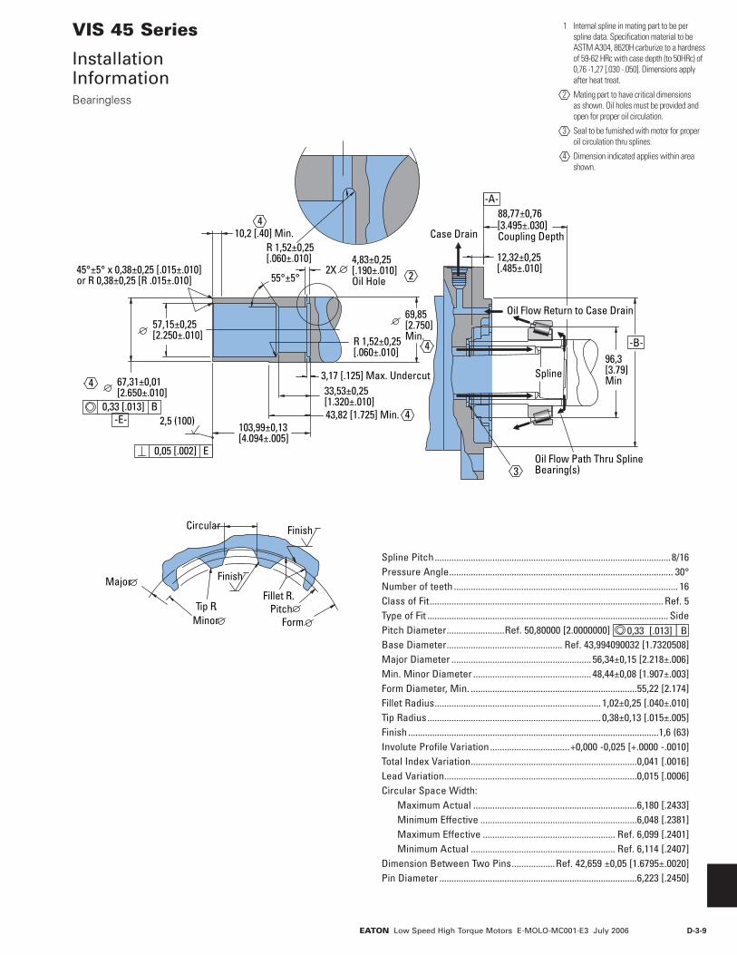
D-3-9EATON Low Speed High Torque Motors E-MOLO-MC001-E3 July 2006
2,5 (100)0,33 [.013] B
-B-96,3[3.79]Min
10,2 [.40] Min.
4,83±0,25[.190±.010]Oil Hole55°±5°
45°±5° x 0,38±0,25 [.015±.010]or R 0,38±0,25 [R .015±.010]
57,15±0,25[2.250±.010] R 1,52±0,25
[.060±.010]
69,85[2.750]Min.
12,32±0,25[.485±.010]
88,77±0,76[3.495±.030]Coupling Depth
3,17 [.125] Max. Undercut
43,82 [1.725] Min.103,99±0,13[4.094±.005]
33,53±0,25[1.320±.010]
67,31±0,01[2.650±.010]
-E-
-A-
0,05 [.002] E
Circular
Major
MinorTip R.
Fillet R.Pitch
Form
Finish
Finish
4
4
4
4
2
3Oil Flow Path Thru SplineBearing(s)
Oil Flow Return to Case Drain
Spline
Case DrainR 1,52±0,25[.060±.010]
2X
VIS 45 Series
Installation InformationBearingless
Spline Pitch ..................................................................................................8/16Pressure Angle ............................................................................................. 30° Number of teeth ............................................................................................. 16 Class of Fit ................................................................................................. Ref. 5 Type of Fit .................................................................................................... SidePitch Diameter ........................Ref. 50,80000 [2.0000000] 0,33 [.013] | B Base Diameter ................................................ Ref. 43,994090032 [1.7320508] Major Diameter .......................................................... 56,34±0,15 [2.218±.006] Min. Minor Diameter ................................................. 48,44±0,08 [1.907±.003] Form Diameter, Min. .....................................................................55,22 [2.174]Fillet Radius ..................................................................... 1,02±0,25 [.040±.010]Tip Radius ........................................................................ 0,38±0,13 [.015±.005] Finish ........................................................................................................1,6 (63) Involute Profile Variation .................................+0,000 -0,025 [+.0000 -.0010] Total Index Variation .....................................................................0,041 [.0016] Lead Variation ................................................................................0,015 [.0006] Circular Space Width: Maximum Actual ....................................................................6,180 [.2433] Minimum Effective .................................................................6,048 [.2381] Maximum Effective ....................................................... Ref. 6,099 [.2401] Minimum Actual ............................................................ Ref. 6,114 [.2407] Dimension Between Two Pins ..................Ref. 42,659 ±0,05 [1.6795±.0020] Pin Diameter ..................................................................................6,223 [.2450]
1 Internal spline in mating part to be per spline data. Specification material to be ASTM A304, 8620H carburize to a hardness of 59-62 HRc with case depth (to 50HRc) of 0,76 -1,27 [.030 -.050]. Dimensions apply after heat treat.
2 Mating part to have critical dimensions as shown. Oil holes must be provided and open for proper oil circulation.
3 Seal to be furnished with motor for proper oil circulation thru splines.
4 Dimension indicated applies within area shown.

D-3-10 EATON Low Speed High Torque Motors E-MOLO-MC001-E3 July 2006
Standard Mount
45,7 [1.80]Min. Full Spline
72,26/71,75[2.845/2.825]
74,42/72,90[2.930/2.870]
85,85/84,33[3.380/3.320]
70,0 [2.76] 22 Tooth3 Modulus Per Din 5480
M16 x 1.531,8 [1.25]Min. Full Thread
MountingSurface
70 mm 22 Tooth Splined
Standard Mount
52,07 [2.050]Min. Full Spline
89,40 [3.520] MaxCoupling Engagement
69,85 [2.750] Dia. Flat Root Side Fit32 Tooth 12/24 DP 30 Involute SplinePer ANSI B92.1 - 1970
5/8-18 UNF - 2B30,3/29,7 [1.19/1.17] Full Thread Depth
106,55/105,03[4.195/4.135]
MountingSurface
2–3/4 Inch32 Tooth Splined
VIS 45 Series
Dimensions ShaftsSplined

D-3-11EATON Low Speed High Torque Motors E-MOLO-MC001-E3 July 2006
Standard Mount
Wheel Mount
81,8/80,8[3.22/3.18]
66,675/66,655[2.6250/2.6242]
3,3 [.13]R Max.
106,55/105,03[4.195/4.135]
95,00/93,47[3.74/3.68]
89,4[3.52] Max
15,90/15,87[626/.625] Square
73,58/73,33[2.897/2.887]
5/8-18 UNF - 2B30,3/29,7 [1.19/1.17]Full Thread Depth
183,1/181,6[7.21/7.15]
MountingSurface
MountingSurface
2–5/8 Inch Straight
Note:
For motor torque ratings above 4010 Nm [35500 lb - in] use split coupler.
60 mm Tapered
VIS 45 Series
Dimensions ShaftsKeyed
Standard Mount
Wheel Mount8,25/7,75[.325/.305]Dia. Thru
121,59/120,06[4.787/4.727]
32,25/31,75[1.270/1.250]
16,36/14,83[.644/.584]
30,2/29,8[1.19/1.17]
60,04/60,00[2.364/2.362]
10:1 Taper ISO R775
16,020/15,980[.6307/.6291]
32,34/32,18[1.273/1.267]
65,38/64,62[2.574/2.544]
M42 x 3 - 6H
93,06/91,54[3.664/3.604]
198,30/196,77[7.807/7.747]
MountingSurface
MountingSurface
Slotted Hex Nut Torque:Dry — 1200 Nm [900 lb-ft]Lubricated — 900 Nm [670 lb-ft]Plus Torque Required to Align the Slotted Nut with Crosshole.

D-3-12 EATON Low Speed High Torque Motors E-MOLO-MC001-E3 July 2006
VIS 45 Series
Side Load Capacity
These curves indicate the radial load capacity on the motor shaft(s) at various locations.
The curve is based on B 10 bearing life (2000 hours or 12,000,000 shaft revolutions at 100 RPM) at rated output torque. To determine radial load at speeds other than 100 RPM, multiply the load values given on the bearing curve by the factors in the chart below.
RPM Multiplication Factor 50 1.23 100 1.00 200 0.81 300 0.72 400 0.66 500 0.62 600 0.58 700 0.56 800 0.54
For 3,000,000 shaft revolutions or 500 hours — Increase these shaft loads 52%.
Mounting Surface
0
0 [1] [2] [3] [4] [5] [6] [inch][-6] [-5] [-4] [-3] [-2] [-1]
2 0 4 0 6 0 8 0 12 010 0 14 0 16 0 mm-120 -100-140 -80 -60 -40 -200
[10000]
0
2000
4000
6000
8000
10000
kg [lb]
[20000]
0
[10000]
0
2000
4000
6000
8000
10000
kg [lb]
[20000]
Mounting Surface
0
0 [1] [2] [3] [4] [5] [6] [7] [8] [9] [inch][-3] [-2] [-1]
20 40 60 80 120 140100 160 180 200 220 mm-80 -60 -40 -20
Standard Mount
Wheel Mount
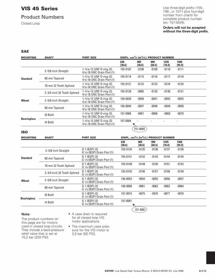
D-3-13EATON Low Speed High Torque Motors E-MOLO-MC001-E3 July 2006
VIS 45 Series
Product NumbersClosed Loop
MOUNTING SHAFT PORT SIZE DISPL. cm3/ r [in3/ r] / PRODUCT NUMBER
630 805 990 1245 1560 [38.6] [48.6] [60.5] [76.0] [95.0] 2–5/8 inch Straight 1–5/16-12 UNF O-ring (2) 155-0107 -0108 -0109 -0110 -0111 9/16-18 UNC Drain Port (1) 60 mm Tapered 1–5/16-12 UNF O-ring (2) 155-0114 -0115 -0116 -0117 -0118 9/16-18 UNC Drain Port (1) 70 mm 22 Tooth Splined 1–5/16-12 UNF O-ring (2) 155-0121 -0122 -0123 -0124 -0125 9/16-18 UNC Drain Port (1) 2–3/4 inch 32 Tooth Splined 1–5/16-12 UNF O-ring (2) 155-0128 -0085 -0129 -0130 -0131 9/16-18 UNC Drain Port (1) 2–5/8 inch Straight 1–5/16-12 UNF O-ring (2) 156-0039 -0040 -0041 -0042 -0043 9/16-18 UNC Drain Port (1) 60 mm Tapered 1–5/16-12 UNF O-ring (2) 156-0046 -0047 -0048 -0049 -0050 9/16-18 UNC Drain Port (1) (8 Bolt) 1–5/16-12 UNF O-ring (2) 157-0066 -0067 -0068 -0069 -0070 9/16-18 UNC Drain Port (1) (4 Bolt) 1–5/16-12 UNF O-ring (2) 157-0004 - - - - 9/16-18 UNC Drain Port (1)
Standard
Bearingless
Wheel
157-0004
MOUNTING SHAFT PORT SIZE DISPL. cm3/ r [in3/ r] / PRODUCT NUMBER
630 805 990 1245 1560 [38.6] [48.6] [60.5] [76.0] [95.0] 2–5/8 inch Straight G 1 (BSP) (2) 155-0134 -0135 -0136 -0137 -0138 G 1/4 (BSP) Drain Port (1) 60 mm Tapered G 1 (BSP) (2) 155-0141 -0142 -0143 -0144 -0145 G 1/4 (BSP) Drain Port (1) 70 mm 22 Tooth Splined G 1 (BSP) (2) 155-0148 -0149 -0150 -0151 -0152 G 1/4 (BSP) Drain Port (1) 2–3/4 inch 32 Tooth Splined G 1 (BSP) (2) 155-0155 -0156 -0157 -0158 -0159 G 1/4 (BSP) Drain Port (1) 2–5/8 inch Straight G 1 (BSP) (2) 156-0053 -0054 -0055 -0056 -0057 G 1/4 (BSP) Drain Port (1) 60 mm Tapered G 1 (BSP) (2) 156-0060 -0061 -0062 -0063 -0064 G 1/4 (BSP) Drain Port (1) (8 Bolt) G 1 (BSP) (2) 157-0074 -0075 -0076 -0077 -0078 G 1/4 (BSP) Drain Port (1) (4 Bolt) G 1 (BSP) (2) 157-0081 G 1/4 (BSP) Drain Port (1)
Standard
Wheel
Use three-digit prefix (155-, 156-, or 157-) plus four-digit number from charts for complete product number (ex: 157-0034).
Orders will not be accepted without the three-digit prefix.
SAE
ISO
Bearingless
157-0081 Note:
The product numbers on this page are for motors used in closed loop circuits. They include a back-pressure relief valve that is set at 15,2 bar [220 PSI].
• A case drain is required for all closed loop VIS motor applications.
• The maximum case pres-sure for the VIS motor is 3,5 bar [50 PSI].

D-3-14 EATON Low Speed High Torque Motors E-MOLO-MC001-E3 July 2006
MOUNTING SHAFT PORT SIZE DISPL. cm3/ r [in3/ r] / PRODUCT NUMBER
630 805 990 1245 1560 [38.6] [48.6] [60.5] [76.0] [95.0] 2–5/8 inch Straight 1–5/16-12 UNF O-ring (2) 155-0029 -0030 -0031 -0032 -0033 9/16-18 UNC Drain Port (1) 60 mm Tapered 1–5/16-12 UNF O-ring (2) 155-0043 -0044 -0045 -0046 -0047 9/16-18 UNC Drain Port (1) 70 mm 22 Tooth Splined 1–5/16-12 UNF O-ring (2) 155-0014 -0057 -0058 -0059 -0060 9/16-18 UNC Drain Port (1) 2–3/4 inch 32 Tooth Splined 1–5/16-12 UNF O-ring (2) 155-0070 -0071 -0072 -0073 -0074 9/16-18 UNC Drain Port (1) 2–5/8 inch Straight 1–5/16-12 UNF O-ring (2) 156-0011 -0012 -0013 -0014 -0015 9/16-18 UNC Drain Port (1) 60 mm Tapered 1–5/16-12 UNF O-ring (2) 155-0025 -0026 -0027 -0028 -0029 9/16-18 UNC Drain Port (1) (8 Bolt) 1–5/16-12 UNF O-ring (2) 157-0050 -0040 -0042 -0044 -0046 9/16-18 UNC Drain Port (1) (4 Bolt) 1–5/16-12 UNF O-ring (2) 157-0038 - - - - 9/16-18 UNC Drain Port (1)
Standard
SAE
ISOMOUNTING SHAFT PORT SIZE DISPL. cm3/ r [in3/ r] / PRODUCT NUMBER
630 805 990 1245 1560 [38.6] [48.6] [60.5] [76.0] [95.0]
2–5/8 inch Straight G 1 (BSP) (2) 155-0036 -0037 -0038 -0039 -0040 G 1/4 (BSP) Drain Port (1) 60 mm Tapered G 1 (BSP) (2) 155-0050 -0051 -0052 -0053 -0054 G 1/4 (BSP) Drain Port (1) 70 mm 22 Tooth Splined G 1 (BSP) (2) 155-0063 -0064 -0065 -0066 -0067 G 1/4 (BSP) Drain Port (1) 2–3/4 inch 32 Tooth Splined G 1 (BSP) (2) 155-0077 -0078 -0079 -0080 -0081 G 1/4 (BSP) Drain Port (1) 2–5/8 inch Straight G 1 (BSP) (2) 156-0018 -0019 -0020 -0021 -0022 G 1/4 (BSP) Drain Port (1) 60 mm Tapered G 1 (BSP) (2) 156-0032 -0033 -0034 -0035 -0036 G 1/4 (BSP) Drain Port (1) (8 Bolt) G 1 (BSP) (2) 155-0053 -0041 -0043 -0045 -0047 G 1/4 (BSP) Drain Port (1) (4 Bolt) G 1 (BSP) (2) 157-0039 -0036 -0037 -0078 G 1/4 (BSP) Drain Port (1)
157-0036
Standard
Bearingless
Wheel
Use three-digit prefix (155-, 156-, or 157-) plus four-digit number from charts for complete product number (ex: 157-0038).
Orders will not be accepted without three digit prefix.
VIS 45 Series
Product NumbersOpen Loop
Bearingless
Wheel
Note:
All product numbers in the charts (above) are for motors without a back-pressure relief valve. These motors would generally be used in open loop circuits.
For closed loop circuits a motor with a back-pressure relief valve is required.
157-0038
• A case drain is recom-mended for all VIS motor applications.
• The maximum case pres-sure for the VIS motor is 3,5 bar [50 PSI].
• In open loop circuits, return pressure must be 3,5 bar [50 PSI] greater than case pressure to properly lubricate the internal drive.
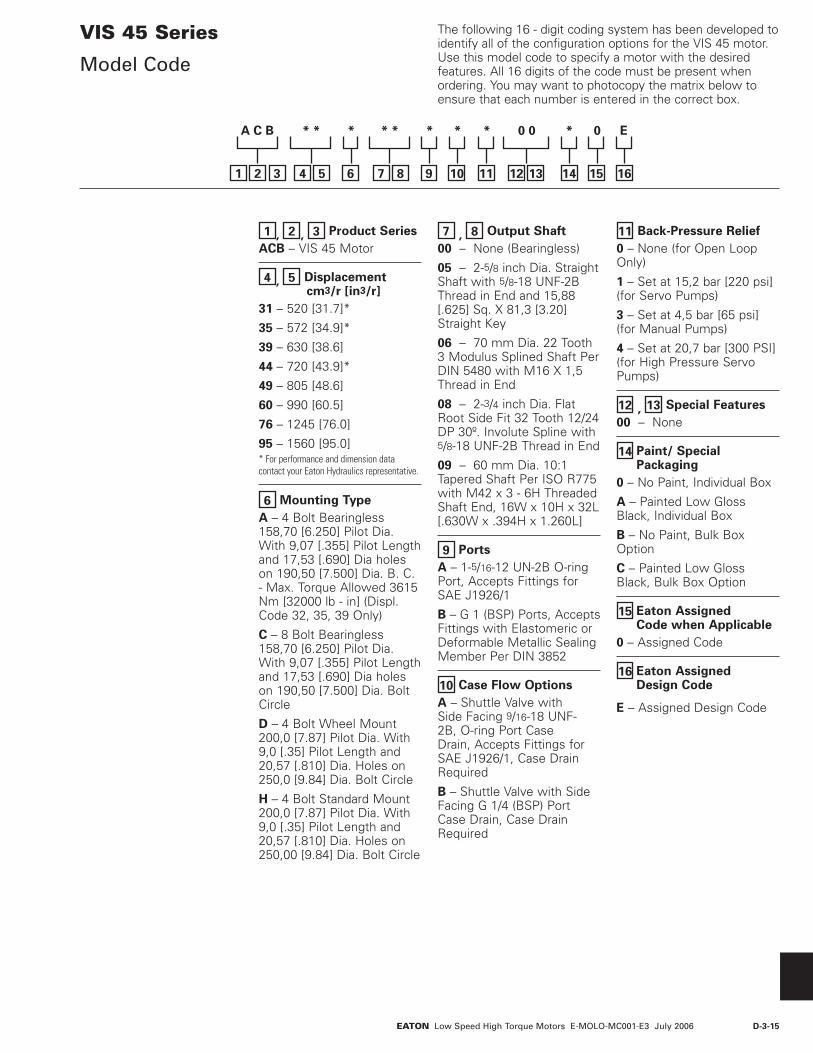
D-3-15EATON Low Speed High Torque Motors E-MOLO-MC001-E3 July 2006
1 , 2 , 3 Product Series
ACB – VIS 45 Motor
4 , 5 Displacement cm3/r [in3/r]
31 – 520 [31.7]*
35 – 572 [34.9]*
39 – 630 [38.6]
44 – 720 [43.9]*
49 – 805 [48.6]
60 – 990 [60.5]
76 – 1245 [76.0]
95 – 1560 [95.0]* For performance and dimension data contact your Eaton Hydraulics representative.
6 Mounting Type
A – 4 Bolt Bearingless 158,70 [6.250] Pilot Dia. With 9,07 [.355] Pilot Length and 17,53 [.690] Dia holes on 190,50 [7.500] Dia. B. C. - Max. Torque Allowed 3615 Nm [32000 lb - in] (Displ. Code 32, 35, 39 Only)
C – 8 Bolt Bearingless 158,70 [6.250] Pilot Dia. With 9,07 [.355] Pilot Length and 17,53 [.690] Dia holes on 190,50 [7.500] Dia. Bolt Circle
D – 4 Bolt Wheel Mount 200,0 [7.87] Pilot Dia. With 9,0 [.35] Pilot Length and 20,57 [.810] Dia. Holes on 250,0 [9.84] Dia. Bolt Circle
H – 4 Bolt Standard Mount 200,0 [7.87] Pilot Dia. With 9,0 [.35] Pilot Length and 20,57 [.810] Dia. Holes on 250,00 [9.84] Dia. Bolt Circle
7 , 8 Output Shaft
00 – None (Bearingless)
05 – 2-5/8 inch Dia. Straight Shaft with 5/8-18 UNF-2B Thread in End and 15,88 [.625] Sq. X 81,3 [3.20] Straight Key
06 – 70 mm Dia. 22 Tooth 3 Modulus Splined Shaft Per DIN 5480 with M16 X 1,5 Thread in End
08 – 2-3/4 inch Dia. Flat Root Side Fit 32 Tooth 12/24 DP 30º. Involute Spline with 5/8-18 UNF-2B Thread in End
09 – 60 mm Dia. 10:1 Tapered Shaft Per ISO R775 with M42 x 3 - 6H Threaded Shaft End, 16W x 10H x 32L [.630W x .394H x 1.260L]
9 Ports
A – 1-5/16-12 UN-2B O-ring Port, Accepts Fittings for SAE J1926/1
B – G 1 (BSP) Ports, Accepts Fittings with Elastomeric or Deformable Metallic Sealing Member Per DIN 3852
10 Case Flow Options
A – Shuttle Valve with Side Facing 9/16-18 UNF-2B, O-ring Port Case Drain, Accepts Fittings for SAE J1926/1, Case Drain Required
B – Shuttle Valve with Side Facing G 1/4 (BSP) Port Case Drain, Case Drain Required
11 Back-Pressure Relief
0 – None (for Open Loop Only)
1 – Set at 15,2 bar [220 psi] (for Servo Pumps)
3 – Set at 4,5 bar [65 psi] (for Manual Pumps)
4 – Set at 20,7 bar [300 PSI] (for High Pressure Servo Pumps)
12 , 13 Special Features
00 – None
14 Paint/ SpecialPackaging
0 – No Paint, Individual Box
A – Painted Low Gloss Black, Individual Box
B – No Paint, Bulk Box Option
C – Painted Low Gloss Black, Bulk Box Option
15 Eaton Assigned Code when Applicable
0 – Assigned Code
16 Eaton Assigned Design Code
E – Assigned Design Code
The following 16 - digit coding system has been developed to identify all of the configuration options for the VIS 45 motor. Use this model code to specify a motor with the desired features. All 16 digits of the code must be present when ordering. You may want to photocopy the matrix below to ensure that each number is entered in the correct box.
VIS 45 Series
Model Code
321
A C B * * * * * * * * 0 0 * 0 E
54 6 87 9 10 11 12 13 14 15 16

D-3-16 EATON Low Speed High Torque Motors E-MOLO-MC001-E3 July 2006
VIS 45 SeriesTwo-speed
Seals MountingFlange
OutputShaft
Drive
Rear Bearing(Oil Lubricated)
Seal Guard
Front Bearing(Grease Packed)
End Cap
Geroler®
ShuttleValve
Back-pressureRelief Valve
Valve Plate
Selector Plate
Selector Valve
Performance Data
VIS 45 Series motors are available with an integral two-speed feature that allows the operator to shift the motor between low speed high torque (LSHT) mode and high speed low torque (HSLT) mode. In the LSHT mode, output torque and rotation speed values are equal to those of the conventional VIS 45 motor. In the HSLT mode motor displacement is reduced by one third, resulting in a fifty percent increase in rotation speed and a torque output reduction of one third. The VIS 45 two speed motor is bidirectional. It will function with equal shaft output in either rotation direction (CW or CCW) in both LSHT and HSLT modes. Shift on the fly technology allows full-power operation throughout the full duration of the shift.
Changing between modes is accomplished by changing the displacement in a ratio of 1 to 1.5. An external two-position three-way control valve is required for shifting pressure to the pilot port between low pressure (LSHT mode) and pilot signal pressure (HSLT mode). An integral selector valve shifts the motor from LSHT mode to HSLT mode. Initially, low pressure is supplied to the pilot port. The selector valve is biased to LSHT mode by a return spring. When pilot signal pressure is supplied to the pilot port and 3,5 ∆bar [50 ΔPSI] is reached, the selector valve overcomes return spring force and the shifts the spool to select HSLT mode. Oil on the opposite side of the spool is drained to tank via the drain port. The pressure difference between the pilot port and drain port must be maintained to keep the motor in the high speed mode. When pilot pressure
is removed from the pilot port, the pressure in the pilot end of the spool valve is relieved and drained back through the control valve and the return spring forces the spool valve to LSHT position.
Pilot pressure may come from any source that will provide uninterrupted pressure during the high-speed mode operation. Allowable pilot pressure must be at least 3,5 ∆bar [50 ΔPSI] and may be as high as full operating pressure of the motor.
All VIS 45 Series two speed motors are equipped with a return line shuttle for closed circuit applications as standard equipment. All options available on the conventional VIS 45 are also available on VIS 45 two speed motors.
In the LSHT mode, torque and speed values are equal to those of the conventional VIS 45 motor. In the HSLT mode, rotation speed is increased by fifty percent and torque output is reduced by one third.
The VIS 45 two speed motor will function with equal shaft output in either rotation direction (CW or CCW) in both LSHT and HSLT modes.
Specifications
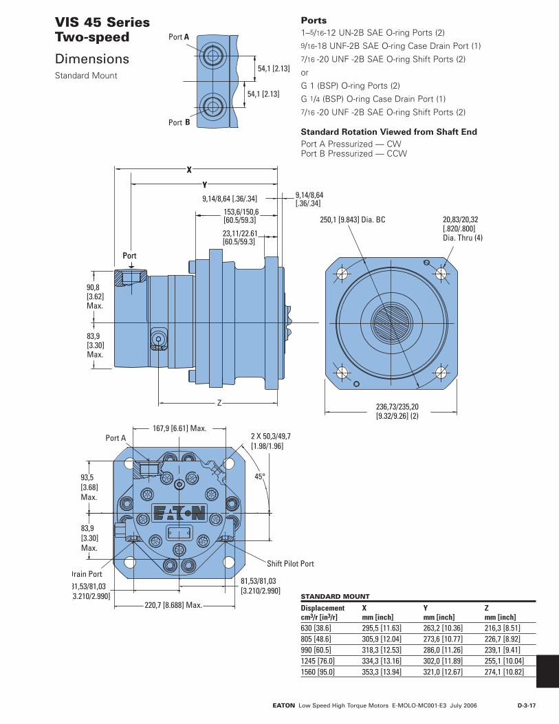
D-3-17EATON Low Speed High Torque Motors E-MOLO-MC001-E3 July 2006
Port
83,9[3.30]Max.
90,8[3.62]Max.
236,73/235,20[9.32/9.26] (2)
Y
X
Z
23,11/22.61[60.5/59.3]
9,14/8,64 [.36/.34] 9,14/8,64[.36/.34]
153,6/150,6[60.5/59.3] 20,83/20,32
[.820/.800]Dia. Thru (4)
250,1 [9.843] Dia. BC
Port
Y
X
167,9 [6.61] Max.Port A
81,53/81,03[3.210/2.990]81,53/81,03
[3.210/2.990]220,7 [8.688] Max.
45°93,5[3.68]Max.
83,9[3.30]Max.
2 X 50,3/49,7[1.98/1.96]
Shift Pilot PortDrain Port
VIS 45 SeriesTwo-speed
DimensionsStandard Mount
STANDARD MOUNT
Displacement X Y Zcm3/r [in3/r] mm [inch] mm [inch] mm [inch]630 [38.6] 295,5 [11.63] 263,2 [10.36] 216,3 [8.51]805 [48.6] 305,9 [12.04] 273,6 [10.77] 226,7 [8.92]990 [60.5] 318,3 [12.53] 286,0 [11.26] 239,1 [9.41]1245 [76.0] 334,3 [13.16] 302,0 [11.89] 255,1 [10.04]1560 [95.0] 353,3 [13.94] 321,0 [12.67] 274,1 [10.82]
Ports 1–5/16-12 UN-2B SAE O-ring Ports (2)9/16-18 UNF-2B SAE O-ring Case Drain Port (1)7/16 -20 UNF -2B SAE O-ring Shift Ports (2)
or
G 1 (BSP) O-ring Ports (2)
G 1/4 (BSP) O-ring Case Drain Port (1)7/16 -20 UNF -2B SAE O-ring Shift Ports (2)
Standard Rotation Viewed from Shaft End
Port A Pressurized — CWPort B Pressurized — CCW
Port A
Port B
54,1 [2.13]
54,1 [2.13]

D-3-18 EATON Low Speed High Torque Motors E-MOLO-MC001-E3 July 2006
250,01 [9.843] Dia.
200,00/199,85[7.874/7.868]Pilot Dia.
Port
9,2/8,6[.36/.34]
48,90/47,62[1.925/1.875]
20,93/20,32[.817/.803] Dia. Thru (4)
23,2/22,6 [.91/.89]236,73/235,20[9.32/9.26] (2)
89,3[3.30]Max.
90,9[3.62]Max. (2)
XY
Z
MountingSurface
Case Drain Port
167,9 [6.61] Max.Port A
81,53/81,03[3.210/2.990]81,53/81,03
[3.210/2.990]220,7 [8.688] Max.
45°93,5[3.68]Max.
83,9[3.30]Max.
2 X 50,3/49,7[1.98/1.96]
Shift Pilot PortShift Drain Port
VIS 45 SeriesTwo-speed
DimensionsWheel Mount
WHEEL MOUNT
Displacement X Y Zcm3/r [in3/r] mm [inch] mm [inch] mm [inch]630 [38.6] 218,8 [8.61] 186,5 [7.34] 139,6 [5.49]805 [48.6] 229,2 [9.02] 196,9 [7.75] 150,0 [5.90]990 [60.5] 241,6 [9.51] 209,4 [8.24] 162,4 [6.39]1245 [76.0] 257,6 [10.14] 225,6 [8.88] 178,4 [7.02]1560 [95.0] 276,6 [10.92] 245,4 [9.66] 197,4 [7.80]
Ports 1–5/16-12 UN-2B SAE O-ring Ports (2)9/16-18 UNF-2B SAE O-ring Case Drain Port (1)7/16 -20 UNF -2B SAE O-ring Shift Ports (2)
or
G 1 (BSP) O-ring Ports (2)
G 1/4 (BSP) O-ring Case Drain Port (1)7/16 -20 UNF -2B SAE O-ring Shift Ports (2)
Standard Rotation Viewed from Shaft End
Port A Pressurized — CWPort B Pressurized — CCW
Port A
Port B
54,1 [2.13]
54,1 [2.13]

D-3-19EATON Low Speed High Torque Motors E-MOLO-MC001-E3 July 2006
223,0/221,5[8.78/8.72]Dia.
Shaft Face SealFurnished with Motor
Port
153,6/150,6[60.5/59.3]
Z
YX
89,3[3.30]Max.
Shift Port (2)
90,8[3.62]Max.
Case DrainPort
9,14/8,89[.360/.350] 23,11/22,61
[.910/.890]
158,75/158,62[6.250/6.245]
VIS 45 SeriesTwo-speed
DimensionsBearingless
Ports 1–1/16-12 UN-2B SAE O-ring Ports (2)
9/16-18 UNF-2B SAE O-ring Case Drain Port (1)7/16 -20 UNF -2B SAE O-ring Shift Ports (2)
Or
G 3/4 (BSP) O-ring Ports (2)
G 1/4 (BSP) O-ring Case Drain Port (1)7/16 -20 UNF -2B SAE O-ring Shift Ports (2)
Standard Rotation Viewed from Drive End
Port A Pressurized — CWPort B Pressurized — CCW
BEARINGLESS MOTORS
Displacement X Y Zcm3/r [in3/r] mm [inch] mm [inch] mm [inch]630 [38.6] 196,1 [7.72] 165,9 [6.53] 116,9 [4.60]805 [48.6] 206,5 [8.13] 176,3 [6.94] 127,3 [5.01]990 [60.5] 218,9 [8.62] 188,8 [7.43] 139,7 [5.50]1245 [76.0] 235,2 [9.26] 205,0 [8.07] 156,0 [6.14]1560 [95.0] 255,0 [10.04] 224,8 [8.85] 175,8 [6.92]
111,5[4.39]Max. (4)
4 x 10° 4 x 10°
94,5 [3.72]Max. (4)
15,2 [.60]Min. R (8)
Case Drain
190,50 [7.500]Dia. Bolt Circle
16,00/15,75[.630/.620]Dia. Thru (8)
105,7 [4.16]Max. to SpotFace
95,20[3.750](4)
15,2 [.60]Min. R (4)
223,0/221,5[8.78/8.72]Dia.
Case Drain
190,50 [7.500]Dia. Bolt Circle
17,78/17,27[.700/.680]Dia. Thru (4)
Mating Coupling BlankEaton Part No. 13521-003
C 116,3 [ 4.58 ] Dia. Max.D 111,8 [ 4.40 ] Dia. Min. E 37,64 [ 1.482] Dia.F 136,7 [ 5.38 ] Max.G 131,6 [ 5.18 ] Min. Full Form Dia.H 64,8 [ 2.55 ]J 26,4 [ 1.04 ]K 109,7 [ 4.32 ] Max.L 104,6 [ 4.12 ] Min. Full Form Dia.M 92,58 [ 3.645] Dia.N 73,28 [ 2.885] Dia. M
F
C
K L
D
EN
GH J
For VIS 45 two-speed bearingless motor application information, contact your Eaton repre-sentative (mating coupling blanks available from Eaton Hydraulics).
Note:
After machining blank, part must be hardened per Eaton specification.
Port A
Port B
54,1 [2.13]
54,1 [2.13]
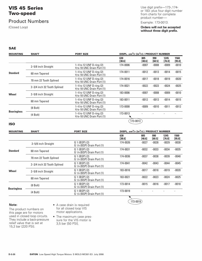
D-3-20 EATON Low Speed High Torque Motors E-MOLO-MC001-E3 July 2006
VIS 45 SeriesTwo-speed
Product Numbers(Closed Loop)
MOUNTING SHAFT PORT SIZE DISPL. cm3/ r [in3/ r] / PRODUCT NUMBER
630 805 990 1245 1560 [38.6] [48.6] [60.5] [76.0] [95.0] 2–5/8 inch Straight 1–5/16-12 UNF O-ring (2) 174-0006 -0007 -0008 -0009 -0010 9/16-18 UNC Drain Port (1) 60 mm Tapered 1–5/16-12 UNF O-ring (2) 174-0011 -0012 -0013 -0014 -0015 9/16-18 UNC Drain Port (1) 70 mm 22 Tooth Splined 1–5/16-12 UNF O-ring (2) 174-0016 -0017 -0018 -0019 -0020 9/16-18 UNC Drain Port (1) 2–3/4 inch 32 Tooth Splined 1–5/16-12 UNF O-ring (2) 174-0021 -0022 -0023 -0024 -0025 9/16-18 UNC Drain Port (1) 2–5/8 inch Straight 1–5/16-12 UNF O-ring (2) 183-0006 -0007 -0008 -0009 -0010 9/16-18 UNC Drain Port (1) 60 mm Tapered 1–5/16-12 UNF O-ring (2) 183-0011 -0012 -0013 -0014 -0015 9/16-18 UNC Drain Port (1) (8 Bolt) 1–5/16-12 UNF O-ring (2) 173-0008 -0009 -0010 -0011 -0012 9/16-18 UNC Drain Port (1) (4 Bolt) 1–5/16-12 UNF O-ring (2) 173-0013 - - - - 9/16-18 UNC Drain Port (1)
Standard
Bearingless
Wheel
173-0013
MOUNTING SHAFT PORT SIZE DISPL. cm3/ r [in3/ r] / PRODUCT NUMBER
630 805 990 1245 1560 [38.6] [48.6] [60.5] [76.0] [95.0] 2–5/8 inch Straight G 1 (BSP) (2) 174-0026 -0027 -0028 -0029 -0030 G 1/4 (BSP) Drain Port (1) 60 mm Tapered G 1 (BSP) (2) 174-0031 -0032 -0033 -0034 -0035 G 1/4 (BSP) Drain Port (1) 70 mm 22 Tooth Splined G 1 (BSP) (2) 174-0036 -0037 -0038 -0039 -0040 G 1/4 (BSP) Drain Port (1) 2–3/4 inch 32 Tooth Splined G 1 (BSP) (2) 174-0041 -0042 -0043 -0044 -0045 G 1/4 (BSP) Drain Port (1) 2–5/8 inch Straight G 1 (BSP) (2) 183-0016 -0017 -0018 -0019 -0020 G 1/4 (BSP) Drain Port (1) 60 mm Tapered G 1 (BSP) (2) 183-0021 -0022 -0023 -0024 -0025 G 1/4 (BSP) Drain Port (1) (8 Bolt) G 1 (BSP) (2) 173-0014 -0015 -0016 -0017 -0018 G 1/4 (BSP) Drain Port (1) (4 Bolt) G 1 (BSP) (2) 173-0019 - - - - G 1/4 (BSP) Drain Port (1)
Standard
Wheel
SAE
ISO
Bearingless
173-0019Note:
The product numbers on this page are for motors used in closed loop circuits. They include a back-pressure relief valve that is set at 15,2 bar [220 PSI].
Use digit prefix—173-,174- or 183- plus four digit number from charts for complete product number-—
Example: 173-0013.
Orders will not be accepted without three digit prefix.
• A case drain is required for all closed loop VIS motor applications.
• The maximum case pres-sure for the VIS motor is 3,5 bar [50 PSI].

D-3-21EATON Low Speed High Torque Motors E-MOLO-MC001-E3 July 2006
The following 18-digit coding system has been developed to identify all of the configuration options for the VIS 45 Two-Speed motor. Use this model code to specify a motor with the desired features. All 18 digits of the code must be present when ordering. You may want to photocopy the matrix below to endure that each number is entered in the correct box.
VIS 45 SeriesTwo-speed
Model Code
1 , 2 , 3 Product Series
ADP – VIS 45 Two-speed Motor
4 Eaton Assigned Code
1 – Assigned Code
5 6 Displacement cm3/r [in3/r]
32 – 520 [31.7]*
35 – 572 [34.9]*
39 – 630 [38.6]
44 – 720 [43.9]*
49 – 805 [48.6]
60 – 990 [60.5]
76 – 1245 [76.0]
95 – 1560 [95.0]
* For performance and dimension data, contact your Eaton Hydraulics representative.
7 Mounting Type
A – 4 Bolt Bearingless 158,70 [6.250] Pilot Dia. With 9,07 [.355] Pilot Length and 17,53 [.690] Dia holes on 190,50 [7.500] Dia. B. C. - Max. Torque Allowed 3615 Nm [32000 lb-in] (Displ. Code 32, 35, 39 Only)
C – 8 Bolt Bearingless 158,70 [6.250] Pilot Dia. With 9,07 [.355] Pilot Length and 17,53 [.690] Dia holes on 190,50 [7.500] Dia. Bolt Circle
D – 4 Bolt Wheel Mount 200,0 [7.87] Pilot Dea. With 9,0 [.35] Pilot Length and 20,57 [.810] Dia. Holes on 250,0 [9.84] Dia. Bolt Circle
H – 4 Bolt Standard Mount 200,0 [7.87] Pilot Dia. With 9,0 [.35] Pilot Length and 20,57 [.810] Dia. Holes on 250,00 [9.84] Dia. Bolt Circle
8 , 9 Output Shaft
00 – None (Bearingless)
05 – 2-5/8 inch Dia. Straight Shaft with 5/8-18 UNF-2B Thread in End and 15,88 [.625] Sq. X 81,3 [3.20] Straight Key
06 – 70 mm Dia. 22 Tooth 3 Modulus Splined Shaft Per DIN 5480 with M16 X 1,5 Thread in End
08 – 2-3/4 inch Dia. Flat Root Side Fit 32 Tooth 12/24 DP 30º. Involute Spline with 5/8-18 UNF-2B Thread in End
09 – 60 mm Dia. 10:1 Tapered Shaft Per ISO R775 with M42 x 3 - 6H Threaded Shaft End, 16W x 10H x 32L [.630W x .394H x 1.260L]
10 Ports
A – 1-5/16-12 UN-2B O-ring Port, Accepts Fittings for SAE J1926/1
B – G 1 (BSP) Straight Thread Ports
11 Case Flow Options
D – Shuttle Valve with Side Facing 9/16-18 UNF-2B, O-ring Port Case Drain, Accepts Fittings for SAE J1926/1, Case Drain Required
F – Shuttle Valve with Side Facing G 1/4 (BSP) Port Case Drain, Case Drain Required
12 Back-Pressure Relief
1 – Set at 15,2 bar [220 psi] (for Servo Pumps)
3 – Set at 4,5 bar [65 psi] (for Manual Pumps)
4 – Set at 20,7 bar [300 PSI] (for High Pressure Servo Pumps)
13 Eaton Assigned Code
0 – Assigned Code
14 , 15 Special Features
00 – None
16 Paint/ Special Packaging
0 – No Paint, Individual Box
A – Painted Low Gloss Black, Individual Box
B – No Paint, Bulk Box Option
C – Painted Low Gloss Black, Bulk Box Option
17 Eaton Assigned Code when Applicable
0 – Assigned Code
18 Eaton Assigned Design Code
B – Assigned Design Code
321
A D P 1 * * * * * * * * * 0 0 * 0 B
654 10 11 12 13 16 17 18987 1514