Virtual stability simulation of a telescopic handler machine according to the standard UNI EN 1459
16
1 This document contains information property of CNH, Iveco and Fiat Industrial. This document and the contained information cannot be used, copied, transmitted, fully or partly, without prior written authorization of CNH, Iveco and Fiat Industrial. DESIGN ANALYSIS AND SIMULATION Virtual stability simulation of a telescopic handler machine according to the standard UNI EN 1459 Gennaro Monacelli, Stefano Largo, Roberto D’Aria 2013 European Altair Technology Conference, Turin
-
Upload
altair-engineering -
Category
Technology
-
view
641 -
download
4
Transcript of Virtual stability simulation of a telescopic handler machine according to the standard UNI EN 1459

1
This document contains information property of CNH, Iveco and Fiat
Industrial. This document and the contained information cannot be used,
copied, transmitted, fully or partly, without prior written authorization of
CNH, Iveco and Fiat Industrial.
DESIGN ANALYSIS AND SIMULATION
Virtual stability simulation of a telescopic
handler machine according to the standard
UNI EN 1459
Gennaro Monacelli, Stefano Largo, Roberto D’Aria
2013 European Altair Technology Conference, Turin

2
This document contains information property of CNH, Iveco and Fiat
Industrial. This document and the contained information cannot be used,
copied, transmitted, fully or partly, without prior written authorization of
CNH, Iveco and Fiat Industrial.
FOREWORD
• A telescopic handler, or telehandler, is similar
to a forklift with the versatility of a single
telescopic boom that can extend forwards
and upward.
• The development of telehandlers in both
capacity and reach makes them so useful, but
provides scope for unsafe use.
• It is fundamental the understanding of the
kinematic stability behaviour of this
machine.
3/29/2013
DESIGN ANALYSIS AND SIMULATION

3
This document contains information property of CNH, Iveco and Fiat
Industrial. This document and the contained information cannot be used,
copied, transmitted, fully or partly, without prior written authorization of
CNH, Iveco and Fiat Industrial.
DESIGN ANALYSIS AND SIMULATION
PROJECT DESCRIPTION
Objective
• Implementation of a multibody parametric tool by Altair MotionView/MotionSolve in order
to simulate the kinematic behaviour of the TLH LM 1445, with reference to the STD UNI EN 1459.
Outputs
• Load charts output and correlation with testing data.
Validation tests
• Correlation references on current product:
1. - Weight on wheels and centre of gravity position evaluation
2. - Tipping load and stability test
• Load comparison between current production load charts and physical test results.
Conclusions
• The quasi static multibody tool reproduces the behaviour of the machine including flexural and torsional
effects on each arm section, hydraulic limits and tires deformation.
• This tool is predictive to avoid overturning and tipping accidents.
3/29/2013

4
This document contains information property of CNH, Iveco and Fiat
Industrial. This document and the contained information cannot be used,
copied, transmitted, fully or partly, without prior written authorization of
CNH, Iveco and Fiat Industrial.
DESIGN ANALYSIS AND SIMULATION
MULTIBODY SIMULATION TOOL FOR TELEHANDLER METHODOLOGY
Step 1: Model setup according to standard EN 1459
Step 3: Instability load evaluation for a discrete number of
angles and payloads
Step 2: Payloads and angles definition by DOE FULL FACTORIAL approach
Step 5: Experimental data Step 4: Load chart diagram output
Boom angle Payload
Reach
He
igh
t
3/29/2013
Correlation

5
This document contains information property of CNH, Iveco and Fiat
Industrial. This document and the contained information cannot be used,
copied, transmitted, fully or partly, without prior written authorization of
CNH, Iveco and Fiat Industrial.
DESIGN ANALYSIS AND SIMULATION
MULTIBODY MODEL OVERVIEW COMPLETE ASSY
Vehicle body
Platform The vehicle model is composed by:
1. Platform (suitable for each angle condition)
2. Vehicle body (condensed masses )
3. Boom (3 arms with simplified shape and
condensed masses + payload)
4. Axle with pivot option
5. Tires (simulated as 3D stiffness)
6. Optional stabilizers to increase the load
capacity if required
Tires Rear axle with pivot
Boom
Stabilizers
Payload
Stabilizers down
in working position
3/29/2013

6
This document contains information property of CNH, Iveco and Fiat
Industrial. This document and the contained information cannot be used,
copied, transmitted, fully or partly, without prior written authorization of
CNH, Iveco and Fiat Industrial.
DESIGN ANALYSIS AND SIMULATION
Vehicle body : • Frame
• Cab
• Fuel Tank
• Engine bay
• Hood
• Counterweight
• Stabilizers
• Axles
• Tires
MULTIBODY MODEL OVERVIEW VEHICLE BODY & TELESCOPIC BOOM DETAILS
Telescopic cylinder
Tilt cylinder
Lift cylinder
Arm 3
Arm 2 Arm 1 Payload
Telescopic boom details
Quick coupler + Carrier
Forks
Telescopic boom
Note: arm sections are modeled with compliant joints in order to simulate flexibility behaviour.
3/29/2013
Hydraulics
Sliding components

7
This document contains information property of CNH, Iveco and Fiat
Industrial. This document and the contained information cannot be used,
copied, transmitted, fully or partly, without prior written authorization of
CNH, Iveco and Fiat Industrial.
DESIGN ANALYSIS AND SIMULATION
INSTABILITY CONFIGURATIONS OVERVIEW
1) Boom in horizontal position parallel to platform: Tipping instability
2) Boom in intermediate position (40°- 50°): Border line between tipping and overturning instability 3) Boom at max angle : Overturning instability
3/29/2013
ISO VIEW FRONT VIEW
8
This document contains information property of CNH, Iveco and Fiat
Industrial. This document and the contained information cannot be used,
copied, transmitted, fully or partly, without prior written authorization of
CNH, Iveco and Fiat Industrial.
DESIGN ANALYSIS AND SIMULATION
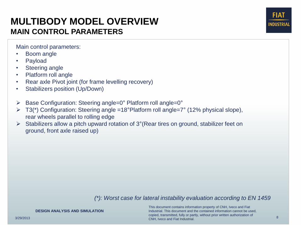
MULTIBODY MODEL OVERVIEW MAIN CONTROL PARAMETERS
Main control parameters:
• Boom angle
• Payload
• Steering angle
• Platform roll angle
• Rear axle Pivot joint (for frame levelling recovery)
• Stabilizers position (Up/Down)
Base Configuration: Steering angle=0° Platform roll angle=0°
T3(*) Configuration: Steering angle =18°Platform roll angle=7° (12% physical slope),
rear wheels parallel to rolling edge
Stabilizers allow a pitch upward rotation of 3°(Rear tires on ground, stabilizer feet on ground, front axle raised up)
(*): Worst case for lateral instability evaluation according to EN 1459
3/29/2013

9
This document contains information property of CNH, Iveco and Fiat
Industrial. This document and the contained information cannot be used,
copied, transmitted, fully or partly, without prior written authorization of
CNH, Iveco and Fiat Industrial.
DESIGN ANALYSIS AND SIMULATION
MULTIBODY MODEL OVERVIEW T3 POSITION (VIRTUAL & PHYSICAL)
1) Machine Flat on ground 2) Rear wheels at max steering angle
3) Tires or stabilizers set up
( yaw rotation at 18 °)
4) Platform inclination at 7°
(12% slope)
3/29/2013
5) Physical test
Test procedure
abstract (T3)

10
This document contains information property of CNH, Iveco and Fiat
Industrial. This document and the contained information cannot be used,
copied, transmitted, fully or partly, without prior written authorization of
CNH, Iveco and Fiat Industrial.
DESIGN ANALYSIS AND SIMULATION
Bush elements to simulate vertical stiffness and adherence
MULTIBODY MODEL OVERVIEW
TIRES
Reference values from supplier database
• Lateral deflection data
• Radial deflection data
• Torque deflection data
• Inflating pressure
Multi body simplification
• Vertical stiffness + lateral and longitudinal adherence to the platform
Vertical stiffness law
Instability sensors
• Instability occurs when one of the tires or the stabilizers lose
adherence from the platform in tipping or overturning conditions.
3/29/2013

11
This document contains information property of CNH, Iveco and Fiat
Industrial. This document and the contained information cannot be used,
copied, transmitted, fully or partly, without prior written authorization of
CNH, Iveco and Fiat Industrial.
DESIGN ANALYSIS AND SIMULATION
CORRELATION PLAN
Config. 2
• Stabilizers up
• Rear axle pivot locked
Config. 3
• Stabilizers down
• Rear axle pivot locked
• Virtual simulation of stability behaviour and lifting capacity of machine in three different configurations.
• Comparison with testing measures evaluated starting from current load chart diagrams.
3/29/2013
Config. 1
• Stabilizers up
• Rear axle pivot free
MACHINE PERFORMANCE
Triangular stability area Rectangular stability area Trapezoidal stability area

12
This document contains information property of CNH, Iveco and Fiat
Industrial. This document and the contained information cannot be used,
copied, transmitted, fully or partly, without prior written authorization of
CNH, Iveco and Fiat Industrial.
DESIGN ANALYSIS AND SIMULATION
Deviation (-0.1%)
Deviation (0%)
Deviation (+10%)
OUTPUTS: LOAD CHARTS TESTING DATA Vs NUMERICAL DATA
Testing data measures on current production load chart Correlation points on numerical load chart
3/29/2013
Config. 1
• Stabilizers up
• Rear axle pivot free
• Flexible tires
• Flexible boom
Virtual Load chart w/out confidence level
Reach H
eig
ht
Test payload 3
Test payload 2
Test payload 1

13
This document contains information property of CNH, Iveco and Fiat
Industrial. This document and the contained information cannot be used,
copied, transmitted, fully or partly, without prior written authorization of
CNH, Iveco and Fiat Industrial.
DESIGN ANALYSIS AND SIMULATION
Deviation (-9%)
Deviation (+3%)
Testing data measures on current production load chart Correlation points on numerical load chart
3/29/2013
Config 2
• Stabilizers up
• Rear axle pivot locked
• Flexible tires
• Flexible boom
OUTPUTS: LOAD CHARTS TESTING DATA Vs NUMERICAL DATA
Virtual Load chart w/out confidence level
Reach H
eig
ht
Test payload 2
Test payload 1

14
This document contains information property of CNH, Iveco and Fiat
Industrial. This document and the contained information cannot be used,
copied, transmitted, fully or partly, without prior written authorization of
CNH, Iveco and Fiat Industrial.
DESIGN ANALYSIS AND SIMULATION
Deviation (0%)
Note: Load chart with pressure limit evaluation on lift cylinder
Virtual Load chart w/out confidence level
OUTPUTS: LOAD CHARTS TESTING DATA Vs NUMERICAL DATA
Config 3
• Stabilizers down
• Rear axle pivot locked
• Flexible tires
• Flexible boom
3/29/2013
Testing data measures on current production load chart
Test payload 2
Test payload 1
Deviation (-4%)
Correlation points on numerical load chart
Reach
He
igh
t

15
This document contains information property of CNH, Iveco and Fiat
Industrial. This document and the contained information cannot be used,
copied, transmitted, fully or partly, without prior written authorization of
CNH, Iveco and Fiat Industrial.
DESIGN ANALYSIS AND SIMULATION
PHYSICAL/NUMERICAL CORRELATION
2 1
OK: Stability verified
NOT OK: Lateral instability
Lateral stability condition is verified in the numerical model according to experimental data (same machine setup at max
angle with different boom extension).
3/29/2013

16
This document contains information property of CNH, Iveco and Fiat
Industrial. This document and the contained information cannot be used,
copied, transmitted, fully or partly, without prior written authorization of
CNH, Iveco and Fiat Industrial.
DESIGN ANALYSIS AND SIMULATION
CONCLUSIONS
3/29/2013
1. Multibody parametric tool produces good results if compared with testing data measures.
2. The tool is predictive for TIPPING & OVERTURNING instability conditions.
3. Multibody methodology might have application in new AG & CE machine development from concept
design to design release.
4. Final goal will be the reduction of physical tests in order to achieve a one shot validation on prototype.
Further steps:
• Improvement of tires model non linear effect .
• Application of other boundary conditions as wind effect.