VIRTUAL SCULPTING WITH ADVANCED GESTURAL INTERFACE · ABSTRACT VIRTUAL SCULPTING WITH ADVANCED...
71
VIRTUAL SCULPTING WITH ADVANCED GESTURAL INTERFACE a thesis submitted to the department of computer engineering and the graduate school of engineering and science of bilkent university in partial fulfillment of the requirements for the degree of master of science By Nurettin C ¸ a˘ grı Kılıboz August, 2013
Transcript of VIRTUAL SCULPTING WITH ADVANCED GESTURAL INTERFACE · ABSTRACT VIRTUAL SCULPTING WITH ADVANCED...
VIRTUAL SCULPTING WITH ADVANCEDGESTURAL INTERFACE
a thesis
submitted to the department of computer engineering
and the graduate school of engineering and science
of bilkent university
in partial fulfillment of the requirements
for the degree of
master of science
By
Nurettin Cagrı Kılıboz
August, 2013

I certify that I have read this thesis and that in my opinion it is fully adequate,
in scope and in quality, as a thesis for the degree of Master of Science.
Assoc. Prof. Dr. Ugur Gudukbay(Advisor)
I certify that I have read this thesis and that in my opinion it is fully adequate,
in scope and in quality, as a thesis for the degree of Master of Science.
Assist. Prof. Dr. Tolga Capın
I certify that I have read this thesis and that in my opinion it is fully adequate,
in scope and in quality, as a thesis for the degree of Master of Science.
Assoc. Prof. Dr. Sinan Gezici
Approved for the Graduate School of Engineering and Science:
Prof. Dr. Levent OnuralDirector of the Graduate School
ii
ABSTRACT
VIRTUAL SCULPTING WITH ADVANCEDGESTURAL INTERFACE
Nurettin Cagrı Kılıboz
M.S. in Computer Engineering
Supervisor: Assoc. Prof. Dr. Ugur Gudukbay
August, 2013
In this study, we propose a virtual reality application that can be utilized to
design preliminary/conceptual models similar to real world clay sculpting. The
proposed system makes use of the innovative gestural interface that enhances the
experience of the human-computer interaction. The gestural interface employs
advanced motion capture hardware namely data gloves and six-degrees-of-freedom
position tracker instead of classical input devices like keyboard or mouse. The
design process takes place in the virtual environment that contains volumetric
deformable model, design tools and a virtual hand that is driven by the data glove
and the tracker. The users manipulate the design tools and the deformable model
via the virtual hand. The deformation on the model is done by stuffing or carving
material (voxels) in or out of the model with the help of the tools or directly
by the virtual hand. The virtual sculpting system also includes volumetric force
feedback indicator that provides visual aid. We also offer a mouse like interaction
approach in which the users can still interact with conventional graphical user
interface items such as buttons with the data glove and tracker. The users can also
control the application with gestural commands thanks to our real time trajectory
based dynamic gesture recognition algorithm. The gesture recognition technique
exploits a fast learning mechanism that does not require extensive training data
to teach gestures to the system. For recognition, gestures are represented as an
ordered sequence of directional movements in 2D. In the learning phase, sample
gesture data is filtered and processed to create gesture recognizers, which are
basically finite-state machine sequence recognizers. We achieve real time gesture
recognition by these recognizers without needing to specify gesture start and end
points. The results of the conducted user study show that the proposed method
is very promising in terms of gesture detection and recognition performance (73%
accuracy) in a stream of motion. Additionally, the assessment of the user attitude
survey denotes that the gestural interface is very useful and satisfactory. One
iii
iv
of the novel parts of the proposed approach is that it gives users the freedom
to create gesture commands according to their preferences for selected tasks.
Thus, the presented gesture recognition approach makes the human-computer
interaction process more intuitive and user specific.
Keywords: virtual sculpting, virtual clay potterry, volumetric deformation, vir-
tual reality, dynamic gesture recognition, gesture detection, finite state machine-
based recognition, gestural interfaces, gesture-based interaction.
OZET
EL HAREKETLERINE DAYALI GELISMIS ARAYUZILE SANAL MODELLEME
Nurettin Cagrı Kılıboz
Bilgisayar Muhendisligi, Yuksek Lisans
Tez Yoneticisi: Doc. Dr. Ugur Gudukbay
Agustos, 2013
Bu calısmada, gercek dunya heykeltraslıgına benzeyen on / kavramsal modelleri
tasarlamak icin kullanılabilir bir sanal gerceklik uygulaması sunuyoruz. Onerilen
sistem, insan-bilgisayar etkilesimi deneyimi artıran yenilikci bir isaret tabanlı
arayuz kullanmaktadır. Isaret tabanlı arayuz, el ve parmak hareketleri yakala-
mak icin, klasik girdi aygıtları olan fare ve klavye yerine, veri eldiven ve altı
derece serbestlikte veri toplayan bir manyetik konum izleyicilerden faydalanmak-
tadır. Tasarımlar; hacimce deforme edilebilir model, tasarım aracları ve sanal
el iceren bir sanal ortamda gerceklestirilmektedir. Sanal tasarım ortamında yer
alan bu sanal el, veri eldiven ve pozisyon izleyici sayesinde kullanıcının el hareket-
lerini taklit ederek yonlendirilmektedir. Sistem, kullanıcıların tasarım aracları
ve sanal el yardımıyla deforme edilebilir modeli isleyerek sekil vermesine olanak
tanımaktadır. Model uzerinde deformasyon, tasarım aracları veya dogrudan
sanal el ile, modele dısardan malzeme (hacim hucreleri) doldurma veya mod-
elden malzeme oyularak yapılmaktadır. Tasarım surecinde sistem “kuvvet geri-
bildirim gostergesi” sayesinde kullanıcılara gorsel yardım saglamaktadır. Ayrıca
kullanıcılar, veri eldiveni ve pozisyon izleyiciyi tarafından yonlendirilen el faresi ile
geleneksel grafik kullanıcı arayuzu ogeleri ile etkilesime girebilmektedirler. Kul-
lanıcılar aynı zamanda gercek zamanlı yorunge tabanlı el hareket/jest tanıyan
algoritma sayesinde uygulamayı kontrol edebilmektedirler. Sunulan el hareketi
tanıma teknigi, kapsamlı ve buyuk egitim verilerine ihtiyac duymadan, sisteme
yeni hareketler ogretmeye olanak saglamaktadır. Sunulan teknikte, el hareket-
leri, iki boyutlu yonlu hareketlerin sıralı dizisi olarak temsil edilir. Ogrenme
asamasında, sisteme sunulan ornek jestler/el hareketleri filtrelenerek islenir. Daha
sonra bu islenmis veri birer sonlu durum makinesi dizi tanıyıcıları olan el hareketi
tanıyıcı makinaları olusturmak icin kullanılmaktadır. El hareketleri, jestlerin
baslangıc ve bitis noktaları belirtmeye gerek kalmadan bu tanıyıcılar tarafından
v
vi
gercek zamanlı olarak sistem tarafından tanınabilmektedirler. Tez kapsamında
yapılan kullanıcı calısmasının sonucunda, onerilen yontem, surekli bir hareket
akısı icerisinde belirli el hareketlerini/jestleri % 73 dogruluk ile algılama ve
tanıma performansı gostermistir. Ayrıca kullanıcı tutum anketinin sonuclarına
gore, isaret tabanlı arayuz kullanıcılar tarafından cok yararlı ve tatmin edici bu-
lunmustur. Onerilen yaklasımın en onemli faydalarından biri de kullanıcıların
secilen gorevler icin kendi tercihlerine gore hareket komutları olusturma ozgurlugu
veriyor olmasıdır. Boylece, sunulan jest tanıma yaklasımı insan-bilgisayar et-
kilesim surecini daha sezgisel ve kullanıcıya ozel hale getirmektedir.
Anahtar sozcukler : sanal modelleme, sanal comlekcilik, hacimsel deformasyon,
sanal gerceklik, dinamik el hareketi tanıma, el hareketi tespiti, sonlu durum mak-
inası tabanlı tanıma, isaret tabanlı arayuzler, isaret tabanlı etkilesim.

Acknowledgement
This thesis is the end of my journey in obtaining my M.S degree. At the end of
this journey, I would like to thank all people, who made this thesis possible.
My first debt of gratitude must go to my advisor, Assoc. Prof. Ugur
Gudukbay. Without his guidance and help, I would not finish this thesis. I
would also like to thank to Assist. Prof. Dr. Tolga Capın and Assoc. Prof. Dr.
Sinan Gezici for reviewing and commenting on this thesis.
I would like to thank to the Scientific and Technological Research Council of
Turkey (TUBITAK) for providing financial assistance during my study, through
BIDEB program.
I also need to thank to the dear employees (especially Murat Ozkan) of I.T.
Department of Ministry of Economy. With their support and permission, I did
have time to complete my work.
I really appreciate the help of my friends Can Koyuncu, Ersin Yumer, Fatma
Guney, Murat Arar and Oguz Yılmaz. During the hardest times of my study,
they were there to support me. I could not complete my work without their
invaluable and friendly assistance.
I owe my deepest gratitude to my parents, Cuma and Mubeccel Kılıboz, and
my brother, Tugrul. Their love, support and encouragement provided my inspi-
ration and were my driving force.
Lastly, my special thanks goes to my beloved wife Duygu Sinem. Her informal
support, sacrifice and encouragement has been indispensable. I feel very lucky to
have a valuable life partner like her.
vii
Contents
1 Introduction 1
1.1 Motivation and Contribution . . . . . . . . . . . . . . . . . . . . . 2
1.1.1 Virtual Sculpting . . . . . . . . . . . . . . . . . . . . . . . 2
1.1.2 Gestural Interface . . . . . . . . . . . . . . . . . . . . . . . 3
1.2 Overview of System Components . . . . . . . . . . . . . . . . . . 4
1.3 Software Development and Test Environment . . . . . . . . . . . 5
1.4 Outline . . . . . . . . . . . . . . . . . . . . . . . . . . . . . . . . . 6
2 Background 7
2.1 Computer-Aided Design . . . . . . . . . . . . . . . . . . . . . . . 7
2.2 Virtual Sculpting . . . . . . . . . . . . . . . . . . . . . . . . . . . 7
2.3 Motion Capture . . . . . . . . . . . . . . . . . . . . . . . . . . . . 9
2.4 Human Computer Interaction . . . . . . . . . . . . . . . . . . . . 10
2.5 Gesture Recognition . . . . . . . . . . . . . . . . . . . . . . . . . 10
3 Motion Capture 12
viii

CONTENTS ix
3.1 Overview . . . . . . . . . . . . . . . . . . . . . . . . . . . . . . . . 12
3.2 Data Glove . . . . . . . . . . . . . . . . . . . . . . . . . . . . . . 12
3.3 6DoF Tracker . . . . . . . . . . . . . . . . . . . . . . . . . . . . . 13
3.4 Hand Model and Its Skeletal Structure . . . . . . . . . . . . . . . 15
3.5 Mapping of Inputs to the Models . . . . . . . . . . . . . . . . . . 16
4 Virtual Sculpting 22
4.1 Volumetric Structure of Deformable Models . . . . . . . . . . . . 22
4.2 Rendering Deformable Objects . . . . . . . . . . . . . . . . . . . . 23
4.3 Deformation Tools and Their Manipulations . . . . . . . . . . . . 24
4.4 Volumetric Deformation . . . . . . . . . . . . . . . . . . . . . . . 25
4.5 Collision Detection . . . . . . . . . . . . . . . . . . . . . . . . . . 26
4.6 Surface-based Deformation . . . . . . . . . . . . . . . . . . . . . . 26
4.7 Visual Force Feedback . . . . . . . . . . . . . . . . . . . . . . . . 27
5 Human Computer Interaction 29
5.1 Overview . . . . . . . . . . . . . . . . . . . . . . . . . . . . . . . . 29
5.2 Hand Mouse . . . . . . . . . . . . . . . . . . . . . . . . . . . . . . 30
5.3 Gesture Detection and Recognition . . . . . . . . . . . . . . . . . 31
5.3.1 Gesture Representation . . . . . . . . . . . . . . . . . . . . 32
5.3.2 Smoothing and Selection of Best Gestures . . . . . . . . . 33
5.3.3 Generating Recognizers . . . . . . . . . . . . . . . . . . . . 35
CONTENTS x
5.3.4 Online Gesture Recognition . . . . . . . . . . . . . . . . . 35
6 Results and Discussion 41
6.1 Experiment . . . . . . . . . . . . . . . . . . . . . . . . . . . . . . 41
6.2 Analysis and Discussion . . . . . . . . . . . . . . . . . . . . . . . 45
6.2.1 Performance . . . . . . . . . . . . . . . . . . . . . . . . . . 45
6.2.2 Attitude . . . . . . . . . . . . . . . . . . . . . . . . . . . . 46
6.2.3 Learning Parameters . . . . . . . . . . . . . . . . . . . . . 47
7 Conclusion and Future Work 48
7.1 Conclusion . . . . . . . . . . . . . . . . . . . . . . . . . . . . . . . 48
7.2 Future Work . . . . . . . . . . . . . . . . . . . . . . . . . . . . . . 51
Bibliography 53

List of Figures
1.1 Overview of the virtual environment. . . . . . . . . . . . . . . . . 5
3.1 5DT Data Glove Ultra 14. . . . . . . . . . . . . . . . . . . . . . . 13
3.2 Polhemus Patriot TM. . . . . . . . . . . . . . . . . . . . . . . . . 14
3.3 Hand model: (a) skeletal structure in the model, (b) smoothed
hand model. . . . . . . . . . . . . . . . . . . . . . . . . . . . . . . 16
3.4 Bone skinning: (a) vertices encapsulated by one of the bones,
(b) weighted vertex-bone mapping. . . . . . . . . . . . . . . . . . 16
3.5 Sensors locations on the glove. . . . . . . . . . . . . . . . . . . . . 18
3.6 Skeletal hand anatomy. . . . . . . . . . . . . . . . . . . . . . . . . 18
3.7 Interpolated sensor values using Equation 3.2: (a) Control point is
closer to end point, (b) Control point is closer to start point. . . . 19
4.1 Mesh views of the deformable model, the tool and the hand. . . . 23
4.2 Grasping types: (a) natural grasping, (b) direct grasping. . . . . . 25
4.3 Visual force feedback indicator. . . . . . . . . . . . . . . . . . . . 28
xi

LIST OF FIGURES xii
5.1 A gesture (circle) is represented as an ordered sequence of direc-
tional movements. . . . . . . . . . . . . . . . . . . . . . . . . . . . 33
5.2 Two raw gesture motion data (a and b), and the result of the
applied filtering (c). . . . . . . . . . . . . . . . . . . . . . . . . . . 37
5.3 Captured gesture samples may be different due to the nature of
trajectory-based gestures and filtering errors. . . . . . . . . . . . . 38
5.4 A sample gesture recognition machine to recognize the gesture in
Figure 5.2 (c). . . . . . . . . . . . . . . . . . . . . . . . . . . . . . 39
6.1 Gesture vocabulary used in the experiments. . . . . . . . . . . . . 42

List of Tables
3.1 Polhemus Patriot TM specifications. . . . . . . . . . . . . . . . . . 15
3.2 Interpolation values of each finger joint in the horizontal axis. . . 20
3.3 Interpolation values of each finger joint in the vertical axis. . . . . 21
5.1 The parameters used for the gesture recognition experiments. . . . 40
6.1 Gesture-action mapping. . . . . . . . . . . . . . . . . . . . . . . . 43
6.2 Gesture recognition rates. . . . . . . . . . . . . . . . . . . . . . . 44
6.3 Results of the user attitude survey. . . . . . . . . . . . . . . . . . 44
xiii
Chapter 1
Introduction
Virtual reality is a computer-simulated environment that tries to achieve life-like
experience of real world. Although the concept of virtual reality (VR) is very
old, the realization and creations of complex virtual worlds that imitate the real
one became possible only after the improvements in the computer hardware capa-
bilities. VR applications accomplish this difficult task thanks to these advanced
hardware devices that can provide realistic sensory information. For most of the
VR applications, the primary target is to provide visual experience via special
stereoscopic displays, while the others may include additional sensory informa-
tion such as audio. Today, even tactile feedback is available via haptic output
devices.
The main reasons behind the popularity of the VR applications is that it
has various practical usage areas such as training, gaming, entertainment and
modeling. Virtual sculpting is one of these branches which simulates the process
of designing models similar to real world clay or wood sculpting [1]. In other
words, virtual sculpting applications create a virtual environment and allow users
to manipulate and deform the design objects in the way they want in this virtual
environment.
Developments in the technology also contribute to the human-computer in-
teraction (HCI) approaches. Various HCI studies have been proposed in the last
1
CHAPTER 1. INTRODUCTION 2
few decades as an alternative to the classic input devices of keyboard and mouse.
However, these new techniques have not been able to supersede the old ones
due to their lack of intuitiveness. Additionally, their poor performance prevents
them from being be practical. However, the cutting edge technologies especially
touch operated devices such as kiosks, tablet PCs re-defined the whole HCI ap-
proaches. More intuitive and natural computer interfaces become the part of our
daily lives. Gestural interfaces also play a crucial role among these interfaces be-
cause our hands are the main means to interact with our environment. Therefore,
interaction approaches that makes use of this phenomenon naturally becomes a
strong alternative the conventional ones.
1.1 Motivation and Contribution
1.1.1 Virtual Sculpting
In this study, we try to accomplish a virtual sculpting tool that can be used
to design preliminary/conceptual models. The general advantage of all digital
modeling tools is that it removes the physical barriers of the real world sculpting.
Some of them, among many advantages, can be listed as follows: being able
to undo the work you have done, collaborative work without being in the same
presence, saving physical effort, being able to do tasks that are not physically
possible, and so on.
With digital modeling tools, while gaining these advantages, we loose two
of the most critical elements of the creative design process: naturalness and
intuitiveness. Because many of CAD (Computer Aided Design) tools rely on the
classical input devices like mouse and keyboard, they often cannot provide means
for intuitive interaction [2]. The first basic advantage of our virtual sculpting
tool is that it grants intuitiveness. Therefore, designing new models with the tool
becomes an easy and natural task that does not require long term training or
proficiency [3].
CHAPTER 1. INTRODUCTION 3
Conceptual design also known as preliminary design is the initial phase of a
design process that aims the capture the essential form or shape of the product [4].
Frequently, it contains conceptual and artistic aspect of the desired model in a
roughly detailed format. In most of the cases, conceptual design is made by
skilled artists in the form of hand drawn sketch or clay model. Later, these
sketches and clay models are interpreted and conveyed to a CAD application for
production by another person who is well-trained and capable of using advanced
CAD application. The major drawback of the traditional method is time and
effort wasted for this transaction. One way of overcoming this drawback is to train
conceptual design artist about how to use advanced CAD applications. However,
most of the CAD applications require serious training and skills. Additionally,
many of these artists are not as comfortable as when they do it on the sketch
or clay model. The solution to this problem is the proposed virtual sculpting
tool in which concept artists can design their models easily and naturally by
means of virtual hand that mimics the artist hand movements in virtual design
environment. With this method, artists can design models in a more intuitive
manner without learning advanced CAD applications.
1.1.2 Gestural Interface
The other important contribution of our study is the proposed gestural interface.
Our simple yet powerful gesture recognition algorithm can effectively detect and
recognize dynamic hand gestures from a continuous hand motion. The recognition
rates of the approach are sufficiently high to be used as alternative HCI technique.
The attitude assessment of the user study also supports this claim with very high
evaluation scores.
Because the presented gesture recognition algorithm does not require extensive
data to learn new gestures, users can teach new gestures by performing a few
sample gestures. This ability makes the user form their own gesture vocabulary
to command the application or device without much effort. This feature also
improves the quality of the interaction and makes the whole HCI experience
more intuitive and user specific.
CHAPTER 1. INTRODUCTION 4
Although we utilize advanced motion capture hardware for our trajectory
based gesture recognition algorithm, it is also applicable to more common and
cheaper motion capture methods such as Microsoft KinectTM or Nintendo WiiTM
due to its gesture representation scheme. Computer vision based motion capture
or inertial approaches are other feasible alternatives for the proposed algorithm.
Additionally, the presented gesture recognition approach can be applied to other
applications and devices such as computer games, video and music players that
can be commanded with gestural interfaces. As a consequence, we can claim that
our interaction technique is suitable for wide range of applications from different
disciplines and research areas.
1.2 Overview of System Components
In order to create preliminary designs or artistic conceptual models, we propose a
virtual reality based method in which users can modify virtual objects by means
of virtual hand and/or virtual tools. The proposed method tries to simulate real
life clay modeling techniques to achieve this task. The virtual design environment
contains the following elements (see Figure 1.1):
Virtual Hand: It is a 3D hand mesh model controlled by the data glove and the
position tracker. It is the primary means to interact with other objects in
the virtual environment. It mimics the user’s hand gestures and movements.
Deformable Object:It is the model that is being designed. It has a volumetric
structure and consists of volume elements called voxels. Users can deform
the virtual deformable object by adding/removing voxels with the help of
deformation tools or virtual hand.
Deformation Tools: These tools are manipulated with the virtual hand or di-
rectly with the position trackers and used to carve/stuff voxels to the de-
formable objects. They may vary in the shape and size so that users can
deform the model in the way they desire.

CHAPTER 1. INTRODUCTION 5
Virtual Hand User Interface: It constitutes the user interface part of the ap-
plication. It consists of hand buttons which can be clicked by the virtual
hand. It is used to control and direct the application as a classical user
interface does.
Gestural Interface: It is the alternative approach to interact with the applica-
tion. The users can command the system by performing trajectory based
hand gestures. It allows users to direct the application in a natural and
intuitive manner.
Figure 1.1: Overview of the virtual environment.
1.3 Software Development and Test Environ-
ment
The proposed system is developed and tested in a standard level personal com-
puter whose specifications are as follows:
Processor: Intel R© Core TM 2 Duo CPU (T6600 2.2GHz)
CHAPTER 1. INTRODUCTION 6
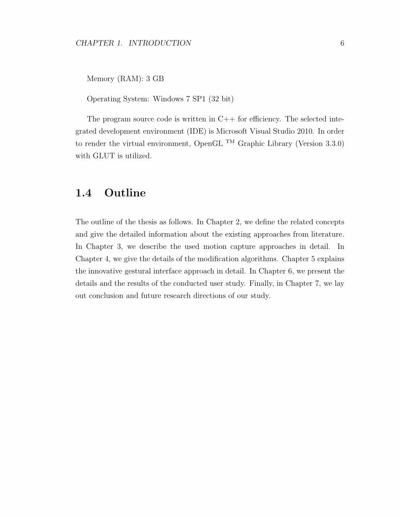
Memory (RAM): 3 GB
Operating System: Windows 7 SP1 (32 bit)
The program source code is written in C++ for efficiency. The selected inte-
grated development environment (IDE) is Microsoft Visual Studio 2010. In order
to render the virtual environment, OpenGL TM Graphic Library (Version 3.3.0)
with GLUT is utilized.
1.4 Outline
The outline of the thesis as follows. In Chapter 2, we define the related concepts
and give the detailed information about the existing approaches from literature.
In Chapter 3, we describe the used motion capture approaches in detail. In
Chapter 4, we give the details of the modification algorithms. Chapter 5 explains
the innovative gestural interface approach in detail. In Chapter 6, we present the
details and the results of the conducted user study. Finally, in Chapter 7, we lay
out conclusion and future research directions of our study.

Chapter 2
Background
2.1 Computer-Aided Design
Computer-Aided Design (CAD) is defined as “use of computer systems to as-
sist in the creation, modification, analysis, or optimization of a design” [5]. To
be able to use computers in design procedure, computer software that enables
users to produce technical drawings has been developed. CAD software makes
use of different structures to represent designed model and support modification
operations. Most widely used approaches used in today’s CAD applications are
Non-uniform Rational Basis Spline (NURBS), Bezier curves, volumetric repre-
sentations and 3D mesh structures [5]. Outputs of CAD applications, in addition
to the fine details, may also convey information about materials, dimension of
designed models etc.; hence, manufacturing the models become feasible.
2.2 Virtual Sculpting
Although traditional CAD systems have been very productive for new product
design, they are not suited to support conceptual design activities because these
activities often require a more natural and intuitive mode of human-computer
7
CHAPTER 2. BACKGROUND 8
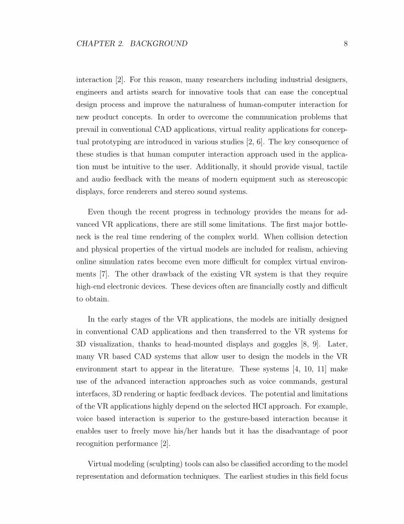
interaction [2]. For this reason, many researchers including industrial designers,
engineers and artists search for innovative tools that can ease the conceptual
design process and improve the naturalness of human-computer interaction for
new product concepts. In order to overcome the communication problems that
prevail in conventional CAD applications, virtual reality applications for concep-
tual prototyping are introduced in various studies [2, 6]. The key consequence of
these studies is that human computer interaction approach used in the applica-
tion must be intuitive to the user. Additionally, it should provide visual, tactile
and audio feedback with the means of modern equipment such as stereoscopic
displays, force renderers and stereo sound systems.
Even though the recent progress in technology provides the means for ad-
vanced VR applications, there are still some limitations. The first major bottle-
neck is the real time rendering of the complex world. When collision detection
and physical properties of the virtual models are included for realism, achieving
online simulation rates become even more difficult for complex virtual environ-
ments [7]. The other drawback of the existing VR system is that they require
high-end electronic devices. These devices often are financially costly and difficult
to obtain.
In the early stages of the VR applications, the models are initially designed
in conventional CAD applications and then transferred to the VR systems for
3D visualization, thanks to head-mounted displays and goggles [8, 9]. Later,
many VR based CAD systems that allow user to design the models in the VR
environment start to appear in the literature. These systems [4, 10, 11] make
use of the advanced interaction approaches such as voice commands, gestural
interfaces, 3D rendering or haptic feedback devices. The potential and limitations
of the VR applications highly depend on the selected HCI approach. For example,
voice based interaction is superior to the gesture-based interaction because it
enables user to freely move his/her hands but it has the disadvantage of poor
recognition performance [2].
Virtual modeling (sculpting) tools can also be classified according to the model
representation and deformation techniques. The earliest studies in this field focus

CHAPTER 2. BACKGROUND 9
on constructive solid geometry (CSG)based modification such as boolean oper-
ation on geometric primitives [12]. Some of the studies [13, 14] use voxel based
representation similar to our work while the others prefer surface based data struc-
tures which can be deformed using B-spline [15], mass-spring [16] techniques.
There are also studies that combine the surface and volume based approaches
like subdivision solids [17]. The deformation approach also changes according the
chosen representation. Volumetric representation is more suitable for volumetric
deformation such as stuffing and carving while physics-based deformations are
more suited for mass-spring and B-spline models [7].
2.3 Motion Capture
Although virtual environments create a realistic image of the real world, users
still need to use classic computer input devices such as mouse and keyboard to
interact with the virtual environments which cause users to lose intuitiveness [18].
To address this problem, different human-computer interaction devices that can
capture human hand motion data are introduced. One of the commonly used
input devices for this purpose are data gloves. Although various glove models
exist, data gloves are generally wearable electronic devices that are capable of
collecting the bending values of finger joints with different number of sensors of
various types. Because most of the data gloves collect only the bending angles,
additional information, namely hand position and orientation are required to fully
simulate the real hand movements. For this purpose, 3D position and orientation
trackers that utilize different technologies, such as magnetic tracking and vision-
based tracking, are developed [18]. Thanks to these technologies, it is possible to
create a virtual hand that is driven by a data glove and a tracker. Thus, human-
computer interaction becomes more natural and intuitive than the ones that use
classic input devices.
CHAPTER 2. BACKGROUND 10
2.4 Human Computer Interaction
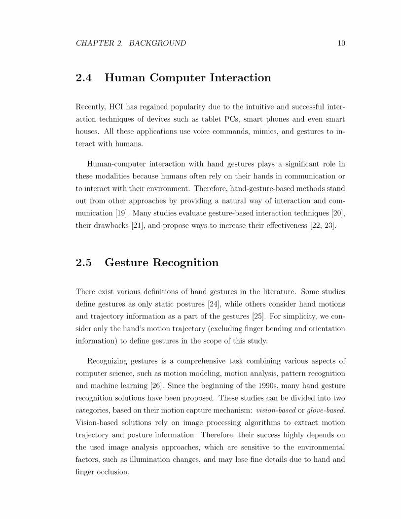
Recently, HCI has regained popularity due to the intuitive and successful inter-
action techniques of devices such as tablet PCs, smart phones and even smart
houses. All these applications use voice commands, mimics, and gestures to in-
teract with humans.
Human-computer interaction with hand gestures plays a significant role in
these modalities because humans often rely on their hands in communication or
to interact with their environment. Therefore, hand-gesture-based methods stand
out from other approaches by providing a natural way of interaction and com-
munication [19]. Many studies evaluate gesture-based interaction techniques [20],
their drawbacks [21], and propose ways to increase their effectiveness [22, 23].
2.5 Gesture Recognition
There exist various definitions of hand gestures in the literature. Some studies
define gestures as only static postures [24], while others consider hand motions
and trajectory information as a part of the gestures [25]. For simplicity, we con-
sider only the hand’s motion trajectory (excluding finger bending and orientation
information) to define gestures in the scope of this study.
Recognizing gestures is a comprehensive task combining various aspects of
computer science, such as motion modeling, motion analysis, pattern recognition
and machine learning [26]. Since the beginning of the 1990s, many hand gesture
recognition solutions have been proposed. These studies can be divided into two
categories, based on their motion capture mechanism: vision-based or glove-based.
Vision-based solutions rely on image processing algorithms to extract motion
trajectory and posture information. Therefore, their success highly depends on
the used image analysis approaches, which are sensitive to the environmental
factors, such as illumination changes, and may lose fine details due to hand and
finger occlusion.
CHAPTER 2. BACKGROUND 11
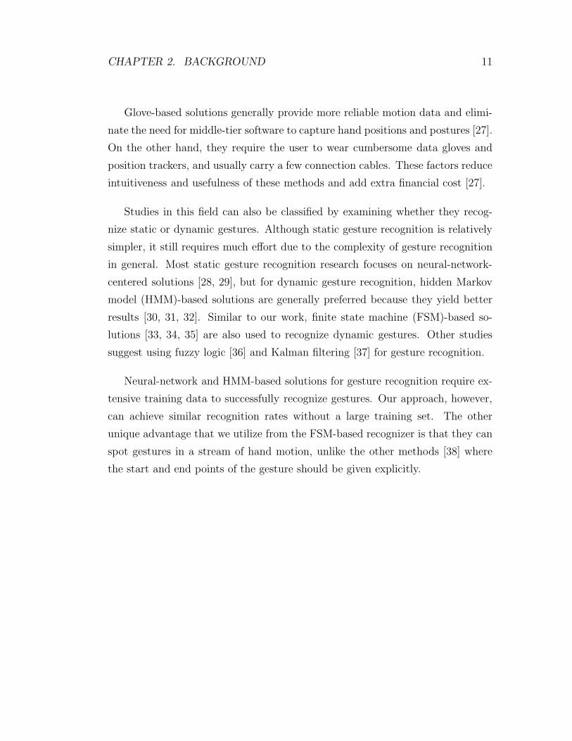
Glove-based solutions generally provide more reliable motion data and elimi-
nate the need for middle-tier software to capture hand positions and postures [27].
On the other hand, they require the user to wear cumbersome data gloves and
position trackers, and usually carry a few connection cables. These factors reduce
intuitiveness and usefulness of these methods and add extra financial cost [27].
Studies in this field can also be classified by examining whether they recog-
nize static or dynamic gestures. Although static gesture recognition is relatively
simpler, it still requires much effort due to the complexity of gesture recognition
in general. Most static gesture recognition research focuses on neural-network-
centered solutions [28, 29], but for dynamic gesture recognition, hidden Markov
model (HMM)-based solutions are generally preferred because they yield better
results [30, 31, 32]. Similar to our work, finite state machine (FSM)-based so-
lutions [33, 34, 35] are also used to recognize dynamic gestures. Other studies
suggest using fuzzy logic [36] and Kalman filtering [37] for gesture recognition.
Neural-network and HMM-based solutions for gesture recognition require ex-
tensive training data to successfully recognize gestures. Our approach, however,
can achieve similar recognition rates without a large training set. The other
unique advantage that we utilize from the FSM-based recognizer is that they can
spot gestures in a stream of hand motion, unlike the other methods [38] where
the start and end points of the gesture should be given explicitly.
Chapter 3
Motion Capture
3.1 Overview
We use our hands to perform various daily tasks, to interact with and manipulate
our environment. Because they play a crucial role in our daily lives, researches
have been trying to develop technologies which capture the hand movements and
convey them to the computers. For this purpose, sensorized gloves started to be
developed in late 1970s [39]. Sensorized gloves, also known as data gloves, may
vary according to the used sensor technology, sensor number and precision. The
basic idea that lies behind data gloves is to collect the joint angle values of hand
fingers and transmit them to a computer via different means such as bluetooth or
cable. For a more detailed survey on data gloves, you can refer to this study [39].
3.2 Data Glove
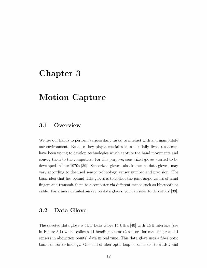
The selected data glove is 5DT Data Glove 14 Ultra [40] with USB interface (see
in Figure 3.1) which collects 14 bending sensor (2 sensors for each finger and 4
sensors in abduction points) data in real time. This data glove uses a fiber optic
based sensor technology. One end of fiber optic loop is connected to a LED and
12
CHAPTER 3. MOTION CAPTURE 13
the other end of the loop has a photo-transistor which measures the intensity of
the light returning from the other end. Since light intensity degenerated when
fingers bend, the glove measures the bending values indirectly according to the
light density. 5DT data glove provides data with the sampling rate which is above
75 Hz. Although there are other sophisticated data gloves exist in the market,
5DT Data Glove 14 Ultra is chosen because of its affordability and accessibility.
Figure 3.1: 5DT Data Glove Ultra 14.
3.3 6DoF Tracker
To be able to completely describe hand motion, knowledge of both hand configu-
ration (amount of joint bending) and hand position in space are needed. Because
the selected data glove does not have sensors for capturing the position and ori-
entation information (total of 6 Degrees of Freedom (DoF): 3 for translations and
3 for rotations), we need to conjunct the data glove with extra accessories called
3D trackers. There are several types of 3D trackers offered over the years which
diverge among each other according to their key performance parameters (accu-
racy, jitter, drift, latency, and so on) and technological infrastructure (magnetic,
ultrasonic, optical and mechanic) [39].

CHAPTER 3. MOTION CAPTURE 14
Figure 3.2: Polhemus Patriot TM.
We selected Patriot TM trackers produced by Polhemus (see Figure 3.2). It
is one of the cost-effective solutions that can offer 6 DoF motion tracking with
reasonable well resolution and range. It is pioneered with A/C magnetic motion
tracking technology. The tracking system composed of source, sensors and a pro-
cessing/transmitting unit. The source and sensor contain electromagnetic coils
enclosed in plastic shells. The source emits magnetic fields, which are detected
by the sensor. Orientation and position calculations are made according to the
readings on the passive sensors. Some of the important company specifications
of the utilized tracker are listed in Table 3.1.
Although accuracy claim is very high in the specifications, it has been exper-
imented that when the distance between source and sensors is above 80-100 cm,
the precision degenerates rapidly and causes shakes on the virtual hand driven
by the tracker. Because we focus on preliminary design and accuracy range is
enough as a design space for users, the problem is not disconcerting.
CHAPTER 3. MOTION CAPTURE 15
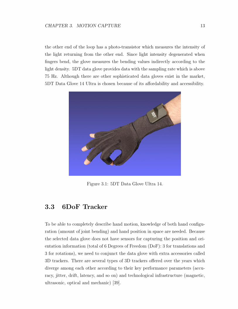
Degrees-of-Freedom 6 DoFNumber of Sensors 1-2Update Rate 60 Hz per sensorStatic Accuracy Position 0.06 in RMSStatic Accuracy Orientation 0.40◦ RMSLatency Less than 18.5 msResolution Position at 12 in range 0.00046 in 0.00117 cmResolution Orientation at 12 in range 0.00381◦
Range from Standard TX2 Source Up to 1.52 metersExtended Range Source n/aInterface RS-232 or USB (both included)
Table 3.1: Polhemus Patriot TM specifications.
3.4 Hand Model and Its Skeletal Structure
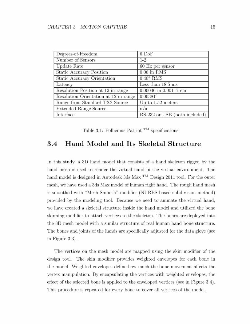
In this study, a 3D hand model that consists of a hand skeleton rigged by the
hand mesh is used to render the virtual hand in the virtual environment. The
hand model is designed in Autodesk 3ds Max TM Design 2011 tool. For the outer
mesh, we have used a 3ds Max model of human right hand. The rough hand mesh
is smoothed with “Mesh Smooth” modifier (NURBS-based subdivision method)
provided by the modeling tool. Because we need to animate the virtual hand,
we have created a skeletal structure inside the hand model and utilized the bone
skinning modifier to attach vertices to the skeleton. The bones are deployed into
the 3D mesh model with a similar structure of real human hand bone structure.
The bones and joints of the hands are specifically adjusted for the data glove (see
in Figure 3.3).
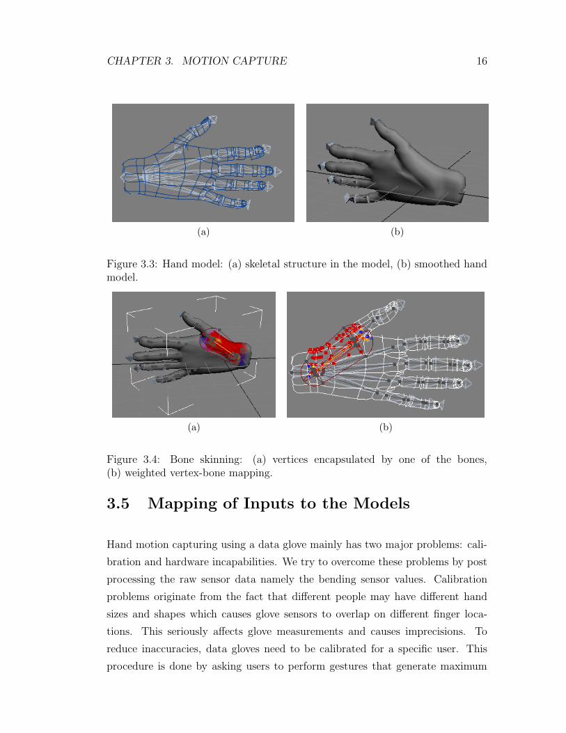
The vertices on the mesh model are mapped using the skin modifier of the
design tool. The skin modifier provides weighted envelopes for each bone in
the model. Weighted envelopes define how much the bone movement affects the
vertex manipulation. By encapsulating the vertices with weighted envelopes, the
effect of the selected bone is applied to the enveloped vertices (see in Figure 3.4).
This procedure is repeated for every bone to cover all vertices of the model.
CHAPTER 3. MOTION CAPTURE 16
(a) (b)
Figure 3.3: Hand model: (a) skeletal structure in the model, (b) smoothed handmodel.
(a) (b)
Figure 3.4: Bone skinning: (a) vertices encapsulated by one of the bones,(b) weighted vertex-bone mapping.
3.5 Mapping of Inputs to the Models
Hand motion capturing using a data glove mainly has two major problems: cali-
bration and hardware incapabilities. We try to overcome these problems by post
processing the raw sensor data namely the bending sensor values. Calibration
problems originate from the fact that different people may have different hand
sizes and shapes which causes glove sensors to overlap on different finger loca-
tions. This seriously affects glove measurements and causes imprecisions. To
reduce inaccuracies, data gloves need to be calibrated for a specific user. This
procedure is done by asking users to perform gestures that generate maximum

CHAPTER 3. MOTION CAPTURE 17
and minimum bending values on the sensors like “flat hand” and “fist” gestures
for 5DT Data Glove 14 Ultra. The automated calibration mechanism applied
in the data glove is based on linear polarization. After minimum and maximum
readings extracted from sensors, all raw bending values are mapped between 0
and 1, respectively. The mapping function is shown in Equation 3.1.
output =rawread − rawminrawmax − rawmin
(3.1)
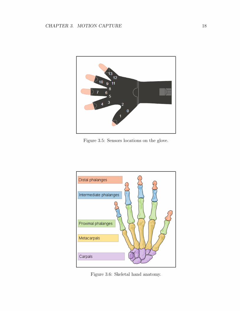
The other problem of the glove-based motion capture is hardware incapabili-
ties. Although human hand (see Figure 3.6) has 19 degrees of freedom excluding
the wrist, the data glove can only provide 14 sensor values. In addition, sensors
on the data glove do not directly correspond to the hand joints (see Figure 3.5).
Thus, the contribution of the joints to the bending value on the sensors is un-
known but it can be estimated using an interpolation function, which is adaptable
to natural bending tendency of the fingers [27]. We use an interpolation function
that defines bending values in the following manner: the start and end points
define the possible minimum and maximum rotation angles respectively and spe-
cific to each joint. In this method, the additional control point is used to give an
affinity value to the joint. For example, if the chosen control point is close to the
minimum value, the interpolation function generates smaller angles which make
the joint have the tendency of stand straight. If the selected control point is close
to the maximum values, the interpolation function generates relatively greater
angles even though the read bending value is small. The interpolation function is
given in Equation 3.2 where α and θ denotes start and end points, respectively,
and β denotes the control point. The t values in the equation are replaced by the
scaled sensor value read from the data glove. The interpolated sensor values for
the Equation 3.2 with different control points can be seen in Figure 3.7.
output = α(1 − t2) + 2β(1 − t)t + θt2 (3.2)
By using the natural constraints and bending tendencies of the finger joints,
we can make a good approximation on the joint angles in spite of relatively
CHAPTER 3. MOTION CAPTURE 18
Figure 3.5: Sensors locations on the glove.
Figure 3.6: Skeletal hand anatomy.

CHAPTER 3. MOTION CAPTURE 19
(a)
(b)
Figure 3.7: Interpolated sensor values using Equation 3.2: (a) Control point iscloser to end point, (b) Control point is closer to start point.

CHAPTER 3. MOTION CAPTURE 20
incorrect sensor values. Bezier curves can also be used for more controlled in-
terpolation but single control point is sufficient in the scope of this study. The
chosen interpolation values, sensor mapping and rotation constraints applied to
the bones in horizontal and vertical axes are listed in Tables 3.2 and 3.3, respec-
tively. After the proposed interpolation function produces the interpolated joint
angles, orientation information are converted to quaternions for representation.
Bone Start (◦) End (◦) Control (◦) Sensor Nolittle metacarpus 0 8 1 12little knuckle 0 90 40 12little lower 0 90 60 13little upper 0 80 60 13ring metacarpus 0 4 1 9ring knuckle 0 90 60 9ring lower 0 100 45 10ring upper 0 90 35 10middle metacarpus 0 4 1 6middle knuckle 0 90 10 6middle lower 0 105 65 7middle upper 0 90 55 7index metacarpus 0 4 1 3index knuckle 0 90 70 3index lower 0 80 30 4index upper 0 110 65 4thumb metacarpus 40 0 7 0thumb knuckle 0 70 10 0thumb upper -5 65 15 1
Table 3.2: Interpolation values of each finger joint in the horizontal axis.
The position and orientation information captured from the tracker is directly
mapped to the root bone thus every motion in the root bone is transferred to child
bones. Therefore, entire hand moves and rotates at each position and orientation
update.
CHAPTER 3. MOTION CAPTURE 21
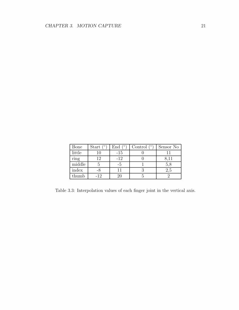
Bone Start (◦) End (◦) Control (◦) Sensor Nolittle 10 -15 0 11ring 12 -12 0 8,11middle 5 -5 1 5,8index -8 11 3 2,5thumb -12 20 5 2
Table 3.3: Interpolation values of each finger joint in the vertical axis.
Chapter 4
Virtual Sculpting
4.1 Volumetric Structure of Deformable Models
The proposed system represents the deformable objects (virtual clay) with a
volumetric approach. The deformable objects lie on the deformation space of the
virtual environment. The deformation space is a 3D grid structure where the
corners of the grids contain volume elements (voxels). The selected size for the
deformation space is 128× 128× 128, which is large enough to represent detailed
models and small enough to process all the space in real time with a standard
personal computer (for computer specification, please see Section 1.3). The size
of the deformation space can be increased to enhance the model quality and real
time processing still can be achieved with more processing power.
In the proposed method, all the deformable objects consist of voxels. We place
the voxels of the deformable objects on the corners of uniform 3D grid structure.
A voxel is either filled or empty. A deformable object is the collection of voxel
that are filled. We modify and deform the objects by toggling the state of the
voxels in deformation space.
22
CHAPTER 4. VIRTUAL SCULPTING 23
4.2 Rendering Deformable Objects
Because the used representation technique is volume based, we need to convert the
model data to OpenGL TM drawable data primitives like vertices, edges, triangles,
quads. Additionally, we need to calculate normal vectors of the primitives for
realistic rendering and shading. For this process, we make use of the famous
marching cubes algorithm [41]. Marching cubes is an algorithm that extracts
polygonal mesh of the surface from a volumetric 3D data. To be able to extract
surface of the voxels in deformation space, the algorithm proceeds on each cube
which consists of neighbouring eight voxels. The polygons that form the surfaces
are determined according to the states of the voxels in the corners of the cube.
Because there are eight corners of a cube, one of the 256 pre-calculated possible
polygon configurations is selected.
To be able to utilize illumination models provided by OpenGL TM , we need
to compute the normal vector of the each vertex generated by the algorithm.
Because each vertex is part of more than one polygon, we calculated the normal
vector of the each vertex by interpolating normal vectors of the contributing
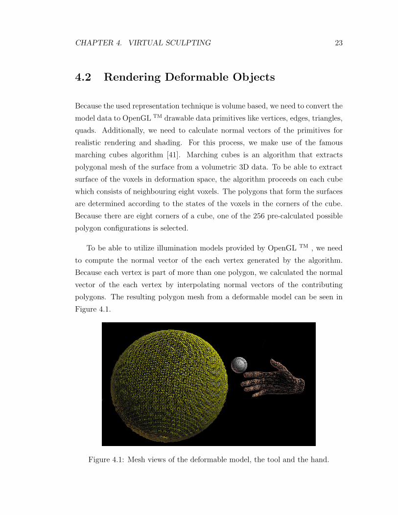
polygons. The resulting polygon mesh from a deformable model can be seen in
Figure 4.1.
Figure 4.1: Mesh views of the deformable model, the tool and the hand.
CHAPTER 4. VIRTUAL SCULPTING 24
4.3 Deformation Tools and Their Manipulations
Deformation tools in the virtual environment are the main means of deforma-
tion. They are simply 3D objects which can be used to carve material from the
deformable model or stuff new material to the existing ones. Because we use
point/surface-based interaction for deformation, they can be an arbitrary shape,
which has a well-defined surface. (For details of the deformation techniques,
please refer to Sections 4.4 and § 4.6). In the virtual sculpting application, we
prefer to use 3D primitives such as cubes, sphere with various size as our defor-
mation tools. These tools can be manipulated with the virtual hand or directly
by the 6 DoF trackers.
In order to manipulate tools intuitively, we make use of grasp gesture where
all of the fingers are closed like a fist. To select and move a tool in the virtual
environment, users need to grasp the tool with the virtual hand firstly. For grasp
action to be detected, virtual hand space and tool space should intersect and the
virtual hand should perform a grasp gesture. As long as the gesture is preserved,
the tool can be manipulated with the virtual hand. Manipulated (grasped) tools
follow the exact same motion of the virtual hand. When the virtual hand is
rotated or moved, the manipulated tool will also be rotated and moved. If the user
ungrasps the virtual tool, the tool performs one of the following pre-determined
action: return to its initial position or stay put in the last location of the virtual
hand.
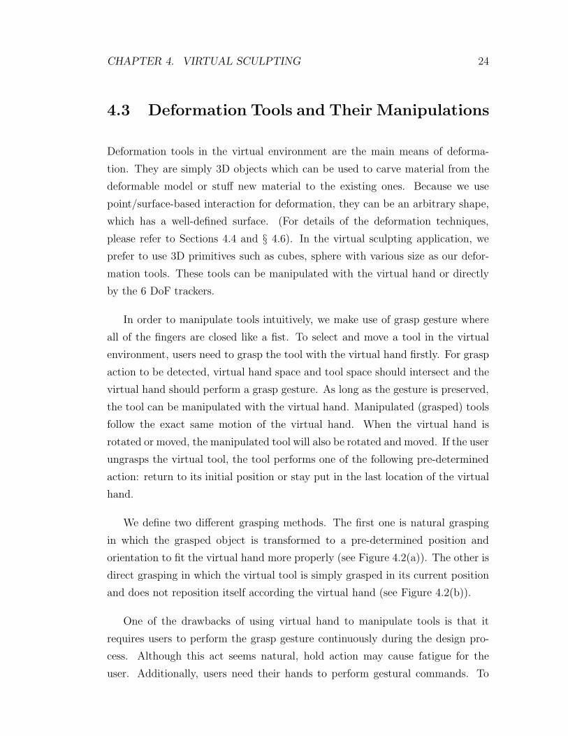
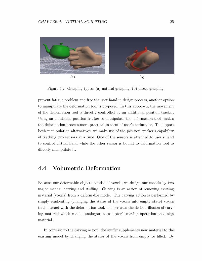
We define two different grasping methods. The first one is natural grasping
in which the grasped object is transformed to a pre-determined position and
orientation to fit the virtual hand more properly (see Figure 4.2(a)). The other is
direct grasping in which the virtual tool is simply grasped in its current position
and does not reposition itself according the virtual hand (see Figure 4.2(b)).
One of the drawbacks of using virtual hand to manipulate tools is that it
requires users to perform the grasp gesture continuously during the design pro-
cess. Although this act seems natural, hold action may cause fatigue for the
user. Additionally, users need their hands to perform gestural commands. To
CHAPTER 4. VIRTUAL SCULPTING 25
(a) (b)
Figure 4.2: Grasping types: (a) natural grasping, (b) direct grasping.
prevent fatigue problem and free the user hand in design process, another option
to manipulate the deformation tool is proposed. In this approach, the movement
of the deformation tool is directly controlled by an additional position tracker.
Using an additional position tracker to manipulate the deformation tools makes
the deformation process more practical in term of user’s endurance. To support
both manipulation alternatives, we make use of the position tracker’s capability
of tracking two sensors at a time. One of the sensors is attached to user’s hand
to control virtual hand while the other sensor is bound to deformation tool to
directly manipulate it.
4.4 Volumetric Deformation
Because our deformable objects consist of voxels, we design our models by two
major means: carving and stuffing. Carving is an action of removing existing
material (voxels) from a deformable model. The carving action is performed by
simply eradicating (changing the states of the voxels into empty state) voxels
that interact with the deformation tool. This creates the desired illusion of carv-
ing material which can be analogous to sculptor’s carving operation on design
material.
In contrast to the carving action, the stuffer supplements new material to the
existing model by changing the states of the voxels from empty to filled. By
CHAPTER 4. VIRTUAL SCULPTING 26
doing so, it is possible to form a new model from scratch resembling adding clay
to create a new design.
4.5 Collision Detection
Unlike our deformable models, deformation tools consist of triangular meshes.
Thus, for collision detection, surface points on the deformation tools need to be
converted to deformation space. The corresponding point in deformation space
for each vertex on the surface of the deformation tool is calculated by inversing the
transformations on the deformation tools. After all surfaces are transferred to the
deformation space (grid), we need to check every vertex on the surface whether
it coincides with one of the voxels. If the brute force approach is used, the cost
of the collision detection process for each update becomes O(M × N3) where M
is the number of surface points and N is the size of one dimension. Because
we have uniform 3D grid as a deformation space, it is possible to directly use
the translated surface points as an index to this grid by means of floor or ceiling
function. Thus, collision calculation for the entire tool can be computed in O(M),
which is more than enough to check collision detection in real time.
In addition to that, another collision detection method is proposed for non-
uniform deformation spaces. Because the processing time is very critical for a real
time design application, we reduce the search cost using an octree based search
algorithm for non-uniform deformation spaces [42].With this approach, collisions
can be detected in O(M × logN) for non-uniform deformation spaces.
4.6 Surface-based Deformation
Although our deformation tools do not have a volume (only have surfaces), by
sweeping the deformation space with their surface points, we can stuff/carve
material to/from the deformable model. Because all our deformation tools are
closed, a voxel cannot get inside of a deformation tool without passing from its
CHAPTER 4. VIRTUAL SCULPTING 27
surface. Thus, it is not necessary to have volumetric deformation tools (models
which contain vertices (voxels) inside of the tool) for deformation operations.
On the contrary, volumetric deformation tools may increase the processing time
because they will have a lot more vertex than a surface based shape.
On the other hand, surface based deformation tools have a major drawback.
Because we only use surface points for collision detection, we may skip some
voxels at the locations where surface points on the tool are sparse. To overcome
this problem, we added more surface layers inside the deformation tools. If a
voxel can pass through outer surface, it coincides with one of the inner surface
layers and deformation action is applied to this voxel.
Because we use surface-based deformation, any model which has dense surface
point distribution can be used as a deformation tool in the proposed system. To
display this functionality and create a more life-like design experience, we used
virtual hand directly as a deformation tool. Because it has a well-defined surface
and a closed 3D shape, users can directly design the deformable models just using
their hands to control virtual hand.
During the deformation phase, another normal calculation approach is used
to increase the quality of the illumination on the deformable model. The inverse
of the surface normal (tool surface) is applied to the deformed voxels, which
enhances the perception of deformation done by the deformation tool.
4.7 Visual Force Feedback
In real life design process, touch sense helps designers to capture the shape of
the model while force feedback from the designed material helps them make fine
adjustments over the deformable model. Without using additional force feedback
hardware, it is difficult to convey this information to the users. In order to
overcome this problem, we add a visual force feedback indicator (see Figure 4.3)
to the proposed system. The force feedback indicator works similar to the real life
equivalent. It shows the amount of material being modified (carved or stuffed)

CHAPTER 4. VIRTUAL SCULPTING 28
as users design the deformable models. The intensity (force) on the indicator is
calculated by counting the number of voxels being edited. When the number of
edited material increases, the force bar in the indicator rises and the colour of
the bar turns red from green. Although visual force feedback indicator cannot
provide the life like design experience and touch, it helps user to capture the
touch sense in a limited way.
Figure 4.3: Visual force feedback indicator.
Because we use 2D displays in our application, providing depth perception for
users is a very difficult task. The visual force feedback indicator also helps users
to understand the depth information by evaluating the number of modifications.

Chapter 5
Human Computer Interaction
5.1 Overview
User interface design and how users interact with the user interface elements is
one of the most crucial design aspects of a computer application. Because we
offer natural hand based interaction to users, a user-friendly interface design that
is suitable for the utilized input device is necessary. To accomplish this task, we
provide two different approaches:
The first component of our gestural interface is the hand mouse. Because our
users wear data gloves, they may not control the mouse effectively. To overcome
this interaction problem, we specifically design an interaction method in which
users can manage the mouse with data glove and position tracker effectively. With
this method, the user can interact with classical GUI items such as windows or
buttons.
The other component that we introduce is a gesture-based command interface.
Users can direct and command the application by performing trajectory based
hand gestures. The gesture vocabulary and their recognizer machines can be
generated by supplying only few sample gesture data for each gesture. This
feature allows users to create their own gesture commands for a particular task
29
CHAPTER 5. HUMAN COMPUTER INTERACTION 30
according to how they think it suits the action. Because the gesture-command
interface has a general architecture, it is not limited to virtual sculpting tool. It
can be used in any context to command applications or devices such as TVs or
e-Readers with gestural commands.
5.2 Hand Mouse
Because the user has limited access to mouse while wearing data glove, a mouse
like interaction cursor is developed which can be manipulated with the virtual
hand. The GUI elements of the proposed system are very similar to classical GUI
elements. In the scope of this study, simple rectangular buttons are utilized as
means of interaction. The intuitive and novel part of the user interface is the
cursor that manipulates these buttons. The cursor of the design application is
controlled by the position tracker and the data glove unlike classical cursors that
are controlled by a mouse.
During the design process, the cursor is hidden to allow access to hand-based
deformation. In order to activate the cursor to interact with user interface el-
ements, users just need to perform a specific static gesture, which is a “point
gesture” where all fingers closed except the index finder. When this gesture is
detected, virtual hand that is used for design process disappears and system goes
into the GUI interaction mode. The GUI interaction mode stays active as long
as the gesture is preserved. When GUI interaction mode is activated, a mouse
cursor appears. The movement of the cursor is controlled by the position tracker.
Users can move the cursor naturally by moving their hands that are attached to
the position tracker. Positions of the hands are transformed to 2D coordinate
system by dropping the depth information collected from the input device. In
other words, cursor follows the hand motion of the user in a manner that simu-
lates mouse motion. A “mouse click” is simulated by bending the index finger.
Bending state of the index finger is like mouse button pressed action.
GUI interaction is performed in the following manner: when a user wants to
CHAPTER 5. HUMAN COMPUTER INTERACTION 31
interact with a GUI element, he/she basically moves the cursor over the GUI
element by moving his/her hand. When the cursor is over the GUI element, user
simply bends his/her index finger to click on it to perform the action that is
related to respective GUI element. The proposed interaction technique removes
the need for a mouse considerably and makes the GUI action more suitable for
the application.
5.3 Gesture Detection and Recognition
Similar to the other gesture recognition techniques, the proposed approach con-
sists of two stages: learning and recognition. In the learning stage, the user is
asked to repeatedly perform a particular gesture. The system records the motion
trajectory of each gesture sample with a magnetic 3D position tracker attached
to the user’s hand. Unlike the other approaches [43], motion data is collected by
recording the relative position of the hand according to its previous location, in-
stead of recording the absolute positions. Additionally, threshold-based filtering
is applied to the collected data to reduce noise caused by unintended vibrations
and tracker precision errors due to distance range of the sensor. Next, collected
motion data is filtered using a component-based sliding window technique for
smoothing and further noise removal. Then, the filtered trajectory information is
transformed into our gesture representation format, which is basically an ordered
sequence of events (directional movements).
In the last step of the learning phase, our method chooses a few event se-
quences (using the Needleman-Wunsch sequence-matching algorithm [44]) from
the provided samples to form a base for gesture recognizers. The algorithm com-
pares every pair of event sequences (gesture pairs) and computes a similarity score
for them. The event sequences with the highest similarity scores are selected to
form the bases for the gesture recognizers. Then, a recognizer finite state machine
(FSM) is generated based on these chosen gestures. Because FSMs are sequence
recognizers, each forward transition in a generated FSM corresponds to an event
in the selected sequence in the respective order. This learning phase is repeated
CHAPTER 5. HUMAN COMPUTER INTERACTION 32
for every distinct gesture, with several FSMs produced for each.
In the recognition stage, continuous inputs from the tracker are processed in
a similar manner as in the learning stage and fed to all the recognizer machines.
If one of the previously captured event sequences occurs during the session, the
respective recognizer machine traverses all the states and reaches the final state
(the accepting state). The resulting gesture recognition event triggers the action
assigned for the gesture. With this approach, gestures can be recognized in real
time.
5.3.1 Gesture Representation
In gesture recognition, representing gestures is a critical issue. We define ges-
tures as a series of events performed consecutively. For trajectory-based dynamic
gestures, this is a valid definition because trajectories are a series of directional
vectors combined in a particular time interval. In our case, events are directional
movements and a gesture is an ordered sequence of these directional movements
(see Figure 5.1).
In this study, we limit the trajectories to the xy-plane for simplicity. Our rep-
resentation not only allows creating many interesting gestures, it also improves
the robustness of the algorithm. It is possible to extend the event (gesture) alpha-
bet with the third dimension, or with other features such as finger movements.
Using only 2D, there are eight different directional movements: (+x), (−x), (+y),
(−y), (+x, +y), (+x, −y), (−x, +y) and (−x, −y), and they constitute a gesture
space large enough to represent a variety of gestures.
To capture hand motions, we use the same six-degrees-of-freedom (DoF) mag-
netic motion tracking device. The device has a 60 Hz update rate for each sensor,
but in our experiments, we observe that a 20 Hz rate is sufficient to teach and
recognize gestures. Although we use hardware-based tracking, it is possible to
employ computer-vision-based tracking for a more intuitive solution. Because
the required motion capture technique does not need a fast update rate or high

CHAPTER 5. HUMAN COMPUTER INTERACTION 33
Figure 5.1: A gesture (circle) is represented as an ordered sequence of directionalmovements.
accuracy, it is also well suited for camera tracking. The cheaper motion tracking
devices utilized by Nintendo Wii TM or Microsoft Kinect TM can also be used as
the motion capture medium for the proposed approach. Gestures are represented
as small directional movements so there is no need to maintain the absolute posi-
tion. This advantage therefore makes the offered solution naturally applicable to
accelerometer based motion tracking algorithms. Collected motion data in abso-
lute position format is converted to relative position data (gradient form) while
recording. In other words, when the tracker sends a new position reading, its po-
sition relative to the previous reading is noted and the direction of the movement
is calculated. However, to prevent noise that may be caused by small vibrations
in the hand and/or by tracker inaccuracies, relatively small changes from the
previous recording are not recorded (see parameters 1 and 2 in Table 5.1).
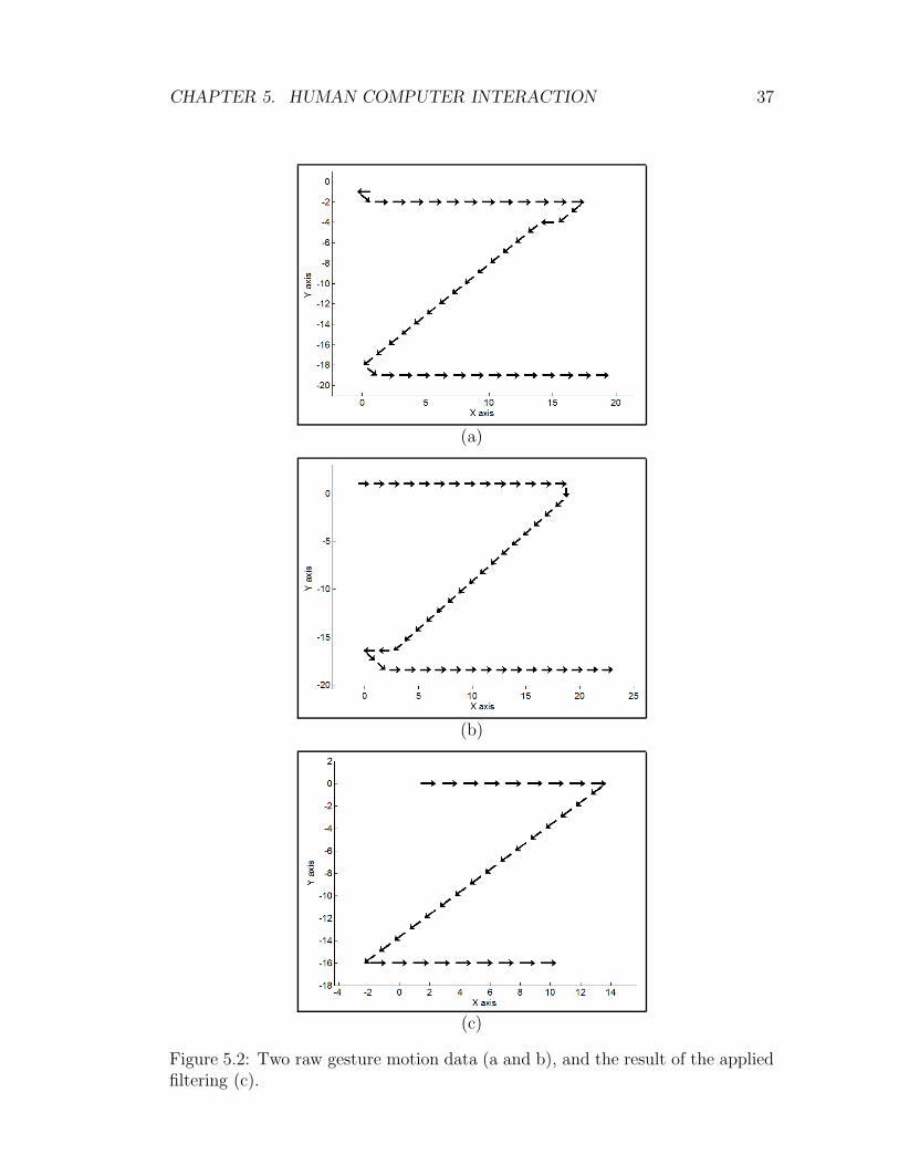
5.3.2 Smoothing and Selection of Best Gestures
Although filtering is applied during the motion capture phase, the collected tra-
jectory data may still contain events that are not part of the gesture due to user
CHAPTER 5. HUMAN COMPUTER INTERACTION 34
reaction error during the initial and final moments of the recording. There also
exist a few events that do not fit the natural flow of the trajectory especially
at points where a major direction change occurs (see Figures 5.2 (a) and (b)).
To eliminate these minor errors, the beginnings and endings of the trajectory
records are discarded (see parameter 3 in Table 5.1) and a smoothing process is
applied to the collected motion data. We use a simple sliding window filter for
smoothing. The windows run on the collected data for majority-based filtering
(see parameter 4 in Table 5.1). An input gesture motion data and the results of
the applied filtering are shown in Figure 5.2.
In the ideal case, when the same gesture is performed, it would yield the same
event sequence so the recognizer could be formed from just one gesture sample.
However, due to the nature of trajectory-based gestures and filtering errors, the
captured gesture samples may not be identical in terms of the resulting event
sequences (Figure 5.3). To determine the correct series of events that a gesture
contains, the system needs several samples of trajectory information, from which
“the best” event sequences are chosen. These choices are made by the Needleman-
Wunsch [44] sequence matching algorithm that produces a similarity score, which
is a global sequence alignment algorithm commonly used in bioinformatics to align
two protein or nucleotide sequences. The alignment procedure also computes a
similarity score between two sequences. Similarity scores are calculated according
to a similarity matrix/function for the characters in alphabets (events). Because
events are vectors in our case, the similarity of two “characters” is calculated
using the distances between vectors. The gap penalty for the sequence matching
algorithm is set to a value higher than the maximum distance between the vectors
to achieve the same length gesture sequences (see parameter 5 in Table 5.1)
A total similarity value for each sequence is acquired by summing its pair-
wise similarity scores. Then, the highest n (see parameter 6 in Table 5.1) event
sequences are selected to later create recognizers. In other words, gestures that
are located closer to the center of the gesture cluster are selected because they
are more likely to generate a more generic sequence of events, which can then be
used to form the bases for gesture recognizers.
CHAPTER 5. HUMAN COMPUTER INTERACTION 35
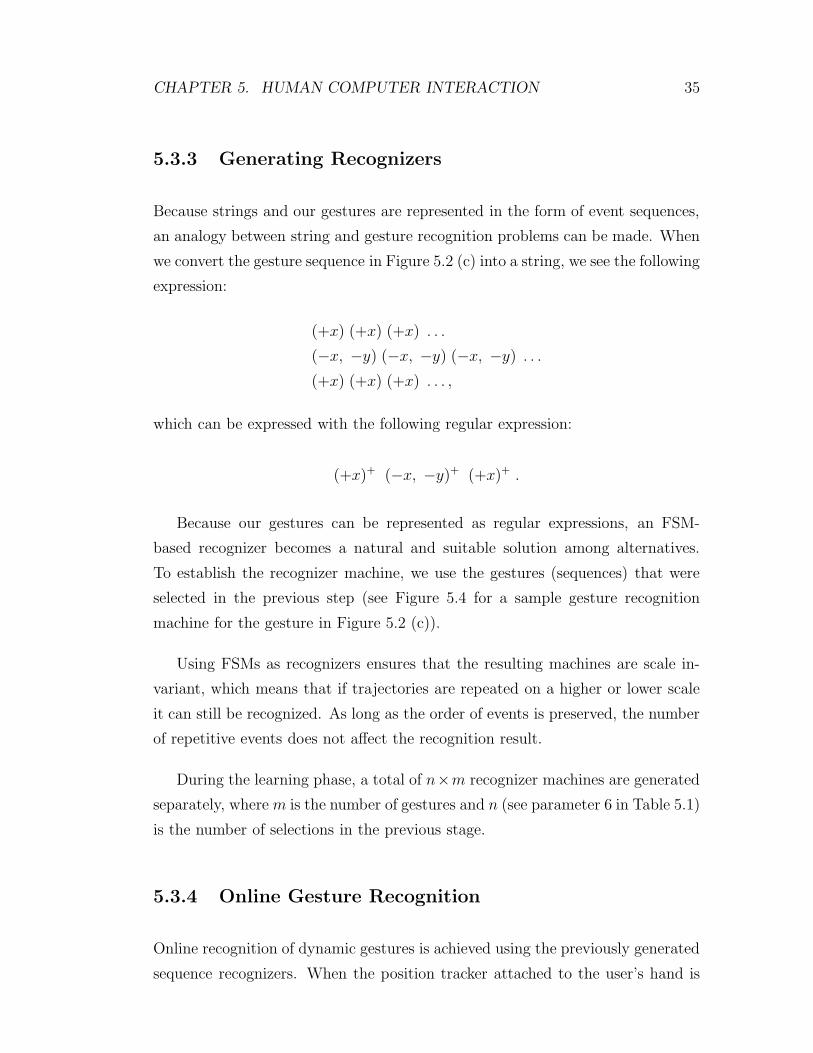
5.3.3 Generating Recognizers
Because strings and our gestures are represented in the form of event sequences,
an analogy between string and gesture recognition problems can be made. When
we convert the gesture sequence in Figure 5.2 (c) into a string, we see the following
expression:
(+x) (+x) (+x) . . .
(−x, −y) (−x, −y) (−x, −y) . . .
(+x) (+x) (+x) . . . ,
which can be expressed with the following regular expression:
(+x)+ (−x, −y)+ (+x)+ .
Because our gestures can be represented as regular expressions, an FSM-
based recognizer becomes a natural and suitable solution among alternatives.
To establish the recognizer machine, we use the gestures (sequences) that were
selected in the previous step (see Figure 5.4 for a sample gesture recognition
machine for the gesture in Figure 5.2 (c)).
Using FSMs as recognizers ensures that the resulting machines are scale in-
variant, which means that if trajectories are repeated on a higher or lower scale
it can still be recognized. As long as the order of events is preserved, the number
of repetitive events does not affect the recognition result.
During the learning phase, a total of n×m recognizer machines are generated
separately, where m is the number of gestures and n (see parameter 6 in Table 5.1)
is the number of selections in the previous stage.
5.3.4 Online Gesture Recognition
Online recognition of dynamic gestures is achieved using the previously generated
sequence recognizers. When the position tracker attached to the user’s hand is
CHAPTER 5. HUMAN COMPUTER INTERACTION 36
activated, it starts to continuously transmit position information to the system.
The received absolute position data is converted to the relative (gradient) form
and filtered as in the learning phase to reduce the effects of small trajectory errors
and to improve the robustness of the algorithm.
Before the filtered event data is fed to all recognizer machines in a continuous
manner, online filtering is applied to the newly received data to determine whether
it is consistent with the previous events. Inconsistent events are not sent to
recognizers because they are not part of the intended gestures. The received
events cause state transitions in the recognizer machines. When a machine reaches
its accepting state, a gesture recognition event is triggered immediately.
If no state transitions are detected for a particular time interval, a time-out
(see parameter 7 in Table 5.1) mechanism is triggered and the gesture recognizer is
reset to the initial state to prevent unnaturally long waits for a gesture recognition
event. In the proposed approach, there is no need to specify a gesture’s start and
end points because the machine returns to its initial state automatically in the
event of an incorrect gesture input or a time-out.
CHAPTER 5. HUMAN COMPUTER INTERACTION 37
(a)
(b)
(c)
Figure 5.2: Two raw gesture motion data (a and b), and the result of the appliedfiltering (c).

CHAPTER 5. HUMAN COMPUTER INTERACTION 38
Figure 5.3: Captured gesture samples may be different due to the nature oftrajectory-based gestures and filtering errors.
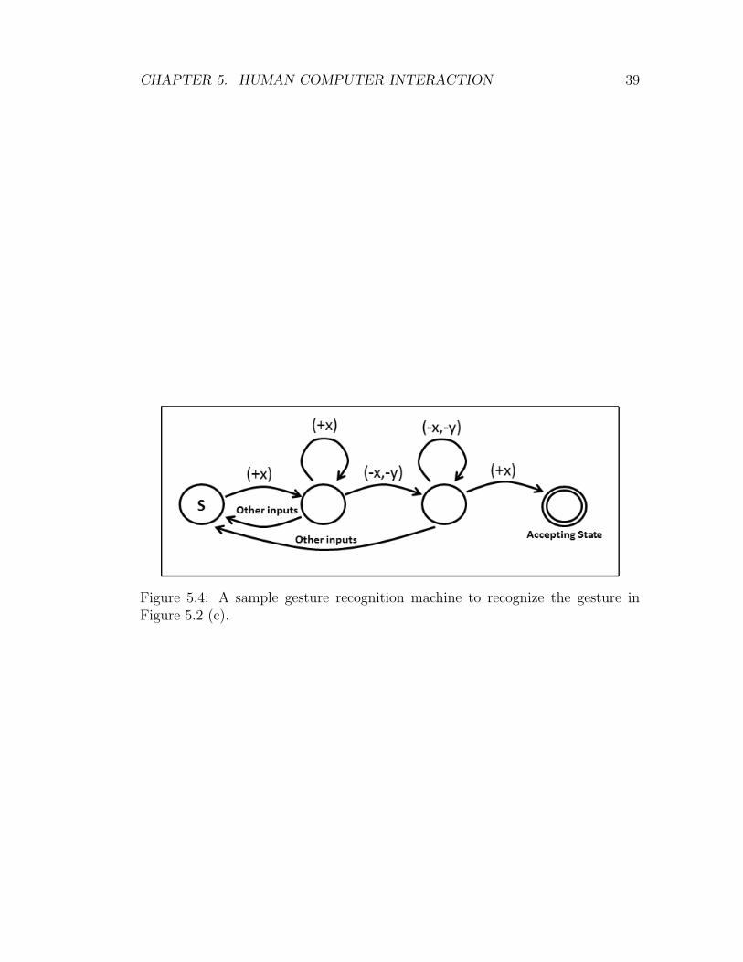
CHAPTER 5. HUMAN COMPUTER INTERACTION 39
Figure 5.4: A sample gesture recognition machine to recognize the gesture inFigure 5.2 (c).
CHAPTER 5. HUMAN COMPUTER INTERACTION 40
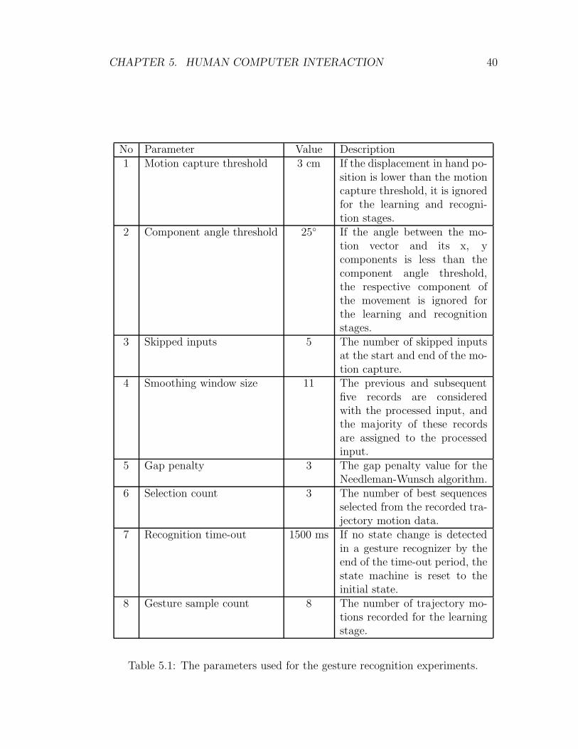
No Parameter Value Description1 Motion capture threshold 3 cm If the displacement in hand po-
sition is lower than the motioncapture threshold, it is ignoredfor the learning and recogni-tion stages.
2 Component angle threshold 25◦ If the angle between the mo-tion vector and its x, ycomponents is less than thecomponent angle threshold,the respective component ofthe movement is ignored forthe learning and recognitionstages.
3 Skipped inputs 5 The number of skipped inputsat the start and end of the mo-tion capture.
4 Smoothing window size 11 The previous and subsequentfive records are consideredwith the processed input, andthe majority of these recordsare assigned to the processedinput.
5 Gap penalty 3 The gap penalty value for theNeedleman-Wunsch algorithm.
6 Selection count 3 The number of best sequencesselected from the recorded tra-jectory motion data.
7 Recognition time-out 1500 ms If no state change is detectedin a gesture recognizer by theend of the time-out period, thestate machine is reset to theinitial state.
8 Gesture sample count 8 The number of trajectory mo-tions recorded for the learningstage.
Table 5.1: The parameters used for the gesture recognition experiments.
Chapter 6
Results and Discussion
6.1 Experiment
We conducted a user study in order to assess the usability of the proposed virtual
sculpting and gesture recognition technique. We selected a pre-trained gesture
vocabulary that consists of eleven gestures (see Figure 6.1) to evaluate the pre-
sented gestural command interface. Each gesture in the vocabulary is mapped to
a specific task/action that can be performed in the application (see Table 6.1).
Although we limit the recognizable gesture space with eleven gestures, the ges-
ture vocabulary can be easily extended by the fast learning method described in
the previous chapter. The parameters used in the learning stage to establish the
recognizers for the gesture recognition library are given in Table 5.1.
We assess the technique in terms of performance and attitude criteria [45]. The
performance criterion is the gesture recognition rate. To measure the recognition
rate, we carefully observe each participant individually and count the number
of trials for a gesture to be recognized. In case of attitude evaluation, we used
the following seven criteria: usefulness, learning, memory, naturalness, comfort,
satisfaction and enjoyment. A questionnaire containing these criteria were filled
by the participants using a Likert scale from 1 (strongly disagree) to 5 (strongly
agree) to assess the proposed HCI approach.
41

CHAPTER 6. RESULTS AND DISCUSSION 42
Figure 6.1: Gesture vocabulary used in the experiments.

CHAPTER 6. RESULTS AND DISCUSSION 43
Gesture No Action0 Rotate the model counter-clockwise1 Rotate the model clockwise2 Activate/deactivate tool3 Change tool mode (Stuffer/Carver)4 Increase tool size5 Decrease tool size6 Activate/deactivate hand deformation7 Save the model8 Load the model9 Activate/deactivate hand mouse10 Exit the program
Table 6.1: Gesture-action mapping.
A total of 30 volunteers with the average age of 28 (5 female, 25 male) were re-
cruited to participate in the study. The participant’s occupation varied; the group
included computer scientists, engineers, accountants and economists. None of the
participants reported previous experience with virtual sculpting tools, gestural in-
terfaces or similar but, all of them were familiar with the classical input devices
because they use desktop computers on a daily basis. The experimental set-up
consists of a standard laptop computer (1.3), 5DT Data Glove 14 Ultra with USB
interface and PatriotTM tracker (PolhemusTM) with two tracking sensors.
Each participant was trained on the aim of the virtual sculpting application
and how to perform the gestures to command the application before the exper-
iment. Then, the participants of the user study were asked to design simple
models that requires the usage of these actions that are mapped to dynamic
hand gestures so that the participants experienced and evaluated the new tech-
nique while designing basic models. The experiments approximately took 20-25
minutes (including the training phase) for each participant.
The performance results that present gesture recognition rates are displayed
in Table 6.2. The mean and std statistics of the survey on the seven attitude
criteria are listed in Table 6.3.
CHAPTER 6. RESULTS AND DISCUSSION 44
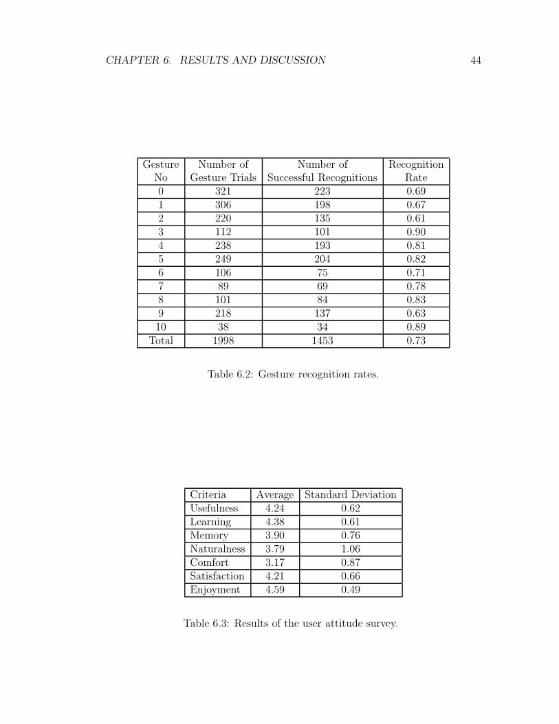
Gesture Number of Number of RecognitionNo Gesture Trials Successful Recognitions Rate0 321 223 0.691 306 198 0.672 220 135 0.613 112 101 0.904 238 193 0.815 249 204 0.826 106 75 0.717 89 69 0.788 101 84 0.839 218 137 0.6310 38 34 0.89
Total 1998 1453 0.73
Table 6.2: Gesture recognition rates.
Criteria Average Standard DeviationUsefulness 4.24 0.62Learning 4.38 0.61Memory 3.90 0.76Naturalness 3.79 1.06Comfort 3.17 0.87Satisfaction 4.21 0.66Enjoyment 4.59 0.49
Table 6.3: Results of the user attitude survey.

CHAPTER 6. RESULTS AND DISCUSSION 45
6.2 Analysis and Discussion
6.2.1 Performance
The performance results of the experiment (See Table 6.2) show that the average
recognition rate of the algorithm is approximately 73% from a stream of motion.
This indicates that a standard user should perform a gesture 1 / 0,73 = 1.37 times
to trigger an application functionality. Thus, we can claim that recognition rate of
the proposed technique is high enough to be used as a reliable human-computer
interface. Because of the differences in the gesture definitions and the gesture
vocabularies, we cannot compare our method with other methods in terms of
gesture recognition performance.
The experiments also show us that sensor incapability of the magnetic tracker
is one of the main reasons behind the unrecognised gestures. When the distance
between the sensor and the magnetic source exceed certain point, the accuracy of
the tracker drops dramatically so after this point, the tracker cannot detect the
position of the hand accurately enough to correctly form the gesture sequence.
This problem can be eliminated by using a more powerful position tracker or
an alternative position detection approach, such as image processing or inertial
motion capture techniques.
We also observe from our experiments that most of the unrecognised gestures
occur in the initial learning phase due to the ill-formed gestures. After the users
are adopted to the new interface, the performed gestures become healthier (more
detectable) and recognition rates increase dramatically. This indicates that higher
recognition rates that reach up to 90-95% can be expected from an experienced
user.

CHAPTER 6. RESULTS AND DISCUSSION 46
6.2.2 Attitude
The outcome of the attitude criteria denotes that the participants of the user
study find the proposed human computer interface and the virtual sculpting
tool useful (4.24) and satisfactory (4.21) with very high attitude scores. This
is promising for the proposed technique, because it indicates that the presented
gestural interface can be an alternative interaction approach for classic HCI in-
terfaces.
A surprising result of the attitude evaluation is the relatively low naturalness
score (3.79) with respect to the other criteria, because our claim is to achieve
more natural and intuitive HCI interface. However, the critical information for
this attitude criterion is the high standard deviation factor. While some par-
ticipants think that the pre-selected gestures are very natural for the assigned
actions, the others find them quite unnatural. This shows that naturalness is
fairly relative to the user. Because the proposed approach is highly adaptable
with the fast learning algorithm, the user can replace the assigned actions and
gestures with more suitable and natural ones for themselves. This makes the
presented technique more superior than the other gesture recognition algorithms
that are not easily adaptable such as HMM-based approaches, which are hard to
train.
The lowest attitude criterion is comfort (3.17) because of the following two
reasons: the users have to perform gestures repeatedly which can be exhausting
after some time and they have to wear cumbersome motion capture hardware
which is not comfortable. The cumbersome equipment problem can be solved
by using an alternative motion capture approach that does not require users to
wear gloves or attach motion tracking devices. The fatigue problem is relatively
insignificant for applications that do not necessitate continuous interaction. How-
ever, it might be a good idea to establish a hand supporting/resting instrument
for applications that need constant interaction for a long time.
CHAPTER 6. RESULTS AND DISCUSSION 47
The learning is one of the strongest aspects of the application. As it is ex-
plained in the performance section, the gesture recognition rates increase notice-
ably after a few trials. This indicates that users can learn and adapt to our virtual
sculpting application in a very short time. This consequence is also supported
by the high learning (4.38) score in the user’s attitude survey. Interestingly, the
highest attitude score of the tool is enjoyment (4.59). This result evidence that
when more natural and intuitive interaction approaches are utilized, the demand-
ing and tiresome design process become quite enjoyable. Our virtual sculpting
tool makes the whole design process more fun. This also contributes the creativity
and productivity of the design artists. [45]
As a consequence, sufficiently high recognition rates prove the effectiveness of
the presented approach to recognize simple and natural gestures that are suitable
to command applications. The assessment of the attitude criteria points out that
proposed HCI technique can be utilized as an intuitive and natural interface.
6.2.3 Learning Parameters
We also emphasize that the selected method parameters have a critical effect on
recognition rate. We observe that small values for motion capture and component
angle threshold (see parameters 1 and 2 in Table 5.1) decreases the recognition
rate dramatically because the system records small changes in trajectory that
are not part of the intended gesture. On the other hand, choosing a large value
for these parameters causes to miss some events that are a part of the intended
gesture.
Smoothing parameter (see parameter 3 in Table 5.1) also has an important
effect on the accuracy, similar to threshold parameters. A large window size
causes fine details of the motion to disappear, while a smaller window size may
not be able to achieve sufficient smoothing to form gesture recognizers.
Chapter 7
Conclusion and Future Work
7.1 Conclusion
We have offered a simple virtual sculpting tool that can be utilised to design
preliminary/conceptual models in a more natural and intuitive way thanks to
the proposed gestural human-computer interaction approaches. The tool tries
to simulate the real world clay potter scenario in which the skilled artists shape
models by stuffing and carving materials in/out into/from clay either using some
design tools or their bare hands.
The proposed HCI approach makes use of the advanced motion capture hard-
ware namely data gloves (5DT Data Glove 14 Ultra) and 6 DoF magnetic motion
trackers (Polhemus Patriot TM). System users wear the data glove with attached
tracker to control the virtual hand placed in the virtual design environment. Vir-
tual hand is a 3D mesh model whose vertices are mapped to a internal hand
skeleton. The user’s finger movements captured by the data glove, firstly, pro-
cessed with a parametrized interpolation function to reduce the effects of the
data glove limitations. Then, the captured bending data are mapped to the mesh
model thanks to the model’s internal skeleton. The orientation and position of
the user’s hand are collected by the tracker and directly mapped to the hand’s
root bone to fully simulate the real hand motion.
48

CHAPTER 7. CONCLUSION AND FUTURE WORK 49
The virtual design environment also contains a deformable model and a few
deformation tools. The deformable model has a volumetric structure and is a
collection of filled volume elements (voxel). The deformable model is positioned
on a uniform 3D grid where the voxels lie on the corners of the gird. We deform
the model by toggling the state of the voxels between filled and empty. The
volumetric model is rendered by the marching cubes algorithm.
On the other hand, the tools in the virtual design environment are basic mesh
models. The virtual hand manipulates these tools by grasping and relocating
them in the virtual environment. Manipulation of the tools can also be achieved
by directly attaching to a 6 DoF tracker. The interactions between the deformable
model and the design tool are accomplished by a real time collision detection
algorithm. The collision of the tool and model is calculated for only the surface
points on the tool. To overcome the sparse surface points problem, a layered
surface definition is utilized. Because our hand model has a mesh structure, the
user can also deform the model directly with the virtual hand thanks to the
surface based collision detection algorithm.
The other contribution of the study is the innovative HCI approach. The
interface has two major elements: hand mouse and gestural command interface.
Hand mouse is an alternative mouse like interaction approach in which users
use their hands instead of a computer mouse. The movements of the cursor are
controlled by the hand motion and system users can click the conventional GUI
elements by slight finger movements.
The other component is the gestural command interface. The proposed ap-
proach is a simple yet powerful technique to detect and recognize trajectory-based
dynamic hand gestures from a stream of motion in real time. Gestures are rep-
resented with an ordered sequence of directional movements in 2D space. Ges-
ture motion data is collected by a magnetic position tracker attached to a user’s
hand, but the proposed method is also applicable to motion data gathered using
computer-vision-based approaches, inertial motion capture algorithms or popular
gaming interfaces used by WiiTM or KinectTM. Motion data in absolute position
format is converted to our representation form during the motion capture phase.

CHAPTER 7. CONCLUSION AND FUTURE WORK 50
We introduce a fast learning methodology to facilitate adding new gestures
to the recognizable gesture set. A few sample gestures are sufficient to form
the gesture recognizers. The learning samples are smoothed to eliminate errors
generated by the imperfect nature of human capture data. From these filtered
samples, the best sequence of events (directional movements) is selected using the
Needleman-Wunsch sequence matching algorithm. The selected learning samples
are later processed to generate the gesture recognizers, which are basically FSM
sequence recognizers.
The experimental results show that the proposed algorithm can recognize dy-
namic hand gestures with an average of 73% accuracy in real time for a vocabulary
of eleven gestures from continuous hand motion. The proposed technique’s high
accuracy rate and online recognition mechanism make it easily adaptable to any
application for gesture-based HCI. As a result, those applications will become
more intuitive in how they interact with their users.
Another contribution of our approach is that a user can create a gesture
command set specific to him or her without the need for extensive training, unlike
neural-network and HMM approaches. In this way, the HCI process becomes more
natural and intuitive. The other favourable functionality that other dynamic
gesture recognition approaches do not provide is that it can also detect and
recognize trajectory based dynamic hand gestures without specifying gesture start
and end points thanks to FSM recognizers. This advantage also improves the
intuitiveness of the procedure.
User’s attitude evaluation survey denotes that the presented virtual sculpting
tool is a useful and satisfactory alternative to the classical CAD applications. The
projected gestural interface provides natural and intuitive interaction mechanism,
which makes the tool more natural and enjoyable. Although the gestural interface
is not very comfortable for long time use, it is applicable to many other tools and
application. In conclusion, the proposed virtual sculpting tool with the advanced
gestural interface is very promising and shows great potential.
CHAPTER 7. CONCLUSION AND FUTURE WORK 51
7.2 Future Work
Virtual reality and HCI are ever growing fields with the contribution of many
researches. Because of these new developments and advances in technology, the
future improvements to existing approaches become countless. There are a few
subjects that we plan to extend and improve our work. The first and the most
important of them is force feedback. Many artists and designers rely on the tac-
tile feedback during the design stages. The clay artist/designers stress out this
fact in our discussion when we exchange thoughts about the virtual sculpting ap-
proaches. Because the touch feeling is very crucial, the virtual sculpting solution
without the tactile feedback seems to lack one of the very important components.
However, the answer to this problem is neither easy nor cheap. There are a few
tactile feedback devices available. Our volume-based deformation approach is
very suitable to be used with these devices. The visual force feedback indica-
tor can be replaced with an effective force feedback solution which can greatly
enhance the intuitiveness of the tool.
The other contribution of the tactile feedback would be to the tool interaction.
When the user’s hand follows a trajectory which causes the virtual hand passes
through one of the virtual objects such as tools and models, the realism of the
interaction diminishes. If this collision problem is only solved in the virtual
environment, the synchronization of the real hand with the virtual hand is lost.
However, if we can deploy a force feedback device that stops the real hand at
such collision points, the interaction between the tool and virtual hand become
more realistic.
Another improvement can be made in visual feedback side. One of the known
problems of our system is depth perception. Our digital design environment is
in 3D but we only use 2D displays to visualize the virtual world. The loss of the
third dimension negatively affects the overall quality of the design process. By
taking advantage of stereoscopic displays, the depth information can be conveyed
to the user and a more realistic virtual environment can be achieved.
CHAPTER 7. CONCLUSION AND FUTURE WORK 52
As a future work to gestural interface, gesture space dimensions can be ex-
tended to increase the number of recognizable gestures. For this purpose, depth
information (z-coordinate) can be added as the third dimension of the gesture
space. To add some constraints to recognized gestures or to recognize orientation-
based gestures, palm orientation can be utilized. We also plan to combine the
proposed dynamic gesture recognition approach with dynamic posture recogni-
tion by using a data glove that can capture finger-bending values. Additionally,
we believe that recognition rate can be improved by using more advanced filtering
techniques and by deploying an online filtering mechanism for captured motion
data. Utilizing cheaper and more comfortable motion capture approaches like
WiiTM, KinectTM, inertial sensors or computer vision can also be a significant
improvement to the proposed algorithm.

Bibliography
[1] S. E. Scharoff, A. Pentland, I. Essa, M. Friedmann, and B. Horowitz, “The
ThingWorld Modeling System: Virtual Sculpting by Modal Forces,” ACM
SIGGRAPH Computer Graphics (Proceedings of the Symposium on Interac-
tive 3D Graphics), vol. 24, pp. 143–144, February 1990.
[2] J. Ye, R. Campbell, T. Page, and K. Badni, “An Investigation into the
Implementation of Virtual Reality Technologies in Support of Conceptual
Design,” Design Studies, vol. 27, no. 1, pp. 77–97, 2006.
[3] K.-L. Perng, W.-T. Wang, M. Flanagan, and M. Ouhyoung, “A Real-time 3D
Virtual Sculpting Tool Based on Modified Marching Cubes,” in Proceedings
of International Conference on Artificial Reality and Tele-Existence (ICAT),
2001.
[4] T. H. Dani and R. Gadh, “Creation of Concept Shape Designs via a Virtual
Reality Interface,” Computer-Aided Design, vol. 29, no. 8, pp. 555–563, 1997.
[5] K. Mallikarjuna, L. Narayan, and M. Sarcar, Computer Aided Design and
Manufacturing. PHI Learning Pvt. Ltd., 2008.
[6] J. Ye and R. Campbell, “Supporting Conceptual Design with Multiple VR
Based Interfaces,” Virtual and Physical Prototyping, vol. 1, no. 3, pp. 171–
181, 2006.
[7] H. Pungotra, “Virtual Reality in Concept Design,” AMAE International
Journal on Manufacturing and Material Science, vol. 2, no. 1, 2012.
53
BIBLIOGRAPHY 54
[8] P. Astheimer, F. Dai, W. Felger, M. Gobel, H. Haase, S. Muller, and
R. Ziegler, “Virtual Design II–An Advanced VR System for Industrial Ap-
plications,” in Proceedings of Virtual Reality World’95, pp. 337–363, 1995.
[9] M. R. Mine, “ISAAC: A Meta-CAD System for Virtual Environments,”
Computer-Aided Design, vol. 29, no. 8, pp. 547–553, 1997.
[10] L. P. Anthony, W. C. Regli, J. E. John, and S. V. Lombeyda, “An Approach
to Capturing Structure, Behavior and Function of Artifacts in CAD,” Trans-
actions of the ASME, the Journal of Computing and Information Science in
Engineering, vol. 1, no. 2, pp. 186–192, 2001.
[11] F. Kuester, M. A. Duchaineau, B. Hamann, K. I. Joy, and A. E. Uva,
“3DIVS: 3-Dimensional Immersive Virtual Sculpting,” in Proceedings of the
Workshop on New Paradigms in Information Visualization and Manipula-
tion, in Conjunction with the Eight International Conference on Information
and Knowledge Management, pp. 92–96, ACM, 1999.
[12] S. Kodiyalam, V. Kumar, and P. M. Finnigan, “Constructive Solid Geome-
try Approach to Three-Dimensional Structural Shape Optimization,” AIAA
Journal, vol. 30, no. 5, pp. 1408–1415, 1992.
[13] W. A. McNeely, K. D. Puterbaugh, and J. J. Troy, “Six Degree-of-
Freedom Haptic Rendering Using Voxel Sampling,” in ACM SIGGRAPH
2005 Courses, p. 42, ACM, 2005.
[14] R. Raffin, G. Gesquiere, E. Remy, and S. Thon, “VirSculpt: A Virtual
Sculpting Environment,” Proceedings of GraphiCon’04, pp. 184–187, 2004.
[15] F. Dachille IX, H. Qin, A. Kaufman, and J. El-Sana, “Haptic Sculpting
of Dynamic Surfaces,” in Proceedings of the Symposium on Interactive 3D
Graphics, pp. 103–110, ACM, 1999.
[16] H. Pungotra, G. Knopf, and R. Canas, “Framework for Modeling and Vali-
dating Concept Designs in Virtual Reality Environments,” in IEEE Toronto
International Conference Science and Technology for Humanity (TIC-STH),
pp. 393–398, IEEE, 2009.

BIBLIOGRAPHY 55
[17] K. T. McDonnell, H. Qin, and R. A. Wlodarczyk, “Virtual Clay: A Real-time
Sculpting System with Haptic Toolkits,” in Proceedings of the Symposium
on Interactive 3D Graphics (I3D’01), pp. 179–190, ACM, 2001.
[18] C. Hand, “A Survey of 3D Interaction Techniques,” Computer Graphics Fo-
rum, vol. 16, no. 5, pp. 269–281, 1997.
[19] V. I. Pavlovic, R. Sharma, and T. S. Huang, “Visual Interpretation of Hand
Gestures for Human-Computer Interaction,” IEEE Transactions on Pattern
Analysis and Machine Intelligence, vol. 19, no. 6, pp. 677–695, 1997.
[20] C. Kirmizibayrak, N. Radeva, M. Wakid, J. Philbeck, J. Sibert, and J. Hahn,
“Evaluation of Gesture Based Interfaces for Medical Volume Visualization
Tasks,” in Proceedings of the 10th International Conference on Virtual Re-
ality Continuum and Its Applications in Industry (VRCAI ’11), pp. 69–74,
ACM, 2011.
[21] D. A. Norman, “Natural User Interfaces Are Not Natural,” Interactions,
vol. 17, no. 3, pp. 6–10, 2010.
[22] G. Ren and E. O’Neill, “3D Selection with Freehand Gesture,” Computers
& Graphics, In Press.
[23] C. Telkenaroglu and T. Capin, “Dual-Finger 3D Interaction Techniques for
Mobile Devices,” Personal and Ubiquitous Computing, pp. 1–22, 2012.
[24] M.-C. Su, W.-F. Jean, and H.-T. Chang, “A Static Hand Gesture Recogni-
tion System Using a Composite Neural Network,” in Proceedings of the Fifth
IEEE International Conference on Fuzzy Systems (Fuzz-IEEE ’96), vol. 2,
pp. 786–792, IEEE, 1996.
[25] G. Rigoll, A. Kosmala, and S. Eickeler, “High Performance Real-time Ges-
ture Recognition Using Hidden Markov Models,” in Gesture and Sign Lan-
guage in Human-Computer Interaction, Lecture Notes in Computer Science,
vol. 1371, pp. 69–80, Springer-Verlag, 1998.
[26] Y. Wu and T. S. Huang, “Vision-Based Gesture Recognition: A Review,”
in Proceedings of the International Gesture Workshop on Gesture-Based

BIBLIOGRAPHY 56
Communication in Human-Computer Interaction (GW’99), pp. 103–115,
Springer-Verlag, 1999.
[27] S. Mitra and T. Acharya, “Gesture Recognition: A Survey,” IEEE Transac-
tions on Systems, Man, and Cybernetics - Part C: Applications and Reviews,
vol. 37, no. 3, pp. 311–324, 1999.
[28] C. Oz and M. C. Leu, “Human-Computer Interaction System with Artificial
Neural Network Using Motion Tracker and Data Glove,” in Pattern Recog-
nition and Machine Intelligence, Lecture Notes in Computer Science (S. P.
et al., ed.), vol. 3776, pp. 280–286, Springer-Verlag, 2005.
[29] J. Weissmann and R. Salomon, “Gesture Recognition for Virtual Reality
Applications Using Data Gloves and Neural Networks,” in Proceedings of
the International Joint Conference on Neural Networks (IJCNN ’99), vol. 3,
pp. 2043–2046, IEEE, 1999.
[30] Y. Nam and K. Wohn, “Recognition of Space-Time Hand-Gestures using
Hidden Markov Model,” in Proceedings of ACM Symposium on Virtual Re-
ality Software and Technology (VRST ’96), pp. 51–58, ACM, 1996.
[31] S. Eickeler, A. Kosmala, and G. Rigoll, “Hidden Markov Model Based Con-
tinuous Online Gesture Recognition,” in Proceedings of the Fourteenth In-
ternational Conference on Pattern Recognition (ICPR ’98), vol. 2, pp. 1206–
1208, IEEE, 1998.
[32] T. Starner and A. Pentland, “Real-Time American Sign Language Recogni-
tion from Video Using Hidden Markov Models,” in Proceedings of the Inter-
national Symposium on Computer Vision, pp. 265–270, IEEE, 1995.
[33] P. Hong, M. Turk, and T. Huang, “Gesture Modeling and Recognition Us-
ing Finite Machines,” in Proceedings of the Fourth IEEE International Con-
ference on Automatic Face and Gesture Recognition (FG’00), pp. 410–415,
IEEE, 2000.
[34] M. Yeasin and S. Chaudhuri, “Visual Understanding of Dynamic Hand Ges-
tures,” Pattern Recognition, vol. 33, no. 11, pp. 1805–1817, 2000.
BIBLIOGRAPHY 57
[35] A. F. Bobick and A. D. Wilson, “A State-Based Approach to the Represen-
tation and Recognition of Gesture,” IEEE Transactions on Pattern Analysis
and Machine Intelligence, vol. 19, no. 12, pp. 1325–1337, 1997.
[36] O. Bimber, “Continuous 6DOF Gesture Recognition: A Fuzzy Logic Ap-
proach,” in Proceedings of WSCG’99, vol. 1, pp. 24–30, 1999.
[37] A. Ramamoorthy, N. Vaswani, S. Chaudhury, and S. Banerjee, “Recognition
of Dynamic Hand Gestures,” Pattern Recognition, vol. 36, no. 9, pp. 2069–
2081, 2003.
[38] M. Chen, G. AlRegib, and B.-H. Juang, “Feature Processing and Modeling
for 6D Motion Gesture Recognition,” IEEE Transactions on Multimedia,
vol. 15, no. 3, pp. 561–571, 2013.
[39] L. Dipietro, A. M. Sabatini, and P. Dario, “A Survey of Glove-based Sys-
tems and Their Applications,” IEEE Transactions on Systems, Man, and
Cybernetics, Part C, vol. 38, no. 4, pp. 461–482, 2008.
[40] 5DT: Fifth Dimension Technologies, “5DT Data Glove 14.”
http://www.5dt.com/products/pdataglove14.html, 2013. [Online;
accessed 15-Aug-2013].
[41] W. E. Lorensen and H. E. Cline, “Marching Cubes: A High Resolution
3D Surface Construction Algorithm,” ACM Computer Graphics (Proc. of
SIGGRAPH’87), vol. 21, no. 4, pp. 163–169, 1987.
[42] H. Samet, The Design and Analysis of Spatial Data Structures. Addison-
Wesley Reading, MA, 1990.
[43] C. David, V. Gui, P. Nisula, and V. Korhonen, “Dynamic Hand Gesture
Recognition for Human-Computer Interactions,” in Proceedings of 6th IEEE
International Symposium on Applied Computational Intelligence and Infor-
matics, pp. 165–170, 2011.
[44] S. B. Needleman and C. D. Wunsch, “A General Method Applicable to the
Search for Similarities in the Amino Acid Sequence of Two Proteins,” Journal
of Molecular Biology, vol. 48, no. 3, pp. 443–453, 1970.

BIBLIOGRAPHY 58
[45] B. Shackel, Usability - Context, Framework, Definition, Design and Evalua-
tion, ch. 2, pp. 21–37. Cambridge University Press, 2009.


![[hal-00945905, v2] Crowd Sculpting: A space-time sculpting ...](https://static.fdocuments.us/doc/165x107/61d00833c69c8e549e339118/hal-00945905-v2-crowd-sculpting-a-space-time-sculpting-.jpg)