Virtual Proving Ground Terrain Validation by Dr. David Lamb, Dr. Alex Reid, Nancy Truong, John...
25
Virtual Proving Ground Terrain Validation by Dr. David Lamb, Dr. Alex Reid, Nancy Truong, John Weller (IVSS-2003-MAS-1) 3 rd Annual Intelligent Vehicle Systems Symposium National Defense Industrial Association 10 June 2003 Presented by: Nancy Truong US Army TACOM-TARDEC National Automotive Center (NAC) Ground Vehicle Simulation Laboratory (GVSL)
-
Upload
justyn-scafe -
Category
Documents
-
view
213 -
download
0
Transcript of Virtual Proving Ground Terrain Validation by Dr. David Lamb, Dr. Alex Reid, Nancy Truong, John...

Virtual Proving Ground Terrain Validation
by Dr. David Lamb, Dr. Alex Reid, Nancy Truong, John Weller(IVSS-2003-MAS-1)
Virtual Proving Ground Terrain Validation
by Dr. David Lamb, Dr. Alex Reid, Nancy Truong, John Weller(IVSS-2003-MAS-1)
3rd Annual Intelligent Vehicle Systems SymposiumNational Defense Industrial Association
10 June 2003
Presented by: Nancy TruongUS Army TACOM-TARDEC
National Automotive Center (NAC)Ground Vehicle Simulation Laboratory (GVSL)

OutlineOutline
• Background Information about Lab
• Visual
• Churchville
• Virtual Profilometer
• Validation Process/Methodology
• NURBS
• Conclusions
• Background Information about Lab
• Visual
• Churchville
• Virtual Profilometer
• Validation Process/Methodology
• NURBS
• Conclusions

RMSRMS
• Capable of reproducing the ride of most ground vehicles • Realistic environment• The Evans and Sutherland ESIG
HD/3000 and Harmony Image Generators.
• Real-time warfighter/hardware-in-the-loopsimulation
• Aberdeen Proving Ground’s (APG) Churchville

Why Do We Need More Resolution?
• To aid in the application of high-fidelity modeling and simulation techniques to the development/testing of new vehicle systems and emerging technologies.
• To include:– motion-based, human- and hardware-in-the-
loop simulations.– high-resolution virtual testing of systems.

Terrain Limitations
• High-resolution dynamic model requires very small terrain resolution
• Higher resolution terrains cannot be rendered in real-time.
3.55
3.6
3.65
x 105
-5.68-5.66
-5.64-5.62
-5.6-5.58
-5.56
x 105
3000
3500
4000
4500• Typical terrain grids come no smaller than 30m x 30m and most areas typically are even lower resolution.
• Use of terrain for primarily off-road simulations

Visual Correlation Questions
• How does the low-resolution IG database correlate to the high-resolution dynamic database?
• Does it need to?
• Why?
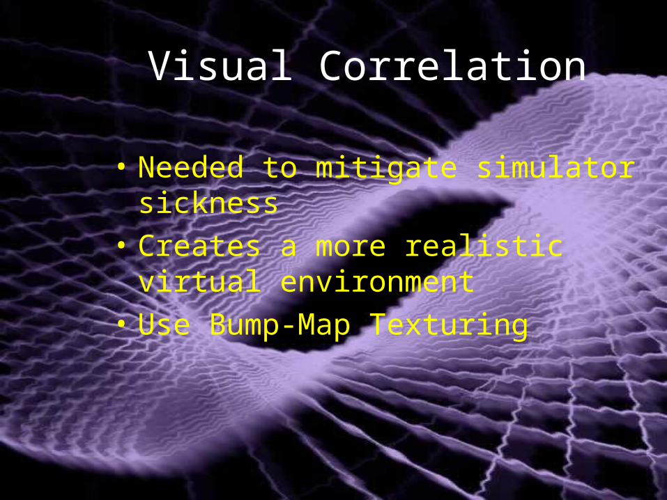
Visual Correlation
• Needed to mitigate simulator sickness
• Creates a more realistic virtual environment
• Use Bump-Map Texturing

GVSLGVSL
• Human Factors
• Vehicle performance
• Motion Sickness
• Comparison of head-mounted display (HMD) vs flat panel
• Human Factors
• Vehicle performance
• Motion Sickness
• Comparison of head-mounted display (HMD) vs flat panel

Components of a Real-Time Simulation
Components of a Real-Time Simulation
Mathematical ModelVirtual Environment
Real-Time Computer
Experimental Environment

Churchville Churchville
• Visual- what we see • Terrain- what we feel
• Visual- what we see • Terrain- what we feel

Validate the TerrainValidate the Terrain
• Acquired the data for the virtual terrain,
• Obtained the x & y coordinates
• Input data into the virtual profilometer
• Acquired the data for the virtual terrain,
• Obtained the x & y coordinates
• Input data into the virtual profilometer

Virtual ProfilometerVirtual Profilometer
• Acts the same way a profilometer acts over a read proving ground
• Simulates a trailer
• Reports other terrain properties stored in the database
• Acts the same way a profilometer acts over a read proving ground
• Simulates a trailer
• Reports other terrain properties stored in the database

Equal distance spacingEqual distance spacing
Input-Constant time delta, but at a variable speed
Output- Constant space delta

Arc Length FormulaArc Length Formula
1
0
222t
tdt
t
z
t
y
t
xs

Interpolation of pointsInterpolation of pointsOnce the arc length (distance) down the course to each point in the input series is computed, then interpolate to get points the desired distance apart.
212121 1,1,1 zzyyxx
This is the new point, where the interpolation parameter is
12
1
ss
ss
The desired distance is s, other distances are for the two points
111 ,, zyx 222 ,, zyx

Other FeaturesOther Features
• A rough Power Spectral Density (PSD) of the course
• Various input and output formats are supported
• Options for track offset (left and right) or single track (centerline) available
• A rough Power Spectral Density (PSD) of the course
• Various input and output formats are supported
• Options for track offset (left and right) or single track (centerline) available

Profile DataProfile Data
• MATLAB • Linear interpolation • Two curves start and stop
at the same point • Virtual proving ground
correlated well with large terrain changes
• MATLAB • Linear interpolation • Two curves start and stop
at the same point • Virtual proving ground
correlated well with large terrain changes

MogulsMoguls
• Virtual terrain has sharper hills and valleys •Sampling and construction

RMS ValuesRMS Values
• Removed wavelengths greater than 18m
• Real-terrain is 4.95 cm.
• Virtual terrain is 4.57 cm.
• A difference of 8%.
• Removed wavelengths greater than 18m
• Real-terrain is 4.95 cm.
• Virtual terrain is 4.57 cm.
• A difference of 8%.

PSDPSD
• Virtual terrain is much lower than the real terrain
• Construction of polygons
• Virtual terrain is much lower than the real terrain
• Construction of polygons

NURBSNURBS
• Non-Uniform Rational B-Splines
• Non-Uniform Rational B-Splines
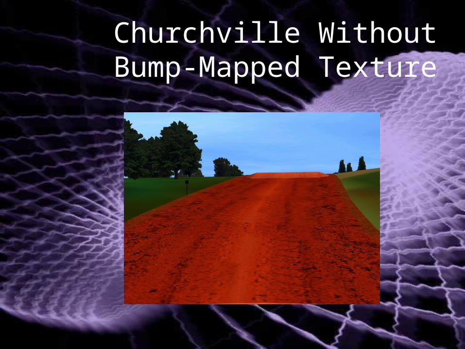
Churchville Without Bump-Mapped Texture

Churchville With Bump-Mapped Texture

ConclusionConclusion
• Need to validate models• Real and virtual terrain
comparisons• NURBS• Work on other APG databases
• Need to validate models• Real and virtual terrain
comparisons• NURBS• Work on other APG databases

QuestionsQuestions
For further information on this presentation, contact:
Dr. David Lamb [email protected] (586)-574-5209Dr. Alex Reid, [email protected] (586)-753-2212Nancy Truong, [email protected] (586)-574-8633John Weller, [email protected] (586)-574-8633
Motion Base Technologies TeamTACOM-TARDEC6501 E. Eleven Mile RoadWarren, MI 48397AMSTA-TR-NMS: 157, Bldg 215