Virtual prototyping and analysis of a robotic prosthetic leg
9
© 2015 Discovery Publication. All Rights Reserved. www.discoveryjournals.com OPEN ACCESS ARTICLE Page112 ANALYSIS Virtual prototyping and analysis of a robotic prosthetic leg Kalyana Chakravarthy Y 1☼ , Pavan Kishore N 2 , Ashok N 2 , Manoj M 2 , Mithun Chakravarty A 2 , Srinath A 3 1. Research Scholar at K L University/Mechanical Engineering, Vaddeswaram, Guntur District, India; Email: [email protected] 2. Under Graduate Student, K L University/Mechanical Engineering, Vaddeshwaram, Guntur District, India 3. UGC Research Awardee Professor, Department of Mechanical Engineering, K L University, Vaddeswaram, Guntur District, India ☼ Corresponding author: Research Scholar at K L University/Mechanical Engineering, Vaddeswaram, Guntur District, India; Email: [email protected] Article History Received: 10 August 2015 Accepted: 21 September 2015 Published: 1 October 2015 Citation Kalyana Chakravarthy Y, PavanKishore N, Ashok N, Manoj M, Mithun Chakravarty A, Srinath A. Virtual Prototyping and Analysis of a Robotic Prosthetic Leg. Discovery, 2015, 46(213), 112-120 Publication License This work is licensed under a Creative Commons Attribution 4.0 International License. General Note Article is recommended to print as color digital version in recycled paper. ABSTRACT This paper presents the components of knee joint which supports the individuals with above knee amputations. The pre-eminent objective of this paper is to design and analyze a pliant prosthetic knee joint and find possibilities and necessary measures to suit the requisites of a refine substitute of a comfortable and light weight prosthetic knee joint. One of the main challenges related with the advancement of prosthetic knee joint components for amputee individuals with above-knee amputations associates with the requirement to design light-weight structures which are proficient of withstanding the high loads that are usually present during mobility. This work deals with the dimensions of the knee which are taken from able-bodied individuals. The modeling of the knee is done with the help of solid works and the model is analyzed using Altair Hyper works software. The 3D model has been generated using Solid works modeling software. The Finite Element meshing is done using Altair Hyper mesh and the meshed component was solved using optistruct. A proto type of knee is examined for structural fortitude of lower-limb prosthesis. Keywords: Above Knee Amputation, Finite Element meshing, and optistruct ANALYSIS 46(213), October 1, 2015 Discovery ISSN 2278–5469 EISSN 2278–5450
Transcript of Virtual prototyping and analysis of a robotic prosthetic leg

© 2015 Discovery Publication. All Rights Reserved. www.discoveryjournals.com OPEN ACCESS
ARTICLE
Page
112
ANALYSIS
Virtual prototyping and analysis of a robotic prosthetic leg Kalyana Chakravarthy Y1☼, Pavan Kishore N2, Ashok N2, Manoj M2, Mithun Chakravarty A2, Srinath A3 1. Research Scholar at K L University/Mechanical Engineering, Vaddeswaram, Guntur District, India; Email: [email protected] 2. Under Graduate Student, K L University/Mechanical Engineering, Vaddeshwaram, Guntur District, India 3. UGC Research Awardee Professor, Department of Mechanical Engineering, K L University, Vaddeswaram, Guntur District, India ☼Corresponding author: Research Scholar at K L University/Mechanical Engineering, Vaddeswaram, Guntur District, India; Email: [email protected] Article History Received: 10 August 2015 Accepted: 21 September 2015 Published: 1 October 2015 Citation Kalyana Chakravarthy Y, PavanKishore N, Ashok N, Manoj M, Mithun Chakravarty A, Srinath A. Virtual Prototyping and Analysis of a Robotic Prosthetic Leg. Discovery, 2015, 46(213), 112-120 Publication License
This work is licensed under a Creative Commons Attribution 4.0 International License. General Note
Article is recommended to print as color digital version in recycled paper.
ABSTRACT
This paper presents the components of knee joint which supports the individuals with above knee amputations. The pre-eminent objective of this paper is to design and analyze a pliant prosthetic knee joint and find possibilities and necessary measures to suit the requisites of a refine substitute of a comfortable and light weight prosthetic knee joint. One of the main challenges related with the advancement of prosthetic knee joint components for amputee individuals with above-knee amputations associates with the requirement to design light-weight structures which are proficient of withstanding the high loads that are usually present during mobility. This work deals with the dimensions of the knee which are taken from able-bodied individuals. The modeling of the knee is done with the help of solid works and the model is analyzed using Altair Hyper works software. The 3D model has been generated using Solid works modeling software. The Finite Element meshing is done using Altair Hyper mesh and the meshed component was solved using optistruct. A proto type of knee is examined for structural fortitude of lower-limb prosthesis. Keywords: Above Knee Amputation, Finite Element meshing, and optistruct
ANALYSIS 46(213), October 1, 2015
Discovery ISSN 2278–5469
EISSN 2278–5450

© 2015 Discovery Publication. All Rights Reserved. www.discoveryjournals.com OPEN ACCESS
ARTICLE
Page
113
ANALYSIS
1. INTRODUCTION Prosthesis is an ancient Greek word which means addition, application or attachment. In medicine prosthesis is an artificial device which is a replica of body part. Amputees whose body parts are missed due to some trauma or congenital diseases can be successfully replaced with artificial body parts called prosthesis. Prosthetic amputee rehabilitation is mainly done by prosthetists with a team of health care professionals and physical therapists. When a prosthetic leg has to be manufactured its design should be according to the patient’s physical appearance and functional needs. [1]Prosthesis is artificial replacement for a missing part of the body, it is used to try to copy or mimic the part that is missing. Stoleperstein in his writings explains the anatomy of artificial joints. He explains that the knee is largest joint in the human body with the help of surrounding ligaments, tendons and muscle, the joint ensures that the subject can walk. The knee does not act only like a simple hinge but it extends forward in rolling and gliding movement. It can bend back up to 150 degrees and also permits lateral balancing movements. Prosthetic knee joints use various techniques to allow the lower leg to be swung forward after the bending movement. In an extensive study of Calumet Orthopaedic &Prosthetic Co. noted that it is important for the amputees to select correct mechanical knee that fits their needs. There are categories within the mechanical prosthetic knees. They all have distinct features that correlate with a wearer’s age, health, activity level and life style. The knee we opt for must provide a reliable support when standing, allow smooth controlled motion when walking and permit unrestricted movement for sitting, bending, kneeling.Fit and alignment are the basic considerations for designing of a prosthetic leg. 1.1. General design A typical prosthetic design employs the interface between a tibia and femur. The tibia-femur interacts with each other and substitutes the posterior cruciate ligament found at the rear of the knee. The major function of the posterior cruciate ligament is to avoid the tibia from slipping backwards on the femur and to permit resistive force among them. The tibia-femur contact causes the femoral rollback which means allowing the femur to roll posteriorly on the tibia for the improvement of the knee flexion. The key difference in manufacturing and design specifications for a variety of lower extremity prosthesis depends upon the geometrical exceptions of the tibia and the location of the femur comparative to the tibia. The anatomy of femur and tibia is shown in figure 1.
Figure 1 knee anatomy 1.2. Weight consideration In lower-limb prostheses the force transmission involving in stump and prosthesis has major significance. To achieve proficient transmission of forces, a steady link involving in stump and prosthesis is necessary. Similarly the maintenance of comfortness and free motion is most important. The weight and mass consideration of the prosthesis play a role in the designing and manufacturing of prosthesis. Light weight prosthesis has the benefit of less requirement of energy to move and hence involves less muscle cost, but disproportionate limb weights can lead to gait unevenness due to dissimilar centre of mass and moments of inertia. a light weight prosthetic needs additional control during swing phase and stances. Stability is often provided by positioning the stump in a socket to a point close to the first proximal joint. The soft stump tissues are not particularly perfect to provide torsional resistance and moments forced by a socket on them while using prosthesis. To provide maximum stability, if the tissues are compressed, then it causes a problem in circulation, if socket is loose, then it produces a false-joint effect which results in abnormal high unit pressures at proximal points, and reduces the ability of controlling the prosthesis. Therefore, utmost care must be taken while designing and fabricating a socket in order to obtain optimum condition.

© 2015 Discovery Publication. All Rights Reserved. www.discoveryjournals.com OPEN ACCESS
ARTICLE
Page
114
ANALYSIS
1.3. Function of patient The purpose of designing and fabricating a prosthetic leg is simply to reinstate the amputee to perform daily activities easily and comfortably. The amputee will be unable to wear prosthesis unless it is comfortable. The amputee finds the prosthesis very useful when it performs the required functions with ease and handiness. The level of satisfaction is attained when it is subjected to a great extent by the existing situation. Even though the prosthesis is elaborate enough, it can’t be made to function in a proper manner if the prosthetic device is not manipulated properly with ease and comfort. On the other hand, a device can be at ease only when its functional descriptions are appropriately incorporated with the residual biomechanics of the amputee. 1.4. Gait analysis Gait is described as a person’s way, style or manner of movement or locomotion. Speed of gait decides the involvement of all body segments. Ordinary walking speed mainly involves the lower extremities, by means of the arms and the trunk by providing equilibrium and stability. When there is a faster speed, the body depends more on the upper extremities and the trunk for balance and stability. The limbs persist to do the work as the joints generate great ranges of motion trough greater muscle response. The three main joints of lower body and pelvis in bipedal system work by means of each other, since muscles and momentum make the body move forward. The center of the body moves side to side and up and down throughout gait. The gait cycle is shown in the figure 2.
Figure 2 gait cycle 1.5. Mechanism compliances Mechanical systems corresponding to compliant mechanisms employ’s a flexible or elements with large-displacement, which opposes the utilization of the elements which are exceptionally inflexible and stiff. The mechanisms which are in use are almost traditional and are commonly used in the manufacturing field at present are called rigid-body mechanisms. They engage solid linkages joined by joints which permit relative motion linking them. Compliant equal in values of such mechanisms are replaced by the linkages and joints by means of a particular portion of material having rigid and flexible parts. The compliant mechanisms are relatively a recent study in design and research field, but it is one which has increase in its significance due its potential utilization and benefits over the mechanisms of rigid-body. The property of the flexible part returning to its actual position after being released is a resilient advantage. These mechanisms are generally lighter in weight and of low expenditure than the rigid-body mechanisms without any change in strength. Since these mechanisms are regularly built in a single piece, the modelling techniques and manufacturing is greatly simplified. Even in the absence of rigid-body links, where the parts of machine persistently come in contact against each other, there is decrease in wear significantly. 1.6. Suspension in the prosthetic limb Efficient and secure prosthesis employment needs the prosthetic device be suspended at ease and without fail on the limb in every activity. Every suspension mechanism must embrace the prosthetic limb securely during gait and must let the amputee to be seated comfortably. A fine suspension decreases the possibility of skin exasperation or breakdown by reducing the pistoning or movement between the limb and the socket. In the prescription process of prosthetics, the patient’s selection of suspension is influenced by the current and predicted physical abilities and activities, in addition to the climatic conditions where they live. New materials have improved suspension, gait, and reduced problems related to suspension [2]. 2. VIRTUAL PROTOTYPING Virtual prototyping refers to the iterative design refinement of the designed product using a computer based physical simulation.

© 2015 Discovery Publication. All Rights Reserved. www.discoveryjournals.com OPEN ACCESS
ARTICLE
Page
115
ANALYSIS
2.1. Modelling of prosthetic leg Based on all the above considerations a primary sketch of the model was proposed and drawn in sketch module of solidworks. 3D modelling of each component of the prosthetic leg was done using the extrude and revolve commands of the solid works as shown in figure 3, figure 4, figure 5. Then all these components were finally assembled using appropriate mates in the assembly module of solid works which were shown in Figure 6.
Figure 3 Model of upper limb part Figure 4 Model of lower limb part
Figure 5 Model of foot Figure 6 Full assembly
The complete assembly is meshed in 3D using hypermesh software with tetra meshed elements shown in Figure7. An average element size of 10 mm was chosen for design space.
© 2015 Discovery Publication. All Rights Reserved. www.discoveryjournals.com OPEN ACCESS
ARTICLE
Page
116
ANALYSIS
Figure 7 Complete assembly with meshing
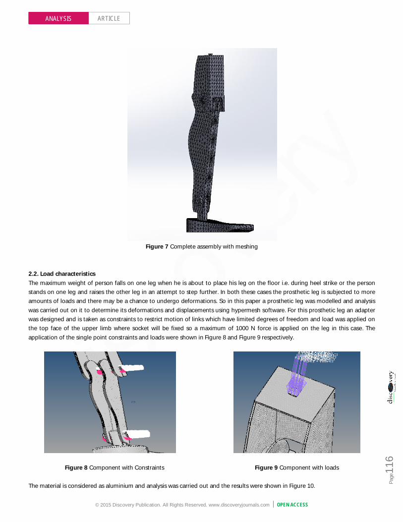
2.2. Load characteristics The maximum weight of person falls on one leg when he is about to place his leg on the floor i.e. during heel strike or the person stands on one leg and raises the other leg in an attempt to step further. In both these cases the prosthetic leg is subjected to more amounts of loads and there may be a chance to undergo deformations. So in this paper a prosthetic leg was modelled and analysis was carried out on it to determine its deformations and displacements using hypermesh software. For this prosthetic leg an adapter was designed and is taken as constraints to restrict motion of links which have limited degrees of freedom and load was applied on the top face of the upper limb where socket will be fixed so a maximum of 1000 N force is applied on the leg in this case. The application of the single point constraints and loads were shown in Figure 8 and Figure 9 respectively.
Figure 8 Component with Constraints Figure 9 Component with loads The material is considered as aluminium and analysis was carried out and the results were shown in Figure 10.

© 2015 Discovery Publication. All Rights Reserved. www.discoveryjournals.com OPEN ACCESS
ARTICLE
Page
117
ANALYSIS
Figure 10 Deflection for aluminium @4450N
Similarly the analysis was carried out using different materials and there deformations were shown in Figure 11(boron epoxy), Figure 12(magnesium), Figure 13(glass epoxy), and Figure 14 (mild steel).
Figure 11 Deformations of boron material @ 4450N Figure 12 Deformations for magnesium @ 4450N
Figure 13 Deformations for glass @ 4450N Figure 14 Deformations for mild steel @ 4450N

© 2015 Discovery Publication. All Rights Reserved. www.discoveryjournals.com OPEN ACCESS
ARTICLE
Page
118
ANALYSIS
Deflections for different materials are considered and represented in a graph as shown in graph 1.
Graph 1 Graph showing deflections for different materials Von misses stresses of different materials are represented in graph 2.
Graph 2 Graph showing von misses stresses for different materials. [3] 3. SOCKET DESIGN Socket design along with careful considerations of residual limb appearance place the stage for patient triumph—maximizing the range of motion, provide stability all through the daily activities, and allowing the amputee to distribute the forces at ease which
0.00130522
1.93E-06
5.764238.85595
1.99293
1.907E-03.815E-07.629E-01.526E-03.052E-06.104E-00.0001220.0002440.0004880.0009760.0019530.0039060.0078120.015625
0.031250.0625
0.1250.25
0.51248
16
Deflection Chart
max
010000000200000003000000040000000500000006000000070000000
von misses stresses
max
© 2015 Discovery Publication. All Rights Reserved. www.discoveryjournals.com OPEN ACCESS
ARTICLE
Page
119
ANALYSIS
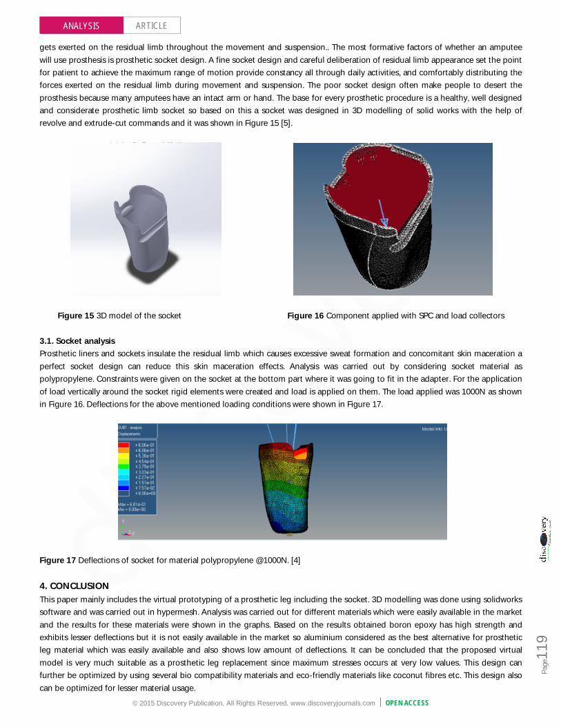
gets exerted on the residual limb throughout the movement and suspension.. The most formative factors of whether an amputee will use prosthesis is prosthetic socket design. A fine socket design and careful deliberation of residual limb appearance set the point for patient to achieve the maximum range of motion provide constancy all through daily activities, and comfortably distributing the forces exerted on the residual limb during movement and suspension. The poor socket design often make people to desert the prosthesis because many amputees have an intact arm or hand. The base for every prosthetic procedure is a healthy, well designed and considerate prosthetic limb socket so based on this a socket was designed in 3D modelling of solid works with the help of revolve and extrude-cut commands and it was shown in Figure 15 [5].
Figure 15 3D model of the socket Figure 16 Component applied with SPC and load collectors
3.1. Socket analysis Prosthetic liners and sockets insulate the residual limb which causes excessive sweat formation and concomitant skin maceration a perfect socket design can reduce this skin maceration effects. Analysis was carried out by considering socket material as polypropylene. Constraints were given on the socket at the bottom part where it was going to fit in the adapter. For the application of load vertically around the socket rigid elements were created and load is applied on them. The load applied was 1000N as shown in Figure 16. Deflections for the above mentioned loading conditions were shown in Figure 17.
Figure 17 Deflections of socket for material polypropylene @1000N. [4]
4. CONCLUSION This paper mainly includes the virtual prototyping of a prosthetic leg including the socket. 3D modelling was done using solidworks software and was carried out in hypermesh. Analysis was carried out for different materials which were easily available in the market and the results for these materials were shown in the graphs. Based on the results obtained boron epoxy has high strength and exhibits lesser deflections but it is not easily available in the market so aluminium considered as the best alternative for prosthetic leg material which was easily available and also shows low amount of deflections. It can be concluded that the proposed virtual model is very much suitable as a prosthetic leg replacement since maximum stresses occurs at very low values. This design can further be optimized by using several bio compatibility materials and eco-friendly materials like coconut fibres etc. This design also can be optimized for lesser material usage.

© 2015 Discovery Publication. All Rights Reserved. www.discoveryjournals.com OPEN ACCESS
ARTICLE
Page
120
ANALYSIS
FUTURE SCOPE This type of structure for prosthetic leg is helpful for motor controlled knee mechanisms. REFERENCE 1. http://en.wikipedia.org/wiki/Prosthesis. 2. Hanz Richter, Dan Simon, William A. Smith, Sergey
Samorezov, “dynamic modelling parameter estimation and control of a prosthesis test robot”. Elsevier, June 2014.
3. Y.Kalyanachakravarthy, “alternate materials for modelling and analysis of prosthetic knee joint”. International journal of science and technology, vol 1 No 5, July 2011.
4. Christina M.webber, Brian L. Davis, “design of a novel prosthetic socket: assessment of thermal performance”. Elsevier, Feb 2015.
5. Chris Lake, CPO, FAAOP, “The evolution of upper limb prosthetic socket design”. American academy of orthotists and prosthetists.