Virtual Modeling Spring
67
Virtual Modeling 04/11/2011 Lecture 11 1
description
virtual modeling
Transcript of Virtual Modeling Spring

Virtual Modeling
04/11/2011Lecture 11
1
Course Context
• 3D Navigation and Rendering• Virtual Modeling
– 3D and Parametric CAD Modeling• 3D model types• Methods of Solid Model Creation• Parametric Models
– Downstream Applications• CAM/CAE/Rapid Prototyping• Laser Scanning
• Building Information Modeling (BIM) 2
Learning Objectives• Describe the difference between the different types of 3D models by recognizing or giving examples
• Identify the appropriate modeling method based on the project objectives and pros and cons of the different modeling options
• Identify the appropriate solid modeling method based on a description of a project and images of the proposed object
• Create a simple 3‐D model in CAD given images of an object
3
Learning Objectives• Describe how 3D models are used by downstream applications by recognizing or giving examples
• Describe the purpose of the different downstream applications for CAD models by giving examples
4
5
Computer Aided Design
• CAD is the use of computer technology to aid in the design of artifacts as products, tools, machinery, buildings, facilities etc.
• Drafting can be done in two dimensions and three dimensions.
• CAD helps lower product development costs and shorten design cycle through enhanced collaboration, reduced rework, and enhanced visualization
• CAD enables designers to layout and develop work on screen, print it out and save it for future editing, saving time on their drawings.

6
Categories of CAD Models
• DRAWING (2D)• WIRE FRAME MODELING (3D)• SURFACE MODELING (3D)• SOLID MODELING (3D)• PARAMETRIC MODELING (2D OR 3D)

7
2D Drawing in 3D Space

8
2-D Drawing in 3-D Space / Wire Frame
H6_Topo.dwg

9
Wire Frame Model
10
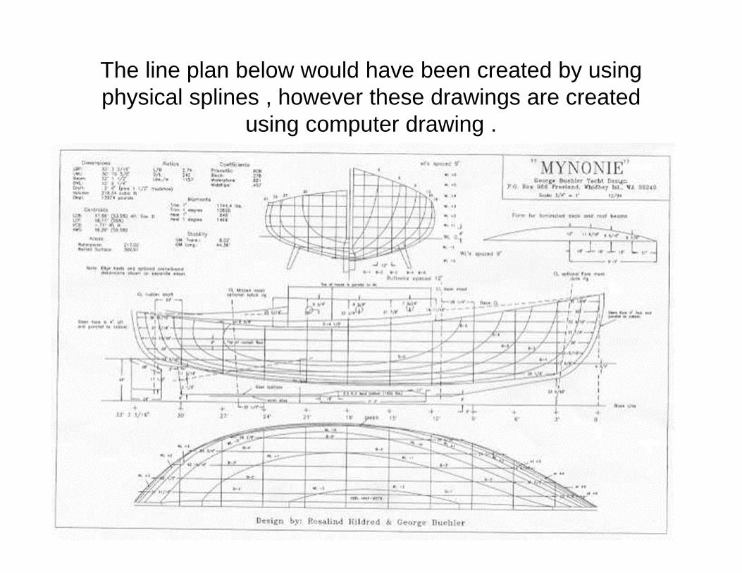
The line plan below would have been created by using physical splines , however these drawings are created
using computer drawing .

11
Surface Model

12
Surface Modeling
• It is the art of engineering freeform surfaces using CAD or CAID system.
• There are two basic methods for the creation of surfaces:The first begins with construction curves ( SPLINES)The second method is direct creation of surface with manipulation of the surface poles/control points.
• Freeform surfacing encompasses two main fields : Aesthetic ( car bodies , consumer outer forms ) and technical (gas turbine blades and other fluid dynamic engineering properties.)
• The continuity of surfaces result in modeling .

13
Computer aided industrial design, CAID
• CAID is a subset of CAD that includes software that directly helps in product development.
• Within CAID programs designers have the freedom of creativity, but typically follow a simple design methodology;
Creating sketches, using stylusGenerating curves directly from the sketchGenerating surfaces directly from the curves.
• The end product is normally a 3D surface model that can be imported into a solid modeler for development by engineering.

14
IPod is an industrially designed productAliasStudio, NX shape studio, solidThinking, Rhinoceros are examples
of CAID
15
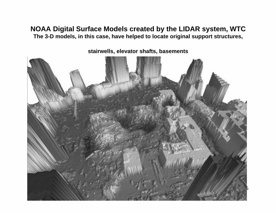
NOAA Digital Surface Models created by the LIDAR system, WTCThe 3-D models, in this case, have helped to locate original support structures,
stairwells, elevator shafts, basements
16
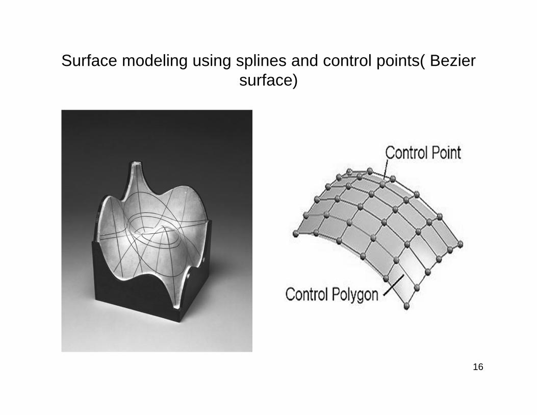
Surface modeling using splines and control points( Bezier surface)

17
Bezier Curve
• These curves are characterized by a control polygon which bounds the curve and control points.
18
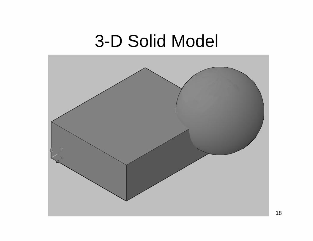
3-D Solid Model

19
Working with Solid Models• Effectively creating and updating all views at one
time– More information represented at once– Plan, Elevation, Section views can be quickly
generated from the model• Allows calculation of properties such as centroid
and weight• Editing is more difficult• More realistic depiction
– Easier and faster to understand– Can navigate through model for visualization

20
SOLID MODELING
• Solid Models are composed of recognizable solid features like boxes and cylinders.
• Solid Models are built up from primitives and sweeps.
• Primitives are solid entities similar to the 2D line, circle and arc entities used in wire frame modeling.
• Sweep operations include extruding, revolving and sweeping.

21
Creating 3-D Objects
• Methods– Primitives– Extrusions– Revolutions– Sweeps– Lofts
22
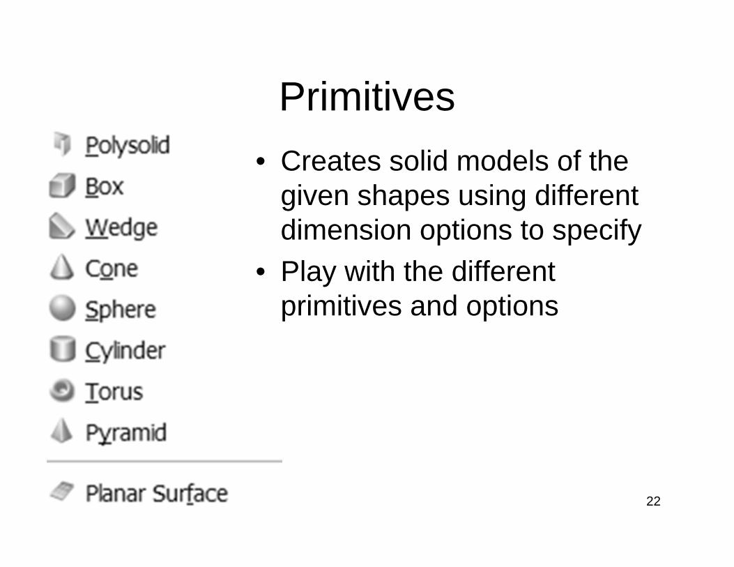
Primitives• Creates solid models of the
given shapes using different dimension options to specify
• Play with the different primitives and options

23
Examples of Solid Primitives
24
3-D Path and Rotation Objects• Provides an alternative means for creating objects
other than using primitives & Boolean operations• Allows for creation of more complex shapes in just
three steps– Create a 2-D cross-section of a solid– Create a path defining the axis of the solid or face– Rotate the cross-section about or Extrude the cross-
section along the axis• The result is a solid or face that fills the space
where the cross-section passes when rotated about or moved along the axis or path
25
Extrusion :Is a modeling technique that creates a 3Dshape by translating a 2D closed profile along a linear path.
Sweep :Is created by moving a 2D closed profile along a path.
Revolution :Is a 3D shape formed by revolving a 2D closed profile about an axis.

26
Examples of extrude, revolve and sweep
27
Creating Object from Cross-Sections and Paths
• 4 Commands are available in AutoCAD 2011 – Extrude– Revolve– Sweep– Loft
• Further examples and options for each command are given in the AutoCAD help files

28
Profiles or Cross-Sections• Objects you can use as cross-sections
– Lines – Arcs – Elliptical arcs – 2D polylines – 2D splines – Circles – Ellipses – 3D faces – 2D solids – Traces (Helix)– Regions – Planar surfaces – Planar faces on solids
29
Paths and Axes• Objects that can be paths:
– Lines – Circles – Arcs – Ellipses – Elliptical arcs – 2D polylines – 3D polylines – 2D splines – 3D splines – Edges of solids – Edges of surfaces – Helixes
• Axes for rotation are specified by two points, a line object, or predefined axes, i.e., the X, Y, or Z axis of the current UCS

30
Creating Paths in 3-D• In general, all objects except lines, solids, and
surfaces can only be drawn in the XY plane of the current UCS
• New commands are 3D polyline which can like lines be drawn in planes other than the XY plane of the current UCS and Helix (spring)
• Coordinates are typically needed for 3D polylines as it is difficult otherwise to know what points you are selecting with the mouse
• 3D polylines can be modified and turned into splines using pedit

31
Extrusion• Creates a solid or surface by giving a cross-
section height or moving it along a path.• If the path option is used the cross-section
will be extruded using its orientation relative to the path
• The taper angle option allows you to reduce the size of the cross-section as it is extruded

32
Sweep• Does the same thing as extrude but
provides different options• The cross-section is extruded perpendicular
to the path unless you specify it to be extruded using its current orientation to the path
• The cross-section can be scaled from beginning to end of the path
• The cross-section can be twisted (rotated about the path) as it is swept along the path

33
Revolve• Creates a solid or surface by revolving a
cross-section about an axis• The axis cannot go through the cross-
section, i.e. to create a sphere using revolve, one must draw a semi-circle arc as a polyline, close it with a line, and revolve it about the line.

34
Loft• Creates a solid or surface from a series of
cross-sections, i.e., could be used to convert a set of contour lines each at their respective elevations into a model of the ground
• You can also specify an path to help define the object, otherwise AutoCAD assumes the path between cross-sections is a straight line.

35
Examples
36
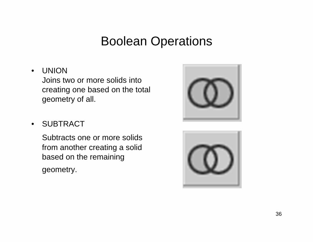
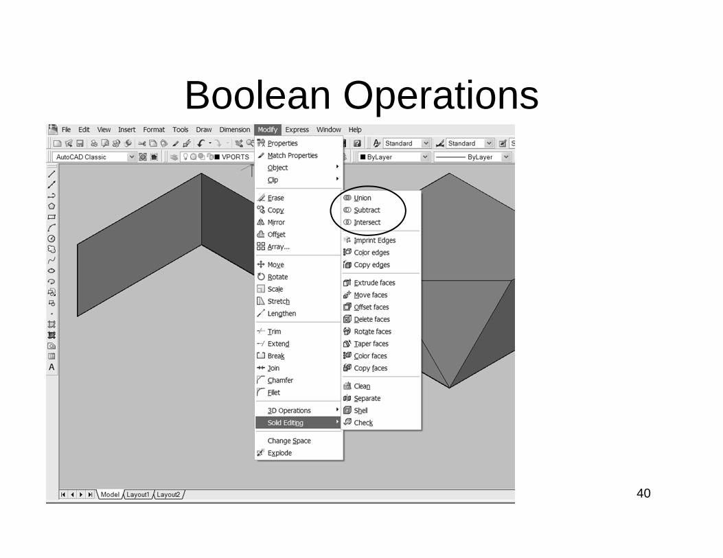
Boolean Operations
• UNIONJoins two or more solids into creating one based on the total geometry of all.
• SUBTRACT
Subtracts one or more solids from another creating a solid based on the remaining geometry.
37
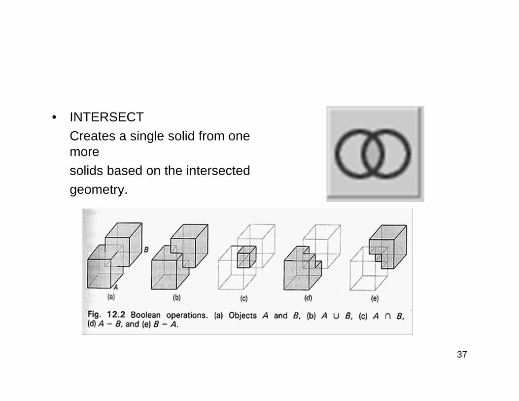
• INTERSECT Creates a single solid from one more solids based on the intersected geometry.

38
Constructive Solid Geometry, CSG
• Constructive Solid Geometry, is yet another way of representing solids.
• A CSG solid is constructed from a few primitives with Booleanoperators (i.e., set union, intersection and difference). Thus, a CSG solid can be written as a set equations and can also be considered a design methodology.
39
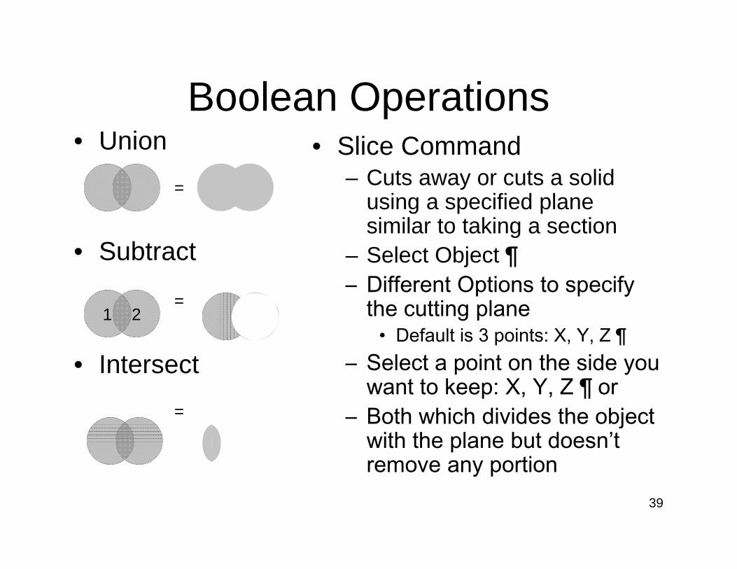
Boolean Operations• Union
=
• Subtract
=
• Intersect
=
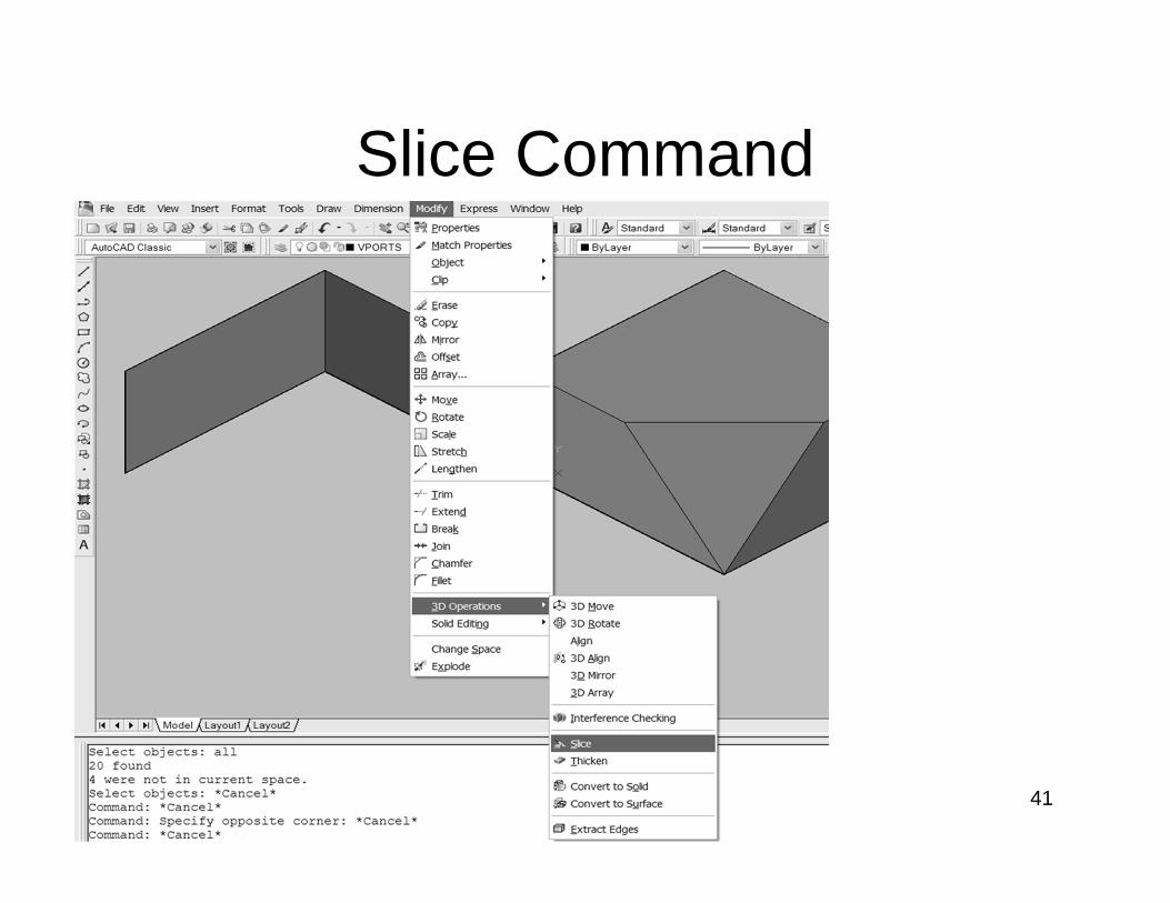
• Slice Command– Cuts away or cuts a solid
using a specified plane similar to taking a section
– Select Object ¶– Different Options to specify
the cutting plane• Default is 3 points: X, Y, Z 
– Select a point on the side you want to keep: X, Y, Z ¶ or
– Both which divides the object with the plane but doesn’t remove any portion
1 2
40
Boolean Operations
41
Slice Command

42
Boundary representation , B-rep
• Is a method for representing shapes using limits.
• Models are a more explicit representation than CSG.
• The object is represented by a complicated data structure giving information about each of the object's faces, edges and vertices and how they are joined together.
• Appears to be a more natural representation for Vision since surface information is readily available.

43
• The description of the object can be into two parts:
TopologyRecords the connectivity of the faces, edges and vertices by means of pointers in the data structure.
GeometryDescribes the exact shape and position of each of the edges, faces and vertices.
• The geometry of a vertex is just its position in space as given by its (x,y,z) coordinates.
• Edges may be straight lines, circular arcs, etc..
• A face is represented by some description of its surface (algebraic or parametric forms used).

44
Parametric Modeling
• Geometry is easy to modify.
• Features contain manufacturing as well as geometric information.
• Dimensions are parametric.
• The model history is available to operator.
• There is room for assembly environment.

45
Parametric Model• Available in AutoCAD on for 2-D• Maintains a history of a models creation
with adjustable parameters• If you adjust a parameter the model updates
following the history, (kind of like an associated dimension or hatch
Box, UCS (Name), Start Point (X, Y, Z), Second Corner (X, Y, Z), Height (#)
Cylinder Subtract from BoxCylinder, UCS (Name), Circle [Tan1 (Box Right Edge), Tan (Box Top Edge), Radius], Height

46
Parametric ExamplesOriginal Parameters Box Height Doubled
Cylinder Radius Doubled Cylinder Circle Definition Changed

47
• Parameter :
It is a named quantity whose value can be changed.Example : d0 = 10 , d0 = parameter, 10 = value
Parametric dimensions control the size and position of features. If the value of a parameter is changed, the feature geometry changes as well.
Say, d0 = 2*d1, id d1 = 5 , then d0 = 10 So if d1 is changed d0 will change by a factor of 2.
• Constraints :
They are mathematical requirements imposed on the geometry of a 3D model.
• Fully constrained Model :
What is an example of a fully constrained model or geometry?

48
Feature Creation
• The most commonly used sketched features include extrude, revolve, sweep and loft.
• Base feature geometry is always additive. Subsequent sketched features are added, subtracted or intersected with the existing geometry depending upon which Boolean Operator is selected.
• Placed features require that the user select existing geometry and supply specific parametric inputs. No sketches are needed.
• Work features do not have a direct effect on the model geometry, rather they enable the creation of a subsequent geometric feature.
49
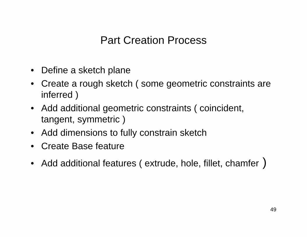
Part Creation Process
• Define a sketch plane• Create a rough sketch ( some geometric constraints are
inferred )• Add additional geometric constraints ( coincident,
tangent, symmetric )• Add dimensions to fully constrain sketch• Create Base feature
• Add additional features ( extrude, hole, fillet, chamfer )
50
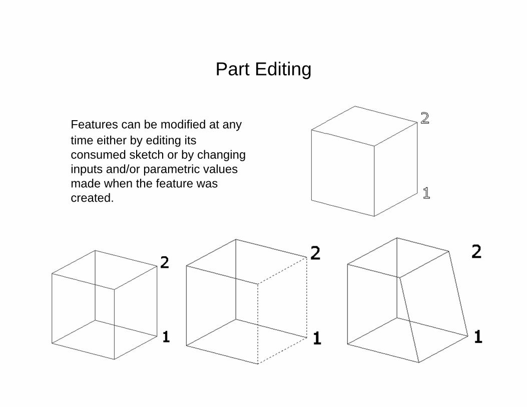
Part Editing
Features can be modified at any time either by editing its consumed sketch or by changing inputs and/or parametric values made when the feature was created.
51
Parent-Child relationships
A parent child relationship refers to the way in which one feature is derived from and is consequently dependent upon another feature.
A child feature must always appear below its parent in the feature tree, and that the base feature will typically be a parent to all other features.
If a parent feature is deleted, then any children will be deleted as well.

52
CAD libraries
• Most parametric modeling packages include a library of standard parts that is linked to the assembly environment.
• Standard parts include threaded fasteners, washers, o –rings, as well as structural shapes.
• In addition to these internal libraries, external CAD part libraries can be accessed via internet.
53
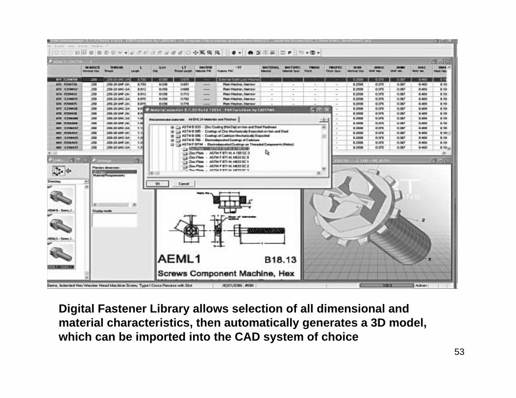
Digital Fastener Library allows selection of all dimensional andmaterial characteristics, then automatically generates a 3D model,which can be imported into the CAD system of choice

54
Downstream ApplicationsCAD/CAM/CAE Integration
• Key elements of the product development process includesDesignManufacturing analysisEngineering analysis
The goal of integrating CAD/CAM/CAE is product development.

55
Computer Aided Manufacturing
CAM is the technology concerned with the use of computer systems to plan, manage and control manufacturing operations.
The most important CAM application areas include numerical control (NC), robotic control and computer aided process planning ( CAPP)
Numerical Control : Uses programmed instruction technique to control a machine tool that grinds, cuts, mills, punches, bends or turns raw stock into a finished part.
56
• Robotic control :Refers to the use of robots to select and positiontools and work pieces for NC machines.
• CAPP :CAPP systems employ software to automate the development of these manufacturing process plans.

57
Computer-Aided Engineering Analysis
CAE is the application of computer software to analyze geometry, allowing the designer to simulate and study how a product behaves in order to refine and optimize the design.
CAE applications include:
Finite element analysis : structural and thermal analysis of components and assemblies.
Computational fluid dynamics – thermal and fluid flow analysis

58
• Large displacement analysis programs-determines loads and displacements in complex assemblies such as automobiles.
• Manufacturing analysis tools – simulate and study manufacturing processes say casting, molding, die press forming.
• Kinematics – determine motion paths and linkage velocities in mechanisms
• Optimization and design automation tools

59
Product data management
PDM software capabilities include;• Product data storage in a secure, centralized vault. This
data includes CAD files, third party CAD files, Non CAD files
• The ability to assign and control access to the data• Search tools to locate and preview the data.• File management tools for check-in, check out and
document release• Version management tools to avoid unintentional
overwriting on files• Viewing and mark up tools.

60
Rapid Prototyping
Refers to the automatic construction of physical objects directly from a geometric solid or surface model.
RP is used for ;Design evaluationFunction VerificationAiding in the creation of models for other manufacturing processesProducing construction quality parts in relatively small numbers
61
Rapid prototypes are also used to verify that a design will function as intended .
Verification tasks include;
Demonstrating the practicality of an assembly. Many products are difficult or even impossible to assemble.
Evaluating the kinematics performance of an assembly.
Assessing aerodynamic performance.

Computer Aided EngineeringVisualization of how a car deforms in an asymmetrical
crash using finite element analysis.

Virtual Models
• Virtual models generally fall into two distinct classes; surface models and solid models.
• Models that are only for visualization purposes may be made with surface modelers.
• A solid model has an additional advantage of having the possibility to generate 2D views than can be developed into conventional documentation.

Model Intelligence
• Refers to the fact that information may be contained in a 3D model. Some of this information is physical and other parametric.
• Physical information includes the dimensions of the object, the location of the object in relation to the location of the other objects in model, the quantity of objects in the model
• Parametric information refers to the info that distinguishes one particular component from another

Laser Scanning
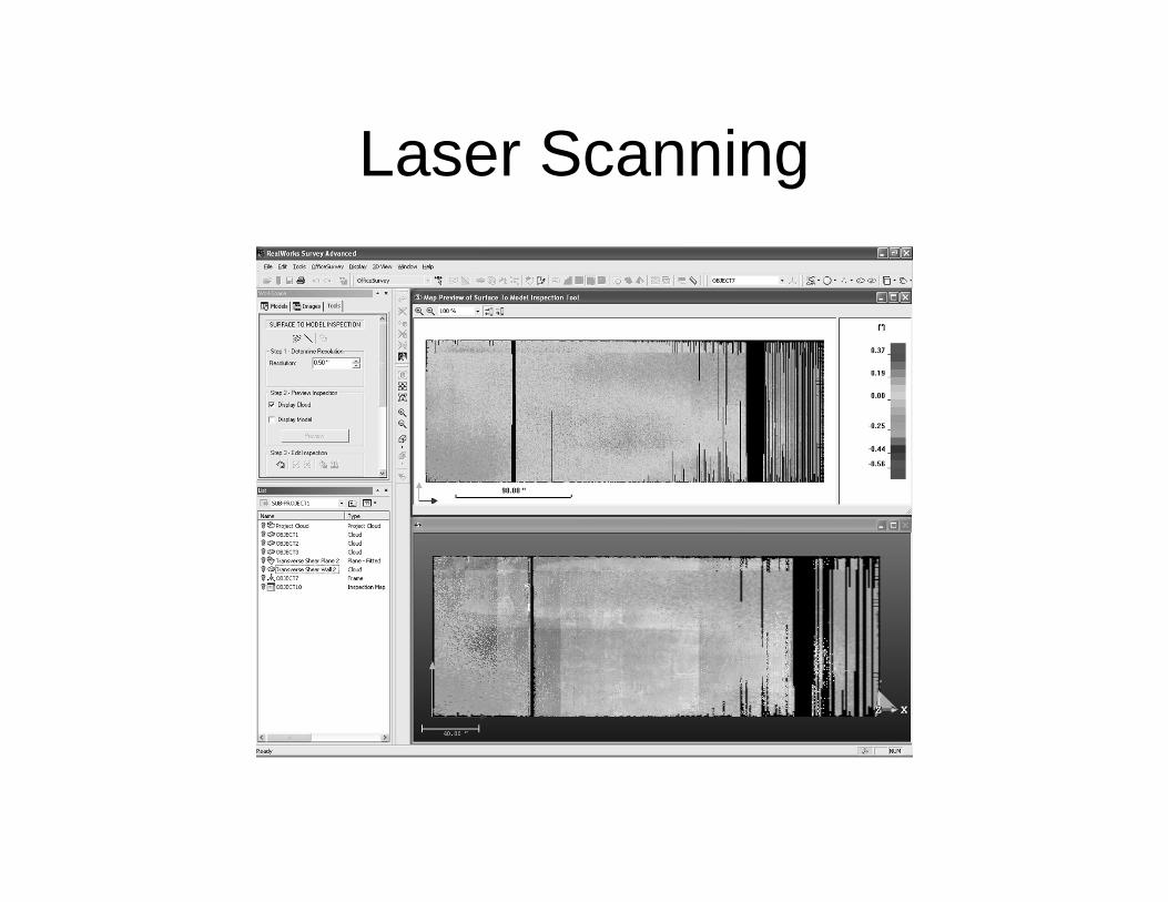
Laser Scanning

Laser Scanning