VIRTUAL MIRROR: A real-time motion capture application for ...
70
Caecilia Charbonnier and Clementine Lo December 2006 VIRTUAL MIRROR: A real-time motion capture application for virtual-try-on Professor: Nadia Magnenat-Thalmann Assistant: Etienne Lyard
Transcript of VIRTUAL MIRROR: A real-time motion capture application for ...
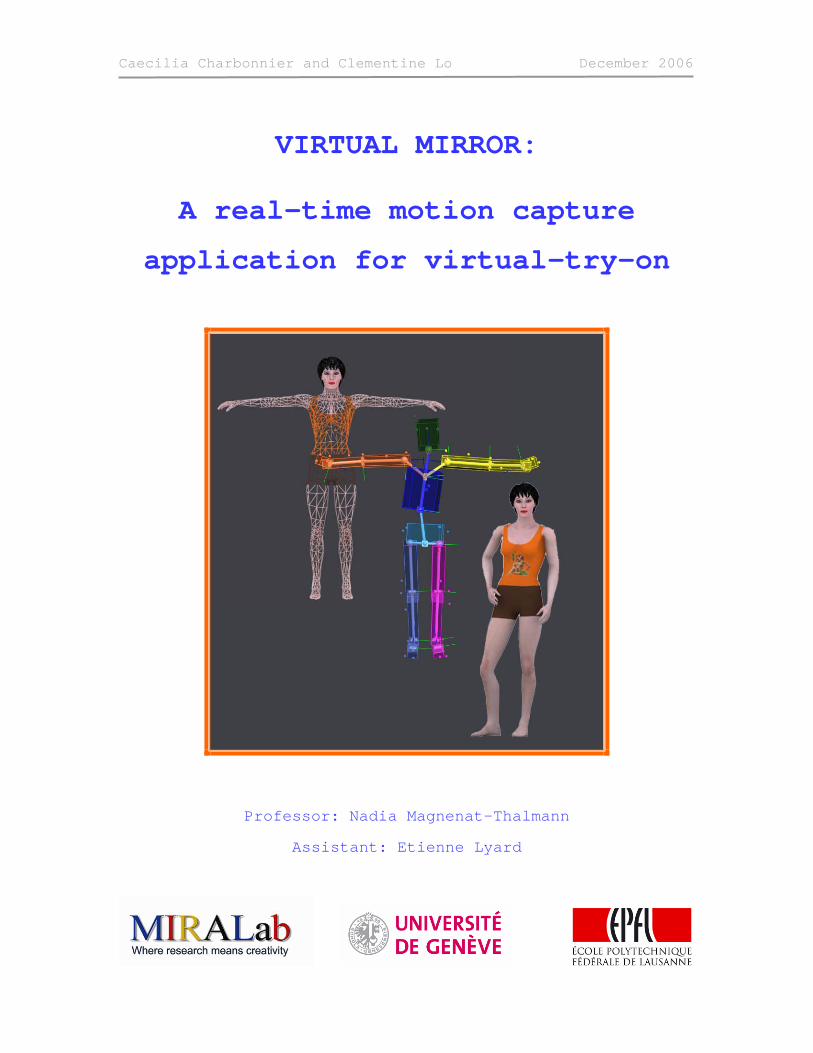
Caecilia Charbonnier and Clementine Lo December 2006
VIRTUAL MIRROR:
A real-time motion capture
application for virtual-try-on
Professor: Nadia Magnenat-Thalmann
Assistant: Etienne Lyard
Caecilia Charbonnier and Clementine Lo December 2006
MIRALab - University of Geneva 2 MAS thesis
Foreword
This project is pretty extensive and requires a broad range of skills. Therefore it has been divided into several separate tasks. They were assigned to two participants considering their respective interests and expertise.
• 3D design (Clementine Lo): modelling of the avatar and of the 3D environment
• Real-time motion capture (Clementine Lo): capturing the motion in real-time with the Vicon
• Networking (Clementine Lo and Caecilia Charbonnier): recovering the data from Tarsus (distributed application). This task involved both participants as it is the communication point between the Vicon (managed by Clementine Lo) and OSG (managed by Caecilia Charbonnier)
• Development of an OSG application (Caecilia Charbonnier): loading and viewing the avatar and 3D environment; applying the motion capture data to the virtual avatar.
• Mathematical calculations (Clementine Lo): calculating the transformations involved to correctly map the subject’s movements onto the avatar according to the mirror illusion; calculating the camera’s position and projection matrix
• Implementation of mathematical results (Caecilia Charbonnier): implementing the different mathematical results in the code for the animation of the avatar and the camera transformation.
A more detailed explanation of the organization of this project is given in chapter 1.2
Of course, even though their work was distinct, both participants have a good understanding of all the techniques, tools and theories involved in this project. For instance one cannot implement a mathematical formula without understanding it and one cannot develop a mathematical solution without comprehending the underlying code.
In order for the reader to understand the project as a whole, the work of both parties is described in this document. Nevertheless, the input of each contributor is made clear:
Caecilia Charbonnier: blue font
Clementine Lo: black font
Common parts (introduction, conclusion, etc.): dark blue font

Caecilia Charbonnier and Clementine Lo December 2006
MIRALab - University of Geneva 3 MAS thesis
Table of contents 1. Introduction...............................................................................................5
1.1. Aim and objectives ................................................................................................ 5 1.2. Organization ......................................................................................................... 6
2. State-of-the-Art .........................................................................................8 3. 3D design .................................................................................................16
3.1. Modelling the avatar ............................................................................................ 16 3.1.1. Body .............................................................................................................................16 3.1.2. Head.............................................................................................................................17 3.1.3. Hair ..............................................................................................................................19 3.1.4. Skeleton and Skinning....................................................................................................20 3.1.5. Textures........................................................................................................................21
3.2. Modelling the 3D environment .............................................................................. 23 4. Real-time motion capture........................................................................25
4.1. Vicon optical motion capture system ..................................................................... 25 4.2. Real-time motion capture with Vicon ..................................................................... 27
4.2.1. Calibration of the system................................................................................................27 4.2.2. Calibration of the subject................................................................................................27 4.2.3. Tracking of the movements ............................................................................................30
4.3. Networking ......................................................................................................... 31 4.3.1. Concepts .......................................................................................................................31 4.3.2. Tarsus communication protocol ......................................................................................32
5. OSG development ....................................................................................33 5.1. Building the viewer .............................................................................................. 33
5.1.1. General principles ..........................................................................................................33 5.1.2. COLLADA file importer....................................................................................................35
5.2. Character animation ............................................................................................ 36 5.2.1. Animation with OSG .......................................................................................................36 5.2.2. Skinning and general concepts........................................................................................37 5.2.3. Application structure and management ...........................................................................39
5.3. Configuration file ................................................................................................. 40 6. Mathematical aspects of the animation ..................................................41
6.1. Global and relative coordinates ............................................................................. 41 6.2. Mirror illusion: symmetry and position in the virtual world....................................... 42
Caecilia Charbonnier and Clementine Lo December 2006
MIRALab - University of Geneva 4 MAS thesis
6.3. Symmetry with quaternions.................................................................................. 43 6.3.1. A naïve approach ...........................................................................................................43 6.3.2. A better approach ..........................................................................................................45
6.4. Pivots ................................................................................................................. 46 6.4.1. Pivots orientation ...........................................................................................................46 6.4.2. Calibration.....................................................................................................................46 6.4.3. Animation......................................................................................................................47
6.5. Conclusion and implementation ............................................................................ 50 7. Camera transformation............................................................................52
7.1. Introduction........................................................................................................ 52 7.2. Mathematical aspects........................................................................................... 53
7.2.1. Camera position.............................................................................................................53 7.2.2. Projection matrix ...........................................................................................................53
7.3. Implementation................................................................................................... 55 8. Tests and results......................................................................................56
8.1. Tests.................................................................................................................. 56 8.2. Results ............................................................................................................... 58
9. Conclusion and future work.....................................................................60 9.1. Real-time cloth simulation .................................................................................... 60 9.2. Body retargeting ................................................................................................. 61
10. Acknowledgements................................................................................63 11. Bibliography...........................................................................................63
Caecilia Charbonnier and Clementine Lo December 2006
MIRALab - University of Geneva 5 MAS thesis
1. Introduction Cloth simulation has been a topic of intensive research for several years. At the
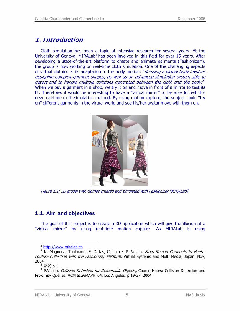
University of Geneva, MIRALab1 has been involved in this field for over 15 years. After developing a state-of-the-art platform to create and animate garments (Fashionizer2), the group is now working on real-time cloth simulation. One of the challenging aspects of virtual clothing is its adaptation to the body motion: “dressing a virtual body involves designing complex garment shapes, as well as an advanced simulation system able to detect and to handle multiple collisions generated between the cloth and the body.”3 When we buy a garment in a shop, we try it on and move in front of a mirror to test its fit. Therefore, it would be interesting to have a “virtual mirror” to be able to test this new real-time cloth simulation method. By using motion capture, the subject could “try on” different garments in the virtual world and see his/her avatar move with them on.
Figure 1.1: 3D model with clothes created and simulated with Fashionizer (MIRALab)4
1.1. Aim and objectives
The goal of this project is to create a 3D application which will give the illusion of a “virtual mirror” by using real-time motion capture. As MIRALab is using
1 http://www.miralab.ch 2 N. Magnenat-Thalmann, F. Dellas, C. Luible, P. Volino, From Roman Garments to Haute-
couture Collection with the Fashionizer Platform, Virtual Systems and Multi Media, Japan, Nov, 2004
3 Ibid, p.1 4 P.Volino, Collision Detection for Deformable Objects, Course Notes: Collision Detection and
Proximity Queries, ACM SIGGRAPH’ 04, Los Angeles, p.19-37, 2004
Caecilia Charbonnier and Clementine Lo December 2006
MIRALab - University of Geneva 6 MAS thesis
OpenSceneGraph5 (OSG), a graphic library, to develop its real-time cloth animation application, the same toolkit is employed for this project. The subject’s movements are tracked using a Vicon6 optical motion capture system and are applied to a virtual avatar in real-time. The avatar is included in a 3D environment and the scene is projected on a big screen in front of the subject. The camera projection is calculated so as to give the impression of a “window” on a virtual world.
This project involves various areas of 3D computer graphics and programming:
• 3D design: modelling of the avatar and of the 3D environment
• Real-time motion capture: capturing the motion in real-time with the Vicon; recovering the data from Tarsus, Vicon’s real-time engine (distributed application).
• Development of an OSG application: loading and viewing the avatar and 3D environment; applying the motion capture data to the virtual avatar.
• Camera transformation: updating the camera’s position in regards to the subject’s head position; calculation of the camera’s projection matrix to give the illusion of a window on another world.
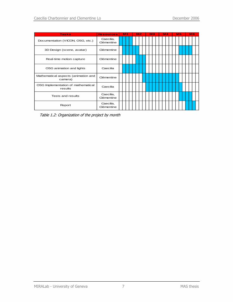
1.2. Organization
The project started beginning of July 2006. On the programming side, the initial needs were to install OSG and build the skeleton of the application. The first month was mainly devoted to the animation of a virtual body with OSG. Meanwhile an initial version of the environment and virtual avatar was created. Once we were able to load the virtual world and animate the bones of our avatar with OSG, we concentrated on the connection with the Vicon. We had to find a way to retrieve the animation data from the Vicon system and integrate it into the OSG application. Unfortunately our first tests with the motion capture were not satisfactory. Indeed, we didn’t take into account the different calculations needed to map the motion of the real body onto the virtual character. This mathematical aspect turned out to be the longest part of the project, involving many trials and errors. Finally, the last part of the project was dedicated to the camera implementation, the scene improvement and real-time optimization. We also tested the application with different subjects.
5 http://www.openscenegraph.org 6 http://www.vicon.com
Caecilia Charbonnier and Clementine Lo December 2006
MIRALab - University of Geneva 7 MAS thesis
Tasks Resources
Documentation (VICON, OSG, etc.) Caecilia, Clémentine
3D Design (scene, avatar) Clémentine
Real-time motion capture Clémentine
OSG animation and lights Caecilia
Mathematical aspects (animation and camera)
Clémentine
OSG Implementation of mathematical results
Caecilia
Tests and results Caecilia, Clémentine
Report Caecilia, Clémentine
M5 M6M1 M2 M3 M4
Table 1.2: Organization of the project by month
Caecilia Charbonnier December 2006
MIRALab - University of Geneva 8 MAS thesis
2. State-of-the-Art Motion capture as we know it today is a very practical and realistic way to animate
virtual human bodies. It is widely used in medicine, sports, the entertainment industry, and in the study of human factors.7 Instead of hand animating the model, the movements of a real person are recorded and transferred to the virtual body. Different techniques are available. The more popular ones are electromagnetic trackers and optical motion capture systems.
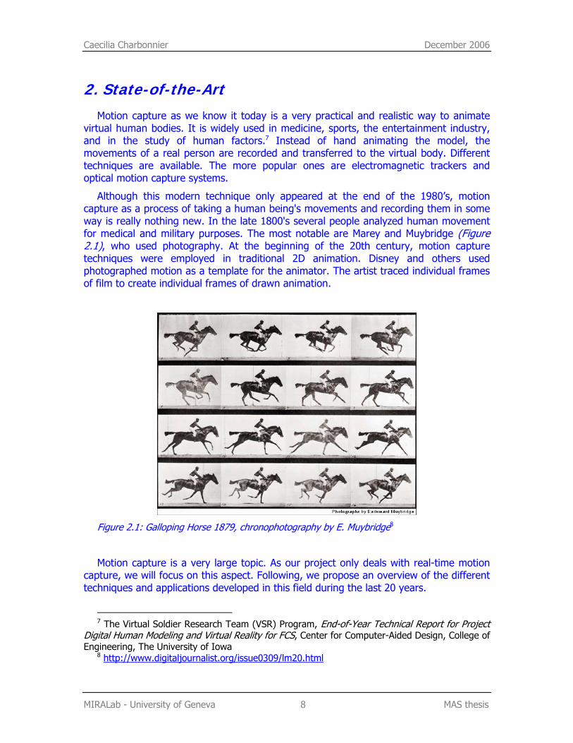
Although this modern technique only appeared at the end of the 1980’s, motion capture as a process of taking a human being's movements and recording them in some way is really nothing new. In the late 1800's several people analyzed human movement for medical and military purposes. The most notable are Marey and Muybridge (Figure 2.1), who used photography. At the beginning of the 20th century, motion capture techniques were employed in traditional 2D animation. Disney and others used photographed motion as a template for the animator. The artist traced individual frames of film to create individual frames of drawn animation.
Figure 2.1: Galloping Horse 1879, chronophotography by E. Muybridge8
Motion capture is a very large topic. As our project only deals with real-time motion capture, we will focus on this aspect. Following, we propose an overview of the different techniques and applications developed in this field during the last 20 years.
7 The Virtual Soldier Research Team (VSR) Program, End-of-Year Technical Report for Project
Digital Human Modeling and Virtual Reality for FCS, Center for Computer-Aided Design, College of Engineering, The University of Iowa
8 http://www.digitaljournalist.org/issue0309/lm20.html
Caecilia Charbonnier December 2006
MIRALab - University of Geneva 9 MAS thesis
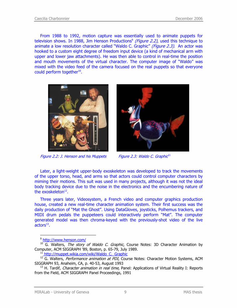
From 1988 to 1992, motion capture was essentially used to animate puppets for television shows. In 1988, Jim Henson Productions9 (Figure 2.2), used this technique to animate a low resolution character called “Waldo C. Graphic” (Figure 2.3). An actor was hooked to a custom eight degree of freedom input device (a kind of mechanical arm with upper and lower jaw attachments). He was then able to control in real-time the position and mouth movements of the virtual character. The computer image of “Waldo” was mixed with the video feed of the camera focused on the real puppets so that everyone could perform together10.
Figure 2.2: J. Henson and his Muppets Figure 2.3: Waldo C. Graphic11
Later, a light-weight upper-body exoskeleton was developed to track the movements of the upper torso, head, and arms so that actors could control computer characters by miming their motions. This suit was used in many projects, although it was not the ideal body tracking device due to the noise in the electronics and the encumbering nature of the exoskeleton12.
Three years later, Videosystem, a French video and computer graphics production house, created a new real-time character animation system. Their first success was the daily production of “Mat the Ghost”. Using DataGloves, joysticks, Polhemus trackers, and MIDI drum pedals the puppeteers could interactively perform “Mat”. The computer generated model was then chroma-keyed with the previously-shot video of the live actors13.
9 http://www.henson.com/ 10 G. Walters, The story of Waldo C. Graphic, Course Notes: 3D Character Animation by
Computer, ACM SIGGRAPH '89, Boston, p. 65-79, July 1989. 11 http://muppet.wikia.com/wiki/Waldo_C._Graphic 12 G. Walters, Performance animation at PDI, Course Notes: Character Motion Systems, ACM
SIGGRAPH 93, Anaheim, CA, p. 40-53, August 1993 13 H. Tardif, Character animation in real time, Panel: Applications of Virtual Reality I: Reports
from the Field, ACM SIGGRAPH Panel Proceedings, 1991
Caecilia Charbonnier December 2006
MIRALab - University of Geneva 10 MAS thesis
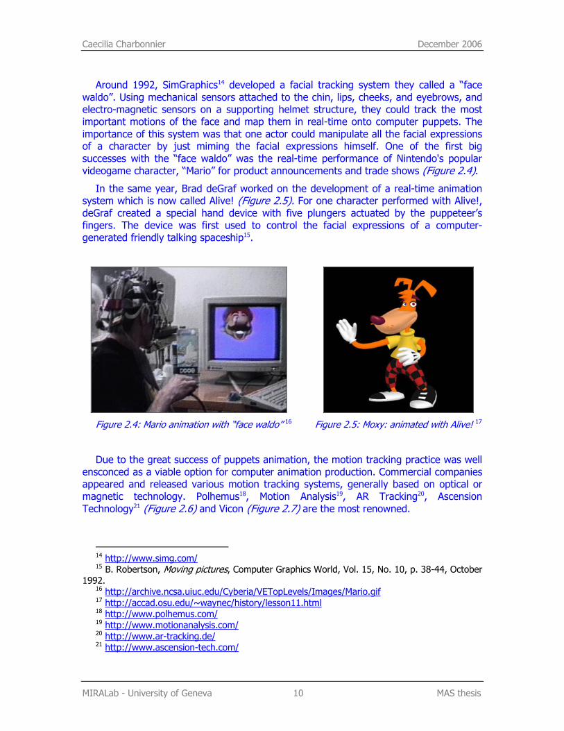
Around 1992, SimGraphics14 developed a facial tracking system they called a “face waldo”. Using mechanical sensors attached to the chin, lips, cheeks, and eyebrows, and electro-magnetic sensors on a supporting helmet structure, they could track the most important motions of the face and map them in real-time onto computer puppets. The importance of this system was that one actor could manipulate all the facial expressions of a character by just miming the facial expressions himself. One of the first big successes with the “face waldo” was the real-time performance of Nintendo's popular videogame character, “Mario” for product announcements and trade shows (Figure 2.4).
In the same year, Brad deGraf worked on the development of a real-time animation system which is now called Alive! (Figure 2.5). For one character performed with Alive!, deGraf created a special hand device with five plungers actuated by the puppeteer’s fingers. The device was first used to control the facial expressions of a computer-generated friendly talking spaceship15.
Figure 2.4: Mario animation with “face waldo” 16 Figure 2.5: Moxy: animated with Alive! 17
Due to the great success of puppets animation, the motion tracking practice was well ensconced as a viable option for computer animation production. Commercial companies appeared and released various motion tracking systems, generally based on optical or magnetic technology. Polhemus18, Motion Analysis19, AR Tracking20, Ascension Technology21 (Figure 2.6) and Vicon (Figure 2.7) are the most renowned.
14 http://www.simg.com/ 15 B. Robertson, Moving pictures, Computer Graphics World, Vol. 15, No. 10, p. 38-44, October
1992. 16 http://archive.ncsa.uiuc.edu/Cyberia/VETopLevels/Images/Mario.gif 17 http://accad.osu.edu/~waynec/history/lesson11.html 18 http://www.polhemus.com/ 19 http://www.motionanalysis.com/ 20 http://www.ar-tracking.de/ 21 http://www.ascension-tech.com/
Caecilia Charbonnier December 2006
MIRALab - University of Geneva 11 MAS thesis
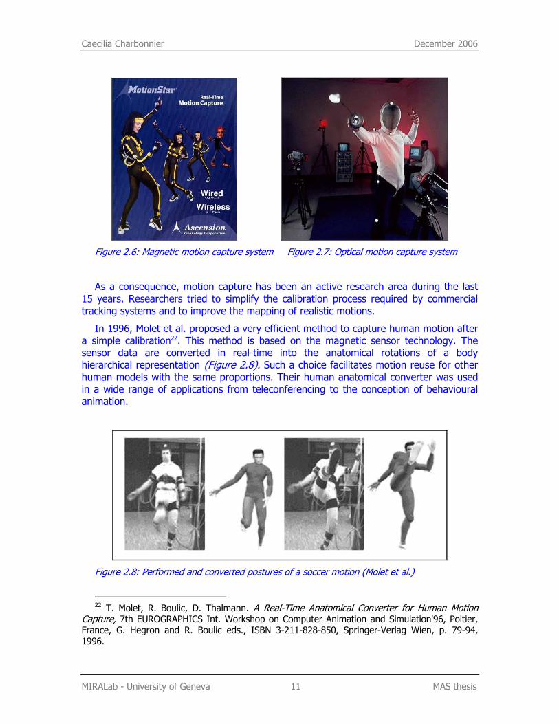
Figure 2.6: Magnetic motion capture system Figure 2.7: Optical motion capture system
As a consequence, motion capture has been an active research area during the last 15 years. Researchers tried to simplify the calibration process required by commercial tracking systems and to improve the mapping of realistic motions.
In 1996, Molet et al. proposed a very efficient method to capture human motion after a simple calibration22. This method is based on the magnetic sensor technology. The sensor data are converted in real-time into the anatomical rotations of a body hierarchical representation (Figure 2.8). Such a choice facilitates motion reuse for other human models with the same proportions. Their human anatomical converter was used in a wide range of applications from teleconferencing to the conception of behavioural animation.
Figure 2.8: Performed and converted postures of a soccer motion (Molet et al.)
22 T. Molet, R. Boulic, D. Thalmann. A Real-Time Anatomical Converter for Human Motion
Capture, 7th EUROGRAPHICS Int. Workshop on Computer Animation and Simulation'96, Poitier, France, G. Hegron and R. Boulic eds., ISBN 3-211-828-850, Springer-Verlag Wien, p. 79-94, 1996.
Caecilia Charbonnier December 2006
MIRALab - University of Geneva 12 MAS thesis
Later, they improved their system by including the multi-joint control. This method allows driving several joints using only one sensor23. As a result the model’s deformations are more realistic whilst the cost remains the same. However it can only be applied to joints that have clear interdependence 24 (i.e. when a variation of one joint implies a variation of the other joint, as for the spine for example).
Using the same anatomical converter system, Nedel et al. improved the representation of the virtual human model by adding the simulation of anatomical muscles and bones25.
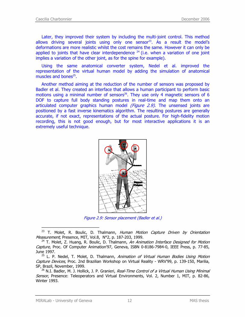
Another method aiming at the reduction of the number of sensors was proposed by Badler et al. They created an interface that allows a human participant to perform basic motions using a minimal number of sensors26. They use only 4 magnetic sensors of 6 DOF to capture full body standing postures in real-time and map them onto an articulated computer graphics human model (Figure 2.9). The unsensed joints are positioned by a fast inverse kinematics algorithm. The resulting postures are generally accurate, if not exact, representations of the actual posture. For high-fidelity motion recording, this is not good enough, but for most interactive applications it is an extremely useful technique.
Figure 2.9: Sensor placement (Badler et al.)
23 T. Molet, R. Boulic, D. Thalmann, Human Motion Capture Driven by Orientation
Measurement, Presence, MIT, Vol.8, N°2, p. 187-203, 1999. 24 T. Molet, Z. Huang, R. Boulic, D. Thalmann, An Animation Interface Designed for Motion
Capture, Proc. Of Computer Animation'97, Geneva, ISBN 0-8186-7984-0, IEEE Press, p. 77-85, June 1997.
25 L. P. Nedel, T. Molet, D. Thalmann, Animation of Virtual Human Bodies Using Motion Capture Devices, Proc. 2nd Brazilian Workshop on Virtual Reality - WRV'99, p. 139-150, Marilia, SP, Brazil, November, 1999.
26 N.I. Badler, M. J. Hollick, J. P. Granieri, Real-Time Control of a Virtual Human Using Minimal Sensor, Presence: Teleoperators and Virtual Environments, Vol. 2, Number 1, MIT, p. 82-86, Winter 1993.

Caecilia Charbonnier December 2006
MIRALab - University of Geneva 13 MAS thesis
Apart from the technical complexity of designing realistic human motion, another recurrent problem is the cost. The equipment to accurately track every body segment (or joint angle) of a human being can be very expensive.
A solution to reduce costs and cumbersome of motion capture devices is to use video-based tracking systems. With this technique, the reconstruction of human motion is based on the estimation and tracking of motion in image sequences using computer vision methods. Okada et al. proposed an interesting application which presents a few similarities with our project. They produced a virtual fashion show using real-time markerless motion capture27. Virtual models were animated according to the motion of the real models and were projected on screens during the catwalk. Furthermore, the avatars wore different clothing than their corresponding model. Obviously, the use of visible markers and sensors had to be avoided to preserve the beauty of the real show. Only pairs of cameras were used to estimate the postures (Figure 2.10).
Figure 2.10: Overview of the virtual fashion show (Okada et al.)
Nowadays, image-based tracking is a well-established branch of special effects for movies and product announcements. In augmented reality applications for example, tracking and registration of cameras and objects are required to combine real and rendered scenes. In this area, CVLab28 an active Swiss computer vision laboratory has presented many accurate solutions that work in real-time even under difficult
27 R. Okada, B. Stenger, T. Ike, N. Kondoh, Virtual Fashion show using real-time markerless
motion capture, ACCV (2), p. 801-810, 2006. 28 http://cvlab.epfl.ch/research/augm/augmented.html
Caecilia Charbonnier December 2006
MIRALab - University of Geneva 14 MAS thesis
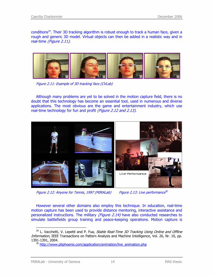
conditions29. Their 3D tracking algorithm is robust enough to track a human face, given a rough and generic 3D model. Virtual objects can then be added in a realistic way and in real-time (Figure 2.11).
Figure 2.11: Example of 3D tracking face (CVLab)
Although many problems are yet to be solved in the motion capture field, there is no doubt that this technology has become an essential tool, used in numerous and diverse applications. The most obvious are the game and entertainment industry, which use real-time technology for fun and profit (Figure 2.12 and 2.13).
Figure 2.12: Anyone for Tennis, 1997 (MIRALab) Figure 2.13: Live performance30
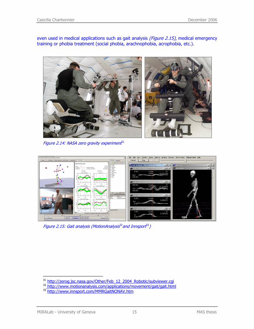
However several other domains also employ this technique. In education, real-time motion capture has been used to provide distance mentoring, interactive assistance and personalized instructions. The military (Figure 2.14) have also conducted researches to simulate battlefields group training and peace-keeping operations. Motion capture is
29 L. Vacchetti, V. Lepetit and P. Fua, Stable Real-Time 3D Tracking Using Online and Offline
Information, IEEE Transactions on Pattern Analysis and Machine Intelligence, Vol. 26, Nr. 10, pp. 1391-1391, 2004.
30 http://www.ptiphoenix.com/application/animation/live_animation.php
Caecilia Charbonnier December 2006
MIRALab - University of Geneva 15 MAS thesis
even used in medical applications such as gait analysis (Figure 2.15), medical emergency training or phobia treatment (social phobia, arachnophobia, acrophobia, etc.).
Figure 2.14: NASA zero gravity experiment31
Figure 2.15: Gait analysis (MotionAnalysis32and Innsport33)
31 http://zerog.jsc.nasa.gov/Other/Feb_12_2004_Robotic/subviewer.cgi 32 http://www.motionanalysis.com/applications/movement/gait/gait.html 33 http://www.innsport.com/MMRGaitNONAV.htm
Clementine Lo December 2006
MIRALab - University of Geneva 16 MAS thesis
3. 3D design While designing the 3D model and environment, we had to consider a few
constraining factors. First of all, given that we are working on a real-time application, the rendering time has to be reduced as much as possible: the number of polygons has to be minimal and the lighting as simple as possible. What's more, as of now, OSG only supports simple bitmap textures. We cannot apply any special rendering effects such as transparency, reflection or raytracing. For these reasons, our possibilities in getting a sophisticated result will be noticeably diminished.
3.1. Modelling the avatar
3.1.1. Body
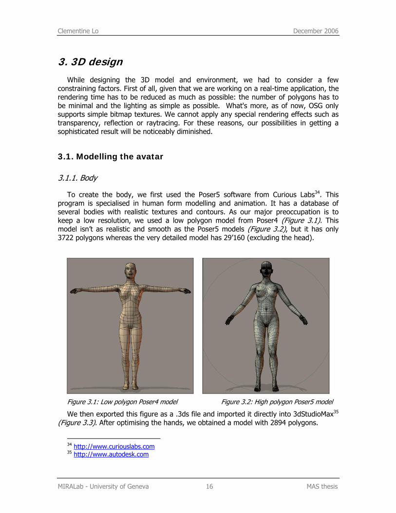
To create the body, we first used the Poser5 software from Curious Labs34. This program is specialised in human form modelling and animation. It has a database of several bodies with realistic textures and contours. As our major preoccupation is to keep a low resolution, we used a low polygon model from Poser4 (Figure 3.1). This model isn’t as realistic and smooth as the Poser5 models (Figure 3.2), but it has only 3722 polygons whereas the very detailed model has 29’160 (excluding the head).
Figure 3.1: Low polygon Poser4 model Figure 3.2: High polygon Poser5 model
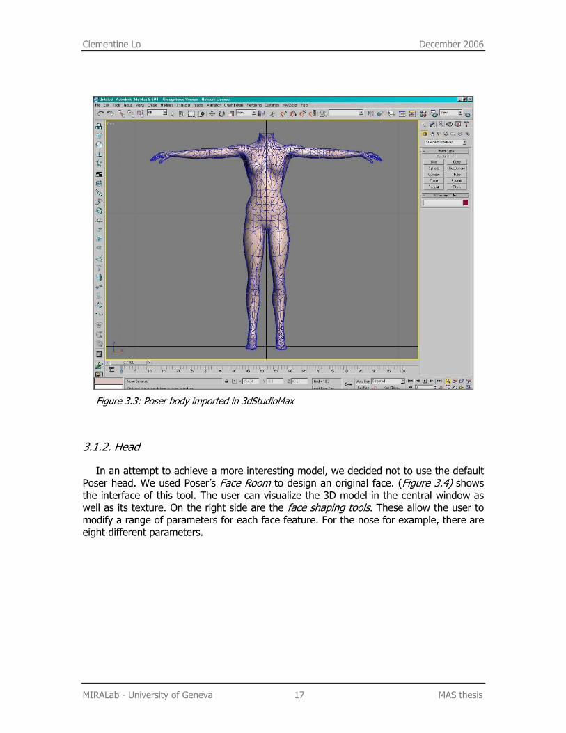
We then exported this figure as a .3ds file and imported it directly into 3dStudioMax35 (Figure 3.3). After optimising the hands, we obtained a model with 2894 polygons.
34 http://www.curiouslabs.com 35 http://www.autodesk.com
Clementine Lo December 2006
MIRALab - University of Geneva 17 MAS thesis
Figure 3.3: Poser body imported in 3dStudioMax
3.1.2. Head
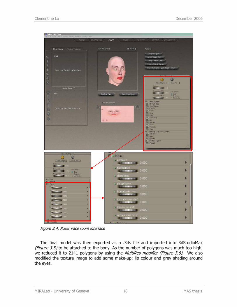
In an attempt to achieve a more interesting model, we decided not to use the default Poser head. We used Poser’s Face Room to design an original face. (Figure 3.4) shows the interface of this tool. The user can visualize the 3D model in the central window as well as its texture. On the right side are the face shaping tools. These allow the user to modify a range of parameters for each face feature. For the nose for example, there are eight different parameters.
Clementine Lo December 2006
MIRALab - University of Geneva 18 MAS thesis
Figure 3.4: Poser Face room interface
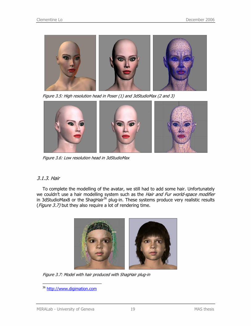
The final model was then exported as a .3ds file and imported into 3dStudioMax (Figure 3.5) to be attached to the body. As the number of polygons was much too high, we reduced it to 2141 polygons by using the MultiRes modifier (Figure 3.6). We also modified the texture image to add some make-up: lip colour and grey shading around the eyes.
Clementine Lo December 2006
MIRALab - University of Geneva 19 MAS thesis
Figure 3.5: High resolution head in Poser (1) and 3dStudioMax (2 and 3)
Figure 3.6: Low resolution head in 3dStudioMax
3.1.3. Hair
To complete the modelling of the avatar, we still had to add some hair. Unfortunately we couldn’t use a hair modelling system such as the Hair and Fur world-space modifier in 3dStudioMax8 or the ShagHair36 plug-in. These systems produce very realistic results (Figure 3.7) but they also require a lot of rendering time.
Figure 3.7: Model with hair produced with ShagHair plug-in
36 http://www.digimation.com
Clementine Lo December 2006
MIRALab - University of Geneva 20 MAS thesis
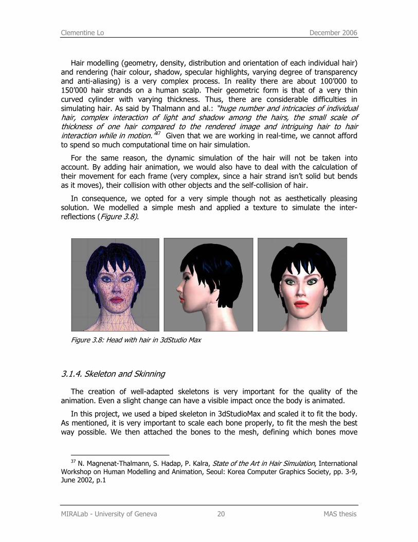
Hair modelling (geometry, density, distribution and orientation of each individual hair) and rendering (hair colour, shadow, specular highlights, varying degree of transparency and anti-aliasing) is a very complex process. In reality there are about 100’000 to 150’000 hair strands on a human scalp. Their geometric form is that of a very thin curved cylinder with varying thickness. Thus, there are considerable difficulties in simulating hair. As said by Thalmann and al.: “huge number and intricacies of individual hair, complex interaction of light and shadow among the hairs, the small scale of thickness of one hair compared to the rendered image and intriguing hair to hair interaction while in motion.”37 Given that we are working in real-time, we cannot afford to spend so much computational time on hair simulation.
For the same reason, the dynamic simulation of the hair will not be taken into account. By adding hair animation, we would also have to deal with the calculation of their movement for each frame (very complex, since a hair strand isn’t solid but bends as it moves), their collision with other objects and the self-collision of hair.
In consequence, we opted for a very simple though not as aesthetically pleasing solution. We modelled a simple mesh and applied a texture to simulate the inter-reflections (Figure 3.8).
Figure 3.8: Head with hair in 3dStudio Max
3.1.4. Skeleton and Skinning
The creation of well-adapted skeletons is very important for the quality of the animation. Even a slight change can have a visible impact once the body is animated.
In this project, we used a biped skeleton in 3dStudioMax and scaled it to fit the body. As mentioned, it is very important to scale each bone properly, to fit the mesh the best way possible. We then attached the bones to the mesh, defining which bones move
37 N. Magnenat-Thalmann, S. Hadap, P. Kalra, State of the Art in Hair Simulation, International
Workshop on Human Modelling and Animation, Seoul: Korea Computer Graphics Society, pp. 3-9, June 2002, p.1
Clementine Lo December 2006
MIRALab - University of Geneva 21 MAS thesis
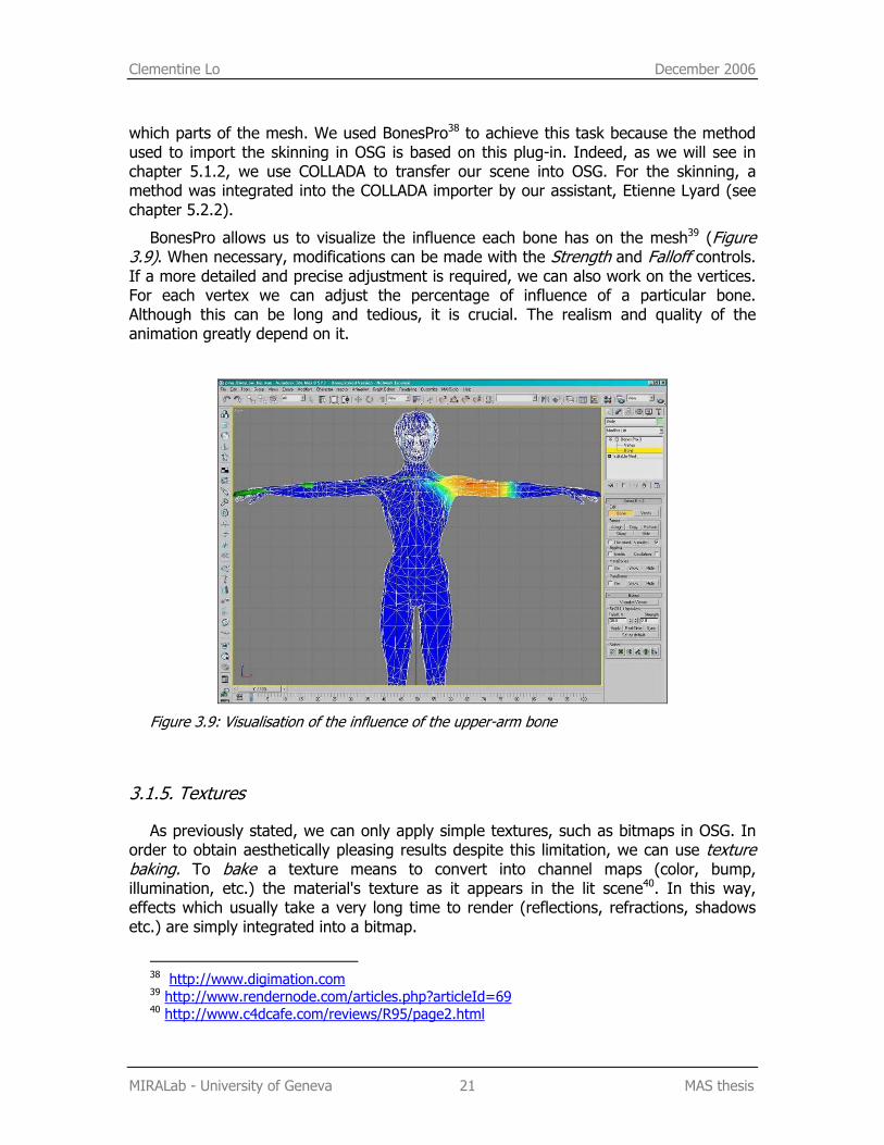
which parts of the mesh. We used BonesPro38 to achieve this task because the method used to import the skinning in OSG is based on this plug-in. Indeed, as we will see in chapter 5.1.2, we use COLLADA to transfer our scene into OSG. For the skinning, a method was integrated into the COLLADA importer by our assistant, Etienne Lyard (see chapter 5.2.2).
BonesPro allows us to visualize the influence each bone has on the mesh39 (Figure 3.9). When necessary, modifications can be made with the Strength and Falloff controls. If a more detailed and precise adjustment is required, we can also work on the vertices. For each vertex we can adjust the percentage of influence of a particular bone. Although this can be long and tedious, it is crucial. The realism and quality of the animation greatly depend on it.
Figure 3.9: Visualisation of the influence of the upper-arm bone
3.1.5. Textures
As previously stated, we can only apply simple textures, such as bitmaps in OSG. In order to obtain aesthetically pleasing results despite this limitation, we can use texture baking. To bake a texture means to convert into channel maps (color, bump, illumination, etc.) the material's texture as it appears in the lit scene40. In this way, effects which usually take a very long time to render (reflections, refractions, shadows etc.) are simply integrated into a bitmap.
38 http://www.digimation.com 39 http://www.rendernode.com/articles.php?articleId=69 40 http://www.c4dcafe.com/reviews/R95/page2.html
Clementine Lo December 2006
MIRALab - University of Geneva 22 MAS thesis
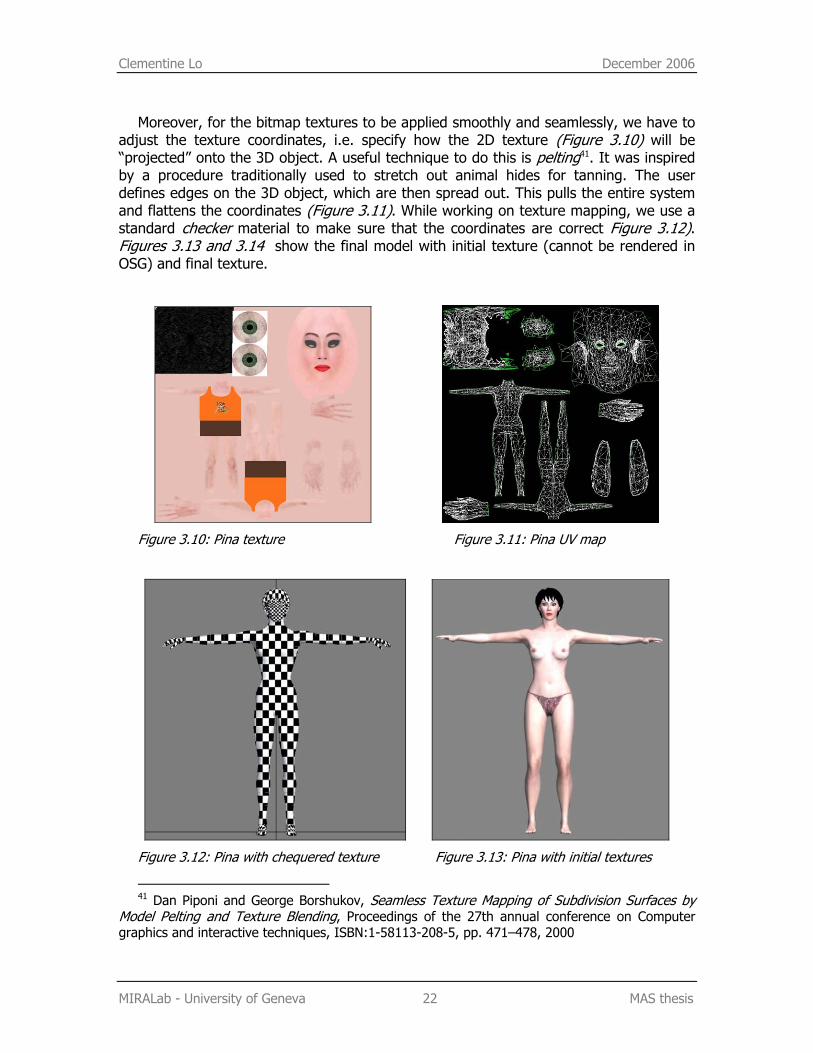
Moreover, for the bitmap textures to be applied smoothly and seamlessly, we have to adjust the texture coordinates, i.e. specify how the 2D texture (Figure 3.10) will be “projected” onto the 3D object. A useful technique to do this is pelting41. It was inspired by a procedure traditionally used to stretch out animal hides for tanning. The user defines edges on the 3D object, which are then spread out. This pulls the entire system and flattens the coordinates (Figure 3.11). While working on texture mapping, we use a standard checker material to make sure that the coordinates are correct Figure 3.12). Figures 3.13 and 3.14 show the final model with initial texture (cannot be rendered in OSG) and final texture.
Figure 3.10: Pina texture Figure 3.11: Pina UV map
Figure 3.12: Pina with chequered texture Figure 3.13: Pina with initial textures
41 Dan Piponi and George Borshukov, Seamless Texture Mapping of Subdivision Surfaces by
Model Pelting and Texture Blending, Proceedings of the 27th annual conference on Computer graphics and interactive techniques, ISBN:1-58113-208-5, pp. 471–478, 2000
Clementine Lo December 2006
MIRALab - University of Geneva 23 MAS thesis
Figure 3.14: Pina final model
3.2. Modelling the 3D environment
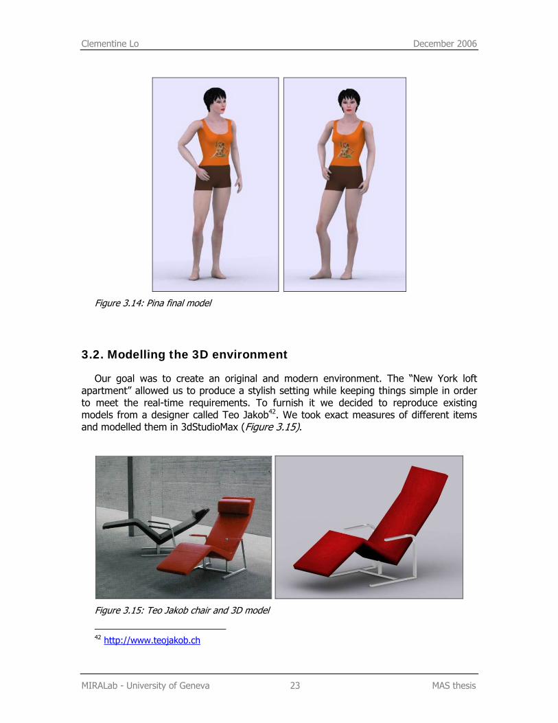
Our goal was to create an original and modern environment. The “New York loft apartment” allowed us to produce a stylish setting while keeping things simple in order to meet the real-time requirements. To furnish it we decided to reproduce existing models from a designer called Teo Jakob42. We took exact measures of different items and modelled them in 3dStudioMax (Figure 3.15).
Figure 3.15: Teo Jakob chair and 3D model
42 http://www.teojakob.ch
Clementine Lo December 2006
MIRALab - University of Geneva 24 MAS thesis
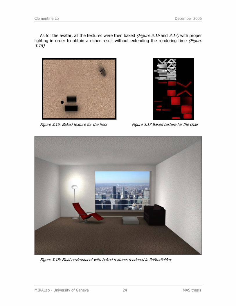
As for the avatar, all the textures were then baked (Figure 3.16 and 3.17) with proper lighting in order to obtain a richer result without extending the rendering time (Figure 3.18).
Figure 3.16: Baked texture for the floor Figure 3.17 Baked texture for the chair
Figure 3.18: Final environment with baked textures rendered in 3dStudioMax
Clementine Lo December 2006
MIRALab - University of Geneva 25 MAS thesis
4. Real-time motion capture
4.1. Vicon optical motion capture system
In this project we first used an 8 camera Vicon 8i system. MIRALab then changed its system to a Vicon MX (still 8 cameras). As we will see later, this upgrade had a positive impact on the quality of our application. As for the software, we used Vicon iQ and Tarsus, Vicon’s real-time engine.
Vicon is an optical detection system, which means the information is transferred to the computer without the need of any cabling. The only limitation is the area in which the subject can move. The cameras can only “see” a certain amount of space. Of course, this depends on the size of the room, the placement and the number of cameras used.
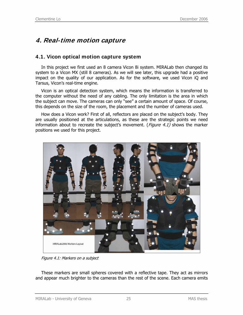
How does a Vicon work? First of all, reflectors are placed on the subject’s body. They are usually positioned at the articulations, as these are the strategic points we need information about to recreate the subject’s movement. (Figure 4.1) shows the marker positions we used for this project.
Figure 4.1: Markers on a subject
These markers are small spheres covered with a reflective tape. They act as mirrors and appear much brighter to the cameras than the rest of the scene. Each camera emits
Clementine Lo December 2006
MIRALab - University of Geneva 26 MAS thesis
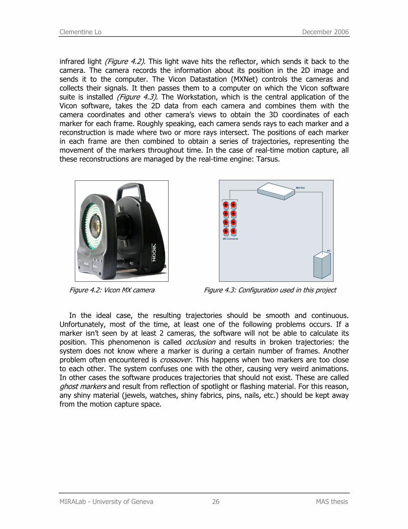
infrared light (Figure 4.2). This light wave hits the reflector, which sends it back to the camera. The camera records the information about its position in the 2D image and sends it to the computer. The Vicon Datastation (MXNet) controls the cameras and collects their signals. It then passes them to a computer on which the Vicon software suite is installed (Figure 4.3). The Workstation, which is the central application of the Vicon software, takes the 2D data from each camera and combines them with the camera coordinates and other camera’s views to obtain the 3D coordinates of each marker for each frame. Roughly speaking, each camera sends rays to each marker and a reconstruction is made where two or more rays intersect. The positions of each marker in each frame are then combined to obtain a series of trajectories, representing the movement of the markers throughout time. In the case of real-time motion capture, all these reconstructions are managed by the real-time engine: Tarsus.
Figure 4.2: Vicon MX camera Figure 4.3: Configuration used in this project
In the ideal case, the resulting trajectories should be smooth and continuous. Unfortunately, most of the time, at least one of the following problems occurs. If a marker isn’t seen by at least 2 cameras, the software will not be able to calculate its position. This phenomenon is called occlusion and results in broken trajectories: the system does not know where a marker is during a certain number of frames. Another problem often encountered is crossover. This happens when two markers are too close to each other. The system confuses one with the other, causing very weird animations. In other cases the software produces trajectories that should not exist. These are called ghost markers and result from reflection of spotlight or flashing material. For this reason, any shiny material (jewels, watches, shiny fabrics, pins, nails, etc.) should be kept away from the motion capture space.
Clementine Lo December 2006
MIRALab - University of Geneva 27 MAS thesis
4.2. Real-time motion capture with Vicon
4.2.1. Calibration of the system
Before starting any movement recording, we need to calibrate the system. This is an essential step, as it plays a considerable role in minimizing the error in the resulting data. It measures the position and orientation of the capture volume and the location of each camera relative to the others. This information is used by the Vicon software when recreating the 3D coordinates with the 2D data sent by the different cameras.
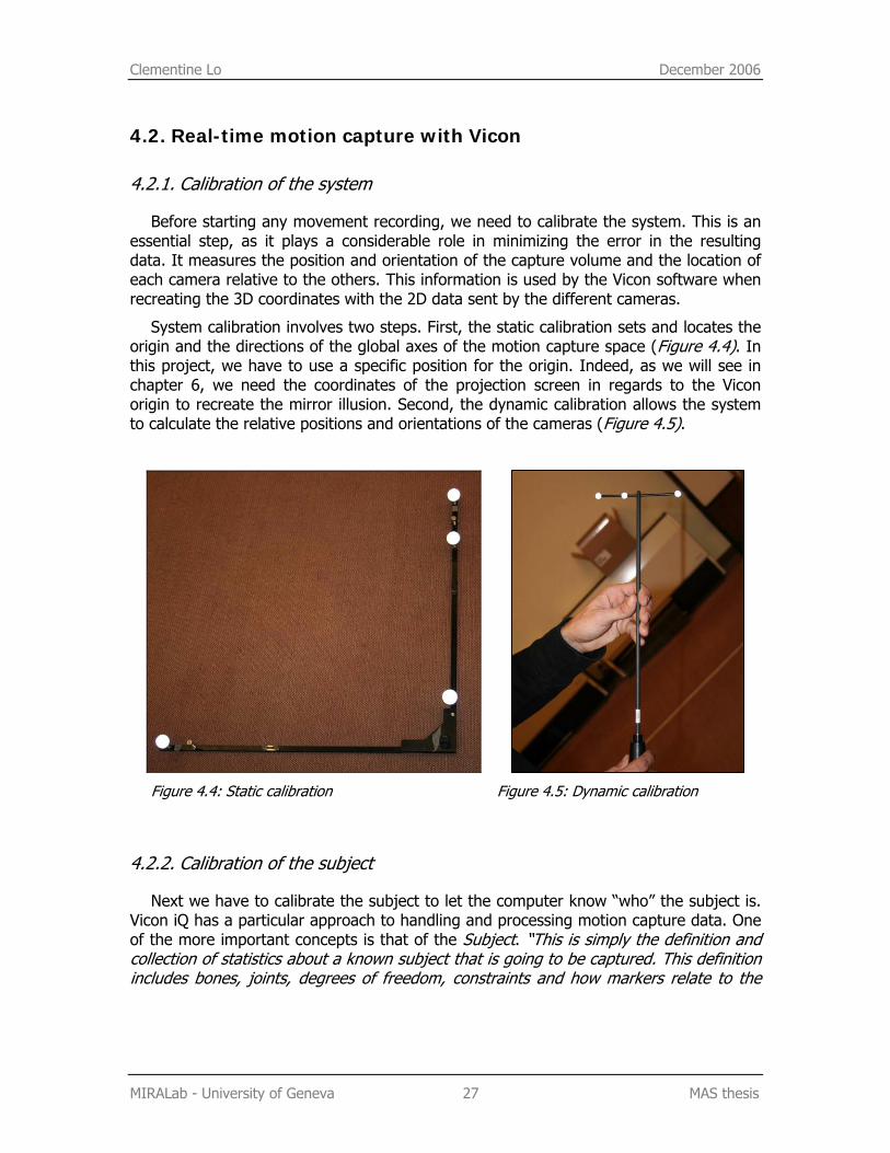
System calibration involves two steps. First, the static calibration sets and locates the origin and the directions of the global axes of the motion capture space (Figure 4.4). In this project, we have to use a specific position for the origin. Indeed, as we will see in chapter 6, we need the coordinates of the projection screen in regards to the Vicon origin to recreate the mirror illusion. Second, the dynamic calibration allows the system to calculate the relative positions and orientations of the cameras (Figure 4.5).
Figure 4.4: Static calibration Figure 4.5: Dynamic calibration
4.2.2. Calibration of the subject
Next we have to calibrate the subject to let the computer know “who” the subject is. Vicon iQ has a particular approach to handling and processing motion capture data. One of the more important concepts is that of the Subject. “This is simply the definition and collection of statistics about a known subject that is going to be captured. This definition includes bones, joints, degrees of freedom, constraints and how markers relate to the
Clementine Lo December 2006
MIRALab - University of Geneva 28 MAS thesis
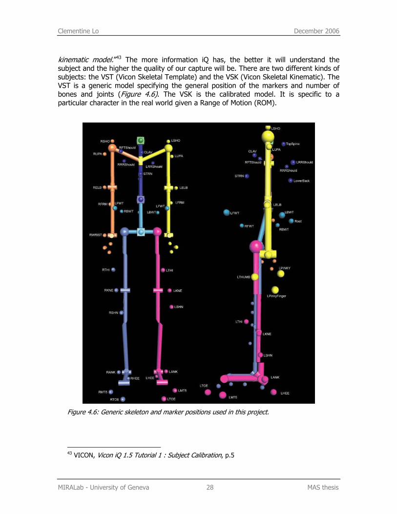
kinematic model.”43 The more information iQ has, the better it will understand the subject and the higher the quality of our capture will be. There are two different kinds of subjects: the VST (Vicon Skeletal Template) and the VSK (Vicon Skeletal Kinematic). The VST is a generic model specifying the general position of the markers and number of bones and joints (Figure 4.6). The VSK is the calibrated model. It is specific to a particular character in the real world given a Range of Motion (ROM).
Figure 4.6: Generic skeleton and marker positions used in this project.
43 VICON, Vicon iQ 1.5 Tutorial 1 : Subject Calibration, p.5
Clementine Lo December 2006
MIRALab - University of Geneva 29 MAS thesis
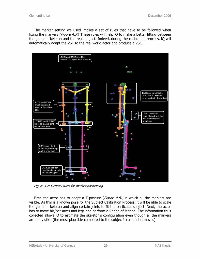
The marker setting we used implies a set of rules that have to be followed when fixing the markers (Figure 4.7). These rules will help iQ to make a better fitting between the generic skeleton and the real subject. Indeed, during the calibration process, iQ will automatically adapt the VST to the real world actor and produce a VSK.
Figure 4.7: General rules for marker positioning
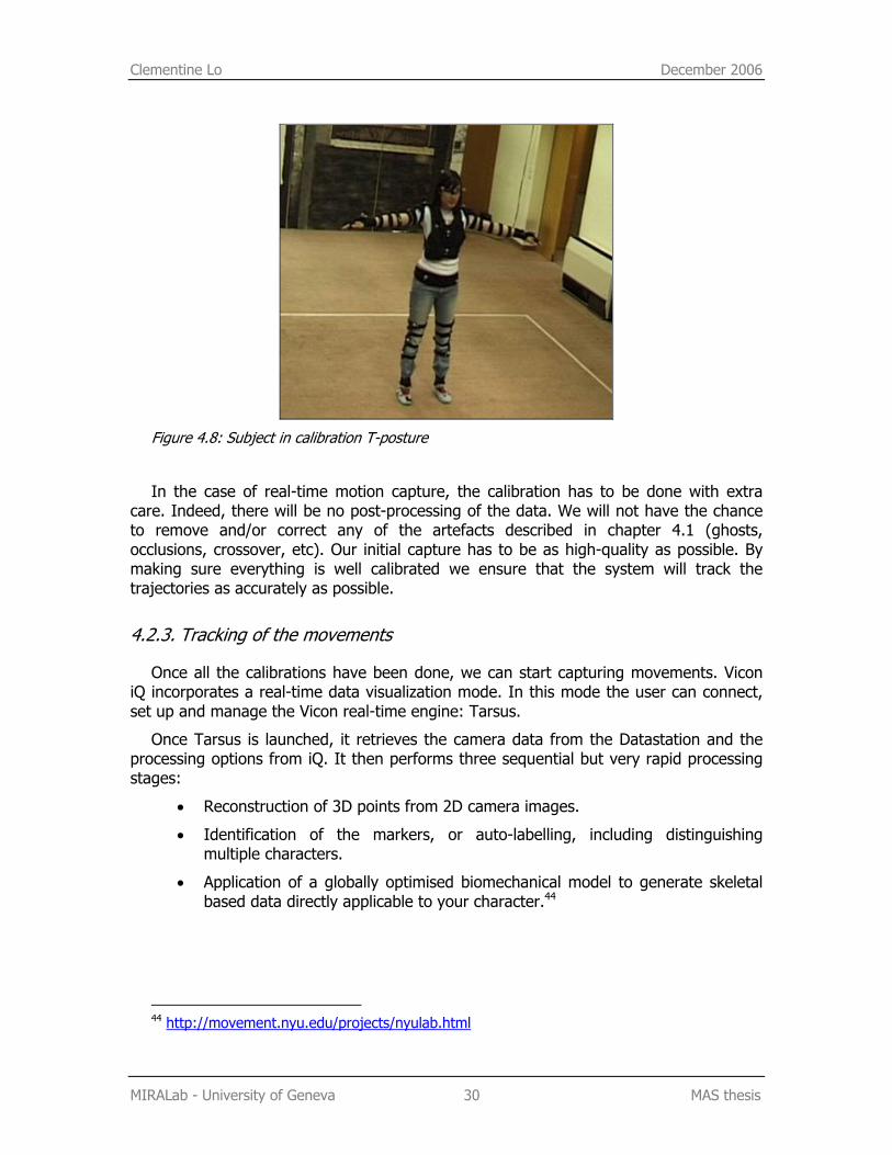
First, the actor has to adopt a T-posture (Figure 4.8), in which all the markers are visible. As this is a known pose for the Subject Calibration Process, it will be able to scale the generic skeleton and align certain joints to fit the particular subject. Next, the actor has to move his/her arms and legs and perform a Range of Motion. The information thus collected allows iQ to estimate the skeleton’s configuration even though all the markers are not visible (the most plausible compared to the subject’s calibration moves).
Clementine Lo December 2006
MIRALab - University of Geneva 30 MAS thesis
Figure 4.8: Subject in calibration T-posture
In the case of real-time motion capture, the calibration has to be done with extra care. Indeed, there will be no post-processing of the data. We will not have the chance to remove and/or correct any of the artefacts described in chapter 4.1 (ghosts, occlusions, crossover, etc). Our initial capture has to be as high-quality as possible. By making sure everything is well calibrated we ensure that the system will track the trajectories as accurately as possible.
4.2.3. Tracking of the movements
Once all the calibrations have been done, we can start capturing movements. Vicon iQ incorporates a real-time data visualization mode. In this mode the user can connect, set up and manage the Vicon real-time engine: Tarsus.
Once Tarsus is launched, it retrieves the camera data from the Datastation and the processing options from iQ. It then performs three sequential but very rapid processing stages:
• Reconstruction of 3D points from 2D camera images.
• Identification of the markers, or auto-labelling, including distinguishing multiple characters.
• Application of a globally optimised biomechanical model to generate skeletal based data directly applicable to your character.44
44 http://movement.nyu.edu/projects/nyulab.html
Caecilia Charbonnier and Clementine Lo December 2006
MIRALab - University of Geneva 31 MAS thesis
4.3. Networking
Now that we understand how to capture motion in real-time using Vicon, we still need to set up a connection between our program and Tarsus in order to retrieve the captured bone’s positions. The communication uses a client/server paradigm and takes place through TCP/IP (Stream Sockets). Let us first quickly overview these different concepts.
4.3.1. Concepts
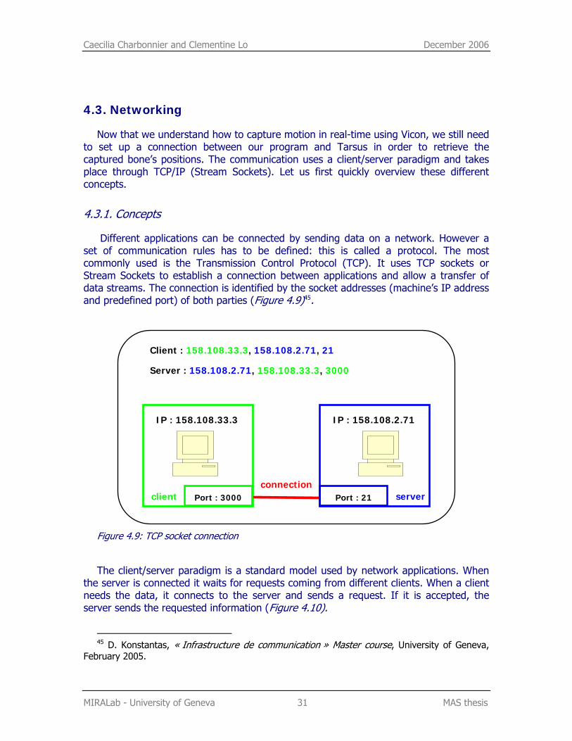
Different applications can be connected by sending data on a network. However a set of communication rules has to be defined: this is called a protocol. The most commonly used is the Transmission Control Protocol (TCP). It uses TCP sockets or Stream Sockets to establish a connection between applications and allow a transfer of data streams. The connection is identified by the socket addresses (machine’s IP address and predefined port) of both parties (Figure 4.9)45.
Figure 4.9: TCP socket connection
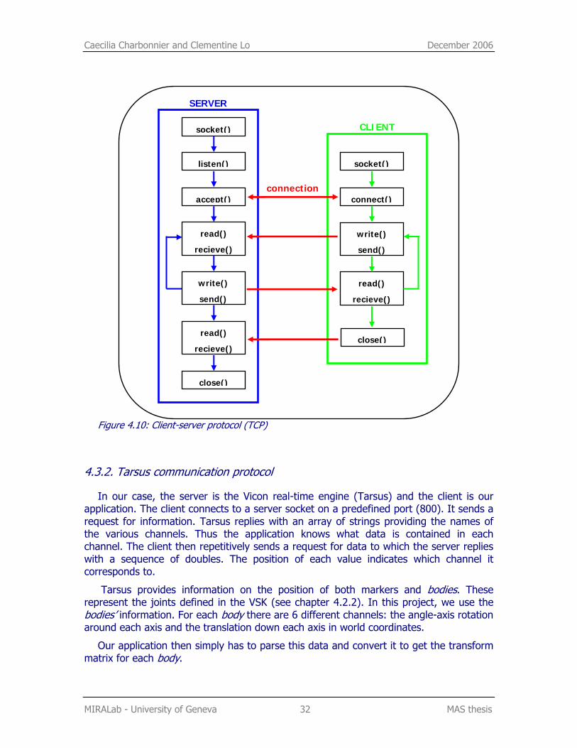
The client/server paradigm is a standard model used by network applications. When the server is connected it waits for requests coming from different clients. When a client needs the data, it connects to the server and sends a request. If it is accepted, the server sends the requested information (Figure 4.10).
45 D. Konstantas, « Infrastructure de communication » Master course, University of Geneva,
February 2005.
IP : 158.108.33.3 IP : 158.108.2.71
client server connection
Port : 3000 Port : 21
Client : 158.108.33.3, 158.108.2.71, 21
Server : 158.108.2.71, 158.108.33.3, 3000
Caecilia Charbonnier and Clementine Lo December 2006
MIRALab - University of Geneva 32 MAS thesis
Figure 4.10: Client-server protocol (TCP)
4.3.2. Tarsus communication protocol
In our case, the server is the Vicon real-time engine (Tarsus) and the client is our application. The client connects to a server socket on a predefined port (800). It sends a request for information. Tarsus replies with an array of strings providing the names of the various channels. Thus the application knows what data is contained in each channel. The client then repetitively sends a request for data to which the server replies with a sequence of doubles. The position of each value indicates which channel it corresponds to.
Tarsus provides information on the position of both markers and bodies. These represent the joints defined in the VSK (see chapter 4.2.2). In this project, we use the bodies’ information. For each body there are 6 different channels: the angle-axis rotation around each axis and the translation down each axis in world coordinates.
Our application then simply has to parse this data and convert it to get the transform matrix for each body.
connection
socket()
socket() CLIENT
listen()
accept() connect()
write()
send()
read()
recieve()
read()
recieve()
close()
SERVER
write()
send()
read()
recieve()
close()
Caecilia Charbonnier December 2006
MIRALab - University of Geneva 33 MAS thesis
5. OSG development As previously stated, this project was developed in OSG. We will now analyse the use
of this toolkit more thoroughly.
5.1. Building the viewer
5.1.1. General principles
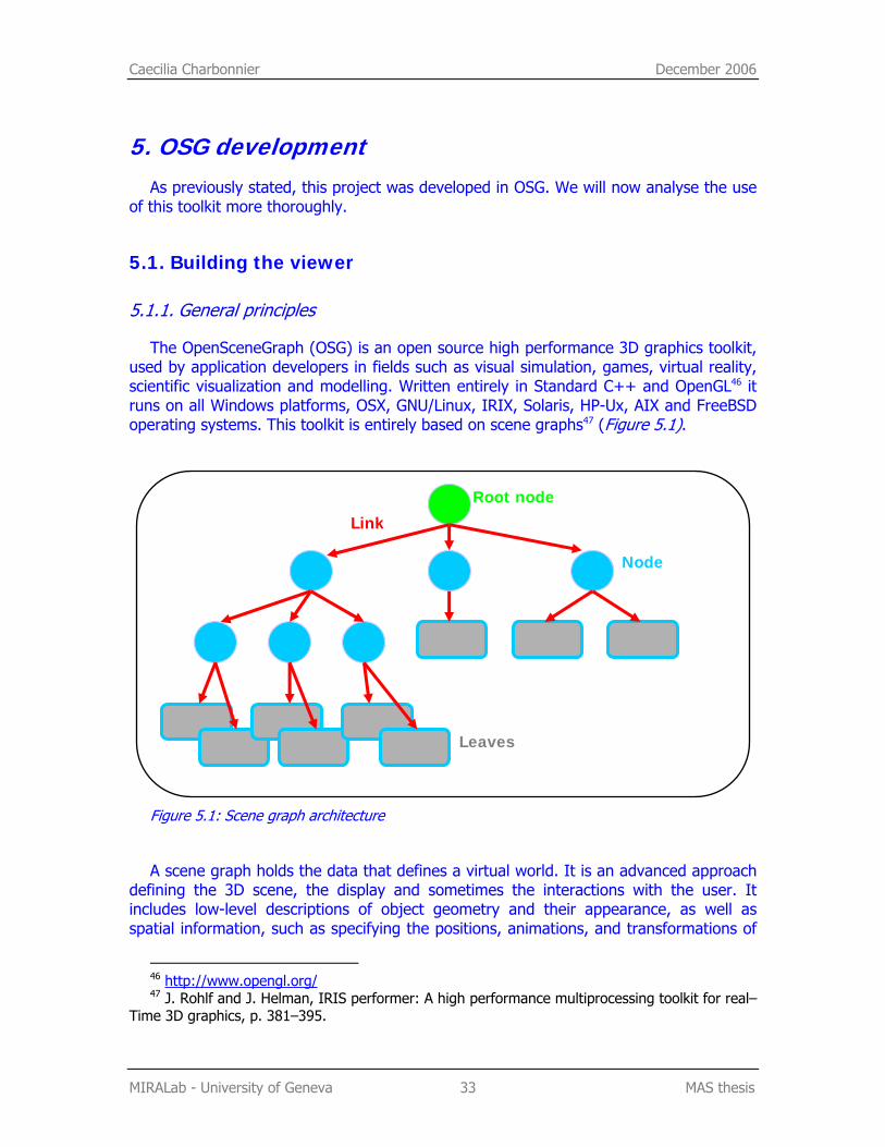
The OpenSceneGraph (OSG) is an open source high performance 3D graphics toolkit, used by application developers in fields such as visual simulation, games, virtual reality, scientific visualization and modelling. Written entirely in Standard C++ and OpenGL46 it runs on all Windows platforms, OSX, GNU/Linux, IRIX, Solaris, HP-Ux, AIX and FreeBSD operating systems. This toolkit is entirely based on scene graphs47 (Figure 5.1).
Figure 5.1: Scene graph architecture
A scene graph holds the data that defines a virtual world. It is an advanced approach defining the 3D scene, the display and sometimes the interactions with the user. It includes low-level descriptions of object geometry and their appearance, as well as spatial information, such as specifying the positions, animations, and transformations of
46 http://www.opengl.org/ 47 J. Rohlf and J. Helman, IRIS performer: A high performance multiprocessing toolkit for real–
Time 3D graphics, p. 381–395.
Root node
Node
Leaves
Link
Caecilia Charbonnier December 2006
MIRALab - University of Geneva 34 MAS thesis
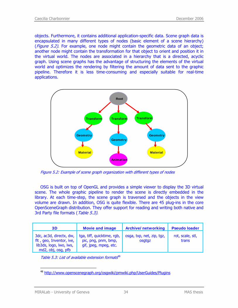
objects. Furthermore, it contains additional application-specific data. Scene graph data is encapsulated in many different types of nodes (basic element of a scene hierarchy) (Figure 5.2). For example, one node might contain the geometric data of an object; another node might contain the transformation for that object to orient and position it in the virtual world. The nodes are associated in a hierarchy that is a directed, acyclic graph. Using scene graphs has the advantage of structuring the elements of the virtual world and optimizes the rendering by filtering the amount of data sent to the graphic pipeline. Therefore it is less time-consuming and especially suitable for real-time applications.
Figure 5.2: Example of scene graph organization with different types of nodes
OSG is built on top of OpenGL and provides a simple viewer to display the 3D virtual scene. The whole graphic pipeline to render the scene is directly embedded in the library. At each time-step, the scene graph is traversed and the objects in the view volume are drawn. In addition, OSG is quite flexible. There are 45 plug-ins in the core OpenSceneGraph distribution. They offer support for reading and writing both native and 3rd Party file formats (Table 5.3).
3D Movie and image Archive/networking Pseudo loader
3dc, ac3d, directx, dw, flt , geo, Inventor, ive, lib3ds, logo, lwo, lws,
md2, obj, osg, pfb
tga, tiff, quicktime, rgb, pic, png, pnm, bmp, gif, jpeg, mpeg, etc.
osga, txp, net, zip, tgz, osgtgz
rot, scale, stl, trans
Table 5.3: List of available extension formats48
48 http://www.openscenegraph.org/osgwiki/pmwiki.php/UserGuides/Plugins
Animation
Transform Transform Transform
Root
Geometry Geometry Geometry
Material Material
Caecilia Charbonnier December 2006
MIRALab - University of Geneva 35 MAS thesis
As the environment and the virtual avatar are designed with 3dStudioMax, we cannot use any of the previously described plug-ins. Indeed, none of them supports high-level information such as skinning data. Therefore, we decided to use the COLLADA file format.
5.1.2. COLLADA file importer
COLLADA is a COLLAborative Design Activity for establishing an interchange file format for interactive 3D applications. It defines a standard XML schema49 for data interchange. Originally established by Sony Computer Entertainment50 as the official format for PlayStation 3 and PlayStation Portable development, COLLADA continues to evolve through the efforts of the Khronos51 contributors. Dozens of commercial game studios and game engines have adopted the standard.
COLLADA supports features such as character skinning and morph targets, rigid body dynamics and shader effects for multiple shading languages. Solutions exist to transfer data from one Digital Content Creation (DCC) tool to another. Supported DCCs include Maya (using ColladaMaya), 3dStudioMax (using ColladaMax), Softimage XSI and Blender. Game engines, such as Unreal engine and the C4 Engine, have also adopted this format.
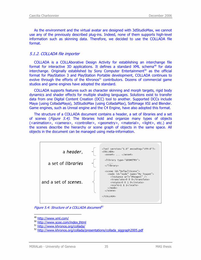
The structure of a COLLADA document contains a header, a set of libraries and a set of scenes (Figure 5.4). The libraries hold and organize many types of objects (<animation>, <camera>, <controller>, <geometry>, <material>, <light>, etc.) and the scenes describe the hierarchy or scene graph of objects in the same space. All objects in the document can be managed using meta-information.
Figure 5.4: Structure of a COLLADA document52
49 http://www.xml.com/ 50 http://www.scee.com/index.jhtml 51 http://www.khronos.org/collada/ 52 http://www.khronos.org/collada/presentations/collada_siggraph2005.pdf
Caecilia Charbonnier December 2006
MIRALab - University of Geneva 36 MAS thesis
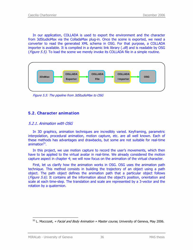
In our application, COLLADA is used to export the environment and the character from 3dStudioMax via the ColladaMax plug-in. Once the scene is exported, we need a converter to read the generated XML schema in OSG. For that purpose, a COLLADA importer is available. It is compiled in a dynamic link library (.dll) and is readable by OSG (Figure 5.5). To load the scene we merely invoke its COLLADA file in a simple routine.
Figure 5.5: The pipeline from 3dStudioMax to OSG
5.2. Character animation
5.2.1. Animation with OSG
In 3D graphics, animation techniques are incredibly varied. Keyframing, parametric interpolation, procedural animation, motion capture, etc. are all well known. Each of these methods has advantages and drawbacks, but some are not suitable for real-time animation53.
In this project, we use motion capture to record the user’s movements, which then have to be applied to the virtual avatar in real-time. We already considered the motion capture aspect in chapter 4; we will now focus on the animation of the virtual character.
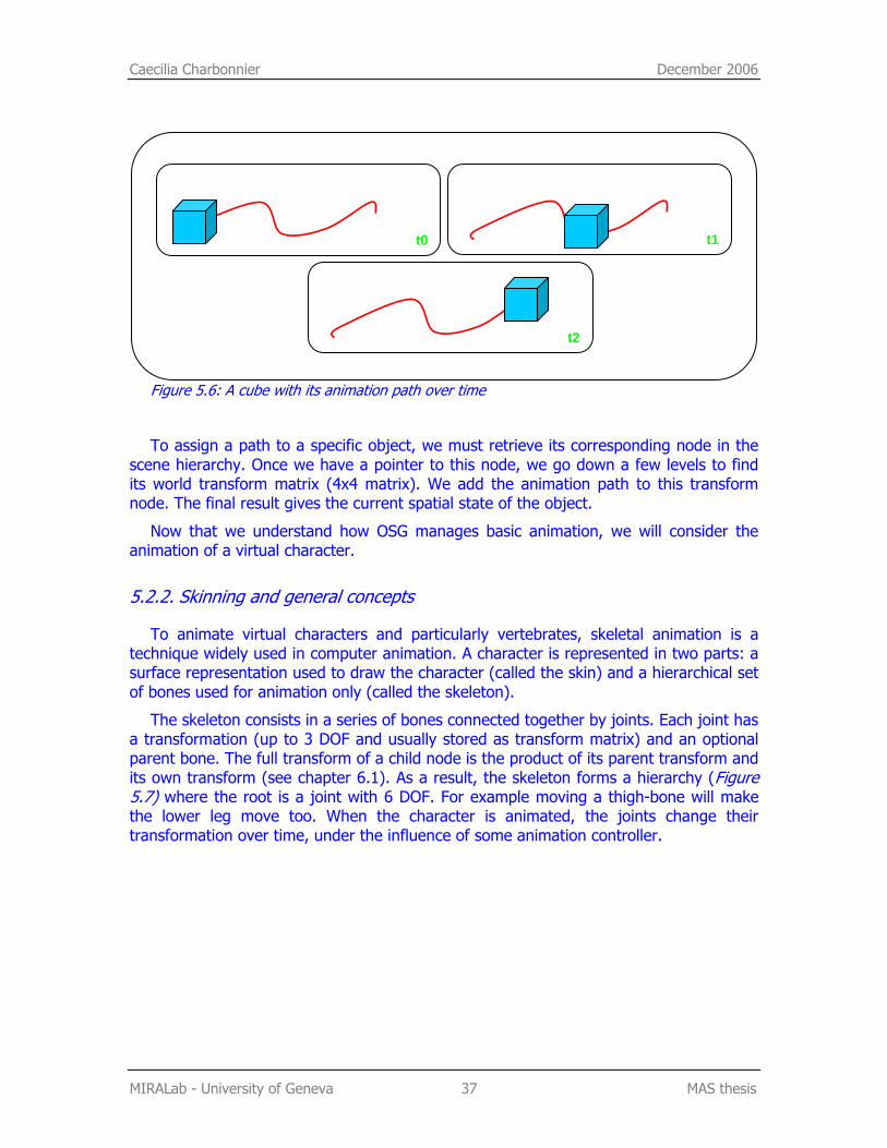
First, let us clarify how the animation works in OSG. OSG uses the animation path technique. This method consists in building the trajectory of an object using a path object. The path object defines the animation path that a particular object follows (Figure 5.6). It contains all the information about the object’s position, orientation and scale at each time-step. The translation and scale are represented by a 3-vector and the rotation by a quaternion.
53 L. Moccozet, « Facial and Body Animation » Master course, University of Geneva, May 2006.
COLLADA
Exporter
COLLADA
Importer
COLLADA
File 3DsMax OSG
Caecilia Charbonnier December 2006
MIRALab - University of Geneva 37 MAS thesis
Figure 5.6: A cube with its animation path over time
To assign a path to a specific object, we must retrieve its corresponding node in the scene hierarchy. Once we have a pointer to this node, we go down a few levels to find its world transform matrix (4x4 matrix). We add the animation path to this transform node. The final result gives the current spatial state of the object.
Now that we understand how OSG manages basic animation, we will consider the animation of a virtual character.
5.2.2. Skinning and general concepts
To animate virtual characters and particularly vertebrates, skeletal animation is a technique widely used in computer animation. A character is represented in two parts: a surface representation used to draw the character (called the skin) and a hierarchical set of bones used for animation only (called the skeleton).
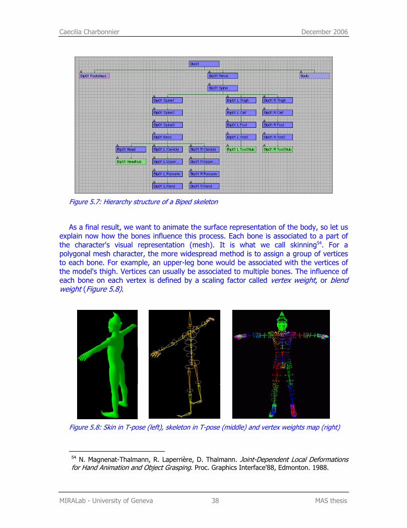
The skeleton consists in a series of bones connected together by joints. Each joint has a transformation (up to 3 DOF and usually stored as transform matrix) and an optional parent bone. The full transform of a child node is the product of its parent transform and its own transform (see chapter 6.1). As a result, the skeleton forms a hierarchy (Figure 5.7) where the root is a joint with 6 DOF. For example moving a thigh-bone will make the lower leg move too. When the character is animated, the joints change their transformation over time, under the influence of some animation controller.
t2
t0 t1
Caecilia Charbonnier December 2006
MIRALab - University of Geneva 38 MAS thesis
Figure 5.7: Hierarchy structure of a Biped skeleton
As a final result, we want to animate the surface representation of the body, so let us explain now how the bones influence this process. Each bone is associated to a part of the character's visual representation (mesh). It is what we call skinning54. For a polygonal mesh character, the more widespread method is to assign a group of vertices to each bone. For example, an upper-leg bone would be associated with the vertices of the model's thigh. Vertices can usually be associated to multiple bones. The influence of each bone on each vertex is defined by a scaling factor called vertex weight, or blend weight (Figure 5.8).
Figure 5.8: Skin in T-pose (left), skeleton in T-pose (middle) and vertex weights map (right)
54 N. Magnenat-Thalmann, R. Laperrière, D. Thalmann. Joint-Dependent Local Deformations for Hand Animation and Object Grasping. Proc. Graphics Interface'88, Edmonton. 1988.
Caecilia Charbonnier December 2006
MIRALab - University of Geneva 39 MAS thesis
To calculate the final position of a vertex, we have to apply each bone’s transformation to its initial position. In order to take into account the vertex weights, these transformations are previously scaled regarding their corresponding weight. This algorithm is called matrix palette skinning, because the set of bone transformations form a palette which the skin vertex can choose from.
In OSG, the process to animate virtual characters is the same as for simple objects (see previous section). We must first retrieve all the bone nodes in the scene graph. An animation path is then assigned to the transform node of each bone. At every time-step, the skin updating routine is called. This skinning method was entirely integrated by our assistant, Etienne Lyard, in the COLLADA importer.
5.2.3. Application structure and management
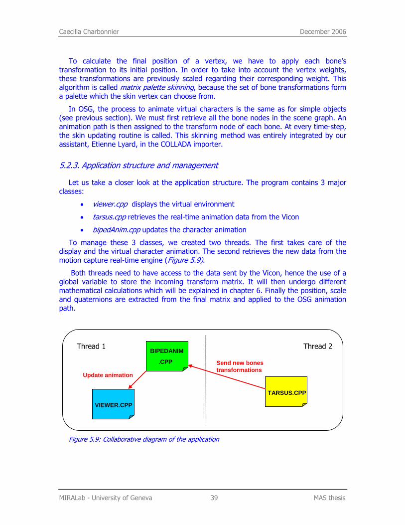
Let us take a closer look at the application structure. The program contains 3 major classes:
• viewer.cpp displays the virtual environment
• tarsus.cpp retrieves the real-time animation data from the Vicon
• bipedAnim.cpp updates the character animation
To manage these 3 classes, we created two threads. The first takes care of the display and the virtual character animation. The second retrieves the new data from the motion capture real-time engine (Figure 5.9).
Both threads need to have access to the data sent by the Vicon, hence the use of a global variable to store the incoming transform matrix. It will then undergo different mathematical calculations which will be explained in chapter 6. Finally the position, scale and quaternions are extracted from the final matrix and applied to the OSG animation path.
Figure 5.9: Collaborative diagram of the application
VIEWER.CPP
TARSUS.CPP
Thread 1
Update animation
Send new bones transformations
Thread 2 BIPEDANIM
.CPP
Caecilia Charbonnier December 2006
MIRALab - University of Geneva 40 MAS thesis
5.3. Configuration file
For our program to be more flexible, we decided to create a configuration file. If the scene, avatar skeleton or an IP address changes, the user should still be able to use our program without having to change the source code. Therefore, all variable parameters are stored in the configuration file (see annex 1):
• IP Address of the machine running Tarsus
• Name of the COLLADA scene file (3D environment and avatar)
• Name of the root of the bones hierarchy (for a 3dStudioMax biped: BIP01)
• Names of all the other bones
• Position (x, y, z) of the bottom left corner of the screen in the 3D environment
When the application starts, the system asks for a configuration file with the extension: .pina. It can then update all these parameters accordingly.
Clementine Lo December 2006
MIRALab - University of Geneva 41 MAS thesis
6. Mathematical aspects of the animation
6.1. Global and relative coordinates
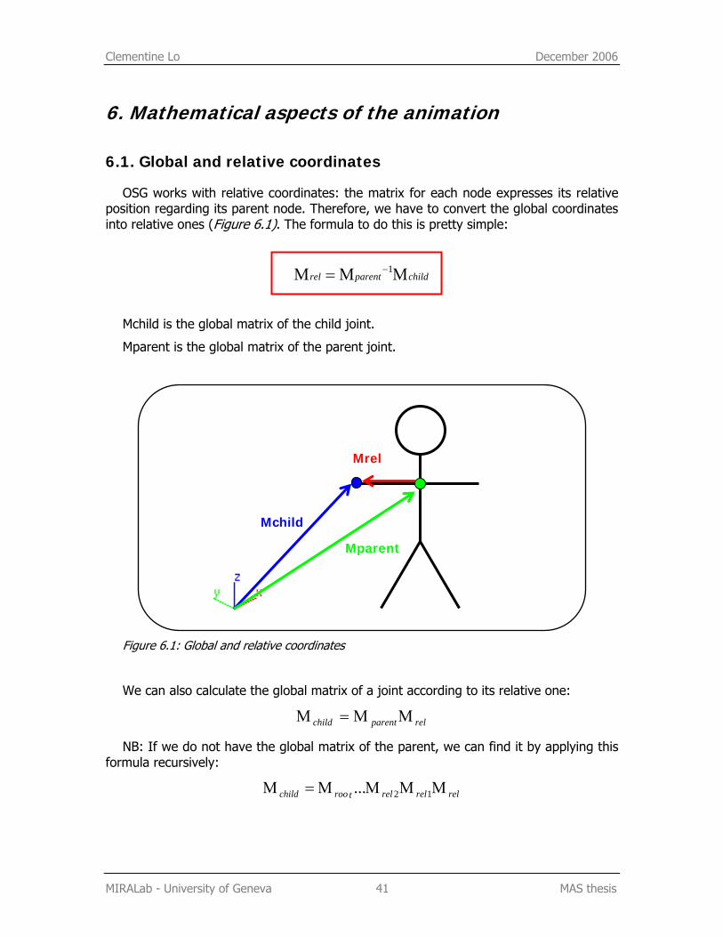
OSG works with relative coordinates: the matrix for each node expresses its relative position regarding its parent node. Therefore, we have to convert the global coordinates into relative ones (Figure 6.1). The formula to do this is pretty simple:
childparentrel ΜΜ=Μ −1
Mchild is the global matrix of the child joint.
Mparent is the global matrix of the parent joint.
Figure 6.1: Global and relative coordinates
We can also calculate the global matrix of a joint according to its relative one:
relparentchild ΜΜ=Μ
NB: If we do not have the global matrix of the parent, we can find it by applying this formula recursively:
relrelreltroochild ΜΜΜΜ=Μ 12...
Mparent
Mchild
Mrel
Clementine Lo December 2006
MIRALab - University of Geneva 42 MAS thesis
6.2. Mirror illusion: symmetry and position in the virtual world
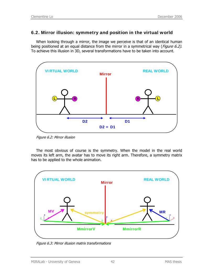
When looking through a mirror, the image we perceive is that of an identical human being positioned at an equal distance from the mirror in a symmetrical way (Figure 6.2). To achieve this illusion in 3D, several transformations have to be taken into account.
Figure 6.2: Mirror illusion
The most obvious of course is the symmetry. When the model in the real world moves its left arm, the avatar has to move its right arm. Therefore, a symmetry matrix has to be applied to the whole animation.
Figure 6.3: Mirror illusion matrix transformations
MR
REAL WORLD VIRTUAL WORLD Mirror
MmirrorRMmirrorV
symmetryMV
REAL WORLD VIRTUAL WORLD Mirror
D2 D1 D2 = D1
L R L R
Clementine Lo December 2006
MIRALab - University of Geneva 43 MAS thesis
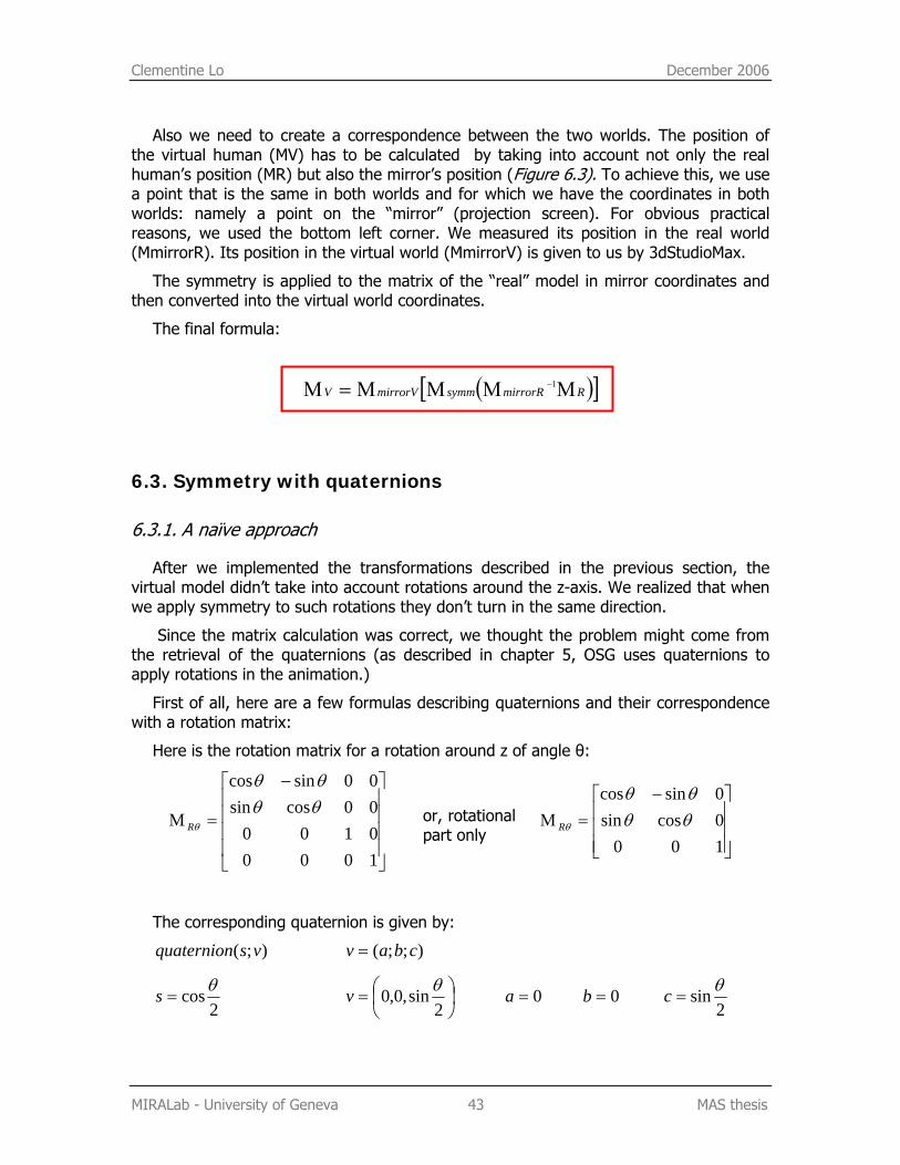
Also we need to create a correspondence between the two worlds. The position of the virtual human (MV) has to be calculated by taking into account not only the real human’s position (MR) but also the mirror’s position (Figure 6.3). To achieve this, we use a point that is the same in both worlds and for which we have the coordinates in both worlds: namely a point on the “mirror” (projection screen). For obvious practical reasons, we used the bottom left corner. We measured its position in the real world (MmirrorR). Its position in the virtual world (MmirrorV) is given to us by 3dStudioMax.
The symmetry is applied to the matrix of the “real” model in mirror coordinates and then converted into the virtual world coordinates.
The final formula:
( )[ ]RmirrorRsymmmirrorVV ΜΜΜΜ=Μ −1
6.3. Symmetry with quaternions
6.3.1. A naïve approach
After we implemented the transformations described in the previous section, the virtual model didn’t take into account rotations around the z-axis. We realized that when we apply symmetry to such rotations they don’t turn in the same direction.
Since the matrix calculation was correct, we thought the problem might come from the retrieval of the quaternions (as described in chapter 5, OSG uses quaternions to apply rotations in the animation.)
First of all, here are a few formulas describing quaternions and their correspondence with a rotation matrix:
Here is the rotation matrix for a rotation around z of angle θ:
⎥⎥⎥⎥
⎦
⎤
⎢⎢⎢⎢
⎣
⎡ −
=Μ
1000010000cossin00sincos
θθθθ
θR
⎥⎥⎥
⎦
⎤
⎢⎢⎢
⎣
⎡ −=Μ
1000cossin0sincos
θθθθ
θR
The corresponding quaternion is given by:
);( vsquaternion );;( cbav =
2cosθ=s ⎟
⎠⎞
⎜⎝⎛=
2sin,0,0 θv 0=a 0=b
2sin θ=c
or, rotational part only
Clementine Lo December 2006
MIRALab - University of Geneva 44 MAS thesis
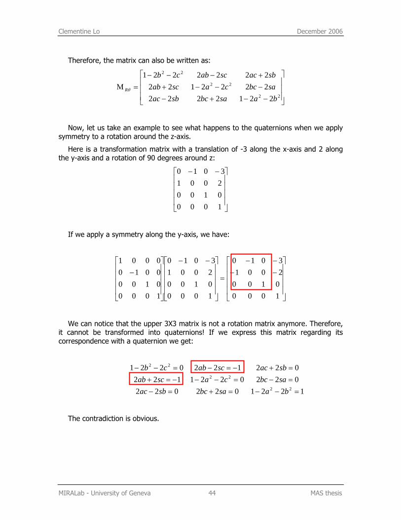
Therefore, the matrix can also be written as:
⎥⎥⎥
⎦
⎤
⎢⎢⎢
⎣
⎡
−−+−−−−++−−−
=Μ22
22
22
221222222221222222221
basabcsbacsabccascabsbacscabcb
Rθ
Now, let us take an example to see what happens to the quaternions when we apply symmetry to a rotation around the z-axis.
Here is a transformation matrix with a translation of -3 along the x-axis and 2 along the y-axis and a rotation of 90 degrees around z:
⎥⎥⎥⎥
⎦
⎤
⎢⎢⎢⎢
⎣
⎡ −−
1000010020013010
If we apply a symmetry along the y-axis, we have:
⎥⎥⎥⎥
⎦
⎤
⎢⎢⎢⎢
⎣
⎡−−−−
=
⎥⎥⎥⎥
⎦
⎤
⎢⎢⎢⎢
⎣
⎡ −−
⎥⎥⎥⎥
⎦
⎤
⎢⎢⎢⎢
⎣
⎡−
1000010020013010
1000010020013010
1000010000100001
We can notice that the upper 3X3 matrix is not a rotation matrix anymore. Therefore, it cannot be transformed into quaternions! If we express this matrix regarding its correspondence with a quaternion we get:
122102202202202211220221220221
22
22
22
=−−=+=−=−=−−−=+=+−=−=−−
basabcsbacsabccascabsbacscabcb
The contradiction is obvious.
Caecilia Charbonnier December 2006
MIRALab - University of Geneva 45 MAS thesis
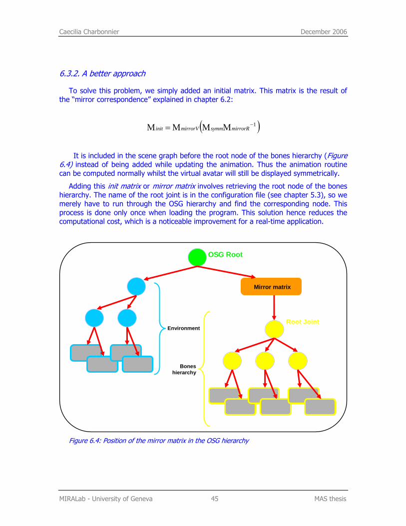
6.3.2. A better approach
To solve this problem, we simply added an initial matrix. This matrix is the result of the “mirror correspondence” explained in chapter 6.2:
( )1−ΜΜΜ=Μ mirrorRsymmmirrorVinit
It is included in the scene graph before the root node of the bones hierarchy (Figure 6.4) instead of being added while updating the animation. Thus the animation routine can be computed normally whilst the virtual avatar will still be displayed symmetrically.
Adding this init matrix or mirror matrix involves retrieving the root node of the bones hierarchy. The name of the root joint is in the configuration file (see chapter 5.3), so we merely have to run through the OSG hierarchy and find the corresponding node. This process is done only once when loading the program. This solution hence reduces the computational cost, which is a noticeable improvement for a real-time application.
Figure 6.4: Position of the mirror matrix in the OSG hierarchy
OSG Root
Mirror matrix
Bones hierarchy
Root Joint Environment
Clementine Lo December 2006
MIRALab - University of Geneva 46 MAS thesis
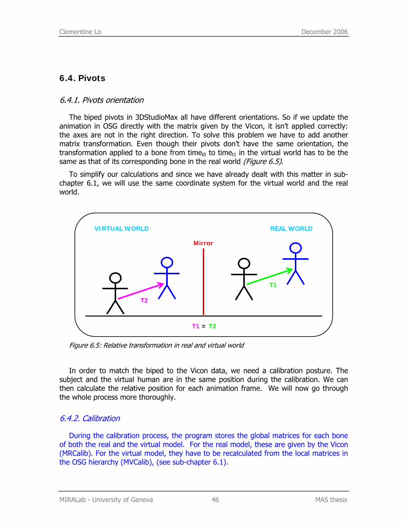
6.4. Pivots
6.4.1. Pivots orientation
The biped pivots in 3DStudioMax all have different orientations. So if we update the animation in OSG directly with the matrix given by the Vicon, it isn’t applied correctly: the axes are not in the right direction. To solve this problem we have to add another matrix transformation. Even though their pivots don’t have the same orientation, the transformation applied to a bone from timet0 to timet1 in the virtual world has to be the same as that of its corresponding bone in the real world (Figure 6.5).
To simplify our calculations and since we have already dealt with this matter in sub-chapter 6.1, we will use the same coordinate system for the virtual world and the real world.
Figure 6.5: Relative transformation in real and virtual world
In order to match the biped to the Vicon data, we need a calibration posture. The subject and the virtual human are in the same position during the calibration. We can then calculate the relative position for each animation frame. We will now go through the whole process more thoroughly.
6.4.2. Calibration
During the calibration process, the program stores the global matrices for each bone of both the real and the virtual model. For the real model, these are given by the Vicon (MRCalib). For the virtual model, they have to be recalculated from the local matrices in the OSG hierarchy (MVCalib), (see sub-chapter 6.1).
REAL WORLD VIRTUAL WORLD
Mirror
T1
T2
T1 = T2
Clementine Lo December 2006
MIRALab - University of Geneva 47 MAS thesis
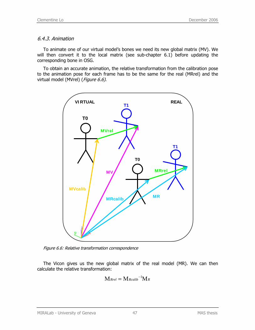
6.4.3. Animation
To animate one of our virtual model’s bones we need its new global matrix (MV). We will then convert it to the local matrix (see sub-chapter 6.1) before updating the corresponding bone in OSG.
To obtain an accurate animation, the relative transformation from the calibration pose to the animation pose for each frame has to be the same for the real (MRrel) and the virtual model (MVrel) (Figure 6.6).
Figure 6.6: Relative transformation correspondence
The Vicon gives us the new global matrix of the real model (MR). We can then calculate the relative transformation:
RRcalibRrel ΜΜ=Μ −1
REAL VIRTUAL
MRrel MV
T0
T0
T1
MRcalib
MVcalib
MVrel
MR
T1
Clementine Lo December 2006
MIRALab - University of Geneva 48 MAS thesis
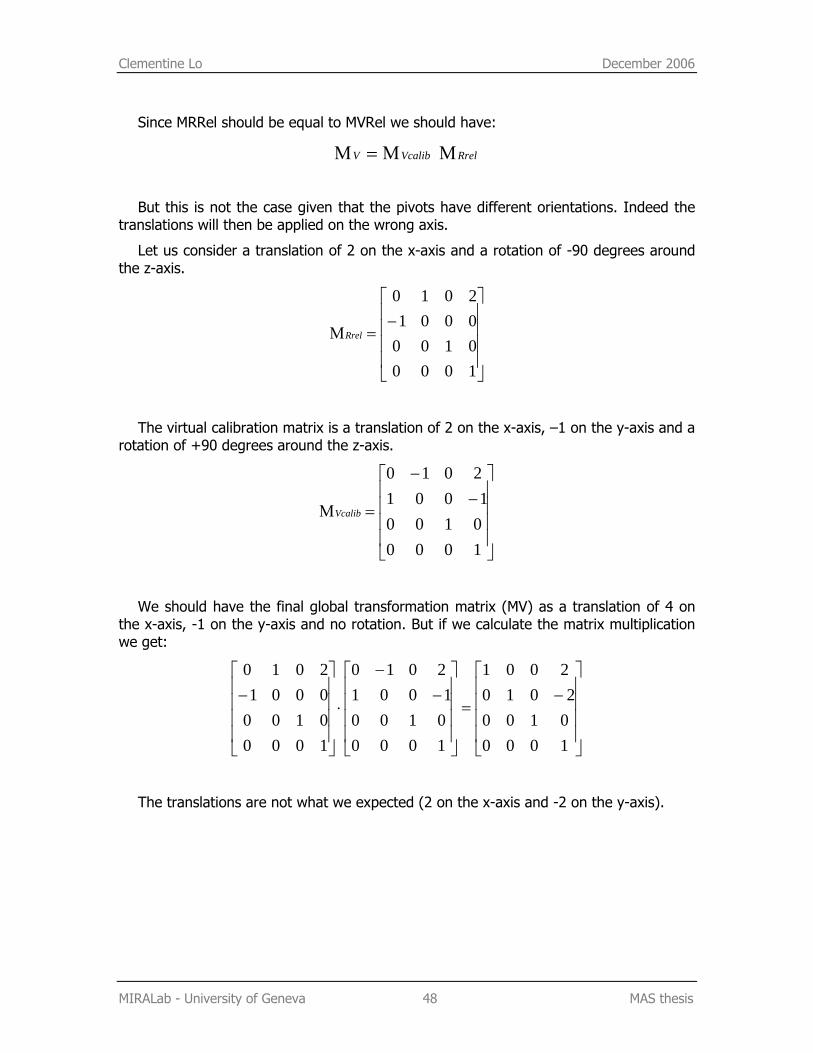
Since MRRel should be equal to MVRel we should have:
RrelVcalibV ΜΜ=Μ
But this is not the case given that the pivots have different orientations. Indeed the translations will then be applied on the wrong axis.
Let us consider a translation of 2 on the x-axis and a rotation of -90 degrees around the z-axis.
⎥⎥⎥⎥
⎦
⎤
⎢⎢⎢⎢
⎣
⎡−
=Μ
1000010000012010
Rrel
The virtual calibration matrix is a translation of 2 on the x-axis, –1 on the y-axis and a rotation of +90 degrees around the z-axis.
⎥⎥⎥⎥
⎦
⎤
⎢⎢⎢⎢
⎣
⎡−
−
=Μ
100001001001
2010
Vcalib
We should have the final global transformation matrix (MV) as a translation of 4 on the x-axis, -1 on the y-axis and no rotation. But if we calculate the matrix multiplication we get:
⎥⎥⎥⎥
⎦
⎤
⎢⎢⎢⎢
⎣
⎡−
=
⎥⎥⎥⎥
⎦
⎤
⎢⎢⎢⎢
⎣
⎡−
−
⋅
⎥⎥⎥⎥
⎦
⎤
⎢⎢⎢⎢
⎣
⎡−
100001002010
2001
100001001001
2010
1000010000012010
The translations are not what we expected (2 on the x-axis and -2 on the y-axis).
Clementine Lo December 2006
MIRALab - University of Geneva 49 MAS thesis
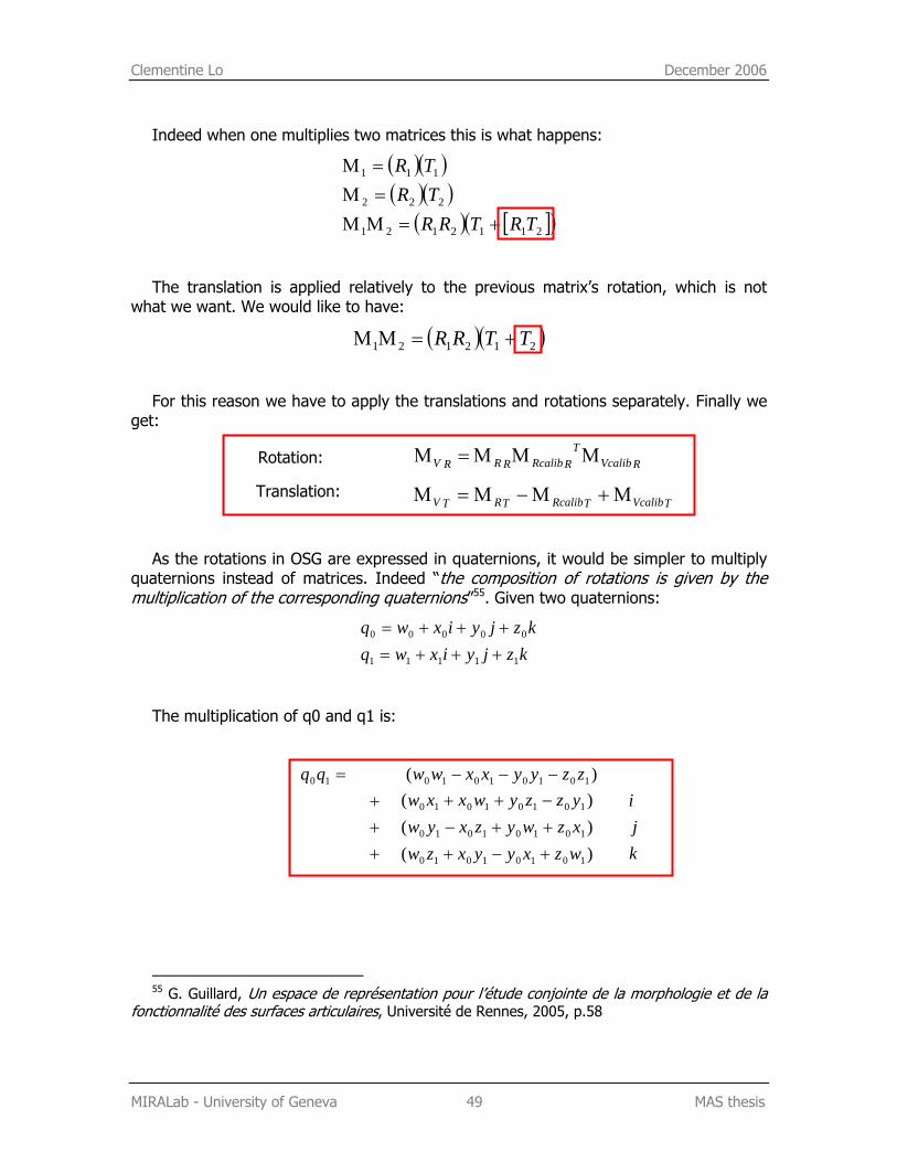
Indeed when one multiplies two matrices this is what happens:
( )( )( )( )
( ) [ ]( )2112121
222
111
TRTRRTRTR
+=ΜΜ=Μ=Μ
The translation is applied relatively to the previous matrix’s rotation, which is not what we want. We would like to have:
( )( )212121 TTRR +=ΜΜ
For this reason we have to apply the translations and rotations separately. Finally we get:
Rotation: RVcalibT
RRcalibRRRV ΜΜΜ=Μ
TVcalibTRcalibTRTV Μ+Μ−Μ=Μ
As the rotations in OSG are expressed in quaternions, it would be simpler to multiply quaternions instead of matrices. Indeed “the composition of rotations is given by the multiplication of the corresponding quaternions”55. Given two quaternions:
kzjyixwqkzjyixwq
11111
00000
+++=+++=
The multiplication of q0 and q1 is:
=10qq )( 10101010 zzyyxxww −−−
+++
)()()(
10101010
10101010
10101010
wzxyyxzwxzwyzxywyzzywxxw
+−+++−−++
kji
55 G. Guillard, Un espace de représentation pour l’étude conjointe de la morphologie et de la
fonctionnalité des surfaces articulaires, Université de Rennes, 2005, p.58
Translation:
Caecilia Charbonnier and Clementine Lo December 2006
MIRALab - University of Geneva 50 MAS thesis
6.5. Conclusion and implementation
To conclude, we have to put all these formulas together. We will summarize the situation by examining the implementation. But before that, let us notify a particularity in OSG: the transposition of the matrices. When first implementing the formulas, we reported errors because OSG uses transposed matrices. It means that all matrices calculation must be done in reverse. For example, if you want to multiply A by B, you usually post-multiply A with B but in OSG you must pre-multiply. The matrix multiplication is not commutative (that is AB≠BA), so we obtained surprising results!
Here is how the program proceeds (an abstract of the code is provided in annex 2):
1. When the application starts, the system asks for a configuration file which gives all the parameters required to run the program (joint names, root joint, virtual mirror’s position, etc.)
2. The 3D virtual scene is loaded.
3. The mirror matrix is added on top of the root node.
4. The OSG hierarchy is traversed and with the joint’s names we retrieve the corresponding nodes. For each node, we go down a few levels to find its world transform matrix.
5. The system requests and retrieves information data of the various channels. It then waits for the user to start the calibration.
6. When the user presses the ‘c’ key, the calibration starts. The program stocks the global transform matrices for each bone of both the real and the virtual model. For the real model, these are given by the Vicon. For the virtual model, they have to be calculated from the local matrices in the OSG hierarchy.
7. The system waits for the user to start the animation.
8. When the user presses the ‘s’ key, the animation starts. For each frame, the application retrieves each bone’s global matrix from the Vicon. We then compute the different transformations to get the new global transformation matrix for the virtual character.
9. As OSG only deals with relative coordinates, this global matrix is converted to a local matrix.
10. Finally, the final matrix forms a new animation path for the bone.
We have now taken into account all the transformations to apply the real world animation to our virtual avatar according to the mirror illusion.
Caecilia Charbonnier and Clementine Lo December 2006
MIRALab - University of Geneva 51 MAS thesis
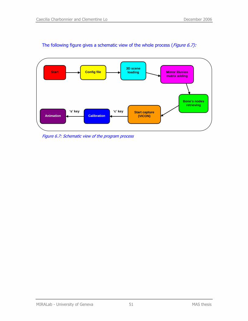
The following figure gives a schematic view of the whole process (Figure 6.7):
Figure 6.7: Schematic view of the program process
Start Config file 3D scene loading Mirror illusion
matrix adding
Bone’s nodes retrieving
Start capture (VICON) Calibration Animation
‘c’ key ‘s’ key
Caecilia Charbonnier and Clementine Lo December 2006
MIRALab - University of Geneva 52 MAS thesis
7. Camera transformation
7.1. Introduction
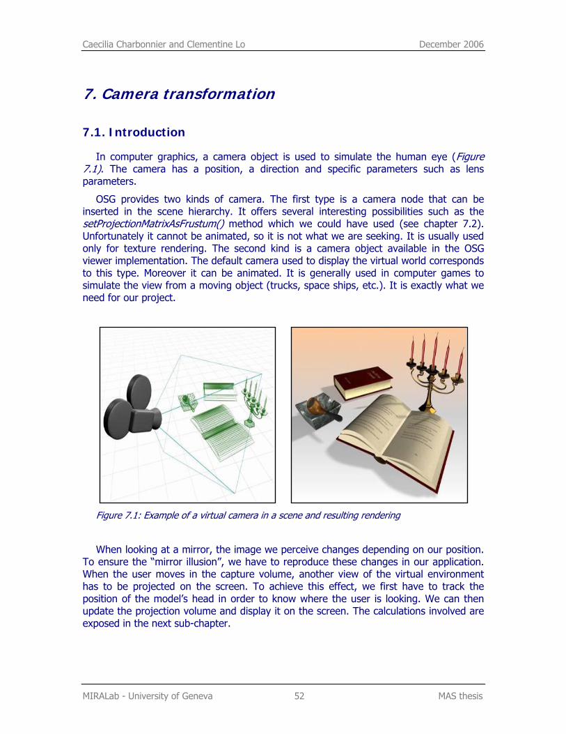
In computer graphics, a camera object is used to simulate the human eye (Figure 7.1). The camera has a position, a direction and specific parameters such as lens parameters.
OSG provides two kinds of camera. The first type is a camera node that can be inserted in the scene hierarchy. It offers several interesting possibilities such as the setProjectionMatrixAsFrustum() method which we could have used (see chapter 7.2). Unfortunately it cannot be animated, so it is not what we are seeking. It is usually used only for texture rendering. The second kind is a camera object available in the OSG viewer implementation. The default camera used to display the virtual world corresponds to this type. Moreover it can be animated. It is generally used in computer games to simulate the view from a moving object (trucks, space ships, etc.). It is exactly what we need for our project.
Figure 7.1: Example of a virtual camera in a scene and resulting rendering
When looking at a mirror, the image we perceive changes depending on our position. To ensure the “mirror illusion”, we have to reproduce these changes in our application. When the user moves in the capture volume, another view of the virtual environment has to be projected on the screen. To achieve this effect, we first have to track the position of the model’s head in order to know where the user is looking. We can then update the projection volume and display it on the screen. The calculations involved are exposed in the next sub-chapter.
Caecilia Charbonnier and Clementine Lo December 2006
MIRALab - University of Geneva 53 MAS thesis
7.2. Mathematical aspects
7.2.1. Camera position
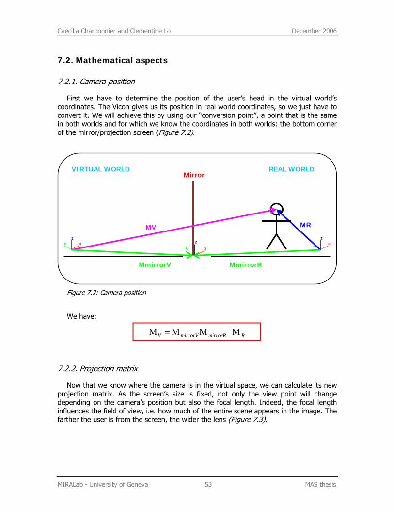
First we have to determine the position of the user’s head in the virtual world’s coordinates. The Vicon gives us its position in real world coordinates, so we just have to convert it. We will achieve this by using our “conversion point”, a point that is the same in both worlds and for which we know the coordinates in both worlds: the bottom corner of the mirror/projection screen (Figure 7.2).
Figure 7.2: Camera position
We have:
RmirrorRmirrorVV ΜΜΜ=Μ −1
7.2.2. Projection matrix
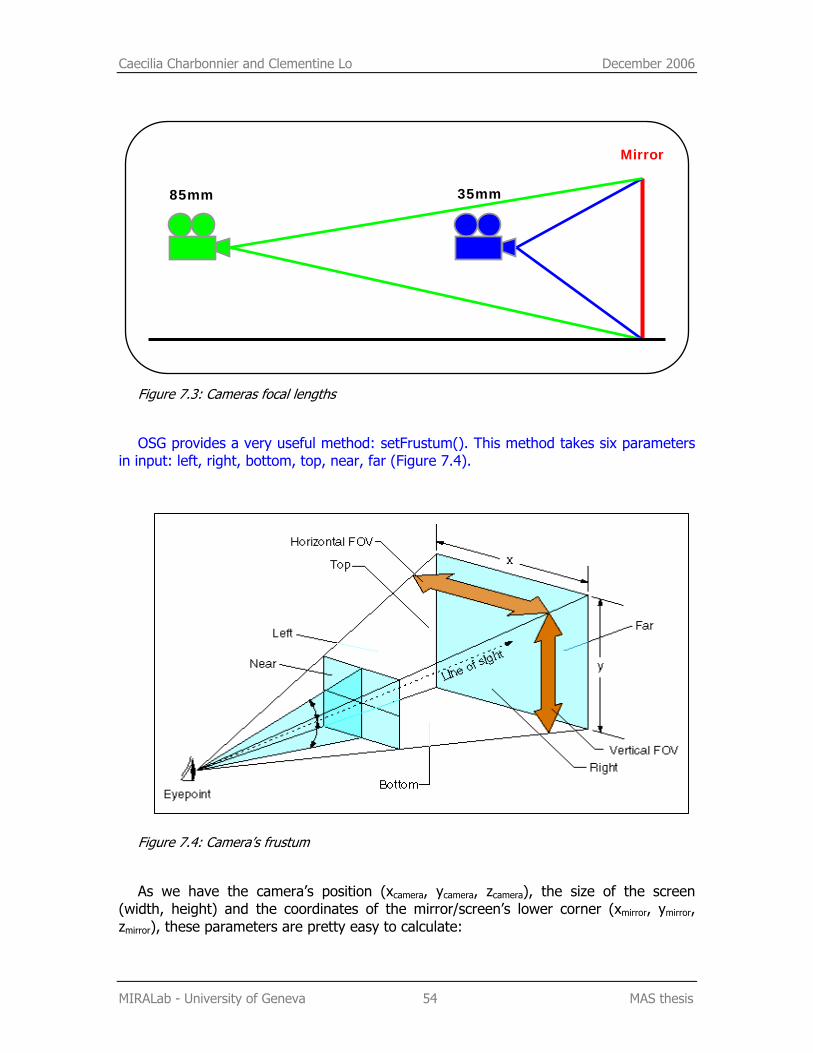
Now that we know where the camera is in the virtual space, we can calculate its new projection matrix. As the screen’s size is fixed, not only the view point will change depending on the camera’s position but also the focal length. Indeed, the focal length influences the field of view, i.e. how much of the entire scene appears in the image. The farther the user is from the screen, the wider the lens (Figure 7.3).
MR
REAL WORLD VIRTUAL WORLD Mirror
MmirrorR MmirrorV
MV
Caecilia Charbonnier and Clementine Lo December 2006
MIRALab - University of Geneva 54 MAS thesis
Figure 7.3: Cameras focal lengths
OSG provides a very useful method: setFrustum(). This method takes six parameters in input: left, right, bottom, top, near, far (Figure 7.4).
Figure 7.4: Camera’s frustum
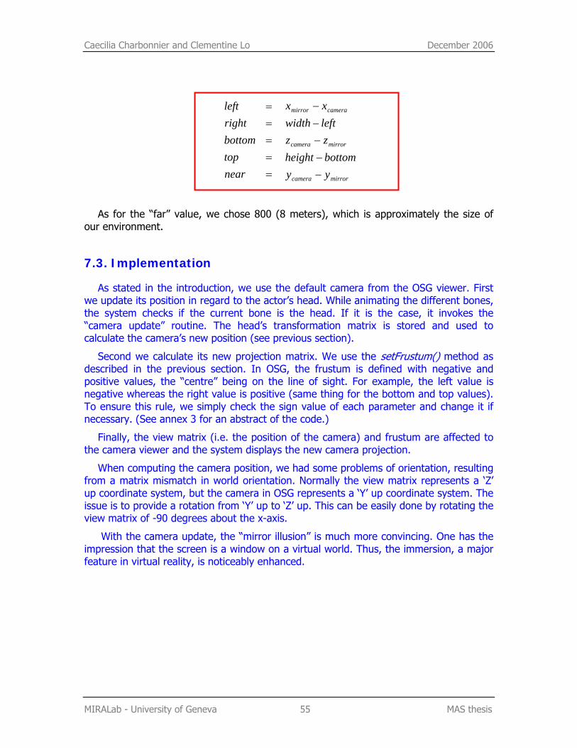
As we have the camera’s position (xcamera, ycamera, zcamera), the size of the screen (width, height) and the coordinates of the mirror/screen’s lower corner (xmirror, ymirror, zmirror), these parameters are pretty easy to calculate:
Mirror
85mm 35mm
Caecilia Charbonnier and Clementine Lo December 2006
MIRALab - University of Geneva 55 MAS thesis
neartopbottomrightleft
=====
mirrorcamera
mirrorcamera
cameramirror
yybottomheightzzleftwidthxx
−−−−−
As for the “far” value, we chose 800 (8 meters), which is approximately the size of our environment.
7.3. Implementation
As stated in the introduction, we use the default camera from the OSG viewer. First we update its position in regard to the actor’s head. While animating the different bones, the system checks if the current bone is the head. If it is the case, it invokes the “camera update” routine. The head’s transformation matrix is stored and used to calculate the camera’s new position (see previous section).
Second we calculate its new projection matrix. We use the setFrustum() method as described in the previous section. In OSG, the frustum is defined with negative and positive values, the “centre” being on the line of sight. For example, the left value is negative whereas the right value is positive (same thing for the bottom and top values). To ensure this rule, we simply check the sign value of each parameter and change it if necessary. (See annex 3 for an abstract of the code.)
Finally, the view matrix (i.e. the position of the camera) and frustum are affected to the camera viewer and the system displays the new camera projection.
When computing the camera position, we had some problems of orientation, resulting from a matrix mismatch in world orientation. Normally the view matrix represents a ‘Z’ up coordinate system, but the camera in OSG represents a ‘Y’ up coordinate system. The issue is to provide a rotation from ‘Y’ up to ‘Z’ up. This can be easily done by rotating the view matrix of -90 degrees about the x-axis.
With the camera update, the “mirror illusion” is much more convincing. One has the impression that the screen is a window on a virtual world. Thus, the immersion, a major feature in virtual reality, is noticeably enhanced.
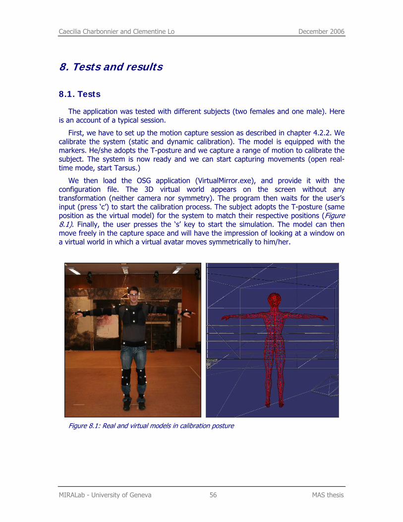
Caecilia Charbonnier and Clementine Lo December 2006
MIRALab - University of Geneva 56 MAS thesis
8. Tests and results
8.1. Tests
The application was tested with different subjects (two females and one male). Here is an account of a typical session.
First, we have to set up the motion capture session as described in chapter 4.2.2. We calibrate the system (static and dynamic calibration). The model is equipped with the markers. He/she adopts the T-posture and we capture a range of motion to calibrate the subject. The system is now ready and we can start capturing movements (open real-time mode, start Tarsus.)
We then load the OSG application (VirtualMirror.exe), and provide it with the configuration file. The 3D virtual world appears on the screen without any transformation (neither camera nor symmetry). The program then waits for the user’s input (press ‘c’) to start the calibration process. The subject adopts the T-posture (same position as the virtual model) for the system to match their respective positions (Figure 8.1). Finally, the user presses the ‘s’ key to start the simulation. The model can then move freely in the capture space and will have the impression of looking at a window on a virtual world in which a virtual avatar moves symmetrically to him/her.
Figure 8.1: Real and virtual models in calibration posture
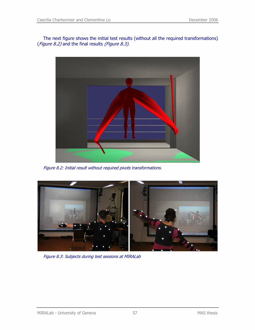
Caecilia Charbonnier and Clementine Lo December 2006
MIRALab - University of Geneva 57 MAS thesis
The next figure shows the initial test results (without all the required transformations) (Figure 8.2) and the final results (Figure 8.3).
Figure 8.2: Initial result without required pivots transformations.
Figure 8.3: Subjects during test sessions at MIRALab
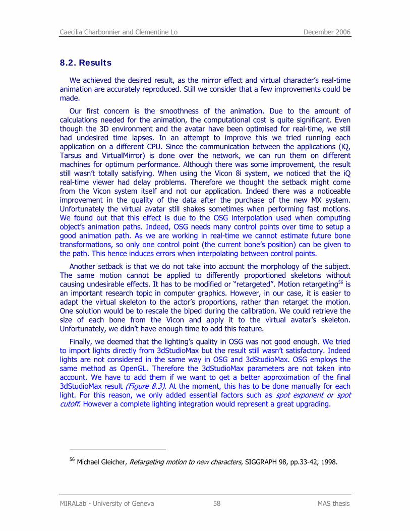
Caecilia Charbonnier and Clementine Lo December 2006
MIRALab - University of Geneva 58 MAS thesis
8.2. Results
We achieved the desired result, as the mirror effect and virtual character’s real-time animation are accurately reproduced. Still we consider that a few improvements could be made.
Our first concern is the smoothness of the animation. Due to the amount of calculations needed for the animation, the computational cost is quite significant. Even though the 3D environment and the avatar have been optimised for real-time, we still had undesired time lapses. In an attempt to improve this we tried running each application on a different CPU. Since the communication between the applications (iQ, Tarsus and VirtualMirror) is done over the network, we can run them on different machines for optimum performance. Although there was some improvement, the result still wasn’t totally satisfying. When using the Vicon 8i system, we noticed that the iQ real-time viewer had delay problems. Therefore we thought the setback might come from the Vicon system itself and not our application. Indeed there was a noticeable improvement in the quality of the data after the purchase of the new MX system. Unfortunately the virtual avatar still shakes sometimes when performing fast motions. We found out that this effect is due to the OSG interpolation used when computing object’s animation paths. Indeed, OSG needs many control points over time to setup a good animation path. As we are working in real-time we cannot estimate future bone transformations, so only one control point (the current bone’s position) can be given to the path. This hence induces errors when interpolating between control points.
Another setback is that we do not take into account the morphology of the subject. The same motion cannot be applied to differently proportioned skeletons without causing undesirable effects. It has to be modified or “retargeted”. Motion retargeting56 is an important research topic in computer graphics. However, in our case, it is easier to adapt the virtual skeleton to the actor’s proportions, rather than retarget the motion. One solution would be to rescale the biped during the calibration. We could retrieve the size of each bone from the Vicon and apply it to the virtual avatar’s skeleton. Unfortunately, we didn’t have enough time to add this feature.
Finally, we deemed that the lighting’s quality in OSG was not good enough. We tried to import lights directly from 3dStudioMax but the result still wasn’t satisfactory. Indeed lights are not considered in the same way in OSG and 3dStudioMax. OSG employs the same method as OpenGL. Therefore the 3dStudioMax parameters are not taken into account. We have to add them if we want to get a better approximation of the final 3dStudioMax result (Figure 8.3). At the moment, this has to be done manually for each light. For this reason, we only added essential factors such as spot exponent or spot cutoff. However a complete lighting integration would represent a great upgrading.
56 Michael Gleicher, Retargeting motion to new characters, SIGGRAPH 98, pp.33-42, 1998.
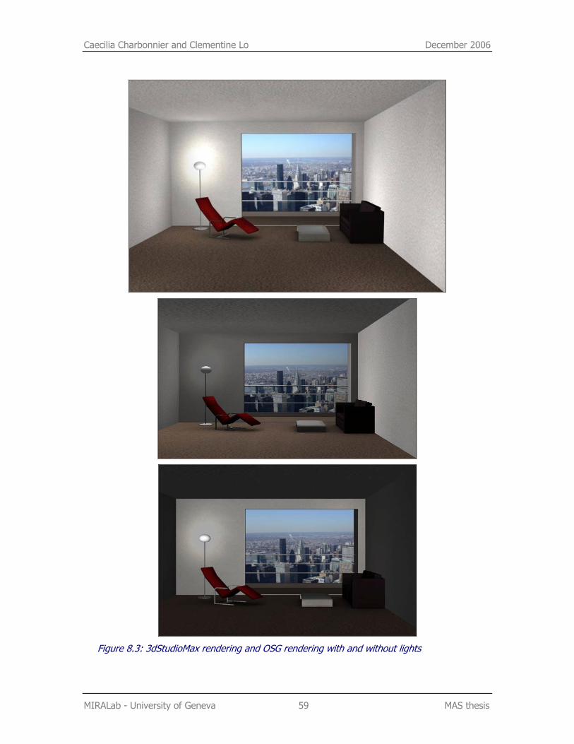
Caecilia Charbonnier and Clementine Lo December 2006
MIRALab - University of Geneva 59 MAS thesis
Figure 8.3: 3dStudioMax rendering and OSG rendering with and without lights
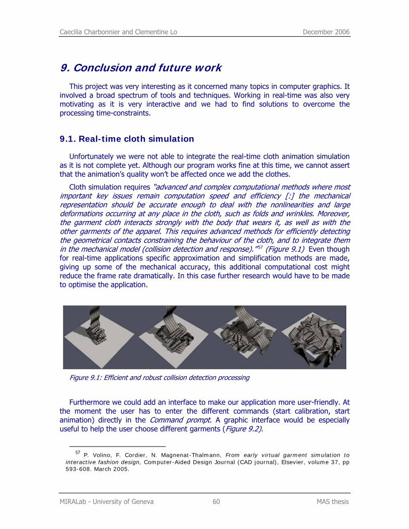
Caecilia Charbonnier and Clementine Lo December 2006
MIRALab - University of Geneva 60 MAS thesis
9. Conclusion and future work This project was very interesting as it concerned many topics in computer graphics. It
involved a broad spectrum of tools and techniques. Working in real-time was also very motivating as it is very interactive and we had to find solutions to overcome the processing time-constraints.
9.1. Real-time cloth simulation
Unfortunately we were not able to integrate the real-time cloth animation simulation as it is not complete yet. Although our program works fine at this time, we cannot assert that the animation’s quality won’t be affected once we add the clothes.
Cloth simulation requires “advanced and complex computational methods where most important key issues remain computation speed and efficiency [:] the mechanical representation should be accurate enough to deal with the nonlinearities and large deformations occurring at any place in the cloth, such as folds and wrinkles. Moreover, the garment cloth interacts strongly with the body that wears it, as well as with the other garments of the apparel. This requires advanced methods for efficiently detecting the geometrical contacts constraining the behaviour of the cloth, and to integrate them in the mechanical model (collision detection and response).” 57 (Figure 9.1) Even though for real-time applications specific approximation and simplification methods are made, giving up some of the mechanical accuracy, this additional computational cost might reduce the frame rate dramatically. In this case further research would have to be made to optimise the application.
Figure 9.1: Efficient and robust collision detection processing
Furthermore we could add an interface to make our application more user-friendly. At the moment the user has to enter the different commands (start calibration, start animation) directly in the Command prompt. A graphic interface would be especially useful to help the user choose different garments (Figure 9.2).
57 P. Volino, F. Cordier, N. Magnenat-Thalmann, From early virtual garment simulation to
interactive fashion design, Computer-Aided Design Journal (CAD journal), Elsevier, volume 37, pp 593-608. March 2005.
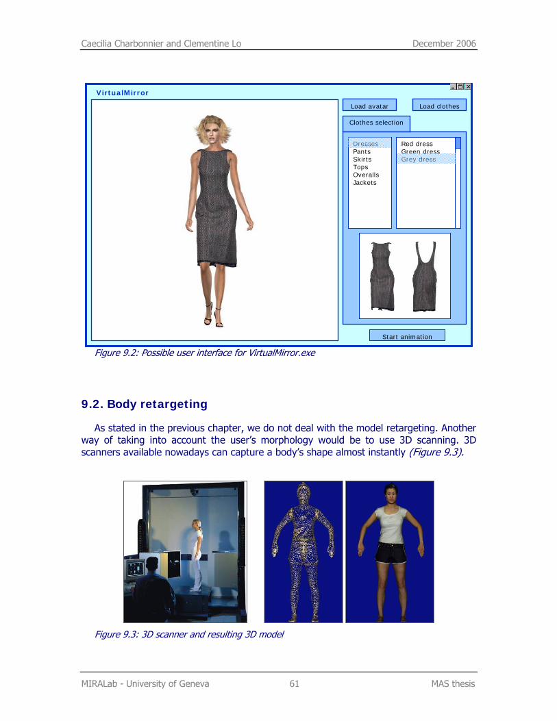
Caecilia Charbonnier and Clementine Lo December 2006
MIRALab - University of Geneva 61 MAS thesis
Figure 9.2: Possible user interface for VirtualMirror.exe
9.2. Body retargeting
As stated in the previous chapter, we do not deal with the model retargeting. Another way of taking into account the user’s morphology would be to use 3D scanning. 3D scanners available nowadays can capture a body’s shape almost instantly (Figure 9.3).
Figure 9.3: 3D scanner and resulting 3D model
Clothes selection
Load avatar Load clothes
Start animation
Dresses Pants Skirts Tops Overalls Jackets
Red dress Green dress Grey dress
VirtualMirror
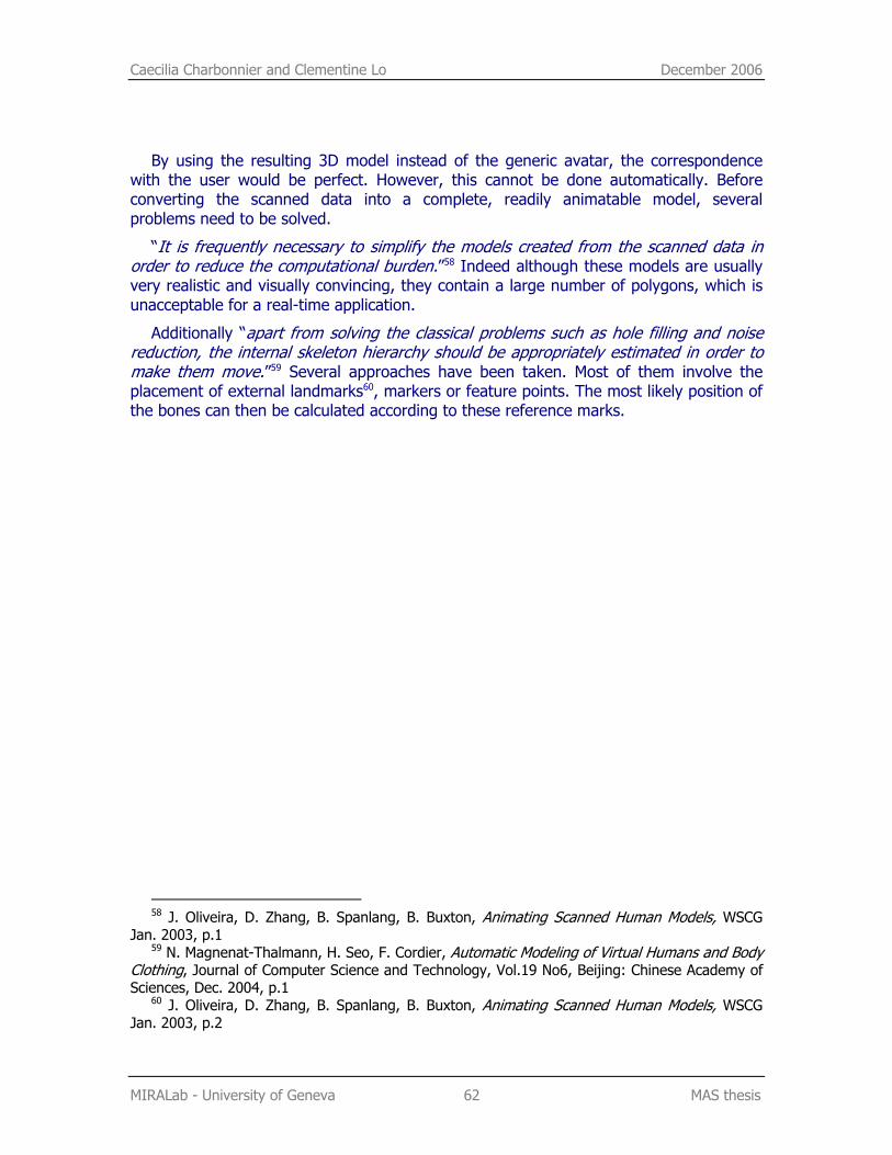
Caecilia Charbonnier and Clementine Lo December 2006
MIRALab - University of Geneva 62 MAS thesis
By using the resulting 3D model instead of the generic avatar, the correspondence with the user would be perfect. However, this cannot be done automatically. Before converting the scanned data into a complete, readily animatable model, several problems need to be solved.
“It is frequently necessary to simplify the models created from the scanned data in order to reduce the computational burden.”58 Indeed although these models are usually very realistic and visually convincing, they contain a large number of polygons, which is unacceptable for a real-time application.
Additionally “apart from solving the classical problems such as hole filling and noise reduction, the internal skeleton hierarchy should be appropriately estimated in order to make them move.”59 Several approaches have been taken. Most of them involve the placement of external landmarks60, markers or feature points. The most likely position of the bones can then be calculated according to these reference marks.
58 J. Oliveira, D. Zhang, B. Spanlang, B. Buxton, Animating Scanned Human Models, WSCG
Jan. 2003, p.1 59 N. Magnenat-Thalmann, H. Seo, F. Cordier, Automatic Modeling of Virtual Humans and Body
Clothing, Journal of Computer Science and Technology, Vol.19 No6, Beijing: Chinese Academy of Sciences, Dec. 2004, p.1
60 J. Oliveira, D. Zhang, B. Spanlang, B. Buxton, Animating Scanned Human Models, WSCG Jan. 2003, p.2
Caecilia Charbonnier and Clementine Lo December 2006
MIRALab - University of Geneva 63 MAS thesis
10. Acknowledgements We would like to thank:
Professor Nadia Magnenat-Thalmann and Professor Daniel Thalmann for giving us the opportunity to realise this project
Etienne Lyard, Dr. Gwenael Guillard and Alessandro Foni for their help, patience, and precious advice
All the people at MIRALab for their help and technical support
11. Bibliography P. S. Strauss and R. Carey, An object-oriented 3D graphics toolkit, In Edwin E. Catmull, editor, Computer Graphics (SIGGRAPH ’92 Proceedings), volume 26, p. 341–349, July 1992.
N. Magnenat-Thalmann, F. Dellas, C. Luible, P. Volino, From Roman Garments to Haute-couture Collection with the Fashionizer Platform, Virtual Systems and Multi Media, Japan, Nov, 2004
P.Volino, Collision Detection for Deformable Objects, Course Notes: Collision Detection and Proximity Queries, ACM SIGGRAPH’ 04, Los Angeles, p.19-37, 2004
G. Walters, The story of Waldo C. Graphic, Course Notes: 3D Character Animation by Computer, ACM SIGGRAPH '89, Boston, p. 65-79, July 1989.
G. Walters, Performance animation at PDI, Course Notes: Character Motion Systems, ACM SIGGRAPH 93, Anaheim, CA, p. 40-53, August 1993
H. Tardif, Character animation in real time, Panel: Applications of Virtual Reality I: Reports from the Field, ACM SIGGRAPH Panel Proceedings, 1991
B. Robertson, Moving pictures, Computer Graphics World, Vol. 15, No. 10, p. 38-44, October 1992.
T. Molet, R. Boulic, D. Thalmann. A Real-Time Anatomical Converter for Human Motion Capture, 7th EUROGRAPHICS Int. Workshop on Computer Animation and Simulation'96, Poitier, France, G. Hegron and R. Boulic eds., ISBN 3-211-828-850, Springer-Verlag Wien, p. 79-94, 1996.
T. Molet, R. Boulic, D. Thalmann, Human Motion Capture Driven by Orientation Measurement, Presence, MIT, Vol.8, N°2, p. 187-203, 1999.
T. Molet, Z. Huang, R. Boulic, D. Thalmann, An Animation Interface Designed for Motion Capture, Proc. Of Computer Animation'97, Geneva, ISBN 0-8186-7984-0, IEEE Press, p. 77-85, June 1997.
Caecilia Charbonnier and Clementine Lo December 2006
MIRALab - University of Geneva 64 MAS thesis
L. P. Nedel, T. Molet, D. Thalmann, Animation of Virtual Human Bodies Using Motion Capture Devices, Proc. 2nd Brazilian Workshop on Virtual Reality - WRV'99, p. 139-150, Marilia, SP, Brazil, November, 1999.
N.I. Badler, M. J. Hollick, J. P. Granieri, Real-Time Control of a Virtual Human Using Minimal Sensor, Presence: Teleoperators and Virtual Environments, Vol. 2, Number 1, MIT, p. 82-86, Winter 1993.
R. Okada, B. Stenger, T. Ike, N. Kondoh, Virtual Fashion show using real-time markerless motion capture, ACCV (2), p. 801-810, 2006.
L. Vacchetti, V. Lepetit and P. Fua, Stable Real-Time 3D Tracking Using Online and Offline Information, IEEE Transactions on Pattern Analysis and Machine Intelligence, Vol. 26, Nr. 10, pp. 1391-1391, 2004.
N. Magnenat-Thalmann, S. Hadap, P. Kalra, State of the Art in Hair Simulation, International Workshop on Human Modelling and Animation, Seoul: Korea Computer Graphics Society, pp. 3-9, June 2002, p.1
Dan Piponi and George Borshukov, Seamless Texture Mapping of Subdivision Surfaces by Model Pelting and Texture Blending, Proceedings of the 27th annual conference on Computer graphics and interactive techniques, ISBN:1-58113-208-5, pp. 471–478, 2000
The Virtual Soldier Research Team (VSR) Program, End-of-Year Technical Report for Project Digital Human Modeling and Virtual Reality for FCS, Center for Computer-Aided Design, College of Engineering, The University of Iowa
J. Rohlf and J. Helman, IRIS performer: A high performance multiprocessing toolkit for real–Time 3D graphics, p. 381–395.
N. Magnenat-Thalmann, R. Laperrière, D. Thalmann. Joint-Dependent Local Deformations for Hand Animation and Object Grasping, Proc. Graphics Interface'88, Edmonton. 1988.
G. Guillard, Un espace de représentation pour l’étude conjointe de la morphologie et de la fonctionnalité des surfaces articulaires, Université de Rennes, 2005, p.58
Michael Gleicher, Retargeting motion to new characters, SIGGRAPH 98, pp.33-42, 1998.
P. Volino, F. Cordier, N. Magnenat-Thalmann, From early virtual garment simulation to interactive fashion design, Computer-Aided Design Journal (CAD journal), Elsevier, volume 37, pp 593-608. March 2005.
J. Oliveira, D. Zhang, B. Spanlang, B. Buxton, Animating Scanned Human Models, WSCG Jan. 2003, p.1
N. Magnenat-Thalmann, H. Seo, F. Cordier, Automatic Modeling of Virtual Humans and Body Clothing, Journal of Computer Science and Technology, Vol.19 No6, Beijing: Chinese Academy of Sciences, Dec. 2004, p.1
J. Oliveira, D. Zhang, B. Spanlang, B. Buxton, Animating Scanned Human Models, WSCG Jan. 2003, p.2
Caecilia Charbonnier and Clementine Lo December 2006
MIRALab - University of Geneva 65 MAS thesis
Courses
D. Konstantas, « Infrastructure de communication » Master course, University of Geneva, February 2005.
L. Moccozet, « Facial and Body Animation » Master course, University of Geneva, May 2006.
Manuals and tutorials
Curious Lab, Poser User’s Guide
Discreet, Character Studio R2 User’s Guide
MIRALab - University of Geneva, Vicon User Manual
Vicon, ViconiQ tutorials and User’s guide
Internet
MIRALab - University of Geneva http://www.miralab.ch
Open Scene Graph (OSG) http://www.openscenegraph.org
Vicon http://www.vicon.com
The Digital Journalist http://www.digitaljournalist.org/issue0309/lm20.html
Jim Henson Productions http://www.henson.com/
Muppet Wiki http://muppet.wikia.com/wiki/Waldo_C._Graphic
SimGraphics http://www.simg.com/
Polhemus http://www.polhemus.com/
Motion Analysis http://www.motionanalysis.com/
AR Tracking http://www.ar-tracking.de/
Ascension Technology http://www.ascension-tech.com/
Caecilia Charbonnier and Clementine Lo December 2006
MIRALab - University of Geneva 66 MAS thesis
National Center for Supercomputing Applications (NCSA) - University of Illinois at Urbana-Champaign http://archive.ncsa.uiuc.edu/Cyberia/VETopLevels/Images/Mario.gif
The Advanced Computing Center for the Arts and Design – Ohio State University http://accad.osu.edu/~waynec/history/lesson11.html
CVLab – Ecole Polytechnique Federale de Lausanne (EPFL) http://cvlab.epfl.ch/research/augm/augmented.html
PhoeniX Technologies http://www.ptiphoenix.com/application/animation/live_animation.php
Nasa ZeroG Experiments http://zerog.jsc.nasa.gov/Other/Feb_12_2004_Robotic/subviewer.cgi
MotionAnalysis application http://www.motionanalysis.com/applications/movement/gait/gait.html
Innovative Sports Training http://www.innsport.com/MMRGaitNONAV.htm
Curious Labs http://www.curiouslabs.com
Autodesk http://www.autodesk.com
Digimation http://www.digimation.com
Bones Pro review article http://www.rendernode.com/articles.php?articleId=69
Cinema 4D 9.5 review by c4dcafe.com http://www.c4dcafe.com/reviews/R95/page2.html
Teo Jakob http://www.teojakob.ch
The NYU movement group http://movement.nyu.edu/projects/nyulab.html
OpenGL http://www.opengl.org/
OpenScenegraph Plugins http://www.openscenegraph.org/osgwiki/pmwiki.php/UserGuides/Plugins
XML http://www.xml.com/
Sony Computer Entertainment http://www.scee.com/index.jhtml

Caecilia Charbonnier and Clementine Lo December 2006
MIRALab - University of Geneva 67 MAS thesis
Khronos group http://www.khronos.org/collada/
COLLADA show (Siggraph ’05) http://www.khronos.org/collada/presentations/collada_siggraph2005.pdf
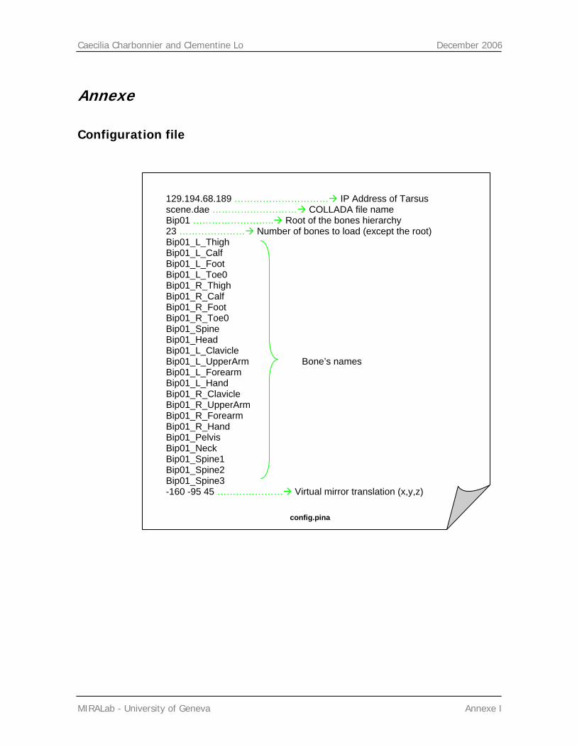
Caecilia Charbonnier and Clementine Lo December 2006
MIRALab - University of Geneva Annexe I
Annexe
Configuration file
config.pina
129.194.68.189 ………………………… IP Address of Tarsus scene.dae ……………………… COLLADA file name Bip01 …………………….. Root of the bones hierarchy 23 ………………… Number of bones to load (except the root) Bip01_L_Thigh Bip01_L_Calf Bip01_L_Foot Bip01_L_Toe0 Bip01_R_Thigh Bip01_R_Calf Bip01_R_Foot Bip01_R_Toe0 Bip01_Spine Bip01_Head Bip01_L_Clavicle Bip01_L_UpperArm Bone’s names Bip01_L_Forearm Bip01_L_Hand Bip01_R_Clavicle Bip01_R_UpperArm Bip01_R_Forearm Bip01_R_Hand Bip01_Pelvis Bip01_Neck Bip01_Spine1 Bip01_Spine2 Bip01_Spine3 -160 -95 45 ………………… Virtual mirror translation (x,y,z)
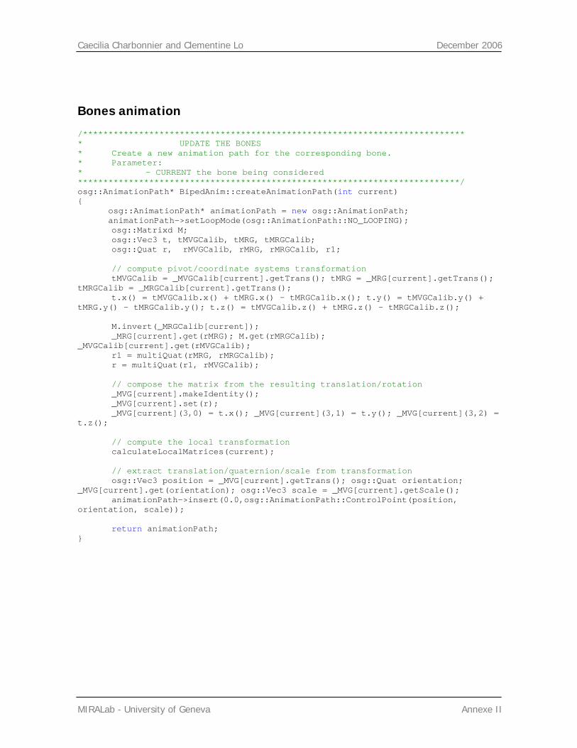
Caecilia Charbonnier and Clementine Lo December 2006
MIRALab - University of Geneva Annexe II
Bones animation
/*************************************************************************** * UPDATE THE BONES * Create a new animation path for the corresponding bone. * Parameter: * - CURRENT the bone being considered ***************************************************************************/ osg::AnimationPath* BipedAnim::createAnimationPath(int current) { osg::AnimationPath* animationPath = new osg::AnimationPath; animationPath->setLoopMode(osg::AnimationPath::NO_LOOPING); osg::Matrixd M; osg::Vec3 t, tMVGCalib, tMRG, tMRGCalib; osg::Quat r, rMVGCalib, rMRG, rMRGCalib, r1; // compute pivot/coordinate systems transformation tMVGCalib = _MVGCalib[current].getTrans(); tMRG = _MRG[current].getTrans(); tMRGCalib = _MRGCalib[current].getTrans(); t.x() = tMVGCalib.x() + tMRG.x() - tMRGCalib.x(); t.y() = tMVGCalib.y() + tMRG.y() - tMRGCalib.y(); t.z() = tMVGCalib.z() + tMRG.z() - tMRGCalib.z(); M.invert(_MRGCalib[current]); _MRG[current].get(rMRG); M.get(rMRGCalib); _MVGCalib[current].get(rMVGCalib); r1 = multiQuat(rMRG, rMRGCalib); r = multiQuat(r1, rMVGCalib); // compose the matrix from the resulting translation/rotation _MVG[current].makeIdentity(); _MVG[current].set(r); _MVG[current](3,0) = t.x(); _MVG[current](3,1) = t.y(); _MVG[current](3,2) = t.z(); // compute the local transformation calculateLocalMatrices(current); // extract translation/quaternion/scale from transformation osg::Vec3 position = _MVG[current].getTrans(); osg::Quat orientation; _MVG[current].get(orientation); osg::Vec3 scale = _MVG[current].getScale(); animationPath->insert(0.0,osg::AnimationPath::ControlPoint(position, orientation, scale)); return animationPath; }
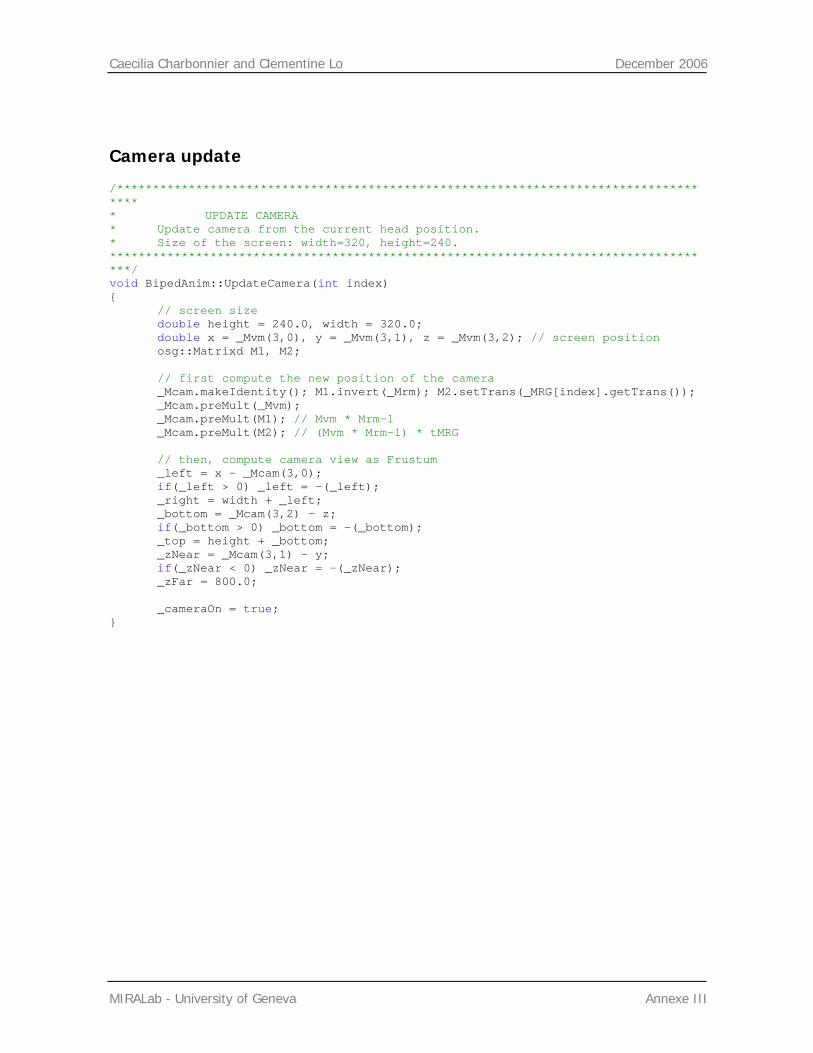
Caecilia Charbonnier and Clementine Lo December 2006
MIRALab - University of Geneva Annexe III
Camera update
/************************************************************************************* * UPDATE CAMERA * Update camera from the current head position. * Size of the screen: width=320, height=240. *************************************************************************************/ void BipedAnim::UpdateCamera(int index) { // screen size double height = 240.0, width = 320.0; double x = _Mvm(3,0), y = _Mvm(3,1), z = _Mvm(3,2); // screen position osg::Matrixd M1, M2; // first compute the new position of the camera _Mcam.makeIdentity(); M1.invert(_Mrm); M2.setTrans(_MRG[index].getTrans()); _Mcam.preMult(_Mvm); _Mcam.preMult(M1); // Mvm * Mrm-1 _Mcam.preMult(M2); // (Mvm * Mrm-1) * tMRG // then, compute camera view as Frustum _left = x - _Mcam(3,0); if(_left > 0) _left = -(_left); _right = width + _left; _bottom = _Mcam(3,2) - z; if(_bottom > 0) _bottom = -(_bottom); _top = height + _bottom; _zNear = _Mcam(3,1) - y; if(_zNear < 0) _zNear = -(_zNear); _zFar = 800.0; _cameraOn = true; }