
Virtis and Opis User’s Manual - KDOT: Home · Sybase Adaptive Server Anywhere ... This Virtis and...
58
VIRTIS AND OPIS USER’S MANUAL Version 5.4 April 2006
Transcript of Virtis and Opis User’s Manual - KDOT: Home · Sybase Adaptive Server Anywhere ... This Virtis and...

VIRTIS AND OPIS USER’S MANUAL
Version 5.4 April 2006

Disclaimer
This system was developed by AASHTO. AASHTO assumes no liability or responsibility for and makes no representations or warranties as to applicability or suitability of this computer system. Anyone making use thereof or relying thereon assumes all responsibility and liability arising from such use or reliance.
INTRODUCTION..............................................................................................................1
INITIAL SETUP................................................................................................................2 General .............................................................................................................................................2
Sybase Adaptive Server Anywhere .............................................................................................................2 Oracle 9i ......................................................................................................................................................2 Microsoft Data Engine/SQL Server 2000....................................................................................................2
Configuring Parameters and System Defaults..................................................................................3 GETTING STARTED.......................................................................................................4 Getting Started..................................................................................................................................4 General Bridge Description..............................................................................................................7
Location-Definition .....................................................................................................................................7 Girder Line vs. Girder System...................................................................................................................10 Cross-Section-Based vs. Schedule-Based Data Entry ...............................................................................10
Entering a New Bridge Description ...............................................................................................11 Description of Graphic User Interface ...........................................................................................11 Wizards...........................................................................................................................................12 Database Overview.........................................................................................................................13 Units ...............................................................................................................................................13 Importing a BAR7 Input File .........................................................................................................14 Importing a BARS Input File .........................................................................................................16 Importing a BRASS Input File .......................................................................................................18 GLOSSARY OF TERMS USED IN VIRTIS AND OPIS............................................20
BRIDGE EXPLORER.....................................................................................................22 Bridge Explorer ..............................................................................................................................22
Purpose of the Bridge Explorer .................................................................................................................22 Left Portion of the Bridge Explorer...........................................................................................................22 Right Portion of the Bridge Explorer.........................................................................................................22 How to Open the Bridge Workspace .........................................................................................................22
Bridge Explorer Toolbar ................................................................................................................22 BRIDGE WORKSPACE.................................................................................................25 Bridge Workspace ..........................................................................................................................25
Purpose of the Bridge Workspace .............................................................................................................25 Description of the Bridge Workspace........................................................................................................25 How to Open an Item from the Bridge Workspace Window.....................................................................25 Items Included in the Bridge Workspace...................................................................................................25
Bridge Workspace Toolbar.............................................................................................................25 Bridge Workspace Windows..........................................................................................................28 LIBRARY EXPLORER..................................................................................................32 Library Explorer .............................................................................................................................32
Purpose of the Library Explorer ................................................................................................................32 Items Included in the Library ....................................................................................................................32 Purpose of the Library ...............................................................................................................................32 Left Portion of the Library Explorer..........................................................................................................32 Right Portion of the Library Explorer .......................................................................................................32 Types of Libraries......................................................................................................................................32
How to Open a Library Window ...............................................................................................................32 Library Explorer Toolbar ...............................................................................................................33 Library Explorer Windows.............................................................................................................35 CONFIGURATION BROWSER ...................................................................................36 Configuration Browser ...................................................................................................................36
Purpose of the Configuration Browser ......................................................................................................36 Description of the Configuration Browser ................................................................................................36 How to Open a Configuration Browser Window ......................................................................................36 Users..........................................................................................................................................................36 How to Add a New User ...........................................................................................................................36
Configuration Browser Toolbar .....................................................................................................36 Configuration Browser Windows...................................................................................................38 EXAMPLE BRIDGES.....................................................................................................39
MISCELLANEOUS ........................................................................................................43 Specification Check........................................................................................................................43 Results Graph .................................................................................................................................43 Bridge Workspace Report ..............................................................................................................44 Schematics......................................................................................................................................45 Validate ..........................................................................................................................................45 Dead Loads.....................................................................................................................................46 Factors ............................................................................................................................................46 Metric Reinforcing Steel ................................................................................................................47 Batch Analysis................................................................................................................................48 Rating from the Bridge Explorer....................................................................................................48 Adding Users to the Virtis/Opis Database......................................................................................48
Adding Users to Sybase Adaptive Server Anywhere 8.0 and 9.0..............................................................49 Adding Users to Oracle 9i .........................................................................................................................51 Adding Users to MSDE/SQL Server 2000................................................................................................52
Checkin/Checkout ..........................................................................................................................53 Security...........................................................................................................................................54

INTRODUCTION
This Virtis and Opis User’s Manual contains basic portions of the Virtis/Opis – Help file. Included in this manual are help topics that provide a general overview of the program and that are foundational to understanding the program.
The complete Virtis/Opis – Help file is accessible by pressing F1 from within the program. It contains a description of every input field on every window. Links are provided in appropriate places throughout the various topics to assist in navigation within the help file.
1

INITIAL SETUP
This section describes the procedure for setting up the Virtis/Opis system for both stand-alone and client/server database configurations. If you have already been assigned a username and password then you may proceed to the Getting Started section of the manual.
General Virtis/Opis requires the installation of either a stand-alone database or client/server database for the storage and retrieval of data. After a database has been installed the Virtis/Opis system needs to be configured for your organization’s use. A model of the database schema is available in a Logic Works ERwin (version 3.5) file named VirtisOpisDBModel54.ER1 on the installation CD in the \BRIDGEWare Database\ directory. In the same directory are two Adobe PDF files named TablesReport54.pdf and ColumnsReport54.pdf that contain descriptions of the tables and columns of the database. The following sections outline the configuration steps necessary for SQL Adaptive Server Anywhere, Oracle 9i (client/server) databases and Microsoft Data Engine/SQL Server 2000.
Sybase Adaptive Server Anywhere The Virtis/Opis installation will install two Sybase database files. All database files contain the BRIDGEWare database schema (tables and relationships) and are populated with system data. The Virtis54.db file is the production database and is populated with template bridges. The Virtis54-Sample.db file is the sample database and is populated with sample bridges. The template bridges and samples bridges describe the same bridges. See the Virtis/Opis on-line help for a description of a template bridge.
Prior to having installed Virtis/Opis, one of the following should have been installed: • Sybase Adaptive Server Anywhere 8.0 (accepting all defaults) • Sybase Adaptive Server Anywhere 9.0 (accepting all defaults)
The databases supplied have several users predefined. Users’ passwords are the same as their usernames. The bridgeware user is the owner of Virtis/Opis database tables.
Oracle 9i The Virtis/Opis installation CD contains SQL script files to create the BRIDGEWare database schema and populate system data and sample data on an Oracle 9i database server. Please refer to BRIDGEWare Startup Guide for installation instructions.
Each client machine installed with Virtis/Opis will need an ODBC data source defined for the instances of the BRIDGEWare database schema installed on the Oracle server.
Microsoft Data Engine/SQL Server 2000 The Virtis/Opis installation will install two MSDE/SQL Server database(s). Both databases contain the BRIDGEWare database schema (tables and relationships) and are populated with system data. The Virtis54 database is the production database and is populated with template bridges. The Virtis54-Sample database is the sample database and is populated with sample bridges. The template bridges and samples bridges describe the same bridges. See the
2

Virtis/Opis on-line help for a description of a template bridge.
If MSDE is not installed when Virtis/Opis is installed, the Virtis/Opis installation will install MSDE.
The databases supplied have several users predefined. Users’ passwords are the same as their usernames. The bridgeware user is the owner of Virtis/Opis database tables.
Configuring Parameters and System Defaults The Virtis/Opis system allows for the defining of organization specific parameters such as counties and districts for each data source. In order to add these parameters, login to Virtis/Opis with the username virtis by running the Virtis, Opis, or VirtisOpis application. Open the Configuration Browser by selecting Window/Configuration Browser from the menu. Double click on the tree item named Parameters. Press the F1 key for on-line help on setting parameters.
There is system defaults associated with each database source. Double click on the tree item named System Defaults in the Configuration Browser to modify these defaults. Press the F1 key for on-line help on setting System Defaults.
3

GETTING STARTED
Getting Started 1. Start Virtis/Opis by opening the Windows Start menu (click Start on the windows
taskbar) and selecting AASHTOWARE/VirtisOpis. The splash window and Connect dialog will open.
2. Enter your username and password and click the ellipsis button next to the Data Source.
The system is delivered with a Sybase database and the username and password are virtis. Refer to Sybase help for changing your password. Oracle users should see their database administrator for their username and password.
4

3. The Select Data Source dialog will open.
4. Find the data source in the list of data sources. (Setup adds Virtis54 and Virtis54s to the list for access to Sybase Adaptive Server. Virtis54 is for production, and Virtis54s is for teaching.) Select the data source, and click the OK button. (For Sybase Adaptive Server - if Virtis54 or Virtis54s is not in the list, then something went wrong with the installation.) (For Oracle - your Oracle database administrator should create an ODBC data source on each client PC. That data source should then be available for selection.) (For MSDE/SQL Server 2000 – if Virtis54_SQLServer or Virtis54s_SQLServer is not in the list, then something went wrong with the installation.)
5. The Connect dialog should look like the one shown above in Step 2. Click the OK button. Virtis will continue to open. As it does, you should see a button for the database (if running Sybase Adaptive Server) on the Windows System Tray. Virtis opens to the Bridge Explorer. You will also see a button for Virtis/Opis on the Windows Taskbar.
The Bridge Explorer is similar to the Windows Explorer, with a folder view on the left and a list view on the right. The folders represent groups of bridges. The list view contains a list of bridges. You can add a new folder by selecting a folder (the new folder will be a child of the selected folder) and selecting File/New/New Folder. Enter the name of the folder, and select List as the save option. Clicking Save Folder will add the folder to the Bridge Explorer. Clicking the text in the Bridge Explorer tree toggles the item to edit mode, and the name can be changed. Bridges in the list view can be selected and dragged into folders.
Adding a new bridge – You can add a new bridge by selecting File/New/New Bridge. The Bridge Workspace opens with a new bridge. You must enter a Bridge ID and an NBI Structure ID (the database is designed to share data with Pontis, and Pontis requires this data). Click the OK button to close the window and save the changes to memory. Select File/Save to save the new bridge to the database. A Bridge Validation dialog will appear listing any warning or error messages. Click Continue Saving to save the new bridge to the database.
5

6. Analyzing a bridge that is already in the database – Select the “Sample Bridges”
folder on the Bridge Explorer. The list will change to include 35 bridges. Select bridge 4, “PCITrainingBridge1”, and select File/Open. The Bridge Workspace, shown below, will open.
Select Bridge/Analysis Settings. Open the Vehicles tree, select a vehicle, and click the Add to Rating/Analysis button. Click the OK button to close the Analysis Settings dialog. Next, select "Member Alternative #1" in the Bridge Workspace. Then select Bridge/Analyze to initiate an analysis. The Progress view will open, and the generated BRASS input commands will be displayed. When the analysis is completed, the Cancel button will change to OK. Click the OK button to close the view.
7. Viewing analysis results – Select Bridge/Tabular Report. The results view will open.
Select a report type. Results can be saved to and retrieved from the database by selecting
6

File/Save Analysis Results from the menu or by selecting Bridge/Analysis Events from the menu, clicking the event in the table of events, and clicking the Save button. The same dialog can be used to retrieve analysis results from the database and to select the current event. The current event is the event used by the results views. Previously saved analysis results can be made current (available for viewing), or deleted using this dialog.
8. Viewing graphs – Select Bridge/Charts. The graph view will open. The tree in the
lower left can be used to select the data to be plotted. 9. Viewing specification-check results (Opis only) – Select Bridge/Specification Check.
The Spec-Check view will open. Use the tree on the left to select the stage and location for which you would like to view results. The list on the right will display the specification checks performed by BRASS. Clicking on the header will sort the list. Selecting Edit/Filter will open a filter dialog that can be used to filter the list. Double-clicking the list opens a dialog that displays detail about that particular specification check.
10. Viewing the BRASS output file – Select Bridge/Output. The Analysis Output window
will open displaying a tree containing the most recent BRASS output files. Double-click the name of a file to open that file for viewing.
11. Exploring the other views of the Bridge Workspace – Select a tree item and use
File/New to create a new item and File/Open to open an existing item. 12. Closing the Bridge Workspace – Select File/Close. 13. Opening the Library Explorer – Select Window/Library Explorer. The Library
Explorer will open and display a view similar to the Bridge Explorer, with a folder view on the left and a list view on the right. Selecting an item in the list view and selecting File/Open will open a view of the data for the selected item.
General Bridge Description The Bridge Workspace is the master outline for all of the data pertaining to each bridge. When you open the Bridge Workspace for a bridge, you will see a hierarchical (tree-structured) presentation of the bridge and all its parts. In general, each indented level of the tree lists the components of the level above it. Several features of the Bridge Workspace are important to understand.
Location-Definition The tree structure exhibits a pattern of location-definition. The tree first shows a location where a structural component is needed, and under this it lists one or more alternative definitions of the component that might satisfy the need. This serves three different purposes:
• For Virtis load rating, it allows the database to contain multiple conditions for a component.
7

When a bridge is first built, you can enter it in its original form. Later, a revised model of the structure can be stored without having to erase the original model.
• For Opis bridge design, it allows you to store two or more alternative ways of configuring the same bridge. You can use this feature to flesh out and compare design ideas before committing to just one of them. This is a great way to perform “what-if” analysis of a design.
• For both Virtis and Opis, this pattern allows you to enter the definition of a superstructure or member just once, and re-use the same definition in more than one place in the same bridge design. For example, in a long bridge consisting of several identical simply-supported spans, you can enter the definition of just one of the spans and have the system re-use the same definition for each of the other span locations.
To maximize the usefulness of this feature, it is offered at three different levels of the Bridge Workspace hierarchy, as follows:
• Bridge - Bridge Alternative: When designing a bridge, you can use this feature to maintain two or more alternative configurations of superstructure and substructure (when available). For example, you can try out a two-span bridge and compare it to a one-span bridge for the same crossing. Each mutually-exclusive alternative configuration for a bridge is called a Bridge Alternative.
• Structure - Structure Alternative: Each bridge can contain more than one structure unit. For example, a truss main unit with multi-beam approach units on each end would consist of three structures. You can compare a steel design against a concrete design for the approach structures. A Structure Alternative is a way of matching a Structure to a specific Superstructure Definition. The Superstructure Definition is stored separately (that is, in a different place in the tree) from the Structure Alternative, so you can easily mix-and-match Superstructure Definitions in various places within the design.
• Member - Member Alternative: Each superstructure definition can contain one or more members. Each member can have one or more alternative definitions. For example, you can compare a steel plate girder with transverse stiffeners against one with longitudinal stiffeners. Each mutually-exclusive alternative definition of a member is a Member Alternative.
The following figure depicts the location-definition hierarchy in Virtis/Opis. As you become experienced with creating bridge models in Virtis and Opis, you’ll find that these features give you a lot of flexibility and convenience in managing your bridge data.
8

Bridge
BridgeAlternative
BridgeAlternative
StructureDefinition
GirderLine
Member
MemberAlternative
MemberAlternative
CrossSectionBased
ScheduleBased
GirderSystem
Member Member Member Member
Structure Structure Structure Structure
Structure
or
Structure Structure
StructureAlternative
StructureAlternative
StructureAlternative
StructureAlternative
Structure
or
assigned to
assi
gned
to
9

Girder Line vs. Girder System The most general way to describe a superstructure is to describe each girder individually, including the position of each girder within the overall structure. This is called a girder system, and it is used for normal bridges.
Another way to describe a superstructure is to describe just one girder, making simplifying assumptions about distribution factors. This is called a girder line, and it is used for odd bridges which can not be entered using a girder system. Girder line is also used for importing existing BARS and BRASS files.
Cross-Section-Based vs. Schedule-Based Data Entry Within the definition of an individual girder, Virtis/Opis also offers two different levels of detail. The most detailed way to describe a girder is to list and describe all its parts individually. For example, you can describe the web plate, the flange plates, the stiffeners, and the cover plates individually, including their size and position within the girder. This is called Schedule-Based data entry. This type of data entry is very precise and offers maximum flexibility in the analysis.
Another way to describe a girder is to select a small number of points along the length of the beam and describe the beam cross-section at those points. Typically, the points would be selected as places where the cross section changes, such as where a cover plate begins or ends. This is called Cross-Section-Based data entry. This type of data entry often requires simplifying assumptions which tend to make the model more conservative but less detailed.
Virtis/Opis supports both types of data entry. Schedule-based entry would be favored for more complex girders. Cross-section-based entry is used by the BARS and BRASS import utilities and for built-up sections. However, if you anticipate using Virtis/Opis with one or more analytical engines (computational software packages) other than BRASS, you should keep in mind that cross-section-based features are more closely tied to the capabilities of the engine. Schedule-based entry is more generic and thus more likely to work with a wide variety of engines.
For a glossary of the various terms used in this help topic, presented in alphabetical order, go to the Glossary of Terms Used in Virtis and Opis.
For information about the applicable system of units, go to Units.
10
Entering a New Bridge Description The following steps can be followed to enter a new bridge description:
1. Log into Virtis/Opis, as described in Getting Started. Virtis/Opis opens to the Bridge Explorer.
2. Select File/New/New Bridge or click the New Bridge toolbar button. This will open the Bridge Workspace and the Bridge Description window.
3. Click on the New Bridge folder, opening the Bridge Description window entitled New Bridge.
4. Enter the Bridge ID and the NBI Structure ID, as a minimum. Then click the OK button to save this information to memory.
5. Click the Save button on the toolbar to save this information to the database. It is recommended that you save your information to the database on a regular basis while you are entering data.
6. Work your way down through the tree on the Bridge Workspace, entering the appropriate data in the entry fields of the various windows and tabs. To open a new window, select the appropriate folder, use the right mouse click and select New. Some windows are used only for certain structure types (girder line or girder system) or for certain girder property input methods (schedule based or cross-section based). The appropriate windows are listed automatically in the appropriate portions of the tree based on your input.
7. To perform an analysis, select Bridge/Analysis Settings. Open the Vehicles tree and select a vehicle, and then click the Add to Rating button. Click the OK button to close the Analysis Settings window. Next, select a member alternative in the tree on the Bridge Workspace. Then click the Analyze button on the toolbar.
8. If the program gives you a message, revise the input as requested and then repeat Step 7.
Description of Graphic User Interface The following features are common to the windows and tabs of the graphic user interface (GUI):
1. To access the help topics, press F1 or click the toolbar Help button.
2. When blue italic font is used on the GUI, entering a value for that input field is optional.
3. A red folder in a Bridge Explorer tree indicates that the folder is dynamic and is populated based on a filter. A yellow folder in the Bridge Explorer tree indicates that the folder is static and is populated based on a predefined list.
4. In the Bridge Workspace, the OK button saves the information in that window to memory and closes the window. The Apply button saves the information in that window to memory and keeps the window open. The Cancel button closes the window without saving the information in that window to memory.
5. In the Library Explorer, the Save button saves the information in that window to the library. The Close button closes the window without saving the information in that window to the library.
11
6. In the Configuration Browser, the Save button saves the information in that window to the database and closes the window. The Close button closes the window without saving the information in that window to the database.
7. For windows or tabs with tables, the New button adds a new row to the table in which you can enter new data. The Duplicate button duplicates an existing row in the table, allowing you to copy and edit existing data into new data. The Delete button deletes an existing row of data from the table.
8. In the Bridge Workspace, the OK button and the Apply button save the information in the window to memory, but they do not save the information to the database. To save the information to the database, you must either select File/Save or click the Save button on the toolbar.
9. There are three ways to enter new information. You can select File/New, you can click the New button on the toolbar, or you can double click on the name of the appropriate item in the tree.
Wizards Wizards are available in this program to provide a shortcut for defining data. There are several wizards available at this time.
The Simple Bridge Layout Wizard (Opis Substructure only) provides a shortcut for creating a new bridge and corresponding components. The information entered in the wizard creates a new bridge, a new bridge alternative, and a new superstructure for a bridge alternative containing one superstructure. A new girder system superstructure definition is also created and assigned to the new superstructure alternative. New substructure components, such as abutments and piers, are also created in the Opis Substructure Module. The wizard can be accessed by clicking the Simple Bridge Layout Wizard button on the toolbar of the Bridge Explorer.
The Superstructure Definition Wizard provides a shortcut for adding a girder line or girder system superstructure definition. The information entered in the wizard creates all of the applicable components, such as members and member alternatives. It also populates the applicable windows within the Superstructure Definition tree. The information entered in the wizard can then be modified within the applicable windows of the Superstructure Definition tree.
This wizard is to be used primarily for design (based on LRFD). If you use the wizard for rating, you will need to modify information in several windows that are populated using the wizard assumptions (such as diaphragm and stiffener locations, distribution factors, and analysis engine).
The Superstructure Definition Wizard can be accessed by clicking SUPERSTRUCTURE DEFINITION in the Bridge Workspace and then clicking the Wizard button on the toolbar of the Bridge Workspace.
The Diaphragm Wizard provides a shortcut for defining the diaphragms for a girder system structure definition. The Diaphragm Wizard will create diaphragms for all of the girder bays in the structure based on the diaphragm layout and spacing you input. The diaphragm locations can then be modified on the Diaphragms tab of the Structure Framing Plan Details window if necessary.
The Diaphragm Wizard can be accessed by clicking the Diaphragm Wizard button on the Structure Framing Plan Details: Diaphragms tab.
The Floorbeam Location Wizard provides a shortcut for creating floorbeam members in a floor
12

system superstructure definition. The Floorbeam Location Wizard will create floorbeam members based on the naming convention and spacing you input. The floorbeam member locations can then be modified on the Floorbeam Member Locations window.
The Floorbeam Location Wizard can be accessed by clicking the Floorbeam Location Wizard button on the Floorbeam Member Locations window.
The Stringer Unit Layout Wizard provides a shortcut for creating stringer member alternatives quickly in a floor system superstructure definition. This wizard also lets you assign stringer definitions and live load distribution factors to the newly created stringer member alternatives.
The Stringer Unit Layout Wizard can be accessed by clicking STRINGER UNIT LAYOUT in the Bridge Workspace and then clicking the Wizard button on the toolbar of the Bridge Workspace.
The Floorbeam Member Alternative Wizard provides a shortcut for creating floorbeam member alternatives quickly in a floor system superstructure definition. The Floorbeam Member Alternative Wizard can be accessed by clicking FLOORBEAM MEMBERS in the Bridge Workspace and then clicking the Wizard button on the toolbar of the Bridge Workspace.
Database Overview Virtis/Opis currently supports the following databases: Sybase Adaptive Server Anywhere 8.0, Sybase Adaptive Server Anywhere 9.0, Oracle 9i, and MSDE/SQL Server 2000.
Sybase Adaptive Server Anywhere and MSDE are single user databases for standalone applications. Virtis/Opis comes ready to run with these databases.
Oracle 9i and SQL Server 2000 are for multiple users. An Oracle implementation supports multiple users working concurrently with the same database. If a workgroup environment is desired, then Oracle RDBMS should be used in a client/server environment. To set up an Oracle database within the Oracle RDBMS environment, Oracle scripts on the Virtis/Opis installation CD are provided. Please refer to BRIDGEWare Startup Guide for installation instructions. To complete your Virtis/Opis to Oracle setup, you will also need to add an ODBC data source using the ODBC Administrator. Your database administrator will also have to add Virtis users to Oracle.
Adding a user only adds the user to the list of valid users of Virtis and Opis. It does not add the user to the database such that he or she can connect to the database. That must be done using the Sybase, Oracle, MSDE, or SQL Server 2000 database utilities for adding users. For more information, go to Adding Users to the Virtis/Opis Database.
Units You can use either U.S. customary units or SI/metric units in Virtis/Opis.
You can define the system of units at four different levels within the program, as follows:
1. At the bridge level, using the Bridge Description: Description tab.
2. At the superstructure definition level, using the Girder System or Girder Line or Floor System or Floor Line or Truss System Superstructure Definition: Definition tab.
3. At the member alternative level, using the Member Alternative Description:
13
Description tab.
4. At the member definition level, using the Floorbeam or Stringer Definition: Description tab.
The system of units entered at the member alternative level overrides the system of units entered at the bridge level and the superstructure definition level for that specific member alternative. Similarly, the system of units entered at the superstructure definition level overrides the system of units entered at the bridge level for that specific superstructure definition.
The system of units initially shown on the toolbar is based on the system of units entered at the next highest level. The system of units shown on the toolbar can be changed. This will only affect the system of units displayed on the window or the tab that is currently active. However, it will not affect the system of units saved within the program, even if you click the OK or Apply button.
Importing a BAR7 Input File Description of BAR7 Import Utility
The BAR7 import utility reads PENNDOT BAR7 (Version 7.10) input files and inserts the data into the Virtis/Opis database. This utility program can be run directly by selecting the BAR7 Import item under AASHTOWARE/Virtis-Opis from the Start menu or by selecting Tools/BAR7 Import on the Bridge Explorer menu. Importing a BAR7 input file is not available in Opis.
The following types of bridges may be imported from BAR7 into Virtis:
• Steel rolled beams, plate beams and built-up beams (GGG)
• Reinforced concrete Tee beams (CTB)
• Reinforced concrete slab beams (CSL)
This utility reads an entire BAR7 import file and sorts the data as necessary. Each input command is parsed, and the data is checked for correctness. The user will be notified of any errors found for any command. The user has the option of skipping the import of the entire structure, skipping the import of the member, ignoring the error, or aborting the import processes. Any messages displayed in the BAR7 import utility window are written to disk using the name of the imported file with the extension ".log".
After a structure’s commands have been parsed, the user is queried for a 30 character bridge ID. The bridge ID supplied by the user is checked against the database. If the bridge ID already exists in the database, the user is queried to choose between selecting a different bridge ID, adding the structure as a new structural unit to the bridge already defined in the database, or skipping the import of the bridge.
The BAR7 import utility verifies that the data being imported is consistent. Errors are displayed to the user with the option of skipping the import of the entire bridge, skipping the import of the member, ignoring the error, or aborting the import processes. After the data is verified, it is translated into a data structure representative of the Virtis/Opis database.
The final process of the utility is to insert the data into the database. Any errors during this final process are displayed to the user. The user has the option of skipping the import of the entire bridge, skipping the import of the member, or aborting the import processes.
14

Any assumptions used or modifications made to the imported data are displayed to the user as a message in the application windows. This information is also stored in the Virtis/Opis database and is retrievable through the Virtis/Opis Member Alternative Description: Import. It should be noted that ignoring certain errors may result in incorrectly defined structures in the database. It is up to the user to verify that the structure described in the database correctly represents the structure being modeled.
To Import a BAR7 Input File into Virtis
1. Run BAR7 Import.
Double-click on the file "Bar7Import.exe" from Explorer. A Connect dialog similar to the Connect dialog that appears when starting Virtis/Opis will appear. Enter your username, password and select a data source similar to the steps taken when starting Virtis/Opis.
2. Select a data file to import.
From the command menu, click on File and select Import, or click on the folder icon on the toolbar to open the import file dialog. Select the directory containing the BAR7 data files. Select the data file to be imported and click on the Import button. The data file will be displayed in the window as the file is being processed.
3. Respond to error messages during processing.
Various error messages will be displayed as the data files are imported. Generally, the error messages will provide the option to ignore the error, skip the current member, skip the current bridge, or abort the current data file. Most error message may be ignored. When ignore is not an option, the current member may be skipped. When all processing is complete, the number of imports is displayed in the window.
4. Exit BAR7 Import.
From the command menu, click on File and select Exit, or click on the "X" in the upper right corner of the window exit BAR7 Import.
5. Run Virtis (see Virtis instructions).
6. Open Bridge Workspace for the imported bridge.
7. Review any error or warning messages from the import process on the Member Alternative Description: Import window.
15
Importing a BARS Input File An import function exists in Virtis that allows users to import existing AASHTO BARS program data files for their bridges into the Virtis/Opis database. There are thousands of bridges stored in these data files, and users can run the import function to bring that data into the Virtis/Opis database. The data from the BARS input files will then be displayed in the Virtis/Opis windows. The import status, including error information, is displayed in the Member Alternative Description: Import tab. The display fields on the Member Alternative Description: Import tab will be empty if you are entering the data through the windows. Importing a BARS input file is not available in Opis.
Description of BARS Import Utility
The BARS import utility reads AASHTO BARS input files and inserts the data into the Virtis/Opis database.
This utility program can be run directly by selecting BARS Import item under AASHTOWARE/Virtis-Opis from the Start menu or by selecting Tools/BARS Import on the Bridge Explorer menu.
This utility reads an entire BARS import file and sorts the data. The data is sorted by the BARS six-character structure ID, the three-character Member ID, and the two-character card type. Card types that do not include member ID’s are sorted before card types that do include member ID. Each input card is parsed, and the data is checked for correctness. Any card that contains an error is rejected, and the user is notified of the type of error found on that card. The user has the option of skipping the import of the entire structure, skipping the import of the member, ignoring the error, or aborting the import of the current file. Any messages displayed in the BARS import utility window are written to disk using the name of the imported file with the extension ".log".
After a structure’s input cards have been parsed, the utility checks to see if a bridge ID exists in the input file to be used as the bridge ID. The import utility first looks for a bridge ID on a card type 06. If the keyword BRIDGEID is found in columns 10 through17, then columns 19 through 48 will be used as the bridge ID. If the keyword BRIDGEID is not found on card type 06, the bridge number on card type 05 is used as the bridge ID. If no bridge ID is found on card type 05 or 06, then the six-character structure ID is used as the bridge ID. If the user preference “Always prompt for Bridge ID” is selected, the user is queried to input a bridge ID up to 30 characters in length. The bridge ID found in the input file or the one supplied by the user is checked against the database. If the Bridge ID is unique and the user has not selected to always prompt for the Bridge ID the import process will continue without querying the user. If the bridge ID already exists in the database, the user is queried to choose between selecting a different bridge ID, adding the structure as a new structural unit to the bridge already defined in the database, or skipping the import of the bridge.
BARS import will use default material properties based on the Year of Construction entered on card type 02. The import utility first looks for a Customized Sequential Text File (custom.std) in the same directory as the import executable. If found, the import utility reads the data from section 1400 of this file to define the Year of Construction default properties. The format of this file must be the same as documented in Appendix J of the BARS Manual 2 – Data Preparation Instructions. If the custom.std data file is not found, a message is displayed at the start of the import program and the defaults in Appendix J are used. If your agency has modified the custom.std file delivered with BARS, the modified custom.std file should be placed in the same directory as the import executable. Otherwise, the custom.std file delivered with BARS should
16
be placed in the import executable directory to avoid the “file not found” message each time the import utility is started.
For standard prestressed beam sections BARS Import will read the PSC Section Customized Sequential Text file (E57psc.prn) in the same directory as the import executable. The format of this file must be the same as documented in Appendix K of the BARS Manual 2 – Data Preparation Instructions. If the E57psc.prn data file is not found, a message is displayed and the standard prestressed beam section will not be imported.
The BARS import utility verifies that the data being imported is consistent, such as cross section id's being defined if they are used in a span definition. Errors are displayed to the user with the option of skipping the import of the entire bridge, skipping the import of the member, ignoring the error, or aborting the import processes. After the data is verified, it is translated into a data structure representative of the Virtis/Opis database.
The final process of the utility is to insert the data into the Virtis/Opis database. Any errors during this final process are displayed to the user. The user has the option of skipping the import of the entire bridge, skipping the import of the member, ignoring the error, or aborting the import processes.
Any assumptions used or modifications made to the imported data are displayed to the user as a message in the application windows. This information is also stored in the Virtis/Opis database and is retrievable through the Virtis/Opis application. It should be noted that ignoring certain errors may result in incorrectly defined structures in the database. It is up to the user to verify that the structure described in the database correctly represents the structure being modeled.
To Import a BARS Input File into Virtis 1. Run BARS Import.
Double-click on the file "BarsImport.exe" from Explorer. A Connect dialog similar to the Connect dialog that appears when starting Virtis/Opis will appear. Enter your username, password and select a data source similar to the steps taken when starting Virtis/Opis.
2. Select a data file to import.
From the command menu, click on File and select Import, or click on the folder icon on the toolbar to open the import file dialog. Select the directory containing the sample BARS data files. Select the data file to be imported and click on the Import button. The data file will be displayed in the window as the file is being processed.
3. Respond to error messages during processing.
Various error messages will be displayed as the data files are imported. Generally, the error messages will provide the option to ignore the error, skip the current member, skip the current bridge, or abort the current data file. Most error message may be ignored. When ignore is not an option, the current member may be skipped. When all processing is complete, the number of imports is displayed in the window.
4. Exit BARS Import.
17

From the command menu, click on File and select Exit, or click on the "X" in the upper right corner of the window exit BARS Import.
5. Run Virtis (see Virtis instructions). 6. Open Bridge Workspace for the imported bridge. 7. Prepare the bridge for rating.
Select "Mbr Alt 1" and click on the View Analysis Settings icon to select the vehicle for rating.
8. Perform rating. 9. Review results.
Importing a BRASS Input File Description of BRASS Import Utility
The BRASS import utility reads Wyoming BRASS (Version 5) input files and inserts the data into the Virtis/Opis database. This utility program can be run directly by selecting BRASS Import item under AASHTOWARE/Virtis-Opis from the Start menu or by selecting Tools/BRASS Import on the Bridge Explorer menu. Importing a BRASS input file is not available in Opis.
This utility reads an entire BRASS import file and sorts the data as necessary. Each input command is parsed, and the data is checked for correctness. The user will be notified of any errors found for any command. The user has the option of skipping the import of the entire structure, skipping the import of the member, ignoring the error, or aborting the import processes. Any messages displayed in the BRASS import utility window are written to disk using the name of the imported file with the extension ".log".
After a structure’s commands have been parsed, the user is queried for a 30 character bridge ID. The bridge ID supplied by the user is checked against the database. If the bridge ID already exists in the database, the user is queried to choose between selecting a different bridge ID, adding the structure as a new structural unit to the bridge already defined in the database, or skipping the import of the bridge.
The BRASS import utility verifies that the data being imported is consistent, such as cross section id’s being defined if they are used in a span definition. Errors are displayed to the user with the option of skipping the import of the entire bridge, skipping the import of the member, ignoring the error, or aborting the import processes. After the data is verified, it is translated into a data structure representative of the Virtis/Opis database.
The final process of the utility is to insert the data into the database. Any errors during this final process are displayed to the user. The user has the option of skipping the import of the entire bridge, skipping the import of the member, or aborting the import processes.
Any assumptions used or modifications made to the imported data are displayed to the user as a message in the application windows. This information is also stored in the Virtis/Opis database
18

and is retrievable through the Virtis/Opis application. It should be noted that ignoring certain errors may result in incorrectly defined structures in the database. It is up to the user to verify that the structure described in the database correctly represents the structure being modeled.
To Run the BRASS Import Utility
The BRASS import utility is similar to the BARS import utility. For information about importing a BARS input file, go to Importing a BARS Input File.
19

GLOSSARY OF TERMS USED IN VIRTIS AND OPIS
Software packages frequently use terminology that is unique to that program and that may not be readily understandable at first glance to those who are not familiar with the program. It is important that you understand the meaning of the various terms used throughout this software. Therefore, the following glossary is provided to define basic terms that are used throughout Virtis and Opis. Bold font is used to identify terms within a specific definition that are defined elsewhere in this glossary. For additional information about how these terms relate to one another, including a schematic illustrating their various inter-relationships, refer to the General Bridge Description.
Bridge – a group of structures providing continuity of a highway across an entire crossing.
Bridge alternative – a configuration of superstructure and substructure units making up the physical definition of a bridge. Virtis and Opis allow you to define more than one mutually-exclusive bridge alternative for the same bridge, a feature useful for comparing design alternatives. For example, you can have a one-span alternative and a two-span alternative for the same bridge.
Cross-section based input – a method of entering data about a beam by selecting a small number of points along the length of the beam and describing the beam cross section at those points. Typically, the points would be selected at places where the cross section changes, such as where a cover plan begins or ends.
Girder line – a method of entering a superstructure definition by describing just one girder, making simplifying assumptions about distribution factors. No relationship between the girders is defined. This is used for odd bridges which can not be entered using a girder system. Girder line is also used for importing existing BARS and BRASS files.
Girder property input method – used to specify the method by which girder properties are being input as either schedule based or cross-section based. Both input methods are available to facilitate existing data files. You can not change the girder property input method once the member alternative is saved.
Girder system – a method of entering a superstructure definition by describing each girder individually, including the position of each girder within the overall superstructure definition. This is used for normal bridges.
Member – a component of a superstructure definition, such as a girder. The member screen stores the location and identification information about the member and allows for the assignment of a member alternative to the member.
Member alternative – each member can have one or more mutually-exclusive alternative definitions. For example, you can compare a steel plate girder with transverse stiffeners against one with longitudinal stiffeners. This feature is useful when comparing various alternatives for a preliminary study or when evaluating the benefits of various rehabilitation alternatives.
Schedule based input – a method of entering data about a beam by listing and describing all of its parts individually. For example, you can describe the web plate, the flange plates, the stiffeners, and the cover plates individually, including their size and position within the girder.
Structure – one or more spans that have the same structural type (such as girder, truss, or frame) and for which a load acting anywhere within the structure affects all spans within that
20

structure. Each bridge alternative may contain one or more structures. The structure screen provides location and identification information about the structure, with one or more structure alternatives providing the assignment to superstructure definitions.
Structure alternative – a means of relating a superstructure definition to a structure, which serves the purpose of relating a physical description of a structure (the superstructure definition) to one or more positions in the bridge where the superstructure definition is used (the structure). This allows a structure to be described just once and used in several different places in a bridge. It also allows more than one superstructure definition to be evaluated as an alternative for any given structure.
Superstructure definition – describes the physical characteristics of a superstructure.
21
BRIDGE EXPLORER
Bridge Explorer
Purpose of the Bridge Explorer The Bridge Explorer allows you to enter new bridge information into Virtis/Opis or to access existing bridge information previously entered into Virtis/Opis. The Bridge Explorer has three components - a tree view, a list view, and a toolbar. Each of these is described below.
Left Portion of the Bridge Explorer The left portion of the Bridge Explorer contains a tree. For each tree item, the tree includes a button, a folder, and a name. Two primary folders are included in the tree, one named “All Bridges” and the other named “Deleted Bridges.” “Deleted Bridges” is available to users with proper privilege.
Under the “All Bridges” folder, additional subfolders can be created. If you double click on the “All Bridges” folder, its subfolders will be shown in the tree. If you click on the name of a subfolder, existing bridge information from that subfolder will be presented in the right portion of the Bridge Explorer.
If you delete a bridge from the “All Bridges” folder, the deleted bridge will be discarded into the “Deleted Bridges” folder.
Right Portion of the Bridge Explorer The right portion of the Bridge Explorer presents a complete list of the bridges corresponding with the folder selected in the tree. The list represents the current contents of that particular folder.
For each bridge, the following information is presented: BID (a system assigned identification number), Bridge Id, Bridge Name, District, County, Facility, Location, Route, Feature, Mi. Post (or Km Post), Owner, Maintainer, Area, Length, and Built. This information is entered into Virtis/Opis using the Bridge Description window. For additional details about this information, refer to the Bridge Description window and its tabs.
How to Open the Bridge Workspace If you want to access the Bridge Workspace for a specific bridge, click on the name of the appropriate tree item in the left portion of the Bridge Explorer. This will bring up, in the right portion of the Bridge Explorer, a complete list of the bridges within that folder. Select the desired bridge in the right portion of the Bridge Explorer. Then either double click on the selected bridge, or single click on it and then select File and Open from the menu.
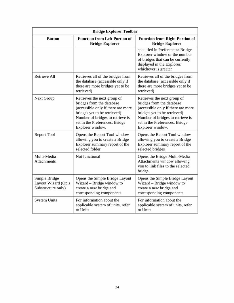
Bridge Explorer Toolbar The following buttons are included on the toolbar of the Bridge Explorer:
22

Bridge Explorer Toolbar
Button Function from Left Portion of Bridge Explorer
Function from Right Portion of Bridge Explorer
New Not functional Not functional
Open Not functional Opens the Bridge Workspace for the selected bridge
Save Not functional Not functional
Properties Opens the Folder Properties window
Not functional
Create New Folder Creates a new folder Creates a new folder
Create New Bridge Creates a new bridge Creates a new bridge
Cut Not functional Not functional
Copy Not functional Copies the selected bridge
Paste Pastes the previously copied bridge into the current folder
Pastes the previously copied bridge into the selected folder
Print Not functional Prints the specified information
Help Opens help topic Opens help topic
Bridge Explorer Opens the Bridge Explorer Opens the Bridge Explorer
Library Explorer Opens the Library Explorer Opens the Library Explorer
Configuration Browser
Opens the Configuration Browser Opens the Configuration Browser
Rate (Virtis only) Opens the Analysis Settings window to initiate a rating event
Opens the Analysis Settings window to initiate a rating event
View Rating Results Not functional Opens the Bridge Rating Results window
Recent Rating Results
Opens the Bridge Rating Results window for the most recent analysis
Opens the Bridge Rating Results window for the most recent analysis
Manage Analysis Events
Not functional Opens the Analysis Events Summary window for the currently selected bridge in the Bridge Explorer
Update Pontis Ratings (Virtis only)
Opens the Pontis Bridge Rating window to initiate a rating event to update Pontis rating fields.
Opens the Pontis Bridge Rating window to initiate a rating event to update Pontis rating fields.
Find Opens the Find Bridge window Opens the Find Bridge window
Refresh Not functional Updates the Bridge Explorer with either the number of bridges
23
Bridge Explorer Toolbar
Button Function from Left Portion of Bridge Explorer
Function from Right Portion of Bridge Explorer
specified in Preferences: Bridge Explorer window or the number of bridges that can be currently displayed in the Explorer, whichever is greater
Retrieve All Retrieves all of the bridges from the database (accessible only if there are more bridges yet to be retrieved)
Retrieves all of the bridges from the database (accessible only if there are more bridges yet to be retrieved)
Next Group Retrieves the next group of bridges from the database (accessible only if there are more bridges yet to be retrieved). Number of bridges to retrieve is set in the Preferences: Bridge Explorer window.
Retrieves the next group of bridges from the database (accessible only if there are more bridges yet to be retrieved). Number of bridges to retrieve is set in the Preferences: Bridge Explorer window.
Report Tool Opens the Report Tool window allowing you to create a Bridge Explorer summary report of the selected folder
Opens the Report Tool window allowing you to create a Bridge Explorer summary report of the selected bridges
Multi-Media Attachments
Not functional Opens the Bridge Multi-Media Attachments window allowing you to link files to the selected bridge
Simple Bridge Layout Wizard (Opis Substructure only)
Opens the Simple Bridge Layout Wizard – Bridge window to create a new bridge and corresponding components
Opens the Simple Bridge Layout Wizard – Bridge window to create a new bridge and corresponding components
System Units For information about the applicable system of units, refer to Units
For information about the applicable system of units, refer to Units
24
BRIDGE WORKSPACE
Bridge Workspace
Purpose of the Bridge Workspace The Bridge Workspace allows you to navigate the various windows to enable you to define a bridge.
Description of the Bridge Workspace The Bridge Workspace contains a tree-structured list of all the components of the bridge (as listed in the Description Module). In the same way as Windows Explorer, you can click the small button (containing a plus sign) to the left of each icon to open that part of the tree to see what is inside.
How to Open an Item from the Bridge Workspace Window To access the data about any item in a Bridge Workspace window, either double click on the item, or single click on it and then select File and Open from the menu. Select File and New from the menu if you would like to add a new component to the bridge.
Items Included in the Bridge Workspace The Bridge Workspace supports several different ways of entering bridge data and provides a convenient means of organizing the data. For more information, see General Bridge Description. For information about the applicable system of units, refer to Units.
For an Opis analysis, as a minimum, you must enter data defining the bridge, the superstructure definition, the member, and the member alternative. For a Virtis rating of an entire bridge (all structures and members), you must enter data defining the bridge, the bridge alternative, the structure, the structure alternative, the superstructure definition, the member, and the member alternative. For a Virtis rating of a single member alternative, you must define the bridge, the superstructure definition, the member, and the member alternative.
Several windows are listed in the tree immediately under the bridge folder (at the top of the tree). These windows allow you to enter information about the materials, appurtenances, impact, and factors. The information entered in these windows applies to the entire bridge (that is, the information applies to all of the bridge alternatives, structures, structure alternatives, superstructure definitions, members, and member alternatives within the bridge). However, you can override some of this information using the windows at a lower level. Override information entered at a lower level applies only to the level at which it is entered.
Items can not be deleted if any windows for the Bridge Workspace are open.
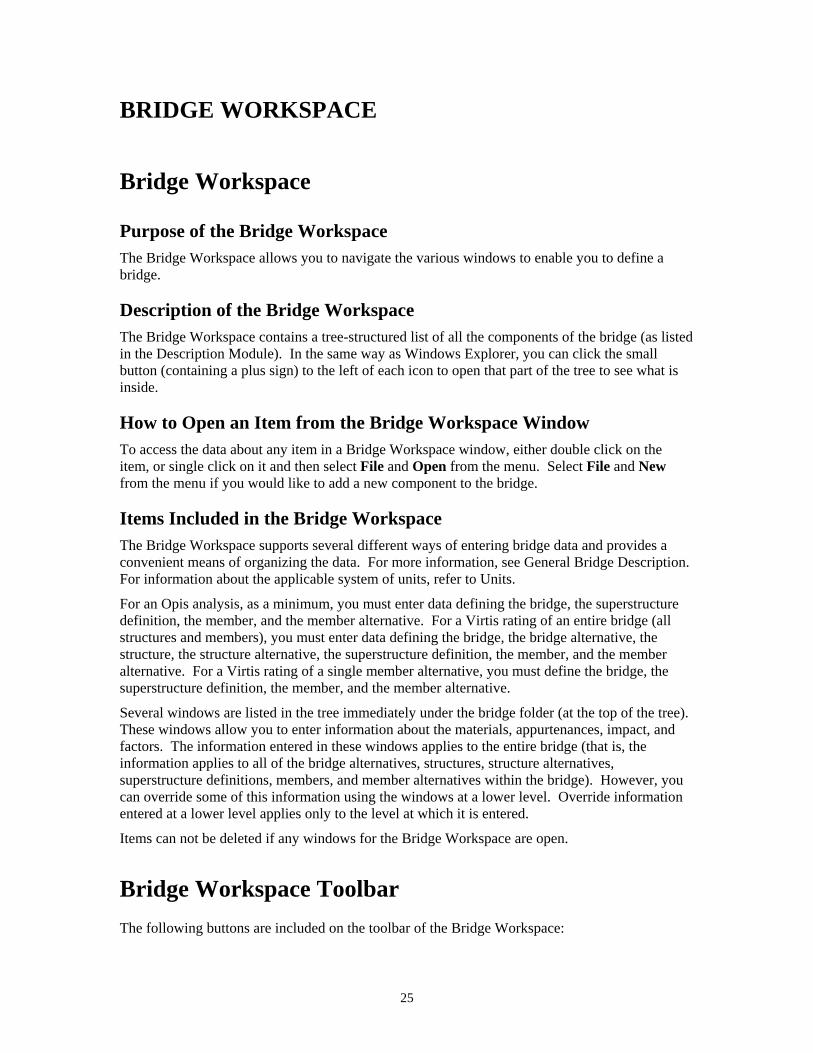
Bridge Workspace Toolbar The following buttons are included on the toolbar of the Bridge Workspace:
25
Bridge Workspace Toolbar
Button Function
New Opens the window (corresponding with the selected folder) in which new data can be entered
Open Opens the window corresponding with the selected folder
Save Saves new data to the database
Properties Not functional
Create New Folder Not functional
Create New Bridge Not functional
Cut Cuts the selected data
Copy Copies the selected data
Paste Pastes the previously cut or copied data into the selected item
Print Prints the specified information
Help Opens help topic
Bridge Explorer Opens the Bridge Explorer
Library Explorer Opens the Library Explorer
Configuration Browser Opens the Configuration Browser
Rate (Virtis only) Not functional
View Rating Results Not functional
Recent Rating Results Not functional
Manage Analysis Events Not functional
Update Pontis Ratings (Virtis only)
Not functional
Find Not functional
Refresh Not functional
Retrieve All Not functional
Next Group Not functional
Report Tool Opens the Report Tool window allowing you to create a summary report of the Bridge Workspace or analysis output
Multi-Media Attachments Opens the Bridge Multi-Media Attachments window allowing you to link files to the bridge
Simple Bridge Layout Wizard (Opis Substructure only)
Not functional
26

Bridge Workspace Toolbar
Button Function
System Units For information about the applicable system of units, refer to Units
View Analysis Settings Opens the Analysis Settings window
Analyze Opens the Progress window and analyzes the selected item (bridge, superstructure definition, member, or member alternative)
Save Analysis Results Saves the results of the analysis to the database
View Analysis Report Opens the Analysis Results window
View Spec Check Opens the Specification Check window (Opis only)
Filter Opens the Spec-Check Viewer Filter Properties window (accessible only from the Specification Check window) (Opis only)
View Latest Analysis Output Opens a window allowing you to select analysis output files for viewing
View Analysis Charts Opens the Results Graph window
View Chart Properties Opens a window allowing you to edit properties of the chart (accessible only from the Results Graph window)
Wizard Opens the Superstructure Definition Wizard – Superstructure Definition window (if SUPERSTRUCTURE DEFINITION is selected), opens the Stringer Unit Layout Wizard (if STRINGER UNIT LAYOUT is selected), opens the Floorbeam Member Alternative Wizard (if FLOORBEAM MEMBERS is selected)
PS Design Tool Opens the Prestress Design Tool window (accessible only if a prestressed concrete member alternative is selected)
View BWS Report Opens a summary report of definitions corresponding with the selected item (must be a structural part) in the tree and its sub-items within the tree; for additional information, go to Bridge Workspace Report
View Schematic Opens a schematic view of the selected item (accessible only for member cross section view, member profile view, structure typical section view, and framing plan view); for additional information, go to Schematics
Validate Validates the selected item
27

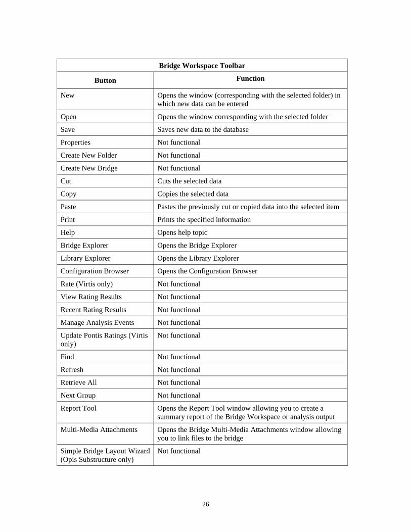
Bridge Workspace Windows The following is a list of the major windows that are accessible from the Bridge Workspace:
Analysis Event Properties Review
Analysis Events
Analysis Results
Analysis Settings
Beam Details - Prestressed Concrete Members
Beam Details - Timber Members
Bearing Stiffener Definition: Angle
Bearing Stiffener Definition: Plate
Bearing Stiffener Location
Bracing Ranges
Bridge Alternative
Bridge Appurtenances - Generic
Bridge Appurtenances - Median
Bridge Appurtenances - Parapet
Bridge Appurtenances - Railing
Bridge Description
Bridge Materials - Concrete
Bridge Materials - Prestress Strand
Bridge Materials - Reinforcing Steel
Bridge Materials - Structural Steel
Bridge Materials - Timber - Sawn
Bridge Rating Results
Compute Lane Positions
Connect
Copy Diaphragm Bay
Cross Section Ranges - Reinforced Concrete Members
Cross Section Ranges - Steel Members
Cross Sections - Reinforced Concrete Members
Cross Sections - Steel Members
Deck
Deck Details - Generic Deck
28
Deck Details - Timber Deck
Deck Profile
Default Materials
Deterioration Profile
Factors - LFD
Factors - LRFD
Find Bridge, Folder Properties, or New Folder Properties
Floor System Geometry
Floorbeam Definition
Floorbeam Intermediate Supports
Floorbeam Member
Floorbeam Member Alternative
Floorbeam Member Alternative Wizard
Floorbeam Member Locations
Floorbeam Stringer Reactions
Girder Profile
Haunch Profile - Prestressed Concrete Members
Haunch Profile - Steel Members
Hinge
Impact
Input Folder Properties
Interior Diaphragms
Knee Braces
Lateral Support
Live Load Distribution
Load Case Description
Loads - Member
Member
Member Alternative Description
Member Rating Results
New Bearing Stiffener Definition
New Floorbeam Definition
New Member Alternative
New Stringer Definition
New Superstructure Definition
29

New Transverse Stiffener Definition
Point of Interest
Prestress Beam Shapes - I Beams
Prestress Beam Shapes - Box Beams
Prestress Beam Shapes - Tee Beams
Prestress Beam Shapes - U Beams
Prestress Design Tool
Prestress Properties
PS Shear Reinforcement Ranges
RC Shear Reinforcement Ranges
Results Graph
Report Tool
Select Data Source
Shear Connector Definition
Shear Reinforcement Definition - Vertical
Shear Reinforcement Definition - Horizontal
Shrinkage/Time
Spec Check Detail
Specification Check
Spec-Check Viewer Filter Properties
Splice
Steel Angle
Steel Channel
Steel I Shape
Steel Structural
Stiffener Ranges
Strand Layout
Stress Limits
Stringer Definition
Stringer Member
Stringer Member Alternative
Stringer Unit Layout
Stringer Unit Layout Wizard
Structure
Structure Alternative
30

Structure Definition Connectors - Bolt Definition
Structure Definition Connectors - Nail Definition
Structure Definition Connectors - Weld Definition
Structure Framing Plan Details
Structure Rating Results
Structure Typical Section
Superstructure Definition
Superstructure Definition Wizard - Beam Data
Superstructure Definition Wizard - Deck
Superstructure Definition Wizard - Deck Template
Superstructure Definition Wizard - Loads
Superstructure Definition Wizard - Plate Girder
Superstructure Definition Wizard - Prestressing Strand
Superstructure Definition Wizard - Rolled Shape
Superstructure Definition Wizard - Superstructure Definition
Superstructure Loads
Support Constraints - Beam
Timber Beam - Rectangular
Transverse Stiffener Definition: Angle
Transverse Stiffener Definition: Plate
Truss
Vehicle Properties
31

LIBRARY EXPLORER
Library Explorer
Purpose of the Library Explorer The Library Explorer allows you to navigate the library module and access desired information from the various library windows.
Items Included in the Library The various items included in the library are listed in the Library Module.
Purpose of the Library The purpose of the library is to save commonly used items in the program and to eliminate the need for you to define the same items repeatedly throughout the program. You need to define them only once in the appropriate library window, and they can then be used repeatedly in other windows.
Left Portion of the Library Explorer The left portion of the Library Explorer contains a tree, which includes each of the library items (as listed in the Library Module). For each tree item, the tree includes a button, a folder, and a name. If you click on the name of a tree item, existing library information will appear in the right portion of the explorer.
Right Portion of the Library Explorer The right portion of the Library Explorer presents a complete list of the existing names and descriptions corresponding with the item selected in the tree. The list represents the current contents of that particular library.
Types of Libraries Items can be stored in the library as either standard or agency-defined. Standard library items are those defined by AASHTO, and agency-defined library items are those defined for your agency. For standard items, you can view them but you can not change them. For agency-defined items, you can view and change them. The Library Explorer allows you to select either standard or agency-defined library items. Standard and agency-defined library items can be copied and pasted within the library.
How to Open a Library Window To access existing library information, click on the name of the tree item in the left portion of the explorer. This will bring up a complete list of the existing names and descriptions in the right portion of the explorer. Select the row corresponding with the desired library information. Then either double click on it in the right portion of the explorer, or single click on it and then select File and Open from the menu.
32
To create new library information, click Agency under the appropriate tree item in the left portion of the explorer. Then select File and New from the menu, and enter the new library information. You can not create new standard library items.
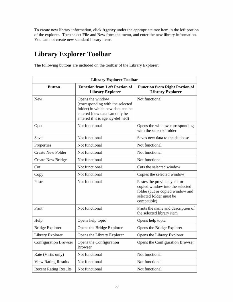
Library Explorer Toolbar The following buttons are included on the toolbar of the Library Explorer:
Library Explorer Toolbar
Button Function from Left Portion of Library Explorer
Function from Right Portion of Library Explorer
New Opens the window (corresponding with the selected folder) in which new data can be entered (new data can only be entered if it is agency-defined)
Not functional
Open Not functional Opens the window corresponding with the selected folder
Save Not functional Saves new data to the database
Properties Not functional Not functional
Create New Folder Not functional Not functional
Create New Bridge Not functional Not functional
Cut Not functional Cuts the selected window
Copy Not functional Copies the selected window
Paste Not functional Pastes the previously cut or copied window into the selected folder (cut or copied window and selected folder must be compatible)
Print Not functional Prints the name and description of the selected library item
Help Opens help topic Opens help topic
Bridge Explorer Opens the Bridge Explorer Opens the Bridge Explorer
Library Explorer Opens the Library Explorer Opens the Library Explorer
Configuration Browser Opens the Configuration Browser
Opens the Configuration Browser
Rate (Virtis only) Not functional Not functional
View Rating Results Not functional Not functional
Recent Rating Results Not functional Not functional
33
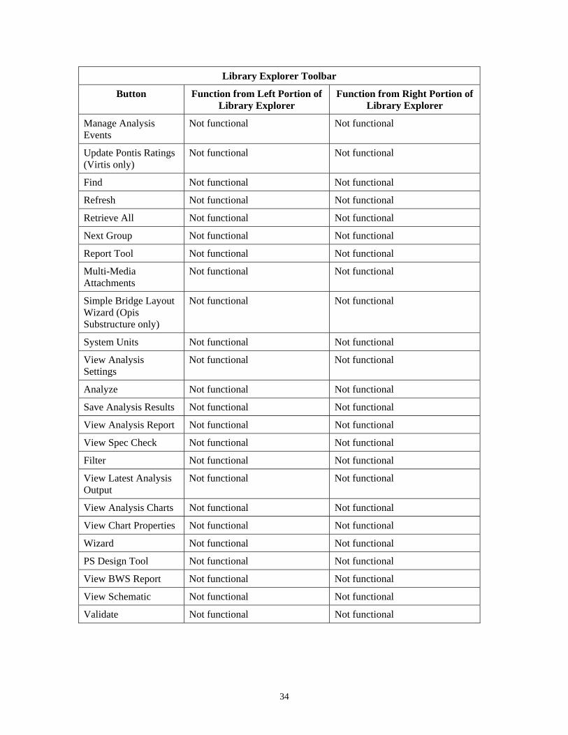
Library Explorer Toolbar
Button Function from Left Portion of Library Explorer
Function from Right Portion of Library Explorer
Manage Analysis Events
Not functional Not functional
Update Pontis Ratings (Virtis only)
Not functional Not functional
Find Not functional Not functional
Refresh Not functional Not functional
Retrieve All Not functional Not functional
Next Group Not functional Not functional
Report Tool Not functional Not functional
Multi-Media Attachments
Not functional Not functional
Simple Bridge Layout Wizard (Opis Substructure only)
Not functional Not functional
System Units Not functional Not functional
View Analysis Settings
Not functional Not functional
Analyze Not functional Not functional
Save Analysis Results Not functional Not functional
View Analysis Report Not functional Not functional
View Spec Check Not functional Not functional
Filter Not functional Not functional
View Latest Analysis Output
Not functional Not functional
View Analysis Charts Not functional Not functional
View Chart Properties Not functional Not functional
Wizard Not functional Not functional
PS Design Tool Not functional Not functional
View BWS Report Not functional Not functional
View Schematic Not functional Not functional
Validate Not functional Not functional
34

Library Explorer Windows The following is a list of the major windows that are accessible from the Library Explorer:
Library - Appurtenances - Generic
Library - Appurtenances - Median
Library - Appurtenances - Parapet
Library - Appurtenances - Railing
Library - Connections - Bolt
Library - Connections - Nail
Library - Factors - LFD
Library - Factors - LRFD
Library - LRFD Substructure Design Settings
Library - Materials - Concrete
Library - Materials - Prestressing Strand
Library - Materials - Reinforcing Steel
Library - Materials - Structural Steel
Library - Materials - Timber - Sawn
Library - Materials - Wearing Surface
Library - Materials - Weld
Library - PS Shape
Library - Steel Shapes - Angle
Library - Steel Shapes - Channel
Library - Steel Shapes - Rolled Beam
Library - Steel Shapes - Tee
Library - Timber Shapes - Rectangular
Library - Vehicle
Library Data
35

CONFIGURATION BROWSER
Configuration Browser
Purpose of the Configuration Browser The Configuration Browser provides access to the configuration features of Virtis/Opis.
Description of the Configuration Browser The Configuration Browser contains a tree, which includes each of the applicable windows (as listed in the Configuration Module). For each tree item, the tree includes a button, a folder, and a name. If you click on the button of a tree item, its sub-items in the tree will appear beneath that tree item.
How to Open a Configuration Browser Window To access a Configuration Browser window, either double click on the name of the tree item, or single click on it and then select File and Open from the menu. You can either edit existing data within a window or you can enter new data in a blank window.
Users Several different folders are available in which to define users. These folders include the following: All users, Administrators, Design Engineers, Managers, Rating Engineers, and Routing Engineers. Users can be placed in more than one folder. Additional folders can be added, and existing folders can be deleted.
How to Add a New User Adding a user only adds the user to the list of valid users of Virtis and Opis. It does not add the user to the database such that he or she can connect to the database. That must be done using the Oracle or Sybase database utilities for adding users.
Configuration Browser Toolbar
The following buttons are included on the toolbar of the Configuration Browser:
Configuration Browser Toolbar
Button Function
New Opens the window (corresponding with the selected folder) in which new data can be entered
Open Opens the window corresponding with the selected folder
Save Saves new data to the database
36
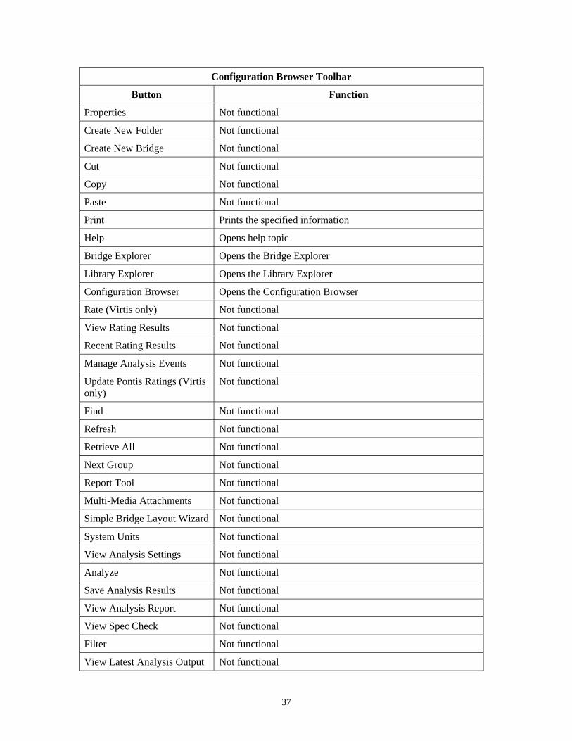
Configuration Browser Toolbar
Button Function
Properties Not functional
Create New Folder Not functional
Create New Bridge Not functional
Cut Not functional
Copy Not functional
Paste Not functional
Print Prints the specified information
Help Opens help topic
Bridge Explorer Opens the Bridge Explorer
Library Explorer Opens the Library Explorer
Configuration Browser Opens the Configuration Browser
Rate (Virtis only) Not functional
View Rating Results Not functional
Recent Rating Results Not functional
Manage Analysis Events Not functional
Update Pontis Ratings (Virtis only)
Not functional
Find Not functional
Refresh Not functional
Retrieve All Not functional
Next Group Not functional
Report Tool Not functional
Multi-Media Attachments Not functional
Simple Bridge Layout Wizard Not functional
System Units Not functional
View Analysis Settings Not functional
Analyze Not functional
Save Analysis Results Not functional
View Analysis Report Not functional
View Spec Check Not functional
Filter Not functional
View Latest Analysis Output Not functional
37

Configuration Browser Toolbar
Button Function
View Analysis Charts Not functional
View Chart Properties Not functional
Superstructure Definition Wizard
Not functional
PS Design Tool Not functional
View BWS Report Not functional
View Schematic Not functional
Validate Not functional
Configuration Browser Windows The following is a list of the major windows that are accessible from the Configuration Browser:
Access Privileges
Parameters
System Defaults
User
38

EXAMPLE BRIDGES
To help you learn how to enter bridges into Virtis/Opis, a set of eighteen example bridges have been included with the program. Three example bridges are steel bridges, seven of the example bridges are prestressed concrete, one example bridge is reinforced concrete and one example bridge is timber. The remaining six example bridges are steel bridges containing either floor system or floor line superstructure definitions.
The three steel example bridges (called Training Bridges) are taken from American Iron and Steel Institute’s (AISI) and National Steel Bridge Alliance’s (NSBA) Four LRFD Design Examples of Steel Highway Bridges (with Training Bridge Number 2 being changed from a plate girder bridge to a built-up section bridge).
A table describing each of the three steel example bridges is presented on the following page. These bridges can be accessed from the Bridge Explorer in the All Bridges folder or the Sample Bridges folder.
The seven prestressed concrete example bridges are taken from Precast/Prestressed Concrete Institute’s (PCI) Bridge Design Manual. The one reinforced concrete example bridge is a sample bridge created for Virtis/Opis. A table describing each of these eight concrete example bridges is presented on page 41.
The timber example bridge is a single span sawn lumber beam bridge with a nail-laminated transverse deck. This bridge is taken from Chapter 7 of the USDA Forest Service’s Timber Bridges: Design, Construction, Inspection, and Maintenance manual.
A table describing each of the six floor system and floor line example bridges is presented on page 42.
To enter a new bridge, you can refer to the Getting Started section of this manual (page 4). You can also look at the table on the following page and identify the example bridge that most closely resembles the bridge that you are entering. You can begin with that bridge, copy and rename it, and modify it into your bridge.
39

AASHTO Virtis/Opis ProgramSteel Girder Example Bridges
Training Bridge Number1 2 3
General DescriptionUnits US US USBeam material SteelBasic beam type Plate girder Built-up Plate girderSimple or continuous Simple Continuous ContinuousSkewed Yes No NoComposite Yes Yes YesBearing stiffeners Yes Yes YesSuperstructure definition method Girder system Girder line Girder lineSection input method Schedule Cross section ScheduleAnalysis/design method LRFD LRFD LRFD
Rolled Beam DataCover plates - - -
Plate Girder DataHybrid No - NoTransverse stiffeners Yes - YesLongitudinal stiffeners No - NoWeb depth variation None - None
Built-up Girder DataHybrid - No -Web depth variation - None -
LoadingLive load HL-93 HL-93 HL-93Pedestrian load No No NoConcentrated dead load No No No
40

RC Training Bridge1 2 3 4 5 6 1
General DescriptionUnits US US US US US US US USBeam material Reinforced ConcreteBasic beam type Box Beam Box Beam I Beam I Beam I Beam I Beam I Beam T BeamSimple or continuous Simple Simple Simple Simple Continuous Continuous Simple SimpleSkewed No No No No No No No NoComposite No No Yes Yes Yes Yes Yes NoSuperstructure definition method Girder line Girder line Girder line Girder line Girder system Girder system Girder system Girder systemSection input method Schedule Schedule Schedule Schedule Schedule Schedule Schedule Cross section, ScheduleAnalysis/design method LFD LRFD LFD LRFD LFD LRFD LFD LFD
Strand Layout Straight/debonded Straight/debonded Harped Harped Harped Harped Harped -Loading
Live load HS25 HL-93 HS20 HL-93 HS20 HL-93 HS20 HS20Pedestrian load No No No No No No No NoConcentrated dead load No No No No No No No No
Prestressed Concrete
PCI Training Bridge Example7
AASHTO Virtis/Opis ProgramConcrete Girder Example Bridges
41

FSys GFSTraining Bridge 1
FSys FSTraining Bridge 2
FSys GFTraining Bridge 3
FLine GFSTraining Bridge 1
FLine FSTraining Bridge 2
FLine GFTraining Bridge 3
General DescriptionUnits US US US US US USBeam material Steel Steel Steel Steel Steel SteelSuperstructure definition method Floor system Floor system Floor system Floor line Floor line Floor lineMembers Girders, Floorbeams,
StringersFloorbeams,
StringersGirders, Floorbeams Girders, Floorbeams,
StringersFloorbeams,
StringersGirders, Floorbeams
Basic beam type Plate, rolled beam Plate, rolled beam Plate, rolled beam Plate, rolled beam Plate, rolled beam Plate, rolled beamSkewed No No No No No NoComposite Yes Yes Yes Yes Yes YesSection input method Schedule Schedule Schedule Schedule Schedule ScheduleAnalysis/design method LFD LFD LFD LFD LFD LFD
LoadingLive load HS20 HS20 HS20 HS20 HS20 HS20Pedestrian load No No No No No NoConcentrated dead load No No No Yes Yes Yes
AASHTO Virtis/Opis ProgramFloor System and Floor Line Example Bridges
42
MISCELLANEOUS
Specification Check This window is available in Opis only, and it allows you to review the LRFD specification checks based on the LRFD analysis results.
In the left portion of the window, each of the inputted stages are presented, along with each of the inputted analysis points. Select the stage and the analysis point for which you want to see the specification check results. Specification check table In the right portion of the window, the specification check results are presented for the selected stage and analysis point.
Specification Reference Displays the specification, including both the AASHTO reference and a brief description. Limit State Displays the limit state for which the specification was checked. Flex. Sense Displays the flexural sense for which the specification was checked as either positive flexure, negative flexure, or not applicable. Pass/Fail Displays the results of the specification check for the displayed limit state and flexural sense as either passed, failed, not applicable, general computation, not checked, or not satisfied.
To review more detailed specification check information, select the desired specification reference and then press “Enter” on your keypad. This will open the Spec Check Detail window.
Results Graph This window allows you to view graphs of the analysis results. You can create a variety of different graphs, allowing you to see a quick snapshot view of the results.
In the lower left-hand corner of the window, several different types of results are listed. These include moment, shear, and axial, as well as dead load, live load, capacity, and critical. Check the box corresponding with the desired graph.
In the lower right-hand corner of the window, the analysis results are presented in tabular form. The analysis results correspond with the box that you checked to indicate the desired graph.
In the top portion of the window, the analysis results are plotted in graph form. A different
43

symbol is used for each table column heading (for example, each different type of dead load or live load). Data is presented in the graph for each location presented in the table. A tool bar button is available to allow you to modify the appearance of the graph.
A Rating Factor is defined as the ratio of the live load reserve capacity divided by the factored live load effect. The live load reserve capacity is equal to the section capacity minus all dead load effects.
LLDLCapacity −
= Factor Rating
If the rating factor is greater than 1.0, then the reserve capacity is greater than the applied force effects and the design is acceptable. If the rating factor is less than 1.0, then the reserve capacity is less than the applied force effects and the design is not acceptable. The closer the rating factor is to 1.0, the closer the reserve capacity is to equaling the applied force effects. The rating factor is presented only for Opis; it is not presented for Virtis.
The following symbols are used in this window:
A Axle DL Dead load DREnv Rating factor envelope F Fatigue L Lane LL Live load and impact M Moment MDR Moment rating factor Min Minimum S1 Stage 1 (S2 represents Stage 2, etc.) T Tandem or truck train V Shear VDR Shear rating factor (+) Positive action (-) Negative action
Bridge Workspace Report The Bridge Workspace Report window presents a summary of the input describing the bridge. You can access the Bridge Workspace Report window by clicking the View BWS Report button on the toolbar.
Included in the Bridge Workspace Report is such information as a general bridge description, materials, appurtenances, impact, factors, loads, plate dimensions, and points of interest. Information is presented for all levels within Virtis/Opis, including bridge alternative, superstructure definition, and member.
44
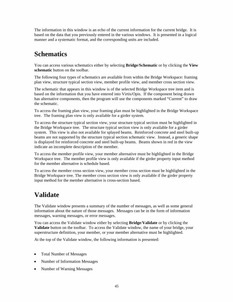
The information in this window is an echo of the current information for the current bridge. It is based on the data that you previously entered in the various windows. It is presented in a logical manner and a systematic format, and the corresponding units are included.
Schematics You can access various schematics either by selecting Bridge/Schematic or by clicking the View schematic button on the toolbar.
The following four types of schematics are available from within the Bridge Workspace: framing plan view, structure typical section view, member profile view, and member cross section view.
The schematic that appears in this window is of the selected Bridge Workspace tree item and is based on the information that you have entered into Virtis/Opis. If the component being drawn has alternative components, then the program will use the components marked “Current” to draw the schematic.
To access the framing plan view, your framing plan must be highlighted in the Bridge Workspace tree. The framing plan view is only available for a girder system.
To access the structure typical section view, your structure typical section must be highlighted in the Bridge Workspace tree. The structure typical section view is only available for a girder system. This view is also not available for splayed beams. Reinforced concrete and steel built-up beams are not supported by the structure typical section schematic view. Instead, a generic shape is displayed for reinforced concrete and steel built-up beams. Beams shown in red in the view indicate an incomplete description of the member.
To access the member profile view, your member alternative must be highlighted in the Bridge Workspace tree. The member profile view is only available if the girder property input method for the member alternative is schedule based.
To access the member cross section view, your member cross section must be highlighted in the Bridge Workspace tree. The member cross section view is only available if the girder property input method for the member alternative is cross-section based.
Validate The Validate window presents a summary of the number of messages, as well as some general information about the nature of those messages. Messages can be in the form of information messages, warning messages, or error messages.
You can access the Validate window either by selecting Bridge/Validate or by clicking the Validate button on the toolbar. To access the Validate window, the name of your bridge, your superstructure definition, your member, or your member alternative must be highlighted.
At the top of the Validate window, the following information is presented:
• Total Number of Messages
• Number of Information Messages
• Number of Warning Messages
45

• Number of Error Messages
Immediately below the above four numbers, general information is presented about the nature of any information messages, warning messages, or error messages. Based on the information presented in the Validate window, you can revise your input and run the problem again.
Dead Loads The following table summarizes which dead load components are computed automatically by the engine (BRASS) and which must be entered by the user.
Dead Loads
Dead Load Component
Structure Type
Girder Property Input Method
Beam Self-weight
Stiffener Self-weight Slab Haunch
Appur-tenances
Wearing Surface
Diaphragms
Girder line Cross-section based E U 3 E U 1 U 1 U 1 U 4
Girder system Cross-section based E U 3 E U 1 E U 2 U 4
Girder line Schedule based E U 3 E E U 1 U 1 U 4
Girder system Schedule based E U 3 E E E U 2 U 4
Legend: E – Computed automatically by the engine (BRASS)
U – Must be entered by the user
1 – Use the Loads - Member window
2 – Use the Structure Typical Section window
3 – Use the Member Alternative Description or the Loads - Member window
4 – Use the Structure Framing Plan Details window or the Bracing Ranges window
Factors You can enter factors in several different ways, as follows:
Library factors in the System Defaults window
These are the default set of factors that will be used for analysis. However, these can be overridden by specifying a different set of factors on the Superstructure Definition: Analysis tab.
Factor override on the Girder System or Girder Line or Floor System or Floor Line or Truss System Superstructure Definition: Analysis tab
These factor overrides allow you to use a set of factors that have been entered for this
46
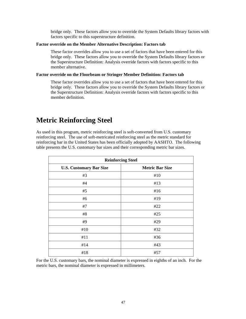
bridge only. These factors allow you to override the System Defaults library factors with factors specific to this superstructure definition.
Factor override on the Member Alternative Description: Factors tab
These factor overrides allow you to use a set of factors that have been entered for this bridge only. These factors allow you to override the System Defaults library factors or the Superstructure Definition: Analysis override factors with factors specific to this member alternative.
Factor override on the Floorbeam or Stringer Member Definition: Factors tab
These factor overrides allow you to use a set of factors that have been entered for this bridge only. These factors allow you to override the System Defaults library factors or the Superstructure Definition: Analysis override factors with factors specific to this member definition.
Metric Reinforcing Steel As used in this program, metric reinforcing steel is soft-converted from U.S. customary reinforcing steel. The use of soft-metricated reinforcing steel as the metric standard for reinforcing bar in the United States has been officially adopted by AASHTO. The following table presents the U.S. customary bar sizes and their corresponding metric bar sizes.
Reinforcing Steel
U.S. Customary Bar Size Metric Bar Size
#3 #10
#4 #13
#5 #16
#6 #19
#7 #22
#8 #25
#9 #29
#10 #32
#11 #36
#14 #43
#18 #57
For the U.S. customary bars, the nominal diameter is expressed in eighths of an inch. For the metric bars, the nominal diameter is expressed in millimeters.
47

Batch Analysis A batch analysis is an analysis of multiple bridge components during the same process. For example, the line girder analysis of a superstructure definition is a batch analysis of the members belonging to the superstructure definition. Another example of a batch analysis is the analysis of multiple bridges by rating from the Bridge Explorer.
Rating from the Bridge Explorer One or more bridges can be rated in a batch analysis from the Bridge Explorer. All of the bridges contained in a folder can also be rated in a batch analysis from the Bridge Explorer.
From the Bridge Explorer, select one or more bridges (or a folder) and click the Rate button on the toolbar or select Bridge and Rate from the menu. The Analysis Settings window will open. Select the vehicles to use in the analysis from the Analysis Settings: Vehicles tab. Select the desired output reports from the Analysis Settings: Output tab and click the OK button. Virtis will rate all appropriate member alternatives for each selected bridge. To do this, Virtis searches for bridge components that are marked as "Existing". Virtis uses the bridge alternative marked as existing and rates each structure in that bridge alternative. For each structure, Virtis looks at the structure alternative marked as existing and for each of the structure alternatives Virtis looks at the superstructure definition assigned to it. For the superstructure definition, Virtis continues to look at member alternatives within the superstructure definition that are marked as existing. If the Bridge Workspace tree does not contain bridge alternatives, structures, structure alternatives, superstructure definitions assigned to structure alternatives and member alternatives marked as existing there is nothing for the Bridge Explorer to rate.
After the analysis is complete, the Bridge Rating Results window will be displayed for viewing the rating results.
Adding Users to the Virtis/Opis Database These instructions assume a basic understanding of your particular database system (Sybase Adaptive Server Anywhere or Oracle 9i) and its tools.
To add users to the Virtis/Opis database, complete the following two steps: 1. Add the user to Virtis/Opis system.
a. Start the Virtis, Opis, or VirtisOpis application.
b. Log into Virtis/Opis using a username with read, write, and create turned on for the access rights privilege.
c. Open Configuration Browser and select the user group (such as Design Engineers) that you would like the user to be a member of.
d. Select File/New from the menu.
e. Enter user information and click the Save button.
48

2. Add the user to the database, and set user table permissions. See the instructions below
for adding a user to a Sybase Adaptive Server Anywhere 8.0, Sybase Adaptive Server Anywhere 9.0, Oracle 9i or MSDE/SQL Server 2000 database.
Adding Users to Sybase Adaptive Server Anywhere 8.0 and 9.0 1. Start the Sybase Central application.
2. Connect to the Virtis/Opis database.
3. Expand the tree to find the Users & Groups tree item, and select it.
4. You will see a list of users and groups and also an icon (Add User) in the window on the right. Double-click on Add User.
5. Enter the user name as shown below.
6. Click on the Next > button.
7. Check “Allow this user to connect” and enter the password.
49
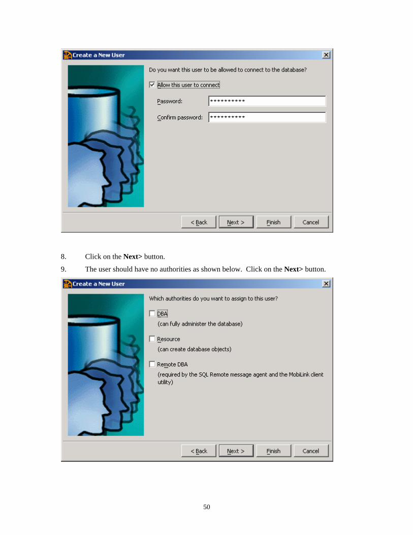
8. Click on the Next> button.
9. The user should have no authorities as shown below. Click on the Next> button.
50

10. A comment can be added. Click on the Finish button.
11. Add the new user to the VirtisUsersGroup by copying and pasting the new user from the Users & Groups folder to the VirtisUsersGroup tree item. The new user should now be listed in both the Users & Groups folder and the VirtisUsersGroup group. This step gives the user the appropriate table permissions.
Adding Users to Oracle 9i 1. Start the Oracle Security Manager.
2. Select User/Create from the menu.
3. Enter the required information.
4. Set the Read-Only and Read/Write Roles for the new user. The database administrator should have already created these roles. Please refer to the BRIDGEWare Startup Guide if you do not find these roles on the Oracle database.
a. Select the Roles/Privileges tab.
b. Select Virtis/Opis database Read-Only and Read/Write Roles from the available roles list. Select the arrow down button to add them to the granted roles list.
c. Check the Admin Option and Default indicators for the Read-Only role in the granted roles list.
d. Uncheck the Admin Option and Default indicators for the Read/Write role in the granted roles list.
51

5. Click the Create button.
6. Create public synonyms for all of the Virtis/Opis database tables (if you haven’t already created them). An SQL script file is present on the installation CD-ROM to create public synonyms. You can use this script to create public synonyms for all of the tables.
Adding Users to MSDE/SQL Server 2000 1. In a command prompt window, start the OSQL program and log in as the system
administrator ‘sa’.
C:\osql –U sa
2. Add a new login for the new user. EXEC sp_addlogin @loginame = 'username',
@passwd = 'username', @defdb = 'database'
GO 3. Switch to the database to which you want to add the user.
USE database GO
4. Grant database access to the new user EXEC sp_grantdbaccess N'username', N'username' GO
5. Grant virtis database role to the new user EXEC sp_addrolemember N'VIRTIS_USER_READ_ONLY_ROLE', N'username' GO
6. Exit OSQL EXIT
An example of adding user ‘VirtisUser’ to the database ‘Virtis54s’ is shown below: C:\>osql –U sa Password: 1>EXEC sp_addlogin @loginame = 'VirtisUser', 2> @passwd = 'VirtisUser', 3> @defdb = 'Virtis54s' 4> GO New login created. 1> USE Virtis54s 2> GO 1> EXEC sp_grantdbaccess N'VirtisUser', N'VirtisUser' 2> GO Granted database access to 'VirtisUser' 1> EXEC sp_addrolemember N'VIRTIS_USER_READ_ONLY_ROLE', N'VirtisUser' 2> GO 'VirtisUser' added to role 'VIRTIS_USER_READ_ONLY_ROLE' 1> EXIT C:\>
52
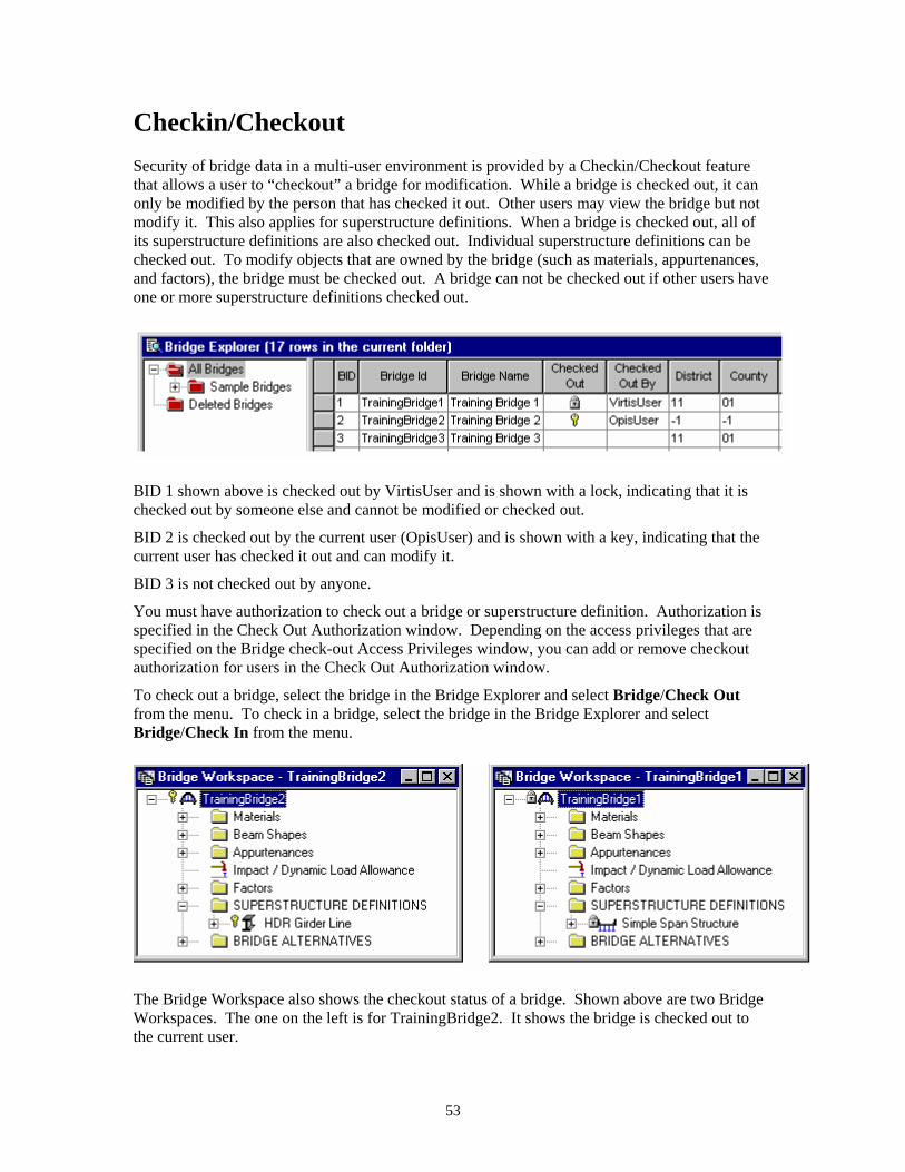
Checkin/Checkout Security of bridge data in a multi-user environment is provided by a Checkin/Checkout feature that allows a user to “checkout” a bridge for modification. While a bridge is checked out, it can only be modified by the person that has checked it out. Other users may view the bridge but not modify it. This also applies for superstructure definitions. When a bridge is checked out, all of its superstructure definitions are also checked out. Individual superstructure definitions can be checked out. To modify objects that are owned by the bridge (such as materials, appurtenances, and factors), the bridge must be checked out. A bridge can not be checked out if other users have one or more superstructure definitions checked out.
BID 1 shown above is checked out by VirtisUser and is shown with a lock, indicating that it is checked out by someone else and cannot be modified or checked out.
BID 2 is checked out by the current user (OpisUser) and is shown with a key, indicating that the current user has checked it out and can modify it.
BID 3 is not checked out by anyone.
You must have authorization to check out a bridge or superstructure definition. Authorization is specified in the Check Out Authorization window. Depending on the access privileges that are specified on the Bridge check-out Access Privileges window, you can add or remove checkout authorization for users in the Check Out Authorization window.
To check out a bridge, select the bridge in the Bridge Explorer and select Bridge/Check Out from the menu. To check in a bridge, select the bridge in the Bridge Explorer and select Bridge/Check In from the menu.
The Bridge Workspace also shows the checkout status of a bridge. Shown above are two Bridge Workspaces. The one on the left is for TrainingBridge2. It shows the bridge is checked out to the current user.
53
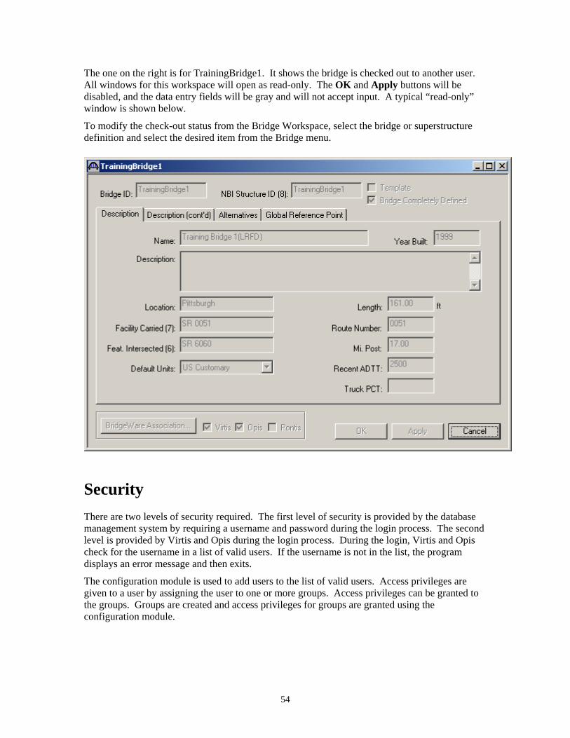
The one on the right is for TrainingBridge1. It shows the bridge is checked out to another user. All windows for this workspace will open as read-only. The OK and Apply buttons will be disabled, and the data entry fields will be gray and will not accept input. A typical “read-only” window is shown below.
To modify the check-out status from the Bridge Workspace, select the bridge or superstructure definition and select the desired item from the Bridge menu.
Security There are two levels of security required. The first level of security is provided by the database management system by requiring a username and password during the login process. The second level is provided by Virtis and Opis during the login process. During the login, Virtis and Opis check for the username in a list of valid users. If the username is not in the list, the program displays an error message and then exits.
The configuration module is used to add users to the list of valid users. Access privileges are given to a user by assigning the user to one or more groups. Access privileges can be granted to the groups. Groups are created and access privileges for groups are granted using the configuration module.
54