Virginia Weatherization Field Guide - Virginia DHCD
252
Virginia Weatherization Field Guide Best Practices for Improving the Comfort, Safety, and Efficiency of Existing Homes
Transcript of Virginia Weatherization Field Guide - Virginia DHCD

VirginiaWeatherization
Field Guide
Best Practices for Improving the Comfort, Safety, and Efficiency of Existing Homes


VirginiaWeatherization
Field GuideProduced for
U.S. Department of EnergyWeatherization Assistance
Programand
Virginia Department of Housing and Community Development
Written by John Krigger and Chris DorsiThis edition compiled by Darrel Tenter
Copyright 2005 • Saturn Resource Management, Inc.
Printed in the U.S.A.
Virginia Field Guide Project Coordinators: Robbie Campbell and Tom Stephens
Terry AtwellBill Beachy
John BodtmannDoug Sheets
Melissa ComminsDavid CornettAnthony Cox
Bill CraigLil Weston
Technical contributors and reviewers
The Virginia Department of Housing and Community Development (DHCD) is pleased to have a network of
dedicated and experienced personnel who volunteered their time and technical expertise to refine this field guide. DHCD appreciates their contributions toward
making this project a success.


Virginia Weatherization Field Guide 5
Foreword
Greetings from the Virginia Department of Housing and Com-munity Development (DHCD), administrator of the Depart-ment of Energy Weatherization Assistance Program.
The intent of this Field Guide is to document and communicate the best practices and procedures of our state’s weatherization program. It contains important information on housing weatherization specific to Virginia’s climate that has been developed and improved since the 1970s.
The Virginia Weatherization Assistance Program received a comprehensive evaluation in 1989 that resulted in increased cost-effectiveness and demonstrated the benefits of home weatherization in mild climates. This evaluation established the basis for innovative conservation procedures that are still in use, such as advanced diagnostic techniques and effective air sealing guidelines.
In 2003, DHCD obtained a grant to educate clients on energy use and conservation, and to measure the effectiveness of cur-rent weatherization strategies. The three-year study will identify the most cost-effective conservation techniques used in the state program. The weatherization program design undergoes peri-odic improvements to attain its goals of reducing energy usage and expenditures, enhancing health and safety, providing edu-cation, and assisting the most vulnerable populations of Vir-ginia’s communities.
On behalf of the authors, the state staff, and the local weather-ization committee volunteers who edited this edition, we thank you for using this Field Guide. Please address any comments regarding the format or content of the Field Guide to DHCD staff.


Virginia Weatherization Field Guide 7
C
ONTENTS
Chapter 1: Health and Safety
When not to weatherize a dwelling . . . . . . . . . . . . . . . . . . . . . 14
Client health and safety. . . . . . . . . . . . . . . . . . . . . . . . . . . . . . . . . 16Carbon monoxide . . . . . . . . . . . . . . . . . . . . . . . . . . . . . . . . . . . . 16CO and smoke alarms . . . . . . . . . . . . . . . . . . . . . . . . . . . . . . . . 18Moisture problems . . . . . . . . . . . . . . . . . . . . . . . . . . . . . . . . . . . 19Lead-safe weatherization . . . . . . . . . . . . . . . . . . . . . . . . . . . . . 24Electrical safety. . . . . . . . . . . . . . . . . . . . . . . . . . . . . . . . . . . . . . . 26
Worker health and safety . . . . . . . . . . . . . . . . . . . . . . . . . . . . . . . 27Commitment to safety. . . . . . . . . . . . . . . . . . . . . . . . . . . . . . . . 27First aid . . . . . . . . . . . . . . . . . . . . . . . . . . . . . . . . . . . . . . . . . . . . . . 28Falls. . . . . . . . . . . . . . . . . . . . . . . . . . . . . . . . . . . . . . . . . . . . . . . . . . 29Driving. . . . . . . . . . . . . . . . . . . . . . . . . . . . . . . . . . . . . . . . . . . . . . . 30Back injuries. . . . . . . . . . . . . . . . . . . . . . . . . . . . . . . . . . . . . . . . . . 30Hazardous materials . . . . . . . . . . . . . . . . . . . . . . . . . . . . . . . . . . 31Tool safety . . . . . . . . . . . . . . . . . . . . . . . . . . . . . . . . . . . . . . . . . . . 31Repetitive stress injuries . . . . . . . . . . . . . . . . . . . . . . . . . . . . . 32
Chapter 2: Auditing, Education, and
Baseload
Weatherization work flow. . . . . . . . . . . . . . . . . . . . . . . . . . . . . . . 33Energy estimation and assessment. . . . . . . . . . . . . . . . . . . . 34Installation of materials . . . . . . . . . . . . . . . . . . . . . . . . . . . . . . . 37Final inspection . . . . . . . . . . . . . . . . . . . . . . . . . . . . . . . . . . . . . . 40
Understanding energy usage . . . . . . . . . . . . . . . . . . . . . . . . . . . 41
Client education. . . . . . . . . . . . . . . . . . . . . . . . . . . . . . . . . . . . . . . . 42Reducing heating costs . . . . . . . . . . . . . . . . . . . . . . . . . . . . . . . 42Hot water and laundry savings . . . . . . . . . . . . . . . . . . . . . . . . 43Staying cool during hot weather . . . . . . . . . . . . . . . . . . . . . . 44Other energy-saving opportunities . . . . . . . . . . . . . . . . . . . 45

Contents8
Appliances and lighting . . . . . . . . . . . . . . . . . . . . . . . . . . . . . . . . 45
Chapter 3: Air Sealing and Insulating
Reducing air leakage . . . . . . . . . . . . . . . . . . . . . . . . . . . . . . . . . . . 47Sealing bypasses . . . . . . . . . . . . . . . . . . . . . . . . . . . . . . . . . . . . . 49Minor air sealing . . . . . . . . . . . . . . . . . . . . . . . . . . . . . . . . . . . . . 53
Installing insulation. . . . . . . . . . . . . . . . . . . . . . . . . . . . . . . . . . . . . 54Attic insulation . . . . . . . . . . . . . . . . . . . . . . . . . . . . . . . . . . . . . . . 55Attic ventilation . . . . . . . . . . . . . . . . . . . . . . . . . . . . . . . . . . . . . . 59Blowing attic insulation. . . . . . . . . . . . . . . . . . . . . . . . . . . . . . . 60Installing batt insulation . . . . . . . . . . . . . . . . . . . . . . . . . . . . . . 61Finished attics in story-and-a-half homes. . . . . . . . . . . . . . 62Walk-up stairway and door . . . . . . . . . . . . . . . . . . . . . . . . . . . 65Wall insulation . . . . . . . . . . . . . . . . . . . . . . . . . . . . . . . . . . . . . . . 66Floor and foundation insulation. . . . . . . . . . . . . . . . . . . . . . . 72Foundation insulation . . . . . . . . . . . . . . . . . . . . . . . . . . . . . . . . 76
Chapter 4: Heating and Cooling Systems
Combustion safety and efficiency testing. . . . . . . . . . . . . . . . 79Gas-burner safety and efficiency testing. . . . . . . . . . . . . . . 80Leak-testing gas piping . . . . . . . . . . . . . . . . . . . . . . . . . . . . . . . 84Gas range and oven safety . . . . . . . . . . . . . . . . . . . . . . . . . . . . 86Oil-burner safety and efficiency . . . . . . . . . . . . . . . . . . . . . . . 88
Measuring draft and house pressures . . . . . . . . . . . . . . . . . . . 94Draft characteristics in combustion appliances . . . . . . . . 94Worst-case draft and pressure test . . . . . . . . . . . . . . . . . . . . 96Improving inadequate draft . . . . . . . . . . . . . . . . . . . . . . . . . . 98
Venting combustion gases. . . . . . . . . . . . . . . . . . . . . . . . . . . . . 100General venting requirements . . . . . . . . . . . . . . . . . . . . . . . 101Vent connectors. . . . . . . . . . . . . . . . . . . . . . . . . . . . . . . . . . . . . 102Chimneys . . . . . . . . . . . . . . . . . . . . . . . . . . . . . . . . . . . . . . . . . . . 104Special venting considerations for gas . . . . . . . . . . . . . . . 109Power venters for sidewall venting. . . . . . . . . . . . . . . . . . . 113

Virginia Weatherization Field Guide 9
Wood-heating venting and safety. . . . . . . . . . . . . . . . . . . . 114
Combustion air . . . . . . . . . . . . . . . . . . . . . . . . . . . . . . . . . . . . . . . . 116Un-confined-space combustion air. . . . . . . . . . . . . . . . . . . 118Confined-space combustion air . . . . . . . . . . . . . . . . . . . . . . 119Proprietary combustion-air systems. . . . . . . . . . . . . . . . . . 121
Forced-air system standards . . . . . . . . . . . . . . . . . . . . . . . . . . . 124Inspecting furnace heat exchangers. . . . . . . . . . . . . . . . . . 124Furnace operating standards . . . . . . . . . . . . . . . . . . . . . . . . 125Duct air-tightness standards . . . . . . . . . . . . . . . . . . . . . . . . . 127Duct insulation . . . . . . . . . . . . . . . . . . . . . . . . . . . . . . . . . . . . . . 130Improving duct-system airflow. . . . . . . . . . . . . . . . . . . . . . . 131
Duct system quick sizing chart . . . . . . . . . . . . . . . . . . . . . . . . . 135
Heating-system replacement specifications . . . . . . . . . . . . 136Furnace replacement . . . . . . . . . . . . . . . . . . . . . . . . . . . . . . . . 137Oil-fired heating installation . . . . . . . . . . . . . . . . . . . . . . . . . 139Gas-fired heating installation . . . . . . . . . . . . . . . . . . . . . . . . 141Electric-furnaces and electric baseboard heat . . . . . . . . 142
Hot-water and steam standards . . . . . . . . . . . . . . . . . . . . . . . . 143Boiler efficiency and maintenance . . . . . . . . . . . . . . . . . . . 143Hot-water space-heating . . . . . . . . . . . . . . . . . . . . . . . . . . . . 144Steam heating . . . . . . . . . . . . . . . . . . . . . . . . . . . . . . . . . . . . . . 147Boiler replacement . . . . . . . . . . . . . . . . . . . . . . . . . . . . . . . . . . 150
Water-heating energy savings . . . . . . . . . . . . . . . . . . . . . . . . . 153Water-saving shower head . . . . . . . . . . . . . . . . . . . . . . . . . . 154Gas- and oil-fired water-heater insulation . . . . . . . . . . . . 155Pipe insulation . . . . . . . . . . . . . . . . . . . . . . . . . . . . . . . . . . . . . . 156Electric water–heater safety and efficiency . . . . . . . . . . . 156Gas and oil water-heater replacement. . . . . . . . . . . . . . . . 157
Maintaining air-conditioning systems . . . . . . . . . . . . . . . . . . 157Cleaning air-conditioning coils. . . . . . . . . . . . . . . . . . . . . . . 159

Contents10
Chapter 5: Diagnosing Shell & Duct Air
Leakage
Blower door testing. . . . . . . . . . . . . . . . . . . . . . . . . . . . . . . . . . . . 167Measuring pressure and airflow. . . . . . . . . . . . . . . . . . . . . . 167Preparing for a blower door test . . . . . . . . . . . . . . . . . . . . . 169Blower door test procedures . . . . . . . . . . . . . . . . . . . . . . . . . 171Minimum Ventilation Rate (MVR). . . . . . . . . . . . . . . . . . . . . 173Target air leakage reductions . . . . . . . . . . . . . . . . . . . . . . . . 174Blower door target charts. . . . . . . . . . . . . . . . . . . . . . . . . . . . 175
Leak-testing air barriers . . . . . . . . . . . . . . . . . . . . . . . . . . . . . . . . 178Primary versus secondary air barriers. . . . . . . . . . . . . . . . . 180Very simple pressure tests . . . . . . . . . . . . . . . . . . . . . . . . . . . 181Using a manometer to test air barriers . . . . . . . . . . . . . . . 182Zone pressures, air sealing, and insulation. . . . . . . . . . . . 186Zone leakage ratio diagrams. . . . . . . . . . . . . . . . . . . . . . . . . 189Zone Pressure Diagnostics . . . . . . . . . . . . . . . . . . . . . . . . . . . 190Decisions about basement and crawl spaces . . . . . . . . . 190
Duct airtightness testing. . . . . . . . . . . . . . . . . . . . . . . . . . . . . . . 192Pressure-pan testing. . . . . . . . . . . . . . . . . . . . . . . . . . . . . . . . . 193
Duct-induced room pressures. . . . . . . . . . . . . . . . . . . . . . . . . . 195Measuring duct-induced room pressures. . . . . . . . . . . . . 195
Chapter 6: Mobile Home Standards
Mobile home heating. . . . . . . . . . . . . . . . . . . . . . . . . . . . . . . . . . 200Furnace replacement . . . . . . . . . . . . . . . . . . . . . . . . . . . . . . . . 201
Mobile home air sealing . . . . . . . . . . . . . . . . . . . . . . . . . . . . . . . 203Air-leakage locations . . . . . . . . . . . . . . . . . . . . . . . . . . . . . . . . 203Duct-leak locations . . . . . . . . . . . . . . . . . . . . . . . . . . . . . . . . . . 205Pressure-pan testing mobile home ducts . . . . . . . . . . . . . 208
Mobile home insulation. . . . . . . . . . . . . . . . . . . . . . . . . . . . . . . . 209Blowing mobile home roof cavities . . . . . . . . . . . . . . . . . . 209Mobile home floor insulation . . . . . . . . . . . . . . . . . . . . . . . . 213

Virginia Weatherization Field Guide 11
Mobile home windows and doors . . . . . . . . . . . . . . . . . . . . . . 217Mobile home storm windows . . . . . . . . . . . . . . . . . . . . . . . . 217Replacing mobile home windows . . . . . . . . . . . . . . . . . . . . 218Mobile home doors. . . . . . . . . . . . . . . . . . . . . . . . . . . . . . . . . . 219Mobile home skirting . . . . . . . . . . . . . . . . . . . . . . . . . . . . . . . . 219Mobile home health and safety . . . . . . . . . . . . . . . . . . . . . . 219
Appendices . . . . . . . . . . . . . . . . . . . . . . . . . . . . . . . . . . . . . . . . . . . 221
Tables and Illustrations . . . . . . . . . . . . . . . . . . . . . . . . . . . . . . . . 229
Glossary . . . . . . . . . . . . . . . . . . . . . . . . . . . . . . . . . . . . . . . . . . . . . . . 235
Index. . . . . . . . . . . . . . . . . . . . . . . . . . . . . . . . . . . . . . . . . . . . . . . . . . 245

Contents12

Virginia Weatherization Field Guide 13
C
HAPTER
1: H
EALTH
AND
S
AFETY
This chapter explains some of the most pressing hazards that your clients face in their homes, as well as those you face at work as a weatherization specialist.
Health and safety measures must be performed in conjunction with cost-effective weatherization and not as stand alone mea-sures. Allowable health and safety activities are those that elimi-nate hazards that are affected or caused by the installation of weatherization materials.
Major hazards and potentially life-threatening conditions must be corrected before weatherization installers can work in the dwelling unless the installers are making the corrections.
When a weatherization agency finds serious safety problems in a customer’s home, they should inform the customer in writing about the hazards and make suggestions about how to eliminate them.
The most common home health hazards related to weatheriza-tion are:
• Carbon monoxide
• Moisture accumulation
• Lead-based paint dust
• Unsanitary conditions
• Insects, reptiles, and other animals
Weatherization specialists should also be aware of home health and safety hazards that aren’t directly related to weatherization. The home is second only to the automobile as a dangerous place to be: household accidents are reported to kill 24,000 Americans and injure another 3,500,000 each year. Children may be at a greater risk because they spend more time at home and are less aware of danger than adults.

Health and Safety14
Note these three leading causes of non-workplace injuries:
• Falls
• Poisoning by solids and liquids
• Smoke inhalation and burns from fires
1.1 W
HEN
NOT
TO
WEATHERIZE
A
DWELLING
There are some conditions and situations under which a sub-grantee must not or may choose not to weatherize an otherwise eligible dwelling unit. Information for making this determina-tion may become evident during either the eligibility process or during the audit or estimation.
If the subgrantee makes a determination that there are circum-stances that prevent the weatherization process from proceed-ing, they must follow these guidelines:
• The subgrantee must inform the client and landlord (if rental property), in writing, of the problem and how the problem relates to the decision not to weatherize.
• The letter must contain the corrective actions required before weatherization can take place.
• A time frame for the corrective action must be in the let-ter.
• The letter must notify the client of the right to appeal.
• A copy of the letter must be in the client file.
A subgrantee
must
not
weatherize if:
• The unit was weatherized with DOE funds after Sep-tember 30, 1993 (statement only pertains to using DOE funds, this date subject to periodic updates and the most current DOE guidelines.). For current DOE guidelines and further explanation see DOE regulations in CFR440.

Virginia Weatherization Field Guide 15
• The dwelling is vacant. (Exception: multifamily units using DOE funds and the 50% or 66% rule).
• Demolition of the dwelling is scheduled in the next 12 months.
• The dwelling is condemned.
• The dwelling is for sale.
• The dwelling has serious structural problems that make weatherization impossible or impractical.
• A mobile home is not adequately installed or supported.
• The heating system has not passed a safety and opera-tional audit and inspection.
A subgrantee
may
choose
not to weatherize a dwelling unit if:
• There are vermin, unsanitary conditions or other health and safety problems on the property that present an immediate hazard to the weatherization workers.
• There is a dog or other animal which poses a threat.
• The client or occupants are physically or verbally abu-sive.
• The dwelling unit is being remodeled and weatheriza-tion work is not coordinated with the rehabilitation pro-gram.
• The client/owner refuses to allow specific weatheriza-tion activities. However, the subgrantee should deter-mine if other weatherization services to bring the dwelling unit into compliance with Virginia Weatheriza-tion standards can be provided.
• There are unusual situations which in the judgement of the auditor/subgrantee must be corrected before provid-ing weatherization services.

Health and Safety16
1.2 C
LIENT
HEALTH
AND
SAFETY
Carbon monoxide, moisture problems, and lead-paint dust are important health and safety problems related to weatherization work. When these are detected, inform the customer verbally and in writing as appropriate. Addressing these problems should be a top priority.
1. Test combustion appliances and homes for carbon mon-oxide and other related hazards and solve problems causing these hazards.
2. Find moisture problems and discuss them with the cli-ent. Never make moisture problems worse. See
“Mois-ture problems” on page 19
.
3. Practice lead-safe weatherization. See
“Lead-safe weatherization” on page 24
.
Some hazards are not related to weatherization but pose a great statistical danger to occupants. The auditor may choose to edu-cate the client to prevent falls, poisoning, and fires by pointing out noticeable hazards. Referrals should be discussed with the client regarding other resources such as local human service agencies.
C
ARBON
MONOXIDE
Carbon monoxide (CO) is released by combustion appliances, automobiles, and cigarettes as a product of incomplete combus-tion. CO is the largest cause of injury and death in the U.S. from gas poisoning, resulting in more than 500 deaths per year. Many more people are injured by high concentrations of the gas, or temporarily sickened by lower concentrations of 5-to-50 parts per million (ppm). The symptoms of low-level CO exposure are similar to the flu, and may go unnoticed.
CO blocks the oxygen-carrying capacity of the blood’s hemoglo-bin, which carries vital oxygen to the tissues. At low concentra-tions (5-to-50 ppm), CO reduces nerve reaction time and causes

Virginia Weatherization Field Guide 17
mild drowsiness, nausea, and headaches. Higher concentrations (50-to-3000 ppm) lead to severe headaches, vomiting, and even death if the high concentration persists. The effects of CO poi-soning are usually reversible, except for exposure to very high levels, which can cause brain damage.
The EPA’s suggested maxi-mum 8-hour exposure is 9 ppm in room air. Room lev-els of CO at or above 9 ppm are usually associated with the use of malfunctioning combustion appliances within the living space, although cigarette smoking or automobile exhaust are also common CO sources.
CO is a common problem in low-income housing, affecting 20% or more of residential build-ings in some regions. Offending appliances include: unvented gas space heaters, kerosene space heaters, backdrafting vented space heaters, gas ranges, leaky wood stoves, and automobiles idling in attached garages or near the home. Backdrafting fur-naces and boilers may also lead to high levels of CO.
The most common CO-testing instruments are electronic sen-sors with a digital readouts in parts per million (ppm). Follow the manufacturer’s recommendations on zeroing the meter—usually by exposing the meter to clean air. CO testers usually need re-calibration every 6 months or so, using factory-speci-fied procedures.
CO is normally tested in the flue of vented appliances. CO is usually caused by one of the following:
• Overfiring
• Backdrafting of combustion gases smothering the flame
10
20
30
40
50
60
70
80
90
1 2 3 4
Collapse
HeadacheDizziness
Impairedjudgement
Fatal
Hours of Exposure
CO
per
cent
blo
od s
atur
atio
n100
200
400
800
16003200

Health and Safety18
• Flame interference by an object (a pan over a gas burner on a range top, for example)
• Inadequate combustion air
• Flame interference by moving air
• Misalignment of the burner
CO
AND
SMOKE
ALARMS
All homes should have at least one smoke alarm on each level, including one near the combustion zone and at least one near the bedrooms. CO alarms are appropriate whenever the CO hazard is considered a likely occurrence.
Customers should be educated about the purpose and features of the alarms and what to do if an alarm sounds. Follow these specifications when installing CO alarms and smoke alarms.
CO alarms
CO alarms must be installed in all homes. Always install CO alarms according to the manufacturer’s instructions.
Don’t install CO alarms:
✔
In a room that may get too hot or cold for alarm to function properly
✔
Within 5 feet of a combustion appliance, vent, or chim-ney
✔
Within 5 feet of a storage area for vapor-producing chemicals
✔
Within 12 inches of exterior doors and windows
✔
Within a furnace closet or room
✔
With an electrical connection to a switched circuit
✔
With a connection to a ground-fault interrupter circuit (GFCI)

Virginia Weatherization Field Guide 19
Smoke alarms
Always install smoke alarms according to the manufacturer’s instructions.
MOISTURE PROBLEMS
Moisture causes billions of dollars worth of property damage and high energy bills each year in American homes. Water dam-ages building materials by dissolving glues and mortar, corrod-ing metal, and nurturing pests like mildew, mold and dust mites. These pests, in turn, cause many cases of respiratory distress.
Water reduces the thermal resistance of insulation and other building materials. High humidity also increases air condition-ing costs because the air conditioner must remove the moisture from the air to improve comfort.
The most common sources of moisture are plumbing and roof leaks, and damp foundations. Other critical moisture sources include dryers venting indoors, showers, cooking appliances, and unvented gas appliances like ranges or decorative fireplaces. Climate is also a major contributor to moisture problems. The more rain, extreme temperatures, and humid weather a region has, the more its homes are vulnerable to moisture problems.
soil moisture
oven & range
perspiration
showeringwasher & dryer
aquariumhumidifier
Moisture sources: Moisture sources abound in typical homes.

Health and Safety20
Reducing sources of moisture is the first priority for solving moisture problems. Next most important are air and vapor bar-riers to prevent water vapor from migrating through building cavities. Relatively airtight homes may need mechanical ventila-tion to remove accumulating water vapor.
Symptoms of moisture problems
Condensation on windows, walls, and other surfaces signals high relative humidity and the need to find and reduce moisture sources. During very cold weather or rapid weather changes, condensation may occur. This occasional condensation isn’t a major problem. However, if window condensation is a persistent problem, reduce moisture sources, add insulation, or consider other remedies that lead to warmer interior surfaces. The colder the outdoor temperature, the more likely condensation is to occur. Adding insulation helps eliminate cold areas where water vapor condenses.
Moisture problems arise when the moisture content of building materials reaches a threshold where pests like termites, dust mites, rot, and fungus can thrive. Asthma, bronchitis and other
Table 1-1: Typical Household Moisture Sources
Moisture SourcePotential Amount
Pints
Ground moisture 0–105 per day
Unvented combustion space heater 0.5 –20 per hour
Seasonal evaporation from materials 6–19 per day
Dryers venting indoors 4–6 per load
Dishwashing 1–2 per day
Cooking (meals for four) 2–4 per day
Showering 0.5 per shower

Virginia Weatherization Field Guide 21
respiratory ailments can be made worse by moisture problems because mold, mildew, and dust mites are potent allergens.
Rot and wood decay indicate advanced moisture damage. Unlike surface mold and mildew, wood decay fungi penetrate, soften, and weaken wood.
Peeling, blistering or cracking paint may indicate that moisture is moving through a wall, damaging the paint and possibly the building materials underneath.
Corrosion, oxidation and rust on metal are unmistakable signs that moisture is at work. Deformed wooden surfaces may appear as damp wood swells and then warps and cracks as it dries.
Concrete and masonry efflorescence is a white, powdery deposit left by water that moves through a masonry wall and leaves min-erals from mortar or the soil behind as it evaporates.
Solutions to moisture problems
Water moves easily as a liquid or vapor from the ground through porous building materials like concrete and wood. A high groundwater table can channel moisture into a home faster than anything short of a big roof leak. The most common ground-moisture source is water vapor rising through the soil or liquid water moving up through the soil by capillary action. To prevent this, all crawl spaces should have ground moisture bar-riers.
A ground moisture barrier is simply a piece of heavy plastic sheeting laid on the ground. Black or heavy polyethylene film works well, but should be at least 6 mils thick. The seams should be overlapped a minimum of twelve (12) inches.
Dust mites: Biological pests create bioaerosols that can cause allergies and asthma.

Health and Safety22
A sump pump is the most effective remedy when ground water continually seeps into a basement or crawl space and collects there as standing water. Serious groundwater problems may require excavating and installing drain pipe and gravel—to dis-perse accumulations of groundwater between a home and nearby hillside.
Rainwater flowing from roofs often plays a major role in damp-ening foundations. Health and Safety funds may be used to install rain gutters with downspouts that drain roof water away from the foundation.
Avoid excessive watering around the home’s perimeter. Watering lawns and plants close to the house can dampen its foundation. In wet climates, keep shrubbery away from the foundation, to allow wind circulation near the foundation.
Preventing moisture prob-lems is the best way to guar-antee a building’s durability and its occupant’s respiratory health. Besides the all-impor-tant source-reduction strate-gies listed above, consider the following additional mois-ture solutions. Health and Safety funds can be used to mitigate moisture problems directly impacting weatherization.
• Installing or improving air barriers and vapor barriers to prevent air leakage and vapor diffusion from transport-ing moisture into building cavities. See “Sealing bypasses” on page 49.
• Adding insulation to the walls, floor, and ceiling of a home to keep the indoor surfaces warmer and less prone
Stopping water leakage: Choose from a variety of measures to protect homes from water intrusion.
rain gutter
sloped ground
sump pump
perforated drain pipe
downspout directs water away
gravel drainage

Virginia Weatherization Field Guide 23
to condensation. During cold weather, well-insulated homes can tolerate higher humidity without condensa-tion than can poorly insulated homes.
• Ventilating the home with drier outdoor air to dilute the more humid indoor air. However, passive ventilation is only effective when the outdoor air is drier than the inside air.
Mechanical ventilation
Ventilation is an important health and safety concern in homes where the blower door reading is lower than the Minimum Ven-tilation Rate (MVR). Pollution sources include moisture, smok-ing, off-gassing of new carpet and furniture, and a large number of pets. When the blower door reading falls below the MVR, then a house-specific MVR should be calculated to determine whether additional mechanical ventilation is needed, and how much additional ventilation is needed.
In most cases, working bathroom and kitchen exhaust fans are enough to address the issue. Actual exhaust flow should be mea-sured to ensure that adequate ventilation is present. If exhaust flow is lower than needed, open a window and re-measure the exhaust flow. If the exhaust flow is higher with the window open, then passive intake vents may satisfy the requirement. Existing fans may need to be replaced with a higher capacity fan to satisfy the requirement.
Exhaust fans must be vented to the outdoors, and never into building attics or crawlspaces. They should have tight-fitting backdraft dampers. Low sone (.5) fans should be installed to encourage the client to run them longer, and particularly in those cases where a continuous exhaust fan is installed
Exhaust fans can also provide whole-house ventilation. Make-up air comes from outdoors through the home’s air leaks. Man-ual switches, dehumidistats, and timers are used to control exhaust fans for whole-house ventilation. Exhaust fans typically

Health and Safety24
run from 2 to 6 hours per day when providing whole-house ven-tilation.
LEAD-SAFE WEATHERIZATION
All dust is dangerous, but lead dust is particularly dangerous because lead is a poison. Children are more vulnerable than adults because of their greater hand-to-mouth behavior. Take all necessary steps, outlined here, to protect customers and their children from lead dust.
Lead-safe weatherization (LSW) is a group of safe practices used by weatherization technicians when they suspect or confirm the presence of lead paint. LSW practices are simply rigorous dust-prevention and housekeeping precautions. Lead-safe weather-ization is required when workers will disturb painted surfaces by cutting, scraping, drilling, or other dust-creating activities.
All workers should be educated on lead safe awareness. Techni-cians may either assume the presence of lead paint or else test to detect lead paint. Lead paint was commonly used in homes built before it was outlawed in 1978. Weaztherization providers are required by EPA regulations to distribute the EPA pamphlet "Protect your Family from Lead in Your Home" to clients before work activities begin. The client must sign a confirmation form to be kept in their file. Weatherization activities that could dis-turb lead paint and create lead dust include the following.
• Glazing, weatherstripping, or replacing windows
• Weatherstripping, repairing, or replacing doors
• Drilling holes in the interior of the home for installing insulation
• Removing trim or cutting through walls or ceilings to seal air leaks, install ducts, replace windows, etc.
• Removing siding for installing insulation

Virginia Weatherization Field Guide 25
When engaging in these activities, take the following precau-tions.
1. Wear a tight-fitting respirator to protect yourself from breathing dust or other pollutants.
2. Confine your work area within the home to the smallest possible floor area. Seal this area off carefully with floor-to-ceiling barriers made of disposable plastic sheeting, sealed at floor and ceiling with tape. Cover furniture and carpet in the work area with disposable plastic sheeting.
3. Spray water on the painted surfaces to keep dust out of
the air during drilling, cutting, or scraping painted sur-faces.
4. Use a dust-containment system with a HEPA vacuum when drilling holes indoors.
5. Clean up as you work. Vacuum affected areas with a HEPA vacuum and wet mop these surfaces daily. Don’t use the customer’s cleaning tools or leave the customer with lead dust to clean up.
Protective tarp: Protect clients and their belongings with disposable plastic sheeting when drilling, scraping, cutting, or blowing insulation.

Health and Safety26
6. Avoid taking lead dust home on clothing, shoes, or tools. Wear boot covers while in the work area, and remove them to avoid tracking dirt from the work area to other parts of the house.Wear disposable coveralls, or else vacuum cloth coveralls with a HEPA vacuum before leaving the work area.
7. Wash thoroughly before eating, drinking, or quitting for the day.
8. Keep children and pets away from the work area.
ELECTRICAL SAFETY
Electrical safety is a basic housing need affecting home weather-ization and repair. Electrical repairs and safety costs may be per-formed under either “Health and Safety” or “Incidental Repairs” weatherization policy guidelines. Any extensive repairs need to be covered by non-weatherization funds. All electrical work must be performed by qualified personnel.
Observe the following specifi-cations for electrical safety in existing homes.
• All home electrical sys-tems should be properly grounded.
• #14 copper or #12 alumi-num wiring should be protected by a fuse or breaker rated for no more than 15 amps. #12 copper or #10 aluminum should be protected by a fuse or breaker rated at no more than 20 amps.
• S-type fuses should be installed where appropriate to prevent occupants from installing oversized fuses.
Knob-and-Tube Wiring: Knob and Tube wiring must be replaced and inspected by a licensed electrician before insulation is installed.

Virginia Weatherization Field Guide 27
• Wiring splices must be enclosed in metal or plastic elec-trical boxes, fitted with cover plates. Electrical boxes in attics must marked with a flag that is visible above the insulation.
1.3 WORKER HEALTH AND SAFETY
The personal health and safety of each employee is vitally important. Preventing injuries on the job is your employer’s highest priority. Having a rash of injuries or accidents in the workplace can cause production timelines to suffer and raise your insurance rates. Insurance companies can also provide bet-ter coverage rates if there is a company safety committee that stresses workplace safety standards, safe operation procedures with machinery and ladders, first aid safety, and proper usage of safety glasses, hearing protection, and gloves.
Occupational Safety and Health Administration (OSHA) stan-dards, Construction Trade Safety Standards, as well as your company’s safety standards must be observed by everyone in the weatherization industry. For this reason, this section is not intended to be the final authority, but rather to remind you to be responsible for your own safety in the office, in the warehouse, while driving, and on the jobsite. These standards should be incorporated in your weatherization career.
COMMITMENT TO SAFETY
Safety requires communication and action. Workers are encour-aged to recognize hazards, communicate with co-workers and supervisors, and to take actions to reduce or eliminate hazards. The safety committee should hold regular meetings that include training, and they should require that all state and federal stan-dards are observed. Safety training should be especially empha-sized for new employees, because they are most likely to injure themselves on the job. All employees should be instructed in proper dress for the job for safety.

Health and Safety28
The following hazards merit special attention for weatherization staff because of their statistical importance.
1. Falls
2. Driving
3. Back injuries
4. Hazardous material
5. Electrical and tool hazards
6. Repetitive stress injuries
7. Drugs and alcohol usage on the job
FIRST AID First aid is extremely important but is beyond the scope of this guidebook. All agencies must have training, procedures, and first aid supplies available to their workers, in the field.
• All vehicles should carry first aid kits and eyewash sta-tions.
• Workers should receive training on first aid and cardio pulmonary resuscitation.
• Workers should be instructed on emergency proce-dures.
• Workers should be trained on the dangers and avoid-ance of blood borne pathogens (HIV, Hepatitis), toxic
Safety meetings: Safety education is an essential part of a successful safety program.

Virginia Weatherization Field Guide 29
materials, insect and animal bites, hanta virus, and all other workplace hazards.
FALLS
Over 13% of workplace inju-ries are due to falls off ladders and stairs, according to the National Safety Council. Of these injuries in the work-place, slips and trips cause 7% of these injuries. Any change in elevation greater than 19 inches must be served by a ladder or stairway. Observe your safety committee’s stan-dard, based on OSHA’s regula-tion, on proper use and care of your ladder or scaffolding.
The top of a ladder should be set so it is at least 3 feet above the roof or landing. The base of the ladder should be set out at least one foot for each 4 feet of ladder height. The base of the ladder also must be level and secured each and every time it’s used. Scaffolding must be level and plumb, and each leg should be stabilized for the expected weight loads. Scaffold planks should be secured for the required work activity.
Ladders: Ladders are the most dangerous tools workers use.

Health and Safety30
DRIVING
Over one-third of all occupa-tional fatalities occur in motor vehicle accidents according to the Bureau of Labor statistics. You should plan and organize your errands and commuting to minimize vehicular travel. The safety committee should incorporate weekly and monthly vehicle safety inspec-tions. Vehicles should be kept in good working order by having regular maintenance. When traveling to the job, tools and materials should be properly stowed and secured in the cargo area. Always discuss any vehicle problems with your safety committee.
BACK INJURIES
One out of every five people suffers back injuries at the workplace. Four out of every five of these are lower back injuries. Of those lower back injuries, most are due to improper lifting or carrying.
Ask for help in lifting heavy or awkward loads. Observe safety guidelines on proper lifting techniques. Lift with your legs and keep your back straight whenever possible.
Safe vehicles: Maintain vehicles in good repair. Drivers and passengers should always wear seat belts.
Awkward loads: Ask for help when moving heavy or awkward loads.

Virginia Weatherization Field Guide 31
HAZARDOUS MATERIALS
OSHA requires that a Material Safety Data Sheet (MSDS) be readily available for every workplace hazardous material. The manufacturer or distributor provides the MSDS information. MSDS sheets must be on each vehicle, in the warehouse, and office. Observe your safety committee’s standard on proper usage, proper cleanup, and the use of appropriate protective equipment for all hazardous materials.
TOOL SAFETY Observe the care and safe use of hand tools and power tools. One moment of inattention can cause an injury that changes your life.
Always follow these basic safety rules.
1. Keep work areas clean and uncluttered.
2. Keep all tools in good condi-tion with regular mainte-nance.
3. Use the right tool for the job.
4. Inspect tools for damage.
5. Operate tools according to the manufacturer’s instruc-tions.
6. Use appropriate personal protective equipment.
7. Use ground-fault interrupter extension cords.
8. Use a properly sized generator for powering blowing machines and equipment with high amp draw.
Personal protective equipment: Employees should own and maintain protective equipment to protect themselves from hazardous materials.

Health and Safety32
REPETITIVE STRESS INJURIES Use good ergonomic positions when working with tools. This helps reduce repetitive stress injuries. Long term injuries can be avoided by stretching just a few minutes a day. New designs are being made in hand and power tools, office equipment as well as every day home equipment uses. Your safety committee should have their ergonomics standard posted for your own personal safety. Electrical safety: Cords should be
maintained in good condition. Special ground-fault-interrupter cords or outlets should be used in wet conditions.

Virginia Weatherization Field Guide 33
CHAPTER 2: AUDITING, EDUCATION, AND BASELOAD
Energy-auditing has a logical sequence of steps as determined by the auditor and the policies of the weatherization program. The measures installed in each home are determined by visual inspections, practical considerations, calculations of the sav-ings-to-investment-ratio, and the Virginia Weatherization Stan-dards.
The first section on weatherization work flow provides a guide to the sequential process of weatherization. This work flow is divided into three main phases: audit, installation, inspection. Completing the steps in each phase lays the groundwork for the next.
The next section describes how the home uses energy, and how some simple measures can help reduce energy consumption. Many of these measures are cost-effective energy savers for most homes and don’t require much analysis. They may even be installed during the weatherization audit by the auditor.
Client education is also covered in this chapter. A motivated cli-ent who uses the suggestions listed here can reduce energy con-sumption without any weatherization work at all. If the auditor is persuasive enough about the benefits of energy-saving habits, weatherization efforts will be measurably more successful.
2.1 WEATHERIZATION WORK FLOW
This section provides a guide to the process needed to success-fully weatherize a dwelling. Each step is equally important.
Just as no two dwellings are identical, the work flow will not be the same in every dwelling. In some homes you may not need to complete each step, while in other dwellings you may need to take additional steps in order to best serve the household. In

Auditing, Education, and Baseload34
every case, be sure to document the steps you do take, as well as why any steps were omitted.
ENERGY ESTIMATION AND ASSESSMENT
The audit must be completed to the Virginia Weatherization Installation Standards and include at least the following activi-ties.
✔ Information collection: Assess and record the existing conditions of the dwelling being audited and its mechanical systems.
✔ Dwelling evaluation: Evaluate the existing conditions for energy conservation opportunities and energy-related health/safety problems.
✔ Dwelling strategy: Develop a strategy for improved energy efficiency and for correcting energy-related health and safety problems.
INFORMATION COLLECTION
Dwelling exterior:
• Inspect for chimney or other vent location/condition, roof and plumbing vent locations, general roof condi-tion, window/door/siding condition, foundation condi-tion and amount exposed, site drainage, crawl space/basement entrance. Evidence of additions to the dwell-ing.
• Test for CO in dwellings with attached garages, test for air leakage between the house and the garage.
• Inspect for Health and Safety issues.
• Record all information in the appropriate sections of the approved estimation form.

Virginia Weatherization Field Guide 35
Mechanical systems:
• Inspect for signs of rust/corrosion on or in combustion appliances and their flues, size/slope of vent connectors, height of chimneys, presence of chimney lining, and clearance to combustibles. Check for related wiring problems, signs of water leaks (boilers and water heaters only), air conditioner pan leaks above heat exchanger, adequacy and integrity of distribution system.
• Test all combustion appliances for carbon monoxide and adequate draft, and heating plant for efficiency per the requirements in the VA installation standards, the VA Heating System Manual and the mechanical systems section in Chapter 4 "Heating and Cooling Systems”.
• Record all information on the appropriate sections of the approved estimation form.
Dwelling interior:
• Inspect for moisture/mold or evidence of past prob-lems, other energy related health/safety problems, the presence/depth/type of attic insulation, the condition of any attic or other wiring that could be affected by weath-erization activities, major air leakage holes/bypasses.
• Check for presence and type of wall insulation.
• Measure building tightness using a blower door, zone and room pressures, and building dimensions including wall and attic square footage.
• Check electrical service panel for safety and capacity.
• Record all information in the appropriate sections of the approved estimation form.
Client interview/education:
• Interview client in regards to problem identification, dwelling use, and comfort issues.

Auditing, Education, and Baseload36
• Record all information in the appropriate sections of the approved estimation form.
• Discuss energy conservation opportunities, and health and safety issues with the client.
DWELLING EVALUATION
Health/safety:
• Identify energy-related health and safety deficiencies which could be caused by or made worse by weatheriza-tion activities. Include mechanical and non-mechanical deficiencies.
• Determine the severity of the deficiencies, and whether there is an immediate threat to the health or safety of household members. Address emergencies immediately.
• Estimate costs for correction of deficiencies. Get bids as needed or required.
Energy conservation:
• Identify potential opportunities for saving energy.
• Estimate materials, labor, and associated job costs.
• Prioritize the measures as per the VA WAP Standards.
DWELLING STRATEGY
• Calculate the total cost for all proposed energy conser-vation and health/safety activities.
• Identify the availability of materials needed for job completion.
• Prioritize activities such as emergency or urgent health/safety deficiencies prior to beginning any work on the building shell. Non-urgent health/safety activities may be completed after building shell activities.
• Determine what funding sources (at least tentatively) will be used to pay for various activities. Make referrals

Virginia Weatherization Field Guide 37
to other programs for needs beyond the scope of weath-erization and related programs.
• Write work orders for all activities to be completed with program funds. Include sufficient detail in the Estima-tion forms to enable installers and/or contractors to ade-quately complete their activities.
INSTALLATION OF MATERIALS
The installation of materials is at the heart of every weatheriza-tion job, and the installers are crucial members of the service delivery team. The work of installers serves three purposes:
✔ Conserves energy and lowers energy bills for the house-hold.
✔ Protects household members from energy-related haz-ards.
✔ Informs clients of energy saving steps they can take.
Though installation activities may vary from house to house, all must be completed in accordance with the Virginia Weatheriza-tion Standards. The following work flow for installers pertains to most houses.
When you receive the weatherization file
Review the approved estimation form and related documents:
• Understand what work has been called for and what materials will be needed.
• Note any mechanical work that was to be completed prior to the start of building shell activities.
• Know the order in which activities are to be completed.
• Clarify with the auditor anything about the job that is unclear or incomplete.
• Confirm the date/time of arrival at the client’s house.

Auditing, Education, and Baseload38
• Load materials, supplies, tools, equipment on the truck. Track inventory item as required.
At the job site
Greet the owner/tenant, identify yourself, state your purpose, and review the job schedule. Manage their expectations as needed.
Walk around the exterior:
• Confirm the information in the audit.
• Note anything not recorded in the estimation form that could affect the completion of installation activities.
• Record any changes to the building exterior or problems that could interfere with installation activities.
Walk through the interior:
• Confirm the information in the audit.
• Note anything not recorded in the Estimation forms that could affect the completion of installation activities.
• Record any changes to the building interior or problems that could interfere with installation activities.
Contact your Wx Coordinator or supervisor for further instruc-tions and/or change orders if:
✔ The heating plant or other combustion appliance is cur-rently malfunctioning.
✔ Household members exhibit symptoms that could be from carbon monoxide poisoning. Open windows or evacuate the house if necessary.
✔ There is a strong odor of heating gas or sewer gas. Open windows or evacuate the house if necessary.
✔ Existing conditions have changed in ways that would make proposed work difficult or no longer cost-effec-tive. Example: shingles/roof are in such bad shape that

Virginia Weatherization Field Guide 39
attic and/or slanted ceiling insulation could be dam-aged by water.
Complete initial diagnostics:
• Include blower door and pressure diagnostics tests.
• Record test results in the estimation form.
Review proposed work with the client:
• Explain what will be happening, and approximately how long it will take.
• Enlist the client’s assistance for such things as keeping children or pets out of the way or moving personal items.
Complete energy conservation and health/safety activities:
• Install building shell and health and safety materials in the order prescribed by the audit.
• Record blower door test results in the appropriate places in the estimation form. Also record which materials are actually installed, and the quantities where appropriate.
In houses with forced air furnaces:
• Seal supply and return ducts.
Ensure that combustion appliances draft properly:
• Test appliances such as heating systems and gas water heaters under worst-case conditions. Use the procedures and standards in the Heating and Cooling chapter of this Field Guide. If installers are present at final inspection, this test may be done in conjunction with final inspec-tion testing.
• Record test results in the estimation form.
• Correct draft problems where appliances fail to meet program standards. If the problem cannot be corrected, contact the coordinator or field supervisor for assis-tance.

Auditing, Education, and Baseload40
Complete final diagnostics:
• Include blower door and pressure diagnostics tests.
• Record test results in the estimation form.
FINAL INSPECTION
Final inspections are required for all dwellings after all work is complete. Inspections ensure that weatherization services have been provided in a quality manner and that the home is left in a safe condition. A post test must be performed by installers at completion of the job.
Inspections may take place while installers are still at the job site or after they have gone. Where inspections are completed with both installers and auditor/inspector present, only one final blower door test and worst case draft test need be performed.
Inspection steps must include all the following components.
Building shell:
• Inspect all work to ensure that workmanship and mate-rials standards are met. Make sure that the job site is cleaned up.
• Verify that materials were installed as proposed by the audit or that materials could not be installed and that the reasons are recorded in the inspection form.
• Measure the CFM reduction by using a blower door.
• Confirm final pressure diagnostic readings and compli-ance with installation standards.
• Call for re-work or corrective actions where initial work does not meet standards.
Mechanical system:
• Inspect all work to assure that work quality and materi-als standards are met.

Virginia Weatherization Field Guide 41
• Verify that all work was completed as directed by the approved estimation form.
• Re-test appliances to confirm that they currently oper-ate in a safe/dependable manner according to the stan-dards in “Heating and Cooling Systems” on page 79. Include Worst-Case Draft Test.
• Call for re-work or corrective actions where initial work does not meet standards.
Client interview:
• Review all completed work with the client.
• Ask if the client is satisfied with the work. Make correc-tions only within the scope of program rules and poli-cies.
• Have the client complete the client response form only after all work and any re-work activities are completed.
2.2 UNDERSTANDING ENERGY USAGE
Energy usage can be divided into two categories: baseload and seasonal energy use. Baseload includes water heating, lighting, refrigerator, and the use of other year-round appliances. Sea-sonal energy use includes heating and cooling.
The challenge of energy auditing is to determine where the waste is and to allocate weatherization resources according to the potential a particular home has for energy waste reduction.
Seasonal energy use is much more variable and difficult to reduce than baseload energy use. Reducing heating costs has become an especially complex endeavor because of specialized diagnostic procedures and the important linkages to health and safety issues.
All-electric homes best demonstrate the distribution of energy usage because all their energy usage is measured in the same units: kilowatt-hours.

Auditing, Education, and Baseload42
Insulation levels can be determined easily from observation, but air leakage and heating performance require extensive testing. Water heating is of special interest because of its year-round expense of $15 to $35 per month. Avoid getting too focused on a single waste category.
2.3 CLIENT EDUCATION
Client education is a potent weatherization measure. A well-designed education program engages families in household energy management, and assures the success of weatherization measures such as compact fluorescent lamp installation, setback thermostat installation, or furnace filter maintenance. Clients can enhance our weatherization efforts by developing good hab-its for using energy wisely. The following simple recommenda-tions are designed to save energy without overwhelming the client.
REDUCING HEATING COSTS
The auditor should suggest the following practices for reducing heating costs:
Heating Energy
R-Values Air Leakage
Equipment Efficiency
Water Heating Energy
Tank R-Value Hot-Water Usage
Water Temperature
Heating energy waste: Heating energy waste fits into three categories. The challenge to reducing heating costs is finding the largest pockets of energy waste and spending resources on the major problems.
Water-heating energy waste: The challenge to reducing water-heating costs is ensuring that all three waste categories have been improved.

Virginia Weatherization Field Guide 43
✔ Set thermostat back 5 to 15 degrees at night.
✔ Check furnace filters monthly and change or clean them as necessary.
✔ Open all registers and don’t obstruct them with furni-ture.
✔ Clean grilles when they appear dusty.
✔ Check prime and storm windows regularly during cold weather to make sure they are closed.
✔ Furnaces: perform annual maintenance.
✔ Hot water systems: periodically bleed the radiators of any excess air. After bleeding air, read the boiler pres-sure gauge to confirm that the system pressure is still within the specified limits.
HOT WATER AND LAUNDRY SAVINGS
The auditor should suggest the following habits for reducing hot water and laundry energy costs.
✔ Wash clothes in cold water unless warm or hot water is needed to get dirty clothes clean.
✔ Wash and dry full loads of clothes.
✔ Clean the dryer lint filter after each load.
Reach for the cold water tap: Unless you need hot water, use cold.

Auditing, Education, and Baseload44
✔ Use the electronic cycle. Note the dial reading that gets clothes acceptably dry and use that setting consistently.
✔ Remove lint and outdoor debris from the dryer vent termination.
✔ Dry clothes on a clothesline during nice weather.
STAYING COOL DURING HOT WEATHER
Clients can improve comfort and reduce air conditioning costs by taking the following advice.
✔ Use circulating fans indoors to improve comfort.
✔ Set your air conditioner at the highest thermostat set-ting where it still provides adequate comfort.
✔ Turn off lights and appliances when not in use. They produce considerable heat.
1020
304050
60
TIM
EDDRYING
AU
TO
MAT
ICELECTRONIC CYC
LE
VERY DRY
LE
SS
DRY
O F F
OFF
Modern dryer dial: Somewhere in the middle of the electronic or automatic cycle is the most conservative setting.
Clothes line: Drying clothes on a clothesline could save the average family up to $100 per year.

Virginia Weatherization Field Guide 45
✔ Close interior doors to limit the area cooled by room air conditioners.
✔ Use ventilating fans during the night. In the morning, shut the house up and draw drapes and blinds.
OTHER ENERGY-SAVING OPPORTUNITIES
Stress the importance of the following general habits.
✔ Turn off lights, TVs, and computers when not in use.
✔ Cook in a microwave oven to save energy compared to cooking with a conventional range or oven.
2.4 APPLIANCES AND LIGHTING
The importance of lighting and appliances to residential energy conservation is increasing along with the costs of electricity. Electric Baseload measures can only be installed if cost justified by an approved energy audit (NEAT, MHEA etc.). Electrical conservation measures that should be considered are:
• Central air conditioning tune-ups and recharging
• Refrigerator and freezer replacements and recycling
• Refrigerator coil cleaning
• Lighting retrofits: incandescent lamps and halogen tor-chiers should be replaced with compact fluorescents and fluorescent torchieres
• Installation of low-flow showerheads and aerators
Auditing, Education, and Baseload46
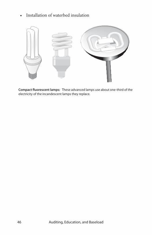
• Installation of waterbed insulation
Compact fluorescent lamps: These advanced lamps use about one-third of the electricity of the incandescent lamps they replace.

Virginia Weatherization Field Guide 47
CHAPTER 3: AIR SEALING AND INSULATING
Air sealing and insulation measures improve the building’s ther-mal boundary. Perform air-leakage testing and evaluation before beginning air-sealing or insulation work. See “Diagnosing Shell & Duct Air Leakage” on page 165. Air sealing may also reduce the flow of moisture into building cavities.
3.1 REDUCING AIR LEAKAGE
Air leakage in homes accounts for 5% to 40% of annual heating costs. Air-leakage reduction is one of weatherization’s most important functions, and often the most difficult.
The primary goals of air-leakage reduction are to:
• Avoid moisture migration into building cavities
Thermal boundary flaws: The thermal boundary contains the air barrier and insulation, which should be adjacent to one other. The insulation and the air barrier are often discontinuous at corners and transitions. These areas merit special attention.
rim joist area
joint between collar beam and rafter
cantilevered floorcorner at garage ceiling
insulation
air barrier
thermal boundary
joint between porch and house
joint between finished-attic floor and kneewall

Air Sealing and Insulating48
• Save energy by protecting insulation’s thermal resistance
• Increase comfort
Air travels into and out of the building by three main pathways:
• Bypasses, which are significant flaws in the home’s air barrier
• Seams between building materials
• The building materials themselves. See “Building Com-ponents Compared by Air Permeance” on page 179.
Before air sealing, become aware of all air pollution and house-pressure hazards. State and local governments may set standards for airtightness levels and ventilation. See “Minimum Ventilation Rate (MVR)” on page 173.
Air sealing exceptions
Because of structural conditions or other factors, some dwell-ings may not reach the standard. Exceptions are allowed when:
1. The weatherization installers made every reasonable attempt to reach the standard, or
2. Further air sealing is not cost effective, or
3. The dwelling unit is at or below the Minimum Ventila-tion Rate and there are large openings or major bypasses that must be sealed.
Make every reasonable attempt to reach the blower door target for every home. Note that structural or other conditions may prevent you from reaching the blower door target in some dwellings. In all cases the household file must provide clear and adequate documentation of the installer’s efforts to reach the standard, and the reason(s) the standard could not be achieved.

Virginia Weatherization Field Guide 49
SEALING BYPASSES
Major air sealing includes sealing bypasses and other relatively large openings between the heated and unheated space. Major air sealing activities are generally completed prior to other shell measure activities, and usually result in a significant drop in the blower door reading and/or changes in pressure diagnostics readings.
Bypasses will often be found between the conditioned space and intermediate zones such as floor cavities, attics, crawl spaces, attached garages, and porch roofs. The time and effort you spend to seal a bypass should depend on its size. For information on measuring and locating air leaks, see “Using a manome-ter to test air barriers” on page 182.
It is always preferable to use strong air-barrier materials like plywood or drywall to seal bypasses, particularly in regions with strong winds. These materials should be attached with mechanical and/or adhesive bonds. Air barriers must be able to resist severe wind pressures.
Bypasses are not always easily accessible. When they are hard to access, technicians sometimes blow dense-packed cellulose insulation into surrounding cavities, hoping that the cellulose will resist airflow and plug cracks between building materials.
The following are examples of bypasses and how to seal them. Seal all bypasses prior to insulating except where cellulose is also being used to seal bypasses.
Porch air leakage: Porch roof cavities often allow substantial air leakage because of numerous joints, and because there may be no siding or sheathing installed in hidden areas.

Air Sealing and Insulating50
Joist cavities under knee walls in finished attic areas: Connect knee wall with the plaster ceiling of the floor below by creating a rigid seal under the knee wall. See “Finished attics in story-and-a-half homes” on page 62 for specific techniques.
Kitchen or bathroom interior soffits: Seal the top of the soffit with fire-rated foil-faced foam board, plywood or drywall, fastened and sealed to ceiling joists and soffit framing.
Soil stacks, plumbing vents, open plumbing walls: Seal joints with expanding foam or caulk. If joint is too large, stuff with fiber-glass insulation, and spray foam over the top to seal the surface of the plug.
Kitchen soffits: These framing flaws are often open to both the wall cavity and ventilated attic. Any hole in the soffit creates a direct connection between the kitchen and attic.
soffit vents
recessed light
insulationbut no drywall
drywall has been incorrectlyinstalled after soffit is framed.

Virginia Weatherization Field Guide 51
Two-level attics in split-level houses: Seal the wall cavity with a rigid material fastened to studs and wall material.
Tops and bottoms of balloon-framed interior partition wall cavi-ties, missing top plates: Options can include the following. Seal with a fiberglass insulation plug, covered with a 2-part foam air seal. Seal with a rigid barrier, like 1/4-inch plywood or 1-inch foam board sealed to surrounding materials with caulk or liquid foam.
Two-level attic: Split-level homes create wall cavities connected to the ventilated attic. Other bypasses shown are duct, recessed light, and chimney.
ductrecessed light
chimney
soil stackopen wall cavities
wire

Air Sealing and Insulating52
Chimney, fireplace: Seal chimney and fireplace bypasses with sheet metal (minimum 28 gauge thickness). Seal to chimney or flue and ceiling structure with a high temperature sealant or chimney cement.
Housings of exhaust fans and recessed lights: Caulk joints where housing comes in contact with the ceiling with high-tempera-ture silicone sealant. See “Insulation safety procedures” on page 55 for more information on recessed lights.
Balloon-framed interior walls: These wall cavities can be open to both the attic and basement.
interior wall
floor joist
fiberglassbatt
wall stud
Recessed light fixtures: These are major leakage sites, but these fixtures must remain ventilated to cool their incandescent bulbs. Plug the top of the soffit in this case with drywall.
drywall air seal
recessed light fixture

Virginia Weatherization Field Guide 53
Duct boots and registers: If ducts are located in attic, crawl space, or attached garage, seal the joint between the boot and the ceil-ing, wall, or floor.
Duct chases: If chase opening is large, seal with a rigid barrier such as fire-rated foam board, plywood or drywall, and seal the new barrier to ducts with caulk or foam. Smaller cracks between the barrier and surrounding materials may be foamed or caulked.
Bathtubs and shower stalls: Seal holes and cracks from under-neath with expanding foam. Seal large openings with rigid materials caulked or foamed at edges.
Wiring and conduit penetra-tions: Seal penetration with caulk or foam.
Attic hatches and stairwell drops: Weatherstrip around doors and hatches. Caulk around frame perimeter. See “Manufactured retractable-stair cover” on page 66.
Other openings in the air bar-rier: Seal with rigid material, caulk, spray foam, or expand-ing foam depending upon size and nature of opening.
MINOR AIR SEALING
Minor air sealing includes sealing small openings with such materials as caulk, weather stripping, or sash locks. The follow-ing minor air sealing activities rarely result in significant blower door reductions, or changes in pressure diagnostic readings.
Large holes: Tradesmen often knock large holes in concrete walls without patching them. These can create large air leaks.

Air Sealing and Insulating54
• Cracks in exterior window and door frames can be sealed to keep water out. If the crack is deeper than 5/16-inch, it must be backed with a material such as backer rod and then sealed with caulk. Any existing loose or brittle material should be removed before the crack is re-caulked.
• Joints in sill plate (mud sill) and around utility openings in foundation should be sealed.
• Holes and cracks in masonry surfaces can be sealed with a cement-patching compound or mortar mix.
• Interior joints can be caulked if blower door testing indicates sub-stantial leakage. These joints include where baseboard, crown molding and/or cas-ing meet the wall/ceil-ing/floor surfaces. Gaps around surface-mounted or recessed light fixtures and ven-tilation fans should also be caulked if appropriate.
3.2 INSTALLING INSULATION
The building shell’s thermal resistance is increased by adding insulation. Insulation reduces heat transmission. Combined with the home’s air barrier, insulation forms the thermal bound-ary. Make sure that the air barrier and insulation will be aligned using procedures outlined in “Leak-testing air barriers” on page 178.
Insulation should cover the entire area intended for insulation without voids or edge gaps. Blown insulation should be installed
Backer rod: Use it to support caulk when sealing large uniform gaps. Use liquid foam for sealing irregular gaps.

Virginia Weatherization Field Guide 55
at sufficient density to resist settling, according to manufac-turer’s instructions. Insulation should be protected from air movement by an effective air barrier. Insulation should be pro-tected from moisture.
Wall cavities should be dense packed. Observe lead-safe weath-erization practices with all tasks that may disturb interior paint. See “Lead-safe weatherization” on page 24.
ATTIC INSULATION Air-leakage testing and air sealing should always precede attic insulation because attic insulation is not itself an air barrier– it needs an air barrier adjacent to it to be effective. Air moving through insula-tion reduces its R-value and can deposit moisture in the insulation. See “Zone leak-testing methodology” on page 184 and “Sealing bypasses” on page 49 for more informa-tion.
Insulation safety procedures
Comply with the following fire and electrical safety procedures before insulating.
✔ Inspect knob-and-tube wiring, and upgrade the sys-tems as needed. See the Virginia Weatherization Stan-dards on knob and tube wiring.
Top-plate leakage: Even thin cracks between the top plate and drywall can create significant air leaks because there are many linear feet of these cracks.
top plate
drywall drywall

Air Sealing and Insulating56
✔ Follow the manufac-turer’s instructions concerning clearance to combustibles for recessed light fixtures. If there are no instructions, con-struct a box from fire code gypsum or cement board that is two foot square and enclosed (notches may have to be cut to accommodate attic floor joists). Insulate over this box.
✔ Install collars or dams around masonry chimneys, B-vent chimneys, and manufactured chimneys after seal-ing bypass.
✔ All-fuel wood-stove chimneys should have ventilated insulation shields to prevent insulation from touching the chimney.
✔ All junction boxes must have approved covers, and their location marked with a flag or other visible marker.
✔ If sheet metal is used as a barrier around heat produc-ing devices or chimneys, it must be fastened securely to the ceiling joist so the barrier won’t collapse. Barriers should extend at least 4 inches above the insulation and be secured to keep insulation a minimum of 3 inches away from the heat-producing device.
Covering recessed light fixtures: Cover recessed light fixtures with fire-rated foil-faced foam board, fire-resistant drywall or sheet-metal enclosures. This reduces air leakage and allows insulation to be blown around the box.
maintain 3-inch clearance

Virginia Weatherization Field Guide 57
✔ If insulation is to cover wiring, inspect fuse boxes to ensure that wiring isn’t over-loaded.
✔ Install S-type fuses where appropriate to prevent circuit over-loading. Maximum ampacity for 14-gauge wire is 15 amps and for 12-gauge wire is 20 amps.
Preparation for attic insulation
Observe the following important preparatory steps before installing attic insulation.
✔ OSHA-approved respirators or dust masks should be worn while blowing insulation or installing batts. See “Worker health and safety” on page 27 for more infor-mation.
✔ Repair all roof leaks before insulating attic. If roof leaks cannot be repaired, don’t insulate the attic.
✔ All kitchen and bath fans must be vented outdoors through roof fittings. Fans without operating backdraft dampers should be retrofitted with backdraft dampers, or the fan should be replaced. Check new fans for proper damper operation. Use PVC, rigid metal, or gal-vanized pipe for venting whenever possible, and insu-late the pipe to prevent condensation. Do not use flexible plastic ducting.
S-type fuse: An S-type fuse won’t allow residents to oversize the fuse and overload a electrical circuit.

Air Sealing and Insulating58
✔ Install chutes, dams, tubes, or other block-ing materials to pre-vent blown insulation from plugging air channels between sof-fit vents and the attic. These devices maxi-mize the amount of insulation that may be installed over top plates, and help to prevent the wind-washing of insulation caused by cold air entering soffit vents.
✔ Before insulating the attic, seal bypasses as described previously. Air leakage and convection can significantly degrade the thermal resistance of attic insulation. If attic bypasses are not properly sealed, increasing attic ventilation may increase the home’s air-leakage rate.
Soffit chute or dam: Prevents wind washing and airway blockage by blown insulation. Also allows installation of maximum amount of insulation in this cold area.

Virginia Weatherization Field Guide 59
✔ Build a permanent insulation dam around the attic access hatch with rigid materials like plywood or oriented-strand board so that it will support the weight of a person entering or leaving the attic. Install latches, sash locks, gate hooks, or other positive closure to provide substantially airtight hatch closure where appropriate.
ATTIC VENTILATION
Attic ventilation is intended to remove moisture from the attic during the heating season and to remove solar heat from the attic during the cooling season. Adding attic ventilation during weatherization, however, is seldom necessary.
Many building codes require a minimum ratio of one square foot of net free area to 150 square feet of attic area if a vapor bar-rier isn’t present. With a vapor barrier, only one square foot per 300 square feet of attic area is required.
Adding attic ventilation to cure a moisture problem will not work if excess moisture migrates up from the living space. Pre-venting moisture from entering the attic in the first place is now recognized as the best way to keep attic insulation dry. Ceilings should be thoroughly air-sealed to prevent leakage of moist indoor air through the ceiling, which deposits condensation in the insulation during cold weather.
Insulated attic hatch: R-38 insulation prevents this area from being a thermal weakness. Building a dam prevents loose-fill insulation from falling down the hatchway.
R-38 insulation
plywood dam ceiling joists
latch holds hatch tight to stops

Air Sealing and Insulating60
Many building experts now believe that attic venting requirements are excessive. Attic venting can increase ceiling air leakage by increasing the stack effect. Attic decking, cooled by heat radia-tion into the cold night sky, can condense water out of ventilating air in some climates.
BLOWING ATTIC INSULATION
Attic insulation should be installed to meet Virginia Weatheriza-tion Installation Standards. Attic insulation always settles: cellu-lose settles 10% to 20% and fiberglass settles 3% to 10%. Insulation should be installed to a uniform depth according to manufacturer’s specifications for proper coverage.
Blown insulation is preferred to batt insulation because blown insulation forms a seamless blanket. Blowing attic insulation at the highest achievable insulation density helps minimize settling and slows convection currents from moving within the insula-tion.
Low and high attic ventilation: Ventilation creates air exchange with outdoors to remove moisture caused by condensation or roof leakage, and to keep the attic from overheating in summer.

Virginia Weatherization Field Guide 61
The highest density is achieved by moving the most insulation through the hose with the least amount of air pressure. The more the insulation is packed together in the blowing hose, the greater its installed density will be.
Identification cards should be placed in accessible attics of all buildings with loose fill insulation. Follow these standards.
1. Install insulation thickness markers within the attic. They should be labeled at a minimum of one-inch increments.
2. Attach an attic insulation receipt card to the framing near the access opening in a clearly visible place. It must identify the type of insulation installed, the manufac-turer, the installer, the R-value, the designed thickness after settling, the square footage of attic coverage area, and the number of bags installed. It should be signed and dated by the installer.
INSTALLING BATT INSULATION
If batt insulation is approved for use in the attic, then it must be installed in such a manner to ensure tight fit between ceiling joists. Unfaced fiberglass insulation is preferred to faced insula-tion because the facing is a hindrance to the insulation laying flat. If the insulation has vapor barrier facing, it should be toward the heated space. When insulation with a vapor barrier is installed over existing insulation, the vapor barrier should be removed to allow drying if the insulation gets wet.
Blown-in attic insulation: Blown insulation is more continuous than batts and produces bettercoverage. Insulation should be blown at a high density to reduce settling.

Air Sealing and Insulating62
FINISHED ATTICS IN STORY-AND-A-HALF HOMES
The finished attic consists of five separate sections that may require different sealing and insulating methods.
• Exterior walls of finished attic. See “Wall insulation” on page 66.
• Collar-beam attic, above finished attic.
• Sloped roof, where wall/roof finish is installed directly to roof rafters.
• Knee walls, between finished attic and unconditioned attic space.
• Outer ceiling joists, between knee wall and top plate of exterior wall.
Follow these specifications when insulating finished attics. See also “Sealing bypasses” on page 49.
✔ Seal attic bypasses before insulating.

Virginia Weatherization Field Guide 63
✔ Assure adequate structural integrity to support the weight of the insulation.
✔ Create an airtight and structurally strong seal in the joist space under the knee wall. Two methods are: Cut 2-inch-thick foam sheets an inch short in length and width and foam their perimeters with one-part foam. Or insert a fiberglass batt to block the empty space and foam the opening and its perimeter with two-part spray foam. See “Worker health and safety” on page 27 for safety precautions when using foam.
✔ Where possible, insulate sloped roof with dense pack cellulose.
Finished attic: This illustration depicts two approaches to insulating a finished attic. Either A) insulate the kneewall and side attic, or B) insulate the rafters.
rafter insulatio
side attic
kneewall
collar beam
ceiling joist
insulated ceiling joist, knee wall, and slope
Method A
Method B

Air Sealing and Insulating64
✔ Insulate knee walls with two-part foam, or densely packed cellulose or fiberglass. Prepare the knee wall for blowing by nailing house wrap to the knee wall with large-headed nails or stapling the house wrap through a strip of cardboard or thin wood. Or insulate the knee wall with high-density batts and air seal the knee-wall to prevent convection and air leakage.
✔ Insulate knee wall access hatches to R-19 and collar-beam access hatch to Virginia Weatherization Installa-tion Standards. Weatherstrip the hatch and provide positive closure (latch, sash locks, gate hooks, etc.) where needed.
flexible fill-tube
lath and plaster
second floor
celluloseinsulation
fiberglassinsulation
joist
rafter
fiberglass batt plug
2-part spray foam seal
air-barrier paper
Finished attic best practices: Air sealing and insulation combine to dramatically reduce heat transmission and air leakage in homes with finished attics.

Virginia Weatherization Field Guide 65
WALK-UP STAIRWAY AND DOOR
Think carefully about how to establish a continuous insulation and air barrier around or over the top of an attic stairway. If the attic is accessed by a stairwell and standard vertical door, blow dense pack cellulose insulation into walls of the stairwell. Install a threshold or door sweep, and weatherstrip the door. Also blow packed cellulose insulation into the cavity beneath the stair treads and risers.
When planning to insulate walls and stairway, investigate barri-ers that might prevent insulation from filling cavities you want to fill and what passageways may lead to filling other areas (like closets) by mistake. Balloon-framed walls and deep stair cavities complicate this measure and may prevent blown insulation from being cost-effective.
Insulating and sealing the attic stairway : Insulating and air sealing these is one way of establishing the thermal boundary.
Insulating and weatherstripping the attic hatch: Air sealing around the hatch is alternative way of establishing the thermal boundary here.

Air Sealing and Insulating66
Insulating & sealing retractable attic stairway
Retractable attic stairways are sometimes installed above the access hatch. Building an insulated box or buying a manufac-tured stair-and-hatchway cover are good solutions to insulating and sealing this weak point in the thermal boundary.
WALL INSULATION
Dense pack cellulose wall insulation reduces air leakage through walls and other closed building cavities because the fibers are driven into the cracks by the blowing machine.
Install wall insulation with a uniform coverage and density. Wall cavities are like chimneys, and convection currents or air leak-age can significantly reduce the insulation’s thermal perfor-mance.
If you find the existing walls uninsulated or partially insulated, add insulation to provide complete coverage for all the home’s exterior walls.
Inspecting and repairing walls
✔ Inspect walls for evidence of moisture damage. If con-dition of the siding, sheathing, or interior wall finish indicates an existing moisture problem, no sidewall insulation should be installed until the moisture prob-lem has been identified and corrected.
retractable stair
polystyrene cover
magnetic tape
attic floor joists
Manufactured retractable-stair cover: Magnetic tape forms the seal of this manufactured molded polystyrene insulated cover.

Virginia Weatherization Field Guide 67
✔ Seal gaps in external window trim and other areas that may admit rain water into the wall.
✔ Inspect indoor surfaces of exterior walls to assure that they are strong enough to withstand the force of insula-tion blowing.
✔ Inspect for interior openings from which insulation may escape, such as pocket doors, balloon framing, un-backed cabinets, interior soffits, and closets. Seal open-ings as necessary to prevent insulation from escaping.
✔ Exterior wall cavities used as returns should be replaced with a ducted return, and the wall cavity insulated with cellulose.
✔ Ensure that electrical circuits contained within walls aren’t overloaded. Maximum ampacity for 14-gauge copper wire is 15 amps and for 12-gauge copper wire is 20 amps. Install S-type fuses where appropriate to pre-vent circuit overloading. If walls contain live knob and tube wiring, then either the wiring should be replaced or the walls should not be insulated. See “Electrical safety” on page 26.
Blowing insulation using a directional nozzle: Blowing insulation through one or two holes usually creates voids inside the wall cavity. Insulation won’t reliably blow at an adequate density more than about one foot from the nozzle. This is why tube-filling is required here.
interior wall
voids from settling
insulation that bridged and never filled the bottom of cavity
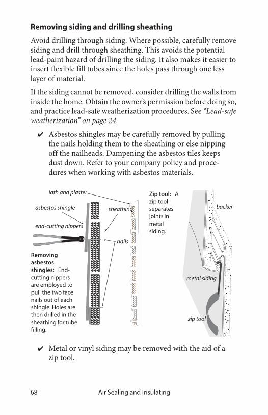
Air Sealing and Insulating68
Removing siding and drilling sheathing
Avoid drilling through siding. Where possible, carefully remove siding and drill through sheathing. This avoids the potential lead-paint hazard of drilling the siding. It also makes it easier to insert flexible fill tubes since the holes pass through one less layer of material.
If the siding cannot be removed, consider drilling the walls from inside the home. Obtain the owner’s permission before doing so, and practice lead-safe weatherization procedures. See “Lead-safe weatherization” on page 24.
✔ Asbestos shingles may be carefully removed by pulling the nails holding them to the sheathing or else nipping off the nailheads. Dampening the asbestos tiles keeps dust down. Refer to your company policy and proce-dures when working with asbestos materials.
✔ Metal or vinyl siding may be removed with the aid of a zip tool.
asbestos shingle sheathing
lath and plaster
nails
end-cutting nippers
zip tool
metal siding
backerboard
zip tool
metal siding
backer
Zip tool: A zip tool separates joints in metal siding.
Removing asbestos shingles: End-cutting nippers are employed to pull the two face nails out of each shingle. Holes are then drilled in the sheathing for tube filling.

Virginia Weatherization Field Guide 69
✔ Homes with brick veneer or blind-nailed asbestos sid-ing may be insulated from the inside. Holes drilled for insulation must be returned to an appearance as close to original as possible or satisfactory to the customer.
✔ Probe all wall cavities through holes, as you drill them, to identify fire blocking, diagonal bracing, and other obstacles.
✔ After probing, drill whatever additional holes are nec-essary to ensure complete coverage.
✔ Stucco walls may be insulated from either interior or exterior access.
✔ Back-plastered (two layer) walls are difficult to insulate properly. This is not a feasible measure.
Dense-packing wall insulation
1. Drill 2-to-3-inch diameter holes to access stud cavity.
2. To prevent settling, cellulose insulation must be blown at 3.5 pounds per cubic foot density. Blow-ing cellulose insula-tion this densely typically requires using a fill tube.
3. Dense-pack wall insulation is best installed using a blower equipped with separate con-trols for air and material feed.
Tube-filling walls: This method can be accomplished from inside or outside the home. It is the preferred wall insulation method because it is a reliable way to achieve a uniform coverage and density.

Air Sealing and Insulating70
4. Mark the fill tube in one-foot intervals to help the per-son blowing insulation to verify the correct penetration of the tube into the wall.
5. Starting with several full-height, unobstructed wall cav-ities allows the crew to measure the insulation density. Start with an empty hopper. Fill the hopper with a bag you’ve weighed. An 8-foot cavity (2-by-4 on 16-inch centers) should consume a minimum of 10 pounds of cellulose.
6. Seal and plug holes before replacing siding.
When insulating balloon-framed walls, try to blow an insulation plug into each floor cavity to insulate the perimeter between the two floors. This also seals the floor cavity so it does not become a conduit for air migration. If the process is requiring too much insulation, try placing a plastic bag over the end of the fill tube and blowing the insulation into the plastic bag. The bag will limit the amount of insulation it takes to plug this area. But the
Insulation hoses, fittings, and the fill tube: Smooth, gradual transitions are important to the free flow of insulation.

Virginia Weatherization Field Guide 71
best method is to pull exterior siding, when possible, and install a rigid air barrier to block the floor joist cavity.
Open-cavity wall insulation
Fiberglass batts are the most common open-cavity wall insula-tion. They achieve their rated R-value only when installed care-fully. If there are gaps between the cavity and batt at the top and bottom, the R-value can be reduced by as much as 30 percent. The batt should fill the entire cavity without spaces in corners or edges.
✔ Use unfaced friction-fit batt insulation where possible. Fluff to fill entire wall cavity.
✔ Choose R-13 batts rather than R-11.
✔ Staple faced insulation to outside face of studs; avoid inset stapling.
✔ Cut batt insulation to the exact length of the cavity. A too-short batt creates air spaces above and beneath the batt, allowing convection. A too-long batt will bunch up, creating air pockets.
baseboard
wind wall cavity
siding
Balloon framing: Floor cavities are usually connected to wall cavities. Blow a plug of insulation into the floor cavity to seal this bypass.
lath and plaster

Air Sealing and Insulating72
✔ Split batt around wiring, rather than letting the wiring bunch the batt to one side of the cavity.
✔ Insulate behind and around obstacles with scrap pieces of batt before installing batt.
✔ Fiberglass insulation exposed to the interior living space must be covered with minimum half-inch dry-wall or other material that has an ASTM flame spread rating of 25 or less.
FLOOR AND FOUNDATION INSULATION
Floor and foundation insulation are undertaken in conjunction with air sealing to complete the thermal boundary at the base of the building. With heated, occupied basements, one choice is to insulate and air-seal the basement walls. If it shows an SIR of 1 or greater however, the choice between insulating the floor or the basement walls is often less straightforward for homes with unused basements or crawl spaces.
Establishing a thermal boundary
To establish an effective thermal boundary, the insulation and air barrier should be adjacent to each other. Establishing an
Fiberglass batts, compressed by a cable: This reduces the wall’s R-value by creating a void between the wire and interior wallboard.
Batt, split around a cable: The batt attains its rated R-value.

Virginia Weatherization Field Guide 73
effective air barrier—comparable to the air barriers in the above-grade walls and ceiling—may be difficult. Furthermore, foundation or floor insulation may or may not be cost-effective or practical, considering the home’s weatherization budget and potential moisture problems.
Most building experts prefer to insulate and air-seal the founda-tion walls and not the floor because this strategy encloses the furnace, ducts, pipes and other features within an insulated and air-sealed space. This involves plugging crawl-space vents if appropriate – check your local building codes to see if this is acceptable. Floor insulation is generally preferred where there are crawl-space moisture problems or where rubble masonry makes insulating and air-sealing the foundation wall difficult.
Reducing moisture sources
With either floor or foundation insulation, install a ground air/moisture barrier in crawl spaces and dirt-floor basements. Use six-mil plastic. Any ducts from exhaust fans or clothes dryers that terminate in crawl spaces or basements must be extended to the outside. For more information about making decisions about where to insulate, see “Decisions about basement and crawl spaces” on page 190.
Rim insulation and air sealing
The joist spaces at the perimeter of the floor are a major weak point in the air barrier and insulation. Insulating and air sealing both the rim joist and longitudinal box joist are appropriate either as individual procedures or as part of floor or foundation insulation.
Air-seal stud cavities in balloon-framed homes as a part of insu-lating the rim joist. Air-seal other penetrations through the rim before insulating. Two-part spray foam is the most versatile air-sealing and insulation system for the rim joist because spray foam air-seals and insulates in one step. Polystyrene or polyure-thane rigid board insulation is also good for insulating and air-

Air Sealing and Insulating74
sealing the rim joist area. Longitudinal box joist cavities, enclosed by a floor joist, may be sealed and blown with wall insulation unless moisture is present.
Fiberglass-batt insulation should not be used because air can circulate around the fiberglass causing condensation and encouraging mold on the cold rim joist. If foam-board is used to insulate the rim, liquid foam sealant should be used to seal around the edges.
In most cases, rim-joist insulation work may not be allowed under SIR cost guidelines. Perform this work only when it is cost-effec-tive.
Floor insulation
All appropriate measures should be taken to establish an effec-tive air barrier at the floor, prior to insulating the floor, to pre-vent air from passing through or around floor insulation. The best way to insulate a floor cavity is to completely fill the joist cavity with unfaced fiberglass batt insulation. Partially filling the cavity with a fiberglass batt is less satisfactory because securing the batts up against the subfloor can be difficult. Consider the following specifications.
✔ Install R-19 insulation between floor joists.
Foam-insulated rim joists: Installing foam insulation is the best way to insulate and air-seal the rim joist.
foam boardtwo-part spray foam
liquid-foam seal
seal separately with caulk

Virginia Weatherization Field Guide 75
✔ Install insulation without voids, edge gaps, or end gaps.
✔ Fit insulation closely around cross bracing and other obstructions.
✔ Securely fasten batt insulation to framing with insula-tion hangers, plastic mesh, or other supporting mate-rial.
✔ Fit floor insulation tightly against the subfloor and the rim joist to prevent convecting air above the insulation from reducing its R-value.
✔ To insulate floor cavities with loose-fill insulation, enclose the cavities with belly-paper or like product and secure with lath. Fill with blown fiberglass only.
✔ If the walls are balloon-framed, air-seal stud cavities prior to installing floor insulation.
✔ Insulate water lines if they protrude below the insula-tion.
✔ Seal and insulate ducts remaining in the crawl space or unoccupied basement.
✔ In crawl spaces, install a ground moisture barrier that runs up the foundation walls.
Floor insulating with batts: Use unfaced fiberglass batts, installed flush to the floor bottom, to insulate floors. The batt should fill the whole cavity if it is supported by lath or plastic twine underneath. For batts that don’t fill the whole cavity, use wire insulation supports.
Don’t leave a space between the batt and floor bottombest practice

Air Sealing and Insulating76
FOUNDATION INSULATION
Foundation insulation is installed either on the inside or the outside of the foundation wall. Interior insulation is the most common because it does not require excavation. Exterior insula-tion is superior, however, because it is more effective at blocking ground water migration through the foundation.
Extruded or expanded polystyrene insulations are the most appropriate insulation products for flat concrete or concrete-block walls, because they are good air barriers with excellent moisture resistance. For rubble masonry walls, use two-part spray foam. A wet-spray cellulose may also be installed on dry interior walls. Spray foam is preferred whenever there is much moisture present.
• Foundation insulation in basements should be covered with a material that has an ASTM flame spread rating of 25 or less, such as half-inch drywall.
• Insulation should be attached to the entire inside wall surface with appropriate fasteners and/or adhesive. Install insulation with no significant voids or edge gaps.
• If the heating system is located in crawl space, precau-tions must be taken to assure that adequate outside combustion air is available.
• Eliminate foundation vents whenever insulating crawl-space foundation walls.
• Outside access hatches should be securely attached to foundation wall. Any crawl-space access hatch from conditioned basement should be insulated if the founda-tion walls are insulated. A latch, sash lock, gate hook, or other device should be installed to provide a tight clo-sure.

Virginia Weatherization Field Guide 77
Ground moisture and air barriers
The ground is neither an air barrier nor a moisture barrier and can transport air and moisture into a crawl space. Crawl-space moisture can lead to condensation, mold, and rot. Air passing through the soil can also contain radon and pesticides. Covering the ground with an airtight moisture barrier establishes an air barrier and seals out moisture and soil gases.
Crawl-space ventilation is often not effective at controlling moisture and other ground-source pollutants. It is not recom-mended.

Air Sealing and Insulating78

Virginia Weatherization Field Guide 79
CHAPTER 4: HEATING AND COOLING SYSTEMS
Combustion heating systems heat most homes and their opera-tion generates many important topics in this chapter.
4.1 COMBUSTION SAFETY AND EFFICIENCY TESTING
This section specifies maintenance, repair, and efficiency improvements to the combustion systems of existing heating appliances. Procedures outlined here require training, skill, experience, and knowledge of the health and safety hazards associated with combustion heating systems.
The information contained in this chapter provides useful guid-ance on testing, diagnosing and remedying situations that can be experienced with combustion appliances. State laws regulate Construction and Tradesmen licensing. State and local laws reg-ulate and enforce building code requirements and the construc-tion permit process. Before any work activities are performed, be sure that contractors, sub-contractors and employees comply with all state and local requirements.
For oil-fired systems there is opportunity for significant energy savings by adjustments to the combustion system. For gas, there is less opportunity.
For both oil and gas, safety-testing is extremely important. Heat-ing systems with their burners, heat exchangers, and chimneys are often neglected for decades.

Heating and Cooling Systems80
GAS-BURNER SAFETY AND EFFICIENCY TESTING
Gas burners should be maintained every 2 to 4 years. These fol-lowing specifications apply to gas furnaces, boilers, water heat-ers, and space heaters.
Perform the following inspection procedures and maintenance practices on all gas-fired furnaces, boilers, water heaters, and space heaters. The goal of these measures is to reduce carbon monoxide (CO), stabilize flame, and test safety controls. For information on the effects of CO, see “Carbon monoxide” on page 16.
CH4 + O2 CO2 + H2O + CO + O2 Some oxygen goes through combustion without reacting. This excess oxygen informs us about the fuel-air mixture.
Carbon dioxide and water are the products of complete combustion.
Carbon monoxide is the product of incomplete combustion
Natural gas or another hydrocarbon
Oxygen from the air
THE COMBUSTION PROCESS AND ITS BY-PRODUCTS
primary air
secondary air
dilution air
draft diverter
fluid in
fluid out
spud and orifice
Atmospheric gas burners: These burners use the heat of the flame to pull combustion air into the burner. Dilution air, entering at the draft diverter, limits excess air and reduces the likelihood of condensation in the chimney.

Virginia Weatherization Field Guide 81
✔ Look for soot, burned wires, and other evidence of flame roll-out.
✔ Inspect the burners for dust, debris, misalignment, and other flame-interference problems. Clean, vacuum and adjust as needed.
✔ Inspect the heat exchanger for leaks. See “Inspecting furnace heat exchangers” on page 124.
✔ Assure that all 120-volt wiring connections are enclosed in covered electrical boxes. Furnaces and boil-ers should have dedicated circuits.
✔ Determine that the pilot light is burning (if equipped) and that main burner ignition is satisfactory.
✔ Sample the undiluted combustion gases with a cali-brated flue-gas analyzer during operation.
✔ Test pilot-safety control for complete gas valve shutoff when pilot is extinguished.
–0.008 IWC
–0.02 IWC
pascalsBA
A B
BA
A B
–5.0
–2.0 50
5
Sampling combustion gases: Sample combustion gases at the exhaust vent of the appliance before dilution air mixes with the gases. Test by inserting the probe on each side of the baffle in the fire tube.If there is more than one exhaust port, sample each one.
Measuring draft: Measure chimney draft downstream of the draft diverter.
inches of water column (IWC)parts per million CO

Heating and Cooling Systems82
✔ Check the thermostat’s heat-anticipator setting. The thermostat’s heat anticipator setting should match the measured current in the 24-volt control circuit.
✔ Check venting system for proper size and pitch.
✔ Check venting system for obstructions, blockages, or leaks.
✔ Measure chimney draft downstream of the draft diverter.
✔ When a fan inducer is present (80+ and 90+), test the pressure switch by disconnecting the hose.
✔ Test to ensure that the high-limit control extinguishes the burner furnace temperature rises within 10% of 200° F.
✔ Measure gas input, and observe flame characteristics if soot, CO, or other combustion problems are present.
Proceed with burner maintenance and adjustment when:
• CO is greater than 100 ppm.
• Visual indicators of soot or flame roll-out exist.
• Burners are visibly dirty.
• Measured draft is low or nonexistent.
• The appliance has not been serviced for two years or more.
Gas-burner maintenance includes the following measures.
✔ Clean air distribution blower fan (squirrel cage fan).
✔ Remove causes of CO and soot, such as over-firing, closed primary air intake, and flame impingement.
✔ Remove dirt, rust, and other debris that may be inter-fering with the burners.

Virginia Weatherization Field Guide 83
✔ Take action to improve draft, if inadequate because of improper venting, obstructed chimney, etc.
✔ Seal leaks in vent connectors and chimneys.
✔ Adjust gas input if combustion testing indicates overfir-ing or underfiring.
Table 4-1: Combustion Standards:70+, 80+ and 90+ Furnaces
Performance Indicator 70+ 80+ 90+
Maximum CAZ depressur-ization (Pa)
–5 Pa. –5 Pa. –10 Pa.
Carbon monoxide (CO) (ppm)
≤ 100 ppm ≤ 100 ppm ≤ 100 ppm
Stack temperature (°F) 350°–450° 310°–400° ≤ 120° Heat rise (°F) 40–70°* 40–70°* 30–70°*Oxygen (%O2) 6–11% 6–9% 6–9%
Gas pressure Inches (IWC)3.2–4.2 IWC*†
3.2–4.2 IWC*†
3.2–4.2 IWC*†
Steady-state efficiency (SSE) (%)
72–78% 80–82% 92–97%
Draft (IWC)–5 Pa. or –0.02 IWC
–5 Pa. or –0.02 IWC
25–100 Pa. or 0.1–0.4 IWC*
* pmi = per manufacturer’s specifications; † IWC = inches water col-umn
Table 4-2: Minimum Worst-Case Draft
Outdoor Temperature (Degrees F)
Appliance <20 21-40 41-60 61-80 >80
Gas-fired furnace, boiler, or water heater with atmo-spheric chimney
–5 Pa.–0.02 IWC
– 4 Pa.–0.016 IWC
–3 Pa. –0.012 IWC
–2 Pa.–0.008 IWC
–1 Pa.–0.004 IWC

Heating and Cooling Systems84
Measuring BTU input on natural gas appliances
Use the following procedure when it’s necessary to measure the input of a natural gas appliance.
1. Turn off all gas combus-tion appliances such as water heaters, dryers, cook stoves, and space heaters that are con-nected to the meter you are timing, except for the appliance you wish to test.
2. Fire the unit being tested, and watch the dials of the gas meter.
3. Carefully count how long it takes for one revolution of 1/2, 1, or 2 cubic-foot dial. Find that number of seconds on Table 4-3 on page 85 in the columns marked “Sec-onds per Revolution.” Follow that row across to the right to the correct column for the 1/2, 1, or 2 cubic-foot dial. Note that you must multiply the number in the table by 1000. Record the input in thousands of Btus per hour.
4. If the measured input is higher or lower than input on the name plate by more than 10%, adjust gas pressure up or down within a range of 3.2 to 3.9 IWC.
5. If the measured input is still out of range, replace the existing orifices with orifices sized to give the correct input.
LEAK-TESTING GAS PIPING Natural gas and propane piping systems may leak at their joints and valves. Find gas leaks with an electronic combustible-gas
1
2
3456
7
89
0 1
2
34 5
67
8
90
12
34 5 6
7
8
90 1
2
34
567
8
90
FOOT
ONE
1 MILLION10 THOUSAND
100 THOUSAND 1 THOUSAND
HALF
FOOT
Gas meter dial: Use the number of seconds per revolution of the one-foot dial and the table on the following page to find the appliance’s input.

Virginia Weatherization Field Guide 85
detector, often called a gas sniffer. A gas sniffer will find all sig-nificant gas leaks if used carefully. Remember that natural gas
Table 4-3: Input in thousands of Btu/hr for 1000 Btu/cu. ft. gas
Seconds per
Rotation
Size of Meter Dial Seconds per
Rotation
Size of Meter Dial Seconds per
Rotation
Size of Meter Dial
1/2 cu. ft.
1 cu. ft. 2 cu. ft. 1/2 cu. ft.
1 cu. ft. 2 cu. ft. 1/2 cu. ft.
1 cu. ft. 2 cu. ft.
15 120 240 480 40 45 90 180 70 26 51 103
16 112 225 450 41 44 88 176 72 25 50 100
17 106 212 424 42 43 86 172 74 24 48 97
18 100 200 400 43 42 84 167 76 24 47 95
19 95 189 379 44 41 82 164 78 23 46 92
20 90 180 360 45 40 80 160 80 22 45 90
21 86 171 343 46 39 78 157 82 22 44 88
22 82 164 327 47 38 77 153 84 21 43 86
23 78 157 313 48 37 75 150 86 21 42 84
24 75 150 300 49 37 73 147 88 20 41 82
25 72 144 288 50 36 72 144 90 20 40 80
26 69 138 277 51 35 71 141 94 19 38 76
27 67 133 267 52 35 69 138 98 18 37 74
28 64 129 257 53 34 68 136 100 18 36 72
29 62 124 248 54 33 67 133 104 17 35 69
30 60 120 240 55 33 65 131 108 17 33 67
31 58 116 232 56 32 64 129 112 16 32 64
32 56 113 225 57 32 63 126 116 15 31 62
33 55 109 218 58 31 62 124 120 15 30 60
34 53 106 212 59 30 61 122 130 14 28 55
35 51 103 206 60 30 60 120 140 13 26 51
36 50 100 200 62 29 58 116 150 12 24 48
37 49 97 195 64 29 56 112 160 11 22 45
38 47 95 189 66 29 54 109 170 11 21 42
39 46 92 185 68 28 53 106 180 10 20 40

Heating and Cooling Systems86
rises from a leak and propane falls, so position the sensor accordingly.
✔ Sniff all valves and joints with the gas sniffer.
✔ Accurately locate leaks using a non-corrosive bubbling liquid, designed for finding gas leaks.
✔ All gas leaks should be repaired. If gas leak is detected, shut off the supply valve and have occupant notify the fuel supplier.
GAS RANGE AND OVEN SAFETY
Gas ranges and ovens can produce significant quantities of CO in a kitchen. Overfiring, dirt buildup, and foil installed around burners are frequent causes of CO. Oven burners are likely to produce CO even when not obstructed by dirt or foil. Test the range and oven for safety following these steps and take the rec-ommended actions before or during weatherization.
1. All gas stoves must have exhaust fan vented to the out-side. Test with fan turned on and off.
2. Test each stove-top burner separately, using a digital combustion analyzer or CO meter and holding the probe about 8 inches above the flame for 2 minutes.
3. Clean and adjust burners producing more than 25 parts per million (ppm). Burners often have an adjustable gas control.
4. Turn on the oven to bake at high temperature. Sample the CO level in exhaust gases at the oven vent and in the ambient air after 10 minutes.
5. Actions include cleaning the oven, removing aluminum foil, or adjusting the burner’s adjustable gas control.

Virginia Weatherization Field Guide 87
6. If the CO reading is over 100 ppm or if the ambient-air reading rises to 25 ppm or more during the test, abort the test. Advise the client of hazardous condition. Defi-ciencies must be corrected before proceeding with weatherization.
Most range and oven burners are equipped with adjustable nee-dle-and-seat valves. Most ranges also have an adjustable gas reg-ulator that services the entire unit.
Advise the client of the following important operating practices.
✔ Never install aluminum foil around a range burner or oven burner.
✔ Never use a range burner or gas oven as a space heater.
✔ Open a window or turn on the kitchen exhaust fan when using the range or oven.
✔ Keep range burners and ovens clean to prevent dirt from interfering with combustion.
25100
25
Oven CO level should be less than 100 ppm.
Ambient-air CO level should be less than 25 ppm after 10 minutes.
Stove-top burner CO level should be less than 25 ppm.

Heating and Cooling Systems88
✔ Burners should display hard blue flames. Yellow or white flames, wavering flames, or noisy flames should be investigated by a trained gas technician.
✔ Observe the installed CO detector, and discontinue use of the range and oven if the CO level rises above 25 ppm in ambient air.
OIL-BURNER SAFETY AND EFFICIENCY Oil burners require annual maintenance to retain their opera-tional safety and combustion efficiency. Testing for combustion efficiency (steady-state efficiency), draft, carbon monoxide, and smoke should be used to guide and evaluate maintenance. These procedures pertain to oil-fired furnaces, boilers, and water heat-ers.
Oil-burner inspection and testing
Use visual inspection and combustion testing to evaluate oil burner operation. An oil burner passing visual inspection and giving good test results may need no maintenance. If the test results are fair, adjustments may be necessary. Unsatisfactory test results may indicate the need to replace the burner or the entire heating unit.
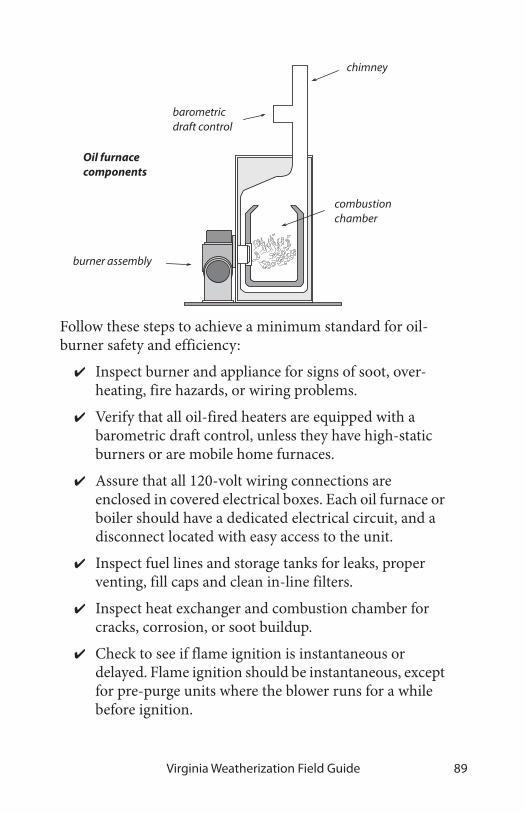
Virginia Weatherization Field Guide 89
Follow these steps to achieve a minimum standard for oil-burner safety and efficiency:
✔ Inspect burner and appliance for signs of soot, over-heating, fire hazards, or wiring problems.
✔ Verify that all oil-fired heaters are equipped with a barometric draft control, unless they have high-static burners or are mobile home furnaces.
✔ Assure that all 120-volt wiring connections are enclosed in covered electrical boxes. Each oil furnace or boiler should have a dedicated electrical circuit, and a disconnect located with easy access to the unit.
✔ Inspect fuel lines and storage tanks for leaks, proper venting, fill caps and clean in-line filters.
✔ Inspect heat exchanger and combustion chamber for cracks, corrosion, or soot buildup.
✔ Check to see if flame ignition is instantaneous or delayed. Flame ignition should be instantaneous, except for pre-purge units where the blower runs for a while before ignition.
barometric draft control
chimney
burner assembly
combustion chamber
Oil furnace components
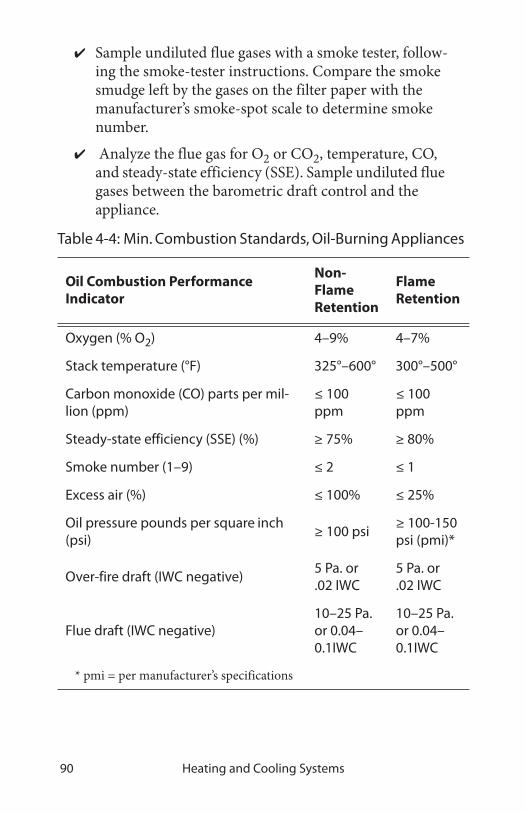
Heating and Cooling Systems90
✔ Sample undiluted flue gases with a smoke tester, follow-ing the smoke-tester instructions. Compare the smoke smudge left by the gases on the filter paper with the manufacturer’s smoke-spot scale to determine smoke number.
✔ Analyze the flue gas for O2 or CO2, temperature, CO, and steady-state efficiency (SSE). Sample undiluted flue gases between the barometric draft control and the appliance.
Table 4-4: Min. Combustion Standards, Oil-Burning Appliances
Oil Combustion Performance Indicator
Non-Flame Retention
Flame Retention
Oxygen (% O2) 4–9% 4–7%
Stack temperature (°F) 325°–600° 300°–500°
Carbon monoxide (CO) parts per mil-lion (ppm)
≤ 100 ppm
≤ 100 ppm
Steady-state efficiency (SSE) (%) ≥ 75% ≥ 80%
Smoke number (1–9) ≤ 2 ≤ 1
Excess air (%) ≤ 100% ≤ 25%
Oil pressure pounds per square inch (psi)
≥ 100 psi ≥ 100-150 psi (pmi)*
Over-fire draft (IWC negative)5 Pa. or .02 IWC
5 Pa. or .02 IWC
Flue draft (IWC negative)10–25 Pa. or 0.04–0.1IWC
10–25 Pa. or 0.04–0.1IWC
* pmi = per manufacturer’s specifications

Virginia Weatherization Field Guide 91
✔ Measure flue draft between the appliance and baromet-ric draft control and over-fire draft over the fire inside the firebox.
✔ Measure high-limit shut-off temperature and adjust or replace the high-limit control if the shut-off tempera-ture is more than 200° F for furnaces or 180° F for hot-water boilers.
✔ Measure oil-pump pressure, and adjust to manufac-turer’s specifications if necessary.
✔ Measure transformer voltage, and replace if necessary.
✔ Assure that barometric draft controls are mounted plumb and level and that the damper swings freely.
✔ Time the CAD cell control or stack control to verify that the burner will shut off, within 45 seconds, when the cad cell is blocked from seeing the flame.
Table 4-5: Minimum Worst-Case Draft
Outdoor Temperature (Degrees F)
Appliance <20 21-40 41-60 61-80 >80
Oil-fired fur-nace, boiler, or water heater with atmo-spheric chimney
–15 Pa.–0.06 IWC
–13 Pa.–0.053 IWC
–11 Pa. –0.045 IWC
–9 Pa.–0.038 IWC
–7 Pa.–0.030 IWC

Heating and Cooling Systems92
Oil burner maintenance and adjustment
After evaluating the oil burner’s initial operation, perform some or all of the following maintenance tasks as needed to optimize safety and efficiency as part of weatherization service.
✔ Verify correct flame-sensor operation.
✔ Replace burner nozzle after matching the nozzle size to the home’s heat-load requirements and manufacturers requirements.
✔ Clean the burner’s blower wheel.
✔ Install or replace oil filter(s).
✔ Clean or replace air filter. Provide a six (6) month sup-ply of furnace air filters.
✔ Clean air distribution blower fan (squirrel cage fan).
✔ Remove soot and sludge from combustion chamber.
375
#1 Smoke
100#
-0.02 IWC
BA
A B
BA
A B
E78% ∆
-10.0
-5.0
-0.04 IWC
Measuring oil-burner performance: To measure oil-burning performance indicators, a manometer, flue-gas analyzer, smoke tester, and pressure gauge are required.
barometric draft control
oil burner
over-fire draft
flue draft
SSEoil pump pressure stack temperature
smoke test
Note: IWC = inches of water column pressure

Virginia Weatherization Field Guide 93
✔ Remove soot from heat exchange surfaces.
✔ Clean dust, dirt, and grease from the burner assembly.
✔ Set oil pump to correct pressure.
✔ Adjust air shutter to achieve oxygen and smoke values, specified in “Min. Combustion Standards, Oil-Burning Appliances” on page 90.
✔ Adjust barometric damper for flue draft of negative 7–15 pascals or negative 0.03-to-0.06 IWC (before baro-metric damper).
✔ Adjust gap between electrodes to manufacturer’s speci-fications.
✔ Repair the ceramic combustion chamber, or replace it if necessary.
✔ Repair or replace any leaking fuel lines. Replace all in-line compression fittings with flare fittings.
After these maintenance procedures, the technician performs the diagnostic tests described previously to evaluate improve-ment made by the maintenance procedures and to determine if fine-tuning is required.
nozzle
oil pump
motorelectrodes
air shutter
blower transformer
Oil burner: Performance and efficiency will deteriorate over time if neglected. Annual maintenance is recommended.
blast tube

Heating and Cooling Systems94
4.2 MEASURING DRAFT AND HOUSE PRESSURES
The main purpose of measuring draft is to insure that the com-bustion gases are being vented from a dwelling. Draft is mea-sured in inches of water column (IWC) or Pascals. House pres-sure affects draft and must be measured and controlled.
Technicians create worst-case conditions for naturally drafting appliances in order to insure that appliances will draft even in worst-case conditions of house depressurization. Depressuriza-tion is the leading cause of backdrafting and flame roll-out.
DRAFT CHARACTERISTICS IN COMBUSTION APPLIANCES
There are several different classifications of combustion appliances based on the type of draft they employ to exhaust their flue gases. Most existing appliances exhaust their gases into an atmo-spheric chimney. An atmo-spheric chimney produces negative draft—a slight vac-uum. The strength of this draft is determined by the chim-ney’s height, its cross-sectional area, and the temperature dif-ference between the flue gases and outdoor air. Atmospheric draft should always be negative.
Most existing gas and oil appliances are designed to operate with at least negative 0.02 inches of water column (IWC) or –5 pas-
109876543210
0.040.030.020.010.00
Pascals
Inches of water column (IWC)
Designchimneydraft (80+)
Negative versus positive draft: With positive draft air flows down the chimney and out the draft diverter. A smoke bottle helps distinguish between positive and negative draft.
positive draftnegative draft

Virginia Weatherization Field Guide 95
cals chimney draft. Tall chimneys located indoors can produce strong drafts and short chimneys or outdoor chimneys typically produce weak drafts. Wind and house pressures also affect draft.
Atmospheric combustion appliances exhaust combustion gases solely by their buoyancy. Fan-assisted appliances have the help of a small fan near the exhaust of their heat exchanger that regu-lates airflow through the heat exchanger.
Power burners have fans at the intake of the combustion chamber to mix combustion air with fuel and inject the mixture into the combustion chamber. The standard power oil burner is the most com-mon type of power burner. Most appliances with draft-assisting fans and power burn-ers vent into atmospheric chimneys.
Positive-draft appliances, which are either condensing or non-condensing, vent either horizontally or vertically and require airtight chimneys. Most positive-draft appliances are condensing furnaces and boilers. Most non-condensing posi-tive-draft appliances are boilers, although some furnaces and newer water heaters are also designed to vent through positive-draft, sidewall vents. These appliances have draft in the range of +0.05 to +0.35 IWC or 12 to 85 pascals and are much less influ-enced by indoor and outdoor pressures.
Power venters with sidewall vents are a good alternative, when a vertical chimney is inadequate or non-existent. The power ven-ter is located near the end of the vent and creates a negative draft. See “Power venters for sidewall venting” on page 113.
Atmospheric, or fan-assisted heater with power venter
barometric damper
power venter
Power-vent draft: A power venter is an external draft-inducing fan that helps atmospheric, and fan-assisted furnaces, boilers, and water heaters vent through sidewall vents.

Heating and Cooling Systems96
WORST-CASE DRAFT AND PRESSURE TEST
This test uses the home’s exhaust fans, air handler, and chimneys to create worst-case depressurization in the combustion-appli-ance zone (CAZ). A combustion appliance zone (CAZ) is an area containing one or more combustion appliances. During this worst-case testing, you measure the indoor-outdoor pres-sure difference and chimney draft. Draft is the pressure differ-ence between the chimney and combustion zone.
The reason for these tests is that worst-case conditions do occur, and chimneys should vent their combustion gases even under these extreme con-ditions. This worst-case draft test will discover whether or not the venting system will exhaust the combustion gases when the combustion-zone pressure is as negative as you can make it. A sensitive digital manometer is usually used for accurate and reliable readings of both combustion-zone depres-surization and chimney draft.
Start the testing by turning on combustion appliances and exhaust fans. With exterior doors and windows closed, connect a digital manometer to read the pressure difference between combustion zone and outdoors. Then take the following steps and measurements.
1. Record the CAZ-to-outdoors pressure difference with the CAZ door open. Then close the door and measure the pressure difference again. Whatever negative pres-sure you measure is caused by the combustion appli-ances and exhaust appliances.
Combustionair downchimney
Flame roll-out: Flame roll-out can occur when the combustion zone is depressurized beyond 8 pascals or during very cold weather.

Virginia Weatherization Field Guide 97
2. Next, turn on the air handler; measure the CAZ-to-out-doors pressure difference again—first with the CAZ door closed, then with it open. Negative pressure or increased negative pressure (compared to Step 1) is caused by the furnace blower and return ducts.
3. Now, close all interior doors; measure the CAZ-to-out-doors pressure difference again—first with the CAZ door closed then with it open. Negative pressure or increased negative pressure (compared to Step 2) is caused by imbalanced airflow between supply and return registers. See also “Measuring duct-induced room pressures” on page 195.
4. Finally, recreate the conditions observed in steps 1 through 3 above that produced the highest negative pressure. Measure actual worst-case draft for all appli-ances under these conditions. When there are multiple combustion appliances, operate them separately and together. Measure draft in each appliance and compare the negative draft to the values in the table “Minimum Worst-Case Draft” on page 99.
BA
A B
Combustion Zone WRT Outdoors
–5
Worst-case depressurization: Worst-case testing is used to identify pressure sources that oppose draft and restrict combustion air. The testing described here is intended to isolate the negative-pressure source.
A reading more negative than –5 pascals indicates a significant possibility of backdrafting.

Heating and Cooling Systems98
5. If the home has a wood-burning fireplace, simulate a 300 cfm chimney exhaust with the blower door, and repeat the conditions and measurements of Step 4 above.
Take all necessary steps to iden-tify and remove excessive nega-tive house pressures and to improve draft to standards in the table below. For more infor-mation, see“Venting combus-tion gases” on page 100 and “Combustion air” on page 116.
Ambient CO levels should be monitored in the combustion zone during draft testing, espe-cially if CAZ depressurization exceeds –5 pascals during test-ing. If ambient CO levels in the combustion zone exceed 20 parts per million (ppm), draft tests should cease for the techni-cian’s safety. The combustion zone should be ventilated before draft-testing and diagnosis of CO problems resumes.
IMPROVING INADEQUATE DRAFT
If measured draft is below minimum draft pressures, investigate the reason for the weak draft. Open a window or door to observe whether the addition of combustion air will improve draft. If this added air strengthens draft, the problem usually is depressurization or lack of combustion air. If opening a window has no effect, inspect the chimney. The chimney could be blocked or excessively leaky.
–0.008 IWC
–0.02 IWC
pascalsBA
A B
BA
A B
–5.0
–2.0
Worst-case draft testing: Measure draft for atmospheric gas appliances at worst-case conditions to ensure proper venting. Draft is measured on the chimney side of the draft diverter. For oil appliances, measure draft between the barometric draft control and the appliance.

Virginia Weatherization Field Guide 99
Chimney improvements to solve draft problems
✔ Repair chimney obstructions, disconnections, or leaks, which can weaken draft.
✔ Measure the size of the vent connector and chimney and compare to vent-sizing information listed in Sec-tion 504 of the International Fuel Gas Code. A vent con-nector or chimney liner that is either too large or too small can result in poor draft.
✔ If wind is causing erratic draft, consider a wind-damp-ening chimney cap.
✔ If the masonry chimney is deteriorated, consider installing a new chimney liner. See “Metal liners for masonry chimneys” on page 107.
Duct improvements to solve draft problems
✔ Repair return-duct leaks near furnace.
Table 4-6: Minimum Worst-Case Draft
Outdoor Temperature (Degrees F)
Appliance <20 21-40 41-60 61-80 >80
Gas-fired fur-nace, boiler, or water heater with atmo-spheric chim-ney
–5 Pa.–0.02 IWC
– 4 Pa.–0.016 IWC
–3 Pa. –0.012 IWC
–2 Pa.–0.008 IWC
–1 Pa.–0.004 IWC
Oil-fired fur-nace, boiler, or water heater with atmo-spheric chim-ney
–15 Pa.–0.06 IWC
–13 Pa.–0.053 IWC
–11 Pa. –0.045 IWC
–9 Pa.–0.038 IWC
–7 Pa.–0.030 IWC

Heating and Cooling Systems100
✔ Isolate furnace from return registers by air-sealing.
✔ Improve balance between supply and return air by installing new return ducts, transfer grills, or jumper ducts. See“Improving duct-system airflow” on page 131.
Reducing depressurization from exhaust devices
✔ Isolate furnace from exhaust fans and clothes dryers by air-sealing between the combustion zone and zones containing these depressurizing forces.
✔ Reduce capacity of large exhaust fans.
Combustion and make-up air
✔ Provide make-up air for dryers and exhaust fans.
✔ Provide combustion-air inlet to combustion zone. See “Combustion air” on page 116.
4.3 VENTING COMBUSTION GASES
Proper venting is essential to the operation, efficiency, safety and durability of combustion heaters. The National Fire Protec-tion Association (NFPA) and the International Code Council (ICC) are the authoritative information sources on material-choice, sizing, and clearances for chimneys and vent connectors, as well as for combustion air. The information in this venting section is based on the following NFPA and ICC documents.
• The International Fuel Gas Code (IFGC) (ICC)
• NFPA 31: Standard for the Installation of Oil-Burning Equipment
• NFPA 211: Standard for Chimneys, Fireplaces, Vents, and Solid-Fuel-Burning Appliances
• NFPA 54: The National Fuel Gas Code

Virginia Weatherization Field Guide 101
GENERAL VENTING REQUIREMENTS
Combustion gases are vented through vertical chimneys or other types of approved hori-zontal or vertical vent piping. Identifying the type of existing venting material, verifying the correct size of vent piping, and making sure the venting con-forms to the applicable codes are important tasks in inspect-ing and repairing venting sys-tems. Too large a vent often leads to condensation and cor-rosion. Too small a vent can result in spillage. The wrong vent materials can corrode or dete-riorate from heat.
Table 4-7: Guide to Venting Standards
Topic Standard and Section
Vent Sizing IFGC, Section 504
Clearances
IFGC, Section 308 and Tables 308.2INFPA 31, Section 4-4.1.1 and Tables 4-4.1.1 and 4-4.1.2NFPA 211, Sections 6.5, 4.3, 5
Combus-tion Air
IFGC, Section 304NFPA 31, Section 1-9; NFPA 211, Section 8.5 and 9.3
Two vent connectors joining chimney: The water heater’s vent connector enters the chimney above the furnace because the water heater has a smaller input.
vent connectors

Heating and Cooling Systems102
VENT CONNECTORS
A vent connector connects the appliance’s venting outlet with the chimney. Approved vent connectors for gas- and oil-fired units are made from the following materials.
1. Type-B vent, consisting of a galvanized-steel outer pipe and aluminum inner pipe
2. Type-L vent connector with a stainless-steel inner pipe and either galvanized or black-steel outer pipe.
3. Galvanized-steel pipe (28 gauge)
4. Aluminum pipe (24 gauge)
5. Stainless-steel pipe (33 gauge)
6. Various manufactured vent connectors
Double-wall vent connectors are the best option, especially for appliances with horizontal sections of vent connector. A double-wall vent connector helps maintain flue-gas temperature and prevent condensation. Gas appliances with draft hoods, installed in attics or crawl spaces must use a Type-B vent con-nector. Type-L vent pipe is commonly used for vent connectors for oil and solid fuels but can also be used for gas.
Observe the following general specifications, concerning vent connectors.
• A vent connector is almost always the same size as the vent collar on the appliance it vents.
• Vent-pipe sections should be fastened together with 3 screws or rivets.
• The vent connector should be sealed where it enters the chimney.
• Vent connectors should be free of rust, corrosion and holes.
• The chimney combining two vent connectors should have a cross-sectional area equal to the area of the larger

Virginia Weatherization Field Guide 103
vent connector plus half the area of the smaller vent connector. This common vent should be no larger than 7 times the area of the smallest vent. For specific vent sizes, see NFPA codes themselves listed in “Guide to Venting Standards” on page 101.
• The horizontal length of vent connectors shouldn’t be more than 75% of the chimney’s vertical height or have more than 18 inches horizontal run per inch of vent diameter.
• Vent connectors must have upward slope to their con-nection with the chimney. A slope of 1/4 inch of rise per foot of horizontal run along their entire length is recom-mended to prevent condensation from pooling and rust-ing the vent.
• When two vent connectors connect to a single chimney, the vent connector servicing the smaller appliance should enter the chimney above the vent for the larger appliance.
• Only one solid-fuel (wood or coal) appliance is allowed per flue. Note that some chimneys may contain more than one flue.
Table 4-8: Areas of Round Vents
Vent diameter 4" 5" 6" 7" 8"
Vent area (square inches) 12.6 19.6 28.3 38.5 50.2
Table 4-9: Vent Connector Diameter vs. Max. Horizontal Length
3" 4" 5" 6" 7" 8" 9" 10" 12" 14"
4.5' 6' 7.5' 9' 10.5' 12' 13.5' 15' 18' 21'
From International Fuel Gas Code 2000

Heating and Cooling Systems104
• Clearances for common vent connectors are listed here.
CHIMNEYS
There are two common types of vertical chimneys for venting combustion fuels that satisfy NFPA and ICC codes. First there are masonry chimneys lined with fire-clay tile, and second there are man-ufactured metal chim-neys, including all-fuel metal chimneys, Type-B vent chimneys for gas-fired appliances, and Type-L chimneys for oil-fired appliances.
Masonry chimneys
Observe the following general specifications for inspecting, repairing, and retrofitting masonry chimneys.
Table 4-10: Clearances to Combustibles for Vent Connectors
Vent Connector Type Clearance
Single-wall galvanized-steel vent pipe9" (gas)18" (oil)
Type-B double-wall vent pipe (gas) 1" (gas)
Type L double wall vent pipe (stainless steel inner liner, stove pipe or galvanized outer liner)
3", or per manu-facturer’s instructions
concrete cap
clay liner
foundation
inlet
Masonry chimneys: Remain a very common vent for all fuels.
Cleanout should be inspected and emptied out as part of heating service

Virginia Weatherization Field Guide 105
• Masonry chimneys should be supported by their own masonry foundation.
• Existing masonry chimneys should be lined with a fire-clay flue liner. There should be a 1/2-inch to 1-inch air gap between the clay liner and the chimney’s masonry to insulate the liner. The liner shouldn’t be bonded struc-turally to the outer masonry because it needs to expand and contract independently of the chimney’s masonry structure. The clay liner can be sealed to the chimney cap with a flexible high-temperature sealant.
• The chimney’s penetrations through floors and ceilings should be sealed with metal as a firestop and air barrier.
• Deteriorated or unlined masonry chimneys may be rebuilt as specified above or relined as part of a heating-system replacement or a venting-safety upgrade. As an alternative, the vertical chimney may be replaced by a sidewall vent, equipped with a power venter mounted on the exterior wall.
• Masonry chimneys should have a cleanout 12 inches or more below the lowest inlet. Mortar and brick dust should be cleaned out of the bottom of the chimney
Table 4-11: Clearances to Combustibles for Common Chimneys
Chimney Type Clearance
Interior chimney masonry w/ fireclay liner 2"
Exterior masonry chimney w/ fireclay liner 1"
All-fuel metal vent: insulated double wall or tri-ple-wall pipe
2"
Type B double-wall vent (gas only) 1"
Type L double-wall vent (oil/gas) 3"

Heating and Cooling Systems106
through the clean-out door, so that this debris won’t eventually interfere with venting.
Manufactured chimneys
Manufactured metal chimneys have engineered parts that fit together in a prescribed way. Metal chimneys have all manufac-tured components from the vent connector to the termination fitting on the roof. Parts include: metal pipe, weight-supporting hardware, insulation shields, roof jacks, and chimney caps. One manufacturer’s chimney may not be compatible with another’s connecting fittings.
All-fuel metal chimneys come in two types: insulated double wall metal pipe and triple-wall metal pipe. Install them strictly observing the manufacturer’s specifications.
Type-B vent pipe is permitted as a chimney for gas appliances. Some older manufactured gas chimneys were made of metal-reinforced asbestos cement.
Type L vent pipe is permitted as a chimney for oil or gas.
Chimney termination
Masonry chimneys and all-fuel metal chimneys should termi-nate at least three feet above the roof penetration and two feet above any obstacle within ten feet of the chimney outlet. Chim-neys should have a cap to prevent rain and strong downdrafts from entering.
Type-B and type-L chimneys can terminate as close as one foot above flat roofs and pitched roofs up to a 6/12 roof pitch, with a UL-approved wind-resistant termination cap. As the pitch rises, the minimum termination height rises as shown in the table.
All-fuel metal chimney: These chimney systems include transition fittings, support brackets, roof jacks, and chimney caps. The pipe is double-wall insulated or triple wall.

Virginia Weatherization Field Guide 107
Metal liners for masonry chimneys
Unlined masonry chimneys or chimneys with deteriorated lin-ers should be relined as part of heating system replacement. Use either Type-B vent, a flexible or rigid stainless-steel liner, or a flexible aluminum liner. See also“Power venters for sidewall venting” on page 113.
Table 4-12: Roof Slope and B-Vent Chimney Height Above Roof
flat-6/12
6/12-7/12
7/12-8/12
8/12-9/12
9/12-10/12
10/12-11/12
11/12-12/12
12/12-14/12
14/12-16/12
16/12-18/12
1' 1' 3" 1' 6" 2' 2' 6" 3' 3" 4' 5’ 6' 7'
From International Fuel Gas Code 2000
Chimney terminations: Should have vent caps and be given adequate clearance height from nearby building parts. These requirements are for masonry chimneys and manufactured all-fuel chimneys.
2 feet3 feet
10 feet

Heating and Cooling Systems108
Flexible liners require care-ful installation to avoid a low spot at the bottom, where the liner turns a right angle to pass through the wall of the chimney. Follow the manufacturer’s instructions, which usually prescribe stretching the liner and fas-tening it securely at both ends, to prevent it from sag-ging and thereby creating such a low spot.
To reduce condensation, flexible liners should be insulated—especially when installed in exterior chimneys. Always insulate flexible metal chimney liners with a fiberglass-insulation jacket if the manu-facturer’s instructions allow.
Sizing flexible chimney liners correctly is very important. Over-sizing is common and can lead to condensation and corrosion. The manufacturers of the liners include vent-sizing tables in their instructions. Liners should bear the label of a testing lab like Underwriters Laboratories (UL). Solid fuel liners must also have a minimum 12-inch clean out.
Flexible metal chimney liners: The most important installation issues are sizing the liner correctly along with fastening and supporting the ends to prevent sagging.
cap
flexible liner
mortar sleeve
single-wall collar
termination fitting

Virginia Weatherization Field Guide 109
SPECIAL VENTING CONSIDERATIONS FOR GAS
The American Gas Association (AGA) has devised a classifica-tion system for venting systems serving natural gas and propane appliances. This classification system assigns Roman numer-als to four categories of venting based on whether there is posi-tive or negative pressure in the vent and whether condensation is likely to occur in the vent.
A great majority of appliances found in homes and multifam-ily buildings are Category I, which have negative pressure in vertical chimneys with no con-densation expected in the vent connector or chimney. Condensing furnaces are usually Cate-gory IV with positive pressure in their vent and condensation occurring in both the appliance and vent.
Venting fan-assisted furnaces and boilers
Newer gas-fired fan-assisted central heaters control flue-gas flow and excess air better than atmospheric heaters, resulting in their higher efficiency. These are non-condensing Category I furnaces in the 80%-plus Annual Fuel Utilization Efficiency (AFUE) range. Because these units eliminate dilution air and have slightly cooler flue gases, chimneys should be carefully inspected to ensure that they are ready for a possibly more cor-rosive flue-gas flow. The chimney should be relined when any of the following three conditions are present.
1. When the existing masonry chimney is unlined.
Negative-pressureVenting
Positive-pressureVenting
American Gas Association Vent Categories
Con
dens
ing
Non
-con
dens
ing I
II
III
IV
Combustion Efficiency Combustion Efficiency
Combustion Efficiency Combustion Efficiency
83% or less 83% or less
over 83% over 83%
Use standardventing: masonry or
Type B vent
Use onlypressurizable vent as
specified bymanufacturer
Use onlypressurizable
condensing-servicevent as specified by
manufacturer
Use only specialcondensing-servicevent as specified by
manufacturer
AGA venting categories: The AGA classifies venting by whether there is positive or negative pressure in the vent and whether condensation is likely.

Heating and Cooling Systems110
2. When the old clay or metal chimney liner is deterio-rated.
3. When the new heater has a smaller input than the old one. The new chim-ney should be sized to the new furnace or boiler and the existing water heater.
For gas-fired 80+ AFUE furnaces, a chimney liner should consist of:
• Type-B vent
• A rigid or flexible stainless steel liner
• A poured masonry liner
• An insulated flexible aluminum liner
Because of the considerable expense that chimney relining can entail, sidewall venting with a power venter should be consid-ered.
Pressurized sidewall vents
Sometimes, the manufacturer gives the installer a venting choice of whether to install a fan-assisted furnace or boiler into a verti-cal chimney (Category I) or as a positive-draft appliance (Cate-gory III), vented through a sidewall vent. Sidewall-vented fan-assisted furnaces and boilers may vent through B-vent, stainless-steel single-wall vent pipe, or high-temperature plastic pipe. Pressurized sidewall vents should be virtually airtight at the operating draft. B-vent must be sealed with high-temperature silicone caulking or other approved means to air-seal its joints.
B-vent chimney liner: Double-wall Type-B vent is the most commonly available chimney liner and is recommended over flexible liners. Rigid stainless-steel single-wall liners are also a permanent solution to deteriorated chimneys.

Virginia Weatherization Field Guide 111
Some high-temperature positive-draft plastic vent pipe, used in horizontal installations, was recalled by manufacturers because of deterioration from heat and condensation. Deteriorated high-temperature plastic vent should be replaced by airtight stainless-steel vent piping or B-vent.
Existing fan-assisted appliances may have problems with weak draft and condensation when vented horizontally. Horizontally vented, fan-assisted furnaces and boilers may require a retrofit power venter to create adequate draft.
Condensing-furnace venting
Condensing furnaces with 90+ AFUE are vented horizontally or vertically through PVC Schedule 40 pipe. The vent is pressur-ized, making it Category IV. Vent piping should be sloped back toward the appliance, so the condensate can be drained and treated if necessary.
Table 4-13: Characteristics of Gas Furnaces and Boilers
AFUE Operating characteristics
70+Category I, draft diverter, no draft fan, standing pilot, non-condensing, indoor combustion and dilution air
80+Category I, no draft diverter, draft fan, electronic ignition, indoor combustion air
90+
Category IV, no draft diverter, draft fan, low-tem-perature plastic venting, positive draft, elec-tronic ignition, condensing heat exchanger, outdoor combustion air is strongly recom-mended

Heating and Cooling Systems112
Combustion air is supplied from outdoors through a sealed plastic pipe or from indoors. Outdoor combustion air is highly recommended, and most condensing furnaces are equipped for outdoor combustion air through a dedicated pipe. This com-bined combustion-air and venting system is referred to as direct-vent or sealed-combustion.
Fan-assisted gas heaters with vertical chimneys: These 80% AFUE central heaters are almost always vented into atmospheric chimneys, which may need to be relined.
Fan-assisted heaters with sidewall vents: Sometimes these appliances are vented through a side wall through airtight plastic or stainless-steel vent pipe.
exhaust
combustion air
Condensing furnace venting: The two common types of termination for plastic condensing vents are separate pipes and a combined fitting. Vents going through the roof are preferred for their being more resistant to tampering and damage.

Virginia Weatherization Field Guide 113
POWER VENTERS FOR SIDEWALL VENTING
Power venters are installed just inside or outside an exterior wall and are used for sidewall venting. Power venters create a stable negative draft.
Many power venters allow pre-cise control of draft through air controls on the their fans. Barometric draft controls can also provide good draft con-trol when installed either on the common vent for two-appliances or on the vent con-nector for each appliance. This more precise draft control, provided by the power venter and/or barometric damper, minimizes excess combustion and dilution air. Flue gas tem-peratures for power venters can be cooler than temperatures needed to power vertical atmo-spheric chimneys. Less excess air and cooler flue gases can improve combustion efficiency in many cases, compared to the non-adjustable draft of a vertical chimney. However, the power venter must be installed by a technician familiar with adjusting the draft to each appliance.
A single power venter can vent both a furnace or boiler and also a water heater. Types B or L vent are good choices for horizontal vent piping. Use Type B for gas only.
Power venters should be considered as a venting option when:
• Wind, internal house pressures, or nearby buildings have created a stubborn drafting problem that other options can’t solve.
• An existing horizontally vented appliance has weak draft and/or condensation problems.
Power venters: Sidewall venting with a power venter is an excellent option when the chimney is dilapidated or when no chimney exists.

Heating and Cooling Systems114
• Clients who currently heat with electricity want to con-vert to gas space heating and water heating but have no chimney.
• The cost of lining an unlined or deteriorated chimney exceeds the cost of installing a power venter with its hor-izontal vent.
• A floor furnace or other appliance with a long horizon-tal vent connector has backdrafting problems.
• A water heater is orphaned in a too-large vertical chim-ney when the new furnace or boiler is vented through a plastic venting system.
• High draft in the existing vertical chimney is creating unstable combustion or low steady-state efficiency in the appliances connected to it.
WOOD-HEATING VENTING AND SAFETY
Wood stoves and fireplaces can cause indoor-air-pollution and fire hazards. It’s important to inspect wood stoves to assess potential hazards.
Stoves that are listed by a testing agency like Underwriters Labo-ratory have a tag stating their clearance from combustibles. Unlisted stoves should conform to the minimum clearances shown here. Ventilated wall protectors, described in NFPA codes and standards, generally allow the listed clearance to be reduced by half. See “Venting combustion gases” on page 100.
All components of wood-stove venting systems should be approved for use with wood stoves. Chimney sections penetrat-ing floor, ceiling, or roof should have approved thimbles, sup-port packages, and ventilated shields to protect combustible materials from high temperatures.
✔ Inspect stove, vent connector, and chimney for correct clearances from combustible materials as listed in

Virginia Weatherization Field Guide 115
NFPA 211. Ensure that stove is sitting on a noncombus-tible floor.
✔ Inspect vent connector, clean-out door, and chimney for leaks, and seal leaks with a high-temperature sealant designed for use with metal or masonry. Seal all unused flue openings.
✔ Inspect chimney and vent connector for creosote build-up, and clean chimney if creosote build-up exists.
✔ Inspect the house for soot on seldom-cleaned horizon-tal surfaces. If soot is present or if the blower door indi-cates leakage, inspect and replace the gasket on the wood-stove door if appropriate. Seal other air leaks, and take steps to improve draft as necessary, to reduce indoor smoke emissions.
✔ Inspect and clean stack damper and/or combustion air intake if necessary.
✔ Check catalytic combustor for repair or replacement if the wood stove has one.
✔ Assure that heat exchange surfaces and flue passages within the wood stove are free of accumulations of soot or debris.
✔ Replace fire brick if missing or damaged.
✔ All fire places must have operating dampers or sealed.
✔ Wood stove inserts must have a clean-out and be direct vented.
✔ Wood stove in mobile homes must be UL-approved for mobile homes.

Heating and Cooling Systems116
4.4 COMBUSTION AIR
Combustion appliances need a source of combustion air while they are operating. The exception to this rule is sealed-combus-tion or direct-vent appliances, which bring in their own outdoor air through a dedicated pipe. Common combustion-air and venting problems, combined with the complexity of codes and recommendations on combustion air argue strongly in favor of installing direct-vent appliances.
support package
to ventilated wall protector
single-wall
double-wall
2 inches clearance to combustibles
Wood-stove installation: Wood-stove venting and clearances are vitally important to wood-burning safety. Read and follow all manufacturer’s instructions for the stove and its venting components.
18"
18"
36"
insulation shield
Note: Newer wood stoves have a metal tag stating their required clearance from combustibles, which may be less than 18 inches.
vent connector
1 pipe diameter
to combustibles

Virginia Weatherization Field Guide 117
A combustion-air source must deliver between 17 cfm and 600 cfm. The lower end of this scale represents small furnaces and space heaters, and the upper end represents wood-burning fire-places or large boilers in multifamily buildings.
The goal of assessing combustion air is to verify that there is an adequate supply, and to ensure that a combustion-air problem isn’t creating CO or interfering with combustion.
A combustion appliance zone (CAZ) is an area containing one or more combustion appliances. Combustion appliance zones are classified as either un-confined spaces or confined spaces. Un-confined spaces are open or connected to enough building volume and air leakage to provide combustion air. For un-con-fined spaces, combustion air comes from leaks within the com-bustion zone. Confined spaces are combustion zones with a closed door and sheeted walls and ceiling that create an air bar-rier between the appliance and other indoor spaces. For con-
Table 4-14: Air Requirements for Combustion Furnaces or Boilers
ApplianceCombustion
Air (cfm)Dilution Air (cfm)
Conventional Oil 38 195
Flame-Retention Oil 25 195
High-Efficiency Oil 22 –
Conventional Atmospheric Gas 30 143
Fan-Assisted Gas 26 –
Condensing Gas 17 –
Fireplace (no doors) 100–600 –
Airtight Wood Stove 10–50 –
A.C.S. Hayden, Residential Combustion Appliances: Venting and Indoor Air QualitySolid Fuels Encyclopedia

Heating and Cooling Systems118
fined spaces, combustion air must come from outside the combustion zone. A relatively airtight home is itself a confined space and must bring combustion air in from outdoors.
Combustion air is supplied to the combustion appliance in four ways.
1. To an un-confined space through leaks in the building.
2. To a confined space through an intentional opening or openings between the CAZ and other indoor areas where air leaks replenish combustion air.
3. To a confined space through an intentional opening or openings between the CAZ and outdoors or ventilated intermediate zones like attics and crawl spaces.
4. Directly from the outdoors to the combustion appliance through a duct. Appliances with direct combustion-air ducts are called sealed-combustion or direct-vent appli-ances.
UN-CONFINED-SPACE COMBUSTION AIR
Combustion appliances located in most basements, attics, and crawl spaces get adequate combustion air from leaks in the building shell. Even when a combustion appliance is located within the home’s living space, it usually gets adequate combus-tion air from air leaks unless the house is airtight or the combus-tion zone is depressurized. See “Worst-case draft and pressure test” on page 96.

Virginia Weatherization Field Guide 119
CONFINED-SPACE COMBUSTION AIR
A combustion appliance, located in a confined space and sur-rounded by materials that are relatively effective air barriers, may need a vent connecting it to an adjacent indoor area, a crawl space, or outdoors. A confined space is defined by the IFGC as a room containing one or more combustion appliances that has less than 50 cubic feet of volume for every 1000 Btu per hour of appliance input.
However, the code definition aside, if the mechanical room is connected to adjacent spaces through large air passages like floor-joist spaces, the combustion appliance zone is not actually a confined space even though it has a door separating it from other indoor spaces. This connection between the combustion zone and other spaces could be confirmed by pressure testing. See “Very simple pressure tests” on page 181. On the other hand, if the home is unusually airtight, the combustion zone may be unable to provide adequate combustion air, even when the combustion zone is larger than the minimum confined-space room volume, defined earlier. See “Building Components Compared by Air Permeance” on page 179.
combustion air from adjacent spaces combustion air
from outdoors
Passive combustion-air options: Combustion air can be supplied from adjacent indoor spaces or from outdoors. Two openings into the combustion zone are preferred.
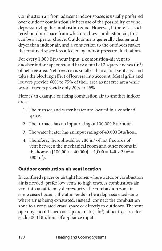
Heating and Cooling Systems120
Combustion air from adjacent indoor spaces is usually preferred over outdoor combustion air because of the possibility of wind depressurizing the combustion zone. However, if there is a shel-tered outdoor space from which to draw combustion air, this can be a superior choice. Outdoor air is generally cleaner and dryer than indoor air, and a connection to the outdoors makes the confined space less affected by indoor pressure fluctuations.
For every 1,000 Btu/hour input, a combustion-air vent to another indoor space should have a total of 2 square inches (in2) of net free area. Net free area is smaller than actual vent area and takes the blocking effect of louvers into account. Metal grills and louvers provide 60% to 75% of their area as net free area while wood louvers provide only 20% to 25%.
Here is an example of sizing combustion air to another indoor area:
1. The furnace and water heater are located in a confined space.
2. The furnace has an input rating of 100,000 Btu/hour.
3. The water heater has an input rating of 40,000 Btu/hour.
4. Therefore, there should be 280 in2 of net free area of vent between the mechanical room and other rooms in the home. ([100,000 + 40,000] ÷ 1,000 = 140 x 2 in2 = 280 in2).
Outdoor combustion-air vent location
In confined spaces or airtight homes where outdoor combustion air is needed, prefer low vents to high ones. A combustion-air vent into an attic may depressurize the combustion zone in some cases because the attic tends to be a depressurized zone where air is being exhausted. Instead, connect the combustion zone to a ventilated crawl space or directly to outdoors. The vent opening should have one square inch (1 in2) of net free area for each 3000 Btu/hour of appliance input.

Virginia Weatherization Field Guide 121
Choose an outdoor location that is sheltered, where the wall containing the vent isn’t parallel to prevailing winds. Wind blowing parallel to an exterior wall and at a right angle to the vent opening tends to de-pressurize both the combustion-air opening and the CAZ connected to it. Indoors, locate combus-tion air vents away from water pipes to prevent freezing in cold climates.
Combustion air through a supply duct
Combustion air can also come through a supply register of a forced-air duct system, which makes the CAZ a heated space and creates a connection between the CAZ and the rest of the house. This method can help weak chimney draft or depressur-ization because it supplies air to the CAZ.
PROPRIETARY COMBUSTION-AIR SYSTEMS
Any passive combustion-air inlet can potentially depressurize the combustion zone because pressure from wind or stack effect can extract air from the combustion zone instead of supplying air. Several proprietary systems are available that offer superior assurance of adequate combustion air compared to passive vents. These systems are particularly appropriate in confined areas suffering from: stubborn draft problems, combustion-zone depressurization, inadequate combustion-air, or a combi-nation of these problems.
Combustion air through supply register: The duct system can open the upstairs to providing some combustion air to supplement the combustion air available in the basement.

Heating and Cooling Systems122
Direct combustion-air supply
Many new combustion appliances are designed for direct out-door-air supply to the burner. These include most condensing furnaces, mobile home furnaces, mobile home water heaters, many space heaters, and some non-condensing furnaces and boilers. Some appliances give installers a choice between indoor
and outdoor combustion air. Outdoor combustion air is usually preferable in order to prevent the depressurization problems, combustion-air deficiencies, and draft problems.
combustion air
combustion by-products
Sealed combustion: Sealed combustion appliances draw combustion air in andexhaust combustion by-products, either using a draft fan or by pressure differenccreated by the fire.

Virginia Weatherization Field Guide 123
Fan-powered combustion air
At least one company manu-factures a proprietary combus-tion-air system that introduces outdoor air through a fan that sits on the floor and attaches to a combustion-air duct to outdoors.
Direct combustion air supply to oil-fired heaters
Oil furnaces and boilers can be either purchased new or may be retrofitted with a sealed combustion-air and venting system. The burner fan is fitted with an air boot that feeds the burner with outdoor air. The amount of outdoor air fed to the burner is usually regulated by a barometric draft control.
Fan-powered combustion air: Fans for supplying combustion air can help solve stubborn combustion air and drafting problems.
combustion-air fans
Sealed-combustion, oil-heating retrofit: Direct supply of combustion air to gun-type oil burners is a good option for shielding the oil burner from house pressures.
barometric draft control
barometric air control
gases exhausted
combustion air intake

Heating and Cooling Systems124
Combustion air combined with power venting
Both gas- and oil-fired heating systems can be supplied with combustion air by proprietary systems that combine power venting with powered combustion-air supply. The combustion air simply flows into the combustion zone from outdoors, pow-ered by the power venter. If the appliance has a power burner, like a gun-type oil burner, a boot may be available to supply combustion air directly to the burner as shown here.
4.5 FORCED-AIR SYSTEM STANDARDS
The overall system efficiency of an oil or gas forced-air heating system is affected by blower operation, duct leakage, balance between supply and return air, and duct insulation levels. Retro-fits to the forced-air system generally are more cost-effective than retrofits to the heating unit itself.
INSPECTING FURNACE HEAT EXCHANGERS
Leaks in heat exchangers are a common problem, causing the flue gases to mix with house air. Ask clients about respiratory problems, flue-like symptoms, and smells in the house when the heat is on. Also, check around supply registers for signs of soot, especially with oil heating. All furnace heat exchangers should be inspected as part of weatherization. Consider using one or more of the following 7 general options for evaluating heat exchangers.
1. Look for rust at exhaust ports and vent connector.
2. Look for flame impingement on the heat exchanger during firing.
3. Observe flame movement, change in chimney draft, or change in CO reading as blower is turned on and off.
4. Look for flame-damaged areas near the burner flame.

Virginia Weatherization Field Guide 125
5. Measure the flue-gas oxygen concentration before the blower starts and just after it has started. There should be no more than a 1% change in the oxygen concentra-tion.
6. Examine the heat exchanger, shining a bright light on one side and looking for light traces on the other using a mirror to peer into tight locations.
7. Employ chemical detection techniques, following manufacturer’s instructions.
Furnaces with heat exchanger leaks should always be replaced.
FURNACE OPERATING STANDARDS
The effectiveness of a furnace depends on its heat rise and flue-gas temperature. For efficiency you want a low heat rise and low flue-gas temperature. However, you must maintain a minimum flue-gas temperature to prevent corrosion in the venting. Apply the following furnace-operation standards to maximize the heating system’s seasonal efficiency and safety.
• Check heat rise after 5 minutes of operation. Refer to manufacturer’s nameplate for acceptable heat rise (sup-ply temperature minus return temperature). The heat rise should be between 40°F and 70°F with the lower end of this scale being preferable for energy efficiency.
• All forced-air heating systems must deliver supply air and collect return air only within the intentionally heated portion of the house. Taking return air from an un-heated area of the house such as an unoccupied basement is not acceptable.
Furnace heat exchangers: Although no heat exchanger is completely airtight, it should not leak enough to display the warning signs described here.

Heating and Cooling Systems126
• The fan-off temperature should be between 95° and 105° F, with the lower end of the scale being preferable for maximum efficiency.
• The fan-on temperature should be less than 140° F.
• The high-limit controller should shut the burner off before the furnace temperature reaches 200°F.
• On time-activated fan controls, verify that the fan is switched on within two minutes of burner ignition and is switched off within 2.5 minutes of the end of the com-bustion cycle.
If the heating system does not conform to these standards, con-sider the following improvements.
✔ Clean or change dirty filters
Inadequate heat rise:condensation andcorrosion possible.
Heat rise OK for bothefficiency and avoidanceof condensation.
Heat rise excessive:Check fan speed, heatexchanger and ducts.
Excellent fan-offtemperature if comfortis acceptable.
Borderline acceptable:Consider replacing fancontrol.
Unacceptable range:Significant savingspossible by replacingfan control.
Excellent fan-ontemperature range: Nochange needed.
Fair: Consider fan-controlreplacement if fan-offtemperature is alsoborderline.
Poor: Replace fancontrol.
20° 45° 70° 95°
85° 100° 115° 130°
100° 120° 140° 160°
Heat Rise = Supply Temperature – Return Temperature
Fan-off Temperature
Fan-on Temperature
Table 4-15: Furnace Operating Parameters

Virginia Weatherization Field Guide 127
✔ Clean the blower, increase fan speed, and improve ducted air circulation. See “Improving duct-system air-flow” on page 131.
✔ Adjust fan control to conform to the above standards, or replace the fan control if adjustment fails. Many fan controls on modern furnaces aren’t adjustable.
✔ Adjust the high-limit control to conform to the above standards, or replace the high-limit control.
DUCT AIR-TIGHTNESS STANDARDS
Duct air leakage is a major energy-waster in homes where the ducts are located outside the home’s thermal boundary in a crawl space, attic, attached garage, or leaky basement. When the weatherization job will leave these intermediate zones outside the thermal boundary, duct air-sealing is cost-effective.
Ducts should be tested to determine how much they leak before any duct air sealing is performed. Caution should be used when there is an A-Coil present in the system. For information on duct testing, see “Duct airtightness testing” on page 192.
Adjustable drive pulley: This adjustable pulley moves back and forth allowing the belt to ride higher or lower, adjusting the blower’s speed.
A fan/limit control: Turns the furnace blower on and off, according to temperature. Also turns the burner off if the heat exchanger gets too hot (high limit).
set screw
terminals
bimetal element
adjustable dial

Heating and Cooling Systems128
Duct leakage sites
Ducts located outside the thermal boundary or in an intermedi-ate zone like a ventilated attic or crawl space should be sealed. The following is a list of duct-leak locations in order of their rel-ative importance. Leaks nearer to the air handler see higher pressure and are more important than leaks further away.
✔ First, seal all return leaks within the combustion zone to prevent this leakage from depressurizing the com-bustion zone and causing backdrafting.
✔ Plenum joint at air handler: These joints may have been difficult to fasten and seal because of tight access. Go the extra mile to seal them airtight even if it requires cutting an access hole in the plenum.
✔ Joints at branch takeoffs: These important joints should be sealed with a thick layer of mastic. Fabric mesh tape is a plus for new installations or when access is easy.
✔ Joints in sectioned elbows: Known as gores, these are usually leaky.
✔ Tabbed sleeves: Attach the sleeve to the main duct with 3-to-5 screws and apply mastic plentifully.
✔ Flexduct-to-metal joints: Apply mastic to the metal sleeve. Clamp the flexduct’s inner liner over this strip of mastic with a plastic strap, using a strap tensioner. Clamp the insulation and outer liner with another strap.
✔ Support ducts and duct joints with duct hangers where needed.
✔ Seal leaky joints between building materials composing cavity-return ducts, like panned floor cavities and fur-nace return platforms.

Virginia Weatherization Field Guide 129
✔ Seal leaky joints between supply and return regis-ters and the floor, wall, and ceiling to which they are attached.
✔ Consider sealing off supply and return regis-ters in unoccupied base-ments.
✔ Seal penetrations made by wires or pipes travel-ing through ducts. Even better: move the pipes and wires and patch the holes.
Flexduct joints: Flexduct itself is usually fairly airtight, but joints, sealed improperly with tape, can be very leaky. Use methods shown here to make
strap tightener
sheet-metal screw
metal sleeve
inner linerinsulationtightened straps
tabbed sleeve
Panned floor joists: These return ducts are often very leaky and may require removing the panning to seal the cavity.
return register
return duct
leakage
leakage
metal panning

Heating and Cooling Systems130
Materials for duct air-sealing
Duct mastic is the preferred duct-sealing material because of its supe-rior durability and adhesion. Apply at least 1/16-inch thick and use rein-forcing mesh for all joints wider than 1/8 inch or joints that may experience some movement.
Two-part foam may be used to seal ducts in unconditioned areas.
Joints should rely on mechanical fasteners to prevent joint movement or separation. Tape should never be expected to hold a joint together nor expected to resist the force of compacted insulation or joint movement. Aluminum foil or cloth duct tape are not good materials for duct sealing because their adhesive often fails after a short time.
DUCT INSULATION
Insulate supply ducts that run through unconditioned areas out-side the thermal boundary such as crawl spaces, attics, and attached garages with a minimum of R-6 vinyl, foil faced insula-tion, bubble wrap, or one (1) inch of two part foam. Don’t insu-late ducts that run through conditioned areas unless they cause overheating in winter or condensation in summer. Follow the best practices listed below for installing insulation.
• Always perform necessary duct sealing before insulating ducts.
DUCT SEALANT
Duct mastic: Mastic, reinforced with fabric webbing, is the best choice for sealing ducts.

Virginia Weatherization Field Guide 131
• Insulation should cover all exposed sup-ply ducts, without sig-nificant areas of bare duct left uninsulated.
• Insulation should be fastened by mechani-cal means such as plas-tic straps. Tape can be effective for covering joints in bubble wrap.
IMPROVING DUCT-SYSTEM AIRFLOW
Inadequate airflow is a common cause of comfort complaints. The airflow capacity of the air handler may be evaluated in rela-tionship to the capacity of the furnace or air conditioner. For combustion furnaces, there should be 110 to 150 cfm of airflow for each 10,000 Btuh of output. Central air conditioners and heat pumps should deliver 400 cfm of airflow per ton of cooling capacity. See “Furnace replacement” on page 137 for more information about evaluating airflow.
When the air handler is on there should be a strong flow of air out of each supply register, providing its balancing damper is open. Low airflow may mean that a branch is blocked or sepa-rated, or that return air is not sufficient. When low airflow is a problem, consider the following obvious improvements.
✔ Clean or change filter.
✔ Clean furnace blower.
✔ Clean air-conditioning or heat pump coil. (If the blower is dirty, the coil is probably also dirty.)
✔ Increase blower speed.
plastic strap holds insulation to round duct
bubble wrap duct insulation
Duct insulation: Supply ducts, located in unheated areas, should be insulated with bubble wrap to a minimum of R-6.
Joints sealed with two-part foam
Heating and Cooling Systems132
✔ Lubricate blower motor, and check tension on drive belt.
✔ Repair or replace bent, damaged, or restricted registers.
✔ Confirm that supply and return ducts are properly sized. See “Heating and cooling duct sizes” on page 135.
Filter and blower maintenance
A dirty filter can reduce airflow significantly. Take action to pre-vent filter-caused airflow restriction by the following steps:
• Install a filter whistle that indicates when the filter is dirty.
• Insure that filters are easy to change or clean and are easily accessible. Filter grills may be installed to improve accessibility.
• Stress to the client the importance of changing or clean-ing filters, and suggest to the client a regular filter-main-tenance schedule.
• Clean the blower. This task involves removing the blower and removing dirt completely with a brush or water spray.
• Special air-cleaning filters offer more resistance than standard filters, especially when saturated with dust. Avoid using them, unless you test for airflow after instal-lation.

Virginia Weatherization Field Guide 133
• Measure the current draw of the blower motor in amps. If the amp measurement exceeds the motor amp rating by more than 10%, replace the motor.
Duct improvements to increase airflow and improve comfort
Consider the following improvements in response to customer complaints and conditions you observe during a thorough duct inspection. Unbalanced airflow through ducts can pressurize or depressurize rooms, leading to increased air leakage through the building shell. For information on how to test these room pres-sures, see “Measuring duct-induced room pressures” on page 195. Consider the following duct changes to increase system air-flow and reduce the imbalance between supply and return.
• Remove obstructions to registers and ducts such as rugs, furniture, and objects placed inside ducts, like children’s toys and water pans for humidification.
• Remove kinks from flex duct, and replace collapsed flex duct and fiberglass duct board.
Furnace filter location: Filters are installed on the return-air side of forced air systems. Look for them in one or more of the places illustrated here.
Washable filter installed on a rack inside the blower compartment.
Panel filter installed in return register
Panel filter installed in filter slot in return plenum

Heating and Cooling Systems134
• Install additional supply ducts and return ducts as needed to provide heated air throughout the building, especially into additions to the building.
• Install a transfer grille between the bedroom and main body of house to improve airflow.
• Undercut bedroom doors, especially in homes with sin-gle return registers.
• Retrofit jumper ducts, composed of one register in the bedroom, one register in the central return-air zone, and a duct in between (usually running through an attic or crawl space).
• Install registers and grilles where missing.
New ducts
New ducts should not be installed in unconditioned spaces unless absolutely necessary. If ducts are located in uncondi-tioned spaces, joints should be sealed and the ducts insulated as described previously. See “Duct air-tightness standards” on page 127 and “Duct insulation” on page 130.
Restricted return air: Return air is often restricted, requiring a variety of strategies to relieve the resulting house pressures and low system airflow. Installing an additional return duct directly into the air handler is a preferred strategy.
Installing grills in doors or through walls allows return air to escape from bedrooms
Jumper ducts can bring air from a restricted area of the home back to a main return register.

Virginia Weatherization Field Guide 135
New ducts must be physically connected to the existing distribu-tion system or to the furnace. Install balancing damper in each new branch duct. Registers should terminate each new supply or return branch duct.
4.6 DUCT SYSTEM QUICK SIZING CHART
Table 4-16: Heating and cooling duct sizes
Airflow CFM Supply or return main duct size200 8” RD or 6” X 8”300 9” RD or 8” X 8”400 10” RD or 10” X 8”500 11” RD or 14” X 8” 10” x 10”600 12” RD or 16” X 8” 12” x 10”700 13” RD or 18” X 8” 14” x 10” 12” x 12”800 14” RD or 22” X 8” 16” x 10” 14” x 12”
1000 16” RD or 28” X 8” 20” x 10” 16” x 12”1200 17” RD or 32” X 8” 24” x 10” 20” x 12”1400 18” RD or 28” x 10” 24” x 12”1600 20” RD or 32” x 10” 28” x 12”1800 21” RD or 30” x 12”2000 22” RD or 34” x 12”
Supply branch duct sizea
a. Air moving device must have available 0.1 inch of external pressure for each 100 equivalent feet of duct system.
80 5” RD120 6” RD or 3.5” x 10”160 7” RD
Return branch duct sizea
175 Stud wall 14” x 3.5”400 Panned Joist 14” x 8”
Return air grille size200 80 Sq. In.400 160 Sq. In.600 240 Sq. In.800 340 Sq. In.
1000 440 Sq. In.1200 540 Sq. In.

Heating and Cooling Systems136
4.7 HEATING-SYSTEM REPLACEMENT SPECIFICATIONS
Don’t assume that older furnaces and boilers are inefficient until testing them. During testing, make appropriate efforts to repair and adjust the existing furnace or boiler, before deciding to replace it. Replacement parts like gas valves and controls for older heating units are commonly available.
Heating appliances are often replaced when the cost of repairs and retrofits exceeds one half of estimated replace-ment costs. Estimate the repair and retrofit costs and com-pare them to replacement cost before deciding between retro-fit and replacement.
Heating appliances that are not operational and/or not repairable may be replaced.
New heating appliances must be installed to manufacturer’s specifications, following all applicable building and fire codes. Replacement furnaces and boilers should have a minimum AFUE of 80%. However gas furnaces and boilers with AFUEs of 90% should be given special consideration. These high-efficiency furnaces are direct-vent, sealed-combustion units with health and safety benefits in addi-tion to their superior efficiency and significantly lower fuel usage.
Heat load calculations, used to size the new heater, should account for reduced heating loads, resulting from insulation and air-sealing work. Heat load calculations should follow the proce-dures in Manual J, NEAT, MHEA, or a DOE-approved audit.
Oil-fired downflow furnaces: Their design hasn’t changed much in recent years except for the flame-retention burner.
burner
heat exchanger
blower
primary control

Virginia Weatherization Field Guide 137
Specifications are presented here first according to fuel-type—oil or gas—then by distribution type: forced air, hot water, or steam.
FURNACE REPLACEMENT
The overall goal of furnace replacement is to provide a forced-air heating system in vir-tually new condition, even though existing supply and return ducts may remain. Any design flaws in the ducts and registers should be diagnosed and cor-rected during the furnace replace-ment.
Observe the following standards in furnace installation.
✔ Furnace should be sized to the approximate heating load of the home, accounting for post-weatherization heat-loss reductions.
✔ Installer should add return ducts or supply ducts as part of furnace replacement to improve air distribution, to eliminate duct-induced house pressures, and to estab-lish acceptable values for static pressure and heat rise. See “Heating and cooling duct sizes” on page 135.
✔ Supply and return plenums should be mechanically fas-tened with screws and sealed to air handler with mastic and fabric mesh tape to form an essentially airtight connection on all sides of these important joints.
✔ All ducts should be sealed as described in “Duct air-tightness standards” on page 127.
Sealed combustion heaters: Sealed combustion furnaces and boilers prevent the air pollution and house depressurization caused by some open-combustion heating units.

Heating and Cooling Systems138
✔ Heat rise (supply temperature minus return tempera-ture) must be within manufacturer’s specifications.
✔ High limit should stop fuel flow within 10% of 200° F. Furnace must not cycle on high limit.
✔ Fan control should be set to activate fan at 130° to 140° F and deactivate it at 95° to 105° F. Slightly higher set-tings are acceptable if these recommended settings cause a comfort complaint.
80+ gas furnace: An 80+ furnace has a restrictive heat exchanger, a draft fan, and has no draft diverter or standing pilot.
90+ gas furnace: A 90+ furnace has a condensing heat exchanger and a stronger draft fan for pulling combustion gases through its more restrictive heat exchange system and establishing a strong positive draft.
condensingheat exchanger
burner
draft fan
combustion air

Virginia Weatherization Field Guide 139
✔ Static pressure, mea-sured in both supply and return plenums should be within manufacturer’s speci-fications.
✔ Blower should not be set to operate contin-uously.
✔ Seal holes through the jacket of the air han-dler with mastic or foil tape.
✔ Filters should be held firmly in place and provide complete cov-erage of blower intake or return register. Filters should be easy to replace.
OIL-FIRED HEATING INSTALLATION
The overall goal of the system replacement is to provide an oil-fired heating system in virtually new condition, even though components like the oil tank, chimney, piping, or ducts may remain. Any maintenance or repair on these remaining compo-nents should be considered part of the job. Any design flaws related to the original system should be diagnosed and corrected during the heating-system replacement.
✔ Examine existing chimney and vent connector for suit-ability as venting for new appliance. The vent connector may need to be re-sized and the chimney may need to be re-lined.
55
∆T°
Static pressure and temperature rise: Testing static pressure and temperature rise across the new furnace should verify that the duct system isn’t restricted. The correct airflow, specified by the manufacturer, is necessary for high efficiency.

Heating and Cooling Systems140
✔ Check clearances of heating unit and its vent connector to nearby combustibles, by referring to NFPA 31. See “Clearances to Combustibles for Vent Connectors” on page 104.
✔ Check for the presence of a control that will interrupt power to the burner in the event of a fire.
✔ Test oil pressure to verify compliance with manufac-turer’s specifications.
✔ Test transformer voltage to verify compliance with manufacturer’s specifications.
✔ Test control circuit amperage, and adjust thermostat heat anticipator to match.
✔ Adjust oxygen, flue-gas temperature, and smoke num-ber to match manufacturer’s specifications.
✔ Inspect oil tank and remove deposits at bottom of tank as part of new installation.
✔ Install new fuel filter and purge fuel lines as part of new installation.
✔ Bring tank and oil lines into compliance with NFPA 31, Chapters 2 and 3.
Oil heating system: Components of an oil heating system may need repair and cleaning during replacement of the furnace or boiler.
oil storage tank
barometric draft control
fill pipe
vent
filter
service switch
chimney with liner

Virginia Weatherization Field Guide 141
✔ Check for emergency shut-off, installed in the living space.
✔ See “Min. Combustion Standards, Oil-Burning Appli-ances” on page 90.
GAS-FIRED HEATING INSTALLATION
The overall goal of the system replacement is to provide a gas-fired heating system in virtually new condition, even though existing components like the gas lines, chimney, water piping, or ducts may remain. Any necessary maintenance or repair on these remaining components should be considered part of the installation. Any design flaws in the original system should be diagnosed and corrected during the heating-system replace-ment.
The new furnace should have an Annual Fuel Utilization Effi-ciency (AFUE) of at least 80% and have a draft-assisting fan, electronic ignition, and no draft diverter. However, a sealed-combustion, condensing furnace with an AFUE of at least 90% is strongly recommended.
✔ Check clearances of heating unit and its vent connector to nearby combustibles, according to the International Fuel Gas Code (IFGC). See“Guide to Venting Stan-dards” on page 101 for more information about National Fire Protection Association (NFPA) Stan-dards.
✔ Clock gas meter to insure correct gas input. See “Mea-suring BTU input on natural gas appliances” on page 84.
✔ If necessary, measure gas pressure, and increase or decrease gas pressure to obtain proper gas input.
✔ Test gas water heater to insure that it vents properly after installation of a sealed-combustion, 90+ AFUE furnace. Install a chimney liner if necessary.

Heating and Cooling Systems142
✔ Set thermostat’s heat anticipator to the amperage mea-sured in the control circuit, or follow thermostat manu-facturer’s instructions for adjusting cycle length.
✔ Follow manufacturer’s venting instructions along with the IFGC to establish a proper venting system.
✔ Ensure proper sediment trap on gas line.
ELECTRIC-FURNACES AND ELECTRIC BASEBOARD HEAT
The purpose of servicing electric furnaces and electric base-board heat is to clean the heat exchangers and blower.
✔ Check and clean thermostat.
✔ Clean and lubricate blower if appropriate.
✔ Clean or replace all filters, and provide a six (6) month supply of filters.
✔ Vacuum and clean housing around electric elements, if dirty.
Table 4-17: Combustion Standards for Gas-Burning Furnaces
Gas Combustion Performance Indicator
80+ Furnace
90+ Furnace
Oxygen (% O2) 6–9% 6–9%
Stack temperature (°F) 310°–400° 90°–120°
Carbon monoxide (CO) parts per mil-lion (ppm)
≤ 100 ppm
≤ 100 ppm
Steady-state efficiency (SSE) (%) 80–82% 92–97%
Gas pressure (inches water column or IWC)
3.2–4.2 IWC
3.2–4.2 IWC
Supply temperature (°F) 120–140° 95–140°

Virginia Weatherization Field Guide 143
✔ Clean fins on electric-baseboard systems, if applicable.
✔ Take extra care in duct sealing and duct airflow improvements for electric furnaces because of the high cost of electricity. See “Duct air-tightness standards” on page 127 and “Improving duct-system airflow” on page 131.
✔ Verify that safety limits, heat rise, and static pressure conform to manufacturer’s specifications.
4.8 HOT-WATER AND STEAM STANDARDS
The following standards refer to hot-water and steam systems commonly found in single-family homes. Hot-water and steam systems found in multifamily buildings are generally more com-plex and should be tested and evaluated by professionals experi-enced in their operation.
BOILER EFFICIENCY AND MAINTENANCE
Boilers can maintain good performance and efficiency for many years if they are regularly maintained and tuned-up. Boiler per-formance and efficiency improve after effective maintenance and tune-up procedures. There are more ways for performance and efficiency to deteriorate in boilers compared to furnaces. Specifically these are:
• Corrosion, scaling, and dirt on the water side of the heat exchanger.
• Corrosion, dust, and dirt on the fire side of the heat exchanger.
• Excess air during combustion from air leaks and incor-rect fuel-air mixture.
• Off-cycle air circulation through the firebox and heat exchanger, removing heat from stored water.

Heating and Cooling Systems144
Consider the following maintenance and efficiency improve-ments for both hot-water and steam boilers.
✔ Check for leaks on the boiler, around its fittings, or on any of the distribution piping connected to the boiler.
✔ Clean fire side of heat exchanger of noticeable dirt.
✔ Check doors and cleanout covers for air leakage. Replace gaskets or replace warped doors or warped cleanout covers.
✔ Drain water from the boiler drain until the water flows clean.
HOT-WATER SPACE-HEATING Hot-water heating is generally a little more efficient than forced-air heating and consid-erably more efficient than steam heating. The most sig-nificant energy wasters in hot-water systems are poor steady-state efficiency, off-cycle flue losses robbing heat from stored water, and boilers oper-ating at too high a water tem-perature.
Consider the following safety checks and improvements.
✔ Confirm the existence of a 30-psi-rated pressure-relief valve. Replace a malfunctioning valve or add one if
Cast-iron sectional boilers: The most common boiler type for residential applications.
cast-iron section
burner
Tankless coil water heater found on some boilers
controls

Virginia Weatherization Field Guide 145
none exists. Note signs of leakage or discharges, and find out why the relief valve is discharging.
✔ Make sure that the expansion tank isn’t waterlogged or sized too small for the system. This could cause the pressure-relief valve to discharge. Test expansion tank for its rated air pressure—often 15 psi.
✔ If rust is observed in venting, verify that return water temperature is above 130° F for gas and above 150° F for oil, to prevent acidic condensation.
✔ High-limit control should deactivate burner at 180° F or less.
✔ Lubricate circulator pump(s) if necessary.
Consider the following efficiency improvements.
✔ Repair water leaks in the system.
✔ Boiler should not have low-limit control for maintain-ing a minimum boiler-water temperature, unless the boiler is heating domestic water in addition to space heating.
Note: You can recognize a hot-water boiler by its expansion tank, located somewhere above the boiler. This cylindrical tank provides an air cushion to allow the system’s water to expand and contract as it is heated and cooled without discharging through the relief valve.

Heating and Cooling Systems146
✔ Bleed air from radiators and piping through air vents on piping or radia-tors. Most systems have an automatic fill valve. If there is a manual fill valve for refilling system with water, it should be open to push water in and air out, during air purging.
✔ Consider installing a two-stage thermostat or timer control to increase circulator on-time compared to burner on-time.
✔ Consider installing outdoor reset controllers on larger boilers to regulate water temperature, depending on outdoor temperature.
✔ After control improvements like two-stage thermostats or reset controllers, verify that return water tempera-ture is high enough to prevent condensation and corro-sion in the chimney as noted previously.
✔ Vacuum and clean fins of fin-tube convectors if you notice dust and dirt there.
Purging air: Trapped air collects at the hot-water system’s highest parts. Bleeding air from radiators fills the radiator and gives it more heating surface area.
trapped air
air bleed valve

Virginia Weatherization Field Guide 147
✔ Insulate all supply pip-ing, passing through unheated areas, with foam pipe insulation, at least one-inch thick, rated for temperatures up to 200° F.
✔ Consider installing electric vent dampers on atmospheric gas- and oil-fired high-mass boilers.
STEAM HEATING
Steam heating is less efficient than hot-water heating because higher temperature heating systems are less efficient than lower temperature ones. A steam boiler heats water to its boiling point before making steam or accomplishing any space heating. Steam boilers are also more hazardous because of the steam pressure. For these reasons heating-system replacement with a hot-water or forced-air system should be considered, depending on the boiler’s operating efficiency after a tune-up.
If the steam-heating system must remain, operate it at the lowest steam pressure that will heat the building. This may be consider-ably less than 1 psi on the boiler-pressure gauge. Large buildings may need higher steam pressures, but smaller ones can operate at small steam pressure. Traps and air vents are crucial to oper-ating at a low steam pressure. Electric vent dampers will reduce off-cycle losses for both gas- and oil-fired systems.
Vent dampers: Electric vent dampers close the chimney when the burner isn’t firing, preventing circulating air from carrying the boiler’s stored heat up the chimney.
A solenoid opens the damper and connects a switch in series with the burner.
Note: You can recognize a steam boiler by its sight glass, which will indicate the boiler’s water level. Notice that the water doesn’t completely fill the boiler, but instead allows a space for the steam to form above the boiler’s water.

Heating and Cooling Systems148
Perform the following for safety and maintenance checks on steam systems.
✔ Verify that steam boilers are equipped with high-pres-sure limits and low-water cut-off controls.
✔ Verify that flush valves on low water cutoffs are opera-ble and do not leak.
✔ On steam boilers with externally mounted low water cutoffs, verify the function of the control by flushing the low water cutoff with the burner operating. Com-bustion must cease when the water level in the boiler drops below the level of the float.
✔ Drain water out of blow-down valve until water runs clear.
✔ Check with owner about chemicals added to boiler water to prevent corrosion and mineral deposits. Add chemicals if necessary.
One-pipe and two-pipe steam systems: Still common in multifamily buildings, one-pipe steam works best when very low pressure steam can drive air out of the piping and radiators quickly through plentiful vents. Vents are located on each radiator and also on main steam lines.
condensate tank
vents
traps
Two-pipe steam systems: Radiator traps keep steam inside radiators until it condenses. No steam should be present at the condensate tank.

Virginia Weatherization Field Guide 149
✔ Ask owner about instituting a schedule of blow-down and chemical-level checks.
Consider the following efficiency checks and improvements for steam systems.
✔ Verify that high-pressure limit control is set at or below 1 (one) psi.
✔ Verify steam vents are operable and that all steam radi-ators receive steam during every cycle. Unplug vents as necessary. Add vents to steam lines and radiators as needed to achieve this goal.
✔ Check steam traps with a digital thermometer or listen-ing device to detect any steam escaping from radiators through the condensate return. Replace leaking steam traps or their thermostatic elements.
✔ Repair leaks on the steam supply piping or on condensate return piping.
✔ Consider a flame-reten-tion burner and elec-tric vent damper as retrofits for steam boil-ers.
✔ Clean fire side of heat exchanger of noticeable dirt.
✔ All steam piping, pass-ing through uncondi-tioned areas, should be insulated to at least R-3 with fiberglass or spe-cially designed foam pipe insulation rated for steam piping.
Steam traps: Steam enters the steam trap heating its element and expanding the fluid inside. The expanded element plugs the steam’s escape with a valve.
steam first entering
expanding fluid
condensed water escaping
condensing steam
valve seated
valve un-seated
is trapped

Heating and Cooling Systems150
BOILER REPLACEMENT
Don’t assume that a boiler replacement will save much energy unless the boiler’s steady-state efficiency can’t be raised to around 80%. The overall goal of boiler replace-ment is to provide a hydronic heating system in virtually new condition, even though existing supply and return pip-ing may remain. Any design flaws in the venting, piping, and controls should be diag-nosed and corrected during the boiler replacement.
Boiler piping and controls present many options for zoning, boiler staging, and energy-saving controls. Dividing homes or multifamily buildings into zones, with separate thermostats, can significantly improve energy efficiency over operating a single zone. Modern hydronic controls can provide different water temperatures to different zones with varying heating loads.
The new boiler should have an AFUE of at least 80%. The new boiler should be equipped with electronic ignition and a draft-assisting or power-draft fan. It should not have a draft diverter.
Cast-iron sectional boilers: Are the most common boilers for residential applications.
cast-iron section
burner
Tankless coil water heater found on some boilers
controls

Virginia Weatherization Field Guide 151
Boiler seasonal efficiency is more sensitive to proper sizing than is furnace efficiency. A boiler should not be oversized by more than 15%. Consider the following spec-ifications when replacing boilers.
✔ Inspect chimney for deterio-ration and correct sizing. Repair and re-line the chim-ney as necessary.
✔ An effective air-excluding device or devices must be part of the new hydronic system.
✔ Install the pump near the downstream side of the expansion tank to prevent the suction side of the pump from depressurizing the piping, which can pull air into the piping.
✔ The expansion tank should be replaced, unless it is ver-ified to be the proper size for the new system and tested for correct pressure during boiler installation.
✔ Verify that return water temperature is above 130° F for gas and above 150° F for oil, to prevent acidic conden-sation within the boiler, unless the boiler is designed for condensing. Install piping bypasses, mixing valves, pri-mary-secondary piping, or other strategies, as neces-sary, to prevent condensation within a non-condensing boiler.
✔ Recognize the boiler installation’s potential for causing condensation in the vent connector and chimney. If the boiler’s steady-state efficiency is expected to be more than 83%, condensation-resistant venting and conden-sation drains should be designed into the venting sys-
vent
combustion air
burner
heat exchanger
Wall-hung boiler: Energy-efficient wall-hung boilers require less space of standard boilers.
draft fan

Heating and Cooling Systems152
tem. These custom venting systems are provided or specified by the manufacturer.
✔ A pressure-relief valve must be installed with the new boiler and connected to a drain pipe, draining into a floor drain.
✔ Maintaining a low-limit boiler-water temperature is wasteful. Boilers should be controlled for a cold start, unless the boiler is used for domestic water heating.
✔ Insulate all supply piping, outside conditioned spaces, with foam or fiberglass pipe insulation.
baseboard convectors
expansion tank
pumpair excluder
boiler
pressure-relief valve
return
insulated supply
Simple reverse-return hot-water system: The reverse-return method of piping is the simplest way of balancing flow among heat emitters.

Virginia Weatherization Field Guide 153
✔ Extend new piping and radiators to condi-tioned areas like addi-tions and finished basements, currently heated by space heat-ers.
✔ For large boilers, con-sider installing outdoor reset controllers to adjust supply water temperature according to outdoor temperature.
✔ For large boilers, consider installing a cutout controller that prevents the boiler from firing when the outdoor temperature is above a certain setpoint where heat is not needed.
4.9 WATER-HEATING ENERGY SAVINGS
Gas-, propane-, and oil-fired water heaters must be tested, maintained, repaired, adjusted, and replaced as described in the next chapter, titled “Heating and Cooling Systems” on page 79. Observe the following gen-eral specifications concerning water heaters.
✔ A water heater must have a pressure-and-temperature relief valve and a safety discharge pipe. Install a relief valve and discharge pipe if none exists. The discharge pipe should ter-minate 6 inches above the floor, outside the dwelling,
Reset controller: The circulating water is controlled by the reset controller according to the outdoor temperature.
outdoor sensorreset controller
aquastat boiler-water sensor
Standard gas water heater: Is an open combustion appliance often troubled by spillage and
draft diverter
burner
cold water dip tube
sacrificial anode
Turbulator reduces flow rate of combustion gases through the flue to squeeze more heat out of the gases

Heating and Cooling Systems154
outside the perimeter of a mobile home, or as specified by local codes. The discharge pipe should be made of rigid metal pipe or approved high temperature plastic pipe.
✔ Water heaters should be insulated to at least R-5 with an external insulation blanket, unless the water-heater label gives specific instructions not to insulate or the water heater is already insulated.
✔ Water heater insulation must not obstruct draft diverter, pressure relief valve, thermostats, hi-limit switch, plumbing pipes, or element/ther-mostat access plates.
✔ Adjust water tempera-ture between 115° and 120°F with clients’ approval, unless the client has a older auto-matic dishwasher without its own water-heating booster. In this case the maximum setting is 140°F. When making electric water heater temperature adjust-ments, be sure power to the unit is turned off before removing access panels.
✔ Inspect faucets for hot-water leaks and repair leaks if found.
WATER-SAVING SHOWER HEAD
The shower is typically the biggest hot-water user. You can mea-sure shower volume by measuring the time it takes to fill a one-gallon plastic milk jug with the top cut out to fit over the shower head. If the jug fills in less than 20 seconds, your flow rate is
90
110 130 150
U N I T R O L
HO
T
WARM
Electric
Gas
Setting hot-water temperature: Getting the temperature between 115 and 120°F can take a few adjustments and temperature measurements.

Virginia Weatherization Field Guide 155
more than 3 gallons per minute. In this case, buy a water-saving shower head rated for a flow of 1.5 to 2.5 gallons per minute.
GAS- AND OIL-FIRED WATER-HEATER INSULATION
✔ Keep insulation at least 2 inches away from the burner or gas valve. No insulation should be installed directly below the burner access panel.
✔ Do not insulate the tops of gas- or oil-fired water heat-ers.
Water-saving shower heads: Two varieties of shower heads are shown here. The showerhead on the left produces less steam and poses less of a risk of moisture problems.
pressure relief valveinsulated top
no insulation on top
insulation cut away at burner access door, gas valve, and drain.
insulation marked at access doors for elements and their controls
Water heater insulation: Insulation should be installed carefully so it doesn’t interfere with the burner, elements, draft diverter, or pressure relief valve.
discharge pipeElectric water heater Gas water heater

Heating and Cooling Systems156
Electric water-heater insulation
✔ Set both upper and lower thermostat to keep water at 120°F before insulating water heater. Make sure power to the unit is turned off before removing access panels.
✔ Insulation may cover the water heater’s top if the insu-lation will not obstruct the pressure relief valve.
✔ Access plates should be marked on the insulation facing to locate heating elements and their thermostats.
✔ Overlapped ends of the protective backing should be sealed and banded in order to provide an adequate seal on fiberglass blanket.
✔ Water heaters located within three (3) feet of furnaces or stoves should not be insulated.
PIPE INSULATION
✔ Insulate the first 6 feet of both hot- and cold-water pipes.
✔ Cover elbows, unions and other fittings to same thick-ness as pipe.
✔ Keep pipe insulation at least 6 inches away from flue pipe.
✔ Interior diameter of pipe insulation sleeve should match exterior diameter of pipe.
ELECTRIC WATER–HEATER SAFETY AND EFFICIENCY
✔ Electric water heaters should be serviced by a dedicated electrical circuit.
✔ Replace damaged wiring and correct loose or improper wiring connections.

Virginia Weatherization Field Guide 157
✔ A replacement electric water heater should have an energy factor of at least 0.88 and be equipped with at least three inches of foam insulation.
GAS AND OIL WATER-HEATER REPLACEMENT
Existing gas water heaters typically use 250 or more therms per year. New gas water heaters us as little as 175 therms per year. A savings of around 75 therms can repay the initial investment in 4-to-9 years at today’s gas costs.
Any replacement gas or oil water heater must have an energy factor of at least 0.61 or have a minimum of 2 inches of foam insulation. Replacement water heaters should be wrapped with external insulating blankets for additional savings, unless the manufacturer recommends against installing an external blan-ket.
In tight homes or homes where the mechanical room is located in living areas, replacement gas or oil water heaters should be either power-draft or sealed-combustion. Sealed-combustion water heaters are preferred in tight homes with the water heater installed in a living space.
4.10 MAINTAINING AIR-CONDITIONING SYSTEMS
Many low-income clients in the Southeast have room air condi-tioners and a smaller percentage have central air conditioning systems. Maintaining clean filters and coils is essential to keep-ing air conditioners running at an acceptable efficiency. Other

Heating and Cooling Systems158
air-conditioning adjustments require more training and skill in diagnosing specific problems.
Air conditioners come in two basic types, packaged systems and split systems. Packaged air conditioners include room air condi-tioners and room heat pumps, along with packaged central air conditioners mounted on roofs and on concrete slabs outdoors. Split-systems have a condenser outdoors and an air-condition-ing coil, located indoors inside a furnace, heat pump, or adjoin-ing main supply duct.
Refrigeration and air-conditioning cycle: Refrigerant evaporates in the evaporator, absorbing heat from the metal coil and circulating air. The compressor compresses the refrigerant, preparing it to condense within the condenser. The condensing refrigerant heats the condenser coil to a significantly higher temperature than the outdoor air and so the outdoor circulating through the condenser is heated and takes away the heat collected by the evaporator indoors.
evaporatorcondenser
compressor
expansion device
fan fan
high pressure low pressure
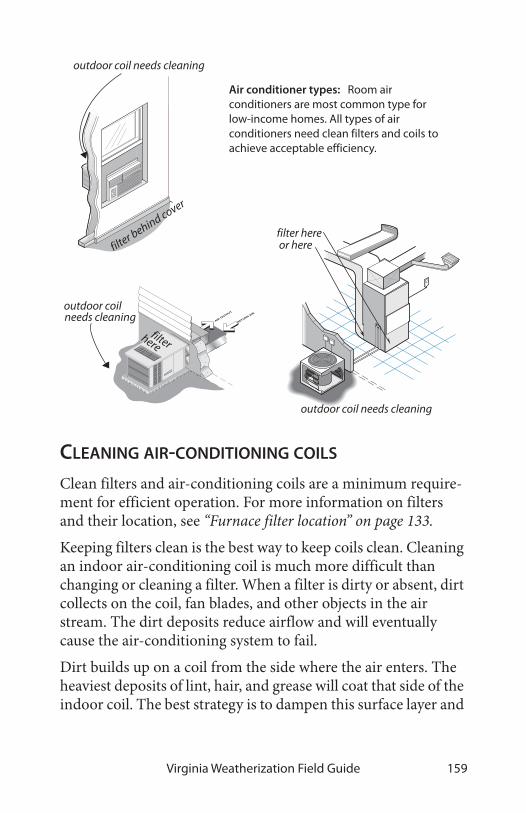
Virginia Weatherization Field Guide 159
CLEANING AIR-CONDITIONING COILS
Clean filters and air-conditioning coils are a minimum require-ment for efficient operation. For more information on filters and their location, see “Furnace filter location” on page 133.
Keeping filters clean is the best way to keep coils clean. Cleaning an indoor air-conditioning coil is much more difficult than changing or cleaning a filter. When a filter is dirty or absent, dirt collects on the coil, fan blades, and other objects in the air stream. The dirt deposits reduce airflow and will eventually cause the air-conditioning system to fail.
Dirt builds up on a coil from the side where the air enters. The heaviest deposits of lint, hair, and grease will coat that side of the indoor coil. The best strategy is to dampen this surface layer and
RETURN AIR
AIR OUTPUT
Air conditioner types: Room air conditioners are most common type for low-income homes. All types of air conditioners need clean filters and coils to achieve acceptable efficiency.
filter here
filter
filter behind cover
outdoor coil needs cleaning
outdoor coil needs cleaning
or here
here
outdoor coilneeds cleaning

Heating and Cooling Systems160
brush the heavy dirt off before trying to wash the finer dirt out with cleanser and water.
The outdoor coils of air conditioning systems aren’t protected by filters. They get dirty depending on how much dust is in the outdoor air. If there is little dust and pollen in an area, the out-door coil may only need cleaning every three years or so. How-ever, if there is a lot of pollen and dust, annual cleaning would be a good practice. It would be a safe assumption that all outdoor coils need cleaning.
Cleaning room air conditioner coils
Room air conditioners have flimsy foam or fiberglass filters that lie up against the inside coil (evaporator coil). It’s good practice to carry a roll of filter material to replace worn-out or non-exis-tent filters. Cleaning the indoor coil is easy since the heaviest dirt collects on the surface of the coil facing the inside of the home. Cleaning the outdoor coil (condenser coil) is more diffi-cult. Usually cleaning the outdoor coil involves removing the room air conditioner from the window and taking it to an out-door location where you can use a hose. The housing of the air conditioner must be removed to clean the outdoor coil.
Air-conditioning coils: Evaporator and condenser coils gather dust over time, which reduces airflow and heat transfer.
Slant coil
A-coil
coiled copper tubing

Virginia Weatherization Field Guide 161
Observe the following steps when cleaning the indoor and out-door coils of a room air conditioner.
1. Remove the grill and filter on the interior side of the unit.
2. Unplug and remove the air conditioner temporarily from the window or wall. With some units, the mechanical parts slide out of the housing, and with oth-ers you must remove the whole unit, housing and all.
3. Take the unit to an clean outdoor area that drains well, like a driveway or patio.
4. Cover the compressor, fan motor, and electrical compo-nents with plastic bags, held in place with rubber bands.
5. Dampen each of the coils with a light spray of water, then rake as much dirt off the coils as you can with an old hairbrush.
indoor coiloutdoor coil
filter
removable grill
housing fan motor(runs both fans)
condensate drain
compressor
controls
Cleaning room air conditioners: Room-air-conditioner performance deteriorates as it accumulates dirt. The unit will eventually fail to cool the room or break down unless cleaned.

Heating and Cooling Systems162
6. Spray some heavy-duty household cleaner into both coils, and let the cleaner set for a minute or two.
7. Rinse the cleaner and dirt out of the coils with a gentle spray from a hose.
8. Repeat the process until the water draining from the coils is clean.
9. Straighten bent fins with a fin comb to prevent bent fins from reducing airflow.
Cleaning blowers and indoor evaporator coils
Every indoor evaporator coil should be protected by an air filter that fills the entire cross-sectional area of return duct leading to the blower and indoor coil. Filters are easier to change or clean compared to cleaning a blower or coil. If equipped with clean well-fitting filters, the blower and coil will remain clean for many years. However, many coils haven’t had the benefit of such filters and are packed with dirt.
1. Shut off the main switch to the air handler.
2. Open the blower compartment and look into the blades of the blower, using a flashlight. Reach in and slide your finger along a fan blade. Have you collected a mound of dust?
3. If the blower is dirty, remove it and clean it. If you remove the motor, you can use hot water or cleaner and water to remove the dirt.
4. If the blower was dirty, the indoor coil is probably also dirty. Inspect the coil visually if you have access.
5. If the coil is dirty, clean it using a brush, cleaner and water as described previously in “Cleaning room air conditioner coils” on page 160.
6. Straighten bent fins with a fin comb to prevent bent fins from reducing airflow.

Virginia Weatherization Field Guide 163
Cleaning an A-coil: A-coils are found in upflow and downflow air handlers. In downflow models the dirt collects on top and on upflow units dirt collects on the bottom.
A-coils are found in the air-handler cabinet or main duct above the furnace

Heating and Cooling Systems164

Virginia Weatherization Field Guide 165
CHAPTER 5: DIAGNOSING SHELL & DUCT AIR LEAKAGE
An air barrier, aligned with the insulation, forms the building’s thermal boundary. The home may or may not have an effective air barrier surrounding it. The testing described here will help you analyze the existing air barriers and decide whether and where air sealing is needed. The energy impact of duct leakage depends on whether the ducts are located within or outside of the thermal boundary.
Controlling shell air leakage is the key ingredient in a successful weatherization job. Air leakage influences every aspect of weatherization. The decisions you make about sealing air leaks will affect a building dramatically throughout its lifetime. Note these important effects of air leakage.
• Air leakage causes 5% to 40% of a building’s heat loss.
• Air leakage can significantly reduce insulation R-value.
• Air leakage moves moisture into and out of the house, and exerts a wetting and/or drying effect.
• The type and amount of air leakage can determine whether or not a combustion appliance like a furnace or fireplace will vent its gases out the chimney as it should.
Furthermore, air leakage usually provides ventilation for exhausting pollutants and admitting fresh air. However, air leaks can bring pollutants in as easily as they let pollutants out.
Air sealing or duct sealing may affect combustion-appliance venting by increasing house pressures or reducing the available supply of combustion air. After all weatherization materials have been installed, all crews or contractors must conduct worst-case draft testing and check the safety of all combustion appliances.
The first goal of air-leakage and pressure testing is to decide how much time and effort is required to achieve acceptable air-leak-

Diagnosing Shell & Duct Air Leakage166
age and duct-leakage rates, while safeguarding indoor air qual-ity. For more on indoor air quality, see “Client health and safety” on page 16.
The second goal of leak testing is to decide where to locate the air barrier when an intermediate zone like an attic or crawl space presents two choices of air barriers. The ceiling is usually the thermal boundary, rather than the roof. However, at the foundation, the air barrier can be located at the first floor or at the foundation wall.
Duct leakage in the heating system is now established as one of the major treatable energy problems in homes. However, sealing every joint without testing can be a waste of time and money. Duct-leakage tests help you determine the severity and locations of duct leaks.
The reason for the number of air-leakage and duct-leakage tests is that there is so much uncertainty about air leakage and duct leakage. Air leakage and duct leakage are a problem in many homes but not in others. Testing is needed because there simply is no accurate prescriptive method for determining the severity and location of leaks. Depending on the complexity of a home, you may need more or less testing to control air leakage and duct leakage to within accepted standards.
Do ducts supply heated air to the addition?
Are the crawl space ducts inside or outside the air barrier?
Where is the primary air barrier: at the rafter or ceiling joist?
Is the half basement inside or outside the air barrier? Is
Is the crawl space vented?Is this floor cavity connected to outdoors?
Questions to ask during an

Virginia Weatherization Field Guide 167
5.1 BLOWER DOOR TESTING All Virginia WAP dwellings units must have a blower door test performed both before and after weatherization.
The blower door creates a 50-pascal pressure difference across the building shell – this is about equal to a 20-m.p.h. wind. Manometers are used to measure airflow in cubic feet per minute at 50 Pascals (CFM50), in order to compare the leakiness of homes. The blower door also creates pres-sure differences between rooms in the house and inter-mediate zones like attics and crawl spaces that can give
clues about the location and size of a home’s air leaks. For more information on air-leak location, see “Sealing bypasses” on page 49.
MEASURING PRESSURE AND AIRFLOW
Connecting the manometer’s hoses correctly is essential for accurate testing. A widely accepted method for communicating correct hose connection helps avoid confusion. This method uses the phrase “with reference to” (WRT), to discriminate between the input zone and reference zone for a particular mea-surement. The outdoors is the most commonly used reference zone for blower door testing. The reference zone is considered to be the zero point on the pressure scale. For example, house WRT outdoors = –50 pascals means that the house (input) is 50 pascals negative compared to the outdoors (reference or zero-point). The pressure reading in the last example is called the house-to-outdoors pressure difference.
2.
0 60
30
∆P
50
0 6000
3000
Airflow
Standard blower door test: The house is depressurized to –50 pascals and the airflow through the fan is measured.

Diagnosing Shell & Duct Air Leakage168
During the blower door test, the airflow is measured through the fan. This airflow is directly proportional to the surface area of the home’s air leaks. For the blower door to measure airflow accurately, the air must be flowing at an ade-quate speed. In tighter homes you do not have to turn the speed control up very far to reach 50 Pa, causing an unsta-ble reading because of the low airflow across the flow sen-sor.This necessitates using one of three low-flow plates pro-
vided with the blower door to reduce the fan’s opening and increase air speed through the fan.
When using one of these low-flow plates, you must read the cor-rect scale on the analog gauges, shown below. When using a dig-ital gauge, follow the manufacturer’s instructions for selecting
BA
A B
OFF
TIME SELECT
PRESSURE
FLOW
FAN SELECT
FAN TYPE 2000
200TIME
FAN CONFIG.
-50.0
pressure ports: connect test area to these
reference ports: connect reference area
channel selectormode selector
display
Digital manometers: Diagnose zone pressures and duct pressures conveniently and accurately.

Virginia Weatherization Field Guide 169
the proper fan configuration corresponding to the correct low-flow plate.
Some homes are so leaky that the blower door isn’t powerful enough to depressurize them to –50 pascals. In these cases, you must apply a factor to the airflow you measure at a lower pres-sure. Those factors are listed in “‘Can’t Reach Fifty’ Factors” on page 172. Use these factors only when absolutely necessary because they may result in inaccurate air-leakage estimates. The DG-700 digital manometer can automatically calculate this.
PREPARING FOR A BLOWER DOOR TEST
Preparing the house for a blower door test involves putting the house in its heating or cooling operating condition with all con-ditioned zones open to the blower door. Anticipate safety prob-lems that the blower door could cause, particularly with combustion appliances. Understand how you will use the mea-surements you take during the blower door test.
fan pressure in pascals
Read from either of these scales when operating the blower door with the rings removed. This orientation is called “open fan.”
Read from the correct scale depending on which low-flow plate, Ring A or Ring B, is installed.
Blower door analog gauges: Blower door airflow gauges provide ranges for accurate measurement of homes with a wide variety of airtightness.

Diagnosing Shell & Duct Air Leakage170
✔ Identify location of the thermal boundary and which house zones are conditioned.
✔ Identify and repair large air leaks that could prevent the blower door from achieving adequate house pressure.
✔ Inspect above suspended ceilings for large holes in orig-inal ceiling. It is a good idea to remove one of the panels in the ceiling when operating the blower door to pre-vent pulling down weak suspended ceilings.
✔ Survey pollutants that may be drawn into the home during a blower door test. Be aware of sewer gas, liquid propane and natural gas smells.
✔ Ensure that any bio-mass burning appliance, such as wood stoves or fireplaces, have not been used recently in order to prevent any re-combustion.
✔ Put the house in its heating and/or cooling mode with windows, doors, and vents closed and air registers open.
✔ Turn off combustion appliances temporarily.
✔ Open interior doors so that all indoor areas inside the thermal boundary are connected to the blower door.
✔ Measure house volume. This will be used to figure the target air leakage rate for the dwelling.
✔ Ensure children and pets are at a safe distance from fan blades.
Zeroing blower door manometers
To obtain accurate blower door measurements, you must zero the manometers. The procedure for zeroing a manometer is dif-ferent for analog manometers versus digital manometers. Con-sider these specifications for zeroing these two types of manometers.

Virginia Weatherization Field Guide 171
Analog manometer: Block the blower door’s opening to prevent ambient airflow through the fan. Make sure that the house-pres-sure hose is connected to outdoors and that the fan hose is dis-connected. Tap each gauge face with your finger to make sure that the needle isn’t stuck. Use the adjustment screw on the face of the dial to set the needle at exactly zero.
Basic digital manometer: Block the blower door’s opening to prevent ambient airflow through the fan. Make sure that the house-pressure hose is connected to outdoors and that the fan hose is disconnected. This gives you a baseline reading to adjust the house WRT outside pressure difference for a more accurate blower door reading.
DG-700: This gauge has a built-in baseline function on the gauge that provides a baseline adjusted house WRT outside pressure.
BLOWER DOOR TEST PROCEDURES
Follow these general instructions when performing a blower-door test.
1. Install blower door frame, panel, and fan in an exterior doorway with a clear path to outdoors.
2. Follow manufacturer’s instructions for fan orientation and manometer setup for either pressurization or depressurization.
3. For the analog/Magnehelic gauge connect one hose to high pressure tap of the house pressure gauge to mea-sure house pressure WRT outdoors. For the two chan-nel digital manometer, connect one hose to the reference tap of channel A to measure house pressure WRT outdoors.
4. For the analog/Magnehelic gauge connect second hose to high pressure tap of the fan pressure gauge WRT zone near fan inlet. For the two channel digital manom-

Diagnosing Shell & Duct Air Leakage172
eter, connect second hose to the input tap of channel B WRT zone near fan inlet. The zone near the fan inlet is indoors for depressurization and outdoors for pressur-ization.
5. Make pretest adjustments to manometers following manufacturer’s instructions. Zero manometers as described previously.
6. Turn on the fan and increase its speed until you read 50 pascals of pressure difference between indoors and out-doors.
7. Read the CFM50 from the fan pressure gauge or from channel B of a two-channel digital manometer.
8. If the house cannot be depressurized to –50 pascals, depressurize to highest multiple of 5 and multiply your measured airflow by the “can’t reach fifty” (CRF) fac-tors in the conversion table shown here.
Post blower-door test essentials
Be sure to return all temporary measures, taken to facilitate the blower door test, to their original condition.
✔ Inspect all pilot lights of combustion appliances to ensure that blower door testing did not extinguish them.
✔ Reset thermostats of heaters and water heaters that were turned down for testing.
Table 5-1: ‘Can’t Reach Fifty’ Factors
House Pressure 15 20 25 30 35 40 45
Can’t Reach Fifty Factor
2.2 1.8 1.6 1.4 1.3 1.2 1.1
Courtesy of The Energy Conservatory

Virginia Weatherization Field Guide 173
✔ Remove temporary plugs, installed to increase house pressure, and make air seals permanent.
Approximate leakage area
There are several ways to convert blower-door CFM50 measure-ments into square inches of total leakage area. The simplest way to convert CFM50 into an approximate leakage area (ALA) is to divide CFM50 by 10. The ALA can help you visualize the size of openings you’re looking for in a home or section of a home.
MINIMUM VENTILATION RATE (MVR)Air leakage must provide fresh outdoor air when no mechanical ventilation system exists because the air leaks are the home’s only means of fresh air intake and pollutant removal.
The minimum ventilation rate is based on the number of occu-pants in the dwelling x 300cfm, calculated for a minimum of 5 people. For example:
• 1-5 people = 1500 CFM50
• 6 people = 1800 CFM50
If the blower door reading (in CFM50) is below the MVR, mechanical ventilation may be needed. Perform a house specific
ALA = CFM50 ÷ 10
Example: a home showing 3500 CFM50 will have an approxi-mate leakage area of 3500 ÷ 10 = 350 square inches
10”
35”
350 SQ. INCHES

Diagnosing Shell & Duct Air Leakage174
MVR calculation to determine this. See the Appendices and ref-erence CD for house-specific MVR worksheet.
Pollution control
Pollution control and ventilation also may be priorities for homes testing below the MVR. The importance of pollution control and ventilation depends on answers to the following questions.
• Are sources of moisture like high groundwater, humidi-fiers, water leaks, unvented clothes dryers, or unvented space heaters causing indoor air pollution, high relative humidity, or moisture damage? See “Solutions to mois-ture problems” on page 21.
• Do occupants complain or show symptoms of building-related illnesses?
Pollutant sources combined with tight houses produce poor indoor air quality. Educate residents about removing pollu-tion sources and ventilating their homes. Take appropriate steps during weatherization to reduce pollutants and to install mechanical ventilation if needed. See “Mechanical ventilation” on page 23 for more information.
TARGET AIR LEAKAGE REDUCTIONS
Based on the initial CFM50 blower door test reading and house volume, follow the prescribed target air leakage reduction values specified in the following Blower Door Target Charts.

Virginia Weatherization Field Guide 175
BLOWER DOOR TARGET CHARTS
Volume
2000
2250
2500
2750
3000
3250
3500
3750
4000
4250
4500
4750
5000
5250
5500
5750
2,000
2000
2000
2000
2010
2101
2178
2239
2284
2315
2330
2330
2315
2285
2239
2200
2300
3,000
2000
2000
2000
2051
2151
2237
2309
2366
2409
2437
2451
2450
2436
2407
2363
2305
4,000
2000
2000
2000
2088
2196
2291
2371
2439
2492
2532
2559
2571
2571
2556
2528
2486
5,000
2000
2000
2000
2121
2236
2339
2428
2504
2568
2618
2656
2680
2692
2691
2677
2650
6,000
2000
2000
2017
2151
2273
2382
2479
2564
2636
2696
2744
2779
2802
2813
2811
2797
7,000
2000
2000
2039
2178
2306
2421
2525
2617
2698
2767
2823
2869
2902
2924
2933
2931
8,000
2000
2000
2059
2203
2336
2457
2568
2667
2775
2831
2896
2950
2993
3025
3045
3054
9,000
2000
2000
2077
2226
2364
2490
2607
2712
2806
2890
2963
3025
3077
3117
3147
3166
10,000
2000
2000
2094
2247
2389
2521
2642
2753
2854
2945
3025
3094
3154
3203
3241
3270
11,000
2000
2000
2110
2266
2413
2549
2675
2792
2898
2995
3081
3158
3225
3281
3328
3365
12,000
2000
2000
2124
2284
2434
2575
2706
2827
2939
3041
3134
3217
3290
3354
3409
3453
13,000
2000
2000
2138
2301
2454
2599
2734
2860
2977
3084
3183
3272
3352
3422
3483
3535
14,000
2000
2000
2150
2316
2473
2621
2761
2891
3012
3125
3228
3323
3408
3485
3553
3612
15,000
2000
2000
2162
2331
2491
2642
2785
2919
3045
3162
3271
3370
3461
3544
3618
3683
16,000
2000
2000
2173
2344
2507
2662
2808
2946
3076
3197
3310
3415
3511
3599
3679
3750
17,000
2000
2001
2183
2357
2523
2680
2830
2971
3105
3230
3347
3457
3558
3651
3735
3812
18,000
2000
2009
2193
2369
2537
2698
2850
2995
3132
3261
3382
3496
3601
3699
3789
3871
19,000
2000
2016
2202
2380
2551
2714
2869
3017
3157
3290
3415
3533
3642
3745
3839
3926
20,000
2000
2022
2210
2391
2564
2729
2887
3038
3182
3318
3446
3567
3681
3788
3887
3978
21,000
2000
2029
2218
2401
2576
2744
2904
3058
3204
3343
3475
3600
3718
3828
3931
4028
22,000
2000
2035
2226
2410
2587
2757
2920
3077
3226
3368
3503
3631
3752
3867
3974
4074
23,000
2000
2040
2233
2419
2598
2770
2936
3094
3246
3391
3529
3661
3785
3903
4014
4118
24,000
2000
2046
2240
2427
2608
2783
2950
3111
3265
3413
3554
3689
3816
3938
4052
4160
25,000
2000
2051
2246
2436
2618
2794
2964
3127
3284
3434
3578
3715
3846
3970
4088
4200
Pre
-Tes
t C
FM
Table 5-2: Blower door target - homes of 2000-5750 CFM50
Minimum Ventilation Rate: 300 CFM50 per person, but not less than 1500 CFM50

Diagnosing Shell & Duct Air Leakage176
Volume
2,000
3,000
4,000
5,000
6,000
7,000
8,000
9,000
10,000
11,000
12,000
13,000
14,000
15,000
16,000
17,000
18,000
19,000
20,000
21,000
22,000
23,000
24,000
25,000
6000
6250
6500
6750
7000
7250
7500
7750
8000
8250
8500
8750
9000
9250
9500
9750
2400
2500
2600
2700
2800
2900
3000
3100
3200
3300
3400
3500
3600
3700
3800
3900
2400
2500
2600
2700
2800
2900
3000
3100
3200
3300
3400
3500
3600
3700
3800
3900
2431
2500
2600
2700
2800
2900
3000
3100
3200
3300
3400
3500
3600
3700
3800
3900
2610
2557
2600
2700
2800
2900
3000
3100
3200
3300
3400
3500
3600
3700
3800
3900
2771
2732
2682
2700
2800
2900
3000
3100
3200
3300
3400
3500
3600
3700
3800
3900
2918
2892
2855
2806
2800
2900
3000
3100
3200
3300
3400
3500
3600
3700
3800
3900
3052
3038
3014
2978
2930
2900
3000
3100
3200
3300
3400
3500
3600
3700
3800
3900
3175
3172
3159
3135
3100
3054
3000
3100
3200
3300
3400
3500
3600
3700
3800
3900
3288
3295
3292
3279
3256
3222
3178
3124
3200
3300
3400
3500
3600
3700
3800
3900
3392
3409
3416
3413
3400
3377
3344
3301
3249
3300
3400
3500
3600
3700
3800
3900
3489
3514
3530
3536
3533
3521
3498
3466
3425
3374
3400
3500
3600
3700
3800
3900
3578
3612
3636
3651
3657
3654
3641
3619
3588
3548
3498
3500
3600
3700
3800
3900
3662
3703
3735
3758
3772
3778
3774
3762
3740
3710
3671
3622
3600
3700
3800
3900
3740
3788
3827
3858
3880
3893
3898
3895
4000
4125
4250
4375
4500
4625
4750
4875
3813
3867
3913
3951
3981
4002
4015
4019
4015
4125
4250
4375
4500
4625
4750
4875
3881
3942
3994
4039
4075
4103
4123
4136
4140
4136
4250
4375
4500
4625
4750
4875
3945
4012
4070
4121
4164
4199
4226
4245
4257
4260
4256
4375
4500
4625
4750
4875
4006
4077
4142
4198
4247
4288
4322
4348
4367
4378
4381
4377
4500
4625
4750
4875
4063
4139
4209
4271
4326
4373
4413
4445
4470
4488
4499
4501
4500
4625
4750
4875
4116
4198
4273
4340
4400
4453
4499
4537
4569
4593
4610
4619
4622
4625
4750
4875
4167
4254
4333
4405
4470
4528
4580
4624
4661
4692
4715
4731
4740
4743
4750
4875
4216
4306
4390
4467
4537
4600
4657
4706
4749
4785
4814
4837
4853
4861
4863
4875
4261
4356
4444
4525
4600
4668
4730
4784
4832
4874
4909
4937
4959
4974
4982
4984
4305
4403
4495
4581
4660
4733
4799
4858
4912
4958
4999
5033
5060
5081
5095
5103
Pre
-Tes
t C
FM
Table 5-3: Blower door target - homes of 6000-9750 CFM50
Minimum Ventilation Rate: 300 CFM50 per person, but not less than 1500 CFM50

Virginia Weatherization Field Guide 177
Volume
2,000
3,000
4,000
5,000
6,000
7,000
8,000
9,000
10,000
11,000
12,000
13,000
14,000
15,000
16,000
17,000
18,000
19,000
20,000
21,000
22,000
23,000
24,000
25,000
10
00
01
02
50
10
50
01
07
50
11
00
01
12
50
11
50
01
17
50
12
00
01
22
50
12
50
01
27
50
13
00
01
32
50
13
50
01
37
50
40
00
41
00
42
00
43
00
44
00
45
00
46
00
47
00
48
00
49
00
50
00
51
00
52
00
53
00
54
00
55
00
40
00
41
00
42
00
43
00
44
00
45
00
46
00
47
00
48
00
49
00
50
00
51
00
52
00
53
00
54
00
55
00
40
00
41
00
42
00
43
00
44
00
45
00
46
00
47
00
48
00
49
00
50
00
51
00
52
00
53
00
54
00
55
00
40
00
41
00
42
00
43
00
44
00
45
00
46
00
47
00
48
00
49
00
50
00
51
00
52
00
53
00
54
00
55
00
40
00
41
00
42
00
43
00
44
00
45
00
46
00
47
00
48
00
49
00
50
00
51
00
52
00
53
00
54
00
55
00
40
00
41
00
42
00
43
00
44
00
45
00
46
00
47
00
48
00
49
00
50
00
51
00
52
00
53
00
54
00
55
00
40
00
41
00
42
00
43
00
44
00
45
00
46
00
47
00
48
00
49
00
50
00
51
00
52
00
53
00
54
00
55
00
40
00
41
00
42
00
43
00
44
00
45
00
46
00
47
00
48
00
49
00
50
00
51
00
52
00
53
00
54
00
55
00
40
00
41
00
42
00
43
00
44
00
45
00
46
00
47
00
48
00
49
00
50
00
51
00
52
00
53
00
54
00
55
00
40
00
41
00
42
00
43
00
44
00
45
00
46
00
47
00
48
00
49
00
50
00
51
00
52
00
53
00
54
00
55
00
40
00
41
00
42
00
43
00
44
00
45
00
46
00
47
00
48
00
49
00
50
00
51
00
52
00
53
00
54
00
55
00
40
00
41
00
42
00
43
00
44
00
45
00
46
00
47
00
48
00
49
00
50
00
51
00
52
00
53
00
54
00
55
00
40
00
41
00
42
00
43
00
44
00
45
00
46
00
47
00
48
00
49
00
50
00
51
00
52
00
53
00
54
00
55
00
50
00
51
25
52
50
53
75
55
00
56
25
57
50
58
75
60
00
61
25
62
50
63
75
65
00
66
25
67
50
68
75
50
00
51
25
52
50
53
75
55
00
56
25
57
50
58
75
60
00
61
25
62
50
63
75
65
00
66
25
67
50
68
75
50
00
51
25
52
50
53
75
55
00
56
25
57
50
58
75
60
00
61
25
62
50
63
75
65
00
66
25
67
50
68
75
50
00
51
25
52
50
53
75
55
00
56
25
57
50
58
75
60
00
61
25
62
50
63
75
65
00
66
25
67
50
68
75
50
00
51
25
52
50
53
75
55
00
56
25
57
50
58
75
60
00
61
25
62
50
63
75
65
00
66
25
67
50
68
75
50
00
51
25
52
50
53
75
55
00
56
25
57
50
58
75
60
00
61
25
62
50
63
75
65
00
66
25
67
50
68
75
50
00
51
25
52
50
53
75
55
00
56
25
57
50
58
75
60
00
61
25
62
50
63
75
65
00
66
25
67
50
68
75
50
00
51
25
52
50
53
75
55
00
56
25
57
50
58
75
60
00
61
25
62
50
63
75
65
00
66
25
67
50
68
75
50
00
51
25
52
50
53
75
55
00
56
25
57
50
58
75
60
00
61
25
62
50
63
75
65
00
66
25
67
50
68
75
50
00
51
25
52
50
53
75
55
00
56
25
57
50
58
75
60
00
61
25
62
50
63
75
65
00
66
25
67
50
68
75
50
00
51
25
52
50
53
75
55
00
56
25
57
50
58
75
60
00
61
25
62
50
63
75
65
00
66
25
67
50
68
75
Pre
-Tes
t C
FM
Table 5-4: Blower door target - homes of 10000-13750 CFM50
Minimum Ventilation Rate: 300 CFM50 per person, but not less than 1500 CFM50

Diagnosing Shell & Duct Air Leakage178
5.2 LEAK-TESTING AIR BARRIERS
Leaks in air barriers cause energy and moisture problems in many homes. You can test air barriers for leakiness during blower-door testing. Air-barrier leak-testing avoids unnecessary visual inspection and air sealing in hard-to-reach areas. Air-bar-rier pressure-testing uses a manometer to measure pressure dif-ferences between zones in order to estimate air leakage between zones. Specifically air-barrier leak-testing can:
• Evaluate the airtightness of portions of a building’s air barrier—especially floors and ceilings.
• Decide which of two possible air barriers to air seal—for example, the floor versus foundation walls.
• Estimate the air leakage in CFM50 through a particular air barrier, for the purpose of estimating the effort and cost necessary to seal the leaks.
• Determine whether building cavities like floor cavities, porch roofs, and overhangs are conduits for air leakage.
• Determine whether building cavities, intermediate zones, and ducts are connected by air leaks.
2.
BA
A B
3000
2.
BA
A B
house WRT outdoors
-50
Blower door test: Leak-testing air barriers involves a series of techniques, applied during a blower-door test, with the house at a negative pressure of 50 pascals with reference to outdoors. This house has 3000 CFM50 of air leakage. Testing air barriers can help determine where that leakage is coming from.

Virginia Weatherization Field Guide 179
Air-barrier leak-testing provides a range of information from simple clues about which parts of a building are leakiest, to spe-cific estimates of the airflow and hole size through a particular air barrier like a ceiling.
When you’re planning to identify and improve a home’s air bar-rier, consider the leakage characteristics of the building compo-nents. Creating an effective air barrier in an existing home involves choosing existing building components to act as air barriers and then air-sealing their border regions. Chances are that you’ll find two or more of these components adjacent to one
Table 5-5: Building Components Compared by Air Permeance
Good air barriers (<2 CFM50 per 100
ft.2)
Fair air barriers(2–10 CFM50 per
100 ft.2)
Poor air barriers(10–1000 CFM50
per 100 ft.2)
5/8" oriented strand board
15# perforated felt5/8" tongue-and-
groove wood sheeting
1/2" drywall concrete block 6" fiberglass batt
4-mil air barrier paper
rubble masonry1.5" wet-spray cel-
lulose
Asphalt shingles and perforated felt over 1/2" plywood
7/16" asphalt-coated fiberboard
wood siding over plank sheathing
1/8" tempered hardboard
1" expanded poly-styrene
wood shingles over plank sheathing
painted uncracked lath and plaster
brick veneerblown fibrous insu-
lation
Measurements taken at 50 pascals pressure. Based on information from: “Air Permeance of Building Materials” by
Canada Mortgage Housing Corporation, and estimates of comparable assemblies by the author.

Diagnosing Shell & Duct Air Leakage180
another so that they combine to form a better air barrier com-pared to being considered alone. The classification above includes only the component itself, not seams and border areas where it meets other components.
PRIMARY VERSUS SECONDARY AIR BARRIERS
The air barrier should be a material that is continuous, sealed at seams, and is itself relatively impermeable to airflow. Where there are two possible air barriers, the most airtight air barrier is the primary air barrier and the least airtight is the secondary air barrier. The primary air barrier should be adjacent to the insula-tion to ensure the insulation’s effectiveness. Therefore, testing is important to verify that insulation and primary air barrier are together. Sometimes we’re surprised during testing to find that our assumed primary air barrier is actually secondary, and the secondary air barrier is actually primary. For example, the roof may be the primary air barrier instead of the top-floor ceiling as assumed.
Intermediate zones are unconditioned spaces, sheltered within the exterior shell of the house. Intermediate zones can be included inside the home’s primary air barrier or outside it. Intermediate zones include: unheated basements, crawl spaces, attics, enclosed porches, and attached garages. Intermediate zones have two potential air barriers: one between the zone and house and one between the zone and outdoors. For example, an attic or roof space has two air barriers: the ceiling and roof.

Virginia Weatherization Field Guide 181
VERY SIMPLE PRESSURE TESTS
You can find valuable infor-mation about the relative leakiness of rooms or sections of the home during a blower-door test. Listed below are 4 simple methods
1. Feeling zone air leakage: Close an interior door partially so that there is a one-inch gap between the door and door jamb. Feel the airflow along the length of that crack, and compare that air-flow intensity with air-flow from other rooms, using the same technique. Discovering that there is a lot of leakage coming from one zone and only a little coming from another is this test’s limit.
2. Room pressure differ-ence: Check the pres-sure difference between a closed room or zone and the main body of a home. Larger pressure differences indicate larger poten-tial air leakage within the closed room or else a tight air barrier between the room and main body. A small pressure difference means little leakage to
50 pa.
Interior door test: Feeling airflow with your hand at the crack of an interior door gives a rough indication of the air leakage coming from the outdoors through that room.
BA
A B
20
50 pa.
Room WRT House
Bedroom test: This bedroom pressure difference may be caused by its leaky exterior walls or tight interior walls, separating it from the main body of the home. This test can determine whether or not a confined combustion zone is connected to other rooms.

Diagnosing Shell & Duct Air Leakage182
the outdoors through the room or a leaky air barrier between the house and room.
3. Observing the ceiling/attic floor: Pressurize the home to 50 pascals and observe the top-floor ceiling from the attic with a good flashlight. Air leaks will show in movement of loose-fill insulation, blowing dust, mov-ing cobwebs, etc.
4. Observing smoke movement: Pressurize the home to 50 pascals and observe the movement of smoke through the house and out of its air leaks.
Tests 1, 3, and 4 are important observations. Feeling airflow with your hand or observing smoke are mere observations and are good client education opportunities. But these simple tech-niques have helped identify many air leaks that could otherwise have remained hidden. Closing doors to leakier rooms will usu-ally produce a greater reduction in CFM50 than closing doors to tighter ones.
Air leakage, restricted by closing a door, may have alternative indoor paths rendering test 2 inaccurate. Only practice and experience can guide your decisions about the applicability and usefulness of these tests.
USING A MANOMETER TO TEST AIR BARRIERS
A digital manometer, used for blower-door testing, also can measure pressures between the house and its intermediate zones during blower-door tests.
The blower door, when used to create a house-to-outdoors pres-sure of –50 pascals, also creates zone-to-house pressures of between 0 and 50 pascals in the home’s intermediate zones. The

Virginia Weatherization Field Guide 183
amount of depressurization depends on the relative leakiness of the zone’s two air barriers.
For example, in an attic with a fairly airtight ceiling and a well-ventilated roof, the attic will indicate that it is mostly outdoors by having a zone-to-house pressure of 45 to 50 pascals. The leakier the ceiling and the tighter the roof, the smaller the zone-to-house pressure will be. This holds true for other intermediate zones like crawl spaces, attached garages, and unheated base-ments.
Measuring zone pressure WRT indoors
• 50 = Outdoors (Unconditioned)
• 0 = Indoors (Conditioned)
house WRT outdoors = –50 pa.
BA
A B
27
BA
A B
34
BA
A B
38
BA
A B
47
50Pa
Pressure-testing building parts: Measuring the pressure difference across the assumed thermal boundary tells you whether the air barrier and insulation are aligned. If the manometer reads close to 50 pascals, they are aligned, assuming the tested zones are well-connected to outdoors.
air barrierair barrier

Diagnosing Shell & Duct Air Leakage184
Zone leak-testing methodology
Depressurize house to –50 pascals with a blower door.
1. Find an existing hole, or drill a hole through the floor, wall, or ceiling between the conditioned space and the intermediate zone.
2. Connect the input port (digital manometer) to a hose connected into the zone.
3. Leave the reference port (digital manometer) open to the indoors.
4. Read the pressure given by the manometer. This is the zone-to-house pressure, which will be 50 pascals if the air barrier between house and zone is airtight and the zone is open to outdoors.
5. If the reading is significantly less than 45 pascals, find the air barrier’s largest leaks and seal them.
6. Repeat steps 1 through 5, performing more air-sealing as necessary, until the pressure is as close to 50 pascals as possible.
BA
A B
attic WRT outdoors
–13
50 pa.
BA
A B
37
attic WRT house50 pa.
Attic-to-house pressure: This commonly used measurement is convenient because it requires only one hose.
Attic-to-outdoors pressure: This measurement confirms the first because the two add up to 50 pascals.

Virginia Weatherization Field Guide 185
Leak-testing building cavities
Building cavities like wall cavities, floor cavities between stories, and dropped soffits in kitchens and bathrooms can also be tested as described above to determine their connection to the outdoors as shown here.
Testing zone connectedness
Sometimes it is useful to determine whether two zones are con-nected by an air passage like a large bypass. Measuring the zone-to-house pressure during a blower door test before and then after opening the other zone to the outdoors can establish whether the two zones are connected. Both zone readings should move closer to 50 pascals. You can also open an interior door to one of the zones and check for pressure changes in the other. Both zone readings should move closer to 0 pascals. The blower door should be readjusted to -50 pascals after opening a zone to the outdoors or indoors.
3.
BA
A B50 pa.
41
3.
BA
A B50 pa.
47
Zone connectedness: The attic measures closer to outdoors after the basement window is opened, indicating that the attic and basement are connected by a large bypass. If a door were opened between house and basement the zone readings would move closer to 0 pascals.

Diagnosing Shell & Duct Air Leakage186
ZONE PRESSURES, AIR SEALING, AND INSULATION
Zone pressures are one of several factors used to determine where the thermal boundary should be. Where to air-seal and where to insulate are necessary retrofit decisions. When there are two choices of where to insulate and air-seal, zone pressures along with other considerations help you decide.
Including the heating ducts within the thermal boundary is often preferred because this option reduces energy waste from duct leakage. The location of ducts either within or outside the thermal boundary is an important factor in determining the cost-effectiveness of duct sealing and insulation.
BA
A B
20
Porch roof WRToutdoors = 20 pa.50 pa.
BA
A B
30
Cantilevered floor WRToutdoors = 30 pa.-50 pa.
Cantilevered floor test: We hope to find the cantilevered floor to be indoors. A reading of –50 pascals would indicate that it is completely indoors. A reading less negative than –50 pascals is measured here, indicating that the floor cavity is partially connected to outdoors.
Porch roof test: If the porch roof were outdoors, the manometer would read near 0 pascals. We hope that the porch roof is outdoors because it is outside the insulation. We find, however, that it is partially indoors, indicating that it may harbor significant air leaks through the thermal boundary.
These examples assume that the manometer is outdoors with the
reference port open to outdoors
MEASURING ZONE PRESSURES FROM OUTDOORS Outdoors - unconditioned space = 0 pascalsIndoors - conditioned space = 50 pascals

Virginia Weatherization Field Guide 187
If a floor is already insulated, it makes sense to establish the air barrier there. If the foundation wall is more airtight than the floor, that would be one reason to insulate the foundation wall.
For zone leak-testing, the zone-to-house pressure is often used to determine which of two air barriers is tighter, for example.
• Readings of 25-to-50 pascals attic-to-house pressure mean that the ceiling is tighter than the roof. If the roof is quite airtight, achieving a 50-pascal attic-to-house pressure difference may be difficult. However if the roof is well-ventilated, achieving a near-50-pascal difference should be possible.
• Readings of 0-to-25 pascals attic-to-house pressure mean that the roof is tighter than the ceiling. If the roof is well-ventilated, the ceiling has even more leak area than the roof ’s vent area.
• Readings around 25 pascals attic-to-house pressure indicate that the roof and ceiling are equally airtight or leaky.
You can use the leakage characteristics you observe in one air barrier to estimate leakage through another. The area of attic or crawl-space vents is a valuable piece of information. The relative airtightness of building component is another. See “Building Components Compared by Air Permeance” on page 179.

Diagnosing Shell & Duct Air Leakage188
Pressure readings higher than 45 pascals indicate that the primary air barrier is ade-quately airtight. Lower read-ings indicate that bypasses should be located and sealed. See “Sealing bypasses” on page 49.
The floor, shown here, is tighter than the crawl-space foundation walls. If the crawl-space foundation walls are insulated, holes and vents in the foundation wall should be sealed until the pressure dif-ference between the crawl space and outside is as close to 50 pascals as you can make it—ideally higher than 45 pas-cals. A leaky foundation wall renders its insulation nearly worthless.
If the floor above the crawl space were insulated instead of the foundation walls in the above example, the air barrier and the insulation would be aligned.
Generally, the thermal boundary (air barrier and insulation) should be between the conditioned space and attic. An excep-tion would be insulating the roof to enclose an attic air handler and its ducts within the thermal boundary.
The thermal boundary should always be between the condi-tioned space and a tuck-under or attached garage, to separate the living spaces from this unconditioned and often polluted zone.
25 pa.
25 pa.
–5 pa.
45 pa.
40 pa.
10 pa.
50 pa.
Pressure measurements and air-barrier location: The air barrier and insulation are aligned at the ceiling. The crawl-space pressure measurements show that the floor is the air barrier and the insulation is misaligned—installed at the foundation wall. We could decide to close the crawl space vents and air-seal the crawl space. Then the insulation would be aligned with the air barrier.

Virginia Weatherization Field Guide 189
ZONE LEAKAGE RATIO DIAGRAMS
Attic zone reading of 25 pascals
Means the holes between the house and attic are the same size as the holes between the attic and outdoors.
Attic zone reading of 48 pascals
Means the holes between the house and attic are the 1/8 the size of the holes between the attic and outdoors. Just because attic zone reading is greater than 45 pascals doesn't mean there aren't any significant bypasses especially if the attic has a large amount of venting.
3
Z o n e -H o u se Z o n e -O u t Z o n e -H o u se Z o n e -O u t
1 2 3 8 2 1
2 5 2 5 1 1
3 7 1 3 ½ 1
4 1 9 1 /3 1
4 5 5 ¼ 1
4 8 2 1 /8 1
4 9 1 1 /1 3 1
Zone pressures Relative size of leaks
Courtesy of Jim Fitzgerald

Diagnosing Shell & Duct Air Leakage190
ZONE PRESSURE DIAGNOSTICS
If you are still unsure of the location and severity of air leaks after the simpler diagnostic tests, you can use the Add-a-Hole or Open-a-Door methods to predict a more specific amount of leakage. This would be especially important for areas that are of indoor air quality or health and safety concern. (such as attached garages, moldy crawlspaces, or attics with moisture problems)
There is information on this in your blower door manual. The Energy Conservatory, makers of the Minneapolis Blower Door, also have a free zone pressure diagnostic software program (ZPD Calculation Utility) on their website. Go to www.energy-conservatory.com in the product /software section.
DECISIONS ABOUT BASEMENT AND CRAWL SPACES
The importance of creating an effective air barrier at the foun-dation walls or floor depends on how much of the home’s air leakage is coming through the foundation or floor.
The auditor or technician may choose either the first floor or the foundation wall as the air barrier. If installing insulation in that building component is also a weatherization priority, the insula-tion is installed in either the floor or the foundation wall, depending on which was chosen as the air barrier. Most base-ments and crawl spaces in existing homes are uninsulated.
The results of air-barrier tests are only one deciding factor in selecting the thermal boundary’s location. Moisture problems, duct and furnace location, and the necessity of crawl-space venting are other important considerations. See “Floor and foundation insulation” on page 72.

Virginia Weatherization Field Guide 191
Basement insulation may not be a very practical weatheriza-tion option because of mois-ture concerns, cost, or the need to drywall and tape any newly insulated interior sur-faces. Crawl-space insulation poses fewer problems and is often undertaken using foam sheeting, wet-spray cellulose, spray two-part foam, or even vinyl-faced fiberglass.
The table presented next sum-marizes the decision factors for choosing between the floor and the foundation wall as the air barrier. You may also encoun-ter situations that aren’t addressed here.
BA
A B
25
50 pa.
Crawl space-to-house pressure: Many homes with crawl spaces have an ambiguous thermal boundary at the foundation. Is the air barrier at the floor or foundation wall? Answer: in this case, each is an equal part of the air barrier.

Diagnosing Shell & Duct Air Leakage192
5.3 DUCT AIRTIGHTNESS TESTING
The blower door can be used for duct-airtightness testing at the same time that it is testing house airtightness. The goal of the tests explained below is to roughly estimate duct leakage so that a decision can be made about the level of duct sealing necessary.
Table 5-6: Unoccupied basement: Where is the air barrier?
Favors foundation wall Favors floor
Ground drainage and no exist-ing moisture problems
Damp basement with no solu-tion during weatherization
Interior stairway between house and basement
Floor air-sealing and insulation is a reasonable option, consid-ering access and obstacles
Ducts and furnace in base-ment
No furnace or ducts present
Foundation walls test tighter than the floor
Floor tests tighter than foun-dation walls
Basement may be occupied some day
Exterior entrance and stairway only
Laundry in basementRubble masonry foundation walls
Floor air-sealing and insulation would be very difficult
Dirt floor or deteriorating con-crete floor
Concrete floorBadly cracked foundation walls

Virginia Weatherization Field Guide 193
PRESSURE-PAN TESTING
Pressure-pan tests can help identify leaky or disconnected ducts. All forced air ducts should be tested by pressure-pan method. With the house depressurized by the blower door to –50 pascals with refer-ence to outdoors, pressure-pan readings are taken at each sup-ply and return register. Pres-sure-pan testing is reliable for mobile homes and small site-built homes where the ducts are outside the air barrier.
Pressure testing is required for all basements, whether they are considered non-conditioned living areas or not. Pressure-pan testing is also required for furnace ductwork in attic spaces, especially in situations where ductwork is not part of the “condi-tioned” space. Thus, a window or door or hatch, or any opening between these areas and the house, must be closed during the pressure-pan testing.
Pressure pan test procedure
1. Install blower door and set-up house for winter condi-tions. Open all interior doors.
2. If any zone containing ducts has a zone to house pres-sure differential less than 45 pascals, then the pressure differential must be magnified. A window or door in the zone which leads to the outside should be opened to cause a larger pressure differential.
3. Remove furnace filter, and tape filter slot if one exists. Ensure that all grilles, registers, and dampers are fully open.
BA4.0
A pressure pan: Blocks a single register and measures the air pressure behind it, during a blower door test. The magnitude of that pressure is an indicator of duct leakage.

Diagnosing Shell & Duct Air Leakage194
4. Temporarily seal any outside fresh-air intakes to the duct system. Seal all registers that are in unconditioned living spaces (supply registers in unconditioned base-ments, for example).
5. Open attics, crawl spaces, and garages as much as possi-ble to the outside.
6. Connect hose between pressure pan and the input tap on the digital manometer. Leave the reference tap open.
7. With the blower door at –50 pascals, place the pressure pan completely over a grille or register to form a tight seal. Record the reading.
8. If a grille is too large or a supply register is difficult to access (under a kitchen cabinet, for example), seal the grille or register with masking tape. Insert a pressure probe through the masking tape and record reading.
9. Repeat this test for each supply register and return grille in a systematic fashion.
Pressure-pan duct standards
If the ducts are perfectly sealed with no leakage to the outside, no pressure difference (0 pascals) will be measured during a pressure-pan test. The higher the measured pressure-pan reading, the more connected the duct is to the out-doors. Readings greater than 1.0 pascal require investigation and sealing of leaks causing the read-ing.
Pay particular attention to regis-ters connected to ducts that are located in areas outside the conditioned living space. These spaces include attics, crawl spaces, garages, and unoccupied
BA
A B
50 pa.
1.0
Acceptable reading: A pressure-pan reading of more than 1.0 pascal indicates duct leaks that must be sealed
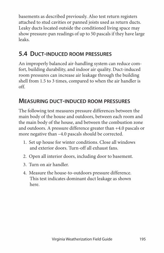
Virginia Weatherization Field Guide 195
basements as described previously. Also test return registers attached to stud cavities or panned joists used as return ducts. Leaky ducts located outside the conditioned living space may show pressure-pan readings of up to 50 pascals if they have large leaks.
5.4 DUCT-INDUCED ROOM PRESSURES
An improperly balanced air-handling system can reduce com-fort, building durability, and indoor air quality. Duct-induced room pressures can increase air leakage through the building shell from 1.5 to 3 times, compared to when the air handler is off.
MEASURING DUCT-INDUCED ROOM PRESSURES
The following test measures pressure differences between the main body of the house and outdoors, between each room and the main body of the house, and between the combustion zone and outdoors. A pressure difference greater than +4.0 pascals or more negative than –4.0 pascals should be corrected.
1. Set up house for winter conditions. Close all windows and exterior doors. Turn-off all exhaust fans.
2. Open all interior doors, including door to basement.
3. Turn on air handler.
4. Measure the house-to-outdoors pressure difference. This test indicates dominant duct leakage as shown here.

Diagnosing Shell & Duct Air Leakage196
A positive pressure indicates that the return ducts (which pull air from leaky intermediate zones) are leakier than the supply ducts. A negative pressure indicates that the supply ducts (which push air into intermediate zones through their leaks) are leakier than return ducts. A pressure at or near zero indicates equal supply and return leakage, little duct leakage, or the house is too leaky to hold pressure.
1. Now, close interior doors.
2. Place hose from input tap on the manometer under one of the closed interior doors. Leave reference tap open to indoors.
3. Read and record this pressure measurement for each room. This pressure’s magnitude indicates the degree to which the air-handler’s airflow is unbalanced between supply and return.
BA
A B
2BA
A B
–3
Dominant return leaks: When return leaks are larger than supply leaks, the house shows a positive pressure with reference to the outdoors.
Dominant supply leaks: When supply leaks are larger than return leaks, the house shows a negative pressure with reference to the outdoors.
leak
leak leak leakleakleak
leak
leak
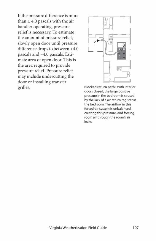
Virginia Weatherization Field Guide 197
If the pressure difference is more than ± 4.0 pascals with the air handler operating, pressure relief is necessary. To estimate the amount of pressure relief, slowly open door until pressure difference drops to between +4.0 pascals and –4.0 pascals. Esti-mate area of open door. This is the area required to provide pressure relief. Pressure relief may include undercutting the door or installing transfer grilles.
BA
A B
8
Blocked return path: With interior doors closed, the large positive pressure in the bedroom is caused by the lack of a air return register in the bedroom. The airflow in this forced-air system is unbalanced, creating this pressure, and forcing room air through the room’s air leaks.
+

Diagnosing Shell & Duct Air Leakage198

Virginia Weatherization Field Guide 199
CHAPTER 6: MOBILE HOME STANDARDS
There are several important code requirements regarding weatherization work done on manufactured or mobile homes in Virginia. These homes are built under different codes and regu-lations than site-built housing, and there may also be local ordi-nances governing mobile homes.
Typical Components of a Mobile Home: 1–Steel chassis. 2–Steel outriggers and cross members. 3–Underbelly. 4–Fiberglass insulation. 5–Floor joists. 6–Heating/air conditioning duct. 7–Decking. 8–Floor covering. 9–Top plate. 10–Interior paneling. 11–Bottom plate. 12–Fiberglass insulation. 13–Metal siding. 14–Ceiling board. 15–Bowstring trusses. 16–Fiberglass insulation. 17–Vapor barrier. 18–Galvanized steel one-piece roof. 19–Metal windows.

Mobile Home Standards200
6.1 MOBILE HOME HEATING
Mobile home furnaces are different from conventional furnaces in the following ways.
• A great majority of mobile homes are equipped with downflow furnaces, designed specifically for mobile homes.
• Mobile home combustion furnaces are sealed-combus-tion units that use outdoor combustion air, unlike most furnaces in site-built homes. They don’t have draft diverters or barometric draft controls.
• Mobile home furnaces require an outdoor source of combustion air.
• Mobile home furnaces have either a manufactured chimney that includes a passageway for combustion air or a combustion-air chute connecting the burner with the crawl space.
• Natural gas-fired furnaces have kits attached, containing alternative orifices, to burn either propane or gas.
• Return air is supplied to the furnace through a large opening in the furnace cabinet, rather than through ducts connected to the blower compartment.
Mobile home furnaces have been sealed-combustion since the early 1970s. Gas furnaces are either the old atmospheric sealed-combustion type, newer fan-assisted mid-efficiency type, or high efficiency 90%+ units. Some older less-efficient sealed-combustion furnaces had draft fans also.
Mobile home oil furnaces are a close relative to oil furnaces in site-built homes. However, they should have a housing that fits around the burner’s air shutter and provides outdoor air directly to the burner. The installation should include the complete chimney assembly and supply duct connector.

Virginia Weatherization Field Guide 201
FURNACE REPLACEMENT
The information contained in this chapter provides useful guid-ance on testing, diagnosing and remedying situations that can be experienced with combustion appliances. State laws regu-late Construction and Tradesmen licensing. State and local laws regulate and enforce building code requirements and the con-struction permit process. Before any work activities are per-formed, be sure that contractors, sub-contractors and employees comply with all state and local requirements.
Mobile home furnace airflow: Return air flows from the hallway through the furnace grille. The air is heated and distributed through the ducts.
return air
combustion air
flue gases
Mobile home furnace combustion: Combustion air enters through the flue assembly on the roof and feeds the flame through a sealed passageway.
optional outdoor air for duct duct
Mobile Home Standards202
Mobile home furnaces must be replaced by furnaces designed and listed for use in mobile homes. They should be sized according to an approved load-calculating tool.
Mobile home furnaces may be replaced when any of the follow-ing is observed.
• The furnace has a heat exchanger which is cracked or rusted through.
• The furnace is not operating and not repairable.
• A drip-pot oil furnace is installed.
Follow these procedures when installing new mobile home fur-naces.
✔ The furnace must be installed on a properly sized dedi-cated circuit with a disconnect at the furnace.
✔ Upgrade the furnace compartment if needed to comply with fire codes.
✔ Install a new furnace base.
✔ Attach the furnace base firmly to the duct, and seal all seams between the base and duct with mastic and fabric tape before installing the furnace.
✔ Support the main duct underneath the furnace with additional strapping if necessary.
✔ When replacing mobile home furnaces, note the differ-ences between old furnace and new, in the way each supplies itself with combustion air.
✔ Install a new chimney that is manufactured specifically for the new furnace. Often the old chimney opening doesn’t exactly line up with the new furnace’s flue. In this case cut the opening large enough to allow the new chimney to be installed absolutely vertical. Install a ceil-ing plate to seal the new opening to the chimney. Make sure the chimney cap is installed absolutely straight.

Virginia Weatherization Field Guide 203
✔ Confirm that the mobile home’s thermostat is installed on an inside wall and away from drafts, direct heat sources, or direct sunlight. Use only thermostats designed specifically for mobile homes, and replace any mercury bulb thermostats.
✔ If furnace is located in an enclosed closet. a room pres-sure test shall be performed to determine if return air is unrestricted.
Mobile home furnaces have short chimneys, and their combus-tion process depends on a delicate balance between combustion air entering and combustion gases leaving. The furnace demands a vertical, leak-free chimney, and a properly installed chimney cap. Follow manufacturer’s installation instructions exactly.
6.2 MOBILE HOME AIR SEALING
The locations and relative importance of air-leakage sites was a mystery before blower doors. Some mobile homes are fairly air-tight and some are incredibly leaky. It’s recommended that a blower door be used to guide air-sealing work and to check Minimum Ventilation Rates in mobile homes.
AIR-LEAKAGE LOCATIONS
The following locations have been identified by technicians using blower doors as the most serious air-leakage sites. Win-dow and door air leakage is more of a comfort problem than a serious energy problem.
• Plumbing penetrations in floors, walls, and ceilings. Water-heater closets with exterior doors are particularly serious air-leakage problems, having large openings into the bathroom and other areas. Check carefully for pene-trations from the belly that may go un-noticed from inside the home.

Mobile Home Standards204
• Torn or missing underbelly, exposing flaws in the floor to the ventilated crawl space.
• Large gaps around furnace and water heater chimneys at the ceiling enclosures. A large gap around the furnace chimney jack, combined with inadequate return air, can cause the blower fan to depressurize the home’s attic and draw moist air into the attic cavity. This moist air will condense during some seasons and cause moisture dam-age.
• Severely deteriorated floors in water heater compart-ments.
• Gaps around the electrical service panel box, light fix-tures, and fans.
• Joints between the halves of doublewide mobile homes and between the main dwelling and additions.
• Unused flues and fireplaces.
• Missing glass, windows, and doors.
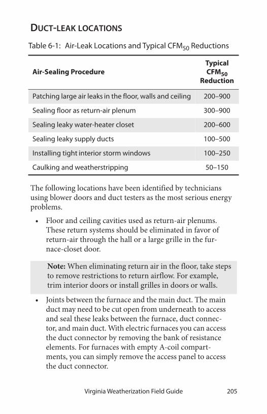
Virginia Weatherization Field Guide 205
DUCT-LEAK LOCATIONS
The following locations have been identified by technicians using blower doors and duct testers as the most serious energy problems.
• Floor and ceiling cavities used as return-air plenums. These return systems should be eliminated in favor of return-air through the hall or a large grille in the fur-nace-closet door.
• Joints between the furnace and the main duct. The main duct may need to be cut open from underneath to access and seal these leaks between the furnace, duct connec-tor, and main duct. With electric furnaces you can access the duct connector by removing the bank of resistance elements. For furnaces with empty A-coil compart-ments, you can simply remove the access panel to access the duct connector.
Table 6-1: Air-Leak Locations and Typical CFM50 Reductions
Air-Sealing ProcedureTypical CFM50
Reduction
Patching large air leaks in the floor, walls and ceiling 200–900
Sealing floor as return-air plenum 300–900
Sealing leaky water-heater closet 200–600
Sealing leaky supply ducts 100–500
Installing tight interior storm windows 100–250
Caulking and weatherstripping 50–150
Note: When eliminating return air in the floor, take steps to remove restrictions to return airflow. For example, trim interior doors or install grilles in doors or walls.

Mobile Home Standards206
• Joints between the main duct and the register boot.
• Joints between register boots and floor.
• The poorly sealed end of the duct trunk.
• Disconnected, damaged or poorly joined crossover duct.
• Supply and return ducts for outdoor air conditioner units.
• Holes cut to provide freeze protection.
• New ductwork added to supply heat to room additions.
• Wood stove inter-connection ductwork.
Be sure to seal floor penetrations and ductwork before perform-ing any belly repair. Pollutants in the crawl space such as mold, mildew, and fiberglass will be disturbed by repair work, and can be drawn into the home by duct depressurization.
furnace
duct
return grille
floor cavity
duct connector
furnace closet door
main return
return grilles
furnace
supply registers main return
Floor return air: Return-air registers at the floor’s perimeter bring air back to the furnace. The floor cavity serves as one big leaky return duct. When leakage is serious, the floor return system should be eliminated.

Virginia Weatherization Field Guide 207
Mobile home ducts: Mobile home ducts leak at their ends and joints—especially at the joints beneath the furnace. The furnace base attaches the furnace to the duct connector. Leaks occur where the duct connector meets the main duct and where it meets the furnace. Branch ducts are rare, but easy to find, because their supply register isn’t in line with the others. Crossover ducts are found only in double-wide and triple-wide homes (A double-wide home has a single furnace; however each section has its own main duct. These main ducts are connected by the crossover duct.)
furnace
register boot
branch duct
crossover ductduct end
duct connector
furnace base
Sealing the end of the main duct: The main duct is usually capped or crimped loosely at each end, creating a major air leakage point. Seal this area and improve airflow by installing a sheet metal ramp, inside the duct, through the last register boot. Seal the ramp to the ductwork with metal tape and silicone or mastic. Install the barrier several inches back from last register to help create more even static pressure and airflow.

Mobile Home Standards208
PRESSURE-PAN TESTING MOBILE HOME DUCTS
Pressure-pan testing of mobile home ductwork helps locate duct separations or holes. Because mobile home ductwork is usually located outside the home’s air barrier, it can often be a major source of energy loss for the home. Use this procedure.
1. Install blower door and set up house for winter condi-tions. Open all interior doors and all floor register grilles.
2. Identify all the combustion appliances, such as furnaces and water heaters, and adjust their controls to the Off or Pilot position. Confirm that any solid fuel appliances have been extinguished for several hours.
3. Connect the input tap on a digital manometer to the pressure pan. Leave the reference tap open to the room.
4. Adjust the blower door to –50 pascals WRT outdoors. Place the pressure pan completely over a floor register grille to form a tight seal. Record the reading.
5. If a register grille is too large, or is difficult to access, seal the register grille with foil tape and insert a pres-sure probe through the tape and record the reading.
6. Repeat this test for each register grille in a systematic fashion.
7. The optimum reading at each register grille would be 0 pascals, indicating that the ductwork is well-sealed and completely within the home’s air boundary. Realisti-cally, the ductwork will never be totally sealed, but readings of 1 pascal or less are an achievable target.
8. When higher readings are found in numerous locations, isolate sections of ductwork using a “pillow” (usually fiberglass stuffed in a plastic bag) to help pinpoint the leaky ductwork.

Virginia Weatherization Field Guide 209
When all blower-door testing is complete, inspect the pilot lights at the furnace, water heater, or other combustion appli-ances to be sure they are still lit. Then turn these appliances back on.
6.3 MOBILE HOME INSULATION
Over the past 15 years, effective methods for insulating mobile homes have been developed by weatherization agencies. If your contractor or crew is trained in these methods, use the following standards for floor and ceiling insulation.
Address all significant moisture problems before insulating. The most important moisture-control measure is installing a ground-moisture barrier. See “Moisture problems” on page 19.
BLOWING MOBILE HOME ROOF CAVITIES
Before installing mobile home roof cavity insulation, you must perform a MHEA audit to justify the measure, and you must have received training on installation methods.
Perform careful assessment of the mobile home’s condition before performing this measure. Roof leaks can be created dur-ing the insulation process. It is strongly advised that all seams, stacks, vents, and other penetrations be sealed after attic insula-tion is installed.

Mobile Home Standards210
Blowing a closed mobile home roof cavity is similar to blowing a closed wall cavity, only the insulation doesn’t have to be as dense. Fiberglass blowing wool is used since cellulose is too heavy and absorbs water too readily for use around a mobile home’s lightweight sheeting materials.
There are two common and effective methods for blow-ing mobile home roof cavi-
ties. The first is cutting a square hole in the metal roof and blowing fiberglass through a flexible fill-tube. The second is dis-connecting the metal roof at its edge and blowing fiberglass through a rigid fill-tube. Do not insulate mobile home attics from the interior.
Preparing to blow a mobile home roof
✔ Reinforce weak areas in the ceiling.
✔ Inspect the ceiling and seal all penetrations.
✔ Take steps to maintain safe clearances between insula-tion and chimney roof jacks, recessed light fixtures, and ceiling fans.
✔ Assemble patching materials such as metal patches, roof cement, sheet-metal screws, putty tape, and roof coating.
Blowing through the top
This procedure involves cutting large square holes. Each square hole provides access to two truss cavities. If the roof contains a strongback running the length of the roof, the holes should be
Bowstring roof details: Hundreds of thousands of older mobile homes were constructed with these general construction details.
stud
galvanized-steel roof
J-rail
metal trim
insulation
truss
3/4-inch top plate
fiberboard ceiling

Virginia Weatherization Field Guide 211
centered over the strongback, which is usually near the center of the roof ’s width. A strongback is a 1-by-4 or a 1-by-6, installed at a right angle to the trusses near their center point, to add strength to the roof structure.
1. Cut 10-inch square holes at the roof ’s apex on top of every second truss. Each square hole permits access to two truss cavities.
2. Use a 2-inch or 2-1/2-inch diameter fill-tube. Insert the fill-tube and push it forcefully out toward the edge of the cavity.
3. Blow fiberglass insu-lation into each cav-ity.
4. Stuff the area under each square hole with a piece of unfaced fiberglass batt so that the fin-ished roof patch will stand a little higher than the surround-ing roof.
5. Patch the hole with a 14-inch-square piece of stiff galva-nized steel, sealed with roof cement and screwed into the existing metal roof.
6. Cover the first patch with a second patch, consisting of an 18-inch-square piece of foil-faced butyl rubber.
This approach fills the critical edge area with insulation, and the patches are easy to install if you have the right materials. It is
Roof-top insulation: Blowing fiberglass insulation through the roof top is effective at achieving good coverage and density on almost any metal roof.

Mobile Home Standards212
important to complete the work during good weather, however, since the roof will be vulnerable to rain or snow during the job.
Blowing a mobile home roof from the edge
This procedure requires scaffold to be performed safely and efficiently. Mobile home metal roofs are usually fastened only at the edge, where the roof joins the wall.
1. Remove the screws from the metal j-rail at the roof edge. Also remove staples or other fasteners, and scrape off putty tape.
2. Pry the metal roof up far enough to insert a 2-inch-diameter, 10- to 14-foot-long rigid fill-tube. Two com-mon choices are steel muffler pipe and aluminum irri-gation pipe. Inspect the cavity with a bright light to identify any wires or piping that could be damaged by the fill tube.
3. Blow insulation through the fill-tube into the cavity. Turn down the air on the blowing machine when the
Square roof patch: An 18-inch square of foil-faced butyl rubber covers a base patch of galvanized steel, which is cemented with roof cement and screwed with self-drilling screws.
foil-faced butyl rubber patch
galvanized steel patch
trap door cut in roof steel
mobile home truss
Roof-edge blowing: Use a rigid fill tube to blow insulation through the roof edge. This avoids making holes in the roof itself, though this process requires much care in refastening the roof edge.

Virginia Weatherization Field Guide 213
tube is a couple feet from the roof edge, in order to avoid blowing insulation out through the opening in the roof edge. Or stop blowing a foot or two from the edge, and stuff the last foot or two with unfaced fiber-glass batts.
4. Fasten the roof edge back to the wall using galvanized roofing nails, a new metal j-rail, new putty tape, and larger screws. The ideal way to re-fasten the metal roof edge is with air-driven galvanized staples, which is the way most roof edges were attached originally.
Note that re-installation of the roof edge is the most important part of this procedure. Putty tape must be replaced and installed as it was originally. This usually involves installing one layer of putty tape under the metal roof and another between the metal roof edge and the j-rail.
The advantages of blowing through the edge is that if you have the right tools, including a powered stapler, this method can be very fast and doesn’t require cutting into the roof. The disadvan-tages of this procedure are that you need scaffolding to work at the edges, and it won’t work on roof systems with a central strongback that stops the fill tube from reaching all the way across the roof.
MOBILE HOME FLOOR INSULATION
Mobile home floor insulation is a beneficial measure for cool climates. The original insulation is usually fastened to the bot-tom of the floor joists, leaving the cavity uninsulated and subject to convection currents. This greatly reduces the insulation’s R-value.
Preparing for mobile home floor insulation
Prior to installing floor insulation, always perform these repairs.
1. Repair plumbing leaks.

Mobile Home Standards214
2. Tightly seal all holes in the floor. For large holes, use plywood, glue and screws.
3. Inspect and seal ducts.
4. Install a ground-moisture barrier in the crawl space if possible.
Insulating the floor
The preferred method for insulating mobile home floors is through the underbelly. Flexible fill-tubes are used to install loose-fill fiberglass.
First repair all holes in the belly. Use mobile home belly-paper, adhesive, and stitch staples. Keep the sealant away from the sta-ples to avoid staple-damaging corrosion. Use these same patches over the holes cut for fill-tubes. Screw wood lath over weak areas if needed.
Identify any plumbing lines, and avoid installing insulation between them and the living space. This may require running a piece of belly-paper under the pipes, and insulating the resulting cavity, to include them in the heated envelope of the home. Wrap any exposed water lines.
Blowing bellies from underneath: A flexible fill-tube, which is significantly stiffer than the blower hose, blows fiberglass insulation through a hole in the belly from underneath the home.
existing insulation
new insulation

Virginia Weatherization Field Guide 215
Blowing crosswise cavities: Blowing insulation into belly is easy if the floor joists run crosswise. However, the dropped belly requires more insulation than a home with lengthwise joists.
Blowing lengthwise cavities: Floors with lengthwise joists can rarely be filled completely from the ends because of the long tubing needed. The middle can be filled from underneath.
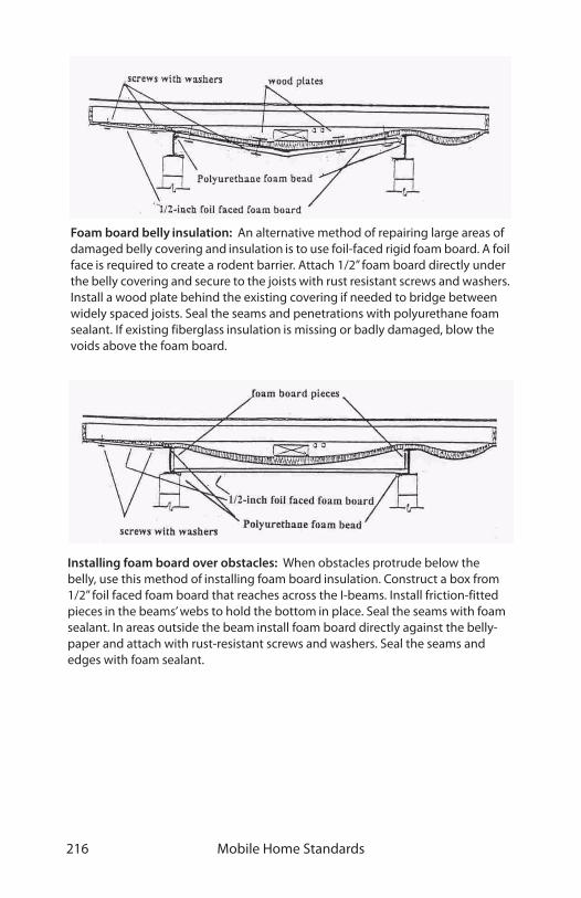
Mobile Home Standards216
Foam board belly insulation: An alternative method of repairing large areas of damaged belly covering and insulation is to use foil-faced rigid foam board. A foil face is required to create a rodent barrier. Attach 1/2” foam board directly under the belly covering and secure to the joists with rust resistant screws and washers. Install a wood plate behind the existing covering if needed to bridge between widely spaced joists. Seal the seams and penetrations with polyurethane foam sealant. If existing fiberglass insulation is missing or badly damaged, blow the voids above the foam board.
Installing foam board over obstacles: When obstacles protrude below the belly, use this method of installing foam board insulation. Construct a box from 1/2” foil faced foam board that reaches across the I-beams. Install friction-fitted pieces in the beams’ webs to hold the bottom in place. Seal the seams with foam sealant. In areas outside the beam install foam board directly against the belly-paper and attach with rust-resistant screws and washers. Seal the seams and edges with foam sealant.

Virginia Weatherization Field Guide 217
6.4 MOBILE HOME WINDOWS AND DOORS
Replacing windows and doors is generally not cost-effective and should only be done if repairs cannot hold the window or door together any longer. New jalousie or awning windows are not acceptable as replacements.
MOBILE HOME STORM WINDOWS
Interior storm windows are common in mobile homes. These stationary interior storms serve awning and jalousie windows. Sliding interior storm windows pair with exterior sliding prime windows.
• Interior storm windows double the R-value of a single-pane window. They also reduce infiltration, especially in the case of leaky jalousie prime windows.
• Avoid replacing existing storm windows unless the existing storm windows cannot be re-glazed or repaired.
• Inexpensive storms can be installed that are made from frame strips covered with clear plastic sheeting. These
Glass interior storms: Traditional mobile home storm windows have aluminum frames glazed with glass.
clip
gasket spline
plastic film
aluminum frame
foam tape
Plastic storms: Some newer storm-window designs use a lightweight aluminum frame and flexible or rigid plastic glazing.

Mobile Home Standards218
frames can accommodate owner-provided fiberglass insect screen to encourage summer ventilation and cooling.
• When sliding primary windows are installed, use a sliding storm window that slides from the same side as the primary window. Sliding storm win-dows stay in place and aren’t removed season-ally, and are therefore less likely to be lost or broken.
REPLACING MOBILE HOME WINDOWS
Inspect condition of rough opening members before replacing windows. Replace deterio-rated, weak or waterlogged framing members.
Prepare replacement window by lining the perimeter of the inner lip with 1/8-inch thick putty tape or silicone caulk. Caulk exterior window frame perimeter to wall after installing win-dow.
Mobile home double window: In mobile homes, the prime window is installed over the siding outdoors, and the storm window is installed indoors.
interior storm window
prime window

Virginia Weatherization Field Guide 219
MOBILE HOME DOORS
Mobile home doors come in two basic types: the mobile home door and the house-type door. Mobile home doors swing outwardly, and house-type doors swing inwardly. Pre-hung insulated steel house doors are more durable, better insulated, and more expensive than mobile home doors. They require a larger rough opening, however, that may necessitate framing adjustments such as installing a new header.
Program guidelines allow the installation of new pre-hung steel doors only in “Pre-Code” (before 1972) mobile homes. Note that only doors manufactured for mobile homes can be installed in “Code” (after 1976) mobile homes. Door replacement is an allowable expense only when the existing door is damaged beyond repair and constitutes a severe air-leakage problem.
MOBILE HOME SKIRTING
Installation and repair of mobile home skirting is seldom cost-effective and not allowable as a weatherization measure. The primary purpose of skirting is to keep animals out of the crawl space. The insulation and air barrier are ideally located at the floor.
MOBILE HOME HEALTH AND SAFETY
Several health and safety items should be considered when weatherizing mobile homes.
Mobile home door: Mobile home doors swing outwardly and have integral weatherstrip.

Mobile Home Standards220
• All exhaust fans must be inspected, and repaired or replaced as needed. They should be vented to the out-side. All gas ranges must have an exhaust fan that is vented to the outdoors with rigid pipe.
• Dryer vents should be inspected and upgraded as needed. Use non-combustible vent materials only.
• Smoke and CO alarms should be installed.
• Water heaters should be inspected for draft, clearances, combustion air, and PT valve. The PT valve must be extended through the floor and skirt. Wrap the water heater and first 3' of both hot and cold water lines.
• Air distribution systems should be pressure balanced.

Virginia Weatherization Field Guide 221
APPENDICES
Formulas. . . . . . . . . . . . . . . . . . . . . . . . . . . . . . . . . . . . . . . . . . . . 222
Air sealing and insulating tools . . . . . . . . . . . . . . . . . . . . . . 224
Auditing and mechanical tools . . . . . . . . . . . . . . . . . . . . . . 225
Weatherization materials . . . . . . . . . . . . . . . . . . . . . . . . . . . . 226
R-values for construction materials . . . . . . . . . . . . . . . . . . 227
Resources . . . . . . . . . . . . . . . . . . . . . . . . . . . . . . . . . . . . . . . . . . . 228
Tables and Illustrations . . . . . . . . . . . . . . . . . . . . . . . . . . . . . . 229
Index . . . . . . . . . . . . . . . . . . . . . . . . . . . . . . . . . . . . . . . . . . . . . . . 245

Appendices222
A1 — FORMULAS
To convert square feet to square inches
• Multiply by 144
• Example: 2 square feet = 2 x 144= 288 square inches
To convert square inches to square feet
• Divide by 144
• Example: 36" x 80” door = 2880 square inches
• Therefore: 2880 square inches/144 = 20 square feet
Area of rectangle
• Length x width
• Example: 60 feet x 12 feet = 720 square feet
Volume of rectangle
• Length x width x height
• Example: 60 feet x 12 feet x 7 feet = 5040 cubic feet
Perimeter
• Add the length of all sides
• Side A + side B + side C + side D = perimeter
Area of triangle, as for gable end
• Base x height x 0.5
• Example: 24 feet across gable x 5 feet high at center
• 24 x 5 x .5 = 60 square feet

Virginia Weatherization Field Guide 223
Volume of triangle, as for volume of garage attic
• Base x height x length x 0.5
• Example: 24 feet across gable x 5 feet high x 20 long
• 24 x 5 x 20 x .5 = 1200 cubic feet
Attic ventilation
• Ratio of 1square foot to each 300 square feet of attic
• Example: 1000 square foot attic ÷ 300 = 3.33 square feet of total ventilation
• Convert from feet to inches: 3.33 x 144 = 480 square inches
• Always split attic vents high and low: 240 square inches of intake and 240 square inches of exhaust
• Measure area of vents, and deduct for restriction of screen and grill to get NFA (net free area), usually 1/2 of total area of vent
Minimum ventilation rate (MVR): use the largest number from these calculations
• Number of bedrooms + 1 x 15 x 20 = MVR in cfm50
• Number of people x 15 x 20 = MVR in cfm50
• Volume of house x .35 x 20 ÷ 60 = MVR in cfm50

Appendices224
A2 — AIR SEALING AND INSULATING TOOLS
Insulation blower Broom and dust pan
Blower hoses 4, 3, & 2.5 inch Cat’s paw
Fill tubes and hose fittings Caulking guns
Coveralls and gloves Chisels: cold and wood
First-aid kit Cleaning fluid and rags
Hard hat End nippers
Respirators and filters Flashlight
Safety glasses Hack saw and blades
Extension ladders, leveler, & hooks
Hammers and wrecking bars
Portable lights Hand saws
Scaffold, planks, and handrail Hand staplers
Step ladders: 4, 6, & 8 foot Metal & Vinyl-siding zip tools
Circular saw with blades Mirror
Compressor and power stapler Pliers: electrical & slip-joint
Drill index with bits Putty knives and scrapers
Drills, drivers, and bits Putty warmer
Extension cords Scratch awl and pin punches
HEPA vacuum with attachments Screw- and nut-driver bits
Lead paint drill shroud Screw drivers and nut drivers
Reciprocating saw with bladesSquares: framing, combo, dry-wall
Shop vacuum, hoses, attach-ments
Steel tape measures
Tin snips: hand and electric

Virginia Weatherization Field Guide 225
A3 — AUDITING AND MECHANICAL TOOLS
Adjustable wrenches Pipe wrenches
Camera Pliers: electrical & slip-joint
Chisels: cold and wood Screw and nut driver bits
Clipboard box, writing supplies Screw and nut drivers
Extra batteries Screw drivers and nut drivers
Flash lights and portable lights Sheet-metal crimper
Flexduct strap tightener Sockets and ratchet
Hack saw and blades Steel tape measures
Hammer Tin snips
Hand truck Vacuum cleaner
Inspection mirror Wire and bristle brushes
Ladder Wire strippers
Coveralls and gloves Non-contact voltage detector
Safety glasses Volt-ohmmeter
Cordless drill-driver Digital wattmeter
Drill index with bits Plug-in circuit tester
Blower door Digital thermometer with ∂T
Digital manometer with hoses Moisture meter
Pressure pan Remove viewer
Heat-exchanger test kit Combustion gas leak detector
Digital combustion analyzer Calculator
Digital CO detector Auditing software

Appendices226
A4 — WEATHERIZATION MATERIALS
Cellulose Assorted wire nuts and electrical
Closed-cell foam tape Compact fluorescent lamps
Fiberglass batts Energy-saving shower heads
Fiberglass blowing wool Programmable thermostats
Fiberglass duct wrap Replacement fan controls
Foam backer rod Replacement furnaces
Foam pipe sleeves Replacement refrigerators
One-part squirt foam Replacement water heaters
Sheet foam insulation 1/4-inch plywood or hardboard
Two-part spray foam Assorted lumber
Water heater insulation Assorted screws and nails
Putty tape Assorted staples
Silicone or urethane caulk Construction adhesive
Siliconized acrylic-latex caulk Disposable coveralls, boot cov-
Acoustical sealant Disposable paint brushes
Bronze v-seal weatherstrip Plastic garbage bags
Jamb-up weatherstrip Plastic sheeting
Portable tape recorder Pop riveter
Client-education booklets CO detector
Assorted chimney pipe CO video
Assorted furnace filters Doors And Windows
Duct mastic and web tape Dryer kits (metal hose)
Duct tape and electrical tape Exhaust fan
Furnace filter material Smoke detectors
Proper vents Bubbler wrap
Sheet metal High temperature caulk
Weatherstrip Window glass & glazing
Door sweeps Aluminum coil stock

Virginia Weatherization Field Guide 227
A5 — R-VALUES FOR CONSTRUCTION MATERIALS
Material R-value
Fiberglass or rock wool batts and blown 1” 2.8–4.0a
a. Varies according to density (increases with increasing density).
Blown cellulose 1” 3.0–4.0b
b. Varies according to density (decreases with increasing density).
Vermiculite loose fill 1” 2.7
White expanded polystyrene foam (beadboard) 1” 3.9–4.3a
Polyurethane/polyisocyanurate foam 1” 6.2–7.0c
c. Varies according to age and formulation.
Extruded polystyrene (blue, yellow or pink) 1” 5.0
Oriented strand board (OSB) or plywood 1/2” 1.6
Concrete 1” 0.1
Wood 1” 1.0d
d. Varies by species.
Fired clay bricks 1” 0.1–0.4
Gypsum or plasterboard 1/2” 0.4
Single pane glass 0.9
Low-e insulated glass 3.3–4.2e
e. Varies according to Solar Heat Gain Coefficient (SHGC) rating.
Triple glazed glass with 2 low-e coatings 8.3

Appendices228
A6 — RESOURCES
Lead-Safe Weatherization, A Training and Reference Manual for Weatherization Managers and Crews, by Montana State Univer-sity Extension Service, November 2001
Residential Energy: Cost Savings and Comfort for Existing Build-ings, by John Krigger and Chris Dorsi, Fourth Edition, 2004
Weatherization Training Manual for Housing Technicians I & II, by John Krigger, First Edition, 1997
Your Mobile Home: Energy and Repair Guide for Manufactured Housing, by John Krigger, Fourth Edition, 1998

Virginia Weatherization Field Guide 229
TABLES AND ILLUSTRATIONS
Health and Safety
Moisture sources . . . . . . . . . . . . . . . . . . . . . . . . . . . . . . . . . . . . . . 19Typical Household Moisture Sources. . . . . . . . . . . . . . . . . . . 20Dust mites . . . . . . . . . . . . . . . . . . . . . . . . . . . . . . . . . . . . . . . . . . . . 21Stopping water leakage . . . . . . . . . . . . . . . . . . . . . . . . . . . . . . . 22Protective tarp . . . . . . . . . . . . . . . . . . . . . . . . . . . . . . . . . . . . . . . . 25Knob-and-Tube Wiring . . . . . . . . . . . . . . . . . . . . . . . . . . . . . . . . 26Safety meetings. . . . . . . . . . . . . . . . . . . . . . . . . . . . . . . . . . . . . . . 28Ladders . . . . . . . . . . . . . . . . . . . . . . . . . . . . . . . . . . . . . . . . . . . . . . . 29Safe vehicles . . . . . . . . . . . . . . . . . . . . . . . . . . . . . . . . . . . . . . . . . . 30Awkward loads . . . . . . . . . . . . . . . . . . . . . . . . . . . . . . . . . . . . . . . 30Personal protective equipment . . . . . . . . . . . . . . . . . . . . . . . . 31Electrical safety . . . . . . . . . . . . . . . . . . . . . . . . . . . . . . . . . . . . . . . 32
Auditing, Education, and Baseload
Heating energy waste . . . . . . . . . . . . . . . . . . . . . . . . . . . . . . . . . 42Water-heating energy waste. . . . . . . . . . . . . . . . . . . . . . . . . . . 42Reach for the cold water tap . . . . . . . . . . . . . . . . . . . . . . . . . . . 43Modern dryer dial . . . . . . . . . . . . . . . . . . . . . . . . . . . . . . . . . . . . . 44Clothes line . . . . . . . . . . . . . . . . . . . . . . . . . . . . . . . . . . . . . . . . . . . 44Compact fluorescent lamps . . . . . . . . . . . . . . . . . . . . . . . . . . . 46
Air Sealing and Insulating
Thermal boundary flaws. . . . . . . . . . . . . . . . . . . . . . . . . . . . . . . 47Porch air leakage. . . . . . . . . . . . . . . . . . . . . . . . . . . . . . . . . . . . . . 49Kitchen soffits. . . . . . . . . . . . . . . . . . . . . . . . . . . . . . . . . . . . . . . . . 50Two-level attic . . . . . . . . . . . . . . . . . . . . . . . . . . . . . . . . . . . . . . . . 51Balloon-framed interior walls . . . . . . . . . . . . . . . . . . . . . . . . . . 52Recessed light fixtures. . . . . . . . . . . . . . . . . . . . . . . . . . . . . . . . . 52Large holes . . . . . . . . . . . . . . . . . . . . . . . . . . . . . . . . . . . . . . . . . . . 53Backer rod . . . . . . . . . . . . . . . . . . . . . . . . . . . . . . . . . . . . . . . . . . . . 54
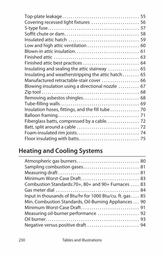
Tables and Illustrations230
Top-plate leakage . . . . . . . . . . . . . . . . . . . . . . . . . . . . . . . . . . . . . 55Covering recessed light fixtures . . . . . . . . . . . . . . . . . . . . . . . 56S-type fuse. . . . . . . . . . . . . . . . . . . . . . . . . . . . . . . . . . . . . . . . . . . . 57Soffit chute or dam. . . . . . . . . . . . . . . . . . . . . . . . . . . . . . . . . . . . 58Insulated attic hatch . . . . . . . . . . . . . . . . . . . . . . . . . . . . . . . . . . 59Low and high attic ventilation . . . . . . . . . . . . . . . . . . . . . . . . . 60Blown-in attic insulation. . . . . . . . . . . . . . . . . . . . . . . . . . . . . . . 61Finished attic . . . . . . . . . . . . . . . . . . . . . . . . . . . . . . . . . . . . . . . . . 63Finished attic best practices . . . . . . . . . . . . . . . . . . . . . . . . . . . 64Insulating and sealing the attic stairway . . . . . . . . . . . . . . . 65Insulating and weatherstripping the attic hatch . . . . . . . . 65Manufactured retractable-stair cover . . . . . . . . . . . . . . . . . . 66Blowing insulation using a directional nozzle . . . . . . . . . . 67Zip tool . . . . . . . . . . . . . . . . . . . . . . . . . . . . . . . . . . . . . . . . . . . . . . . 68Removing asbestos shingles. . . . . . . . . . . . . . . . . . . . . . . . . . . 68Tube-filling walls . . . . . . . . . . . . . . . . . . . . . . . . . . . . . . . . . . . . . . 69Insulation hoses, fittings, and the fill tube . . . . . . . . . . . . . . 70Balloon framing . . . . . . . . . . . . . . . . . . . . . . . . . . . . . . . . . . . . . . . 71Fiberglass batts, compressed by a cable. . . . . . . . . . . . . . . . 72Batt, split around a cable . . . . . . . . . . . . . . . . . . . . . . . . . . . . . . 72Foam-insulated rim joists. . . . . . . . . . . . . . . . . . . . . . . . . . . . . . 74Floor insulating with batts. . . . . . . . . . . . . . . . . . . . . . . . . . . . . 75
Heating and Cooling Systems
Atmospheric gas burners . . . . . . . . . . . . . . . . . . . . . . . . . . . . . . 80Sampling combustion gases. . . . . . . . . . . . . . . . . . . . . . . . . . . 81Measuring draft . . . . . . . . . . . . . . . . . . . . . . . . . . . . . . . . . . . . . . . 81Minimum Worst-Case Draft . . . . . . . . . . . . . . . . . . . . . . . . . . . . 83Combustion Standards:70+, 80+ and 90+ Furnaces . . . . 83Gas meter dial . . . . . . . . . . . . . . . . . . . . . . . . . . . . . . . . . . . . . . . . 84Input in thousands of Btu/hr for 1000 Btu/cu. ft. gas . . . . 85Min. Combustion Standards, Oil-Burning Appliances . . . 90Minimum Worst-Case Draft . . . . . . . . . . . . . . . . . . . . . . . . . . . . 91Measuring oil-burner performance . . . . . . . . . . . . . . . . . . . . 92Oil burner. . . . . . . . . . . . . . . . . . . . . . . . . . . . . . . . . . . . . . . . . . . . . 93Negative versus positive draft . . . . . . . . . . . . . . . . . . . . . . . . . 94

Virginia Weatherization Field Guide 231
Power-vent draft . . . . . . . . . . . . . . . . . . . . . . . . . . . . . . . . . . . . . . 95Flame roll-out . . . . . . . . . . . . . . . . . . . . . . . . . . . . . . . . . . . . . . . . . 96Worst-case depressurization. . . . . . . . . . . . . . . . . . . . . . . . . . . 97Worst-case draft testing . . . . . . . . . . . . . . . . . . . . . . . . . . . . . . . 98Minimum Worst-Case Draft . . . . . . . . . . . . . . . . . . . . . . . . . . . . 99Two vent connectors joining chimney . . . . . . . . . . . . . . . . 101Guide to Venting Standards . . . . . . . . . . . . . . . . . . . . . . . . . . 101Areas of Round Vents . . . . . . . . . . . . . . . . . . . . . . . . . . . . . . . . 103Vent Connector Diameter vs. Max. Horizontal Length. . 103Clearances to Combustibles for Vent Connectors. . . . . . 104Masonry chimneys . . . . . . . . . . . . . . . . . . . . . . . . . . . . . . . . . . . 104Clearances to Combustibles for Common Chimneys. . . 105All-fuel metal chimney . . . . . . . . . . . . . . . . . . . . . . . . . . . . . . . 106Chimney terminations. . . . . . . . . . . . . . . . . . . . . . . . . . . . . . . . 107Roof Slope and B-Vent Chimney Height Above Roof. . . 107Flexible metal chimney liners . . . . . . . . . . . . . . . . . . . . . . . . . 108AGA venting categories . . . . . . . . . . . . . . . . . . . . . . . . . . . . . . 109B-vent chimney liner . . . . . . . . . . . . . . . . . . . . . . . . . . . . . . . . . 110Characteristics of Gas Furnaces and Boilers. . . . . . . . . . . . 111Fan-assisted gas heaters with vertical chimneys . . . . . . . 112Fan-assisted heaters with sidewall vents . . . . . . . . . . . . . . 112Condensing furnace venting . . . . . . . . . . . . . . . . . . . . . . . . . 112Power venters . . . . . . . . . . . . . . . . . . . . . . . . . . . . . . . . . . . . . . . 113Wood-stove installation . . . . . . . . . . . . . . . . . . . . . . . . . . . . . . 116Air Requirements for Combustion Furnaces or Boilers . 117Passive combustion-air options. . . . . . . . . . . . . . . . . . . . . . . 119Combustion air through supply register . . . . . . . . . . . . . . 121Sealed combustion. . . . . . . . . . . . . . . . . . . . . . . . . . . . . . . . . . . 122Fan-powered combustion air . . . . . . . . . . . . . . . . . . . . . . . . . 123Sealed-combustion, oil-heating retrofit . . . . . . . . . . . . . . . 123Furnace heat exchangers . . . . . . . . . . . . . . . . . . . . . . . . . . . . . 125Furnace Operating Parameters . . . . . . . . . . . . . . . . . . . . . . . 126Adjustable drive pulley . . . . . . . . . . . . . . . . . . . . . . . . . . . . . . . 127A fan/limit control. . . . . . . . . . . . . . . . . . . . . . . . . . . . . . . . . . . . 127Flexduct joints . . . . . . . . . . . . . . . . . . . . . . . . . . . . . . . . . . . . . . . 129Panned floor joists . . . . . . . . . . . . . . . . . . . . . . . . . . . . . . . . . . . 129Duct mastic . . . . . . . . . . . . . . . . . . . . . . . . . . . . . . . . . . . . . . . . . . 130

Tables and Illustrations232
Duct insulation. . . . . . . . . . . . . . . . . . . . . . . . . . . . . . . . . . . . . . . 131Furnace filter location . . . . . . . . . . . . . . . . . . . . . . . . . . . . . . . . 133Restricted return air . . . . . . . . . . . . . . . . . . . . . . . . . . . . . . . . . . 134Heating and cooling duct sizes . . . . . . . . . . . . . . . . . . . . . . . 135Oil-fired downflow furnaces . . . . . . . . . . . . . . . . . . . . . . . . . . 136Sealed combustion heaters. . . . . . . . . . . . . . . . . . . . . . . . . . . 13780+ gas furnace . . . . . . . . . . . . . . . . . . . . . . . . . . . . . . . . . . . . . . 13890+ gas furnace . . . . . . . . . . . . . . . . . . . . . . . . . . . . . . . . . . . . . . 138Static pressure and temperature rise . . . . . . . . . . . . . . . . . . 139Oil heating system . . . . . . . . . . . . . . . . . . . . . . . . . . . . . . . . . . . 140Combustion Standards for Gas-Burning Furnaces . . . . . 142Cast-iron sectional boilers . . . . . . . . . . . . . . . . . . . . . . . . . . . . 144Purging air . . . . . . . . . . . . . . . . . . . . . . . . . . . . . . . . . . . . . . . . . . . 146Vent dampers . . . . . . . . . . . . . . . . . . . . . . . . . . . . . . . . . . . . . . . . 147One-pipe and two-pipe steam systems . . . . . . . . . . . . . . . 148Two-pipe steam systems . . . . . . . . . . . . . . . . . . . . . . . . . . . . . 148Steam traps . . . . . . . . . . . . . . . . . . . . . . . . . . . . . . . . . . . . . . . . . . 149Cast-iron sectional boilers . . . . . . . . . . . . . . . . . . . . . . . . . . . . 150Wall-hung boiler . . . . . . . . . . . . . . . . . . . . . . . . . . . . . . . . . . . . . 151Simple reverse-return hot-water system . . . . . . . . . . . . . . 152Reset controller . . . . . . . . . . . . . . . . . . . . . . . . . . . . . . . . . . . . . . 153Standard gas water heater. . . . . . . . . . . . . . . . . . . . . . . . . . . . 153Setting hot-water temperature . . . . . . . . . . . . . . . . . . . . . . . 154Water-saving shower heads . . . . . . . . . . . . . . . . . . . . . . . . . . 155Water heater insulation . . . . . . . . . . . . . . . . . . . . . . . . . . . . . . 155Refrigeration and air-conditioning cycle . . . . . . . . . . . . . . 158Air conditioner types . . . . . . . . . . . . . . . . . . . . . . . . . . . . . . . . . 159Air-conditioning coils . . . . . . . . . . . . . . . . . . . . . . . . . . . . . . . . 160Cleaning room air conditioners . . . . . . . . . . . . . . . . . . . . . . . 161Cleaning an A-coil. . . . . . . . . . . . . . . . . . . . . . . . . . . . . . . . . . . . 163
Diagnosing Shell & Duct Air Leakage
Standard blower door test. . . . . . . . . . . . . . . . . . . . . . . . . . . . 167Digital manometers . . . . . . . . . . . . . . . . . . . . . . . . . . . . . . . . . . 168Blower door analog gauges . . . . . . . . . . . . . . . . . . . . . . . . . . 169‘Can’t Reach Fifty’ Factors . . . . . . . . . . . . . . . . . . . . . . . . . . . . 172

Virginia Weatherization Field Guide 233
Blower door target - homes of 2000-5750 CFM50 . . . . . . . . .175Blower door target - homes of 6000-9750 CFM50 . . . . . . . . .176Blower door target - homes of 10000-13750 CFM50. . . . 177Blower door test . . . . . . . . . . . . . . . . . . . . . . . . . . . . . . . . . . . . . 178Building Components Compared by Air Permeance . . . 179Bedroom test . . . . . . . . . . . . . . . . . . . . . . . . . . . . . . . . . . . . . . . . 181Interior door test . . . . . . . . . . . . . . . . . . . . . . . . . . . . . . . . . . . . . 181Pressure-testing building parts . . . . . . . . . . . . . . . . . . . . . . . 183Attic-to-house pressure . . . . . . . . . . . . . . . . . . . . . . . . . . . . . . 184Attic-to-outdoors pressure . . . . . . . . . . . . . . . . . . . . . . . . . . . 184Zone connectedness . . . . . . . . . . . . . . . . . . . . . . . . . . . . . . . . . 185Cantilevered floor test. . . . . . . . . . . . . . . . . . . . . . . . . . . . . . . . 186Porch roof test . . . . . . . . . . . . . . . . . . . . . . . . . . . . . . . . . . . . . . . 186Pressure measurements and air-barrier location. . . . . . . 188Crawl space-to-house pressure . . . . . . . . . . . . . . . . . . . . . . . 191Unoccupied basement: Where is the air barrier?. . . . . . . 192A pressure pan . . . . . . . . . . . . . . . . . . . . . . . . . . . . . . . . . . . . . . . 193Acceptable reading . . . . . . . . . . . . . . . . . . . . . . . . . . . . . . . . . . 194Dominant return leaks . . . . . . . . . . . . . . . . . . . . . . . . . . . . . . . 196Dominant supply leaks . . . . . . . . . . . . . . . . . . . . . . . . . . . . . . . 196Blocked return path . . . . . . . . . . . . . . . . . . . . . . . . . . . . . . . . . . 197
Mobile Home Standards
Typical Components of a Mobile Home . . . . . . . . . . . . . . . 199Mobile home furnace airflow . . . . . . . . . . . . . . . . . . . . . . . . . 201Mobile home furnace combustion . . . . . . . . . . . . . . . . . . . . 201Air-Leak Locations and Typical CFM50 Reductions . . . . . 205Floor return air . . . . . . . . . . . . . . . . . . . . . . . . . . . . . . . . . . . . . . . 206Mobile home ducts . . . . . . . . . . . . . . . . . . . . . . . . . . . . . . . . . . 207Sealing the end of the main duct . . . . . . . . . . . . . . . . . . . . . 207Bowstring roof details . . . . . . . . . . . . . . . . . . . . . . . . . . . . . . . . 210Roof-top insulation. . . . . . . . . . . . . . . . . . . . . . . . . . . . . . . . . . . 211Square roof patch . . . . . . . . . . . . . . . . . . . . . . . . . . . . . . . . . . . . 212Roof-edge blowing. . . . . . . . . . . . . . . . . . . . . . . . . . . . . . . . . . . 212Blowing bellies from underneath . . . . . . . . . . . . . . . . . . . . . 214Blowing crosswise cavities. . . . . . . . . . . . . . . . . . . . . . . . . . . . 215

Tables and Illustrations234
Blowing lengthwise cavities . . . . . . . . . . . . . . . . . . . . . . . . . . 215Foam board belly insulation . . . . . . . . . . . . . . . . . . . . . . . . . . 216Installing foam board over obstacles. . . . . . . . . . . . . . . . . . 216Glass interior storms . . . . . . . . . . . . . . . . . . . . . . . . . . . . . . . . . 217Plastic storms . . . . . . . . . . . . . . . . . . . . . . . . . . . . . . . . . . . . . . . . 217Mobile home double window . . . . . . . . . . . . . . . . . . . . . . . . 218Mobile home door . . . . . . . . . . . . . . . . . . . . . . . . . . . . . . . . . . . 219

235Virginia Weatherization Field Guide
GLOSSARY
AFUE (Annual Fuel Utilization Efficiency): A laboratory deter-mined efficiency rating for heating appliances that accounts for chimney losses, jacket losses and cycling losses, but not distribu-tion losses or fan/pump energy usage.
AGA: American Gas Association, a national organization of nat-ural gas producers and suppliers.
Air Changes Per Hour: The number of times the volume of air in a structure will change in one hour. Often measured at a blower door pressure of 50 pascals (CFM50).
Air Exchange: The total building air exchanged with the out-doors through air leakage and intentional ventilation.
Air Barrier: Any part of the building shell that offers resistance to air leakage between indoors and outdoors. Air barriers can be composed of many combinations of materials including prop-erly installed drywall, plastic sheeting, or woven exterior house-wrap. Also known as an air flow retarder.
Air Sealing: A weatherization term or description which deals with activities that help reduce air bypasses or air leakage in a home, measured by blower door readings. “Major air sealing” includes sealing bypasses and other large openings between the heated and unheated spaces. “Minor air sealing” includes seal-ing small air openings with materials such as caulk, weather stripping and sash locks.
Air Tightness: The relationship between the exchange of inside air in a dwelling, being replaced at a standardized rate of exchange, with fresh out-side air measured in cubic feet per minute (CFM).
Ambient Air: The surrounding air. It usually refers to room air in the vicinity of a combustion appliance or furnace.
Aquastat: A heating control device that controls the burner and/or the circulator in a hydronic or water heating system.

Glossary236
Attic Walls: Are either enclosed, which are walls that have no exposed framing on either side or the walls may be open, which have exposed studs or other exposed framing.
Audit: The process of identifying energy conservation measures or opportunities in a building or dwelling unit. This is often referred to as an energy audit.
Backdrafting: Prolonged spillage of combustion by-product gases into a dwelling, lasting longer than three minutes.
Backer Rod: Polyethylene foam rope used to fill an opening before caulking.
Balloon Framing: Building framing in which the studs are con-tinuous from the foundation to the rafter plate. Second floor joists are supported by a ribbon board which is usually mortised into the studs. Unless fire blocking is installed, this type of fram-ing creates an open wall cavity from the attic to the sill.
Batt: A blanket or roll of insulation material.
Blower Door: A weatherization tool which moves a measurable amount of air through the home at a measurable pressure. Tests are usually performed at 50 pascals of pressure in order to calcu-late the cubic feet of air moving through a dwelling per minute (CFM50).
Blower Door Testing: Tests or measurements to determine the air leakage in a dwelling, overall duct leakage in heating distribu-tion ductwork and pinpointing problem areas which are per-formed using the blower door.
Boiler: A water-based heating system, which circulates hot water or steam through a pipe system.
Boot: A duct section that connects between a heating duct and a register or between round and square ducts.
BTU: British Thermal Unit, a measurement used to describe the sizing of combustion appliances, as well as a numerical guide to a specific amount of energy contained in combustible materials. One BTU is the quantity of heat required to raise the tempera-

Virginia Weatherization Field Guide 237
ture of one pound of water one degree Fahrenheit. One unit of natural gas, one hundred cubic feet or CCF, contains 100,000 BTUs.
Building Shell: The outside wall or protective shell of a home or dwelling. Shell measures in weatherization work often describe the wall and attic insulation activities and air sealing activities.
Burner: An device that facilitates the combustion of fossil fuels such as gas or oil.
Carbon Dioxide (CO2): A normal by-product of the complete combustion of a hydrocarbon.
Carbon Monoxide (CO): A odorless and poisonous by-product of incomplete combustion of a hydrocarbon.
CCF: The basic measurement for one unit of natural gas, which is hundred cubic feet and contains 100,000 BTUs of energy. Gas consumption and monthly bills are recorded in CCFs.
Central Healing System: The primary heating system of the dwelling unit, including the heat producing appliance, the return and supply system for heat distribution and a chimney for carrying combustion gases out of the home. Central heating systems usually do not include wood stoves, kerosene heaters, space heaters and electric baseboard heating units.
CFL: Compact fluorescent lamps
CFM (cubic feet per minute): A measurement of airflow. Often taken at 50 pascals pressure difference (CFM50).
Chimney: A masonry, metal, or plastic passageway for discharg-ing flue gases to the outside. This is sometimes referred to as a vent.
Clean and Tune: A standard set of procedures used by heating contractors to clean and ensure safe operations of furnaces or boilers, as well adjusting or tuning their efficiency ratings to set standards and state/local energy or municipal codes.

Glossary238
Combustion Air: Air that combines with fuel in the combustion process. Refers also to the supply of outdoor air that supports this process.
Combustion Analyzer: A device used to measure the steady-state efficiency of combustion heating units.
Combustion Test: A measurement performed to determine, among other things, the efficiency at which a heating appliance is operating.
Condensation: The process of liquid water forming when water vapor is cooled enough to convert it from a gaseous state. The opposite of evaporation.
Conditioned Space: The space within the thermal envelope or boundary that is deliberately heated or cooled.
Conduction: The transfer of heat through a solid material. Resis-tance to heat transfer or heat loss is measured by R-Value.
Consumption: Data pertaining to primary and secondary heat-ing and non-heating electric costs. Also, units, such as gallons of oil or kilowatt-hours (kWh), used by a household or dwelling for a specified period of time.
Convection: The transfer of heat by air movement due to tem-perature and density differentials. Occurs is fluids such as air or water.
Cord of Wood: A measurement of cut wood, usually stacked four by four by eight feet (128 cubic feet).
Cost Effective: A measurement used to determine the savings achieved because of conservation or weatherization activities made to a dwelling.
Data Logger: See Achieved Savings Assessment Program. A device that can record run times of various appliances.
Degree Days: A measure of outdoor temperature difference above or below 65˚ F over a period of time. Used to assess the

Virginia Weatherization Field Guide 239
total heating or cooling needs of a region. Expressed as both heating degree days (HDD) and cooling degree days (CDD).
Design Temperature: The historically low or high temperature for a region used for designing heating and cooling systems. Design temperature will help determine the size of the unit needed to heat a home on the coldest nights or cool it on the hottest days.
Distribution System: The part of a central heating system used to deliver heated air, water or steam to the living space, and return the cooled air, water or steam to the appliance for re-heating.
DOE: Department of Energy, the federal agency that distributes funds to states for the low-income Weatherization and other conservation programs.
Domestic Hot Water (DHW): A system such as a water heater that heats potable (drinking) water and supplies it to a dwelling.
Draft Diverter: A device located in the flue of gas appliances to moderate draft and direct backdrafts away from an appliance.
Dwelling Unit: A home, apartment or physical living space that a client or household uses as their primary residence.
Energy Audit: The process where a trained staff person assesses and documents the energy conservation needs of a dwelling, including furnace safety and efficiency testing, and all cost effec-tive weatherization measures.
Exfiltration: The movement of air out of a building.
Health and Safety: A general weatherization term referring to identifying or doing certain non-insulation activities, such as replacing ventilation fans or installing smoke detectors.
Heat Loss: The amount of heat that escapes through the building shell during a measured period of time.
Heat Rise: The number of degrees of temperature increase that air or water is heated as it is blown or passed over the heat exchanger of a furnace or boiler.

Glossary240
Heating Degree-Day (HDD): A measure of the average outdoor temperature difference below 65O F over a 24 hour period. Colder regions will have a higher number of total or seasonal heating degree-days than warmer sections of the state.
Heating Load: The maximum rate of heat supply needed by a building or dwelling during the very coldest weather.
Heating Season: The coldest months of the year.
Heating Source : The site or location for a dwelling’s primary heating plant, such as a furnace, space heater, boiler, fireplace etc.
High Efficiency: A heating system that utilizes 90% or more of the available heat energy in a fuel source. These systems usually included a secondary condensing heat exchanger.
House Pressure: The difference in air pressure between the indoor air space and outside, measured by a manometer.
Humidity: Water vapor that is absorbed in the air.
Hydronic: A heating system that uses hot water or steam as the heat-transfer fluid.
IAQ: Indoor air quality.
Insulation: A weatherization term used to describe materials used because of their high thermal resistance. Most insulation material in the weatherization program is blown into attic spaces or wall cavities. Properly installed “dense pack” insula-tion may slow air infiltration and convection within building cavities.
Knob and Tube: A type of wiring used in houses in the early 20th century. Homes cannot be weatherized unless certain precau-tions are taken to isolate this wiring from the insulation materi-als.
Living Area: A weatherization description for the total square feet of conditioned (heated or cooled) space that is designed for occupancy. Unintentionally conditioned basements are not usu-

Virginia Weatherization Field Guide 241
ally lived-in areas; however, a basement bedroom or family room would be included as living area for energy audit pur-poses.
Make-Up Air: The air supplied to a space to replace exhausted air. It is often brought into a dwelling to avoid depressurization and backdrafting of combustion appliances.
Mechanical Audit: The specific part of the weatherization energy audit page that documents the furnace and water heater for safety and efficiency ratings.
Mechanical Systems: A dwelling unit’s home air heating and/or water heating designs and their distribution systems. The pri-mary components of the mechanical system include those appli-ances (and their fuel supply, control and distribution systems) which heat the dwelling and provide hot water for domestic use.
Mobile Home: A dwelling which can be moved on a removable trailer or built-in chassis. Also known as a trailer or manufac-tured home.
Pascal: A unit of measurement for air or gas pressure. 256 pas-cals equal one inch of water column (IWC). One pascal= .004 IWC.
Pressure Balancing: To equalize house or duct pressure by adjusting air flow in supply and return ducts. Used on dwellings with forced air heating systems.
Pressure Diagnostics: A tool used to determine the size of air leaks or bypasses as well as the effectiveness of contractor’s air sealing techniques. It measures air pressure differences between outside air, the inside of a dwelling unit’s thermal envelope, and any intermediary zones.
Pressure Pan: A tool used to block a duct register, and so mea-sure pressure differences and locate duct leaks.
R-Value: A measurement of thermal resistance, used to assess the effectiveness of insulating materials.
Glossary242
Retrofit: A change, usually in heating plant design or construc-tion or related equipment, already in operation, in order to incorporate improvements in efficiency or distribution or han-dling.
Sealed Combustion: A heating appliance system that acquires all its combustion air through a sealed passage to the outside. Com-bustion takes place in a sealed combustion chamber. All com-bustion products are vented to the outside through a separate sealed vent.
Savings-To-Investment Ratio (SIR): Measures how many time an energy retrofit pays for itself over its lifetime.
Smoke Detector: A battery operated or hard-wired (permanently running on the household’s 110 electric current) device which emits an alarm after reading fixed levels of smoke or sometimes heat in a room.
Space Heater: A small (usually gas or propane) heating device that has no distribution system but may have a flue to the out-doors for combustion gases. Electric space heaters require no flue.
Supplemental Heat: A heating system that is not powered by the primary fuel type for a dwelling. Supplemental heating costs are added to the primary heat amount in the calculation of total heat costs.
T&TA: Training and Technical Assistance, a formal or program description for individualized or large group training on energy programs.
Thermal Bypass: An opening that allows air movement between conditioned and unconditioned space in a dwelling.
Thermal Envelope: The boundary of the conditioned area within the building shell. It is sometimes referred to as the thermal boundary.
Weatherization : Conservation activities applied to a dwelling which help to slow heat loss or gain, maintain an even tempera-

Virginia Weatherization Field Guide 243
ture in the home, and provide a safe and healthy living environ-ment.
Worst Case Draft Test: A safety test which measures adequate venting of all combustion appliances once weatherization mea-sures are completed on a dwelling. The test assesses the proba-bility of backdrafting occurring.

Glossary244

Virginia Weatherization Field Guide 245
INDEX
A
AFUE. See Annual Fuel Utilization EfficiencyAir barriers
air permeance of 179definition 180primary vs. secondary 180testing for leaks 178-180testing with manometers 182-183
Air conditionerscoil cleaning 159-162maintenance 157-162room, maintaining 160
Air filtersmaintenance 132-133oil burner 92
Air handlersand house pressures 195-197sealing holes in 139
Air leakageduct testing 192-195of materials, rates 179reduction targets 175-177sealing 47-54
Air leaksgeneral types 48
Air permeanceof building materials 179
Air pollution. See Indoor air qualityAir quality. See Indoor air qualityAir sealing 47-54
mobile homes 203-205why do it? 47with foam 73, 74, 76
Air shutters, oil 93Alarms
carbon monoxide 18smoke 18
American Gas Associationventing categories 109
Annual Fuel Utilization Efficiency (AFUE) 109, 141Attics
hatches 53insulation 55-65ventilation 59-60
B
Backdrafting 94-98Balloon framing 71Band joists
insulation 73-74Barometric dampers 89, 91, 113, 123Baseload
definition 41Basements
insulation and air-sealing 76thermal boundary 190-192
Blower doorsairtightness limits 173-174analog gauges 169preparing for tests 169-170pressure diagnostics 178-191simple zone testing 181-182test procedures 171-174testing 167-173testing air barriers 182-185testing ducts with 192-197
Blowerscontinuous operation 139maintenance 132-133
Boilersinstallation 150-153low-limit control 145sizing 151
Building shellevaluation/strategy 36-37inspection 34-35

Index246
Building tightness limits. See Minimum ventilation rateBurners 80-93
combustion air to 124gas, servicing 79-86gun-type oil 95nozzle for oil 92oil 88-93power 95, 124
Bypasses 49-53
C
Cad cell 91Can’t reach fifty 172Carbon monoxide 16-17
alarms 18causes of 17exposure limits 16-17standard for oil 83, 90, 142testing 17, 98
Caulking 205interior cracks 54uses of 50-54
CAZ 121CFM50
defined 167Chimney liners
insulating 108sizing 108
Chimneys 104-106See also Ventingair sealing around 52all-fuel 106clearances 105high-temperature plastic 111horizontal 95masonry specifications 105measures to improve draft 99mobile homes 202retrofit liners 107, 110termination 106types 104when to reline 109
Clientsdenial of services 14-15education 42-45health and safety 16-27interview/discussion 36, 39
Clothes dryer. See LaundryClothes washer. See LaundryCO. See Carbon monoxideCombustion
gas standards 83oil standards 90safety and efficiency 79-93sealed 136, 141testing gas ranges 87the chemical process 80
Combustion air 100, 116-124cfm requirements 96, 117combined with power venting 124confined spaces 119-121direct to burner 123, 124fan-powered 123methods of providing 118mobile home furnaces 200unconfined spaces 118-119
Combustion testinggas ranges 87sampling gases 81
Combustion zonedefinition 96, 117
Compact fluorescent lamps 45Cooling
A/C maintenance 157-162low cost 44-45
Crawl spacesinsulation and air-sealing 76thermal boundary 190-192
D
Denial of services 14-15Dense-packed insulation 69-70Diagnostics
building shell 178-185ducts 192-197

Virginia Weatherization Field Guide 247
pressure-pan testing 193-195Direct vent 136, 141Doors
mobile home 219Draft
and duct improvements 99and house pressures 94measuring, illus. 81over-fire 91positive 95, 111strength of 94-98types of 94-98
Draft proofing. See Air sealingDraft-proofing 49-54Dryer. See LaundryDucts 127-135
airflow 143and house pressures 195-197improvements to solve draft prob-lems 99in crawl spaces 75, 192leak testing 192-195mobile home leakage 205-206pressure-pan testing 193-195return, blocked 197sealing 127-130, 143sealing boots and registers 53sealing chases 53sizing 135
Dustand respirators 25lead 24-26
Dwellingevaluation 36strategy 36-37
E-F
Efflorescence 21Electric furnaces. See Furnaces, electricElectrical safety 26Energy
consumption 41-42
Energy audits 34-39building-shell inspection 34-35health and safety 39, 41heating inspection 35
Energy factorwater heating 157
Excess airoil burners 90
Exhaust fans 24Expansion tanks 145, 151
and pumps 151Fans
exhaust 24ventilation, sealing 54
Filtersair, installation 139maintenance 132-133
Final inspections 40-41First aid 27-29Floors
insulation 74-75Flue dampers. See Vent dampersFlue-gas analysis 90Foam
liquid applied 73, 74, 76Furnaces 124-135
electric 142installation 137-139mobile homes 200-203replacement 137-139sealing holes in 139
G
Gas burnersclocking gas meter 84maintenance/service 79-86operation of 80See also Natural gas
Gaugesblower door 169

Index248
Ground moisture barrier21, 77, 214
H
Hazardous materialsprotective equipment 25, 31
Hazardsavoiding 13-32
Health and safety 13-32assessment 39, 41communication 13worker 27-32
Health risks 14Heat exchangers
mobile-home furnaces 202Heat pumps 142Heat rise 138Heating systems
combustion safety 79-93electric 142forced-air 124-135hot-water 144hydronic 143-149, 150-153inspection 35mobile homes 200-203oil-fired 88-93replacement 136-153steam 147-149
HEPA vacuum 25High limit 138
hot-water heating 145steam 149
House pressuresand draft 94duct-induced 195-197from combustion air 121intermediate zones 169limits 197measuring 167problems with 165reducing 100
I
IAQ. See indoor air qualityIndoor air quality 16-26, 173-174Infiltration. See Air sealing, See Air leakageInjuries
preventing 27-32risk of 14
Inspectionsfinal 40-41
Insulation 54-76attic 55-65dense-packed cellulose 69-70facing 61foam 73, 74, 76hydronic pipe 152hydronic piping 147, 149mobile home 209-213pipe 156steam piping 147, 149to reduce condensation 22wall 66-72water heaters 154, 156
Intermediate zonesdefined 167
J-M
Job book 33Kneewalls 50Laundry
energy savings 44Lead paint 24-26Lead-safe weatherization 24-26Leakage area 173Lights
compact fluorescent 45recessed 52

Virginia Weatherization Field Guide 249
Low-limit 152Magnahelic. See Manometers, analogMake-up air 100Manometers
analog 169digital 96, 168hose connections 167
Mildew 21Minimum ventilation rate 23, 173-174
mobile homes 203Mobile homes 199-220
air sealing 203-205air-leakage locations 203-205construction/components 199doors 219duct leaks 205-206duct pressure testing 208furnaces 200-203insulation 209-213pressure-pan testing 208-209skirting 219windows 217-218
Moistureand health 20-21barriers, ground 21, 77problems 19-23source reduction 22-23sources 19-20sources table 20water leaks 21-22
Mold 21MVR. See Minimum ventilation rate
N-O
National Fire Protection Association
standards 100Natural gas
leak testing 84See also Gas burners
NFPA. See National Fire Protection AssociationOil burners 88-93, 95
air filter 92excess air 90ignition 89maintenance/adjustment 92-93nozzles 92parts of 93performance indicators83, 90, 142
Oil filters 92Oil pressure 83, 90Over-fire draft 91
P-Q
Paintfailure 21lead 24-26
Pipe insulation 147, 149Plumbing penetrations
sealing around 50Policy
walk-away 14-15Porch roof
testing air leakage through 186Power burners 124
and venting 95Power venters 95, 110, 113-114Pressure
measuring differences in 167measuring static 139See also House pressuresWRT notation 167zone leak-testing 182-185
Pressure boundary. See Air barrierPressure diagnostics. See House pressures, See DiagnosticsPressure tanks. See Expansion tanksPressure-pan testing 193-195
mobile homes 208-209Pressure-relief valve 144, 152Propane 109
finding leaks 84

Index250
water heaters 153Pumps
hydronic, installation 151
R-S
Recessed lights 52Refrigeration cycle 158Respirators 25Rim joists
insulation 73-74Safety
communication 13, 16electrical 26first aid 27-29tools 31-32worker 27-32
Safety and health 13-32Saving-to-investment ratio 33Sealed-combustion 136, 141
water heaters 157Siding
removal 68Skirting
mobile home 219Smoke alarms 18Smoke number 83, 90Soffits
kitchen 50Steady-state efficiency 83, 90, 142
testing for 90Steam heating 147-149Steam traps 147, 149Storm windows
mobile home 217-218Stoves
combustion testing 87
T-V
Thermal boundarybasements 190-192crawl spaces 190-192flaws in 47
ideal location 188Thermal bypasses
locations of 49-53sealing 49-53
Thermal resistanceimproving 54-59
Toolssafety 31-32
Vent connectors 102-103clearances 104materials 102specifications 102
Vent dampers 147Ventilation
See also Minimum ventilation rateattic 59-60determining need for 174mechanical 23-24
VentingSee also ChimneysSee also VentilationAGA categories 109atmospheric 100-108fan-assisted 109-111for condensing furnaces 111high-temperature plastic 111problems 111sealed-combustion 111
Virginia Weatherization Policy Manual 34
W-Z
Walk-away policy 14-15Walls
dense-packing 69-70inspection 66-67insulation 66-73
Washer. See LaundryWater
leakage 21-22Water heaters 153-157
insulation 154, 156sealed-combustion 157

Virginia Weatherization Field Guide 251
Weatherstripattic hatches 53
Windowsmobile home 217-218
Wood decay 21Wood heating 114-115
clearances 114inspection checklist 114
Worst-case depressurization test 96Worst-case draft test 96-98Zone Leakage Ratio Diagrams 189Zones
input vs. reference 167intermediate 127, 167pressure testing 182-190simple pressure test 181

Index252