ViO Enhanced Model API Reference Manual - apcvest · ViO Enhanced Model is a development tool...
44
VEST-ViOe-USG-002, REV B Page 1 APC Proprietary Information November 24, 2016 ViO Enhanced Model API Reference Manual VEST-ViOe-USG-002 Copyright © 2016 Advanced Products Corporation Pte Ltd. All rights reserved. No part of this document may be photocopied, reproduced, or translated to another language without the prior written permission of Advanced Products Corporation Pte Ltd.
-
Upload
truonghanh -
Category
Documents
-
view
220 -
download
0
Transcript of ViO Enhanced Model API Reference Manual - apcvest · ViO Enhanced Model is a development tool...
VEST-ViOe-USG-002, REV B
Page 1 APC Proprietary Information November 24, 2016
ViO Enhanced Model API Reference Manual
VEST-ViOe-USG-002
Copyright © 2016 Advanced Products Corporation Pte Ltd. All rights reserved. No part of this document may be photocopied, reproduced, or translated to another language without the prior written permission of Advanced Products Corporation Pte Ltd.
VEST-ViOe-USG-002, REV B
Page 2 APC Proprietary Information November 24, 2016
TABLE OF CONTENTS 1 Overview .........................................................................................................................................5
1.1 Introduction ........................................................................................................................................ 5 1.2 List Of Acronyms ................................................................................................................................. 5 1.3 Reference Documents ........................................................................................................................ 5
2 ViO API Command ...........................................................................................................................6
2.1 ViO communication Protocol ............................................................................................................. 6 2.2 ViO API Command List ........................................................................................................................ 6 2.3 Peripheral Control Commands ........................................................................................................... 9
2.3.1 Move ........................................................................................................................................... 9 2.3.2 MoveToSensor .......................................................................................................................... 10 2.3.3 StartMove ................................................................................................................................. 11 2.3.4 Home ........................................................................................................................................ 12 2.3.5 SetPWM .................................................................................................................................... 13 2.3.6 GetPinValue .............................................................................................................................. 14 2.3.7 SetPinValue ............................................................................................................................... 15
2.4 Motion Profile Management Commands ......................................................................................... 16 2.4.1 SaveProfile ................................................................................................................................ 16 2.4.2 DeleteProfile ............................................................................................................................. 17 2.4.3 GetProfile .................................................................................................................................. 18 2.4.4 ListProfile .................................................................................................................................. 19 2.4.5 GenerateProfile ......................................................................................................................... 20
2.5 Configuration Access and Parameter Manipulation Commands ..................................................... 21 2.5.1 GetViOData ............................................................................................................................... 21 2.5.2 SetViOData ............................................................................................................................... 22 2.5.3 GetServoData ........................................................................................................................... 23
2.6 Project Management Commands ..................................................................................................... 24 2.6.1 SaveProject ............................................................................................................................... 24 2.6.2 DeleteProject ............................................................................................................................ 25
2.7 Script Execution Commands ............................................................................................................. 26 2.7.1 RunScript ................................................................................................................................... 26 2.7.2 StopScript .................................................................................................................................. 27
2.8 System Commands ........................................................................................................................... 28 2.8.1 GetFWVersion ........................................................................................................................... 28 2.8.2 ResetCard .................................................................................................................................. 29 2.8.3 PrepareForDownload ................................................................................................................ 30 2.8.4 Reset ......................................................................................................................................... 31 2.8.5 GetUnitID .................................................................................................................................. 32 2.8.6 SetKey ....................................................................................................................................... 33 2.8.7 GetKey ...................................................................................................................................... 34
3 ViO Objects .................................................................................................................................... 35
3.1 ViO Objects ....................................................................................................................................... 35 3.1.1 ViO System Objects ................................................................................................................... 35 3.1.2 ViO Daughter Board Objects..................................................................................................... 35
4 ViO Status and Error code .............................................................................................................. 41
5 Revision History ............................................................................................................................. 43
VEST-ViOe-USG-002, REV B
Page 3 APC Proprietary Information November 24, 2016
6 Legal Notices ................................................................................................................................. 44
VEST-ViOe-USG-002, REV B
Page 4 APC Proprietary Information November 24, 2016
LIST OF TABLES
Table 2-1: Command Data Type ......................................................................................................................... 7 Table 2-2: Command List .................................................................................................................................... 8 Table 3-1: Object index number grouping ....................................................................................................... 35 Table 3-2: ViO System Objects ......................................................................................................................... 35 Table 3-3: ViO Daughter Board Objects ........................................................................................................... 40 Table 4-1: Error Code List ................................................................................................................................. 42
VEST-ViOe-USG-002, REV B
Page 5 APC Proprietary Information November 24, 2016
1 OVERVIEW
1.1 INTRODUCTION ViO Enhanced Model is a development tool designed by VEST for embedded control system application. ViO Enhanced Model consists of ViO hardware, ViO firmware and ViO IDE software. ViO firmware is pre-programmed into ViO hardware in factory and ViO API commands are sent from ViO IDE (or a host system) to ViO firmware for system configuration and device execution. The communication protocol used and a list of supported API commands will be presented in this document. For more information on ViO Enhanced Model, please refer to VEST-ViOe-QSG-001_ViO Enhanced Model Quick Start Guide and VEST-ViOe-USG-001_ViO IDE User Manual.
1.2 LIST OF ACRONYMS Acronym Abbreviation
VEST Venture Embedded Solutions Technology
APC Advanced Products Corporation Private Limited
ViO Venture IO
1.3 REFERENCE DOCUMENTS VEST-ViOe-QSG-001_ViO Enhanced Model Quick Start Guide
VEST-ViOe-USG-001_ViO IDE User Manual
VEST-ViOe-USG-003_ViO FCL Reference Manual
VEST-ViO-USG-001_Main Board External Reference Specification
ViO Daughter Board ERS documents:
1. VEST-ViO-USG-002_DC Motor Card External Reference Specification
2. VEST-ViO-USG-003_Stepper Motor Card External Reference Specification
3. VEST-ViO-USG-004_Power Control Card External Reference Specification
ViO Schematic Documents:
1. VEST-ViO-SCH-001_ViO Main Controller Board Schematic
2. VEST-ViO-SCH-002_ViO Brushed DC Motor Daughter Board Schematic
3. VEST-ViO-SCH-003_ViO Stepper Motor Daughter Board Schematic
4. VEST-ViO-SCH-004_ViO Power Control Daughter Board Schematic
5. VEST-ViO-SCH-005_ViO Sensor Daughter Board Schematic
VEST-ViOe-USG-002, REV B
Page 6 APC Proprietary Information November 24, 2016
2 VIO API COMMAND
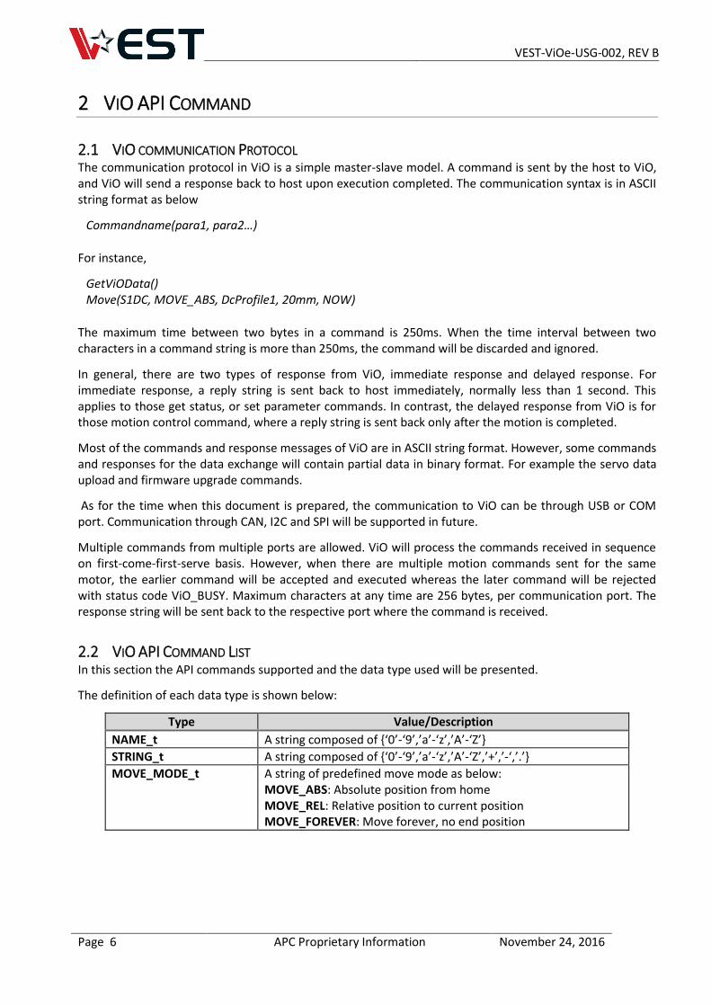
2.1 VIO COMMUNICATION PROTOCOL The communication protocol in ViO is a simple master-slave model. A command is sent by the host to ViO, and ViO will send a response back to host upon execution completed. The communication syntax is in ASCII string format as below
Commandname(para1, para2…)
For instance,
GetViOData() Move(S1DC, MOVE_ABS, DcProfile1, 20mm, NOW)
The maximum time between two bytes in a command is 250ms. When the time interval between two characters in a command string is more than 250ms, the command will be discarded and ignored.
In general, there are two types of response from ViO, immediate response and delayed response. For immediate response, a reply string is sent back to host immediately, normally less than 1 second. This applies to those get status, or set parameter commands. In contrast, the delayed response from ViO is for those motion control command, where a reply string is sent back only after the motion is completed.
Most of the commands and response messages of ViO are in ASCII string format. However, some commands and responses for the data exchange will contain partial data in binary format. For example the servo data upload and firmware upgrade commands.
As for the time when this document is prepared, the communication to ViO can be through USB or COM port. Communication through CAN, I2C and SPI will be supported in future.
Multiple commands from multiple ports are allowed. ViO will process the commands received in sequence on first-come-first-serve basis. However, when there are multiple motion commands sent for the same motor, the earlier command will be accepted and executed whereas the later command will be rejected with status code ViO_BUSY. Maximum characters at any time are 256 bytes, per communication port. The response string will be sent back to the respective port where the command is received.
2.2 VIO API COMMAND LIST In this section the API commands supported and the data type used will be presented.
The definition of each data type is shown below:
Type Value/Description
NAME_t A string composed of {‘0’-‘9’,’a’-‘z’,’A’-‘Z’}
STRING_t A string composed of {‘0’-‘9’,’a’-‘z’,’A’-‘Z’,’+’,’-‘,’.’}
MOVE_MODE_t A string of predefined move mode as below: MOVE_ABS: Absolute position from home MOVE_REL: Relative position to current position MOVE_FOREVER: Move forever, no end position
VEST-ViOe-USG-002, REV B
Page 7 APC Proprietary Information November 24, 2016
Type Value/Description
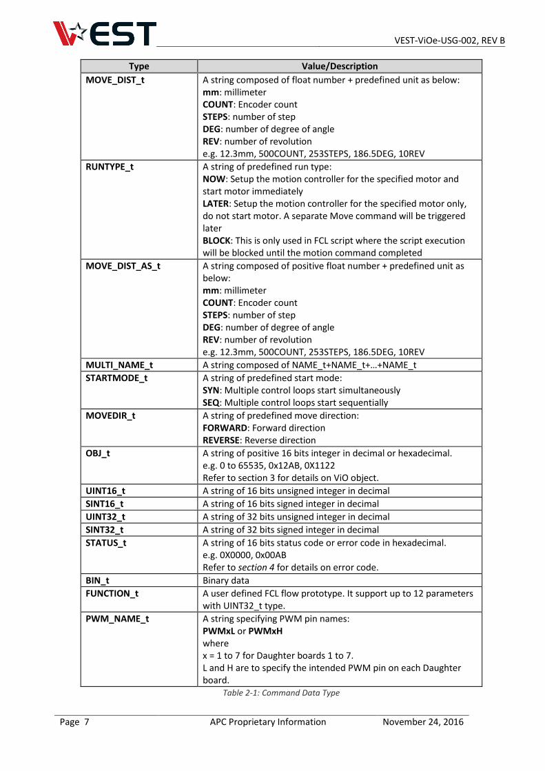
MOVE_DIST_t A string composed of float number + predefined unit as below: mm: millimeter COUNT: Encoder count STEPS: number of step DEG: number of degree of angle REV: number of revolution e.g. 12.3mm, 500COUNT, 253STEPS, 186.5DEG, 10REV
RUNTYPE_t A string of predefined run type: NOW: Setup the motion controller for the specified motor and start motor immediately LATER: Setup the motion controller for the specified motor only, do not start motor. A separate Move command will be triggered later BLOCK: This is only used in FCL script where the script execution will be blocked until the motion command completed
MOVE_DIST_AS_t A string composed of positive float number + predefined unit as below: mm: millimeter COUNT: Encoder count STEPS: number of step DEG: number of degree of angle REV: number of revolution e.g. 12.3mm, 500COUNT, 253STEPS, 186.5DEG, 10REV
MULTI_NAME_t A string composed of NAME_t+NAME_t+…+NAME_t
STARTMODE_t A string of predefined start mode: SYN: Multiple control loops start simultaneously SEQ: Multiple control loops start sequentially
MOVEDIR_t A string of predefined move direction: FORWARD: Forward direction REVERSE: Reverse direction
OBJ_t A string of positive 16 bits integer in decimal or hexadecimal. e.g. 0 to 65535, 0x12AB, 0X1122 Refer to section 3 for details on ViO object.
UINT16_t A string of 16 bits unsigned integer in decimal
SINT16_t A string of 16 bits signed integer in decimal
UINT32_t A string of 32 bits unsigned integer in decimal
SINT32_t A string of 32 bits signed integer in decimal
STATUS_t A string of 16 bits status code or error code in hexadecimal. e.g. 0X0000, 0x00AB Refer to section 4 for details on error code.
BIN_t Binary data
FUNCTION_t A user defined FCL flow prototype. It support up to 12 parameters with UINT32_t type.
PWM_NAME_t A string specifying PWM pin names: PWMxL or PWMxH where x = 1 to 7 for Daughter boards 1 to 7. L and H are to specify the intended PWM pin on each Daughter board.
Table 2-1: Command Data Type
VEST-ViOe-USG-002, REV B
Page 8 APC Proprietary Information November 24, 2016
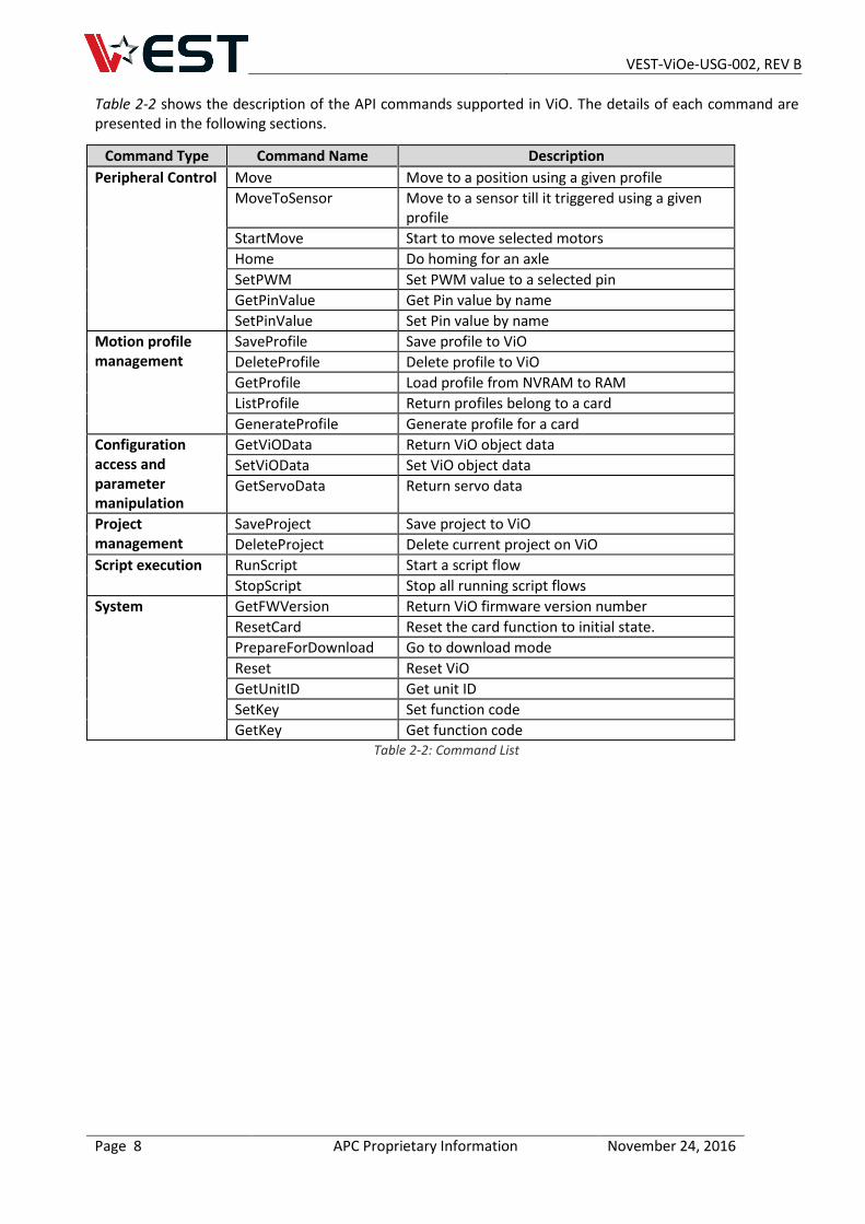
Table 2-2 shows the description of the API commands supported in ViO. The details of each command are presented in the following sections.
Command Type Command Name Description
Peripheral Control Move Move to a position using a given profile
MoveToSensor Move to a sensor till it triggered using a given profile
StartMove Start to move selected motors
Home Do homing for an axle
SetPWM Set PWM value to a selected pin
GetPinValue Get Pin value by name
SetPinValue Set Pin value by name
Motion profile management
SaveProfile Save profile to ViO
DeleteProfile Delete profile to ViO
GetProfile Load profile from NVRAM to RAM
ListProfile Return profiles belong to a card
GenerateProfile Generate profile for a card
Configuration access and parameter manipulation
GetViOData Return ViO object data
SetViOData Set ViO object data
GetServoData Return servo data
Project management
SaveProject Save project to ViO
DeleteProject Delete current project on ViO
Script execution RunScript Start a script flow
StopScript Stop all running script flows
System GetFWVersion Return ViO firmware version number
ResetCard Reset the card function to initial state.
PrepareForDownload Go to download mode
Reset Reset ViO
GetUnitID Get unit ID
SetKey Set function code
GetKey Get function code Table 2-2: Command List
VEST-ViOe-USG-002, REV B
Page 9 APC Proprietary Information November 24, 2016
2.3 PERIPHERAL CONTROL COMMANDS
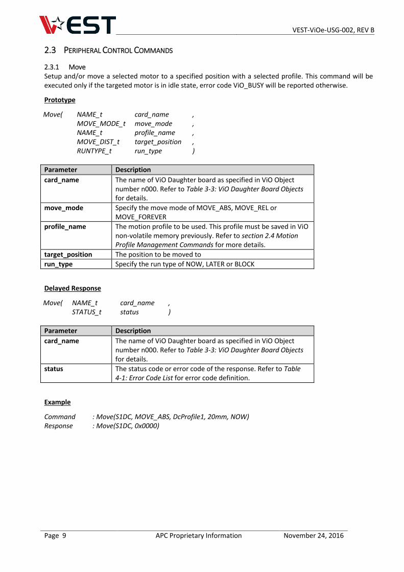
2.3.1 Move Setup and/or move a selected motor to a specified position with a selected profile. This command will be executed only if the targeted motor is in idle state, error code ViO_BUSY will be reported otherwise.
Prototype
Move( NAME_t card_name , MOVE_MODE_t move_mode , NAME_t profile_name , MOVE_DIST_t target_position , RUNTYPE_t run_type )
Parameter Description
card_name The name of ViO Daughter board as specified in ViO Object number n000. Refer to Table 3-3: ViO Daughter Board Objects for details.
move_mode Specify the move mode of MOVE_ABS, MOVE_REL or MOVE_FOREVER
profile_name The motion profile to be used. This profile must be saved in ViO non-volatile memory previously. Refer to section 2.4 Motion Profile Management Commands for more details.
target_position The position to be moved to
run_type Specify the run type of NOW, LATER or BLOCK
Delayed Response
Move( NAME_t card_name , STATUS_t status )
Parameter Description
card_name The name of ViO Daughter board as specified in ViO Object number n000. Refer to Table 3-3: ViO Daughter Board Objects for details.
status The status code or error code of the response. Refer to Table 4-1: Error Code List for error code definition.
Example
Command : Move(S1DC, MOVE_ABS, DcProfile1, 20mm, NOW) Response : Move(S1DC, 0x0000)
VEST-ViOe-USG-002, REV B
Page 10 APC Proprietary Information November 24, 2016
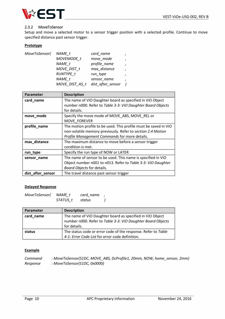
2.3.2 MoveToSensor Setup and move a selected motor to a sensor trigger position with a selected profile. Continue to move specified distance past sensor trigger.
Prototype
MoveToSensor( NAME_t card_name , MOVEMODE_t move_mode , NAME_t profile_name , MOVE_DIST_t max_distance , RUNTYPE_t run_type , NAME_t sensor_name , MOVE_DIST_AS_t dist_after_sensor )
Parameter Description
card_name The name of ViO Daughter board as specified in ViO Object number n000. Refer to Table 3-3: ViO Daughter Board Objects for details.
move_mode Specify the move mode of MOVE_ABS, MOVE_REL or MOVE_FOREVER
profile_name The motion profile to be used. This profile must be saved in ViO non-volatile memory previously. Refer to section 2.4 Motion Profile Management Commands for more details.
max_distance The maximum distance to move before a sensor trigger condition is met.
run_type Specify the run type of NOW or LATER
sensor_name The name of sensor to be used. This name is specified in ViO Object number n001 to n013. Refer to Table 3-3: ViO Daughter Board Objects for details.
dist_after_sensor The travel distance past sensor trigger
Delayed Response
MoveToSensor( NAME_t card_name , STATUS_t status )
Parameter Description
card_name The name of ViO Daughter board as specified in ViO Object number n000. Refer to Table 3-3: ViO Daughter Board Objects for details.
status The status code or error code of the response. Refer to Table 4-1: Error Code List for error code definition.
Example
Command : MoveToSensor(S1DC, MOVE_ABS, DcProfile1, 20mm, NOW, home_sensor, 2mm) Response : MoveToSensor(S1DC, 0x0000)
VEST-ViOe-USG-002, REV B
Page 11 APC Proprietary Information November 24, 2016
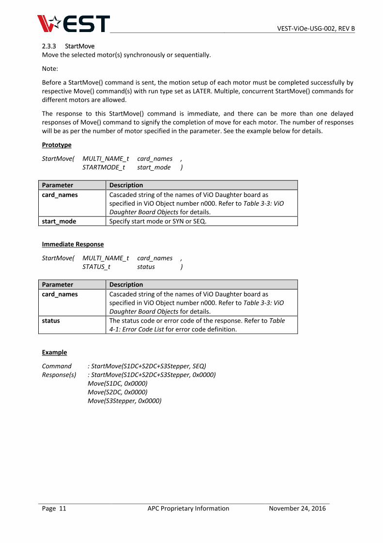
2.3.3 StartMove Move the selected motor(s) synchronously or sequentially.
Note:
Before a StartMove() command is sent, the motion setup of each motor must be completed successfully by respective Move() command(s) with run type set as LATER. Multiple, concurrent StartMove() commands for different motors are allowed.
The response to this StartMove() command is immediate, and there can be more than one delayed responses of Move() command to signify the completion of move for each motor. The number of responses will be as per the number of motor specified in the parameter. See the example below for details.
Prototype
StartMove( MULTI_NAME_t card_names , STARTMODE_t start_mode )
Parameter Description
card_names Cascaded string of the names of ViO Daughter board as specified in ViO Object number n000. Refer to Table 3-3: ViO Daughter Board Objects for details.
start_mode Specify start mode or SYN or SEQ.
Immediate Response
StartMove( MULTI_NAME_t card_names , STATUS_t status )
Parameter Description
card_names Cascaded string of the names of ViO Daughter board as specified in ViO Object number n000. Refer to Table 3-3: ViO Daughter Board Objects for details.
status The status code or error code of the response. Refer to Table 4-1: Error Code List for error code definition.
Example
Command : StartMove(S1DC+S2DC+S3Stepper, SEQ) Response(s) : StartMove(S1DC+S2DC+S3Stepper, 0x0000)
Move(S1DC, 0x0000) Move(S2DC, 0x0000) Move(S3Stepper, 0x0000)
VEST-ViOe-USG-002, REV B
Page 12 APC Proprietary Information November 24, 2016
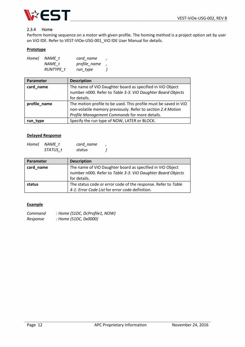
2.3.4 Home Perform homing sequence on a motor with given profile. The homing method is a project option set by user on ViO IDE. Refer to VEST-VIOe-USG-001_ViO IDE User Manual for details.
Prototype
Home( NAME_t card_name , NAME_t profile_name , RUNTYPE_t run_type )
Parameter Description
card_name The name of ViO Daughter board as specified in ViO Object number n000. Refer to Table 3-3: ViO Daughter Board Objects for details.
profile_name The motion profile to be used. This profile must be saved in ViO non-volatile memory previously. Refer to section 2.4 Motion Profile Management Commands for more details.
run_type Specify the run type of NOW, LATER or BLOCK.
Delayed Response
Home( NAME_t card_name , STATUS_t status )
Parameter Description
card_name The name of ViO Daughter board as specified in ViO Object number n000. Refer to Table 3-3: ViO Daughter Board Objects for details.
status The status code or error code of the response. Refer to Table 4-1: Error Code List for error code definition.
Example
Command : Home (S1DC, DcProfile1, NOW) Response : Home (S1DC, 0x0000)
VEST-ViOe-USG-002, REV B
Page 13 APC Proprietary Information November 24, 2016
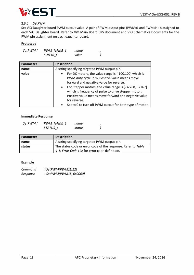
2.3.5 SetPWM Set ViO Daughter board PWM output value. A pair of PWM output pins (PWMxL and PWMxH) is assigned to each ViO Daughter board. Refer to ViO Main Board ERS document and ViO Schematics Documents for the PWM pin assignment on each daughter board.
Prototype
SetPWM ( PWM_NAME_t name , SINT16_t value )
Parameter Description
name A string specifying targeted PWM output pin.
value For DC motors, the value range is [-100,100] which is PWM duty cycle in %. Positive value means move forward and negative value for reverse.
For Stepper motors, the value range is [-32768, 32767] which is frequency of pulse to drive stepper motor. Positive value means move forward and negative value for reverse.
Set to 0 to turn off PWM output for both type of motor.
Immediate Response
SetPWM ( PWM_NAME_t name , STATUS_t status )
Parameter Description
name A string specifying targeted PWM output pin.
status The status code or error code of the response. Refer to Table 4-1: Error Code List for error code definition.
Example
Command : SetPWM(PWM1L,12) Response : SetPWM(PWM1L, 0x0000)
VEST-ViOe-USG-002, REV B
Page 14 APC Proprietary Information November 24, 2016
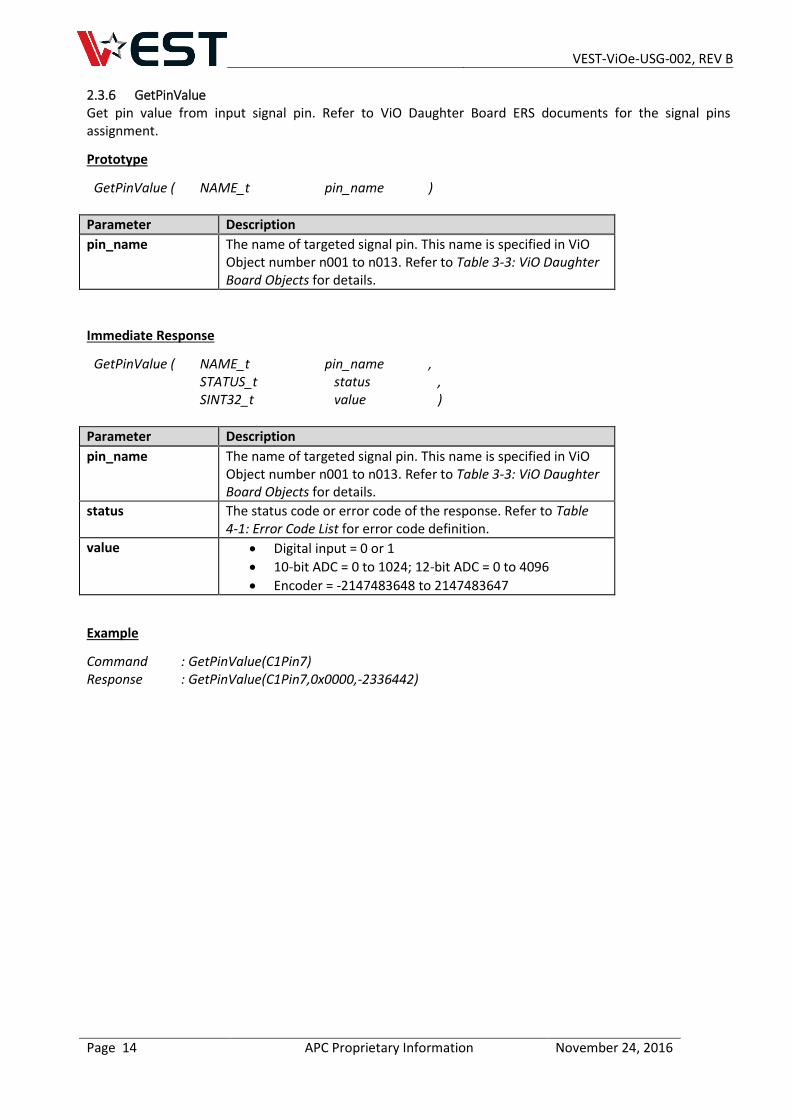
2.3.6 GetPinValue Get pin value from input signal pin. Refer to ViO Daughter Board ERS documents for the signal pins assignment.
Prototype
GetPinValue ( NAME_t pin_name )
Parameter Description
pin_name The name of targeted signal pin. This name is specified in ViO Object number n001 to n013. Refer to Table 3-3: ViO Daughter Board Objects for details.
Immediate Response
GetPinValue ( NAME_t pin_name , STATUS_t status , SINT32_t value )
Parameter Description
pin_name The name of targeted signal pin. This name is specified in ViO Object number n001 to n013. Refer to Table 3-3: ViO Daughter Board Objects for details.
status The status code or error code of the response. Refer to Table 4-1: Error Code List for error code definition.
value Digital input = 0 or 1
10-bit ADC = 0 to 1024; 12-bit ADC = 0 to 4096
Encoder = -2147483648 to 2147483647
Example
Command : GetPinValue(C1Pin7) Response : GetPinValue(C1Pin7,0x0000,-2336442)
VEST-ViOe-USG-002, REV B
Page 15 APC Proprietary Information November 24, 2016
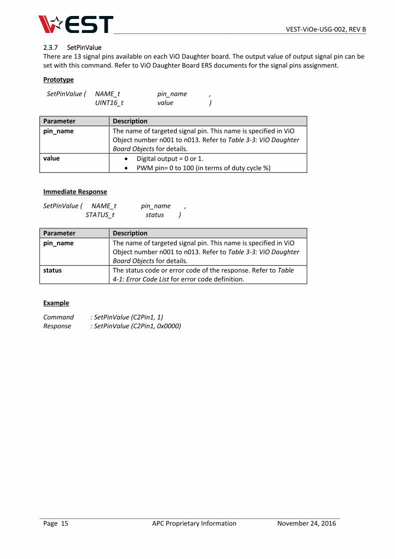
2.3.7 SetPinValue There are 13 signal pins available on each ViO Daughter board. The output value of output signal pin can be set with this command. Refer to ViO Daughter Board ERS documents for the signal pins assignment.
Prototype
SetPinValue ( NAME_t pin_name , UINT16_t value )
Parameter Description
pin_name The name of targeted signal pin. This name is specified in ViO Object number n001 to n013. Refer to Table 3-3: ViO Daughter Board Objects for details.
value Digital output = 0 or 1.
PWM pin= 0 to 100 (in terms of duty cycle %)
Immediate Response
SetPinValue ( NAME_t pin_name , STATUS_t status )
Parameter Description
pin_name The name of targeted signal pin. This name is specified in ViO Object number n001 to n013. Refer to Table 3-3: ViO Daughter Board Objects for details.
status The status code or error code of the response. Refer to Table 4-1: Error Code List for error code definition.
Example
Command : SetPinValue (C2Pin1, 1) Response : SetPinValue (C2Pin1, 0x0000)
VEST-ViOe-USG-002, REV B
Page 16 APC Proprietary Information November 24, 2016
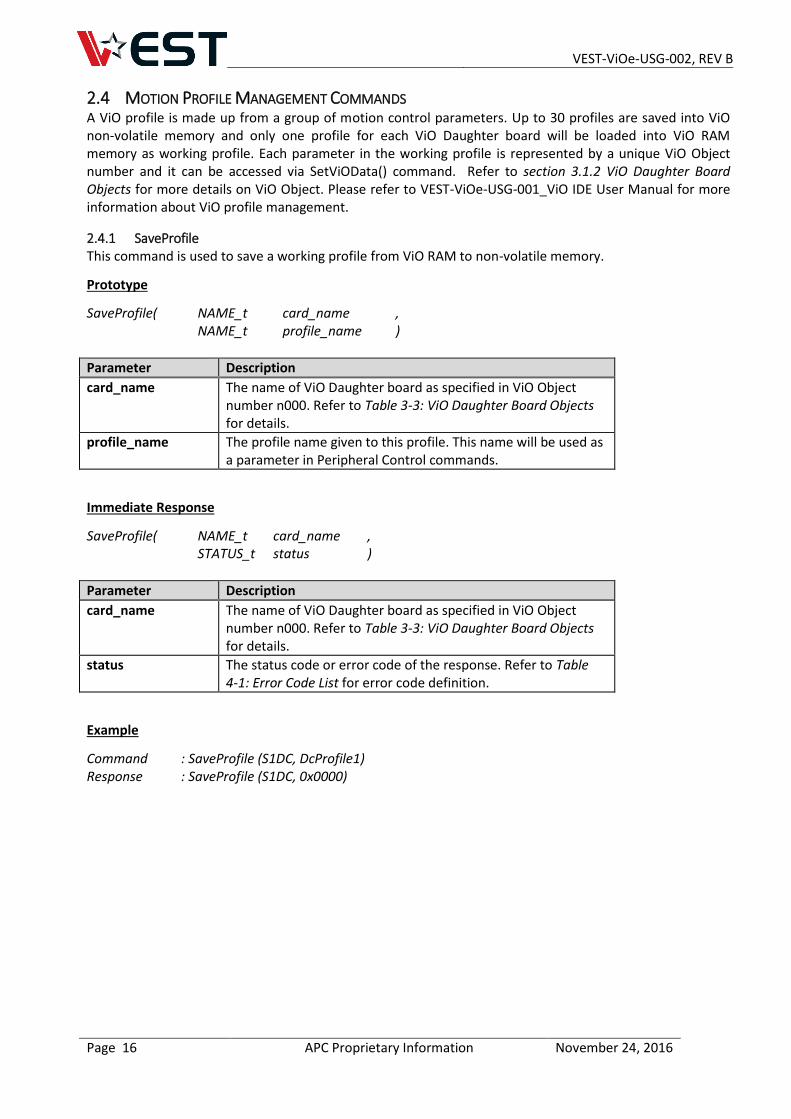
2.4 MOTION PROFILE MANAGEMENT COMMANDS A ViO profile is made up from a group of motion control parameters. Up to 30 profiles are saved into ViO non-volatile memory and only one profile for each ViO Daughter board will be loaded into ViO RAM memory as working profile. Each parameter in the working profile is represented by a unique ViO Object number and it can be accessed via SetViOData() command. Refer to section 3.1.2 ViO Daughter Board Objects for more details on ViO Object. Please refer to VEST-ViOe-USG-001_ViO IDE User Manual for more information about ViO profile management.
2.4.1 SaveProfile This command is used to save a working profile from ViO RAM to non-volatile memory.
Prototype
SaveProfile( NAME_t card_name , NAME_t profile_name )
Parameter Description
card_name The name of ViO Daughter board as specified in ViO Object number n000. Refer to Table 3-3: ViO Daughter Board Objects for details.
profile_name The profile name given to this profile. This name will be used as a parameter in Peripheral Control commands.
Immediate Response
SaveProfile( NAME_t card_name , STATUS_t status )
Parameter Description
card_name The name of ViO Daughter board as specified in ViO Object number n000. Refer to Table 3-3: ViO Daughter Board Objects for details.
status The status code or error code of the response. Refer to Table 4-1: Error Code List for error code definition.
Example
Command : SaveProfile (S1DC, DcProfile1) Response : SaveProfile (S1DC, 0x0000)
VEST-ViOe-USG-002, REV B
Page 17 APC Proprietary Information November 24, 2016
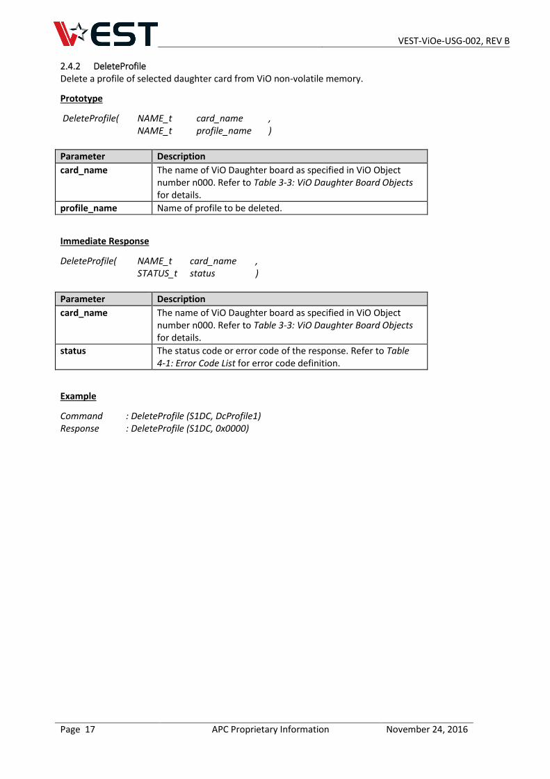
2.4.2 DeleteProfile Delete a profile of selected daughter card from ViO non-volatile memory.
Prototype
DeleteProfile( NAME_t card_name , NAME_t profile_name )
Parameter Description
card_name The name of ViO Daughter board as specified in ViO Object number n000. Refer to Table 3-3: ViO Daughter Board Objects for details.
profile_name Name of profile to be deleted.
Immediate Response
DeleteProfile( NAME_t card_name , STATUS_t status )
Parameter Description
card_name The name of ViO Daughter board as specified in ViO Object number n000. Refer to Table 3-3: ViO Daughter Board Objects for details.
status The status code or error code of the response. Refer to Table 4-1: Error Code List for error code definition.
Example
Command : DeleteProfile (S1DC, DcProfile1) Response : DeleteProfile (S1DC, 0x0000)
VEST-ViOe-USG-002, REV B
Page 18 APC Proprietary Information November 24, 2016
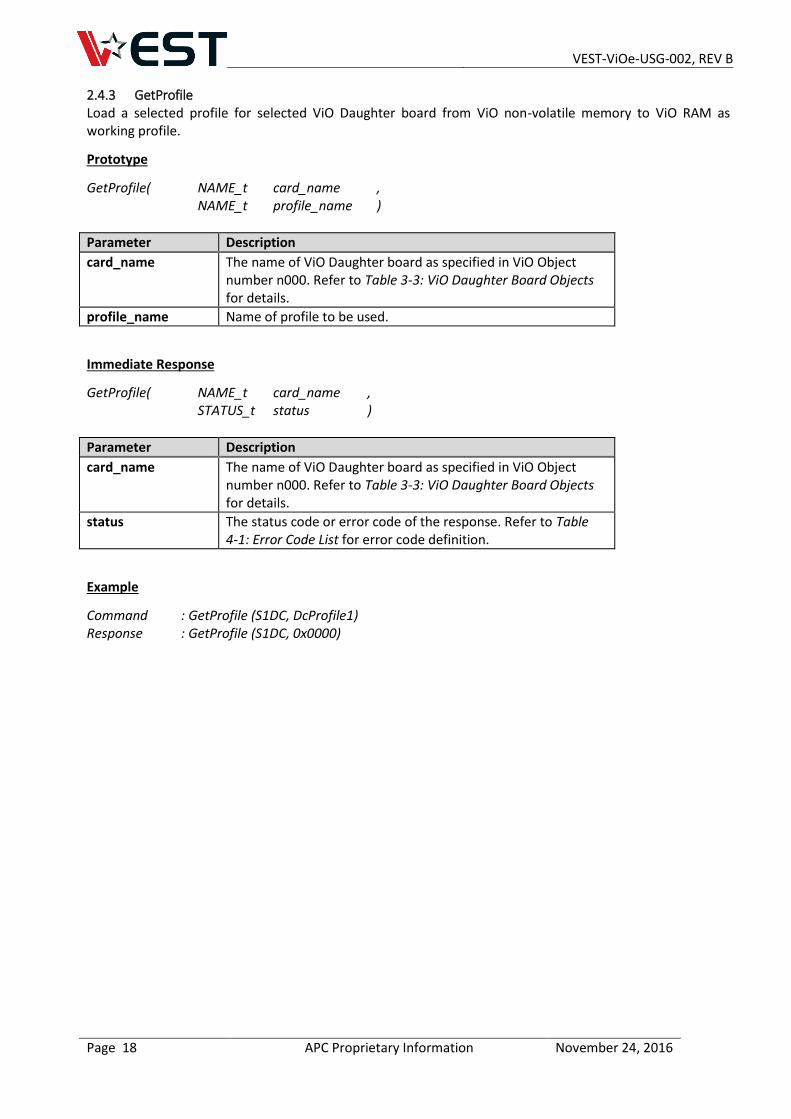
2.4.3 GetProfile Load a selected profile for selected ViO Daughter board from ViO non-volatile memory to ViO RAM as working profile.
Prototype
GetProfile( NAME_t card_name , NAME_t profile_name )
Parameter Description
card_name The name of ViO Daughter board as specified in ViO Object number n000. Refer to Table 3-3: ViO Daughter Board Objects for details.
profile_name Name of profile to be used.
Immediate Response
GetProfile( NAME_t card_name , STATUS_t status )
Parameter Description
card_name The name of ViO Daughter board as specified in ViO Object number n000. Refer to Table 3-3: ViO Daughter Board Objects for details.
status The status code or error code of the response. Refer to Table 4-1: Error Code List for error code definition.
Example
Command : GetProfile (S1DC, DcProfile1) Response : GetProfile (S1DC, 0x0000)
VEST-ViOe-USG-002, REV B
Page 19 APC Proprietary Information November 24, 2016
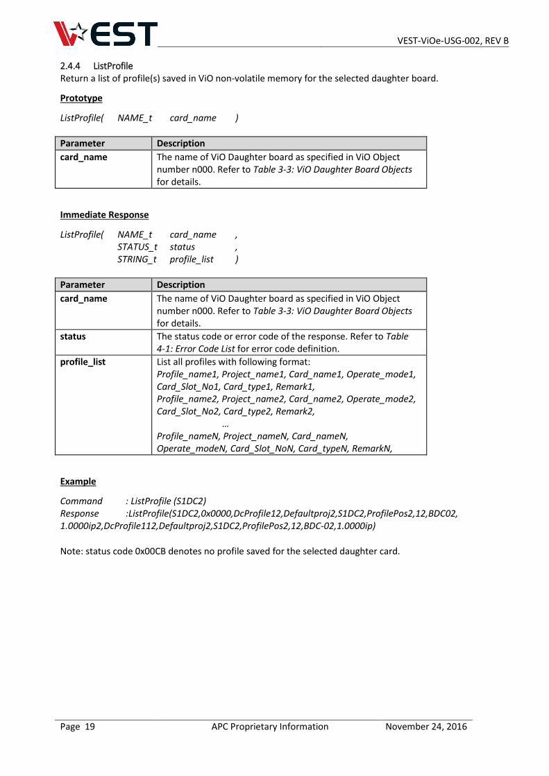
2.4.4 ListProfile Return a list of profile(s) saved in ViO non-volatile memory for the selected daughter board.
Prototype
ListProfile( NAME_t card_name )
Parameter Description
card_name The name of ViO Daughter board as specified in ViO Object number n000. Refer to Table 3-3: ViO Daughter Board Objects for details.
Immediate Response
ListProfile( NAME_t card_name , STATUS_t status , STRING_t profile_list )
Parameter Description
card_name The name of ViO Daughter board as specified in ViO Object number n000. Refer to Table 3-3: ViO Daughter Board Objects for details.
status The status code or error code of the response. Refer to Table 4-1: Error Code List for error code definition.
profile_list List all profiles with following format: Profile_name1, Project_name1, Card_name1, Operate_mode1, Card_Slot_No1, Card_type1, Remark1, Profile_name2, Project_name2, Card_name2, Operate_mode2, Card_Slot_No2, Card_type2, Remark2,
… Profile_nameN, Project_nameN, Card_nameN, Operate_modeN, Card_Slot_NoN, Card_typeN, RemarkN,
Example
Command : ListProfile (S1DC2) Response :ListProfile(S1DC2,0x0000,DcProfile12,Defaultproj2,S1DC2,ProfilePos2,12,BDC02, 1.0000ip2,DcProfile112,Defaultproj2,S1DC2,ProfilePos2,12,BDC-02,1.0000ip)
Note: status code 0x00CB denotes no profile saved for the selected daughter card.
VEST-ViOe-USG-002, REV B
Page 20 APC Proprietary Information November 24, 2016
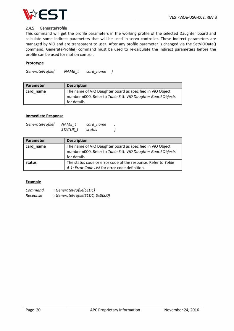
2.4.5 GenerateProfile This command will get the profile parameters in the working profile of the selected Daughter board and calculate some indirect parameters that will be used in servo controller. These indirect parameters are managed by ViO and are transparent to user. After any profile parameter is changed via the SetViOData() command, GenerateProfile() command must be used to re-calculate the indirect parameters before the profile can be used for motion control.
Prototype
GenerateProfile( NAME_t card_name )
Parameter Description
card_name The name of ViO Daughter board as specified in ViO Object number n000. Refer to Table 3-3: ViO Daughter Board Objects for details.
Immediate Response
GenerateProfile( NAME_t card_name , STATUS_t status )
Parameter Description
card_name The name of ViO Daughter board as specified in ViO Object number n000. Refer to Table 3-3: ViO Daughter Board Objects for details.
status The status code or error code of the response. Refer to Table 4-1: Error Code List for error code definition.
Example
Command : GenerateProfile(S1DC) Response : GenerateProfile(S1DC, 0x0000)
VEST-ViOe-USG-002, REV B
Page 21 APC Proprietary Information November 24, 2016
2.5 CONFIGURATION ACCESS AND PARAMETER MANIPULATION COMMANDS
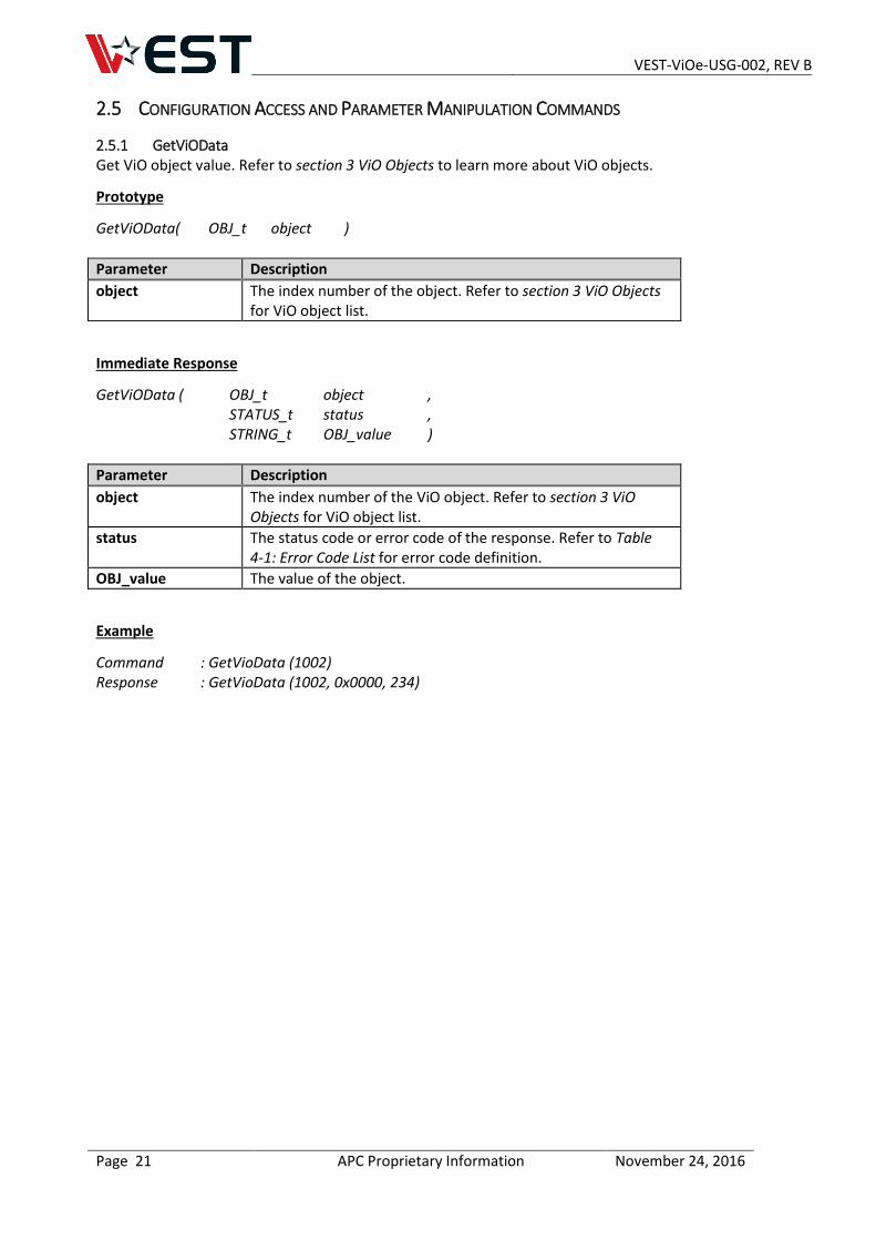
2.5.1 GetViOData Get ViO object value. Refer to section 3 ViO Objects to learn more about ViO objects.
Prototype
GetViOData( OBJ_t object )
Parameter Description
object The index number of the object. Refer to section 3 ViO Objects for ViO object list.
Immediate Response
GetViOData ( OBJ_t object , STATUS_t status , STRING_t OBJ_value )
Parameter Description
object The index number of the ViO object. Refer to section 3 ViO Objects for ViO object list.
status The status code or error code of the response. Refer to Table 4-1: Error Code List for error code definition.
OBJ_value The value of the object.
Example
Command : GetVioData (1002) Response : GetVioData (1002, 0x0000, 234)
VEST-ViOe-USG-002, REV B
Page 22 APC Proprietary Information November 24, 2016
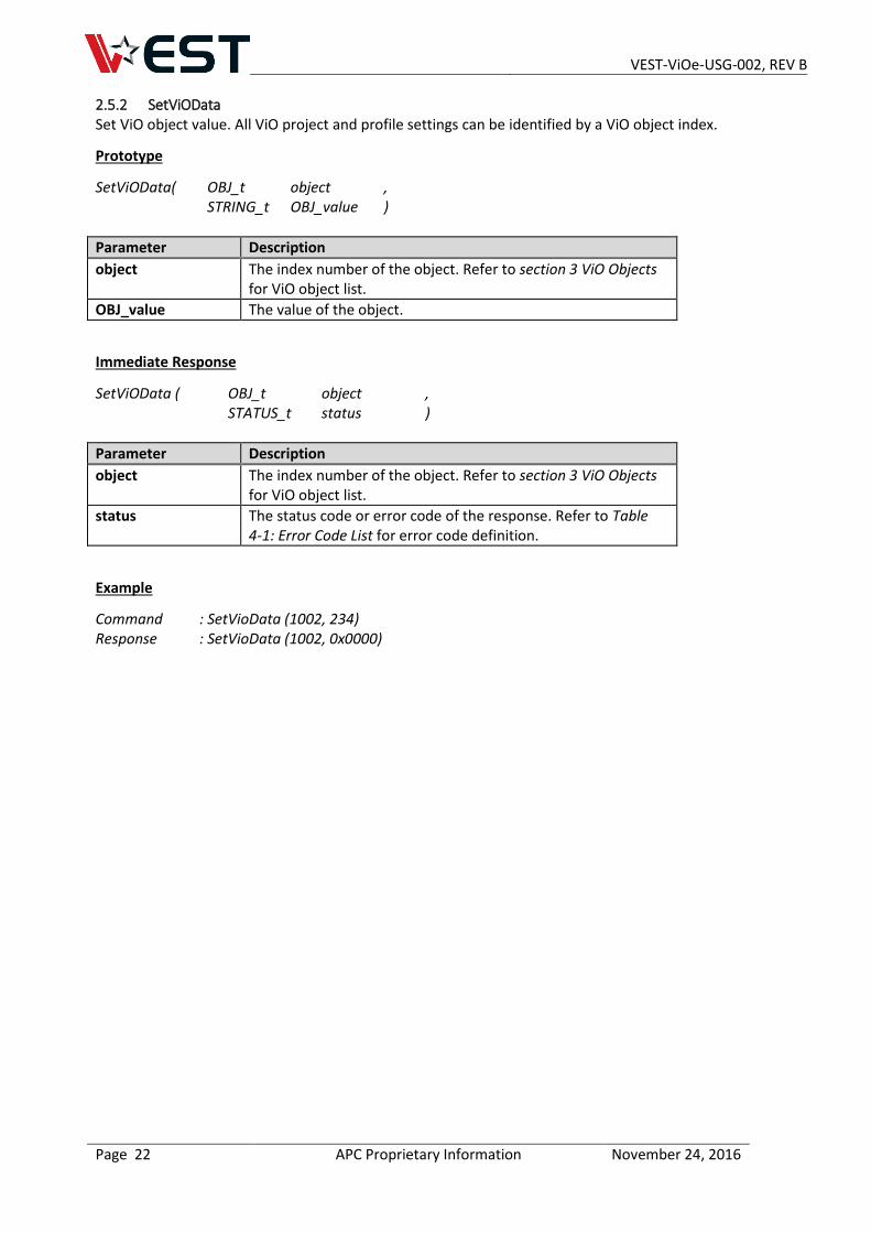
2.5.2 SetViOData Set ViO object value. All ViO project and profile settings can be identified by a ViO object index.
Prototype
SetViOData( OBJ_t object , STRING_t OBJ_value )
Parameter Description
object The index number of the object. Refer to section 3 ViO Objects for ViO object list.
OBJ_value The value of the object.
Immediate Response
SetViOData ( OBJ_t object , STATUS_t status )
Parameter Description
object The index number of the object. Refer to section 3 ViO Objects for ViO object list.
status The status code or error code of the response. Refer to Table 4-1: Error Code List for error code definition.
Example
Command : SetVioData (1002, 234) Response : SetVioData (1002, 0x0000)
VEST-ViOe-USG-002, REV B
Page 23 APC Proprietary Information November 24, 2016
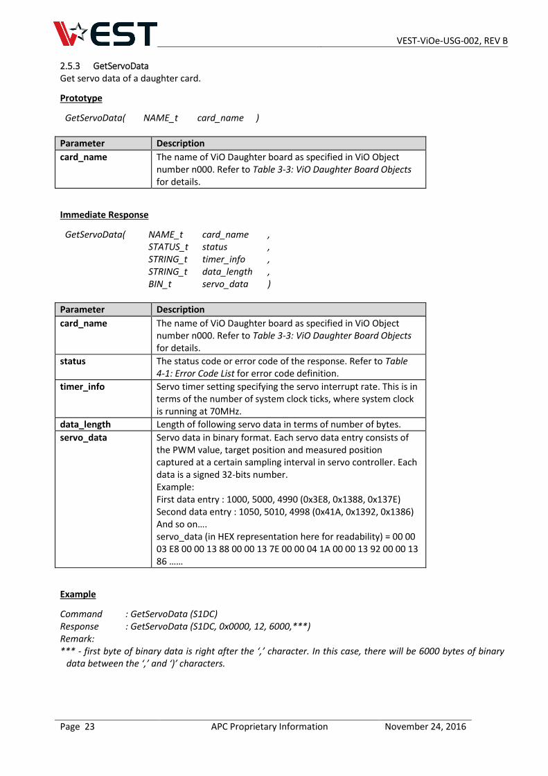
2.5.3 GetServoData Get servo data of a daughter card.
Prototype
GetServoData( NAME_t card_name )
Parameter Description
card_name The name of ViO Daughter board as specified in ViO Object number n000. Refer to Table 3-3: ViO Daughter Board Objects for details.
Immediate Response
GetServoData( NAME_t card_name , STATUS_t status , STRING_t timer_info , STRING_t data_length , BIN_t servo_data )
Parameter Description
card_name The name of ViO Daughter board as specified in ViO Object number n000. Refer to Table 3-3: ViO Daughter Board Objects for details.
status The status code or error code of the response. Refer to Table 4-1: Error Code List for error code definition.
timer_info Servo timer setting specifying the servo interrupt rate. This is in terms of the number of system clock ticks, where system clock is running at 70MHz.
data_length Length of following servo data in terms of number of bytes.
servo_data Servo data in binary format. Each servo data entry consists of the PWM value, target position and measured position captured at a certain sampling interval in servo controller. Each data is a signed 32-bits number. Example: First data entry : 1000, 5000, 4990 (0x3E8, 0x1388, 0x137E) Second data entry : 1050, 5010, 4998 (0x41A, 0x1392, 0x1386) And so on…. servo_data (in HEX representation here for readability) = 00 00 03 E8 00 00 13 88 00 00 13 7E 00 00 04 1A 00 00 13 92 00 00 13 86 ……
Example
Command : GetServoData (S1DC) Response : GetServoData (S1DC, 0x0000, 12, 6000,***) Remark: *** - first byte of binary data is right after the ‘,’ character. In this case, there will be 6000 bytes of binary
data between the ‘,’ and ‘)’ characters.
VEST-ViOe-USG-002, REV B
Page 24 APC Proprietary Information November 24, 2016
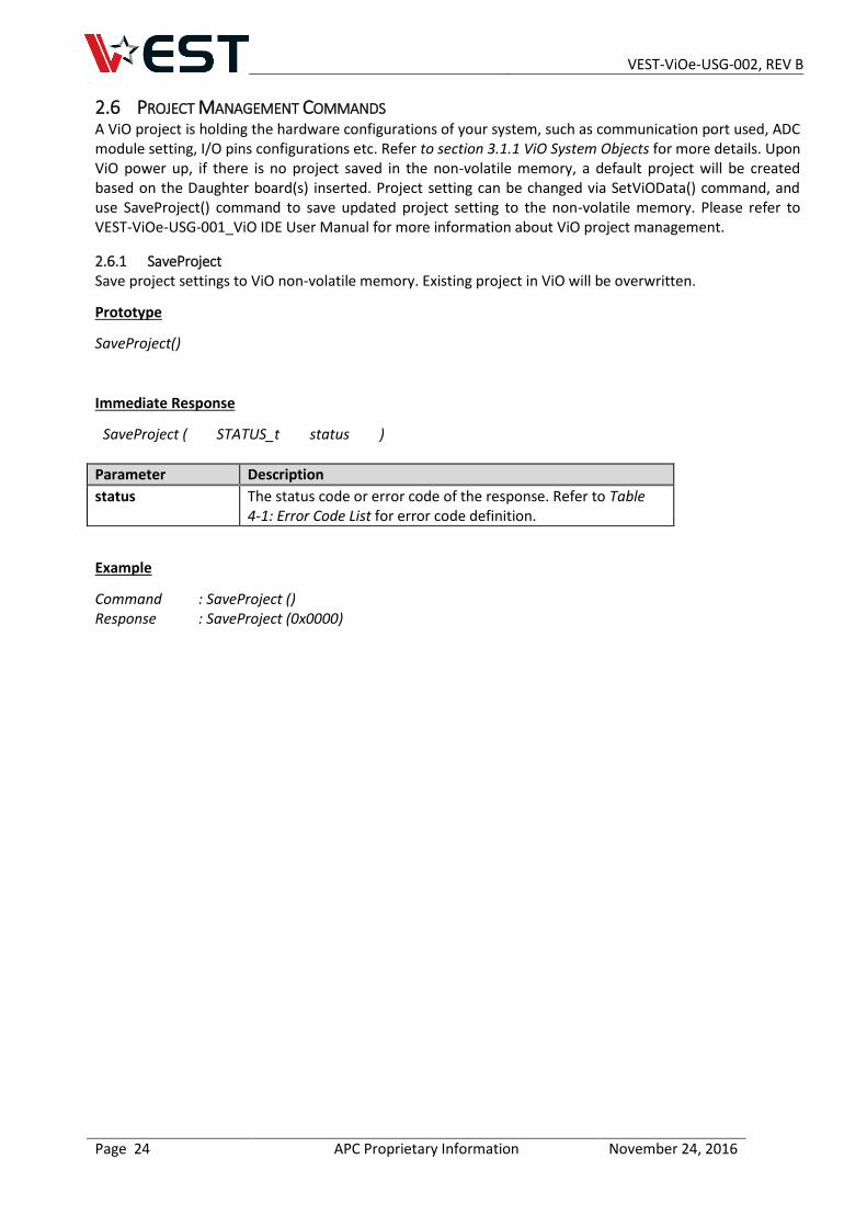
2.6 PROJECT MANAGEMENT COMMANDS A ViO project is holding the hardware configurations of your system, such as communication port used, ADC module setting, I/O pins configurations etc. Refer to section 3.1.1 ViO System Objects for more details. Upon ViO power up, if there is no project saved in the non-volatile memory, a default project will be created based on the Daughter board(s) inserted. Project setting can be changed via SetViOData() command, and use SaveProject() command to save updated project setting to the non-volatile memory. Please refer to VEST-ViOe-USG-001_ViO IDE User Manual for more information about ViO project management.
2.6.1 SaveProject Save project settings to ViO non-volatile memory. Existing project in ViO will be overwritten.
Prototype
SaveProject()
Immediate Response
SaveProject ( STATUS_t status )
Parameter Description
status The status code or error code of the response. Refer to Table 4-1: Error Code List for error code definition.
Example
Command : SaveProject () Response : SaveProject (0x0000)
VEST-ViOe-USG-002, REV B
Page 25 APC Proprietary Information November 24, 2016
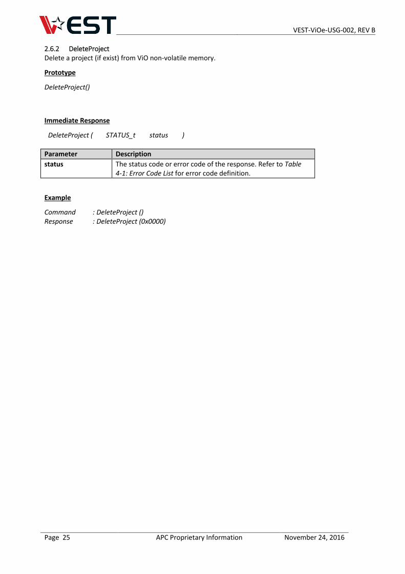
2.6.2 DeleteProject Delete a project (if exist) from ViO non-volatile memory.
Prototype
DeleteProject()
Immediate Response
DeleteProject ( STATUS_t status )
Parameter Description
status The status code or error code of the response. Refer to Table 4-1: Error Code List for error code definition.
Example
Command : DeleteProject () Response : DeleteProject (0x0000)
VEST-ViOe-USG-002, REV B
Page 26 APC Proprietary Information November 24, 2016
2.7 SCRIPT EXECUTION COMMANDS
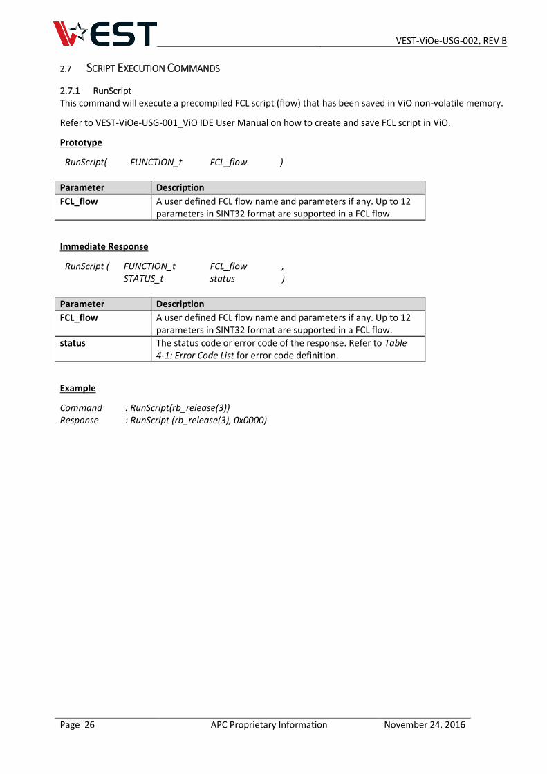
2.7.1 RunScript This command will execute a precompiled FCL script (flow) that has been saved in ViO non-volatile memory.
Refer to VEST-ViOe-USG-001_ViO IDE User Manual on how to create and save FCL script in ViO.
Prototype
RunScript( FUNCTION_t FCL_flow )
Parameter Description
FCL_flow A user defined FCL flow name and parameters if any. Up to 12 parameters in SINT32 format are supported in a FCL flow.
Immediate Response
RunScript ( FUNCTION_t FCL_flow , STATUS_t status )
Parameter Description
FCL_flow A user defined FCL flow name and parameters if any. Up to 12 parameters in SINT32 format are supported in a FCL flow.
status The status code or error code of the response. Refer to Table 4-1: Error Code List for error code definition.
Example
Command : RunScript(rb_release(3)) Response : RunScript (rb_release(3), 0x0000)
VEST-ViOe-USG-002, REV B
Page 27 APC Proprietary Information November 24, 2016
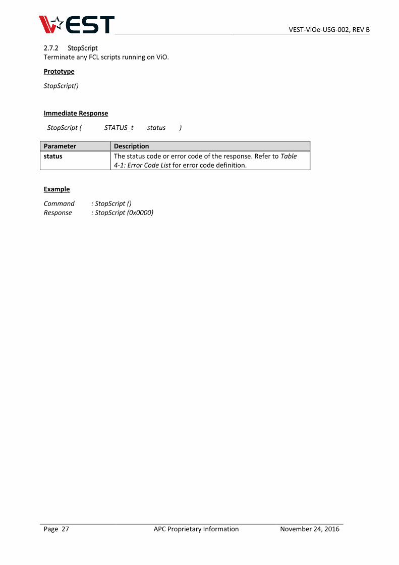
2.7.2 StopScript Terminate any FCL scripts running on ViO.
Prototype
StopScript()
Immediate Response
StopScript ( STATUS_t status )
Parameter Description
status The status code or error code of the response. Refer to Table 4-1: Error Code List for error code definition.
Example
Command : StopScript () Response : StopScript (0x0000)
VEST-ViOe-USG-002, REV B
Page 28 APC Proprietary Information November 24, 2016
2.8 SYSTEM COMMANDS
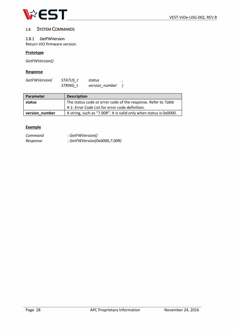
2.8.1 GetFWVersion Return ViO firmware version.
Prototype
GetFWVersion()
Response
GetFWVersion( STATUS_t status , STRING_t version_number )
Parameter Description
status The status code or error code of the response. Refer to Table 4-1: Error Code List for error code definition.
version_number A string, such as “7.00R”. It is valid only when status is 0x0000.
Example
Command : GetFWVersion() Response : GetFWVersion(0x0000,7.00R)
VEST-ViOe-USG-002, REV B
Page 29 APC Proprietary Information November 24, 2016
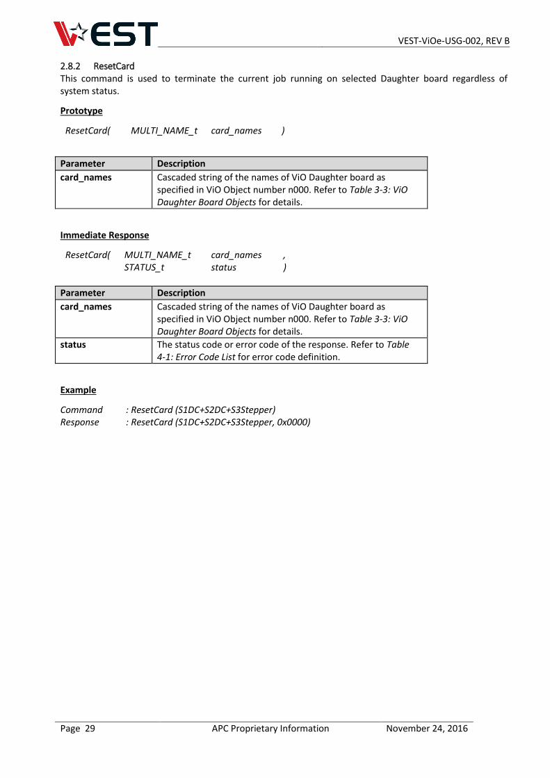
2.8.2 ResetCard This command is used to terminate the current job running on selected Daughter board regardless of system status.
Prototype
ResetCard( MULTI_NAME_t card_names )
Parameter Description
card_names Cascaded string of the names of ViO Daughter board as specified in ViO Object number n000. Refer to Table 3-3: ViO Daughter Board Objects for details.
Immediate Response
ResetCard( MULTI_NAME_t card_names , STATUS_t status )
Parameter Description
card_names Cascaded string of the names of ViO Daughter board as specified in ViO Object number n000. Refer to Table 3-3: ViO Daughter Board Objects for details.
status The status code or error code of the response. Refer to Table 4-1: Error Code List for error code definition.
Example
Command : ResetCard (S1DC+S2DC+S3Stepper) Response : ResetCard (S1DC+S2DC+S3Stepper, 0x0000)
VEST-ViOe-USG-002, REV B
Page 30 APC Proprietary Information November 24, 2016
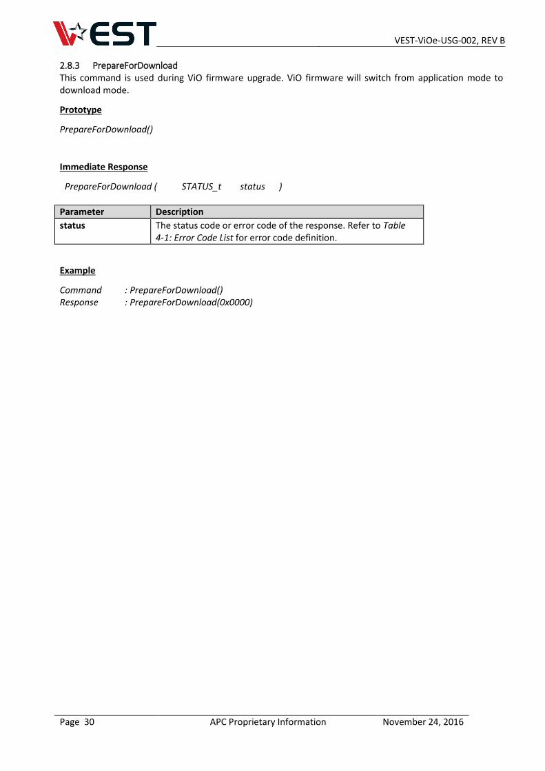
2.8.3 PrepareForDownload This command is used during ViO firmware upgrade. ViO firmware will switch from application mode to download mode.
Prototype
PrepareForDownload()
Immediate Response
PrepareForDownload ( STATUS_t status )
Parameter Description
status The status code or error code of the response. Refer to Table 4-1: Error Code List for error code definition.
Example
Command : PrepareForDownload() Response : PrepareForDownload(0x0000)
VEST-ViOe-USG-002, REV B
Page 31 APC Proprietary Information November 24, 2016
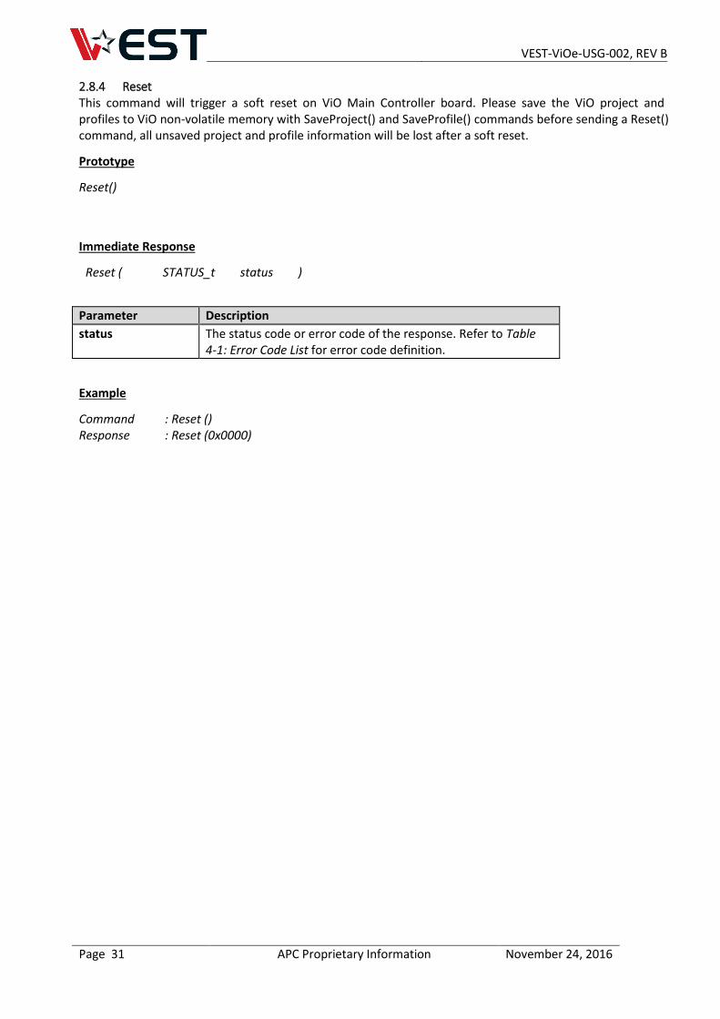
2.8.4 Reset This command will trigger a soft reset on ViO Main Controller board. Please save the ViO project and profiles to ViO non-volatile memory with SaveProject() and SaveProfile() commands before sending a Reset() command, all unsaved project and profile information will be lost after a soft reset.
Prototype
Reset()
Immediate Response
Reset ( STATUS_t status )
Parameter Description
status The status code or error code of the response. Refer to Table 4-1: Error Code List for error code definition.
Example
Command : Reset () Response : Reset (0x0000)
VEST-ViOe-USG-002, REV B
Page 32 APC Proprietary Information November 24, 2016
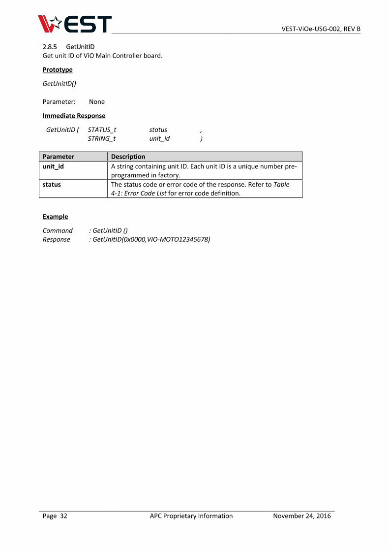
2.8.5 GetUnitID Get unit ID of ViO Main Controller board.
Prototype
GetUnitID()
Parameter: None
Immediate Response
GetUnitID ( STATUS_t status , STRING_t unit_id )
Parameter Description
unit_id A string containing unit ID. Each unit ID is a unique number pre-programmed in factory.
status The status code or error code of the response. Refer to Table 4-1: Error Code List for error code definition.
Example
Command : GetUnitID () Response : GetUnitID(0x0000,VIO-MOTO12345678)
VEST-ViOe-USG-002, REV B
Page 33 APC Proprietary Information November 24, 2016
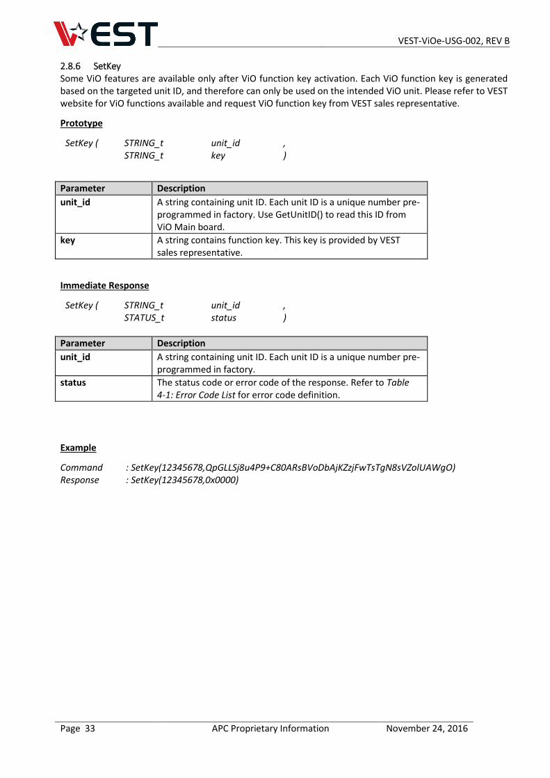
2.8.6 SetKey Some ViO features are available only after ViO function key activation. Each ViO function key is generated based on the targeted unit ID, and therefore can only be used on the intended ViO unit. Please refer to VEST website for ViO functions available and request ViO function key from VEST sales representative.
Prototype
SetKey ( STRING_t unit_id , STRING_t key )
Parameter Description
unit_id A string containing unit ID. Each unit ID is a unique number pre-programmed in factory. Use GetUnitID() to read this ID from ViO Main board.
key A string contains function key. This key is provided by VEST sales representative.
Immediate Response
SetKey ( STRING_t unit_id , STATUS_t status )
Parameter Description
unit_id A string containing unit ID. Each unit ID is a unique number pre-programmed in factory.
status The status code or error code of the response. Refer to Table 4-1: Error Code List for error code definition.
Example
Command : SetKey(12345678,QpGLLSj8u4P9+C80ARsBVoDbAjKZzjFwTsTgN8sVZolUAWgO) Response : SetKey(12345678,0x0000)
VEST-ViOe-USG-002, REV B
Page 34 APC Proprietary Information November 24, 2016
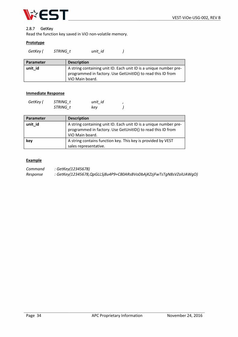
2.8.7 GetKey Read the function key saved in ViO non-volatile memory.
Prototype
GetKey ( STRING_t unit_id )
Parameter Description
unit_id A string containing unit ID. Each unit ID is a unique number pre-programmed in factory. Use GetUnitID() to read this ID from ViO Main board.
Immediate Response
GetKey ( STRING_t unit_id , STRING_t key )
Parameter Description
unit_id A string containing unit ID. Each unit ID is a unique number pre-programmed in factory. Use GetUnitID() to read this ID from ViO Main board.
key A string contains function key. This key is provided by VEST sales representative.
Example
Command : GetKey(12345678) Response : GetKey(12345678,QpGLLSj8u4P9+C80ARsBVoDbAjKZzjFwTsTgN8sVZolUAWgO)
VEST-ViOe-USG-002, REV B
Page 35 APC Proprietary Information November 24, 2016
3 VIO OBJECTS
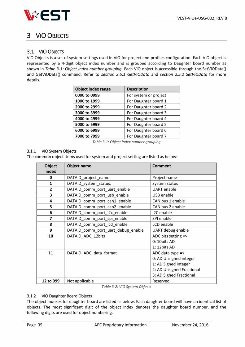
3.1 VIO OBJECTS ViO Objects is a set of system settings used in ViO for project and profiles configuration. Each ViO object is represented by a 4-digit object index number and is grouped according to Daughter board number as shown in Table 3-1: Object index number grouping. Each ViO object is accessible through the SetViOData() and GetViOData() command. Refer to section 2.5.1 GetViOData and section 2.5.2 SetViOData for more details.
Object index range Description
0000 to 0999 For system or project
1000 to 1999 For Daughter board 1
2000 to 2999 For Daughter board 2
3000 to 3999 For Daughter board 3
4000 to 4999 For Daughter board 4
5000 to 5999 For Daughter board 5
6000 to 6999 For Daughter board 6
7000 to 7999 For Daughter board 7 Table 3-1: Object index number grouping
3.1.1 ViO System Objects The common object items used for system and project setting are listed as below:
Object index
Object name Comment
0 DATAID_project_name Project name
1 DATAID_system_status, System status
2 DATAID_comm_port_uart_enable UART enable
3 DATAID_comm_port_usb_enable USB enable
4 DATAID_comm_port_can1_enable CAN bus 1 enable
5 DATAID_comm_port_can2_enable CAN bus 2 enable
6 DATAID_comm_port_i2c_enable I2C enable
7 DATAID_comm_port_spi_enable SPI enable
8 DATAID_comm_port_lcd_enable LCD enable
9 DATAID_comm_port_uart_debug_enable UART debug enable
10 DATAID_ADC_12bits ADC bits setting => 0: 10bits AD 1: 12bits AD
11 DATAID_ADC_data_format ADC data type => 0: AD Unsigned integer 1: AD Signed integer 2: AD Unsigned Fractional 3: AD Signed Fractional
12 to 999 Not applicable Reserved. Table 3-2: ViO System Objects
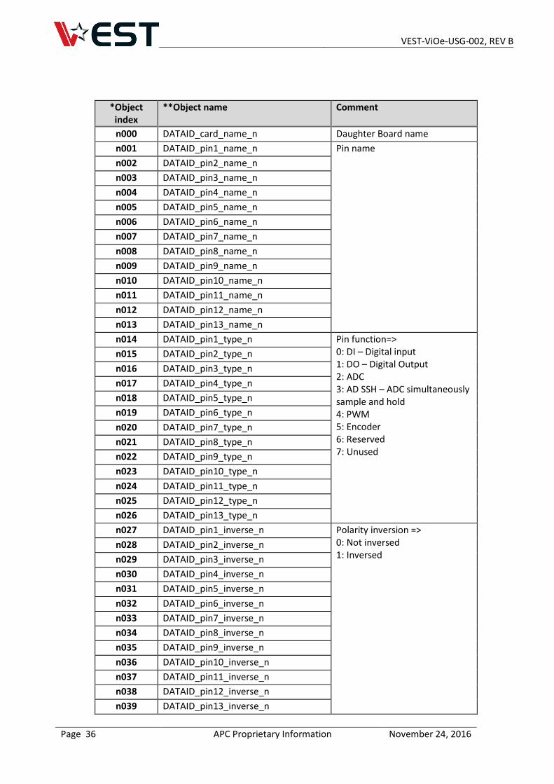
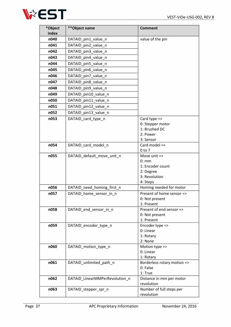
3.1.2 ViO Daughter Board Objects The object indexes for daughter board are listed as below. Each daughter board will have an identical list of objects. The most significant digit of the object index denotes the daughter board number, and the following digits are used for object numbering.
VEST-ViOe-USG-002, REV B
Page 36 APC Proprietary Information November 24, 2016
*Object index
**Object name Comment
n000 DATAID_card_name_n Daughter Board name
n001 DATAID_pin1_name_n Pin name
n002 DATAID_pin2_name_n
n003 DATAID_pin3_name_n
n004 DATAID_pin4_name_n
n005 DATAID_pin5_name_n
n006 DATAID_pin6_name_n
n007 DATAID_pin7_name_n
n008 DATAID_pin8_name_n
n009 DATAID_pin9_name_n
n010 DATAID_pin10_name_n
n011 DATAID_pin11_name_n
n012 DATAID_pin12_name_n
n013 DATAID_pin13_name_n
n014 DATAID_pin1_type_n Pin function=> 0: DI – Digital input 1: DO – Digital Output 2: ADC 3: AD SSH – ADC simultaneously sample and hold 4: PWM 5: Encoder 6: Reserved 7: Unused
n015 DATAID_pin2_type_n
n016 DATAID_pin3_type_n
n017 DATAID_pin4_type_n
n018 DATAID_pin5_type_n
n019 DATAID_pin6_type_n
n020 DATAID_pin7_type_n
n021 DATAID_pin8_type_n
n022 DATAID_pin9_type_n
n023 DATAID_pin10_type_n
n024 DATAID_pin11_type_n
n025 DATAID_pin12_type_n
n026 DATAID_pin13_type_n
n027 DATAID_pin1_inverse_n Polarity inversion => 0: Not inversed 1: Inversed
n028 DATAID_pin2_inverse_n
n029 DATAID_pin3_inverse_n
n030 DATAID_pin4_inverse_n
n031 DATAID_pin5_inverse_n
n032 DATAID_pin6_inverse_n
n033 DATAID_pin7_inverse_n
n034 DATAID_pin8_inverse_n
n035 DATAID_pin9_inverse_n
n036 DATAID_pin10_inverse_n
n037 DATAID_pin11_inverse_n
n038 DATAID_pin12_inverse_n
n039 DATAID_pin13_inverse_n
VEST-ViOe-USG-002, REV B
Page 37 APC Proprietary Information November 24, 2016
*Object index
**Object name Comment
n040 DATAID_pin1_value_n value of the pin
n041 DATAID_pin2_value_n
n042 DATAID_pin3_value_n
n043 DATAID_pin4_value_n
n044 DATAID_pin5_value_n
n045 DATAID_pin6_value_n
n046 DATAID_pin7_value_n
n047 DATAID_pin8_value_n
n048 DATAID_pin9_value_n
n049 DATAID_pin10_value_n
n050 DATAID_pin11_value_n
n051 DATAID_pin12_value_n
n052 DATAID_pin13_value_n
n053 DATAID_card_type_n Card type => 0: Stepper motor 1: Brushed DC 2: Power 3: Sensor
n054 DATAID_card_model_n Card model => 0 to 7
n055 DATAID_default_move_unit_n Move unit => 0: mm 1: Encoder count 2: Degree 3: Revolution 4: Steps
n056 DATAID_need_homing_first_n Homing needed for motor
n057 DATAID_home_sensor_in_n Present of home sensor => 0: Not present 1: Present
n058 DATAID_end_sensor_in_n Present of end sensor => 0: Not present 1: Present
n059 DATAID_encoder_type_n Encoder type => 0: Linear 1: Rotary 2: None
n060 DATAID_motion_type_n Motion type => 0: Linear 1: Rotary
n061 DATAID_unlimited_path_n Borderless rotary motion => 0: False 1: True
n062 DATAID_LinearMMPerRevolution_n Distance in mm per motor revolution
n063 DATAID_stepper_spr_n Number of full steps per revolution
VEST-ViOe-USG-002, REV B
Page 38 APC Proprietary Information November 24, 2016
*Object index
**Object name Comment
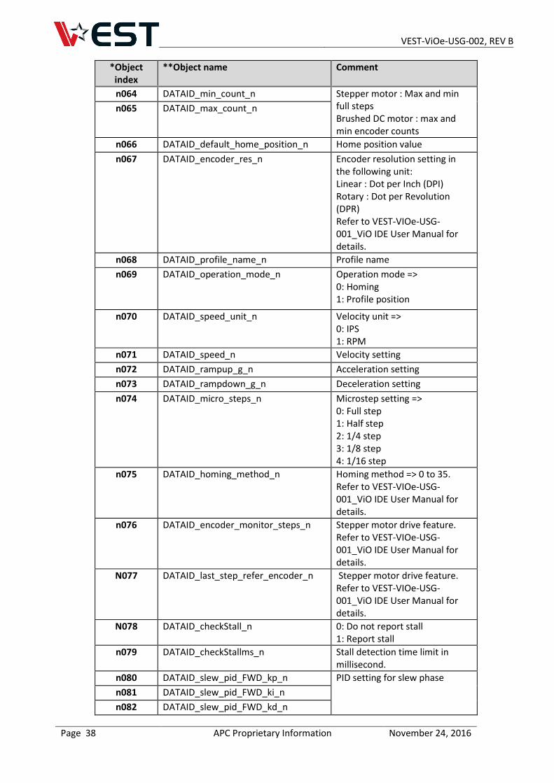
n064 DATAID_min_count_n Stepper motor : Max and min full steps Brushed DC motor : max and min encoder counts
n065 DATAID_max_count_n
n066 DATAID_default_home_position_n Home position value
n067 DATAID_encoder_res_n Encoder resolution setting in the following unit: Linear : Dot per Inch (DPI) Rotary : Dot per Revolution (DPR) Refer to VEST-VIOe-USG-001_ViO IDE User Manual for details.
n068 DATAID_profile_name_n Profile name
n069 DATAID_operation_mode_n Operation mode => 0: Homing 1: Profile position
n070 DATAID_speed_unit_n Velocity unit => 0: IPS 1: RPM
n071 DATAID_speed_n Velocity setting
n072 DATAID_rampup_g_n Acceleration setting
n073 DATAID_rampdown_g_n Deceleration setting
n074 DATAID_micro_steps_n Microstep setting => 0: Full step 1: Half step 2: 1/4 step 3: 1/8 step 4: 1/16 step
n075 DATAID_homing_method_n Homing method => 0 to 35. Refer to VEST-VIOe-USG-001_ViO IDE User Manual for details.
n076 DATAID_encoder_monitor_steps_n Stepper motor drive feature. Refer to VEST-VIOe-USG-001_ViO IDE User Manual for details.
N077 DATAID_last_step_refer_encoder_n Stepper motor drive feature. Refer to VEST-VIOe-USG-001_ViO IDE User Manual for details.
N078 DATAID_checkStall_n 0: Do not report stall 1: Report stall
n079 DATAID_checkStallms_n Stall detection time limit in millisecond.
n080 DATAID_slew_pid_FWD_kp_n PID setting for slew phase
n081 DATAID_slew_pid_FWD_ki_n
n082 DATAID_slew_pid_FWD_kd_n
VEST-ViOe-USG-002, REV B
Page 39 APC Proprietary Information November 24, 2016
*Object index
**Object name Comment
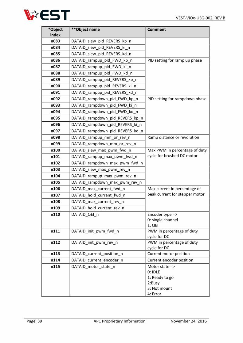
n083 DATAID_slew_pid_REVERS_kp_n
n084 DATAID_slew_pid_REVERS_ki_n
n085 DATAID_slew_pid_REVERS_kd_n
n086 DATAID_rampup_pid_FWD_kp_n PID setting for ramp up phase
n087 DATAID_rampup_pid_FWD_ki_n
n088 DATAID_rampup_pid_FWD_kd_n
n089 DATAID_rampup_pid_REVERS_kp_n
n090 DATAID_rampup_pid_REVERS_ki_n
n091 DATAID_rampup_pid_REVERS_kd_n
n092 DATAID_rampdown_pid_FWD_kp_n PID setting for rampdown phase
n093 DATAID_rampdown_pid_FWD_ki_n
n094 DATAID_rampdown_pid_FWD_kd_n
n095 DATAID_rampdown_pid_REVERS_kp_n
n096 DATAID_rampdown_pid_REVERS_ki_n
n097 DATAID_rampdown_pid_REVERS_kd_n
n098 DATAID_rampup_mm_or_rev_n Ramp distance or revolution
n099 DATAID_rampdown_mm_or_rev_n
n100 DATAID_slew_max_pwm_fwd_n Max PWM in percentage of duty cycle for brushed DC motor n101 DATAID_rampup_max_pwm_fwd_n
n102 DATAID_rampdown_max_pwm_fwd_n
n103 DATAID_slew_max_pwm_rev_n
n104 DATAID_rampup_max_pwm_rev_n
n105 DATAID_rampdown_max_pwm_rev_n
n106 DATAID_max_current_fwd_n Max current in percentage of peak current for stepper motor n107 DATAID_hold_current_fwd_n
n108 DATAID_max_current_rev_n
n109 DATAID_hold_current_rev_n
n110 DATAID_QEI_n Encoder type => 0: single channel 1: QEI
n111 DATAID_init_pwm_fwd_n PWM in percentage of duty cycle for DC
n112 DATAID_init_pwm_rev_n PWM in percentage of duty cycle for DC
n113 DATAID_current_position_n Current motor position
n114 DATAID_current_encoder_n Current encoder position
n115 DATAID_motor_state_n Motor state => 0: IDLE 1: Ready to go 2:Busy 3: Not mount 4: Error
VEST-ViOe-USG-002, REV B
Page 40 APC Proprietary Information November 24, 2016
*Object index
**Object name Comment
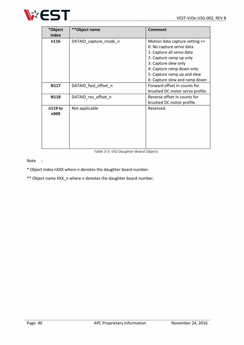
n116 DATAID_capture_mode_n Motion data capture setting => 0: No capture servo data 1: Capture all servo data 2: Capture ramp up only 3: Capture slew only 4: Capture ramp down only 5: Capture ramp up and slew 6: Capture slew and ramp down
N117 DATAID_fwd_offset_n Forward offset in counts for brushed DC motor servo profile.
N118 DATAID_rev_offset_n Reverse offset in counts for brushed DC motor profile.
n119 to n999
Not applicable Reserved.
Table 3-3: ViO Daughter Board Objects
Note :
* Object index nXXX where n denotes the daughter board number.
** Object name XXX_n where n denotes the daughter board number.
VEST-ViOe-USG-002, REV B
Page 41 APC Proprietary Information November 24, 2016
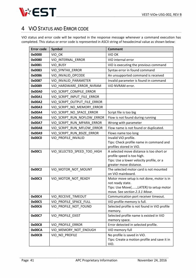
4 VIO STATUS AND ERROR CODE
ViO status and error code will be reported in the response message whenever a command execution has completed. This status or error code is represented in ASCII string of hexadecimal value as shown below:
Error code Symbol Comment
0x0000 ViO_OK ViO OK
0x0080 ViO_INTERNAL_ERROR ViO internal error
0x0081 ViO_BUSY ViO is executing the previous command
0x0083 ViO_SYNTAX_ERROR Syntax error in found command
0x0086 ViO_INVALID_OPCODE An unsupported command is received
0x0087 ViO_INVALID_PARAMETER Invalid parameter is found in command
0x0089 ViO_HARDWARE_ERROR_NVRAM ViO NVRAM error.
0x00A0 ViO_SCRIPT_COMPILE_ERROR
0x00A1 ViO_SCRIPT_INPUT_FILE_ERROR
0x00A2 ViO_SCRIPT_OUTPUT_FILE_ERROR
0x00A3 ViO_SCRIPT_NO_MEMORY_ERROR
0x00A4 ViO_SCRIPT_NO_SPACE_ERROR Script file is too big
0x00A6 ViO_SCRIPT_RUN_NOFLOW_ERROR Flow is not found during running
0x00A7 ViO_SCRIPT_RUN_MPARA_ERROR Wrong with parameter
0x00A8 ViO_SCRIPT_RUN_MFLOW_ERROR Flow name is not found or duplicated.
0x00A9 ViO_SCRIPT_RUN_BSIZE_ERROR Flows name too long
0x00C0 ViO_PROFILE_INVALID Invalid ViO profile. Tips: Check profile name in command and profiles stored in ViO.
0x00C1 ViO_SELECTED_SPEED_TOO_HIGH A selected move distance is too short or profile speed is too high. Tips: Use a lower velocity profile, or a greater move distance.
0x00C2 ViO_MOTOR_NOT_MOUNT The selected motor card is not mounted on ViO mainboard.
0x00C3 ViO_MOTOR_NOT_READY Motor move setup is not done, motor is in not ready state. Tips: Use Move(……,LATER) to setup motor move. See section 2.3.1 Move.
0x00C4 ViO_RECEIVE_TIMEOUT Communication port receiver timeout.
0x00C5 ViO_PROFILE_SPACE_FULL ViO profile memory is full.
0x00C6 ViO_PROFILE_NOT_FOUND Selected profile is not found in ViO profile memory.
0x00C7 ViO_PROFILE_EXIST Selected profile name is existed in ViO memory space.
0x00C8 ViO_PROFILE_ERROR Error detected in selected profile.
0x00CA ViO_MEMORY_NOT_ENOUGH ViO memory full
0x00CB ViO_NO_PROFILE No profile is saved in ViO. Tips: Create a motion profile and save it in ViO.
VEST-ViOe-USG-002, REV B
Page 42 APC Proprietary Information November 24, 2016
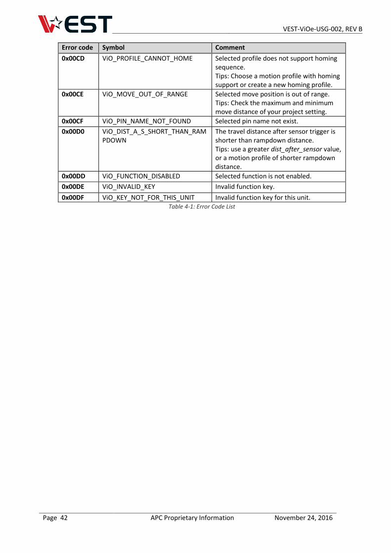
Error code Symbol Comment
0x00CD ViO_PROFILE_CANNOT_HOME Selected profile does not support homing sequence. Tips: Choose a motion profile with homing support or create a new homing profile.
0x00CE ViO_MOVE_OUT_OF_RANGE Selected move position is out of range. Tips: Check the maximum and minimum move distance of your project setting.
0x00CF ViO_PIN_NAME_NOT_FOUND Selected pin name not exist.
0x00D0 ViO_DIST_A_S_SHORT_THAN_RAMPDOWN
The travel distance after sensor trigger is shorter than rampdown distance. Tips: use a greater dist_after_sensor value, or a motion profile of shorter rampdown distance.
0x00DD ViO_FUNCTION_DISABLED Selected function is not enabled.
0x00DE ViO_INVALID_KEY Invalid function key.
0x00DF ViO_KEY_NOT_FOR_THIS_UNIT Invalid function key for this unit. Table 4-1: Error Code List
VEST-ViOe-USG-002, REV B
Page 43 APC Proprietary Information November 24, 2016
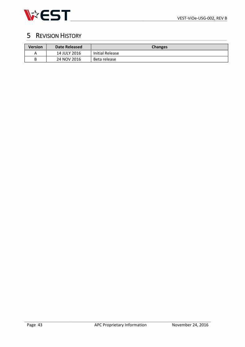
5 REVISION HISTORY
Version Date Released Changes
A 14 JULY 2016 Initial Release
B 24 NOV 2016 Beta release
VEST-ViOe-USG-002, REV B
Page 44 APC Proprietary Information November 24, 2016
6 LEGAL NOTICES
The signed agreement between Purchaser and APC will govern the sale and purchase of APC’s Venture Embedded Solutions Technology (“VEST”) products (“Products”). In the event that no agreement has been concluded, APC’s terms and conditions of supply will apply.
Testing and other quality control techniques are used to the extent that APC deems necessary to support its warranty.
Except where required by law, specific testing of all parameters of each Product is not necessarily performed.
Purchaser must provide adequate design and operating safeguards to minimize inherent or procedural and technical risks associated with Purchaser products and applications. Purchaser is solely responsible for its selection and use of APC Products. APC assumes no liability for applications assistance, Purchaser product design or any incompatibility of the Product with Purchaser product.
Products supplied by APC are not designed, intended or authorized for use in life support, life sustaining, medical systems or devices, aircraft navigation, nuclear, or other applications, including, but not limited to, public transportation operating systems, in which the failure of such Products could reasonably be expected to result in personal injury, loss of life or severe property or environmental damage. Purchaser acknowledges that use of APC’s Products in such product applications is understood to be fully at the risk of Purchaser and that Purchaser is responsible for verification and validation of the suitability of APC’s Products in such applications. Purchaser agrees that APC is not and shall not be liable, in whole or in part, for any claim or damage arising from use in such applications. Purchaser agrees to indemnify, defend and hold APC harmless from and against any and all claims, damages, losses, costs, expenses and liabilities arising out of or in connection with any such use or application.
APC retains all rights to all proprietary intellectual property in the Products and associated manufacturing processes and has the right to file for and obtain intellectual property protection for same.