VIO 300 D Service Manual -...
144
ERBE VIO 200 D V 1.4.x V 1.5.x V 1.6.x V 1.7.x Service Manual ERBE 04.06 VIO 300 D V 1.2.x V 1.3.x V 1.4.x V 1.5.x V 1.6.x V 1.7.x
Transcript of VIO 300 D Service Manual -...

ERBEERBE
VIO 300 D V 1.2.xV 1.3.xV 1.4.xV 1.5.x V 1.6.xV 1.7.x
VIO 200 D V 1.4.xV 1.5.xV 1.6.xV 1.7.x
04.06
Service
Man
ual

SERVICE MANUALVIO 300 D VIO 200 D

Service Manual Art. No. 80116-271
All rights to this Service Manual, in particular rights of duplication, dissemination and translation, are reserved. No part of this Service Manual may be reproduced in any form (by photocopying, microfilming or other methods) or processed, duplicated or disseminated by the use of electronic systems without the written consent of ERBE Ele-ktromedizin GmbH.
The information contained in this Service Manual may be amended or supplemented without prior notice and rep-resents no obligation on the part of ERBE Elektromedizin GmbH.
Printed by ERBE Elektromedizin
Printed in Germany
Copyright © ERBE Elektromedizin GmbH, Tübingen 2006

TABLE OF CONTENTSA
rt.-
Nr.
: 801
16-2
71
04.0
6
Table of Contents
Chapter Title Page
1 Safety information.......................................................................... 9
Classification of the safety information ........................................................9
Knowledge of the User Manual....................................................................9
Protection from the risk of electric shock .....................................................9
Electrostatically sensitive components ......................................................10
Liability and warranty .................................................................................10
2 Modifications ................................................................................ 11
3 Controls......................................................................................... 15
Controls at the front ...................................................................................15
Controls at the rear ....................................................................................16
4 Technical Data.............................................................................. 19
5 Circuit Descriptions ..................................................................... 21
Block diagram VIO 300 D ..........................................................................22
Block diagram VIO 200 D ..........................................................................23
Description of the various assemblies .......................................................24Line input .............................................................................................. 24Low voltage power supply unit (l.v. supply) .......................................... 24Power supply (high-voltage power supply unit) .................................... 25HF generator......................................................................................... 26CPU + Sensors..................................................................................... 27User Interface (control panel) ............................................................... 28ECB (ERBE Communication Bus) ........................................................ 28IIF (Instrument Interface) ...................................................................... 29Nessy2.................................................................................................. 30
6 SET-UP .......................................................................................... 31
General information ...................................................................................31
Overview of settings for SET-UP level 1....................................................31
Overview of settings for SET-UP level 2....................................................32
Call up SET-UP .........................................................................................36
Change settings.........................................................................................37
5 / 144

TABLE OF CONTENTS
Art
.-N
r.: 8
0116
-271
04
.06
7 Test programs............................................................................... 39
Call up Test programs............................................................................... 39
Exit Test programs.................................................................................... 41
Parameter inputs in Test programs........................................................... 41
Description of test programs ..................................................................... 42Test program "Display test" .................................................................. 42Test program "TP relay" ....................................................................... 43Test program "TP valves (APC)" .......................................................... 44Test program "TP activation signal" ..................................................... 44Test program "TP power supply unit" ................................................... 45Test program "TP generator"................................................................ 46Test program "Burn-In test" (only for production) ................................. 48Test program "Watchdog" .................................................................... 48Test program "CheckStop" ................................................................... 48Test program "Measured values" (only with V 1.3.x and later)............. 49
8 Measurement and adjustment..................................................... 51
Measurement of the HF power output....................................................... 51Temperature conditions........................................................................ 51Test equipment..................................................................................... 51Test set-up............................................................................................ 52Test procedure ..................................................................................... 52
Adjustment ................................................................................................ 53Personnel requirements ....................................................................... 53Temperature conditions........................................................................ 53Test sequence ...................................................................................... 53Test equipment..................................................................................... 54Voltage ................................................................................................. 55Spark .................................................................................................... 56Currents................................................................................................ 57
9 Troubleshooting ........................................................................... 59
ERROR list for VIO system....................................................................... 59A/E-Errors............................................................................................. 60B-Errors ................................................................................................ 63C-Errors ................................................................................................ 79D-Errors ................................................................................................ 852,3,5,6-Errors........................................................................................ 864 (NE)-Errors ........................................................................................ 909-Errors................................................................................................. 92
Testing and measuring equipment............................................................ 93
6 / 144
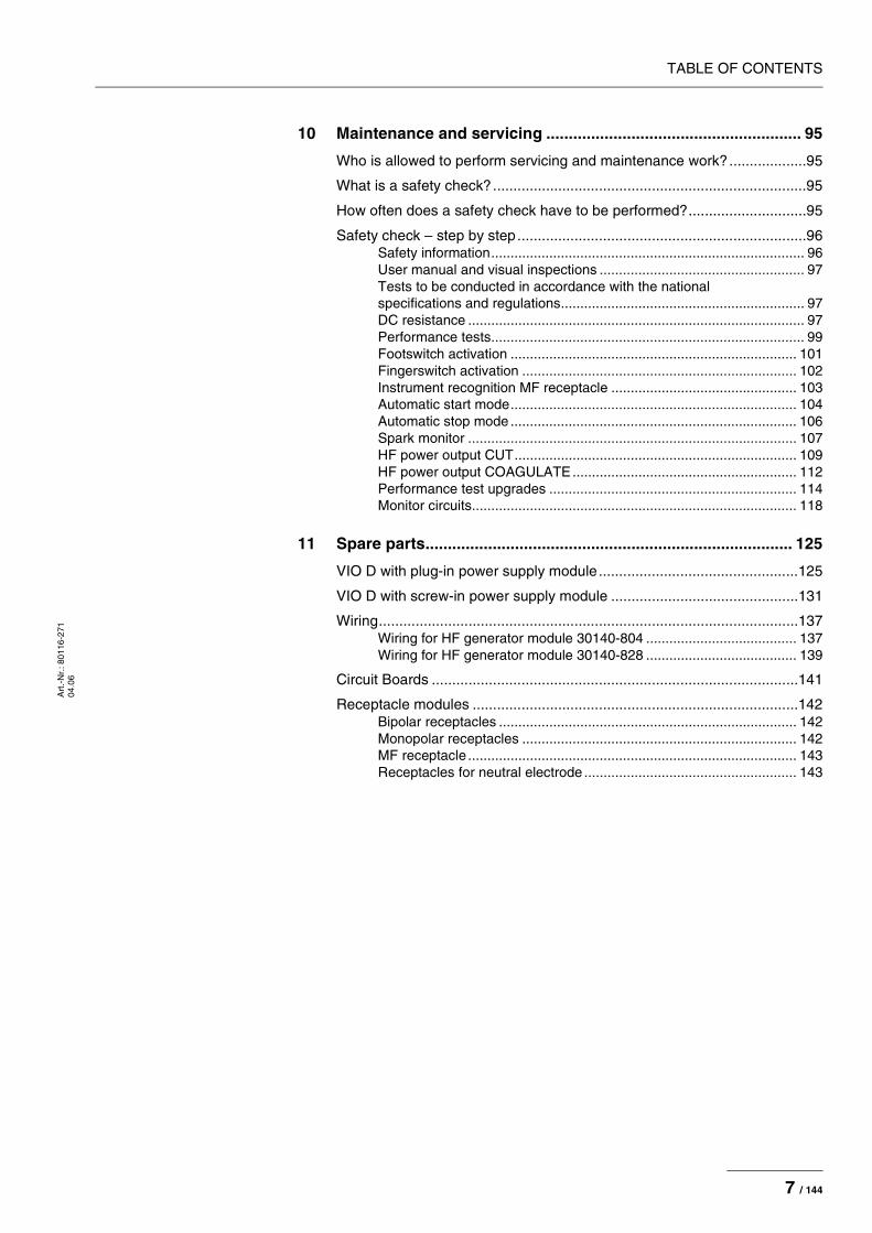
TABLE OF CONTENTSA
rt.-
Nr.
: 801
16-2
71
04.0
6
10 Maintenance and servicing ......................................................... 95
Who is allowed to perform servicing and maintenance work?...................95
What is a safety check?.............................................................................95
How often does a safety check have to be performed?.............................95
Safety check – step by step.......................................................................96Safety information................................................................................. 96User manual and visual inspections ..................................................... 97Tests to be conducted in accordance with the national specifications and regulations............................................................... 97DC resistance ....................................................................................... 97Performance tests................................................................................. 99Footswitch activation .......................................................................... 101Fingerswitch activation ....................................................................... 102Instrument recognition MF receptacle ................................................ 103Automatic start mode.......................................................................... 104Automatic stop mode .......................................................................... 106Spark monitor ..................................................................................... 107HF power output CUT......................................................................... 109HF power output COAGULATE.......................................................... 112Performance test upgrades ................................................................ 114Monitor circuits.................................................................................... 118
11 Spare parts.................................................................................. 125
VIO D with plug-in power supply module.................................................125
VIO D with screw-in power supply module ..............................................131
Wiring.......................................................................................................137Wiring for HF generator module 30140-804 ....................................... 137Wiring for HF generator module 30140-828 ....................................... 139
Circuit Boards ..........................................................................................141
Receptacle modules ................................................................................142Bipolar receptacles ............................................................................. 142Monopolar receptacles ....................................................................... 142MF receptacle ..................................................................................... 143Receptacles for neutral electrode ....................................................... 143
7 / 144

TABLE OF CONTENTS
Art
.-N
r.: 8
0116
-271
04
.06
8 / 144

1 • Safety informationA
rt.-
Nr.
: 801
16-2
71
04.0
6
CHAPTER 1
Safety information
Classification of the safety information
Knowledge of the User ManualThe user manuals relating to the units form part of this service man-ual. Familiarity with the user manuals, in particular the procedures for setting up, commissioning and handling described in the manuals, is a prerequisite for the performance of servicing work.
Protection from the risk of electric shock
WARNING! The WARNING! safety indication refers to a risk of personal injury.
CAUTION! The CAUTION! safety indication refers to a risk of damage to prop-erty.
ATTENTION! The ATTENTION! safety indication refers to a risk which can cause equipment to become unserviceable.
IMPORTANT! The IMPORTANT! designation indicates application information and other particularly important information.
WARNING! The supply voltage must match the voltage specified on the rating plate. Connect the unit / the equipment cart to a properly installed grounded outlet. Only use the ERBE power cord or an equivalent power cord for this purpose. The power cord must bear the national test symbol.
For safety reasons, multiple outlets and extension cords should not be used. If their use is unavoidable, they also must be provided with proper grounding.
WARNING! Unplug the power cord from the outlet before exchanging parts of the unit or cleaning it.
WARNING! Do not plug a wet power cord into the unit or into an outlet.
WARNING! Do not touch any unprotected wires or conductive surfaces while the unit is disassembled and is under voltage.
9 / 144

1 • Safety information
Art
.-N
r.: 8
0116
-271
04
.06
Electrostatically sensitive components
Liability and warrantyThis service manual enables the service technician to perform main-tenance work to the necessary extent. The work may only be per-formed by ERBE or persons specially trained by ERBE. The manufacturer accepts no liability and warranty rights shall be void if:
• the unit is adjusted incorrectly by untrained personnel, • maintenance work, modifications, or repairs to the unit or acces-
sories are performed by untrained personnel,• original spare parts are not used.
WARNING! Blown line fuses may only be replaced by a competent technician. Only replacement fuses of the rating specified on the unit's name plate may be used. Before resuming operation the unit must be subjected to a performance test by a competent technician.
CAUTION! This unit contains electrostatically sensitive components. Work at an anti-static workplace while repairing the unit. Wear a grounding armband while working with electrostatically sensitive compo-nents. Hold the circuit boards by their non-conducting corners. Use an anti-static container for transporting electrostatically sensi-tive components and the circuit boards.
10 / 144

2 • ModificationsA
rt.-
Nr.
: 801
16-2
71
04.0
6
CHAPTER 2
Modifications
As from VIO version 1.3.x
Hardware
Software
Component affected Description of the modification
APC 2 module In addition to the APC receptacle, another receptacle can be added. The second receptacle can be either a multifunctional (only in conjunction with a VIO 300 D), monopolar or bipolar receptacle.
IES 2 module The IES 2 smoke evacuation system can be attached to the VIO HF surgical unit and operated via said unit.
Component affected Description of the modification
VIO module New modes:
DRY CUT ° (only relevant for VIO 300 D)
SWIFT COAG ° (only relevant for VIO 300 D)
SET-UP settings Power Display:
When the unit is restarted, the power display is always deactivated (=OFF).
Neutral electrode:
Additional option “dynamic”.
New SET-UP settings:
Display time
APC Purge Flow/APC purging flow
DRY °/SWIFT ° (only relevant for VIO 300 D)
Additions to test programs:
Error list IIF/NE
Hardware TP
Upgrade list
11 / 144

2 • Modifications
Art
.-N
r.: 8
0116
-271
04
.06
As from VIO version 1.4.x
Hardware
Software
Test programs New “Measured values” test program.
Test program mode can also be called up when the unit is ON.
Component affected Description of the modification
Component affected Description of the modification
APC 2 module In addition to the APC receptacle, another receptacle can be added. The second receptacle can be either a multifunctional (only in conjunction with a VIO 300 D), monopolar, bipolar or APC receptacle.
VEM 2 module The VEM 2 can expand the VIO HF surgical unit by up to two receptacles. It can accommodate multifunctional receptacles (only in conjunction with a VIO 300 D), monopolar recepta-cles, and bipolar receptacles.
Component affected Description of the modification
VIO module New modes:
ENDO CUT I
ENDO CUT Q
SET-UP settings New SET-UP settings:
APC AutoPurge
APC PurgeDuration
Test programs:
Version list extended to include the "safe config." option
12 / 144
2 • ModificationsA
rt.-
Nr.
: 801
16-2
71
04.0
6
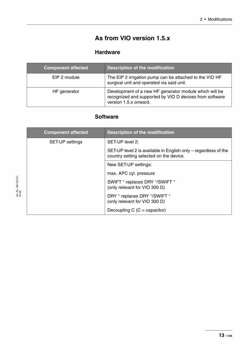
As from VIO version 1.5.x
Hardware
Software
Component affected Description of the modification
EIP 2 module The EIP 2 irrigation pump can be attached to the VIO HF surgical unit and operated via said unit.
HF generator Development of a new HF generator module which will be recognized and supported by VIO D devices from software version 1.5.x onward.
Component affected Description of the modification
SET-UP settings SET-UP level 2:
SET-UP level 2 is available in English only – regardless of the country setting selected on the device.
New SET-UP settings:
max. APC cyl. pressure
SWIFT ° replaces DRY °/SWIFT ° (only relevant for VIO 300 D)
DRY ° replaces DRY °/SWIFT ° (only relevant for VIO 300 D)
Decoupling C (C = capacitor)
13 / 144
2 • Modifications
Art
.-N
r.: 8
0116
-271
04
.06
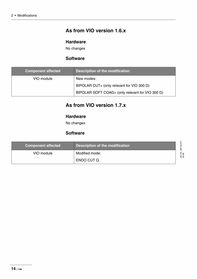
As from VIO version 1.6.x
HardwareNo changes
Software
As from VIO version 1.7.x
HardwareNo changes
Software
Component affected Description of the modification
VIO module New modes:
BIPOLAR CUT+ (only relevant for VIO 300 D)
BIPOLAR SOFT COAG+ (only relevant for VIO 300 D)
Component affected Description of the modification
VIO module Modified mode:
ENDO CUT Q
14 / 144

3 • ControlsA
rt.-
Nr.
: 801
16-2
71
04.0
6
CHAPTER 3
Controls
Controls at the front
Fig. 3-1
IMPORTANT! This chapter contains an overview of the controls of the unit(s). The relevant User Manual for the unit(s), knowledge of which is assumed for servicing work, provides detailed information about how to use the unit(s).
1 Power Switch
2 – 9 Selection buttons
10 Up/Down buttons
11 Enter button
12 – 15 Focus buttons
16 Pilot lamps for footswitches
17 Pilot lamp for AUTO START
18 Pilot lamps for neutral electrodes
15 / 144

3 • Controls
Art
.-N
r.: 8
0116
-271
04
.06
Controls at the rear
VIO D with screw-in power supply module
Fig. 3-2
IMPORTANT! This unit comes with different power supply modules – plug-in or screw-in.
1 Footswitch sockets
2 ECB socket (ERBE Communication Bus)
3 Potential equalization terminal
4 Power supply module with fuses
16 / 144
3 • ControlsA
rt.-
Nr.
: 801
16-2
71
04.0
6
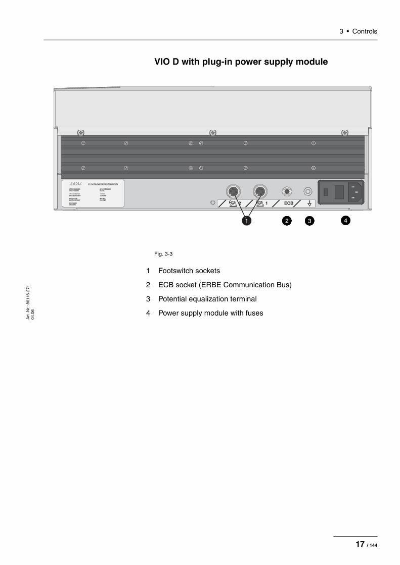
VIO D with plug-in power supply module
Fig. 3-3
1 Footswitch sockets
2 ECB socket (ERBE Communication Bus)
3 Potential equalization terminal
4 Power supply module with fuses
17 / 144
3 • Controls
Art
.-N
r.: 8
0116
-271
04
.06
18 / 144
4 • Technical DataA
rt.-
Nr.
: 801
16-2
71
04.0
6
CHAPTER 4
Technical Data
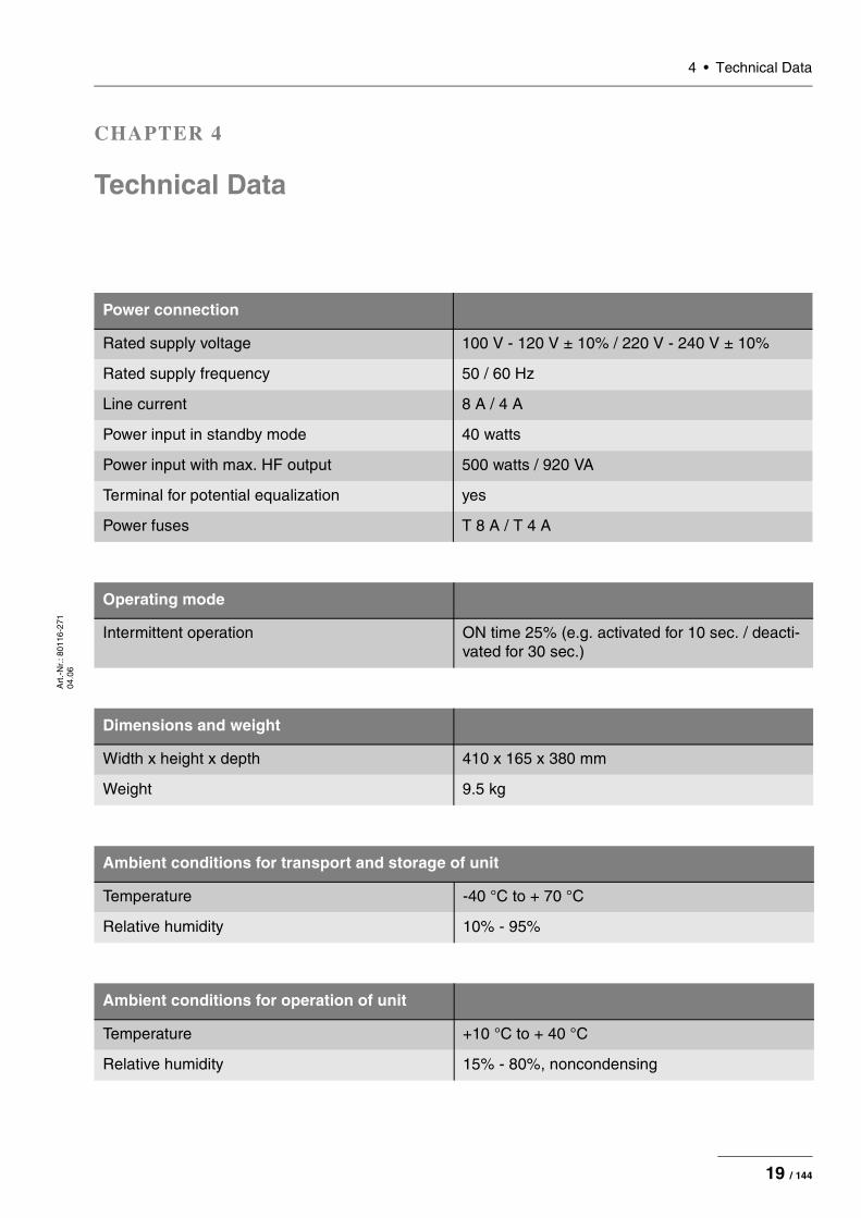
Power connection
Rated supply voltage 100 V - 120 V ± 10% / 220 V - 240 V ± 10%
Rated supply frequency 50 / 60 Hz
Line current 8 A / 4 A
Power input in standby mode 40 watts
Power input with max. HF output 500 watts / 920 VA
Terminal for potential equalization yes
Power fuses T 8 A / T 4 A
Operating mode
Intermittent operation ON time 25% (e.g. activated for 10 sec. / deacti-vated for 30 sec.)
Dimensions and weight
Width x height x depth 410 x 165 x 380 mm
Weight 9.5 kg
Ambient conditions for transport and storage of unit
Temperature -40 °C to + 70 °C
Relative humidity 10% - 95%
Ambient conditions for operation of unit
Temperature +10 °C to + 40 °C
Relative humidity 15% - 80%, noncondensing
19 / 144
4 • Technical Data
Art
.-N
r.: 8
0116
-271
04
.06
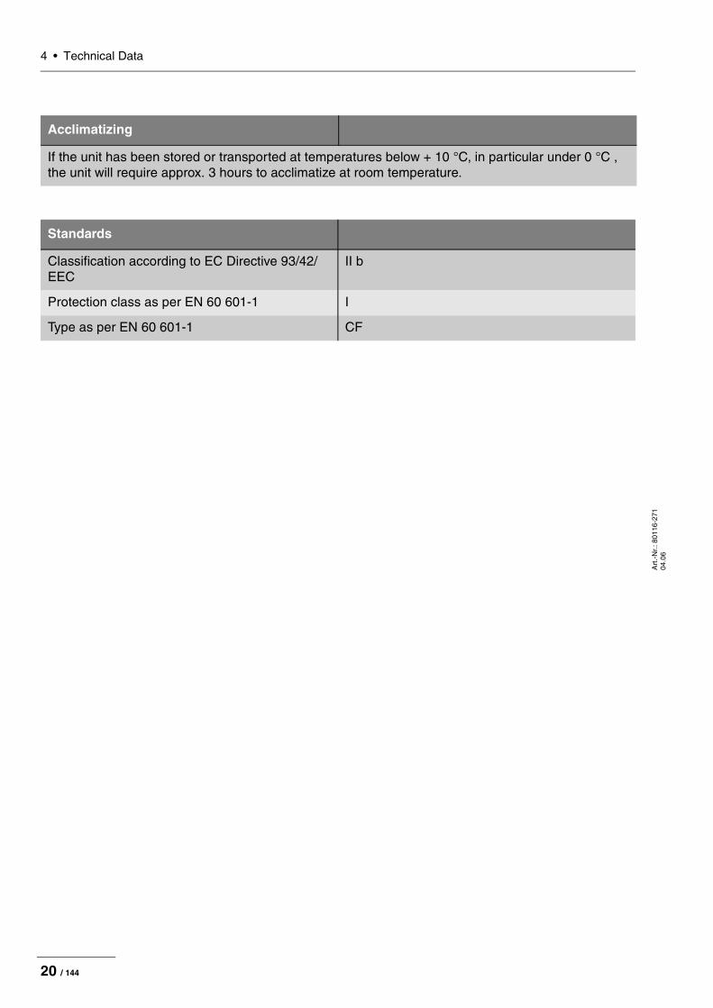
Acclimatizing
If the unit has been stored or transported at temperatures below + 10 °C, in particular under 0 °C , the unit will require approx. 3 hours to acclimatize at room temperature.
Standards
Classification according to EC Directive 93/42/EEC
II b
Protection class as per EN 60 601-1 I
Type as per EN 60 601-1 CF
20 / 144
5 • Circuit DescriptionsA
rt.-
Nr.
: 801
16-2
71
04.0
6
CHAPTER 5
Circuit Descriptions
21 / 144

5 • Circuit Descriptions
Art
.-N
r.: 8
0116
-271
04
.06
Block diagram VIO 300 D
Fig. 5-1
SC
I
SC
I
SP
I
115
V23
0V
AC
DC
AC
DC
EC
B 1 2
AE
NE
AE
NE
AE
NE A
E
NE
A A
IK
LN
CU
TC
OA
G
NE
1
NE
2
ECBERBECommunicationBus
Po
wer
Su
pp
lyH
Fg
ener
ato
r
CP
U+
Sen
sors
Line
Inpu
t
I.v.s
up
ply
Pow
erS
uppl
yC
ontr
ol
Gen
erat
orC
ontr
olC
PLD
Sen
sors
Con
trol
ler
Uni
t
IIF NE
SS
Y2
Use
rIn
terf
ace
AE
NE
Dis
play
Key
boar
dP
ower
PC
Ope
ratin
gV
olta
ges
AK
AE
NE
AK
Inst
rum
ent
Inte
rfac
e
VA
IIF Inst
rum
ent
Inte
rfac
e
G0.
..450
V0.
..3,5
A
230V
50H
z11
5V60
Hz
BIPOLAR MONOPOLAR/ MF/ NEUTRAL
Con
nect
orto
AP
C2
AK
:Akt
ivie
rung
serk
ennu
ngac
tivat
ion
reco
gniti
onIK
:Ins
trum
ente
nerk
ennu
ngin
stru
men
trec
ogni
tion
+5V
+15
V+
24V 0V
-15V
Con
nect
orto
AP
C2
BIPOLAR MONOPOLAR
22 / 144

5 • Circuit DescriptionsA
rt.-
Nr.
: 801
16-2
71
04.0
6
Block diagram VIO 200 D
Fig. 5-2
SC
I
SC
I
SP
I
115
V23
0V
AC
DC
AC
DC
EC
B
1 2
AE
NE
AE
NE
AE
NE A
E
NE
A A
LN
CU
TC
OA
G
NE
1
NE
2
ECBERBECommunicationBus
Po
wer
Su
pp
lyH
Fg
ener
ato
r
CP
U+
Sen
sors
Line
Inpu
t
l.v.s
up
ply
Pow
erS
uppl
yC
ontr
ol
Gen
erat
orC
ontr
olC
PLD
Sen
sors
Con
trol
ler
Uni
t
IIF NE
SS
Y2
Use
rIn
terf
ace
AE
NE
Dis
play
Key
boar
dP
ower
PC
Ope
ratin
gV
olta
ges
AK
AE
NE
AK
Inst
rum
ent
Inte
rfac
e
VA
IIF Inst
rum
ent
Inte
rfac
e
G0.
..450
V0.
..3,5
A
230V
50H
z11
5V60
Hz
BIPOLAR MONOPOLAR/BIPOLAR
MONOPOLAR NEUTRAL
Con
nect
orto
AP
C2
AK
:Akt
ivie
rung
serk
ennu
ngac
tivat
ion
reco
gniti
on
+5V
+15
V+
24V 0V
-15V
Con
nect
orto
AP
C2
23 / 144

5 • Circuit Descriptions
Art
.-N
r.: 8
0116
-271
04
.06
Description of the various assemblies
Line inputThe VIO system can be operated with a line voltage of either 220 – 240 V or 100 – 120 V. For this the corresponding value (230 V for a line voltage of 220 – 240 V or 115 V for 100 – 120 V) must be visible in the inspection window on the power connection, and fuses corre-sponding to the value given on the rating plate must be used.
Low voltage power supply unit (l.v. supply)The low voltage power supply unit produces the operating voltages +5 V, +15 V, –15 V and +24 V. A special socket on the underside of the unit is used to supply the +24 V voltage to other system compo-nents (e.g. APC 2).
The input voltage range for this power supply unit is 90...264 V with 50 or 60 Hz. Switching over the line voltage at the power connection has no effect on this power supply unit.
Pin assignment
Fig. 5-3
CAUTION! An incorrect setting or unsuitable fuses may damage the unit.
24 / 144

5 • Circuit DescriptionsA
rt.-
Nr.
: 801
16-2
71
04.0
6
Power supply (high-voltage power supply unit)The high-voltage power supply unit provides the HF generator with a DC voltage which may reach 450 V. It depends on the surgical effect selected and the alternating voltage necessary for this.
The line input voltage is directly rectified using a bridge-connected rectifier. The AC line voltage of 230 V changes to a DC voltage of ap-prox. 320 V; this can be checked between MP3 (ground) and the holding clips of the fuse holder. If the power connection is set to 115 V, the bridge circuit becomes a voltage doubler connection, also producing approx. 320 V.
The input circuit contains two NTC resistors to limit the high charging current which flows when the unit is switched on. Once the capacitors of the high-voltage power supply unit are charged, limitation is no longer necessary. The NTC resistors are therefore jumpered during activation via the make contacts of relay Rel10.
The resulting DC voltage is chopped by a chopper regulator and sup-plied to a transformer. The transformer is equipped with two identical output windings which produce a DC voltage again through rectifica-tion. With relay Rel13 these two output windings can be connected ei-ther in series or in parallel, resulting in two operating ranges for the power supply unit: in the range up to 250 V the maximum output cur-rent is 3.5 A, and in the range up to 450 V 1.75 A max. is possible.
The high-voltage power supply unit is controlled by two analog inputs: The setpoint voltage is specified at J21 Pin 11. A control voltage of 4.5 V results in a power supply unit output voltage of 450 V. The cur-rent limitation is specified at pin 9. Here 5 V corresponds to the max-imum current of 3.5 A. Measuring devices are available for both voltage and current. Analog signaling of the measurement values also takes place at pin 8 (actual voltage) and pin 6 (actual current) with the same amplification factors. Two other control inputs are also available: an enable signal (pin 7 5 V -> off), used to switch the high-voltage power supply unit on and off, and the control for the discharge circuit (pin 1 5 V -> on), used to discharge the output capacitors.
WARNING! Make sure you observe the safety regulations when using line volt-age!
25 / 144

5 • Circuit Descriptions
Art
.-N
r.: 8
0116
-271
04
.06
HF generatorThe high-frequency generator consists of the "HF generator" circuit board with the power components, and the programmable logic de-vice (CPLD), which is responsible for transistor control but is located on the "CPU+Sensors" circuit board.
The VIO system is only equipped with one generator module. To achieve the individual surgical effects there are widely differing re-quirements on the types of voltage and current to be generated. Both the HF generator and the downstream sensors have therefore been designed for a very wide dynamic range.
The alternating current is generated by using transistors to control a resonant circuit in the right frequency. This parallel resonant circuit in-cludes a transformer which has three taps on its secondary winding: for HF output voltages up to approx. 1000 V (Rel35), voltages up to approx. 2500 V (Rel37) and voltages up to approx. 4000 V (Rel39). Depending on the operating ranges of the high-voltage power sup-ply unit, a pair of switching transistors is available for DC input voltag-es up to 250 V and 450 V respectively. Rel43 is used for switching here. The zero crossings of the resulting alternating voltage are detected by a comparator and signaled to the control logic. It can then be de-cided here, depending on the type of modulation selected, whether there should be another actuation pulse for the switching transistors or not. With very high-resistance loads the energy stored in the resonant cir-cuit can only dissipate slowly, so that the generator would also con-tinue to oscillate without actuation. However, this would mean that modulation would be determined by the external load and not by the control system. The transformer is therefore equipped with another secondary winding, which can be short-circuited via a transistor. This results in discharge of the resonant circuit and thus a defined dying out process. This transistor is also controlled by the CPLD; another comparator circuit indicates when generator oscillation has died out.
When the contact monitor is activated, the generator produces a rel-atively low HF voltage which is used to produce a measurement cur-rent. Depending on size of this current, it can be decided whether there is tissue contact.
26 / 144
5 • Circuit DescriptionsA
rt.-
Nr.
: 801
16-2
71
04.0
6
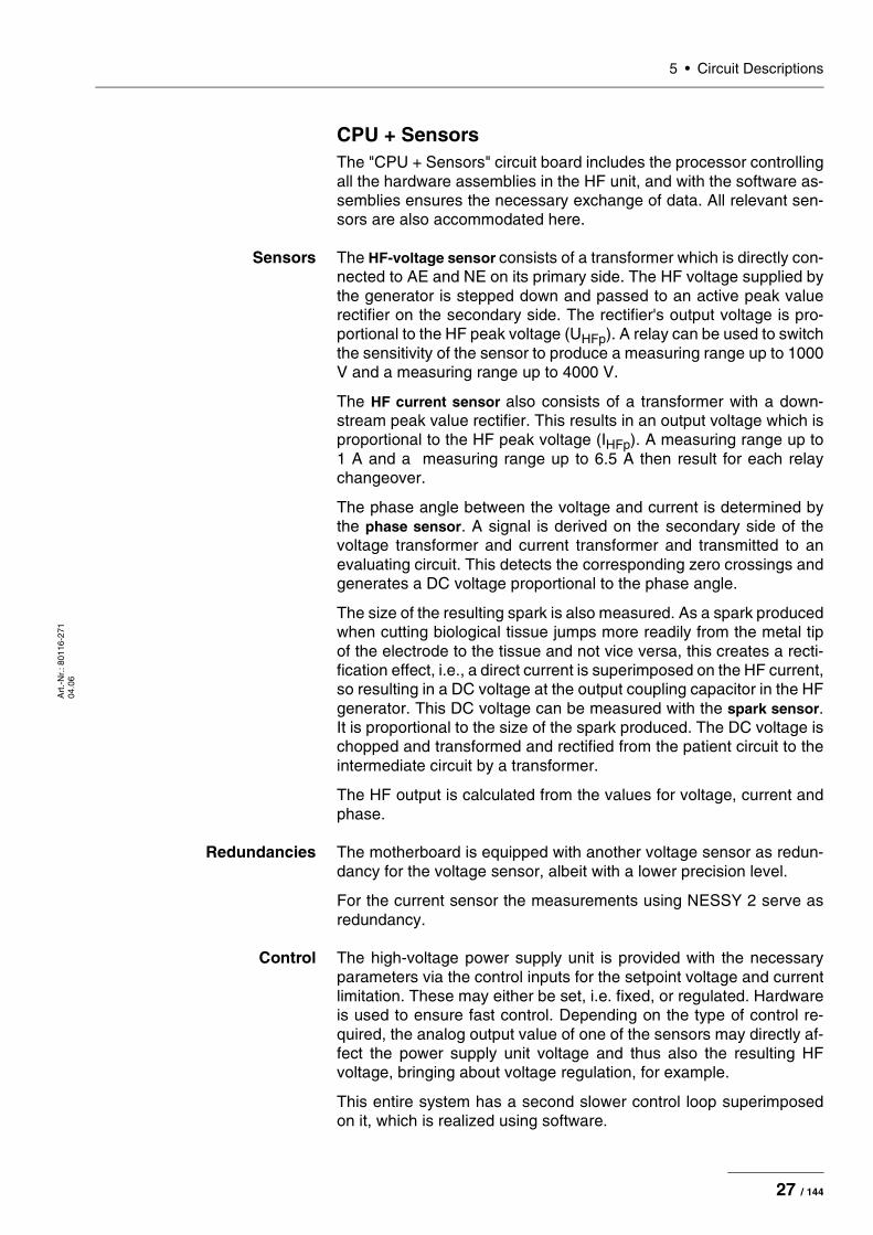
CPU + SensorsThe "CPU + Sensors" circuit board includes the processor controlling all the hardware assemblies in the HF unit, and with the software as-semblies ensures the necessary exchange of data. All relevant sen-sors are also accommodated here.
Sensors The HF-voltage sensor consists of a transformer which is directly con-nected to AE and NE on its primary side. The HF voltage supplied by the generator is stepped down and passed to an active peak value rectifier on the secondary side. The rectifier's output voltage is pro-portional to the HF peak voltage (UHFp). A relay can be used to switch the sensitivity of the sensor to produce a measuring range up to 1000 V and a measuring range up to 4000 V.
The HF current sensor also consists of a transformer with a down-stream peak value rectifier. This results in an output voltage which is proportional to the HF peak voltage (IHFp). A measuring range up to 1 A and a measuring range up to 6.5 A then result for each relay changeover.
The phase angle between the voltage and current is determined by the phase sensor. A signal is derived on the secondary side of the voltage transformer and current transformer and transmitted to an evaluating circuit. This detects the corresponding zero crossings and generates a DC voltage proportional to the phase angle.
The size of the resulting spark is also measured. As a spark produced when cutting biological tissue jumps more readily from the metal tip of the electrode to the tissue and not vice versa, this creates a recti-fication effect, i.e., a direct current is superimposed on the HF current, so resulting in a DC voltage at the output coupling capacitor in the HF generator. This DC voltage can be measured with the spark sensor. It is proportional to the size of the spark produced. The DC voltage is chopped and transformed and rectified from the patient circuit to the intermediate circuit by a transformer.
The HF output is calculated from the values for voltage, current and phase.
Redundancies The motherboard is equipped with another voltage sensor as redun-dancy for the voltage sensor, albeit with a lower precision level.
For the current sensor the measurements using NESSY 2 serve as redundancy.
Control The high-voltage power supply unit is provided with the necessary parameters via the control inputs for the setpoint voltage and current limitation. These may either be set, i.e. fixed, or regulated. Hardware is used to ensure fast control. Depending on the type of control re-quired, the analog output value of one of the sensors may directly af-fect the power supply unit voltage and thus also the resulting HF voltage, bringing about voltage regulation, for example.
This entire system has a second slower control loop superimposed on it, which is realized using software.
27 / 144

5 • Circuit Descriptions
Art
.-N
r.: 8
0116
-271
04
.06
Monitoring All measurement values are continuously compared with specified setpoints and monitored. In the event of critical divergence the power supply unit and generator are switched off and an error message out-put.
Besides the parameters necessary for the surgical effects, the oper-ating voltages are also measured and monitored.
The inside temperature of the unit is additionally measured. The speed of the circulation fan is controlled accordingly.
User Interface (control panel)The most powerful processor (Power PC) in the VIO system can be found on the control panel. It operates the display as well as the but-tons and displays on the front of the unit. It is the master unit for the ERBE Communication Bus (ECB). The control panel is used to log on all the assemblies, e.g. the HF module, APC 2, smoke evacuator, footswitches and all the sockets, and also to request the issue of sta-tus messages on a cyclical basis. This means that there is always an overview of the components involved in the system and their state (off, on, error, etc.).
The activation of one or more assemblies is also controlled from the Power PC. It receives activation signals from the finger or footswitch-es, then issues the appropriate commands for switch-on or off. The status messages (e.g. current contact resistance of NESSY 2) are also used to decide whether activation can start or whether it is nec-essary to switch off the unit due to user error or a malfunction.
ECB (ERBE Communication Bus)The ECB is based on the CAN bus system. The CAN bus was devel-oped for the automotive industry and is also widely used in other sec-tors due to its structure and safety characteristics.
In the VIO system all subsystems are connected to the control panel via the ECB.
28 / 144

5 • Circuit DescriptionsA
rt.-
Nr.
: 801
16-2
71
04.0
6
IIF (Instrument Interface)The instrument interface assembly may be found up to four times in the VIO system: twice in the electrosurgical unit and twice in the APC 2 unit and VEM 2 unit respectively.
The IIF is used to provide the system with the key instrument informa-tion via an electrically isolated serial interface:
Activation recognition The activation regognition checks whether one of the activation but-tons (or ReMode button) has been pressed. It is designed to analyze the different coding systems (diode coding, resistor coding connected in parallel or series).
Receptacle recognition The receptacle recognition can recognize the type of receptacle via the coding jumpers on the receptacle connectors.
Instrument recognition (only relevant for MF and
APC receptacles)
The instrument recognition can identify instruments coded by resis-tance and read instruments equipped with an electronic memory, transmitting the relevant data to the system.
This data is converted to CAN using the "CPU + Sensors" and sent to the control panel.
The safety relays used to switch the HF voltage to the connected in-strument on activation are also located on the IIF assembly. The ac-tual circuit state of the relay is signaled to the system to ensure that defective relays or improper circuit states are detected.
There are three IIF versions:
• IIF ME: for monopolar instruments, equipped with a relay that can switch the activated electrode to the instrument.
• IIF BE: for bipolar instruments and multifunctional instruments designed for bipolar use only. Each equipped with one relay for the activated electrode and patient plate.
• IIF MF (only relevant for VIO 300 D or in conjunction with a VIO 300 D): equipped with 4 relays, which on multifunctional instruments with several electrodes allows a very wide range of configurations.
Receptacle type Type number
Coding jumper
Pin 2 - Pin 6
Coding jumper
Pin 1 - Pin 6
Bipolar 1 – X
Monopolar 2 X –
Multifunctional (MF)1
1. Only relevant for VIO 300 D or in conjunction with a VIO 300 D.
3 X X
APC 4 – –
29 / 144

5 • Circuit Descriptions
Art
.-N
r.: 8
0116
-271
04
.06
Nessy2The NESSY 2 assembly measures the electrical resistance between the two connections to the patient plate. In addition, the currents in both connecting lines are measured.
The measured values are transmitted to the "CPU + Sensors" via an electronically insulated asynchronous serial interface. There they are converted to CAN and sent to the control panel. Here it is then as-sessed whether the measured contact resistance permits activation or not. In addition, it is checked whether the limits specified for current density and symmetry have been exceeded.
30 / 144

6 • SET-UPA
rt.-
Nr.
: 801
16-2
71
04.0
6
CHAPTER 6
SET-UP
General informationThis unit has two SET-UP levels. The first level is accessible to users and service staff. The second level is only for use by the service staff.
Overview of settings for SET-UP level 1
Setting Available from Description
Brightness V 1.2.x Setting the display brightness in 16 levels.
System vol-ume
V 1.2.x Setting the volume of activation tones in 16 levels. The activation tones must be clearly audible!
Key volume V 1.2.x Setting the button volume in 16 levels.
Viewing angle
V 1.2.x Rough graduation of display brightness in 3 levels.
Power display
V 1.2.x A bar diagram is shown on the display on activation of the output indicator. The bar diagram provides a dynamic display of the delivered out-put during activation. At the end of activation, Pmax shows the maximum delivered output, and Pavg the mean value of the deliv-ered output over the activation period. The green line in the bar diagram represents the power limitation selected.
Only V 1.3.x: When the unit is restarted, the power display is always deactivated (=OFF).
Display UpMax
V 1.2.x Display of maximum HF voltage [Vp] on activation of the unit. In the user manual for the instrument or on the instrument itself the maximum electrical capacity is given in [Vp]. If the HF voltage exceeds the capacity of the instrument, the instrument may be damaged. Select a reduced effect to avoid this.
AUTO START 1
V 1.2.x Input of start delay for the AUTO START function. The start delay value for AUTO START 1 depends on the value entered for AUTO START 2 but is always below the start delay value of AUTO START 2. A start delay between 0.0 and 9.5 s is possible.
31 / 144

6 • SET-UP
Art
.-N
r.: 8
0116
-271
04
.06
Overview of settings for SET-UP level 2
AUTO START 2
V 1.2.x Input of start delay for the AUTO START function. The start delay value for AUTO START 2 depends on the value entered for AUTO START 1 but is always above the start delay value of AUTO START 1. A start delay between 0.1 and 10 s is possible.
Service program
V 1.2.x This menu item leads to the second SET-UP level.
Setting Available from Description
IMPORTANT! From V 1.5.x on, this SET-UP menu is available in English only – regardless of the country setting selected on the device.
Setting Avaiable from Description
Date V 1.2.x Self-explanatory.
Time V 1.2.x Self-explanatory.
Neutral electrode
V 1.2.x single surface dual surface either way
As from V 1.3.x: Additional option "dynamic". On delivery, the unit is set to neutral electrode “dual surface”.
AUTO START
V 1.2.x Setting for whether AUTO START is permitted as an activation type.
Time limit V 1.2.x Setting the time period after which activation is automatically ended: 1 to 99 s or OFF
Display time
V 1.3.x Setting the length of time for which indicator window and error messages appear on the display: 1 to 15 s or OFF.
Automatic time
V 1.2.x Setting the length of time for which an input window appears on the display: 3 to 29 s or Not automatic.
Start screen
V 1.2.x Selection of start screen: Guide or List of Programs.
Expert mode
V 1.2.x To permit other selection options, e.g. modification of modulation in modes without power limitation.
Language V 1.2.x Self-explanatory.
APC supply
V 1.2.x Self-explanatory.
32 / 144
6 • SET-UPA
rt.-
Nr.
: 801
16-2
71
04.0
6
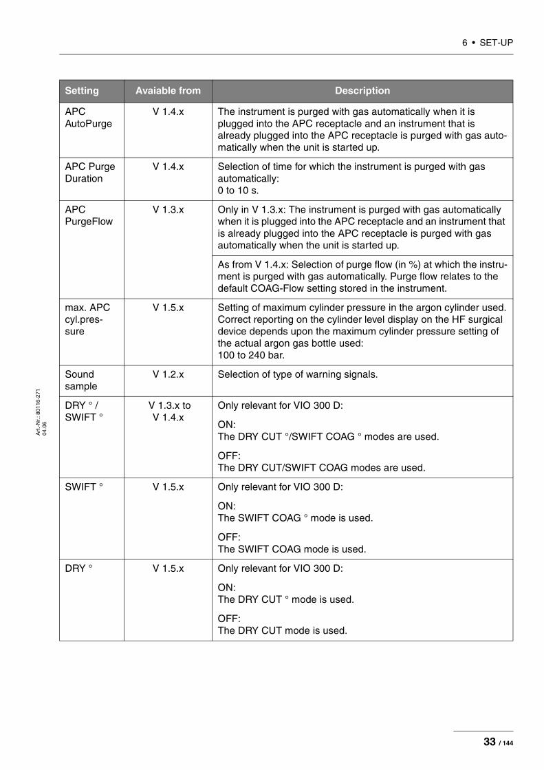
APC AutoPurge
V 1.4.x The instrument is purged with gas automatically when it is plugged into the APC receptacle and an instrument that is already plugged into the APC receptacle is purged with gas auto-matically when the unit is started up.
APC Purge Duration
V 1.4.x Selection of time for which the instrument is purged with gas automatically: 0 to 10 s.
APC PurgeFlow
V 1.3.x Only in V 1.3.x: The instrument is purged with gas automatically when it is plugged into the APC receptacle and an instrument that is already plugged into the APC receptacle is purged with gas automatically when the unit is started up.
As from V 1.4.x: Selection of purge flow (in %) at which the instru-ment is purged with gas automatically. Purge flow relates to the default COAG-Flow setting stored in the instrument.
max. APC cyl.pres-sure
V 1.5.x Setting of maximum cylinder pressure in the argon cylinder used. Correct reporting on the cylinder level display on the HF surgical device depends upon the maximum cylinder pressure setting of the actual argon gas bottle used: 100 to 240 bar.
Sound sample
V 1.2.x Selection of type of warning signals.
DRY ° / SWIFT °
V 1.3.x to V 1.4.x
Only relevant for VIO 300 D:
ON: The DRY CUT °/SWIFT COAG ° modes are used.
OFF: The DRY CUT/SWIFT COAG modes are used.
SWIFT ° V 1.5.x Only relevant for VIO 300 D:
ON: The SWIFT COAG ° mode is used.
OFF: The SWIFT COAG mode is used.
DRY ° V 1.5.x Only relevant for VIO 300 D:
ON: The DRY CUT ° mode is used.
OFF: The DRY CUT mode is used.
Setting Avaiable from Description
33 / 144

6 • SET-UP
Art
.-N
r.: 8
0116
-271
04
.06
Decoupling C (C = capacitor)
V 1.5.x Setting on the decoupling capacitor.
MAX: Decoupling capacitor with maximum capacity. Available in HF generator modules 30140-804 and 30140-828.
MIN: Decoupling capacitor with minimized capacity. Available only in HF generator module 30140-828. At this setting, neuromuscular stimuli are reduced in the PULSED APC mode.
Next safety check
V 1.2.x Self-explanatory.
Test pro-grams1
V 1.2.x Error list: Stores all errors detected and signaled by the control panel.
V 1.2.x Event list: Stores all events (=information and activations) in a looped mem-ory.
V 1.2.x Version list: Shows the software versions of all connected components.
From V 1.4.x onward: Option “safe config.” is available.2
V 1.2.x EEPROM: Shows memory usage by the application program on EEPROM.
V 1.2.x HF-CPU error list: Stores all errors detected and signaled by the “CPU + Sensors”; up to 16 entries.
V 1.2.x No. HF errors: Records the frequency of errors detected and signaled by the “CPU + Sensors”.
V 1.2.x APC error list: Stores all errors detected and signaled by the APC.
V 1.2.x No. APC errors: Records the frequency of errors detected and signaled by the APC.
Setting Avaiable from Description
34 / 144

6 • SET-UPA
rt.-
Nr.
: 801
16-2
7104
.06
V 1.2.x Loudsp. test:Unit checks the loudspeaker function. Three different tones must be heard.
V 1.3.x Error list IIF/NE:Stores all errors detected and signaled by the IIF (instrument interface) and the NE (Nessy2).
V 1.3.x Hardware TP:Branching to the hardware test programs.
V 1.3.x Upgrade list:Indicates which upgrades have been installed.
V 1.4.x Enable Kali (only relevant for VIO 200 D):Makes it possible to increase the HF power limitation for SWIFT COAG to 150 W. When switching off, the unit resets the increase back to the standard power limitation of 120 W automatically.
1. Test programs not explained here are not relevant for the service technicians.2. "safe config." saves the receptacle configuration of the unit detected by the system. The receptacle configuration must be saved by the
service technician after each software update and each time the unit is upgraded or converted. For this purpose compare the receptacleconfiguration indicated on the "Version list" with the physical configuration on the unit. If they agree, save the receptacle configuration with"safe config."
Setting Avaiable from Description
35 / 144
6 • SET-UP
Art
.-N
r.: 8
0116
-271
04
.06
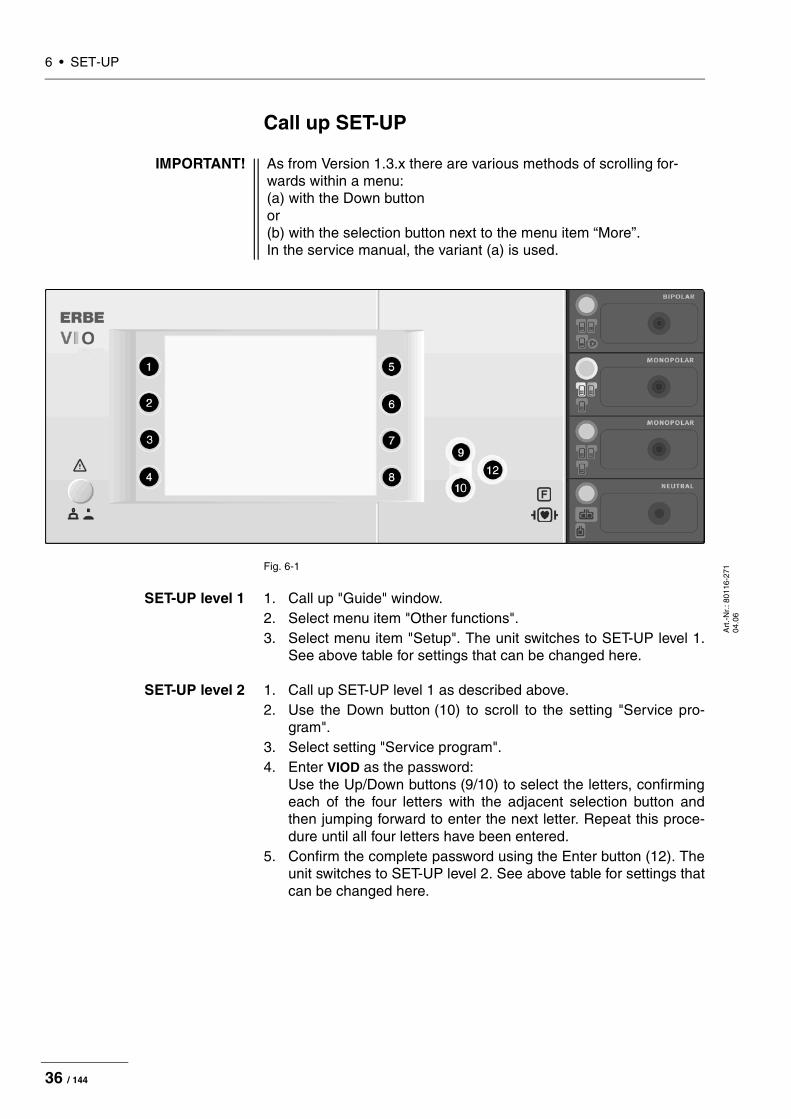
Call up SET-UP
Fig. 6-1
SET-UP level 1 1. Call up "Guide" window.2. Select menu item "Other functions".3. Select menu item "Setup". The unit switches to SET-UP level 1.
See above table for settings that can be changed here.
SET-UP level 2 1. Call up SET-UP level 1 as described above.2. Use the Down button (10) to scroll to the setting "Service pro-
gram".3. Select setting "Service program".4. Enter VIOD as the password:
Use the Up/Down buttons (9/10) to select the letters, confirming each of the four letters with the adjacent selection button and then jumping forward to enter the next letter. Repeat this proce-dure until all four letters have been entered.
5. Confirm the complete password using the Enter button (12). The unit switches to SET-UP level 2. See above table for settings that can be changed here.
IMPORTANT! As from Version 1.3.x there are various methods of scrolling for-wards within a menu: (a) with the Down button or (b) with the selection button next to the menu item “More”. In the service manual, the variant (a) is used.
36 / 144
6 • SET-UPA
rt.-
Nr.
: 801
16-2
71
04.0
6
Change settings
1. Select the setting to be changed using the adjacent selection button (1...8). The setting is highlighted.
2. Change the setting with the Up/Down buttons (9/10).3. Confirm the changed setting with the Enter button (12).
37 / 144

6 • SET-UP
Art
.-N
r.: 8
0116
-271
04
.06
38 / 144
7 • Test programsA
rt.-
Nr.
: 801
16-2
71
04.0
6
CHAPTER 7
Test programs
Call up Test programs
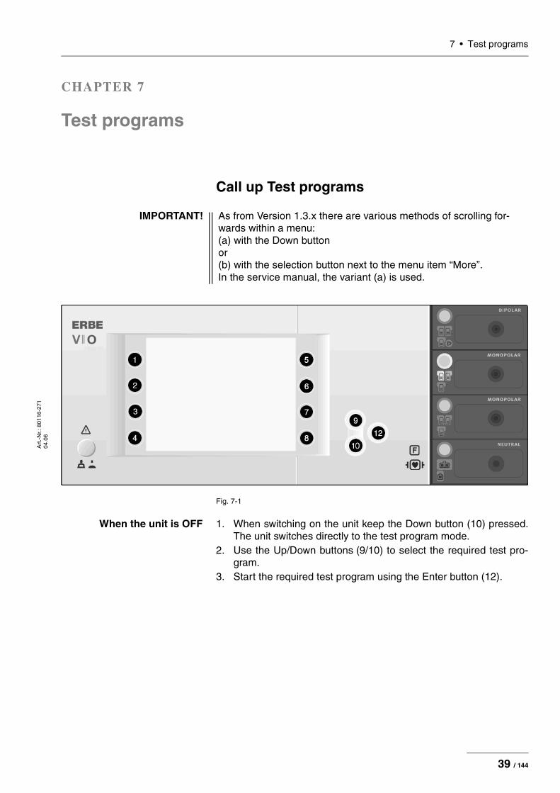
Fig. 7-1
When the unit is OFF 1. When switching on the unit keep the Down button (10) pressed. The unit switches directly to the test program mode.
2. Use the Up/Down buttons (9/10) to select the required test pro-gram.
3. Start the required test program using the Enter button (12).
IMPORTANT! As from Version 1.3.x there are various methods of scrolling for-wards within a menu: (a) with the Down button or (b) with the selection button next to the menu item “More”. In the service manual, the variant (a) is used.
39 / 144
7 • Test programs
Art
.-N
r.: 8
0116
-271
04
.06
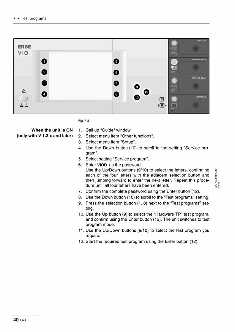
Fig. 7-2
When the unit is ON (only with V 1.3.x and later)
1. Call up "Guide" window.2. Select menu item "Other functions".3. Select menu item "Setup".4. Use the Down button (10) to scroll to the setting "Service pro-
gram".5. Select setting "Service program".6. Enter VIOD as the password:
Use the Up/Down buttons (9/10) to select the letters, confirming each of the four letters with the adjacent selection button and then jumping forward to enter the next letter. Repeat this proce-dure until all four letters have been entered.
7. Confirm the complete password using the Enter button (12).8. Use the Down button (10) to scroll to the “Test programs” setting.9. Press the selection button (1..8) next to the “Test programs” set-
ting.10. Use the Up button (9) to select the “Hardware TP” test program,
and confirm using the Enter button (12). The unit switches to test program mode.
11. Use the Up/Down buttons (9/10) to select the test program you require.
12. Start the required test program using the Enter button (12).
40 / 144
7 • Test programsA
rt.-
Nr.
: 801
16-2
71
04.0
6
Exit Test programs
1. Keep pressing the Up button (9) until "Restart" appears in the display.
2. Confirm the setting with the Enter button (12). The unit exits the test program mode.
Parameter inputs in Test programsIn some test programs it is possible to select or change values (e.g. for power supply unit voltage).
Example 1. Start a test program.2. Press the selection button (1..8) next to the value to be selected
or changed. The value is shown in red and can now be changed.3. Set the required value using Up/Down buttons (9/10).4. Confirm value set. To do so press the selection button (1..8) next
to the value set again. The value is now shown in black again.5. Use the Up/Down buttons (9/10) to switch to another test pro-
gram.
41 / 144

7 • Test programs
Art
.-N
r.: 8
0116
-271
04
.06
Description of test programs
Test program "Display test"This test program allows the brightness of the display to be changed.
The current setting is displayed visually according to the color scale of red/ green/ blue and various shades of gray. On the socket covers all LEDs (focus buttons, pilot lamps for footswitches and for neutral electrodes) are switched on for control purposes.
The brightness of the display can be adjusted with the "Bright" and "Dark" buttons.
Increase brightness Pressing the "Bright" button will increase the brightness level. When the button is pressed, an acknowledgement tone will be heard at min-imum volume.
Reduce brightness Pressing the "Dark" button will decrease the brightness level. When the button is pressed, an acknowledgement tone will be heard at maximum volume.
Fig. 7-3
42 / 144

7 • Test programsA
rt.-
Nr.
: 801
16-2
71
04.0
6
Test program "TP relay"With this test program all relays in the patient circuit can be controlled.
The current switching position is shown by symbols and can be changed by pressing a button.
For relays equipped with readback contacts (all except NE) the sig-naled circuit state is shown.
As IIF modules with different relay configurations are used, the con-figuration detected is also shown.
Up to version 1.3.x
Fig. 7-4
As from version 1.4.x
Fig. 7-5
Setpoint / actual
value comparison:
Okay
Required status
open
Required status
closed
Setpoint / actual
value comparison:
Error
Circuit state:
0 open
1 closed
Relay configuration:
1 Relay fittet
0 no Relay fittet
Setpoint / actual
value comparison:
Okay
Required status
open
Required status
closed
Setpoint / actual
value comparison:
Error
Circuit state:
0 open
1 closed
Relay configuration:
1 Relay fittet
0 no Relay fittet
43 / 144

7 • Test programs
Art
.-N
r.: 8
0116
-271
04
.06
Test program "TP valves (APC)"In this test program the valves in the APC can be controlled.
The current switching position is shown by symbols and can be changed by pressing a button.
The control level for the proportional valve can be set from 0 to 100%
Fig. 7-6
Test program "TP activation signal"This test program visually displays the activation state of the foot and finger switches.
Fig. 7-7
Output valve
APC receptacle 1
Output valve
APC receptacle 2
(option)
Proportional valve
control voltage
0...100 = 0...20 V
Yellow button
pressed
At receptacle 2
44 / 144
7 • Test programsA
rt.-
Nr.
: 801
16-2
71
04.0
6
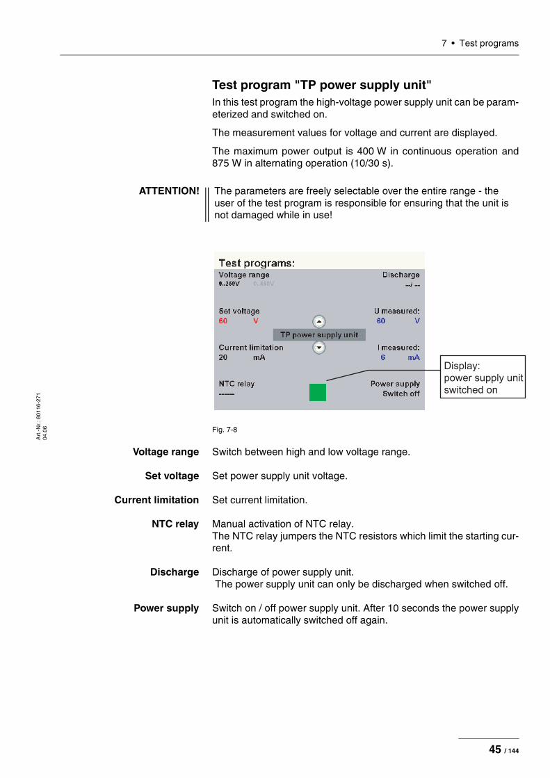
Test program "TP power supply unit"In this test program the high-voltage power supply unit can be param-eterized and switched on.
The measurement values for voltage and current are displayed.
The maximum power output is 400 W in continuous operation and 875 W in alternating operation (10/30 s).
Fig. 7-8
Voltage range Switch between high and low voltage range.
Set voltage Set power supply unit voltage.
Current limitation Set current limitation.
NTC relay Manual activation of NTC relay. The NTC relay jumpers the NTC resistors which limit the starting cur-rent.
Discharge Discharge of power supply unit. The power supply unit can only be discharged when switched off.
Power supply Switch on / off power supply unit. After 10 seconds the power supply unit is automatically switched off again.
ATTENTION! The parameters are freely selectable over the entire range - the user of the test program is responsible for ensuring that the unit is not damaged while in use!
Display:
power supply unit
switched on
45 / 144

7 • Test programs
Art
.-N
r.: 8
0116
-271
04
.06
Test program "TP generator"
Fig. 7-9
Test mode Switch between basic modes.
The various surgical effects of this unit call for a high dynamic perfor-mance in terms of output voltage, current and power. For this reason the high-voltage power supply unit and the high-frequency generator offer many switching options which are broken down into 4 basic modes to simplify handling in the test program:
• SOFT (SOFT COAG)• AUTO (AUTO CUT)• FORC. (FORCED COAG)• SPRAY (SPRAY COAG)
Power supply voltage Set power supply unit voltage.
ATTENTION! Never switch high voltages (FORC. / SPRAY) to a bipolar or multi-functional receptacle.
ATTENTION! When there is no load the generator may produce high voltages, possibly resulting in irreparable damage to components or assem-blies. The power supply unit voltage should therefore not be set too high.
Maximum HF voltages: SOFT 1000 VAUTO 1000 VFORC. 2500 VSPRAY 4000 V
ATTENTION! Unlike in the regular operating modes FORCED COAG and SPRAY COAG no leakage current suppression is provided for the generator control. For this reason it should only be activated briefly when there is no load as otherwise this may subject the transistor in the generator discharge circuit to thermal overload.
Display:
power supply unit
switched on
46 / 144

7 • Test programsA
rt.-
Nr.
: 801
16-2
71
04.0
6
Output receptacle Select active receptacle (1...3) and its configuration (monopolar or bi-polar). With the setting "No receptacle" the HF voltage is only present at the throughplating on the floor of the housing.
Generator The generator can be switched on with any available activation ele-ment:
• fingerswitch at monopolar receptacle (yellow or blue)• fingerswitch at APC receptacle (yellow or blue)• dual-pedal footswitch (yellow or blue)• single-pedal footswitch
Measurement values
Settings Test modes
U DC: output voltage of high-voltage power supply unitI DC: output current of high-voltage power supply unit
UpHF: peak value (pos.) of HF voltageIpHF: peak value of HF current
Phase: phase angle (0...90°)Spark: value measured by spark sensor
(no spark = 44 ERBE)
UHF red.: value measured by redundant voltage sensorTemp.: Inside temperature of unit
(measured on “CPU + Sensors” circuit board)
SOFT AUTO FORC. SPRAY
Setting range of power supply unit voltage
0...250 V 0...250 V 0...450 V 0...450 V
Current limitation power supply unit
3.5 A 3.5 A 1.75 A 1.75 A
Power supply unit range 250 V / 450 V Rel 13
250 250 450 450
Switching transis-tors 250 V / 500 V Rel 43
250 250 500 500
Transformer tap Rel 35 (1 : 4) Rel 37 (1 : 5.5) Rel 39 (1 : 11)
1 : 4 1 : 4 1 : 5.5 1 : 11
Attenuation Rel 41
no no yes yes
47 / 144

7 • Test programs
Art
.-N
r.: 8
0116
-271
04
.06
Test program "Burn-In test" (only for production)
Test program "Watchdog"If the watchdog is functioning, the screen will briefly go dark after the Enter button is pressed and the unit restarts.
Test program "CheckStop"If the watchdog is functioning, the screen will briefly go dark after the Enter button is pressed and the unit restarts.
Voltage sensor measuring range Rel 12
1000 V 1000 V 4000 V 4000 V
Current sensor measuring range Rel 14
1.0 A 6 A 6 A 6 A
SOFT AUTO FORC. SPRAY
48 / 144

7 • Test programsA
rt.-
Nr.
: 801
16-2
71
04.0
6
Test program "Measured values" (only with V 1.3.x and later)
Fig. 7-10
Low voltage It is not possible to measure all the operating voltages simultaneous-ly. All the blue measured values are being measured at the present moment. All the gray values are those last measured, and they are not updated.
To change the measured value range, you must press the selection button next to the measured value you require.
Other measured values U DC: output voltage of high-voltage power supply unitI DC: output current of high-voltage power supply unit
UpHF: peak value (pos.) of HF voltageIpHF: peak value of HF current
Phase: phase angle (0...90°)Spark: value measured by spark sensor
(no spark = 44 ERBE)
UHF red.: value measured by redundant voltage sensorTemp.: Inside temperature of unit
(measured on “CPU + Sensors” circuit board)
49 / 144

7 • Test programs
Art
.-N
r.: 8
0116
-271
04
.06
50 / 144

8 • Measurement and adjustmentA
rt.-
Nr.
: 801
16-2
71
04.0
6
CHAPTER 8
Measurement and adjustment
Measurement of the HF power output
Temperature conditions
Test equipment
IMPORTANT! Measurement/adjustment should take place when the unit has warmed up (standby temperature). For this purpose, switch on the unit and wait until the temperature attains a constant value. This value is between +45 °C and +55 °C and is attained after approx. half an hour. (This value is displayed in the test program "TP gen-erator", for example.)
IMPORTANT! The following list contains the testing and measuring equipment recommended by ERBE for servicing. Where ERBE article num-bers are specified, only original ERBE testing and measuring equipment should be used.
ERBE Art. No. Description
– HF power meter (recommended: Metron QA-ES)
20190-045 Elektrode handle ICC/ACC
20189-101 Dual-pedal footswitch with ReMode
20192-127
20192-110
Patient cable AE or Patient cable AE, international
20194-070
20194-075
Patient cable NE or Patient cable NE, international
20196-045
20196-053
Bipolar cable or Bipolar cable, international
51 / 144

8 • Measurement and adjustment
Art
.-N
r.: 8
0116
-271
04
.06
Test set-up
Fig. 8-1
Fig. 8-2
Test procedure
1. Switch the unit off and start it again in normal mode.2. Set the mode, effect and power limitation using the values in the
safety check (STK) log.3. Also set the impedance on the HF power meter using the values
in the safety check (STK) log.4. Activate the unit. The values measured can be checked on the
HF power meter.5. Repeat steps 2 to 4 with other settings.
IMPORTANT! ERBE Elektromedizin recommends measuring HF output power with a Metron QA-ES. For this purpose the Metron must be adjusted so that it is up to date. To this end please contact a Met-ron service point. Measurements that are conducted with a different HF power meter or one which has not been adjusted can produce figures that are very different than those on the final test report of the unit.
ERBE
AE
NE
HF power meter
ERBE
HF power meter
Bipolar
IMPORTANT! Measure the HF power output using the values in the safety check (STK) log.
52 / 144

8 • Measurement and adjustmentA
rt.-
Nr.
: 801
16-2
71
04.0
6
Adjustment
Personnel requirements
Temperature conditions
Test sequence
ATTENTION! Adjustments, technical tests, modifications, maintenance and repair work may only be performed by ERBE or persons trained by ERBE. If the work is not performed by trained persons, ERBE accepts no liability and warranty rights become void.
IMPORTANT! Measurement/adjustment should take place when the unit has warmed up (standby temperature). For this purpose, switch on the unit and wait until the temperature attains a constant value. This value is between +45 °C and +55 °C and is attained after approx. half an hour. (This value is displayed in the test program "TP gen-erator", for example.)
IMPORTANT! Please ensure you follow the sequence specified for the individual tests in this chapter.
53 / 144

8 • Measurement and adjustment
Art
.-N
r.: 8
0116
-271
04
.06
Test equipment
IMPORTANT! The following list contains the testing and measuring equipment recommended by ERBE for servicing. Where ERBE article num-bers are specified, only original ERBE testing and measuring equipment should be used.
ERBE Art. No. Description
– PC/laptop WIN 98 or higher
29140-211 VIO HF Adjustment Tool (software, only for inter-nal use by ERBE)
– Oscilloscope, 100 MHz or higher (recommended: Tektronix TDS 1012)
– HF power meter (recommended: Metron QA-ES)
– High Voltage Differential Probe (recommended: TESTTEC TT-SI 9010, Tektronix P5210 or Sapphire SI-9010)
20100-019 Testbox spark monitor, 230 V
20189-101 Dual-pedal footswitch with ReMode
20140-002 VIO Support Hardware (only for internal use by ERBE)
20192-127
20192-110
Patient cable AE or Patient cable AE, international
20194-070
20194-075
Patient cable NE or Patient cable NE, international
54 / 144

8 • Measurement and adjustmentA
rt.-
Nr.
: 801
16-2
71
04.0
6
Voltage
Test set-up
Fig. 8-3
• The test setup is designed as shown in the illustration above.• The test specimen is connected to the power supply via the power
cord.• The test specimen is switched on.• On the PC the "VIO HF Adjustment Tool" software is installed.
Test procedure
1. Start "VIO HF Adjustment Tool" software.2. Start the adjustment procedure with the <Start adjusment> but-
ton.3. Perform adjustment steps 1 – 5 as described in the software. 4. Do not switch off the test specimen during rearrangement for
next test step.
ATTENTION! When connecting the probe to the input of the HF power meter, make absolutely sure that minus is connected to the patient plate.
ATTENTION! For adjustment steps "Voltage range 700 V" and "Voltage range 3 kV" set the pulse duty factor on the probe to 1000:1 or else the probe will be damaged.
ERBE
AE
NE
HF power meter
High Voltage
Differential probe
Desktop PC
ECB connection
Oscilloscope
55 / 144

8 • Measurement and adjustment
Art
.-N
r.: 8
0116
-271
04
.06
Spark
Test set-up
Fig. 8-4
• The test setup is designed as shown in the illustration above.• The test specimen is connected to the power supply via the power
cord.• The test specimen is switched on.• On the PC the "VIO HF Adjustment Tool" software is installed.
Test procedure
1. Perform adjustment step 6 as described in the software. 2. Using the <Continue> button switch to the next test step.3. Do not switch off the test specimen during rearrangement for
next test step.
ERBE
AE
NE
Desktop PC
ECB connection
Testbox
20100-019
+ -
Power S1 DC 70 V
56 / 144

8 • Measurement and adjustmentA
rt.-
Nr.
: 801
16-2
71
04.0
6
Currents
Test set-up
The currents are determined using a power meter.
Fig. 8-5
• The test setup is designed as shown in the illustration above.• The test specimen is connected to the power supply via the power
cord.• The test specimen is switched on.• The test specimen is in normal operation.• On the PC the "VIO HF Adjustment Tool" software is installed.
ATTENTION! No probe must be connected with the following measurements.
IMPORTANT! Only relevant for VIO 300 D from V 1.3.x onward
The SWIFT COAG ° mode should not be set. To ensure this, go to SET-UP level 2 and if necessary switch the setting DRY ° / SWIFT ° or from V 1.5.x onward SWIFT ° to OFF.
IMPORTANT! Only relevant for VIO 200 D
For the "current range 4 A" adjustment step call up the test pro-gram "Enable Kali" (SET-UP level 2) and confirm with the Enter button. HF prower limitation for SWIFT COAG can now be increased to the 150 W for the adjustment step. When switching off, the unit resets this increase again automatically.
ERBE
AE
NE
HF power meter
Desktop PC
ECB connection
57 / 144
8 • Measurement and adjustment
Art
.-N
r.: 8
0116
-271
04
.06
Test procedure
1. Perform adjustment steps 7 – 8 as described in the software.
58 / 144
9 • TroubleshootingA
rt.-
Nr.
: 801
16-2
71
04.0
6
CHAPTER 9
Troubleshooting
ERROR list for VIO systemAbbreviations used for identifying modules:
A: APC
B: Control panel
C: CPU + Sensors
D: Smoke evacuation system IES 2
E: Extension module VEM 2
2,3,5,6: IIF (Instrument Interface) of corresponding receptacle slot
4 (NE): Nessy2
9: ERBE Irrigation Pump EIP 2
59 / 144

9 • Troubleshooting
Art
.-N
r.: 8
0116
-271
04
.06
Status of ERROR list: 08.04
A/E-Errors
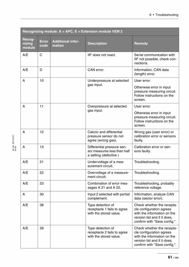
Recognizing module: A = APC, E = Extension module VEM 2
Recog-nizing module
Error code
Additional infor-mation Description Remedy
A 1 Timeout of activation sig-nal.
Ensure uninterrupted CAN transmission (e.g. shielded FS cable or position of FS cable to HF cable).
If reproducible error: Carry out CAN analysis (e.g. PCAN explorer).
A/E 2 APC setup parameters invalid.
Information, analyse CAN data (sector error).
A/E 3 Position of safety relays IIF1.
Relay on IIF module 1 or control on APC controller faulty.
A/E 4 Safety relay IIF2 is addressed via relay 1+i.
Relay on IIF module 2 or control on APC controller faulty.
A/E 5 Button error receptacle 1. Short circuit or interruption to/on receptacle board 1, check connector.
A/E 6 Button error receptacle 2. Short circuit or interruption to/on receptacle board 2, check connection.
A 7 Valve error. Input valve coil is not inserted or is faulty, check connection.
A 8 Interruption - proportional valve.
Proportional valve coil is not inserted or is faulty, check connection.
A 9 Short circuit - proportional valve
Short circuit in proportional valve circuit.
A A Control transistor - propor-tional valve.
Control transistor faulty.
A/E B Error in test mode. Error during calibration or diagnosis, mostly caused by PC program. Mostly uncritical.
60 / 144
9 • TroubleshootingA
rt.-
Nr.
: 801
16-2
71
04.0
6
A/E C IIF does not react. Serial communication with IIF not possible, check con-nections.
A/E D CAN error. Information, CAN data (length) error.
A 10 Underpressure at selected gas input.
User error.
Otherwise error in input pressure measuring circuit. Follow instructions on the screen.
A 11 Overpressure at selected gas input.
User error.
Otherwise error in input pressure measuring circuit. Follow instructions on the screen.
A 12 Caloric and differential pressure sensor do not agree (wrong gas).
Wrong gas (user error) or calibration error or sensors faulty.
A 13 Differential pressure sen-sor measures less than half a setting (defective )
Calibration error or sen-sors faulty.
A/E 21 Undervoltage of a mea-surement circuit.
Troubleshooting.
A/E 22 Overvoltage of a measure-ment circuit.
Troubleshooting.
A/E 23 Combination of error mes-sages A 21 and A 22.
Troubleshooting, probably reference voltage.
A 30 Input 2 selected with partial complement.
Information, analyze CAN data (sector error).
A/E 38 Type detection of receptacle 1 fails to agree with the stored value.
Check whether the recepta-cle configuration agrees with the information on the version list and if it does, confirm with "Save config.".
A/E 39 Type detection of receptacle 2 fails to agree with the stored value.
Check whether the recepta-cle configuration agrees with the information on the version list and if it does, confirm with "Save config.".
Recognizing module: A = APC, E = Extension module VEM 2
Recog-nizing module
Error code
Additional infor-mation Description Remedy
61 / 144

9 • Troubleshooting
Art
.-N
r.: 8
0116
-271
04
.06
A 40 Flow specification not attained.
User error.
A 41 Flow specification exceeded.
Calibration error or sen-sors faulty.
A/E 7D Program CRC test. Information, reprogram.
A/E 7E EEPROM not ready to read.
Access to EEPROM not possible at times, mostly secondary fault. (Another write access already exists in the error memory)
A/E 7F Operating system error. Information if error occurs during operation, can also occur after software update or when switching off/on.
A/E 80 Internal state incorrect. Information.
A/E 81 Protocol violation CAN. Information, analyze CAN data (length).
A/E 82 Protocol violation SIO -> IIF.
If frequent event, check IIF.
A/E 83 Time exceeded SIO -> IIF. If frequent event, check IIF.
A/E 85 Invalid resistance instru-ment number.
Replace instrument.
A 86 Gas underdose, e.g. hose blocked.
Replace instrument.
A 90 Low pressure at cylinder 1. Change gas bottle 1.
A 91 Low pressure at cylinder 2. Change gas bottle 2.
A A0 Calibration in EEPROM invalid.
Readjust unit.
Recognizing module: A = APC, E = Extension module VEM 2
Recog-nizing module
Error code
Additional infor-mation Description Remedy
62 / 144

9 • TroubleshootingA
rt.-
Nr.
: 801
16-2
71
04.0
6
B-Errors
Recognizing module: B = Control panel
Recog- nizing module
Error code
Additional informa-tion Description Remedy
B 1 Software watchdog: Occurs if the program crashes due to a software error or malfunction (e.g. EMC).
One-off event -> EMC prob-lem => Check environment.
Reproducible -> Software error => Inform ERBE Tübingen Technical Ser-vice.
B 2 Bit combination con-sisting of the nonap-plication module codes (hexadecimal): HF module 0X00000001 APC module 0X00000002 IES module 0X00000004 master remote control 0X00000010 slave remote control 0X00000020 1 pedal footswitch 0X00000100 2 pedal footswitch 0X00000200 multifunctional foot-switch 0X00000400 VIO receptacle 1 0X00010000 VIO receptacle 2 0X00020000 VIO receptacle 3 0X00040000 NE receptacle 0X00080000 APC receptacle 1 0X00100000 APC receptacle 2 0X00200000 AutoStart monitor 0X10000000
Timeout monitoring: Occurs if a module involved in activation (e.g. HF mod-ule, footswitch, APC mod-ule) fails to transmit a valid status message via CAN for longer than 110 ms.
Check module given in additional information.
Communication problem due to EMC interference possible => Check environ-ment.
63 / 144
9 • Troubleshooting
Art
.-N
r.: 8
0116
-271
04
.06
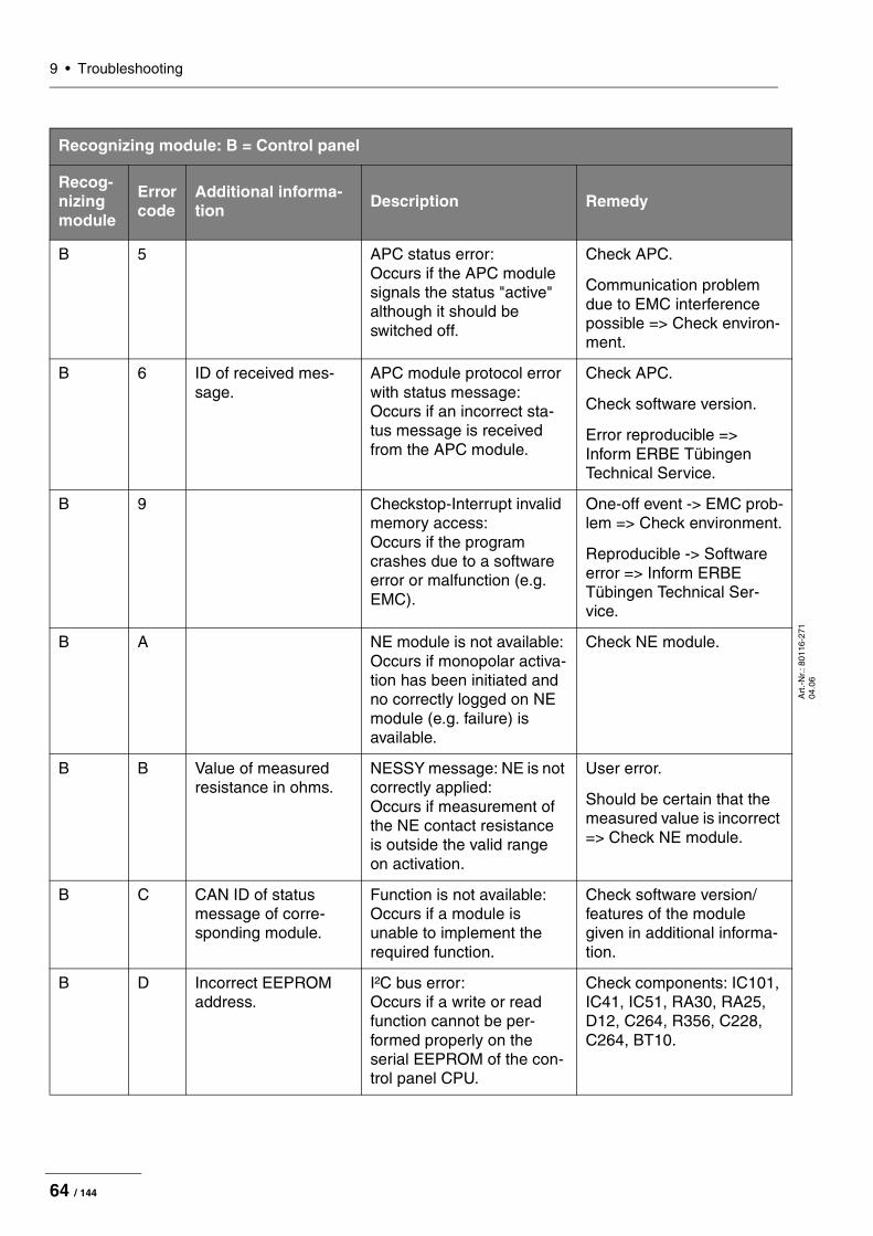
B 5 APC status error: Occurs if the APC module signals the status "active" although it should be switched off.
Check APC.
Communication problem due to EMC interference possible => Check environ-ment.
B 6 ID of received mes-sage.
APC module protocol error with status message: Occurs if an incorrect sta-tus message is received from the APC module.
Check APC.
Check software version.
Error reproducible => Inform ERBE Tübingen Technical Service.
B 9 Checkstop-Interrupt invalid memory access: Occurs if the program crashes due to a software error or malfunction (e.g. EMC).
One-off event -> EMC prob-lem => Check environment.
Reproducible -> Software error => Inform ERBE Tübingen Technical Ser-vice.
B A NE module is not available: Occurs if monopolar activa-tion has been initiated and no correctly logged on NE module (e.g. failure) is available.
Check NE module.
B B Value of measured resistance in ohms.
NESSY message: NE is not correctly applied: Occurs if measurement of the NE contact resistance is outside the valid range on activation.
User error.
Should be certain that the measured value is incorrect => Check NE module.
B C CAN ID of status message of corre-sponding module.
Function is not available: Occurs if a module is unable to implement the required function.
Check software version/ features of the module given in additional informa-tion.
B D Incorrect EEPROM address.
I²C bus error: Occurs if a write or read function cannot be per-formed properly on the serial EEPROM of the con-trol panel CPU.
Check components: IC101, IC41, IC51, RA30, RA25, D12, C264, R356, C228, C264, BT10.
Recognizing module: B = Control panel
Recog- nizing module
Error code
Additional informa-tion Description Remedy
64 / 144

9 • TroubleshootingA
rt.-
Nr.
: 801
16-2
71
04.0
6
B E ECB bus error: Occurs if the control panel CPU detects an error at the CAN bus (e.g. CAN con-nection interrupted).
Check communication on the ECB bus. Check all connection lines (also inside unit).
If the error can be narrowed down to the CPU823:
Check IC109 with wiring and bus connection to IC101.
B F No signal from capacitive keyboard: Occurs if the control panel CPU does not receive a signal from the capacitive keyboard (e.g. connection interrupted).
Check connector to key-board. Check IC44. Track signal and check compo-nents.
B 10 Please terminate activation: Occurs if activation has been automatically termi-nated (e.g. by AutoStop) and the activation signal remains (longer than 5 s) (e.g. footswitch).
User error.
B 11 Error during activation: Occurs if activation has not been enabled for over 110 ms during activation.
Communication error.
One-off event -> EMC prob-lem => Check environment.
Reproducible -> Software error => Inform ERBE Tübingen Technical Ser-vice.
B 12 CAN ID of activation signal (e.g. 100 with dual-pedal foot-switch).
Activation signal during switch-on: Occurs if an activation sig-nal is present during initial-ization of the unit (e.g. footswitch pedal pressed).
User error or faulty activa-tion element. Check activa-tion element (see additional information)
Recognizing module: B = Control panel
Recog- nizing module
Error code
Additional informa-tion Description Remedy
65 / 144

9 • Troubleshooting
Art
.-N
r.: 8
0116
-271
04
.06
B 13 1 => Error file 1 Errors in list management: Occurs if an error is identi-fied in the corresponding flash file when managing the event or error list.
Delete lists. If this recurs, there could be a fault in the flash memory => Replace assembly. Inform ERBE Tübingen Technical Ser-vice.
2 => Error file 2
10 => Event file 1
20 => Event file 2
B 14 CRC error: Occurs if an error is identi-fied by the continuous CRC monitoring of the program. (e.g. A bit flipping in the flash memory or an error when downloading soft-ware).
Reload system software.
If this recurs, there could be a fault in the flash memory => Replace assembly. Inform ERBE Tübingen Technical Service
B 15 FLASH RAM verification error: Occurs if an error is identi-fied by the continuous mon-itoring of the program. (e.g. a bit flips in DRAM mem-ory).
One-off event -> EMC prob-lem => Check environment.
Reproducible -> Error in system memory => Replace assembly. Inform ERBE Tübingen Technical Service.
B 16 Insufficient EEPROM mem-ory: Occurs if the memory for user programs is full.
Delete programmes that are not required.
B 17 CAN ID of second activation signal.
Double activation: Occurs if two activation sig-nals (e.g. both pedals of a footswitch) are present simultaneously (within 100 ms).
User error or faulty activa-tion element.
B 18 Bit combination of HF module and APC module: 1000 or 100 HF mod-ule (Coag) 2000 or 200 HF mod-ule (Cut) 4000 or 400 APC module
No deactivation signal: Occurs if a module involved in activation (HF module or APC module) fails to react to a deactivation request for longer than 110 ms.
Communication error.
One-off event -> EMC prob-lem => Check environment.
Reproducible -> Software error => Inform ERBE Tübingen Technical Ser-vice.
Recognizing module: B = Control panel
Recog- nizing module
Error code
Additional informa-tion Description Remedy
66 / 144

9 • TroubleshootingA
rt.-
Nr.
: 801
16-2
71
04.0
6
B 19 PowerFail: Occurs if a PowerFail signal is received but the Power-Fail does not actually hap-pen within 2 s.
Check house installation.
Check low-voltage power supply unit.
B 1A Number of the incor-rect parameter (Hex): 0: Activation assign-ment 3: CutMode 4: CutIntensity 5: CutEffect 6: CoagIntensity 7: CoagEffect 8: CoagMode B: CutAPCFlow C: CoagAPCFlow D: CutIESFlow E: CoagIESFlow F: IES-Basic Suction 10: IES-Run-On Time
Error in parameter memory: Occurs if an error is identi-fied by the checksum parameter monitoring of a program. (e.g. a bit flips in DRAM memory).
One-off event -> EMC prob-lem => Check environment.
Frequent event -> Error in system memory => Replace assembly.
Reproducible -> Software error => Inform ERBE Tübingen Technical Ser-vice.
B 1B CRC check not yet com-pleted: Occurs if the user wants to operate the unit after downloading software before there has been at least one successful CRC check.
Wait until the CRC check has been completed.
B 1C The maximum ON time has been exceeded: Occurs if activation lasts longer than the ON time selected in SET-UP.
User error.
B 1D Number of the incor-rect parameter (Hex): 101 Cut-Mode 102 Coag-Mode 201 Cut-Effect 202 Coag-Effect 301 Cut-Power 302 Coag-Power 501 Cut-APC-Flow 502 Coag-APC-Flow
Incorrect instrument param-eters: Occurs if an instrument is detected via instrument recognition and the param-eter is outside the permissi-ble tolerances.
Check instrument software version. Replace instru-ment. Check IIF.
Recognizing module: B = Control panel
Recog- nizing module
Error code
Additional informa-tion Description Remedy
67 / 144

9 • Troubleshooting
Art
.-N
r.: 8
0116
-271
04
.06
B 1E Button code: 0x001 => buttonUp 0x002 => buttonDwn 0x004 => buttonEnter 0x008 => buttonReceptacle 1 0x010 => buttonReceptacle 2 0x020 => buttonReceptacle 3 0x040 => buttonNE 0x080 =>buttonAPC1 0x100 =>buttonAPC2
Keyboard error: Occurs if a button pressed is recognized during initial-ization.
User error or => Check keyboard.
B 1F NESSY symmetry value in %.
NESSY symmetry monitor-ing: Occurs if an error is sig-naled by the Nessy symme-try monitoring during activation.
User error.
Should be certain that the measured value is incorrect => Check NE module.
B 21 Incorrect or missing bit map file: Occurs if an incompatible bit map file is found.
Transfer compatible bit map file.
B 22 Occurs if activation was ter-minated automatically (e.g. by AutoStop) and tissue is still touched.
Discontinue touching.
B 23 Configuration error of HF CPU: Occurs if the HF CPU transmits an invalid status message (0X27).
Check software version of HF CPU.
B 24 Occurs if an incorrect sta-tus message is received from the IES 2.
Check software status of the system components.
If the error is reproducible notify => Technical Service ERBE Tübingen.
Recognizing module: B = Control panel
Recog- nizing module
Error code
Additional informa-tion Description Remedy
68 / 144
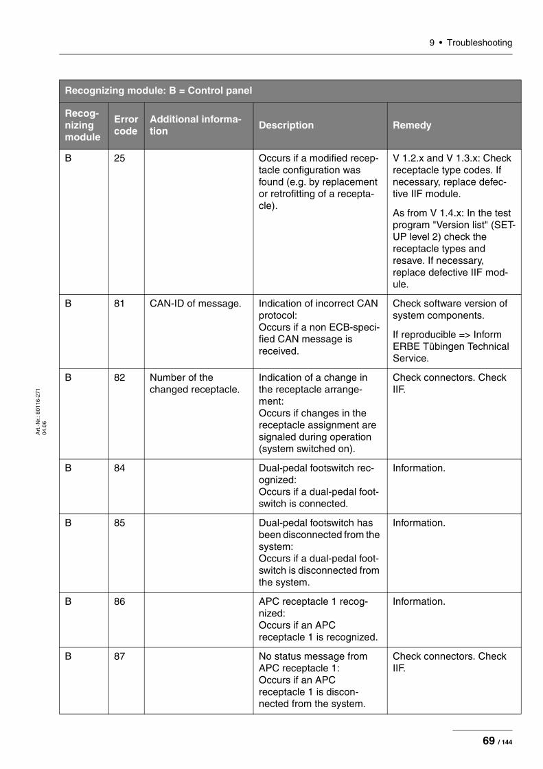
9 • TroubleshootingA
rt.-
Nr.
: 801
16-2
71
04.0
6
B 25 Occurs if a modified recep-tacle configuration was found (e.g. by replacement or retrofitting of a recepta-cle).
V 1.2.x and V 1.3.x: Check receptacle type codes. If necessary, replace defec-tive IIF module.
As from V 1.4.x: In the test program "Version list" (SET-UP level 2) check the receptacle types and resave. If necessary, replace defective IIF mod-ule.
B 81 CAN-ID of message. Indication of incorrect CAN protocol: Occurs if a non ECB-speci-fied CAN message is received.
Check software version of system components.
If reproducible => Inform ERBE Tübingen Technical Service.
B 82 Number of the changed receptacle.
Indication of a change in the receptacle arrange-ment: Occurs if changes in the receptacle assignment are signaled during operation (system switched on).
Check connectors. Check IIF.
B 84 Dual-pedal footswitch rec-ognized: Occurs if a dual-pedal foot-switch is connected.
Information.
B 85 Dual-pedal footswitch has been disconnected from the system: Occurs if a dual-pedal foot-switch is disconnected from the system.
Information.
B 86 APC receptacle 1 recog-nized: Occurs if an APC receptacle 1 is recognized.
Information.
B 87 No status message from APC receptacle 1: Occurs if an APC receptacle 1 is discon-nected from the system.
Check connectors. Check IIF.
Recognizing module: B = Control panel
Recog- nizing module
Error code
Additional informa-tion Description Remedy
69 / 144

9 • Troubleshooting
Art
.-N
r.: 8
0116
-271
04
.06
B 88 Single-pedal footswitch rec-ognized: Occurs if a single-pedal footswitch is connected.
Information.
B 89 Single-pedal footswitch has been disconnected from the system: Occurs if a single-pedal footswitch is disconnected from the system.
Information.
B 8A APC receptacle 2 recog-nized: Occurs if an APC receptacle 2 is detected.
Information.
B 8B No status message from APC receptacle 2: Occurs if an APC receptacle 2 is discon-nected from the system.
Check connectors. Check IIF.
B 8C APC module recognized: Occurs if an APC module is detected.
Information.
B 8D No status message from APC module: Occurs if an APC module is disconnected from the sys-tem.
Check connectors. Check APC.
B 8E No status message from HF receptacle 1: Occurs if an HF receptacle 1 is discon-nected from the system.
Check connectors. Check IIF.
B 8F No status message from HF receptacle 2: Occurs if an HF receptacle 2 is discon-nected from the system.
Check connectors. Check IIF.
B 90 No status message from HF receptacle 3: Occurs if an HF receptacle 3 is discon-nected from the system.
Check connectors. Check IIF.
Recognizing module: B = Control panel
Recog- nizing module
Error code
Additional informa-tion Description Remedy
70 / 144
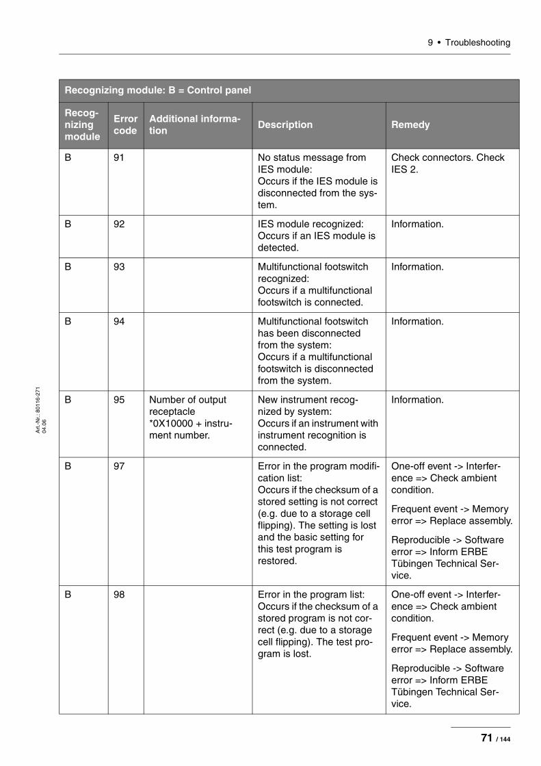
9 • TroubleshootingA
rt.-
Nr.
: 801
16-2
71
04.0
6
B 91 No status message from IES module: Occurs if the IES module is disconnected from the sys-tem.
Check connectors. Check IES 2.
B 92 IES module recognized: Occurs if an IES module is detected.
Information.
B 93 Multifunctional footswitch recognized: Occurs if a multifunctional footswitch is connected.
Information.
B 94 Multifunctional footswitch has been disconnected from the system: Occurs if a multifunctional footswitch is disconnected from the system.
Information.
B 95 Number of output receptacle *0X10000 + instru-ment number.
New instrument recog-nized by system: Occurs if an instrument with instrument recognition is connected.
Information.
B 97 Error in the program modifi-cation list: Occurs if the checksum of a stored setting is not correct (e.g. due to a storage cell flipping). The setting is lost and the basic setting for this test program is restored.
One-off event -> Interfer-ence => Check ambient condition.
Frequent event -> Memory error => Replace assembly.
Reproducible -> Software error => Inform ERBE Tübingen Technical Ser-vice.
B 98 Error in the program list: Occurs if the checksum of a stored program is not cor-rect (e.g. due to a storage cell flipping). The test pro-gram is lost.
One-off event -> Interfer-ence => Check ambient condition.
Frequent event -> Memory error => Replace assembly.
Reproducible -> Software error => Inform ERBE Tübingen Technical Ser-vice.
Recognizing module: B = Control panel
Recog- nizing module
Error code
Additional informa-tion Description Remedy
71 / 144

9 • Troubleshooting
Art
.-N
r.: 8
0116
-271
04
.06
B 99 Activation type: This activation type is not available: Occurs if the user assigns an activation signal that is not currently available. (e.g. unconnected footswitch).
User error or activation ele-ment (see additional infor-mation) faulty and therefore not available on the system.
1 => Dual-pedal foot-switch both pedals
2 => Dual-pedal foot-switch only Coag
3 => Dual-pedal foot-switch only Cut
4 => Single-pedal footswitch
5 => AutoStart 1
6 => AutoStart 2
B 9A Please check the clock: Occurs if the VIO was switched off for such a long time that the supply current to the built-in realtime clock was no longer sufficient.
Set time.
If frequent event, check BT10.
B 9B Master remote control rec-ognized: Occurs if a master remote control is recognized by the VIO.
Information.
B 9C Master remote control has been disconnected from the system: Occurs if the master remote control is disconnected from the system.
Information.
B 9D Remote control recognized: Occurs if a remote control is recognized by the VIO.
Information.
B 9E Remote control has been disconnected from the sys-tem: Occurs if the remote control is disconnected from the system.
Information.
Recognizing module: B = Control panel
Recog- nizing module
Error code
Additional informa-tion Description Remedy
72 / 144

9 • TroubleshootingA
rt.-
Nr.
: 801
16-2
71
04.0
6
B 9F Number of output receptacle.
Instrument has been dis-connected from the system: Occurs if an instrument with instrument recognition is disconnected from the sys-tem.
Information.
B A0 Number of output receptacle.
No other mode can be set for this instrument: Occurs if the user wants to assign a different mode to an instrument with a fixed mode.
Information.
B A1 No status message from HF module: Occurs if the control panel does not receive a status message from the HF mod-ule (for longer than 1 s).
One-off event -> Interference => Check ambient conditions.
Frequent event -> Memory error => Check CPU+sensors.
B A3 Error number of foot-switch (see error description for foot-switch): + 0x100 (with single-pedal footswitch) + 0x200 (with dual-pedal footswitch) + 0x400 (with multi-functional footswitch)
Footswitch not assigned: Occurs if a footswitch which has not been assigned to an output socket is pressed.
User error.
B A4 CAN ID of second footswitch or 2 if it cannot be assigned to any CAN ID.
Two footswitches are con-nected: Occurs if two foot-switches of the same type are connected.
User error.
B A6 EEPROM is updated: Occurs if the unit is pro-grammed using a con-nected PC.
Information.
B A8 CAN ID of module. Invalid ECB version: Occurs if a module with an invalid ECB version logs on.
Check software version of system components.
Recognizing module: B = Control panel
Recog- nizing module
Error code
Additional informa-tion Description Remedy
73 / 144

9 • Troubleshooting
Art
.-N
r.: 8
0116
-271
04
.06
B A9 Activation not possible until settings are confirmed: Occurs if the user wants to perform activation after switching on the unit with-out confirming the settings beforehand.
User error.
B AA CAN ID of activation request.
No valid mode is assigned: Occurs if an output channel is activated without a mode being assigned to it.
User error. If necessary, load upgrade.
B AB CAN ID of activation request.
Activation is only possible with a valid instrument: Occurs if an MF receptacle is activated at which no instrument is recognized.
User error or check plug-in contacts. Check instrument software.
B AC 0x140 (CAN ID of AutoStart monitor).
AutoStart is not possible if contact is made during assignment: Occurs if the AutoStart function is assigned while contact has already been recognized.
User error or check AUTO START monitor (CPU+sen-sors).
B AD CAN ID of module. Error with version check: Occurs if a module with an invalid version tries to log on.
Check software version of system components.
B AE No modules logged on: Occurs if no modules log on during the initialization phase.
Check connectors, ECB and electrical supply.
B AF NE module ceases to respond: Occurs if the NE module ceases responding.
Check NE module.
B BO NESSY symmetry value in %.
NESSY symmetry warning: Occurs if the Nessy sym-metry monitoring signals a value between 20 % and 50 %.
User error.
It should be certain that the measured value is incorrect => Check NE module.
Recognizing module: B = Control panel
Recog- nizing module
Error code
Additional informa-tion Description Remedy
74 / 144

9 • TroubleshootingA
rt.-
Nr.
: 801
16-2
71
04.0
6
B B1 NESSY current value. NESSY current density warning: Occurs if the Nessy current density monitoring signals a value above the limit curve.
User error.
It should be certain that the measured value is incorrect => Check NE module.
B B2 IES footswitch detected: Occurs if an IES footswitch is connected.
Information.
B B3 Calibration of keyboard: Occurs if the capacitive keyboard is recalibrated.
Information.
If frequent event, replace assembly.
B B4 Rinsing of an APC instru-ment: Occurs if rinsing of an APC instrument is initiated.
Information.
B B5 CAN warning: Occurs if the error counter of the CAN controller reaches a critical value.
ECB communication error. Check ambient conditions.
B B6 Incorrect receptacle version signal: Occurs if an incorrect receptacle version signal is received.
Check software version of receptacle module.
B B7 Permissible limit value of AUTO START activation has been exceeded: Occurs if an attempt is made to assign AUTO START activation a non-permissible power limitation value.
Information.
B B8 New interface module rec-ognized: Occurs if an interface mod-ule (e.g. VIO PORTAL) logs on to the system.
Information.
Recognizing module: B = Control panel
Recog- nizing module
Error code
Additional informa-tion Description Remedy
75 / 144
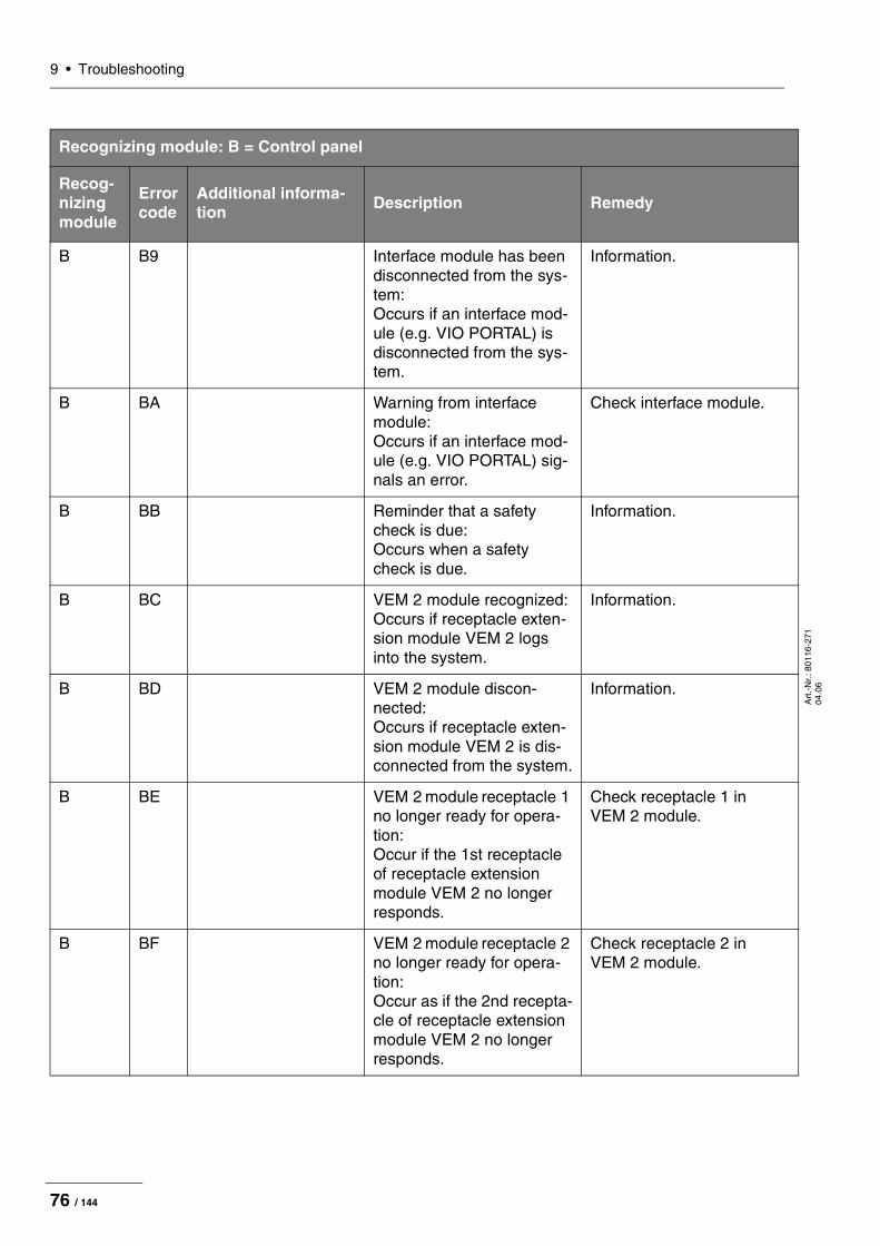
9 • Troubleshooting
Art
.-N
r.: 8
0116
-271
04
.06
B B9 Interface module has been disconnected from the sys-tem: Occurs if an interface mod-ule (e.g. VIO PORTAL) is disconnected from the sys-tem.
Information.
B BA Warning from interface module: Occurs if an interface mod-ule (e.g. VIO PORTAL) sig-nals an error.
Check interface module.
B BB Reminder that a safety check is due: Occurs when a safety check is due.
Information.
B BC VEM 2 module recognized: Occurs if receptacle exten-sion module VEM 2 logs into the system.
Information.
B BD VEM 2 module discon-nected: Occurs if receptacle exten-sion module VEM 2 is dis-connected from the system.
Information.
B BE VEM 2 module receptacle 1 no longer ready for opera-tion: Occur if the 1st receptacle of receptacle extension module VEM 2 no longer responds.
Check receptacle 1 in VEM 2 module.
B BF VEM 2 module receptacle 2 no longer ready for opera-tion: Occur as if the 2nd recepta-cle of receptacle extension module VEM 2 no longer responds.
Check receptacle 2 in VEM 2 module.
Recognizing module: B = Control panel
Recog- nizing module
Error code
Additional informa-tion Description Remedy
76 / 144

9 • TroubleshootingA
rt.-
Nr.
: 801
16-2
71
04.0
6
B CO Neither footswitch nor AUTO START assigned: Occurs if an instrument without a fingerswitch is recognized and neither a footswitch nor AUTO START is assigned.
Information.
B C1 EIP 2 was recognized by the system: Occurs if the EIP 2 is con-nected to the system.
Information.
B C2 EIP 2 was disconnected from the system: Occurs if EIP 2 is discon-nected from the system.
Information.
B C3 IES 2 footswitch was dis-connected from the system: Occurs if the IES 2 foot-switch is disconnected from the system.
Information.
B C4 Purge function not assigned: Occurs if the purge button on the APC is pressed and no APC receptacle was selected.
Select APC receptacle.
B FC Power Down: Occurs if the unit is switched off.
Information.
B FD System Reset: Occurs if a system reset is performed (e.g. when switching on unit).
Information.
B FE PowerFail: Occurs if a PowerFail is sig-naled (e.g. when switching off unit).
Information.
Recognizing module: B = Control panel
Recog- nizing module
Error code
Additional informa-tion Description Remedy
77 / 144

9 • Troubleshooting
Art
.-N
r.: 8
0116
-271
04
.06
B FF ID of CAN message with associated data bytes.
CAN MESSAGE: Occurs as soon as a CAN message, which is to be logged in a protocol, is transmitted by the control panel.
Information.
Recognizing module: B = Control panel
Recog- nizing module
Error code
Additional informa-tion Description Remedy
78 / 144

9 • TroubleshootingA
rt.-
Nr.
: 801
16-2
71
04.0
6
C-Errors
Recognizing module: C = CPU + Sensors
Recog- nizing module
Error code
Additional infor-mation Description Remedy
C 1 System error: CPU has not received necessary CAN message from control panel at proper time.
Ensure uninterrupted CAN transmission (e.g. shielded FS cable or position of FS cable to HF cable).
If reproducible error: Carry out CAN analysis (e.g. PCAN explorer).
C 4 System error: Internal sta-tus.
One-off event: Switch unit off and on again.
Reproducible: Inform ERBE Tübingen Technical Ser-vice.
C 5 System error: CAN mes-sage with wrong length.
One-off event: Switch unit off and on again.
Reproducible: Inform ERBE Tübingen Technical Ser-vice.
C 6 System error: Activation request without parameter message.
Ensure uninterrupted CAN transmission (e.g. shielded FS cable or position of FS cable to HF cable).
If reproducible error: Carry out CAN analysis (e.g. PCAN explorer).
C D System error: CAN length of message.
One-off event: Switch unit off and on again.
Reproducible: Inform ERBE Tübingen Technical Ser-vice.
C 21 Overdose: Output 20 % too high.
Check high-voltage power supply unit (TP power sup-ply unit).
Check generator (TP generator).
79 / 144

9 • Troubleshooting
Art
.-N
r.: 8
0116
-271
04
.06
C 26 Measurement values of P_HF and P_NT do not agree.
E.g. HF power output > NT power output.
Check power supply unit (TP power supply unit).
Check generator (TP generator).
Check calibration.
C 30 Redundant measurement value for HF voltage too great during activation.
Check generator (TP generator).
Check sensors.
C 31 Measurement value for HF voltage too great with OFF.
Check power supply unit (TP power supply unit).
Check generator (TP generator).
Check sensors.
C 32 Measurement value for HF voltage too small with OFF.
Check power supply unit (TP power supply unit).
Check generator (TP generator).
Check sensors.
C 33 Measurement value for HF voltage too great with ON.
Check power supply unit (TP power supply unit).
Check generator (TP generator).
Check sensors.
C 34 Measurement value for HF voltage too small with ON.
Check power supply unit (TP power supply unit).
Check generator (TP generator).
Check sensors.
C 35 Measurement value for HF current too great with OFF.
Check power supply unit (TP power supply unit).
Check generator (TP generator).
Check sensors.
Recognizing module: C = CPU + Sensors
Recog- nizing module
Error code
Additional infor-mation Description Remedy
80 / 144

9 • TroubleshootingA
rt.-
Nr.
: 801
16-2
71
04.0
6
C 36 Measurement value for HF current too small with OFF.
Check power supply unit (TP power supply unit).
Check generator (TP generator).
Check sensors.
C 37 Measurement value for HF current too great with ON.
Check power supply unit (TP power supply unit).
Check generator (TP generator).
Check sensors.
C 38 Measurement value for HF current too small with ON.
Check power supply unit (TP power supply unit).
Check generator (TP generator).
Check sensors.
C 41 Measurement value for spark too great with OFF.
Check generator (TP generator).
Check sensors.
C 42 Measurement value for spark too small with OFF.
Check generator (TP generator).
Check sensors.
C 43 Measurement value for spark too great with ON.
Check generator (TP generator).
Check sensors.
C 44 Measurement value for spark too small with ON.
Check generator (TP generator).
Check sensors.
C 45 Measurement value for phase too great with OFF.
Check generator (TP generator).
Check sensors.
C 46 Measurement value for phase too small with OFF.
Check generator (TP generator).
Check sensors.
Recognizing module: C = CPU + Sensors
Recog- nizing module
Error code
Additional infor-mation Description Remedy
81 / 144
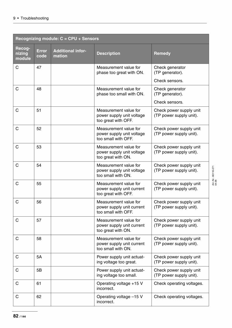
9 • Troubleshooting
Art
.-N
r.: 8
0116
-271
04
.06
C 47 Measurement value for phase too great with ON.
Check generator (TP generator).
Check sensors.
C 48 Measurement value for phase too small with ON.
Check generator (TP generator).
Check sensors.
C 51 Measurement value for power supply unit voltage too great with OFF.
Check power supply unit (TP power supply unit).
C 52 Measurement value for power supply unit voltage too small with OFF.
Check power supply unit (TP power supply unit).
C 53 Measurement value for power supply unit voltage too great with ON.
Check power supply unit (TP power supply unit).
C 54 Measurement value for power supply unit voltage too small with ON.
Check power supply unit (TP power supply unit).
C 55 Measurement value for power supply unit current too great with OFF.
Check power supply unit (TP power supply unit).
C 56 Measurement value for power supply unit current too small with OFF.
Check power supply unit (TP power supply unit).
C 57 Measurement value for power supply unit current too great with ON.
Check power supply unit (TP power supply unit).
C 58 Measurement value for power supply unit current too small with ON.
Check power supply unit (TP power supply unit).
C 5A Power supply unit actuat-ing voltage too great.
Check power supply unit (TP power supply unit).
C 5B Power supply unit actuat-ing voltage too small.
Check power supply unit (TP power supply unit).
C 61 Operating voltage +15 V incorrect.
Check operating voltages.
C 62 Operating voltage –15 V incorrect.
Check operating voltages.
Recognizing module: C = CPU + Sensors
Recog- nizing module
Error code
Additional infor-mation Description Remedy
82 / 144

9 • TroubleshootingA
rt.-
Nr.
: 801
16-2
71
04.0
6
C 63 Operating voltage +24 V incorrect.
Check operating voltages.
C 64 Operating voltage –5 V incorrect.
Check operating voltages.
C 70 Relay configuration insuffi-cient.
Check IIF components (ME,BE,MF).
Check relay (TP relay)
C 71 At least 1 relay is signaled as closed although all should be open.
Check relay (TP relay).
C 72 At least 1 relay is signaled as open although all should be closed.
Check relay (TP relay).
C 75 IIF signals invalid instru-ment number.
Replace IIF.
C 7D System error: CRC error in program memory.
Replace or reprogram CPU + sensors.
C 7E System error: EEPROM not ready to read.
Replace CPU + sensors.
C 7F System error: Multitasking. Replace CPU + sensors.
C 81 System error: CAN protocol length incorrect.
Replace control panel.
C 82 System error: SIO protocol length incorrect.
Replace IIF.
C 83 System error: IIF has not responded at proper time.
Replace IIF.
C 84 Short circuit between AE and NE.
Information.
C 91 Redundancy error: Current at NESSY is greater than at CPU + sensors.
Check calibration, replace NESSY.
C 92 Redundancy error: Power supply unit current available but no corresponding HF current.
Check calibration.
Check power supply unit (TP power supply unit).
Recognizing module: C = CPU + Sensors
Recog- nizing module
Error code
Additional infor-mation Description Remedy
83 / 144
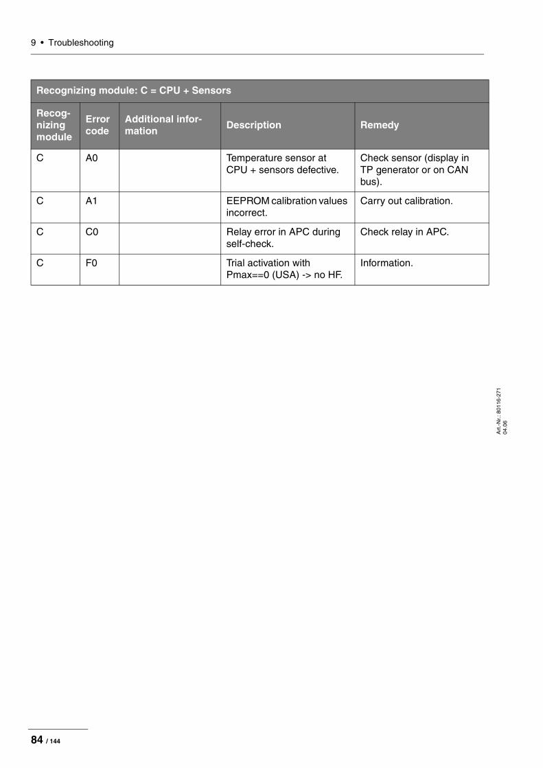
9 • Troubleshooting
Art
.-N
r.: 8
0116
-271
04
.06
C A0 Temperature sensor at CPU + sensors defective.
Check sensor (display in TP generator or on CAN bus).
C A1 EEPROM calibration values incorrect.
Carry out calibration.
C C0 Relay error in APC during self-check.
Check relay in APC.
C F0 Trial activation with Pmax==0 (USA) -> no HF.
Information.
Recognizing module: C = CPU + Sensors
Recog- nizing module
Error code
Additional infor-mation Description Remedy
84 / 144
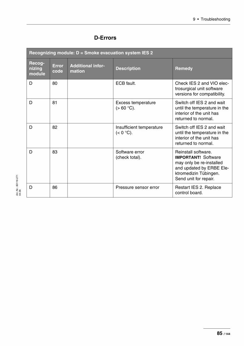
9 • TroubleshootingA
rt.-
Nr.
: 801
16-2
71
04.0
6
D-Errors
Recognizing module: D = Smoke evacuation system IES 2
Recog-nizing module
Error code
Additional infor-mation Description Remedy
D 80 ECB fault. Check IES 2 and VIO elec-trosurgical unit software versions for compatibility.
D 81 Excess temperature (> 60 °C).
Switch off IES 2 and wait until the temperature in the interior of the unit has returned to normal.
D 82 Insufficient temperature (< 0 °C).
Switch off IES 2 and wait until the temperature in the interior of the unit has returned to normal.
D 83 Software error (check total).
Reinstall software. IMPORTANT! Software may only be re-installed and updated by ERBE Ele-ktromedizin Tübingen. Send unit for repair.
D 86 Pressure sensor error Restart IES 2. Replace control board.
85 / 144

9 • Troubleshooting
Art
.-N
r.: 8
0116
-271
04
.06
2,3,5,6-Errors
Recognizing module: 2,3,5,6 = IIF (Instrument Interface) of corresponding receptacle slot
Recog- nizing module
Error code
Additional infor-mation Description Remedy
2,3,5,6 (socket)
1 Interrupt error: An undefined IR vector has been invoked.
Reprogram µC. Replace µC.
2,3,5,6 (socket)
2 CRC error: Defective program mem-ory discovered during self-check after reset.
Reprogram µC. Replace µC.
2,3,5,6 (socket)
3 Undervoltage 5 V: 5 V voltage discovered to be too low during self-check after reset.
Check 5 V electrical sup-ply and monitoring.
2,3,5,6 (socket)
4 Overvoltage 5 V: 5 V voltage discovered to be too high during self-check after reset.
Check 5 V electrical sup-ply and monitoring. Can also be caused by missing +12 V voltage (because then ADC ref.volt. is miss-ing).
2,3,5,6 (socket)
5 Undervoltage ±12 V: +12 V voltage discovered to be too low or –12 V voltage too high during self-check after reset.
Check +12 and –12 V elec-trical supply and monitor-ing.
2,3,5,6 (socket)
6 Overvoltage ±12 V: +12 V voltage discovered to be too high or –12 V voltage too low during self-check after reset.
Check +12 and –12 V elec-trical supply and monitor-ing. Can also be caused by missing +12 V voltage (because then ADC ref.volt. is missing).
2,3,5,6 (socket)
7 Undercurrent activation recognition: The measurement current for analysis of the activa-tion recognition is too low.
Check power source IC18, voltage dividers R195, R196 and test resistor R197.
2,3,5,6 (socket)
8 Overcurrent activation rec-ognition: The measurement current for analysis of the activa-tion recognition is too high.
Check power source IC18, voltage dividers R195, R196 and test resistor R197.
86 / 144

9 • TroubleshootingA
rt.-
Nr.
: 801
16-2
71
04.0
6
2,3,5,6 (socket)
9 Undercurrent instrument recognition: The measurement current for analysis of the instru-ment recognition is too low.
Check power source IC17, voltage dividers R168, R169 and test resistor R126.
2,3,5,6 (socket)
A Overcurrent instrument recognition: The measurement current for analysis of the instru-ment recognition is too high.
Check power source IC17, voltage dividers R168, R169 and test resistor R126.
2,3,5,6 (socket)
C Stack error: The stack pointer does not point to Top of Stack in the main program loop (no UPR call up, no IR).
Reprogram µC. Replace µC.
2,3,5,6 (socket)
D State error: The state variable contains a non-permissible value.
Reprogram µC. Replace µC.
2,3,5,6 (socket)
E CRC error: Defective pro-gram memory discovered by system check during operation.
Reprogram µC. Replace µC.
2,3,5,6 (socket)
F U Coag error: +12 V volt-age during Coag activation too low.
Check power source IC18 and control.
2,3,5,6 (socket)
70 Relay error. Check IIF components (ME,BE,MF), check relay (TP relay)
2,3,5,6 (socket)
71 Relay error. Check relay (TP relay)
2,3,5,6 (socket)
72 Relay error. Check relay (TP relay)
2,3,5,6 (socket)
81 Short circuit instrument recognition R: The resistor value determined for the instrument recognition cor-responds to a short circuit.
Check instrument and socket module.
Recognizing module: 2,3,5,6 = IIF (Instrument Interface) of corresponding receptacle slot
Recog- nizing module
Error code
Additional infor-mation Description Remedy
87 / 144
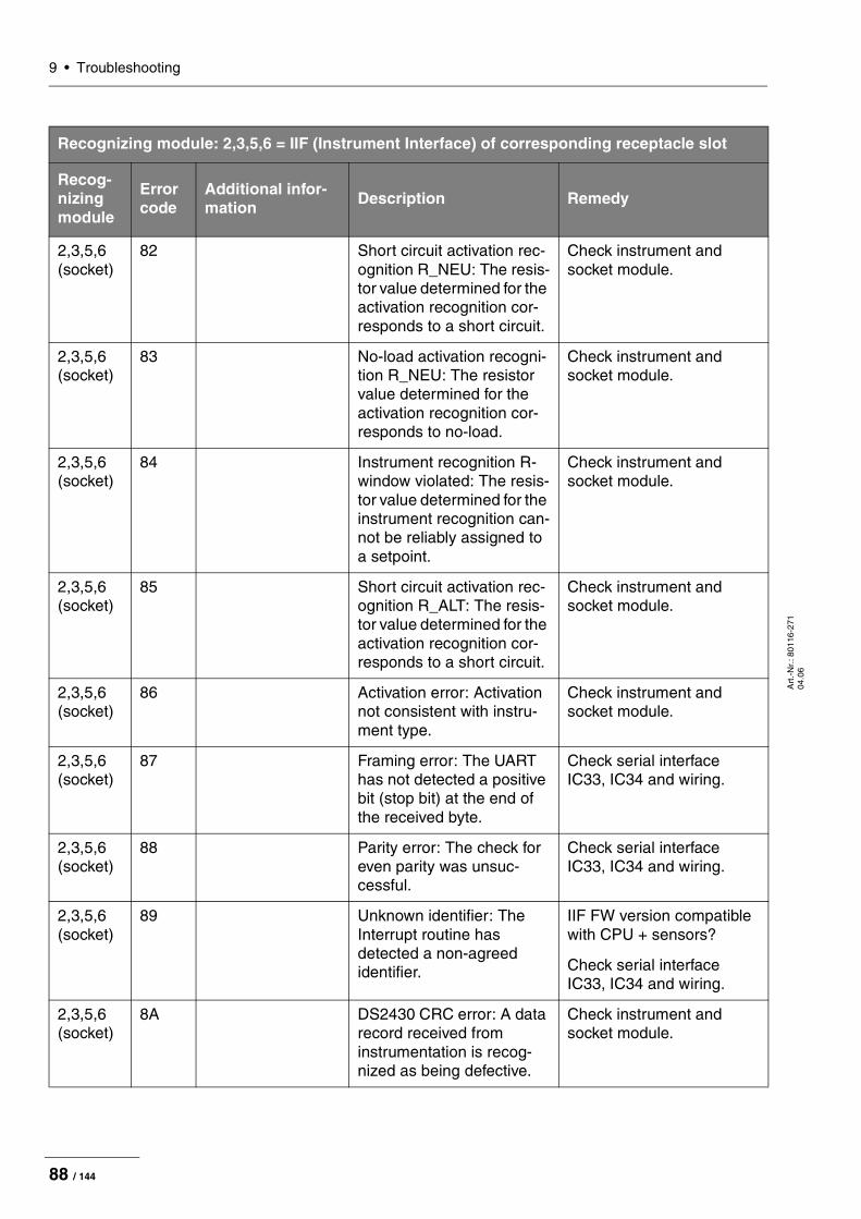
9 • Troubleshooting
Art
.-N
r.: 8
0116
-271
04
.06
2,3,5,6 (socket)
82 Short circuit activation rec-ognition R_NEU: The resis-tor value determined for the activation recognition cor-responds to a short circuit.
Check instrument and socket module.
2,3,5,6 (socket)
83 No-load activation recogni-tion R_NEU: The resistor value determined for the activation recognition cor-responds to no-load.
Check instrument and socket module.
2,3,5,6 (socket)
84 Instrument recognition R-window violated: The resis-tor value determined for the instrument recognition can-not be reliably assigned to a setpoint.
Check instrument and socket module.
2,3,5,6 (socket)
85 Short circuit activation rec-ognition R_ALT: The resis-tor value determined for the activation recognition cor-responds to a short circuit.
Check instrument and socket module.
2,3,5,6 (socket)
86 Activation error: Activation not consistent with instru-ment type.
Check instrument and socket module.
2,3,5,6 (socket)
87 Framing error: The UART has not detected a positive bit (stop bit) at the end of the received byte.
Check serial interface IC33, IC34 and wiring.
2,3,5,6 (socket)
88 Parity error: The check for even parity was unsuc-cessful.
Check serial interface IC33, IC34 and wiring.
2,3,5,6 (socket)
89 Unknown identifier: The Interrupt routine has detected a non-agreed identifier.
IIF FW version compatible with CPU + sensors?
Check serial interface IC33, IC34 and wiring.
2,3,5,6 (socket)
8A DS2430 CRC error: A data record received from instrumentation is recog-nized as being defective.
Check instrument and socket module.
Recognizing module: 2,3,5,6 = IIF (Instrument Interface) of corresponding receptacle slot
Recog- nizing module
Error code
Additional infor-mation Description Remedy
88 / 144

9 • TroubleshootingA
rt.-
Nr.
: 801
16-2
71
04.0
6
2,3,5,6 (socket)
8B Non-permissible instru-ment recognition R_S3: Non-permissible value determined for resistor-coded instrument recogni-tion.
Carry out reset. Repro-gram µC. Replace µC.
2,3,5,6 (socket)
8C Non-permissible sockets and relay status: Non-permissible value determined for socket rec-ognition.
Carry out reset. Repro-gram µC. Replace µC.
2,3,5,6 (socket)
8D Non-permissible instru-ment recognition R_S4: Non-permissible value determined for resistor-coded instrument recogni-tion.
Carry out reset. Repro-gram µC. Replace µC.
2,3,5,6 (socket)
8E Non-permissible instru-ment recognition R_S8: Non-permissible value determined for resistor-coded instrument recogni-tion.
Carry out reset. Repro-gram µC. Replace µC.
2,3,5,6 (socket)
8F UART timeout: UPR "Receive_UART" has not received anything 351us after call-up.
Check serial interface IC33, IC34 and wiring.
2,3,5,6 (socket)
90 DS2430_Write error: Attempt to write to EEPROM for instrument recognition unsuccessful.
Check instrument and socket module.
Recognizing module: 2,3,5,6 = IIF (Instrument Interface) of corresponding receptacle slot
Recog- nizing module
Error code
Additional infor-mation Description Remedy
89 / 144

9 • Troubleshooting
Art
.-N
r.: 8
0116
-271
04
.06
4 (NE)-Errors
Recognizing module: 4 (NE) = Nessy2
Recog- nizing module
Error code
Additional infor-mation Description Remedy
4 (NE) 1 Interrupt error: An undefined IR vector has been invoked.
Reprogram µC. Replace µC.
4 (NE) 2 CRC error: Defective program mem-ory discovered during self-check after reset.
Reprogram µC. Replace µC.
4 (NE) 3 Undervoltage 5 V: 5 V voltage discovered to be too low during self-check after reset.
Check 5 V electrical supply and monitoring.
4 (NE) 4 Overvoltage 5 V: 5 V voltage discovered to be too high during self-check after reset.
Check 5 V electrical supply and monitoring. Can also be caused by missing +12 V voltage (because then ADC ref.volt. is miss-ing).
4 (NE) 5 Undervoltage ±12 V: +12 V voltage discovered to be too low or –12 V volt-age too high during self-check after reset.
Check +12 and –12 V elec-trical supply and monitor-ing.
4 (NE) 6 Overvoltage ±12 V: +12 V voltage discovered to be too high or –12 V volt-age too low during self-check after reset.
Check +12 and –12 V elec-trical supply and monitor-ing. Can also be caused by missing +12 V voltage (because then ADC ref.volt. is missing).
4 (NE) 7 I-source defective: No signal provided by power source for NE con-tact resistance measure-ment.
Check power source IC23 and wiring and L16.
4 (NE) 8 MOSI_error: The SPI receive register contains $FF after Inter-rupt call-up.
Check serial data transmis-sion IC14, IC15, IC16 and wiring.
90 / 144
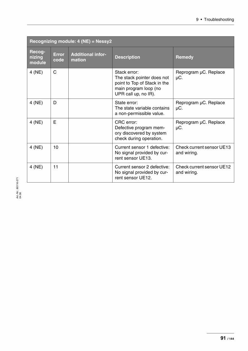
9 • TroubleshootingA
rt.-
Nr.
: 801
16-2
71
04.0
6
4 (NE) C Stack error: The stack pointer does not point to Top of Stack in the main program loop (no UPR call up, no IR).
Reprogram µC. Replace µC.
4 (NE) D State error: The state variable contains a non-permissible value.
Reprogram µC. Replace µC.
4 (NE) E CRC error: Defective program mem-ory discovered by system check during operation.
Reprogram µC. Replace µC.
4 (NE) 10 Current sensor 1 defective: No signal provided by cur-rent sensor UE13.
Check current sensor UE13 and wiring.
4 (NE) 11 Current sensor 2 defective: No signal provided by cur-rent sensor UE12.
Check current sensor UE12 and wiring.
Recognizing module: 4 (NE) = Nessy2
Recog- nizing module
Error code
Additional infor-mation Description Remedy
91 / 144

9 • Troubleshooting
Art
.-N
r.: 8
0116
-271
04
.06
9-Errors
Recognizing module: 9 = ERBE Irrigation Pump EIP 2
Recog-nizing module
Error code
Additional information Description Remedy
9 80 CRC Error. CRC error: Occurs if the EIP 2 CRC monitoring procedure per-formed at unit startup dis-covers an error (e.g. turnover of a bit in the flash memory or error during software download).
Reprogram the EIP 2 main board or replace the main board.
9 82 Pump lid open at ON.
User error: The pump lid of the EIP 2 is not closed at the start of activation or is opened dur-ing activation.
Close the pump lid before activation or do not open it during activation.
Unit error: The Hall sensor circuit board is not connected to the main board or the Hall sensor circuit board is faulty.
Check jumper J35 between the Hall sensor circuit board and the main board or replace the Hall sensor circuit board.
9 84 Time Out Error. User error: Activation of the EIP 2 was maintained for more than 20 seconds. Maximum acti-vation time for the EIP 2 is 20 seconds.
Discontinue activation. Then the EIP 2 can be reactivated.
9 88 UeWS Error. The motor control monitor-ing circuit is faulty.
Replace EIP 2 main board.
9 90 No current or no load.
During activation there is no measurable current input to the motor.
Check jumper J10 between EIP 2 main board and motor or replace the EIP 2 main board and/or motor.
9 A0 Current too high at ON.
The current input to the motor is too high. The motor or pump head is jammed or faulty.
Check the motor and pump head. If necessary, replace the motor and/or pump head.
9 C0 Motor control faulty (voltage too high at ON).
The measured voltage is too high. The motor control is faulty.
Replace EIP 2 main board.
92 / 144

9 • TroubleshootingA
rt.-
Nr.
: 801
16-2
71
04.0
6
Testing and measuring equipment
IMPORTANT! The following list contains the testing and measuring equipment recommended by ERBE for servicing. Where ERBE article num-bers are specified, only original ERBE testing and measuring equipment should be used.
ERBEArt. No
Description
– PC/laptop WIN 98 or higher
– Oscilloscope, 100 MHz or higher (recommended: Tektronix TDS 1012)
– Safety tester (with insulation testing >500 V DC)
– HF power meter (recommended: Metron QA-ES)
– High Voltage Differential Probe (recommended: TESTTEC TT-SI 9010, Tektronix P5210 oder Sapphire SI-9010)
29140-211 VIO HF Adjustment Tool (software, only for internal use by ERBE)
20140-002 VIO Support Hardware (software, only for internal use by ERBE)
20188-100 Single-pedal footswitch
20189-101 Dual-pedal footswith with ReMode
20190-115 VIO ReMode Electrode handle (only if there is an MF receptacle)
20190-045 Electrode handle ICC/ACC
20192-127 Patient cable AE
20192-110 Patient cable AE, international
20196-045 Bipolar cable
20196-053 Bipolar cable, international
20100-034 Adapter cable bipolar
20194-070 Patient cable NE
20194-075 Patient cable NE, international
20100-033 Adapter cable NE
20100-035 Cable LF – leakage current
20100-038 Cable LF – leakage current, international
20100-152 BiClamp measuring cable (only if there is an MF receptacle)
20100-174 Test cable for bipolar resection (only if there is an MF receptacle)
20100-101 VIO Testbox Symmetry/Resistance (NE assymmetry/critical resistance)
20100-102 VIO Testbox Auto Start/Auto Stop (bipolar start/stop)
93 / 144
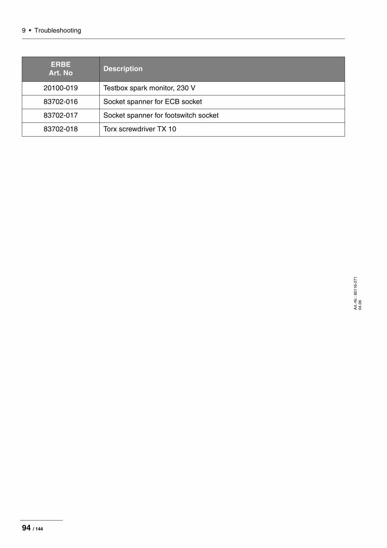
9 • Troubleshooting
Art
.-N
r.: 8
0116
-271
04
.06
20100-019 Testbox spark monitor, 230 V
83702-016 Socket spanner for ECB socket
83702-017 Socket spanner for footswitch socket
83702-018 Torx screwdriver TX 10
ERBEArt. No Description
94 / 144

10 • Maintenance and servicingA
rt.-
Nr.
: 801
16-2
71
04.0
6
CHAPTER 10
Maintenance and servicing
Who is allowed to perform servicing and main-tenance work?
What is a safety check?
How often does a safety check have to be per-formed?
ATTENTION! Adjustments, tests, modifications, maintenance and repair work may only be performed by ERBE or persons trained by ERBE. If the work is not performed by trained persons, ERBE accepts no liability and warranty rights become void.
It is recommended that the safety check also be performed by ERBE or persons trained by ERBE.
IMPORTANT! The safety check is a preventive measure to examine whether the device is safe and ready for operation. In order to perform the vari-ous tests the current specifications and regulations of the particu-lar country and the instructions in this service manual must be observed.
IMPORTANT! ERBE recommends performing a safety check after every repair, but at least once a year.
95 / 144
10 • Maintenance and servicing
Art
.-N
r.: 8
0116
-271
04
.06
Safety check – step by stepFor simplification the device to be tested is referred to below as the "test specimen".
Safety information
WARNING! For safety reasons (personnel protection) the test specimen should generally be operated by a suitable isolating transformer. An exceptional case is the tests for grounded conductor resis-tance, ground leakage current, and patient leakage current, in which the test specimen is supplied with current via the safety tester.
ATTENTION! In the event of a fault occurring in the test specimen or individual components during the safety check the test steps taken so far no longer apply. Remedy the defect and repeat the safety check from the beginning.
IMPORTANT! It is assumed that the user knows how to operate the test speci-men, the test equipment, the measuring equipment, and auxiliary test equipment. The test instructions only apply in conjunction with the relevant test steps.
IMPORTANT! Test equipment, measuring equipment, and auxiliary test equip-ment (cables, test boxes, etc.) are listed separately at the begin-ning of each test unit. Where ERBE article numbers are specified, only original ERBE test equipment, measuring equipment, and auxiliary test equipment may be used.
IMPORTANT! The test report for the safety check can be requested from ERBE Technical Service Tübingen. For the address see address sheet on last page.
96 / 144

10 • Maintenance and servicingA
rt.-
Nr.
: 801
16-2
71
04.0
6
User manual and visual inspections• Test specimen and accessories (where enclosed) undamaged
externally.• User manual present.• All labels on the test specimen (conformity declaration mark, rat-
ing plate, and all wording) present and readily legible.
Tests to be conducted in accordance with the national specifications and regulations
Grounded conductor test • Ground terminal to chassis.• Ground terminal to potential equalization pin.
Leakage current measurement
• Ground leakage current, normal condition (N.C.).• Ground leakage current, single-fault condition (S.F.C.).
IMPORTANT! For the following tests close the output relays of the unit with the “TP relay” test program.
• Patient leakage current, normal condition (N.C.).• Patient leakage current, single-fault condition (S.F.C.).
DC resistance
Testing and measuring equipment
ERBE Art. No. Description
20192-127
20192-110
Patient cable AE or Patient cable AE, international
20190-045 Electrode handle ICC/ACC
20194-070
20194-075
Patient cable NE or Patient cable NE, international
20100-033 Adapter cable NE
– Safety tester (with insulation testing >500 V DC)
97 / 144

10 • Maintenance and servicing
Art
.-N
r.: 8
0116
-271
04
.06
Test set-up
Fig. 10-1
• The test specimen is connected to the power supply via the power cord.
• The NE receptacle of the test specimen is connected to the safety tester via the patient cable with NE with the adapter cord.
• The AE receptacle of the test specimen is connected to the safety tester via the patient cable with AE and electrode handle with the laboratory cable.
Test procedure
1. Start safety tester in the "Insulation resistance" function The measured value displayed should be >200 MOhm.
2. Start test specimen and select the test progam "TP relay".3. In the test program "TP relay" use "All switch on" or "All" to switch
through all the output relays on the test specimen. When doing so the measured value displayed on the safety tester must drop significantly from >200 MOhm.
4. Determine insulation resistance using the safety tester. The measured value must be >2 MOhm.
5. Document the measured value.
WARNING! Across the measuring lines there is the DC voltage of 500 V! In order to avoid injuries, only switch on the test specimen and safety tester when all the electrical connections have been made.
ERBE
98 / 144

10 • Maintenance and servicingA
rt.-
Nr.
: 801
16-2
71
04.0
6
Performance tests
Testing and measuring equipment
Test set-up
• The test specimen is connected to the power supply via the power cord.
• The dual-pedal footswitch with ReMode is connected.• The NE patient cable with the shorted adapter cable is connected
to the NE receptacle on the test specimen.
Test procedure
Power switch 1. Check power switch for smooth operation. The power switch must be easy to operate and must neither stick nor scrape.
2. Press power switch. The power switch must snap into the "ON" position and the test specimen must perform a system start.
Start routine / acknowledgement tone
1. The test specimen must perform the system start without error message(s).
2. The test specimen must emit an acoustic signal (acknowledge-ment tone) during the self-test.
Control buttons / acknowl-edgement tone when
pressed
1. Check all the selection buttons on the glass control panel to make sure they operate properly. Press each button at least twice. There must be an acoustic signal (acknowledgement tone) every time a button is pressed.
Pushbuttons / acknowledge-ment tone when pressed
1. Check all the pushbuttons (focus buttons, up and down buttons, enter button) on the test specimen to make sure they are opera-ting properly. Press each button at least twice. There must be an acoustic signal (acknowledgement tone) every time a button is pressed.
Software download 1. Document whether a software update was performed.
Neutral electrode setting 1. In SET-UP level 2 obtain and document the current setting of the neutral electrode.
Date and time 1. In SET-UP level 2 check date and time and correct if necessary.
ERBE Art. No. Description
20189-101 Dual-pedal footswitch with ReMode
20194-070
20194-075
Patient cable NE or Patient cable NE, international
20100-033 Adapter cable NE
99 / 144

10 • Maintenance and servicing
Art
.-N
r.: 8
0116
-271
04
.06
Display / LEDs Display:
1. Check the backlighting of the display to make sure it is operating properly. If backlighting is faulty, no image will be visible.
LEDs:
1. At system all the LEDs must light up green briefly with equal brightness. In the case of the neutral electrode receptacle red and green must light up together briefly, creating orange.
Activation tones 1. Press CUT pedal on the dual-pedal footswitch at least twice. When pressing the pedal there must be an acoustic signal every time (= acknowledgement tone).
2. Press COAG pedal on the dual-pedal footswitch at least twice. When pressing the pedal there must be an acoustic signal every time (= acknowledgement tone).
100 / 144

10 • Maintenance and servicingA
rt.-
Nr.
: 801
16-2
71
04.0
6
Footswitch activation
Testing and measuring equipment
Test set-up
Fig. 10-2
• The test specimen is connected to the power supply via the power cord.
• The test program "TP activation signal" is selected.• The single-pedal footswitch is connected.• The dual-pedal footswitch with ReMode is connected.
Test procedure
Single-pedal footswitch activation COAG
1. Press COAG pedal on the single-pedal footswitch. The test pro-gram must confirm activation by lighting up the "Single-pedal" icon in color.
Dual-pedal footswitch activation CUT / COAG
1. Press CUT pedal on the dual-pedal footswitch. The test program must confirm activation lighting up the relevant field in color (yel-low) in the "MF" icon.
2. Press COAG pedal on the dual-pedal footswitch. The test pro-gram must confirm activation by lighting up the relevant field in color (blue) in the "MF" icon.
ERBE Art. No. Description
20188-100 Single-pedal footswitch
20189-101 Dual-pedal footswitch with ReMode
101 / 144
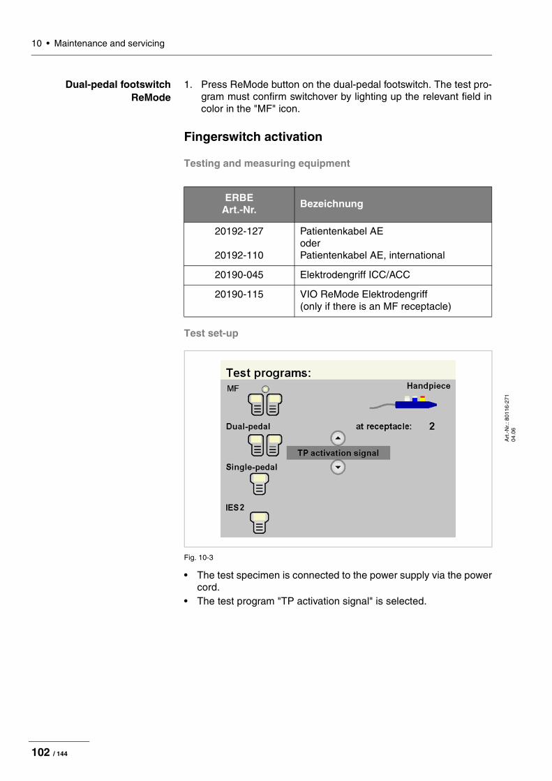
10 • Maintenance and servicing
Art
.-N
r.: 8
0116
-271
04
.06
Dual-pedal footswitch ReMode
1. Press ReMode button on the dual-pedal footswitch. The test pro-gram must confirm switchover by lighting up the relevant field in color in the "MF" icon.
Fingerswitch activation
Testing and measuring equipment
Test set-up
Fig. 10-3
• The test specimen is connected to the power supply via the power cord.
• The test program "TP activation signal" is selected.
ERBE Art.-Nr. Bezeichnung
20192-127
20192-110
Patientenkabel AE oder Patientenkabel AE, international
20190-045 Elektrodengriff ICC/ACC
20190-115 VIO ReMode Elektrodengriff (only if there is an MF receptacle)
102 / 144
10 • Maintenance and servicingA
rt.-
Nr.
: 801
16-2
71
04.0
6
Test procedure
20190-045 Activation CUT / COAG
1. Connect the electrode handle with patient cable AE to the Mono-polar receptacle of the test specimen.
2. Press CUT button on the electrode handle. The test program must confirm activation by lighting up the relevant field in color in the "Handpiece" icon.
3. Press COAG button on the electrode handle. The test program must confirm activation by lighting up the relevant field in color in the "Handpiece" icon.
4. Remove the electrode handle.
20190-115 Activation CUT / COAG
(only if there is an MF receptacle)
1. Connect the VIO ReMode electrode handle to the MF receptacle of the test specimen.
2. Press CUT button on the VIO ReMode electrode handle. The test program must confirm activation by lighting up the relevant field in color in the "Handpiece" icon.
3. Press COAG button on the VIO ReMode electrode handle. The test program must confirm activation by lighting up the relevant field in color in the "Handpiece" icon.
20190-115 ReMode
(only if there is an MF receptacle)
1. Press ReMode button on the electrode handle. The test program must confirm switchover by lighting up the relevant field in color in the "Handpiece" icon.
2. Remove the VIO ReMode electrode handle.
Instrument recognition MF receptacle
Testing and measuring equipment
Instrument recognition via resistance
Currently not available.
Instrument recognition via EEPROM
Test set-up
• The test specimen is connected to the power supply via the power cord.
Test procedure
1. Connect BiClamp measuring cable to the MF receptacle of the test specimen. The test specimen must indicate instrument recognition with a message. The setting for COAG mode must change to BiClamp.
ERBE Art. No. Description
20100-152 BiClamp measuring cable
103 / 144

10 • Maintenance and servicing
Art
.-N
r.: 8
0116
-271
04
.06
Automatic start mode
Testing and measuring equipment
Test set-up
Fig. 10-4
• The test specimen is connected to the power supply via the power cord.
• The Bipolar receptacle of the test specimen is connected to the VIO Testbox via the bipolar cable with the adapter cable.
Test procedure
Up to V 1.2.x
1st test step 1. In the SET-UP of the test specimen establish the set start delay for the setting AUTO START 1. Record the value.
2. Set test specimen to: BIPOLAR SOFT, Effect 1, 50 watts AUTO START 1
3. On the VIO Testbox press button T1. The test specimen must start activation after the set start delay.
4. Press button T2. The test specimen must terminate activation.
ERBE Art. No. Description
20196-045
20196-053
Bipolar cable or Bipolar cable, international
20100-034 Adapter cable bipolar
20100-102 VIO Testbox Auto Start/Auto Stop (bipolar start/stop)
ERBE
Testbox 20100-102
2
X X
X X
1BP1 BP2
T1 T2
104 / 144

10 • Maintenance and servicingA
rt.-
Nr.
: 801
16-2
71
04.0
6
2nd test step 1. Set test specimen to: BIPOLAR SOFT, Effect 8, 50 watts AUTO START 1
2. On the VIO Testbox press button T1. The test specimen must start activation after the set start delay.
3. Press button T2. The test specimen must terminate activation.
As from V 1.3.x
1st test step 1. In the SET-UP of the test specimen establish the set start delay for the setting AUTO START 1. Record the value.
2. Set test specimen to: BIPOLAR SOFT, Effect 1, 50 watts AUTO START 1
3. On the VIO Testbox keep button T1 pressed. The test specimen must start activation after the set start delay.
4. Press button T2. The test specimen must terminate activation.
2nd test step 1. Set test specimen to: BIPOLAR SOFT, Effect 8, 50 watts AUTO START 1
2. On the VIO Testbox keep button T1 pressed. The test specimen must start activation after the set start delay.
3. Press button T2. The test specimen must terminate activation.
105 / 144

10 • Maintenance and servicing
Art
.-N
r.: 8
0116
-271
04
.06
Automatic stop mode
Testing and measuring equipment
Test set-up
Fig. 10-5
• The test specimen is connected to the power supply via the power cord.
• The Bipolar receptacle of the test specimen is connected to the VIO Testbox via the bipolar cable with the adapter cable.
• The single-pedal footswitch is connected.
Test procedure
1. Set test specimen to: BIPOLAR SOFT with AutoStop, Effect 4, 50 W
2. On the VIO Testbox hold down button T3.3. Activate BIPOLAR SOFT with the footswitch, keeping the pedal
pressed.4. Hold down button T3 for approx. 5 s, then let go. Within another
9 s at the latest the test specimen must terminate activation and emit two brief signal tones.
ERBE Art. No. Description
20196-045
20196-053
Bipolar cable or Bipolar cable, international
20100-034 Adapter cable bipolar
20100-102 VIO Testbox Auto Start/Auto Stop (bipolar start/stop)
20188-100 Single-pedal footswitch
ERBE
Testbox 20100-102
X X
X1
BP3 BP4
T3
43
106 / 144

10 • Maintenance and servicingA
rt.-
Nr.
: 801
16-2
71
04.0
6
Spark monitor
Testing and measuring equipment
Test set-up
The test set-up depends on the respective receptacle configuration of the test specimen so it may vary. This test set-up assumes a recep-tacle configuration of Bipolar receptacle, Monopolar receptacle, Mo-nopolar receptacle, NE receptacle. Measurement is conducted at the 2nd Monopolar receptacle.
Fig. 10-6
ERBE Art. No. Description
20192-127
20192-110
Patient cable AE or Patient cable AE, international
20190-045 Electrode handle ICC/ACC
20194-070
20194-075
Patient cable NE or Patient cable NE, international
20100-033 Adapter cable NE
20100-019 Testbox spark monitor, 230 V
ERBE
AE
NE
Testbox
20100-019
+ -
Power S1 DC 70 V
107 / 144

10 • Maintenance and servicing
Art
.-N
r.: 8
0116
-271
04
.06
Fig. 10-7
• The test specimen is connected to the power supply via the power cord.
• The test specimen is connected to the testbox.• On the test specimen the test program "TP generator" is selected.
In the test program the output receptacle at which measurement takes place is selected (in this case "Output receptacle: 2 MONOPOLAR").
Test procedure
1. On the Testbox press button S1.2. In the test program read off the measured value for "Spark". The
tolerance range is 245 to 285 ERBE.
108 / 144

10 • Maintenance and servicingA
rt.-
Nr.
: 801
16-2
71
04.0
6
HF power output CUT
Testing and measuring equipment
AUTO CUT DRY CUT
Test set-up
Fig. 10-8
• The test specimen is connected to the power supply via the power cord.
• The levels of power are determined with the HF power meter. The measuring cables are plugged into the HF power meter direct.
ERBE Art. No. Description
20192-127
20192-110
Patient cable AE or Patient cable AE, international
20190-045 Elektrode handle ICC/ACC
20194-070
20194-075
Patient cable NE or Patient cable NE, international
20100-033 Adapter cable NE
20196-045
20196-053
Bipolar cable or Bipolar cable, international
20100-034 Adapter cable bipolar
20100-174 Test cable for bipolar resection (only if there is an MF receptacle)
– HF power meter
20189-101 Dual-pedal footswitch with ReMode
ERBE
AE
NE
HF power meter
109 / 144

10 • Maintenance and servicing
Art
.-N
r.: 8
0116
-271
04
.06
Test procedure
1. Set test specimen to: AUTO CUT, Effect 8, 300 watts
2. Set HF power meter to: RL = 500 ohms
3. Activate test specimen via CUT button on the electrode handle.4. Determine and document measured value. The tolerance range
is 240 to 360 watts.
Only relevant with VIO 300 D
1. Set test specimen to: DRY CUT1, Effect 8, 200 watts
2. Set HF power meter tof: RL = 500 ohms
3. Activate test specimen via CUT button on the electrode handle.4. Determine and document measured value. The tolerance range
is 160 to 240 watts.
BIPOLAR CUT Test set-up of the bipolar receptacle
Fig. 10-9
• The test specimen is connected to the power supply via the power cord.
• The levels of power are determined with the HF power meter. The measuring cables are plugged into the HF power meter direct.
• The dual-pedal footswitch with ReMode is connected.
1. The DRY CUT is only standard scope of supply with VIO 300 D electrosurgical units. With VIO 200 D electrosurgical units it can be purchased and installed as an upgrade. For details of how to test DRY CUT with VIO 200 D electrosurgical units see chapter "Performance test upgrades".
ERBE
HF power meter
Bipolar
110 / 144

10 • Maintenance and servicingA
rt.-
Nr.
: 801
16-2
71
04.0
6
Test procedure
1. Set test specimen to: BIPOLAR CUT, Effect 8, 100 watts
2. Set HF power meter to: RL = 500 ohms
3. Activate test specimen via CUT pedal on the footswitch.4. Determine and document measured value. The tolerance range
is 80 to 120 watts.
BIPOLAR CUT+ (only if there is an
MF receptacle)
Test set-up of the multifunctional receptacle
Fig. 10-10
• The test specimen is connected to the power supply via the power cord.
• The levels of power are determined with the HF power meter. The measuring cables are plugged into the HF power meter direct.
• The dual-pedal footswitch with ReMode is connected.
Test procedure
1. Set test specimen to: BIPOLAR CUT+, Effect 8
2. Set HF power meter to: RL = 500 ohms
3. Activate test specimen via CUT pedal on the footswitch.4. Determine and document measured value. The tolerance range
is 296 to 400 watts.
ERBE
HF power meter
Bipolar
111 / 144

10 • Maintenance and servicing
Art
.-N
r.: 8
0116
-271
04
.06
HF power output COAGULATE
Testing and measuring equipment
BIPOLAR FORCED COAG Test set-up
Fig. 10-11
• The test specimen is connected to the power supply via the power cord.
• The levels of power are determined with the HF power meter. The measuring cables are plugged into the HF power meter direct.
• The dual-pedal footswitch with ReMode is connected.
ERBE Art. No. Description
20192-127
20192-110
Patient cable AE or Patient cable AE, international
20190-045 Electrode handle ICC/ACC
20194-070
20194-075
Patient cable NE or Patient cable NE, international
20100-033 Adapter cable NE
20196-045
20196-053
Bipolar cable or Bipolar cable, international
20100-034 Adapter cable bipolar
– HF power meter
20189-101 Dual-pedal footswitch with ReMode
ERBE
HF-Leistungsmessgerät
Bipolar
112 / 144
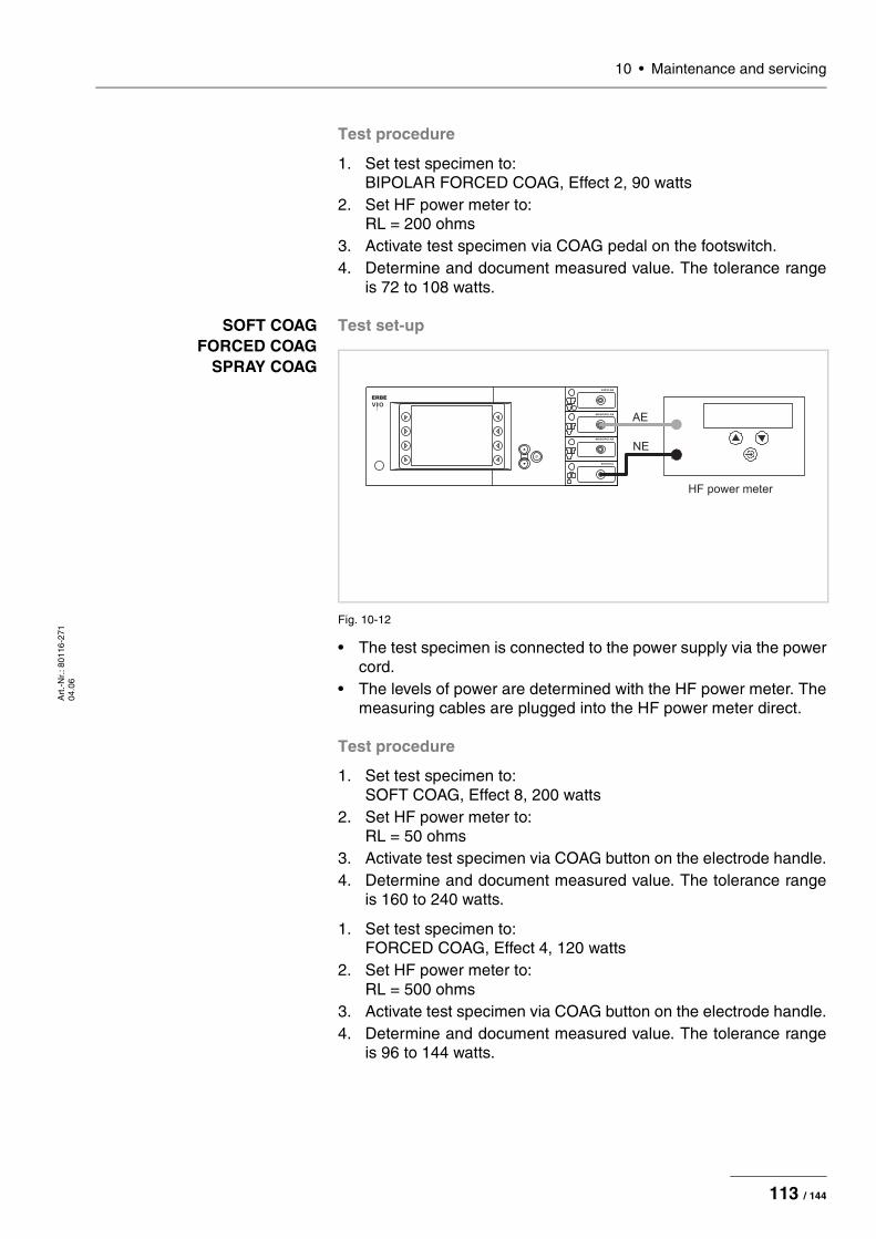
10 • Maintenance and servicingA
rt.-
Nr.
: 801
16-2
71
04.0
6
Test procedure
1. Set test specimen to: BIPOLAR FORCED COAG, Effect 2, 90 watts
2. Set HF power meter to: RL = 200 ohms
3. Activate test specimen via COAG pedal on the footswitch.4. Determine and document measured value. The tolerance range
is 72 to 108 watts.
SOFT COAG FORCED COAG
SPRAY COAG
Test set-up
Fig. 10-12
• The test specimen is connected to the power supply via the power cord.
• The levels of power are determined with the HF power meter. The measuring cables are plugged into the HF power meter direct.
Test procedure
1. Set test specimen to: SOFT COAG, Effect 8, 200 watts
2. Set HF power meter to: RL = 50 ohms
3. Activate test specimen via COAG button on the electrode handle.4. Determine and document measured value. The tolerance range
is 160 to 240 watts.
1. Set test specimen to: FORCED COAG, Effect 4, 120 watts
2. Set HF power meter to: RL = 500 ohms
3. Activate test specimen via COAG button on the electrode handle.4. Determine and document measured value. The tolerance range
is 96 to 144 watts.
ERBE
AE
NE
HF power meter
113 / 144

10 • Maintenance and servicing
Art
.-N
r.: 8
0116
-271
04
.06
Only relevant with VIO 300 D
1. Set test specimen to: SPRAY COAG, Effect 2, 120 watts
2. Set HF power meter to: RL = 500 ohms
3. Activate test specimen via COAG button on the electrode handle.4. Determine and document measured value. The tolerance range
is 96 to 144 watts.
Performance test upgrades
Testing and measuring equipment
ERBE Art. No. Description
20192-127
20192-110
Patient cable AE or Patient cable AE, international
20190-045 Elektrode handle ICC/ACC
20100-152 BiClamp measuring cable (only if there is an MF receptacle)
20194-070
20194-075
Patient cable NE or Patient cable NE, international
20100-033 Adapter cable NE
– HF power meter
– Oscilloscope
– Probe 100 :1
20189-101 Dual-pedal footswitch with ReMode
114 / 144

10 • Maintenance and servicingA
rt.-
Nr.
: 801
16-2
71
04.0
6
DRY CUT (only to be tested as an
upgrade with VIO 200 D)
Test set-up
Fig. 10-13
• The test specimen is connected to the power supply via the power cord.
• The levels of power are determined with the HF power meter. The measuring cables are plugged into the HF power meter direct.
Test procedure
1. Set test specimen to: DRY CUT, Effect 8, 200 watts
2. Set HF power meter to: RL = 500 ohms
3. Activate test specimen via CUT button on the electrode handle.4. Determine and document measured value. The tolerance range
is 160 to 240 watts.
BiClamp Short-circuit detection (only if there is an MF
receptacle)
Test set-up
• The test specimen is connected to the power supply via the power cord.
• The BiClamp measuring cable is connected to the MF receptacle of the test specimen, the cable end is shorted.
• The dual-pedal footswitch with ReMode is connected.
Test procedure
Up to V 1.3.x
1. Activate the BiClamp function with the footswitch. After approx. 3 to 4 seconds the test specimen must discontinue activation and emit a warning signal "C-84-2 short circuit".
As from V 1.4.x
1. Activate the BiClamp function with the footswitch. After approx. 8 seconds the test specimen must interrupt activation and emit a warning message "C-84-2 short circuit".
ERBE
AE
NE
HF power meter
115 / 144

10 • Maintenance and servicing
Art
.-N
r.: 8
0116
-271
04
.06
ENDO CUT I and Q Test set-up
Fig. 10-14
• The test setup is designed as shown in the illustration above.• The test specimen is connected to the power supply via the power
cord.• The levels of power are determined with the HF power meter. The
measuring cables are plugged into the HF power meter direct.
Test procedure
1. Set test specimen to: EndoCut I, Effect 1, Cutting duration 1, Cutting interval 1
2. Set HF power meter to: RL = 1000 ohms
3. Connect the probe of an oscilloscope to AE and NE.4. Set oscilloscope to:
200 V / Div, 20 ms5. Activate test specimen via the CUT button on the electrode
handle.6. Determine the duration of the cutting pulse. The tolerance range
is 90 to 110 ms.
ATTENTION! When connecting the probe to the input of the HF power meter, make absolutely sure that minus is connected to the patient plate.
IMPORTANT! For these tests in SET-UP level 2 set the Expert mode to "ON".
ERBE
AE
NE
HF power meter
High Voltage
Differential probe
Oscilloscope
116 / 144
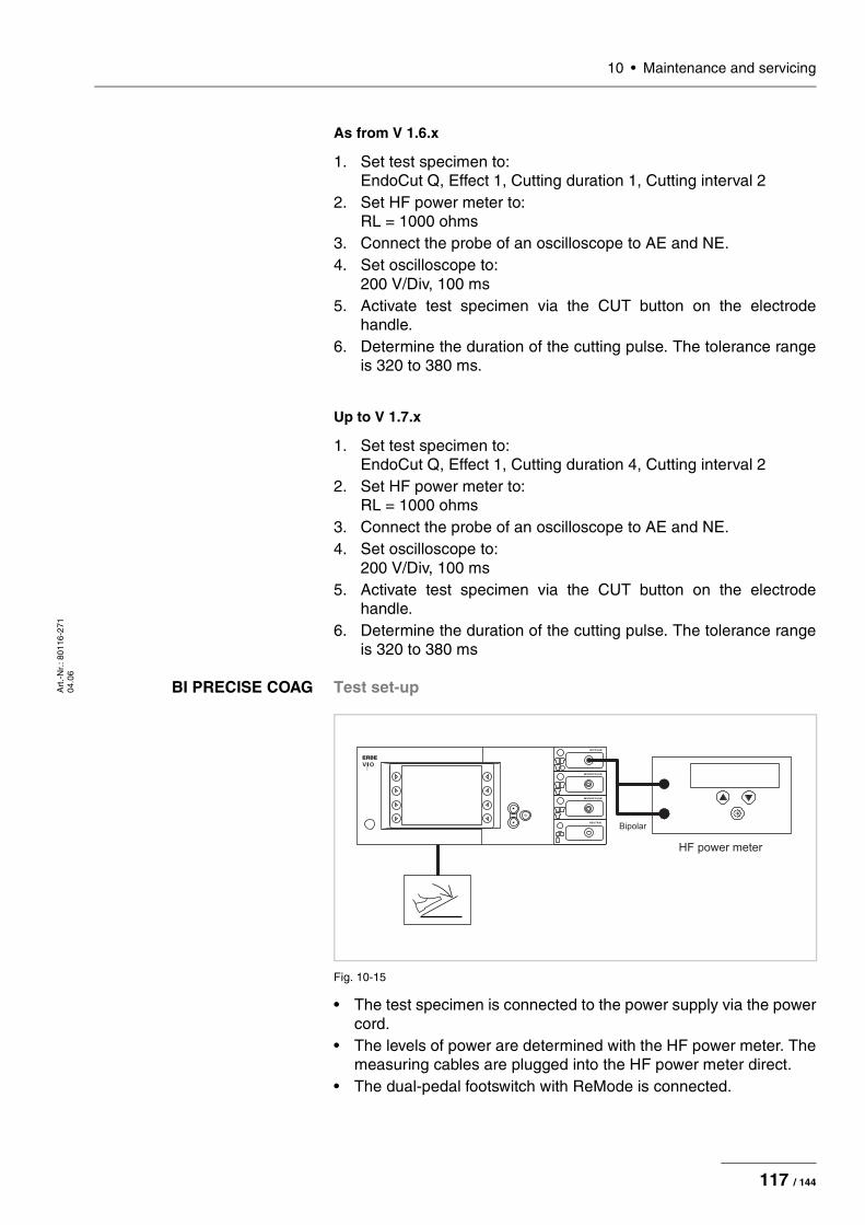
10 • Maintenance and servicingA
rt.-
Nr.
: 801
16-2
71
04.0
6
As from V 1.6.x
1. Set test specimen to: EndoCut Q, Effect 1, Cutting duration 1, Cutting interval 2
2. Set HF power meter to: RL = 1000 ohms
3. Connect the probe of an oscilloscope to AE and NE.4. Set oscilloscope to:
200 V/Div, 100 ms5. Activate test specimen via the CUT button on the electrode
handle.6. Determine the duration of the cutting pulse. The tolerance range
is 320 to 380 ms.
Up to V 1.7.x
1. Set test specimen to: EndoCut Q, Effect 1, Cutting duration 4, Cutting interval 2
2. Set HF power meter to: RL = 1000 ohms
3. Connect the probe of an oscilloscope to AE and NE.4. Set oscilloscope to:
200 V/Div, 100 ms5. Activate test specimen via the CUT button on the electrode
handle.6. Determine the duration of the cutting pulse. The tolerance range
is 320 to 380 ms
BI PRECISE COAG Test set-up
Fig. 10-15
• The test specimen is connected to the power supply via the power cord.
• The levels of power are determined with the HF power meter. The measuring cables are plugged into the HF power meter direct.
• The dual-pedal footswitch with ReMode is connected.
ERBE
HF power meter
Bipolar
117 / 144
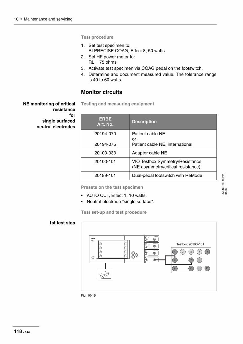
10 • Maintenance and servicing
Art
.-N
r.: 8
0116
-271
04
.06
Test procedure
1. Set test specimen to: BI PRECISE COAG, Effect 8, 50 watts
2. Set HF power meter to: RL = 75 ohms
3. Activate test specimen via COAG pedal on the footswitch.4. Determine and document measured value. The tolerance range
is 40 to 60 watts.
Monitor circuits
NE monitoring of critical resistance
for single surfaced
neutral electrodes
Testing and measuring equipment
Presets on the test specimen
• AUTO CUT, Effect 1, 10 watts.• Neutral electrode "single surface".
Test set-up and test procedure
1st test step
Fig. 10-16
ERBE Art. No. Description
20194-070
20194-075
Patient cable NE or Patient cable NE, international
20100-033 Adapter cable NE
20100-101 VIO Testbox Symmetry/Resistance (NE asymmetry/critical resistance)
20189-101 Dual-pedal footswitch with ReMode
ERBE
Testbox 20100-101
1 2
9
4 53
10
6
11 12
7 8
118 / 144

10 • Maintenance and servicingA
rt.-
Nr.
: 801
16-2
71
04.0
6
• The test specimen is connected to the power supply via the power cord.
• The test is performed without a load.• The NE receptacle of the test specimen is connected to the VIO
Testbox via the patient cable NE with the adapter cable. • The dual-pedal footswitch with ReMode is connected.
1. On the test specimen the (single surfaced) neutral electrode lamp must light up red.
2. Activate AUTO CUT via the footswitch. The test specimen must inhibit activation and emit or display an optical and acoustic war-ning.
2nd test step
Fig. 10-17
• The test specimen is connected to the power supply via the power cord.
• The test is performed without a load.• The NE receptacle of the test specimen is connected to the VIO
Testbox via the patient cable NE with the adapter cable. • The dual-pedal footswitch with ReMode is connected.
1. On the test specimen the (single surfaced) neutral electrode lamp must light up green.
2. Activate AUTO CUT via the footswitch. It must be possible to activate the test specimen without error or warning signals.
ERBE
Testbox 20100-101
1 2
9
4 53
10
6
11 12
7 8
119 / 144

10 • Maintenance and servicing
Art
.-N
r.: 8
0116
-271
04
.06
NE monitoring of critical resistance
for dual surfaced
neutral electrodes
Testing and measuring equipment
Presets on the test specimen
• AUTO CUT, Effect 1, 10 watts.• Neutral electrode "dual surface".
Test set-up and test procedure
1st test step
Fig. 10-18
• The test specimen is connected to the power supply via the power cord.
• The test is performed without a load.• The NE receptacle of the test specimen is connected to the VIO
Testbox via the patient cable NE with the adapter cable. • The dual-pedal footswitch with ReMode is connected.
1. On the test specimen the (dual surfaced) neutral electrode lamp must light up red.
2. Activate AUTO CUT via the footswitch. The test specimen must inhibit activation and display or emit an optical and acoustic war-ning.
ERBE Art. No.
Description
20194-070
20194-075
Patient cable NE or Patient cable NE, international
20100-033 Adapter cable NE
20100-101 VIO Testbox Symmetry/Resistance (NE asymmetry/critical resistance)
20189-101 Dual-pedal footswitch with ReMode
ERBE
Testbox 20100-101
1 2
9
4 53
10
6
11 12
7 8
120 / 144
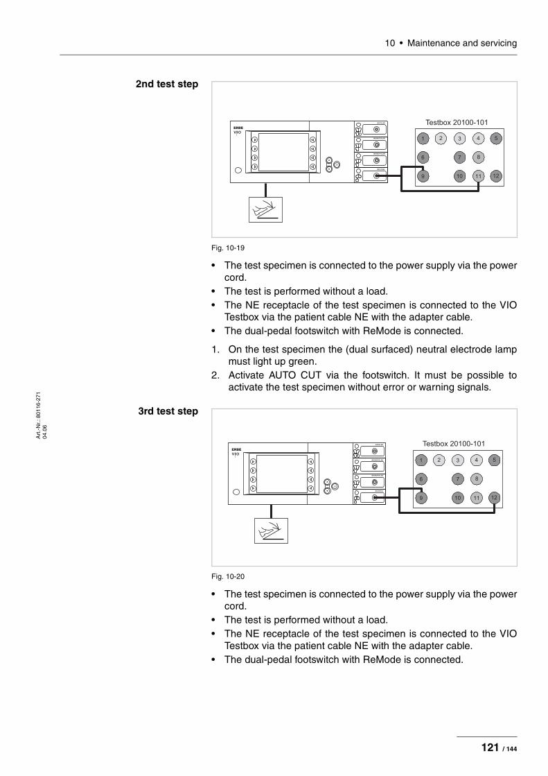
10 • Maintenance and servicingA
rt.-
Nr.
: 801
16-2
71
04.0
6
2nd test step
Fig. 10-19
• The test specimen is connected to the power supply via the power cord.
• The test is performed without a load.• The NE receptacle of the test specimen is connected to the VIO
Testbox via the patient cable NE with the adapter cable. • The dual-pedal footswitch with ReMode is connected.
1. On the test specimen the (dual surfaced) neutral electrode lamp must light up green.
2. Activate AUTO CUT via the footswitch. It must be possible to activate the test specimen without error or warning signals.
3rd test step
Fig. 10-20
• The test specimen is connected to the power supply via the power cord.
• The test is performed without a load.• The NE receptacle of the test specimen is connected to the VIO
Testbox via the patient cable NE with the adapter cable. • The dual-pedal footswitch with ReMode is connected.
ERBE
Testbox 20100-101
1 2
9
4 53
10
6
11 12
7 8
ERBE
Testbox 20100-101
1 2
9
4 53
10
6
11 12
7 8
121 / 144
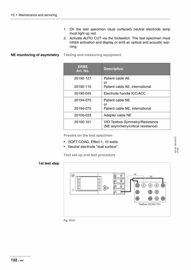
10 • Maintenance and servicing
Art
.-N
r.: 8
0116
-271
04
.06
1. On the test specimen (dual surfaced) neutral electrode lamp must light up red.
2. Activate AUTO CUT via the footswitch. The test specimen must inhibit activation and display or emit an optical and acoustic war-ning.
NE monitoring of asymmetry Testing and measuring equipment
Presets on the test specimen
• SOFT COAG, Effect 1, 10 watts.• Neutral electrode "dual surface".
Test set-up and test procedure
1st test step
Fig. 10-21
ERBE Art. No. Description
20192-127
20192-110
Patient cable AE or Patient cable AE, international
20190-045 Electrode handle ICC/ACC
20194-070
20194-075
Patient cable NE or Patient cable NE, international
20100-033 Adapter cable NE
20100-101 VIO Testbox Symmetry/Resistance (NE asymmetry/critical resistance)
ERBE
Testbox 20100-101
1 2
9
4 53
10
6
11 12
7 8
AENE
122 / 144

10 • Maintenance and servicingA
rt.-
Nr.
: 801
16-2
71
04.0
6
• The test specimen is connected to the power supply via the power cord.
• The NE receptacle of the test specimen is connected to the VIO Testbox via the patient cable NE with the adapter cable.
• The AE receptacle of the test specimen is connected to the VIO Testbox (AE receptacle) via the patient cable AE and the elec-trode handle with the laboratory cable.
1. Activate test specimen via CUT button on the electrode handle for approx. 10 seconds. During the entire activation time there must be no warning signal.
2nd test step
Fig. 10-22
• The test specimen is connected to the power supply via the power cord.
• The NE receptacle of the test specimen is connected to the VIO Testbox via the patient cable NE with the adapter cable.
• The AE receptacle of the test specimen is connected to the VIO Testbox (AE receptacle) via the patient cable AE and the elec-trode handle with the laboratory cable.
1. Activate test specimen via CUT button on the electrode handle for approx. 10 seconds. There must be an optical warning signal 2 seconds after activation at the latest. The test specimen must not interrupt activation.
ERBE
Testbox 20100-101
1 2
9
4 53
10
6
11 12
7 8
AE
NE
123 / 144

10 • Maintenance and servicing
Art
.-N
r.: 8
0116
-271
04
.06
3rd test step
Fig. 10-23
• The test specimen is connected to the power supply via the power cord.
• The NE receptacle of the test specimen is connected to the VIO Testbox via the patient cable NE with the adapter cable.
• The AE receptacle of the test specimen is connected to the VIO Testbox (AE receptacle) via the patient cable AE and the elec-trode handle with the laboratory cable.
1. Activate the test specimen with the CUT button on the electrode handle for approx. 10 seconds. Within 2 seconds after activation at the latest an optical warning must be emitted and within ano-ther 2 seconds an acoustic warning must be emitted. The test specimen must interrupt activation.
ERBE
Testbox 20100-101
1 2
9
4 53
10
6
11 12
7 8
AE
NE
124 / 144
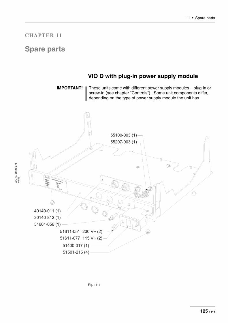
11 • Spare partsA
rt.-
Nr.
: 801
16-2
71
04.0
6
CHAPTER 11
Spare parts
VIO D with plug-in power supply module
Fig. 11-1
IMPORTANT! These units come with different power supply modules – plug-in or screw-in (see chapter "Controls"). Some unit components differ, depending on the type of power supply module the unit has.
51400-017 (1)
51501-215 (4)
51611-051 230 V~ (2)
51611-077 115 V~ (2)
51601-056 (1)
40140-011 (1)
30140-812 (1)
55207-003 (1)
55100-003 (1)
125 / 144

11 • Spare parts
Art
.-N
r.: 8
0116
-271
04
.06
Fig. 11-2
30140-808 (1)
55000-122 (3)
40140-018 (1)
126 / 144

11 • Spare partsA
rt.-
Nr.
: 801
16-2
71
04.0
6
Fig. 11-3
30140-811 (1)
50610-011 (1)
30140-712 (1)
40140-061 (1)
40140-099 (2)
40140-076 (8)
55000-116 (4)
40140-126 (1)
40140-070 (1)
55105-004 (3)
127 / 144
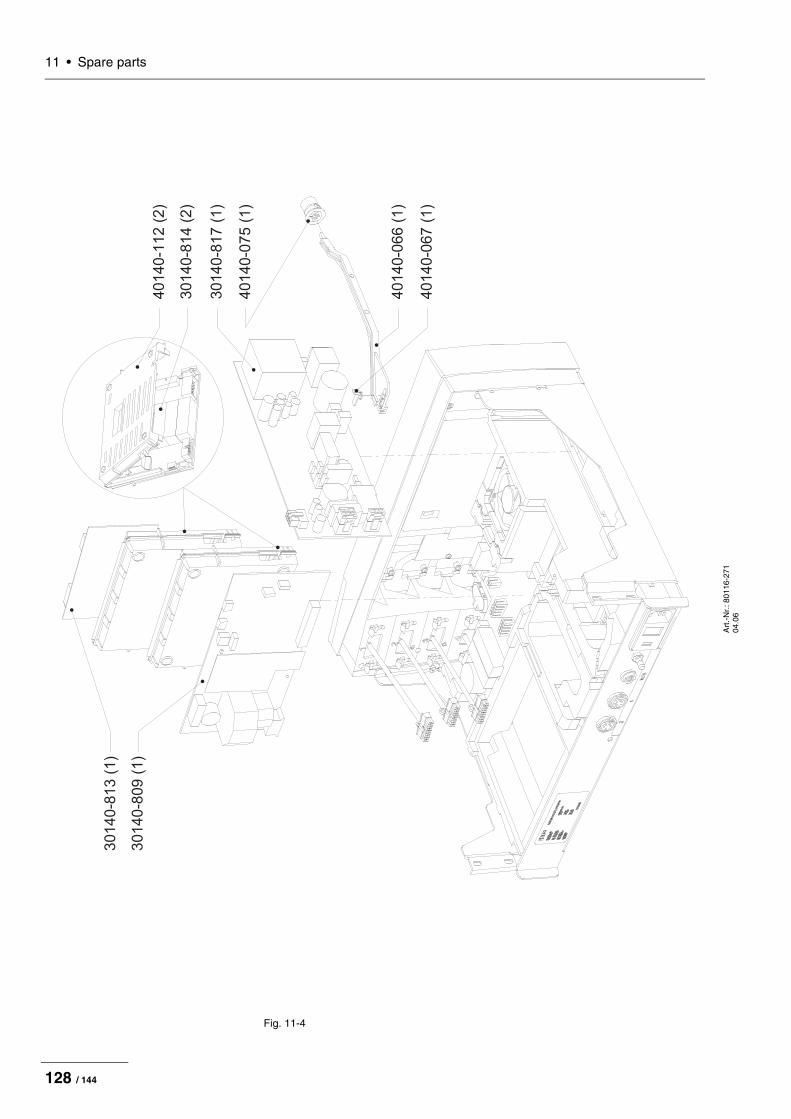
11 • Spare parts
Art
.-N
r.: 8
0116
-271
04
.06
Fig. 11-4
30140-813(1)
30140-809(1)
40140-112(2)
30140-814(2)
30140-817(1)
40140-075(1)
40140-066(1)
40140-067(1)
128 / 144
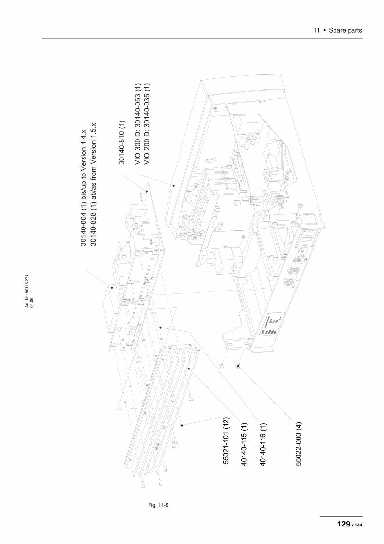
11 • Spare partsA
rt.-
Nr.
: 801
16-2
71
04.0
6
Fig. 11-5
30140-8
04 (
1)
bis
/up t
o V
ers
ion 1
.4.x
30140-8
10 (
1)
VIO
300 D
: 30140-0
53 (
1)
30140-8
28 (
1)
ab/a
s f
rom
Vers
ion 1
.5.x
4
0140-1
16
(1)
5
5022-0
00
(4)
4
0140-1
15
(1)
55021-1
01
(12)
VIO
200 D
: 30140-0
35 (
1)
129 / 144

11 • Spare parts
Art
.-N
r.: 8
0116
-271
04
.06
Fig. 11-6
40140-0
12
(1)
55000-1
16
(2)
40140-1
26
(1)
55022-0
00
(3)
130 / 144
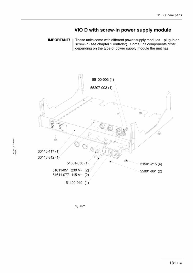
11 • Spare partsA
rt.-
Nr.
: 801
16-2
71
04.0
6
VIO D with screw-in power supply module
Fig. 11-7
IMPORTANT! These units come with different power supply modules – plug-in or screw-in (see chapter "Controls"). Some unit components differ, depending on the type of power supply module the unit has.
55207-003 (1)
55001-061 (2)
51501-215 (4)
51400-019 (1)
51611-077 115 V~ (2)
51611-051 230 V~ (2)
51601-056 (1)
30140-812 (1)
30140-117 (1)
55100-003 (1)
131 / 144

11 • Spare parts
Art
.-N
r.: 8
0116
-271
04
.06
Fig. 11-8
30140-808 (1)
55000-122 (3)
40140-018 (1)
132 / 144

11 • Spare partsA
rt.-
Nr.
: 801
16-2
71
04.0
6
Fig. 11-9
40140-099 (2)
40140-070 (1)
40140-061 (1)
55105-004 (3)
50610-011 (1)
55000-116 (4)
40140-076 (8)
40140-126 (1)
30140-712 (1)
30140-811 (1)
133 / 144
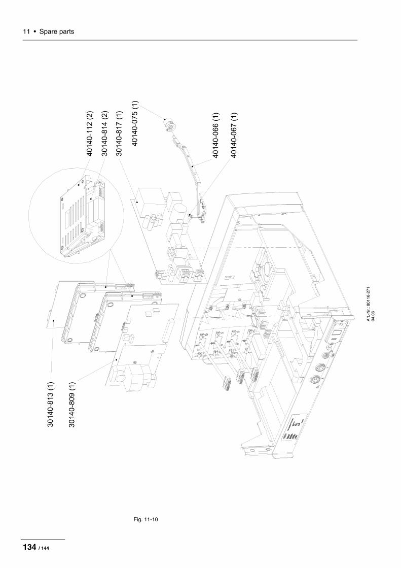
11 • Spare parts
Art
.-N
r.: 8
0116
-271
04
.06
Fig. 11-10
40140-1
12
(2)
30140-8
14
(2)
40140-0
75
(1)
30140-8
13
(1)
30140-8
09
(1)
40140-0
67
(1)
40140-0
66
(1)
30140-8
17
(1)
134 / 144

11 • Spare partsA
rt.-
Nr.
: 801
16-2
71
04.0
6
Fig. 11-11
VIO
30
0 D
: 3
01
40
-05
3 (
1)
30140-8
10
(1)
40140-1
16
(1)
55022-0
00
(4)
40140-1
15
(1)
55021-1
01
(12)
30140-8
04 (
1)
bis
/up t
o V
ers
ion 1
.4.x
30140-8
28 (
1)
ab/a
s f
rom
Vers
ion 1
.5.x
VIO
20
0 D
: 3
01
40
-03
5 (
1)
135 / 144

11 • Spare parts
Art
.-N
r.: 8
0116
-271
04
.06
Fig. 11-12
30140-1
18
(1)
55000-1
16
(2)
40140-1
26
(1)
55022-0
00
(3)
136 / 144

11 • Spare partsA
rt.-
Nr.
: 801
16-2
71
04.0
6
Wiring
Wiring for HF generator module 30140-804
Fig. 11-13
J20
J34
J21
J26
J21
J14
J23J11
J25
3
01
40
-70
6 (
1)
30
14
0-7
05
(1
)
30
14
0-7
04
(1
)
3
01
40
-71
7 (
1)
137 / 144

11 • Spare parts
Art
.-N
r.: 8
0116
-271
04
.06
Fig. 11-14
30140-7
10
(1)
51501-0
99
(2)
30140-7
11
(1)
30140-7
02
(1)
30140-7
01
(1)
30140-7
09
(1)
30140-7
07
(1)
J11
J25
J23
J1
4
J2
0
55100-0
01
(2)
55200-0
01
(2)
55207-0
00
(2)
55100-0
01
(1)
55207-0
00
(2)
55200-0
01
(1)
138 / 144

11 • Spare partsA
rt.-
Nr.
: 801
16-2
71
04.0
6
Wiring for HF generator module 30140-828
Fig. 11-15
J2
0
J3
4
J2
1
J2
6
J2
1
J1
4
J23J11
J25
30140-7
06 (
1)
3
0140-7
05 (
1)
30140-7
04 (
1)
30140-7
17 (
1)
139 / 144

11 • Spare parts
Art
.-N
r.: 8
0116
-271
04
.06
Fig. 11-16
30140-7
10
(1)
51501-0
99
(2)
30140-7
11
(1)
30140-7
02
(1)
30140-7
01
(1)
30140-7
09
(1)
30140-7
07
(1)
J11
J25
J23
J1
4
J2
0
55100-0
01
(2)
55200-0
01
(2)
55207-0
00
(2)
55100-0
01
(1)
55207-0
00
(2)
55200-0
01
(1)
140 / 144
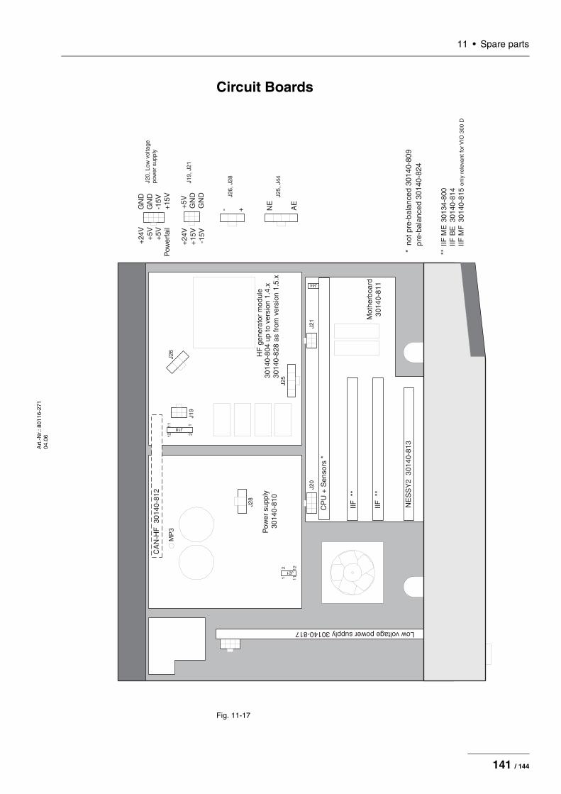
11 • Spare partsA
rt.-
Nr.
: 801
16-2
71
04.0
6
Circuit Boards
Fig. 11-17
Mot
herb
oard
3014
0-81
1
Pow
ersu
pply
3014
0-81
0
HF
gene
rato
rm
odul
e30
140-
804
upto
vers
ion
1.4.
x30
140-
828
asfr
omve
rsio
n1.
5.x
NE
SS
Y2
3014
0-81
3
IIF**
IIF**
CP
U+
Sen
sors
*
CA
N-H
F30
140-
812
J21
1
1211
2
J18 1
1211
2
Lowvoltagepowersupply30140-817
**IIF
ME
3013
4-80
0IIF
BE
3014
0-81
4IIF
MF
3014
0-81
5on
lyre
leva
ntfo
rVIO
300
D
MP
3
AE
NE
+-GN
DG
ND
-15V
+15
V
+24
V+
5V+
5VP
ower
fail
+24
V+
15V
-15V
+5V
GN
DG
ND
J20
J21
J28
J26
J19
J25
*no
tpre
-bal
ance
d30
140-
809
pre-
bala
nced
3014
0-82
4
J20,
Low
volta
gepo
wer
supp
ly
J19,
J21
J26,
J28
J25,
J44
J44
141 / 144

11 • Spare parts
Art
.-N
r.: 8
0116
-271
04
.06
Receptacle modules
Bipolar receptacles
ERBE Art. No. 20140-610 Receptacle module BI 8/4
Fig. 11-18
ERBE Art. No. 20140-611 Receptacle module BI 2PIN 28
Fig. 11-19
ERBE Art. No. 20140-612 Receptacle module BI 2PIN 22
Fig. 11-20
Monopolar receptacles
ERBE Art. No. 20140-620 Receptacle module MO 9/5
Fig. 11-21
ERBE Art. No. 20140-621 Receptacle module MO 4
Fig. 11-22
142 / 144

11 • Spare partsA
rt.-
Nr.
: 801
16-2
71
04.0
6
ERBE Art. No. 20140-622 Receptacle module MO 3PIN-Bovie
Fig. 11-23
ERBE Art. No. 20140-623 Receptacle module MO 3PIN-9/5
Fig. 11-24
MF receptacle
ERBE Art. No. 20140-630 Receptacle module MF 0
Fig. 11-25
Receptacles for neutral electrode
ERBE Art. No. 20140-640 Receptacle module NE 6
Fig. 11-26
ERBE Art. No. 20140-641 Receptacle module NE 2PIN
Fig. 11-27
143 / 144
11 • Spare parts
Art
.-N
r.: 8
0116
-271
04
.06
144 / 144