· Web viewMr. Ruchir Desai is an Assistant Professor in Mechanical Engineering Department,...
10
DESIGN AND ANALYSIS OF GATING SYSTEM FOR CASTING OF SPROCKET Azadkumar Vegda 1 , Sumit Bhingradiya 2 , Kaushik Faldu 3 , Parth Gandhi 4 , Mihir Shah 5 [1, 2, 3, 4, 5] B.E Student, Department of Mechanical Engineering, A.D.Patel Institute of Technology, New V V Nagar, Gujarat, India. ABSTRACT Casting is a suitable economical manufacturing process for various components. It may experience different defects such as cracks, hotspot, mis-run, etc. because of poor design of gating system. The objective of project is to design and simulate gating and risering system components by using simulation technology to get defect free casting. Casting simulation utilizes finite element procedures depending upon the complexity of the problem. It provides a large range of the complete behavior of the casting during solidification. Using the casting simulation as a virtual test foundry in the computer, it is possible to do a number of what- if- scenarios, to establish the optimum casting design and foundry process. Index terms: Casting, simulation, Casting Defects, Design. 1. INTRODUCTION Casting is one of the oldest manufacturing processes, and even today is the first step in manufacturing most products in industries. Nowadays, in industries it is very important to save time and money in manufacturing product, because there is lots of competition in industrial world. Many researchers reported that about 90% of the defects in castings are due to wrong design of gating & risering system and only 10% due to manufacturing problems[4]. Casting simulation process is able to solve these problems. It has observed that various type of simulation software has been used in foundry, out of which FEM and VEM based casting simulations are widely used to study the solidification behavior of material and detection of defects like hot spots in castings[5]. In casting process material is first liquefied by properly heating it in a suitable furnace. Then, the liquid is poured into a previously prepared mould cavity where it is allowed to solidify. Subsequently, the product is taken out of the mould cavity, trimmed, and cleaned to get final shape. Casting process offers the widest variety in terms of metals and alloys, size and weight, shape complexity, production quantity and different applications. Computer simulation of casting solidification of metals and alloys is a very complex phenomenon. Casting simulation has become a powerful tool to visualize mould filling, solidification and cooling, and to predict the location of internal defects[6]. The simulation offers an attractive alternative to foundry experiments which helps to study progress of metal flow and solidification. Velocities, temperatures and cooling rates at different locations inside the casting at different time can be measured. Metallurgical models can
-
Upload
trinhxuyen -
Category
Documents
-
view
216 -
download
1
Transcript of · Web viewMr. Ruchir Desai is an Assistant Professor in Mechanical Engineering Department,...

DESIGN AND ANALYSIS OF GATING SYSTEM FOR CASTING OF SPROCKET
Azadkumar Vegda1, Sumit Bhingradiya2, Kaushik Faldu3, Parth Gandhi4, Mihir Shah5
[1, 2, 3, 4, 5] B.E Student, Department of Mechanical Engineering, A.D.Patel Institute of Technology, New V V Nagar, Gujarat, India.
ABSTRACTCasting is a suitable economical manufacturing process for various components. It may experience different defects such as cracks, hotspot, mis-run, etc. because of poor design of gating system. The objective of project is to design and simulate gating and risering system components by using simulation technology to get defect free casting. Casting simulation utilizes finite element procedures depending upon the complexity of the problem. It provides a large range of the complete behavior of the casting during solidification. Using the casting simulation as a virtual test foundry in the computer, it is possible to do a number of what- if-scenarios, to establish the optimum casting design and foundry process.Index terms: Casting, simulation, Casting Defects, Design.
1. INTRODUCTIONCasting is one of the oldest manufacturing processes, and even today is the first step in manufacturing most products in industries. Nowadays, in industries it is very important to save time and money in manufacturing product, because there is lots of competition in industrial world. Many researchers reported that about 90% of the defects in castings are due to wrong design of gating & risering system and only 10% due to manufacturing problems[4]. Casting simulation process is able to solve these problems. It has observed that various type of simulation software has been used in foundry, out of which FEM and VEM based casting simulations are widely used to study the solidification behavior of material and detection of defects like hot spots in castings[5]. In casting process material is first liquefied by properly heating it in a suitable furnace. Then, the liquid is poured into a previously prepared mould cavity where it is allowed to solidify. Subsequently, the product is taken out of the mould cavity, trimmed, and cleaned to get final shape. Casting process offers the widest variety in terms of metals and alloys, size and weight, shape complexity, production quantity and different applications.
Computer simulation of casting solidification of metals and alloys is a very complex phenomenon.
Casting simulation has become a powerful tool to visualize mould filling, solidification and cooling, and to predict the location of internal defects[6]. The simulation offers an attractive alternative to foundry experiments which helps to study progress of metal flow and solidification. Velocities,
temperatures and cooling rates at different locations inside the casting at different time can be measured. Metallurgical models can be applied to predict casting defects and properties. The gating and risering system can be iteratively modified in order to improve casting quality and can be verified by simulation using software. The product which we are working for the design and simulation is a sprocket.
A sprocket is a profiled wheel with teeth, cogs, or even sprockets that mesh with a chain, track or other perforated or indented material. The name 'sprocket' applies generally to any wheel upon which radial projections engage a chain passing over it. It is distinguished from a gear in that sprockets are never meshed together directly, and differs from a pulley in that sprockets have teeth and pulleys are smooth.
2. METHODOLOGY
2.1 Component Description
Industry has allocated sprocket component for gating system design. This component is complicated and costly to cast using shop floor trial methods. Because it takes some trial and error method to achieve sound casting which is both time consuming and expensive. Our task is to prepare gating system for sprocket and simulate the same system into finite element method based software so to achieve defect free casting at minimum trial and at lower cost.Component is made up of SS-304 which is shown in fig 1.

Fig 1. Sprocket (Component)
2.2 CAD model of sprocket The modeling has been performed on the creo parametric 1.0 version.Industry has allocated sprocket component to our team. We took the detailed dimensions of tooth profile and other shapes.
Fig 2. CAD model of sprocket
Fig3.Top and front view of sprocket
2.3 E-foundry result
In the initial stage for design a better gating system for sprocket we have used e-foundry software. This software provides chances of defect which is hotspots in component. We have uploaded our component without gating and risering system in E-foundry software.
Fig 3 - Result from e-foundryFrom above result we can conclude that hotspot may arise at thickest section of casting component which are six teeth and central place. So our gating system must eliminate hotspots at these places and also it is necessary to provide the directional solidification in order to achieve sound casting.
2.4 Gating design Calculations
Pouring time- The time for complete filling of mould termed as pouring time.For steel casting,Pouring time ‘t’ = (2.4335 - 0.3953 log w)*√w secWhere, w = mass of the casting, kgtp= (2.4335- 0.3953log73.40)*√73.40 = 35.27 seconds.Choke area = The main control area which meters the metal flow into mould cavity sothat mould is completely filled within the calculated pouring time. Normally choke area happens to be at the bottom of the sprue.Choke area A = W/dtc√2ghWhere, W = casting mass, kg d = density of molten metal kg/mm3H = effective height of metal head (sprue height) in mmC = efficiency factor for gating systemt = pouring time (sec)d’=sprue bottom area in mm
Area A= 73.40/(7.85*10-6*35.27*0.9*√2*9810*100)= 416mm2Πd’2/4 = 416 mm2d’ = 19.8 mmSprue top area = 2*sprue bottom areaπ D’2/4 = 2*416D’ = 33 mmFor steel we have taken gating ratio = 1:2: 1.5Runner area = 2 * sprue area= 2* 416=832 mm2Sprue well top area = 5 * area of sprue base

A2= 5*416a = 39.24mmWhere, a = side of square shape sprue well topSprue well depth = 2 * runner depth= 2*26= 52 mmDesign of riserDesign of riser by Modulus method,Volume of the casting = 9.219*10 6mm3Surface area of the casting = 5.830*105 mm3Volume of the riser = π*D3/4
Surface area of the riser = π.D2 + π*D2/4 = 1.25πD2. Where, D is the riser diameter.
Modulus of the casting = volume of the casting / surface area of the casting= 5*106 / 2.78*105= 15.8124
According to the formula,Modulus of the riser = 1.2* Modulus of casting= 1.2*15.8124
= 18.9749..........................................Eq. 1Now,Modulus of riser = (π*D3/4) / (1.25πD2)= D/5....................................................Eq.2Comparing Eq.1 & 2D = 78.33 mm
Solidification time(t)
Where,t is the solidification time,V is the volume of the casting,A is the surface area of the casting that contacts the mold,n is a constant,B is the mold constant.
Where, Tm = melting or freezing temperature of the liquid (in Kelvin)To = initial temperature of the mold (in Kelvin)ΔTs = Tpour − Tm = superheat (in Kelvin)L = latent heat of fusion (in [J·kg−1])k = thermal conductivity of the mold (in [W·m−1·K−1)])ρ = density of the mold (in [kg·m−3])c = specific heat of the mold (in [J·kg−1·K−1])ρm = density of the metal (in [kg·m−3])cm = specific heat of the metal (in [J·kg−1·K−1])t = 691 sec.
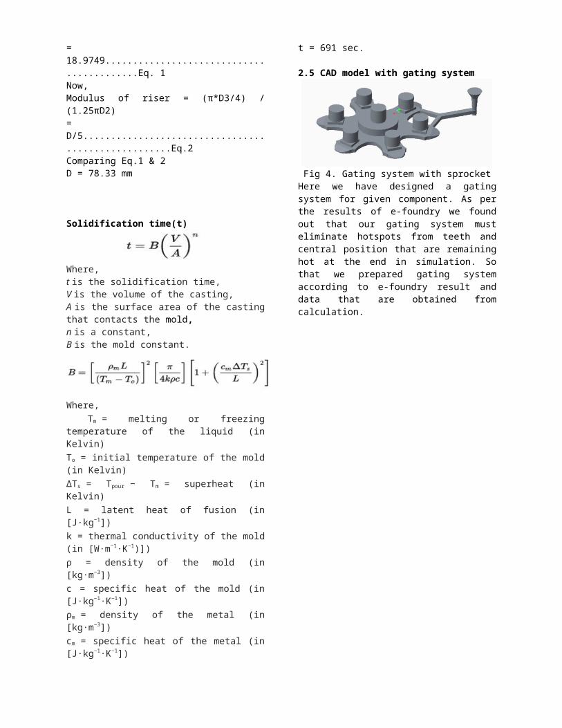
2.5 CAD model with gating system
Fig 4. Gating system with sprocketHere we have designed a gating system for given component. As per the results of e-foundry we found out that our gating system must eliminate hotspots from teeth and central position that are remaining hot at the end in simulation. So that we prepared gating system according to e-foundry result and data that are obtained from calculation.
Table 1. Input material properties and conditionsWe selected Parting line gating system because to take advantages of top gating system and bottom gating system. As geometry is complicated and
Parameters Type of mould Condition
Material Green mould SS304
density 1.5 gm/cm3 7.85 gm/cm3
Initial temp. 300k 1858k
Liquidus temp. - 1728k
Solidus temp. - 1600k
Heat coefficient 500W/m2k -
component is bulky, we have provided two ingate at the teeth of sprocket which will fill the mould completely before liquidus temperature is attained. Also gating system is pressurized gating system, thus maintaining back pressure throught the gating system and that is why air aspiration effect can be avoided.
There are six risers placed at teeth of sprocket as because of e-foundry result, in which we found out that this thicker section may leave hot after solidification. Also one central riser is placed to compensate liquid shrinkage and avoid shrinkage porosity as a result of e-foundry.
2.6 Casting simulation
ANSYS is finite element based software which is used to simulate fluid flow and solidification of sand casting. Casting simulation and result analysis was done to predict the molten metal solidification behavior inside the mould. The casting component with gating and risering system was imported in (.stp) format into the software and then meshing is done. The messed model was taken into the set up module of the ANSYS software, where the number of materials, density of cast material, Pouring temperature, liquids and solidus temperatures and other input parameters of fluid flow and solidification conditions like mass flow rate, direction of gravity etc. were assigned. After the assignment of material properties and simulation conditions prediction of temperature distribution and solidification direction are carried out.
Simulation procedure:
Step01: Import geometryImport 3d cad model in .stp format and assign inlet surface.
Step 02: Meshing Here fine meshing is done on whole geometry.Number of nodes-72655Number of elements -336142
Step 03: Set-up-Input material properties and conditions
The main inputs for the casting simulation process are: 1) Thermo-physical properties (density, specific heat, and thermal conductivity of the cast metal as well as the mould material, as a function of temperature).
2) Boundary conditions (i.e. the metal mould heat transfer coefficient, for normal mould as well as feed aids including chills, insulation and exothermic materials). 3) Process parameters (such as pouring rate, time and temperature).
Parameters Input conditions
Mass flow rate 2.15 m/sFill time 35.27 sec
Pouring system Gravity pouringRiser type open
Output Results Temperature distribution,Liquid fraction
Table 2. Input parameters and conditions
3. RESULTS AND DISCUSSION
Result 01: For initial design
Temperature distribution –
The phase changes from liquid state to solid state gradually with the decrease of temperature, in which a lot of physical and surrounding parameter play an important role for the casting quality. Temperature distribution of sprocket component with respect to time is shown in figure. We have simulated our component with gating system in ANSYS using above mentioned parameters. Here dimensions of riser are as given below
6-Side riser = Diameter 60 mm & height 80mm
1-Central riser = Diameter 80mm & height 90 mm
Fig.7 Temperature distribution contour 1In above contour showing temperature distribution we can observe that at the end of solidification

thickest section remains hot while risers get solidified before the thick sections.By simulating design we found out that by taking given dimensions of risers hotspots may come on the surface of casting that can adversely affect the quality of casing .So now we have to modify our gating system design to avoid such defects and get defect free casting.
Result 02: For modified systemBy taking consideration previous result we have modified gating system design in that dimension of risers have been changed to avoid hotspots at the surface of casting. Modified dimension of risers are given below,
6-Side riser = Diameter 80 mm & height 120 mm
1-Central riser =diameter 80mm & height 100 mm
We have increased the size of the risers in order to transfer hot spot from component to the riser. To increase the size of the risers we have provided step at the bottom of the riser with diameter and height of 60mm and 10mm respectively. The advantage of using step at the bottom of the riser is that by using the same surface area at the bottom surface we have more material on its top ready to get poured in the cavity as and when required.
Fig.8. Modified gating system design
Temperature distribution contour:There are total three temperature distribution contour at different time stage for modified gating system design.
(1) Time – 60sec.We have poured molten metal at 1850K and provided boundary conditions like heat transfer coefficient, mass flow rate and simulated initially after filling mould and obtained results as follows.Initially we have simulated after 60sec. The contour shows temperature distribution range in whole geometry which indicates that the whole mould is fully filled with molten metal. Initially the temperature in almost all parts of the component is higher as it doesn’t allow too much time to transfer heat.
Fig.9. Temperature distribution contour 2
(2) Time – 200sec.
In second phase we provided time of 300sec. for solidification and obtained results of temperature distribution as follows. Here temperature range changes because as time passes temperature of casting reduces. As we can observe in the contour that thinner sections started to get solidify because these parts have released their latent heat to mould. While the thicker sections are still at higher temperatures as they have not completely liberated latent heat. So thickest sections are at about liquidus temperature while thinner sections are at about solidus temperature.
Fig.10. Temperature distribution contour 3
(3) Time- 800sec
In final iteration we allowed time of 800sec and got results as follows. In temperature distribution contour scale indicates temperature from 1100K to 1900K .As we can observe that almost every part of the component are at lower temperature than solidus temperature which means that they became solidified. We can also observe that riser is slightly at higher temperature compared to other parts of the casting which specifies directional solidification. Hence hotter sections are transferred to riser which ensures elimination of hotspot defect from the casting

Fig.11. Temperature distribution contour 4
Liquid fraction
There are total three liquid fraction contour at different time stage for modified gating system design.
(1) Time – 60sec
We have poured molten metal at 1850K and provided boundary conditions like heat transfer coefficient, mass flow rate and simulated initially after filling mould and obtained results as follows. Initially we have simulated after 60sec. The contour shows liquid fraction range from 0.25 to 1.00.We can observe that most of the sections of casting are in liquid state. Initially the temperature in almost all parts of the component is higher as it doesn’t allow too much time to transfer heat so they are in liquid state.
Fig.12. Liquid fraction 1
(2) Time- 300sec
In following result we can observe that thinner section get solidified as it can transfer heat from mould easily. While thicker sections are in liquid sate as they cannot liberate heat easily. Liquid fraction range is from 0 to 1 which is more than earlier range because as time passes temperature of casting reduces and liquid portion tries to become solid.
Fig.13 Liquid fraction 2(3) Time – 800sec
From the following result of liquid fraction after 800sec almost all regions of casting gets solidified and some portion of riser is in liquid state which notifies that riser can provide liquid molten metal to the cavity till the end of solidification. Hence we can achieve directional solidification which helps in getting defect free casting. We can also comment that riser will provide molten metal till the end of solidification of casting and so that there will be lesser chances of shrinkage porosity.
Fig.14. Liquid fraction 3
4.CONCLUSION
From the presented work it can concluded that(1) The application of computer aided solid
modeling, and casting simulation technologies in foundries can able to minimize the bottlenecks and non-value added time in casting development, as it reduces the number of trial casting required on the shop floor.
(2) Due to the fluid is the carrier of temperature, the change of temperature field is decided by the change of flow field. The conclusion that temperature field is largely influenced by flow field.
(3) We can mark that hotspot defect may occur at the thicker sections of the geometry and we

can eliminate it by providing riser in that area so that hotspot can be transferred to riser.
(4) As the time passes we can observe the changes in solidification direction and can direct the solidification process by modifying gating and risering system or other process parameters.
(5) In first iteration improper dimension of riser led to formation of hotspot where in the second iteration proper dimension of riser helped to draw hotspot in to the riser and can get defect free casting.
ACKNOWLEDGEMENT
We would like to express our deepest appreciation to all those who provided us the possibility to complete this project. A special gratitude to our project guide, Mr. Tejas Prajapati and his contribution in stimulating suggestions and encouragement helped us to coordinate our project. We would also like to gratefully and sincerely thanks to Head of Mechanical Engineering Department, A.D.Patel Institute of Technology, Dr. Vishal N Singh for his guidance and understanding during our project work. We would also like to thank Mr. Paresh Shah (SHREE VALLABH ALLOY STEEL CASTINGS, V.U.Nagar), who gave us an opportunity to work with him and the rest of the industry members for their cooperation and support.
REFERENCES
(1) Casting Simulation for Sand Casting of Flywheel by Naveen Hebsur, Sunil Mangshetty, e-ISSN: 2278-1684.
(2) Design and Analysis of Gating and Risering System for Casting of Ball Valves by P. G. Panchal, S. J. Joshi and N. D. Ghetiya.
(3) Solidification behavior and detection of Hotspots in Aluminium Alloy castings: Computer Aided Analysis and experimental validation by Rabindra Behera , Kayal.S , Sutradhar.G, ISSN 09764259.
(4) Simulation of Casting and Its Validation by Experiments by Mazhar Iqbal, Sushil Patel, Ganesh Vidyarthee, ISSN: 2277-9655.
(5) Solidification Analysis and Optimization Using Pro-Cast by Bhupendra j. Chudasama, ISSN: 2320-6586.
(6) Casting Simulation and Optimisation: Benefits, Bottlenecks, and Best Practices by Dr. B. Ravi, Indian Foundry Journal January 2008.
(7) Metal Casting: Computer-aided Design and Analysis by B. Ravi Prentice-Hall India, ISBN-81-203-2726-8, 4th print, 2007.
BIOGRAPHIES
Mr. Tejas Prajapati is an Assistant Professor in Mechanical Engineering Department, A.D.Patel Institute of Technology, New V V Nagar. He has received his M.Tech degree from Charotar Institute of Technology, Changa with CAD/CAM as specialization.
Mr. Ruchir Desai is an Assistant Professor in Mechanical Engineering Department, A.D.Patel Institute of Technology, New V V Nagar. He has received his masters degree from Sardar Vallabhbhai Institute of Technology, Vasad with CAD/CAM as specialization.