· Web viewFiber Optic Communication - FAQ, News & Trainings Home About Fiber Optics For Sale Co....
16
Fiber Optic Communication - FAQ, News & Trainings Home About Fiber Optics For Sale Co. RSS feed How to Terminate 3M Hot Melt Fiber Connectors 3M Hot Melt fiber connectors continue to be a popular choice among fiber optic installers in the field. The Hot Melt connectors utilize an advanced adhesive technology eliminating the application of epoxy. The connectors provide quick termination in 2 minutes or less and are re-heatable to allow for fiber repositioning. We will demonstrate the detailed steps for polishing a LC Hot Melt connector, including multimode and single mode LC connectors. The LC connector termination kit (6650-LC ) is an extension to the basic FC,SC and ST connector termination kit(6365 and 6361). 6650-LC needs to work together with 6365 or 6361.But if you are terminating FC,SC or ST Hot Melt connectors, you only need 6365 or 6361(230 voltage version). :: Tools needed for terminating 3M Hot Melt FC,SC and ST connectors The 3M 6365(120V version) and 6361(230V version) universal Hot Melt connector termination tool kit provides all tools, test equipment and consumables necessary for terminating 3M FC, SC and ST Hot Melt connectors. Here is the list of items in this tool kit
Transcript of · Web viewFiber Optic Communication - FAQ, News & Trainings Home About Fiber Optics For Sale Co....
Fiber Optic Communication - FAQ, News & Trainings
Home About Fiber Optics For Sale Co.
RSS feed
How to Terminate 3M Hot Melt Fiber Connectors
3M Hot Melt fiber connectors continue to be a popular choice among fiber optic installers in the field. The Hot Melt connectors utilize an advanced adhesive technology eliminating the application of epoxy. The connectors provide quick termination in 2 minutes or less and are re-heatable to allow for fiber repositioning.
We will demonstrate the detailed steps for polishing a LC Hot Melt connector, including multimode and single mode LC connectors. The LC connector termination kit (6650-LC) is an extension to the basic FC,SC and ST connector termination kit(6365 and 6361). 6650-LC needs to work together with 6365 or 6361.But if you are terminating FC,SC or ST Hot Melt connectors, you only need 6365 or 6361(230 voltage version).
:: Tools needed for terminating 3M Hot Melt FC,SC and ST connectors
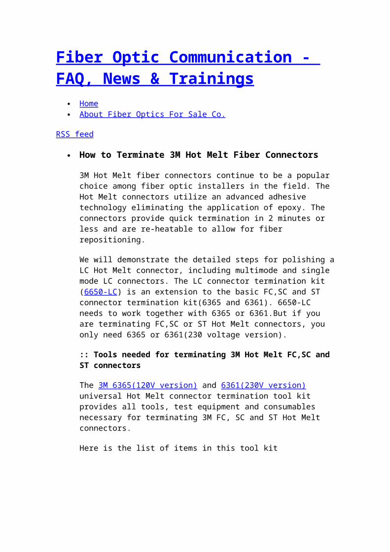
The 3M 6365(120V version) and 6361(230V version) universal Hot Melt connector termination tool kit provides all tools, test equipment and consumables necessary for terminating 3M FC, SC and ST Hot Melt connectors.
Here is the list of items in this tool kit
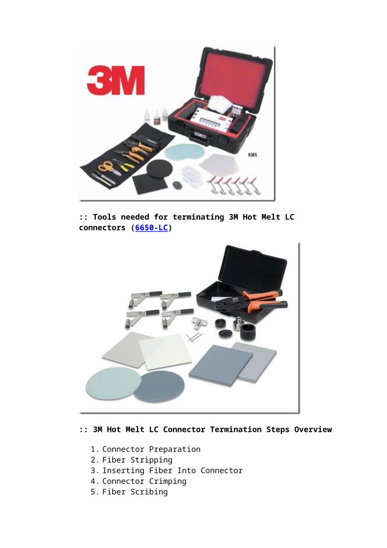
:: Tools needed for terminating 3M Hot Melt LC connectors (6650-LC)
:: 3M Hot Melt LC Connector Termination Steps Overview
1. Connector Preparation 2. Fiber Stripping 3. Inserting Fiber Into Connector 4. Connector Crimping 5. Fiber Scribing 6. Multimode Fiber Polishing 7. Single Mode Fiber Polishing 8. Connector Inspection 9. Put on Dust Cap for Stocking
Step 1: Connector Preparation
A. Turn on the 3M Hot Melt oven. The oven needs 6 minutes to warm up.
B. Remove LC connector from the package.

C. Attach LC Hot Melt holder handle to the load adapter with the slot aligned to the front.
D. Insert the connector into the hot melt connector holder
E. Place the load adapter, with slot aligned with handle, into an available port in the oven
F. Heat the LC hot melt connector for 75 seconds to 5 minutes
G. Place the heat shrink fixture in an available port in the oven

Step 2: Fiber Stripping
A. Place the strain relief boot first, then place the heat shrink crimp sleeve on the cable.
B. Place the jacketed fiber on the strip template. Mark the location of the jacket cut with a black marker on the cable. Then use fiber stripping tool 6365-CT to remove 33mm of fiber jacket.

C. Trim the aramid yarn to 5mm length.
D. Flare the aramid yarn evenly around the fiber buffer tube.
E. With 6365-CT fiber stripping tool, remove the 900um tight buffer in small pieces, until 22mm of 900um buffer tube is left. Now you should have about 11mm bare fiber at the front.

F. Clean the 11mm bare fiber with lint-free wiper moistened with isopropyl alcohol. The bare fiber should have no oil or acrylate coating debris.
Step 3: Insertion Fiber Into Connector
A. While the LC hot melt connector is still in the oven, insert the stripped fiber into the connector until it stops. Make sure that you are inserting the fiber into the fiber guiding tube at the back of the connector.

B. While still keeping the fiber’s position in the connector, push fiber jacket into the slot on the connector load adapter to secure the fiber cable. Keep the cable as straight as possible.
C. Now it’s time to remove the connector from the oven. While holding the connector holder’s cool-tough handle, remove it from the oven.
D. Place the connector holder into the cooling port on both sides of the oven. Leave it to cool for at least 3 minutes.
Step 4: Connector Crimping
A. Slide the heat shrink crimp sleeve towards the connector, covering oven the aramid yarn.

B. Remove LC connector from the connector holder.
C. With the 3M lettering facing to the left, crimp the metal part of the heat shrink crimp sleeve once. You should use the crimp tool die labeled “A”.
D. Place the heat shrink crimp sleeve in the shrink fixture assembly for 10 seconds. The heat shrink tube should shrink snug around the fiber jacket. Rotate the fiber jacket when necessary in order to shrink evenly.

E. Slide the connector rubber boot over the crimp sleeve.
Step 5: Fiber Scribing
A. Hold the fiber scribe tool so the flat side of the blade faces down. Make sure the scribe blade is perpendicular to the fiber.
B. Score the fiber just above the adhesive bead by gently sliding the scribe blade across the fiber. You are only making a small scratch on the outside of the fiber, make sure you are not pushing too hard. The fiber should not break at this step.
C. Pull the fiber straight away from the fiber along the axis of the fiber. The fiber should break easily.

D. Now dispose the fiber scrap into a fiber disposal container.
Step 6: Multimode Fiber Polishing
A. Perform an air polish by holding the 9 micron lapping film firmly in one hand and gently moving the film in a circular motion for approximately 10 strokes or until approximately one half of the bead height is removed.
B. Using a lint-free cloth and isopropyl alcohol clean the connector after the air polish to remove all debris left by the 9 micron lapping film.
C. Clean the round polishing pad found in the 3M™ Universal Hot Melt Kit 6365/6361 with a lint-free cloth moistened with isopropyl alcohol.
D. Place several drops of alcohol onto the round polishing pad.

E. Before alcohol evaporates, place a sheet of the pale green 2 micron lapping film, shiny side down on the pad. The alcohol creates suction on the lapping film and helps hold it in place.
F. Clean the lapping film with a lint-free cloth moistened with isopropyl alcohol.
G. Clean the flat side of the polishing jig with a lint-free cloth moistened with isopropyl alcohol.
H. Place the polishing jig assembly on the lapping film.
I. Place the ferrule in the polishing jig aligning the latch side of the connector with the slot until it stops.

J. Insert the polishing weight into the adapter/jig assembly covering the connector.
K. Polish 10 figure-eight strokes or until bead of adhesive is no longer visible.
L. After bead of adhesive is no longer visible, polish an additional 5 strokes.
M. Remove the connector from the polishing jig assembly and clean the connector endface with a lint-free cloth moistened with isopropyl alcohol.
Step 7: Single Mode Fiber Polishing
A. Complete the multimode fiber polishing steps as in step 6.

B. Clean the gray rectangular polishing pad with a lint-free cloth moistened with isopropyl alcohol.
C. Place several drops of alcohol on to the rectangular rubber pad.
D. Before the alcohol evaporates, place a sheet of the 0.5 micron pale gray diamond lapping film on the polishing pad, shiny side down.
E. Clean the lapping film with a lint-free cloth moistened with isopropyl alcohol.
F. Place several drops of distilled water on to the diamond lapping film.
G. Insert the connector into the polishing jig assembly.
H. Clean the flat side of the polishing jig with a lint-free cloth moistened with isopropyl alcohol.
I. Place the polishing jig assembly on the wet diamond lapping film. Perform 3 to 4 figure eights.
J. Leaving the polishing jig assembly positioned on the lapping film, rotate 180 degrees. Perform 3 to 4 additional figure eights.

Step 8: Connector Inspection
A. Inspect the connector endface with the 200X fiber optic inspection microscope. Use the thumb toggle switch to activate the light onto the fiber end face.
B. Good polish picture
C. Bad polish picture

Step 9: Connector Stocking
If connector is not to be immediately put into service, install the protective dust cap.