· Web viewExplain IPv4 packet format with help of neat diagram. Packets in the network (internet)...
218
Syllabus Unit-I OSI Model TCP/IP Protocol Suite IPV 4 Addresses and Protocol and IPV6 Addresses and Protocol Address Resolution Protocol (ARP) Unit-II Internet Control Message Protocol Version 4 (ICMPv4) Mobile IP Unicast Routing Protocols (RIP, OSPF and BGP) Unit-III User Datagram Protocol (UDP) Transmission Control Protocol (TCP) Unit-IV Stream Control Transmission Protocol (SCTP) Host Configuration: DHCP Domain Name System (DNS) Unit-V Remote Login: TELNET and SSH File Transfer: FTP and TFTP World Wide Web and HTTP Unit-VI Electronic Mail: SMTP, POP, IMAP and MIME Multimedia Index Sr. No Topic Page No OSI Model 1 TCP/IP Protocol Suite IPV 4 Addresses and Protocol IPV6 Addresses and Protocol Address Resolution Protocol (ARP) 2 Internet Control Message Protocol Version 4 (ICMPv4) Mobile IP Unicast Routing Protocols (RIP, OSPF and BGP) 3 User Datagram Protocol (UDP) Transmission Control Protocol (TCP) 4 Stream Control Transmission Protocol (SCTP) Host Configuration: DHCP Domain Name System (DNS) 5 Remote Login: TELNET and SSH File Transfer: FTP and TFTP World Wide Web and HTTP 6 Electronic Mail: SMTP, POP, IMAP and MIME Multimedia
Transcript of · Web viewExplain IPv4 packet format with help of neat diagram. Packets in the network (internet)...

Syllabus
Unit-IOSI ModelTCP/IP Protocol SuiteIPV 4 Addresses and Protocol and IPV6 Addresses and Protocol
Address Resolution Protocol (ARP)
Unit-IIInternet Control Message Protocol Version 4 (ICMPv4)Mobile IPUnicast Routing Protocols (RIP, OSPF and BGP)
Unit-III User Datagram Protocol (UDP)Transmission Control Protocol (TCP)
Unit-IVStream Control Transmission Protocol (SCTP)Host Configuration: DHCPDomain Name System (DNS)
Unit-VRemote Login: TELNET and SSHFile Transfer: FTP and TFTPWorld Wide Web and HTTP
Unit-VI Electronic Mail: SMTP, POP, IMAP and MIMEMultimedia
Index
Sr. No Topic Page No
OSI Model
1 TCP/IP Protocol Suite
IPV 4 Addresses and Protocol
IPV6 Addresses and Protocol
Address Resolution Protocol (ARP)
2 Internet Control Message Protocol Version 4 (ICMPv4)
Mobile IP
Unicast Routing Protocols (RIP, OSPF and BGP)
3 User Datagram Protocol (UDP)
Transmission Control Protocol (TCP)
4Stream Control Transmission Protocol (SCTP)
Host Configuration: DHCP
Domain Name System (DNS)
5Remote Login: TELNET and SSH
File Transfer: FTP and TFTP
World Wide Web and HTTP
6Electronic Mail: SMTP, POP, IMAP and MIME
Multimedia

Unit-ITopics:
OSI Model |TCP/IP Protocol Suite | IPv4 Addresses and Protocol | IPv6 Addresses and
Protocol

Q1. What is OSI model? Explain its different layer and their function.
OSI:International Standards Organization (ISO) is a multinational body dedicated to worldwide agreement on international standards. Almost three-fourths of countries in the world are represented in the ISO. An ISO standard that covers all aspects of network communications is the Open Systems Interconnection Model.
The OSI model is a layered framework for the design of network systems that allows communication between all types of computer systems.
Layers in the OSI Model
1. Physical Layer
The physical layer coordinates the functions required to carry a bit stream over a physical medium. It deals with the mechanical and electrical specifications of the interface and transmission media.
The physical layer is also concerned with the following:
Representation of bits: The physical layer data consists of a stream of bits (sequence of 0s or 1s) with no interpretationData rate: The transmission rate—the number of bits sent each second—is also defined by the physical layerSynchronization of bits: The sender and receiver must not only use the same bit rate but must also be synchronized at the bit level.Line configuration: The physical layer is concerned with the connection of devices to the media. In a point to-point configuration, two devices are connected together through a dedicated link. In a multipoint configuration, a link is shared between several devices.Physical topology: The physical topology defines how devices are connected to make a network.Transmission mode: The physical layer also defines the direction of transmission betweentwo devices: simplex, half-duplex, or full-duplex.
2. Data Link Layer
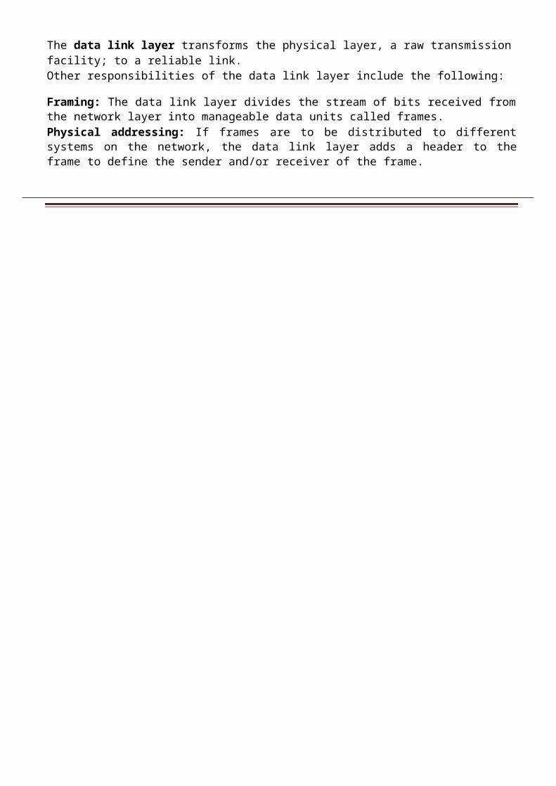
The data link layer transforms the physical layer, a raw transmission facility; to a reliable link.Other responsibilities of the data link layer include the following:
Framing: The data link layer divides the stream of bits received from the network layer into manageable data units called frames.Physical addressing: If frames are to be distributed to different systems on the network, the data link layer adds a header to the frame to define the sender and/or receiver of the frame.

Flow control: If the rate at which the data is absorbed by the receiver is less than the rate produced at the sender, the data link layer imposes a flow control mechanism to prevent overwhelming the receiver.Error control: The data link layer adds reliability to the physical layer by adding mechanisms to detect and retransmit damaged or lost frames. It also uses a mechanism to recognize duplicate frames. Error control is normally achieved through a trailer added to the end of the frame.Access control: When two or more devices are connected to the same link, data link layer protocols are necessary to determine which device has control over the link at any given time.
3. Network Layer
The network layer is responsible for the source-to-destination delivery of a packet; possibly across multiple networks (links).Other responsibilities of the network layer include the following:
Logical addressing: The network layer adds a header to the packet coming from the upper layer that, among other things, includes the logical addresses of the sender and receiver.
Routing: When independent networks or links are connected together to create internetworks (network of networks) or a large network, the connecting devices (called routers or switches) route or switch the packets to their final destination.
4. Transport Layer
The transport layer is responsible for process-to-process delivery of the entire message. A process is an application program running on the host. Other responsibilities of the transport layer include the following:
Segmentation and reassembly: A message is divided into transmittable segments, with each segment containing a sequence number. Segmentation process takes place at sender side and reassembly at receiver side.
Connection control: The transport layer can be either connectionless or connection oriented. For a connectionless transport layer use UDP protocol and for connection oriented TCP protocol.
Flow control: Like the data link layer, the transport layer is responsible for flow control.However, flow control at this layer is performed end to end rather than across a single link.
Error control: Like the data link layer, the transport layer is responsible for error control. The sending transport layer makes sure that the entire message arrives at the receiving transport layer without error (damage, loss, or duplication).
5. Session Layer
The session layer is the network dialog controller. It establishes, maintains, and synchronizes the interaction between communicating systems. Specific responsibilities of the session layer include the following:
Dialog control: The session layer allows two systems to enter into a dialog. It allows the communication between two processes to take place in either half duplex (one way at a time) or full-duplex (two ways at a time) mode.
Synchronization: The session layer allows a process to add checkpoints (synchronization points) into a stream of data.
6. Presentation Layer
The presentation layer is concerned with the syntax and semantics of the information exchanged between two systems. Specific responsibilities of the presentation layer include the following:
Translation: The processes (running programs) in two systems are usually exchanging information in the form of character strings, numbers, and so on. The information should be changed to bit streams before being transmitted.
Encryption\Decryption: Encryption means that the sender transforms the original information to another form and sends the resulting message out over the network. Decryption reverses the original process to transform the message back to its original form.
Compression: Data compression reduces the number of bits contained in the information. Data compression becomes particularly important in the transmission of multimedia such as text, audio, and video.
7. Application Layer
The application layer enables the user, whether human or software, to access the network. It provides user interfaces and support for services such as electronic mail, remote file access and transfer, shared database management, and other types of distributed information services. Specific services provided by the application layer include the following:
Network virtual terminal: A network virtual terminal is a software version of a physical terminal and allows a user to log on to a remote host.
File transfer, access, and management (FTAM): This application allows a user to access files in a remote host (to make changes or read data), to retrieve files from a remote computer for use in the local computer, and to manage or control files in a remote computer locally.
E-mail services: This application provides the basis for e-mail forwarding and storage.
Directory services: This application provides distributed database sources and access for global information about various objects and services.
Q2. Explain TCP\IP Protocol suite in detail.
The TCP/IP protocol suite was developed prior to the OSI model. Therefore, the layers in the TCP/IP protocol suite do not match exactly with those in the OSI model.
When we compare the two models, we find that two layers, session and presentation, are missing from the TCP/IP protocol suite. These two layers were not added to the TCP/IP protocol suite after the publication of the OSI model. The application layer in the suite is usually considered to be the combination of three layers in the OSI model, as shown in Figure.
First, TCP/IP has more than one transport-layer protocol. Some of the functionalities of the session layer are available in some of the transport layer protocols.
Q3. Explain various types of address in TCP\IP Protocol suite in detail.
Four levels of addresses are used in an internet employing the TCP/IP protocols: physical address, logical address, port address, and application-specific address.

Physical AddressesThe physical address also known as the link address or MAC (Media Access Control) or hardware address. It is included in the frame used by the data link layer. It is the lowest-level address. The size and format of these addresses vary depending on the network.Example: Ethernet uses a 6-byte (48-bit) physical address that is imprinted on the network interface card (NIC).
07:01:02:01:2C:4BA 6-byte (12 hexadecimal digits) physical address
Logical AddressesLogical addresses are necessary for universal communications that are independent of underlying physical networks. A logical address in the Internet is currently a 32-bit address that can uniquely define a host connected to the Internet. Example of IPv4 addresses 192.168.12.5
Port Addresses
Port address is made of 16 bit and resides at transport layer. The IP address and the physical address are necessary for a quantity of data to travel from a source to the destination host.
There are 3 types of port address.
Well Known Port (0-1023)User defined Port (1024-49151)Private Port (49152-65535)
753A 16-bit port address represented as one single number
Application-Specific Addresses
Some applications have user-friendly addresses that are designed for that specific application. Examples include the e-mail address (for example, [email protected]) and the Universal Resource Locator (URL) (for example, www.mhhe.com).
Q4. Explain different notation of IPv4 address?
The identifier used in the IP layer of the TCP/IP protocol suite to identify each device connected to the Internet is called the Internet address or IP address. An IPv4 address is a 32-bit address that uniquely and universally defines the connection of a host or a router to the Internet.
Types of Notation
There are three common notations to show an IPv4 address: binary notation (base 2), dotted-decimal notation (base 256), and hexadecimal notation (base 16).
Binary Notation: Base 2

In binary notation, an IPv4 address is displayed as 32 bits. To make the address more readable, one or more spaces are usually inserted between each octet (8 bits).
01110101 10010101 00011101 11101010
Dotted-Decimal Notation: Base 256To make the IPv4 address more compact and easier to read, an IPv4 address is usually written in decimal form with a decimal point (dot) separating the bytes. This format is referred to as dotted-decimal notation.
Hexadecimal Notation: Base 16We sometimes see an IPv4 address in hexadecimal notation. Each hexadecimal digit is equivalent to four bits. This means that a 32-bit address has 8 hexadecimal digits.
Q. Change the following IPv4 addresses from binary notation to dotted-decimal notation.a. 10000001 00001011 00001011 11101111b. 11000001 10000011 00011011 11111111c. 11100111 11011011 10001011 01101111d. 11111001 10011011 11111011 00001111SolutionWe replace each group of 8 bits with its equivalent decimal number and add dots for separation:a. 129.11.11.239b. 193.131.27.255c. 231.219.139.111d. 249.155.251.15
Q. Change the following IPv4 addresses from dotted-decimal notation to binary notation.a. 111.56.45.78b. 221.34.7.82c. 241.8.56.12d. 75.45.34.78SolutionWe replace each decimal number with its binary equivalent a. 01101111 00111000 00101101 01001110 b. 11011101 00100010 00000111 01010010c. 11110001 00001000 00111000 00001100d. 01001011 00101101 00100010 01001110
Q. Find the error, if any, in the following IPv4 addresses:a. 111.56.045.78b. 221.34.7.8.20c. 75.45.301.14d. 11100010.23.14.67Solutiona. There should be no leading zeroes in dotted-decimal notation (045).b. We may not have more than 4 bytes in an IPv4 address.c. Each byte should be less than or equal to 255; 301 is outside this range.

d. A mixture of binary notation and dotted-decimal notation is not allowed.
Q. Change the following IPv4 addresses from binary notation to hexadecimal notation.a. 10000001 00001011 00001011 11101111b. 11000001 10000011 00011011 11111111SolutionWe replace each group of 4 bits with its hexadecimal equivalent. Note that hexadecimal notation normally has no added spaces or dots; however, 0X (or 0x) is added at the beginning or the subscript 16 at the end to show that the number is in hexadecimal. a. 0X810B0BEF or 810B0BEFb. 0XC1831BFF or C1831BFF
Q. Find the number of addresses in a range if the first address is 146.102.29.0 and the last address is 146.102.32.255.SolutionWe can subtract the first address from the last address in base 256. The result is 0.0.3.255 in this base. To find the number of addresses in the range (in decimal), we convert this number to base 10 and add 1 to the result.
Q. The first address in a range of addresses is 14.11.45.96. If the number of addresses in the range is 32, what is the last address?SolutionWe convert the number of addresses minus 1 to base 256, which is 0.0.0.31. We then add it to the first address to get the last address. Addition is in base 256.Last address= (14.11.45.96+0.0.0.31) =14.11.45.127 Q5.
Explain classful addressing in detail.
In classful addressing, the IP address space is divided into five classes: A, B, C, D, and E.Each class occupies some part of the whole address space.
Occupation of the address space
Recognizing ClassesWe can find the class of an address when the address is given either in binary or dotted decimal Notation.
Q. Find the class of each address:
a. 00000001 00001011 00001011 11101111b. 11000001 10000011 00011011 11111111c. 10100111 11011011 10001011 01101111d. 11110011 10011011 11111011 00001111

Solution a. The first bit is 0. This is a class A address.b. The first 2 bits are 1; the third bit is 0. This is a class C address.c. The first bit is 1; the second bit is 0. This is a class B address.d. The first 4 bits are 1s. This is a class E address.
Q Find the class of each address:
a. 227.12.14.87b. 193.14.56.22c. 14.23.120.8d. 252.5.15.111
Solutiona. The first byte is 227 (between 224 and 239); the class is D.b. The first byte is 193 (between 192 and 223); the class is C.c. The first byte is 14 (between 0 and 127); the class is A.d. The first byte is 252 (between 240 and 255); the class is E.
Q6. Explain netid , hosted , network mask and network address.
Netid and Hostid
In classful addressing, an IP address in classes A, B, and C is divided into netid and hostid. These parts are of varying lengths, depending on the class of the address. Note that classes D and E are not divided into netid and hosted.
In class A, 1 byte defines the netid and 3 bytes define the hostid. In class B, 2 bytes define the netid and 2 bytes define the hostid. In class C, 3 bytes define the netid and 1 byte defines the hostid.
Network Address
Network address, is particularly important because it is used in routing a packet to its destination network.The network address is the identifier of a network.
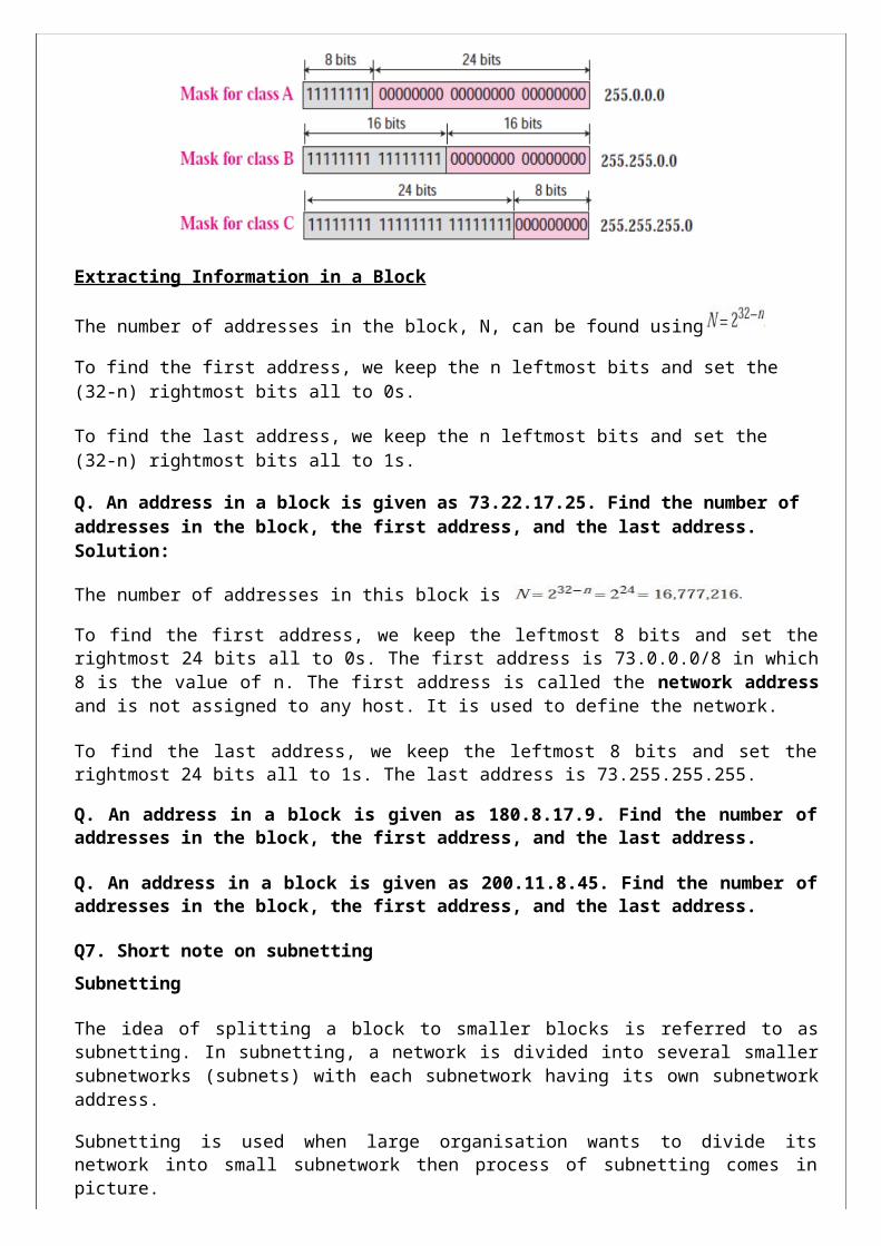
Network Mask
A network mask or a default mask in classful addressing is a 32-bit number with n leftmost bits all set to 1s and (32 −n) rightmost bits all set to 0s.

Extracting Information in a Block
The number of addresses in the block, N, can be found using
To find the first address, we keep the n leftmost bits and set the (32-n) rightmost bits all to 0s.
To find the last address, we keep the n leftmost bits and set the (32-n) rightmost bits all to 1s.
Q. An address in a block is given as 73.22.17.25. Find the number of addresses in the block, the first address, and the last address. Solution:
The number of addresses in this block is
To find the first address, we keep the leftmost 8 bits and set the rightmost 24 bits all to 0s. The first address is 73.0.0.0/8 in which 8 is the value of n. The first address is called the network address and is not assigned to any host. It is used to define the network.
To find the last address, we keep the leftmost 8 bits and set the rightmost 24 bits all to 1s. The last address is 73.255.255.255.
Q. An address in a block is given as 180.8.17.9. Find the number of addresses in the block, the first address, and the last address.
Q. An address in a block is given as 200.11.8.45. Find the number of addresses in the block, the first address, and the last address.
Q7. Short note on subnetting
Subnetting
The idea of splitting a block to smaller blocks is referred to as subnetting. In subnetting, a network is divided into several smaller subnetworks (subnets) with each subnetwork having its own subnetwork address.
Subnetting is used when large organisation wants to divide its network into small subnetwork then process of subnetting comes in picture.
Following diagram shows the concept of subnetting where network 141.14.0.0\16 divide into four subnet.

Advantages to subnetting:
Enables to use one IP address and split it up so that it can be used on several physically connected local networks.
Different network topologies can exist on different network segments within the same organization
Overall network traffic is reduced. Enables increased security by separating traffic into local networks.
Subnet MaskSubnetting increases the length of the netid and decreases the length of hostid. When we divide a network to s number of subnetworks, each of equal numbers of hosts, we can calculate the subnetid for each subnetwork as
nsub = n + log2s
SupernettingSubnetting could not completely solve address depletion problems in classful addressing because most organizations did not want to share their granted blocks with others.
In supernetting, an organization can combine several class C blocks to create a larger range of addresses. In other words, several networks are combined to create a super network.
Q8. Short note on CIDR or Slash notation or classless addressing.
Classless Addressing
In classful addressing, two-level addressing was provided by dividing an address into netid and hostid. The netid defined the network; the hostid defined the host in the network.

The same idea can be applied in classless addressing. When an organization is granted a block of addresses, the block is actually divided into two parts, the prefix and the suffix. The prefix plays the same role as the netid; the suffix plays the same role as the hostid.
Slash Notation
The netid length in classful addressing or the prefix length in classless addressing play a very important role when we need to extract the information about the block from a given address in the block. However, there is a difference here in classful and classless addressing.
In classful addressing, the netid length is inherent in the address. Given an address, we know the class of the address that allows us to find the netid length (8, 16, or 24).
In classless addressing, the prefix length cannot be found if we are given only an address in the block. The given address can belong to a block with any prefix length.
In classless addressing, we need to include the prefix length to each address if we need to find the block of the address. In this case, the prefix length, n, is added to the address separated by a slash. The notation is informally referred to as slash notation.
Extracting Block InformationAn address in slash notation (CIDR) contains all information we need about the block: the first address (network address), the number of addresses, and the last address. These three pieces of information can be found as follows:
The number of addresses in the block, N, can be found using
The first address (network address) in the block can be found by ANDing the address with the network mask:
First address= (any address) AND (network mask)
The last address in the block can be found by either adding the first address with the number of addresses or, directly, by ORing the address with the complement (NOTing) of the network mask:
Last address = (any address) OR [NOT (network mask)]
Q. One of the addresses in a block is 167.199.170.82/27. Find the number of addresses in the network, the first address, and the last address. Solution:-
The value of n is 27. The network mask has twenty-seven 1s and five 0s. It is 255.255.255.240.The number of addresses in the network is
We use the AND operation to find the first address (network address).The first address is 167.199.170.64/27.

To find the last address, we first find the complement of the network mask and then OR it with the given address: The last address is 167.199.170.95/27.
Q. One of the addresses in a block is 17.63.110.114/24. Find the number of addresses, the first address, and the last address in the block.
Q. One of the addresses in a block is 110.23.120.14/20. Find the number of addresses, the first address, and the last address in the block.
Designing SubnetsThe following steps need to be carefully followed to guarantee the proper operation of the subnetworks.
The number of addresses in each subnetwork should be a power of 2.The prefix length for each subnetwork should be found using the following formula:
The starting address in each subnetwork should be divisible by the number of addresses in that subnetwork. This can be achieved if we first assign addresses to larger networks.
Q. An organization is granted the block 130.34.12.64/26. The organization needs four subnetworks, each with an equal number of hosts. Design the subnetworks and find the information about each network.
SolutionThe number of addresses for the whole network can be found as
Using the process described in the previous section, the first address in the network is 130.34.12.64/26 and the last address is 130.34.12.127/26. We now design the subnetworks:
We grant 16 addresses for each subnetwork to meet the first requirement (64/16 is a power of 2).
The subnetwork mask for each subnetwork is:

Q. An organization is granted a block of addresses with the beginning address 14.24.74.0/24. The organization needs to have 3 sub blocks of addresses to use in its three subnets as shown below: One sub block of 120 addresses. One sub block of 60 addresses. One sub block of 10 addresses.
Q. an ISP is granted a block of addresses starting with 190.100.0.0/16 (65,536 addresses). The ISP needs to distribute these addresses to three groups of customers as follows: The first group has 64 customers; each needs approximately 256 addresses. The second group has 128 customers; each needs approximately 128 addresses. The third group has 128 customers; each needs approximately 64 addresses.
We design the sub blocks and find out how many addresses are still available after these allocations.
Q9. Short note on NAT
A technology that can provide the mapping between the private and universal addresses, and at the same time, support virtual private networks is network address translation (NAT).
The technology allows a site to use a set of private addresses for internal communication and a set of global Internet addresses (at least one) for communication with the rest of the world. The site must have only one single connection to the global Internet through a NAT-capable router that runs NAT software.
Below figure shows a simple implementation of NAT.
As the figure shows, the private network uses private addresses. The router that connects the network to the global address uses one private address and one global address. The private network is transparent to the rest of the Internet; the rest of the Internet sees only the NAT router with the address 200.24.5.8.
Address TranslationAll of the outgoing packets go through the NAT router, which replaces the source address in the packet with the global NAT address. All incoming packets also pass through the NAT router, which replaces the destination address in the packet (the NAT router global address) with the appropriate private address.
Translation Table

The reader may have noticed that translating the source addresses for an outgoing packet is straightforward. There may be tens or hundreds of private IP addresses, each belonging to one specific host. The problem is solved if the NAT router has a translation table.
Q10. Explain IPv4 packet format with help of neat diagram.
Packets in the network (internet) layer are called datagrams. A datagram is a variable-length packet consisting of two parts: header and data.
The header is 20 to 60 bytes in length and contains information essential to routing and delivery.
Version (VER): This 4-bit field defines the version of the IP protocol. Currently the version is 4.However, version 6 (or IPv6) may totally replace version 4 in the future.
Header Length (HLEN): This 4-bit field defines the total length of the datagram header in 4-byte words. When there are no options, the header length is 20 bytes, and the value of this
its maximum size, the value of this field is 15 (15x4=60).
Service Type: In the original design of IP header, this field was referred to as type of service (TOS), which defined how the datagram should be handled. Part of the field was used to define the precedence of the datagram; the rest defined the type of service (low delay, high throughput, and so on). IETF has changed the interpretation of this 8-bit field. This field now defines a set of differentiated services.
The first 6 bits make up the codepoint subfield and the last 2 bits are not used. The codepoint subfield can be used in two different ways.
When the 3 right-most bits are 0s, the 3 left-most bits are interpreted the same as the precedence bits in the service type interpretation.
The precedence defines the eight-level priority of the datagram (0 to 7) in issues such as congestion.
Total Length: This is a 16-bit field that defines the total length (header plus data) of the IP datagram in bytes.
Total length =Length of data + Header Length
Identification: This field is used in fragmentation.

Flags: This field is used in fragmentation
Fragmentation Offset: This field is used in fragmentation
Time to Live (TTL): A datagram has a limited lifetime in its travel through an internet. This field was originally designed to hold a timestamp, which was decremented by each visited router. The datagram was discarded when the value became zero.
Protocol: This 8-bit field defines the higher-level protocol that uses the services of the IP layer. An IP datagram can encapsulate data from several higher level protocols such as TCP, UDP, ICMP, and IGMP.
Checksum: This 16-bit field defines header checksum.
Source Address: This 32-bit field defines the IP address of the source.
Destination Address: This 32-bit field defines the IP address of the destination.
Q11. What is fragmentation? Explain with example.
A datagram can travel through different networks. Each router decapsulates the IP datagram from the frame it receives, processes it, and then encapsulates it in another frame.
The format and size of the received frame depend on the protocol used by the physical network through which the frame has just travelled.
Maximum Transfer Unit (MTU)
Each data link layer protocol has its own frame format in most protocols. One of the fields defined in the format is the maximum size of the data field. In other words, when a datagram is encapsulated in a frame, the total size of the datagram must be less than this maximum size.
The value of the MTU differs from one physical network protocol to another. For example, the value for the Ethernet LAN is 1500 bytes, for FDDI LAN is 4352 bytes, and for PPP is 296 bytes.
When a datagram is fragmented, each fragment has its own header with most of the fields repeated, but some changed. A fragmented datagram may itself be fragmented if it encounters a network with an even smaller MTU.
Q12. Explain various fields related to fragmentation.
Identification: This 16-bit field identifies a datagram originating from the source host. The combination of the identification and source IP address must uniquely define a datagram as it leaves the source host. To guarantee uniqueness, the IP protocol uses a counter to label the datagrams. The counter is initialized to a positive number. When the IP protocol sends a datagram, it copies the current value of the counter to the identification field and increments the counter by one.
When a datagram is fragmented, the value in the identification field is copied into all fragments.
Flags: This is a three-bit field. The first bit is reserved (not used). The second bit is called the do not fragment bit. If its value is 1, the machine must not fragment the datagram. If its value is 0, the datagram can be fragmented if necessary. The third bit is called the more fragment bit. If its value is 1, it means the datagram is not the last fragment; there are more fragments after this one. If its value is 0, it means this is the last or only fragment.

Fragmentation Offset: This 13-bit field shows the relative position of this fragment with respect to the whole datagram. It is the offset of the data in the original datagram measured in units of 8 bytes.A datagram with a data size of 4000 bytes fragmented into three fragments. The bytes in the original datagram are numbered 0 to 3999. The first fragment carries bytes 0 to 1399. The offset for this datagram is 0/8=0. The second fragment carries bytes 1400 to 2799; the offset value for this fragment is 1400/8 =175. Finally, the third fragment carries bytes 2800 to 3999. The offset value for this fragment is 2800/8 =350.
Q13. Explain the format of option in IPv4.
The header of the IP datagram is made of two parts: a fixed part and a variable part. The variable part comprises the options, which can be a maximum of 40 bytes. They can be used for network testing and debugging.
It is composed of a 1-byte type field, a 1-byte length field, and a variable-sized value field. The three fields are often referred to as type-length-value or TLV.
Type: The type field is 8 bits long and contains three subfields: copy, class, and number.
Copy: This 1-bit subfield controls the presence of the option in fragmentation. When its value is 0, it means that the option must be copied only to the first fragment. If its value is 1, it means the option must be copied to all fragments.
Class: This 2-bit subfield defines the general purpose of the option.
Number: This 5-bit subfield defines the type of option. Although 5 bits can define up to 32 different types, currently only 6 types are in use.
Length: The length field defines the total length of the option including the type field and the length field itself. This field is not present in all of the option types.
Value: The value field contains the data that specific options require.
Q14. Explain the different types of option in IP.
Six options are currently being used. Two of these are 1-byte options, and they do not require the length or the data fields. Four of them are multiple-byte options; they require the length and the data fields.
No-Operation OptionA no-operation option is a 1-byte option used as filler between options.
End-of-Option OptionAn end-of-option option is also a 1-byte option used for padding at the end of the option field.It, however, can only be used as the last option.
Record-Route OptionA record-route option is used to record the Internet routers that handle the datagram. It can list up to nine router IP addresses since the maximum size of the header is 60 bytes, which must include 20 bytes for the base header.
Strict-Source-Route OptionA strict-source-route option is used by the source to predetermine a route for the datagram as it travels through the Internet. Dictation of a route by the source can be useful for several purposes. The sender can choose a route with a specific type of service, such as minimum delay or maximum throughput.
Loose-Source-Route OptionA loose-source-route option is similar to the strict source route, but it is more relaxed. Each router in the list must be visited, but the datagram can visit other routers as well.
TimestampA timestamp option is used to record the time of datagram processing by a router. The time is expressed in milliseconds from midnight, Universal Time. Knowing the time a datagram is processed can help users and managers track the behaviour of the routers in the Internet. We can estimate the time it takes for a datagram to go from one router to another. We say estimate because, although all routers may use Universal Time, their local clocks may not be synchronized.
Q15. What is checksum? How to calculate checksum at sender and receiver side?
The error detection method used by most TCP/IP protocols is called the checksum. The checksum protects against the corruption that may occur during the transmission of a packet. It is redundant information added to the packet.
The checksum is calculated at the sender and the value obtained is sent with the packet. The receiver repeats the same calculation on the whole packet including the checksum.
Checksum Calculation at the Sender
To create the checksum the sender does the following:
The packet is divided into k sections, each of n bits. All sections are added together using one’s complement arithmetic. The final result is complemented to make the checksum.
Checksum Calculation at the Receiver

The receiver divides the received packet into k sections and adds all sections. It then complements the result. If the final result is 0, the packet is accepted; otherwise, it is rejected.
Q16. Explain the IP package in detail.
IP package involves eight components: a header-adding module, a processing module, a forwarding module, a fragmentation module, a reassembly module, a routing table, an MTU table, and a reassembly table.
Header-Adding ModuleThe header-adding module receives data from an upper-layer protocol along with the destination IP address. It encapsulates the data in an IP datagram by adding the IP header.
Processing ModuleThe processing module is the heart of the IP package. In our package, the processing module receives a datagram from an interface or from the header-adding module. It treats both cases the same. A datagram must be processed and routed regardless of where it comes from.
QueuesOur package uses two types of queues: input queues and output queues. The input queues store the datagrams coming from the data link layer or the upper-layer protocols. The output queues store the datagrams going to the data link layer or the upper layer protocols.
Routing TableThe routing table is used by the forwarding module to determine the next-hop address of the packet.
Forwarding ModuleThe forwarding module receives an IP packet from the processing module.
MTU Table

The MTU table is used by the fragmentation module to find the maximum transfer unit (MTU) of a particular interface.
Fragmentation ModuleIn our package, the fragmentation module receives an IP datagram from the forwarding module. The forwarding module gives the IP datagram, the IP address of the next station (either the final destination in a direct delivery or the next router in an indirect delivery), and the interface number through which the datagram is sent out.
Reassembly TableThe reassembly table is used by the reassembly module. In our package, the reassembly table has five fields: state, source IP address, datagram ID, time-out, and fragments.
Reassembly ModuleThe reassembly module receives, from the processing module, those datagram fragments that have arrived at their final destinations. In our package, the reassembly module treats an un-fragmented datagram as a fragment belonging to a datagram with only one fragment.
Q17. Explain different notation in IPv6 addressing.
An IPv6 address is 128 bits or 16 bytes (octet) long. The address length in IPv6 is four times of the length address in IPv4.
Notations
Several notations have been proposed to represent IPv6 addresses when they are handled by humans:
Dotted-Decimal Notation
Notation is convenient for 4-byte IPv4 addresses; it seems too long for 16-byte IPv6 addresses as shown below:
221.14.65.11.105.45.170.34.12.234.18.0.14.0.115.255
Colon Hexadecimal Notation
IPv6 specifies colon hexadecimal notation (or colon hex for short). In this notation, 128 bits are divided into eight sections, each 2 bytes in length. Two bytes in hexadecimal notation require four hexadecimal digits.
Zero compression, can be applied to colon hex notation if there are consecutive sections consisting of zeros only. We can remove all the zeros altogether and replace them with a double semicolon.
Mixed Representation
Sometimes we see a mixed representation of an IPv6 address: colon hex and dotted decimal notation.
FDEC:14AB:2311:BBFE:AAAA:BBBB:130.24.24.18CIDR Notation
IPv6 uses hierarchical addressing.IPv6 allows classless addressing and CIDR notation. For example

Q. Show the unabbreviated colon hex notation for the following IPv6 addresses:a. An address with 64 0s followed by 64 1s.b. An address with 128 0s.c. An address with 128 1s.d. An address with 128 alternative 1s and 0s.
Solution
a. 0000:0000:0000:0000: FFFF: FFFF: FFFF: FFFF b. 0000:0000:0000:0000:0000:0000:0000:0000c. FFFF: FFFF: FFFF: FFFF: FFFF: FFFF: FFFF: FFFFd. AAAA: AAAA: AAAA: AAAA: AAAA: AAAA: AAAA: AAAA
Q. The following shows the zero contraction versions of addresses.
a.:: FFFF: FFFF: FFFF: FFFFb. ::c. FFFF: FFFF: FFFF: FFFF: FFFF: FFFF: FFFF: FFFFd. AAAA: AAAA: AAAA: AAAA: AAAA: AAAA: AAAA: AAAA
Q. Show abbreviations for the following addresses:
a. 0000:0000: FFFF: 0000:0000:0000:0000:0000b. 1234:2346:0000:0000:0000:0000:0000:1111c. 0000:0001:0000:0000:0000:0000:1200:1000d. 0000:0000:0000:0000:0000: FFFF: 24.123.12.6
Solution
a. 0:0: FFFF::b. 1234:2346::1111c. 0:1::1200:1000d. ::FFFF:24.123.12.6
Q18. Explain the IPv6 packet format in detail.
Each packet is composed of a mandatory base header followed by the payload. The payload consists of two parts: optional extension headers and data from an upper layer.
The base header occupies 40 bytes, whereas the extension headers and data from the upper layer contain up to 65,535 bytes of information.
These fields are as follows:

Version: This 4-bit field defines the version number of the IP. For IPv6, the value is 6.
Traffic Class: This 8-bit field is used to distinguish different payloads with different delivery requirements. It replaces the service class field in IPv4.
Flow Label: The flow label is a 20-bit field that is designed to provide special handling for a particular flow of data. We will discuss this field later.
Payload Length: The 2-byte payload length field defines the length of the IP datagram excluding the base header.
Next Header: The next header is an 8-bit field defining the header that follows the base header in the datagram. The next header is either one of the optional extension headers used by IP or the header of an encapsulated packet such as UDP or TCP.
Hop Limit: This 8-bit hop limit field serves the same purpose as the TTL field in IPv4.
Source Address: The source address field is a 16-byte (128-bit) Internet address that identifies the original source of the datagram.
Destination Address: The destination address field is a 16-byte (128-bit) Internet address that usually identifies the final destination of the datagram.
Q19. Explain types of extension headers in IPv6. The length of the base header is fixed at 40 bytes. However, to give more functionality to the IP
datagram, the base header can be followed by up to six extension headers. Six types of extension headers have been defined as shown in below figure.
Hop-by-Hop OptionThe hop-by-hop option is used when the source needs to pass information to all routers visited by the datagram
Destination OptionThe destination option is used when the source needs to pass information to the destination only. Intermediate routers are not permitted access to this information.
Source RoutingThe source routing extension header combines the concepts of the strict source route and the loose source route options of IPv4.
FragmentationThe concept of fragmentation is the same as that in IPv4. However, the place where fragmentation occurs differs. In IPv4, the source or a router is required to fragment if the size of the datagram is larger than the MTU of the network over which the datagram travels. In IPv6, only the original source can fragment.
AuthenticationThe authentication extension header has a dual purpose: it validates the message sender and ensures the integrity of data. The former is needed so the receiver can be sure that a message is from the genuine sender and not from an imposter. The latter is needed to check that the data is not altered in transition by some hacker.
Encrypted Security PayloadThe encrypted security payload (ESP) is an extension that provides confidentiality and guards against eavesdropping.

Q20. Differentiate between IPv4 and IPv6.
The following shows the comparison between IPv4 and IPv6 headers.
The header length field is eliminated in IPv6 because the length of the header is fixed in this version.
The service type field is eliminated in IPv6. The traffic class and flow label fields together take over the function of the service type field.
The total length field is eliminated in IPv6 and replaced by the payload length field.
The identification, flag, and offset fields are eliminated from the base header in IPv6. They are included in the fragmentation extension header.
The TTL field is called hop limit in IPv6. The protocol field is replaced by the next header field.
The header checksum is eliminated because the checksum is provided by upper layer protocols; it is therefore not needed at this level.
The option fields in IPv4 are implemented as extension headers in IPv6.
Q21. Comparison between IPv4 and IPv6 options.
The no-operation and end-of-option options in IPv4 are replaced by Pad1 and PadN options in IPv6. The record route option is not implemented in IPv6 because it was not used. The timestamp option is not implemented because it was not used.
The source route option is called the source route extension header in IPv6.
The fragmentation fields in the base header section of IPv4 have moved to the fragmentation
Extension header in IPv6. The authentication extension header is new in IPv6.
The encrypted security payload extension header is new in IPv6.
Q22. Explain different types of transition strategies from IPv4 to IPv6.
Huge number of systems on the Internet, the transition from IPv4 to IPv6 cannot happen suddenly. It will take a considerable amount of time before every system in the Internet can move from IPv4 to IPv6.
The transition must be smooth to prevent any problems between IPv4 and IPv6 systems.Three strategies have been devised by the IETF to help the transition.
Dual StackIt is recommended that all hosts, before migrating completely to version 6, have a dual stack of protocols. In other words, a station must run IPv4 and IPv6 simultaneously until all the Internet uses IPv6.

Tunnelling
Tunnelling is a strategy used when two computers using IPv6 want to communicate with each other and the packet must pass through a region that uses IPv4. To pass through this region, the packet must have an IPv4 address. So the IPv6 packet is encapsulated in an IPv4 packet when it enters the region, and it leaves its capsule when it exits the region.
Header Translation
Header translation is necessary when the majority of the Internet has moved to IPv6 but some systems still use IPv4. The sender wants to use IPv6, but the receiver does not understand IPv6.Header translation uses the mapped address to translate an IPv6 address to an IPv4 address.

Unit-IITopics:
OSI Model |TCP/IP Protocol Suite | IPv4 Addresses and Protocol | IPv6 Addresses and
Protocol

Q1. Types of mapping and various protocol used in mapping.
Static Mapping
Static mapping means creating a table that associates a logical address with a physical address.This table is stored in each machine on the network.
Dynamic Mapping
In dynamic mapping, each time a machine knows the logical address of another machine; it can use a protocol to find the physical address.
Two protocols have been designed to perform dynamic mapping: Address Resolution Protocol (ARP) and Reverse Address Resolution Protocol (RARP).
ARP maps a logical address to a physical address. RARP maps a physical address to a logical address.
Q2. “ARP request is broadcast and reply is unicast”-comment.
When host or a router wants to send an IP datagram to another host or router, it has the logical (IP) address of the receiver. But the IP datagram must be encapsulated in a frame to be able to pass through the physical network.
This means that the sender needs the physical address of the receiver. ARP associates an IP address with its physical address.
To find the physical address of another host or router on its network, it sends an ARP query packet. The packet includes the physical and IP addresses of the sender and the IP address of the receiver. Because the sender does not know the physical address of the receiver, the query is broadcast over the network as shown above figure.

Every host or router on the network receives and processes the ARP query packet, but only the intended recipient recognizes its IP address and sends back an ARP response packet.
The response packet contains the recipient’s IP and physical addresses. The packet is unicast directly to the inquirer using the physical address received in the query packet.
Q3. Explain the packet format of ARP with neat diagram.
Below diagram shows the format of an ARP packet which consist of various fields are as follows:
Hardware Type: This is a 16-bit field defining the type of the network on which ARP is running.For example, Ethernet is given the type 1.
Protocol Type: This is a 16-bit field defining the protocol. For example, the value of this field for the IPv4 protocol is 0800.
Hardware Length: This is an 8-bit field defining the length of the physical address in bytes. For example, for Ethernet the value is 6.
Protocol Length: This is an 8-bit field defining the length of the logical address in bytes. For example, for the IPv4 protocol the value is 4.
Operation: This is a 16-bit field defining the type of packet. Two packet types are defined: ARP request (1), ARP reply (2).
Sender Hardware Address (SHA): This is a variable-length field defining the physical address of the sender. For example, for Ethernet this field is 6 bytes long.
Sender Protocol Address (SPA): This is a variable-length field defining the logical (for example, IP) address of the sender. For the IP protocol, this field is 4 bytes long.
Target Hardware Address (THA): This is a variable-length field defining the physical address of the target. For example, for Ethernet this field is 6 bytes long. For an ARP request message, this field is all 0s because the sender does not know the physical address of the target.
Target Protocol Address (TPA): This is a variable-length field defining the logical address of the target. For the IPv4 protocol, this field is 4 bytes long.
Q3. Explain ARP Encapsulation.
An ARP packet is encapsulated directly into a data link frame. For example, in below figure an ARP packet is encapsulated in an Ethernet frame.
Note that the type field indicates that the data carried by the frame is an ARP packet.

A host with IP address 130.23.43.20 and physical address B2:34:55:10:22:10 has a packet to send to another host with IP address 130.23.43.25 and physical address A4:6E:F4:59:83: AB (which is unknown to the first host). The two hosts are on the same Ethernet network. Show the ARP request and reply packets encapsulated in Ethernet frames.
Q4. Explain the packet format of ATMARP.
Packet FormatThe format of an ATMARP packet, which is similar to the ARP packet, is shown in figure. The fields are as follows:
Hardware type (HTYPE): The 16-bit HTYPE field defines the type of the physical network. Its value is 001316 for an ATM network.
Protocol type (PTYPE): The 16-bit PTYPE field defines the type of the protocol. For IPv4 protocol the value is 080016.
Sender hardware length (SHLEN): The 8-bit SHLEN field defines the length of the sender’s physical address in bytes. For an ATM network the value is 20.
Operation (OPER): The 16-bit OPER field defines the type of the packet. Five packet types are definedSender protocol length (SPLEN): The 8-bit SPLEN field defines the length of the address in bytes. For IPv4 the value is 4 bytes.
Target hardware length (TLEN): The 8-bit TLEN field defines the length of the receiver’s physical address in bytes. For an ATM network the value is 20.

Target protocol length (TPLEN): The 8-bit TPLEN field defines the length of the address in bytes. For IPv4 the value is 4 bytes.
Sender hardware address (SHA): The variable-length SHA field defines the physical address of the sender. For ATM networks defined by the ATM Forum, the length is 20 bytes.
Sender protocol address (SPA): The variable-length SPA field defines the address of the sender. For IPv4 the length is 4 bytes.
Target hardware address (THA): The variable-length THA field defines the physical address of the receiver. For ATM networks defined by the ATM Forum, the length is 20 bytes. This field is left empty for request messages and filled in for reply and NACK messages.
Target protocol address (TPA): The variable-length TPA field defines the address of the receiver. For IPv4 the length is 4 bytes.
Q5. Short note on ARP Proxy
A technique called proxy ARP is used to create a subnetting effect. A proxy ARP is an ARP that acts on behalf of a set of hosts. Whenever a router running a proxy ARP receives an ARP request looking for the IP address of one of these hosts, the router sends an ARP reply announcing its own hardware (physical) address.After the router receives the actual IP packet, it sends the packet to the appropriate host or router.
ARP installed on the right-hand host will answer only to an ARP request with a target IP address of 141.23.56.23.
One solution is to add a router running a proxy ARP. In this case, the router acts on behalf of all of the hosts installed on the subnet. When it receives an ARP request with a target IP address

that matches the address of one of its protégés (141.23.56.21, 141.23.56.22, and 141.23.56.23), it sends an ARP reply and announces its hardware address as the target hardware address.
Q6. Explain ATMARP Packet format with help of neat diagram.
When IP packet are moving through an ATMWAN, a mechanism protocol is needed to find (map) the physical address of the exiting-point router in the ATM WAN given the IP address of the router.
This is the same task performed by ARP on a LAN. However, there is a difference between a LAN and an ATM network. A LAN is a broadcast network (at the data link layer); ARP uses the broadcasting capability of a LAN to send (broadcast) an ARP request.
Following diagram shows the packet format of ATMARP.
The format of an ATMARP packet, which is similar to the ARP packet, is shown in above figure.The fields are as follows:
Hardware Type: The 16-bit HTYPE field defines the type of the physical network. Its value is 001316 for an ATM network.
Protocol Type: The 16-bit PTYPE field defines the type of the protocol. For IPv4 protocol the value is 080016.
Sender Hardware Length: The 8-bit SHLEN field defines the length of the sender’s physical address in bytes. For an ATM network the value is 20.
Reserved Field: It is made of 8-bit and used to define the length of the second address.
Operation (OPER): The 16-bit OPER field defines the type of the packet.
Sender Protocol Length (SPLEN): The 8-bit SPLEN field defines the length of the address in bytes. For IPv4 the value is 4 bytes.
Target Hardware Length (TLEN): The 8-bit TLEN field defines the length of the receiver’s physical address in bytes. For an ATM network the value is 20.
Target Protocol Length (TPLEN): The 8-bit TPLEN field defines the length of the address in bytes. For IPv4 the value is 4 bytes.
Sender Hardware Address (SHA): The variable-length SHA field defines the physical address of the sender. For ATM networks defined by the ATM Forum, the length is 20 bytes.
Sender Protocol Address (SPA): The variable-length SPA field defines the address of the sender. For IPv4 the length is 4 bytes.

Target Hardware Address (THA): The variable-length THA field defines the physical address of the receiver. For ATM networks defined by the ATM Forum, the length is 20 bytes.
Target Protocol Address (TPA): The variable-length TPA field defines the address of the receiver. For IPv4 the length is 4 bytes.
Q7. Explain ARP Package format with help of neat diagram.
ARP package consist of five components: a cache table, queues, an output module, an input module, and a cache-control module.
Below diagram shows structure of ARP Package.
Cache TableThe cache table is implemented as an array of entries. In our package, each entry contains the following fields:
State: This column shows the state of the entry. It can have one of three values: FREE, PENDING, or RESOLVED. The Free State means that the time-to-live for this entry has expired. The PENDING state means a request for this entry has been sent, but the reply has not yet been received. The RESOLVED state means that the entry is complete.
Queue Number: ARP uses numbered queues to enqueue the packets waiting for address resolution. Packets for the same destination are usually enqueued in the same queue.
Attempts: This column shows the number of times an ARP request is sent out for this entry.
Time-out: This column shows the lifetime of an entry in seconds. Queues
ARP package maintains a set of queues, one for each destination, to hold the IP packets while ARP tries to resolve the hardware address.
The output module sends unresolved packets into the corresponding queue. The input module removes a packet from a queue and sends it, with the resolved physical address, to the data link layer for transmission.

Q8. Explain ARP Output Module in detail.
Output module is one of component of ARP Package. Below pseudocode shows working of the output module in detail.
It consist of 2 condition, first if entry in found and second one in which entry is not found.
Q9. Explain ARP Input Module in detail.
Input module is one of component of ARP Package. Below pseudocode shows working of the input module in detail.
It consist of 2 condition, first if entry in found and second one in which entry is not found.

Q10. Explain ARP Cache-Control Module in detail.
Cache-Control module is one of component of ARP Package. Below pseudocode shows working of the cache control module in detail.
The cache-control module is responsible for maintaining the cache table. It periodically checks the cache table, entry by entry.

Q11. Need of ICMP at network layer.
The IP protocol has no error-reporting or error-correcting mechanism. The IP protocol also lacks a mechanism for host and management queries.
A host sometimes needs to determine if a router or another host is alive. And sometimes a network manager needs information from another host or router.
The Internet Control Message Protocol (ICMP) has been designed to compensate for the above two deficiencies.ICMP itself is a network layer protocol. However, its messages are not passed directly to the data link layer as would be expected. Instead, the messages are first encapsulated inside IP datagrams before going to the lower layer.

Q12. Explain the different types of ICMP messages.
ICMP messages are divided into two broad categories:
1. Error-reporting messages2. Query messages.
The error-reporting messages report problems that a router or a host (destination) may encounter when it processes an IP packet.
The query messages, which occur in pairs, help a host or a network manager get specific information from a router or another host.
Q13. Explain the different types of error reporting messages in ICMP.
Error Reporting Messages
The error-reporting messages report problems that a router or a host (destination) may encounter when it processes an IP packet.
Five types of errors are handled: destination unreachable, source quench, time exceeded parameter problems, and redirection as shown below figure.
Destination Unreachable
When a router cannot route a datagram or a host cannot deliver a datagram, the datagram is discarded and the router or the host sends a destination-unreachable message back to the source host that initiated the datagram.
Destination-unreachable messages with codes 2 or 3 can be created only by the destination host. Other destination-unreachable messages can be created only by routers.
Source Quench

The IP protocol is a connectionless protocol. There is no communication between the source host, which produces the datagram, the routers, which forward it, and the destination host, which processes it.
The source-quench message in ICMP was designed to add a kind of flow control and congestion control to the IP. When a router or host discards a datagram due to congestion, it sends a source-quench message to the sender of the datagram.
Time Exceeded
The time-exceeded message is generated in two cases:
1. Whenever a router decrements a datagram with a time-to-live value to zero, it discards the datagram and sends a time-exceeded message to the original source.
2. When the final destination does not receive all of the fragments in a set time, it discards the received fragments and sends a time-exceeded message to the original source.
Parameter Problem
Any ambiguity in the header part of a datagram can create serious problems as the datagram travels through the Internet. If a router or the destination host discovers an ambiguous or missing value in any field of the datagram, it discards the datagram and sends a parameter-problem message back to the source.
The code field in this case specifies the reason for discarding the datagram:
Code 0: There is an error or ambiguity in one of the header fields. In this case, the value in the pointer field points to the byte with the problem. For example, if the value is zero, then the first byte is not a valid field.
Code 1: The required part of an option is missing. In this case, the pointer is not used.
Redirection
When a router needs to send a packet destined for another network, it must know the IP address of the next appropriate router. The same is true if the sender is a host. Both routers and hosts then must have a routing table to find the address of the router or the next router.
For efficiency, hosts do not take part in the routing update process because there are many more hosts in an internet than routers. Updating the routing tables of hosts dynamically produces unacceptable traffic.
Q13. Explain the different types of query messages in ICMP.
The query messages, which occur in pairs, help a host or a network manager get specific information from a router or another host.
Echo Request and Reply

An echo-request message can be sent by a host or router. An echo-reply message is sent by the host or router that receives an echo-request message.
Echo-request and echo-reply messages can be used by network managers to check the operation of the IP protocol.
Echo-request and echo-reply messages can test the reachability of a host. This is usually done by invoking the ping command.
Timestamp Request and Reply
Two machines (hosts or routers) can use the timestamp-request and timestamp-reply messages to determine the round-trip time needed for an IP datagram to travel between them.
It can also be used to synchronize the clocks in two machines.
The timestamp-request and timestamp-reply messages can be used to compute the one-way or round-trip time required for a datagram to go from a source to a destination and then back again. The formulas are
For example, given the following information:
We can calculate the round-trip time to be 20 milliseconds:
Q14. Short note on Mobile IP
The main problem that must be solved in providing mobile communication using the IP protocol is addressing.
Stationary HostsThe original IP addressing was based on the assumption that a host is stationary, attached to one specific network. The IP addresses are designed to work with stationary hosts because part of the address defines the network to which the host is attached.
Mobile HostsWhen a host moves from one network to another, the IP addressing structure needs to be modified. Several solutions have been proposed. Changing the Address
One simple solution is to let the mobile host change its address as it goes to the new network.The host can use DHCP to obtain a new address to associate it with the new network.
This approach has several drawbacks. First, the configuration files would need to be changed.Second, each time the computer moves from one network to another, it must be rebooted.

Two AddressesThe approach that is more feasible is the use of two addresses. The host has its original address, called the home address, and a temporary address, called the care-of address.
The home address is permanent; it associates the host to its home network, the network that is the permanent home of the host. The care-of address is temporary.
When a host moves from one network to another, the care-of address changes; it is associated with the foreign network, the network to which the host moves.
Q15. Explain different types of agent in Mobile IP.
There are two of agents in Mobile IP i.e. Home Agent and Foreign AgentTo make the change of address transparent to the rest of the Internet requires a home agent and a foreign agent. Below figure shows the position of a home agent relative to the home network and a foreign agent relative to the foreign network.
Home Agent
The home agent is usually a router attached to the home network of the mobile host as shown above diagram.
The home agent acts on behalf of the mobile host when a remote host sends a packet to the mobile host. The home agent receives the packet and sends it to the foreign agent.
Foreign Agent
The foreign agent is usually a router attached to the foreign network. The foreign agent receives and delivers packets sent by the home agent to the mobile host.
The mobile host can also act as a foreign agent. In other words, the mobile host and the foreign agent can be the same.When the mobile host acts as a foreign agent, the care-of address is called a colocated care-of address.
The advantage of using a colocated care-of address is that the mobile host can move to any network without worrying about the availability of a foreign agent. The disadvantage is that the mobile host needs extra software to act as its own foreign agent.

Q16. What are the three phases that a mobile host should go through to communicate with the remote host?
To communicate with a remote host, a mobile host goes through three phases:
Agent discovery Registration Data transfer
Agent Discovery
The first phase in mobile communication, agent discovery, consists of two sub phases. A mobile host must discover a home agent before it leaves its home network.
A mobile host must also discover a foreign agent after it has moved to a foreign network. This discovery consists of learning the care-of address as well as the foreign agent’s address.
The discovery involves two types of messages: advertisement and solicitation. Agent Advertisement
When a router advertises its presence on a network using an ICMP router advertisement, it can append an agent advertisement to the packet if it acts as an agent. Agent Solicitation
When a mobile host has moved to a new network and has not received agent advertisements, it can initiate an agent solicitation.
Registration
The second phase in mobile communication is registration. After a mobile host has moved to a foreign network and discovered the foreign agent, it must register. There are four aspects of registration:
1. The mobile host must register itself with the foreign agent.2. The mobile host must register itself with its home agent.3. The mobile host must renew registration if it has expired.4. The mobile host must cancel its registration (deregistration) when it returns home.

Request and Reply
To register with the foreign agent and the home agent, the mobile host uses a registration request and a registration reply.
Data Transfer
After agent discovery and registration, a mobile host can communicate with a remote host.
Q17. What is the inefficiency in mobile IP? Explain with the solution.
INEFFICIENCY IN MOBILE IPCommunication involving mobile IP can be inefficient. The inefficiency can be severe or moderate. The severe case is called double crossing or 2X. The moderate case is called triangle routing or dog-leg routing
Double CrossingDouble crossing occurs when a remote host communicates with a mobile host that has moved to the same network (or site) as the remote host. When the mobile host sends a packet to the remote host, there is no inefficiency; the communication is local.
However, when the remote host sends a packet to the mobile host, the packet crosses the Internet twice. Since a computer usually communicates with other local computers (principle of locality), the inefficiency from double crossing is significant.
Triangle RoutingTriangle routing, the less severe case, occurs when the remote host communicates with a mobile host that is not attached to the same network (or site) as the mobile host. When the mobile host sends a packet to the remote host, there is no inefficiency.However, when the remote host sends a packet to the mobile host, the packet goes from the remote host to the home agent and then to the mobile host. The packet travels the two sides of a triangle, instead of just one side.
SolutionOne solution to inefficiency is for the remote host to bind the care-of address to the home address of a mobile host. For example, when a home agent receives the first packet for a mobile host, it forwards the packet to the foreign agent; it could also send an update binding packet to the remote host so that future packets to this host could be sent to the care-of address. The remote host can keep this information in a cache.

The problem with this strategy is that the cache entry becomes outdated once the mobile host moves. In this case the home agent needs to send a warning packet to the remote host to inform it of the change.
Q18. What is routing? Explain types of routing table.Routing
It is a process of finding shortest path in minimum time in minimum distance. For this purpose router maintains its routing table. There are two types of routing table as follows. A routing table can be of 2 types as follows.
Static Table Dynamic. Table
A static table is one with manual entries. A dynamic table, on the other hand, is one that is updated automatically when there is a change somewhere in the internet.
Q19. Explain different types of routing protocol.Routing Protocol
Routing protocols have been created in response to the demand for dynamic routing tables. A routing protocol is a combination of rules.
Routing protocols can be either an interior protocol or an exterior protocol. An interior protocol handles intra domain routing; an exterior protocol handles inter domain routing.
An internet is divided into autonomous systems. An autonomous system (AS) is a group of networks and routers under the authority of a single administration.
Routing inside an autonomous system is referred to as intra-domain routing.
Routing between autonomous systems is referred to as inter-domain routing.
Routing Information Protocol (RIP) is the implementation of the distance vector protocol. Open Shortest Path First (OSPF) is the implementation of the link state protocol. Border Gateway Protocol (BGP) is the implementation of the path vector protocol. RIP and OSPF are interior routing protocols; BGP is an exterior routing protocol.

Q20. Explain distance vector routing in detail.
This method sees an AS, with all routers and networks, as a graph, a set of nodes and lines (edges) connecting the nodes. A router can normally be represented by a node and a network by a link connecting two nodes, although other representations are also possible.
The graph theory used an algorithm called Bellman-Ford for a while to find the shortest path between nodes in a graph given the distance between nodes.
Distance Vector Routing Algorithm
Distance vector algorithm works as follows.
In distance vector routing, the cost is normally hop counts (how many networks are passed before reaching the destination). So the cost between any two neighbours is set to 1.
Each router needs to update its routing table asynchronously, whenever it has received some information from its neighbours.
After a router has updated its routing table, it should send the result to its neighbours so that they can also update their routing table.
Each router should keep at least three pieces of information for each route: destination network, the cost, and the next hop.
Q21. How Bellman-Ford algorithm helps to find least cost between any two nodes?
Bellman-Ford Algorithm
The algorithm can be used in many applications in graph theory. If we know the cost between each pair of nodes, we can use the algorithm to find the least cost (shortest path) between any two nodes. Below figure shows a map with nodes and lines. The cost of each line is given over the line; the algorithm can find the least cost between any two nodes.
We create a shortest distance table (vector) for each node using the following steps: The shortest distance and the cost between a node and itself is initialized to 0.
The shortest distance between a node and any other node is set to infinity. The cost between a node and any other node should be given (can be infinity if the nodes are not connected).

The algorithm repeat until there is no more change in the shortest distance vector.
Q22. State and explain the solutions to the two node instability in RIP.Count to InfinityFor a routing protocol to work properly, if a link is broken (cost becomes infinity), every other router should be aware of it immediately, but in distance vector routing, this takes some time.
The problem is referred to as count to infinity. It takes several updates before the cost for a broken link is recorded as infinity by all routers.
One example of count to infinity is the two-node loop problem.
At the beginning, both nodes A and B know how to reach node X. But suddenly, the link between A and X fails. Node A changes its table. If A can send its table to B immediately, everything is fine.
However, the system becomes unstable if B sends its routing table to A before receiving A’s routing table. Node A receives the update and, assuming that B has found a way to reach X, immediately updates its routing table. Now A sends its new update to B.
Now B thinks that something has been changed around A and updates its routing table. The cost of reaching X increases gradually until it reaches infinity. At this moment, both A and B know that X cannot be reached. However, during this time the system is not stable. Node A thinks that the route to X is via B; node B thinks that the route to X is via A.
A few solutions have been proposed for instability of this kind.
Defining Infinity
The first obvious solution is to redefine infinity to a smaller number, such as 16.
Split Horizon

Another solution is called split horizon. Node B thinks that the optimum route to reach X is via A, it does not need to advertise this piece of information to A; the information has come from A (A already knows).
Q23. Explain the packet format of RIP.
RIP Message Format
The format of the RIP message is shown in Figure.
Command: This 8-bit field specifies the type of message: request (1) or response (2).
Version: This 8-bit field defines the version. In this book we use version 1, but at the end of this section, we give some new features of version 2.
Family: This 16-bit field defines the family of the protocol used. For TCP/IP the value is 2.
Network Address: The address field defines the address of the destination network. RIP has allocated 14 bytes for this field to be applicable to any protocol. However, IP currently uses only 4 bytes. The rest of the address is filled with 0s.
Distance: This 32-bit field defines.
Q24. Explain the different types of RIP Timers.
Timers in RIP
RIP uses three timers to support its operation The periodic timer controls the sending of messages, the expiration timer governs the validity of a route, and the garbage collection timer advertises the failure of a route.
Periodic Timer
The periodic timer controls the advertising of regular update messages. Although the protocol specifies that this timer must be set to 30 s, the working model uses a random number between 25 and 35 s.
This is to prevent any possible synchronization and therefore overload on an internet if routers update simultaneously.
Each router has one periodic timer that is randomly set to a number between 25 and 35. It counts down; when zero is reached, the update message is sent, and the timer is randomly set once again.
Expiration Timer

The expiration timer governs the validity of a route. When a router receives update information for a route, the expiration timer is set to 180 s for that particular route. Every time a new update for the route is received, the timer is reset. In normal situations this occur every 30 s.
However, if there is a problem on an internet and no update is received within the allotted 180 s, the route is considered expired and the hop count of the route is set to 16, which means the destination is unreachable.
Garbage Collection TimerWhen the information about a route becomes invalid, the router does not immediately purge that route from its table. Instead, it continues to advertise the route with a metric value of 16.
At the same time, a timer called the garbage collection timer is set to 120 s for that route.When the count reaches zero, the route is purged from the table.
Q25. Explain link state routing.Link state routing has a different philosophy from that of distance vector routing. In link state routing, if each node in the domain has the entire topology of the domain— the list of nodes and links, how they are connected including the type, cost (metric), and the condition of the links (up or down) the node can use the Dijkstra algorithm to build a routing table.
In link state routing it share information with its neighbours whenever there is change in network in terms of adding or removing from exiting network. Whereas in distance vector routing it share information with its neighbours after specific period of time around 25 to 35 second.
Q26. Explain Area and Metric in OSPF.
The Open Shortest Path First (OSPF) protocol is an intra domain routing protocol based on link state routing. Its domain is also an autonomous system.
AreasTo handle routing efficiently and in a timely manner, OSPF divides an autonomous system into areas. An area is a collection of networks, hosts, and routers all contained within an autonomous system.
An autonomous system can be divided into many different areas. All networks inside an area must be connected Routers inside an area flood the area with routing information.
At the border of an area, special routers called area border routers summarize the information about the area and send it to other areas. Among the areas inside an autonomous system is a special area called the backbone; all of the areas inside an autonomous system must be connected to the backbone.
The routers inside the backbone are called the backbone routers.
Metric
The OSPF protocol allows the administrator to assign a cost, called the metric, to each route. The metric can be based on a type of service (minimum delay, maximum throughput, and so on).
Q27. Explain different types of links in OSPF.

In OSPF terminology, a connection is called a link. Four types of links have been defined:point-to-point, transient, stub, and virtual.
Point-to-Point Link
A point-to-point link connects two routers without any other host or router in between. In other words, the purpose of the link (network) is just to connect the two routers.
Transient Link
A transient link is a network with several routers attached to it. The data can enter through any of the routers and leave through any router. All LANs and some WANs with two or more routers are of this type. In this case, each router has many neighbours.
Stub Link
A stub link is a network that is connected to only one router. The data packets enter the network through this single router and leave the network through this same router.
Virtual Link
When the link between two routers is broken, the administration may create a virtual link between them using a longer path that probably goes through several routers.
Q28. Explain different types of packets in OSPF.
OSPF uses five different types of packets: hello, database description, link state request, link state update, and link state acknowledgment.
The most important one is the link state update that itself has five different kinds.

Common Header
All OSPF packets have the same common header before studying the different types of packets; let us talk about this common header.
Version: This 8-bit field defines the version of the OSPF protocol. It is currently version 2.
Type: This 8-bit field defines the type of the packet. As we said before, we have five types, with values 1 to 5 defining the types.
Message Length: This 16-bit field defines the length of the total message including the header.
Source Router IP Address: This 32-bit field defines the IP address of the router that sends the packet.
Area Identification: This 32-bit field defines the area within which the routing takes place.
Checksum: This field is used for error detection on the entire packet excluding the authentication type and authentication data field.
Authentication Type: This 16-bit field defines the authentication protocol used in this area. Atthis time, two types of authentication are defined: 0 for none and 1 for password.
Authentication: This 64-bit field is the actual value of the authentication data.
Q29. Explain Hello packet in OSPF.
OSPF uses the hello message to create neighbourhood relationships and to test the reachability of neighbours. This is the first step in link state routing.
Before a router can flood all of the other routers with information about its neighbours, it must first greet its neighbours. It must know if they are alive, and it must know if they are reachable.

Network Mask: This 32-bit field defines the network mask of the network over which the hello message is sent.
Hello Interval: This 16-bit field defines the number of seconds between hello messages.
E flag: This is a 1-bit flag. When it is set, it means that the area is a stub area.
T flag: This is a 1-bit flag. When it is set, it means that the router supports multiple metrics.
Priority: This field defines the priority of the router.
Dead Interval: This 32-bit field defines the number of seconds that must pass, before a router assumes that a neighbour is dead.
Designated Router IP Address: This 32-bit field is the IP address of the designated router for the network over which the message is sent.
Backup designated Router IP Address: This 32-bit field is the IP address of the backup designated router for the network over which the message is sent.
Neighbour IP Address: This is a repeated 32-bit field that defines the routers that have agreed to be the neighbours of the sending router.
Database Description MessageWhen a router is connected to the system for the first time or after a failure, it needs the complete link state database immediately. It cannot wait for all links state update packets to come from every other router before making its own database and calculating its routing table.
Therefore, after a router is connected to the system, it sends hello packets to greet its neighbours. If this is the first time that the neighbours hear from the router, they send a database description message.
Link State Request Packet
This is a packet that is sent by a router that needs information about a specific route or routes. It is answered with a link state update packet. It can be used by a newly connected router to request more information about some routes after receiving the database description packet.
Link State Update Packet
Link state update packet the heart of the OSPF operation. It is used by a router to advertise the states of its links.
Link State Acknowledgment Packet
OSPF makes routing more reliable by forcing every router to acknowledge the receipt of every link state update packet.
Q30. Explain different types of LSA in OSPF.

Router Link LSA
A router link defines the links of a true router. A true router uses this advertisement to announce information about its entire links and what is at the other side of the link (neighbours).
Network Link LSAA network link defines the links of a network. A designated router, on behalf of the transient network, distributes this type of LSP packet. The packet announces the existence of all of the routers connected to the network.
Summary Link to Network LSARouter link and network link advertisements flood the area with information about the router links and network links inside an area. But a router must also know about the networks outside its area; the area border routers can provide this information.
Summary Link to AS Boundary Router LSA
The previous advertisement lets every router know the cost to reach all of the networks inside the autonomous system.
If a router inside an area wants to send a packet outside the autonomous system, it should first know the route to an autonomous boundary router; the summary link to AS boundary router provides this information.

External Link LSA
Although the previous advertisement lets each router know the route to an AS boundary router, this information is not enough.
A router inside an autonomous system wants to know which networks are available outside the autonomous system; the external link advertisement provides this information.
Q31. Explain Path Vector Routing.
Path vector routing is exterior routing protocol proved to be useful for inter domain or inter-AS routing as it is sometimes called.
In distance vector routing, a router has a list of networks that can be reached in the same AS with the corresponding cost (number of hops). In path vector routing, a router has a list of networks that can be reached with the path (list of ASs to pass) to reach each one.
ReachabilityTo be able to provide information to other ASs, each AS must have at least one path vector routing that collects reachability information about each network in that AS.
The information collected in this case only means which network, identified by its network address (CIDR prefix), exists (can be reached in this AS).

Q32. Explain different types of AS in BGP.
Internet is divided into hierarchical domains called autonomous systems (ASs).
We can divide autonomous systems into three categories: stub, multihomed and transit.
Stub AS
A stub AS has only one connection to another AS. The inter domain data traffic in a stub AS can be either created or terminated in the AS.
Multihomed ASA multihomed AS has more than one connection to other ASs, but it is still only a source or sink for data traffic. It can receive data traffic from more than one AS.
It can send data traffic to more than one AS, but there is no transient traffic. It does not allow data coming from one AS and going to another AS to pass through.
Transit ASA transit AS is a multihomed AS that also allows transient traffic.

Q33. Explain Path Attribute and BGP Session.
Path AttributesThe list of attributes helps the receiving router make a better decision when applying its policy.Attributes are divided into two broad categories: well-known and optional.
A well-known attribute is one that every BGP router must recognize.
An optional attribute is one that needs not be recognized by every router.
BGP SessionsThe exchange of routing information between two routers using BGP takes place in a session. A session is a connection that is established between two BGP routers only for the sake of exchanging routing information.
The session established between AS1 and AS2 is an E-BGP session. The two speaker routers exchange information they know about networks in the Internet.
However, these two routers need to collect information from other routers in the autonomous systems. This is done using I-BGP sessions.
Q34. Explain different types of message in BGP.
BGP uses four different types of messages: open, update, keepalive, and notification.
Packet Format
All BGP packets share the same common header. The fields of this header are as follows:
Marker: The 16-byte marker field is reserved for authentication.
Length: This 2-byte field defines the length of the total message including the header.
Type: This 1-byte field defines the type of the packet. As we said before, we have four types, and
the values 1 to 4 define those types.

Open MessageTo create a neighbourhood relationship, a router running BGP opens a TCP connection with a neighbour and sends an open message.
If the neighbour accepts the neighbourhood relationship, it responds with a keepalive message, which means that a relationship has been established between the two routers.
Update MessageThe update message is the heart of the BGP protocol. It is used by a router to withdraw destinations that have been advertised previously, announce a route to a new destination, or both.
Keepalive MessageThe routers (called peers in BGP parlance) running the BGP protocols exchange keepalive messages regularly (before their hold time expires) to tell each other that they are alive. The keepalive message consists of only the common header.
Notification MessageA notification message is sent by a router whenever an error condition is detected or a router wants to close the connection. The format of the message is shown in figure.
Error Code: This 1-byte field defines the category of the error.
Error Sub-code: This 1-byte field further defines the type of error in each category.
Error Data: This field can be used to give more diagnostic information about the error.

Unit-IIITopics:
TCP | UDP

Q1. What are the services of TCP?Following are various services of provided by TCP
Process-to-Process CommunicationTCP provides process-to-process communication using port numbers following lists shows some well-known port numbers used by TCP.
Stream Delivery ServiceTCP, unlike UDP, is a stream-oriented protocol. TCP allows the sending process to deliver data as a stream of bytes and allows the receiving process to obtain data as a stream of bytes.TCP creates an environment in which the two processes seem to be connected by an imaginary “tube” that carries their bytes across the Internet.
Because the sending and the receiving processes may not necessarily write or read data at the same rate, TCP needs buffers for storage. There are two buffers, the sending buffer and the receiving buffer, one for each direction.
Full-Duplex CommunicationTCP offers full-duplex service, where data can flow in both directions at the same time.
Multiplexing and DemultiplexingTCP performs multiplexing at the sender and demultiplexing at the receiver.
Connection-Oriented ServiceTCP is a connection-oriented protocol. When a process at site A wants to send to and receive data from another process at site B, the following three phases occur:
The two TCPs establish a virtual connection between them.

Data are exchanged in both directions. The connection is terminated.
Reliable ServiceTCP is a reliable transport protocol. It uses an acknowledgment mechanism to check the safe and sound arrival of data.
Q2. Explain Byte number, Sequence number, Acknowledgement number with example. OR Explain features of TCP.
Numbering SystemTCP software keeps track of the segments being transmitted or received; there is no field for a segment number value in the segment header. Instead, there are two fields called the sequence number and the acknowledgment number. These two fields refer to a byte number and not a segment number.
Byte NumberTCP numbers all data bytes (octets) that are transmitted in a connection. Numbering is independent in each direction. When TCP receives bytes of data from a process, TCP stores them in the sending buffer and numbers them.
The numbering does not necessarily start from 0.For example, if the number happens to be 1,057 and the total data to be sent is 6,000 bytes, the bytes are numbered from 1,057 to 7,056.
Sequence NumberAfter the bytes have been numbered, TCP assigns a sequence number to each segment that is being sent. The sequence number for each segment is the number of the first byte of data carried in that segment.
Acknowledgment NumberThe value of the acknowledgment field in a segment defines the number of the next byte a party expects to receive. The acknowledgment number is cumulative.
Flow ControlTCP, unlike UDP, provides flow control. The sending TCP controls how much data can be accepted from the sending process; the receiving TCP controls how much data can to be sent by the sending TCP. This is done to prevent the receiver from being overwhelmed with data.
Error ControlTo provide reliable service, TCP implements an error control mechanism. Although error control considers a segment as the unit of data for error detection (loss or corrupted segments)
Congestion ControlTCP, unlike UDP, takes into account congestion in the network. The amount of data sent by a sender is not only controlled by the receiver (flow control), but is also determined by the level of congestion, if any, in the network.
Q3. Explain TCP segment format with diagram.
A packet in TCP is called a segment. The format of a segment is shown in below figure. The segment consists of a header of 20 to 60 bytes, followed by data from the application program. The header is 20 bytes if there are no options and up to 60 bytes if it contains options.

Source Port Address (SPA): This is a 16-bit field that defines the port number of the application program in the host that is sending the segment.
Destination Port Address (DPA): This is a 16-bit field that defines the port number of the application program in the host that is receiving the segment.
Sequence Number: This 32-bit field defines the number assigned to the first byte of data contained in segment.During connection establishment (discussed later) each party uses a random number generator to create an initial sequence number (ISN), which is usually different in each direction.
Acknowledgment Number: This 32-bit field defines the byte number that the receiver of the segment is expecting to receive from the other party. If the receiver of the segment has
acknowledgment number.
Header Length: This 4-bit field indicates the number of 4-byte words in the TCP header. The length of the header can be between 20 and 60 bytes.
Reserved: This is a 6-bit field reserved for future use.
Control Fields: This field defines 6 different control bits or flags as shown in figure.
Window Size: This field defines the window size of the sending TCP in bytes. Note that the length of this field is 16 bits, which means that the maximum size of the window is 65,535 bytes. This value is normally referred to as the receiving window (rwnd) and is determined by the receiver.
Checksum: This 16-bit field contains the checksum.
Urgent Pointer: This 16-bit field, which is valid only if the urgent flag is set, is used when the segment contains urgent data.
Options: There can be up to 40 bytes of optional information in the TCP header.

Q4. Explain TCP connection establishment by 3 way handshaking concept.
Connection EstablishmentTCP transmits data in full-duplex mode. When two TCPs in two machines are connected, they are able to send segments to each other simultaneously. This implies that each party must initialize communication and get approval from the other party before any data are transferred.
Three-Way HandshakingThe connection establishment in TCP is called three-way handshaking. An application program, called the client, wants to make a connection with another application program, called the server, using TCP as the transport layer protocol.
The three steps in this phase are as follows.
The client sends the first segment, a SYN segment, in which only the SYN flag is set. This segment is for synchronization of sequence numbers. The client in our example chooses a random number as the first sequence number and sends this number to the server. This sequence number is called the initial sequence number (ISN).
The server sends the second segment, a SYN + ACK segment with two flag bits set: SYN and ACK. This segment has a dual purpose. First, it is a SYN segment for communication in the other direction.
The client sends the third segment. This is just an ACK segment. It acknowledges the receipt of the second segment with the ACK flag and acknowledgment number field.
Q5. Explain TCP connection termination by 3 way handshaking concept.
Connection TerminationAny of the two parties involved in exchanging data (client or server) can close the connection, although it is usually initiated by the client.
Most implementations allow two options for connection termination: three-way handshaking and four-way handshaking with a half-close option.
Three-Way Handshaking
In a common situation, the client TCP, after receiving a close command from the client process, sends the first segment, a FIN segment in which the FIN flag is set.

The server TCP, after receiving the FIN segment, informs its process of the situation and sends the second segment, a FIN+ACK segment, to confirm the receipt of the FIN segment from the client and at the same time to announce the closing of the connection in the other direction.
The client TCP sends the last segment, an ACK segment, to confirm the receipt of the FIN segment from the TCP server.
Q6. Explain Half Close in TCP Connection Termination.
In TCP, one end can stop sending data while still receiving data. This is called a half close. Either the server or the client can issue a half-close request. It can occur when the server needs all the data before processing can begin.
A good example is sorting. When the client sends data to the server to be sorted, the server needs to receive all the data before sorting can start. This means the client, after sending all data, can close the connection in the client-to-server direction.
However, the server-to-client direction must remain open to return the sorted data. The server, after receiving the data, still needs time for sorting; its outbound direction must remain open.

The data transfer from the client to the server stops. The client half-closes the connection by sending a FIN segment. The server accepts the half-close by sending the ACK segment.
The server, however, can still send data. When the server has sent all of the processed data, it sends a FIN segment, which is acknowledged by an ACK from the client.
Q7. Explain the server states of the TCP state transition.
To keep track of all the different events happening during connection establishment, connection termination, and data transfer, TCP is specified as the finite state machine shown in figure.
Client States
The client process issues a command to its TCP to request a connection to a specific socket address. This called an active open. TCP sends a SYN segment and moves to the SYN-SENT state.
After receiving the SYN+ACK segment, TCP sends an ACK segment and goes to the ESTABLISHED state. Data are transferred, possibly in both directions, and acknowledged.
When the client process has no more data to send, it issues a command called an active close. The client TCP sends a FIN segment and goes to the FIN-WAIT-1 state.
When it receives the ACK for the sent FIN, it goes to FIN-WAIT-2 state and remains there until it receives a FIN segment from the server. When the FIN segment is received, the client sends an ACK segment and goes to the TIME-WAIT state and sets a timer for a time-out value of twice the maximum segment lifetime (MSL).
Server States
The server process issues an open command. This must happen before the client issues an open command. The server TCP goes to the LISTEN state and remains there, passively, until it receives a SYN segment.
When the server TCP receives a SYN segment, it sends a SYN+ACK segment and goes to SYNRCVD state, waiting for the client to send an ACK segment.

After receiving the ACK segment, it goes to ESTABLISHED state, where data transfer can take place. TCP remains in this state until it receives a FIN segment from the client TCP signifying that there are no more data to be sent and that the connection can be closed.
At this moment, the server sends an ACK to the client, delivers outstanding data in its queue to the application, and goes to the CLOSE-WAIT state. In our scenario, we assume a half-close connection. The server TCP can still send data to the client and receive acknowledgments, but no data can flow in the other direction.
The server TCP remains in this state until the application actually issues a close command. It then sends a FIN to the client to show that it is closing the connection too, and goes to LAST-ACK state. It remains in this state until it receives the final ACK, when it then goes to the CLOSED state. The termination phase beginning with the first FIN is called a four-way handshake.
Q8. What is silly window syndrome? Explain the syndrome created by the sender and the receiver.
A serious problem can arise in the sliding window operation when either the sending application program creates data slowly or the receiving application program consumes data slowly, or both which reduces the efficiency of the operation.
For example, if TCP sends segments containing only 1 byte of data, it means that a 41-byte datagram (20 bytes of TCP header and 20 bytes of IP header) transfers only 1 byte of user data. Here the overhead is 41/1, which indicates that we are using the capacity of the network very inefficiently. The inefficiency is even worse after accounting for the data link layer and physical layer overhead. This problem is called the silly window syndrome.
Syndrome Created by the SenderThe sending TCP may create a silly window syndrome if it is serving an application program that creates data slowly.Solution of this problem is below algorithm.
Nagle’s Algorithm
Nagle’s algorithm is simple:
The sending TCP sends the first piece of data it receives from the sending application program even if it is only 1 byte.
After sending the first segment, the sending TCP accumulates data in the output buffer and waits until either the receiving TCP sends an acknowledgment or until enough data has accumulated to fill a maximum-size segment.
Step 2 is repeated for the rest of the transmission. Segment 3 is sent immediately if an acknowledgment is received for segment 2, or if enough data have accumulated to fill a maximum-size segment.
Syndrome Created by the ReceiverThe receiving TCP may create a silly window syndrome if it is serving an application program that consumes data slowly.
Two solutions have been proposed to prevent the silly window syndrome created by an application program that consumes data slower than they arrive.
Clark’s Solution

Clark’s solution is to send an acknowledgment as soon as the data arrive, but to announce a window size of zero until either there is enough space to accommodate a segment of maximum size or until at least half of the receive buffer is empty.
Delayed AcknowledgmentThe second solution is to delay sending the acknowledgment. This means that when a segment arrives, it is not acknowledged immediately. Delayed acknowledgment also has another advantage: it reduces traffic.
Q8. How to achieve error handling in TCP?
TCP is a reliable transport layer protocol. This means that an application program that delivers a stream of data to TCP relies on TCP to deliver the entire stream to the application program.
TCP provides reliability using error control. Error control includes mechanisms for detecting and resending corrupted segments, resending lost segments, storing out of order segments until missing segments arrive, and detecting and discarding duplicated segments.
Error control in TCP is achieved through the use of three simple tools: Checksum, Acknowledgment, and Time-Out.
Checksum
Each segment includes a checksum field, which is used to check for a corrupted segment. If a segment is corrupted as deleted by an invalid checksum, the segment is discarded by the destination TCP and is considered as lost. TCP uses a 16-bit checksum that is mandatory in every segment.
AcknowledgmentTCP uses acknowledgments to confirm the receipt of data segments. Control segments that carry no data, but consume a sequence number, are also acknowledged. ACK segments are never acknowledged.
TCP used only 2 type of acknowledgment: Cumulative acknowledgment and Selective acknowledgment.
Cumulative Acknowledgment (ACK)TCP was originally designed to acknowledge receipt of segments cumulatively. This is sometimes referred to as positive cumulative acknowledgment or ACK. The word “positive” indicates that no feedback is provided for discarded, lost, or duplicate segments. The 32-bit ACK field in the TCP header is used for cumulative acknowledgments and its value is valid only when the ACK flag bit is set to 1.
Selective Acknowledgment (SACK)More and more implementations are adding another type of acknowledgment called selective acknowledgment or SACK. A SACK does not replace ACK, but reports additional information to the sender. A SACK reports a block of data that is out of order, and also a block of segments that is duplicated, i.e. received more than once.
Retransmission
The heart of the error control mechanism is the retransmission of segments. When a segment is sent, it is stored in a queue until it is acknowledged. When the retransmission timer expires or when the sender receives three duplicate ACKs for the first segment in the queue, that segment is retransmitted.
Q8. What is congestion control? Explain congestion avoidance and congestion detection.

Congestion control in TCP is based on both open-loop and closed-loop mechanisms. TCP uses a congestion window and congestion policies that avoid congestion and detect and alleviate congestion after it has occurred.
Congestion WindowIf the network cannot deliver the data as fast as it is created by the sender, it must tell the sender to slow down. In other words, in addition to the receiver, the network is a second entity that determines the size of the sender’s window.
The sender has two pieces of information: the receiver-advertised window size and the congestion window size. The actual size of the window is the minimum of these two.
TCP’s general policy for handling congestion is based on three phases: Slow Start, Congestion Avoidance, and Congestion Detection.
Slow Start: Exponential IncreaseThe slow start algorithm is based on the idea that the size of the congestion window (cwnd) starts with one maximum segment size (MSS).
The MSS is determined during connection establishment using an option of the same name.The size of the window increases one MSS each time one acknowledgement arrives.
If we look at the size of the cwnd in terms of round-trip times (RTTs), we find that the growth rate is exponential as shown below:
Congestion Avoidance: Additive Increase
If we start with the slow start algorithm, the size of the congestion window increases exponentially. To avoid congestion before it happens, one must slow down this exponential growth. TCP defines another algorithm called congestion avoidance, which increases the cwnd additively instead of exponentially.

If we look at the size of cwnd in terms of round-trip time (RTT), we find that the rate is additive as shown below:
Congestion Detection: Multiplicative Decrease
If congestion occurs, the congestion window size must be decreased. The only way a sender can guess that congestion has occurred is the need to retransmit a segment. This is a major assumption made by TCP.
Retransmission is needed to recover a missing packet which is assumed to have been dropped (i.e., lost) by a router that had so many incoming packets, that had to drop the missing segment, i.e., the router/network became overloaded or congested.
Most TCP implementations have two reactions:
1. If a time-out occurs, there is a stronger possibility of congestion in this case TCP reacts strongly:
a. It sets the value of the threshold to half of the current window size.b. It reduces cwnd back to one segment.c. It starts the slow start phase again.
2. If three duplicate ACKs are received, there is a weaker possibility of congestion in this case; TCP has a weaker reaction as shown below:
a. It sets the value of the threshold to half of the current window size.b. It sets cwnd to the value of the threshold (some implementations add three segment sizes to the threshold).c. It starts the congestion avoidance phase.
Summary
Using below figure, we summarize the congestion policy of TCP and the relationships between the three phases.

Q9. What are the different timers in TCP? Explain each in detail.
To perform its operation smoothly, most TCP implementations use at least four timers as shown in below figure.
Retransmission TimerTo retransmit lost segments, TCP employs one retransmission timer (for the whole connection period) that handles the retransmission time-out (RTO), the waiting time for an acknowledgment of a segment.
We can define the following rules for the retransmission timer:
When TCP sends the segment in front of the sending queue, it starts the timer.
When the timer expires, TCP resends the first segment in front of the queue, and restarts the timer.
When a segment (or segments) is cumulatively acknowledged, the segment (or segments) is purged from the queue.
If the queue is empty, TCP stops the timer; otherwise, TCP restarts the timer.
Round-Trip Time (RTT)To calculate the retransmission time-out (RTO), we first need to calculate the round trip time (RTT).
Retransmission Time-Out (RTO) =2xRound Trip Time (RTT)
Round Trip Time (RTT) = (K*Previous RTT) + ((1-K)*Current RTT)
Persistence Timer
To deal with a zero-window-size advertisement, TCP needs another timer. If the receiving TCP announces a window size of zero, the sending TCP stops transmitting segments until the receiving TCP sends an ACK segment announcing a nonzero window size.
This ACK segment can be lost. Remember that ACK segments are not acknowledged nor retransmitted in TCP. If this acknowledgment is lost, the receiving TCP thinks that it has done its job and waits for the sending TCP to send more segments. There is no retransmission timer for a segment containing only an acknowledgment. The sending TCP has not received an acknowledgment and waits for the other TCP to send an acknowledgment advertising the size of the window. Both TCPs might continue to wait for each other forever (a deadlock).

To correct this deadlock, TCP uses a persistence timer for each connection. When the sending TCP receives an acknowledgment with a window size of zero, it starts a persistence timer. When the persistence timer goes off, the sending TCP sends a special segment called a probe. The value of the persistence timer is set to the value of the retransmission time.
Keepalive TimerA keepalive timer is used in some implementations to prevent a long idle connection between two TCP. Suppose that a client opens a TCP connection to a server, transfers some data, and becomes silent. Perhaps the client has crashed. In this case, the connection remains open forever.
TIME-WAIT Timer
The TIME-WAIT (2MSL) timer is used during connection termination.
Q10. List the multiple byte options supported by TCP. Explain ANY ONE with proper example
The TCP header can have up to 40 bytes of optional information. Options convey additional information to the destination or align other options. We can define two categories of options: 1-byte options and multiple-byte options.
End of Option (EOP)The end-of-option (EOP) option is a 1-byte option used for padding at the end of the option section. It can only be used as the last option.
No Operation (NOP)The no-operation (NOP) option is also a 1-byte option used as filler.
Maximum Segment Size (MSS)The maximum-segment-size option defines the size of the biggest unit of data that can be received by the destination of the TCP segment.
Window Scale FactorThe window size field in the header defines the size of the sliding window. This field is 16 bits long, which means that the window can range from 0 to 65,535 bytes.
Timestamp
This is a 10-byte option. Note that the end with the active open announces a timestamp in the connection request segment (SYN segment). If it receives a timestamp in the next segment (SYN + ACK) from the other end, it is allowed to use the timestamp; otherwise, it does not use it any more. The time stamp option has two applications: it measures the round-trip time and prevents wraparound sequence numbers.

SACK-Permitted
Selective acknowledgment allows the sender to have a better idea of which segments are actually lost and which have arrived out of order. The new proposal even includes a list for duplicate packets.
The sender can then send only those segments that are really lost. The list of duplicate segments can help the sender find the segments which have been retransmitted by a short time-out.
SACK Options
The SACK option, of variable length, is used during data transfer only if both ends agree (if they have exchanged SACK-permitted options during connection establishment). The option includes a list for blocks arriving out of order.
Q10. Explain TCP package and its components.
TCP is a complex protocol. It is a stream-service, connection-oriented protocol with an involved state transition diagram. It uses flow and error control.
The package involves tables called transmission control blocks, a set of timers, and three software modules: a main module, an input processing module, and an output processing module.
Transmission Control Blocks (TCBs)
TCP is a connection-oriented transport protocol. A connection may be open for a long period of time. To control the connection, TCP uses a structure to hold information about each connection. This is called a transmission control block (TCB). Because at any time there can be several connections, TCP keeps an array of TCBs in the form of a table.
Timers
Several timers TCP needs to keep track of its operations.
Main Module
The main module is invoked by an arriving TCP segment, a time-out event, or a message from an application program. This is a very complicated module because the action to be taken depends on the current state of the TCP.
Input Processing Module
In our design, the input processing module handles all the details needed to process data or an acknowledgment received when TCP is in the ESTABLISHED state.
Output Processing Module

In our design, the output processing module handles all the details needed to send out data received from application program when TCP is in the ESTABLISHED state.
Q11. Explain header format of UDP datagram.
UDP packets, called user datagrams, have a fixed-size header of 8 bytes. Below diagram shows the format of a user datagram. The fields are as follows:
Source Port Number (SPN): This is the port number used by the process running on the source host. It is 16 bits long, which means that the port number can range from 0 to 65,535.
Destination Port Number (DPN): This is the port number used by the process running on the destination host. It is 16 bits long, which means that the port number can range from 0 to 65,535.
Length: This is a 16-bit field that defines the total length of the user datagram, header plus data. The 16 bits can define a total length of 0 to 65,535 bytes.
Checksum: This field is used to detect errors over the entire user datagram (header plus data).
Q12. The following is a dump of a UDP header in hexadecimal format.
a. What is the source port number?b. What is the destination port number?c. What is the total length of the user datagram?d. What is the length of the data?
Solution
a. The source port number is the first four hexadecimal digits (CB8416), which means that the source port number is 52100.b. The destination port number is the second four hexadecimal digits (000D16), which means that the destination port number is 13.c. The third four hexadecimal digits (001C16) define the length of the whole UDP packet as 28 bytes.d. The length of the data is the length of the whole packet minus the length of the header, or 28 – 8 = 20 bytes.
Q13. Explain the services provided by UDP.
Following is list of general services are provided by UDP.
Process-to-Process Communication
UDP provides process-to-process communication using sockets, a combination of IP addresses and port numbers.Several port numbers used by UDP are shown in Table.

Connectionless Services
UDP provides a connectionless service. This means that each user datagram sent by UDP is an independent datagram. There is no relationship between the different user datagrams even if they are coming from the same source process and going to the same destination program. The user datagrams are not numbered.
Flow ControlUDP is a very simple protocol. There is no flow control, and hence no window mechanism.
Error ControlThere is no error control mechanism in UDP except for the checksum. This means that the sender does not know if a message has been lost or duplicated.
Congestion Control
Since UDP is a connectionless protocol, it does not provide congestion control.
Encapsulation and Decapsulation
To send a message from one process to another, the UDP protocol encapsulates and decapsulates messages
Multiplexing and Demultiplexing
In a host running a TCP/IP protocol suite, there is only one UDP but possibly several processes that may want to use the services of UDP. To handle this situation, UDP multiplexes and demultiplexes.
Q14. Explain the services provided by UDP.

Following are various features provided by UDP
Connectionless Service
UDP is a connectionless protocol. Each UDP packet is independent from other packets sent by the same application program. This feature can be considered as an advantage or disadvantage depending on the application requirement.
Lack of Error Control
UDP does not provide error control; it provides an unreliable service. Most applications expect reliable service from a transport-layer protocol. Although a reliable service is desirable, it may have some side effects that are not acceptable to some applications.
Lack of Congestion ControlUDP does not provide congestion control. However, UDP does not create additional traffic in an error-prone network. TCP may resend a packet several times and thus contribute to the creation of congestion or worsen a congested situation.
Q15. Explain UDP package and its components.
UDP package involves five components: a control-block table, input queues, a control-block module, an input module, and an output module.
Control-Block Table
UDP has a control-block table to keep track of the open ports. Each entry in this table has a minimum of four fields: the state, which can be FREE or IN-USE, the process ID, the port number, and the corresponding queue number.
Input QueuesUDP package uses a set of input queues, one for each process.
Control-Block Module
The control-block module is responsible for the management of the control-block table. When a process starts, it asks for a port number from the operating system. The operating system assigns well-known port numbers to servers and ephemeral port numbers to clients.
Input Module
The input module receives a user datagram from the IP. It searches the control-block table to find an entry having the same port number as this user datagram. If the entry is found, the module uses the information in the entry to enqueue the data. If the entry is not found, it generates an ICMP message.

Output ModuleThe output module is responsible for creating and sending user datagrams.
Q16. Difference between TCP and UDP

Unit-IVTopics:
Remote Login | File Transfer | WWW & HTTP
Q1. Explain the services of Stream Control Transmission Protocol.
Following is the list of services offered by SCTP to the application layer processes.
Process-to-Process Communication
SCTP uses all well-known ports in the TCP space. Below table lists some extra port numbers used by SCTP.
Multiple Streams
TCP is a stream-oriented protocol. Each connection between a TCP client and a TCP server involves one single stream. SCTP allows multi stream service in each connection, which is called association in SCTP terminology.
If one of the streams is blocked, the other streams can still deliver their data. The idea is similar to multiple lanes on a highway.
Multihoming
A TCP connection involves one source and one destination IP address. This means that even if the sender or receiver is a multihomed host (connected to more than one physical address with multiple IP addresses), only one of these IP addresses per end can be utilized during the connection. An SCTP association, on the other hand, supports multihoming service. The sending and receiving host can define multiple IP addresses in each end for an association.
Full-Duplex Communication
Like TCP, SCTP offers full-duplex service, where data can flow in both directions at the same time.
Connection-Oriented ServiceLike TCP, SCTP is a connection-oriented protocol. However, in SCTP, a connection is called an association. When a process at site A wants to send and receive data from another process at site B, the following occurs:
The two SCTPs establish an association between each other. Data are exchanged in both directions. The association is terminated.
Reliable Service

SCTP, like TCP, is a reliable transport protocol. It uses an acknowledgment mechanism to check the safe and sound arrival of data.
Q2. Explain the features of Stream Control Transmission Protocol.
Transmission Sequence Number (TSN)
The unit of data in TCP is a byte. Data transfer in TCP is controlled by numbering bytes using a sequence number. On the other hand, the unit of data in SCTP is a data chunk, which may or may not have a one-to-one relationship with the message coming from the process because of fragmentation.
Data transfer in SCTP is controlled by numbering the data chunks. SCTP uses a transmission sequence number (TSN) to number the data chunks. In other words, the TSN in SCTP plays the analogous role as the sequence number in TCP.
Stream Identifier (SI)In TCP, there is only one stream in each connection. In SCTP, there may be several streams in each association. Each stream in SCTP needs to be identified using a stream identifier (SI). Each data chunk must carry the SI in its header so that when it arrives at the destination, it can be properly placed in its stream. The SI is a 16-bit number starting from 0.
Stream Sequence Number (SSN)
When a data chunk arrives at the destination SCTP, it is delivered to the appropriate stream and in the proper order. This means that, in addition to an SI, SCTP defines each data chunk in each stream with a stream sequence number (SSN).
ExampleA process needs to send 11 messages to process B in three streams. The first four messages are in the first stream, the second three messages are in the second stream, and the last four messages are in the third stream.
Data chunks in stream 0 are carried in the first and part of the second packet; those in stream 1 are carried in the second and the third packet; those in stream 2 are carried in the third and fourth packet.
Each data chunk needs three identifiers: TSN, SI, and SSN. TSN is a cumulative number and used, as we will see later, for flow control and error control. SI defines the stream to which the chunk belongs. SSN defines the chunk’s order in a particular stream.
Q3. Differentiate between a TCP header and a SCTP header.

The control information in TCP is part of the header; the control information in SCTP is included in the control chunks. There are several types of control chunks; each is used for a different purpose.
The data in a TCP segment treated as one entity; an SCTP packet can carry several data chunks; each can belong to a different stream.
The options section, which can be part of a TCP segment, does not exist in an SCTP packet.
Options in SCTP are handled by defining new chunk types.
The mandatory part of the TCP header is 20 bytes, while the general header in SCTP is only 12 bytes. The checksum in TCP is 16 bits; in SCTP, it is 32 bits. The verification tag in SCTP is an association identifier, which does not exist in TCP.
TCP includes one sequence number in the header, which defines the number of the first byte in the data section. An SCTP packet can include several different data chunks. TSNs, ISs, and SSNs define each data chunk.
Q4. Differentiate between a TCP header and a SCTP header.
An SCTP packet has a mandatory general header and a set of blocks called chunks. There are two types of chunks: control chunks and data chunks. A control chunk controls and maintains the association; a data chunk carries user data. In a packet, the control chunks come before the data chunks.
SCTP packet format
General headerAbove diagram shows the general header (packet header) of SCTP.
There are four fields in the general header:
Source Port Address: This is a 16-bit field that defines the port number of the process sending the packet.
Destination Port Address: This is a 16-bit field that defines the port number of the process receiving the packet.

Verification Tag: This is a number that matches a packet to an association. This prevents a packet from a previous association from being mistaken as a packet in this association.
Checksum: This 32-bit field contains a CRC-32 checksum.
Q4. What is chunk in SCTP? Explain data chunk in detail.
Control information or user data are carried in chunks. Chunks have a common layout as shown in figure.
The first three fields are common to all chunks; the information field depends on the type of chunk.
The descriptions of the common fields are as follows:
Type: This 8-bit field can define up to 256 types of chunks. See below table for a list of chunks.
Flag: This 8-bit field defines special flags that a particular chunk may need. Each bit has a different meaning depending on the type of chunk.
Length: This 16-bit field defines the total size of the chunk, in bytes, including the type, flag, and length fields.
DATA Chunk
The DATA chunk carries the user data. A packet may contain zero or more data chunks.Below figure shows the format of a DATA chunk.
Transmission Sequence Number (TSN): This 32-bit field defines the transmission sequence number. It is a sequence number that is initialized in an INIT chunk for one direction and in the INIT ACK chunk for the opposite direction.

Stream Identifier (SI): This 16-bit field defines each stream in an association. All chunks belonging to the same stream in one direction carry the same stream identifier.Stream sequence number (SSN). This 16-bit field defines a chunk in a particular stream in one direction.
Protocol Identifier: This 32-bit field can be used by the application program to define the type of data.
User Data: This field carries the actual user data.
INITThe INIT chunk (initiation chunk) is the first chunk sent by an end point to establish an association. The packet that carries this chunk cannot carry any other control or data chunks. The value of the verification tag for this packet is 0, which means no tag has yet been defined.
INIT ACKThe INIT ACK chunk is the second chunk sent during association establishment. The packet that carries this chunk cannot carry any other control or data chunks. The value of the verification tag for this packet is the value of the initiation tag defined in the received INIT chunk.
SACKThe SACK chunk (selective ACK chunk) acknowledges the receipt of data packets.
HEARTBEAT and HEARTBEAT ACKThe HEARTBEAT chunk and HEARTBEAT ACK chunk are similar except for the type field. The first has a type of 4 and the second a type of 5.These two chunks are used to periodically probe the condition of an association. An end point sends a HEARTBEAT chunk; the peer responds with a HEARTBEAT ACK if it is alive.
ABORTThe ABORT chunk is sent when an end point finds a fatal error and needs to abort the association.
SHUTDOWN, SHUTDOWN ACK, and SHUTDOWN COMPLETEThese three chunks (used for closing an association) are similar. The SHUTDOWN chunk, type 7, is eight bytes in length; the second four bytes define the cumulative TSN. The SHUTDOWN ACK chunk, type 8, is four bytes in length. The SHUTDOWN COMPLETE chunk, type 14, is also 4 bytes long, and has a one bit flag, the T flag. The T flag shows that the sender does not have a TCB table.
ERRORThe ERROR chunk is sent when an end point finds some error in a received packet.
COOKIE ECHOThe COOKIE ECHO chunk is the third chunk sent during association establishment. It is sent by the end point that receives an INIT ACK chunk (normally the sender of the INIT chunk).
COOKIE ACKThe COOKIE ACK chunk is the fourth and last chunk sent during association establishment. It is sent by an end point that receives a COOKIE ECHO chunk.
Q5. Explain the association establishment in SCTP.
Association establishment in SCTP requires a four-way handshake. In this procedure, a process, normally a client wants to establish an association with another process, normally a server, using SCTP as the transport layer protocol.
Similar to TCP, the SCTP server needs to be prepared to receive any association (passive open). Association establishment, however, is initiated by the client (active open). SCTP association establishment is shown in Figure
The steps, in a normal situation, are as follows:

The client sends the first packet, which contains an INIT chunk. The verification tag (VT) of this packet (defined in the general header) is 0 because no verification tag has yet been defined for this direction (client to server).
The server sends the second packet, which contains an INIT ACK chunk. The verification tag is the value of the initial tag field in the INIT chunk. The client sends the third packet, which includes a COOKIE ECHO chunk.
The server sends the fourth packet, which includes the COOKIE ACK chunk that acknowledges the receipt of the COOKIE ECHO chunk.
Q6. Explain the association termination in SCTP.
In SCTP, like TCP, either of the two parties involved in exchanging data (client or server) can close the connection. However, unlike TCP, SCTP does not allow a “half closed” association. If one end closes the association, the other end must stop sending new data. Association termination uses three packets as shown in figure.
Q7. Short note on DHCP
The Dynamic Host Configuration Protocol (DHCP) is a client/server protocol designed to provide following four pieces of information for a diskless computer or a computer that is booted for the first time.
The IP address of the computer The subnet mask of the computer The IP address of a router The IP address of a name server
DHCP is a successor to BOOTP and is backward compatible with it. Although BOOTP is considered deprecated, there may be some systems that may still use BOOTP for host configuration.
BOOTP, however, is a static configuration protocol. When a client requests its IP address, the BOOTP server consults a table that matches the physical address of the client with its IP address. This implies that the binding between the physical address and the IP address of the client already exists. The binding is predetermined.

Q8. Draw and explain DHCP Packet Format.
Below diagram shows the format of DHCP packet, following briefly describes each field:
Operation code: This 8-bit field defines the type of DHCP packet: request (1) or reply (2).
Hardware type: This is an 8-bit field defining the type of physical network. Each type of network has been assigned an integer. For example, for Ethernet the value is 1.
Hardware length: This is an 8-bit field defining the length of the physical address in bytes. For example, for Ethernet the value is 6.
Hop count. This is an 8-bit field defining the maximum number of hops the packet can travel.
Transaction ID: This is a 4-byte field carrying an integer. The transaction identification is set by the client and is used to match a reply with the request. The server returns the same value in its reply.
Number of seconds: This is a 16-bit field that indicates the number of seconds elapsed since the time the client started to boot.
Flag: This is a 16-bit field in which only the leftmost bit is used and the rest of the bits should be set to 0s.
Client IP address: This is a 4-byte field that contains the client IP address. If the client does not have this information, this field has a value of 0.
Your IP address: This is a 4-byte field that contains the client IP address. It is filled by the server (in the reply message) at the request of the client.
Server IP address: This is a 4-byte field containing the server IP address. It is filled by the server in a reply message.
Gateway IP address: This is a 4-byte field containing the IP address of a router. It is filled by the server in a reply message.
Client hardware address: This is the physical address of the client. Although the server can retrieve this address from the frame sent by the client, it is more efficient if the address is supplied explicitly by the client in the request message.

Server name: This is a 64-byte field that is optionally filled by the server in a reply packet. It contains a null-terminated string consisting of the domain name of the server. If the server does not want to fill this field with data, the server must fill it with all 0s.
Boot filename: This is a 128-byte field that can be optionally filled by the server in a reply packet. It contains a null-terminated string consisting of the full pathname of the boot file.
Options: This is a 64-byte field with a dual purpose. It can carry either additional information (such as the network mask or default router address) or some specific vendor information. The field is used only in a reply message.
Q9. Explain different operation of DHCP.
The DHCP client and server can either be on the same network or on different networks.
Same Network
Administrator may put the client and the server on the same network as shown in figure.
In this case, the operation can be described as follows:
The DHCP server issues a passive open command on UDP port number 67 and waits for a client.
A booted client issues an active open command on port number 68. The message is encapsulated in a UDP user datagram, using the destination port number 67 and the source port number 68. The server responds with either a broadcast or a unicast message using UDP source port
number 67 and destination port number 68. The response can be unicast because the server knows the IP address of the client.Different Networks
A client can be in one network and the server in another, separated by several other networks.
The DHCP request is broadcast because the client does not know the IP address of the server. A broadcast IP datagram cannot pass through any router. A router receiving such a packet discards it.
To solve the problem, there is a need for an intermediary. One of the hosts can be used as a relay. The host in this case is called a relay agent. The relay agent knows the unicast address of a DHCP server and listens for broadcast messages on port 67. When it receives this type of packet, it encapsulates the message in a unicast datagram and sends the request to the DHCP server.
Q10. Draw and explain the DHCP Client Transition diagram.

To provide dynamic address allocation, the DHCP client acts as a state machine that performs transitions from one state to another depending on the messages it receives or sends.
INIT StateWhen the DHCP client first starts, it is in the INIT state (initializing state). The client broadcasts a DHCPDISCOVER message (a request message with the DHCPDISCOVER option).
SELECTING StateAfter sending the DHCPDISCOVER message, the client goes to the selecting state. Those servers that can provide this type of service respond with a DHCPOFFER message. The server that sends a DHCPOFFER locks the offeredIP address so that it is not available to any other clients. The client chooses one of the offers and sends a DHCPREQUEST message to the selected server.
REQUESTING StateThe client remains in the requesting state until it receives a DHCPACK message from the server after receipt of the DHCPACK, the client goes to the bound state.
BOUND StateIn this state, the client can use the IP address until the lease expires. When 50 percent of the lease period is reached, the client sends another DHCPREQUEST to ask for renewal. It then goes to the renewing state.
RENEWING StateThe client remains in the renewing state until one of two events happens. It can receive a DHCPACK, which renews the lease agreement. Or, if a DHCPACK is not received, and 87.5 percent of the lease time expires, the client goes to the rebinding state.
REBINDING StateThe client remains in the rebinding state until one of three events happens. If the client receives a DHCPNACK or the lease expires, it goes back to the initializing state if the client receives a DHCPACK; it goes to the bound state and resets the timer.
Q11. Short note on need of DNS
To identify an entity, TCP/IP protocols use the IP address, which uniquely identifies the connection of a host to the Internet. Therefore, we need a system that can map a name to an address or an address to a name.
When the Internet was small, mapping was done using a host file. The host file had only two columns: name and address. Every host could store the host file on its disk and update it periodically from a master host file. When a program or a user wanted to map a name to an address, the host consulted the host file and found the mapping.

One solution, the one used today, is to divide this huge amount of information into smaller parts and store each part on a different computer. In this method, the host that needs mapping can contact the closest computer holding the needed information. This method is used by theDomain Name System (DNS).
Q12. What is namespace in DNS and its types?
A name space that maps each address to a unique name can be organized in two ways: flat or hierarchical.
Flat Name SpaceIn a flat name space, a name is assigned to an address. A name in this space is a sequence of characters without structure.
Hierarchical Name SpaceIn a hierarchical name space, each name is made of several parts. The first part can define the nature of the organization, the second part can define the name of an organization, and the third part can define departments in the organization, and so on.
Domain Name Space
To have a hierarchical name space, a domain name space was designed. In this design the names are defined in an inverted-tree structure with the root at the top. The tree can have only 128 levels: level 0 (root) to level 127.
LabelEach node in the tree has a label, which is a string with a maximum of 63 characters. The root label is a null string (empty string).
Domain NameEach node in the tree has a domain name. A full domain name is a sequence of labels separated by dots (.). The domain names are always read from the node up to the root.
Q13. Define and give example of the following: i.FQDN. ii.PQDN

Fully Qualified Domain Name (FQDN)If a label is terminated by a null string, it is called a fully qualified domain name (FQDN). An FQDN is a domain name that contains the full name of a host. It contains all labels, from the most specific to the most general, that uniquely define the name of the host. Note that the name must end with a null label, but because null means nothing, the label ends with a dot (.).
Example:
Partially Qualified Domain Name (PQDN)If a label is not terminated by a null string, it is called a partially qualified domain name (PQDN). A PQDN starts from a node, but it does not reach the root. It is used when the name to be resolved belongs to the same site as the client.Example:
Q14. What is domain? Its types.
A domain is a subtree of the domain name space. The name of the domain is the name of the node at the top of the subtree. Below figure shows some domains. Note that a domain may itself be divided into domains (or subdomains as they are sometimes called).
Distribution of Name SpaceThe information contained in the domain name space must be stored. However, it is very inefficient and also not reliable to have just one computer store such a huge amount of information. It is inefficient because responding to requests from all over the world places a heavy load on the system. It is not reliable because any failure makes the data inaccessible.
Hierarchy of Name ServersThe solution to these problems is to distribute the information among many computers called DNS servers. One way to do this is to divide the whole space into many domains based on the first level.

ZoneSince the complete domain name hierarchy cannot be stored on a single server, it is divided among many servers. What a server is responsible for or has authority over is called a zone.
Root ServerA root server is a server whose zone consists of the whole tree. A root server usually does not store any information about domains but delegates its authority to other servers, keeping references to those servers.
Primary and Secondary ServersDNS defines two types of servers: primary and secondary. A primary server is a server that stores a file about the zone for which it is an authority. It is responsible for creating, maintaining, and updating the zone file. It stores the zone file on a local disk. A secondary server is a server that transfers the complete information about a zone from another server (primary or secondary) and stores the file on its local disk. The secondary server neither creates nor updates the zone files.
Types of domainThe domain name space (tree) is divided into three different sections: generic domains, country domains, and the inverse domain.
Generic DomainsThe generic domains define registered hosts according to their generic behaviour. Each node in the tree defines a domain. Following table shows the various example of generic domain.
Country DomainsThe country domains section uses two-character country abbreviations (e.g., us for United States).
Inverse DomainThe inverse domain is used to map an address to a name.

Generic domain labels Inverse domain
Q15. What is resolution? Its types in DNS
Mapping a name to an address or an address to a name is called name-address resolution.
ResolverDNS is designed as a client-server application. A host that needs to map an address to a name or a name to an address calls a DNS client called a resolver.
Recursive ResolutionBelow figure shows the recursive resolution. The client (resolver) can ask for a recursive answer from a name server. This means that the resolver expects the server to supply the final answer. If the server is the authority for the domain name, it checks its database and responds.
If the server is not the authority, it sends the request to another server (the parent usually) and waits for the response. If the parent is the authority, it responds; otherwise, it sends the query to yet another server. When the query is finally resolved, the response travels back until it finally reaches the requesting client.
Recursive resolutionIterative ResolutionIf the client does not ask for a recursive answer, the mapping can be done iteratively. If the server is an authority for the name, it sends the answer. If it is not, it returns (to the client) the IP address of the server that it thinks can resolve the query. The client is responsible for repeating the query to this second server.
If the newly addressed server can resolve the problem, it answers the query with the IP address; otherwise, it returns the IP address of a new server to the client. Now the client must repeat the query to the third server. This process is called iterative because the client repeats the same query to multiple servers.

Iterative resolution
Q16. With the help of a diagram explain the header format of DNS message in detail.
DNS has two types of messages: query and response. Both types have the same format. The query message consists of a header and question records; the response message consists of a header, question records, answer records, authoritative records, and additional records.
HeaderBoth query and response messages have the same header format with some fields set to zero for the query messages. The header is 12 bytes and its format is shown in figure.
The header fields are as follows:
Identification: This is a 16-bit field used by the client to match the response with the query. The client uses a different identification number each time it sends a query. The server duplicates this number in the corresponding response.
Flags: This is a 16-bit field consisting of the subfields shown in figure.
Q17. Explain types of records in DNS.
TYPES OF RECORDS

Two types of records are used in DNS. The question records are used in the question section of the query and response messages. The resource records are used in the answer, authoritative and additional information sections of the response message.
Question RecordA question record is used by the client to get information from a server. This contains the domain name.
The list below describes question record fields.
Query Name. This is a variable-length field containing a domain name.Query Type. This is a 16-bit field defining the type of query.Query Class. This is a 16-bit field defining the specific protocol using DNS.
Resource Record
Each domain name (each node on the tree) is associated with a record called the resource record. The server database consists of resource records. Resource records are also what is returned by the server to the client.
Domain Name: This is a variable-length field containing the domain name. It is a duplication of the domain name in the question record.
Domain Type: This field is the same as the query type field in the question record except the last two types are not allowed.
Domain Class: This field is the same as the query class field in the question record.
Time-To-Live (TTL): This is a 32-bit field that defines the number of seconds the answer is valid. The receiver can cache the answer for this period of time. A zero value means that the resource record is used only in a single transaction and is not cached.
Resource Data Length: This is a 16-bit field defining the length of the resource data.
Resource Data: This is a variable-length field containing the answer to the query (in the answer section) or the domain name of the authoritative server (in the authoritative section) or additional information (in the additional information section).

Unit-VTopics:
Remote Login | File Transfer | WWW & HTTP

Q1. Short note on TELNET
TELNET is an abbreviation for Terminal Network. It is the standard TCP/IP protocol for virtual terminal service as proposed by ISO. TELNET enables the establishment of a connection to a remote system in such a way that the local terminal appears to be a terminal at the remote system.
Time-Sharing Environment
TELNET was designed at a time when most operating systems, such as UNIX, were operating in a time-sharing environment. In such an environment, a large computer supports multiple users.
The interaction between a user and the computer occurs through a terminal, which is usually a combination of keyboard, monitor, and mouse. In a time-sharing environment, all of the processing must be done by the central computer. When a user types a character on the keyboard, the character is usually sent to the computer and echoed to the monitor.
Local LoginWhen a user logs into a local time-sharing system, it is called local login. As a user types at a terminal or at a workstation running a terminal emulator, the keystrokes are accepted by the terminal driver. The terminal driver passes the characters to the operating system. The operating system, in turn, interprets the combination of characters and invokes the desired application program or utility.
Remote Login
When a user wants to access an application program or utility located on a remote machine, he or she performs remote login. Here the TELNET client and server programs come into use. The user sends the keystrokes to the terminal driver where the local operating system accepts the characters but does not interpret them. The characters are sent to the TELNET client, which transforms the characters to a universal character set called Network Virtual Terminal (NVT) characters and delivers them to the local TCP/IP stack.
Q2. Explain NVT characters set.
The mechanism to access a remote computer is complex. This is because every computer and its operating system accept a special combination of characters as tokens.
We are dealing with heterogeneous systems. If we want to access any remote computer in the world, we must first know what type of computer we will be connected to, and we must also install

the specific terminal emulator used by that computer. TELNET solves this problem by defining a universal interface called the Network Virtual Terminal (NVT) character set.
NVT Character SetNVT uses two sets of characters, one for data and one for control. Both are 8-bit bytes.
Data CharactersFor data, NVT normally uses what is called NVT ASCII. This is an 8-bit character set in which the seven lowest order bits are the same as US ASCII and the highest order bit is 0. Although it is possible to send an 8-bit ASCII (with the highest order bit set to be 0 or 1), this must first be agreed upon between the client and the server using option negotiation.
Control CharactersTo send control characters between computers (from client to server or vice versa), NVT uses an 8-bit character set in which the highest order bit is set to 1.
Q3. Describe NVT character set for option negotiation\
Four control characters are used for option negotiation between the client and the server; these are shown in Table
Offer to EnableA party can offer to enable an option if it has the right to do so. The offering can be approved or disapproved by the other party. The offering party sends the WILL command, which means “Will I enable the option?” The other party sends either the DO command, which means “Please do,” or the DONT command, which means “Please don’t.” See Figure
Request to EnableA party can request from the other party the enabling of an option. The request can be accepted or refused by the other party. The requesting party sends the DO command, which means “Please do enable the option.” The other party sends either the WILL command, which means “I will,” or the WON’T command, which means “I won’t.”

Offer to DisableA party can offer to disable an option. The other party must approve the offering; it cannot be disapproved. The offering party sends the WONT command, which means “I won’t use this option anymore.” The answer must be the DONT command, which means “Don’t use it anymore.” Figure shows an offer to disable an option.
Request to DisableA party can request from another party the disabling of an option. The other party must accept the request; it cannot be rejected. The requesting party sends the DONT command, which means “Please don’t use this option anymore.” The answer must be the WONT command, which means “I won’t use it anymore.” Figure shows a request to disable an option.
Q4. List and explain various modes of operation available in telnet.
Most TELNET implementations operate in one of three modes: Default mode, Character mode, or Line mode.
Default ModeThe default mode is used if no other modes are invoked through option negotiation. In this mode, the echoing is done by the client. The user types a character and the client echoes the character on the screen (or printer) but does not send it until a whole line is completed.
Character ModeIn the character mode, each character typed is sent by the client to the server. The server normally echoes the character back to be displayed on the client screen.
Line ModeA new mode has been proposed to compensate for the deficiencies of the default mode and the character mode. In this mode, called the line mode, line editing (echoing, character erasing, line erasing, and so on) is done by the client.
Q5. What are the components of SSH? Explain
Another popular remote login application program is uses TCP as the underlying transport protocol, but services than TELNET.
Secure Shell (SSH). SSH, like TELNET, SSH is more secure and provides more
There are two versions of SSH: SSH-1 and SSH-2, which are totally incompatible. The first version, SSH-1 is now deprecated because of security flaws in it. In this section, we discuss only SSH-2.
Components o SSH
SSH is a proposed application-layer protocol with four components, as shown in figure.

SSH Transport-Layer Protocol (SSH-TRANS)Since TCP is not a secured transport layer protocol, SSH first uses a protocol that creates a secured channel on the top of TCP. This new layer is an independent protocol referred to as SSH-TRANS.
SSH Authentication Protocol (SSH-AUTH)After a secure channel is established between the client and the server and the server is authenticated for the client, SSH can call software that can authenticate the client for the server.
SSH Connection Protocol (SSH-CONN)After the secured channel is established and both server and client are authenticated for each other, SHH can call a piece of software that implements the third protocol, SSHCONN. One of the services provided by the SSH-CONN protocol is to do multiplexing. SSH-CONN takes the secure channel established by the two previous protocols and lets the client create multiple logical channels over it.
SSH ApplicationsAfter the connection phase is completed, SSH allows several application programs to use the connection. Each application can create a logical channel as described above and then benefit from the secured connection.
Q6. Explain packet format of SSH
Format of the SSH Packets
Below figure shows the format of packets used by the SSH protocols.
The following is the brief description of each field:
Length: This 4-byte field defines the length of the packet including the type, the data, and the CRC field, but not the padding and the length field.
Padding: One to eight bytes of padding is added to the packet to make the attack on the security provision more difficult.
Type: This one-byte field defines the type of the packet used by SSH protocols.
Data: This field is of variable length. The length of the data can be found by deducting the five bytes from the value of the length field.
CRC: The cyclic redundancy check filed is used for error detection Q7. Short note on FTP
File Transfer Protocol (FTP) is the standard mechanism provided by TCP/IP for copying a file from one host to another.

FTP differs from other client-server applications in that it establishes two connections between the hosts. One connection is used for data transfer, the other for control information (commands and responses). Separation of commands and data transfer makes FTP more efficient. The control connection uses very simple rules of communication.
FTP uses two well-known TCP ports: Port 21 is used for the control connection, and port 20 is used for the data connection.
Type of FTP Connections
The two FTP connections control and data use different strategies and different port numbers.
Control Connection
The control connection is created in the same way as other application programs described so far. There are two steps:
The server issues a passive open on the well-known port 21 and waits for a client. The client uses an ephemeral port and issues an active open.
Data ConnectionThe data connection uses the well-known port 20 at the server site. However, the creation of a data connection is different from what we have seen so far. The following shows how FTP creates a data connection:
The client, not the server, issues a passive open using an ephemeral port. This must be done by the client because it is the client that issues the commands for transferring files.
The client sends this port number to the server using the PORT command
The server receives the port number and issues an active open using the well-known port 20 and the received ephemeral port number.
The steps for creating the initial data connection are shown

Q8. Explain the structure of file in FTP
File Type
FTP can transfer one of the following file types across the data connection:
ASCII File: This is the default format for transferring text files. Each character is encoded using NVT ASCII. The sender transforms the file from its own representation into NVT ASCII characters and the receiver transforms the NVT ASCII characters to its own representation.
EBCDIC File:If one or both ends of the connection use EBCDIC encoding; the file can be transferred using EBCDIC encoding.
Image File: This is the default format for transferring binary files. The file is sent as continuous streams of bits without any interpretation or encoding. This is mostly used to transfer binary files such as compiled programs.
Data Structure
FTP can transfer a file across the data connection using one of the following interpretations about the structure of the data:
File Structure: The file has no structure. It is a continuous stream of bytes.
Record Structure: The file is divided into records. This can be used only with text files.
Page Structure: The file is divided into pages, with each page having a page number and a page header. The pages can be stored and accessed randomly or sequentially.
Transmission Mode
FTP can transfer a file across the data connection using one of the following three transmission modes:
Stream Mode: This is the default mode. Data are delivered from FTP to TCP as a continuous stream of bytes. TCP is responsible for chopping data into segments of appropriate size.
Block Mode: Data can be delivered from FTP to TCP in blocks.
Compressed Mode: If the file is big, the data can be compressed. The compression method normally used is run-length encoding
Q9. Explain various types of commands in FTP
Following are types of Commands
Access Commands: These commands let the user access the remote system. Below table lists common commands in this group.

File Management Commands: These commands let the user access the file system on the remote computer. They allow the user to navigate through the directory structure, create new directories, delete files, and so on. Below table gives common commands in this group.
Data Formatting Commands: These commands let the user define the data structure, file type, and transmission mode. The defined format is then used by the file transfer commands. Below table shows common commands in this group.
Q10. What are the types of TFTP messages? What is the purpose of each one?
There are occasions when we need to simply copy a file without the need for all of the features of the FTP protocol. For example, when a diskless workstation or a router is booted, we need to download the bootstrap and configuration files. Here we do not need all of the sophistication provided in FTP. We just need a protocol that quickly copies the files.
Trivial File Transfer Protocol (TFTP) is designed for these types of file transfer. It is so simple that the software package can fit into the read-only memory of a diskless workstation. It can be used at bootstrap time. The reason that it fits on ROM is that it requires only basic IP and UDP. However, there is no security for TFTP. TFTP can read or write a file for the client. Reading means copying a file from the server site to the client site. Writing means copying a file from the client site to the server site.
Messages
There are five types of TFTP messages, RRQ, WRQ, DATA, ACK, and ERROR, as shown in figure.
RRQThe read request (RRQ) message is used by the client to establish a connection for reading data from the server. Its format is shown in figure.
WRQ

The write request (WRQ) message is used by the client to establish a connection for writing data to the server. The format is the same as RRQ except that the OpCode is 2.
DATAThe data (DATA) message is used by the client or the server to send blocks of data. Its format is shown in figure. The DATA message fields are as follows:
ACKThe acknowledge (ACK) message is used by the client or server to acknowledge the receipt of a data block. The message is only 4 bytes long. Its format is shown in figure.
ERRORThe ERROR message is used by the client or the server when a connection cannot be established or when there is a problem during data transmission. It can be sent as a negative response to RRQ or WRQ.
Q11.Explain Static, Dynamic and Active Documents
The documents in the WWW can be grouped into three broad categories: static, dynamic, and active. The category is based on the time the contents of the document are determined.
Static Documents
Static documents are fixed-content documents that are created and stored in a server. The client can get a copy of the document only. In other words, the contents of the file are determined when the file is created, not when it is used. Of course, the contents in the server can be changed, but the user cannot change them. When a client accesses the document, a copy of the document is sent. The user can then use a browsing program to display the document.
Static documents are prepared using one of the several languages: Hypertext Markup Language (HTML), Extensible Markup Language (XML), Extensible Style Language (XSL), and Extended Hypertext Markup Language (XHTML).
Dynamic Documents
A dynamic document is created by a Web server whenever a browser requests the document. When a request arrives, the Web server runs an application program or a script that creates the dynamic document. The server returns the output of the program or script as a response to the browser that requested the document. Because a fresh document is created for each

request, the contents of a dynamic document may vary from one request to another. A very simple example of a dynamic document is the retrieval of the time and date from a server.
Active Documents
For many applications, we need a program or a script to be run at the client site. These are called active documents. For example, suppose we want to run a program that creates animated graphics on the screen or a program that interacts with the user. The program definitely needs to be run at the client site where the animation or interaction takes place. When a browser requests an active document, the server sends a copy of the document or a script. The document is then run at the client (browser) site.
One way to create an active document is to use Java applets. Java is a combination of a high-level programming language, a run-time environment, and a class library that allows a programmer to write an active document (an applet) and a browser to run it.
Q12. Write a note on: HTTP
The Hypertext Transfer Protocol (HTTP) is a protocol used mainly to access data on the World Wide Web. HTTP functions like a combination of FTP and SMTP. It is similar to FTP because it transfers files and uses the services of TCP. However, it is much simpler than FTP because it uses only one TCP connection. There is no separate control connection; only data are transferred between the client and the server.
HTTP is like SMTP because the data transferred between the client and the server look like SMTP messages. HTTP messages are not destined to be read by humans; they are read and interpreted by the HTTP server and HTTP client (browser). SMTP messages are stored and forwarded, but HTTP messages are delivered immediately. HTTP uses the services of TCP on well-known port 80.
HTTP Transaction
Below figure shows the HTTP transaction between the client and server. Although HTTP uses the services of TCP, HTTP itself is a stateless protocol, which means that the server does not keep information about the client. The client initializes the transaction by sending a request. The server replies by sending a response.

Q13. What are HTTP persistent and non-persistent connections? Explain
No persistent Connection
In a no persistent connection, one TCP connection is made for each request/response. The following lists the steps in this strategy:
The client opens a TCP connection and sends a request. The server sends the response and closes the connection.
Persistent Connection
HTTP version 1.1 specifies a persistent connection by default. In a persistent connection, the server leaves the connection open for more requests after sending a response. The server can close the connection at the request of a client or if a time-out has been reached.

Unit-VITopics:
Electronic Mail | Multimedia

Q1. Explain various architecture of email.
Following are various architecture of email
First ScenarioIn the first scenario, the sender and the receiver of the e-mail are users on the same mail server; they are directly connected to a shared mail server. The administrator has created one mailbox for each user where the received messages are stored. A mailbox is part of a local hard drive, a special file with permission restrictions.
Second ScenarioIn the second scenario, the sender and the receiver of the e-mail are users (or application programs) on two different mail servers. The message needs to be sent over the Internet. However need user agents (UAs) and message transfer agents (MTAs) as shown in figure.
Third ScenarioIn third scenario, Bob, as in the second scenario, is directly connected to his mail server. Alice, however, is separated from her mail server. Alice is either connected to the mail server via WAN or LAN in an organization that uses one mail server for handling e-mails; all users need to send their messages to this mail server. Whenever Alice has a message to send, she calls the user agent which, in turn, calls the MTA client.
The MTA client establishes a connection with the MTA server on the system, which is running all the time. The system at Alice’s site queues all messages received. It then uses an MTA client to send the messages to the system at Bob’s site; the system receives the message and stores it in Bob’s mailbox.
Fourth Scenario

In the fourth and most common scenario, Bob is also connected to his mail server by a WAN or a LAN. After the message has arrived at Bob’s mail server, Bob needs to retrieve it. Here, we need another set of client-server agents, which we call message access agents (MAAs). Bob uses an MAA client to retrieve his messages. The client sends a request to the MAA server, which is running all the time, and requests the transfer of the messages. The situation is shown in figure.
Q2. Explain various components of email.
USER AGENT
The first component of an electronic mail system is the user agent (UA). It provides service to the user to make the process of sending and receiving a message easier.
User Agent Types
There are two types of user agents: command-driven and GUI-based. Command-driven user agents belong to the early days of electronic mail. They are still present as the underlying user agents in servers. A command-driven user agent normally accepts a one character command from the keyboard to perform its task.
MESSAGE TRANSFER AGENT
The actual mail transfer is done through message transfer agents (MTAs). To send mail, a system must have the client MTA, and to receive mail, a system must have a server MTA. The formal protocol that defines the MTA client and server in the Internet is called Simple Mail Transfer Protocol (SMTP).
SMTP is used two times, between the sender and the sender’s mail server and between the two mail servers. As we will see shortly, another protocol is needed between the mail server and the receiver. SMTP simply defines how commands and responses must be sent back and forth.
Commands and ResponsesSMTP uses commands and responses to transfer messages between an MTA client and an MTA server.
Commands
Salvi College Assistant Professor: Sonu Raj | 8976249271 Page 101

Commands are sent from the client to the server. The format of a command is shown below:
It consists of a keyword followed by zero or more arguments. SMTP defines 14 commands listed in table and described in more detail below.
ResponsesResponses are sent from the server to the client. A response is a three-digit code that may be followed by additional textual information. Below table lists some of the responses.
MESSAGE ACCESS AGENT
The first and the second stages of mail delivery use SMTP. However, SMTP is not involved in the third stage because SMTP is a push protocol; it pushes the message from the client to the server. Third stage needs a pull protocol; the client must pull messages from the server. The direction of the bulk data are from the server to the client. The third stage uses a message access agent. Currently two message access protocols are available: Post Office Protocol version 3(POP3) and Internet Mail Access Protocol version 4 (IMAP4).
Q3. Explain various phases used in mail transfer.
The process of transferring a mail message occurs in three phases: connection establishment, mail transfer, and connection termination.
Connection Establishment
After a client has made a TCP connection to the well-known port 25, the SMTP server starts the connection phase. This phase involves the following three steps, which are illustrated in figure.
Message Transfer
Salvi College Assistant Professor: Sonu Raj | 8976249271 Page 102

After connection has been established between the SMTP client and server, a single message between a sender and one or more recipients can be exchanged.
Connection Termination
After the message is transferred successfully, the client terminates the connection. This phase involves two steps
Q4. Write a short note on POP3.Post Office Protocol, version 3 (POP3) is simple and limited in functionality. The client POP3 software is installed on the recipient computer; the server POP3 software is installed on the mail server. Mail access starts with the client when the user needs to download its e-mail from the mailbox on the mail server. The client opens a connection to the server on TCP port 110. It then sends its user name and password to access the mailbox. The user can then list and retrieve the mail messages, one by one.
POP3 has two modes: the delete mode and the keep mode. In the delete mode, the mail is deleted from the mailbox after each retrieval. In the keep mode, the mail remains in the
Salvi College Assistant Professor: Sonu Raj | 8976249271 Page 103

mailbox after retrieval. The delete mode is normally used when the user is working at her permanent computer and can save and organize the received mail after reading or replying. The keep mode is normally used when the user accesses her mail away from her primary computer.
Q5. Write a short note on IMAP4.Another mail access protocol is Internet Mail Access Protocol, version 4 (IMAP4). IMAP4 is similar to POP3, but it has more features; IMAP4 is more powerful and morecomplex.POP3 is deficient in several ways. It does not allow the user to organize her mail on the server; the user cannot have different folders on the server. In addition, POP3 does not allow the user to partially check the contents of the mail before downloading.
IMAP4 provides the following extra functions: A user can check the e-mail header prior to downloading.
A user can search the contents of the e-mail for a specific string of characters prior to downloading.
A user can partially download e-mail. This is especially useful if bandwidth is limited and the e-mail contains multimedia with high bandwidth requirements.
A user can create, delete, or rename mailboxes on the mail server. A user can create a hierarchy of mailboxes in a folder for e-mail storage.
Q6. Write a short note on MIME.
Multipurpose Internet Mail Extensions (MIME) is a supplementary protocol that allows non-ASCII data to be sent through e-mail. MIME transforms non-ASCII data at the sender site to NVT ASCII data and delivers it to the client MTA to be sent through the Internet.
MIME Headers
MIME defines five headers that can be added to the original e-mail header section to define the transformation parameters: MIME-Version Content-Type
Content-Transfer-Encoding
Content-Id Content-Description
MIME-Version
This header defines the version of MIME used.
Salvi College Assistant Professor: Sonu Raj | 8976249271 Page 104

Content-Type
This header defines the type of data used in the body of the message. The content type and the content subtype are separated by a slash.
Content-Transfer-EncodingThis header defines the method used to encode the messages into 0s and 1s for transport:
The five types of encoding methods are listed in Table
Content-Id
This header uniquely identifies the whole message in a multiple message environment.
Content-Description
This header defines whether the body is image, audio, or video.
Q7. Explain various categories of audio and video.We can divide audio and video services into three broad categories: streaming stored audio/video, streaming live audio/video, and interactive audio/video, as shown in figure. Streaming means a user can listen (or watch) the file after the downloading has started.
In the first category, streaming stored audio/video, the files are compressed and stored on a server. A client downloads the files through the Internet.
Salvi College Assistant Professor: Sonu Raj | 8976249271 Page 105

This is sometimes referred to as on-demand audio/video. Examples of stored audio files are songs, symphonies, books on tape, and famous lectures. Examples of stored video files are movies, TV shows, and music video clips.
In the second category, streaming live audio/video, a user listens to broadcast audio and video through the Internet. A good example of this type of application is the Internet radio.
In the third category, interactive audio/video, people use the Internet to interactively communicate with one another. A good example of this application is Internet telephony and Internet teleconferencing.
Q8. Explain audio compression and various technique used in it.
Audio CompressionAudio compression can be used for speech or music. For speech, we need to compress a 64-kHz digitized signal; for music, we need to compress a 1.411-MHz signal. Two categories of techniques are used for audio compression: predictive encoding and perceptual encoding.
Predictive Encoding
In predictive encoding, the differences between the samples are encoded instead of encoding all the sampled values. This type of compression is normally used for speech. Several standards have been defined such as GSM (13 kbps), G.729 (8 kbps), and G.723.3 (6.4 or 5.3 kbps).
Perceptual Encoding: MP3
The most common compression technique that is used to create CD-quality audio is based on the perceptual encoding technique. This type of audio needs at least 1.411 Mbps; this cannot be sent over the Internet without compression.MP3 (MPEG audio layer 3), a part of the MPEG standard (discussed in the video compression section), uses this technique.
MP3 produces three data rates: 96 kbps, 128 kbps, and 160 kbps. The rate is based on the range of the frequencies in the original analog audio.
Q9. Explain video compression and various technique used in it.
Video is composed of multiple frames. Each frame is one image. We can compress video by first compressing images. Two standards are prevalent in the market. Joint Photographic Experts Group (JPEG) is used to compress images. Moving Picture Experts Group (MPEG) is used to compress video.
Image Compression: JPEG
If the picture is not in color (gray scale), each pixel can be represented by an 8-bit integer (256 levels). If the picture is in color, each pixel can be represented by 24 bits (3 *8 bits), with each 8 bits representing red, blue, or green (RBG).
In JPEG, a gray scale picture is divided into blocks of 8x8 pixels.
The purpose of dividing the picture into blocks is to decrease the number of calculations because; the number of mathematical operations for each picture is the square of the number of units.
Salvi College Assistant Professor: Sonu Raj | 8976249271 Page 106

Discrete Cosine Transform (DCT)
In this step, each block of 64 pixels goes through a transformation called the discrete cosine transform (DCT). The transformation changes the 64 values so that the relative relationships between pixels are kept but the redundancies are revealed.
This process consists of 3 cases as follows:-
Case 1: uniform gray scaleCase 2: two sectionsCase 3: gradient gray scale
Quantization
After the T table is created; the values are quantized to reduce the number of bits needed for encoding.
CompressionAfter quantization, the values are read from the table, and redundant 0s are removed.
Video Compression: MPEG
The Moving Picture Experts Group (MPEG) method is used to compress video. In principle, a motion picture is a rapid flow of a set of frames, where each frame is an image.
A frame is a spatial combination of pixels, and a video is a temporal combination of frames that are sent one after another.
Spatial Compression: The spatial compression of each frame is done with JPEG (or a modification of it). Each frame is a picture that can be independently compressed.
Temporal Compression: In temporal compression, redundant frames are removed. When we watch television, we receive 50 frames per second. However, most of the consecutive frames are almost the same.
MPEG method divides frames into three categories: I-frames, P-frames, and B-frames.Below figure shows a sample sequence of frames.
I-Frames: An Intracoded frame (I-frame) is an independent frame that is not related to any other frame (not to the frame sent before or to the frame sent after). They are present at regular intervals
P-Frames: A predicted frame (P-frame) is related to the preceding I-frame or P-frame.
B-Frames: A bidirectional frame (B-frame) is related to the preceding and following I-frame or P-frame.
Salvi College Assistant Professor: Sonu Raj | 8976249271 Page 107
Q10. Explain characteristics of real time audio/video.
Following are various characteristics of Real time audio/video:
Time RelationshipReal-time data on a packet-switched network require the preservation of the time relationship between packets of a session.
There are only three packets, and each packet holds 10 s of video information. The first packet starts at 00:00:00, the second packet starts at 00:00:10, and the third packet starts at 00:00:20. Also imagine that it takes 1s for each packet to reach the destination (equal delay). The receiver can play back the first packet at 00:00:01, the second packet at 00:00:11, and the third packet at 00:00:21. Although there is a 1s time difference between what the server sends and what the client sees on the computer screen, the action is happening in real time. The time relationship between the packets is preserved.
But what happens if the packets arrive with different delays? For example, the first packet arrives at 00:00:01 (1s delay), the second arrives at 00:00:15 (5s delay), and the third arrives at 00:00:27 (7s delay). If the receiver starts playing the first packet at 00:00:01, it will finish at 00:00:11. However, the next packet has not yet arrived; it arrives 4 s later. There is a gap between the first and second packets and between the second and the third as the video is viewed at the remote site. This phenomenon is called jitter.
TimestampOne solution to jitter is the use of a timestamp. If each packet has a timestamp that shows the time it was produced relative to the first (or previous) packet, then the receiver can add this time to the time at which it starts the playback.
Playback BufferTo be able to separate the arrival time from the playback time, we need a buffer to store the data until they are played back. The buffer is referred to as a playback buffer.
Salvi College Assistant Professor: Sonu Raj | 8976249271 Page 108

Multicasting Multimedia plays a primary role in audio and video conferencing. The traffic can be heavy, and the data are distributed using multicasting methods. Conferencing requires two-way communication between receivers and senders.
TranslationSometimes real-time traffic needs translation. A translator is a computer that can change the format of a high-bandwidth video signal to a lower-quality narrow bandwidth signal.
Q11. Explain packet format of RTP.
Real-time Transport Protocol (RTP) is the protocol designed to handle real-time traffic on the Internet. It must be used with UDP. RTP stands between UDP and the application program. The main contributions of RTP are timestamping, sequencing, and mixing facilities.
RTP Packet Format
Below figure shows the format of the RTP packet header.
Q12. Explain various messages used in RTCP
RTP allows only one type of message, one that carries data from the source to the destination. These messages control the flow and quality of data and allow the recipient to send feedback to the source or sources. Real-Time Transport Control Protocol (RTCP) is a protocol designed for this purpose. RTCP has five types of messages.
Sender ReportThe sender report is sent periodically by the active senders in a conference to report transmission and reception statistics for all RTP packets sent during the interval.
Receiver ReportThe report informs the sender and other receivers about the quality of service.
Source Description MessageTo provide additional information such as name, e-mail address, telephone number, and address of the owner or controller of the source.
Salvi College Assistant Professor: Sonu Raj | 8976249271 Page 109

Bye MessageA source sends a bye message to shut down a stream. It allows the source to announce that it is leaving the conference.
Application-Specific MessageThe application-specific message is a packet for an application that wants to use new applications.
Q13. What is VOIP? Explain various protocols related to it
The idea is to use the Internet as a telephone network with some additional capabilities. Instead of communicating over a circuit-switched network, this application allows communication between two parties over the packet-switched Internet.
Two protocols have been designed to handle this type of communication: SIP and H.323.
SIP
The Session Initiation Protocol (SIP) was designed by IETF. It is an application layer protocol that establishes, manages, and terminates a multimedia session (call).
Messages
SIP is a text-based protocol like HTTP. SIP uses six messages are defined as shown in figure.
The caller initializes a session with the INVITE message. After the callee answers the call, the caller sends an ACK message for confirmation. The BYE message terminates a session. The OPTIONS message queries a machine about its capabilities. The CANCEL message cancels an already started initialization process. The REGISTER message makes a connection when the callee is not available.
H.323
H.323 is a standard designed by ITU to allow telephones on the public telephone network to talk to computers (called terminals in H.323) connected to the Internet. Below figure shows the general architecture of H.323.
A gateway connects the Internet to the telephone network. In general, a gateway is a five-layer device that can translate a message from one protocol stack to another. The gatekeeper server on the local area network plays the role of the registrar server, as we discussed in the SIP protocol.
Q14. Explain various flow characteristics of QoS.
Quality of service (QoS) is an internetworking. We can informally define quality of service as something a flow of data seeks to attain.
Flow Characteristics
Four types of characteristics are attributed to a flow: reliability, delay, jitter, and bandwidth, as shown in figure.
Salvi College Assistant Professor: Sonu Raj | 8976249271 Page 110

ReliabilityReliability is a characteristic that a flow needs. Lack of reliability means losing a packet or acknowledgment, which entails retransmission.
DelaySource-to-destination delay is another flow characteristic. Again applications can tolerate delay in different degrees. In this case, telephony, audio conferencing, video conferencing, and remote log-in need minimum delay, while delay in file transfer or e-mail is less important.
JitterJitter is the variation in delay for packets belonging to the same flow. For example, if four packets depart at times 0, 1, 2, 3 and arrive at 20, 21, 22, 23, all have the same delay, 20 units of time. On the other hand, if the above four packets arrive at 21, 23, 21, and 28, they will have different delays: 21, 22, 19, and 24.
BandwidthDifferent applications need different bandwidths. In video conferencing we need to send millions of bits per second to refresh a color screen while the total number of bits in an e-mail may not reach even a million.
Q15. What is traffic shaping? Explain any one technique related to it
Traffic Shaping
Traffic shaping is a mechanism to control the amount and the rate of the traffic sent to the network.Two techniques can shape traffic: Leaky bucket Token bucket
Leaky Bucket
If a bucket has a small hole at the bottom, the water leaks from the bucket at a constant rate as long as there is water in the bucket. The rate at which the water leaks does not depend on the rate at which the water is input to the bucket unless the bucket is empty.
The input rate can vary, but the output rate remains constant. Similarly, in networking, a technique called leaky bucket. Below figure shows a leaky bucket and its effects.
Salvi College Assistant Professor: Sonu Raj | 8976249271 Page 111

The host sends a burst of data at a rate of 12 Mbps for 2s, for a total of 24 Mbits of data. The host is silent for 5s and then sends data at a rate of 2 Mbps for 3s, for a total of 6 Mbits of data. In all, the host has sent 30 Mbits of data in 10s. The leaky bucket smooths the traffic by sending out data at a rate of 3 Mbps during the same 10s.
Token Bucket
Token bucket algorithm allows idle hosts to accumulate credit for the future in the form of tokens.
For each tick of the clock, the system sends n tokens to the bucket. The system removes one token for every cell (or byte) of data sent.
For example, if n is 100 and the host is idle for 100 ticks, the bucket collects 10,000 tokens. Now the host can consume all these tokens in one tick with 10,000 cells, or the host takes 1,000 ticks with 10 cells per tick. In other words, the host can send bursty data as long as the bucket is not empty. Below figure shows the idea.
The token bucket can easily be implemented with a counter. The token is initialized to zero. Each time a token is added, the counter is incremented by 1. Each time a unit of data is sent, the counter is decremented by 1. When the counter is zero, the host cannot send data.
Salvi College Assistant Professor: Sonu Raj | 8976249271 Page 112