5 Greatest Studs of All Time 5 Greatest Studs of All Time 5 Greatest Studs of All Time
Upload
duongkhanhCategory
view
217download
2
UNIT-III Design of Fasteners and welded JointsSession -1
Objective To introduce the joints and its types
httpsatecentralnetg18237
Recap Recall the Fundamentals of coupling design particularly in bolt design with suitable
formula
SCREWED FASTENER
A screw thread is obtained by cutting a continuous helical groove on a cylindrical surface
(external thread) The threaded portion engages with corresponding threaded hole (internal
thread) forming screwed fastener Screwed f a s t e n e r s s u c h a s b o l t s s t u d s a n d n u t s i n
combination machine screws are used for fastening components that require frequent assembly and
disassembly Screwed fasteners are to hold parts together and to transmit power
1 Major diameter
This is the largest diameter of a screw thread touching the crests on external thread or the
roots on internal thread This is also called nominal diameter
2 Minor diameter
This is the smallest diameter of a screw thread touching the roots or core of external
thread or the crests of internal thread This is also called core or root diameter
3 Pitch diameter
This is the diameter of an imaginary cylinder passing through the threads at the points
where the width of thread is equal to the space between threads
4 Pitch
It is the distance measured parallel to the axis between corresponding points on adjacent
screw threads
5 Lead
It is the distance a screw advances axially in one turn For a single threaded screw the
pitch and lead are equal For a double threaded screw the lead is twice the pitch and so on
FORMS OF THREADS
Bureau of Indian Standards (BIS) adopts ISO (International Organization for Standards)
metric threads which are followed by number of countries
1 V-Thread
This thread profile has a larger contact area providing more frictional resistance to motion
It is used where effective positioning is required
2 British Standard Whitworth (BSW) thread
This thread is adopted in Britain in inch units The profile has rounded ends making it less
liable to damage than sharp V-threads
3 Square thread
This is an ideal thread form for power transmission In this as the threaded flank is at right
angle to the axis The normal force between the threads acts parallel to the axis with zero radial
components This enables the nut to transmit very high pressure as in case of a screw jack and other
similar applications
4 Buttress thread
This thread form is combination of V-thread and square thread It exhibits the advantages of
square threads like the ability to transmit power and low frictional resistance and the strength of a
V-thread It is used where power transmission takes place in one direction only
5 ACME thread
It is a modification form of square thread It is much stronger than square thread because of
the wider base and it is easy to cut The inclined sides of thread facilitate quick and easy
engagement and disengagement as for example the split nut with the lead screw of lathe
Conclusion ampSummary Recall the basics of thread parameters
Session -2
Objective To design the threaded bolts under axial load
webituedutrtemizvVTDN6_Screwspdf
Recap Recall the basics of thread parameters
PPT and Board Explanation
STRESSES DUE TO EXTERNAL FORCES
Bolts studs and screws are subjected to tensile stresses by the external forces acting on them
but occasionally the bolts are subjected to shear loads also the common example being the bolts of the
flange coupling When a bolt is subjected to an axial tensile load the weakest section will be at the root
of the thread If d be the diameter at the root of the thread then
DESIGN OF BOLTS FOR EASY SITUATION
Conclusion ampSummary Conclude the session by recalling the various stresses induced on threads
Session -3
Objective To design bolts under eccentric load condition
npteliitmacincoursesWebcourse-contentsModule-4_lesson-4pdf
Recap Recall the Fundamentals of bolts design
Recalling the fundamentals by asking
What is core dia
From the given load condition and torque calculate the core dia of bolt
ECCENTRICALLY LOADED BOLTED JOINTS PPT and Board Explanation
Taking moments about 0
It can be seen from the above that bolts in the second two stresses due to F and F are are put into higher stress
Conclusion ampSummary Recall formula for eccentric load condition
Session -4
Objective To solve simple problems blot design
Recap Recall what is screw what are all the types design procedure and methods
Tutorial Problem Board Presentation
From university question bank solve simple problems on bolt design under axial load condition
Conclusion ampSummary Conclude the session by recalling the various steps involved in bolt design
Session -5
Objective To simple problems on bolts design
Recap Recall steps involved in bolt design
ProblemThe cylinder head of a steam engine with 250mm bore is fastened by eight stud bolts made of
30C8 steel Maximum pressure inside the cylinder is 1 Mpa Determine the bolt size and approximate
tightening torque Take 20 overload Assume 1048881 = 300Mpa for bolt material
Board Presentation
Given data
To findi) Bolt size ii) Tightening torqueiii) Total load on the head(With 20 overload)
SolutionTotal load on the head (with 20 over load)
This is shared by 8 bolts
Conclusion ampSummary Recall the session by summarizing the concepts of coupling and its function with types
Session -6
Objective To develop the design procedure on riveted joints
wwwstatcolumbiaedu~reginaresearchslides5pdf
Recap Recall
Board Presentation
RIVETED JOINTS
A rivet is a round bar provided with a head on one side and a tail on t other side as shown in fig
various parts of the rivet also described in this fig
It is general made of mild Steel or iron Sometimes it may be made of copper and Aluminum
where the corrosion Resistance and lightweight The material used should be strong and ductile
Riveted joints arc used for connecting two parts in high strength necessary in structural
connections strength and rigidity are required Pressure vessel work Strength Rigidity and leakage are
the essentialities of the joint It is also used for general-purpose turbines break bands etc
EFFICIENCY OF A RIVETED JOINT
The efficiency of a riveted joint is defined as the ratio of strength of the joint at the weakest
made of failure to the strength of un punched plate in one pitch length of the joint
According to I B R the thickness of cover plate (ti) butt joint is as
Follows
row having alternate rivets
for double cover with the outer most row having alternate rivetsFor unequal width of cover plates
Conclusion ampSummary Recall procedure for designing riveted joints
Session -7
Objective To design welded joints under axial load condition
wwwignouacinuploadUnit-4-60pdf
Recap Recall the Fundamentals of welding and the types joints
INTRODUCTION PPT and Board Explanation
Welding is the most commonly used process for permanently joining machine parts
Welding is done by fusing the metallic parts with heat at their junction with or without pressure
Advantages of welding over riveting
Possibility of joining curvilinear parts
Cost is less
Tightness of joint
Noiseless process
Greater strength
DESIGN OF WELDED JOINTS
In order to determine the strength of fillet joint it is assumed that the section of fillet is
a right angle triangle ABC with hypotenuse AC making equal angles with other two sides AB
and BC The length of each side is known as leg or size of the weld and the perpendicular
distance of
hypo tenuous from intersection of legs (BD) is known as the throat thickness
BD 1048881 sin
1048881
AB
In the triangle BDA
BD 1048881 AB sin 1048881
=s sin45=0707s
STRENGTH OF TRANSVERSE FILLET WELDED JOINT
The fillet or lap joint is obtained by overlapping the plates and then welding the edges
of the plates The transverse fillet welds are designed for tensile strength
Assumed that the weld section is right angle triangle ABC with hypotenuse AC making
equal with other two sides AB and BC
t- throat thickness
s- thickness of plate l-length of weld throat thickness
t=ssin45=0707s
minimum aera of the weld
A=tl=0707sl
σt is the allowable tensile stress for the weld then tensile strength of joint for single fillet weld
P 1048881 0707s 1048881 l 1048881 1048881 t
Tensile strength of joint for double fillet weld
P 1048881 2 1048881 0707s 1048881 l 1048881 1048881 t
STRENGTH OF PARALLEL FILLET WELD
The parallel filet weld joints are designed for shear strength Consider a double parallel
fillet weld as shown in figure
Shear strength of joint due to double parallel fillet weld
P 1048881 2 1048881 0707s 1048881 l 10488811048881
1048881 1414 1048881 s 1048881 l 10488811048881
Combination of single transverse and double parallel fillet weld then the strength of joint
P 1048881 0707s 1048881 l1 1048881 1048881 t 1048881 1414 1048881 s 1048881 l2 10488811048881
Conclusion ampSummary Recall formula for Axially load condition with PSG data book
Session -8
Objective To solve simple problems weld design
Recap Recall thickness of weld what are all the types design procedure and methods
Tutorial Problem Board Presentation
From university question bank solve simple problems on weld design under axial load condition
Conclusion ampSummary Conclude the session by recalling the various steps involved in weld
design
Session -9
Objective To design Unsymmetrical welded joints under axial load condition
wwwroymechcoukUseful_TablesRivetshtml
Recap Recall the Fundamentals of welding and the types joints
AXIALLY LOADED UNSYMMETRICAL WELD SECTIONS
PPT and Board Explanation
Unsymmetrical sections such as angles channels T-sections etc welded on the flange
edges are loaded axially as shown in figure In such case the length of weld should
be proportioned in such a way that the sum of resisting moments of the welds about the gravity
axis is zero
la- length of weld at the top
lb- length of weld at the
bottom l- total length of weld
a- distance of top weld from gravity axis
b- distance of bottom weld from gravity axis
la 1048881
l 1048881
b
a 1048881
b
lb
1048881 l 1048881
a a 1048881
l 1048881 la 1048881 lb
Solve simple problems on unsymmetrical welded Joints
Conclusion ampSummary Recall unsymmetrical weld joints
formula for axially load condition with PSG data book
Session -10
Objective To design welded joints under eccentric load condition
wwwignouacinuploadUnit-4-60pdf
Recap Recall what is thickness of weld what are all the types design procedure and
methods
ECCENTRICALLY LOADED WELD JOINTS PPTampBoard Presentation
When a welded joint is eccentrically loaded the principle stress will be applied because
the welded part undergoing direct load and a bending moment when a welded joint is loaded
eccentrically as shown in figure subjected to two types of stresses
1 Direct or primary shear stress
2 Shear stress due to turning moment
P- Eccentric load
e- Eccentricity (ie) perpendicular distance between the line of action of load and center
of gravity(G) of throat section
l- length of single
weld t- throat
thickness
Direct or primary shear stress
1048881 1 1048881
P
1414 1048881 s 1048881
l
Shear stress due to turning moment (ie) secondary shear stress
1048881 1048881 P 1048881 e 1048881 r2
1 2
1 J
The polar moment of inertia of the throat area (A) about the center of gravity (G) is
obtained by the parallel axis theorem
x- perpendicular distance between two parallel axis
1048881 l 1048881
J 1048881 2 A1048881 2 1048881 x 2 1048881
1048881 12 1048881
A 1048881 0707 1048881 s 1048881 l
Resultant shear stress at A
1048881 A 1048881 2 1048881
1048881 2
1048881 10488811048881 1 1048881 1048881 2 1048881 cos 1048881 1048881
θ-angle between τ1 and τ2
cos 1048881 1048881 r1
r2
Conclusion ampSummary Recall welded joints design for
eccentric load condition with PSG data book
Session -11
Objective To design Knuckle joints
Recap Recall what is thickness of weld what are all the types design procedure and
methods
KNUCKLE JOINT
A knuckle joint is used to connect two rods which are under the action of tensile
loads It consists of mainly three elements a fork or double eye rod a single eye rod and
knuckle pin Its use may be found in the link of a cycle chain tie rod joint for roof truss
Dimension of various parts of the knuckle joint d- diameter of rod
d1- diameter of pin outer dia of eye
d2=2d diameter of knukle pin head and coller
d3=15d thickness of single eye or rod end
t=125d thickness of fork
t1=075dthickness of pin head
t2=05d
Conclusion ampSummary Recall Knuckle joints and its applications
Session -12
Objective To solve simple problems weld design and knuckle joints
Recap Recall the concepts of weld design with eccentric load
Tutorial Problem Board Presentation
From university question bank solve simple problems on weld design under eccentric
load condition
Conclusion ampSummary Conclude the session by recalling the various steps involved in
weld design
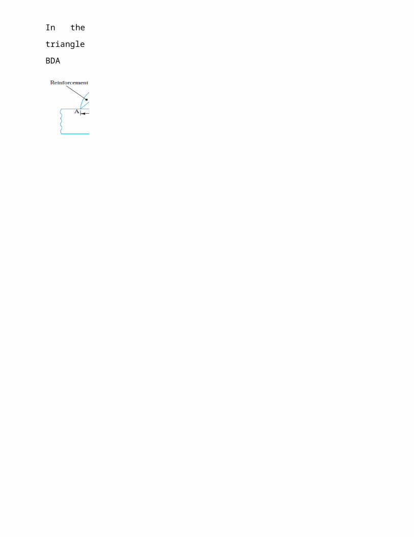