VIEW Certified Configuration Guide - Spectralink … · VIEW Certified Configuration Guide 8 PN:...
59
February 2012 Edition 1725-36920-001 Version A VIEW Certified Configuration Guide Motorola Access Points AP6532, AP7131N, AP7161 standalone or Access Points AP6532, AP7131N, AP7161, AP650 with WLAN controllers RFS4010, RFS4011, RFS6010, RFS7010, NX9000, and NX9500
Transcript of VIEW Certified Configuration Guide - Spectralink … · VIEW Certified Configuration Guide 8 PN:...

February 2012 Edition 1725-36920-001 Version A
VIEW Certified Configuration Guide
Motorola
Access Points AP6532, AP7131N, AP7161 standalone or Access Points AP6532, AP7131N, AP7161, AP650
with WLAN controllers RFS4010, RFS4011, RFS6010, RFS7010, NX9000, and NX9500
VIEW Certified Configuration Guide
2 1725-36920-001_RevA.docx
Patent Information The accompanying product is protected by one or more US and foreign patents and/or pending patent applications held by Polycom, Inc.
Copyright Notice © 2012 Polycom, Inc. All rights reserved. POLYCOM®, the Polycom "Triangles" logo and the names and marks associated with Polycom's products are trademarks and/or service marks of Polycom, Inc. and are registered and/or common law marks in the United States and various other countries. All other trademarks are property of their respective owners. No portion hereof may be reproduced or transmitted in any form or by any means, for any purpose other than the recipient's personal use, without the express written permission of Polycom. All rights reserved under the International and pan-American copyright Conventions. No part of this manual, or the software described herein, may be reproduced or transmitted in any form or by any means, or translated into another language or format, in whole or in part, without the express written permission of Polycom, Inc. Do not remove (or allow any third party to remove) any product identification, copyright or other notices. Every effort has been made to ensure that the information in this document is accurate. Polycom, Inc. is not responsible for printing or clerical errors. Information in this document is subject to change without notice and does not represent a commitment on the part of Polycom, Inc.
Notice Polycom, Inc. has prepared this document for use by Polycom personnel and customers. The drawings and specifications contained herein are the property of Polycom and shall be neither reproduced in whole or in part without the prior written approval of Polycom, nor be implied to grant any license to make, use, or sell equipment manufactured in accordance herewith. Polycom reserves the right to make changes in specifications and other information contained in this document without prior notice, and the reader should in all cases consult Polycom to determine whether any such changes have been made. NO REPRESENTATION OR OTHER AFFIRMATION OF FACT CONTAINED IN THIS DOCUMENT INCLUDING BUT NOT LIMITED TO STATEMENTS REGARDING CAPACITY, RESPONSE-TIME PERFORMANCE, SUITABILITY FOR USE, OR PERFORMANCE OF PRODUCTS DESCRIBED HEREIN SHALL BE DEEMED TO BE A WARRANTY BY POLYCOM FOR ANY PURPOSE, OR GIVE RISE TO ANY LIABILITY OF POLYCOM WHATSOEVER.
Contact Information Please contact your Polycom Authorized Reseller for assistance. Polycom, Inc. 4750 Willow Road, Pleasanton, CA 94588 http://www.polycom.com

AP6532, AP650, AP7131N, AP716, AP650 and RFS4010, RFS4011, RFS6010, RFS7010, NX9000, NX9500
PN: 1725-36920-001_RevA.docx 3
Contents
Overview .................................................................................................. 4
Certified Product Summary ..............................................................4
Product Support ..................................................................................5
Known Limitations .............................................................................6
Polycom References ............................................................................6
Network Topology .................................................................................... 7
Connecting to a Controller or Standalone AP for the First Time ..................... 8
Using Zeroconf IP to connect ............................................................8
Using a DHCP Server .........................................................................8
Configuring Controller or AP’s IP address through CLI ..............9
Logging in from GUI for the first time: ...........................................9
Configuring Controller or AP’s IP address through the GUI ....11
Installing a New Image ....................................................................19
Configuring the Controller and Access Point from Default Configuration ..... 23
SSID, QoS and Security Settings .....................................................23
Radio Settings ....................................................................................49

VIEW Certified Configuration Guide
PN: 1725-36920-001_RevA.docx 4
Overview Polycom’s Voice Interoperability for Enterprise Wireless (VIEW) Certification Program is designed to ensure interoperability and high performance between SpectraLink 8400 Series and 8020/8030 Wireless Telephones and WLAN infrastructure products.
The products listed below have been thoroughly tested in Polycom’s lab using the VIEW Certification Test Plan. This document details how to configure the Motorola controllers RFS4010, RFS4011, RFS6011, RFS7010, NX9000, and NX9500 to work with AP6532, AP650, AP7131N, AP7161. It also details how to operate the AP6532, AP7131N, and AP7181 products in standalone mode. The configurations are chosen to best support SpectraLink wireless telephones.
Certified Product Summary Manufacturer: Motorola Approved products: AP6532, AP7131N, AP7161 Access Points standalone;
Above AP’s and AP650 with WLAN controllers: RFS4010, RFS4011, RFS6010, RFS7010, NX9000, and NX9500
RF technology 802.11abgn Radio: 2.4 GHz (802.11bg), 5 GHz (802.11a) Security : None, WEP, WPA-PSK, WPA2-PSK, WPA2-Enterprise
(EAP-FAST and PEAPv0/MSCHAPv2) QoS: Wi-Fi Standard AP/controller software version tested: 5.2.3.0-023D Handset* models tested: SpectraLink 8440/8450 Wireless Telephone Handset software version tested: UCS 4.0.1.13681 (4.0.1 on support website) Handset radio mode: 802.11b 802.11 b/g 802.11b/g/n 802.11a & a/n Meets VIEW minimum call capacity per AP:**
6 8 10 10
Handset models tested: SpectraLink 8020/8030 Wireless Telephone* Handset software version tested: 131.031 Handset radio mode: 802.11b/g 802.11a Meets VIEW minimum call capacity per AP:**
6 (Wi-Fi Standard QoS)***
8 (Wi-Fi Standard QoS)***
Network topology Switched Ethernet (recommended)

AP6532, AP650, AP7131N, AP716, AP650 and RFS4010, RFS4011, RFS6010, RFS7010, NX9000, NX9500
PN: 1725-36920-001_RevA.docx 5
*SpectraLink handset models and their OEM derivates are verified compatible with the WLAN hardware and software identified in the table. Throughout the remainder of this document they will be referred to collectively as “SpectraLink wireless telephones”, “phones” or “handsets”.
** Maximum calls tested per the VIEW Certification Test Plan. The certified product may actually support a higher number of maximum calls.
*** WPA2-Enterprise and Wi-Fi Standard QoS are not available for SpectraLink 8020/8030 handsets connecting to traditional PBXs.
Product Support
Motorola’s Enterprise Mobility Support Center If you have a problem with your equipment, contact Enterprise Mobility support for your region. Support and issue resolution is provided for products under warranty or that are covered by an Enterprise Mobility Services agreement.
Contact information and web self-service is available by visiting http://supportcentral.motorola.com/
When contacting Enterprise Mobility support, please provide the following information:
• Serial number of the unit
• Model number or product name
• Software type and version number
Motorola Solutions responds to calls by email or telephone within the time limits set forth in support agreements. If you purchased your Enterprise Mobility business product from a Motorola business partner, contact that business partner for support.
Customer Support Web Site Motorola's Support Central Web site, located at http://supportcentral.motorola.com/ provides information and online assistance including developer tools, software downloads, product manuals, support contact information and online repair requests.
VIEW Certified Configuration Guide
PN: 1725-36920-001_RevA.docx 6
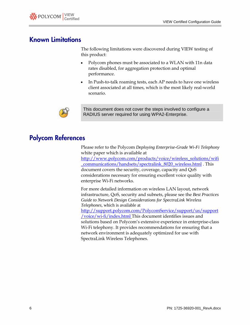
Known Limitations The following limitations were discovered during VIEW testing of this product:
• Polycom phones must be associated to a WLAN with 11n data rates disabled, for aggregation protection and optimal performance.
• In Push-to-talk roaming tests, each AP needs to have one wireless client associated at all times, which is the most likely real-world scenario.
This document does not cover the steps involved to configure a RADIUS server required for using WPA2-Enterprise.
Polycom References Please refer to the Polycom Deploying Enterprise-Grade Wi-Fi Telephony white paper which is available at http://www.polycom.com/products/voice/wireless_solutions/wifi_communications/handsets/spectralink_8020_wireless.html . This document covers the security, coverage, capacity and QoS considerations necessary for ensuring excellent voice quality with enterprise Wi-Fi networks.
For more detailed information on wireless LAN layout, network infrastructure, QoS, security and subnets, please see the Best Practices Guide to Network Design Considerations for SpectraLink Wireless Telephones, which is available at http://support.polycom.com/PolycomService/support/us/support/voice/wi-fi/index.html This document identifies issues and solutions based on Polycom’s extensive experience in enterprise-class Wi-Fi telephony. It provides recommendations for ensuring that a network environment is adequately optimized for use with SpectraLink Wireless Telephones.

AP6532, AP650, AP7131N, AP716, AP650 and RFS4010, RFS4011, RFS6010, RFS7010, NX9000, NX9500
PN: 1725-36920-001_RevA.docx 7
Network Topology The following topology was used during VIEW Certification testing.
It is important to note that this configuration is not necessarily applicable to all customer environments.

VIEW Certified Configuration Guide
PN: 1725-36920-001_RevA.docx 8
Connecting to a Controller or Standalone AP for the First Time
There are two ways to connect to a controller or standalone AP with factory default settings via IP: use its zeroconf IP, or connect it to a DHCP server.
Using Zeroconf IP to connect Every controller is given the default address of 192.268.0.1. A PC or laptop may be reconfigured with an IP that can access this address.
To access a standalone AP:
1. Every AP has a label on the back side with its MAC address printed.
2. Take a note of the last 4 digits of the MAC address and convert them from hexadecimal to decimal.
3. For example, an AP has a MAC address of 00-23-68-86-47-DC. Convert 47 and DC from hex to decimal, and they become 71 and 220.
4. This AP can then be accessed by its zeroconf IP address of 169.254.71.220/16.
Using a DHCP Server By default, an RFS6000 or an AP6532 is set to be a DHCP client. Connect its GEx port to a DHCP server and it will obtain an IP address. From the DHCP server, find the DHCP address lease using the AP’s MAC address, which can be found on the back side of the device. The AP can now be accessed by this DHCP IP address.
Controller and AP can be accessed via SSH for CLI access, or via HTTPS for GUI access. Configurations can be performed by either CLI or GUI, both of which will be explained in this document. In CLI, use the command ‘commit write memory’ after changes are made to save the entry. In GUI, click ‘commit’ button located on the upper-right side of the screen, and then ‘save’, to save changes.

AP6532, AP650, AP7131N, AP716, AP650 and RFS4010, RFS4011, RFS6010, RFS7010, NX9000, NX9500
PN: 1725-36920-001_RevA.docx 9
Connecting to the Controller or AP via CLI for the first time Establish an SSH session to the device. The default login credentials are admin and motorola. The user will be prompted to change the password when logging in for the first time. Enter the new password twice for verification purposes.
The AP’s IP address can be displayed using the following commands.
ap6532-8647DC>enable ap6532-8647DC#config terminal ap6532-8647DC(config)# show ip interface brief --------------------------------------------------------------------------- INTERFACE IP-ADDRESS/MASK TYPE STATUS PROTOCOL --------------------------------------------------------------------------- vlan1 20.1.1.35/24(DCHP) primary UP up ---------------------------------------------------------------------------
Configuring Controller or AP’s IP address through CLI To use a static IP for the device, follow these steps:
ap6532-8647DC#configure terminal Enter configuration commands, one per line. End with CNTL/Z. ap6532-8647DC(config)#self ap6532-8647DC(config-device-00-23-68-86-47-DC)#interface vlan 1 ap6532-8647DC(config-device-00-23-68-86-47-DC-if-vlan1)#ip address <desired IP address>/24 ap6532-8647DC(config-device-00-23-68-86-47-DC-if-vlan1)#exit ap6532-8647DC(config-device-00-23-68-86-47-DC)#ip default-gateway <desired IP address> ap6532-8647DC(config-device-00-23-68-86-47-DC-if-vlan1)#commit write memory
Logging in from GUI for the first time: Open a browser and enter in the address bar https://<AP IP Address>.
1. Be sure that the browser has the latest Adobe Flash Player installed, which is required for GUI access.
2. Enter default username and password of ‘admin’ and ‘motorola’. The GUI will prompt to enter a new password.

VIEW Certified Configuration Guide
PN: 1725-36920-001_RevA.docx 10

AP6532, AP650, AP7131N, AP716, AP650 and RFS4010, RFS4011, RFS6010, RFS7010, NX9000, NX9500
PN: 1725-36920-001_RevA.docx 11
3. A confirmation window appears after password change. Click OK to proceed. Now you are connected to the AP via GUI.
4. A Wizard window pops up when you connect to the AP for the
first time. The wizard is intended for quick configuration, which does not cover some of VIEW Certification configurations. So we advise NOT to use the wizard. Click Never.
Configuring Controller or AP’s IP address through the GUI
From factory defaults, only the CLI can be used to initially configure a static address. Thereafter, the static address may be changed using the GUI.
1. To assign a static IP address, navigate to Configuration > Devices > Device overrides on a standalone AP or Configuration > Devices on a controller. Select the Controller or AP and click Edit located on the lower-right side of the screen.

VIEW Certified Configuration Guide
PN: 1725-36920-001_RevA.docx 12
Controller GUI

AP6532, AP650, AP7131N, AP716, AP650 and RFS4010, RFS4011, RFS6010, RFS7010, NX9000, NX9500
PN: 1725-36920-001_RevA.docx 13
Standalone AP GUI

VIEW Certified Configuration Guide
PN: 1725-36920-001_RevA.docx 14
2. Under Profile Overrides > Interfaces > Virtual Interfaces, select Vlan1 and click Edit. Controller GUI

AP6532, AP650, AP7131N, AP716, AP650 and RFS4010, RFS4011, RFS6010, RFS7010, NX9000, NX9500
PN: 1725-36920-001_RevA.docx 15
Standalone AP GUI

VIEW Certified Configuration Guide
PN: 1725-36920-001_RevA.docx 16
3. Uncheck Use DHCP to Obtain IP, and manually enter an IP address. Click OK to accept the change.
AP6532, AP650, AP7131N, AP716, AP650 and RFS4010, RFS4011, RFS6010, RFS7010, NX9000, NX9500
PN: 1725-36920-001_RevA.docx 17
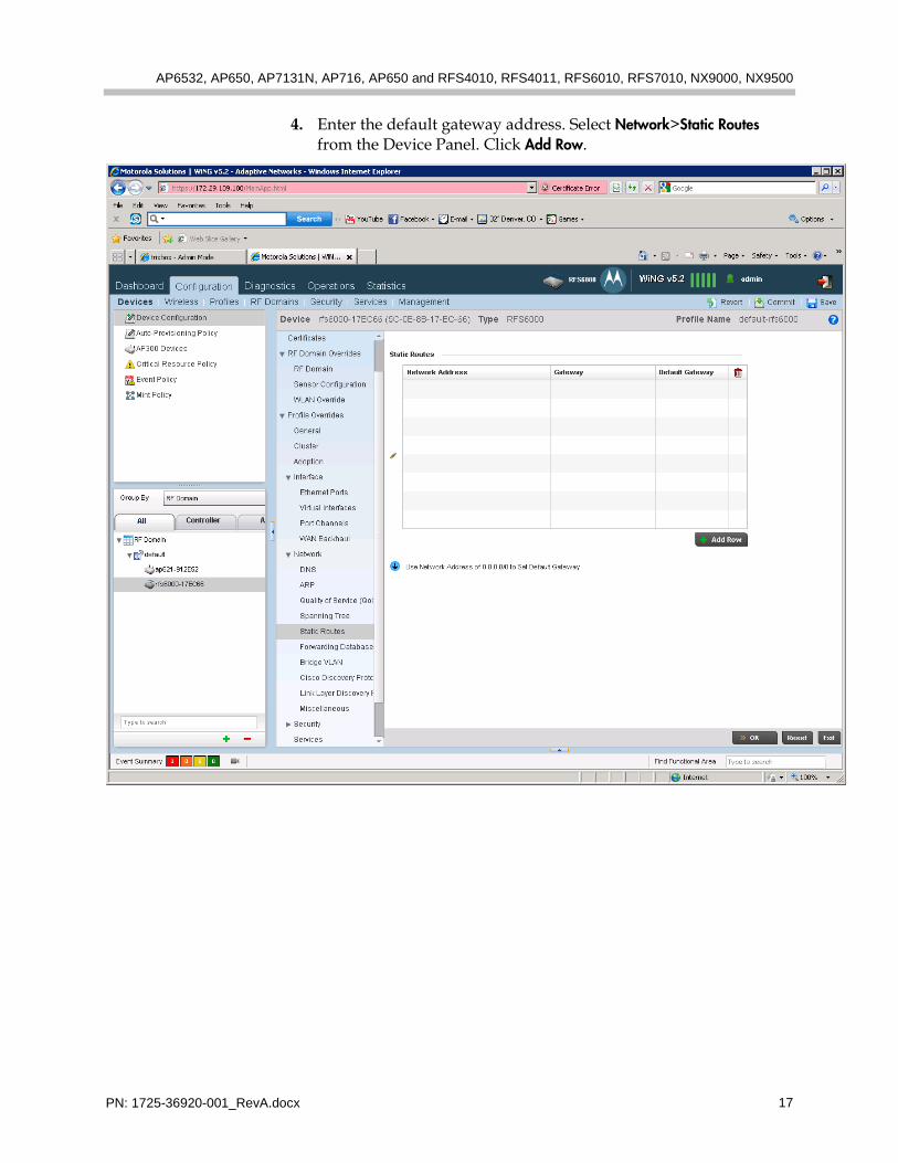
4. Enter the default gateway address. Select Network>Static Routes from the Device Panel. Click Add Row.

VIEW Certified Configuration Guide
PN: 1725-36920-001_RevA.docx 18
5. Enter a Network Address of 0.0.0.0/0 and enter the desired Default Gateway address for the network. Use the down arrow by the network address to change the network mask if necessary.
AP6532, AP650, AP7131N, AP716, AP650 and RFS4010, RFS4011, RFS6010, RFS7010, NX9000, NX9500
PN: 1725-36920-001_RevA.docx 19
Installing a New Image The VIEW Certified firmware release can be obtained from Motorola’s Developer Zone at http://support.symbol.com/support/product/softwaredownloads.do. Upgrading the AP6532 Access Point to the new firmware can be done through the Web interface or through the command line interface (CLI). Place the image on the FTP server or TFTP server depending on the file transfer mechanism chosen.
Installing firmware through the CLI for a controller or standalone AP 1. Enter your username and password to log into the CLI.
2. Connect the FTP/TFTP server to subnet 1.
3. For TFTP, issue the following commands: ap6532-8647DC>en ap6532-8647DC#upgrade tftp://<TFTP_SERVER_IP_ADDR>/<AP6532_FIRMWARE_FILENAME>
4. For FTP, issue the following commands:
ap6532-8647DC>en ap6532-8647DC#upgrade ftp://<FTP_USERNAME>:<FTP_PASSWD>@<FTP_SERVER_IP_ADDR>/ <FIRMWARE_FILENAME>
5. After the upgrade is successful issue the following command:
ap6532-8647DC#reload
After upgrading the controller, it will upgrade the adopted APs through its auto upgrade process.

VIEW Certified Configuration Guide
PN: 1725-36920-001_RevA.docx 20
Installing firmware through the Web interface 1. Open the GUI by entering the IP address: https://<AP IP address>
2. Navigate to Operations > Devices. On the left pane, click System to expand the tree, and Default, then select the desired standalone AP or controller.
3. On the lower-right screen, click Load Firmware. The Firmware Upgrade screen pops up. Click Advanced.

AP6532, AP650, AP7131N, AP716, AP650 and RFS4010, RFS4011, RFS6010, RFS7010, NX9000, NX9500
PN: 1725-36920-001_RevA.docx 21
4. Select protocol, enter host IP, and specify path/file name. Click Apply to start firmware upgrade.
5. When finished, close the firmware upgrade screen.
6. Click Restart to reboot the device with new firmware.

VIEW Certified Configuration Guide
PN: 1725-36920-001_RevA.docx 22

AP6532, AP650, AP7131N, AP716, AP650 and RFS4010, RFS4011, RFS6010, RFS7010, NX9000, NX9500
PN: 1725-36920-001_RevA.docx 23
Configuring the Controller and Access Point from Default Configuration
SSID, QoS and Security Settings
Configuring SSID, Radio QoS, WLAN QoS and security settings through the CLI 1. Create an AAA policy, policy name, authentication server IP,
shared secret, and authentication protocol . ap6532-8647DC(config)#aaa-policy <aaa policy name> ap6532-8647DC(config-aaa-policy-<aaa policy name>)#authentication server 1 host 20.1.1.100 secret <shared secret>
2. Set Radius communication:
a. For dependent AP, send Radius communication through the controller:
rfs6000-818170(config-aaa-policy-<aaa policy name>)#authentication server 1 proxy-mode through-controller
b. For standalone AP, send Radius communication directly: ap6532-8647DC(config-aaa-policy-<aaa policy name>)#authentication server 1 proxy-mode none ap6532-8647DC(config-aaa-policy-<aaa policy name>)#authentication protocol chap ap6532-8647DC(config-aaa-policy-<aaa policy name>)#commit write memory ap6532-8647DC(config-aaa-policy-<aaa policy name>)#exit
(This command returns to configure a different item. It is assumed that this command is entered in between cli configuration sections.)
3. Create a WLAN QoS policy and enable voice prioritization: ap6532-8647DC(config)#wlan-qos-policy default ap6532-8647DC(config-wlan-qos-default)#voice-prioritization ap6532-8647DC(config-wlan-qos-default)# commit write memory
4. Create a Radio QoS policy, and set cw-min and cw-max values: ap6532-8647DC(config)#radio-qos-policy <radio policy name> ap6532-8647DC(config-radio-qos-<radio policy name>)#wmm voice cw-min 0 ap6532-8647DC(config-radio-qos-<radio policy name>)#wmm voice cw-max 0 ap6532-8647DC(config-radio-qos-<radio policy name>)#commit write memory
VIEW Certified Configuration Guide
PN: 1725-36920-001_RevA.docx 24
5. Set up admission control to control network loading. The percentage of bandwidth entered for maximum airtime varies whether the network is using 2.4 GHz or 5 GHz and whether 8020/8030 phones or 8400 series phones are in use.
a. 2.4 GHz settings (allows 8 8400 series phones if high definition codecs are not in use on the 8400 series):
ap6532-8647DC(config-radio-qos-<radio policy name>)#admission-control voice max-airtime-percent 45 ap6532-8647DC(config-radio-qos-<radio policy name>)#admission-control video max-airtime-percent 15
b. 2.4 GHz settings (allows 6 8020/8030 phones): ap6532-8647DC(config-radio-qos-<radio policy name>)#admission-control voice max-airtime-percent 40 ap6532-8647DC(config-radio-qos-<radio policy name>)#admission-control video max-airtime-percent 15
c. 5 GHz settings for a network with 8400 series phones (allows 10 8400 series phones if high definition codecs are not in use on the 8400 series):
ap6532-8647DC(config-radio-qos-<radio policy name>)#admission-control voice max-airtime-percent 50 ap6532-8647DC(config-radio-qos-<radio policy name>)#admission-control video max-airtime-percent 15
d. 5 GHz settings for a network with 8020/8030 phones (allows 8 phones):
ap6532-8647DC(config-radio-qos-<radio policy name>)#admission-control voice max-airtime-percent 20 ap6532-8647DC(config-radio-qos-<radio policy name>)#admission-control video max-airtime-percent 15
If both 8400 series and 8020/8030 series phones are in use on the same 5 GHz network, use the smaller max-airtime percent.
If the phones are to be used on both 2.4 GHz and 5 GHz networks, create two qos radio policies and assign them to ap radio interfaces as shown below.
6. Configure a WLAN. Specify SSID, bridging mode, syslog host, and security settings using following commands:

AP6532, AP650, AP7131N, AP716, AP650 and RFS4010, RFS4011, RFS6010, RFS7010, NX9000, NX9500
PN: 1725-36920-001_RevA.docx 25
rfs6000-818170(config)#wlan <WLAN Name> rfs6000-818170(config-wlan-<WLAN NAME>)#ssid <SSID name> rfs6000-818170(config-wlan-<WLAN NAME>)#bridging-mode tunnel
or rfs6000-818170(config-wlan-<WLAN NAME>)#bridging-mode local
Use bridging-mode tunnel if the AP is adopted by a controller or a virtual controller and local if the network uses standalone AP’s.
rfs6000-818170(config-wlan-<WLAN NAME>)#accounting syslog host <syslog server IP>
a. For WPA2-Enterprise security (PEAP or EAP-FAST) rfs6000-818170(config-wlan-<WLAN NAME>)#use aaa-policy <aaa-policy name> rfs6000-818170(config-wlan-<WLAN NAME>)#encryption-type ccmp rfs6000-818170(config-wlan-<WLAN NAME>)#authentication-type eap
b. WPA2-PSK security: ap6532-8647DC(config-wlan-<WLAN NAME>)#encryption-type ccmp ap6532-8647DC(config-wlan-<WLAN NAME>)#authentication-type none ap6532-8647DC(config-wlan-<WLAN NAME>)#wpa-wpa2 psk 0 12345678
c. WPA-PSK security tkip: ap6532-8647DC(config-wlan-<WLAN NAME>)#encryption-type tkip ap6532-8647DC(config-wlan-<WLAN NAME>)#authentication-type eap-psk ap6532-8647DC(config-wlan-<WLAN NAME>)#wpa-wpa2 psk 0 12345678
d. WEP:
The handsets must use the Authentication: Open System setting with WEP on the Motorola products.
For 128 bit key (called 104 bit on 8020/8030) ap6532-8647DC(config-wlan-<WLAN NAME>)#authentication-type none ap6532-8647DC(config-wlan-<WLAN NAME>)#encryption-type wep128 ap6532-8647DC(config-wlan-<WLAN NAME>)#wep128 key <1-4> hex 012345678901234567890123456
or for 64 bit key (called 40 bit on 8020/8030) ap6532-8647DC(config-wlan-<WLAN NAME>)#encryption-type wep64 ap6532-8647DC(config-wlan-<WLAN NAME>)#wep64 key <1-4> hex 0 0123456789 ap6532-8647DC(config-wlan-<WLAN NAME>)#authentication-type none

VIEW Certified Configuration Guide
PN: 1725-36920-001_RevA.docx 26
In networks where background traffic runs in 11n mode, the WLAN to which the phones associate will need to use only non-n rates to provide aggregation protection.
7. Turn off n rates in the WLAN that contains the phones.
11an mode: ap6532-8647DC(config-wlan-<WLAN NAME>)#data-rates 5GHz a-only
11bgn mode: ap6532-8647DC(config-wlan-<WLAN NAME>)#data-rates 2.4GHz bg

AP6532, AP650, AP7131N, AP716, AP650 and RFS4010, RFS4011, RFS6010, RFS7010, NX9000, NX9500
PN: 1725-36920-001_RevA.docx 27
Configuring SSID, Radio QoS, WLAN QoS, and security settings through the Web interface 1. Open the GUI by entering its IP address: <IP address>.
2. In tab Configuration > Wireless > AAA Policy, click Add to create a new AAA policy.

VIEW Certified Configuration Guide
PN: 1725-36920-001_RevA.docx 28
3. Enter a policy name, and click Continue.
AP6532, AP650, AP7131N, AP716, AP650 and RFS4010, RFS4011, RFS6010, RFS7010, NX9000, NX9500
PN: 1725-36920-001_RevA.docx 29
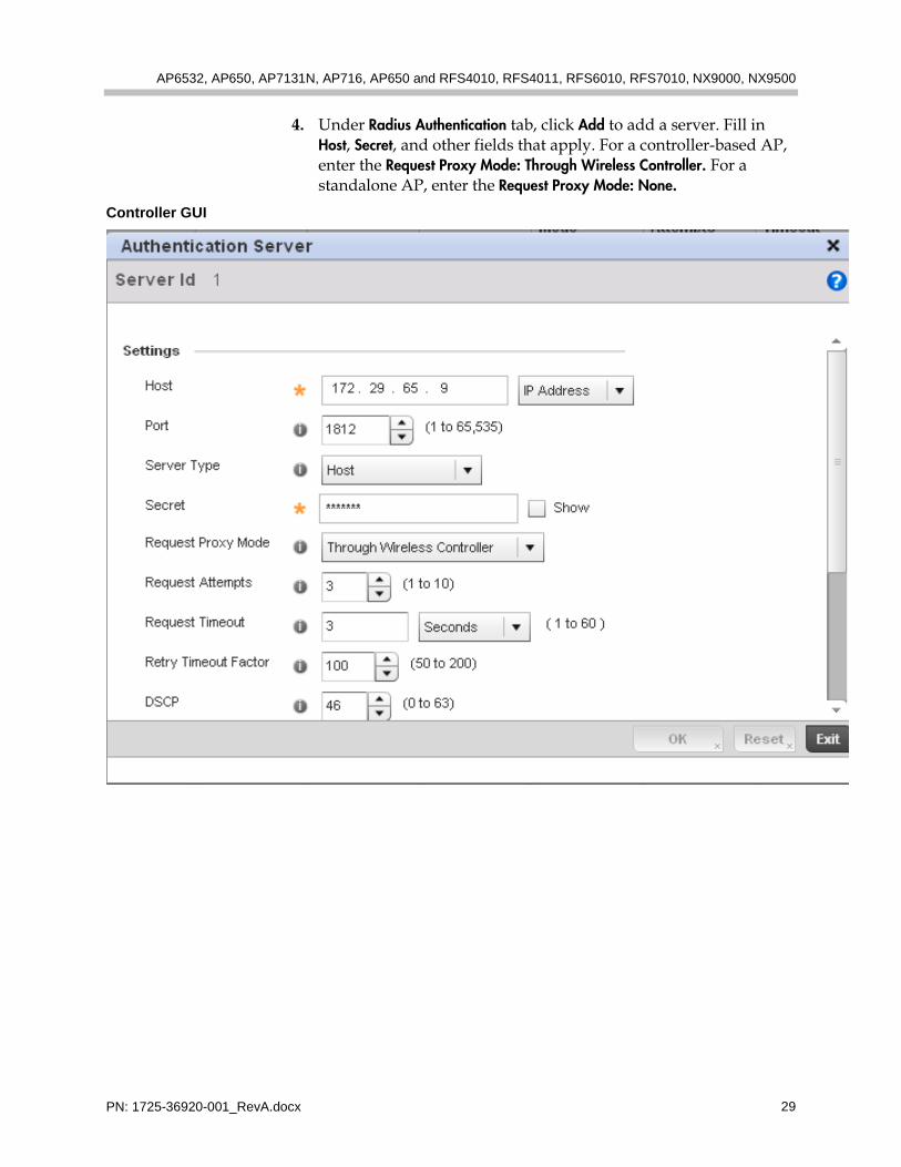
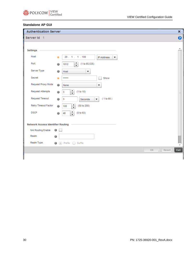
4. Under Radius Authentication tab, click Add to add a server. Fill in Host, Secret, and other fields that apply. For a controller-based AP, enter the Request Proxy Mode: Through Wireless Controller. For a standalone AP, enter the Request Proxy Mode: None.
Controller GUI
VIEW Certified Configuration Guide
PN: 1725-36920-001_RevA.docx 30
Standalone AP GUI

AP6532, AP650, AP7131N, AP716, AP650 and RFS4010, RFS4011, RFS6010, RFS7010, NX9000, NX9500
PN: 1725-36920-001_RevA.docx 31
5. Set the Radius Authentication type under the Settings tab to CHAP.

VIEW Certified Configuration Guide
PN: 1725-36920-001_RevA.docx 32
6. Create a WLAN QoS Policy: Navigate to Configuration > Wireless > WLAN QoS Policy, double-click the default policy to edit it.

AP6532, AP650, AP7131N, AP716, AP650 and RFS4010, RFS4011, RFS6010, RFS7010, NX9000, NX9500
PN: 1725-36920-001_RevA.docx 33
7. Check Enable Voice Prioritization.

VIEW Certified Configuration Guide
PN: 1725-36920-001_RevA.docx 34
8. Navigate to Configuration > Wireless > Radio QoS Policy, double click the default policy to edit.

AP6532, AP650, AP7131N, AP716, AP650 and RFS4010, RFS4011, RFS6010, RFS7010, NX9000, NX9500
PN: 1725-36920-001_RevA.docx 35
9. Under WMM tab, Voice Access, set ECW Min and ECW Max to zero.

VIEW Certified Configuration Guide
PN: 1725-36920-001_RevA.docx 36
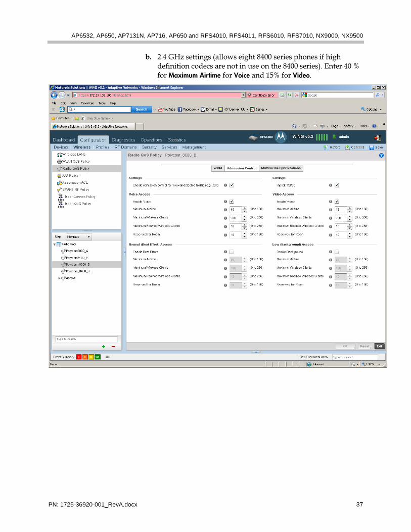
10. Set up admission control to control network loading. The percentage of bandwidth entered for maximum airtime varies whether the network is using 2.4 GHz or 5 GHz and whether 8020/8030 phones or 8400 series phones are in use. Click the Admission Control tab.
a. 2.4 GHz settings (allows eight 8400 series phones if high definition codecs are not in use on the 8400 series). Enter 45 % for Maximum Airtime for Voice and 15% for Video.
AP6532, AP650, AP7131N, AP716, AP650 and RFS4010, RFS4011, RFS6010, RFS7010, NX9000, NX9500
PN: 1725-36920-001_RevA.docx 37
b. 2.4 GHz settings (allows eight 8400 series phones if high definition codecs are not in use on the 8400 series). Enter 40 % for Maximum Airtime for Voice and 15% for Video.

VIEW Certified Configuration Guide
PN: 1725-36920-001_RevA.docx 38
c. 5 GHz settings for a network with 8400 series phones (allows ten 8400 series phones if high definition codecs are not in use on the 8400 series):

AP6532, AP650, AP7131N, AP716, AP650 and RFS4010, RFS4011, RFS6010, RFS7010, NX9000, NX9500
PN: 1725-36920-001_RevA.docx 39
d. 5 GHz settings for a network with 8020/8030 phones (allows eight phones):

VIEW Certified Configuration Guide
PN: 1725-36920-001_RevA.docx 40
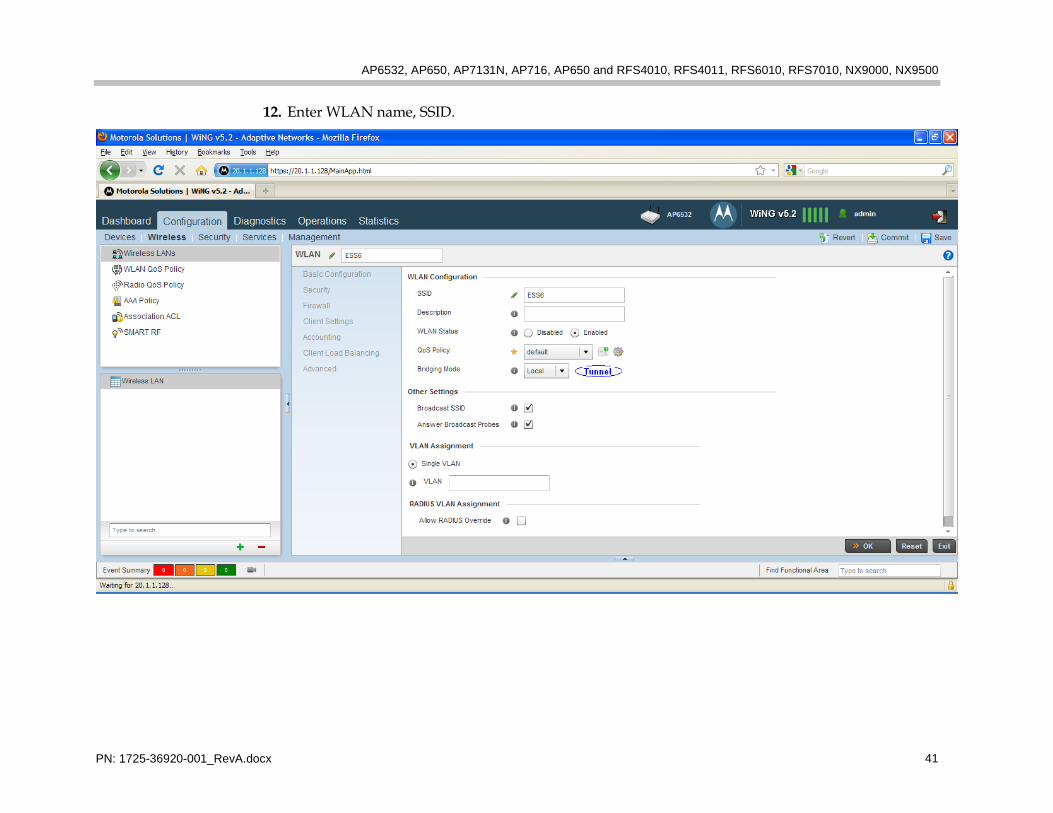
11. WLAN configuration: Under Configuration > Wireless > Wireless LANs, click Add to create a new WLAN.
AP6532, AP650, AP7131N, AP716, AP650 and RFS4010, RFS4011, RFS6010, RFS7010, NX9000, NX9500
PN: 1725-36920-001_RevA.docx 41
12. Enter WLAN name, SSID.

VIEW Certified Configuration Guide
PN: 1725-36920-001_RevA.docx 42
Use bridging-mode Tunnel if the AP is adopted by a controller or a virtual controller and Local if the network uses standalone AP’s.
13. Define a syslog server if desired. Select Accounting under the WLAN <WLAN name> panel. Check Enable Syslog Accounting. Enter the Syslog Host IP address or DNS name.
AP6532, AP650, AP7131N, AP716, AP650 and RFS4010, RFS4011, RFS6010, RFS7010, NX9000, NX9500
PN: 1725-36920-001_RevA.docx 43
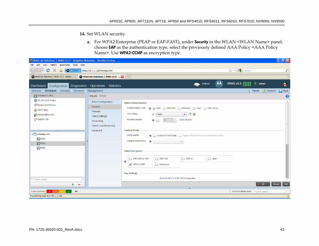
14. Set WLAN security.
a. For WPA2 Enterprise (PEAP or EAP-FAST), under Security in the WLAN <WLAN Name> panel, choose EAP as the authentication type, select the previously defined AAA Policy <AAA Policy Name>. Use WPA2-CCMP as encryption type.

VIEW Certified Configuration Guide
PN: 1725-36920-001_RevA.docx 44
b. For WPA2-PSK under Security in the WLAN <WLAN Name> panel, choose PSK/None as the authentication type. Use WPA2-CCMP as encryption type. Enter the pre-shared key.
AP6532, AP650, AP7131N, AP716, AP650 and RFS4010, RFS4011, RFS6010, RFS7010, NX9000, NX9500
PN: 1725-36920-001_RevA.docx 45
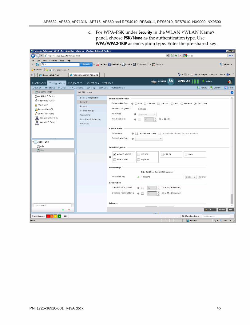
c. For WPA-PSK under Security in the WLAN <WLAN Name> panel, choose PSK/None as the authentication type. Use WPA/WPA2-TKIP as encryption type. Enter the pre-shared key.
VIEW Certified Configuration Guide
PN: 1725-36920-001_RevA.docx 46
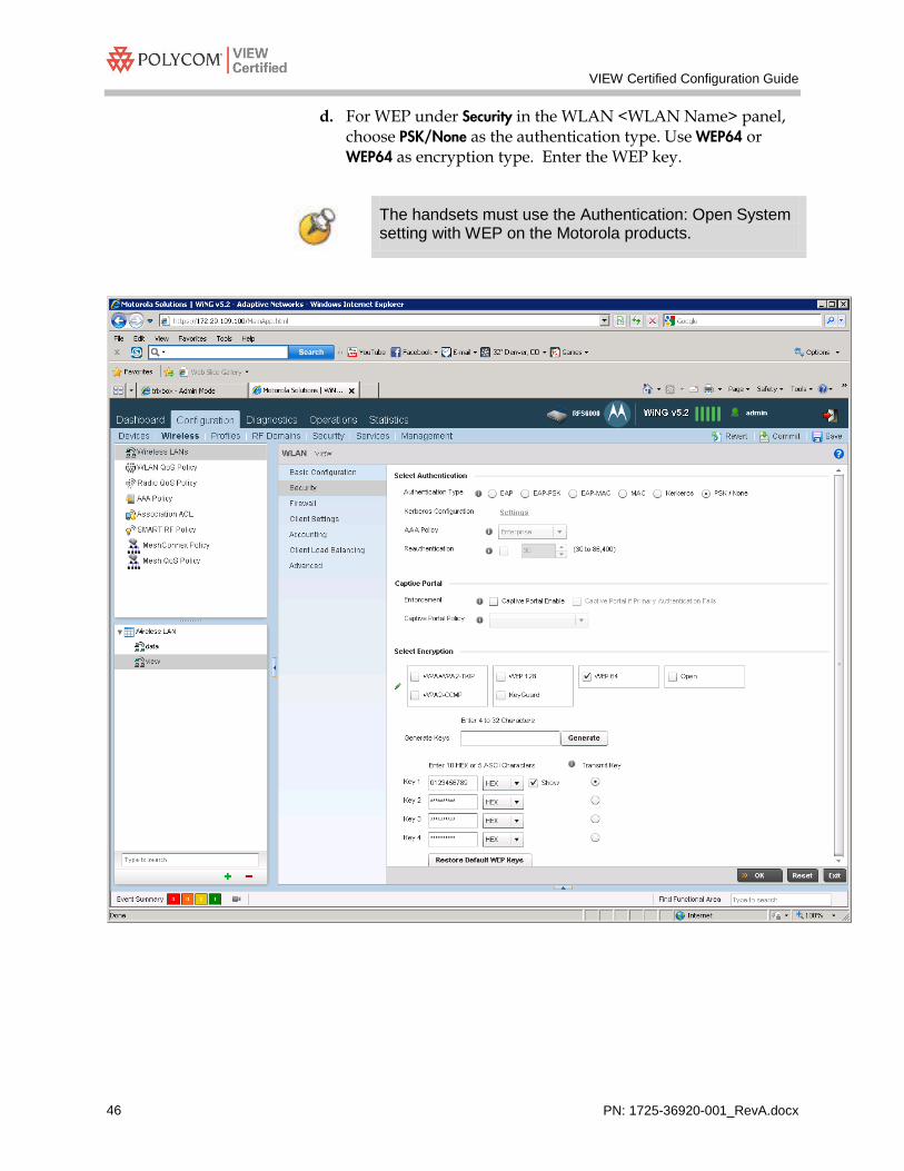
d. For WEP under Security in the WLAN <WLAN Name> panel, choose PSK/None as the authentication type. Use WEP64 or WEP64 as encryption type. Enter the WEP key.
The handsets must use the Authentication: Open System setting with WEP on the Motorola products.
AP6532, AP650, AP7131N, AP716, AP650 and RFS4010, RFS4011, RFS6010, RFS7010, NX9000, NX9500
PN: 1725-36920-001_RevA.docx 47
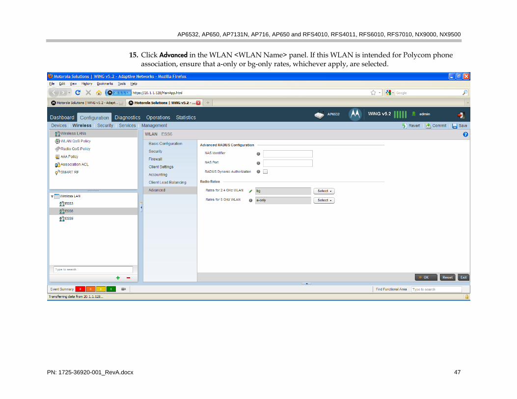
15. Click Advanced in the WLAN <WLAN Name> panel. If this WLAN is intended for Polycom phone association, ensure that a-only or bg-only rates, whichever apply, are selected.
VIEW Certified Configuration Guide
PN: 1725-36920-001_RevA.docx 48
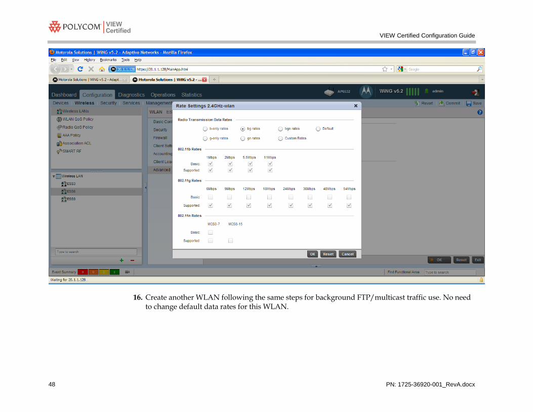
16. Create another WLAN following the same steps for background FTP/multicast traffic use. No need to change default data rates for this WLAN.

AP6532, AP650, AP7131N, AP716, AP650 and RFS4010, RFS4011, RFS6010, RFS7010, NX9000, NX9500
PN: 1725-36920-001_RevA.docx 49
Radio Settings
Configuring radio settings through the CLI The parameters for default-11bg will be configured on the controller or standalone access point. When an AP is powered up it will inherit all the default-11bg or 11a parameters. To configure radio settings, use the following commands.
To associate Polycom Wireless Telephones to radio 1 (11bg)
Configure AP’s country code, radio power, channel, aggregation, WLAN assignment, and guard interval
CLI Commands on controller rfs6000-818170(config)#rf-domain default rfs6000-818170(config-rf-domain-default)#country-code <country> rfs6000-818170(config-rf-domain-default)#exit rfs6000-818170(config)#profile <ap model> default-<ap model> rfs6000-818170(config-profile-default-<ap model>)#interface radio 1 rfs6000-818170(config-profile-default-<ap model>-if-radio1)#power 10 rfs6000-818170(config-profile-default-<ap model>-if-radio1)#channel 6 rfs6000-818170(config-profile-default-<ap model>-if-radio1)#wlan <WLAN NAME> bss 1 primary rfs6000-818170(config-profile-default-<ap model>-if-radio1)#aggregation ampdu tx-rx rfs6000-818170(config-profile-default-<ap model>-if-radio1)#aggregation amssave du tx-rx rfs6000-818170(config-profile-default-<ap model>-if-radio1)#guard-interval any rfs6000-818170(config-profile-default-<ap model>-if-radio1)#use radio-qos-policy <radio policy name> rfs6000-818170(config-profile-default-<ap model>-if-radio1)#commit write memory
CLI Commands on standalone AP ap6532-8647DC>enable ap6532-8647DC#config terminal ap6532-8647DC(config)#self ap6532-8647DC(config-device-00-23-68-86-47-DC)#country-code us ap6532-8647DC(config-device-00-23-68-86-47-DC)#interface radio 1 ap6532-8647DC(config-device-00-23-68-86-47-DC-if-radio1)#power 10 ap6532-8647DC(config-device-00-23-68-86-47-DC-if-radio1)#channel 6 ap6532-8647DC(config-device-00-23-68-86-47-DC-if-radio1)#wlan <WLAN NAME> bss 1 primary ap6532-8647DC(config-device-00-23-68-86-47-DC-if-radio1)#aggregation ampdu tx-rx ap6532-8647DC(config-device-00-23-68-86-47-DC-if-radio1)#aggregation amsdu tx-rx ap6532-8647DC(config-device-00-23-68-86-47-DC-if-radio1)#guard-interval any ap6532-8647DC(config-device-00-23-68-86-47-DC-if-radio1)# use radio-qos-policy <radio policy name>

VIEW Certified Configuration Guide
PN: 1725-36920-001_RevA.docx 50
ap6532-8647DC(config-device-00-23-68-86-47-DC-if-radio1)#commit write memory
Note:
• 11b/g non-n and 11bgn mode can be specified by using different data rates: b-only, bg, bgn, g-only, gn
• In 11n mode, use a single channel (for example, ‘channel 6’) for 20MHz mode. Use a channel with its adjacent channel (for example, ‘channel 6+’) for 40MHz mode.
• To enable or disable the radio, use command ‘no shutdown’ or ‘shutdown’.
To associate Polycom Wireless Telephones to radio 2 (11a)
Configure AP’s country code, radio power, channel, aggregation, and WLAN assignment.
CLI Commands on controller rfs6000-818170(config)#rf-domain default rfs6000-818170(config-rf-domain-default)#country-code us rfs6000-818170(config-rf-domain-default)#exit rfs6000-818170(config)#profile <ap model> default-<ap model> rfs6000-818170(config-profile-default-<ap model>)#interface radio 2 rfs6000-818170(config-profile-default-<ap model>-if-radio2)#power 10 rfs6000-818170(config-profile-default-<ap model>-if-radio2)#channel 40 rfs6000-818170(config-profile-default-<ap model>-if-radio2)#wlan <WLAN NAME> bss 1 primary rfs6000-818170(config-profile-default-<ap model>-if-radio2)#aggregation ampdu tx-rx rfs6000-818170(config-profile-default-<ap model>-if-radio2)#aggregation amsdu tx-rx rfs6000-818170(config-profile-default-<ap model>-if-radio1)#use radio-qos-policy <radio policy name> rfs6000-818170(config-profile-default-<ap model>-if-radio2)#commit write memory
CLI Commands on standalone AP ap6532-8647DC>enable ap6532-8647DC#config terminal ap6532-8647DC(config)#self ap6532-8647DC(config-device-00-23-68-86-47-DC)#country-code us ap6532-8647DC(config-device-00-23-68-86-47-DC)#interface radio 2 ap6532-8647DC(config-device-00-23-68-86-47-DC-if-radio2)power 10 ap6532-8647DC(config-device-00-23-68-86-47-DC-if-radio2)channel 40 ap6532-8647DC(config-device-00-23-68-86-47-DC-if-radio2)wlan <WLAN NAME> bss 1 primary ap6532-8647DC(config-device-00-23-68-86-47-DC-if-radio2)aggregation ampdu tx-rx ap6532-8647DC(config-device-00-23-68-86-47-DC-if-radio2)aggregation amsdu tx-rx ap6532-8647DC(config-device-00-23-68-86-47-DC-if-radio1)# use radio-qos-policy <radio policy name> ap6532-8647DC(config-device-00-23-68-86-47-DC-if-radio2)commit write memory
AP6532, AP650, AP7131N, AP716, AP650 and RFS4010, RFS4011, RFS6010, RFS7010, NX9000, NX9500
PN: 1725-36920-001_RevA.docx 51
Note:
• 11a non-n and 11an mode can be switched using different data rates: a-only, an.
• In 11n mode, use a single channel (for example, ‘channel 40’) for 20M Hz mode. Use a channel with its adjacent channel (for example, ‘channel 40-’) for 40M Hz mode.
• To enable or disable the radio, use command ‘no shutdown’ or ‘shutdown’.

VIEW Certified Configuration Guide
PN: 1725-36920-001_RevA.docx 52
Configuring radio settings through the Web interface 1. Open the AP6532 applet by entering the IP address of the wireless controller: http://<AP IP
address>
2. Under Configuration > Devices > Device Overrides for a standalone AP or Configuration > Devices for a controller, double click the AP.
Controller GUI:
AP6532, AP650, AP7131N, AP716, AP650 and RFS4010, RFS4011, RFS6010, RFS7010, NX9000, NX9500
PN: 1725-36920-001_RevA.docx 53
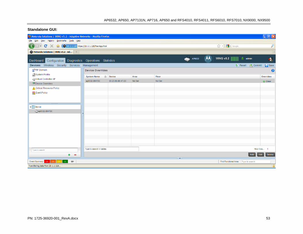
Standalone GUI:

VIEW Certified Configuration Guide
PN: 1725-36920-001_RevA.docx 54
3. In the RF Domain Overrides screen, select correct country code.

AP6532, AP650, AP7131N, AP716, AP650 and RFS4010, RFS4011, RFS6010, RFS7010, NX9000, NX9500
PN: 1725-36920-001_RevA.docx 55
4. Under Device > Interface > Radios, select the radio you would like to configure and click Edit.
VIEW Certified Configuration Guide
PN: 1725-36920-001_RevA.docx 56
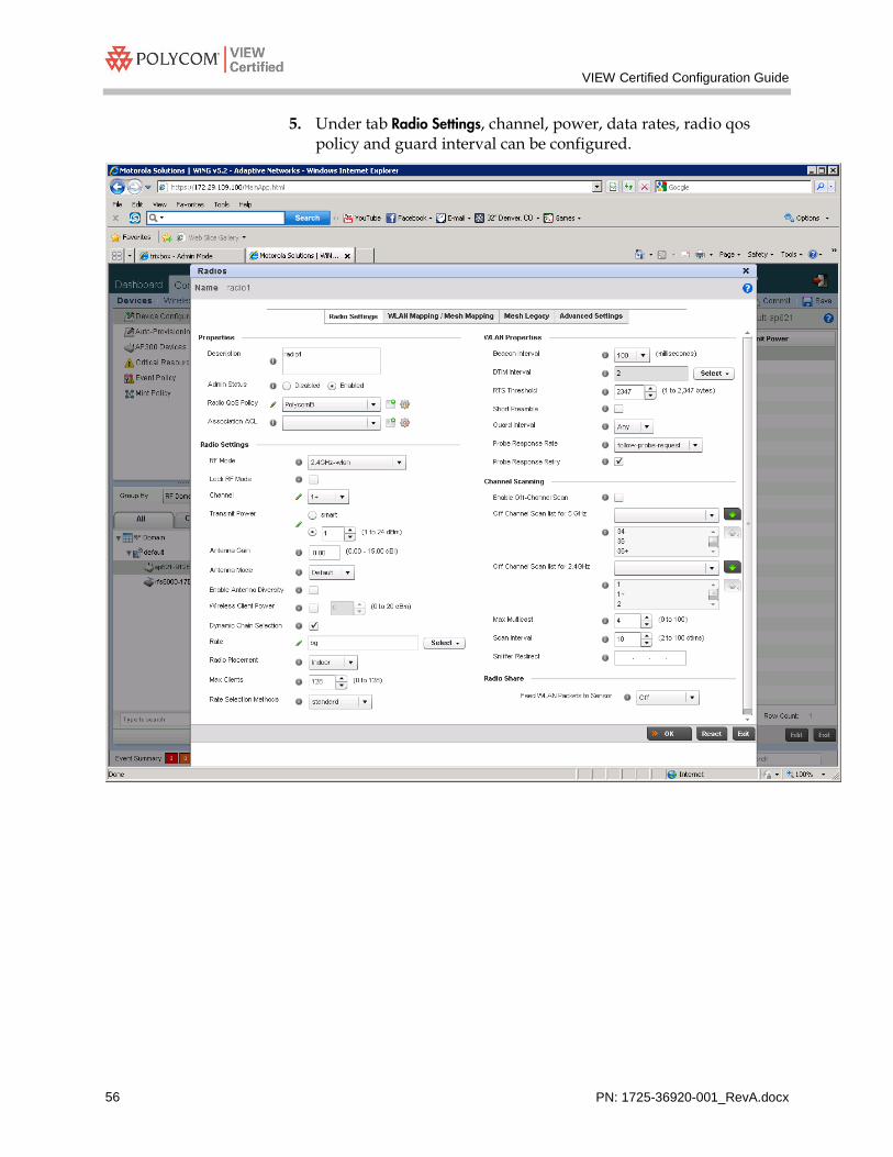
5. Under tab Radio Settings, channel, power, data rates, radio qos policy and guard interval can be configured.

AP6532, AP650, AP7131N, AP716, AP650 and RFS4010, RFS4011, RFS6010, RFS7010, NX9000, NX9500
PN: 1725-36920-001_RevA.docx 57
6. Under tab WLAN Mapping/Mesh Mapping, WLANs can be mapped to the radio.
VIEW Certified Configuration Guide
PN: 1725-36920-001_RevA.docx 58
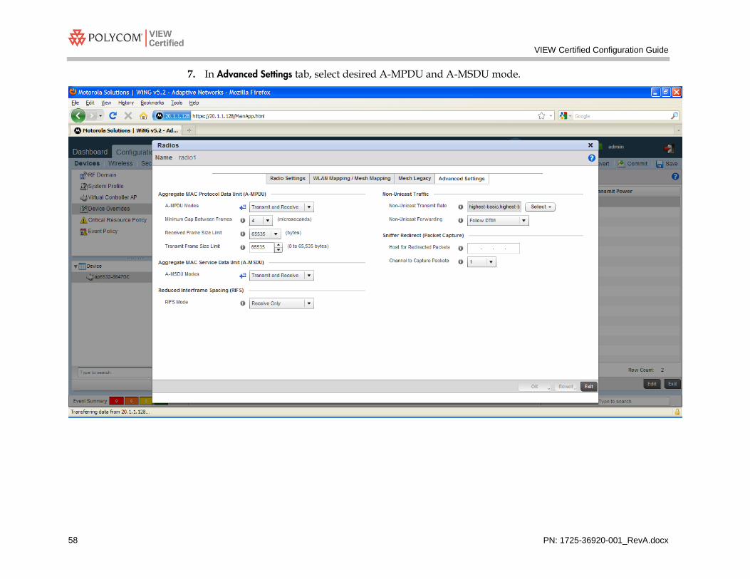
7. In Advanced Settings tab, select desired A-MPDU and A-MSDU mode.

AP6532, AP650, AP7131N, AP716, AP650 and RFS4010, RFS4011, RFS6010, RFS7010, NX9000, NX9500
PN: 1725-36920-001_RevA.docx 59
8. Repeat the steps to configure 11a radio. The picture below shows the Radio Settings screen.