VideoMic Instruction Manual
12
(EMC, LVD) N3594 VideoMic Instruction Manual www.rodemic.com
Transcript of VideoMic Instruction Manual
(EMC, LVD) N3594
VideoMicInstruction Manual
www.rodemic.com
- 2 -
Introduction
Thank you for investing in the VideoMic.
Those of you who are fi rst time customers, may be interested to know that is one of the largest and most respected professional microphone companies in the world. Our studio microphones are the ‘tone’ behind some of the biggest hits of the last decade, and our award winning live performance microphones are on tour throughout the world.
The VideoMic is a very special product. Like many great inventions, it is the result of a need thatwas not being met. I bought a high quality MiniDV camera, and went looking for a shotgun mic.The choices were either totally useless low-cost rubbish, or mics not designed for MiniDV cameras that cost a fortune.
I was amazed that no one offered a quality productthat worked and was affordable. This mademe decide to design and build the defi nitivevideo microphone.
I wanted a microphone that would provide the same level of sound quality and low noise specifi cations as high cost professional models, and be easy to use and mount. The VideoMic delivers on that aim!
How can achieve this when others can’t?It is simple. spends millions of dollars on R&D and automated machinery. When you invest inhigh volume production technologies, the costsdrop dramatically. We pass on these savings toour customers. We have been doing this with our studio microphones for the last 16 years, and continue to win international awards for performance and quality.
Please take the time to read this manual so that you can get the best out of your microphone.
If you have any questions or comments, you can log onto our web site at www.rodemic.com where there are answers to frequently asked questions as well as our contact details.
Peter Freedman
MicrophonesSydney, Australia
- 3 -
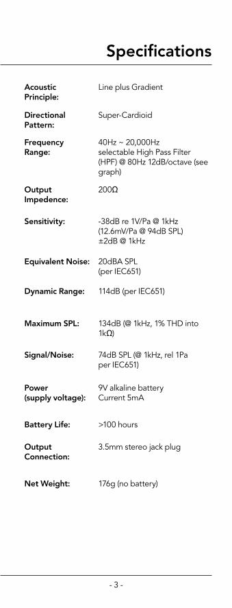
Specifi cations
Acoustic Principle:
Line plus Gradient
Directional Pattern:
Super-Cardioid
Frequency Range:
40Hz ~ 20,000Hzselectable High Pass Filter (HPF) @ 80Hz 12dB/octave (see graph)
Output Impedence:
200Ω
Sensitivity: -38dB re 1V/Pa @ 1kHz(12.6mV/Pa @ 94dB SPL)±2dB @ 1kHz
Equivalent Noise: 20dBA SPL(per IEC651)
Dynamic Range: 114dB (per IEC651)
Maximum SPL: 134dB (@ 1kHz, 1% THD into 1kΩ)
Signal/Noise: 74dB SPL (@ 1kHz, rel 1Paper IEC651)
Power (supply voltage):
9V alkaline batteryCurrent 5mA
Battery Life: >100 hours
Output Connection:
3.5mm stereo jack plug
Net Weight: 176g (no battery)

- 4 -
Specifi cations
Frequency Response
Polar Responses
dB r
e 1
V./P
a
�10
� 0
�-10
�-20
�-30
�-4020 Hz� 100� 1000� 10 000� 20 000
0˚
90˚ 270˚
180˚
0.0-2.0-4.0-6.0-8.0
-10.0-12.0-14.0-16.0-18.0-20.0-22.0-24.0
-25.0
dB rel. 1V/Pa
+5.0
0˚
90˚ 270˚
180˚
0.0-2.0-4.0-6.0-8.0
-10.0-12.0-14.0-16.0-18.0-20.0-22.0-24.0
-25.0
dB rel. 1V/Pa
+5.0
0˚
90˚ 270˚
180˚
0.0-2.0-4.0-6.0-8.0
-10.0-12.0-14.0-16.0-18.0-20.0-22.0-24.0
-25.0
dB rel. 1V/Pa
+5.0
Super-Cardioid - 250Hz
Super-Cardioid - 1kHz
Super-Cardioid - 4kHz

- 5 -
Features
• Studio recording quality
• Rugged ABS construction
• 9V battery operation
• Custom designed integral ‘wind’ screen
• Condenser microphone
• Low noise circuitry
• Low handling noise
• Integral ‘camera shoe’ mount
• Designed & manufactured in Australia
• Full 10 year guarantee*
Powering the VideoMic
• The VideoMic operates on a standard 9V battery
(ANSI:1604A or IEC:6LR61). We recommend you
use either Alkaline or Lithium batteries for the
longest continuous operating time.
• The VideoMic will run continuously for over 100 hrs
with a good quality Alkaline battery. It is however
important to understand that battery performance
can vary dramatically with ambient temperature
and shelf life.
Actual operation times will vary, and we suggest
you always carry a spare battery.
If the application is critical and where there is no
opportunity to ‘re-shoot’, we suggest that you use
a fresh battery.
*Online product registration required.
- 6 -
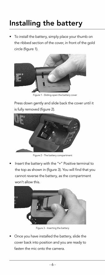
• To install the battery, simply place your thumb on
the ribbed section of the cover, in front of the gold
circle (fi gure 1).
Figure 1 - Sliding open the battery cover
Press down gently and slide back the cover until it
is fully removed (fi gure 2).
Figure 2 - The battery compartment
• Insert the battery with the “+” Positive terminal to
the top as shown in (fi gure 3). You will fi nd that you
cannot reverse the battery, as the compartment
won’t allow this.
Figure 3 - Inserting the battery
• Once you have installed the battery, slide the
cover back into position and you are ready to
fasten the mic onto the camera.
Installing the battery

- 7 -
• The VideoMic incorporates a standard camera-
shoe adaptor on the underside of the suspension
shock mount (fi gure 4).
Figure 4 - Camera-shoe adaptor
Designed to reduce camera borne motor and
handling noise, the shock mount has a 3/8” x 16
and a 1/4” x 20 threaded insert for mounting on
tripods and poles.
• You will fi nd older model and low cost cameras
produce more motor noise, which the VideoMic
can pick up. If so, switch on the High Pass Filter
(HPF) to reduce this (refer to page 9 for more
details).
You could also notice that your camera’s inbuilt
microphone may not pick up this noise and wonder
why. On-board mics are for general-purpose use,
and designed to do a basic job. They can cancel
out certain sounds such as motor noise at the
expense of tone and directional characteristics.
The very latest cameras incorporate low noise/
vibration motors, making them relatively silent.
• Before sliding the camera-shoe into place, turn
the knurled tightening ring anti clockwise to make
sliding the camera-shoe into place much easier
(fi gure 5).
Now turn the knurled ring in a clockwise direction,
gently tightening it so the VideoMic base is seated
fi rmly in place. The actual microphone will exhibit
Mounting the VideoMic

- 8 -
some play, due to the shock mounting system.
Figure 5 - Mounting the VideoMic
The VideoMic has eight cable clips to eliminate
noise transmission and secure it in place once
connected (fi gure 6).
Figure 6 - Correctly mounting the cable
• The VideoMic delivers a mic level signal to the
video camera via a stereo mini jack audio lead.
The mini jack should be connected to the camera
via the camera’s “Audio-In” socket (fi gure 7) - refer
to your video camera user manual.
Figure 7 - Connecting the VideoMic lead to your camera
knurled ring
- 9 -
• Now that you have the VideoMic securely fastened
to your camera and the audio output lead
connected, you can switch the mic on.
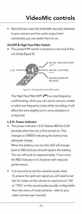
On/Off & High Pass Filter Switch• The power/HPF switch is located on the end of the
mic body (fi gure 8).
Figure 8 - The High Pass Filter (HPF) switch
The High Pass FIlter (HPF ) is a low frequency
cutoff setting, which you can use to remove rumble
or other low frequency noise while recording. It will
affect the tone slightly but in some situations it
is required.
L.E.D. Power Indicator• The power indicator L.E.D. fl ashes RED for 0.25
seconds when the mic is fi rst turned on. This
changes to GREEN indicating the battery has
adequate charge.
When the battery runs low the LED will change
back to RED and you should replace the battery.
The mic will work for approximately 1 hour once
the RED indicator is lit, however with reduced
performance.
• It is now time to set the camera’s audio level.
To ensure the optimum signal you will need to set
the VU meter on the camera to read around “3/4”
or “75%” on the sound peaks (usually confi gurable
from the menu of most cameras - refer to your
video camera user manual).
VideoMic controls
L.E.D.
BATTERY POWER OFFMIC MUTE
MIC ON - FLAT FILTER
MIC ON - HIGH PASS FILTER
- 10 -
• You should try and set the level using the sound
source you will be recording, or a sound source of
similar level, before starting to record or you could
distort the input if the level has been set too high.
Please consult your video camera user manual for
more details.
• The Video Mic has been optimised for high
rejection of radio frequency interference, but we
suggest you keep all transmitters, cell phones,
pagers etc. at least two metres away to reduce the
possibility of interference ruining your recordings.
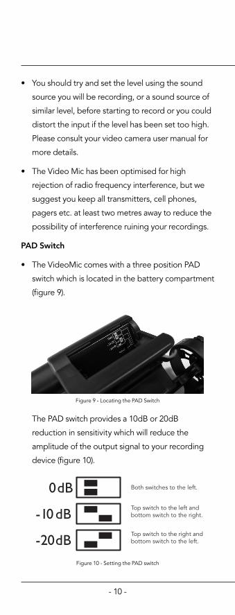
PAD Switch
• The VideoMic comes with a three position PAD
switch which is located in the battery compartment
(fi gure 9).
Figure 9 - Locating the PAD Switch
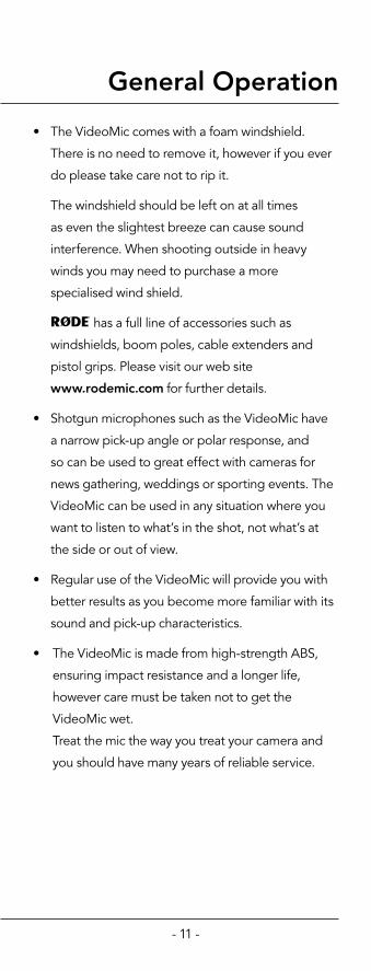
The PAD switch provides a 10dB or 20dB
reduction in sensitivity which will reduce the
amplitude of the output signal to your recording
device (fi gure 10).
Figure 10 - Setting the PAD switch
- 11 -
• The VideoMic comes with a foam windshield.
There is no need to remove it, however if you ever
do please take care not to rip it.
The windshield should be left on at all times
as even the slightest breeze can cause sound
interference. When shooting outside in heavy
winds you may need to purchase a more
specialised wind shield.
has a full line of accessories such as
windshields, boom poles, cable extenders and
pistol grips. Please visit our web site
www.rodemic.com for further details.
• Shotgun microphones such as the VideoMic have
a narrow pick-up angle or polar response, and
so can be used to great effect with cameras for
news gathering, weddings or sporting events. The
VideoMic can be used in any situation where you
want to listen to what’s in the shot, not what’s at
the side or out of view.
• Regular use of the VideoMic will provide you with
better results as you become more familiar with its
sound and pick-up characteristics.
• The VideoMic is made from high-strength ABS,
ensuring impact resistance and a longer life,
however care must be taken not to get the
VideoMic wet.
Treat the mic the way you treat your camera and
you should have many years of reliable service.
General Operation

- 12 -
Warranty
All products are warranted for one year from
date of purchase. You can extend that to a full ten
years if you register online at www.rodemic.com.
The warranty covers parts and labour that may
be required to repair the microphone during the
warranty period. The warranty excludes defects
caused by normal wear and tear, modifi cation,
shipping damage, or failure to use the microphone as
per the instruction guide.
If you experience any problem, or have any questions
regarding your microphone, fi rst contact the
dealer who sold it to you. If the microphone requires a
factory authorised service, return will be organised by
that dealer.
We have an extensive distributor/dealer network, but
if you have diffi culty getting the advice or assistance
you require, do not hesitate to contact us directly.
Microphones
International107 Carnarvon StreetSilverwater NSW 2128 AustraliaPh: +61 2 9648 5855Fax: +61 2 9648 2455
USAP.O. Box 4189Santa Barbara, CA 93140-4189Ph: 805 566 7777Fax: 805 566 0071
Technical SupportFor information and technical support questions contact:[email protected]
In the Unites States and Puerto Rico, contact [email protected] or call 805 566 7777
In Australia, contact [email protected] or call (02) 9648 5855
Anywhere except Australia, the United States and Puerto Rico, contact [email protected] or call +61 2 9648 5855