Video Intercom System — Control Box
108
PC Programming Manual Video Intercom System — Control Box Model No. VL-VN1800 Thank you for purchasing this Panasonic product. Please read this manual carefully before using this product and save this manual for future use. In particular, be sure to read "1.1.1 For Your Safety, page 10" before using this product. PNMPR Software File Version 001.00000 or later Manuals and supporting information are provided on the Panasonic Web site at: https://panasonic.net/cns/pcc/support/intercom/vn1900
Transcript of Video Intercom System — Control Box

PC Programming ManualVideo Intercom System — Control Box
Model No. VL-VN1800
Thank you for purchasing this Panasonic product.Please read this manual carefully before using this product and save this manual for future use.In particular, be sure to read "1.1.1 For Your Safety, page 10" before using this product. PNMPR Software File Version 001.00000 or later Manuals and supporting information are provided on the Panasonic Web site at:https://panasonic.net/cns/pcc/support/intercom/vn1900

IntroductionAbout this Programming Manual
The PC Programming Manual is designed to serve as a system programming reference for the PanasonicVideo Intercom System Control Box. It explains how to programme the Control Box using Web MaintenanceConsole.The PC Programming Manual is divided into the following sections:
Section 1, OverviewProvides an overview of programming the Control Box.
Section 2, Introduction of Web Maintenance ConsoleExplains the layout and menus of Web Maintenance Console.
Sections 3 – 16, Web Maintenance Console Operating InstructionsServes as reference operating instructions when using Web Maintenance Console to programme theControl Box.
Feature Programming ReferencesProvides a list of all related programming items for each feature.
References Found in the PC Programming ManualPC Programming Manual ReferencesRelated sections of the PC Programming Manual are listed for your reference.
Feature Manual ReferencesThe Feature Manual explains what the Control Box can do, as well as how to obtain the most of its manyfeatures and facilities. Sections from the Feature Manual are listed throughout this manual for yourreference.
Installation Manual ReferencesThe Installation Manual provides instructions detailing the installation and maintenance of the Control Box.Sections from the Installation Manual are listed throughout this manual for your reference.
Links to Other Pages and ManualsIf you are viewing this manual with a PC, certain items are linked to different sections of this and otherControl Box manuals. Click on a link to jump to that section.Linked items include:• Installation Manual References
• PC Programming Manual References
• Feature Manual References
Trademarks• Microsoft, Internet Explorer, Windows and Windows Vista are either registered trademarks or trademarks
of Microsoft Corporation in the United States and/or other countries.• Intel and Intel Core are trademarks of Intel Corporation in the U.S. and/or other countries.
• Mozilla and Firefox are registered trademarks of the Mozilla Foundation.
• Google and Google Chrome are trademarks of Google LLC.
Introduction
2 PC Programming Manual

• All other trademarks identified herein are the property of their respective owners.
• Microsoft product screen shot(s) reprinted with permission from Microsoft Corporation.
Notice• During a long programming session, it is highly recommended that you periodically save the system data
to the Storage Memory Card. If the Control Box undergoes a sudden power failure or if the system isreset for some reason, all the system data in RAM will be lost. However, if system data has been saved tothe Storage Memory Card, it can be easily reloaded.
• To save the system data to the Storage Memory Card, (1) click the button on the Home screen of WebMaintenance Console before resetting the Control Box or turning off the power, or (2) log out from WebMaintenance Console so that the Control Box automatically saves the system data.
NOTES• The contents of this manual apply to a certain software version, as indicated on the cover of this manual.
To confirm the software version, see How do I confirm the software version of the Control Box? inMaintenance Console Software in 2.3 Frequently Asked Questions (FAQ).
• Some optional hardware, software, and features are not available in some countries/areas, or for somemodels. Please consult your certified Panasonic dealer for more information.
• Product specifications, including text displayed by the software, are subject to change without notice.
• In this manual, the suffix of each model number (e.g., VL-VN1800BX) is omitted unless necessary.
• Do not change the setting items that are described as "Factory use only". Correct operation cannot beguaranteed if these settings are changed.
Introduction
PC Programming Manual 3

Introduction
4 PC Programming Manual
Table of Contents1 Overview .................................................................................................. 91.1 Introduction ................................................................................................................... 101.1.1 For Your Safety ............................................................................................................. 101.1.2 Introduction ................................................................................................................... 111.1.3 Entering Characters ...................................................................................................... 111.2 PC Programming ........................................................................................................... 131.2.1 Starting Web Maintenance Console ............................................................................. 13
2 Introduction of Web Maintenance Console ........................................ 172.1 Introduction ................................................................................................................... 182.1.1 Web Maintenance Console Accounts ........................................................................... 182.1.2 Logging in to Web Maintenance Console ..................................................................... 182.1.3 Quick Setup Wizard ...................................................................................................... 192.1.4 Software Interface ........................................................................................................ 192.1.5 Card Status ................................................................................................................... 222.1.6 Extension Number Setting ............................................................................................ 232.2 Logout ............................................................................................................................ 242.3 Frequently Asked Questions (FAQ) ............................................................................. 25
3 Web Maintenance Console Home Screen .......................................... 273.1 Home Screen ................................................................................................................. 28
4 Status ..................................................................................................... 294.1 Status—Equipment Status ........................................................................................... 304.1.1 Status—Equipment Status—UM Port status ................................................................ 30
5 System Control ..................................................................................... 315.1 System Control—Program Update .............................................................................. 325.1.1 System Control—Program Update—Download Program File ...................................... 325.1.2 System Control—Program Update—Update Program File .......................................... 325.2 System Control—System Reset ................................................................................... 345.3 System Control—System Shutdown ........................................................................... 35
6 Tool ........................................................................................................ 376.1 Tool—Extension List View ............................................................................................ 386.2 Tool—Import .................................................................................................................. 396.3 Tool—Export .................................................................................................................. 41
7 Utility ...................................................................................................... 437.1 Utility—Diagnosis .......................................................................................................... 447.1.1 Utility—Diagnosis—Ping ............................................................................................... 447.2 Utility—Log .................................................................................................................... 457.2.1 Utility—Log—Error Log ................................................................................................. 457.2.2 Utility—Log—Syslog ..................................................................................................... 477.2.3 Utility—Log—WEB Operation Log ................................................................................ 477.2.4 Utility—Log—UM System Log ...................................................................................... 487.3 Utility—Email Notification ............................................................................................ 497.3.1 Utility—Email Notification—Alert .................................................................................. 497.3.2 Utility—Email Notification—Test Email ......................................................................... 497.4 Utility—Activation Key Installation .............................................................................. 49
8 Users ...................................................................................................... 51
Table of Contents
PC Programming Manual 5
8.1 Users—User Container ................................................................................................. 528.1.1 Users—User Container—Add User/Edit User .............................................................. 538.1.2 Users—User Container—Add Multiple Users ............................................................... 568.2 Users—Advanced Extension Settings ........................................................................ 57
9 Control Box Configuration—[1] Configuration .................................. 599.1 Control Box Configuration—[1-1] Configuration—Slot ............................................. 609.2 Control Box Configuration—[1-1] Configuration—Slot—System Property ............. 619.3 Control Box Configuration—[1-1] Configuration—Slot—Site Property ................... 629.3.1 Control Box Configuration—[1-1] Configuration—Slot—Site Property—Main .............. 629.4 Control Box Configuration—[1-1] Configuration—Slot—UM Property—UM System
Property .......................................................................................................................... 649.5 Control Box Configuration—[1-1] Configuration—Slot—UM Property—UM Port
Property .......................................................................................................................... 659.6 Control Box Configuration—[1-1] Configuration—Slot—V-SIPEXT128—Card
Property .......................................................................................................................... 669.7 Control Box Configuration—[1-1] Configuration—Slot—V-SIPEXT128—Port
Property .......................................................................................................................... 679.8 Control Box Configuration—[1-5] Configuration—DSP Resource ........................... 699.8.1 Control Box Configuration—[1-5-1] Configuration—DSP Resource—Setting .............. 699.8.1.1 Control Box Configuration—[1-5-1] Configuration—DSP Resource—Setting—DSP
Resource Advisor ...................................................................................................... 699.8.2 Control Box Configuration—[1-5-2] Configuration—DSP Resource—Usage ............... 699.9 Control Box Configuration—[1-1] Configuration—Slot—Mobile SIP ....................... 699.9.1 Control Box Configuration—[1-1] Configuration—Slot—Mobile SIP-Main ................... 69
10 Control Box Configuration—[2] System ............................................. 7110.1 Control Box Configuration—[2-1] System—Date & Time .......................................... 7210.1.1 Control Box Configuration—[2-1-1] System—Date & Time—Date & Time Setting ...... 7210.1.2 Control Box Configuration—[2-1-2] System—Date & Time—SNTP / Daylight Saving ......
7210.1.2.1 Control Box Configuration—[2-1-2] System—Date & Time—SNTP / Daylight Saving—
Daylight Saving .......................................................................................................... 7310.2 Control Box Configuration—[2-6] System—Numbering Plan ................................... 7410.2.1 Control Box Configuration—[2-6-1] System—Numbering Plan—Main ......................... 74
11 Control Box Configuration—[3] Group ............................................... 7511.1 Control Box Configuration—[3-5] Group—Incoming Call Distribution Group ........ 7611.1.1 Control Box Configuration—[3-5-1] Group—Incoming Call Distribution Group—Group
Settings ......................................................................................................................... 7611.1.1.1 Control Box Configuration—[3-5-1] Group—Incoming Call Distribution Group—Group
Settings—Member List .............................................................................................. 7611.2 Control Box Configuration—[3-7] Group—UM Group ............................................... 7711.2.1 Control Box Configuration—[3-7-2] Group—UM Group—Unit Settings ....................... 7711.2.1.1 Control Box Configuration—[3-7-2] Group—UM Group—Unit Settings—Member List
.................................................................................................................................... 77
12 Control Box Configuration—[11] Maintenance .................................. 7912.1 Control Box Configuration—[11-1] Maintenance—Main ............................................ 80
13 UM Configuration—[1] Mailbox Settings ............................................ 8313.1 UM Configuration—[1] Mailbox Settings ..................................................................... 84
14 UM Configuration—[2] Class of Service ............................................. 8514.1 UM Configuration—[2] Class of Service ..................................................................... 86
Table of Contents
6 PC Programming Manual

15 UM Configuration—[7] System Security ............................................ 9115.1 UM Configuration—[7] System Security ..................................................................... 92
16 Network Service .................................................................................... 9316.1 Network Service—[1] IP Address/Ports ...................................................................... 9416.2 Network Service—[2] Server Feature .......................................................................... 9816.2.1 Network Service—[2-1] Server Feature—DHCP(LAN) ................................................ 9816.2.2 Network Service—[2-5] Server Feature—HTTP ........................................................... 9916.2.3 Network Service—[2-6] Server Feature—NTP ............................................................. 9916.2.4 Network Service—[2-7] Server Feature—SMTP ........................................................ 10016.3 Network Service—[3] Client Feature ......................................................................... 10216.3.1 Network Service—[3-2] Client Feature—Syslog ......................................................... 102
Feature Programming References ............................................................................. 103Automatic Time Adjustment ..................................................................................... 104Call Forwarding (FWD) ............................................................................................ 104Do Not Disturb (DND) .............................................................................................. 104Dynamic Host Configuration Protocol (DHCP) Assignment .................................... 104Dynamic Host Configuration Protocol (DHCP) Server ............................................. 104E-mail Notification for Extension Users ................................................................... 104Flexible Numbering .................................................................................................. 104Floating Extension ................................................................................................... 105Group ....................................................................................................................... 105Incoming Call Distribution Group Features .............................................................. 105Intercom Call ............................................................................................................ 105Ping .......................................................................................................................... 105SIP (Session Initiation Protocol) Extension ............................................................. 105Software Upgrading ................................................................................................. 106Syslog Record Management ................................................................................... 106UM Group ................................................................................................................ 106Unified Messaging—Class of Service (COS) .......................................................... 106Unified Messaging—Hospitality Mode ..................................................................... 106Unified Messaging—Mailbox ................................................................................... 106Unified Messaging—Message Waiting Notification—E-mail Device ....................... 106Unified Messaging—System Prompts ..................................................................... 106Unified Messaging—System Security ...................................................................... 107User Container ......................................................................................................... 107
Table of Contents
PC Programming Manual 7

Table of Contents
8 PC Programming Manual

Section 1Overview
This section provides an overview of programming theControl Box.
PC Programming Manual 9

1.1 Introduction1.1.1 For Your Safety
To prevent personal injury and/or damage to property, be sure to observe the following safety precautions.The following symbols classify and describe the level of hazard and injury caused when this unit isoperated or handled improperly.
WARNINGThis notice means that misuse could result in deathor serious injury.
CAUTIONThis notice means that misuse could result in injuryor damage to property.
The following types of symbols are used to classify and describe the type of instructions to beobserved.
This symbol is used to alert users to a specific operating procedure that must not beperformed.
This symbol is used to alert users to a specific operating procedure that must be followed inorder to operate the unit safely.
WARNING
• Unplug the Control Box from the AC outlet if it emits smoke, an abnormal smell or makes unusual noise.These conditions can cause fire or electric shock. Confirm that smoke has stopped and contact anauthorised Panasonic Factory Service Centre.
CAUTION
• To the Administrator regarding account passwords1. To avoid unauthorised access and possible abuse of the Control Box, keep the passwords secret,
and be aware of the importance of the passwords, and the possible dangers if they become knownto others.
2. The Control Box has no passwords set initially. For security, select a secure password as soon asthe Control Box is installed at the site.
3. Change the passwords periodically.
1.1 Introduction
10 PC Programming Manual

4. It is strongly recommended that passwords of 10 numbers or characters be used for maximumprotection against unauthorised access.
1.1.2 IntroductionThese programming instructions are designed to serve as an overall system programming reference for theControl Box. Each feature in the Control Box has default settings that can be changed to customise theControl Box to your requirements. These settings control the functions of the Control Box, and changingthem is referred to as "system programming".All features and settings of the Control Box can be programmed using Web Maintenance Console. StartingWeb Maintenance Console is described in 1.2 PC Programming. Individual system programming items aredescribed from 3 Web Maintenance Console Home Screen.
ProgrammingYou can programme the Control Box by accessing Web Maintenance Console from a PC. Modifications tosettings are stored in the Control Box's temporary memory (DRAM). To permanently apply the changes,either click or log out of Web Maintenance Console. For details, see Web Maintenance ConsoleFeatures in 2.1.4 Software Interface.
1.1.3 Entering CharactersThe characters on a white background below can be used when storing a name, message, password orother text entry data using a PC.
1.1.2 Introduction
PC Programming Manual 11

1.1.3 Entering Characters
12 PC Programming Manual

1.2 PC Programming1.2.1 Starting Web Maintenance Console
System programming, diagnosis and administration can be performed with a PC using Web MaintenanceConsole. Web Maintenance Console is accessed through a Web browser running on a networked PC.This section describes how to set up and access Web Maintenance Console.
System RequirementsRequired Operating System• Microsoft® Windows® 7, Windows 8.1, Windows 8.1 Professional, or Windows 10 operating system
NoteIn Windows 8.1 / 8.1 Professional, Web Maintenance Console runs only in desktop mode. It is notavailable from the Windows 8.1 Start screen.
Recommended Display Settings• Screen resolution: XGA (1024 × 768)
• DPI setting: Normal size (96 DPI)
Supported Browsers for Use with Web Maintenance Console for users• Windows Internet Explorer 11
• Mozilla® Firefox® version 57 or ESR52
• Google ChromeTM version 58
Supported Browsers for Use with Web Maintenance Console for Maintenance• Windows Internet Explorer 11
• Mozilla Firefox 57 or ESR52Always apply the latest updates to your Web browser software. For details, refer to your Web browser’sdocumentation. Only the browsers and browser versions listed above are supported for use with WebMaintenance Console.
NoteWhen using Windows Internet Explorer, there may be a delay when displaying some screens of WebMaintenance Console. A message may be displayed that reads "Stop running this script?". Thismessage is automatically displayed when a script takes a long time to complete. If this message isdisplayed, click No to continue using Web Maintenance Console. If you click Yes, you will have to closethe browser window for Web Maintenance Console and log in again. For information about disabling thisprompt, refer to your Web browser’s on-line support resources.
Browser Setting RequirementsThe following functions must be enabled in the Web browser’s settings to use Web Maintenance Console:• Cookies
• JavaScript
• The ability to download files
• The display of animations
• The display of imagesFor details regarding the above settings, refer to your Web browser’s documentation.
1.2 PC Programming
PC Programming Manual 13

PC Specifications (for programming)The following are recommended specifications for PCs used for programming.
Recommended Specification
CPU 3.2 GHz Intel® Core™ 2 Duo processor or comparable CPU
RAM 2048 MB
Hard Disk 10 GB available space
Copyright for MD5This software uses the Source Code of RSA Data Security, Inc. described in the RFC1321 (MD5 Message-Digest Algorithm). Copyright (C) 1991-2, RSA Data Security, Inc. Created 1991. All rights reserved. Licence to copy and use this software is granted provided that it is identified as the "RSA Data Security, Inc.MD5 Message-Digest Algorithm" in all material mentioning or referencing this software or this function. Licence is also granted to make and use derivative works provided that such works are identified as"derived from the RSA Data Security, Inc. MD5 Message-Digest Algorithm" in all material mentioning orreferencing the derived work. RSA Data Security, Inc. makes no representations concerning either the merchantability of this software orthe suitability of this software for any particular purpose. It is provided "as is" without express or impliedwarranty of any kind.These notices must be retained in any copies of any part of this documentation and/or software.
PC ConnectionTo connect to Web Maintenance Console, both the PC and the Control Box must be connected. Theconnection can be made through a local area network (LAN) or a virtual private network (VPN). A PC canalso be connected directly to the maintenance port of the Control Box.
Connecting to Web Maintenance Console1. Connect the PC to the Control Box:
• Connect the Control Box to a PC with the MNT port and access the Control Box directly from the PC.
• Connect the Control Box to a network with the LAN port and access the Control Box from a PC inyour LAN or VPN.
Notice• When connecting the PC to the MNT port, if the PC is set to obtain the IP address automatically,
the IP address of the PC will be set to an appropriate IP address to establish a connection to theControl Box. For more information about the connection procedure, refer to "5.2 PC Connection"in the Installation Manual.
2. Access Web Maintenance Console:MNT Port connection:Launch your Web browser and in the address bar, enter the following address exactly as shown:– 223.0.0.1
NoteIf connecting using 223.0.0.1 takes a long time, configure a static IP address for the PC.
1.2.1 Starting Web Maintenance Console
14 PC Programming Manual
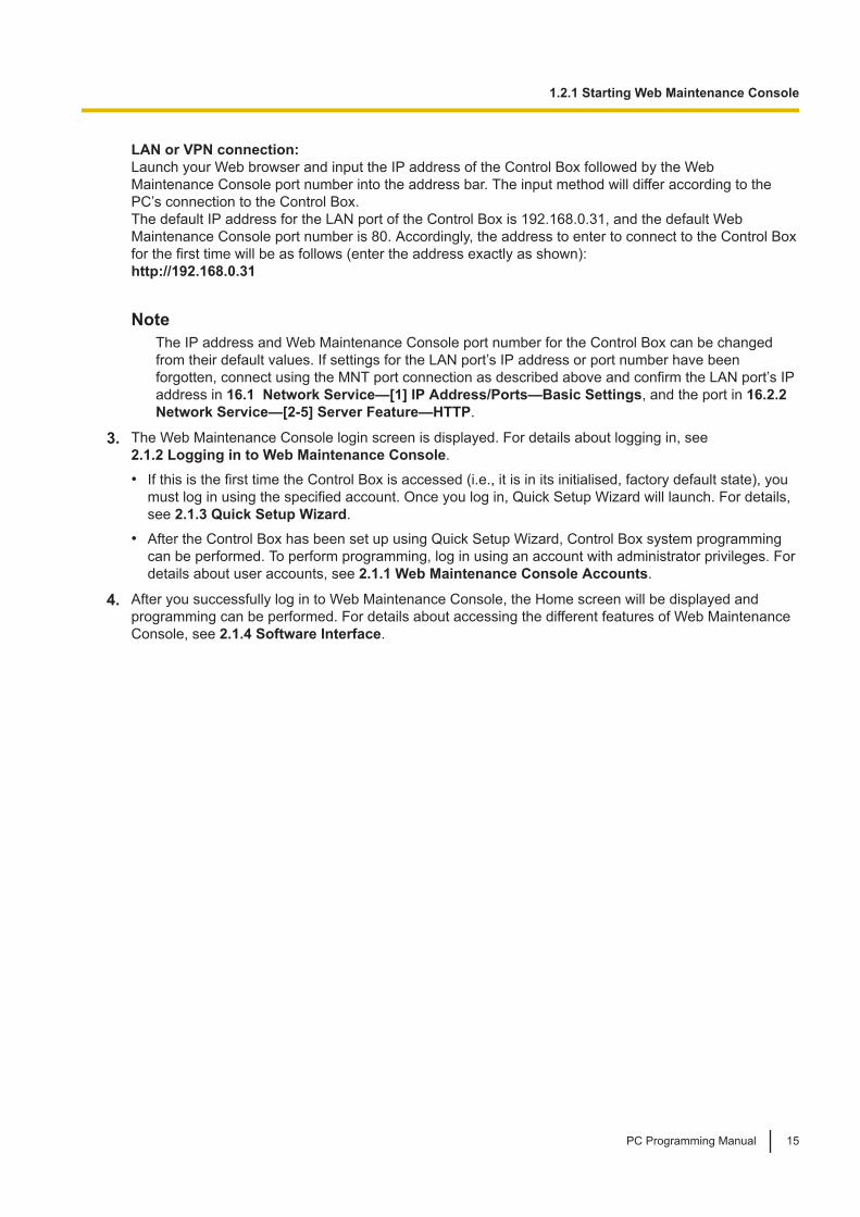
LAN or VPN connection:Launch your Web browser and input the IP address of the Control Box followed by the WebMaintenance Console port number into the address bar. The input method will differ according to thePC’s connection to the Control Box.The default IP address for the LAN port of the Control Box is 192.168.0.31, and the default WebMaintenance Console port number is 80. Accordingly, the address to enter to connect to the Control Boxfor the first time will be as follows (enter the address exactly as shown):http://192.168.0.31
NoteThe IP address and Web Maintenance Console port number for the Control Box can be changedfrom their default values. If settings for the LAN port’s IP address or port number have beenforgotten, connect using the MNT port connection as described above and confirm the LAN port’s IPaddress in 16.1 Network Service—[1] IP Address/Ports—Basic Settings, and the port in 16.2.2 Network Service—[2-5] Server Feature—HTTP.
3. The Web Maintenance Console login screen is displayed. For details about logging in, see2.1.2 Logging in to Web Maintenance Console.• If this is the first time the Control Box is accessed (i.e., it is in its initialised, factory default state), you
must log in using the specified account. Once you log in, Quick Setup Wizard will launch. For details,see 2.1.3 Quick Setup Wizard.
• After the Control Box has been set up using Quick Setup Wizard, Control Box system programmingcan be performed. To perform programming, log in using an account with administrator privileges. Fordetails about user accounts, see 2.1.1 Web Maintenance Console Accounts.
4. After you successfully log in to Web Maintenance Console, the Home screen will be displayed andprogramming can be performed. For details about accessing the different features of Web MaintenanceConsole, see 2.1.4 Software Interface.
1.2.1 Starting Web Maintenance Console
PC Programming Manual 15

1.2.1 Starting Web Maintenance Console
16 PC Programming Manual

Section 2Introduction of Web Maintenance Console
This section serves as reference operating instructionswhen using Web Maintenance Console to programmethe Control Box.
PC Programming Manual 17

2.1 Introduction2.1.1 Web Maintenance Console Accounts
User AccountsAccess to Web Maintenance Console requires a user account with Administrator privileges.
Account Login Names and PasswordsLogin names and passwords are specified as follows. Passwords are set in Web Maintenance Console (see8.1.1 Users—User Container—Add User/Edit User).
Login Name Password
1-16 character login name, using a-z, A-Z, and 0-9 (case sensitive).Set during account creation.
4-16 character password, using a-z, A-Z,and 0-9 (case sensitive). Set duringaccount creation.
For more information about creating and managing end user accounts, see 8 Users.
CAUTIONTo the Administrator regarding account passwords1. To avoid unauthorised access and possible abuse of the Control Box, keep the passwords secret,
and be aware of the importance of the passwords, and the possible dangers if they become knownto others.
2. The Control Box has no passwords set initially. For security, select a secure password as soon asthe Control Box is installed at the site.
3. Change the passwords periodically.
4. It is strongly recommended that passwords of 10 numbers or characters be used for maximumprotection against unauthorised access.
2.1.2 Logging in to Web Maintenance ConsoleAfter establishing a connection to Web Maintenance Console (see 1.2.1 Starting Web MaintenanceConsole), the login window is displayed, and a login name and password must be entered. If this is the firsttime to log in to Web Maintenance Console, and the Control Box is in its initialised, factory default state, youmust log in using a specified account to begin Quick Setup Wizard (see 2.1.3 Quick Setup Wizard).For information about account names and passwords, see 2.1.1 Web Maintenance Console Accounts.
Login Screen
2.1 Introduction
18 PC Programming Manual
Login Restrictions• If two logged-in users change the same setting, the change made last will be the effective setting.
• If a user attempts to log in, but enters an incorrect password three times, the failure is recorded in theerror log of the Control Box. Also, the user may not attempt to log in again for a 5-minute period.
2.1.3 Quick Setup WizardIn Quick Setup Wizard, you configure the mandatory settings for the Control Box. When you log in to WebMaintenance Console and the Control Box is in its initialised, factory default state, Quick Setup Wizardstarts automatically.For details about Quick Setup Wizard, refer to "5.4.1 Quick Setup Wizard" in the Installation Manual.
2.1.4 Software InterfaceThis section explains the functions of the various elements of the software interface.
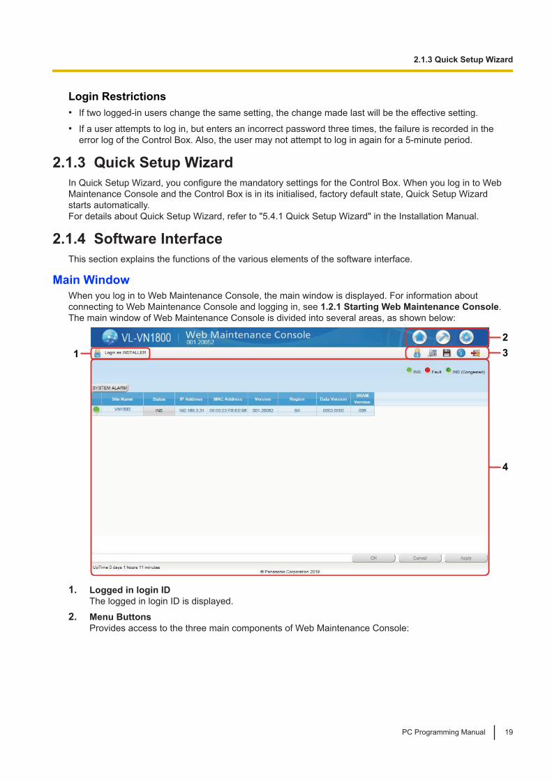
Main WindowWhen you log in to Web Maintenance Console, the main window is displayed. For information aboutconnecting to Web Maintenance Console and logging in, see 1.2.1 Starting Web Maintenance Console.The main window of Web Maintenance Console is divided into several areas, as shown below:
4
1
2
3
1. Logged in login IDThe logged in login ID is displayed.
2. Menu ButtonsProvides access to the three main components of Web Maintenance Console:
2.1.3 Quick Setup Wizard
PC Programming Manual 19

Button Description
Home Screen
Clicking this button will load the Home Screen. From the Home Screen, you can:• View the status of the Control Box
• Select the Control Box to perform programmingFor more information, see 3.1 Home Screen.
MaintenanceScreen
Clicking this button will display the Maintenance Screen tree view items. From theMaintenance Screen, you can:• Check the status and equipment of the Control Box
• Update Control Box system files
• Use tools and reports to monitor and analyse system usageFor more information, see Maintenance Screen Tree View Items below.
Setup Screen
Clicking this button will display the Setup Screen tree view items. From the SetupScreen, you can:• Configure Control Box hardware and virtual cards
• Programme settings for extensions and call handling
• Configure network settings and auxiliary Control Box functions
• Configure the Unified Messaging (UM) systemFor more information, see Setup Screen Tree View Items below.
3. Web Maintenance Console FeaturesClicking these buttons provides features for Web Maintenance Console, as follows:
Button Description
Save Data
Clicking this button will save any changes made to settings to the Storage MemoryCard. Programming changes that are not saved will be lost if the Control Box isreset or is turned off. Changes may also be lost if Web Maintenance Console issuddenly terminated or the PC running Web Maintenance Console loses powerunexpectedly. Be sure to save the data periodically while programming, especiallyduring long programming sessions.
SystemInformation
Clicking this button displays the Web Maintenance Console software version,copyright notices, and licences.
Logout
Clicking this button will save any programming changes to the Control Box'sStorage Memory Card and log you out of Web Maintenance Console. For moreinformation, see 2.2 Logout.
ExtensionList View
Clicking this button will display the Extension List View in a separate window. Fordetails, see 6.1 Tool—Extension List View.
2.1.4 Software Interface
20 PC Programming Manual

Button Description
UserContainerList View
Clicking this button will display the User Container List View in a separate window.
4. Home Screen/Tree ViewThe Home Screen (shown above) displays the Control Box list view. The information and status of theControl Box can be managed and confirmed. For more information, see 3.1 Home Screen.When the Maintenance Screen or Setup Screen is selected, the tree view is displayed. The tree view isused to display Control Box setting items. Setting items are listed in categories, and by clicking items inthe tree, setting items are displayed to the right in the settings programming area. Some tree itemshave sub-categories with additional options and settings. Clicking a sub-category will open anadditional layer of settings. Below is a summary of the tree view menu items for the Setup Screen andthe Maintenance Screen.
Maintenance Screen Tree View ItemsItem Primary Functions
Status • Check the status of extensions used by the Unified Messaging systemFor details, see 4 Status.
System Control • Download and update Control Box software files
• Reset or shutdown the systemFor details, see 5 System Control.
Tool • View a list of Control Box extensions
• Import and export Control Box settings and user informationFor details, see 6 Tool.
Utility • Perform tests for network connections
• Transfer files between the Control Box and a connected PC
• View reports, error logs, event logs, and programme update logs
• Monitor and trace Control Box communications
• Manage activation keysFor details, see 7 Utility.
Setup Screen Tree View ItemsItem Primary Functions
Users • Manage, view, and add User Containers and account informationFor details, see 8 Users.
Control BoxConfiguration
• Configure Control Box hardware settings for cards, equipment, andnetworking
• Configure dialling features and incoming call settings
• Configure call logging (SMDR) and other Control Box maintenance itemsFor details, see 9 Control Box Configuration—[1] Configuration to 12 Control Box Configuration—[11] Maintenance.
2.1.4 Software Interface
PC Programming Manual 21

Item Primary Functions
UM Configuration • Configure Unified Messaging mailboxes and voice mail subscriber settingsFor details, see 13 UM Configuration—[1] Mailbox Settings to 15 UMConfiguration—[7] System Security.
Network Service • Configure server and client features for the Control Box
• Configure connection settings and network securityFor details, see 16 Network Service.
Standard ButtonsThere are standard buttons that are displayed on many screens within the Maintenance Console.The standard buttons are as follows:
Button Function
OK Temporarily implements changes to the system’s memory(DRAM) and closes the current screen.
Cancel Abandons changes and closes the current screen.
Apply Temporarily implements changes to the system’s memory(DRAM) and remains on the same screen.
Copying and Pasting DataMany setting items in Web Maintenance Console can be copied and pasted to other items on the samescreen. When the icon is displayed, clicking it will open a menu where you can specify the copy sourceand the paste destinations.
1. On a programming screen, click . The copy window will be displayed.
NoteThe icon may not be displayed for some programming screens.
2. Select the copy source from the Copy From drop-down menu.
3. In Copy To, select one or more paste destinations. Hold down the "Ctrl" key and click to selectdestinations one at a time, or hold down the "Shift" key and click to select a range of destinations.
4. In Items, select one or more items to copy from the source selected in Copy From. Hold down the "Ctrl"key and click to select items one at a time, or hold down the "Shift" key and click to select a range ofitems.
5. Click Copy. The programming item(s) selected in Items for the copy source specified in Copy From willbe copied to the destination(s) specified in Copy To.
Individual items can also be copied and pasted in a manner similar to other software programmes. Press"Ctrl"+"c" to copy a highlighted (orange-coloured) programming item entry, select a target cell by pressingthe keyboard arrow keys, and then press "Ctrl"+"v" to paste the copied information to the selected cell.
2.1.5 Card StatusCertain tools, utilities and settings require that the target card be set to out-of-service (OUS) or in-service(INS) status before the operation is carried out. Where required, this is noted in the description of each item.• "In service" means that the card is installed correctly in the Control Box, and is capable of being used
normally.
2.1.5 Card Status
22 PC Programming Manual
• "Out of service" means that the card is installed correctly in the Control Box, but has been temporarilyremoved from use. This allows settings to be modified or software to be upgraded.
• "Fault" means that the card is not functioning correctly. For more information, see the Installation Manual.For details about how to change the status of a card, see To change the status (INS/OUS) of a card in 9.1 Control Box Configuration—[1-1] Configuration—Slot.
2.1.6 Extension Number SettingMany screens within the Maintenance Console software allow you to select extensions as part ofprogramming various features (for example, as members of a group). These screens use a standardwindow to make selecting multiple extensions easy, accessed by clicking a button. This feature is for factoryuse only.
2.1.6 Extension Number Setting
PC Programming Manual 23

2.2 LogoutTo log out of Web Maintenance Console, click the button to end the programming session and return tothe Login screen. When this option is chosen, system data is automatically saved from the temporarymemory (DRAM) of the Control Box to the Storage Memory Card.
To log out1. Click the button.
A confirmation message will be displayed.
2. Click Yes.
Note• If the PC running the Web browser that is connected to Web Maintenance Console is shut down, or
the Web browser is closed, any changes that have not been saved to the Storage Memory Card willbe lost. To save settings while programming, click the button on the Home screen. Always end yourprogramming session by clicking the button.
• If you are logged in but do not perform any operations in Web Maintenance Console for 60 minutes(default value), you will be automatically logged out.
2.2 Logout
24 PC Programming Manual

2.3 Frequently Asked Questions (FAQ)This section provides answers to some common questions about using the Maintenance Console softwareto programme the Control Box. The information is divided into the following topics:
Title Description
Connection Connecting to the Control Box using Maintenance Console.
Maintenance Console Software Using the Maintenance Console software.
Numbering Changing numbers of individual extensions.
Saving Modified Data Safely saving Control Box data edited with Maintenance Console.
Setting Features Setting up individual features.
ConnectionQ The Maintenance Console cannot connect to the Control Box via a LAN
connection.A • Is the PC connected to the LAN?
• Have the IP address and port number of the Control Box been set correctly? Formore details, see 16.1 Network Service—[1] IP Address/Ports.
• Is the login name and password correct?
Maintenance Console SoftwareQ How do I confirm the software version of the Control Box?A • From the Home Screen, access the List View (see 3.1 Home Screen). The software
version of the Control Box is displayed on this screen.
Q Not all of the characters of a setting can be displayed because the column is toonarrow.
A • Move the mouse to the line between the names of 2 setting items, at the top of thetable.The pointer will change to a double arrow. Click and drag the line to the right until allcharacters are displayed.
NumberingQ How do I change the extension number of a wired extension?A • Change the extension number of the target port to the new number, and click Apply.
Next, set the port to OUS status, and then back to INS status.You must also change the extension number on the SIP phone. For details, refer tothe SIP phone's documentation.
Saving Modified DataQ Modified settings have not been updated in the Control Box.A • Click Apply or OK in the main screen.
Q If I reset the Control Box directly after modifying settings, the modified settingsare not updated in the Control Box.
2.3 Frequently Asked Questions (FAQ)
PC Programming Manual 25
A • When you click Apply, the settings are updated in the Control Box, but are not yetsaved to the Storage Memory Card. If system data is not saved to the StorageMemory Card, the Control Box will restore the data that was last saved to the card inthe event that the Control Box is reset, or power is turned off and back on again.Therefore, before resetting the Control Box, click the button on the Home screen tosave the system data to the Storage Memory Card. Also, when you finish aprogramming session, be sure to click the button to log out and save the systemdata to the Storage Memory Card.
Setting FeaturesQ How do I add an extension as a member of an Incoming Call Distribution (ICD)
group?A • Perform the following steps:
1. On the 11.1.1.1 Control Box Configuration—[3-5-1] Group—Incoming CallDistribution Group—Group Settings—Member List screen, from the ICDGroup No. drop-down list, select the group you want to modify.The ICD group must have an extension number set.
2. Enter the extension number of the extension you want to add in a blank cell ofthe Extension Number column.
3. Set Delayed Ring as necessary.
4. Click Apply.Note that it is necessary to set the extension number of the ICD group in advance.
Q I have set FWD through system programming, but calls are still not beingforwarded.
A • Perform the following steps:1. Check that the Telephony Feature settings of the target extension on the
8.1.1 Users—User Container—Add User/Edit User screen are set to one ofthe forwarding settings.
2.3 Frequently Asked Questions (FAQ)
26 PC Programming Manual
Section 3Web Maintenance Console Home Screen
This section explains how to setup the Control Box fromthe Home Screen of Web Maintenance Console.
PC Programming Manual 27
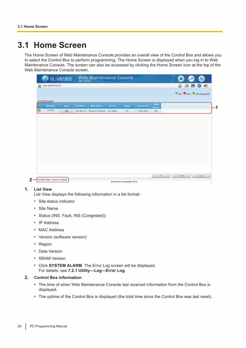
3.1 Home ScreenThe Home Screen of Web Maintenance Console provides an overall view of the Control Box and allows youto select the Control Box to perform programming. The Home Screen is displayed when you log in to WebMaintenance Console. The screen can also be accessed by clicking the Home Screen icon at the top of theWeb Maintenance Console screen.
2
1
1. List ViewList View displays the following information in a list format:• Site status indicator
• Site Name
• Status (INS, Fault, INS (Congested))
• IP Address
• MAC Address
• Version (software version)
• Region
• Data Version
• SRAM Version
• Click SYSTEM ALARM. The Error Log screen will be displayed.For details, see 7.2.1 Utility—Log—Error Log.
2. Control Box information• The time of when Web Maintenance Console last received information from the Control Box is
displayed.• The uptime of the Control Box is displayed (the total time since the Control Box was last reset).
3.1 Home Screen
28 PC Programming Manual

Section 4Status
This section serves as reference operating instructionsfor the Status menu of the Maintenance screen of WebMaintenance Console.
PC Programming Manual 29

4.1 Status—Equipment Status4.1.1 Status—Equipment Status—UM Port status
The UM Port status screen displays each port’s status and number for the Unified Messaging system. Thescreen will be updated every 30 seconds. Each port’s status will be displayed in one of the following ways:• Online (Ready): The port is ready to be used.
• Incoming Call: The port is handling an incoming call.
• Outgoing Call: An outgoing service is being processed.
• Error Occurred: An error has been detected.
• Off Line: The port is offline.
4.1 Status—Equipment Status
30 PC Programming Manual

Section 5System Control
This section serves as reference operating instructionsfor the System Control menu of the Maintenance screenwhen programming using Web Maintenance Console.
PC Programming Manual 31

5.1 System Control—Program UpdateThe programme file for the following hardware component can be updated with the Program Update feature.The file must be named as indicated in the table to be recognised by the Control Box.
Hardware that can be updated using Program UpdateProgramme Type Target of Update File Name
MPR Programme Mother Board PNMPR
5.1.1 System Control—Program Update—Download ProgramFile
Software updates for the Control Box can be downloaded to the Control Box.
ManualUsing manual operations, the location of updated Control Box software is specified and downloaded to theControl Box.To download programme files manually1. In Location of program files, select Local PC from the Look in drop-down list.
2. Click Browse and specify the location of the updated programme files stored on the PC logged in toWeb Maintenance Console.
3. Click Execute, and then click OK on the confirmation message that appears. When the transfer iscomplete, click OK.
NoteIf downloading cannot be completed within 10 minutes (due to slow network speeds or other connectionproblems), the download operation will be cancelled.
5.1.2 System Control—Program Update—Update Program FileOnce updated programme files have been downloaded and are stored on the Control Box, they can be usedto update the system files of the Control Box. The update process can be set to be automatically performedat a specified time, or the update process can be carried out manually.
Note• When the programme has been updated, the format of the system data is converted automatically to
the updated version.• If the conversion of the system data fails during a programme update, the system can be recovered
as follows:1. System is rolled back to previous version automatically.
2. Check the error log to confirm whether the system data conversion had failed. See 7.2.1 Utility—Log—Error Log.
3. Update the programme and restart the system.
4. Transfer the converted system data to the Control Box.
For Program Update Type, select Immediately or Timed Update.
Immediately (Manual update)Update the Control Box's software immediately.
5.1 System Control—Program Update
32 PC Programming Manual

1. In Email notification, specify up to 2 e-mail addresses that will receive a notification when programmefiles have been updated.
2. Updated programme files that can be used to update the Control Box are listed in Available ProgramFile(s). In Select the target to update, select the check box for the Control Box (listed as "MainUnit").
NoteWhen selecting an item, a warning message may be displayed. Confirm the contents of the warning,and then click OK to continue.
3. Click Apply.
4. Click Execute.The programme files for the Control Box will be updated.
NoteThe Control Box resets when the update is complete.
Timed Update (Automatic update)Specify a specific date and time to update the Control Box software.
1. In Email notification, specify up to 2 e-mail addresses that will receive a notification when programmefiles have been updated.
2. Updated programme files that can be used to update the Control Box are listed in Available ProgramFile(s). In Select the target to update, select the check box for the Control Box (listed as "MainUnit").
NoteWhen selecting an item, a warning message may be displayed. Confirm the contents of the warning,and then click OK to continue.
3. In Date, specify the date when the update will be executed.
4. In Update Time, specify the time of day when the update will be executed.
5. Click Apply.
6. Click Execute.The programme files will be updated at the specified date and time.
NoteAt most, the process of updating the Control Box can take approximately 30 minutes to complete.
5.1.2 System Control—Program Update—Update Program File
PC Programming Manual 33

5.2 System Control—System ResetWhen programming changes or other changes to Control Box settings require a system reset, thiscommand allows a reset to be performed remotely from Web Maintenance Console.When the system is reset, any settings not saved to the Storage Memory Card are lost. A backup should beperformed before the reset to ensure no data is lost. However, a backup should not be performed if settingsor data have recently been imported into the system, because performing a backup would overwrite theimported data with the current Control Box settings.
[Manual System Reset]1. Select the System Reset tab.
2. Confirm the contents of the displayed warning message.
3. Click Backup or Skip according to the system’s status:• Backup: Click to backup system settings. The system will be reset after the backup has been
performed.• Skip: The system is reset without performing a backup.
If you are logged in to the Control Box that is reset using this command, it is necessary to re-log in to WebMaintenance Console to continue programming.
[System Reset by Timed Schedule]1. Select the Timed Reset tab.
2. Select the Reset Mode (None, One Time, Daily).
3. Set the Reset Time (00:00-23:59).
4. Click Apply or OK to set the system reset.
5.2 System Control—System Reset
34 PC Programming Manual

5.3 System Control—System ShutdownIn order to turn off the power to the Control Box, it must first be issued a shutdown command using WebMaintenance Console. Follow the procedure below to prepare the Control Box for system shutdown.When the system is shut down, any settings not saved to the Storage Memory Card are lost. A backupshould be performed before the shutdown to ensure no data is lost. However, a backup should not beperformed if settings or data have recently been imported into the system, because performing a backupwould overwrite the imported data with the current Control Box settings.1. Confirm the contents of the displayed warning message.
2. Click Backup or Skip according to the system’s status:• Backup: Click to backup system settings. The system will prepare for shutdown after the backup
has been performed.• Skip: The system is prepared for shutdown without performing a backup.
3. The STATUS LED on the front of the Control Box will flash amber. When shutdown preparations arecompleted, the STATUS LED will stop flashing and remain a solid amber. Once the STATUS, BATTALARM, and SYSTEM MODE LEDs light in amber, red, and amber respectively, you may turn off thepower switch on the back of the Control Box.
5.3 System Control—System Shutdown
PC Programming Manual 35

5.3 System Control—System Shutdown
36 PC Programming Manual

Section 6Tool
This section serves as reference for the Tool menu ofthe Maintenance screen of Web Maintenance Console.
PC Programming Manual 37

6.1 Tool—Extension List ViewDisplays a list of all programmed extension numbers and types. It is possible to sort the informationaccording to Extension Number, Type, Extension Name, Slot, or Port. There is also a key-word searchingfeature. The types that can be displayed are as follows:
Type Detail
SIP SIP Extension
UM Unified Messaging
ICD Group Incoming Call Distribution Group
6.1 Tool—Extension List View
38 PC Programming Manual
6.2 Tool—ImportAllows several types of system data files or tables to be imported.The files from which data can be imported are files that were previously saved at the Control Box using theExport tool (see 6.3 Tool—Export), or comma-separated value (CSV) files. Unsupported file types cannotbe opened.For all tables, it is possible to edit the CSV file directly using an appropriate editor, before importing.
Note• You can import only a CSV file that was exported with all items.
• The numbering plan cannot be imported on this screen. To import the numbering plan, you must useQuick Setup Wizard. Therefore, to change the numbering plan after you have set up the Control Box,initialise the Control Box, and then import the desired file again in Quick Setup Wizard.
The types of data that can be imported using this tool are as follows:
User ContainerData Type Import Destination
(no fields to select) (no fields to select)
Related programming: 8.1 Users—User Container
SIP ExtensionData Type Import Destination
(no fields to select) (no fields to select)
Related programming: 9.7 Control Box Configuration—[1-1] Configuration—Slot—V-SIPEXT128—PortProperty
ICD GroupData Type Import Destination
(no fields to select) (no fields to select)
Related programming: 11.1 Control Box Configuration—[3-5] Group—Incoming Call DistributionGroup
Media Relay GatewayData Type Import Destination
(no fields to select) (no fields to select)
Related programming: 9.3 Control Box Configuration—[1-1] Configuration—Slot—Site Property
To import system data1. From the Tool tree menu, select Import, and then click the type of data to import.
2. Navigate to the folder containing the system data file you want to open.
3. Select the file.
4. Click OK to open the file.If applicable, a list of field names found in the imported file will be displayed.
6.2 Tool—Import
PC Programming Manual 39
5. Click OK to perform the import operation.If data in a field being imported does not match the required format for the import destination, an errormessage will be displayed when the import operation is attempted, and the operation will be cancelled.This can occur when, for example, the destination field can only accept numeric data, but the data beingimported contains alphabet characters, as the correct fields were not linked together.
6.2 Tool—Import
40 PC Programming Manual

6.3 Tool—ExportAllows several types of system data to be exported to files. These files can be used with the Import tool (see6.2 Tool—Import) to update another Control Box.System data is exported as comma-separated value (CSV) files.
NoteThe separator used in CSV files created using the Export tool is decided by the unit specified in ListSeparator, found in the Windows Control Panel’s "Regional Options".
To export system data1. From the Tool tree menu, select Export, and then click the type of data to export.
2. Click OK.
3. If a message window is displayed, click OK.
4. In the file selection screen, select the Save check box, and then click OK.
6.3 Tool—Export
PC Programming Manual 41

6.3 Tool—Export
42 PC Programming Manual
Section 7Utility
This section serves as reference operating instructionsfor the Utility menu of the Maintenance screen of WebMaintenance Console.
PC Programming Manual 43

7.1 Utility—Diagnosis7.1.1 Utility—Diagnosis—Ping
Performs a connection test on network devices. This function sends echo requests to a particular IP addressacross an IP network, and displays the result of responses and round-trip time.
To perform a Ping test1. Enter a specific IP address in the IP Address box.
2. Click Test to perform the test.The result will be displayed.
3. Select an option:• Click Capture if you want to save the displayed information.
1. Enter a file name, or select a file to overwrite.
2. Click Save.
• Click Cancel to return to the Ping screen.
7.1 Utility—Diagnosis
44 PC Programming Manual

7.2 Utility—Log7.2.1 Utility—Log—Error Log
Collects and displays system error information.Whenever there is a system failure, the Control Box stores the error code generated. The connected PCcollects all of these codes, along with other information, and displays an explanatory error message. The functions of the buttons on this screen are as follows:
Button Function
Cancel Closes the Error Log screen without saving.
Save Saves the currently displayed Error Log information as a text file.
Minor Displays minor errors, which affect only a certain part of system operation.
Major Displays major errors, which affect operation of the whole system, or result insystem failure.
Information Displays the information log.
Clear Erases the stored error log information from both the screen and the ControlBox.
Log Information Clicking this button displays a list of errors and solutions in PDF format, asshown below.
The items displayed on screen are as follows:
Item Description
Date The date of the error detection.
Time The time of the error detection.
Error Code The 3-digit error code assigned by the Control Box. For details about theerror code, refer to the "Log Information" item in the previous table.
Sub Code SMDR:The 10-digit sub code of the relevant hardware (BBBWXYYZZZ).Web Maintenance Console:The 7-digit sub code of the relevant hardware (WXYYZZZ).For information about the digits of the Sub Code, refer to table "Sub CodeDetails" below.SIP Registration Failure/SIP Registration Restored:The 5-digit sub code of the extension number.
Error Message A description of the error.
[Sample] List of Errors and SolutionsFor each error code, the error message, probable cause, and solutions are explained.
7.2 Utility—Log
PC Programming Manual 45

Sub Code DetailsSub Code Description
BBB Site ID000
W Slot TypeFor virtual slots
– "*" (asterisk)
X Shelf Number• – Main Unit: 1
– Control Box process: 5
– Convert process: 6
YY Slot NumberWhen X is not 5 or 6
Virtual shelfVirtual Extension slots: 1–47
When X is 5
YY: Process code When X is 6
YY: Convert code
7.2.1 Utility—Log—Error Log
46 PC Programming Manual
Sub Code Description
ZZZ Port NumberWhen X is not 5 or 6
ZZZ: Optional service card port number (001–XXX) When X is 5
ZZZ: Process number (determined by each process) When X is 6
ZZZ: Convert code
NoteWhen there is no parameter for slot and port number, YY and ZZZ will be displayed as "000".Example: Sub code for the mother board = "001 100000"
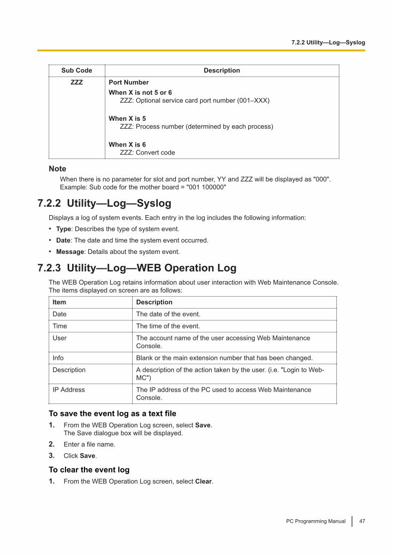
7.2.2 Utility—Log—SyslogDisplays a log of system events. Each entry in the log includes the following information:• Type: Describes the type of system event.
• Date: The date and time the system event occurred.
• Message: Details about the system event.
7.2.3 Utility—Log—WEB Operation LogThe WEB Operation Log retains information about user interaction with Web Maintenance Console.The items displayed on screen are as follows:
Item Description
Date The date of the event.
Time The time of the event.
User The account name of the user accessing Web MaintenanceConsole.
Info Blank or the main extension number that has been changed.
Description A description of the action taken by the user. (i.e. "Login to Web-MC")
IP Address The IP address of the PC used to access Web MaintenanceConsole.
To save the event log as a text file1. From the WEB Operation Log screen, select Save.
The Save dialogue box will be displayed.2. Enter a file name.
3. Click Save.
To clear the event log1. From the WEB Operation Log screen, select Clear.
7.2.2 Utility—Log—Syslog
PC Programming Manual 47

7.2.4 Utility—Log—UM System LogYou can export a log of events from the Unified Messaging system for troubleshooting purposes.
1. Click OK to export a UM System Log file.
2. Click Save to save the data to a local file.
3. Click OK.
7.2.4 Utility—Log—UM System Log
48 PC Programming Manual

7.3 Utility—Email Notification7.3.1 Utility—Email Notification—Alert
You can specify e-mail addresses that will receive messages regarding the Control Box’s status.
System AlarmAn e-mail message will be sent to the specified address when there is a system alarm. The e-mail messagewill contain details about the alarm.
1. For Filtering Setting, select the check boxes to specify whether to receive e-mails when there is aMajor alarm, a Minor alarm, or Information.
2. Specify one or two e-mail addresses that will receive system alarm alert messages.
NoticeBe sure to enter e-mail addresses correctly. If an address is incorrectly entered, an alert will not bereceived when there is a system alarm, or information regarding the Control Box may be sentunintentionally to a third party.
3. In Subject enter the text that will be used for the subject header of e-mails that are sent.For Format—Message body type, select the check boxes to specify whether to include the subject inthe message body.• Type1: Message body does not include the subject
• Type2: Message body includes the subject
4. Click OK when finished.
7.3.2 Utility—Email Notification—Test EmailSend a test e-mail to confirm e-mail sending settings are correctly configured.1. Enter up to 2 e-mail addresses in Email Address 1 and Email Address 2.
2. In Subject, enter text to be used as the subject line of the e-mail sent.
3. Click Execute. A test mail will be sent to the specified address(es).Mail settings can be viewed and set in 16.2.4 Network Service—[2-7] Server Feature—SMTP.
7.4 Utility—Activation Key InstallationFor information about registering additionally purchased activation keys, refer to "5.4.4 Installing AdditionalActivation Keys" in the Installation Manual.
7.3 Utility—Email Notification
PC Programming Manual 49

7.4 Utility—Activation Key Installation
50 PC Programming Manual

Section 8Users
This section serves as reference operating instructionsfor the Users menu of the Setup screen of WebMaintenance Console.
PC Programming Manual 51

8.1 Users—User ContainerManage each user's devices (such as a wired extension and built-in Unified Messaging mailbox). Usercontainer information can be registered, edited, or deleted here.The settings that can be changed in the User Container information for each user are as follows:
CommonItem Description
First Name Specifies the first name of the user (max. 20 characters).
Last Name Specifies the last name of the user (max. 20 characters).
Extension No. Displays the extension number associated with this user (reference only).Extension numbers can be set in Extension Settings:8.1.1 Users—User Container—Add User/Edit User
Sub Device No. Displays the Sub Device No. of the user (0-5 digits) (reference only).The extension number set in Sub Device No. on the Add/Edit screen will bedisplayed. If no extension number is set, this item will be left blank.
FWDItem Description
First Name Displays the first name of the user specified in First Name on theCommon tab (reference only).
Last Name Displays the last name of the user specified in Last Name on theCommon tab (reference only).
FWD setting - call from Ext. Mode Displays the FWD setting for calls from extensions specified inFWD Setting in the Telephony Feature tab on the Add User/Edit User screen (reference only).
FWD setting - call from Ext.Destination
Displays the FWD destination for calls from extensions specifiedin FWD Setting in the Telephony Feature tab on the Add User/Edit User screen (reference only).
FWD No Answer Time (s) Select the length of time that an incoming call rings at theextension before the call is forwarded.
For settings and details for FWD items, refer to the following:• 8.1.1 Users—User Container—Add User/Edit User
SecurityItem Description
First Name Displays the first name of the user specified in First Name on theCommon tab (reference only).
Last Name Displays the last name of the user specified in Last Name on theCommon tab (reference only).
User PIN / Mailbox Password ExpiryPeriod (days)
Factory use only
8.1 Users—User Container
52 PC Programming Manual

OptionItem Description
Rule of copy to extension name Determines how the First Name and Last Name set in UserContainer is used for the Display Name of the following settings.8.1.1 Users—User Container—Add User/Edit User
ActivationItem Description
First Name Displays the first name of the user specified in First Name on the Common tab.
Last Name Displays the last name of the user specified in Last Name on the Common tab.
Extension No. Displays the extension number associated with this user (reference only).Extension numbers can be set in Extension Settings:8.1.1 Users—User Container—Add User/Edit User
Sub Device No. Displays the Sub Device No. of the user (0-5 digits) (reference only).The extension number set in Sub Device No. on the Add/Edit screen will bedisplayed. If no extension number is set, this item will be left blank.
Room Monitor Displays if there is (On) or is not (Off) a room monitor set to Room Monitor.
Mobilephone Displays the number of registered smartphones (0-4).
Activation Displays the number of activations (0-2) set to Activation.
User Controls• Add Button/Add Single User Button
To add a user profile for a single extension, click the button or Add Single User button to open the AddUser screen. See 8.1.1 Users—User Container—Add User/Edit User.
• Edit ButtonTo edit information on an individual user level, select a user from the list by clicking on the row of the userto edit, then clicking the button to open the Edit User screen with the selected user’s information filledin. See 8.1.1 Users—User Container—Add User/Edit User.
• Delete ButtonTo delete users:
1. Check the box(es) next to the user’s name(s) and click the button.
2. A confirmation message will appear. Click OK.
3. The user’s information is deleted from the list.
• Add Range Button/Add Multiple Users ButtonTo add multiple User Containers for a range of extensions at one time, click the button or Add MultipleUsers button. See 8.1.2 Users—User Container—Add Multiple Users.
8.1.1 Users—User Container—Add User/Edit UserThe Add User/Edit User screen provides a method to create user accounts and establish the Control Boxsettings on a per-user level. When adding a user, the following settings can be specified. This screen willalso be displayed with information already entered when editing an existing user.
8.1.1 Users—User Container—Add User/Edit User
PC Programming Manual 53

User InformationItem Description
First Name*1 Specifies the first name of the user (max 20 characters).
Last Name Specifies the last name of the user (max 20 characters).
Display Name Displays the first name and the last name of the user (max 32 characters).
Extension Number Specifies Extension Number of the user (blank or 2-5 digits).*2
Login ID*1 Set a login ID for the user (1-16 characters in length).
Password ["A-Z", "a-z","0-9", "*", "#"]*1
Set a password for the user (4-16 characters in length).
Re-enter ["A-Z", "a-z","0-9", "*", "#"]*1
Re-enter the password for confirmation.
User PIN / MailboxPassword ["0-9"]
Factory use only
Confirm new PIN["0-9"]
Factory use only
WebMC Language Select the Web Maintenance Console language displayed for the user from thedrop-down list. Users may select different display languages without affectingthe display of other users.
Memo-1 Specifies the memo (max 64 characters).
Memo-2 Specifies the memo (max 64 characters).
Admin Capability Select whether to give Administrator authority from the drop-down list.
User Group Select a User Group from the drop-down list.
Class of Service (COS) Select the COS for the user from the drop-down list.
*1 Required item to set*2 It is impossible to reset the extension number once registered.The Display Name set on this screen are applied to system settings as follows.• The Display Name is used as Extension Name for the user’s extension number.
The format of the extension name is determined by the setting in the User Container—Option tab:– Rule-A: [First Name] [space] [Last Name]– Rule-B: [Last Name] [,] [First Name]
NoticeIf the length of the name copied to the Display Name is longer than the maximum number ofcharacters allowed for the setting, the letters at the end of the name exceeding the maximum will bediscarded.
• The First Name and Last Name are copied to the corresponding First Name and Last Name for thespecified mailbox number.
• Changing the name settings in the Mailbox Settings screen will not change the First Name or Last Nameon this screen (the copying function is one-way).
Device SettingsItem Description
Main Device—Number Displays the extension number of the Main Device.
8.1.1 Users—User Container—Add User/Edit User
54 PC Programming Manual

Item Description
Sub Device—Number Specifies the extension number of the Sub Device (2-5 digits).
Sub Device—DelayedRinging
Select a delayed ringing setting of the Sub Device from the drop-down list.
ContactItem Description
Phone (Home) Specifies the user’s home telephone number (max. 32 digits).
Email 1–3 Specifies the user’s e-mail address(es) (max. 128 characters).
NoticeThe e-mail addresses set for Email 1–3 on this screen are applied to system settings as follows.• If Use for missed call notification is checked when the Email 1–3 information is input, the user will
receive an e-mail at the specified addresses when an incoming call is missed.• If Use for voice mail notification is checked when the Email 1–3 information is input, the user will
receive an e-mail at the specified addresses when the user has a new voice message.• When the Email 1-3 information is input, the user will receive an e-mail at the specified addresses when
there is a sensor notification, an emergency notification, or a user password expiration notification.
Unified MessageItem Description
Mailbox Number Indicates the UM mailbox number for the user (reference only).
Telephony FeatureItem Description
FWD / Do Not Disturb—For internal calls—Status
Specifies whether to enable the user’s FWD/DND settings for extension calls.To enable FWD, specify a value other than None for FWD Setting, and thenselect FWD On. To enable DND, specify Do Not Disturb for Do Not DisturbSetting and then select DND On.
FWD / Do Not Disturb—For internal calls—FWD Setting
Specifies the user’s FWD settings for extension calls. For the FWD destination,Phone (Home) (as specified in the Contact tab), or a manually input number(1-32 digits) can be specified.
NoteCalls can be forwarded only to valid extension numbers. If you selectPhone (Home), make sure that an extension number is specified for thatsetting.
FWD / Do Not Disturb—For internal calls—Do Not Disturb Setting
Specifies the user's DND settings for extension calls.
FWD / Do Not Disturb—FWD No AnswerTime
Specifies the length of time that an incoming call rings at the extension beforethe call is forwarded.
8.1.1 Users—User Container—Add User/Edit User
PC Programming Manual 55

8.1.2 Users—User Container—Add Multiple UsersThe User Container—Add Multiple Users screen provides a method to create multiple User Containers fora range of extensions at one time.
1. In the From and Number of Users fields, specify the number of users to create profiles for.
2. Select Create User Container Data from other User template check box if you want to create UserContainer data from other User template.
3. If you choose to copy the other User Container data, select a user template from the Select templatedrop-down list.
4. Click OK.
5. A confirmation message will be displayed. Confirm the massage, and then click OK to continue.
Settings automatically programmed for each user• First Name: "User_" + 4 digits of User Container number (i.e., if User Container number is "1", the First
Name for the user will be "User_0001".)• Login ID and Password:
4 digits of User Container number (i.e., if User Container number is "1", the Login ID and Password forthe user will be "0001".)
• User Group (when not copying from a User template):– If an Administrator creates the user: "1"
Note• When OK is clicked, if any extensions within the range specified in step 1 already have user accounts
associated with them, User Containers cannot be created, and an error message will be displayed.• When OK is clicked, the progress of creating the User Container data will be displayed. A dialogue
box will be displayed to indicate when the process is complete.• A maximum of 1999 users can be created at once using this feature.
8.1.2 Users—User Container—Add Multiple Users
56 PC Programming Manual
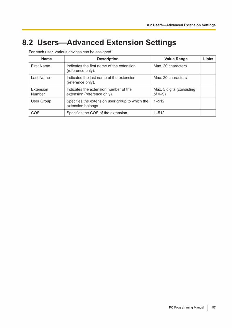
8.2 Users—Advanced Extension SettingsFor each user, various devices can be assigned.
Name Description Value Range Links
First Name Indicates the first name of the extension(reference only).
Max. 20 characters
Last Name Indicates the last name of the extension(reference only).
Max. 20 characters
ExtensionNumber
Indicates the extension number of theextension (reference only).
Max. 5 digits (consistingof 0–9)
User Group Specifies the extension user group to which theextension belongs.
1–512
COS Specifies the COS of the extension. 1–512
8.2 Users—Advanced Extension Settings
PC Programming Manual 57

8.2 Users—Advanced Extension Settings
58 PC Programming Manual

Section 9Control Box Configuration—[1] Configuration
This section serves as reference operating instructionsfor the Configuration menu of the Control BoxConfiguration menu of the Setup screen of WebMaintenance Console.
PC Programming Manual 59

9.1 Control Box Configuration—[1-1] Configuration—Slot
The operating characteristics associated with each service card can be programmed.Click the corresponding button or column to display the menu of options for the installed card.
To access card propertiesClick Edit in the Card Property column. The property screen for that card will be displayed.
To access port propertiesClick Port Property button. The property screen for that card’s port or ports will be displayed.
To change the status (INS/OUS) of a card1. Click INS or OUS in the Status column.
2. Select the desired status:• Click INS to set the card to in-service status.
• Click OUS to set the card to out-of-service status.
Supported Card TypesCard Maximum Number Card Programming
V-SIPEXT128: Virtual 128-ChannelSIP Extension Card 16
9.6 Control Box Configuration—[1-1] Configuration—Slot—V-SIPEXT128—Card Property
Common Programming Reference ItemsWhen programming settings for cards, extensions, and other devices using Web Maintenance Console,depending on the screen being accessed, the following items may be listed on the screen for yourreference:
Item Description
Slot Indicates the slot number where the card is located.
Port Indicates the port number assigned to the extension or device.
9.1 Control Box Configuration—[1-1] Configuration—Slot
60 PC Programming Manual

9.2 Control Box Configuration—[1-1] Configuration—Slot—System Property
The properties of the Control Box system can be specified.
MainName Description Value Range Links
DSP CODEC G.711 only(SIP extension)
Specifies whether or not to only use the G.711codec for SIP extension calls.
Enable, Disable
System StatusName Description Value Range Links
CPU Usage Displays the system CPU’s current processor load,expressed as a percentage of total capacity (reference only).
1.00–100.00%
Memory Usage Displays the amount of system memory currently being used,displayed as a percentage of total capacity (reference only).
1.00–100.00%
Storage Usage Displays the capacity and used space of the pre-installedStorage Memory Card of the Control Box as a percentage.
1.00–100.00%
Storage Usage(for Log)
Displays the amount of storage for logs currently being usedfor the Control Box as a percentage.
0–100%
9.2 Control Box Configuration—[1-1] Configuration—Slot—System Property
PC Programming Manual 61

9.3 Control Box Configuration—[1-1] Configuration—Slot—Site Property
The properties of the Control Box site can be specified. When you place the mouse cursor over the SiteProperty button, the Main button is displayed. Click the button to open that site property screen.
9.3.1 Control Box Configuration—[1-1] Configuration—Slot—SiteProperty—Main
Overall settings for the Control Box site can be specified.
VoIP-DSP OptionsThis feature is for factory use only.
Port Number
Name Description ValueRange Links
Voice (RTP) UDPPort No. (Server)
Specifies the UDP port used by the system totransmit and receive RTP (Real-time TransferProtocol) data. This must be changed if anothernetwork application is using the same port.For voice communications, the system uses 128contiguous UDP ports, starting from the portnumber specified here.
1024–64000
NAT - Voice (RTP)UDP Port No.
Specifies the starting port number of thedynamic ports used for NAT Traversal. (Readonly) *1
1024–65535
UDP Port No. forSIP ExtensionServer
Specifies the UDP port number used for the SIPExtension server.
1024–65535
FeatureManualReferences4.2.1 SIP(SessionInitiationProtocol)Extension
TLS Port No. for SIPExtension Server
Factory use only -
LOGIN Port Number Specifies the port number used to log in to theControl Box via the LAN.
1024–65535
*1 This setting value is the value from the import file of Quick Setup.
LAN StatusName Description Value Range Links
Link-MNT/LAN1/LAN2/LAN3
Displays the link status (reference only).Up is displayed when an L2 link is established.Down is displayed when there is no connection.
Up, Down
9.3 Control Box Configuration—[1-1] Configuration—Slot—Site Property
62 PC Programming Manual

Name Description Value Range Links
Speed-MNT/LAN1/LAN2/LAN3
When devices are connected and the L2 link-up issuccessful, its communication speed is displayed(reference only).
10 Mbps Half Duplex, 10Mbps Full Duplex, 100Mbps Half Duplex, 100Mbps Full Duplex,1Gbps, -
Media RelayName Description Value Range Links
Common NAT—External IP Address *1
Specifies the NAT device external IP address(common)
blank, 1.0.0.1–223.255.255.254
Common NAT—External Server Name(for DDNS) *1
Specifies the URL of the DDNS service thatthe router of the site where VL-VN1800 isinstalled will use.
Max. 253 characters
SIP Extension NAT—SIP Proxy Server PortNo. *1
Specifies the outside-facing port of thenetwork gateway connected to SIP proxyserver.
0–65535 (Except"50xx" and "x50xx")
Option NAT—RTP IPAddress
Specifies the RTP server's IP address. Ifusing a separate IP address from Common -NAT—External IP Address, configure thissetting.
blank, 1.0.0.1–223.255.255.254
Option NAT—SIPProxy Server IPAddress
Specifies the outside-facing IP address orhost name of the network gateway connectedto the SIP proxy server. If using a separate IPaddress from Common - NAT—External IPAddress, configure this setting.
blank, 1.0.0.1–223.255.255.254
*1 This setting value is the value from the import file of Quick Setup.
SIP ExtensionThis feature is for factory use only.
Echo CancellationThis feature is for factory use only.
9.3.1 Control Box Configuration—[1-1] Configuration—Slot—Site Property—Main
PC Programming Manual 63

9.4 Control Box Configuration—[1-1] Configuration—Slot—UM Property—UM System Property
This feature is for factory use only.
9.4 Control Box Configuration—[1-1] Configuration—Slot—UM Property—UM System Property
64 PC Programming Manual

9.5 Control Box Configuration—[1-1] Configuration—Slot—UM Property—UM Port Property
The properties of the Unified Messaging (UM) system’s ports can be specified.
MainThe Port for each item is displayed for your reference. For details, see Common Programming ReferenceItems in 9.1 Control Box Configuration—[1-1] Configuration—Slot.
Name Description Value Range Links
ExtensionNumber
Specifies the extension number of theport.
Max. 5 digits (consisting of 0–9)
Connection Indicates the port status. To change thestatus of the port, click the desired cellin the column, and then select INS orOUS for the port.
INS: The port is in service.OUS: The port is out of service.Fault: The port is notcommunicating with the network.
COS Specifies the COS of the UM port. 1–512
9.5 Control Box Configuration—[1-1] Configuration—Slot—UM Property—UM Port Property
PC Programming Manual 65

9.6 Control Box Configuration—[1-1] Configuration—Slot—V-SIPEXT128—Card Property
This feature is for factory use only.
9.6 Control Box Configuration—[1-1] Configuration—Slot—V-SIPEXT128—Card Property
66 PC Programming Manual

9.7 Control Box Configuration—[1-1] Configuration—Slot—V-SIPEXT128—Port Property
Various settings can be programmed for each virtual SIP extension port.The Slot and Port for each item are displayed for your reference. For details, see Common ProgrammingReference Items in 9.1 Control Box Configuration—[1-1] Configuration—Slot.
MainName Description Value Range Links
ExtensionNumber
Specifies the extension number ofthe port.
Max. 5 digits (consistingof 0–9)
Feature ManualReferences4.2.1 SIP (SessionInitiation Protocol)Extension
Password Specifies the password used forregistering a SIP Extension to theControl Box. This parameter canonly be modified when the virtualSIP extension port is set to OUS.1. Click the Edit button.
Password screen is displayed.2. Enter the new password and
then enter it again to confirm it.3. Click OK.
4–16 characters(consisting of 0–9, a–z,A–Z)
Feature ManualReferences4.2.1 SIP (SessionInitiation Protocol)Extension
Connection Indicates the port status. To changethe status of the port, click thedesired cell in the column, and thenselect INS or OUS for the port.
INS: The port is inservice.OUS: The port is out ofservice.Fault: The port is notcommunicating with thenetwork.
Feature ManualReferences4.2.1 SIP (SessionInitiation Protocol)Extension
Current IPAddress
Indicates the current IP address ofthe SIP Extension (reference only).
1.0.0.0–223.255.255.255 Feature ManualReferences4.2.1 SIP (SessionInitiation Protocol)Extension
MWI Method Factory use only -
OptionThe Slot and Port for each item are displayed for your reference. For details, see Common ProgrammingReference Items in 9.1 Control Box Configuration—[1-1] Configuration—Slot.
9.7 Control Box Configuration—[1-1] Configuration—Slot—V-SIPEXT128—Port Property
PC Programming Manual 67

Name Description Value Range Links
ExtensionNumber
Specifies the extension number ofthe port.
Max. 5 digits (consistingof 0–9)
Feature ManualReferences4.2.1 SIP (SessionInitiation Protocol)Extension
Password Specifies the password used forregistering a SIP Extension to theControl Box. This parameter canonly be modified when the virtual SIPextension port is set to OUS.1. Click the Edit button.
Password screen is displayed.2. Enter the new password and
then enter it again to confirm it.3. Click OK.
4–16 characters(consisting of 0–9, a–z,A–Z)
Feature ManualReferences4.2.1 SIP (SessionInitiation Protocol)Extension
Connection Indicates the port status. To changethe status of the port, click thedesired cell in the column, and thenselect INS or OUS for the port.
INS: The port is inserviceOUS: The port is out ofserviceFault: The port is notcommunicating with thenetwork.
Feature ManualReferences4.2.1 SIP (SessionInitiation Protocol)Extension
PacketSampling Time(G.711/G.722)
Factory use only-
PacketSampling Time(G.729A)
Factory use only-
9.7 Control Box Configuration—[1-1] Configuration—Slot—V-SIPEXT128—Port Property
68 PC Programming Manual

9.8 Control Box Configuration—[1-5] Configuration—DSP Resource9.8.1 Control Box Configuration—[1-5-1] Configuration—DSPResource—Setting
This feature is for factory use only.
9.8.1.1 Control Box Configuration—[1-5-1] Configuration—DSPResource—Setting—DSP Resource Advisor
This feature is for factory use only.
9.8.2 Control Box Configuration—[1-5-2] Configuration—DSPResource—Usage
The Usage screen is a graphical display of DSP resource usage. This information is useful to analyse usagepatterns over time to determine DSP resource needs and optimal configuration settings.• The graph displays DSP resource usage over time. The time frame displayed can be displayed in
increments of 1 hour, 4 hours, or 24 hours. Up to 30 days of usage data can be stored.
9.9 Control Box Configuration—[1-1] Configuration—Slot—Mobile SIP
The properties of the Mobile SIP can be specified.When you place the mouse cursor over the Mobile SIP button, click the button to open that Mobile SIPproperty screen.
9.9.1 Control Box Configuration—[1-1] Configuration—Slot—Mobile SIP-Main
Select Extension No. for main room monitor and click Select button, following items are displayed.
Name Description Value Range Links
Mobile SIP Mobilephone 1-4
Displays the name of the Mobile phone to be linked tothe extension number of the selected main roommonitor.
Max. 32 characters
Stopping linked operations1. Click the Delete button next to the name of each Mobile phone.
2. A confirmation message appears. Click OK to delete the Mobile phone's name.
3. Click Apply or OK to save settings.
9.8 Control Box Configuration—[1-5] Configuration—DSP Resource
PC Programming Manual 69

9.9.1 Control Box Configuration—[1-1] Configuration—Slot—Mobile SIP-Main
70 PC Programming Manual

Section 10Control Box Configuration—[2] System
This section serves as reference operating instructionsfor the System menu of the Control Box Configurationmenu of the Setup screen of Web MaintenanceConsole.
PC Programming Manual 71
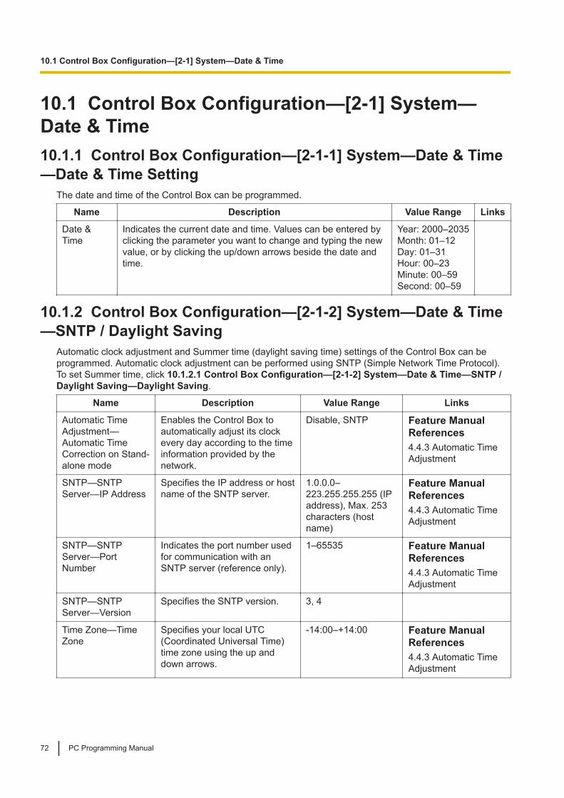
10.1 Control Box Configuration—[2-1] System—Date & Time10.1.1 Control Box Configuration—[2-1-1] System—Date & Time—Date & Time Setting
The date and time of the Control Box can be programmed.
Name Description Value Range Links
Date &Time
Indicates the current date and time. Values can be entered byclicking the parameter you want to change and typing the newvalue, or by clicking the up/down arrows beside the date andtime.
Year: 2000–2035Month: 01–12Day: 01–31Hour: 00–23Minute: 00–59Second: 00–59
10.1.2 Control Box Configuration—[2-1-2] System—Date & Time—SNTP / Daylight Saving
Automatic clock adjustment and Summer time (daylight saving time) settings of the Control Box can beprogrammed. Automatic clock adjustment can be performed using SNTP (Simple Network Time Protocol).To set Summer time, click 10.1.2.1 Control Box Configuration—[2-1-2] System—Date & Time—SNTP /Daylight Saving—Daylight Saving.
Name Description Value Range Links
Automatic TimeAdjustment—Automatic TimeCorrection on Stand-alone mode
Enables the Control Box toautomatically adjust its clockevery day according to the timeinformation provided by thenetwork.
Disable, SNTP Feature ManualReferences4.4.3 Automatic TimeAdjustment
SNTP—SNTPServer—IP Address
Specifies the IP address or hostname of the SNTP server.
1.0.0.0–223.255.255.255 (IPaddress), Max. 253characters (hostname)
Feature ManualReferences4.4.3 Automatic TimeAdjustment
SNTP—SNTPServer—PortNumber
Indicates the port number usedfor communication with anSNTP server (reference only).
1–65535 Feature ManualReferences4.4.3 Automatic TimeAdjustment
SNTP—SNTPServer—Version
Specifies the SNTP version. 3, 4
Time Zone—TimeZone
Specifies your local UTC(Coordinated Universal Time)time zone using the up anddown arrows.
-14:00–+14:00 Feature ManualReferences4.4.3 Automatic TimeAdjustment
10.1 Control Box Configuration—[2-1] System—Date & Time
72 PC Programming Manual

Name Description Value Range Links
Time Zone—TimeZone for PC
Indicates the UTC (CoordinatedUniversal Time) time zone ofthe PC (reference only).
-14:00–+14:00 Feature ManualReferences4.4.3 Automatic TimeAdjustment
10.1.2.1 Control Box Configuration—[2-1-2] System—Date & Time—SNTP / Daylight Saving—Daylight Saving
Summer time can be programmed. Summer time sets the clock one hour forward at 2:00 AM on the startdate, and one hour back at 2:00 AM on the end date. The start and end dates of a maximum of 20 differentsummer times can be programmed.
Name Description Value Range Links
Setting Enables Summertime.
Disable, Enable PC Programming Manual References10.1.2 Control Box Configuration—[2-1-2]System—Date & Time—SNTP / Daylight Saving
Feature Manual References4.4.3 Automatic Time Adjustment
Start Date—Year,Month, Day
Specifies the startdate of daylightsavings time.
Year: 2000–2035Month: 1–12Day: 1–31
PC Programming Manual References10.1.2 Control Box Configuration—[2-1-2]System—Date & Time—SNTP / Daylight Saving
Feature Manual References4.4.3 Automatic Time Adjustment
End Date—Year,Month, Day
Specifies the enddate of daylightsavings time.
Year: 2000–2035Month: 1–12Day: 1–31
PC Programming Manual References10.1.2 Control Box Configuration—[2-1-2]System—Date & Time—SNTP / Daylight Saving
Feature Manual References4.4.3 Automatic Time Adjustment
10.1.2 Control Box Configuration—[2-1-2] System—Date & Time—SNTP / Daylight Saving
PC Programming Manual 73

10.2 Control Box Configuration—[2-6] System—Numbering Plan10.2.1 Control Box Configuration—[2-6-1] System—NumberingPlan—Main
Details of the extension numbering schemes can be programmed here.For more information on flexible numbering, see "4.4.5 Flexible Numbering" in the Feature Manual.
Note• Numbering does not necessarily have to be uniform; varying numbers of digits can be used for each
setting.• To programme these settings, all installed V-SIPEXT cards must first be set to OUS. For details, see
9.1 Control Box Configuration—[1-1] Configuration—Slot.
ExtensionThe leading numbers and the number of additional digits of the extension numbers for a maximum of 128different extension numbering schemes can be programmed.
Name Description Value Range Links
LeadingNumber
Specifies the leading number ofextension numbers and floatingextension numbers.
NoteChanging this value willalso affect the followingsettings.• Extension Number as
set in User Container
Max. 3 digits(consisting of 0–9)
PC Programming ManualReferences11.1.1 Control Box Configuration—[3-5-1] Group—Incoming CallDistribution Group—Group Settings11.2.1 Control Box Configuration—[3-7-2] Group—UM Group—UnitSettings8.2 Users—Advanced ExtensionSettings12.1 Control Box Configuration—[11-1] Maintenance—Main13.1 UM Configuration—[1] MailboxSettings—Mailbox Number
No. ofAdditionalDigits
Specifies the number ofadditional digits following theleading number.
None: 0 digitX: 1 digitXX: 2 digits
10.2 Control Box Configuration—[2-6] System—Numbering Plan
74 PC Programming Manual

Section 11Control Box Configuration—[3] Group
This section serves as reference operating instructionsfor the Group menu of the Control Box ConfigurationMenu of the Setup screen of Web MaintenanceConsole.
PC Programming Manual 75

11.1 Control Box Configuration—[3-5] Group—Incoming Call Distribution Group11.1.1 Control Box Configuration—[3-5-1] Group—Incoming CallDistribution Group—Group Settings
Extensions can be assigned as members of an incoming call distribution group. Calls to an incoming calldistribution group are distributed to its member extensions as programmed. A maximum of 256 incomingcall distribution groups can be programmed.To assign extensions to ICD groups and change extension settings, click Member List.For more information on ICD Groups, see "2.2.1 Incoming Call Distribution Group" in the Feature Manual.
MainName Description Value Range Links
Floating ExtensionNumber
Specifies the floating extension number ofthe incoming call distribution group.
Max. 5 digits (consistingof 0–9)
Group Name Specifies the name of the incoming calldistribution group.
Max. 20 characters
Call WaitingDistribution
Factory use only -
FWD Mode Factory use only -
11.1.1.1 Control Box Configuration—[3-5-1] Group—Incoming CallDistribution Group—Group Settings—Member List
Each incoming call distribution group can have a maximum of 128 members (extensions) assigned to it. Anextension can be a member of multiple incoming call distribution groups. Select the desired ICD group (1–256) from the ICD Group No. list.To assign members to the group, enter directly or click Extension No. Setting (see 2.1.6 ExtensionNumber Setting). To copy the members to another group, click Member list copy, select the group, andclick OK.
Name Description Value Range Links
ExtensionNumber
Specifies the extensionnumber of each member.
Max. 5 digits(consisting of 0–9)
Feature ManualReferences2.2.1 Incoming CallDistribution Group
ExtensionName
Indicates the name of theextension (reference only).
Max. 20 characters Feature ManualReferences2.2.1 Incoming CallDistribution Group
Delayed Ring Factory use only -
11.1 Control Box Configuration—[3-5] Group—Incoming Call Distribution Group
76 PC Programming Manual

11.2 Control Box Configuration—[3-7] Group—UMGroup11.2.1 Control Box Configuration—[3-7-2] Group—UM Group—Unit Settings
A UM group has a floating extension number, which can be assigned as the destination for redirected callsand incoming calls.To assign extension numbers to the group, click Member List. To view a list of all programmed extensionnumbers and types, click Extension List View (see 6.1 Tool—Extension List View).
Name Description Value Range Links
FloatingExtension No.
Specifies the floatingextension number of the UMgroup.
Max. 5 digits(consisting of 0–9)
PC ProgrammingManual References9.5 Control BoxConfiguration—[1-1]Configuration—Slot—UMProperty—UM PortProperty
Feature ManualReferences3.1.1 Unified MessagingSystem Overview—UMPorts and the UM Group
Group Name Specifies the name of the UMgroup, which will be shown onthe display of extensions thatcall the UM group.
Max. 20 characters PC ProgrammingManual References9.5 Control BoxConfiguration—[1-1]Configuration—Slot—UMProperty—UM PortProperty
Feature ManualReferences3.1.1 Unified MessagingSystem Overview—UMPorts and the UM Group
11.2.1.1 Control Box Configuration—[3-7-2] Group—UM Group—UnitSettings—Member List
Displays information about all UM ports that belong to the selected UM group.
11.2 Control Box Configuration—[3-7] Group—UM Group
PC Programming Manual 77

Name Description Value Range Links
No. Indicates the UM port number(reference only).
1–128 PC ProgrammingManual References11.2.1 Control BoxConfiguration—[3-7-2]Group—UM Group—UnitSettings
ExtensionNumber
Indicates the extensionnumber assigned to the UMport (reference only).
Max. 5 digits(consisting of 0–9)
PC ProgrammingManual References11.2.1 Control BoxConfiguration—[3-7-2]Group—UM Group—UnitSettings
Feature ManualReferences3.1.1 Unified MessagingSystem Overview—UMPorts and the UM Group
11.2.1 Control Box Configuration—[3-7-2] Group—UM Group—Unit Settings
78 PC Programming Manual
Section 12Control Box Configuration—[11] Maintenance
This section serves as reference operating instructionsfor the Maintenance menu of the Control BoxConfiguration menu of the Setup screen of WebMaintenance Console.
PC Programming Manual 79

12.1 Control Box Configuration—[11-1]Maintenance—MainSMDR
Station Message Detail Recording (SMDR) automatically records detailed information about outgoingintercom calls.
Name Description Value Range Links
SMDR Format—Date Format
Selects the printed dateformat.
MM-DD-YY,DD-MM-YY, YY-MM-DD, YY-DD-MM
Feature ManualReferences2.6.1.1 Station MessageDetail Recording (SMDR)
SMDR Format—Time Format (12H /24H)
Selects whether times aredisplayed using the 12- or24-hour format.
12H, 24H Feature ManualReferences2.6.1.1 Station MessageDetail Recording (SMDR)
Print Information—Intercom Call
Specifies whether the dialleddigits of outgoing intercomcalls are printed.
No Print, Print Feature ManualReferences2.6.1.1 Station MessageDetail Recording (SMDR)
Print Information—Error Log
Specifies whether ControlBox error log information isoutput to SMDR.
No Print, Print Feature ManualReferences2.6.1.1 Station MessageDetail Recording (SMDR)
SMDR OptionsName Description Value Range Links
LAN—SMDR PortNumber
Specifies theport numberused tooutput SMDRdata via theLAN.
1–65535 Feature Manual References2.6.1.1 Station Message Detail Recording (SMDR)
LAN—SMDRPassword
Specifies thepasswordused tooutput theSMDR datavia the LAN.
Max. 10characters
Feature Manual References2.6.1.1 Station Message Detail Recording (SMDR)
12.1 Control Box Configuration—[11-1] Maintenance—Main
80 PC Programming Manual

Name Description Value Range Links
LAN—NewLine Codefor Telnet
Specifies thenew line codefor a terminalemulator.If the terminalemulatorautomaticallyfeeds lineswith acarriagereturn, selectCR (CarriageReturn).If not, selectCR + LF (LineFeed).
CR + LF, CR Feature Manual References2.6.1.1 Station Message Detail Recording (SMDR)
12.1 Control Box Configuration—[11-1] Maintenance—Main
PC Programming Manual 81

12.1 Control Box Configuration—[11-1] Maintenance—Main
82 PC Programming Manual

Section 13UM Configuration—[1] Mailbox Settings
This section serves as reference operating instructionsfor the Mailbox Settings menu of the UM Configurationmenu of the Setup screen of Web MaintenanceConsole.
PC Programming Manual 83
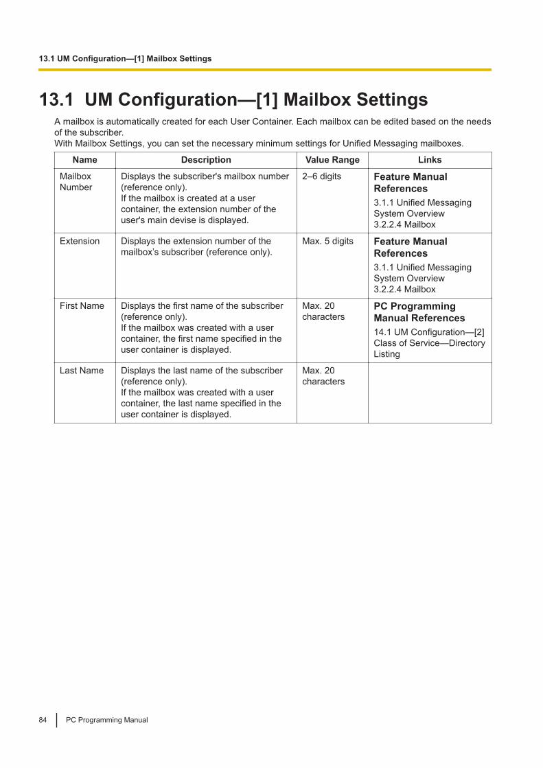
13.1 UM Configuration—[1] Mailbox SettingsA mailbox is automatically created for each User Container. Each mailbox can be edited based on the needsof the subscriber.With Mailbox Settings, you can set the necessary minimum settings for Unified Messaging mailboxes.
Name Description Value Range Links
MailboxNumber
Displays the subscriber's mailbox number(reference only).If the mailbox is created at a usercontainer, the extension number of theuser's main devise is displayed.
2–6 digits Feature ManualReferences3.1.1 Unified MessagingSystem Overview3.2.2.4 Mailbox
Extension Displays the extension number of themailbox’s subscriber (reference only).
Max. 5 digits Feature ManualReferences3.1.1 Unified MessagingSystem Overview3.2.2.4 Mailbox
First Name Displays the first name of the subscriber(reference only).If the mailbox was created with a usercontainer, the first name specified in theuser container is displayed.
Max. 20characters
PC ProgrammingManual References14.1 UM Configuration—[2]Class of Service—DirectoryListing
Last Name Displays the last name of the subscriber(reference only).If the mailbox was created with a usercontainer, the last name specified in theuser container is displayed.
Max. 20characters
13.1 UM Configuration—[1] Mailbox Settings
84 PC Programming Manual

Section 14UM Configuration—[2] Class of Service
This section serves as reference operating instructionsfor the Class of Service menu of the UM Configurationmenu of the Setup screen of Web MaintenanceConsole.
PC Programming Manual 85

14.1 UM Configuration—[2] Class of ServiceEach mailbox is assigned a Class of Service (COS) that determines the set of services that are available toits subscriber. There are 514 classes. Mailboxes can be assigned to their own or to the same COS asneeded. COS No. 514 is assigned to the System Manager by default.No other mailboxes can be assigned to COS No. 513 and 514.
GeneralName Description Value Range Links
Class Of ServiceName
Specifies the Class of Service’sname.
Max. 32characters
Feature ManualReferences3.2.1.2 Class of Service(COS)
Prompt Mode Specifies the language used forsystem prompts played for thesubscriber during SubscriberService.
Primary,Guidance No. 1–8
Feature ManualReferences3.2.1.6 System Prompts
Directory Listing Factory use only -
Tutorial Factory use only -
Call-throughService
Factory use only -
E-mail Option Specifies if subscribers in the Classof Service can receive notificationsby e-mail when they have a newmessage waiting.
Yes, No Feature ManualReferences3.2.1.4 Message WaitingNotification—E-mailDevice
DesktopMessaging
Factory use only -
System ManagerAuthority
Specifies if subscribers in the Classof Service have access to theUnified Messaging system as aSystem Manager.
Yes, No Feature ManualReferences3.1.1 Unified MessagingSystem Overview
MessageManager Authority
Factory use only -
MailboxName Description Value Range Links
Personal GreetingLength (s)
Factory use only -
Message Length(Selection)
Specifies if the length of messages left forsubscribers in the Class of Service are unlimitedin duration or have a specified time limit. If set to"Unlimited", the maximum recording time is 60minutes.
Unlimited, Limited
14.1 UM Configuration—[2] Class of Service
86 PC Programming Manual

Name Description Value Range Links
Message Length(Limited) (min)
Specifies the maximum recording time formessages left to subscribers in the Class ofService. Only specified if Message Length(Selection) is set to "Limited".
1–60 min
Mailbox CapacityMaximum MessageTime (Selection)
Specifies if a maximum limit is applied to the totalamount of messages (new and saved) formailboxes of subscribers in the Class of Service.
Unlimited, Limited
Mailbox CapacityMaximum MessageTime (Limited) (min)
Specifies the total number of available minutesfor storing messages (both new and saved) formailboxes of subscribers in the Class of Service.Only specified if Mailbox Capacity MaximumMessage Time (Selection) is set to "Limited".
1–600 min
New MessageRetention Time(Selection)
Specifies if a retention time limit is applied to newmessages in mailboxes of subscribers in theClass of Service. If "Unlimited" is selected, newmessages will remain in the mailbox until erasedby the subscriber.
Unlimited, Limited
New MessageRetention Time(Limited) (days)
Defines the number of days that new messageswill remain in mailboxes for subscribers in theClass of Service. The storage period begins theday after the message reception. Only specifiedif New Message Retention Time (Selection) isset to "Limited".
1–30 days
Saved MessageRetention Time(Selection)
Specifies if a retention time limit is applied tosaved messages in mailboxes of subscribers inthe Class of Service. If "Unlimited" is selected,saved messages will remain in the mailbox untilerased by the subscriber.
Unlimited, Limited
Saved MessageRetention Time(Limited) (days)
Defines the number of days that savedmessages will remain in mailboxes forsubscribers in the Class of Service. Onlyspecified if Saved Message Retention Time(Selection) is set to "Limited".
1–30 days
Message RetrievalOrder
Specifies the order in which messages will beretrieved for subscribers in the Class of Service(played back for listening).
LIFO: Messagesare retrievedstarting with themost recent (Last InFirst Out).FIFO: Messagesare retrievedstarting with theoldest (First In FirstOut).
14.1 UM Configuration—[2] Class of Service
PC Programming Manual 87

Name Description Value Range Links
Message EnvelopeSetting
Specifies when message envelopes (messagedate and time, name of the person who recordedor transferred the message, telephone number ofthe caller) are announced.
Before: The systemannounces themessage envelopebefore playing therecorded message.After: The systemannounces themessage envelopeafter playing therecorded message.Require: Thesystem announcesthe messageenvelope when theuser presses theappropriate dial keyas prompted whenlistening to themessage.
Mailbox CapacityWarning (Selection)
Factory use only -
Mailbox CapacityWarning (Other) (min)
Factory use only -
Delete MessageConfirmation
If set to "Yes", the system requests confirmationfrom subscribers in the Class of Service beforeerasing a message in the mailbox. If set to "No",the message is erased immediately.
No, Yes
Autoplay NewMessage
If set to "Yes", the system plays new messagesautomatically when subscribers in the Class ofService log into their mailboxes.
No, Yes
Play New MessagesSequentially
If set to "Yes", the system plays all newmessages for subscribers in the Class of Servicesequentially without system prompts. Thesubscriber’s Service Top Menu will be heardafter all of the messages are played. This featureis only available when Autoplay New Messageis set to "Yes".
No, Yes
Announce MessageTransferredInformation
Factory use only-
Announce OptionMenu after ErasingMessage
Factory use only-
New Message LengthAnnouncement
Factory use only -
Call TransferThis feature is for factory use only.
14.1 UM Configuration—[2] Class of Service
88 PC Programming Manual
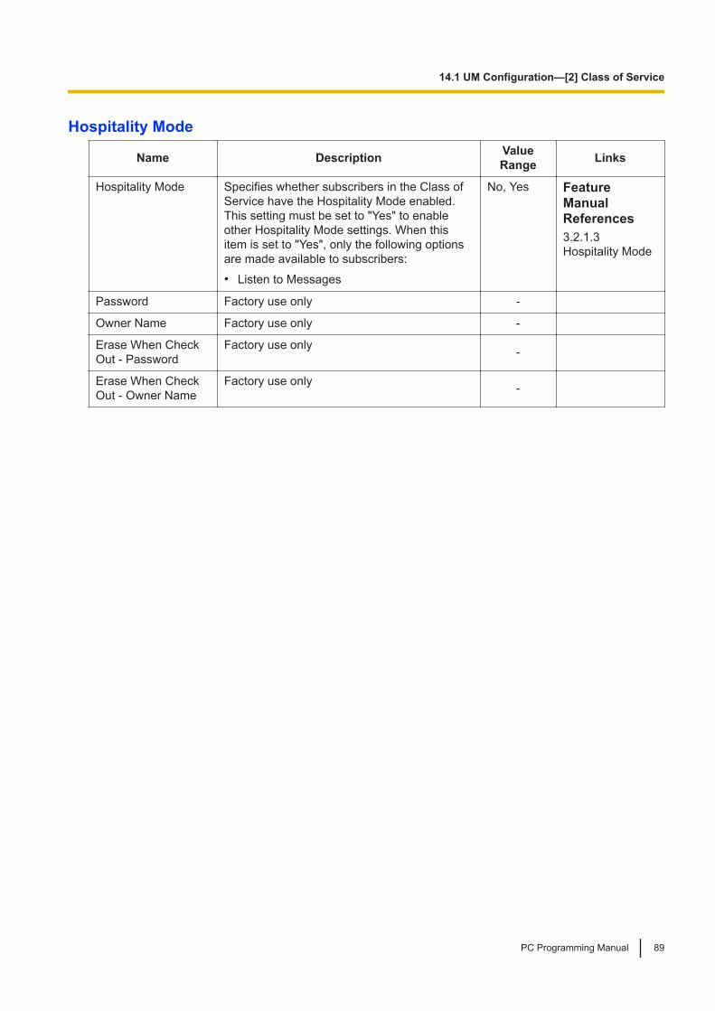
Hospitality Mode
Name Description ValueRange Links
Hospitality Mode Specifies whether subscribers in the Class ofService have the Hospitality Mode enabled.This setting must be set to "Yes" to enableother Hospitality Mode settings. When thisitem is set to "Yes", only the following optionsare made available to subscribers:• Listen to Messages
No, Yes FeatureManualReferences3.2.1.3Hospitality Mode
Password Factory use only -
Owner Name Factory use only -
Erase When CheckOut - Password
Factory use only -
Erase When CheckOut - Owner Name
Factory use only -
14.1 UM Configuration—[2] Class of Service
PC Programming Manual 89

14.1 UM Configuration—[2] Class of Service
90 PC Programming Manual

Section 15UM Configuration—[7] System Security
This section serves as reference operating instructionsfor the System Security menu of the UM Configurationmenu of the Setup screen of Web MaintenanceConsole.
PC Programming Manual 91

15.1 UM Configuration—[7] System SecurityManager
Name Description ValueRange Links
Tenant Number Factory use only -
Login Failures beforeDisconnection (1-99times)
Specifies the number of times an invalidpassword can be entered, when the SystemManager tries to log in to the system usinga telephone, before the call is disconnected.
1–99 times
System ManagerAccess from Telephone
Enables or disables access to the UnifiedMessaging system from the SystemManager’s telephone.
Disable,Enable
Password for SystemManager (Up to 16numeric digits)
If "Enable" is selected in System ManagerAccess from Telephone, assign anumerical password here for the SystemManager to log in to the system.
Max. 16digits
FeatureManualReferences3.1.2.1 SystemSecurity
15.1 UM Configuration—[7] System Security
92 PC Programming Manual

Section 16Network Service
This section serves as reference operating instructionsfor the Network Service menu of the Setup screen ofWeb Maintenance Console.
PC Programming Manual 93
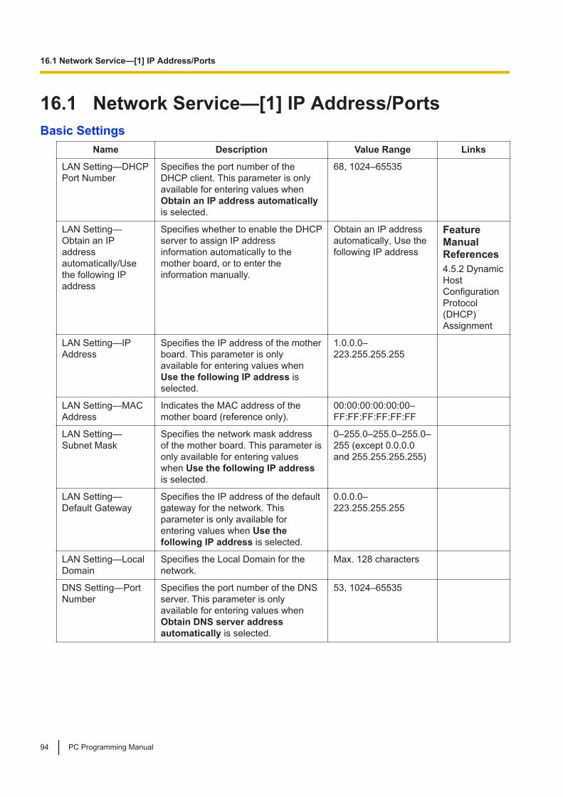
16.1 Network Service—[1] IP Address/PortsBasic Settings
Name Description Value Range Links
LAN Setting—DHCPPort Number
Specifies the port number of theDHCP client. This parameter is onlyavailable for entering values whenObtain an IP address automaticallyis selected.
68, 1024–65535
LAN Setting—Obtain an IPaddressautomatically/Usethe following IPaddress
Specifies whether to enable the DHCPserver to assign IP addressinformation automatically to themother board, or to enter theinformation manually.
Obtain an IP addressautomatically, Use thefollowing IP address
FeatureManualReferences4.5.2 DynamicHostConfigurationProtocol(DHCP)Assignment
LAN Setting—IPAddress
Specifies the IP address of the motherboard. This parameter is onlyavailable for entering values whenUse the following IP address isselected.
1.0.0.0–223.255.255.255
LAN Setting—MACAddress
Indicates the MAC address of themother board (reference only).
00:00:00:00:00:00–FF:FF:FF:FF:FF:FF
LAN Setting—Subnet Mask
Specifies the network mask addressof the mother board. This parameter isonly available for entering valueswhen Use the following IP addressis selected.
0–255.0–255.0–255.0–255 (except 0.0.0.0and 255.255.255.255)
LAN Setting—Default Gateway
Specifies the IP address of the defaultgateway for the network. Thisparameter is only available forentering values when Use thefollowing IP address is selected.
0.0.0.0–223.255.255.255
LAN Setting—LocalDomain
Specifies the Local Domain for thenetwork.
Max. 128 characters
DNS Setting—PortNumber
Specifies the port number of the DNSserver. This parameter is onlyavailable for entering values whenObtain DNS server addressautomatically is selected.
53, 1024–65535
16.1 Network Service—[1] IP Address/Ports
94 PC Programming Manual
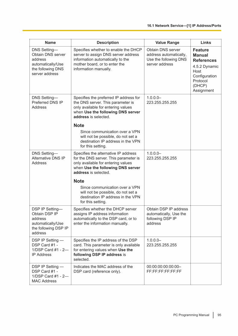
Name Description Value Range Links
DNS Setting—Obtain DNS serveraddressautomatically/Usethe following DNSserver address
Specifies whether to enable the DHCPserver to assign DNS server addressinformation automatically to themother board, or to enter theinformation manually.
Obtain DNS serveraddress automatically,Use the following DNSserver address
FeatureManualReferences4.5.2 DynamicHostConfigurationProtocol(DHCP)Assignment
DNS Setting—Preferred DNS IPAddress
Specifies the preferred IP address forthe DNS server. This parameter isonly available for entering valueswhen Use the following DNS serveraddress is selected.
NoteSince communication over a VPNwill not be possible, do not set adestination IP address in the VPNfor this setting.
1.0.0.0–223.255.255.255
DNS Setting—Alternative DNS IPAddress
Specifies the alternative IP addressfor the DNS server. This parameter isonly available for entering valueswhen Use the following DNS serveraddress is selected.
NoteSince communication over a VPNwill not be possible, do not set adestination IP address in the VPNfor this setting.
1.0.0.0–223.255.255.255
DSP IP Setting—Obtain DSP IPaddressautomatically/Usethe following DSP IPaddress
Specifies whether the DHCP serverassigns IP address informationautomatically to the DSP card, or toenter the information manually.
Obtain DSP IP addressautomatically, Use thefollowing DSP IPaddress
DSP IP Setting —DSP Card #1 -1/DSP Card #1 - 2—IP Address
Specifies the IP address of the DSPcard. This parameter is only availablefor entering values when Use thefollowing DSP IP address isselected.
1.0.0.0–223.255.255.255
DSP IP Setting —DSP Card #1 -1/DSP Card #1 - 2—MAC Address
Indicates the MAC address of theDSP card (reference only).
00:00:00:00:00:00–FF:FF:FF:FF:FF:FF
16.1 Network Service—[1] IP Address/Ports
PC Programming Manual 95
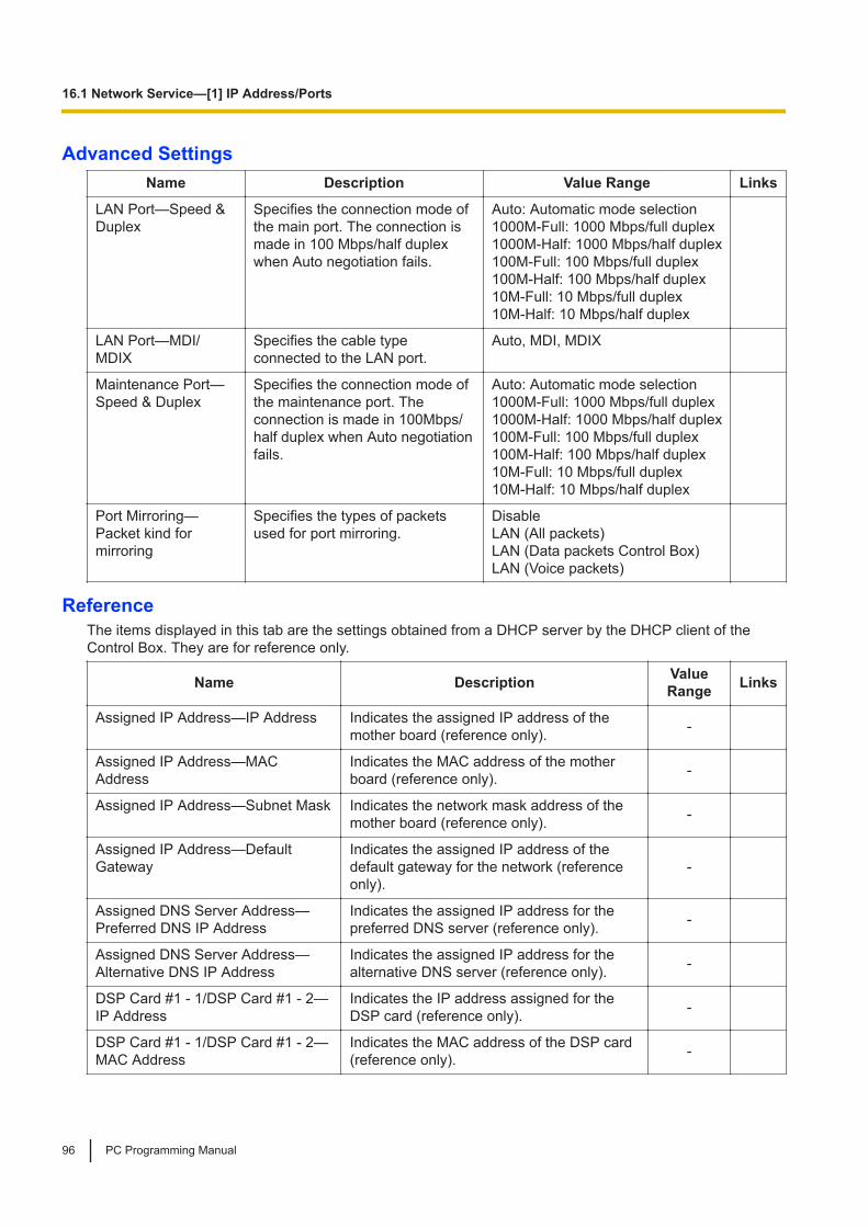
Advanced SettingsName Description Value Range Links
LAN Port—Speed &Duplex
Specifies the connection mode ofthe main port. The connection ismade in 100 Mbps/half duplexwhen Auto negotiation fails.
Auto: Automatic mode selection1000M-Full: 1000 Mbps/full duplex1000M-Half: 1000 Mbps/half duplex100M-Full: 100 Mbps/full duplex100M-Half: 100 Mbps/half duplex10M-Full: 10 Mbps/full duplex10M-Half: 10 Mbps/half duplex
LAN Port—MDI/MDIX
Specifies the cable typeconnected to the LAN port.
Auto, MDI, MDIX
Maintenance Port—Speed & Duplex
Specifies the connection mode ofthe maintenance port. Theconnection is made in 100Mbps/half duplex when Auto negotiationfails.
Auto: Automatic mode selection1000M-Full: 1000 Mbps/full duplex1000M-Half: 1000 Mbps/half duplex100M-Full: 100 Mbps/full duplex100M-Half: 100 Mbps/half duplex10M-Full: 10 Mbps/full duplex10M-Half: 10 Mbps/half duplex
Port Mirroring—Packet kind formirroring
Specifies the types of packetsused for port mirroring.
DisableLAN (All packets)LAN (Data packets Control Box)LAN (Voice packets)
ReferenceThe items displayed in this tab are the settings obtained from a DHCP server by the DHCP client of theControl Box. They are for reference only.
Name Description ValueRange Links
Assigned IP Address—IP Address Indicates the assigned IP address of themother board (reference only). -
Assigned IP Address—MACAddress
Indicates the MAC address of the motherboard (reference only). -
Assigned IP Address—Subnet Mask Indicates the network mask address of themother board (reference only). -
Assigned IP Address—DefaultGateway
Indicates the assigned IP address of thedefault gateway for the network (referenceonly).
-
Assigned DNS Server Address—Preferred DNS IP Address
Indicates the assigned IP address for thepreferred DNS server (reference only). -
Assigned DNS Server Address—Alternative DNS IP Address
Indicates the assigned IP address for thealternative DNS server (reference only). -
DSP Card #1 - 1/DSP Card #1 - 2—IP Address
Indicates the IP address assigned for theDSP card (reference only). -
DSP Card #1 - 1/DSP Card #1 - 2—MAC Address
Indicates the MAC address of the DSP card(reference only). -
16.1 Network Service—[1] IP Address/Ports
96 PC Programming Manual

Name Description ValueRange Links
DSP Card #1 - 1/DSP Card #1 - 2—Subnet Mask
Indicates the Subnet Mask address of theDSP card (reference only). -
DSP Card #1 - 1/DSP Card #1 - 2—Default Gateway
Indicates the Default Gateway address ofthe DSP card (reference only). -
16.1 Network Service—[1] IP Address/Ports
PC Programming Manual 97
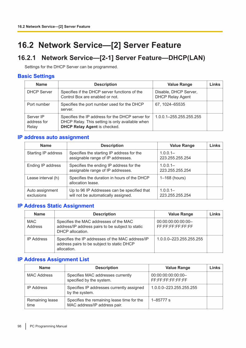
16.2 Network Service—[2] Server Feature16.2.1 Network Service—[2-1] Server Feature—DHCP(LAN)
Settings for the DHCP Server can be programmed.
Basic SettingsName Description Value Range Links
DHCP Server Specifies if the DHCP server functions of theControl Box are enabled or not.
Disable, DHCP Server,DHCP Relay Agent
Port number Specifies the port number used for the DHCPserver.
67, 1024–65535
Server IPaddress forRelay
Specifies the IP address for the DHCP server forDHCP Relay. This setting is only available whenDHCP Relay Agent is checked.
1.0.0.1–255.255.255.255
IP address auto assignmentName Description Value Range Links
Starting IP address Specifies the starting IP address for theassignable range of IP addresses.
1.0.0.1–223.255.255.254
Ending IP address Specifies the ending IP address for theassignable range of IP addresses.
1.0.0.1–223.255.255.254
Lease interval (h) Specifies the duration in hours of the DHCPallocation lease.
1–168 (hours)
Auto assignmentexclusions
Up to 96 IP Addresses can be specified thatwill not be automatically assigned.
1.0.0.1–223.255.255.254
IP Address Static AssignmentName Description Value Range Links
MACAddress
Specifies the MAC addresses of the MACaddress/IP address pairs to be subject to staticDHCP allocation.
00:00:00:00:00:00–FF:FF:FF:FF:FF:FF
IP Address Specifies the IP addresses of the MAC address/IPaddress pairs to be subject to static DHCPallocation.
1.0.0.0–223.255.255.255
IP Address Assignment ListName Description Value Range Links
MAC Address Specifies MAC addresses currentlyspecified by the system.
00:00:00:00:00:00–FF:FF:FF:FF:FF:FF
IP Address Specifies IP addresses currently assignedby the system.
1.0.0.0–223.255.255.255
Remaining leasetime
Specifies the remaining lease time for theMAC address/IP address pair.
1–85777 s
16.2 Network Service—[2] Server Feature
98 PC Programming Manual

16.2.2 Network Service—[2-5] Server Feature—HTTPHTTP server settings can be programmed.
Name Description Value Range Links
HTTP (LAN / MNT)—Port number
Specifies the port number for HTTP connections usingthe LAN or MNT ports. This port is used for accessingthe Control Box for Web Maintenance Consoleprogramming.
80, 1024–65535
HTTPs (LAN / MNT)—HTTPs server
Enables or disables HTTPs for connections to the LANor MNT ports using the Control Box's HTTP serverfunction.
Disable,Enable
HTTPs (LAN / MNT)—Port number
Specifies the port number for HTTPs connections.This port is used for accessing the Control Box forWeb Maintenance Console programming when usinga TLS connection.
443, 1024–65535
HTTPs (WAN)—HTTPs Server
Enable or disable HTTPs for connections to the WANport using the Control Box's HTTP server function.
Disable/Enable
HTTPs (WAN)—Portnumber
Specifies the port number for HTTPs connections tothe WAN port using the Control Box's HTTP serverfunction.
443, 1024–65535
HTTPs (WAN)—PortClose Control
Specifies how HTTPs (WAN) is disabled.If you enabled the HTTPs (WAN) port and selectAutomatic (24H), it will be disabled automatically after24 hours for security purpose.
Automatic(24H), Manual
Automatic logoutTimer (min)
Factory use only -
16.2.3 Network Service—[2-6] Server Feature—NTPNTP server settings for use with SIP phones can be programmed.
Name Description ValueRange Links
NTPserver
Enables or disables NTP service withthe Control Box's NTP server forconnected SIP phones.When this feature is enabled, theControl Box will report to connectedSIP phones the information obtainedfrom the SNTP server specified in10.1.2 Control Box Configuration—[2-1-2] System—Date & Time—SNTP / Daylight Saving.If this feature is disabled, connectedSIP phones will use their individuallyprogrammed time settings.
Disable,Enable
PC Programming ManualReferences10.1.2 Control Box Configuration—[2-1-2] System—Date & Time—SNTP /Daylight Saving—SNTP—SNTP Server—IP Address10.1.2 Control Box Configuration—[2-1-2] System—Date & Time—SNTP /Daylight Saving—SNTP—SNTP Server—Port Number10.1.2 Control Box Configuration—[2-1-2] System—Date & Time—SNTP /Daylight Saving—Time Zone—TimeZone
16.2.2 Network Service—[2-5] Server Feature—HTTP
PC Programming Manual 99

16.2.4 Network Service—[2-7] Server Feature—SMTPSettings for SMTP for sending e-mail for Control Box functions can be programmed.
Name Description Value Range Links
Mail sending—Mail senderinformation name
Specifies the name to be used as thesender of the e-mails from the ControlBox.
Max. 64 characters
Mail sending—Mail address Specifies the sending e-mail addressfor messages sent from the ControlBox. This address, for example, couldbe set as the e-mail address of anadministrator.
Max. 128 characters
SMTP server for relay—SMTP server address—IPAddress
Specifies the IP address of the SMTPserver to be used to send e-mails.
1.0.0.0–223.255.255.255
SMTP server for relay—SMTP server address—Name
Specifies the host name of the SMTPserver to be used to send e-mails.
Max. 128 characters
SMTP server for relay—SMTP server Port number
Specifies the port number of the SMTPserver to be used to send e-mails.
25, 1024–65535
SMTP server for relay—SMTP over TLS
Specifies whether the SMTP serveruses Transport Layer Security.
Enable, Disable
NoteWhen Enable isselected, theencryption methodused is STARTTLS.
SMTP Authentication—SMTP Authentication
Specifies whether authentication on theSMTP server is enabled.
Enable, Disable
SMTP Authentication—UserName
Specifies the user name required toaccess the SMTP server.
Max. 64 characters
SMTP Authentication—Password
Specifies the password required toaccess the SMTP server.
Max. 64 characters
POP Before SMTP—POPbefore SMTP
Specifies whether POP before SMTP isenabled on the SMTP server.
Enable, Disable
POP Before SMTP—POPserver address—IP Address
Specifies the IP address of the POPserver when POP before SMTP isenabled.
1.0.0.0–223.255.255.255
POP Before SMTP—POPserver address—Name
Specifies the host name of the POPserver when POP before SMTP isenabled.
Max. 128 characters
POP Before SMTP—POPserver Port number
Specifies the port number of the POPserver when POP before SMTP isenabled.
110, 1024–65535
16.2.4 Network Service—[2-7] Server Feature—SMTP
100 PC Programming Manual

Name Description Value Range Links
POP Before SMTP—UserName
Specifies the user name for the POPserver when POP before SMTP isenabled.
Max. 64 characters
POP Before SMTP—Password
Specifies the password for the POPserver when POP before SMTP isenabled.
Max. 64 characters
Mail Receiving—SMTPAuthentication
Specifies if SMTP authentication isenabled for mail receiving.
Enable, Disable
Mail Receiving—SMTP overTLS
Specifies whether mail receiving usesTransport Layer Security for SMTP.
Enable, Disable
Mail Receiving—ReceivePort number (SMTPs)
Specifies the receiving port numberwhen using SMTPs.
25, 465, 587, 1024–65535
Mail Receiving—ReceivePort number (SMTP)
Specifies the receiving port numberwhen using SMTP.
25, 1024–65535
16.2.4 Network Service—[2-7] Server Feature—SMTP
PC Programming Manual 101

16.3 Network Service—[3] Client Feature16.3.1 Network Service—[3-2] Client Feature—Syslog
Settings can be programmed for a Syslog client connection.
Name Description Value Range Links
Remote Syslog Specifies whether an external Syslogserver will be used with the Control Box.
Enable, Disable
Remote Syslogserver—IPaddress / Hostname
Specifies the IP address or host name ofthe external Syslog server.
1.0.0.0–223.255.255.255 (IPaddress), Max. 253 characters(host name)
Port Specifies the connection port for theremote Syslog server.
514, 1024–65535
16.3 Network Service—[3] Client Feature
102 PC Programming Manual

Feature Programming References
PC Programming Manual 103
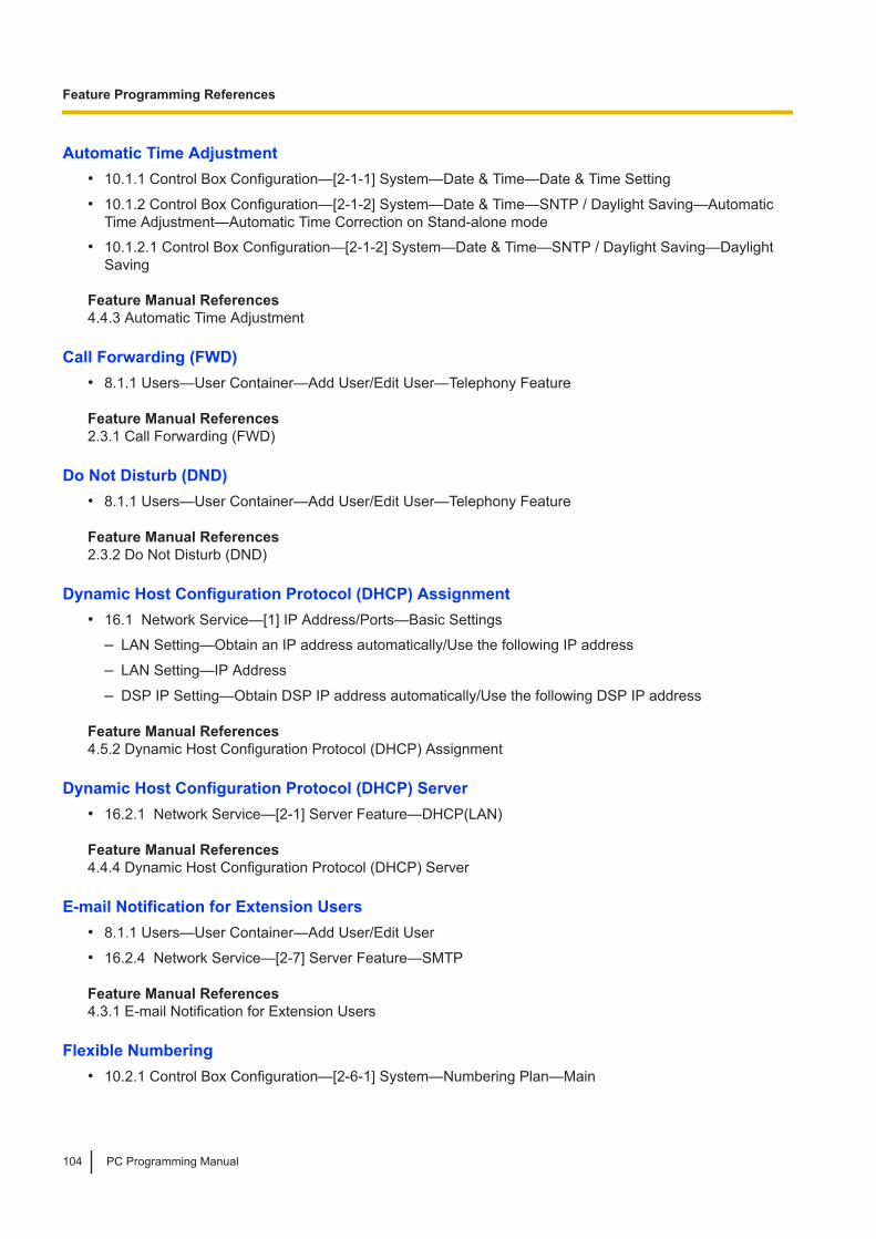
Automatic Time Adjustment• 10.1.1 Control Box Configuration—[2-1-1] System—Date & Time—Date & Time Setting
• 10.1.2 Control Box Configuration—[2-1-2] System—Date & Time—SNTP / Daylight Saving—AutomaticTime Adjustment—Automatic Time Correction on Stand-alone mode
• 10.1.2.1 Control Box Configuration—[2-1-2] System—Date & Time—SNTP / Daylight Saving—DaylightSaving
Feature Manual References4.4.3 Automatic Time Adjustment
Call Forwarding (FWD)• 8.1.1 Users—User Container—Add User/Edit User—Telephony Feature Feature Manual References2.3.1 Call Forwarding (FWD)
Do Not Disturb (DND)• 8.1.1 Users—User Container—Add User/Edit User—Telephony Feature Feature Manual References2.3.2 Do Not Disturb (DND)
Dynamic Host Configuration Protocol (DHCP) Assignment• 16.1 Network Service—[1] IP Address/Ports—Basic Settings
– LAN Setting—Obtain an IP address automatically/Use the following IP address
– LAN Setting—IP Address
– DSP IP Setting—Obtain DSP IP address automatically/Use the following DSP IP address Feature Manual References4.5.2 Dynamic Host Configuration Protocol (DHCP) Assignment
Dynamic Host Configuration Protocol (DHCP) Server• 16.2.1 Network Service—[2-1] Server Feature—DHCP(LAN) Feature Manual References4.4.4 Dynamic Host Configuration Protocol (DHCP) Server
E-mail Notification for Extension Users• 8.1.1 Users—User Container—Add User/Edit User
• 16.2.4 Network Service—[2-7] Server Feature—SMTP Feature Manual References4.3.1 E-mail Notification for Extension Users
Flexible Numbering• 10.2.1 Control Box Configuration—[2-6-1] System—Numbering Plan—Main
Feature Programming References
104 PC Programming Manual

Feature Manual References4.4.5 Flexible Numbering
Floating Extension• 10.2.1 Control Box Configuration—[2-6-1] System—Numbering Plan—Main—Extension
• 11.1.1 Control Box Configuration—[3-5-1] Group—Incoming Call Distribution Group—Group Settings—Main– Floating Extension Number
– Group Name
• 11.2.1 Control Box Configuration—[3-7-2] Group—UM Group—Unit Settings—Floating Extension No. Feature Manual References4.4.6 Floating Extension
Group• 11 Control Box Configuration—[3] Group Feature Manual References4.1.1 Group
Incoming Call Distribution Group Features• 11.1.1 Control Box Configuration—[3-5-1] Group—Incoming Call Distribution Group—Group Settings
• 11.1.1.1 Control Box Configuration—[3-5-1] Group—Incoming Call Distribution Group—Group Settings—Member List
Feature Manual References2.2.1 Incoming Call Distribution Group
Intercom Call• 8.1.1 Users—User Container—Add User/Edit User
– Extension Number
– Display Name Feature Manual References2.4.1 Intercom Call
Ping• 7.1.1 Utility—Diagnosis—Ping Feature Manual References4.5.3 PING Confirmation
SIP (Session Initiation Protocol) Extension• 9.7 Control Box Configuration—[1-1] Configuration—Slot—V-SIPEXT128—Port Property Feature Manual References4.2.1 SIP (Session Initiation Protocol) Extension
Feature Programming References
PC Programming Manual 105

Software Upgrading• 5.1 System Control—Program Update Feature Manual References4.4.7 Software Upgrading
Syslog Record Management• 7.2.2 Utility—Log—Syslog
• 16.3.1 Network Service—[3-2] Client Feature—Syslog Feature Manual References2.6.1.2 Syslog Record Management
UM Group• 9.5 Control Box Configuration—[1-1] Configuration—Slot—UM Property—UM Port Property
• 11.2.1 Control Box Configuration—[3-7-2] Group—UM Group—Unit Settings Feature Manual References3.1.1 Unified Messaging System Overview—UM Ports and the UM Group
Unified Messaging—Class of Service (COS)• 8.2 Users—Advanced Extension Settings—COS
• 14.1 UM Configuration—[2] Class of Service Feature Manual References3.2.1.2 Class of Service (COS)
Unified Messaging—Hospitality Mode• 14.1 UM Configuration—[2] Class of Service—Hospitality Mode Feature Manual References3.2.1.3 Hospitality Mode
Unified Messaging—Mailbox• 13.1 UM Configuration—[1] Mailbox Settings Feature Manual References3.2.2.4 Mailbox
Unified Messaging—Message Waiting Notification—E-mail Device• 14.1 UM Configuration—[2] Class of Service—General—E-mail Option Feature Manual References3.2.1.4 Message Waiting Notification—E-mail Device
Unified Messaging—System Prompts• 14.1 UM Configuration—[2] Class of Service—General—Prompt Mode
Feature Programming References
106 PC Programming Manual

Feature Manual References3.2.1.6 System Prompts
Unified Messaging—System Security• 15.1 UM Configuration—[7] System Security Feature Manual References3.1.2.1 System Security
User Container• 8 Users
• 13 UM Configuration—[1] Mailbox Settings Feature Manual References2.7 User Container
Note
PC Programming Manual 107

1006, Oaza Kadoma, Kadoma-shi, Osaka 571-8501, Japan
http://www.panasonic.com
© Panasonic Corporation 2019
PNQP1454YA PM0319MG1060