VIDEO DIVISION VICTOR COMPANY OF JAPAN, …diagramas.diagramasde.com/camaras/JVC Camcorder...
41
SERVICE MANUAL No. 86614 February 2001 SPECIFICATIONS (The specifications shown pertain specifically to the model GR-DVL150/157/355/357/450/555/557) DIGITAL VIDEO CAMERA Printed in Japan This service manual is printed on 100% recycled paper. COPYRIGHT © 2001 VICTOR COMPANY OF JAPAN, LTD. GR-DVL355EG/EK,DVL357EG/EK,DVL555EG/EK,DVL557EG/EK No. 86614 VICTOR COMPANY OF JAPAN, LIMITED VIDEO DIVISION S40894 GR-DVL355EG/EK, DVL357EG/EK, DVL555EG/EK, DVL557EG/EK Camcorder For General Power supply : DC 11.0 V } (Using AC Adapter) DC 7.2 V } (Using battery pack) Power consumption LCD monitor off, viewfinder on : Approx. 4.3 W LCD monitor on, viewfinder off : Approx. 5.3 W Video light : Approx. 3.5 W Dimensions (W x H x D) : 83 mm x 97 mm x 188 mm (with the LCD monitor closed and the viewfinder pushed down) Weight : Approx. 610 g (GR-DVL557/DVL555/DVL450) Approx. 590 g (GR-DVL357/DVL355/DVL157/DVL150) Operating temperature : 0°C to 40°C Operating humidity : 35% to 80% Storage temperature : –20°C to 50°C Pickup : 1/4" CCD Lens : F 1.8, f = 3.6 mm to 36 mm, 10:1 power zoom lens Filter diameter : ø37 mm LCD monitor : 3.5" diagonally measured, LCD panel/TFT active matrix system (GR-DVL557/DVL555/DVL450) 2.5" diagonally measured, LCD panel/TFT active matrix system (GR-DVL357/DVL355/DVL157/DVL150) Viewfinder : Electronic viewfinder with 0.44" colour LCD (GR-DVL557/DVL555/DVL450) Electronic viewfinder with 0.24" black/white LCD (GR-DVL357/DVL355/DVL157/DVL150) Speaker : Monaural For Digital Video Camera Format : DV format (SD mode) Signal format : PAL standard Recording/Playback format : Video: Digital component recording : Audio: PCM digital recording, 32 kHz 4-channel (12-bit), 48 kHz 2-channel (16-bit) Cassette : Mini DV cassette Tape speed : SP: 18.8 mm/s LP: 12.5 mm/s Maximum recording time : SP: 80 min. (using 80 min. cassette) LP: 120 min. For Digital Still Camera (GR-DVL557/DVL555/DVL357/DVL355 only) Storage media : SD Memory Card/MultiMediaCard Compression system : JPEG (compatible) File size : VGA (640 x 480 pixels) Picture quality : 2 modes (FINE/STANDARD) Approximate number of storable images with memory card [8 MB] (provided) FINE : 100 STANDARD : 200 with memory card [16 MB] (optional) FINE : 200 STANDARD : 400 with memory card [32 MB] (optional) FINE : 400 STANDARD : 800 with memory card [64 MB] (optional) FINE : 800 STANDARD : 1600 For Connectors S-Video Output : Y : 1 V (p-p), 75 Ø, analogue C: 0.29 V (p-p), 75 Ø, analogue Input (GR-DVL557 only) : Y : 0.8 V (p-p) – 1.2 V (p-p), 75 Ø, analogue C: 0.2 V (p-p) – 0.4 V (p-p), 75 Ø, analogue AV Video output : 1 V (p-p), 75 Ø, analogue Video input (GR-DVL557 only) : 0.8 V (p-p) – 1.2 V (p-p), 75 Ø, analogue Audio output : 300 mV (rms), 1 kØ, analogue, stereo Audio input (GR-DVL557 only) : 300 mV (rms), 50 kØ, analogue, stereo DV Output : 4-pin, IEEE 1394 compliant Input (GR-DVL557/DVL357/DVL157 only) : 4-pin, IEEE 1394 compliant USB (GR-DVL557/DVL555/DVL357/DVL355 only) : 5-pin PC (DIGITAL PHOTO) (GR-DVL450/DVL157/DVL150 only) : ø2.5 mm, 3-pole EDIT (GR-DVL557/DVL555/DVL357/DVL355 only) : ø3.5 mm, 2-pole JLIP (GR-DVL450/DVL157/DVL150 only) : ø3.5 mm, 4-pole AC adapter AP-V10EG Power requirement : AC 110 V to 240 V`, 50 Hz/60 Hz Output : DC 11 V } , 1 A Dimensions (W x H x D) : 59 mm x 31 mm x 84 mm Weight : Approx. 140 g (not including Power Cord) Specifications shown are for SP mode unless otherwise indicated. E & O.E. Design and specifications subject to change without notice.
Transcript of VIDEO DIVISION VICTOR COMPANY OF JAPAN, …diagramas.diagramasde.com/camaras/JVC Camcorder...
SERVICE MANUAL
No. 86614February 2001
SPECIFICATIONS (The specifications shown pertain specifically to the model GR-DVL150/157/355/357/450/555/557)
DIGITAL VIDEO CAMERA
Printed in Japan This service manual is printed on 100% recycled paper.COPYRIGHT © 2001 VICTOR COMPANY OF JAPAN, LTD.
GR
-DV
L355EG
/EK
,DV
L357EG
/EK
,DV
L555EG
/EK
,DV
L557EG
/EK
No
. 86614
VICTOR COMPANY OF JAPAN, LIMITEDVIDEO DIVISION S40894
GR-DVL355EG/EK, DVL357EG/EK,DVL555EG/EK, DVL557EG/EK
Camcorder
For GeneralPower supply : DC 11.0 V } (Using AC Adapter)
DC 7.2 V } (Using battery pack)Power consumption
LCD monitor off, viewfinder on : Approx. 4.3 WLCD monitor on, viewfinder off : Approx. 5.3 WVideo light : Approx. 3.5 W
Dimensions (W x H x D) : 83 mm x 97 mm x 188 mm(with the LCD monitor closed and the viewfinderpushed down)
Weight : Approx. 610 g(GR-DVL557/DVL555/DVL450)Approx. 590 g(GR-DVL357/DVL355/DVL157/DVL150)
Operating temperature : 0°C to 40°COperating humidity : 35% to 80%Storage temperature : –20°C to 50°CPickup : 1/4" CCDLens : F 1.8, f = 3.6 mm to 36 mm, 10:1 power zoom lensFilter diameter : ø37 mmLCD monitor : 3.5" diagonally measured, LCD panel/TFT active matrix system
(GR-DVL557/DVL555/DVL450)2.5" diagonally measured, LCD panel/TFT active matrix system(GR-DVL357/DVL355/DVL157/DVL150)
Viewfinder : Electronic viewfinder with 0.44" colour LCD(GR-DVL557/DVL555/DVL450)Electronic viewfinder with 0.24" black/white LCD(GR-DVL357/DVL355/DVL157/DVL150)
Speaker : Monaural
For Digital Video CameraFormat : DV format (SD mode)Signal format : PAL standardRecording/Playback format : Video: Digital component recording
: Audio: PCM digital recording, 32 kHz 4-channel (12-bit),48 kHz 2-channel (16-bit)
Cassette : Mini DV cassetteTape speed : SP: 18.8 mm/s
LP: 12.5 mm/sMaximum recording time : SP: 80 min.(using 80 min. cassette) LP: 120 min.
For Digital Still Camera (GR-DVL557/DVL555/DVL357/DVL355 only)Storage media : SD Memory Card/MultiMediaCardCompression system : JPEG (compatible)File size : VGA (640 x 480 pixels)Picture quality : 2 modes (FINE/STANDARD)Approximate number of storable images
with memory card [8 MB] (provided)FINE : 100STANDARD : 200with memory card [16 MB] (optional)FINE : 200STANDARD : 400with memory card [32 MB] (optional)FINE : 400STANDARD : 800with memory card [64 MB] (optional)FINE : 800STANDARD : 1600
For ConnectorsS-Video
Output : Y : 1 V (p-p), 75 Ø, analogueC : 0.29 V (p-p), 75 Ø, analogue
Input (GR-DVL557 only) : Y : 0.8 V (p-p) – 1.2 V (p-p), 75 Ø, analogueC : 0.2 V (p-p) – 0.4 V (p-p), 75 Ø, analogue
AVVideo output : 1 V (p-p), 75 Ø, analogueVideo input (GR-DVL557 only) : 0.8 V (p-p) – 1.2 V (p-p), 75 Ø, analogueAudio output : 300 mV (rms), 1 kØ, analogue, stereoAudio input (GR-DVL557 only) : 300 mV (rms), 50 kØ, analogue, stereo
DVOutput : 4-pin, IEEE 1394 compliantInput (GR-DVL557/DVL357/DVL157 only) : 4-pin, IEEE 1394 compliant
USB (GR-DVL557/DVL555/DVL357/DVL355 only) : 5-pinPC (DIGITAL PHOTO)
(GR-DVL450/DVL157/DVL150 only) : ø2.5 mm, 3-poleEDIT (GR-DVL557/DVL555/DVL357/DVL355 only) : ø3.5 mm, 2-poleJLIP (GR-DVL450/DVL157/DVL150 only) : ø3.5 mm, 4-pole
AC adapter AP-V10EGPower requirement : AC 110 V to 240 V`, 50 Hz/60 HzOutput : DC 11 V } , 1 ADimensions (W x H x D) : 59 mm x 31 mm x 84 mmWeight : Approx. 140 g (not including Power Cord)
Specifications shown are for SP mode unless otherwise indicated. E & O.E. Design and specificationssubject to change without notice.

Important Safety Precautions
INSTRUCTIONS
1. DISASSEMBLY1.1 BEFORE ASSEMBLY AND DISASSEMBLY ......................... 1-1
1.1.1 Precautions ..................................................................... 1-11.1.2 Assembly and disassembly ............................................ 1-11.1.3 Destination of connectors ............................................... 1-11.1.4 Disconnection of Connectors (Wires) ............................. 1-1
1.2 JIGS AND TOOLS REQUIRED FOR DISASSEMBLY,ASSEMBLY AND ADJUSTMENT .......................................... 1-2
1.2.1 Tools required for adjustments ....................................... 1-21.3 DISASSEMBLY/ASSEMBLY OF CABINET PARTS AND
BOARD ASSEMBLY ............................................................. 1-21.3.1 Disassembly flow chart ................................................... 1-21.3.2 Disassembly method ...................................................... 1-3
1.4 # MONITOR ASSEMBLY ..................................................... 1-81.4.1 Disassembly/assembly of monitor assembly
(for 2.5”-type LCD) .......................................................... 1-81.4.2 Disassembly/assembly of hinge assembly
(for 2.5”-type LCD) .......................................................... 1-81.4.3 Disassembly/assembly of monitor assembly
(for 3.5”-type LCD) .......................................................... 1-91.4.4 Disassembly/assembly of hinge assembly
(for 3.5”-type LCD) .......................................................... 1-91.5 ! E. VF ASSEMBLY ........................................................... 1-10
1.5.1 Disassembly/assembly of E. VF assembly(for B/W VF) .................................................................. 1-10
1.5.2 Disassembly/assembly of E. VF assembly(for Color VF) ................................................................. 1-11
1.6 DISASSEMBLY/ASSEMBLY OF OP BLOCKASSEMBLY/CCD BOARD ASSEMBLY .............................. 1-12
1.6.1 Precautions ................................................................... 1-121.6.2 How to remove CCD board assembly and CCD base
assembly ...................................................................... 1-121.6.3 How to assemble CCD base assembly and CCD board
assembly ...................................................................... 1-121.6.4 Replacement of Service Repair Parts .......................... 1-12
1.7 EMERGENCY DISPLAY ..................................................... 1-131.8 SERVICE NOTE ................................................................. 1-14
2. MECHANISM ADJUSTMENT2.1 PRELIMINARY REMARKS ON ADJUSTMENT AND REPAIR ... 2-1
2.1.1 Precautions ..................................................................... 2-12.1.2 Notes on procedure for disassemby/assembly ............... 2-1
2.2 JIGS AND TOOLS REQUIRED FOR DISASSEMBLY,ASSEMBLY AND ADJUSTMENT .......................................... 2-2
2.2.1 Tools required for adjustments ....................................... 2-22.3 DISASSEMBLY/ASSEMBLY OF MECHANISM ASSEMBLY 2-3
2.3.1 General statement .......................................................... 2-32.3.2 Explanation of mechanism mode ................................... 2-32.3.3 Mechanism timing chart .................................................. 2-4
2.4 Disassembly/assembly of mechanism assembly .................. 2-52.4.1 Follow chart .................................................................... 2-52.4.2 Disassembly/assembly ................................................... 2-82.4.3 List of procedures for disassembly ............................... 2-14
2.5 CHECKUP AND ADJUSTMENT OF MECHANISM PHASE 2-152.6 MECHANISM ADJUSTMENTS ........................................... 2-16
2.6.1 Assembling slide deck assembly and main deck assembly . 2-162.6.2 Locating tension pole .................................................... 2-17
2.7 SERVICE NOTE ................................................................. 2-182.8 JIG CONNECTOR CABLE CONNECTION ........................ 2-203. ELECTRICAL ADJUSTMENT3.1 PRECAUTION ...................................................................... 3-13.2 SETUP .................................................................................. 3-2
TABLE OF CONTENTSSection Title Page Section Title Page
4. CHARTS AND DIAGRAMSNOTES OF SCHEMATIC DIAGRAM .......................................... 4-1CIRCUIT BOARD NOTES ........................................................... 4-24.1 BOARD INTERCONNECTIONS ........................................... 4-34.2 SYSCON SCHEMATIC DIAGRAM ............................................. 4-54.3 PC IF SCHEMATIC DIAGRAM ................................................... 4-74.4 VTR CPU SCHEMATIC DIAGRAM ............................................ 4-94.5 MDA SCHEMATIC DIAGRAM .................................................. 4-114.6 AUDIO SCHEMATIC DIAGRAM ............................................... 4-134.7 DV MAIN SCHEMATIC DIAGRAM ........................................... 4-154.8 PRE/REC SCHEMATIC DIAGRAM .......................................... 4-174.9 V OUT SCHEMATIC DIAGRAM ............................................... 4-194.10 ANA IN SCHEMATIC DIAGRAM [GR-DVL557EG] ................ 4-214.11 CAM DSP SCHEMATIC DIAGRAM ....................................... 4-234.12 OP DRIVE SCHEMATIC DIAGRAM ...................................... 4-254.13 TG/VDRV SCHEMATIC DIAGRAM ........................................ 4-274.14 REG SCHEMATIC DIAGRAM ................................................ 4-294.15 DSC/USB SCHEMATIC DIAGRAM ........................................ 4-314.16 MONITOR SCHEMATIC DIAGRAM ....................................... 4-334.17 LCD BL SCHEMATIC DIAGRAM ........................................... 4-354.18 CCD SCHEMATIC DIAGRAM ................................................ 4-374.19 JUNCTION SCHEMATIC DIAGRAM ..................................... 4-384.20 JACK SCHEMATIC DIAGRAM .............................................. 4-394.21 B/W VF SCHEMATIC DIAGRAM ........................................... 4-404.22 ZOOM UNIT SCHEMATIC DIAGRAM ................................... 4-414.23 MAIN CIRCUIT BOARD ......................................................... 4-434.24 MONITOR CIRCUIT BOARD [GR-DVL355EG/EK,
DVL357EG/EK] ....................................................................... 4-494.25 MONITOR CIRCUIT BOARD [GR-DVL555EG/EK,
DVL557EG/EK] ....................................................................... 4-514.26 LCD BL CIRCUIT BOARD [GR-DVL355EG/EK,
DVL357EG/EK] ....................................................................... 4-534.27 LCD BL CIRCUIT BOARD [GR-DVL555EG/EK,
DVL557EG/EK] ....................................................................... 4-554.28 CCD AND JUNCTION CIRCUIT BOARDS ............................ 4-574.29 JACK CIRCUIT BOARD ......................................................... 4-594.30 VOLTAGE CHARTS ............................................................... 4-614.31 POWER SYSTEM BLOCK DIAGRAM ................................... 4-674.32 VIDEO SYSTEM BLOCK DIAGRAM ...................................... 4-694.33 REGULATOR SYSTEM BLOCK DIAGRAM .......................... 4-734.34 AUDIO SYSTEM BLOCK DIAGRAM ..................................... 4-75
5. PARTS LIST5.1 PACKING AND ACCESSORY ASSEMBLY <M1> ............... 5-15.2 FINAL ASSEMBLY <M2> ..................................................... 5-35.3 MECHANISM ASSEMBLY <M3> ......................................... 5-65.4 ELECTRONIC VIEWFINDER ASSEMBLY <M4>
[GR-DVL555EG/EK, 557EG] ................................................ 5-85.4 ELECTRONIC VIEWFINDER ASSEMBLY <M4>
[GR-DVL355EG/EK, 357EG/EK, 557EK] .............................. 5-95.5 MONITOR ASSEMBLY <M5>
[GR-DVL355EG/EK, 357EG/EK] ........................................ 5-105.5 MONITOR ASSEMBLY <M5>
[GR-DVL555EG/EK, 557EG/EK] .........................................5-115.6 ELECTRICAL PARTS LIST ................................................. 5-12
MONITOR BOARD ASSEMBLY <02> ..................................... 5-21LCD BL BOARD ASSEMBLY <03> ......................................... 5-23CCD BOARD ASSEMBLY <04> .............................................. 5-23JUNCTION BOARD ASSEMBLY <05> ................................... 5-23JACK BOARD ASSEMBLY <06> ............................................ 5-23
GR-DVL355EG GR-DVL355EK GR-DVL357EG GR-DVL357EK GR-DVL555EG GR-DVL555EK GR-DVL557EG GR-DVL557EK
VIEW FINDER B/W B/W B/W B/W COLOR COLOR COLOR B/WLCD MONITOR 2.5” 2.5” 2.5” 2.5” 3.5” 3.5” 3.5” 3.5”
AV IN NOT USED NOT USED NOT USED NOT USED NOT USED NOT USED USED NOT USEDS IN NOT USED NOT USED NOT USED NOT USED NOT USED NOT USED USED NOT USED
DV IN NOT USED NOT USED USED USED NOT USED NOT USED USED NOT USEDAC ADAPTER AP-V10EG AP-V10EK AP-V10EG AP-V10EK AP-V10EG AP-V10EK AP-V10EG AP-V10EK
The following table lists the differing points between Models GR-DVL355EG/EK,GR-DVL357EG/EK,GR-DVL555EG/EK andGR-DVL557EG/EK in this series.

Important Safety PrecautionsPrior to shipment from the factory, JVC products are strictly inspected to conform with the recognized product safety and electrical codes of thecountries in which they are to be sold. However, in order to maintain such compliance, it is equally important to implement the following precautionswhen a set is being serviced.
Fig.1
1. Locations requiring special caution are denoted by labels and in-scriptions on the cabinet, chassis and certain parts of the product.When performing service, be sure to read and comply with theseand other cautionary notices appearing in the operation and serv-ice manuals.
2. Parts identified by the ! symbol and shaded ( ) parts arecritical for safety.Replace only with specified part numbers.Note: Parts in this category also include those specified to com-
ply with X-ray emission standards for products usingcathode ray tubes and those specified for compliancewith various regulations regarding spurious radiationemission.
3. Fuse replacement caution notice.Caution for continued protection against fire hazard.Replace only with same type and rated fuse(s) as specified.
4. Use specified internal wiring. Note especially:1) Wires covered with PVC tubing2) Double insulated wires3) High voltage leads
5. Use specified insulating materials for hazardous live parts. Noteespecially:1) Insulation Tape 3) Spacers 5) Barrier2) PVC tubing 4) Insulation sheets for transistors
6. When replacing AC primary side components (transformers, powercords, noise blocking capacitors, etc.) wrap ends of wires securelyabout the terminals before soldering.
Power cord
Fig.2
10. Also check areas surrounding repaired locations.
11. Products using cathode ray tubes (CRTs)In regard to such products, the cathode ray tubes themselves, thehigh voltage circuits, and related circuits are specified for compli-ance with recognized codes pertaining to X-ray emission.Consequently, when servicing these products, replace the cath-ode ray tubes and other parts with only the specified parts. Underno circumstances attempt to modify these circuits.Unauthorized modification can increase the high voltage value andcause X-ray emission from the cathode ray tube.
12. Crimp type wire connectorIn such cases as when replacing the power transformer in setswhere the connections between the power cord and power trans-former primary lead wires are performed using crimp type connec-tors, if replacing the connectors is unavoidable, in order to preventsafety hazards, perform carefully and precisely according to thefollowing steps.
1) Connector part number : E03830-0012) Required tool : Connector crimping tool of the proper type which
will not damage insulated parts.3) Replacement procedure
(1) Remove the old connector by cutting the wires at a pointclose to the connector.Important : Do not reuse a connector (discard it).
Fig.7
cut close to connector
Fig.3
(2) Strip about 15 mm of the insulation from the ends of thewires. If the wires are stranded, twist the strands to avoidfrayed conductors.
15 mm
Fig.4
(3) Align the lengths of the wires to be connected. Insert thewires fully into the connector.
Connector
Metal sleeve
Fig.5
(4) As shown in Fig.6, use the crimping tool to crimp the metalsleeve at the center position. Be sure to crimp fully to thecomplete closure of the tool.
I
• Precautions during Servicing
7. Observe that wires do not contact heat producing parts (heatsinks,oxide metal film resistors, fusible resistors, etc.)
8. Check that replaced wires do not contact sharp edged or pointedparts.
9. When a power cord has been replaced, check that 10-15 kg offorce in any direction will not loosen it.
1.252.0
5.5
Crimping tool
Fig.6
(5) Check the four points noted in Fig.7.
Not easily pulled free Crimped at approx. centerof metal sleeve
Conductors extended
Wire insulation recessedmore than 4 mm
S40888-01
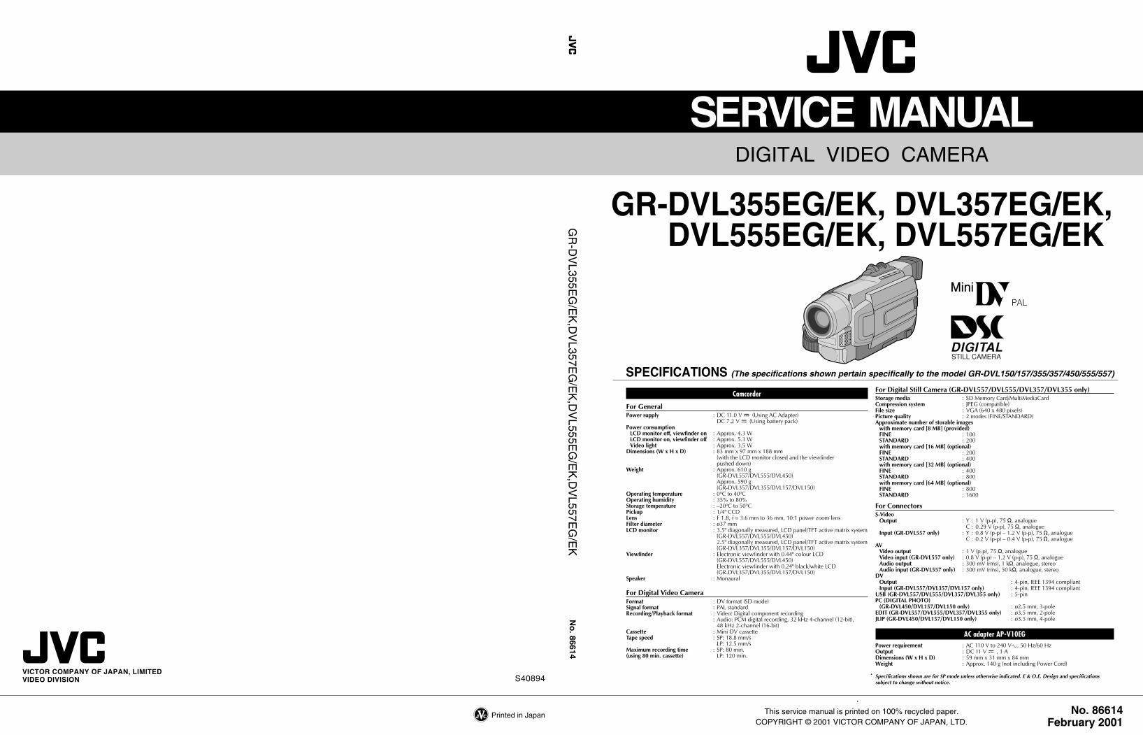
• Safety Check after ServicingExamine the area surrounding the repaired location for damage or deterioration. Observe that screws, parts and wires have been returnedto original positions, Afterwards, perform the following tests and confirm the specified values in order to verify compliance with safetystandards.
1. Insulation resistance testConfirm the specified insulation resistance or greater between power cord plug prongs and exter-nally exposed parts of the set (RF terminals, antenna terminals, video and audio input and outputterminals, microphone jacks, earphone jacks, etc.). See table 1 below.
2. Dielectric strength testConfirm specified dielectric strength or greater between power cord plug prongs and exposed acces-sible parts of the set (RF terminals, antenna terminals, video and audio input and output terminals,microphone jacks, earphone jacks, etc.). See table 1 below.
3. Clearance distanceWhen replacing primary circuit components, confirm specified clearance distance (d), (d’) be-tween soldered terminals, and between terminals and surrounding metallic parts. See table 1below.
4. Leakage current testConfirm specified or lower leakage current between earth ground/power cord plug prongs andexternally exposed accessible parts (RF terminals, antenna terminals, video and audio input andoutput terminals, microphone jacks, earphone jacks, etc.).Measuring Method : (Power ON)Insert load Z between earth ground/power cord plug prongs and externally exposed accessibleparts. Use an AC voltmeter to measure across both terminals of load Z. See figure 9 and followingtable 2.
5. Grounding (Class 1 model only)Confirm specified or lower grounding impedance between earth pin in AC inlet and externally exposed accessible parts (Video in, Video out,Audio in, Audio out or Fixing screw etc.).Measuring Method:Connect milli ohm meter between earth pin in AC inlet and exposed accessible parts. See figure 10 and grounding specifications.
Fig. 10
Fig. 9
Fig. 8
Table 1 Specifications for each region
Table 2 Leakage current specifications for each region
Note: These tables are unofficial and for reference only. Be sure to confirm the precise values for your particular country and locality.
II S40888-01
a b
c
V
AExternallyexposedaccessible part
Z


1-1
(1) (2) (3) (4) (5)
SECTION 1DISASSEMBLY
1.1.4 Disconnection of Connectors (Wires)ConnectorPull both ends of the connector in the arrow direction, re-move the lock and disconnect the flat wire.
1.1 BEFORE ASSEMBLY AND DISASSEMBLY
1.1.1 Precautions1. Be sure to remove the power supply unit prior to mount-
ing and soldering of parts.2. When removing a component part that needs to discon-
nect the connector and to remove the screw for remov-ing itself, first disconnect the connecting wire from theconnector and then remove the screw beforehand.
3. When connecting and disconnecting the connectors, becareful not to damage the wire.
4. Carefully remove and handle the part to which somespacer or shield is attached for reinforcement or insula-tion.
5. When replacing chip parts (especially IC parts), desoldercompletely first (to prevent peeling of the pattern).
6. Tighten screws properly during the procedures.Unless specified otherwise, tighten screws at a torqueof 0.069N•m(0.7kgf•cm).
1.1.2 Assembly and disassembly
(1) Indicate the disassembly steps. When assembling, per-form in the reverse order of these steps. This numbercorresponds to the number in the disassembly diagram.
(2) Indicates the name of disassembly/assembly parts.(3) Indicates the number in the disassembly diagram.(4) Indicates parts and points such as screws, washers,
springs which must be removed during disassembly/assembly.
Symbol Name, PointS ScrewL Lock, Pawl, HookSD Soldering�(Others) Connector, Cover, Bracket, etc.
(Example)• 2 (S1) : Remove the two screws (S1) for removing the
part 1.• CN 2a : Disconnect the connector 2a .• SD1 : Unsolder at the point SD1.
(5) Precautions on disassembly/assembly.
1.1.3 Destination of connectors
Note: Three kinds of double-arrows in connection tables re-spectively show kinds of connector/wires.↔ : Wire⇔ : Flat wire
: Board to Board connector[Example]
Fig. 1-1-1 Connector 1
Connector
Flat wire
Fig. 1-1-2 Connector 2
Connector
Flat wire
Extend the locks in the direction of the arrow for unlockingand then pull out the wire. After removing the wire, immedi-ately restore the locks to their original positions becausethe locks are apt to come off the connector.
B-B connectorPull the board by both the sides in the direction of the ar-row for disconnecting the B-B connector.
Fig. 1-1-3 Connector 3
Connector
Connector
Fig. 1-1-4 Connector 4
Connector
1 COVER(ZOOM) Fig.1-3-1 (S1a),(S1b),2(L1a),2(L1b ) -ASSY
2 UPPER CASE ASSY Fig.1-3-2 (S2a),(S2b),(L2),(S2c) NOTE2( Inc.E.VF UNIT 2(S2a),(S2d),4(S2a) (B/W,COLOR), CAP(DC JACK) SPEAKER/ �CN 2a MONITOR)
STEPNo. PART Fig.No. POINT NOTE
CONN.No. Pin No.CONNECTOR
2a MAIN CN101 ⇔ MONITOR CN761 50
Note: Remove the parts marked in .

1-2
1.2 JIGS AND TOOLS REQUIRED FOR DISASSEMBLY,ASSEMBLY AND ADJUSTMENT
1.2.1 Tools required for adjustments
1. Torque driverBe sure to use to fastening the mechanism and exteriorparts because those parts must strictly be controlled fortightening torque.
2. BitThis bit is slightly longer than those set in conventionaltorque drivers.
3. TweezersTo be used for removing and installing parts and wires.
4. Chip IC replacement jigTo be used for adjustment of the camera system.
5. Cleaning clothRecommended cleaning cloth to wipe down the videoheads, mechanism (tape transport system), optical lenssurface.
1.3 DISASSEMBLY/ASSEMBLY OF CABINET PARTSAND BOARD ASSEMBLY
1.3.1 Disassembly flow chart
This flowchart indicates the disassembly step for the cabi-net parts and board assembly in order to gain access toitem(s) to be serviced. When reassembling, perform thestep(s) in reverse order.
Table 1-2-1
Table 1-3-1
Torque DriverYTU940881 Bit
YTU94088-0032
3 Chip IC Replacement JigPTS40844-24
5 Cleaning ClothKSMM-01
TweezersP-895
COVER(ZOOM) ASSY
UPPER CASE ASSY (Inc.E.VF UNIT(B/W,COLOR),SPEAKER/MONITOR)
FRONT COVER ASSY (Inc.DC LIGHT,MIC)
OP BLOCK ASSY /BRACKET(OP) ASSY
REAR UNIT
LOWER CASE ASSY (Inc.ZOOM UNIT)
/JACK BOARD ASSY
JUNCTION BOARD ASSY
MAIN BOARD ASSY/MECHANISM ASSY
E.VF UNIT /SPEAKER
MONITOR ASSY/MONITOR BOARD ASSY
2
1
3
4
5
8
8/0
6/7
#/$
!/@

1-3
1 COVER(ZOOM) Fig.1-3-1 (S1a),(S1b),2(L1a),2(L1b ) -ASSY
2 UPPER CASE ASSY Fig.1-3-2 (S2a),(S2b),(L2),(S2c) NOTE2( Inc.E.VF UNIT 2(S2a),(S2d),4(S2a) (B/W,COLOR), CAP(DC JACK) SPEAKER/ �CN 2a MONITOR)
3 FRONT COVER Fig.1-3-3 COVER(JACK),3(S3),(L3a) NOTE3aASSY (L3b),�CN 3a NOTE3b (Inc.DC LIGHT,MIC)
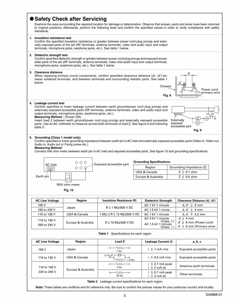
4 OP BLOCK ASSY Fig.1-3-4 �CN 4a , 4b -/BRACKET(OP) 2(S4),2(L4)ASSY
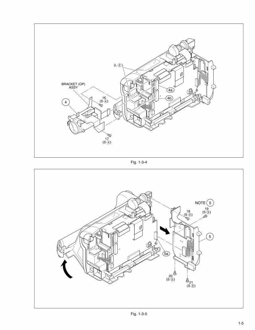
5 REAR UNIT Fig.1-3-5 �CN 5a NOTE54(S5)
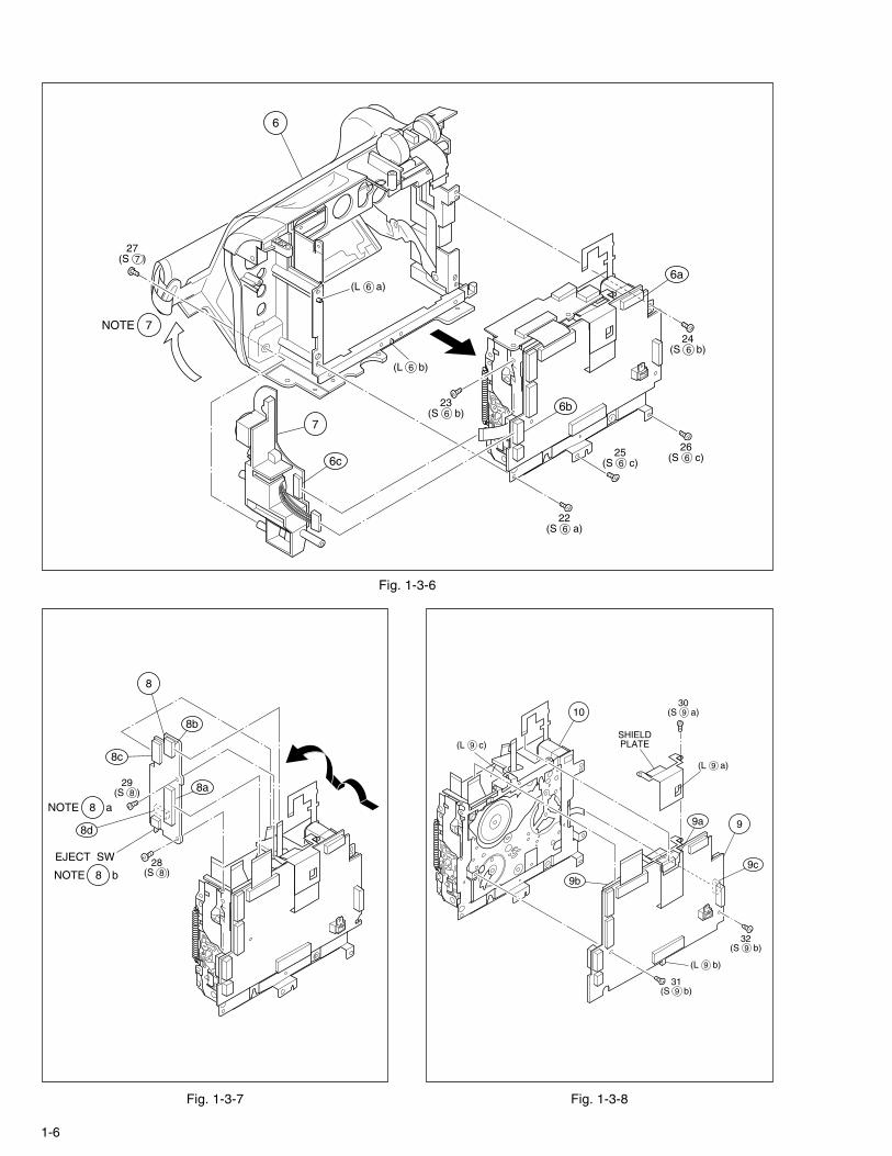
6 LOWER CASE ASSY Fig.1-3-6 �CN 6a , 6b , 6c -(Inc.ZOOMUNIT) (S6a),2(S6b),2(S6c)
/ (L6a),(L6b)
7 JACK BOARD ASSY (S7) NOTE7
8 JUNCTION BOARD Fig.1-3-7 �CN 8a , 8b , 8c NOTE8aASSY 2(S8),�CN 8d NOTE8b
9 MAIN BOARD ASSY Fig.1-3-8 (S9a),(L9a),SHIELD PLATE -/ �CN 9a , 9b , 9c0 /MECHANISM ASSY 2(S9b),(L9b),(L9c)
! E.VF UNIT Fig.1-3-9 �CN 11a ,(S!a),(S!b) NOTE!a/ (L!) NOTE!b
@ SPEAKER (S@),PLATE(SPK) -�CN 12a
# MONITOR ASSY Fig.1-3-10 2(S#a),COVER(HINGE) NOTE#/ �CN 13a , 2(S#b)
$ MONITOR BOARD 3(S$),(L$) NOTE$aASSY NOTE$b
NOTE$cNOTE$d
STEPNo. PART Fig.No. POINT NOTE
1.3.2 Disassembly method
Table 1-3-2
- - - - - - - - - - - - - - - - - - - - - - - - - - - - - - - - - - - - - - - - - - - - - - - - - - - - - - -
- - - - - - - - - - - - - - - - - - - - - - - - - - - - - - - - - - - - - - - - - - - - - - - - - - - - - - -
- - - - - - - - - - - - - - - - - - - - - - - - - - - - - - - - - - - - - - - - - - - - - - - - - - - - - - -
NOTE 2: Remove the CAP (DC JACK) before removingthese parts .
NOTE 3a: As it is difficult to remove (L3b), remove theF. COVER ASSY by lowering it.
NOTE 3b: Be careful not to damage any parts.Particularly, take care not to scratch or stain thelenses.
NOTE 5: As screw No. 19 is hidden behind the cassettecover, open the cassette cover to enable re-moval of the screw.
NOTE 7: As screw No. 27 is hidden behind the cassettecover, open it before removing the screw.
NOTE 8a: As the CN572 is located at the back of the as-sembly, unplug the three connectors and re-move the screws before disconnecting theCN572.
NOTE 8b: Be careful not to damage any of the switches.
NOTE !a: To remove the unit, unlock the connector andpull out the unit together with the FPC.
NOTE !b: When removing the unit, insert the FPC into thegap.
NOTE #: When reassembling the MONITOR ASSY, becareful not to damage any of the parts.
NOTE $a: To remove the assembly, pull the memory cardout in advance. (MMC compatible models only)
NOTE $b: Be careful not to damage any of the parts.NOTE $c: Be careful not to damage any of the parts.
SW KNOB(DC LIGHT: Gray)NOTE $d: Be careful not to damage any of the parts.
SW KNOB(VIDEO-DSC: Violet)
CONN.No. Pin No.CONNECTOR
Table 1-3-3
Note: Remove the parts marked in .
2a MAIN CN101 ⇔ MONITOR CN761 50
3a MAIN CN106 ←→ MIC — 3
4a MAIN CN107 ⇔ CCD — 20
4b MAIN CN108 ⇔ OP BLOCK ASSY — 24
5a MAIN CN104 ←→ REAR UNIT CN1 10
6a MAIN CN109 ⇔ ZOOM UNIT — 15
6b MAIN CN102 ←→ JACK CN501 9
6c JACK CN502 ⇔ MAIN CN103 14
8a JUNCTION CN571 ⇔ MAIN CN113 34
8b JUNCTION CN574 ⇔ LOADING MOTOR — 6
8c JUNCTION CN573 ⇔ DRUM MOTOR — 11
8d JUNCTION CN572 ⇔ SENSOR — 15
9a MAIN CN110 ⇔ HEAD — 8
9b MAIN CN112 ⇔ CAPSTAN MOTOR — 18
9c MAIN CN111 ⇔ ROTARY ENCODER — 6
11a MONITOR CN763 ⇔ E.VF UNIT (C_B/W) CN721/CN751 20
12a MONITOR CN765 ←→ SPEAKER — 2
13a MONITOR CN764 ⇔ LCD BL CN751 33/32
Fig. 1-3-1
1
1(S 1 a)
2(S 1 b)
(L 1 a)
(L 1 b)

1-4
Fig. 1-3-2
Fig. 1-3-3
2 ( )11 12 13 14
2a
8(S 2 d)3
(S 2 a)
12(S 2 a)
11(S 2 a)
10(S 2 a)
9(S 2 a)
4(S 2 b)
NOTE
CAP(DC JACK)
2
5(S 2 c)
7(S 2 a)
6(S 2 a)
126
7
89
(BOTTOM SIDE) (REAR SIDE)
10 11
(L 2 )
COVER(JACK)
3
3NOTE a
3NOTE b
(L 3 a)
(L 3 b)
13(S 3 )
14(S 3 )
15(S 3 )
3a
1-5
Fig. 1-3-5
5
5a
18(S 5 )
19(S 5 )
20(S 5 )
21(S 5 )
5NOTE
Fig. 1-3-4
4
BRACKET (OP)ASSY
4b
4a
17(S 4 )
16(S 4 )
(L 2 )
1-6
Fig. 1-3-6
7
6a
6c
6b
27(S 7 )
6
(L 6 a)
24(S 6 b)
26(S 6 c)25
(S 6 c)
22(S 6 a)
(L 6 b)
23(S 6 b)
7NOTE
Fig. 1-3-7 Fig. 1-3-8
8a
8c
8d
8b
8NOTE a
8NOTE b
29(S 8 )
28(S 8 )
EJECT SW
8
9
10
9c
9a
9b
(L 9 c)
(L 9 b)
30(S 9 a)
31(S 9 b)
(L 9 a)
SHIELDPLATE
32(S 9 b)

1-7Fig. 1-3-10
1440(S 14 )
41(S 14 )
42(S 14 )
COVER(HINGE)
14NOTE a
13NOTE
14NOTE b
14NOTE c
14NOTE
SW
SW
SWd
(L 14 )13
38(S 13 b)
37(S 13 a)
36(S 13 a)
39(S 13 b)
: 0.147N·m (1.5kgf·cm)
13a
Fig. 1-3-9
12PLATE(SPK)
35(S 12 )
11
34(S 11 b)
33(S 11 a)
11NOTE a
11NOTE b
(L 11 )
11a
12a
1-8
Fig. 1-4-1
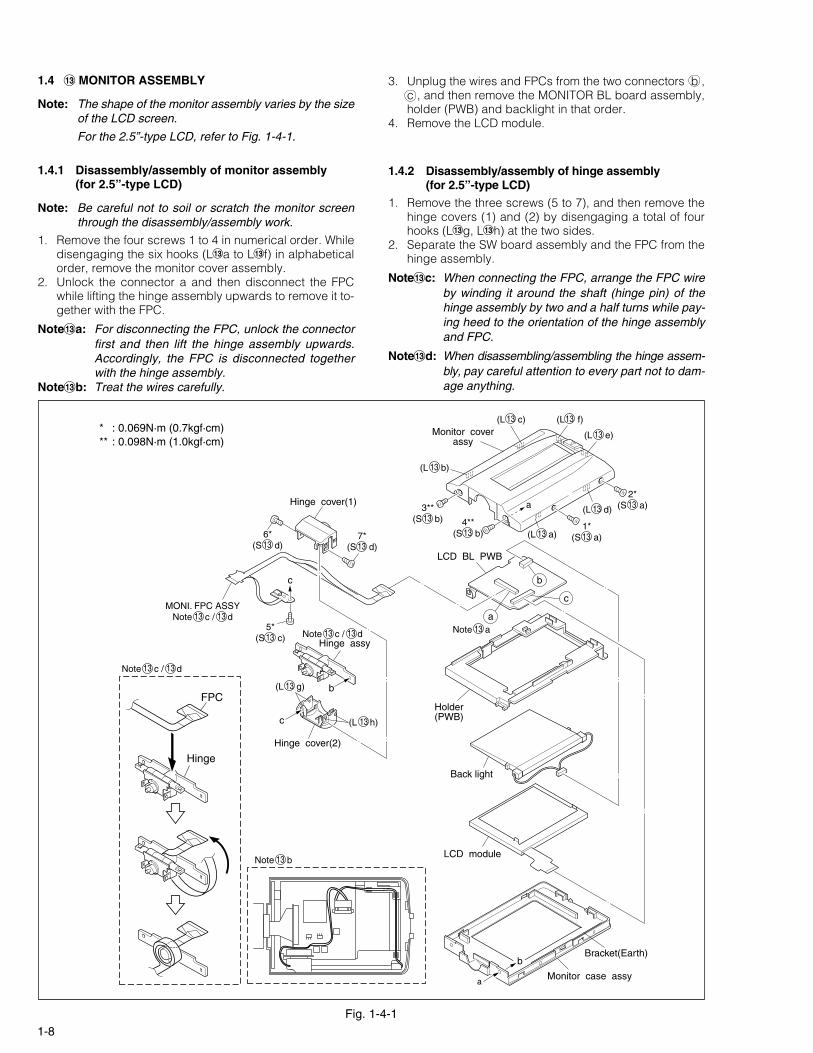
1.4 # MONITOR ASSEMBLY
Note: The shape of the monitor assembly varies by the sizeof the LCD screen.
For the 2.5”-type LCD, refer to Fig. 1-4-1.
1.4.1 Disassembly/assembly of monitor assembly(for 2.5”-type LCD)
Note: Be careful not to soil or scratch the monitor screenthrough the disassembly/assembly work.
1. Remove the four screws 1 to 4 in numerical order. Whiledisengaging the six hooks (L#a to L#f) in alphabeticalorder, remove the monitor cover assembly.
2. Unlock the connector a and then disconnect the FPCwhile lifting the hinge assembly upwards to remove it to-gether with the FPC.
Note#a: For disconnecting the FPC, unlock the connectorfirst and then lift the hinge assembly upwards.Accordingly, the FPC is disconnected togetherwith the hinge assembly.
Note#b: Treat the wires carefully.
3. Unplug the wires and FPCs from the two connectors b ,c , and then remove the MONITOR BL board assembly,holder (PWB) and backlight in that order.
4. Remove the LCD module.
1.4.2 Disassembly/assembly of hinge assembly(for 2.5”-type LCD)
1. Remove the three screws (5 to 7), and then remove thehinge covers (1) and (2) by disengaging a total of fourhooks (L#g, L#h) at the two sides.
2. Separate the SW board assembly and the FPC from thehinge assembly.
Note#c: When connecting the FPC, arrange the FPC wireby winding it around the shaft (hinge pin) of thehinge assembly by two and a half turns while pay-ing heed to the orientation of the hinge assemblyand FPC.
Note#d: When disassembling/assembling the hinge assem-bly, pay careful attention to every part not to dam-age anything.
Monitor case assy
Bracket(Earth)
LCD module
Back light
Holder(PWB)
LCD BL PWB
Hinge cover(1)
c
Hinge assy
Hinge cover(2)
c
Monitor coverassy
a
b
b
a
c
b
Hinge
FPC
a2*
(S a)13
1*(S a)13
3**(S b)13 4**
(S b)13
5*(S c)13
6*(S d)13
7*(S d)13
(L c)13 (L f)13
(L e)13
(L d)13
(L a)13
(L b)13
(L g)13
(L h)13
Note a13
Note b13
Note c / d13 13
MONI. FPC ASSYNote c / d13 13
Note c / d13 13
* : 0.069N·m (0.7kgf·cm)** : 0.098N·m (1.0kgf·cm)

1-9
Fig. 1-4-2
Note: The shape of the monitor assembly varies depend-ing on the size of the LCD screen.
For the 3.5”-type LCD, refer to Fig. 1-4-2.
1.4.3 Disassembly/assembly of monitor assembly(for 3.5”-type LCD)
Note: Be careful not to soil or scratch the monitor screenthrough the disassembly/assembly work.
1. Remove the four screws 1 to 4 in numerical order. Whiledisengaging the six hooks (L#a to L#f) in alphabeticalorder, open the monitor cover assembly and remove itafter disconnecting the FPC from the connector a..
Note#e: When removing the monitor cover assembly, becareful not to damage the FPC and connector.
2. Unlock the connector b and then disconnect the FPCwhile lifting the hinge assembly upwards to remove it to-gether with the FPC.
Note#f: For disconnecting the FPC, unlock the connectorfirst and then lift the hinge assembly upwards.Accordingly, the FPC is disconnected togetherwith the hinge assembly.
Note#g: Treat the wires carefully.
1.4.4 Disassembly/assembly of hinge assembly(for 3.5”-type LCD)
1. Remove the three screws (5 to 7), and then remove thehinge covers (1) and (2) by disengaging a total of fourhooks (L#g, L#h) at the two sides.
2. Separate the SW board assembly and the FPC from thehinge assembly.
Note#h: When disassembling/assembling the hinge assem-bly, pay careful attention to every part not to dam-age anything.
Note#j: When connecting the FPC, arrange the FPC wireby winding it around the shaft (hinge pin) of thehinge assembly by two and a half turns while pay-ing heed to the orientation of the hinge assemblyand FPC.
3. Unplug the wires and FPCs from the two connectors b ,c , and then remove the MONITOR BL board assembly,holder (PWB) and backlight in that order.
4. Remove the LCD module.
Monitor case assy
LCD module
Back light
Holder(PWB)
LCD BL PWB
Hinge cover(1)
c
Hinge assy
Hinge cover(2)
c
Monitor cover assy
a
a
b
b
Bracket(Earth)
b
c
a
d
Hinge
3.5”
FPC
(L h)13
(L g)13
Note e13
Note f13
Note g13
Note h / j13 13
Note h / j13 13
2*(S a)13
1*(S a)13
3**(S b)13
7*(S d)13
5*(S c)13
6*(S d)13
4**(S b)13
(L c)13 (L f)13
(L e)13
(L d)13
(L a)13
(L b)13
* : 0.069N·m (0.7kgf·cm)** : 0.098N·m (1.0kgf·cm)
MONI. FPC ASSYNote h / j13 13

1-10
Fig. 1-5-1
3. Remove the screw (5) and then remove the LCD assem-bly.
1.5 ! E. VF ASSEMBLY
Note: The shape of the E. VF assembly varies by the typeof the viewfinder (B/W, color VF).
For the B/W VF, refer to Fig. 1-5-1. For the COLOR VF, refer to Fig. 1-5-2.
1.5.1 Disassembly/assembly of E. VF assembly (for B/W VF)
1. Remove the two screws (1, 2) and the eyepiece assem-bly while disengaging the hook (L!a).
2. Remove the two screws (3, 4). And spread one side ofthe top case sub-assembly to disengage the hooks(L!b, L!c) that are located at both sides of the top casesub-assembly, then remove the top case sub-assembly.
Note!a: When removing the top case sub-assembly, peeloff or unplug the FPC that is bonded to the sub-assembly.
Note!b: When reassembling the top case sub-assembly,be careful not to catch the FPC between any ofthe parts.
TOP CASESUB ASSY
HINGE ASSYFPC
LCD ASSY
EYE PIECE ASSYTOP CASE SUB ASSY
HINGE ASSY
BOTTOM CASE
(L a)11
(L b)11(L c)11FPC
NOTE a11
NOTE b11
5(S b)11
1(S a)11
2(S a)11
4(S a)11
3(S a)11

1-11
Fig. 1-5-2
3. Remove the screw (5) and then remove the LCD assem-bly.
1.5.2 Disassembly/assembly of E. VF assembly (for Color VF)
Note: Place the E. VF assembly with the VF case (upper)assembly down through the disassembly/assemblywork.
1. Remove the two screws (1, 2) and the eyepiece assem-bly while disengaging the hook (L!a).
2. Remove the two screws (3, 4). And spread one side ofthe top case sub-assembly to disengage the hooks(L!b, L!c) that are located at both sides of the top casesub-assembly, then remove the top case sub-assembly.
Note!c: When removing the top case sub-assembly, peeloff or unplug the FPC that is bonded to the sub-assembly.
Note!d: When reassembling the top case sub-assembly,be careful not to catch the FPC between any ofthe parts.
TOP CASESUB ASSY
HINGE ASSY
LCD ASSY
TOP CASE SUB ASSY
HINGE ASSY
EYE PIECE ASSY
BOTTOM CASE
(L a)11
NOTE d11
FPCNOTE c11
5(S b)11
1(S a)11
2(S a)11
4(S a)11
3(S a)11
(L b)11
(L c)11
1-12
Fig. 1-6-1
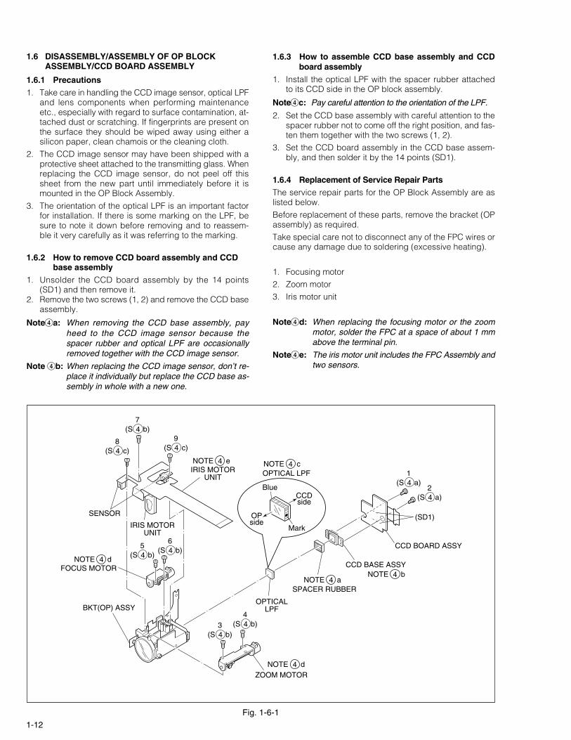
1.6 DISASSEMBLY/ASSEMBLY OF OP BLOCKASSEMBLY/CCD BOARD ASSEMBLY
1.6.1 Precautions
1. Take care in handling the CCD image sensor, optical LPFand lens components when performing maintenanceetc., especially with regard to surface contamination, at-tached dust or scratching. If fingerprints are present onthe surface they should be wiped away using either asilicon paper, clean chamois or the cleaning cloth.
2. The CCD image sensor may have been shipped with aprotective sheet attached to the transmitting glass. Whenreplacing the CCD image sensor, do not peel off thissheet from the new part until immediately before it ismounted in the OP Block Assembly.
3. The orientation of the optical LPF is an important factorfor installation. If there is some marking on the LPF, besure to note it down before removing and to reassem-ble it very carefully as it was referring to the marking.
1.6.2 How to remove CCD board assembly and CCDbase assembly
1. Unsolder the CCD board assembly by the 14 points(SD1) and then remove it.
2. Remove the two screws (1, 2) and remove the CCD baseassembly.
Note4a: When removing the CCD base assembly, payheed to the CCD image sensor because thespacer rubber and optical LPF are occasionallyremoved together with the CCD image sensor.
Note 4b: When replacing the CCD image sensor, don’t re-place it individually but replace the CCD base as-sembly in whole with a new one.
1.6.3 How to assemble CCD base assembly and CCDboard assembly
1. Install the optical LPF with the spacer rubber attachedto its CCD side in the OP block assembly.
Note4c: Pay careful attention to the orientation of the LPF.
2. Set the CCD base assembly with careful attention to thespacer rubber not to come off the right position, and fas-ten them together with the two screws (1, 2).
3. Set the CCD board assembly in the CCD base assem-bly, and then solder it by the 14 points (SD1).
1.6.4 Replacement of Service Repair Parts
The service repair parts for the OP Block Assembly are aslisted below.Before replacement of these parts, remove the bracket (OPassembly) as required.Take special care not to disconnect any of the FPC wires orcause any damage due to soldering (excessive heating).
1. Focusing motor2. Zoom motor3. Iris motor unit
Note4d: When replacing the focusing motor or the zoommotor, solder the FPC at a space of about 1 mmabove the terminal pin.
Note4e: The iris motor unit includes the FPC Assembly andtwo sensors.
CCD BOARD ASSY
(SD1)
CCD BASE ASSY
OPTICALLPF
ZOOM MOTOR
SPACER RUBBER
9(S c)4
8(S c)4
7(S b)4
1(S a)4
6(S b)4
3(S b)4
4(S b)4
5(S b)4
2(S a)4
BKT(OP) ASSY
IRIS MOTORUNIT
IRIS MOTORUNIT
SENSOR
NOTE d4
NOTE a4NOTE b4
OPTICAL LPFNOTE c4NOTE e4
FOCUS MOTORNOTE d4
OPside
CCDside
Blue
Mark

1-13
1. The CAPSTAN FG signal is not received by the sysconCPU.1) Disconnection in the middle of the signal line.2) Failure of the CAPSTAN FG pulse generator (MR
element).2. No capstan control voltage is supplied to the MDA.3. No power is supplied to the CAPSTAN MDA.4. The capstan cannot be started or capstan rotation is
stopped because tape transport load is too high.1) Tape tension is extremely high. (Mechanical lock-
ing)2) The tape is damaged or soiled with grease, etc.
(Tape tangling occurs, etc.)
1.7 EMERGENCY DISPLAY
Whenever some abnormal signal is input to the syscon CPU,an error number (E01, as an example) is displayed on theLCD monitor or (in the electronic view finder).In every error status, such the message as shown belowalternately appear over and over.
• In an emergency mode, all operations except turning on/off the POWER switch are ineffectual.
E01UNIT IN SAFEGUARD MODE
E01REMOVE AND REATTACH BATTERY
Example (in case of the error number E01):
E01 LOADING
LCDdisplay
Emergencymode
Details Possible cause
In the case the encoder position is not shiftedto the next point though the loading motor hasrotated in the loading direction for 4 secondsor more. This error is defined as [E01].
1. The mechanism is locked during mode shift.2. The mechanism is locked at the mechanism loading
end, because the encoder position is skipped duringmechanism mode shift.
3. No power is supplied to the loading MDA.
E02 UNLOADING In the case the encoder position is not shiftedto the next point though the loading motor hasrotated in the unloading direction for 4 secondsor more. This error is defined as [E02].
1. The mechanism is locked during mode shift.2. The mechanism is locked at the mechanism loading
end, because the encoder position is skipped duringmechanism mode shift.
E03 TU & SUP REELFG
In the case no REEL FG is produced for 4 sec-onds or more in the capstan rotation mode af-ter loading was complete, the mechanism modeis shifted to STOP with the pinch roller set off.This error is defined as [E03].However, no REEL EMG is detected in theSLOW/STILL mode.
1. The idler gear does not engage with the reel disk well.2. Though the idler gear and reel disk are engaged with
each other, the tape is not wound because of over-load to the mechanism.
3. No FG pulse is output from the reel sensor.4. No power is supplied to the reel sensor.5. Tape transport operation takes place with a cassette
having no tape inside.6. The tape slackens and no pulse is produced until the
slack is taken up and the tape comes into the normalstatus.
E04 DRUM FG In the case there is no DRUM FG input in thedrum rotation mode for 4 seconds or more. Thiserror is defined as [E04], and the mechanismmode is shifted to STOP with the pinch rollerset off.
1. The drum cannot be started or drum rotation is stoppedbecause tape transport load is too high.1) Tape tension is extremely high.2) The tape is damaged or soiled with grease, etc.
2. The DRUM FG signal is not received by the sysconCPU.1) Disconnection in the middle of the signal line.2) Failure of the DRUM FG pulse generator (hall ele-
ment).3. No drum control voltage is supplied to the MDA.4. No power is supplied to the DRUM MDA.
E05 – – –
E06 CAPSTAN FG In the case no CAPSTAN FG is produced inthe capstan rotation mode for 2 seconds ormore. This error is defined as [E06], and themechanism mode is shifted to STOP with thepinch roller set off.However, no CAPSTAN EMG is detected in theSTILL/FF/REW mode.
(DVC_03)
Table 1-7-1

1-14
1.8 SERVICE NOTE
Tab
le 1
-8-1
12
34
56
78
910
1112
1314
1516
17
1
8
19
2
0
21
12
( -/ =
/ ~/ !
)4
35
✻
✻✻
✻✻
✻✻
✻
Fig
. 1-3
-2F
ig. 1
-3-3
Fig
. 1-3
-4F
ig. 1
-3-5
Fig
. 1-3
-1
I
2223
2425
2627
2829
3031
3233
3435
366
8-
=~
!
M
ON
ITO
R A
SS
Y
79
/ 0
Fig
. 1-3
-6F
ig. 1
-3-7
Fig
. 1-3
-8F
ig. 1
-3-9
Fig
. 1-3
-10
I
Fig
. 1-4
-1, 2
IIIIII
IV
V
III
Sym
bol N
o.
Rem
ovin
g or
der
of s
crew
Pla
ce to
stic
k sc
rew
Ref
eren
ce d
raw
ing
Scr
ew ti
ghte
ning
torq
ue
→ → →→ →
Sym
bol N
o.
Rem
ovin
g or
der
of s
crew
Pla
ce to
stic
k sc
rew
Ref
eren
ce d
raw
ing
Scr
ew ti
ghte
ning
torq
ue
→ → →→ →
Rem
ovin
g or
der
of s
crew
Pla
ce to
stic
k sc
rew
Ref
eren
ce d
raw
ing
Scr
ew ti
ghte
ning
torq
ue
→ →→ →
Rem
ovin
g or
der
of s
crew
Pla
ce to
stic
k sc
rew
Ref
eren
ce d
raw
ing
Scr
ew ti
ghte
ning
torq
ue
→ →→ →
12
34
56
7
VF
UN
IT(B
/W,C
OLO
R)
Fig
. 1-5
-1, 2
III
Rem
ovin
g or
der
of s
crew
Pla
ce to
stic
k sc
rew
Ref
eren
ce d
raw
ing
Scr
ew ti
ghte
ning
torq
ue
→ →→ →
12
34
5
OP
BLO
CK
AS
SY
Fig
. 1-6
-1
12
34
56
78
9
< N
OT
E >
1)✻
:
Don
t’t r
euse
the
scre
w, b
ecau
se s
crew
lock
bon
d w
as a
pplie
d to
them
.
2)P
ay c
aref
ul a
ttent
ion
to ti
ghte
ning
torq
ue fo
r ea
ch s
crew
.
I
: 0
.088
N·m
(0.
9kgf
·cm
)II
: 0
.147
N·m
(1.
5kgf
·cm
)III
: 0
.069
N·m
(0.
7kgf
·cm
)
IV
: 0
.098
N·m
(1.
0kgf
·cm
)V
: 0
.118
N·m
(1.
2kgf
·cm
)
3738
3940
4142

2-1
SECTION 2MECHANISM ADJUSTMENT
2.1 PRELIMINARY REMARKS ON ADJUSTMENT ANDREPAIR
2.1.1 Precautions1. When fastening parts, pay careful attention to the tight-
ening torque of each screw. Unless otherwise specified,tighten a screw with the torque of 0.039 N•m (0.4 kgf•cm).
2. Be sure to disconnect the set from the power supply be-fore fastening and soldering parts.
3. When disconnecting/connecting wires, be careful not toget them and their connectors damaged. (Refer to theSection 1.)
4. When replacing parts, be very careful neither to dam-age other parts nor to fit wrong parts by mistake.
2.1.2 Notes on procedure for disassemby/assembly
The disassembling procedure table (Table 2-4-1 on page2-6,a part of the table is shown below for reference)showsthe procedure to disassemble/reassemble mechanismparts.Carefully read the following explanation before starting ac-tual disassembling/reassembling work. The item numbers(circled numbers)in the following explanation correspondto those appearing under respective columns of the table.
(1) Circled numbers appearing in this column indicate theorder to remove parts. When reassembling, follow thesenumbers in the reverse order. Circled numbers in thiscolumn correspond to those appearing in drawings ofthis section.
(2) This column shows part names corresponding to circlednumbers in the left column.
(3) The symbol (T or B)appearing in this column shows theside which the objective part is mounted on.T =the upper side, B =the lower side
(4) Symbols appearing in this column indicate drawingnumbers.Step Part Name Fig. Point Note Remarks
(5) This column indicates parts and points such as screws,washers,springs,and others to be removed/fitted for dis-assembling/reassembling the mechanism. Besides suchthe parts, this column occasionally indicates workingpoints.
P = SpringW = WasherS = Screw* = Lock (L),soldering (SD),shield,connector (CN),
etc.Example • Remove ((W1)=Washer W1.
• **Remove the solder at (SD1)=Point SD1.• **Disconnect Å =Connector Å .
(6) Numbers in this column represent the numbers of notesin the text.For example, “1” means “Note 1”.(For parts that need phase adjustment after reassem-bling, refer to “2.6 MECHANISM ADJUSTMENTS”.)
(7) This column indicates required after-disassembling/-re-assembling work such as phase adjustment or mecha-nism adjustment.
(1) (2) (3) (4) (5) (6) (7)
NO. PART NAME FIG. POINT NOTE REMARKS
A Cassette housing assembly T Fig. 2-4-5 3(S1),(L1a)-(L1d) 1a, 1b, 1c, 1d Adjustment
2a Reel disk (SUP) assembly T Fig. 2-4-6 (W2) 2a, 2b
2b Reel disk (TU) assembly T Fig. 2-4-6 (W2) 2a, 2b
2c Reel cover assembly T Fig. 2-4-6 (S2b),2(S2a),(W2) 2d
3a Tension arm assembly T Fig. 2-4-7 (W3a) 3b
3b Release guide assembly T Fig. 2-4-7 - 3a
3c Idler arm assembly T Fig. 2-4-7 (W3b) -
3d Guide arm assembly T Fig. 2-4-7 - 3a
3e Pinch roller arm assembly T Fig. 2-4-7 (W3a) -
4a Cleaner arm assembly T Fig. 2-4-8 (L4a) 4a
4b Slant pole arm assembly T Fig. 2-4-8 (W4),(L4b),(P4a),(P4b) 4b
4c Drum assembly T Fig. 2-4-8 3(S4) -
5a Guide roller (S) assembly T Fig. 2-4-9 (P5) 5a
5b Rail assembly T Fig. 2-4-9 3(W5a), (W5b) 5b, 5c

2-2
2.2 JIGS AND TOOLS REQUIRED FOR DISASSEMBLY,ASSEMBLY AND ADJUSTMENT
2.2.1 Tools required for adjustments
1. Torque DriverBe sure to use to fastening the mechanism and exteriorparts because those parts must strictly be controlled fortightening torque.
2. BitThis bit is slightly longer than those set in conventionaltorque drivers.
3. TweezersTo be used for removing and installing parts and wires.
4. Chip IC replacement JigTo be used for adjustment of the camera system.
5. Guide DriverTo be used to turn the guide roller to adjustment of thelinarity of playback envelope.
6. Adjustment DriverTo be used for adjustment.
7. Slit washer Installation JigTo be used to install slit washers.
8. Slit washer Installation Jig (NEW TYPE)To be used to install slit washers.
9. Jig Connector cableConnected to CN105 of the main board and used forelectrical adjustment, etc.
10. Communication cableConnect the Communication cable between the PC ca-ble and Jig connector cable when performing a PC ad-justment.
11. PC cableTo be used to connect the VideoMovie and a personalcomputer with each other when a personal computer isused for adjustment.
12. Service Support SystemTo be used for adjustment with a personal computer.
13. Alignment TapeTo be used for check and adjustment of interchange-ability of the mechanism.
14. Cleaning ClothRecommended cleaning cloth to wipe down the videoheads, mechanism (tape transport system), optical lenssurface.
Torque DriverYTU940881 Bit
YTU94088-0032
3 Chip IC Replacement JigPTS40844-24
Guide DriverYTU94148A5 Adjustment Driver
YTU940286
Slit Washer Installation JigYTU94121A7 Slit Washer Installation Jig
YTU94121B8
Jig Connector cableYTU93082G9 10 Communication cable
YTU93107A
11 PC cableQAM0099-002 12
Alignment TapeMC-213
Service Support SystemYTU94057-52
14 Cleaning ClothKSMM-01
TweezersP-895
Table 2-2-1

2-3
2.3 DISASSEMBLY/ASSEMBLY OF MECHANISM
ASSEMBLY
2.3.1 General statement
The mechanism should generally be disassembled/assem-bled in the EJECT mode (ASSEMBLY mode). (Refer to Fig.2-3-1.)However, when the mechanism is removed from the mainbody, it is set in the STOP mode. Therefore, after themechanism is removed from the main body, supply 3 V DCto the electrode on the top of the loading motor to enterthe mechanism mode into the EJECT mode compulsory.
<Mechanism assembly/Cassette housing assembly>
<Back side of the mechanism assembly>
Fig. 2-3-1
Fig. 2-3-3
Fig. 2-3-4
Fig. 2-3-5
Fig. 2-3-6
Fig. 2-3-7
Motor
DC3V
EJECT mode Back side of deck
<C IN mode>
<EJECT mode>
<STOP mode>
<SHORT FF mode>
<PLAY mode>
<REV mode>
<SUB CAM GEAR>
TOP VIEW BOTTOM VIEW
Fig. 2-3-8
2.3.2 Explanation of mechanism mode
The mechanism mode of this model is classified into sixmodes as shown in Table 2-3-1. Each mechanism modecan be distinguished from others by the relative positionof “ ” mark on the sub cam gear to the inner or outer pro-trusion on the main deck.Refer to Fig. 2-3-2 to 2-3-8 below.The EJECT mode, C IN mode and SHORT FF mode shouldbe recognized by the relative position of the “ ” mark tothe inner protrusion, while the STOP mode, REV mode andPLAY mode should be recognized by that to the outer pro-trusion.
Fig. 2-3-2

2-4
Table 2-3-1
ENCODER (ø10)
MODEPARTS
MAIN CAM (ø10.4)
SUB CAM (ø11)
ENCODER (ø10)
MAIN CAM (ø10.4)
SUB CAM (ø11)
POLE BASE
EJECT LEVER
SLIDE
<SLIDE DECK>
CAM SW
A
B
C
RELEASE GUIDE
SUP LOADING
SUB BRAKE (T)
PINCH ROLLER
BRAKE
PAD ARM
TENSION
0
0
0
EJECT C IN
30
31.7
33
70
74.04
77
SHORT FF STOP
169.2
160
176
REV
211.5
200
220
PLAY
280.3
265
291.5
43.1
45.6
47.4
46.8
49.5
51.5
122.5
129.5
134.7
156.6
148.1
162.9
44.6
47.2
49.1
49.2
52.0
54.1 161.7
155.5
147.0 250.5
265.0
275.6
SLIDE STARTSLIDE END
ROTARYENCODER
3
2
1
2.3.3 Mechanism timing chart

2-5
2.4 DISASSEMBLY/ASSEMBLY OF MECHANISM ASSEMBLY
2.4.1 Follow chart
1. Configuration
2. Procedures for disassembly
A
Mechanism assembly
Main deck assemblySlide deck assembly
Mechanism assembly
Main deck assemblySlide deck assembly
Cassette housing assembly
Cassette housing assembly
B CA
B C
2a 5b
7a 8a 11e7h
Fig. 2-4-1
Fig. 2-4-2

2-6
3. Disassembling procedure table
NO. PART NAME FIG. POINT NOTE REMARKS
Table 2-4-1
A Cassette housing assembly T Fig. 2-4-5 3(S1),(L1a)-(L1d) 1a, 1b, 1c, 1d Adjustment
2a Reel disk (SUP) assembly T Fig. 2-4-6 (W2) 2a, 2b
2b Reel disk (TU) assembly T Fig. 2-4-6 (W2) 2a, 2b
2c Reel cover assembly T Fig. 2-4-6 (S2b),2(S2a),(W2) 2d
3a Tension arm assembly T Fig. 2-4-7 (W3a) 3b
3b Release guide assembly T Fig. 2-4-7 - 3a
3c Idler arm assembly T Fig. 2-4-7 (W3b) -
3d Guide arm assembly T Fig. 2-4-7 - 3a
3e Pinch roller arm assembly T Fig. 2-4-7 (W3a) -
4a Cleaner arm assembly T Fig. 2-4-8 (L4a) 4a
4b Slant pole arm assembly T Fig. 2-4-8 (W4),(L4b),(P4a),(P4b) 4b
4c Drum assembly T Fig. 2-4-8 3(S4) -
5a Guide roller (S) assembly T Fig. 2-4-9 (P5) 5a
5b Rail assembly T Fig. 2-4-9 3(W5a), (W5b) 5b, 5c
B Slide deck assembly / C Main deck assembly T Fig. 2-4-10 (W6),(L6a)-(L6d) 6a, 6b (Adjustment)
B Slide deck assembly
7a Loading brake assembly T Fig. 2-4-11 (W7),(L7a),(P7a) 7e Adjustment
7b Guide pin (SUPPLY) T Fig. 2-4-11 (S7a) -
7c Pad arm assembly T Fig. 2-4-11 (W7),(L7b),(P7b) 7d
7d Slide guide plate assembly T Fig. 2-4-11 (S7b) 7c Adjustment
7e Collar T Fig. 2-4-11 - 7a
7f Collar T Fig. 2-4-11 - 7a
7g Sub brake assembly T Fig. 2-4-11 (W7),(L7c),(P7c) 7b
7h Control plate assembly T Fig. 2-4-11 2(W7),(L7d),(P7d) 7b
C Main deck assembly
8a Tension lever assembly T Fig. 2-4-12 - 8c
8b Slide lever assembly T Fig. 2-4-12 - 8b
8c Brake control lever assembly T Fig. 2-4-12 - 8a
9a Loading guide T Fig. 2-4-13 (S9) -
9b Timing belt T Fig. 2-4-13 - 9b
9c Center gear assembly T Fig. 2-4-13 - -
9d Motor bracket assembly T Fig. 2-4-13 2(S9) 9a
9e Worm wheel T Fig. 2-4-13 (W9) - (Phase adjustment)
9f Gear holder T Fig. 2-4-13 (S9) -
10a Main cam gear T Fig. 2-4-14 (S10) 10b Phase adjustment
10b Brake control plate T Fig. 2-4-14 (L10) 10b Phase adjustment
10c Rotary encoder T Fig. 2-4-14 (S10),(W10a) 10a Phase adjustment
10d Connect gear T Fig. 2-4-14 (W10a) - (Phase adjustment)
10e Reel drive pulley assembly T Fig. 2-4-14 (W10b) -
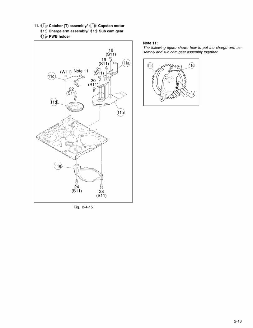
11a Catcher (T) assembly T Fig. 2-4-15 2(S11) -
11b Capstan motor T Fig. 2-4-15 2(S11) -
11c Charge arm assembly T Fig. 2-4-15 (W11) 11
11d Sub cam gear T Fig. 2-4-15 (S11) - Phase adjustment
11e PWB holder B Fig. 2-4-15 2(S11) -

2-7
Fig. 2-4-3
Fig. 2-4-4
10d
3a
7c
2a
7b 7a 7d 7e 9c 3c 3b 7h 2b
9f
8a
10c
9e
5b
9d 5a 4c 4a 4b 11b 11a
CMain deck assembly
BSlide deck assembly
10e
3d
9a
2c
3e
9b
8c
7f
7g
< TOP VIEW >
< BOTTOM VIEW >
11e
11d
11c
8b
10b
CMain deck assembly
BSlide deck assembly
10a

2-8
Fig. 2-4-5
Fig. 2-4-6
2.4.2 Disassembly/assembly
1. A Cassette housing assembly
2. 2a Reel disk (SUP) assembly2b Reel disk (TU) assembly2c Reel cover assembly
2(S1)
3(S1)
Cassettehousing assembly1
(S1)
Slide deck assembly/Main deck assembly
(L1b)
(L1a)
(L1a)
(L1c)
Note 1c
(L1d)
(L1b)
A
Note 1b
2c
(W2)
(W2)(W2)
6(S2b)
4(S2a)
5(S2a)
2a2b
Slide deck assembly/Main deck assembly
Note 2a
Note 2c
Note 2a
Note 2c
Note 2d
Note 2b
Note 2b
Note 1a:Shift the mechanism modefrom the STOP mode to theEJECT mode.
Note 1b:Reassemble the cassettehousing assembly to themechanism as the cancellever is moved in the direc-tion of the arrow.
Note 1c:When reassembling thecassette housing to themechanism, make sure thatthere is no deformation inthe frame or no damage tothe switches, etc.
Note 1d:After reassembling the com-ponent parts, check themechanism operation in thePLAY mode.For details of checkingmethod, refer to “2.6.1 as-sembling slide deck assem-bly and main deck assem-bly”.
<STOP mode>
<EJECT mode>
<PLAY mode>
Note 2a:When removing the reel disk assembly, be careful not tobreak the brake pad which applies lateral pressure to thereel disk.
Note 2b:Be careful not to make a mistake in installing the reel disk.The SUP reel disk and TU reel disk can be distinguishedfrom each other by the appearance as shown below.
Note 2c:When reassembling the cassette housing to the mechanism,make sure that there is no deformation in the frame or nodamage to the switches, etc.
Note 2d:When fitting the reel cover assembly to the set, carefullytighten the screw with the specified tightening torque of0.069N •m (0.7kgf •cm).
(SUP) (TU)

2-9
Fig. 2-4-7
Fig. 2-4-8
4. 4a Cleaner arm assembly/ 4b Slant pole arm assembly4b Drum assembly
Note 3a:When removing the reel cover assembly, pay heed to re-lease guide assembly and guide arm assembly. For, theguide arm assembly is just inserted into the slide deck as-sembly from the upside and it is apt to come off after thereel cover assembly is removed.
Note 3b:Reassemble the tension arm assembly to the mechanismas the pad arm assembly is moved to the extent in the di-rection of the arrow.
Note 4a:When removing the cleaner arm assembly, it is recom-mended to remove the slant pole arm assembly togetherwith it except the case of a single unit replacement, becausethe hook (L4a) is hard to disengage.
Note 4b:How to set the coil spring (P4b).
3. 3a Tension arm assembly/ 3b Release guide assembly3b Idler arm assembly/ 3d Guide arm assembly3c Pinch roller arm assembly
3a
(W3b)
(W3a)
(W3a)
3d
3e
3c
3b
Note 3b
Note 3a
Note 3a
4c
(W4)
(L4a)
(P4a)
(L4b)
8(S4)
7(S4)
9(S4)
4a
4b(P4b)
Note 4a
Note 4b
(P4b)
4a
4b
(P4b)

2-10
Fig. 2-4-9
Note 5a:When reassembling, insert the tipof the guide roller with the coilspring put on it into the hole onthe main deck. Tighten the guideroller by about 6 turns so that theheight of the guide roller assem-bly is 19 mm or so as shown inthe figure.
5. 5a Guide roller (SUPPLY) assembly/ 5b Rail assembly
Fig. 2-4-10
6. B Slide deck assembly/ C Main deck assembly
Note 5b:Pay careful attention to the spring not to lose it.
Note 5c:Pay careful attention to the engagement of the rail assem-bly’s arm ends because they easily come off the engage-ment. Moreover, make sure that there is neither deforma-tion nor damage observed in them.
Note 5d:When removing the rail assembly, check to see if the collaris securely set in the arm groove.
Note 6a:When removing the slide deck assembly, pay heed to thethree components of the following because they are apt tocome off after the slide deck assembly is removed.
8a Tension lever assembly/ 8b Slide lever assembly 8c Brake control lever assemblyFor reassembling those components, refer to Fig. 2-4-12.
Note 6b:When reassembling the slide deck assembly to the maindeck assembly, combine them with each other by the sidegrooves and then slide the slide deck assembly by 1 mmor so.
Guide roller(s) assembly
19mm
1mm
5b
(W5a)
(W5a)
(W5a)(W5b)
(P5)Note 5b
Note 5c
Note 5a
Note 5d
5a
CMain deck assembly
BSlide deck assembly(L6a)
(L6b)
(L6d)(L6c)
Note 6b
Note 6a
(W6)

2-11
Fig. 2-4-11
7. 7a Loading brake assembly/ 7b Guide pin (S)7c Pad arm assembly/ 7d Slide guide plate assembly7e Collar/ 7f Collar/ 7g Sub brake assembly7h Control plate assembly
Note 7a:Don’t remove these parts unreasonably. If they are removedfor some reason, be very careful not to lose them.
Note 7b:When reinstalling the sub brake assembly, set the controlplate assembly so that its hook is set in the part of thesub brake assembly.
Note 7c:Since the slide guide plate assembly controls the slide deckassembly so that it exactly slides the main deck assembly, itmust exactly be assembled in the PLAY mode. Therefore,temporarily fix the slide guide plate assembly in this stage.For details of reassembling procedure, refer to “2.6.1Assembling slide deck assembly and main deck as-sembly” .
Note 7d:The pad arm assembly controls the tension level of thetension arm assembly. For adjustment of the tension armassembly, refer to “2.6.2 Locating tension pole”.
Note 7e:When reinstalling the load brake assembly, slightly lift theslide deck assembly upwards because the lower part of theload brake assembly sticks out of the slide deck assembly.
Fig. 2-4-12
8. 8a Tension lever assembly/ 8b Slide lever assembly8c Brake control lever assembly
Note 8a, 8b, 8c:For refitting the respective parts, refer to the following fig-ures
7a
(W7)
(W7)
(W7)
(W7)
(P7d)
Note 7e
Note 7c
Note7a
Note 7b
Note 7d
(L7a)
(W7)
11(S7b)10
(S7a)
7b7d
7g
7c
7e(P7a)
(P7b)
(P7c)
(L7b)
(L7d) (L7c)
7f
7h
8b
8a
8c
Note 8c
Note8b
Note 8a
Note 7b
8a Tension lever assembly 8b Slide lever assembly
8c Brake control lever assembly

2-12
Fig. 2-4-13
9. 9a Loading guide/ 9b Timing belt9c Center gear assembly/ 9d Motor bracket assembly9e Worm wheel/ 9f Gear holder
Note 9a:Carefully handle the DEW sensor. (Don’t touch the sensorsurface in particular.)
Note 9b:When engaging the timing belt, make sure that it securelyengages with the gears of both the center gear assembly andreel drive pulley assembly.
Fig. 2-4-14
10. 10a Main cam gear/ 10b Brake control plate10c Rotary encoder/ 10d Connect gear10e Reel drive pulley assembly
Note 10a:When removing/refitting parts, pay careful attention to theflexible board and so on not to damage them.
Note 10b:When reinstalling the main cam gear and the brake control plate,first fit them together so that the protrusion on the brake controlplate is set in the slot on the main cam gear as shown below,next install the two together to the main deck assembly.
9f
(W9)15
(S9)
14(S9)
Note 9aNote 9b
13(S9)
12(S9)
9c
9b9d
9e
9a
10a
(W10a)
(W10a)
17(S10)
16(S10)
Note10b
Note 10a(L10)
(W10b)
10b
10c
10d
10e
Note 10b
10a 10b
2-13
11e
24(S11)
22(S11)
20(S11)
Note 11 21(S11)
19(S11)
18(S11)
(W11)
23(S11)
11d
11c
11b
11a
Fig. 2-4-15
11. 11a Catcher (T) assembly/ 11b Capstan motor11c Charge arm assembly/ 11d Sub cam gear11e PWB holder
Note 11:The following figure shows how to put the charge arm as-sembly and sub cam gear assembly together.
11d 11c

2-14
2.4.3 List of procedures for disassembly
Fig. 2-4-16
(W3b)
(W10b)
(W5a)
(W5a)(W5b)
(W5a)
(P5)
AA
AA
AA
AAAA
AA
AA
AA
AABBBB
BB
BB
2(S1)
3(S1)
14(S9)
9(S4)
18(S11)
19(S11)
(W10a)
(W9)
(W10a)
(W4)
(W3a)
(W11)
(W7)
(W2)
Note 3b
(W2)
(P7d)
(P7a)
(P7b)
(W2)
(W7)
(W7)
(W7)
(W3a)
(W6)
(W7)
(P7c)
(P4a)
(P4b)
20(S11)
21(S11)
7(S10)
15(S9)
16(S10)
12(S9)
22(S11)
24(S11)
5(S2a)
4(S2a) 6
(S2b)
11(S7b)
10(S7a)
23(S11)
7(S4)
8(S4)
13(S9)
Cassette housing assembly
CMain deck assembly
1(S1)
(L1b)
(L1d)
(L1c)
(L1a)
A
BSlide deck assembly
3c
9b
9c 10e
10d
9e
10c
8a9f10b
10a
8b
11a
11b 4a
4b
9a
3e
8c
11d
11e
7g
7a
2a
7d 7h
2b
2c
3d
3b
3a
7c
7b
11c
4c
5a
9d
5b
7f7e
Note)
Classification Part No. Symbol in drawingGrease KYODO-SH-P AA
Oil YTU94027 BB

2-15
2.5 CHECKUP AND ADJUSTMENT OF MECHANISM PHASE
Fig. 2-5-1
<Rotary encoder>Set the “�” of the rotary part at the tapped hole as shown in the figure.
<Worm wheel> (Note 2)Set the worm wheel so that its locating hole meets the hole on the main deck assembly.
<Main cam gear/Brake control plate>After fitting the main cam\gear and brake control plat together,set them togetherso that their locating holesmeet the hole on the main \deck assembly.
<Connect gear 2> (Note 2)Set the connect gear 2 so that its locating hole meets the hole on the main deck assembly.
<Sub cam gear> Set the sub cam gear so that its locating hole meets the hole on the main deck assembly.This state represents that the mechanism is in the EJECT mode, which is the “mechanism assembly mode”.
<Connect gear> (Note 2)Set the connect gear so that its locating hole meets the hole on the main deck assembly.
Note 1
Note 1:Since the connect gear 2 is tightly fixed to the main deckby caulking, adjust its phase with the connect gear andsub cam gear.
Note 2:The part that needs phase adjustment by the hole on the maindeck assembly must exactly be set as the specified phase.There is a fear that some part is installed in a wrong phasebecause assembling of the mechanism is automated. If so,set every part in the correct phase whenever the mechanismis reassembled.

2-16
2.6 MECHANISM ADJUSTMENTS
2.6.1 Assembling slide deck assembly and main deck assembly
Fig. 2-6-1
Assembling procedure1. Loosen the screw A.2. Set the mechanism in the PLAY mode.
(Refer to “2.3.2 Explanation of mechanism mode”.)3. Press the end face B of the slide deck assembly (reel
disk side) and the end face C of the main deck assem-bly (drum assembly side) with uniform force so that thetwo assemblies are tightly pressed to each other. Further-more, press the part D and tighten the screw A.
Note : Tightening torque for screw A: 0.069 N·m (0.7 kgf·cm)
32
3
3
13
3
C C
D
A B B
œŒ

2-17
b
a
c
<PLAY mode>
2.6.2 Locating tension pole
Fig. 2-6-2
Locating procedure1. Enter the mechanism assembly into the PLAY mode.
(Refer to “2.3.2 Explanation of mechanism mode”.)2. When the “ ” part is positioned down, make sure
that the part “a” of the tension arm assembly is locatedwithin the range of “b”.
3. If the part “a” is out of the range, turn the pin “c” toadjust the position.

2-18
1
2
3
4
5
A Cassette housing assembly
S1×3
W2×1
Reel disk (SUP) assembly
W2×1
W3a×1
P5×1
Reel cover assembly
S2a×2 S2b×1 W2×1
Reel disk (TU) assembly
Tension arm assembly
Release guide assembly
W3b×1
Idler arm assembly
W3a×1
Pinch roller arm assembly
Guide arm assembly
Cleaner arm assembly
W4×1 P4a×1 P4b×1
Slant pole arm assembly
S4×3
Drum assembly
Guide roller (S) assembly
W5a×3 W5b×1
Rail assembly
2a
2b
3a 3b 3c 3d 3e
2c
4b
5b
4a
5a
4c
2.7 SERVICE NOTE
Use the following chart to manage mechanism parts that are removed for disassembling the mechanism.
Table 2-7-1a

2-19
Table 2-7-1b
6
8
7
9
10
11
W7×1 P7a×1
S9×1
S10×1
S11×2
Loading brake assembly
Collar
S7a×1
Guide pin (SUPPLY)
Collar
W7×1 P7b×1
Pad arm assembly
W7×1 P7c×1
Sub brake assembly
S7b×1
Slide guide plateassembly
Control plateassembly
W7×2 P7d×1
W7×1
B Slide deck assembly
C Main deck assembly Tension lever assembly
Slide lever assembly
Brake control lever assembly
Loading guide
Timing belt Center gear assembly
S9×2
Motor bracketassembly
W9×1
Worm wheel
S9×1
Gear holder
Main cam gear
Brake control plate
S10×1 W10a×1
W6×1
Rotary encoder
W10a×1
Connect gear
W10b×1
Reel drive pulleyassembly
Catcher (T) assembly
S11×2
Capstan motor
W11×1
Charge arm assembly
S11×1
Sub cam gear
S11×2
PWB holder
7a 7b
7e
8b
9c 9d 9e 9f
10d10c
11c 11d 11e
10b10a
11b11a
10e
8a
9b9a
7f
7c
7g
8c
7d
7h

2-20
2.8 JIG CONNECTOR CABLE CONNECTION
Remove one screw (1) first and the cover (JIG) next.
Fig. 2-8-1 Jig connector cable connection
1Cover(JIG)
JIG BOARD
CN105
Jig connector cable(YTU93082G)
Fig. 2-8-2 Jig connector cable schematic diagram
20 20AL_3VSYS19181716151413121110987654321
(LABEL)MAIN
CN105JIG BOARD
(PIN NO.)
DJIG_SCK 1019DJIG_SPT
CVF_G 918MON_G
JLIP_RX 817JLIP_TX
GND 716HID1
PB_CLK 615ENV_OUT
MAIN_VCO 514ATFI
FS_PLL 413I_MTR
IF_TX 312CJIG_RST
DJIG_MOD 211REG_3V
VPP
AL_3VSYSDJIG_SPTMON_GJLIP_TXHID1ENV_OUTATFII_MTRCJIG_RSTREG_3VDJIG_SCKCVF_GJLIP_RXGNDPB_CLKMAIN_VCOFS_PLLIF_TXDJIG_MODVPP1
3-1
SECTION 3ELECTRICAL ADJUSTMENT
3.1 PRECAUTION
1. PrecautionBoth the camera and deck sections of this model needs apersonal computer for adjustment except simple adjustmentwith potentiometers. If some of the following parts is replacedfor repair or other reason, the repaired set must be adjustedwith a personal computer.
• OP block• E2PROM (IC1003 of MAIN board)• MONITOR• E2PROM (IC7603 of MONITOR board)
In the event of malfunction with electrical circuits, trouble-shooting with the aid of proper test instruments most be donefirst, and then commence necessary repair, replacement andadjustment, etc.
1. In case of wiring to chip test points for measurement,use IC clips, etc. to avoid any stress.
2. Since connectors are fragile, carefully handle them in dis-connecting and connecting.
3. Shortcircuit between operation un it and DECK chassis.
2. Required test equipment
1. Color TV monitor.
2. AC power adapter/charger
3. Oscilloscope (dual-trace type, observable 100 MHz orhigher frequency)Note : It is recommended to use one observable 300 MHz
or higher frequency.
4. Digital voltmeter
5. Frequency counter (with threshold level adjuster)
6. Personal computer
Table 3-1-1
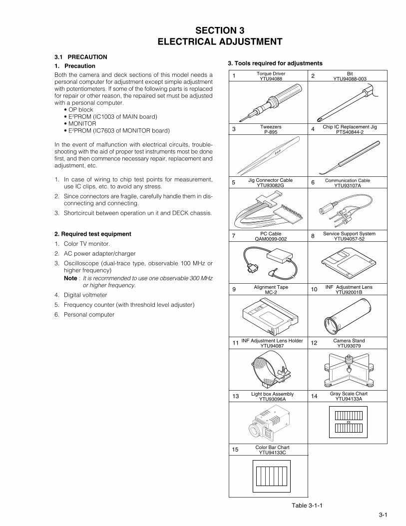
3. Tools required for adjustments
Torque DriverYTU940881 Bit
YTU94088-0032
Service Support SystemYTU94057-52
10 INF Adjustment LensYTU92001B
11 INF Adjustment Lens HolderYTU94087 12 Camera Stand
YTU93079
13 Light box AssemblyYTU93096A 14 Gray Scale Chart
YTU94133A
15 Color Bar ChartYTU94133C
Communication CableYTU93107A
7 PC CableQAM0099-002 8
Alignment TapeMC-29
3 Chip IC Replacement JigPTS40844-24Tweezers
P-895
Jig Connector CableYTU93082G5 6
3-2
1. Torque driverBe sure to use to fastening the mechanism and exte-rior parts because those parts must strictly be control-led for tightening torque.
2. BitThis bit is slightly longer than those set in conventionaltorque drivers.
3. TweezersTo be used for removing and installing parts and wires.
4. Chip IC replacement jigTo be used for adjustment of the camera system.
5. Jig connector cableConnected to CN105 of the main board and used forelectrical adjustment, etc.
6. Communication CableConnect the Communication cable between the PCcable and Jig connector cable when performing a PCadjustment.
7. PC cableTo be used to connect the VideoMovie and a personalcomputer with each other when a personal computeris used for adjustment.
8. Service support systemTo be used for adjustment with a personal computer.
3.2 SETUP1. Setup for electrical adjustment with personal computer.
NOTE: Remove one screw (1) first and the cover (JIG)next.
Fig. 3-2-1 Connection for Service support system
9. Alignment tapeTo be used for check and adjustment of interchange-ability of the mechanism.
10. INF adjustment lensTo be used for adjustment of the camera system.
11. INF adjustment lens holderTo be used together with the camera stand for operat-ing the VideoMovie in the stripped-downcondition such as the status without the exterior partsor for using commodities that are not yet conformableto the interchangeable ring.
12. Camera standTo be used together with the INF adjustment lensholder.
13. Light box assemblyTo be used for adjustment of the camera system.
14. Gray scale chart (for Light box assembly)To be used for adjustment of the camera system.
15. Color bar chart (for Light box assembly)To be used for adjustment of the camera system.
Service Support System
RS232CCOM Port
PC CABLE
Personal Computer
MENU
REDto 8 pin ( JLIP_RX )
WHITE
BLACK
to 17 pin ( JLIP_TX )
to 7 pin ( GND )
COMMUNICATION CABLE JIG CONNECTOR
1Cover(JIG)
COMMUNICATION CABLE
CN105
Jig connector cable