VIDEO CASSETTE RECORDER - sils.unc.edu
68
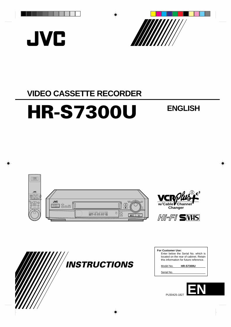
HR-S7300U VIDEO CASSETTE RECORDER INSTRUCTIONS PU30425-1827 For Customer Use: Enter below the Serial No. which is located on the rear of cabinet. Retain this information for future reference. Model No. HR-S7300U Serial No. w Channel Changer Cable REW FF JOG SHUTTLE POWER MENU CH/SET A.DUB 00 0 0 0 0 0 0 0 0 0 0 0 0 0000000 00 0 0 0 0 0 0 0 0 0 0 0 0 0 000000 PAUSE REC STOP/EJECT PLAY INSERT SELECT + – H M S ITR TIMER VIDEO M SP EP REC SAP PAUSE ST AM PM PLAY S-VHS DYNAMIC CONTRAST POWER TV/ VIDEO VOL. CH TV VCR CABLE TIMER SEARCH SKIP SEARCH BACK LIGHT PLAY STOP DISPLAY JOG/SHUTTLE MBR ILLUMINATED MULTI BRAND REMOTE REMOTE CONTROL UNIT EN ENGLISH
Transcript of VIDEO CASSETTE RECORDER - sils.unc.edu
HR-S7300UVIDEO CASSETTE RECORDER
INSTRUCTIONS
PU30425-1827
For Customer Use: Enter below the Serial No. which is located on the rear of cabinet. Retain this information for future reference. Model No. HR-S7300U Serial No.
w ChannelChanger
CableREW FF
JOG
SHUTTLE
POWER MENU CH/SET
A.DUB
0000
0000
0000
0000
0000
0
0000
00000000000000000
PAUSE
REC
STOP/EJECT PLAY
INSERT
SELECT
+
–
H M S
I T R TIMER
VIDEO
MSPEP
R E C
SAPPAUSE
STAMPM
PLAY
L
dB –20 15 10 8 46 2 0 2 4 6 +8
R
dB –20 15 10 8 46 2 0 2 4 6 +8
S-VHS
DYNAMIC CONTRAST
POWER
TV/ VIDEO
VOL. CH
TV
VCR
CA
BLE
TIMER SEARCH SKIP SEARCH
BACK LIGHT
PLAY
STOP
DISPLAYJOG/SHUTTLE
MBR
ILLUMINATED MULTI BRAND REMOTE
REMOTE CONTROL UNIT
EN
ENGLISH
2Dear Customer,Thank you for purchasing the JVC VHS video cassette recorder. Before use, please read the safety information and precautionscontained in the following pages to ensure safe use of your new VCR.
CAUTIONS
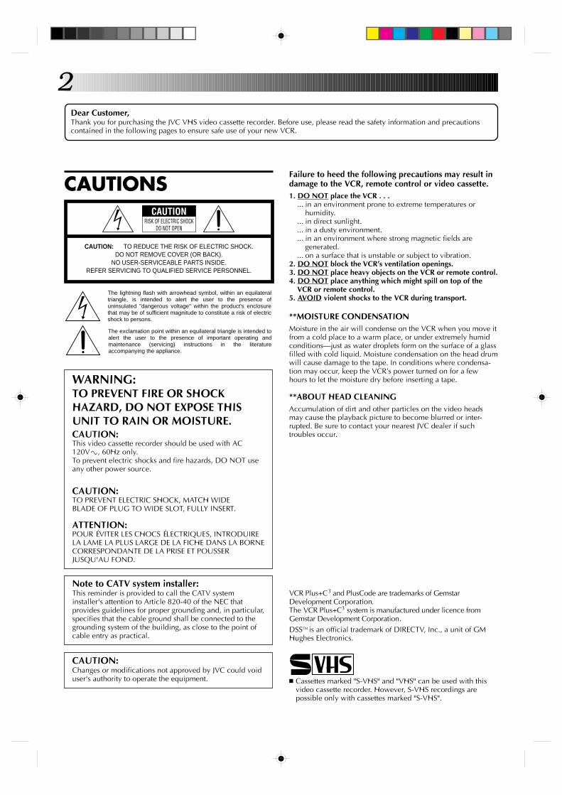
WARNING:TO PREVENT FIRE OR SHOCKHAZARD, DO NOT EXPOSE THISUNIT TO RAIN OR MOISTURE.CAUTION:This video cassette recorder should be used with AC120V`, 60Hz only.To prevent electric shocks and fire hazards, DO NOT useany other power source.
CAUTION:TO PREVENT ELECTRIC SHOCK, MATCH WIDEBLADE OF PLUG TO WIDE SLOT, FULLY INSERT.
ATTENTION:POUR ÉVITER LES CHOCS ÉLECTRIQUES, INTRODUIRELA LAME LA PLUS LARGE DE LA FICHE DANS LA BORNECORRESPONDANTE DE LA PRISE ET POUSSERJUSQU'AU FOND.
CAUTION RISK OF ELECTRIC SHOCK
DO NOT OPEN
CAUTION: TO REDUCE THE RISK OF ELECTRIC SHOCK. DO NOT REMOVE COVER (OR BACK).
NO USER-SERVICEABLE PARTS INSIDE. REFER SERVICING TO QUALIFIED SERVICE PERSONNEL.
The lightning flash with arrowhead symbol, within an equilateral triangle, is intended to alert the user to the presence of uninsulated "dangerous voltage" within the product's enclosure that may be of sufficient magnitude to constitute a risk of electric shock to persons.
The exclamation point within an equilateral triangle is intended to alert the user to the presence of important operating and maintenance (servicing) instructions in the literature accompanying the appliance.
Failure to heed the following precautions may result indamage to the VCR, remote control or video cassette.1. DO NOT place the VCR . . .
... in an environment prone to extreme temperatures orhumidity.
... in direct sunlight.
... in a dusty environment.
... in an environment where strong magnetic fields aregenerated.
... on a surface that is unstable or subject to vibration.2. DO NOT block the VCR’s ventilation openings.3. DO NOT place heavy objects on the VCR or remote control.4. DO NOT place anything which might spill on top of the
VCR or remote control.5. AVOID violent shocks to the VCR during transport.
**MOISTURE CONDENSATIONMoisture in the air will condense on the VCR when you move itfrom a cold place to a warm place, or under extremely humidconditions—just as water droplets form on the surface of a glassfilled with cold liquid. Moisture condensation on the head drumwill cause damage to the tape. In conditions where condensa-tion may occur, keep the VCR’s power turned on for a fewhours to let the moisture dry before inserting a tape.
**ABOUT HEAD CLEANINGAccumulation of dirt and other particles on the video headsmay cause the playback picture to become blurred or inter-rupted. Be sure to contact your nearest JVC dealer if suchtroubles occur.
Note to CATV system installer:This reminder is provided to call the CATV systeminstaller's attention to Article 820-40 of the NEC thatprovides guidelines for proper grounding and, in particular,specifies that the cable ground shall be connected to thegrounding system of the building, as close to the point ofcable entry as practical.
n Cassettes marked "S-VHS" and "VHS" can be used with thisvideo cassette recorder. However, S-VHS recordings arepossible only with cassettes marked "S-VHS".
CAUTION:Changes or modifications not approved by JVC could voiduser's authority to operate the equipment.
VCR Plus+C3 and PlusCode are trademarks of GemstarDevelopment Corporation.The VCR Plus+C3 system is manufactured under licence fromGemstar Development Corporation.DSSTM is an official trademark of DIRECTV, Inc., a unit of GMHughes Electronics.
3IMPORTANT PRODUCTSAFETY INSTRUCTIONSElectrical energy can perform many useful functions. Butimproper use can result in potential electrical shock or firehazards. This product has been engineered and manufacturedto assure your personal safety. In order not to defeat the built-insafeguards, observe the following basic rules for its installation,use and servicing.
ATTENTION:Follow and obey all warnings and instructions marked on yourproduct and its operating instructions. For your safety, pleaseread all the safety and operating instructions before you operatethis product and keep this booklet for future reference.
INSTALLATION1. Grounding or Polarization(A) Your product may be equipped with a polarized alternating-
current line plug (a plug having one blade wider than theother). This plug will fit into the power outlet only one way.This is a safety feature.If you are unable to insert the plug fully into the outlet, tryreversing the plug. If the plug should still fail to fit, contactyour electrician to replace your obsolete outlet. Do notdefeat the safety purpose of the polarized plug.
(B) Your product may be equipped with a 3-wire grounding-typeplug, a plug having a third (grounding) pin. This plug willonly fit into a grounding-type power outlet. This is a safetyfeature.If you are unable to insert the plug into the outlet, contactyour electrician to replace your obsolete outlet. Do notdefeat the safety purpose of the grounding-type plug.
2. Power SourcesOperate your product only from the type of power sourceindicated on the marking label. If you are not sure of the type ofpower supply to your home, consult your product dealer orlocal power company. If your product is intended to operatefrom battery power, or other sources, refer to the operatinginstructions.
3. OverloadingDo not overload wall outlets, extension cords, or integralconvenience receptacles as this can result in a risk of fire orelectric shock.
4. Power Cord ProtectionPower supply cords should be routed so that they are not likelyto be walked on or pinched by items placed upon or againstthem, paying particular attention to cords at plugs, conveniencereceptacles, and the point where they exit from the product.
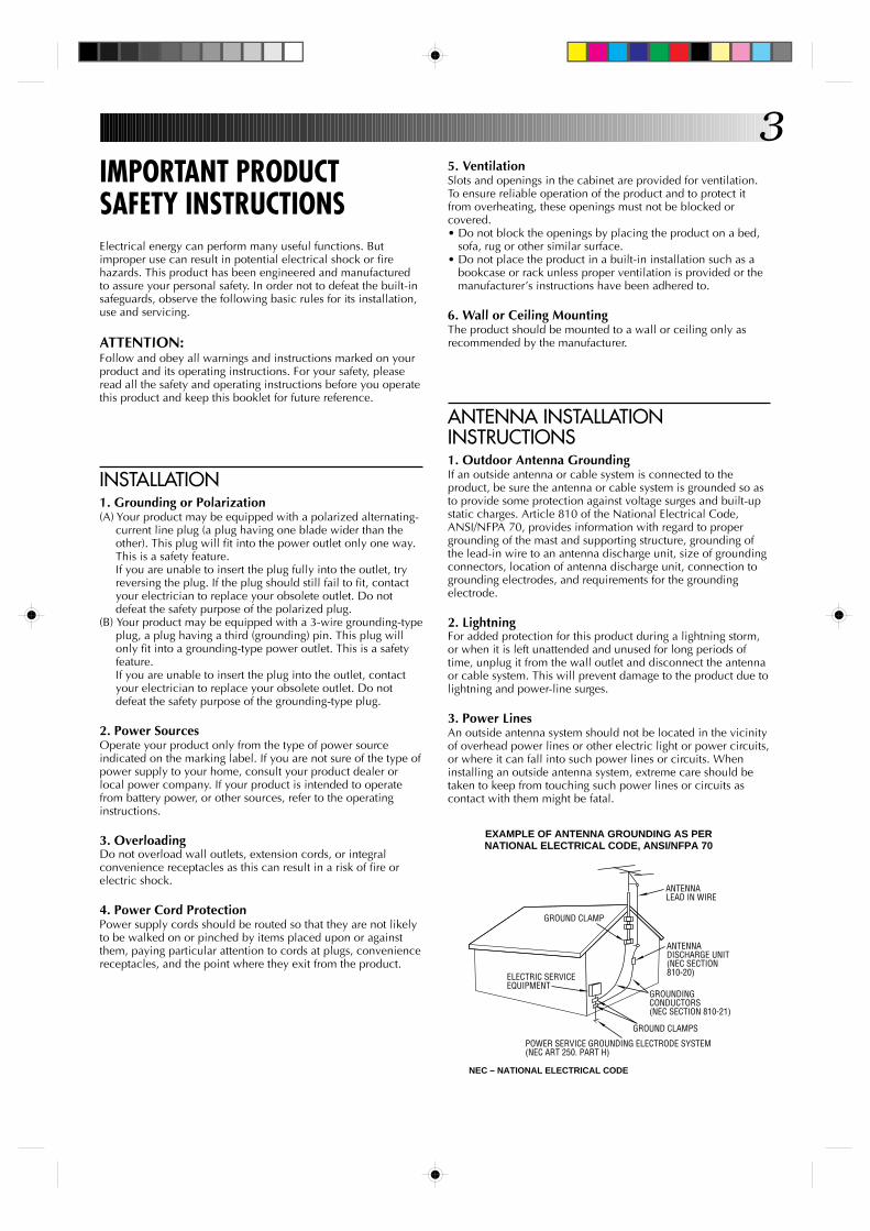
5. VentilationSlots and openings in the cabinet are provided for ventilation.To ensure reliable operation of the product and to protect itfrom overheating, these openings must not be blocked orcovered.• Do not block the openings by placing the product on a bed,
sofa, rug or other similar surface.• Do not place the product in a built-in installation such as a
bookcase or rack unless proper ventilation is provided or themanufacturer’s instructions have been adhered to.
6. Wall or Ceiling MountingThe product should be mounted to a wall or ceiling only asrecommended by the manufacturer.
ANTENNA LEAD IN WIRE
ANTENNA DISCHARGE UNIT (NEC SECTION 810-20)
GROUNDING CONDUCTORS (NEC SECTION 810-21)
GROUND CLAMPS
POWER SERVICE GROUNDING ELECTRODE SYSTEM (NEC ART 250. PART H)
NEC – NATIONAL ELECTRICAL CODE
ELECTRIC SERVICE EQUIPMENT
EXAMPLE OF ANTENNA GROUNDING AS PER NATIONAL ELECTRICAL CODE, ANSI/NFPA 70
GROUND CLAMP
ANTENNA INSTALLATIONINSTRUCTIONS1. Outdoor Antenna GroundingIf an outside antenna or cable system is connected to theproduct, be sure the antenna or cable system is grounded so asto provide some protection against voltage surges and built-upstatic charges. Article 810 of the National Electrical Code,ANSI/NFPA 70, provides information with regard to propergrounding of the mast and supporting structure, grounding ofthe lead-in wire to an antenna discharge unit, size of groundingconnectors, location of antenna discharge unit, connection togrounding electrodes, and requirements for the groundingelectrode.
2. LightningFor added protection for this product during a lightning storm,or when it is left unattended and unused for long periods oftime, unplug it from the wall outlet and disconnect the antennaor cable system. This will prevent damage to the product due tolightning and power-line surges.
3. Power LinesAn outside antenna system should not be located in the vicinityof overhead power lines or other electric light or power circuits,or where it can fall into such power lines or circuits. Wheninstalling an outside antenna system, extreme care should betaken to keep from touching such power lines or circuits ascontact with them might be fatal.
4SERVICING1. ServicingIf your product is not operating correctly or exhibits a markedchange in performance and you are unable to restore normaloperation by following the detailed procedure in its operatinginstructions, do not attempt to service it yourself as opening orremoving covers may expose you to dangerous voltage or otherhazards. Refer all servicing to qualified service personnel.
2. Damage Requiring ServiceUnplug this product from the wall outlet and refer servicing toqualified service personnel under the following conditions:a.When the power supply cord or plug is damaged.b.If liquid has been spilled, or objects have fallen into the
product.c. If the product has been exposed to rain or water.d.If the product does not operate normally by following the
operating instructions. Adjust only those controls that arecovered by the operating instructions as an improperadjustment of other controls may result in damage and willoften require extensive work by a qualified technician torestore the product to its normal operation.
e. If the product has been dropped or damaged in any way.f. When the product exhibits a distinct change in
performance—this indicates a need for service.
3. Replacement PartsWhen replacement parts are required, be sure the servicetechnician has used replacement parts specified by themanufacturer or have the same characteristics as the originalpart. Unauthorized substitutions may result in fire, electricshock or other hazards.
4. Safety CheckUpon completion of any service or repairs to this product, askthe service technician to perform safety checks to determinethat the product is in safe operating condition.
HOW TO USE THIS INSTRUCTIONMANUAL● All major sections and subsections are listed in the Table Of
Contents on page 5. Use this when searching for informationon a specific procedure or feature.
● The Index on pages 63–65 lists frequently-used terms, andthe number of the first page on which they are used orexplained in the manual. This section also illustrates thecontrols and connections on the front and rear panel, thefront display panel and the remote control.
● The Z mark signals a reference to another page forinstructions or related information.
● Operation buttons necessary for the various procedures areclearly indicated through the use of illustrations at thebeginning of each major section.
BEFORE YOU INSTALL YOUR NEWVCR . . .. . . please read the sections/literature listed below.● ”Cautions” on page 2● ”Important Products Safety Instructions” on the previous pages
USE1. AccessoriesTo avoid personal injury:• Do not place this product on an unstable cart, stand, tripod,
bracket, or table. It may fall, causing serious injury to a childor adult, and serious damage to the product.
• Use only with a cart, stand, tripod, bracket, or tablerecommended by the manufacturer or sold with the product.
• Use a mounting accessory recommended by themanufacturer and follow the manufacturer’s instructions forany mounting of the product.
• Do not try to roll a cart with small casters across thresholds ordeep-pile carpets.
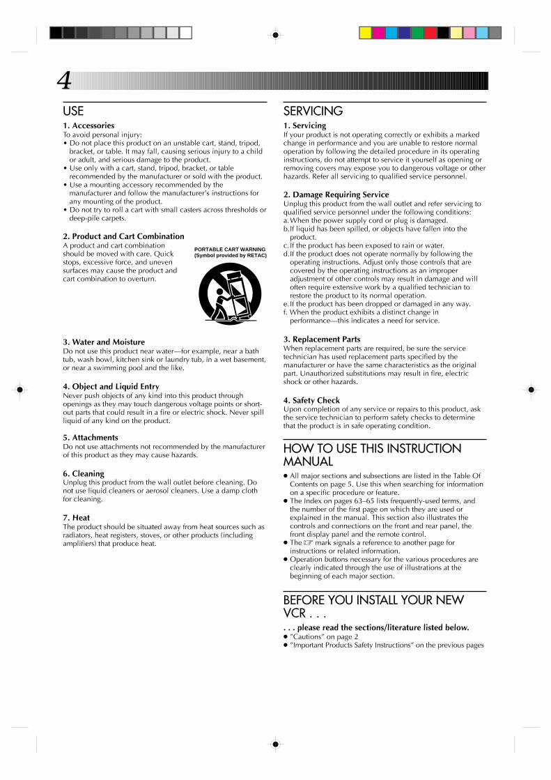
2. Product and Cart CombinationA product and cart combinationshould be moved with care. Quickstops, excessive force, and unevensurfaces may cause the product andcart combination to overturn.
3. Water and MoistureDo not use this product near water—for example, near a bathtub, wash bowl, kitchen sink or laundry tub, in a wet basement,or near a swimming pool and the like.
4. Object and Liquid EntryNever push objects of any kind into this product throughopenings as they may touch dangerous voltage points or short-out parts that could result in a fire or electric shock. Never spillliquid of any kind on the product.
5. AttachmentsDo not use attachments not recommended by the manufacturerof this product as they may cause hazards.
6. CleaningUnplug this product from the wall outlet before cleaning. Donot use liquid cleaners or aerosol cleaners. Use a damp clothfor cleaning.
7. HeatThe product should be situated away from heat sources such asradiators, heat registers, stoves, or other products (includingamplifiers) that produce heat.
PORTABLE CART WARNING (Symbol provided by RETAC)
5CONTENTS
TIMER RECORDING 39Instant Timer Recording (ITR) ............... 39VCR Plus+ Timer Programming ............ 40On-Screen Timer Programming ........... 42
Check And Cancel Programs .......................... 44Auto Timer ......................................................45
EDITING 46Edit From A Camcorder ....................... 46Edit To Or From Another VCR ............... 48Assemble Editing .................................49Insert Editing .......................................50Random Assemble Editing ................... 52Audio Dubbing ....................................54
SPECIAL FEATURES 55TV Multi-Brand Remote Control ..................... 55Cable Box Multi-Brand Remote Control .......... 56DSS Receiver Multi-Brand Remote Control ..... 57Control Two JVC VCRs ................................... 57
TROUBLESHOOTING 58Power .................................................58Tape Transport .....................................58Playback ............................................. 58Recording ............................................ 59Timer Recording ...................................59Other Problems....................................60
QUESTIONS AND ANSWERS 61Playback ............................................. 61Recording ............................................ 61Timer Recording ...................................61
S PECIFICATIONS 62
INDEX 63List Of Terms ........................................63Front View...........................................64Rear View ...........................................64Front Display Panel ..............................65Remote Control ....................................65
FOR SERVICING 66
WARRANTY 67
INSTALLING YOUR NEW VCR 6Connections ...........................................6
Basic Connections ............................................ 6S-VIDEO Connection ....................................... 7
INITIAL SETTINGS 8Clock .....................................................8
Advanced Auto Clock Set ................................. 8Clock Setting .....................................................9Preparation .......................................................9Semi-Auto .......................................................10Manual ........................................................... 11Auto ................................................................ 11
Language ............................................ 12Tuner ................................................... 13
Set Receivable Channels ................................ 13Add Or Delete A Channel .............................. 15
Cable Box Control ................................16Situate And Connect Controller ...................... 16Set Cable Box Output Channel ....................... 17Set Cable Box Brand....................................... 18
VCR Plus+ Setup ..................................20
SIMPLE PLAYBACK ANDRECORDING 23
Simple Playback ..................................23Simple Recording .................................24
PLAYBACK AND RECORDINGFEATURES 25
Playback .............................................25Still Picture/Frame-By-Frame Playback ........... 25Slow Motion/Reverse Slow Motion ................. 25Variable-Speed Search/Reverse MotionPlayback .........................................................26High-Speed Search ......................................... 26Manual Tracking............................................. 27Skip Search .....................................................27Repeat Playback ............................................. 27Dynamic Contrast .......................................... 28Video Stabilizer ...............................................28Select The Soundtrack .................................... 29Superimpose ...................................................30Index Search ...................................................31Manual Index Mark/Erase ............................... 31Instant ReView ................................................32Counter Reset ..................................................32Counter Memory ............................................ 32Next-Function Memory .................................. 33AV COMPU LINK Playback ............................ 33
Recording ............................................35Record One Program WhileWatching Another .......................................... 35Display Elapsed Recording Time ..................... 35S-VHS (Super VHS) and VHS .......................... 35Stereo And SAP (Second Audio Program) ........ 36To Record SAP Programs ................................ 36Hi-Fi Audio Recording Level Control .............. 37Display Tape Remaining Time ........................ 38
6 INSTALLING YOUR NEW VCR
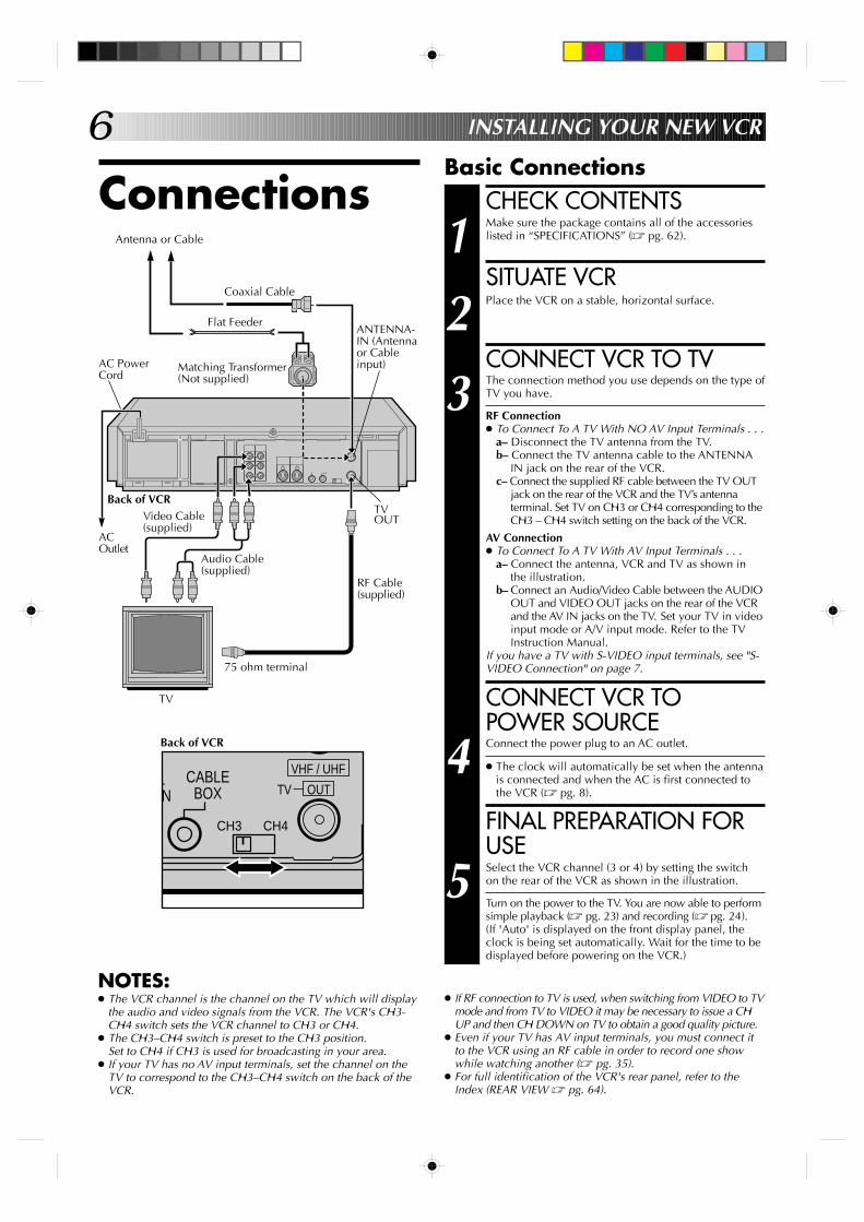
ConnectionsAntenna or Cable
Flat Feeder
Matching Transformer(Not supplied)
Basic ConnectionsCHECK CONTENTS
1 Make sure the package contains all of the accessorieslisted in “SPECIFICATIONS” (Z pg. 62).
SITUATE VCR
2 Place the VCR on a stable, horizontal surface.
CONNECT VCR TO TV
3 The connection method you use depends on the type ofTV you have.
RF Connection● To Connect To A TV With NO AV Input Terminals . . .
a– Disconnect the TV antenna from the TV.b– Connect the TV antenna cable to the ANTENNA
IN jack on the rear of the VCR.c– Connect the supplied RF cable between the TV OUT
jack on the rear of the VCR and the TV’s antennaterminal. Set TV on CH3 or CH4 corresponding to theCH3 – CH4 switch setting on the back of the VCR.
AV Connection● To Connect To A TV With AV Input Terminals . . .
a– Connect the antenna, VCR and TV as shown inthe illustration.
b– Connect an Audio/Video Cable between the AUDIOOUT and VIDEO OUT jacks on the rear of the VCRand the AV IN jacks on the TV. Set your TV in videoinput mode or A/V input mode. Refer to the TVInstruction Manual.
If you have a TV with S-VIDEO input terminals, see "S-VIDEO Connection" on page 7.
CONNECT VCR TOPOWER SOURCE
4 Connect the power plug to an AC outlet.
● The clock will automatically be set when the antennais connected and when the AC is first connected tothe VCR (Z pg. 8).
FINAL PREPARATION FORUSE
5 Select the VCR channel (3 or 4) by setting the switchon the rear of the VCR as shown in the illustration.
Turn on the power to the TV. You are now able to performsimple playback (Z pg. 23) and recording (Z pg. 24).(If 'Auto' is displayed on the front display panel, theclock is being set automatically. Wait for the time to bedisplayed before powering on the VCR.)
Coaxial Cable
AC PowerCord
Back of VCR
ACOutlet
Video Cable(supplied)
Audio Cable(supplied)
TVOUT
ANTENNA-IN (Antennaor Cableinput)
RF Cable(supplied)
75 ohm terminal
TV
Back of VCR
CH3
/ L
ONCABLE
BOX
CH4
VHF / UHF
OUTTV
NOTES:● The VCR channel is the channel on the TV which will display
the audio and video signals from the VCR. The VCR's CH3-CH4 switch sets the VCR channel to CH3 or CH4.
● The CH3–CH4 switch is preset to the CH3 position.Set to CH4 if CH3 is used for broadcasting in your area.
● If your TV has no AV input terminals, set the channel on theTV to correspond to the CH3–CH4 switch on the back of theVCR.
● If RF connection to TV is used, when switching from VIDEO to TVmode and from TV to VIDEO it may be necessary to issue a CHUP and then CH DOWN on TV to obtain a good quality picture.
● Even if your TV has AV input terminals, you must connect itto the VCR using an RF cable in order to record one showwhile watching another (Z pg. 35).
● For full identification of the VCR's rear panel, refer to theIndex (REAR VIEW Z pg. 64).
7
TV OUT
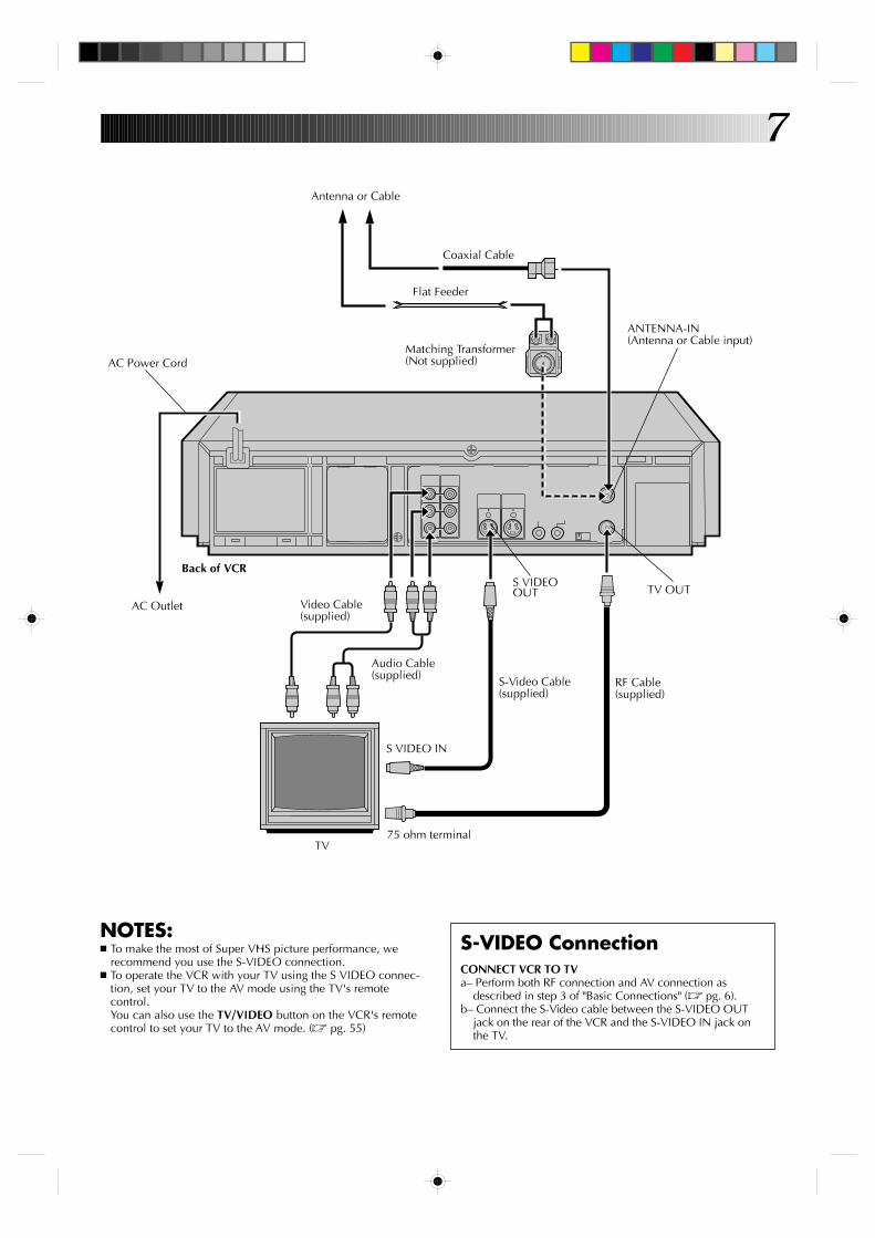
NOTES:n To make the most of Super VHS picture performance, we
recommend you use the S-VIDEO connection.n To operate the VCR with your TV using the S VIDEO connec-
tion, set your TV to the AV mode using the TV's remotecontrol.You can also use the TV/VIDEO button on the VCR's remotecontrol to set your TV to the AV mode. (Z pg. 55)
S-VIDEO ConnectionCONNECT VCR TO TVa– Perform both RF connection and AV connection as
described in step 3 of "Basic Connections" (Z pg. 6).b– Connect the S-Video cable between the S-VIDEO OUT
jack on the rear of the VCR and the S-VIDEO IN jack onthe TV.
Coaxial Cable
Flat Feeder
Antenna or Cable
Matching Transformer(Not supplied)
Back of VCR
AC Outlet Video Cable(supplied)
Audio Cable(supplied) S-Video Cable
(supplied)
S VIDEO IN
75 ohm terminalTV
S VIDEOOUT
ANTENNA-IN(Antenna or Cable input)
AC Power Cord
RF Cable(supplied)
8 INITIAL SETTINGS
Clock
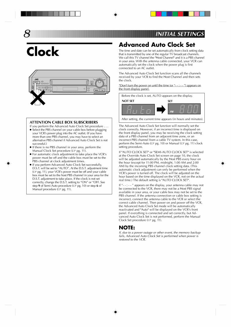
ATTENTION CABLE BOX SUBSCRIBERSIf you perform the Advanced Auto Clock Set procedure . . .● Select the PBS channel on your cable box before plugging
your VCR’s power plug into the AC outlet. (If you havemore than one PBS channel, you may have to select analternative PBS channel if Advanced Auto Clock Set is notsuccessful.)
● If there is no PBS channel in your area, perform theManual Clock Set procedure (Z pg. 11).
● For automatic clock adjustment to take place the VCR'spower must be off and the cable box must be set to thePBS channel at clock adjustment times.
● If you perform Advanced Auto Clock Set successfully,D.S.T. will be set to “AUTO”. At the D.S.T. adjustment time(Z pg. 11), your VCR's power must be off and your cablebox must be set to the host PBS channel in your area for theD.S.T. adjustment to take place. If the clock is not setcorrectly, change the D.S.T. setting to “ON” or “OFF. Seestep 9 of Semi-Auto procedure (Z pg. 10) or step 6 ofManual procedure (Z pg. 11).
Advanced Auto Clock SetThe time and date can be set automatically from clock setting datathat is transmitted by one of the regular TV broadcast channels.We call this TV channel the "Host Channel" and it is a PBS channelin your area. With the antenna cable connected, your VCR canautomatically set the clock when the power plug is firstconnected to an AC outlet.
The Advanced Auto Clock Set function scans all the channelsreceived by your VCR to find the Host Channel and then setsthe clock.
*Don’t turn the power on until the time (or “- - : - - ”) appears onthe front display panel.
Before the clock is set, AUTO appears on the display.
After setting, the current time appears (in hours and minutes).
The Advanced Auto Clock Set function will normally set theclock correctly. However, if an incorrect time is displayed onthe front display panel, you may be receiving the clock settingdata of a PBS channel from an adjacent time zone, or anincorrect PBS channel from a cable TV system. In this case,perform the Semi-Auto (Z pg. 10) or Manual (Z pg. 11) clocksetting procedure.
If "AUTO CLOCK SET" or "SEMI-AUTO CLOCK SET" is selectedat the Override Auto Clock Set screen on page 10, the clockwill be adjusted automatically by the Host PBS every hour onthe hour (except for 11:00 PM, midnight, 1:00 AM and 2:00AM) by the incoming PBS channel clock setting data. (Thisautomatic clock adjustment can only be performed when theVCR’s power is turned off. The clock will be adjusted on thehour based on the time displayed on the VCR, not on the actualreal time.) The default setting is "AUTO CLOCK SET".
If “- - : - - ” appears on the display, your antenna cable may notbe connected to the VCR, there may not be a Host PBS signalavailable in your area, or your cable box may not be set to thePBS channel. If the antenna connection or cable box setting isincorrect, connect the antenna cable to the VCR or select thecorrect cable channel. Then power on and power off the VCR,the Advanced Auto Clock Set mode will be automaticallyreactivated and "Auto" will be displayed on the VCR's frontpanel. If everything is connected and set correctly, but Ad-vanced Auto Clock Set is not performed, perform the ManualClock Set procedure (Z pg. 11).
NOTE:If, due to a power outage or other event, the memory backupfails, Advanced Auto Clock Set is performed when power isrestored to the VCR.
NOT SET
PM
SET
+
–
0000
0000
0000
0000
0000
0
0000
00000000000000000
9
9
3
6
8
2
5
7
1
4
0
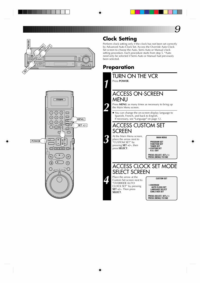
Clock SettingPerform clock setting only if the clock has not been set correctlyby Advanced Auto Clock Set. Access the Override Auto ClockSet screen to choose the Auto, Semi-Auto or Manual clocksetting procedure. Each procedure starts from step 5. *Autoneed only be selected if Semi-Auto or Manual had previouslybeen selected.
Preparation
TURN ON THE VCR
1 Press POWER.
ACCESS ON-SCREENMENU
2 Press MENU as many times as necessary to bring upthe Main Menu screen.
● You can change the on-screen display language toSpanish, French, and back to English.If necessary, see "Language" on page 12.
ACCESS CUSTOM SETSCREEN
3 At the Main Menu screen,place the arrow next to“CUSTOM SET” bypressing SET +/–, thenpress SELECT.
ACCESS CLOCK SET MODESELECT SCREEN
4 Place the arrow at theCustom Set screen next to“OVERRIDE AUTOCLOCK SET” by pressingSET +/–. Then pressSELECT.
MAIN MENU
PROGRAM SETFUNCTION SETTUNER SET
=CUSTOM SETR.A. EDIT
PRESS (SELECT, SET+/–)PRESS (MENU) TO END
CUSTOM SET
=OVERRIDEAUTO CLOCK SET
LANGUAGE SELECTCABLE BOX SET
PRESS (SELECT, SET+/–)PRESS (MENU) TO END
+
–
0000
0000
0000
0000
0000
0
0000
00000000000000000
POW
ER
SELE
CT
MEN
U
POWER
MENU
SELE
CT
SET +
/–
SET +/–
10
9
3
6
8
2
5
7
1
4
0
+
–
0000
0000
0000
0000
0000
0
0000
00000000000000000
INITIAL SETTINGS (cont.)
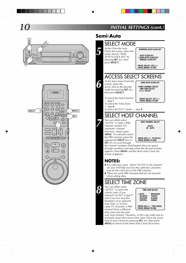
SELECT MODE
5 At the Override AutoClock Set screen, place thearrow next to “SEMI-AUTO CLOCK SET” bypressing SET +/–, thenpress SELECT.
ACCESS SELECT SCREENS
6 At the Semi-Auto Clock Setscreen, place thearrow next to the desiredmode by pressing SET +/–,then press SELECT.
To select the Host Channel— step 7To select the Time Zone— step 8To select the D.S.T. mode — step 9
SELECT HOST CHANNEL
7 You can either select“AUTO”, or enter a PBSchannel number. Forautomatic channelselection, simply pressMENU. To manually selectthe PBS channel, press theappropriate DIGIT key orSET +/– to cycle throughthe channel numbers (hold button down to speedthrough numbers) and stop when the desired numberappears. Press MENU and the Semi-Auto Clock Setscreen reappears.
NOTES:● For cable box users: Select "AUTO" or the channel
on your VCR that receives the cable box channels,and set the cable box to the PBS channel.
● There are some PBS channels that do not transmitclock setting data.
SELECT TIME ZONE
8 You can either select“AUTO”, or select thecorrect zone. If youselected "AUTO" in step 7and if you live near theboundary of an adjacenttime zone, or receivecable TV channels, a PBSchannel from a differenttime zone may becomeyour host channel. Therefore, in this case make sure tomanually select the correct time zone. Place the arrownext to your choice by pressing SET +/–, then pressMENU to return to the Semi-Auto Clock Set screen.
Semi-Auto
OVERRIDE AUTO CLOCK SET
AUTO CLOCK SET=SEMI-AUTO CLOCK SET
MANUAL CLOCK SET
PRESS (SELECT, SET+/–)PRESS (MENU) TO END
TIME ZONE SELECT
=AUTO MOUNTAINATLANTIC PACIFICEASTERN ALASKACENTRAL HAWAII
PRESS (SET+/–) FOR CHOICEPRESS (MENU) TO END
SEMI-AUTO CLOCK SET
=HOST CHANNEL SELECTTIME ZONE SELECTD.S.T. SELECT
PRESS (SELECT, SET+/–)PRESS (MENU) TO END
HOST CHANNEL SELECT
(CATV)CH AUTO
PRESS (SET+/–) TO SELECTPRESS (MENU) TO END
MEN
U
SELE
CT
DIGIT MENU
SELE
CT
SET
SET
11
9
3
6
8
2
5
7
1
4
0
+
–
0000
0000
0000
0000
0000
0
0000
00000000000000000
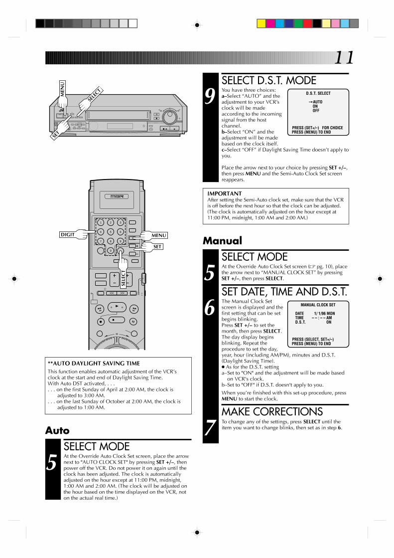
SELECT D.S.T. MODE
9 You have three choices:a–Select “AUTO” and theadjustment to your VCR’sclock will be madeaccording to the incomingsignal from the hostchannel.b–Select “ON” and theadjustment will be madebased on the clock itself.c–Select “OFF” if Daylight Saving Time doesn’t apply toyou.
Place the arrow next to your choice by pressing SET +/–,then press MENU and the Semi-Auto Clock Set screenreappears.
D.S.T. SELECT
=AUTOONOFF
PRESS (SET+/–) FOR CHOICEPRESS (MENU) TO END
IMPORTANTAfter setting the Semi-Auto clock set, make sure that the VCRis off before the next hour so that the clock can be adjusted.(The clock is automatically adjusted on the hour except at11:00 PM, midnight, 1:00 AM and 2:00 AM.)
SELECT MODE
5 At the Override Auto Clock Set screen (Z pg. 10), placethe arrow next to “MANUAL CLOCK SET” by pressingSET +/–, then press SELECT.
SET DATE, TIME AND D.S.T.
6 The Manual Clock Setscreen is displayed and thefirst setting that can be setbegins blinking.Press SET +/– to set themonth, then press SELECT.The day display beginsblinking. Repeat theprocedure to set the day,year, hour (including AM/PM), minutes and D.S.T.(Daylight Saving Time).● As for the D.S.T. settinga–Set to "ON" and the adjustment will be made based
on VCR's clock.b–Set to "OFF" if D.S.T. doesn't apply to you.
When you’re finished with this set-up procedure, pressMENU to start the clock.
MAKE CORRECTIONS
7 To change any of the settings, press SELECT until theitem you want to change blinks, then set as in step 6.
MANUAL CLOCK SET
DATE 1/ 1/96 MON TIME – – : – – AM D.S.T. ON
PRESS (SELECT, SET+/–)PRESS (MENU) TO END
Manual
**AUTO DAYLIGHT SAVING TIMEThis function enables automatic adjustment of the VCR’sclock at the start and end of Daylight Saving Time.With Auto DST activated, . . .. . . on the first Sunday of April at 2:00 AM, the clock is
adjusted to 3:00 AM.. . . on the last Sunday of October at 2:00 AM, the clock is
adjusted to 1:00 AM.
SELECT MODE
5 At the Override Auto Clock Set screen, place the arrownext to "AUTO CLOCK SET" by pressing SET +/–, thenpower off the VCR. Do not power it on again until theclock has been adjusted. The clock is automaticallyadjusted on the hour except at 11:00 PM, midnight,1:00 AM and 2:00 AM. (The clock will be adjusted onthe hour based on the time displayed on the VCR, noton the actual real time.)
Auto
MEN
U
SELE
CT
DIGIT MENU
SELE
CT
SET
SET
12
9
3
6
8
2
5
7
1
4
0
+
–
0000
0000
0000
0000
0000
0
0000
00000000000000000
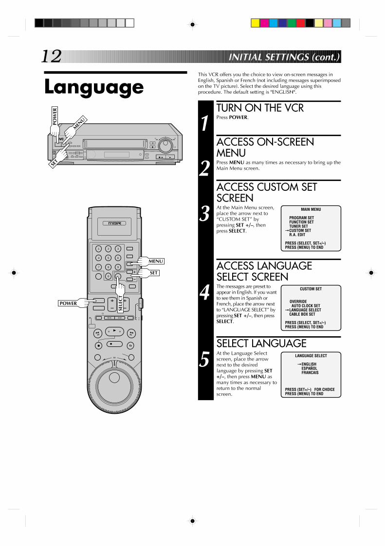
LanguageThis VCR offers you the choice to view on-screen messages inEnglish, Spanish or French (not including messages superimposedon the TV picture). Select the desired language using thisprocedure. The default setting is "ENGLISH".
TURN ON THE VCR
1 Press POWER.
ACCESS ON-SCREENMENU
2 Press MENU as many times as necessary to bring up theMain Menu screen.
ACCESS CUSTOM SETSCREEN
3 At the Main Menu screen,place the arrow next to“CUSTOM SET” bypressing SET +/–, thenpress SELECT.
ACCESS LANGUAGESELECT SCREEN
4 The messages are preset toappear in English. If you wantto see them in Spanish orFrench, place the arrow nextto “LANGUAGE SELECT” bypressing SET +/–, then pressSELECT.
SELECT LANGUAGE
5 At the Language Selectscreen, place the arrownext to the desiredlanguage by pressing SET+/–, then press MENU asmany times as necessary toreturn to the normalscreen.
MAIN MENU
PROGRAM SETFUNCTION SETTUNER SET
=CUSTOM SETR.A. EDIT
PRESS (SELECT, SET+/–)PRESS (MENU) TO END
CUSTOM SET
OVERRIDEAUTO CLOCK SET
=LANGUAGE SELECTCABLE BOX SET
PRESS (SELECT, SET+/–)PRESS (MENU) TO END
LANGUAGE SELECT
=ENGLISHESPAÑOLFRANCAIS
PRESS (SET+/–) FOR CHOICEPRESS (MENU) TO END
INITIAL SETTINGS (cont.)
POWER
MENU
SELE
CT
POW
ER
MEN
U
SET
SET
13
9
3
6
8
2
5
7
1
4
0
+
–
0000
0000
0000
0000
0000
0
0000
00000000000000000
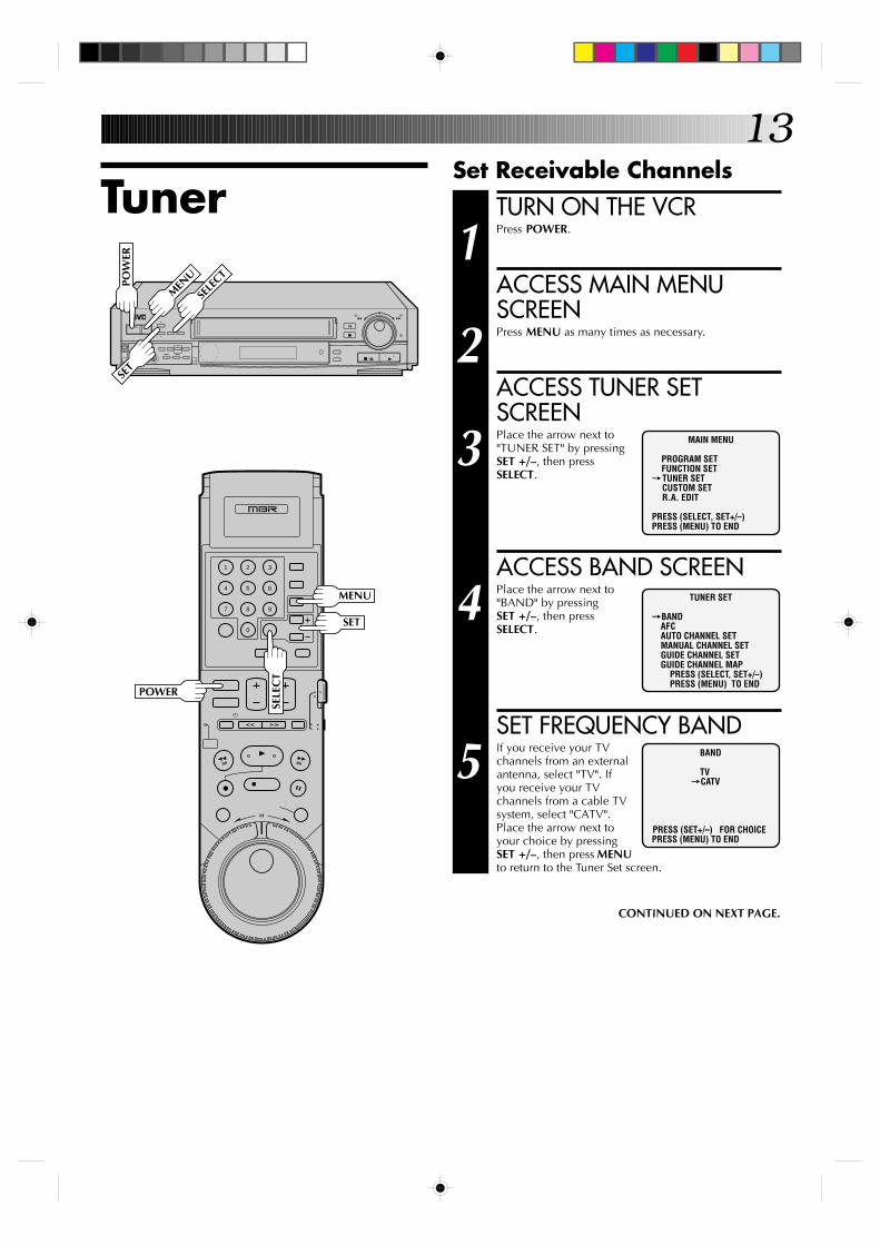
TunerSet Receivable Channels
TURN ON THE VCR
1 Press POWER.
ACCESS MAIN MENUSCREEN
2 Press MENU as many times as necessary.
ACCESS TUNER SETSCREEN
3 Place the arrow next to"TUNER SET" by pressingSET +/–, then pressSELECT.
ACCESS BAND SCREEN
4 Place the arrow next to"BAND" by pressingSET +/–, then pressSELECT.
SET FREQUENCY BAND
5 If you receive your TVchannels from an externalantenna, select "TV". Ifyou receive your TVchannels from a cable TVsystem, select "CATV".Place the arrow next toyour choice by pressingSET +/–, then press MENUto return to the Tuner Set screen.
MAIN MENU
PROGRAM SETFUNCTION SET
=TUNER SETCUSTOM SETR.A. EDIT
PRESS (SELECT, SET+/–)PRESS (MENU) TO END
BAND
TV=CATV
PRESS (SET+/–) FOR CHOICEPRESS (MENU) TO END
CONTINUED ON NEXT PAGE.
TUNER SET
=BANDAFCAUTO CHANNEL SETMANUAL CHANNEL SETGUIDE CHANNEL SETGUIDE CHANNEL MAP PRESS (SELECT, SET+/–) PRESS (MENU) TO END
POW
ER
MEN
U
SELE
CT
POWER
MENU
SELE
CT
SET
SET
14
9
3
6
8
2
5
7
1
4
0
+
–
0000
0000
0000
0000
0000
0
0000
00000000000000000
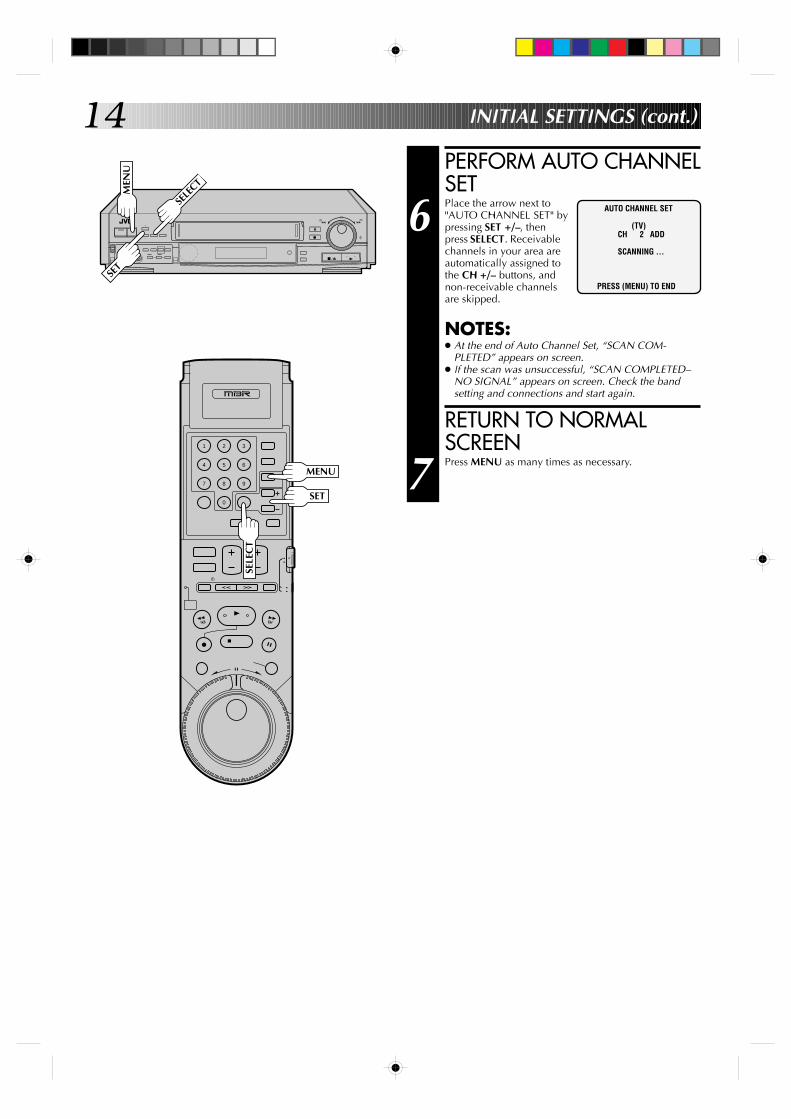
PERFORM AUTO CHANNELSET
6 Place the arrow next to"AUTO CHANNEL SET" bypressing SET +/–, thenpress SELECT. Receivablechannels in your area areautomatically assigned tothe CH +/– buttons, andnon-receivable channelsare skipped.
NOTES:● At the end of Auto Channel Set, “SCAN COM-
PLETED” appears on screen.● If the scan was unsuccessful, “SCAN COMPLETED–
NO SIGNAL” appears on screen. Check the bandsetting and connections and start again.
RETURN TO NORMALSCREEN
7 Press MENU as many times as necessary.
AUTO CHANNEL SET
(TV)CH 2 ADD
SCANNING ...
PRESS (MENU) TO END
INITIAL SETTINGS (cont.)M
ENU
SELE
CT
MENU
SELE
CT
SET
SET
15
9
3
6
8
2
5
7
1
4
0
+
–
0000
0000
0000
0000
0000
0
0000
00000000000000000
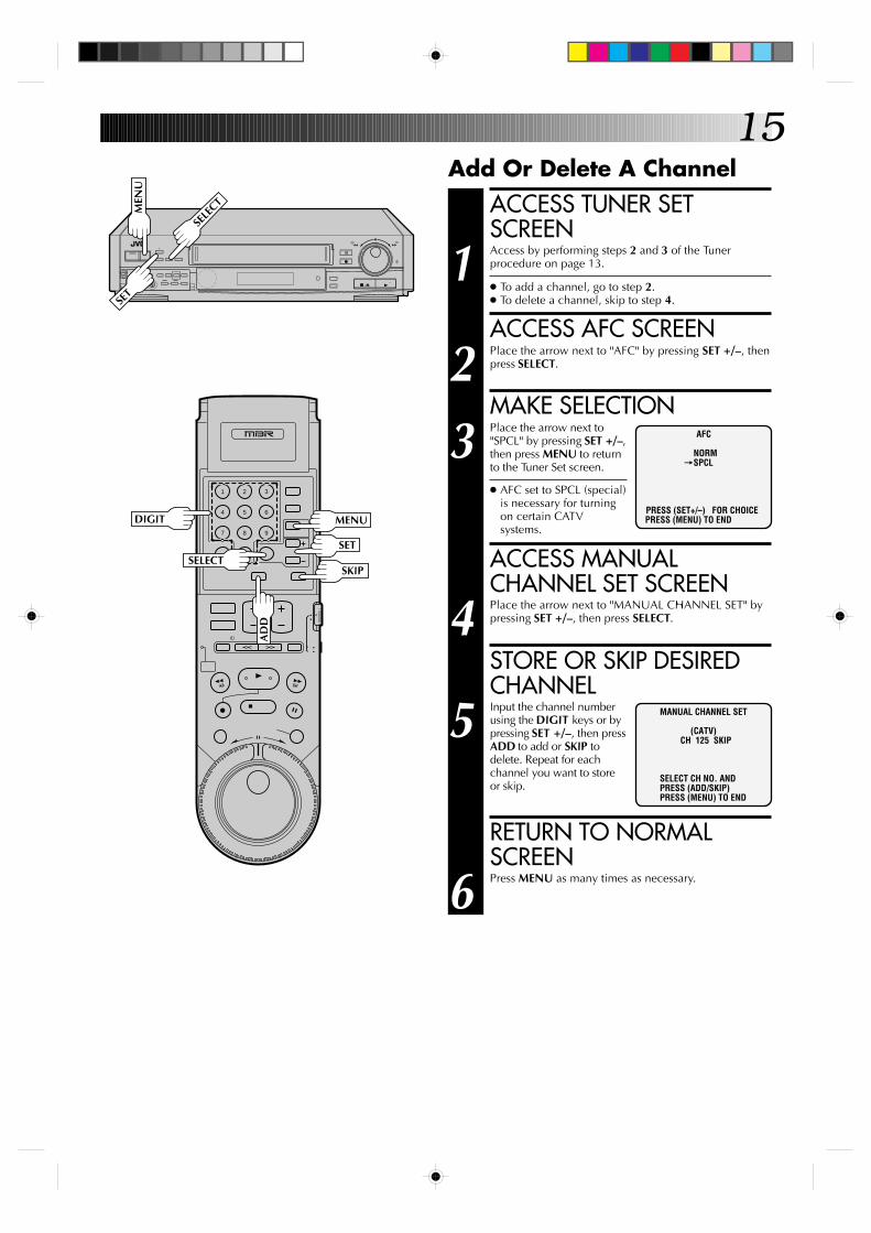
Add Or Delete A ChannelACCESS TUNER SETSCREEN
1 Access by performing steps 2 and 3 of the Tunerprocedure on page 13.
● To add a channel, go to step 2.● To delete a channel, skip to step 4.
ACCESS AFC SCREEN
2 Place the arrow next to "AFC" by pressing SET +/–, thenpress SELECT.
MAKE SELECTION
3 Place the arrow next to"SPCL" by pressing SET +/–,then press MENU to returnto the Tuner Set screen.
● AFC set to SPCL (special)is necessary for turningon certain CATVsystems.
ACCESS MANUALCHANNEL SET SCREEN
4 Place the arrow next to "MANUAL CHANNEL SET" bypressing SET +/–, then press SELECT.
STORE OR SKIP DESIREDCHANNEL
5 Input the channel numberusing the DIGIT keys or bypressing SET +/–, then pressADD to add or SKIP todelete. Repeat for eachchannel you want to storeor skip.
RETURN TO NORMALSCREEN
6 Press MENU as many times as necessary.
AFC
NORM=SPCL
PRESS (SET+/–) FOR CHOICEPRESS (MENU) TO END
MEN
U
SELE
CT
DIGIT MENU
AD
D
SELECTSET
SKIP
SET
MANUAL CHANNEL SET
(CATV)CH 125 SKIP
SELECT CH NO. ANDPRESS (ADD/SKIP)PRESS (MENU) TO END
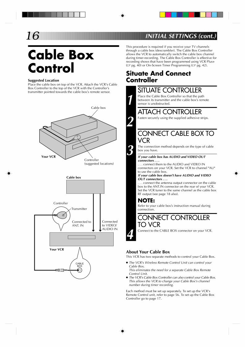
16This procedure is required if you receive your TV channelsthrough a cable box (descrambler). The Cable Box Controllerallows the VCR to automatically switch the cable box channelduring timer-recording. The Cable Box Controller is effective forrecording shows that have been programmed using VCR Plus+(Z pg. 40) or On-Screen Timer Programming (Z pg. 42).
Situate And ConnectController
Cable BoxControl
INITIAL SETTINGS (cont.)
SITUATE CONTROLLER
1 Place the Cable Box Controller so that the pathbetween its transmitter and the cable box’s remotesensor is unobstructed.
ATTACH CONTROLLER
2 Fasten securely using the supplied adhesive strips.
CONNECT CABLE BOX TOVCR
3 The connection method depends on the type of cablebox you have.
If your cable box has AUDIO and VIDEO OUTconnectors . . .. . . connect them to the AUDIO and VIDEO INconnectors on your VCR. Set the VCR to channel "AU"to use the cable box.If your cable box doesn’t have AUDIO and VIDEOOUT connectors . . .. . . connect the antenna output connector on the cablebox to the ANT.IN connector on the rear of your VCR.Set the VCR tuner to the same channel as the cable boxRF output (see page 18 also).
NOTE:Refer to your cable box’s instruction manual duringconnection.
CONNECT CONTROLLERTO VCR
4 Connect to the CABLE BOX connector on your VCR.
About Your Cable BoxThis VCR has two separate methods to control your Cable Box.
● The VCR's Wireless Remote Control Unit can control yourCable Box.This eliminates the need for a separate Cable Box RemoteControl Unit.
● The VCR's Cable Box Controller can also control your Cable Box.This allows the VCR to change your Cable Box's channelnumber during timer recording.
Each method must be set up separately. To set up the VCR'sRemote Control unit, refer to page 56. To set up the Cable BoxController go to page 17.
Suggested LocationPlace the cable box on top of the VCR. Attach the VCR's CableBox Controller to the top of the VCR with the Controller’stransmitter pointed towards the cable box’s remote sensor.
CABLE BOX
Cable box
Controller(suggested locations)
Cable box
Controller
Transmitter
Connected toANT. IN
Connectedto VIDEO/AUDIO IN
Your VCR
Your VCR
17
9
3
6
8
2
5
7
1
4
0
+
–
0000
0000
0000
0000
0000
0
0000
00000000000000000
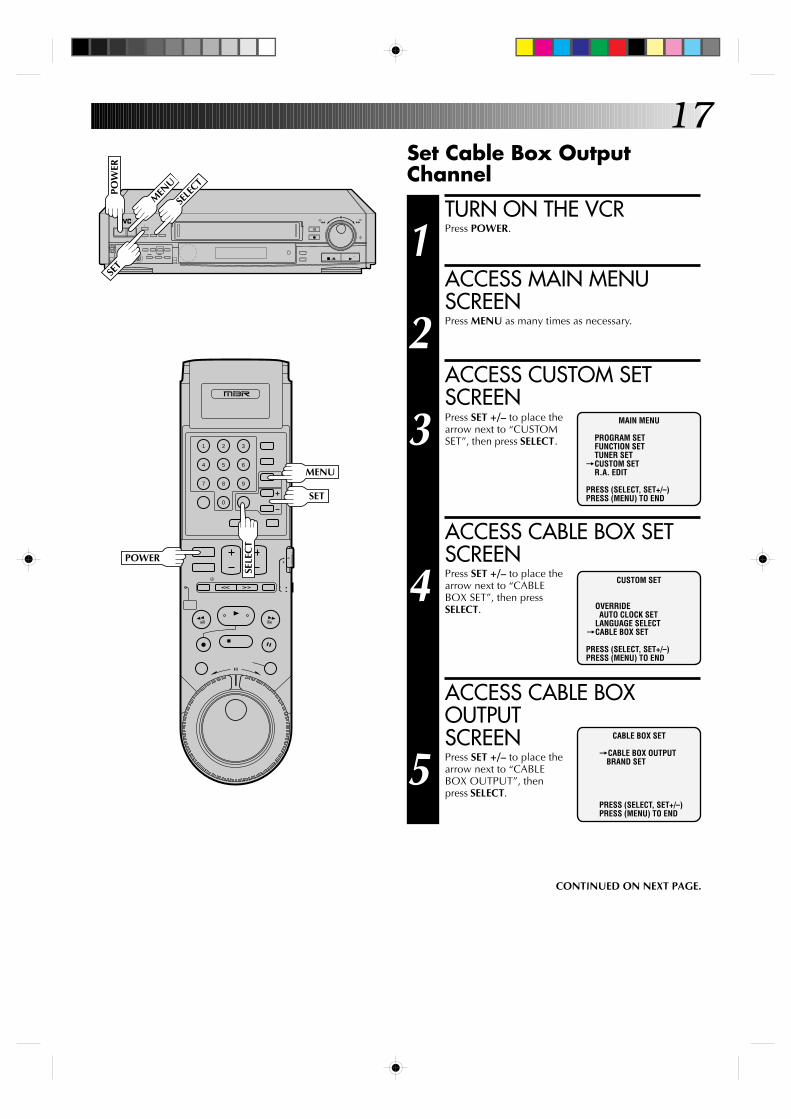
Set Cable Box OutputChannel
TURN ON THE VCR
1 Press POWER.
ACCESS MAIN MENUSCREEN
2 Press MENU as many times as necessary.
ACCESS CUSTOM SETSCREEN
3 Press SET +/– to place thearrow next to “CUSTOMSET”, then press SELECT.
ACCESS CABLE BOX SETSCREEN
4 Press SET +/– to place thearrow next to “CABLEBOX SET”, then pressSELECT.
ACCESS CABLE BOXOUTPUTSCREEN
5 Press SET +/– to place thearrow next to “CABLEBOX OUTPUT”, thenpress SELECT.
CUSTOM SET
OVERRIDEAUTO CLOCK SET
LANGUAGE SELECT=CABLE BOX SET
PRESS (SELECT, SET+/–)PRESS (MENU) TO END
CABLE BOX SET
=CABLE BOX OUTPUTBRAND SET
PRESS (SELECT, SET+/–)PRESS (MENU) TO END
MAIN MENU
PROGRAM SETFUNCTION SETTUNER SET
=CUSTOM SETR.A. EDIT
PRESS (SELECT, SET+/–)PRESS (MENU) TO END
CONTINUED ON NEXT PAGE.
SELE
CT
MEN
U
POW
ER
POWER
SELE
CT
MENU
SET
SET
18
9
3
6
8
2
5
7
1
4
0
+
–
0000
0000
0000
0000
0000
0
0000
00000000000000000
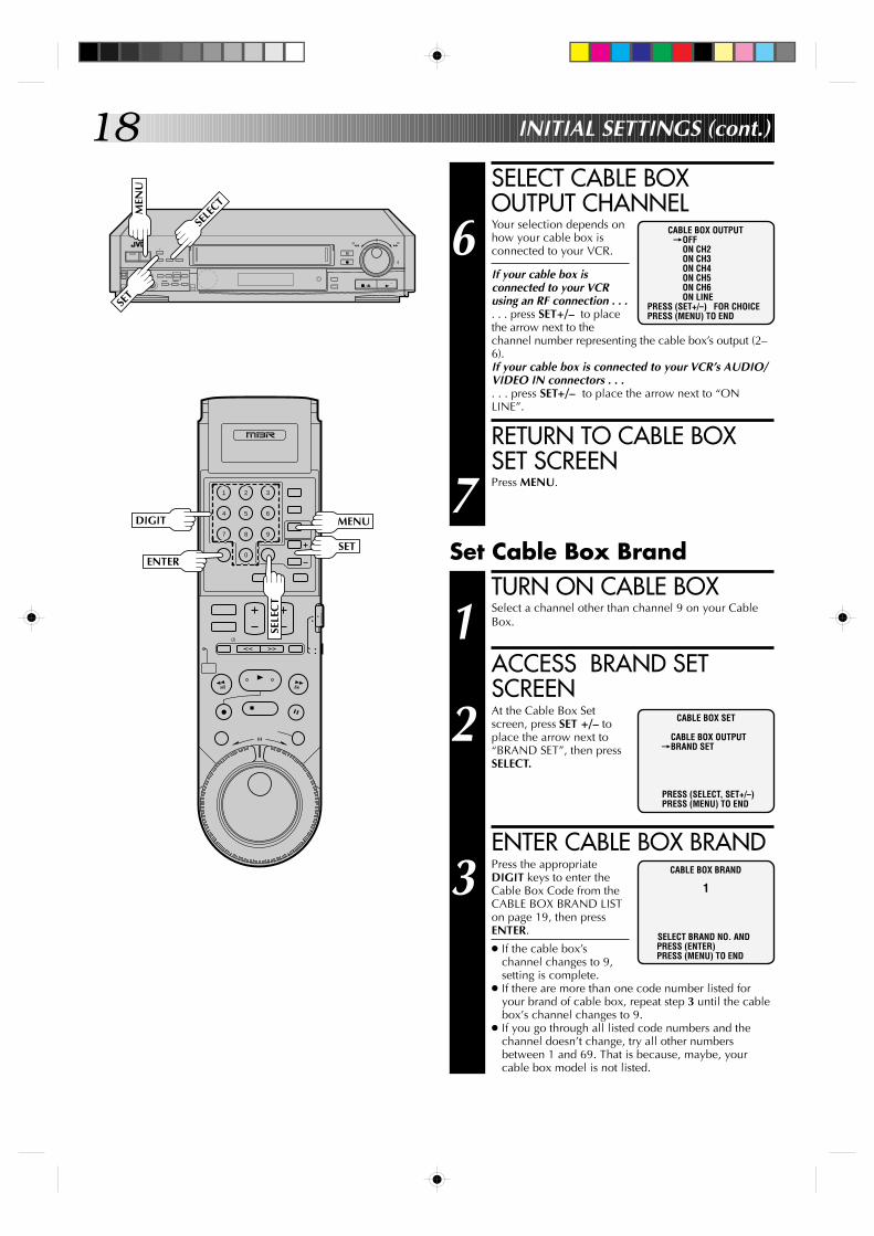
SELECT CABLE BOXOUTPUT CHANNEL
6 Your selection depends onhow your cable box isconnected to your VCR.
If your cable box isconnected to your VCRusing an RF connection . . .. . . press SET+/– to placethe arrow next to thechannel number representing the cable box’s output (2–6).If your cable box is connected to your VCR’s AUDIO/VIDEO IN connectors . . .. . . press SET+/– to place the arrow next to “ONLINE”.
RETURN TO CABLE BOXSET SCREEN
7 Press MENU.
CABLE BOX OUTPUT=OFF
ON CH2ON CH3ON CH4ON CH5ON CH6ON LINE
PRESS (SET+/–) FOR CHOICEPRESS (MENU) TO END
TURN ON CABLE BOX
1 Select a channel other than channel 9 on your CableBox.
ACCESS BRAND SETSCREEN
2 At the Cable Box Setscreen, press SET +/– toplace the arrow next to“BRAND SET”, then pressSELECT.
ENTER CABLE BOX BRAND
3 Press the appropriateDIGIT keys to enter theCable Box Code from theCABLE BOX BRAND LISTon page 19, then pressENTER.
● If the cable box’schannel changes to 9,setting is complete.
● If there are more than one code number listed foryour brand of cable box, repeat step 3 until the cablebox’s channel changes to 9.
● If you go through all listed code numbers and thechannel doesn’t change, try all other numbersbetween 1 and 69. That is because, maybe, yourcable box model is not listed.
CABLE BOX SET
CABLE BOX OUTPUT=BRAND SET
PRESS (SELECT, SET+/–)PRESS (MENU) TO END
Set Cable Box Brand
INITIAL SETTINGS (cont.)
CABLE BOX BRAND
1
SELECT BRAND NO. ANDPRESS (ENTER)PRESS (MENU) TO END
SELE
CT
MEN
U
DIGIT
ENTER
SELE
CT
MENU
SET
SET
19
9
3
6
8
2
5
7
1
4
0
+
–
0000
0000
0000
0000
0000
0
0000
00000000000000000
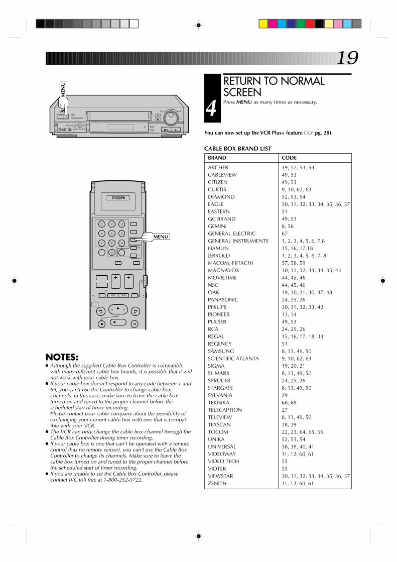
RETURN TO NORMALSCREEN
4 Press MENU as many times as necessary.
You can now set up the VCR Plus+ feature ( Z pg. 20).
CABLE BOX BRAND LIST
BRAND CODE
ARCHER 49, 52, 53, 54CABLEVIEW 49, 53CITIZEN 49, 53CURTIS 9, 10, 62, 63DIAMOND 52, 53, 54EAGLE 30, 31, 32, 33, 34, 35, 36, 37EASTERN 51GC BRAND 49, 53GEMINI 8, 56GENERAL ELECTRIC 67GENERAL INSTRUMENTS 1, 2, 3, 4, 5, 6, 7,8HAMLIN 15, 16, 17,18JERROLD 1, 2, 3, 4, 5, 6, 7, 8MACOM, HITACHI 57, 58, 59MAGNAVOX 30, 31, 32, 33, 34, 35, 43MOVIETIME 44, 45, 46NSC 44, 45, 46OAK 19, 20, 21, 30, 47, 48PANASONIC 24, 25, 26PHILIPS 30, 31, 32, 33, 42PIONEER 13, 14PULSER 49, 53RCA 24, 25, 26REGAL 15, 16, 17, 18, 33REGENCY 51SAMSUNG 8, 13, 49, 50SCIENTIFIC ATLANTA 9, 10, 62, 63SIGMA 19, 20, 21SL MARX 8, 13, 49, 50SPRUCER 24, 25, 26STARGATE 8, 13, 49, 50SYLVANIA 29TEKNIKA 68, 69TELECAPTION 27TELEVIEW 8, 13, 49, 50TEXSCAN 28, 29TOCOM 22, 23, 64, 65, 66UNIKA 52, 53, 54UNIVERSAL 38, 39, 40, 41VIDEOWAY 11, 12, 60, 61VIDEO TECH 55VIDTER 55VIEWSTAR 30, 31, 32, 33, 34, 35, 36, 37ZENITH 11, 12, 60, 61
NOTES:● Although the supplied Cable Box Controller is compatible
with many different cable box brands, it is possible that it willnot work with your cable box.
● If your cable box doesn’t respond to any code between 1 and69, you can’t use the Controller to change cable boxchannels. In this case, make sure to leave the cable boxturned on and tuned to the proper channel before thescheduled start of timer recording.Please contact your cable company about the possibility ofexchanging your current cable box with one that is compat-ible with your VCR.
● The VCR can only change the cable box channel through theCable Box Controller during timer recording.
● If your cable box is one that can’t be operated with a remotecontrol (has no remote sensor), you can’t use the Cable BoxController to change its channels. Make sure to leave thecable box turned on and tuned to the proper channel beforethe scheduled start of timer recording.
● If you are unable to set the Cable Box Controller, pleasecontact JVC toll free at 1-800-252-5722.
MEN
U
MENU

20
9
3
6
8
2
5
7
1
4
0
+
–
0000
0000
0000
0000
0000
0
0000
00000000000000000
The VCR Plus+ timer programming system eliminates the needto input channel, date, start and stop time data when setting thetimer record function. Simply key in the PlusCode number forthe TV program you wish to record (found in most TV listings)and the VCR’s timer is automatically programmed.
Depending on the TV or cable stations that you receive and thechannel numbers that they are received on in your area, you mayhave to make certain changes in your VCR’s “Guide Channel Set”menu to get proper results. Please read the following informationcarefully to find out which tasks you need to perform.
Before VCR Plus+ setup you must have performed the followingprocedures:● Advanced Auto Clock Setting (Z pg. 8)
ORClock setting (Z pg. 9)
● Tuner setting (Z pg. 13)● Tuner and cable box setting if you receive your TV channels
through a cable box (Z pg. 16)
Channel Number MatchingMost TV listings have a chart indicating the “Guide Channel”number assigned to each station for purposes of VCR Plus+programming. Check the chart in your TV listings and see if theGuide Channel numbers listed for the stations you receive arethe same as the channel number on which each is received byyour VCR or cable box.
**SPECIAL NOTES FOR CABLE SUBSCRIBERS**● In many instances, cable TV stations have VCR Plus+ Guide
Channel numbers that DO NOT match the number of thechannel on which you receive the station. Check your TVlistings, or contact your cable supplier for details.
● Many normal broadcast TV stations can be viewed on cable.Check your TV listing, or contact your cable supplier fordetails.
If the numbers match, go directly to “VCR Plus+ TimerProgramming” (Z pg. 40).
If the numbers are different, and you want to be able to timerrecord programs from those stations, you have to inform theVCR of the mismatch. Go to step 1. If you will not want to timerrecord from those stations, you can go directly to “VCR Plus+Timer Programming” (Z pg. 40).
VCR Plus+Setup
INITIAL SETTINGS (cont.)
TURN ON THE VCR
1 Press POWER.
ACCESS MAIN MENUSCREEN
2 Press MENU as many times as necessary.
POW
ER
MEN
U
POWER
MENU
21
9
3
6
8
2
5
7
1
4
0
+
–
0000
0000
0000
0000
0000
0
0000
00000000000000000
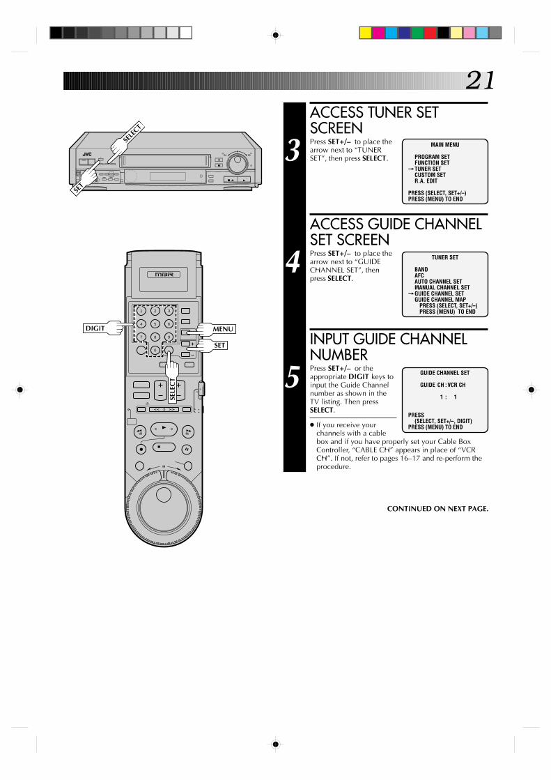
ACCESS TUNER SETSCREEN
3 Press SET+/– to place thearrow next to “TUNERSET”, then press SELECT.
ACCESS GUIDE CHANNELSET SCREEN
4 Press SET+/– to place thearrow next to “GUIDECHANNEL SET”, thenpress SELECT.
INPUT GUIDE CHANNELNUMBER
5 Press SET+/– or theappropriate DIGIT keys toinput the Guide Channelnumber as shown in theTV listing. Then pressSELECT.
● If you receive yourchannels with a cablebox and if you have properly set your Cable BoxController, “CABLE CH” appears in place of “VCRCH”. If not, refer to pages 16–17 and re-perform theprocedure.
MAIN MENU
PROGRAM SETFUNCTION SET
=TUNER SETCUSTOM SETR.A. EDIT
PRESS (SELECT, SET+/–)PRESS (MENU) TO END
TUNER SET
BANDAFCAUTO CHANNEL SETMANUAL CHANNEL SET
=GUIDE CHANNEL SETGUIDE CHANNEL MAP PRESS (SELECT, SET+/–) PRESS (MENU) TO END
GUIDE CHANNEL SET
GUIDE CH :VCR CH
1 : 1
PRESS(SELECT, SET+/–, DIGIT)
PRESS (MENU) TO END
CONTINUED ON NEXT PAGE.
SELE
CT
DIGIT
SELE
CT
MENU
SET
SET

22
9
3
6
8
2
5
7
1
4
0
+
–
0000
0000
0000
0000
0000
0
0000
00000000000000000
INPUT RECEIVING CHANNELNUMBER
6 Press SET+/– or the appropriate DIGIT keys to input thenumber of the channel on which the Guide Channel’sbroadcasts are received. Then press SELECT.
● If there is more than one mismatch, repeat steps 5 and 6for each instance.
RETURN TO TUNER SETSCREEN
7 Press MENU.
CHECK INPUT DATA
8 Press SET+/– to place thearrow next to “GUIDECHANNEL MAP”, thenpress SELECT.
● The Guide Channel andVCR or cable boxchannel numbers youinput appear on thescreen in ascendingorder. Check to ensureyou’ve entered themcorrectly.
● If you entered more than10 sets of numbers, pressSELECT to see the nextset of numbers.
● Guide Channel Mapcontains only the GuideChannels and VCR channels that you entered. (GuideChannels 90 through 99 may be included even if youdid not enter them; this has no effect on actualoperation.)
RETURN TO NORMALSCREEN
9 Press MENU as many times as necessary.
TUNER SET
BANDAFCAUTO CHANNEL SETMANUAL CHANNEL SETGUIDE CHANNEL SET
=GUIDE CHANNEL MAP PRESS (SELECT, SET+/–) PRESS (MENU) TO END
GUIDE CHANNEL MAP
GUIDE :VCR GUIDE : VCR 6 :47 10 : 5512 :41 15 : 3833 :28 67 : 49
PRESS (SELECT) TO NEXTPRESS (MENU) TO END
INITIAL SETTINGS (cont.)
You can now use VCR Plus+ for quick and simple timerprogramming (Z pg. 40).
MEN
U
SELE
CT
DIGIT
SELE
CT
MENU
SET
SET
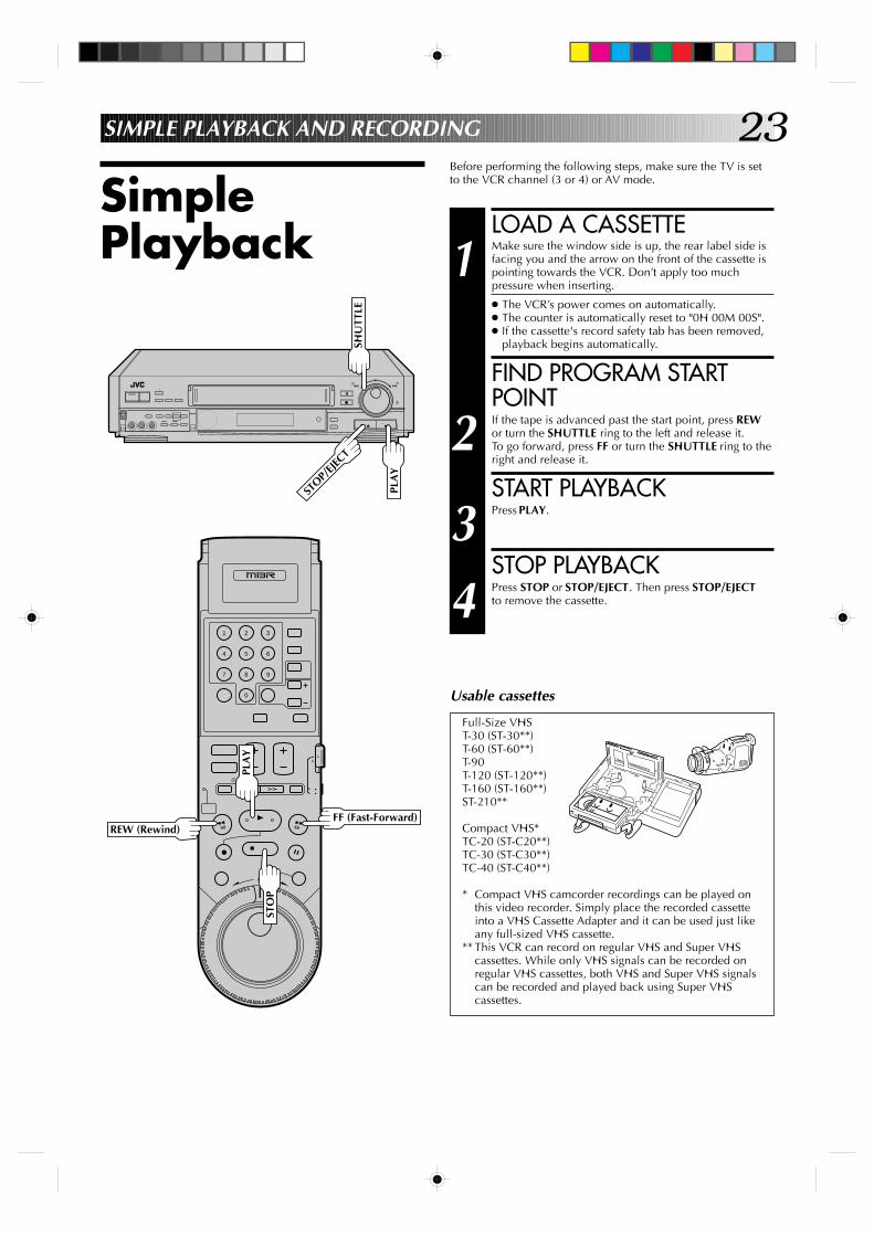
23SIMPLE PLAYBACK AND RECORDING
LOAD A CASSETTE
1 Make sure the window side is up, the rear label side isfacing you and the arrow on the front of the cassette ispointing towards the VCR. Don’t apply too muchpressure when inserting.
● The VCR’s power comes on automatically.● The counter is automatically reset to "0H 00M 00S".● If the cassette's record safety tab has been removed,
playback begins automatically.
FIND PROGRAM STARTPOINT
2 If the tape is advanced past the start point, press REWor turn the SHUTTLE ring to the left and release it.To go forward, press FF or turn the SHUTTLE ring to theright and release it.
START PLAYBACK
3 Press PLAY.
STOP PLAYBACK
4 Press STOP or STOP/EJECT. Then press STOP/EJECTto remove the cassette.
SimplePlayback
Full-Size VHST-30 (ST-30**)T-60 (ST-60**)T-90T-120 (ST-120**)T-160 (ST-160**)ST-210**
Compact VHS*TC-20 (ST-C20**)TC-30 (ST-C30**)TC-40 (ST-C40**)
* Compact VHS camcorder recordings can be played onthis video recorder. Simply place the recorded cassetteinto a VHS Cassette Adapter and it can be used just likeany full-sized VHS cassette.
** This VCR can record on regular VHS and Super VHScassettes. While only VHS signals can be recorded onregular VHS cassettes, both VHS and Super VHS signalscan be recorded and played back using Super VHScassettes.
Usable cassettes
9
3
6
8
2
5
7
1
4
0
+
–
0000
0000
0000
0000
0000
0
0000
00000000000000000
PLA
Y
STOP/
EJECT
SHU
TTLE
PLA
Y
REW (Rewind)FF (Fast-Forward)
STO
P
Before performing the following steps, make sure the TV is setto the VCR channel (3 or 4) or AV mode.
24
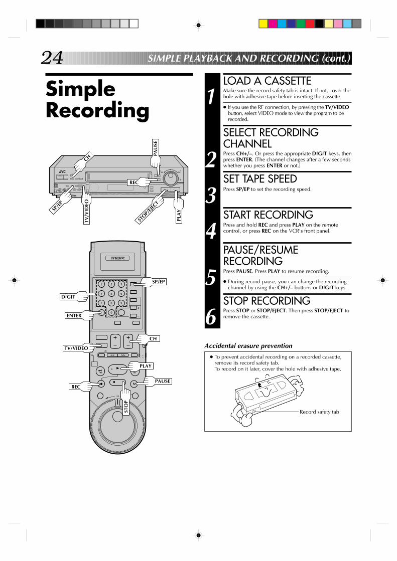
SimpleRecording
LOAD A CASSETTE
1 Make sure the record safety tab is intact. If not, cover thehole with adhesive tape before inserting the cassette.
● If you use the RF connection, by pressing the TV/VIDEObutton, select VIDEO mode to view the program to berecorded.
SELECT RECORDINGCHANNEL
2 Press CH+/–. Or press the appropriate DIGIT keys, thenpress ENTER. (The channel changes after a few secondswhether you press ENTER or not.)
SET TAPE SPEED
3 Press SP/EP to set the recording speed.
START RECORDING
4 Press and hold REC and press PLAY on the remotecontrol, or press REC on the VCR's front panel.
PAUSE/RESUMERECORDING
5 Press PAUSE. Press PLAY to resume recording.
● During record pause, you can change the recordingchannel by using the CH+/– buttons or DIGIT keys.
STOP RECORDING
6 Press STOP or STOP/EJECT. Then press STOP/EJECT toremove the cassette.
● To prevent accidental recording on a recorded cassette,remove its record safety tab.To record on it later, cover the hole with adhesive tape.
Record safety tab
Accidental erasure prevention
SIMPLE PLAYBACK AND RECORDING (cont.)
9
3
6
8
2
5
7
1
4
0
+
–
0000
0000
0000
0000
0000
0
0000
00000000000000000
STO
P
STOP/
EJECT
PLA
Y
PAU
SE
REC
DIGIT
SP/EP
ENTER
RECPAUSE
CH
CH
SP/E
P
TV/V
IDEO
TV/VIDEO
PLAY
25
9
3
6
8
2
5
7
1
4
0
+
–
0000
0000
0000
0000
0000
0
0000
00000000000000000
PLAYBACK AND RECORDING FEATURES
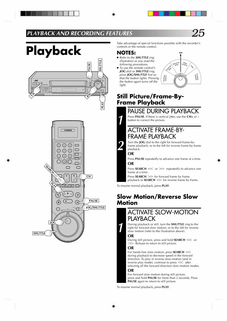
PlaybackTake advantage of special functions possible with the recorder’scontrols or the remote control.
NOTES:● Refer to the SHUTTLE ring
illustration as you read thefollowing procedures.
● To use the remote control'sJOG dial or SHUTTLE ring,press JOG/SHUTTLE first sothat the button lights. Pressingthe button again turns off thelight.
Slow Motion/Reverse SlowMotion
ACTIVATE SLOW-MOTIONPLAYBACK
1 During playback or still, turn the SHUTTLE ring to theright for forward slow motion, or to the left for reverseslow motion (refer to the illustration above).
ORDuring still picture, press and hold SEARCH T orY. Release to return to still picture.
ORFor hands-free slow-motion, press SEARCH Tduring playback to decrease speed in the forwarddirection. To play in reverse slow-motion (and inreverse play mode), continue to press T afterselecting all the forward direction slow-motion modes.
ORFor forward slow motion during still picture,press and hold PAUSE for more than 2 seconds. PressPAUSE again to return to still picture.
To resume normal playback, press PLAY.
Still Picture/Frame-By-Frame Playback
PAUSE DURING PLAYBACK
1 Press PAUSE. If there is vertical jitter, use the CH+ or –button to correct the picture.
ACTIVATE FRAME-BY-FRAME PLAYBACK
2 Turn the JOG dial to the right for forward frame-by-frame playback, or to the left for reverse frame-by-frameplayback.
ORPress PAUSE repeatedly to advance one frame at a time.
ORPress SEARCH T or Y repeatedly to advance oneframe at a time.Press SEARCH Y for forward frame by frameplayback or SEARCH T for reverse frame by frame.
To resume normal playback, press PLAY.
Rev
erse
Rev
erse
Reverse SlowPlay
Forward
sear
ch
play
slow motion
search
Still
0000
0000
0000
0000
0000
0
0000
00000000000000000
PAU
SE
SHU
TTLE
JOG
PLA
Y
PLAY
PAUSE
JOG
SHUTTLE
SEARCHT
Y
JOG/SHUTTLE
CH
CH
26
9
3
6
8
2
5
7
1
4
0
+
–
0000
0000
0000
0000
0000
0
0000
00000000000000000
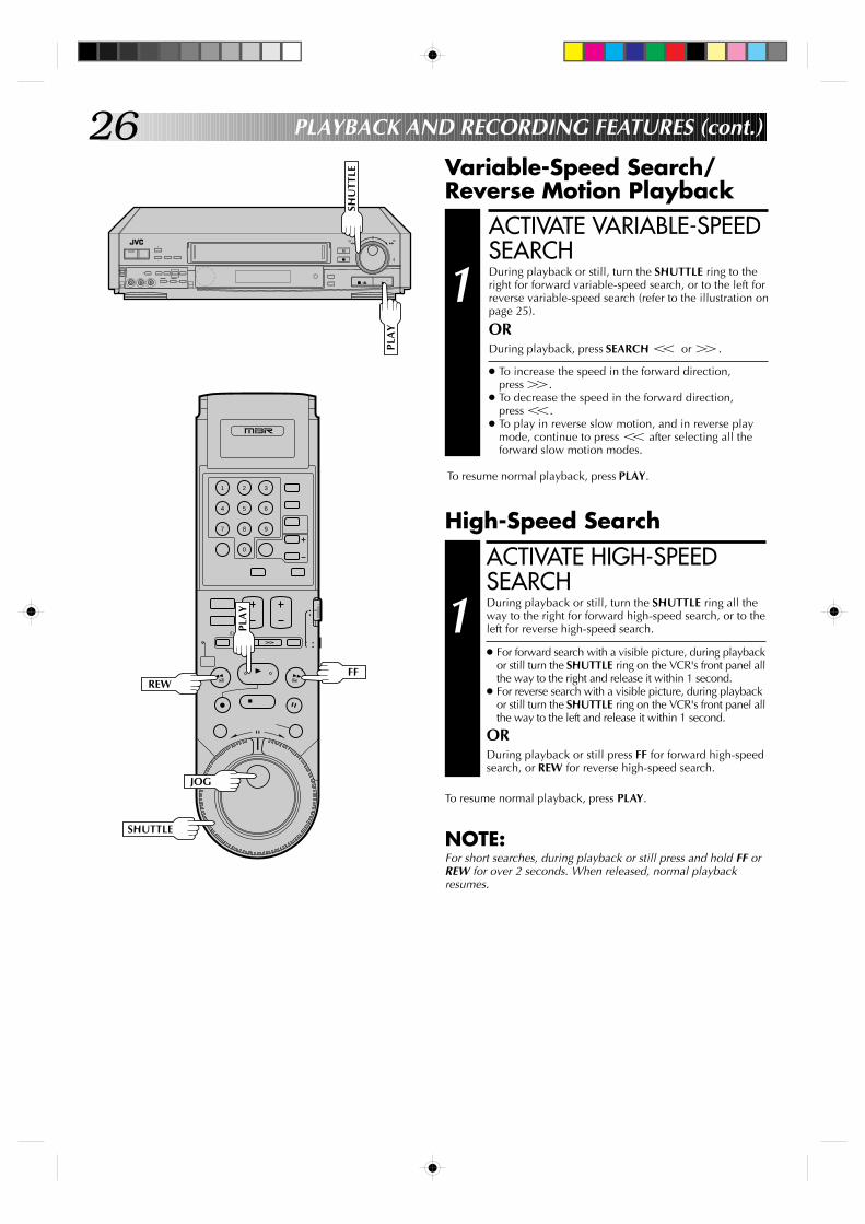
Variable-Speed Search/Reverse Motion Playback
PLAYBACK AND RECORDING FEATURES (cont.)
High-Speed SearchACTIVATE HIGH-SPEEDSEARCH
1 During playback or still, turn the SHUTTLE ring all theway to the right for forward high-speed search, or to theleft for reverse high-speed search.
● For forward search with a visible picture, during playbackor still turn the SHUTTLE ring on the VCR's front panel allthe way to the right and release it within 1 second.
● For reverse search with a visible picture, during playbackor still turn the SHUTTLE ring on the VCR's front panel allthe way to the left and release it within 1 second.
ORDuring playback or still press FF for forward high-speedsearch, or REW for reverse high-speed search.
To resume normal playback, press PLAY.
NOTE:For short searches, during playback or still press and hold FF orREW for over 2 seconds. When released, normal playbackresumes.
ACTIVATE VARIABLE-SPEEDSEARCH
1 During playback or still, turn the SHUTTLE ring to theright for forward variable-speed search, or to the left forreverse variable-speed search (refer to the illustration onpage 25).
ORDuring playback, press SEARCH T or Y.
● To increase the speed in the forward direction,press Y.
● To decrease the speed in the forward direction,press T.
● To play in reverse slow motion, and in reverse playmode, continue to press T after selecting all theforward slow motion modes.
To resume normal playback, press PLAY.
SHU
TTLE
PLA
Y
PLA
Y
FF REW
JOG
SHUTTLE
27
9
3
6
8
2
5
7
1
4
0
+
–
0000
0000
0000
0000
0000
0
0000
00000000000000000
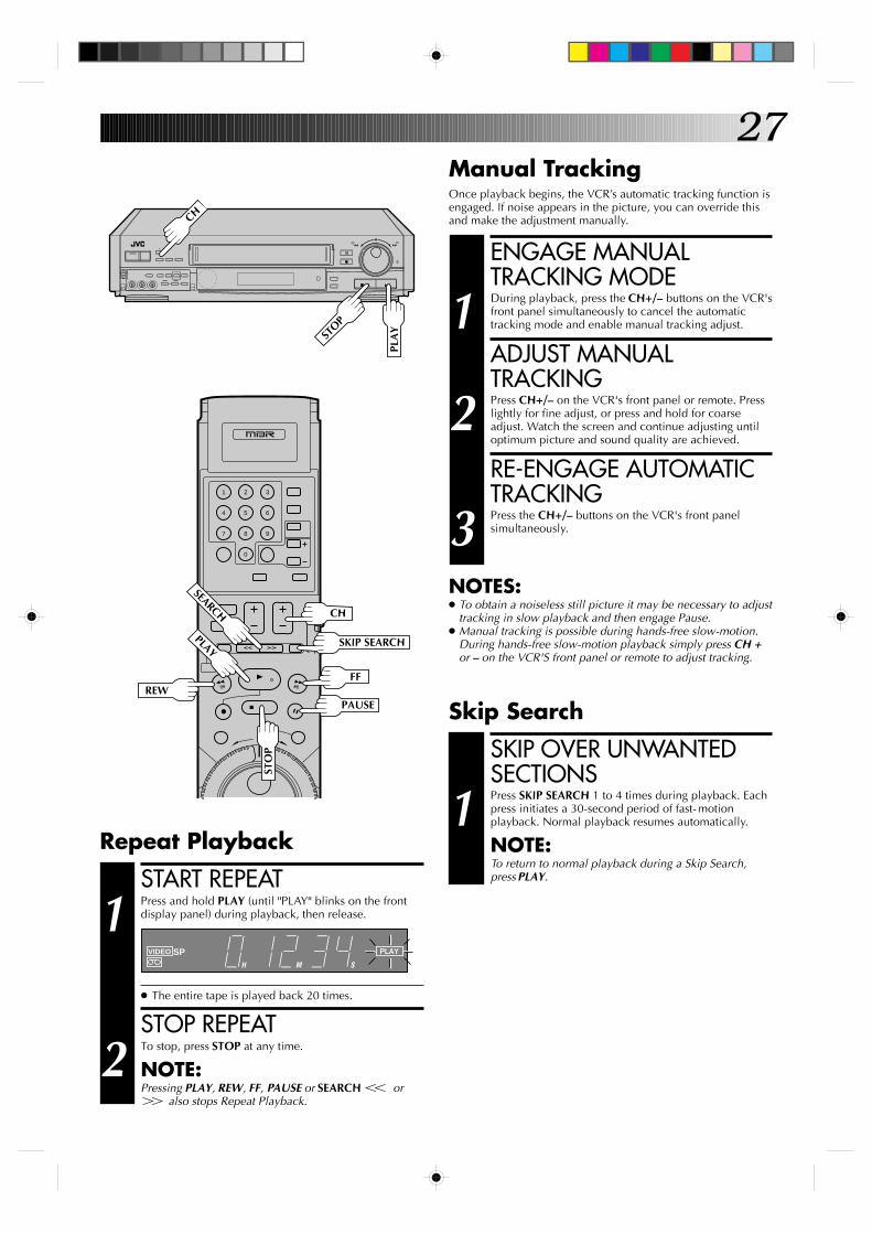
Manual TrackingOnce playback begins, the VCR’s automatic tracking function isengaged. If noise appears in the picture, you can override thisand make the adjustment manually.
ENGAGE MANUALTRACKING MODE
1 During playback, press the CH+/– buttons on the VCR'sfront panel simultaneously to cancel the automatictracking mode and enable manual tracking adjust.
ADJUST MANUALTRACKING
2 Press CH+/– on the VCR's front panel or remote. Presslightly for fine adjust, or press and hold for coarseadjust. Watch the screen and continue adjusting untiloptimum picture and sound quality are achieved.
RE-ENGAGE AUTOMATICTRACKING
3 Press the CH+/– buttons on the VCR's front panelsimultaneously.
NOTES:● To obtain a noiseless still picture it may be necessary to adjust
tracking in slow playback and then engage Pause.● Manual tracking is possible during hands-free slow-motion.
During hands-free slow-motion playback simply press CH +or – on the VCR'S front panel or remote to adjust tracking.
START REPEAT
1 Press and hold PLAY (until "PLAY" blinks on the frontdisplay panel) during playback, then release.
● The entire tape is played back 20 times.
STOP REPEAT
2 To stop, press STOP at any time.
NOTE:Pressing PLAY, REW, FF, PAUSE or SEARCH T orY also stops Repeat Playback.
Repeat Playback
VIDEO SP PLAY
H M S
SKIP OVER UNWANTEDSECTIONS
1 Press SKIP SEARCH 1 to 4 times during playback. Eachpress initiates a 30-second period of fast-motionplayback. Normal playback resumes automatically.
NOTE:To return to normal playback during a Skip Search,press PLAY.
Skip Search
PLA
Y
STOP
REWFF
PAUSE
STO
P
SKIP SEARCHPLAY
CH
CH
SEARCH
28
9
3
6
8
2
5
7
1
4
0
+
–
0000
0000
0000
0000
0000
0
0000
00000000000000000
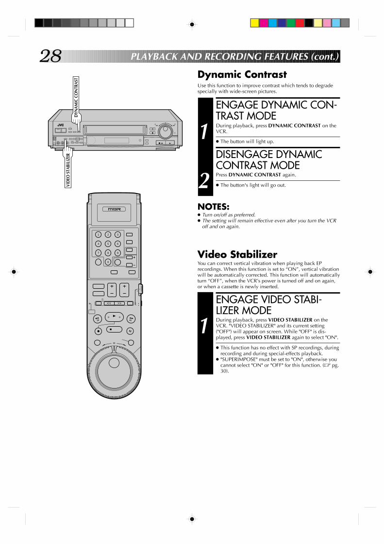
Dynamic ContrastUse this function to improve contrast which tends to degradespecially with wide-screen pictures.
PLAYBACK AND RECORDING FEATURES (cont.)
ENGAGE DYNAMIC CON-TRAST MODE
1 During playback, press DYNAMIC CONTRAST on theVCR.
● The button will light up.
DISENGAGE DYNAMICCONTRAST MODE
2 Press DYNAMIC CONTRAST again.
● The button's light will go out.
NOTES:● Turn on/off as preferred.● The setting will remain effective even after you turn the VCR
off and on again.
DYN
AMIC
CO
NTR
AST
VID
EO S
TABI
LIZE
R
Video StabilizerYou can correct vertical vibration when playing back EPrecordings. When this function is set to “ON”, vertical vibrationwill be automatically corrected. This function will automaticallyturn “OFF”, when the VCR’s power is turned off and on again,or when a cassette is newly inserted.
ENGAGE VIDEO STABI-LIZER MODE
1 During playback, press VIDEO STABILIZER on theVCR. "VIDEO STABILIZER" and its current setting("OFF") will appear on screen. While "OFF" is dis-played, press VIDEO STABILIZER again to select "ON".
● This function has no effect with SP recordings, duringrecording and during special-effects playback.
● "SUPERIMPOSE" must be set to "ON", otherwise youcannot select "ON" or "OFF" for this function. (Z pg.30).
29
9
3
6
8
2
5
7
1
4
0
+
–
0000
0000
0000
0000
0000
0
0000
00000000000000000
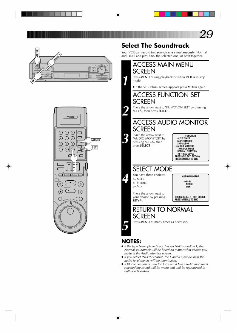
Select The SoundtrackYour VCR can record two soundtracks simultaneously (Normaland Hi-Fi) and play back the selected one, or both together.
ACCESS MAIN MENUSCREEN
1 Press MENU during playback or when VCR is in stopmode.
● If the VCR Plus+ screen appears press MENU again.
ACCESS FUNCTION SETSCREEN
2 Place the arrow next to "FUNCTION SET" by pressingSET+/–, then press SELECT.
ACCESS AUDIO MONITORSCREEN
3 Place the arrow next to"AUDIO MONITOR" bypressing SET+/–, thenpress SELECT.
SELECT MODE
4 You have three choices:a– Hi-Fib– Normalc– Mix
Place the arrow next toyour choice by pressingSET+/–.
RETURN TO NORMALSCREEN
5 Press MENU as many times as necessary.
NOTES:● If the tape being played back has no Hi-Fi soundtrack, the
Normal soundtrack will be heard no matter what choice youmake at the Audio Monitor screen.
● If you select "HI-FI" or "MIX", the L and R symbols near theaudio level meters will be illuminated.
● If RF connection is used for TV, even if Hi-Fi audio monitor isselected the sound will be mono and will be reproduced inboth loudspeakers.
FUNCTIONAUTO TIMERSUPERIMPOSE2ND AUDIO
=AUDIO MONITORTAPE DUB MODESPECIAL FUNCTIONHI-FI REC LEVEL
PRESS (SELECT, SET+/–)PRESS (MENU) TO END
AUDIO MONITOR
=HI-FINORMMIX
PRESS (SET+/–) FOR CHOICEPRESS (MENU) TO END
MEN
U
SELE
CT
MENU
SELE
CT
SET
SET
30
9
3
6
8
2
5
7
1
4
0
+
–
0000
0000
0000
0000
0000
0
0000
00000000000000000
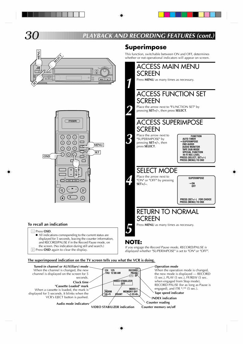
SuperimposeThis function, switchable between ON and OFF, determineswhether or not operational indicators will appear on screen.
ACCESS MAIN MENUSCREEN
1 Press MENU as many times as necessary.
ACCESS FUNCTION SETSCREEN
2 Place the arrow next to "FUNCTION SET" bypressing SET+/–, then press SELECT.
ACCESS SUPERIMPOSESCREEN
3 Place the arrow next to"SUPERIMPOSE" bypressing SET+/–, thenpress SELECT.
SELECT MODE
4 Place the arrow next to"ON" or "OFF" by pressingSET+/–.
RETURN TO NORMALSCREEN
5 Press MENU as many times as necessary.
NOTE:If you engage the Record Pause mode, RECORD/PAUSE isdisplayed whether "SUPERIMPOSE" is set to "ON" or "OFF".
The superimposed indication on the TV screen tells you what the VCR is doing.
CH 125 RECORDTHU 12:00 AM PAUSE
] SP
VIDEO STABILIZEROFF
INDEX-1NORM MEMORY OFFHI–FI COUNT –1:23:45
Operation modeWhen the operation mode is changed,the new mode is displayed — RECORD(5 sec.), PLAY (5 sec.), FF/REW (5 sec.when engaged from Stop mode),RECORD PAUSE (for as long as Pause isengaged), and ITR *:** (5 sec.).Tape speed indicator
Counter memory on/off
INDEX indicationCounter reading
To recall an indication
1 Press OSD.n All indications corresponding to the current status are
displayed for 5 seconds, leaving the counter information,and RECORD/PAUSE if in the Record Pause mode, onthe screen. (No indication during still and search.)
2 Press OSD again to clear the display.
FUNCTIONAUTO TIMER
=SUPERIMPOSE2ND AUDIOAUDIO MONITORTAPE DUB MODESPECIAL FUNCTIONHI-FI REC LEVEL
PRESS (SELECT, SET+/–)PRESS (MENU) TO END
SUPERIMPOSE
=ONOFF
PRESS (SET+/–) FOR CHOICEPRESS (MENU) TO END
PLAYBACK AND RECORDING FEATURES (cont.)
Tuned-in channel or AUX(iliary) modeWhen the channel is changed, the new
channel is displayed on the screen for 5seconds.
Clock time"Cassette Loaded" mark
When a cassette is loaded, the mark isdisplayed for 5 seconds. It blinks when the
VCR's EJECT button is pushed.
Audio mode indicatorsVIDEO STABILIZER indication
MEN
U
SELE
CT
MENU
OSD
SELE
CT
SET
SET

31
+
–
0000
0000
0000
0000
0000
0
0000
00000000000000000
9
3
6
8
2
5
7
1
4
0
Index SearchThis function seeks out index codes that are placed on the tapeat recording start.
START SEARCH
1 While the tape is stopped, press SEARCH T or Y.
ACCESS DISTANT CODE
2 To access a recording 2–9 index codes away, pressSEARCH T or Y repeatedly until the correctnumber is displayed on screen (only if SUPERIMPOSEis set to ON (Z pg. 30). Playback begins automaticallywhen the desired recording is located.
● To find the very beginning of the desired program,press REW or FF and search visually for the start point.
NOTE:An index code is not placed on the tape when recording ispaused and then resumed.
Manual Index Mark/EraseTo mark an index code......during playback press INDEX MARK on the VCR.n The VCR will mark an index code at that location.n If "SUPERIMPOSE" is set to ON (Z pg. 30), "MARK" blinks on
the screen while an index code is being marked.
To erase an index code......during playback or still press INDEX ERASE on the VCR.n The VCR will fast-forward to the nearest index code and erase
it. Playback continues after the index code is erased.n If "SUPERIMPOSE" is set to ON (Z pg. 30), "ERASE" blinks on
the screen while an index code is being erased.
PLA
Y
STOP
FF REW
SEARCH
IND
EX ERASE
IND
EX M
ARK
32
9
3
6
8
2
5
7
1
4
0
+
–
0000
0000
0000
0000
0000
0
0000
00000000000000000
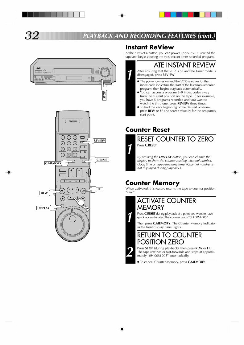
Instant ReViewAt the press of a button, you can power up your VCR, rewind thetape and begin viewing the most recent timer-recorded program.
ATE INSTANT REVIEW
1 After ensuring that the VCR is off and the Timer mode isdisengaged, press REVIEW.
● The power comes on and the VCR searches for theindex code indicating the start of the last timer-recordedprogram, then begins playback automatically.
● You can access a program 2–9 index codes awayfrom the current position on the tape. If, for example,you have 5 programs recorded and you want towatch the third one, press REVIEW three times.
● To find the very beginning of the desired program,press REW or FF and search visually for the program’sstart point.
PLAYBACK AND RECORDING FEATURES (cont.)
RESET COUNTER TO ZERO
1 Press C.RESET.
By pressing the DISPLAY button, you can change thedisplay to show the counter reading, channel number,clock time or tape remaining time. (Channel number isnot displayed during playback.)
Counter MemoryWhen activated, this feature returns the tape to counter position“zero”.
ACTIVATE COUNTERMEMORY
1 Press C.RESET during playback at a point you want to havequick access to later. The counter reads “0H 00M 00S”.
Then press C.MEMORY. The Counter Memory indicatorin the front display panel lights.
RETURN TO COUNTERPOSITION ZERO
2 Press STOP (during playback), then press REW or FF.The tape rewinds or fast-forwards and stops at approxi-mately “0H 00M 00S” automatically.
● To cancel Counter Memory, press C.MEMORY.
Counter Reset
STO
P
REVIEW
C.RESET
REWFF
STOP
C.MEMORY
DISPLAY
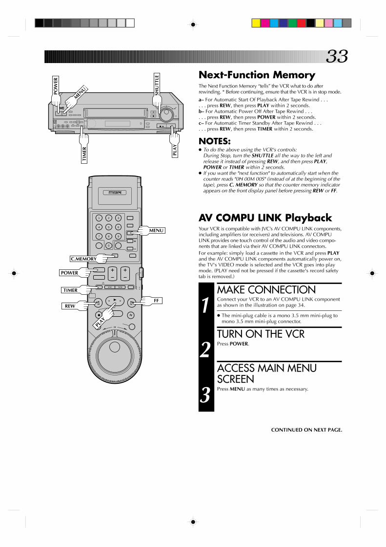
33Next-Function MemoryThe Next Function Memory “tells” the VCR what to do afterrewinding. * Before continuing, ensure that the VCR is in stop mode.
a– For Automatic Start Of Playback After Tape Rewind . . .. . . press REW, then press PLAY within 2 seconds.b– For Automatic Power Off After Tape Rewind . . .. . . press REW, then press POWER within 2 seconds.c– For Automatic Timer Standby After Tape Rewind . . .. . . press REW, then press TIMER within 2 seconds.
NOTES:● To do the above using the VCR's controls:
During Stop, turn the SHUTTLE all the way to the left andrelease it instead of pressing REW, and then press PLAY,POWER or TIMER within 2 seconds.
● If you want the "next function" to automatically start when thecounter reads "0H 00M 00S" (instead of at the beginning of thetape), press C. MEMORY so that the counter memory indicatorappears on the front display panel before pressing REW or FF.
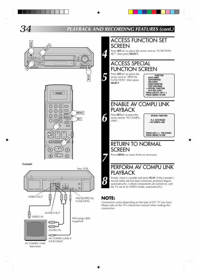
AV COMPU LINK PlaybackYour VCR is compatible with JVC’s AV COMPU LINK components,including amplifiers (or receivers) and televisions. AV COMPULINK provides one touch control of the audio and video compo-nents that are linked via their AV COMPU LINK connectors.For example: simply load a cassette in the VCR and press PLAYand the AV COMPU LINK components automatically power on,the TV's VIDEO mode is selected and the VCR goes into playmode. (PLAY need not be pressed if the cassette's record safetytab is removed.)
MAKE CONNECTION
1 Connect your VCR to an AV COMPU LINK componentas shown in the illustration on page 34.
● The mini-plug cable is a mono 3.5 mm mini-plug tomono 3.5 mm mini-plug connector.
TURN ON THE VCR
2 Press POWER.
ACCESS MAIN MENUSCREEN
3 Press MENU as many times as necessary.
CONTINUED ON NEXT PAGE.
9
3
6
8
2
5
7
1
4
0
+
–
0000
0000
0000
0000
0000
0
0000
00000000000000000
POW
ER
MEN
U
SHU
TTLE
PLA
Y
TIM
ER
C.MEMORY
POWER
MENU
REWFF
TIMER
PLAY
34
+
–
0000
0000
0000
0000
0000
0
0000
00000000000000000
ACCESS FUNCTION SETSCREEN
4 Press SET+/– to place the arrow next to “FUNCTIONSET”, then press SELECT.
ACCESS SPECIALFUNCTION SCREEN
5 Press SET+/– to place thearrow next to “SPECIALFUNCTION”, then pressSELECT.
ENABLE AV COMPU LINKPLAYBACK
6 Press SET+/– to place thearrow next to “AV COMPULINK”.
RETURN TO NORMALSCREEN
7 Press MENU as many times as necessary.
PERFORM AV COMPU LINKPLAYBACK
8 Simply insert a cassette and press PLAY (if the cassette’srecord safety tab has been removed, playback beginsautomatically). Linked components are turned on, andthe TV set to its VIDEO mode, automatically!
NOTE:Connection varies depending on the type of JVC TV you have.Please refer to the TV’s instruction manual when making thisconnection.
FUNCTIONAUTO TIMERSUPERIMPOSE2ND AUDIOAUDIO MONITORTAPE DUB MODE
=SPECIAL FUNCTIONHI-FI REC LEVEL
PRESS (SELECT, SET+/–)PRESS (MENU) TO END
SPECIAL FUNCTION
R.A. EDIT/PAUSE=AV COMPU-LINK
PRESS (SET+/–) FOR CHOICEPRESS (MENU) TO END
PAUSE/SPECIALFUNCTION
AUDIO OUT
PLAYBACK AND RECORDING FEATURES (cont.)M
ENU
SELE
CT
PLA
Y
9
3
6
8
2
5
7
1
4
0
MENU
PLAY
SELE
CT
Your VCR
Example
VIDEO IN
AUDIO IN
Mini-plug cable(supplied)
AV COMPU LINK II(VCR ONLY)
AV COMPU LINKTelevision
VIDEO OUT
SET
SET
35
9
3
6
8
2
5
7
1
4
0
+
–
0000
0000
0000
0000
0000
0
0000
00000000000000000
Record One Program WhileWatching AnotherRecording
Display Elapsed RecordingTime
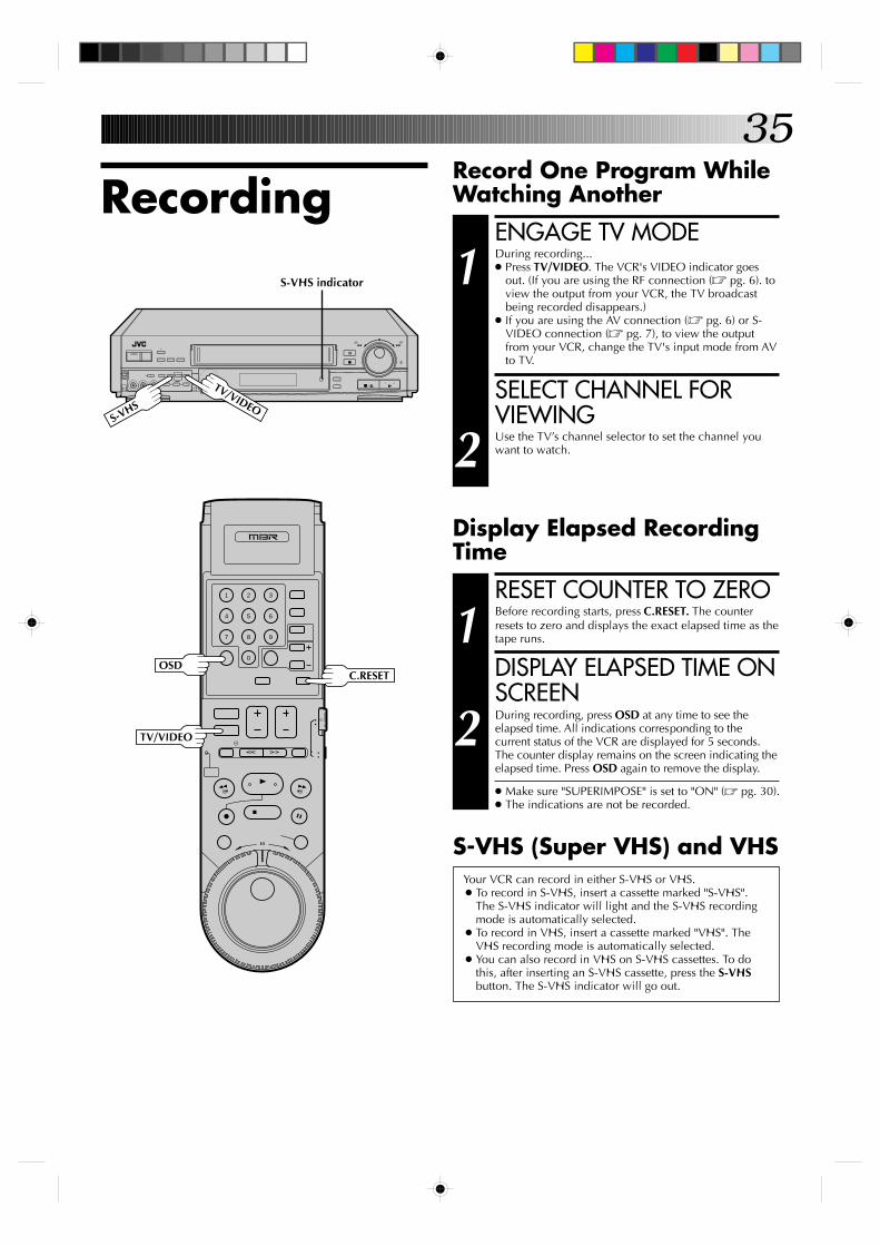
ENGAGE TV MODE
1 During recording...● Press TV/VIDEO. The VCR's VIDEO indicator goes
out. (If you are using the RF connection (Z pg. 6). toview the output from your VCR, the TV broadcastbeing recorded disappears.)
● If you are using the AV connection (Z pg. 6) or S-VIDEO connection (Z pg. 7), to view the outputfrom your VCR, change the TV's input mode from AVto TV.
SELECT CHANNEL FORVIEWING
2 Use the TV’s channel selector to set the channel youwant to watch.
RESET COUNTER TO ZERO
1 Before recording starts, press C.RESET. The counterresets to zero and displays the exact elapsed time as thetape runs.
DISPLAY ELAPSED TIME ONSCREEN
2 During recording, press OSD at any time to see theelapsed time. All indications corresponding to thecurrent status of the VCR are displayed for 5 seconds.The counter display remains on the screen indicating theelapsed time. Press OSD again to remove the display.
● Make sure "SUPERIMPOSE" is set to "ON" (Z pg. 30).● The indications are not be recorded.
Your VCR can record in either S-VHS or VHS.● To record in S-VHS, insert a cassette marked "S-VHS".
The S-VHS indicator will light and the S-VHS recordingmode is automatically selected.
● To record in VHS, insert a cassette marked "VHS". TheVHS recording mode is automatically selected.
● You can also record in VHS on S-VHS cassettes. To dothis, after inserting an S-VHS cassette, press the S-VHSbutton. The S-VHS indicator will go out.
S-VHS (Super VHS) and VHS
S-VHS
TV/VIDEO
OSD
TV/VIDEO
C.RESET
S-VHS indicator
36
9
3
6
8
2
5
7
1
4
0
+
–
0000
0000
0000
0000
0000
0
0000
00000000000000000
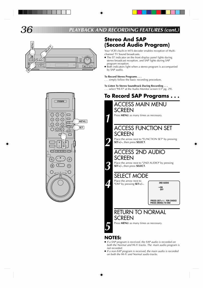
Stereo And SAP(Second Audio Program)Your VCR’s built-in MTS decoder enables reception of Multi-channel TV Sound broadcasts.● The ST indicator on the front display panel lights during
stereo broadcast reception, and SAP lights during SAPprogram reception.
● Both indicators light when a stereo program is accompaniedby SAP audio.
To Record Stereo Programs . . .. . . simply follow the basic recording procedure.
To Listen To Stereo Soundtrack During Recording . . .. . . select "HI-FI" at the Audio Monitor screen (Z pg. 29).
PLAYBACK AND RECORDING FEATURES (cont.)
To Record SAP Programs . . .ACCESS MAIN MENUSCREEN
1 Press MENU as many times as necessary.
ACCESS FUNCTION SETSCREEN
2 Place the arrow next to "FUNCTION SET" by pressingSET+/–, then press SELECT.
ACCESS 2ND AUDIOSCREEN
3 Place the arrow next to "2ND AUDIO" by pressingSET+/–, then press SELECT.
SELECT MODE
4 Place the arrow next to"ON" by pressing SET+/–.
RETURN TO NORMALSCREEN
5 Press MENU as many times as necessary.
NOTES:● If a SAP program is received, the SAP audio is recorded on
both the Normal and Hi-Fi tracks. The main audio program isnot recorded.
● If a non-SAP program is received, the main audio is recordedon both the Hi-Fi and Normal audio tracks.
2ND AUDIO
=ONOFF
PRESS (SET+/–) FOR CHOICEPRESS (MENU) TO END
MEN
U
SELE
CT
MENU
SELE
CT
SET
SET
37
9
3
6
8
2
5
7
1
4
0
+
–
0000
0000
0000
0000
0000
0
0000
00000000000000000
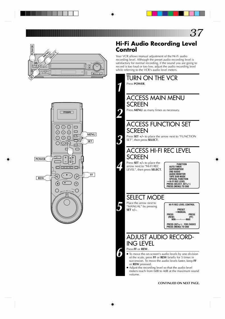
Hi-Fi Audio Recording LevelControlYour VCR allows manual adjustment of the Hi-Fi audiorecording level. Although the preset audio recording level issatisfactory for normal recording, if the sound you are going torecord is too loud or too low, adjust the audio recording levelwhile referring to the VCR's audio level meters.
TURN ON THE VCR
1 Press POWER.
ACCESS MAIN MENUSCREEN
2 Press MENU as many times as necessary.
ACCESS FUNCTION SETSCREEN
3 Press SET +/– to place the arrow next to “FUNCTIONSET”, then press SELECT.
ACCESS HI-FI REC LEVELSCREEN
4 Press SET +/– to place thearrow next to “HI-FI RECLEVEL”, then press SELECT.
SELECT MODE
5 Place the arrow next to“MANUAL” by pressingSET +/–.
ADJUST AUDIO RECORD-ING LEVEL
6 Press FF or REW.
● To move the on-screen's audio levels by one divisionof the scale, press FF or REW briefly for 5 times insuccession. To move the audio levels faster, keep FFor REW presssed.
● Adjust the recording level so that the audio levelmeters reach from 0dB to 4dB at the maximum soundvolume.
FUNCTIONAUTO TIMERSUPERIMPOSE2ND AUDIOAUDIO MONITORTAPE DUB MODESPECIAL FUNCTION
=HI-FI REC LEVELPRESS (SELECT, SET+/–)PRESS (MENU) TO END
HI-FI REC LEVEL CONTROL
PRESET=MANUAL
PRESS PRESS(REW) (FF)
MIN------*------MAX
PRESS (SET+/–) FOR CHOICEPRESS (MENU) TO END
CONTINUED ON NEXT PAGE.
POW
ER
MEN
U
SELE
CT
POWER
REWFF
MENU
SELE
CT
SET
SET
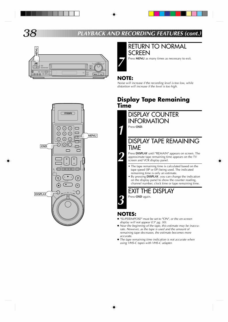
38
9
3
6
8
2
5
7
1
4
0
+
–
0000
0000
0000
0000
0000
0
0000
00000000000000000
RETURN TO NORMALSCREEN
7 Press MENU as many times as necessary to exit.
NOTE:Noise will increase if the recording level is too low, whiledistortion will increase if the level is too high.
PLAYBACK AND RECORDING FEATURES (cont.)
Display Tape RemainingTime
DISPLAY COUNTERINFORMATION
1 Press OSD.
DISPLAY TAPE REMAININGTIME
2 Press DISPLAY until "REMAIN" appears on screen. Theapproximate tape remaining time appears on the TVscreen and VCR display panel.
• The tape remaining time is calculated based on thetape speed (SP or EP) being used. The indicatedremaining time is only an estimate.
• By pressing DISPLAY, you can change the indicationon the display panel to show the counter reading,channel number, clock time or tape remaining time.
EXIT THE DISPLAY
3 Press OSD again.
NOTES:● "SUPERIMPOSE" must be set to "ON", or the on-screen
display will not appear (Z pg. 30).● Near the beginning of the tape, this estimate may be inaccu-
rate. However, as the tape is used and the amount ofremaining tape decreases, the estimate becomes moreaccurate.
● The tape remaining time indication is not accurate whenusing VHS-C tapes with VHS-C adapter.
MEN
U
OSD
DISPLAY
MENU
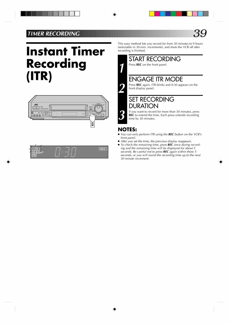
39
Instant TimerRecording(ITR)
This easy method lets you record for from 30 minutes to 9 hours(selectable in 30-min. increments), and shuts the VCR off afterrecording is finished.
START RECORDING
1 Press REC on the front panel.
ENGAGE ITR MODE
2 Press REC again. ITR blinks and 0:30 appears on thefront display panel.
SET RECORDINGDURATION
3 If you want to record for more than 30 minutes, pressREC to extend the time. Each press extends recordingtime by 30 minutes.
NOTES:● You can only perform ITR using the REC button on the VCR's
front panel.● After you set the time, the previous display reappears.● To check the remaining time, press REC once during record-
ing and the remaining time will be displayed for about 5seconds. Be careful not to press REC again within these 5seconds, or you will round the recording time up to the next30 minute increment.
+
–
0000
0000
0000
0000
0000
0
0000
00000000000000000
I T R
VIDEO SPR E C
TIMER RECORDING
REC
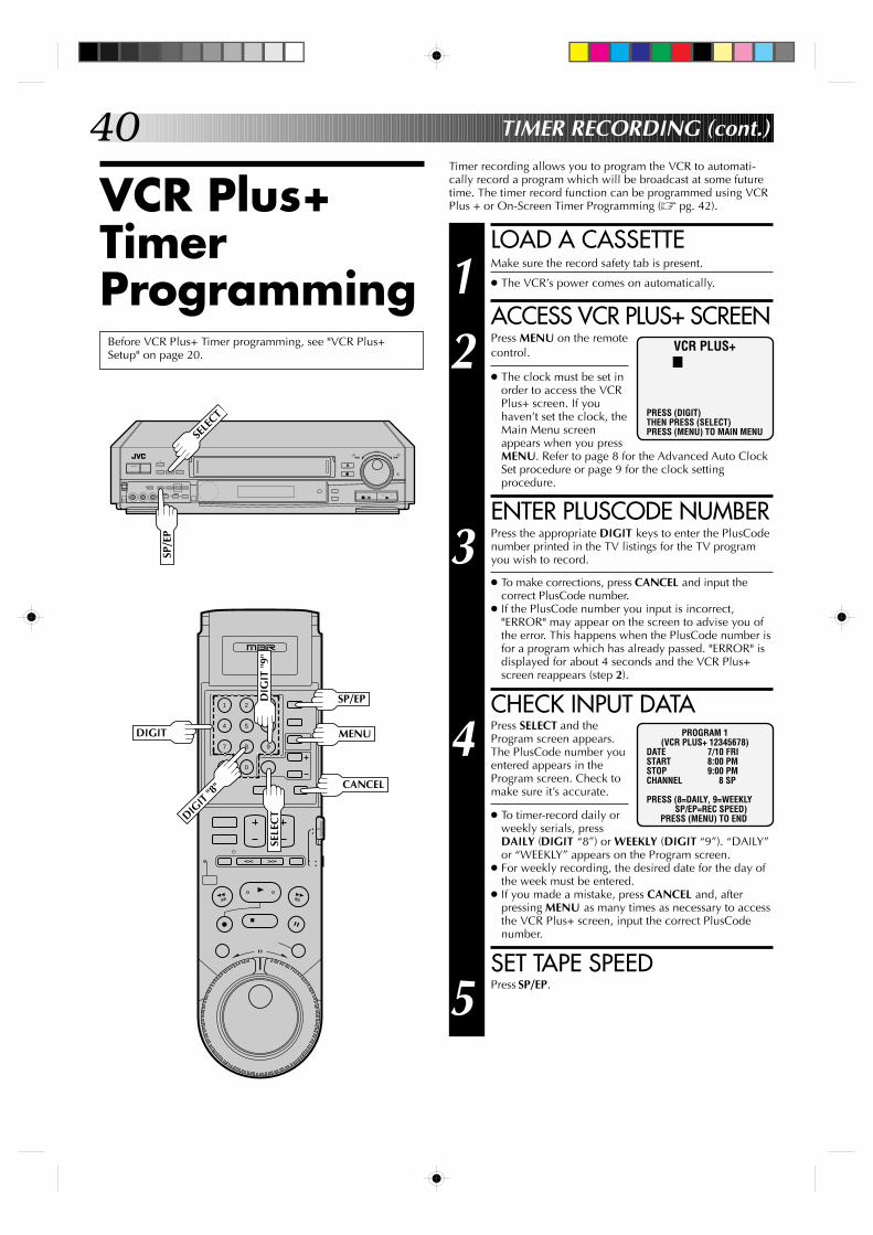
40
9
3
6
8
2
5
7
1
4
0
+
–
0000
0000
0000
0000
0000
0
0000
00000000000000000
VCR Plus+TimerProgramming
TIMER RECORDING (cont.)
Before VCR Plus+ Timer programming, see "VCR Plus+Setup" on page 20.
Timer recording allows you to program the VCR to automati-cally record a program which will be broadcast at some futuretime. The timer record function can be programmed using VCRPlus + or On-Screen Timer Programming (Z pg. 42).
LOAD A CASSETTE
1 Make sure the record safety tab is present.
● The VCR’s power comes on automatically.
ACCESS VCR PLUS+ SCREEN
2 Press MENU on the remotecontrol.
● The clock must be set inorder to access the VCRPlus+ screen. If youhaven’t set the clock, theMain Menu screenappears when you pressMENU. Refer to page 8 for the Advanced Auto ClockSet procedure or page 9 for the clock settingprocedure.
ENTER PLUSCODE NUMBER
3 Press the appropriate DIGIT keys to enter the PlusCodenumber printed in the TV listings for the TV programyou wish to record.
● To make corrections, press CANCEL and input thecorrect PlusCode number.
● If the PlusCode number you input is incorrect,"ERROR" may appear on the screen to advise you ofthe error. This happens when the PlusCode number isfor a program which has already passed. "ERROR" isdisplayed for about 4 seconds and the VCR Plus+screen reappears (step 2).
CHECK INPUT DATA
4 Press SELECT and theProgram screen appears.The PlusCode number youentered appears in theProgram screen. Check tomake sure it’s accurate.
● To timer-record daily orweekly serials, pressDAILY (DIGIT “8”) or WEEKLY (DIGIT “9”). “DAILY”or “WEEKLY” appears on the Program screen.
● For weekly recording, the desired date for the day ofthe week must be entered.
● If you made a mistake, press CANCEL and, afterpressing MENU as many times as necessary to accessthe VCR Plus+ screen, input the correct PlusCodenumber.
SET TAPE SPEED
5 Press SP/EP.
VCR PLUS+
PRESS (DIGIT)THEN PRESS (SELECT)PRESS (MENU) TO MAIN MENU
PROGRAM 1(VCR PLUS+ 12345678)
DATE 7/10 FRISTART 8:00 PMSTOP 9:00 PMCHANNEL 8 SP
PRESS (8=DAILY, 9=WEEKLY SP/EP=REC SPEED)PRESS (MENU) TO END
DIGIT
SP/EP
CANCEL
SELE
CTDIG
IT "8
"
DIG
IT "
9"
MENU
SP/E
P
SELE
CT
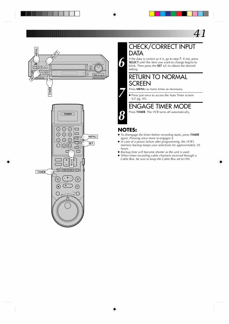
41
9
3
6
8
2
5
7
1
4
0
+
–
0000
0000
0000
0000
0000
0
0000
00000000000000000
CHECK/CORRECT INPUTDATA
6 If the data is correct as it is, go to step 7. If not, pressSELECT until the item you want to change begins toblink. Then press the SET +/– to obtain the desiredsetting.
RETURN TO NORMALSCREEN
7 Press MENU as many times as necessary.
● Press just once to access the Auto Timer screen(Z pg. 45).
ENGAGE TIMER MODE
8 Press TIMER. The VCR turns off automatically.
NOTES:● To disengage the timer before recording starts, press TIMER
again. Pressing once more re-engages it.● In case of a power failure after programming, the VCR’s
memory backup keeps your selections for approximately 20hours.
● Backup time will become shorter as the unit is used.● When timer-recording cable channels received through a
Cable Box, be sure to keep the Cable Box set to ON.
TIM
ER
MENU
TIMER
SELE
CT
SELE
CT
MEN
U
SET
SET
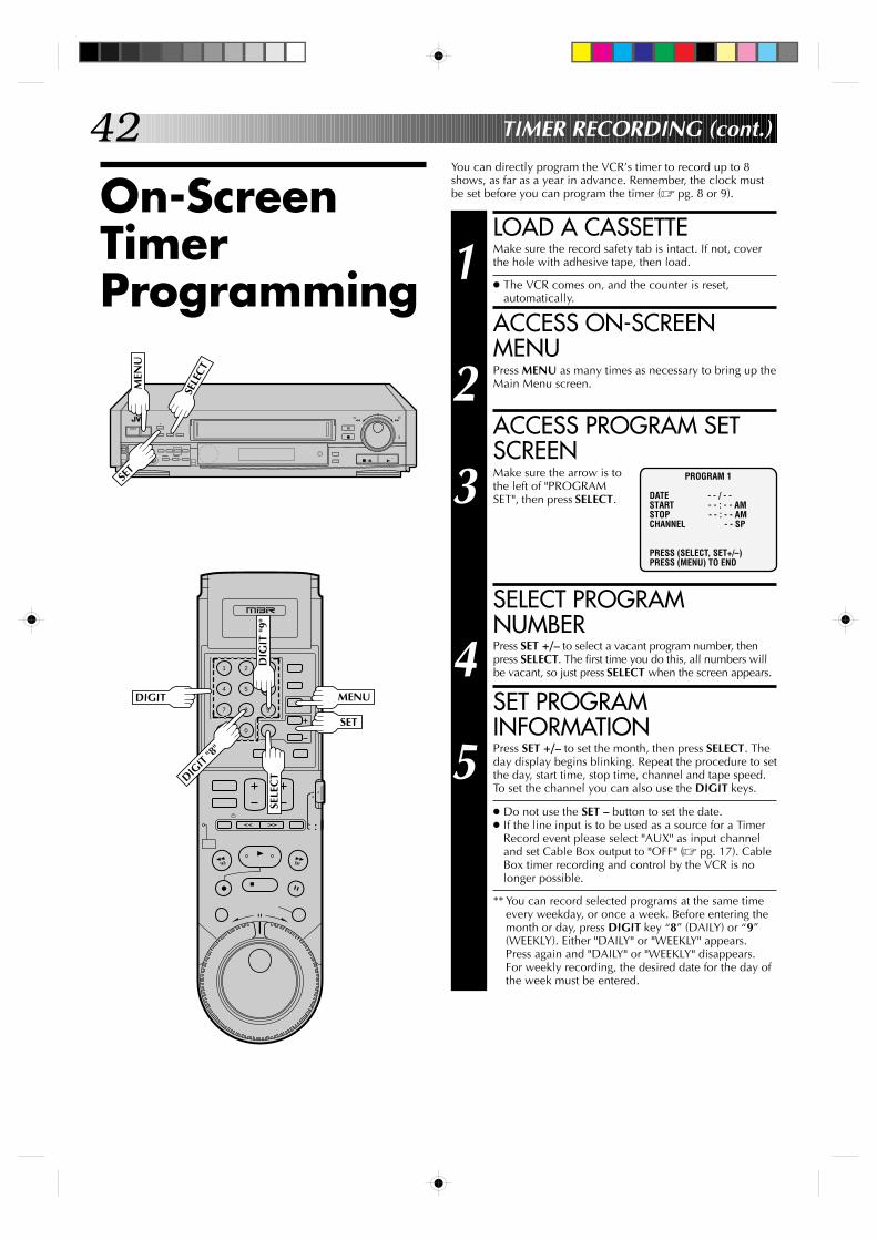
42
On-ScreenTimerProgramming
You can directly program the VCR’s timer to record up to 8shows, as far as a year in advance. Remember, the clock mustbe set before you can program the timer (Z pg. 8 or 9).
TIMER RECORDING (cont.)
LOAD A CASSETTE
1 Make sure the record safety tab is intact. If not, coverthe hole with adhesive tape, then load.
● The VCR comes on, and the counter is reset,automatically.
ACCESS ON-SCREENMENU
2 Press MENU as many times as necessary to bring up theMain Menu screen.
ACCESS PROGRAM SETSCREEN
3 Make sure the arrow is tothe left of "PROGRAMSET", then press SELECT.
SELECT PROGRAMNUMBER
4 Press SET +/– to select a vacant program number, thenpress SELECT. The first time you do this, all numbers willbe vacant, so just press SELECT when the screen appears.
SET PROGRAMINFORMATION
5 Press SET +/– to set the month, then press SELECT. Theday display begins blinking. Repeat the procedure to setthe day, start time, stop time, channel and tape speed.To set the channel you can also use the DIGIT keys.
● Do not use the SET – button to set the date.● If the line input is to be used as a source for a Timer
Record event please select "AUX" as input channeland set Cable Box output to "OFF" (Z pg. 17). CableBox timer recording and control by the VCR is nolonger possible.
** You can record selected programs at the same timeevery weekday, or once a week. Before entering themonth or day, press DIGIT key “8” (DAILY) or “9”(WEEKLY). Either "DAILY" or "WEEKLY" appears.Press again and "DAILY" or "WEEKLY" disappears.For weekly recording, the desired date for the day ofthe week must be entered.
PROGRAM 1
DATE - - / - -START - - : - - AMSTOP - - : - - AMCHANNEL - - SP
PRESS (SELECT, SET+/–)PRESS (MENU) TO END
9
3
6
8
2
5
7
1
4
0
+
–
0000
0000
0000
0000
0000
0
0000
00000000000000000
SELE
CT
MEN
U
SELE
CT
MENU
SET
SET
DIGIT
DIGIT
"8"
DIG
IT "
9"
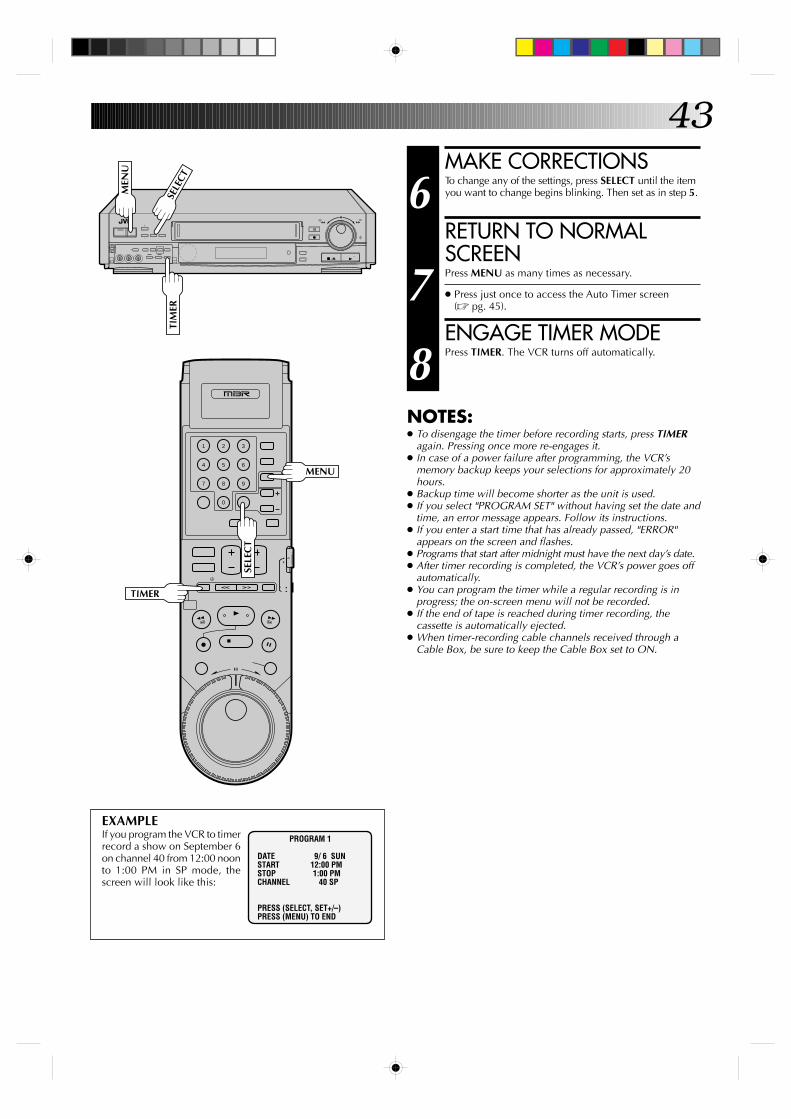
43
9
3
6
8
2
5
7
1
4
0
+
–
0000
0000
0000
0000
0000
0
0000
00000000000000000
MAKE CORRECTIONS
6 To change any of the settings, press SELECT until the itemyou want to change begins blinking. Then set as in step 5.
RETURN TO NORMALSCREEN
7 Press MENU as many times as necessary.
● Press just once to access the Auto Timer screen(Z pg. 45).
ENGAGE TIMER MODE
8 Press TIMER. The VCR turns off automatically.
EXAMPLEIf you program the VCR to timerrecord a show on September 6on channel 40 from 12:00 noonto 1:00 PM in SP mode, thescreen will look like this:
PROGRAM 1
DATE 9/ 6 SUNSTART 12:00 PMSTOP 1:00 PMCHANNEL 40 SP
PRESS (SELECT, SET+/–)PRESS (MENU) TO END
SELE
CT
MEN
U
TIM
ER
SELE
CT
TIMER
MENU
NOTES:● To disengage the timer before recording starts, press TIMER
again. Pressing once more re-engages it.● In case of a power failure after programming, the VCR’s
memory backup keeps your selections for approximately 20hours.
● Backup time will become shorter as the unit is used.● If you select "PROGRAM SET" without having set the date and
time, an error message appears. Follow its instructions.● If you enter a start time that has already passed, "ERROR"
appears on the screen and flashes.● Programs that start after midnight must have the next day’s date.● After timer recording is completed, the VCR’s power goes off
automatically.● You can program the timer while a regular recording is in
progress; the on-screen menu will not be recorded.● If the end of tape is reached during timer recording, the
cassette is automatically ejected.● When timer-recording cable channels received through a
Cable Box, be sure to keep the Cable Box set to ON.
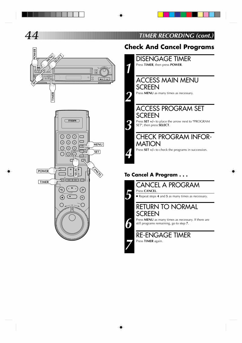
44
9
3
6
8
2
5
7
1
4
0
+
–
0000
0000
0000
0000
0000
0
0000
00000000000000000
TIMER RECORDING (cont.)
DISENGAGE TIMER
1 Press TIMER, then press POWER.
ACCESS MAIN MENUSCREEN
2 Press MENU as many times as necessary.
ACCESS PROGRAM SETSCREEN
3 Press SET +/– to place the arrow next to "PROGRAMSET", then press SELECT.
CHECK PROGRAM INFOR-MATION
4 Press SET +/– to check the programs in succession.
Check And Cancel Programs
CANCEL A PROGRAM
5 Press CANCEL.
● Repeat steps 4 and 5 as many times as necessary.
RETURN TO NORMALSCREEN
6 Press MENU as many times as necessary. If there arestill programs remaining, go to step 7.
RE-ENGAGE TIMER
7 Press TIMER again.
To Cancel A Program . . .
POW
ER
MEN
U
SELE
CTTI
MER
POWER
SELE
CT
MENU
TIMER
SET
SET
CANCEL
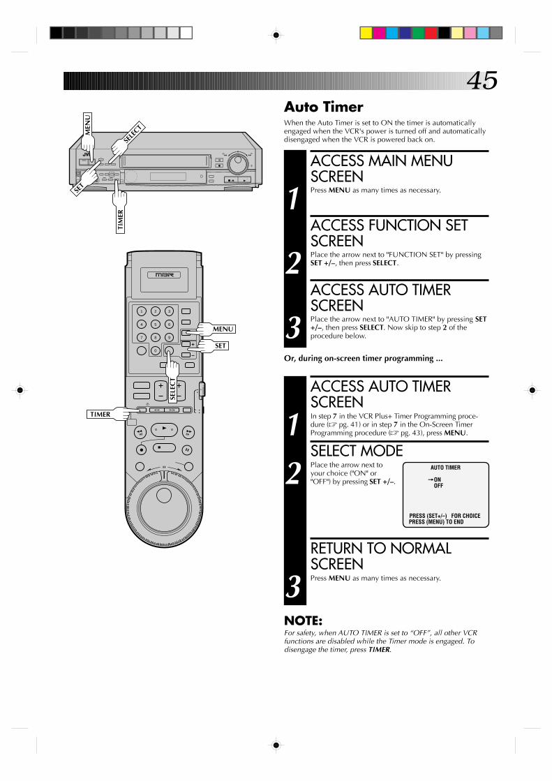
45
9
3
6
8
2
5
7
1
4
0
+
–
0000
0000
0000
0000
0000
0
0000
00000000000000000 ACCESS MAIN MENU
SCREEN
1 Press MENU as many times as necessary.
ACCESS FUNCTION SETSCREEN
2 Place the arrow next to "FUNCTION SET" by pressingSET +/–, then press SELECT.
ACCESS AUTO TIMERSCREEN
3 Place the arrow next to "AUTO TIMER" by pressing SET+/–, then press SELECT. Now skip to step 2 of theprocedure below.
Or, during on-screen timer programming ...
ACCESS AUTO TIMERSCREEN
1 In step 7 in the VCR Plus+ Timer Programming proce-dure (Z pg. 41) or in step 7 in the On-Screen TimerProgramming procedure (Z pg. 43), press MENU.
SELECT MODE
2 Place the arrow next toyour choice ("ON" or"OFF") by pressing SET +/–.
RETURN TO NORMALSCREEN
3 Press MENU as many times as necessary.
NOTE:For safety, when AUTO TIMER is set to “OFF”, all other VCRfunctions are disabled while the Timer mode is engaged. Todisengage the timer, press TIMER.
Auto TimerWhen the Auto Timer is set to ON the timer is automaticallyengaged when the VCR's power is turned off and automaticallydisengaged when the VCR is powered back on.
AUTO TIMER
=ONOFF
PRESS (SET+/–) FOR CHOICEPRESS (MENU) TO END
MEN
U
SELE
CTTI
MER
MENU
TIMER
SELE
CT
SET
SET
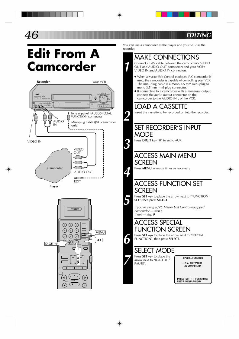
46
+
–
0000
0000
0000
0000
0000
0
0000
00000000000000000
9
3
6
8
2
5
7
1
4
0
EDITING
Edit From ACamcorder
You can use a camcorder as the player and your VCR as therecorder.
MAKE CONNECTIONS
1 Connect an AV cable between the camcorder’s VIDEOOUT and AUDIO OUT connectors and your VCR’sVIDEO IN and AUDIO IN connectors.
● When a Master Edit Control-equipped JVC camcorder isused, the camcorder is capable of controlling your VCR.The mini-plug cable is a mono 3.5 mm mini-plug tomono 3.5 mm mini-plug connector.
● If connecting to a camcorder with a monaural output,connect the audio output connector on thecamcorder to the AUDIO IN L of the VCR.
LOAD A CASSETTE
2 Insert the cassette to be recorded on into the recorder.
SET RECORDER’S INPUTMODE
3 Press DIGIT key “0” to set to AUX.
ACCESS MAIN MENUSCREEN
4 Press MENU as many times as necessary.
ACCESS FUNCTION SETSCREEN
5 Press SET +/– to place the arrow next to “FUNCTIONSET”, then press SELECT.
If you’re using a JVC Master Edit Control-equippedcamcorder — step 6If not — step 9
ACCESS SPECIALFUNCTION SCREEN
6 Press SET +/– to place the arrow next to “SPECIALFUNCTION”, then press SELECT.
SELECT MODE
7 Press SET +/– to place thearrow next to “R.A. EDIT/PAUSE”.
Recorder
SPECIAL FUNCTION
=R.A. EDIT/PAUSEAV COMPU-LINK
PRESS (SET+/–) FOR CHOICEPRESS (MENU) TO END
Your VCR
To rear panel PAUSE/SPECIALFUNCTION connector
Mini-plug cable (JVC camcorderonly)
VIDEOOUT
AUDIO OUT
EDIT
Player
Camcorder
VIDEO IN
AUDIOIN
DIGIT "0"
MENU
SELE
CT
SET
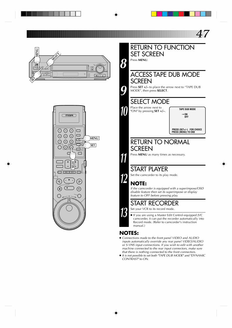
47
9
3
6
8
2
5
7
1
4
0
+
–
0000
0000
0000
0000
0000
0
0000
00000000000000000
RETURN TO FUNCTIONSET SCREEN
8 Press MENU.
ACCESS TAPE DUB MODESCREEN
9 Press SET +/– to place the arrow next to “TAPE DUBMODE”, then press SELECT.
SELECT MODE
10 Place the arrow next to"ON" by pressing SET +/–.
RETURN TO NORMALSCREEN
11 Press MENU as many times as necessary.
START PLAYER
12 Set the camcorder to its play mode.
NOTE:If the camcorder is equipped with a superimpose/OSDdisable feature then set its superimpose or displayfeature to OFF before pressing play.
START RECORDER
13 Set your VCR to its record mode.
● If you are using a Master Edit Control-equipped JVCcamcorder, it can put the recorder automatically intoRecord mode. (Refer to camcorder's instructionmanual.)
NOTES:● Connections made to the front panel VIDEO and AUDIO
inputs automatically override any rear panel VIDEO/AUDIOor S-VHS input connections. If you wish to edit with anothermachine connected to the rear input connectors, make surethat there is nothing connected to the front connectors.
● It is not possible to set both "TAPE DUB MODE" and "DYNAMICCONTRAST" to ON.
TAPE DUB MODE
=ONOFF
PRESS (SET+/–) FOR CHOICEPRESS (MENU) TO END
MEN
U
SELE
CT
MENU
SELE
CT
SET
SET
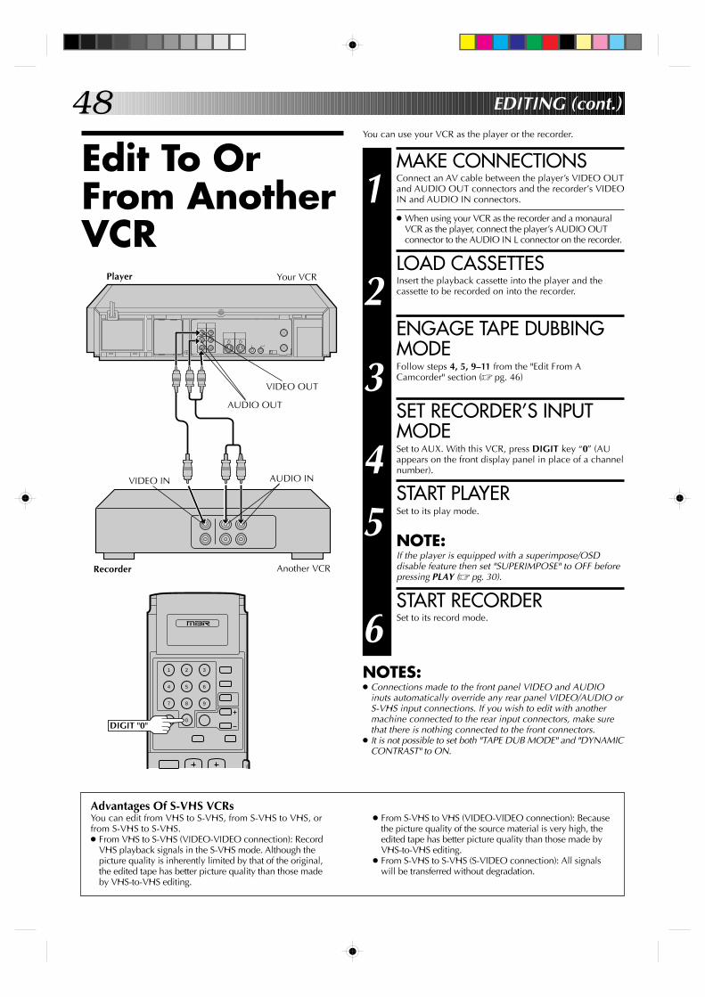
48
Edit To OrFrom AnotherVCR
You can use your VCR as the player or the recorder.
MAKE CONNECTIONS
1 Connect an AV cable between the player’s VIDEO OUTand AUDIO OUT connectors and the recorder’s VIDEOIN and AUDIO IN connectors.
● When using your VCR as the recorder and a monauralVCR as the player, connect the player’s AUDIO OUTconnector to the AUDIO IN L connector on the recorder.
LOAD CASSETTES
2 Insert the playback cassette into the player and thecassette to be recorded on into the recorder.
ENGAGE TAPE DUBBINGMODE
3 Follow steps 4, 5, 9–11 from the "Edit From ACamcorder" section (Z pg. 46)
SET RECORDER’S INPUTMODE
4 Set to AUX. With this VCR, press DIGIT key “0” (AUappears on the front display panel in place of a channelnumber).
START PLAYER
5 Set to its play mode.
NOTE:If the player is equipped with a superimpose/OSDdisable feature then set "SUPERIMPOSE" to OFF beforepressing PLAY (Z pg. 30).
START RECORDER
6 Set to its record mode.
NOTES:● Connections made to the front panel VIDEO and AUDIO
inuts automatically override any rear panel VIDEO/AUDIO orS-VHS input connections. If you wish to edit with anothermachine connected to the rear input connectors, make surethat there is nothing connected to the front connectors.
● It is not possible to set both "TAPE DUB MODE" and "DYNAMICCONTRAST" to ON.
EDITING (cont.)
VIDEO IN AUDIO IN
9
3
6
8
2
5
7
1
4
0
Advantages Of S-VHS VCRsYou can edit from VHS to S-VHS, from S-VHS to VHS, orfrom S-VHS to S-VHS.● From VHS to S-VHS (VIDEO-VIDEO connection): Record
VHS playback signals in the S-VHS mode. Although thepicture quality is inherently limited by that of the original,the edited tape has better picture quality than those madeby VHS-to-VHS editing.
● From S-VHS to VHS (VIDEO-VIDEO connection): Becausethe picture quality of the source material is very high, theedited tape has better picture quality than those made byVHS-to-VHS editing.
● From S-VHS to S-VHS (S-VIDEO connection): All signalswill be transferred without degradation.
VIDEO OUT
Player Your VCR
AUDIO OUT
Another VCRRecorder
DIGIT "0"
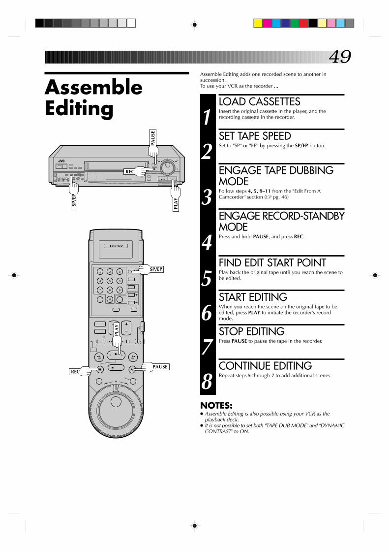
49
9
3
6
8
2
5
7
1
4
0
+
–
0000
0000
0000
0000
0000
0
0000
00000000000000000
AssembleEditing
Assemble Editing adds one recorded scene to another insuccession.To use your VCR as the recorder ...
LOAD CASSETTES
1 Insert the original cassette in the player, and therecording cassette in the recorder.
SET TAPE SPEED
2 Set to "SP" or "EP" by pressing the SP/EP button.
ENGAGE TAPE DUBBINGMODE
3 Follow steps 4, 5, 9–11 from the "Edit From ACamcorder" section (Z pg. 46)
ENGAGE RECORD-STANDBYMODE
4 Press and hold PAUSE, and press REC.
FIND EDIT START POINT
5 Play back the original tape until you reach the scene tobe edited.
START EDITING
6 When you reach the scene on the original tape to beedited, press PLAY to initiate the recorder’s recordmode.
STOP EDITING
7 Press PAUSE to pause the tape in the recorder.
CONTINUE EDITING
8 Repeat steps 5 through 7 to add additional scenes.
NOTES:● Assemble Editing is also possible using your VCR as the
playback deck.● It is not possible to set both "TAPE DUB MODE" and "DYNAMIC
CONTRAST" to ON.
PLA
YREC
PAU
SE
SP/E
P
SP/EP
PAUSEREC
PLA
Y
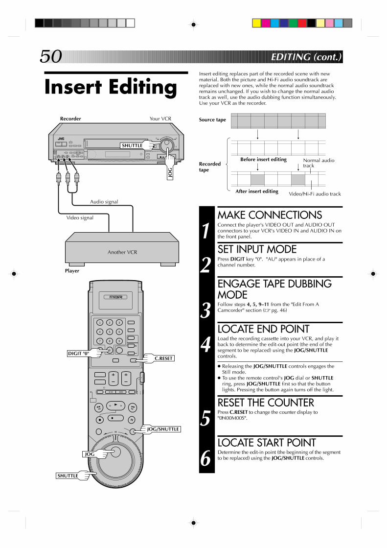
50
+
–
0000
0000
0000
0000
0000
0
0000
00000000000000000
Insert editing replaces part of the recorded scene with newmaterial. Both the picture and Hi-Fi audio soundtrack arereplaced with new ones, while the normal audio soundtrackremains unchanged. If you wish to change the normal audiotrack as well, use the audio dubbing function simultaneously.Use your VCR as the recorder.
Insert Editing
EDITING (cont.)
Recordedtape
Source tape
Before insert editing
After insert editing Video/Hi-Fi audio track
Normal audiotrack
MAKE CONNECTIONS
1 Connect the player's VIDEO OUT and AUDIO OUTconnectors to your VCR's VIDEO IN and AUDIO IN onthe front panel.
SET INPUT MODE
2 Press DIGIT key "0". "AU" appears in place of achannel number.
ENGAGE TAPE DUBBINGMODE
3 Follow steps 4, 5, 9–11 from the "Edit From ACamcorder" section (Z pg. 46)
LOCATE END POINT
4 Load the recording cassette into your VCR, and play itback to determine the edit-out point (the end of thesegment to be replaced) using the JOG/SHUTTLEcontrols.
● Releasing the JOG/SHUTTLE controls engages theStill mode.
● To use the remote control's JOG dial or SHUTTLEring, press JOG/SHUTTLE first so that the buttonlights. Pressing the button again turns off the light.
RESET THE COUNTER
5 Press C.RESET to change the counter display to"0H00M00S".
LOCATE START POINT
6 Determine the edit-in point (the beginning of the segmentto be replaced) using the JOG/SHUTTLE controls.
Your VCRRecorder
JOG
SHUTTLE
Audio signal
Video signal
Another VCR
Player
9
3
6
8
2
5
7
1
4
0
C.RESETDIGIT "0"
JOG/SHUTTLE
JOG
SHUTTLE
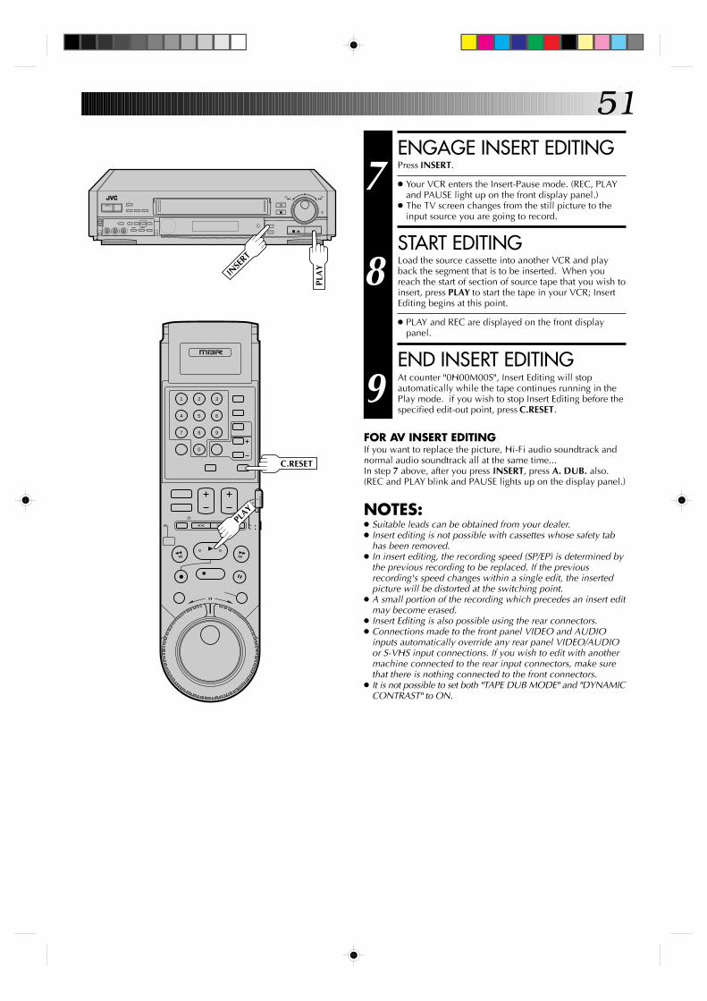
51
9
3
6
8
2
5
7
1
4
0
+
–
0000
0000
0000
0000
0000
0
0000
00000000000000000
ENGAGE INSERT EDITING
7 Press INSERT.
● Your VCR enters the Insert-Pause mode. (REC, PLAYand PAUSE light up on the front display panel.)
● The TV screen changes from the still picture to theinput source you are going to record.
START EDITING
8 Load the source cassette into another VCR and playback the segment that is to be inserted. When youreach the start of section of source tape that you wish toinsert, press PLAY to start the tape in your VCR; InsertEditing begins at this point.
● PLAY and REC are displayed on the front displaypanel.
END INSERT EDITING
9 At counter "0H00M00S", Insert Editing will stopautomatically while the tape continues running in thePlay mode. if you wish to stop Insert Editing before thespecified edit-out point, press C.RESET.
FOR AV INSERT EDITINGIf you want to replace the picture, Hi-Fi audio soundtrack andnormal audio soundtrack all at the same time...In step 7 above, after you press INSERT, press A. DUB. also.(REC and PLAY blink and PAUSE lights up on the display panel.)
NOTES:● Suitable leads can be obtained from your dealer.● Insert editing is not possible with cassettes whose safety tab
has been removed.● In insert editing, the recording speed (SP/EP) is determined by
the previous recording to be replaced. If the previousrecording's speed changes within a single edit, the insertedpicture will be distorted at the switching point.
● A small portion of the recording which precedes an insert editmay become erased.
● Insert Editing is also possible using the rear connectors.● Connections made to the front panel VIDEO and AUDIO
inputs automatically override any rear panel VIDEO/AUDIOor S-VHS input connections. If you wish to edit with anothermachine connected to the rear input connectors, make surethat there is nothing connected to the front connectors.
● It is not possible to set both "TAPE DUB MODE" and "DYNAMICCONTRAST" to ON.
PLA
Y
C.RESET
PLAY
INSE
RT
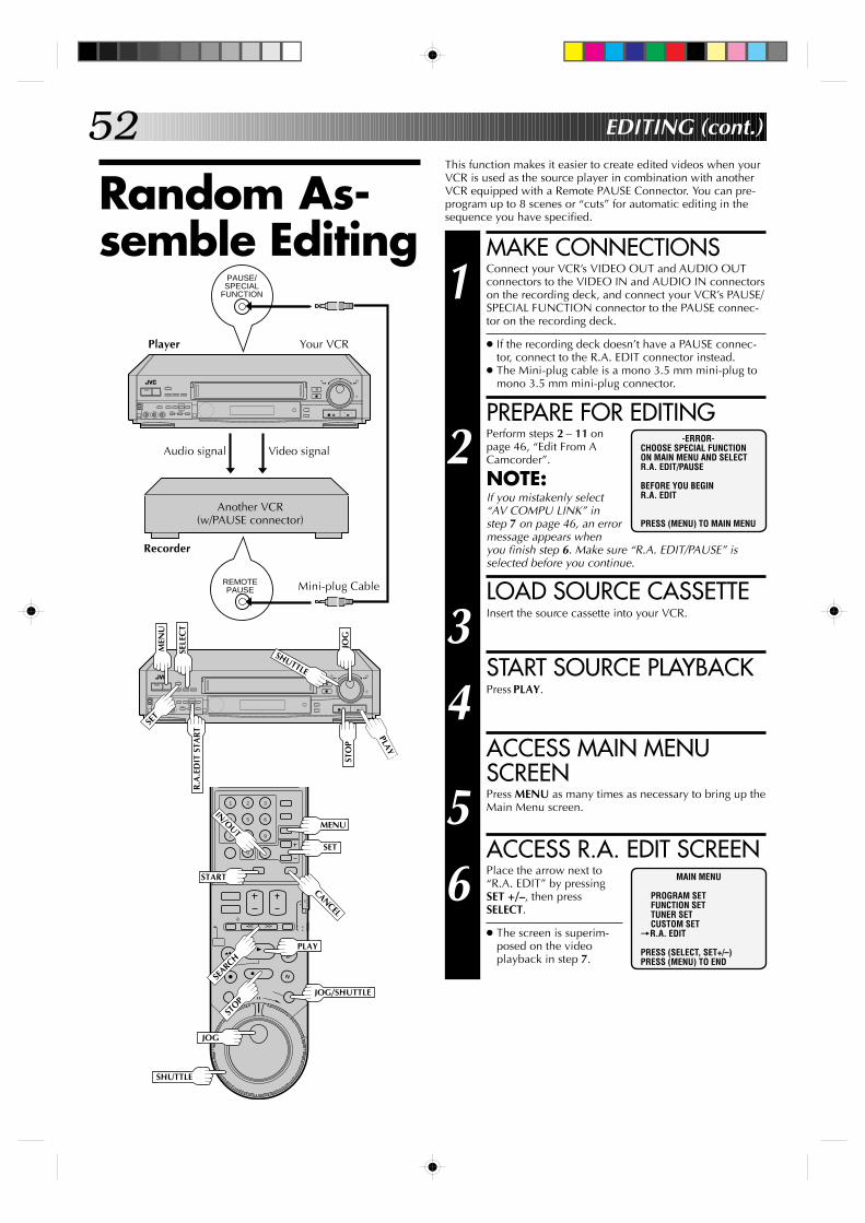
52
PAUSE/ SPECIAL
FUNCTION
REMOTE PAUSE
+
–
0000
0000
0000
0000
0000
0
0000
00000000000000000
This function makes it easier to create edited videos when yourVCR is used as the source player in combination with anotherVCR equipped with a Remote PAUSE Connector. You can pre-program up to 8 scenes or “cuts” for automatic editing in thesequence you have specified.
Random As-semble Editing MAKE CONNECTIONS
1 Connect your VCR’s VIDEO OUT and AUDIO OUTconnectors to the VIDEO IN and AUDIO IN connectorson the recording deck, and connect your VCR’s PAUSE/SPECIAL FUNCTION connector to the PAUSE connec-tor on the recording deck.
● If the recording deck doesn’t have a PAUSE connec-tor, connect to the R.A. EDIT connector instead.
● The Mini-plug cable is a mono 3.5 mm mini-plug tomono 3.5 mm mini-plug connector.
PREPARE FOR EDITING
2 Perform steps 2 – 11 onpage 46, “Edit From ACamcorder”.
NOTE:If you mistakenly select“AV COMPU LINK” instep 7 on page 46, an errormessage appears whenyou finish step 6. Make sure “R.A. EDIT/PAUSE” isselected before you continue.
LOAD SOURCE CASSETTE
3 Insert the source cassette into your VCR.
START SOURCE PLAYBACK
4 Press PLAY.
ACCESS MAIN MENUSCREEN
5 Press MENU as many times as necessary to bring up theMain Menu screen.
ACCESS R.A. EDIT SCREEN
6 Place the arrow next to“R.A. EDIT” by pressingSET +/–, then pressSELECT.
● The screen is superim-posed on the videoplayback in step 7.
-ERROR-CHOOSE SPECIAL FUNCTIONON MAIN MENU AND SELECTR.A. EDIT/PAUSE
BEFORE YOU BEGINR.A. EDIT
PRESS (MENU) TO MAIN MENU
EDITING (cont.)
MAIN MENU
PROGRAM SETFUNCTION SETTUNER SETCUSTOM SET
=R.A. EDIT
PRESS (SELECT, SET+/–)PRESS (MENU) TO END
Player Your VCR
Video signalAudio signal
Recorder
Another VCR(w/PAUSE connector)
Mini-plug Cable
+
–
0000
0000
0000
0000
0000
0
0000
00000000000000000
JOG
SHUTTLE
STO
P
PLAY
MEN
U
R.A
.ED
IT S
TAR
T
9
3
6
8
2
5
7
1
4
0
MENU
PLAY
CANCEL
SET
SELE
CT
JOG
SHUTTLE
JOG/SHUTTLE
SET
START
IN/OUT
STOP
SEARCH
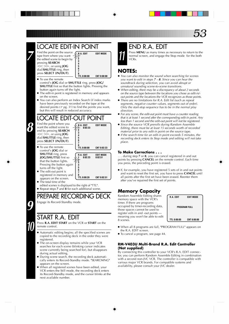
53END R.A. EDIT
11 Press MENU as many times as necessary to return to thenormal screen, and engage the Stop mode for the bothVCRs.
NOTES:● You can also monitor the sound when searching for scenes
you want to edit in steps 7 – 8. Since you can hear thesoundtrack during selection, you can avoid abrupt orunnatural sounding scene-to-scene transitions.
● When editing, there may be a discrepancy of about 2 secondson the source tape between the locations you chose as edit-in/-out points and the locations the VCR recognizes as those points.
● There are no limitations for R.A. Edit list (such as repeatsegments, negative counter values, segments out of order).Only the start-stop sequence has to be in the normal playdirection.
● For any scene, the edit-out point must have a counter readingthat is at least 1 second after the corresponding edit-in point. Anyless than 1 second and the edit-out point will not be registered.
● Since the source VCR prerolls during Random AssembleEditing, there must be at least 15 seconds worth of recordedmaterial prior to any edit-in point on the source tape.
● If the search time for an edit-in point exceeds 5 minutes, therecording deck enters its Stop mode and editing will not takeplace.
To Make Corrections . . .. . . during step 7 or 8, you can cancel registered in and outpoints by pressing CANCEL on the remote control. Each timeyou press, the preceding point is erased.
● If, for example, you have registered 5 sets of in and out pointsand want to reset the first set, you have to press CANCEL untilall points after the first set have been erased. Reenter themafter you've repaired the first set of points.
Memory CapacityRandom Assemble Editing sharesmemory space with the VCR'stimer. If there are programsoccupied by timer-recording data,those spaces cannot be used toregister edit-in and -out points —meaning you won't be able to edit8 scenes.
● When all 8 programs are full, "PROGRAM FULL" appears onthe R.A. EDIT screen.
● To cancel a program, see page 44.
RM-V403U Multi-Brand R.A. Edit Controller(Not supplied)By connecting this controller to your VCR's R.A. EDIT connec-tor, you can perform Random Assemble Editing in combinationwith a second non-JVC VCR. The controller is compatible withvarious major VCR brands. For compatible systems andavailability, please consult your JVC dealer.
LOCATE EDIT-IN POINT
7 Find the point on the sourcetape from where you wantthe edited scene to begin bypressing SEARCHTY, or using JOGdial/SHUTTLE ring, thenpress SELECT (IN/OUT).
● To use the remotecontrol's JOG dial or SHUTTLE ring, press JOG/SHUTTLE first so that the button lights. Pressing thebutton again turns off the light.
● The edit-in point is registered in memory and appearson the screen.
● You can also perform an Index Search (if index markshave been previously recorded on the tape at thedesired points Z pg. 31) to find the points you want,but this will result in reduced accuracy.
LOCATE EDIT-OUT POINT
8 Find the point where youwant the edited scene toend by pressing SEARCHTY, or using JOGdial/SHUTTLE ring, thenpress SELECT (IN/OUT).
● To use the remotecontrol's JOG dial orSHUTTLE ring, pressJOG/SHUTTLE first sothat the button lights.Pressing the button againturns off the light.
● The edit-out point isregistered in memory andappears on the screen.
● The total time of theedited scenes is displayed to the right of "TTL".
● Repeat steps 7 and 8 for each additional scene.
PREPARE RECORDING DECK
9 Engage its Record-Standby mode.
START R.A. EDIT
10 Press R.A. EDIT START on the VCR or START on theremote control.
● Automatic editing begins; all the specified scenes arecopied to the recording deck in the order they wereregistered.
● The on-screen display remains while your VCRsearches for each scene (blinking cursor indicatesscene currently being searched for), but disappearsduring actual editing.
● During scene search, the recording deck automati-cally enters its Record-Standby mode. "SEARCHING"appears on the screen.
● When all registered scenes have been edited, yourVCR enters the Still mode, the recording deck entersits Record-Standby mode, and the cursor blinks at thenext available number.
R.A. EDIT EDIT MODE=1
2345678TTL 0:00:00 CNT 0:00:00
R.A. EDIT EDIT MODE
PROGRAM FULL
TTL 0:00:00 CNT 0:00:00
R.A. EDIT EDIT MODE=1 0:02:23
2345678TTL 0:00:00 CNT 0:02:23
R.A. EDIT EDIT MODE1 0:02:23 0:02:51
=2345678TTL 0:00:28 CNT 0:02:51
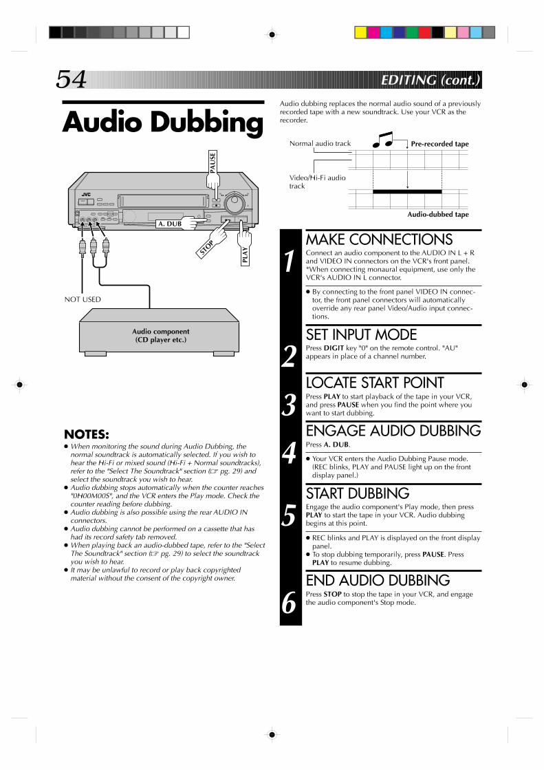
54
+
–
0000
0000
0000
0000
0000
0
0000
00000000000000000
Audio dubbing replaces the normal audio sound of a previouslyrecorded tape with a new soundtrack. Use your VCR as therecorder.Audio Dubbing
MAKE CONNECTIONS
1 Connect an audio component to the AUDIO IN L + Rand VIDEO IN connectors on the VCR's front panel.*When connecting monaural equipment, use only theVCR's AUDIO IN L connector.
● By connecting to the front panel VIDEO IN connec-tor, the front panel connectors will automaticallyoverride any rear panel Video/Audio input connec-tions.
SET INPUT MODE
2 Press DIGIT key "0" on the remote control. "AU"appears in place of a channel number.
LOCATE START POINT
3 Press PLAY to start playback of the tape in your VCR,and press PAUSE when you find the point where youwant to start dubbing.
ENGAGE AUDIO DUBBING
4 Press A. DUB.
● Your VCR enters the Audio Dubbing Pause mode.(REC blinks, PLAY and PAUSE light up on the frontdisplay panel.)
START DUBBING
5 Engage the audio component's Play mode, then pressPLAY to start the tape in your VCR. Audio dubbingbegins at this point.
● REC blinks and PLAY is displayed on the front displaypanel.
● To stop dubbing temporarily, press PAUSE. PressPLAY to resume dubbing.
END AUDIO DUBBING
6 Press STOP to stop the tape in your VCR, and engagethe audio component's Stop mode.
Pre-recorded tape
Audio-dubbed tape
Normal audio track
Video/Hi-Fi audiotrack
EDITING (cont.)
NOTES:● When monitoring the sound during Audio Dubbing, the
normal soundtrack is automatically selected. If you wish tohear the Hi-Fi or mixed sound (Hi-Fi + Normal soundtracks),refer to the "Select The Soundtrack" section (Z pg. 29) andselect the soundtrack you wish to hear.
● Audio dubbing stops automatically when the counter reaches"0H00M00S", and the VCR enters the Play mode. Check thecounter reading before dubbing.
● Audio dubbing is also possible using the rear AUDIO INconnectors.
● Audio dubbing cannot be performed on a cassette that hashad its record safety tab removed.
● When playing back an audio-dubbed tape, refer to the "SelectThe Soundtrack" section (Z pg. 29) to select the soundtrackyou wish to hear.
● It may be unlawful to record or play back copyrightedmaterial without the consent of the copyright owner.
NOT USED
A. DUB
STOP
PLA
Y
PAU
SE
Audio component(CD player etc.)
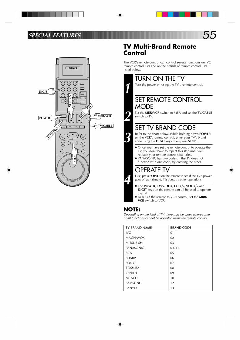
55
9
3
6
8
2
5
7
1
4
0
SPECIAL FEATURES
TV Multi-Brand RemoteControlThe VCR's remote control can control several functions on JVCremote control TVs and on the brands of remote control TVslisted below.
TURN ON THE TV
1 Turn the power on using the TV's remote control.
SET REMOTE CONTROLMODE
2 Set the MBR/VCR switch to MBR and set the TV/CABLEswitch to TV.
SET TV BRAND CODE
3 Refer to the chart below. While holding down POWERon the VCR’s remote control, enter your TV’s brandcode using the DIGIT keys, then press STOP.
● Once you have set the remote control to operate theTV, you don’t have to repeat this step until youreplace your remote control’s batteries.
● PANASONIC has two codes. If the TV does notfunction with one code, try entering the other.
OPERATE TV
4 First, press POWER on the remote to see if the TV’s powergoes off as it should. If it does, try other operations.
● The POWER, TV/VIDEO, CH +/–, VOL +/– andDIGIT keys on the remote can all be used to operatethe TV.
● To return the remote to VCR control, set the MBR/VCR switch to VCR.
NOTE:Depending on the kind of TV, there may be cases where someor all functions cannot be operated using the remote control.
TV BRAND NAME BRAND CODE
JVC 01
MAGNAVOX 02
MITSUBISHI 03
PANASONIC 04, 11
RCA 05
SHARP 06
SONY 07
TOSHIBA 08
ZENITH 09
HITACHI 10
SAMSUNG 12
SANYO 13
DIGIT
TV/V
IDEO
POWER
CH
STO
P
VO
L. +
/-
TV/CABLE
MBR/VCR
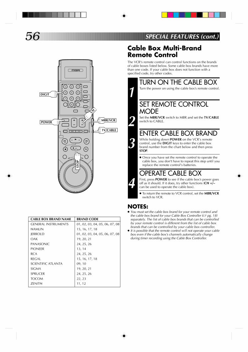
56
9
3
6
8
2
5
7
1
4
0
SPECIAL FEATURES (cont.)
Cable Box Multi-BrandRemote ControlThe VCR's remote control can control functions on the brandsof cable boxes listed below. Some cable box brands have morethan one code. If your cable box does not function with aspecified code, try other codes.
CABLE BOX BRAND NAME BRAND CODE
GENERAL INSTRUMENTS 01, 02, 03, 04, 05, 06, 07, 08
HAMLIN 15, 16, 17, 18JERROLD 01, 02, 03, 04, 05, 06, 07, 08
OAK 19, 20, 21
PANASONIC 24, 25, 26PIONEER 13, 14
RCA 24, 25, 26
REGAL 15, 16, 17, 18SCIENTIFIC ATLANTA 09, 10
SIGMA 19, 20, 21
SPRUCER 24, 25, 26
TOCOM 22, 23ZENITH 11, 12
TURN ON THE CABLE BOX
1 Turn the power on using the cable box’s remote control.
SET REMOTE CONTROLMODE
2 Set the MBR/VCR switch to MBR and set the TV/CABLEswitch to CABLE.
ENTER CABLE BOX BRAND
3 While holding down POWER on the VCR’s remotecontrol, use the DIGIT keys to enter the cable boxbrand number from the chart below and then pressSTOP.
● Once you have set the remote control to operate thecable box, you don't have to repeat this step until youreplace the remote control's batteries.
OPERATE CABLE BOX
4 First, press POWER to see if the cable box’s power goesoff as it should. If it does, try other functions (CH +/–can be used to operate the cable box).
● To return the remote to VCR control, set the MBR/VCRswitch to VCR.
NOTES:● You must set the cable box brand for your remote control and
the cable box brand for your Cable Box Controller (Z pg. 18)separately. The list of cable box brands that can be controlledby your remote control is different from the list of cable boxbrands that can be controlled by your cable box controller.
● It is possible that the remote control will not operate your cablebox even if the cable box’s channels automatically changeduring timer recording using the Cable Box Controller.
POWER
CH
STO
P
TV/CABLE
MBR/VCR
DIGIT
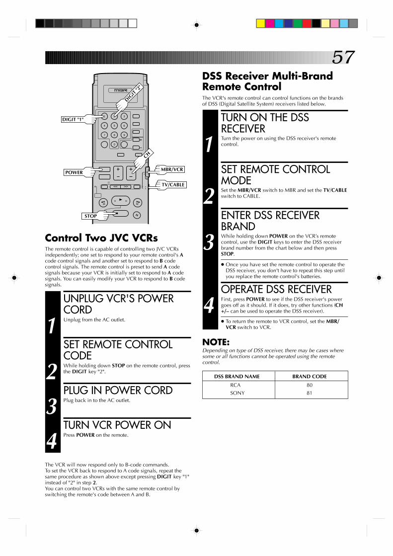
57DSS Receiver Multi-BrandRemote ControlThe VCR's remote control can control functions on the brandsof DSS (Digital Satellite System) receivers listed below.
TURN ON THE DSSRECEIVER
1 Turn the power on using the DSS receiver's remotecontrol.
SET REMOTE CONTROLMODE
2 Set the MBR/VCR switch to MBR and set the TV/CABLEswitch to CABLE.
ENTER DSS RECEIVERBRAND
3 While holding down POWER on the VCR’s remotecontrol, use the DIGIT keys to enter the DSS receiverbrand number from the chart below and then pressSTOP.
● Once you have set the remote control to operate theDSS receiver, you don't have to repeat this step untilyou replace the remote control's batteries.
OPERATE DSS RECEIVER
4 First, press POWER to see if the DSS receiver's powergoes off as it should. If it does, try other functions (CH+/– can be used to operate the DSS receiver).
● To return the remote to VCR control, set the MBR/VCR switch to VCR.
NOTE:Depending on type of DSS receiver, there may be cases wheresome or all functions cannot be operated using the remotecontrol.
DSS BRAND NAME BRAND CODE
RCA 80
SONY 81
9
3
6
8
2
5
7
1
4
0
POWER
CH
TV/CABLE
MBR/VCR
STOP
DIGIT
"2"
DIGIT "1"
UNPLUG VCR'S POWERCORD
1 Unplug from the AC outlet.
SET REMOTE CONTROLCODE
2 While holding down STOP on the remote control, pressthe DIGIT key "2".
PLUG IN POWER CORD
3 Plug back in to the AC outlet.
TURN VCR POWER ON
4 Press POWER on the remote.
The VCR will now respond only to B-code commands.To set the VCR back to respond to A code signals, repeat thesame procedure as shown above except pressing DIGIT key "1"instead of "2" in step 2.You can control two VCRs with the same remote control byswitching the remote's code between A and B.
Control Two JVC VCRsThe remote control is capable of controlling two JVC VCRsindependently; one set to respond to your remote control's Acode control signals and another set to respond to B codecontrol signals. The remote control is preset to send A codesignals because your VCR is initially set to respond to A codesignals. You can easily modify your VCR to respond to B codesignals.
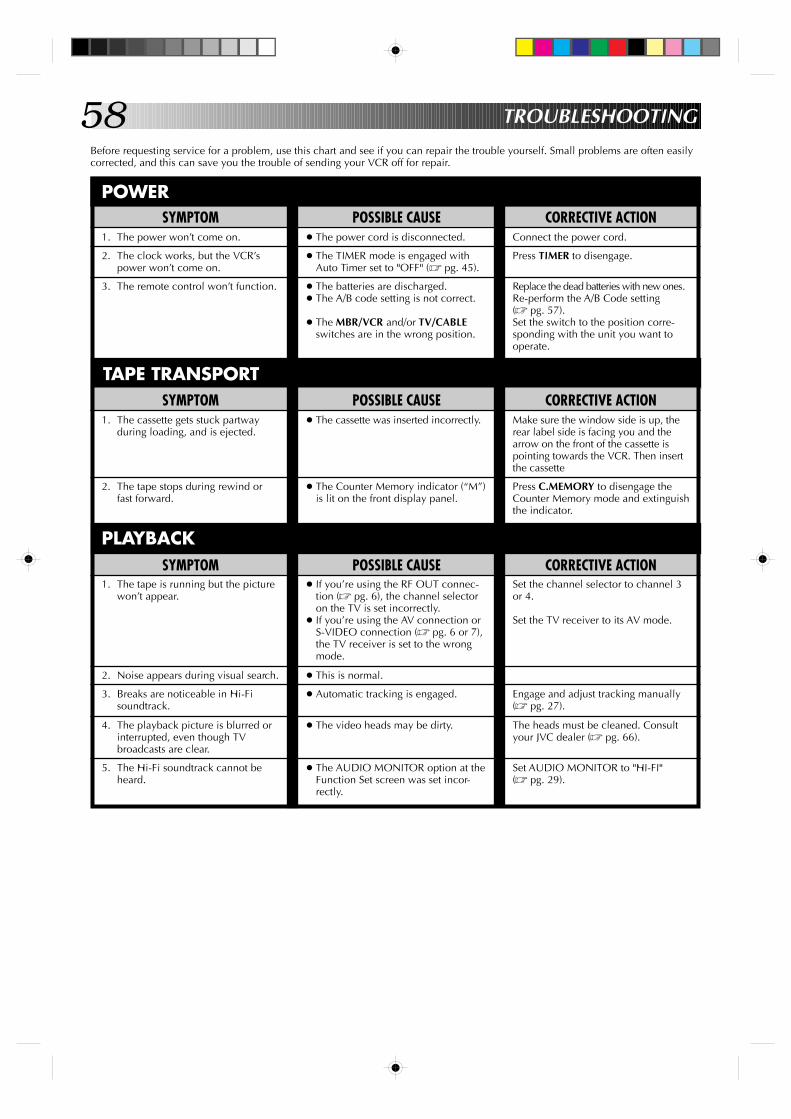
58 TROUBLESHOOTING
Before requesting service for a problem, use this chart and see if you can repair the trouble yourself. Small problems are often easilycorrected, and this can save you the trouble of sending your VCR off for repair.
POWERPOSSIBLE CAUSE
● The power cord is disconnected.
● The TIMER mode is engaged withAuto Timer set to "OFF" (Z pg. 45).
● The batteries are discharged.● The A/B code setting is not correct.
● The MBR/VCR and/or TV/CABLEswitches are in the wrong position.
SYMPTOM1. The power won’t come on.
2. The clock works, but the VCR’spower won’t come on.
3. The remote control won’t function.
CORRECTIVE ACTIONConnect the power cord.
Press TIMER to disengage.
Replace the dead batteries with new ones.Re-perform the A/B Code setting(Z pg. 57).Set the switch to the position corre-sponding with the unit you want tooperate.
TAPE TRANSPORTPOSSIBLE CAUSE
● The cassette was inserted incorrectly.
● The Counter Memory indicator (“M”)is lit on the front display panel.
SYMPTOM1. The cassette gets stuck partway
during loading, and is ejected.
2. The tape stops during rewind orfast forward.
CORRECTIVE ACTIONMake sure the window side is up, therear label side is facing you and thearrow on the front of the cassette ispointing towards the VCR. Then insertthe cassette
Press C.MEMORY to disengage theCounter Memory mode and extinguishthe indicator.
SYMPTOM1. The tape is running but the picture
won’t appear.
2. Noise appears during visual search.
3. Breaks are noticeable in Hi-Fisoundtrack.
4. The playback picture is blurred orinterrupted, even though TVbroadcasts are clear.
5. The Hi-Fi soundtrack cannot beheard.
PLAYBACKPOSSIBLE CAUSE
● If you’re using the RF OUT connec-tion (Z pg. 6), the channel selectoron the TV is set incorrectly.
● If you’re using the AV connection orS-VIDEO connection (Z pg. 6 or 7),the TV receiver is set to the wrongmode.
● This is normal.
● Automatic tracking is engaged.
● The video heads may be dirty.
● The AUDIO MONITOR option at theFunction Set screen was set incor-rectly.
CORRECTIVE ACTIONSet the channel selector to channel 3or 4.
Set the TV receiver to its AV mode.
Engage and adjust tracking manually(Z pg. 27).
The heads must be cleaned. Consultyour JVC dealer (Z pg. 66).
Set AUDIO MONITOR to "HI-FI"(Z pg. 29).
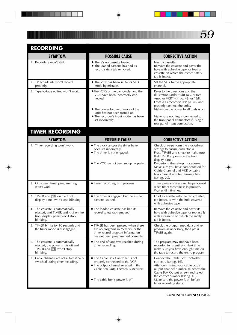
59
CORRECTIVE ACTIONCheck or re-perform the clock/timersettings to ensure correctness.Press TIMER and check to make surethat TIMER appears on the frontdisplay panel.Re-perform the set-up procedures.Make sure you have compensated forGuide Channel and VCR or cablebox channel number mismatches(Z pg. 20).
Timer programming can’t be performedwhen timer recording is in progress.Wait until it finishes.
Load a cassette with the record safetytab intact, or with the hole coveredwith adhesive tape.
Remove the cassette and cover itshole with adhesive tape, or replace itwith a cassette on which the safetytab is intact.
Check the programmed data and re-program as necessary, then pressTIMER again.
The program may not have beenrecorded in its entirety. Next timemake sure you have enough time onthe tape to record the entire program.
Connect the Cable Box Controllercorrectly (Z pg. 16).After confirming your cable box’soutput channel number, re-access theCable Box Output screen and selectthe correct number (Z pg. 18).Make sure the power is on beforetimer recording starts.
POSSIBLE CAUSE● The clock and/or the timer have
been set incorrectly.● The timer is not engaged.
● The VCR has not been set up properly.
● Timer recording is in progress.
● The timer is engaged but there’s nocassette loaded.
● The loaded cassette has had itsrecord safety tab removed.
● TIMER has been pressed when thereare no programs in memory, or thetimer record program informationhas not been programmed correctly.
● The end of tape was reached duringtimer recording.
● The Cable Box Controller is notproperly connected to the VCR.
● The output channel selected in theCable Box Output screen is incorrect.
● The cable box’s power is off.
SYMPTOM1. Timer recording won’t work.
2. On-screen timer programmingwon’t work.
3. TIMER and ] on the frontdisplay panel won’t stop blinking.
4. The cassette is automaticallyejected, and TIMER and ] on thefront display panel won’t stopblinking.
5. TIMER blinks for 10 seconds andthe timer mode is disengaged.
6. The cassette is automaticallyejected, the power shuts off andTIMER and ] won’t stopblinking.
7. Cable channels are not automaticallyswitched during timer recording.
CORRECTIVE ACTIONInsert a cassette.Remove the cassette and cover thehole with adhesive tape, or load acassette on which the record safetytab is intact.
Set the VCR to the appropriatechannel.
Refer to the directions and theillustration under “Edit To Or FromAnother VCR” (Z pg. 48) or “EditFrom A Camcorder” (Z pg. 46) andproperly connect the units.Make sure the power to all units is on.
Make sure nothing is connected tothe front panel connectors if using arear panel input connection.
POSSIBLE CAUSE● There’s no cassette loaded.● The loaded cassette has had its
record safety tab removed.
● The VCR has been set to its AUXmode by mistake.
●The VCRs or the camcorder and theVCR have been incorrectly con-nected.
● The power to one or more of theunits has not been turned on.
● The recorder’s input mode has beenset incorrectly.
SYMPTOM1. Recording won’t start.
2. TV broadcasts won’t recordproperly.
3. Tape-to-tape editing won’t work.
RECORDING
CONTINUED ON NEXT PAGE.
TIMER RECORDING
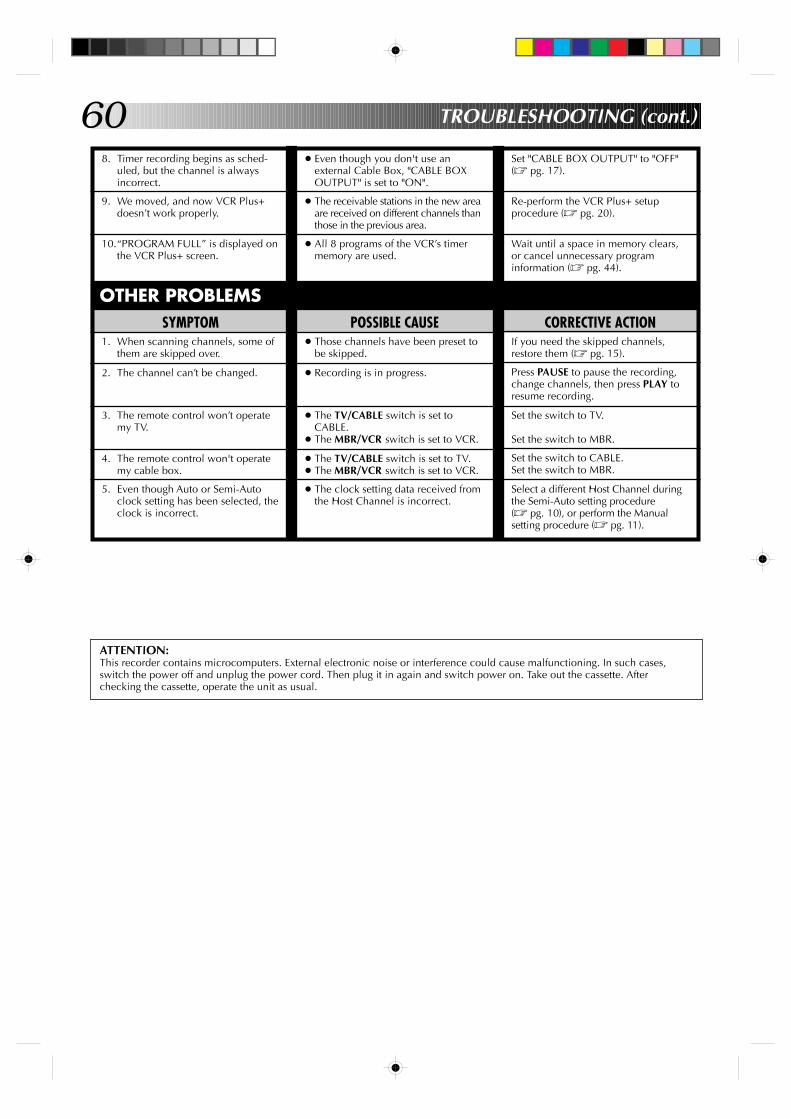
608. Timer recording begins as sched-
uled, but the channel is alwaysincorrect.
9. We moved, and now VCR Plus+doesn’t work properly.
10.“PROGRAM FULL” is displayed onthe VCR Plus+ screen.
● Even though you don't use anexternal Cable Box, "CABLE BOXOUTPUT" is set to "ON".
● The receivable stations in the new areaare received on different channels thanthose in the previous area.
● All 8 programs of the VCR’s timermemory are used.
ATTENTION:This recorder contains microcomputers. External electronic noise or interference could cause malfunctioning. In such cases,switch the power off and unplug the power cord. Then plug it in again and switch power on. Take out the cassette. Afterchecking the cassette, operate the unit as usual.
OTHER PROBLEMSCORRECTIVE ACTION
If you need the skipped channels,restore them (Z pg. 15).
Press PAUSE to pause the recording,change channels, then press PLAY toresume recording.
Set the switch to TV.
Set the switch to MBR.
Set the switch to CABLE.Set the switch to MBR.
Select a different Host Channel duringthe Semi-Auto setting procedure(Z pg. 10), or perform the Manualsetting procedure (Z pg. 11).
SYMPTOM1. When scanning channels, some of
them are skipped over.
2. The channel can’t be changed.
3. The remote control won’t operatemy TV.
4. The remote control won't operatemy cable box.
5. Even though Auto or Semi-Autoclock setting has been selected, theclock is incorrect.
Set "CABLE BOX OUTPUT" to "OFF"(Z pg. 17).
Re-perform the VCR Plus+ setupprocedure (Z pg. 20).
Wait until a space in memory clears,or cancel unnecessary programinformation (Z pg. 44).
POSSIBLE CAUSE● Those channels have been preset to
be skipped.
● Recording is in progress.
● The TV/CABLE switch is set toCABLE.
● The MBR/VCR switch is set to VCR.
● The TV/CABLE switch is set to TV.● The MBR/VCR switch is set to VCR.
● The clock setting data received fromthe Host Channel is incorrect.
TROUBLESHOOTING (cont.)
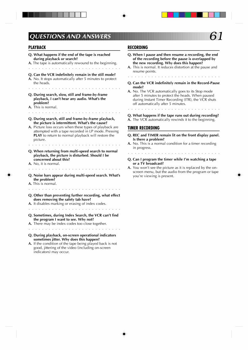
61QUESTIONS AND ANSWERS
PLAYBACKQ. What happens if the end of the tape is reached
during playback or search?
○ ○ ○ ○ ○ ○ ○ ○ ○ ○ ○ ○ ○ ○ ○ ○ ○ ○ ○ ○ ○ ○ ○ ○ ○ ○ ○ ○
A. The tape is automatically rewound to the beginning.
Q. Can the VCR indefinitely remain in the still mode?A. No. It stops automatically after 5 minutes to protect
○ ○ ○ ○ ○ ○ ○ ○ ○ ○ ○ ○ ○ ○ ○ ○ ○ ○ ○ ○ ○ ○ ○ ○ ○ ○ ○ ○
the heads.
Q. During search, slow, still and frame-by-frameplayback, I can’t hear any audio. What’s theproblem?
○ ○ ○ ○ ○ ○ ○ ○ ○ ○ ○ ○ ○ ○ ○ ○ ○ ○ ○ ○ ○ ○ ○ ○ ○ ○ ○ ○
A. This is normal.
Q. During search, still and frame-by-frame playback,the picture is intermittent. What’s the cause?
A. Picture loss occurs when these types of playback areattempted with a tape recorded in LP mode. PressingPLAY to return to normal playback will restore the
○ ○ ○ ○ ○ ○ ○ ○ ○ ○ ○ ○ ○ ○ ○ ○ ○ ○ ○ ○ ○ ○ ○ ○ ○ ○ ○ ○
picture.
Q. When returning from multi-speed search to normalplayback, the picture is disturbed. Should I beconcerned about this?
○ ○ ○ ○ ○ ○ ○ ○ ○ ○ ○ ○ ○ ○ ○ ○ ○ ○ ○ ○ ○ ○ ○ ○ ○ ○ ○ ○
A. No, it is normal.
Q. Noise bars appear during multi-speed search. What’sthe problem?
○ ○ ○ ○ ○ ○ ○ ○ ○ ○ ○ ○ ○ ○ ○ ○ ○ ○ ○ ○ ○ ○ ○ ○ ○ ○ ○ ○
A. This is normal.
Q. Other than preventing further recording, what effectdoes removing the safety tab have?
○ ○ ○ ○ ○ ○ ○ ○ ○ ○ ○ ○ ○ ○ ○ ○ ○ ○ ○ ○ ○ ○ ○ ○ ○ ○ ○ ○
A. It disables marking or erasing of index codes.
Q. Sometimes, during Index Search, the VCR can’t findthe program I want to see. Why not?
○ ○ ○ ○ ○ ○ ○ ○ ○ ○ ○ ○ ○ ○ ○ ○ ○ ○ ○ ○ ○ ○ ○ ○ ○ ○ ○ ○
A. There may be index codes too close together.
Q. During playback, on-screen operational indicatorssometimes jitter. Why does this happen?
A. If the condition of the tape being played back is notgood, jittering of the video (including on-screenindicators) may occur.
RECORDINGQ. When I pause and then resume a recording, the end
of the recording before the pause is overlapped bythe new recording. Why does this happen?
A. This is normal. It reduces distortion at the pause and
○ ○ ○ ○ ○ ○ ○ ○ ○ ○ ○ ○ ○ ○ ○ ○ ○ ○ ○ ○ ○ ○ ○ ○ ○ ○ ○ ○
resume points.
Q. Can the VCR indefinitely remain in the Record-Pausemode?
A. No. The VCR automatically goes to its Stop modeafter 5 minutes to protect the heads. When pausedduring Instant Timer Recording (ITR), the VCR shuts
○ ○ ○ ○ ○ ○ ○ ○ ○ ○ ○ ○ ○ ○ ○ ○ ○ ○ ○ ○ ○ ○ ○ ○ ○ ○ ○ ○
off automatically after 5 minutes.
Q. What happens if the tape runs out during recording?A. The VCR automatically rewinds it to the beginning.
TIMER RECORDINGQ. REC and TIMER remain lit on the front display panel.
Is there a problem?A. No. This is a normal condition for a timer recording
○ ○ ○ ○ ○ ○ ○ ○ ○ ○ ○ ○ ○ ○ ○ ○ ○ ○ ○ ○ ○ ○ ○ ○ ○ ○ ○ ○
in progress.
Q. Can I program the timer while I’m watching a tapeor a TV broadcast?
A. You won’t see the picture as it is replaced by the on-screen menu, but the audio from the program or tapeyou’re viewing is present.
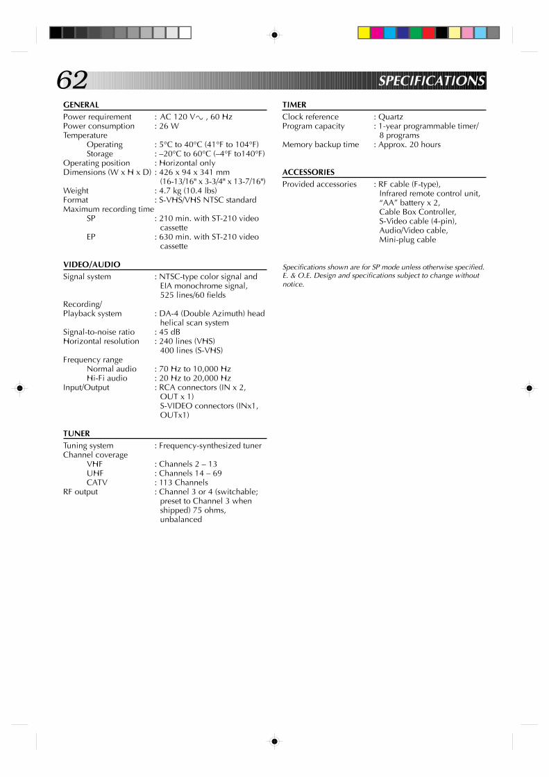
62GENERALPower requirement : AC 120 V` , 60 HzPower consumption : 26 WTemperature
Operating : 5°C to 40°C (41°F to 104°F)Storage : –20°C to 60°C (–4°F to140°F)
Operating position : Horizontal onlyDimensions (W x H x D) : 426 x 94 x 341 mm
(16-13/16" x 3-3/4" x 13-7/16")Weight : 4.7 kg (10.4 lbs)Format : S-VHS/VHS NTSC standardMaximum recording time
SP : 210 min. with ST-210 videocassette
EP : 630 min. with ST-210 videocassette
VIDEO/AUDIOSignal system : NTSC-type color signal and
EIA monochrome signal,525 lines/60 fields
Recording/Playback system : DA-4 (Double Azimuth) head
helical scan systemSignal-to-noise ratio : 45 dBHorizontal resolution : 240 lines (VHS)
400 lines (S-VHS)Frequency range
Normal audio : 70 Hz to 10,000 HzHi-Fi audio : 20 Hz to 20,000 Hz
Input/Output : RCA connectors (IN x 2,OUT x 1)S-VIDEO connectors (INx1,OUTx1)
TUNERTuning system : Frequency-synthesized tunerChannel coverage
VHF : Channels 2 – 13UHF : Channels 14 – 69CATV : 113 Channels
RF output : Channel 3 or 4 (switchable;preset to Channel 3 whenshipped) 75 ohms,unbalanced
TIMERClock reference : QuartzProgram capacity : 1-year programmable timer/
8 programsMemory backup time : Approx. 20 hours
ACCESSORIESProvided accessories : RF cable (F-type),
Infrared remote control unit,“AA” battery x 2,Cable Box Controller,S-Video cable (4-pin),Audio/Video cable,Mini-plug cable
Specifications shown are for SP mode unless otherwise specified.E. & O.E. Design and specifications subject to change withoutnotice.
SPECIFICATIONS
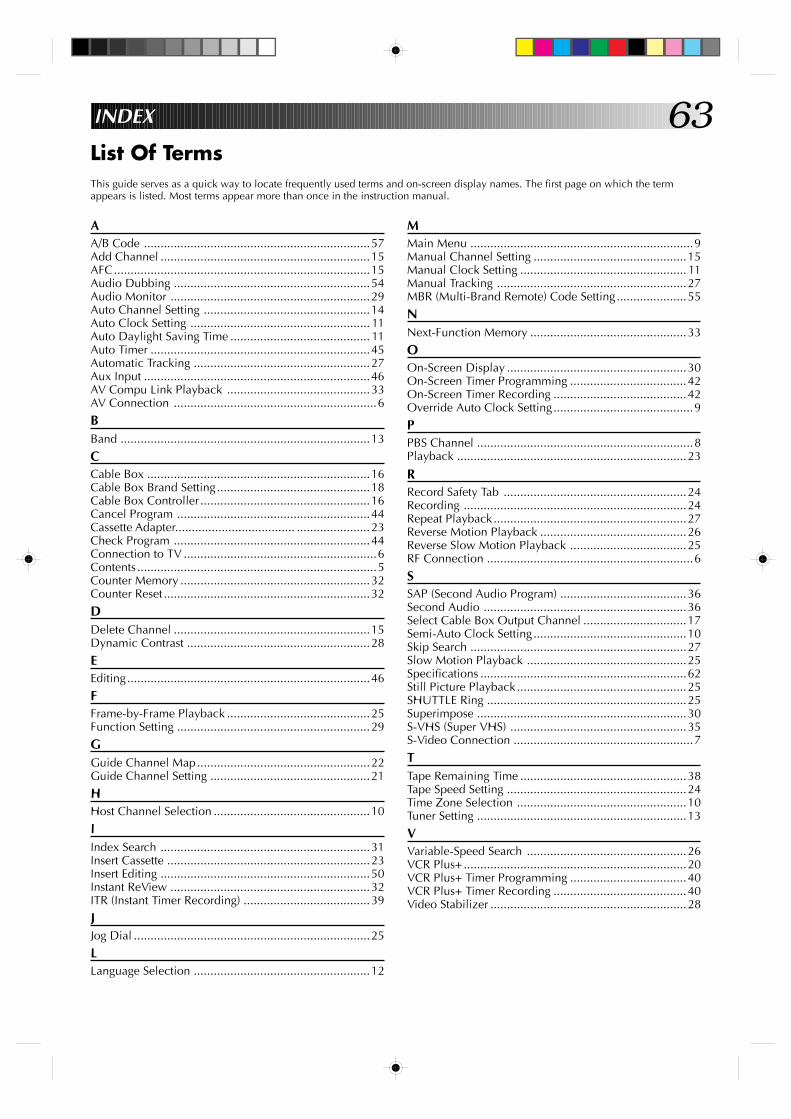
63INDEX
List Of TermsThis guide serves as a quick way to locate frequently used terms and on-screen display names. The first page on which the termappears is listed. Most terms appear more than once in the instruction manual.
AA/B Code ....................................................................57Add Channel ...............................................................15AFC.............................................................................15Audio Dubbing ...........................................................54Audio Monitor ............................................................29Auto Channel Setting ..................................................14Auto Clock Setting ...................................................... 11Auto Daylight Saving Time .......................................... 11Auto Timer ..................................................................45Automatic Tracking .....................................................27Aux Input ....................................................................46AV Compu Link Playback ...........................................33AV Connection .............................................................6
BBand ...........................................................................13
CCable Box ...................................................................16Cable Box Brand Setting..............................................18Cable Box Controller ...................................................16Cancel Program ..........................................................44Cassette Adapter.................................... ......................23Check Program ...........................................................44Connection to TV ..........................................................6Contents ........................................................................5Counter Memory .........................................................32Counter Reset ..............................................................32
DDelete Channel ...........................................................15Dynamic Contrast .......................................................28
EEditing.........................................................................46
FFrame-by-Frame Playback ...........................................25Function Setting ..........................................................29
GGuide Channel Map....................................................22Guide Channel Setting ................................................21
HHost Channel Selection ...............................................10
IIndex Search ...............................................................31Insert Cassette .............................................................23Insert Editing ...............................................................50Instant ReView ............................................................32ITR (Instant Timer Recording) ......................................39
JJog Dial .......................................................................25
LLanguage Selection .....................................................12
MMain Menu ...................................................................9Manual Channel Setting ..............................................15Manual Clock Setting .................................................. 11Manual Tracking .........................................................27MBR (Multi-Brand Remote) Code Setting.....................55
NNext-Function Memory ...............................................33
OOn-Screen Display ......................................................30On-Screen Timer Programming ...................................42On-Screen Timer Recording ........................................42Override Auto Clock Setting..........................................9
PPBS Channel .................................................................8Playback .....................................................................23
RRecord Safety Tab .......................................................24Recording ...................................................................24Repeat Playback..........................................................27Reverse Motion Playback ............................................26Reverse Slow Motion Playback ...................................25RF Connection ..............................................................6
SSAP (Second Audio Program) ......................................36Second Audio .............................................................36Select Cable Box Output Channel ...............................17Semi-Auto Clock Setting..............................................10Skip Search .................................................................27Slow Motion Playback ................................................25Specifications ..............................................................62Still Picture Playback...................................................25SHUTTLE Ring ............................................................25Superimpose ...............................................................30S-VHS (Super VHS) .....................................................35S-Video Connection ......................................................7
TTape Remaining Time ..................................................38Tape Speed Setting ......................................................24Time Zone Selection ...................................................10Tuner Setting ...............................................................13
VVariable-Speed Search ................................................26VCR Plus+...................................................................20VCR Plus+ Timer Programming ...................................40VCR Plus+ Timer Recording ........................................40Video Stabilizer ...........................................................28
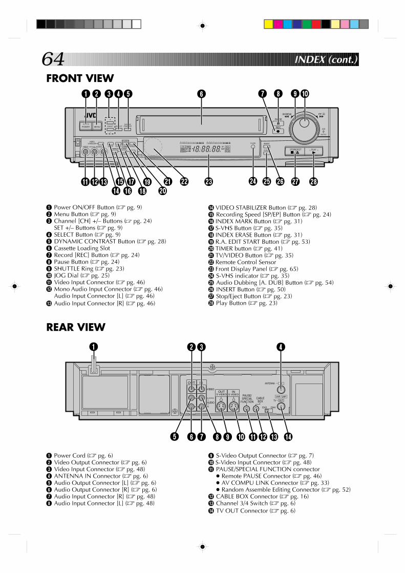
64 INDEX (cont.)
FRONT VIEW
REAR VIEW
1 Power Cord (Z pg. 6)2 Video Output Connector (Z pg. 6)3 Video Input Connector (Z pg. 48)4 ANTENNA IN Connector (Z pg. 6)5 Audio Output Connector [L] (Z pg. 6)6 Audio Output Connector [R] (Z pg. 6)7 Audio Input Connector [R] (Z pg. 48)8 Audio Input Connector [L] (Z pg. 48)
9 S-Video Output Connector (Z pg. 7)0 S-Video Input Connector (Z pg. 48)! PAUSE/SPECIAL FUNCTION connector
● Remote PAUSE Connector (Z pg. 46)● AV COMPU LINK Connector (Z pg. 33)● Random Assemble Editing Connector (Z pg. 52)
@ CABLE BOX Connector (Z pg. 16)# Channel 3/4 Switch (Z pg. 6)$ TV OUT Connector (Z pg. 6)
ANTENNAOUT
CH3
PAUSE/ SPECIAL
FUNCTION
IN
VIDEO
AUDIO
L(MONO)
R
CABLE BOX
CH4
IN
VHF / UHF
OUTTV
OUT S VIDEO
IN S VIDEO
1 2 3 4
6 75 8 9 0 ! @ # $
1 Power ON/OFF Button (Z pg. 9)2 Menu Button (Z pg. 9)3 Channel [CH] +/– Buttons (Z pg. 24)
SET +/– Buttons (Z pg. 9)4 SELECT Button (Z pg. 9)5 DYNAMIC CONTRAST Button (Z pg. 28)6 Cassette Loading Slot7 Record [REC] Button (Z pg. 24)8 Pause Button (Z pg. 24)9 SHUTTLE Ring (Z pg. 23)0 JOG Dial (Z pg. 25)! Video Input Connector (Z pg. 46)@ Mono Audio Input Connector (Z pg. 46)
Audio Input Connector [L] (Z pg. 46)# Audio Input Connector [R] (Z pg. 46)
REW FF
JOG
SHUTTLE
POWER MENU CH/SET
A.DUB
PAUSE
REC
STOP/EJECT PLAY
SELECT
+
–
H M S
I T R TIMER
VIDEO
MSPEP
R E C
SAPPAUSE
STAMPM
PLAY
L
dB –20 15 10 8 46 2 0 2 4 6 +8
R
dB –20 15 10 8 46 2 0 2 4 6 +8
0000
0000
0000
0000
0000
0
0000
00000000000000000
INSERT
MARK
R.A.EDIT
VIDEO (MONO)L–AUDIO–R
ERASE TIMER
START
INDEXSP/EP S-VHS TV/VIDEO
S-VHS
DYNAMIC CONTRAST
VIDEO STABILIZER
1
@! # r e t i u
2 6 97
$ % &
* q (
^ ) y w
8 0 4 53
$ VIDEO STABILIZER Button (Z pg. 28)% Recording Speed [SP/EP] Button (Z pg. 24)^ INDEX MARK Button (Z pg. 31)& S-VHS Button (Z pg. 35)* INDEX ERASE Button (Z pg. 31)( R.A. EDIT START Button (Z pg. 53)) TIMER button (Z pg. 41)q TV/VIDEO Button (Z pg. 35)w Remote Control Sensore Front Display Panel (Z pg. 65)r S-VHS indicator (Z pg. 35)t Audio Dubbing [A. DUB] Button (Z pg. 54)y INSERT Button (Z pg. 50)u Stop/Eject Button (Z pg. 23)i Play Button (Z pg. 23)
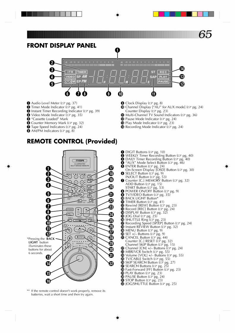
65FRONT DISPLAY PANEL
2L
dB –20 15 10 8 46 2 0 2 4 6 +8
R
dB –20 15 10 8 46 2 0 2 4 6 +8
H M S
R E C
SAPPAUSE
STPLAY
I T R TIMER
VIDEO
MSPEP
AMPM
4
876 0 9
1
$#
3
5 @
!
** If the remote control doesn't work properly, remove itsbatteries, wait a short time and then try again.
1 Audio Level Meter (Z pg. 37)2 Timer Mode Indicator (Z pg. 41)3 Instant Timer Recording Indicator (Z pg. 39)4 Video Mode Indicator (Z pg. 35)5 “Cassette Loaded” Mark6 Counter Memory Mark (Z pg. 32)7 Tape Speed Indicators (Z pg. 24)8 AM/PM Indicators (Z pg. 8)
9 Clock Display (Z pg. 8)0 Channel Display [“AU” for AUX mode] (Z pg. 24)
Counter Display (Z pg. 23)! Multi-Channel TV Sound Indicators (Z pg. 36)@ Pause Mode Indicator (Z pg. 24)# Play Mode Indicator (Z pg. 23)$ Recording Mode Indicator (Z pg. 24)
REMOTE CONTROL (Provided)1 DIGIT Buttons (Z pg. 10)2 WEEKLY Timer Recording Button (Z pg. 40)3 DAILY Timer Recording Button (Z pg. 40)4 “AUX” Mode Select Button (Z pg. 46)5 ENTER Button (Z pg. 24)
On-Screen Display [OSD] Button (Z pg. 30)6 SELECT Button (Z pg. 9)
IN/OUT Button (Z pg. 53)7 Counter [C.] MEMORY Button (Z pg. 32)
ADD Button (Z pg. 15)START Button (Z pg. 53)
8 POWER ON/OFF Button (Z pg. 9)9 TV/VIDEO Button (Z pg. 35)0 BACK LIGHT Button*! TIMER Button (Z pg. 41)@ Rewind [REW] Button (Z pg. 23)# Record [REC] Button (Z pg. 24)$ DISPLAY Button (Z pg. 32)% JOG Dial (Z pg. 25)^ SHUTTLE Ring (Z pg. 23)& Recording Speed [SP/EP] Button (Z pg. 24)* Instant REVIEW Button (Z pg. 32)( MENU Button (Z pg. 9)) SET +/– Buttons (Z pg. 9)q CANCEL Button (Z pg. 44)
Counter [C.] RESET (Z pg. 32)Channel SKIP Button (Z pg. 15)
w Channel [CH] +/– Buttons (Z pg. 24)e MBR/VCR Switch (Z pg. 55)r Volume [VOL] +/– Buttons (Z pg. 55)t TV/CABLE Switch (Z pg. 55)y SKIP SEARCH Button (Z pg. 27)u SEARCH Buttons (Z pg. 25)i Fast-Forward [FF] Button (Z pg. 23)o PLAY Button (Z pg. 23)p PAUSE Button (Z pg. 24)Q STOP Button (Z pg. 23)W JOG/SHUTTLE Button (Z pg. 25)
SP/EP
MENU
SELECT SET
9
3
6
WEEKLY
8
2
5
DAILY(M-F)
7
1
4
0
AUX
ENTER OSD
/ IN/OUT
STARTC.MEMORY / ADO
CANCEL
C.RESET / SKIP
POWER
TV/ VIDEO
VOL. CH
TV
VCR
CA
BLE
TIMER SEARCH SKIP SEARCH
BACK LIGHT
PLAY
STOP
DISPLAYJOG/SHUTTLE
ILLUMINATED MULTI BRAND REMOTE
MBR
1234
567890!
#$
%^
*Pressing the BACK LIGHT button illuminates these buttons for about 6 seconds.
&*()
werty
i
pQW
o
u
q
@
66HOW TO LOCATE YOUR JVC SERVICE CENTER
TOLL FREE: 1-800-252-5722
JVC SERVICE & ENGINEERINGCOMPANY OF AMERICA
DIVISION OF US JVC CORP.
FACTORY SERVICE CENTER LOCATIONS
If you ship the product...
ACCESSORIES
107 Little Falls Road 1500 Lakes Parkway 705 Enterprise StreetFairfield, NJ 07004-2105 Lawrenceville, GA 30243-5357 Aurora, IL 60504-8149(201) 808-9279 (770) 339-2522 (708) 851-7855
5665 Corporate Avenue 10700 Hammerly, Suite 110 2969 Mapunapuna PlaceCypress, CA 90630-0024 Houston, TX 77043-2310 Honolulu, HI 96819-2040(714) 229-8011 (713) 935-9331 (808) 833-5828
230 Eliot Street 14505 Commerce Way 890 Dubuque AvenueAshland, MA 01721-2377 Miami Lakes, FL 33016-1512 South San Francisco, CA 94080-1804(508) 881-5923 (305) 362-6252 (415) 871-2666
Sophisticated electronic products may require occasional service. Just as quality is a keyword in the engineering and productionof the wide array of JVC products, service is the key to maintaining the high level performance for which JVC is world famous. TheJVC service and engineering organization stands behind our products.
NATIONAL HEADQUARTERSJVC SERVICE & ENGINEERING COMPANY OF AMERICA
DIVISION OF US JVC CORP.107 Little Falls Road
Fairfield, NJ 07004-2105
Pack your JVC unit in the original carton or one of equivalentsize and strength. Enclose, with the unit, a letter stating theproblem or symptom that exists and also a copy of the receiptor bill of sale you received when you purchased your JVCunit. Print your home return address on the outside and theinside of the carton. Send to the appropriate JVC FactoryService Center as listed above.
To purchase accessories for your JVC product, you maycontact your local JVC Dealer.Or from the 48 Continental United States call toll free:1-800-882-2345.
Dear customer:In order to receive the most satisfaction from your purchase, read the instruction booklet before operating the unit. In the eventthat repair is necessary, or for the address nearest your location, please refer to the factory service center list below or within theContinental United States, call 1-800-252-5722 for your authorized servicer. Remember to retain your Bill of Sale for WarrantyService.
— JVC
CAUTIONTo prevent electrical shock, do not open the cabinet. No userserviceable parts inside.Refer servicing to qualified service personnel.
Don't service it yourself.
FOR SERVICING
67
LIMITED WARRANTY CONSUMER VIDEO 1-90
JVC COMPANY OF AMERICA warrants this product and all parts thereof, except as set forth below ONLY TO THE ORIGINALPURCHASER AT RETAIL to be FREE FROM DEFECTIVE MATERIALS AND WORKMANSHIP from the date of original retailpurchase for the period as shown below. ("The Warranty Period")
THIS LIMITED WARRANTY IS VALID ONLY IN THE FIFTY (50) UNITED STATES, THE DISTRICT OF COLUMBIA AND INCOMMONWEALTH OF PUERTO RICO.
WHAT WE WILL DO:If this product is found to be defective, JVC will repair or replace defective parts at no charge to the original owner. Such repairand replacement services shall be rendered by JVC during normal business hours at JVC authorized service centers. Partsused for replacement are warranted only for the remainder of the Warranty Period. All products and parts thereof may bebrought to a JVC authorized service center on a carry-in basis except for Television sets having a screen size 25 inches andabove which are covered on an in-home basis.
WHAT YOU MUST DO FOR WARRANTY SERVICE:Return your product to a JVC authorized service center with a copy of your bill of sale. For your nearest JVC authorizedservice center, please call toll free: (800) 252-5722.If service is not available locally, box the product carefully, preferably in the original carton, and ship, insured, with a copy ofyour bill of sale plus a letter of explanation of the problem to the nearest JVC Factory Service Center, the name and locationof which will be given to you by the toll-free number.
If you have any questions concerning your JVC Product, please contact our Customer Relations Department.
WHAT IS NOT COVERED:This limited warranty provided by JVC does not cover:1. Products which have been subject to abuse, accident, alteration, modification, tampering, negligence, misuse, faulty
installation, lack of reasonable care, or if repaired or serviced by anyone other than a service facility authorized by JVC torender such service, or if affixed to any attachment not provided with the products, or if the model or serial number has beenaltered, tampered with, defaced or removed;
2. Initial installation and installation and removal for repair;3. Operational adjustments covered in the Owner's Manual, normal maintenance, video and audio head cleaning;4. Damage that occurs in shipment, due to act of God, and cosmetic damage;5. Signal reception problems and failures due to line power surge;6. Video Pick-up Tubes/CCD Image Sensor, Cartridge, Stylus (Needle) are covered for 90 days from the date of purchase;7. Accessories;8. Batteries (except that Rechargeable Batteries are covered for 90 days from the date of purchase); from the date of purchase);
There are no other express warranties except as listed above.
THE DURATION OF ANY IMPLIED WARRANTIES INCLUDING THE IMPLIED WARRANTY OF MERCHANTABILITY, ISLIMITED TO THE DURATION OF THE EXPRESS WARRANTY HEREIN.
JVC SHALL NOT BE LIABLE FOR THE LOSS OF USE OF THE PRODUCT, INCONVENIENCE, LOSS OR ANY OTHERDAMAGES, WHETHER DIRECT, INCIDENTAL OR CONSEQUENTIAL (INCLUDING, WITHOUT LIMITATION, DAMAGE TOTAPES, RECORDS OR DISCS) RESULTING FROM THE USE OF THIS PRODUCT, OR ARISING OUT OF ANY BREACHOF THIS WARRANTY. ALL EXPRESS AND IMPLIED WARRANTIES, INCLUDING THE WARRANTIES OFMERCHANTABILITY AND FITNESS FOR PARTICULAR PURPOSE, ARE LIMITED TO THE WARRANTY PERIOD SETFORTH ABOVE.
Some states do not allow the exclusion of incidental or consequential dameges or limitations on how long an implied warrantylasts, so these limitations or exclusions may not apply to you. This warranty gives you specific legal rights and you may alsohave other rights which vary from state to state.
JVC COMPANY OF AMERICA 41 Slater DriveDIVISION OF US JVC CORP. Elmwood Park, New Jersey 07407
REFURBISHED PRODUCTS CARRY A SEPARATE WARRANTY, THIS WARRANTY DOES NOT APPLY. FOR DETAILS OFREFURBISHED PRODUCT WARRANTY, PLEASE REFER TO THE REFURBISHED PRODUCT WARRANTY INFORMATIONPACKAGED WITH EACH REFURBISHED PRODUCT.
For customer use:Enter below the Model No. and Serial No. which is located either on the rear, bottom or side of the cabinet. Retain this information for futurereference.
Model No.: Serial No.:
Purchase date: Name of dealer:
PARTS LABOR1 YR 90 DAYS
WARRANTY
ENH
R-S
7300U
COPYRIGHT © 1996 VICTOR COMPANY OF JAPAN, LTD. U Printed in Japan 0696HOV*UN*VP
VICTOR COMPANY OF JAPAN, LIMITED