Video-based eyetracking methods and algorithms in head-mounted
23
Video-based eyetracking methods and algorithms in head-mounted displays Hong Hua and Prasanna Krishnaswamy 3DVIS Lab, College of Optical Sciences, University of Arizona, Tucson, Arizona 85721 [email protected] Jannick P. Rolland ODA Lab, College of Optics and Photonics, University of Central Florida, Orlando, Florida 32816 Abstract: Head pose is utilized to approximate a user’s line-of-sight for real-time image rendering and interaction in most of the 3D visualization applications using head-mounted displays (HMD). The eye often reaches an object of interest before the completion of most head movements. It is highly desirable to integrate eye-tracking capability into HMDs in various applications. While the added complexity of an eyetracked-HMD (ET- HMD) imposes challenges on designing a compact, portable, and robust system, the integration offers opportunities to improve eye tracking accuracy and robustness. In this paper, based on the modeling of an eye imaging and tracking system, we examine the challenges and identify parametric requirements for video-based pupil-glint tracking methods in an ET-HMD design, and predict how these parameters may affect the tracking accuracy, resolution, and robustness. We further present novel methods and associated algorithms that effectively improve eye-tracking accuracy and extend the tracking range. © 2006 Optical Society of America OCIS codes: (330.2210) Eye movements; (120.2040) Displays; (120.2820) Heads-up displays; (120.4640) Optical instruments. ___________________________________________________________________________ References and links 1. M. Bajura, H. Fuchs, and R. Ohbuchi, “Merging virtual objects with the real world: Seeing ultrasound imagery within the patient,” in Proceedings of ACM SIGGRAPH (ACM, Chicago, IL, 1992), pp. 203-210. 2. T. Caudell and D. Mizell, “Augmented reality: An application of heads-up display technology to manual manufacturing processes,” in Proceedings of Hawaii International Conferences on Systems Sciences (Hawaii, HI, 1992), pp. 659-69. 3. J. P. Rolland and H. Fuchs, “Optical versus video see-through head-mounted displays in medical visualization,” Presence: Teleoperators and Virtual Environments 9, 287-309 (2000). 4. H. L. Pryor, T. A. Furness, and E. Viirre, “The Virtual Retinal Display: A New Display Technology Using Scanned Laser Light,” in Proceedings of Human Factors and Ergonomics Society, 42 nd Annual Meeting (1998) pp. 1570-1574. 5. H. Hua, A. Girardot, C. Gao, and J. P. Rolland, "Engineering of head-mounted projective displays," Appl. Opt. 39, 3814-3824 (2000). 6. J. P. Rolland, L. Davis, and Y. Baillot, “A survey of tracking technology for virtual environments,” in Fundamentals of Wearable Computers and Augmented Reality. M. Barfield and T. Caudell, eds. (Mahwah, NJ, 2000). 7. J. Rolland, Y. Ha, and C. Fidopiastis, "Albertian errors in head-mounted displays: I. Choice of eye-point location for a near- or far-field task visualization," J. Opt. Soc. Am. A 21, 901-912 (2004). 8. K. Iwamoto, K. Komoriya, K. Tanie, “Eye Movement Tracking Type Image Display System for Wide View Image Presentation with High-Resolution: -Evaluation of High-resolution Image Presentation,” in Proceedings of the IEEE/RSJ International Conference on Intelligent Robots and Systems (Institute of Electrical and Electronics Engineers, EPFL, Switzerland, 2002 ), pp.1190-95. 9. J. P. Rolland, A. Yoshida, L. Davis, and J.H. Reif, “High resolution inset head-mounted display,” Appl. Opt. 37, 4183-4193 (1998). 10. L. R. Young and D. Sheena, “Methods and Designs: Survey of eye movement recording methods,” Behav. Res. Methods Instrum. 7, 397-429 (1975). #68070 - $15.00 USD Received 14 February 2006; revised 2 May 2006; accepted 8 May 2006 (C) 2006 OSA 15 May 2006 / Vol. 14, No. 10 / OPTICS EXPRESS 4328
Transcript of Video-based eyetracking methods and algorithms in head-mounted

Video-based eyetracking methods and algorithms in head-mounted displays
Hong Hua and Prasanna Krishnaswamy 3DVIS Lab, College of Optical Sciences, University of Arizona, Tucson, Arizona 85721
Jannick P. Rolland ODA Lab, College of Optics and Photonics, University of Central Florida, Orlando, Florida 32816
Abstract: Head pose is utilized to approximate a user’s line-of-sight for real-time image rendering and interaction in most of the 3D visualization applications using head-mounted displays (HMD). The eye often reaches an object of interest before the completion of most head movements. It is highly desirable to integrate eye-tracking capability into HMDs in various applications. While the added complexity of an eyetracked-HMD (ET-HMD) imposes challenges on designing a compact, portable, and robust system, the integration offers opportunities to improve eye tracking accuracy and robustness. In this paper, based on the modeling of an eye imaging and tracking system, we examine the challenges and identify parametric requirements for video-based pupil-glint tracking methods in an ET-HMD design, and predict how these parameters may affect the tracking accuracy, resolution, and robustness. We further present novel methods and associated algorithms that effectively improve eye-tracking accuracy and extend the tracking range.
© 2006 Optical Society of America
OCIS codes: (330.2210) Eye movements; (120.2040) Displays; (120.2820) Heads-up displays; (120.4640) Optical instruments.
___________________________________________________________________________
References and links 1. M. Bajura, H. Fuchs, and R. Ohbuchi, “Merging virtual objects with the real world: Seeing ultrasound
imagery within the patient,” in Proceedings of ACM SIGGRAPH (ACM, Chicago, IL, 1992), pp. 203-210. 2. T. Caudell and D. Mizell, “Augmented reality: An application of heads-up display technology to manual
manufacturing processes,” in Proceedings of Hawaii International Conferences on Systems Sciences (Hawaii, HI, 1992), pp. 659-69.
3. J. P. Rolland and H. Fuchs, “Optical versus video see-through head-mounted displays in medical visualization,” Presence: Teleoperators and Virtual Environments 9, 287-309 (2000).
4. H. L. Pryor, T. A. Furness, and E. Viirre, “The Virtual Retinal Display: A New Display Technology Using Scanned Laser Light,” in Proceedings of Human Factors and Ergonomics Society, 42nd Annual Meeting (1998) pp. 1570-1574.
5. H. Hua, A. Girardot, C. Gao, and J. P. Rolland, "Engineering of head-mounted projective displays," Appl. Opt. 39, 3814-3824 (2000).
6. J. P. Rolland, L. Davis, and Y. Baillot, “A survey of tracking technology for virtual environments,” in Fundamentals of Wearable Computers and Augmented Reality. M. Barfield and T. Caudell, eds. (Mahwah, NJ, 2000).
7. J. Rolland, Y. Ha, and C. Fidopiastis, "Albertian errors in head-mounted displays: I. Choice of eye-point location for a near- or far-field task visualization," J. Opt. Soc. Am. A 21, 901-912 (2004).
8. K. Iwamoto, K. Komoriya, K. Tanie, “Eye Movement Tracking Type Image Display System for Wide View Image Presentation with High-Resolution: -Evaluation of High-resolution Image Presentation,” in Proceedings of the IEEE/RSJ International Conference on Intelligent Robots and Systems (Institute of Electrical and Electronics Engineers, EPFL, Switzerland, 2002 ), pp.1190-95.
9. J. P. Rolland, A. Yoshida, L. Davis, and J.H. Reif, “High resolution inset head-mounted display,” Appl. Opt. 37, 4183-4193 (1998).
10. L. R. Young and D. Sheena, “Methods and Designs: Survey of eye movement recording methods,” Behav. Res. Methods Instrum. 7, 397-429 (1975).
#68070 - $15.00 USD Received 14 February 2006; revised 2 May 2006; accepted 8 May 2006
(C) 2006 OSA 15 May 2006 / Vol. 14, No. 10 / OPTICS EXPRESS 4328

11. R. J.K. Jacob and K.S. Karn, “Eye Tracking in Human-Computer Interaction and Usability Research: Ready to Deliver the Promises (Section Commentary),” in The Mind's Eye: Cognitive and Applied Aspects of Eye Movement Research, J. Hyona, R. Radach, and H. Deubel, eds. (Elsevier Science, Amsterdam, 2003), pp. 573-605.
12. A. T. Duchowski, “Incorporating the viewer's Point-Of-Regard (POR) in gaze-contingent virtual environments,” in Proc. SPIE 3295, 332-43 (1998).
13. M. Hayhoe, D. Ballard, J. Triesch, and H. Shinoda, “Vision in natural and virtual environments,” Proceedings, in Proceedings of ACM 2002 Symposium on Eye Tracking Research and Applications (ACM, New Orleans, USA 2002), pp. 7-13.
14. L. Vaissie, J. Rolland, “Head mounted display with eyetracking capability,” US Patent 6,433,760 B1 (2002). 15. H. Hua, “Integration of eye tracking capability into optical see-through head mounted displays,” in Helmet-
Mounted Displays, Proc. SPIE 4297, 496-503 (2001). 16. C. W. Hess, R. Muri, O. Meienberg, “Recording of horizontal saccadic eye movements: methodological
comparison between electro-oculography and infrared reflection oculography,” Neuro-Ophthalmology 6, 264-272 (1986).
17. D. A. Robinson, “A method of measuring eye movements using a scleral search coil in a magnetic field,” IEEE Trans. Biomed. Electron. BME 10, 137-145 (1963).
18. Applied Science Laboratories: Technology and Systems for Eye Tracking, http://www.a-s-l.com. 19. M. Eizenman, R. C. Frecker, P. E. Hallett, “Precise non-contacting measurement of eye movements using
the corneal reflex,” Vision Res. 24, 167-74 (1984). 20. T. N. Cornsweet, H. D. Crane, “Accurate two-dimensional eye tracker using first and fourth Purkinje
images,” J. Opt. Soc. Am. 63, 921-8 (1973). 21. J. Merchant, R. Morrissette, J. L. Porterfield, “Remote measurement of eye direction allowing subject
motion over one cubic foot of space,” IEEE Trans. Biomed. Engineering BME 21, 309-17 (1974). 22. Y. Ebisawa, “Improved video-based eye-gaze detection method,” IEEE Trans. Instrum. Meas. 47, 948-55
(1998). 23. C. H. Morimoto, D. Koons, A. Amir, and M. Flickner, “Pupil detection and tracking using multiple light
sources,” Image Vision Comput. 18, 331-5 (2000). 24. D. Yoo, J. Kim, B. Lee, M., "Non-contact eye gaze tracking system by mapping of corneal reflections," in
Proceedings of Fifth IEEE International Conference on Automatic Face and Gesture Recognition (IEEE, Piscataway, NJ, USA, 2002), pp. 0101-06.
25. S. W. Shih, and Jin Liu, “A novel approach to 3-D gaze tracking using stereo cameras,” IEEE Trans. on Systems, Man, and Cybernetics-Part B: Cybernetics 34, 234-245 (2004).
26. K. Ryoung Park, “Gaze detection by wide and narrow view stereo camera,” Lecture Notes in Computer Science (CIARP’2004) 3287, 140-147 (2004).
27. M. L. Thomas, W. P. Siegmund, S. E. Antos, and R. M. Robinson, “Fiber optic development for use on the fiber optic helmet-mounted display,” in Helmet-Mounted Displays, J. T. Carollo, ed., Proc. SPIE 116, 90-101 (1989).
28. G. Beach, Charles J Cohen, Jeff Braun, G. Moody, “Eye tracker system for use with head mounted displays,” in Proceedings of the IEEE International Conference on Systems, Man and Cybernetics (IEEE, Piscataway, NJ, USA, 1998) 5, pp. 4348-52.
29. C. Curatu, H. Hua, and J. Rolland, “Projection-based head mounted display with eye tracking capabilities,” in Novel Optical Systems Design and Optimization VIII, Jose M. Sasian, R. John Koshel, and Richard C. Juergens Eds., Proc. SPIE. 5875, 128-140 (2005).
30. C. W. Pansing, H. Hua, and J. Rolland, “Optimization of illumination schemes in a head-mounted display integrated with eye tracking capabilities,” in Novel Optical Systems Design and Optimization VIII, Jose M. Sasian, R. John Koshel, and Richard C. Juergens Eds., Proc. SPIE. 5875, 128-140 (2005).
31. J. Schwiegerling, Field Guide to Visual and Opthalmic Optics (SPIE Press, Bellingham, WA, 2004). 32. L. G. Farkas, Anthropometry of the Head and Face, Second Ed. (Raven Press, New York, 1994). 33. J. D. Foley and A. van Dam, Fundamentals of Interactive Computer Graphics, Second Ed. (Addison-
Wesley, Reading, Mass., 1996). 34. Z. Zhang, “A flexible new technique of camera calibration,” IEEE Trans. Pattern Anal. Mach. Intell. 22(11),
1330-1334 (2000). 35. Karlene Nguyen, Cindy Wagner, David Koons, and Myron Flickner, “Differences in the infrared bright pupil
response of human eyes,” in Proceedings of ACM 2002 Symposium on Eye Tracking Research and Applications (ACM, New Orleans, USA 2002). pp. 133-138.
36. P. Krishnaswamy, “Design and assessment of improved feature-based eye tracking methods for head-mounted displays,” University of Arizona M.S. thesis report, 2005.
___________________________________________________________________________
1. Introduction
Graphics-driven head-mounted displays (HMD) have been explored for a wide range of applications in the fields of 3D virtual and augmented environments, 3D scientific visualization, and engineering processes [1,2]. The broad application of HMDs has spawned many different forms of designs. In immersive HMDs, for example, the user is presented with
#68070 - $15.00 USD Received 14 February 2006; revised 2 May 2006; accepted 8 May 2006
(C) 2006 OSA 15 May 2006 / Vol. 14, No. 10 / OPTICS EXPRESS 4329
an exclusively computer-generated view to replace the physical scene [3]. In see-through HMDs, virtual objects are optically or electronically superimposed on real objects to enhance the physical scene [1, 3]. Virtual retinal displays utilize low-power laser beams as the image source [4]. Head-mounted projection displays utilize the combination of projection optics and retro-reflective material to optically combine virtual objects with the physical scene [5].
In most of the HMD applications required for 3D user interactions, head pose, measured by a head tracking system [6], is utilized to approximate the user’s line-of-sight for real-time image rendering and interaction. The eye often reaches an object of interest before the completion of most head movements. Ignoring the contribution of eye movement to the line-of-sight can cause significant disparity between what a user intends to look at and what he or she actually sees through the display. Rolland et al quantified that an accurate representation of eyepoint can minimize angular and depth errors in high-precision displays [7]. Furthermore, visual interaction in virtual environments is desirable for situations when a user’s hands are fully occupied or disabled. Integration of eye tracking capability into HMDs can create more advanced display solutions such as fovea-contingent display schemes [8, 9]. Finally, HMDs with an integrated eye tracker potentially provide more accurate eye-movement monitoring devices for visual research than the conventional paradigm where a human subject, an eye tracker, and the information display are not attached to each other.
Scientists have been investigating techniques to monitor eye movements for decades and various eye tracking technologies have been developed and adopted in many disciplines as fundamental instruments [10, 11]. An overview of existing eye tracking technologies will be discussed in Section 2. HMD and eyetracker technologies alone are readily available commercially. However, the added complexity of an eyetracked-HMD (ET-HMD) system challenges the compactness, portability, and robustness. The integration of eyetracking to HMDs has proved to be challenging and problematic. A few researchers have attempted to integrate commercially available HMDs and eyetrackers[12,13]. This method is referred to as the functionality integration approach, in which two separate instruments are brought together at a later stage of utilization. In contrast to this approach, we have been investigating a systematic approach to a fully integrated ET-HMD instrument where the system is conceived and optimized as one single instrument from a fundamental design perspective [14, 15]. The significant benefits of the systematic approach include the capabilities to explore the design constraints and requirements for both the display and eyetracker units, conceive new solutions, and optimize the designs for a compact and robust system.
The subject of this paper is to examine the new challenges related to the eyetracker sub-system and to explore schemes and opportunities for optimizing the tracker sub-system to improve eye tracking accuracy, range, and robustness in an ET-HMD design. More specifically, based on the modeling of an eye imaging and tracking system, we present a comprehensive analysis on the speed, resolution, and non-linearity of a pupil-glint tracking method using a single off-axis LED. To improve the eyetracking accuracy and robustness in an ET-HMD system, we further describe a novel eyetracking method and associated algorithms by tracking a virtual on-axis glint created with the use of multiple off-axis LEDs symmetrically placed around the optical axis. The proposed method not only improves the uniformity and robustness of eye illumination, but also corrects the non-linearity of an off-axis glint and extends the allowable tracking range of multiple glints. Although the analyses are done in an ET-HMD setting, the proposed tracking method and algorithms can be applied to stand-alone eye-tracking systems.
The rest of the paper is organized as follows. Section 2 summarizes existing eye tracking methods as well as related efforts in pursuing ET-HMD integration and their applications. In Section 3, the scheme of an ET-HMD system is described and the eye tracking sub-system is modeled for parametric analysis. In Section 4, we examine the parameters related to the eye tracking system and investigate how these parameters affect tracking accuracy and resolution. In Section 5, we describe a new tracking method with improved accuracy by computing a virtual on-axis glint created by using multiple off-axis illuminators. In Section 6, we further present algorithms that extend the tracking range and improve the robustness.
#68070 - $15.00 USD Received 14 February 2006; revised 2 May 2006; accepted 8 May 2006
(C) 2006 OSA 15 May 2006 / Vol. 14, No. 10 / OPTICS EXPRESS 4330

2. Related work
2.1 Overview of eyetracking technology
The eye can make three motions: horizontal rotation, vertical rotation, and rotation about the visual axis. However, the latter only occurs under special circumstances, and most eye movement monitoring techniques only measure the first two rotations. Existing eye tracking methods can be broadly classified into two categories: two-dimensional (2D) tracking and three-dimensional (3D) tracking. In 2D tracking methods, the 3D position of the eye is usually unknown or not measured by the eye tracker itself, and only the relative line of sight with respect to the user’s head is measured. Generally, owing to their 2D nature, these 2D tracking methods require users to hold their head very steady relative to the monitoring device to achieve a good accuracy. In applications demanding high accuracy, attaching the imaging devices to a headgear is a typical practice in addition to adding auxiliary apparatuses such as a chin rest or a bite bar. In contrast to 2D tracking, 3D eye tracking methods determine the 3D position of the eye and thus are capable of providing the complete 3D representation of the line of sight with respect to a fixed reference. Such methods naturally tolerate head movements to some extent and are less restrictive to users.
The 2D tracking techniques can be classified as non-imaging or imaging-based methods. The non-imaging approaches include electro-oculography (EOG) methods, which detect eye movements based on the potential differences around the eyes with electrodes attached around a subject’s eye [16], and sclera search coil methods, which determine eye movements by recording the exact position of a tiny induction coil or contact lens embedded into a subject’s eye [17]. Both approaches are quite invasive and hardly used for human subjects.
Image-based tracking methods, utilizing the various eye features, are the most widely practiced techniques. Most image-based approaches often take advantage of the spectral properties of the eye under near infrared (NIR) illumination. When NIR light is shone onto the eyes, it is reflected off the different structures in the eye and creates several types of IR-illuminated eye features. The typical features that may be tracked include the limbus, pupil, and reflection images formed by the cornea and the eye lens, which move proportionally relative to the eye socket as the eye rotates. For example, limbus tracking detects the boundary between the iris and the white sclera. This method is inaccurate for vertical eye movement due to the eyelids [16]. Pupil tracking, more reliable than limbus tracking, monitors the boundary between the pupil and the iris. Depending on the configurations of the IR illuminator, different pupil tracking schemes may be created. When IR light is shone into the eye from an off-axis position relative to the optical axis of the imaging device, it creates a dark-pupil effect, where the pupil becomes a sink of IR light and looks darker than the iris and other eye features. On the other hand, owing to the retro-reflective property of the retina, a bright-pupil effect is observed with an on-axis IR illuminator, where the pupil looks brighter than the iris as observed with red eyes in photography [18]. Besides creating dark or bright-pupil effects, a corneal reflection image, also known as a glint image or first Purkinje image, is formed by the approximately 2.4% specular reflection of the anterior cornea [19]. Corneal reflection tracking, also known as glint tracking, is less sensitive to eye movement than pupil tracking.
Both the aforementioned eye features and their combinations have been explored for eye movement tracking. For instance, dual Purkinje image tracking detects the separation between the first Purkinje image and the reflection feature formed by the last surface of the eye lens, or the fourth Purkinje image [20]. This technique is generally more accurate but complicated because the fourth Purkinje image is extremely dim and difficult to detect. It usually requires users to keep their heads stationary. Pupil-glint tracking detects the vector difference between the pupil center and the first Purkinje image [21]. Compared to methods using pupil or cornea reflection alone, the combination of pupil and glint tracking tolerates head movements to a small extent. Methods combining both bright and dark pupil images have been reported [22, 23, 24]. In these methods, multiple sets of IR illuminators, one set being on-axis for creating a bright pupil and another set being off-axis for creating a dark pupil, are flashed alternatively
#68070 - $15.00 USD Received 14 February 2006; revised 2 May 2006; accepted 8 May 2006
(C) 2006 OSA 15 May 2006 / Vol. 14, No. 10 / OPTICS EXPRESS 4331

and synchronized with the odd and even fields of a CCD camera. The images of the odd and even fields are subtracted to detect the pupil feature.
3D tracking techniques are more complicated than 2D tracking. They have been explored in recent years driven by the increasing demand for human computer interaction applications [11]. Although most of the 2D tracking methods can be extended to 3D tracking, 3D tracking systems typically require multiple eye features or other facial features and multiple cameras to estimate the center of eye rotation, or require other mechanisms to determine the eye location. For instance, Shih and Liu presented a system that consists of multiple cameras and multiple point light sources without using any user-dependent parameters to estimate the center of eye rotation and therefore to output a 3D gaze direction [25]. Due to their 3D nature, the 3D tracking systems are typically remote-mounted. The field of view (FOV) of the tracking cameras has to be sufficiently large to allow users to move their heads freely in a specified area. However, using large FOV cameras yields limited resolution of the eye features. Several researchers propose systems that either use pan-tilt-zoom cameras or the combination of a wide and narrow FOV cameras [25, 26].
2.2 Integration of eyetracking capability in HMDs
The concept of adding eyetracking capability to HMDs is not new in the sense that it started as early as the high resolution inset displays by CAE Corporation [27]. Thomas et al employed light-valve displays and transported high-resolution images to the eyes by imaging optics coupled to a bundle of optical fibers. The added functionality in this pioneer work was not intended to achieve a compact ET-HMD system at the fundamental level. Another example is the work of Iwamoto et al who developed a bench prototyped stereoscopic display in which a high resolution display inset was scanned across a wide FOV low-resolution background using a mechanical scanner driven by an eyetracker unit [8]. Duchowski worked with ISCAN Corporation to integrate an ISCAN eyetracker into a V8 HMD from Virtual Research Corporation and used the integrated prototype to study software-based fovea-contingent schemes in virtual environments [12]. Duchowski explored gaze direction as well as head pose to allow dynamic level-of-detail changes for stereoscopic image rendering, which demonstrated the potential of the technology to improve rendering speed with complex models. Hayhoe and colleagues used a V8 HMD integrated with an ASL 501 eyetracker to study visual behavior in virtual environments [13]. These integration attempts and research studies of using commercial HMDs and eye-trackers have focused on high-level functionality integration, rather than on the conception and optimization of the design of a compact and robust instrument. In their systems, the HMD and the eye-tracker were two independent units and thus their integration did not take advantages of potential low-level optimization to achieve an optimal design. The approach of using independent commercially available technology creates challenges in relative system alignment, compactness, and robustness.
Only very few and preliminary efforts have been made towards a systematic approach to the ET-HMD integration where the system is conceived and optimized as one single instrument as opposed to two separate instruments brought together at a later stage of utilization [28, 14,15, 29].
3. ET-HMD system architecture: modeling and simulation
In principle, most of the video-based 2D tracking techniques described in Section 2 are suitable for integration with HMDs. However, due to the significant weight of HMD helmets, the potential helmet slippage can result in displacement and tilt of the eye camera with respect to the eye. A possible approach to compensate for any slips is to detect the helmet motion relative to the user’s eye or head by attaching a transducer or marker on the user’s face and mounting a detector on the helmet. An alternative approach is to simultaneously track two eye features that move differentially with respect to each other in the case of eye movements, but move at the same speed in the occurrence of helmet slippage. Among these feature-based methods, the pupil-glint tracking approach is the most practical one that involves the tracking of two differentially moving features, and thus was selected for the integration.
#68070 - $15.00 USD Received 14 February 2006; revised 2 May 2006; accepted 8 May 2006
(C) 2006 OSA 15 May 2006 / Vol. 14, No. 10 / OPTICS EXPRESS 4332

Fig. 1. Schematic diagram of an ET-HMD integrated system.
A systematic approach to the ET-HMD integration aims at optimizing the essential components of the system to achieve a compact, lightweight, and robust system with improved display quality and tracking accuracy. A possible strategy is to share the optical paths between the HMD and the eye tracker as much as the design can afford [14, 15, 29]. A schematic diagram of an ET-HMD integrated system is illustrated in Fig. 1, which traces the optical path of the eye tracking sub-system. The necessary components for an optical see-through HMD include miniature displays, display optics, and beamsplitters. To illuminate the eye, one or multiple near infrared LED (NIR-LED) illuminators are mounted around the display optics or at a position between the optics and the eye. NIR light reflected off the eye features is collimated through the display optics, which is shared with the HMD sub-system, reflected by a hot mirror, and imaged through a second group of lenses (e.g. camera lens) onto an infrared CCD sensor. The display optics together with the camera lens serves as the imaging optics of the eye tracking sub-system. The camera lens shown in the diagram can possibly be eliminated by setting the CCD sensor on the conjugate plane of the eye pupil with respect to the eyepiece, which can further simplify the system [14, 29]. In this case, the system has to be optimized for both the display optics and the eye imaging, which requires at least two different conjugate locations.
The added complexity of an ET-HMD system imposes great challenges and additional constraints on the design of the eyetracking sub-system. However, it also offers opportunities to design more accurate and robust tracking algorithms. For instance, to ensure reliable extraction of the features of interests, it is required that these features are imaged sharply and can be differentiated from any other noisy features at arbitrary angles of eye rotation. There are numerous parameters of the illumination components and imaging optics that affect the resultant image quality of the eye features. Pansing et al have made efforts to investigate optimal illumination schemes that yield good-quality NIR-illuminated eye images in an ET-HMD integrated system in order to achieve robust eye tracking and reduce ad hoc adjustments and calibration [30]. This paper will focus on the imaging aspect of the eye illumination-imaging sub-system and investigate how multiple NIR light sources and their resultant features can be employed to develop new tracking methods that yield improved tracking accuracy and extended tracking range.
To facilitate the understanding and analysis of the dynamic relationships between the relevant eye features and eye rotations, we developed a Matlab®-based simulation of the eye imaging sub-system. The imaging process can be decomposed into two steps: (1) the formation of relevant features via the eye optics (e.g. the formation of LED glints via the reflection off the anterior corneal surface and the formation of the virtual pupil-iris via the refraction of the corneal surfaces and aqueous humor); and (2) the capture of these features and other eye structures through the imaging optics.
3.1 Eye model
Within the context of first-order analysis, the eye optics was simplified from the Arizona Eye model by suppressing the conic coefficients of the surfaces [31]. A cross section of the eye optics and the associated parameters are shown in Fig. 2(a). The cornea is assumed to be a
#68070 - $15.00 USD Received 14 February 2006; revised 2 May 2006; accepted 8 May 2006
(C) 2006 OSA 15 May 2006 / Vol. 14, No. 10 / OPTICS EXPRESS 4333

(a) (b)
Fig. 2. Simulation of an eye illumination and imaging system: (a) Schematic eye model; (b) Illustration of coordinate systems and parameters.
segment of a sphere with an anterior radius 1cr equal 7.8mm, a posterior radius 2cr equal
6.5mm, a thickness ct equal 0.55mm, and a refractive index cn equal 1.3771. The refractive
index of the aqueous humor is an equal 1.3374. The iris, a pigmented diaphragm with a centered hole, namely the pupil, is the aperture stop of the eye optics. The pupil diameter varies from 2 to 8mm in response to illumination levels as well as psychological factors. Given the prevailing luminance levels in HMDs, a 4mm pupil is assumed in the simulation. The outer boundary of the iris with the sclera is often considered to be the limit in which glints can be detected robustly due to the considerations of low image contrast between the sclera and glints and the occurrence of specular reflection by the sclera. Based on anthropometric measurements [32], the diameter of the iris outer boundary is assumed to be 11mm. While the eye lens shape varies when viewing objects at different distances, it does not affect the accuracy of the analysis in Sections 4 and 5, as we will only use the reflection by the anterior corneal surface for glint formation and the refraction of the corneas surfaces for pupil/iris imaging.
Although the eye is not rotationally symmetric in a strict sense, a line passing through the centers of curvature of the optical surfaces in a least square sense is assumed to be the optical axis of the eye. The axis passes through the rotation center, E, of the eyeball. The radius of the eyeball, er , ranging from 12 to 13mm [31], is assumed to be 12.5mm. The actual line of sight is equivalent to the chief ray of the eye optics from the fixation point. Since the fovea is displaced about 4° from the optical axis, the line of sight is displaced by that angle from the optical axis. We hereafter will use the optical axis to represent the visual axis. The actual line of sight will be obtained through a typical calibration process. The upper and lower eyelids are modeled as two parabolas according to anthropometry [32]. Let E denote the eye rotation center and EXYZ the associated eye reference (Fig. 2(a)). The Z-axis of the eye reference, pointing toward the cornea, is aligned with the optical axis of the eye optics.
3.2 Imaging optics model
The eye imaging optics in an ET-HMD is a finite conjugate system consisting of two lens groups: the display optics and the camera lens. Under the assumption of an optimized system with corrected distortion and optical aberrations, it can be simplified and is equivalently modeled as a standard perspective camera. Let O denote the projection center of the perspective camera and OXYZ the associated camera reference (Fig. 2(b)). The Z-axis of the camera reference is aligned with the optical axis of the imaging optics. For the convenience of formalization and implementation in Matlab®, all points are expressed in 4D homogeneous coordinates in all the reference frames, until we need to obtain the actual 2D pixel coordinates of their projections on an image sensor [33]. We denote the homogeneous coordinates of a 3D point, Q, by Twzyx ]~~~~[
~Q and its Cartesian coordinates are given by projection division as
#68070 - $15.00 USD Received 14 February 2006; revised 2 May 2006; accepted 8 May 2006
(C) 2006 OSA 15 May 2006 / Vol. 14, No. 10 / OPTICS EXPRESS 4334

[ ] [ ]TTwywywxzyx ~~~~~~=Q [33]. Unless otherwise specified, all transforms are denoted
as 4x4 matrices in homogeneous coordinates, and vectors and matrices are denoted in bold letters. Therefore, Given an arbitrary 3D point Q in the camera reference, the homogenous coordinates of its projection, T
qqqq wzyx ]~~~~[~q , on an imaging sensor are given by [34]
QQMq~
0/100
0100
010
001
~~ 0
0
proj ⋅⎥⎥⎥⎥
⎦
⎤
⎢⎢⎢⎢
⎣
⎡
=⋅=
f
fvs
fus
y
x
, (1)
where f (mm) is the effective focal distance of the imaging system, xs and ys measured in
mm/pixel are the scale factors of the image sensor in the horizontal and vertical directions, respectively, 0u (pixels) and 0v (pixels) are the horizontal and vertical offsets of the optical axis from the sensor origin which is the bottom-left pixel of the sensor. The symbol ~ thereafter denotes homogeneous coordinates. The point (u0,v0) is referred to as the calibrated sensor center or sensor center for simplicity, which corresponds to the intersection of the eye axis at zero-degree of eye rotation. Given a CCD sensor measured by WxH (mm) with mxn pixels, mWsx /= , and nHsy /= . The actual 2D pixel coordinates of the projection point,
[ ]Tqq vuq , are given by
[ ]Tqqqq wywx ~/~~/~=q . (2)
The Z-axis of the camera reference is further assumed to be aligned with the line connecting the projection and eye rotation centers (Fig. 2(b)). This direction is used as the reference for eye rotation (i.e. zero eye rotation). To ensure symmetry, the camera is positioned in a way such that its Z-axis is perpendicular to the forehead and coincides with the direction when the eye looks straightforward. Therefore, the eye rotations are measured by the angles between the z-axes of the eye and camera references. Without loss of generality, an arbitrary eye rotation can be decomposed into rotations of α degrees around the horizontal X-axis and β degrees around the vertical Y-axis. Thus, the transformation from eye reference to camera reference is given by [33]
)()()( xyzEO αβ RRTT t−=← , (3)
where t is the distance from the camera projection center O to the eye rotation center E.
3.3 Image formation of eye features
When using an LED source to illuminate the eye structure, part of the light is reflected by the anterior corneal surface, forming a glint, which is known as the first Purkinje image of the source. Let L denote the location of an LED in the camera reference, G denotes the glint created by the LED, and g denote the projection of the glint on an image sensor. Since we are mostly concerned about the images of eye features on the sensor, unless specified otherwise, we hereafter will simply refer to g as the glint image or glint. Without compromising the accuracy of the analysis discussed in Sections 4 and 5, we further assume the LED to be a perfect point source and so does the corresponding glint. Approximating the anterior corneal surface to be a spherical mirror, the homogeneous coordinates of the glint image,
[ ]Tgggg wzyx ~~~~ ~g , are given by
LTMTMg~~ 1
EOreflEOproj ⋅⋅⋅⋅= −←← , (4)
#68070 - $15.00 USD Received 14 February 2006; revised 2 May 2006; accepted 8 May 2006
(C) 2006 OSA 15 May 2006 / Vol. 14, No. 10 / OPTICS EXPRESS 4335

where reflM is the first-order reflection imaging matrix of the anterior corneal surface for a
point defined in the eye reference and it is derived in Appendix A. The iris structure (including the pupil) imaged by the camera is the image of the physical
iris via the refraction of the corneal surfaces and is referred to as the virtual iris. The location and shape of the virtual iris can be calculated from the eye optics described under Section 3.1. Let P
~ denote an arbitrary point on the physical iris defined in the eye reference, then the
homogeneous coordinates of its projection on the image sensor, [ ]Tpppp wzyx ~~~~ ~p , are
given by
PMTMp~~
refrEOproj ⋅⋅⋅= ← , (5)
where refrM is the first-order imaging matrix via the refraction of the posterior and anterior corneal surfaces and it is derived in Appendix B. Based on the simplified eye model described earlier, we computed the location and shape of the virtual iris using the first-order imaging matrix. The virtual iris is located at a distance of 3.04mm from the vertex of the anterior corneal surface, the virtual pupil diameter is 4.52mm, and the virtual iris diameter is 11.76mm. As expected because equivalent from a first-order point of view, these results agree well with those obtained using the non-simplified Arizona eye model [31].
Besides the formation of glint and pupil/iris features, the images of other relevant eye structures, such as eyelids, are independent of eye optics and are directly imaged by the imaging system. Let S
~ denote an arbitrary point on these relevant eye structures in the eye
reference, then the homogeneous coordinates of its projection on the image sensor,
[ ]T
ssss wzyxs~ , are given by
STMs~~
EOproj ⋅⋅= ← . (6)
3.4 Simulations of eye feature imaging
Given an arbitrary configuration of IR-LED illuminators and arbitrary eye rotations, the simulation model described in Sections 3.1-3.3 is able to precisely calculate the corresponding eye features on the sensor of the simulated imaging system. As examples, Figs. 3(a) and 3(b) show the projections of the eye features on an image sensor when the eye looks straightforward (i.e. α=β=0°) and rotates 30° diagonally upward (i.e. α=β=30°). In the simulations, an LED was placed 20mm away from the camera projection center O along the X-axis and a 1/3 inch NTSC format CCD sensor (i.e., W=4.8mm, H=3.6mm, m=640 pixels, and n=480 pixels) was selected. Without loss of generality, the same scale factor along the horizontal and vertical directions was assumed (i.e., sx=sy), which reflects on assuming square pixels. The optical axis of the imaging system was assumed to be centered with the sensor and its horizontal and vertical offsets from the sensor origin, ),( 00 vu , were taken to be 320 and 240 pixels, respectively. Although the optical axis of a real imaging system may not be precisely centered with its sensor and a given sensor may not have the same scale factors in the horizontal and vertical directions, a real system can be calibrated to obtain its projective matrix and the associated intrinsic parameters in Eq. (1) to correct any disparities in the offsets and scale factors [34]. In an ET-HMD system, the distance from the imaging optics to the eye is limited by the requirement of compactness and is typically around or less than 80mm. We assume a moderate distance of 50mm from the camera projection center O to the anterior corneal surface (i.e., 62.5mm from the eye rotation center) and the focal length, f, of the imaging optics is 7mm, which yields sufficient field of view to capture an eye area of 32mmx24mm. The two examples not only demonstrated the relative movements between the pupil center and the glint image, but also manifested the deformation of the pupil and iris from a circular to an elliptical shape as the eye rotates from on-axis to off-axis. Unless otherwise
#68070 - $15.00 USD Received 14 February 2006; revised 2 May 2006; accepted 8 May 2006
(C) 2006 OSA 15 May 2006 / Vol. 14, No. 10 / OPTICS EXPRESS 4336

Fig. 3. Examples of simulated eye features: (a) (0,0) degrees of eye rotation; (b) (30,30) degrees of eye rotation.
specified, the simulations in the rest of the paper will use the same sensor and imaging system configurations.
4. Characterization of eye feature movements
We shall now utilize the capabilities of the model detailed in Section 3 to characterize the relationships between the movements of the pupil/glint features and eye rotations, and also to predict how the placements of LEDs affect the tracking accuracy and resolution. These analyses led us to the development of novel methods and associated algorithms for eye tracking described in Sections 5 and 6.
4.1 Speed and resolution of pupil and glint features
The short working distance of the imaging optics in an ET-HMD system imposes significant restrictions on the LED placement and impacts on the movements of the pupil and glint features. To characterize the movements of these features, an LED was assumed to coincide with the origin of the camera reference. By simulating diagonal eye rotations (i.e., α=β) between ±30° at an increment of 5° from the bottom left to the upper right, we calculated the projections of the simulated pupil contour and the glint image formed by the on-axis LED. The geometrical centroid of the pupil, referred to as the pupil centroid or the pupil center, was calculated by averaging the pixel coordinates of the pupil contour. Figure 4(a) shows the horizontal and vertical displacements of the pupil centroid and the glint from the sensor center (i.e., u0=320 pixels, and v0=240 pixels), which corresponds to their locations at zero degrees of eye rotation. The slopes of the curves indicate the speeds of the feature movements with the angle of eye rotation. The absolute speeds of the pupil and glint features were calculated and are presented in Fig. 4(b). The results show that the pupil centroid moves at about twice the speed of the glint in both the horizontal and vertical directions. The relative speeds of the two features in both directions are shown in Fig. 4(c). Such findings can also be explained by the eye structure. Since the distance from the LED illuminator to the cornea is considerably large (e.g. over 12.8 times the focal length of the cornea when t equal 50mm), the glint is roughly located at the focal plane of the anterior corneal surface and rotates about the center of curvature of the cornea by a radius of about 4.7mm. The distance from the pupil centroid to the eye rotation center is roughly 9.5mm. The ratio of the rotation radii of these two features is roughly 0.495, which agrees with the ratios shown in Fig. 4(c).
When either of the two features is used alone for tracking, the speed differences indicate that the resolution with which the pupil is tracked is greater than that of the glints. For instance, under the given settings of the eye imaging system, the pupil tracking approach offers a resolution of about 0.3~0.5 degrees per pixel (i.e., a speed of 2~3 pixels per degree shown in Fig. 4(b)) within ±20 degrees of eye movements. On the other end, glint tracking only offers a resolution of about 0.7~1 degrees per pixel (i.e., a speed of 1.4~1 pixels per
#68070 - $15.00 USD Received 14 February 2006; revised 2 May 2006; accepted 8 May 2006
(C) 2006 OSA 15 May 2006 / Vol. 14, No. 10 / OPTICS EXPRESS 4337

Fig. 4. Movements of the pupil centroid and an on-axis glint as the eye rotates diagonally: (a) Absolute displacements from the sensor center; (b) Absolute velocities; (c) Relative velocity of glint vs. pupil centroid.
degree shown in Fig. 4(b)). Figure 4(b) further shows considerable differences in the absolute speeds of the pupil centroid and the glint between the horizontal and vertical directions, while the relative speeds between the pupil and the glint remain approximately the same in the two directions (Fig. 4(c)). This observation indicates that the horizontal and vertical resolutions with which the eye is tracked are non-uniform when either the pupil or the glint is tracked alone, but they are roughly constant when the differential vector between the pupil center and the glint is utilized instead. Furthermore, the differential movement of the two features can be used to determine the movement caused by eye rotation and that caused by the displacement of the imaging system. Therefore, such differential measurement may be utilized to account for a small amount of head movement from the camera. In an ET-HMD system, the pupil-glint differential vector is particularly useful for tolerating small but inevitable helmet slippage.
The tracking resolution of these features can be theoretically improved by utilizing a detector with a higher resolution or an imaging system with a narrower field of view (FOV). However, the FOV of the imaging system, defined as an eye area of 32mm by 24mm in the above examples, is almost the narrowest to accommodate eye size variations among different user populations [32]. Therefore, there is little space to reduce the FOV of the imaging system without compromising the range of tracking capability and the tolerance to user variations. To maximize tracking resolution, the focal length of the imaging system should be optimally selected by
),max( 00
b
Wz
a
Hzf = , (7)
#68070 - $15.00 USD Received 14 February 2006; revised 2 May 2006; accepted 8 May 2006
(C) 2006 OSA 15 May 2006 / Vol. 14, No. 10 / OPTICS EXPRESS 4338

Fig. 5. Characterization of an off-axis glint movement as the eye rotates diagonally: (a) Horizontal glint location; (b) Vertical glint location; (c) Horizontal glint velocity; (d) Vertical glint velocity.
where a (mm) and b (mm) are the horizontal and vertical dimensions of the eye area to be imaged, and 0z (mm) is the distance of the eye features to the projection center O.
4.2 Non-linearity of off-axis glints
An on-axis LED illuminator yields a bright-pupil effect and is used in some existing tracking systems. However, the quality of bright-pupil illumination tends to be less robust than off-axis dark-pupil illumination due to the degradation of pupil brightness with increasing eye rotation angle and the large variation among different human populations [35]. To examine how the LED placements from the camera axis might affect the accuracy of glint tracking, we placed an LED on the X-axis of the camera reference with an offset varying between 0 and 30mm from the projection center O. We anticipate a typical offset of about 15~30mm in an ET-HMD design. By simulating diagonal eye rotations within ±30°at an increment of 5°, we calculated the 2D glint coordinates and its velocities for each given LED offset along the X-axis. Figures 5(a) and 5(b) show the relative displacements of the glint from the sensor center as a function of the eye rotation angles, in the horizontal and vertical directions, respectively. Figures 5(c) and 5(d) show the horizontal and vertical speeds of the glint as a function of the eye rotation angles. As the LED offset from the center increases along the X-axis, the trajectory of the glint image along the horizontal direction shows significant non-linearity at large negative angles of eye rotation (less than -10°), while its trajectory along the vertical direction remains the same as that of the on-axis LED (Figs. 5(a) and 5(b)). Similarly, as the LED offset increases, the horizontal velocity of the glint drops dramatically at large negative angles of rotations, while its vertical velocity naturally remains the same as that of the on-axis LED. Reduced velocity indicates reduced angular resolution. This non-symmetrical non-linearity can be explained by the fact that the LED was placed on the positive side of the X-axis, and
#68070 - $15.00 USD Received 14 February 2006; revised 2 May 2006; accepted 8 May 2006
(C) 2006 OSA 15 May 2006 / Vol. 14, No. 10 / OPTICS EXPRESS 4339

Fig. 6. The non-linearity of glint movement depends on the placement of the camera from the eye: (a) On-axis glint; (b) Off-axis glint.
thus the non-linearity is significant at the negative side of the horizontal direction. Similarly, if the LED is placed on the Y-axis, the vertical trajectory and velocity are expected to show significant non-linearity and horizontal movement remains the same as that of an on-axis LED. These observations indicate that the resolution and accuracy of an off-axis glint tracking is degraded as the angle of eye rotation increases.
To examine how the non-linearity of an off-axis glint may be affected by the distance of the camera from the eye, we varied the camera distance, z0, from 30mm up to 400mm, and selected the focal length of the camera based on the relationship in Eq. (7) such that the FOV of the imaging system remained constant. By simulating diagonal eye rotations within ±30°at an increment of 5°, we computed the trajectories of the glints created by an on-axis LED and an off-axis LED, respectively. The off-axis LED was placed on the X-axis of the camera reference by an offset of 20mm from the projection center. Figures 6(a) and 6(b) show the horizontal movements of the glints from their initial locations at zero degrees of eye rotation. It is evident that the non-linearity of the off-axis glint increases significantly as the camera is moving closer to the eye, while the non-linearity of an on-axis glint remains approximately constant. A similar non-linear behavior was observed when the off-axis LED was placed at other off-axis locations. To ensure compactness in an ET-HMD, the camera distance is typically less than 100mm and is assumed to be 50mm in the rest of the paper.
When the 2D image coordinates of a glint feature are mapped to the 2D display coordinates through a calibration process, the non-linear movement of the off-axis glint requires a large number of calibration points for high-order polynomial fitting of mapping functions in order to improve the tracking accuracy at large rotation angles to some extent. The inherent non-uniform resolution indicated by the inconstant velocity, however, can not be corrected through a calibration procedure. It is thus highly desirable to achieve the same level of linearity for off-axis glints as that of an on-axis glint.
5. A new tracking method with improved accuracy
Because of the short distance of the LED illuminator from the eye in an ET-HMD, the use of a single LED results in highly non-uniform eye illumination and an eye image example with a single illuminator is shown in Fig. 7(a). The basic analyses in Section 4 further confirms that, with a short working distance in an ET-HMD, the accuracy and resolution of the existing glint tracking methods are challenged by the degradation of resolution with increasing angles of eye rotation and the non-linearity of glint movement. New methods are desired to overcome such limitations for more robust and accurate tracking solutions.
The analysis of illumination schemes by Pansing et al. demonstrated that multiple NIR-LEDs yield more uniform and robust eye images over the entire FOV of the imaging system with high-contrast tracking features than using a single LED [30]. The study further
#68070 - $15.00 USD Received 14 February 2006; revised 2 May 2006; accepted 8 May 2006
(C) 2006 OSA 15 May 2006 / Vol. 14, No. 10 / OPTICS EXPRESS 4340

(a)
(b)
Fig. 7. Examples of eye illumination schemes: (a) Single IR-LED illuminator; (b) Four IR-LED illuminators.
recommended a symmetrical arrangement of multiple LEDs around the camera axis for optimum illumination. An example with four symmetrically arranged LEDs is shown in Fig. 7(b). Several researchers have adopted multiple illuminators or multiple rings of illuminators in their eyetracker implementations, primarily to create dark- and bright-pupil effects along with a single symmetric blob of glint [22, 23, 24], or to estimate the 3D eye location from multiple glints in a 3D eyetracking system [25,26]. In this section, we describe a new method and associated algorithms that utilize the multiple glint features to improve illumination robustness, to correct the non-linearity of off-axis glints, and to improve tracking accuracy.
5.1 Tracking a virtual on-axis glint using multiple illuminators
To predict the effect of multiple illuminators, four LEDs were placed symmetrically around the projection center O, and labeled as Tr ]100[
~1L , Tr ]100[
~2L , Tr ]100[
~3 −L , and
Tr ]100[~
4 −L , where r is the distance of an LED from the center O. Given that the distance, r, is considerably large compared to the distance from the LEDs to the eye, these LEDs create a high-contrast dark pupil effect as well as four off-axis glints, in contrast to a single glint blob by a ring of LEDs placed far from the eye [23]. An eye image example is shown in Fig. 7(b). The projections of these glints on the image sensor are denoted as g1, g2, g3, and g4, respectively. Under the assumption of a moderate offset r of 20mm, the horizontal and vertical movements and velocities of the glints are plotted in Fig. 8 as the eye rotates diagonally within ±30° from the bottom left to the upper right. Figures 8(a) and 8(b) show the horizontal and vertical displacements of the four glints from their initial locations corresponding to a zero-degree eye rotation, respectively. Figures 8(c) and 8(d) show the horizontal and vertical velocities of these glints. On each of the plots, the four glints are denoted as a “circle”, “plus”, square”, and “diamond”, corresponding to the four illuminators, L1, L2, L3, and L4, respectively. Similar to the asymmetrical non-linearity observed in Fig. 5, the movements of these off-axis glints manifest much more prominent non-linearity than an on-axis glint in different directions of eye rotation. For example, glints g1 and g3 corresponding to illuminators placed along the horizontal axis show significant nonlinear trajectory horizontally, but they remain the same linear paths as an on-axis glint vertically. The non-linearity of the glint g1 is prominent when the eye is gazing at the bottom left quadrant, while the non-linearity of the glint g3 is dominant in the upper-right quadrant. Similarly, glints g2 and g4 corresponding to illuminators along the vertical axis show a nonlinear variation vertically but remain linear paths horizontally. Such non-linearity is one of the major sources that limit the accuracy of glint-based eye tracking schemes.
The two pairs of diagonally arranged glints (g1 and g3, and g2 and g4) demonstrate different non-linear performances over the orthogonal directions of eye rotation. Instead of using the individual glint features for tracking or their geometrical centroid [14, 24, 25, 26, 36], we calculate the intersection point g0 of the line connecting the diagonal glints g1 and g3, and the line connecting the glints g2 and g4. The intersection point is referred to as a virtual glint
feature. Given the pixel coordinates of the four off-axis glints, [ ]Tvu 111g , [ ]Tvu 222g ,
#68070 - $15.00 USD Received 14 February 2006; revised 2 May 2006; accepted 8 May 2006
(C) 2006 OSA 15 May 2006 / Vol. 14, No. 10 / OPTICS EXPRESS 4341
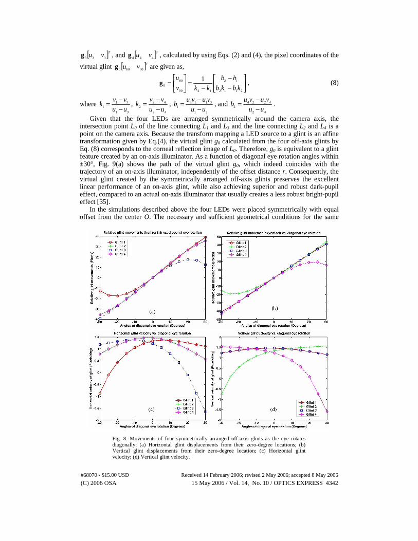
Fig. 8. Movements of four symmetrically arranged off-axis glints as the eye rotates diagonally: (a) Horizontal glint displacements from their zero-degree locations; (b) Vertical glint displacements from their zero-degree location; (c) Horizontal glint velocity; (d) Vertical glint velocity.
[ ]Tvu 333g , and [ ]Tvu 444g , calculated by using Eqs. (2) and (4), the pixel coordinates of the
virtual glint [ ]Tvu 00000g are given as,
⎥⎦
⎤⎢⎣
⎡
−−
−=⎥
⎦
⎤⎢⎣
⎡=
2112
12
1200
00
0
1kbkb
bb
kkv
ug , (8)
where 31
311 uu
vvk
−−= ,
42
422 uu
vvk
−−= ,
31
31131 uu
vuvub
−−= , and
42
42242 uu
vuvub
−−= .
Given that the four LEDs are arranged symmetrically around the camera axis, the intersection point L0 of the line connecting L1 and L3 and the line connecting L2 and L4 is a point on the camera axis. Because the transform mapping a LED source to a glint is an affine transformation given by Eq.(4), the virtual glint g0 calculated from the four off-axis glints by Eq. (8) corresponds to the corneal reflection image of L0. Therefore, g0 is equivalent to a glint feature created by an on-axis illuminator. As a function of diagonal eye rotation angles within ±30°, Fig. 9(a) shows the path of the virtual glint g0, which indeed coincides with the trajectory of an on-axis illuminator, independently of the offset distance r. Consequently, the virtual glint created by the symmetrically arranged off-axis glints preserves the excellent linear performance of an on-axis glint, while also achieving superior and robust dark-pupil effect, compared to an actual on-axis illuminator that usually creates a less robust bright-pupil effect [35].
In the simulations described above the four LEDs were placed symmetrically with equal offset from the center O. The necessary and sufficient geometrical conditions for the same
#68070 - $15.00 USD Received 14 February 2006; revised 2 May 2006; accepted 8 May 2006
(C) 2006 OSA 15 May 2006 / Vol. 14, No. 10 / OPTICS EXPRESS 4342

Fig. 9. Comparison of the virtual glint and the glint centroid created by four symmetrically arranged off-axis LEDs: (a) The virtual glint, independent of the offset distance, r, of the LEDs, follows the same path as an on-axis glint; (b) The distance between two adjacent glints (e.g., g2 and g3) varies with the offset distance, r; The glint centroid shows significant non-linearity and disparity from the path of the on-axis glint in both (b) horizontal and (c) vertical directions.
conclusions to hold are illustrated in Fig. 10(a). Firstly, at least two pairs of LEDs placed on the same plane are necessary. Secondly, let L0 be the intersection point of the camera axis with the LED plane, the lines connecting each pair of LEDs are required to intersect at the point L0. The two LEDs lying on a line through the point L0 are thereafter referred to as a diagonal pair. The angle ζ between the lines connecting the diagonal pairs of LEDs, and the angle φ between the plane containing the LEDs and the camera axis can be arbitrary. The distance from each LED to the point L0 can be different from each other. However, symmetrical arrangements are preferred for a more uniform and robust illumination.
Although more than two pairs of LEDs may be used, two pairs of LEDs usually provide sufficient illumination and yield adequate glint features for the computation of the virtual glint. More than two pairs of glints might improve the tracking robustness by providing redundant glint features, but it can be difficult to segment the glints given that they are cluttered in a small area. The cluttered glints can also compromise the ability of reliably detecting the pupil. Therefore, four LEDs are preferred and will be assumed hereafter.
To examine the separability between two adjacent glints, we placed four LEDs with a symmetrical arrangement similar to the one used in Fig. 8, and varied the offset of each LED, r, from 5mm to 30mm. By simulating diagonal eye rotations within ±30°at an increment of 5°, we computed the separations between two adjacent glints for each LED offset. The separation between glints g2 and g3 was plotted in Fig. 9(b) as a function of eye rotation and the LED offset. For a moderate LED offset r equal 20mm, the separation between two adjacent glints is approximately over 45 pixels. In the example shown in Fig. 7(b), the LED offset was
#68070 - $15.00 USD Received 14 February 2006; revised 2 May 2006; accepted 8 May 2006
(C) 2006 OSA 15 May 2006 / Vol. 14, No. 10 / OPTICS EXPRESS 4343
approximately 25mm.
5.2 Virtual on-axis glint vs. glint centroid As shown in Fig. 8, each of the four off-axis glints alone can be considered to have a
linear path up to ±10°. The displacement from the linear path is about 15 pixels at ±20° and over 25 pixels at ±30°. Such non-linear paths will inevitably reduce tracking accuracy and resolution if the glints are used individually for tracking. On the contrary, in both rotation directions, the plots in Fig. 9(a) show that the non-linearity of the virtual glint is less than 2 pixels at ±20° and less than 5 pixels at ±30°.
The geometrical centroid of the four glints, gc, calculated by averaging their pixel coordinates, might also be considered as an approximation to an on-axis glint [14,36]. However, the non-linearity on the glint trajectories often shows significance only on one or two of the four glints. While the centroid tends to average the non-linearity effects among the four glints, results show that the centroid can not fully cancel them. At large angles of rotation, the centroid is pushed toward the distorted glints and shows less correction to the non-linearity problem. Figures 9(c) and 9(d) plot the horizontal and vertical pixel differences of the virtual glint g0 and the centroid gc compared to an actual on-axis illuminator. There is no difference between the virtual glint and the on-axis glint, but the differences for the centroid estimation are significant. The centroid differences show significant non-linearity and depend on the offset distance of the LEDs from the center O. Considering a moderate offset r equal 20mm, the error can be up to +/-6 pixels at 30° of eye rotation, which corresponds to about 5° of error on the rotation angle estimation. The error increases as the offset distance r increases.
Based on the above comparisons of the predicted performance among individual off-axis glints, the virtual glint, and the geometrical centroid of multiple glints, we anticipate that using the virtual glint will improve the accuracy of eye tracking to a great extent. An initial implementation of the virtual glint tracking method was tested with 7 human subjects. Within a range of ±25° in the horizontal and ±15° in the vertical direction where all of the four glints were detectable concurrently, the average angular error for tracking the pupil-centroid and virtual glint were about 0.5°. On the contrary, when only one off-axis glint is tracked together with the pupil centroid, the average error was about 1° [36].
6. Extension of the eyetracking range
In the case of a single illuminator, glint tracking is often limited to a range in which the glint cannot be detected reliably in the eye image. This usually happens when a glint either inevitably merges with the sclera region at large angles of eye rotation, becoming indistinguishable from specular reflections, or is blocked by eyelashes or eyelids. The usage of multiple LEDs significantly improves the illumination quality and robustness, and the utilization of the virtual glint, which simulates an on-axis glint, helps to correct the non-linear behavior at large angles of eye rotation. However, reliably detecting multiple glints simultaneously at large eye rotation angles is challenging. When we fail to detect one of the glints, the direct calculation of the virtual glint fails and so does the tracking algorithm. Fig. 11(a) shows an example in which the glint marked by the arrow cannot be reliably detected. Consequently, the range of reliable tracking of four glints simultaneously is inevitably reduced.
Using the outer boundary of the iris and eyelids as the limits of reliable glint detection, we examined the range of tracking a single off-axis glint and simultaneously tracking four off-axis glints predicted by the model described in Section 3. The tracking range naturally decreases as the LED offset distance increases. Under the condition of r equal 30mm, tracking a single off-axis LED offers an asymmetrical range. For instance, the ability of tracking an LED placed on the X-axis (e.g., L1) is between -18° and 30° along the diagonal direction of eye rotation. Concurrent tracking of the four glints offers a symmetrical range which is limited up to about ±18° diagonally. The ranges predicated by the model can be reduced further when considering the frequent occurrence of eye blinks or coverage by eyelashes and eyelids.
#68070 - $15.00 USD Received 14 February 2006; revised 2 May 2006; accepted 8 May 2006
(C) 2006 OSA 15 May 2006 / Vol. 14, No. 10 / OPTICS EXPRESS 4344

(a) (b)
(c) (d)
Fig. 10. Illustrations of the new tracking methods: (a) The geometrical conditions for computing an on-axis virtual glint from multiple off-axis glints; (b) The geometrical conditions for orthogonality approximation; (c) The geometrical conditions for parallelism approximation; (d) Estimation of the virtual glint using the orthogonality and parallelism conditions when only two of the four glints are detected.
When some of the multiple glints are undetected, being able to accurately estimate the virtual glint is highly desirable given that it can significantly extend the range of eye movement tracking and effectively improve tracking robustness. Providing that the multiple LEDs are arranged in such a way that their geometrical relationship is fixed, we have examined the geometrical relationships among the glints formed by these LEDs from the simulated model and discovered that some of the geometrical conditions remain constant or predictable as the eye rotates arbitrarily [36]. Such geometrical conditions can be used to compute the same intersection point even if the algorithm fails to detect one or a few of the multiple glints. Consequently, the ability of estimating the same virtual glint from fewer numbers of glints with known geometry significantly extends the range of eye tracking. There are two methods that can be utilized: Orthogonality and parallelism approximation or the transform estimation described in Sections 6.1 and 6.2, respectively.
6.1 Orthogonality and parallelism approximation
By examining the geometrical relationships among the glints using the simulation, we discovered that the angle, referred to as θ, which is formed by the lines connecting the two diagonal pairs of glints (i.e., glints g1 and g3, and glints g2 and g4), remains constantly 90°, regardless of the angle of eye rotation, when the following two perpendicularity conditions are met: (1) the four LEDs are arranged in a way that the lines connecting the diagonal pairs are perpendicular to each other (i.e., ζ equal 90°); (2) the optical axis of the camera passing through the intersection of the lines connecting the diagonal pairs of LEDs is perpendicular to the plane containing the LEDs (i.e. φ equal 0°). These geometrical conditions are illustrated in Figs. 10(a) and 10(b). Under these two conditions, by combining Eqs. (1)-(4), it can be proved that the angle θ is equal to 90°, regardless of the eye rotation angles. This constant orthogonality property can be used to accurately calculate the intersection point even if one of the four glints is undetected and therefore applying such properties allows extending the range of eye tracking. An example is shown in Fig. 11(b) that applies this property to calculate the virtual glint with three of the four glints. As a comparison of the virtual glint and the geometrical centroid of the four glints, under the perpendicularity conditions, we further calculated the angles formed by the glint centroid and two adjacent glints within ±30° of diagonal eye rotations. The results show that these angles vary within the range of 72~103°. This clearly demonstrates the advantage of computing the intersection as the virtual glint.
#68070 - $15.00 USD Received 14 February 2006; revised 2 May 2006; accepted 8 May 2006
(C) 2006 OSA 15 May 2006 / Vol. 14, No. 10 / OPTICS EXPRESS 4345

(a) (b)
Fig.11. (a) Undetected glint failed the tracking of the virtual glint; (b) Orthogonality approximation secured the tracker of the virtual glint with an undetected glint.
Using the orthogonality property requires that the plane containing the LEDs is perpendicular to the optical axis of the camera. In some design configurations, it is practically difficult to implement this perpendicular condition. For instance, in the eyetracked head-mounted projection display reported by Costin et a l[29], it was required to place the camera at a tilt angle up to 45° with the LED plane. When this perpendicular condition is invalid, the angle θ varies with the orientation of the LED plane relative to the camera axis, which is denoted by the angle φ. Given a range of diagonal eye rotations within ±30°, we examined the variations of the angle θ when the angle φ varies from 0° to 40° with an increment of 10°. The results are plotted in Fig. 12(a) as a function of eye rotation angles. Although the plots clearly show that the angle θ varies as the angle φ increases, it can still be approximated by 90° accurately when φ is less than 20°. For instance, when the LED plane is tilted by 20°, the variation of the angle θ is less than 1°, and when the LED plane is tilted by 10°, the variation is less than 0.5°. We further computed the differences between the virtual glint computed from the four glints and the virtual glint estimated from three glints by applying the orthogonal approximation. The results are plotted in Fig. 12(b) as a function of the angles of diagonal eye rotations for the tilt angle φ from 0° up to 20°. Up to 20° of tilt, the overall errors are less than 1 pixel in the range of ±30° of diagonal eye movements. Therefore, the requirement for perpendicularity of the camera axis with the LED plane can be relaxed up to ±20° without compromising tracking accuracy.
Without ambiguity, the above orthogonality approximation allows an accurate calculation of the virtual glint when one of the four glints is undetected. As predicated by the simulations, without eye blinks or eyelash coverage, three of the four glints might be detectable within ±30° horizontally or vertically, or ±22.5° of diagonal eye rotations, under the condition of r equal 30mm. An initial implementation of the orthogonality approximation method was tested with 7 human subjects. The total range of tracking in the prototype was expanded to ±37.5° and ±22.5°in the horizontal and vertical directions, respectively [36].
Besides the two perpendicularity requirements for LED placement, an extra condition can be applied such that the lines connecting the diagonal pairs of LEDs are parallel to the X- and Y-axis of the camera reference, respectively (Fig. 10(c)). In fact, considering the oval shape of the eyelids, it is highly desirable that one pair of the LEDs be aligned with the X-axis so the corresponding glints are less likely blocked by the eyelids. At large angles of vertical rotations, one of the glints aligned with the Y-axis might be undetectable. Given the specified arrangements of the four LEDs, simulations predict that at least one glint of a diagonal pair is detectable within ±30° of diagonal eye rotations, under the condition of r equal 30mm.
Under the parallelism condition and the assumption that the image sensor is parallel with the XOY plane of the camera reference, the lines connecting the diagonal glints are not only orthogonal to each other, but also parallel to the horizontal and vertical axes of the sensor, which is referred to as parallelism approximation. A real imaging system can be calibrated to correct potential skew factors of the sensor plane relative to the camera reference [34]. As illustrated in Fig. 10(d), when only two of the four glints (e.g., g1 and g2), one from each diagonal pair, are detected, two points g00 and g01 can be determined by applying the parallelism approximation. One of these two points is a true estimation of the virtual glint if the ambiguity between the points g00 and g01 can be resolved. This ambiguity is caused by the
#68070 - $15.00 USD Received 14 February 2006; revised 2 May 2006; accepted 8 May 2006
(C) 2006 OSA 15 May 2006 / Vol. 14, No. 10 / OPTICS EXPRESS 4346

Fig. 12. Orthogonality approximation to estimate the virtual glint: (a) The angle θ remains constantly 90° when the camera axis is perpendicular to the LED plane, and it varies within 88~92° when the LED plane is tilted by up to 40° away from its perpendicular orientation; (b) When the LED plane is tilted by up to 20°, the errors of the estimated virtual glint from three of the four glints is less lens 1 pixel by applying orthogonality approximation.
failure to differentiate between the horizontal and the vertical pairs of glints. This ambiguity might be resolved by comparing the vectors from the image center to the estimated virtual glints g00 and g01 with the vector from the image center to the pupil centroid. An estimated virtual glint is selected to be the correct estimation if the magnitude of its corresponding vector from the image center is approximately half of the pupil centroid vector, and its orientation is approximately the same as that of the pupil centroid vector. Alternatively, the ambiguity could be resolved by a hardware implementation. For instance, it is possible to use LEDs with different wavelengths for the diagonal pairs of LEDs, or to drive LEDs with the same wavelength by pulses that are modulated by either the well-known frequency shift keyed modulation or the amplitude shift keyed modulation.
6.2 Transform estimation
The method of orthogonality and parallelism approximation described above requires the validation of the geometrical constraints for the LED and camera placements. On occasions where these conditions can not be implemented practically, for instance in the ET-HMPD system [29], an alternative approach with relaxed geometrical constraints is desired to estimate the virtual glint when one or two of the glints are undetectable. Let the homogeneous
coordinates of a 2D glint image be denoted as [ ]T1~ vug when the eye is gazing in a given direction. The displacement of the glint from g after an arbitrary eye rotation, g~Δ , can be modeled as
gMgΔ ~~ ⋅= , (9)
where M is an arbitrary 3x3 affine transform. If the geometry of the LED placements is fixed, we can use the displacements of the
detected glints from a reference frame to estimate the transform M and to generate an estimated location of a missed glint. The procedures are illustrated in Fig. 13. In Stage 1 corresponding to an initialization illustrated in Fig. 13(a), we can store one set of the glint coordinates as the reference locations when all of the four glints are detected reliably. In Stage 2, illustrated in Fig. 13(b), if one of the glints is missed, we can measure the displacements of the three tracked glints from their reference locations. The six displacement values can be used to estimate the top 2x3 values of the 3x3 affine transform, M1. The displacement of the undetectable glint from its reference location is then estimated by its reference location multiplied by M1. Since the estimated transform M1 encapsulates translation, rotation, scale,
#68070 - $15.00 USD Received 14 February 2006; revised 2 May 2006; accepted 8 May 2006
(C) 2006 OSA 15 May 2006 / Vol. 14, No. 10 / OPTICS EXPRESS 4347

Fig. 13. Transform estimation: (a) A reference frame with all of the four glints detected; (b) Estimation of the fourth undetected glint and the virtual glint from the transform M1 estimated from three tracked glints; (c) Estimation of the two undetected glints and the virtual glint from the transform M2 estimated from two tracked glints.
and skew, it yields a very strong estimate of the missed glint. In Stage 3, illustrated in Fig. 13(c), when a second glint is missed, the displacements of the remaining two glints from their reference locations can be used to estimate another transform, M2. However, this transform is significantly simpler than M1 as it encapsulates only two dimensional translations, one degree of rotation, and one degree of scale.
Therefore, the estimation of the virtual glint can be extended with up to two missing glints. The accuracy of the estimated glints, however, is expected to be significantly lower than the estimation yielded by M1. Compared to the approach of orthogonal approximation, the strict geometric requirements for the LED placements can be significantly relaxed using the transform estimation. The only requirement is that the geometrical relationships among the LEDs, the imaging optics, as well as the user’s head remain fixed.
7. Conclusions and future work
An eyetracked HMD system is highly desirable in various applications. Its complexity imposes however great challenges on designing a compact, portable, and robust system. Instead of pursuing a functionality integration approach by bringing together two separate instruments for integration, we have been exploring a systematic approach that aims at conceiving and optimizing an ET-HMD system as a single instrument. This approach allows us to investigate the potential opportunities offered by the integration and conceive new methods for display and eyetracker designs. In this paper, we particularly focus on the design of new methods and algorithms for the eyetracker sub-unit. To facilitate the understanding and analysis of the dynamic relationships between relevant eye features and eye rotations, we developed a simulated eye imaging sub-system that allows us to accurately predict the movements of the corresponding eye features with an arbitrary configuration of NIR-LED illuminators and eye rotations. Based on this model, we examined the main parameters related to the eyetracker sub-system in an ET-HMD design and demonstrated that the pupil center moves about twice the speed of the glint in both the horizontal and vertical directions. Under the assumption of a 1/3 inch 640x480 (pixels) sensor, we further inferred that pupil tracking offers a resolution of about 0.3~0.5 degrees per pixel within ±20° of eye movements, while the resolution of glint tracking is about 0.7~1 degrees per pixel. Due to the short distance from the LED illuminator to the eye in an ET-HMD system, we demonstrated that an off-axis LED shows considerably large non-linearity at large angles of eye rotation, which can compromise
#68070 - $15.00 USD Received 14 February 2006; revised 2 May 2006; accepted 8 May 2006
(C) 2006 OSA 15 May 2006 / Vol. 14, No. 10 / OPTICS EXPRESS 4348

eyetracking accuracy or require more complicated calibration procedures. For instance, an off-axis glint can be considered to have a linear path up to ±10°, and the displacement from the linear path is about 15 pixels at ±20° and over 25 pixels at ±30°.
Based on these observations, we described novel tracking methods and associated algorithms to correct the non-linearities, improve tracking accuracy, and extend the tracking range and robustness. In the proposed method, we exploited the geometric properties of multiple off-axis LEDs with a suggestion for four LEDs arranged strategically to calculate a virtual glint feature from the glint images of the LEDs. The virtual glint feature emulates excellent linear performance of a glint created by an on-axis LED and achieves superior and robust dark-pupil effect compared to an actual on-axis illuminator that usually creates a less robust bright-pupil effect. The non-linearity of the virtual glint is less than 5 pixels within ±30° of eye rotation and it can potentially improve the accuracy of eye tracking to a great extent.
Glint detection often fails when either a glint merges with the sclera region at large angles of eye rotation, becoming indistinguishable from specular reflections, or is blocked by eyelashes or eyelids. Simultaneously detecting multiple glints at large angles of eye rotation is challenging. Failure to detect a glint imposes challenges on tracking robustness and limits the glint tracking to a small range of eye rotations. By further applying geometrical constraints on LED placements, we presented two methods and algorithms through which the virtual glint can be reliably estimated when up to two of the four glints were undetected. Given the proposed geometry of LED placements, simulated results demonstrated that the proposed methods can accurately estimate the virtual glint with less than 1 pixel error when one or two of the glints are undetected.
As future work, we will report the detailed implementation and testing of the methods and algorithms and will test them in a fully integrated ET-HMD system whose optical design is reported in a companion paper.
Acknowledgments
We acknowledge Craig Pansing for his work on illumination optimization. This work was supported by NSF HCI grants 04-11578 and 03-07189.
Appendix
A. Derivation of imaging matrix via anterior corneal reflection
As shown in Fig. 2(b), a glint is a virtual image of an LED illuminator, created by the reflection through the anterior corneal surface. Given the homogeneous coordinates of a point light source defined in the eye reference, T
eeee zyx ]1[~L , following the law of reflection of
a convex mirror with the focal length that is half of the radius of the curvature, the Cartesian coordinates of the glint created by the source in the same reference, [ ]T
GeGeGee zyxG , is given by
⎪⎪⎪
⎩
⎪⎪⎪
⎨
⎧
+−−
−−=
−−−
=
−−−
=
e
cee
eecGe
e
cee
cGe
e
cee
cGe
rrzr
zrrz
yrzr
ry
xrzr
rx
1
1
1
1
1
1
)(2
)()(2
)(2. (A-1)
By assigning 1)(2~1 −−= ceeGe rzrw , in the homogeneous coordinates, Eq. (A-1) can be
rewritten in a matrix form as erefle
~]~~~~[
~LMG ⋅=T
GeGeGeGe wzyx . The matrix reflM is the first-order imaging matrix of the anterior cornea surface for an object point defined in the eye reference, and it is given by
#68070 - $15.00 USD Received 14 February 2006; revised 2 May 2006; accepted 8 May 2006
(C) 2006 OSA 15 May 2006 / Vol. 14, No. 10 / OPTICS EXPRESS 4349
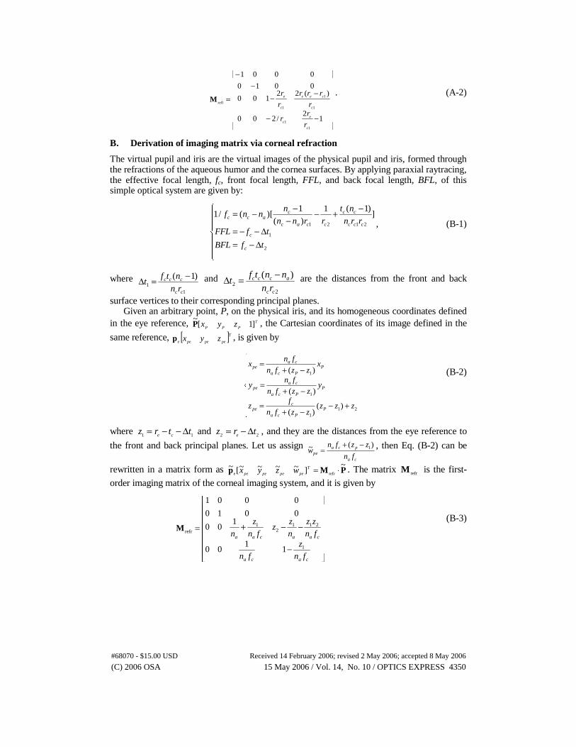
⎥⎥⎥⎥⎥⎥⎥
⎦
⎤
⎢⎢⎢⎢⎢⎢⎢
⎣
⎡
−−
−−
−−
=
12
/200
)(22100
0010
0001
1
1
1
1
1refl
c
ec
c
cee
c
e
r
rr
r
rrr
r
rM
. (A-2)
B. Derivation of imaging matrix via corneal refraction
The virtual pupil and iris are the virtual images of the physical pupil and iris, formed through the refractions of the aqueous humor and the cornea surfaces. By applying paraxial raytracing, the effective focal length, fc, front focal length, FFL, and back focal length, BFL, of this simple optical system are given by:
⎪⎪
⎩
⎪⎪
⎨
⎧
Δ−=Δ−−=
−+−−
−−=
2
1
2121
])1(1
)(
1)[(/1
tfBFL
tfFFLrrn
nt
rrnn
nnnf
c
c
ccc
cc
ccac
cacc
, (B-1)
where 1
1
)1(
cc
ccc
rn
ntft
−=Δ and 2
2
)(
cc
accc
rn
nntft
−=Δ are the distances from the front and back
surface vertices to their corresponding principal planes. Given an arbitrary point, P, on the physical iris, and its homogeneous coordinates defined
in the eye reference, T
PPP zyx ]1[~P , the Cartesian coordinates of its image defined in the
same reference, [ ]T
pepepee zyxp , is given by
⎪⎪⎪
⎩
⎪⎪⎪
⎨
⎧
+−−+
=
−+=
−+=
211
1
1
)()(
)(
)(
zzzzzfn
fz
yzzfn
fny
xzzfn
fnx
PPca
cpe
PPca
cape
PPca
cape
(B-2)
where 11 ttrz ce Δ−−= and 22 trz e Δ−= , and they are the distances from the eye reference to
the front and back principal planes. Let us assign ca
pcape fn
zzfnw
)(~ 1−+= , then Eq. (B-2) can be
rewritten in a matrix form as PMp~
]~~~~[~refre ⋅=T
pepepepe wzyx . The matrix refrM is the first-
order imaging matrix of the corneal imaging system, and it is given by
⎥⎥⎥⎥⎥⎥
⎦
⎤
⎢⎢⎢⎢⎢⎢
⎣
⎡
−
−−+=
caca
caacaa
fn
z
fn
fn
zz
n
zz
fn
z
n
1
2112
1refr
11
00
100
0010
0001
M (B-3)
#68070 - $15.00 USD Received 14 February 2006; revised 2 May 2006; accepted 8 May 2006
(C) 2006 OSA 15 May 2006 / Vol. 14, No. 10 / OPTICS EXPRESS 4350