Victoria Baths heating strategy
26
Victoria Baths heating strategy Sustaining Change Programme A summary report prepared for MERCi and the Victoria Baths Trust November 2010
Transcript of Victoria Baths heating strategy

Victoria Baths heating strategySustaining Change Programme
A summary report prepared for MERCi and the Victoria Baths Trust
November 2010


Contents
1. A flagship retrofit project?
2. Our approach to the study
3. The proposed strategy
Stage 1: Heating the front of house
Stage 2: Re-opening the Turkish Baths
Stage 3: Bringing the pools back into use
Stage 4: Upgrade the energy centre
4. Energy centre investment strategy
5. Precedents for the approach
6. Indicative costs breakdown
7. Energy use and CO2 savings
8. Recommended next steps

A flagship retrofit project?
In-depth technology guide CTG009
Swimming poolsA deeper look at energy efficiency
In-depth technology guide CTG009
Swimming poolsA deeper look at energy efficiency
Opened by Manchester Corporation in 1906 Victoria Baths is an iconic and very special building. It is not just a swimming baths, it is part of the rich cultural history of Manchester.
The Baths themselves symbolise the technological innovation and public service ethos of Manchester Corporation. They were an investment in the health and wellbeing of the city.
The twenty first century has brought new challenges. Manchester’s new Climate Change Action Plan commits the city to a major programme of building retrofit to low carbon standards.
Leisure centres and swimming pools are major users of energy and a sustainably heated Victoria Baths could become a flagship to demonstrate what is possible for even the most challenging heritage buildings.

Our approach to the study
The Victoria Baths heating study was carried out between May and July 2010. Here we outline the main elements of our approach to developing the strategy.
1. Site visitWe carried out a number of site visits in conjunction with the client in order to become more familiar with the building, its history and its original design and servicing.
2. Review of restoration plansWe reviewed the restoration works carried out to date as well as future proposals, including the M&E strategy for the building, and specific requirements of the client and future phasing of works.
3. Review of precedents and system optionsWe reviewed available precedents for restoration projects and low carbon swimming baths, as well as the range of different system options.
4. Development of system conceptBased on our understanding of the possible future phasing and the clients requirements we devised a modular system concept which could be developed in a number of phases.
5. Analysis of performance, cost and benefitsWe carried out outline analysis of the performance of the proposed system, costed the different elements and calculated the likely running costs and CO2 reductions.
6. Recommended next stepsBased on the requirements for taking the proposed system concept forward we highlighted what would be required to further test and develop the concept.

The proposed strategy
Our proposed strategy for Victoria Baths has six main elements which we have developed into a phased plan which could reduce its CO2 emissions by 80% compared to a swimming bath of the same age.
Protect the building fabric Where possible the strategic should seek to protect the building fabric from any further deterioration - for example, from damp penetration.
Make further fabric improvementsWhere possible further opportunities to improve the u-value should be implemented, working within restrictions of the buildings heritage status.
Respect and re-use original building services Where possible original features of how the original building services were designed should be re-used, such as the use of natural ventilation.
A modular approach to heating and ventilation The heating strategy should be capable of being implemented in modules as different parts of the Baths are brought back into active use.
Use of best practice in energy managementOnce parts of the Bath are back in use recognised best practice should be used to optimise the running of the heat systems and minimise energy use.
On-site zero carbon heat sourcesWhilst the heating system should be designed to initially use natural gas, it should be possible to upgrade the primary heat source to zero carbon technologies installed on/in the original boiler house.
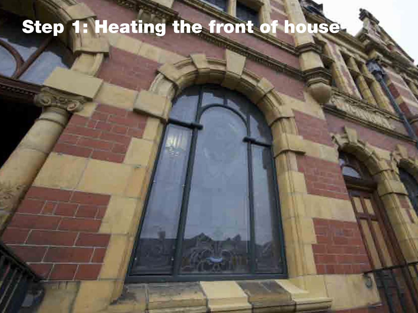
Step 1: Heating the front of house

Step 1: Heating the front of house
The first step would be to provide space heating to the front of the Baths, including the reception area, shop and cafe, as well as the function rooms and Superintendants flat.
Step 1a: Modular energy centre
A gas supply would be brought into the building (notional capacity of 450 kW). Either the current location of the water treatment plant or the original boiler plant would be stripped out to make way for a new energy centre.
A single large gas boiler with a notional capacity of 150 KW and ancillaries would be installed in order to supply the front of the Baths and provide background heating to one of the pool halls.
Step 1b: Create insulated ‘hypercausts’
In preparation for the routing of the heat distribution pipes from the new energy centre to the front of the building floor and wall insulation would be installed in the ducts around the pool spaces that are currently in use. Fans and air transfer grills could also be used to circulate warmed air from the roof lights.

Step 1c: Install heating pipe runs
Heating distribution pipes would be routed from the energy centre to the front of the building through the pool hypercausts. The pipes would have finned tube heating circuits which would allow for heating of the air in the hypercausts.
Transfer grills would be installed in the floor below the balcony areas in each pool. This would allow heat to percolate up from the hypercausts in order to heat the Male Second Class and Female Baths.
Step 1d: Install radiant heating
Heating distribution pipes would be routed through to the front building in order to provide space heating to selected spaces. Thermostatic radiators would be installed in the cafe/shop and selected other rooms. Hot water cylinders could be installed to supply the kitchen and toilets.

Step 2: Re-opening the Turkish Baths

Step 2: Re-opening the Turkish baths
The second step would be to provide higher temperature air heating and an air circulation system to facilitate the re-opening of the Turkish Baths, including the hot rooms, rest rooms and changing rooms on two levels of the front of the building.
Step 2a: High temperature feed
A spur would be taken from the hot water distribution circuit and routed to supply the hot air system for the Turkish Baths.
Step 2b: Re-instate air circulation system
The original air circulation system for the Turkish Baths would be re-instated. The duct routes would be cleaned out and new air handling equipment installed. Heated air would be circulated through the hot rooms and rest rooms before then being extracted.
A heat exchanger would pre-heat fresh air. This would initially be draw in using the original intakes at the front of the building, before being brought in through the hypercausts of each pool hall as the air handling systems have been installed (see Step 3).

Step 2c: Additional roof insulation
Subject to a cost benefit analysis additional insulation could be installed on the roof of the Turkish Baths. There is currently enough of an upstand to make substantial further improvements to the u-value of the roof.
Step 2d: Changing room hot water supply
The hot water supply for the Turkish Bath changing rooms in the basement would be connected to the heat distribution circuit. A hot water cylinder would be installed to provide buffer storage.
Low water use sanitary ware would be specific throughout in order to minimise hot water use. This would include low flow showers and spray taps. Heat recovery from the grey water could also be considered.

Step 3: Bringing the pools back into use

Step 3: Bringing the pools back into use
The third step would be to bring up to two of the pools back into full use, with air handling and water heating systems installed, both with integral heat recovery to maximise their energy efficiency.
Step 3a: Insulate the roofs
Ensure that the remaining pool roofs are insulated to a very high specification in order to reduce heat loss. Higher performance insulation such as aerogel or vacuum insulated panels could be considered in order to achieve a u value greater than 0.35. Double glazing should be specified to achieve a u-value of 1.1.
Step 3b: Fit out the remaining hypercausts
The remaining hypercausts would be fitted out with floor and wall insulation (for the gable ends). Further heat distribution mains with finned tube radiators would be routed through the ducts and transfer grills installed at the pool sides.
11Swimming pools
Heat recoveryHeating the supply air is generally one of the major consumption areas for a pool building. Providing a simple heat exchange device, such as a plate heat exchanger or run-around coils, can optimise energy efficiency by reclaiming large amounts of lost energy from the exhaust air.
Fit heat exchangers with a bypass in the ductwork for occasions when heat recovery is not required. However, make periodic checks to ensure that they are not permanently bypassed and normally operate in the ‘heat recovery’ position.
Moist extracted air
Input air
A
GC
F
B D
J
E
H
I
Hea
t Rec
over
y
A Air intake
B Air filter
C Heat recovery device transferring heat energy from the air being removed from the building to the supply air entering the building
D Centrifugal fan
E Air heater
F Extract fan
G Air extract
H Pool water calorifier
I Boiler system
J Heating water pump
Hot water flow
Cold water flow
Figure 3 Simplified diagram of a pool hall air handling system
Plate heat exchangers
Plate heat exchangers consist of glass, metal or plastic plates arranged in a stack with the exhaust air and incoming air flowing in the adjacent channels. Heat transfers from the outgoing air from the pool hall (which is warm and moist) through the plates to the cold incoming air. They are cheap and free from mechanical problems, although a limit on their application is that the incoming and outgoing air ducts must be adjacent to each other.
If grease and grime are allowed to build up on the plates this will lead to a substantial reduction in their effectiveness, so the heat exchanger should be maintained in accordance with manufacturers’ specifications. If the plates are made of metal, chlorinated air can attack them. Inspect for signs of corrosion at least once a year.

� -� -� -� !� � -� $ !� ' � &%- $ �%�$ ( �- &� �- $ � � � &-&! -� � � � -%" �� � � � � � &� ! -) � � � %&-" ' $ %' � � -� -" ! � � � + -!� -� ! &� ' � �� � " $ ! ( �� � &%- � -" �$ � !$ � � � �- � � -� �%� � �
� � � & � � � & � � � � � !& � �� # � � � � �� � � " � � & � � � & �� " & � � � $ �! % �� " & � �� $ �! %
��
�&�
���
���
�
�
� � � & � � � � & � � � & � � � & � � � � � � � �
� � &� -� � $ �� %� � -� �� � � %- � !$ -� �$ � + -�� � � � � � &-� ' � � � � � %� -� &-� %- �%%� &� � � -&� � &-� �$ � + -� % - !& -) � % &�� � -� &� � � %� � -�� �� &-" � " � � -&� �$ � � � -� �$ � + -� � -� �- $ �� ! ( �$ �� -� $ !� -) � $ � �$ -� � $ -� � -� � � �� -&!- � !!� �$ -� � $ � --� -&�� " �$ � &�� � � � � &�%- &� � %- " �$ � � &%- � �$ � + -%� ( � � -&! -� � -$ �� � � %�� -&� $ !' � � -" $ �� �� &� � -!� -&� �- !' &%� � �- � � $ � -� ! ( �$ %�� + � -� -� ! &� � � � � &�%- &� �- %� ( � � %- � $ �- � %%!� � � &�� -) � &� -" $ �� � !!� � � -!� -&� �- !' &%� � �- � � $ � -
� � -� � � � -� � -� � -� $ $ � � � � -) � &� -� � $ % &$ � � � % -% � � � -� + -% � � � -' % � � -&' � � % -% � ! " � � -� ! ) -&! -&� � -) � $ � � $ -� � $ �� � &� $ � &� ( � � + -&� � -� � $ -% &$ � � � % -� � -� � -% &� � � � � -) � &� -&� � -) � $ � � $ -� � $ % &$ � � � -� &-&� � -� ! &&! � � -� � � % -� ! ' " � � � -) � &�� � � * � � � � � &+ -! � -% � , � � -&! -% ' � &-&� � -� ' � &) ! $ � -! $ -� � $ -� � � � � � -' � &-� � � � % - � � -� � � � -&� � -� � � � � -� � � &-$ � � ! ( � $ + -% ! � ' &� ! �
� �� � & � � � � �� � � & � � � � � � �
� � + -&+ " �%- !� -� �� &-�*� � � � �$ %- � $ �- � ( � � � � � � �- � ! $ -� �� &-$ �� ! ( �$ + -� " " � � � � &� ! %� - ! ) � ( �$ -�� � � -&+ " �- ! � -� �� &�*� � � � �$ -� � %- � �$ &� � -� � ( � &� � �%- � � -� $ � ) � � � � %�
� � � �� � � � & � � � � � $ �- $ �� � &� ( �� + -� �*" � %� ( � � -� ' &-$ �# ' � $ �- � -" ' � " -" � � � -� � -�*" � %� ! -&� � -&!!" �$ � &� � -� ' � � $ !' � -� !!" %- ' %�� -� -� !� � -� � � � � &�%- � ' %&-� �- � � � $ � �� -) � &� -� &� � � $ ��, �- &!- " $ �( � &-� $ ! %&-� � � � � � �� � �+ -� $ �- � ! ) �( �$ -&� �- � � %&-%! � ' &� ! -� ! $ -� %�" � $ � &�� -� � $ -%&$ �� � %�
� � � � � & � � & � � � � � � �� &-�*� � � � �$ %- � $ �- # ' � &�- �� � �� &� ( � � -� ' &-� $ �- � ' � � + � -�*" � %� ( �- � � -( �$ + -� � � � � � ' � &-&! -� � �� � -� � �+ -� � -&$ � " -� ! � � %� &�- $ �%' � &� � -� -&� �- � $ ! ) &� -!� -� !' � � %�
� � � & � � � � � � � � & � � � � � � $ �- � � � &� � � �- � &� %� ( �- � � -" $ ! �- &!- � $ !%%- � ! &� � � � &� ! -� � -� ! - ! &�� � �� &� ( �� + -� $ � � -� ! � � %� &� ! �
� + - � � -� � � � -!� � �$ -� � � -&� �- � � �� � &%- � ! � � � �� � - !- � ! ( � � -" � $ &%� -� � � � -�� � �� &� ( � �%%� -� ! ) -� � $ � " $ �%%' $ �- � $ ! " ��� %+ -� $ � � � � �- !� -� ! � � % � &� ! � - !- � � $ �� &-� �$ � + -$ �# ' � $ �� � &-� � -, �$ ! -� $ ! %%� � ! &� � � � &� ! � -� � �+ -� $ �- � � %!" $ ! ( � -&!- � �- � ! � -� � %&� � -� � -( � $ &' � � � + -� � � &� � � �� � $ �� �
�� � � &� ! � � � + � - � � -� � � � -� � -� �- &$ �� &�� -&! -) � &� %&� � -� ! $ $ ! %� ( �- � ( � $ ! � � &%- %' � � -� %- %) � � � � � -" ! ! � %- � �%!� �- " $ !� �%%- � " " � � � � &� ! %�
75386 Heatpipes A4 12p Folder.qxd:Layout 1 9/1/08 13:19 Page 9Step 3c: Route the extract ducts
An air handling and recirculation system will be required to manage the moisture in the pool halls. The extract ducts for the system would be installed in the gable ends of each pool hall, with grills carefully located so not to detract from any architectural features. The air would then be routed down into what were team changing rooms at the back of the building.
Step 3d: Install the air handling units
High efficiency heat recovery units would be installed in the pump room. These could use innovative heat pipe technology. These units would recover heat from the moist extracted pool air and pre-heat fresh air which would then enter the hypercausts.
As well as heating the pool air the hypercaust system could be used to provide background air heating for the front of the building.

Step 3e: Pool heating system
Additional gas boilers with a notional additional capacity of 300 kW would be installed in the energy centre in order to heat the swimming pools. Heat recovery would be incorporated into the pool water cleaning system.
Step 3f: Night time pool covers
Insulated pool covers would be installed in order to minimise heat losses overnight.

Step 4: Upgrading the energy centre

Step 4: Upgrade the energy centre
The fourth and final step would be to upgrade the energy centre so that Victoria Baths can have its own zero carbon heating supply - based on a combination of biomass (wood chip) and solar thermal technologies.
Step 4a: Large-scale thermal storage
Large (1000 litre+) thermal storage tanks would be installed to serve the two proposed forms of zero carbon heating. These could be purpose designed to be located within the existing water storage tank areas - dependant on structural integrity.
The tanks would serve as buffer tanks allowing the biomass boiler to be run efficiently and as short to medium term (several days or weeks) and potentially also long term (interseasonal) heat storage for solar thermal energy.
Step 4b: Solar thermal array
An array of 250 m2 solar thermal tubes would be installed on the roof of the former boiler house and water treatment plant, with racks affixed above the thermal storage tanks - in a similar fashion to the original aerator system.
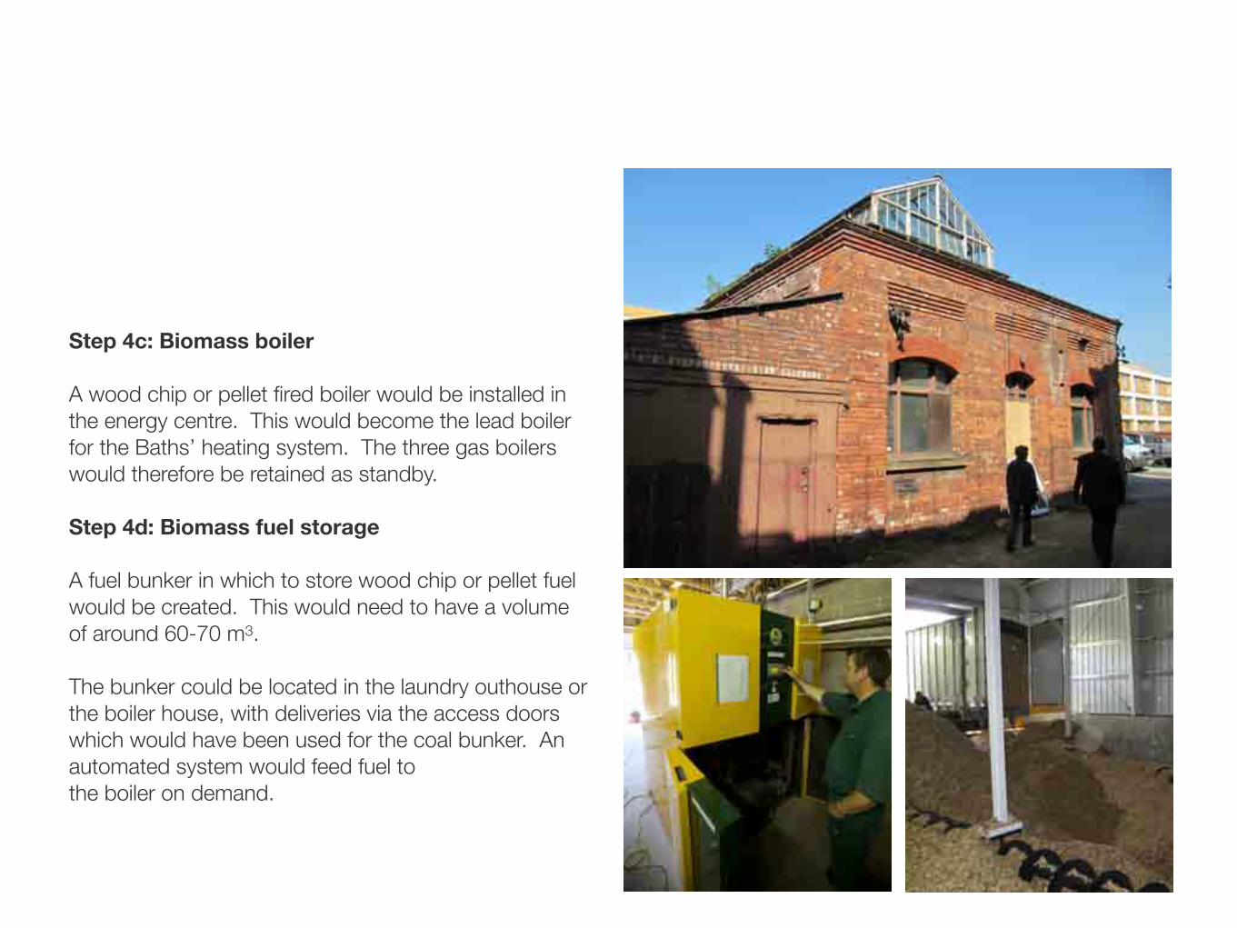
Step 4c: Biomass boiler
A wood chip or pellet fired boiler would be installed in the energy centre. This would become the lead boiler for the Baths’ heating system. The three gas boilers would therefore be retained as standby.
Step 4d: Biomass fuel storage
A fuel bunker in which to store wood chip or pellet fuel would be created. This would need to have a volume of around 60-70 m3.
The bunker could be located in the laundry outhouse or the boiler house, with deliveries via the access doors which would have been used for the coal bunker. An automated system would feed fuel to the boiler on demand.

Indicative 3D visuals

ENERGY PERFORMANCE CONTRACTING
(EPC)
NWhe.g. energy
management, controls, HVAC,
e!cient lighting, peak load management,
thermal insulation, user motivaton
Energy savings service
ENERGY SERVICE CONTRACTING
(ESC)
MWh
Replacing boilers, local heating
networksCHP plants,
solar systems,energy management
Useful energyservice
ENERGY SUPPLIER
(Utility)
Fuel or energy
Primaryenergy
MWhHeating oil, electricity,
district heating, biomass,
Crude oil, natural gas,
coal,
Busin
ess
models
Typic
al
measure
s
Valu
e
chain
Energy centre investment strategy
The upgrade of the energy centre to provide zero carbon heat sources could be financed using new market incentives and third party finance arrangements, thereby reducing the upfront capital cost.
Third party ‘energy service contracting’
Banks such as the Co-operative and specialist companies such as Econergy offer a form of ‘green lease’ for equipment such as biomass boilers. This means that they finance the equipment with the capital cost then being paid off through a charge for providing heating. Victoria Baths would still be responsible for purchasing biomass fuel.
The Renewable Heat Incentive
The Renewable Heat Incentive (RHI) will be introduced by the Government in 2011. This will pay a higher per kWh rate for renewable sources of heat such as solar and biomass.
The RHI now makes it much more economic to install these technologies, enabling finance to be guaranteed by the value of future RHI income over 25 years.
Renewable Heat IncentiveConsultation on the proposed RHI financial support scheme
February 2010
Renewable Heat IncentiveConsultation on the proposedRHI financial support scheme
February 2010

Precedents for the approach
A number of precedents were found for elements of the approach proposed for Victoria Baths. Similar swimming baths and Turkish baths that have been refurbished were also identified for comparative purposes.
Harrogate Turkish Baths and Health Spa
The Baths with their distinctive Moorish design were restored to their former glory and re-opened in 2004 as a luxury health spa centre.
Hexham swimming pool, Northumberland
A 540 kW wood chip boiler has been installed to heat a pool and fitness centre. The boiler will be supplemented by solar thermal panels. The system will save 500 tonnes CO2 per year.
Withington Baths
The Baths were refurbished in 2003 and a new fitness centre added to the complex, which was designed by the same architect as Victoria Baths. The complex is run by Serco for Manchester City Council.

Indicative cost breakdown
An indicative costing exercise was carried out for the proposed approach. Elements of the approach were itemised in order to cost individual items. More detailed modelling will be required to size parts of the system in order to obtain a more accurate costing.
Step 1: Heating the front of house £60,000
Step 2: Re-opening the Turkish baths £16,360
Step 3: Bringing the pools back into use £169,080
Step 4: Upgrading the energy centre £313,890
Total indicative investment required £558,330 (exclusive of VAT and fees)
Total Step 1Front of house
£60,000Total Step 2
Turkish bath£15,360
Total Step 3AHeating
£74,040Total Step 3B
Ventilation£95,040
Total Step 4ASolar thermal
£127,890Total Step 4B
Biomass£186,000Total£558,330
Total Step 1Front of house
£60,000Total Step 2
Turkish bath£15,360
Total Step 3AHeating
£74,040Total Step 3B
Ventilation£95,040
Total Step 4ASolar thermal
£127,890Total Step 4B
Biomass£186,000Total£558,330

Energy use and CO2 savings
An indicative estimate of the gas use, likely annual running costs and the potential CO2 savings from implementing the proposed approach were calculated.
More detailed modelling would be required to validate these figures further and to accurately benchmark its performance - particularly for space heating of the pools which is likely to be an underestimate.
Step 1: Heating the front of house 148,050 kWh/annum £5,198 28 tonnes CO2
Step 2: Re-opening the Turkish baths 225,000 kWh/annum £7,875 42 tonnes CO2
Step 3: Bringing the pools back into use 675,000 kWh/annum £23,625 125 tonnes CO2
Step 4: Upgrading the energy centre 562,500 kWh/annum £14,569 31 tonnes CO2
03Swimming pools
Swimming pool water needs to be continually heated in order to overcome the cooling effect of evaporation and maintain comfortable temperatures. It must also be continuously filtered and treated, so it is not surprising that pools are significant users of energy.
Energy consumption
Pool halls and changing areas are typically kept warmer than other spaces as pool users are wet and wear less clothing. Moreover, bathers consume large volumes of shower water which adds to the overall energy consumption of pool facilities.
Using energy efficiently can save up to 25% of overall operating costs of a typical swimming pool. Implementing good energy management techniques can minimise consumption without lowering the standard of service to users.
The major energy consumption areas in an indoor pool hall and their associated costs are shown in Figure 1 below.
In order to achieve the greatest savings potential, pool hall managers should know where the majority of their energy is being consumed and/or wasted. Typical common wastage areas within the wet leisure sector are:
Space heating and ventilation
Water heating and treatment
Lighting
Motors and drives (particularly for pool pumps and filtration equipment).
Fans and pumpsGeneral power
LightingSpace heating
Water HeatingFans and pumpsGeneral power
LightingSpace heating
Water Heating
Figure 1 Proportion of energy used in an indoor pool Figure 2 Cost of energy used in an indoor pool
Typical energy use breakdown for a swimming pool
Typical breakdown of energy costs for a swimming pool

Recommended next steps
The project team identified a range of uncertainties and issues that would require further detailed work in order to better understand the costs, benefits and performance of the proposed approach.
Recommendation 1: Detailed modelling• Modelling of the buildings thermal performance • Modelling of the pool air movements using Computational Fluid Dynamics
Recommendation 2: Detailed design of servicing• Testing and cost benefit analysis of servicing options proposed by the strategy• Detailed costing exercise for the preferred service option(s)
Recommendation 3: Business planning• Create a cashflow for operation of the energy centre including the upgrade to solar/biomass systems• Explore energy service contract options with potential finance providers and specialist installers• Explore grant and financial support options, including RHI contracts

Nick DoddPrincipal Director, Sustainability
t. 0161 200 5500e. [email protected]
Charlie BakerAssociate
m. 0797 679 3795e. [email protected]
www.urbed.coop
John OglePrincipal Consultant, Building Engineering
t. 0161 602 7513e. [email protected]
www.aecom.com